Friday
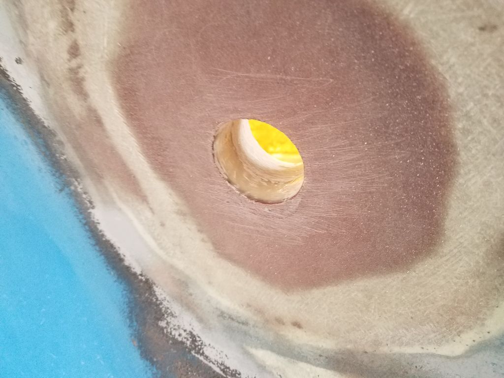
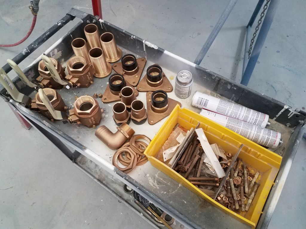
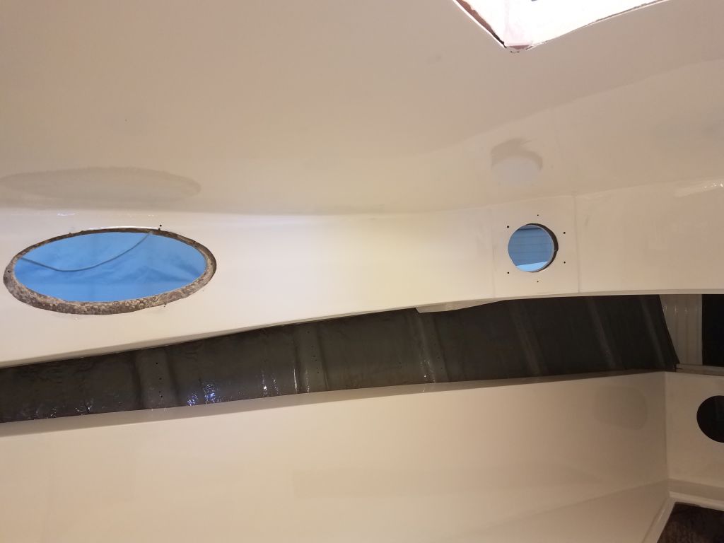
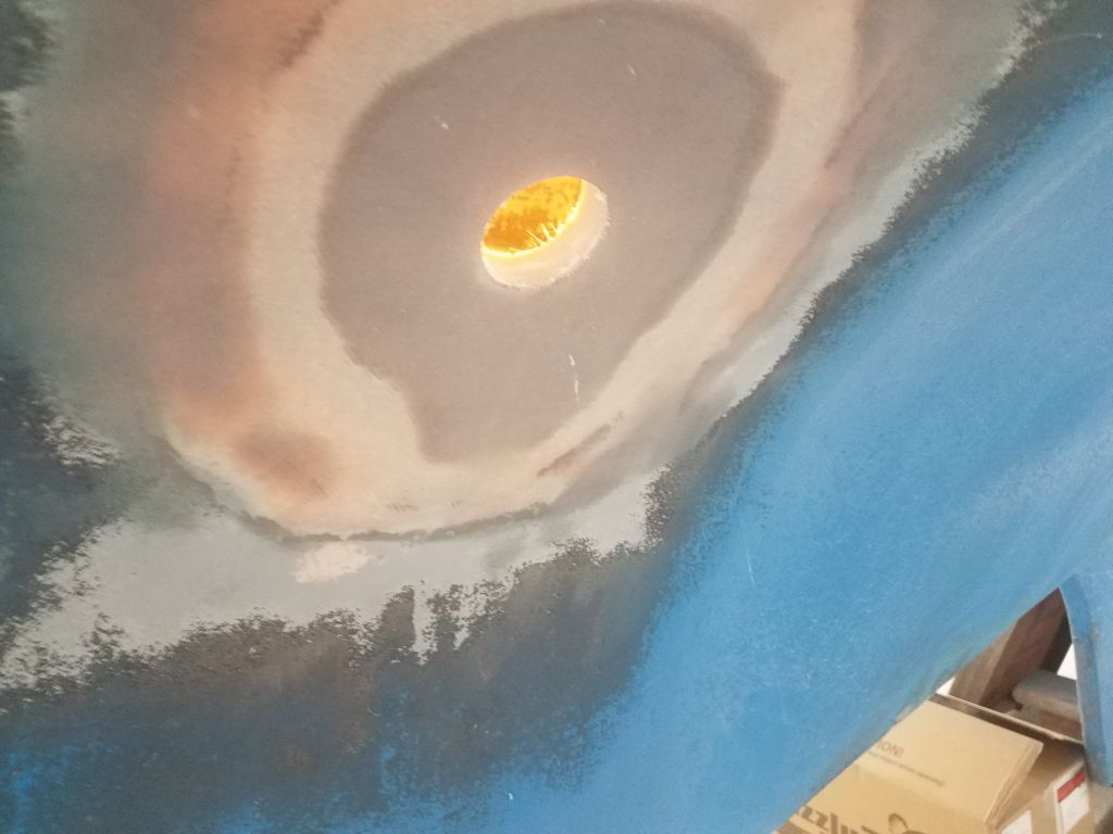
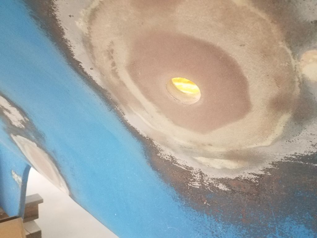
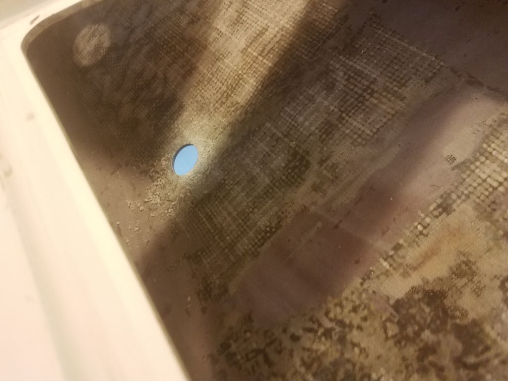
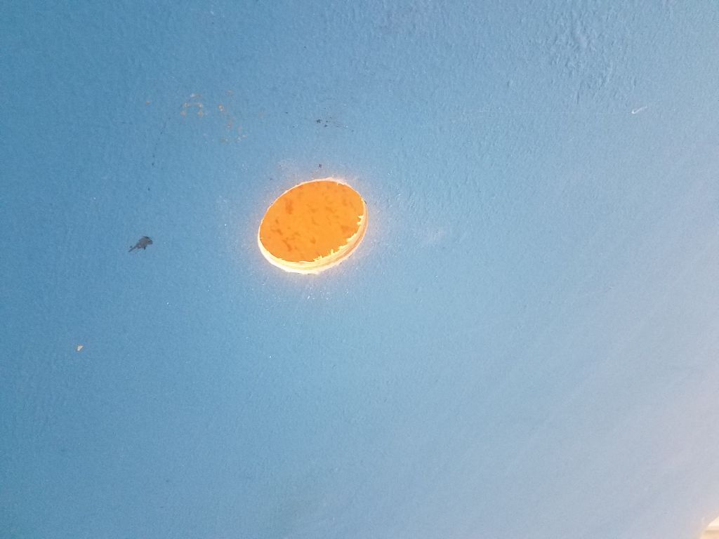
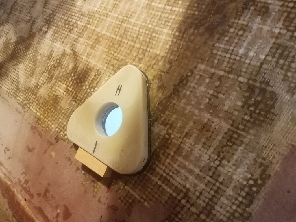
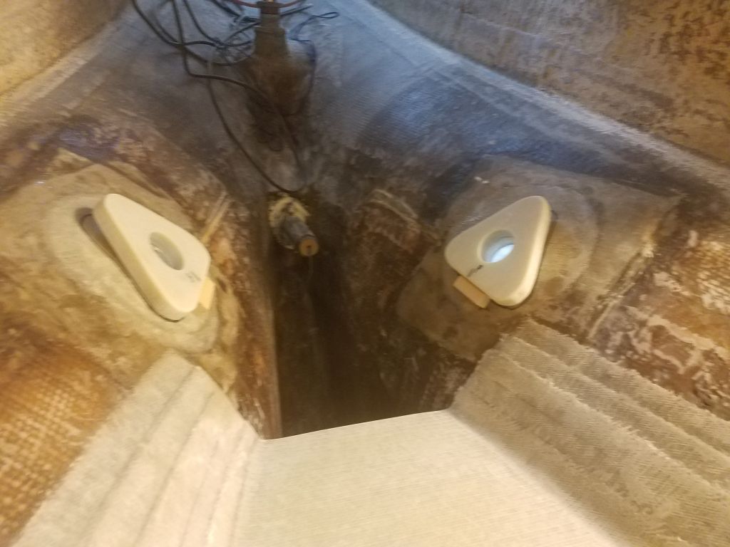
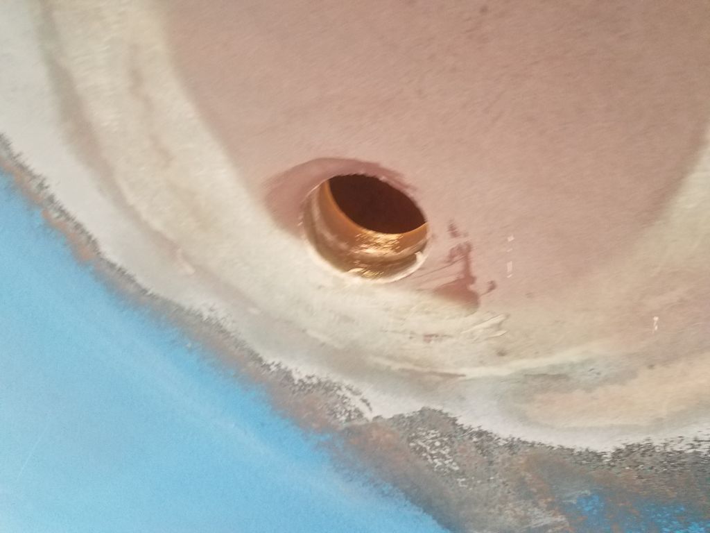
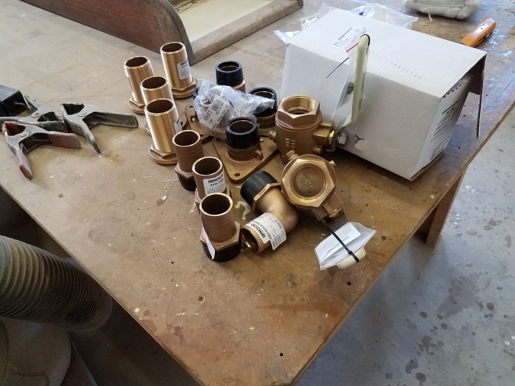
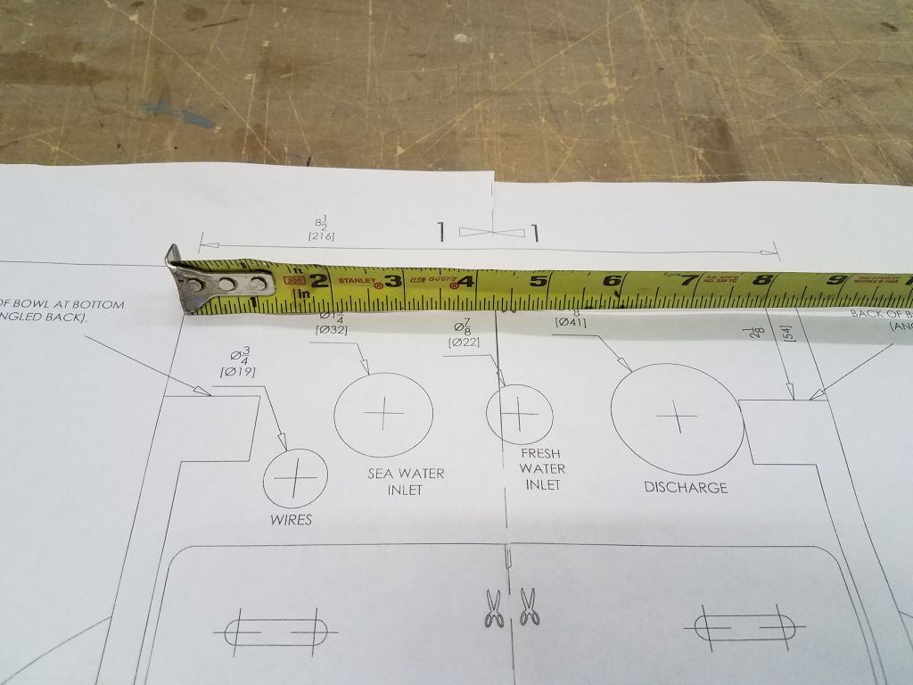
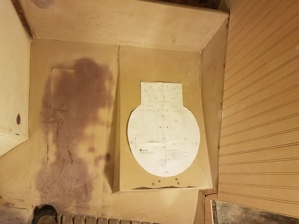
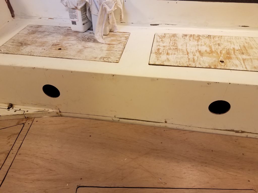
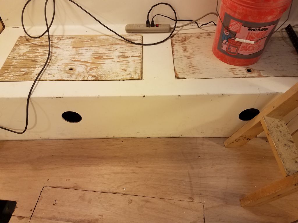
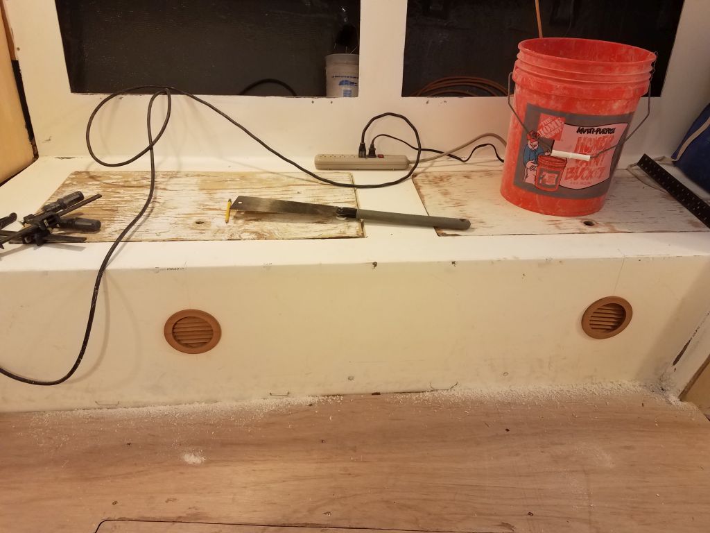
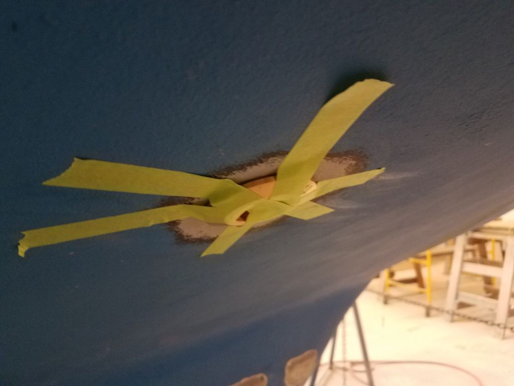
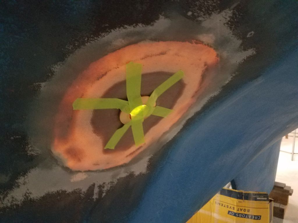
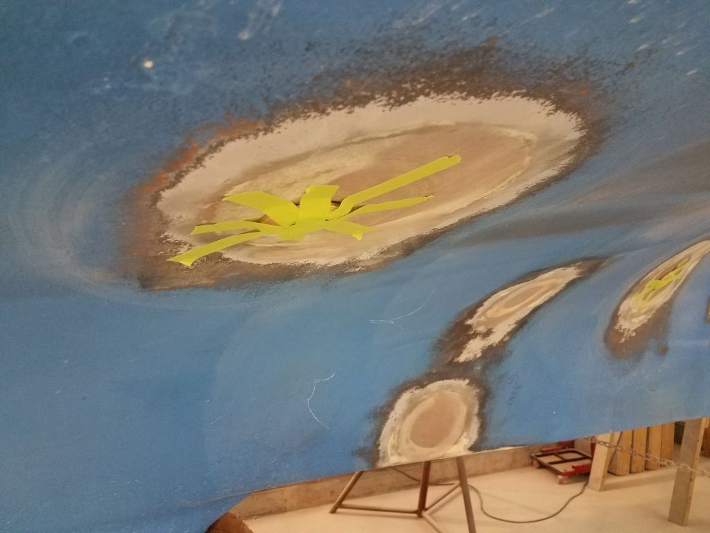
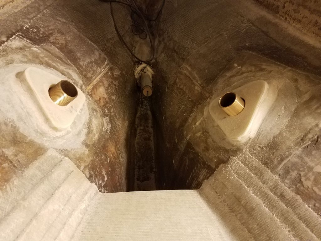
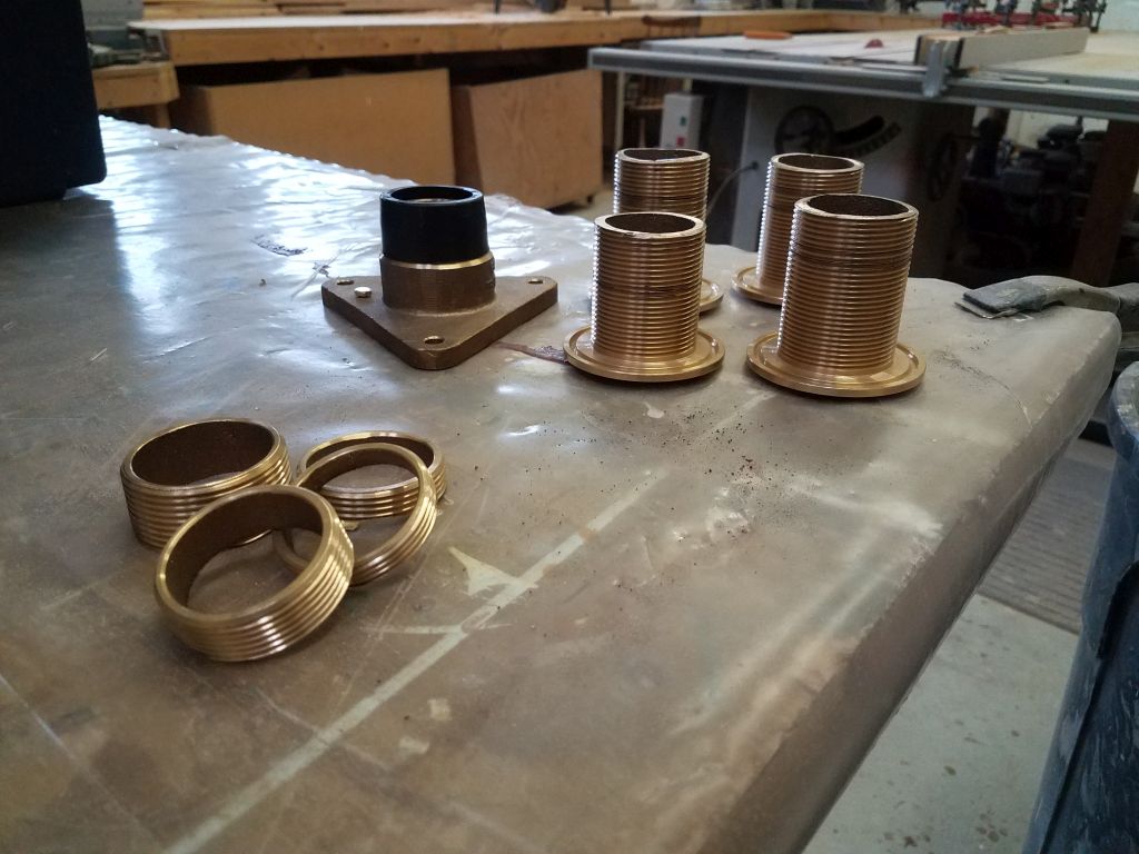
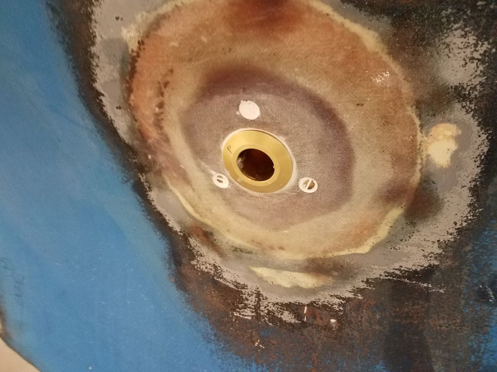
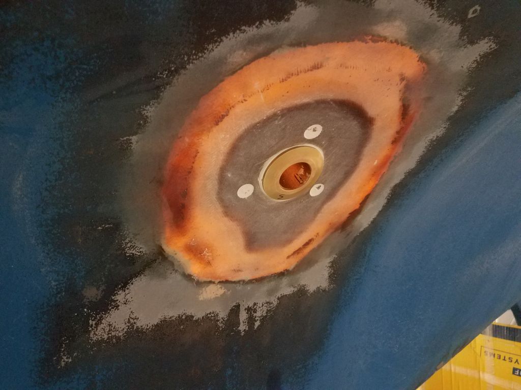
To get started, I inserted all four through hull mushroom fittings in their respective holes (marking each accordingly),securing them temporarily with tape from outside.
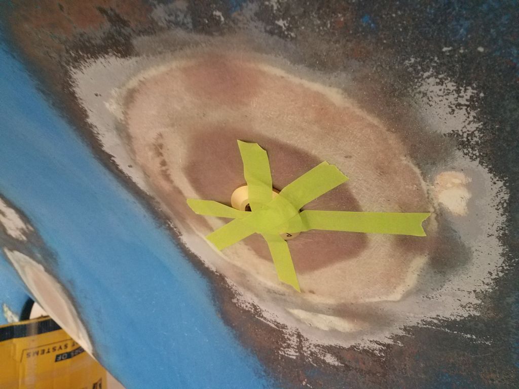
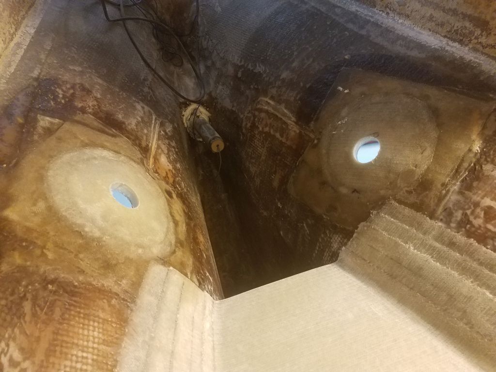
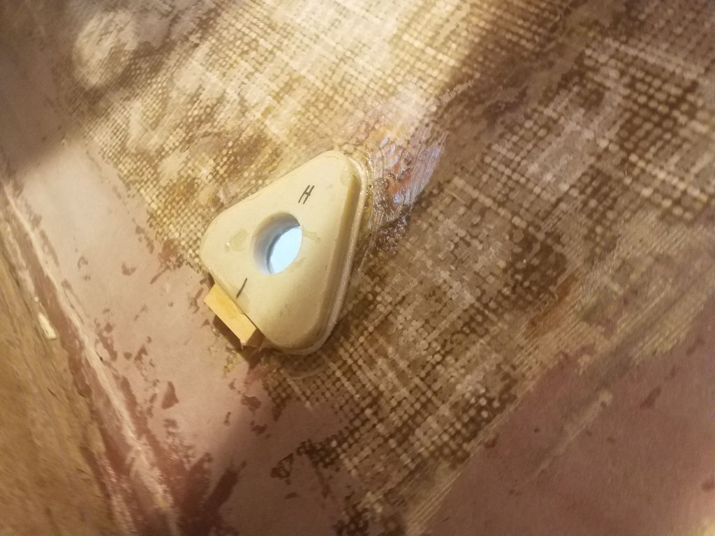
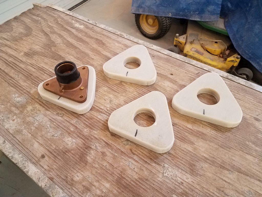
Inside, I marked where each fitting came through the backing pad, then screwed on the flange base as far as it would go to determine whether I’d have to shorten the threaded fittings (expected and almost always necessary), and by how much. With these references, I’d be able to mark and cut off the excess thread length to allow the two pieces to be properly and tightly connected together in the final installation.
With all the fittings removed once more, I threaded the supplied backing nuts all the way on (I’d need these to clean up the threads once cut), and for each fitting marked the cutline with masking tape, before cutting off the excess length and cleaning up the threads to ensure that the fittings would easily thread into the flange base.

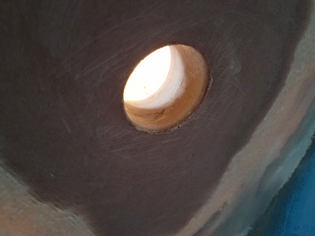
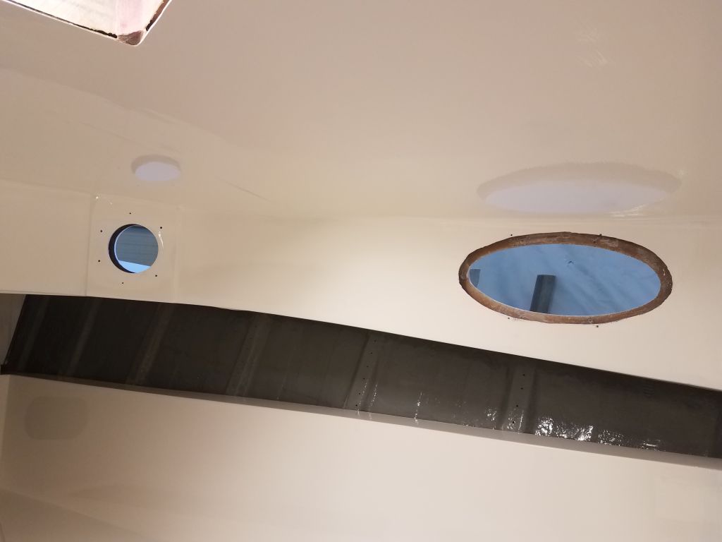
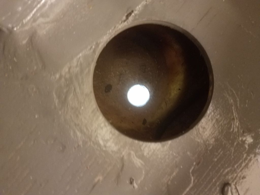
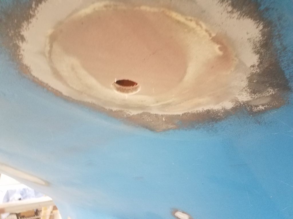
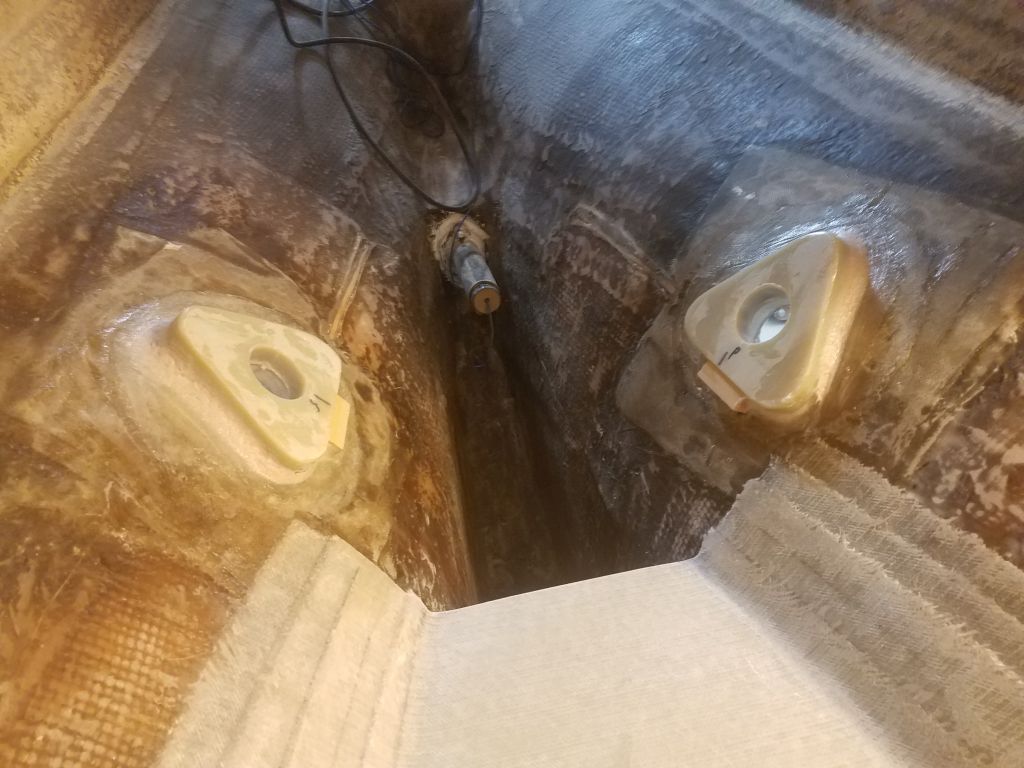
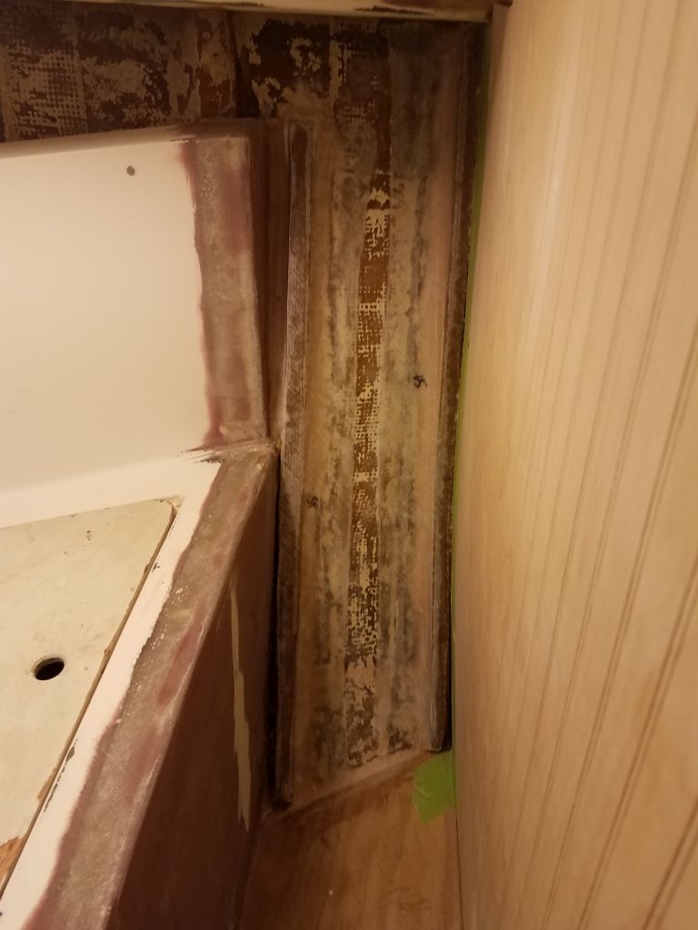
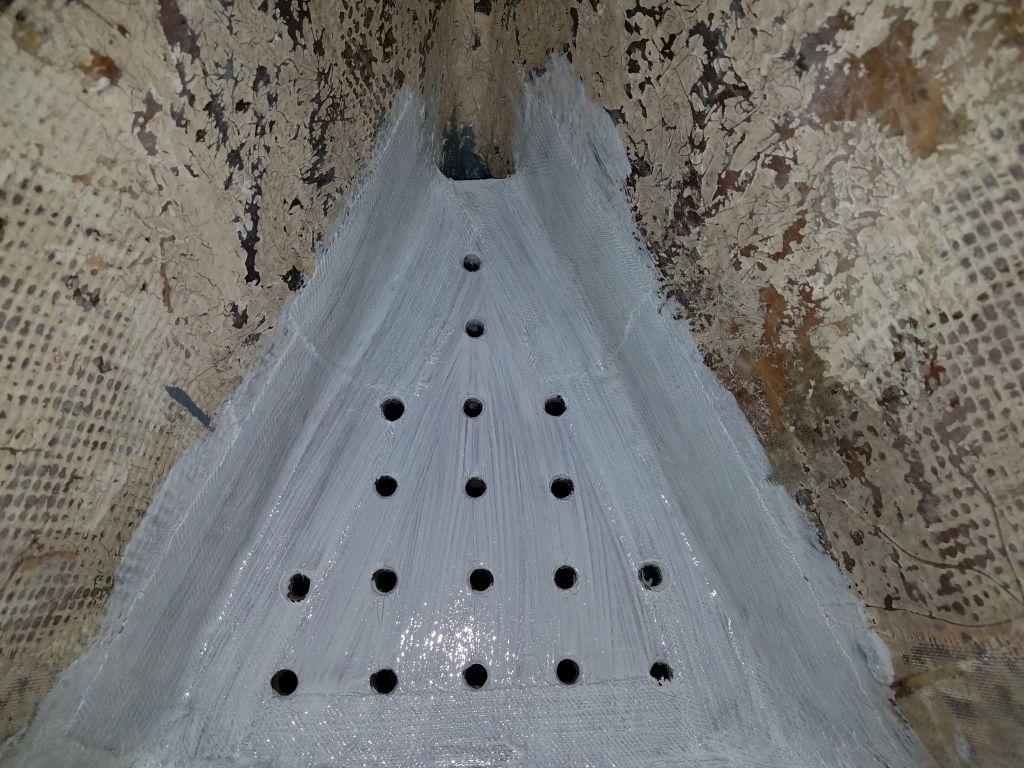
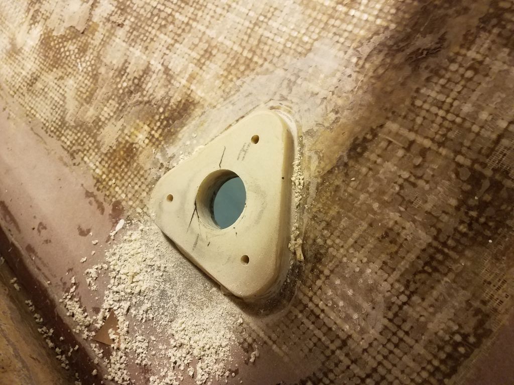
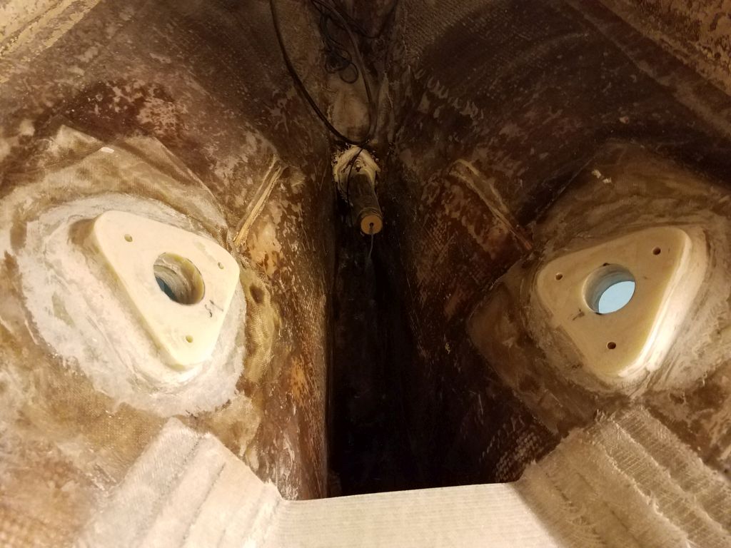
Once more, I dry-fit the mushroom fittings through the hull with tape, and, at each location, threaded on the flange base fully, then drilled the 5/16″ through-bolt holes through the base, pad, and hull, cleaning up afterwards. Once all the holes were drilled through, from outside I milled countersinks at each bolt location to accept the flat-head machine bolts that would secure the bases to the boat.
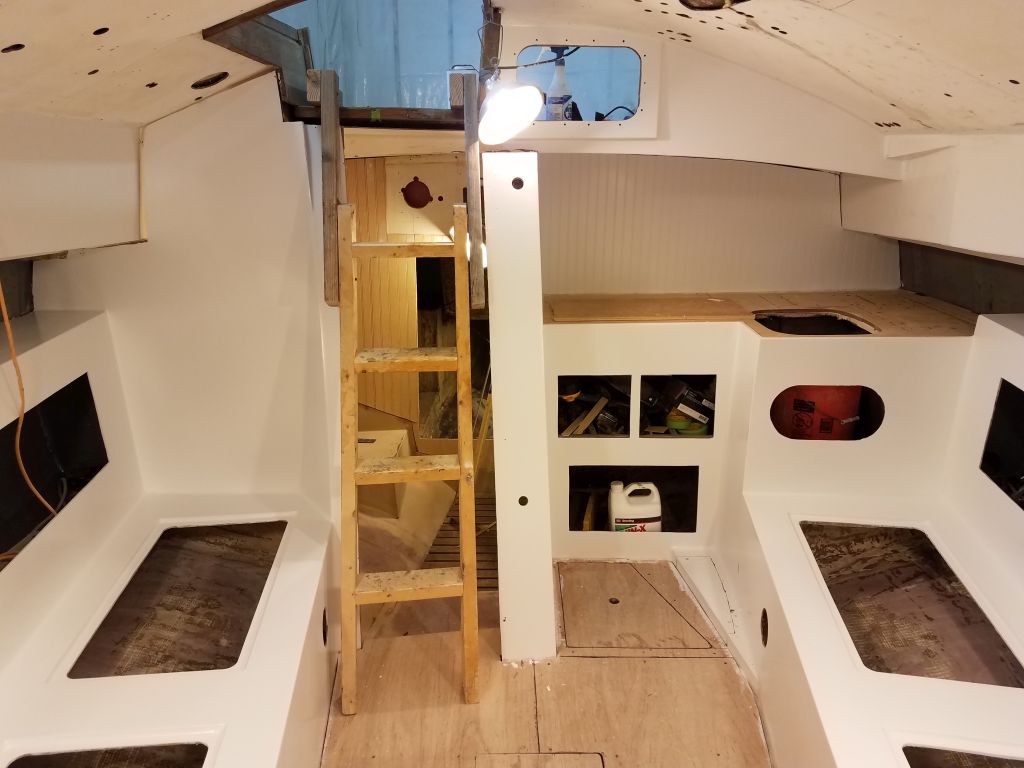
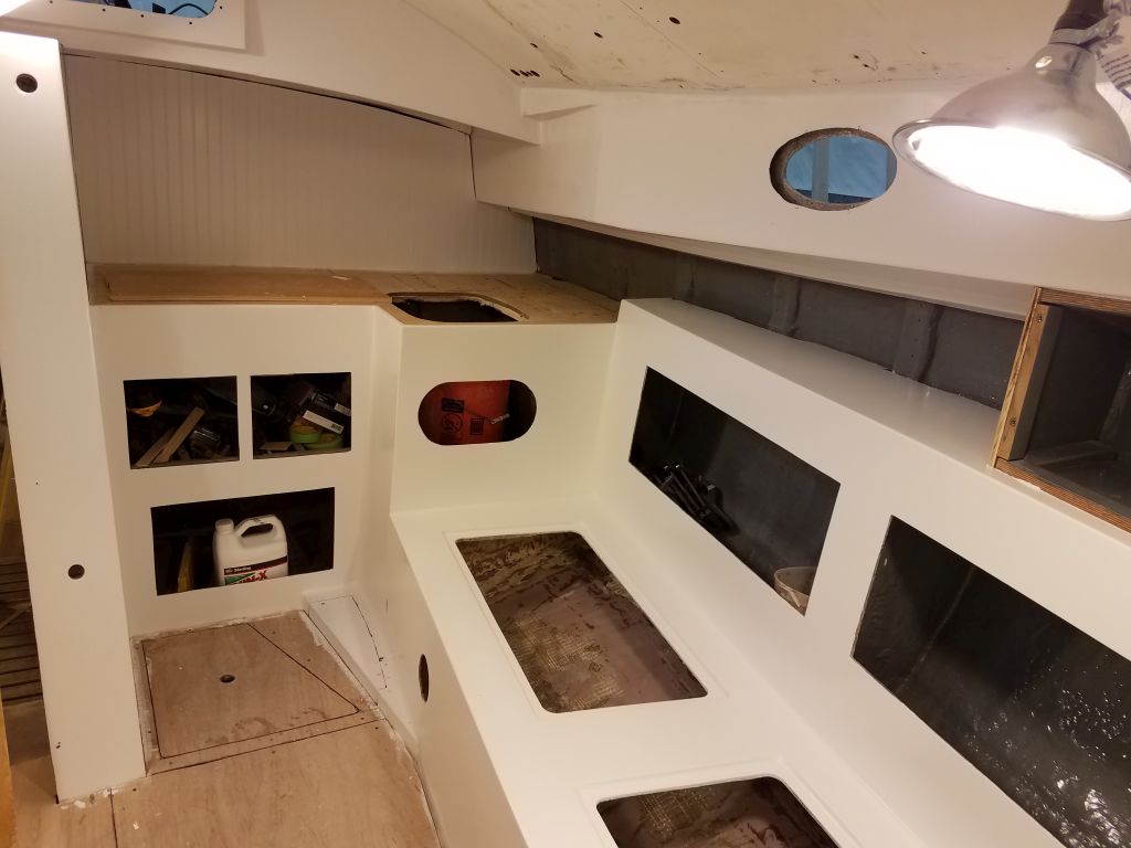
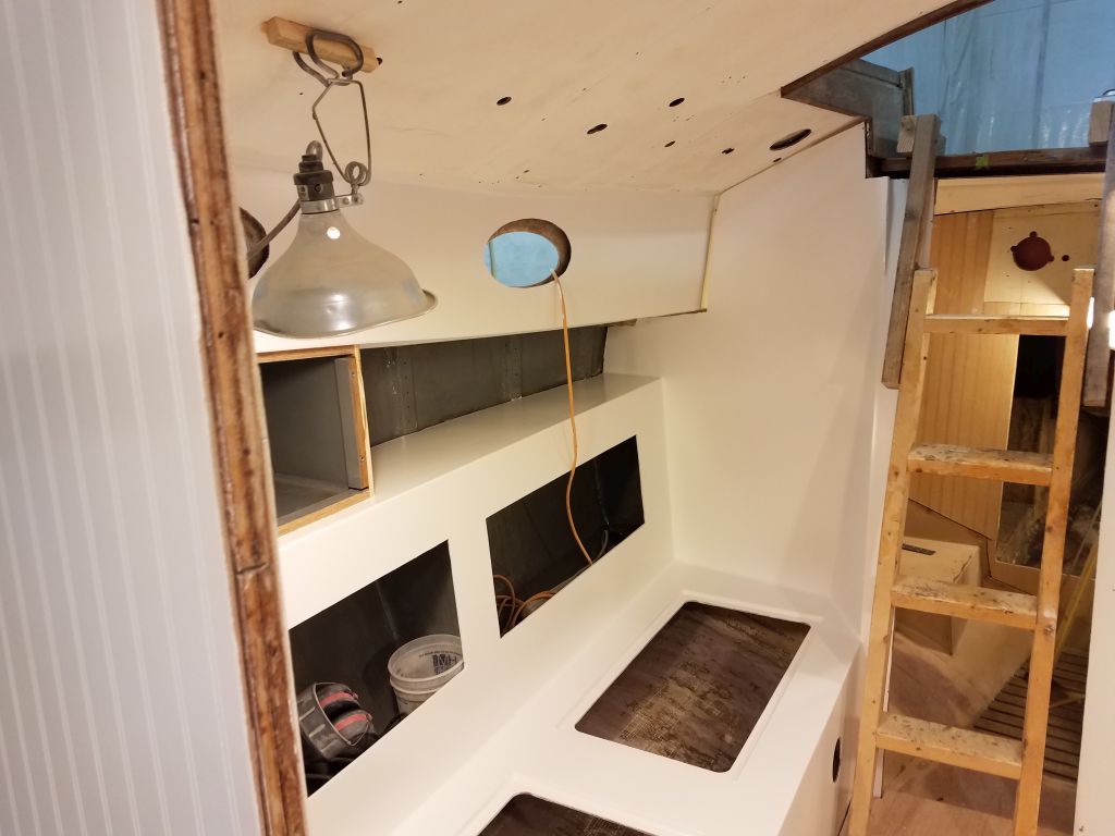
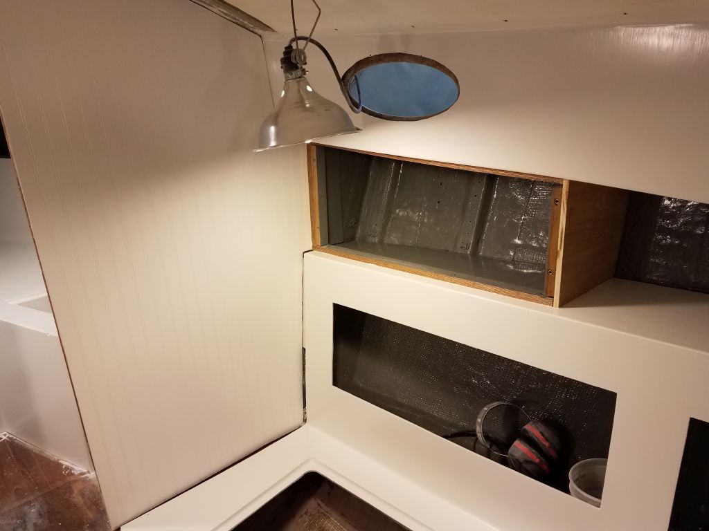
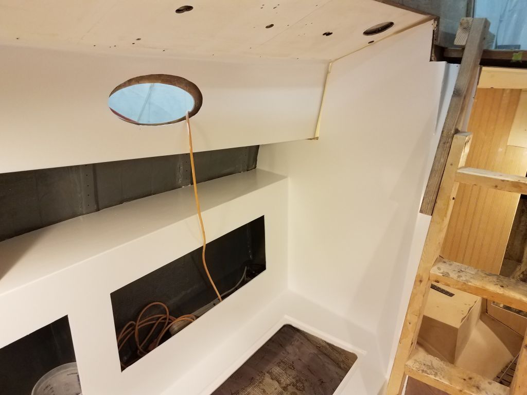
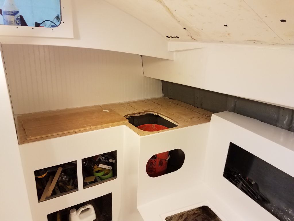
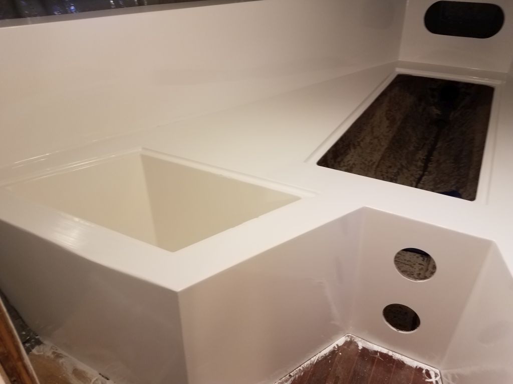
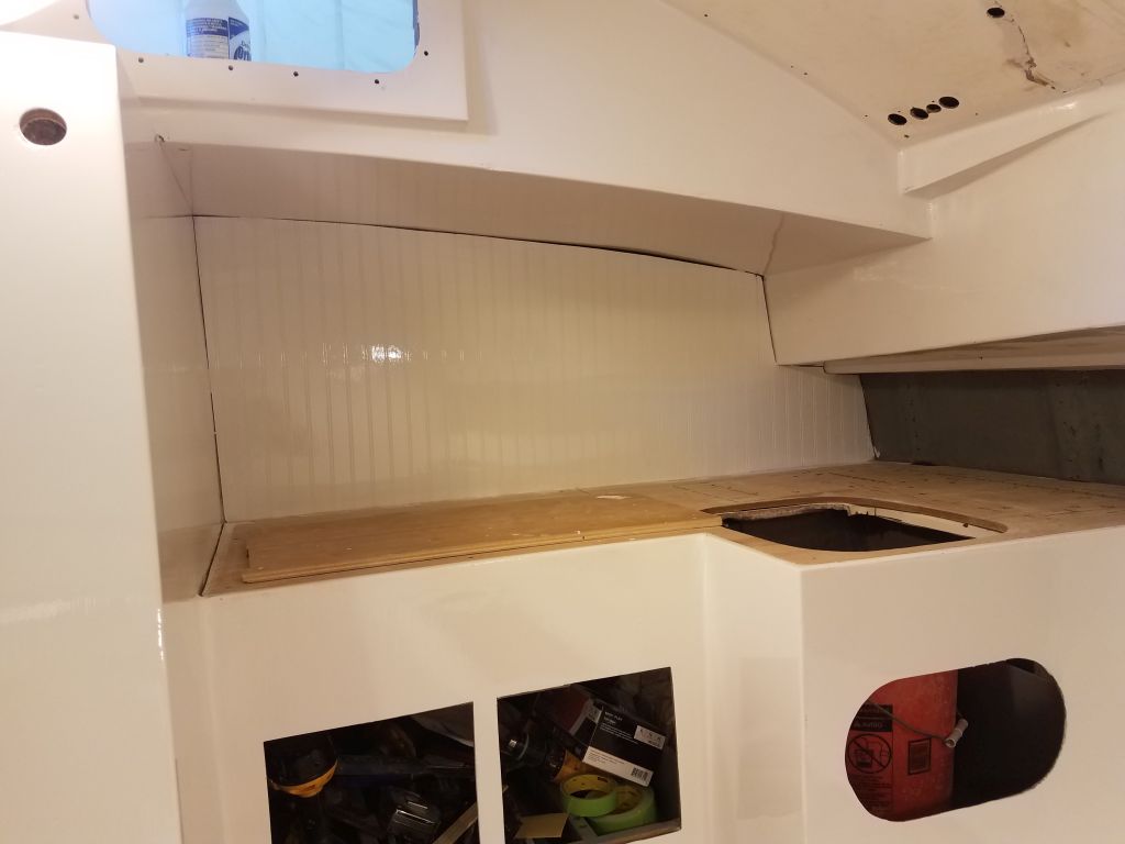
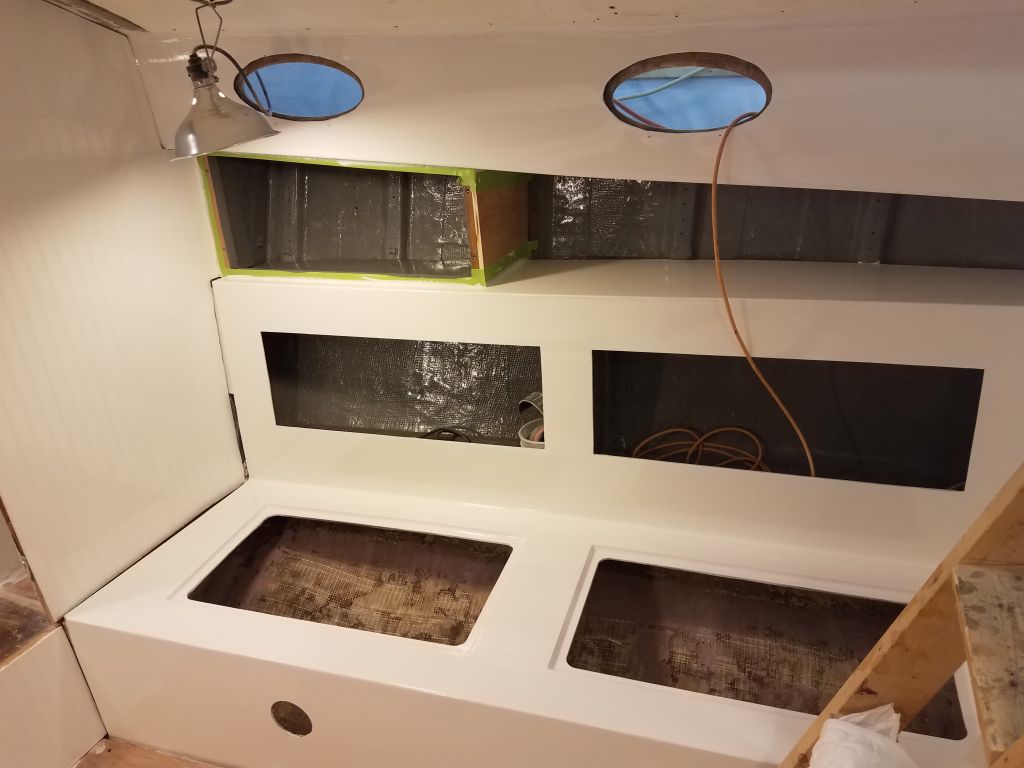
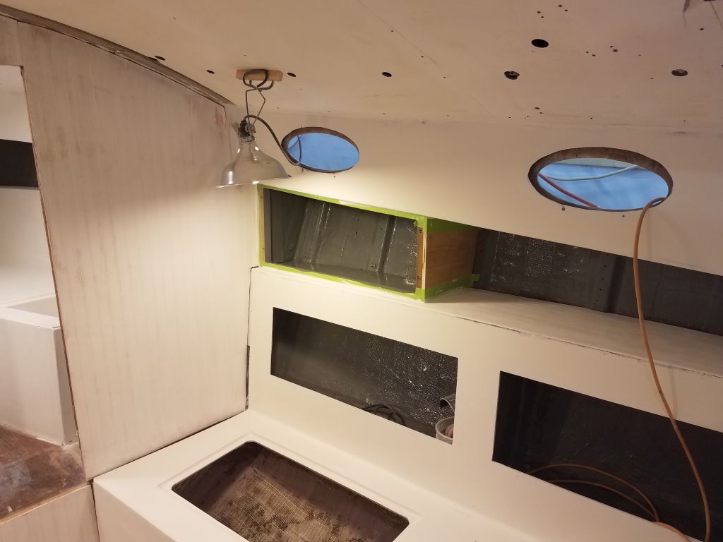
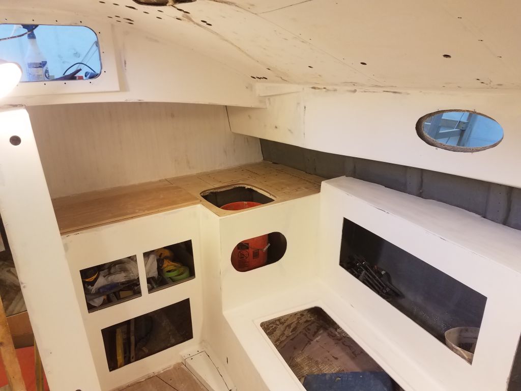
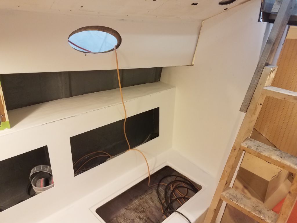
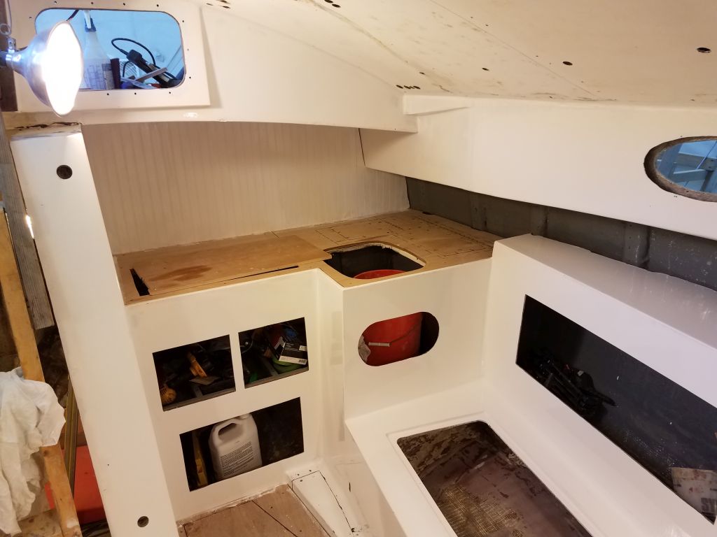
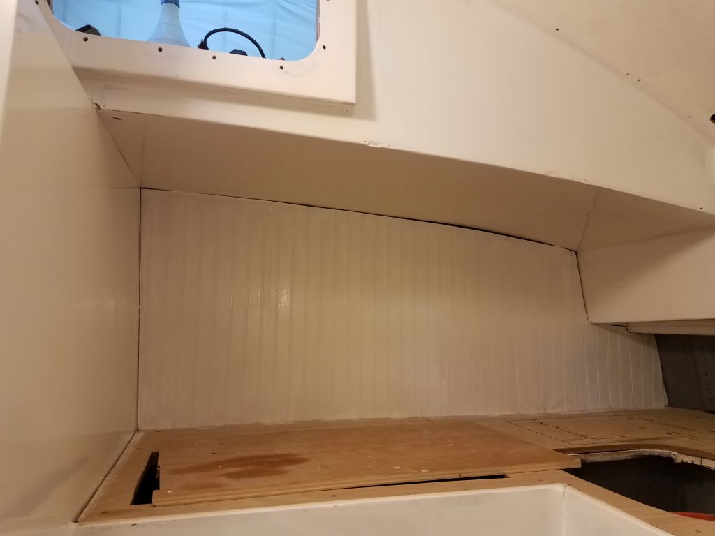
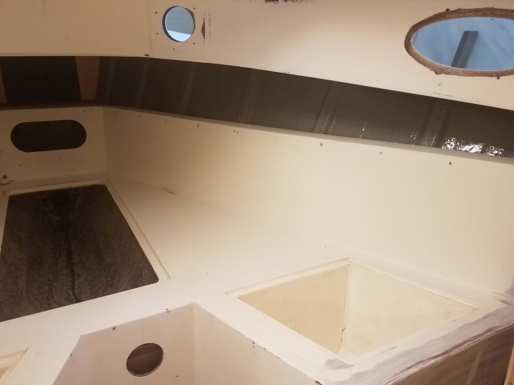
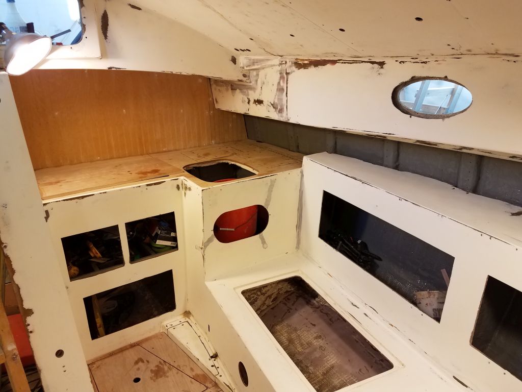
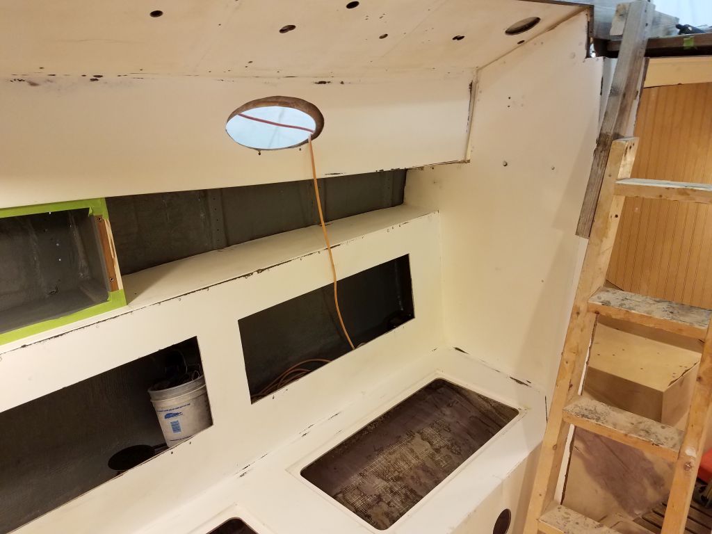
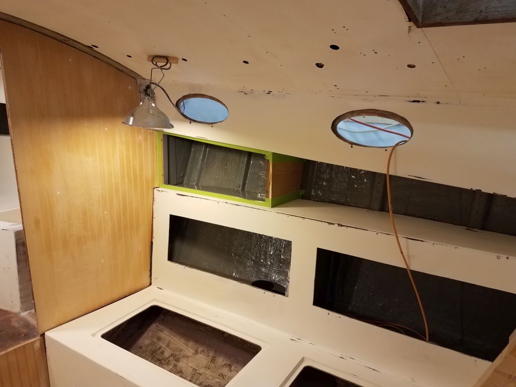
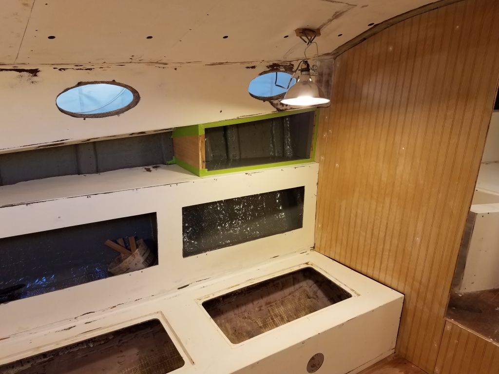
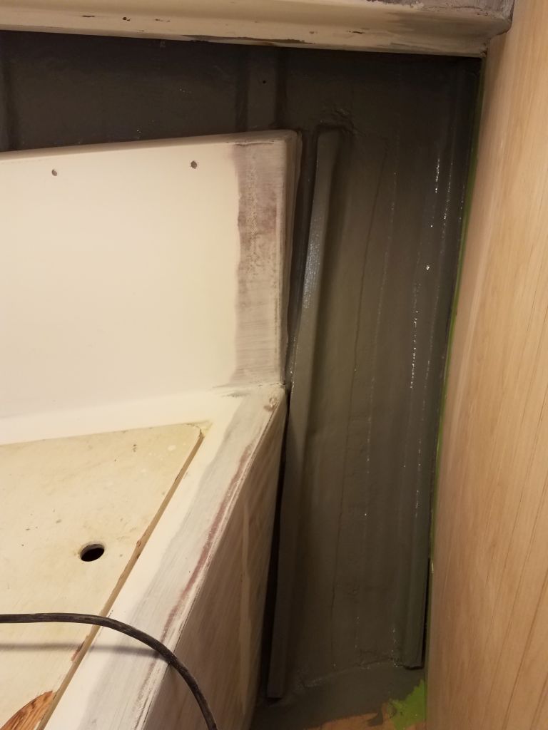
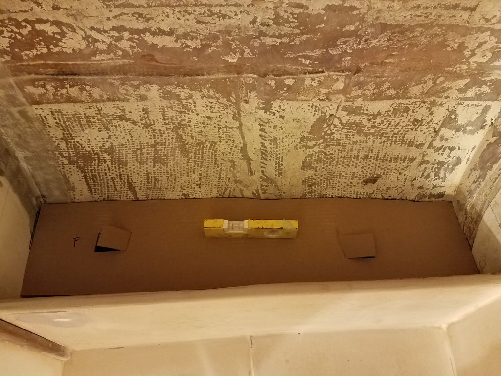
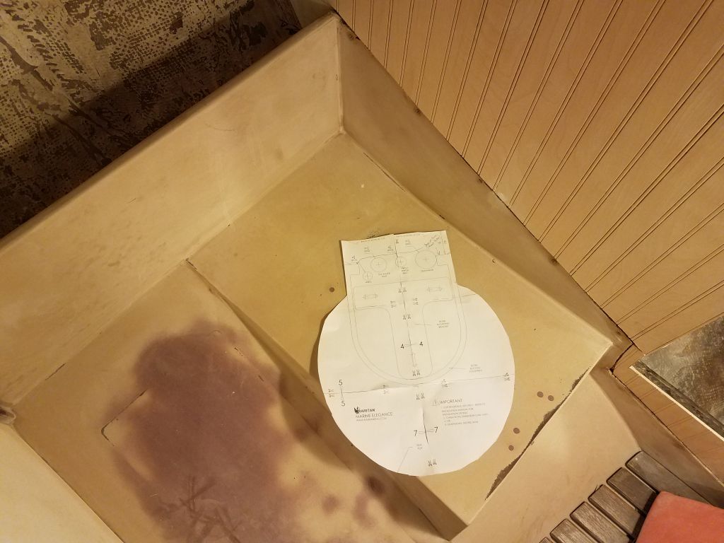
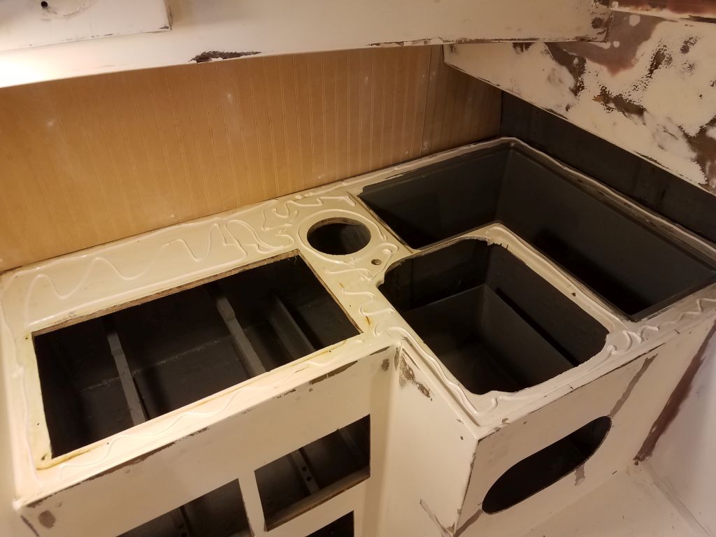
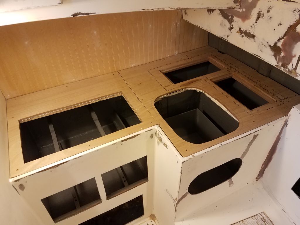
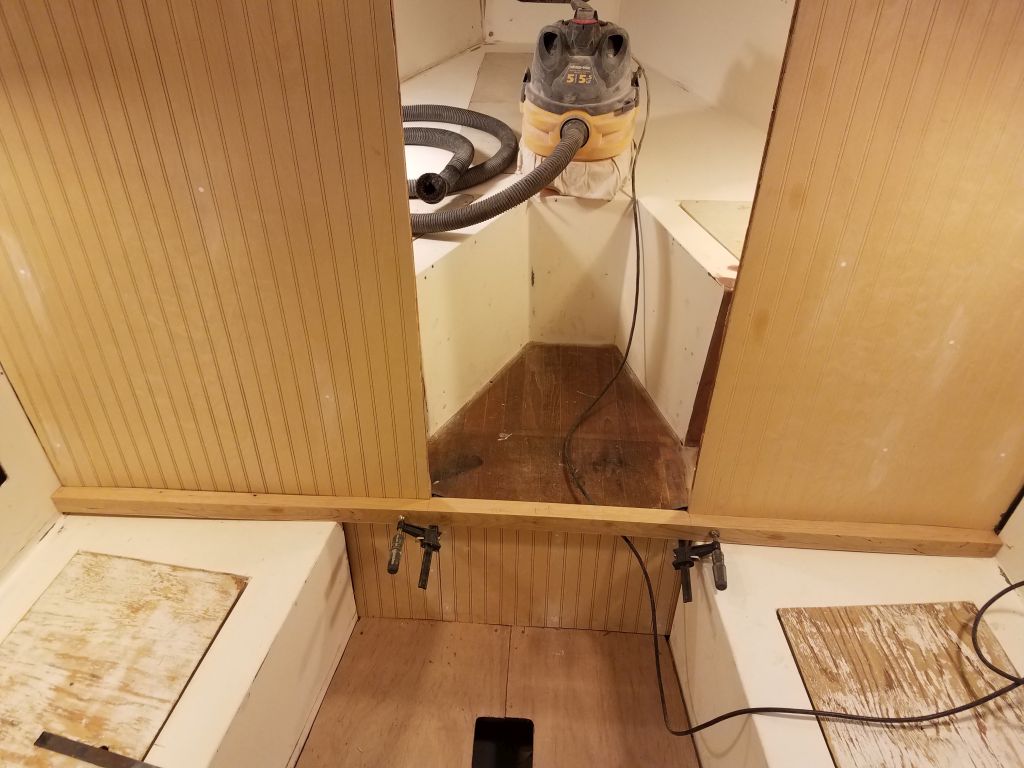
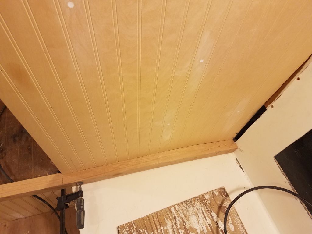
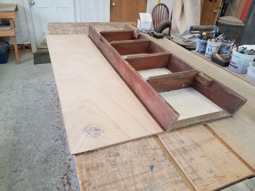
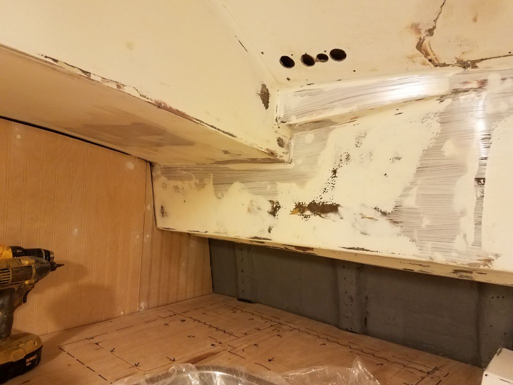
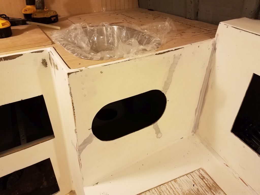
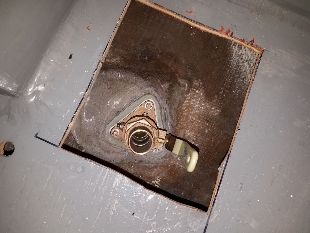
In the galley, I soon found that attempting the installation with existing access was not possible, so I cut a larger opening in the plywood cabinet above the fitting location to improve access for now. Later, I’d cut and install a new plywood base above to clean up the final installation.


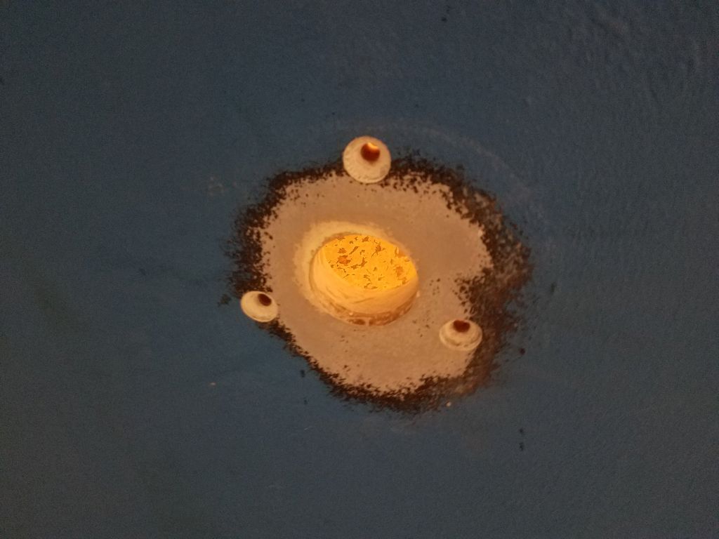

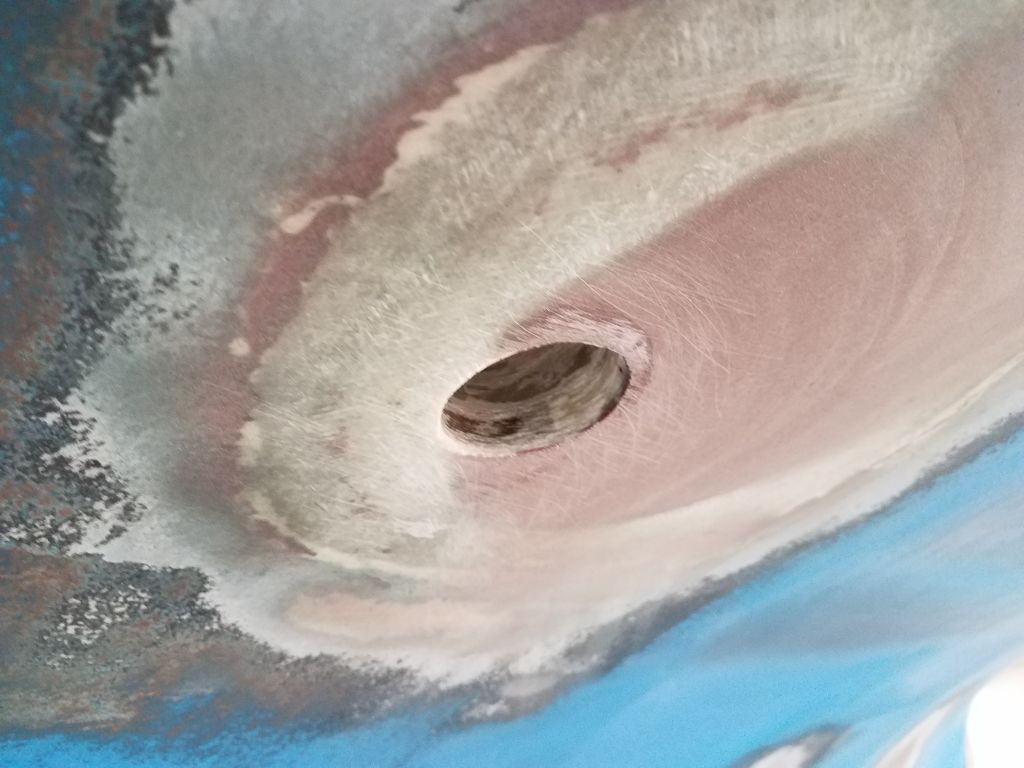
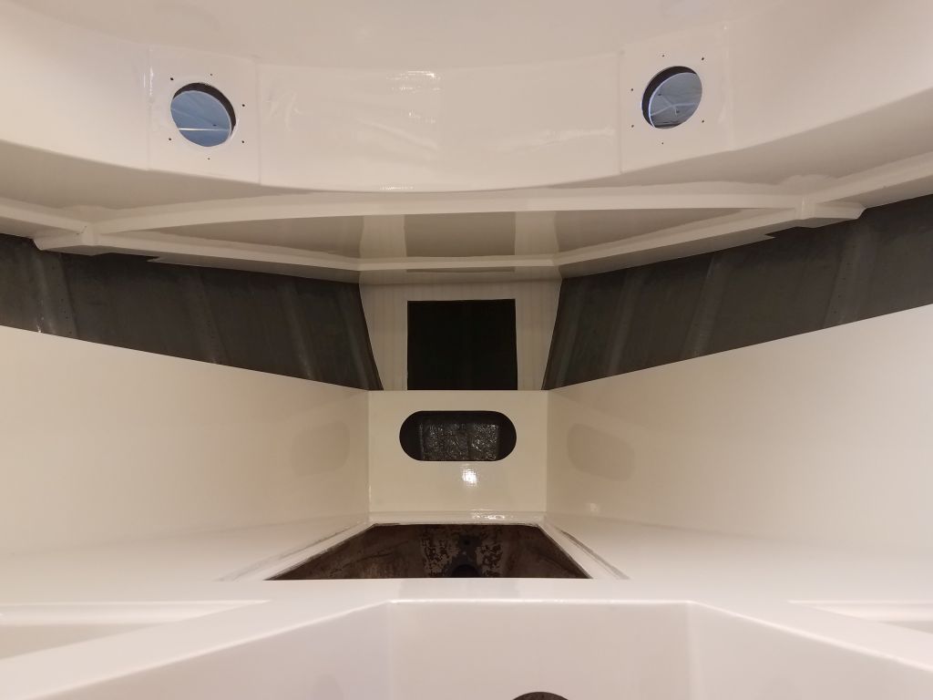
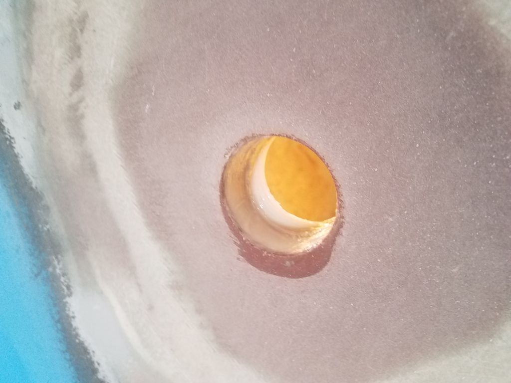
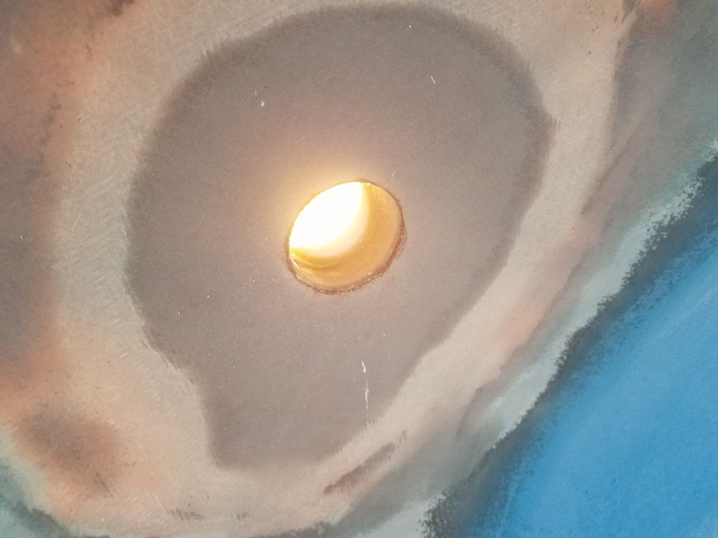
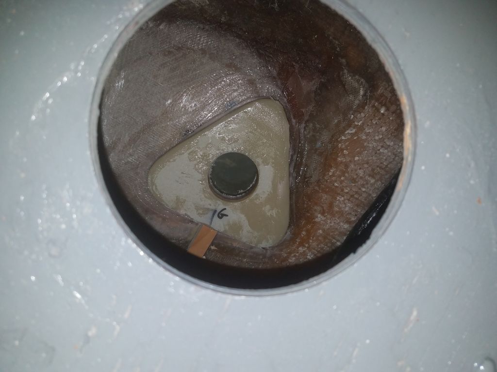
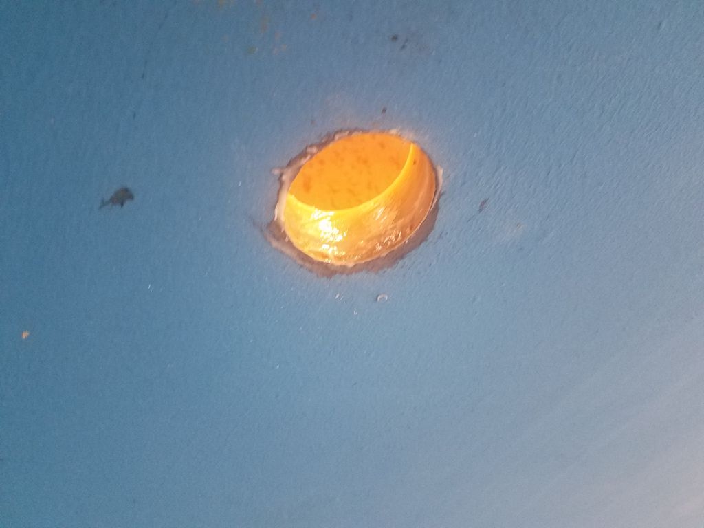
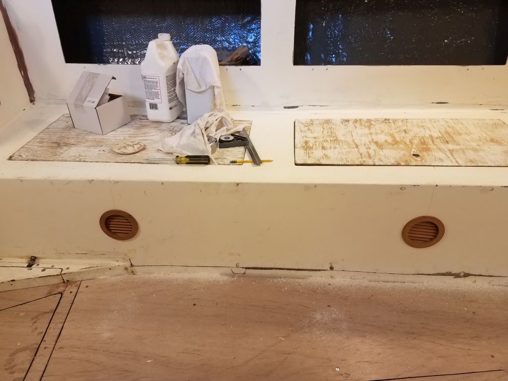
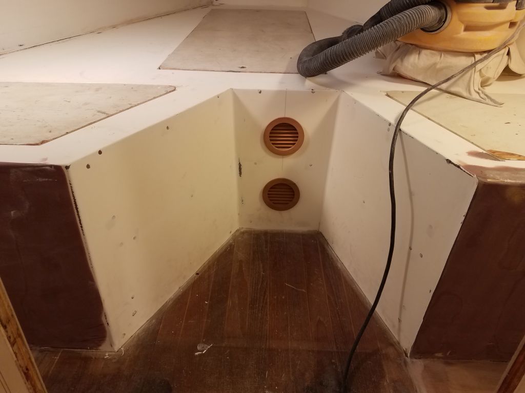
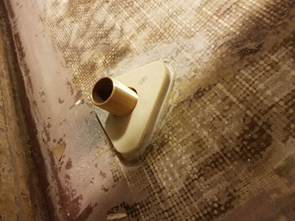
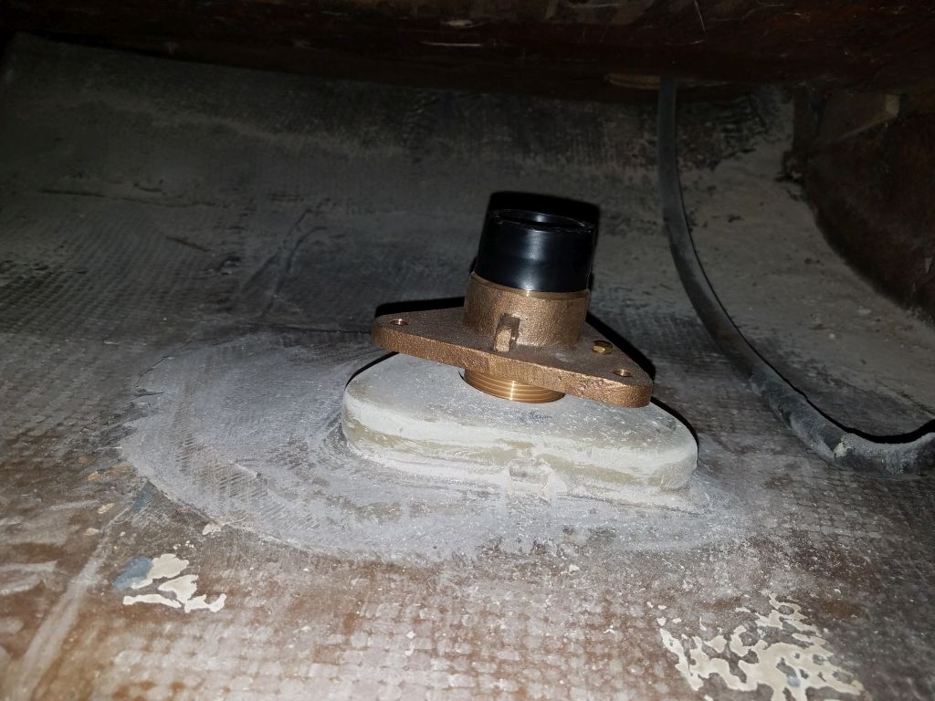
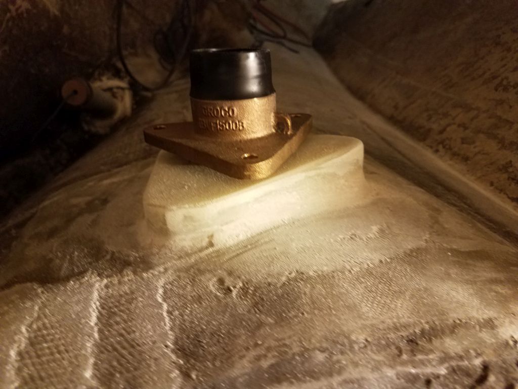
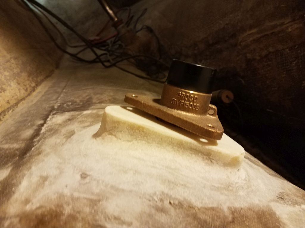
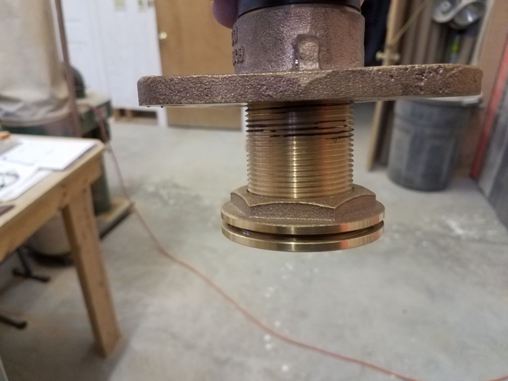
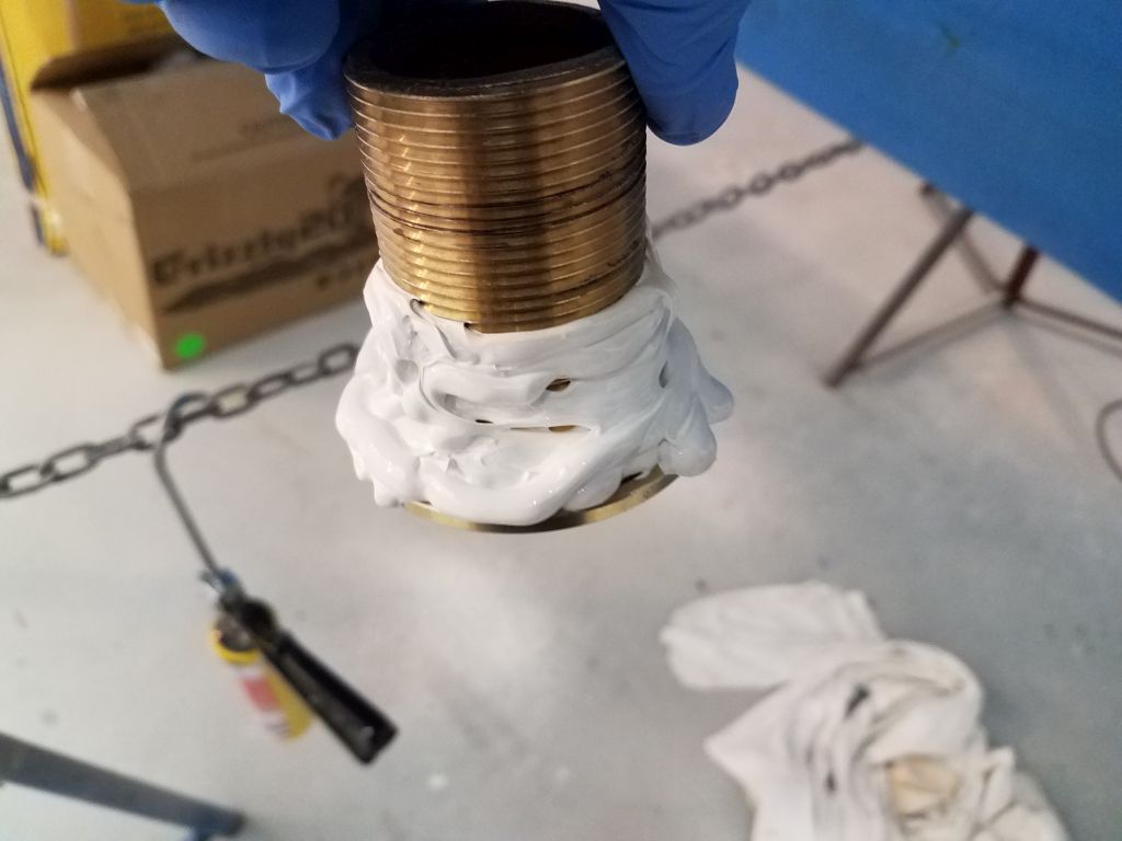
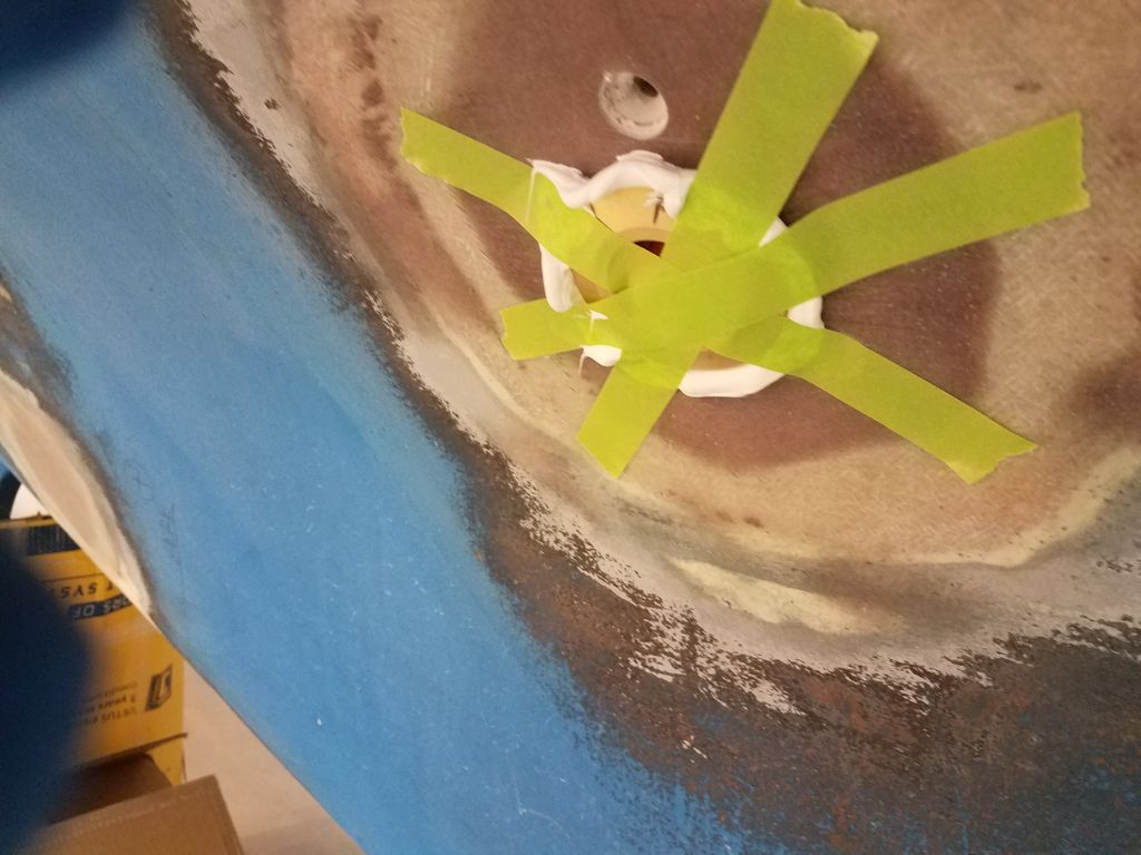
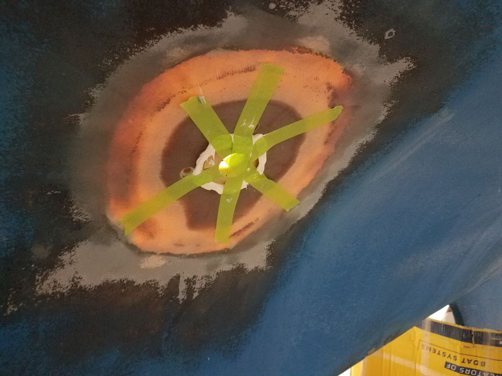
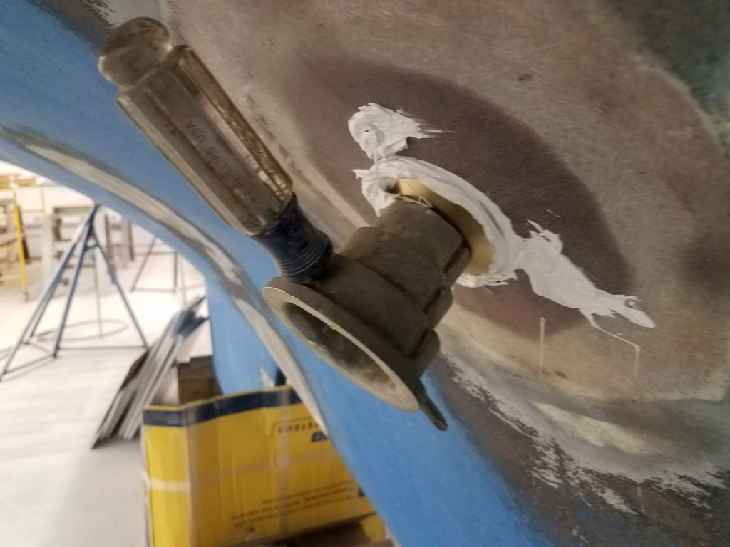
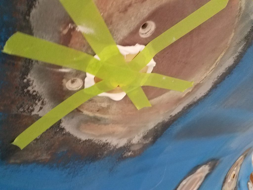
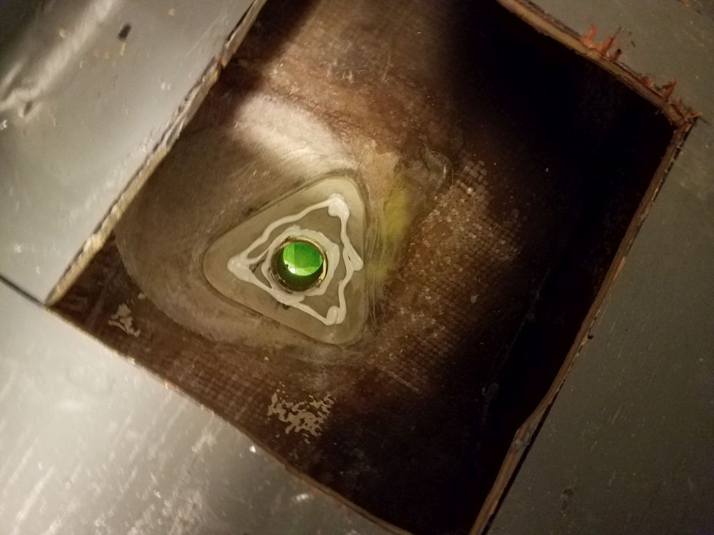
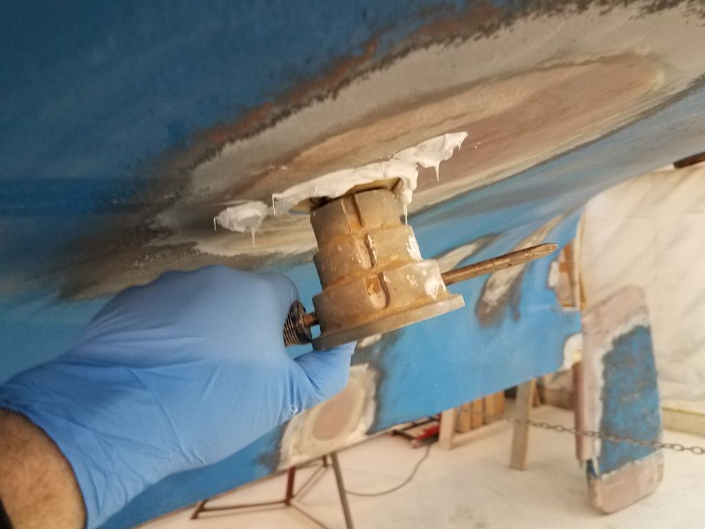
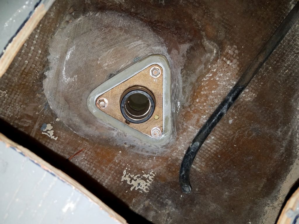
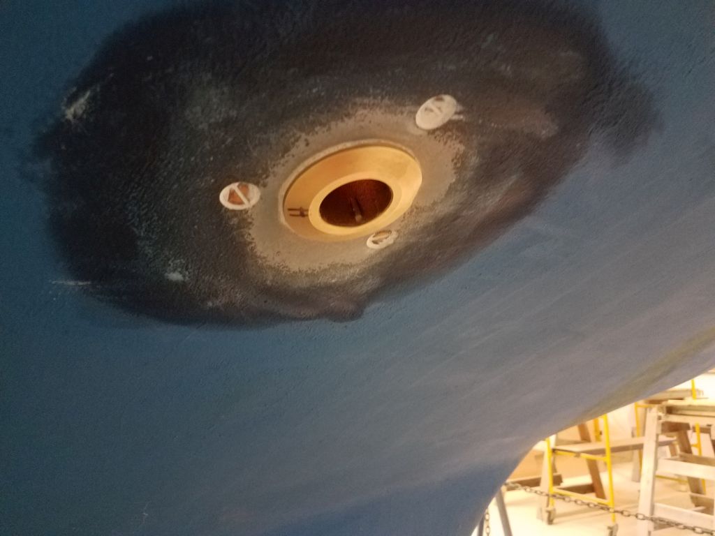
Now, for each of the four fittings in turn, I applied heavy sealant to the mushroom fittings, and installed them from without, securing them with tape. Scampering back into the boat, I applied additional sealant around the protruding threads, and on the backing pads, before threading on the flange base and pinning it in its proper position with temporary and sacrificial bolts from inside. Then, hurrying back outside again, I replaced the temporary bolts with the proper bronze, flat-head machine screws, which I gooped up heavily, and, with the bolts in place, threaded in the through hull fitting tightly with a special tool. At this point, I could clean off most of the excess sealant from outside.
Finally, back inside the boat, I installed bronze washers and nuts and tightened the three through bolts, completing the basic installation other than final sealant cleanup.

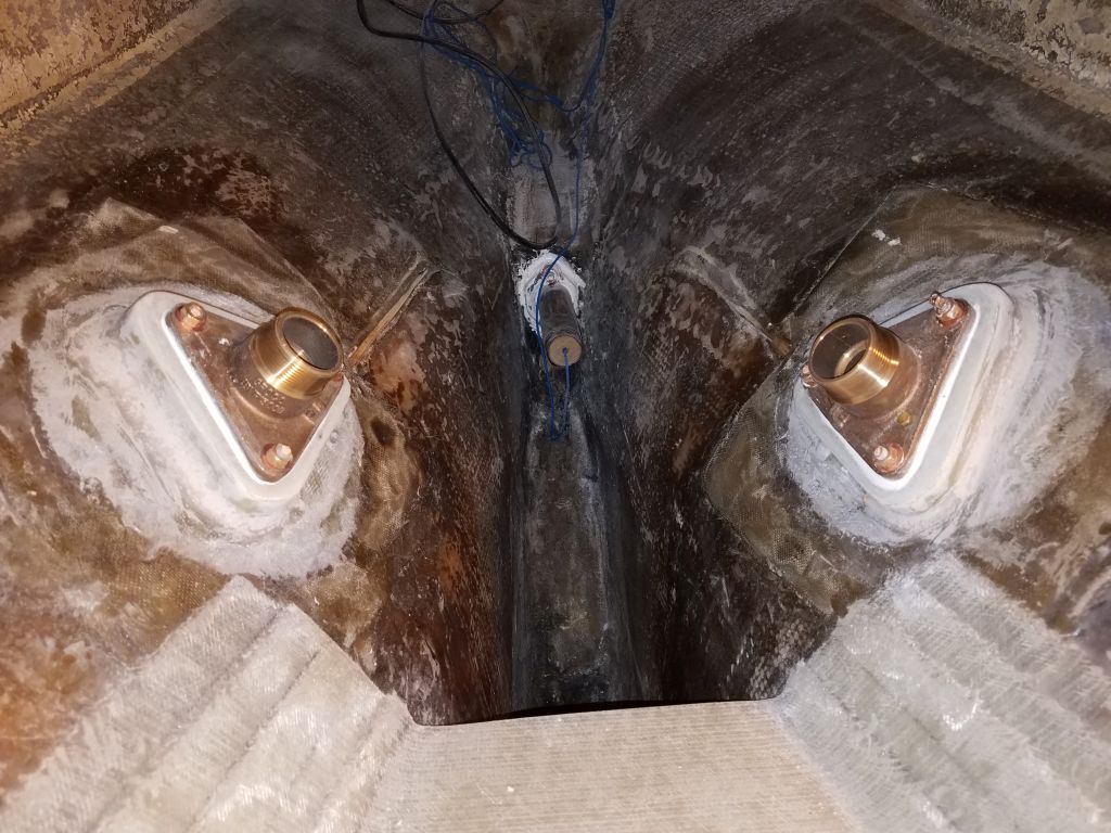
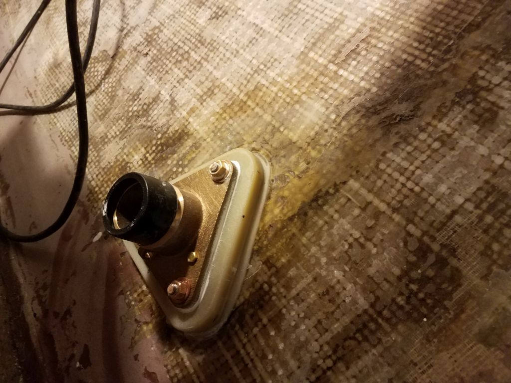

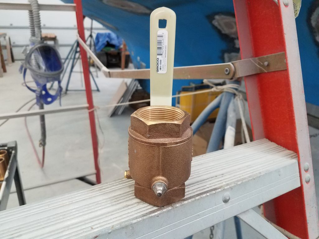
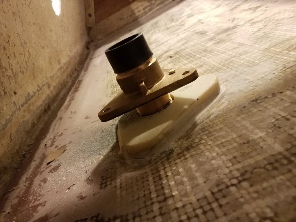
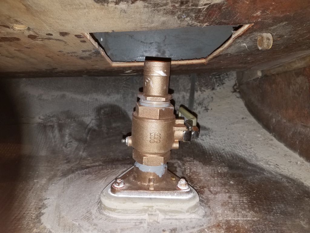
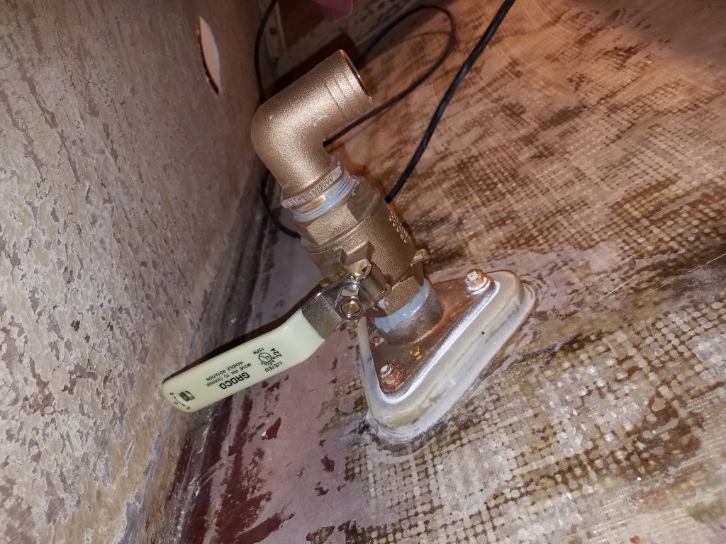
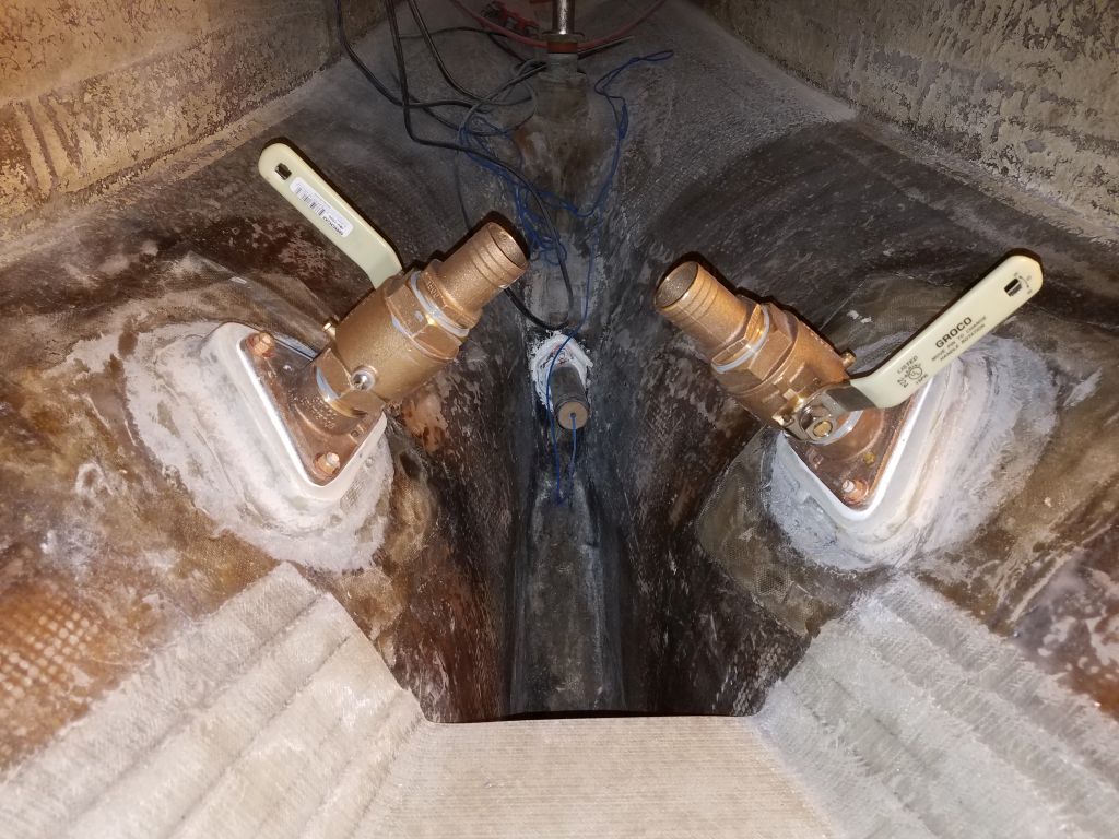
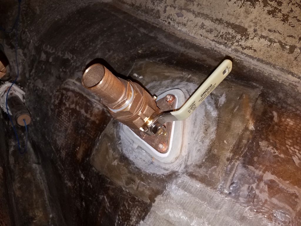
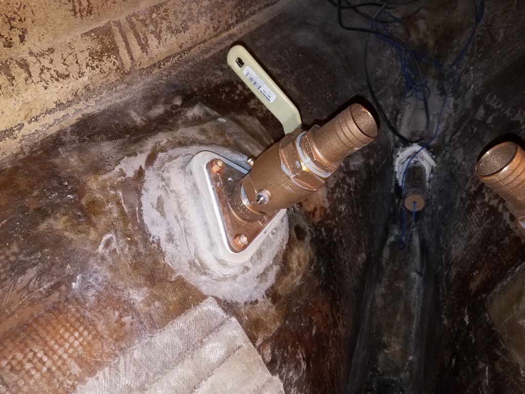
With that done, and any excess bolt length removed from within, I completed the installations by installing the ball valves and pipe-hose connections at each location. While this step didn’t strictly have to happen now, I saw no reason in this instance to postpone it either.
After cleaning up and getting reorganized after this flurry of activity, I prepared to reinstall the rudder permanently following its various repairs, which had taken place sporadically since I dropped the rudder for this purpose some months before. The rudder had been more or less ready for some time, just awaiting the right time–which apparently was now.
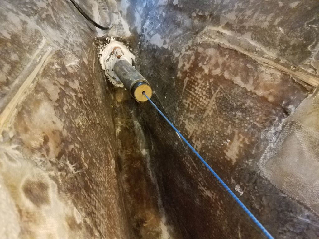
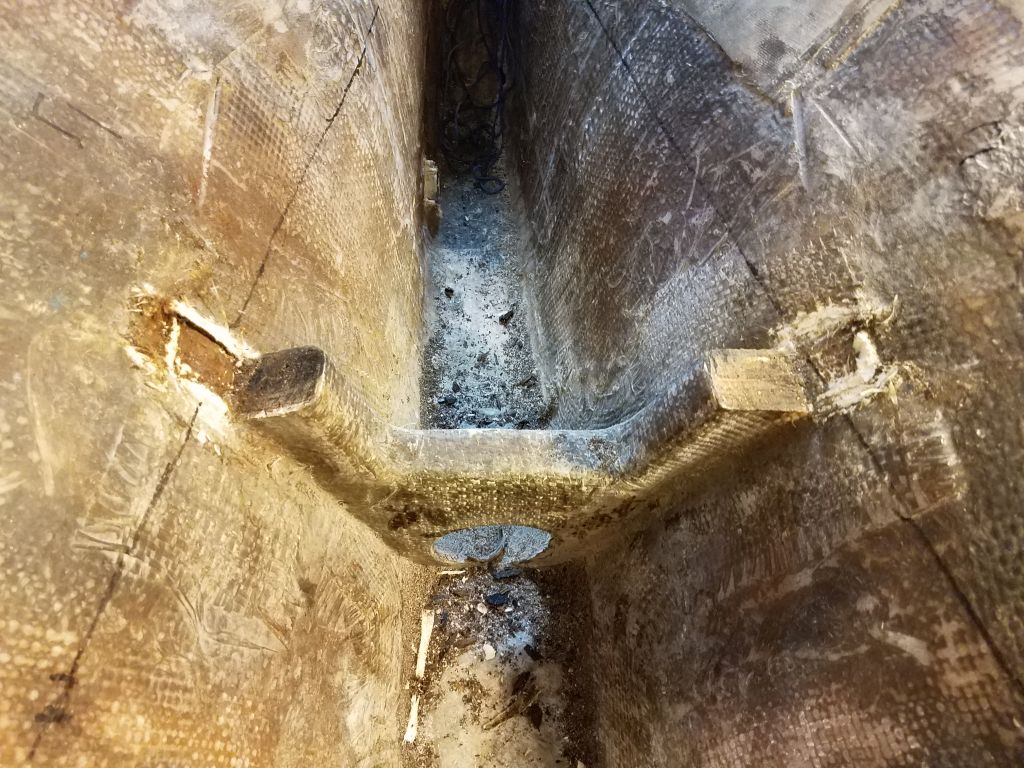
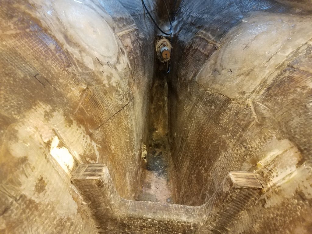
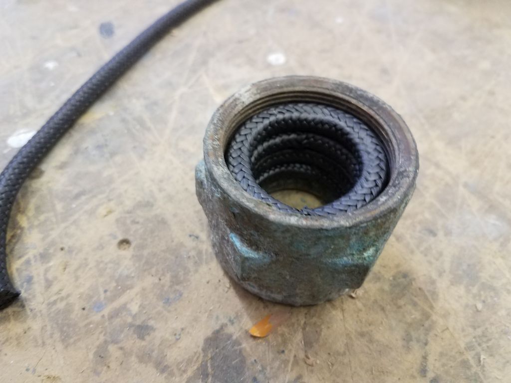
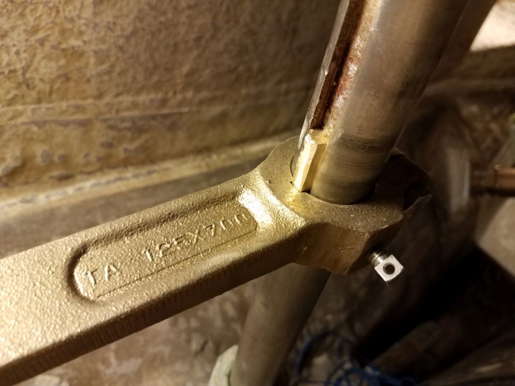
Before raising the rudder back into position, I filled the packing nut with four rings of new graphite packing, then, inside the after steering room, reinstalled the nut on the packing box glassed inside the hull. I also slipped over the rudder shaft a bronze steering arm that I’d obtained as part of a newly-conceived rudder stop system, which would ultimately prevent the rudder from being over-turned and crushing against the hull, a previous design flaw that had directly led to and caused the damage to the upper part of the rudder blade that had required me to remove the rudder in the first place.
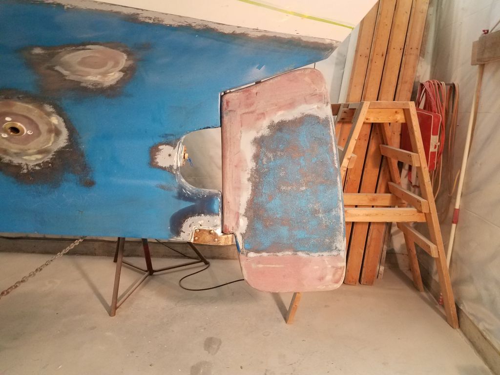
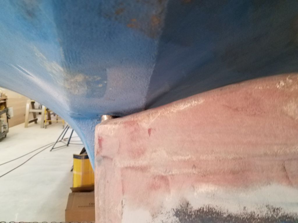
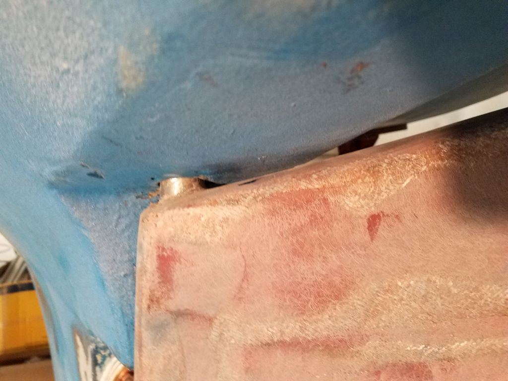
Now, I could raise the rudder back into position with a jack, which process went smoothly and without issue.

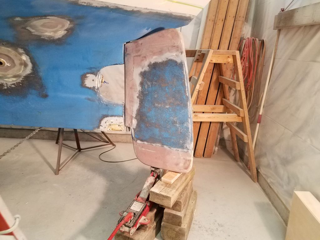

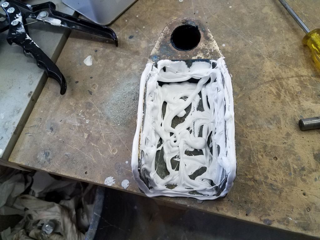
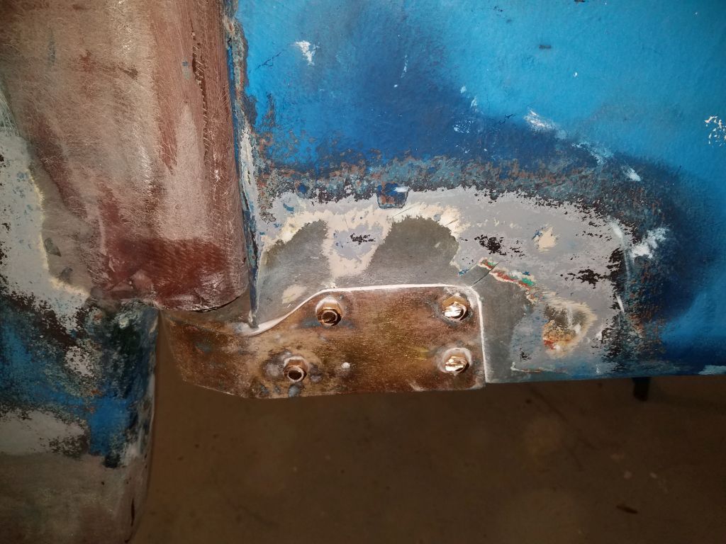
With the rudder all the way up, I heavily applied sealant to the bronze shoe casting (which I’d previously cleaned up), and reinstalled it with new bronze bolts.

In the boat’s previous iteration, a rudder stop system had either failed, or not been in place to begin with, and this allowed the rudder to turn nearly 90 degrees to each side. This caused the top of the rudder blade to hit the hull above, and this ultimately caused failure of the rudder laminate. While the rudder was now whole again, the overturning problem hadn’t gone away.
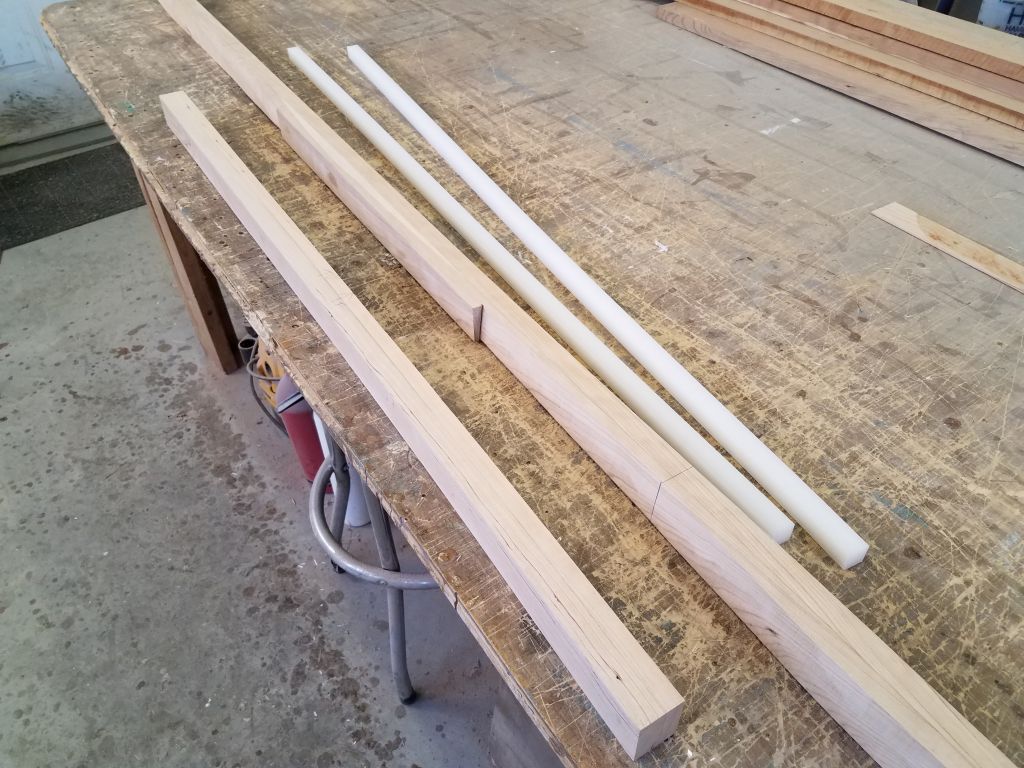
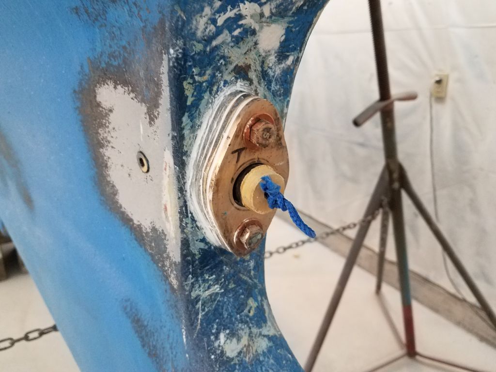
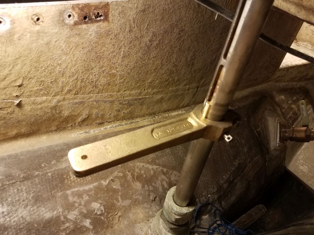
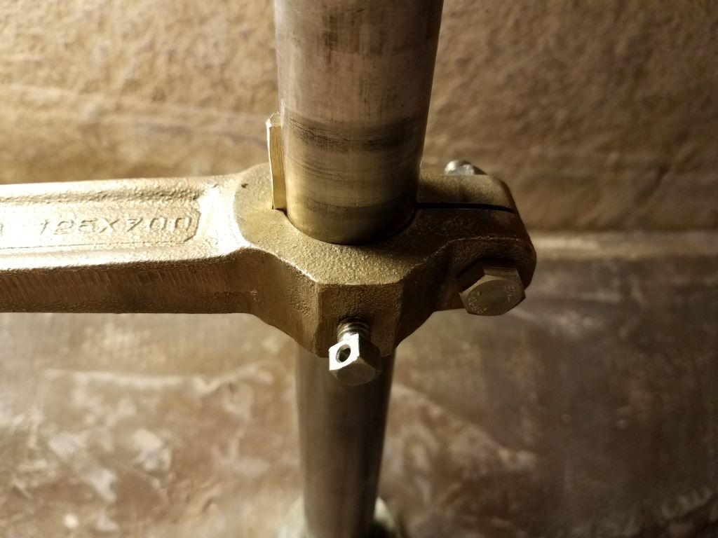
The steering system now was to be a simple tiller, so to prevent the oversteering from occurring in the future, I came up with a rudder stop system based on the existing situation and with as simple a design as possible. The existing rudder shaft featured two machined grooves leftover from the old steering quadrant, and with these as a basis, I found a hefty bronze steering arm that fit my design brief–way overbuilt for this particular task, but pleasingly reasonable in cost–that I could fit to the keyway in the rudder shaft. I did have to modify a length of 3/8″ brass key stock, since the keyway in the shaft was 3/8″, but the corresponding key in the bronze arm was just 1/4″. This was easy enough to do with the brass stock, and soon I had the key stock modified to the point that it would fit and lock the bronze arm in place, facing dead aft. This, along with the pinch-bolt and a cupped setscrew that I tightened against the shaft, would hold this assembly securely.
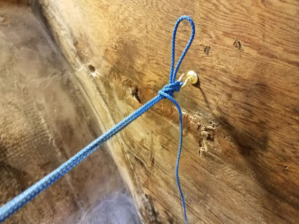
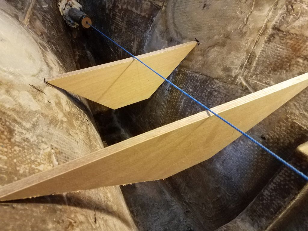
From here, to complete the system I planned to install lengths of cable between the steering arm and the bulkheads on each side, the cables’ lengths to be determined based on how far the rudder could safely be turned to each side. This would prevent oversteering in a simple yet effective way. I’d complete and install the final portions of the system later, but the steering arm had had to be installed while the rudder was still down.
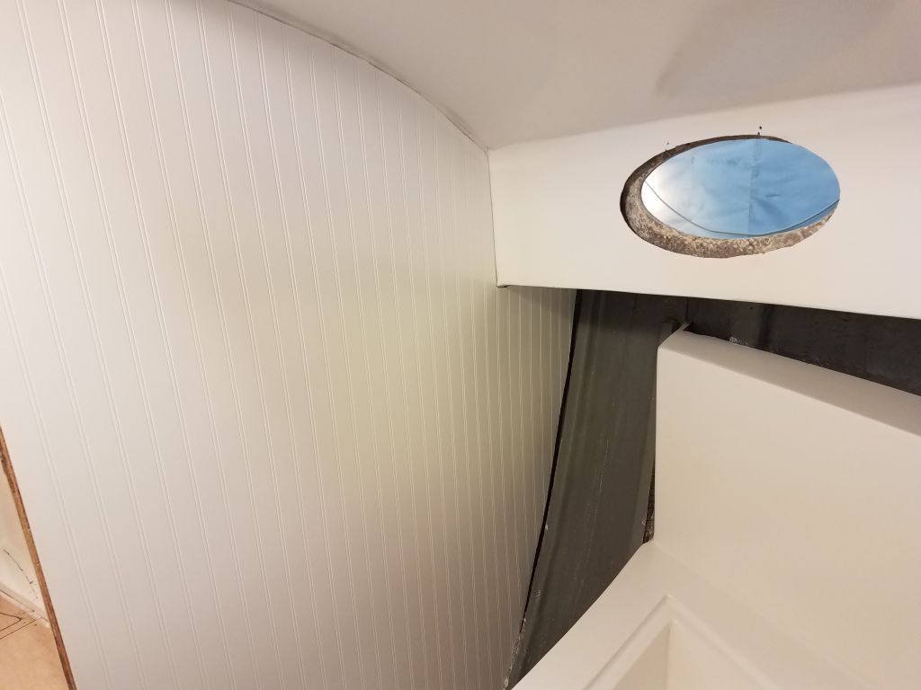
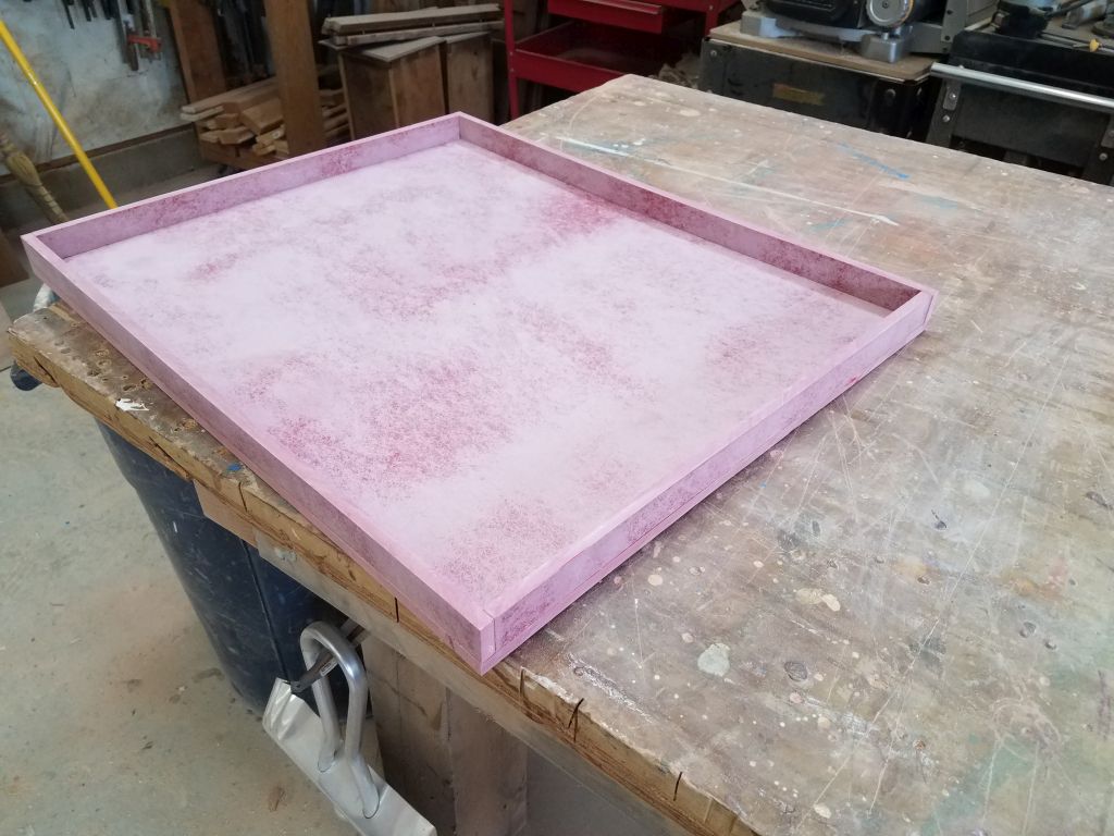
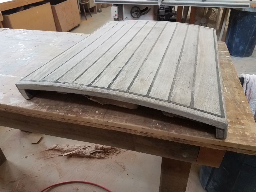
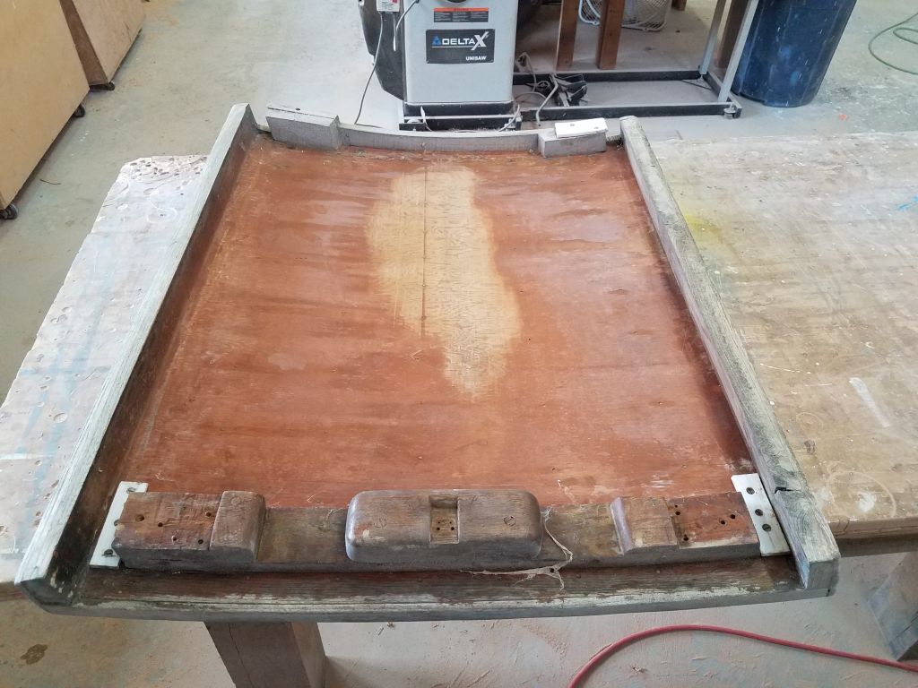
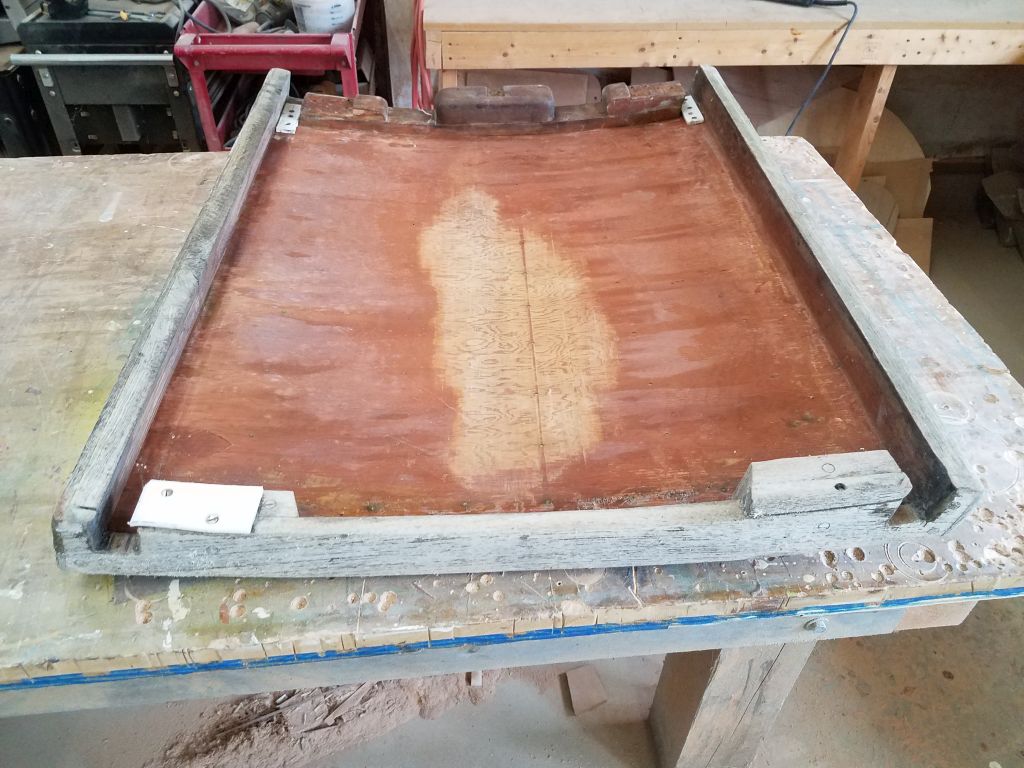
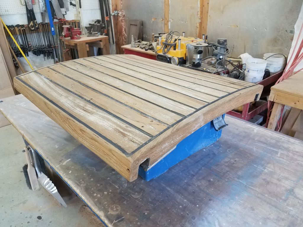
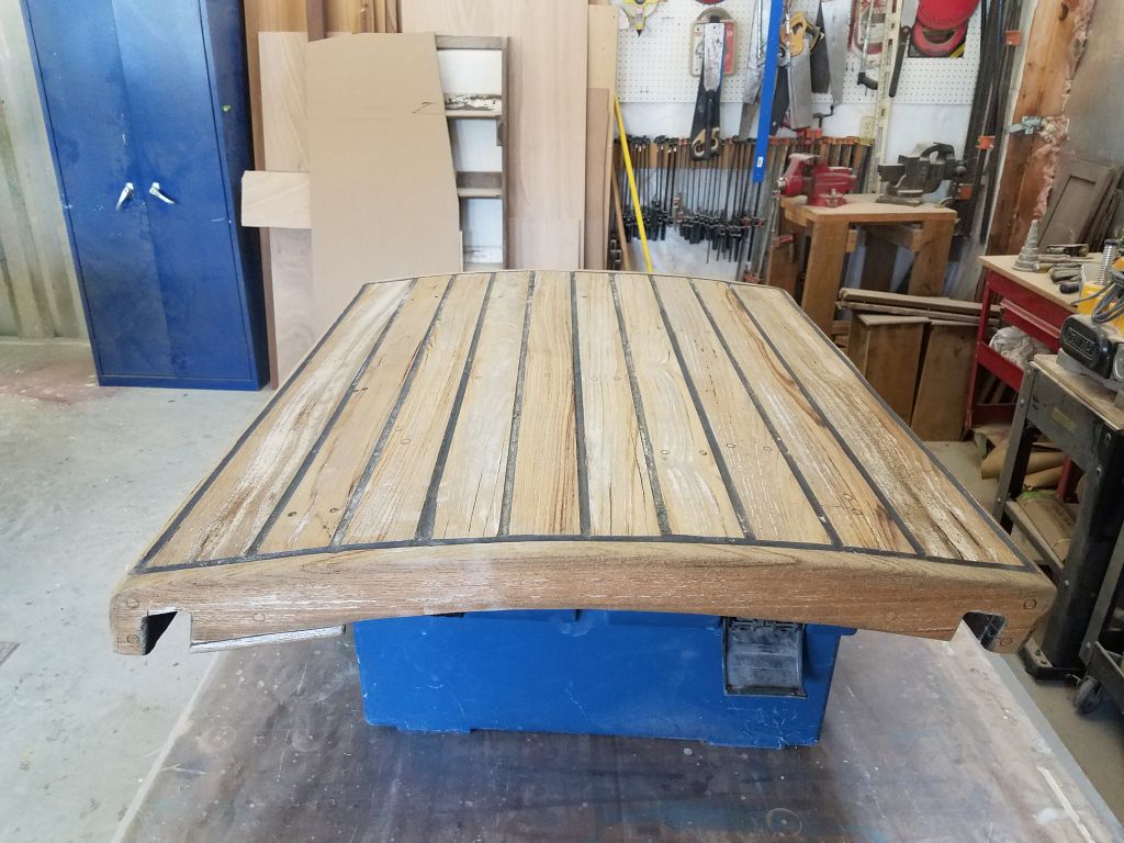
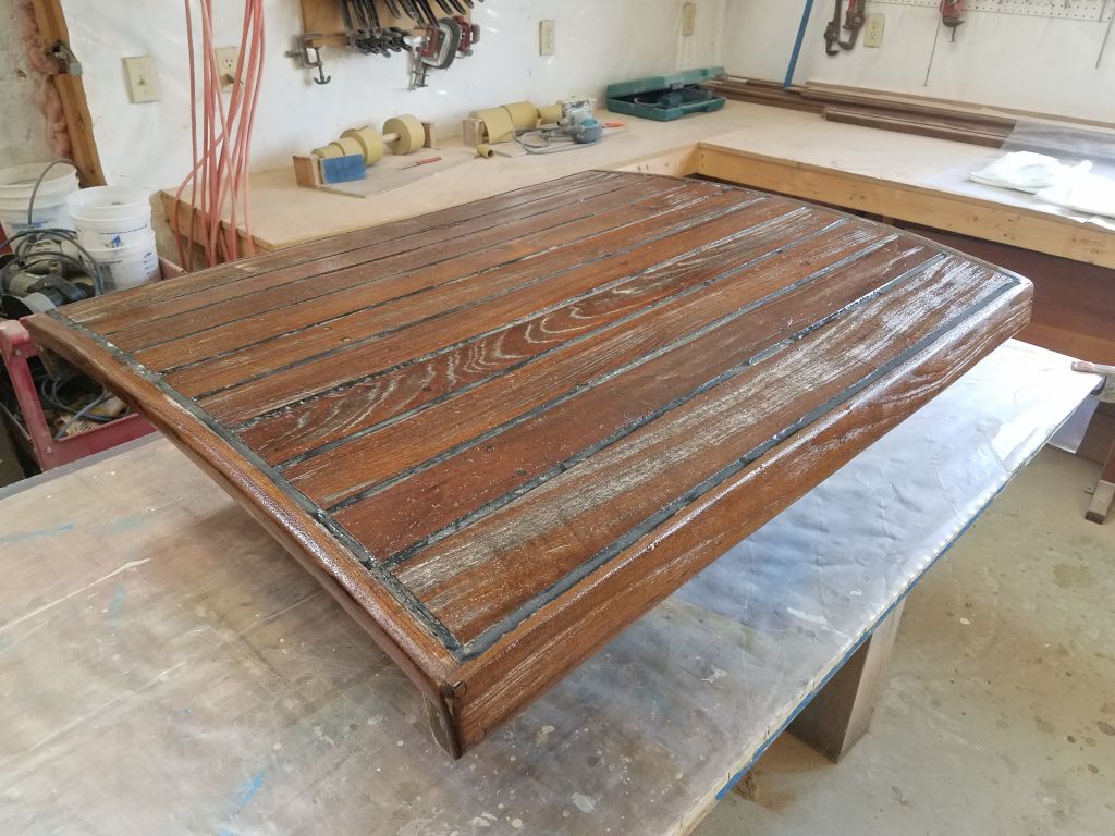
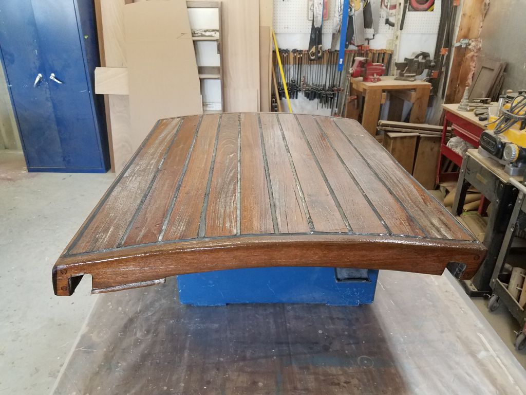
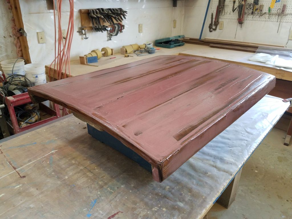
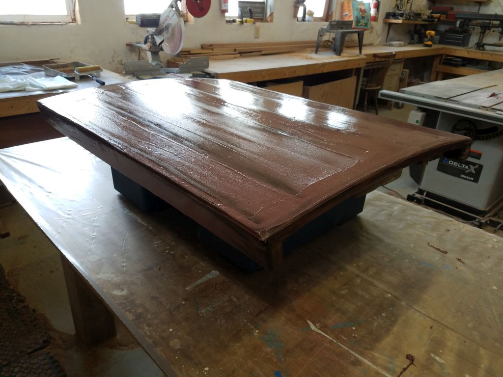
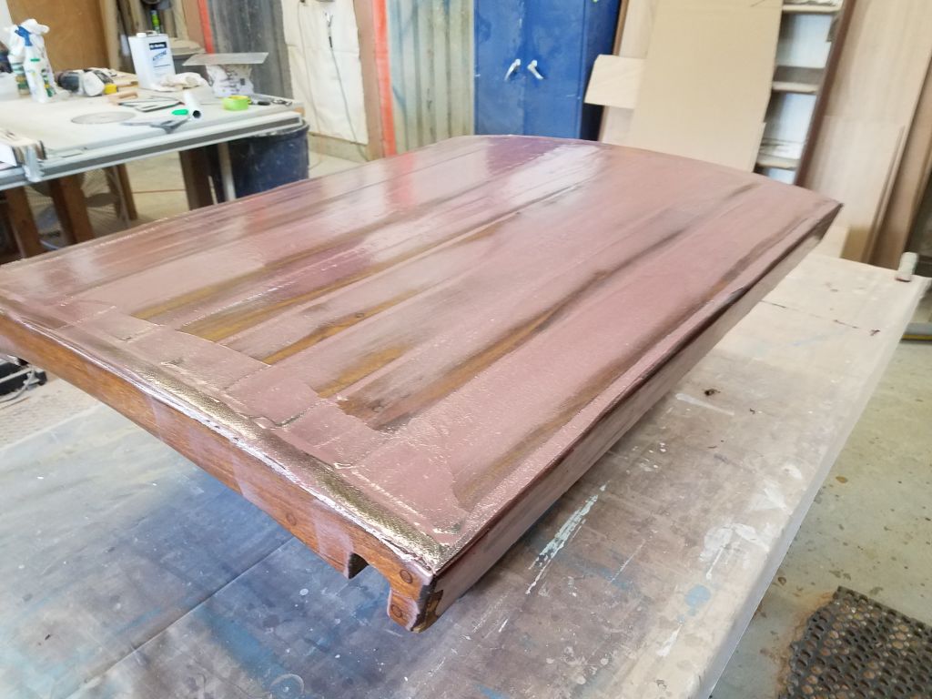
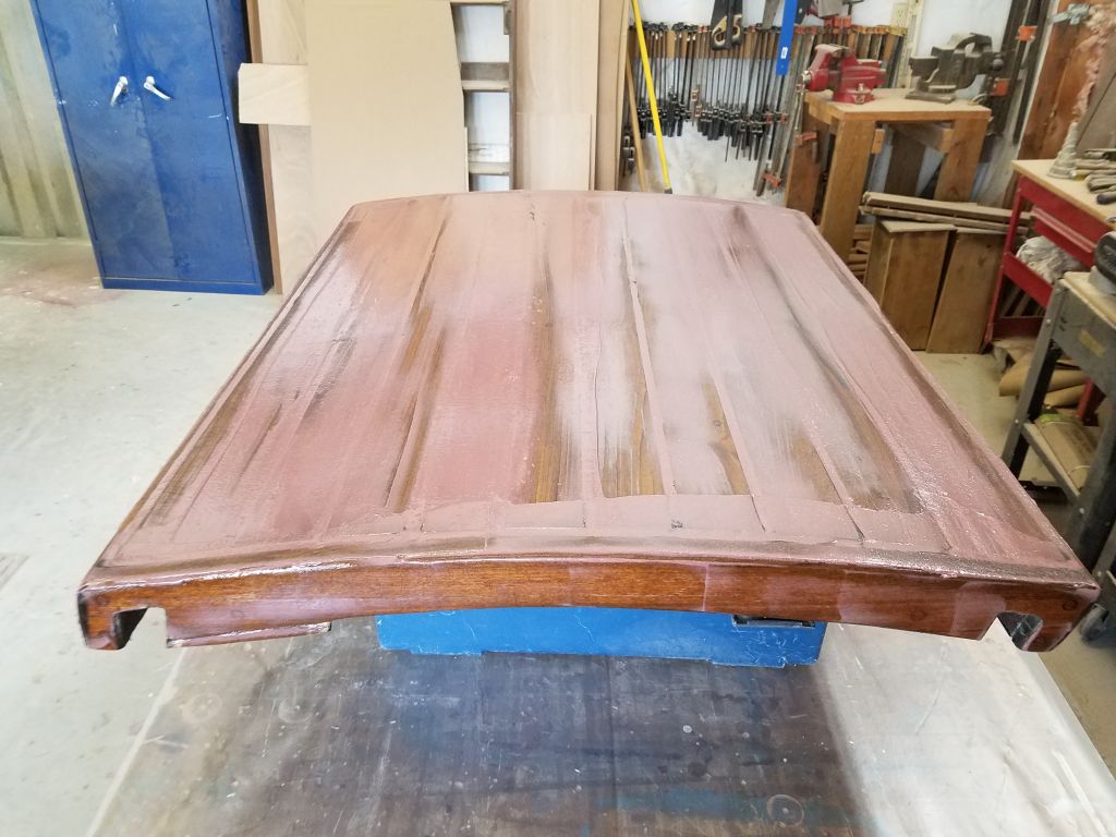
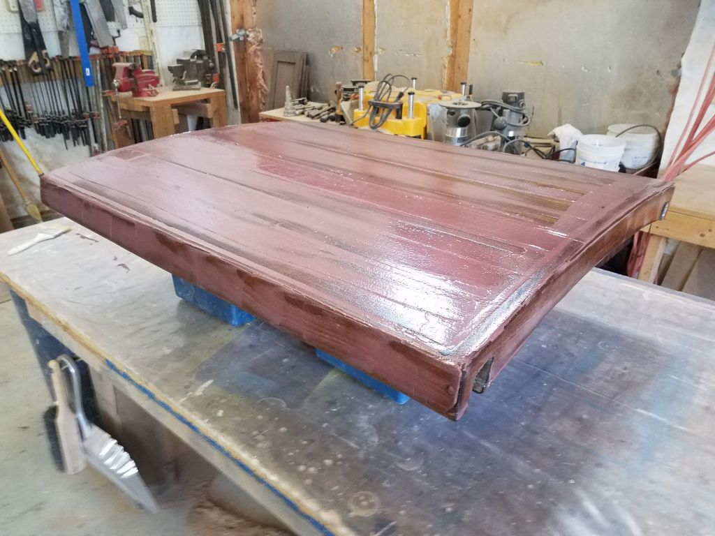
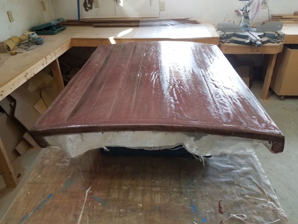
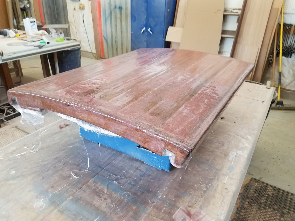
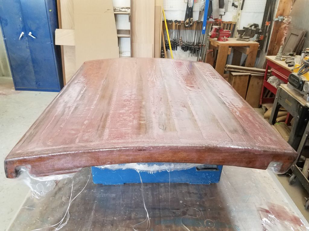
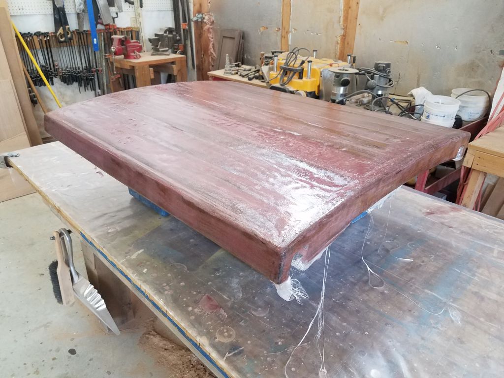
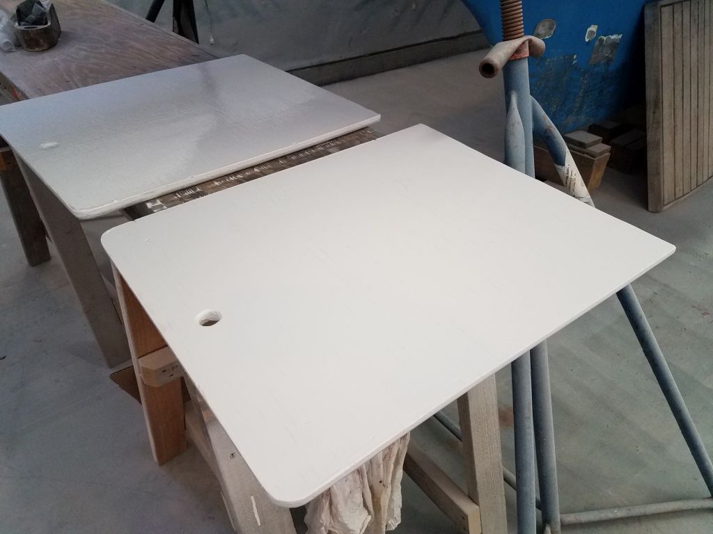
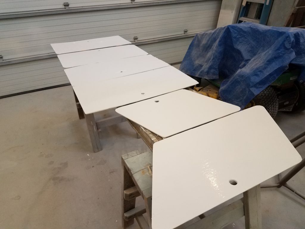
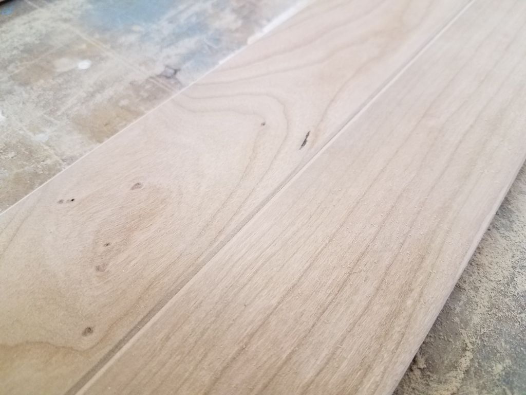
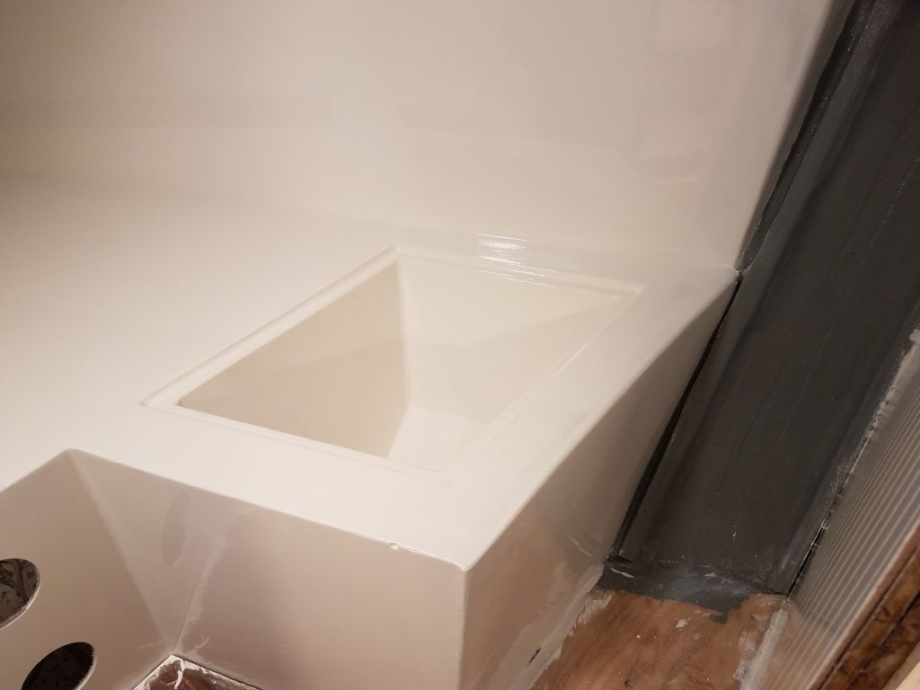
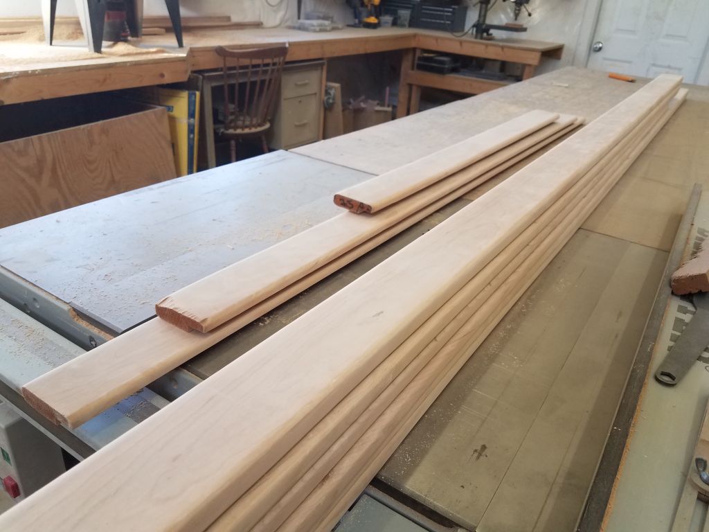
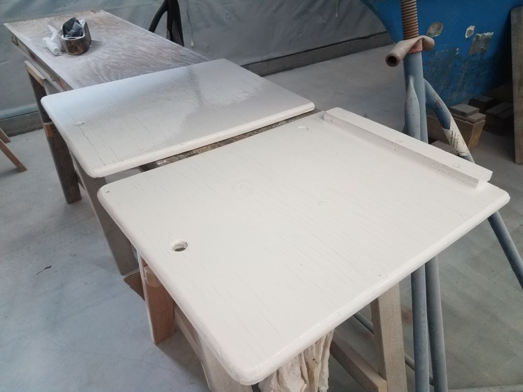
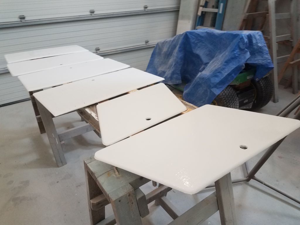
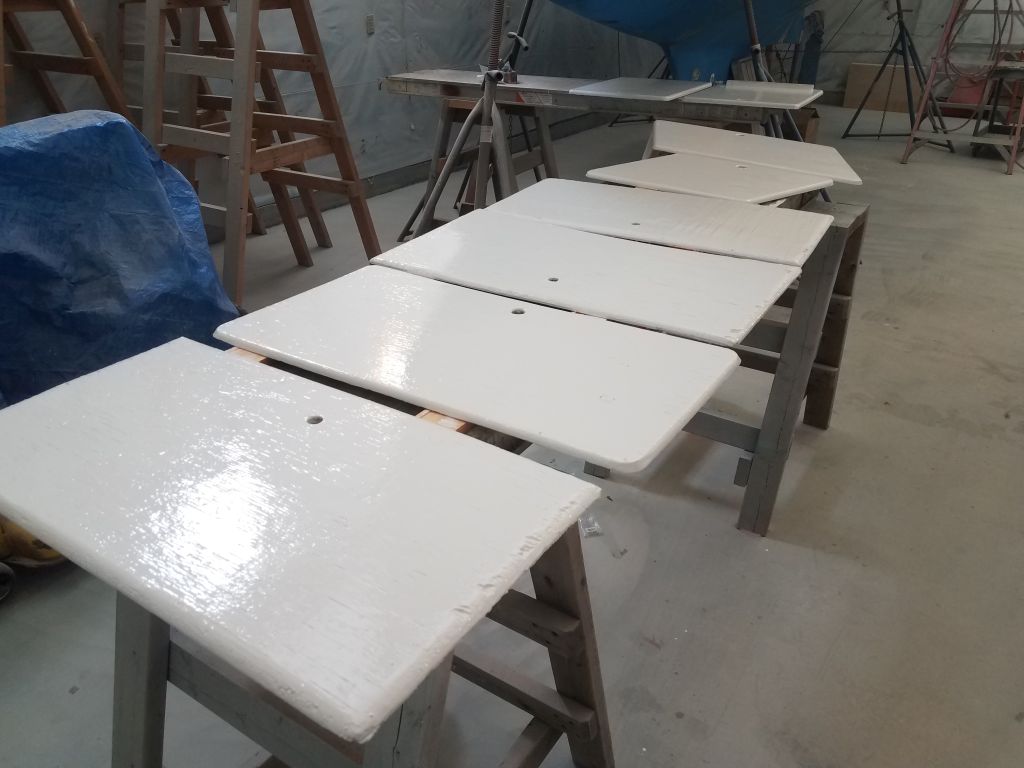
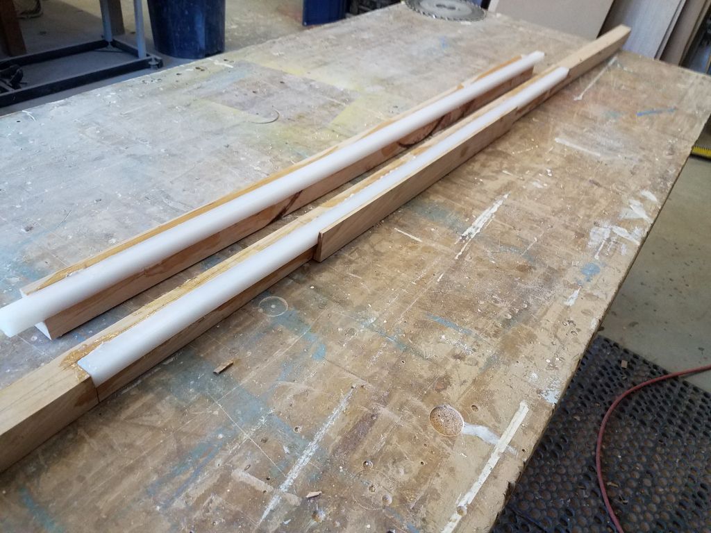
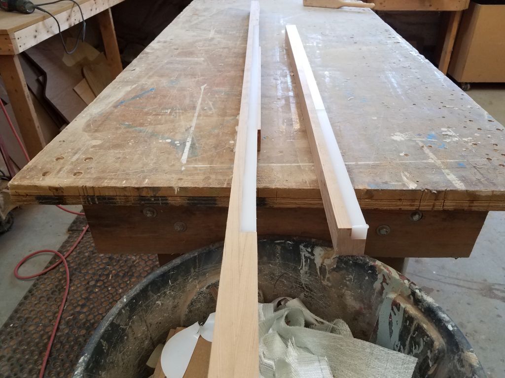
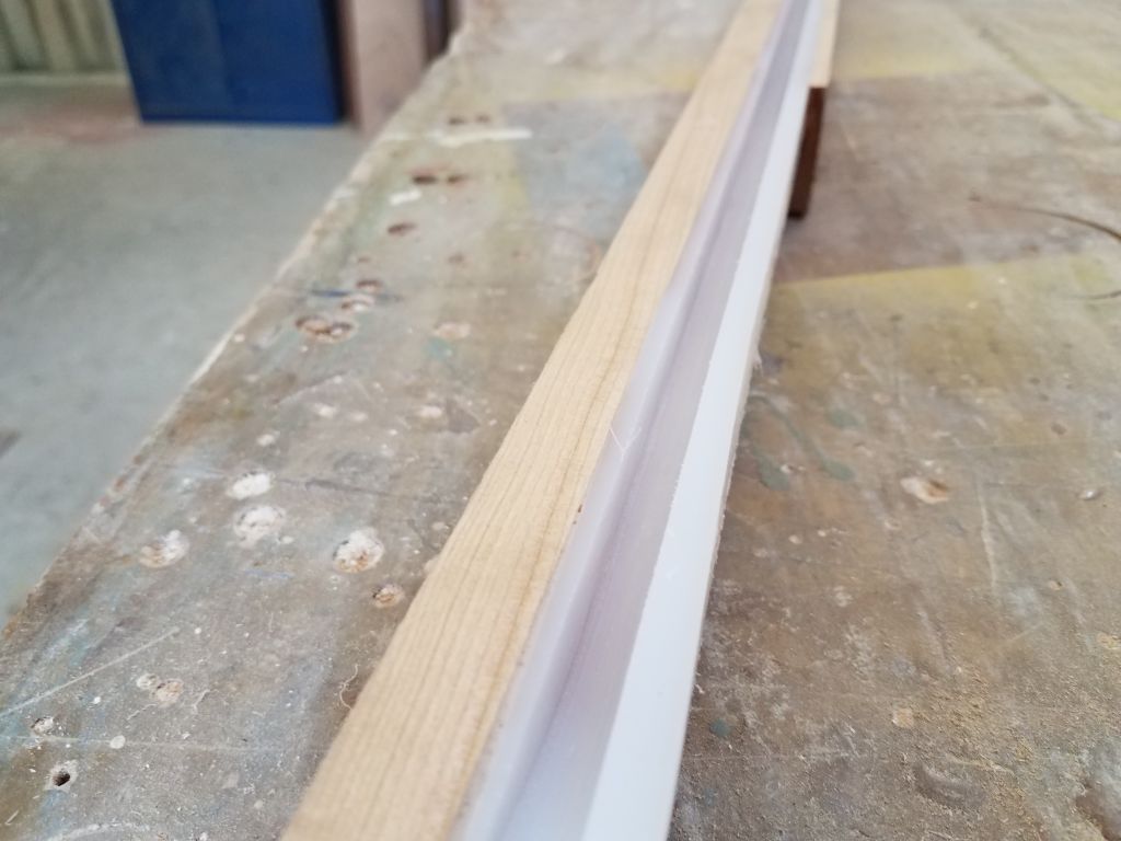
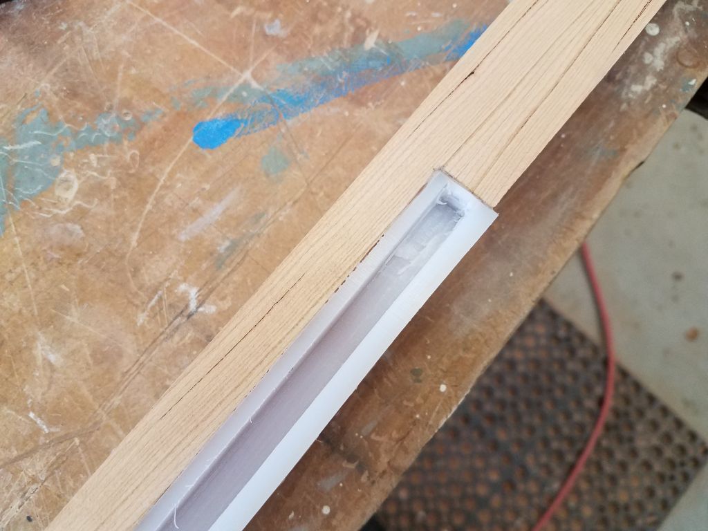
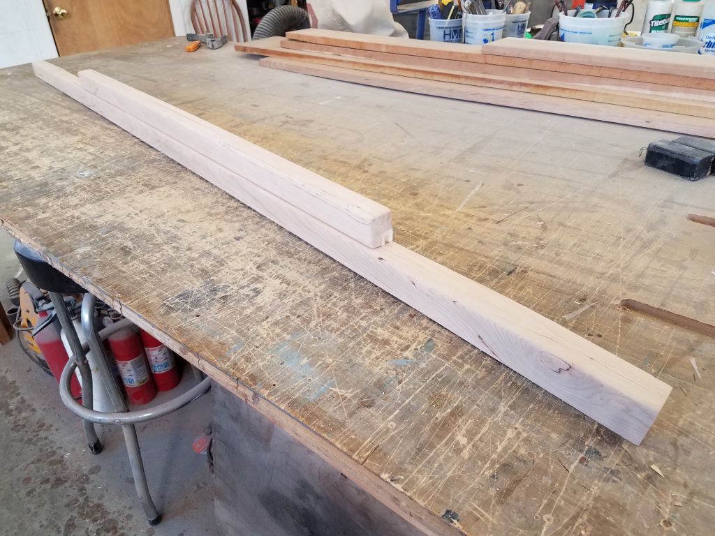
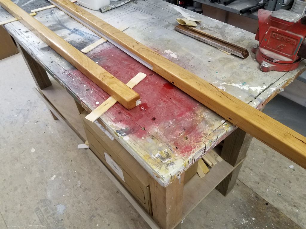
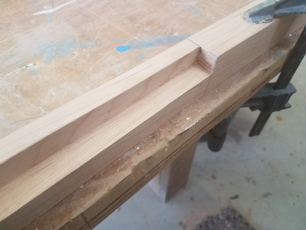
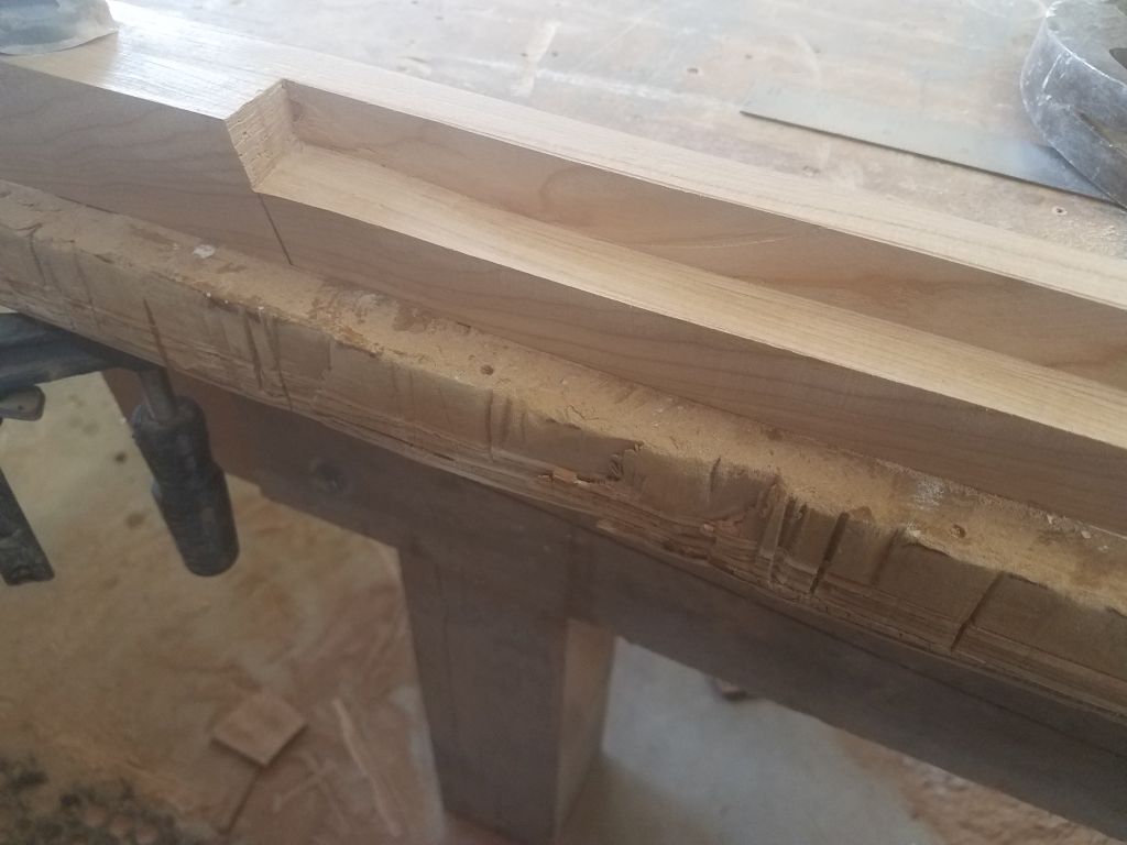
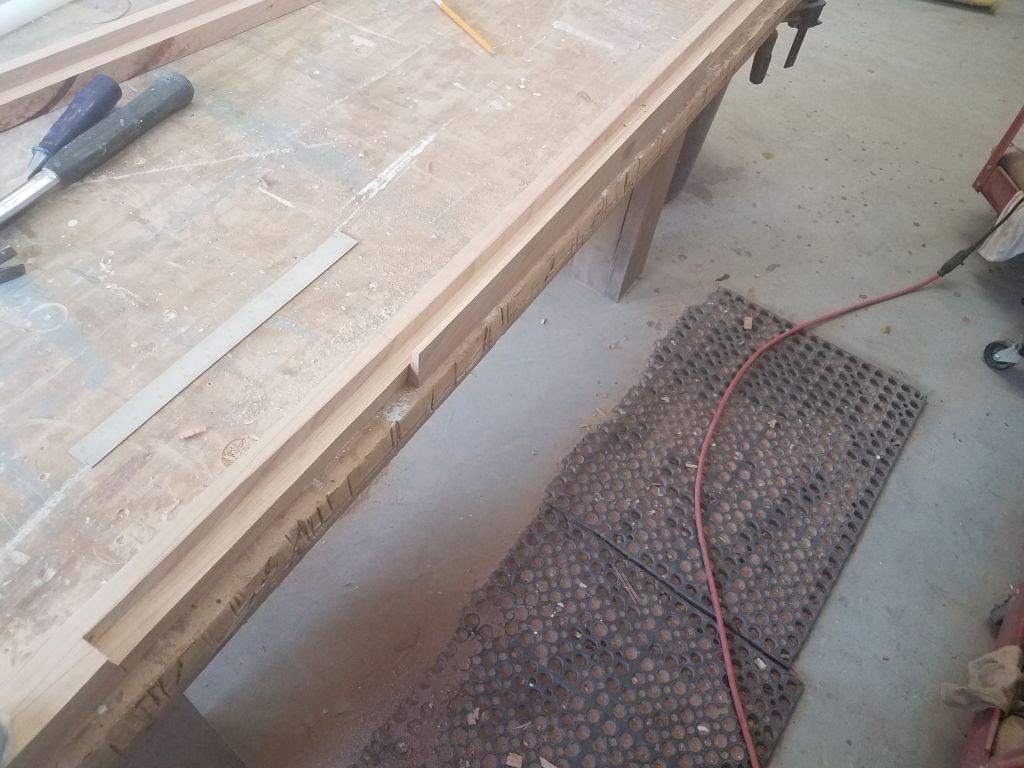
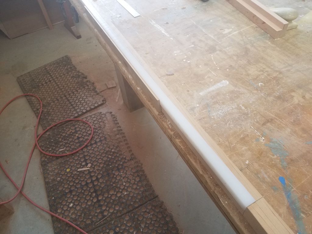
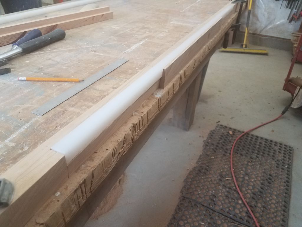
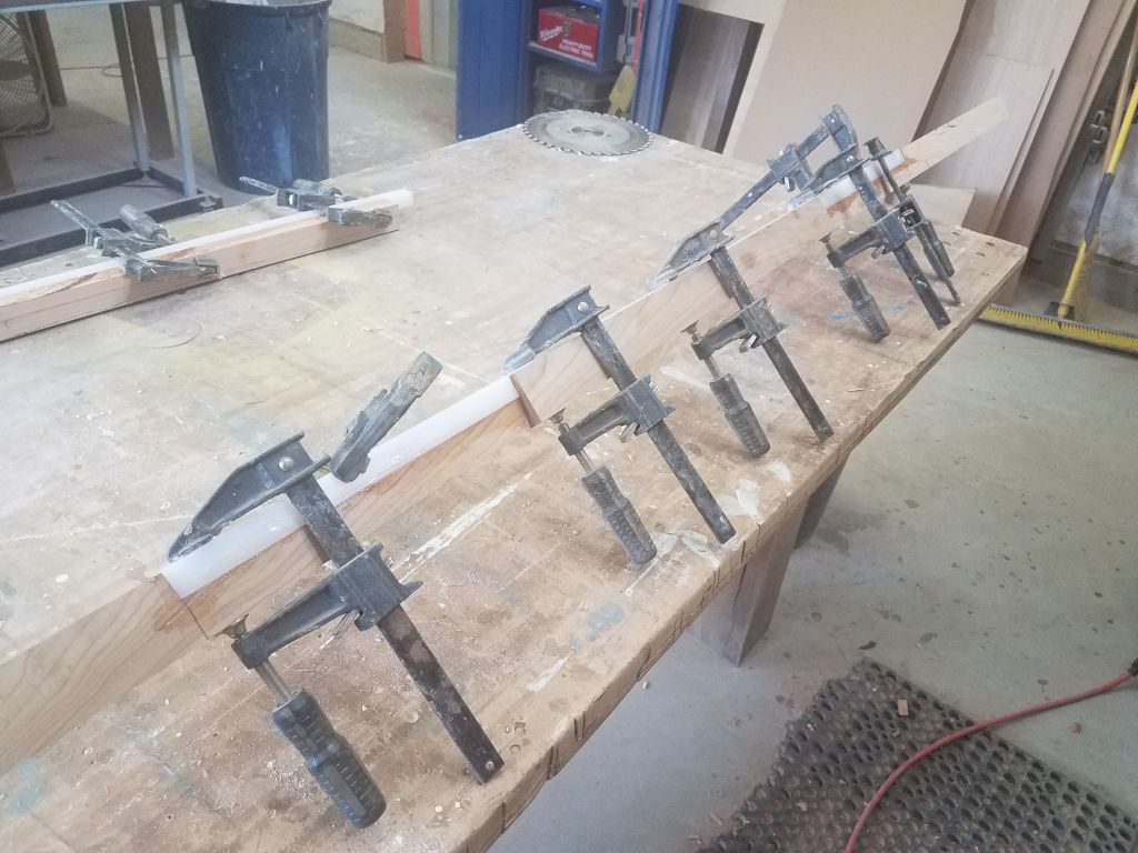
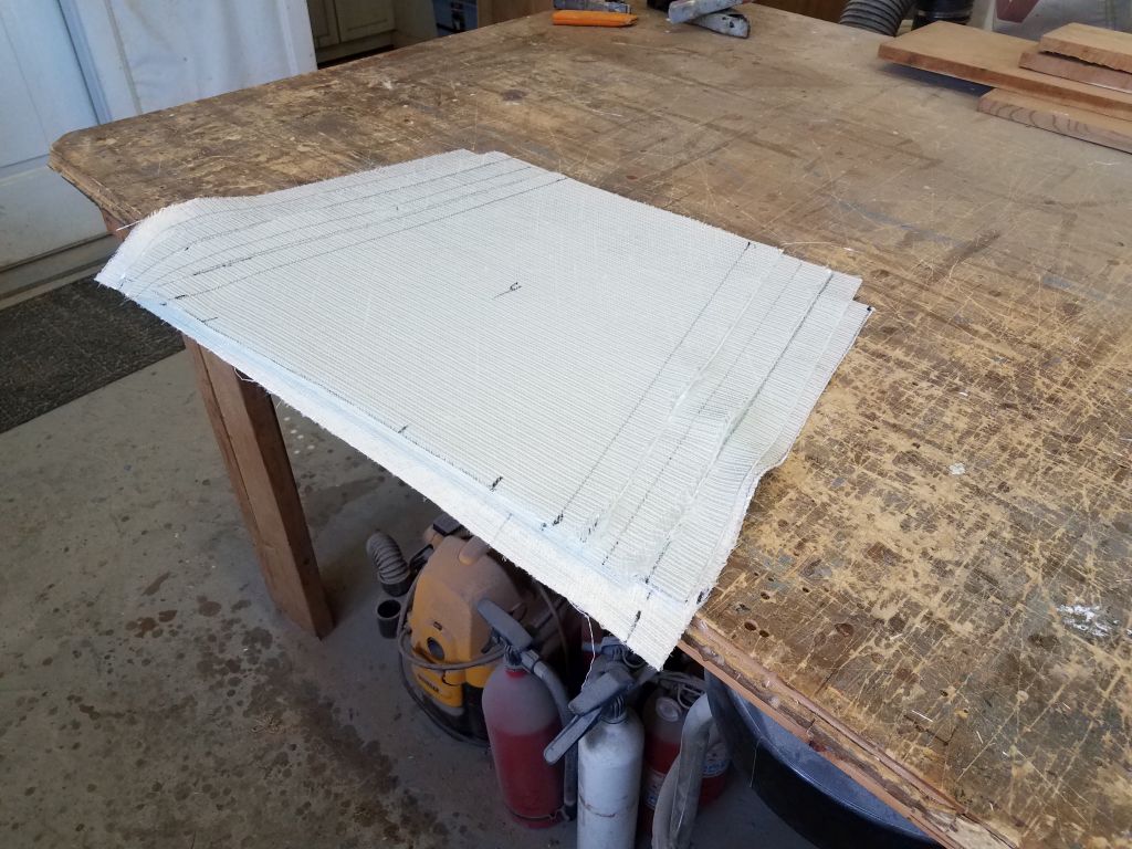
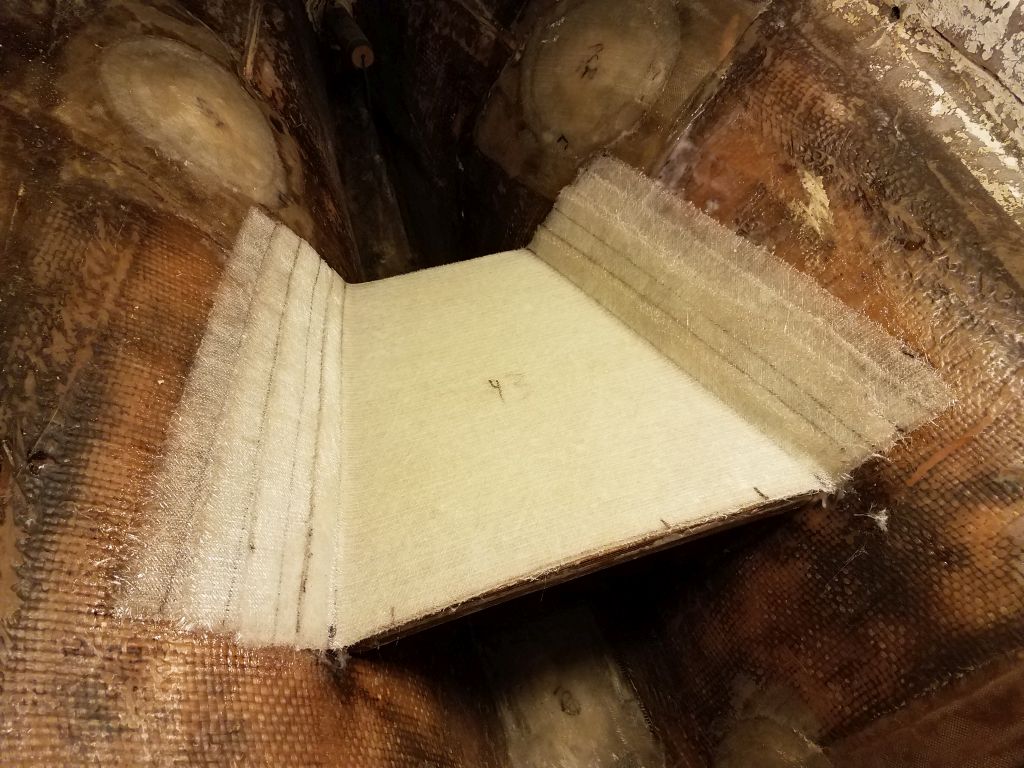
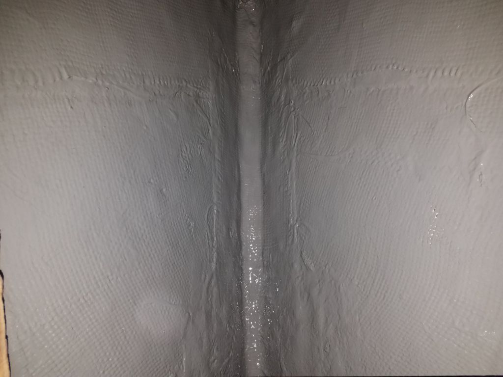
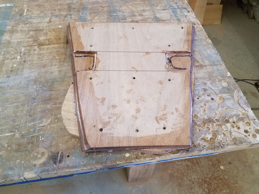
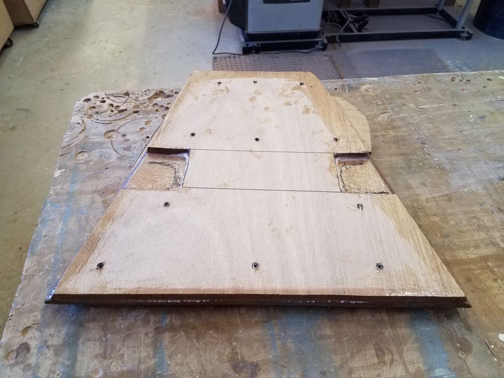
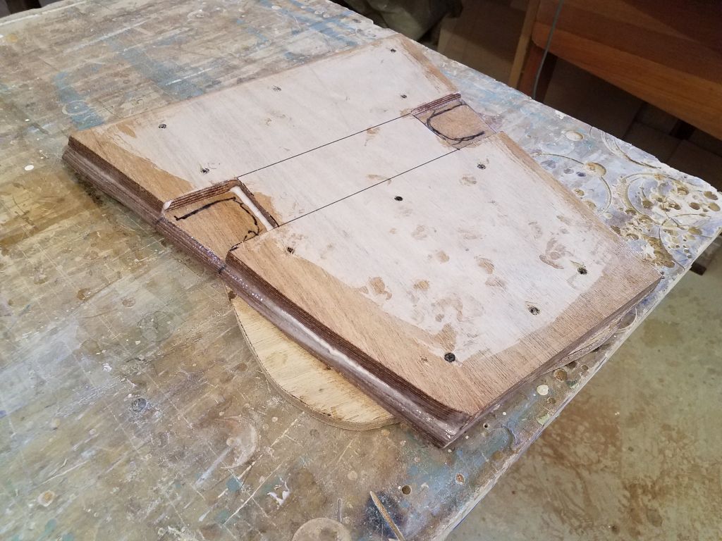
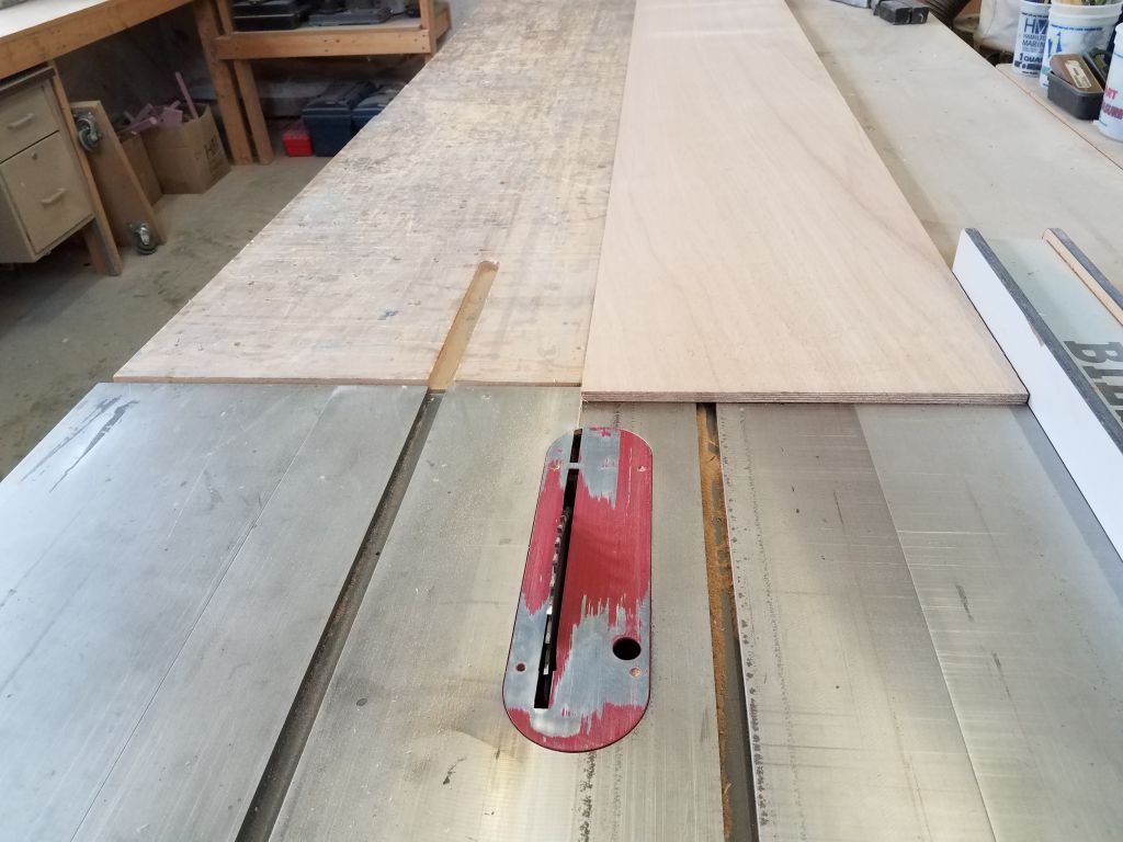
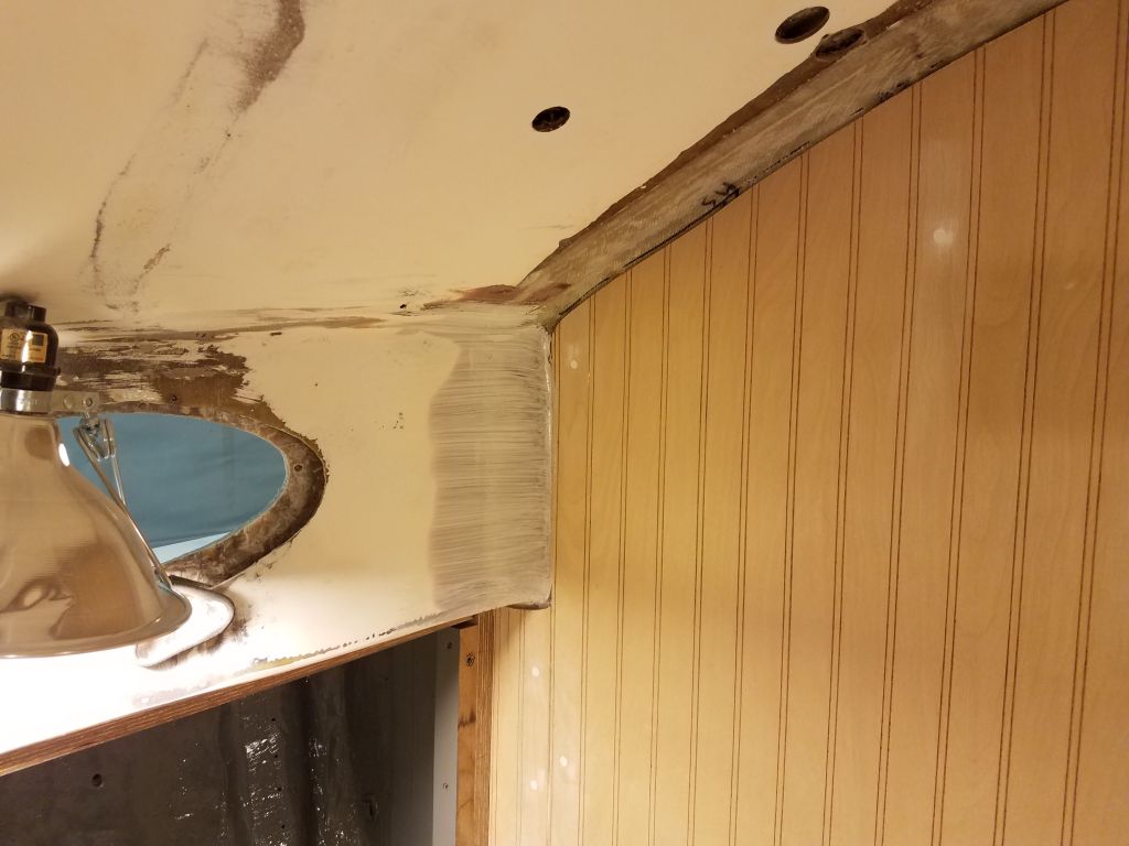
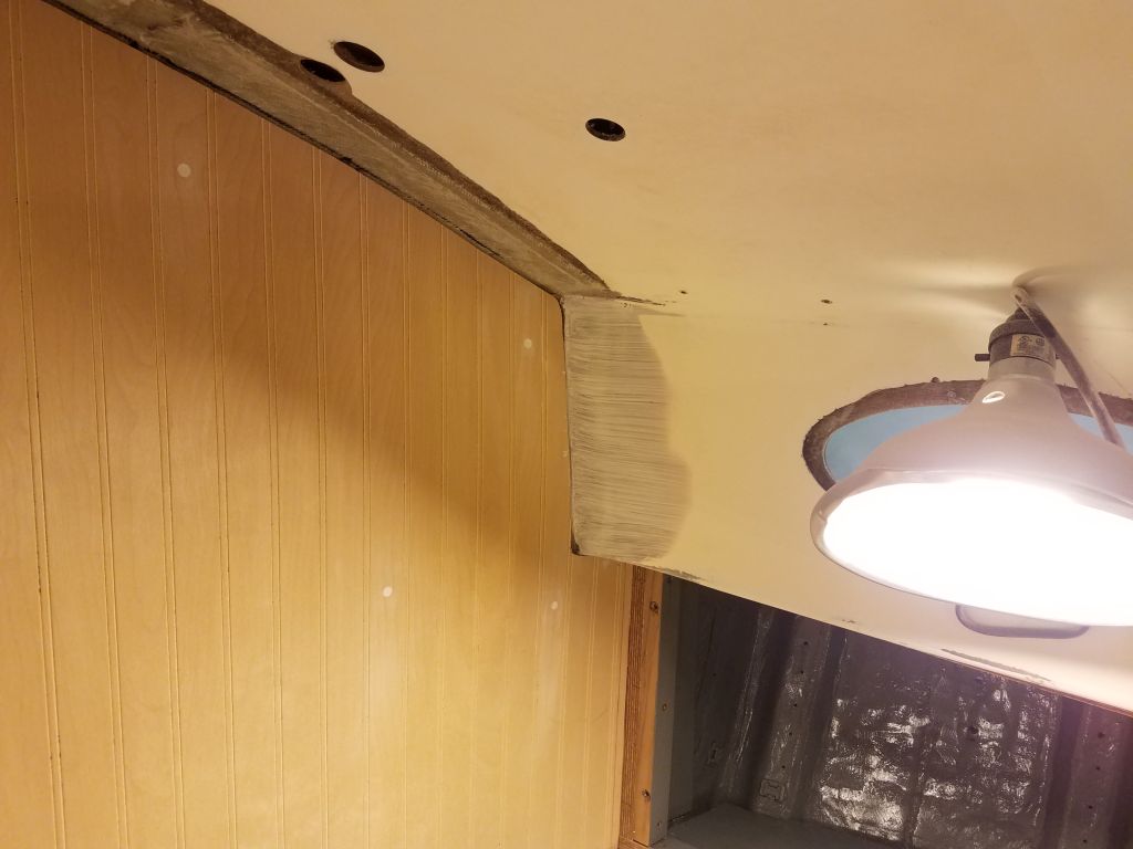
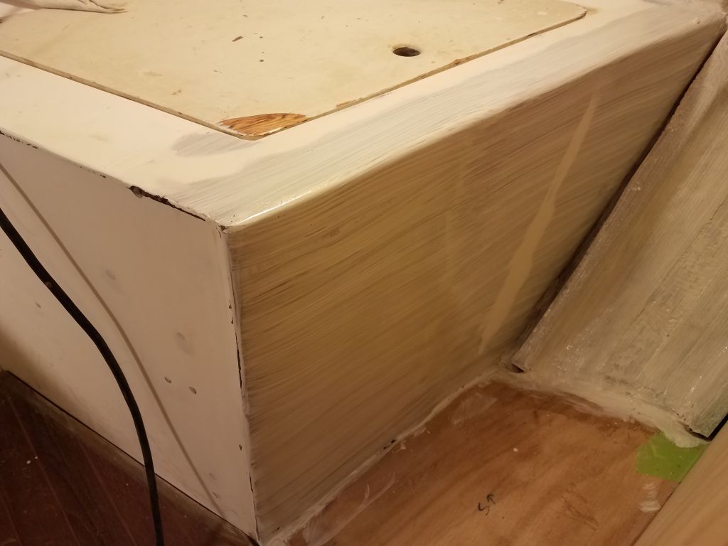
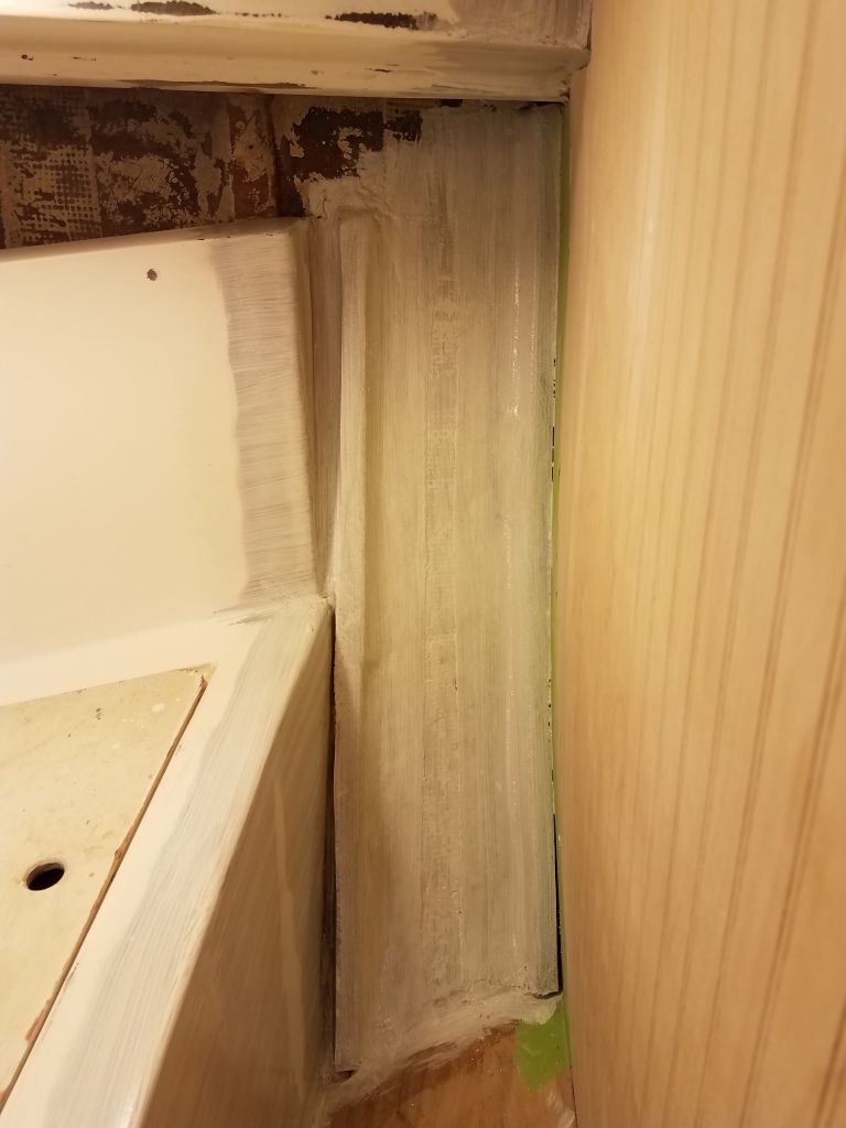
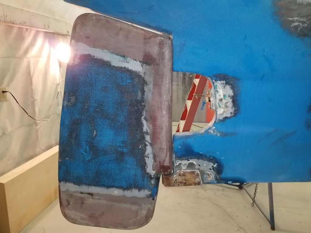
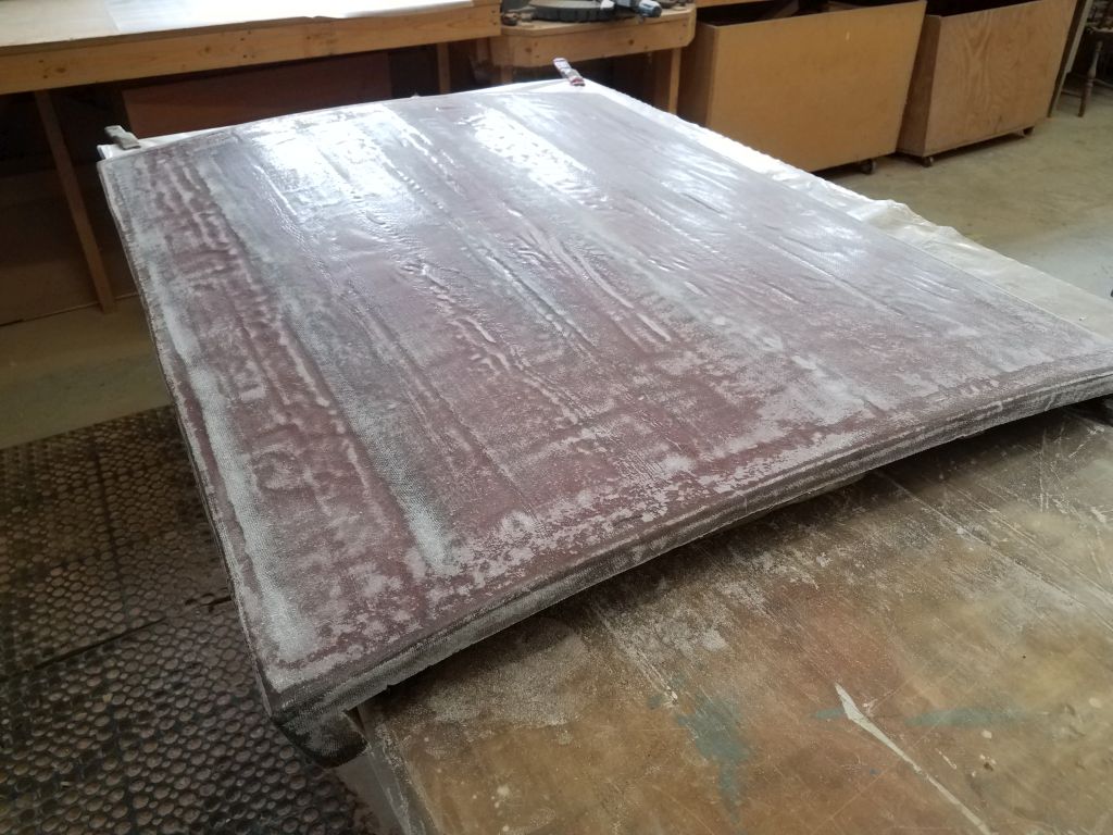
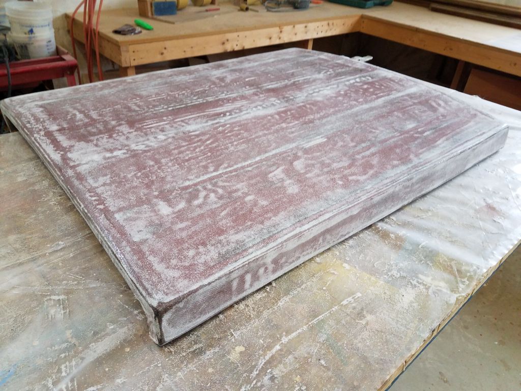
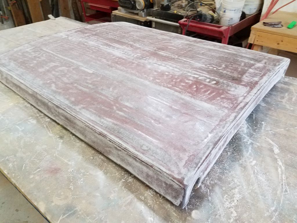
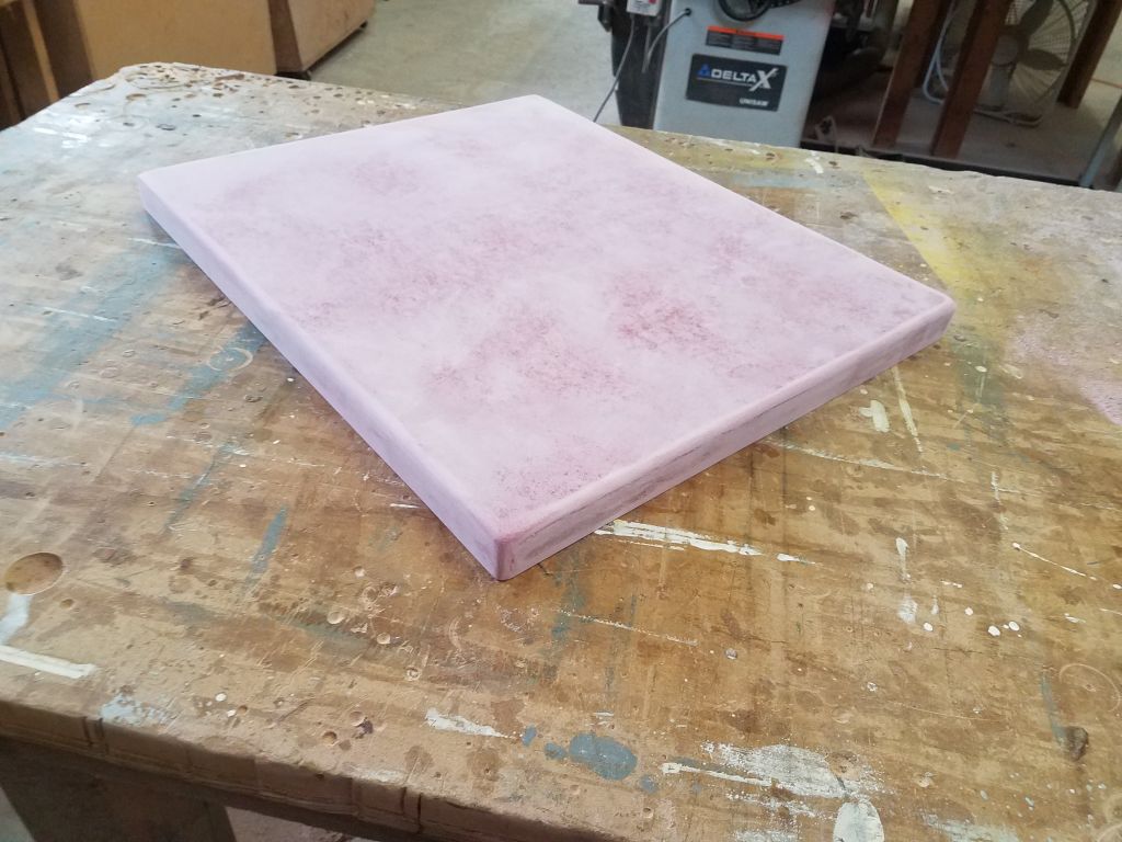
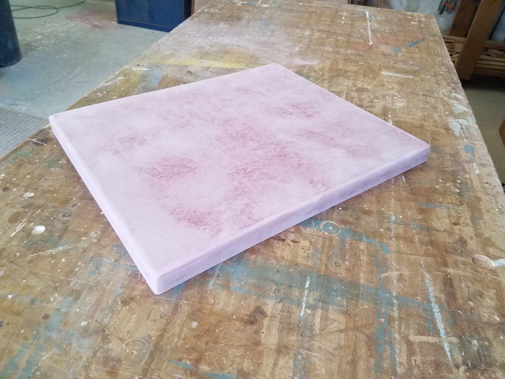
To finish up the day, and the week, I lightly sanded the new glasswork on the companionway hatch, removing the excess material that I’d let hang down during the glassing session. Now it would be a straightforward matter to smooth and fair the final surface.

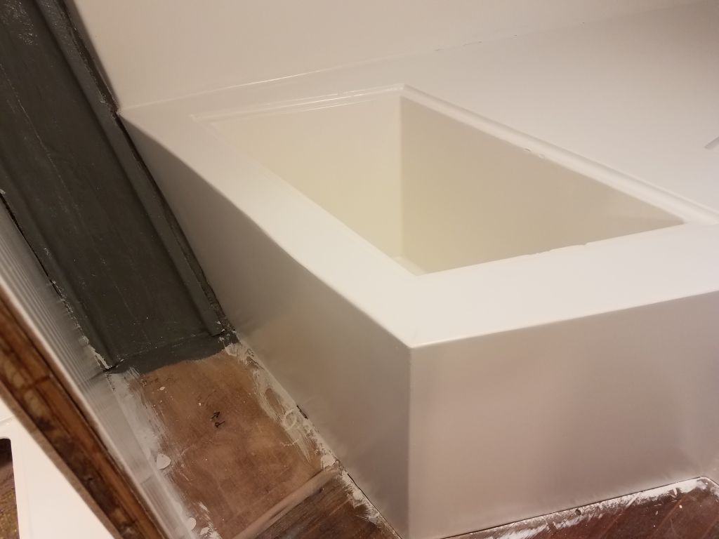
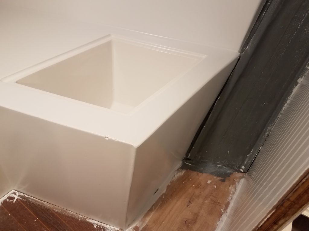
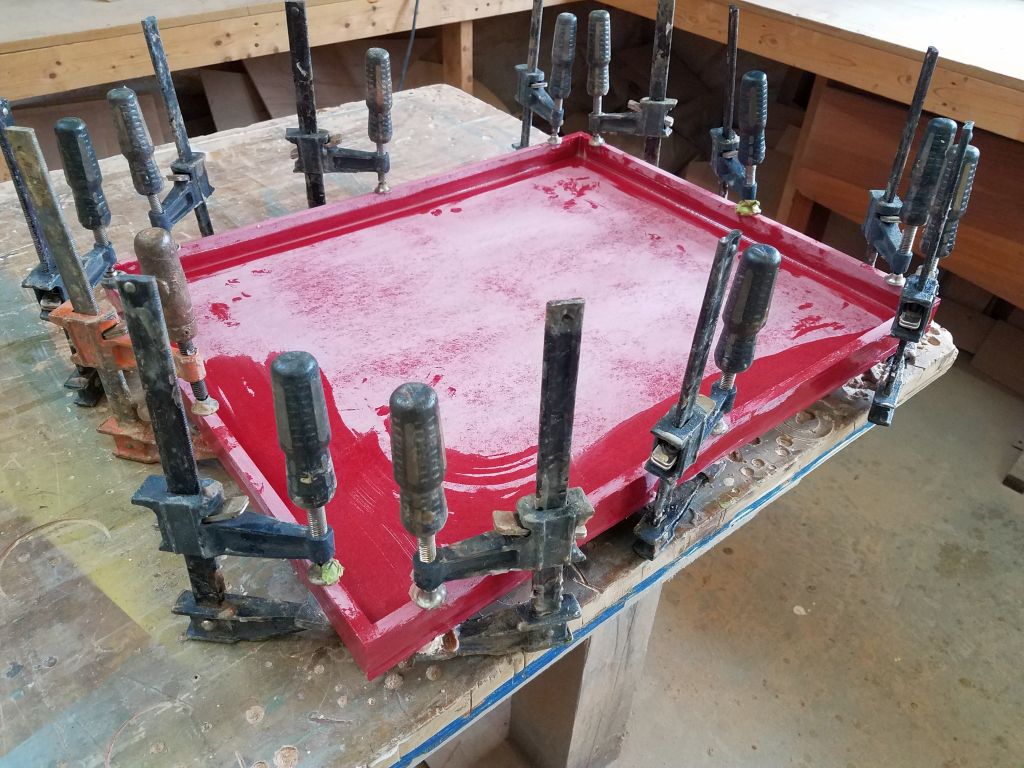
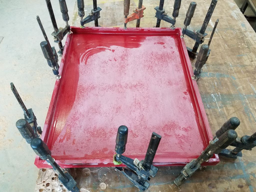
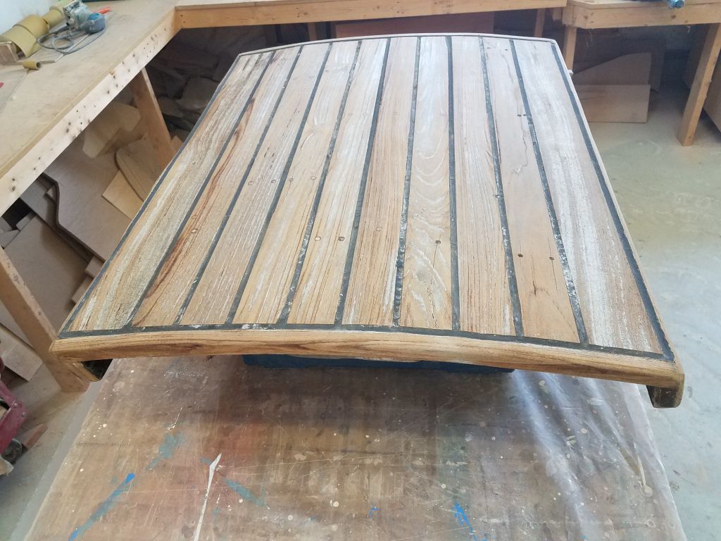
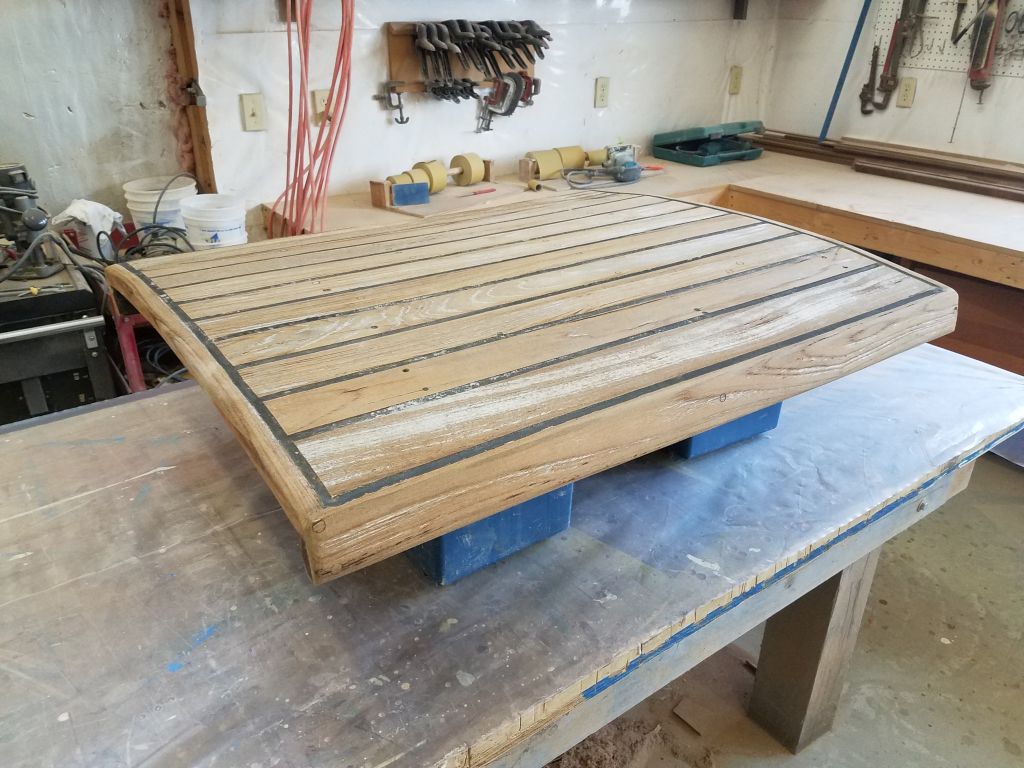
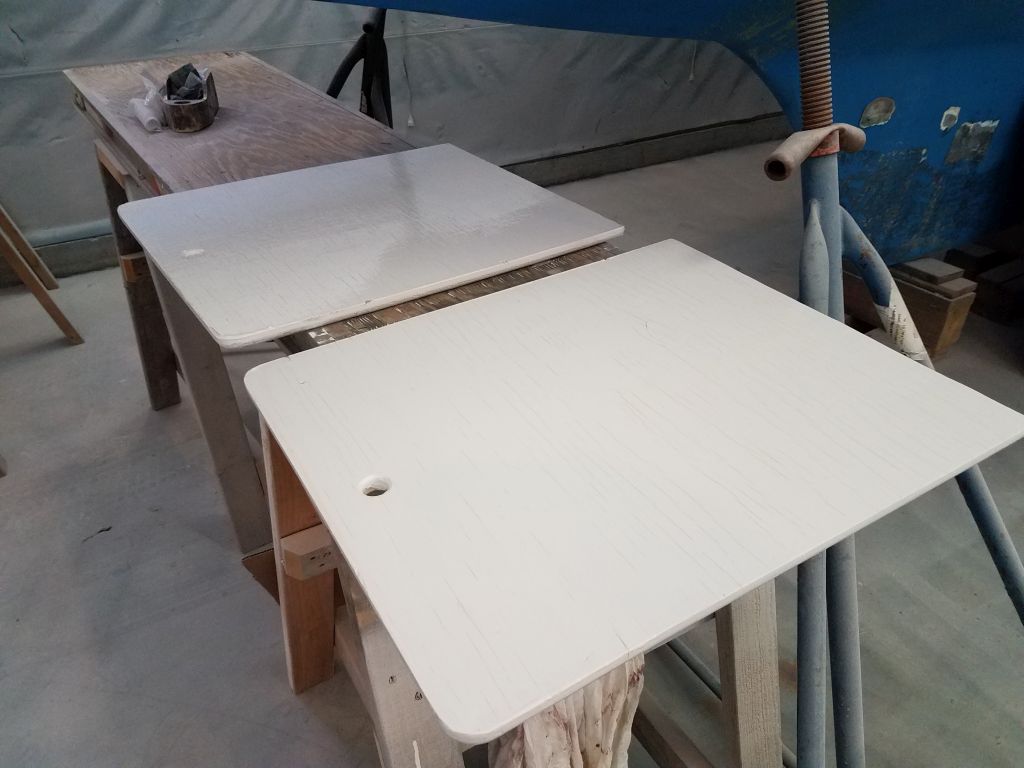
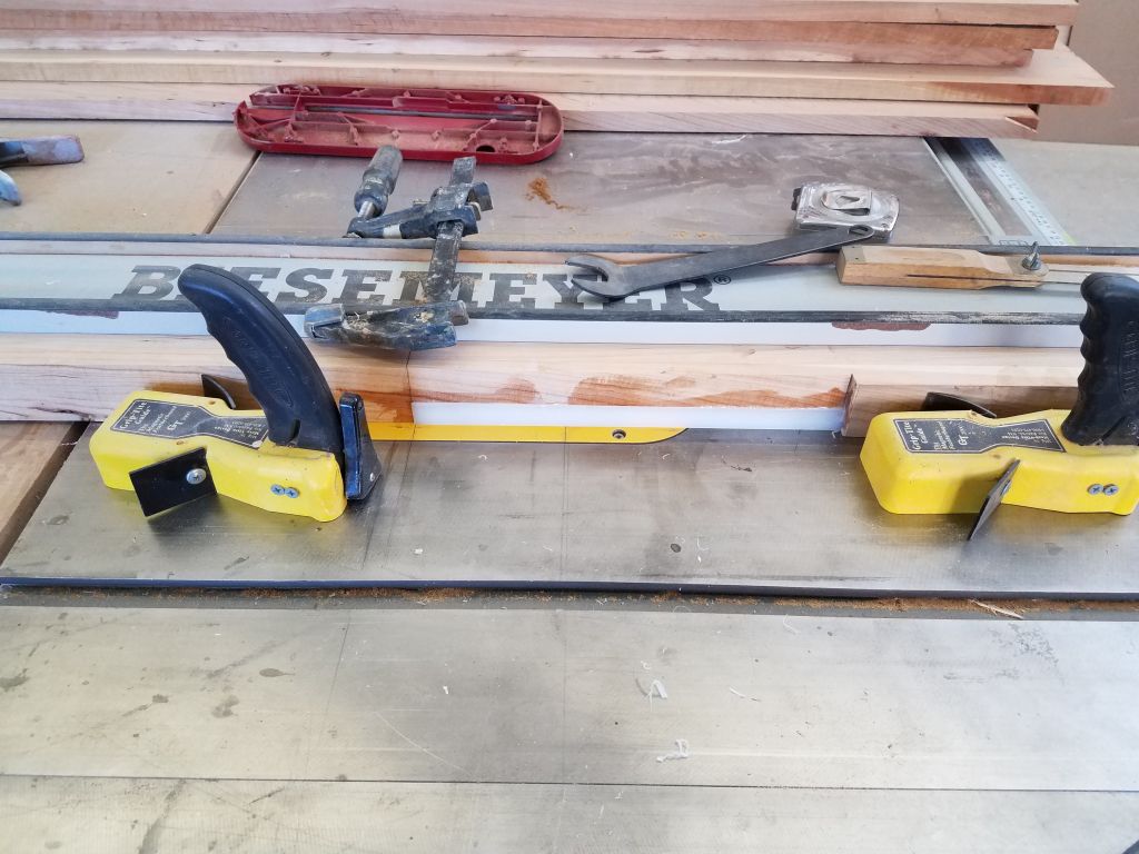
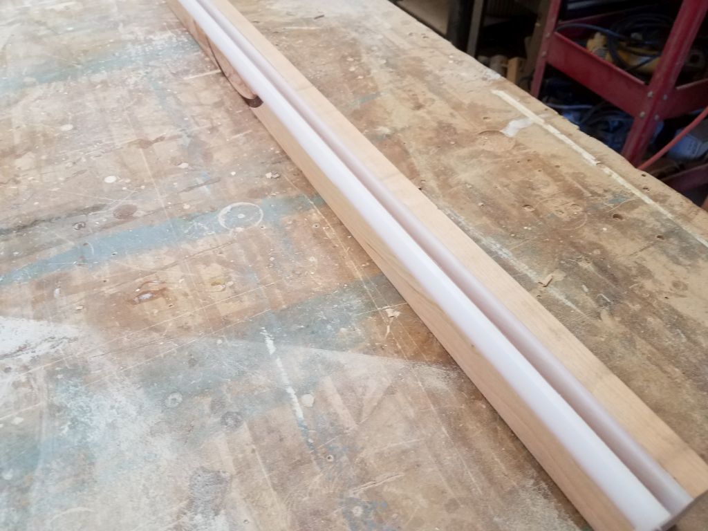
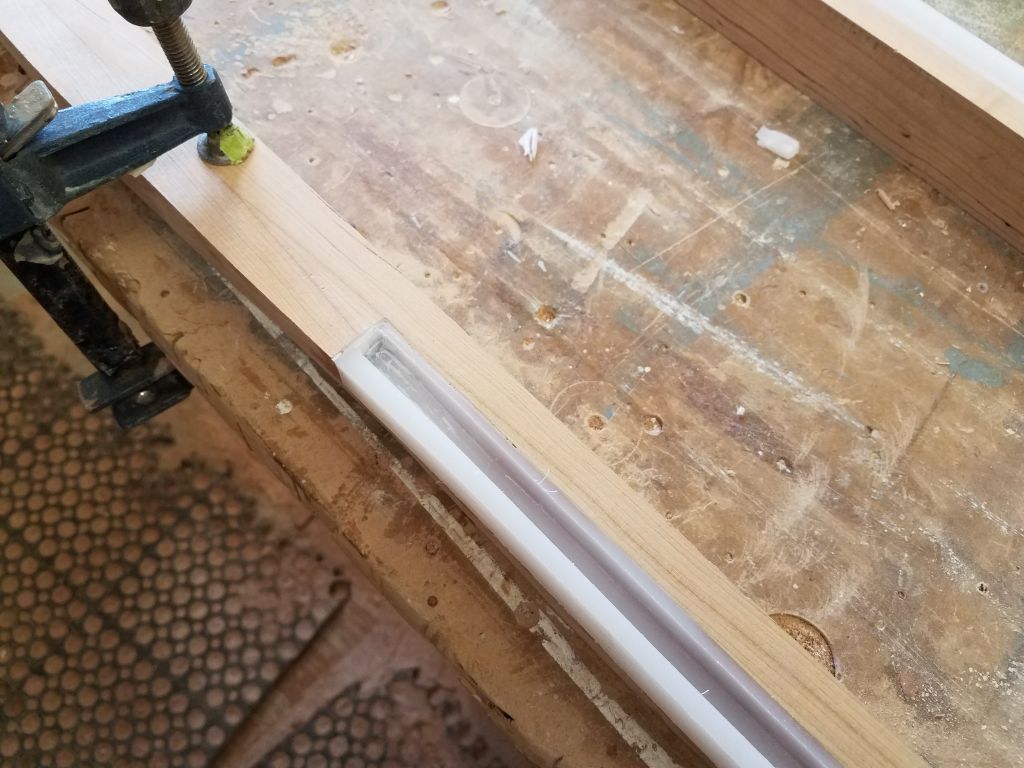
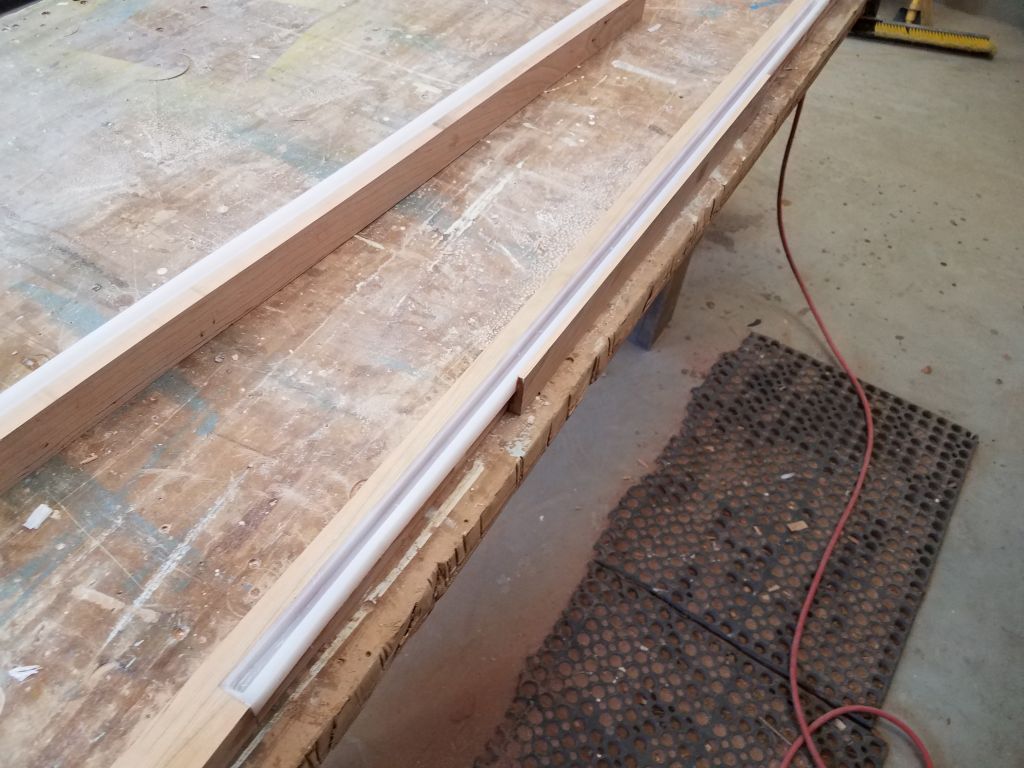
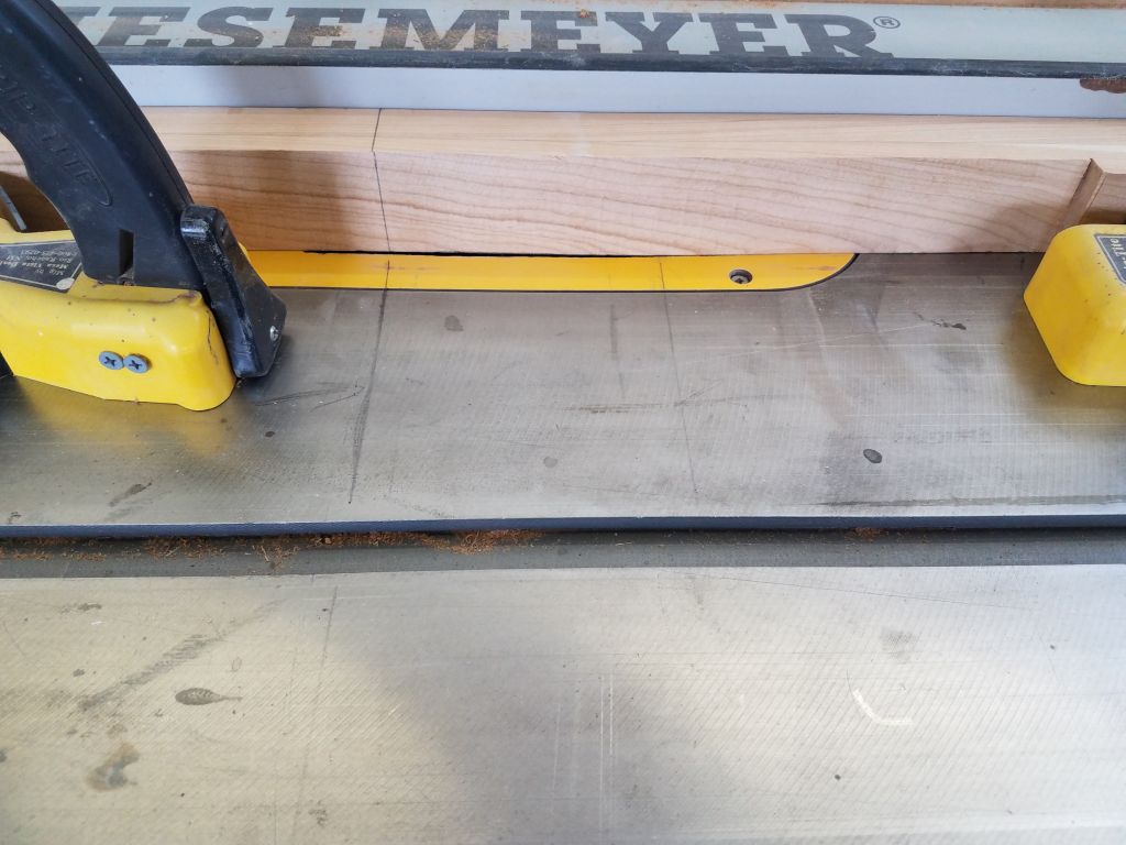
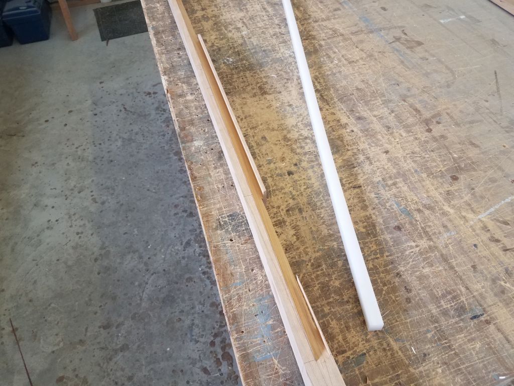
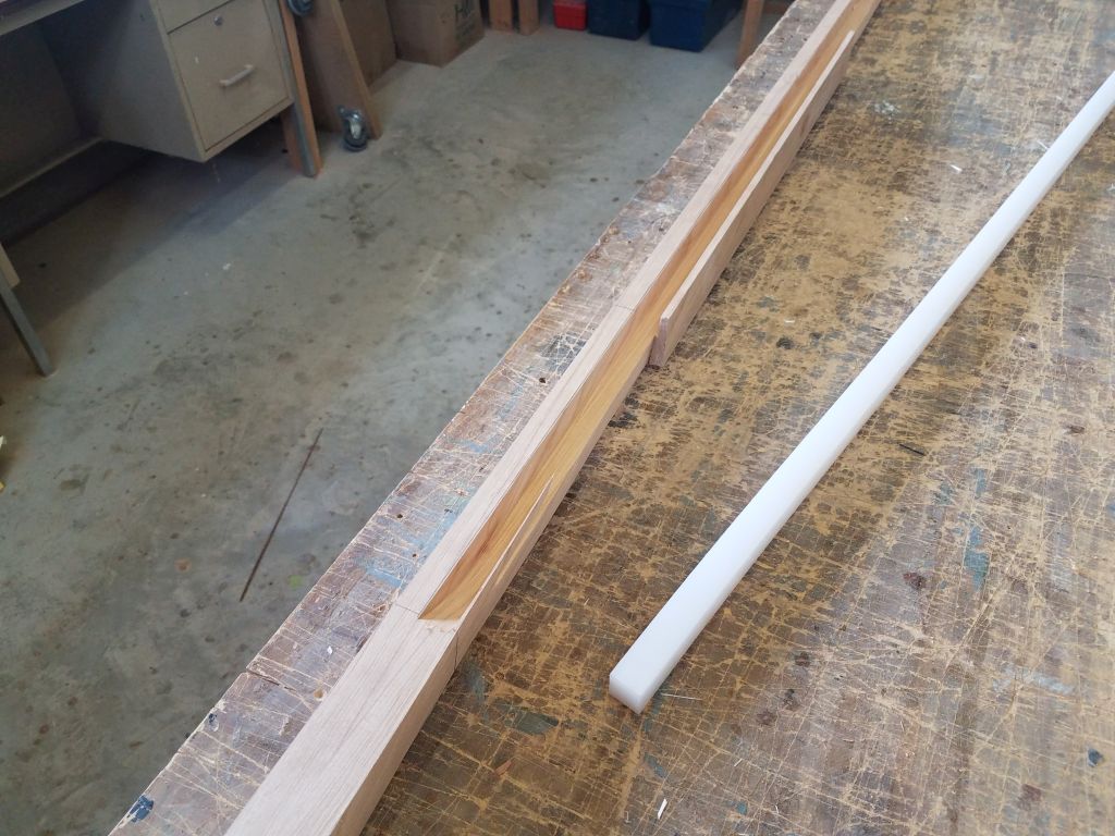
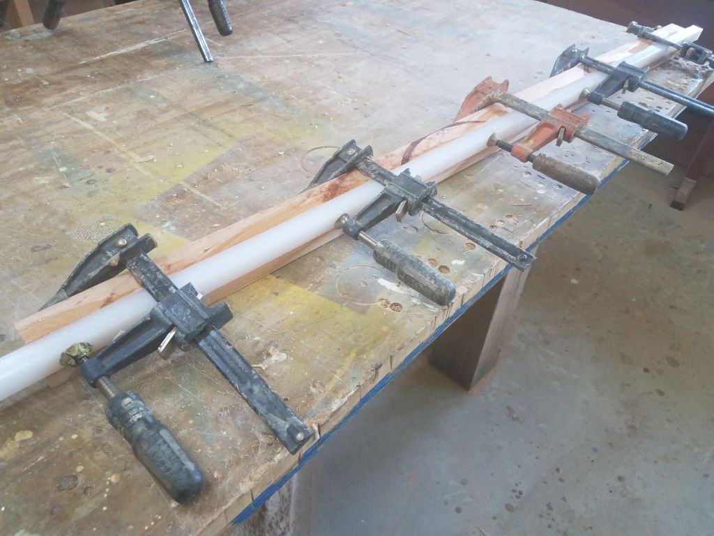
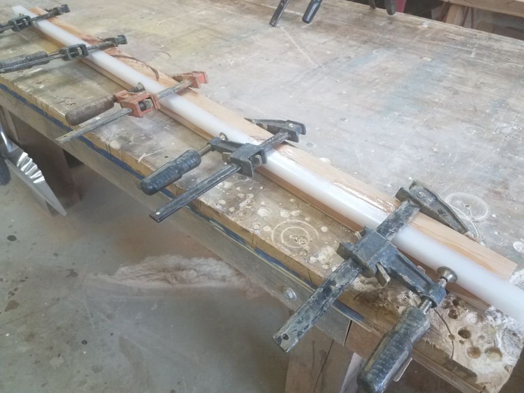
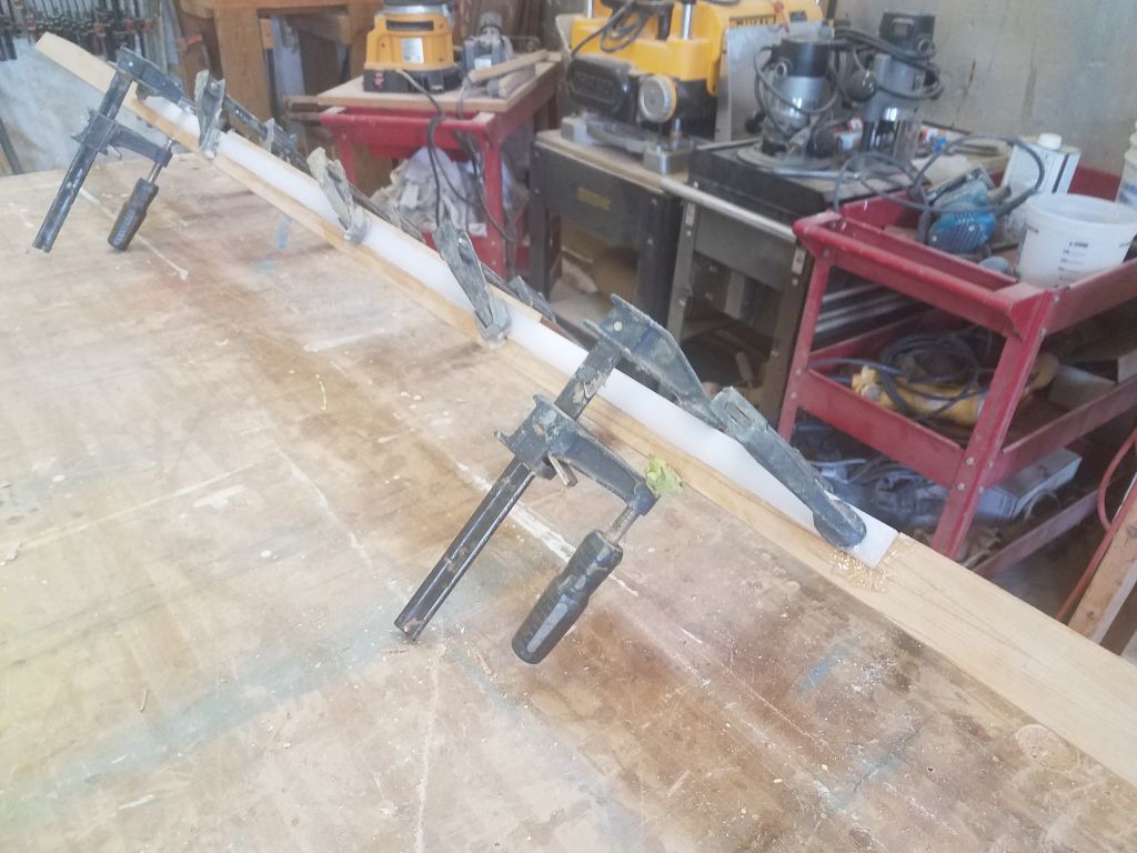
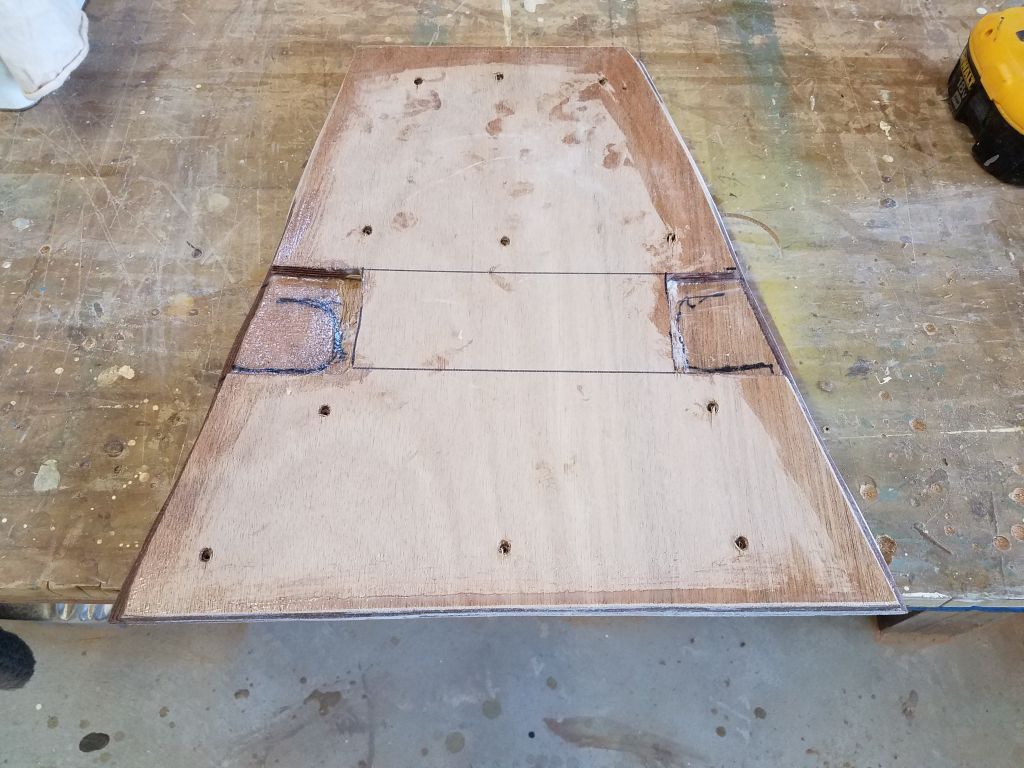
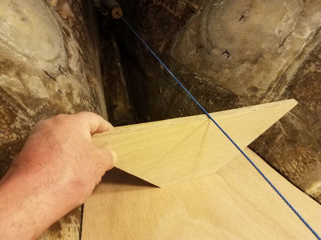
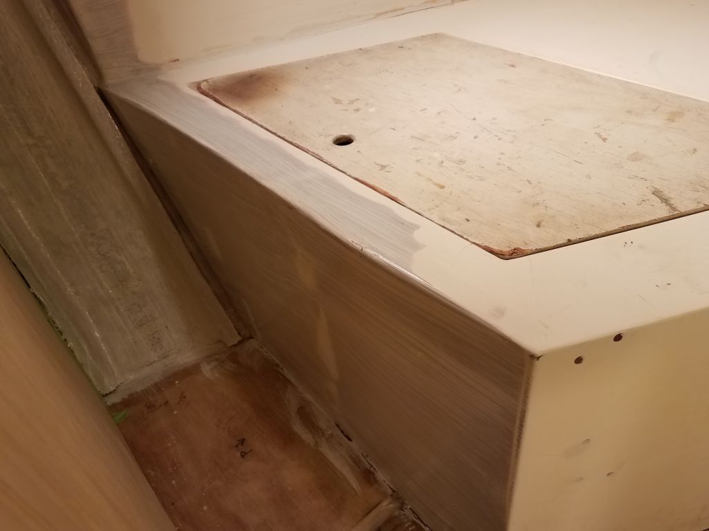
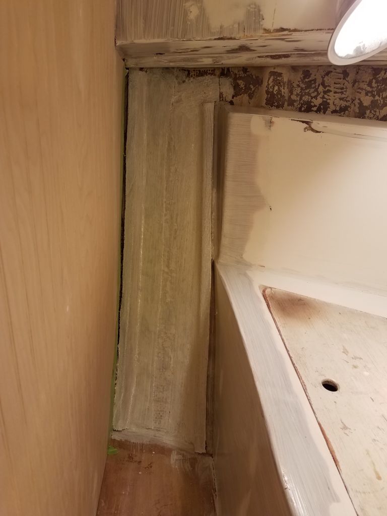
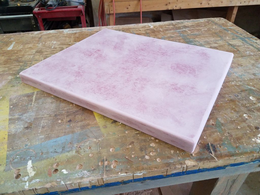
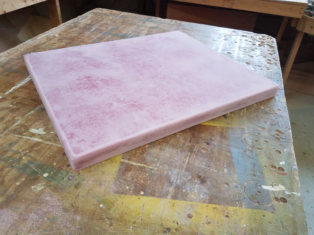
Finally, I unclamped and sanded the new lazarette hatch, smoothing the seams and rounding the exposed corners. There’d be some final fitting and scribing to allow the hatch to fit the deck properly, but that was for another time.
Total time billed on this job today: 8 hours
0600 Weather observation: 40°, cloudy. Forecast for the day: Rain showers and fog, 52°