(page 8 of 27)

Scupper 193

Monday

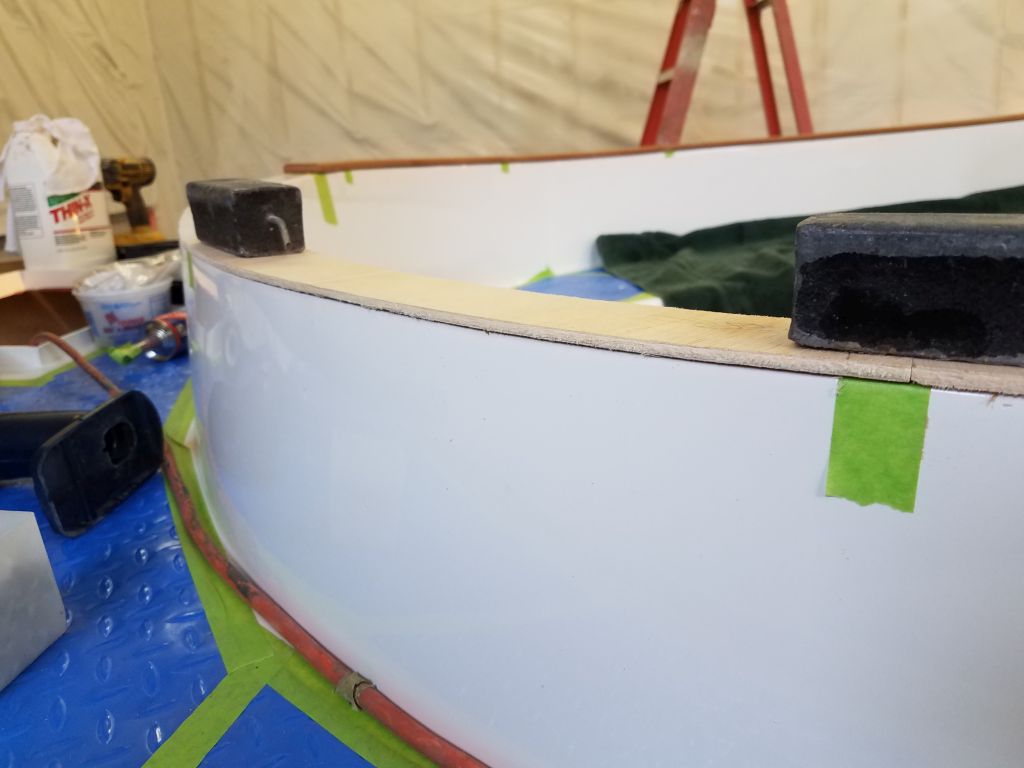
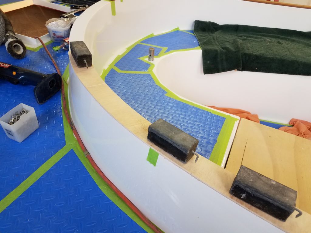
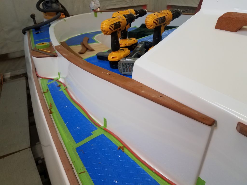
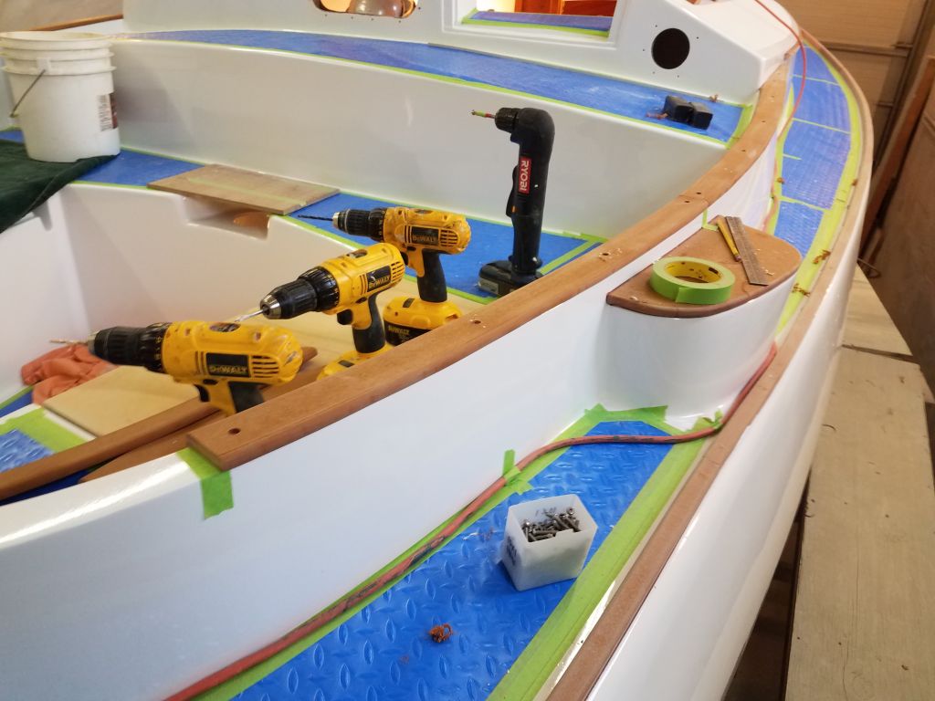
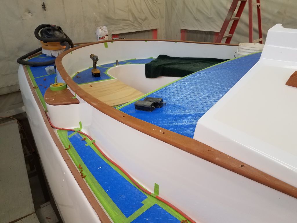
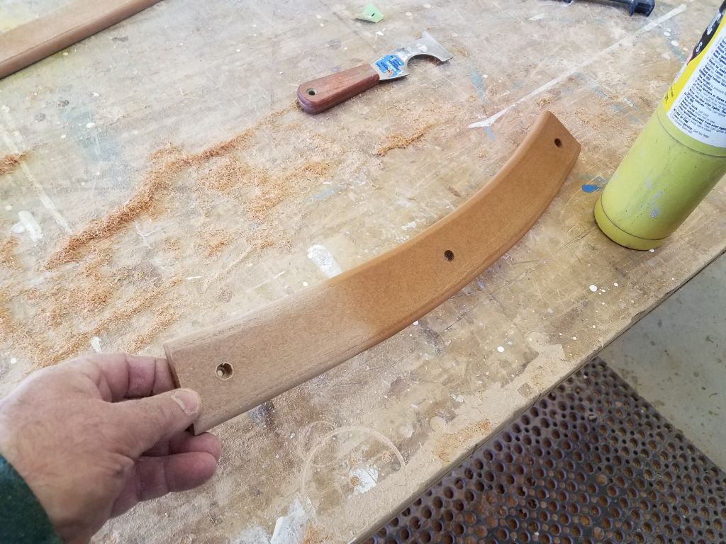
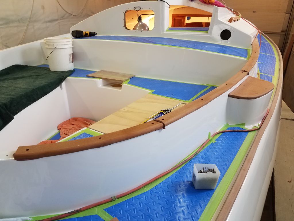
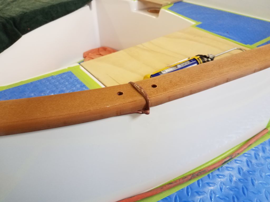
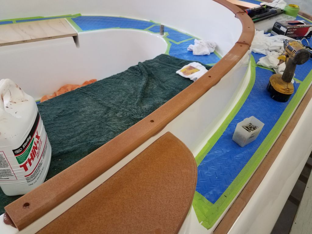
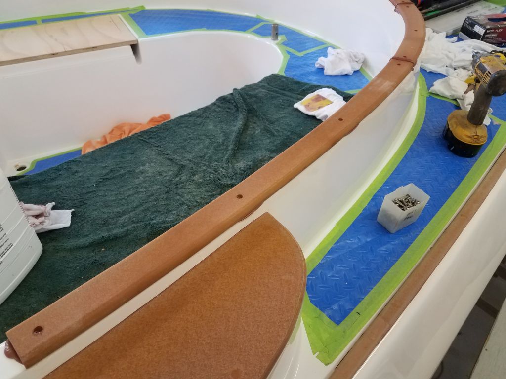
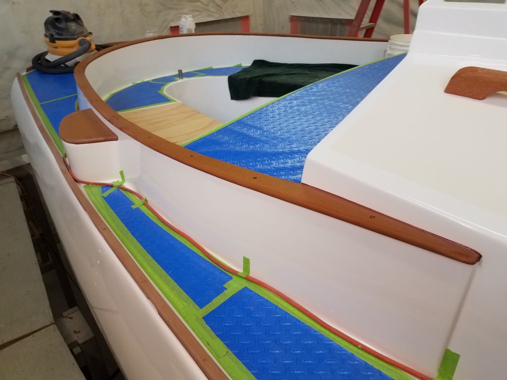
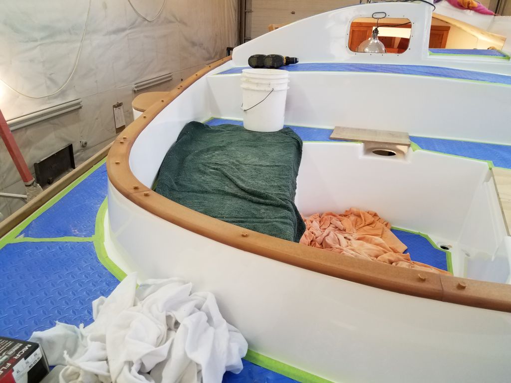
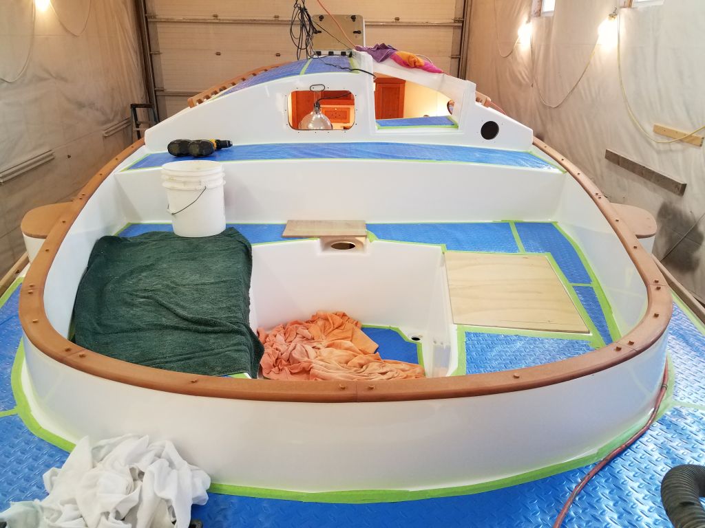
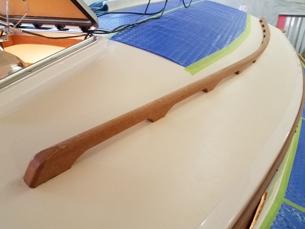
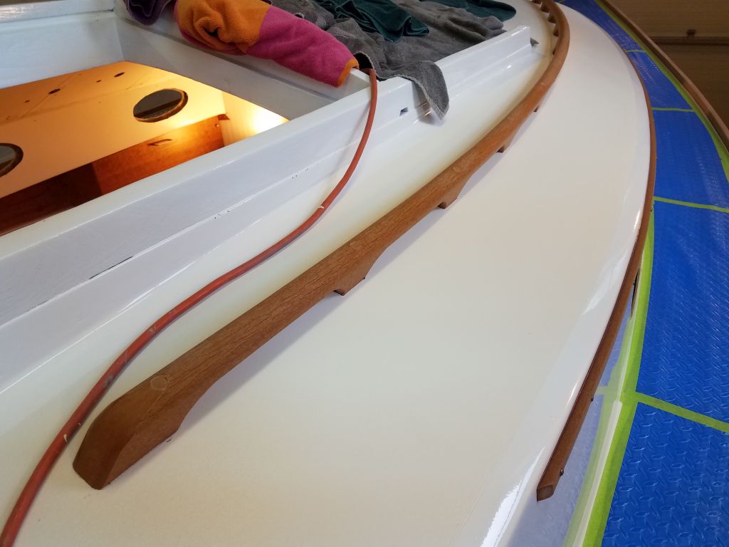
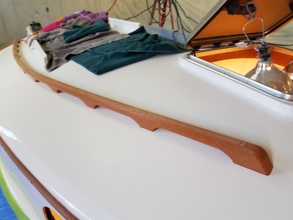
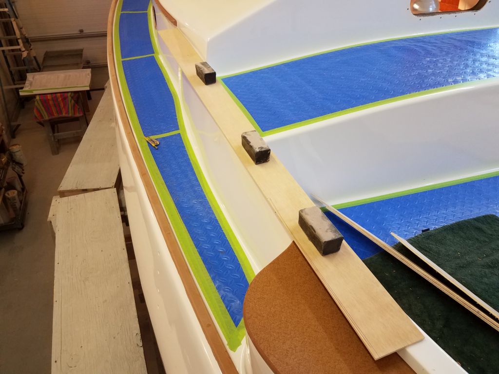
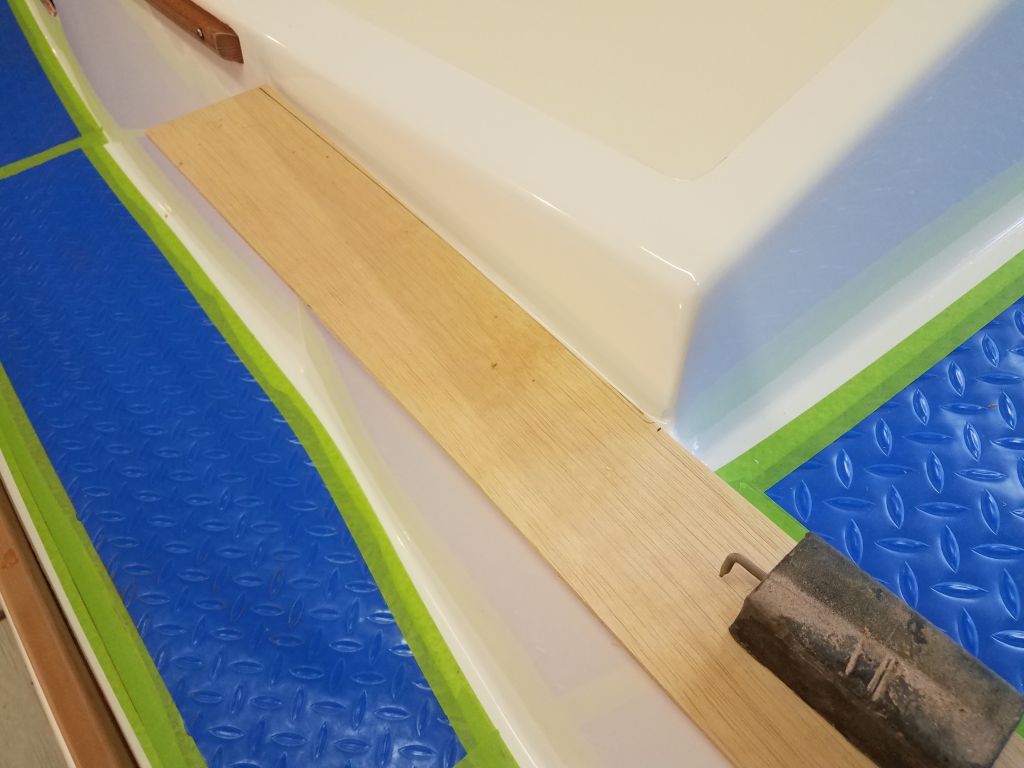
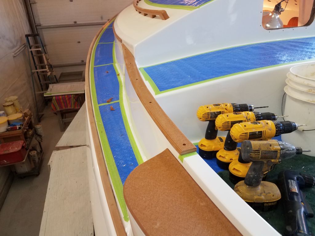
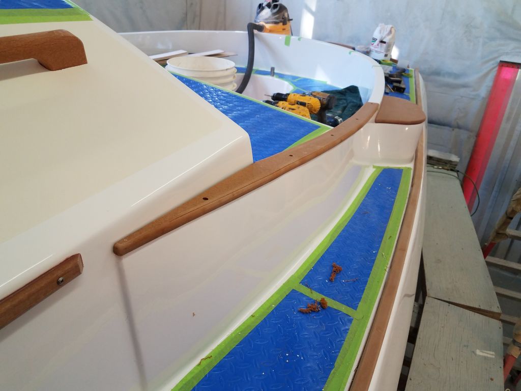
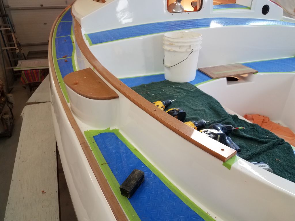
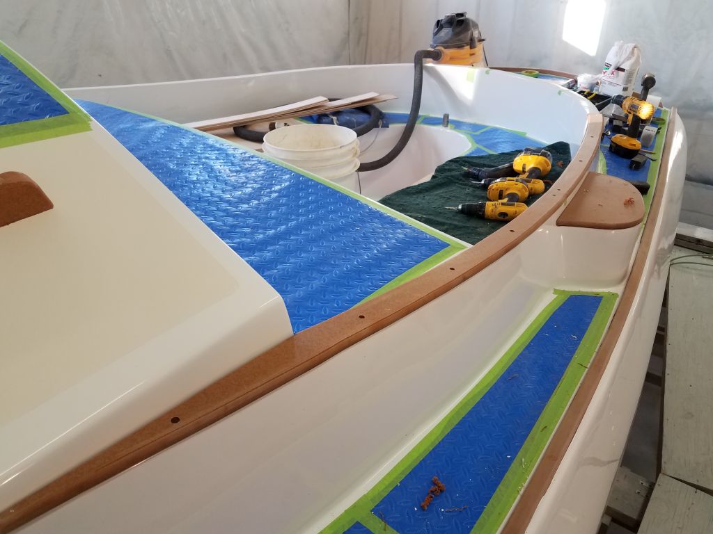
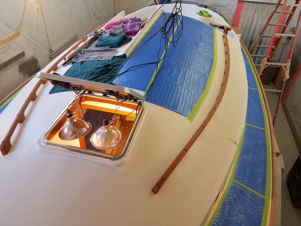
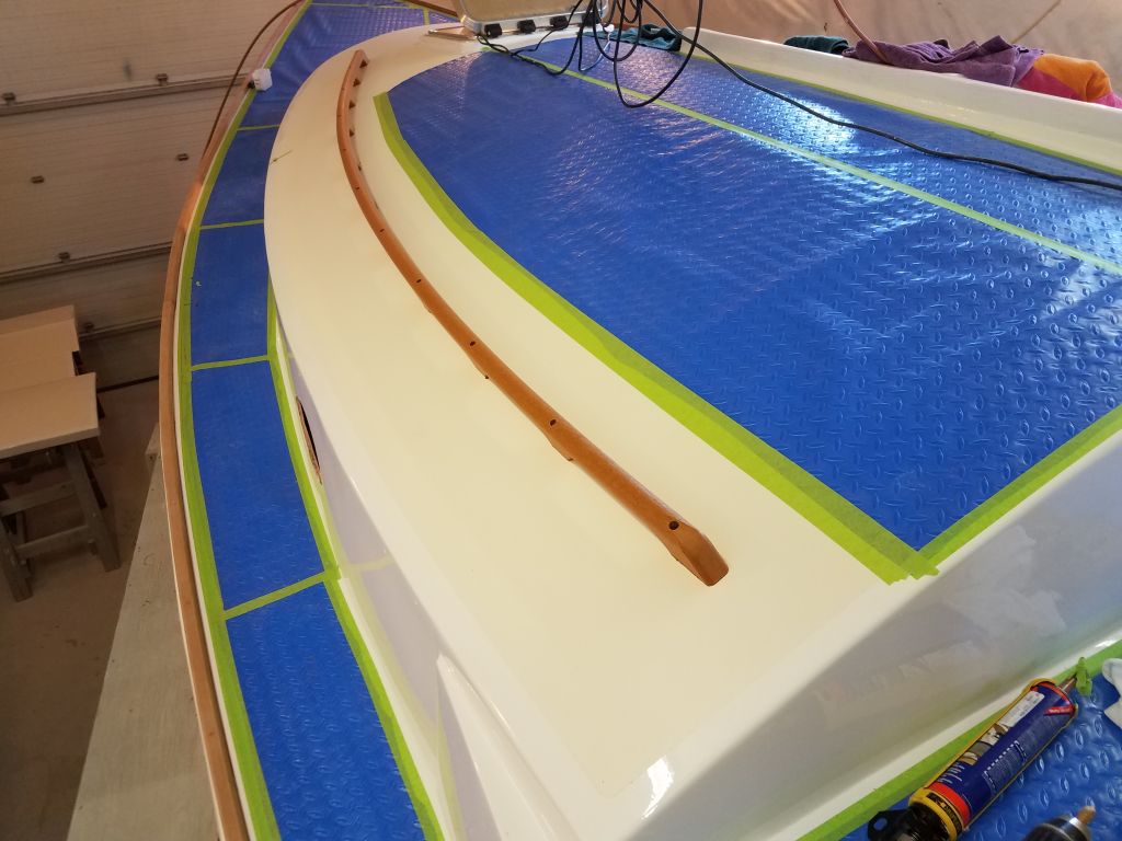
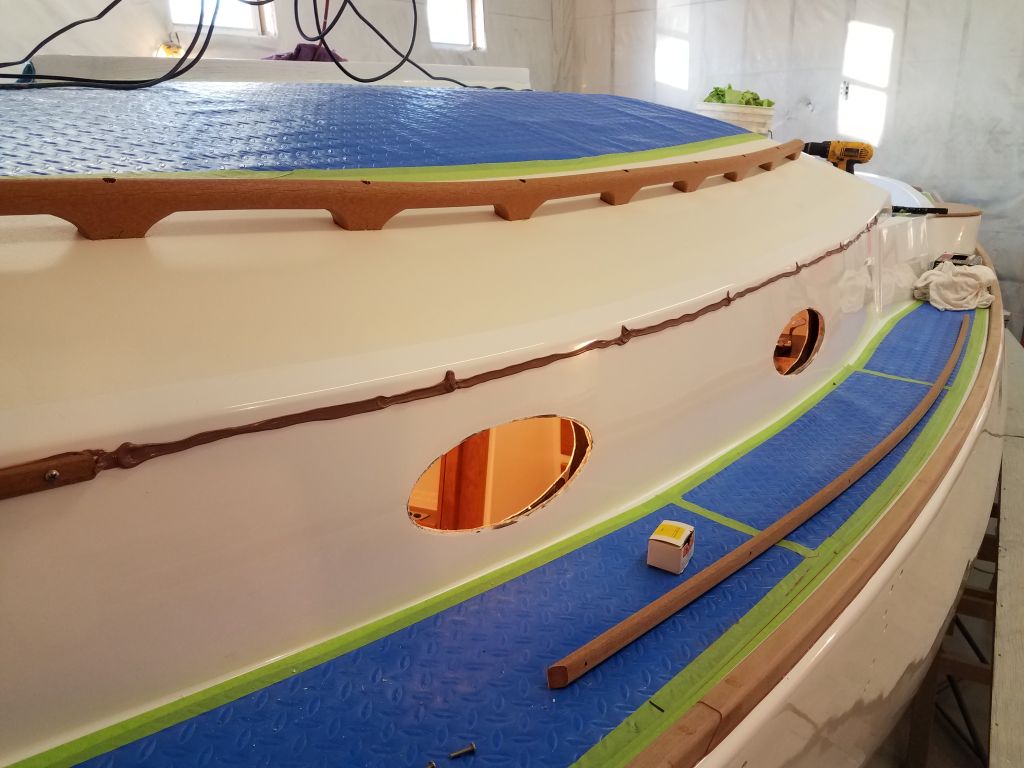
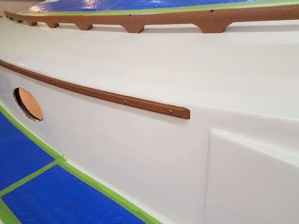
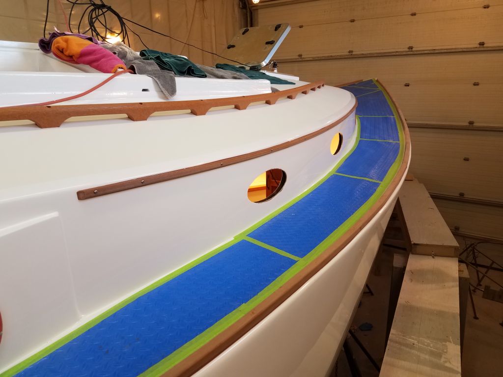
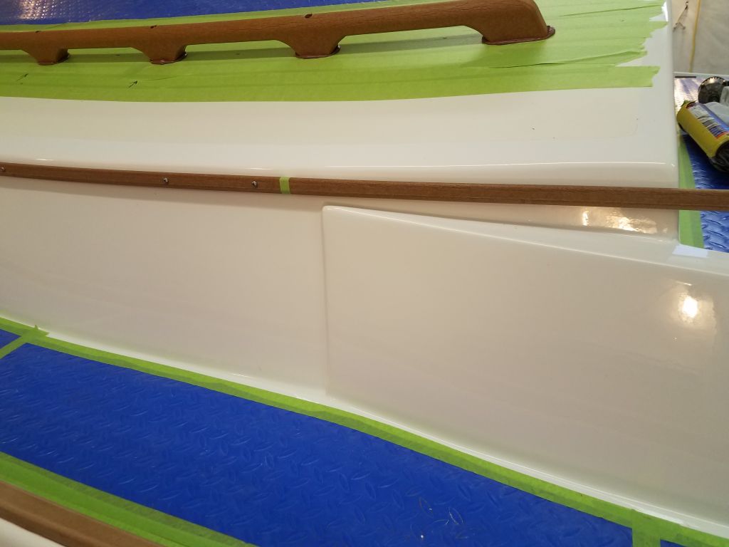
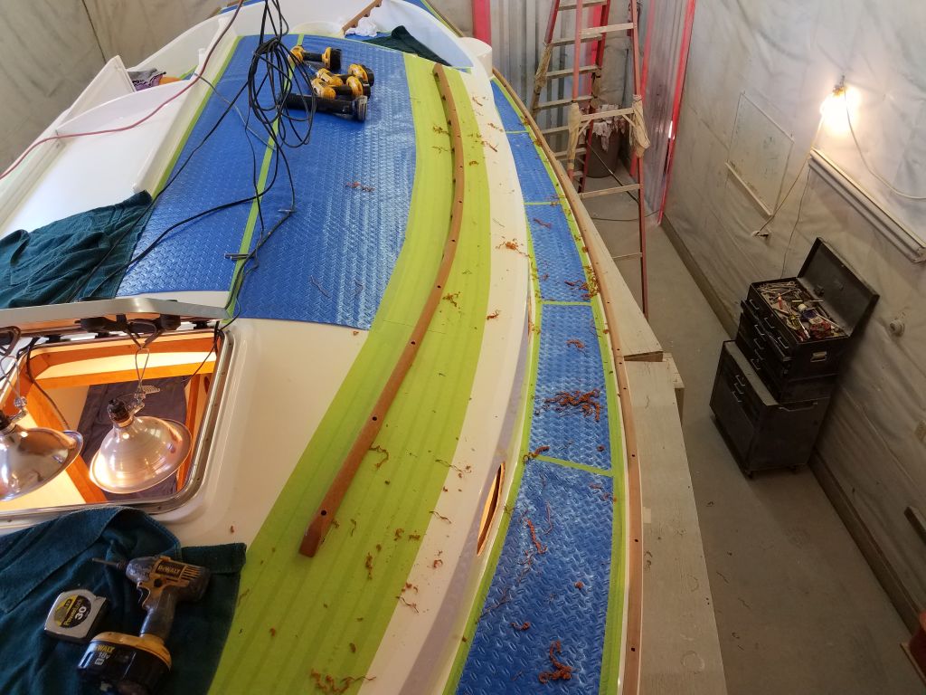
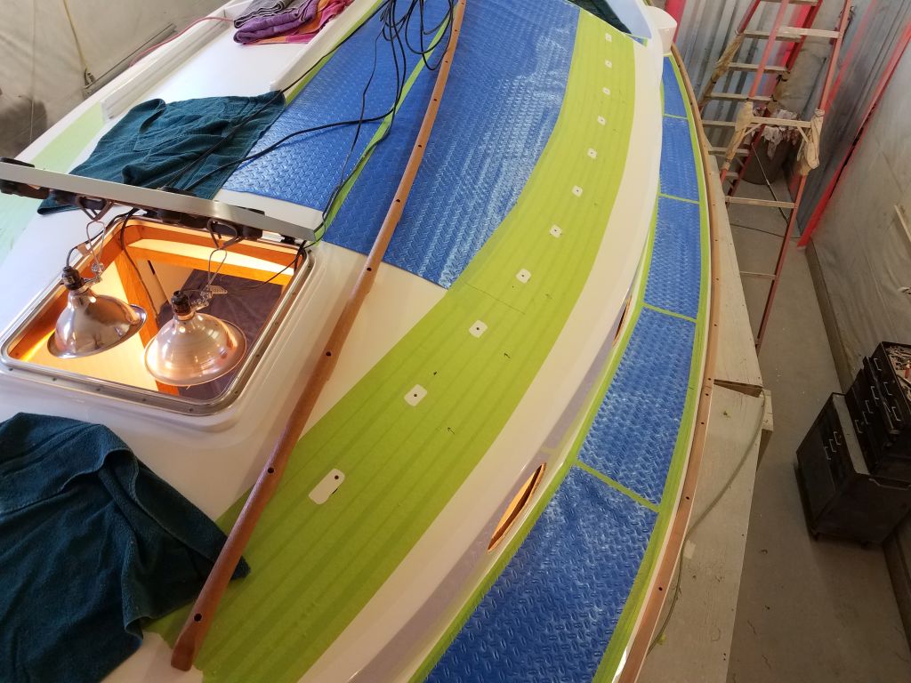
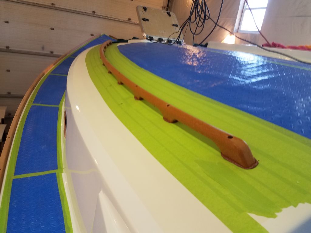
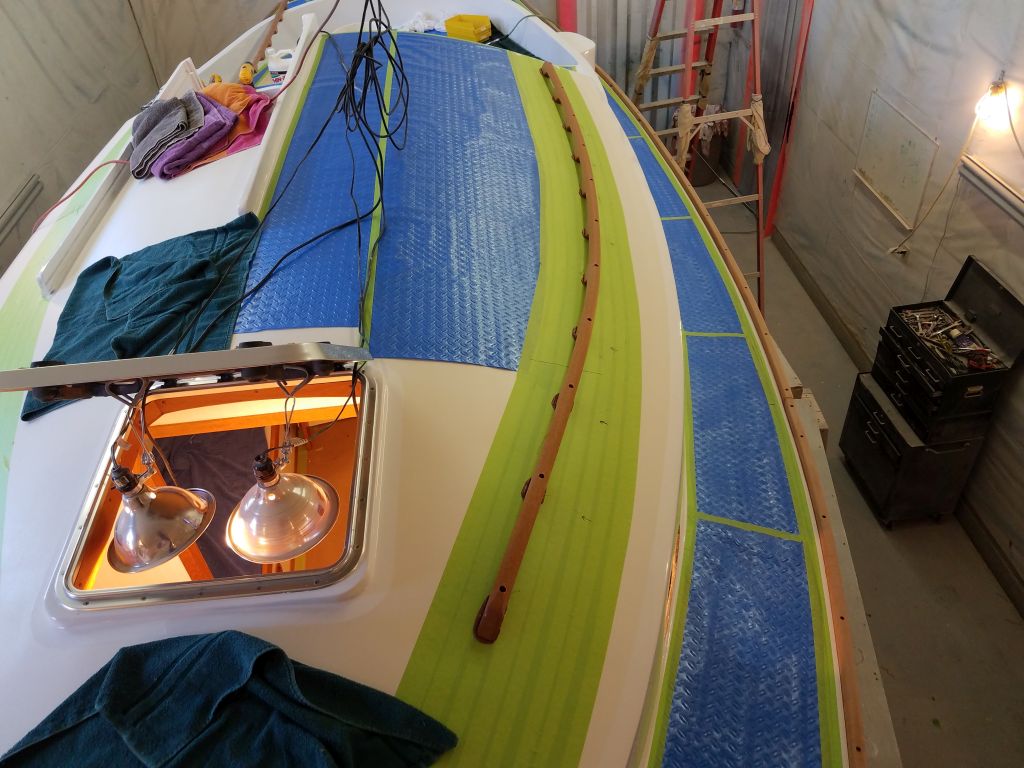
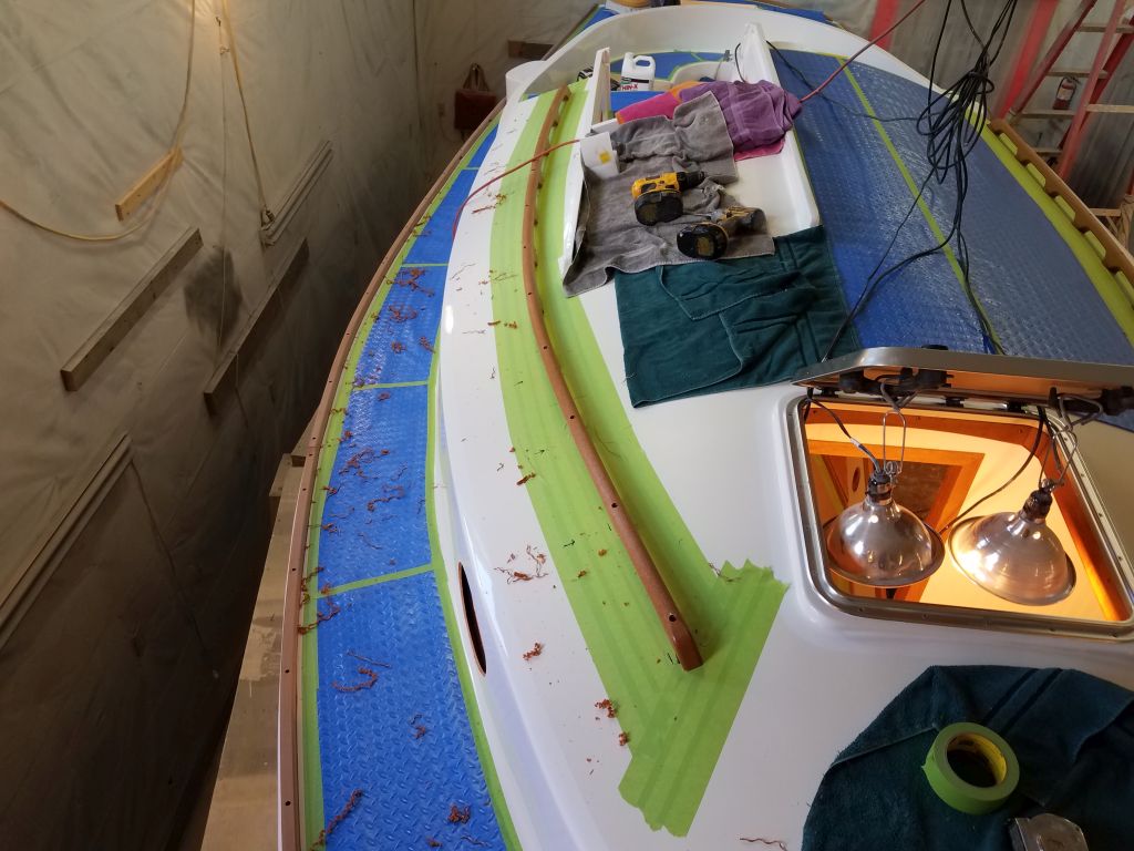
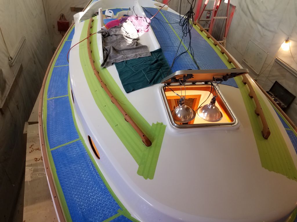
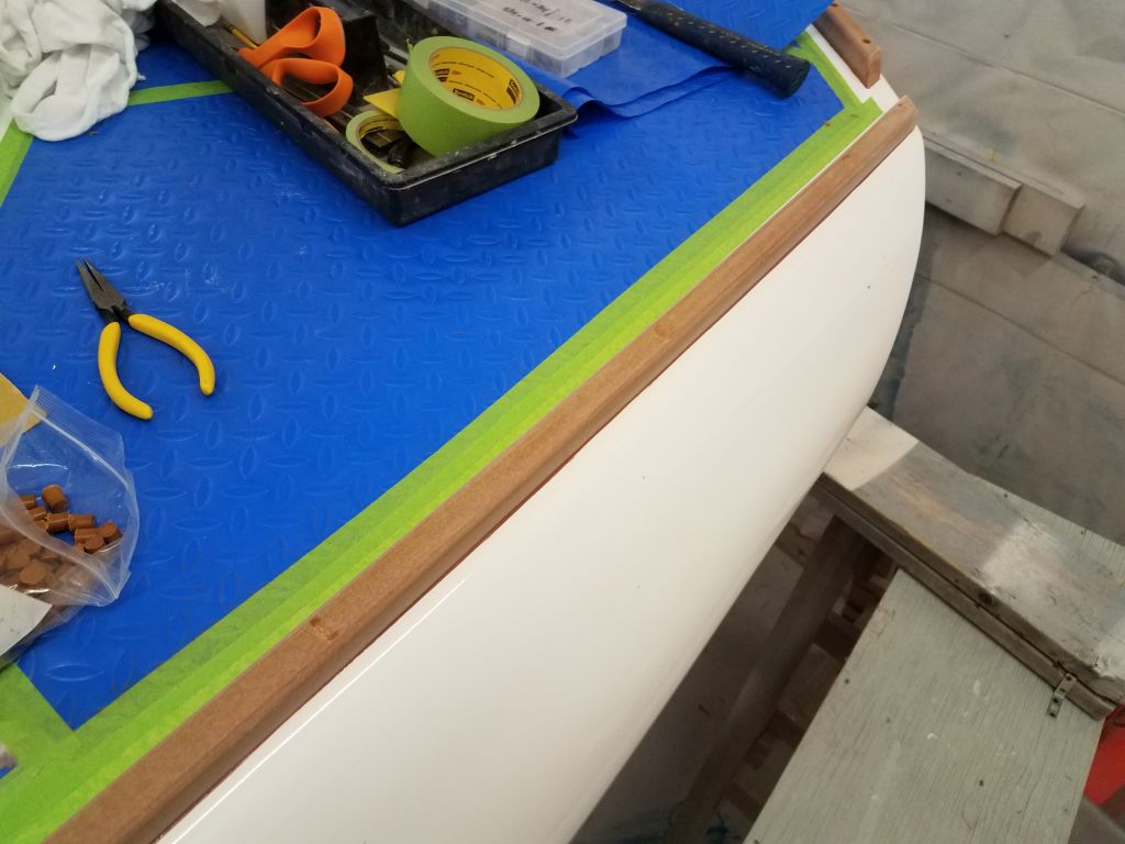
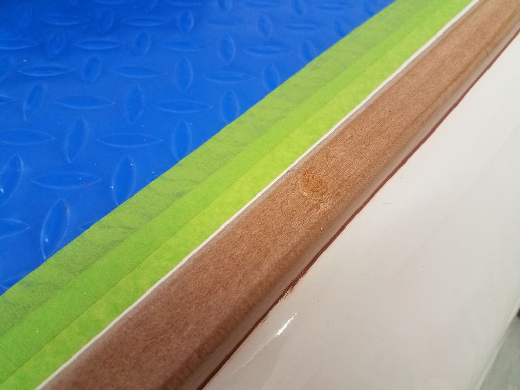
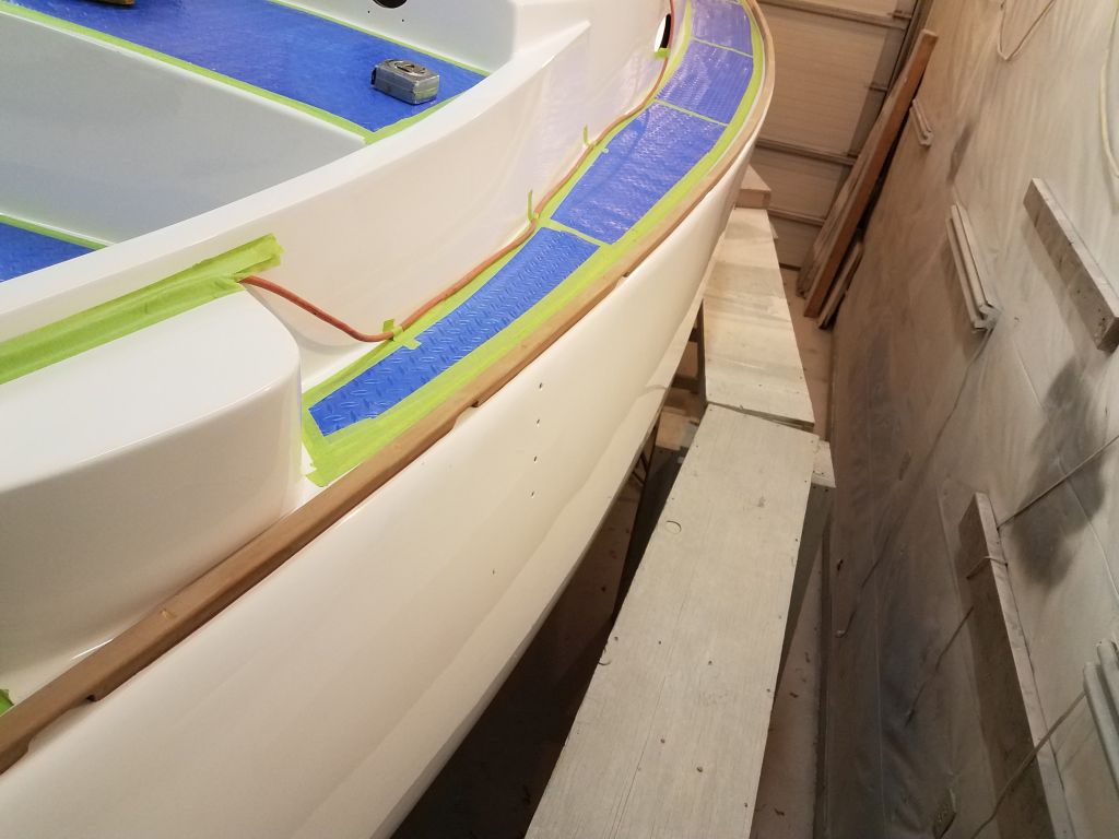
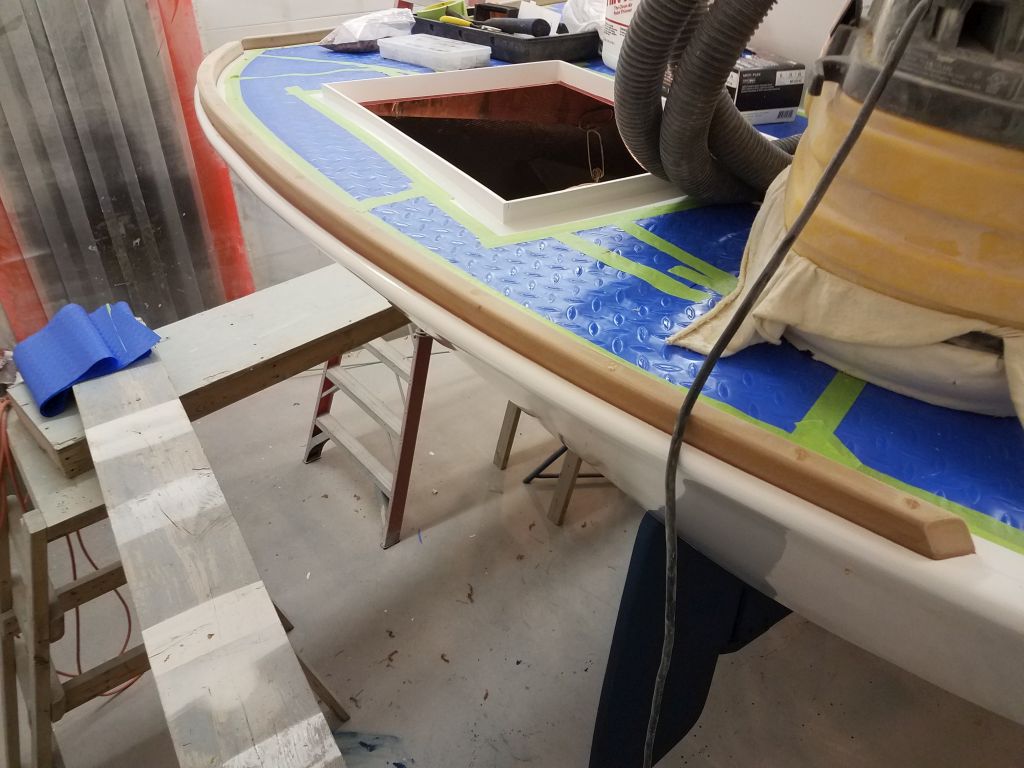
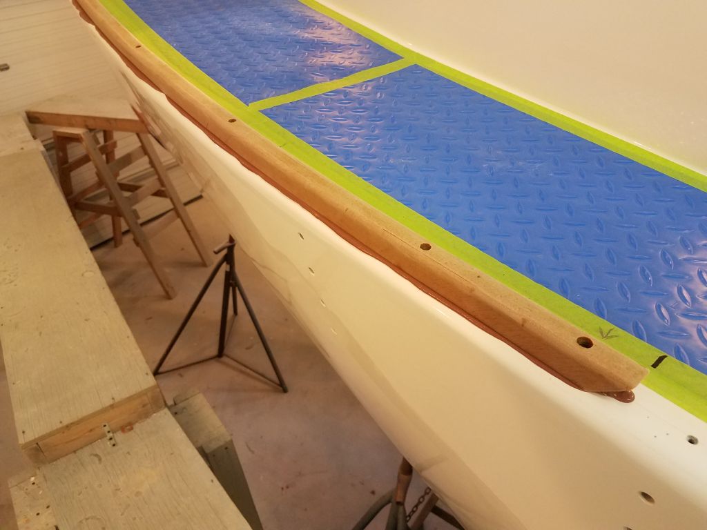
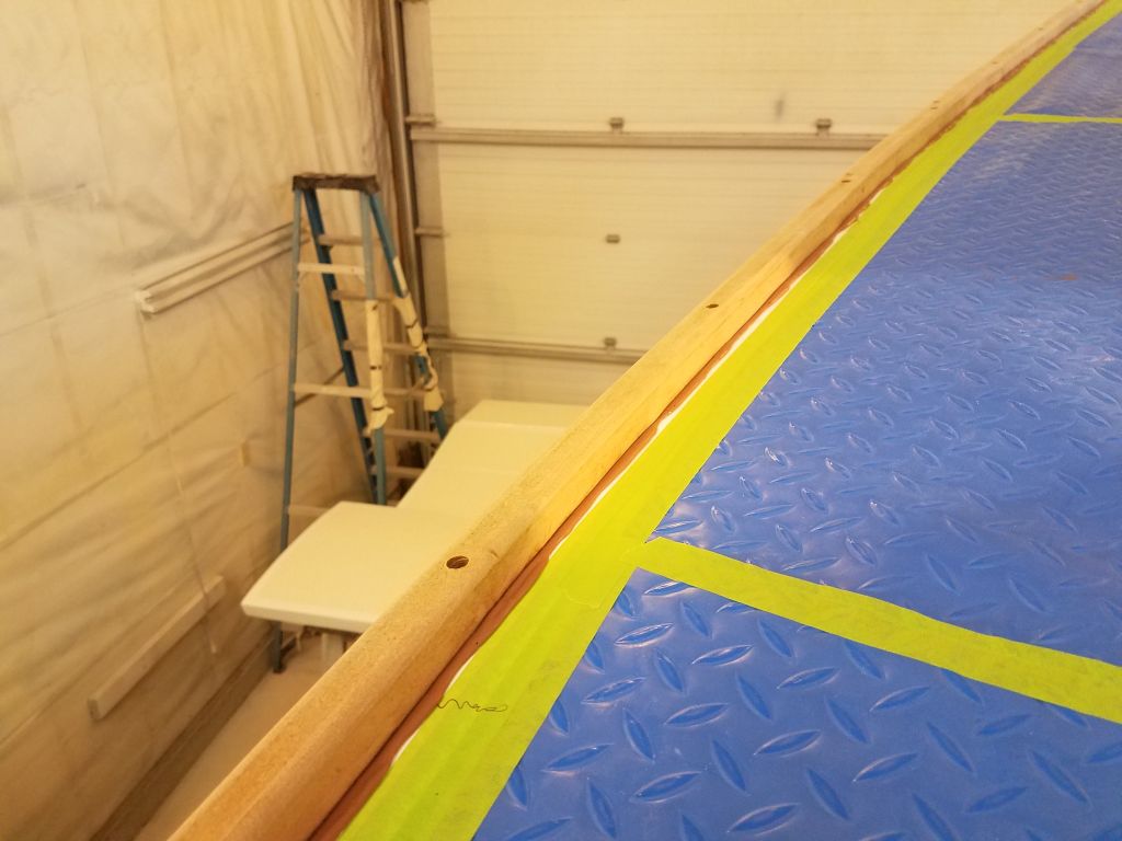
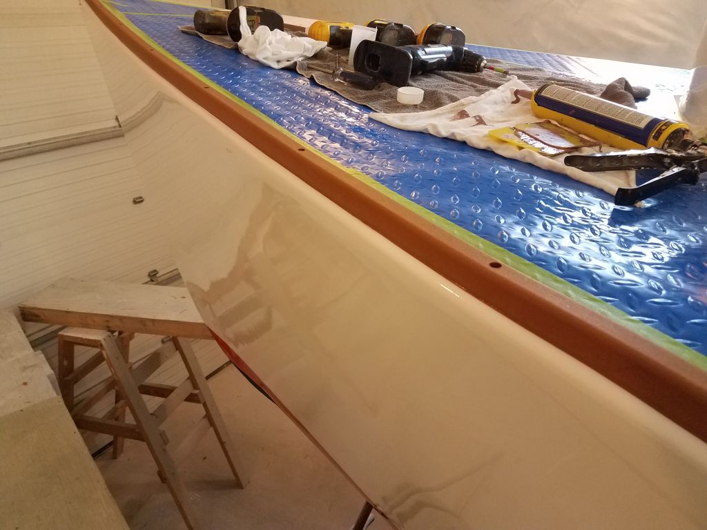
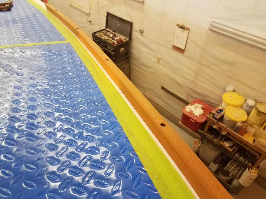
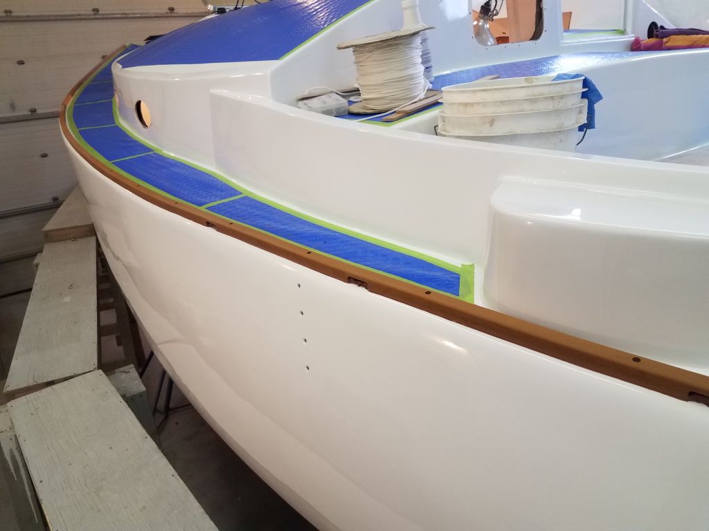
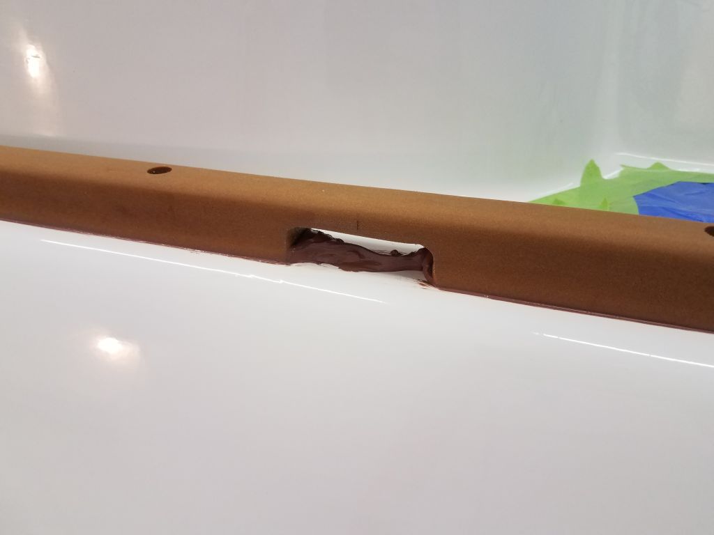
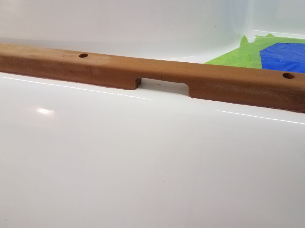
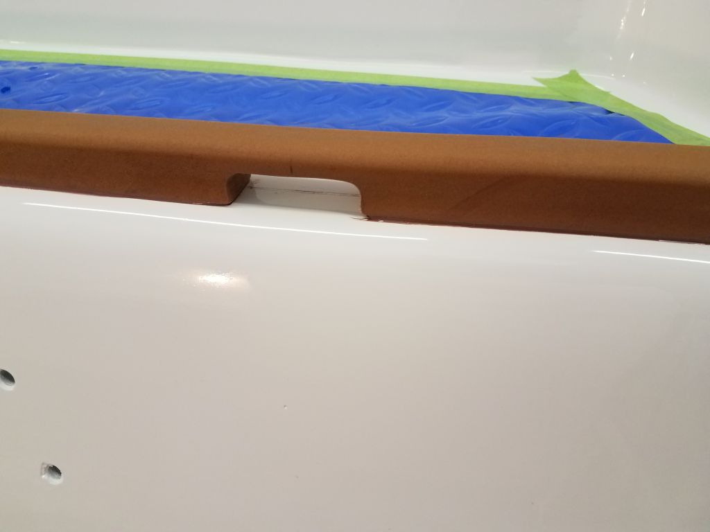
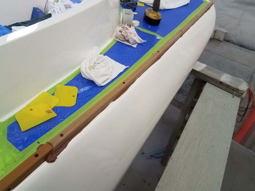
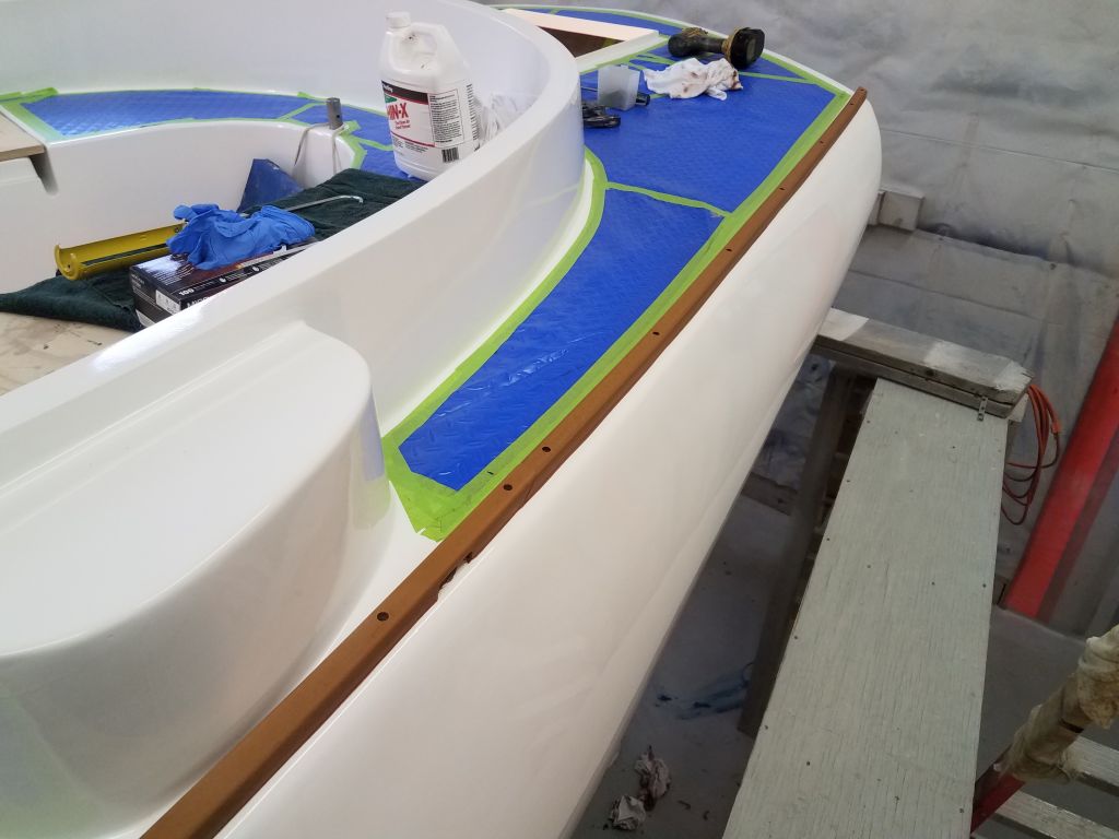
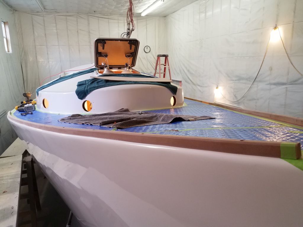
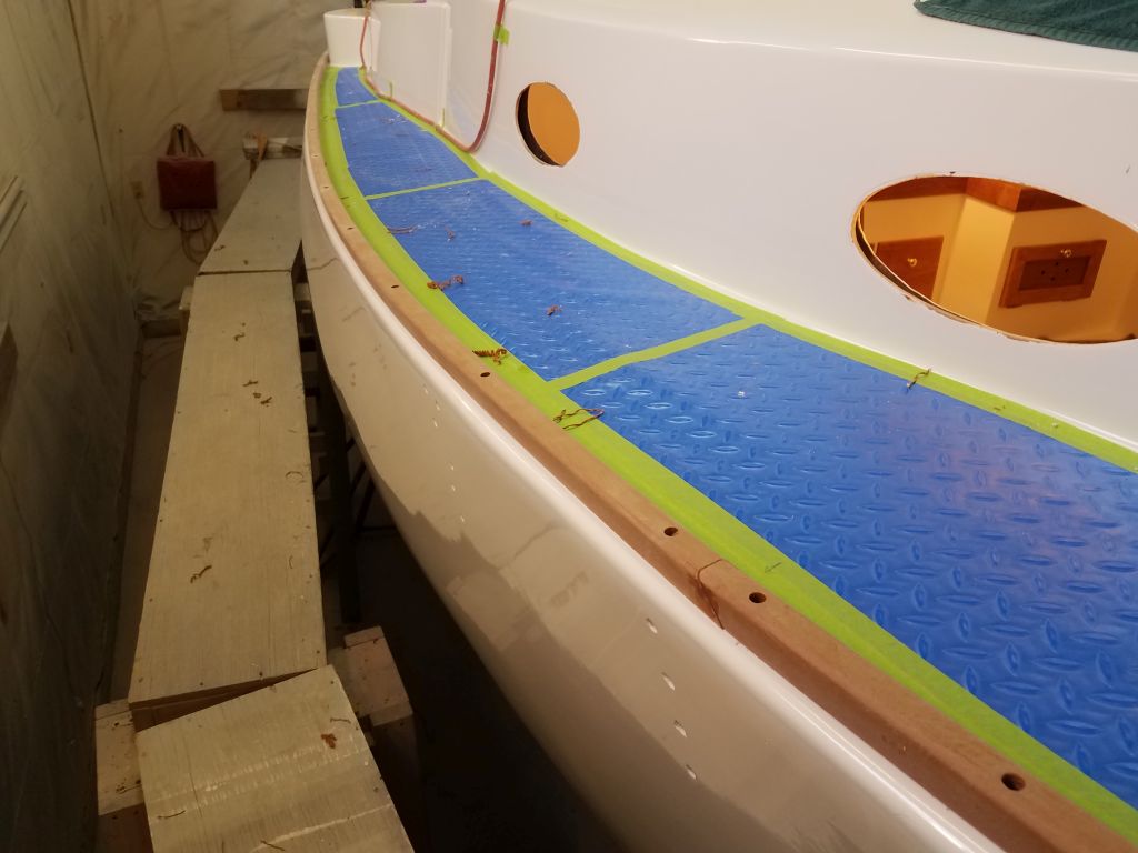
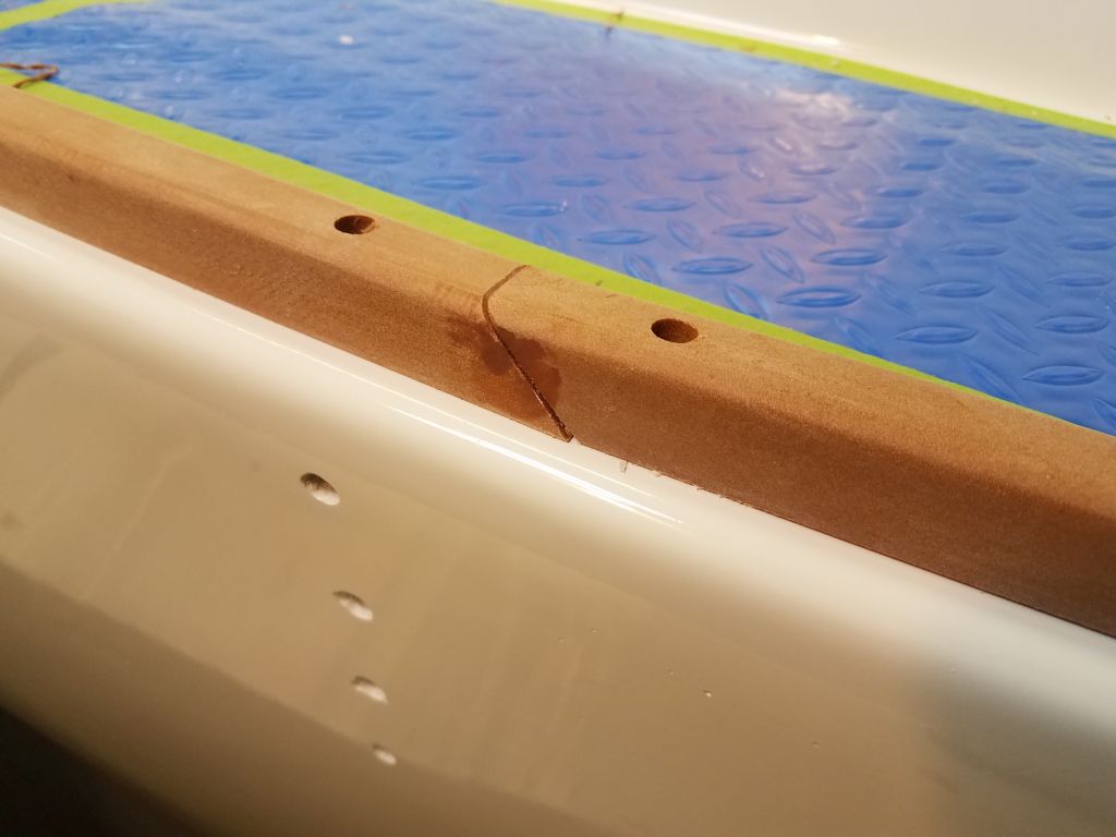
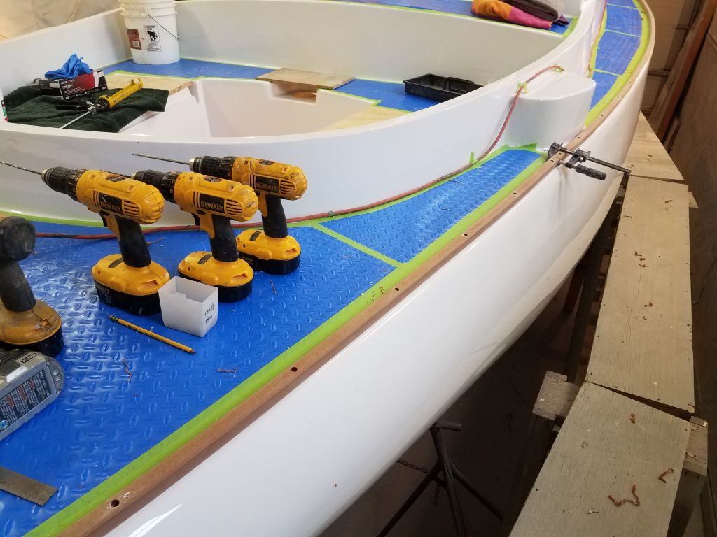
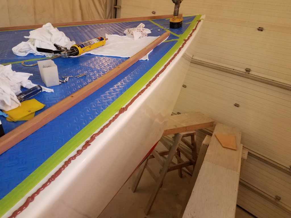
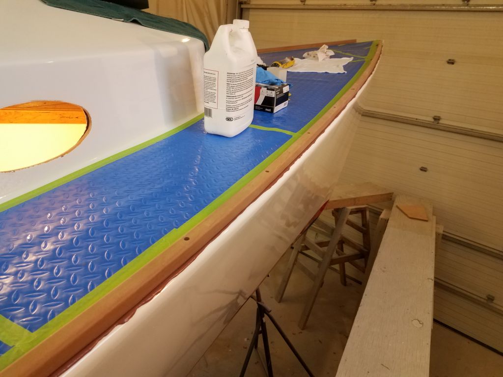
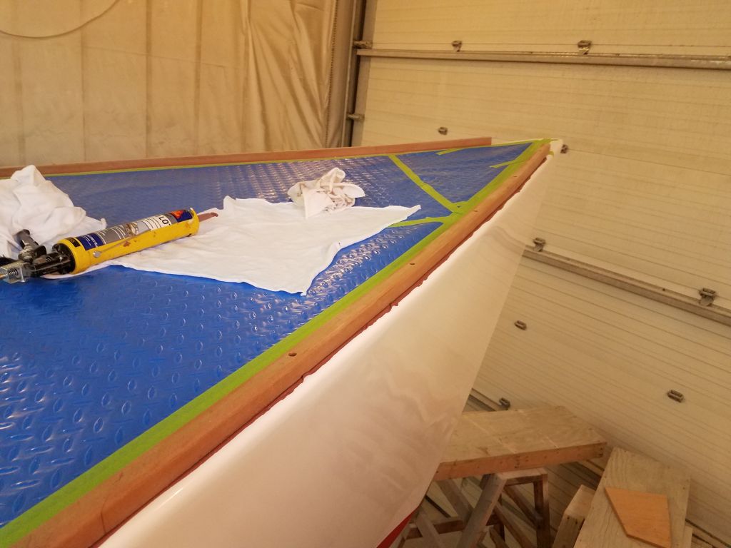
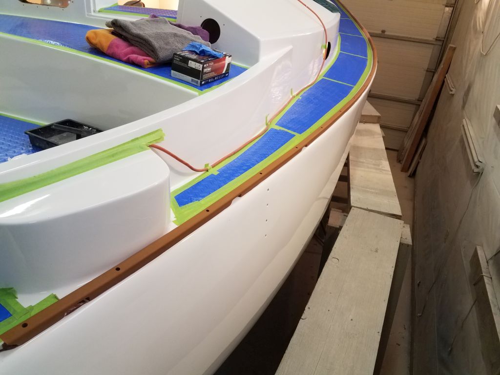
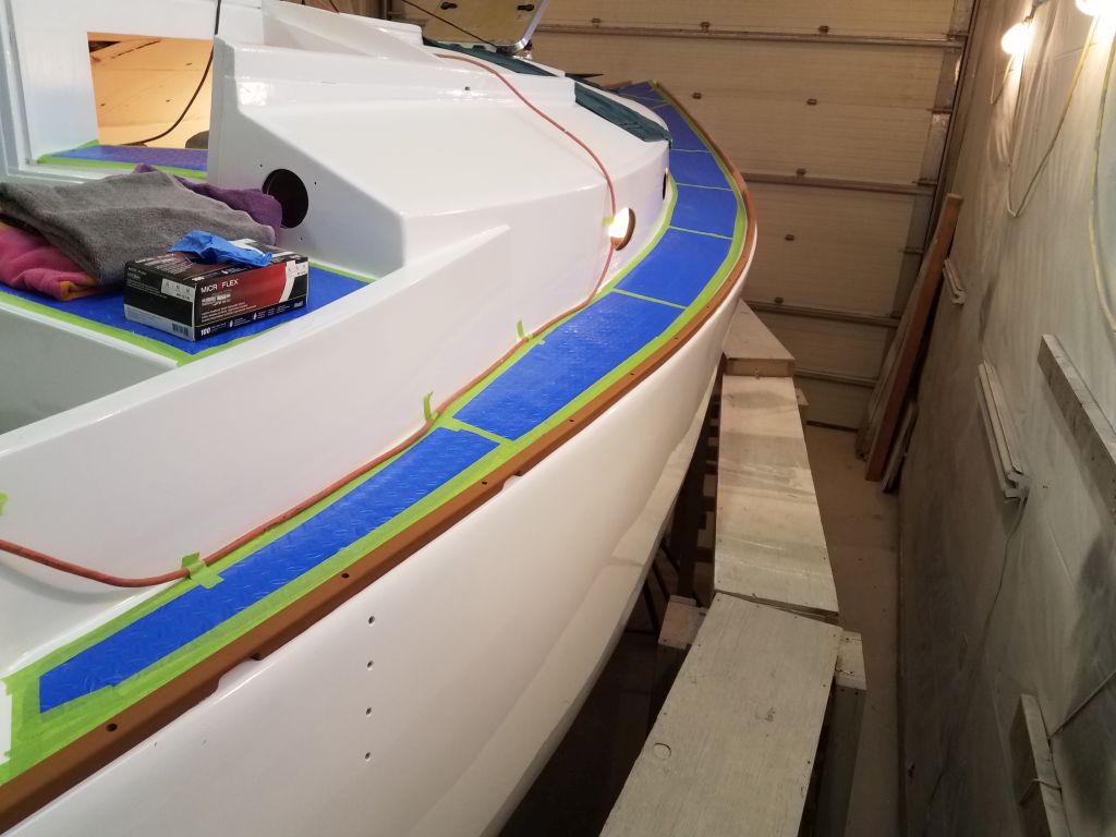
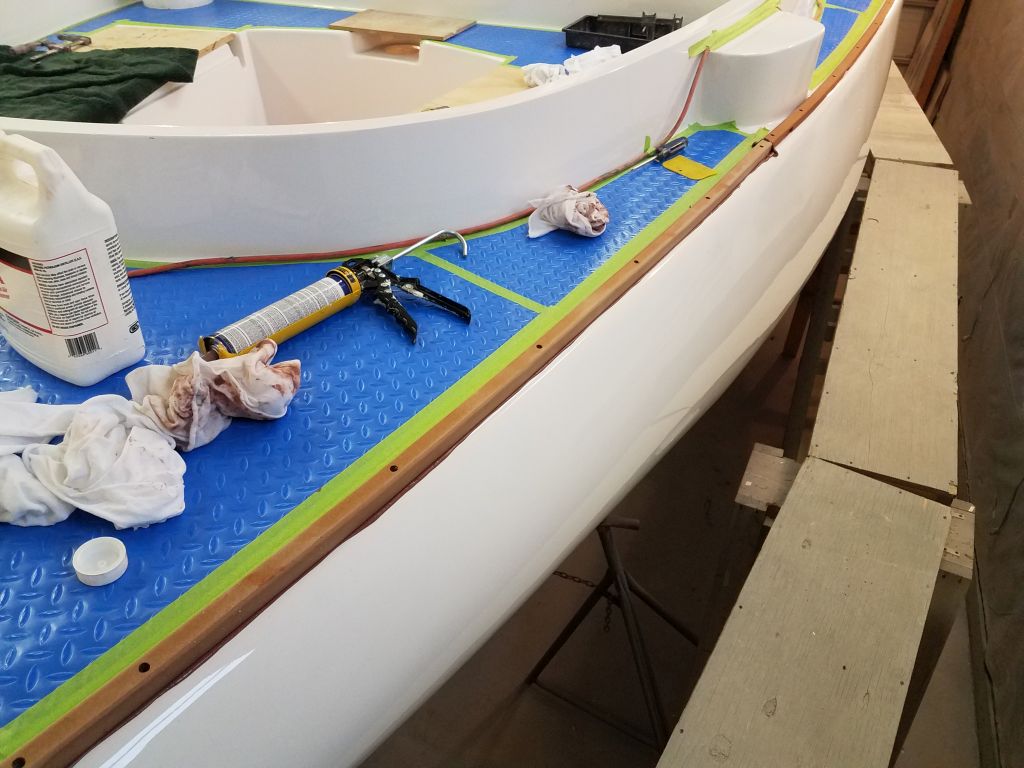
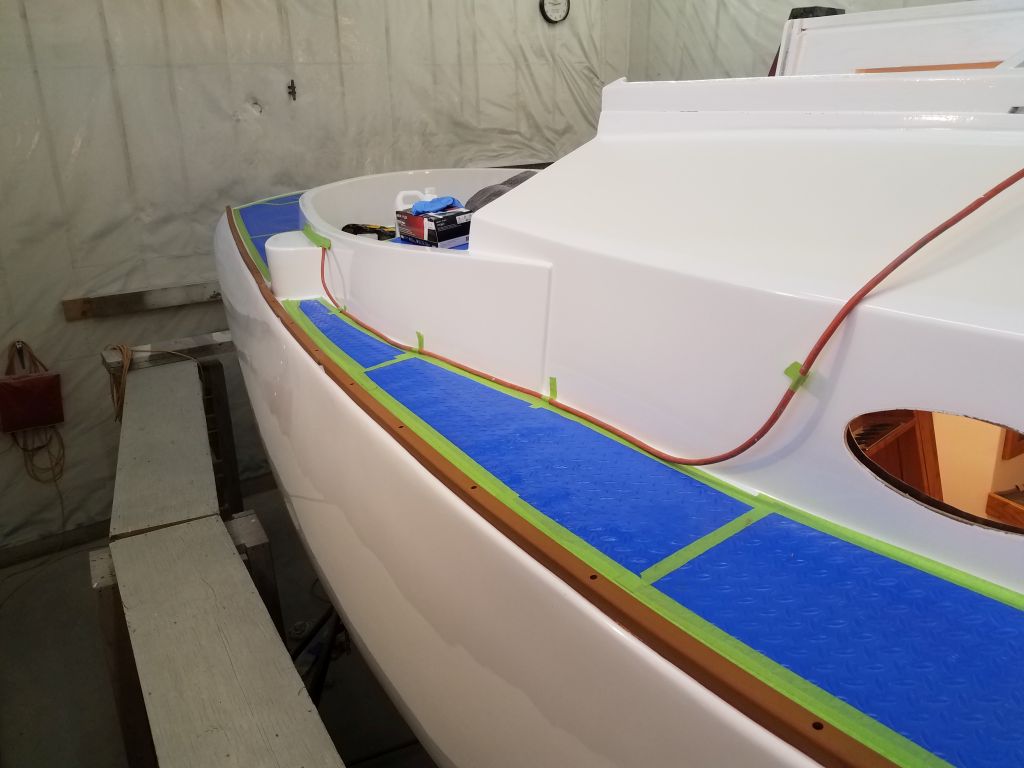
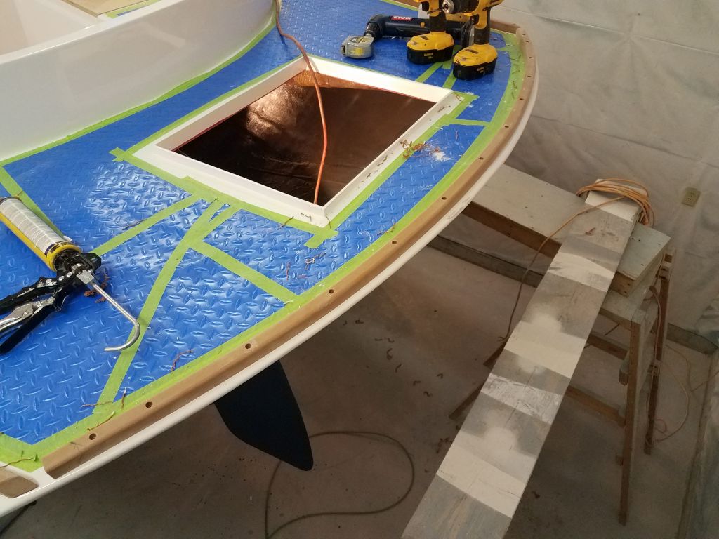
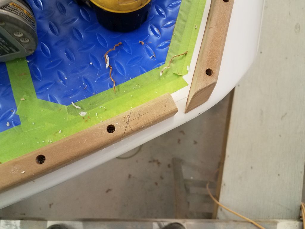
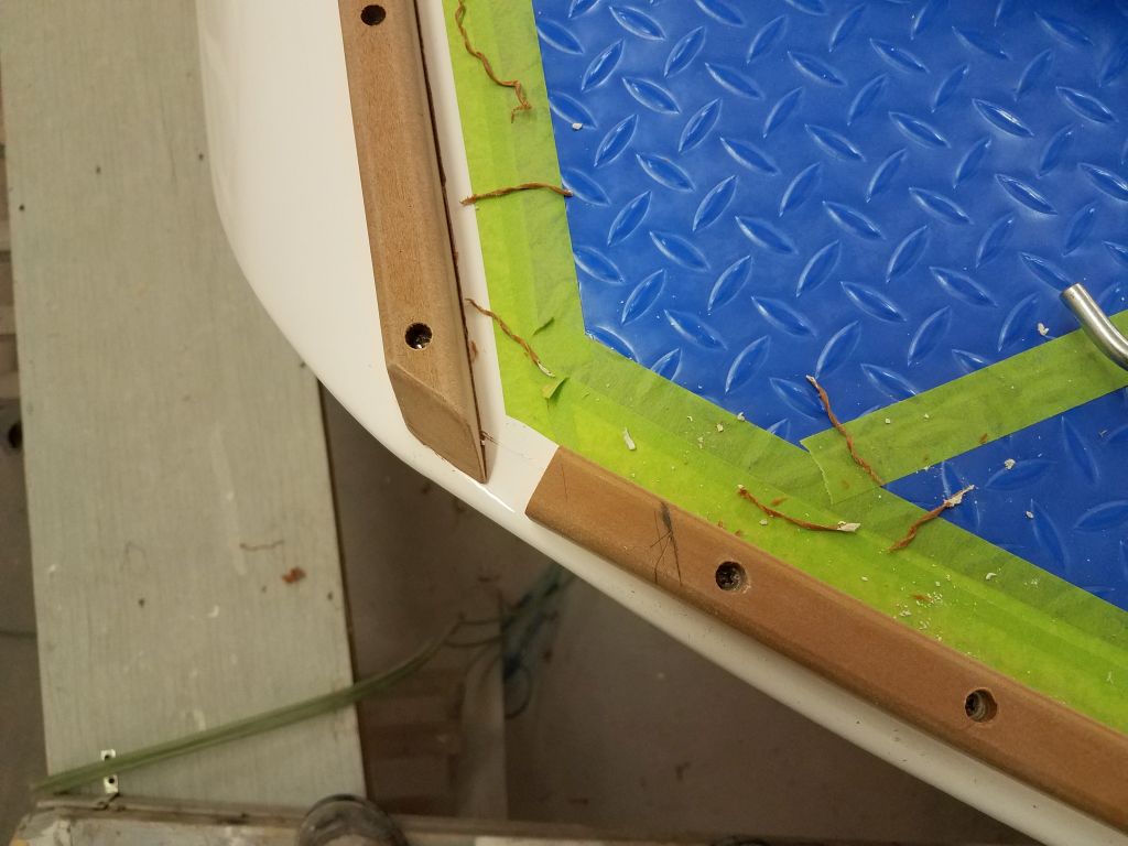
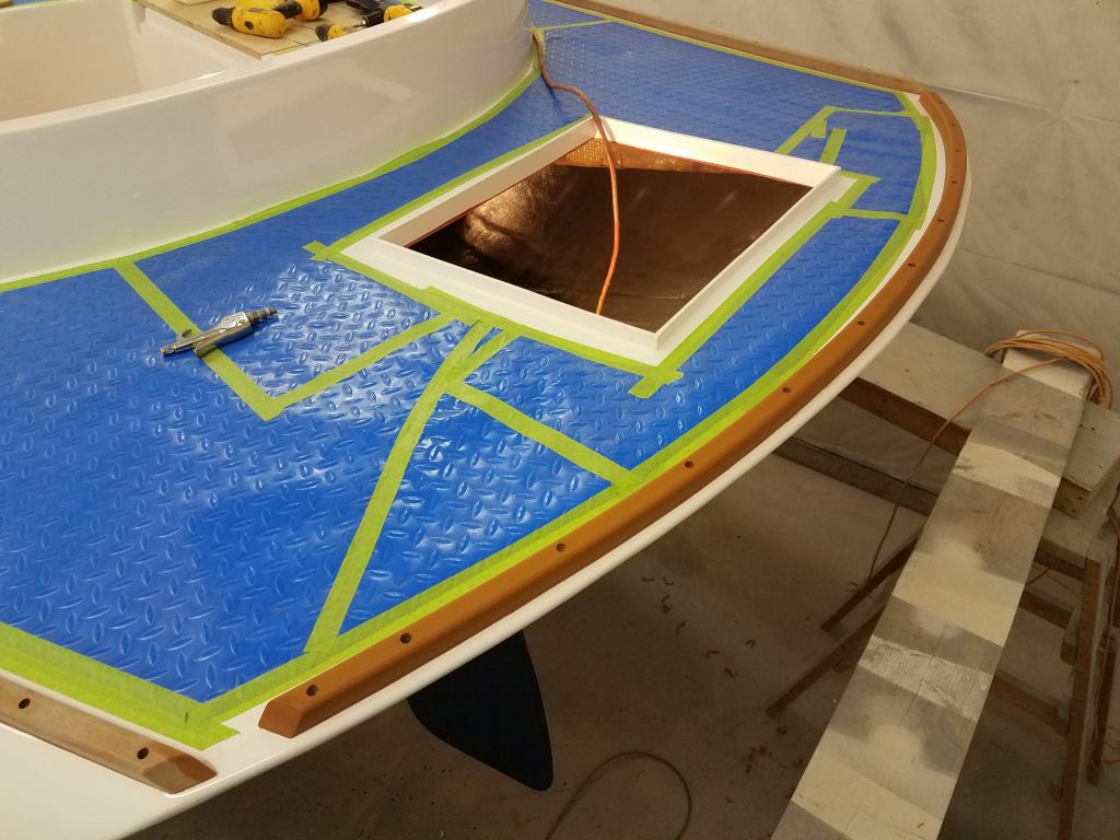
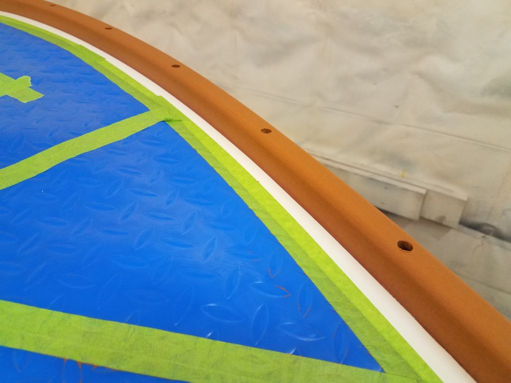
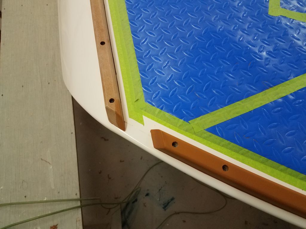
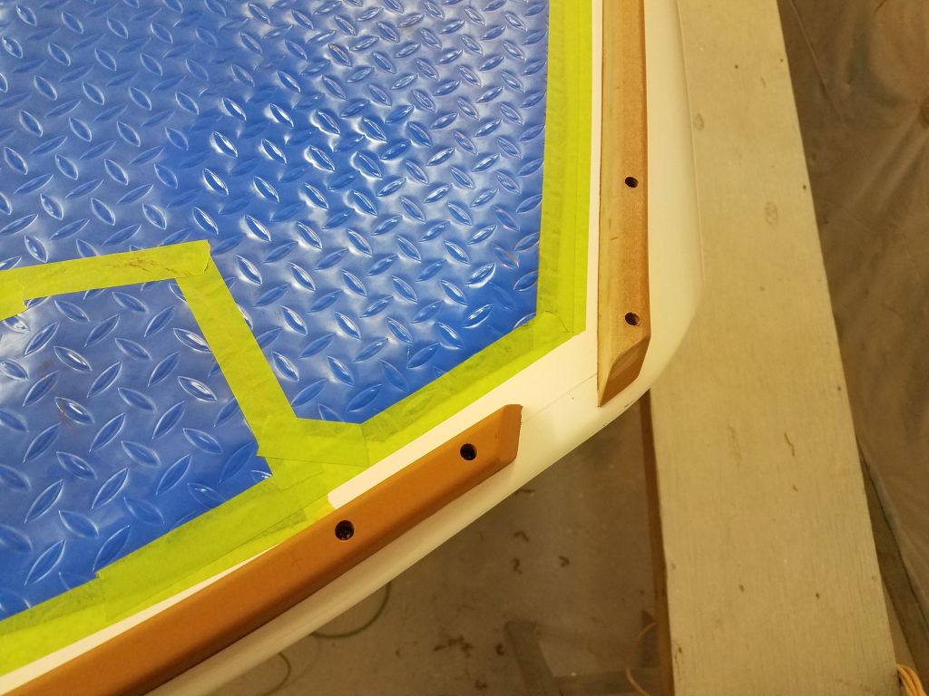
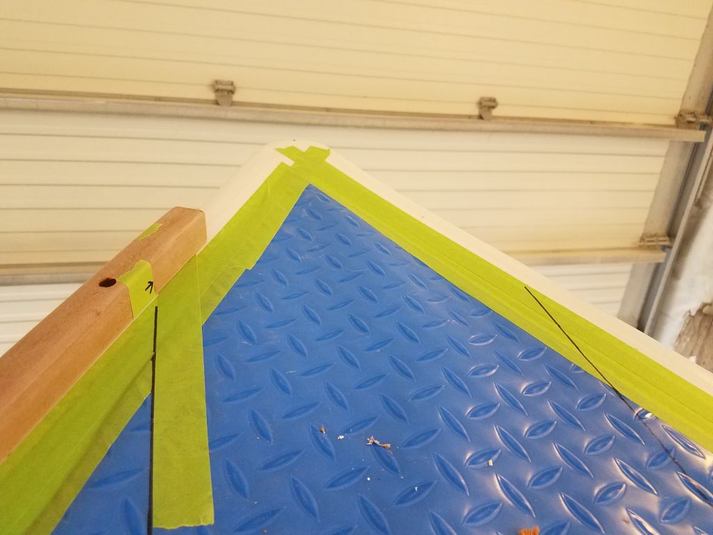
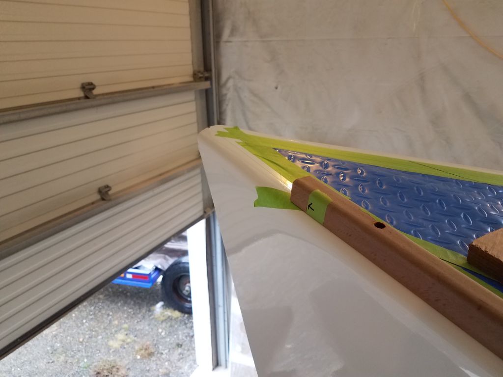
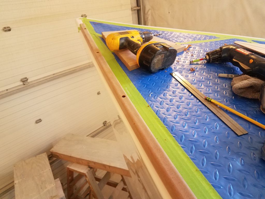
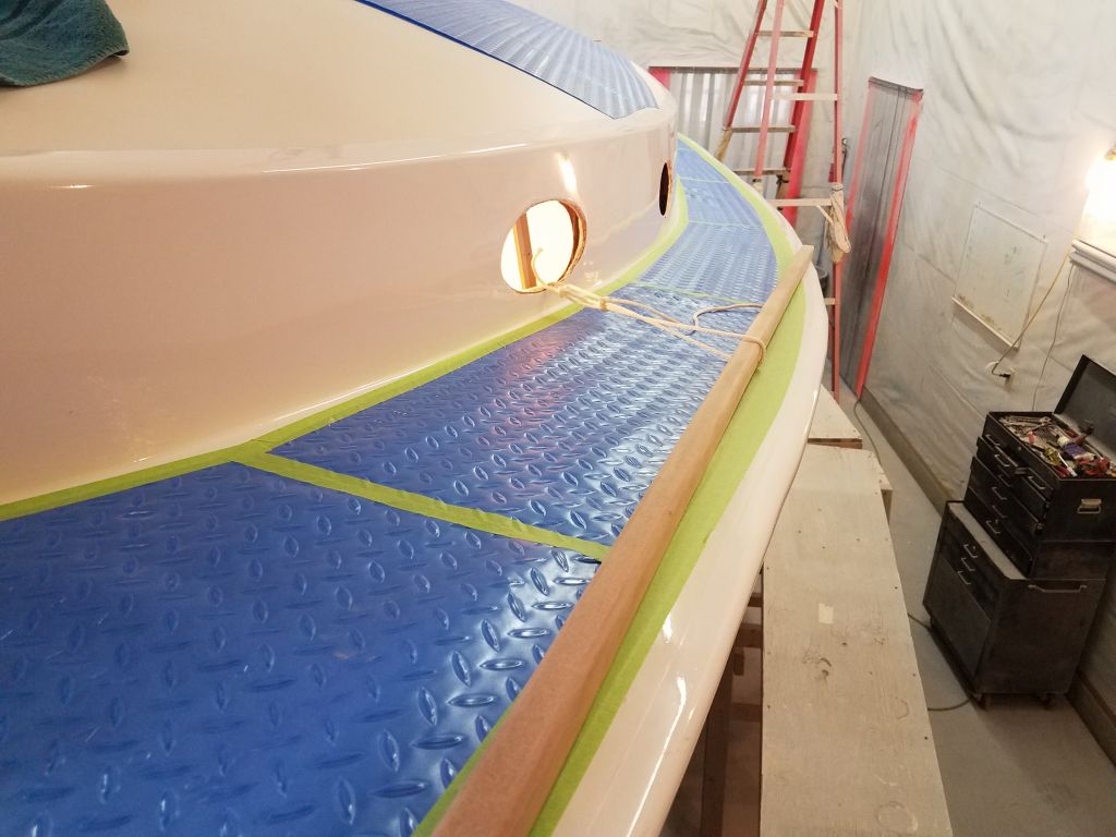
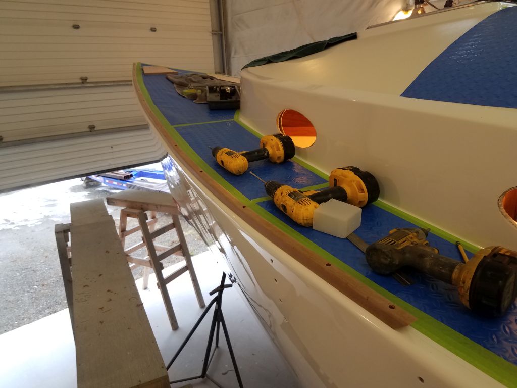
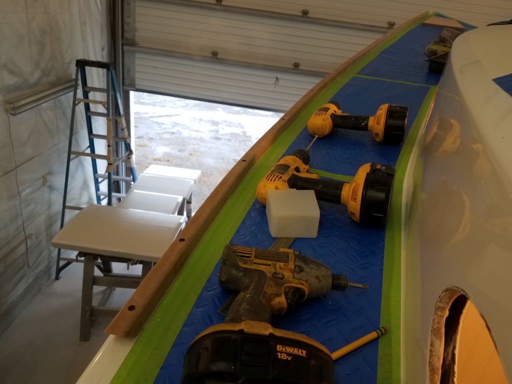
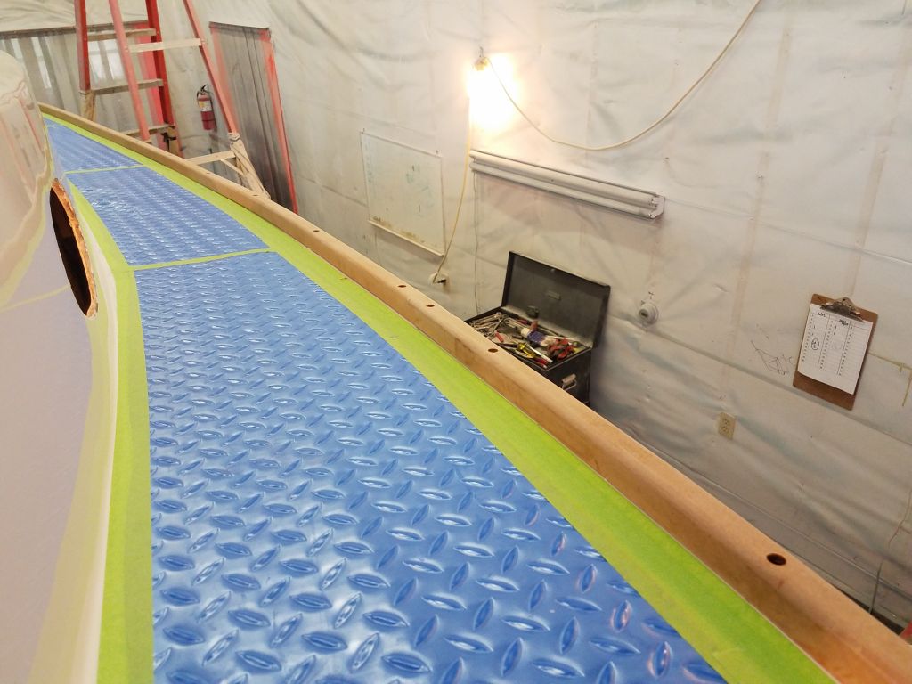
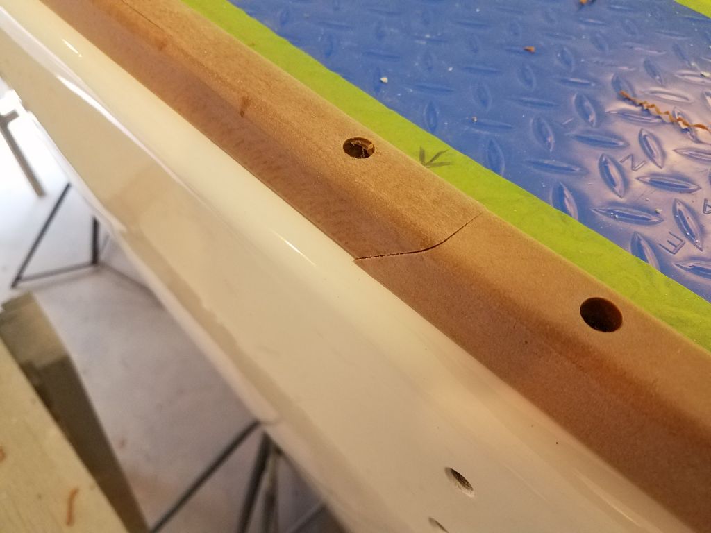
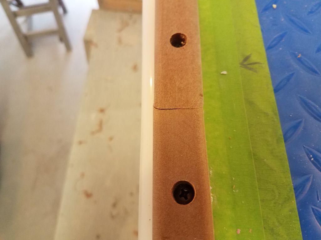
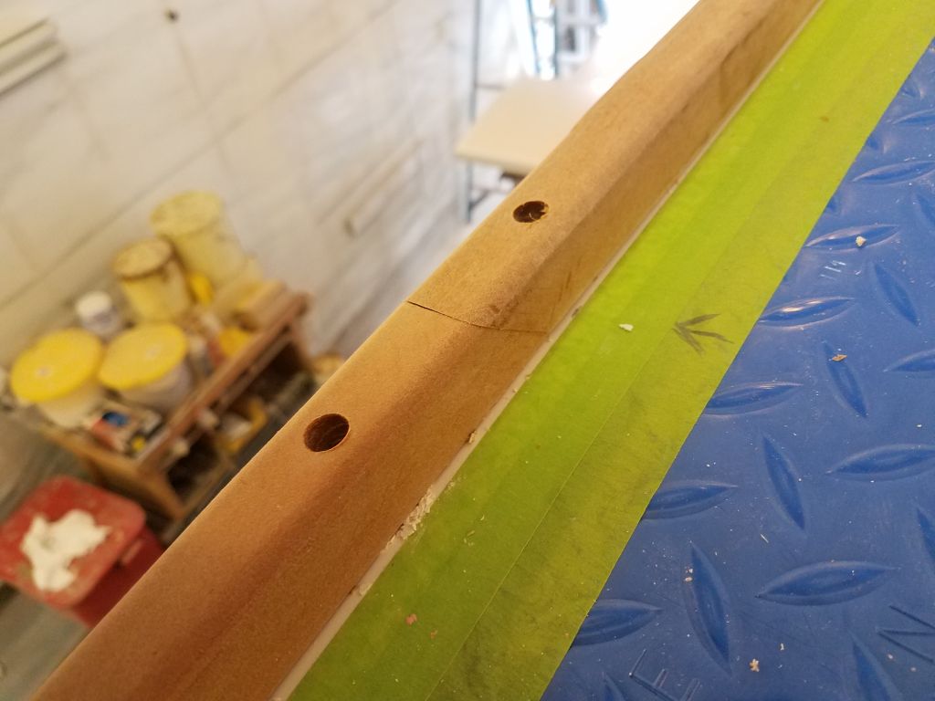
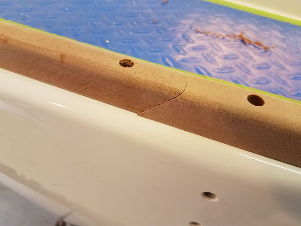
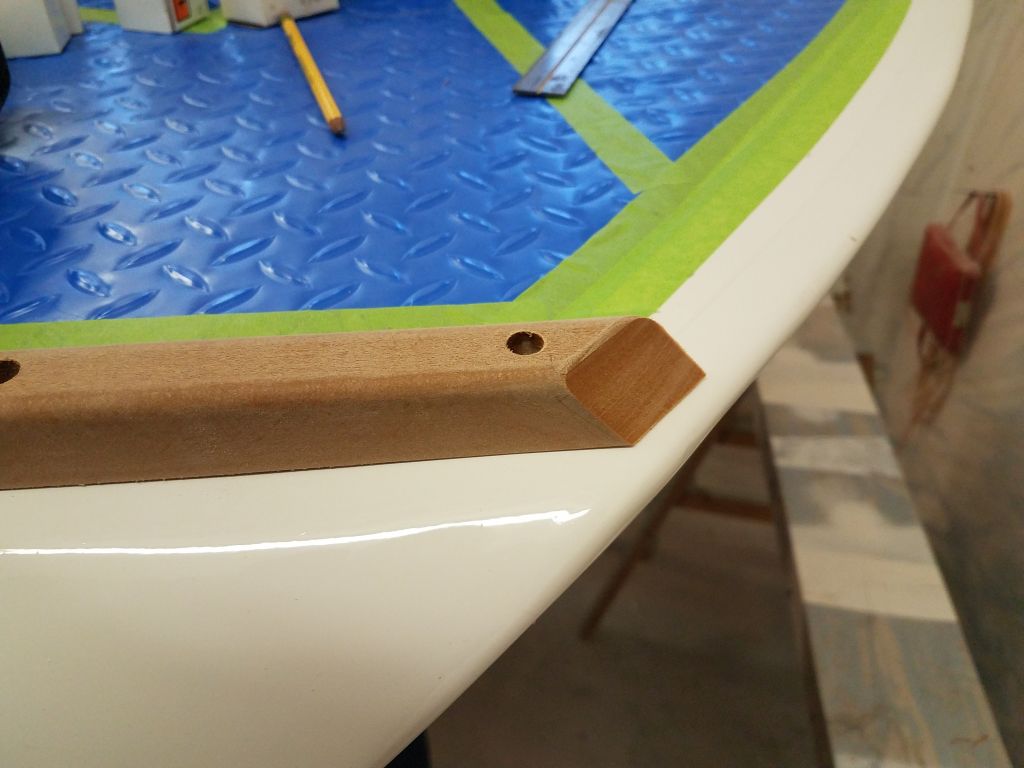
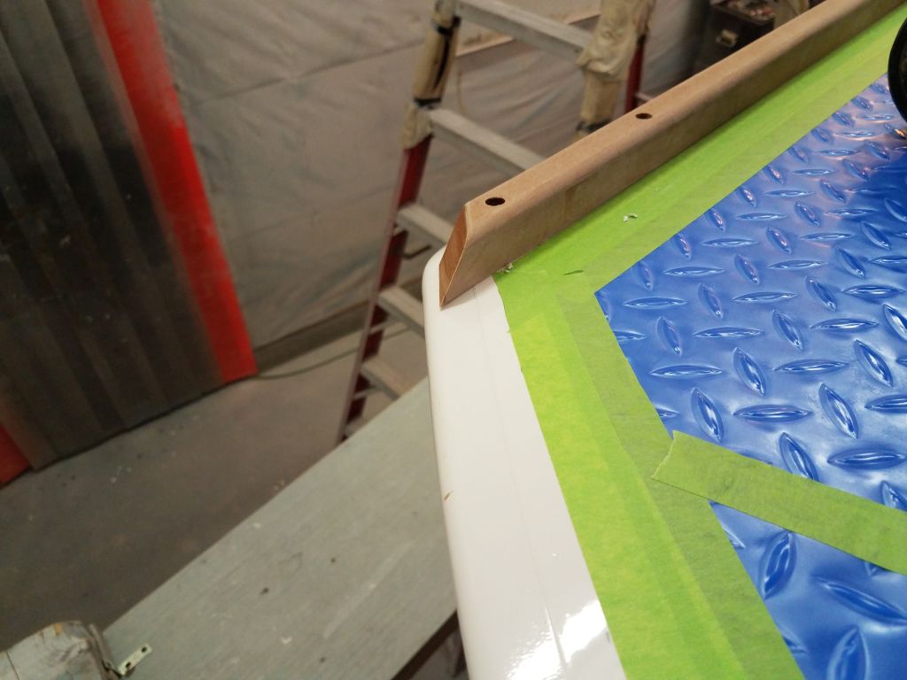
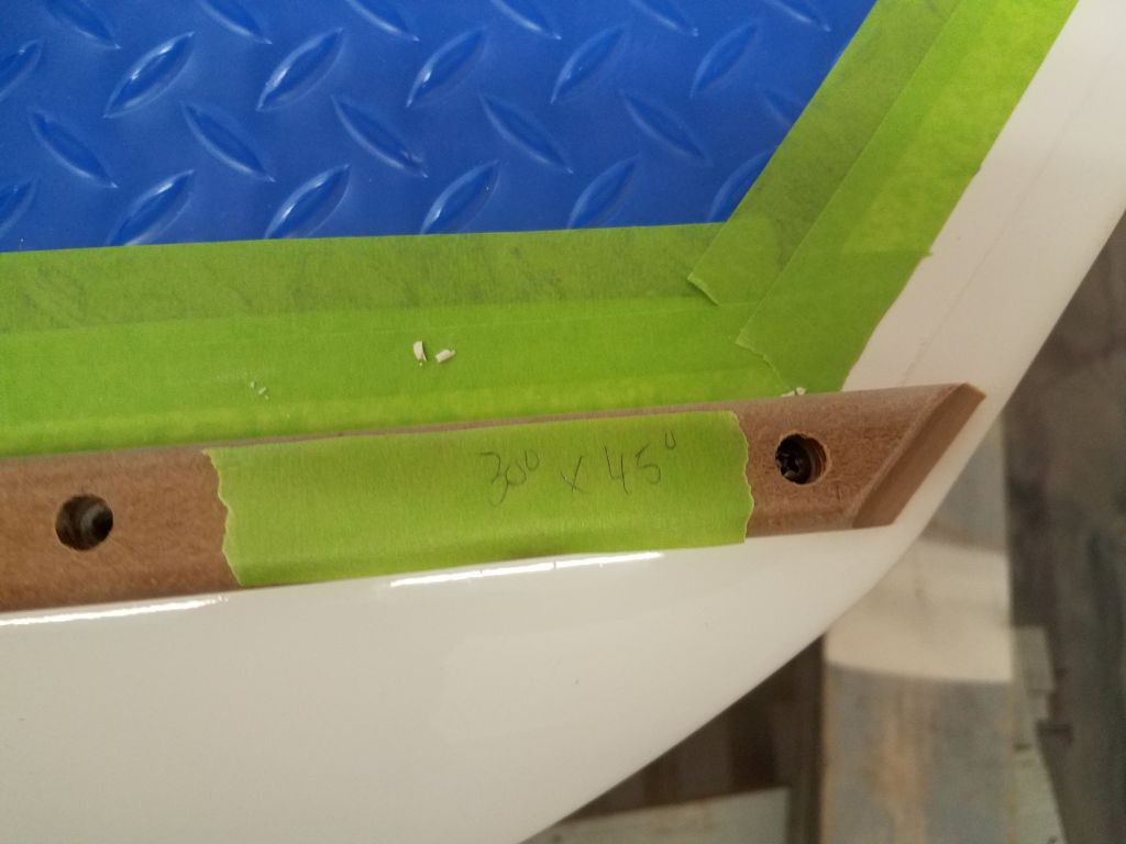
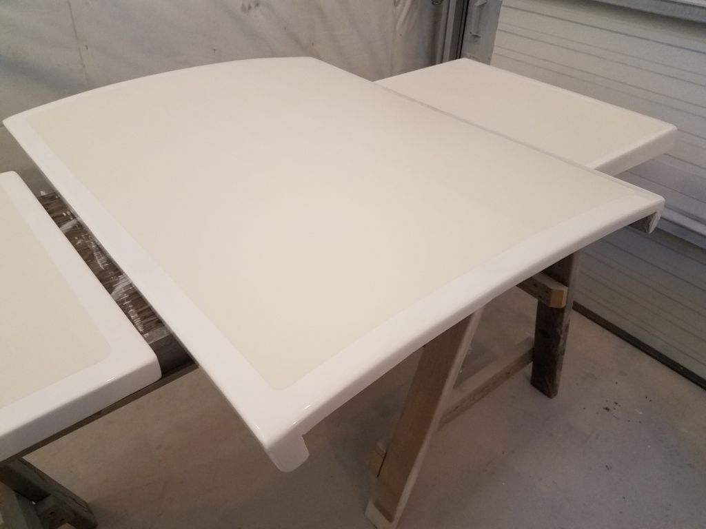
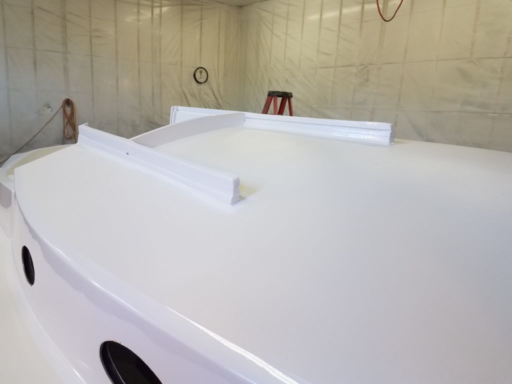
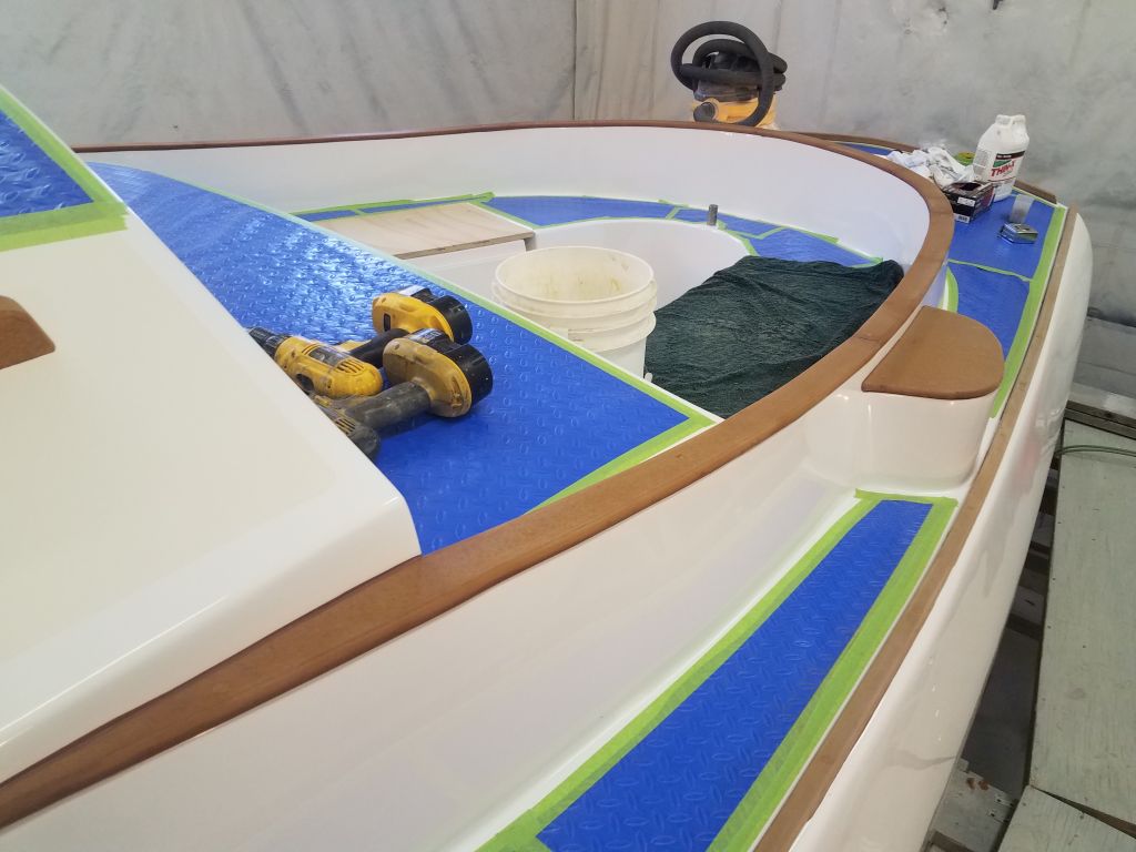
To finish up the deck trim, I pared away the bungs on the coaming caps that I’d installed last time.

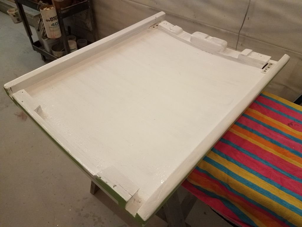
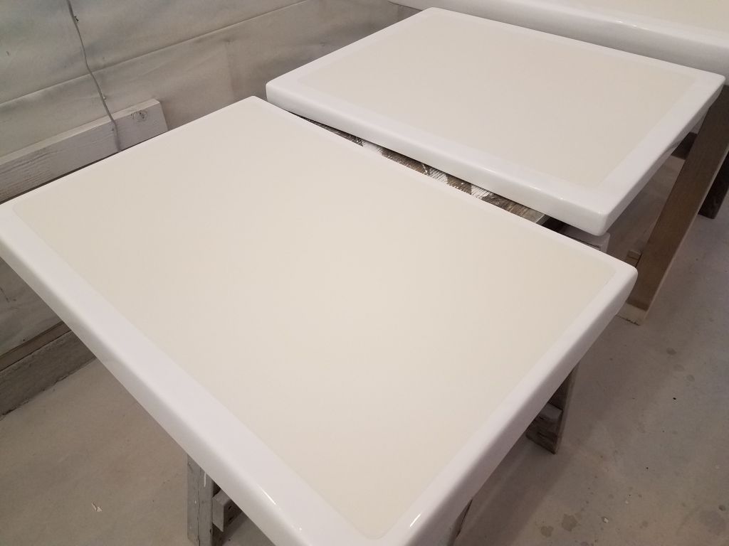
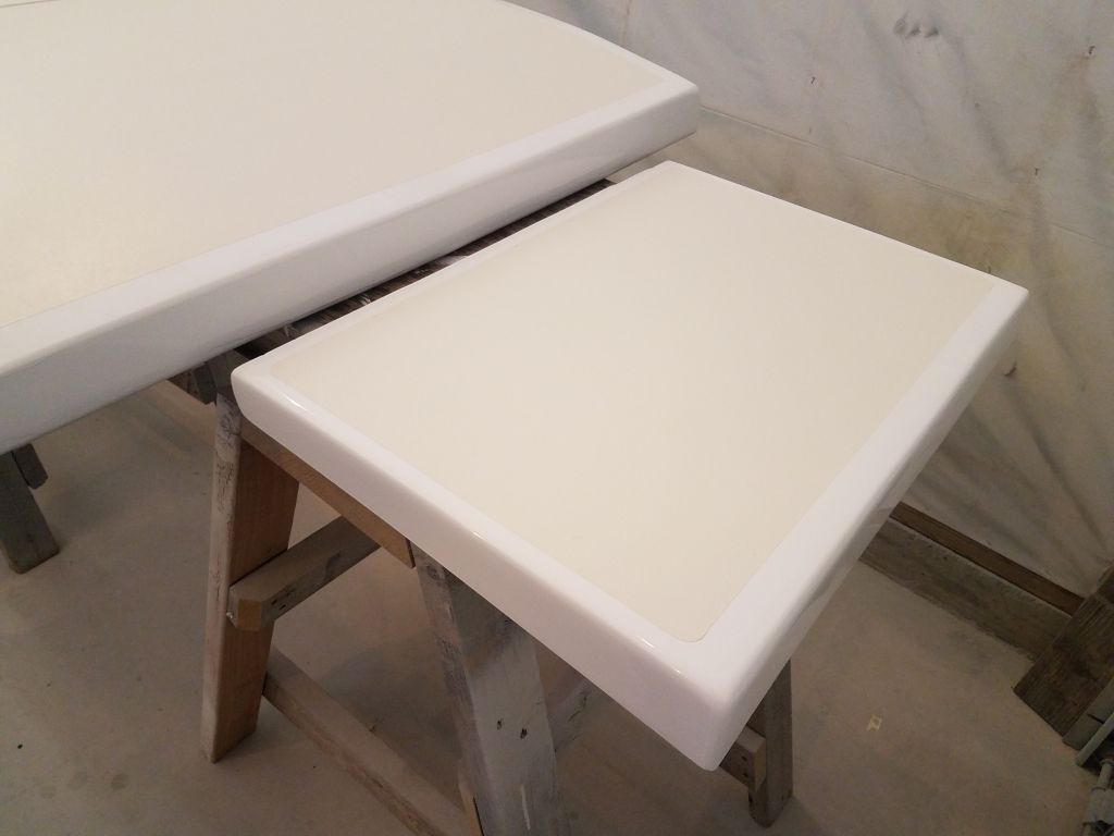
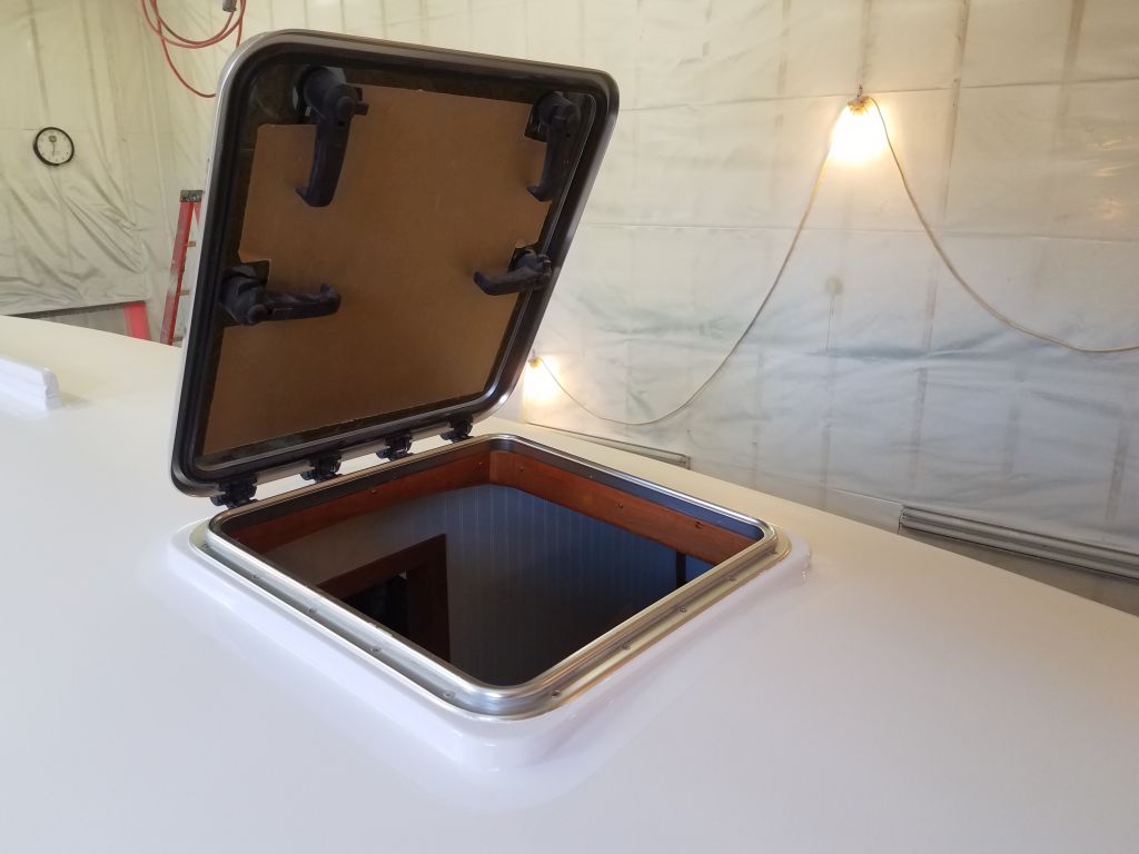
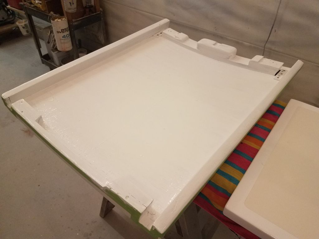
The companionway hatch required a light sanding and then a second coat of the semi-gloss white enamel.

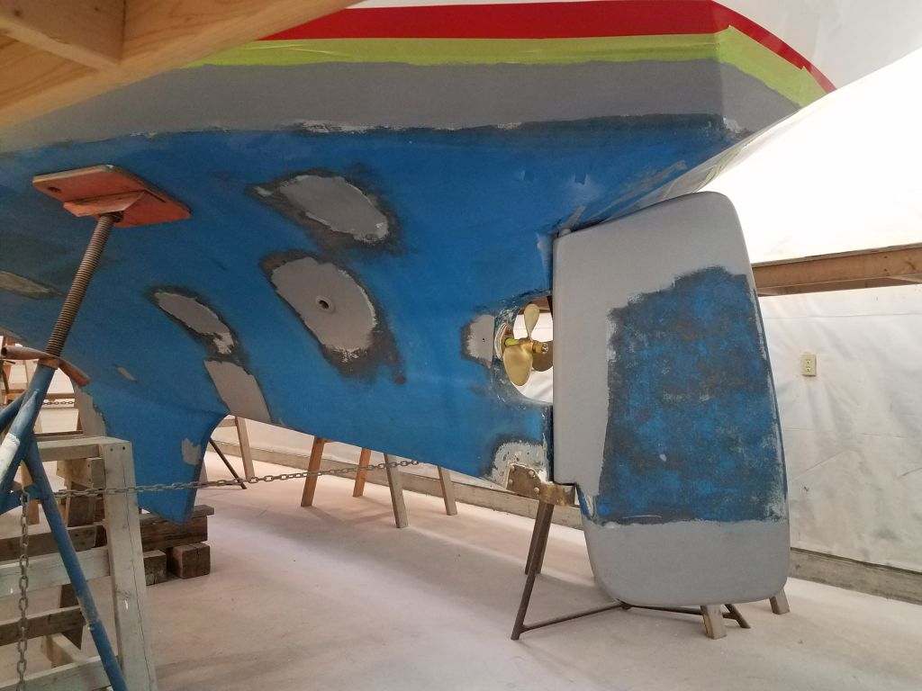
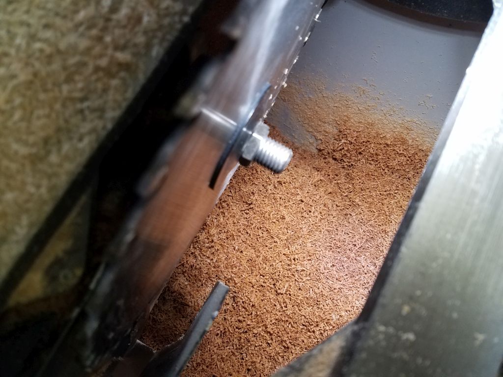
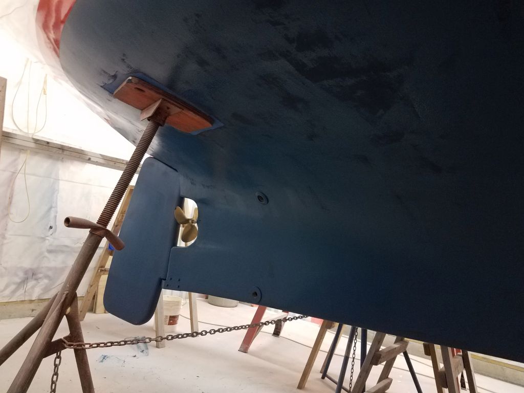
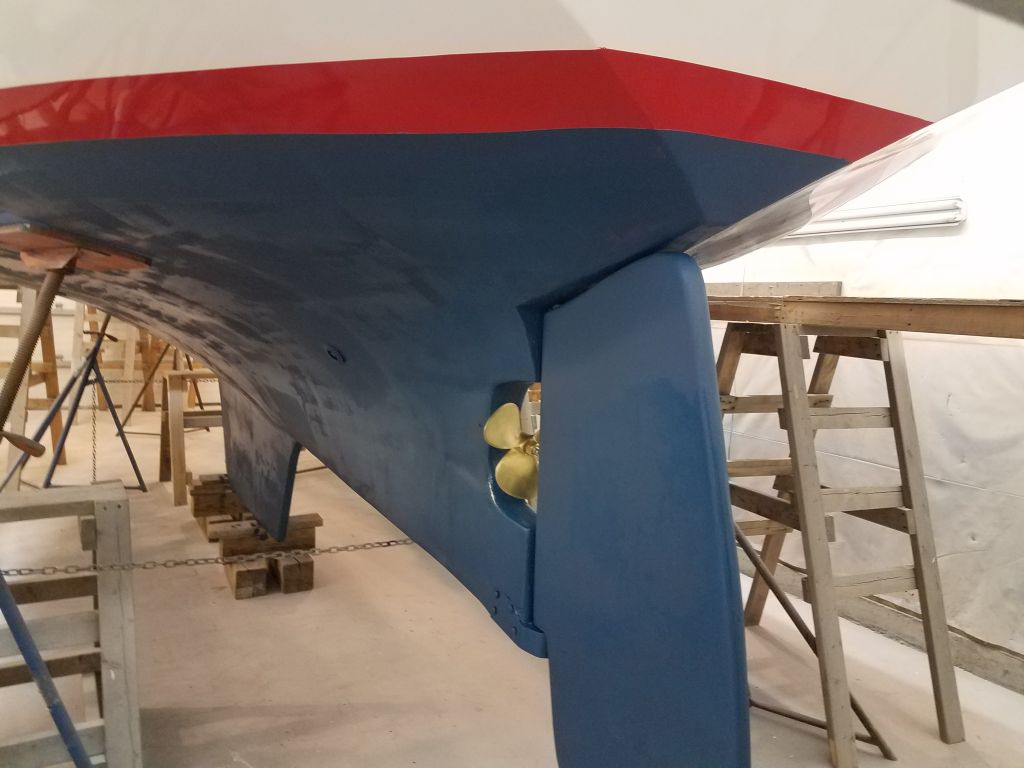
A while back, after completing the shaft and propeller installation, I’d ordered a shaft zinc, and now, to get it out of the way and checked off the list, I took two minutes to install it on the shaft.

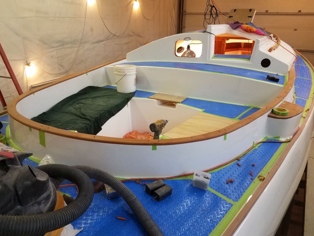
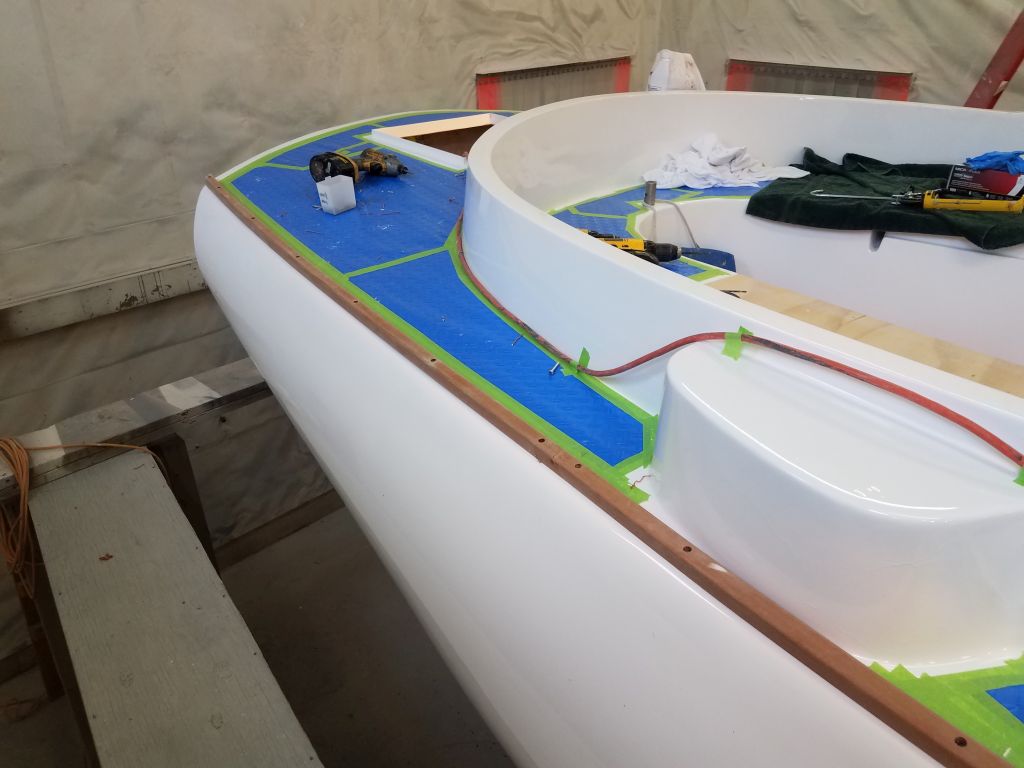
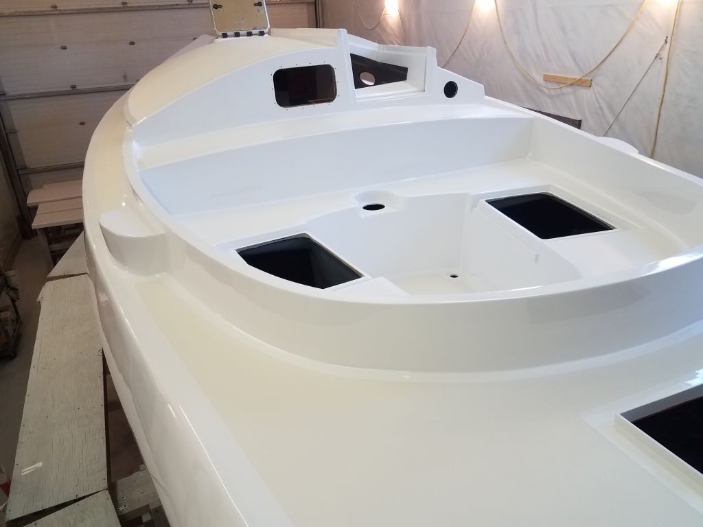
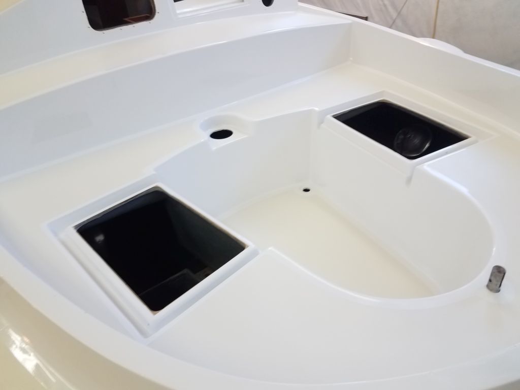
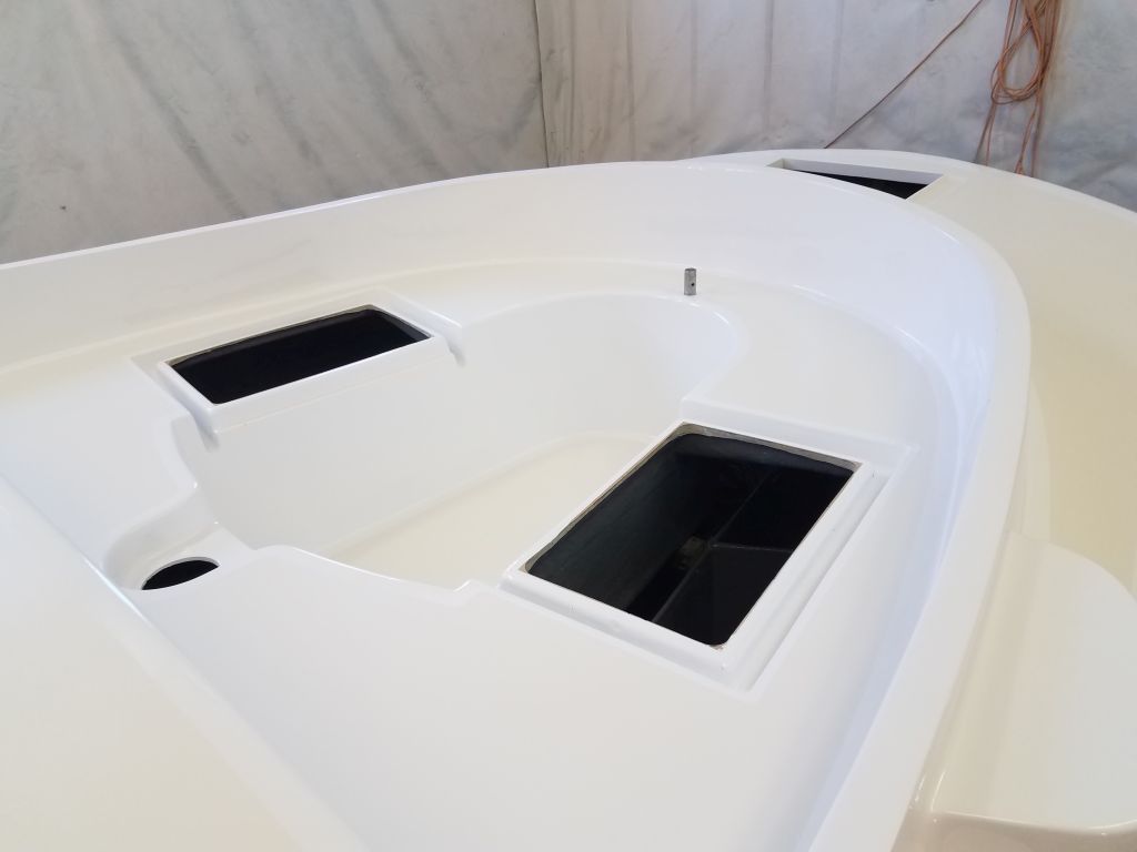
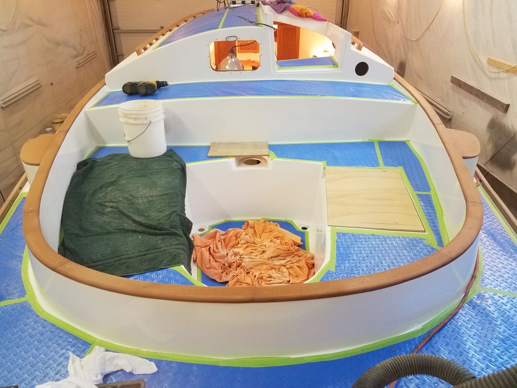
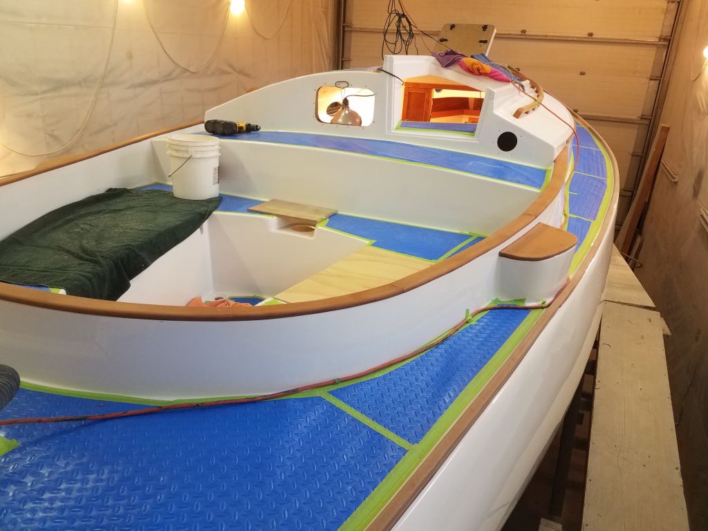
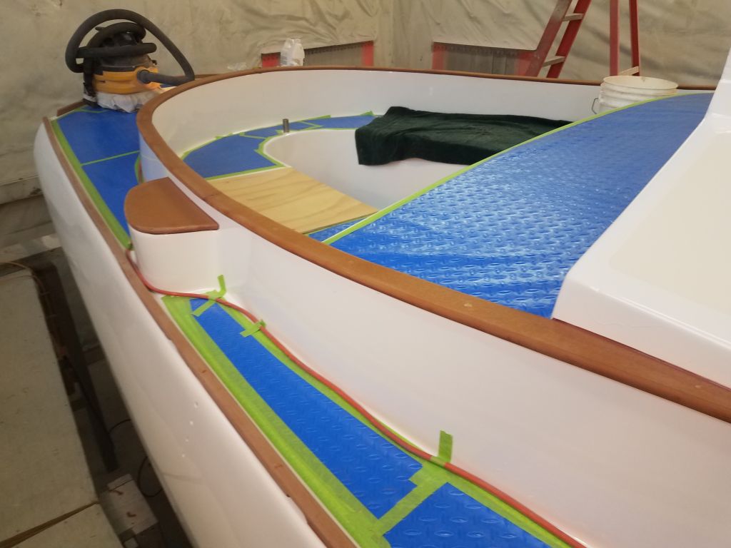
With those small chores complete, I planned to shift gears and start getting into the electrical and plumbing systems in the cabin, and to that end I spent some time preparing orders for some of the materials I’d need to continue work in those directions.  Then, I set to work in the cockpit, where I planned to install the electric motor controls and a cockpit shower housing, all of which were on hand now.

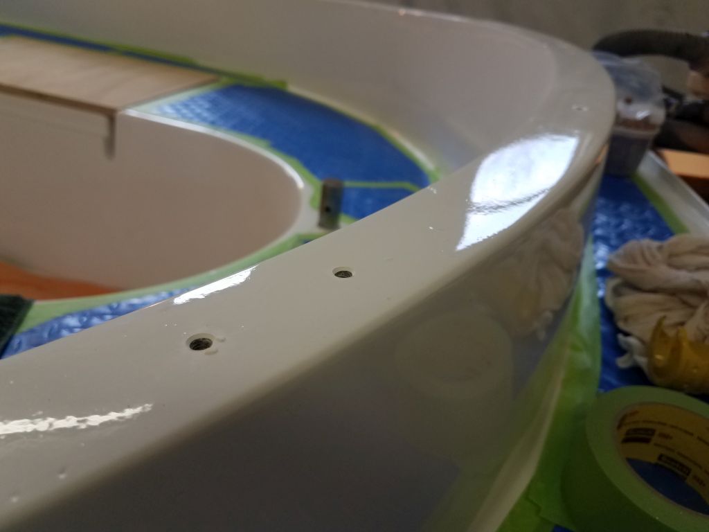
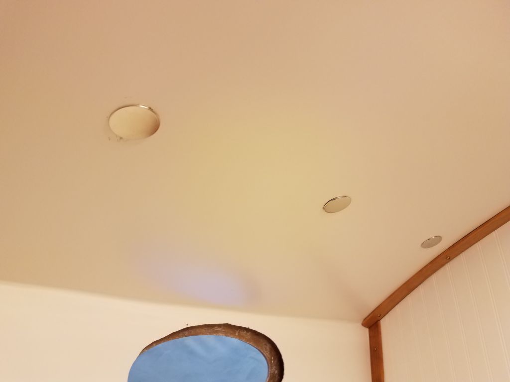
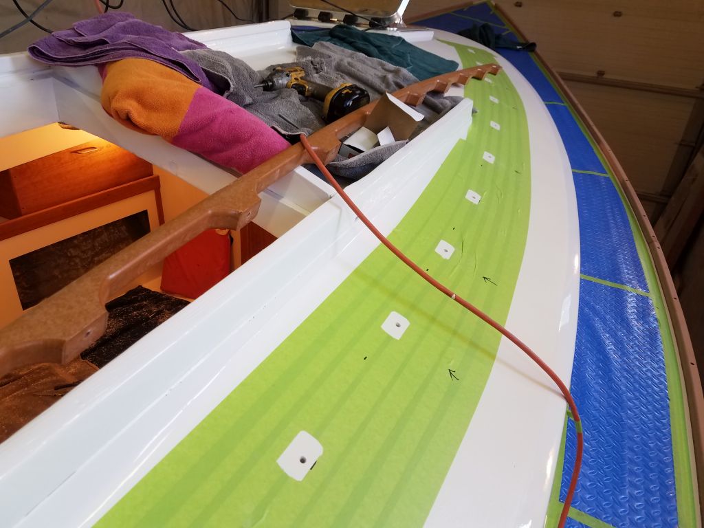
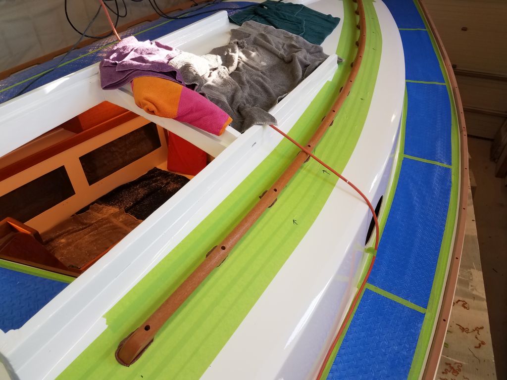
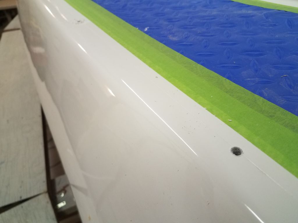
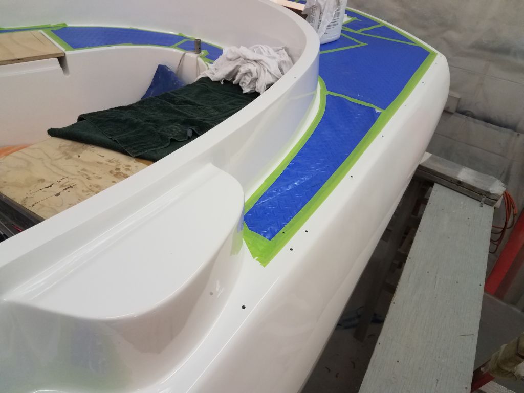
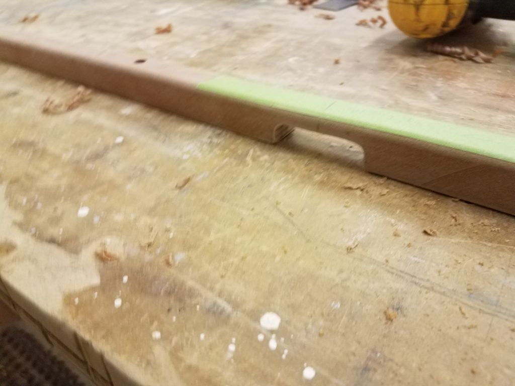
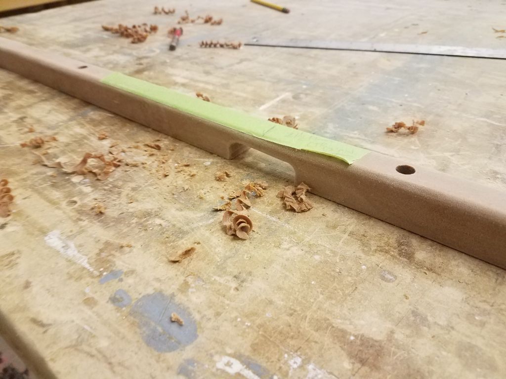
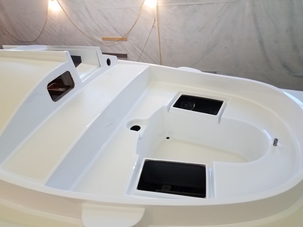
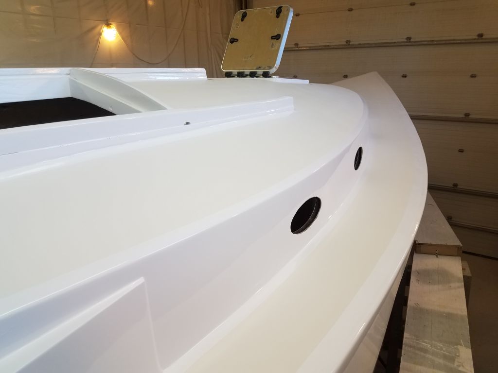
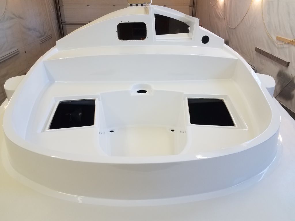
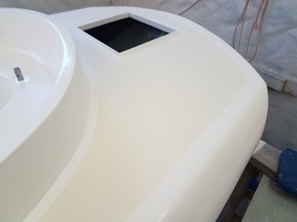
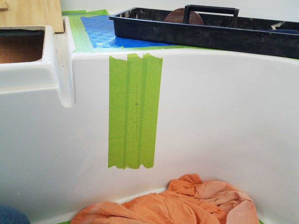
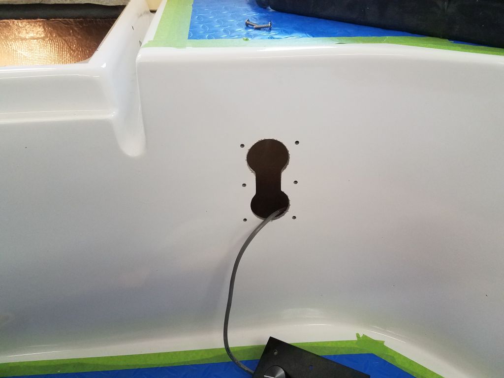
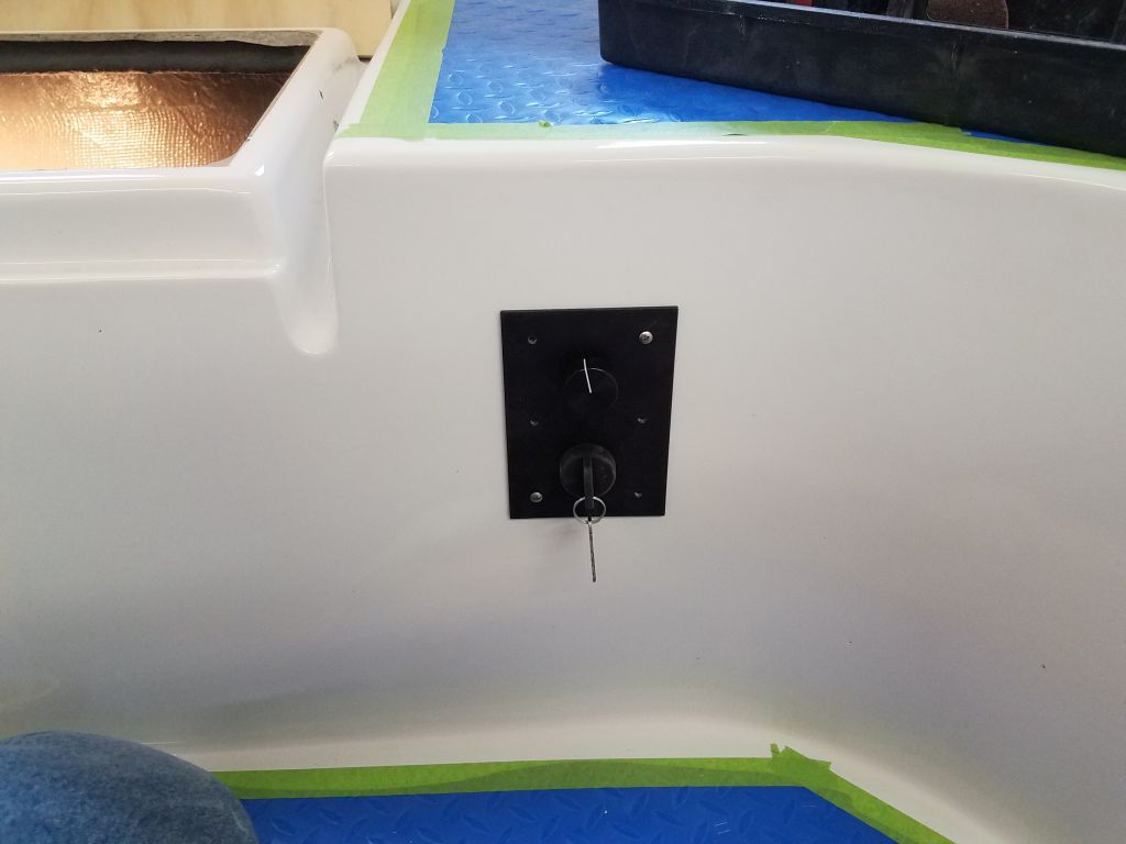
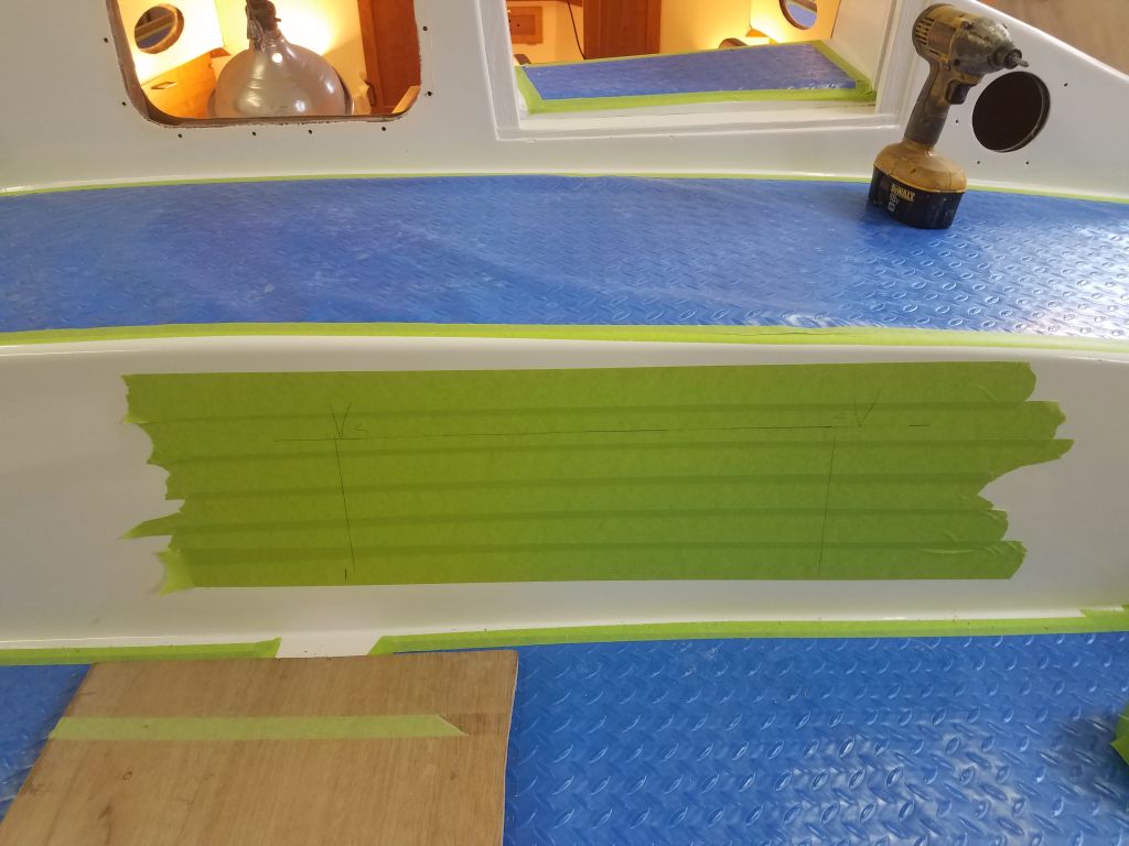
The motor controller (throttle) was a simple panel with a rheostat control and key switch, and the owner had asked that I install it in the cockpit well aft of the starboard cockpit locker.  After some quick layout, I prepared the opening for the controller, drilling a pair of 2″ holes and then connecting them through the center.  Afterwards, I aligned the control panel and drilled for the six screw holes.  I installed the panel dry and only temporarily for now with two screws, since I might need to change some of the wiring leads on the back depending on whether the control knob was properly set up from the factory.

To eventually lead the control wire forward and down to the electric motor, I needed some additional wire tie mounts, so from the starboard locker I installed what I thought I needed, sanding away any locker paint in way of the mount locations before securing them in place with the mount adhesive.  I ran additional mounts aft towards the transom, planning ahead for sternlight wiring later.

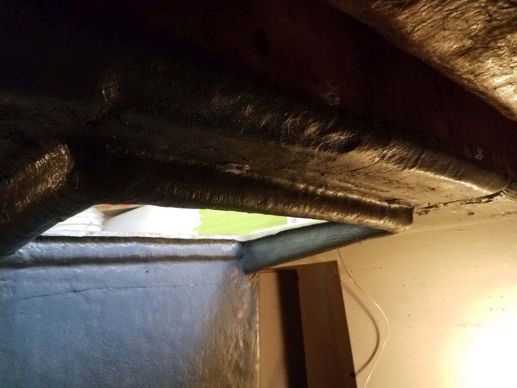
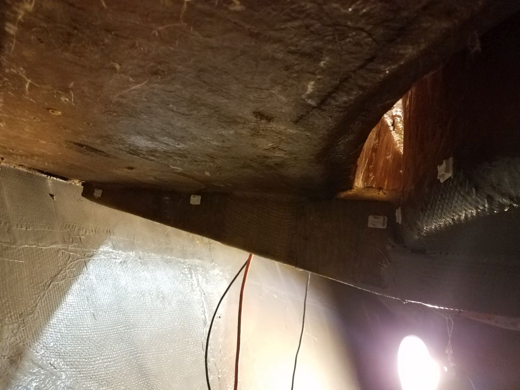
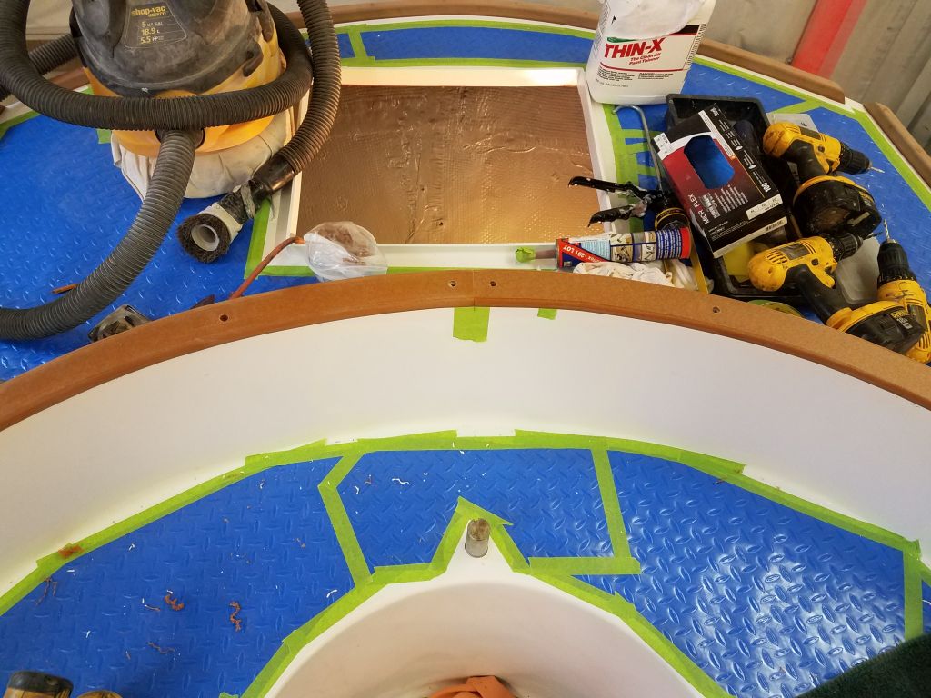
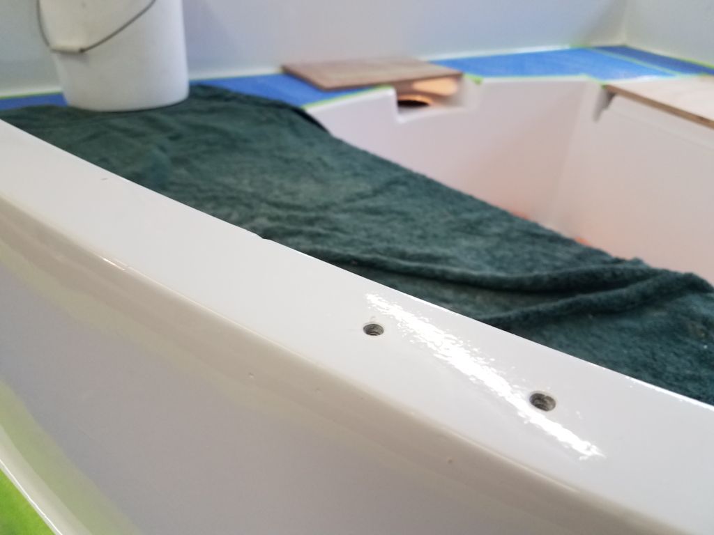
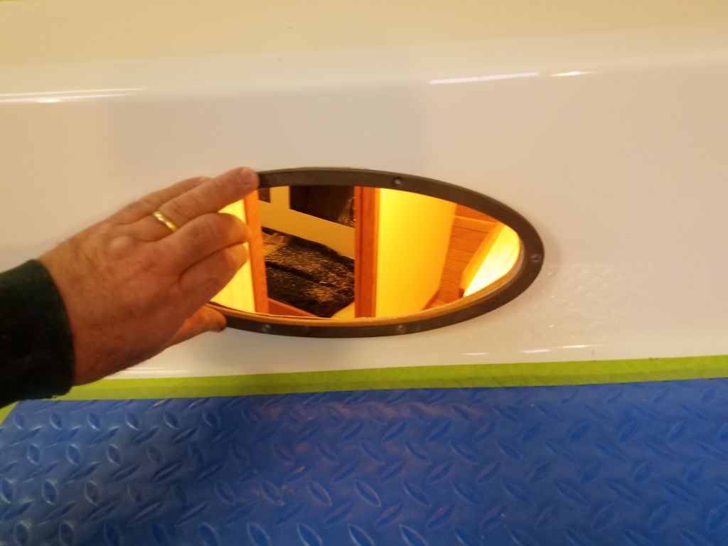
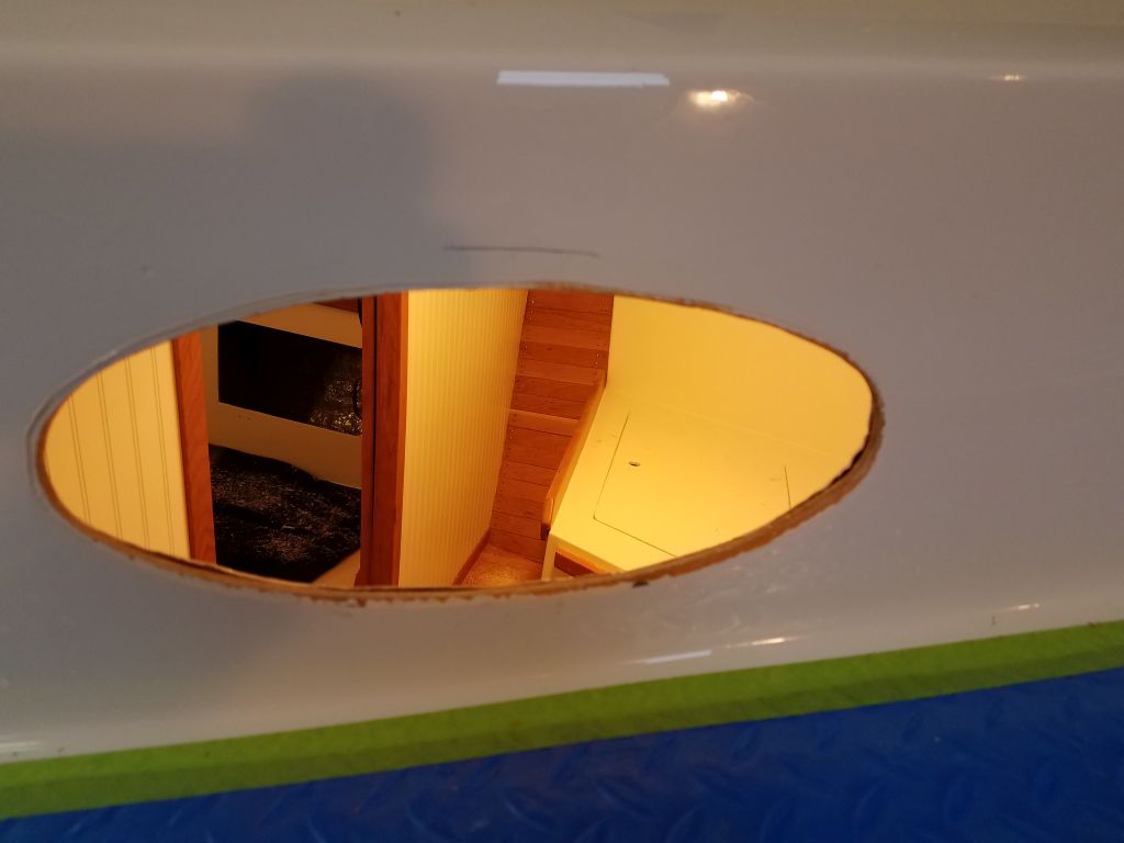
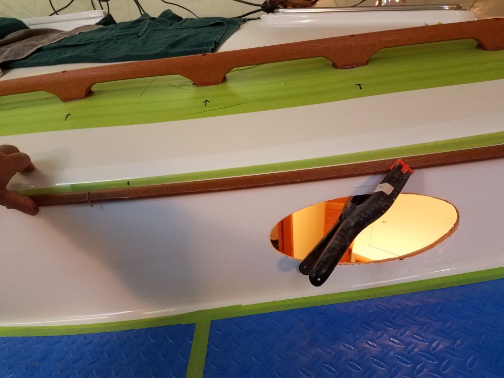
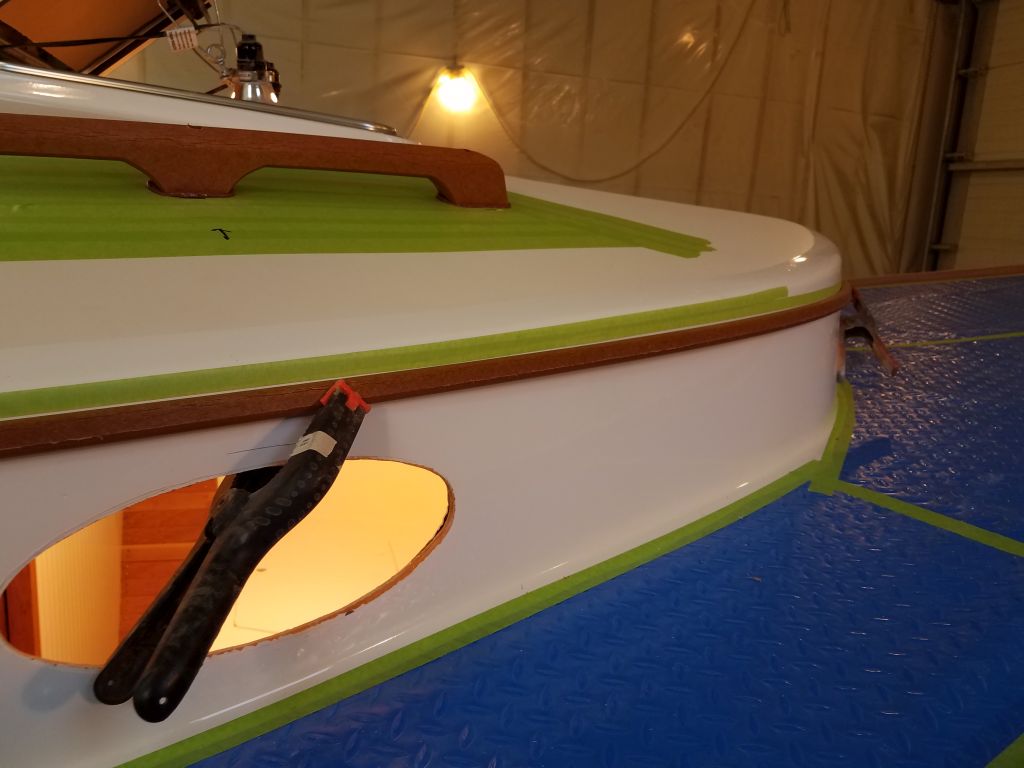
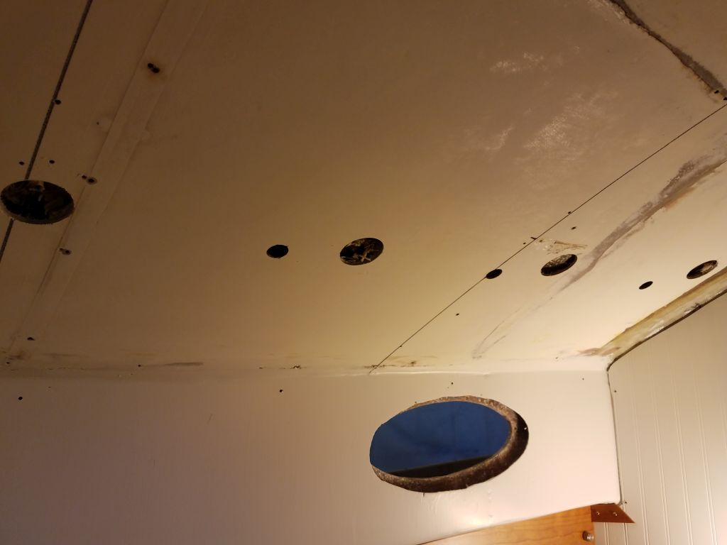
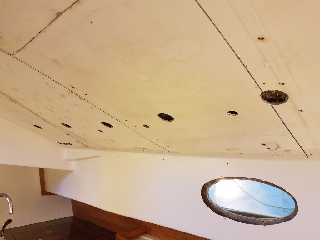
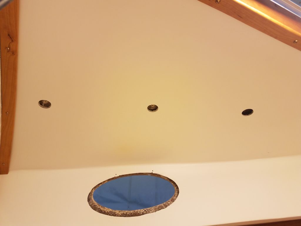
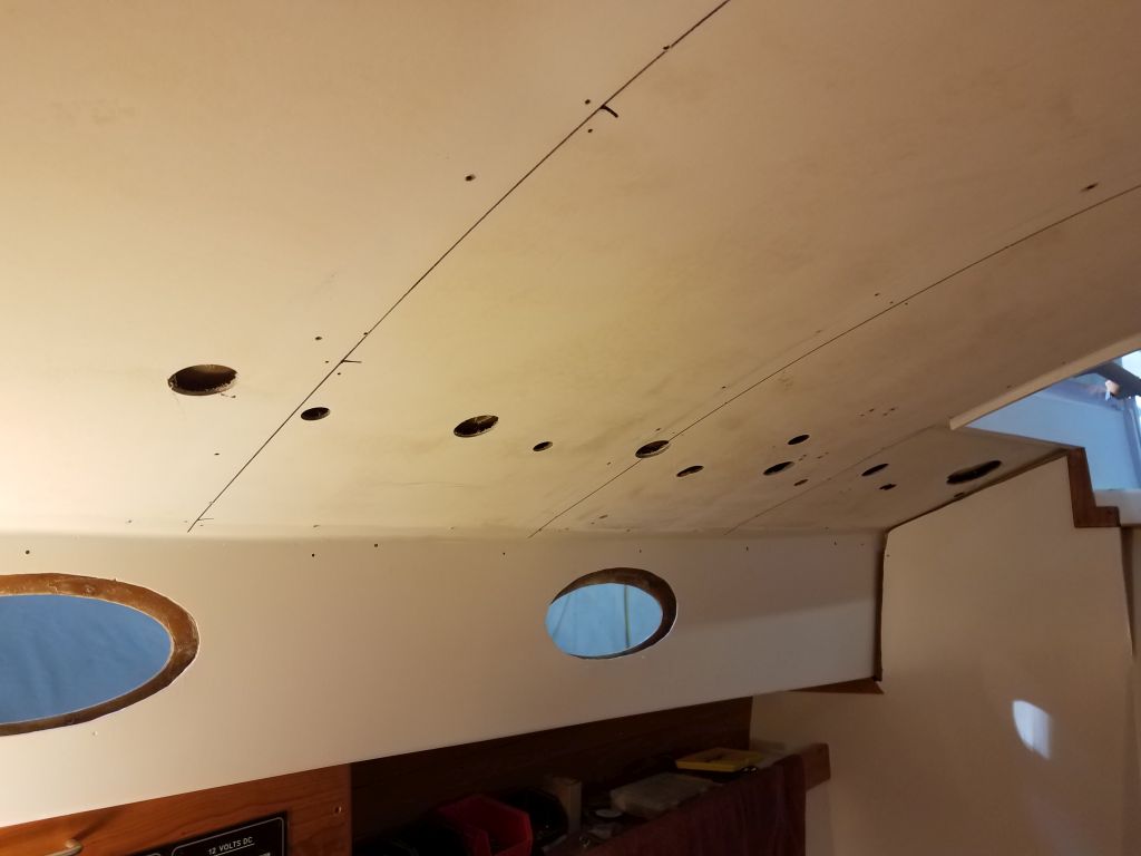
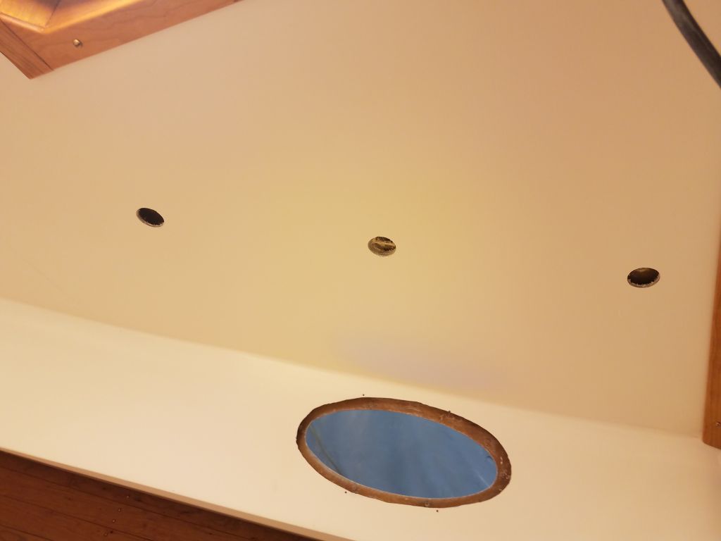
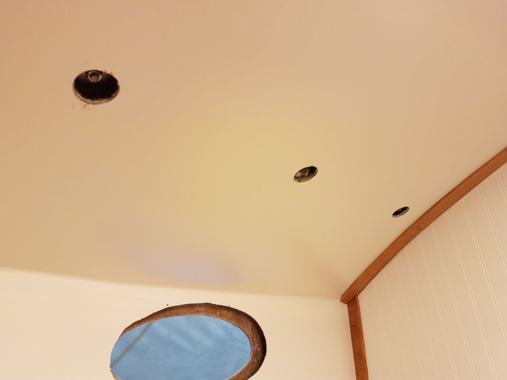
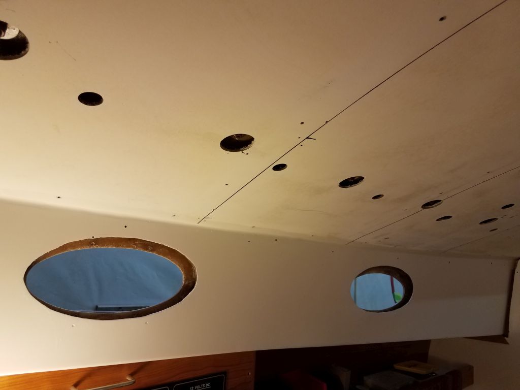
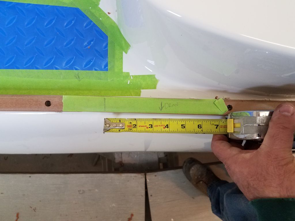
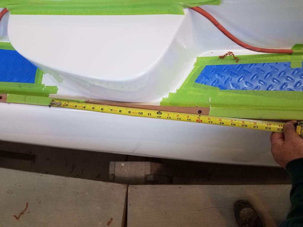
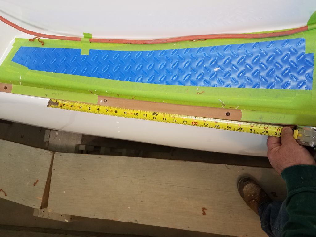
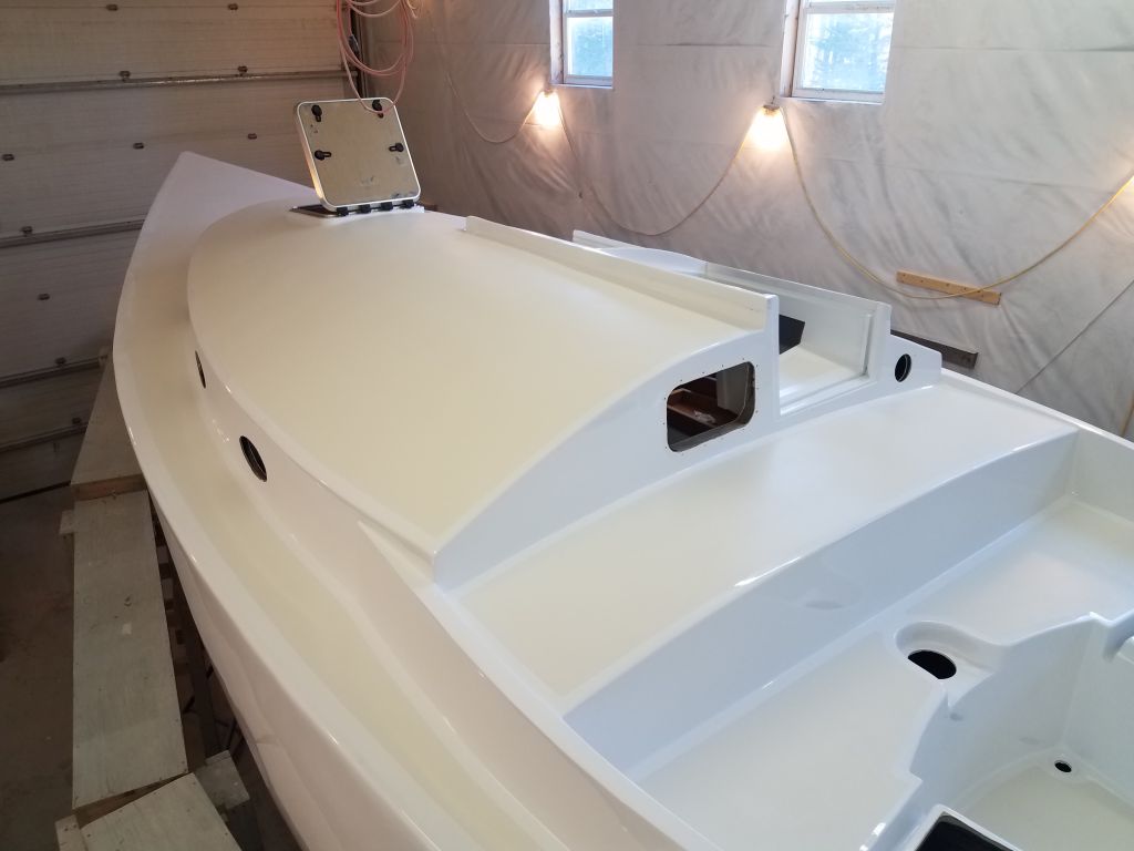
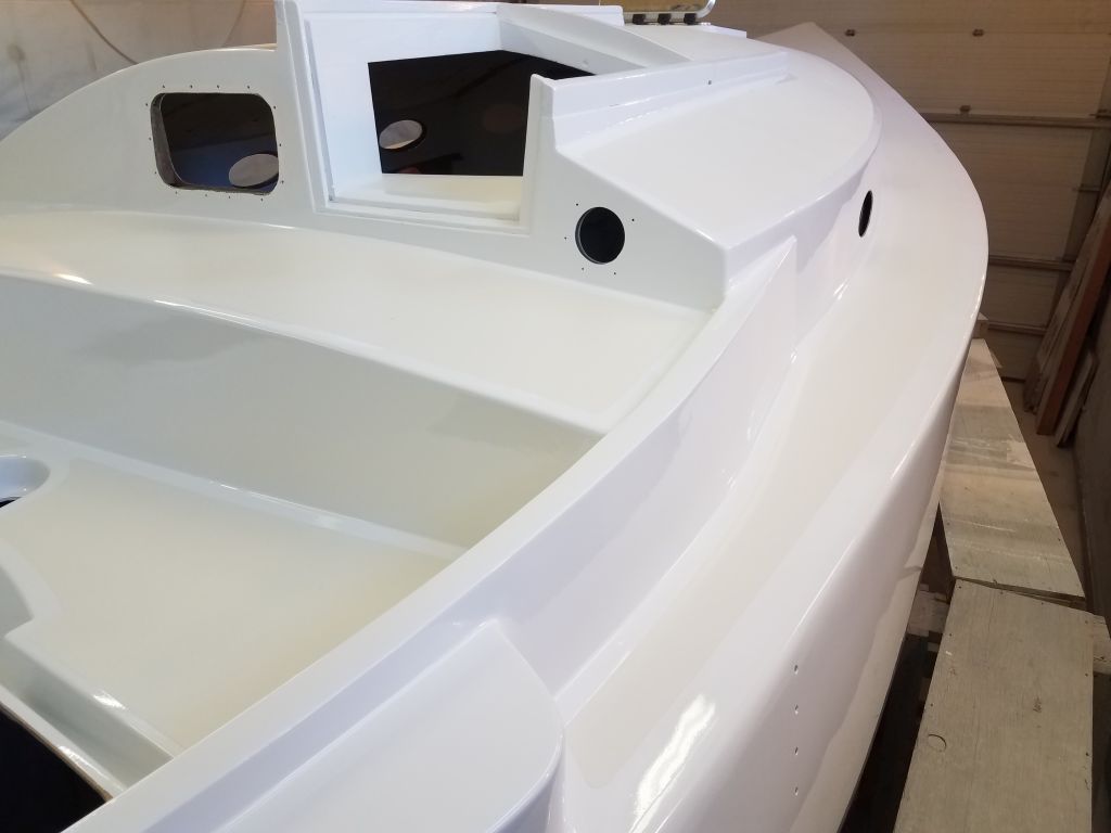
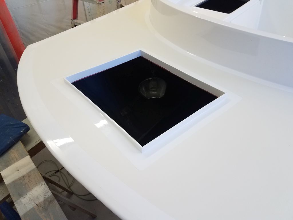
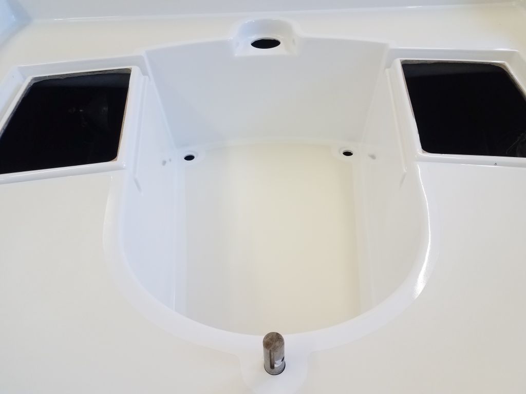
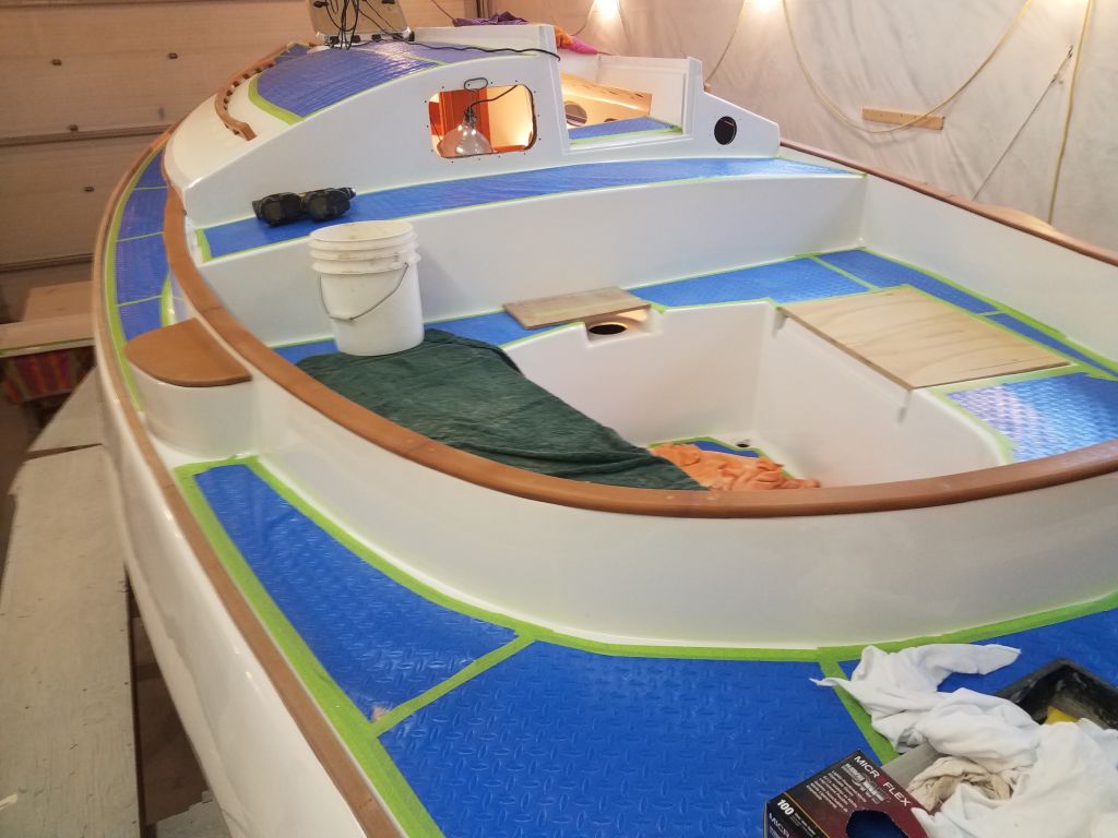
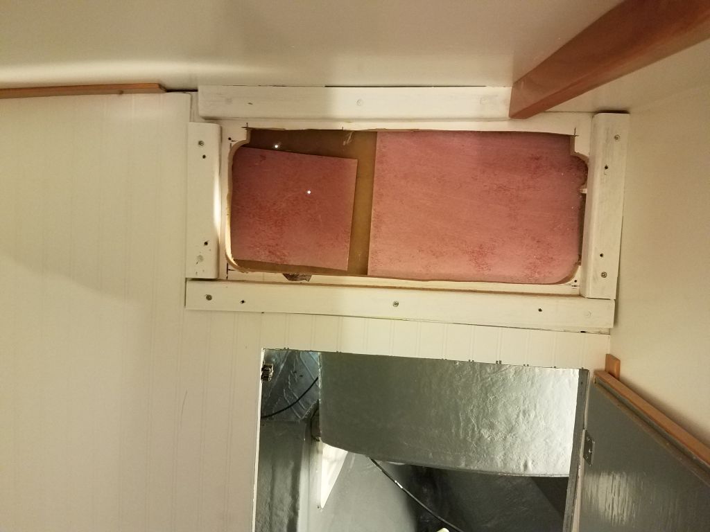
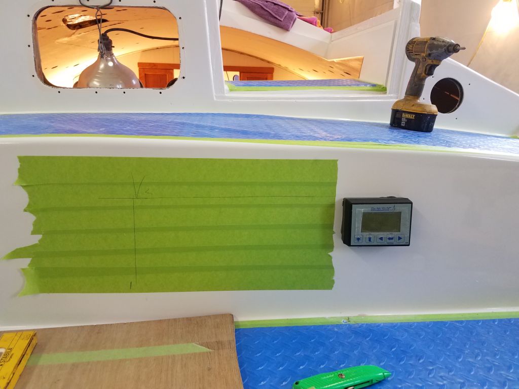
The electric motor system also required a battery monitor, which I planned to install in the raised portion of the cockpit well beneath the bridgedeck.  I’d built in access to the back side of this area from the head, and to begin I removed my access panel, then made various measurements so I could roughly transfer the location of the open access area to the exterior so I’d know where to install the panel, along with some sailing instruments later on.  After the initial layout, I decided to open up the access panel a bit more along the top edge, which I did with a multi-tool.  This increased access at the top side and allowed me to install the panel where I wanted it to go.

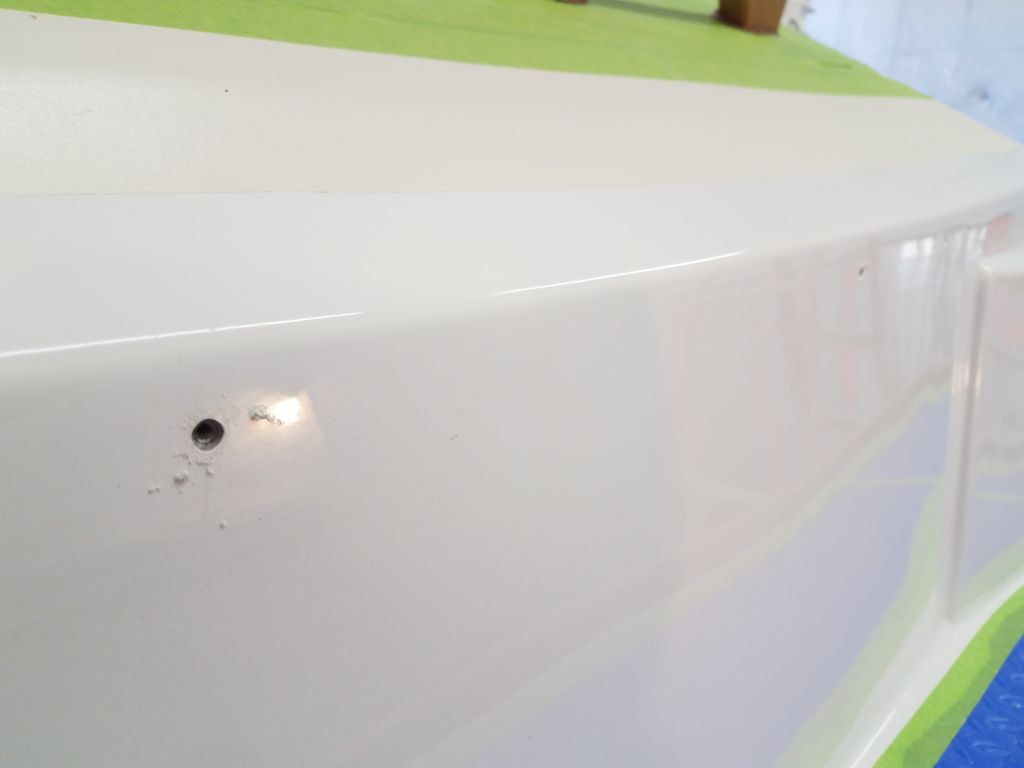
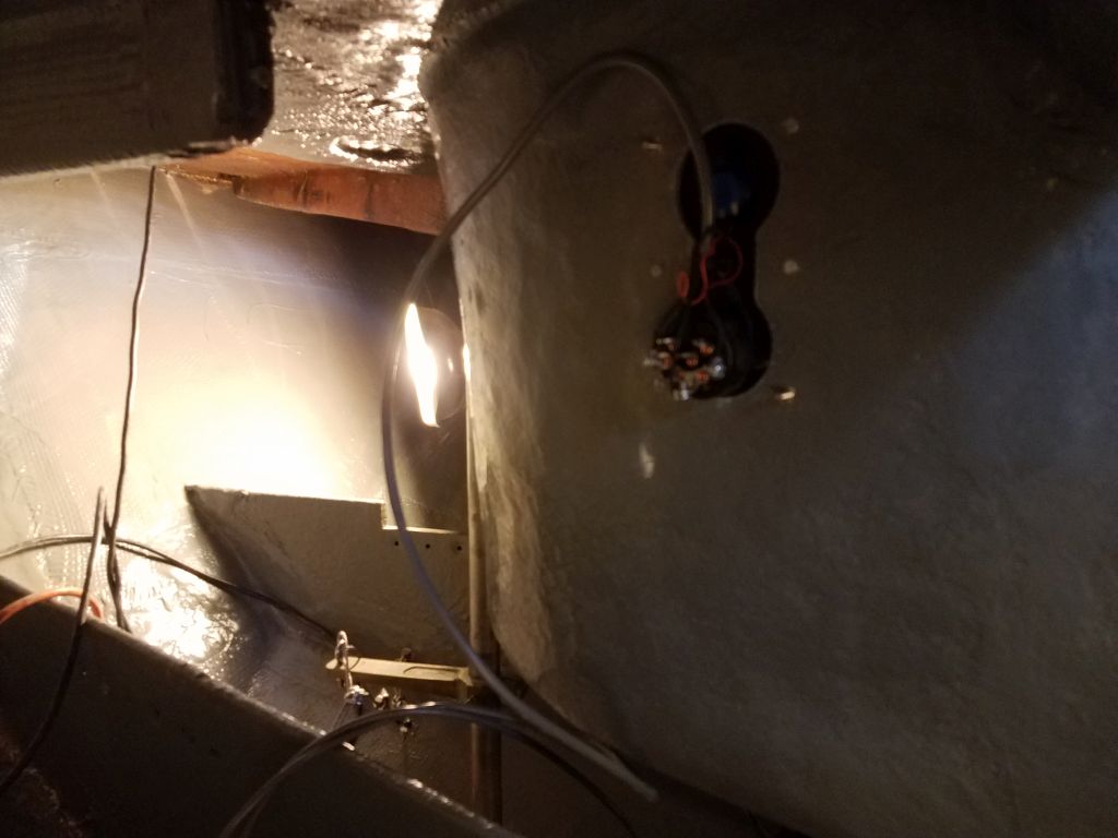
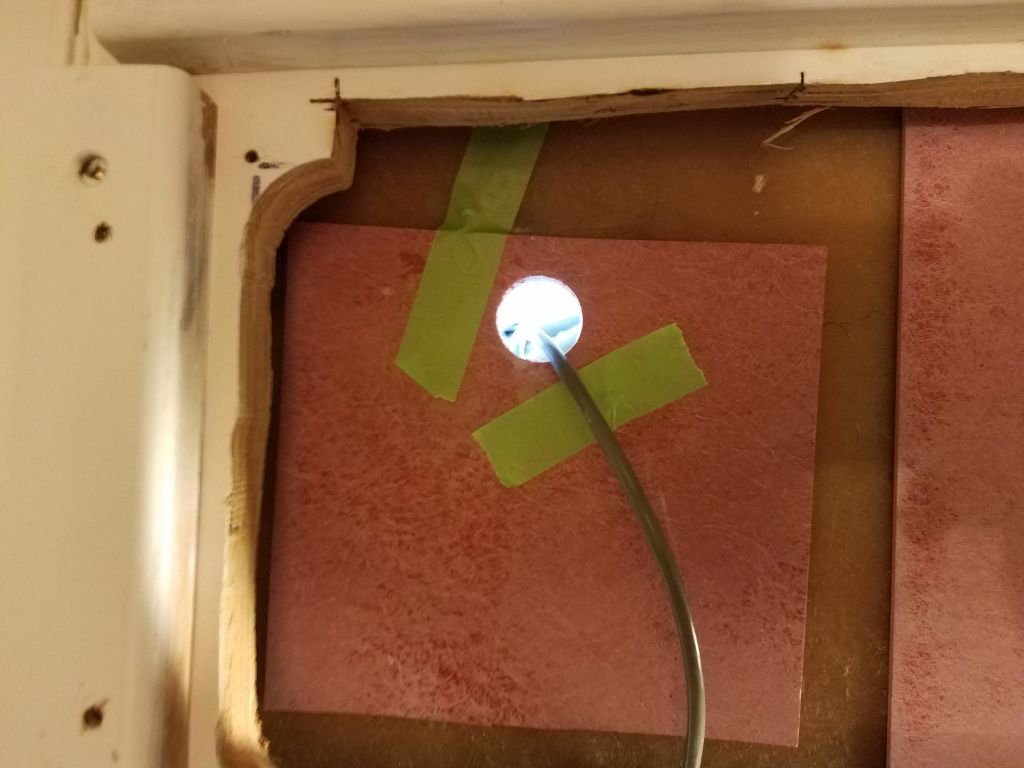
After additional layout, and double-checking, I drilled the holes needed to install the battery monitor, which had a rather fussy means of securing it with two screws from the back side only.  There was a mounting template supplied with the panel, but I discovered–fortunately before I relied on it to do the cutting–that the template was not accurate and didn’t exactly match the actual panel and its pre-marked screw locations.

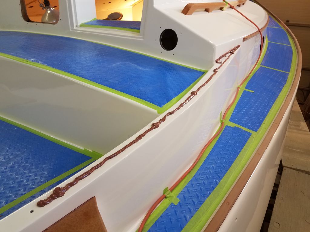
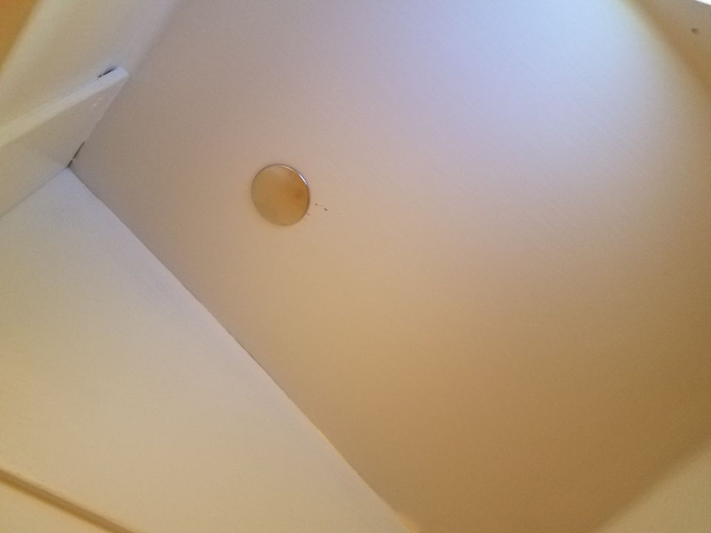
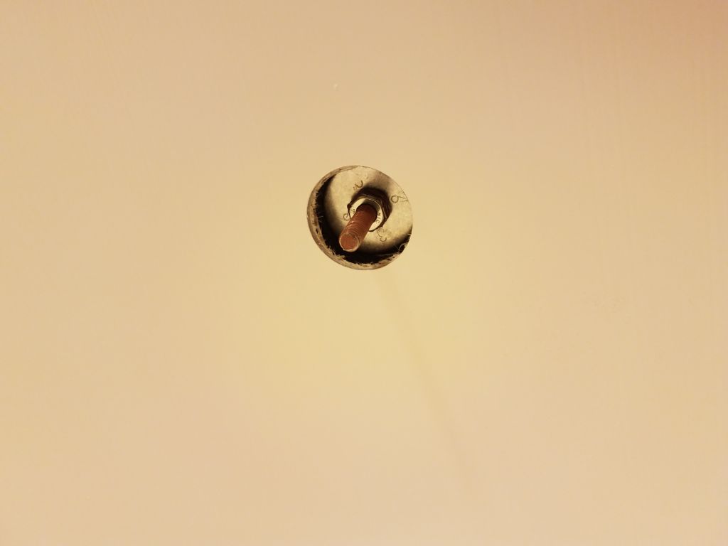
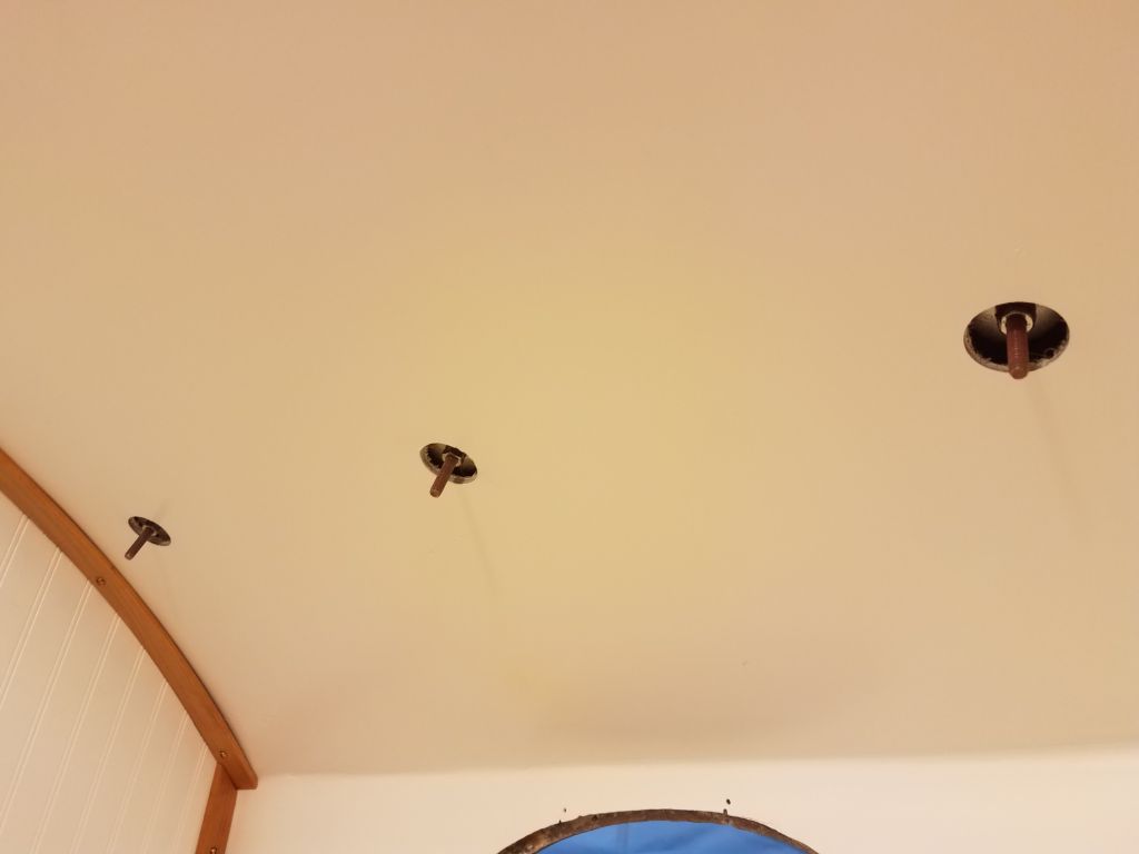
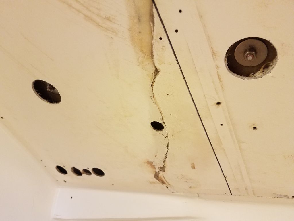
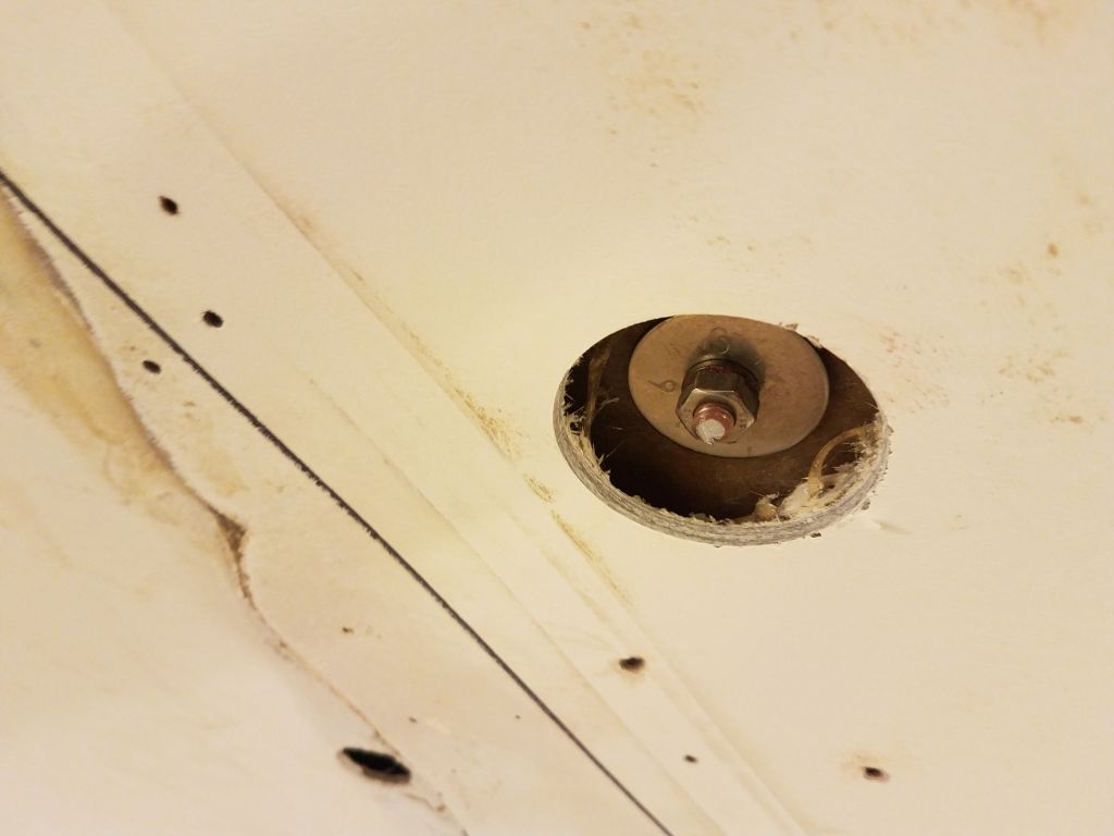
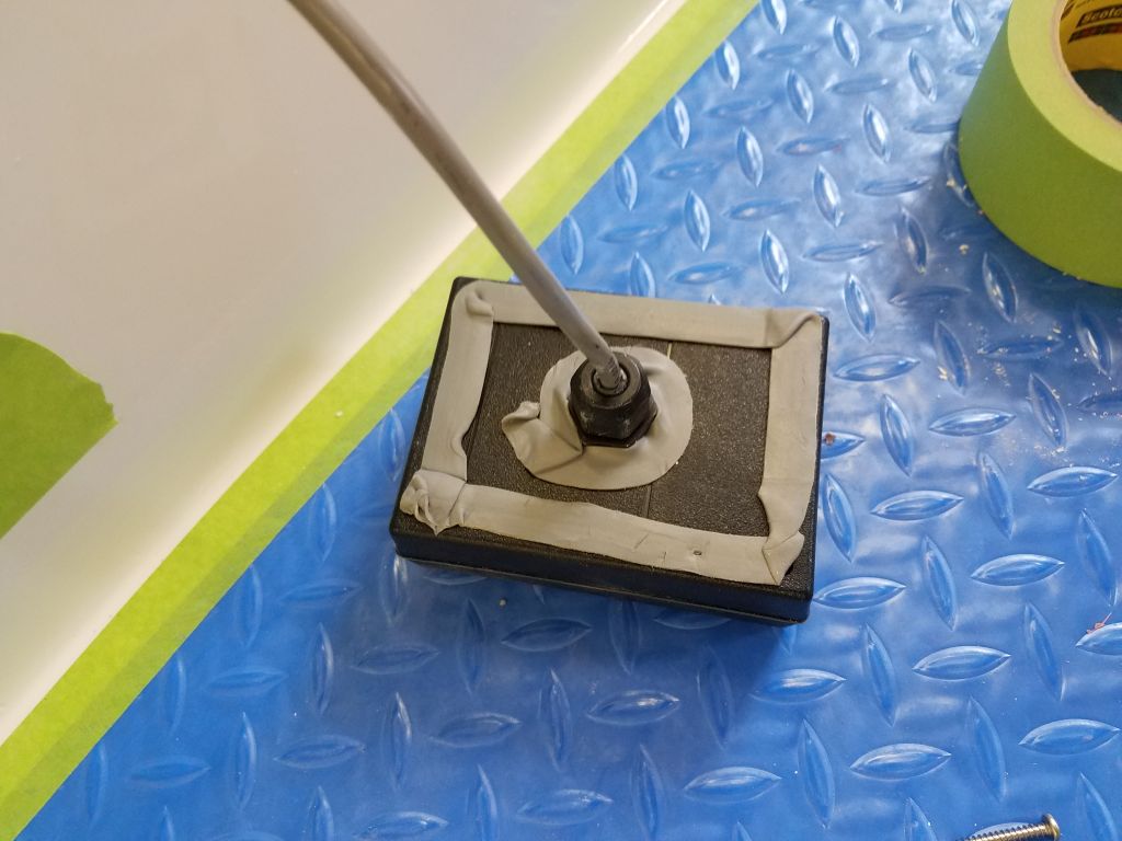
Securing the panel in place from behind, when there was no direct communication between the spaces and no helpers to be found in my one-man shop, was an exercise in patience, frustration, and fortitude, and required numerous trips back and forth between inside and outside before I could properly align, hold in place, and then tighten, the small screws to secure the panel.  I applied butyl tape sealant to the panel and around the central wiring port before installing it (the photo shows an early version of the sealant that I ultimately replaced after the first panel installation attempt failed).

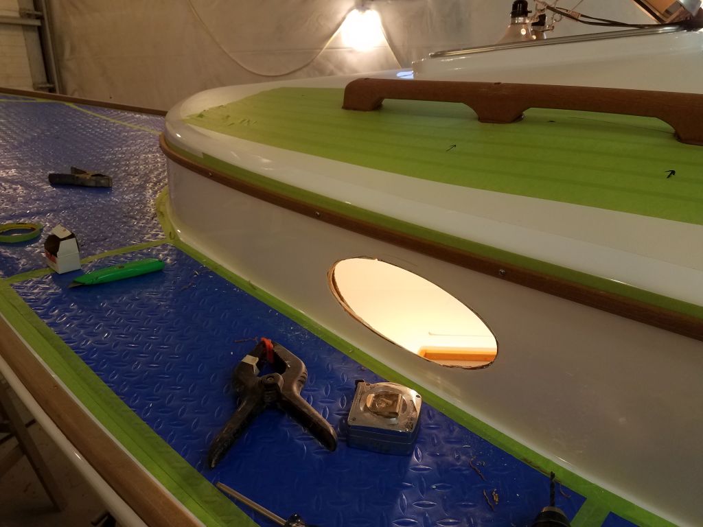
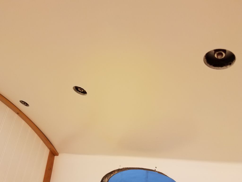
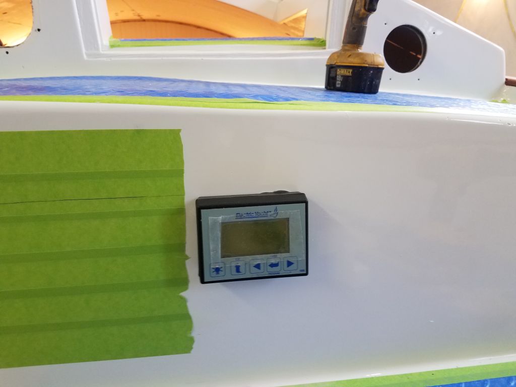
At length–far greater length than such an inherently simple installation ought to require–I secured the panel successfully.

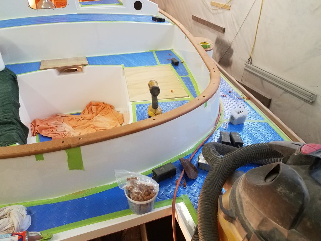
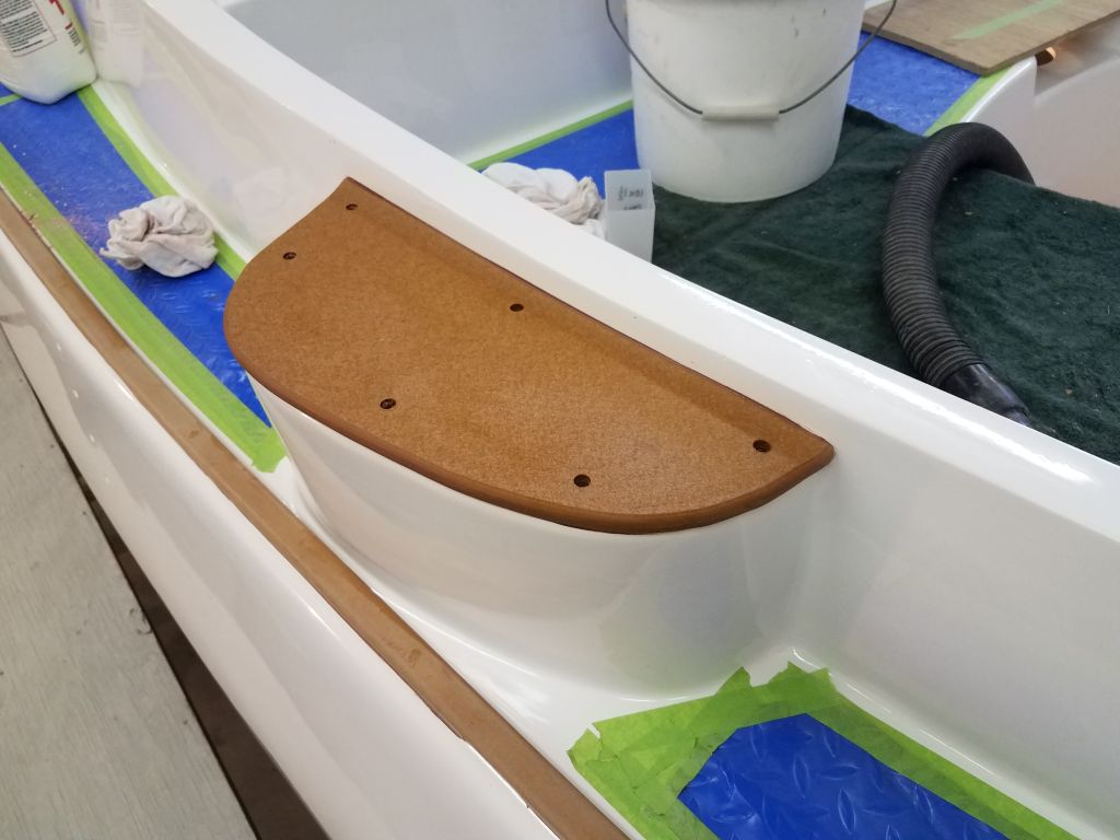
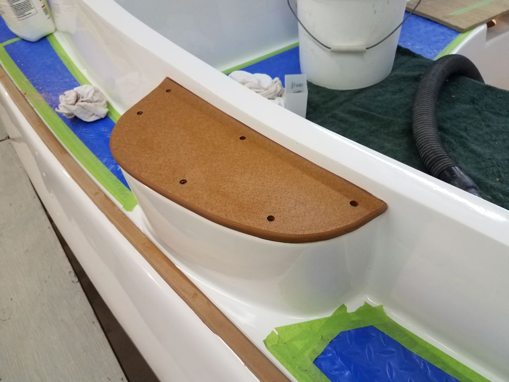
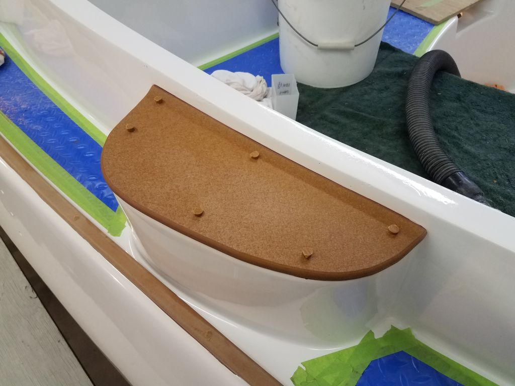
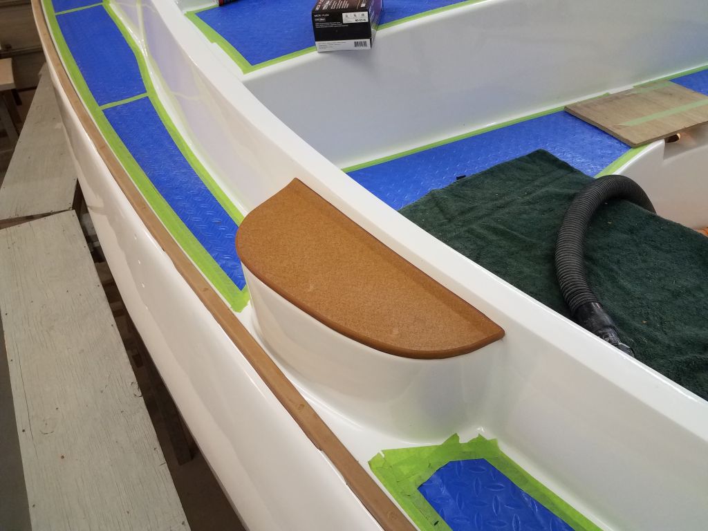
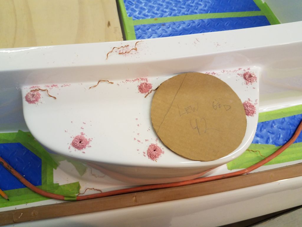
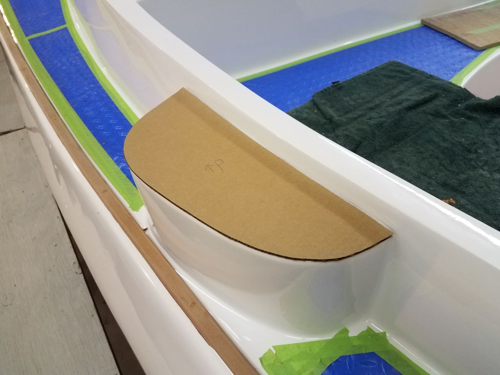
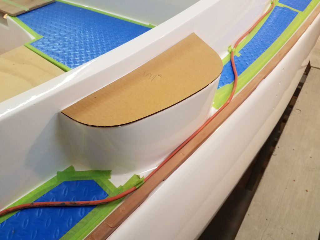
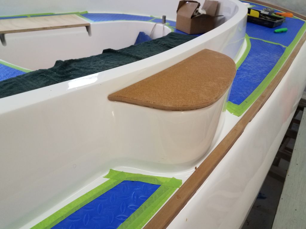
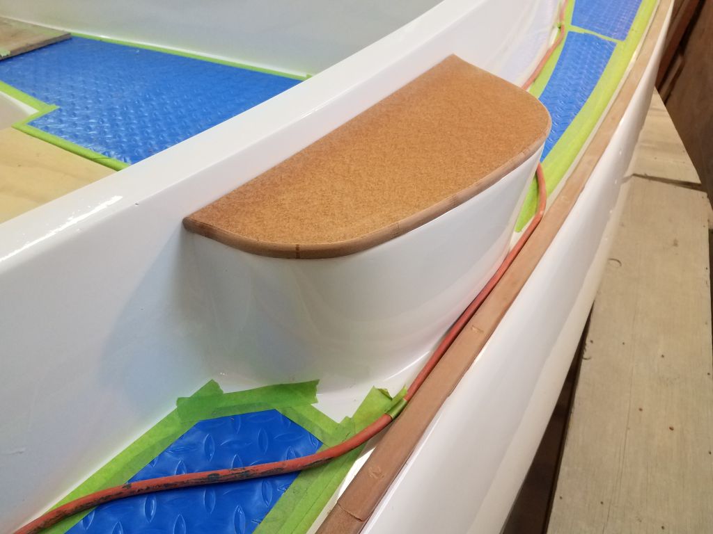
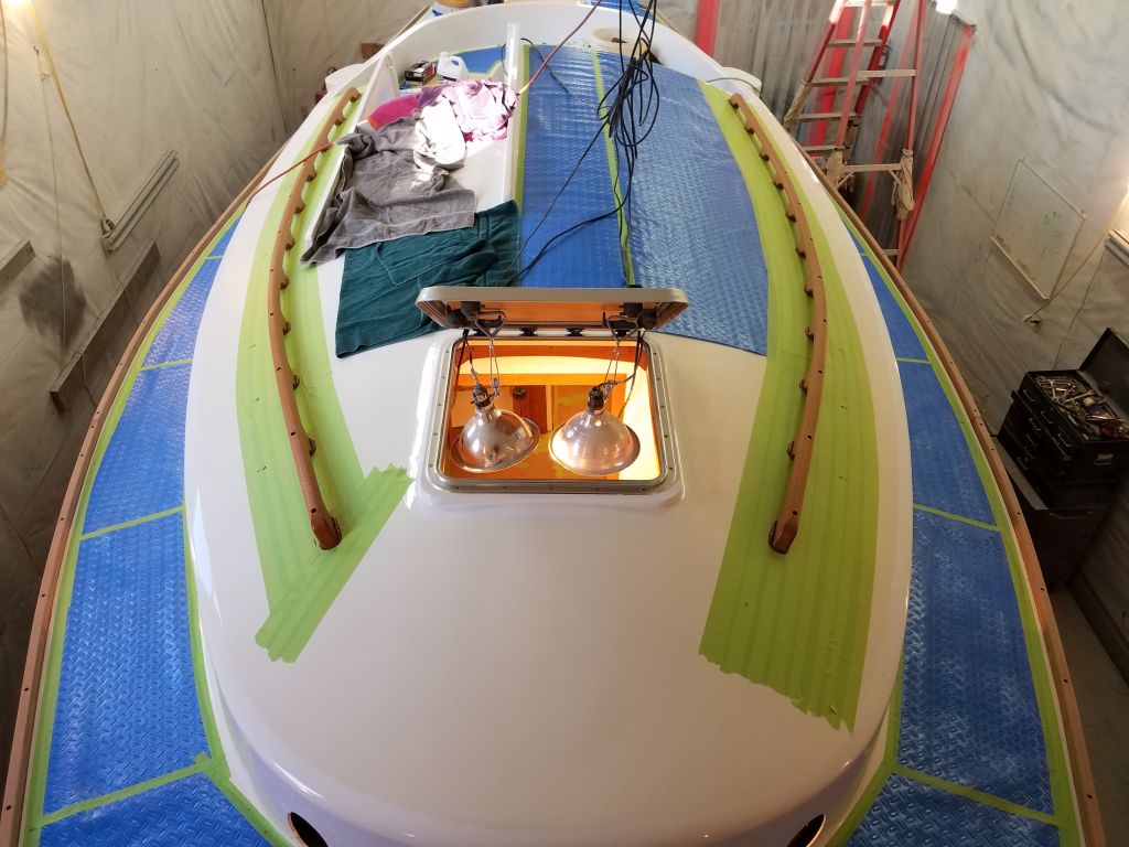
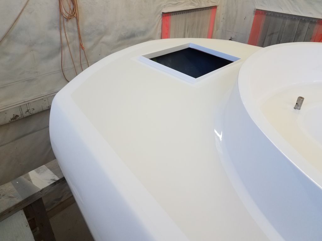
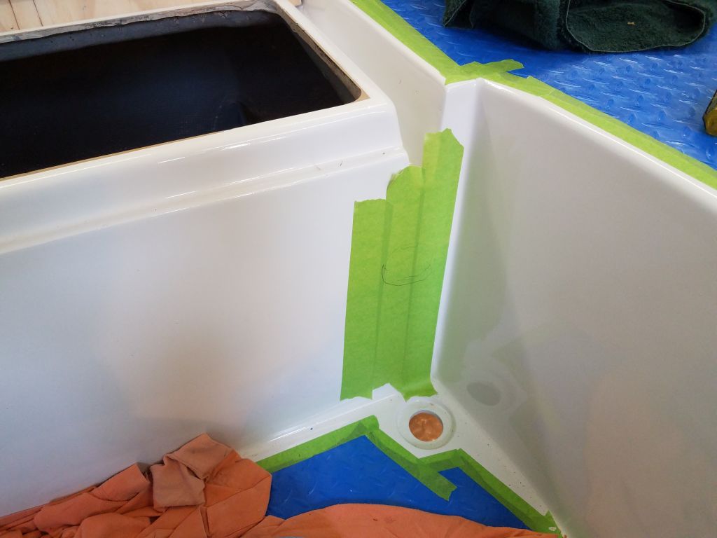
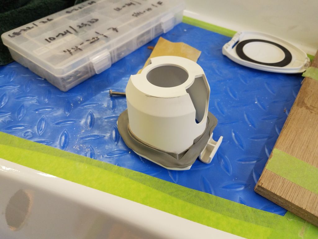
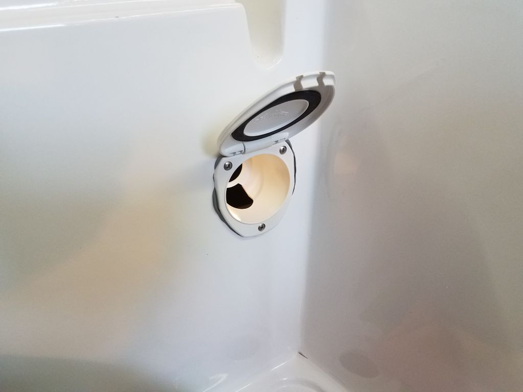
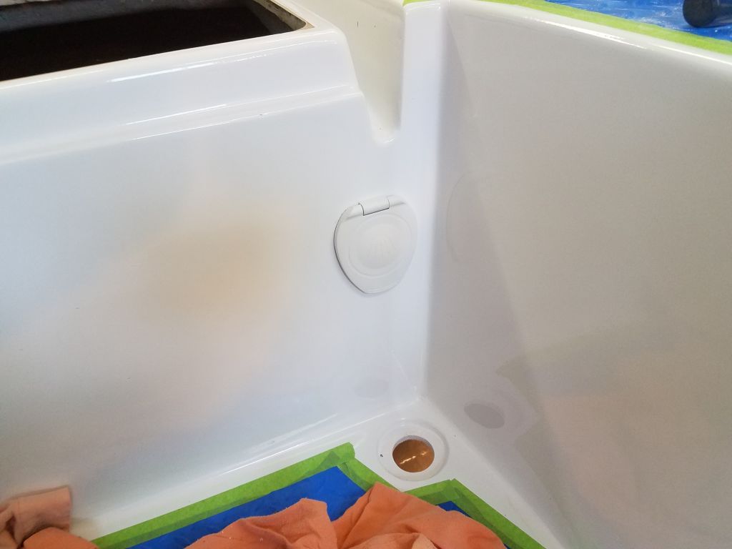
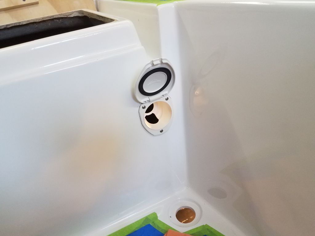
The final cockpit installation for the moment was the shower housing, which the owner had supplied and asked me to install at the forward port corner of the well.  This covered housing would ultimately hold a small shower head and hose leading from within, but for now I worked with the bare housing.  Installation was straightforward with a single large hole, butyl sealant, and three screws.

With some personal business to attend to in the afternoon, I had to call it quits for now, but next time I could lead and connect the wiring from the engine panel and battery monitor and continue with various other aspects of the systems installations.

Total time billed on this job today:  5.5 hours

0600 Weather Observation:  24°, cloudy, a snow shower.  Forecast for the day:  Cloudy, snow showers, and snow beginning late in the evening, 31°

Scupper 192

Wednesday

To start the day, I continued work on the underside of the companionway hatch, which needed a light sanding and then the first of a couple coats of the same semi-gloss white enamel I used throughout the the interior.

Next, I turned to the starboard coaming, where during the course of the morning I repeated the templating and milling process I’d done to port.  Not really expecting it to work, but figuring it was worth a try regardless, I checked to see if the templates from the port side would work if flipped over for the starboard side, but while the forwardmost piece almost worked, the others clearly wouldn’t, owing to slight differences in the original molding, so I made fresh templates for the starboard side.

As before, I traced the templates onto the coaming stock and cut out and milled the pieces, taking some extra time now to completely finish the edges before dry-fitting the starboard pieces into place with screws.

Now I removed all the pieces from both sides, and did all the final prep to the screw holes in the coaming, after which I vacuumed and solvent-washed the surface.

Down on the bench, I finished as necessary the boards from the port side, which still needed a bit of final cleanup at the rounded edges.  I discovered a method of dealing with cut,milled, or sanded edges and surfaces on the plastic material that helped return it to its more or less original color:  light treatment with heat from a torch.  In this photo, the portion to the right has just been lightly heated with the torch, returning the color and texture back to more of an original state.

With all eight pieces fully prepared, I installed them for real in a bed of sealant.

To wrap things up, I tapped bungs into the screw holes, but held off removing the excess for now to avoid getting any chips into the fresh sealant.

Total time billed on this job today:  6.5 hours

0600 Weather Observation:  26°, clear. Forecast for the day:  Mostly sunny, 44°, then a chance of rain in the evening

Scupper 191

Tuesday

The four loose hatches (cockpit locker lids, lazarette hatch, and companionway hatch) were a bit of a loose end, as their undersides required painting.  This had been on my list for a few days, but I’d not been able to get to it, but now I masked off each hatch as needed and did any final surface preparations, then applied a coat of gray Bilgekote to the storage area hatches, and a white primer coat to the underside of the companionway.

The larger screws I’d used to secure the handrails required 1/2″ plugs, which I’d not ordered along with the plastic material as I’d not thought of it.  However, I found there was no problem using a piece of scrap and a normal plug cutter to mill the plugs I needed, and afterwards I installed them in the handrails to complete the installation.

In the finished overhead in forward cabin, and also in the head, I installed some cover caps over the holes I’d drilled when I installed the handrails.

The last bit of exterior  trim was the coaming caps, which would cover the top edge of the molded cockpit coaming. The shape and curvature of the coamings meant that the trim would need to be installed in a number of pieces, and I chose to make basic plywood patterns first.  I milled strips of 1/4″ plywood to the same width as the trim stock I planned to use, then set about patterning at the forward end of the port coaming, where I needed to scribe the piece to fit against the cabin trunk.  Once I’d achieved a decent fit there, I marked the underside of the pattern a set distance from the coaming on each side.  For this, I found a little stub of a pencil, held flat against the coaming, provided the right distance for my marks; I had to use a short stub at least at this stage because of the interference of the bridgedeck on one side, and the winch island on the other.

With the pattern thusly marked, I removed it to the bench and cut out the shape for a final test-fit.

In this manner I worked my way down the coaming, butting the templates together and allowing the width of the pattern stock to dictate how long each piece could be.  I marked and trimmed four sections of coaming cap template in order to reach the centerline of the cockpit at the stern.

With the patterns complete, I transferred their shapes to the final stock and cut out the pieces, which one by one I fine-tuned, edge-milled, and fit in place temporarily, securing them with machine screws to the fiberglass coaming.  This brought me to the end of the day, but next time I’d repeat the process on the starboard coaming.

Total time billed on this job today:  8 hours

0600 Weather Observation:  25°, clear. Forecast for the day:  Mostly sunny, 50°

Scupper 190

Monday

After some administration and a planning session early in the morning, I had to leave the shop on other business  for part of the  day, but in the afternoon I got back to work on the deck trim, starting with the handrails.  With the sealant cured, it was a relatively simple process now to remove the excess and the masking tape.  I had hoped to bung the screw holes, but ran out of time later in the day.

I removed the dry-fit eyebrow and finalized preparations, including milling my usual little countersinks at each fastener location, then cleaning up the bonding surfaces.  I cut the two after pieces of eyebrow trim to the proper length where I’d marked them, and prepared all three pieces for final installation.

I’d thought about using tape to mark the top edge of the eyebrow position before I’d removed it, but decided against it, thinking it wasn’t necessary.  This was a decision I quickly regretted, as installing the eyebrow in a good bed of sealant turned out to be fussier than I’d anticipated, mainly because it was challenging to find the screw holes in the boat beneath the sealant bead, particularly the first few.  I got it done, but it was messier and more frustrating than I’d anticipated, particularly with the first piece that rounded the forward part of the cabin trunk, but even the shorter side pieces, which I could install at eye level from the staging, proved to be more time-consuming than I’d expected.

Because I wanted to ensure a solid and consistent bead of sealant at the top edge of the trim once installed, I’d used a fairly heavy amount beneath, which required substantial cleanup but ultimately achieved the goal.

With the eyebrow complete, I moved on to the winch islands, each of which required six screws (placed to avoid the anticipated winch base bolt pattern) that I drilled and tapped into the fiberglass beneath before installing the trim in a bead of sealant and bunging the screw holes.

Total time billed on this job today:  5.25 hours

0600 Weather Observation:  32°, clear.  Forecast for the day:  Mostly sunny, 45°

Scupper 189

Friday

Sticking with the idea of replicating most of the original wood trim that had been on the boat, I got to work on the winch islands, which had originally featured wooden tops.  To create new faux wood accents, I started with cardboard templates of the winch islands’ shape, which I transferred to some 1/2″ thick plastic lumber stock and cut out and shaped accordingly.

For the moment, I left these at the dry-fit stage, planning to permanently install them later once I had sealant going for some of the other trim on deck.

I’d cut the winch islands now because I wanted to use the same stock to mill pieces for the eyebrow trim, but wanted to ensure enough of the material for the winch islands first.  Now that those were all set, I milled 3/4″ wide pieces of the 1/2″ stock (in 12′ long pieces) to use for the eyebrow.  With one factory edge, I needed only to round over the cut, second edge to complete the trim before I could set about for the layout and dry fit.

The owner and I had discussed the eyebrow but we agreed that this was an important visual feature of the boat that made it worth installing the numerous screws required to hold it in place, though I planned to use no more fasteners than necessary.

The eyebrow needed to follow the shape of the edge of the cabin trunk forward to roughly the forward set of elliptical ports, after which point it took a different line as it curved forward and around the front of the cabin trunk.  My first layout involved the trim rings for the forward ports, which I held in place and marked at the top edge just to be sure the eyebrow wouldn’t interfere with the trim rings at all.

Afterwards, I used 1/2″ masking tape to mark a line following the edge of the cabin trunk as far forward as the forward ports.

Here again, the flexibility of the plastic material made life easier here, as it would easily make the bend around the curved forward edge of the cabin trunk.  Starting with a point on centerline, I clamped a piece of the eyebrow trim in place, bending it round the sides and adjusting it till it looked right and would blend into the line of the after pieces of the trim.  One twelve-foot section was long enough to span the entire forward part of the cabin and past the forward set of ports and the tape line running aft.

After various adjustments and when I was satisfied with the position of the trim, I used masking tape to mark its top edge around the front of the cabin trunk for later reference.

Removing the clamped-on trim, I cut 45° angles on each end, much as I’d done with the toerail, to connect and incorporate the after trims, then dry-fit the forward trim with screws places 12″ apart.

With the forward piece in place, I could continue with a second piece on each side, running aft towards the cockpit.  I let these run long past the edge of the cabin trunk for now, but planned to end the eyebrow just forward of where the coaming caps would later conjoin the cabin trunk, and duly marked these with tape for trimming once I removed the trim before final installation with sealant.

With the eyebrow dry-fit, I cleaned up the boat and shop and called it a day.

Total time billed on this job today:  6.5 hours

0600 Weather Observation:  38°, mostly clear. Forecast for the day:  Mostly cloudy, showers, 46°

Scupper 188

Thursday

Next on the agenda was the cabin top handrails.  I’d had these made to my specifications when I ordered the plastic wood material.  To prepare the deck for installation, I masked off wide areas on both sides to accommodate the rails.

Starting with the location of the old handrails as a general guideline, I settled on 11″ from the edge of the cabin top to the outside face of the handrails, or roughly 12″ on center from the edge of the cabin, and began the rail 6″ forward of the cockpit.  Working my way forward, I secured the rail temporarily with 1/4″ machine screws in tapped holes, using only a few screw locations as needed to align and bend the rail into a fair curve as it went forward, and keeping it a consistent distance from the edge of the cabin top.  With the rail thusly secured, I went back and prepared the remaining screw locations.

Before removing the rail, I used a sharp knife to cut the masking tape around each base location and, after removing the rail, removed the tape in these areas.  Then I milled the usual countersink at each fastener location.

Belowdecks, I had additional work to prepare for the final installation.  Since the overhead in all areas was covered with the molded interior liner, I needed to remove the liner so I could secure the rail directly to the underside of the deck.  In the main cabin, where the original overhead was in such poor condition that I’d built a new plywood cosmetic overhead to cover it, these additional holes posed no issues for the final appearance of the cabin, so here I used a 2″ hole saw to remove the liner in way of each handrail bolt.  In the forward cabin, where the molded liner was still the finished surface, I used a 1-1/4″ hole saw to drill the holes–the same size as the fender washers I planned to use to secure the rails.

I installed the first handrail in a heavy bed of sealant using 1/4-20 machine screws, nuts, and washers.  The bolts I used were a little long, so later I cut off the excess (seen in photos later in this post).  I also ordered some cosmetic caps to use in the forward cabin and hide (or at least improve) the 1-1/4″ holes.

On the starboard side, I repeated the process of layout and installation.  Handrails are always a fussy and time-consuming proposition, but in this case the installation seemed to take an extraordinarily long time for whatever reason (perhaps only perception), but certainly drilling the holes through the interior liner added significantly to the overall process and made a huge mess in the cabin.   I left the excess sealant that squeezed out around the handrails for removal at another time, once it had cured, since I knew it wouldn’t stick to the plastic rails themselves, and in this instance I preferred to give it time to cure before removal.

To finish up the day, I installed bungs in all the toerail fastener holes.  I’d ordered 3/8″ bungs along with the trim material, and these were straightforward to install, though getting them started in the holes was often a little difficult since the bungs were a friction fit only, since no glue would work with this material.  I found them to be a good snug fit, and it was easy enough to remove the excess with a chisel.

Total time billed on this job today:  8.25 hours

0600 Weather Observation:  32°, clear. Forecast for the day:  Sunny, 43°

Scupper 187

Wednesday

With everything ready to go, it was a relatively simple matter to permanently install the port toerail.  For each section, I applied a heavy bead of sealant to the deck, then installed the toerail with the screws I’d used during the dry fit.  Once each section was secured, I cleaned up the excess sealant, then moved on to the next section.

I moved my operation to the starboard side, and, starting at the stem, repeated the dry-fit process with the starboard toerail, working aft to the transom.  As before, I dry-fit the final section at the transom and let it run wild so I could mark and then trim the final length and shape at the end.  Before removing the rails, I measured and marked for the three drains in the rail, using the measurements I’d determined from the port side to do so.

After removing the starboard rail sections, I milled countersinks at each fastener location, then cleaned and prepared the deck surface for the final installation.  Down on the bench, I marked and cut out the drain openings, and cleaned all the rail sections.

Now I repeated the final installation process with the starboard toerail.

Normally (i.e. using wood), the compound curvature at the transom would have been too extreme to bend a single piece of toerail into place, but in this instance, the flexible plastic wood material was up to the challenge, which streamlined the construction of the taffrail.  I cut a length of the previously-prepared toerail stock to rough length to fit between the ends of the toerails, then, starting at centerline, bent and secured the taffrail blank in place, following my layout line and working towards the transom corners in each direction.  Once the taffrail was secured, I determined the width of the scupper opening at each corner, between the toerails and the new taffrail, and marked layout lines for the taffrail cuts; these lines also dictated the position of the final screws on the taffrail, which I placed the same distance from the eventual cutline as those on the adjacent toerails.

Removing the taffrail to the bench, I trimmed the ends according to my lines, cutting a similar angled profile as on the toerail ends, then installed the taffrail permanently in a bed of sealant.

Total time billed on this job today:  8.25 hours

0600 Weather Observation:  34°, cloudy. Forecast for the day:  Cloudy, slight chance of rain or snow, 38°

Scupper 186

Tuesday

Using a ruler to measure off the edge of the nonskid, I made a series of marks 1-1/2″ towards the deck edge, which marks indicated the general position of the inside of the toerail.  During deck painting, I’d worked in the opposite direction to establish the nonskid edge, so now it was straightforward to transfer the marks and leave the desired 1-1/2″ wide glossy border between the nonskid and the edge of the toerail.

With these initial marks made, I masked off and covered the decks with a protective material that would help keep the nonskid clean and unmarred during the rest of construction.  I covered the large port side of the coachroof, but left the outboard edge unsecured as I’d soon be trimming the material more to install the handrails.  Afterwards, I reconnected some electrical cords and the interior lighting that I’d disconnected for the painting project.

I kept the masking tape about 1/2″ inboard of my toerail marks to secure the deck cover; once that was all taped down, I ran a line of masking tape along my pencil marks, giving me a line to which I’d align (generally speaking) the toerail during installation, notwithstanding any minor adjustments as I let the toerail fair itself into a smooth curve.

After getting myself set up with tools and supplies for the toerail installation, I began the job at the port bow.  To begin, I made a quick plywood template of the part of the original bow platform that had been secured to the deck.  Then, I used this  template to determine the eventual position of the bow platform on the foredeck, both for immediate use and for future reference.  I centered the template at the stem and made some reference marks right on the deck cover.

This gave me a general starting point for the toerail, and, more importantly, a reference point for the toerail’s first fastener.  I planned to run the toerail just a bit past the eventual bow platform line for later trimming, but wanted to locate the first fastener close to the cut line, but certainly not in the way of or past it.  From there, I chose an arbitrary length (1″) to extend the toerail past the cut line marked on the deck, and, from there, located the first fastener position and predrilled the counterbore and pilot hole through the toerail before positioning the rail and beginning to secure it with machine screws to the deck, spacing the fasteners 12″ on center.

The flexibility of the plastic lumber material worked in my favor here.  Had this been a wooden rail of similar dimension, I would have had to install it all the way to the stem to ensure that the curvature was fair and true, but here I needed only the slight overlap past my marked cutline, and the rail material had no trouble maintaining its shape.  It also helped that the bow sections on this deck were quite straight with almost no curvature.

This material cannot be glued, and will not hold glue or adhesive of any kind, so this meant I was able–and had no choice but to–install the rail in sections, rather than the normal procedure of scarfing together various lengths of wood into a continuous length to reach the full length of the boat.  This certainly made installation easier, but raised the issue of how to deal with the seams between the 12′ lengths of toerail.

To prepare for this, though I wasn’t sure how it would work just yet, I cut the aft end of the first section at a 45° angle from top to bottom, with the cut leaning aft.  I hoped I’d be able to butt the next section, cut with a corresponding angle, into this joint, but wouldn’t know how that seam would work out till I got there, so I continued working aft and securing the toerail with screws.  For each hole, I bored a 3/8″ counterbore for a bung; then a #25 pilot hole through the toerail and deck; then a 7/32″ “sloppy” pilot hole a little oversized for the #10 screws; and finally tapped the deck hole with a #10 tap.  The material was highly flexible and easy to maneuver, but to help hold it generally in place I used a temporary line secured to a cleat through the port openings to hold the aft end as needed.

With the first section successfully in place (dry), I continued with the next length.  The curvature of the boat where the seam landed wasn’t overly great, so I hoped the angle cuts would work well and that the ends wouldn’t misalign.  I used a clamp to hold the joint together once I’d secured the first screw, which was near the joint, and worked my way aft, securing the rail every 12″ as before.  The second seam ended up just aft of the winch islands.

The dry seam between the two rail sections near the chainplates worked out frankly far better than I ever hoped it would.  The flexibility of the non-wood material really worked in favor here, as such a seam design would never work with wood.  But here, the material was flexible enough even in a short distance that the seam remained basically well-aligned with no clamping pressure, so this was good news.

I finished up the dry toerail installation with the last, shorter section on the port side, running aft to the transom.  I let the rail run wild over the transom for the moment so I could mark its final end.  Again, the seam between the two sections looked good once complete.

I planned to leave a scupper opening between the toerails and the taffrail at the transom, so I made some reference marks on the rail to align it with the angle of the transom and other considerations as needed, then removed the rail and made the cut.

Before I removed the toerails to prepare for final installation, I had to determine and lay out some drain openings at the sheer’s low point to allow water drainage.  To begin, I referred to some old pictures of the boat, to see where these openings had been placed originally.  These photos may also provide a useful reminder of how far we’ve come since this odyssey began, lest we forget.  (The old deck close-ups are even more revealing.)

The original toerails had two drains:  one each forward and aft of the winch islands, which made sense based on the sheerline and the fact that the winch islands, while not completely closing off the channels, at least impeded the free passage of water thereunto.    So, armed with this information, I studied the new toerail and its fastener positions, and eventually marked off three drain locations, using the winch island’s after and forward edges as reference points so I could repeat this process on the starboard side later.  I added a third drain location forward because it seemed like the extra capacity could be helpful rather than relying on just the single pair of drains.  I spaced the three openings 21-1/2″ apart, since this measurement worked between the pair near the winch islands (and avoiding fasteners).

With the drains thusly marked, I removed all three rail sections, and milled small countersinks at each fastener location on deck to better supply sealant to the fastener holes themselves.  Afterwards, I cleaned the decks and the faying surfaces as needed to prepare for final installation.

Finally, I cut the three drain openings in the rail section down on the bench.  I made them 1/2″ high and 2″ long, with rounded corners.  After cleaning the rail sections, all was ready for final installation next time.

Total time billed on this job today:  8.25 hours

0600 Weather Observation:  34°, cloudy. Forecast for the day:  Cloudy, chance of rain or snow, 37°

Scupper 185

Monday

I thought the fresh deck paint would benefit from another day’s cure time before I started covering it up with protective material that would allow me to walk and work on and around the decks for the rest of the project, so I decided to finish up the bottom work now.  The boat in her as-arrived form had had a barrier coat applied to the bottom fairly recently, and with minimal bottom paint above the epoxy coating we decided long ago to leave the bottom as is, and with barrier coat already in place over the bulk of the bottom all that remained was to apply some where needed.

After masking off the bottom edge of the boottop, and cleaning the bottom as needed, I started the first of several coats of epoxy barrier coating on the untreated area above the old waterline, and on various patches and repairs elsewhere on the bottom.

While the first barrier coat cured for a while, I started work on the toerails.  I chose to work on the toerails now because I needed to have them in place sooner than later, as much or most of the other deck hardware depended on the toerails’ placement.  The owner chose a plastic teak-replacement for the exterior trim, and starting with several larger pieces (nominal 2×4), I prepared to mill the 1″ square blanks required for the new rail.  I started with a sample piece to test the material’s mill-ability for the various processes it needed to undergo for this purpose, including routing the two top corners to create a rounded profile, and sanding away any tool marks.

Satisfied with the process, I continued and milled enough blanks for the rest of the toerail.  I found that my dust collector wouldn’t pull through the wiry spoils from the table saw as I milled the blanks, which forced a work stoppage so I could empty out the completely-full table saw base.  I thought that the initial clogging was a result of some pre-existing condition  that I’d been unaware of, but even after cleaning out the base, further milling revealed that the base was filling up again, and that clearly the vacuum system couldn’t manage the heavier plastic spoils.

Meanwhile, the epoxy barrier coat had cured enough so I could continue with the second coat.

With all the toerail blanks milled to their overall dimensions, I ran them through a small router table to round over the two top edges.  During my test piece early in the day, I found that the plastic toerail material was hard to control  through the cutter since it was heavy and slippery yet highly flexible, so I clamped on some wooden supports to pin the square blanks in place while they passed over the table, and the process went smoothly from there.

By lunchtime, I would apply the third and final coat of the epoxy barrier coating to the hull.

I spent most of the afternoon sanding the 12′ toerail blanks to remove tool marks and otherwise prepare the blanks for installation.  The second photo shows the flexibility of the material, which I thought ought to make it fairly easy to bend into place along the deck edge.

Finally, with the barrier coat cured enough to continue, I applied one coat of the owner’s choice of blue antifouling paint.  Although overcoating the barrier coat is required in this way (at least to avoid re-coating or sanding the barrier coat), this coat of bottom paint was really a vanity coat to pull together the final appearance of the refinished boat. Since this hard type of bottom paint requires reactivation (through recoating) if it’s been a certain length time before launching, I planned to apply a second (and even third) coat at the end of the project, but for now the first coat cleaned up the appearance of the bottom and provided the required bond with the fresh barrier coat beneath.

Total time billed on this job today:  8.25 hours

0600 Weather Observation:  25°, cloudy. Forecast for the day:  Freezing rain to rain, 36°

Scupper 184

Saturday

Over the weekend, I applied the second coat of nonskid paint to the deck areas.  Later, once the paint had cured sufficiently, I removed all the masking tape to reveal the finished decks.

Total time billed on this job today:  2.25 hours

0600 Weather Observation:  12°, clear. Forecast for the day:  Sunny, 31°

Older posts Newer posts