(page 6 of 27)

Scupper 213

Monday

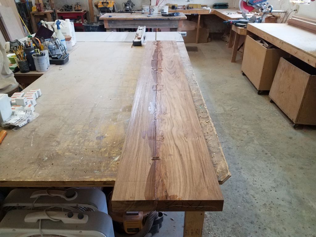
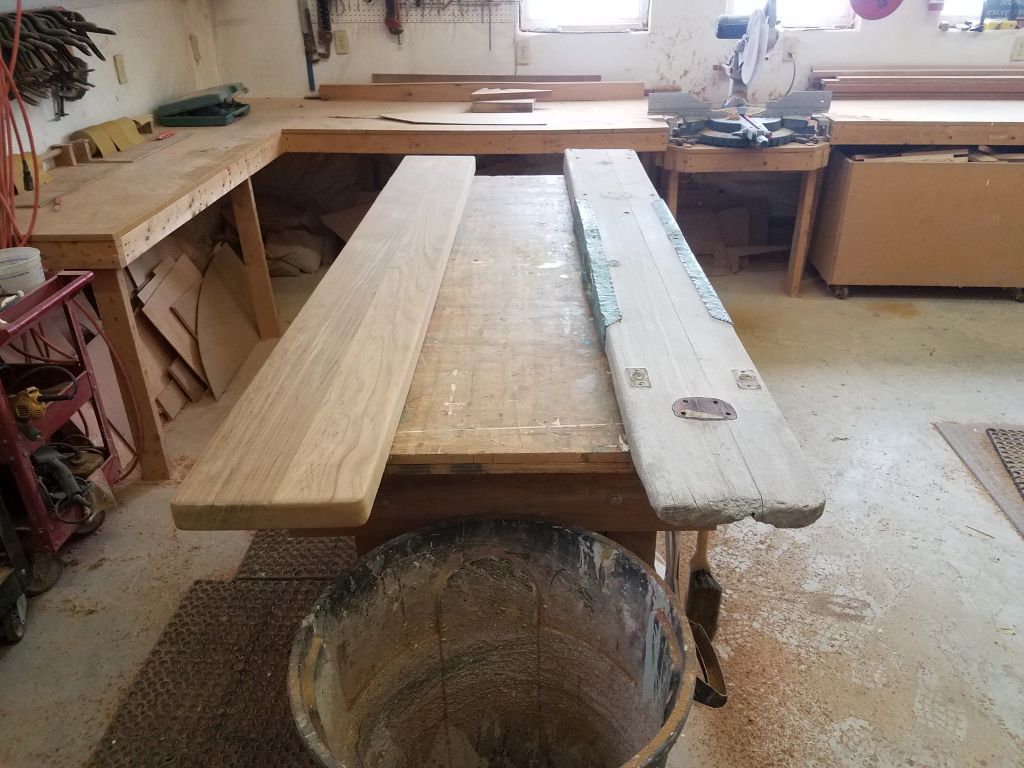
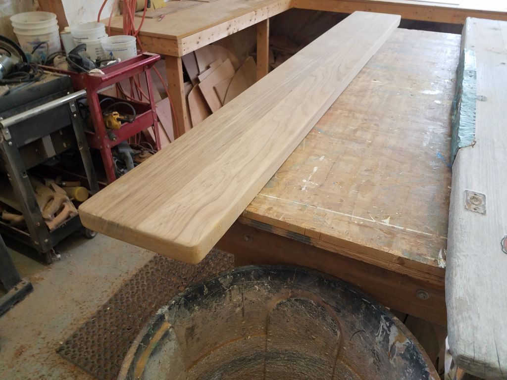
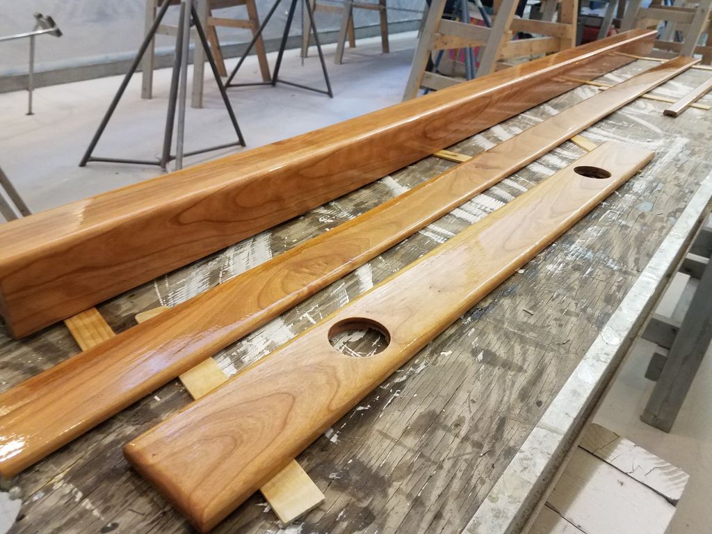
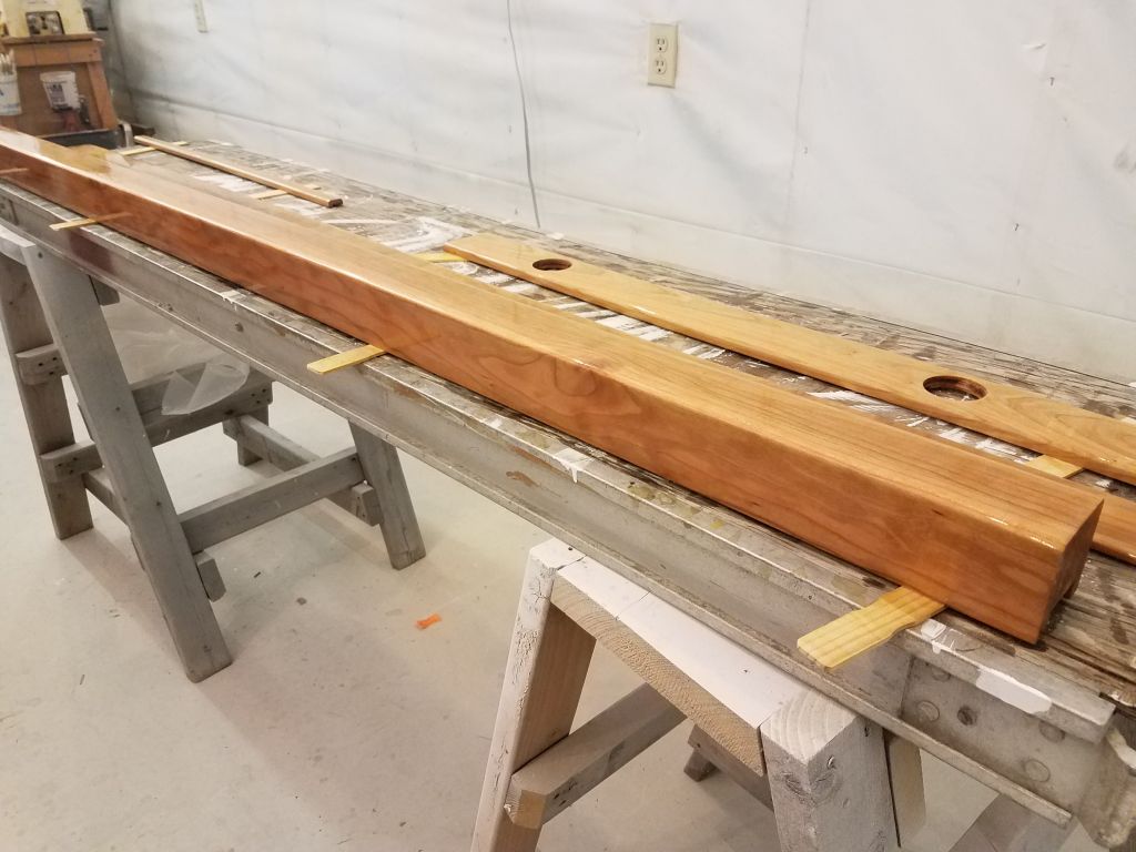
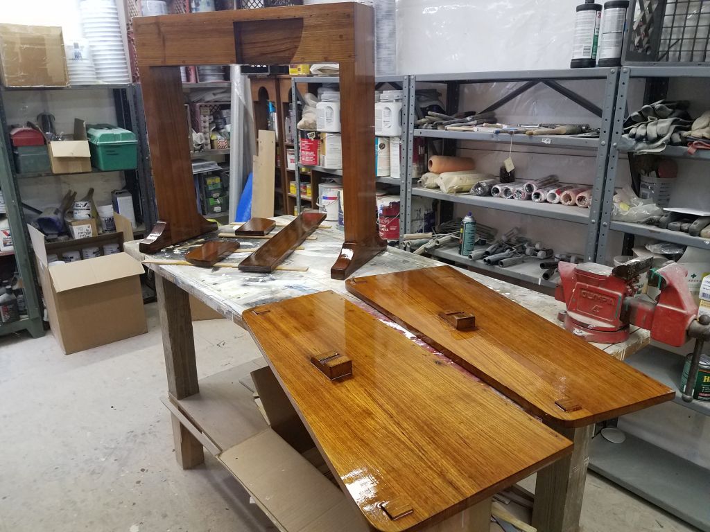
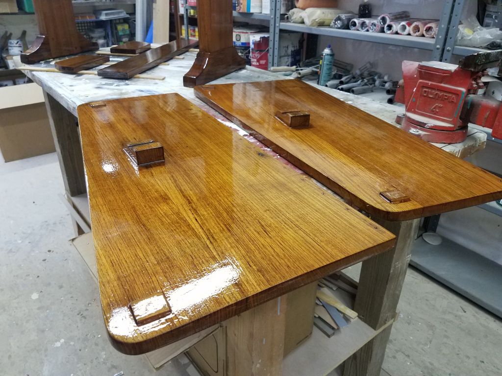
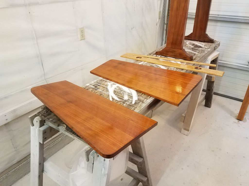
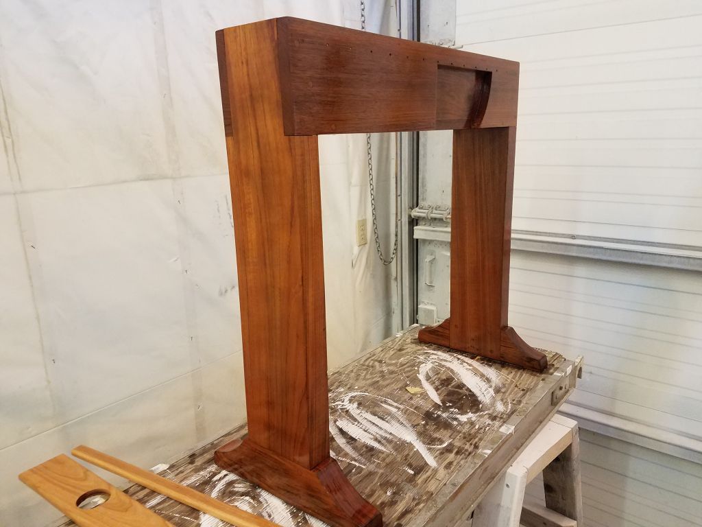
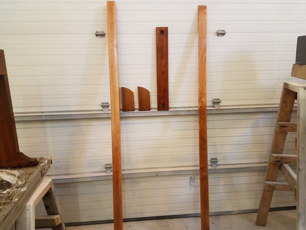
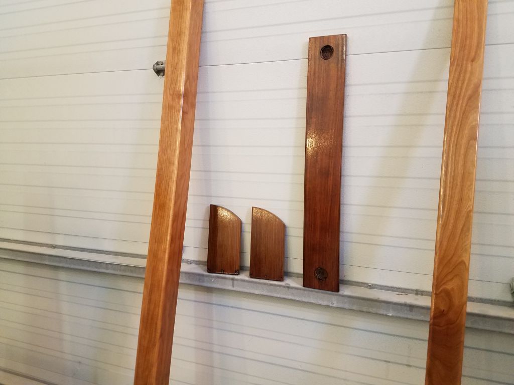
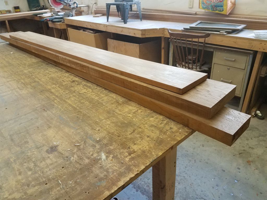
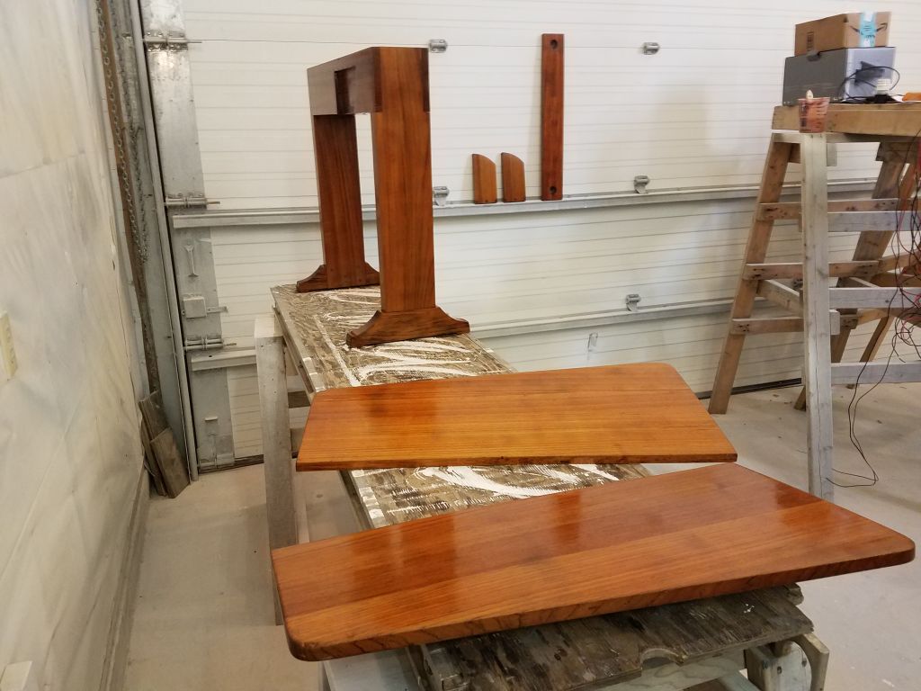
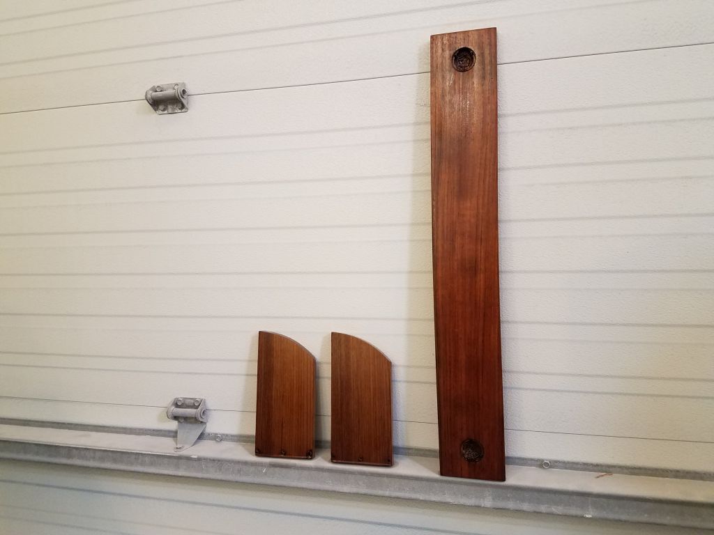
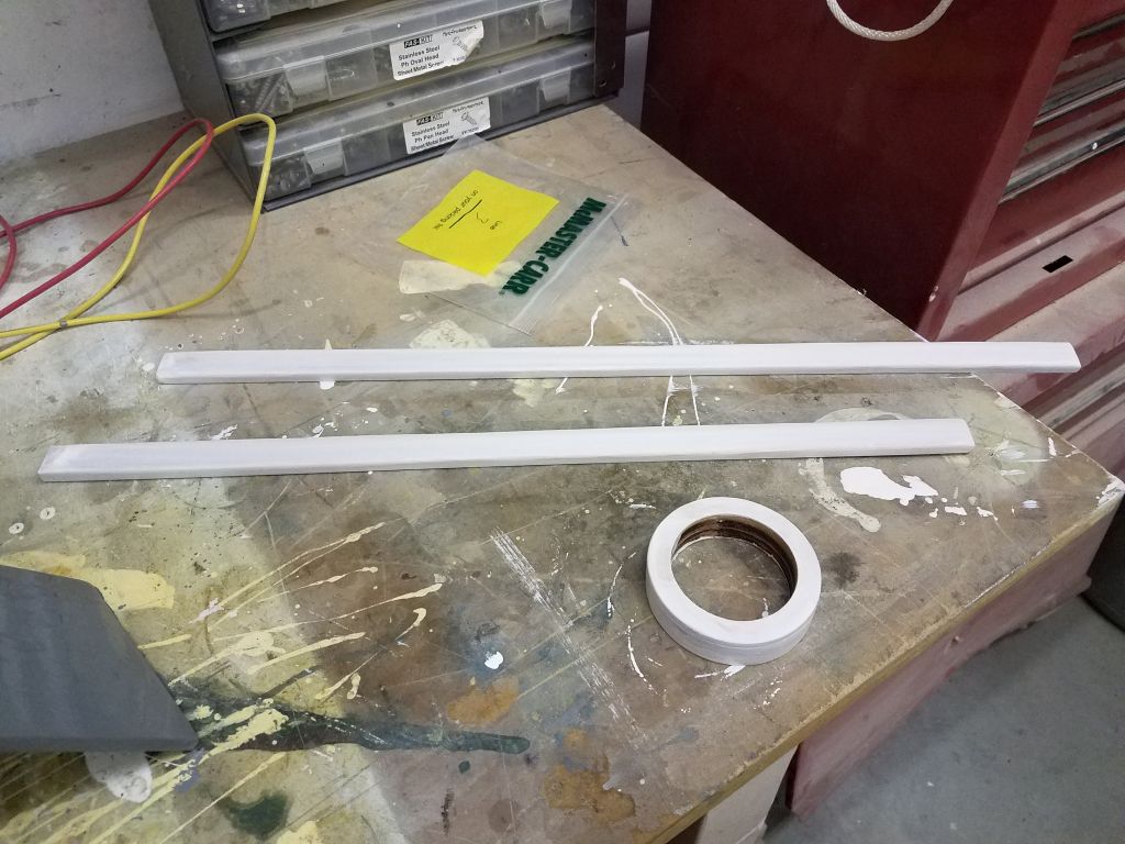
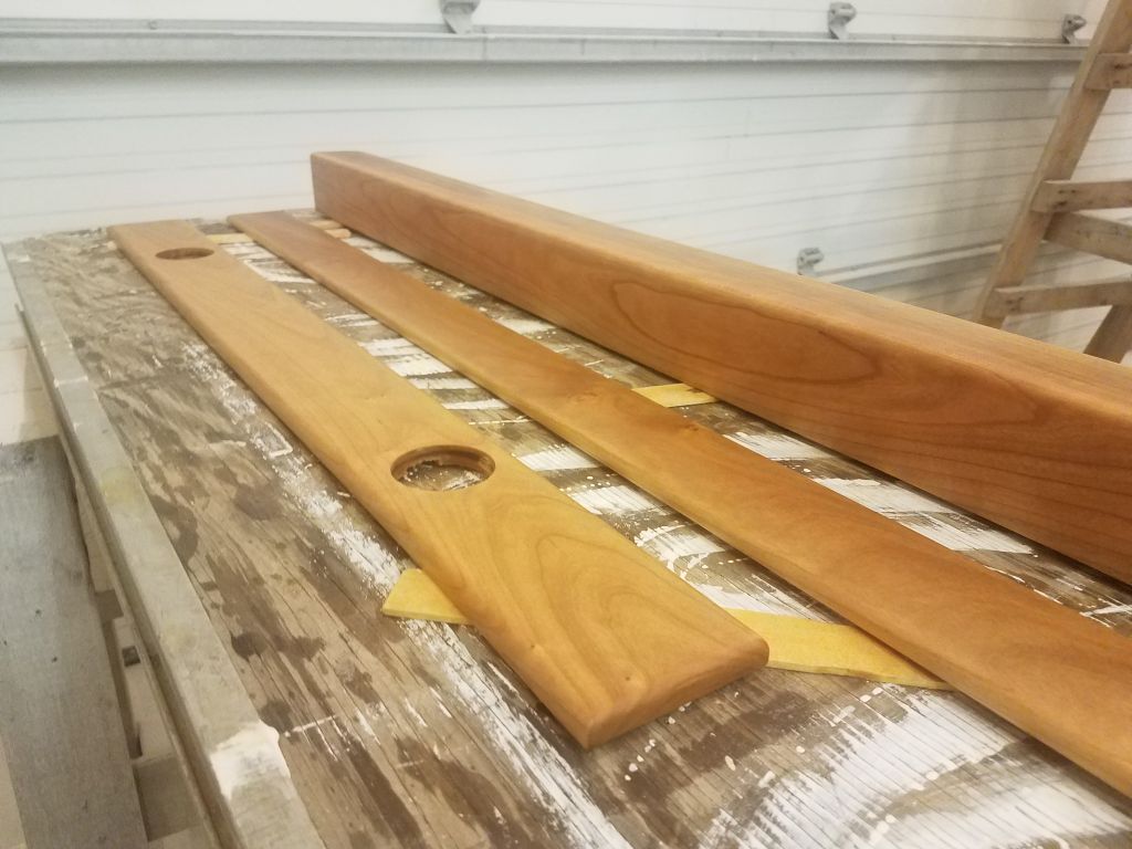
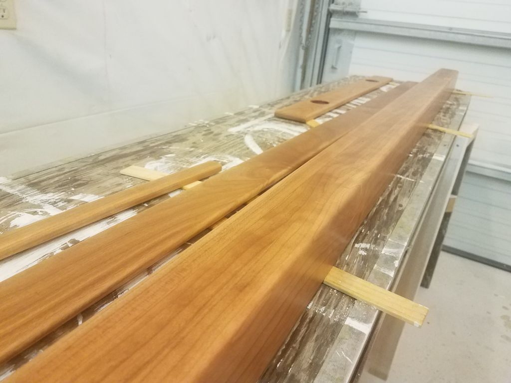
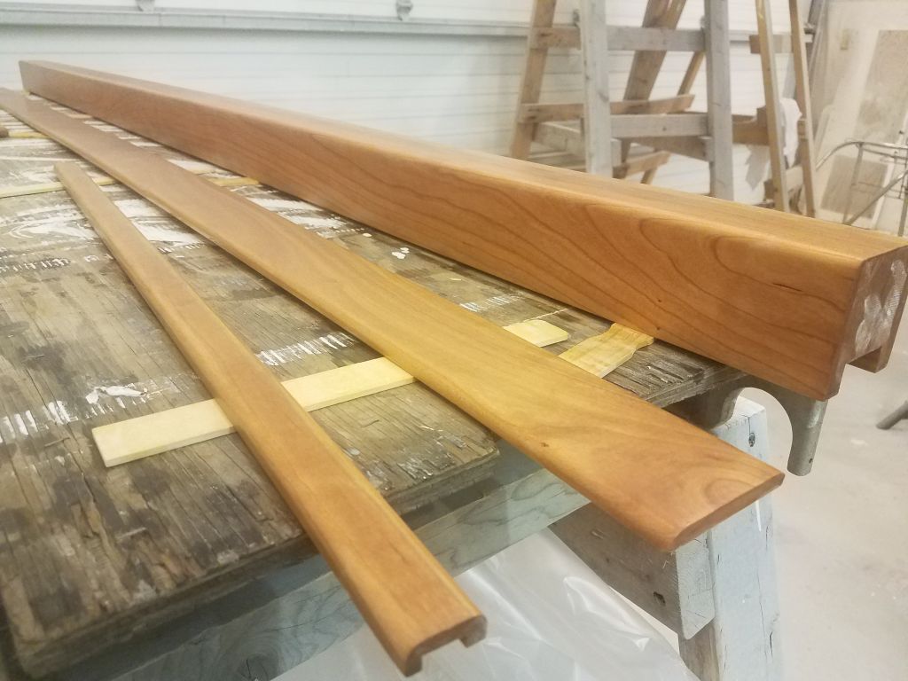
Over the weekend, I finished up the base coats of varnish on the various cherry trim pieces, and to start the day now I applied a final coat using satin varnish.

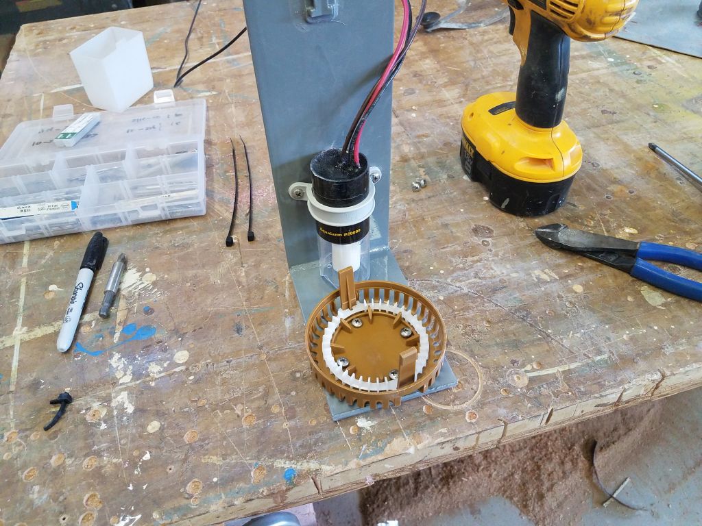
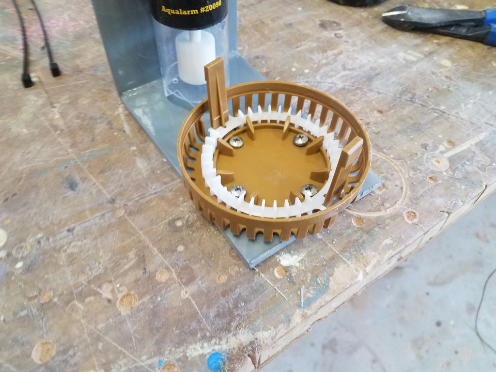
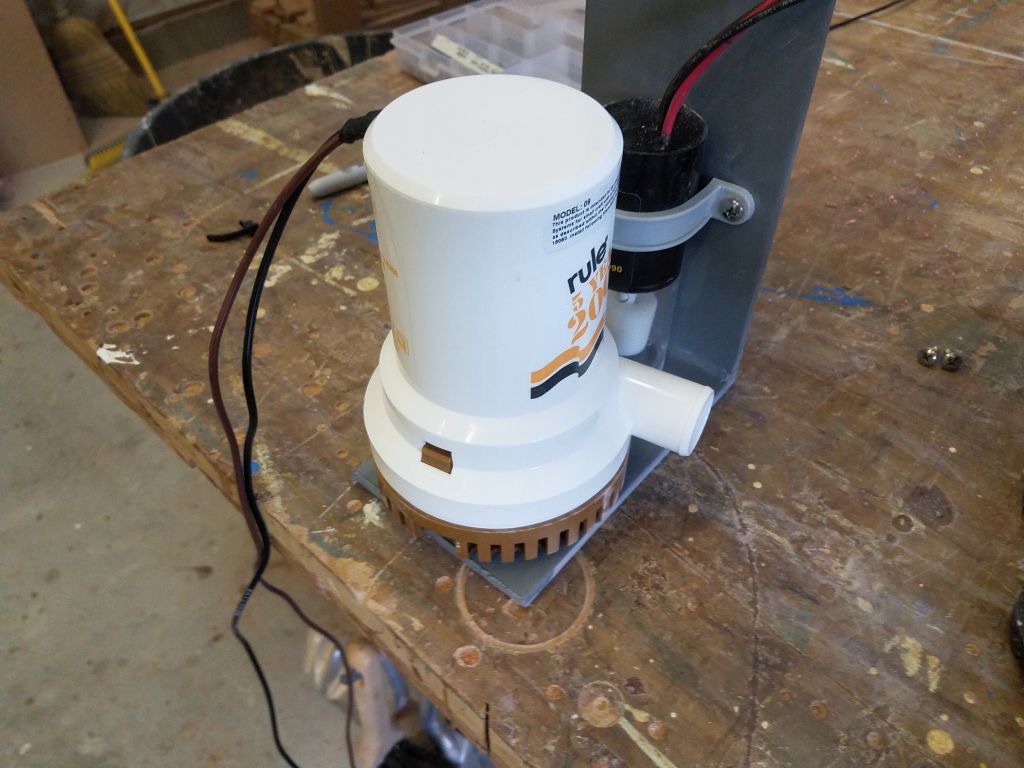
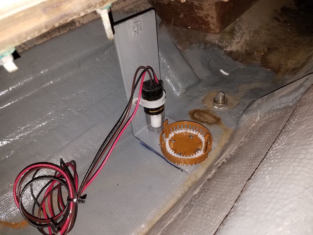
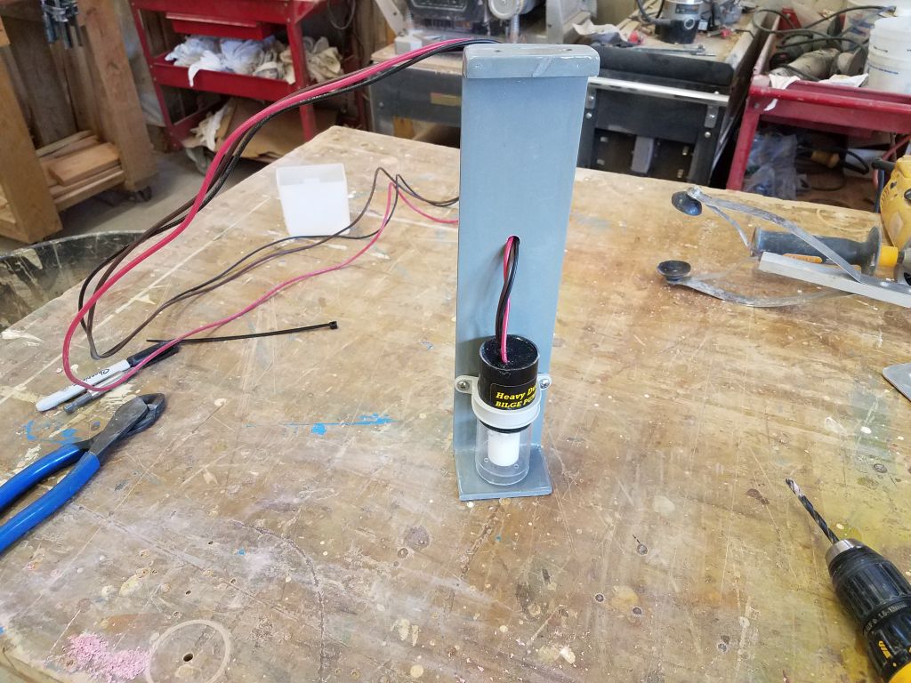
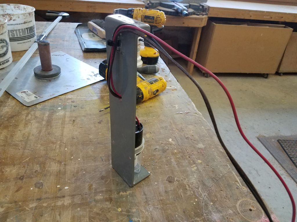
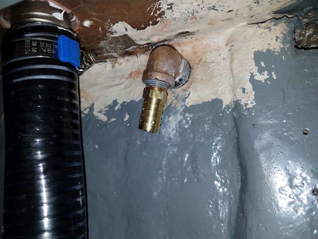
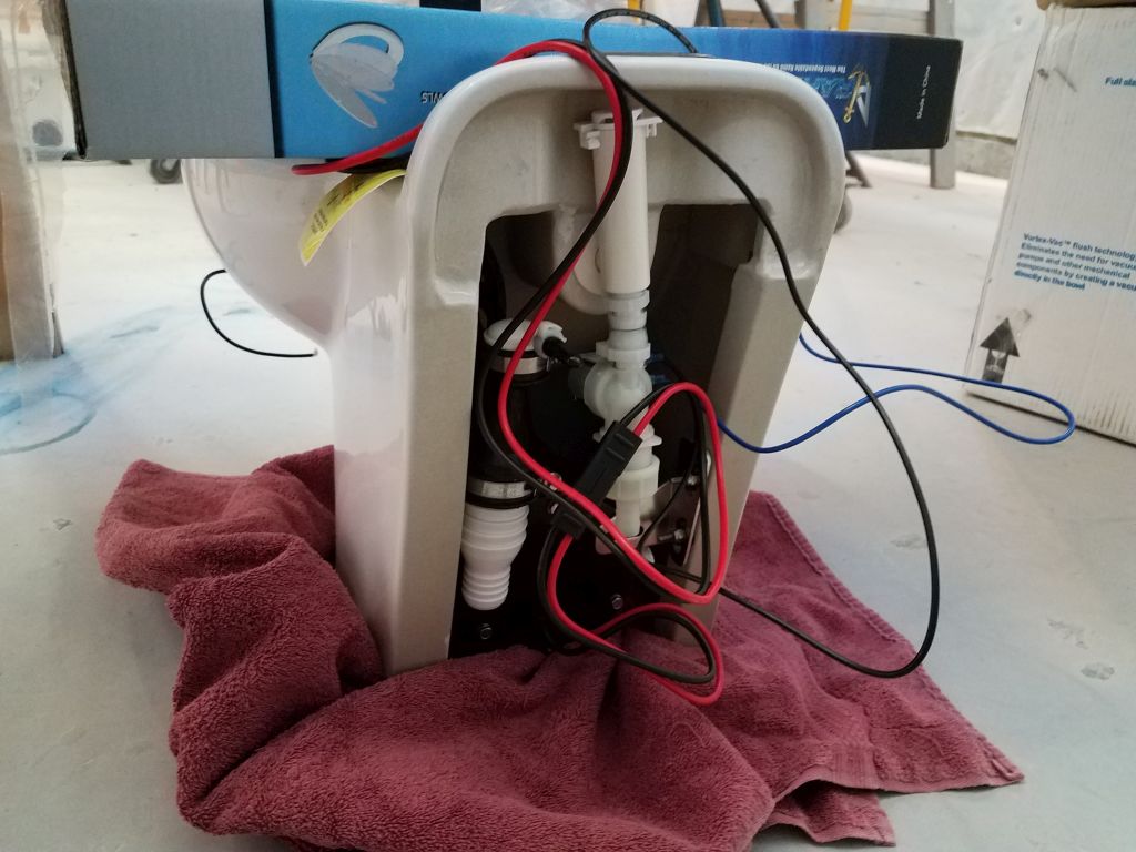
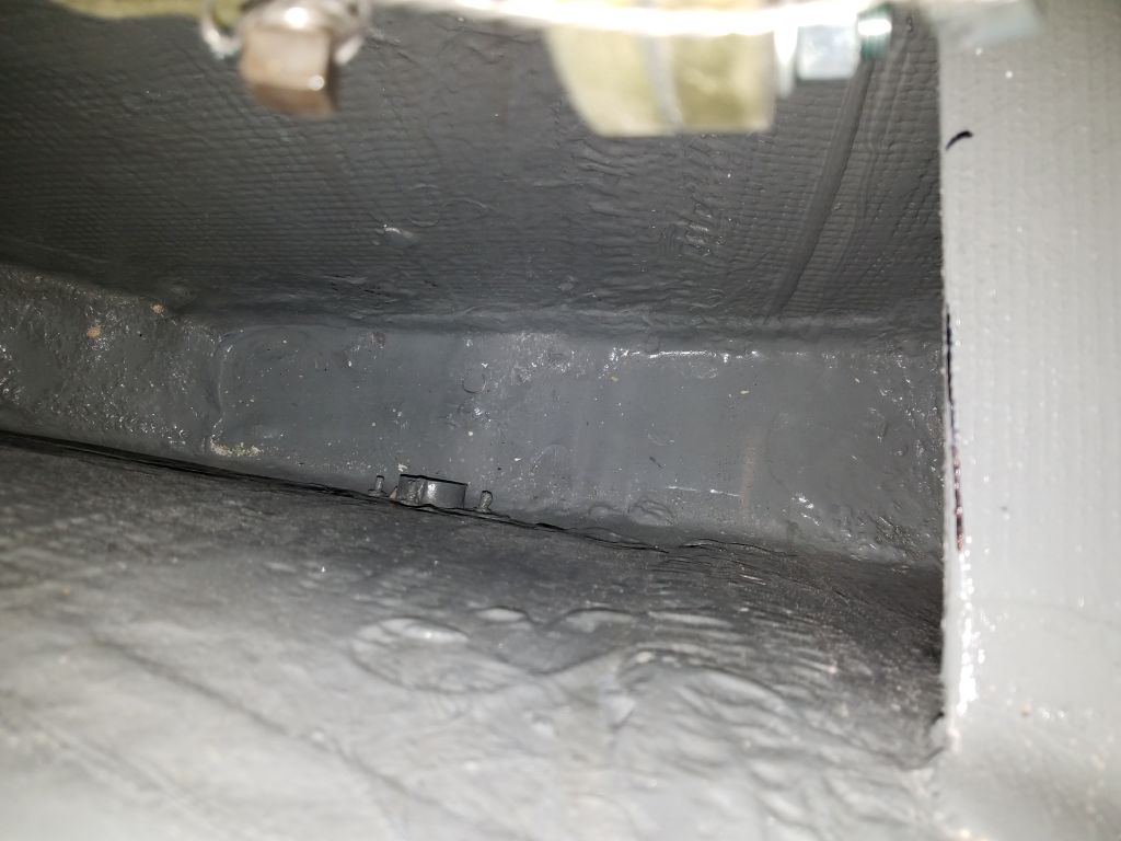
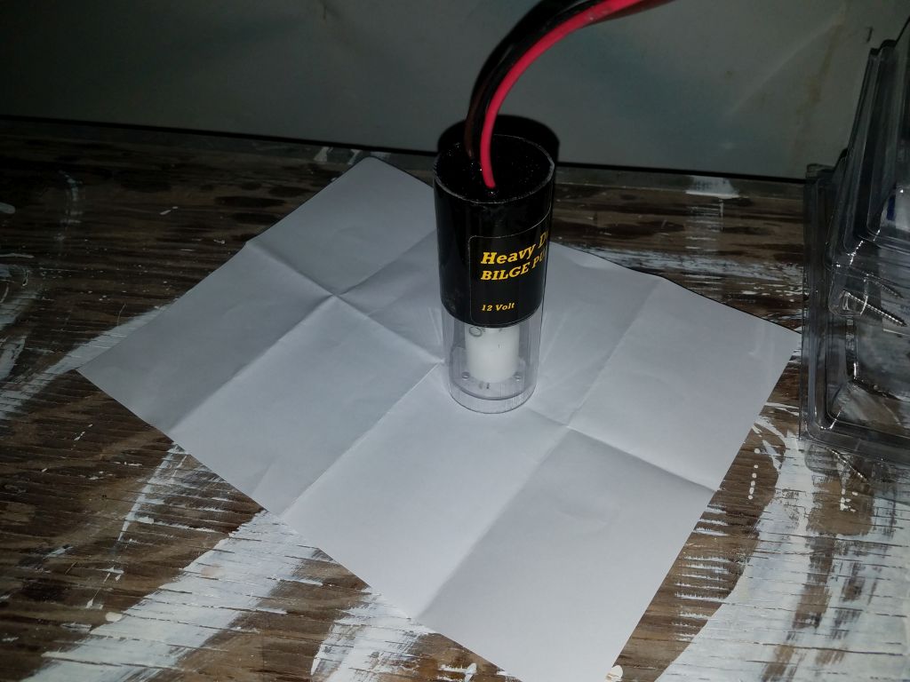
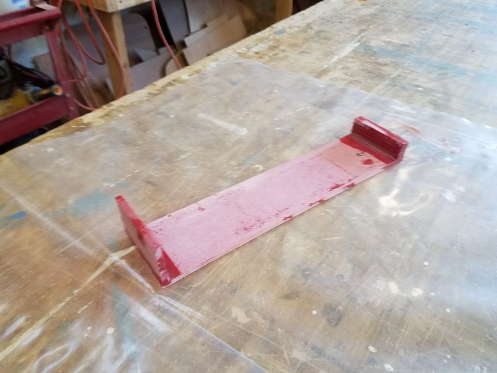
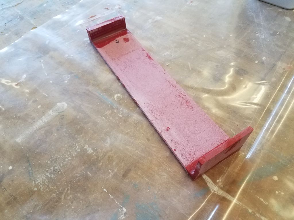
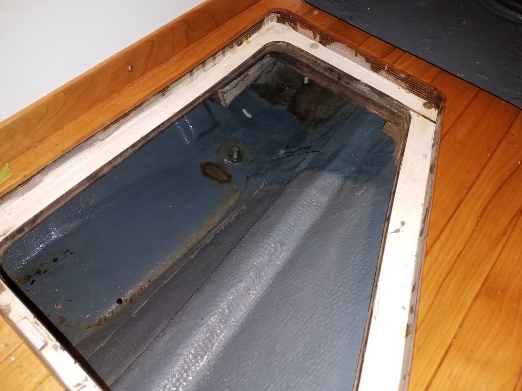
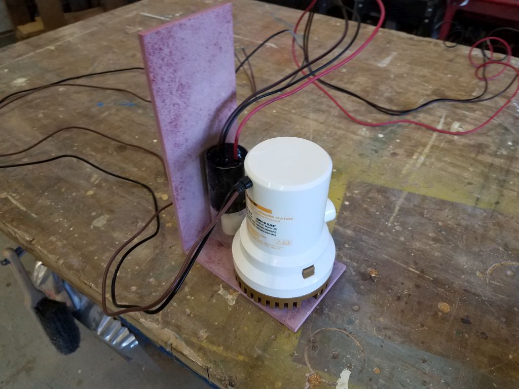
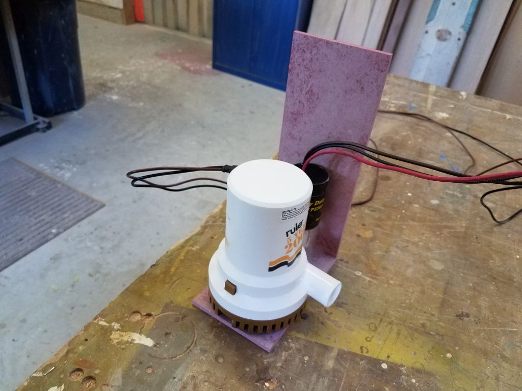
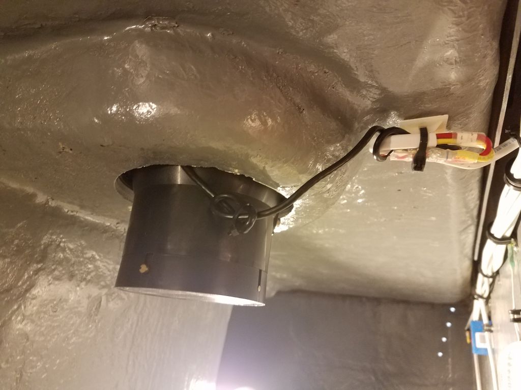
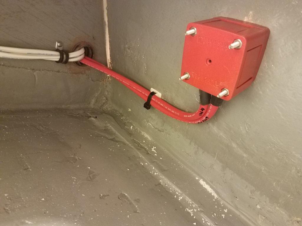
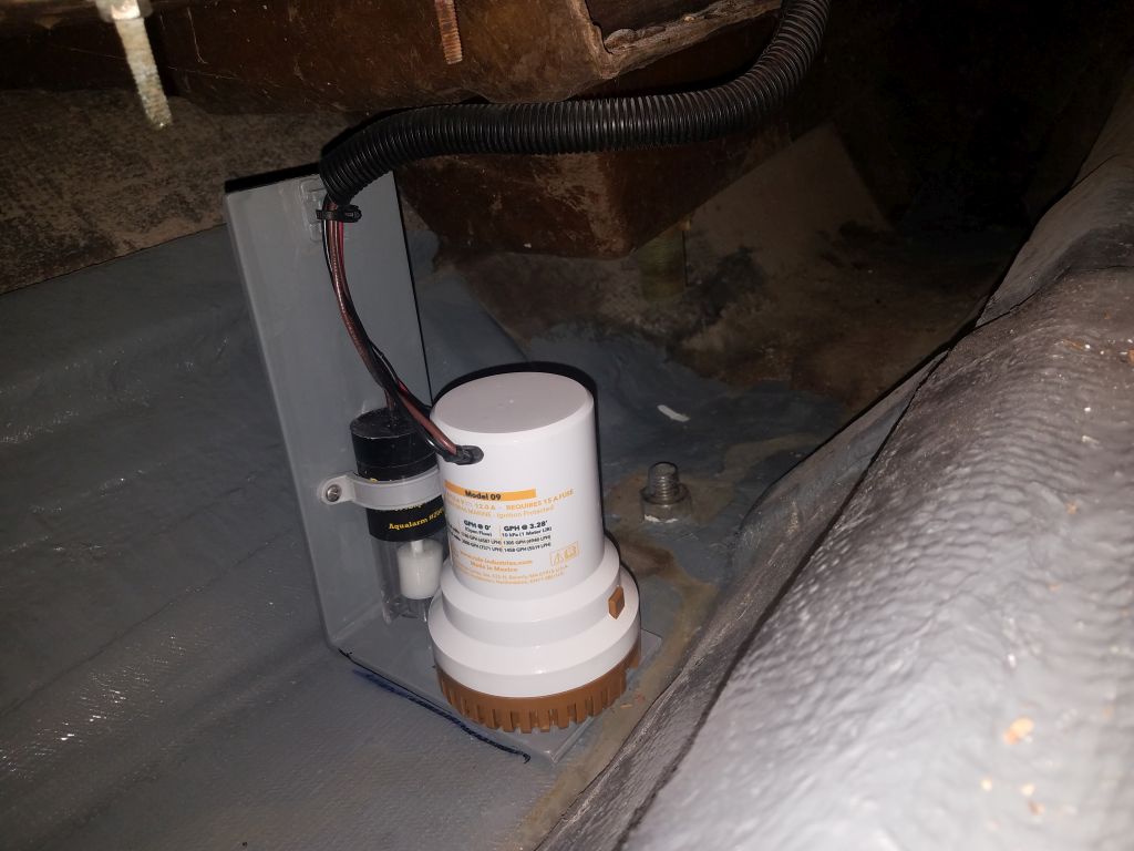
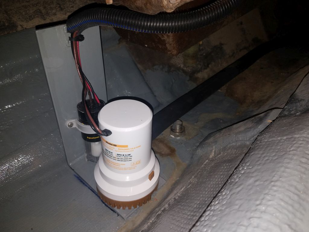
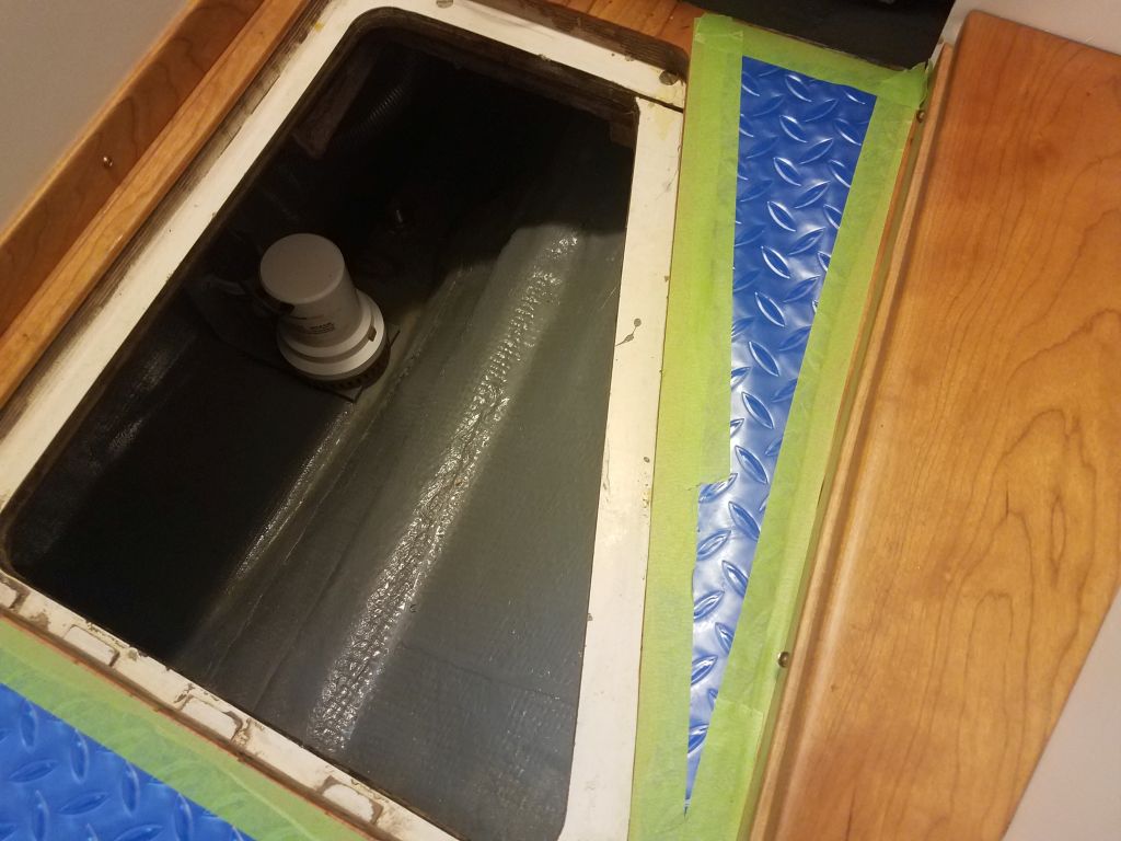
In the main bilge near the galley, I finished up the installation of the new centrifugal “emergency” pump and automatic switch.  Now that the pump bracket was secured to the boat, I snapped the pump back in place and, working from the engine room, led in a length of 1-1/8″ hose, which I connected to the pump.  For now, I left the other end of the hose wild in the engine room pending final connection to a new through hull.

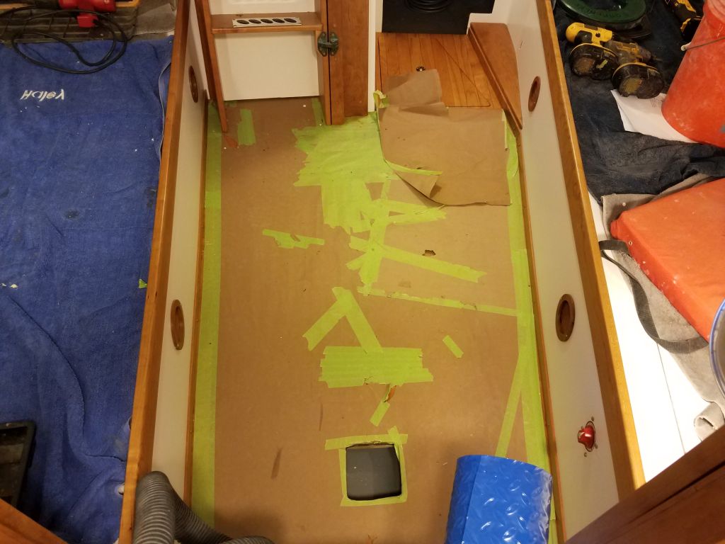
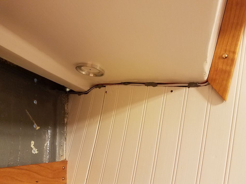
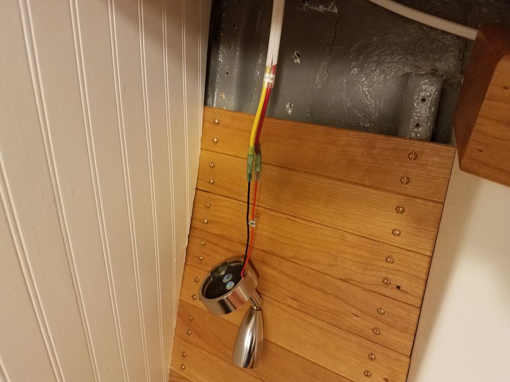
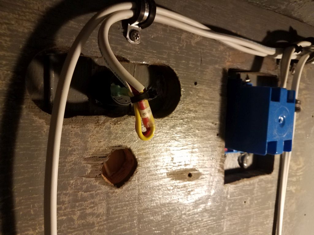
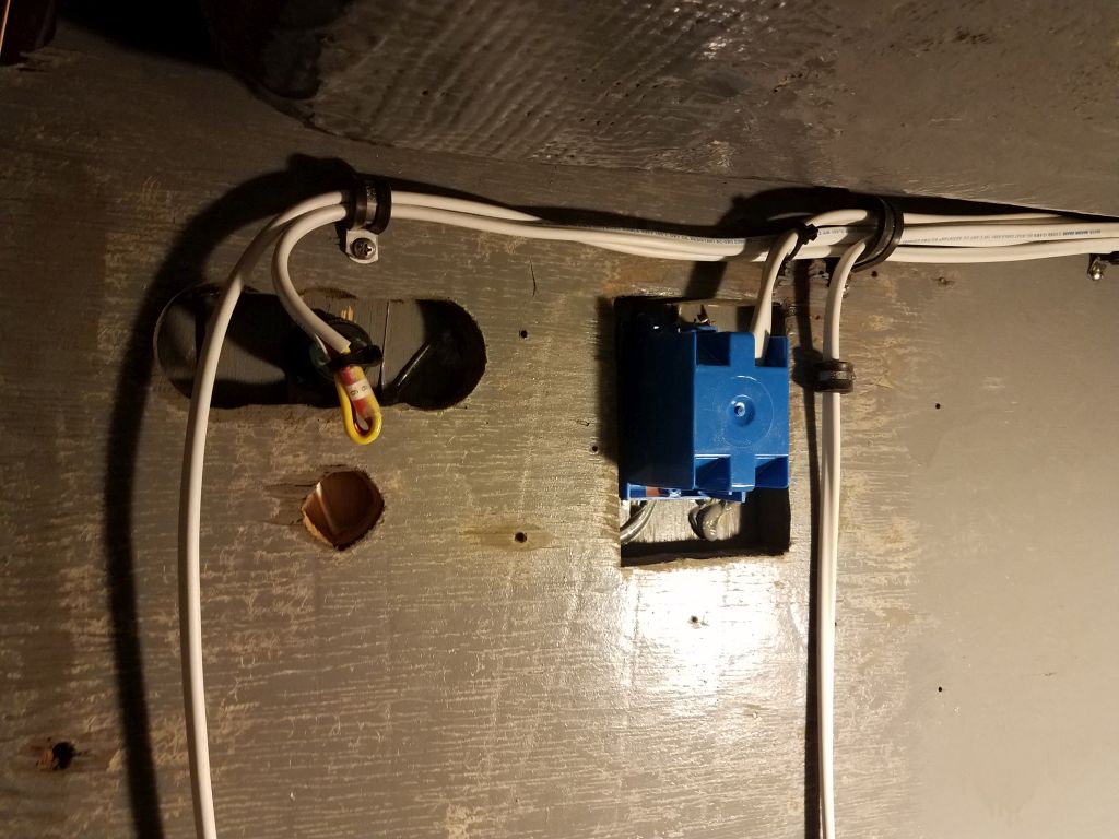
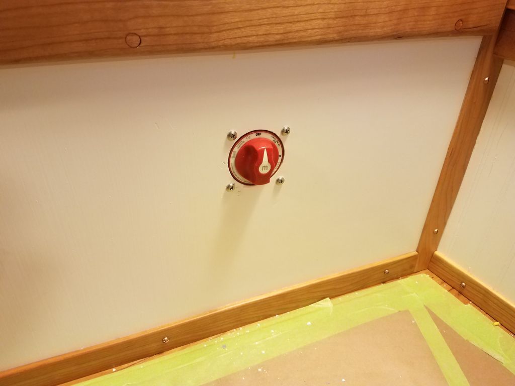
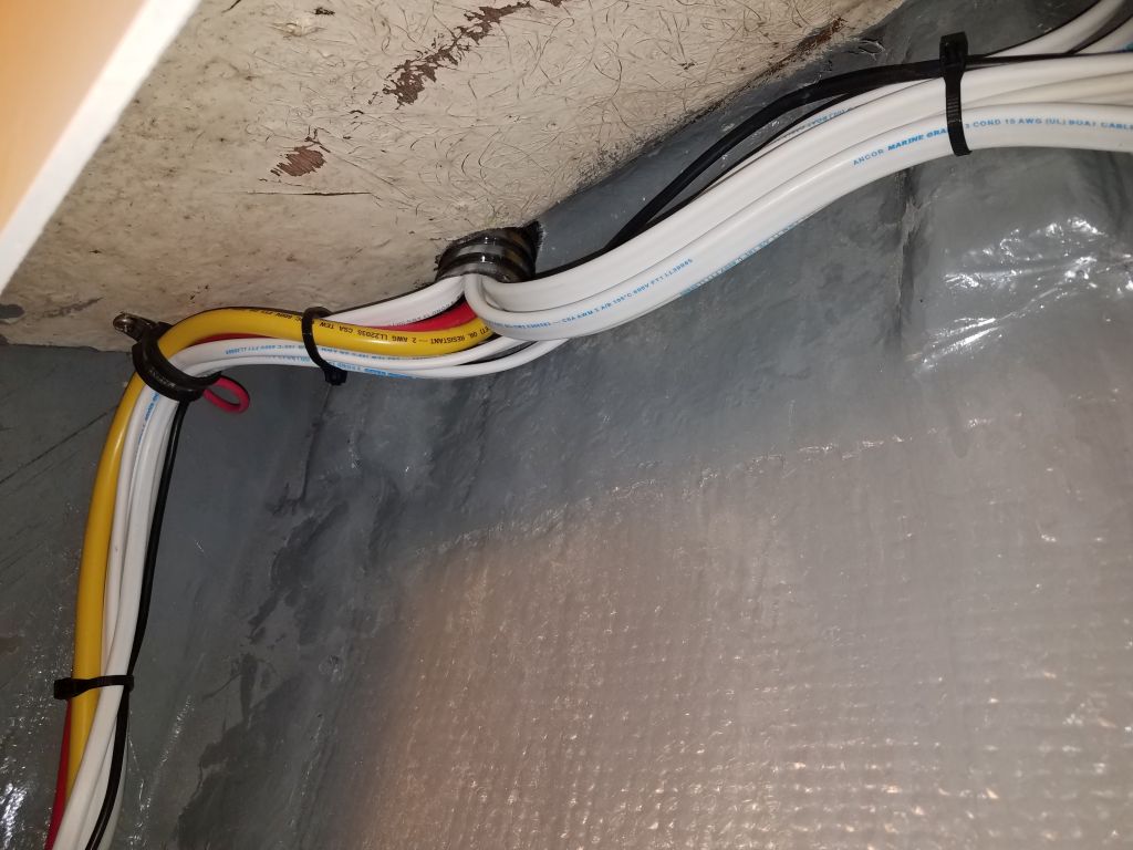
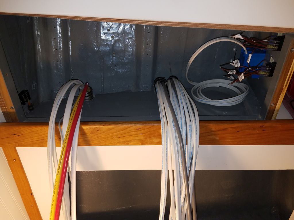
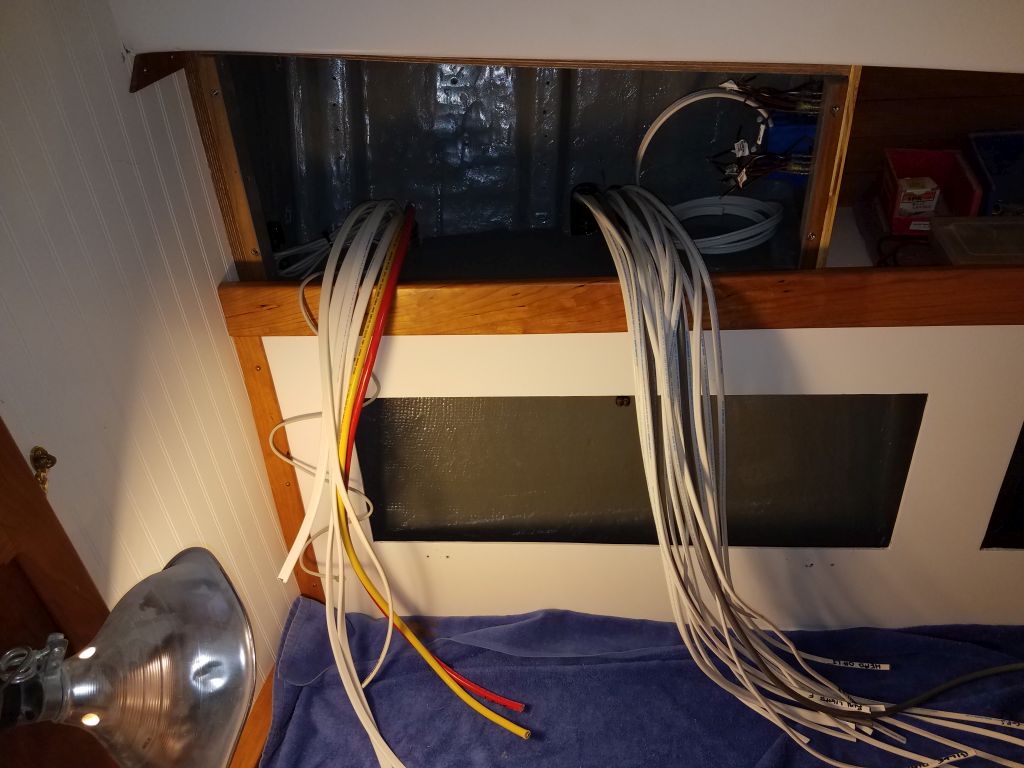
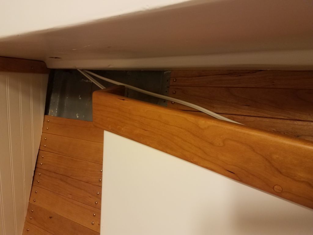
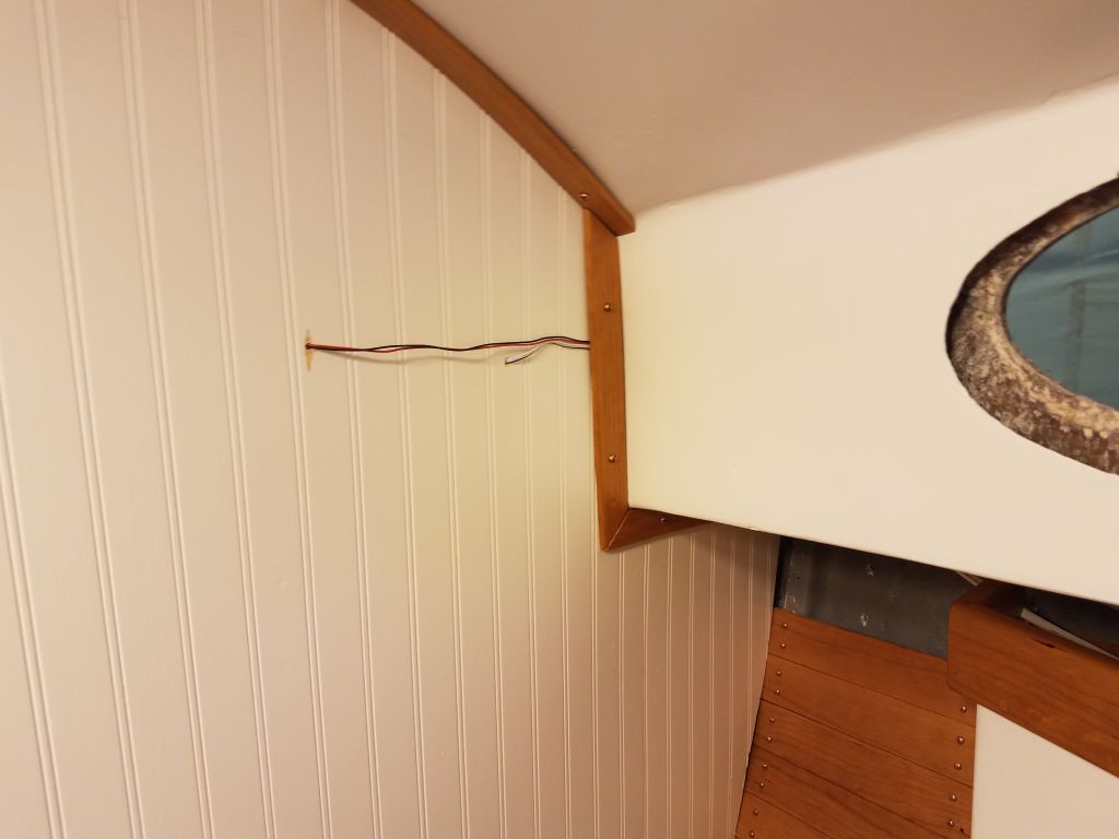
I ran the wires up through into the locker beneath the galley, where I eventually secured them to a terminal block held up out of the way on the inboard side of the locker, and connected the wire leading back to the panel to the other side of the terminal.  This provided a straightforward way to make up the connections between the pump and switch to allow manual or automatic operation; I’d finish up the wiring at the panel end a little later.

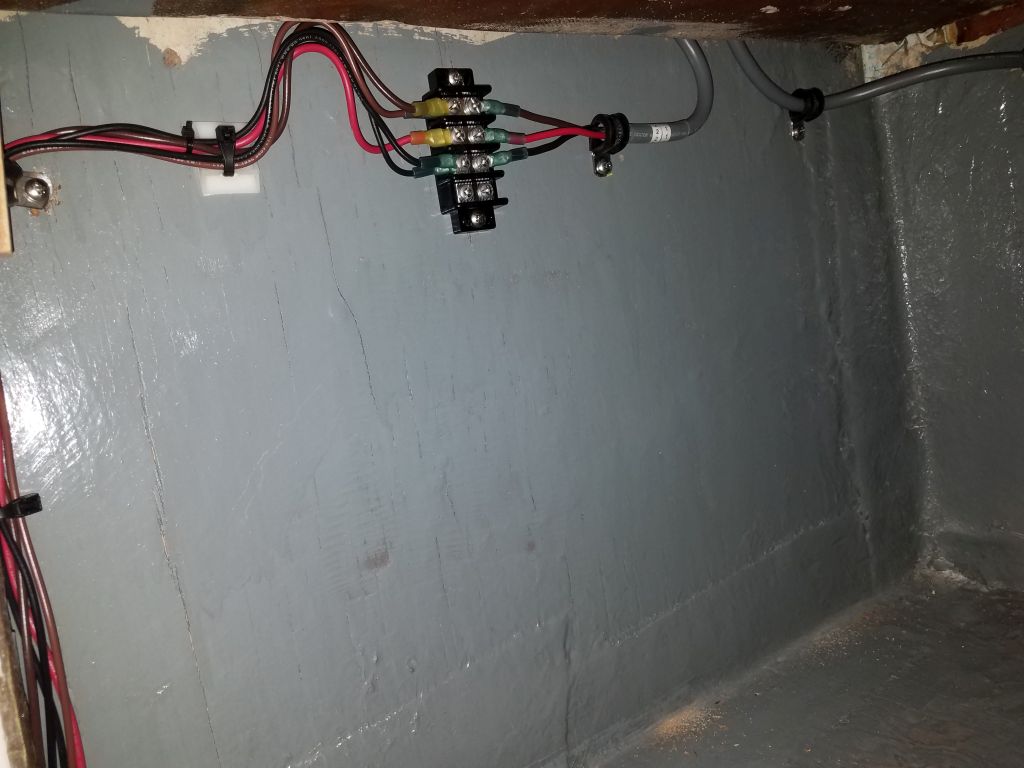
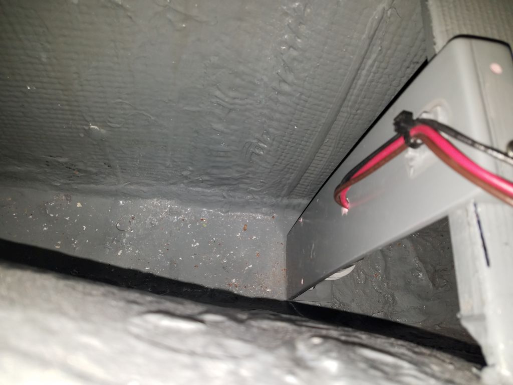
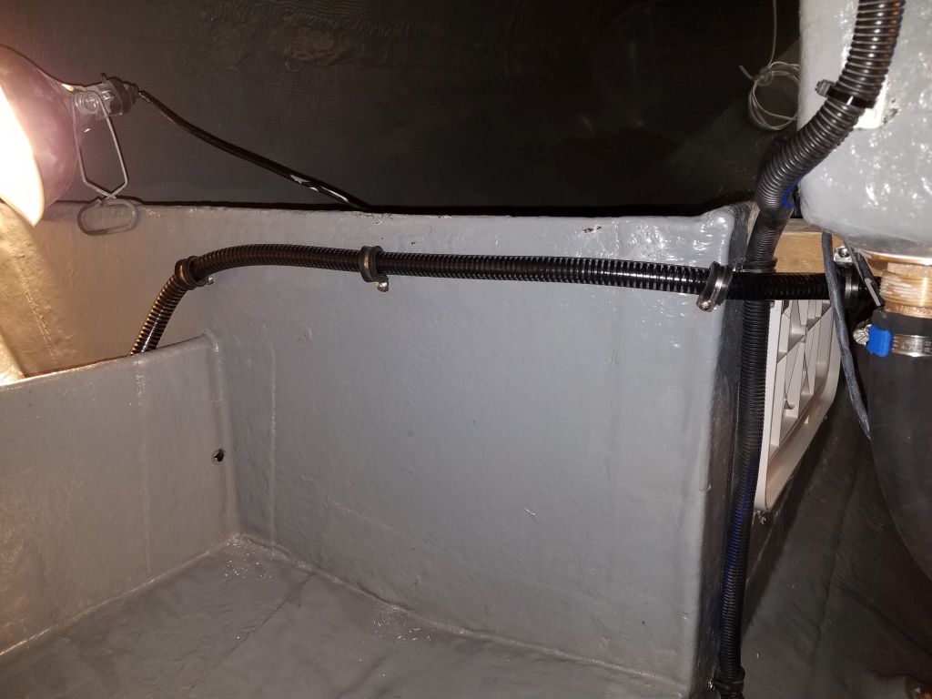
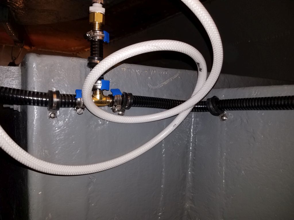
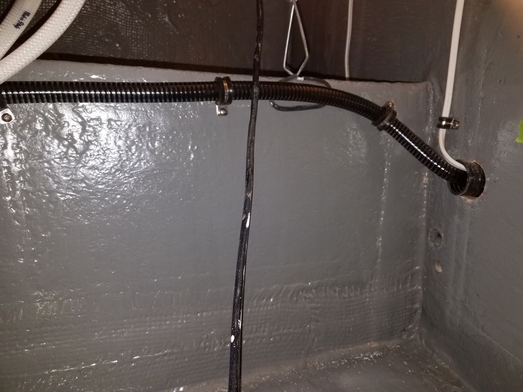
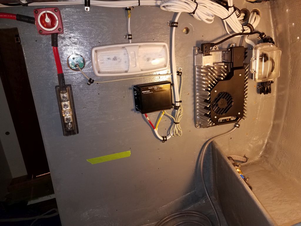
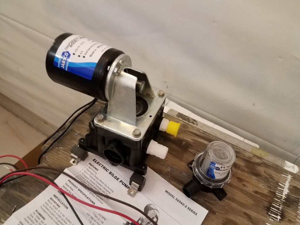
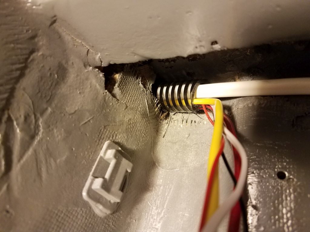
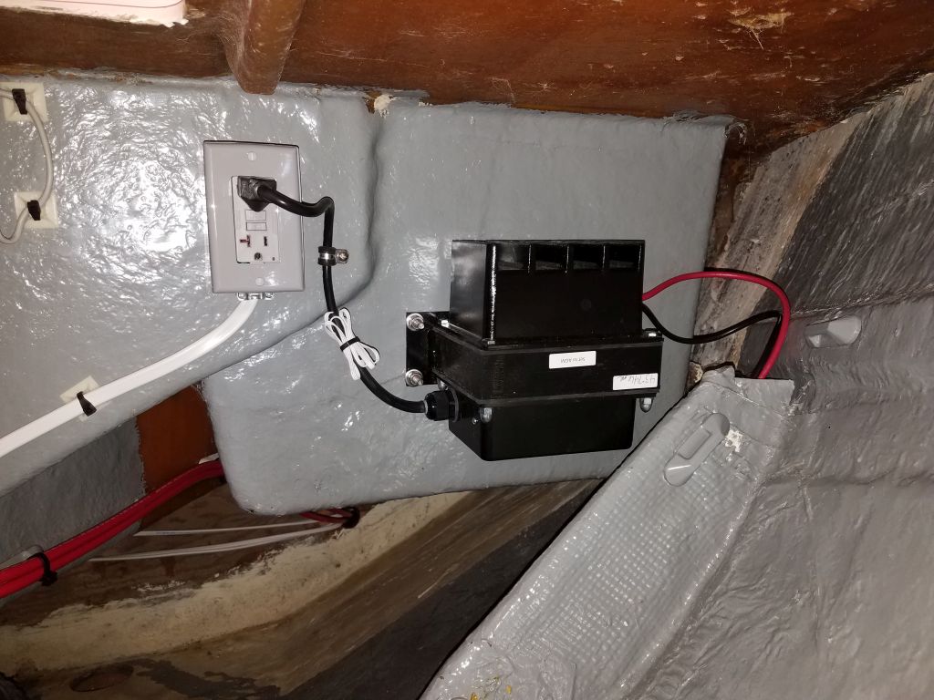
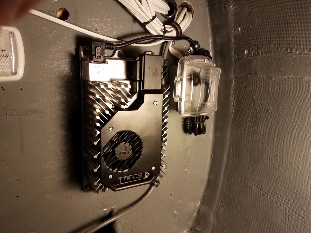
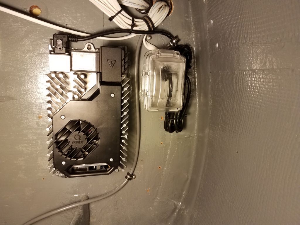
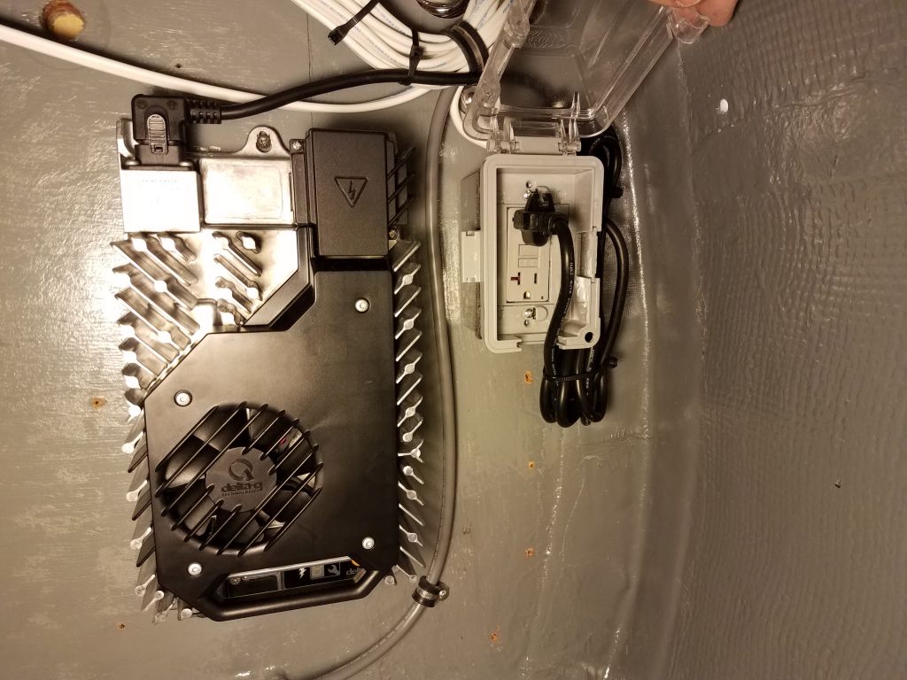
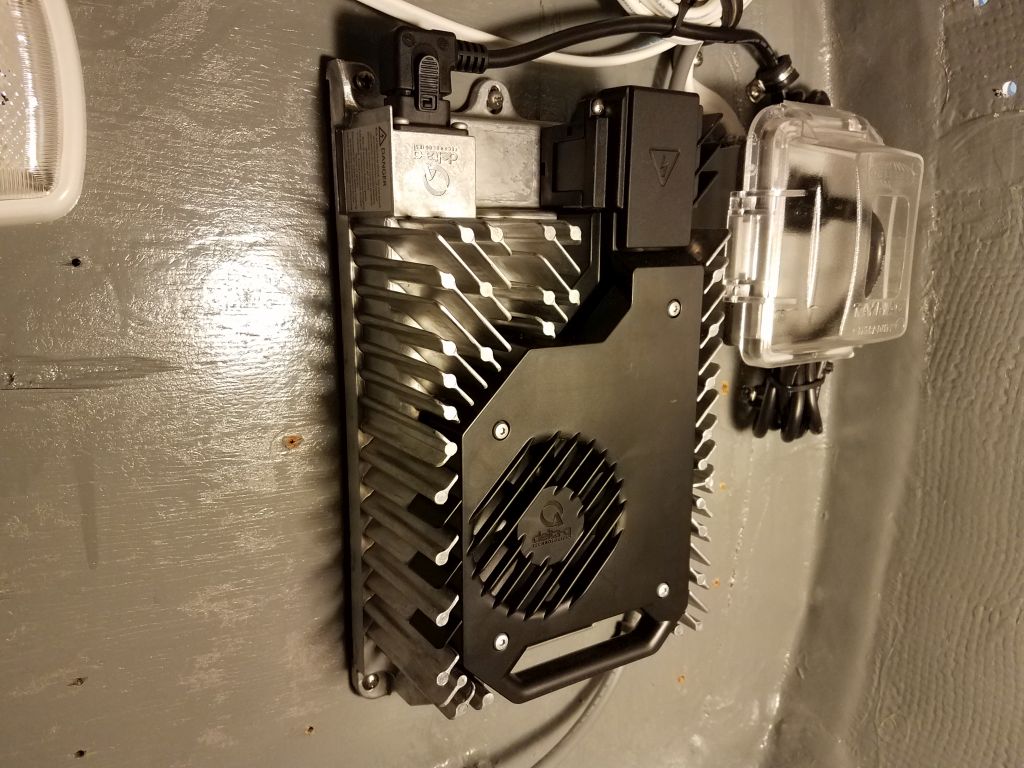
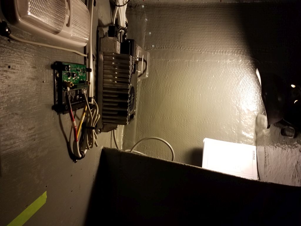
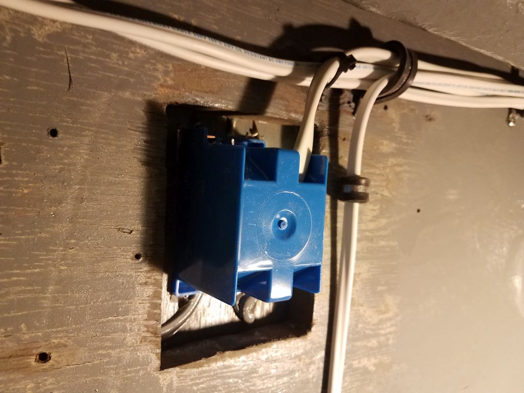
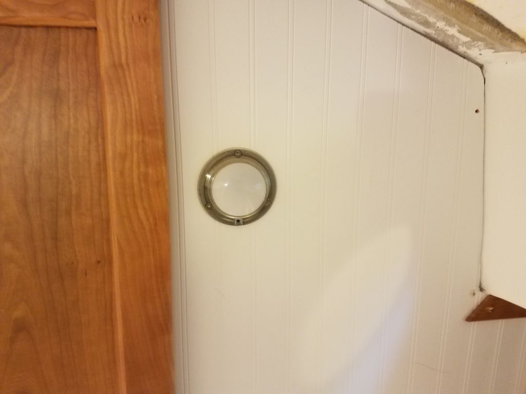
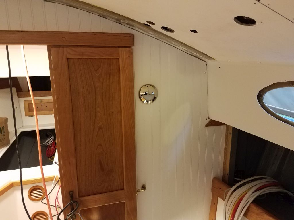
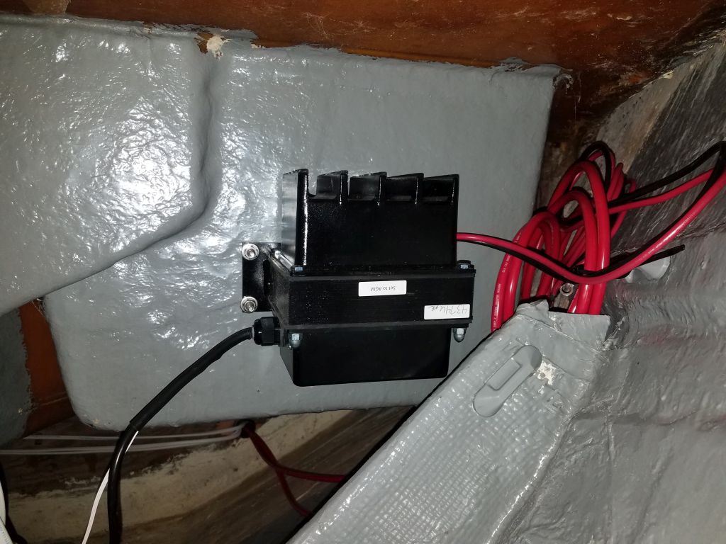
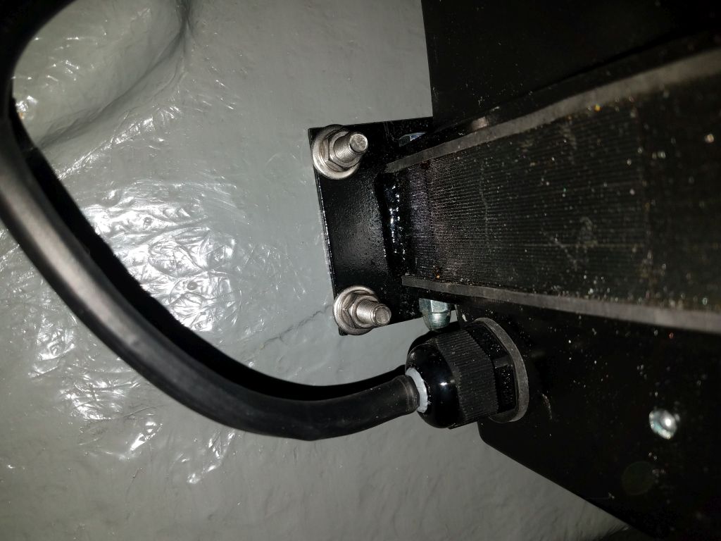
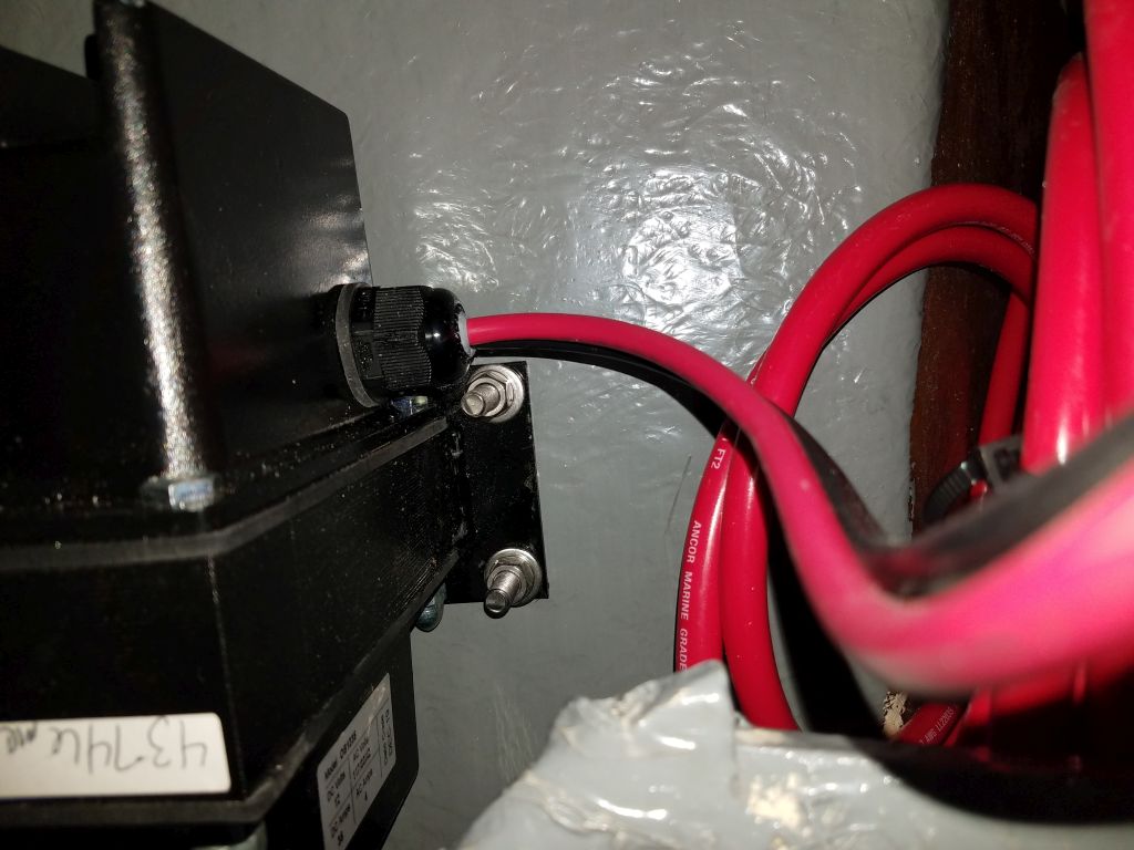
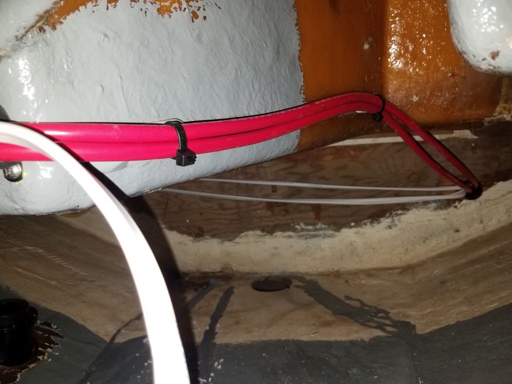
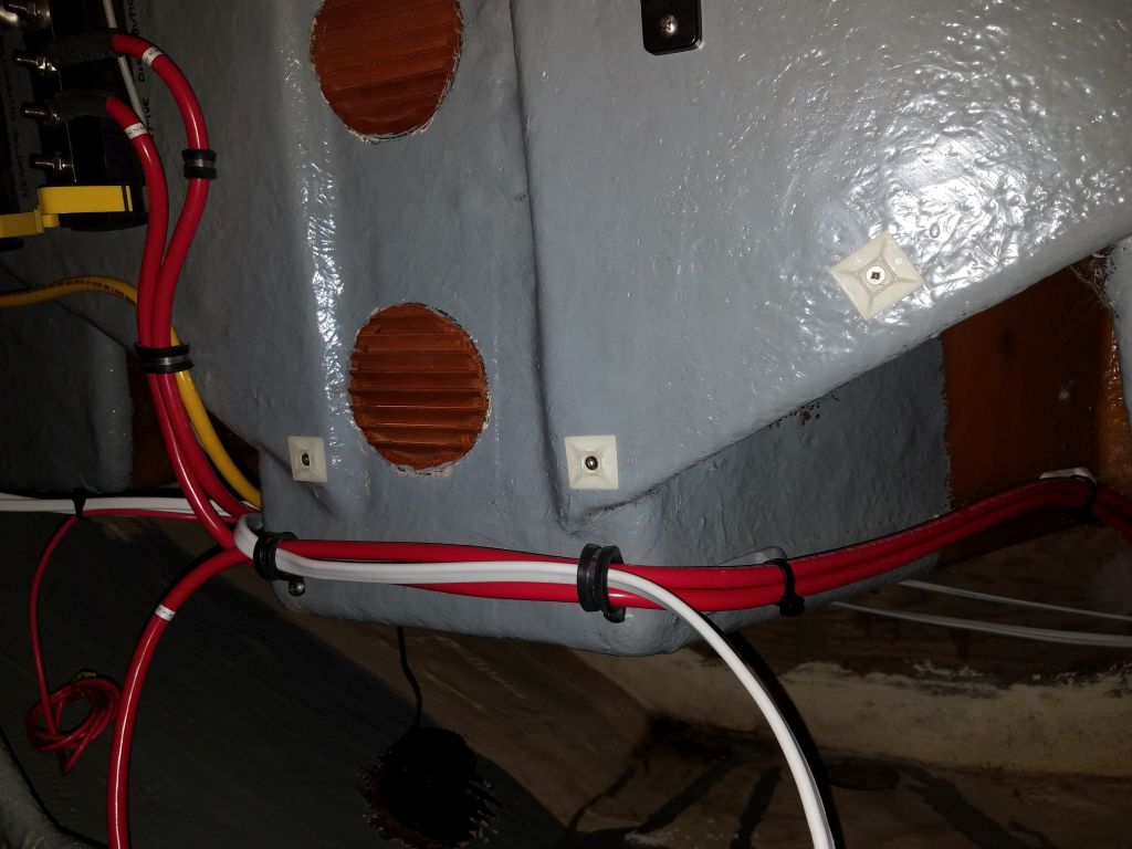
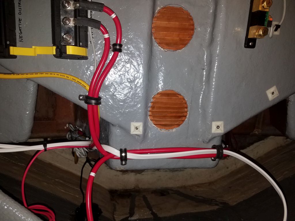
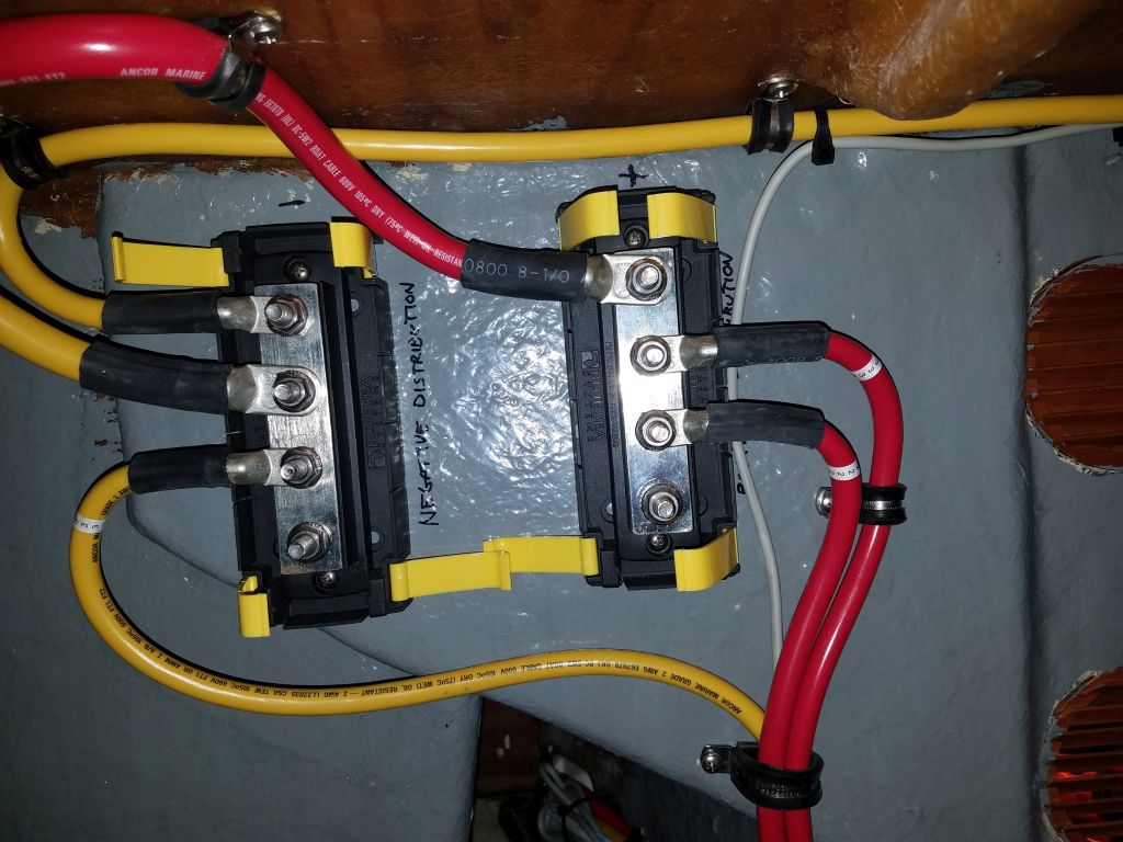
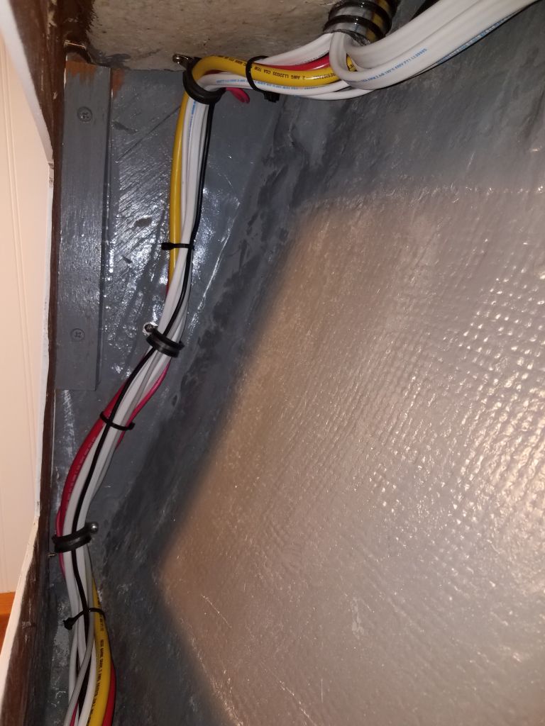
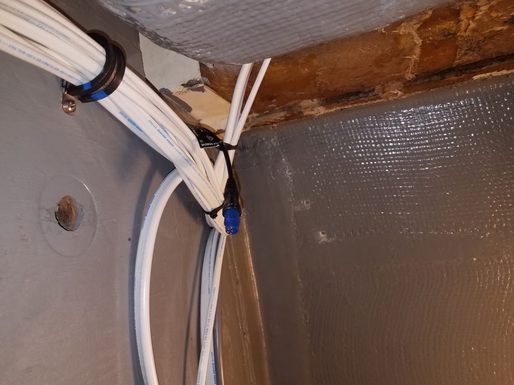
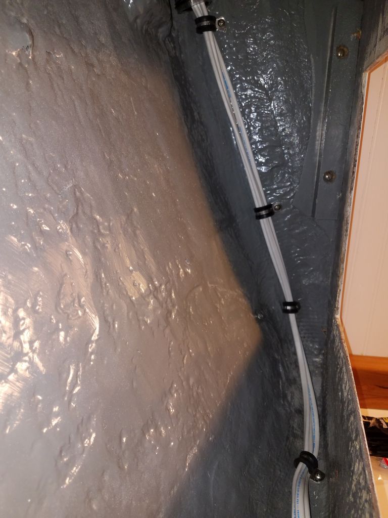
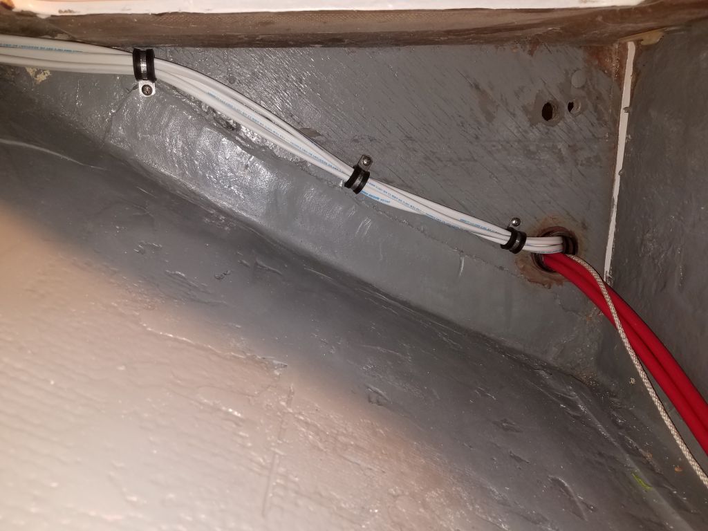
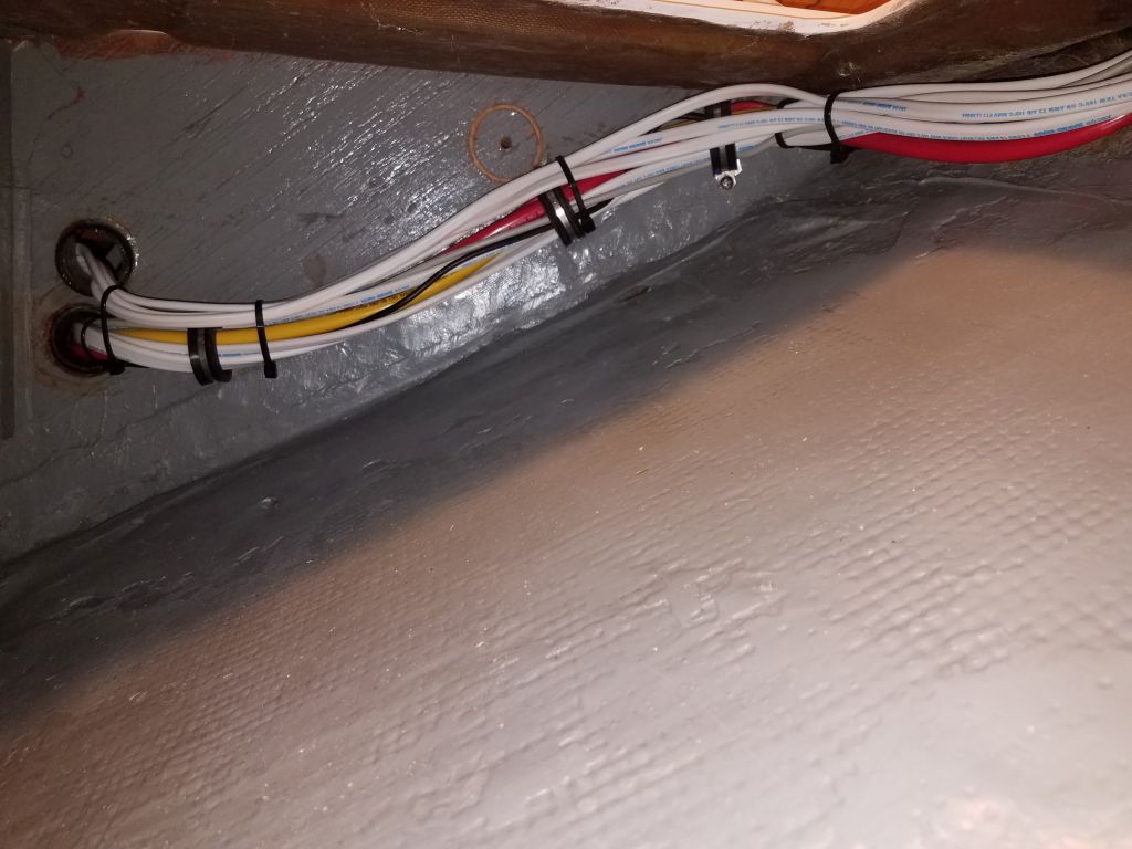
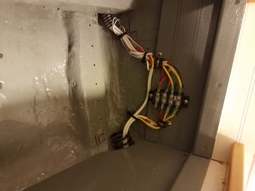
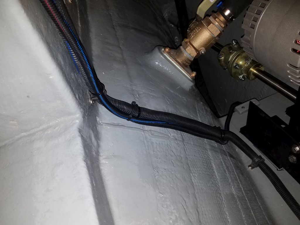
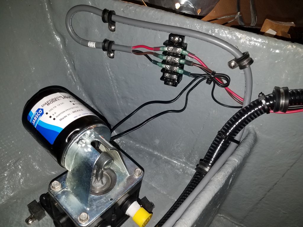
In the engine room, I continued work on the second, main pump:  a diaphragm pump designed for routine and complete dewatering of the bilge.  I’d already installed the bracket and automatic switch in the bilge, and now I led the switch wires through flexible conduit and along the path of some other wires already in place in the engine room and over to the starboard side, where I chose to install the diaphragm pump on a shelf at the outboard side of the engine room.  I wired up the pump and switch to the cable leading to the panel through another terminal block.

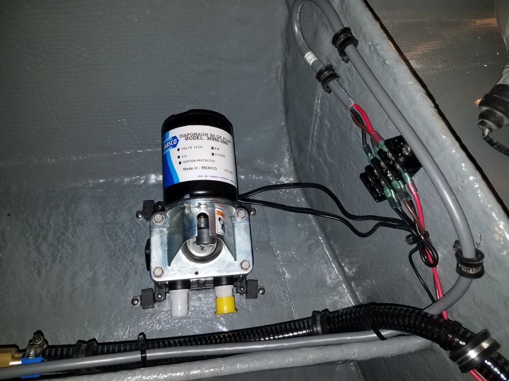
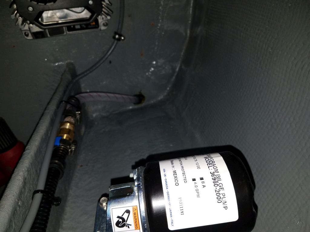
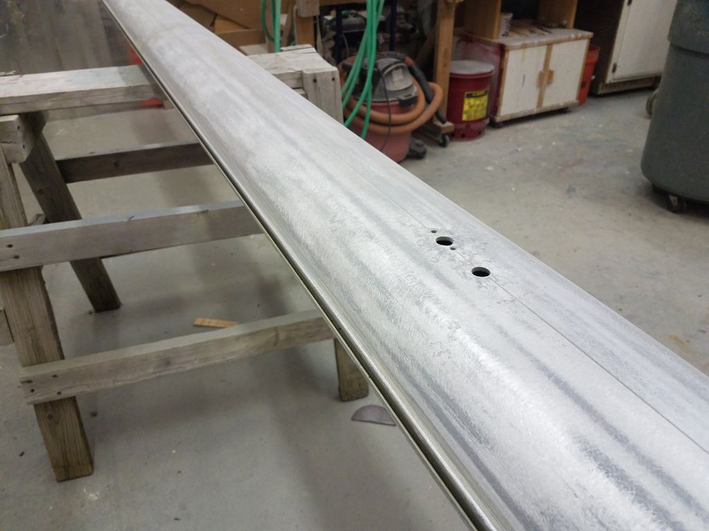
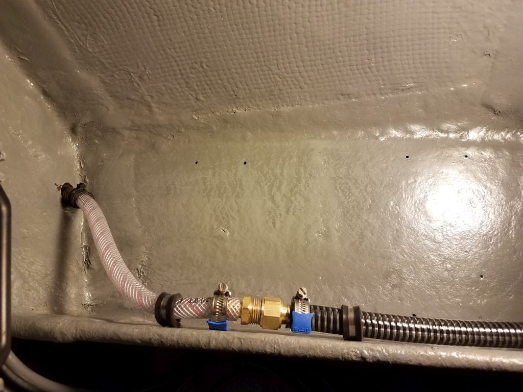
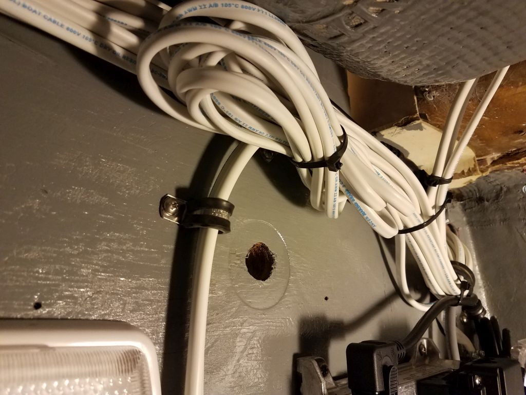
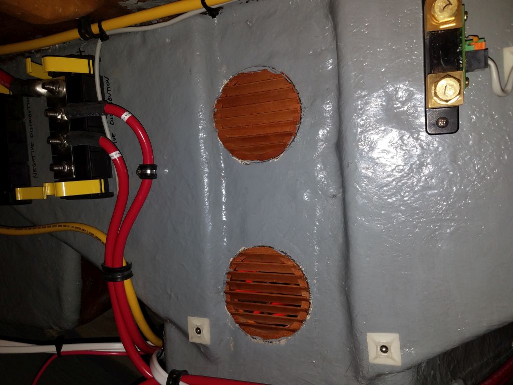
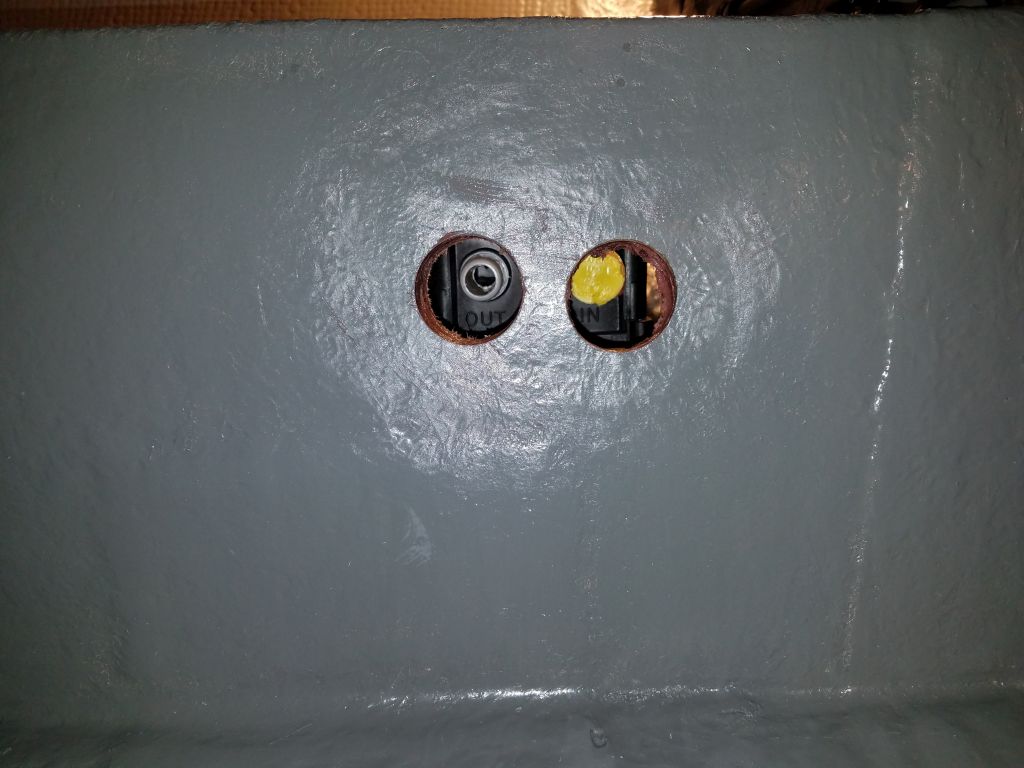
To lead in the suction and discharge hoses for the pump, I drilled a pair of holes through the divider at the side of the pump, in line with the two ports on the pump itself.  I found a plywood void in one of the holes, and while the divider was non-structural, I chose to fill the void with thickened epoxy, and treated the exposed plywood in the second hole as well.  I left the new epoxy to cure overnight.

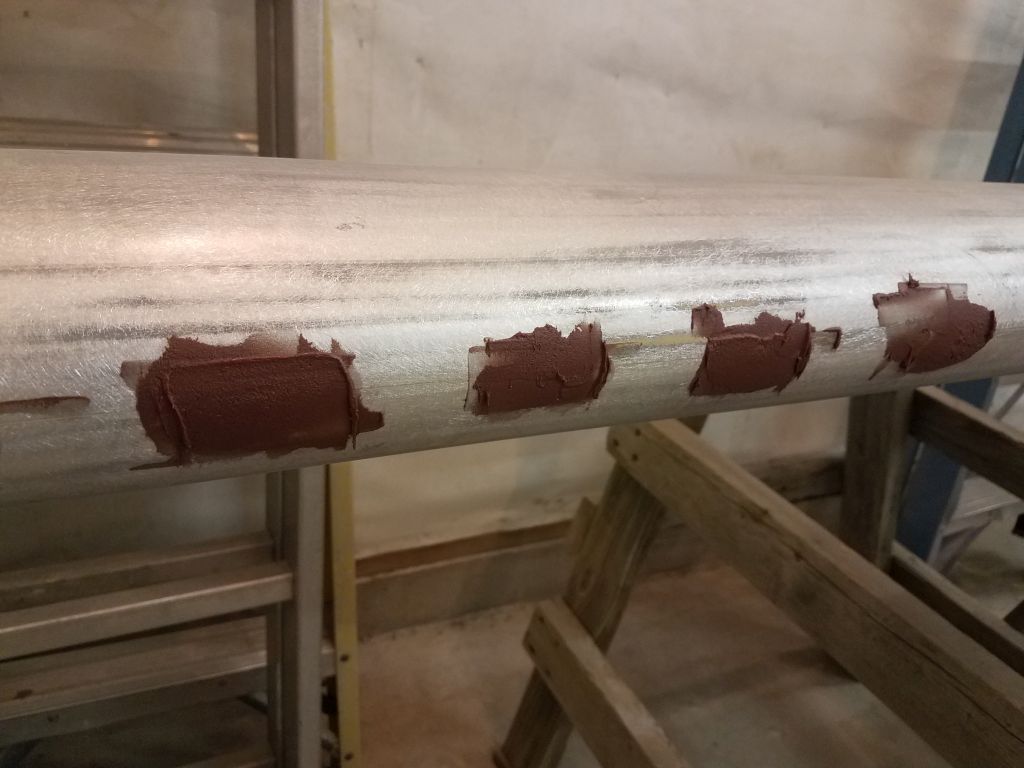
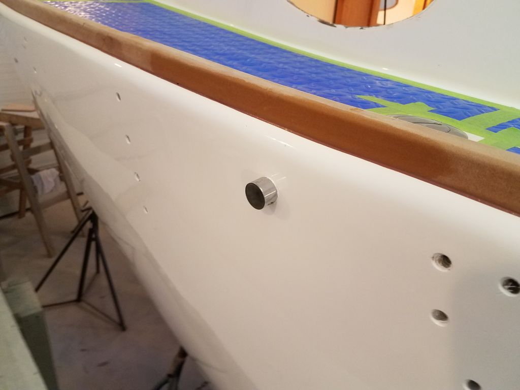
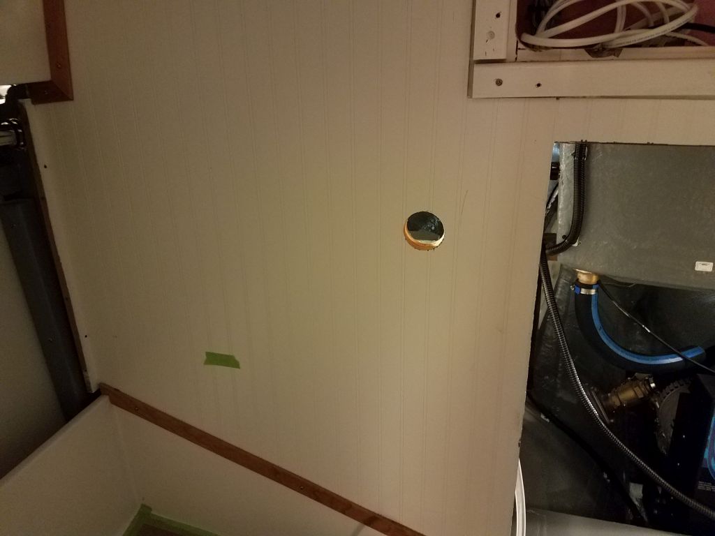
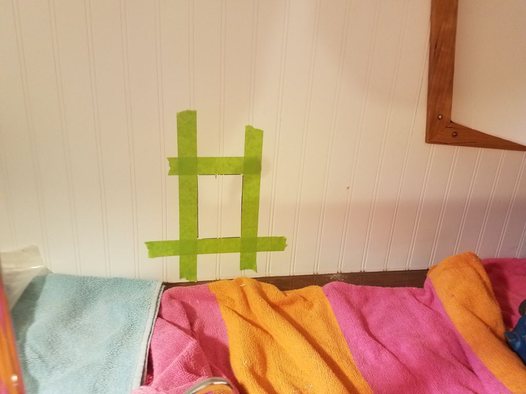
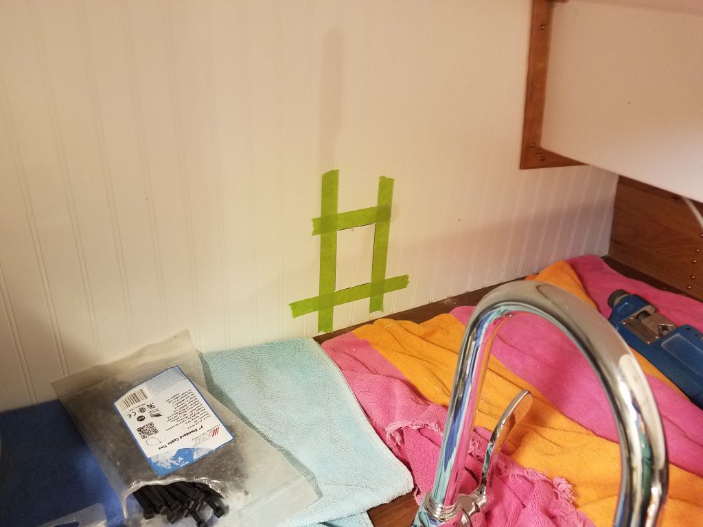
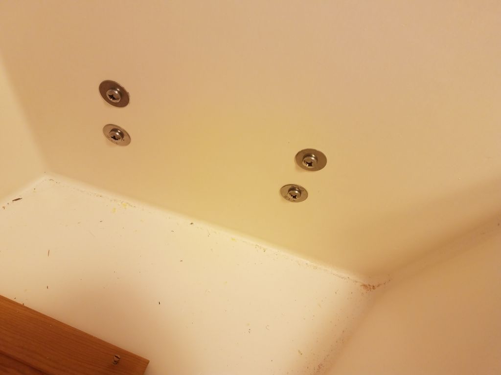
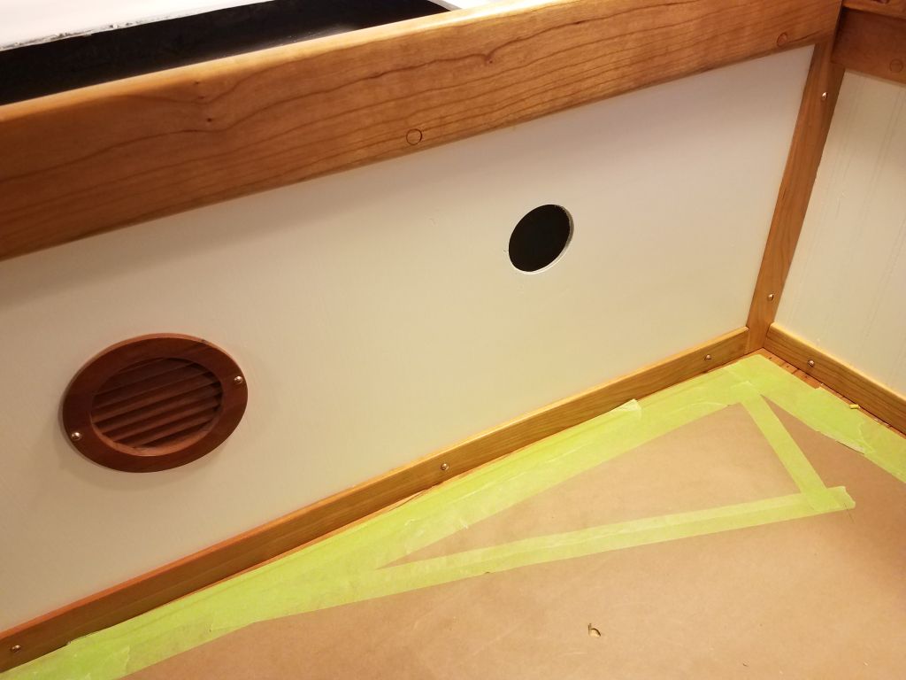
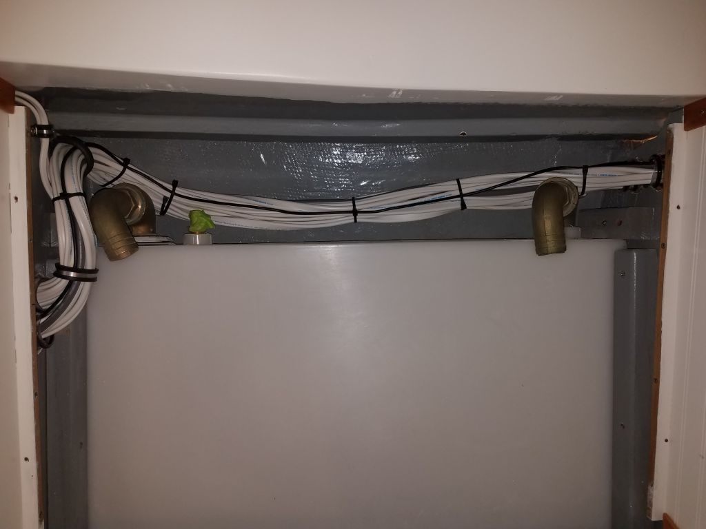
To accept the discharge ends of the two electric pump hoses, as well as a forthcoming manual bilge pump, earlier the owner and I had decided to install a pair of through hulls, one on each side of the counter:  one on the starboard side for the two electric pumps; and a second on the port side for the manual pump.  Using the location left over from the old discharge through hull (which I’d removed and patched much earlier) on the starboard side as a guide for the new locations, I drilled a pilot hole from inside the boat on each side in the desired location, then, from outside, drilled the larger holes required to accept each through hull.

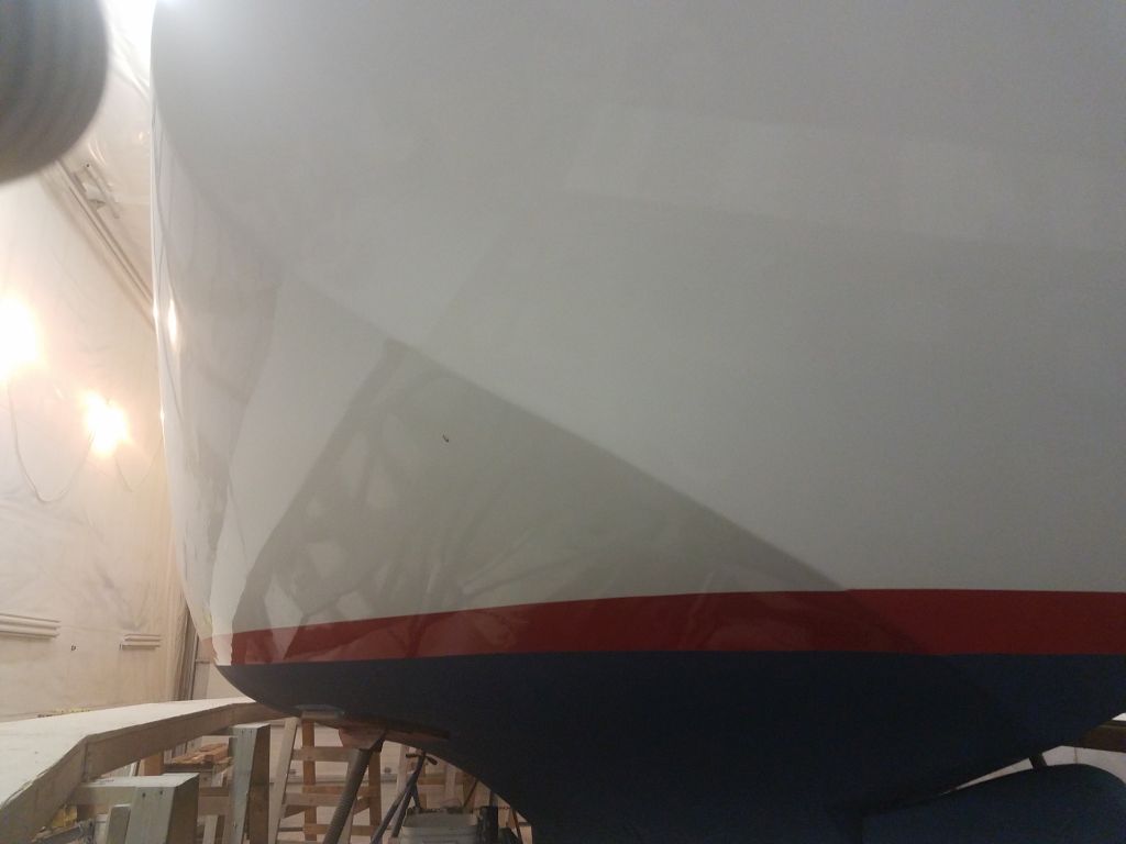
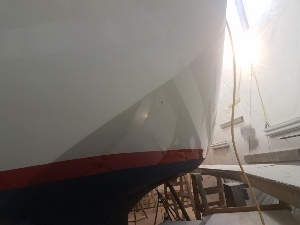
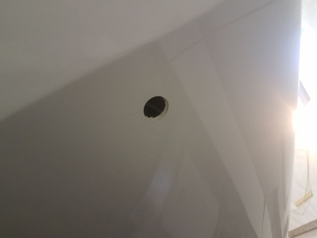
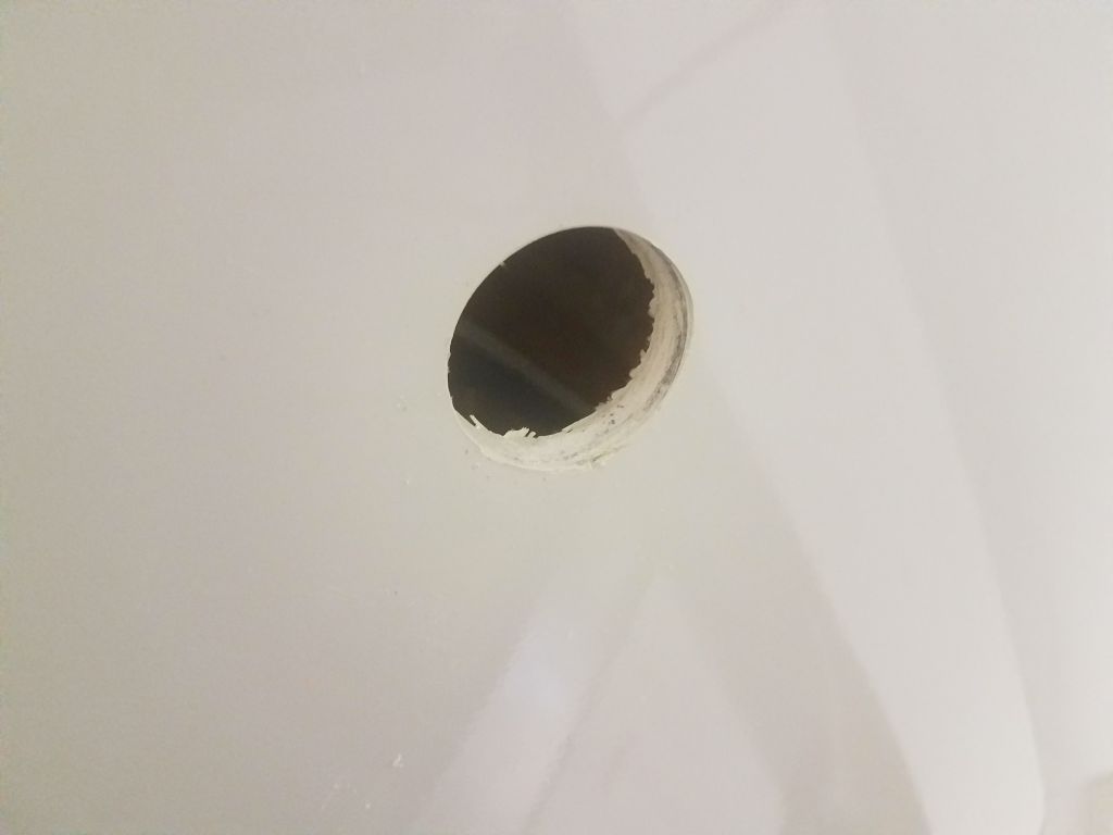
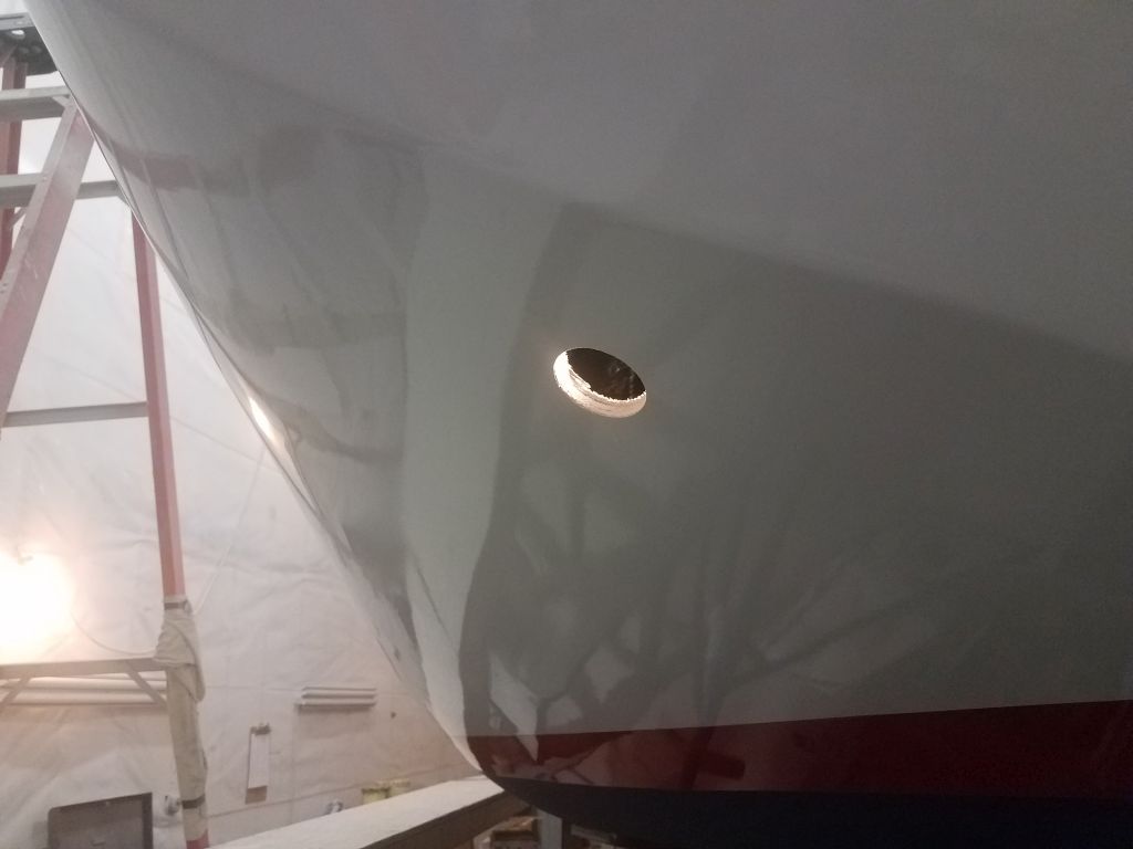
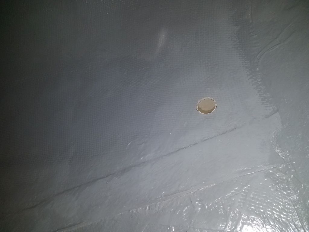
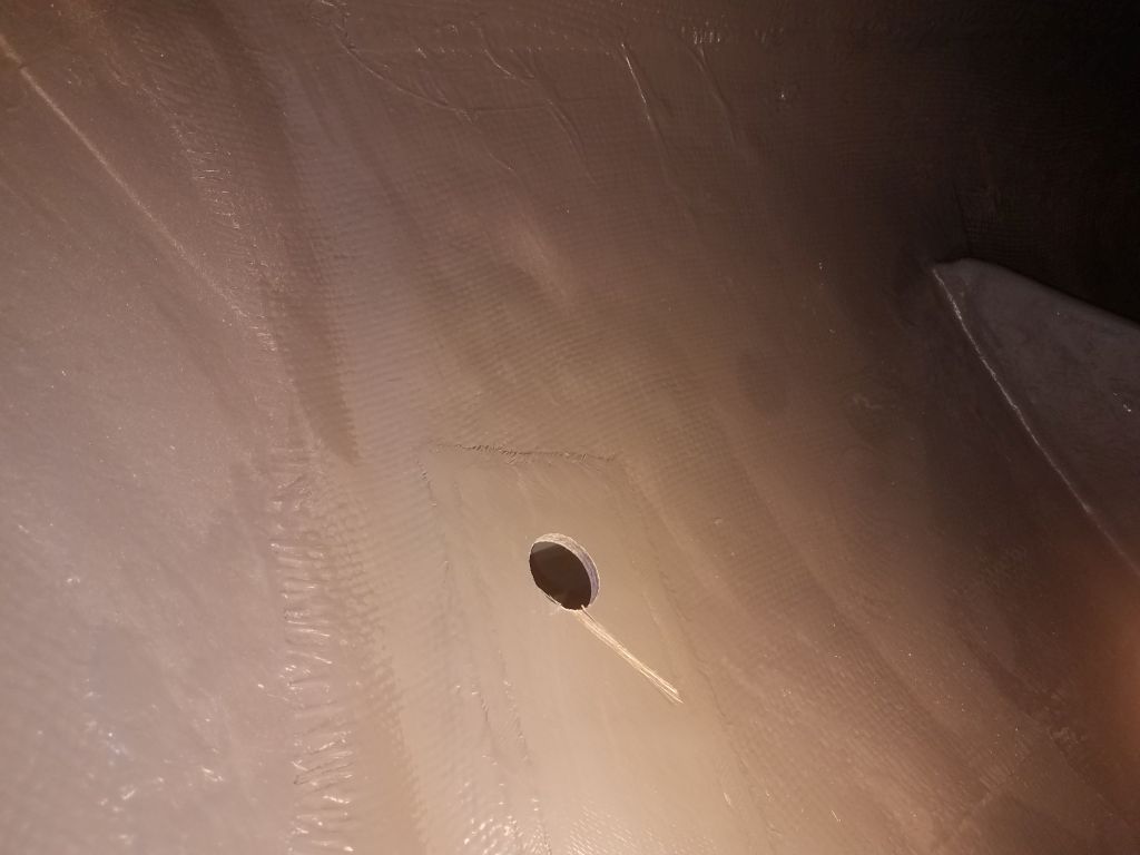
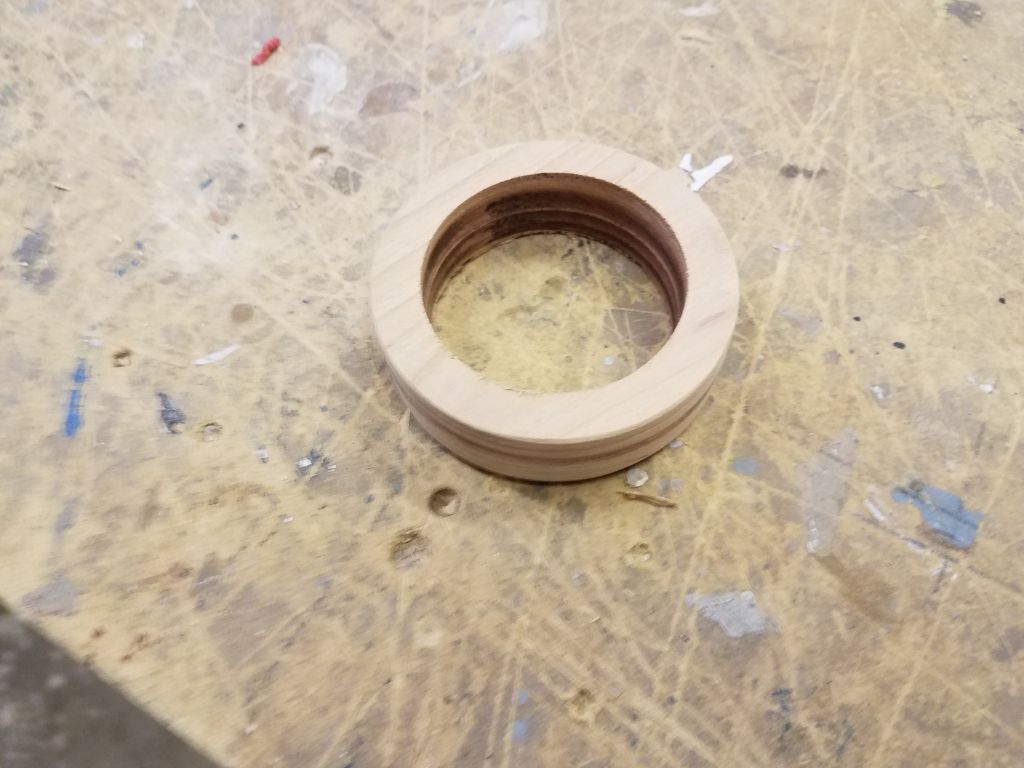
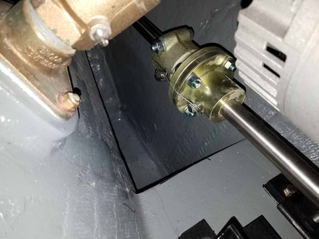
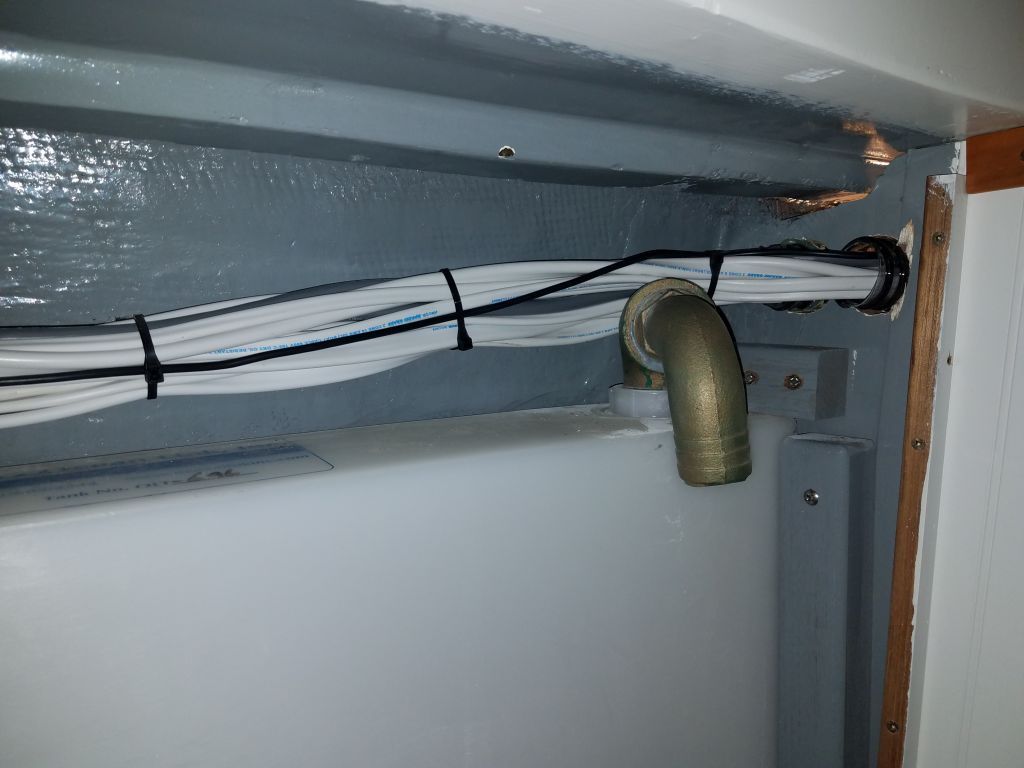
After cleaning up the drill spoils and around the holes themselves, I installed new bronze fittings at each location.

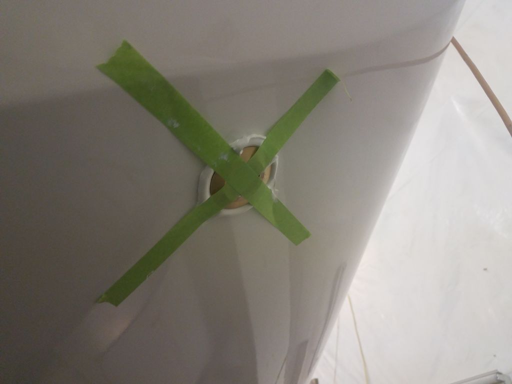
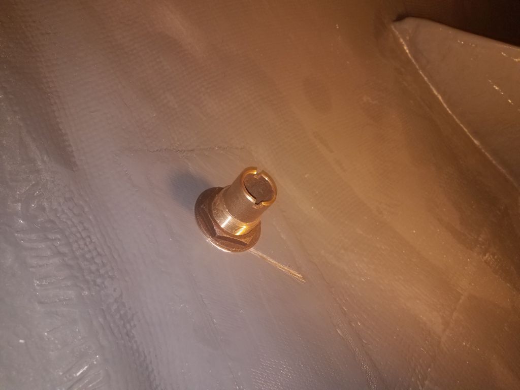
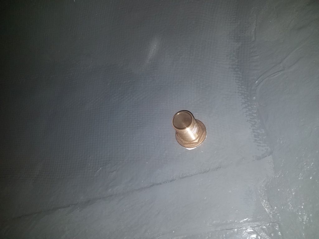
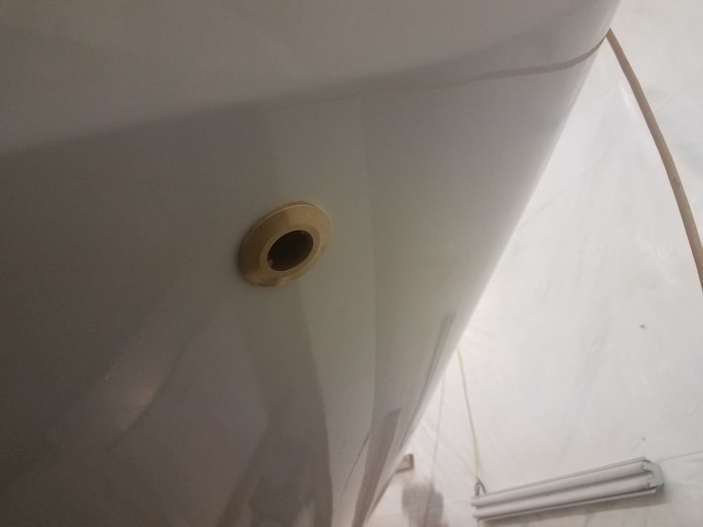
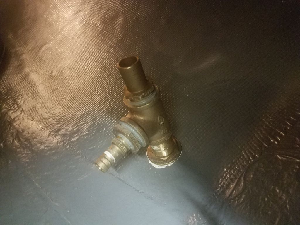
On the port side, I chose a barbed through hull that would later accept the 1-1/2″ discharge hose from the manual bilge pump.  For the starboard fitting, I needed a normal threaded through hull so I could install a bronze tee fitting for the two discharges from the electric pumps:  1-1/8″ from the centrifugal pump, and 3/4″ from the diaphragm pump.

Total time billed on this job today:  7.5 hours

0600 Weather Observation:  5°, mostly cloudy. Forecast for the day:  Mostly cloudy, 28°

Scupper 212

Friday

It was a quiet day, with important yet largely non-visual progress at the shop, aimed mostly at setting things up for the work to come in the next weeks.

To begin, I cleaned up as needed from the mast painting operation,putting away the painting supplies and equipment so I could get that side of the shop back to normal.  I left the freshly-painted spars alone for now for some additional cure time, but soon planned to move them to the side so I could reclaim the bay for a vehicle that I stored there, but had moved out for the painting operation.

Completing the mast painting was a significant milestone, and I wanted to finish its reassembly as soon as possible so the riggers and sailmakers could get back to work on their respective jobs, so to that end I went through all the mast hardware, noting the fasteners required so I could order replacements as needed, which I did once I’d checked existing stock against my scribbled notes.

Next, I turned to the new bowsprit, which I’d glued up some time before.  Now I removed the clamps, scraped off the excess epoxy, and milled the blank to the final dimensions, using the original as a guide:  10-1/4″ wide and 84-1/2″ long.

I finished up the blank by rounding the corners as appropriate, and sanding the whole thing smooth.  Since the bowsprit would remain bare, this completed the initial construction, and I could soon prepare to install it.

Afterwards, I lightly sanded, cleaned, then revarnished the new cherry trim pieces and the cabin table.  I’d recently moved an unrelated finishing project out of my little finishing room, and now I spread the table pieces out there to allow the refinishing process to go on over the coming days, as the numerous two-sided pieces would require extra time to varnish completely.  I planned to finish up the cherry trim over the weekend, so I left them in the main shop for the duration.

Total time billed on this job today:  7 hours

0600 Weather Observation:  30°, cloudy. Forecast for the day:  Cloudy, 42°

Scupper 211

Thursday

The mast painting remained my main focus, but since there was little prep required before I could apply the gloss topcoat, I decided to use the morning to take care of some smaller jobs before continuing on the mast.

I wanted to keep the varnish work going on the cabin table and various trim parts that I’d started before the holidays, so to get going I lightly sanded everything and, after cleanup, applied a second coat of gloss varnish to all surfaces.

On my new bracket, I installed one of the automatic switches, along with the base for the centrifugal bilge pump, using short screws tapped into the fiberglass to avoid penetration through the bracket itself.  I aligned the bilge pump base so that the outlet of the pump would face the desired direction once the bracket was installed.

Inside the boat, in the bilge opening near the galley, I chose the location for the bracket and removed paint from the bottom of the bilge so I could epoxy the bracket in place.  This location allowed relatively easy access for wiring and servicing the pump and switch in the future, and the bracket design intended for the wiring to be easily led up and away from the bilge water, where I could make all connections in a dry location.There was room on each side of the bracket to allow free passage of water towards the aftermost part of the bilge in the engine room, which was the deepest part and where I planned to install the switch and suction for the everyday “nuisance water” pump.

To that end, I installed the second switch on the bracket I’d made for the engine room space, then installed the bracket to the aft edge of the engine platform with a screw.  I’d hoped to use two screws, but the shaft above prevented accessing the second screw location.  The screw only holds the bracket upright, and there’d be no pressure on the installation, so the single screw was ample in any event.  I noted earlier that I’d mistakenly built the bracket backwards from my intention, but this actually worked out well since now the switch was well-protected on the forward side of the bracket, leaving plenty of room behind for the manual and nuisance pump suction hoses.  Final wiring runs and plumbing connections would happen in the near future.

After an early lunch break, I turned to the mast painting for the afternoon.  The anti-corrosive metal primer I chose for the spars didn’t require any further primers before topcoat, nor did it require sanding for adhesive purposes (within the specified time frame, which was six months after application).  The surface as applied was smooth and without obvious flaws, but I went over the spars briefly with a Scotch-Brite pad just to knock down any minor surface  texture.  After solvent-washing and other final preparations, I spray-applied three coats of the Alexseal snow white gloss topcoat I used elsewhere on the boat, leaving the new coating to cure overnight.

Total time billed on this job today:  6.5 hours

0600 Weather Observation:  20°, mostly clear.  Forecast for the day:  Partly sunny, 37°

Scupper 210

Monday

Before continuing work on the spars, I wanted to come up with a way to suspend the spars between the sawhorses so they would be free and clear for primer and paint.  The boom was no issue:  it was small and light enough that I figured I would just hang it from small line led through some screw holes at each end, and to the saw horses.  This would allow the boom to swing, which I wouldn’t want for sanding, but for spray painting it would work fine.  For now, I left the boom as is pending final sanding.

The mast was tougher, as it was too heavy to hold with small line, and in any event there weren’t enough holes at the ends to secure the line even if I’d wanted to do it that way.  I could have built wooden inserts that fit inside the mast, and then used those to secure it to the sawhorses, but that was frankly more work than I felt was necessary or desirable.

After a failed attempt to build a simple internal support with a stick protruding to the sawhorse–this failed because the wedge inside the mast didn’t hold as I’d hoped, and the stick ended up looser than intended–I came up with a plan to secure a square piece of hardwood (actually a leftover stair baluster) inside the mast, with screws through the inside of the mast track.  There were already holes in place at the bottom of the mast that I could use, but I drilled two holes as needed inside the track at the top of the mast.

When suspended between the two sawhorses and clamped at both ends, this held the mast solidly with the track facing down, which is how I wanted it for ease of painting.  I arranged the mast kitty-corner in the shop as needed to accommodate its length and the sawhorses, while still leaving just enough room for me to maneuver around at the masthead end (where the sawhorse was almost at the doorway to the woodshop) as needed so I could work on all sides of the mast.

I sanded the epoxy filler in the screw holes left over from the spinnaker pole track; this came out well and didn’t require any further work.

Everything was set up as I needed it, so next I sanded the mast and boom a final time, this time with 120 grit paper.  Although there was no visual indication that the previously-sanded spars had oxidized over the couple days since their last sanding, this final round of sanding would ensure clean, bright metal to encourage the best possible adhesion of the anti-corrosion metal primer.  The finer grit also brought the prepared surface to the desired level of roughness (or smoothness) for the primer.

With metal, one can’t use rags for solvent-washing after sanding, as tiny fibers might catch in the rough metal and create a tiny wick that could exacerbate primer failure and corrosion later, so all I could do at this stage was vacuum the surfaces thoroughly to remove dust.

Afterwards, I strung up the boom to hang it, bottom side up, from the two sawhorses.  I added vertical pieces to raise the boom’s height and make it easier for me to paint.

After final preparations and getting the paint ready, I spray-applied two coats of the protective anti-corrosion metal primer to the spars.  As always, spraying rendered the shop otherwise uninhabitable, so I called it quits for the day.

Total time billed on this job today:  6 hours

0600 Weather Observation:  26°, cloudy.  Forecast for the day:  Cloudy, chance of snow late, 27°

Scupper 209

Friday

I spent the day preparing the mast and boom for primer and paint, beginning by stripping the old paint off the spars.  To do this, I sanded with 40 grit discs, removing the old paint and primer and abrading the aluminum beneath.  With the mast resting on saw horses, I worked my way down one side from masthead to base in this manner.

Once I’d reached the bottom part of the mast, I was faced with a decision.  Despite repeatedly soaking for a couple weeks the six remaining bolts holding the spinnaker pole track to the mast, I had come no closer to removing them cleanly.  In fact, they were so stuck in place, even with half a can’s worth of penetrating oil, that each time I tried to remove the screws, I simply shattered my driver bit in my impact gun.  It was clear those bolts were not going to budge.

I seriously considered leaving the track in place and working around it for the paint, and almost certainly would have done so if I’d not been able to remove all but six of the screws.  But it seemed so close to removal, and it would be better for the mast prep and paint if I could remove the track entirely–even though at this point it meant destroying the track–so eventually I decided to remove the track through whatever means.

Almost immediately, I rued this decision, as I found the track was extremely difficult to cut through, even though it was aluminum.  It was a heavy, 1-1/4″ T-track that dated to the spar’s original construction. I tried grinding through the heads of the screws, but they were stainless steel and extraordinarily tough, and in any event the threads were still well welded in place through the aluminum track itself.  I tried using the grinding wheel to cut through the track and screw studs, but this was difficult and dangerous, and I didn’t want to risk damaging the spar.  I tried using a reciprocating saw, but again, the track was too difficult to cut through, and too time-consuming.  Ultimately, I employed some combination of these techniques, along with a pry bar to bend and break away the track in sections, finally exposing each screw so I could then grind them flush.  The track was tough enough that it broke the end off my flat pry bar that I was using to help bend and break the track at the cuts I’d made.

With the track successfully–finally–and cleanly removed, I turned the mast over and sanded off the paint from the other side.  The spar was in good condition beneath the old paint, with some minor surface etching here and there where the old coating had failed long before.

Next, I turned to the boom, beginning by removing the end caps and remaining hardware.   This was easy and quick since the riggers had already had these off in order to remove the bits of the old outhaul arrangement and plan for the replacement.  Once the hardware was gone, I set to work sanding away the old paint and primer.  Once I’d reached bare, white (silver) metal and finished the sanding with the 40 grit paper, I switched to 80 grit and sanded the entire boom again, to get closer to the final surface I’d need before applying the corrosion-resistant primer I planned to use.  The bare aluminum would oxidize rather quickly, so I planned to finish the sanding with 120 grit on the day of the primer application, which would finish the spars’ preparation and clean the metal one last time just before the primer.

With the boom complete through 80 grit for now, I returned to the mast and sanded it with the 80 grit as well.

To round out the day, I decided to fill the old screw holes left from the spinnaker pole track, so I used a countersink to bore them out a bit, then, after cleaning with solvent, filled the holes with an epoxy mixture, choosing to leave the fill high in the hopes that I could do the job in one round only.  The old bolt studs at the bottom of the track had ended up flush with the mast, but I applied some fairing compound over them as well, just because.

Total time billed on this job today:  6.25 hours

0600 Weather Observation:  28°, light freezing rain.  Forecast for the day:  Freezing rain and sleet, then rain, 37°

Scupper 208

Monday

As a sort of break and change of pace, I chose to focus for a day on some ancillary, yet still critical, portions of the project that could otherwise tend to be pushed aside in favor of some of the larger ongoing jobs.

To begin, I checked the fit of the after bilge switch platform I’d glued up last time, and found that indeed it would still work fine even though I’d mistakenly glued the top piece on backwards, so I went ahead and sanded the two platforms as needed to clean them up for paint and final fitting.  I added wire tie mounts near the top of each platform to help guide the switch wires, then painted the platforms with bilge paint.

I surface-planed some rough teak 8/4 stock as needed to smooth the sawmill marks, and dimension the wood as needed for the bowsprit.  Afterwards, I straightened one edge with a simple plywood straightedge and a circular saw, then trimmed the opposite edges of the two boards on the table saw to prepare for gluing up into a blank wide enough for the new bowsprit.

Afterwards, I glued the two board together and clamped them securely.

After setting the assembly aside to cure, I got back to work on the original cabin table, which I’d stripped and mostly sanded during the end of Phase 2 earlier in the year.  Now, I went over the table base, leaves, and top and sanded everything with 220 grit to prepare for finishing.  Then, after vacuuming and solvent-washing to remove dust, I applied a sealer coat of varnish to all sides of all pieces.

To finish up some of the lighting and wiring in the cabin, I required a few additional trim pieces, including the following:

During the rest of the day, I milled, sanded, and otherwise prepared these trim pieces as required, so that by the end of the day I had everything ready for primer or sealer coats of varnish as needed.

Total time billed on this job today:  6.5 hours

0600 Weather Observation:  18°, partly clear.  Forecast for the day:  Mostly sunny, 42°

Scupper 207

Friday

I got started by installing the replacement vent I’d ordered for the water tank.  This one was long enough to still work after passing through the thickness of the hull.

Sticking with the plumbing theme for now, I finished up the water hose run leading from the water pump aft, first through a tee fitting on the port side to accommodate the cockpit shower, then across beneath the cockpit and eventually through the bulkhead into the head area, where the water hose would eventually supply the fresh water flush toilet.  Near the end, I reduced the supply line from 5/8″ to 1/2″ to accommodate the nipple on the toilet intake.

I had expected to install a few more wires from the toilet control box to the head, but found that the wires needed were pre-installed inside the back of the toilet itself, so running them to the control box would happen later on, when I installed the toilet permanently.  For now, I didn’t want to do that as I wanted to be sure I finished up as much related (and other) work in and near the head before filling the space with the throne.  For now, I put the cover on the control box in the engine room and left it be.

Next on the agenda was the two electric bilge pumps.  I planned a diaphragm pump for routine dewatering.  This pump, which would be mounted high and dry away from the depths of the bilge, had a smaller flow capacity, but with its diaphragm pumping action and hose to the deepest part of the bilge sump in shaft alley, it would work well to keep the bilge as dry as possible, and wouldn’t allow backflow when the pump stopped.

In order to mount an automatic float switch, I needed to build a little platform to secure the switch and be able to lower it into the bilge sump, since this area was mostly inaccessible and there was no way to secure the switch directly to the boat in any event.  After measuring the depth required, and allowing for a means of securing the little platform to the engine beds, I built the simple arrangement from prefab fiberglass panels.  The switch I chose was a cylindrical fully-enclosed type that hopefully would work consistently without clogging, and was designed to be held in place with a u-shaped bracket; the width of this bracket determined the width of the support I built, but I also included a little base platform on which the pump could rest so it couldn’t slide out of its bracket.  I glued up the new bracket with epoxy and left it to cure.  I realized later, as I reviewed the photos, that I’d glued the top piece–the smaller chunky piece–on the wrong side.  I’d meant the L-shaped bracket to face aft, and for the chunky top to fit over the aft side of the engine platform to accept screws.  That said, I thought the bracket would work even turned around, but I’d soon find out.

As a backup, and for more potentially significant electric dewatering, I also planned a 2000GPH (0′ head) centrifugal bilge pump to be mounted further forward, in this case in the space accessible through the bilge hatch in the galley.  To secure this pump, along with its automatic switch, I built another simple platform, which here I planned to adhere directly to the flat base of the bilge through this locker opening, providing a place to screw in the pump strainer/base and the float switch’s bracket.  I made the vertical part of the bracket tall enough to provide a mounting point for the wires, to keep them elevated out of the bilge, and glued up the simple bracket with epoxy.  There’d also be, of course, a manual bilge pump to come.

Speaking of bilge access, in order to install the final wiring runs for the mast and some related wiring that would lead from the compression post, I needed to regain access to the forward part of the bilge, which access hatch had been covered for much of the construction with protective paper.  In addition, the paper had seen better days, and I’d been patching numerous rips and tears as they occurred.  Now, though, I removed the old paper and installed new protective plastic (same as on deck) to the sole, keeping the covering separate over both bilge access hatches so I could come and go as I pleased in the coming days and weeks.

I eased out of the day and the week by looking in some detail at potential anchor windlasses for the boat.

Total time billed on this job today:  6.5  hours

0600 Weather Observation:  4°, clear. Forecast for the day:  Sunny, 26°

Scupper 206

Thursday

Working in the forward cabin, I continued with the second fan, which I located on the starboard side in the upper corner of the bulkhead (where it was near the wiring from the starboard bulkhead light in the main cabin), and secured the wiring for both appliances behind the trim at the edges of the bulkhead before leading it aft into the electrical locker. I found that a little butyl tape was handy for holding the little wires in the groove behind the trim.  As with the port side, I’d make a piece of trim to cover the exposed wiring on the bulkhead in the near future.

After considering and rejecting various locations, and taking into account the owner’s wishes and the physical requirements of the spaces, I eventually installed the two small berth lights (one per side) under the sidedecks just aft of the berths, where there was open space, relatively convenient for hidden wiring, and to keep the lights out of the way.  These lights also incorporated built-in USP ports, and swiveled in all directions.  On both sides, I was able to run the wiring the short distance beneath the liner and then aft to the main wiring areas.  Note that those top few ceiling boards on both sides will be replaced as soon as I finish the wiring and install the forward chainplates.

I had hoped to begin installing the underdeck secondary lighting, i.e. LED strips, as I’d recently received all the materials I thought I needed, but I found that the diffuser covers I’d selected didn’t work with the LED strips that I had, so I spent a little time sourcing replacement diffusers and would await installation till another day.

Instead, I turned to the battery chargers again, and in the forward cabin, armed with new supplies, I installed an outlet box, wired in the AC outlet, and finished the charger installation.  After discussion, the owner had decided not to install the poorly-executed indicator lamp that came with the charger, since it would have been an eyesore and the digital battery monitor would provide all the salient information anyway.  Once I’d finalized the battery box and house battery location, I could run the charging wires from the charger to the box, but for now left them coiled aside.

The 48-volt charger for the electric motor power supply was a different manufacturer and design, and was easier to handle and install.  I chose a location on the starboard engine room bulkhead that was out of the way yet accessible, and left room for an outlet box for the 110-volt supply to the charger.  On this outlet, I added an external cover to protect the plug, and secured the generous excess power cord out of the way next to the box.  Once the engine batteries were in place, I’d complete the charger wiring, which would include a temperature sensor along with the charging wires.

For future expansion, I’d run one extra circuit aft into the engine room, and now I coiled up and secured this excess cable.

It made sense to continue in the engine room and finish up what was needed to terminate and secure the remaining few wires, starting with the large 8AWG wire pair required for the electric head controller.  With all components of this system now on hand (the toilet itself had been backordered for a couple weeks), I felt ready to begin the installation, starting with the small control panel in the head itself.  After confirming measurements of the throne, and working within existing limitations of the space and the opposite side of the bulkhead, I chose a location for the control and drilled the large hole required for its installation, then installed the panel and its Ethernet cable that would connect it to the control box.

Next, I chose a location for the control/wiring box, keeping it out of the way of the eventual battery boxes yet close and convenient to the main wiring.  With the box in place, I could terminate and connect the main power cables, and also the Ethernet cable from the control panel.  There were a few additional wires required that would run between this control box and the toilet itself,  and I’d continue installing these wires next time, but for now the day was done.

Total time billed on this job today:  8.25 hours

0600 Weather Observation:  14°, mostly clear. Forecast for the day:  Sunny, windy, 17°

Scupper 205

Wednesday

I started the day in the cockpit, where I installed a new compass in the molded recess at the forward end.  The large hole I’d drilled there long ago to remove the engine was the perfect size to accommodate the new compass.  Installation was straightforward with the supplied gasket and three screws, and afterwards I made up the wiring for the compass light belowdecks.

In the galley, I prepared to install both a 110-volt and 12-volt outlet, and cut the required openings for their installation.  I installed an outlet box and completed the wiring for the 110-volt outlet, and similarly installed the simple 12-volt socket and completed its wiring as well.

I connected the newly-arrived transducer extension cable and led it the short distance up to the area where the display would soon be installed (no pictures).  Then, I moved into the main cabin, where I decided to install the starboard bulkhead light fixture.  Because the doorway to the forward cabin was off-center to starboard, I mounted the light at the same height and as close to the same transverse position as on the port side, while accommodating the open doorway.  For now, I just led the wires through the bulkhead for later attention.

While I’d been working below the v-berth over the past couple days, I’d pre-selected the location for the charger for the house battery bank, and now I went ahead with its physical installation.  The location I chose was on the port side, on the forward face of the port storage locker below the berth.  There was ample room on that surface, plus the bolts to secure the charger would be out of sight inside the locker.

The charger was extremely heavy, and to ease installation I made a simple template of the base design and the overall shape of the charger to help me position the holes.

In the boat, I collected all the tools I’d need and got set up in the v-berth, then drilled the mounting holes according to my template.  Then, with some difficulty thanks to the weight of the charger, I secured it to the bulkhead with four 5/16″ bolts, incorporating larger washers on the inside of the locker.  I positioned the charger so that its short power cord would be within reach of the outlet box I planned to install (and had arranged accordingly during earlier “thought sessions” while working elsewhere up there), and its included battery cables were of ample length to reach the battery box once installed.

Appended to the power cord was a short length of wire with a rudimentary “remote” indicator light attached.  This cable was only 18″ or 24″ in length, vastly limiting its remote-installation capabilities, and the entire thing was somehow inelegant and poorly planned, with an ugly stud required for mounting and only a basic lamp as an indicator, all crudely attached to the most minimal circuit board imaginable, and with a thoughtlessly-short length of cable to allow mounting options.  The indicator lamp built into the charger was not accessible for regular or even sporadic viewing in the charger’s location.

This meant the only feasible mounting location, when considering the cable length and the other realities of the available space (including, not unimportantly, access from within and the thickness of the various surfaces), was the forward section of the v-berth cutout, where the fiberglass panel was about 3/16″ thick and could potentially accommodate the light.  As of this writing, installation details were under review.  The good news is that I installed (or am technically still installing) a nice battery monitor for the house bank, so this monitor would more than obviate whatever minimal information the charger indicator light might provide.

Next, I installed the house battery switch, choosing a location in the port settee base.  After drilling the required 2-5/16″ hole, I flush-mounted the switch from behind, making up the cable ends and securing them as required to the switch before installing the back protective cover and installing the whole switch with four bolts, which I’d return to later to remove the excess length.

I pulled the excess cable forward and secured it below the v-berth unit, and finalized the connection for the “downstream” cable leading from the switch to the positive distribution buss.   I left the other cable unterminated for now, as it would eventually connect to the battery positive but I didn’t yet know how long to make the cable.

Total time billed on this job today:  8 hours

0600 Weather Observation:  25°, cloudy. Forecast for the day:  Snow showers, cloudy, 31°

Scupper 204

Tuesday

Working my way from the starboard settee up through the backrest and into the electrical locker above, I finished securing the cables and wires running from the forward part of the boat–a fair challenge given the narrow space and tough access and the bulk of the cables.

Next, starting just forward of the engine room in the head and working my way forward to the electrical locker, I tightened, straightened, and secured the wires I’d recently run aft to and through the engine room.  This included the transducer cable, which I actually had to tighten and secure in the opposite direction (starting forward, but it ended up making it just into the engine room, where I left it to await its extension cable that would take it the rest of the way to the GPS/sounder display.

This finalized the wiring on the starboard side aft of the electrical locker, and greatly improved the related disarray.

Next, I turned to the wiring for the lighting and fan circuits required on the port side.  To streamline the wiring and minimize wiring bulk, I led in three separate wire pairs (circuits):  one each for the cabin lights and under-deck secondary lighting (LED strips–on order); and one for the fan to be mounted on the port bulkhead in the main cabin.  Another fan would be mounted in the forward cabin, but on the starboard side.   I led these wires from the starboard electrical locker, through the space below the forward cabin, and then through the port settee and settee back into the port locker, where I terminated the two lighting circuits in a terminal block that would make it easy to connect two cabin lights (a berth light forward and a bulkhead light in the main cabin) and the two sets of under-deck lighting (main cabin and forward cabin).  I used short lengths of cable to then lead forward from the new terminal block and into the forward cabin, where I left the ends for now pending installation of the underdeck and berth lights.

Then, I could clean up the wiring through the spaces and back to the electrical locker.  On the starboard side, there’d soon be more wiring running through these spaces (leading to the mast), so for now I considered the current result temporary in nature.

The owner had selected and purchased the various light fixtures and fans (one on hand) for the boat, and with no time like the present I decided to go ahead and install the fixtures on the port bulkhead in the main cabin, starting with the fan.  After dry-fitting in several locations, and ensuring full rotation of the fan housing in all directions, I chose the location near the upper port corner, in an attempt to keep the fan out of the way as much as possible.  I led the wire through the bulkhead into the forward cabin.

The LED light fixture destined for this space was a small domed, downward-facing unit with which I was unfamilar, so to ensure its eventual location would properly light the berth below, I temporarily hooked it up to a battery in a dim space.  The light was quite bright, and easily illuminated the bench below my test area.

I chose to mount the fixture near the fan and at the same level, and more or less centered directly above the berth below.  Installation was a simple surface mount, with the wire leading out through the bulkhead to the forward side, where I’d have to secure and hide it as best as possible.

The light fixture came with a good length of wire attached (as did the fan), and it looked like these wires would be long enough to run along the forward bulkhead and back to the aft side, where the lighting terminal block was located.  This also meant I could dispense with the 14/2 wire pair I’d run forward for the fan circuit, so I removed that.   Both sets of wires from these fixtures were quite small, and I thought I could hide them beneath the existing trim pieces at the edges of the bulkhead in the forward cabin, which turned out to work pretty well.  I’d have to mill a piece of trim to cover the wires where they were still exposed across the bulkhead, but I’d get to that a little later.

This meant I could go ahead and make up the wiring for the bulkhead light on the terminal block (cabin lights circuit), as well as the fan on its own separate circuit.  There’d be more wiring here soon when I added the final wiring for the underdeck lights in the saloon, but for now I secured the wires a bit pending some changes later when all the wiring here was finished.

Total time billed on this job today:  7.25 hours

0600 Weather Observation:  22°, cloudy. Forecast for the day:  Snow, 2-4″ expected, 28°

Older posts Newer posts