(page 5 of 27)

Scupper 223

Monday

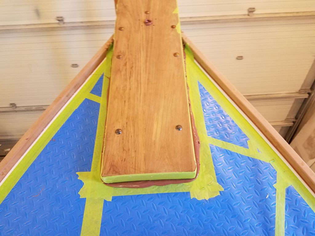
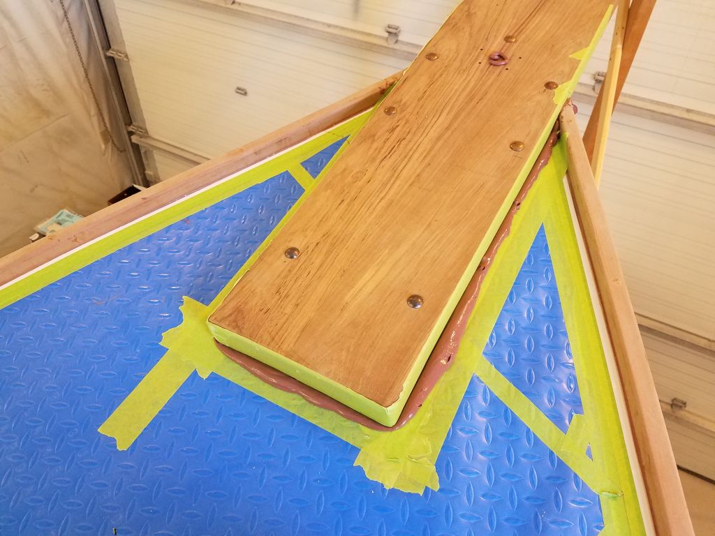
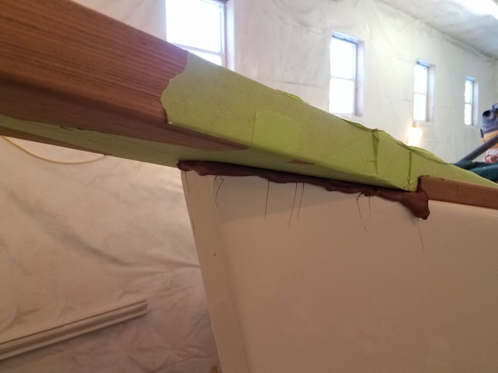
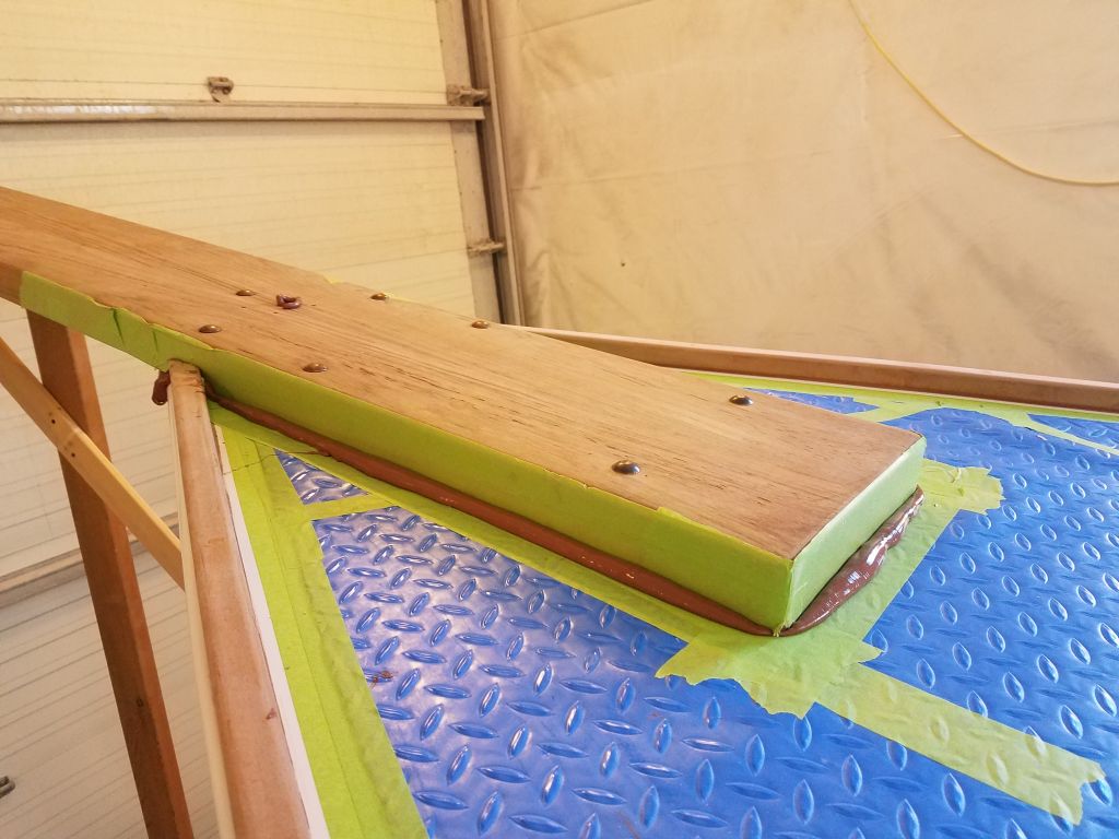
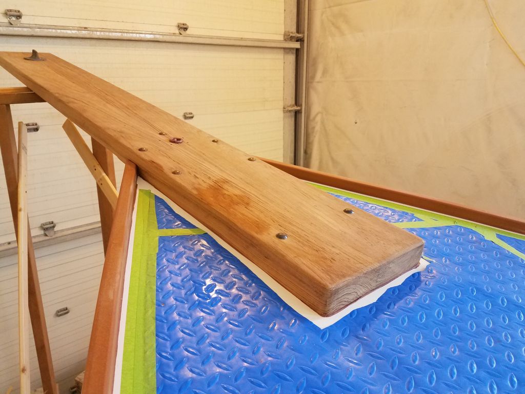
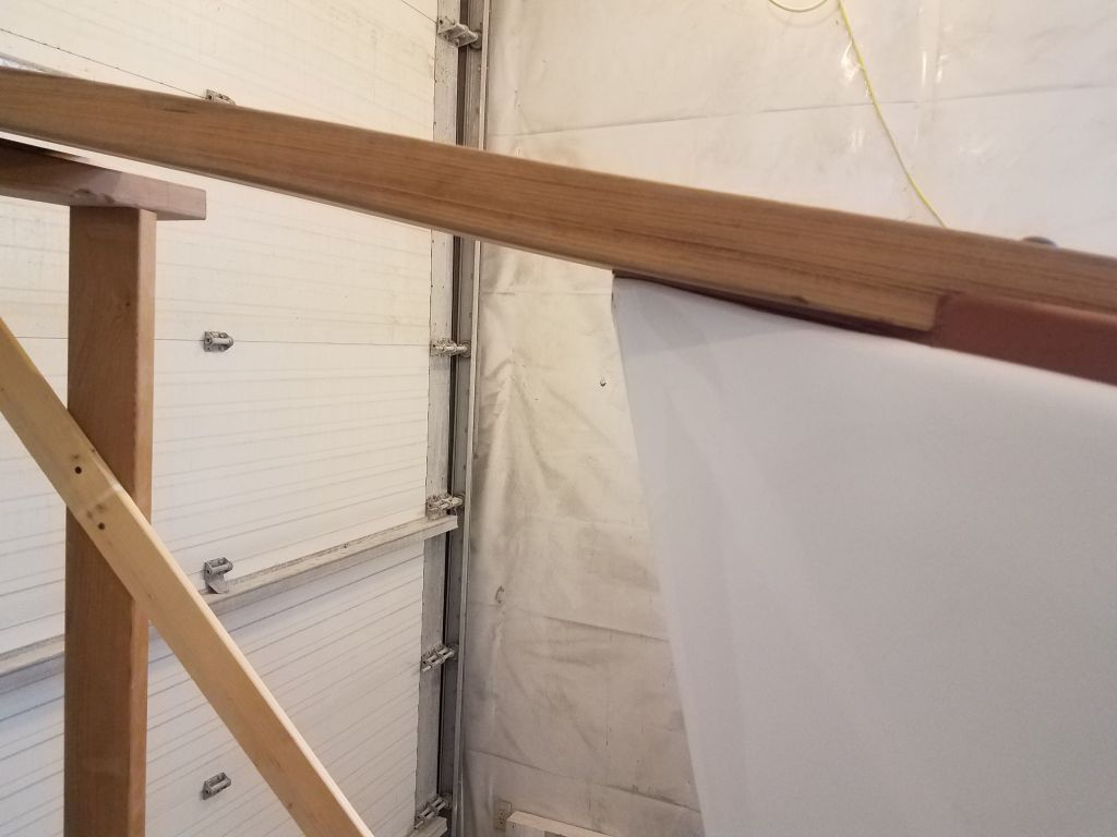
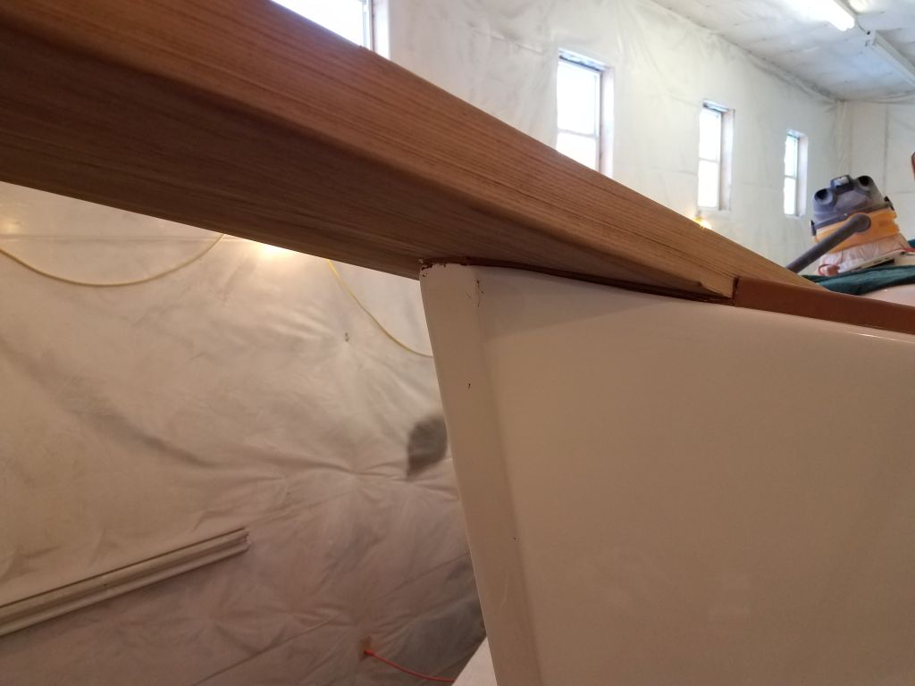
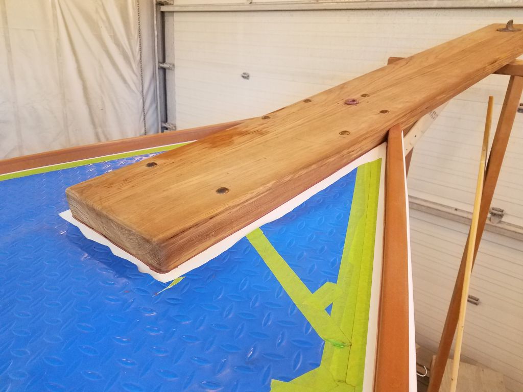
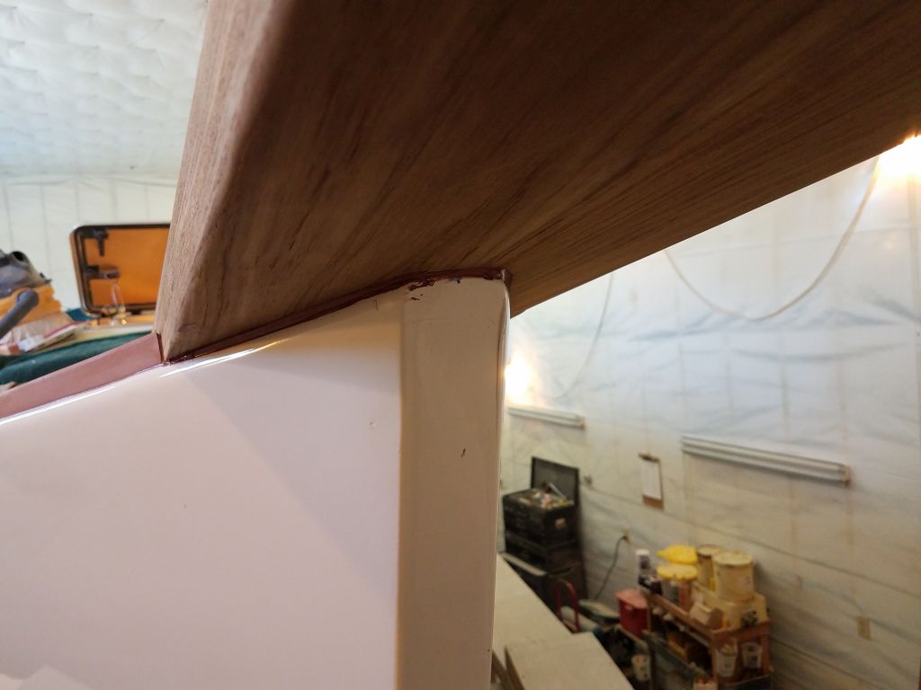
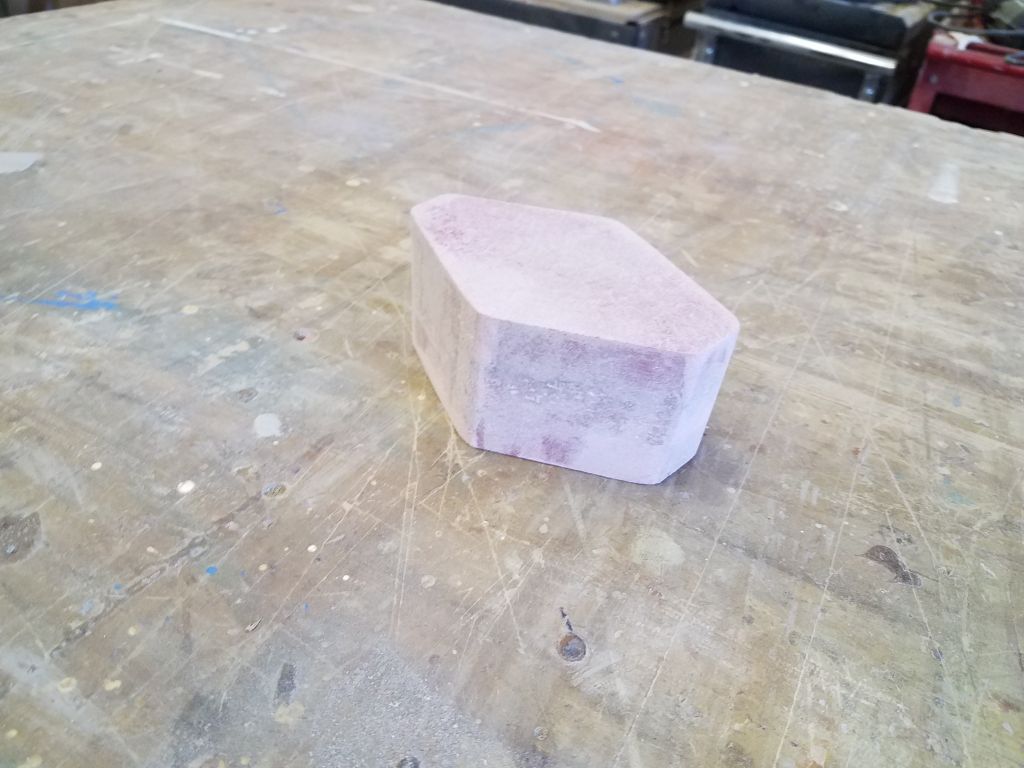
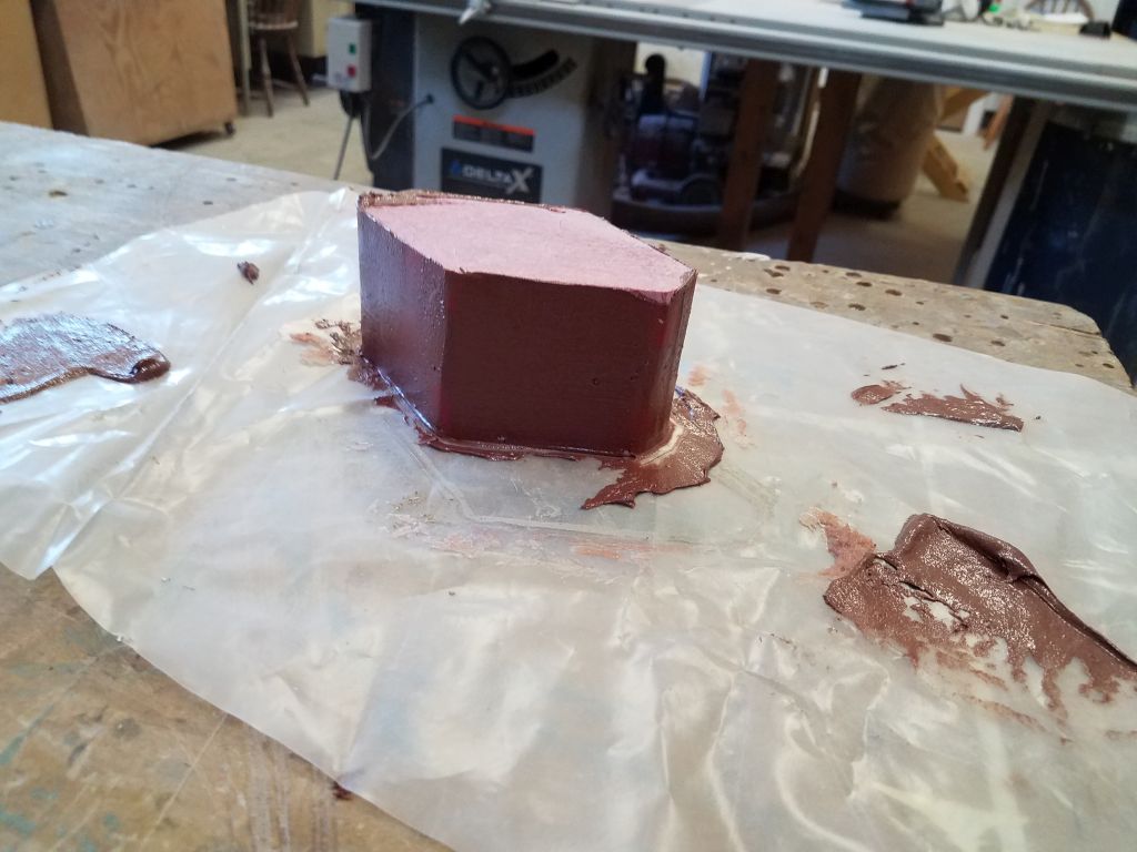
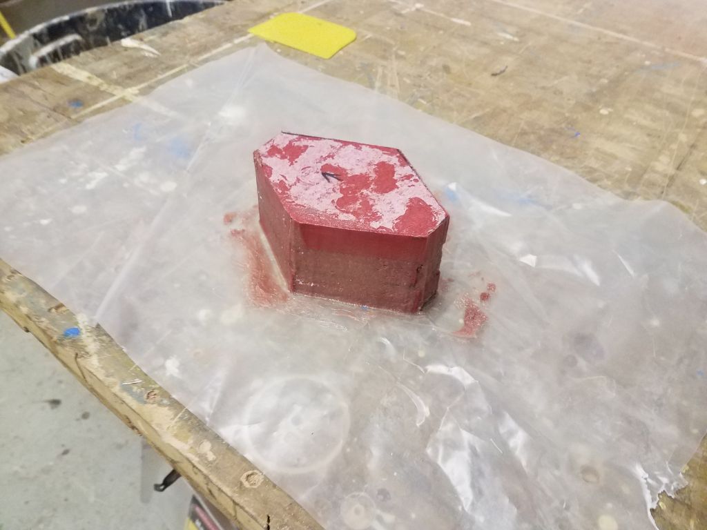
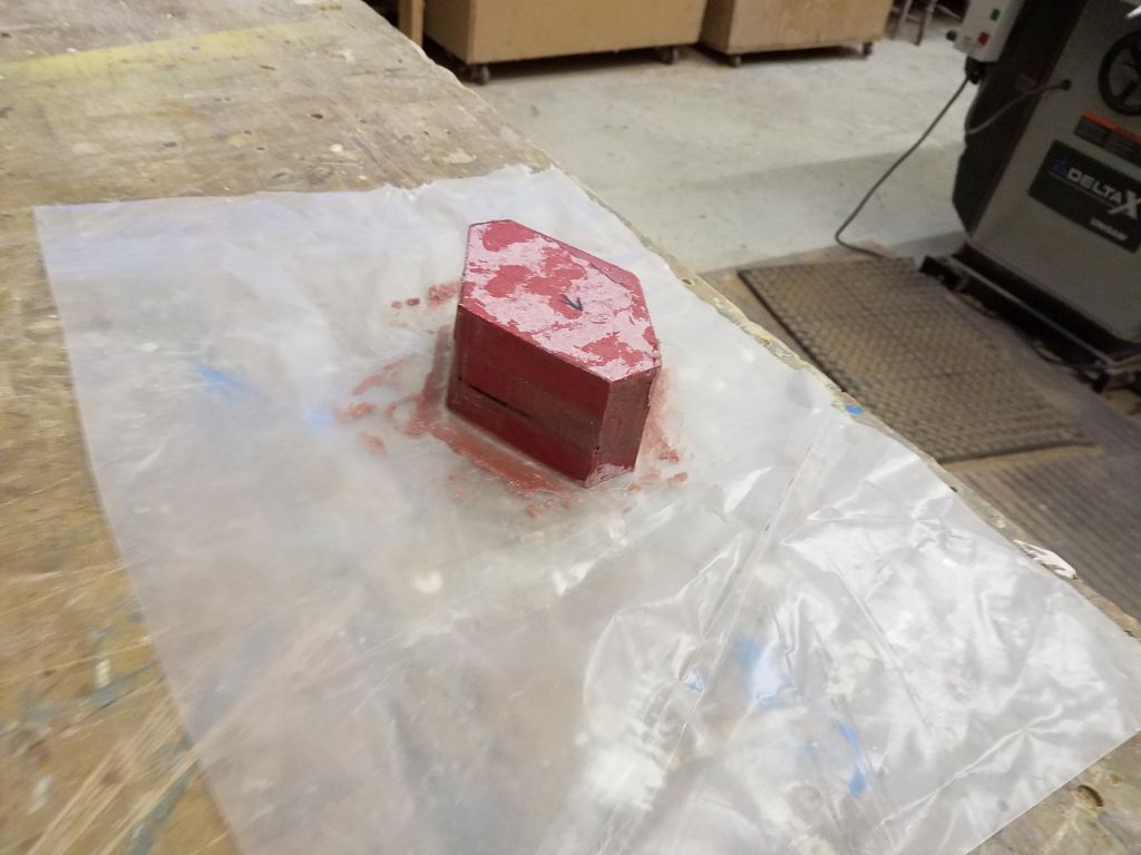
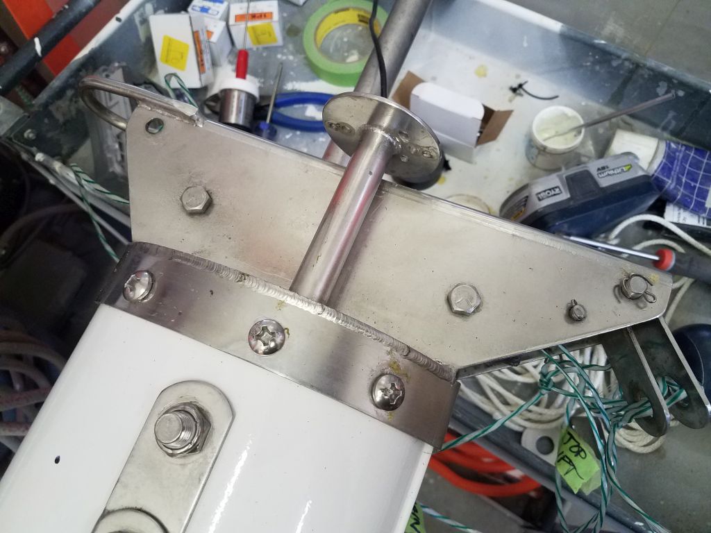
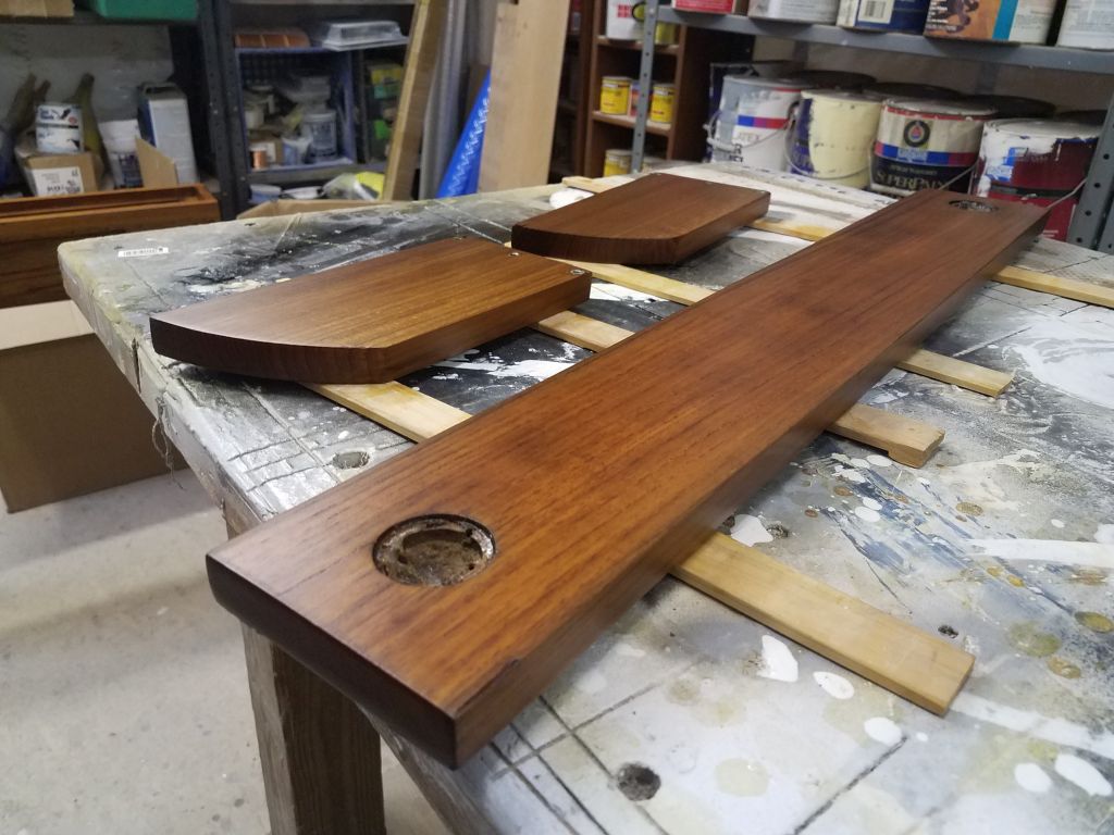
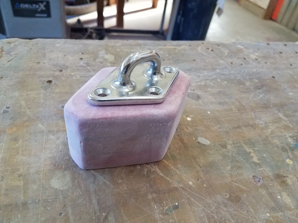
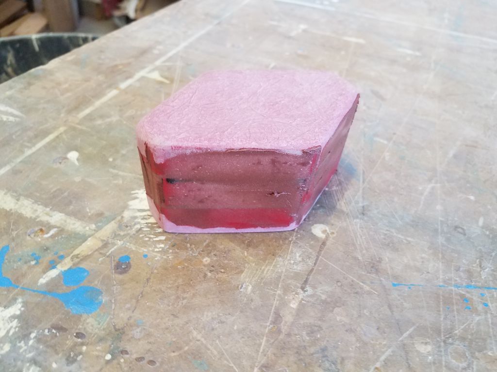
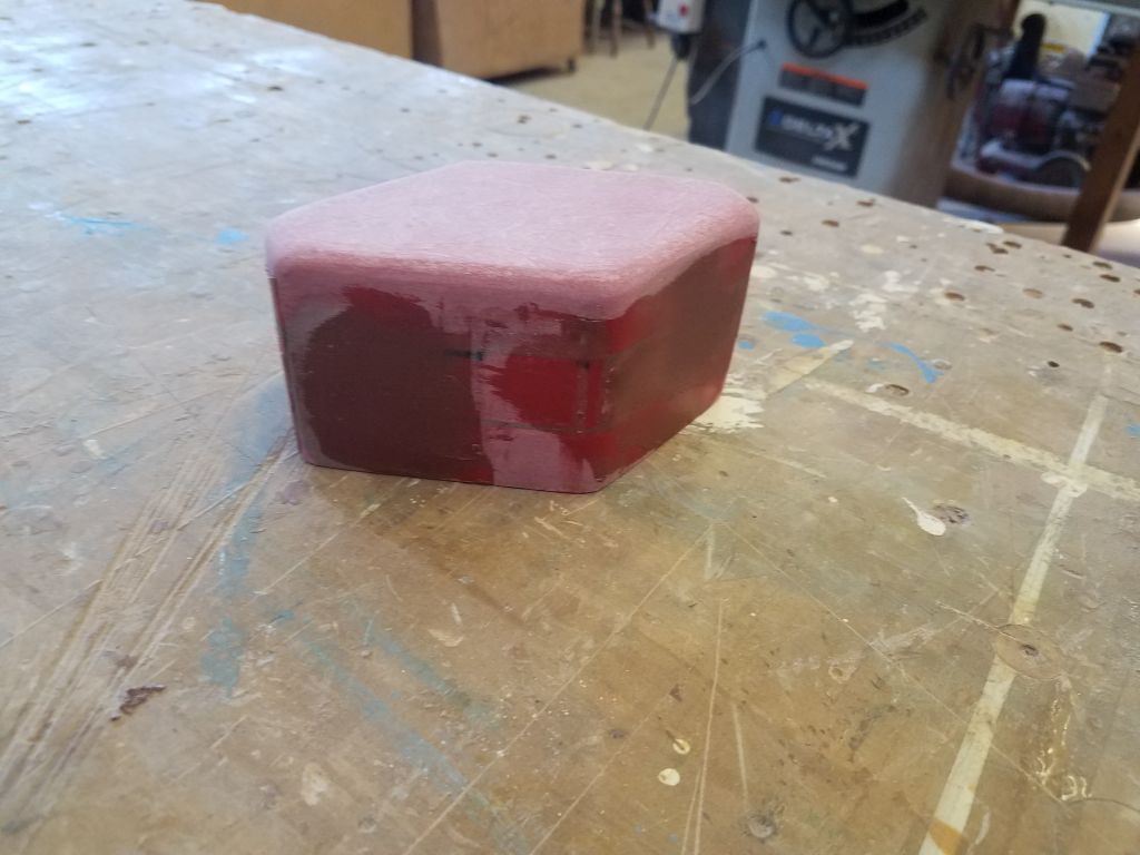
To begin, I lightly sanded the fairing compound I’d applied to the mainsheet riser block, smoothing the surface and eventually rounding over the top edges and other corners for improved appearance.  Though the riser was in good shape now overall, there were some pinholes in the filler, so I applied additional fairing compound to fill these holes.

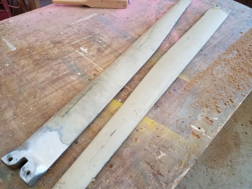
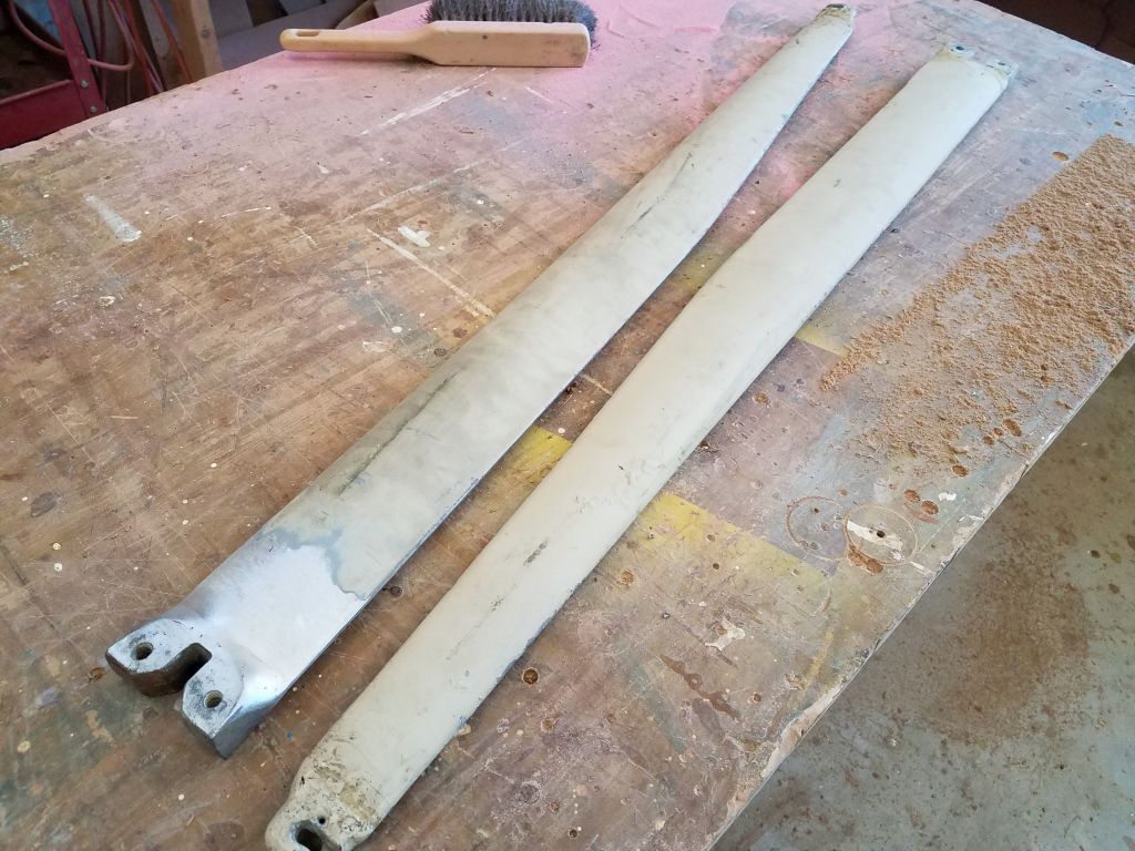
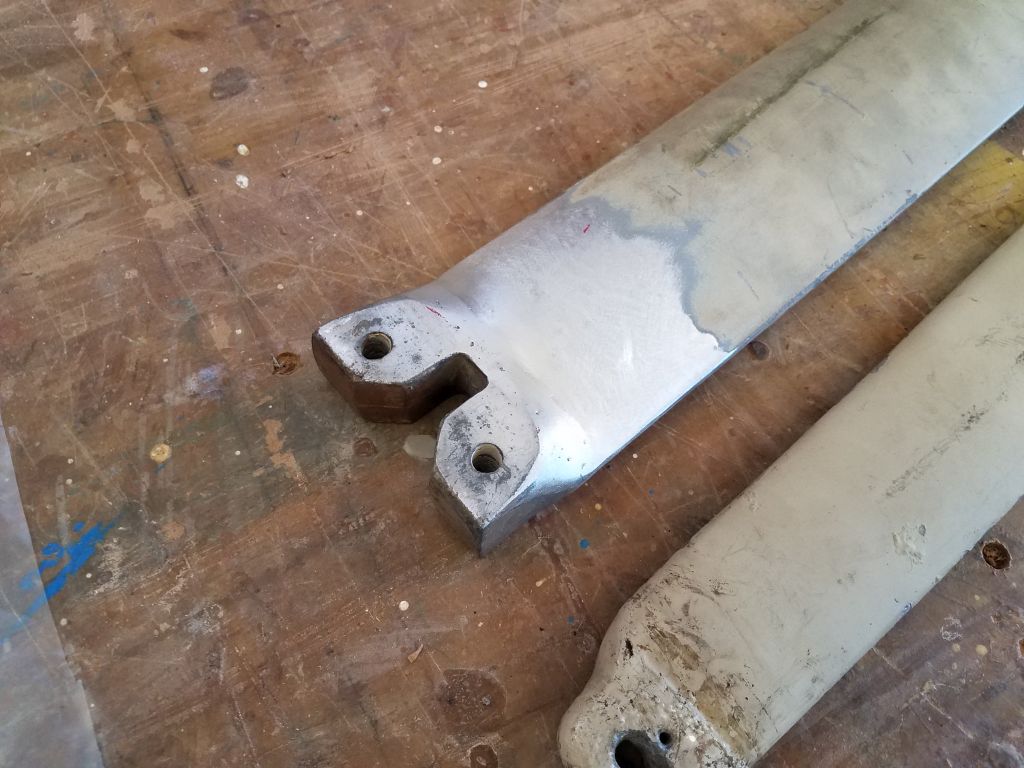
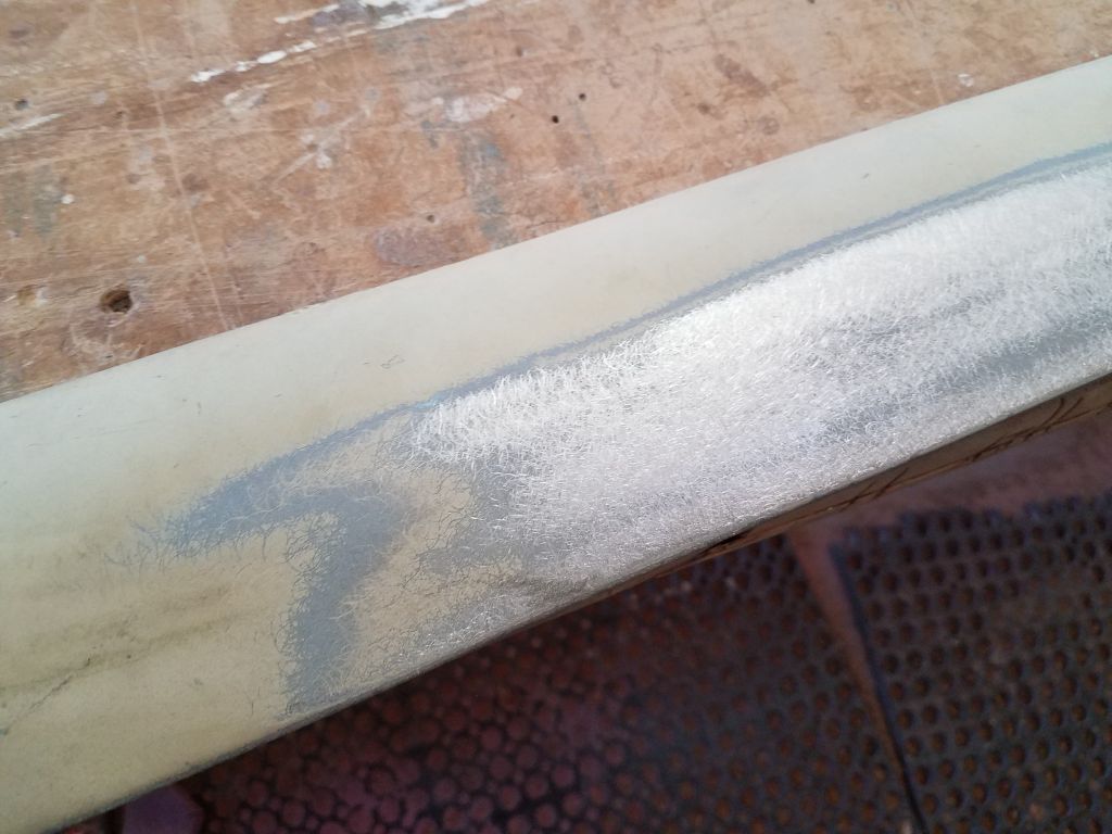
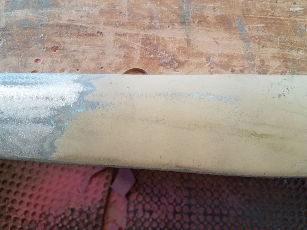
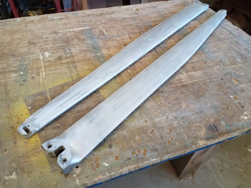
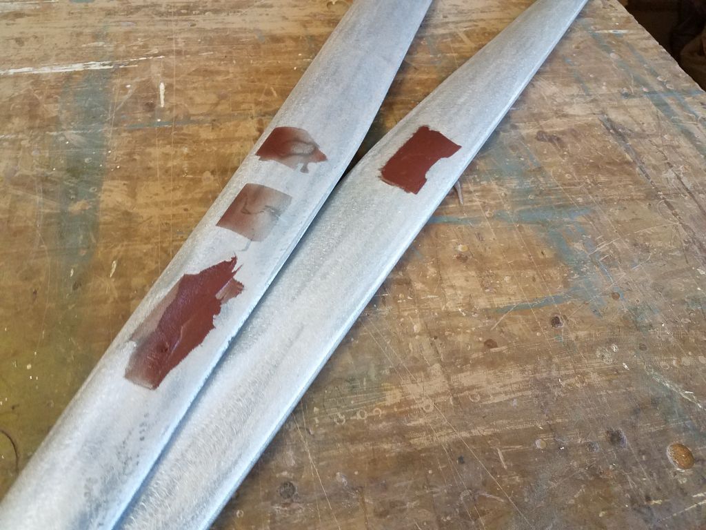
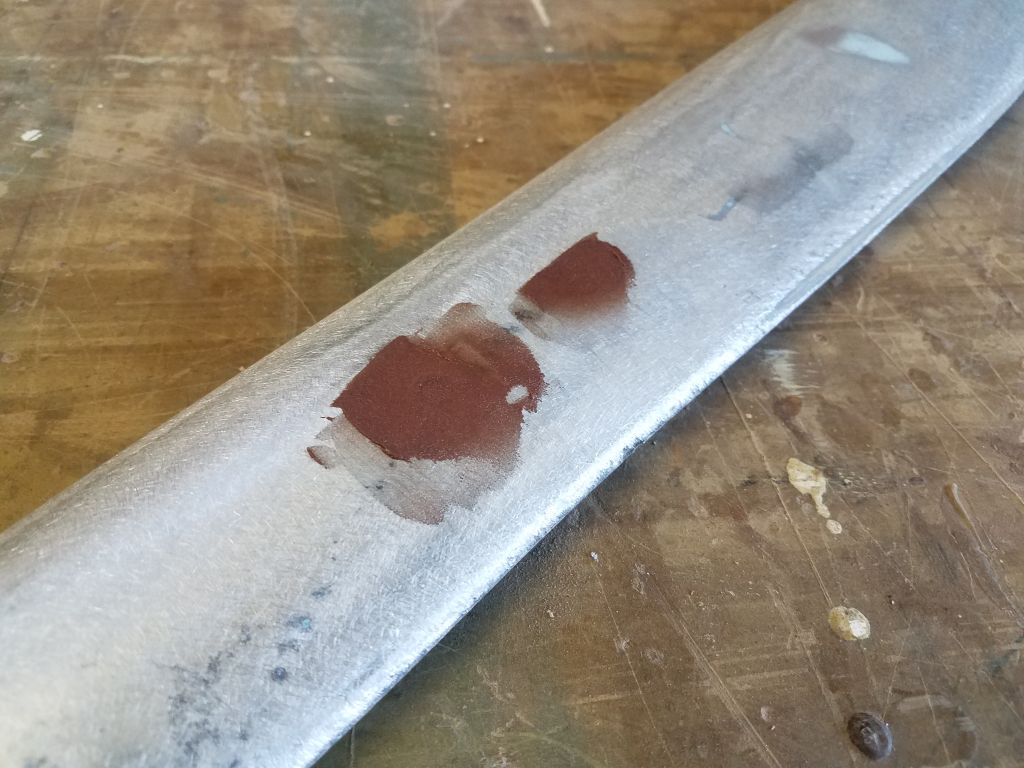
I sanded the filled areas on the spreaders, only to find that the filler in a couple of the screw holes had sunk during curing, so I applied additional fairing compound as needed to fill them smooth.

The little base for the wind transducer mount received several coats of silver spray paint to help it blend into the masthead.

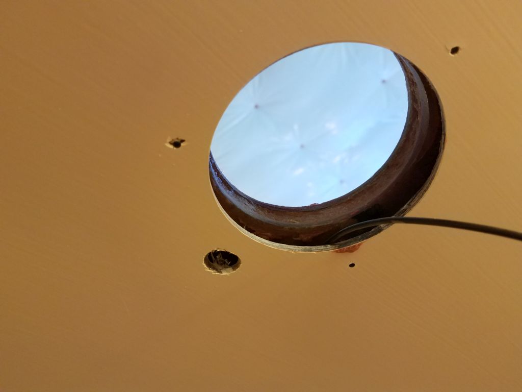
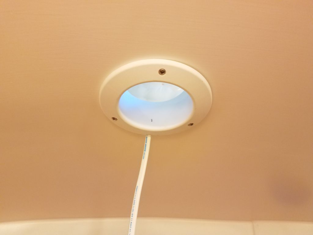
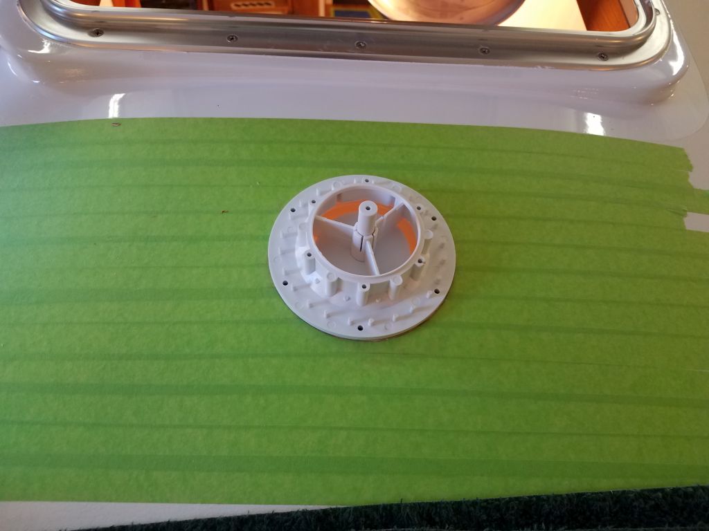
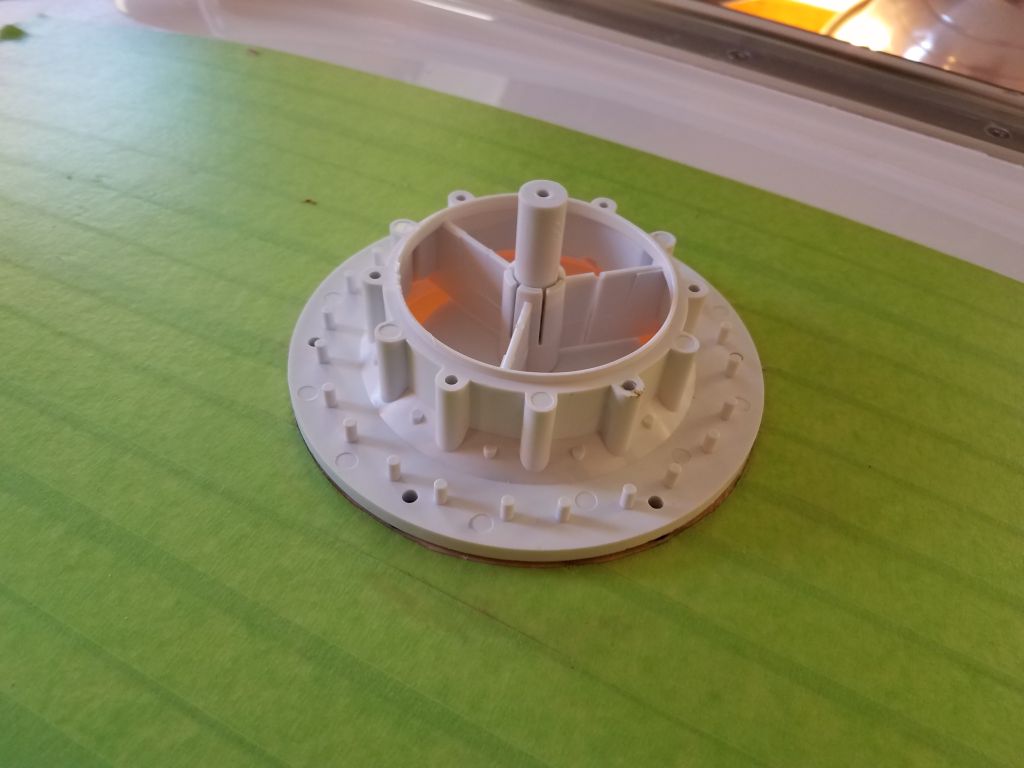
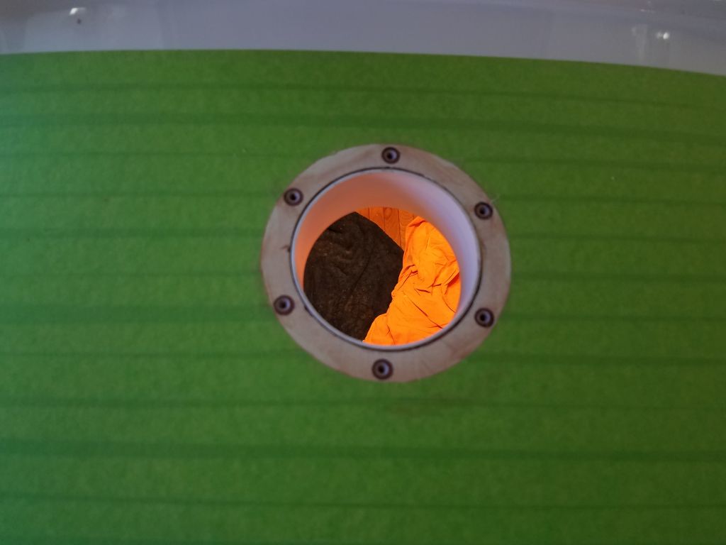
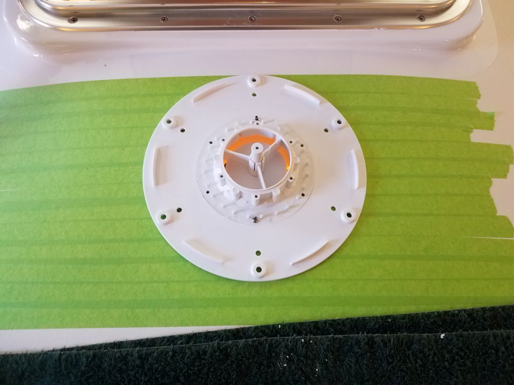
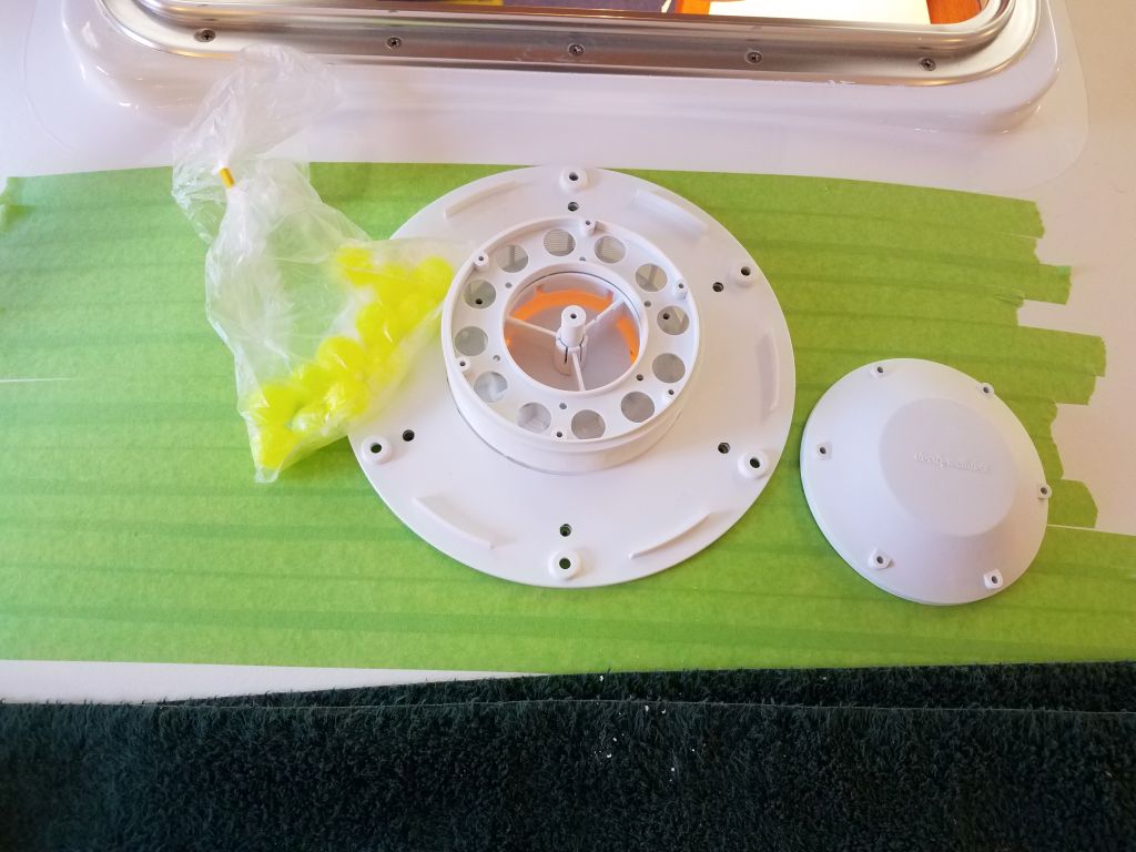
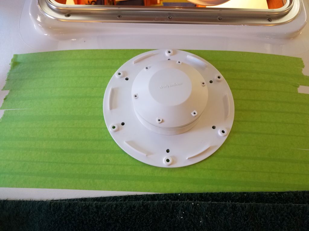
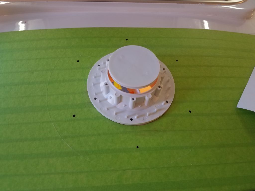
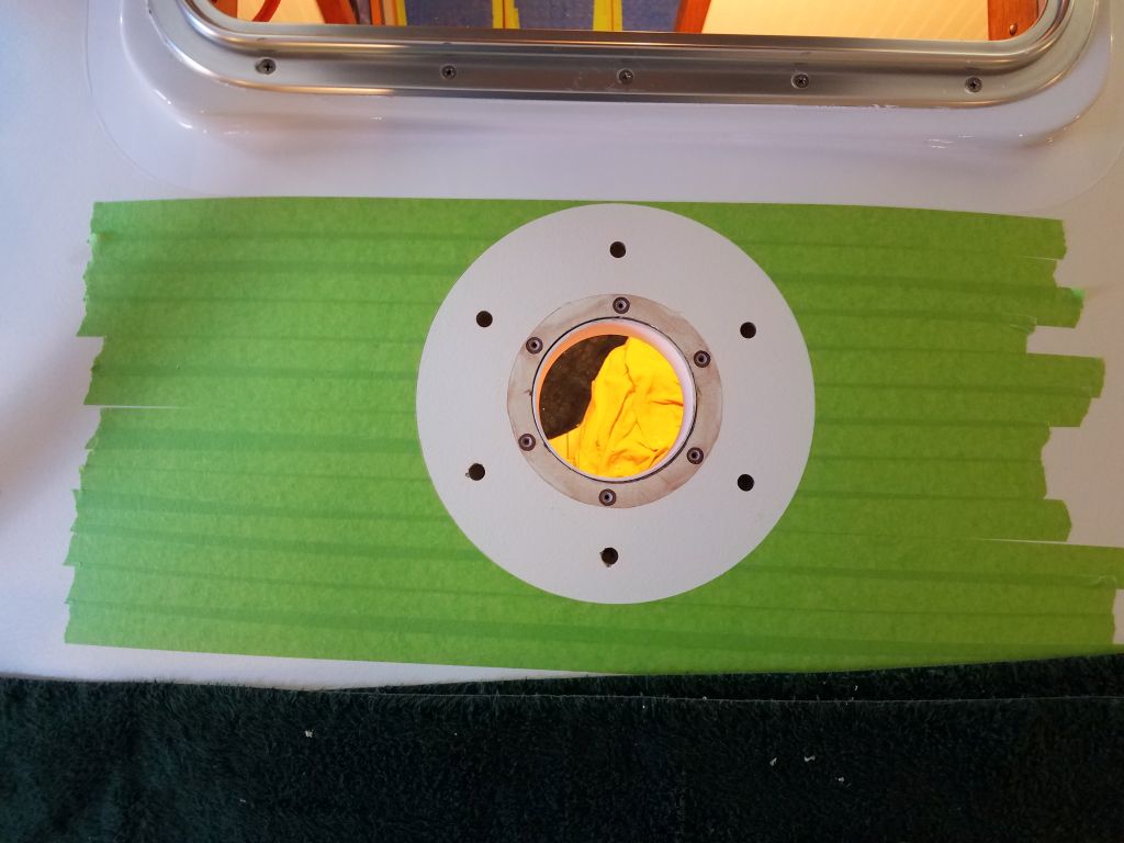
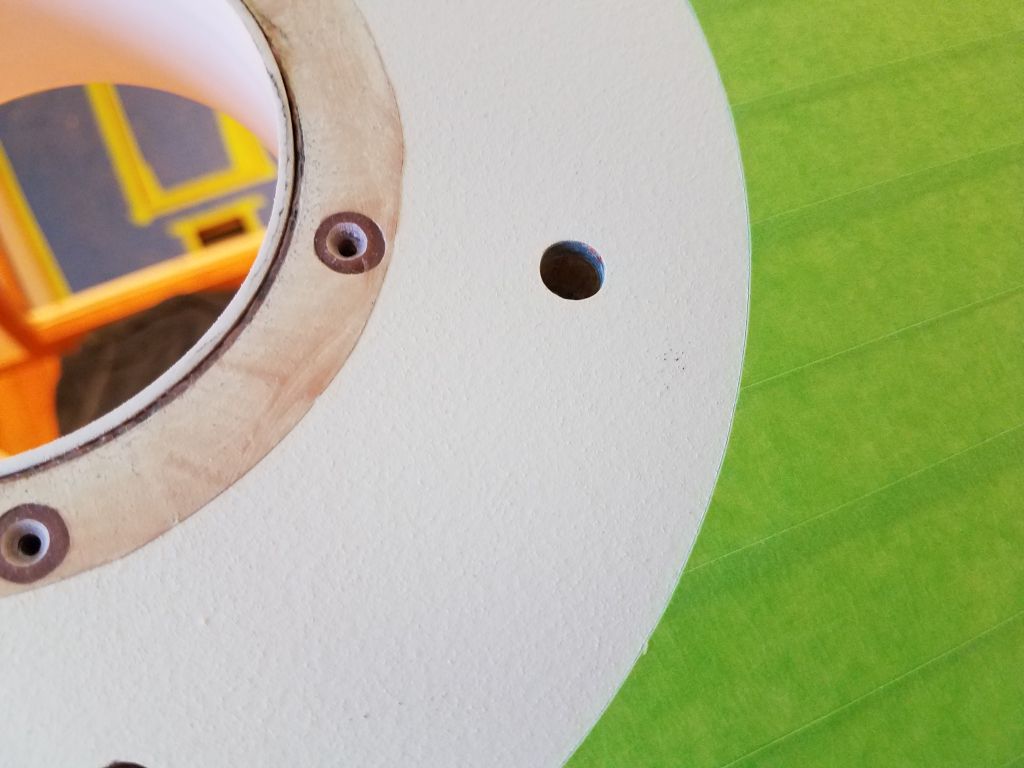
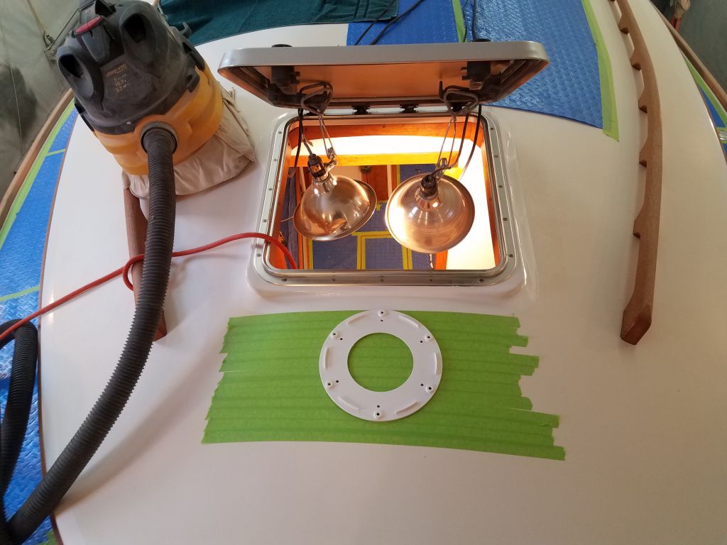
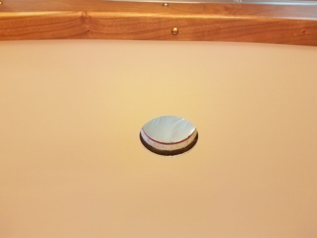
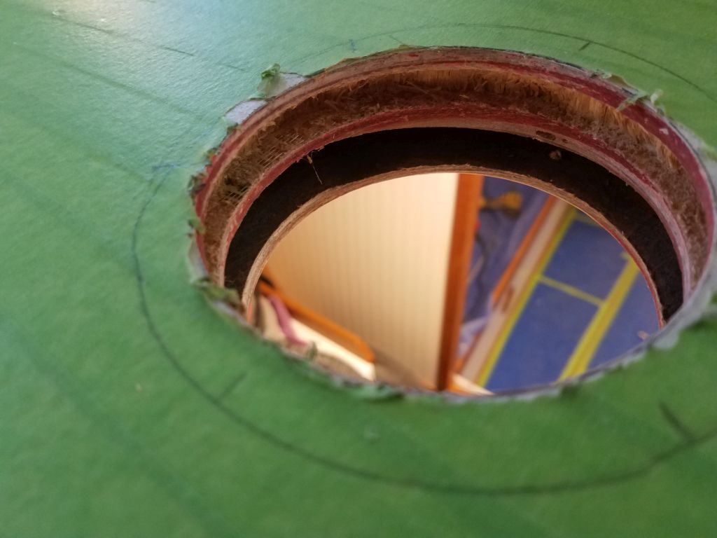
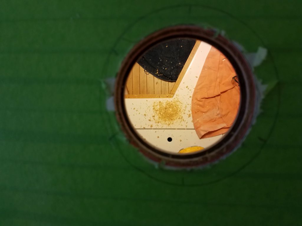
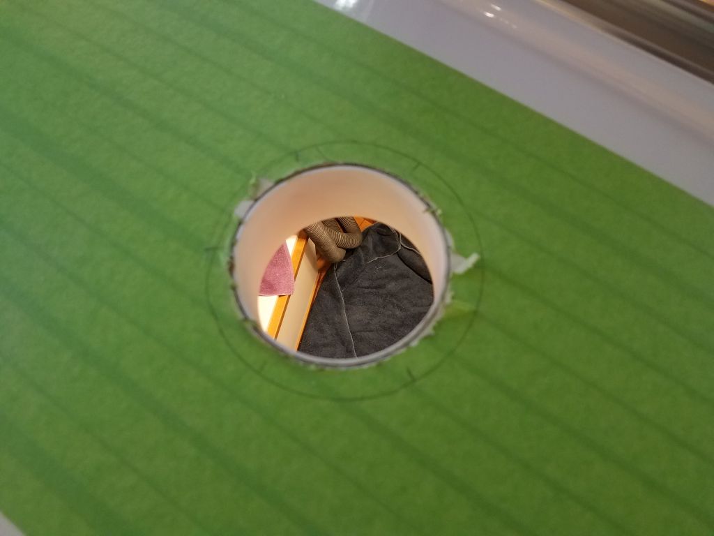
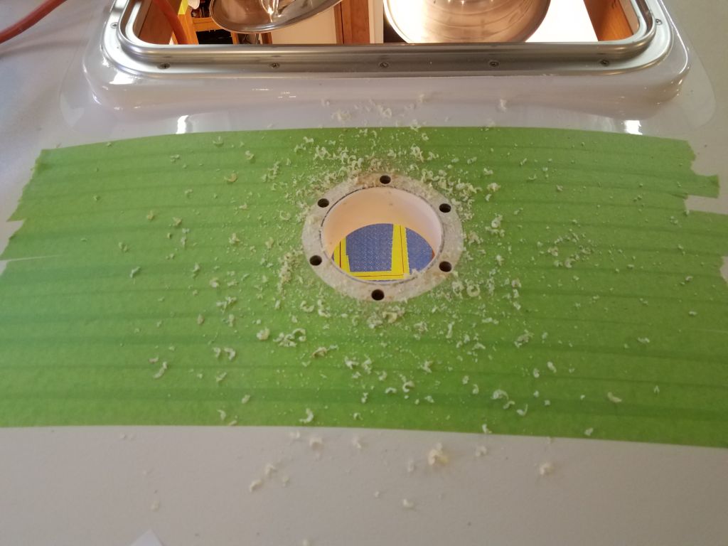
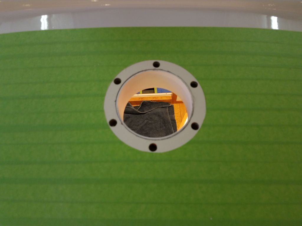
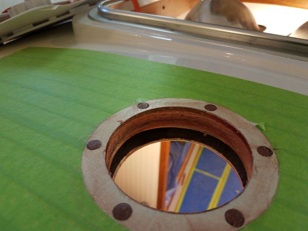
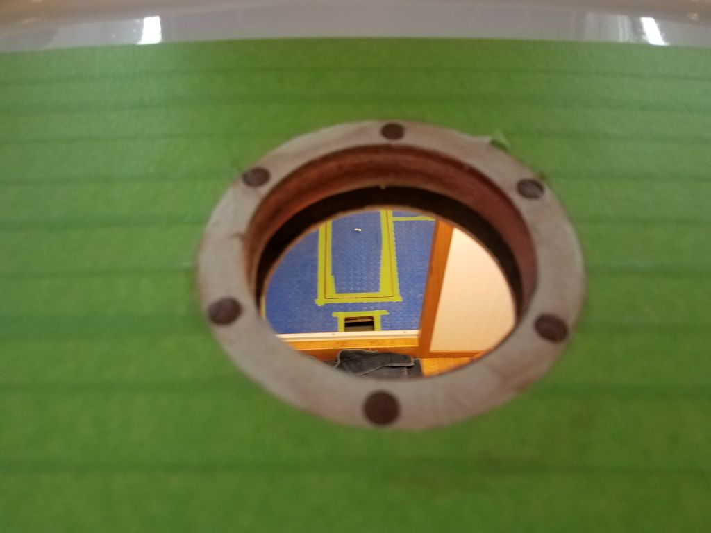
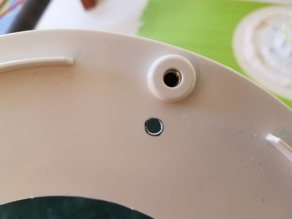
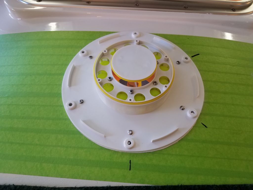
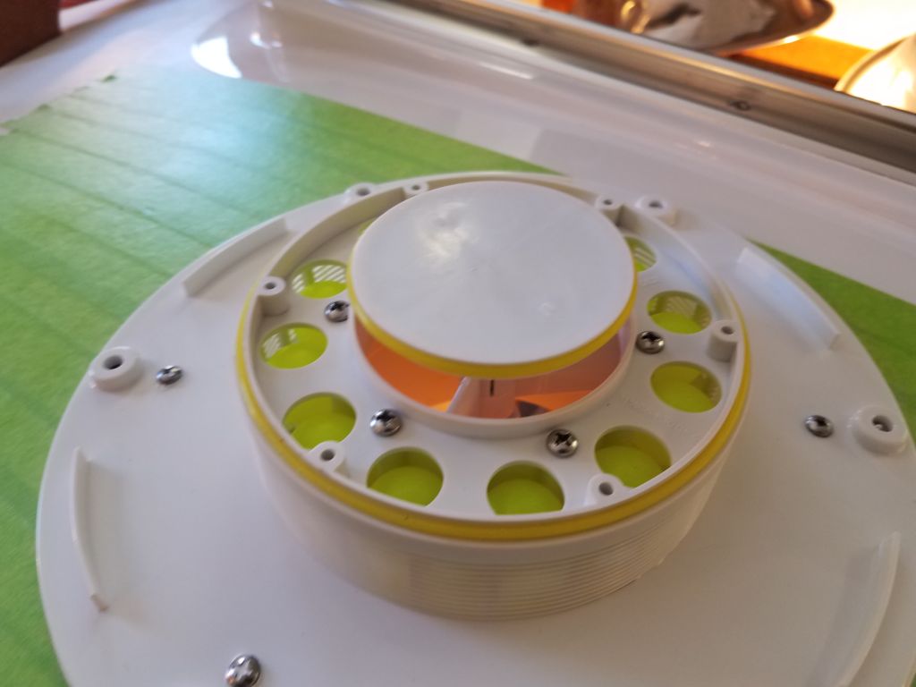
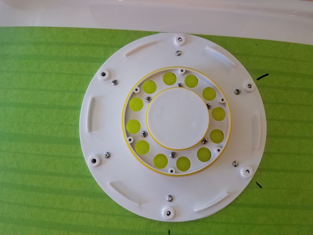
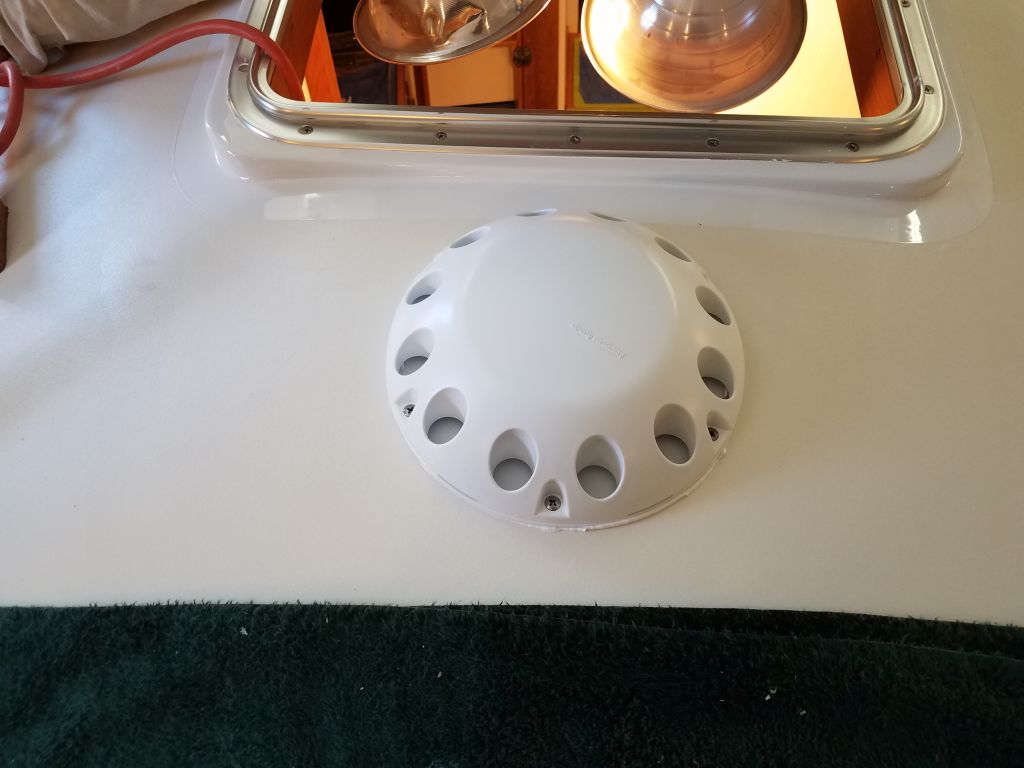
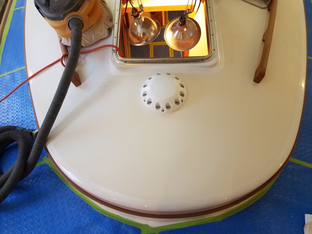
With those little odds and ends out of the way, I got back to work on the forward vent.  With all the deck holes now prepared properly, and after drilling and countersinking the latest screw holes for the outer part of the base, I could proceed with final installation, starting with the internal trim ring in the forward cabin.  Then, back on deck, I installed the inner vent housing in a bed of sealant, followed by the outer part of the base.  Before installing the base, I installed the supplied nuts in the hexagonal holes in the bottom of the base, and used little bits of butyl tape to hold them there; these would later secure the mushroom vent top itself.  Once these parts were secured, I cleaned up the excess sealant all around as needed, and installed some of the supplied yellow silicone gaskets on the inner parts.

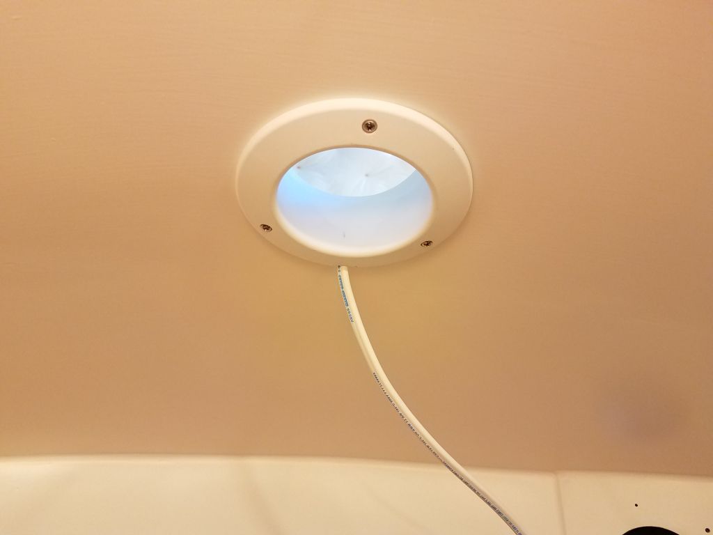
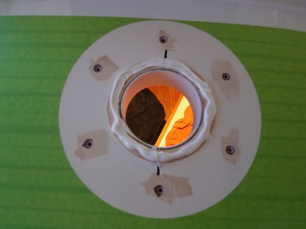
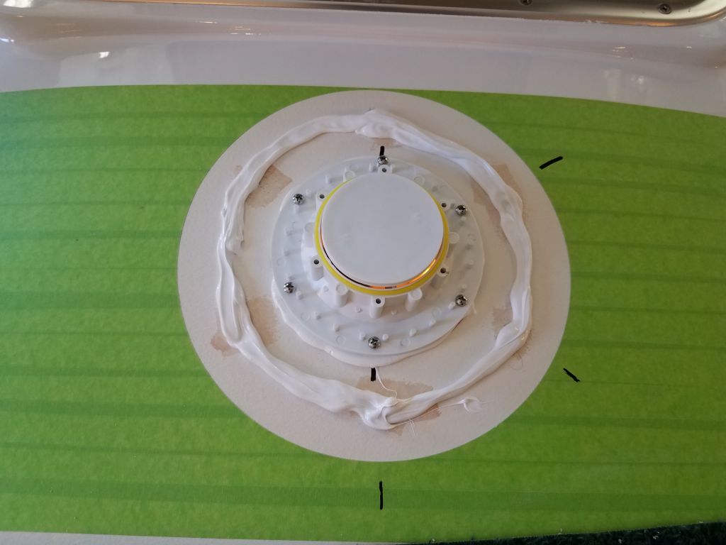
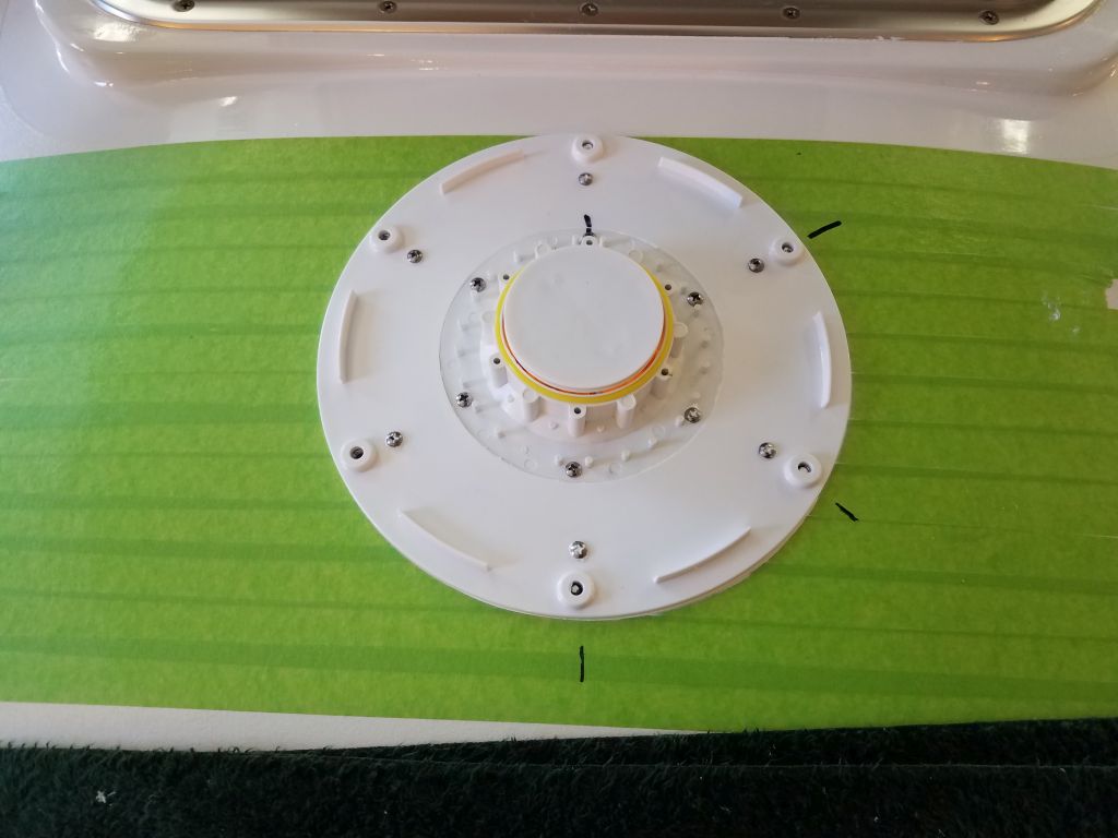
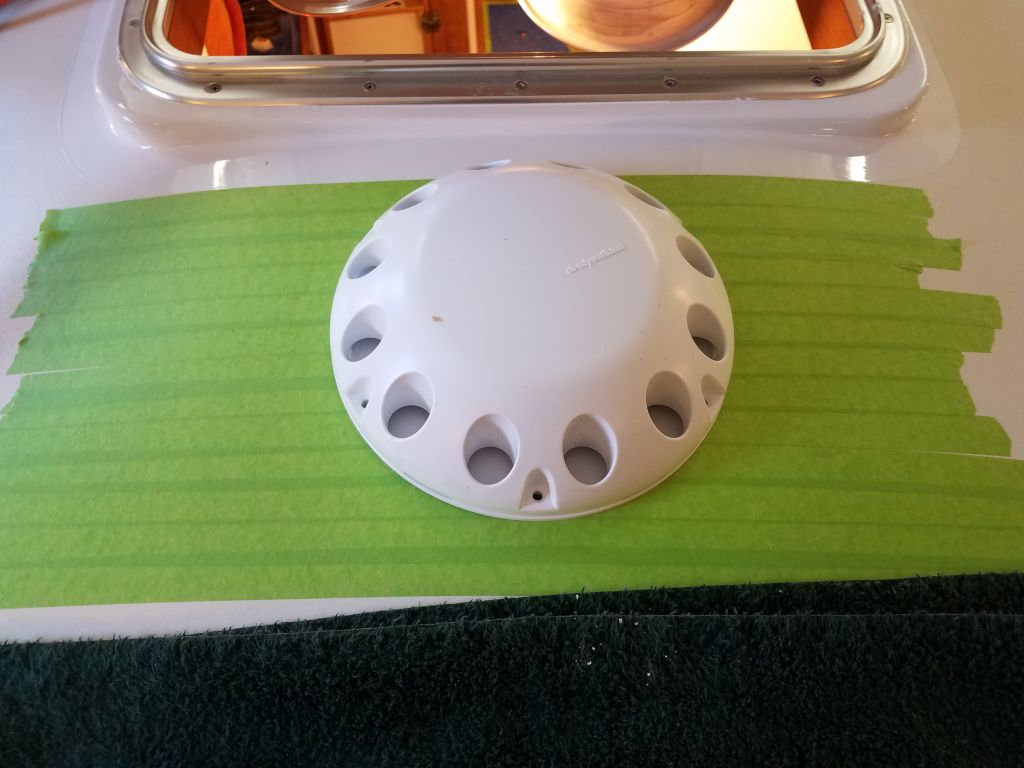
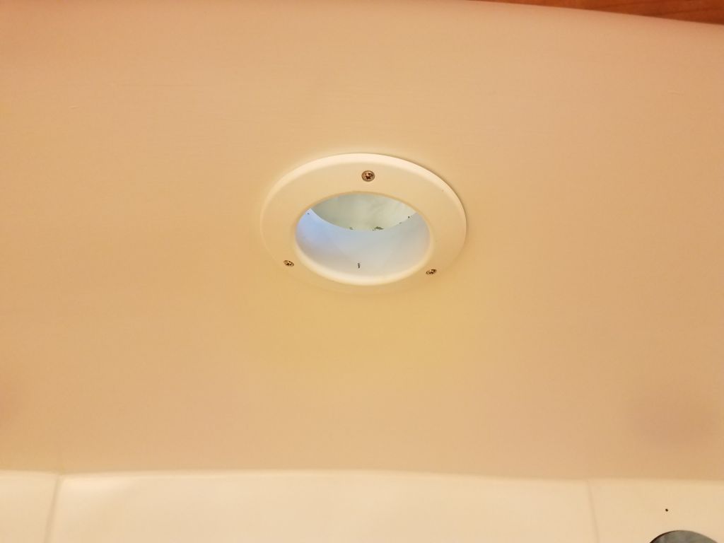
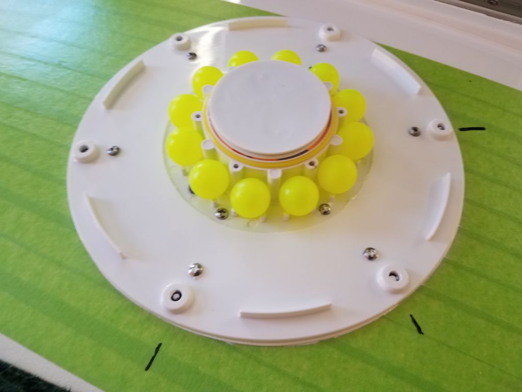
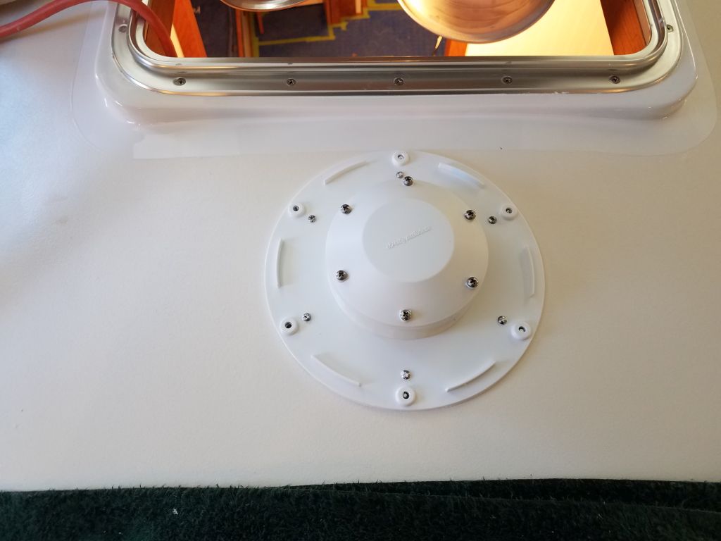
Next, I installed the bright yellow floating balls around the inner housing, then covered it with the slotted vent assembly and finally the top of the inner housing.  Finally, I installed the mushroom vent cover itself to complete the on-deck part of the installation (later I’d need to wire up and install the fan below).  I’d removed the masking tape after installing the base units, but before securing the top, and I found that the act of installing the top squeezed out additional sealant around the base, so I chose to leave that for cleanup later after it had cured.

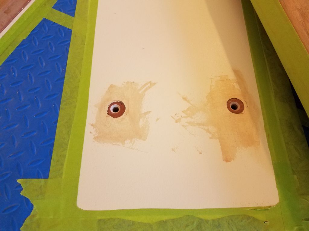
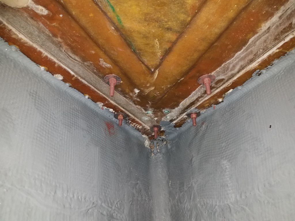
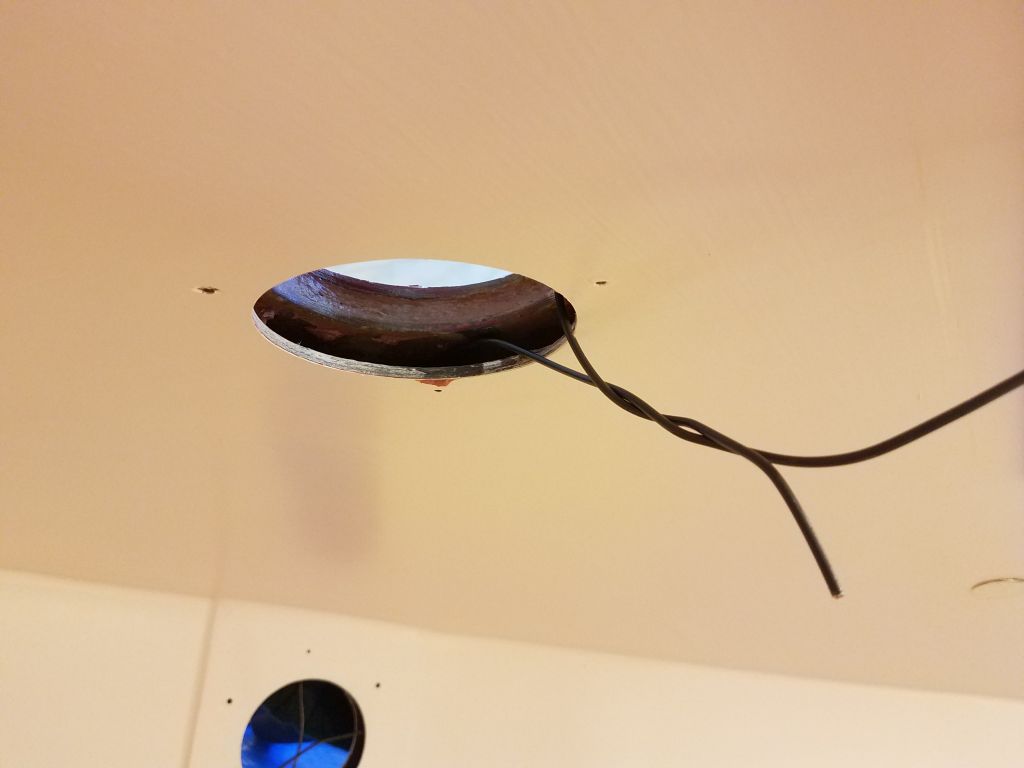
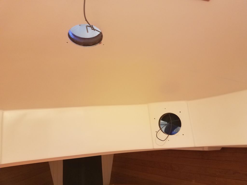
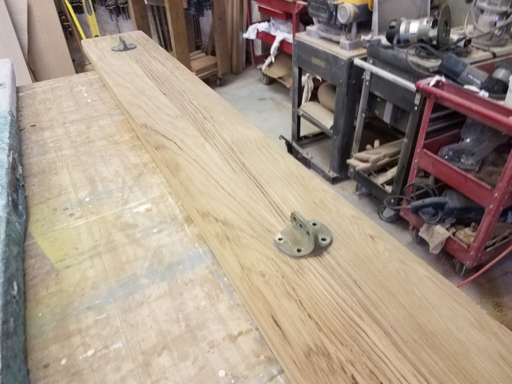
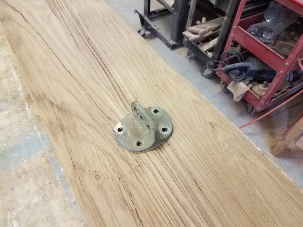
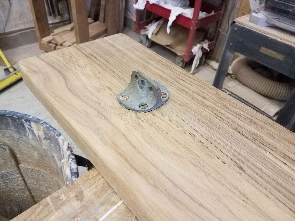
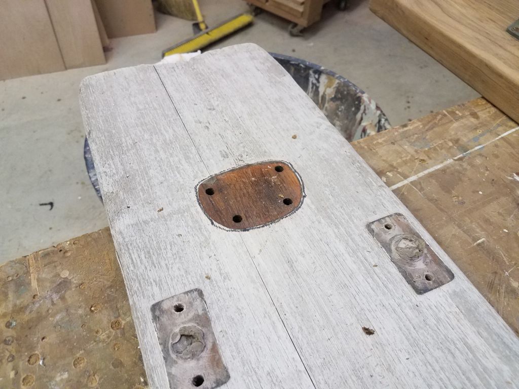
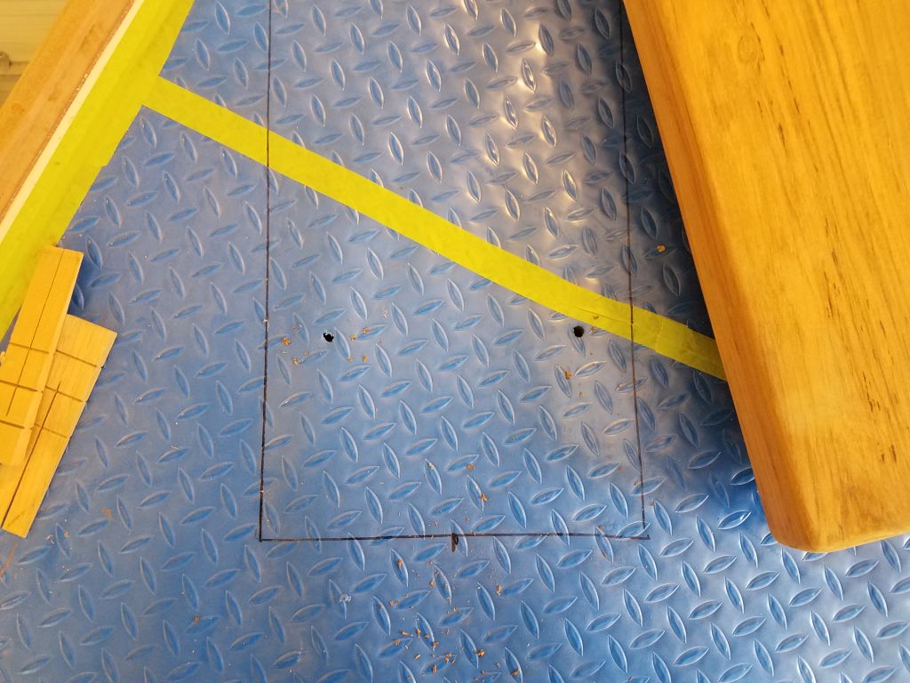
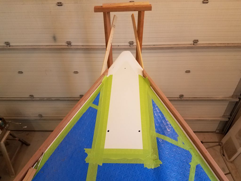
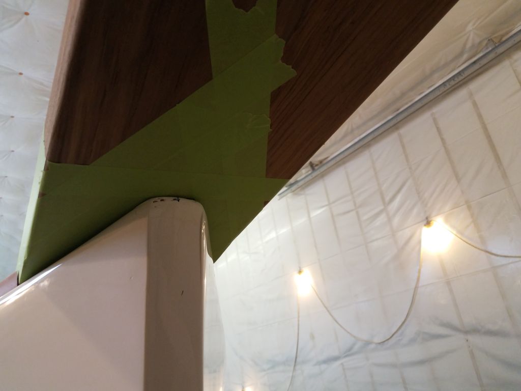
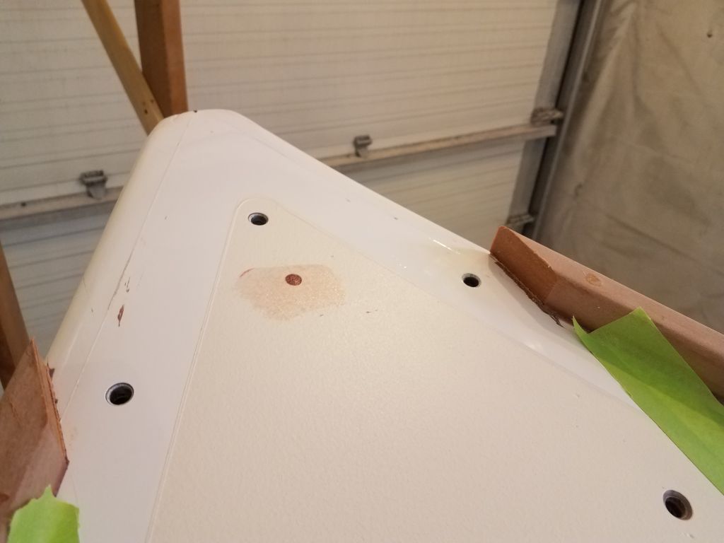
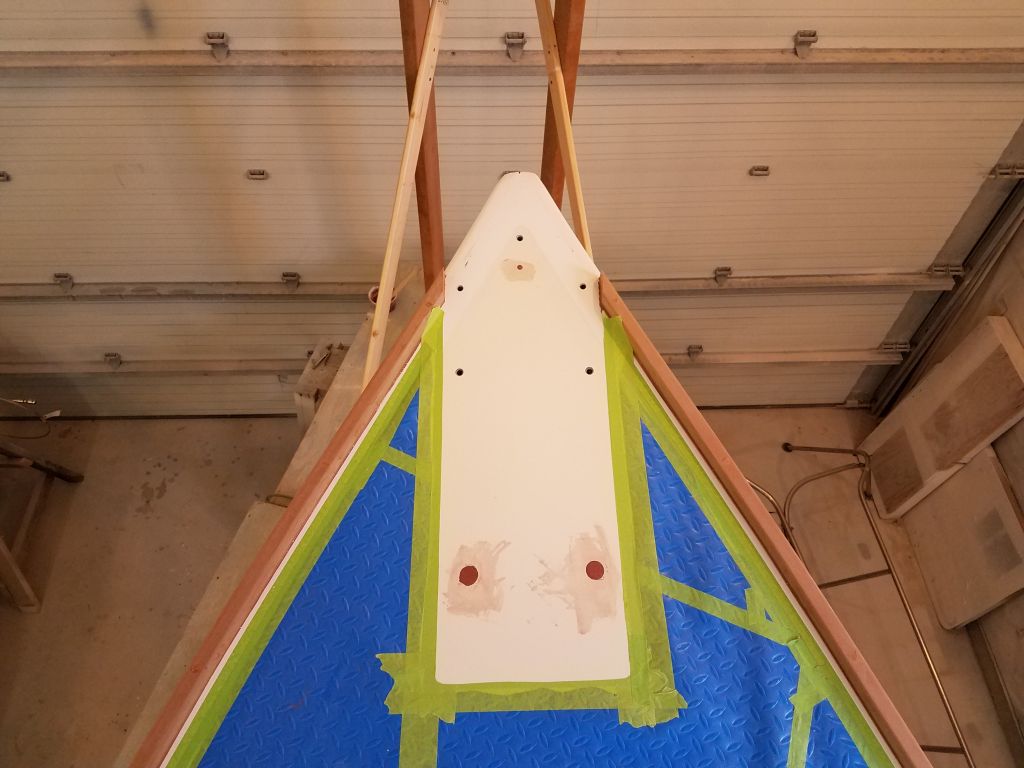
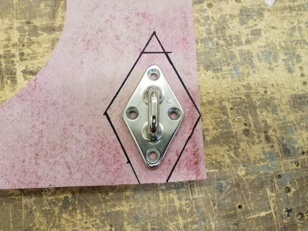
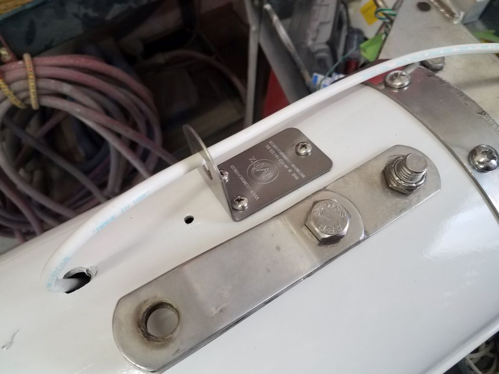
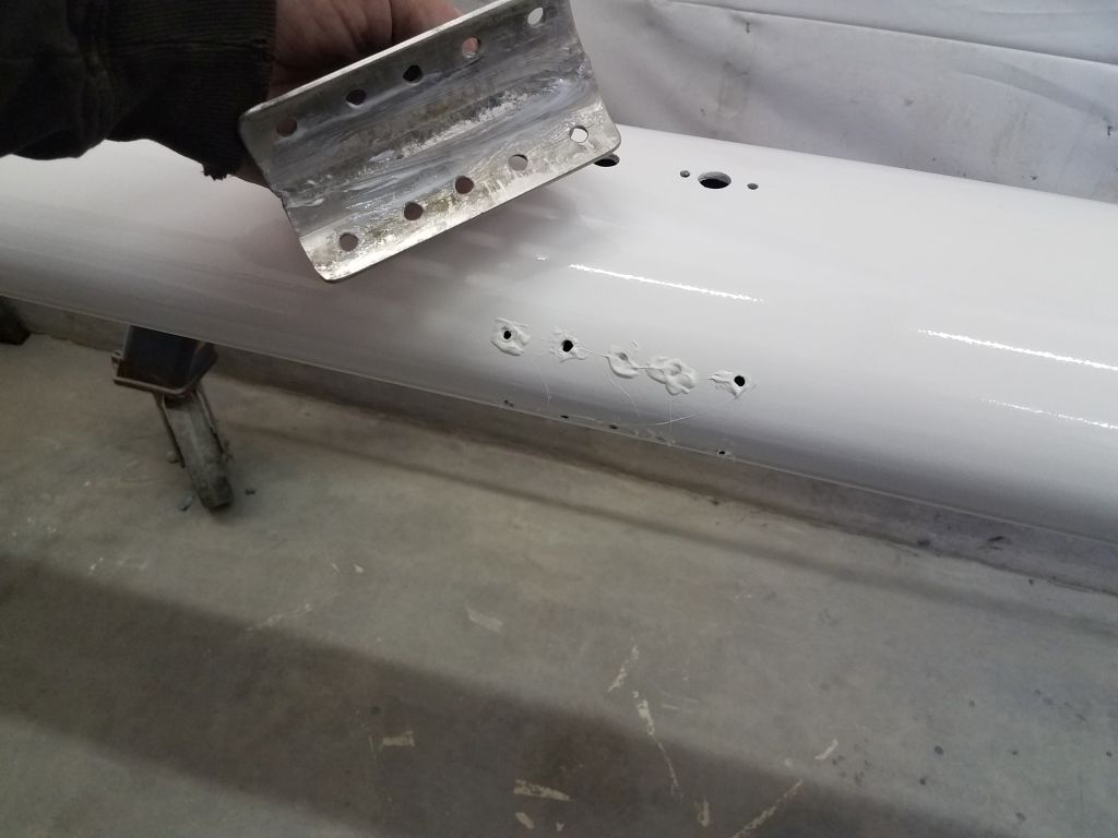
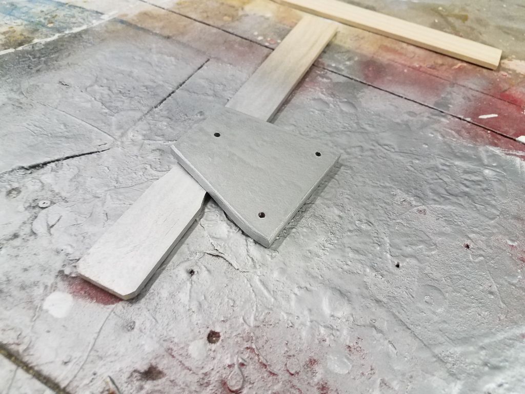
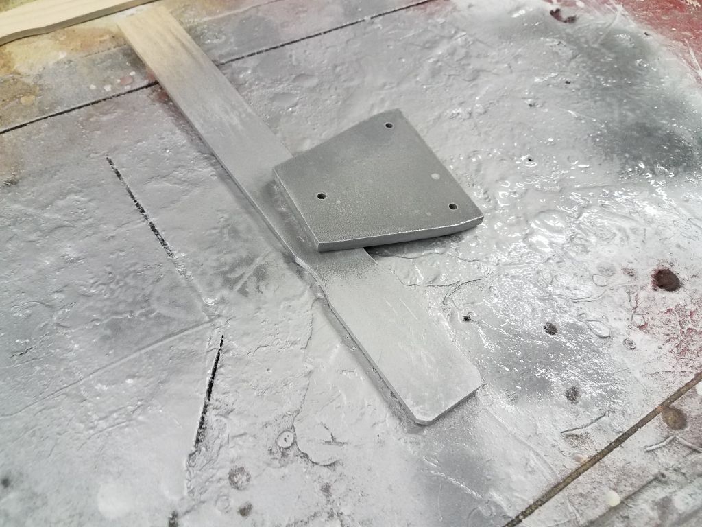
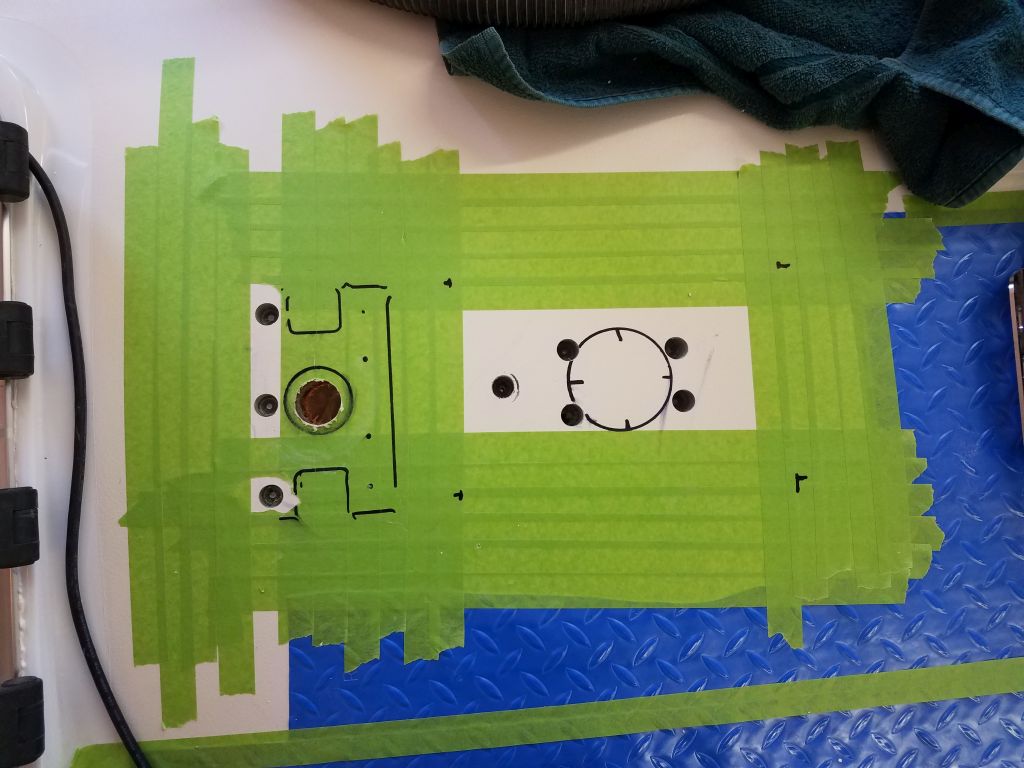
Moving on, I turned to the mast step and through-deck wiring gland.  Before deck painting, I’d marked the old mast step hole locations, so with these basic locators I lined up the mast step plate as needed, checking its position fore and aft and side to side to confirm placement.  Then, I marked as needed and drilled 5/8″ holes in the deck, thinking I needed to remove core, but I found solid fiberglass in all hole locations, which I must have known in the past, but it was nearly two years before that I’d done deck work, and, reviewing old photos, I found that the solid glass mast step area was part of a previous repair and not something I had done.  No wonder I didn’t remember.  In any event, solid fiberglass beneath the mast step was a good thing.

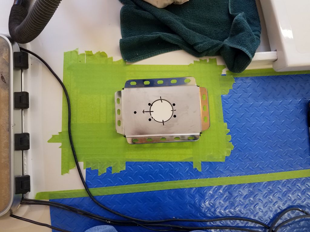
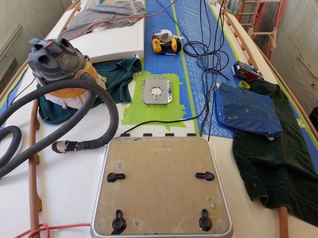
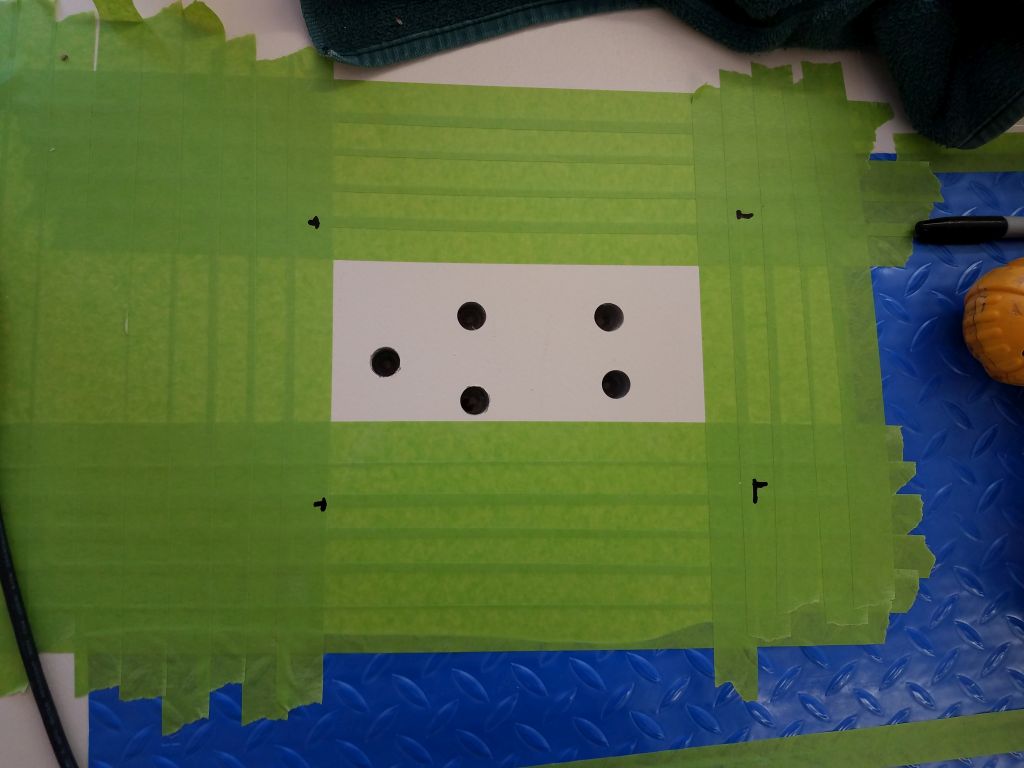
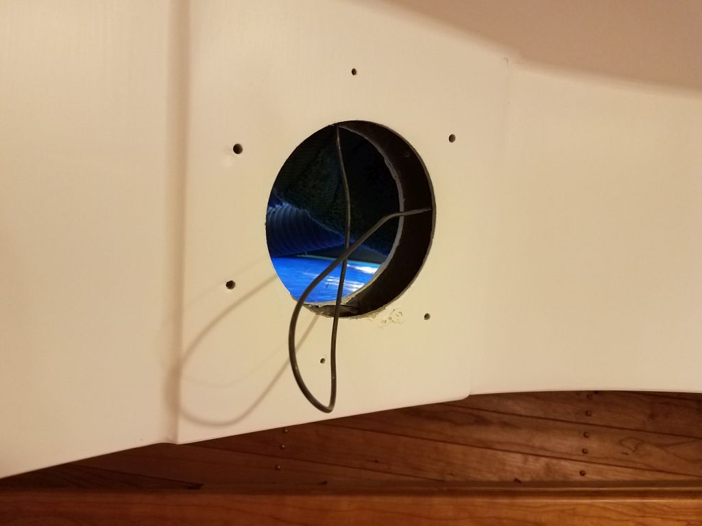
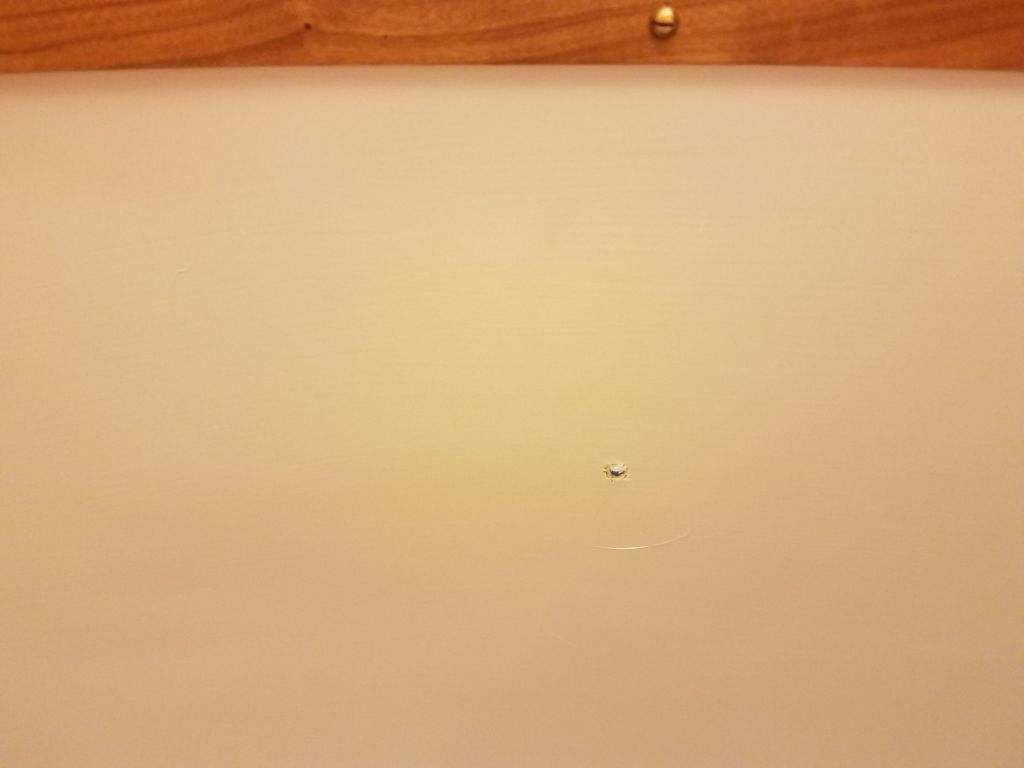
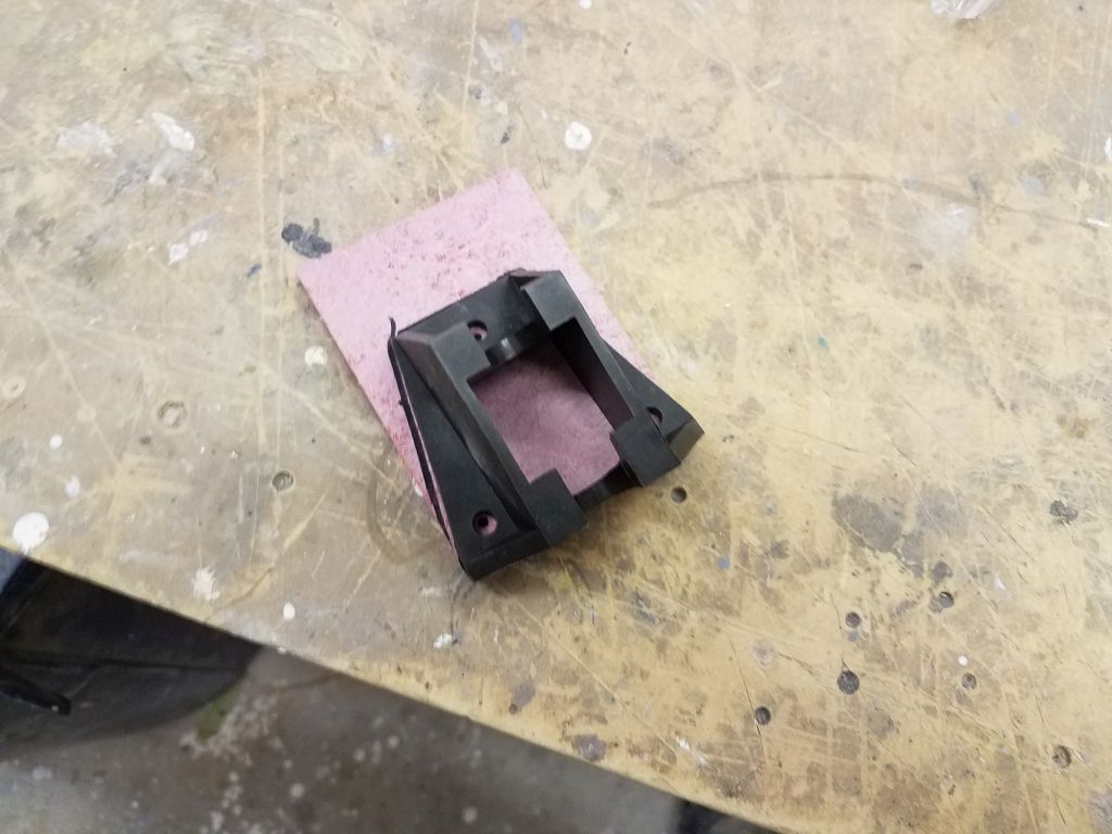
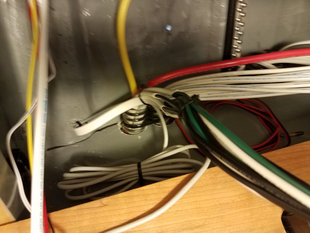
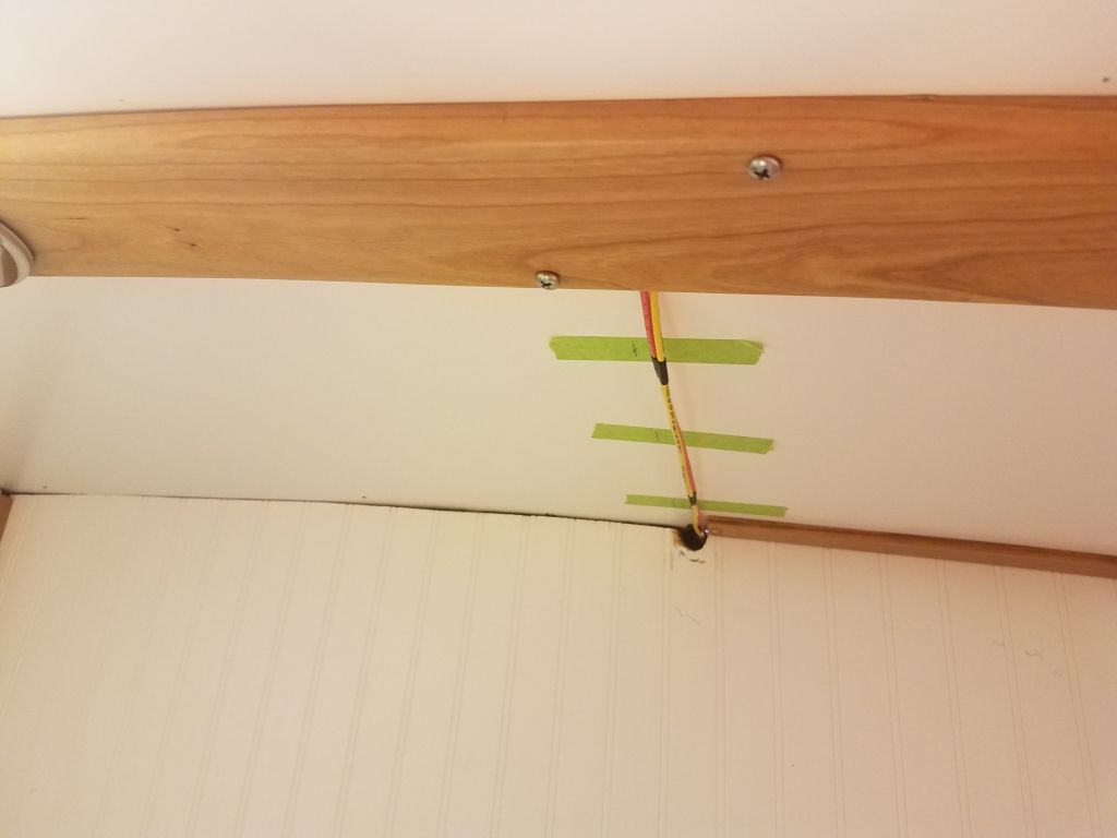
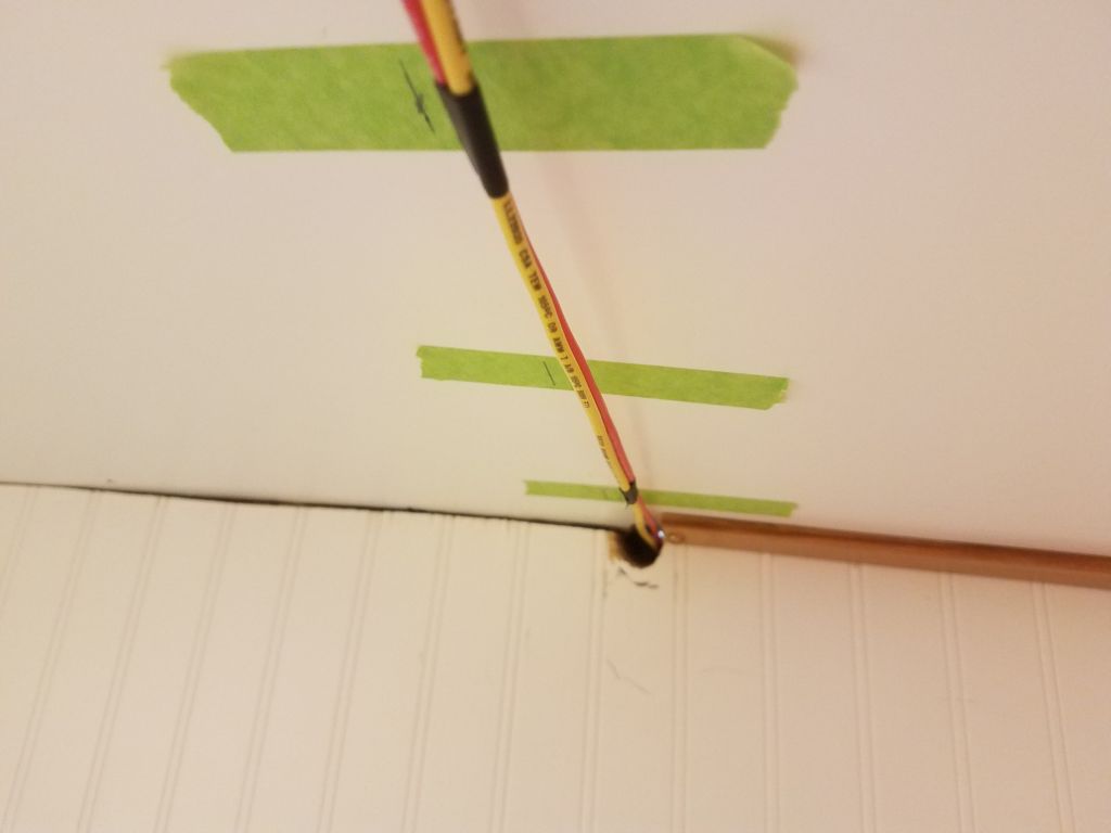
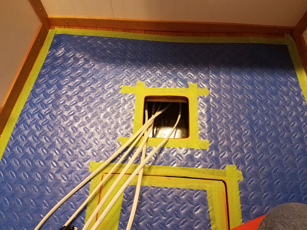
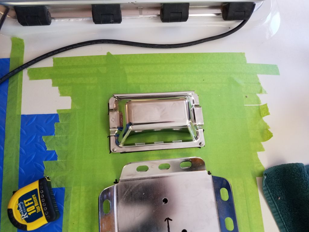
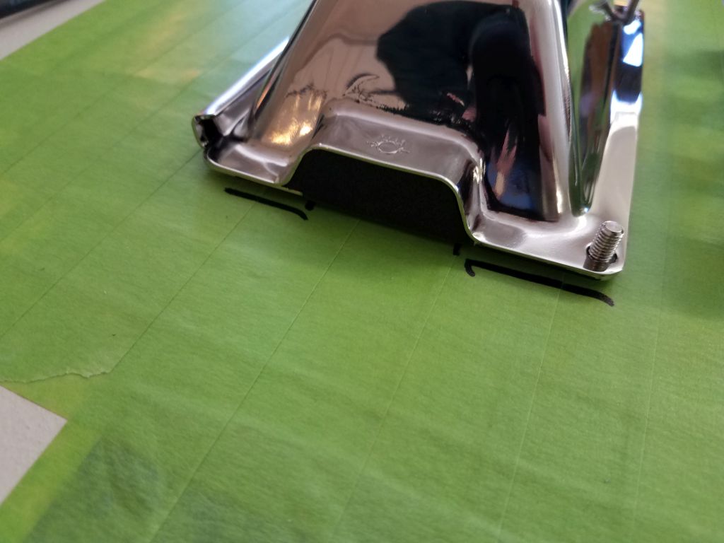
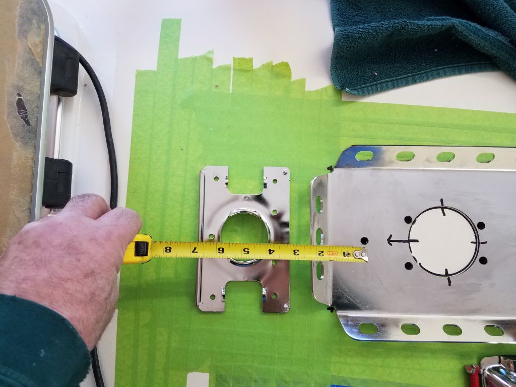
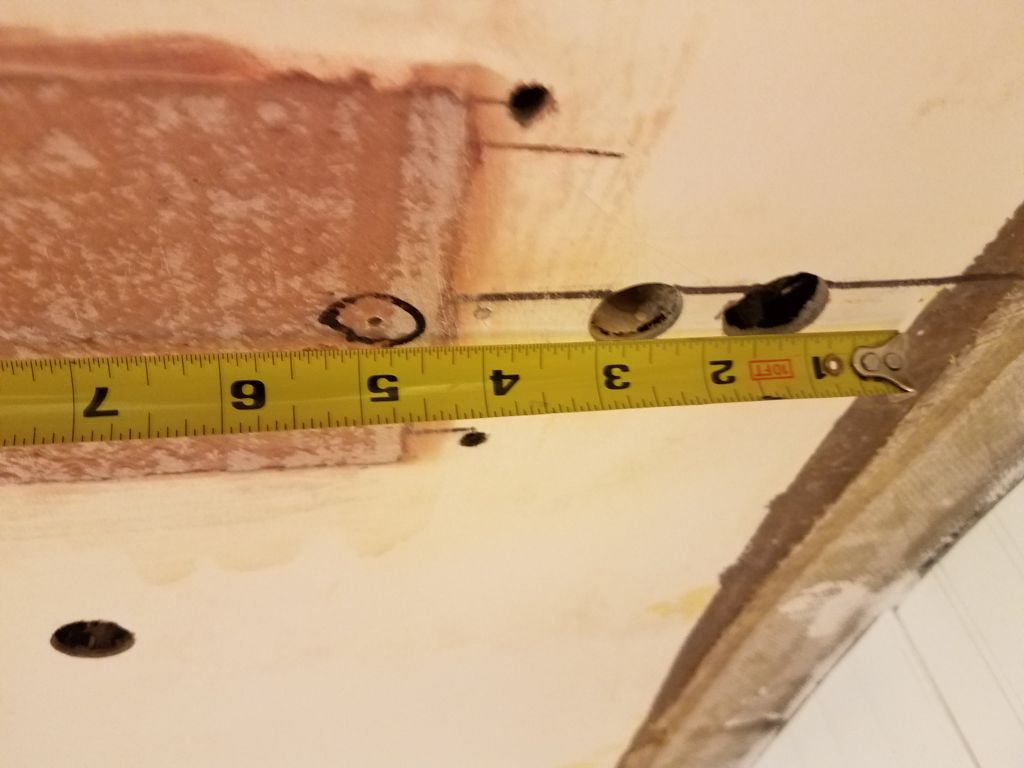
For this project, I chose a new kind of deck gland for the wire passage between the mast and the interior.  This particular gland featured a base with a large raised central hole, complete with smooth and contoured wire guides leading within, and a stainless steel cover that secured over the top, with foam-sealed wire exits on each side.  I lined the base up forward of the mast step where I thought it should go, and took a measurement from the forward mast step fastener hole to the center of the proposed wiring hole (5″), then, after drilling a pilot hole through the fastener hole into the cabin, went below to confirm that the 5″ measurement would work; it did.

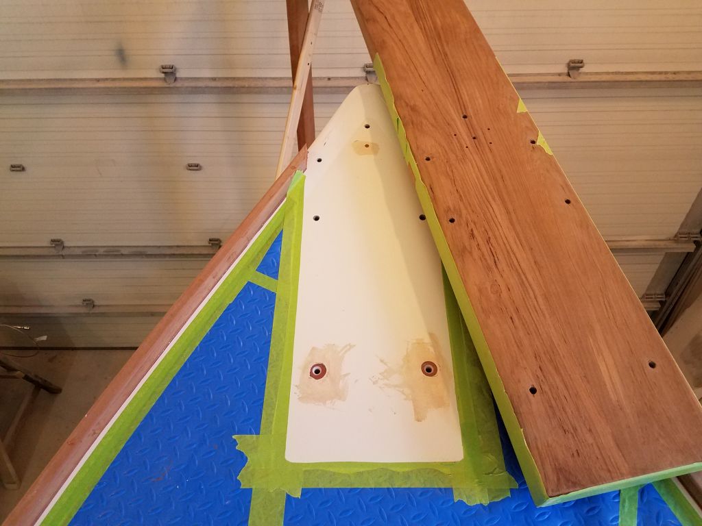
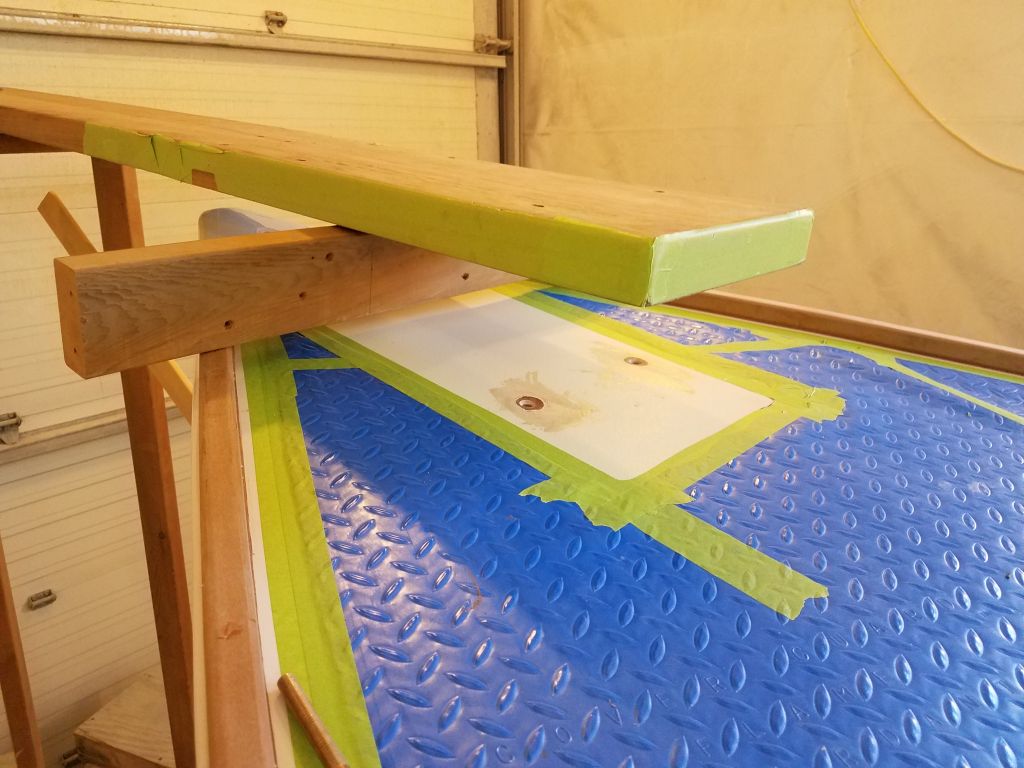
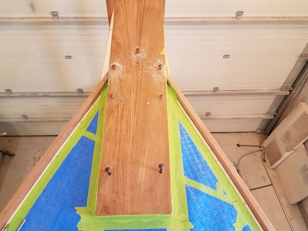
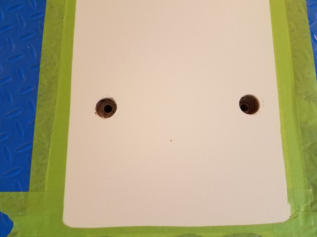
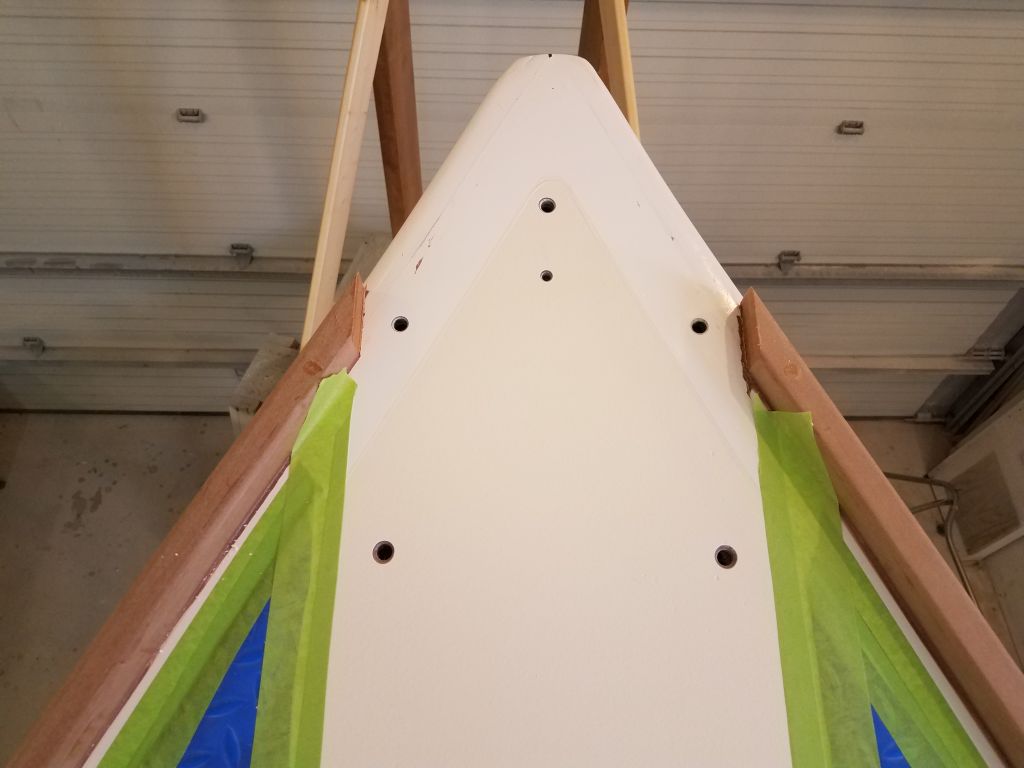
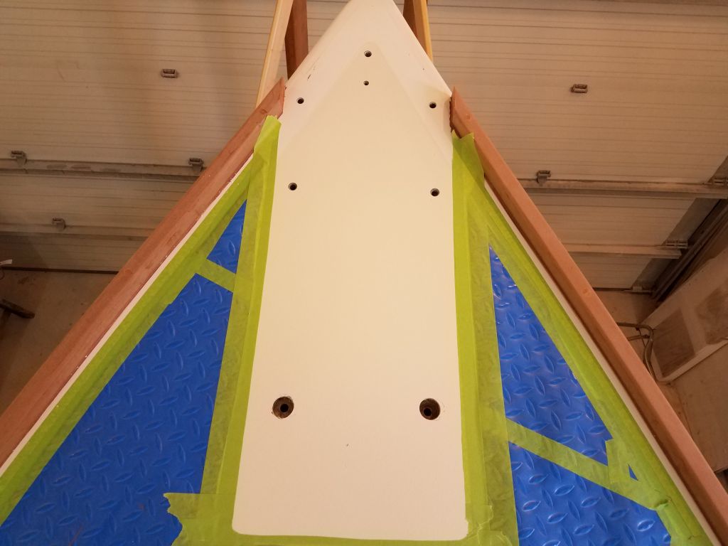
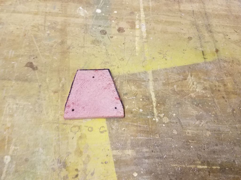
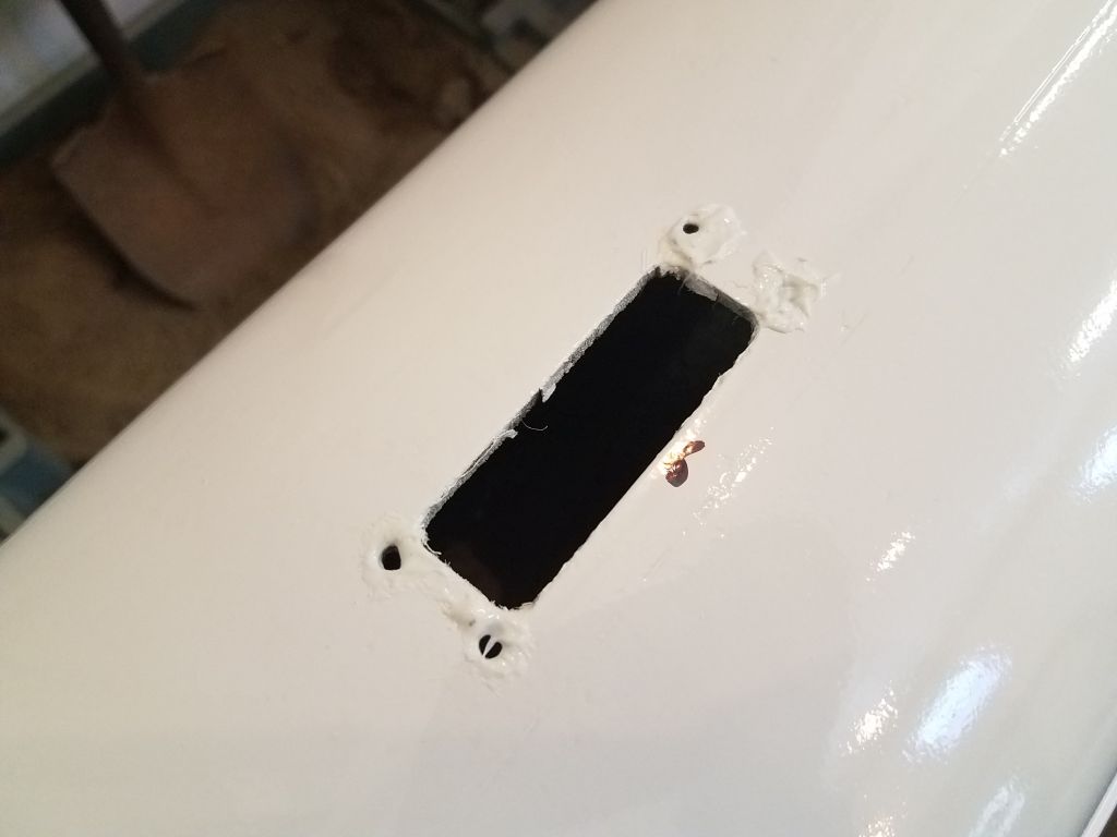
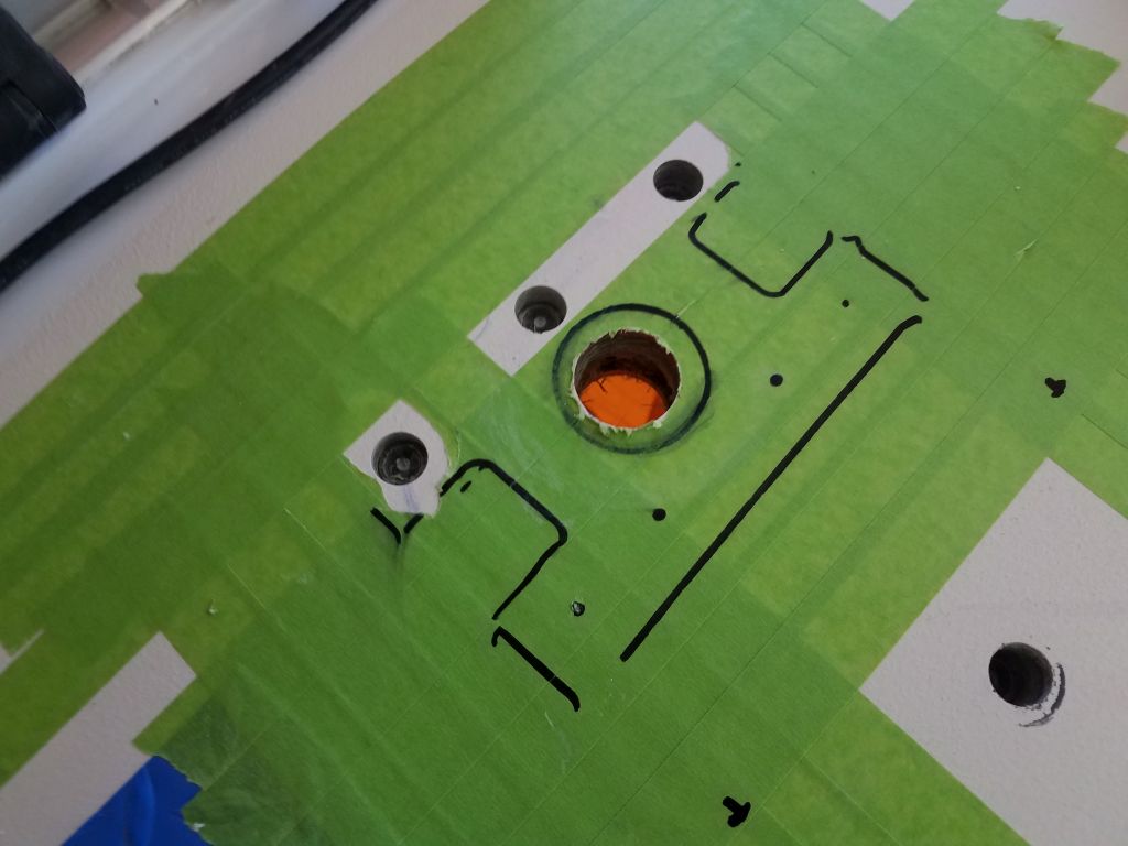
Satisfied with the position of the wiring gland, I marked the screw holes and the center hole, then drilled through the deck as needed.  Here, I also found solid fiberglass all around, and after drilling into the deck beneath the three forward holes I stopped, leaving the after fastener locations untouched since there was no need.

After cleaning up, I filled the various holes I’d bored with a thickened epoxy mixture.

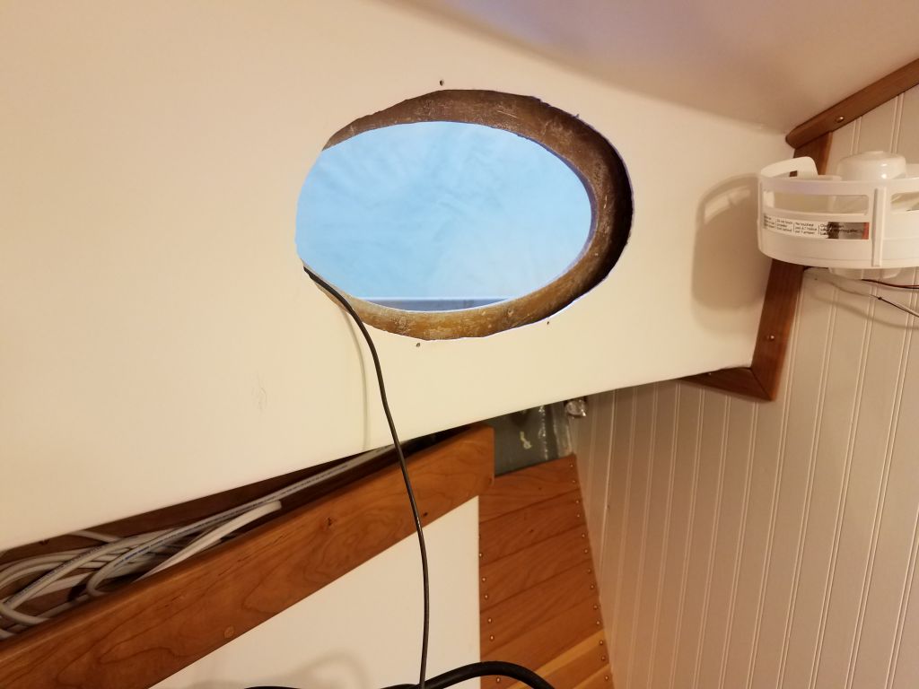
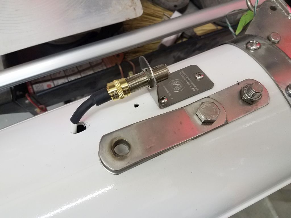
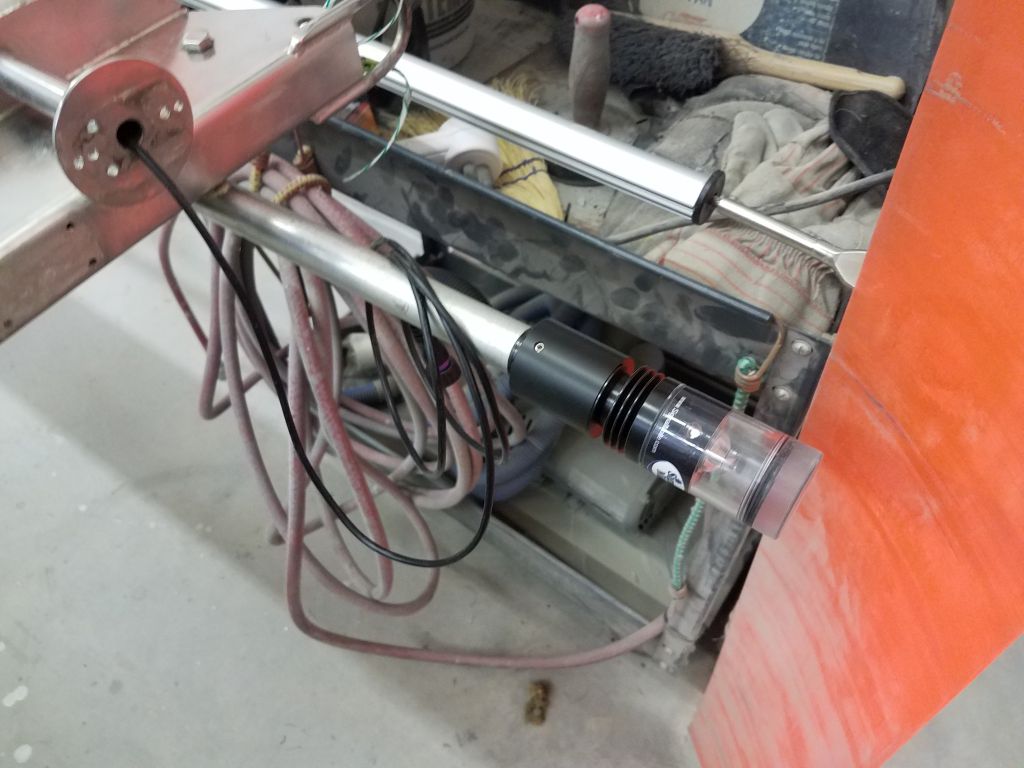
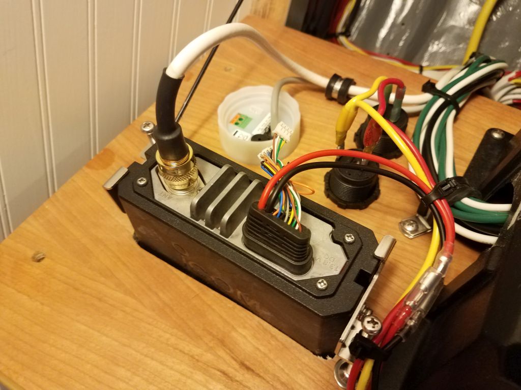
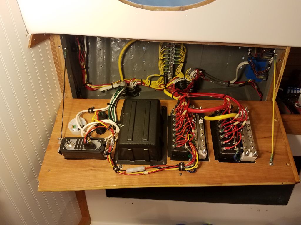
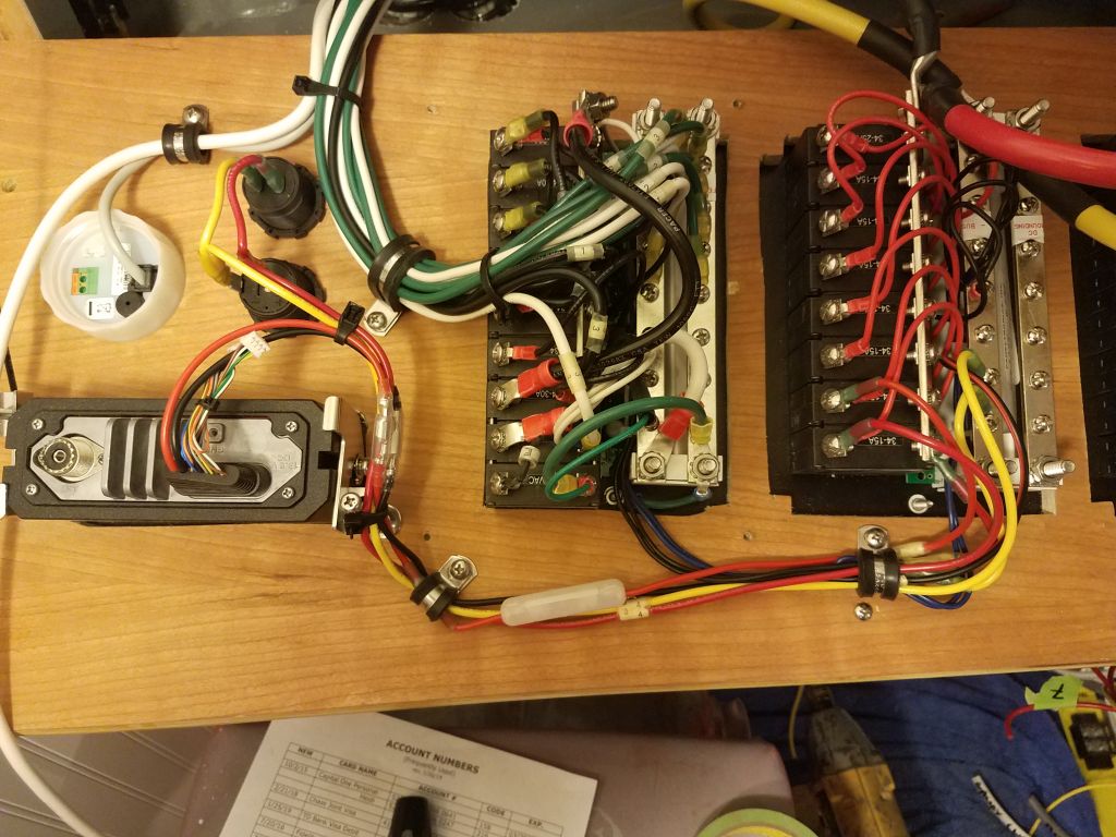
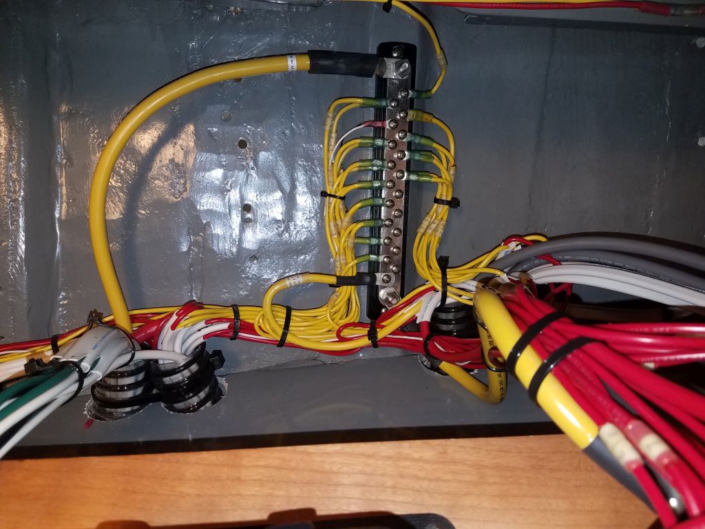
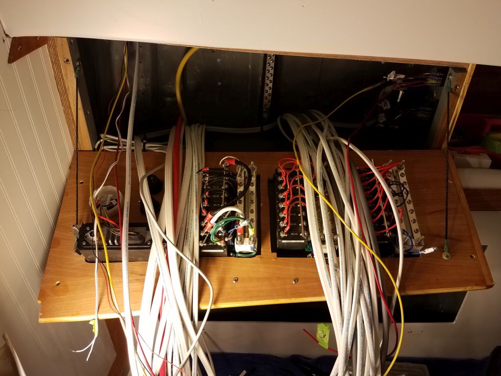
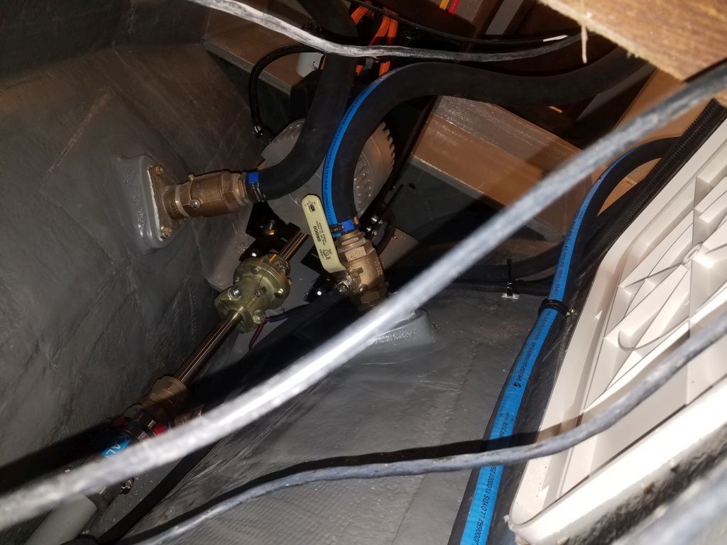
The day seemed to be going well, and I decided to go ahead and tackle the end connector on the wind instrument wiring from the masthead unit.  The ample size of the through-deck hole and location of the network box meant that I could pre-install this now, and the cable could be run with relative ease during mast stepping and commissioning.

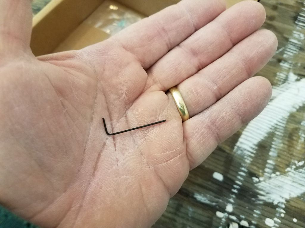
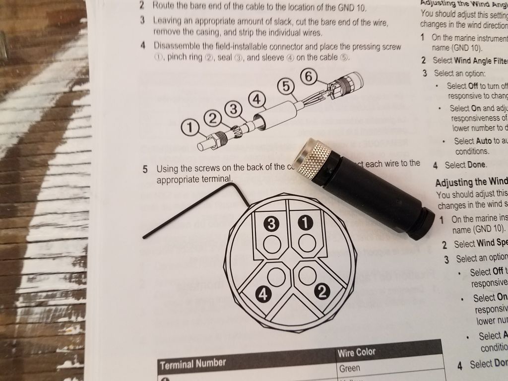
Because of the tiny wires, and the comically small Allen wrench supplied with the connector for installing the wires, I dreaded this installation, but although the tininess was indeed fussier than I liked, in the end it all actually went quite smoothly and without issue, so apparently I picked the right day to do the job.

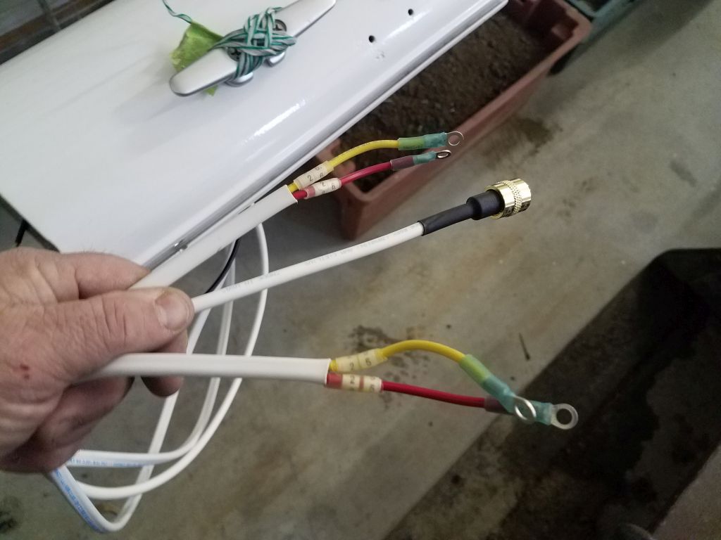
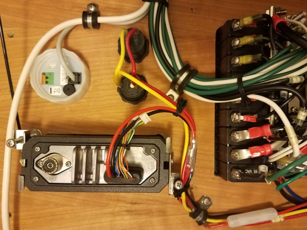
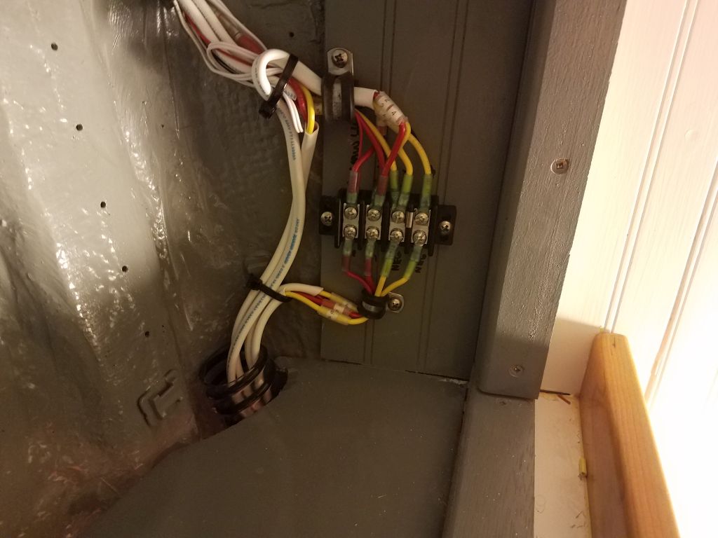
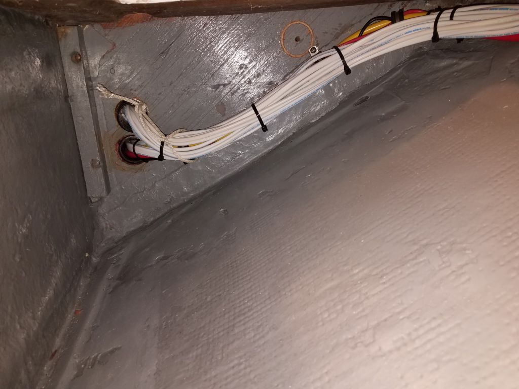
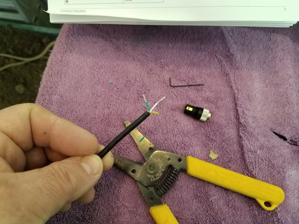
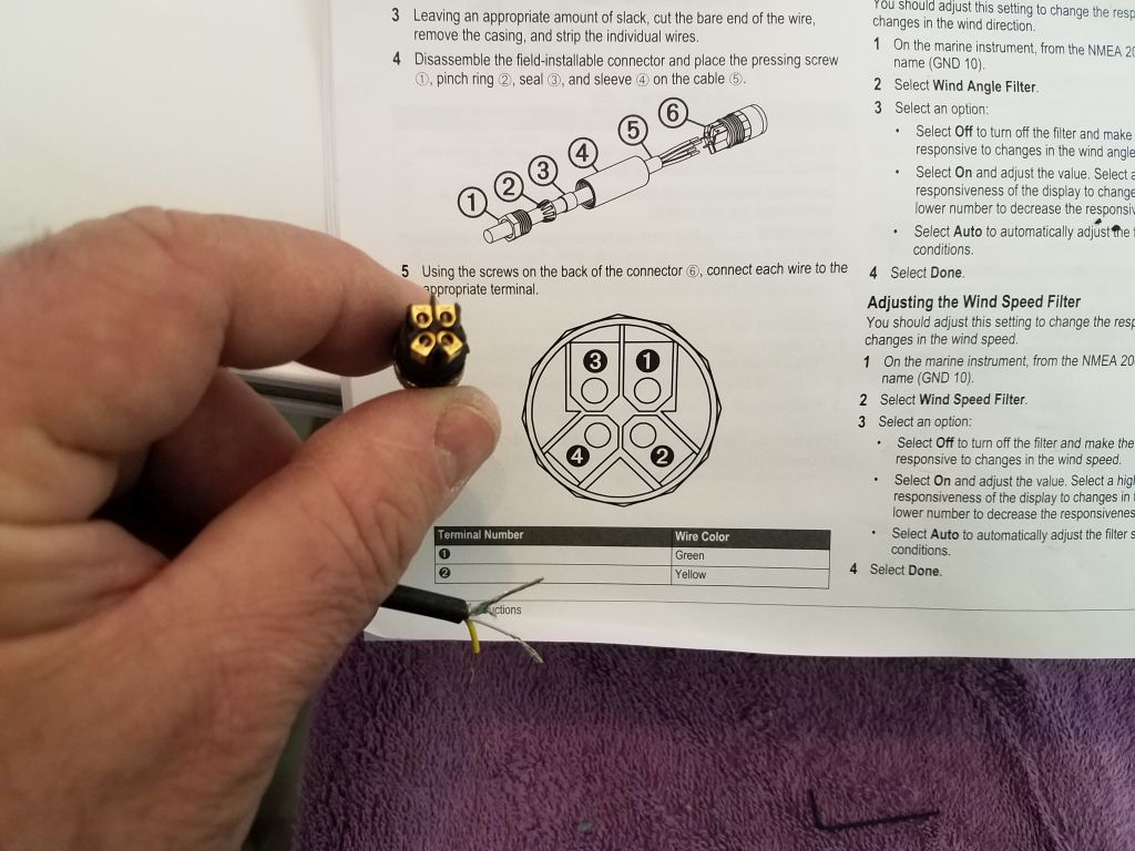
I measured out a generous length of the cable where it exited the mast, allowing for its passage down the compression post and forward to the network box, plus 50%-100% extra, then cut the cable and exposed the four wires within, stripping the ends as needed.  Then, I secured each wire in the appropriate position per the instructions, using the itty-bitty wrench to tighten the wire clamps in the small connector, and then assembled the connector parts.  Though I was pleased with the relative lack of drama, I should point out that the camera picks up details (like the writing on the terminals of the connector) that I couldn’t see myself during the installation.

Feeling like I was on a roll, I decided to tackle another job that was theoretically simple, but in practice might prove to be difficult or impossible:  wiring the bow pulpit for running lights.

In planning the electrical and lighting installations, and reviewing photos of the boat from her arrival here, I realized that there had been no running lights fitted–specifically no bow lights or stern light.  As I studied various lighting choices, along with the specifics of the deck layout particularly at the bow, I decided that I didn’t much care for any of the deck-mounted offerings, few as they were, as most LED lights seemed to be built for vertical mounts (often on welded plates on bow and stern rails).  Rail-mount lights have the advantage of being out of the way, as well as higher up and more visible at sea, so this seemed the way to go if possible.

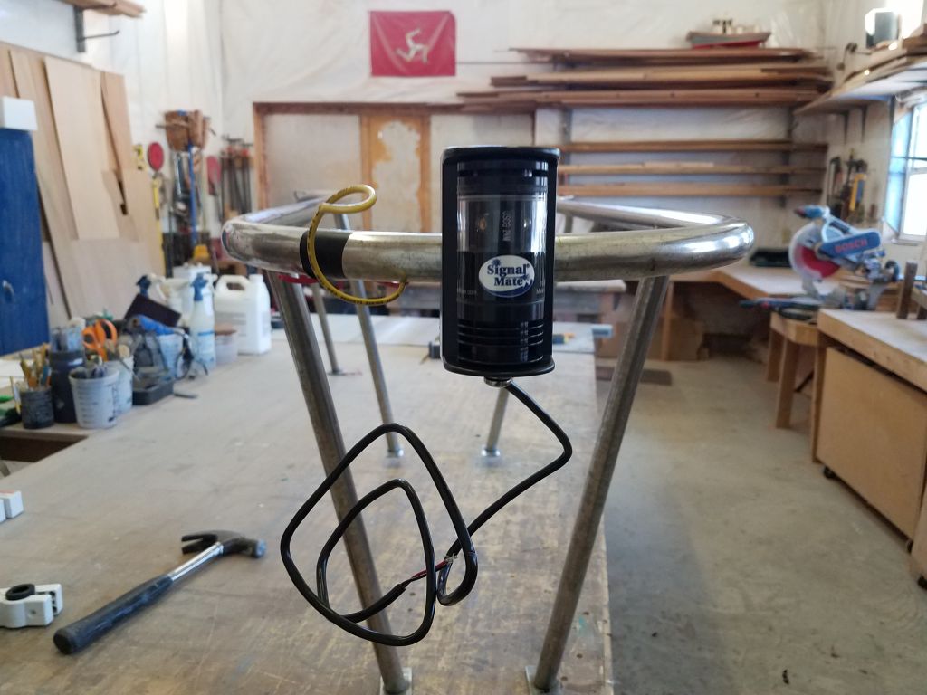
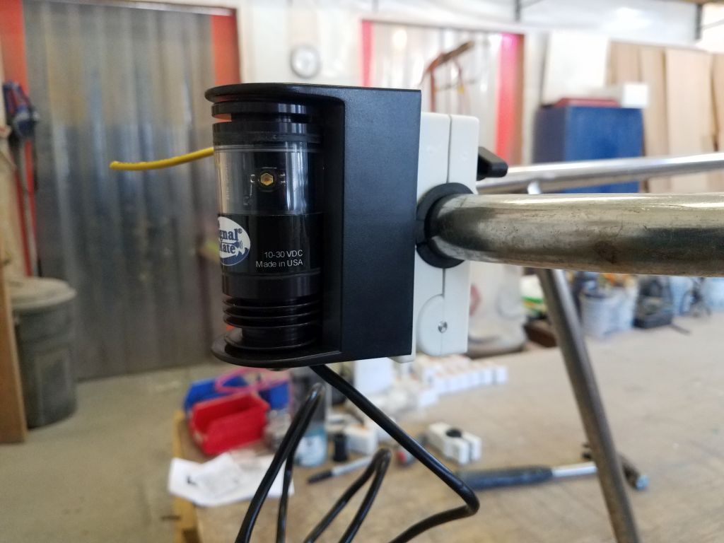
There weren’t any welded mounts on the bow and stern rails here, but I did find some good rail clamps designed to be used with a particular type of LED fixture that I liked anyway for various other reasons, so I chose these for both the bi-color sidelight fixture and the stern light.  Now all I had to do was get wires through the insides of the pulpits.

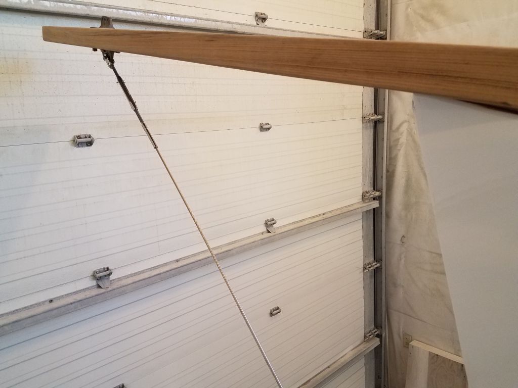
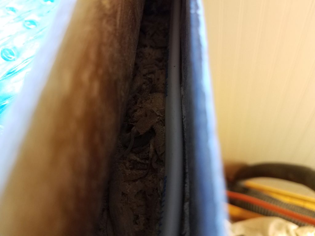
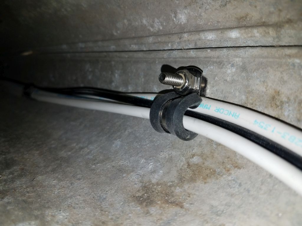
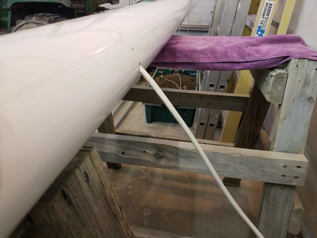
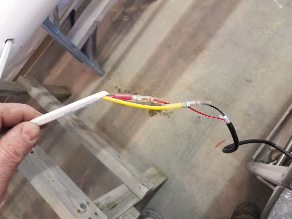
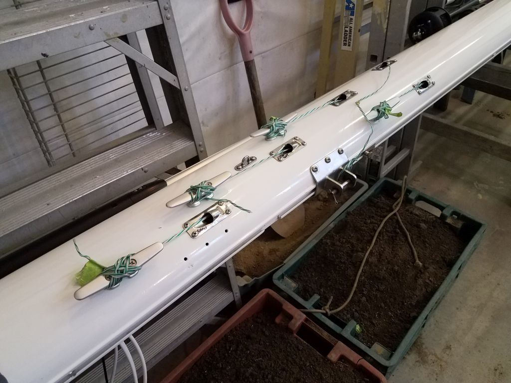
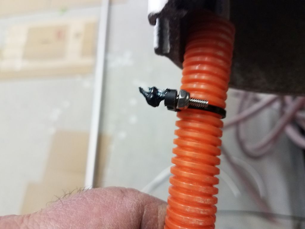
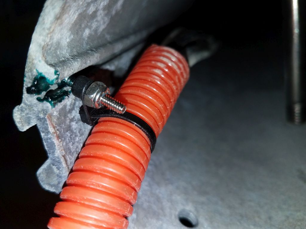
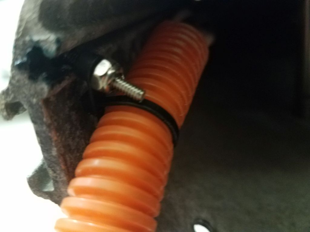
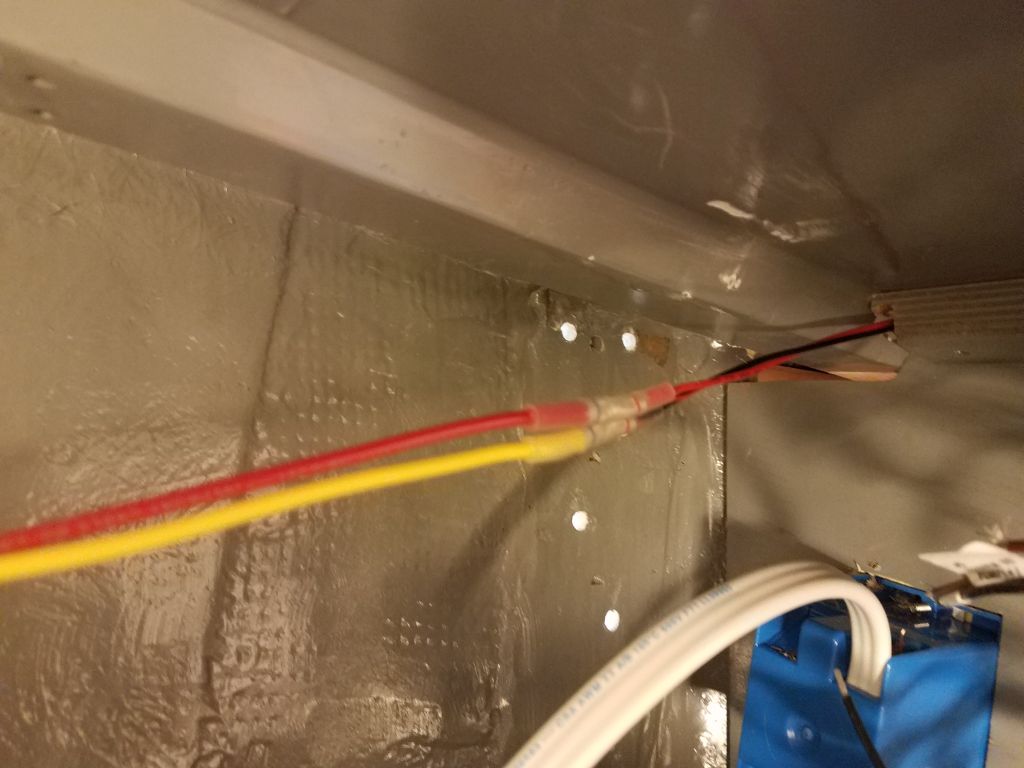
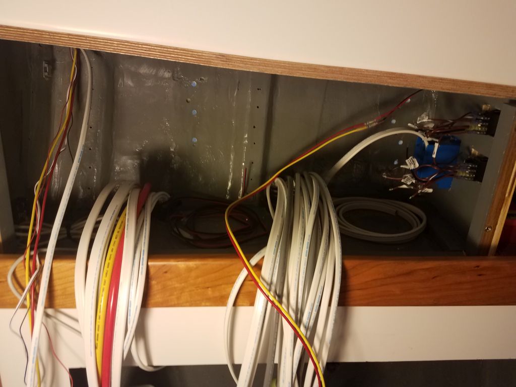
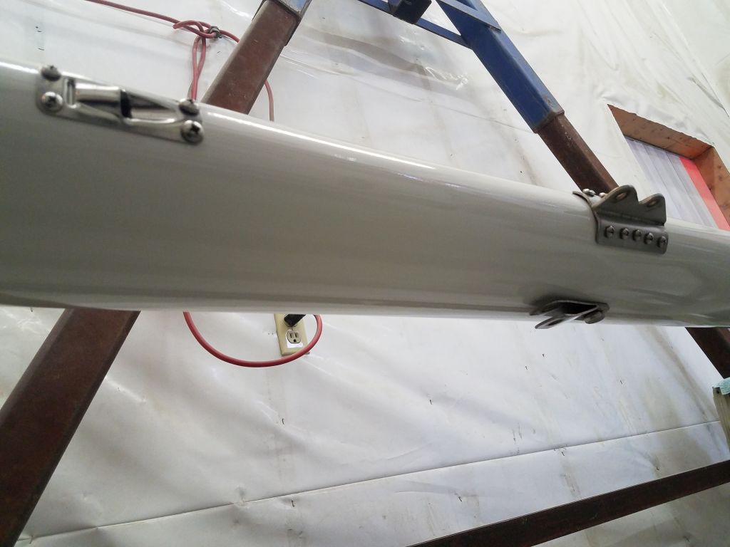
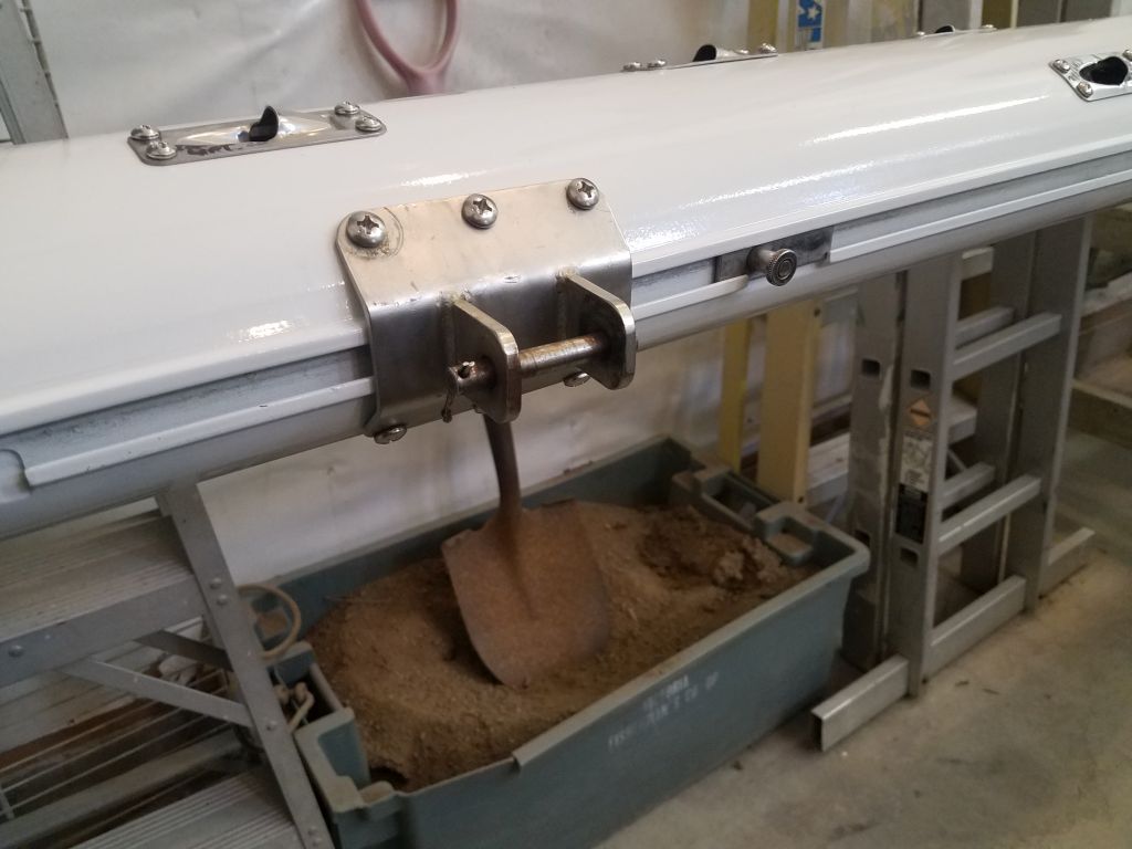
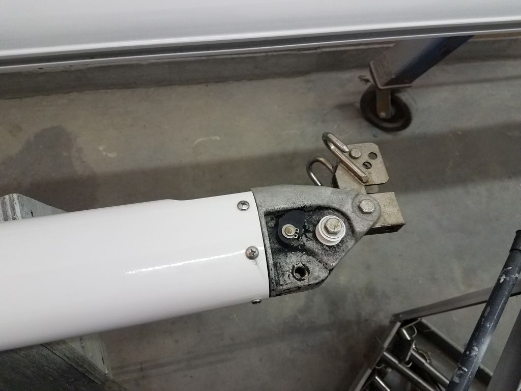
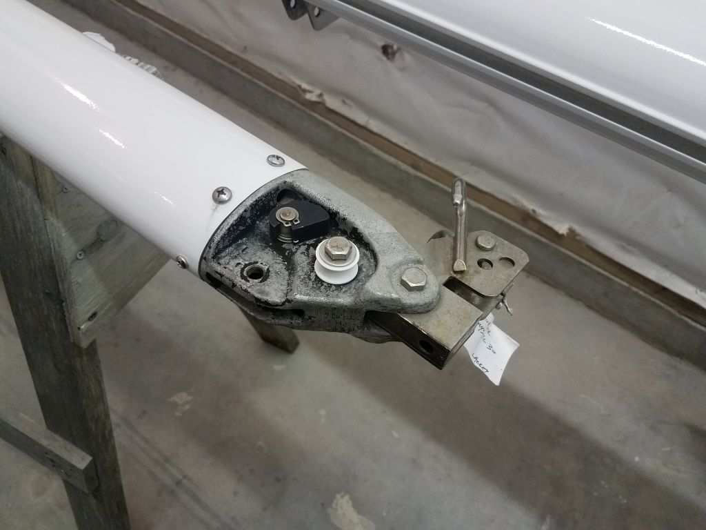
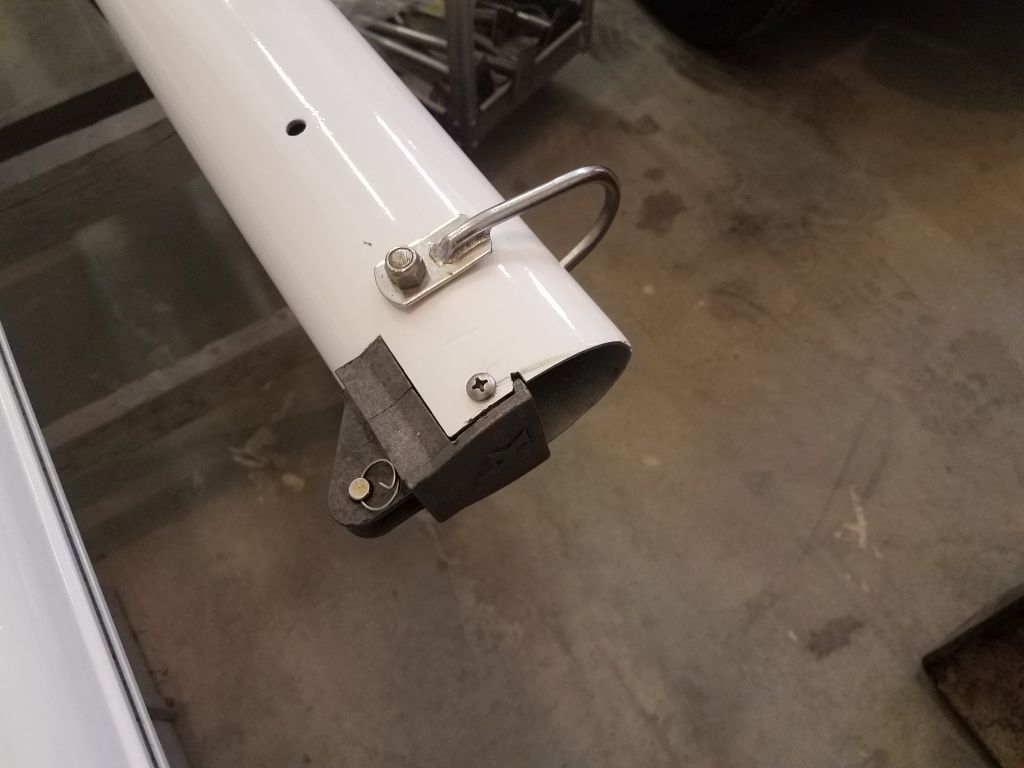
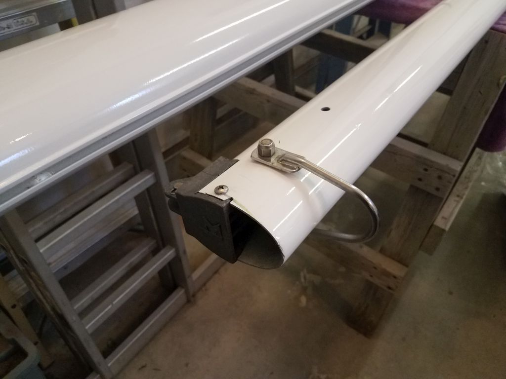
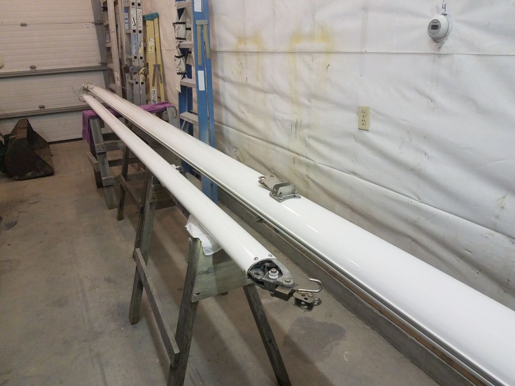
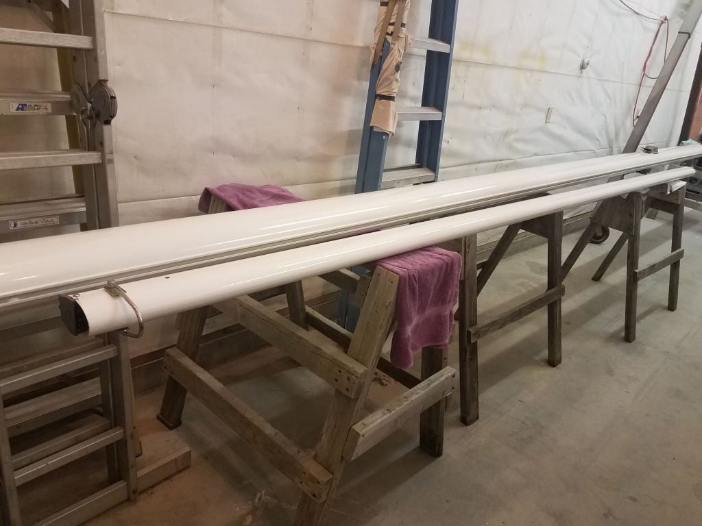
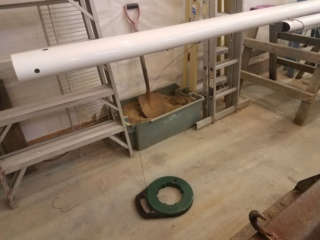
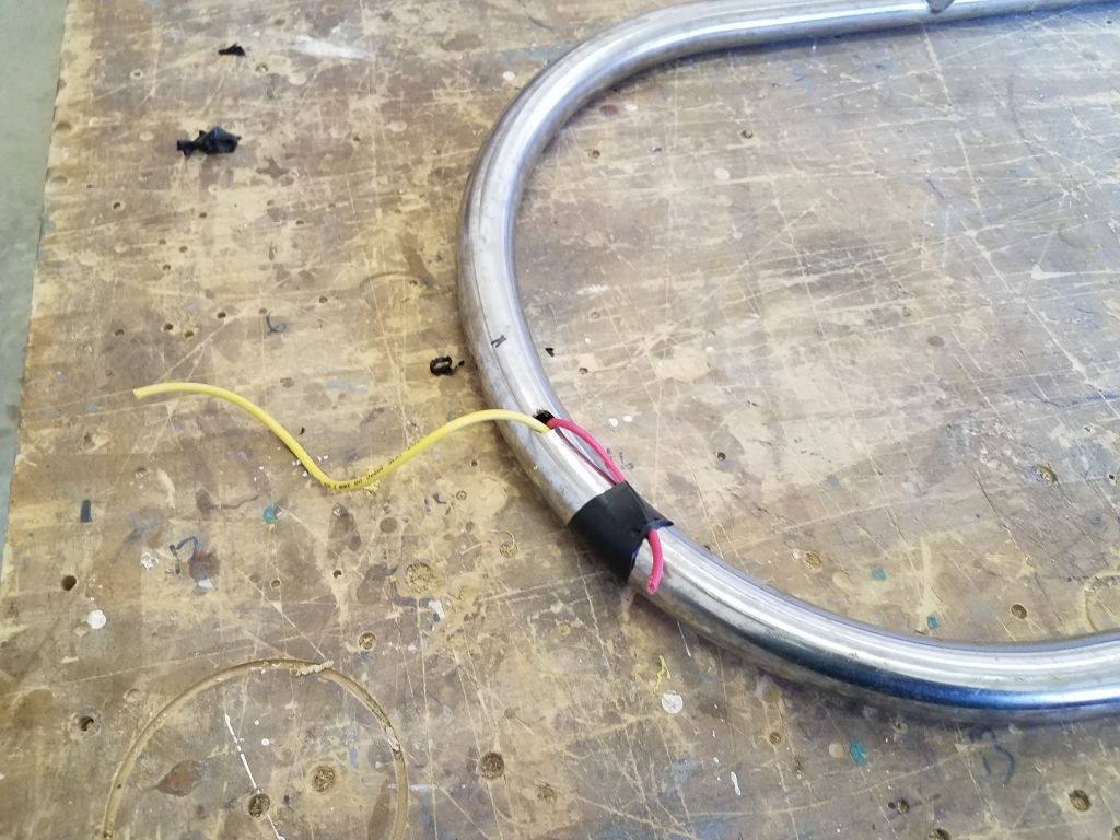
I didn’t expect this to be much of an issue with the stern rail, but the bow pulpit, which extended over the bow platform, was much longer than usual, and wire snaking can be extraordinarily frustrating.  So I started with the bow pulpit, in my normal way of doing the most unsavory work first.  After drilling a hole in the bottom of the rail just off centerline to starboard (the side through which I planned to run the wires), I used a length of stiff household wire (solid strand) as a snake, and with surprisingly little fuss it was soon sticking out through the after rail base where I wanted it.

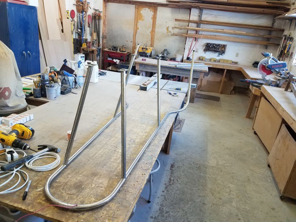
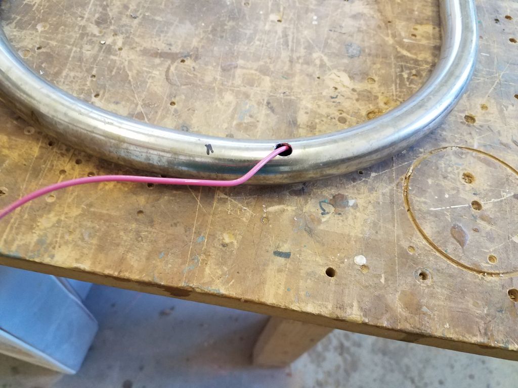
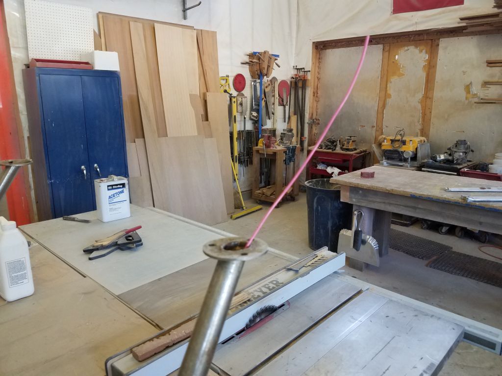
I tried and failed to pull through a length of 16/2 sheathed cable I had on hand for the purpose; although I got the cable started, there was too much friction between the tight hole in the rail, and I suppose the tight rail bends just after.  So instead, I switched to individual conductors, with the ends slightly staggered to avoid excess bulk, and after a bit I succeeded in pulling them through.  This pleased me greatly.

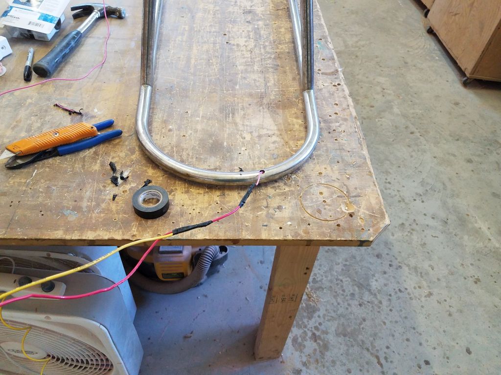
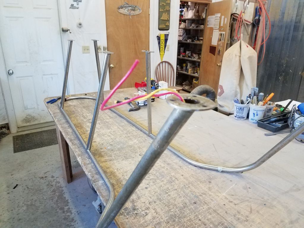
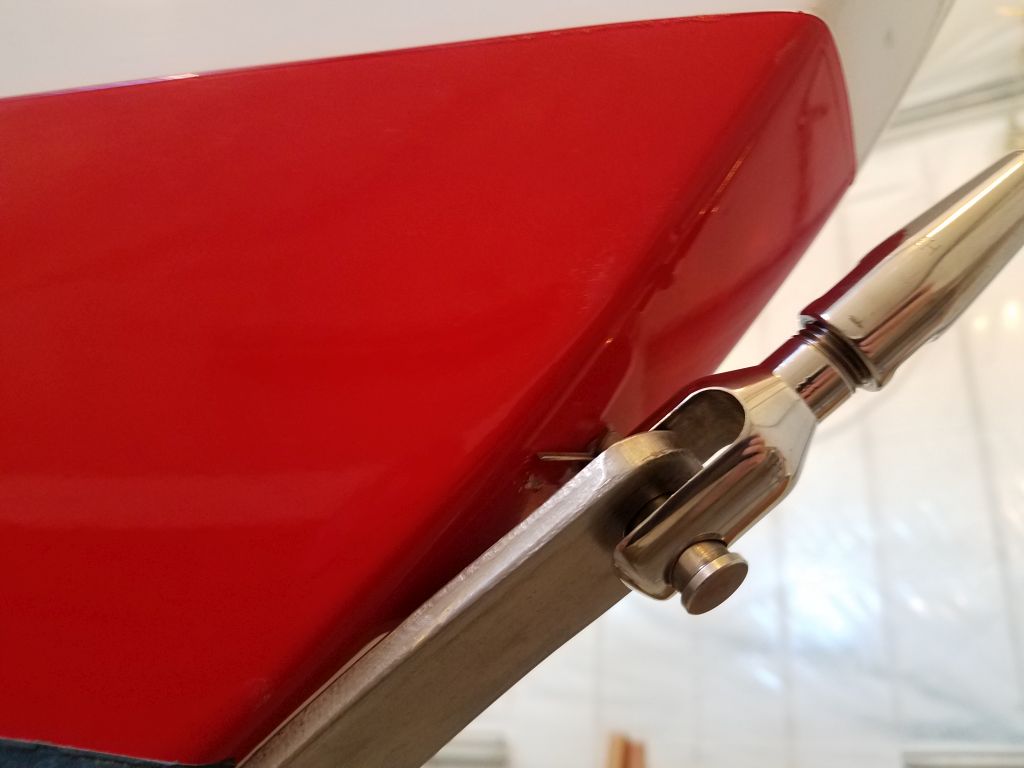
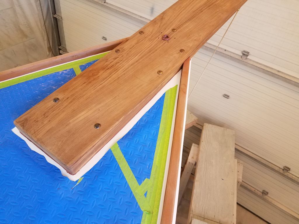
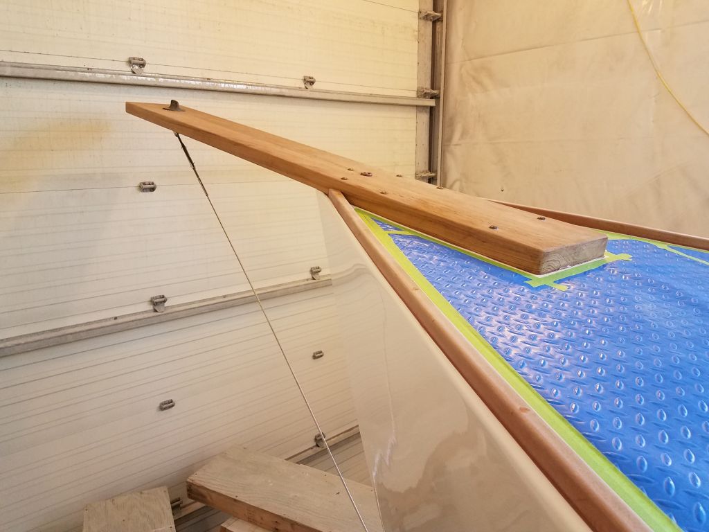
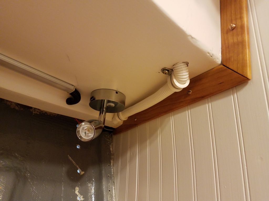
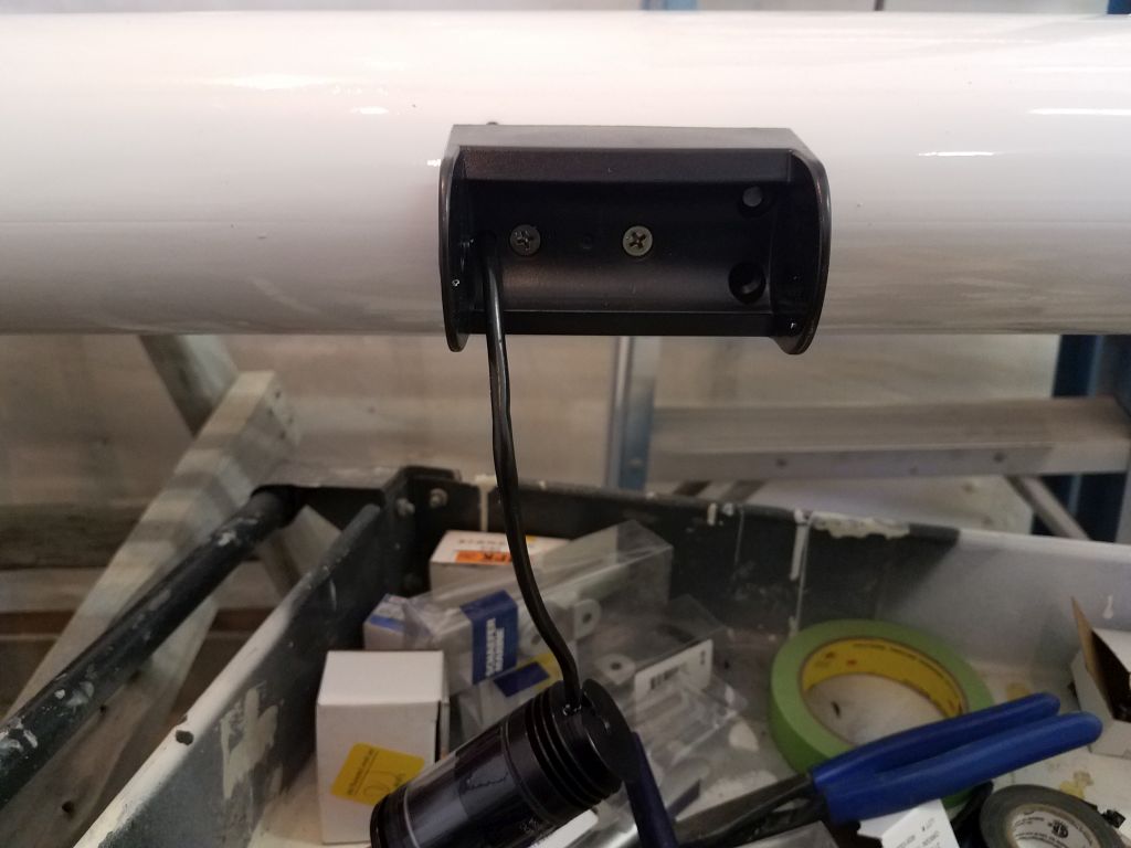
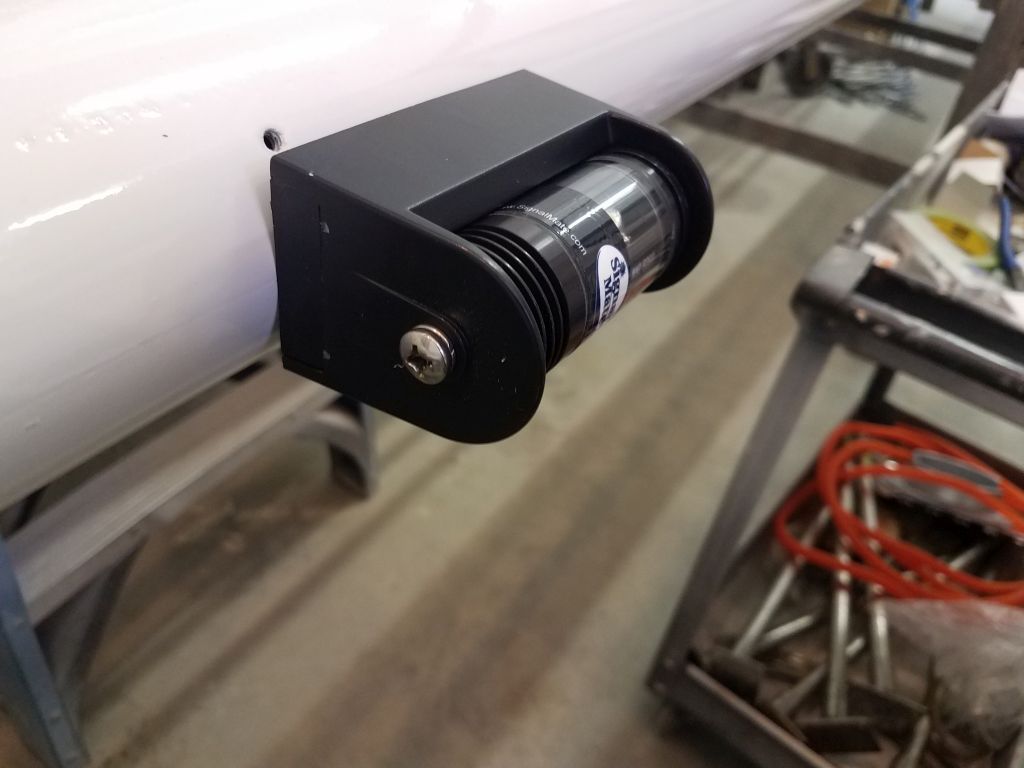
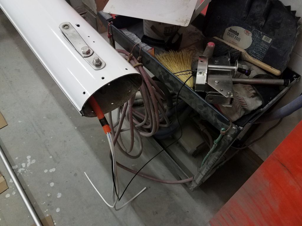
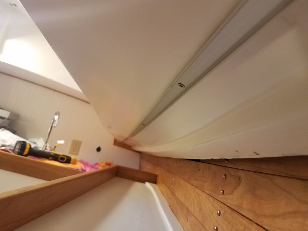
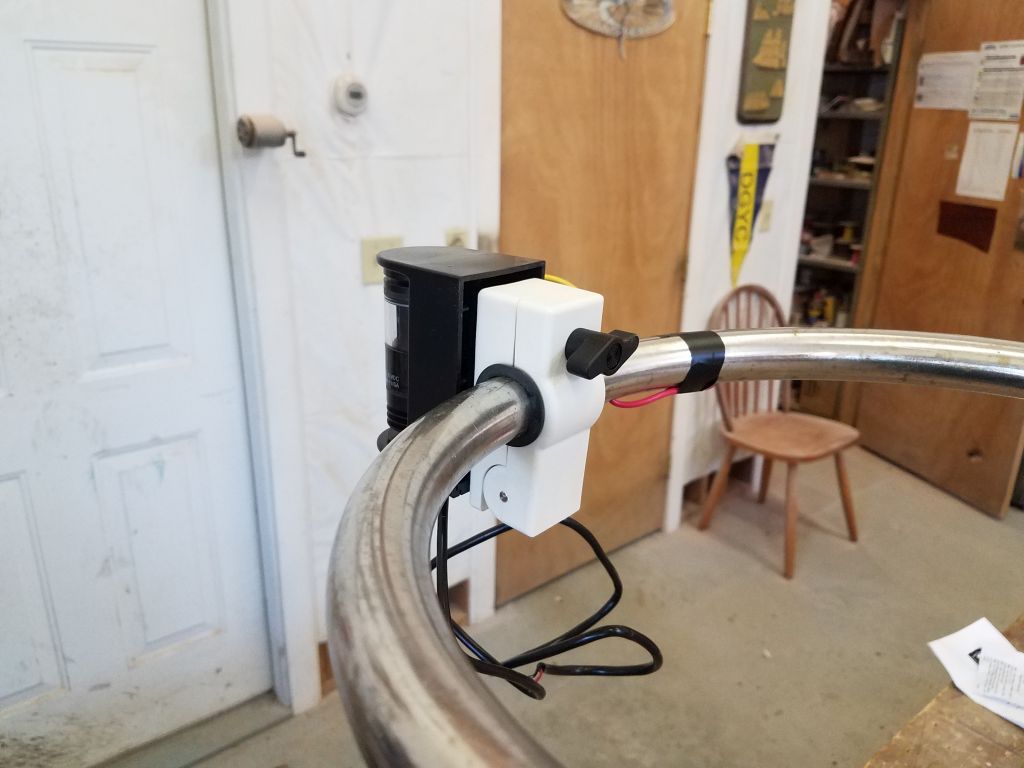
With the hard part done, next I installed the rail clamp and then the new LED bow fixture, leaving the final wiring connection for another time since I didn’t have my wiring stuff right handy.

I planned to repeat this process with the stern rail, and wire up both lights soon, but for now I finished up the day researching, specifying, and in some cases ordering some of the deck hardware needed in the coming days and weeks, as this would be my main focus for the immediate future.

Total time billed on this job today:  6.25 hours

0600 Weather Observation:  15°, clear.    Forecast for the day:  Sunny, 31°

Scupper 222

Friday

After replacing the bowsprit on the foredeck and aligning it properly with the forward bolts, I drilled down through the after two bolt locations to ream out the holes in the deck where I’d omitted the core and filled with epoxy.  Removing the bowsprit again–or at least moving it to the side–I finished up the new holes with my habitual small chamfer at deck level.

After cleaning up, I supported the bowsprit just above the deck with some scrap lumber, leaving it mostly aligned with its deck position but allowing me room beneath to apply the sealant, which I did next.  I applied heavy beads of the sealant (two full tubes) to the deck area, particularly around the bolt locations and the edges of the platform.  Then, I could remove the spacer, press the bowsprit into place, and install the bronze carriage bolts.

Down in the chainlocker, I installed fender washers, lock washers, and nuts at all bolt locations, and tightened them securely.  This was not fun and took a long time.  Access to the chainlocker was tight, and the stepped design of the forward part of the v-berth made this an awkward and uncomfortable proposition.  Installing the nuts and washers on the after pair of bolts, which led through the wooden beam forward of the bulkhead, was simple enough, but the forward sets were out of easy reach, and the opening so small that I could only fit my head and one shoulder through by lying on my back above the shelf and fiddle aft of the opening, and those bolts were at the maximum extent of my arm’s reach.  Needless to say, this was a job I was happy, at length, to have behind me.

With the bolts securely tightened from below, the bowsprit squooched nicely into the sealant, and also raised the platform just slightly above the support I’d built, which was good because I’d actually gone forward to check and remove the shim from beneath to ensure that the platform was not being artificially supported in a way that could affect how it sat on the deck.

Normally I would have liked to clean up the sealant from the nuts and bolts belowdecks, but given the challenge it had been to simply install them, I’d had more than enough of the contortionist act and they’d just have to live the way they were.  It’d be bad enough forcing my way back in there a little later to install the bolts for the inner forestay tang, so I reserved my well-being for that future requirement.

Back on deck, I cleaned up the excess sealant (I left a blob that had pressed up through my temporary bolt hole forward for removal once cured) and removed the masking tape, and then removed the forward support.  Afterwards, I installed the replacement bobstay I’d just received from the riggers.  The bowsprit was an important feature of this boat and it was nice to have it back in place after so long without one.

I continued with prepwork for the new forward air vent on the coachroof. Before continuing with the dry-fit and installation prep, I wanted to address some new wiring for a little interior fan unit that came with the vent to circulate air inside the boat regardless of wind conditions.  I had been thinking about how to run wiring to this new fan, which was in the middle of an otherwise blank area of the finished interior overhead in the forward cabin, and there was no immediately clear or acceptable way to run the wiring through a conduit.  Knowing there was a wide gap between the liner and the underside of the deck in this part of the boat, I hoped that perhaps I could get a snake through there, at least from the new vent location to one of the forward opening port openings, and at least minimize any exposed wiring.

Using a stiff length of wire as a snake, I had a pretty easy time getting from the new vent opening to the starboard port opening at the forward end of the cabin trunk, but from there I had trouble trying to get the wire out beneath the sidedeck, which was my initial hope, since I kept running into (what must be) unseen gobs of adhesive holding the liner in place beneath the deck.  After multiple tries, and running out of the reasonable amount of time I’d allotted for what could be a fool’s errand, I quite by accident forced the wire out through the forward elliptical port on the starboard side, and this gave me the idea to lead the wire up into the liner from beneath the sidedeck just forward of the main bulkhead, which would reduce exposed wiring to just a short 12″ or so in an inconspicuous place.

I drilled a hole in the desired entrance/exit point in the liner, hoping against hope that this plan succeeded now that I was defacing the boat, and eventually got the stiff wire to snake through, after which there was much rejoicing.

Now it was quite straightforward to pull in the length of 14/2 wire I’d  just recently run into the forward cabin for this purpose (since I only received the vent from the owner a short while ago).  At the vent hole in the overhead, I drilled a wiring exit hole just forward, where it would be hidden by the fan to which it would also connect.  I erred a bit too close to the vent opening with this wiring exit, since the space was a little tight and I was concerned I might not be able to get the wire through if the hole was too far forward, but I had to make a slight modification to the inside vent housing to allow the wire free passage–not a concern since the fan unit would later cover this all anyway.

When I conceived of this idea a while back, I frankly never thought it would succeed, but I was greatly pleased with the results.  To finish things up, I installed some white flexible conduit and wire clamps to secure the little bit of exposed cable near the bulkhead.

With that little bit of wiring complete (it had to be before I could move on with the final installation of the vent), and the first set of epoxy-filled holes on deck cured, I marked and drilled them for fasteners, and then temporarily installed the first portion of the vent.  Note that in the first series of photos, the little vent closure (the flat white disc in the center) is upside down, as this is how the assembly came out of the box, but later I realized this and inserted the closure the correct way, which might be seen in later photos.

I fitted over the large base for the vent housing, which was a tight fit around the smaller internal housing, then marked for its own screw holes and cut away the masking tape around its perimeter before overboring the holes and filling the resulting core voids with more epoxy.  It’s a lot of holes, but that’s how it is.  For illustrative purposes here, I have shown photos of the various components of this vent system in order, which includes a series of little balls (Schweddy balls?) that are designed to float up if water enters the vent, thus sealing off the air holes.  This is the kitsch of this particular vent, which the owner ordered (I was unfamiliar with it till now) and which arrived to me direct from Ukraine (Giuliani was not involved in this negotiation to the best of my knowledge).

With that bit of prepwork complete, I’d be able to do the final installation of this vent next time.

In the forward cabin, I took a few minutes to cut to length and install some painted wooden trim pieces over the exposed lighting and fan wiring on the bulkhead.  These were version 2.0 of the trims, as the first ones I’d made a while back were a bit too delicate to install, and I remade the trim in some spare moments over the past weeks.

I recently received back from the riggers the spreaders, one of which had been damaged somewhere in the boat’s checkered past and required repair to the butt end.  The new repair looked great, but the spreaders, still in their old paint coating, looked simply awful, and it seemed a good time to get going on the paint stripping so I could refinish these to match the mast.  So as with the spars, I used coarse sandpaper to remove all the old paint from the spreaders, and afterwards I filled with epoxy a couple old fastener holes and some previous scratches and dents that had become evident after stripping.  I’d finish up the sanding and primer prep later when I was ready to apply the primer.

Finally, I sanded the new mainsheet riser block, and applied a coat of fairing compound over the edges to bring them hopefully to their final contours before shaping and priming.

Total time billed on this job today:  7.5 hours

0600 Weather Observation:  5°, clear.  Forecast for the day:  Sunny, 15°

Scupper 221

Thursday

The new bow platform/bowsprit was complete and awaiting installation, and now was the time to begin.  Before getting into the physical aspects of the install, I did some prepwork down on the bench, where I transferred the locations of the headstay/bobstay chainplate assembly and the inner forestay chainplate.  I thought I might want some way to tie a line to the end of the bowsprit to help hold it during installation (I didn’t yet know how I was going to support it during installation), and it was more straightforward to do now anyway, so I went ahead with the installation of the headstay and bobstay fittings, securing them through the platform with new bronze bolts.  The inner forestay hardware would come later.

After double-checking for accuracy and orientation my plywood template I’d made of the area of the platform that fit over the hull, I used the template on deck to mark the ends of the toerails where I needed to cut them.  I’d left the toerails a bit long on purpose so I could trim them to fit closely against the bow platform.  I cut the rails with a handsaw, then tested the fit of the template once more, aligning it with the marker line I’d drawn on the deck covering during my earlier layout.

Now I could set the new platform in place on deck.  Easing the platform further out through the opening in the bow, till it became unstable, I determined that I needed to build a basic support beneath, as there was no clear means of hanging it with a line, so after some measurements down to the staging–the nearest and most convenient starting point for a support structure–I cut some wood to the proper dimensions and built a simple support at the right height to hold the bowsprit in place while I worked on the deck connection.  I’d intentionally kept the height of my new support a bit low, and once I slid the bowsprit out over it, I added a shim beneath to support the platform in its natural position as determined by the shape and angle of the foredeck.

The original bowsprit had been secured by a number of bolts, the after two of which passed through a heavy wooden beam bolted to the forward side of the chainlocker bulkhead.  I’d kept this beam in place, and now wanted to re-use the bolt holes to secure the new platform.  I’d filled all the holes on deck during that part of the project, but the old holes were still visible from beneath, and after checking to be sure the platform was in the right and final position, I drilled a temporary hole through the platform beneath the spot where the inner forestay hardware would later go (which would hide the temporary hole), and inserted a bolt as a pin to keep the bowsprit from shifting, as movement on the boat and staging tended to wiggle it a bit out of position at this early stage.  Then, once I was sure the platform was where it belonged, I drilled up from below, using the existing holes in the main beam as a guide, and through the deck and just a bit into the platform to mark the holes’ locations.

With those critical holes marked, now I could remove the platform again and, down on the bench, finish drilling the holes I’d just started, as well as lay out and drill a series of holes for additional bolts.  I used the bolt pattern on the old platform as a rough guide, but made sure to leave space for the anchor windlass, using a template supplied with the windlass that the owner had ordered, so there wouldn’t be some bolt in the way.  With the holes all drilled in the platform, and after cutting away the plastic deck covering and adding additional masking tape to the cutout so I could mark the edges of the platform during the next dry-fit, I replaced the platform and, after alignment, drilled for all the boltholes through the deck.

Only the after two bolt locations passed through any deck core; the forward five bolts passed through the solid portion of the deck and/or the original hull flange.  So after marking the deck tape where the platform landed, and also the underside of the platform where it met the hull, I again removed the platform, trimmed the tape as needed, and prepared the holes in the deck as needed.  This meant boring through the top skin and plywood core for the after two bolts, removing all the core down to the inner skin, and counterboring the remaining bolt holes in the usual way to prepare for eventual sealant.  Then, I filled the overbored aft holes with a thickened epoxy mixture, and also patched the single temporary bolt hole beneath the inner forestay.  That ended the work for now on the bowsprit.

For passive ventilation inside the boat, in addition to the solar vent in the companionway hatch the owner also selected a purportedly waterproof mushroom-type vent that he asked I install in the coachroof just forward of the forward hatch.  This vent featured a unique design to prevent or limit the ingress of water, the details of which I haven’t covered here during these early installation steps, but bear with me over the coming days and the various pieces and parts and interesting design features will be revealed.

In any event, it was time to drill the large hole required for the vent, and after some layout using the large vent base (one part of about seven that fit together to complete the vent), I marked and drilled a 3-3/4″ hole through the deck, and, after starting the hole from above, through the cabin liner working from inside.  The core in the cutout was in good condition, and once the hole was finished I reamed out some of the core within the opening so I could fill it with epoxy a little later.

The first piece of the vent was a trim ring/sleeve that fit from beneath, and I had to dry-install this and cut it to length so it was flush with, or even a tiny bit below, the level of the deck.  I temporarily installed the trim ring from below with screws, as I needed it in place to align and mark the next part of the vent on deck.  I don’t have any pictures of this next piece for now, as I forgot, but I used it to mark the deck for its numerous fasteners, which holes I then opened up with a 3/8″ bit to remove the core from each fastener location.

In order to properly proceed with the vent installation, I’d need the first deck piece secured in place so I could align and then mark the deck for additional holes for the next piece of the vent assembly, so I went ahead and filled the initial bolt holes with epoxy, along with the reamed out area inside the vent hole, and could proceed with the next steps once the epoxy cured overnight.

With a little time left in the day, I turned to a couple small jobs, starting with a new fiberglass base to support the bracket for the anemometer masthead unit.  Using the plastic bracket as a guide, I cut a piece of prefab 1/4″ fiberglass to size.  I’d return to this soon to finish it up.

With a rigid boom vang on the way for superior sail twist control, and after various discussions on this subject, the owner elected, with my support, to forgo a traveler for the mainsheet, opting instead for a simple padeye to support the new and excellent tackle, which would mount to the deck aft of the cockpit coaming.  Because of the height of the coaming, it seemed important to raise the attachment point a bit to make reaching the mainsheet’s cam cleat easier.  For a while leading up to this, I considered installing the padeye to the top of the coaming, but access within was tight, and I wasn’t convinced that the coaming was up to the task without reinforcement; I also was unsure how the plastic wood trim would react to having the padeye mounted atop.  So after rejecting this thought some time ago, it meant that the padeye was once again relegated to the poop deck where it belonged.  To this end, I cut out three pieces of 3/4″ prefab fiberglass, each slightly larger than the padeye itself, and then glued them together with epoxy, using excess to start smoothing out the edges of the lamination.  I left this to cure overnight.

Total time billed on this job today:  7.5 hours

0600 Weather Observation:  31°, light snow. Forecast for the day:  Snow, 3-7″ predicted, 32°

Scupper 220

Wednesday

I got started by straightening out the mast wiring problem that had cropped up earlier, and at the top and bottom of the spar I secured the wire bundles with cushioned clamps flush-bolted through the aft side of the mast, inside the internal extruded track.

Next, I snaked through another wire  the relatively short distance from the base of the mast to the old wiring hole from the original steaming light.  From there, I could go ahead and install the new LED light fixture.

When I snaked through the wires earlier, I’d realized that the halyard messenger lines posed a problem, at least for getting my recalcitrant wire snake through the spar, and to make life easier on me, as well as prevent halyard twists and snags later, I’d removed the messenger lines at that time.  Now, I ran them back through for good.  One thing led to another, and with the messengers through I decided to install new cleats at the base of the mast for several of the lines.  The main halyard and various control lines were to lead aft to the cockpit, but the jib, staysail, and spinnaker halyards were to stay on the mast, and thus needed the cleats.  At the same time, I added a pair of small padeyes that the owner requested so he could connect wire leads over the side in a lightning storm.

At the masthead, I installed the bracket for a new VHF antenna, and made up the connector for the cable.  Meanwhile, at the mast base I cut to generous length the mast wires and VHF cable and made up the ends that would later pass through the deck for connection within the boat.  For now I left the wind transducer cable at full-length, though later I could install the supplied field connector after cutting the cable to a length suitable for connection to the included network box that I planned to install in the boat later in the day.

Continuing with the lighting and wiring, I installed a new anchor light at the masthead, using as a mount the long tube leftover from one of the old lights.  Then I could reinstall the masthead cap with new screws.  The bracket for the anemometer required a little platform wide enough to support the bolt pattern, so for now I held off on installing that particular piece.

With the mast work complete for now, I got to work in the boat to install the little network box that was required for connecting the wind instrument, and running a new cable (a network backbone) from the box aft to the cockpit area, where it would later interface with the GPS display unit.  Since the transducer wire from the anemometer had to connect to the network box, I chose a location as convenient as possible for that cable, which in this case meant in the technical area beneath the V-berth.  I led the cable through all the convoluted wire passages along the starboard side, through the head, and eventually into the engine room, where I could run the cable out the access panel near the electronics area.  The cable end, with its usual bulky connector, was a tight fit through some of the existing wire chases, but fortunately with some effort I managed to run it without needing any new openings.

I planned to measure lavishly for the transducer cable length required to lead from the mast, through the deck, down the compression post, and forward to the network box, and would later make up the network field connector to finish that wire as well, which would allow me to remove the substantial excess wire.  This promised to be a fussy little connector with tiny wires, and thus best left till some fresh early morning for me to attack, but since the deck fitting I planned to use for the cable runs would accommodate the connector easily, I thought it’d be good to make this end up now rather than leave it for commissioning.  To help with the cable run later, since the bilge between the mast step and the locker space beneath the V-berth was largely inaccessible, I led a messenger line from the bilge aft of the mast step forward into the technical area (I had a similar messenger already in place on the starboard side).

Total time billed on this job today:  8 hours

0600 Weather Observation:  25°, cloudy, dusting of snow overnight. Forecast for the day:  Gradually clearing, 41°

Scupper 219

Tuesday

For the last remaining lighting circuit, the owner had requested that the galley lights, and a light near the companionway, be operable by a switch near the companionway to make it easy to light the interior when entering.  With limited options for locating the switch, some time ago I chose the bulkhead adjacent to the companionway ladder, and at that time ran in another wire pair leading from the electrical locker to eventually service the switch.

I’d kept the circuits for the galley and companionway lights separate, and now I had to make up a switched circuit to operate them both.  I drew up a basic diagram, then installed the wires as needed using a small terminal block to conjoin the wires appropriately.  Note that the yellow wire in this case is one of the two wires that would connect to the switch, as I used an ordinary sheathed wire pair; the red wire from the switch pair connected to the circuit breaker on the panel, and the two red wires attached to the terminal block are the positive leads for the two lighting circuits serviced by the switch.

After terminating the negative wires from these circuits to the negative distribution buss, I turned to the final wiring connections at the bilge pump switches, and made up these connections as needed.  I ran the power feed to each pumps from the “always hot” buss I’d installed earlier, so the pumps would operate independently of the switched battery circuit.

I made up the end of the boat side of the VHF cable and secured it to the radio, and this completed the wiring connections in the electrical locker.

Next, I turned to the mast wiring.  The masthead required wires for an anchor light, wind instrument, and the VHF antenna, and I bundled these cables in some flexible conduit.   At the masthead casting, I ran the wind instrument cable through one of the two welded pipes at the top, since the connector there was too large to otherwise pass through.  Later I’d install the bracket for the anemometer.  I ran a wire snake through the mast and used it to pull through a piece of 1/4″ line as a messenger to pull the wires, then prepared to pull through the pre-prepared wire bundle.

The old mast wires had been secured inside the mast to an extruded track, but the slot was so small I couldn’t source any slides to fit within.  To attempt to secure the wires along their run through the mast, I came up with a plan to use small self-mounting wire ties (the kind with the mounting hole), and some #4 machine screws and nylock nuts.  I’d previously determined that the head of a #4 flathead screw would fit in the track, and I hoped this arrangement might hold the wires along the way.  I added some waterproof grease to the screw heads to hopefully help them slide through the track.

This surprised me by actually working…almost.  Pulling the bundle through in stages, I added additional screw supports every so often, and after a few temporary bind-ups (much fewer than I’d expected) and  what seemed like a year of pulling the messenger, I finally pulled the wire bundle through the bottom of the mast, but found that somewhere near the bottom of the mast one of the screws had bound on some old debris in the track (impossible to see or reach), and the orange conduit had bunched up within the spar somewhere above the gooseneck.  But at least the wires were through, and it looked like most of the conduit had survived, so for now I called it a relative success and would address the conduit issue in the morning.

Total time billed on this job today:  8 hours

0600 Weather Observation:  20°, partly cloudy. Forecast for the day:  Mostly sunny, 32°

Scupper 218

Monday

In the varnish room, I flipped the loose table pieces and, after final preparations, applied the satin varnish to the opposite sides (the “main” side) and edges of all.  The table base, with its coat of satin varnish from last time, was complete.

I spent the rest of the day working on the electrical panels and final wiring connections.  Starting with remaining circuits at the forward end of the electrical locker, I made up the positive connections as needed to the first part of the panel (the forward section), and also terminated to the negative buss all the negative wires from these circuits plus the various lighting circuits I’d run previously, straightening and securing the wires as progress allowed.  It made logistical sense to run the short leads from the VHF and the two 12-volt outlets in the electrical panel directly over the top part of the panel, where I connected the leads to circuit breakers and the panel’s built-in negative buss.  As I went, I labeled all the wires and noted the breakers I chose for each circuit so I could order the appropriate panel labels.  I temporarily removed the cover over the AC panel since it was impeding clear access to the terminal screws on the adjacent DC panel.

With the forward half of the panel fully wired, I moved on and began making up the wires left near the aft side of the locker, and made various additional connections to the negative buss and second half of the electrical panel by the end of the day’s work.  This left a few wires behind–namely the bilge pumps (2) and a separate switched lighting circuit for the galley and companionway–for me to finish up next time.

Total time billed on this job today:  8 hours

0600 Weather Observation:  15°, mostly cloudy.  Forecast for the day:  Mostly cloudy, chance of light snow, 28°

Scupper 217

Friday

To get started, I lightly sanded the last coat of gloss base varnish on the table parts, then, after cleaning up, applied a coat of rubbed-effect satin varnish to the secondary sides of the leaves and supports, and to the table base itself.

The riggers were on site to assemble the new furlers, install the revamped outhaul system, and deliver the running and standing rigging.  For now, we left the rigging uninstalled pending final mast wiring and any other prep work.

I spent most of the day working at the electrical locker, starting to sort out and terminate the various circuits.  I began with the 110-volt AC panel since the job there was more finite, with only four circuits plus the main cable from the shore power outlet.    Leaving ample slack for wire routing and to allow the main panel to be easily raised and lowered, I terminated all the AC wiring ends, securing them to the breakers and other parts of the panel as needed.

When the AC wiring was complete, I installed a plastic cover over the back of the panel to protect against accidental contact with the higher-voltage circuits when the panel was opened.

The AC panel, as well as the two DC panels, featured small circuits for backlighting that needed to be installed to the DC positive and negative.  I took care of this next.  Then, I installed the main feed cables from the (eventual) house battery bank, and conjoined the two DC panels with additional cable.

Next, I sorted through the various wires and separated out all the lighting circuits.  I planned two main lighting circuits–one each for the underdeck secondary lighting and the main cabin lights–plus a third, separate circuit for the galley lights and a forthcoming light at the companionway, which three lights would be serviced by a switch near the companionway for convenience.

To reduce wiring leading to the panel itself, I installed my habitual terminal block to accept all the lighting circuits, and from whence a single wire could later lead to the appropriate breaker.  In this instance, I combined three of the terminal pairs with jumpers to service the main cabin light circuits, and left the remaining pair separate to service the underdeck lighting circuits.  Then, I began working my way through the wires, separating positive and negative leads and making up the terminal ends and identification labels for some of the positive cabin light leads.  I left the negative wires to one side for later attention.  As I went, I planned the final wire locations and, in some cases, temporarily secured wires along the way, though final securing would only happen once all the wires were terminated and in place.  By the end of the day’s work, I’d made good progress on the cabin lights, though a few circuits still remained untouched–along with the bulk of the other circuits on board.

Total time billed on this job today:  7 hours

0600 Weather Observation:  12°, partly clear. Forecast for the day:  Cloudy, slight chance of rain or sleet, 38°

Scupper 216

Thursday

The cherry trim piece I built to accommodate the owner’s selection of two small flush-mount lights was complete now, and I turned to the final installation.  Each of the two lights fit in the holes I’d prepared in the trim, and I secured them with screws before installing the trim rings.

I’d routed a wire channel on the back side of the trim, and I spent some time at the bench wiring up the two lights and conjoining the wire leads to a single wire pair that would exit the trim and eventually connect to the circuit I’d run into the engine room for these lights.  To accommodate the larger butt connectors needed to connect both lights together, I had to ream out a portion of the existing wiring channel to make it deep enough for the connectors to remain flush.  I used dabs of hot glue to hold the wiring and connectors in place within the channel so they wouldn’t move during installation.

After some layout, I installed the trim with the lights above the galley, securing it to the overhead with screws.  I planned to lead the wiring directly aft to the bulkhead, as I knew there was an open space between the bulkhead and the after bridgedeck molding through which I could lead the wires.  I chose this because it was the most direct and (irony to follow) easiest route for the wires given all the other complications in the mounting location.  I laid out a line perpendicular to the light trim and leading aft to the bulkhead to show where I needed to drill a hole for the wiring (not shown here).

This is where the job got fun.  To drill my hole, I first removed the trim along the upper aft edge of the bulkhead, then drilled a hole through at my mark.  What I’d not counted on was the fact that the actual bulkhead didn’t extend quite all the way up, so there was a small gap hidden behind the beadboard.  This meant that the hole, drilled at the extreme edge/corner of the bulkhead to hide it behind my wiring trim, didn’t come out cleanly or even in the proper orientation, and I had a bear of a time snaking the wires through.  There was no direct, or even indirect, access to the back side, and after various failed attempts I had to open up the hole more than I wanted in order to have a chance at accessing the space for my wires.  At great length I eventually managed to get a tiny, relatively stiff solid copper wire I had on hand through the hole and far enough down into the narrow, tall gap behind so I could finally grab it with a long grabby tool.  Once I had the messenger through, pulling through the wire pair from the lights was straightforward enough, but this had taken inordinately long.

This left me with a larger and uglier hole than I had planned on–a bit too large for the trim to cover properly, so I’d have to patch the hole and repaint the area.  But what mattered for right now  was that the wires were in place.

I temporarily installed the new wiring trim after cutting it to length, and reinstalled the aft bulkhead trim that I cut to accommodate the wires and trim.  So this would be ready to quickly install later, but for now I removed the trim and, after masking and other preparations, filled the excess hole in the bulkhead with an epoxy mixture.

Working from the port cockpit locker, I finished up the wiring connection for the galley lights, securing the new hard-won wires to the end of the circuit I’d run in for the purpose.

With only an hour or so left in the day, I decided to get ready for the final panel wiring and installation.   To accommodate a couple higher-draw appliances on board, namely the electric toilet and the potable water pump, I needed to replace a couple of the stock 15-amp circuit breakers in the panel with larger ones:  25-amp and 20-amp, respectively.  I decided to put these larger breakers at the bottom of each panel, so I disassembled the panels as needed to remove the old breakers and install the new.

In the electrical locker, I chose a location for and installed a large negative distribution buss, so which I’d install all negative wires.  To begin the process, I cut to length and terminated the yellow wire leading to the panel from the house battery location and negative buss there.

To secure the locker cover and electrical panels while working on the final wiring, I made up a couple supports from spare wire, which let the panel hang in an open position with good access for wiring now, and maintenance later.  I looked forward to making order from the wiring mess starting next time.

Total time billed on this job today:  8 hours

0600 Weather Observation:  12°, clear. Forecast for the day:  Sunny, 22°

Scupper 215

Wednesday

I began the day in the varnish room, where I lightly sanded the table parts and applied a coat of gloss varnish to the base and the visible side of the table leaves, locker lid, and support brackets.  This brought all sides of all pieces up to at least 4 base coats.

A few weeks back, after finding that the LED diffusers I’d bought for the underdeck lighting in the forward cabin and main saloon weren’t suitable for my application, I ordered different materials for the purpose–aluminum channels and diffuser covers–and now I could finally return my attention to these lights, starting in the forward cabin.  The channels were longer than I needed for the space available in the forward cabin, so I cut two channels to length.  These came with two kinds of end caps:  solid caps for the blank end, and caps with a hole for wiring at the other end.  In order to secure the channels in place, I drilled pilot holes and countersunk for flat head screws.

Beginning on the starboard side, I installed the channel beneath the sidedeck with 1/2″ screws.  I kept the channel near the outboard side of the space, and started them just forward of the reading lamps I’d installed earlier.  Once the channel was in place, I installed the waterproof LED light strip, which I cut to length as needed to fit within the channel.  This strip was self-adhesive.  I led the wires out the aft end of the channel, through the end cap, and then through a hole I drilled in the liner to accept the wiring and a short length of flexible conduit.

To finish off the first of four installations, I installed the diffuser cover over the channel–a simple snap-in installation–and made up the wire ends to a wire pair I’d already led forward into the space.

I repeated the process on the port side.

Moving aft, I repeated the installation on the starboard side aft of the electrical locker.  Here, I could butt the end of the channel up to the small bulkhead, through which I drilled a hole for the LED wiring.

On the port side of the main cabin, there was room for a full length of the aluminum channel.  Here, to avoid interference at the aft end with possible deck hardware, I let the channel run out towards the inboard side of the space beneath the deck as it ran aft, keeping the outer aft section clear in case I needed to cut access through the liner for the jib track or stanchion base when the time came.  I extended the wiring and led it through the locker and up to the lighting terminal block I’d installed earlier, finishing up the connections there.

To round out the day, I finished up the bulk wiring runs. leading four circuits and a VHF cable from the panel area, through the forward part of the boat, and back into the bilge in way of the mast compression post, through which these wires would ultimately lead.  These circuits would service mast lighting as well as a couple additional interior fixtures based off the compression post.  For now, I left ample length at the bilge end for final connection later, and, after securing the wires through the starboard lockers alongside the existing wire runs,  at the panel end left sufficient length for final connections there, which could start happening soon now that all the basic wires for known circuits were finally in place.

Total time billed on this job today:  8 hours

0600 Weather Observation:  25°, light snow. Forecast for the day:  Light snow, maybe an inch forecast, 32°

Scupper 214

Tuesday

I finished up work on the electric bilge pumps’ installation, beginning with where I left off in the engine room at the new diaphragm pump.  I installed a bronze suction screen on the end of the hose leading to the bilge, then secured the hose as needed from the bilge, through a small intake filter, and to the pump itself, through the new holes I’d prepared in the small divider bulkhead.  Then, I led the discharge hose from the pump and aft through the engine room as needed, securing it with rubber-lined clamps along the way.

At the transom, where I’d recently installed the outlet through hull, I finished off both hose runs from both electric pumps, starting with the larger hose from the forward pump.  I led this hose in an arc to the underside of the deck to minimize backflow potential through the hull fitting, and then secured the smaller hose from the everyday diaphragm pump to the larger hose to keep it out of the way as well.

Armed now with new fasteners, I turned to the mast reassembly, and spent the remainder of the day reinstalling most of the hardware, except for the masthead casting, which I left off for now till I could run in the wires needed.  For all the fasteners, I treated the threads with Tef-Gel to reduce future corrosion problems.

I reassembled the boom ends, and installed a bail at the aft end for the main sheet.

Finally, I re-led messenger lines for the halyards, leaving things ready for the riggers when they returned later in the week.

Total time billed on this job today:  7 hours

0600 Weather Observation:  11°, mostly clear. Forecast for the day:  Mostly sunny, 32°

Older posts Newer posts