(page 18 of 27)

Scupper 93

Tuesday

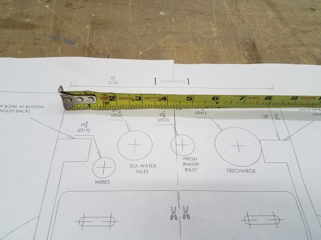
I began the day by finalizing the details on the two new tanks required (water and waste), i.e. determining the desired locations for the various fittings and then submitting the details and the order to the tank manufacturer.

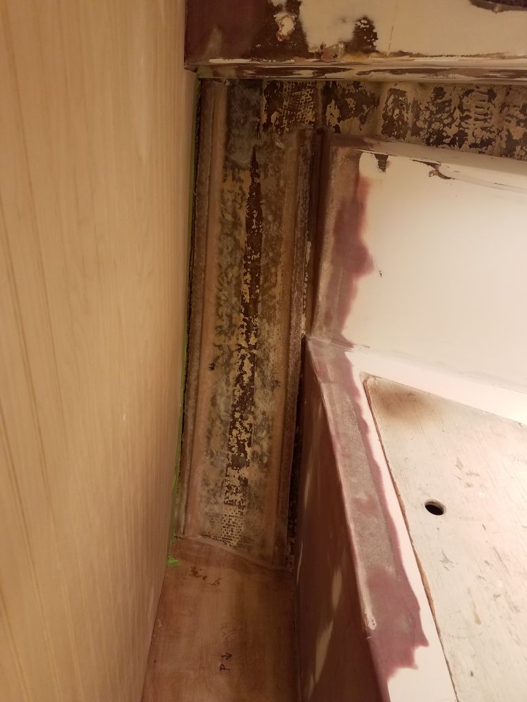
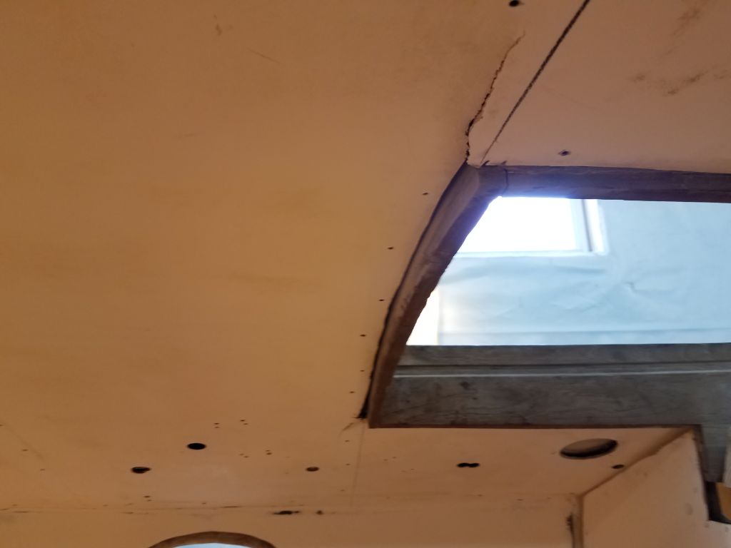
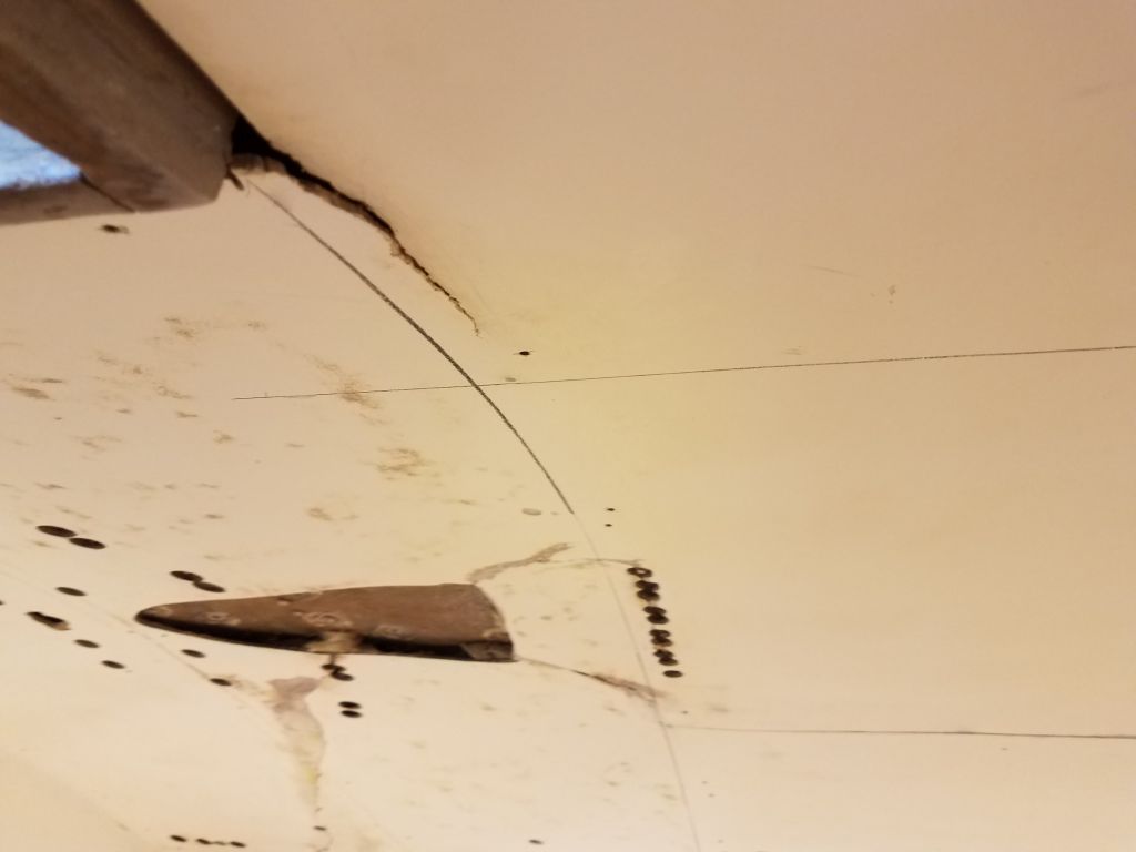
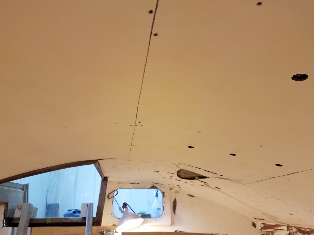
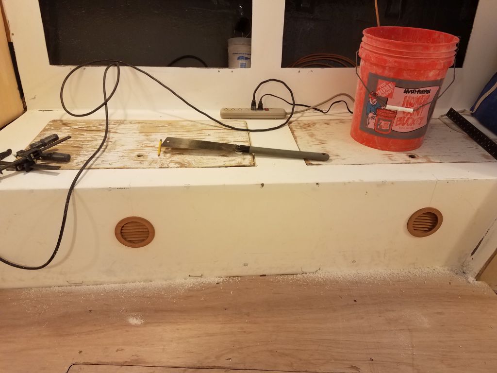
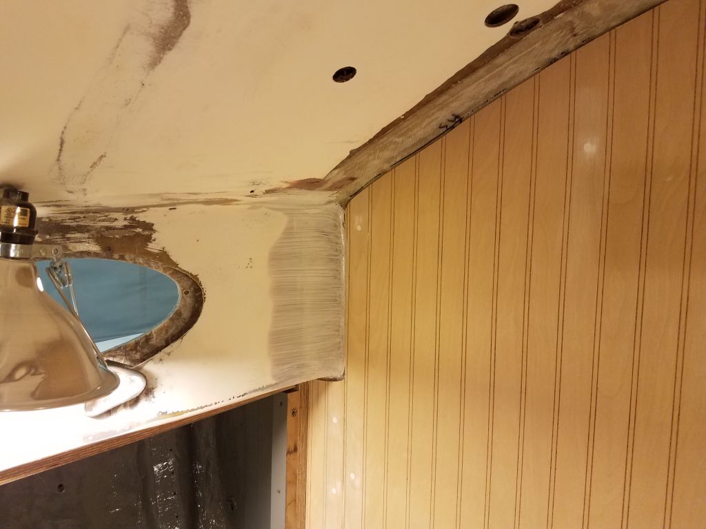
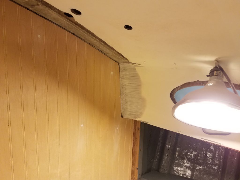
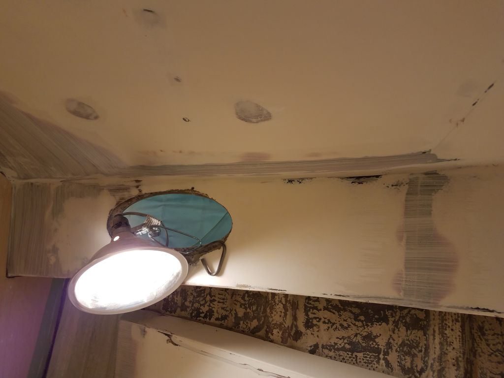
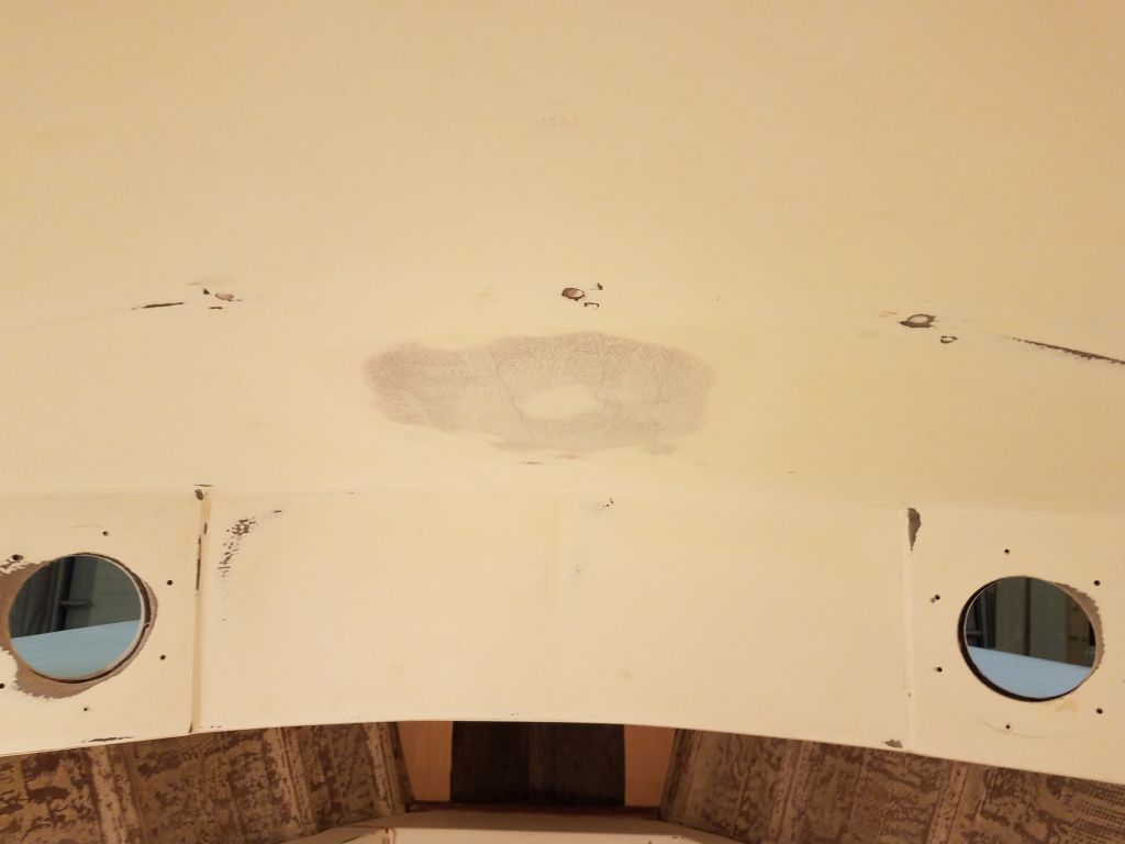
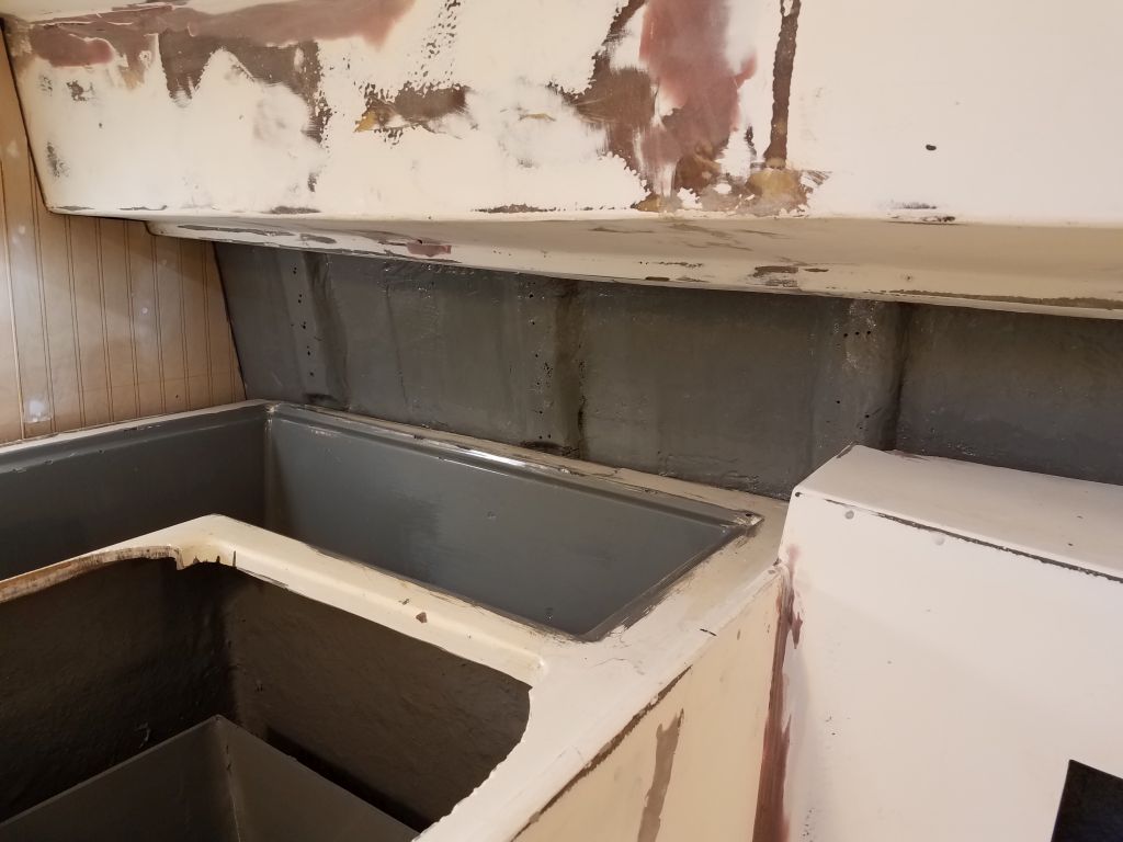
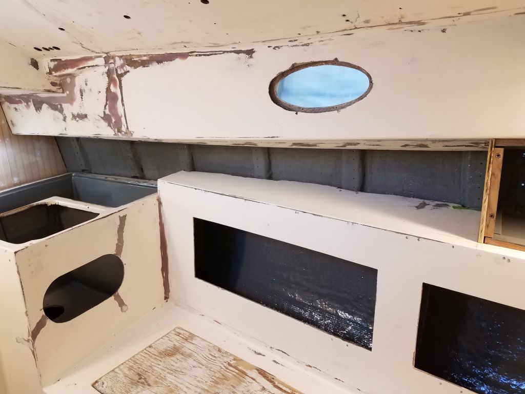
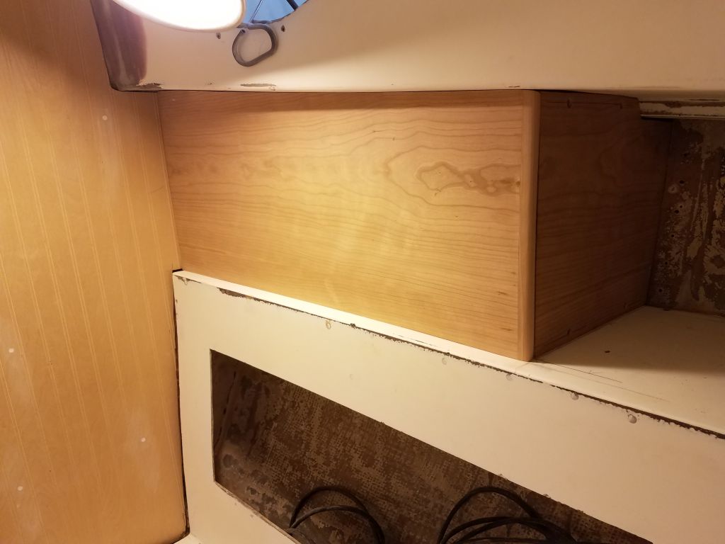
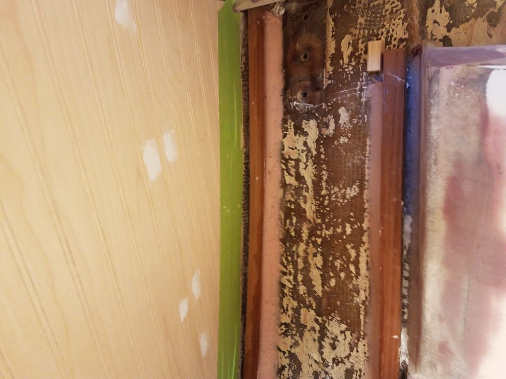
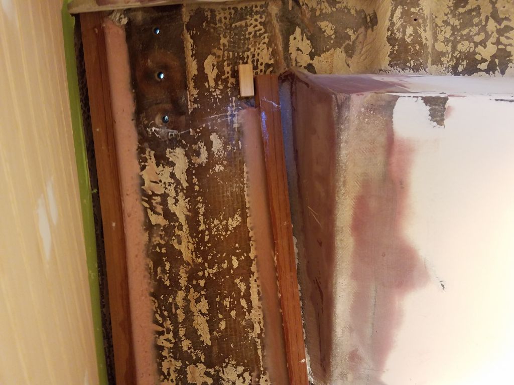
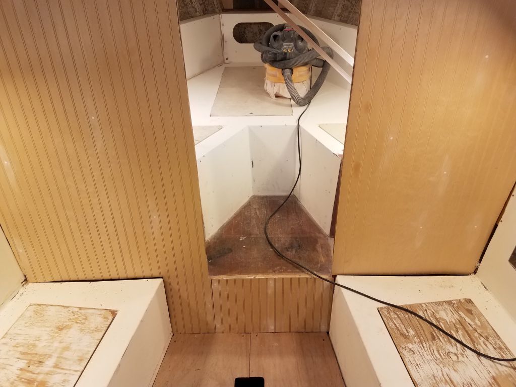
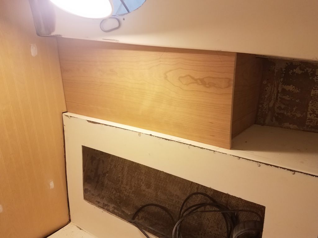
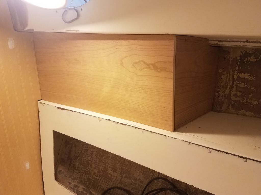
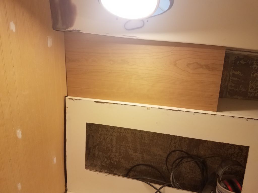
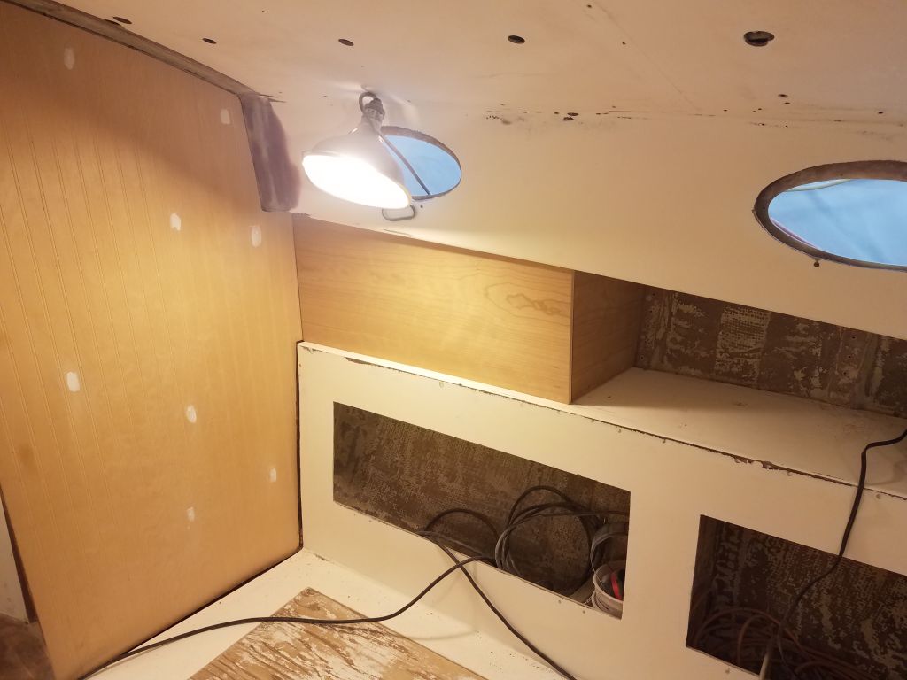
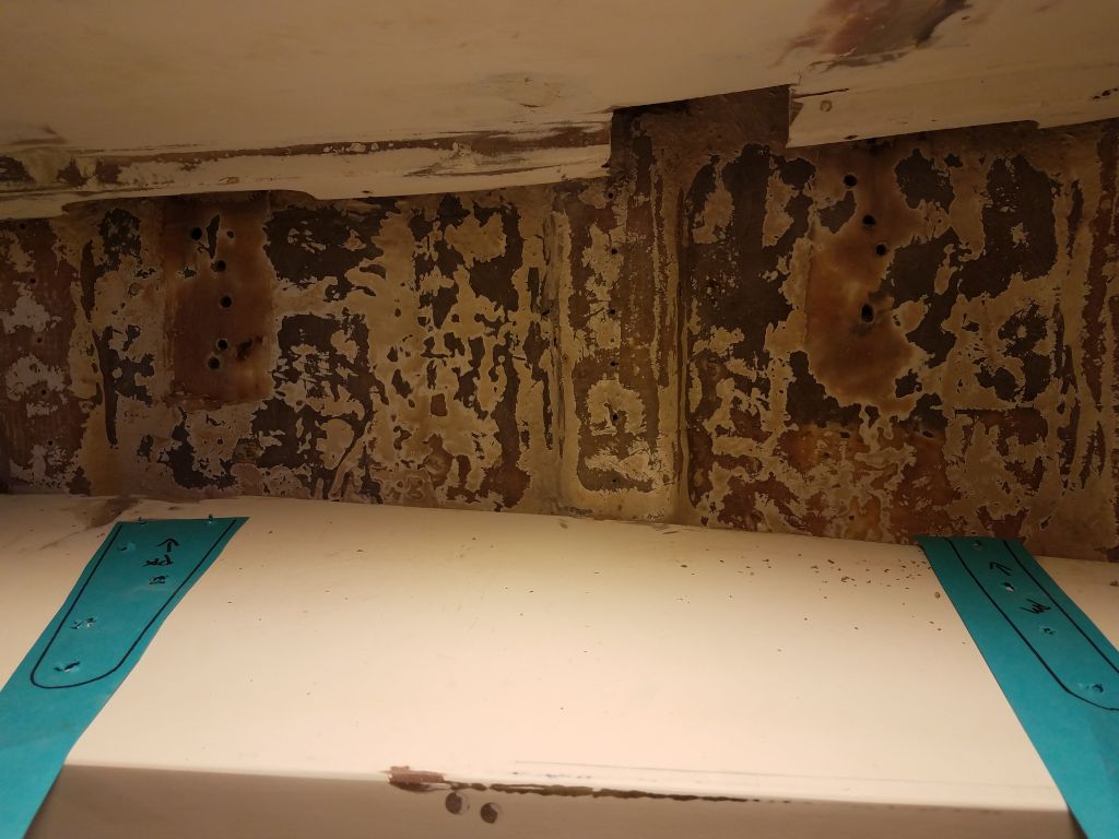
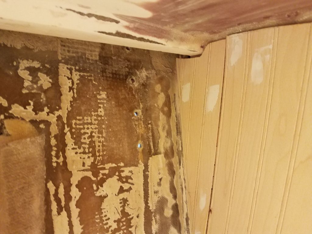
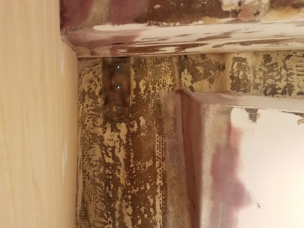
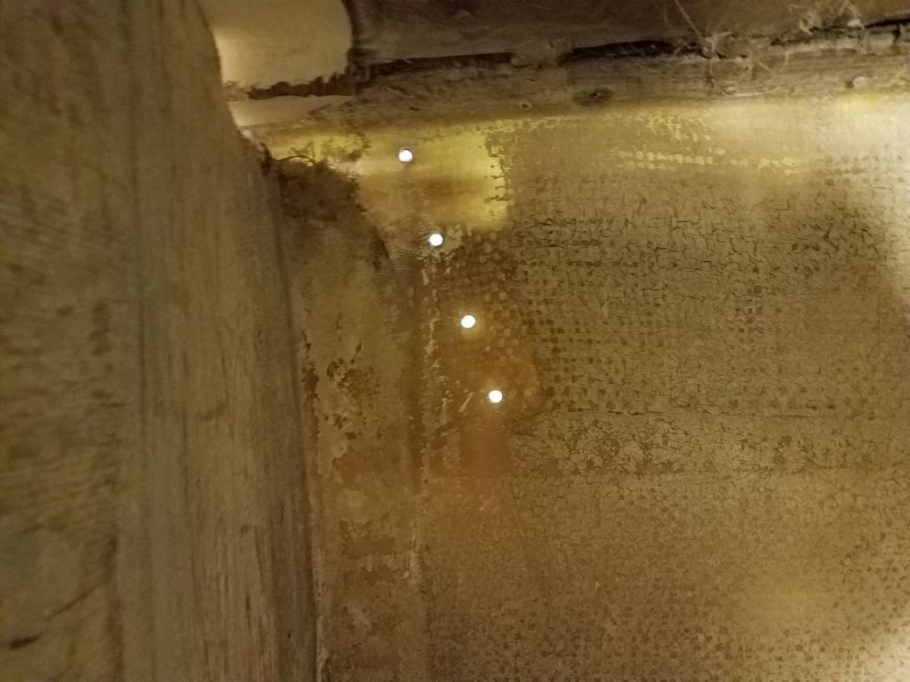
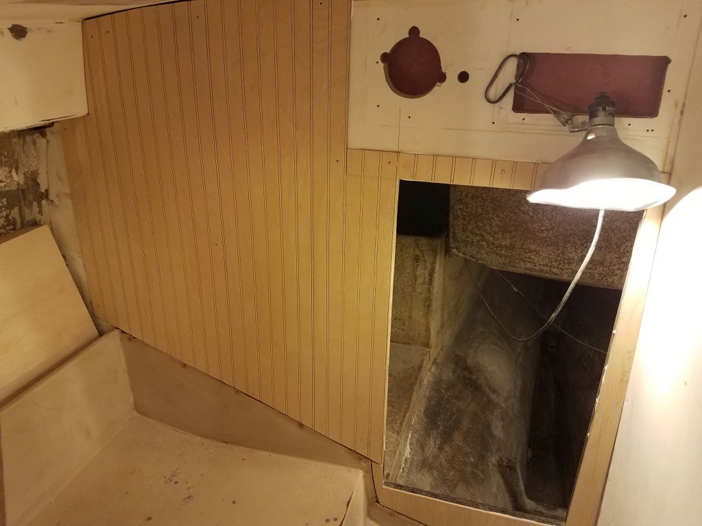
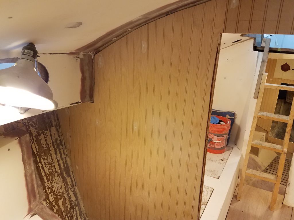
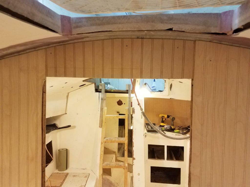
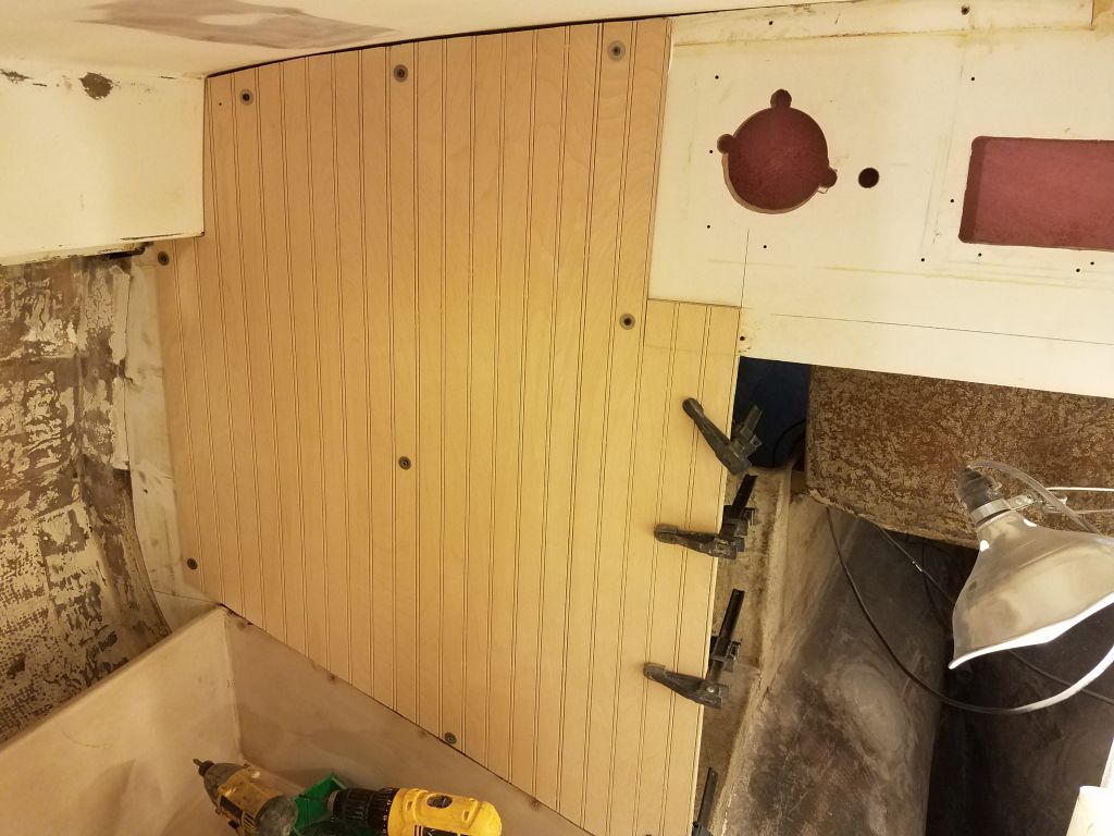
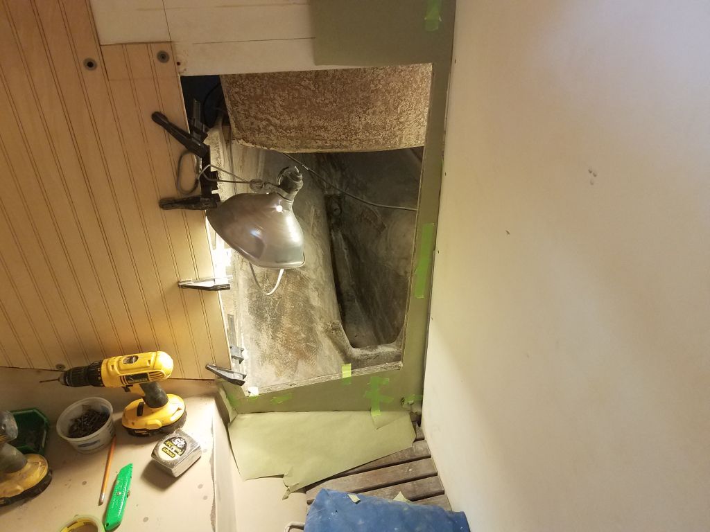
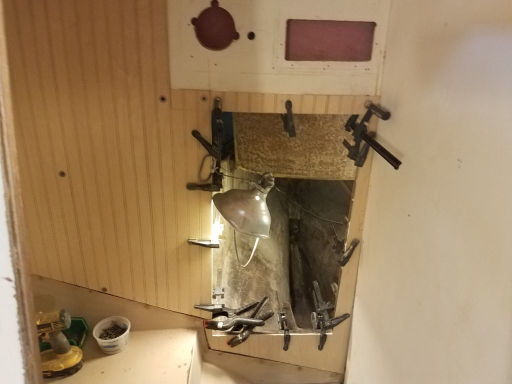
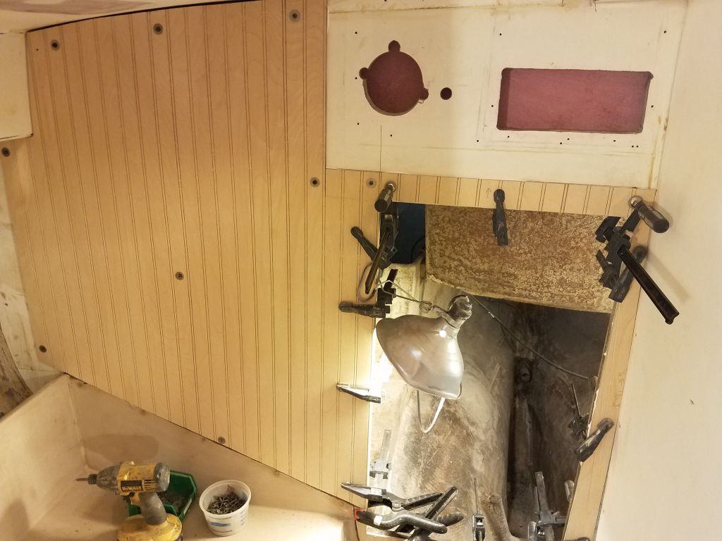
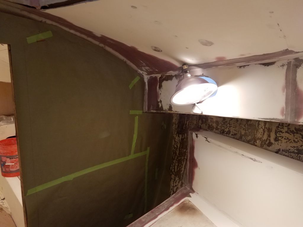
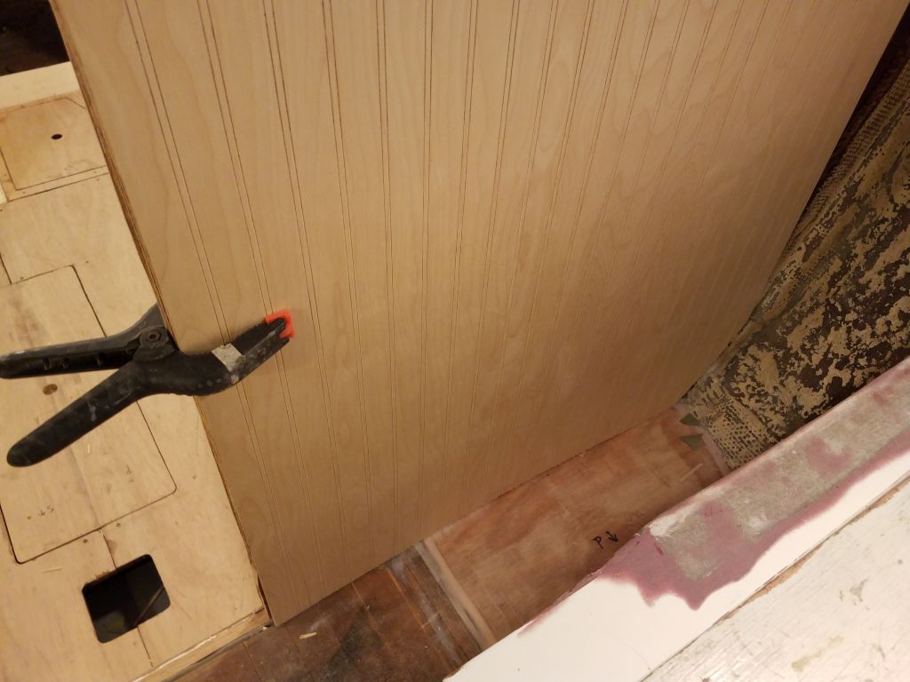
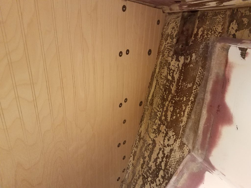
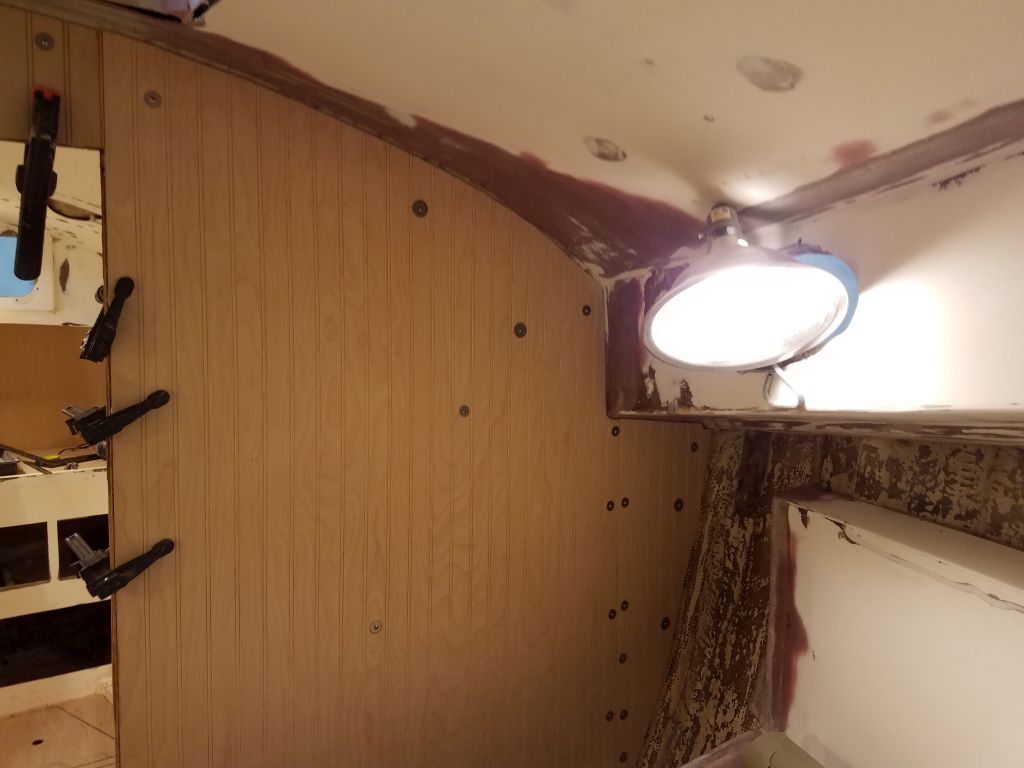
With that done, I prepared to lightly sand the new “tie coat” primer I’d applied in the cabin, but found that it was not yet ready for sanding:  it clogged up the paper immediately.  So I left that job for another time and decided instead to build the support platform for the holding tank in the head.

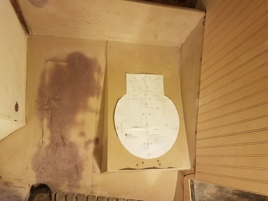
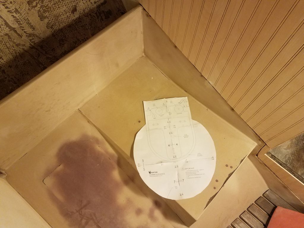
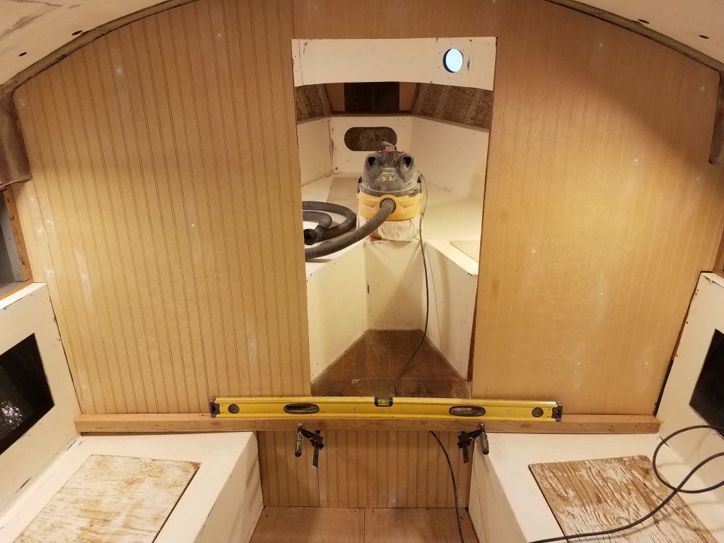
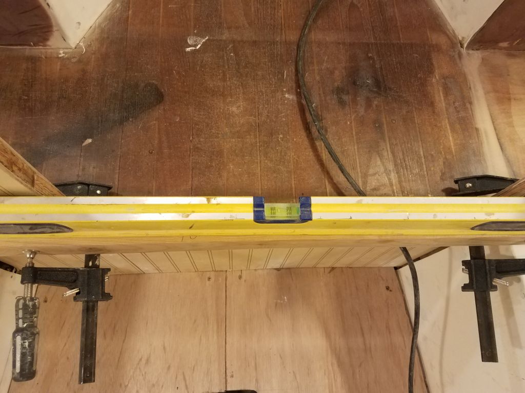
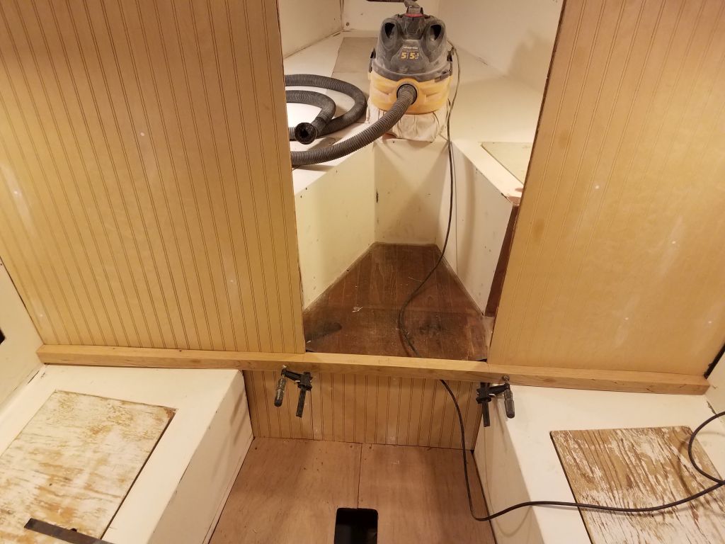
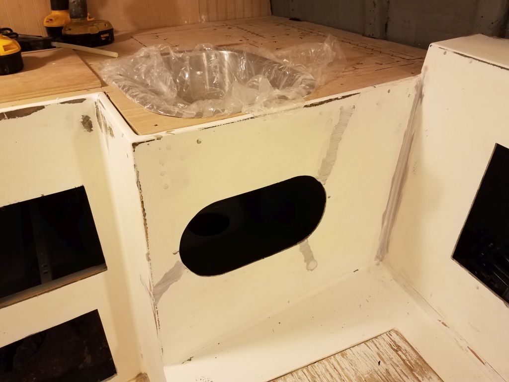
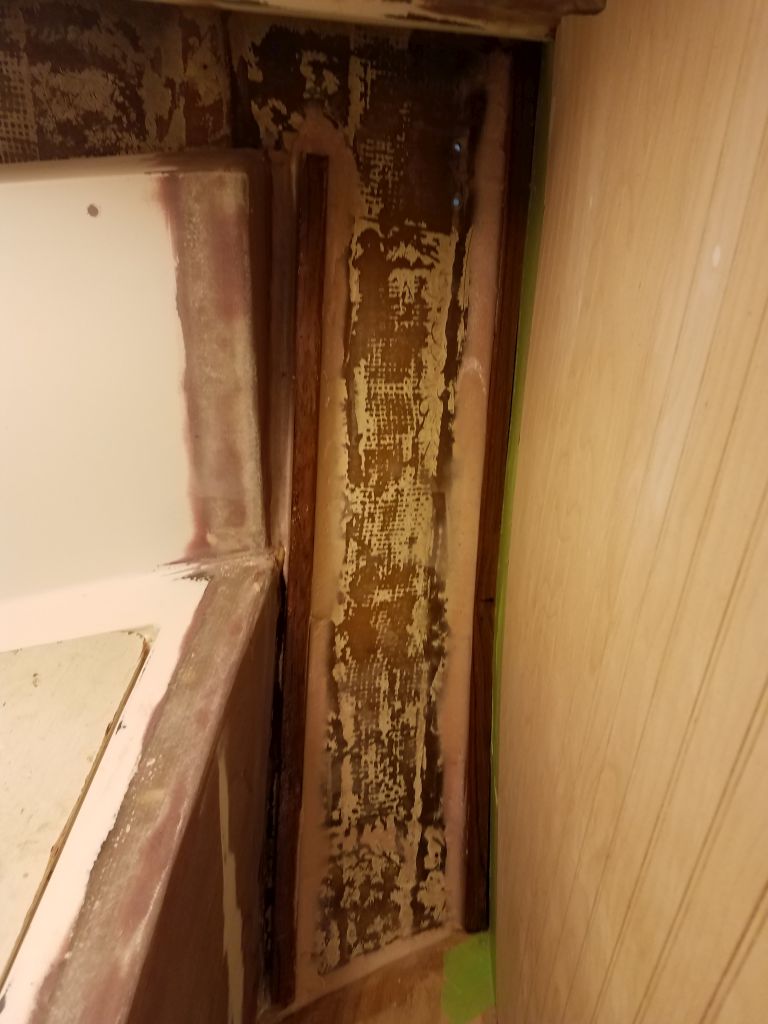
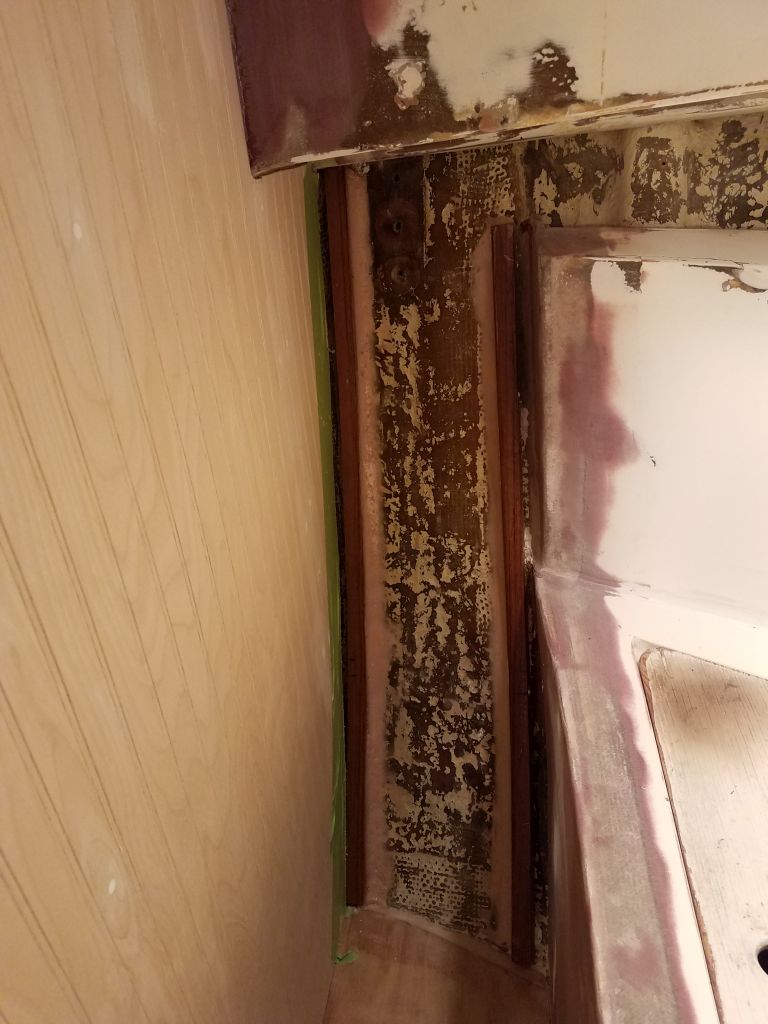
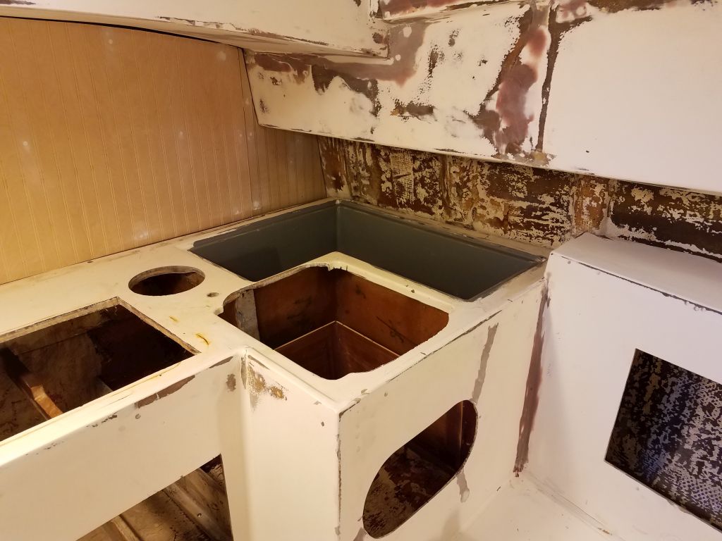
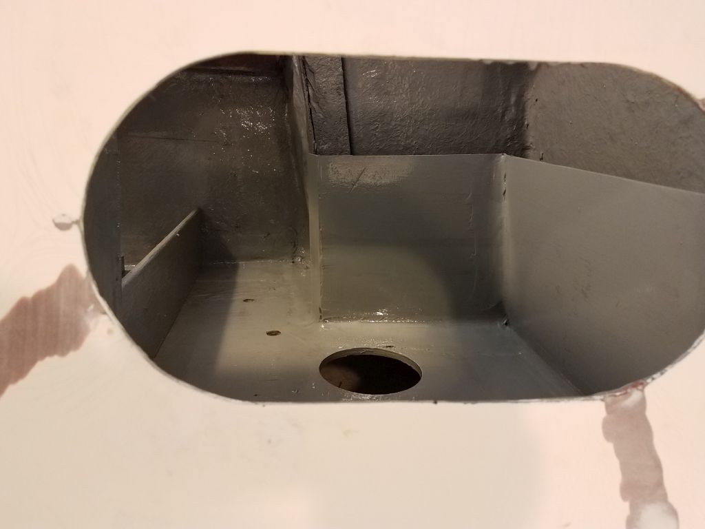
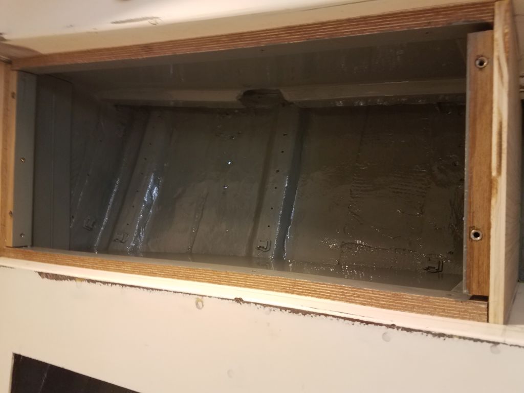
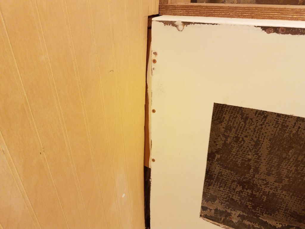
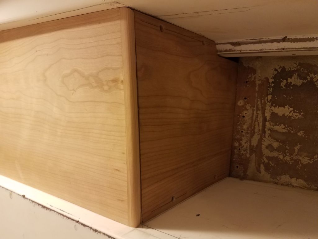
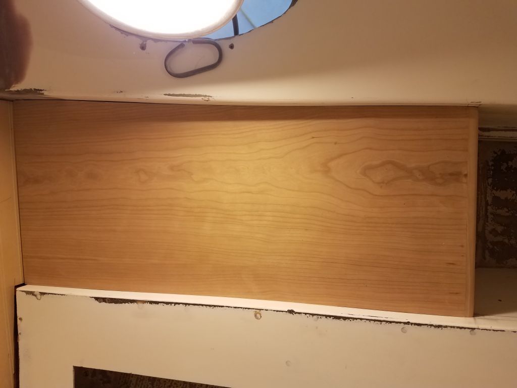
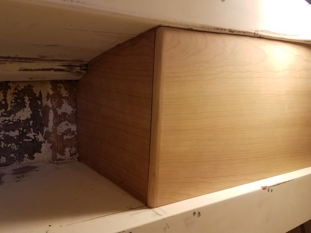
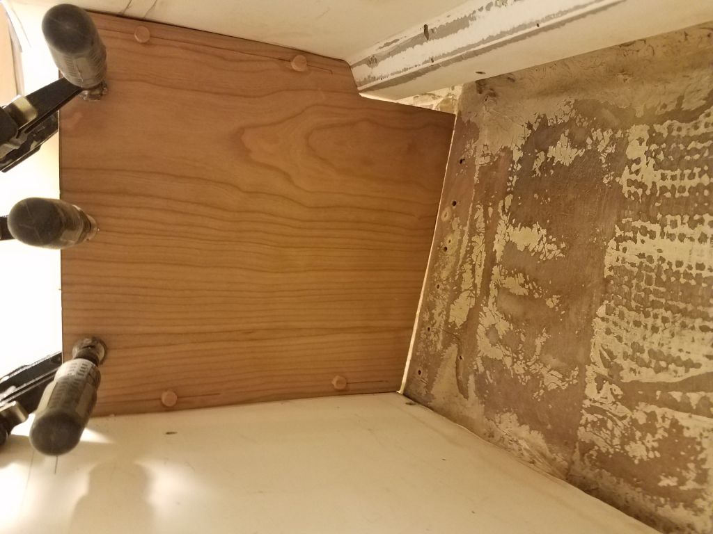
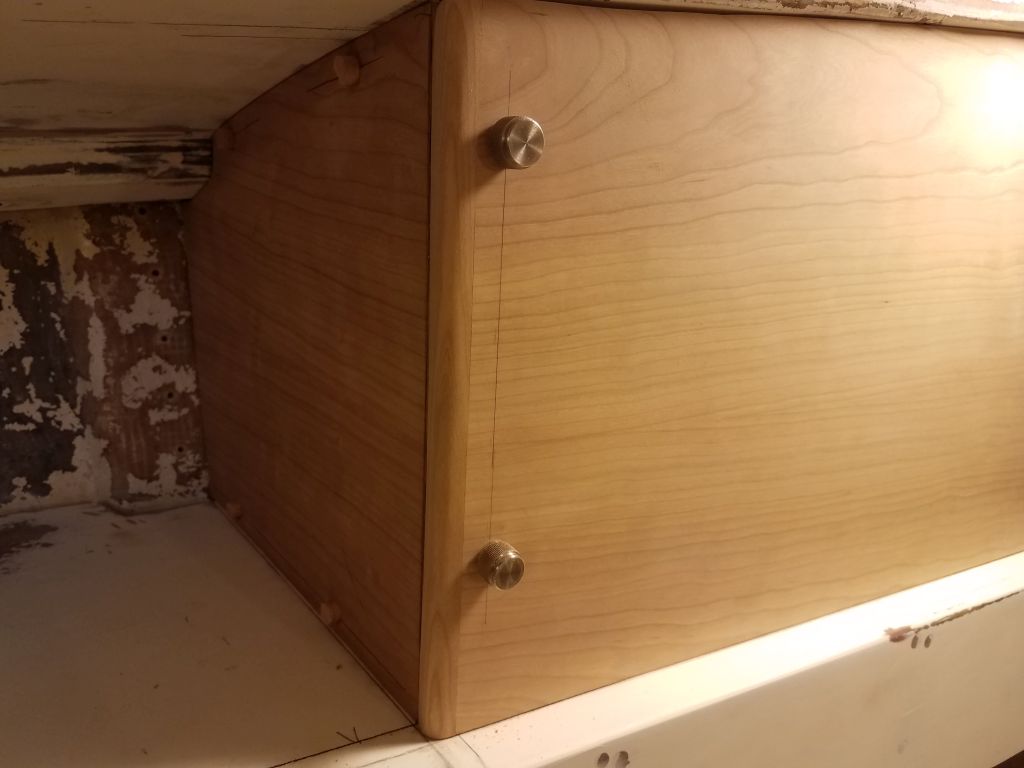
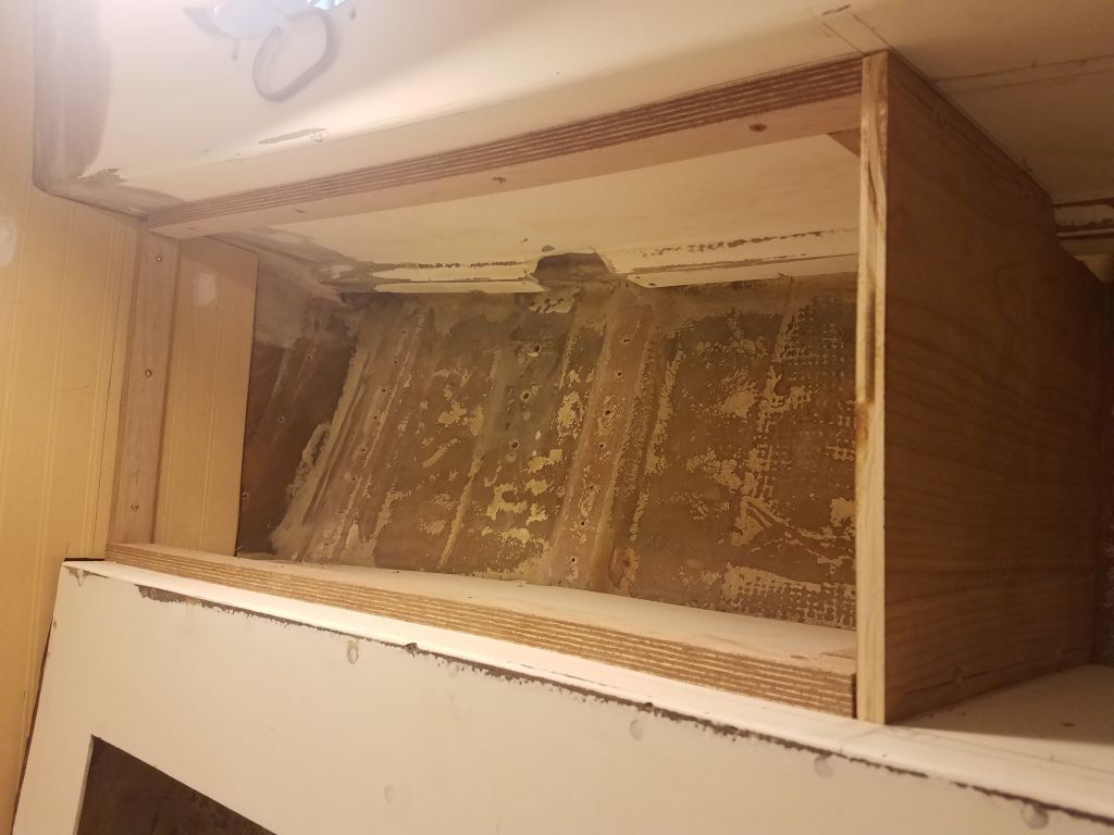
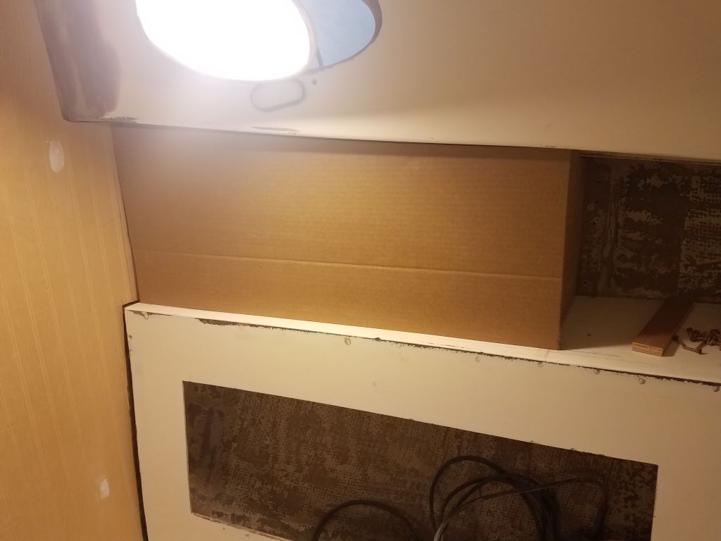
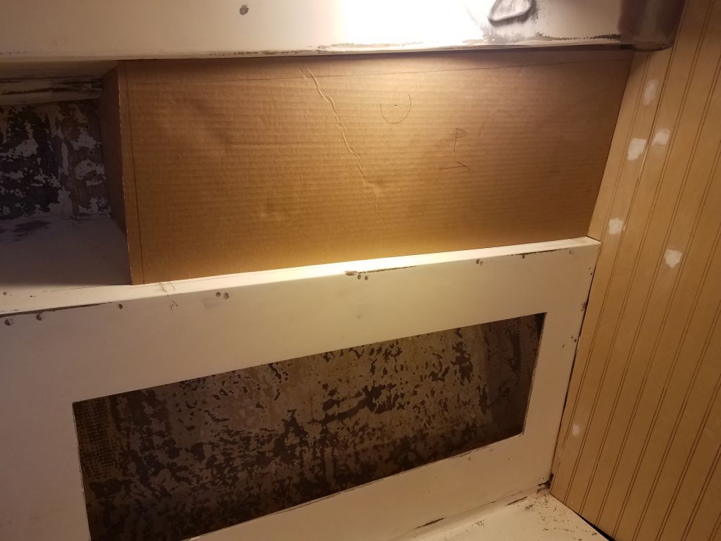
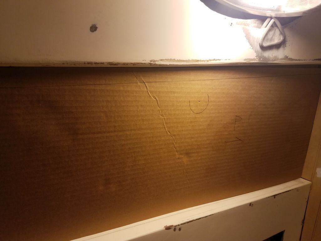
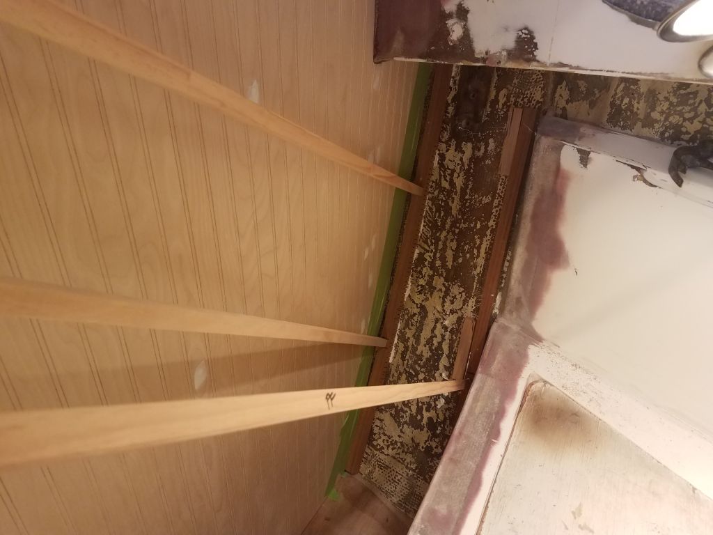
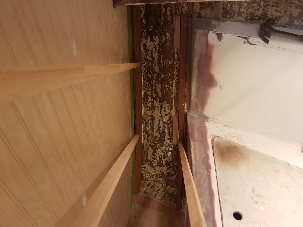
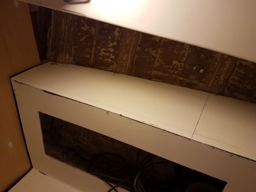
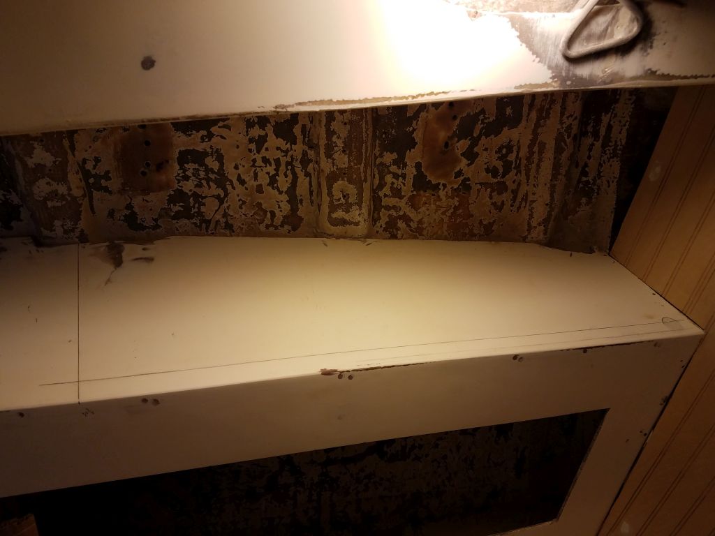
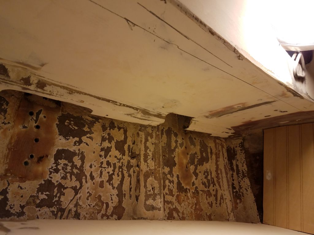
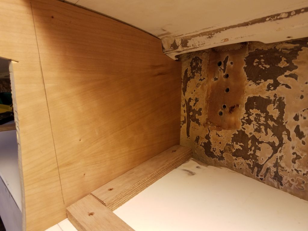
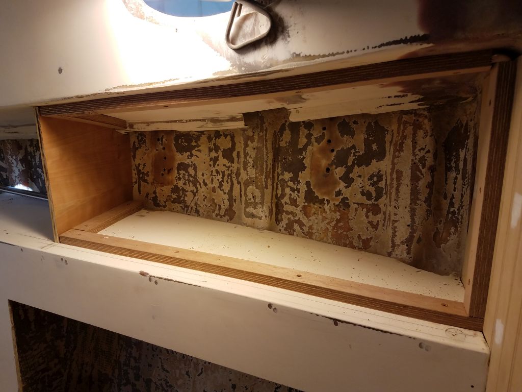
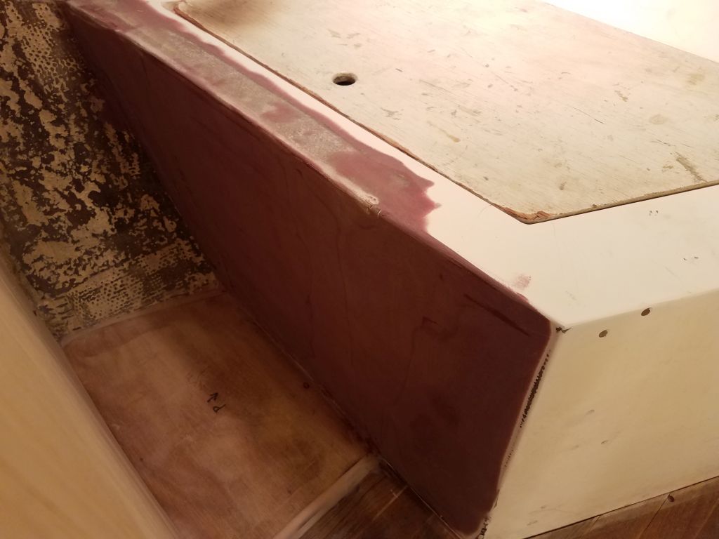
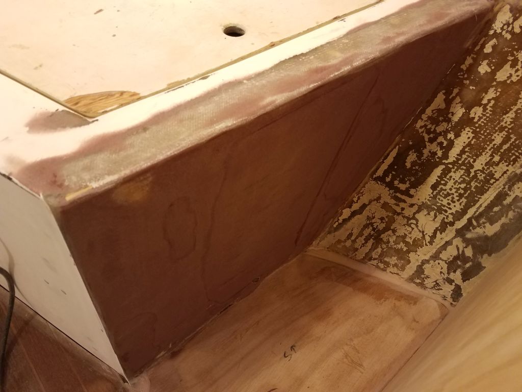
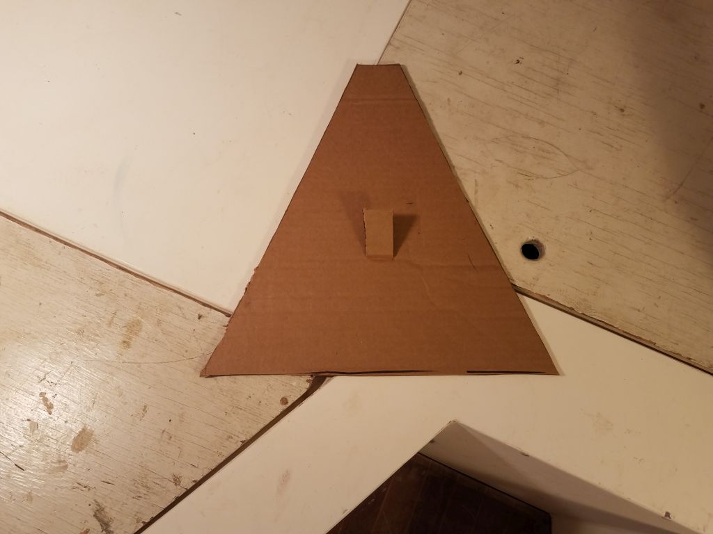
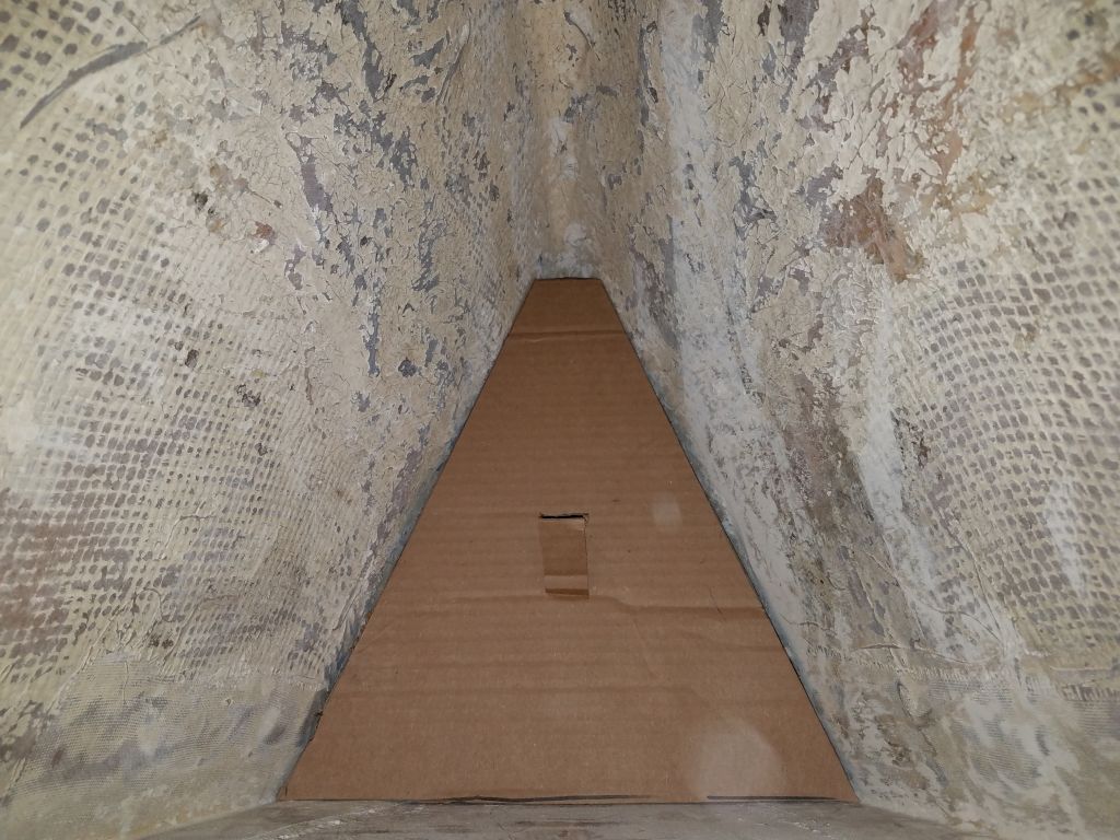
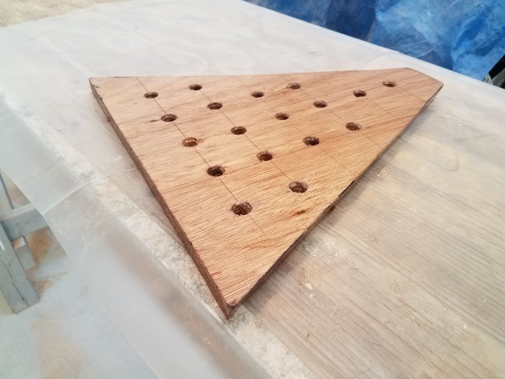
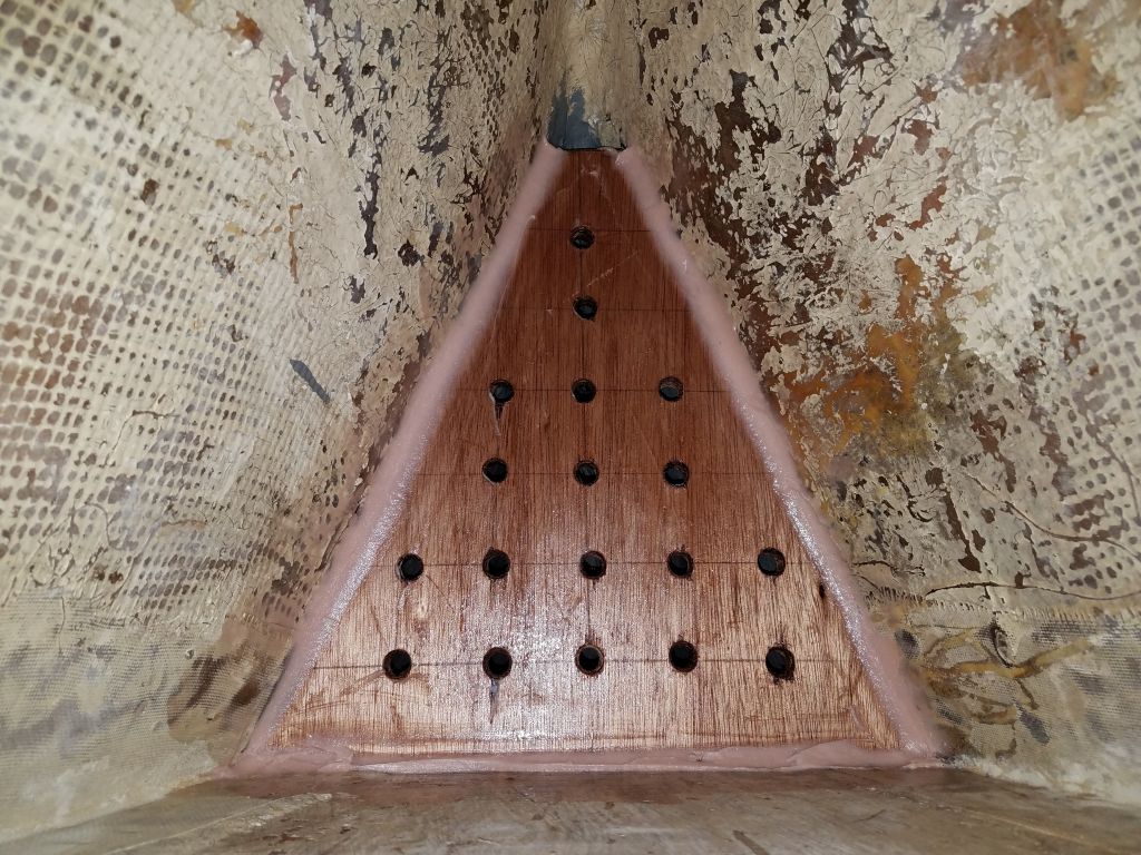
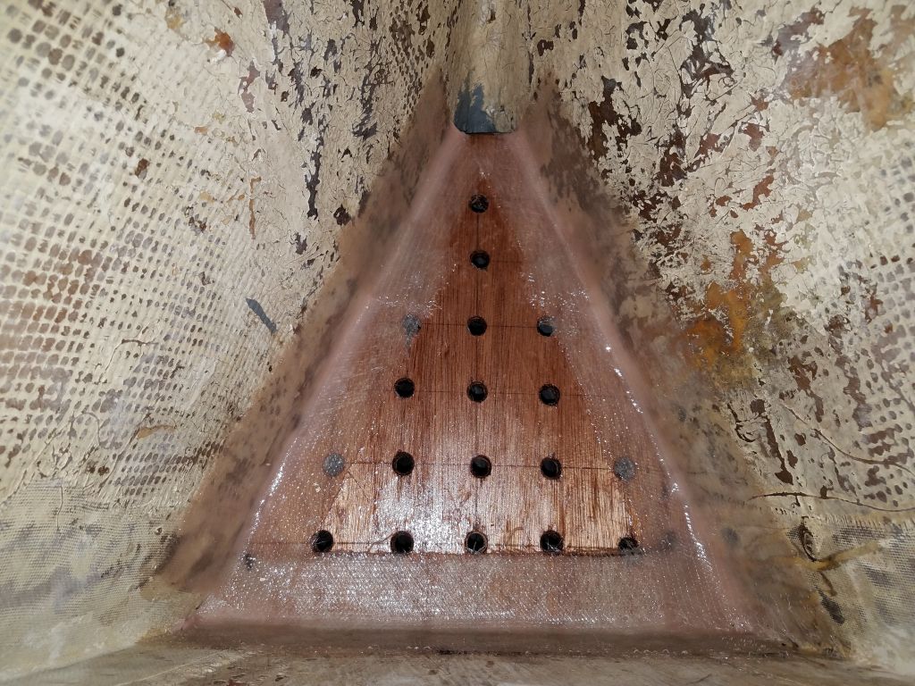
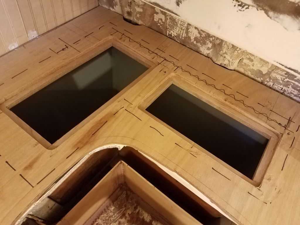
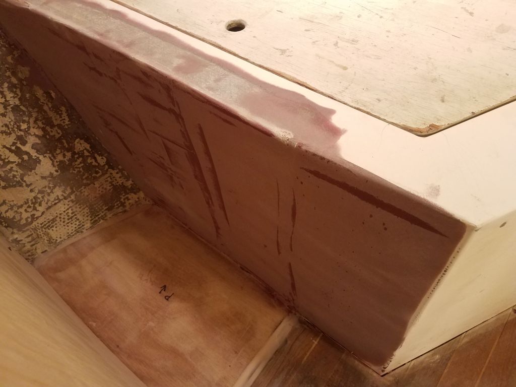
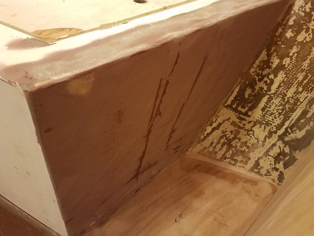
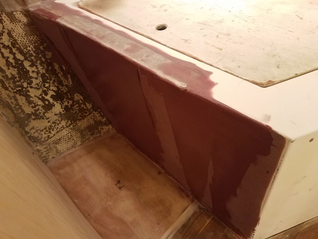
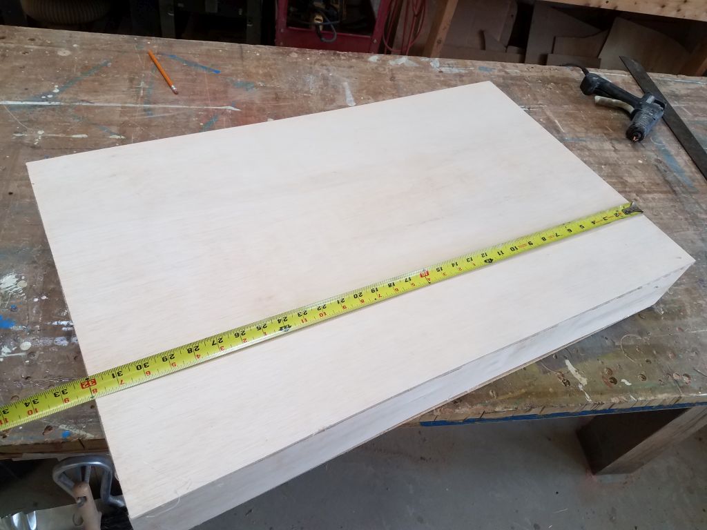
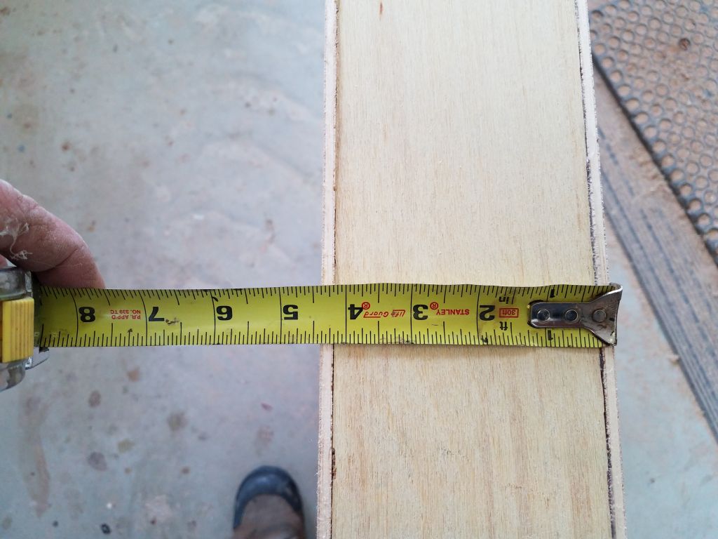
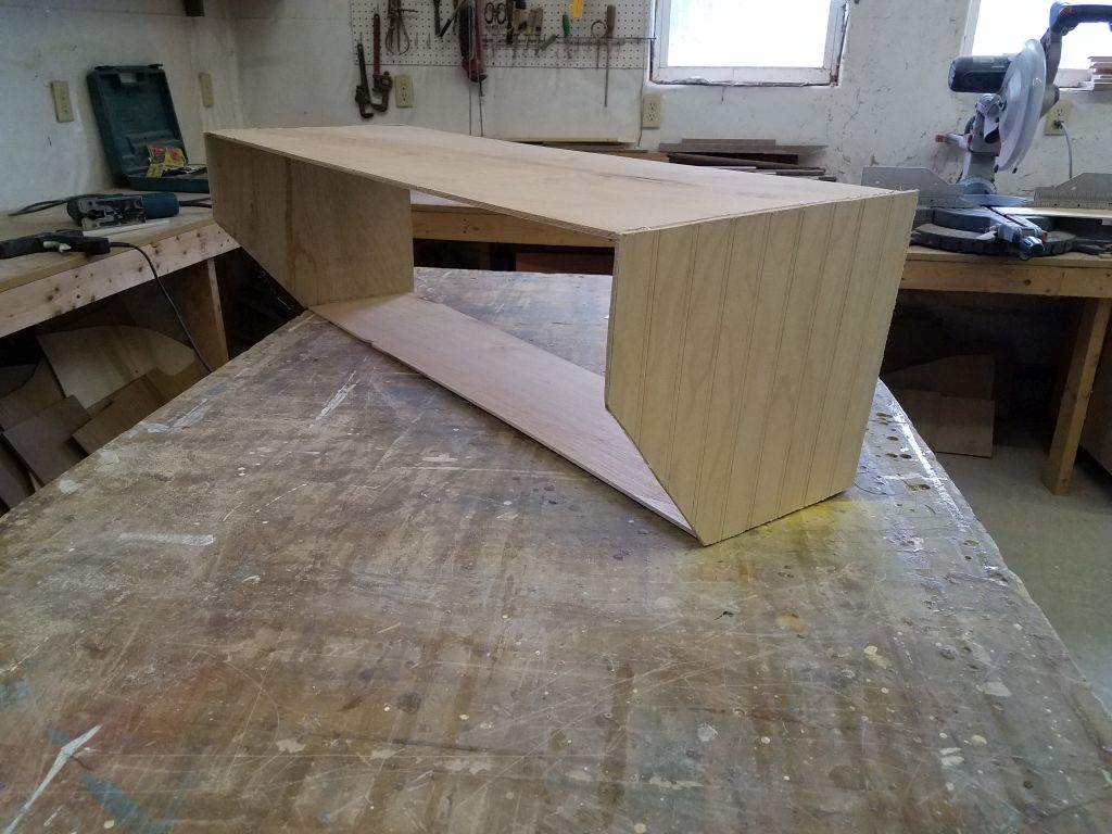
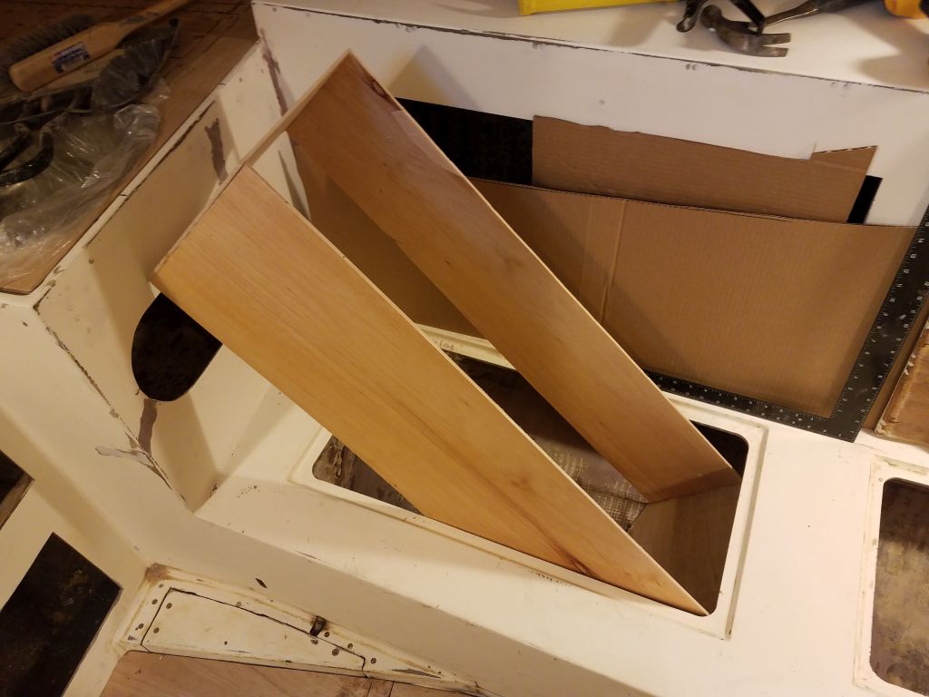
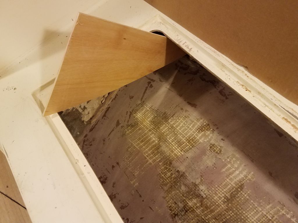
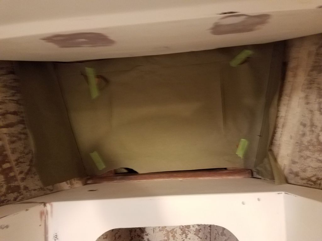
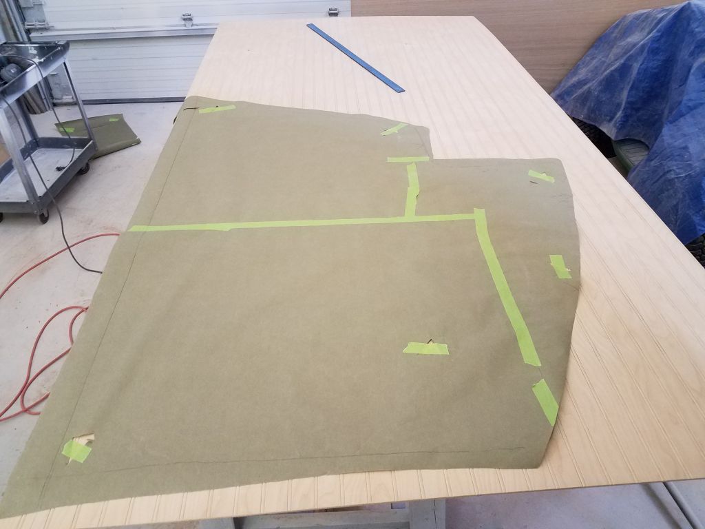
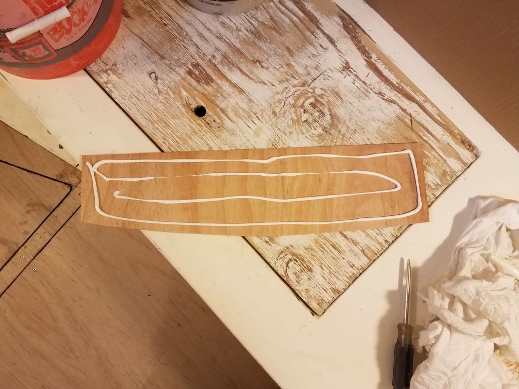
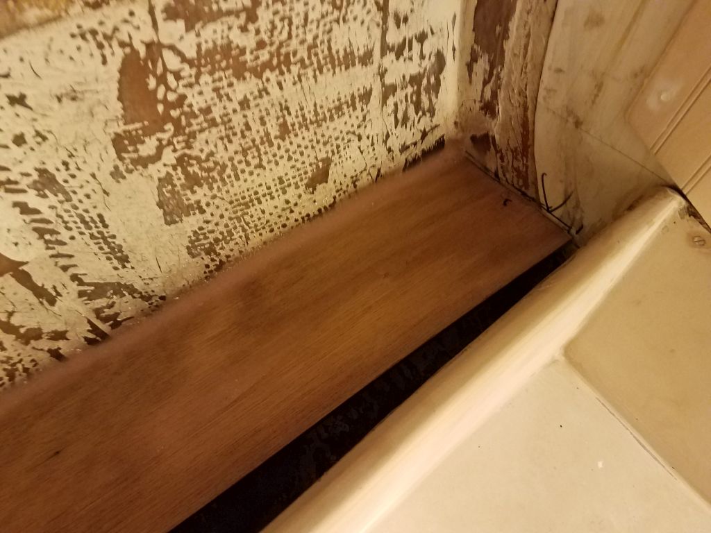
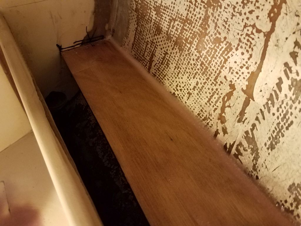
Using my plywood mockup, I placed the tank in the desired location outboard of the head and made some marks on the two adjoining bulkheads where the ends of the tank fell, which would give me a starting reference point for the new platform’s location.  From there, I created a cardboard template of the space, first with a rough piece on which I could scribe, then a more accurate template based on the first go-round.  Once I was satisfied with the template, I transferred it to 12mm plywood and cut out the platform itself, leaving 1-1/2″ extra width inboard  of the tank width itself to allow for support cleats and minor adjustments.  This left some open space within the locker that would be required for hose access and the like.

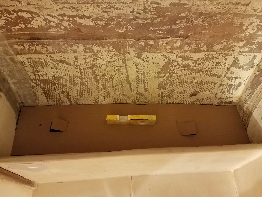
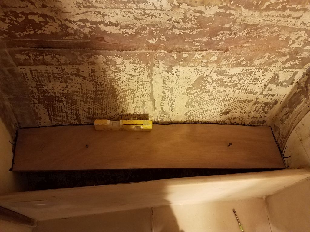
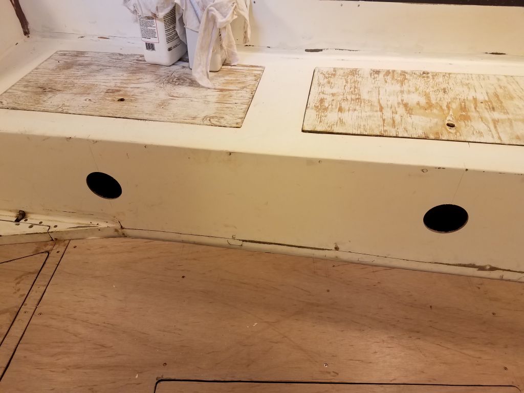
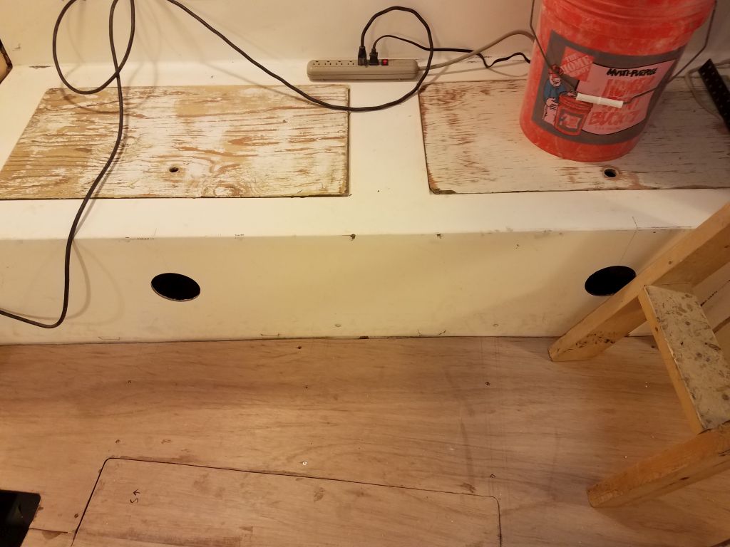
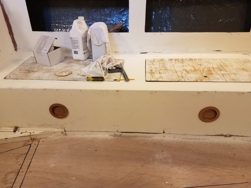
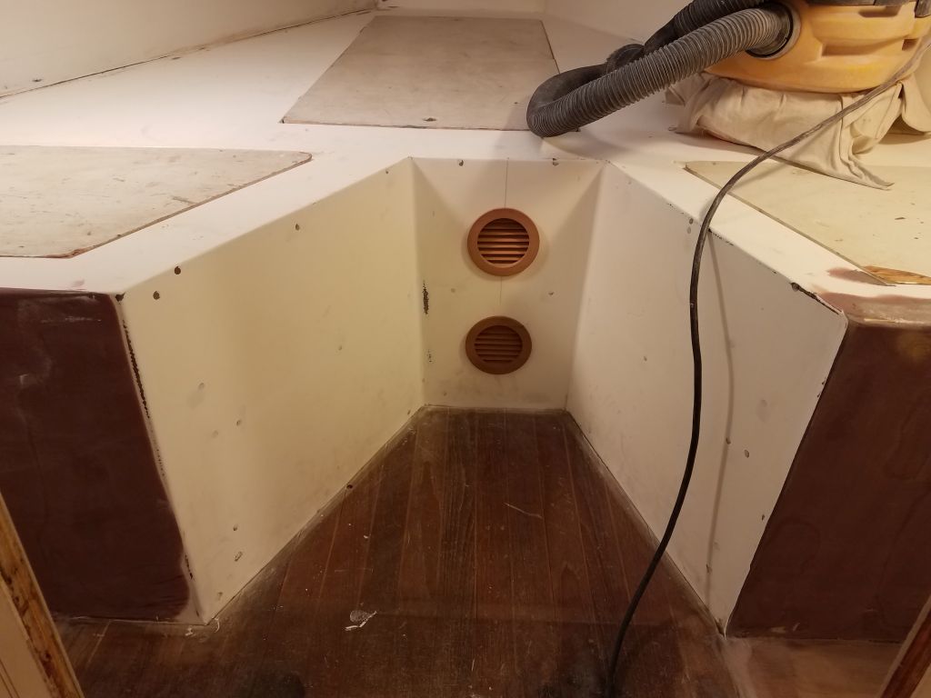
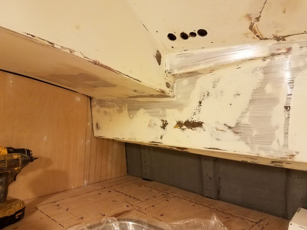
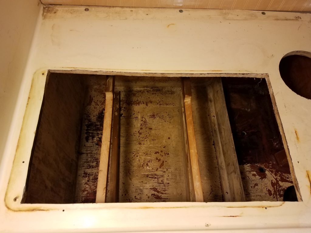
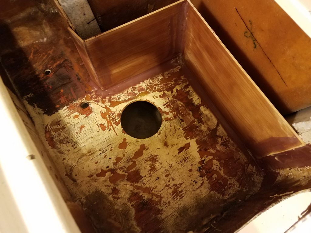
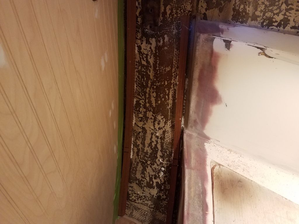
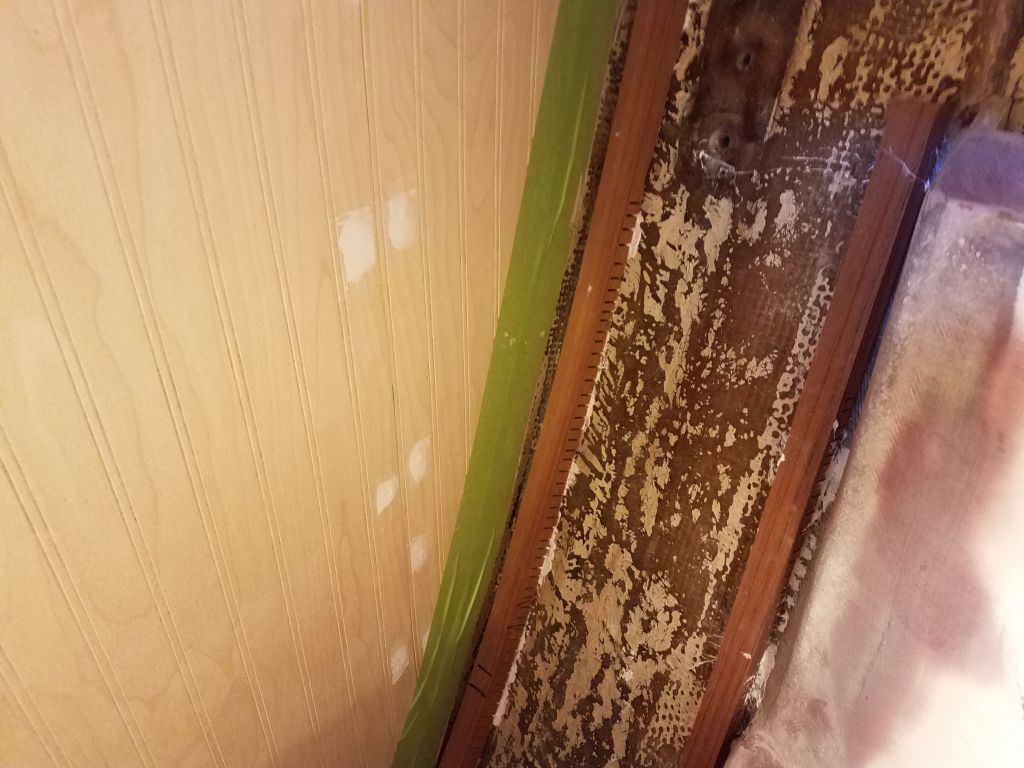
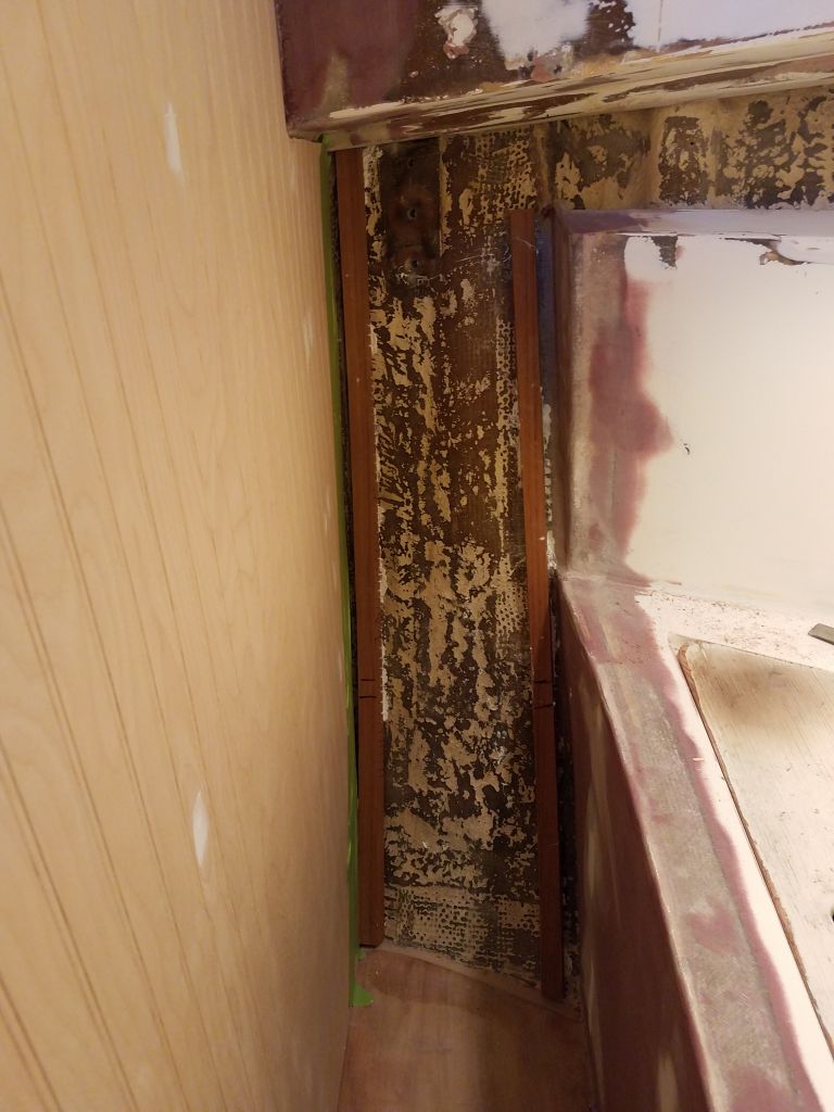
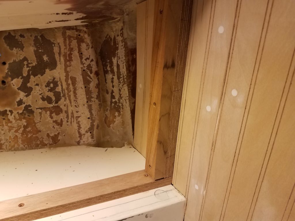
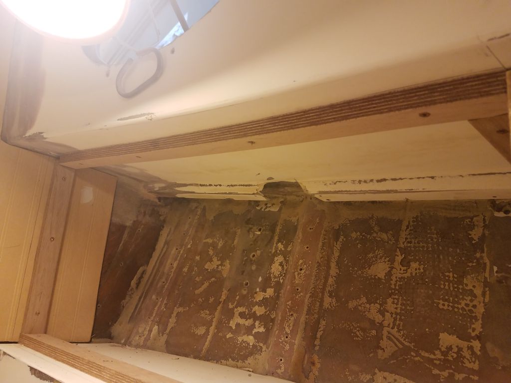
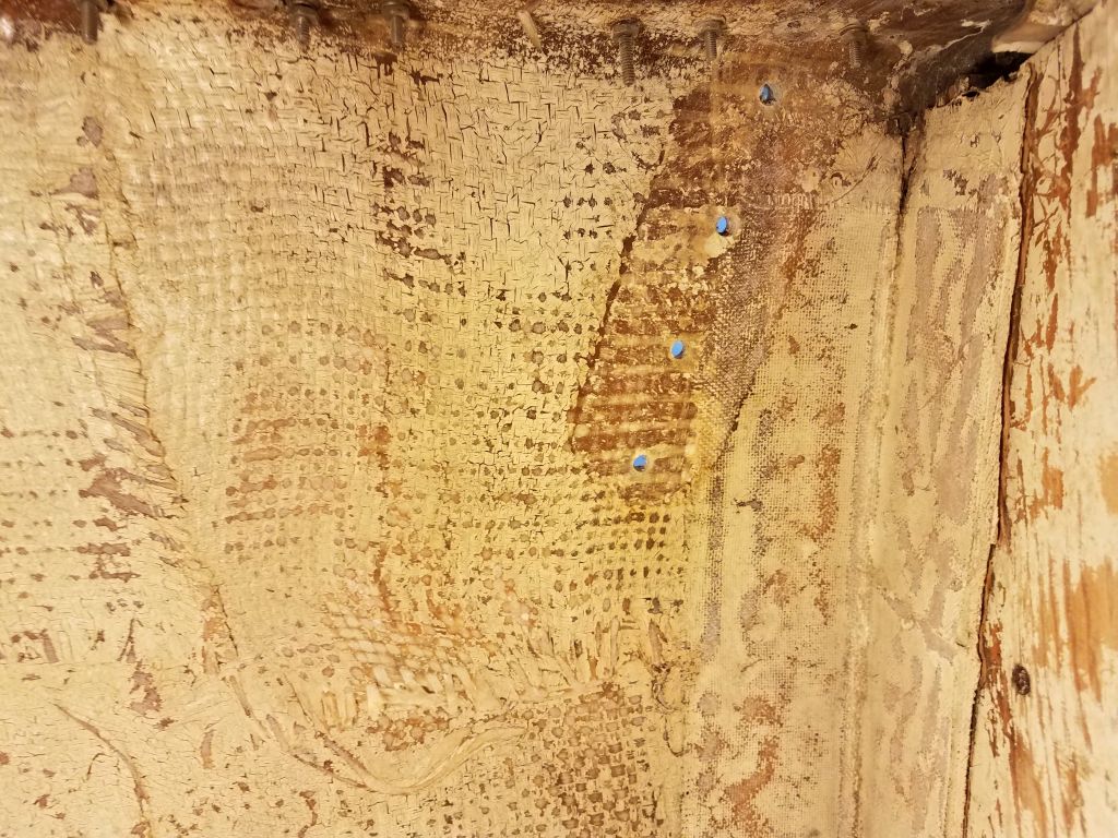
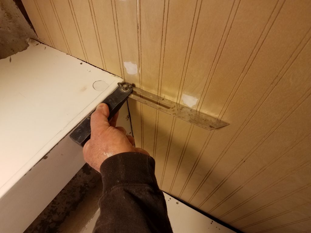
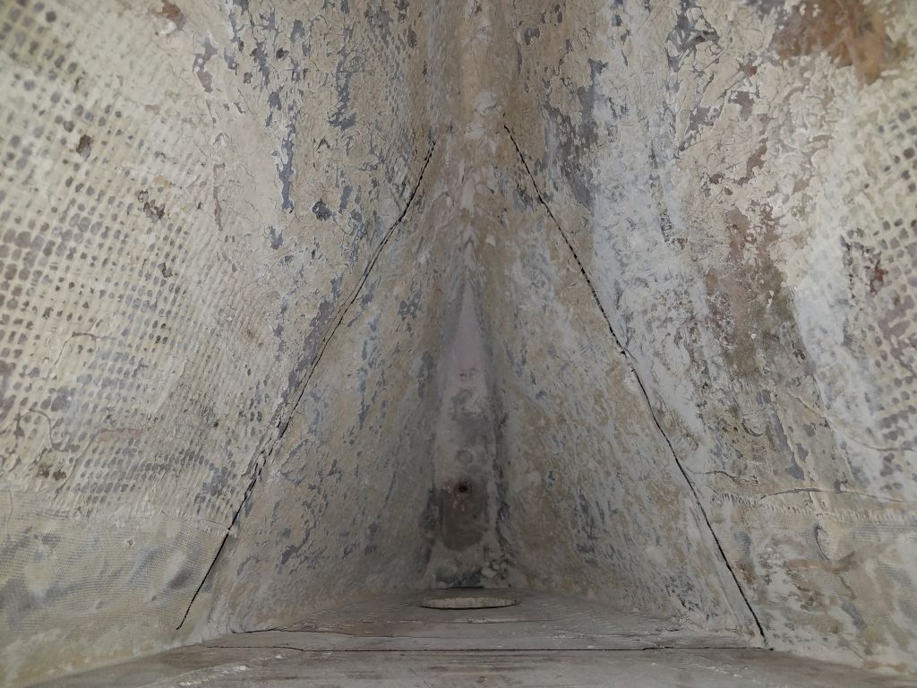
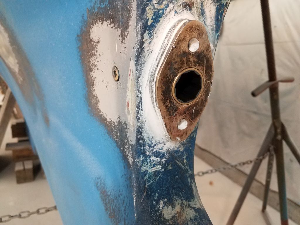
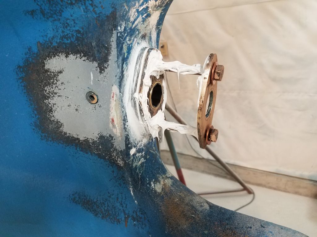
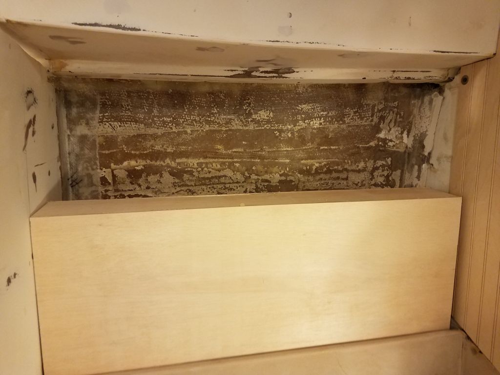
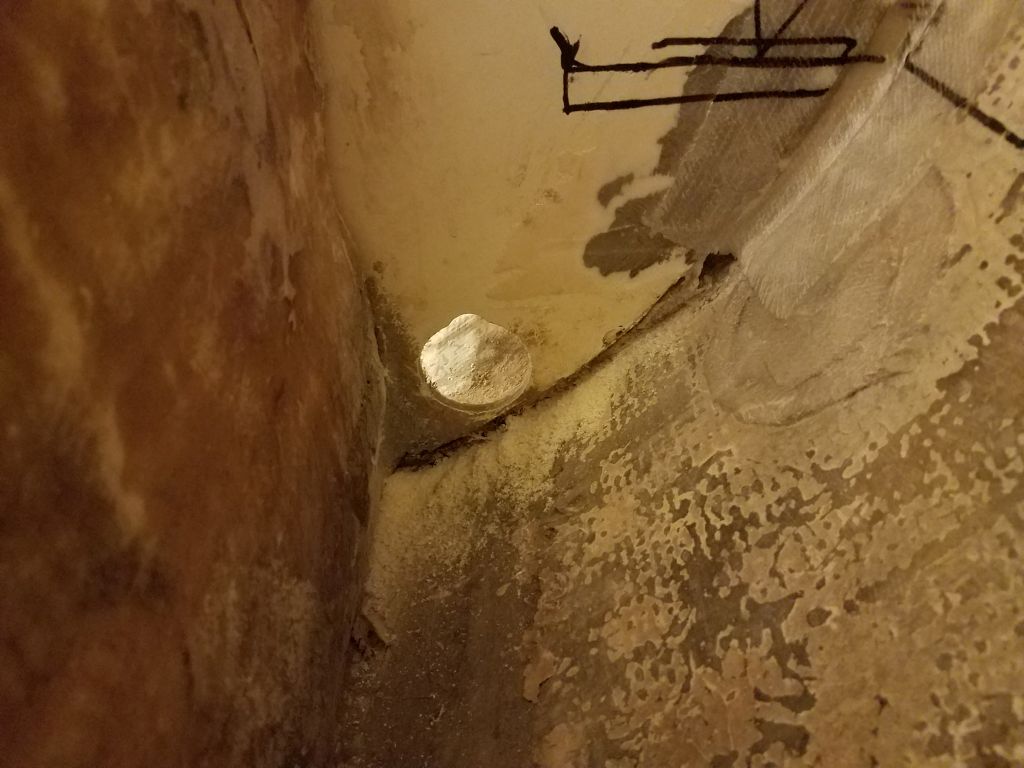
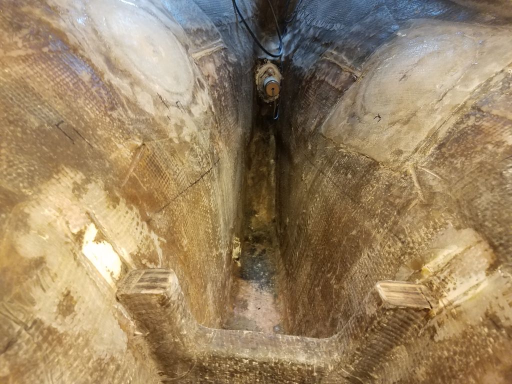
After marking the ends of the platform on the bulkheads (with the platform level in both directions), I removed it and used a hole saw to cut a large hole through the forward bulkhead and into the space beneath the starboard settees, where the overboard pumpout through hull would eventually be located.  To comply with discharge requirements, all waste would be routed into the holding tank first, but from there would be the option of evacuating the tank to a shoreside facility (through a deck fitting) or overboard via a hand pump when the boat was in waters legal for such behavior.

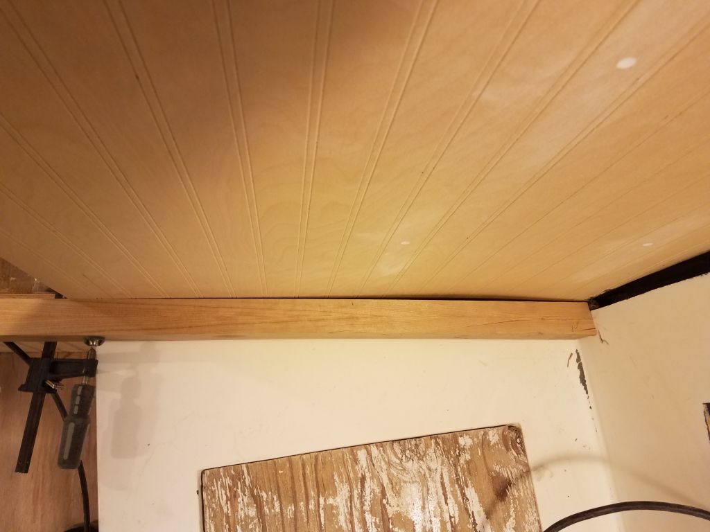
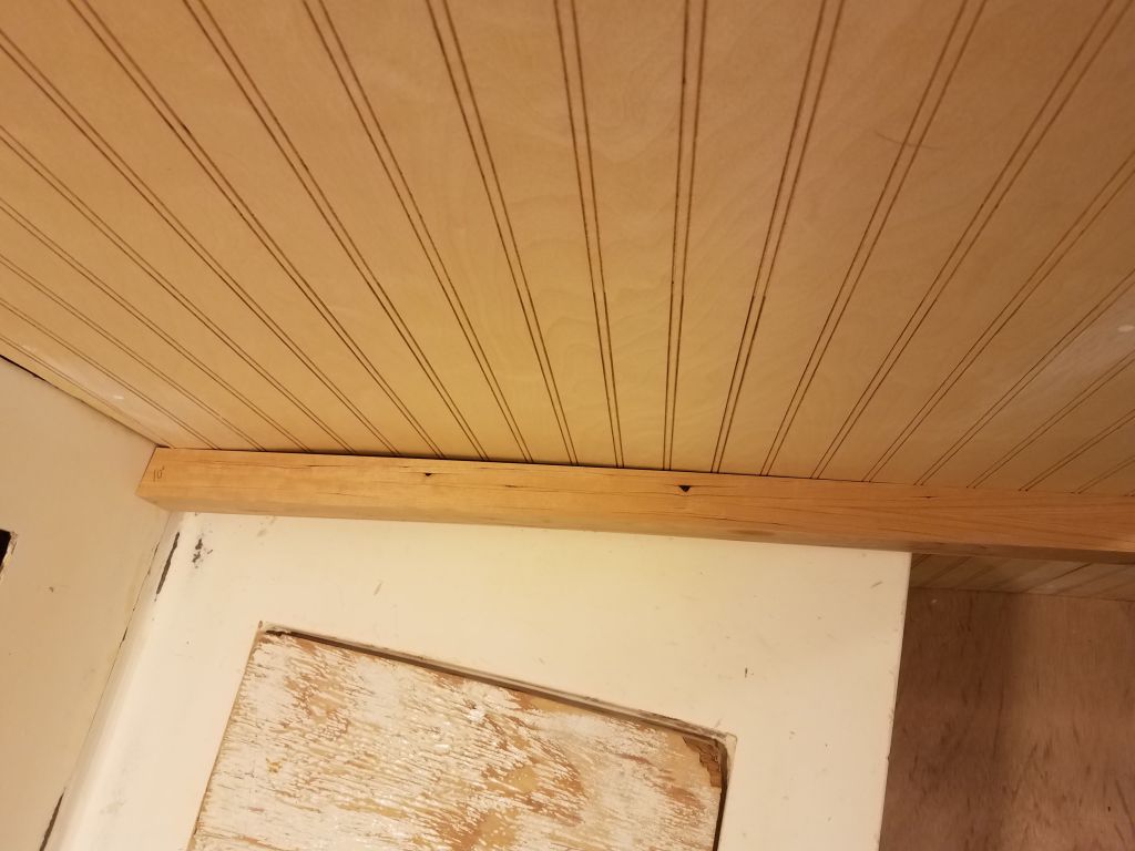
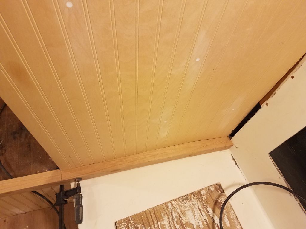
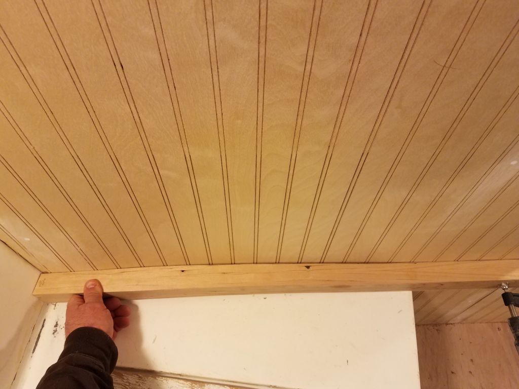
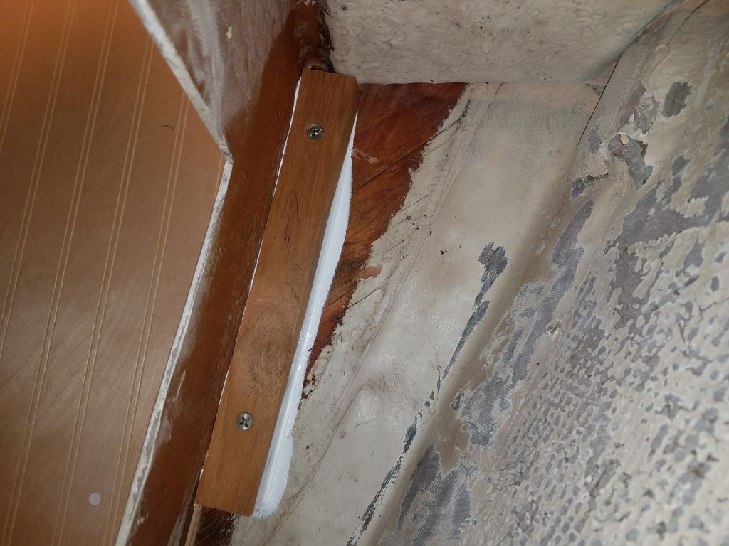
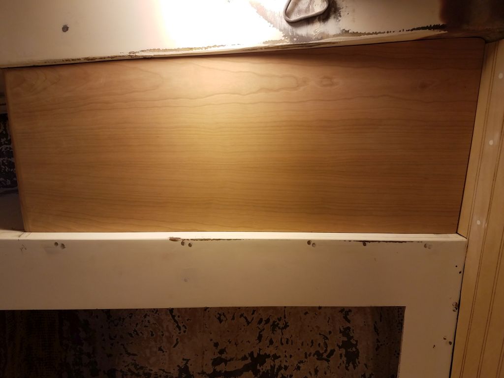
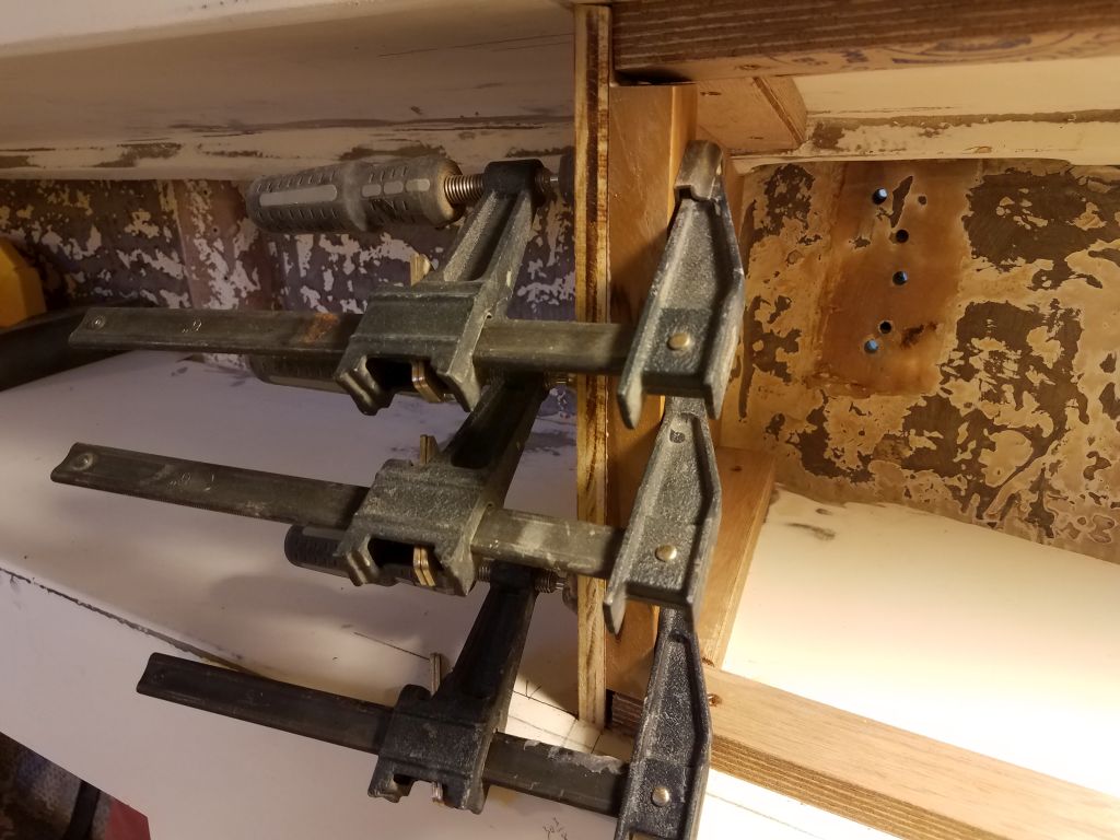
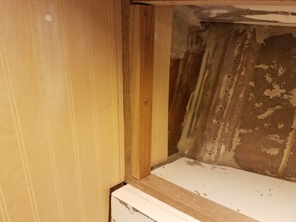
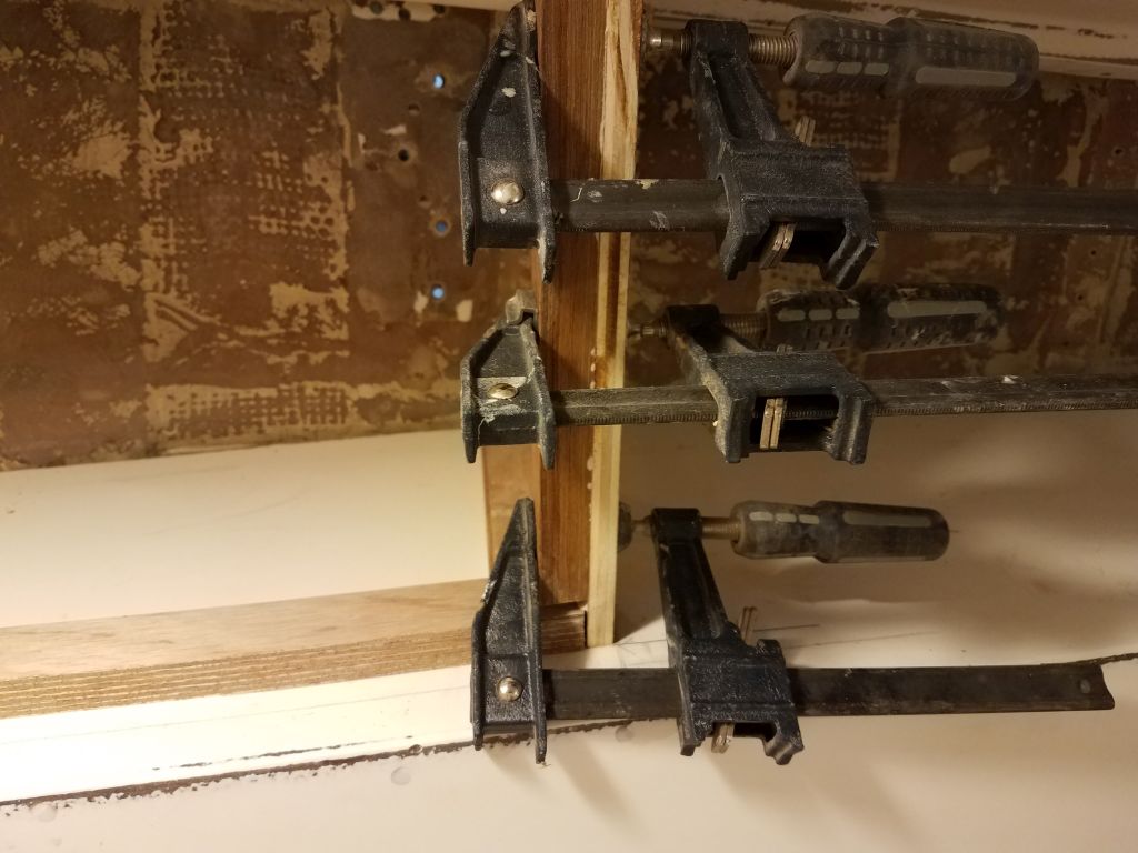
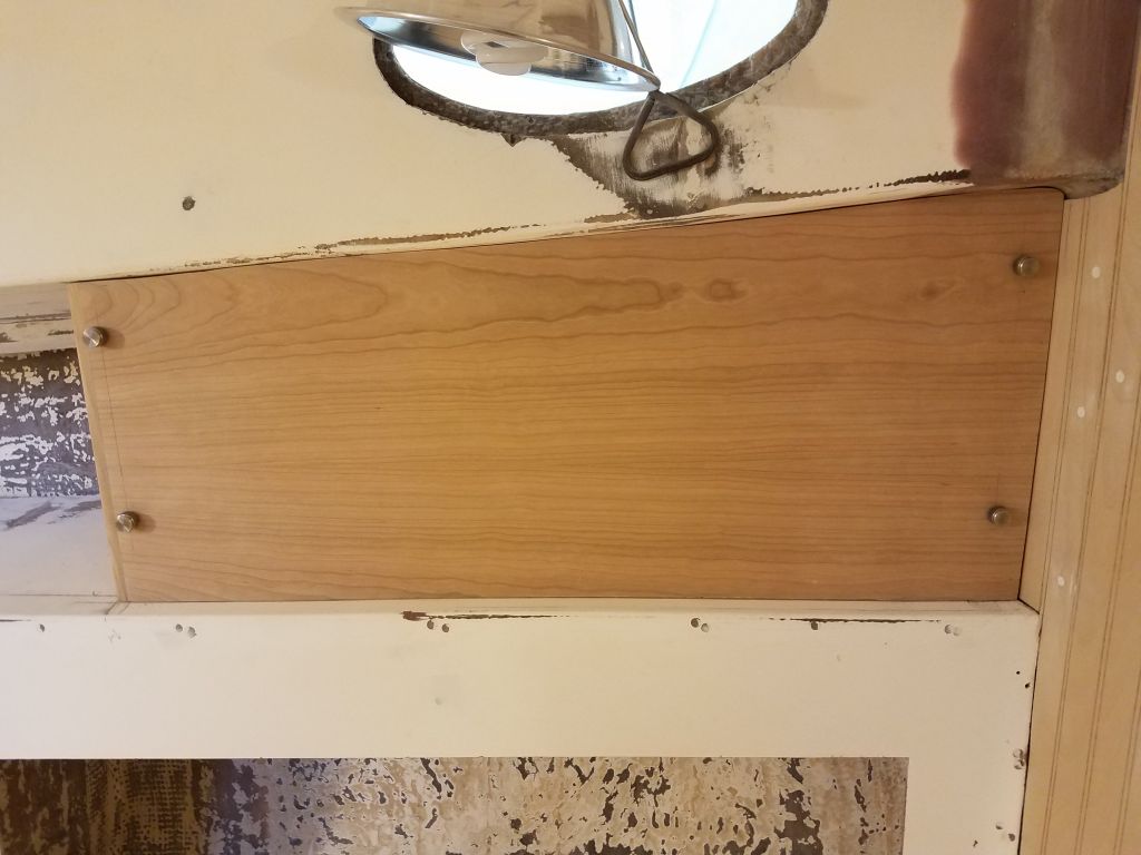
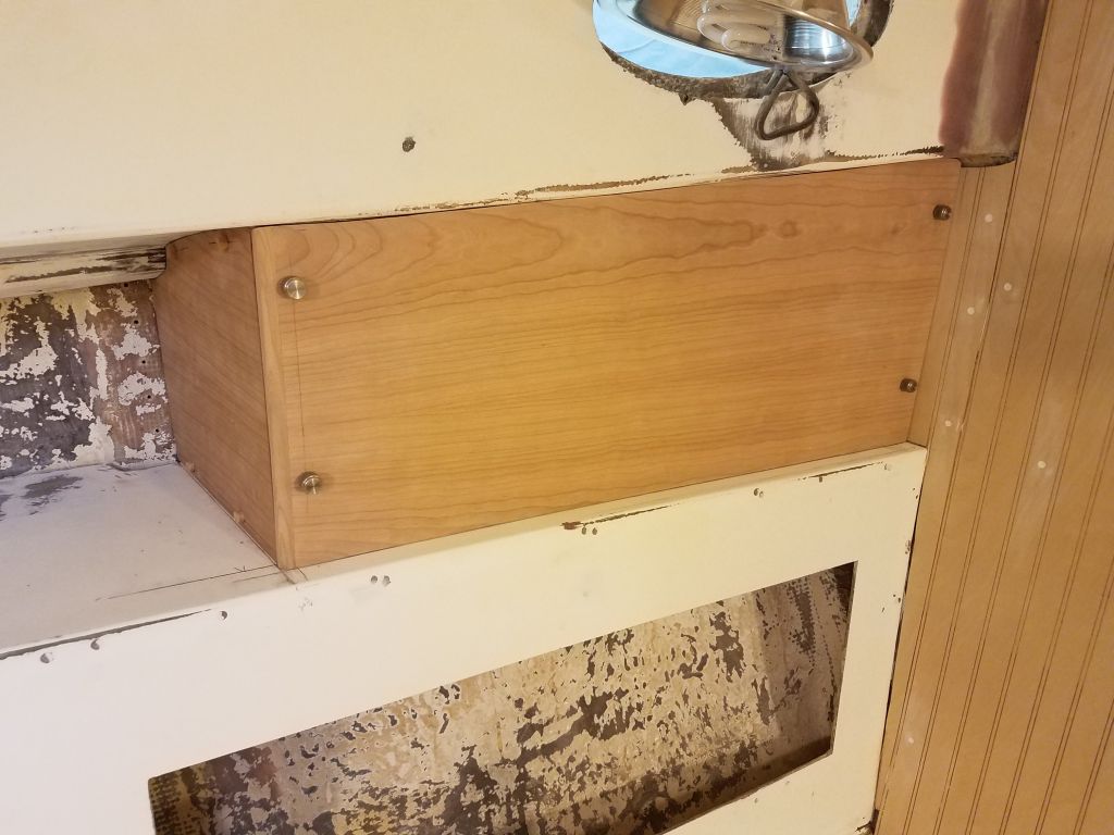
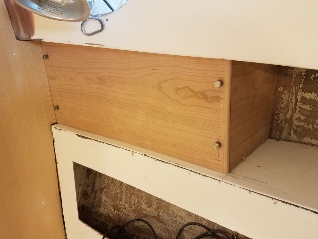
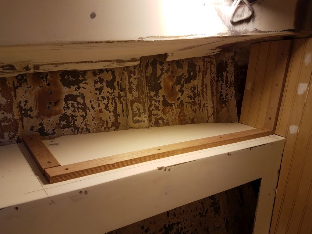
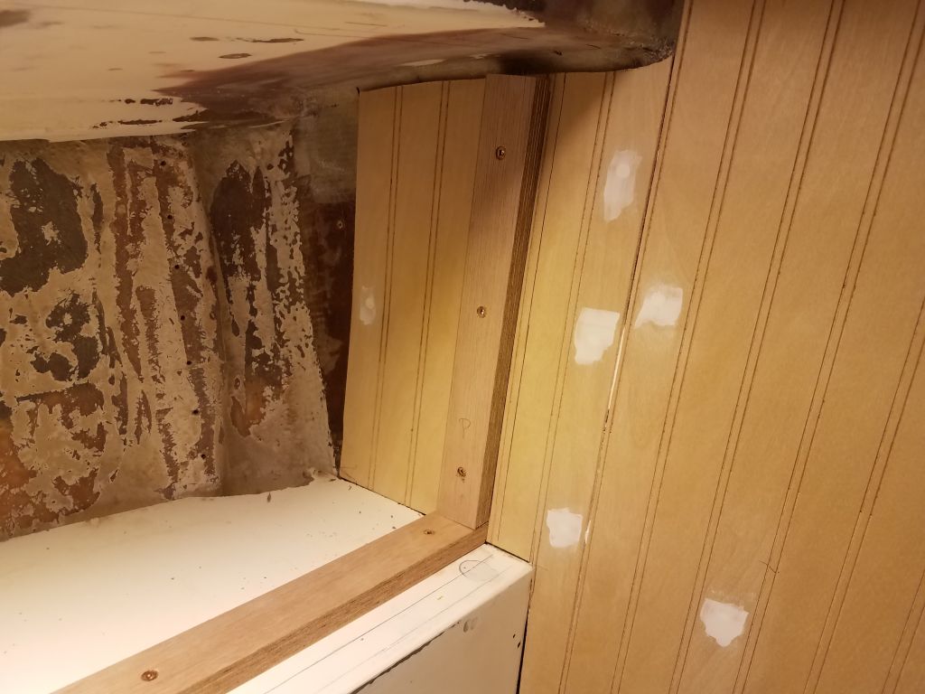
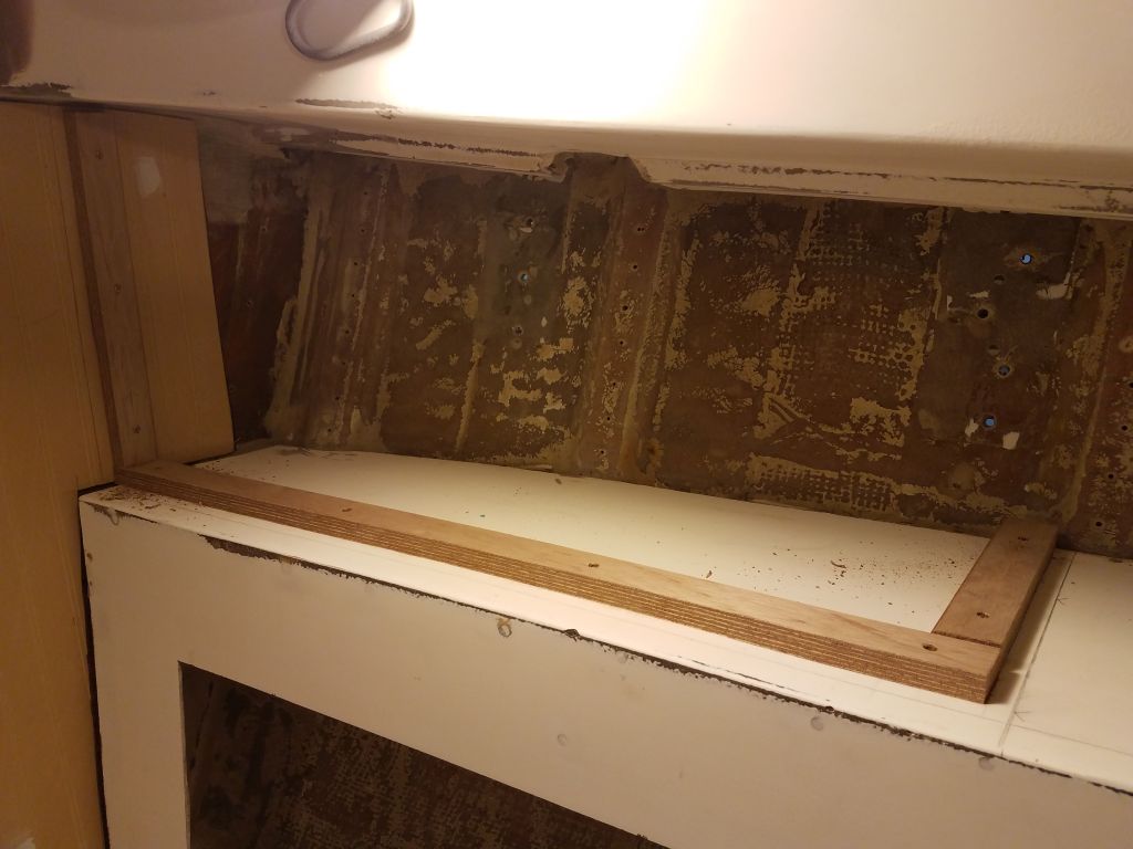
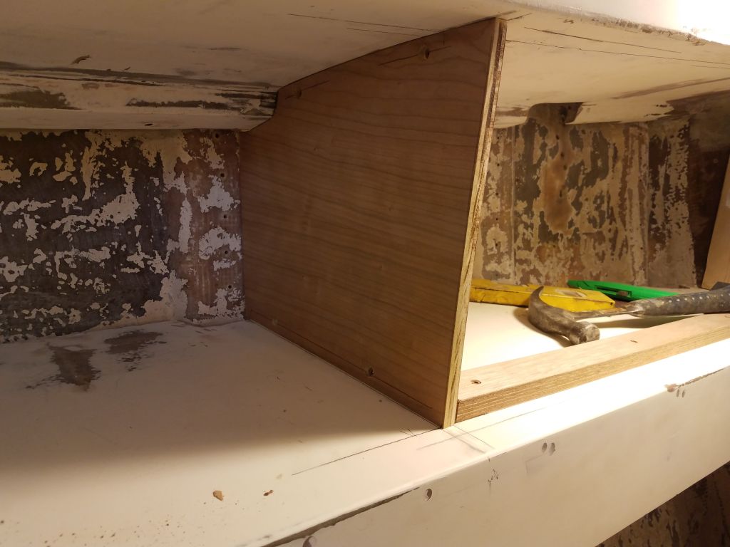
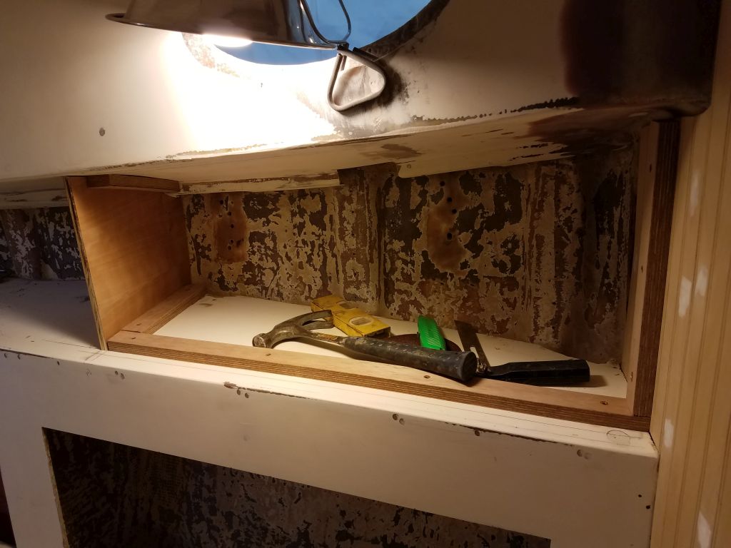
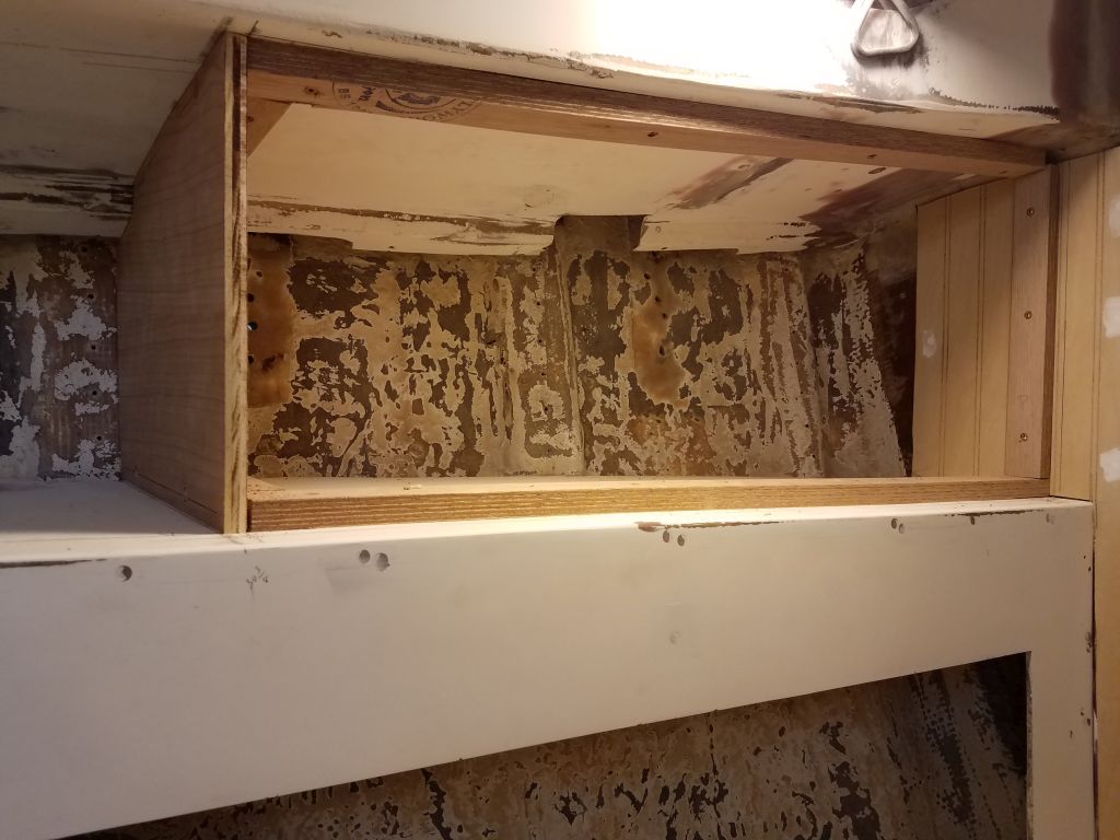
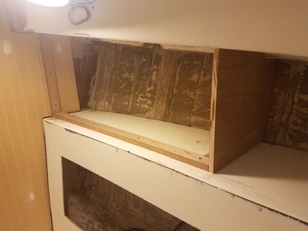
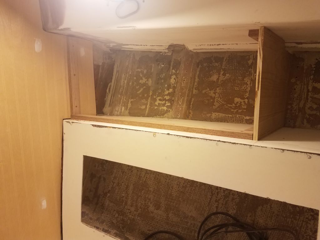
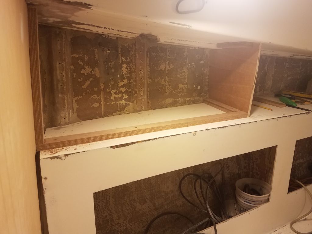
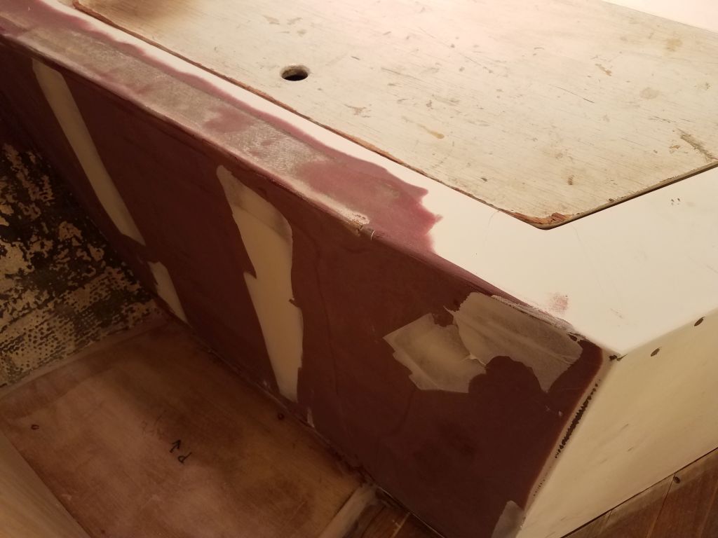
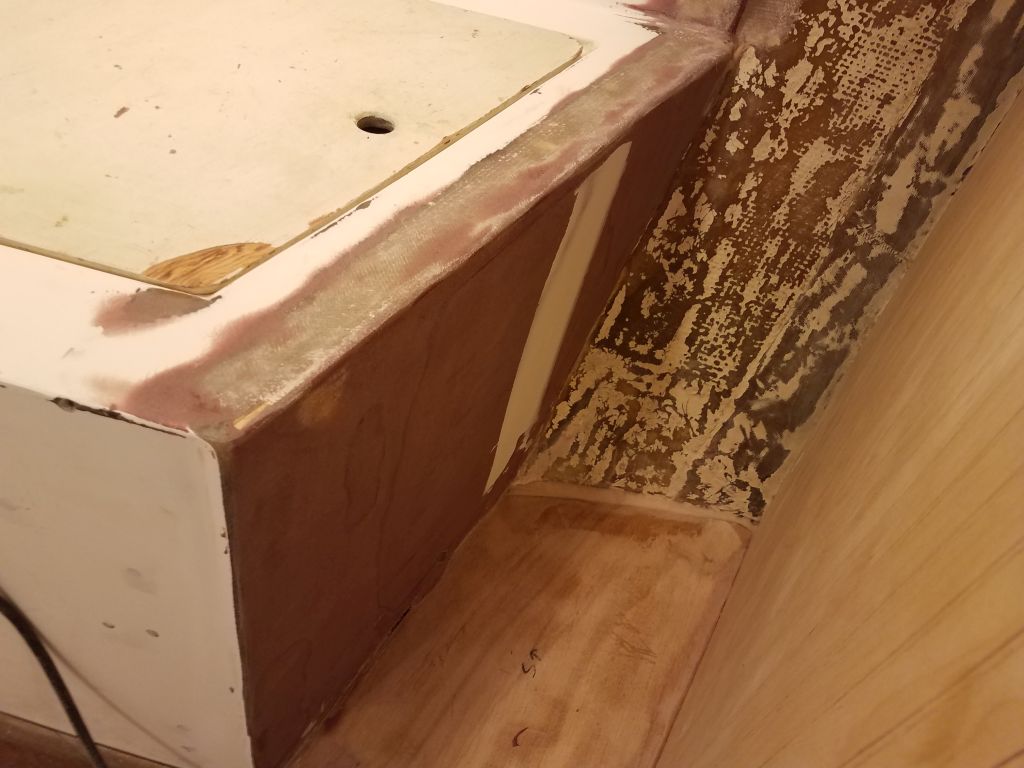
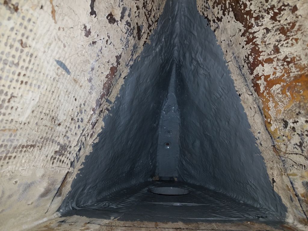
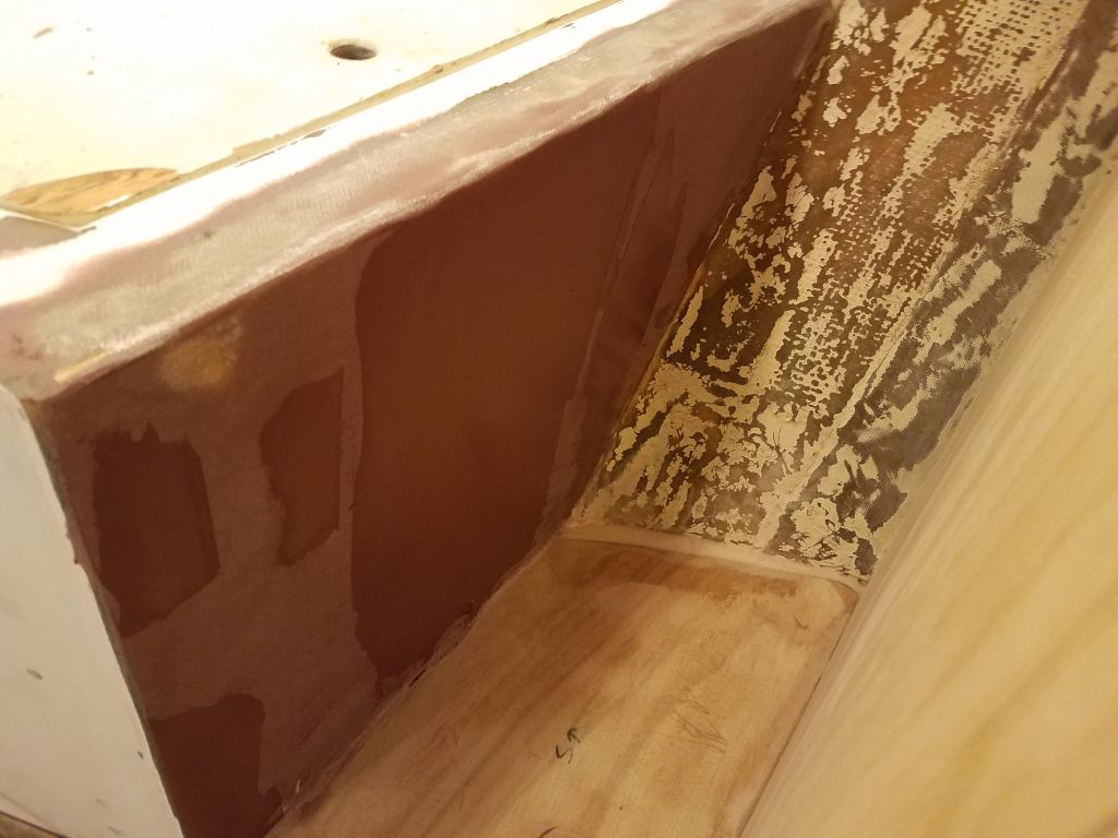
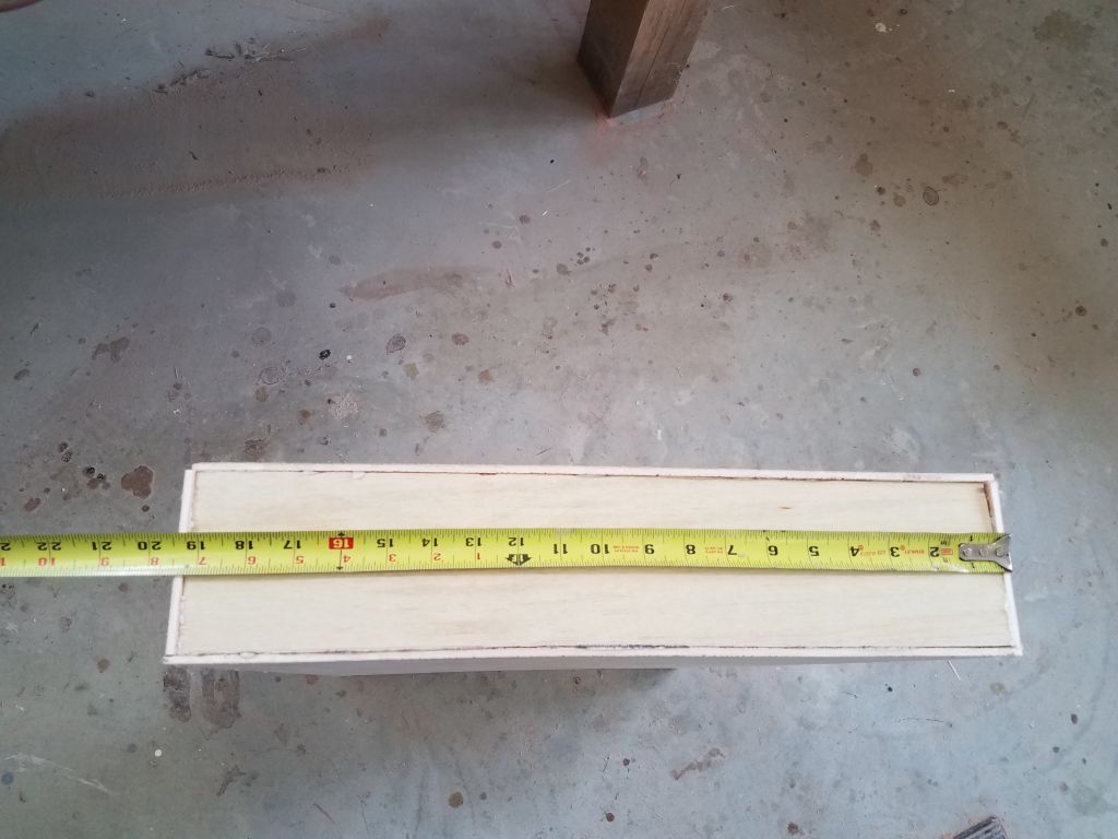
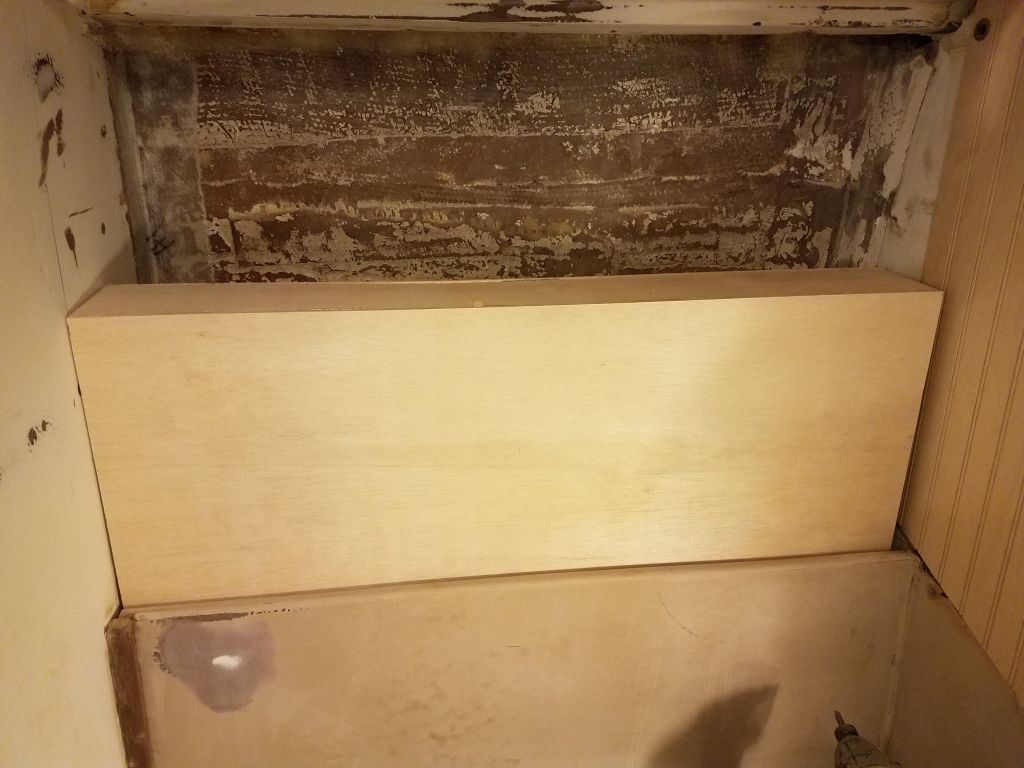
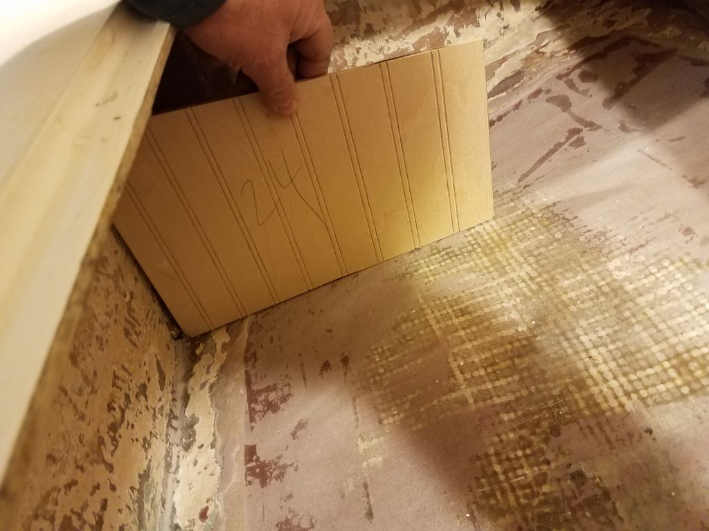
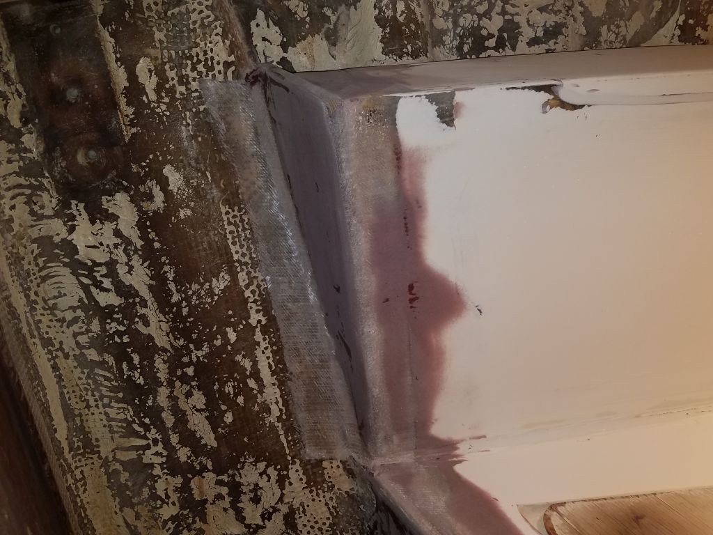
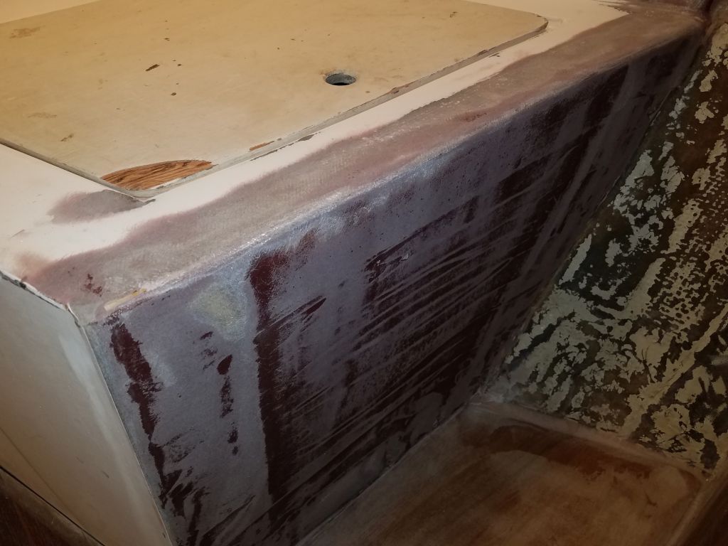
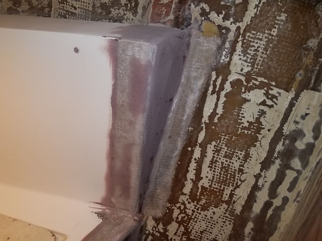
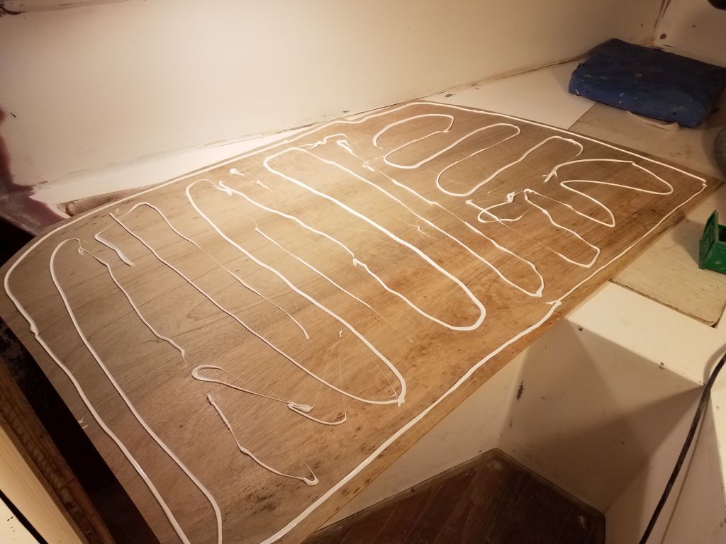
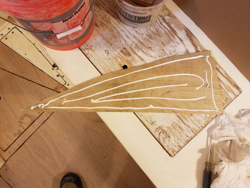
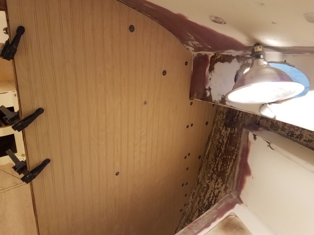
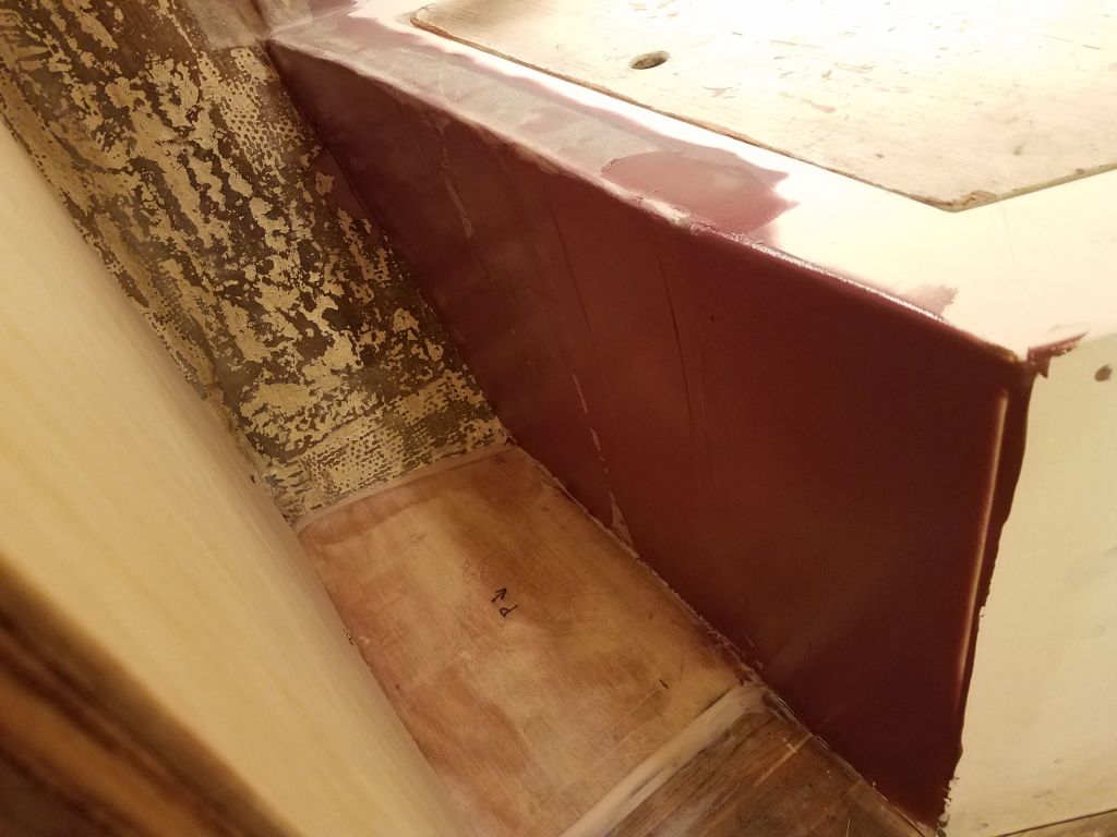
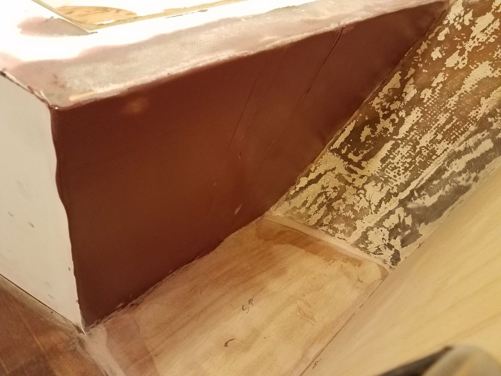
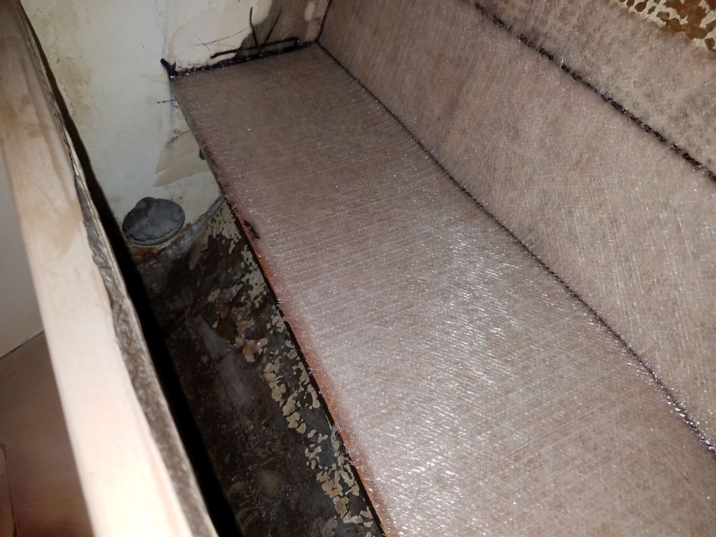
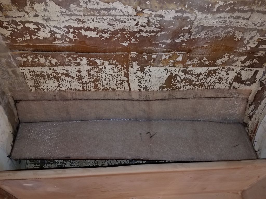
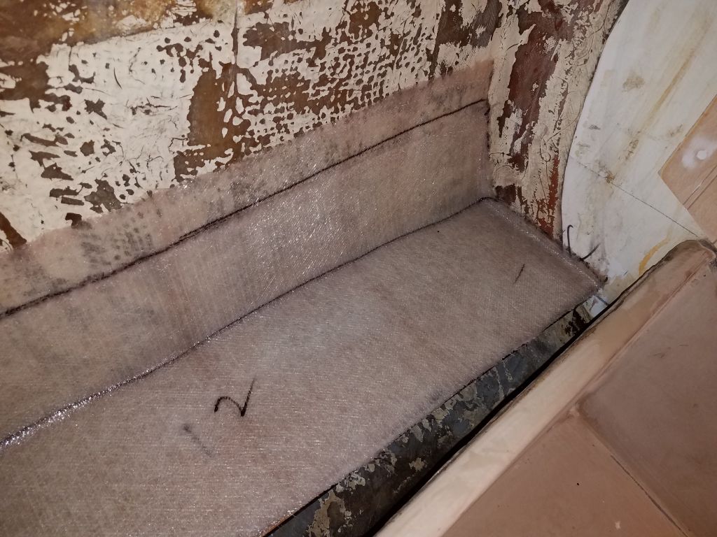
After cleaning up the space, I installed a pair of hardwood cleats for the ends of the platform, securing them to my marks with epoxy and screws, before installing the platform on the cleats and against the hull with more epoxy, and a pair of screws into the cleats just to hold it.  I coated both sides and all edges of the platform with epoxy before installation, and smoothed in a nice fillet along the hull and at any gaps at the ends.

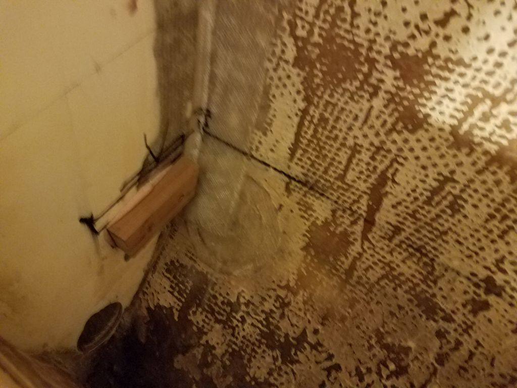
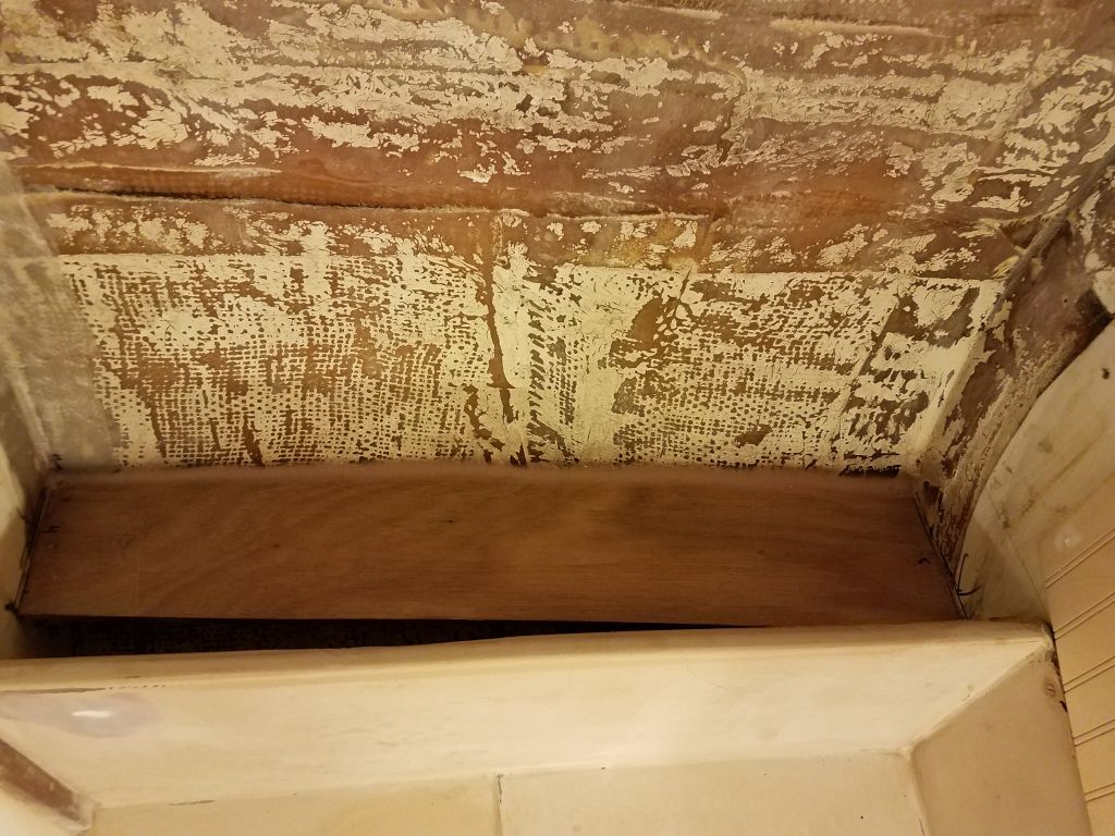
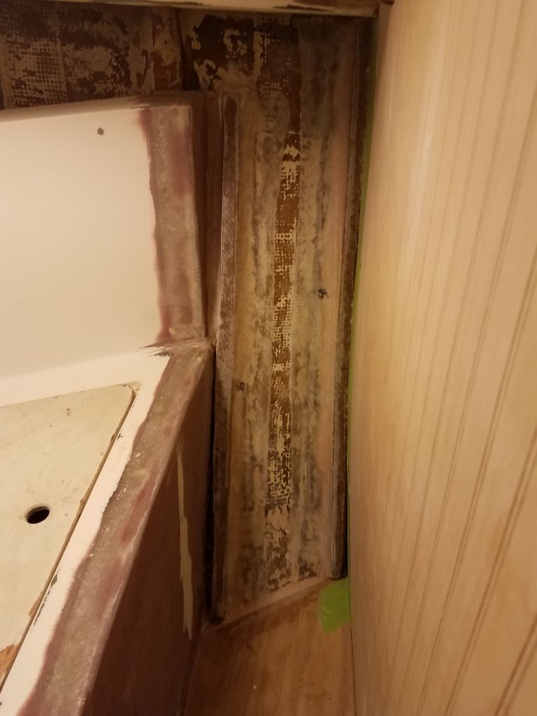
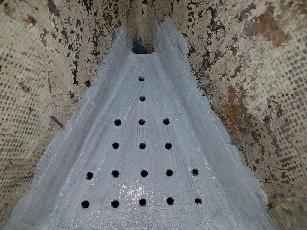
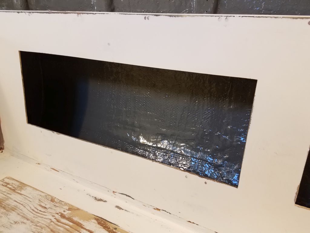
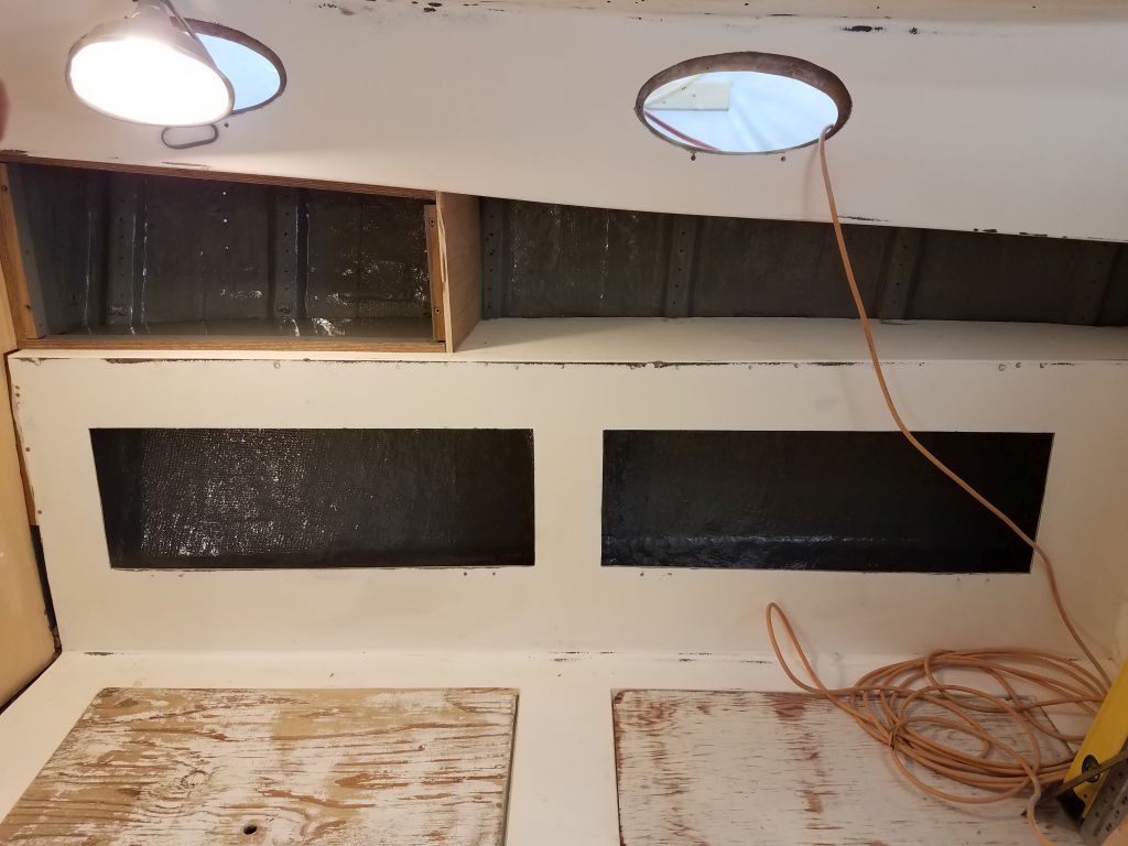
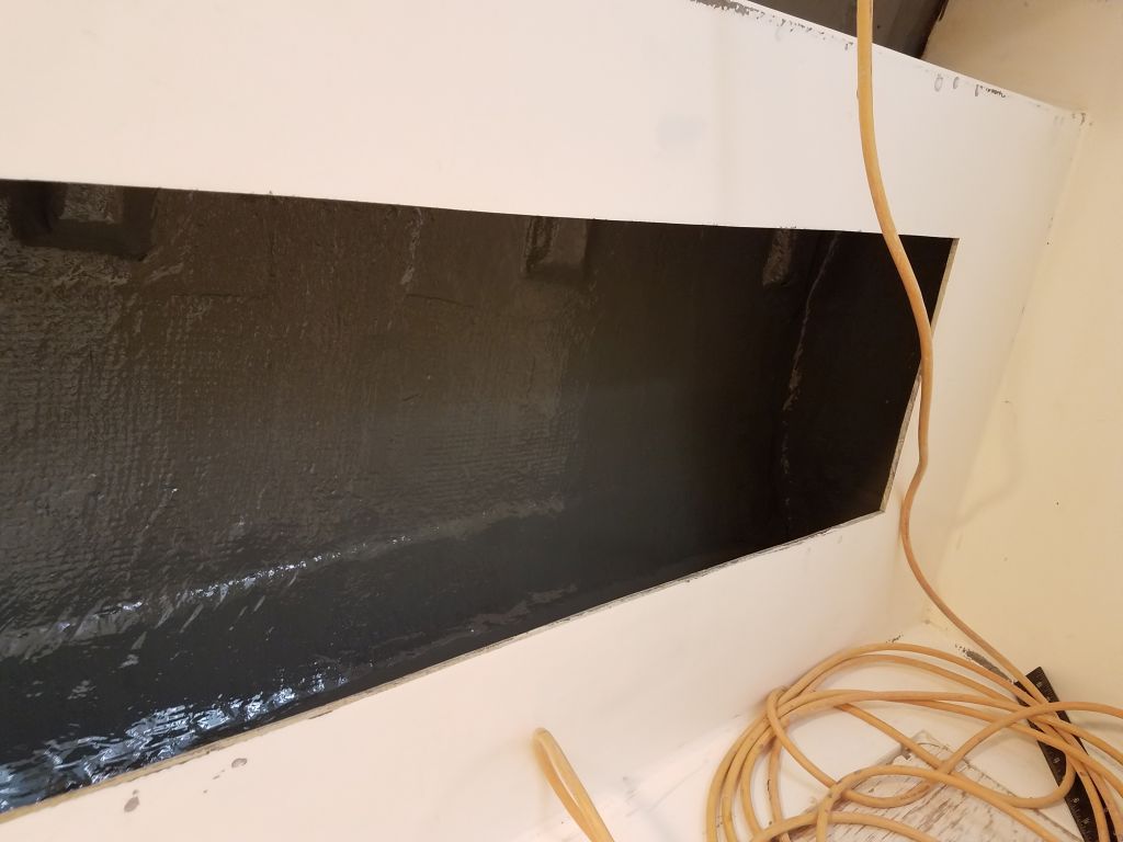
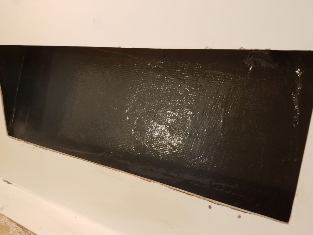
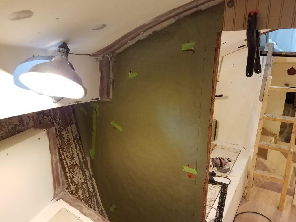
To complete the installation, I installed two layers of heavy fiberglass over the platform and up on to the hull.

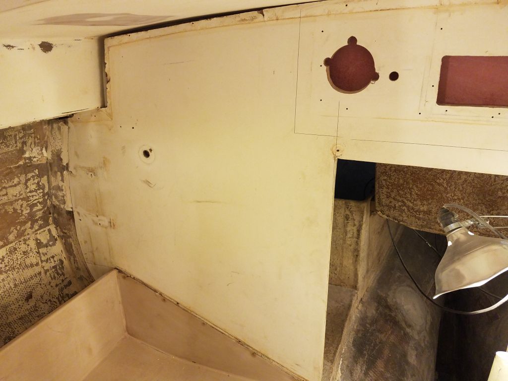
Now that I was on a roll, and anxious to finish up structural and epoxy work in the boat’s various compartments, I decided to work next on the new support platform for the boat’s electric propulsion motor (and please forgive me if by habit I lapse into calling anything here an “engine”).  With the basics of the system chosen by the owner now determined, I was ready to figure out the motor placement and also where the large battery bank would be stored.

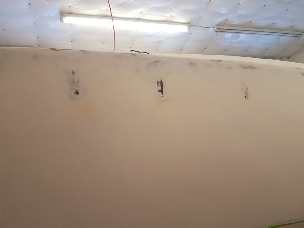
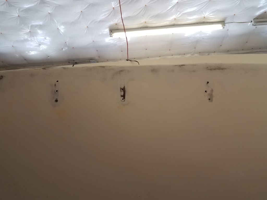
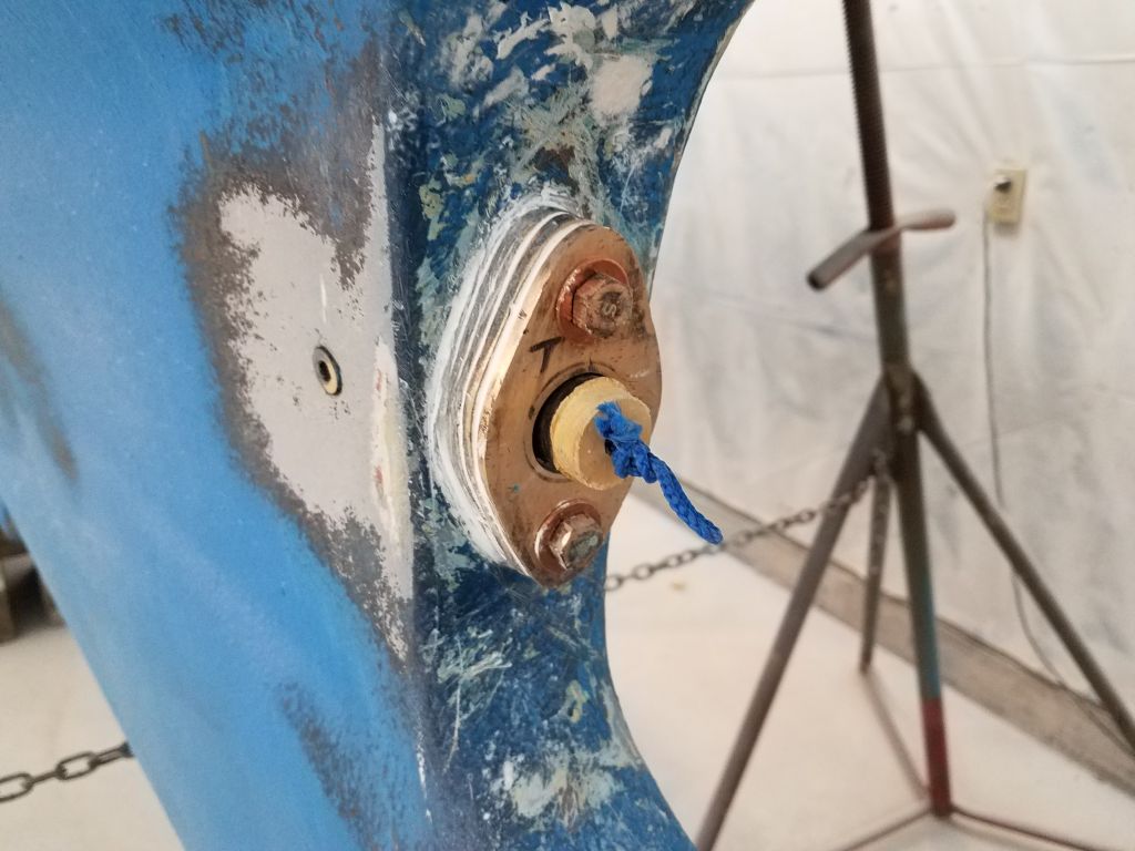
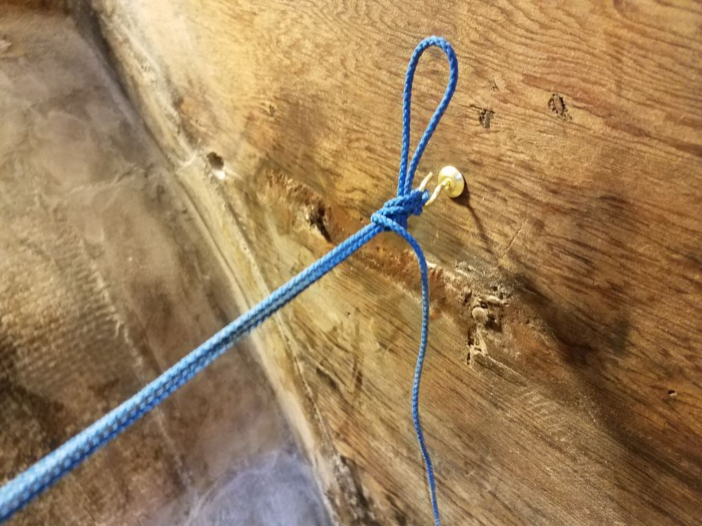
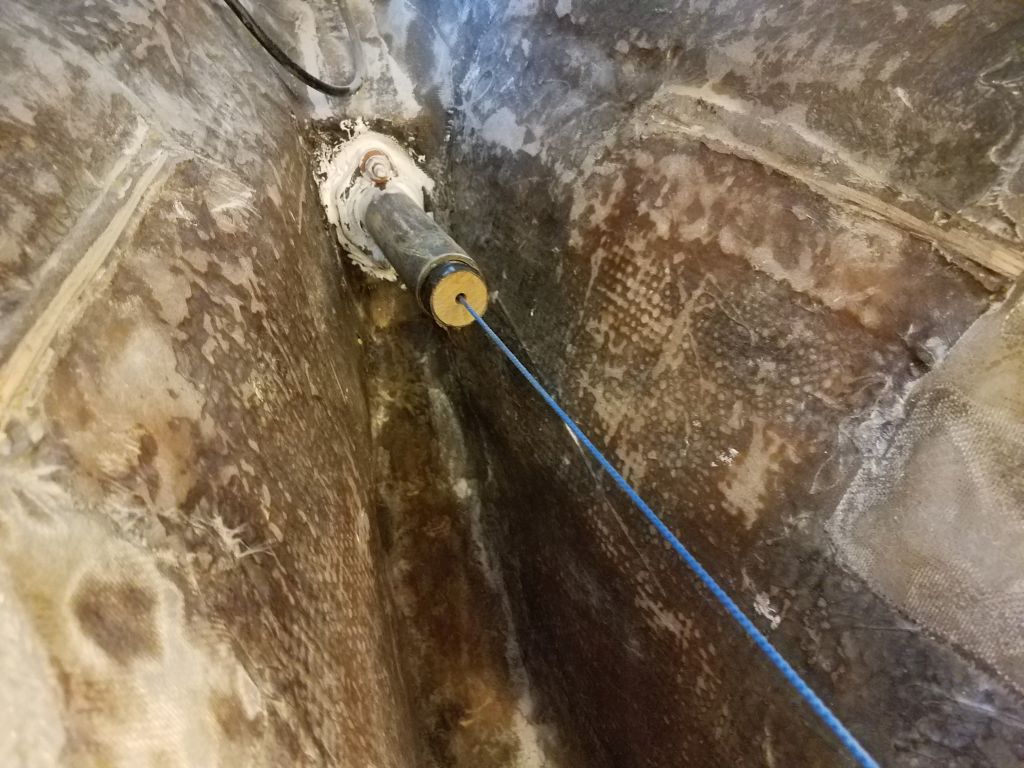
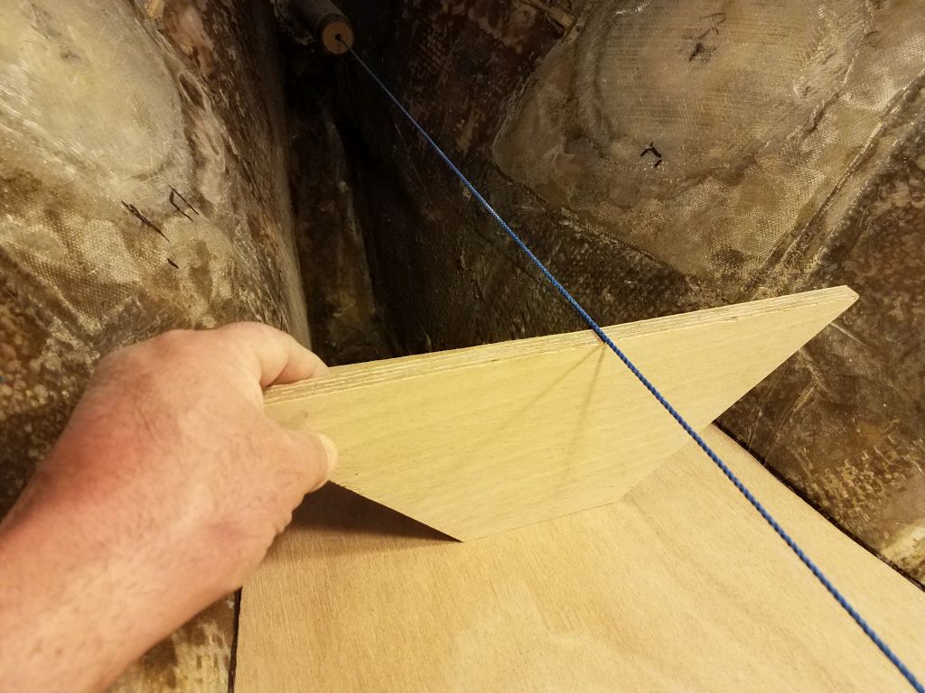
To begin, I set up a string through the shaft log so I could determine the shaft position and angle, which, as always, was the key reference point for such an installation.

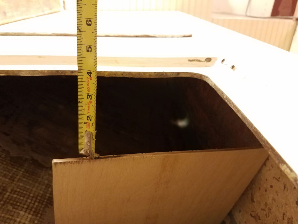
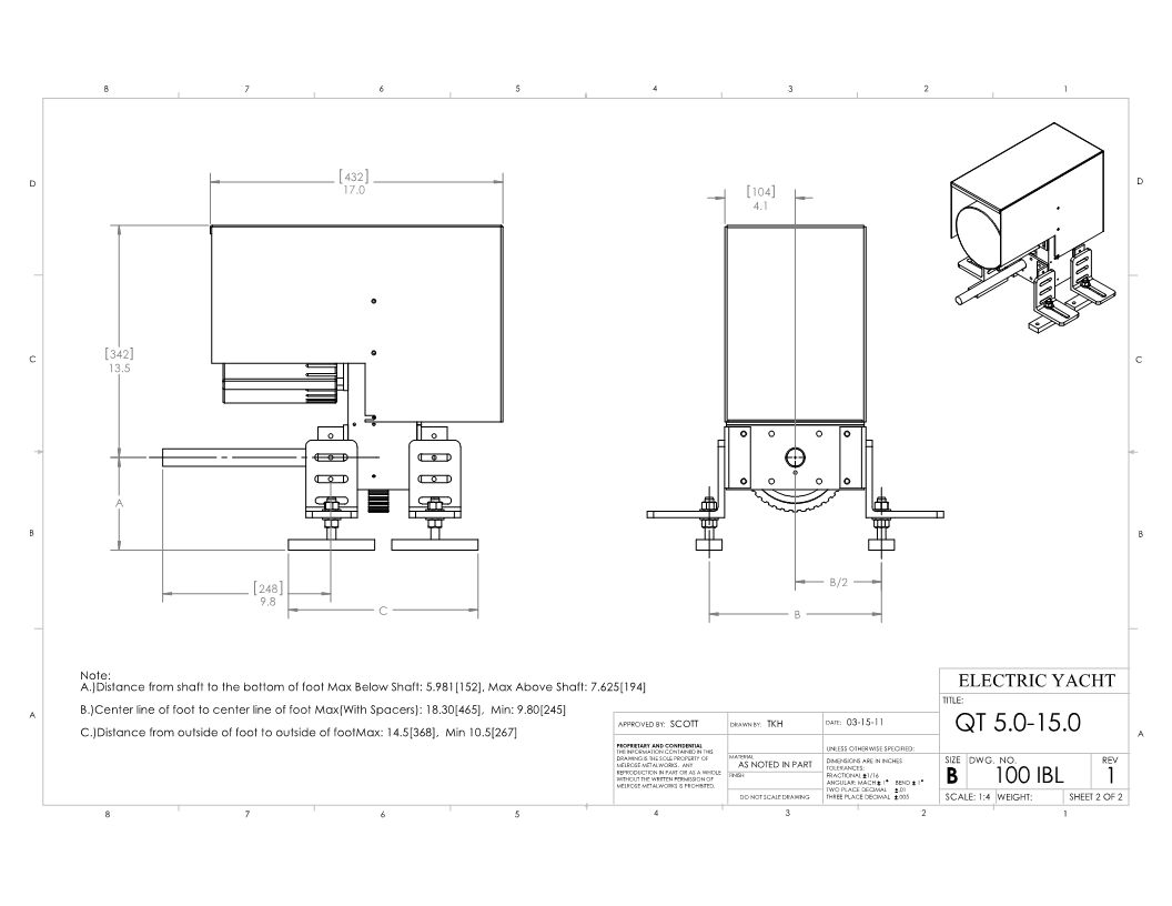
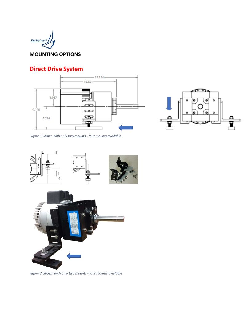
A great benefit to electric propulsion motors from my standpoint is that, because the motor is compact and lacks all the protrusions and low-hanging  transmissions and oil pans found in diesel engines, it can be mounted on a simple flat platform, and in this particular boat such a basic platform worked well with the given space in the engine room.  Using the reference drawing of the chosen electric motor, and the measurements contained therein, I chose as a starting point 5″ below the shaft centerline, which was well within the requirements of the motor installation itself and would also give ample room for minor adjustments in height later.  If, during final installation, I found it beneficial for whatever reason to add height to the platform, it would be straightforward to do easily and accurately, but the mounting system with this motor provided substantial adjustment capability for myriad situations.

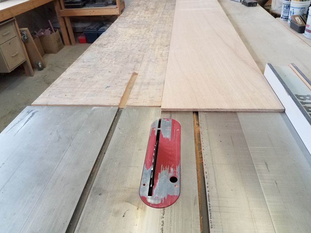
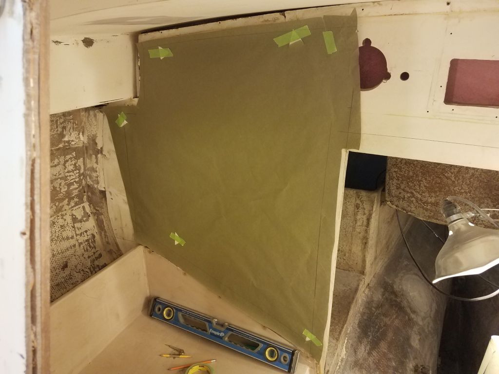
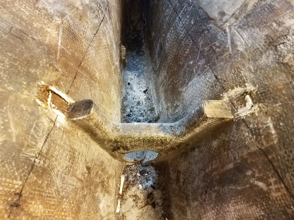
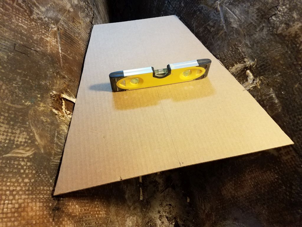
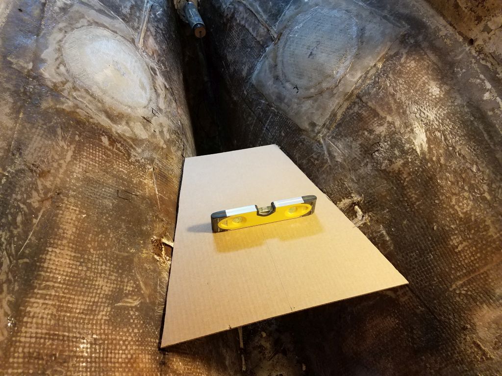
To transfer a starting baseline down from the shaft centerline, I cut a pair of plywood  pieces to 5″ in height, and wide enough (and with sharp angled ends) to extend from hull to hull in a couple different positions along the shaft line.  With the angled ends resting on the hull, I could level the plywood and then use a small straightedge held tight to the bottom edge to transfer a mark to the hull at the new, lower height.  I drew a line between the two points on each side with a flexible metal ruler.  Positionwise, I planned to begin the platform just at the forward edge of the old scupper locations (which would soon have new seacocks installed), and extending 18″ forward from there, which happened to be the overall length of the electric motor and housing, but mainly this platform size would give me final mounting options later, as the full length wasn’t required for the mounts themselves.

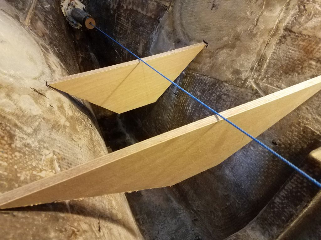
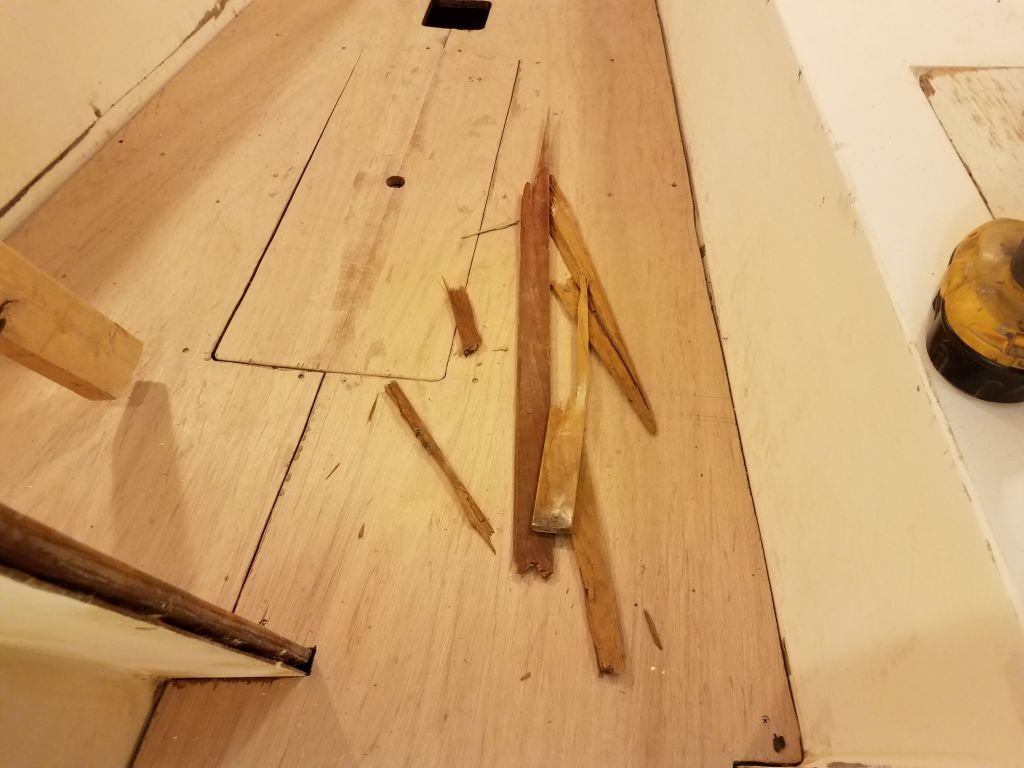
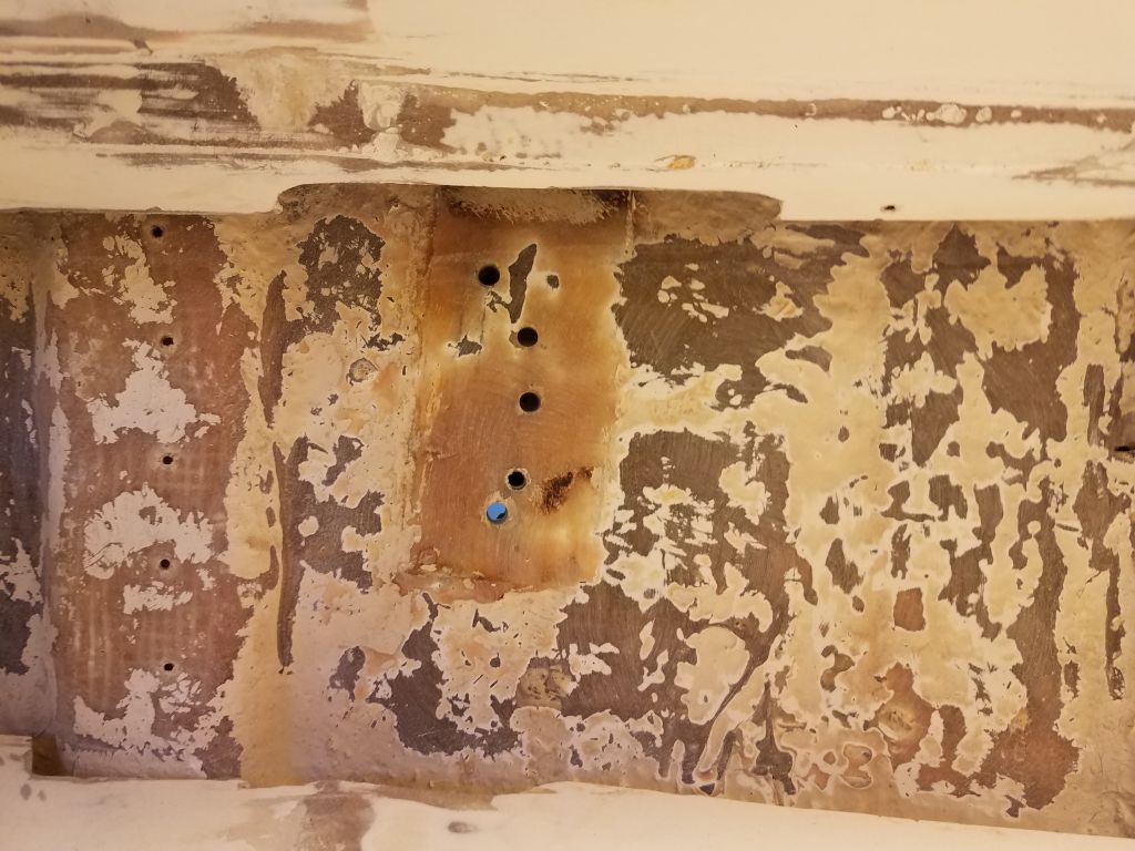
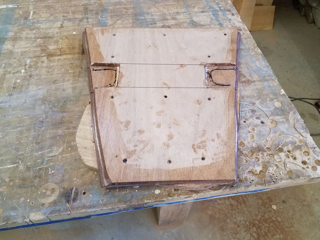
The line ran into the V-shaped small bulkhead that was leftover from the original engine installation, so as best as I could I transferred the new line around the support and cut off the top with a saw, which I found to be difficult in the small space, leading to bent blades and, on the starboard side, an inaccurate cut–but for the moment it was good enough.  Now I could continue the line forward as far as needed, after which I measured for and cut a basic plywood template to fit.

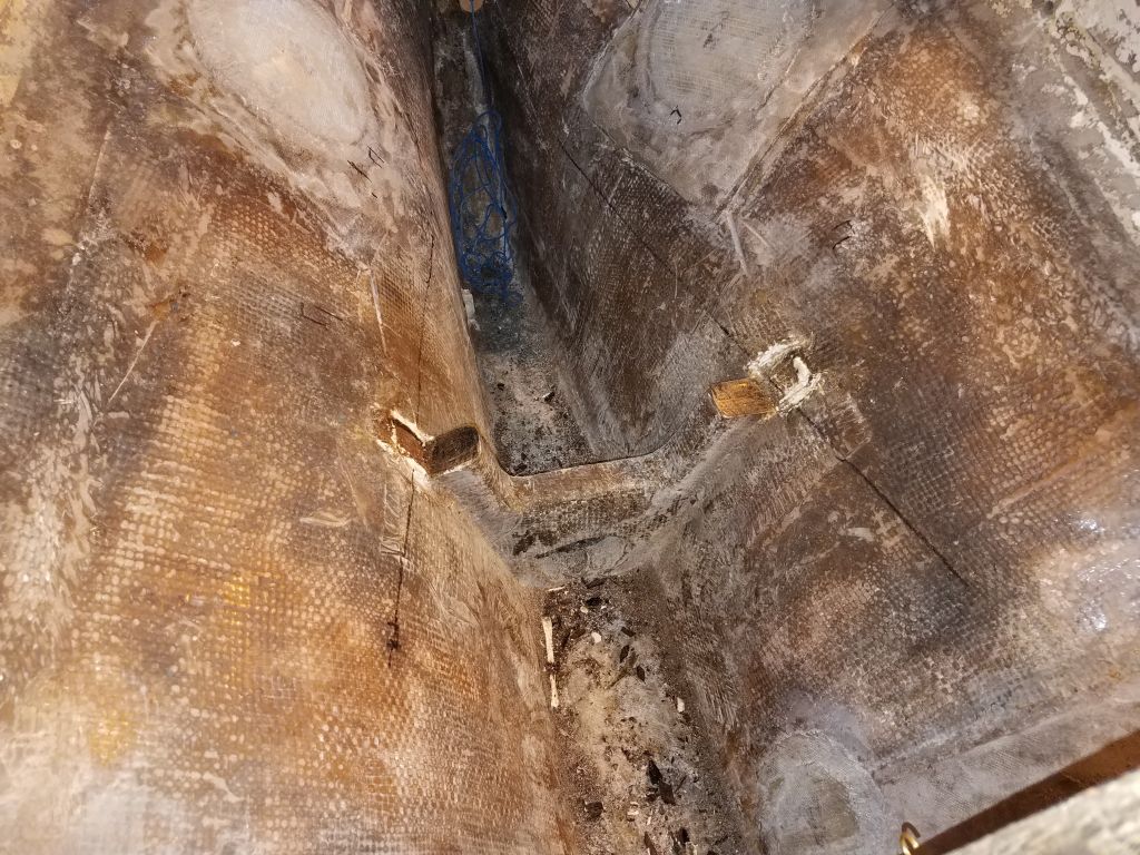
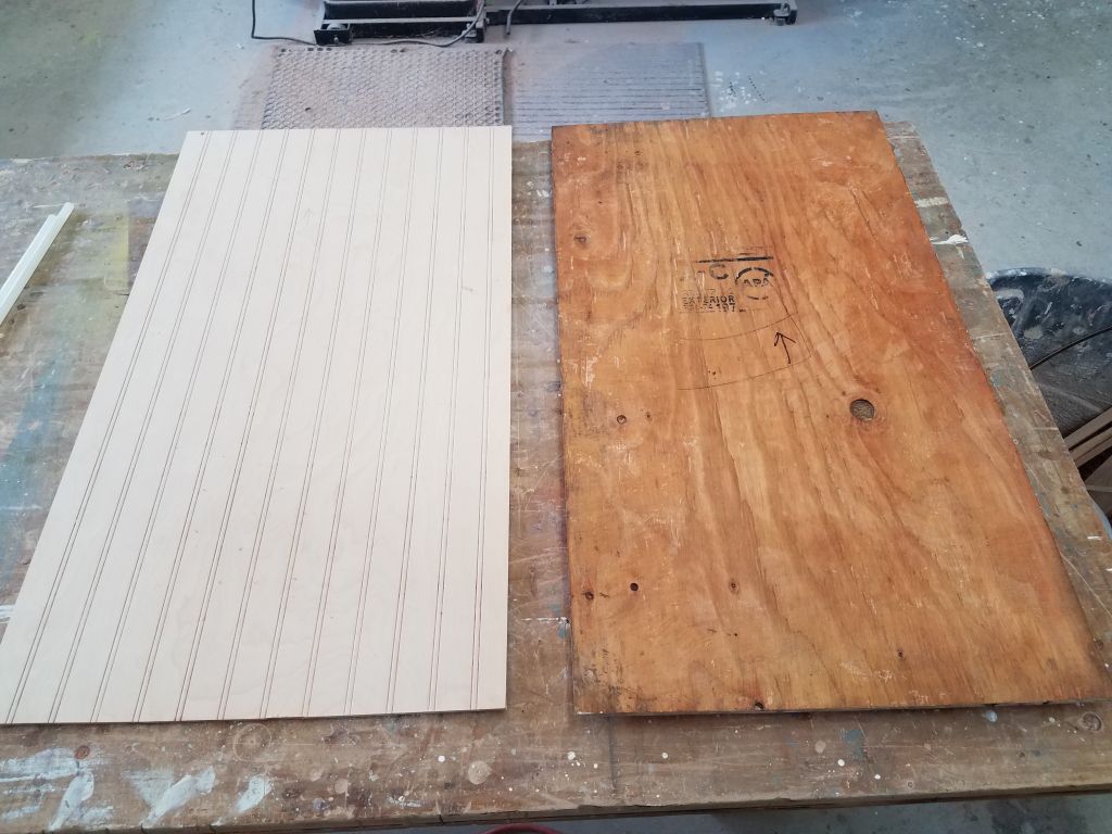
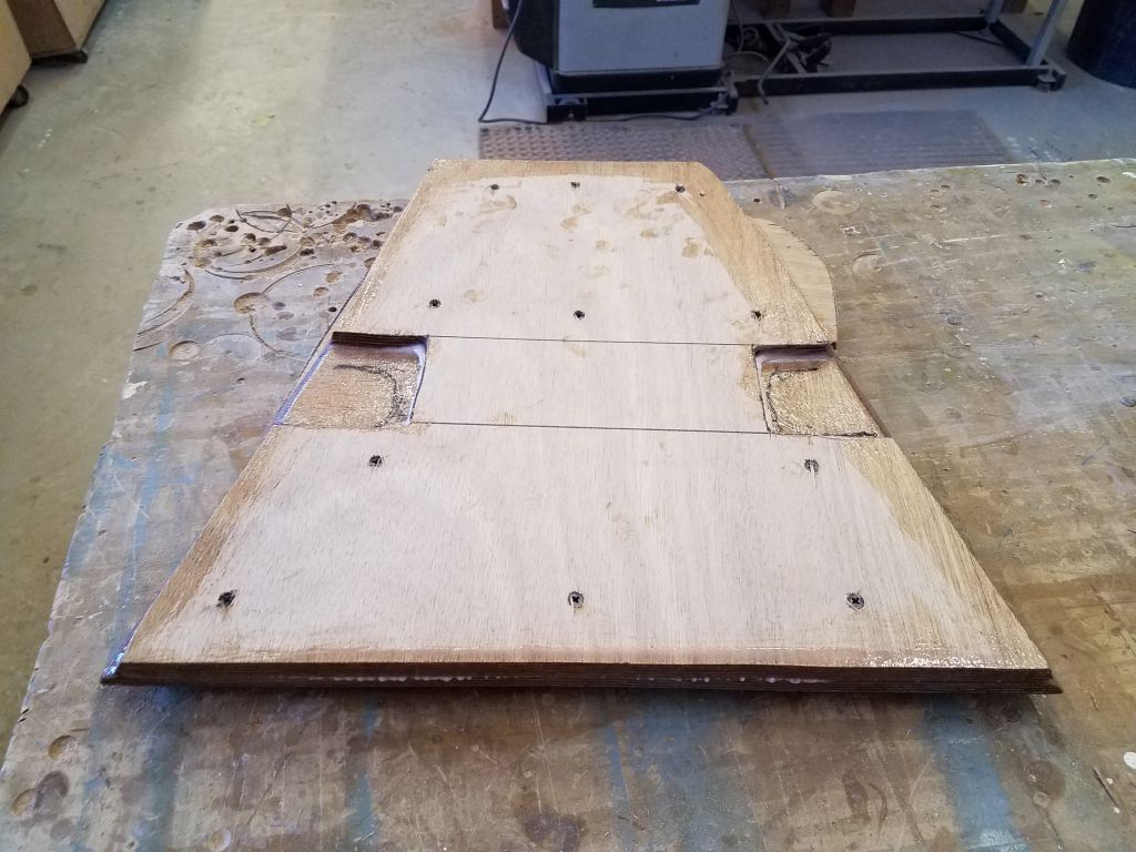
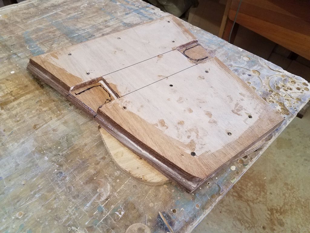
My first cut on the old support had allowed the cardboard to pass by, but I wanted the final platform to rest just on top of and wrap around the existing support so as to incorporate it into the new structure.  I planned to build the platform from a laminate of 2 thicknesses of 12mm plywood, so I made new marks on the top of the support using a scrap of the plywood as a guide, then cut to the new marks with a grinder and cutoff wheel, which was accurate in the confining space  but created lots of wood smoke from the support’s plywood core.

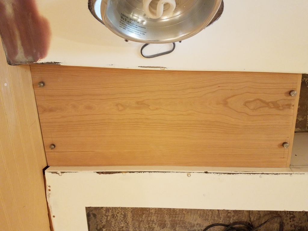
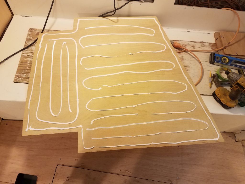
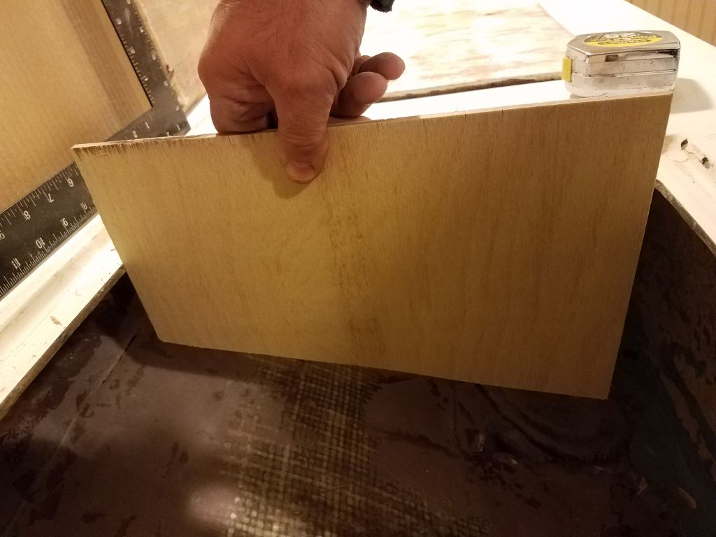
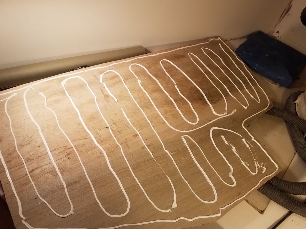
Now I transferred the template shape to one sheet of 12mm plywood, and after some minor adjustments fit the piece in place, level from side to side, in the proper longitudinal position, and 5″ below the shaft centerline.

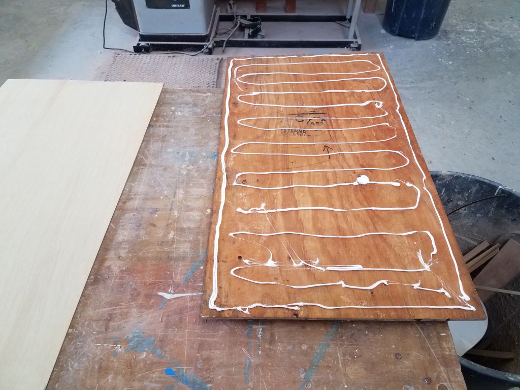
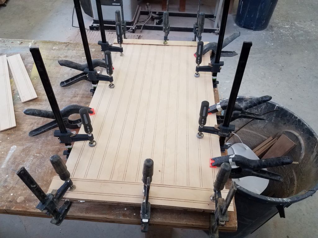
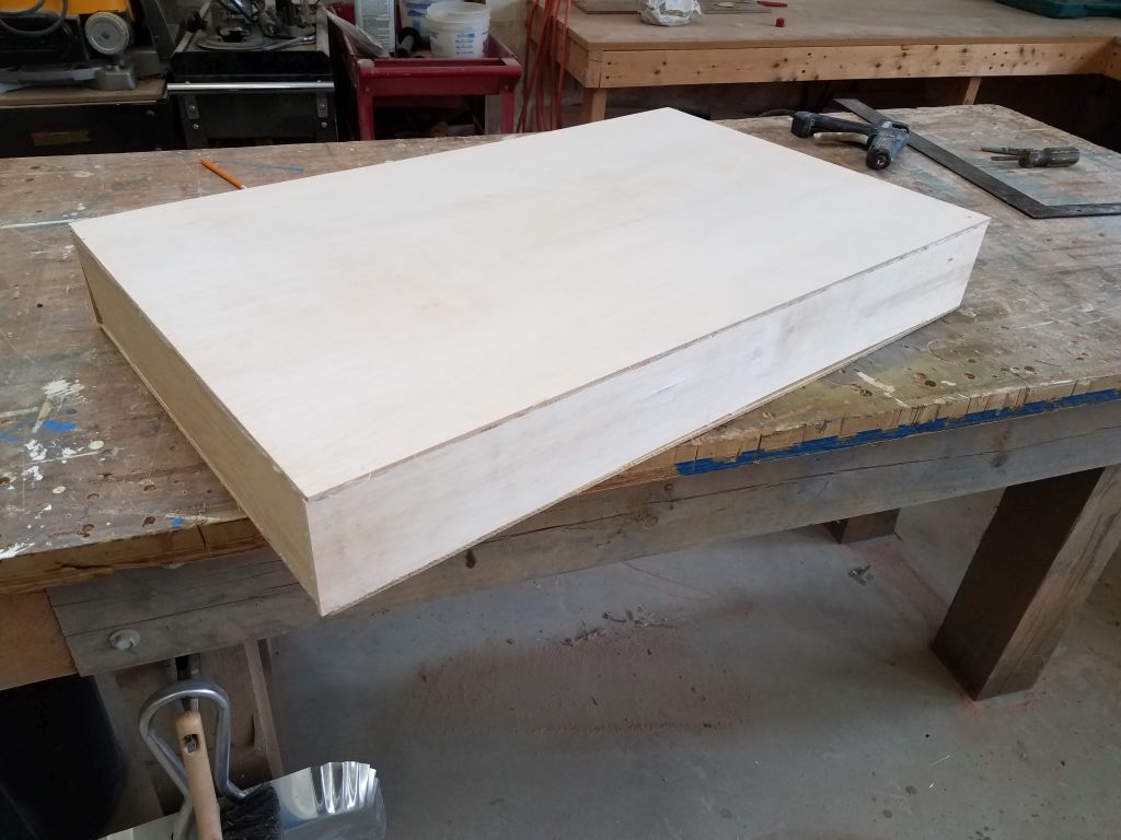
My last task before knocking off for the day was to use the first piece of plywood to transfer the shape to a second layer, which I glued to the first layer with epoxy adhesive after cutting out little notches in the bottom layer to fit around the engine room bilge support.  I used temporary screws to clamp the two pieces together while the epoxy cured overnight.

Total time billed on this job today:  8.25 hours

0600 Weather observation:  8°, clear.  Forecast for the day:  Sunny, 24°

Scupper 92

Monday

Preparing ahead to be sure we were on the right track in the head, I printed out a full-size template of the owner’s chosen unit, the Marine Elegance, so I could test its fit in the head compartment.  I used the included measurements to check the accuracy of the size of the printout and then cut out the template, which I then test-fit in various positions on the platform in the head compartment.  The cutout, which represented the overall size of the bowl and base together, seemed to fit well in any of the possible positions, and with room for adjustment in the final position, so with that step out of the way we could continue planning accordingly.  Actual installation would be some time in the future.

Much of my work in the cabin during this week would focus on various chores required before I could begin the primer on all the paneling and fiberglass surfaces, and this meant taking care of numerous smaller tasks throughout the spaces with this overall goal in mind.

In the forward cabin, I lightly sanded the new fiberglass over the ceiling support cleats at the aft end of the space, completing the basic work there.

Next, I turned to the galley countertop.  Using marks I’d made on the bottom of the substrate earlier, I cut out the opening for the stovetop and then, with nothing else standing in the way of final installation, secured the plywood substrate to the fiberglass galley with polyurethane adhesive and screws.  The finished countertop surface would come a bit later.

At the main bulkhead, relating to the new sliding door trim, I made various measurements and recorded some compound angles for the ends, then transferred these to the ends of the trim blank I’d made earlier till I could fit the piece in position.  The bulkhead itself had some curvature at its lower edge, which I’d known in advance and planned for in making the blank so I could scribe it to the actual shape.

After scribing the bulkhead to the new trim, I cut the trim as needed and eventually achieved a decent fit in all areas as required.  There’d be some additional milling work on the trim to prepare the grooves for the doors, which groove I planned to line with slippery plastic for better operation, but that would come in just a bit once the new materials I required arrived.

I also worked briefly on the companionway ladder.  Using the old one as a general guide, I prepared a piece of new 12mm plywood for the backing for a new replacement ladder (and head doorway).  I chose to do this now because I needed some of the plywood for other uses soon, but first wanted to set aside the large piece required for the ladderway.  I’d continue working on the ladder later, but for now I set it and its new plywood backing aside.

There were many directions I could go and projects I could do, but as I was having a little trouble focusing while I impatiently waited for the snow to end so I could head out and clean up from the storm, I spent a little time beginning the layout for the main cabin overhead, which required a cosmetic veneer of painted plywood to hide the existing fiberglass liner, which was riddled with holes and poor repair work.  I laid out a longitudinal centerline, along with a known seam location corresponding with the companionway opening, then began to work out other seam and trim locations that in the end would make the overhead look good.  More to come on this project soon.

With snow over with and cleanup outside complete, I returned to the shop in mid-afternoon, with an hour or so to kill before I could start the epoxy pre-primer work on the new fiberglass in the forward cabin and elsewhere (I left this till the end of the day because of the strong paint fumes), so I decided to cut holes in the settees and v-berth for some little vents that I’d bought to satisfy the owner’s request for natural ventilation through all the lockers.  I chose round louvered vents made from cherry to match the rest of the cabin trim, and now armed with an appropriate hole saw, I laid out for and drilled six holes (two in each main cabin settee, and two in the v-berth) for the 4-1/2″ round vents.  I’d pre-finish the vents and install them permanently later, once the cabin paintwork was complete.

After final preparations, I went through the forward and main cabins and applied a coat of epoxy-based primer to all the recent glasswork and fairing compound, including the new chainlocker floor, bulkhead tabbing, v-berth ceiling cleats, and other areas throughout.  This primer coat was required  in order to allow one-part paints to cure over the fresher epoxy (some of the work was old enough that it wouldn’t likely be a problem, but I pre-primed it regardless).

With just a bit of time left in the day, I worked in the woodshop to select several cherry boards that I’d soon begin milling into the various fiddles and other trim for the cabin.

Total time billed on this job today:  7.75 hours

0600 Weather Observation:  30°, snow, an inch or two down.  Forecast for the day:  Snow, 4-8″ total, then clearing.

Scupper 91

Friday

After removing the braces and temporary glue blocks from around the cleats in the forward cabin, I touched up all areas with a sander to slightly ease the edge of the wooden cleat and prepare the now-cured epoxy fillets for additional work.  Then, after appropriate cleanup, I filled in the gaps in the fillets in those areas where it was necessary (where I’d worked around the glue blocks earlier).

Meanwhile, I prepared tabbing to lay over the cleats and fillets, and once I’d cut the pieces I wet them out and installed them on both sides.

In the main cabin and galley, I focused my efforts on final preparations for painting out the inside of the hull and some of the lockers.  I chiseled away the excess bungs from the cherry panels at the aft ends of the new lockers, and sanded the plywood smooth before vacuuming and solvent-washing all areas to be painted.  I moved most of my tools and other supplies into the forward cabin for now.

Preparing ahead for the eventual electrical wire runs to the new cabinets above the settees, I installed glued-on wire tie mounts throughout the lockers and wherever I thought they might be needed or handy later; since these mounts don’t stick to paint, I had to do it now.

One of my favorite steps in any large project like this is when it comes time to start painting the raw, sanded hull and lockers with bilge paint–often one of the first true finishing steps that signals the beginning of a new direction.  Now, I painted the exposed areas of the inside of the hull in the main cabin, along with the insides of the new electrical lockers I’d built, plus the upper cabinets behind the settee backs.  I also painted out the upper areas of the galley cabinets, including the drawer area and sink cabinet.

I used the day’s remaining time to set up my planer and plane smooth and clean all the teak I’d reclaimed from the old trim, and which I planned to use for the galley countertop.  I began with a pass over the saw-cut side of each plank, then flipped them and ran them all through the planer to remove the old surface and finish and dimension each piece identically to 1/4″ thickness.  The wood beneath the old finish looked terrific.

Afterwards, I trimmed each piece on the table saw to remove the edges as required, leaving me with a nice stack of teak ready for installation.

While the planer was out, I also cleaned up the newly laminated cherry stock for the forward cabin door frame.

Total time billed on this job today:  7.5 hours

0600 Weather observation:  0°, clear.  Forecast for the  day:  Sunny, 30s

Scupper 90

Thursday

In the forward cabin, I removed the braces from the port ceiling support cleats, which stayed in place despite the challenges in their initial installation.

With lessons learned, I turned to the starboard side.  Here, once I dry-fit the cleats and braces, I added some hot-glued support blocks here and there to help hold the cleats in place once I’d applied the adhesive during installation, since slippage of the cleats had been the biggest issue on the opposite side.

Now I applied the adhesive to the cleats and reinstalled them with their braces, with no drama nor difficulty this time.

Leaving the forward cabin alone for now while the starboard cleats had a chance to set up, I briefly sanded the various hole patches on the bulkhead paneling in the main cabin, galley, and head.  I’d reassess all areas once I’d applied primer and refair any of the holes should it seem necessary then, but for now I called it good.

Behind the top corner of the starboard settee back, sometime earlier I’d removed an old, nasty, and ineffective support cleat.  Now, I prepared a new hardwood cleat to help support this area, and installed it with adhesive and screws.  Since I had the polyurethane right on hand I used it for the installation.

Down in the shop, I unclamped the edge banding I’d installed on the face panels of the new upper cabinets in the saloon, and trimmed the top and bottom flush and shaped as needed so I could test-fit once again.  I’d left the solid cherry edge a bit wider than it needed to be so I could mark it exactly to the aft bulkhead and cut to the proper size, which I did now.  Then, I rounded the outer edge and sanded the panels and edges smooth.

To secure the panels but allow for easy removal for electrical access and the like, I planned knurled hand fasteners and threaded inserts.  To give me a place to install the inserts securely, I added teak cleats inside the opening, at the forward and after ends.  I secured the forward cleats to the existing plywood cleats with screws, but at the aft end I glued and clamped the cleats in place to avoid fasteners through the cherry bulkhead.

While I had the glue out, I installed cherry bungs in the fastener holes that secured the after sides of the lockers.

By early afternoon, I was ready for some more work in the forward cabin.  On the port side, I added epoxy fillets to the new cleats, not only adding additional strength to the installation but also easing the transition to the hull for easier fiberglassing later.

The adhesive to starboard wasn’t fully cured enough to allow removal of the braces and blocks, but I felt I could work around the area a bit, so I added fillets in all the available spaces, working around the little glue blocks for now.  This meant that next time, I’d be able to simply fill in the missing areas and continue with fiberglassing along with the port side, getting me caught back up with where I wanted to be on this installation.

Most of the jobs I’d chosen this week were designed to finish off various tasks required before I could apply primer (and eventually paint) to the whole cabin, but for the moment there wasn’t much more I could do to advance that specific goal, so I turned to the first of the new cherry trim for the cabin.  For various reasons, I chose to start with the lower (and upper) trim pieces for the doorway to the forward cabin.  Since I’d cut the opening down to sole level in the forward cabin, the new lower trim would not only incorporate the sliding mechanism for the doors, but would also extend all the way across the forward edges of the settees to double as the edge trim there.  Since we were starting to think about the interior cushions and upholstery, this extra trim piece would factor into the cushions’ design themselves, so even though I might not install it permanently for a while, it made sense to get started here.

The original door trims, which I’d saved for reference purposes, were one-piece milled with a groove for the doors to fit in, and I planned to emulate though not exactly duplicate the details.

To prepare blanks for the new trim, I needed to glue up a thicker blank from the 4/4 stock I had, so after various measurements I milled two long lengths for the lower trim (extending from settee back to settee back across the forward end of the cabin at berth height), and two shorter lengths for the upper trim, which would remain more or less the same length as the original.  Then, I glued up the pieces to create a thicker blank from which I’d eventually mill the new trim.  I used waterproof wood glue for the glueup.

The glue securing the new cleats in the saloon cabinets had now cured enough to remove the clamps, so I moved on with the installation of the panel fasteners and threaded inserts.  After taking some measurements to locate the desired positions of the fasteners, I laid out the panel fronts accordingly and drilled holes for the 1/4″ knurled-head fasteners.  With the panels in place in their proper positions, I marked the hole locations on the new teak cleats, then drilled for and installed the threaded inserts.   These required a 3/8″ hole, and for the installation itself I had a nice little installation tool to easily and accurately install the stainless steel inserts.

With the inserts in place, I could install the panels with their four fasteners.  I had some handles that I intended to install to help a user remove the panel easily later, but for the moment I decided to hold off on installation till I had a better sense of where the handles should go.

To round out the day, I removed one pesky last piece of original trim that I’d left inside the doorway to the head for some unknown reason.  This trim needed to go before I got to the primer application throughout the boat.  This required first removing a hook that was still in place, and then I quickly broke out the old trim and removed the screws once the wood was out of the way.

Total time billed on this job today:  8 hours

0600 Weather observation:  8°, high clouds.  Forecast for the day:  Becoming mostly sunny, 28°

Scupper 89

Wednesday

Following an early morning commitment elsewhere, I got back to work on the new cabinets in the saloon, starting with the final cleat on the starboard side, which I cut to fit and secured with screws.

For the front panels on each side, I started with cardboard templates that I scribed to the space, and used these to cut cherry plywood panels to fit.  I sneaked my way up to a close fit for the top and forward edges of the new panels, eventually achieving a good fit with the overhead.  For the moment, I let the after side run long past the aft bulkhead.

Once the panels were well fit, I marked the aft ends of the panels where they passed the aft bulkhead of the lockers, then cut the panels to length.

Once I had the panels’ final lengths set in this way, to cover the edge of the plywood face panel I trimmed another 1/2″ from the panels at the aft end, and glued on slightly oversized solid cherry strips that would provide the finished appearance  once complete.  I planned to trim these to exact length with the panels in place.

In the forward cabin, I needed to install a pair of new ceiling support cleats on each side in the newly-opened areas aft of the berth.  The existing cleats throughout the boat were about 3/4″ tall, so I prepared four pieces to the proper lengths from some leftover teak, which happened to be leftover from some previous toerail or another and already had an angle cut on one side, which is the profile I wanted for these pieces.

To allow the cleats to bend into the shape of the hull, I kerfed the back sides of all pieces, clamping them together on the bench and making the cuts freehand with a saw.  These would never be seen when the installation was complete, so I didn’t worry about how the kerf spacing looked; I just wanted enough so that the wood would easily bend.

The teak now bent easily into the shape of the hull,  but figuring out how to brace and hold it there long enough for adhesive to cure was the trick.  With the cleats dry, I tried a couple different things to see what would work, and ultimately had to cut some long braces that I could use against the overhead hatch opening to press the cleats into the hull.  It took quite a bit more time to figure out and prepare the braces successfully than it did for the actual cleat preparation itself.

The original ceiling cleats on the boat were fiberglassed in position, and I planned to do the same, but first I had to simply secure the cleats to the hull.  One problem with these sorts of installations is that as soon as the cleat gets covered with adhesive, it gets slippery, and the braces tend to work less well.  This would certainly be a problem in this location, with fairly substantial compound curvature to the hull.  With this in mind, I thought maybe the polyurethane adhesive would work better than epoxy for the initial securing.  Even though I was prepared for problems, or thought I was, I got started with the two cleats on the port side.  I still had a lot of frustration trying to get the cleats to stay where they needed to and pressed tightly to the hull as required, as the cleats–particularly the forward cleat–wanted to slide all over the place and refused to stay where I wanted them.   I eventually had to use some of the braces I’d cut for the other side just to get the cleats to stay in position, and also added some temporary blocks glued to the hull in a semi-desperate attempt to hold the forward cleat in place.

Though I eventually reached a tenuous state of satisfaction with the port cleats, and I hoped that they would stay put once the adhesive cured, I decided to cut my losses for now and leave the starboard side for next time, since trying to properly brace that side might just end up undermining the work already completed on the port side.  I hoped the other side would go more smoothly in the morning, and with the benefit of the experience here.

Instead, I used up the last bit of time in the day sourcing and ordering some hardware to secure the new saloon cabinet panels for easy removal and access behind.

Total time billed on this job today:  6 hours

0600 weather observation:  -2°, clear.  Forecast for the day:  Sunny, then increasing clouds, 20s

Scupper 88

Tuesday

Before I got much further with interior work, there was a small job I’d been meaning to take care of for quite some time.  When I worked on the hull and deck and glassed over the hull-deck joint during an earlier phase of work, I’d mainly filled most of the old boltholes for the hull-mounted chainplates–mainly because they were in the way and it just happened, not because they needed filling.  On the inside of the hull, the holes were all visible, but in several instances there were two sets of holes, and it was no longer clear which holes were which.  With the outside holes filled and primed over, I needed to redrill the holes from inside so I didn’t lose the locations with interior and additional exterior paint.

To ensure I redrilled the correct holes, I traced each chainplate and marked the holes on some paper, and used these brief templates to drill the correct holes from inside at each chainplate location–or at least all the holes I could access from inside with a drill, as the interior liner blocked drill access to the upper holes in the main cabin.  But in any event, I now had enough of the holes redrilled to ensure proper placement of the chainplates later when the time came.

In order to house electric panels and perhaps some equipment, the owner asked for a pair of new cabinets in the saloon, located at the forward ends of the settees between the deck and the settee shelves.

To provide ample room for the needs, as well as maintain usability of the existing ceiling support cleats on the hull, I chose a cabinet size based on the cleats’ locations on each side, which happened to be about 31″ aft of the bulkhead.  This location for the aft ends of the lockers would allow the ceiling boards to secure just aft of the new locker, and the new lockers would provide a nice wooden accent to the cabin as well as house the electrical service.

The settees were at a bit of an angle to the main bulkhead (7°), so to line up the new cabinet properly I used this angle to mark the aft end of the cabinet on the settee.  I began all the layout work with the port cabinet, but worked generally in tandem from side to side.

Next, I made some additional layout marks for the support cleats to which I’d secure the new cabinet facing.  I wanted the new face to set back a bit from the settee back edge, and in any event the settee didn’t extend out as far as the deck above, so my layout allowed for the new cabinet to stay beneath the deck along its length.  Eventually, I made some layout marks for the face of the cabinet, and then used small pieces of 1/2″ plywood to mark another line beyond these, giving me the location of the support cleats for all sides.

With the port side marked, I repeated the process on the starboard side.

Now I could cut and install support  cleats for the three lower sides of the new cabinet.  I left the top edge for now since that cleat needed to run to the top edge of the after bulkheads, and it was easier to leave this till the bulkhead was actually in place.  While I did the same steps on each side of the boat, in some instances I only photographed the work on the first, port, side.

With cardboard, I made a template of the aft bulkhead shape, which had to fit between the underside of the deck, the hull, and the top of the settee.  Eventually I had an accurate template that I could use to cut 1/2″ cherry plywood to fit the space tightly.  Then, I could mark the outer edge of the new plywood in line with the front support cleat, and I trimmed the bulkhead accordingly.  This would allow the front face to pass and cover the edge of the after bulkhead.  To support the upper edge of the aft side, I installed another support cleat beneath the deck, secured into the overhead liner.

Now I could cut and install the final support cleat along the top edge between the forward and after sides of the new cabinet.  This cleat required a slight angle on its face to match the angle of the overhead and thus remain vertical beneath.

I moved to the starboard side and templated, cut, and installed the after bulkhead in the same way.  By now it was late in the day, and I’d run out of cleat stock, so before knocking off I cut an additional cleat along with the angle required, and set it aside to be installed first thing next time, when I’d also work on the cabinet faces.

Total time billed on this job today:  8 hours

0600 Weather Observation:  10°, clear, windy.  Forecast for the day:  Sunny and windy, 15°

Scupper 87

Monday

It was a short day with a couple short-ish work sessions, in between which I had to leave the shop on other business for much of the day.

Knowing this in advance, I chose to work on several smaller projects, starting with the bulkhead paneling.  I lightly sanded all the hole patches I’d made, then cleaned up and filled a second time as needed.

In the chainlocker, I lightly sanded the new platform, and redrilled a few of the ventilation and drain holes that had been covered with fiberglass during installation.

Preparing to finish up work beneath the galley countertop so I could move forward with final installation when ready, I resecured the original drawer supports below the stove cutout; these had been somewhat loose, and required new fasteners to re-secure.

For the countertop surface itself, the owner asked for teak covered with bartop finish for a standout appearance in the cabin.  I thought I could reclaim enough teak from some of the boat’s old trim pieces that I’d stored since removing them some time ago, so now I went through the pile of old trim, discarding pieces that were of no use because of damage or small size or fastener holes, but in the end I had a fair pile of decent wood to use.

My next step was to trim off any unusable portions of the remaining trim boards, leaving me with clean boards free from major damage or fasteners.  Then, I set up the table saw to resaw the 3/4″+ boards in half, creating two 5/16″ thick pieces that I could later plane and sand smooth and clean and use for the new countertop surface.

Total time billed on this job today:  4.25 hours

0600 Weather Observation:  32°, partly cloudy.  Forecast for the day:  Windy, clear, temperatures dropping

Scupper 86

Friday

After  unclamping the last pieces of paneling in the head, I went around the boat and used a countersink to slightly widen all the screw holes I’d used to hold the paneling in place during installation, then filled these holes with acrylic putty.

After another round of sanding, the ends of the v-berth were just about where they needed to be, but I used a light application of the white putty to fill a couple remaining lows.

In the chainlocker, which was tall and narrow and deep, I prepared to install a platform part of the way up to better hold, drain, and ventilate the anchor chain and rode.  Reaching down from the opening a reasonable distance, I took a quick measurement of the aft width and used a bevel gauge to approximate the side angles, then transferred these to a cardboard pattern.  Satisfied with the pattern, I cut the platform from some 18mm plywood, using a slight bevel on the sides to match the hull shape, and drilled a series of small holes throughout the platform to allow for drainage and ventilation.  I also intentionally left the platform just a bit shy of the stem, leaving another vent and drain area there.

After marking the hull at the top edge of the platform, I removed the platform and epoxy-coated both sides and all edges down on the bench.  Meanwhile, back in the boat, I prepared the lowest section of the locker for paint, since this would be the last time I could access the area for this purpose. (There was access to the very bottom of the space for reaching the bolts that would secure the bobstay fitting later.)

I installed the new platform permanently in a bed of thickened epoxy adhesive along the edges, which I also used to fillet around the three bonding sides, and then I applied fiberglass tabbing to complete the installation.  I’d redrill any of the holes that the new tabbing covered later.

While I had the paint out, I painted the inside of the old icebox (now a storage locker) in the galley.  The other spaces in the galley would also require paint, but these areas weren’t quite ready for this treatment yet.

Friday afternoons are good for random tasks on my list, and it seemed fitting that I spend this Friday afternoon installing the new Cutless bearing and completing the work there, since I’d succeeded at its predecessor’s removal just a week before.  The new bearing is model “BACK”, sized for the 1-1/4″ ID of the stern tube and a 1″ propeller shaft.  The way this housing and stern tube worked, the outermost plate secured the bearing in place with a shallow recess on the bearing side, and the inside edge of the bearing fit against the shoulder inside the stern tube.  The outer plate pressed into the bearing when the two long bolts secured it through the deadwood.  I spent some time removing old paint and sealant from the various parts, and cleaning everything to bright metal.

I cleaned up the inside of the stern tube, and measured to the shoulder within.  This required that I cut about an inch off the bearing to allow it to fit inside.  Once I had the bearing inside the stern tube, I installed the outer part of the housing and the bolts, heavily gooping up the bolts and faying surfaces with polyurethane sealant.  Inside the boat, I rebedded the inside backing plate as well, and, with locking pliers on the outside, secured the nuts and washers from within to draw the assembly tightly together before cleaning up the excess sealant.  This was a job I was most pleased to have behind me in entirety, and after cleaning up the shop I was happy to knock off for the day.

Total time billed on this job today:  6.75 hours

0600 Weather Observation:  22°, clear.  Forecast for the day:  Sunny, 30s

Scupper 85

Thursday

In the forward cabin, I removed the clamps and screws from the new paneling.

With good access restored, I sanded the latest application of fairing compound on the berth ends, highlighting various low areas (mainly in the center of each panel) requiring an additional round of filler, which I took care of next.

The final place that required new paneling was the after bulkhead in the head, which, like its twin in the galley, was plywood covered with old Formica and riddled with holes.  In the usual way, I made a paper pattern of the large section and cut out the paneling accordingly.  I extended the paneling slightly under the sidedeck, but this area would later be covered with another longitudinal panel to hide a holding tank and associated plumbing (more on this presently), so I extended it only far enough that the other panel would cover the edge.  This also helped keep the overall panel width within the confines of the companionway measurement.  After a dry fit and minor recutting for a better fit, I installed the panel with clamps and screws as needed.

I left a planned cutout at the top edge towards the centerline, in way of the cutouts from the old electronics and engine panel.  Later, I’d build a removable cover panel for this area to allow for future installation of display screens or instruments in this space, which faced the cockpit from beneath the bridgedeck.

Next, I patterned the small areas remaining around the doorway to the engine room, and cut paneling to fit, then installed it as usual.  Much of this area would later be covered with trim as well.

To complete the work in this area, I prepared the plywood door, which I’d long ago removed for storage and for better access to the engine room.  I removed the Formica from the door, and cut a beadboard panel to fit, ensuring that the starboard (left in these photos) side of the door matched the pattern of beads already in place on the bulkhead.

The owner hoped to install a new waste tank just outboard of the head, in the space previously occupied by shelving.  To this end, I’d spent some time over the past couple weeks perusing various tank options till I found something that seemed like a good fit in the space.  Measurements are one thing, but fitting the three-dimensional object anywhere can be an entirely different thing, so to check the real-world fit of this possible, tank, I built a plywood mockup to the proper dimensions.

Bringing the tank into the boat, after some brief concern when the outer portion of the head seemed narrower than the tank, but the actual space where it needed to fit was a bit wider thanks to the shape and position of the liner and bulkheads.  The tank fit nicely in the space, and if I built a small platform down in the space behind that brown divider panel, I could mount the tank back against the hull, leaving ample room for tank fittings and plumbing, as well as access to the deck for unrelated deck hardware attachment and the like.  In the photos, the tank is shown up against the divider because that’s where it anted to sit without any support, thanks to the curvature of the hull, but in the final installation it’d be pushed further back to the hull.

While I was on tankage, I wanted to finalize plans for a smallish “day” tank of fresh water near the galley, part of a two-tank system the owner requested (with a larger, possibly portable, tank under the v-berth).  The locker beneath the settee just forward of the galley was a good space for this tank, which would service not only the galley but also the fresh water flush toilet the owner specified for the head.  One limiting factor for the tank was the size of the locker opening in the settee top, and I’d found a few possible tanks that I thought might fit.  Had a large capacity tank been critical for this very space, we could have considered opening the top of the berth to allow installation, but in this case those additional modifications weren’t desired nor necessary since there was plenty of additional space elsewhere in the boat for larger tankage.

I started with one that seemed like it ought to fit, and built a mockup to the correct size.  I didn’t bother with plywood to fill in the additional sides, as I only needed the basic shape and dimensions for the test fit.  The dimensions seemed like they should work, but I soon found out I’d been overconfident–in other words, when I saw how the tank (didn’t) fit, I wondered how I could have ever thought it would.  As it happened even the basic shape of the ends of the tank wouldn’t fit in the space, as the two-sided back was incompatible with the realities of the space even if the tank had been able to twist through the opening.

Next, I cut just the end shape of another possible candidate, not wanting to waste time on a full mockup when there was doubt about the shape in the first place.  Again, on paper this size and shape seemed like it would work, but in reality there was no way to twist the tank through the opening, as the top width of the tank was simply too wide to allow the inside edge to pass through the opening.

Armed now with good knowledge of how the real-world space actually worked, I chose a final version of the tank that would fit without issue, and which left enough room for fittings clearance as well.  This one looked like a winner.

After cleaning up from the week’s panel-cutting operation, and a phone conference with the owner to discuss some of the questions for work ahead, I called it a day.

Total time billed on this job today:  7.5 hours

0600 Weather Observation:  Snow, 2-3 inches down, 22°.  Forecast for the day:  Snow through mid-morning, about 3-4″ total, then clearing, into the 30s

Scupper 84

Wednesday

As usual, I got started with sanding duty, just a light round in the forward cabin to sand the first skim coat on the ends of the berth and liner area.  The goal in the lower sections would be to eventually create a smooth surface, fairing in the various tabbing at the hull and inboard ends with the plywood faces of the ends of the berth.  This would require an additional round or two of fairing compound, but the basics of the contour was now in place.  For the moment, I left the area as is, as I wanted to work on the nearby bulkhead paneling during the day.

At the small bulkhead dividing the chainlocker from the forward cabin, I created a paper pattern (sorry for the blurry photo) and cut out the new beadboard facing to fit, then installed it with clamps and polyurethane adhesive.

I continued with the port side of the forward cabin bulkhead face.  I created a pattern over the entire bulkhead, leading to the edge of the hull, though I knew I’d have to create the panel in two pieces in order to fit through the 33″ maximum dimension of the companionway.  Once I had the pattern laid out on the fresh panel down on the bench, I chose the exact seam location based on the bead locations.

After dry-fitting the panel sections, I went ahead with final installation with the adhesive, clamps, and screws.  I ended the new paneling about one inch away from the hull side; this area would later be covered with the wooden ceiling strips.

I made the small section above the doorway without a pattern, simply starting with a rough-cut piece of the beadboard and scribing the top edge to fit as required.

I finished up the day’s paneling work with the last piece on the port side.

The last paneling required in the boat was the after bulkhead in the head, which I’d finish soon, but to wrap up the work in the boat for the day, I prepared the ends of the v-berth platform and applied a second round of fairing filler, this time concentrating on the inboard and outboard edges, which required the most substantial work.  A wide trowel helped clean up and fair in the tabbing on these two sides, and I used a smaller trowel to fill in some lows in the center portion.

Total time billed on this job today:  8 hours

0600 Weather Observation:  -5°, clear.  Forecast for the day:  Sunny but increasing clouds, about 24°.  Snow tonight.

Older posts Newer posts