(page 17 of 27)

Scupper 103

Tuesday

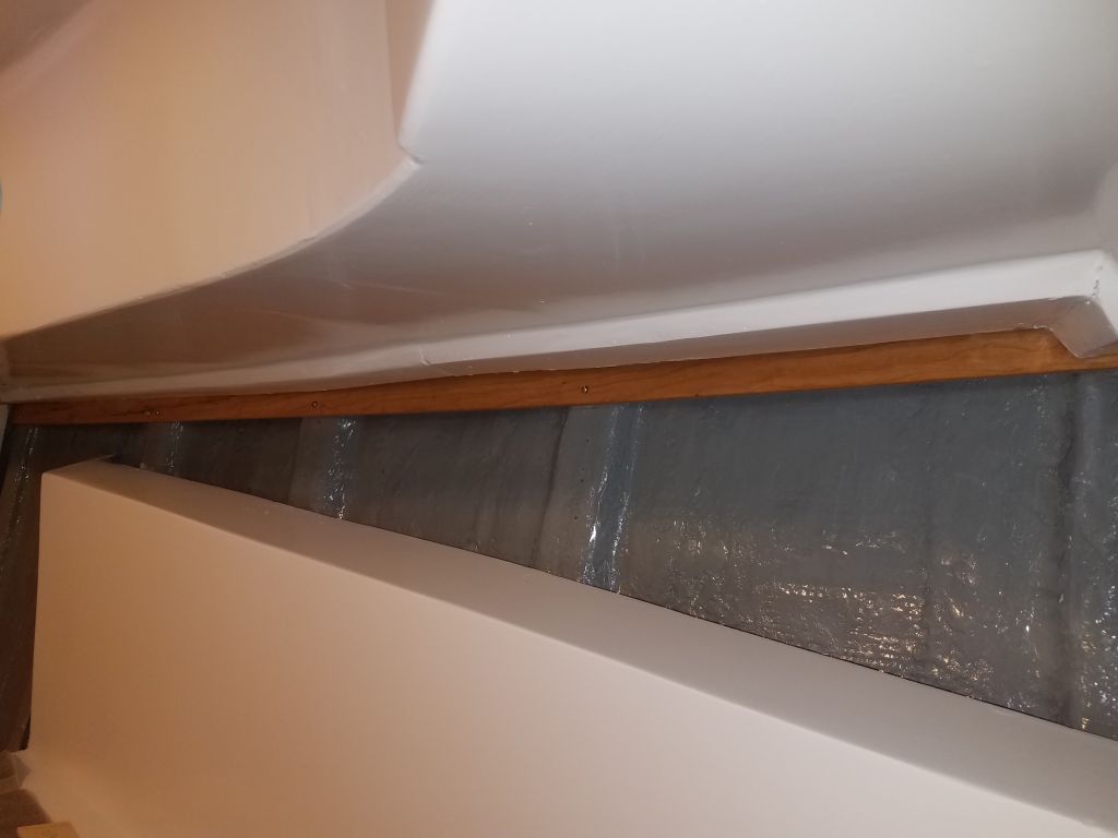
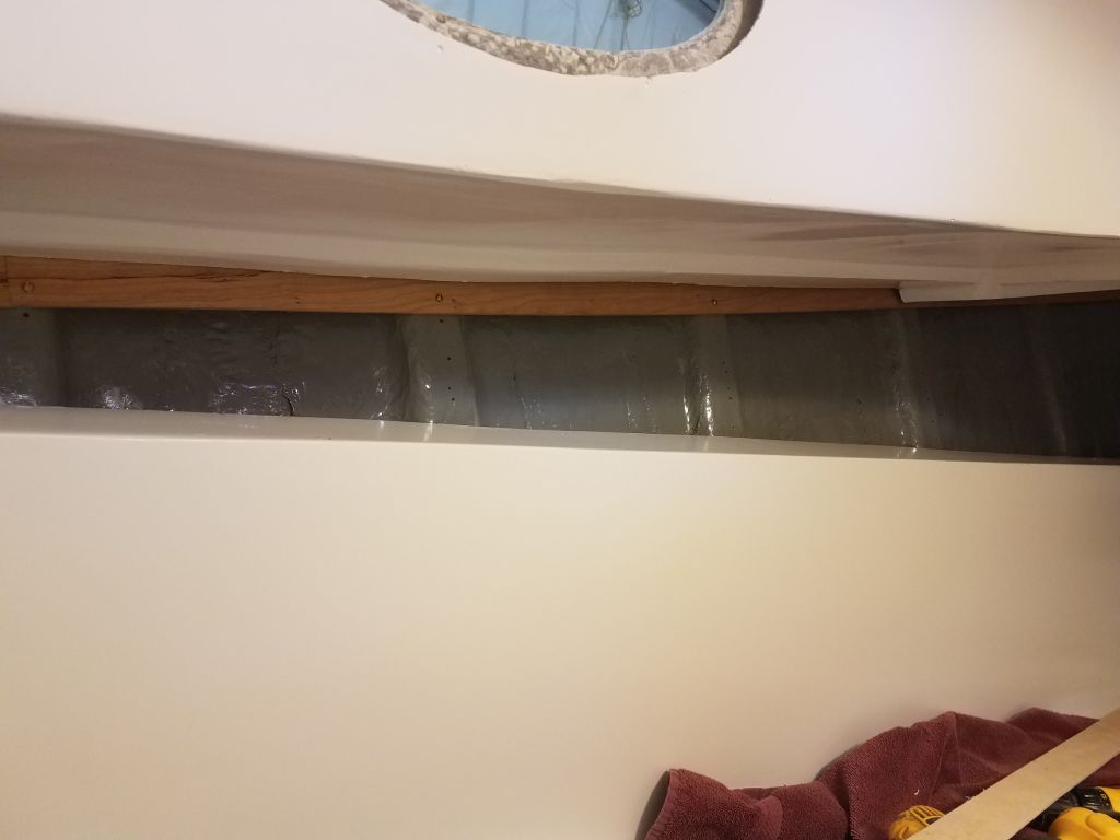
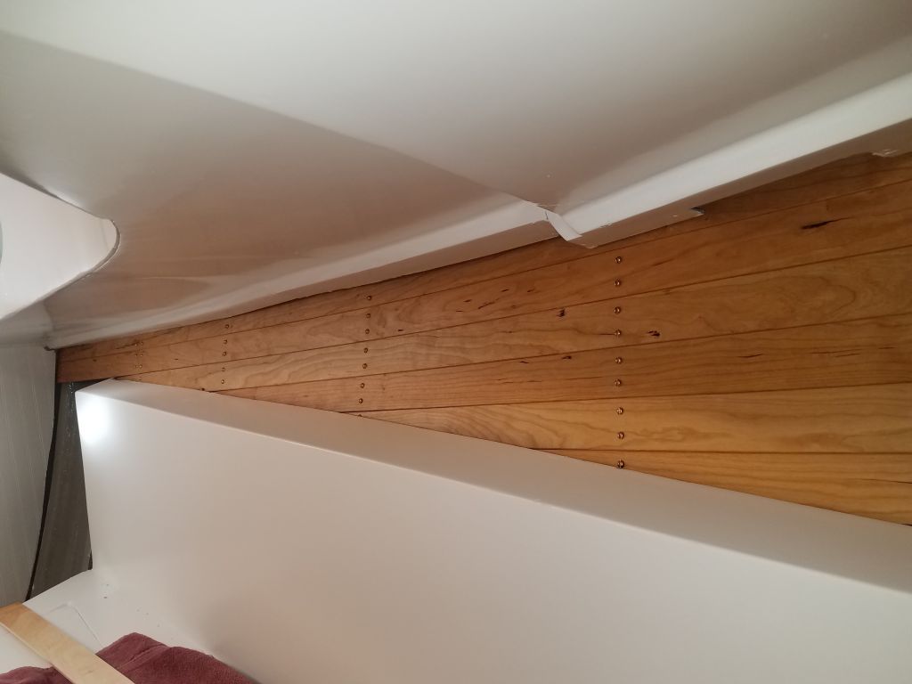
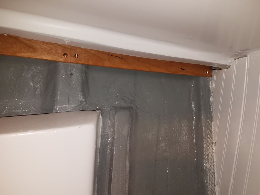
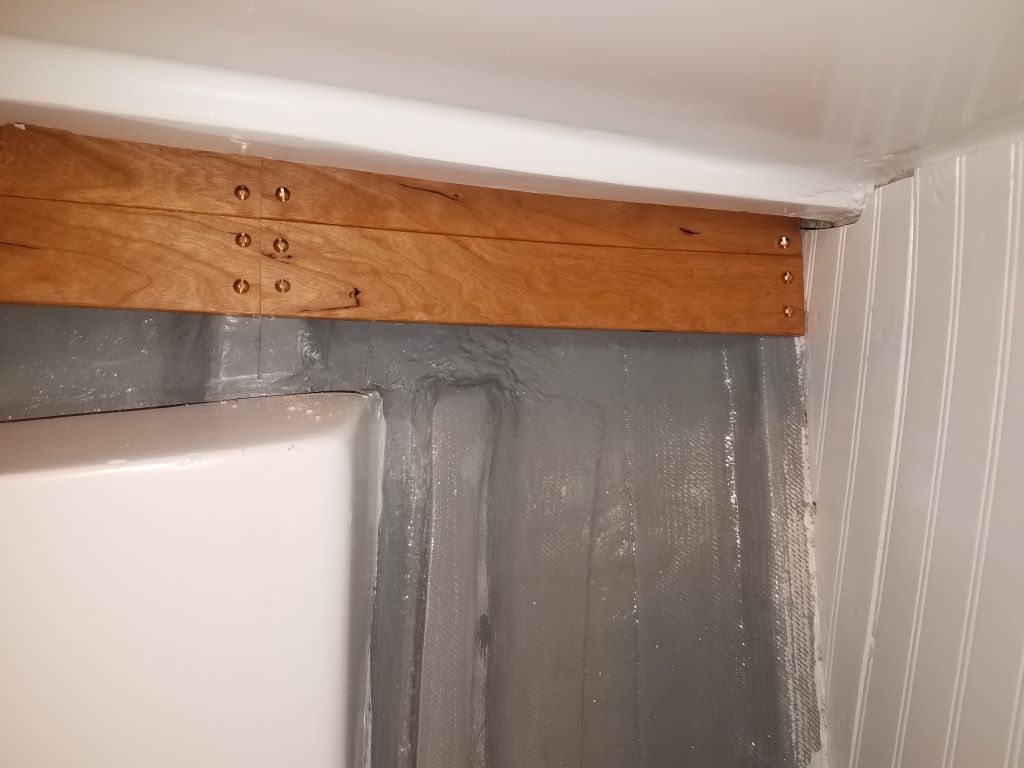
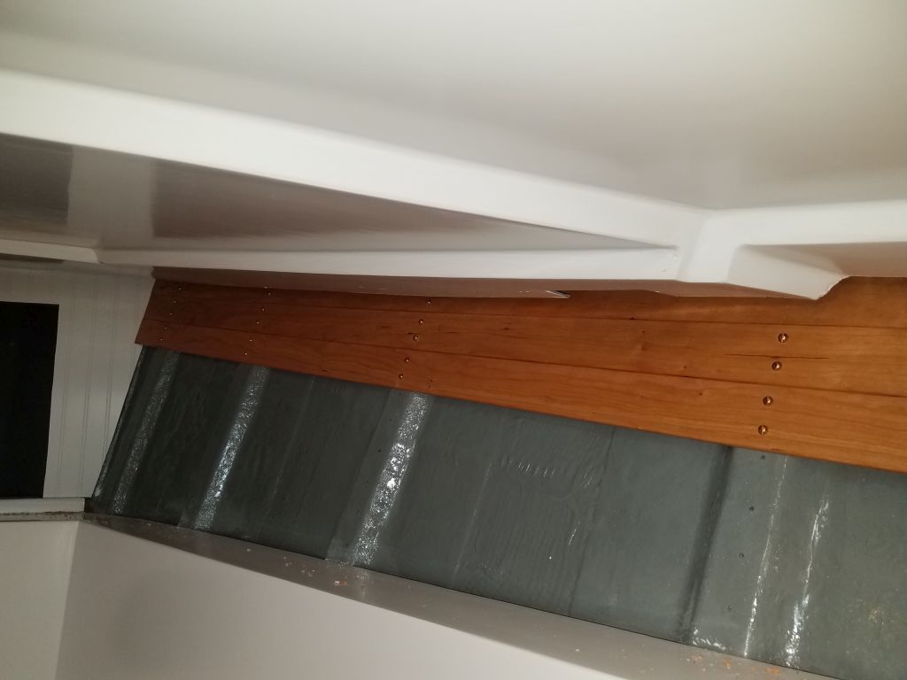
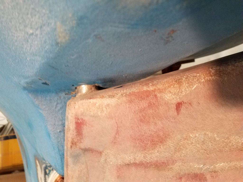
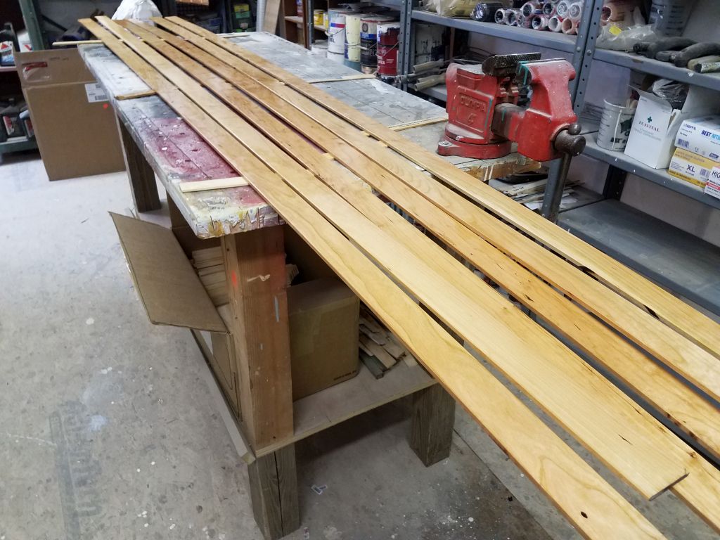
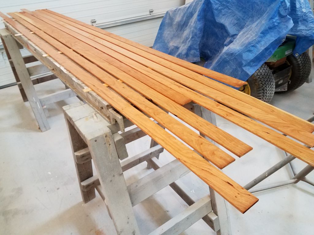
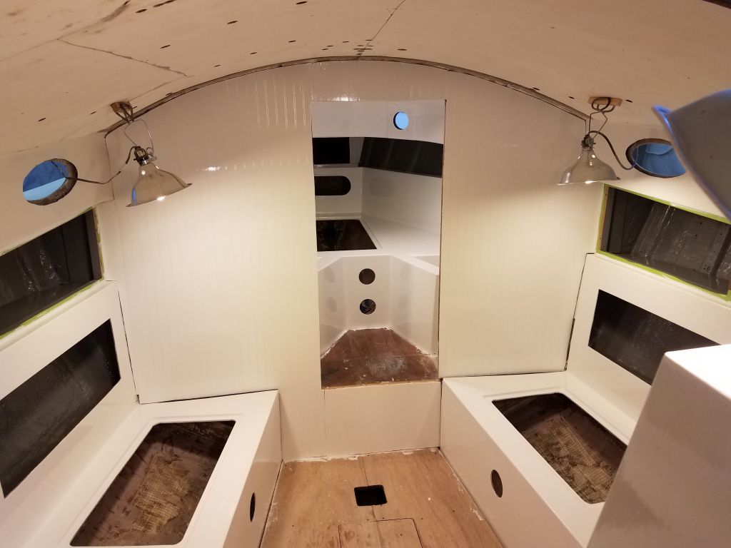
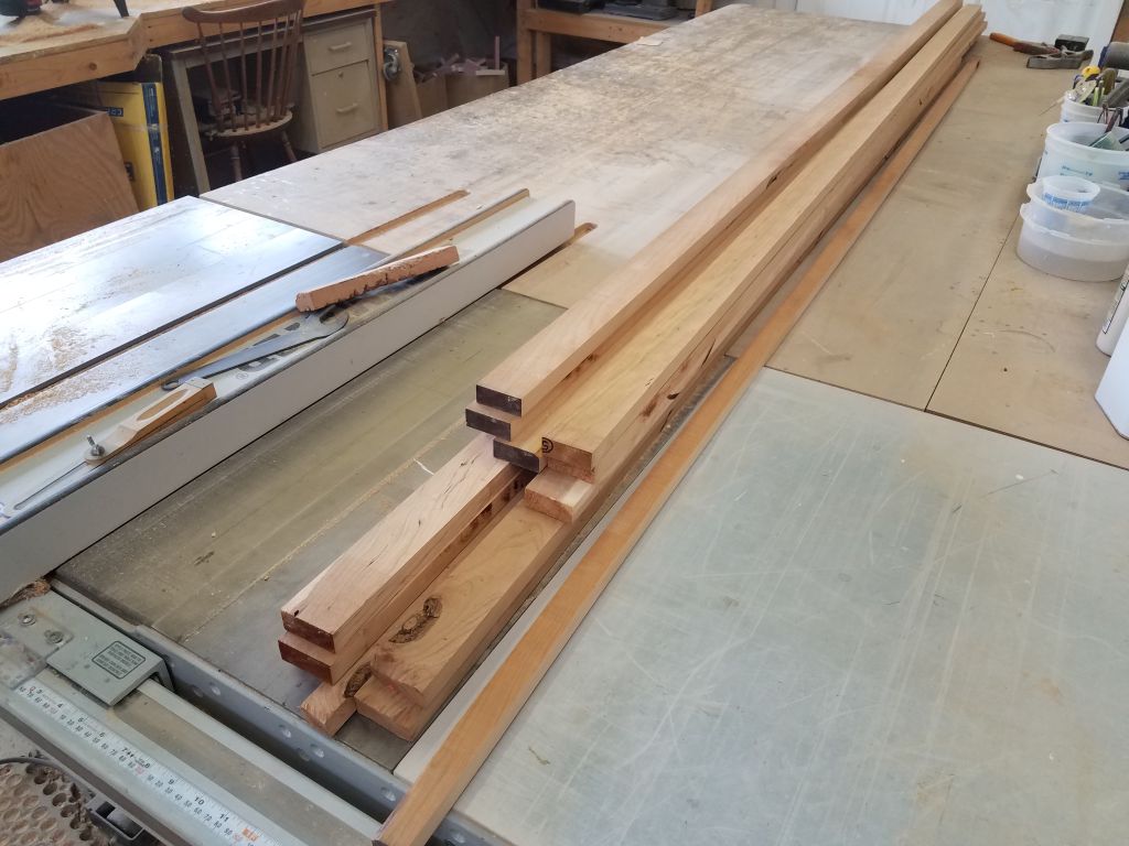
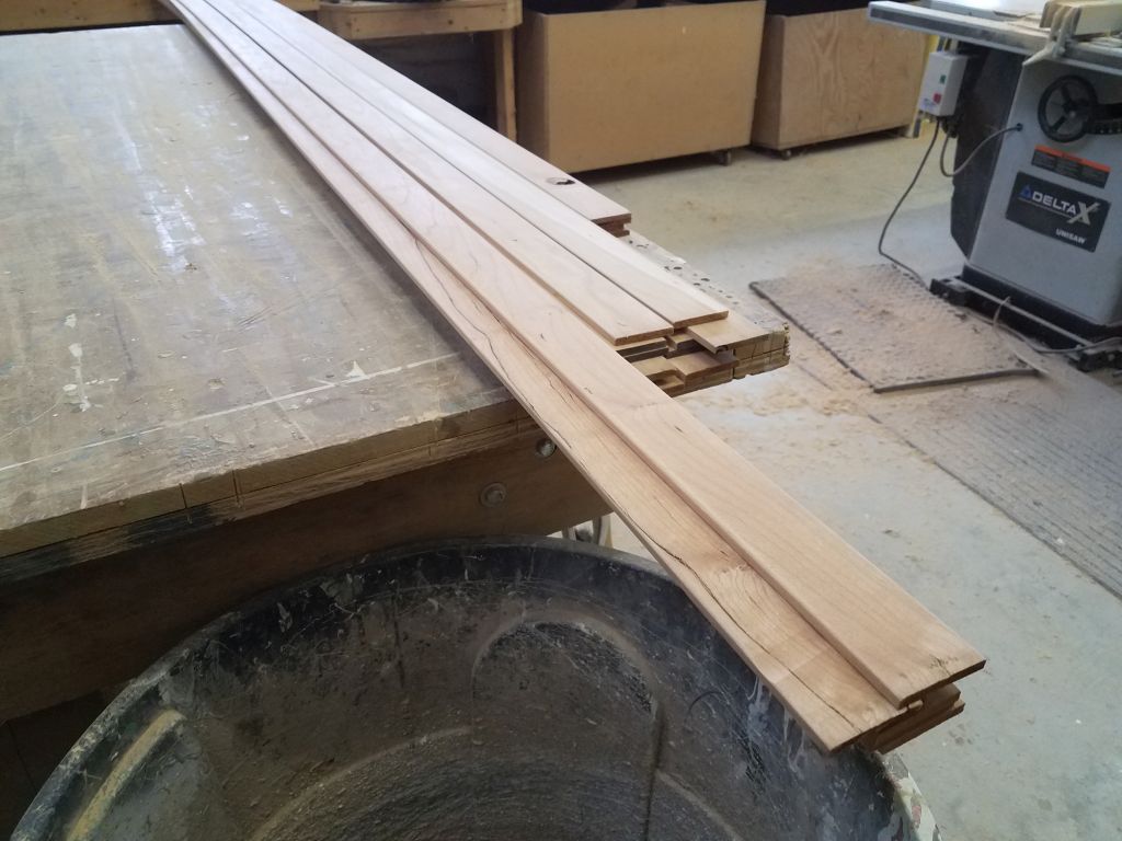
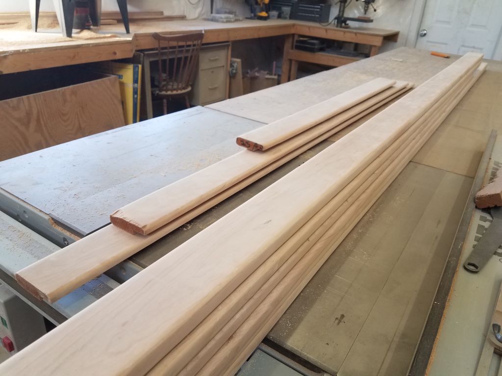
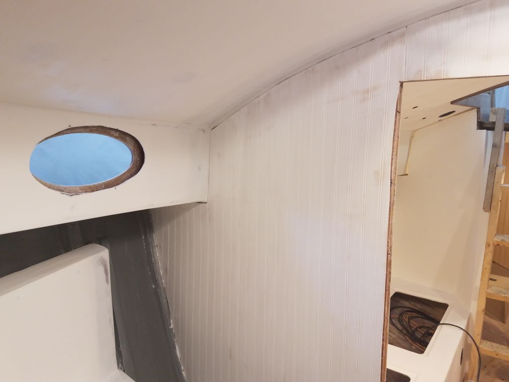
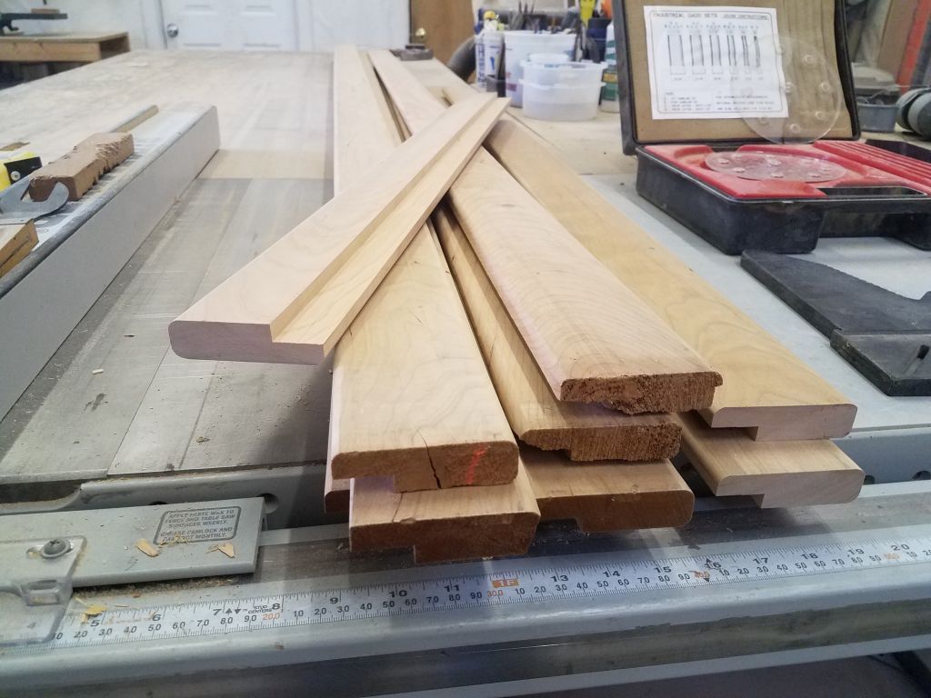
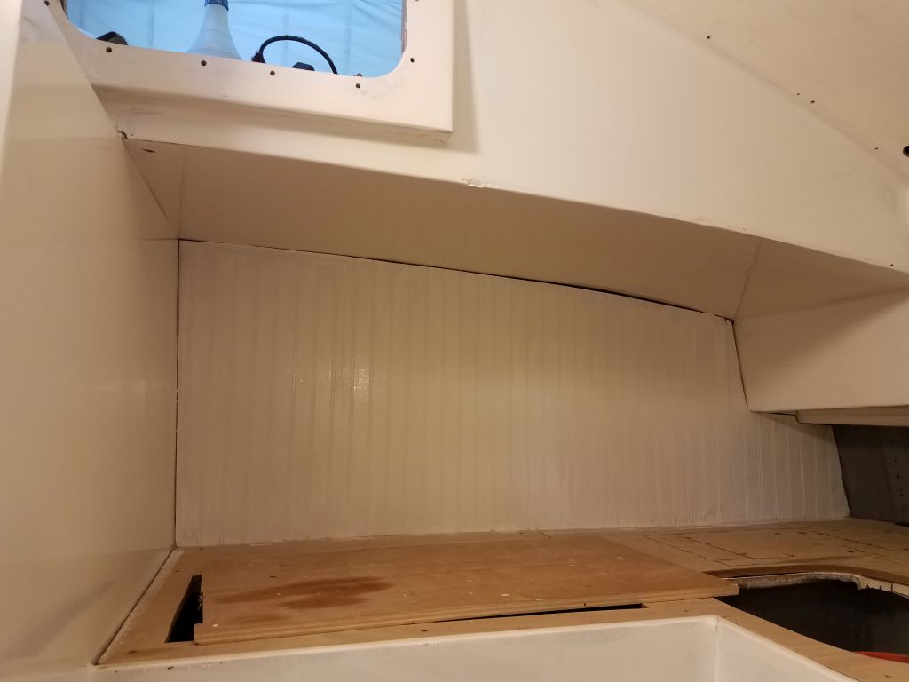
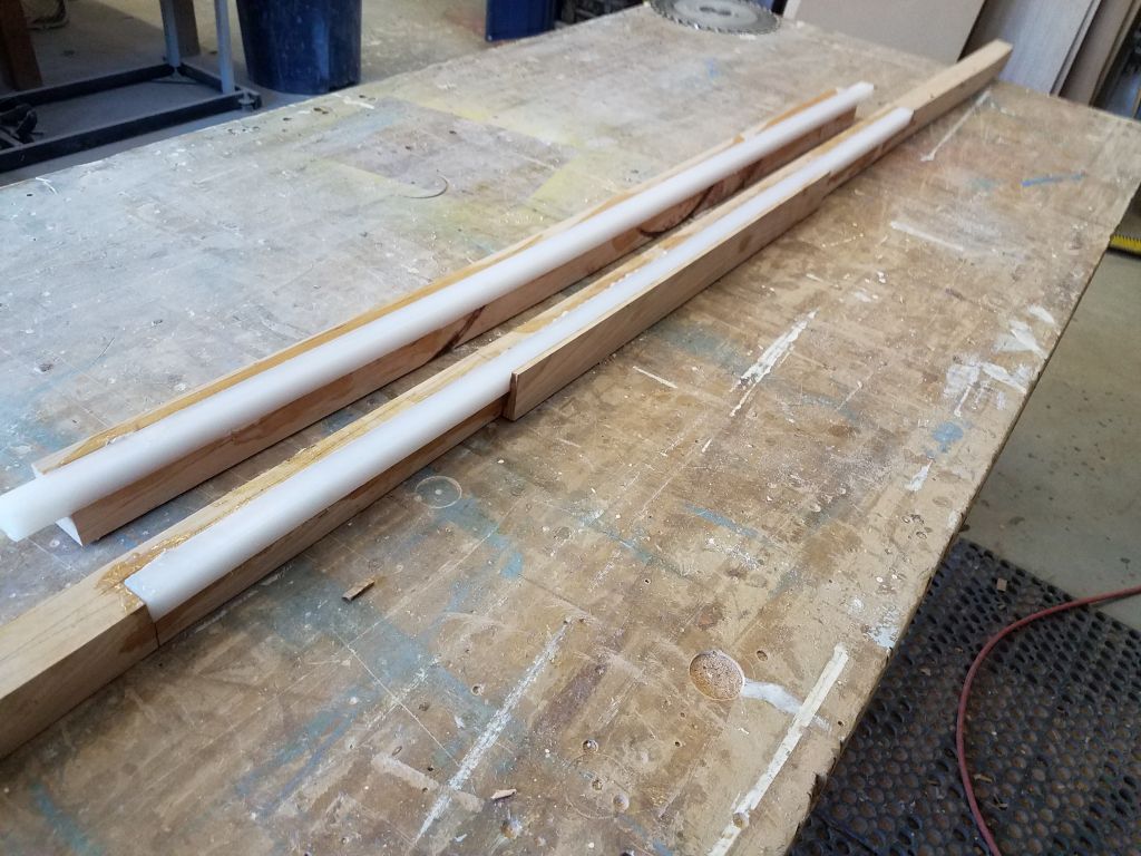
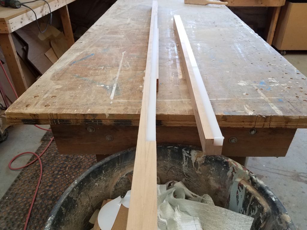
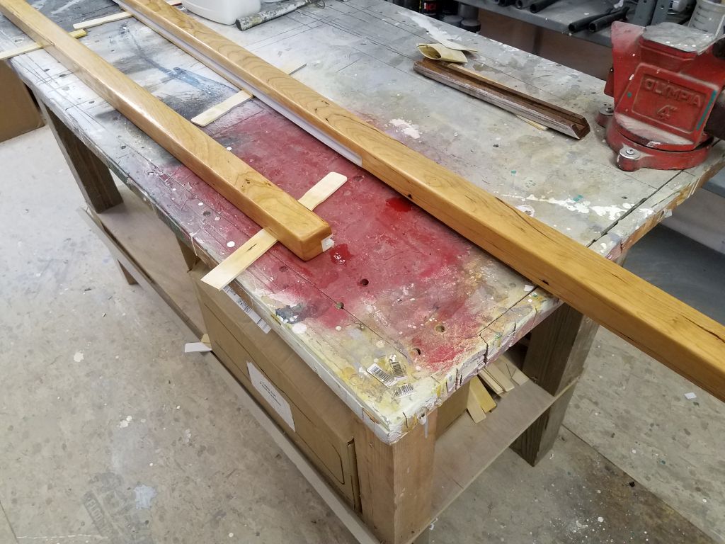
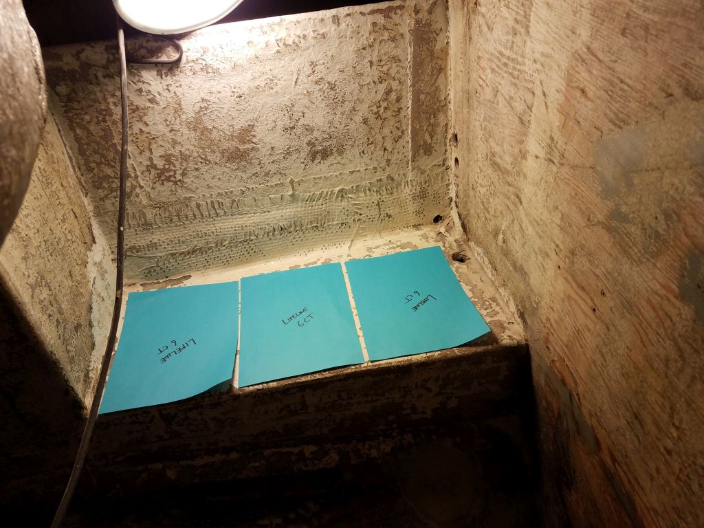
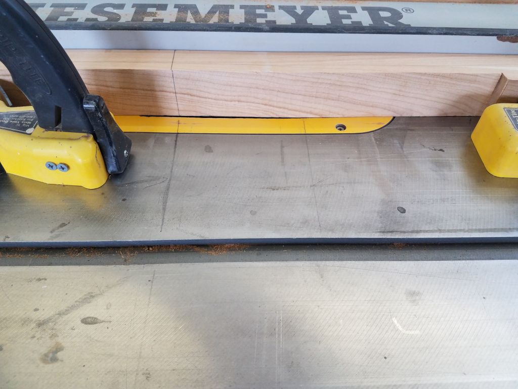
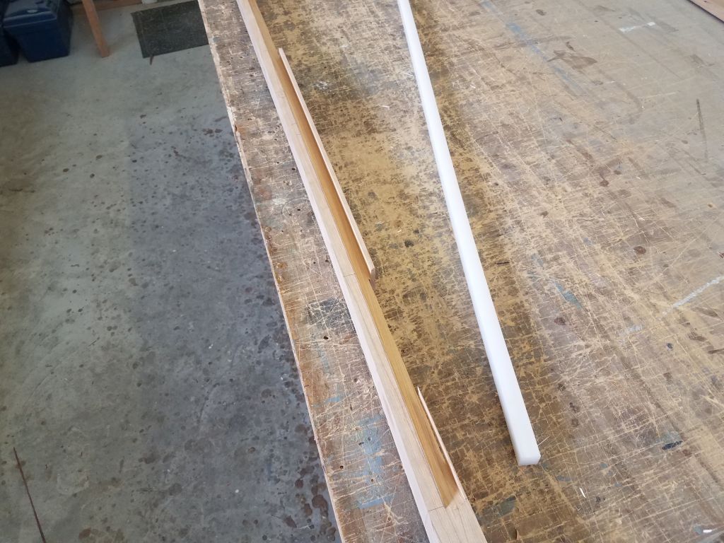
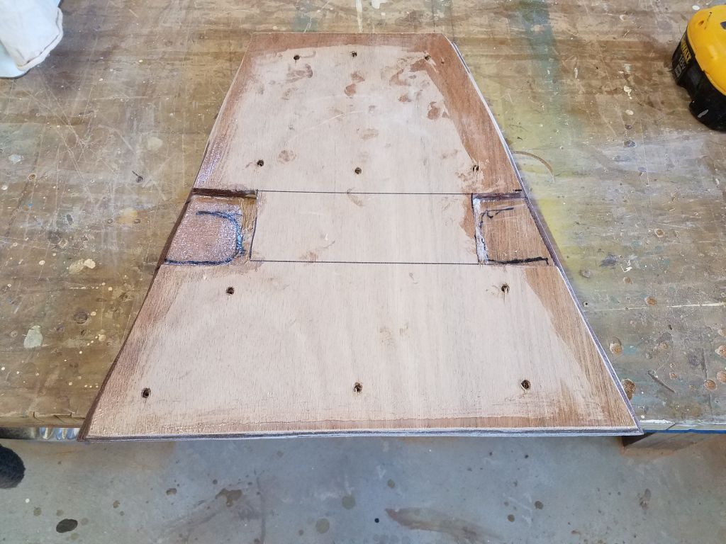
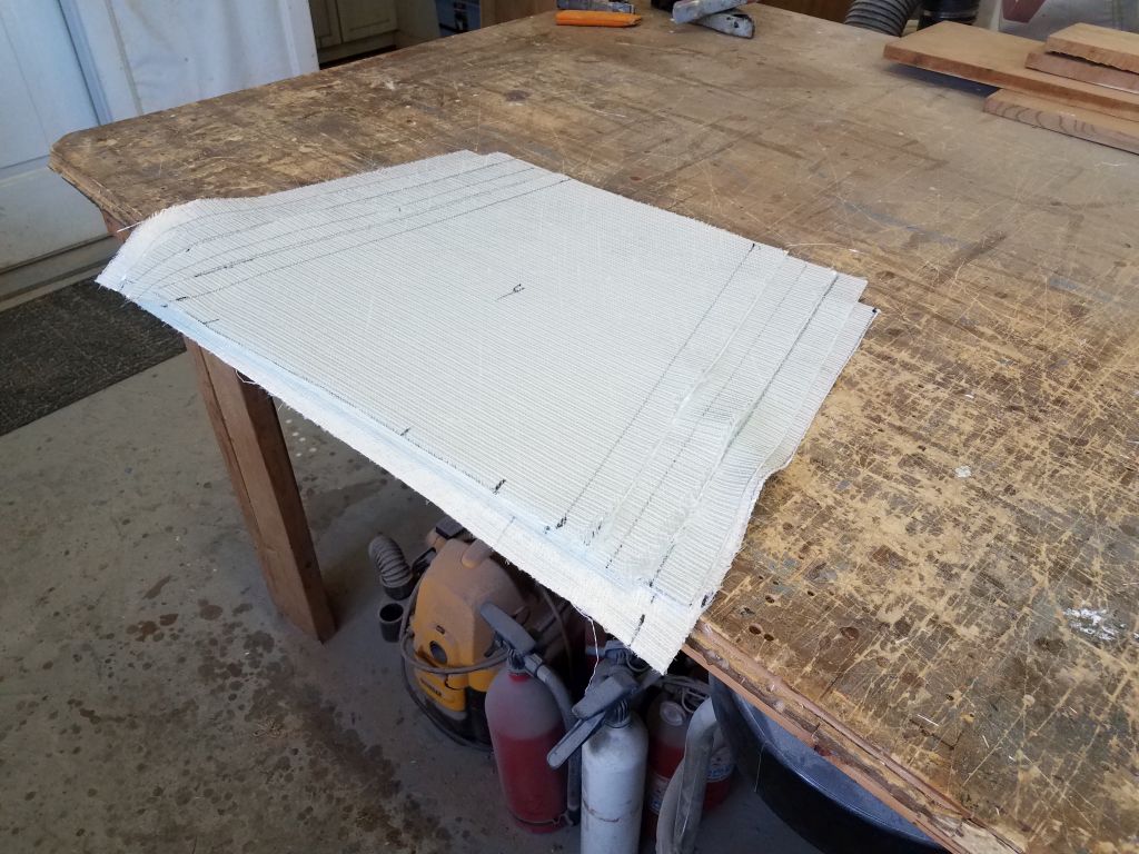
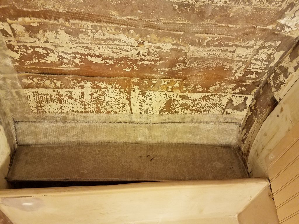
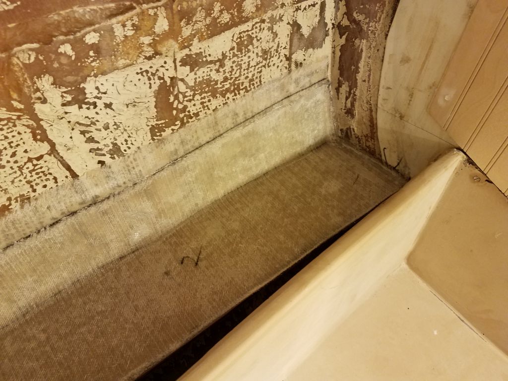
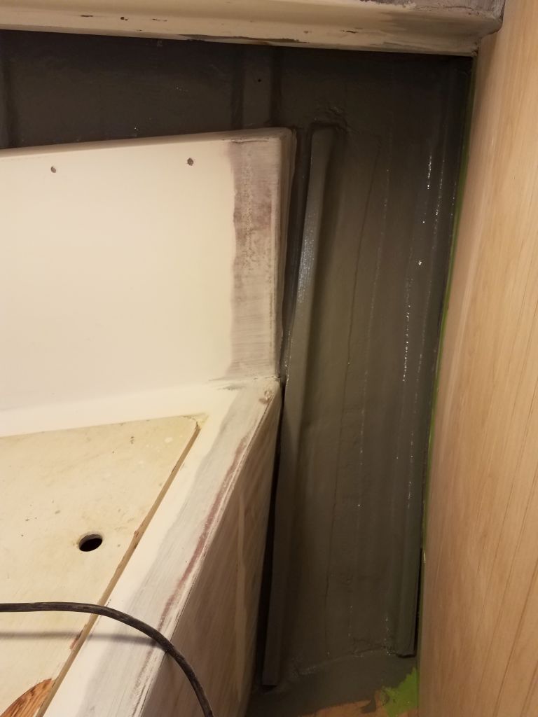
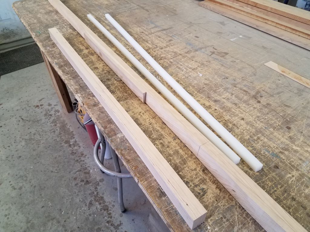
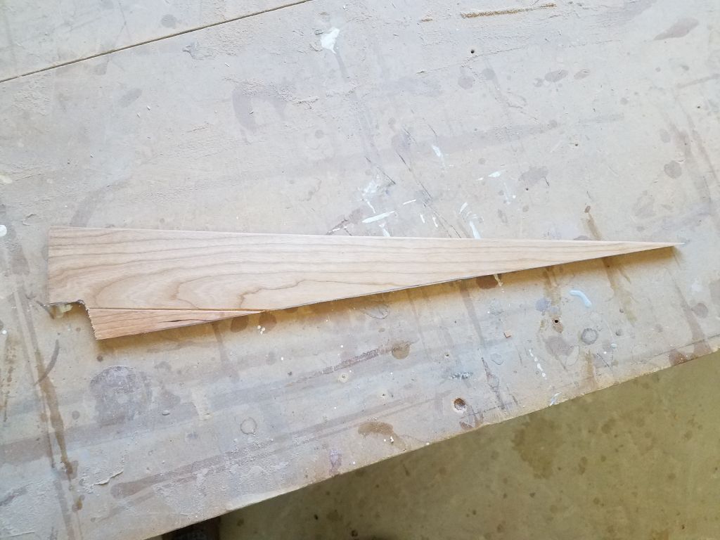
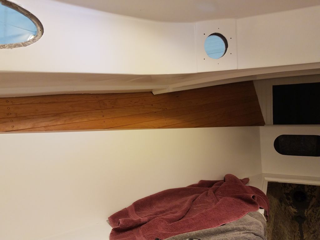
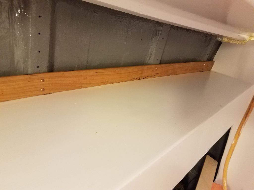
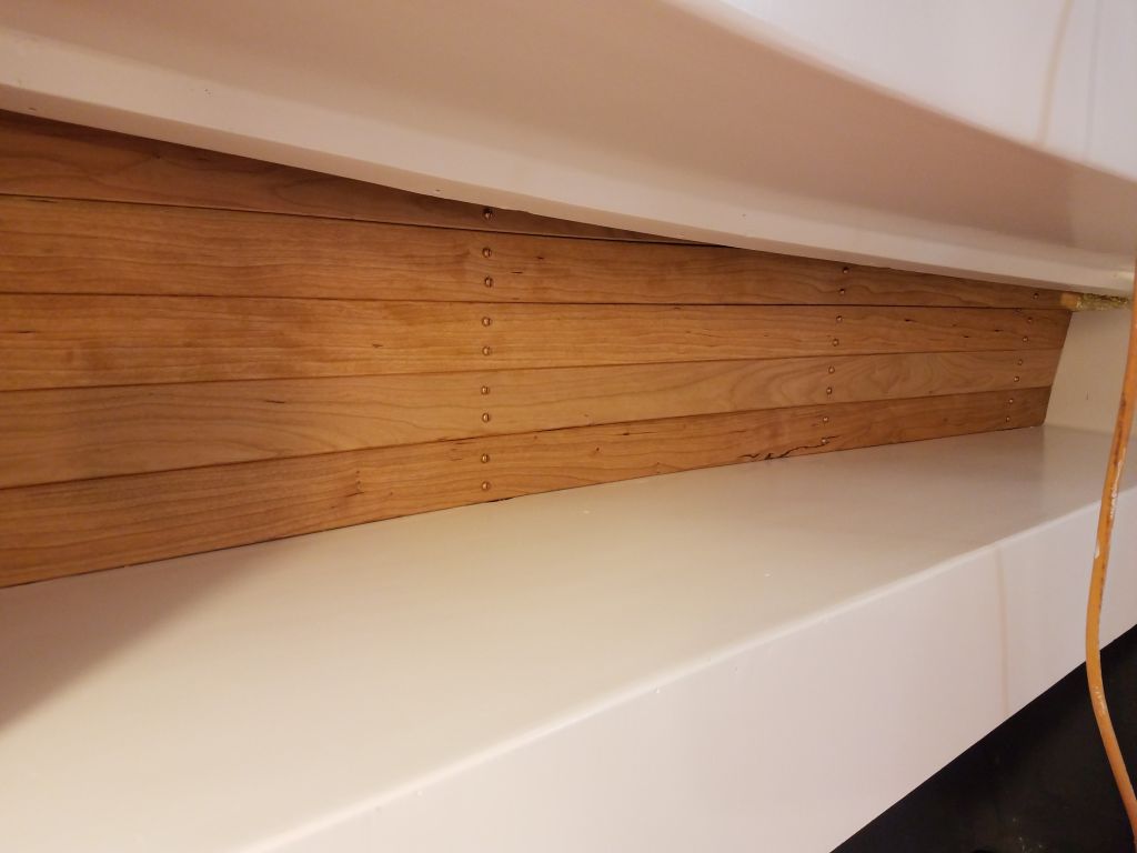
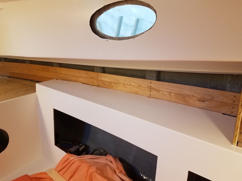
The way the liner met the hull on the starboard side didn’t leave enough space to slide the ceiling boards neatly behind it, as I’d done on the port side, so I’d have to cut a steep angle on the end of each new board where it died out into the liner shelf as I moved forward.  To help with this, I made a template using the 2″ wide plywood strips, and I could use this template to not only help determine the final lengths of each remaining board, but also to mark and cut the angles in each case.

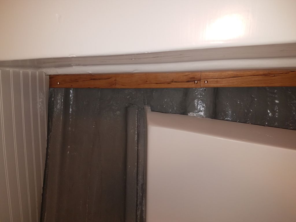
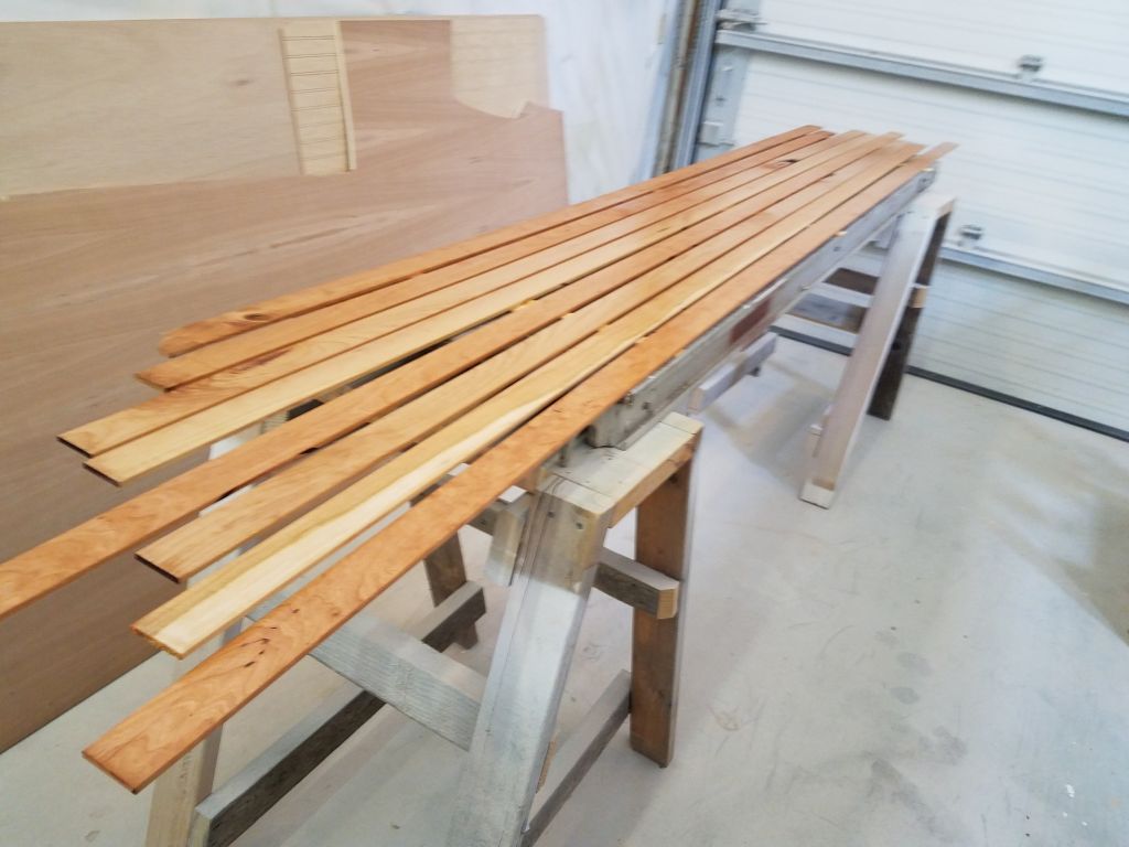
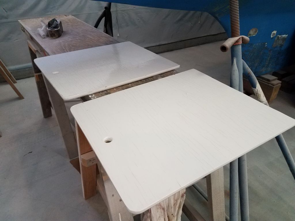
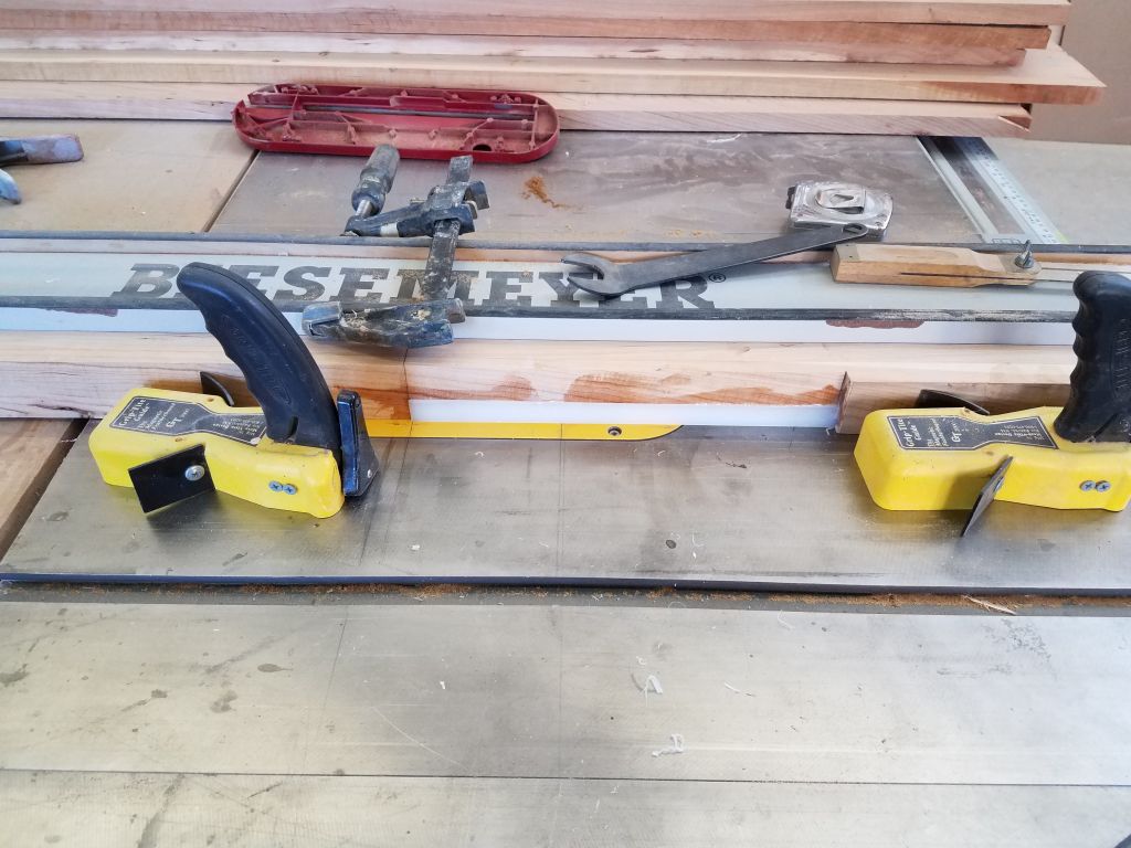
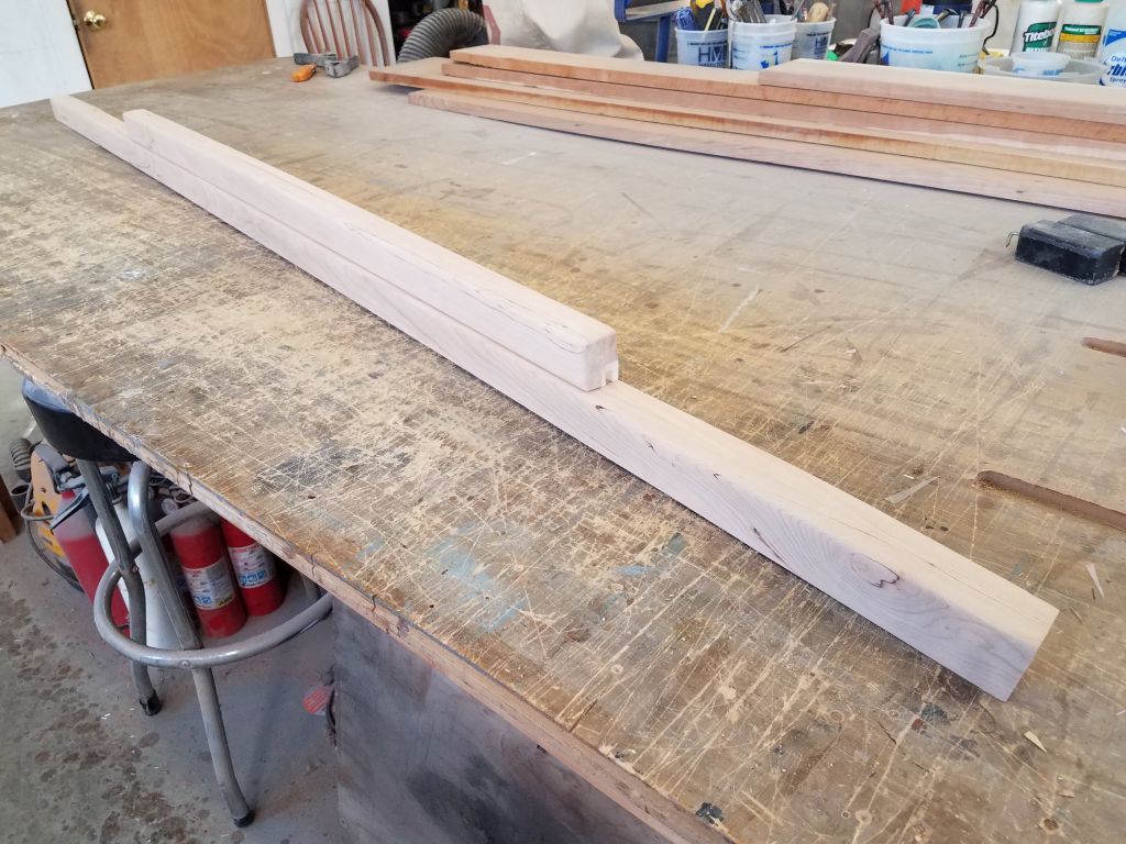
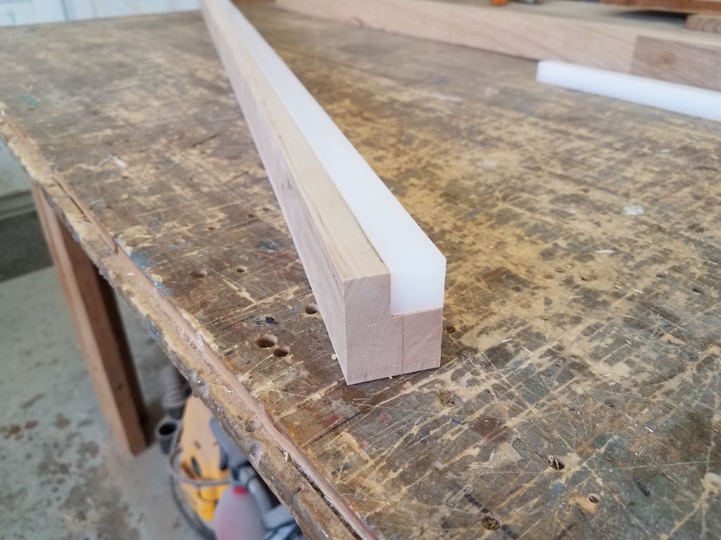
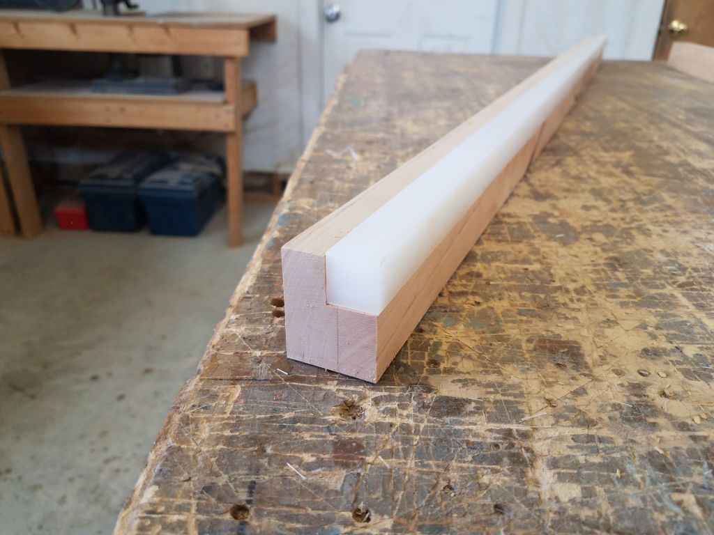
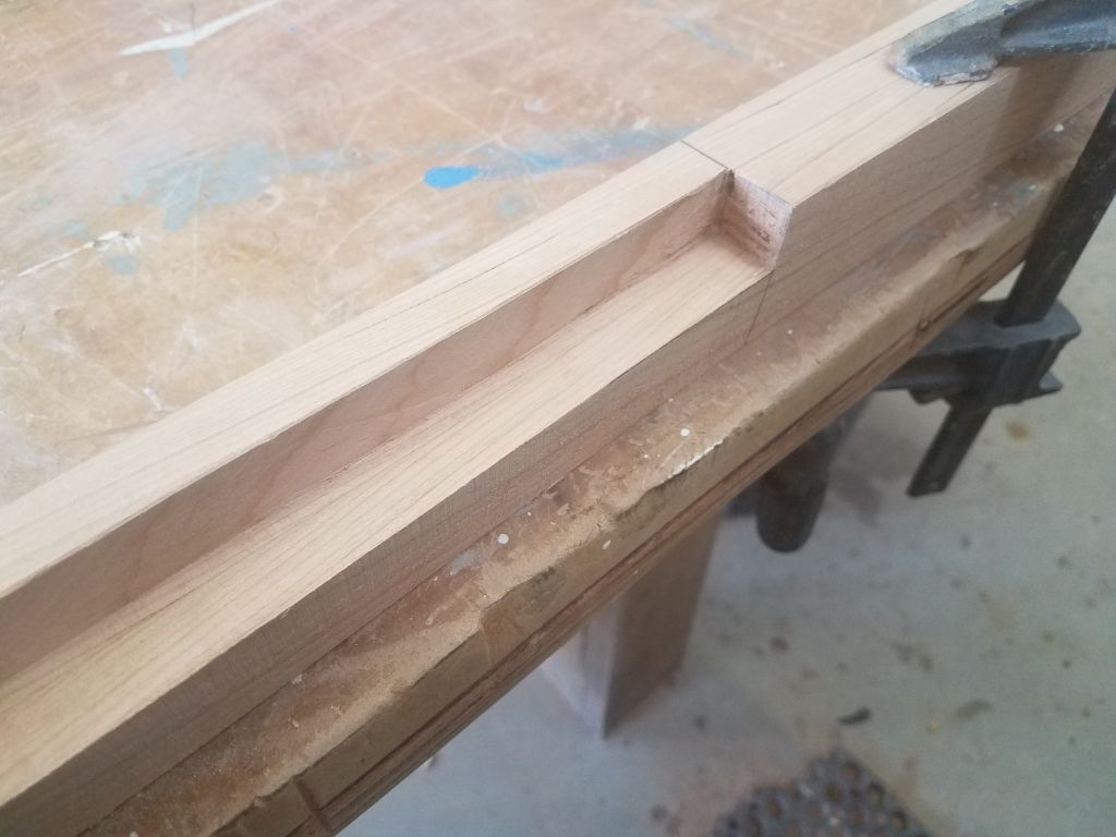
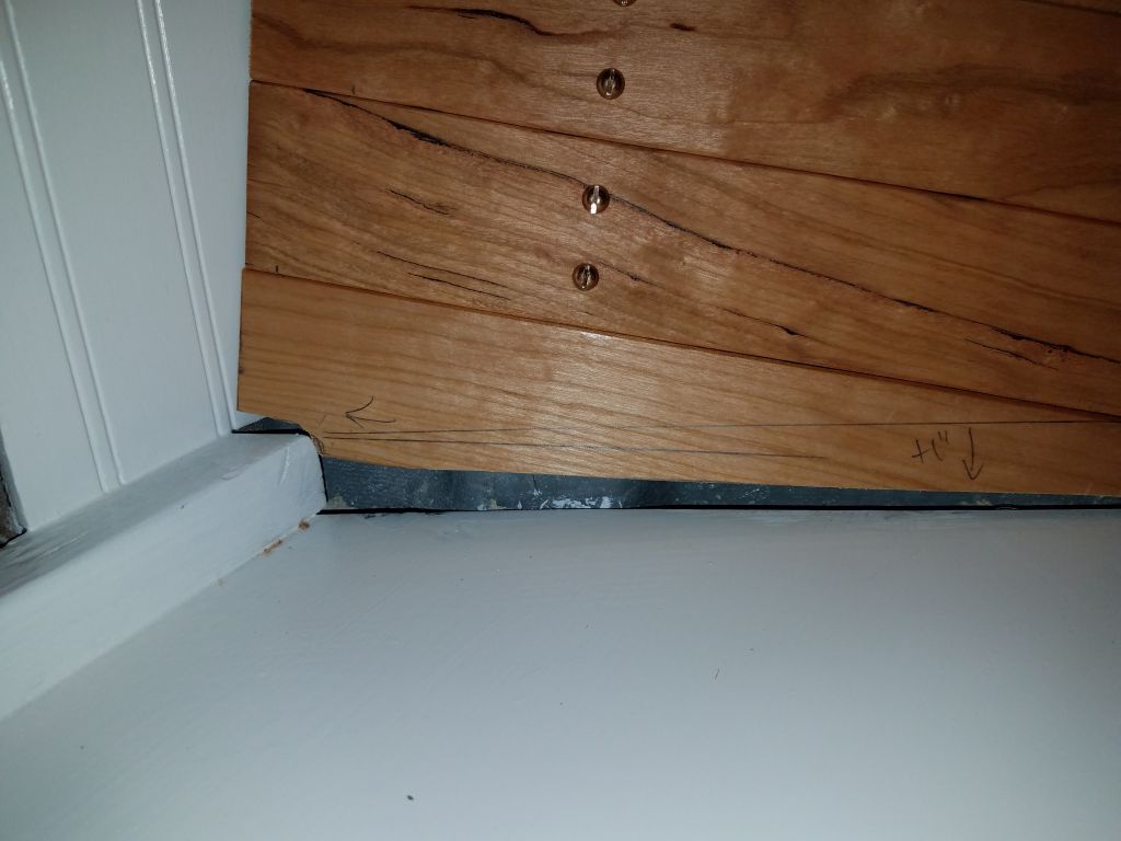
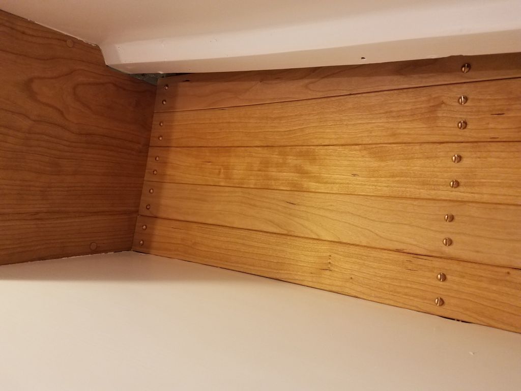
While this meant an extra cut, and a little additional care, I found that it didn’t otherwise slow down the process significantly, and by the end of the morning I’d reached the last piece at the bottom forward corner.  The height here was just a bit more than a single board width at the forward end, and the tiny piece required beneath would be too small to live on its own, much less  secure to the cleats, so after cutting a template of the shape needed out of my junk plywood, I glued up two pieces of the ceiling stock along their narrow edge, from which I could later cut out the final piece as one, thus completing the main part of the ceiling on the starboard side.  I’d return soon to finish up the short boards at the aft end on each side.

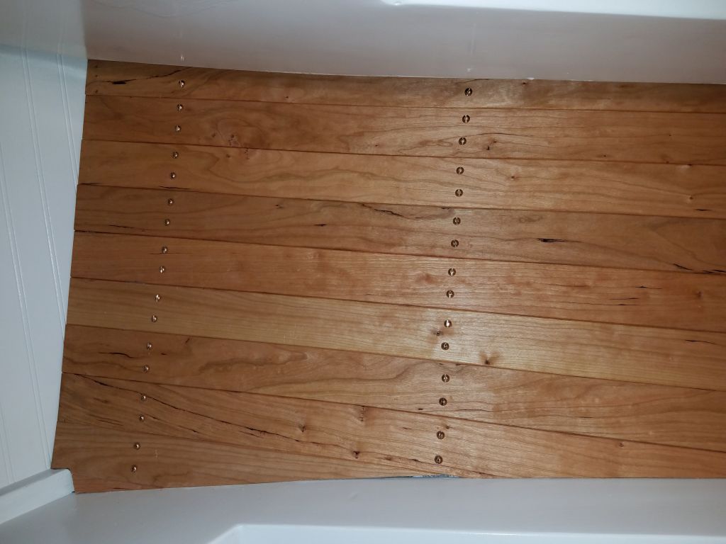
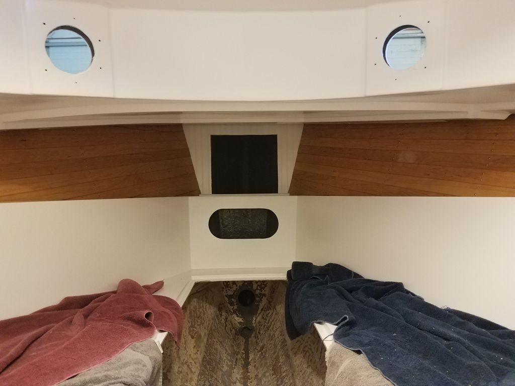
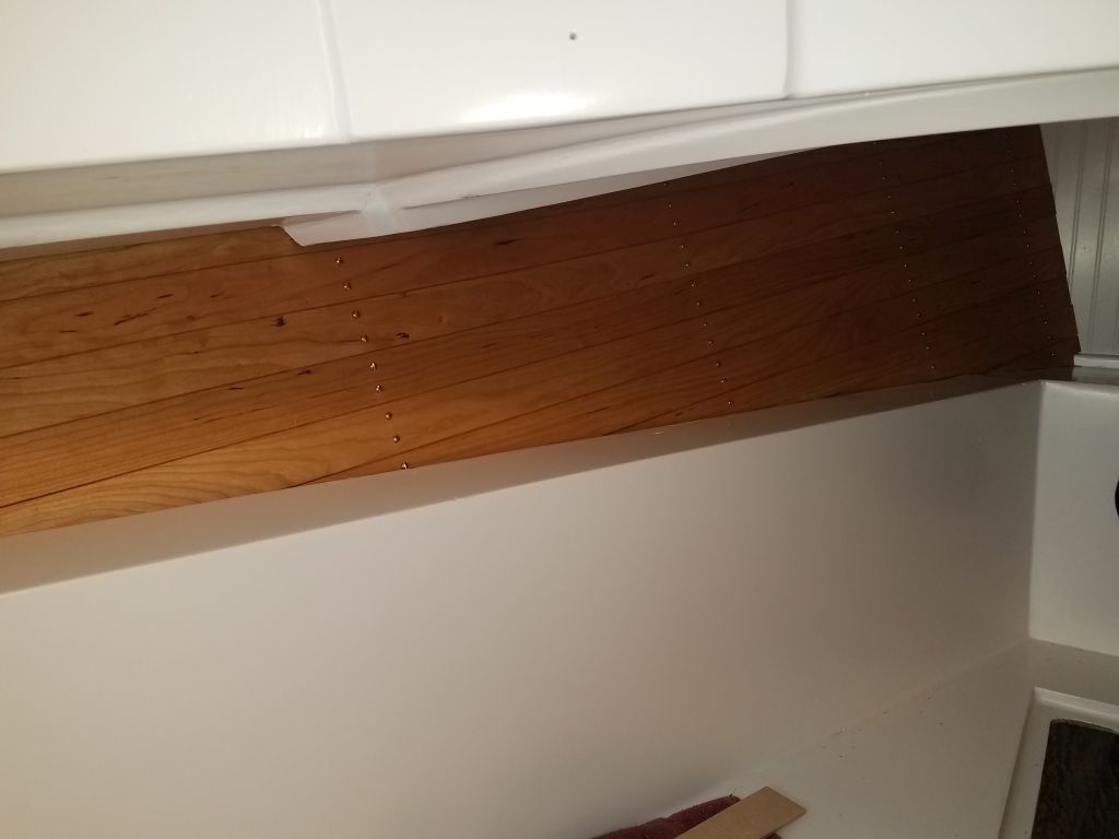
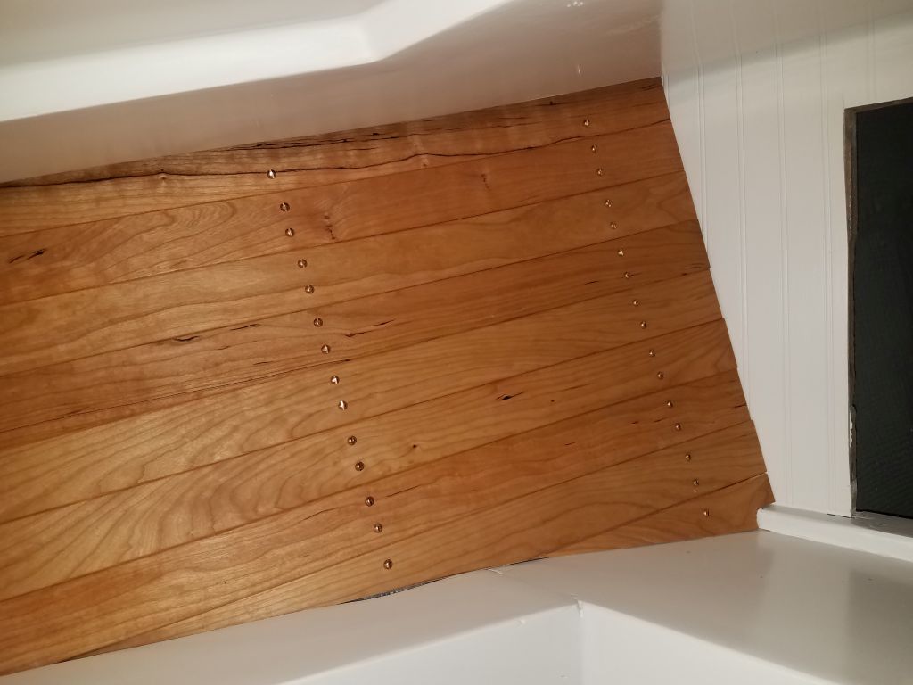
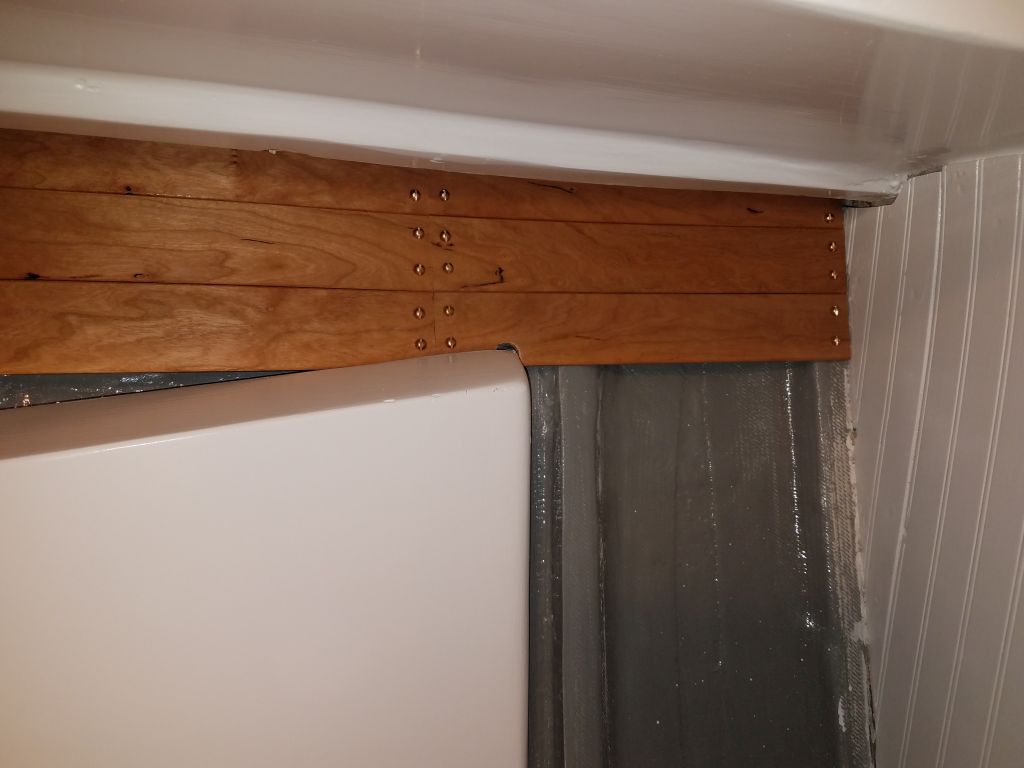
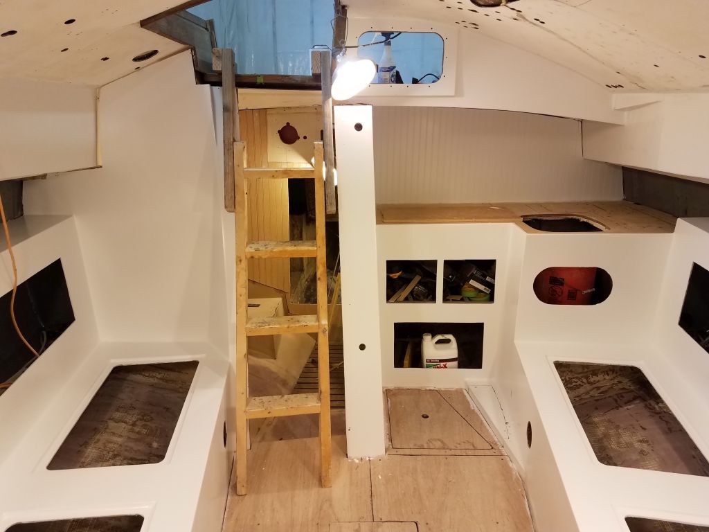
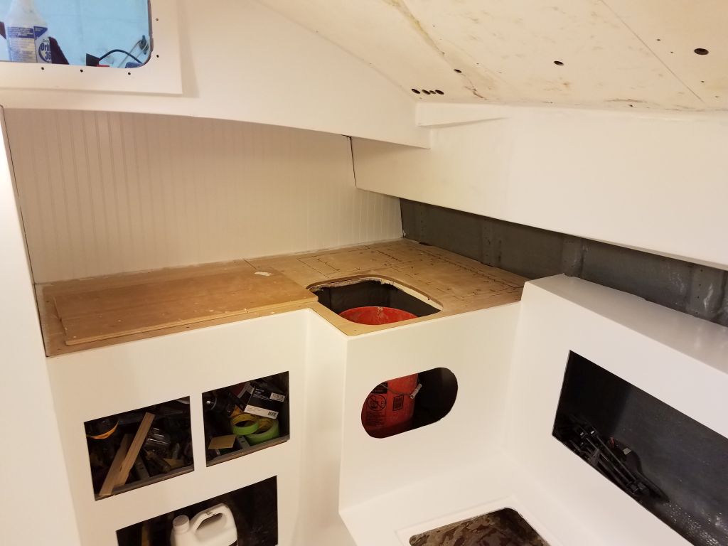
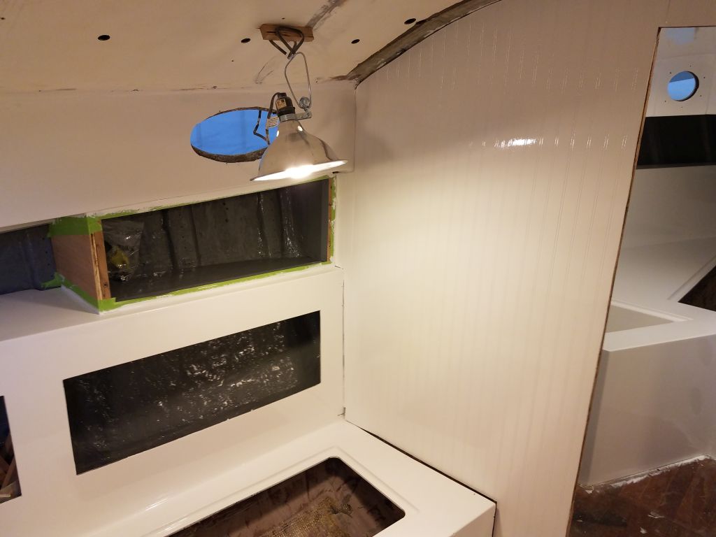
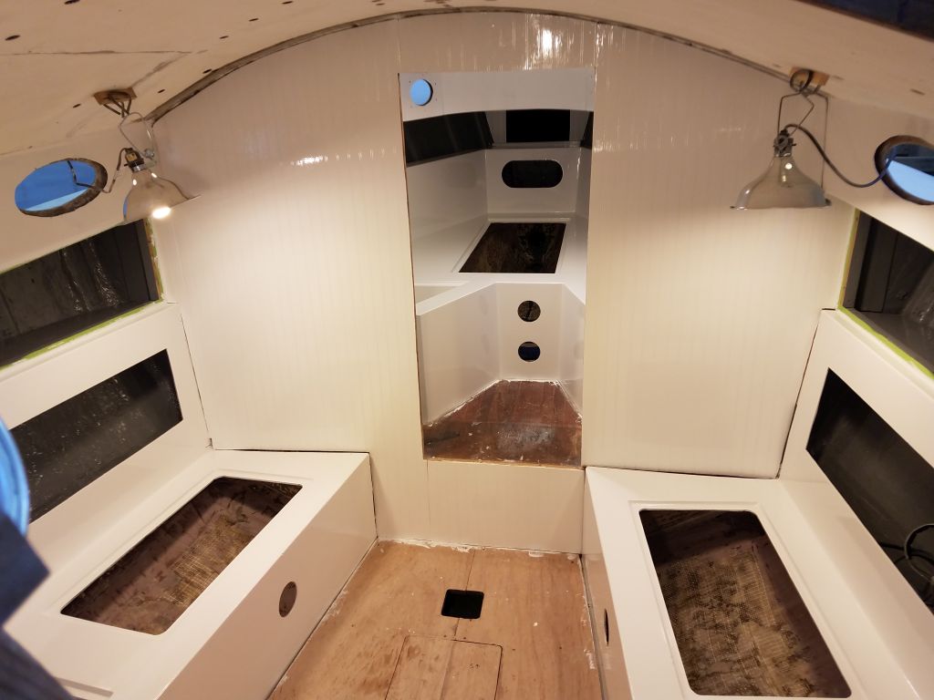
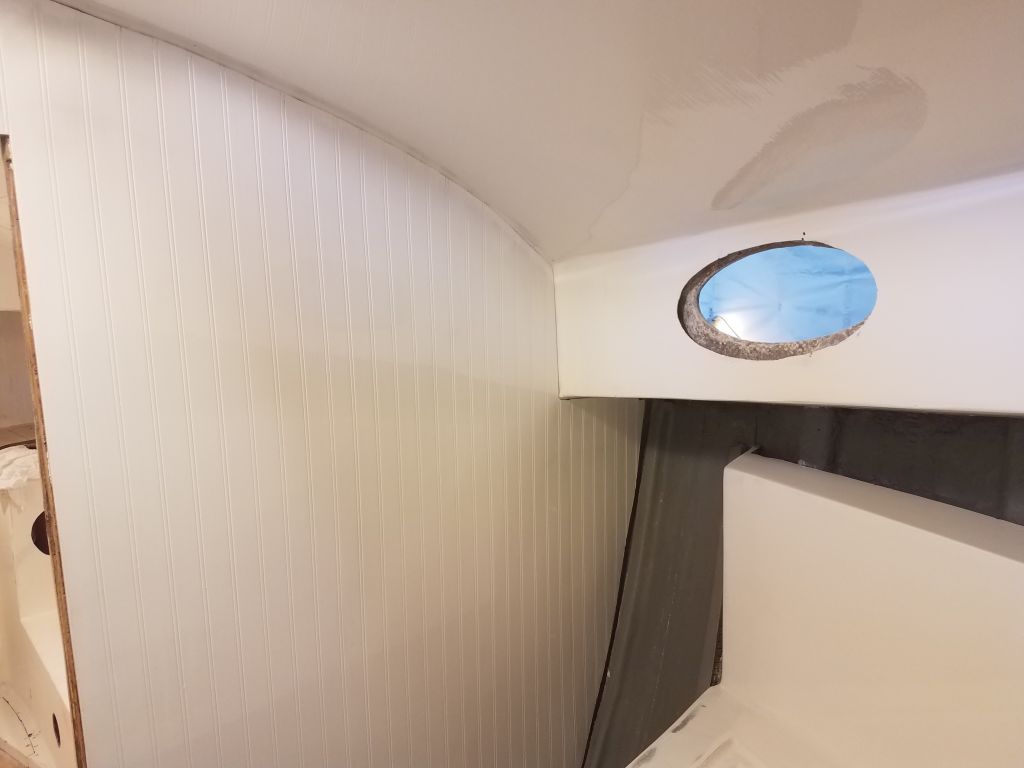
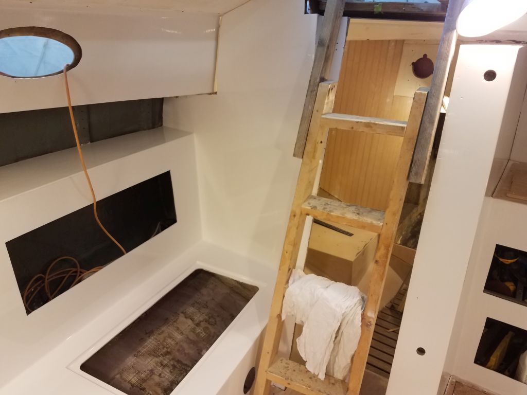
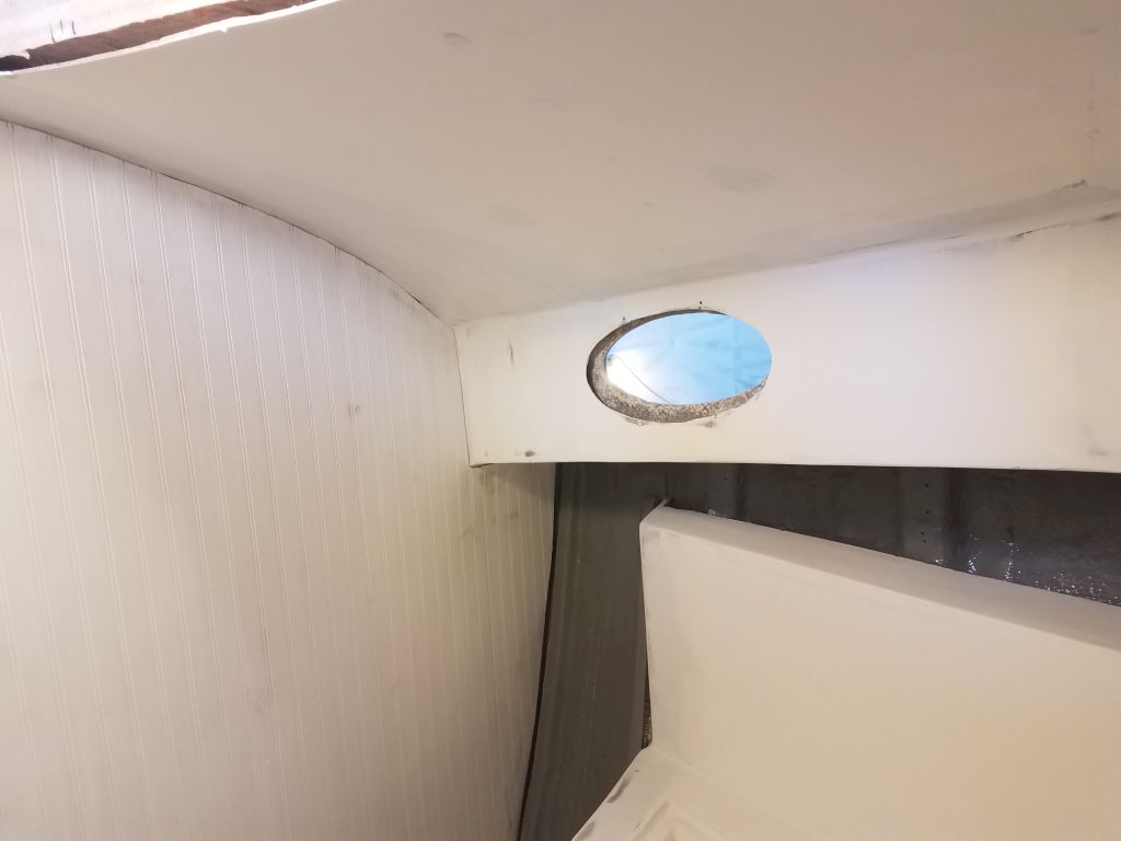
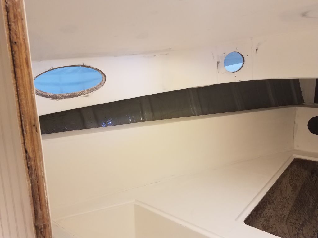
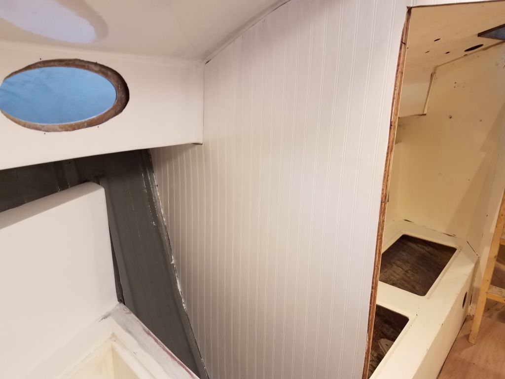
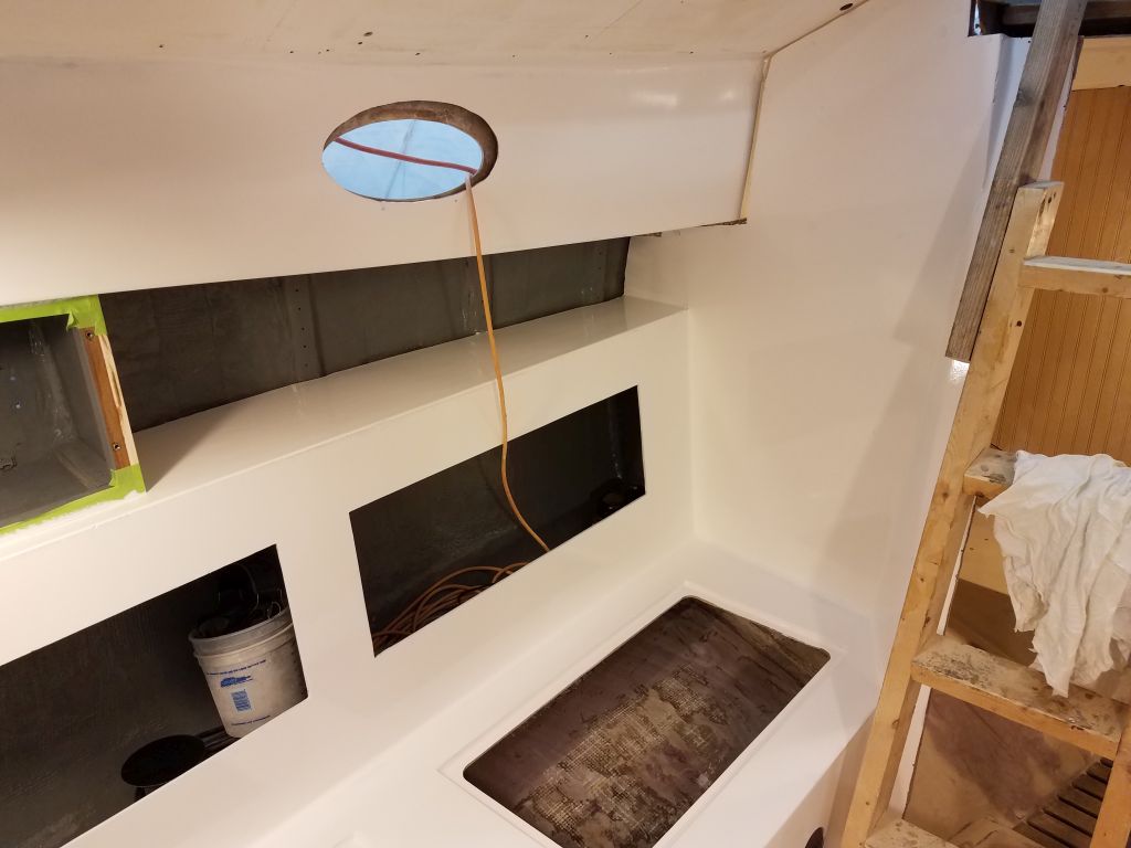
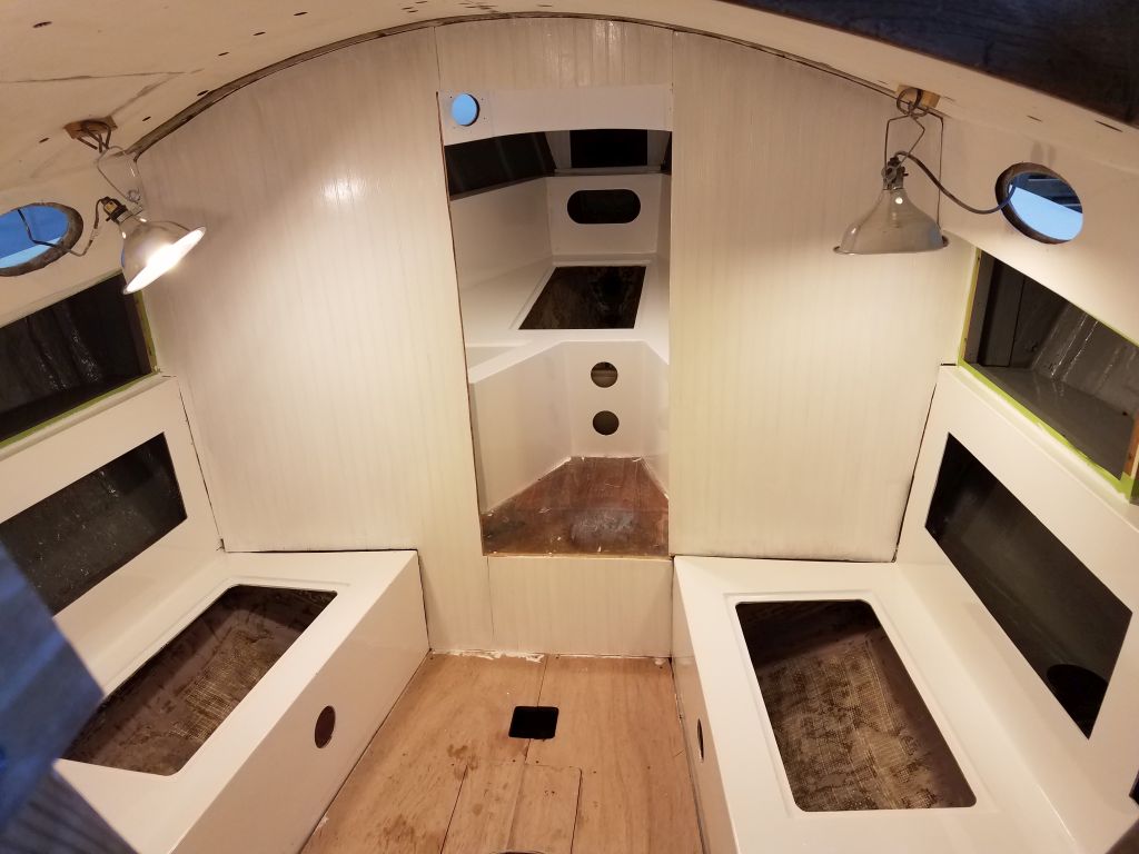
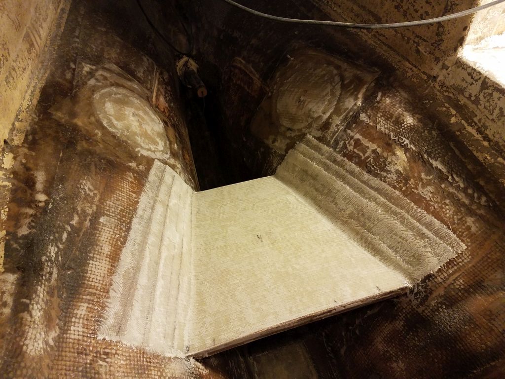
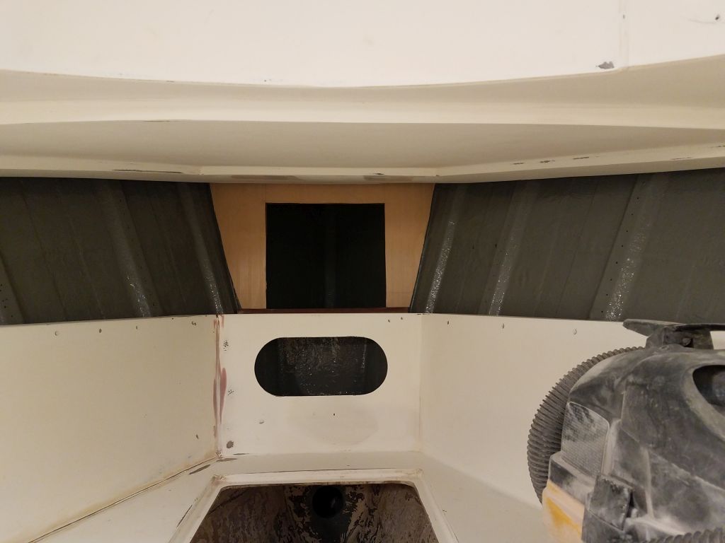
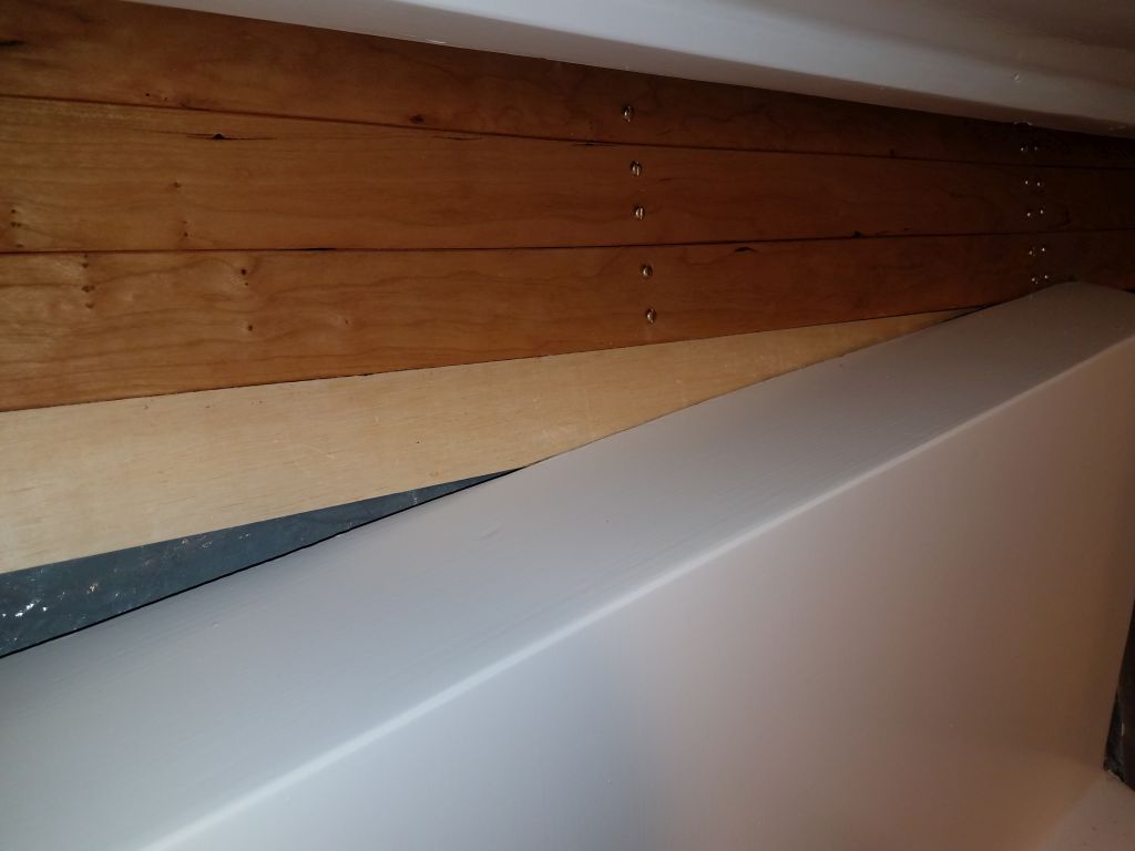
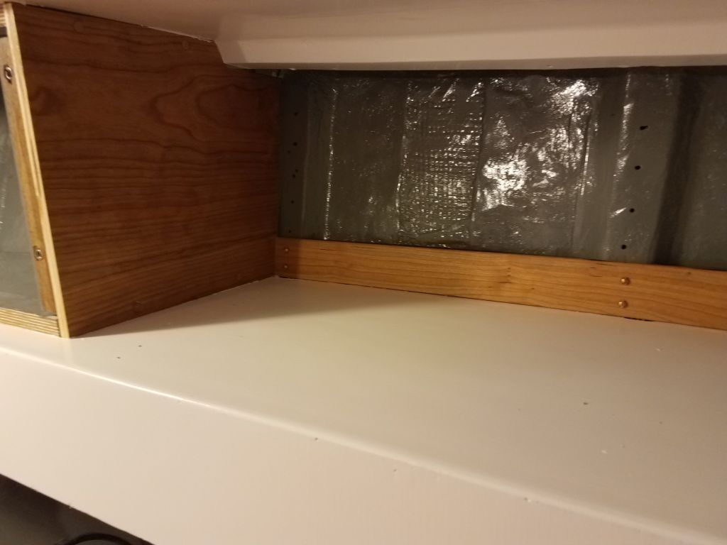
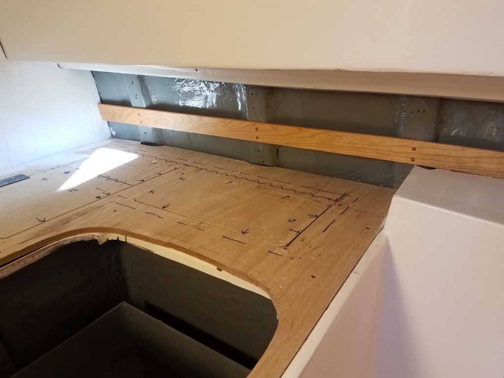
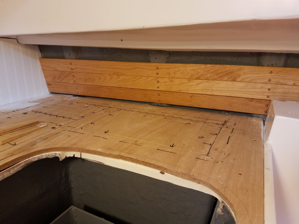
I continued the ceiling  installation in the main cabin, starting with the small section on the starboard side.  Here, I decided to start at the bottom and work up, allowing the boards to follow the plane of the shelf rather than the sheerline and allowing a full-width board along the bottom.  This made sense given the shape and size of the shortened space, since the new locker at the forward end covered over the more extreme part of the boat’s sheerline that, had it all been exposed as in the forward cabin, I’d have wanted to follow here as well.

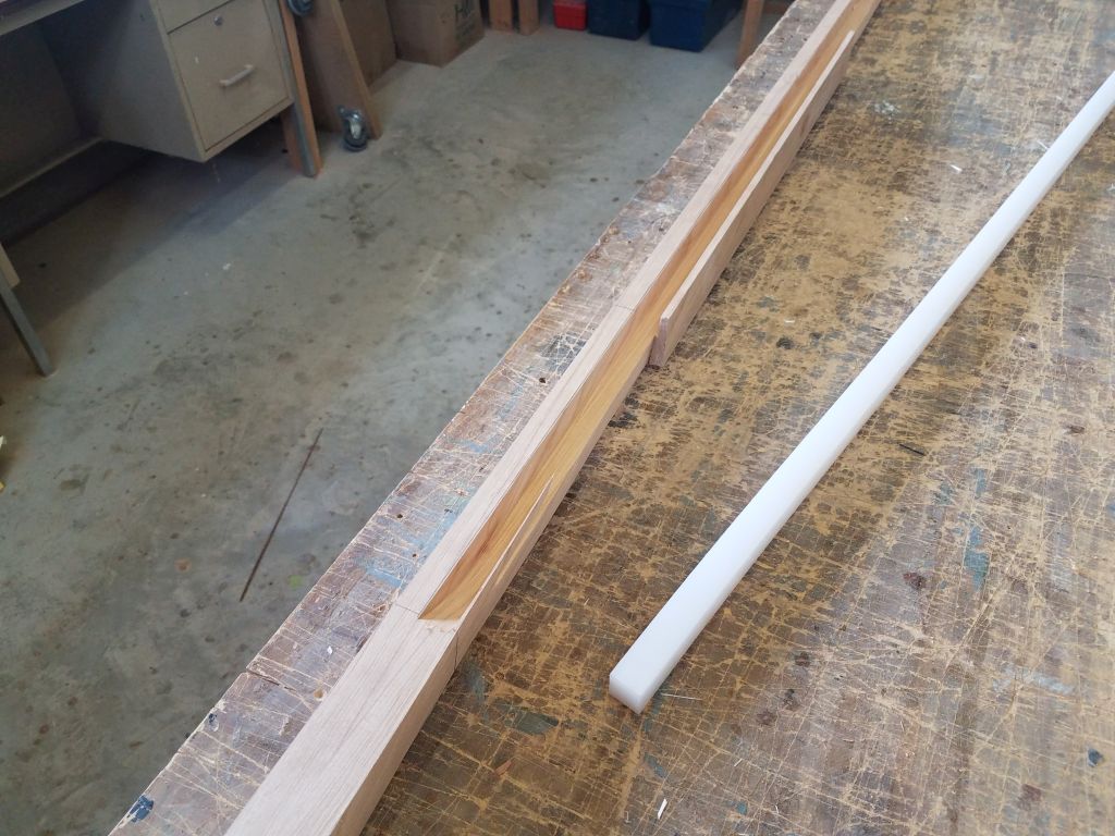
To cut the first board, I used one of my plywood templates, cut just a little short of the overall length, to  template the angles on each end, and then, afterwards, to determine the final length.

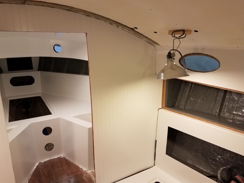
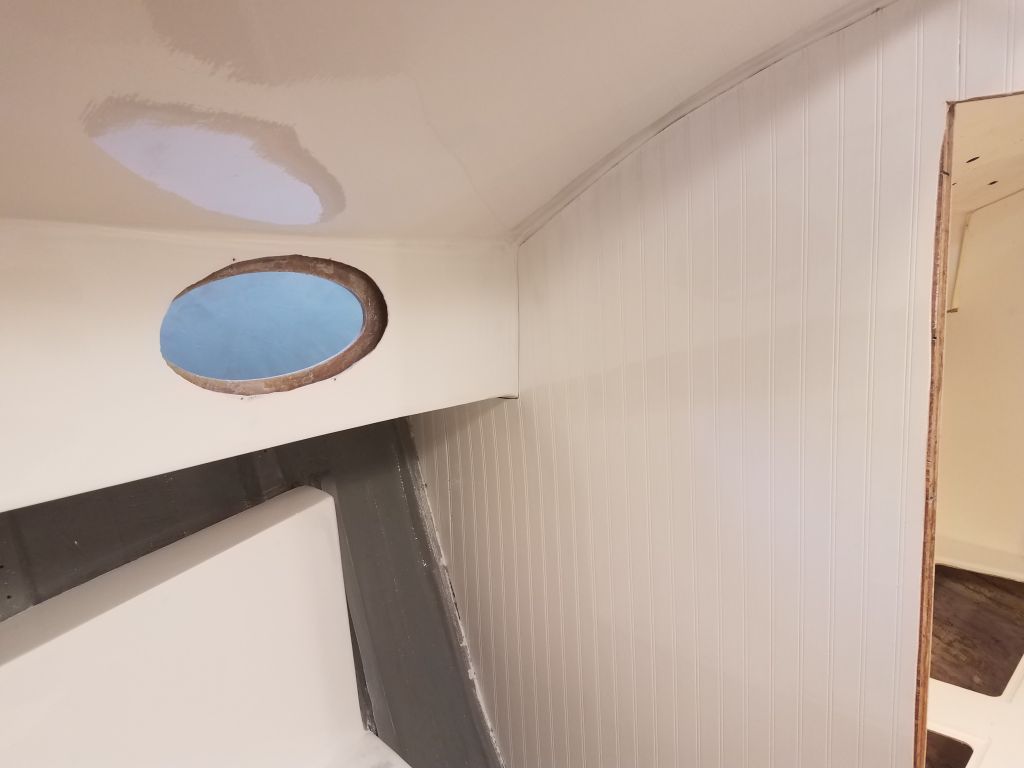
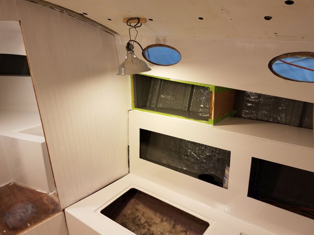
From there, it was pretty quick to fill in the rest of the space, with only the top tier requiring any additional cutting to slip behind the overhead liner and fit beneath the deck above.

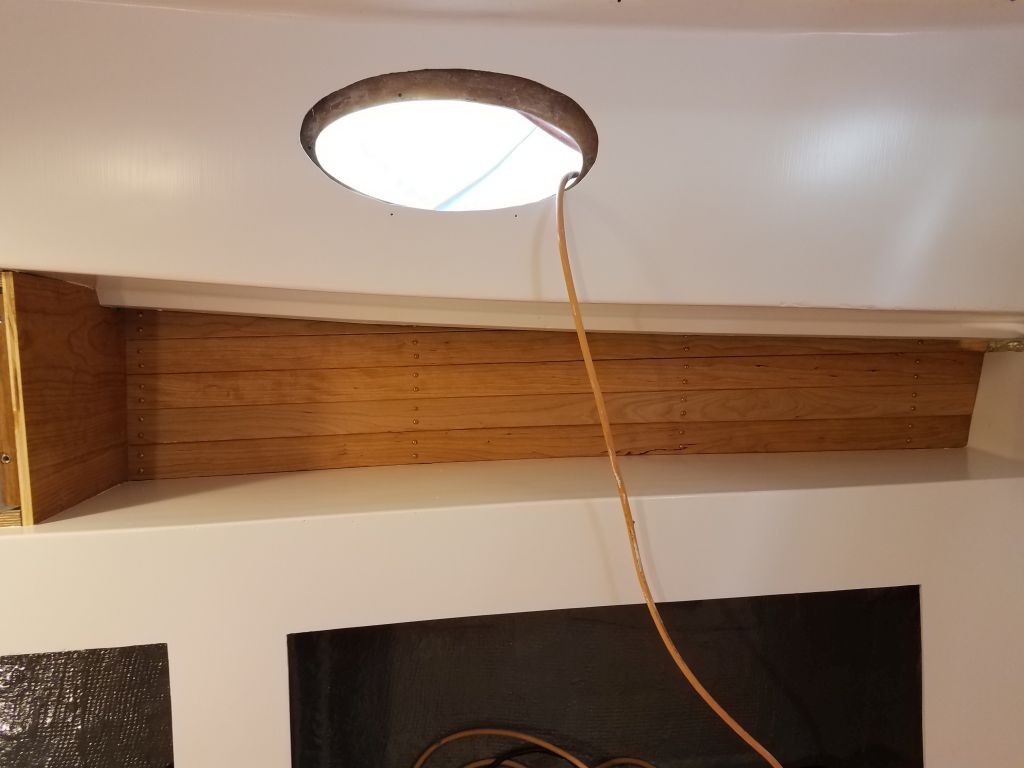
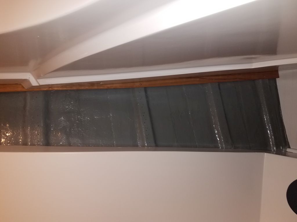
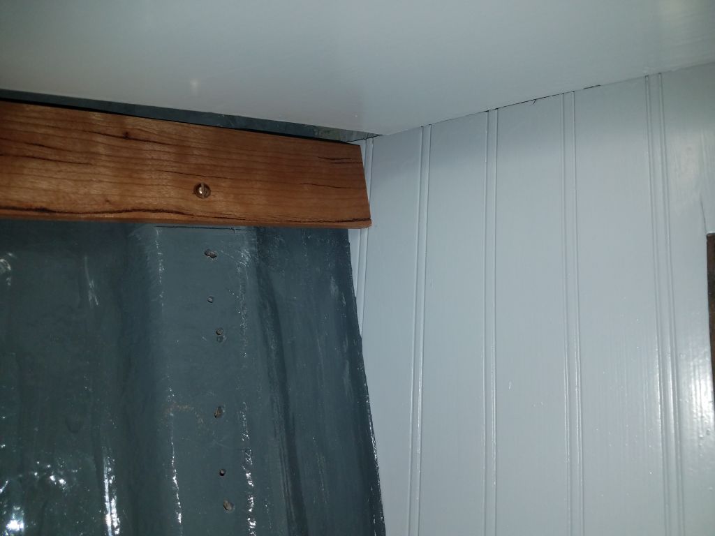
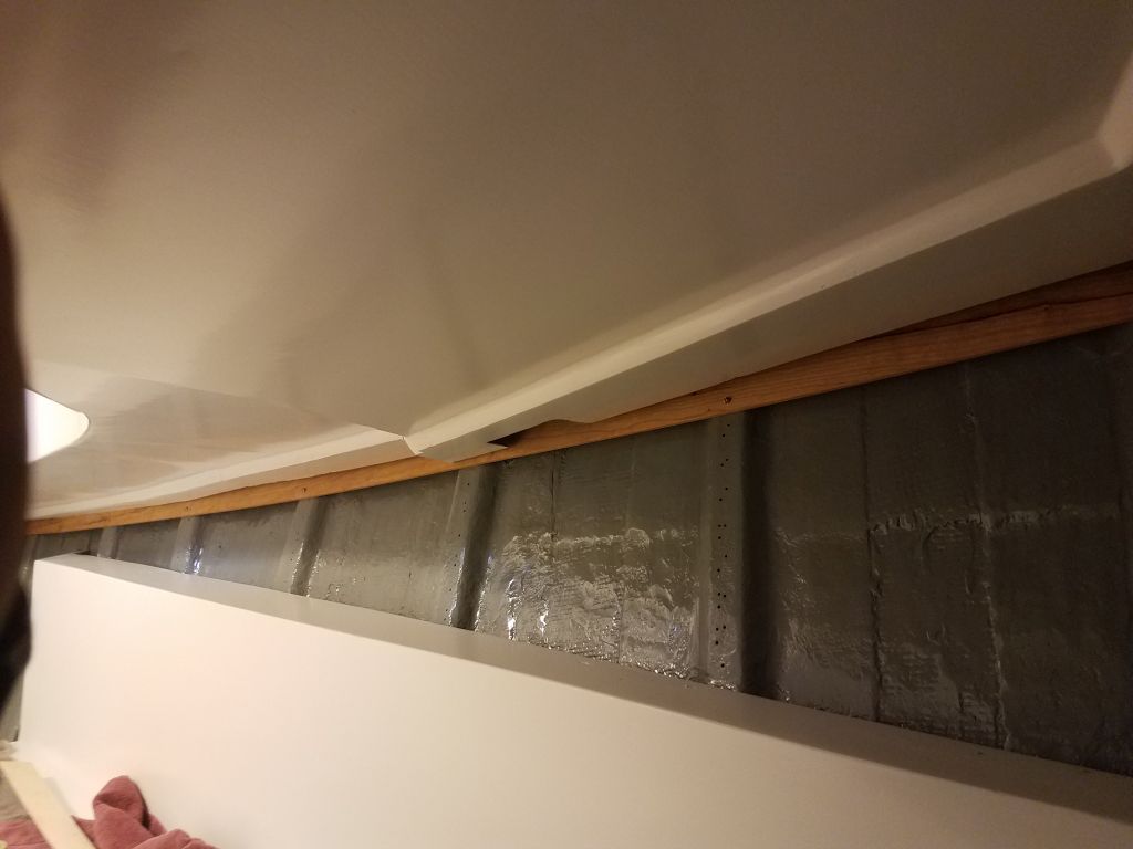
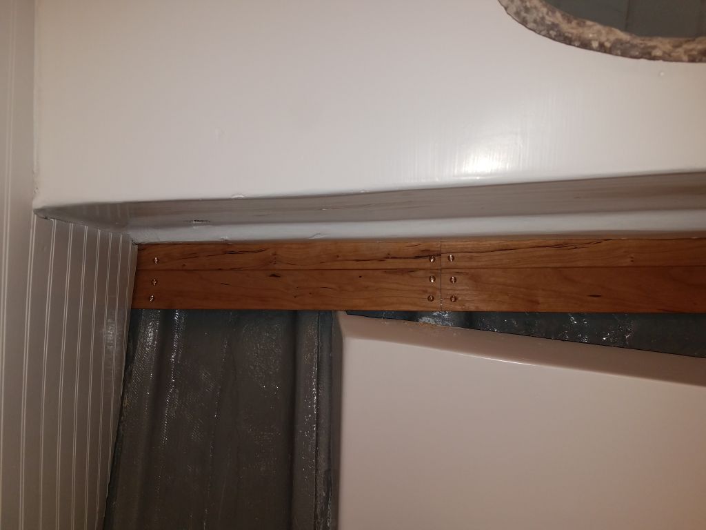
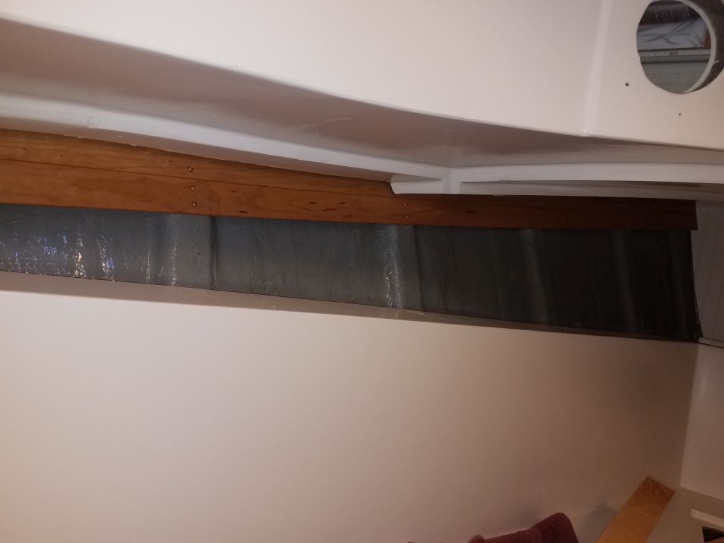
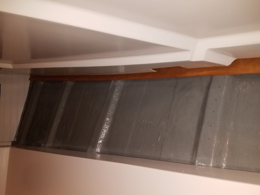
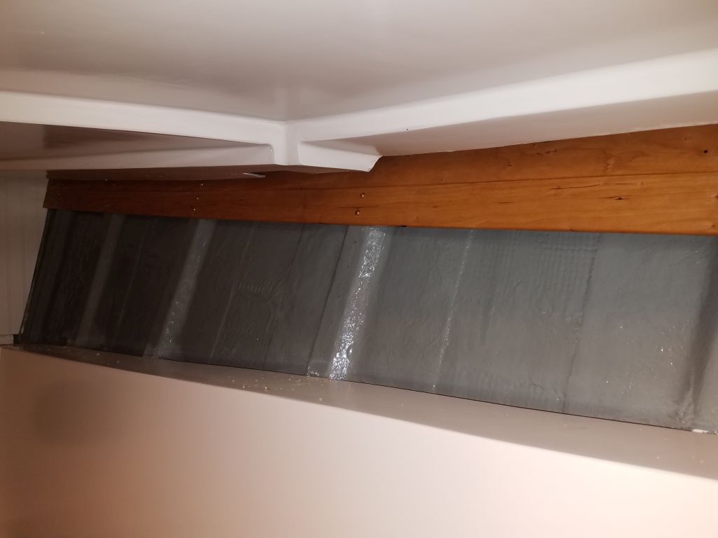
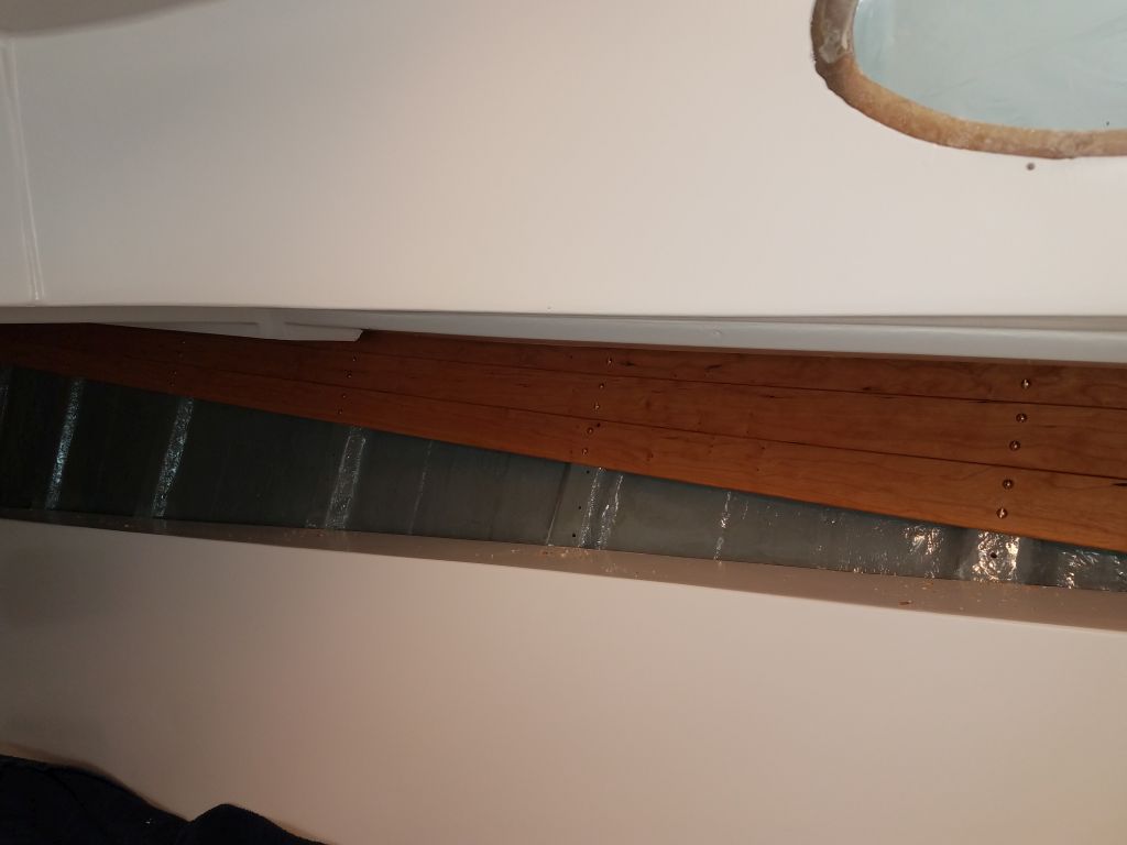
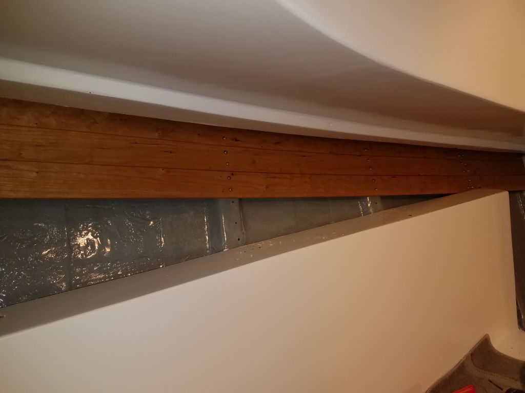
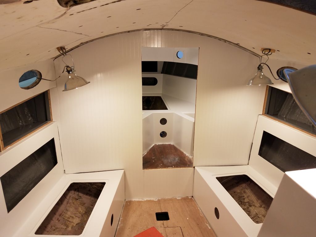
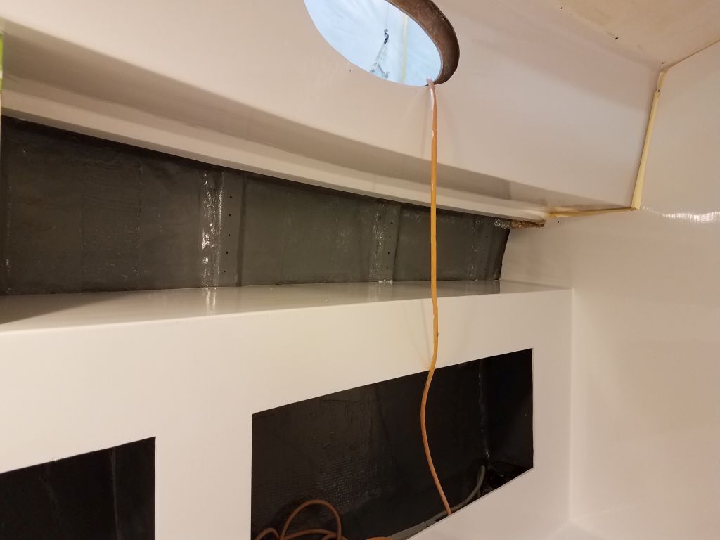
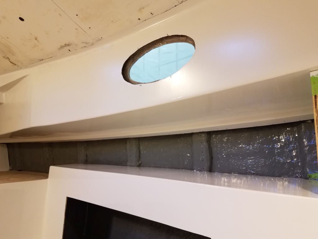
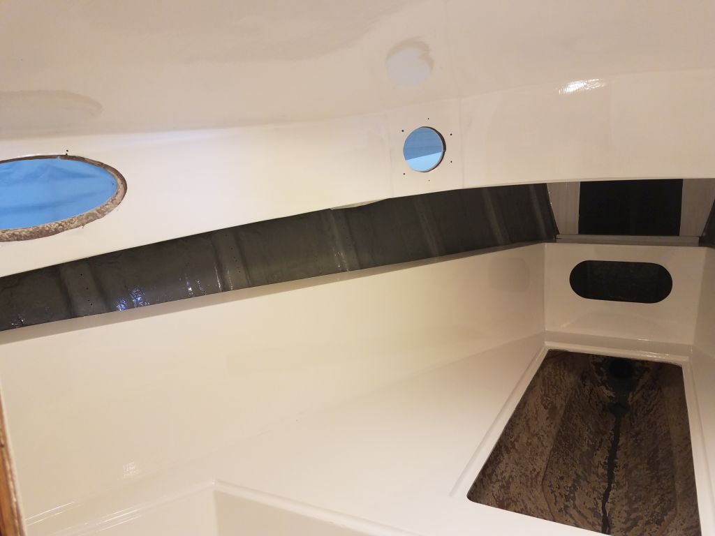
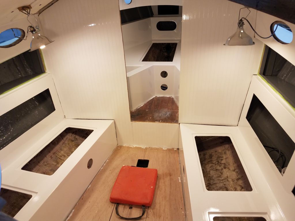
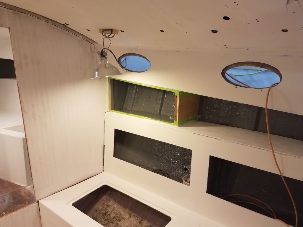
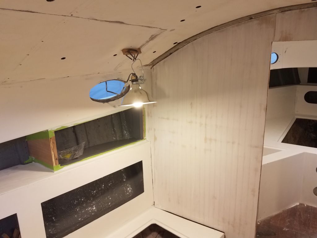
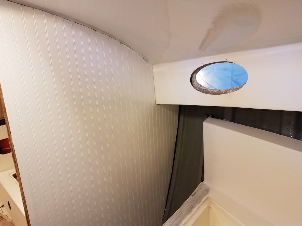
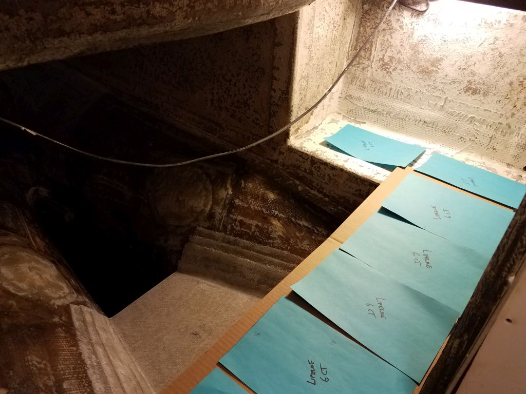
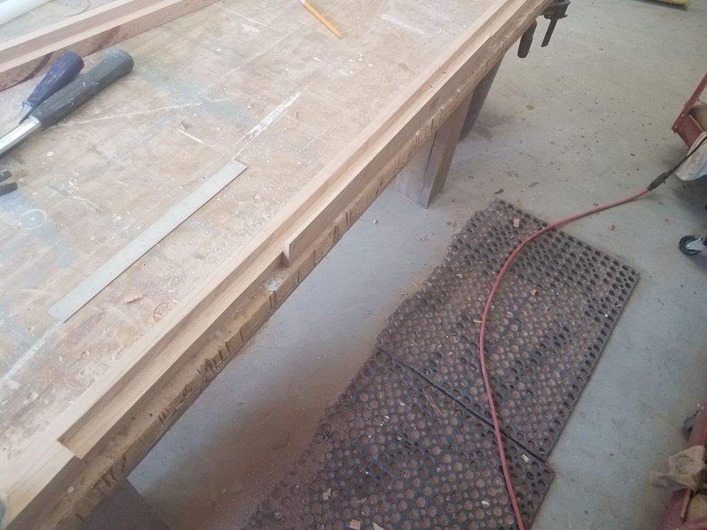
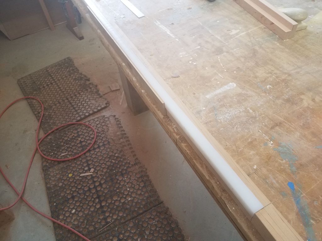
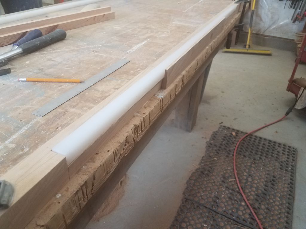
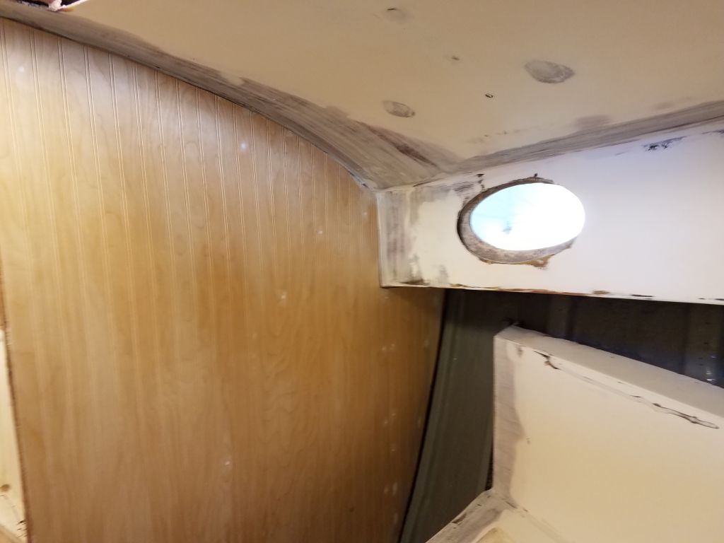
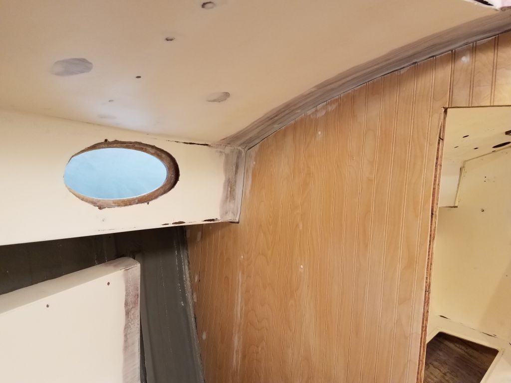
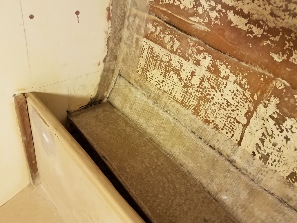
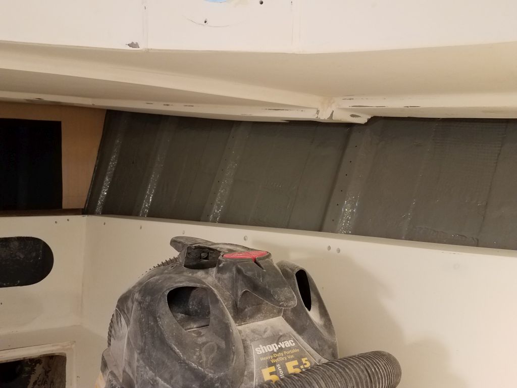
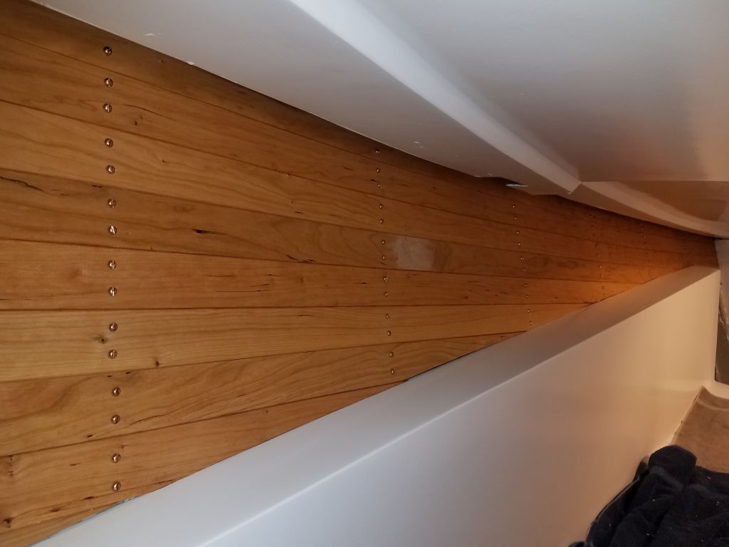
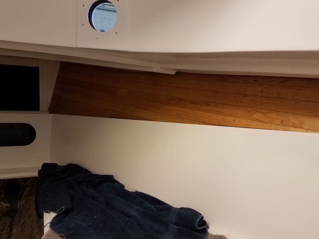
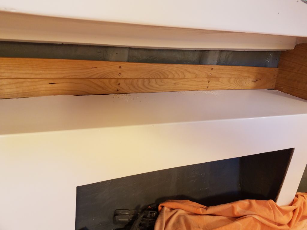
On the port side, the space was longer, leading aft over the galley, but otherwise similar in shape and concept, and once more I registered my first board against the top of the shelf, and extending aft from there.  Here, the shelf/liner had some ragged cutouts on its outer edge, so I’d have to add some additional trim later to cover the raw edge, since the ceiling boards couldn’t hide it.

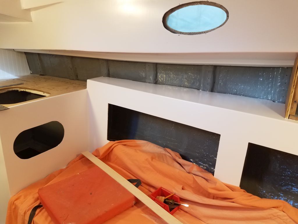
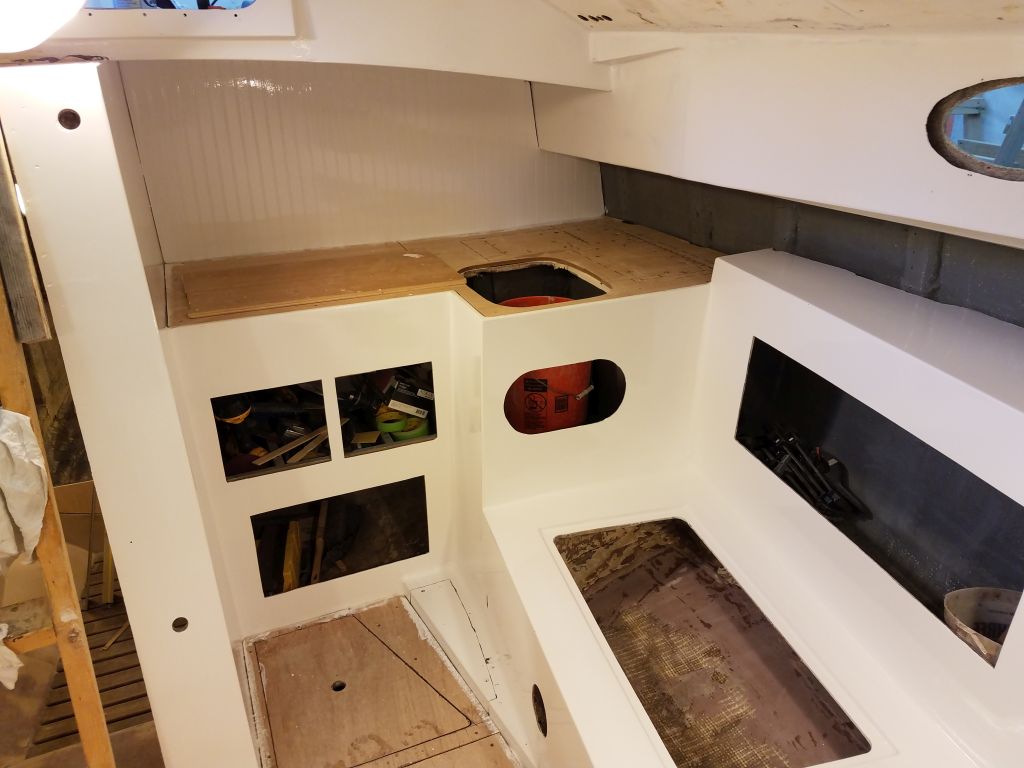
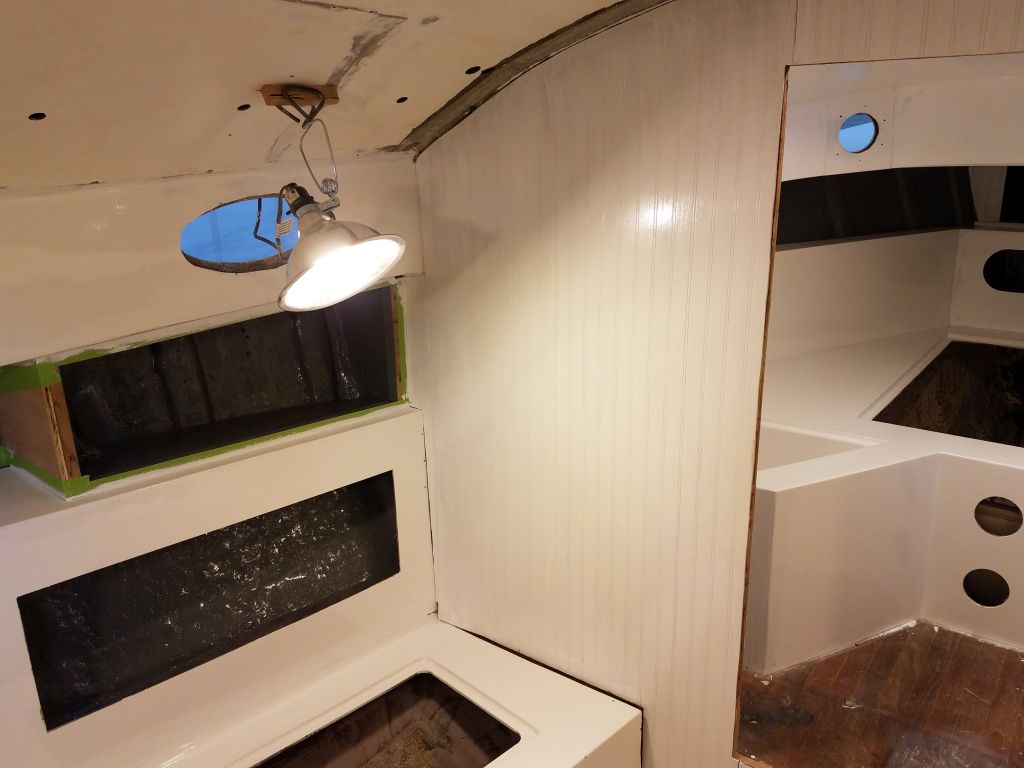
Before the end of the day, I had time to fit and install a second full-length board above, and also a shorter board below the first one in the galley, which left a small space beneath that would allow the countertop boards to slide beneath.  I’d figure out final trim details in that area once the countertop was complete later.

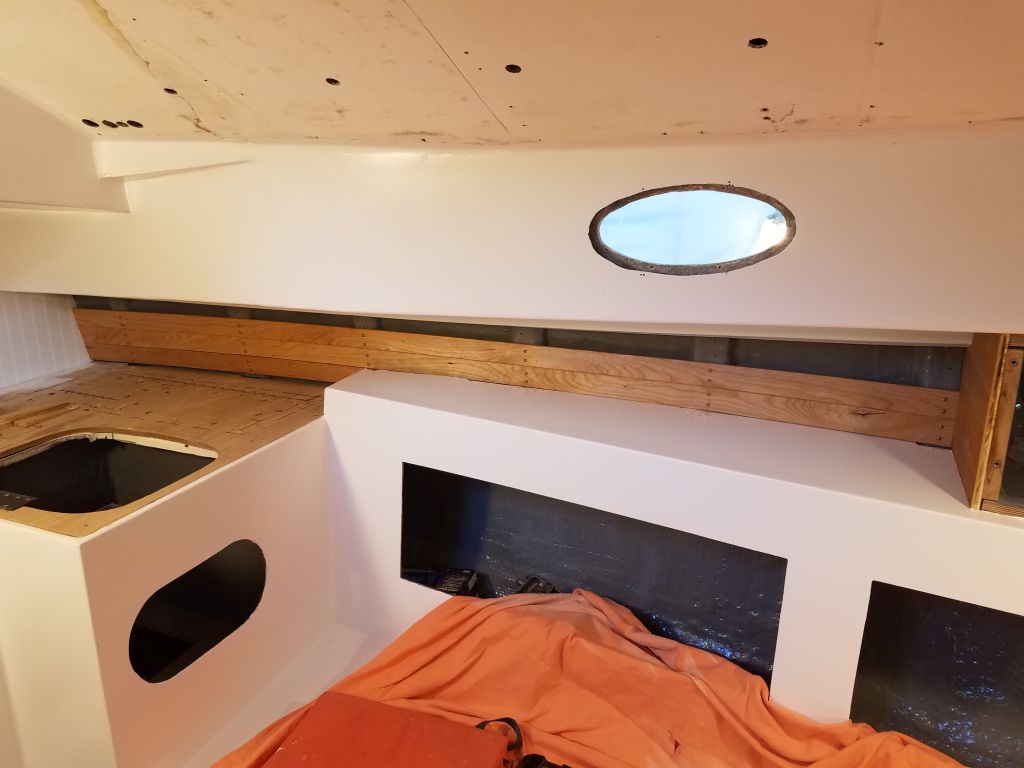
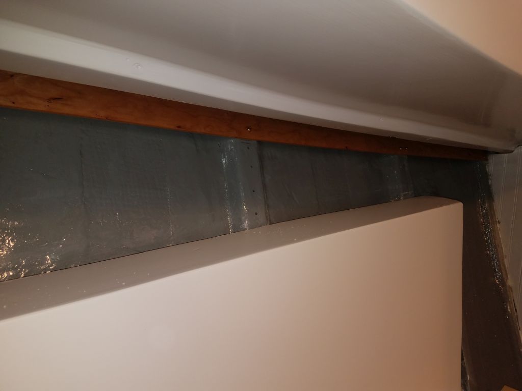
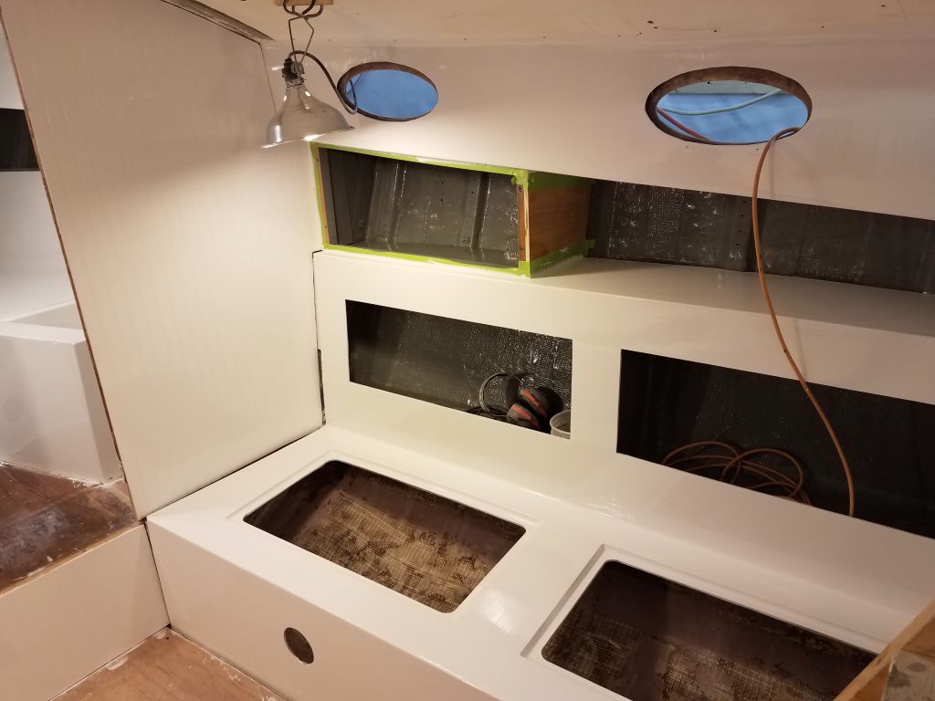
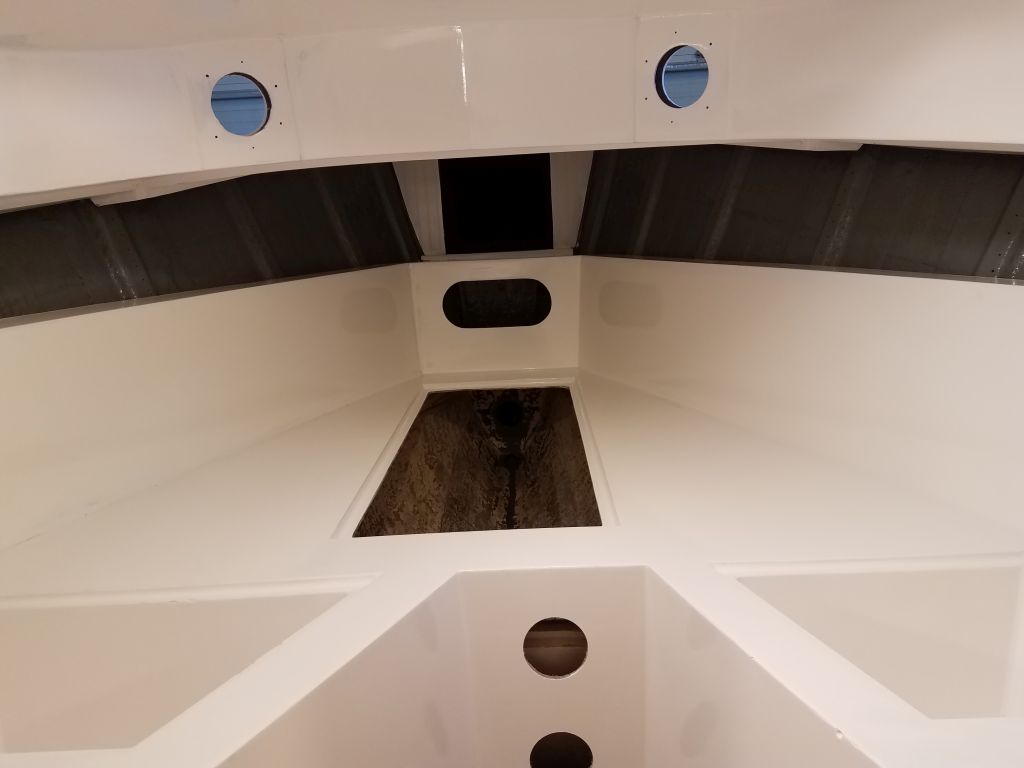
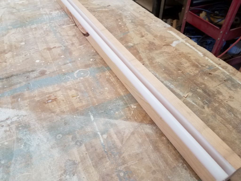
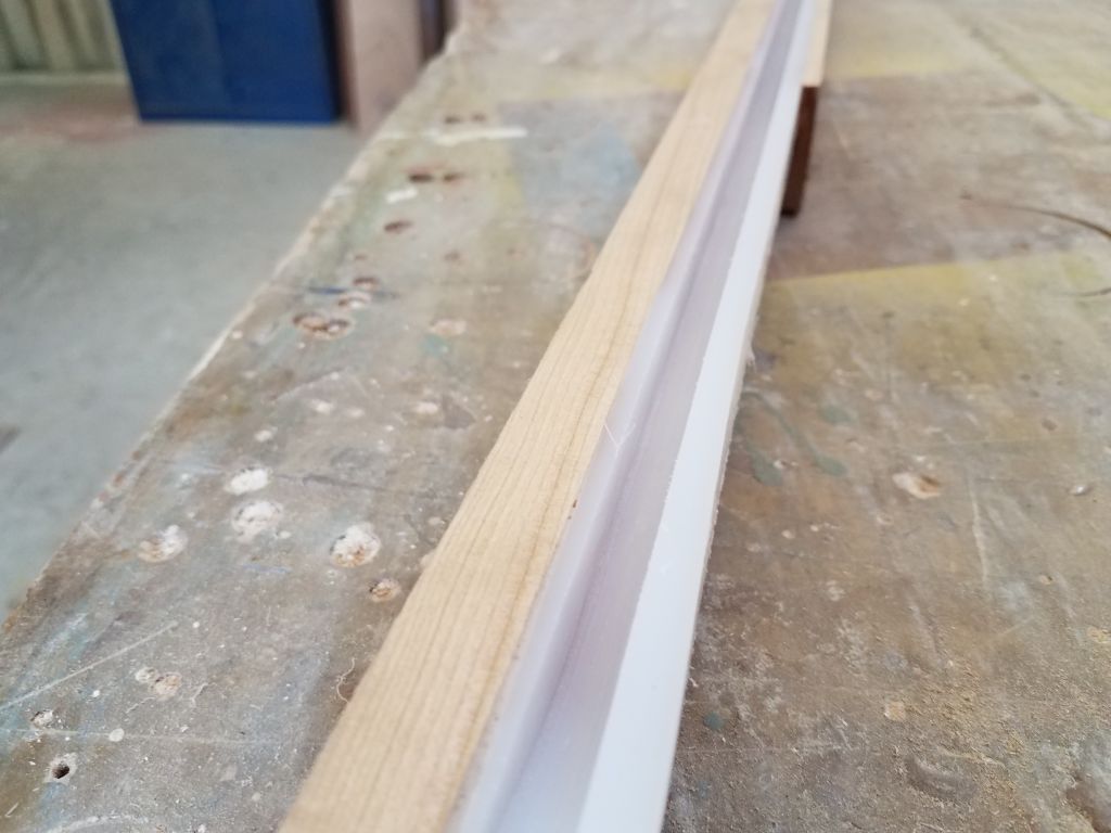
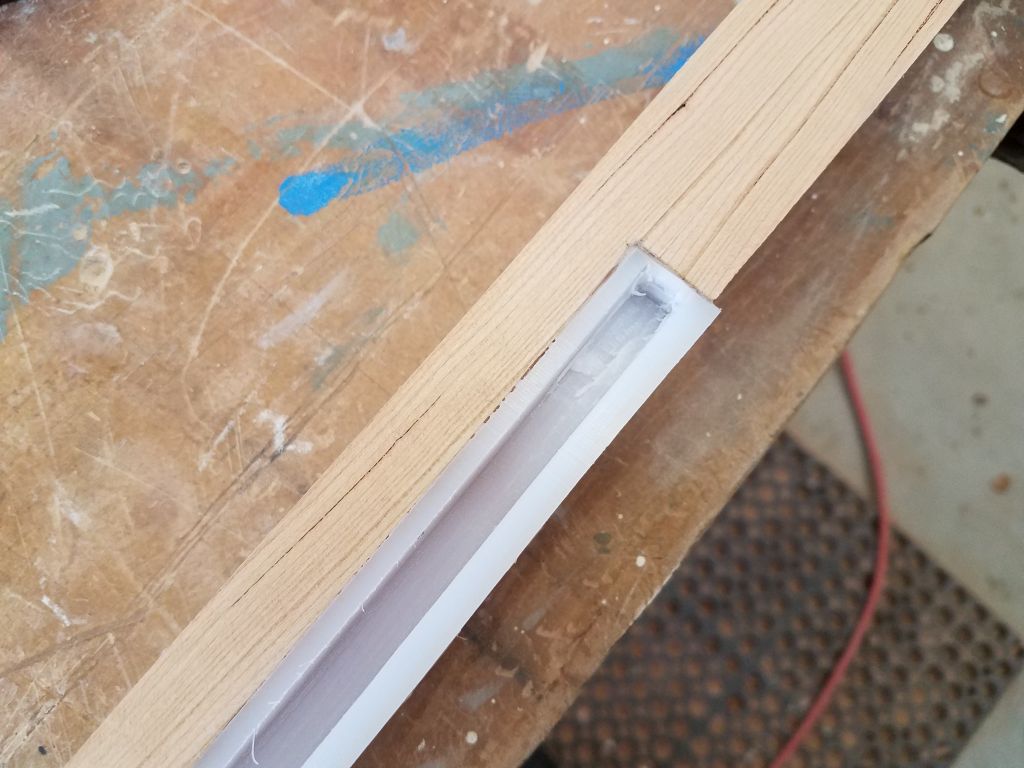
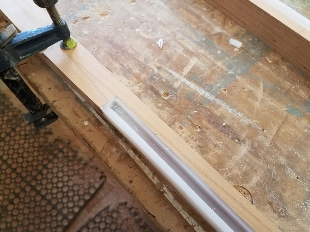
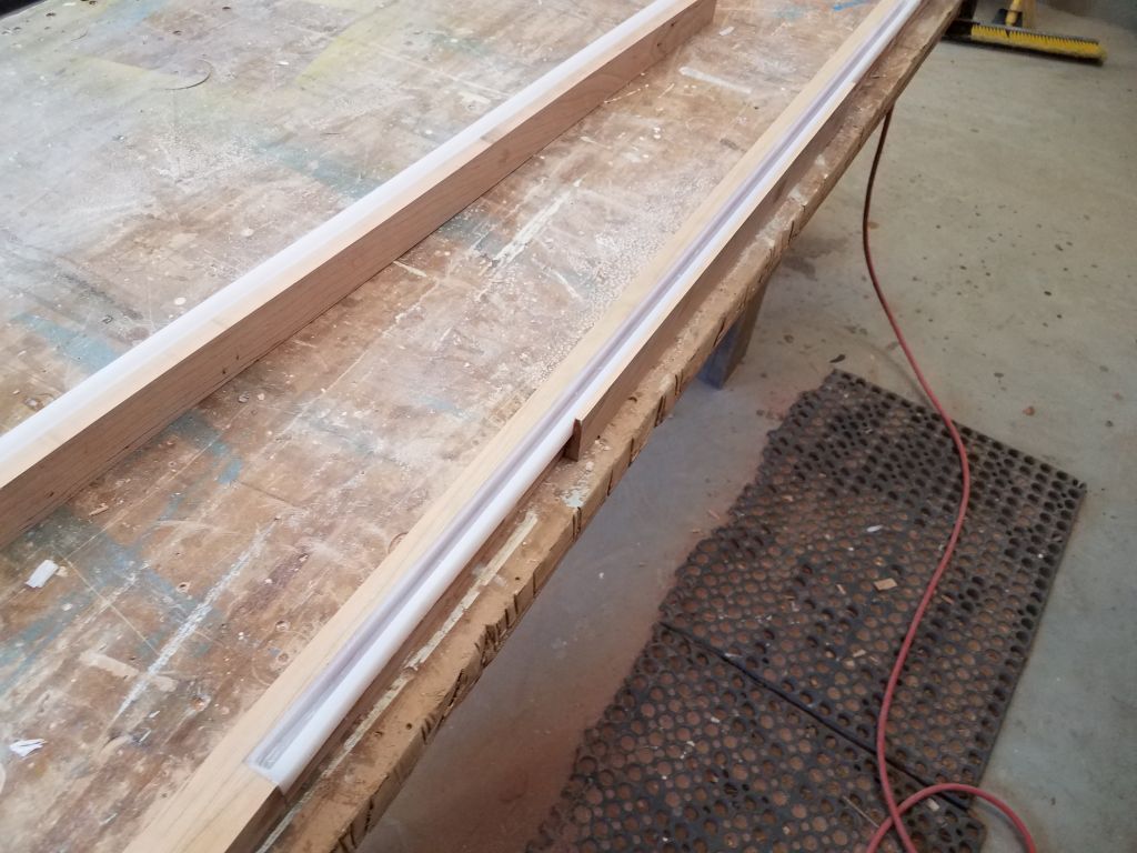
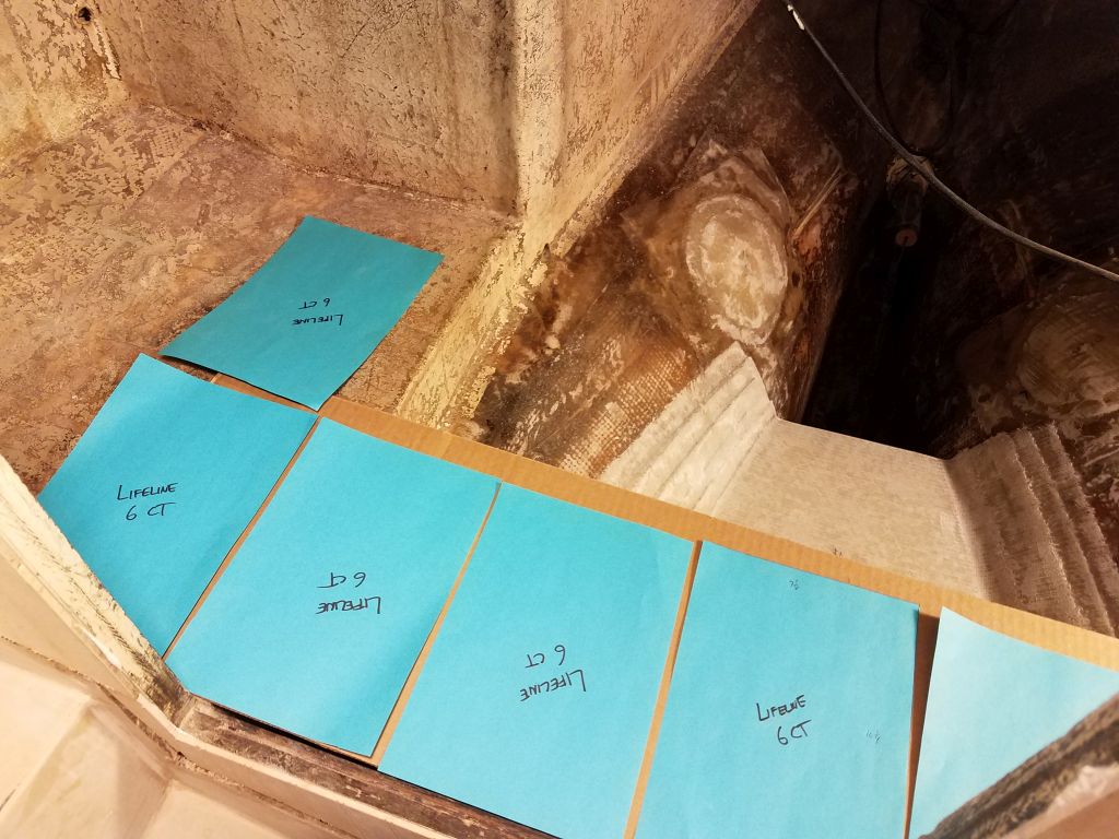
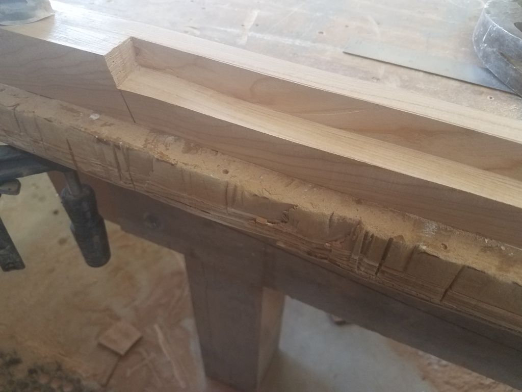
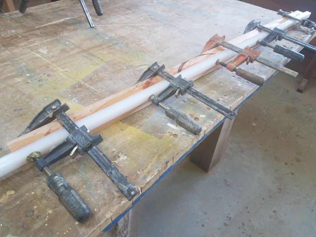
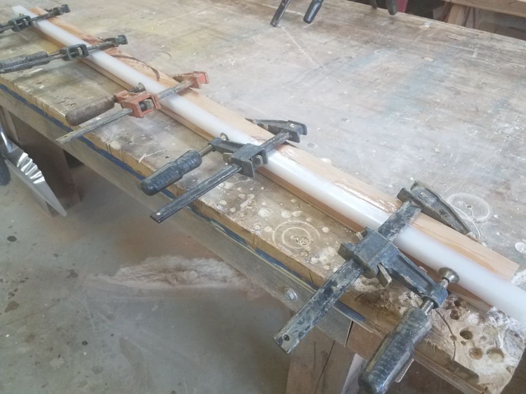
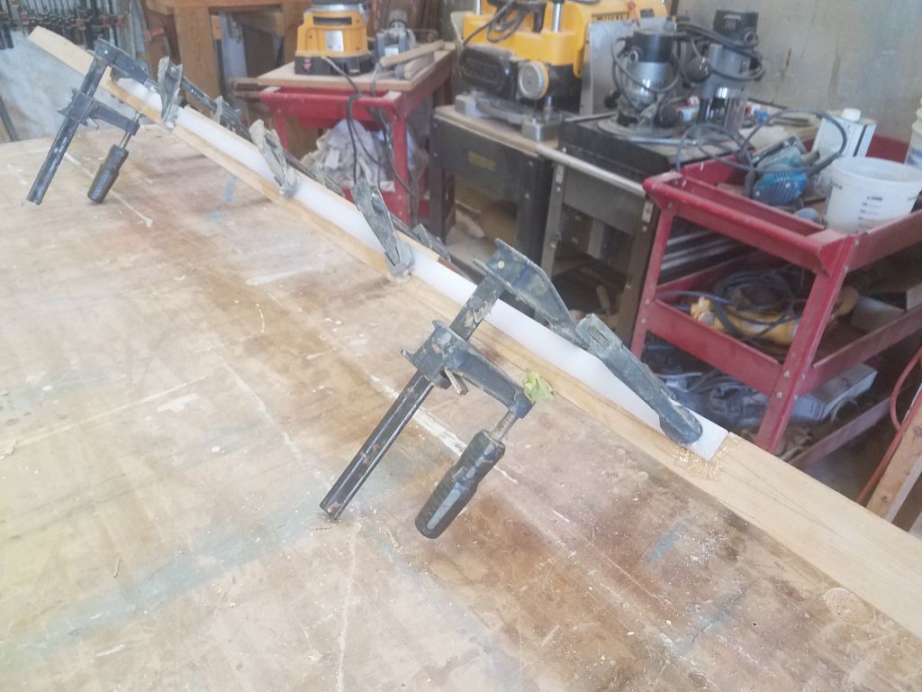
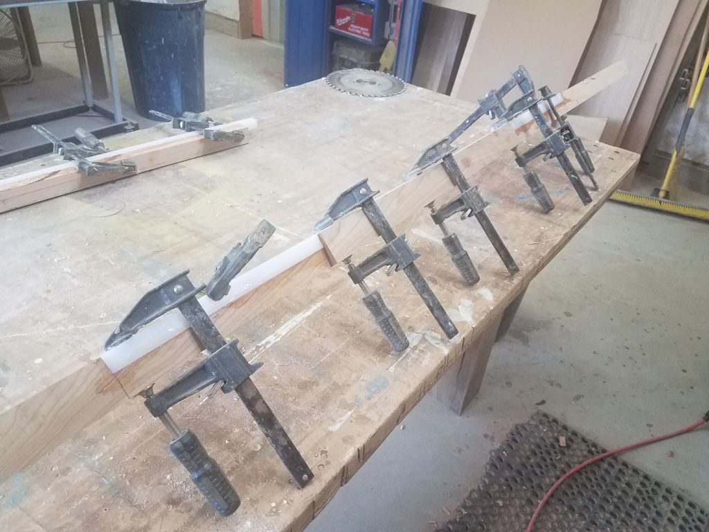
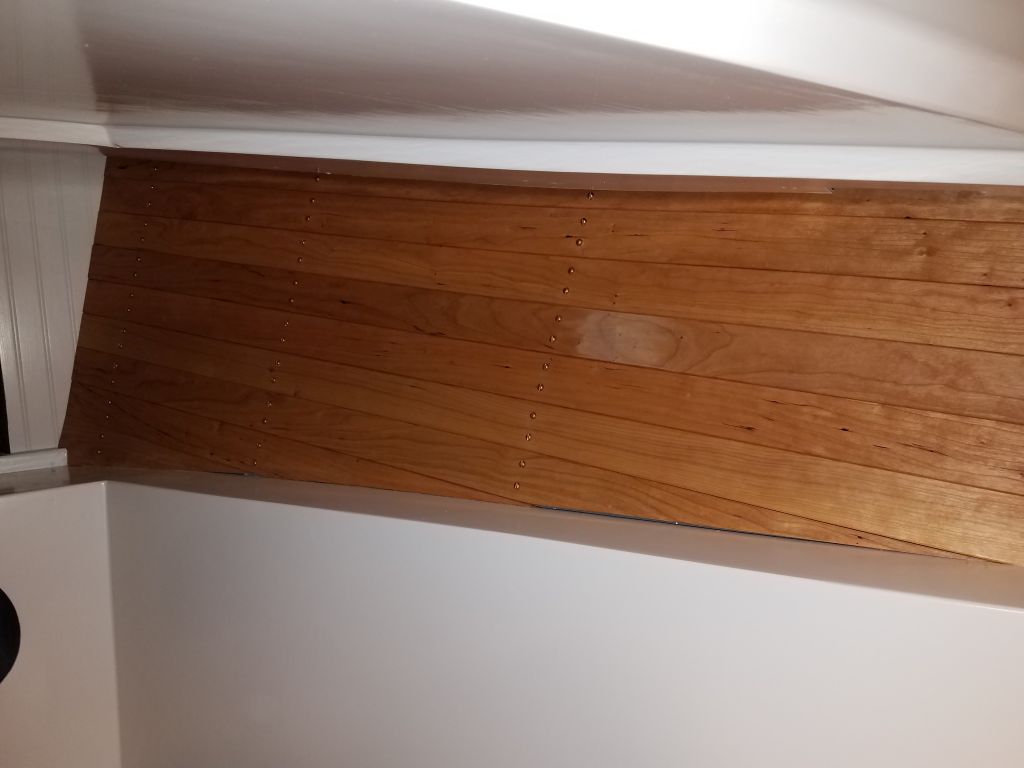
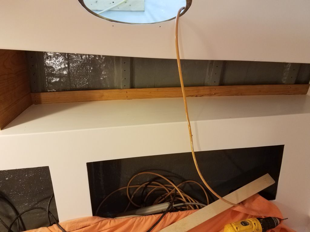
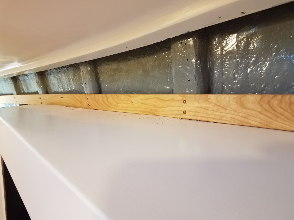
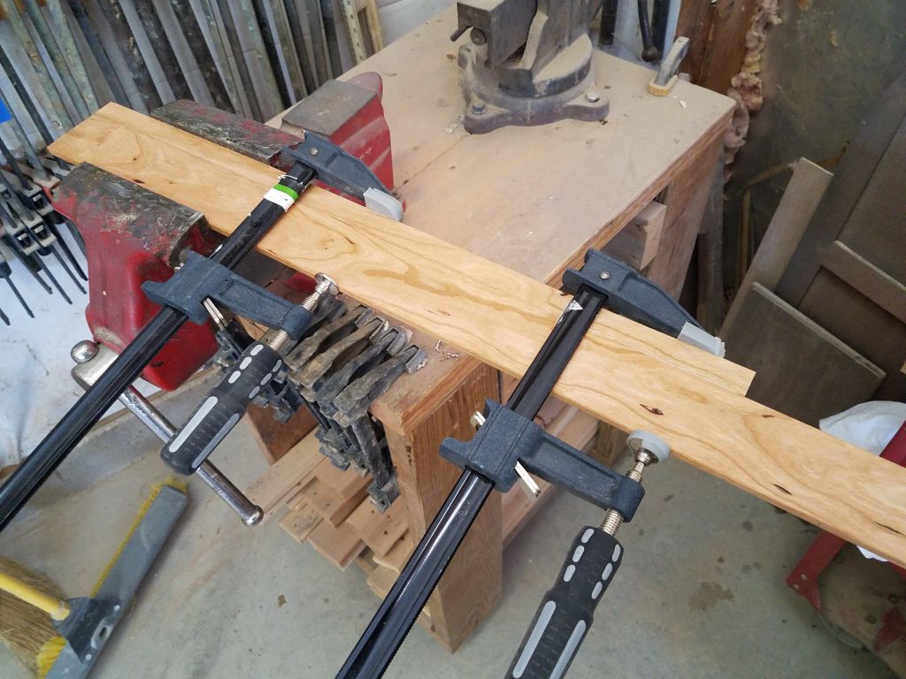
Checking the fit for the next board in the series, I could see that the way the overhead liner was cut and configured at the aft end over the galley meant that from certain angles, the eye could see up farther than in other areas, so the cherry ceiling would have to extend a bit higher there.  I could also see that it was going to require another narrow strip that would be hard or impossible to secure on its own, so before closing for the day I prepared another glued-up section with an additional width secured to the top edge of the third ceiling board with glue, which I left clamped up overnight.

Total time billed on this job today:  7.25 hours

0600 Weather observation:  11°, clear.  Forecast for the day:  Sunny, 38°

Scupper 102

Monday

To start the day, I spent a few minutes on the lazarette hatch and companionway hatch.  To smooth and completely fair the now-glassed surface of the companionway hatch, I had to apply a coat of fairing compound over the whole thing, the first of several that would be required.  Meanwhile, I applied some of the fairing compound to a few areas on the new lazarette hatch as needed.

I spent the remainder of the day working on the ceiling installation in the forward cabin.  These were the longest sections of ceiling, so I wanted to be sure to use the longest pieces of the cherry that I’d prepared first, and for other reasons it was most logical to start here and work back to other areas.

To begin, I ripped a series of 2″ wide strips from some junk 1/4″ plywood.  I could use these as stand-ins for, and templates of, the ceiling boards as needed.  Then, I spread out most of the cherry ceiling strips on a bench to allow me to easily pick and choose based on length and wood features.  For the moment, I set aside some of the “worst” boards, that is boards featuring a lot of sapwood that would only be good for short lengths to stay away from the undesirable grain or coloration features.

Beginning randomly on the port side, I worked on the layout for the first piece, which took the longest, of course.  The space was sharply angled from bow to stern, which meant that only a few boards would be full-length; the rest could die out against the fiberglass berth liner.  The overhead liner featured two levels, and I had to align the first board in such a way as to properly fill the whole space from beginning to end, while remaining accessible enough in all areas for fasteners to hold it in place, and at the same time not drop beneath the edge of the overhead liner on the way aft.  This required some shuffling and layout, but eventually I determined the proper position for the board and, using my plywood fakes, made some reference marks as needed.

Normally I would have made the boards full-length from bow to stern in this space, but I actually had to leave access at the aft ends so the forward chainplate could be installed and, later, inspected or serviced as needed.  This was in the space formerly occupied by the built-in tall hanging lockers that I’d removed.  To accommodate this, I ran the top board aft to the nearest cleat, and cut it halfway across the width of the cleat.  This then left a short space that I filled in with the remainder from the original full-length board stock, keeping the grain and color consistent.  While I would have avoided this if possible, it actually made installation more straightforward since I didn’t have to perfect both ends of a single board at the same time in order to fit.  I secured the boards with bronze screws for appearance.

With the first board in place, the remainder went more quickly, since alignment was now a foregone conclusion with each board butted beneath the one above.  The second board was also full-length and required the short piece at the aft end, but from there, all the boards conveniently passed just outside the fiberglass shelf so their cut ends were hidden beneath, meaning at least on this side I didn’t have to make a lot of fussy end cuts.  Even so, each board required several trips back and forth through the boat and ladder to the shop, and with a pair of screws at each cleat location, took some time to install.  I used a little marking block to keep the screws aligned with the cleats (and the screws above), and properly spaced on each board.

Eventually, I reached the bottom of the space and fitted and installed the final, small piece in the forward corner.

With the port side complete for now (I left the short space at the aft end of the berth for later, once I’d finished all the long pieces of ceiling in the boat and could thus use up and cut the shorter lengths required), I continued on the starboard side, following the same basic process, although this time I knew better what to expect with the topmost board, so its fitting went more quickly.  From there, I managed two additional strips before the end of the day.  Since the shape and position of the two liners (overhead and berth) were slightly different from side to side, here the top three boards passed by the end of the shelf, so in the morning I’d be working on progressively shorter boards to fill in the rest.

Total time billed on this job today:  8.5 hours

0600 Weather observation:  11°, clear.  Forecast for the day:  Sunny, 37°

Scupper 101

Friday

To get started, I inserted all four through hull mushroom fittings in their respective holes (marking each accordingly),securing them temporarily with tape from outside.

Inside, I marked where each fitting came through the backing pad, then screwed on the flange base as far as it would go to determine whether I’d have to shorten the threaded fittings (expected and almost always necessary), and by how much.  With these references, I’d be able to mark and cut off the excess thread length to allow the two pieces to be properly and tightly connected together in the final installation.

With all the fittings removed once more, I threaded the supplied backing nuts all the way on (I’d need these to clean up the threads once cut), and for each fitting marked the cutline with masking tape, before cutting off the excess length and cleaning up the threads to ensure that the fittings would easily thread into the flange base.

Once more, I dry-fit the mushroom fittings through the hull with tape, and, at each location, threaded on the flange base fully, then drilled the 5/16″ through-bolt holes through the base, pad, and hull, cleaning up afterwards.  Once all the holes were drilled through, from outside I milled countersinks at each bolt location to accept the flat-head machine bolts that would secure the bases to the boat.

In the galley, I soon found that attempting the installation with existing access was not possible, so I cut a larger opening in the plywood cabinet above the fitting location to improve access for now.  Later, I’d cut and install a new plywood base above to clean up the final installation.

Now, for each of the four fittings in turn, I applied heavy sealant to the mushroom fittings, and installed them from without, securing them with tape.  Scampering back into the boat, I applied additional sealant around the protruding threads, and on the backing pads, before threading on the flange base and pinning it in its proper position with temporary and sacrificial bolts from inside.  Then, hurrying back outside again, I replaced the temporary bolts with the proper bronze, flat-head machine screws, which I gooped up heavily, and, with the bolts in place, threaded in the through hull fitting tightly with a special tool.  At this point, I could clean off most of the excess sealant from outside.

Finally, back inside the boat, I installed bronze washers and nuts and tightened the three through bolts, completing the basic installation other than final sealant cleanup.

With that done, and any excess bolt length removed from within, I completed the installations by installing the ball valves and pipe-hose connections at each location.  While this step didn’t strictly have to happen now, I saw no reason in this instance to postpone it either.

After cleaning up and getting reorganized after this flurry of activity, I prepared to reinstall the rudder permanently following its various repairs, which had taken place sporadically since I dropped the rudder for this purpose some months before.  The rudder had been more or less ready for some time, just awaiting the right time–which apparently was now.

Before raising the rudder back into position, I filled the packing nut with four rings of new graphite packing, then, inside the after steering room, reinstalled the nut on the packing box glassed inside the hull.  I also slipped over the rudder shaft a bronze steering arm that I’d obtained as part of a newly-conceived rudder stop system, which would ultimately prevent the rudder from being over-turned and crushing against the hull, a previous design flaw that had directly led to and caused the damage to the upper part of the rudder blade that had required me to remove the rudder in the first place.

Now, I could raise the rudder back into position with a jack, which process went smoothly and without issue.

With the rudder all the way up, I heavily applied sealant to the bronze shoe casting (which I’d previously cleaned up), and reinstalled it with new bronze bolts.

In the boat’s previous iteration, a rudder stop system had either failed, or not been in place to begin with, and this allowed the rudder to turn nearly 90 degrees to each side.  This caused the top of the rudder blade to hit the hull above, and this ultimately caused failure of the rudder laminate.  While the rudder was now whole again, the overturning problem hadn’t gone away.

The steering system now was to be a simple tiller, so to prevent the oversteering from occurring in the future, I came up with a rudder stop system based on the existing situation and with as simple a design as possible.  The existing rudder shaft featured two machined grooves leftover from the old steering quadrant, and with these as a basis, I found a hefty bronze steering arm that fit my design brief–way overbuilt for this particular task, but pleasingly reasonable in cost–that I could fit to the keyway in the rudder shaft.  I did have to modify a length of 3/8″ brass key stock, since the keyway in the shaft was 3/8″, but the corresponding key in the bronze arm was just 1/4″.  This was easy enough to do with the brass stock, and soon I had the key stock modified to the point that it would fit and lock the bronze arm in place, facing dead aft.  This, along with the pinch-bolt and a cupped setscrew that I tightened against the shaft, would hold this assembly securely.

From here, to complete the system I planned to install lengths of cable between the steering arm and the bulkheads on each side, the cables’ lengths to be determined based on how far the rudder could safely be turned to each side.  This would prevent oversteering in a simple yet effective way.  I’d complete and install the final portions of the system later, but the steering arm had had to be installed while the rudder was still down.

To finish up the day, and the week, I lightly sanded the new glasswork on the companionway hatch, removing the excess material that I’d let hang down during the glassing session.  Now it would be a straightforward matter to smooth and fair the final surface.

Finally, I unclamped and sanded the new lazarette hatch, smoothing the seams and rounding the exposed corners.  There’d be some final fitting and scribing to allow the hatch to fit the deck properly, but that was for another time.

Total time billed on this job today:  8 hours

0600 Weather observation:  40°, cloudy.  Forecast for the day:  Rain showers and fog, 52°

Scupper 100

Thursday

These photos show the new interior paint work after the second coat, and with the coating cured and in its final appearance.

To allow the fresh paint plenty of time to fully cure and harden up, I planned to more or less stay out of the cabin for the rest of the week, which gave me time to continue to focus on some of the cherry trim preparations and other tasks.

To that end, I cleaned all the new ceiling boards I’d cut earlier, and set them up on three separate benches so I could apply a thinned coat of varnish to all sides of all the pieces.

The new hatch opening I’d cut and prepared in the poop deck required a hatch cover.   Since the boat was to have no exterior woodwork (all future exterior trim would be made with “vegan” wood or other substitutes), I chose to build the new hatch from fiberglass, which would eventually receive paint to match the rest of the deck.  Using prefab 3/8″ fiberglass sheeting, I cut a lid of appropriate size, and 1″  tall strips of the same material for the edges of the hatch.  The fore and aft ends would require scribing to match the deck camber, but I planned to to that later, after assembly.

I epoxied the pieces together into a hatch shape and set the assembly aside.

The original sliding companionway hatch was a massive assembly of plywood and teak strips, and was in sound structural, but poor cosmetic, condition.  The old teak, neglected for years, was heavily weathered and rough, and unsalvageable from a cosmetic standpoint, though it remained solid all around.  During earlier discussions, the owner and I agreed to try sheathing and painting the existing hatch, in keeping with the no-wood mantra.

To prepare the surfaces for the work ahead, I sanded the hatch with coarse paper, exposing fresh wood in many areas.  The black sealant between the wood strips was generally quite a bit lower than the wooden surfaces, so by skimming the sander across I eased the hard edges to bring the surface into general fairness and smooth enough for what was to come next.

I applied a coat of unthickened epoxy to the wood and, after allowing that to sink in for a little while, applied a coat of epoxy fairing compound, mainly over the curved top surface of the hatch to fill in the seams and smooth the surface. I also used the filler to smooth any grain patterns in the sides and ends of the hatch, as needed.

Next, I installed a layer of 10 oz. fiberglass cloth that I’d previously cut to the appropriate size.  I allowed the cloth to drape below the edges of the hatch in all areas, and sheathed the top, sides, and wrapped around the bottom edges of the side and end rails where possible and as necessary.  It would have been nice to come back sometime later with the epoxy in a green state to trim the excess cloth, but the timing didn’t work out for that so I’d cut and sand off the excesses once the epoxy cured fully overnight.

To round out the day, and prepare ahead for one of my planned tasks next time, I used a drum sander to ream out all the through hull holes, removing any excess epoxy that had squeezed out when I installed the interior backing pads.  Then, I took care of various pedestrian–but necessary–tasks with the bronze through hull hardware itself, removing too-sticky pilfer-proof labels (that is, labels that only come off in tiny pieces to prevent removal and  transfer to another item)  from the pieces and replacing the bronze plugs in the valves with the supplied zerk grease fittings, and otherwise getting in order for the through hulls’ installation.

Total time billed on this job today:  7.75 hours

0600 Weather observation:  32°, cloudy, 2″ sticky new snow overnight.  Forecast for the day:  Mostly sunny, 46°

Scupper 99

Wednesday

To begin the day, I applied a second coat of the semi-gloss white paint to the cabin areas and loose hatch covers.

After solvent-washing the new cherry fiddles, I applied a highly-thinned sealer coat of varnish to all sides of the various pieces.

Next on my list of trim to mill and prepare were the ceiling strips, or hull liners for the forward and main cabins.  Using some rough measurements of the spaces that I’d taken earlier, I chose enough cherry boards for the job (I hoped) and, in a series of steps, milled 2″ wide blanks from the boards (plus a couple 1″ wide pieces as by-products), then resawed each blank more or less in half  to create two thinner pieces of roughly 5/16″.  The two halves ended up slightly different thicknesses, and I could have made another saw pass on the thicker pieces, but that was unnecessary since my next step was to clean up and dimension all the planks to 1/4″ in thickness using the planer.  It took a couple extra passes on the thicker pieces first before I could run all the blanks through the planer to achieve the final thickness.

The planer left the surfaces smooth and clean and ready to go, but to finish the work on the blanks, I used a block sander to ease the top edges of each piece, creating a small v-groove between boards that looked nice and would help hide any inconsistencies in the planks in whatever installation lay ahead.  Sanding these small chamfers on all the blanks took me through the close of business.

Total time billed on this job today:  8.5 hours

0600 Weather observation:  12°, clear. Forecast for the day:  Mostly sunny, 41°

Scupper 98

Tuesday

I spent the morning hours applying the first coat of semi-gloss white enamel to all interior surfaces in the forward and main cabins.  While it appears glossy in the just-applied photos, the paint would cure to a pleasing soft sheen.

Next, I applied a coat of the enamel to the top sides of the various loose locker lids.

During the afternoon, I sanded all the newly-milled trim pieces, working through the grits from 80 to 220 to remove tool marks and smooth the wood to prepare for finishing.

Total time billed on this job today:  7.5 hours

0600 Weather observation:  26°, mainly clear.  Forecast for the day: Partly sunny, 37°

Scupper 97

Monday

With the primer well-cured after the weekend, I spent the morning lightly sanding all areas with 220 grit, with subsequent vacuuming and solvent-washing.

I identified a few areas requiring some filler touch-up, mainly a few of the filled fastener holes in the paneling, along with an edge here and there on the fiberglass liner, so I applied the filler and then, after lunch, sanded it smooth and cleaned those areas again as needed.  This left the interior ready for finish paint coats, which I planned to apply the next morning when there was ample time.

When I primed the plywood locker lids, I’d not worried about setting the wet primer on the lids’ bottom sides on the stickers, but for the finish coats I’d need to do one side at a time, so to jump-start the process, I applied a coat of semi-gloss white enamel to the lids’ bottom sides.

I spent the rest of the day in the woodshop, where I milled enough cherry to use for the various fiddles throughout the boat:  berths and shelves, galley, and elsewhere. I’d purchased wood that was surfaced on three sides, which saved me from a long day at the planer, but I’d planned the time in and around the interior paintwork to mill and prepare most or all of the millwork.

With a short cut list detailing the various raw lengths I needed for the fiddles, I chose boards that would provide the rough dimensions required with the least waste, and as needed I straightened edges and milled the blanks to the correct width for the fiddles.  Afterwards, I used a router to mill rounded edges on three of the four corners of each board.

The final milling step for these pieces was a 1/4″ x 1″ dado on the inside lower edge of the boards, to allow the fiddles to cover and slightly hang down beneath the edges over which they’d be installed.  This brought me to the end of the day; next, all these fiddles would require sanding and sealing, and then there’d be other trim pieces to prepare.

Total time billed on this job today:  8 hours

0600 Weather observation:  32°, mainly clear with fog.  Forecast for the day:  Partly sunny, 45°

Scupper 96

Friday

The day’s main event was to be the primer on the interior, and I got right to it, priming all surfaces in the forward and main cabins that required it, including the bulkhead paneling, overhead (forward cabin), cabin trunk, galley, and settees.  The main cabin overhead, as it stood, did not require painting as it would be covered with a cosmetic veneer later.  I left the head compartment for a separate operation some other time.

After a break, I primed both sides of all the loose locker hatches from the settees and forward berth, except the large center pieces from the berth, which I’d left in the storage area beneath the forward berth and would finish later.

The owner and I had a conversation about the battery placement, and ultimately decided upon a plan with four of the batteries across the centerline of the engine room, and two additional on each side, with the two house batteries to be located forward, beneath the v-berth, to help with weight distribution.

Meanwhile, I finished up work on the forward cabin door trim.  After unclamping the UHWM inserts, I lightly planed the surfaces smooth and flush again before setting up the dado cutter for a 5/16″ groove, which I then milled in the appropriate location down the new plastic.  As before, I chiseled square the curved ends of the plunged-cut bottom rail.

Afterwards, I milled rounded edges on the trims where necessary, and sanded them smooth and clean before applying a sealer coat of varnish.

Total time billed on this job today:  7 hours

0600 Weather observation:  -8°, clear. Forecast for the day:  Mostly sunny, 32°

Scupper 95

Thursday

Starting in the engine room, I lightly sanded the new support platform and cleaned up the results.

With a couple cardboard “shelves”, I tried out some various battery placement configurations in the engine room, starting with a potential shelf running across the very forward end of the space, with battery overflow onto the existing platforms on each side.  This might have been nice in some situations, but here, with the only access to the space through the doorway from the head, the batteries, were they to be placed as shown here, would intrude too much on the doorway opening and make access difficult to the other parts of the space. It would also make construction, installation, and maintenance more difficult because of the way it limited access. This configuration assumed the full-width shelf would be at the same height as the adjacent platforms.

A close alternative idea was to run a shelf between the two side platforms, but down at hull height, several inches lower.  This limited space to five batteries on the shelf, with the remainder to be distributed on the two platforms on each side.  While the extra inches would improve access through the door, all the other pitfalls remained.

Ultimately, I thought the best probable solution was also the simplest:  Divide the batteries into two banks of five on each side of the boat, using the existing platforms.   Because of the way the existing dividers were configured, this plan would require modifications to the port side to increase floor space, and because of some curvature to the platforms because of their existing height, which died into the hull as they moved outboard, I’d have to raise slightly the platforms on both sides, just enough to provide sufficient space for the five batteries.

For now, the port platform held only three batteries, but imagine it in an expanded state and identical to the larger starboard side.

I’d probably choose to orient the outboard pair of batteries in the other direction to save space and better fill the floor plan.  Access would be straightforward, but out of the way, and weight distribution would be equal.  It’d be as simple as possible to enclose and/or cover the battery areas as needed.  Regardless, this was a fair bit of weight to add here, somewhat  more than the original diesel installation when all was said and done, but there was no other–and no better–location for the substantial battery banks in this case.

Moving on, I had a meeting with my upholstery contractor to discuss early details about the interior work, and start the process in motion.  More on this to come soon.

Next, I got back to work on the forward cabin door trim.  After some final layout, I set up the table saw with a dado cutter and milled the grooves required to accept the UHMW inserts in the two trim pieces.  The shorter upper trim was straightforward, as the plastic insert could run from end to end, but the long bottom piece required a blind plunge cut that started and ended well inside of the ends of the trim, but with some additional layout work the process went as expected. I intentionally milled the dados just smaller than the plastic to allow final trimming to the exact size desired.

To finish off the ends of the dado in the long trim, which were arced because of the circular saw blade, I chiseled them square to accept the 3/4″ square plastic.

Finally, I roughed up the two bonding sides of the plastic inserts for the trims, and epoxied them into place.  Despite the anti-adhesive nature of the plastic, I hoped that this would prove sufficient for the requirements here, but later, should it be necessary, I could install screws through the final groves that I’d cut later once the epoxy was cured.

I chose the locations for the four new through hull assemblies.  The pair of cockpit scuppers would go back in the same location as original, more or less, and I marked the locations outside the hull based on the flattest section of the area to best accommodate the mushroom fitting.  The galley sink drain would be centered beneath the opening in the cabinet above, so this was also a simple fitting to locate.

For the new holding tank discharge fitting, I tried a few locations in the starboard settee locker, using the loosely-assembled seacock, base, and hose connector to determine the final location based on available headroom and, with the hull angle, clearance to the side of the compartment.  I also wanted to keep the fitting, and its eventual hose run, clear of the remaining space and as unobtrusive as possible.  I had hoped to place the fitting well aft, but there turned out to be insufficient headroom and other clearances there.  In the end, only one location really fit the bill:  directly in the middle of the locker between the two hatch openings.  This worked in all ways, including keeping the bulk of the space clear for other uses, and the ability to hide and secure the hose run directly above and away from the locker openings.

After vacuuming up the spoils and solvent-washing the inside of the hull at each location, I laid out the new 3/4″ backing pads, centering them over the new holes in the hull.  To help hold the pads in place while they were being secured, I hot-glued little blocks beneath each to keep them from slipping down the hull.  There’s no photo of the galley fitting dry-fit this way because initially I thought the hull there was flat enough that it wouldn’t require a glue block, but later I found I needed to hastily install one after all.

With all preparations complete, I installed the pads in a bed of thick epoxy, smoothing fillets around the pads with the excess as needed.  Where the hull was well-curved at the scupper locations, I kept the pads basically square to the holes through the hull so the through hull fittings would seat properly.

The main event for next time was to be the interior primer, so to prepare for that I cleaned up the cabin, moving all tools and supplies out of the way and thoroughly vacuuming and solvent-washing all surfaces to be primed (which was more or less everything).  There was minimal masking to complete around the new cherry lockers above the settees.

Total time billed on this job today:  8 hours

0600 Weather observation:  -8°, mostly clear.  Forecast for the day:  Mostly sunny, 20°

Scupper 94

Wednesday

After unclamping the laminated electric motor platform, I cleaned up some epoxy squeezeout from the edges, then test-fit the platform in the engine room once more, double-checking it for level and against the alignment marks I’d put on the hull and also in relation to the shaft string, which I set up again for a final check.

I used the platform itself to create a pattern for the fiberglass that I’d use to secure it to the hull, and with that done I coated the bottom side of the platform with epoxy, then installed the platform in a bed of thickened epoxy adhesive along the edges and atop the vertical brace in the bilge beneath.  I installed a lavish fillet along the edges where the platform met the hull, and used excess epoxy to coat the top of the platform and the adjacent hull areas as well, before cutting out four layers of 1708 fiberglass and installing them with epoxy resin.

Next, I lightly sanded the new holding tank shelf in the head, completing work there for the moment.

The epoxy primer in the other parts of the cabin had now cured enough so I could continue lightly sanding those areas as required, then cleaned up the spaces, particularly the forward cabin, where I planned to do some painting later in the day.  I had to depart the shop for a couple hours, but with a little time on hand before then I started some rough layout for the planned battery bank for the electric propulsion system, which would consist of eight six-volt batteries to make up the 48-volt bank required.  In addition, there’d be two separate batteries to make up the 12-volt system for the ship’s basic services (lighting, etc), but that pair didn’t pose any installation issues.

With a series of paper cutouts I made to the overall size of the chosen batteries, I set up and measured a few layout alternatives so I could better measure the spaces in the engine room and, in concert with the owner, determine the desired placement for the batteries, after which I could move forward with constructing whatever was needed for that purpose.

When I returned in the afternoon, I got to work in the forward cabin and painted the chainlocker and insides of the hull on both sides, along with the interior of a small locker at the end of the berth.

I now had all the bronze and other supplies for the four new through hulls required (two cockpit scuppers; galley sink drain; holding tank pumpout), and it seemed a good time to prepare the 3/4″ G-10 backing plates, which I cut out to fit each base.  I’d be continuing this installation in the near future.

To round out the day, I spent a little time on some layout for the forward cabin door trim.  The original doors simply slid in a milled groove in the wood, but I thought I could improve upon that with some UHMW plastic inserts, which would make the operation slipperier.  First, I’d have to mill a large dado to accept the 3/4″ square strips of UHMW, and then mill the door groove in that.  For the long bottom piece, this would require a cut that started well in from the end of the trim, and ended before the other end, since this new trim extended all the way across the bottom of the bulkhead, and this required some additional layout steps that I worked on now, though I chose not to do the millwork this late in the day.

Total time billed on this job today:  6 hours

0600 Weather observation:  0°, clear.  Forecast for the day:  Sunny, 23°

Older posts Newer posts