(page 2 of 6)

Salty 41

< Back to Salty

Friday

After an overnight cure for the epoxy plug filling the (as it happened) unneeded hole for the starboard turning block, I proceeded with the block’s reinstallation.

To prepare the modified engine hatch for its final paint, I applied a coat of epoxy-based 2-part primer, which would help ensure that the one-part final paint would cure properly over the still-fresh epoxy.  I had enough primer mixed to coat the entire hatch, though it wasn’t really needed.

enghatch1-41516

With most of the work done in the cabin and no longer any access required forward, I reinstalled the bi-fold head door, and loaded into the forward cabin some of the spare gear and equipment that I’d removed early in the project.

head1-41516

The original light gray gelcoat on the deck (and hull, come to that) was in good overall condition considering its age, but was dirty and oxidized, which didn’t enhance its appearance.

To clean it up and restore shine, I used a light polish on the smooth surfaces, which had a good effect on the gelcoat.  These three photos attempt to show the work in progress, though there’s not enough contrast in the photos to see it properly.

In a couple hours’ work, I polished all the deck areas except the cockpit well (which I’d do a little later, once I was done with work on the engine) and a portion of the after deck, which was cluttered with tools and the ongoing Monitor windvane line installation.

With the required connector now on hand I could finish up the VHF antenna cable installation, after which I could reinstall the backrests in the cabin, since I no longer needed access behind the electronics panel.

Now that deck work was complete, I reinstalled the lifelines, which I’d removed for storage and for the duration of the project.

Total time billed on this job today:  5.75 hours

0600 Weather Observation:
26°, clear.  Forecast for the day:  Sunny, low 50s

Salty 40

< Back to Salty

Thursday

Starting with the halyard winches and rope clutches at the after end, I removed the final pieces of deck hardware from the coachroof so I could rebed them and replace the fasteners.  I removed the old sealant from the deck and the bases of the hardware as needed.

The deck here was not cored, so I could proceed directly with reinstallation.  I masked off the deck around the footprints of the hardware, and reinstalled with sealant and new fasteners.

Near the mast step was a pair of turning blocks to run the halyards aft, and these were the last pieces to remove and rebed.  After removing the blocks, the fasteners looked so long that I figured there must be a core in that part of the deck, so I drilled out one of the fastener holes with a 1/2″ bit.  However, there was no core–it was just a thick solid area, presumably part of the built-in reinforcement for the deck-stepped mast.  So I filled the erroneous hole with thickened epoxy, but I’d have to wait to install the starboard turning block till later.

There was no stopping the progress on the port side, however, where I cleaned up from the old installation and reinstalled the block with new fasteners.

I’d decided to replace all four lifeline tether padeyes on the cabin top, as it just seemed right given their function, and the replacement hardware was inexpensive.  So with new padeyes on hand, I installed the four with new sealant and large washers.  I’d come back later and cut off the excess bolt length beneath.

To smoothly fair the lobster pot batten into the keel, now that it was well-secured I applied some additional epoxy to fair its transition to the bottom of the keel.

lobster1-41316


Total time billed on this job today:  5 hours

0600 Weather Observation:
30°, clear.  Forecast for the day:  sunny, 50

Salty 39

< Back to Salty

Wednesday

To determine what sort of hardware was required to run the pendulum lines from the  Monitor windvane, I mocked up the two lines, using the supplied instructions as a guide.  With tiller steering, the lines must cross when the leave the vane, so I led the lines to the opposite sides accordingly.

The guidance suggested that the lines should attach to the tiller approximately 30″ forward of the rudder post, so with protective masking tape covering the tiller (and the coaming surfaces, for marking purposes), I measured this distance, which ended up right over the aft coaming.

The instructions suggested that the control line should lead at right angles to the tiller when the tiller was turned 15° to the side, so I made marks on the coaming when the tiller was at this angle, and used a square to roughly locate the turning blocks’ locations on the coamings.  The design of the coamings, and the way the lines led forward from the vane, limited the realistic options for block placement, so I adjusted the proposed tiller mounting location forward as needed (about 3″ or more forward of the 30″ mark) in order to achieve close to the desired 90° angle for the control line from the tiller to the coaming block.

The tiller attachment kit included two cam cleats to mount on the underside of the tiller.  With the design of the tiller, and how it related to the coamings as it turned, this was a second reason the attachment point needed to move forward, as the cleats would interfere with the coaming if mounted any further aft.

Of course the tiller could be lifted for additional clearance beyond this point, but mounting the cleats any further aft would likely interfere with normal use of the tiller both on and off the windvane.

monitor14-41316

In the end, this arrangement looked like it should work well, and at least allowed me to order a pair of cheek blocks to mount on the coamings.  The proposed leads were straight and fair, and with the minor adjustments to the ideals suggested by the manual, fulfilled all basic requirements.  I took the time to check with Scanmar, manufacturer of the windvane, about any repercussions from locating the tiller attachment further forward, and  the answer was that this increased leverage on the tiller–not a bad thing–and there didn’t seem to be any negatives given the overall installation situation.  The reality was that there wasn’t much for other options anyway, but it was good to know that the minor adjustments required wouldn’t negatively impact the performance.

After an appointment away from the shop during the mid-morning, I got back to things with the engine hatch.  The clearance above two sections of the engine–the secondary fuel filter and part of the cooling system–was tight enough that I decided to omit the hatch coring in those two areas.  I hoped that final alignment adjustments on the engine would actually lower the front of the engine, increasing this clearance, but I couldn’t be sure, and if I had to raise the engine at all, clearance could become an issue.  So after marking the rough perimeters of the areas in question, down on the bench I cut out the coring from these areas, then sealed the exposed core and created fillets with thickened epoxy around the edges of the cutouts.

enghatch1-41316

While I had the epoxy  going, I quickly prepared the bottom edge of the aft side if the keel and installed a slim fiberglass batten to extend aft beyond the slot formed by the rudder and keel.  This batten would help any lines that one might run over to slip aft cleanly, and reduce or minimize the chance that they might get hooked in that open slot before the rudder.  I taped the batten in place while the epoxy cured.

lobster1-41316

With the owner’s new  VHF radio now on hand, I could move forward with the final installation on the new electronics locker panel, along with the recently-arrived stereo control unit.  With minor adjustments that the owner and I had discussed previously, I laid out the cutouts for these two components according to the diagram and mockup I’d worked out a couple weeks prior, then installed the two units to the panel.

With the hinged panel resecured in the boat, I made up the final wiring connections.  I didn’t have an antenna connector on hand for the VHF, so I’d finish that up once I got the new parts required.  Both units had various extra wires that I tied up as well as I could; for the stereo speaker wiring, I installed removable connectors so the whole panel could be removed for storage during the off-season.  I sent the owner some options for mounting the VHF microphone.

I was all set to finish up the plumbing for the engine’s raw water siphon break, which I planned to mount in the cockpit locker.  I removed the supplied valve fitting from the top of the siphon and installed a hose nipple that I could hook into the existing overflow hose that connected with the exhaust gooseneck at the transom, and prepared a hole to communicate between the engine room and cockpit locker for the hose runs.  To my dismay, however, I discovered that the connection on the engine was for a larger hose than I’d thought–1″ versus 3/4″–and the offcuts of 1″ hose that I had on hand weren’t long enough to make the journey required, so I had to halt the project and order enough 1″ hose to do the job.  It seemed to me that these connections were different every time I installed one of these engines–I was sure I’d used 3/4″ hose before, but perhaps my memory was just short.  In any event, final installation, with all the basic preparations made, would be quick once I got the new hose.

siphon1-41316

Total time billed on this job today:  6.25 hours

0600 Weather Observation:
25°, clear.  Forecast for the day:  sunny, around 50

Salty 38

< Back to Salty

Tuesday

The structural work on the modified engine hatch was complete, and after sanding as necessary I test-fit the hatch, which fit as intended.  I ordered longer screws to secure the hatch to the flange beneath.

With most major tasks on the project list either complete or awaiting additional parts, I turned to some of the interior reassembly, starting in the bow, where I reassembled the wire chase cover on the starboard side and the v-berth fiddles, after cleaning up the shelf areas as needed.

In the hanging locker, at the owner’s request, I installed two pair of utility hooks, then reassembled the various interior dividers and covers, as well as the two sections of the outer bulkhead.

Across the way, I installed new vent hoses to replace the originals that I’d removed earlier in the project, and reassembled the cover panel behind the head.  For now, I held off on reinstalling the bifold door till I was sure I didn’t need access.

In the vertical hatch that covered the forward end of the engine room from the cabin, I installed a fire port, a simple ring that allowed use of a fire extinguisher without removing the hatch.  I installed this as high in the hatch as I could to allow easiest access and best effectiveness.

fireport1-41216

To cover the wire chase between the new electronics locker and the electrical panel, I cut off the aft section of the original cover (the forward part was no longer needed) and installed it.

GE

At the forward end of the cockpit, I installed a pair of heavy padeyes for lifeline tethers, bolting them through the bulkhead into the cabin.  I kept these high enough to clear the newly-raised engine hatch.

During my hardware-rebedding phase earlier, I’d stopped after completing all the sidedeck and related hardware so I could focus on the new systems installations, but there were a few items on the coachroof that still required this treatment, and now was a good time to take care of these.  I started by removing four U-bolts–two at each end of the cabin top.  The port after u-bolt featured highly rusted nuts for some reason, and these took some torque to loosen.  I thought I might replace that particular U-bolt; the other three appeared serviceable.

I removed interior covers over the fasteners securing the cabin top winches and line jammers, but would get to their removal another time.

Meanwhile, at the transom I finished up the installation of the two cable clams.

The replacement exhaust elbow arrived, and I installed it and cut the hose to length, completing that installation.   I’d been contemplating how (or whether) I could run a siphon break for the raw water injection line, but completing that would be for another day.  Space and access was at a premium.

Also engine-related, I installed the new Cutless bearing, securing it with two set screws as original (with a dab of sealant in the set screw holes to help hold them).

GE

I planned to lay out the self steering control lines next time so I could order any hardware required, so to prepare for that I installed the tiller.

GE

Total time billed on this job today:  7 hours

0600 Weather Observation:
45°, showers.  Forecast for the day:  showers and rain, high in the 50s

Salty 37

< Back to Salty

Monday

Preparing for the engine hatch modification to allow the hatch to clear the engine properly, I sanded the underside of the existing hatch, removing the factory finish from the edges to expose bare laminate, and scuffing the whole surface to prepare it for eventual paint later.  I also sanded the factory surface of the prefabricated fiberglass sheet I’d purchased to build the 1-1/2″ tall lip around the edge.

Although 1-1/2″ square prefab fiberglass was available, it came in awkwardly long lengths, and was more expensive in the end than the sheet of 3/4″ that I decided on, so my first step was to rip enough strips of fiberglass to build two layers (for the total 1-1/2″ height required) around the perimeter of the hatch.  The final width of the strips ended up at 1-1/4″, which kept them outside of the engine hatch fixing bolt holes.

With enough strips prepared, I laid out and cut the two layers required to wrap the hatch perimeter, staggering the joints between the two layers.

To clear the heat exchanger on the port side, which stuck out into the edge of the opening quite a bit, I laid out the two port strips as needed and marked and cut out a section in way of the heat exchanger.  I also double-checked the height of the new edge to ensure that it would properly clear the highest point on the engine; with the 1/4″ – 3/8″ downward projection of the engine hatch core, the height was right where it needed to be.

It would be much too difficult to laminate both layers to the hatch at once, so I started with one layer, glued to the hatch with epoxy adhesive and clamped into place.

GE

Late in the day, the first round of epoxy had cured enough to allow me to remove the clamps and install the second layer of 3/4″ edge banding on top of the first.

When the engine was shifted into reverse, the lever on the transmission actually contacted the U-shaped aft edge of the engine foundation.  This is the sort of thing that’s hard to know might happen in advance, but the other side of the foundation had been similarly cut to accommodate the lever on the old engine (which had been to starboard, not port), so I suppose I should have known.  With the engine still loosely secured on its mounts, the lever could push down and actually move the engine over a little, but that wouldn’t happen once the engine was properly secured, and in any event wasn’t an acceptable condition going forward.

With a saw, I cut away some of the foundation to allow the transmission lever the clearance it needed for reverse.  Though the cut was small, access was a challenge, and there was no good way to arrange myself and the saw down in the depths, but it had to be done whether it was easy or hard.  Of greatest concern was the requirement to avoid damaging anything else in the tight confines.

Although I awaited a replacement standard exhaust elbow for the engine, I could move forward with other portions of the exhaust system, namely the final length of hose and the waterlift muffler.  With a length of hose pre-attached to the outlet side of the muffler, I could connect the other end of the hose to the gooseneck fitting inside the transom.  With difficult access, a poorly-installed gooseneck that forced the hose nipple too close to the hull, and a slightly oversized barb on the connector, getting the new hose on was extremely difficult, but eventually I succeeded.

Leaving an extra length of hose for eventual connection to the engine elbow once it arrived, I made up the other end of the muffler as well, and would finish up the final installation as soon as the new part arrived.

GE

Meanwhile, I decided there was nothing to be gained by leaving the scupper hoses off any longer, so I cut the lengths as required and installed the new hoses.

In the cabin, I oil-finished the teak mounting block for the RAM electronics mount, and, later, installed the mount base on the studs.

The owner had ordered a stereo and speakers, which arrived now, and I went ahead and installed the speakers in the chosen location, just aft of the settee back locker on each side where I’d previously run speaker wire.  The stereo also came with a remote USB plug and headphone jack, which I installed in the angled electronics panel, leading the cables forward to where the stereo would hook up.  I decided to wait on installing the stereo control unit in the panel till the VHF radio arrived later in the week, so I could make both installations at one time.

Preparing ahead for the eventual installation, at some later date, of an antenna or two at the stern, I prepared openings for two cable clams to run the wires and their connectors through the deck.  In the usual way, I prepared the fastener locations by removing core material with a larger bit and filling the void with epoxy, leaving this to cure overnight.

Total time billed on this job today:  7 hours

0600 Weather Observation:
32°, cloudy.  Forecast for the day:  clouds, occasional shower, high in the 40s

Salty 36

< Back to Salty

Friday

I spent part of the morning working on rewiring an existing fuel gauge and installing the engine panel and wiring harness, simple jobs made more time-consuming in the usual way by the tight access and convoluted wiring runs required.  The gauge required a wire to the tank sending unit, as well as a negative wire that I led forward to the port negative distribution buss, along with a power wire that I led over to the engine panel and connected to the hot side of the ignition switch, so the gauge would power up when the engine was running.

With those connections made, I ran the engine wiring harness along the port side of the engine room, securing it as needed, and eventually installed the engine gauge panel in its opening.

I had various other chores around the shop and yard, including some small, unrelated projects and various boat and yard moves to open up shop space for several other jobs I’d be working on in the coming weeks, but to round out the week’s work on Salty, I epoxied the mounting block for the RAM electronics base to the cockpit bulkhead in the chosen location.

ram1-40716

Total time billed on this job today:  2.75 hours

0600 Weather  Observation:
Cloudy, showers, 40°.  Forecast for the day:  showers, maybe some sun, around 50°

Salty 35

< Back to Salty

Thursday

At the fuel tank, I installed a shutoff valve near the pickup for the fuel supply line, then continued the line to the filter and on to the engine’s mechanical fuel pump connection.  I also ran a return line from the engine back to the tank, where I adapted it into the vent line near the tank itself, as there was no return fitting built into the tank.

I cut two lengths of hose to use for the engine raw water system–from the seacock to the filter, and from the filter to the pump connection on the front–but I left these hoses and the filter out of the engine room for now to keep space open for the moment.    Meanwhile, I was awaiting a new engine exhaust fitting to replace the high-rise version that was too tall for the engine room, so I couldn’t continue work on the exhaust system till that arrived.  So with little else to do on the engine at the moment, I found a spot for and installed a coolant recovery tank for the engine, located on the port side aft of the engine.  The hose for the tank was already attached to the overflow on the heat exchanger, but I decided to leave it off the tank till I finished the exhaust and other engine work.

expansiontank1-40716

I connected the throttle and engine control cables, which was uneventful.  I found that the transmission gear lever, when pushed down for reverse,  interfered slightly with part of the aft end of the engine foundation (or was it the other way around), so I’d have to make a cut in there to increase the clearance.

To mount and secure the house battery bank in its new box, I first dry-fit one battery and marked its forward end on the platform, then cut a hardwood cleat to screw in place, which would help hold the batteries in place along with a pre-existing cleat on the aft end.  Since the box itself wasn’t necessarily structural in terms of withholding the batteries, I installed a strap over the batteries, and bolted it to the platform beneath.

With the batteries in position, and the back side of the box screwed in place, I led in the cables through a length of flexible conduit for protection.  I’d planned to use terminal-mounted fuses for the overall system protection, but found that the studs were too tall to fit within the box, even if I cut off the excess.  So instead, I installed fuses at the other end of each of the two positive cables, where the fuses would serve the same function, albeit a few feet from the battery.

With all the cables connected to the batteries, and the two 6-volt batteries connected in series to create a 12-volt bank, I secured the top with a corner latch on one side, which was enough to hold it securely along with the cleats on the two opposite edges.

Total time billed on this job today:  5.5 hours

0600 Weather Observation:
Dusting of snow overnight, rain showers, 40°.  Forecast for the day:  showers, and then more steady rain in the afternoon, high around 50

Salty 34

< Back to Salty

Wednesday

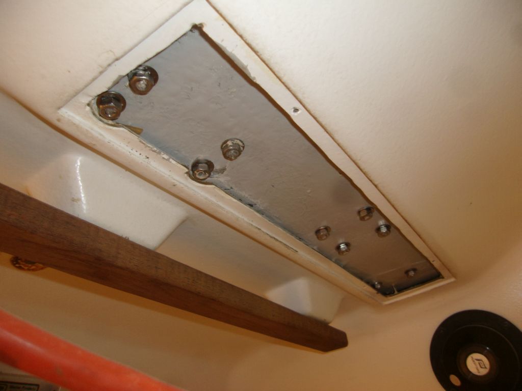
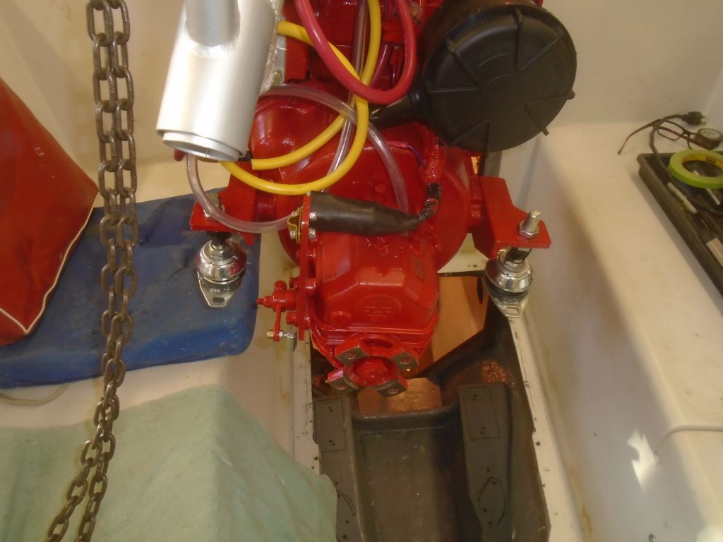
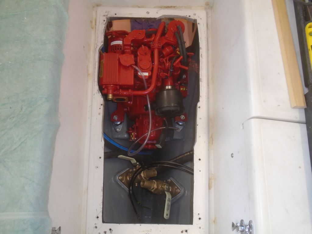
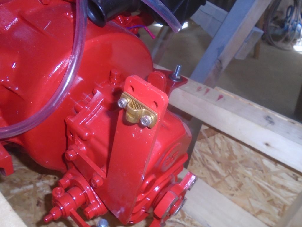
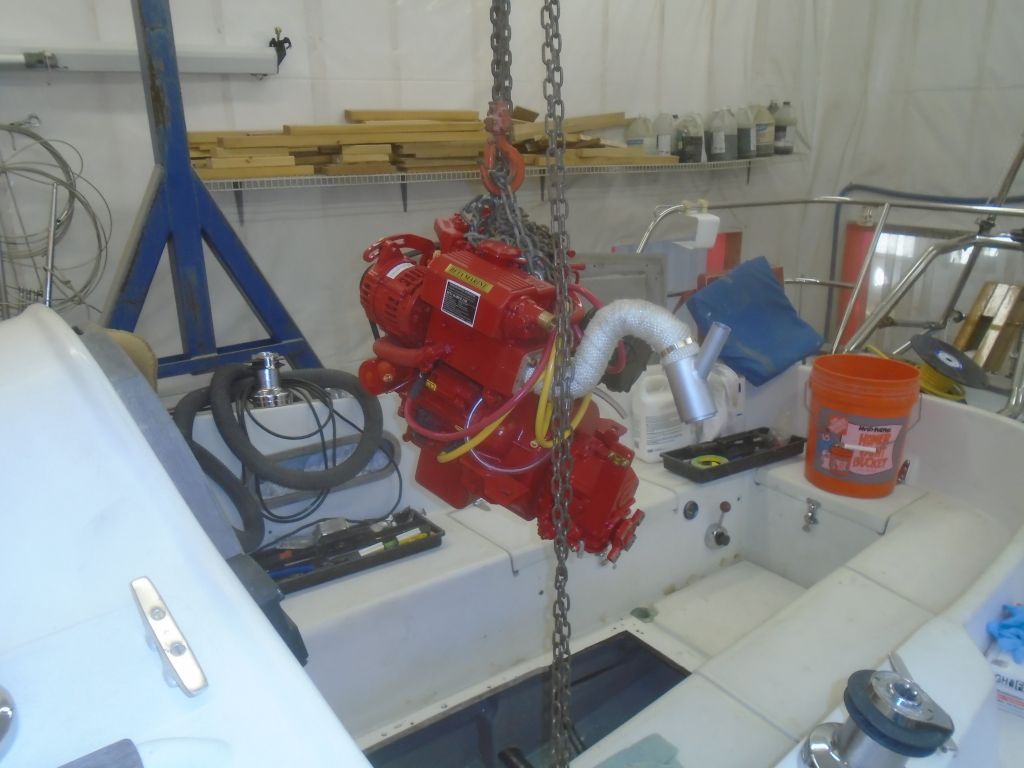
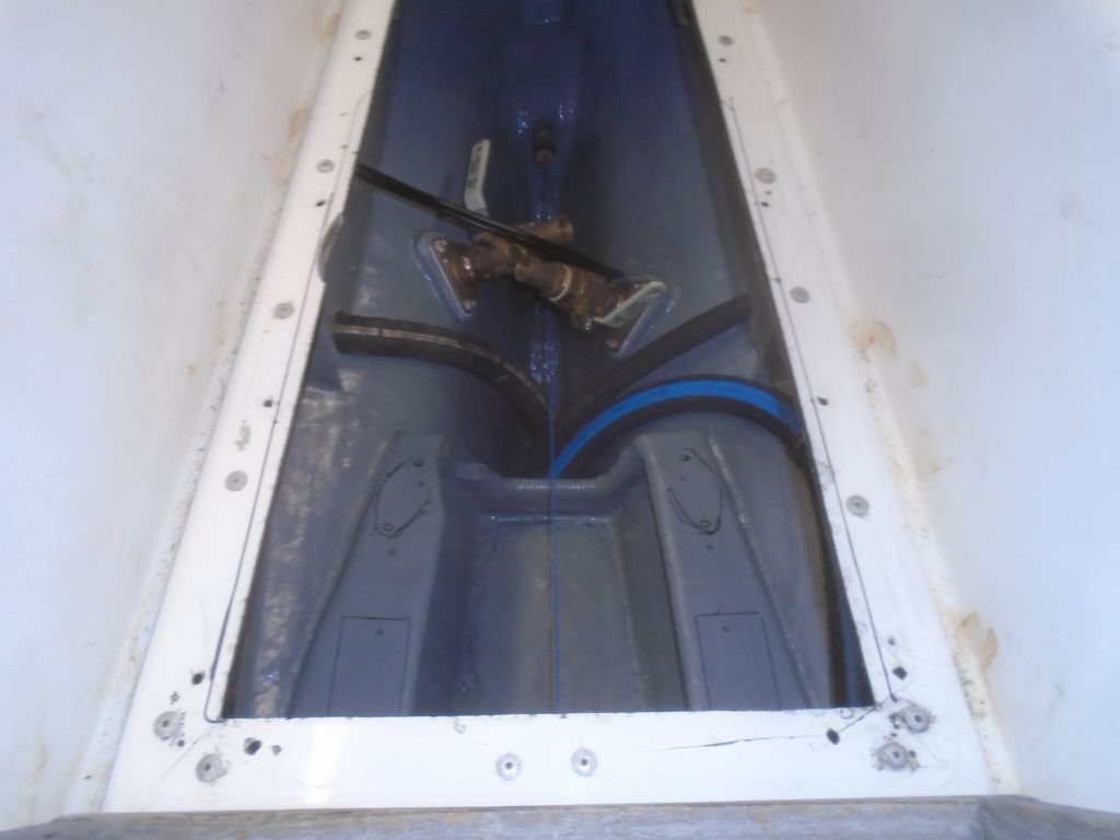
The first order of business was to widen the opening into the engine room, the second time I’d done this, as I was trying to avoid removing any more of the flange than necessary; otherwise I would have made the cut wide the first time around.  After cleaning up the cutting spoils, I pre-installed the after flex mounts on the engine, and prepared to lower it into the engine room.  Even with the extra cutout, it was still a tight fit, and I found I needed to widen it even more right next to the heat exchanger on the port side, which was too close to the cutout when the engine was approaching its final position.

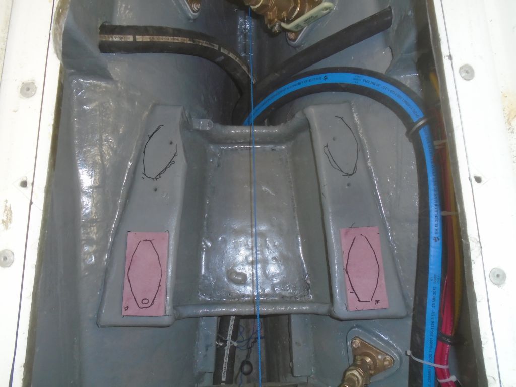
Once I had the engine partially lowered, I paused so I could install the forward mounting flanges and flex mounts from the cabin access.

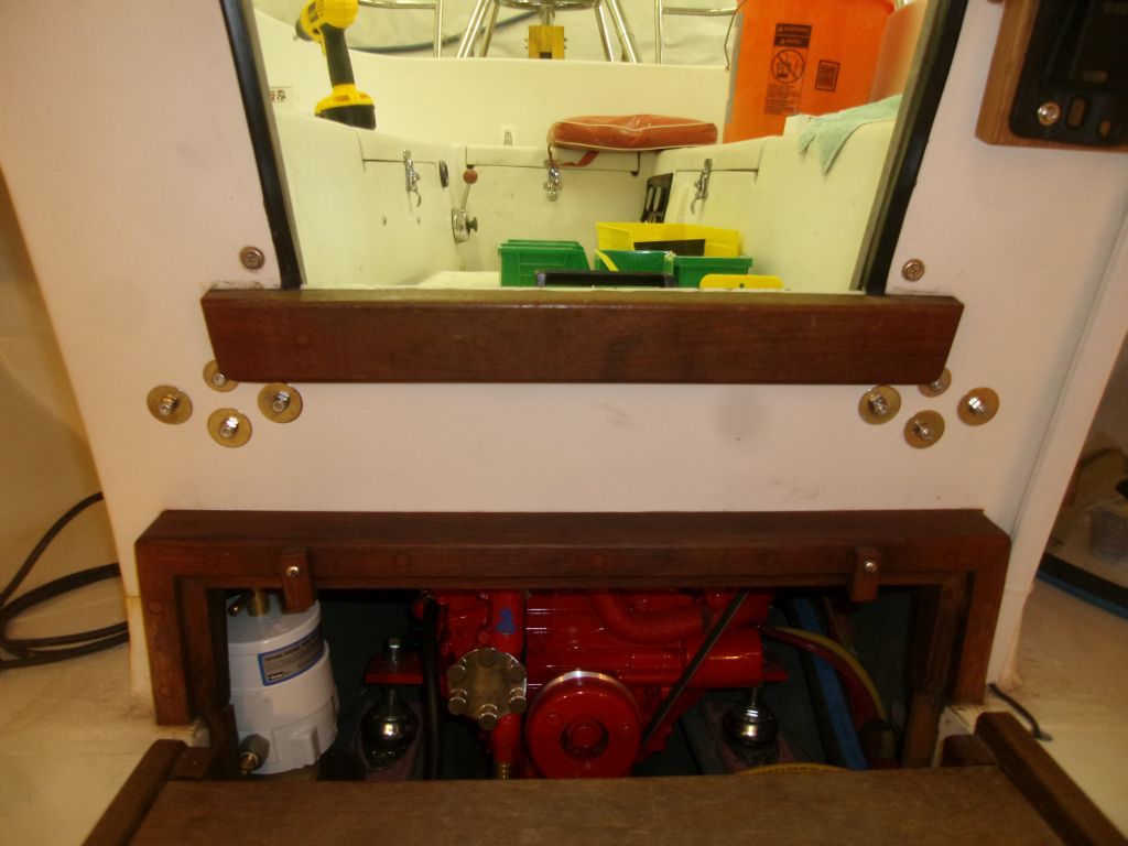
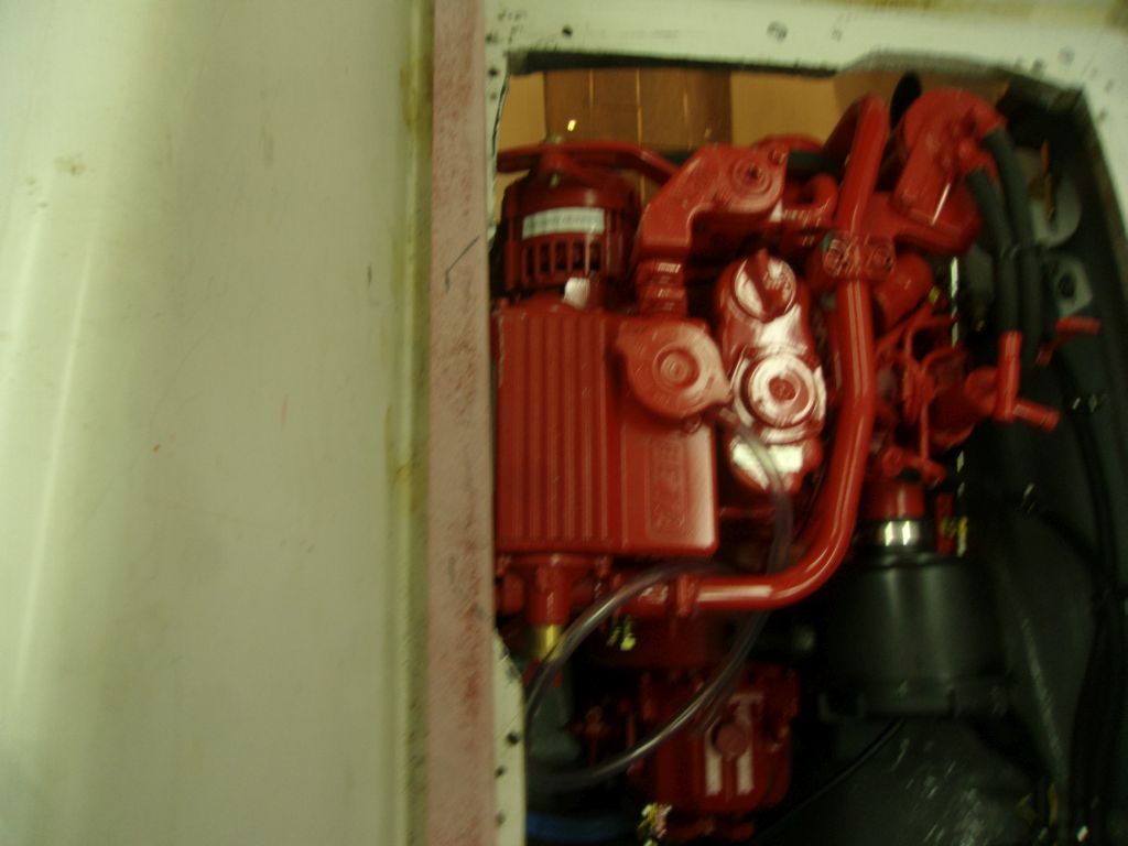
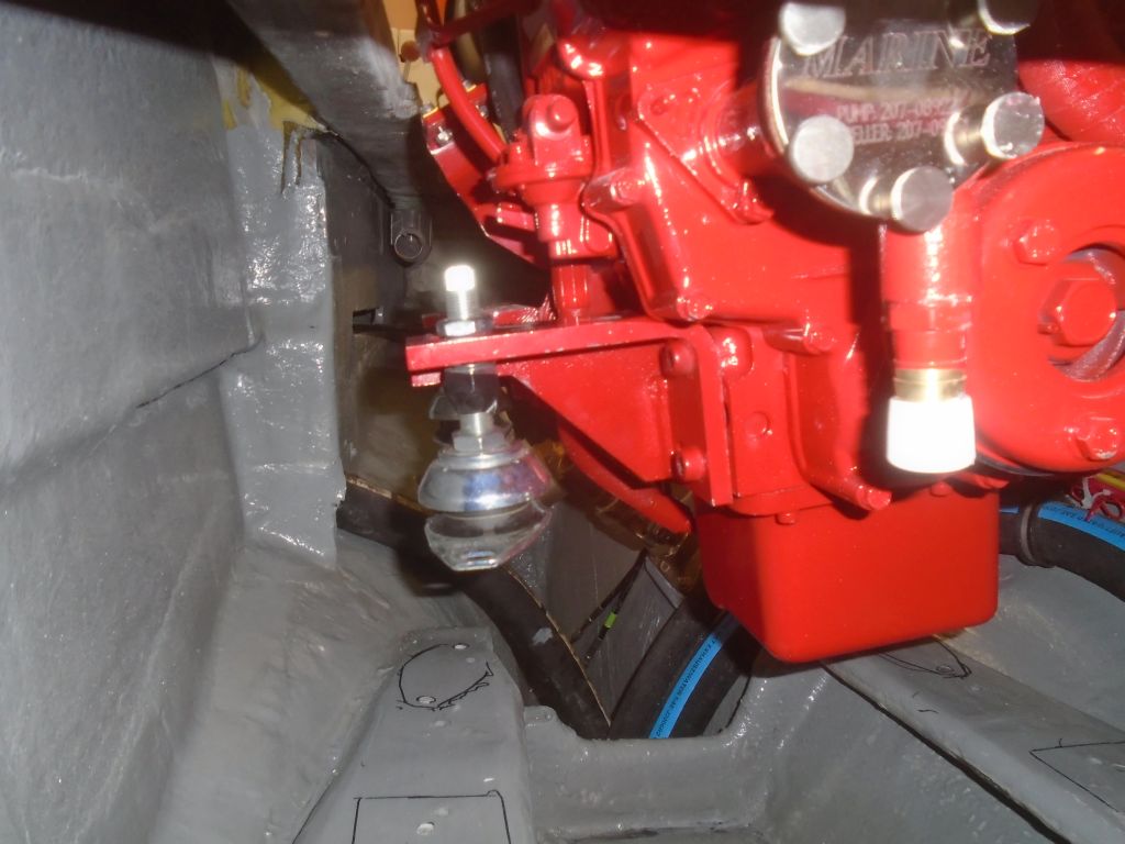
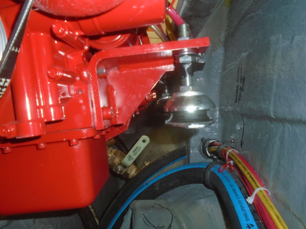
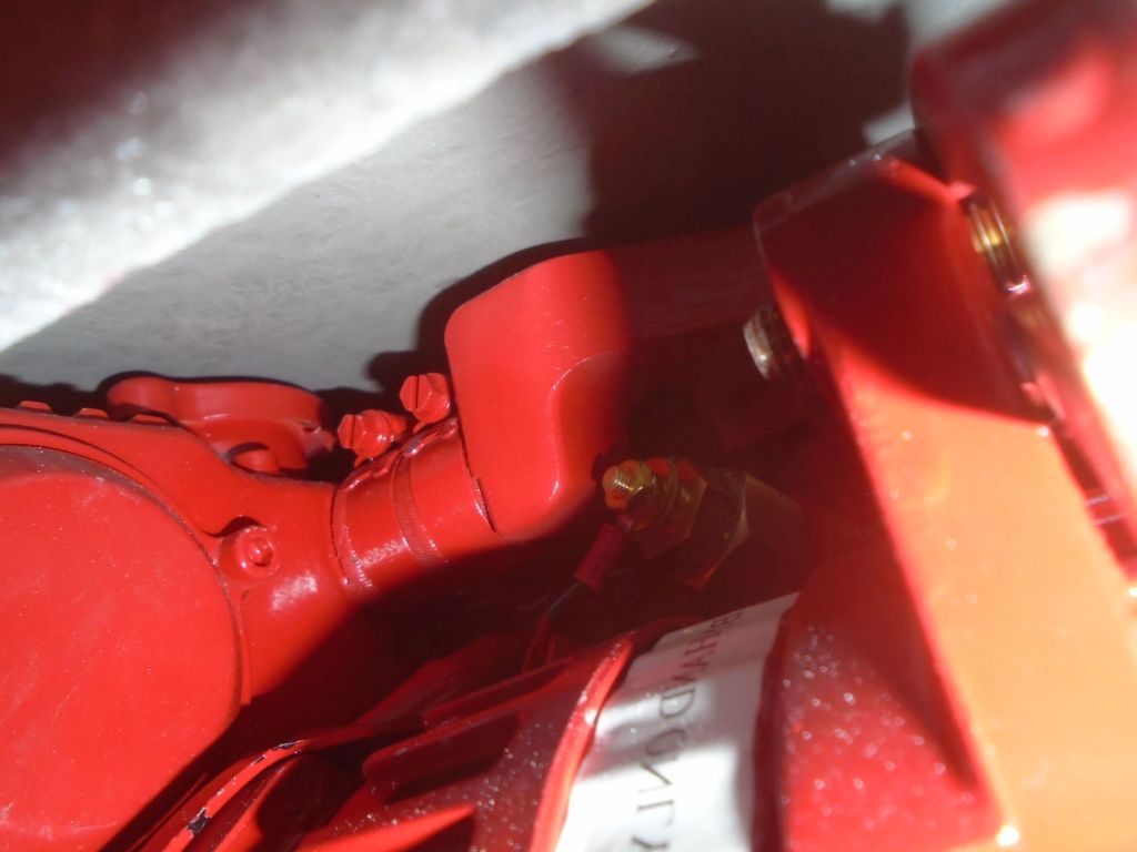
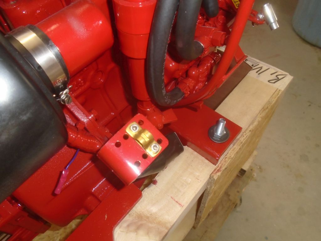
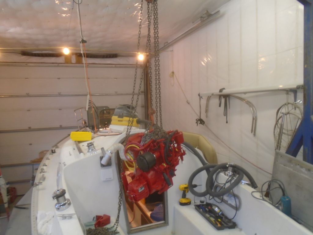
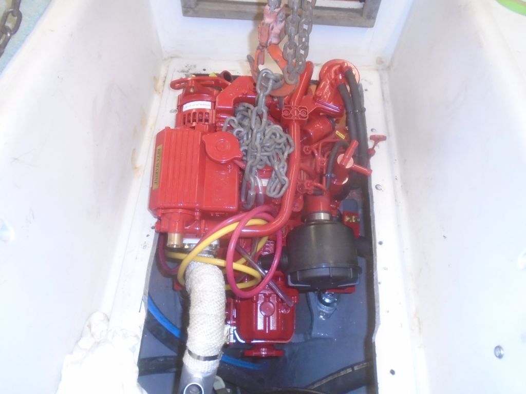
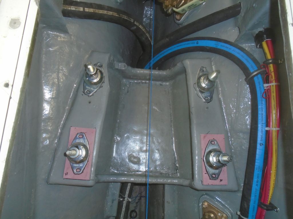
Now I dropped the engine the rest of the way till it rested on the foundations, and pushed it around a little so I could align the mounting bolt holes and get the bolts started.  At this point, every fastener–the mounting studs and bolts–was loose to allow future movement and alignment, but the engine was basically in its final position.

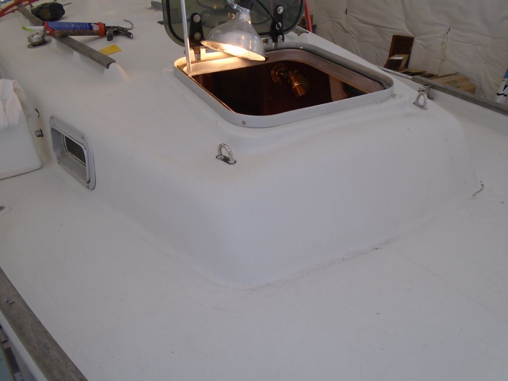
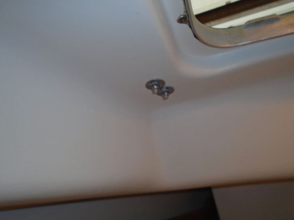
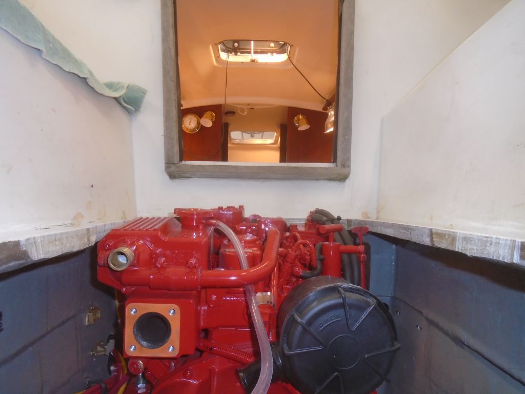
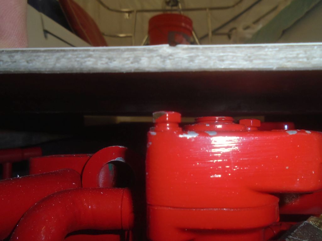
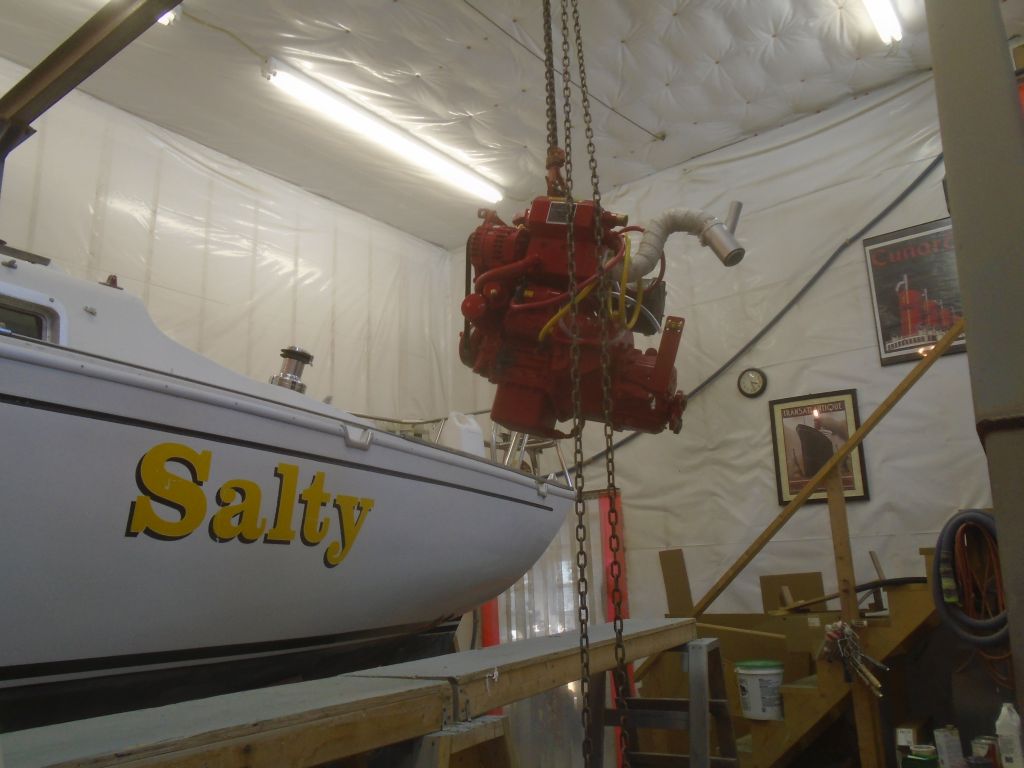
And sticking up an inch or so above the top of the engine room opening.

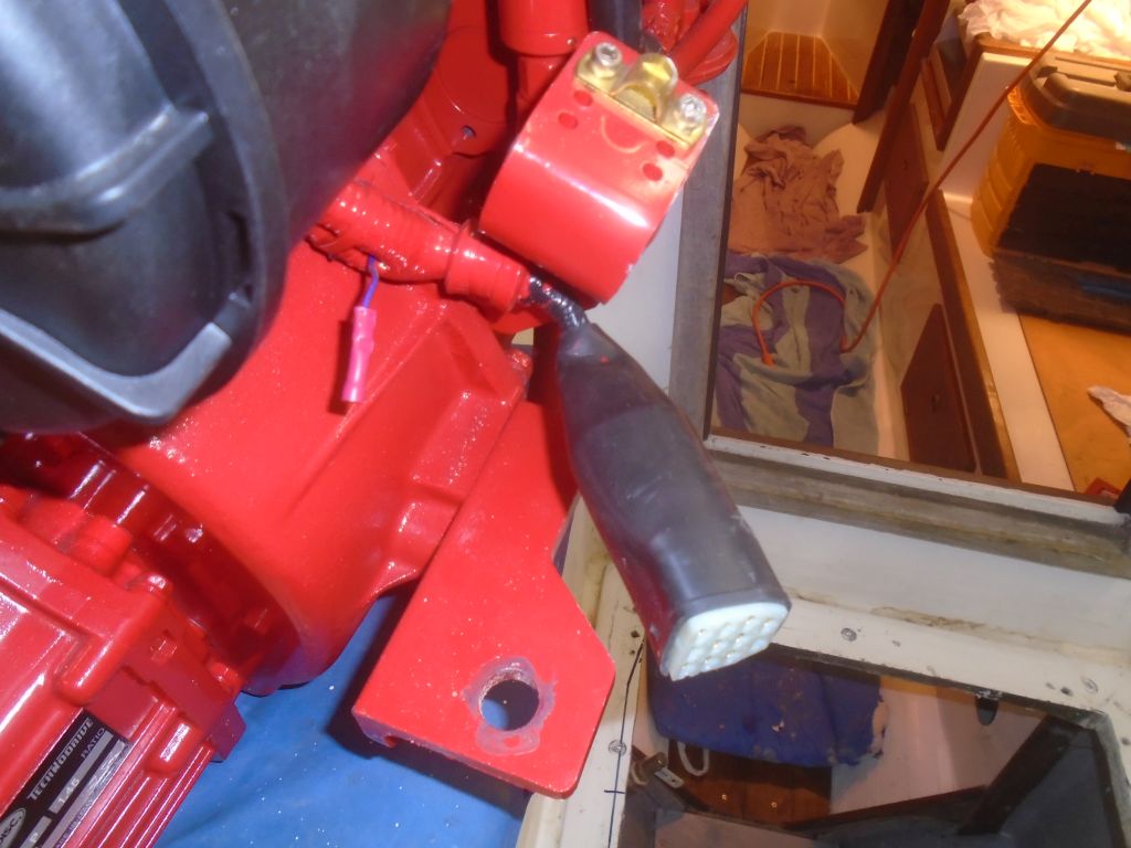
This was a vexing–if not altogether unexpected–development.  During my first attempt at engine placement the day before, I’d thought the engine seemed miles above where it needed to end up as I got it close to its final position, but since I never got the engine fully on the beds at that time, I chalked it up to visual misperception and hoped it would turn out OK.  As it turned out, however, my eye was right (as it usually is).

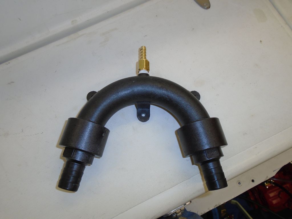
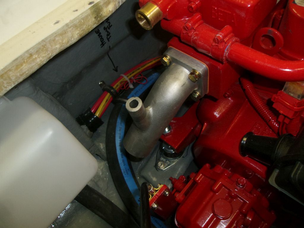
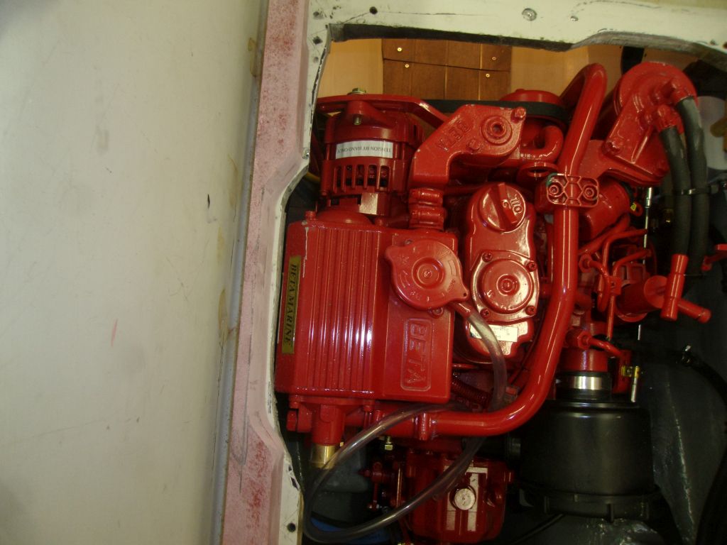
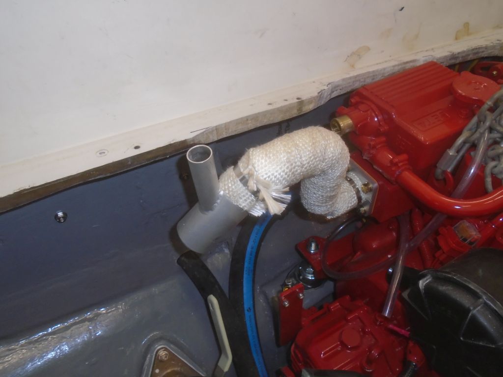
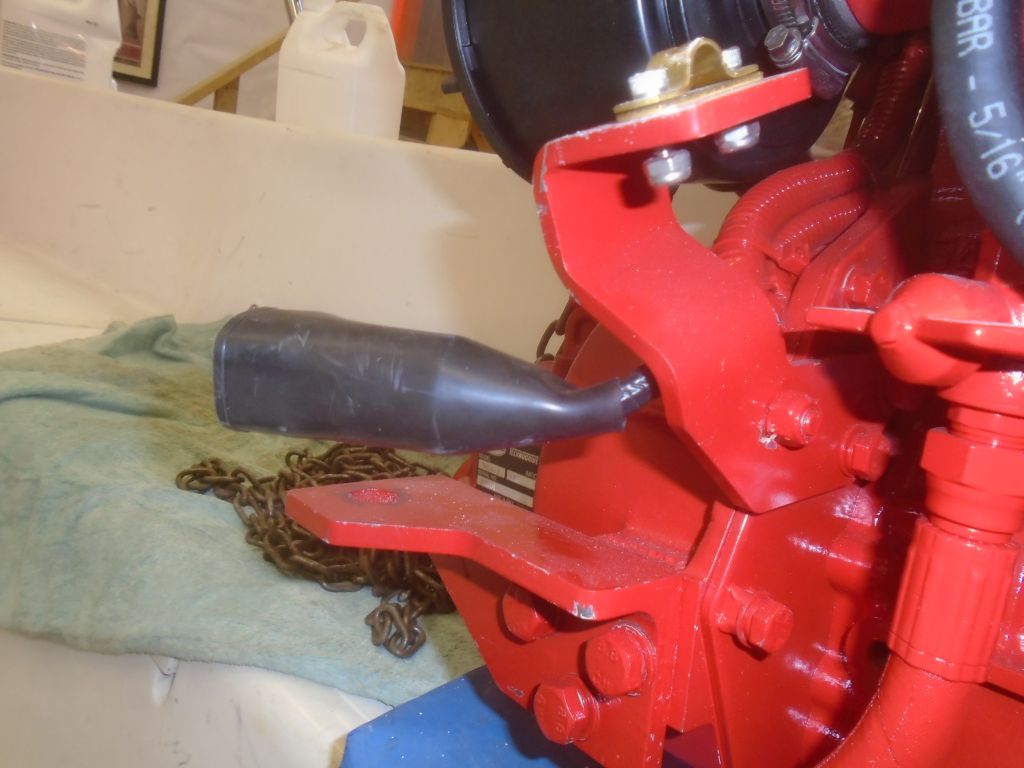
Even worse was the high-rise exhaust elbow, which I’d thought would be a challenge to fit even under better circumstances, and now I knew that no matter what I did from here, there was no way to accommodate the higher elbow.  I’d have to exchange it for the normal elbow.

All throughout the engine process, dating back to some months before when I removed the original engine and made various measurements, I’d known the clearance inside the engine room was a tight fit, but I’d installed the same basic engine in a sistership seven years before (the engine had changed somewhat since then, and the new version was actually shorter and narrower than the one I’d put in before).  It was surprising how different the space apparently was.  That previous installation was also easier to fit through the cockpit opening too, and had required a lot less widening.

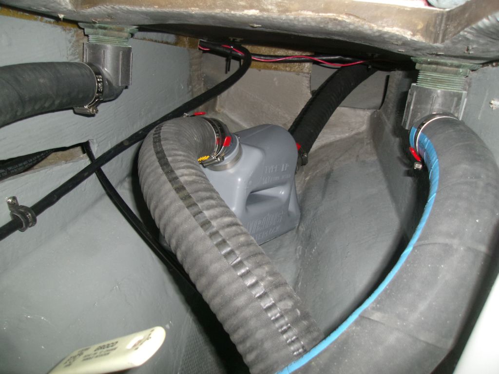
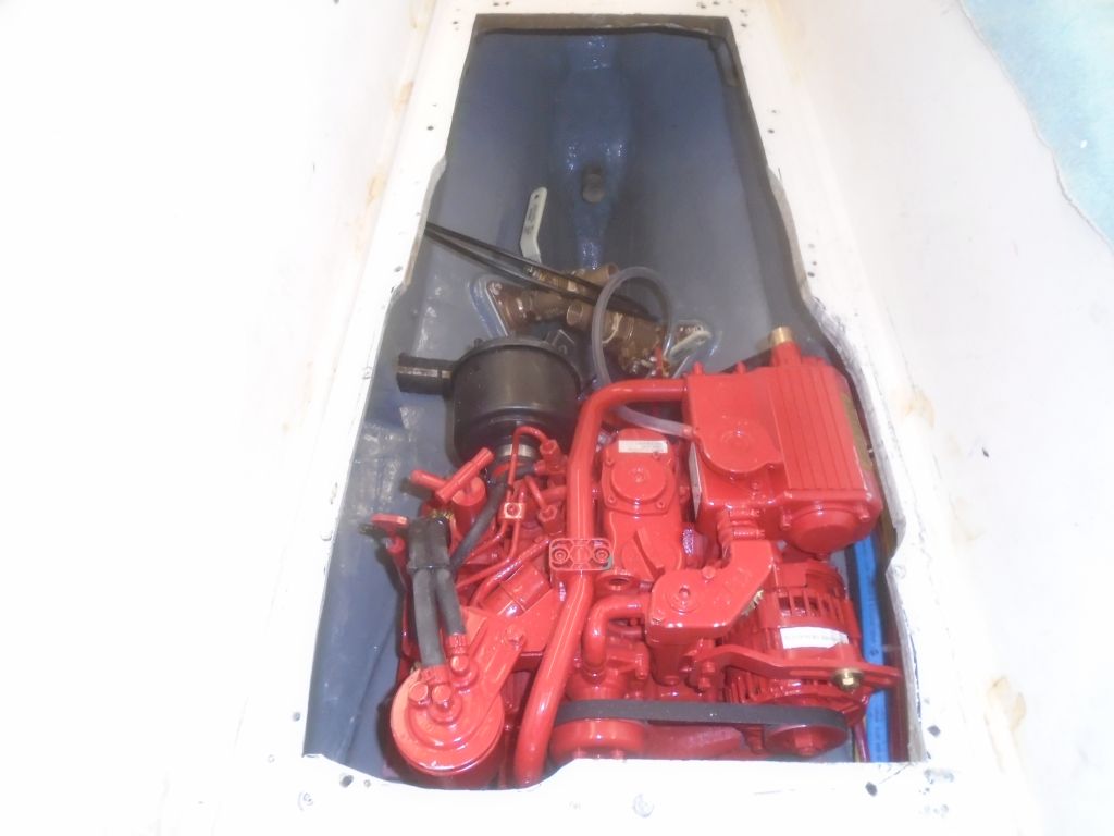
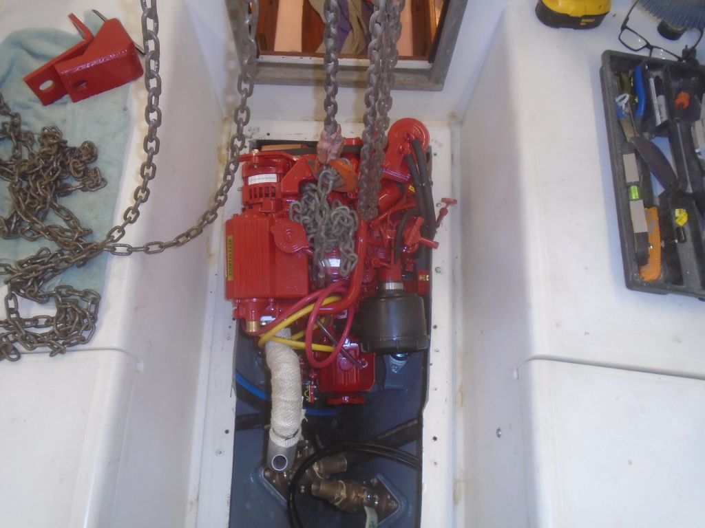
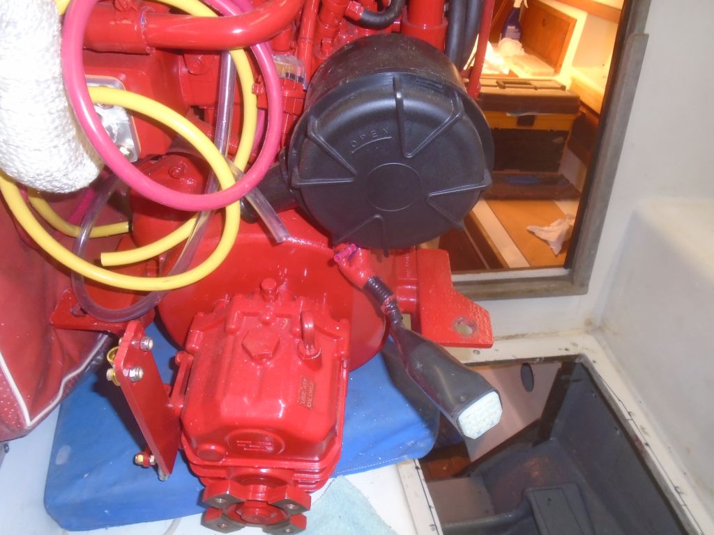
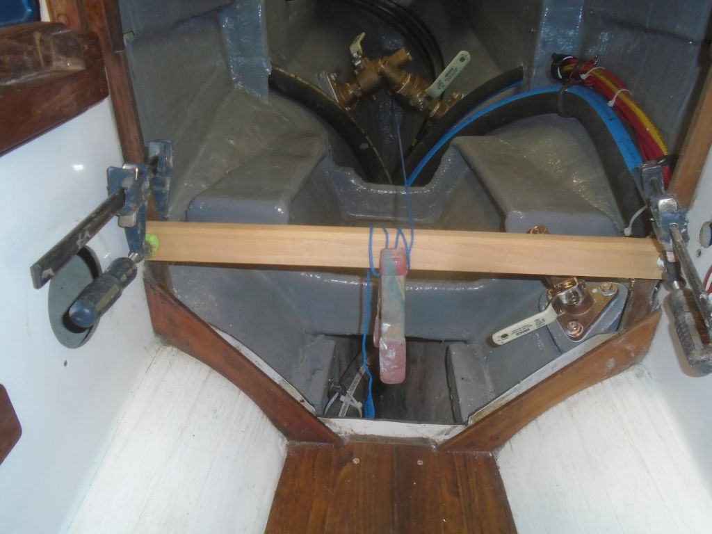
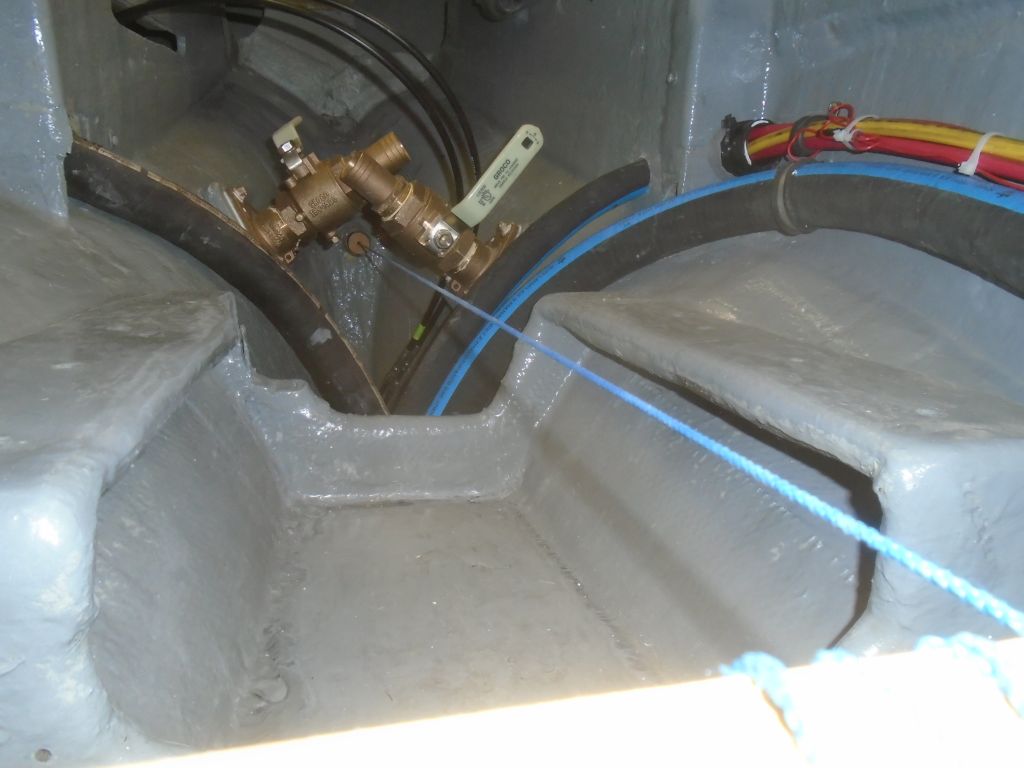
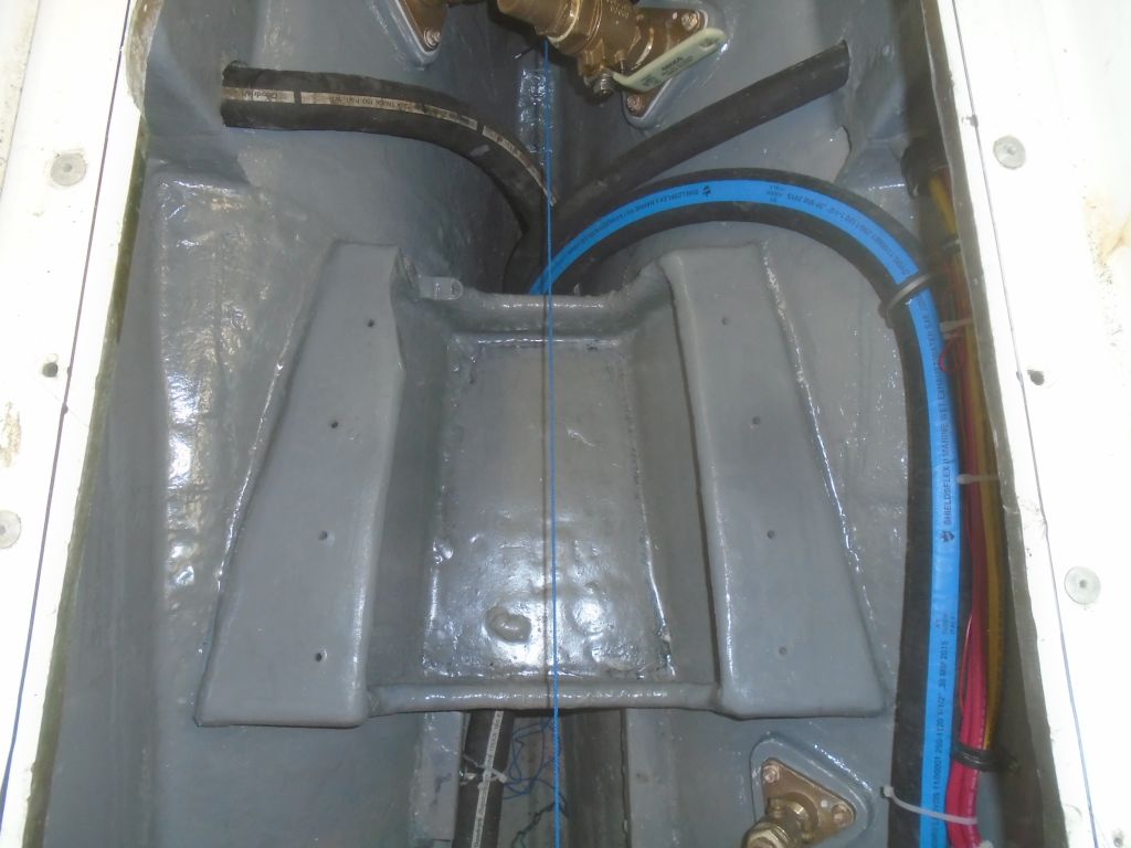
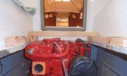
The engine was right where it needed to be according to the propeller shaft, however, so there wasn’t any way I could lower it meaningfully with the engine mounts.  The shaft log was where it was, and the engine had to fit it.  And did.

engine1-40616

Other than the basic manipulations required for final alignment, the center of the transmission coupling was right in line with the stern tube.  There wasn’t room to move the stern tube even if that had been an approach that made sense, so now I had to put all the questions aside and move forward with a way to cope with the fact that the engine was taller than the space afforded it.

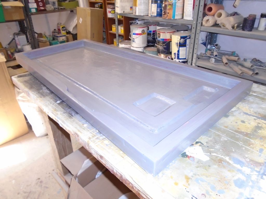
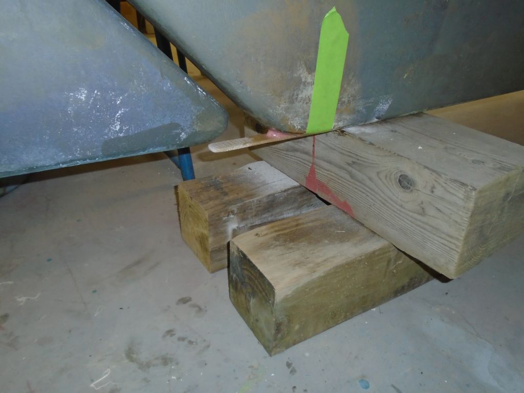
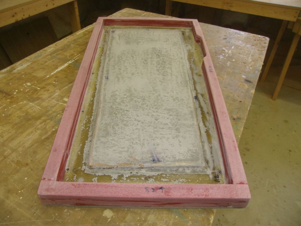
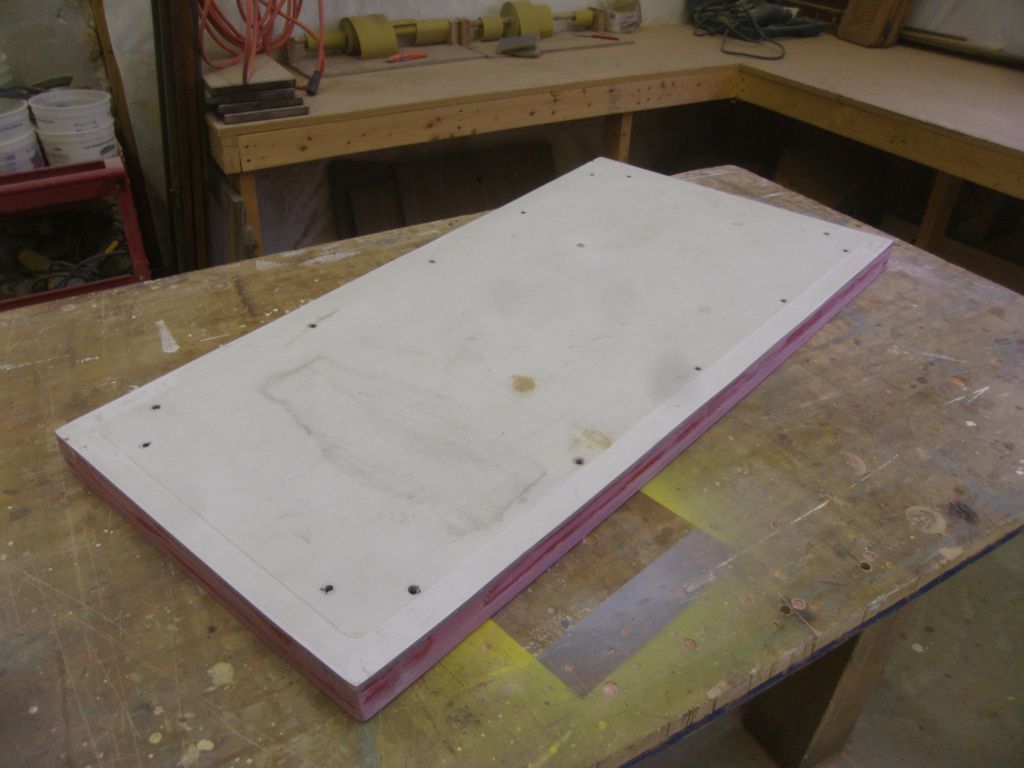
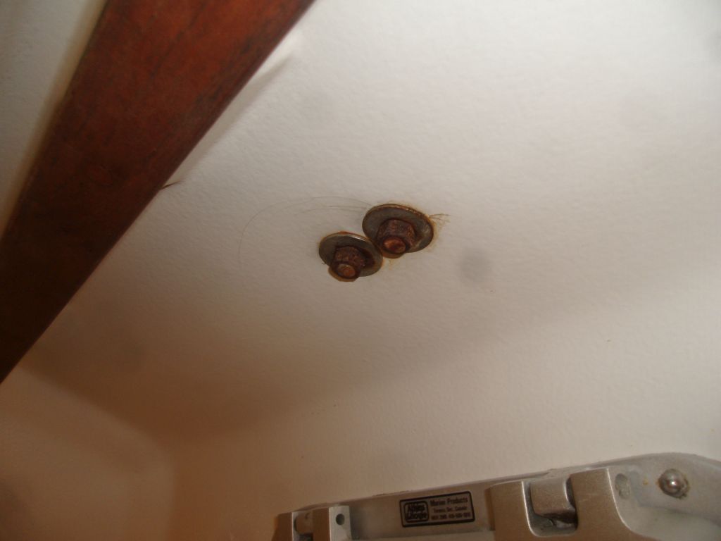
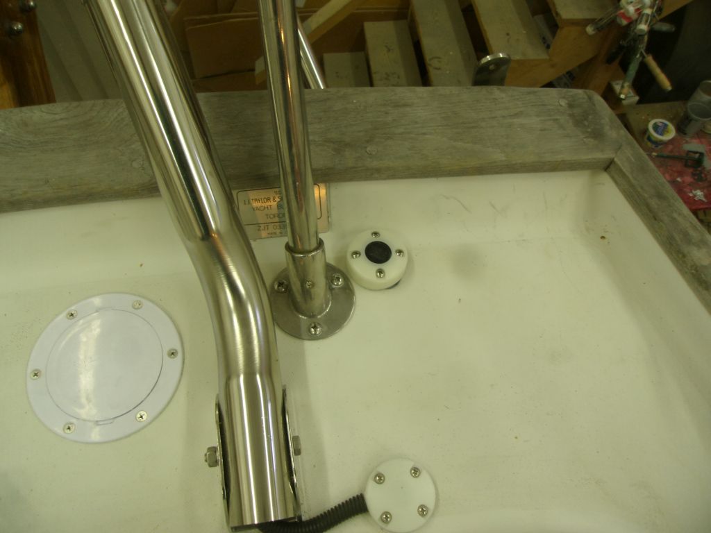
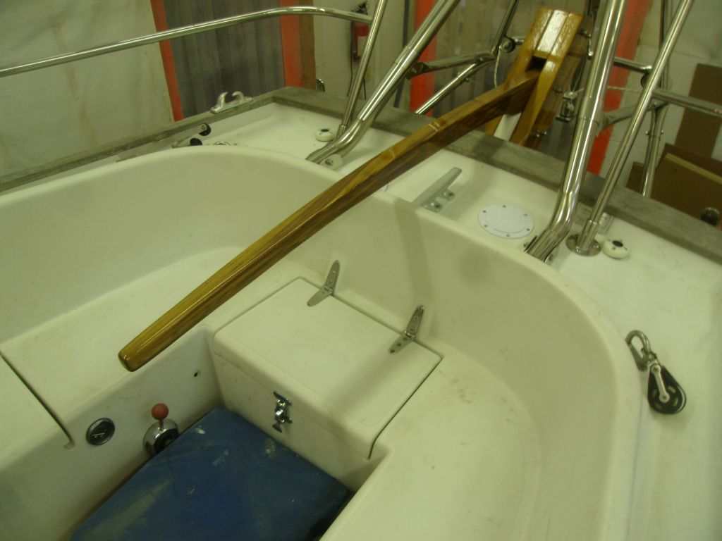
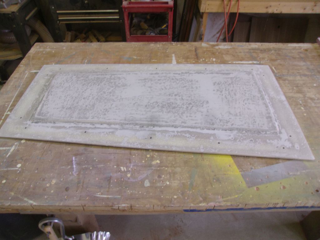
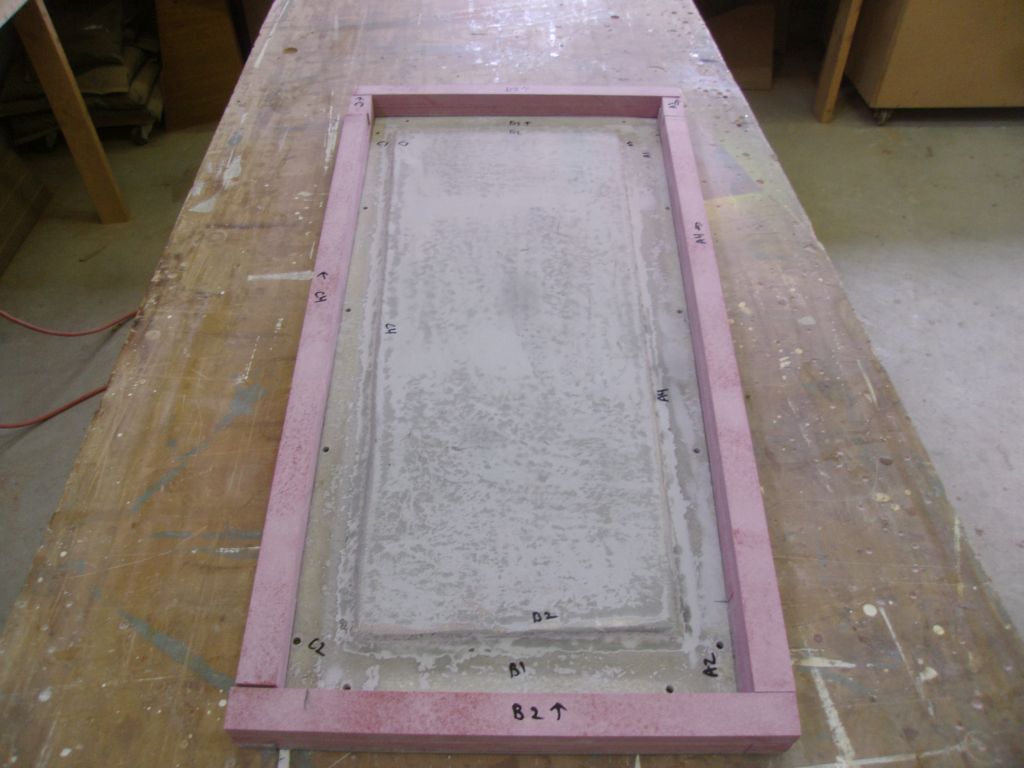
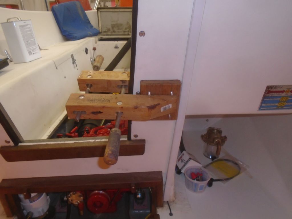
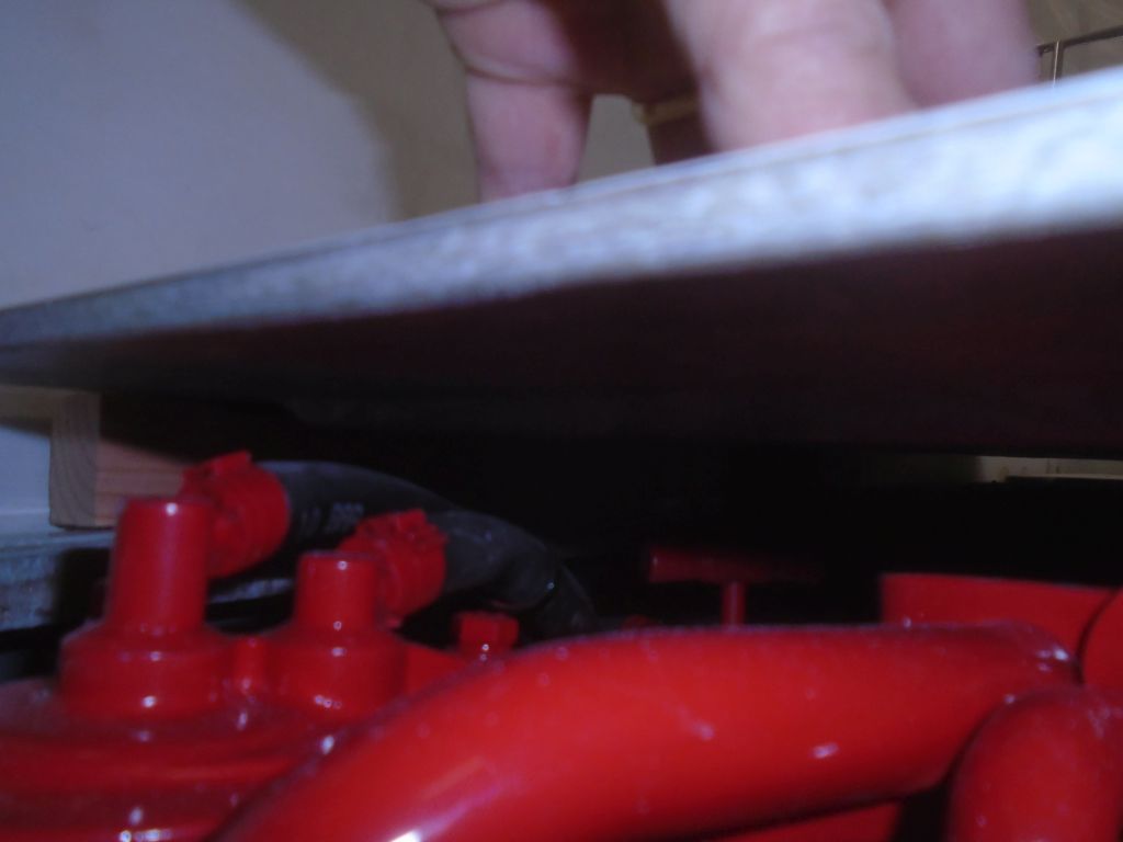
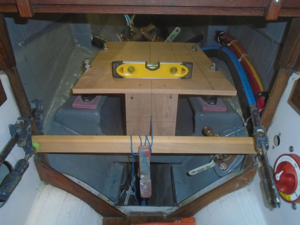
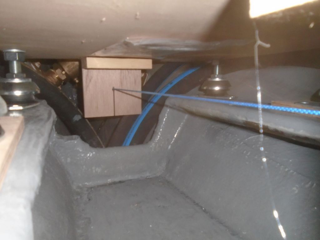
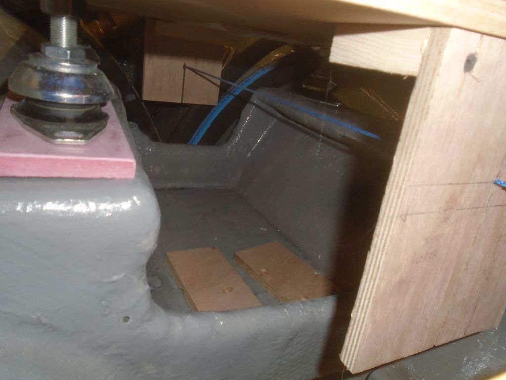
Complicating the issue a bit, the engine hatch–i.e. the cockpit sole–featured a cored center section that protruded down into the opening, so in order to clear that I had to raise the edges even further.  Eventually I determined that I’d need to raise the hatch by 1-1/2″ in order to safely clear the engine.

engine4-40616

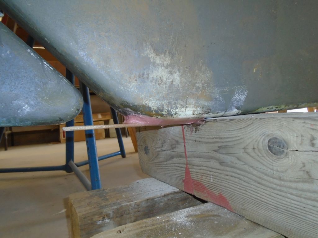
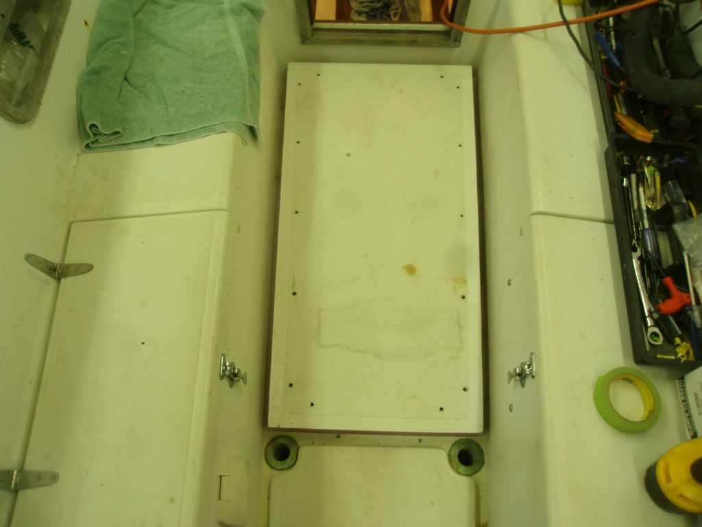
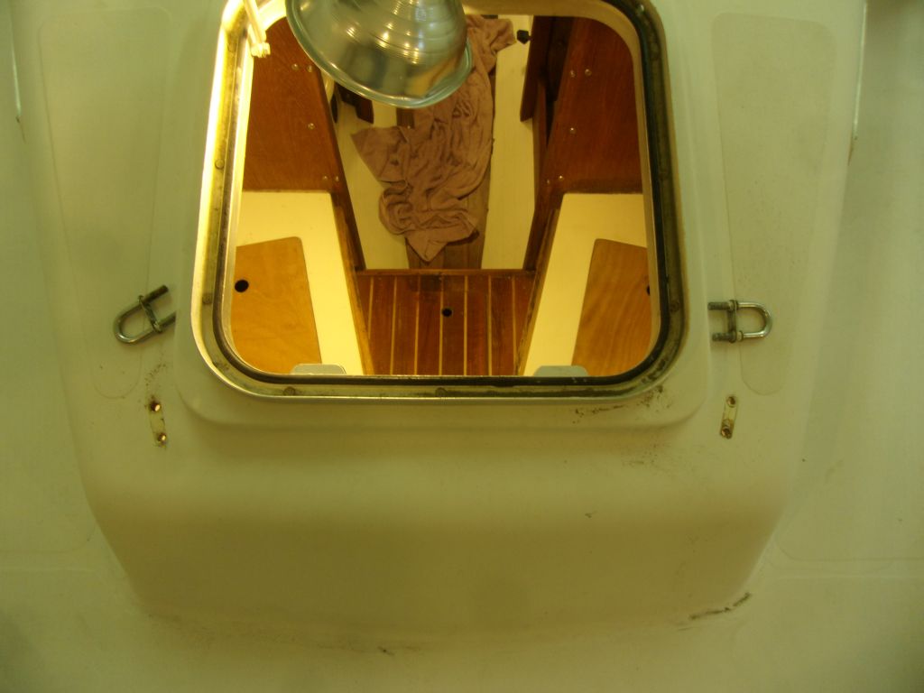
With some 1-1/2″ blocking on all four sides of the hatch opening, I test-fit the hatch over the top, and checked clearances from beneath.  This just cleared the highest part of the engine.  Fortunately, this would have a minimal practical effect on the hatch or the cockpit, other than creating a small step between the hatch surface and the after part of the cockpit (something that could be conceivably taken care of with a wooden grate over the aft part, if needed down the road).  So, after discussing the issues with the owner, I moved forward with a plan to add a 1-1/2″ fiberglass lip to the underside of the hatch–a fairly straightfoward fix, fortunately.

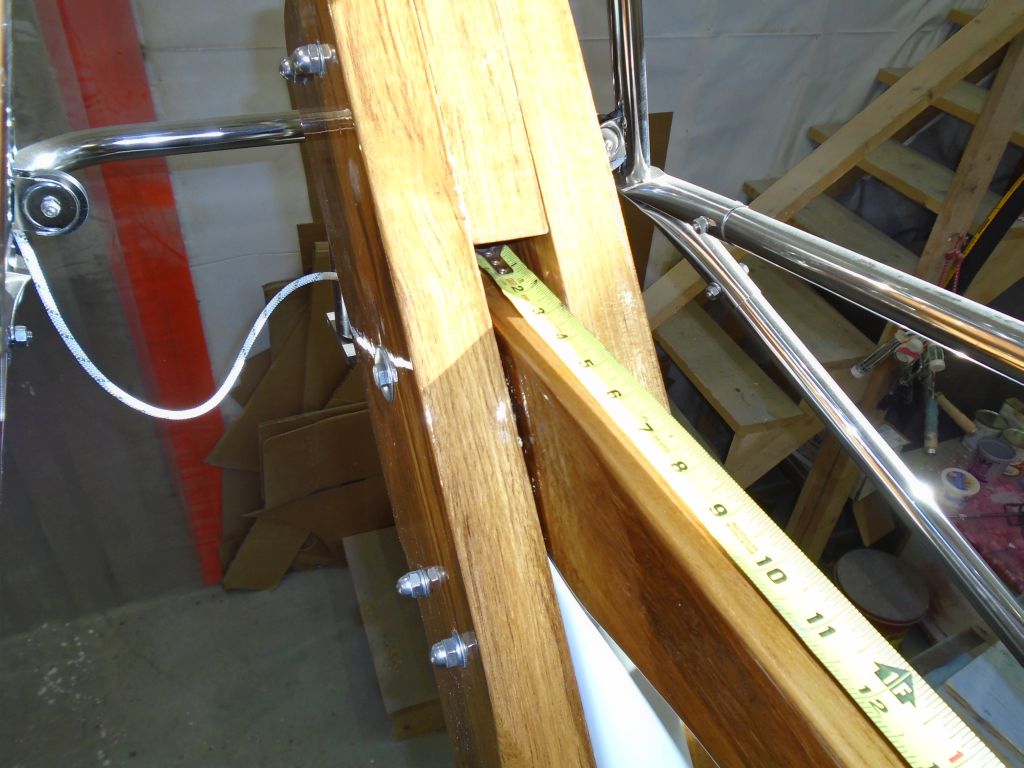
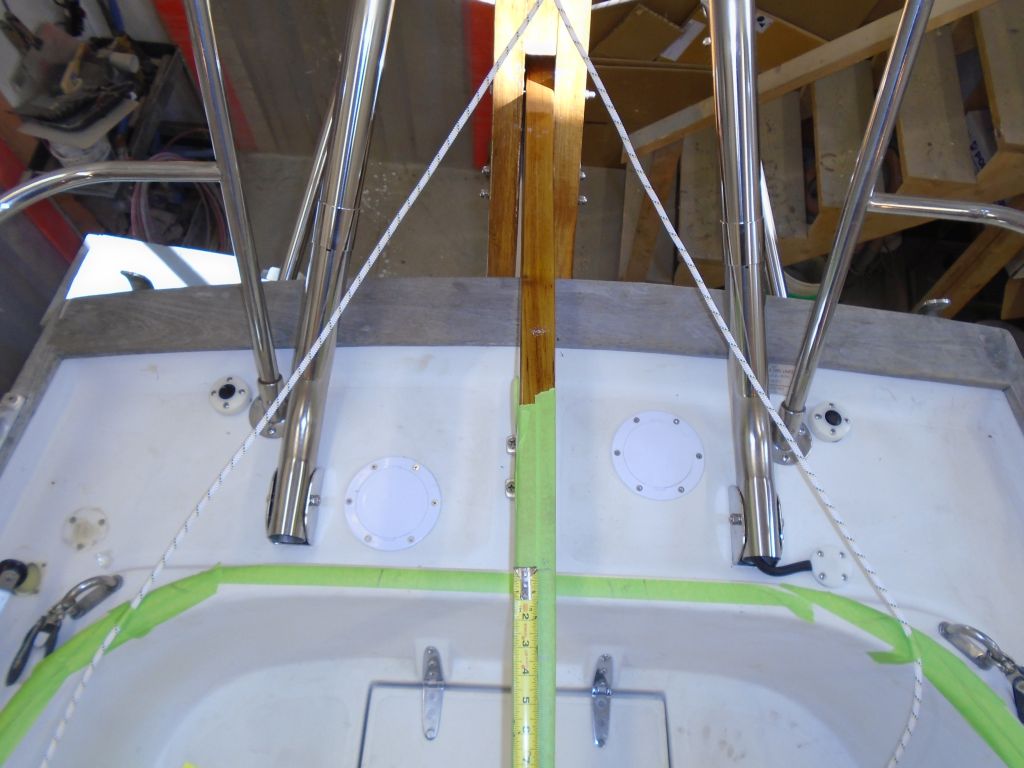
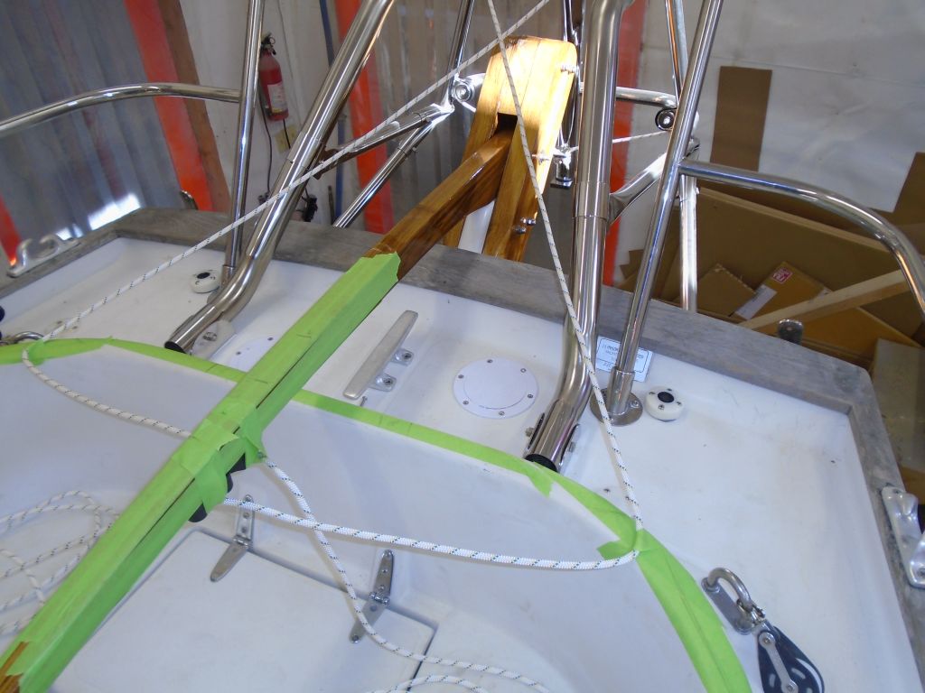
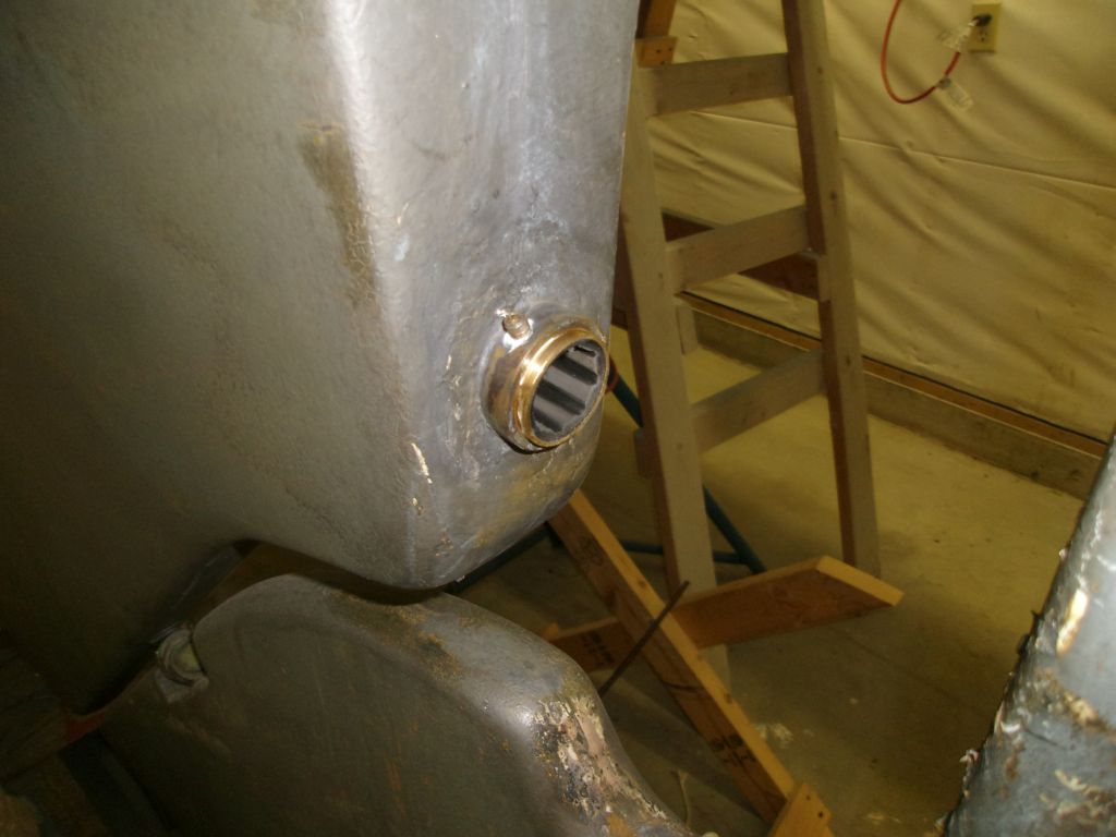
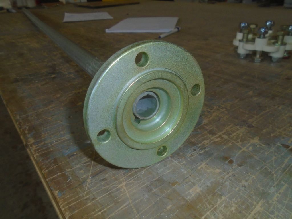
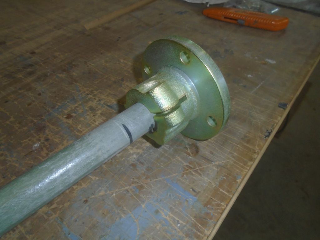
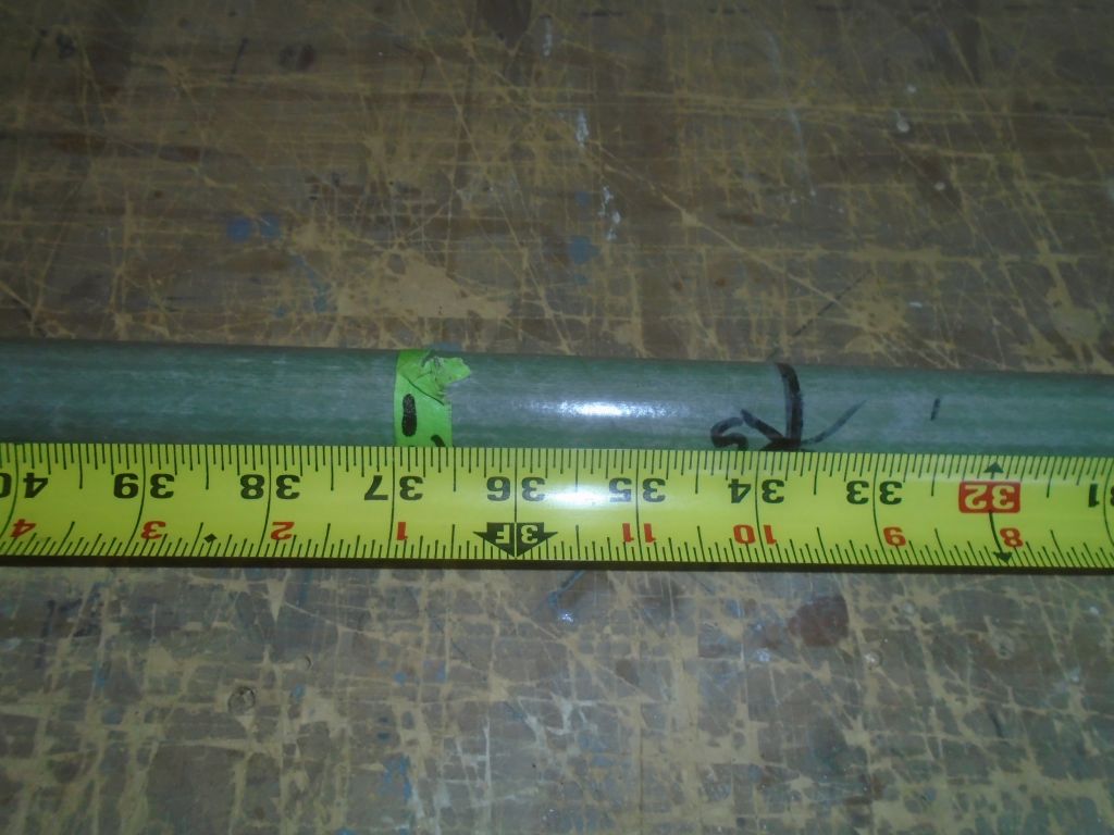
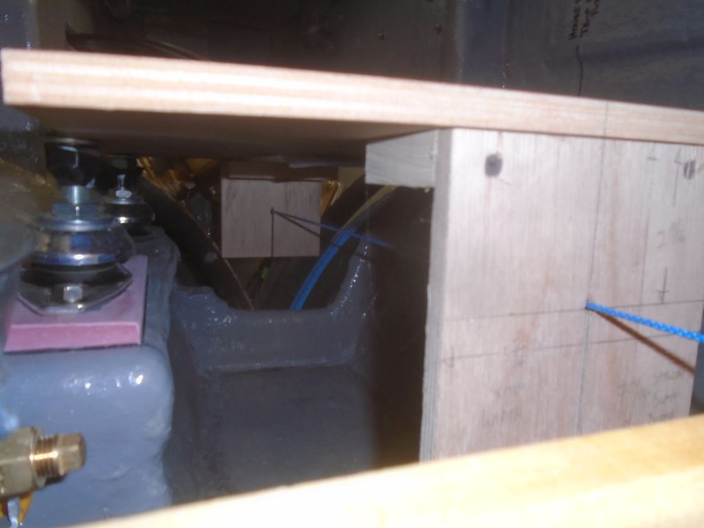
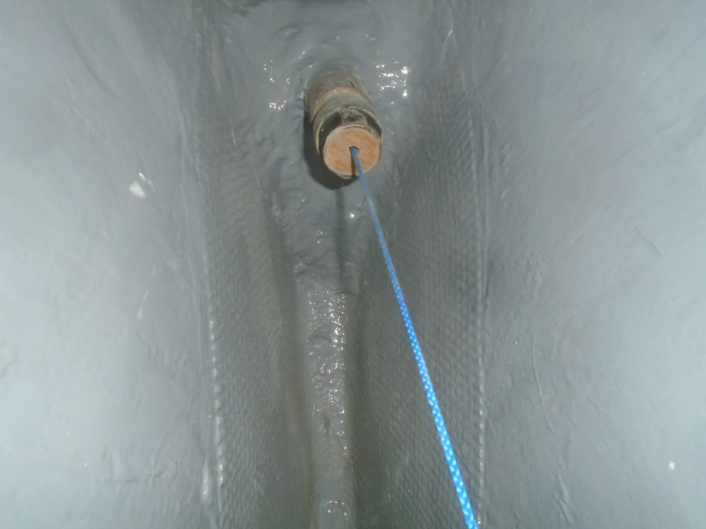
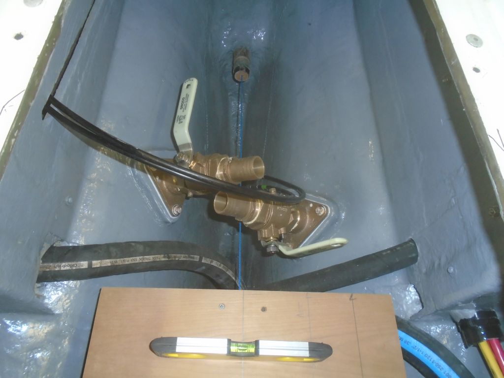
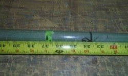
Next, I wanted to measure for the propeller shaft so I could get that ordered without delay.  Clearance was quite tight in the aperture, and the original shaft had extended to within a relative hair’s breadth from the rudder.  I wanted to allow just a bit more clearance there if I could, which really was the one measurement that would define everything else about the shaft (rather than coming up with an idealized version based on other measurements), so I decided to assemble a false shaft with all the critical pieces in place in order to get the most accurate shaft-only measurement.  From previous jobs, I had a length of 1″ fiberglass tubing on hand just for this purpose, and I fit this into the new coupling at the correct place, making a mark on the aft side for later reference when assembling this in the boat.

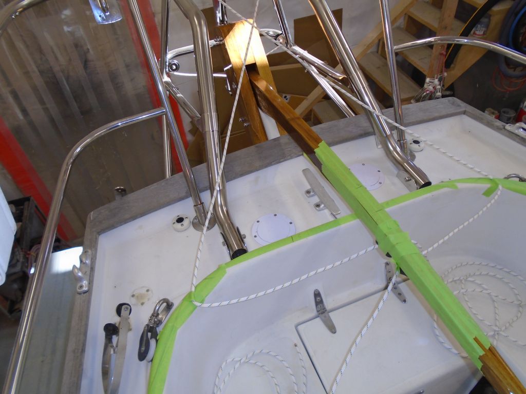
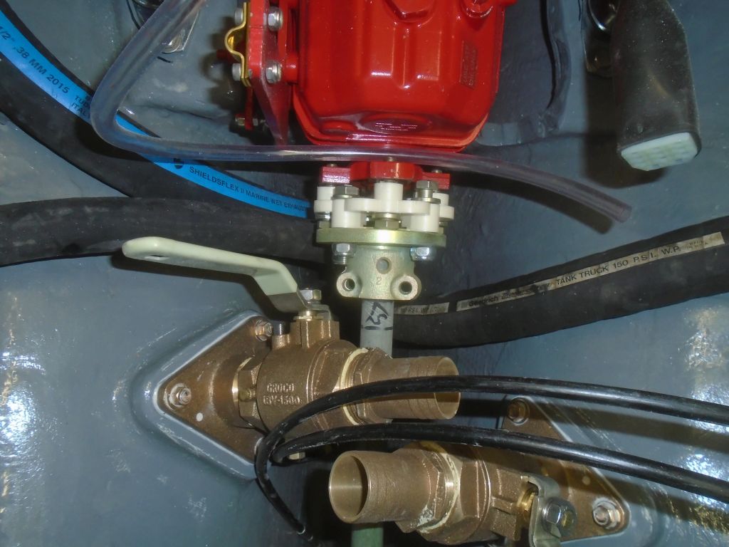
With the new Cutless bearing just started in the tube–I didn’t want to fully install it yet–I ran in the fiberglass shaft, and inside the boat I assembled it with the coupling and a sacrificial coupling, dry-fitting it all to the transmission hub as needed.

shaft3-40616

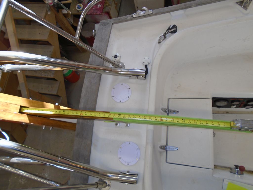
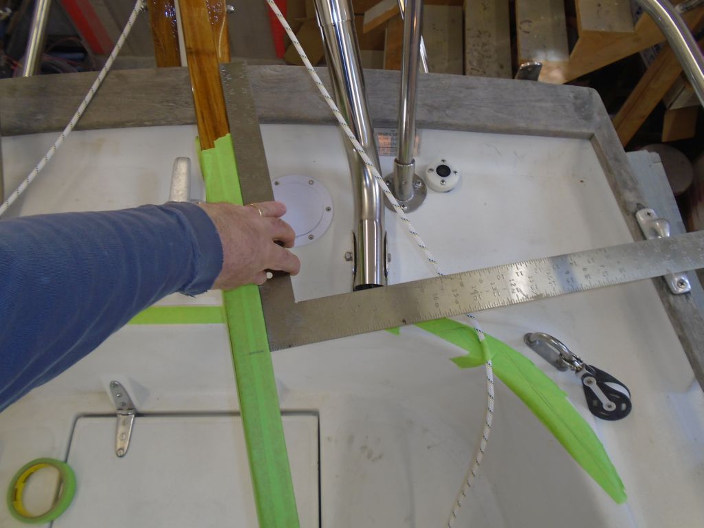
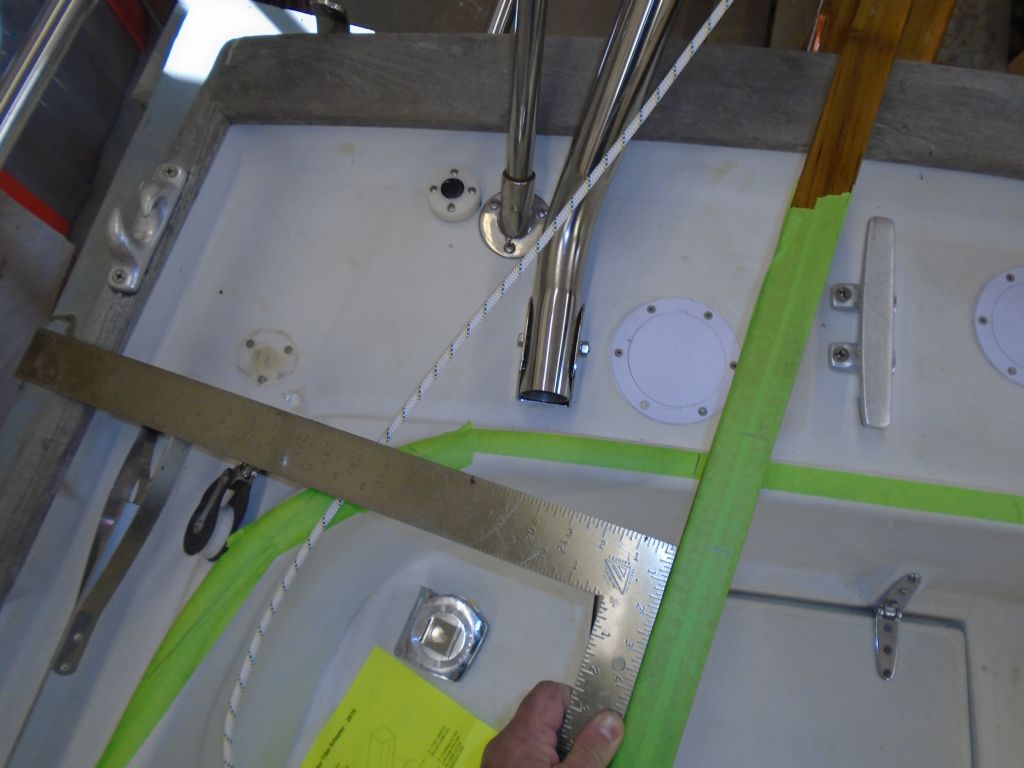
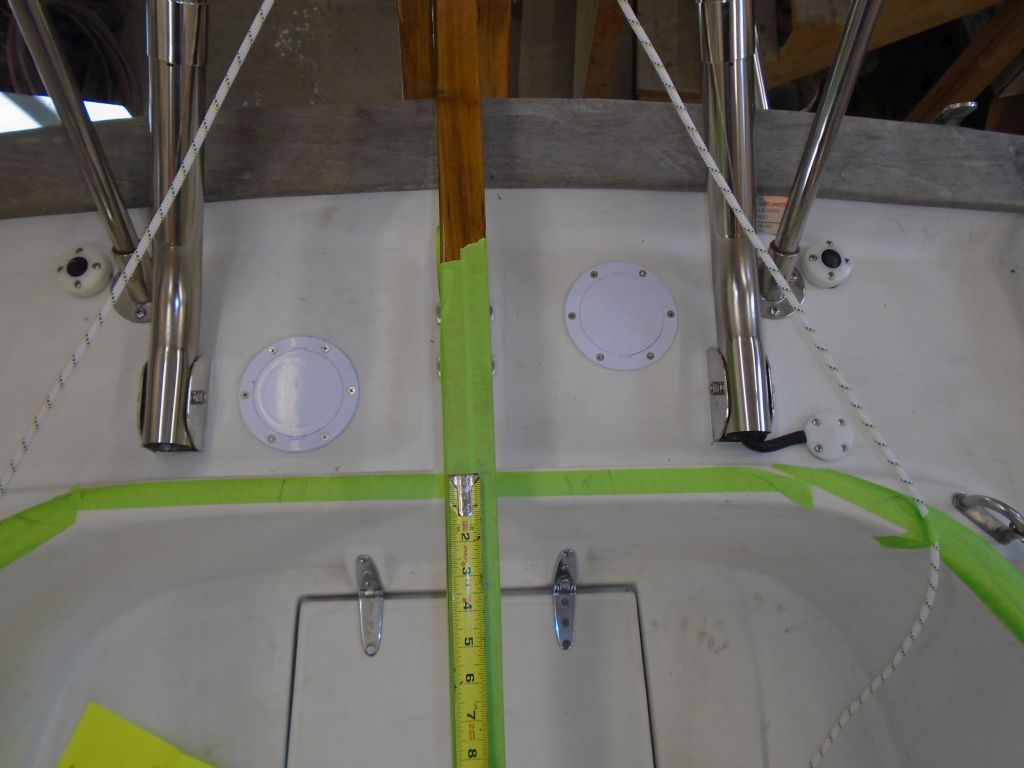
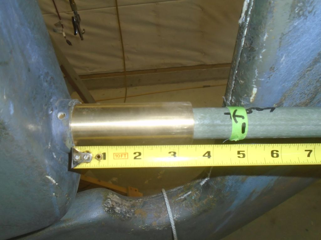
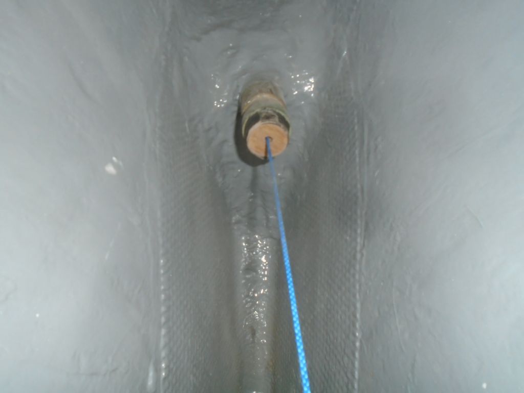
After ensuring that the shaft extended the right amount into the coupling (based on my mark), I went outside the boat and made various marks to indicate where the rudder hit the shaft, as well as a mark 5″ aft of the stern tube, which was the same amount the original shaft had extended.

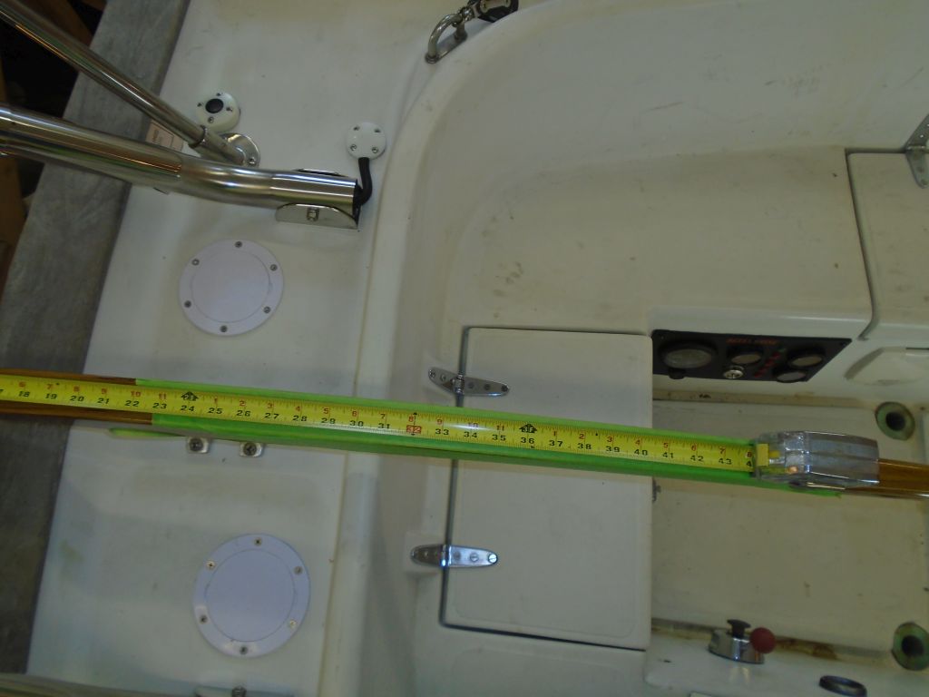
After double-checking the whole arrangement 12 or 13 times, I removed the “shaft” and measured the overall length from the coupling end to the final mark I’d made, erring on the short side.  Then I could order the shaft, and I boxed up the coupling to ship off to the machine shop as well so it could be properly fitted to the end of the shaft.  The final measurement was 36-7/8″.

shaft6-40616

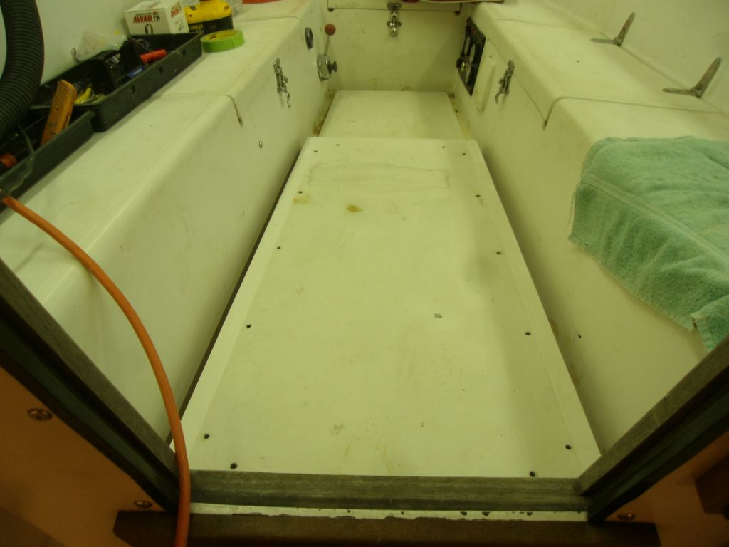
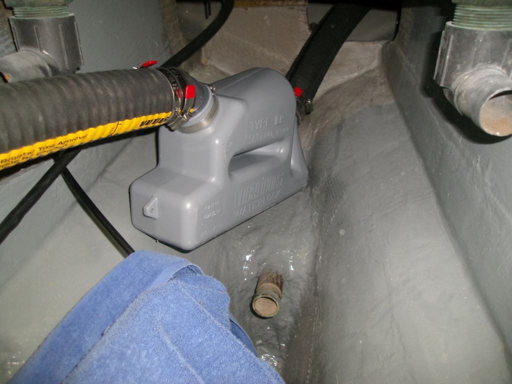
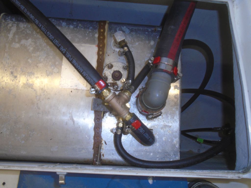
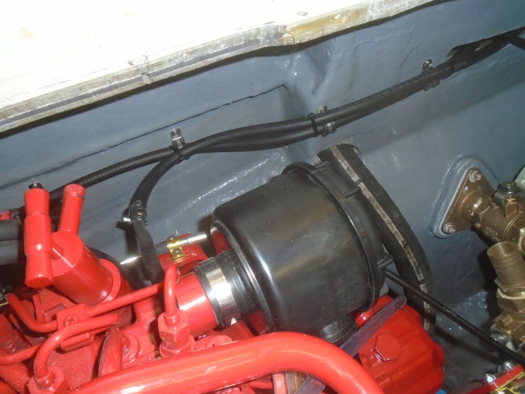
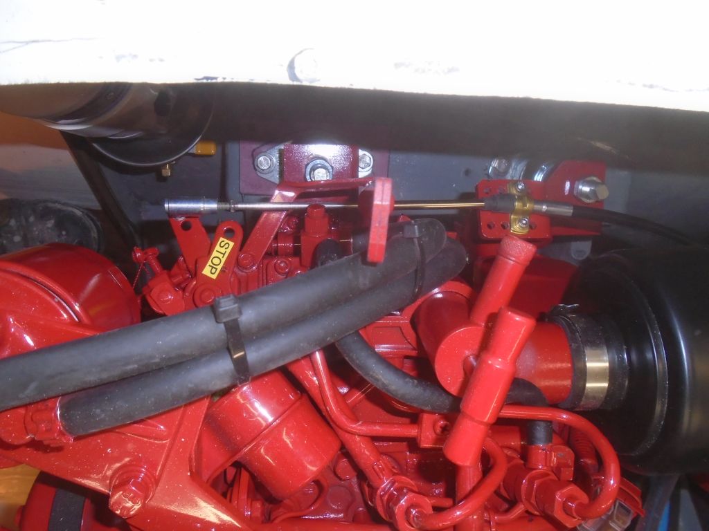
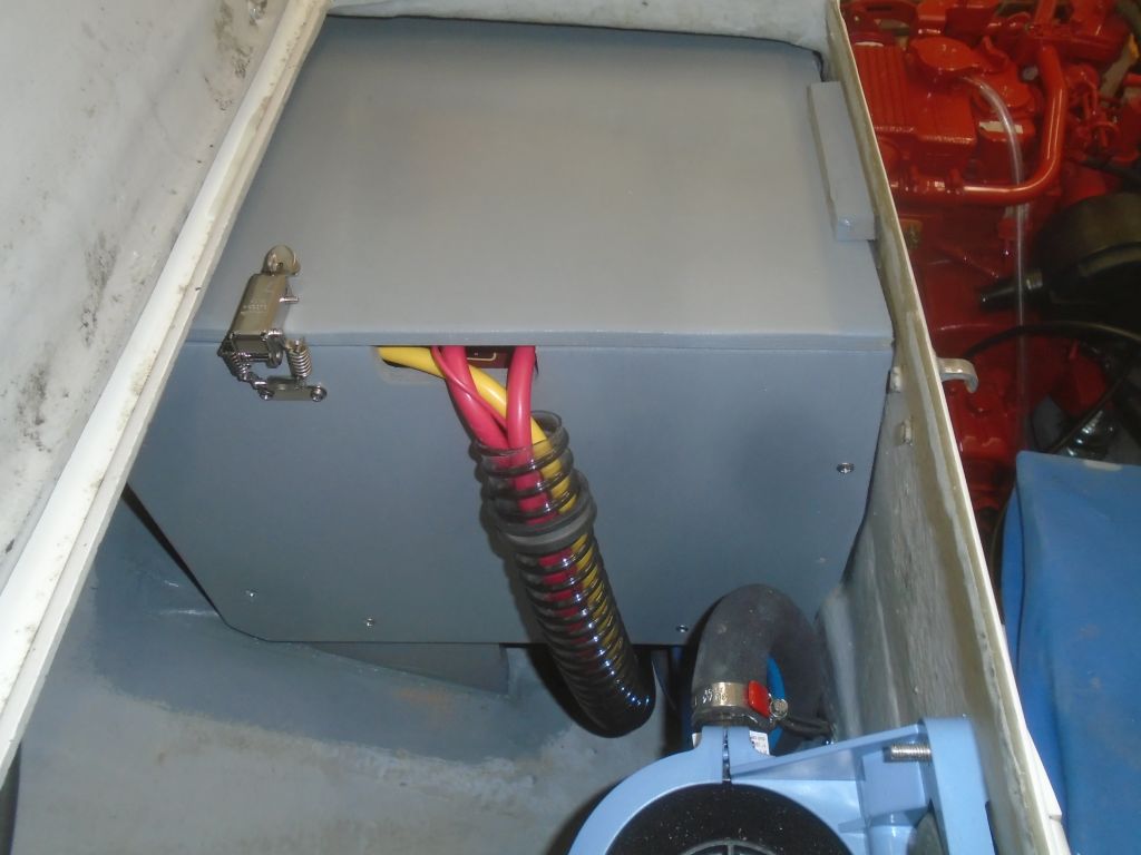
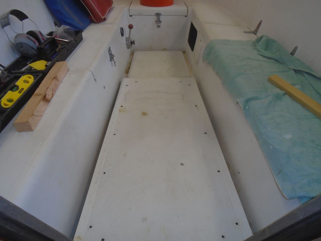
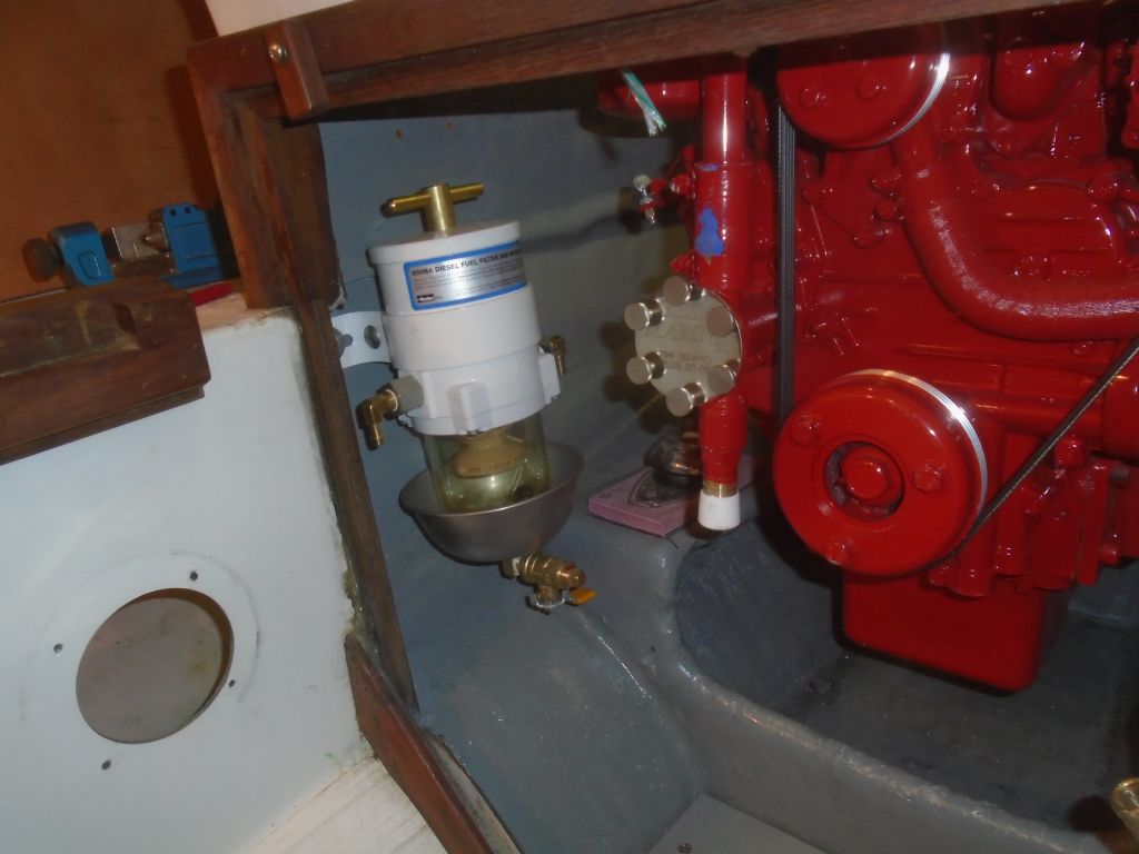
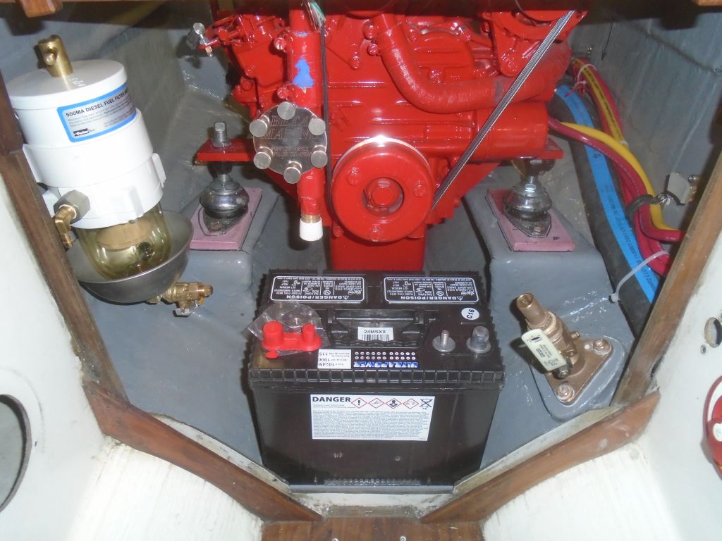
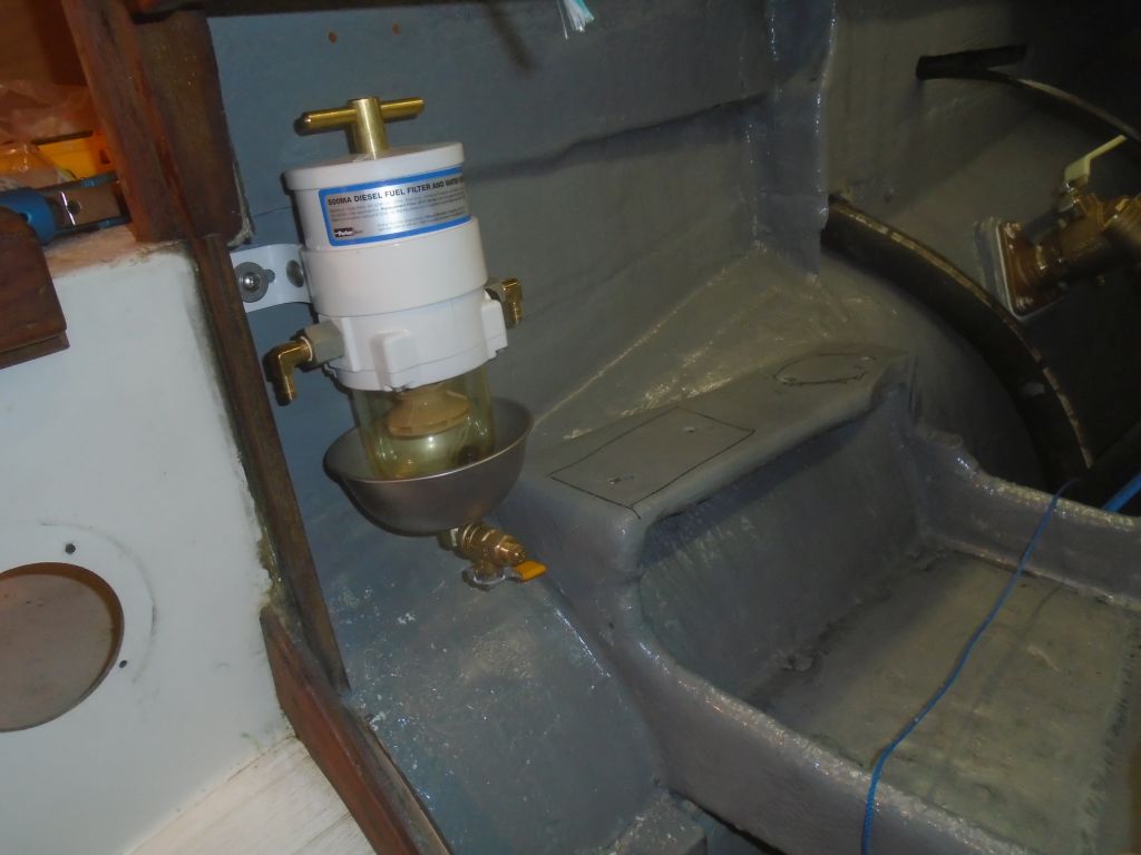
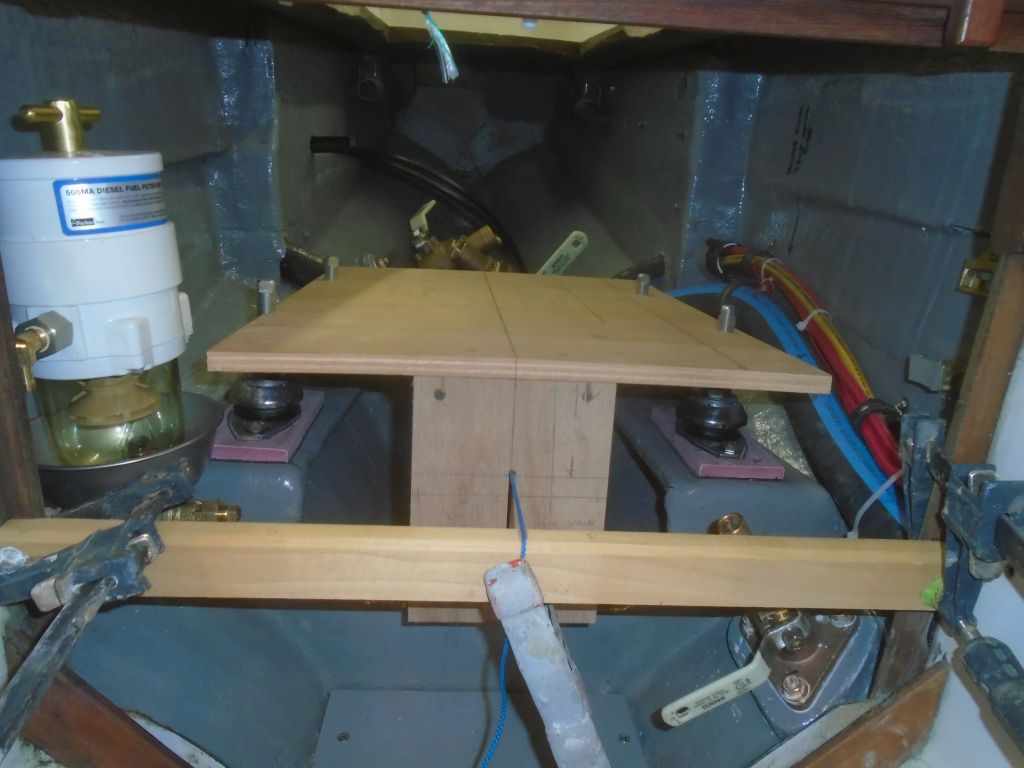
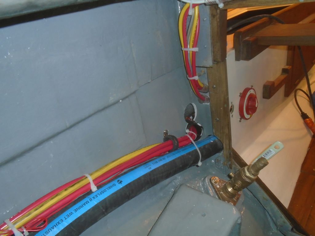
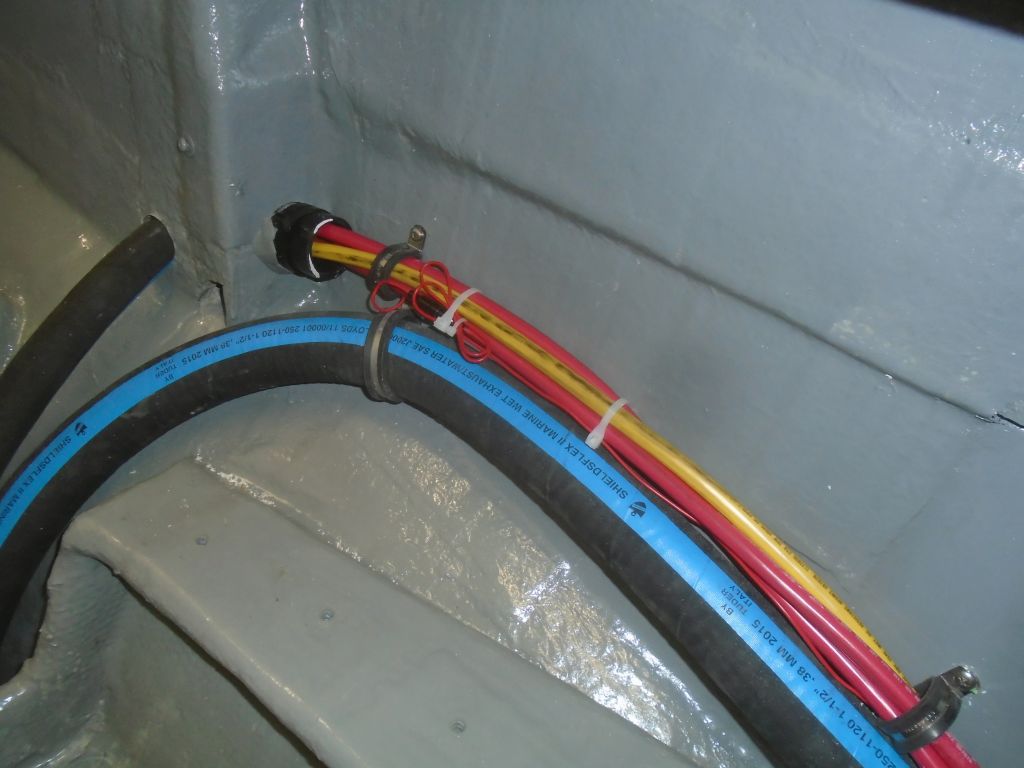
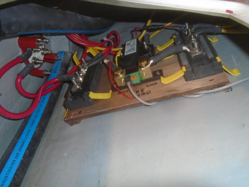
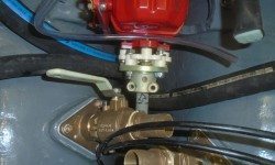
With all that out of the way, I could move forward with the various final connections to the engine.  I reinstalled the fuel filter–permanently, this time–and was preparing to install the rest of the fuel system, but decided instead to finalize the start battery position and therefore the last set of battery cables.

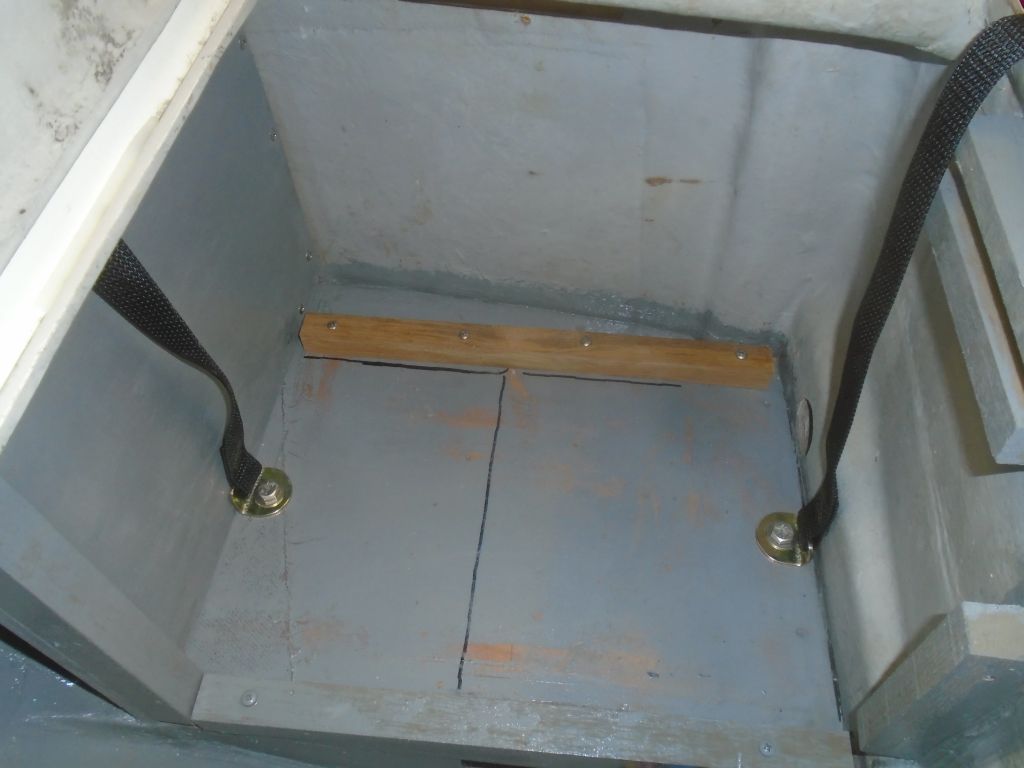
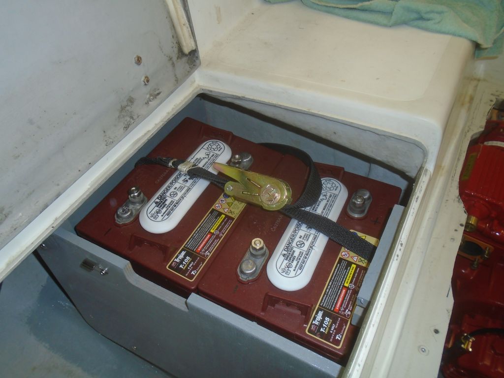
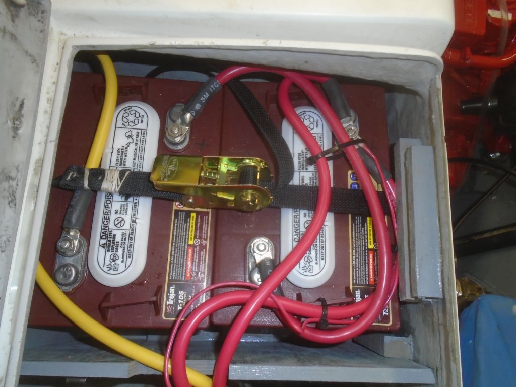
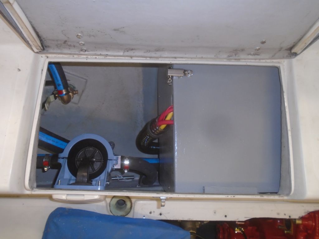
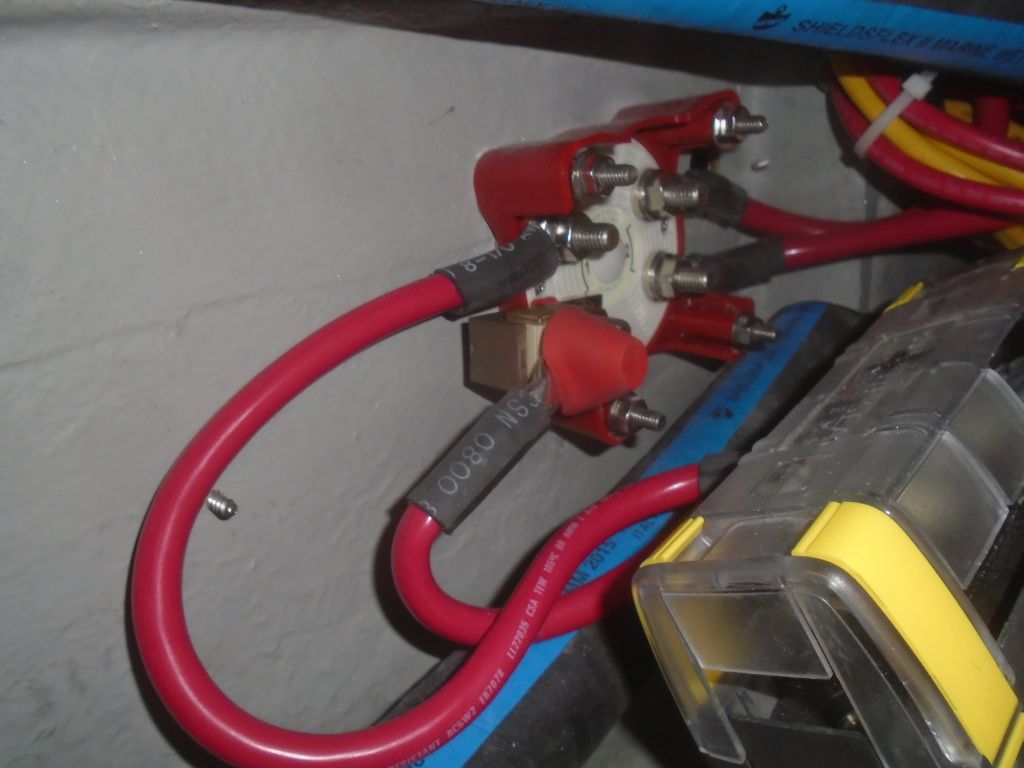
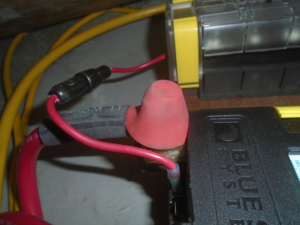
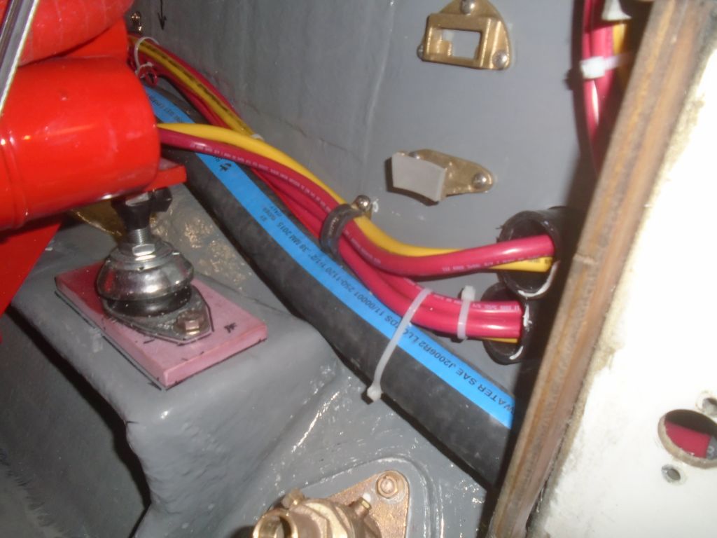
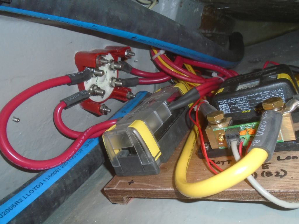
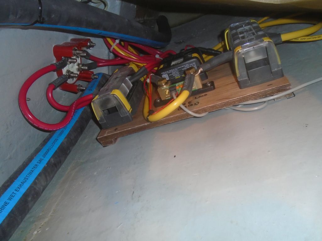
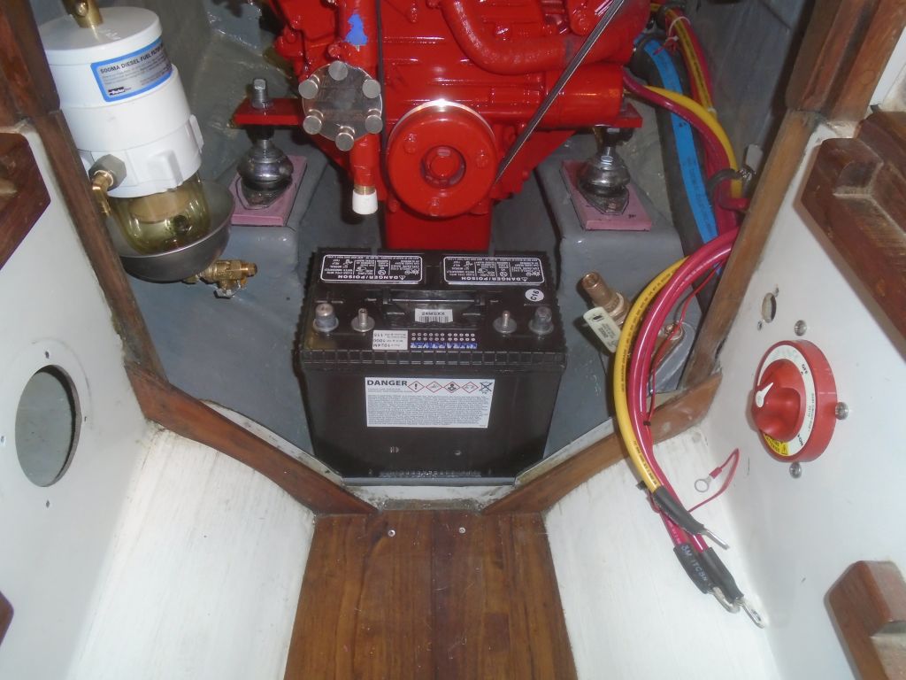
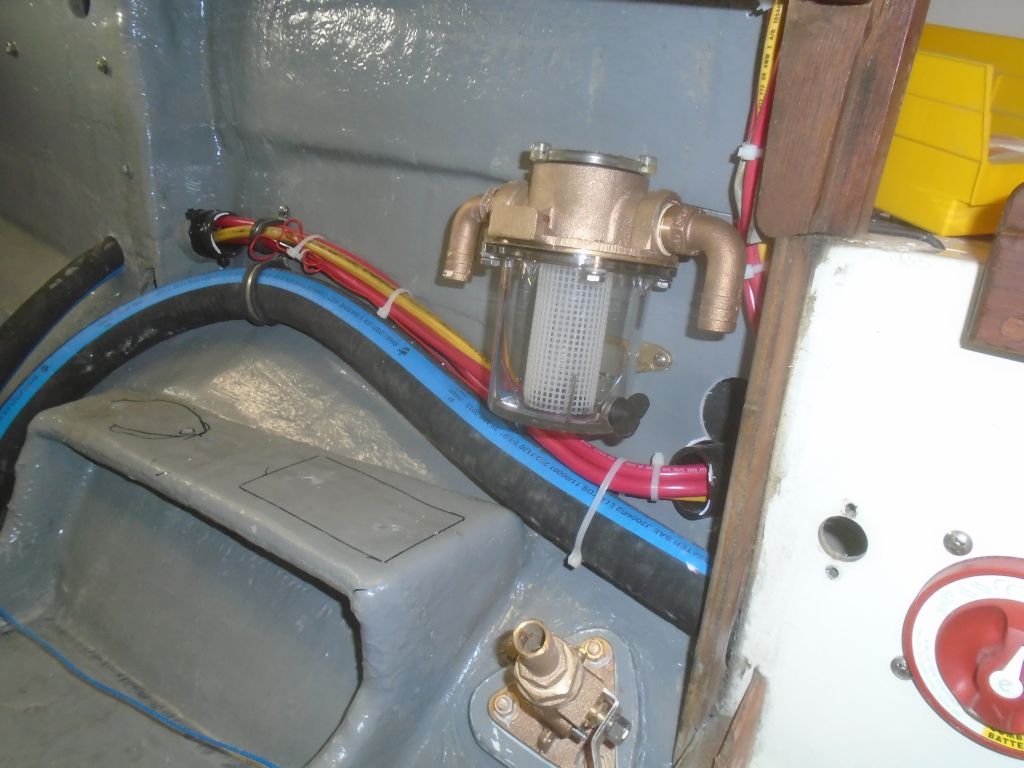
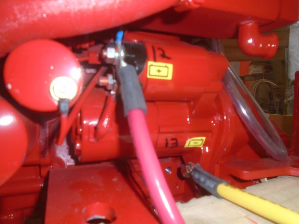
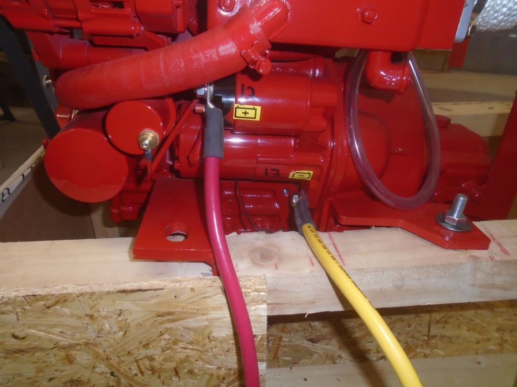
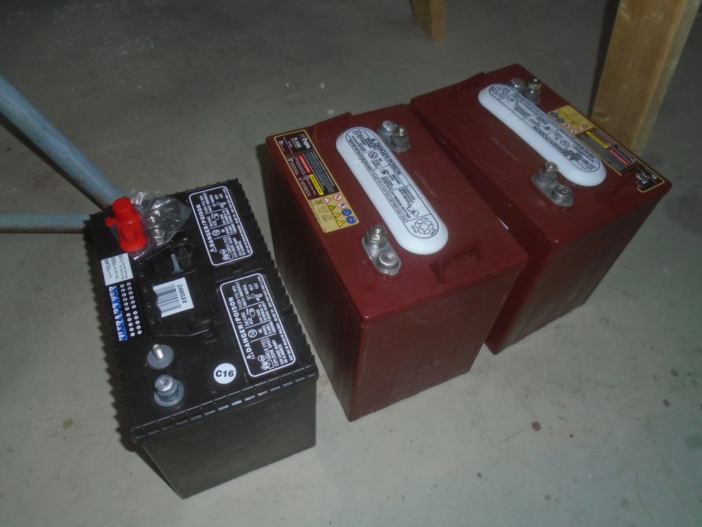
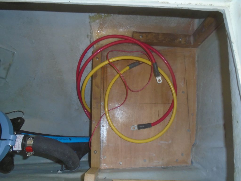
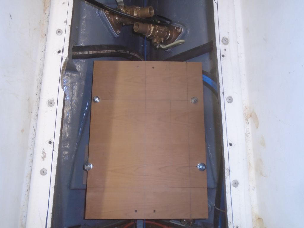
With the actual start battery now on hand, I test-fit it on the platform ahead of the engine, which looked workable, as I’d hoped.  I’d strap it in place and cover the terminals, and that would be that.  So now I could make up the final cable ends, starting with the two cables leading to the engine starter and ground,  and then the three cables to the battery from the switch, ACR, and the required position on the monitor shunt, along with another temperature sensor for the battery monitor.

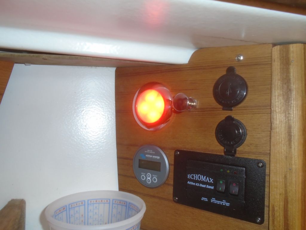
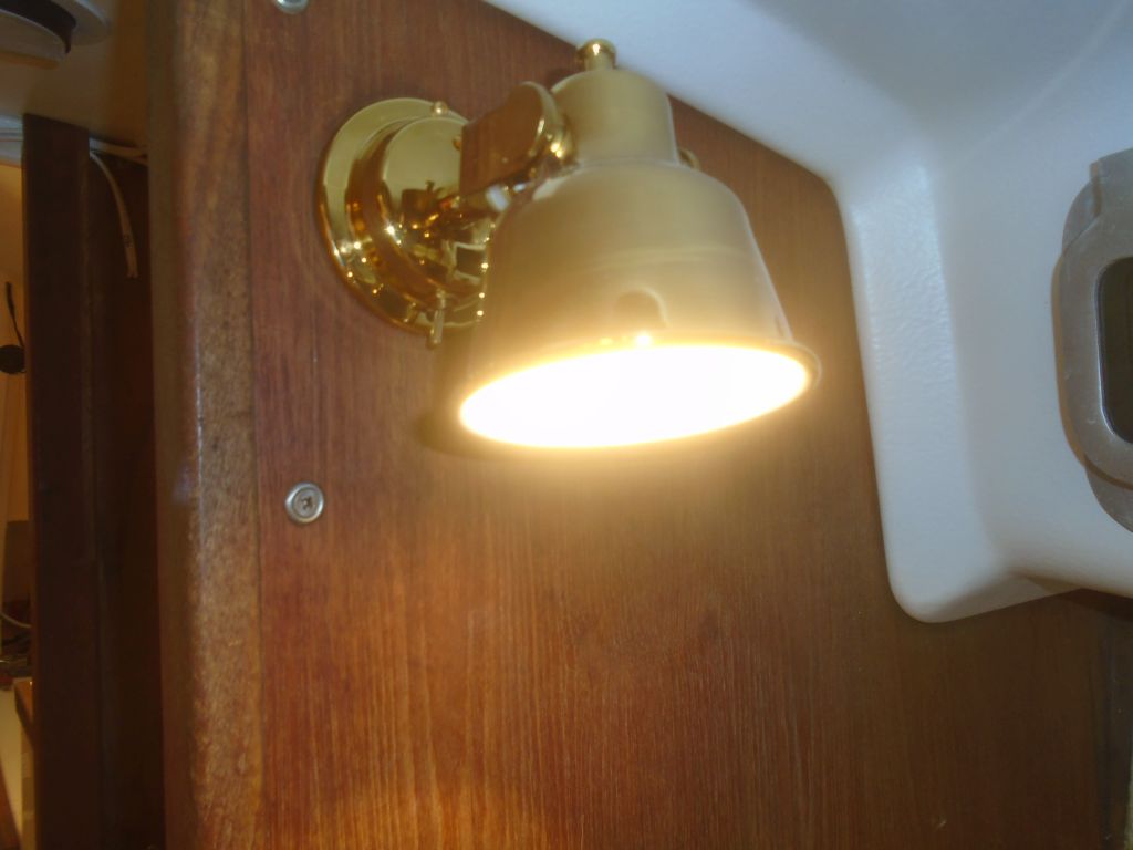
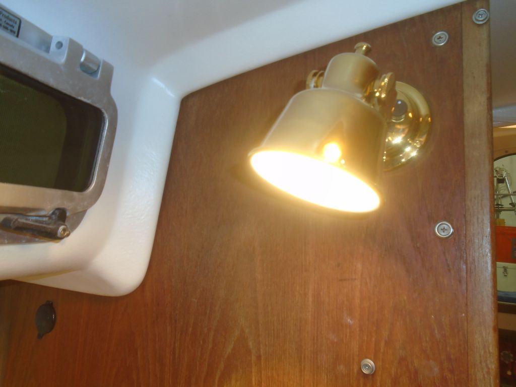
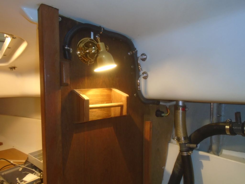
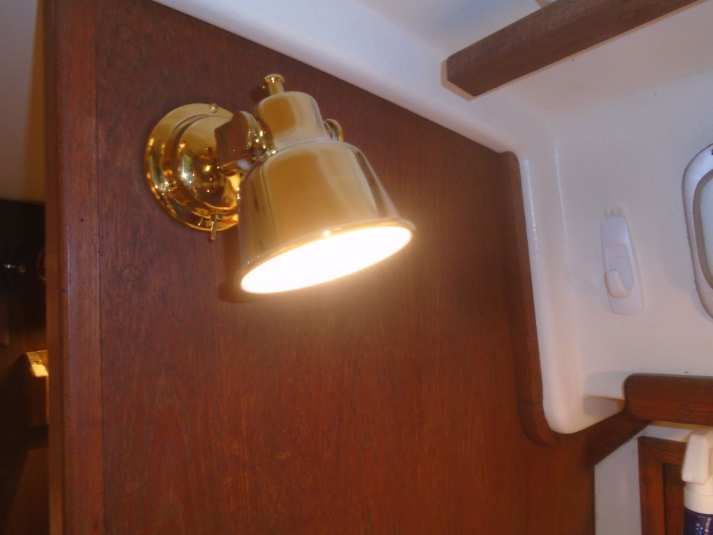
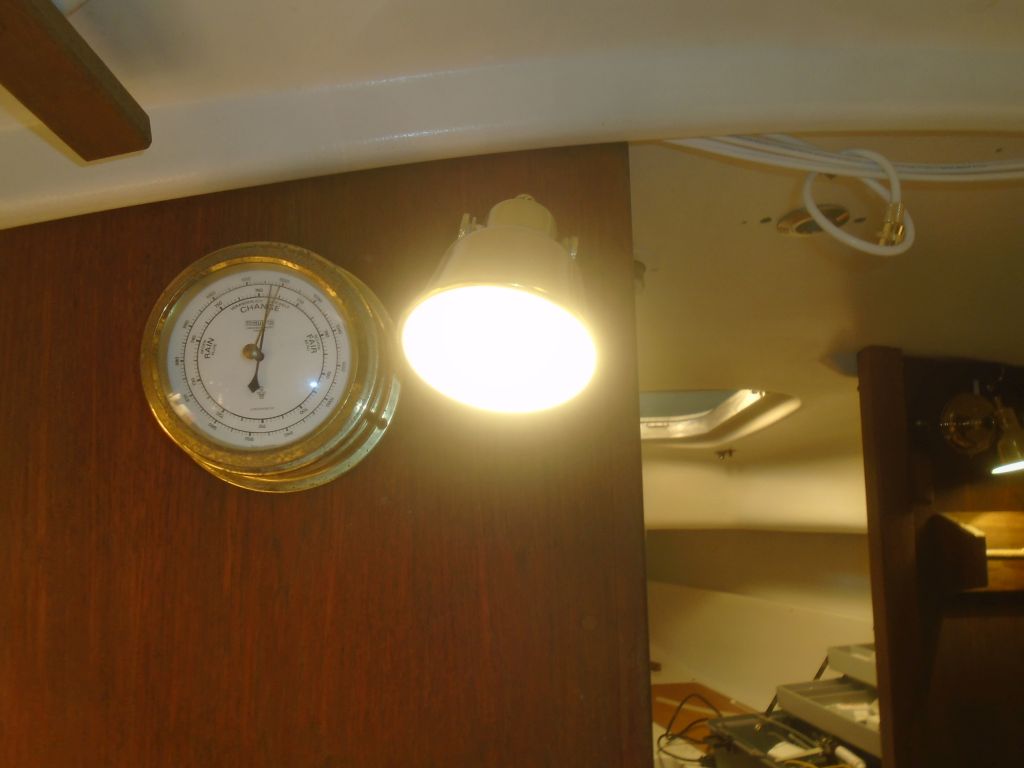
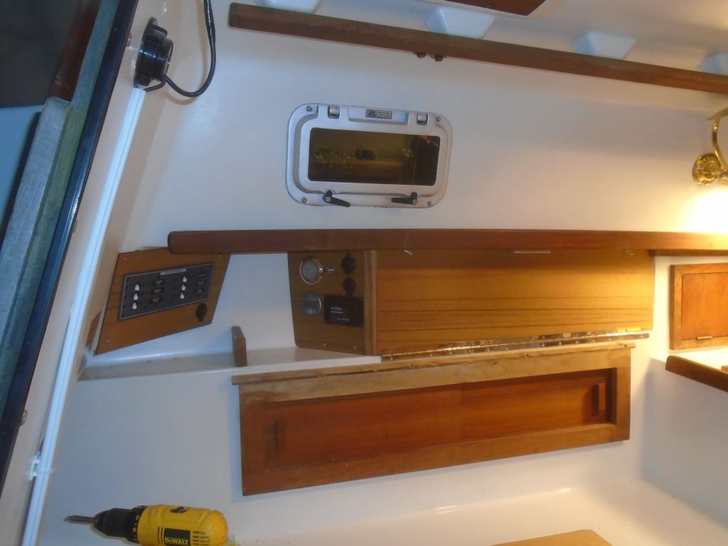
I couldn’t resist the chance to temporarily connect the battery and, through the “combine” position on the battery switch, energize the ship’s power to check out the operation of what I could–namely all the cabin lights and running lights.  Afterwards, I disconnected and removed the battery for now, and cleaned up from the wiring project since that was essentially done and I needed to get some things off the boat to make way for the remaining work.

Total time billed on this job today:  8 hours

0600 Weather Observation:
20°, clear.  Forecast for the day:  increasing clouds, 35

Salty 33

< Back to Salty

Tuesday

The owner requested an electronics mounting base near the companionway, similar (or identical) to an installation I completed on a sistership, and in order to support the base I needed to prepare a wooden mounting base to glue to the bulkhead, since there was no other way to secure the mount without bolting through the cockpit wall.  Using the aluminum base as a guide, I built a simple teak block, and installed flush screws from the back side to create mounting studs for the electronics base.

I planned to epoxy the block–and the studs–to the bulkhead, but since clamping it in place would impede access through the companionway, I set it aside, planning to install it at the end of the day, but as it happened I didn’t get back to it this day.

In the engine room, I installed a plywood panel to close off the bilge access forward of the engine, and hopefully to support the starting battery later.  I’d cut this and painted it earlier.

er1-40516

I mounted the fuel filter on the starboard side of the engine room, as far forward and as low as possible to leave room for access.

filters1-40516

On the opposite side, I installed the brackets for the raw water strainer, though I didn’t permanently install the filter at this time to leave more room for engine installation access (since the filter was simple to install once the brackets were in place).

I had to leave the shop for an appointment, but after returning I worked on the engine itself to prepare a few things before installation.  The engine raw water impeller’s cover place came equipped with six small screws to secure it, but I liked to replace these screws with knurled fasteners to make access for inspection and maintenance easier going forward.

The clamps required to support the gear and throttle control cables were fussy enough by design, with two separate pieces and small fasteners, but the slim slotted screws that came with the engine made these just that much more challenging to work with in tight, dark engine rooms, so I replaced these fasteners with socket cap screws to allow a positive engagement with the installation tool.

Knowing full well how difficult access into this engine room  would be once the engine was in place, I pre-installed two lengths of battery cable to the stater solenoid and engine ground bolt.  I cut these generously to length up in the boat first, to determine how long they should be, then made up one end with the required lugs before installing them and tucking the cable length into the engine to keep it out of the way for now.    This would streamline the final connection chores later.

I hoped to make the installation easier by pre-installing the four flex mounts to the engine beds, since access to these bolts was always tough once the engine was in place.  So with the newly-arrived bolts now on hand, I secured the mounts in place in the pre-drilled holes I made earlier.  Then, I rechecked the positioning and alignment with my template and shaft string once more.

By now it was mid-afternoon, but I thought that with a little luck I had time to actually get the engine in the boat, so I went ahead and hooked up the crane and raised the engine into the boat.  Before doing so, I removed the two forward mounting flanges, which I knew would be too wide on their own to fit through the tight engine room opening.  These were secured to the engine block with two bolts each.

In an ideal world, it should have been no problem to lift and place the engine in the engine room in the hour and a half or so remaining in the day, but in my gut I knew it’d not be that easy, and of course it wasn’t.  Despite already widening the engine room opening, it was simply too tight to get the engine in for all practical purposes.  There’s always a fair bit of jockeying for position when inserting an engine into the typically small sailboat engine room, but here, even with that sort of game playing, there really wasn’t enough width as it stood.  I got the engine partway into the opening, and even reinstalled (from inside the cabin) the forward mounting flanges in preparation for dropping onto the mounts, but it soon became clear that I needed to widen the opening further.  It was also clear, from the way the engine fit into the space and what I’d have to do to actually get it onto the foundations, that having the flex mounts pre-installed wasn’t going to work, so I’d have to install them on the flanges first, then bolt them to the engine beds afterwards.  I had to remove a coolant hose from the port side during this initial trial, and even though the coolant reservoir was dry, there was a surprising amount of coolant somewhere in the engine passages that spilled out and required cleanup.

So reluctantly, I lifted the engine back out and rested it (well-padded) in the cockpit for now while I got better prepared for final installation.  I removed the mounts from the engine room, and also removed the fuel filter, not because it was in the way of the engine, but because I’d determined it made access around the side of the engine to the mounts difficult or impossible.  I marked the engine room flange where I’d need to cut it wider(by now it was late, and I didn’t want to do the cut now), and then, finally, I removed a clamp that had held the engine wiring harness plug annoyingly in the way during my test fit, and wasn’t directing the plug the right direction for this installation anyway, so it would have forced a sharp bend in the wires that wouldn’t have done them any good over time.  With the clamp–bolted and well-painted into place–removed, the harness had some freedom of movement, and would be out of the way next time I lowered the engine into place.

Total time billed on this job today:  5.5 hours

0600 Weather Observation:
12°, clear.  Forecast for the day:  Sunny, high 32°

Salty 32

< Back to Salty

Monday

With other business away from the shop at the end of last week, I took care of some errands at the same time, and picked up the new batteries for the boat.

batteries1-40216

During the weekend, I sanded and varnished the tiller, completing the coating for now with the 6th coat.

tiller1-40216

To finish up the electronics locker, I installed a continuous hinge along the bottom edge, securing it to the existing cabinetry.  For now, I used only a few screws on the bottom leaf of the hinge since I’d need to remove the panel to install some of the electronics.  To secure the panel when in place, I added two screws at the top edge, and also installed a simple handle to allow the panel to be easily swung down or removed as needed.

Meanwhile, I removed the tape and excess sealant from around the mast wiring chase and mast step.

mast1-40216

Next up in the electrical system was the battery cables.  Each battery bank would require three cables–two positive wires (leading from the battery switch and ACR) and a negative cable in each case.  With the final start battery position still up in the air pending the engine installation, I started with the cables to the house bank in the port cockpit locker.  Eventually, after consideration of various alternatives, I decided to run these cables out from the battery switch area (port settee) into the engine room, then aft and through a small bulkhead that connected with the locker containing the batteries.  After determining the lengths required, and making up the ends, I led the three cables (plus a small wire for the battery monitor temperature sensor) aft, securing them along the way and running the cables through short conduits where they passed through the bulkheads.  At the battery end, I provided enough slack to allow the cables to run up, over, and through the battery enclosure.

Back in the battery switch area, I made up the other ends of these cables, along with the positive and negative cables running between the distribution busses and the electrical panels on each side.  I’d finish up the st art battery and engine cables soon, once the engine was in place and I could determine the cables’ requirements.

battcables5-40416

To that end, I next turned to the engine layout so I could pre-adjust the engine mounts and determine their locations in the engine room.  Using existing foundations, I’d long ago determined that the basic layout was adaptable to the replacement engine, but since I didn’t build the foundations specifically for this installation, the final fit and placement wasn’t preordained.

To begin, I set up a layout/centerline string to represent the shaft centerline, leading it through a pair of centering plugs in the stern tube and into the boat, where I adjusted it as needed to center it in the shaft log before securing the string on a temporary cleat.

I placed my engine template over the string, slipping the string into the slots leading to the shaft center holes in the jig, and adjusted the mounts as needed to eventually align the jig properly with the string–and the boat.  The front end needed to be raised a bit, too much to do with just the mounts’ adjustment studs, so I added 1/2″ fiberglass blocks beneath the forward mounts.  At length, I adjusted everything so the engine was centered and level.

I marked the position of the mounting feet–easy at the forward end, but hard to reach at the aft end with the curvature of the hull and overhang of the template–then, with the “engine” removed and the mounts placed back on the rough marks, I pre-drilled pilot holes for the mounting bolts.

There were some additional installations to complete before I actually put the engine in place, and I also wanted to address the engine opening, which still had the old rivets left over from a long-ago removed gasket system (there’d been an ineffective gasket made of flattened foam pipe insulation in place when the boat arrived here).  I drilled out the rivets so I could start fresh with a new gasket, and also opened up the forward end of the opening as much as I could on each side, since the opening was not wide enough for the engine (even with the widening), and I wanted to minimize how much I needed to remove from the engine itself in order to squeeze it through.   I knew I’d have to remove the forward mounting flanges, which stuck out an inch or two beyond the actual engine dimensions, but hoped to avoid removing the alternator or anything else if I could.   These photos show the before and after.


Total time billed on this job today:    8 hours

0600 Weather Observation:
12°, clear.  Forecast for the day:  increasing clouds, chance of snow, high around 30°.

Older posts Newer posts