(page 1 of 6)

Salty 51

< Back to Salty

Friday

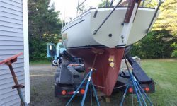
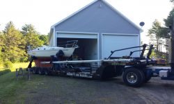
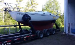
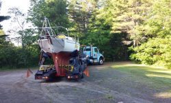
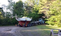
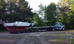
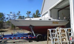
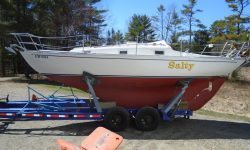
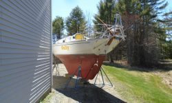
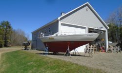
Salty’s next project phase–rigging, sails, and, if all went well, sea trials–started now with her pickup early in the morning.  She was headed for the waterfront and a boatyard there, where others would continue with the final phases of the project before her owner arrived for trials and to bring the boat home on his new trailer.  I’d not be involved in this portion of the project, as I was unavailable during the proposed timeframe, but was on hand to see her departure.

< Back to Salty


Salty 50

< Back to Salty

Thursday

As a last-minute addition, the owner requested installation of a bilge high-water alarm, which I’d ordered a while back but had been awaiting time to install.  Now was that time.

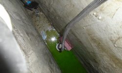
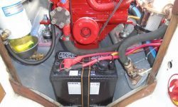
The system required a little float sensor to be mounted near or at the bottom of the bilge, a challenging prospect on this boat with the available access.  The only way in was through the removable shelf containing the starter battery in the engine room, so I disconnected the battery and moved it aside, removing the shelf.  The bottom of the bilge was juuuuust beyond the realistic extent of my reach, given the limits on head and shoulder room at the top, but I cleaned up the side of the sump a bit to accept epoxy and a fiberglass mounting block, to which I installed the sensor float in its supplied bracket.  With the back of the mounting block buttered up, I pressed it into place at the bottom of the sump.  I led the two small wires through some flexible conduit and brought them up into the engine room, leading them through a space at the forward end of the battery platform.

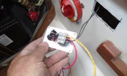
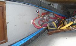
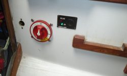
I prepared an opening for the little control panel (which contained the horn for the alarm) just forward of the battery switch, where there was convenient access for the required wiring.  With existing obstructions, there was pretty much only one place the panel could go, and there indeed it went.  I made the wiring connections to the panel, including the two wires leading to the float switch (which, when activated, would sound the horn), and then power and ground (which I led respectively through a fuse to the hot side of the battery switch, so the alarm would always be powered, and to a nearby negative distribution buss).  I screwed the panel into place and neatened up the wiring, and this completed the installation.  The power light on the panel was lit, as it should have been.

Total time billed on this job today:  1.5 hours

0600 Weather Observation:
45°, sunny.  Forecast for the day:  mainly sunny, increasing clouds late in the afternoon, high in the low 60s

Salty 49

< Back to Salty

Wednesday

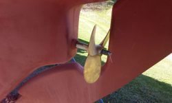
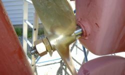
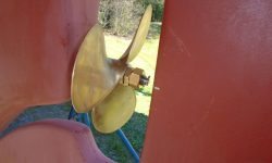
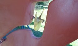
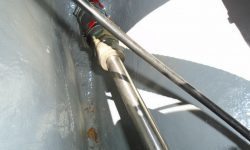
After one final, hopeful, yet unsuccessful attempt to somehow twist the new propeller onto the shaft in the tiny space before the rudder, I gave in and went up and removed the flexible coupling from the shaft.  This gave me additional space to slide the shaft forward, which allowed me to get the prop into position without removing the rudder.  Then, I slid the shaft  (with prop loosely in place) as far aft as possible so I could reconnect the couplings inside.

prop1-51816

Afterwards, with the couplings reinstalled and bolted tightly into place, I finished up the propeller installation by securing it in place with its nuts and cotter pin.  The propeller size is 11RH6.

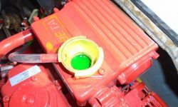
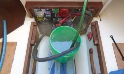
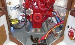
Now, I prepared the engine for its initial firing by adding fluids as needed:  engine oil and coolant.  Fuel had partially filled the fuel filter by gravity from the tank since I’d made those connections, but I added more fuel to the filter to fill it to the top.  I installed the start battery, and prepared a temporary cooling water intake line with a length of hose and a bucket.

With everything in place, I bled the engine at the secondary fuel filter, using the engine’s built-in pump lever to prime the system till I got fuel (and air) out of the bleed screw at the top.  (14mm)  Once I saw relatively clear fuel, it was time to fire the engine.  I knew from past experience that these engines were almost completely self-bleeding, so there was no need to chase fuel through the rest of the system.

Once I started the engine, it took a few times to get it to run properly as it worked fuel and air through its system.  After two starting attempts–the engine started, but wouldn’t run for long–I rebled the fuel system at the secondary filter, and afterwards the engine stayed running once I’d started it.  Easy peasy.

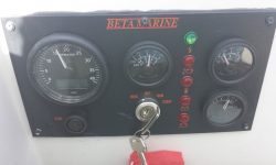
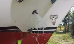
After running the engine for a few minutes, I shut down so I could check the fluid levels again.  Both oil and coolant were fine and I didn’t need to add any.  With this check complete, I started the engine again for a longer run.  The three videos below show various stages of the process.

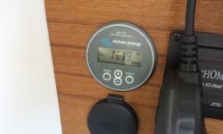
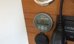
Sorry about the bad reflection on the battery monitor in the video above.  These photos show the battery charging amps at higher speed and again at idle speed.

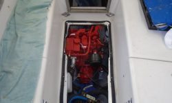
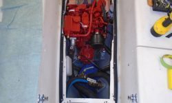
With the successful test firing behind me, the job was complete, and I spent the last minutes of the day cleaning up a bit and putting the boat back together.  I installed the raw water strainer and its hoses, and buttoned up the engine compartment.

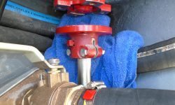
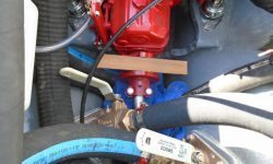
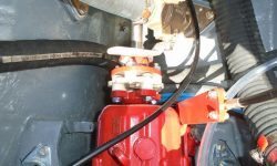
I left the engine raw water seacock closed, and since I wouldn’t be there at launching, to help future operators remember to open the seacock before starting the engine I hung the engine keys right on the seacock (located at the forward end of the engine room and accessed from the panel behind the companionway).

shutdown3-51816

I installed the engine hatch with four screws (out of a total of about 12) so it’d be secured during transport, but easy enough to remove at launching to check the stuffing box and engine.

Total time billed on this  job today:  5.25 hours

0600 Weather Observation:
40°, clear.  Forecast for the day:  mainly sunny, 60

Salty 48

< Back to Salty

Wednesday

Now that the coupling was painted, I continued with the shaft installation.  After inserting the shaft from outside, I installed the new coupling from inside the boat, then used a scrap of wood cut to 1-1/4″ width as a stand-in for the plastic sacrificial coupling that I’d eventually install between the shaft and transmission, but first I wanted to ensure that the shaft length was correct and as I specified, since the clearance with the rudder was so tight.  I didn’t want to install the flexible coupling just yet since I needed to use the steel coupling to finish the engine alignment first.

Fortunately, the shaft length and clearance was correct.

Now I brought the couplings together inside the boat, and adjusted the engine as needed on its mounts to correct the initial alignment, which had the engine just a bit too far to port at the aft side.  But overall, the engine position that I’d determined based on my plywood engine template was very close right from the start, and soon I could tighten all the mounting bolts to secure the engine in its final position.

Next, I pushed back the shaft and then installed it permanently using the plastic sacrificial and isolation coupling between the two steel flanges.

Down on the ground, I’d hoped to install the propeller, but I found to my dismay that I couldn’t seem to twist the very flat-pitched 3-blade prop onto the shaft and around the rudder.  I tried various rudder positions and angles, to no avail, and with time running short on my available time on this day, I decided to approach it again another time.  I thought the easiest way to increase clearance would be to remove the plastic coupling inside–the coupling that I’d only moments before labored to install with its eight bolts (sigh)–but this seemed far easier than removing the rudder.  In any event, sometimes a fresh day makes all the difference, so I’d try anew a little later.  Maybe I’d missed the one perfect angle where the prop would slide right on despite the rudder.

Total time billed on this job today:  2.75 hours

0600 Weather Observation:
32°, clear.  Forecast for the day:  Sunny, 60s

Salty 47

< Back to Salty

Tuesday

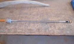
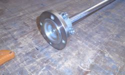
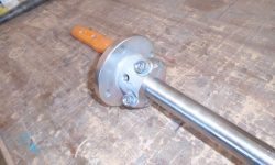
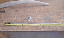
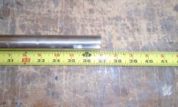
After a lengthy production delay, the new propeller shaft finally arrived, and I wasted no time checking the measurements to ensure it corresponded to my order.

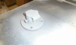
I looked forward to installing the shaft soon, which would allow me to do the final engine alignment and secure the engine permanently, but first I wanted to paint the raw steel coupling, and over the course of the afternoon I applied primer and paint to the piece.

Total time billed on this job today:  0.5 hours

0600 Weather Observation:
32°, clear.  Forecast for the day:  sunny, high in the mid-60s

Salty 46

< Back to Salty

Wednesday

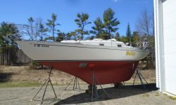
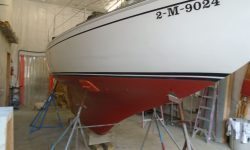
In the near future, I wanted the chance to test-run the new engine, and this need, along with other obligations requiring the inside of the shop, meant that, now that all the work was otherwise complete (excepting the new propeller shaft and engine startup), it was time to move Salty outdoors for storage and the duration of the final stages of the project.  The boat wouldn’t be leaving here for a couple months, so to ensure access to other boats in storage I set her down in an out-of-the way location, but readily accessible to the shop for the final work as needed.  I offset the jackstands so I could easily paint the last patches of the bottom.

Total time billed on this job today:  1 hour

0600 Weather Observation:
Clear, foggy, frosty, 22°.  Forecast for the day:  sunny, 50

Salty 45

< Back to Salty

Friday

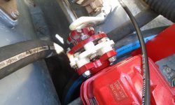
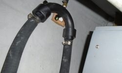
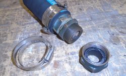
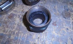
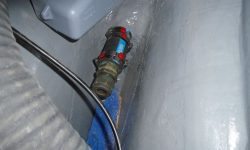
A supply snafu had delayed delivery of the 1″ hose I needed for the engine siphon break system, but now it was on hand, and I gladly finished up the installation.  I located the siphon break fitting in the port cockpit locker, secured to a wood block on the hull, as high up as practicable and just aft and outboard of the battery box.  I connected the vent/overflow hose, which led aft to the gooseneck at the transom, to the nipple on the top

I also cleaned and polished the cockpit well, completing the deck work.

At this point, the project was complete except for installing the new prop shaft, and finalizing the engine alignment, along with the engine start-up and test run.  I anticipated the shaft would be on its way within the next week or so, at which time I’d finish the final tasks.

Total time billed on this job today:  2 hours

0600 Weather Observation:
32°, clouds.  Forecast for the day:  clouds and sun, 60s

Salty 44

< Back to Salty

Wednesday

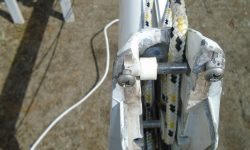
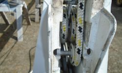
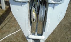
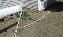
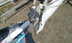
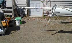
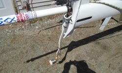
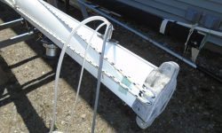
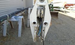
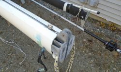
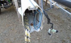
After some morning errands away from the shop, I turned to the mast wiring.  While I had the masthead casting off, I checked over the masthead sheaves, which all looked in good condition as far as I could tell, but it looked like there might be one damaged or partially missing, as evidenced by the plastic hub on the aftermost pin (first photo).  That pin just slipped into cast slots from above, and was contained by the masthead casting when it was normally in place.

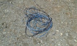
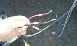
To extend the RTE wiring harness, a 5-conductor cable, I ended up using the same 14/5 cable that I’d run through the boat for this purpose earlier, which meant that wiring connection at the terminal block in the boat would be straightforward same color to same color.  This cable was heavier and larger than I wanted, but options were few and far between, at least with any products I’d trust and that were available in less than 1000′ parcels.  As least I knew it was quality wire.  Somewhere there must be a source for tinned 5-conductor cable in smaller gauge sizes and nominal overall diameters, but I couldn’t find it and after a time further looking was only wasteful.

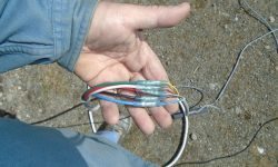
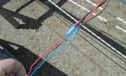
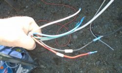
In the event, I connected the new wire to the existing harness, noting again the color conversions between the two, and for added longevity and strength within the mast, I added a sheath of heat shrink over the entire splice.

I chose to use the existing wires (which had powered a tricolor masthead unit) to pull the new cable down from the top.  So I heavily taped the new harness to the old to help it on its way through whatever course it took down the top part of the mast.  In addition to the 14/5 cable, I also secured a new VHF cable to pull through the mast and replace the existing.

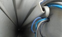
The wires from the masthead ended up in a length of plastic conduit within the mast when they reached the steaming light location at the spreaders, along with the three-wire harness from this light.  The conduit slipped over an extruded lip on the inside of the mast, and therefore was removable as a whole.  At the steaming light, I secured a length of messenger line to the existing wires before starting to pull out the entire harness.
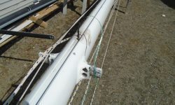
mast5-42016

From there, it was relatively simple to pull out the conduit and old wires from the bottom.  The new harness fed in fairly easily from the top once I got it going, which suggested it had an unimpeded path through the spar.

I left some slack in the masthead wires just below the top of the mast to allow the masthead casting to be removed for sheave access in the future, then resecured the masthead–with RTE and VHF extension attached–back in place before making up the end of the VHF cable as required.  After photos, I removed the VHF antenna for safekeeping, but the RTE was now a permanent fixture by virtue of its hardwired and sealed construction.

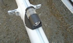
Since it was straightforward to slip on the wire conduit afterwards, I went ahead and ran in the 14/3 wire for the steaming/deck light combo at the spreaders, and made up the wiring at the new LED fixture before installing the fixture with machine screws.  I left some wire slack bundled behind the fixture.

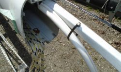
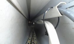
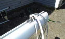
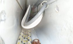
The masthead cable was too large to fit within the internal mast conduit along with the steaming light harness, so to secure it as much as possible I came up with a plan to secure it to the outside of the conduit with cable ties.  With the conduit out of the mast, at intervals I drilled holes at the outer edge to accept wire ties, and as I fed the conduit back into the mast and over the steaming light cable, I secured the thick masthead cable loosely in the wire ties–loose because they had to allow the conduit to slide up, while still securing the exterior cable tightly enough.  This actually worked better than I’d hoped.

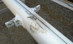
I chose a location on the forward side of the mast for the wire outlet, which would eventually connect (via flexible conduit aka hose) with the deck fitting on the boat.  I drilled a hole for the wires to pass through and installed a rail mount base on the outside, which diameter matched that of the deck fitting (and hose).  Then I led through the wires.

After reinstalling the mast base casting, I measured generously for the final wire lengths, which had to pass through a length of hose/conduit, then through a path in the boat to the terminal blocks for final connection.  Since the terminal blocks were hidden from normal view, and because I wouldn’t be there to make up the wire lengths when the boat was rigged, I left what I thought (and hoped) was more than ample wire length to make up the connections without being ridiculously long.  The wires could always be shortened later if necessary, but at least they were ready to be connected as is.  I labeled the wires as necessary to match up with their respective connections in the boat.

Total time billed on this job today:  5.25 hours

0600 Weather Observation:
35°, clear.  Forecast for the day:  sunny, 50s

Salty 43

< Back to Salty

Tuesday

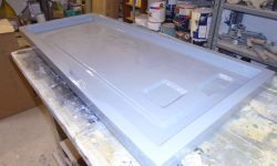
I spent the morning taking care of myriad smaller tasks, starting with the engine hatch, which I lightly sanded and painted with the finish coat.

enghatch1-41916

I installed a new bulb gasket around the perimeter of the engine hatch.

enghatch2-41916

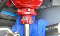
I cleaned up the original bronze stuffing box, and packed it with two layers of new graphite packing.  There simply wasn’t room to thread on the nut if I added a third layer, though I tried several times to make it work.  After repacking the box and compressing the packing using an old shaft, I installed the stuffing box in the boat with new hose and clamps.

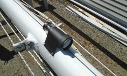
To support and secure the RTE to the masthead, I installed a standard 1″ antenna base, to which the RTE would thread.  I installed it over an existing wire hole in the masthead casting.

mast1-41916

To extend the VHF antenna aft, away from the RTE, I installed an aluminum extension, which I bent to match the angle of the masthead casting so the protruding end would remain level.  I left the extension oversize at the beginning, but later I determined where to mount the VHF antenna bracket and cut off the excess.  The extension could be removed to allow the backstay toggle to be inserted into the mast beneath it, once the masthead casting was back in place.

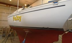
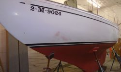
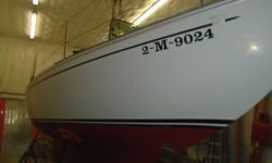
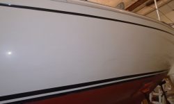
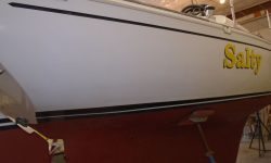
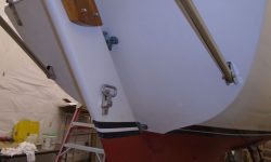
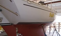
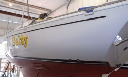
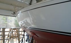
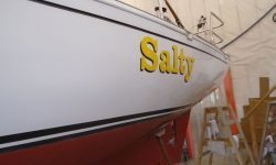
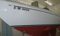
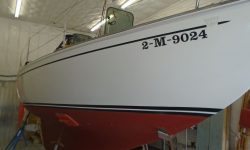
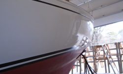
The topsides featured original gelcoat in good condition for its age, but with some staining, dirt, and oxidation.

It didn’t take much to bring back the shine and clean up the surface with light polish.

The engine exhaust outlet was located fairly high on the transom, above any normal levels of submersion, and this, along with the high cast iron gooseneck just inside the transom, would be as effective as anything against potential backflow into the outlet. The very space available in the boat required certain compromises in the exhaust system design.  However, to ward off a following sea in more extreme conditions, the owner elected to add a simple exhaust flap over the outlet, which added a bit of extra protection to the system.

Total time billed on this job today:  6.25 hours

0600 Weather Observation:
40°, light rain.  Forecast for the day:  Rain ending, clouds, 50s
Salty 42

< Back to Salty

Monday

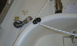
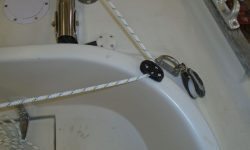
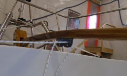
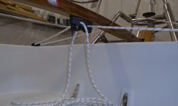
To finish up the basics of the Monitor windvane installation, I installed a pair of small cheek blocks on the coaming, locating them near the initial layout marks I’d made, but adjusting as needed to where they made the most sense and the fairest lead to the vane and to the tiller.
The blocks’ positions allowed me to finalize the installation for the two cam cleats on the underside of the tiller.  I left the lines long for the owner to fine-tune as he saw fit.  Afterwards, I lightly polished the coaming and aft deck to complete the areas I’d not done the last time.

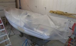
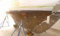
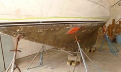
Next on the agenda was the bottom, which required sanding prep before converting to a different type of paint, so I removed the staging for better access and prepared the boat by covering the decks with plastic sheeting to keep dust off and out of the boat.  Before beginning further work, I polished the hull right at the waterline so that later I’d not run into the new paint.  I’d do the rest of the hull later.

bottom1-41816

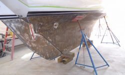
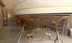
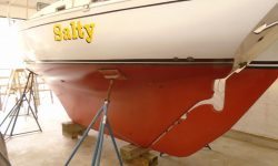
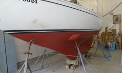
Afterwards, I sanded the bottom to scuff up the surface–the existing was a teflon-based paint that was compatible beneath the new paint the owner chose, but required sanding first.  I didn’t attempt to remove the paint, but just scuffed it thoroughly to ensure good adhesion.  Once complete, I cleaned up and solvent-washed the bottom.

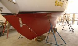
Next, after masking off I applied two coats of red antifouling paint.

Earlier, I’d determined a requirement for some additional wiring for the mast–I’d need to extend the 5-wire harness for  the radar target enhancer (RTE) since the wire provided with the unit was far too short, a shortfall I’d fortunately discovered before it became critical.  The owner and I had also discussed VHF antenna placement to avoid interference and physical contact with the RTE, and came up with a plan that would require some additional material as well.  So while I waited for the new wire and other material to arrive, I thought I’d see what I was in for with the mast project.  I found that both the top and bottom castings of the mast were removable, which greatly helped access within, so that was a plus.  Inside the mast, running up at least as high (but possibly not beyond) the steaming/deck light combo at the spreaders, was a plastic conduit containing the old wires.

I’d begin the mast work soon, but for now I just removed the old steaming light, as there was a new replacement on hand.

Total time billed on this job today:  6.25 hours

0600 Weather Observation:
40°, clouds.  Forecast for the day:  Mostly cloudy, 50s, showers late

Older posts