(page 6 of 7)

Holby 18

I lightly sanded the new interior fiberglass work in the usual way, just lightly scuffing to remove sharp edges and prepare the surface for future steps.

Now, beneath the boat, I prepared the bottom in and around the new repair for its final fiberglass work by grinding a tapered area 4-5″ out from the patch, from gelcoat at the outside to about 1/4″ down at the borders of the new patch, bringing the existing hull there flush with the new repair I’d completed from above, and as designed.  This would provide the space required for the new fiberglass to tie in the repair work with the existing hull from beneath.

Around the vertical transom opening, I created a similarly-prepared area for tying in the eventual new fiberglass required to complete the transom patch.

From here, I planned to start with installing new fiberglass forward of the patch to fill in the slightly-flattened area left from the old tunnel configuration, which I’d complete before installing fiberglass over the whole area to recreate the hull shape and finish the structural repair.  At the transom opening, I planned to fill in with solid fiberglass, and eventually incorporate the final layers with that of the bottom.  Meanwhile, inside the boat, I still had to fiberglass the new transom structure into the sides and bottom of the boat, then, finally, fiberglass over the new cutout in the transom to complete the overall repair.  I’d take care of these steps over the coming days.

Holby 17

After a quick water wash, I lightly sanded the new fiberglass in the aft bilge, previously known as the engine room.  This was only a light scuff to ease any sharp edges and prepare the fiberglass for the next steps; I also took the time to prepare and round over the top edge of the forward micro-bulkhead, as well as a light sanding at the new fiberglass transom to finish off the top edge from its installation a few days earlier, and to round this over for future tabbing work as well.  Additional laminate on the inside of the transom, as well as over the edge of the new cutout, would be coming up sometime a little later.

Next, I removed the mold from the bottom of the hull, starting carefully with the plywood transom template, which I removed separately for further use.  The plywood panels came off with ease, as they were held only with blotches of hot glue wherever.  The bent piece of plywood from the inside of the mold stayed in place; the screw heads pulled clean through as I removed the main part of the mold.

The inner section of bent plywood came off easily from there, leaving behind the masking tape, which was well-stuck to the laminate, as anticipated, but had done its job of preventing the wood from sticking.

The end result was just what I’d been going for:  Shaped in accordance with what the hull needed to be, but inset a fraction of an inch to allow room for the final laminates from beneath, which would further tie in and reinforce the whole repair when all was said and done.  Eyeballing the shape of the vee down the centerline, the new work lined up well with the unmodified shape forward of the repair area.

Now I removed the bits of hot glue from the hull, along with the mold putty and, as much as possible for now, the masking tape from the bottom of the fresh laminate.  The residue would eventually get sanded away, but that was for some other time.

Turning back to the interior for now, I laid out a trial piece of fiberglass to complete the forward section of the repair.  The glass confirmed well to the shape, so no darts or cuts would be needed.  Satisfied with the pattern, I cut two additional layers, each just a touch smaller on the sides and forward end.  After installing a thickened epoxy fillet along the bottom edge of the micro bulkhead, I installed the three new layers in epoxy resin.  This overlapped the adjacent new work by a few inches, and extended well forward to tie the whole thing together as much as possible.

With a bit of time left before I had to depart on other tasks, I decided to begin work on the transom section of the jet tunnel.  Using my plywood pattern, I cut two layers of 3/4″ Corecell, a good material I happened to have on hand, and, after some minor adjacent prep work, including filling the edges of the opening against the fiberglass laminate sheet I’d installed on the inside of the transom, I set the two layers of core in place in epoxy adhesive, filling all edge gaps and the kerfs in the scored core.  I held the bottom edge of the core up flush with the notched part of the jet tunnel so I could fill in the bottom with solid laminate before tying the new hull bottom laminate into that.  Eventually. I’d fill the remaining depth of the transom opening with either solid glass (to be extended out onto the hull around the opening once I prepared said hull).

And so we edge closer to the final stages of this rather extensive hull repair.

Holby 16

Beginning, I patterned and cut five layers of fiberglass to fit within the now-molded opening in the bottom of the boat, plus three additional layers sized to extend up and onto the adjacent hull on each side.  I followed this with final preparations to the space as needed.

I installed the five layers of cloth inside the opening (the one on top says “4”, but that’s only because I stacked the final two in the wrong order), filling much of the void.  I left these to partially cure for a while.

When the initial layers had gelled sufficiently, I dressed up the edges with substantial epoxy fillets to ease the path for the larger, overlapping layers to come.  I also filled minor voids along the edges of the existing hull where I’d previously chipped out some old bondo-type filler.  I left the new epoxy to partially cure over lunchtime.

With the epoxy cured enough to continue, I finished up the day’s fiberglass work with three overlapping and staggered layers over the patch and out onto the hull.  There’d eventually be additional glasswork at the forward end of the patch, which I might have liked to do now, but alas, there was a hard corner on the tiny bulkhead that I’d not thought to ease beforehand, so the tabbing would have to wait till today’s fiberglass had cured.  The after end would also receive more fiberglass when I fiberglassed over the inside of the transom, all of which would  be heavily tied into all adjacent surfaces.  But that was an operation for another time as well, and, much as I wanted to do more at the moment, there was simply nothing more I could practically do.

Holby 15

I test-fit the new plywood hull-shape pattern I’d made, which fit closely at the forward end of the repair area, which it should have since this is where I scribed it to fit.  However, the shape of the hull at the aft end/transom was slightly different, something I’d already surmised after making the new pattern, with a minor flattening of the deadrise and a slight longitudinal upturn in the shape of the centerline.  This meant that the new pattern would not be suitable for use at the aft end after all, so I planned to revert to using the original plywood template I’d made.

Meanwhile, while I still had access, I made a plywood template of the now semi-enclosed transom portion of the jet tunnel, shaping it to fit closely at both the forward and after ends of the roughly 3″ deep space.  I’d use this pattern later to cut core and fiberglass to fill the void.

To ensure the plywood transom pattern was properly aligned with the bottom of the hull on the sides, I temporarily glued a couple blocks to the hull, upon which I rested the template while gluing it in place.  Double-checking the existing transom height from the template once more, I confirmed that it was now 23-1/2″ high, with the final height to be 24″ from the centerline of the hull vee.  I’d build up the surface slightly and make up the rest of the height as intended with the tabbing over the new cutout.

With the transom in place, I marked and cut the hull shape on the bottom edge of the jet tunnel pattern to complete it.

Now I could get on with making the hull mold that would allow me to start rebuilding the hull from the inside first. After marking the centerline on the hull forward of the repair area,  I started with two pieces of 6mm plywood cut to 48″ long and 14″ wide, which spanned the repair on each side of centerline, extending far enough onto the known and adjacent hull to dictate the shape of the new hull in the void.  After some test-fitting and basic alignment, along with the assistance of some glued-on alignment blocks, I hot-glued the plywood to the hull as needed to secure it and define the shape of half the repair.  The plywood rested flat on the adjacent, intact hull along the sides of the opening, at the forward end forward of the slight flattened area in the hull, and, after more glue and clamps, along the bottom edge of the plywood transom template.

I repeated the process on the port side, leaving me with a generally v-shaped surface inside the opening in the hull.  To help align the two plywood halves in the center, I added a couple braces from beneath, just to even up the two edges.

To define the shape of the forward end of the space, since there was that void between the existing hull and the mold in the flattened area leading up to the drive tunnel, I patterned and built a fiberglass “bulkhead”, using the forward plywood hull template as a guide for the shape.  Then, after installing some tape over the plywood as a mold release directly beneath, I installed the new piece with epoxy adhesive against the forward end of the tunnel opening.  Filling in the void forward of this would be part of the repair that would be completed from outside, once the inner repair was complete.

To create the curved profile of the bottom of the vee, as well as to keep the interior repair laminate slightly elevated from the actual level of the “real” hull to provide space for the new exterior laminate to come, I prepared a thin plywood panel cut to fit within the void space, which I pushed down in the center to create the curved shape; I used a few screws to secure the bend in place.  This bend aligned with the curvature of the forward and after bulkheads, and the 3/16″ or so thickness would give more than adequate space outside for the final laminates once the interior repair was in place and I removed the mold.

Along the edges of the plywood, since I had to undercut the panel a bit in order to get it into place, I filled the voids with some spackling putty, just to bring the edges even and prevent future epoxy or laminate from bonding to the plywood.  (Clay would have been nice for this, but I had none.)  This material would all be removed from beneath once I took apart the mold.

To finish off the mold, I covered the whole area with masking tape as a mold release.  This would be adequate since it would prevent bonding to the wood, but since I’d have access from beneath once the mold was removed I could easily remove and sand away any tape residue that did semi-adhere.  Now the mold was ready for new laminate next time.

Holby 14

After some final preparations, mainly cleaning of the transom, surrounding areas, and new fiberglass panel, I installed the panel permanently in a thick bed of epoxy adhesive that I troweled onto the inside of the transom, along the bottom and side edges, and otherwise as needed.  With a large area and some unevenness around the bottom edge and the vertical portion of the jet drive tunnel, it required several batches of mixed epoxy, so there was no time to pause for reflection nor pictures of the adhesive application.

Once the panel was in place, I secured it with clamps along the top edge, which pulled it into the slight curve of the transom shape, and more clamps at the bottom edge through the tunnel opening.

Next, I mixed more of the adhesive epoxy mix and formed broad fillets along the sides where the panel met the existing structures, and slightly smaller fillets at the bottom edge where it met the existing hull.  The fillets increased bonding area and, more importantly, would provide a clean rounded corner to ease application of fiberglass later.

It was time to start focusing on molding the repair work to fill in the bottom portion of the jet tunnel.  This repair would be effected from both inside and out, but first I needed to create a temporary mold of the shape of the bottom, using the adjacent and known hull shape as the guide.  To prepare the surrounding hull for the first steps in the process, I began by scraping away the old bottom paint all around the work area from beneath, which was quick and easy since the old paint was poorly adhered anyway, and age had dried it out to the point that it was essentially falling away on its own.  Removing the paint would give hot glue, which would probably be a crucial part of my mold work,  a chance to actually stick to the boat.  Eventually I’d have to sand/grind the gelcoat and laminate on the underside as well, but not till I’d created the initial laminate from the inside of the boat, as I needed the existing hull shape as is to build the mold.

I couldn’t begin the mold itself till I unclamped the transom, but for now, and with only a half day planned anyway, I built a female pattern of the hull shape, starting with the male transom template I’d made earlier, then using an intact section of the hull just forward of the repair area to scribe closely and fine-tune.  The deadrise and shape looked consistent over the area of the repair, though there might be some increase in the angle as it went forward, but in any event the female pattern would allow me to check the shape once the fiberglassing was underway.  Hopefully this would all come together in the near future so I could make the hull whole once more.

Holby 13

With a new supply of abrasives and cutting tools on hand once more, I finished up the major prep work in the old engine compartment, starting by chiseling away the bulk of the chalky putty/sort-of-adhesive on the inside of the transom that had been used in the original construction to secure the cockpit liner.  This material was friable and relatively easy to remove.

Afterwards, I sanded the inside of the transom to remove the final residue and otherwise clean up and prepare the surface, and finished up the sanding in the remainder of the engine room, removing the remainder of the factory gelcoat from the bilge areas and the lower portion of the structures on each side (below future deck level), as well as bonding areas for future tabbing along the aft edges of the cutout.

When I laid out the transom cutout earlier, I’d measured its height at 24″ above the centerline at the lowest point of the hull, matching the finished height of the sistership I measured for comparison.  But this didn’t take into account the thickness of the fiberglass I wanted to wrap over the opening to finish it off (and also tie it in with new structures to come), and the cutout wasn’t quite level from side to side.  Now, once more setting the boat up level, I made a new mark below the existing cutout, starting 1/4″ below  to accommodate the fiberglass and making sure it was level, which I confirmed with spirit levels and also by measuring from various other points on the hull as needed.  I laid out the corner radii again.

After sawing to the new line, I cleaned up and fine-tuned the cutout once more with various sanding tools as needed till I was happy with the opening, now level with the rest of the boat.  Then, I prepared the adjacent hull for the eventual tabbing by removing the gelcoat and sanding a gradually-tapered area from the inside of the opening to a point about 4″ out all around.  Mainly because of the correction in the level from side to side, which increased towards the high side, the new cutout actually ended up closer to 1/2″ lower than the original (I was going for 1/4″, but I’d rather add more fiberglass to build it up properly than have it end up too high in the final analysis.

Along the two sides of the jet drive opening in the hull was some fairing putty from the original construction around the raised box for the drive.  I’d sanded this smooth and flush, but now I wasn’t happy with its existence:  it was chalky like old terra cotta, so I decided to chip it out and sand anew to ensure the most solid bonding surface for the patch ahead.  I also sanded the inside of the jet opening on the vertical transom, and cleaned up anywhere else that needed it, before vacuuming and solvent-washing the area to clean it enough for my next steps.  I took a moment to remove the small bronze through hull leftover from the old engine’s visual water pump stream, and prepared the piece of prefab fiberglass I planned to use inside the transom by sanding off the factory surface.

To prepare for the next step, I hot-glued my plywood transom-shape template to the aft side of the boat once more.  Working with narrow strips of cheap plywood and glue, I made a template of the inside of the transom, then transferred it to my fiberglass sheeting and cut it to fit the opening, allowing the bottom section to run down through the opening for final trimming.  The purpose of this panel was to add thickness, strength, and compression resistance to the overall transom structure, and it would be heavily bonded and fiberglassed into place to integrate it from all possible directions.

I scribed the shape for the bottom of the new panel by using a strip of plywood wide enough to span between the existing hull and the aft edge of my transom template and bending it manually into shape, making a pencil mark in the inside of the transom cutout opening on each side.  This shape didn’t have to be perfect at the moment, but it made sense to extend the panel down to the ultimate bottom of the boat; I was still working out the logistics of how exactly to mold the final repair, but the plan was coming more into focus with each passing moment spent on the boat.  I cut the panel to the scribed shape, which looked pretty good visually when sighted along the bottom along with the aft template and to a point just forward of the molded flat at the head of the jet box opening (difficult to photograph with the same point of view as through a squinted eye).  With the new panel in place, the transom thickness approached 2-1/2″, which would increase accordingly once I installed the tabbing over the inside of the opening later in the process.

For now, this brought me to the end of the day.

Holby 12

To begin, before it got lost in the shuffle I made various measurements to record the existing position of the waterline (i.e. top of the bottom paint) and boottop at the transom corners, midships transom, and at the bow.  These measurements would be useful much later in the project during the painting phase.

Before getting back to work in the engine room, I wanted to clear the way of old wiring and a few bolts securing some plumbing on the port side.  As needed, I labeled existing wires and cut as needed to remove and pull through the wiring temporarily into the starboard aft locker, out of the way for now.  On the port side, I found it easier simply to remove the battery switch and its cabling entirely.

Next I removed a vented loop for the bilge pump and the old livewell pump beneath, both of which were secured through the longitudinal bulkhead with bolts that would be in the way of engine room work.  The owner didn’t want the livewell pump anyway, which was just as well since it was thoroughly rusted on the bottom side (which didn’t necessarily mean it didn’t work, but it would no longer be needed anyway).  I’d not originally planned to remove the two plastic through hull outlets for these pumps, but in removing the hose from the bilge pump outlet the fitting immediately broke (and, in fact, broke off from the mushroom head as well), so I decided to remove both fittings, which were just old UV-damaged plastic junk anyway.

In the end, this cleared the engine room of annoying wiring in the way.


Now I wanted to get the lead out–literally.  I was not looking forward to this, but the lead trim ballast had to go, whether or not it would be needed again in the future.  To begin, I used a grinder cutoff wheel to score through the laminate encapsulating the lead, allowing me to remove the top and front pieces.  I’d hoped this might allow me to pry out the lead, but they seemed still too firmly affixed and I couldn’t move it just yet.  I feared the lead might be adhered to the hull with epoxy, which would make removal extra unfun.

The remnants of the jet drive tunnel were certainly not helping, and this structure had to be removed as well, so now, working both from outside the boat and in, I cut the heavy fiberglass as much as I could, a rather more difficult prospect than I’d expected even with past experience cutting this very structure during the engine removal.  But at some length, and after several cutting discs and saw blades and prybars and a dash of blue language to apply the necessary afterburners to get the job done, I eventually managed to pry out the miserable pieces.   This boat definitely did not want to be disassembled–a good thing, of course, unless one’s goal is to actually disassemble it in part.

I also cut out the liner in front of the transom, which was actually straightforward, though there was a thick pile of mash that I’d have to remove later.  Before starting on this venture, not knowing if the lead was going to just drop out (haha), I’d protected the floor with a piece of plywood beneath the opening.

Fortunately, now I discovered the lead was actually in three pieces per side, which made removal much easier from all perspectives.  I also found now that the lead was stuck in place with an elastomeric sealant, and from here was generally fairly easy to remove despite the heavy applications of the sealant beneath, between, and behind the lead blocks, as well as the thick gobs of resin-based adhesive and filler in the gaps between the lead and the transom and side bulkheads.  I found water under the lead on both sides.

I weighed all the lead:  each piece weighed about 30 pounds, though one of the last two pieces (which I weighed together since they were still conjoined by rubbery sealant) must have been lighter since those two pieces weighed only about 52 lb.  But that was 172 lb. total trim weight, more than I’d anticipated or guessed (I’d guessed 100 lb.)  I set the lead aside.

With that all out of the way, I spent the rest of the day cleaning up the engine room, laboriously cutting out the last bits of resin adhesive and tabbing, then grinding the cut areas smooth and flush and otherwise generally preparing the surface.  There’d be more sanding and cleanup ahead, but this was a start, and by the end I was working with the last of a series of dull and used-up grinding discs, having unexpectedly used all of a brand-new supply of cutting wheels and discs that I’d ordered just for this process.  More on the way.

The last photo in this series does a pretty good job showing the smallish flat area in the hull forward of the jet cutout that would also need to be reshaped in accordance with the fixed deadrise shape of the designed bottom of the hull.

Holby 11

The rough cut for the transom cutout was fairly accurate where it counted, on the transom surface, but inevitably the blade had wandered through the thickness of the transom, leaving several areas higher than desired on the inward face.

Now, with a saw, grinder, and various sanding tools, I cleaned up these areas, and brought the cutout right to the layout line on the wooden transom as needed, leaving a mostly flat and clean-enough-for-now shape all around.  There’d be ample opportunity to further refine the opening coming up, but for the moment my goal was to clean it up sufficiently to the layout lines so I could move on to removing the wood veneer from the transom.

The teak planks on the transom were about 3/8″ thick, with an overlapping solid teak rubrail at the top corners, integrated with (specifically glued to) the teak coaming cap.  The planks and trim were glued to the transom with a resinous adhesive, presumably epoxy, and several screws beneath bunged holes.  To begin, I used a chisel to expose the screw heads on the trim, and removed the screws.  When attempting to chisel out the trim piece, I quickly found that it risked damaging the coverboard above (which we planned to keep if possible), so I used an oscillating multi tool to cut along the glue line between the trim and the coverboard, after which I could chisel out most of the trim.

Then, as a sort of trial run at removing the teak over the transom field (I was expecting a transport truck to move a boat shortly), I began chiseling out the wood starting at the transom cutout.  The wood was well-adhered to the transom all over, and clearly removal would simply be a matter of literally chipping away at it.

With the departure of the boat in the next bay, I took the opportunity to move this boat to my preferred and dedicated work bay for the duration of the project.

Once I got set back up, I worked the remainder of the day to remove the teak from the transom.  It was a necessarily destructive process, possibly sacrilege, but there was nothing for it but to chisel off the boards however they came.  I found that it worked better if I chiseled across the grain–vertically, in this case, and while it seemed slow during the process, it actually didn’t take too long before the remnants of the transom and rubrail trim littered the floor beneath the boat, leaving behind a layer of wood of variable, but minimal as practicable, thickness.  Some damage to the fiberglass was inevitable, but I tried to minimize it in favor of leaving a bit more wood behind to be dealt with next.

To finish, I sanded away the wood and adhesive reside, bringing the transom back to its original gelcoat.  There’d be some minor repairs required, but there was plenty of structural work to come around the cutout as well and overall the transom fared well.  There’d be additional work required at the top edge in terms of finalizing the profile of the coverboard and covering the now-exposed hull-deck seam there, but the way forward there would become clear as the project progressed.

Holby 10

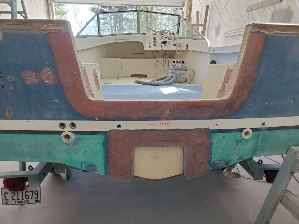
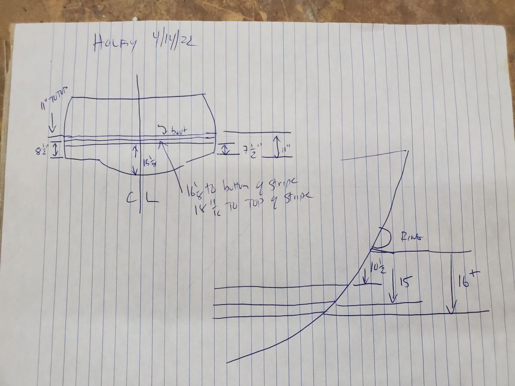
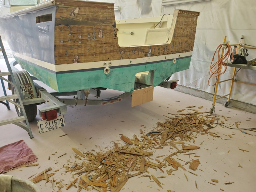
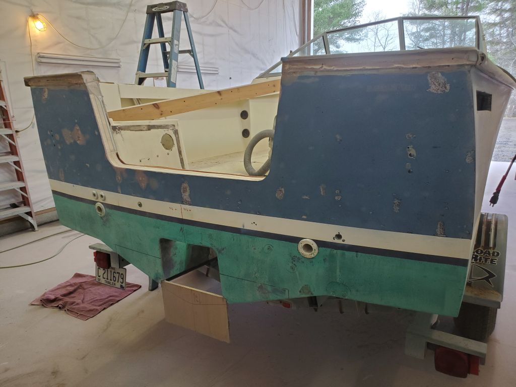
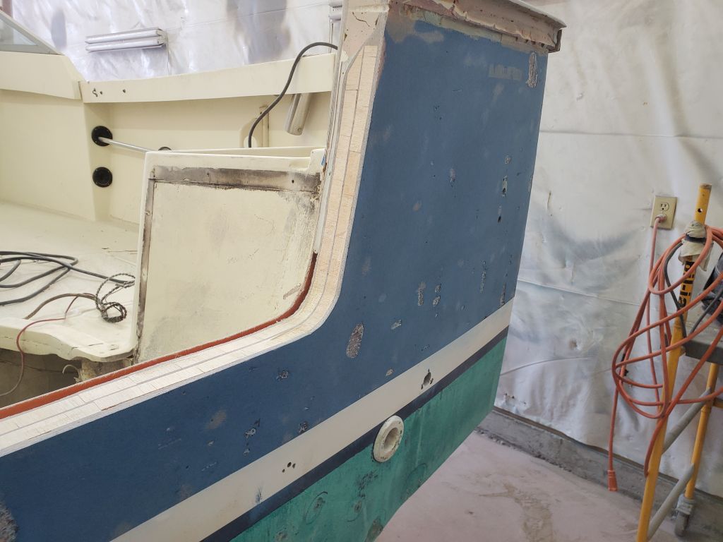
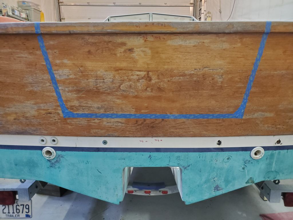
Using the various transom measurements I recorded from the sistership, I worked to lay out the new transom cutout.  The owner had previously laid out, and marked in blue tape, an approximation of the shape, but this was never intended to be the actual cutting template, though I was interested to see how it would compare with the physical measurements I had from the other boat.

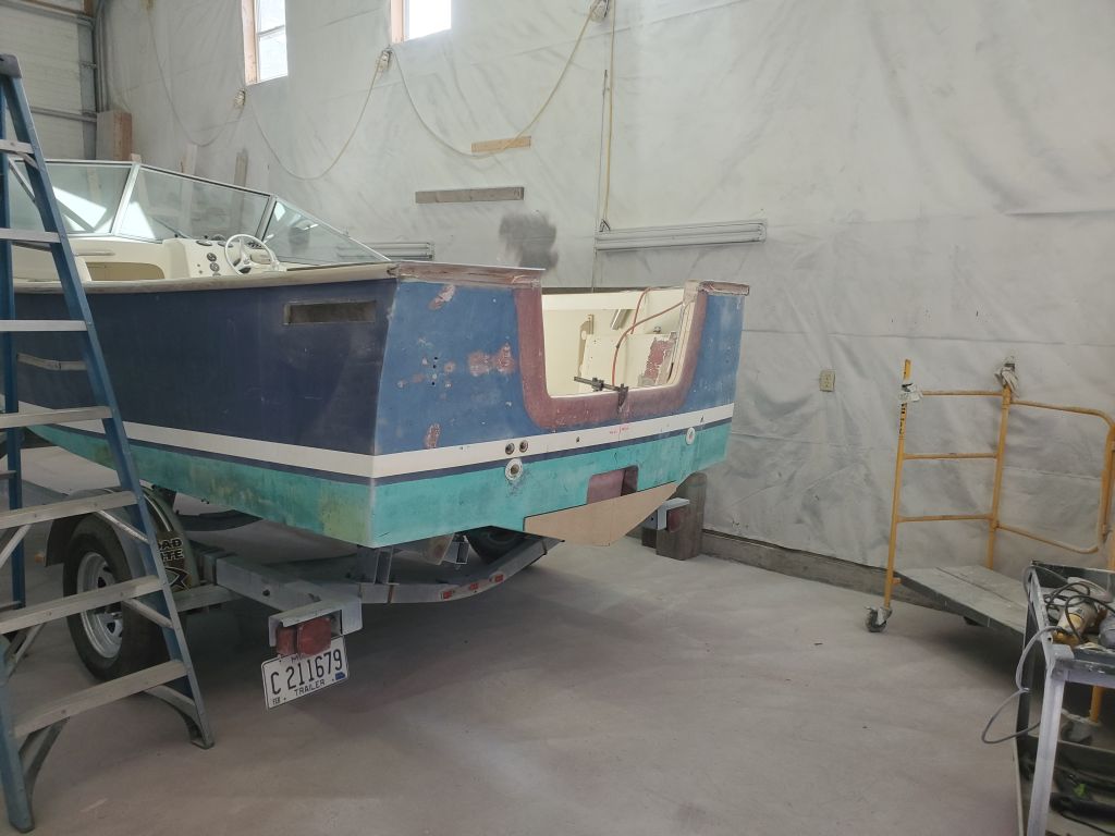
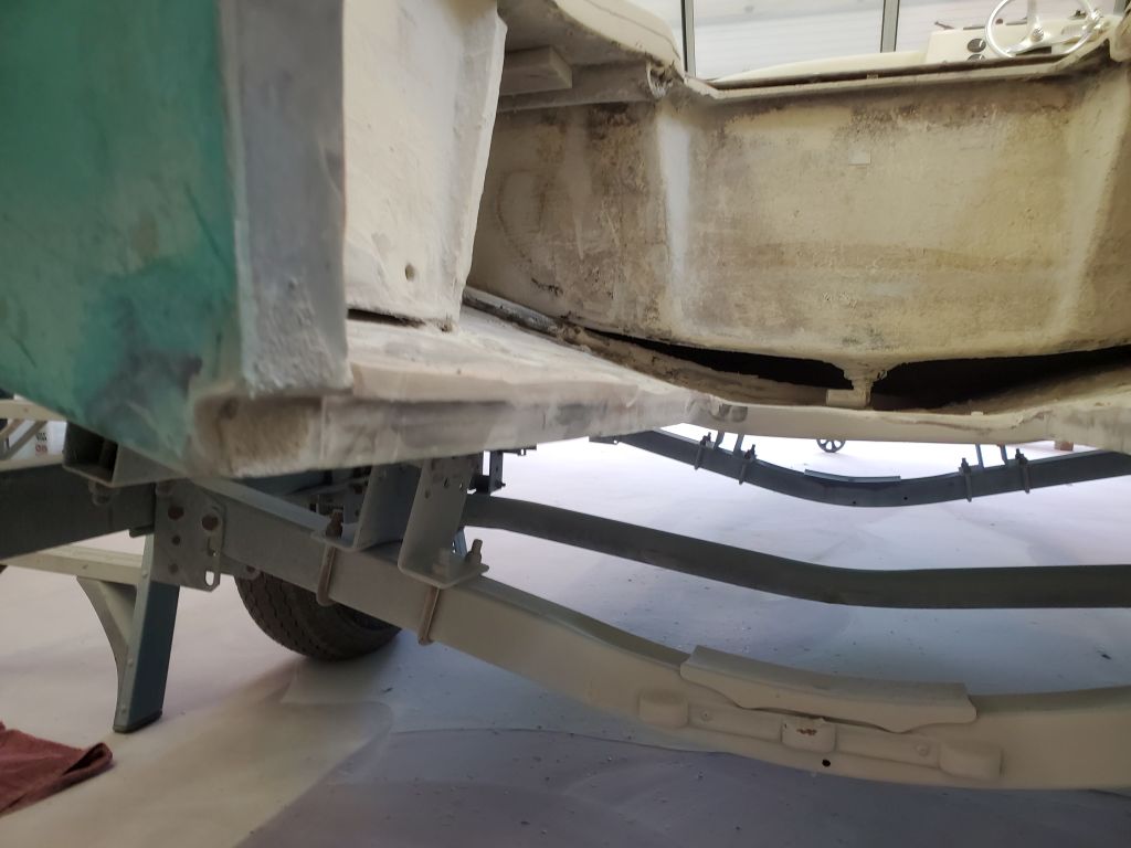
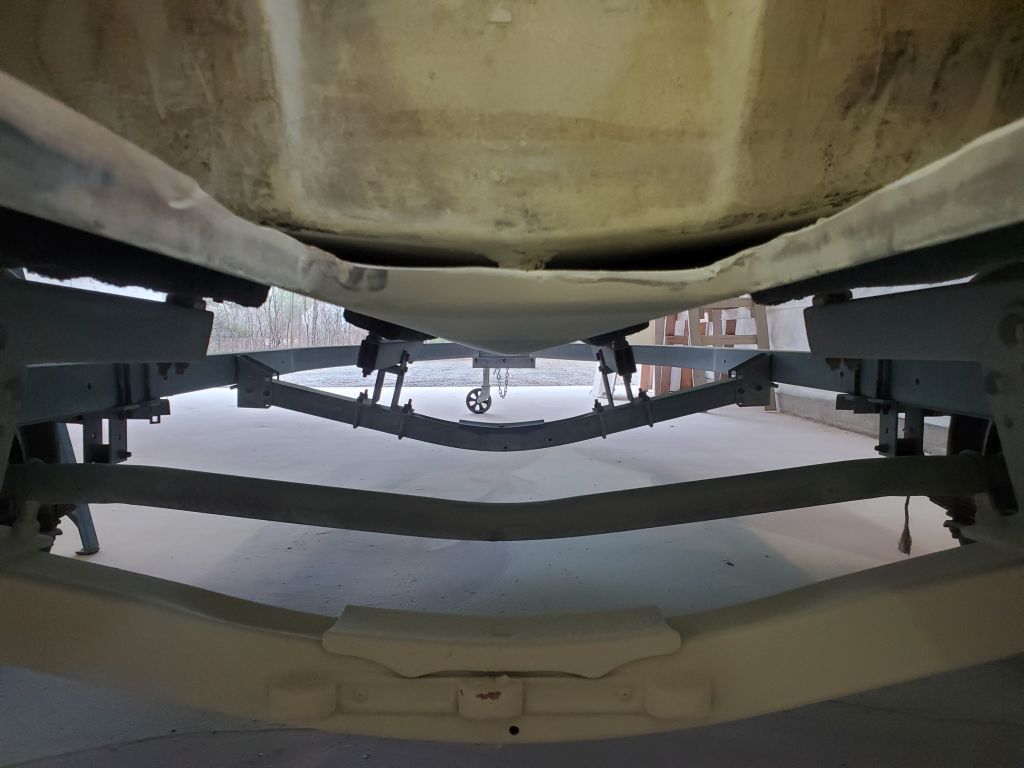
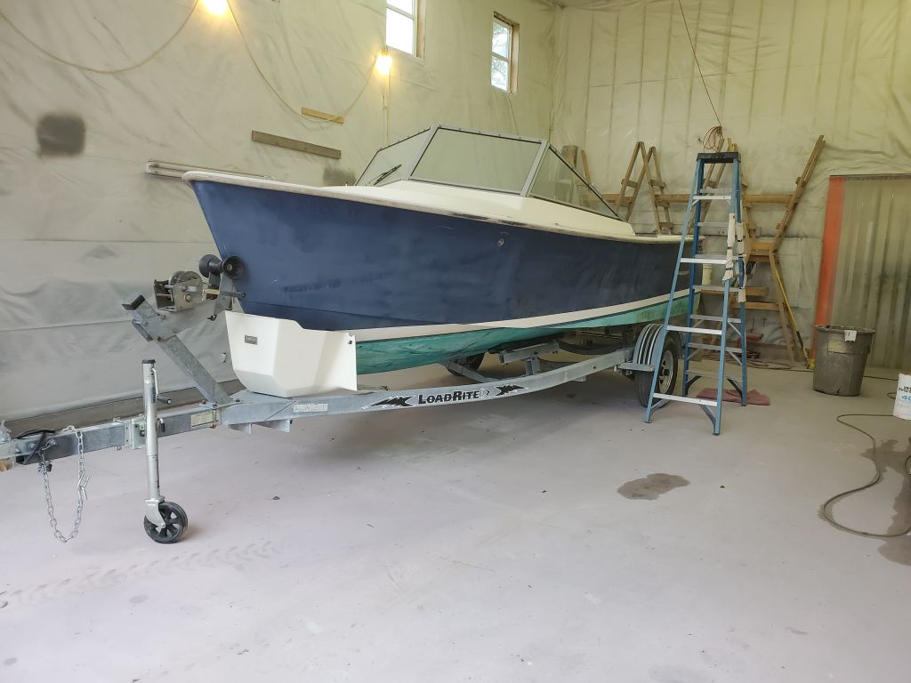
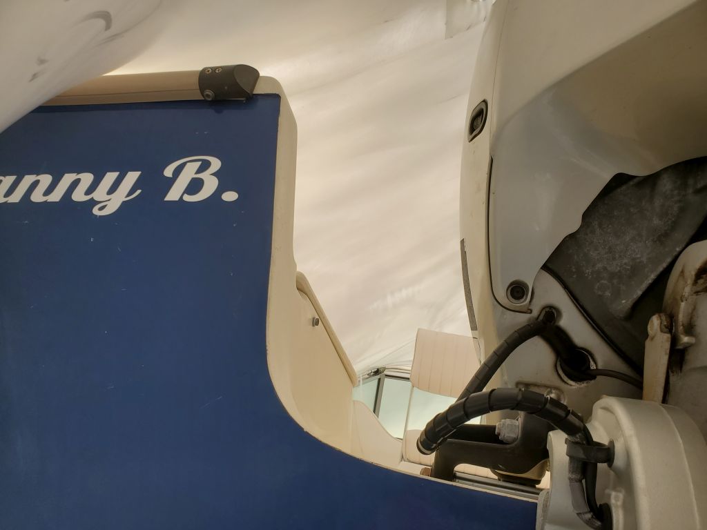
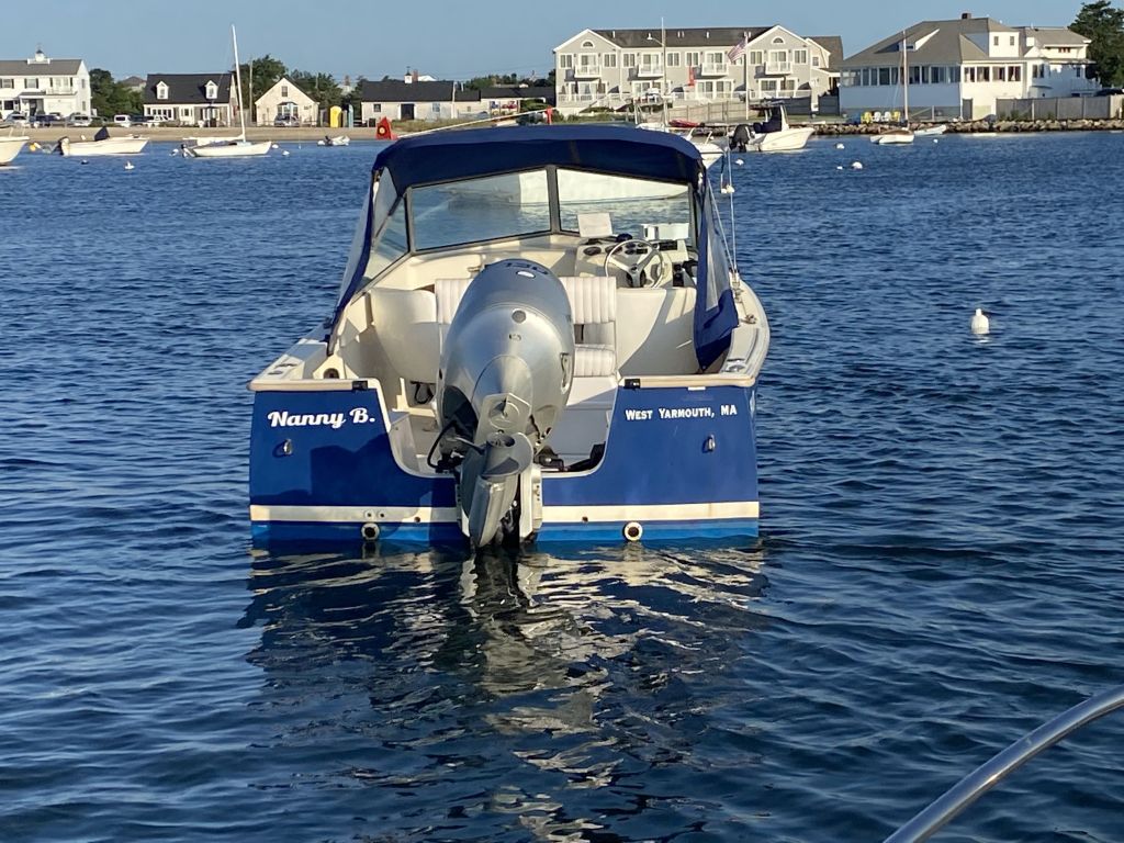
These photos of the sistership, including one from a year or so ago when the boat was in the water, serve as visual references for the work below.  Also refer to this page.

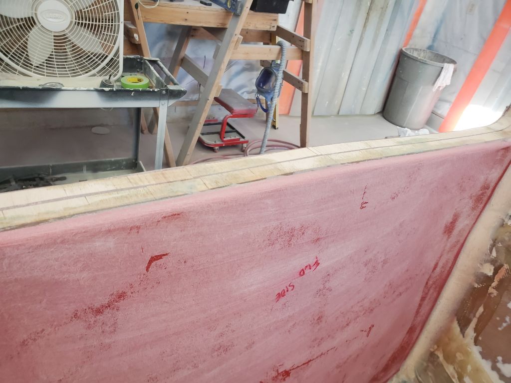
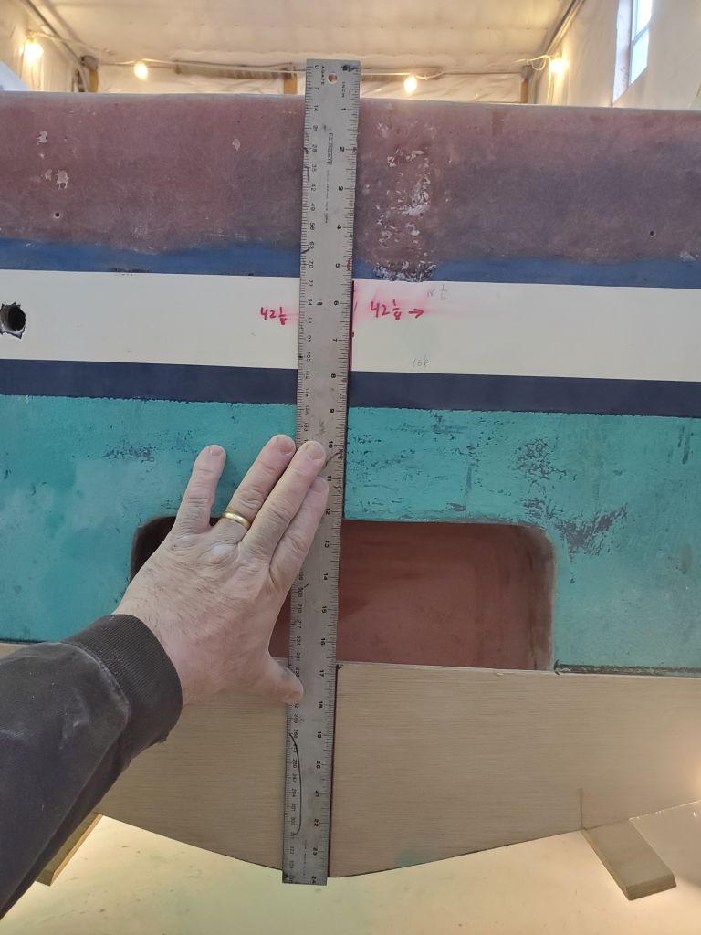
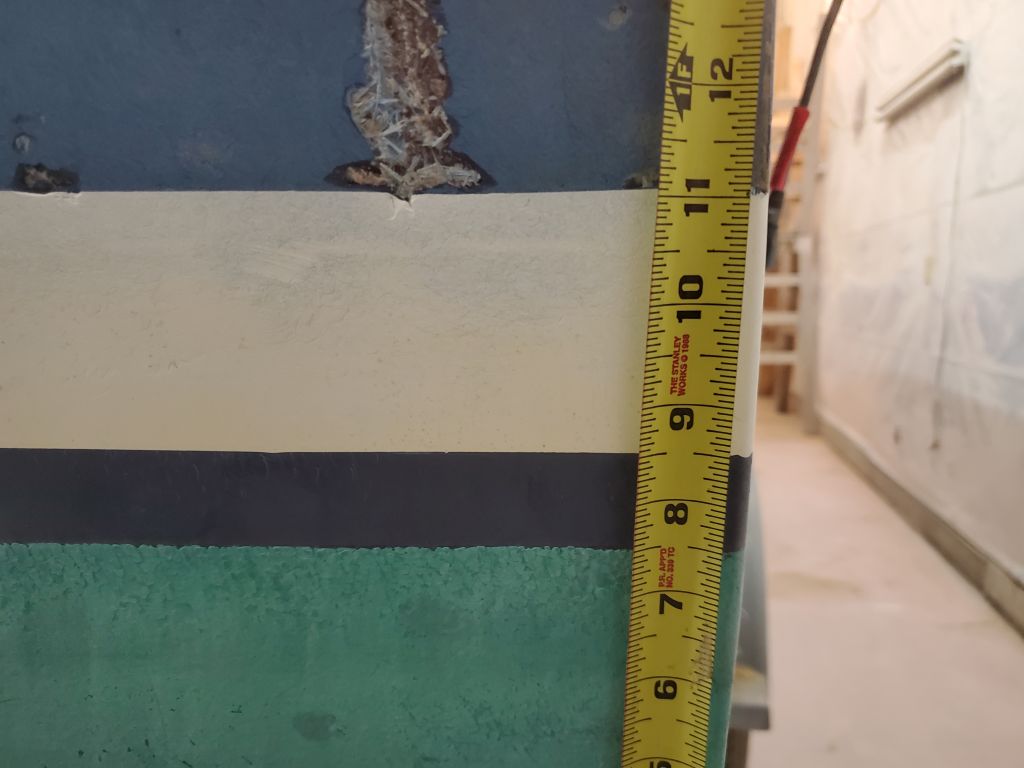
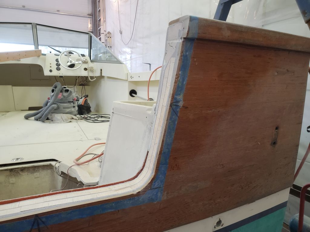
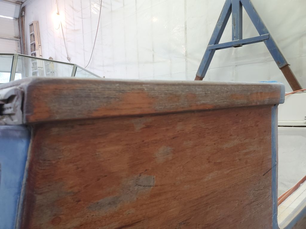
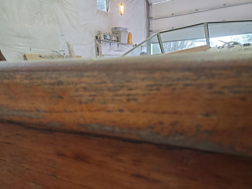
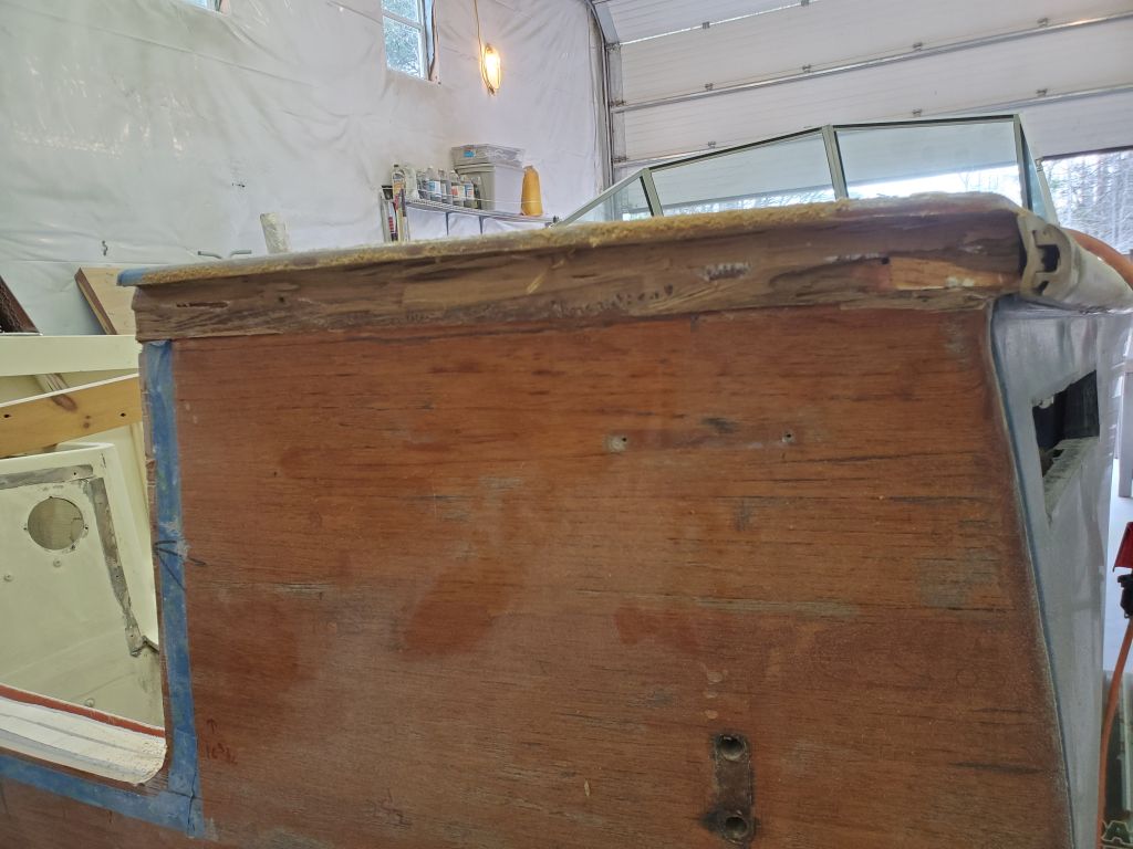
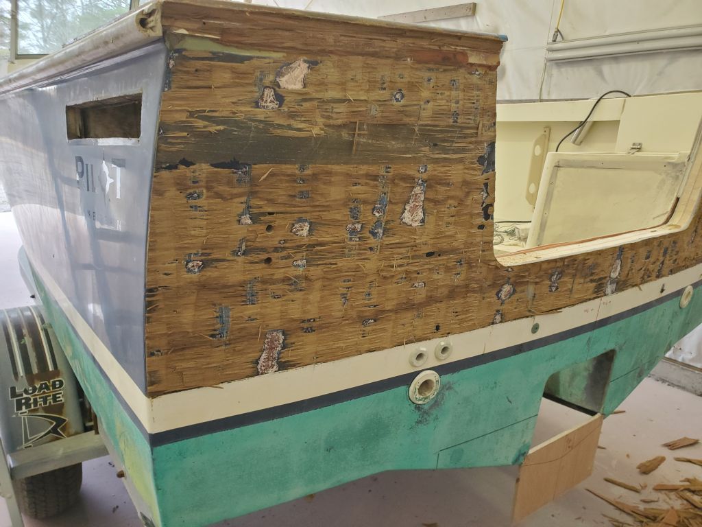
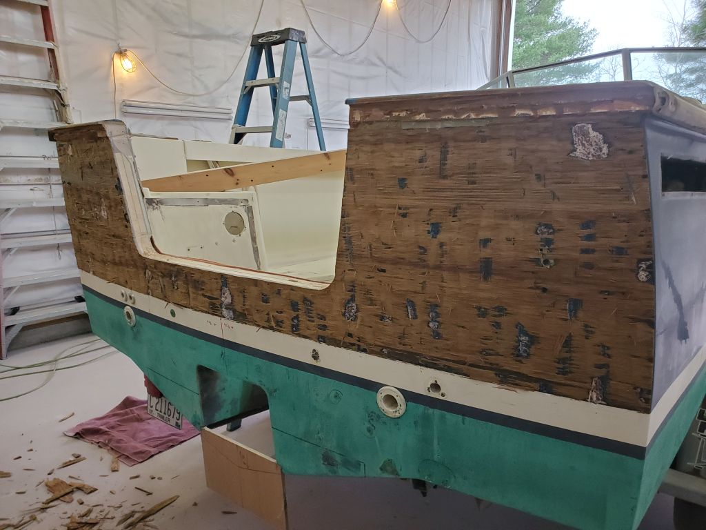
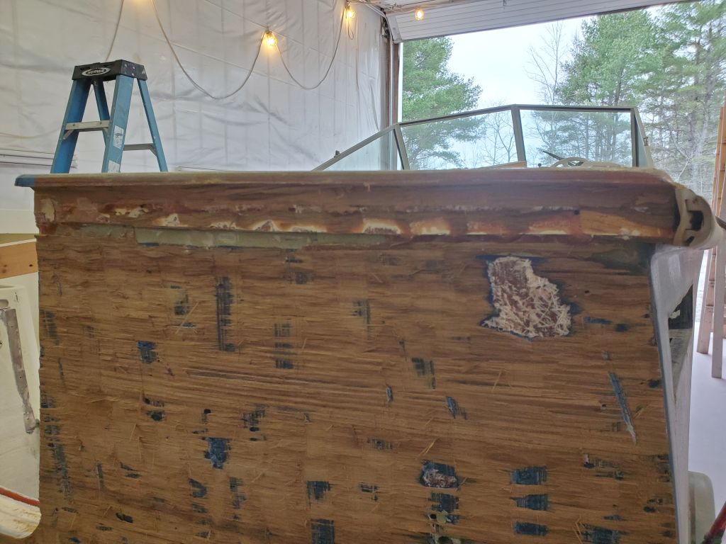
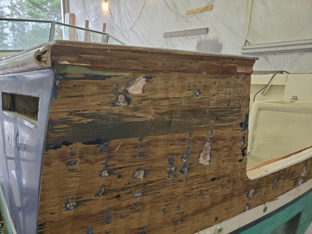
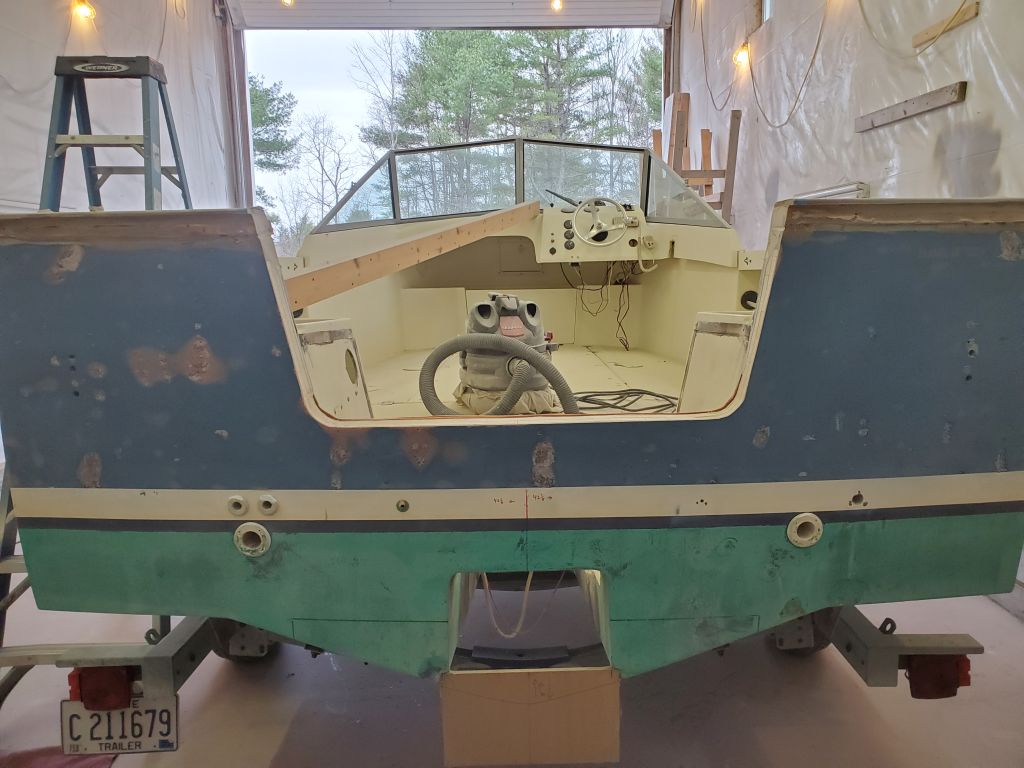
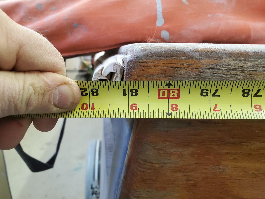
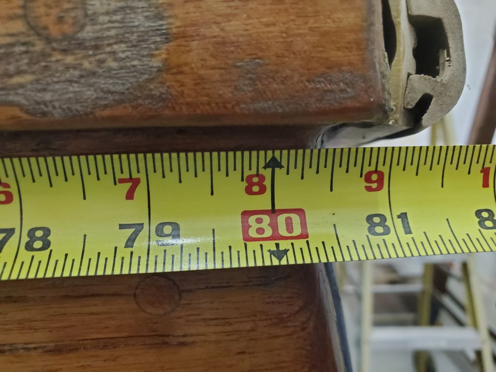
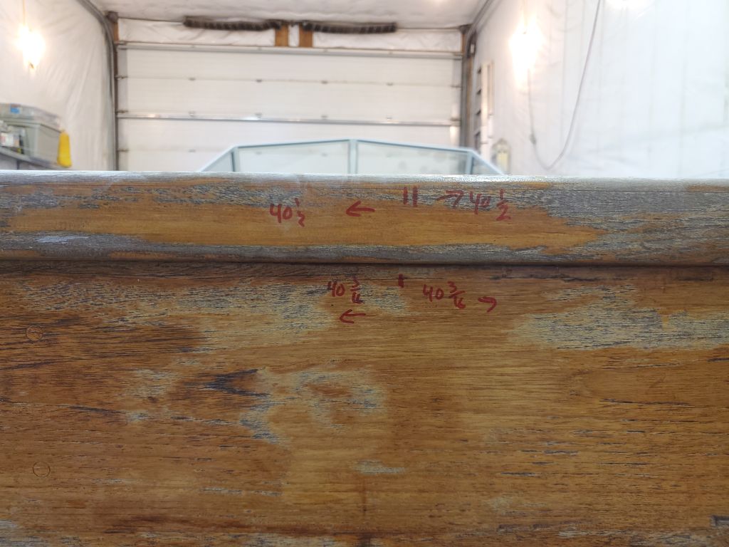
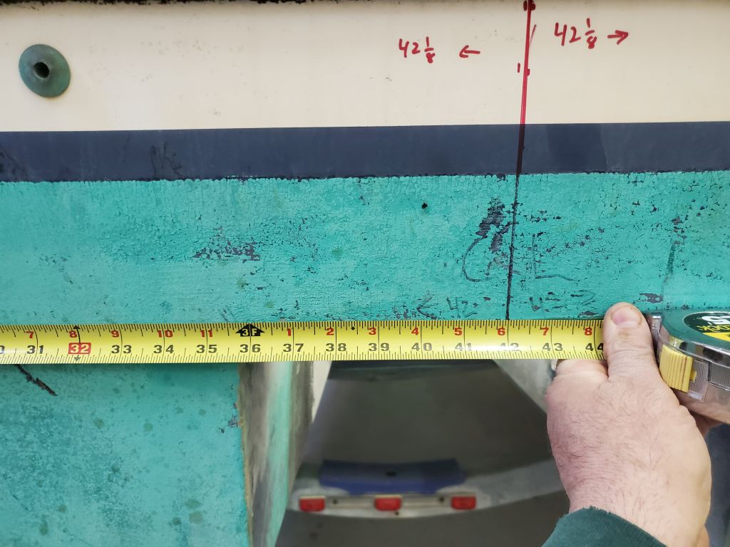
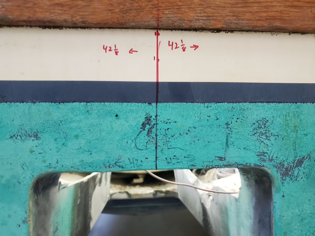
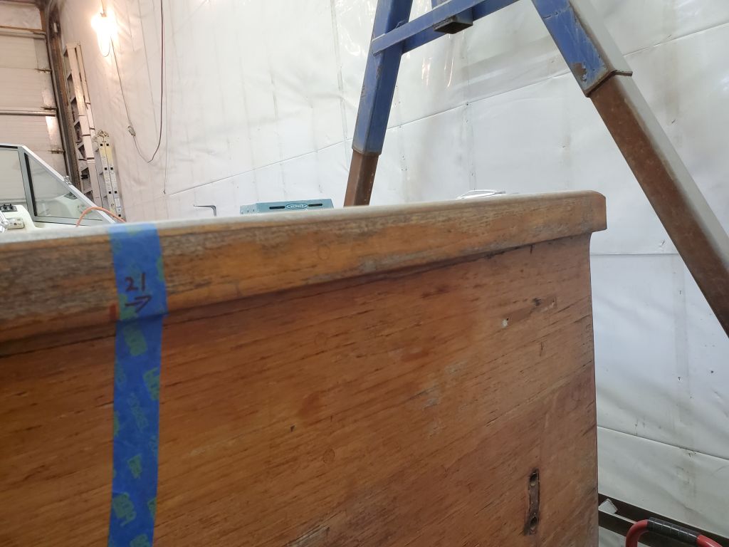
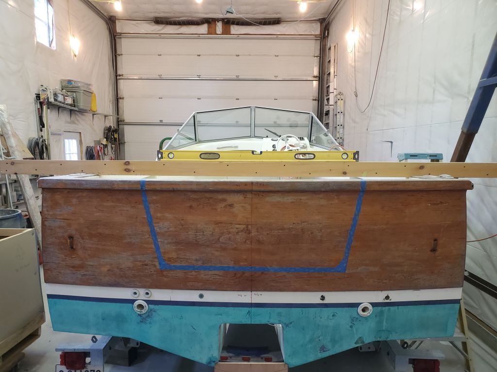
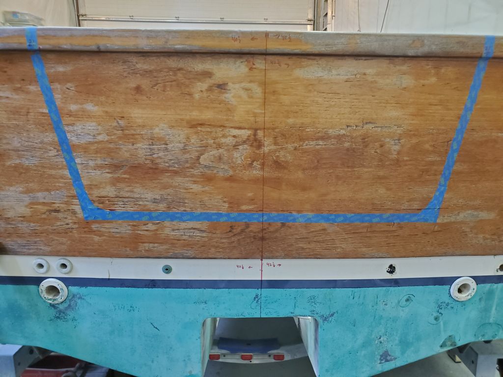
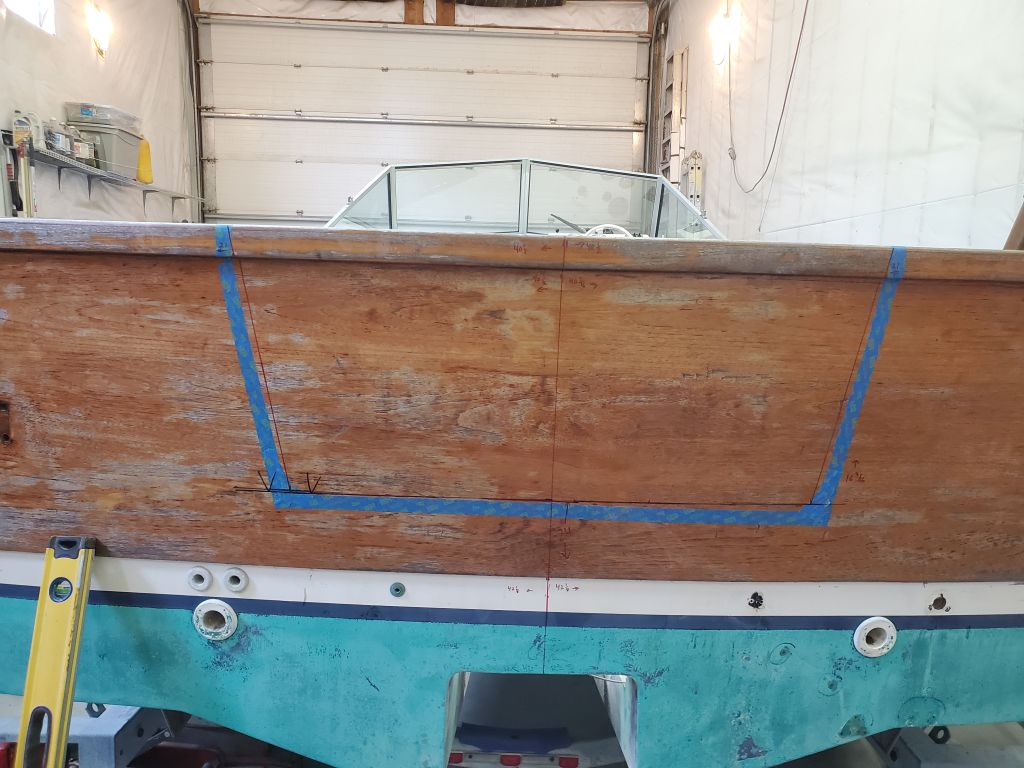
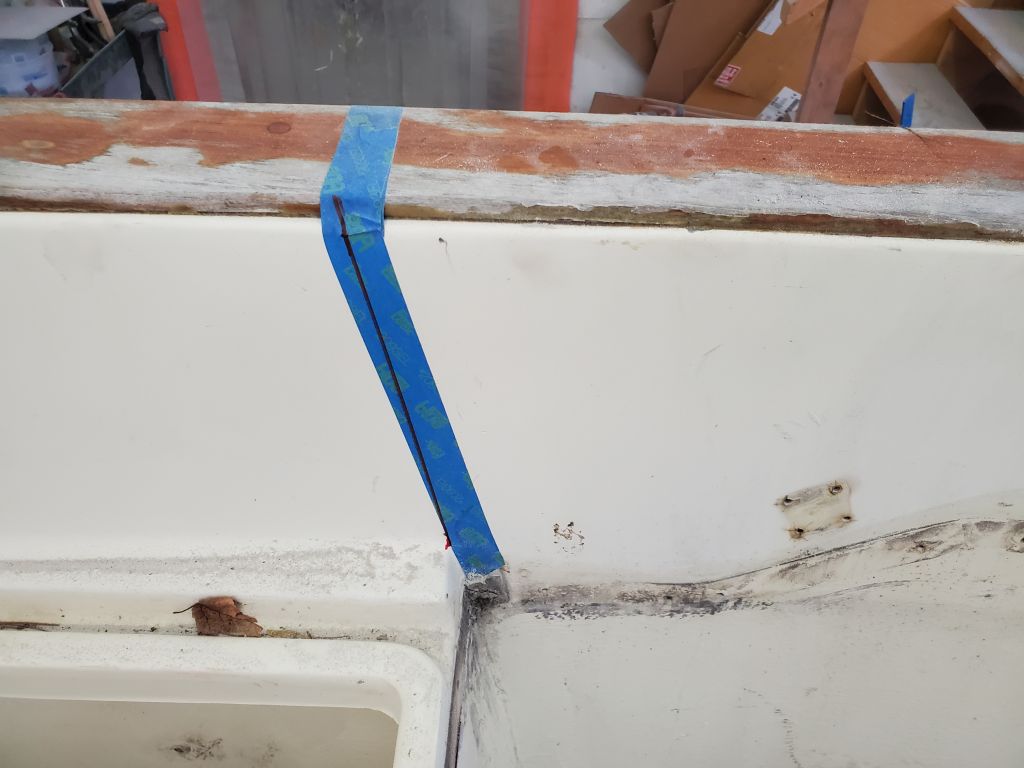
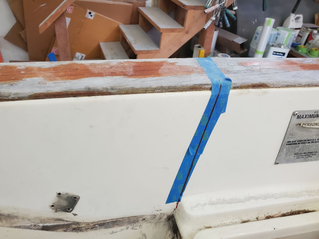
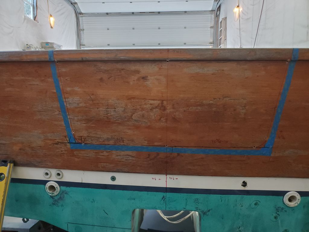
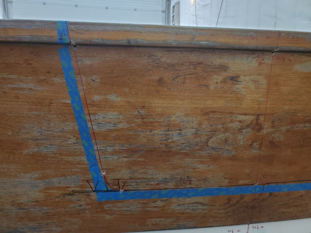
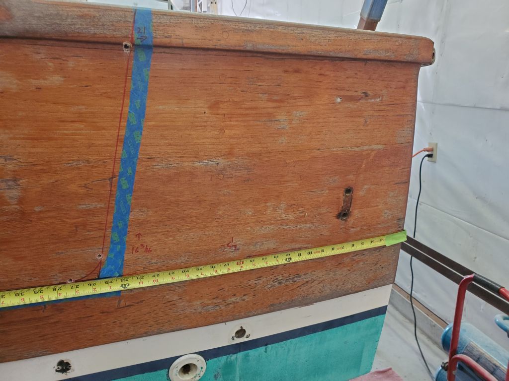
I began by marking a vertical centerline, measuring the overall width in various places and making marks as needed.  I measured across the top of the rubrail at the transom corners; just beneath the rubrail; just beneath the wooden part of the transom; and just above the cutout leftover from the jet drive.  Then I connected these with a line, which would become one of the key bases for the remaining layout.  Note that the wooden transom veneer would be going away as part of this project, so I didn’t worry about marking directly on the old wood.

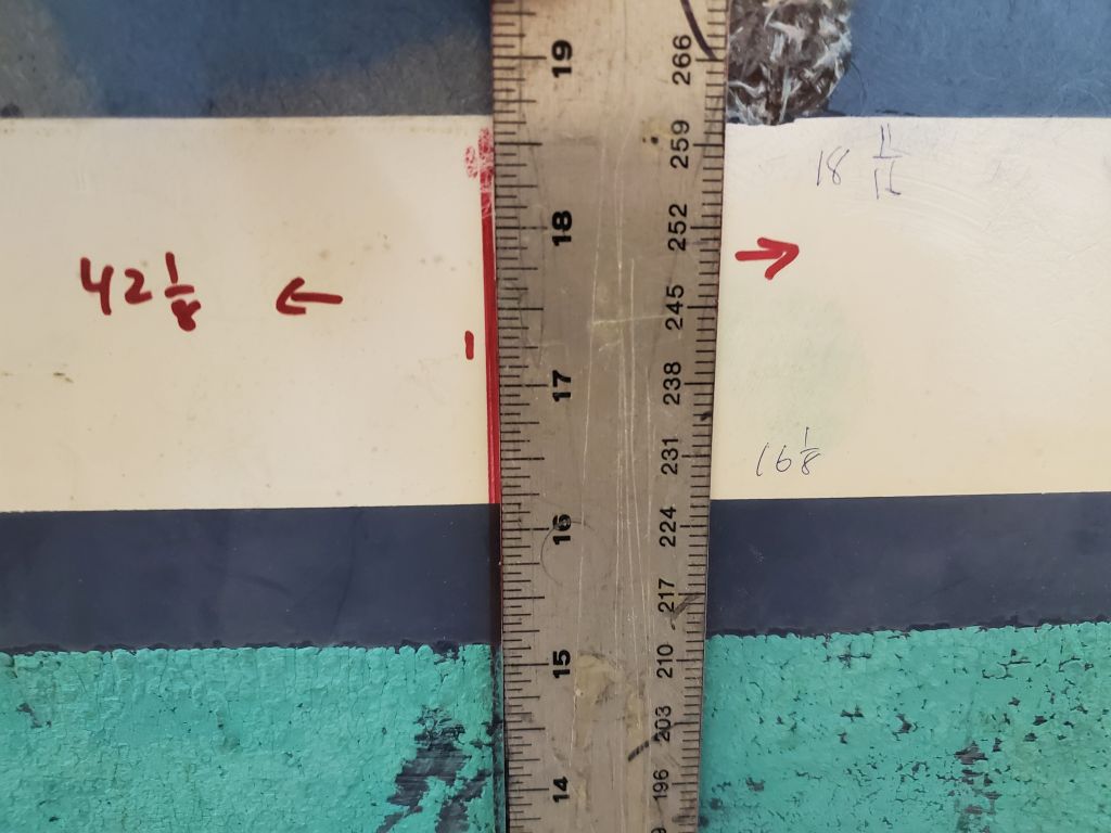
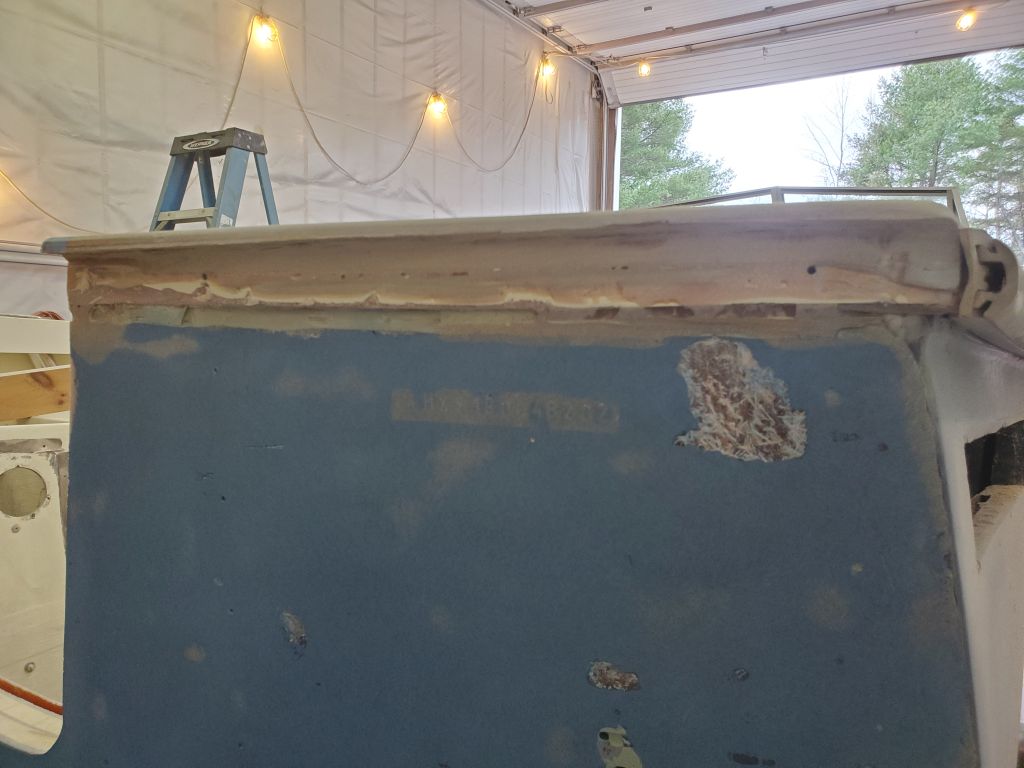
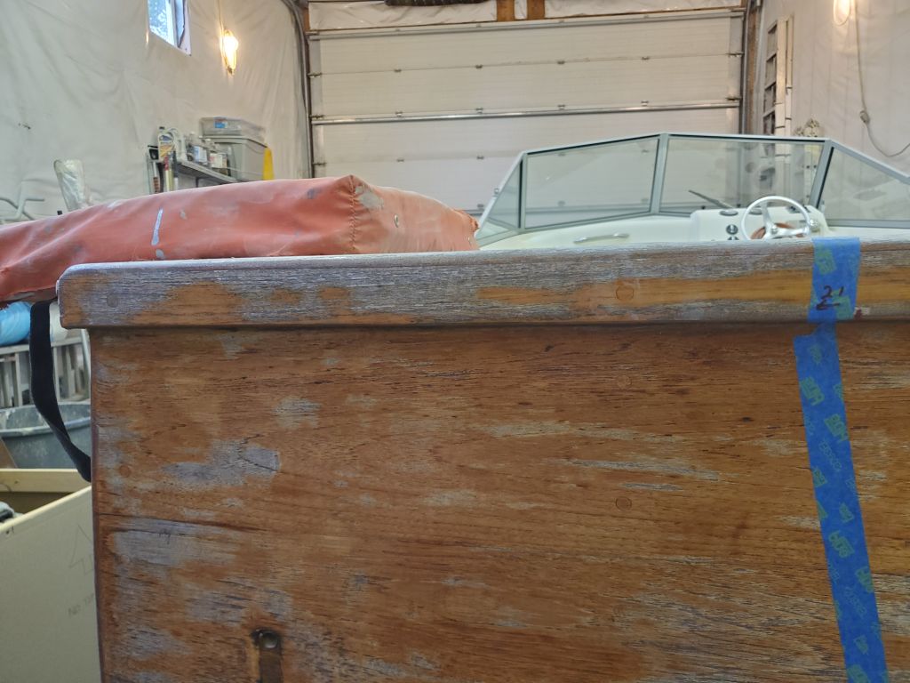
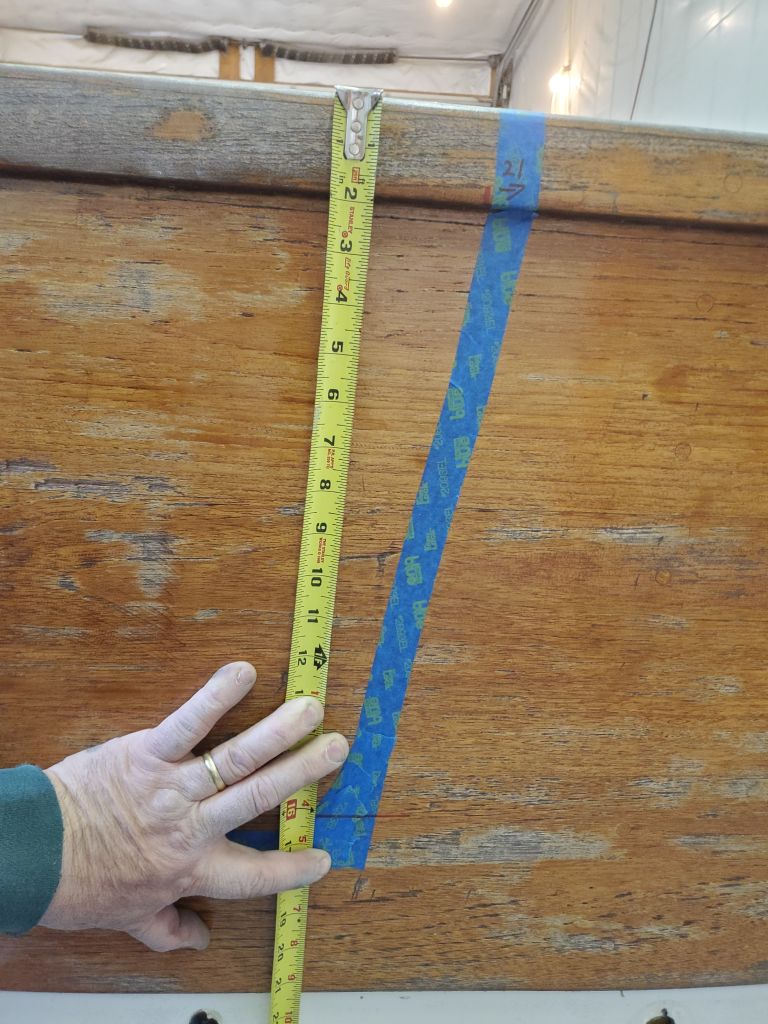
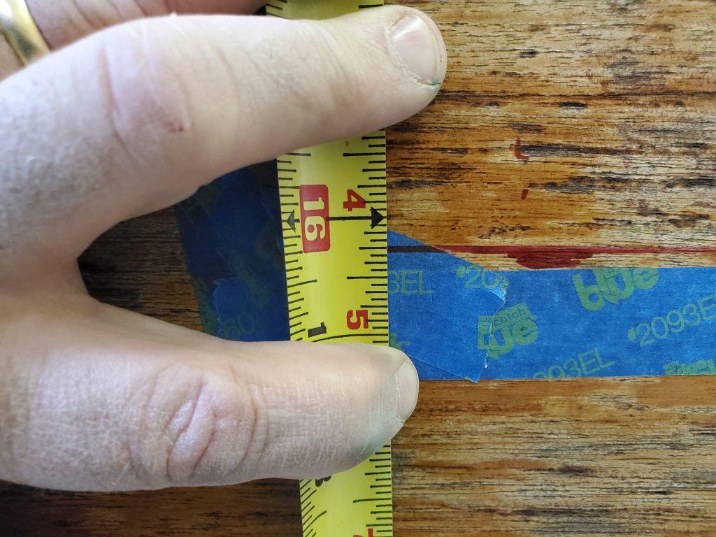
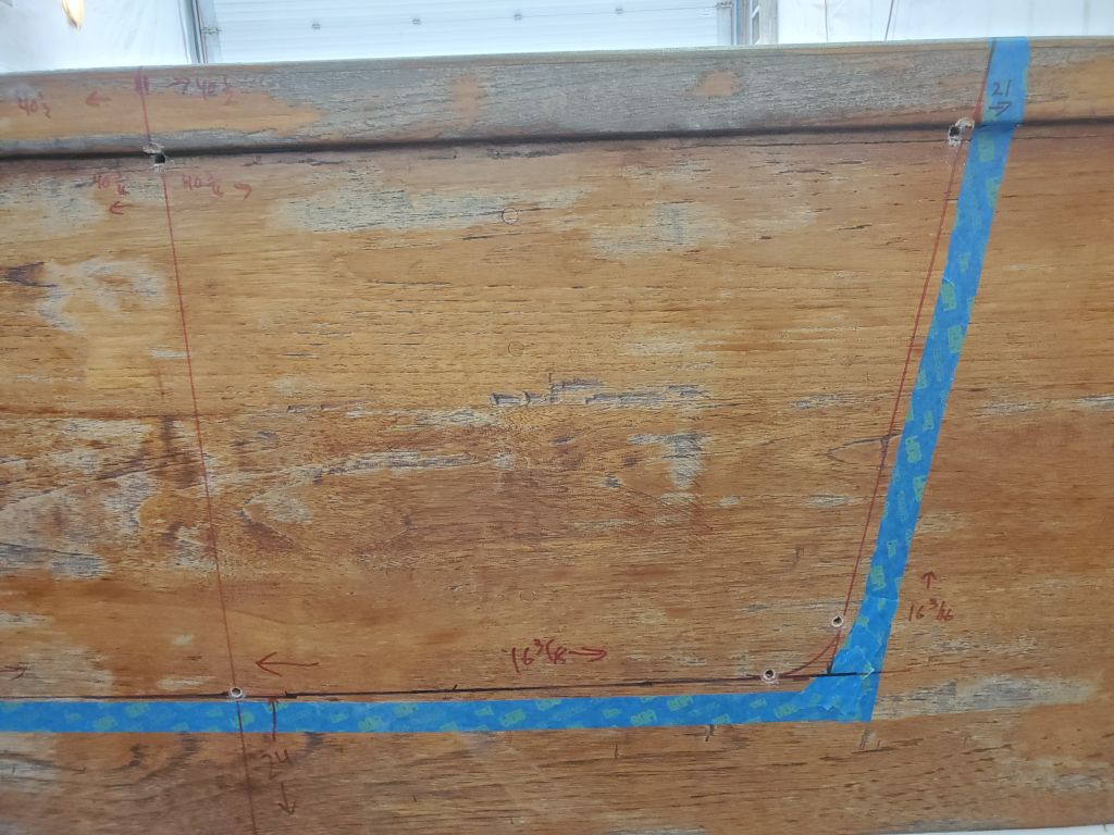
At the top of the transom, I measured 21″ in from each corner, which according to the sistership would provide the overall width of the top of the opening.  So far the measurements were tying in well, but not exactly, with the taped approximation.

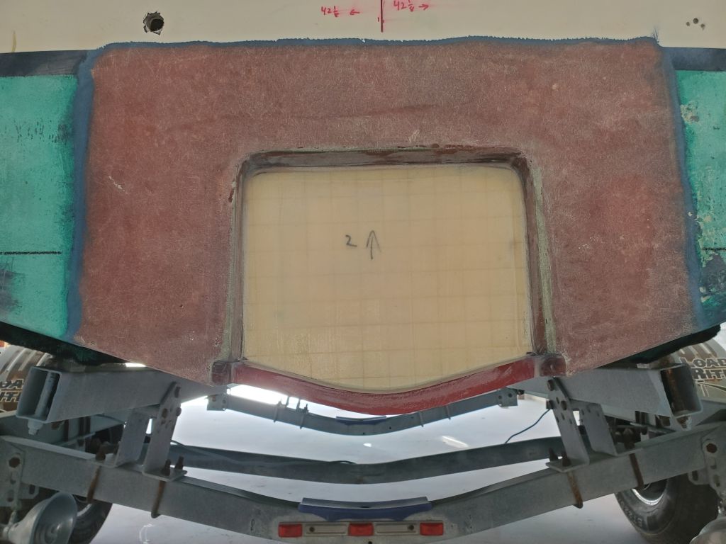
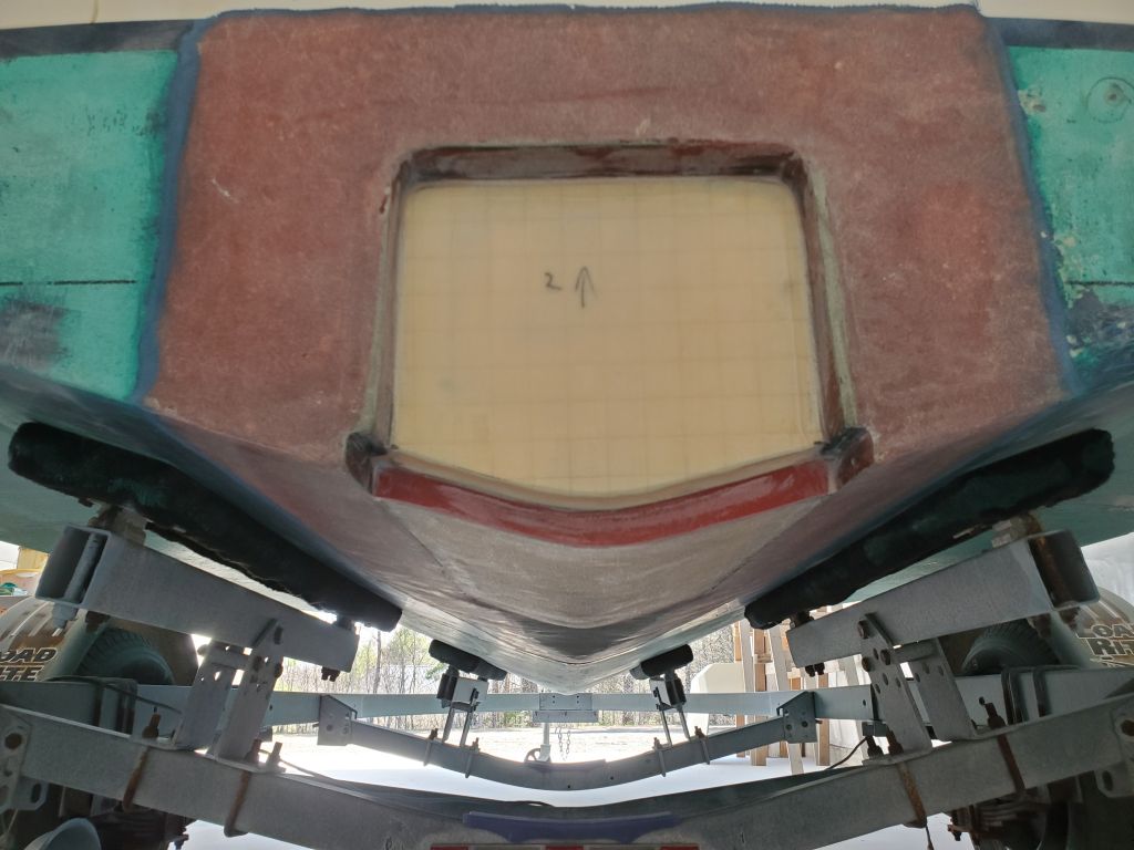
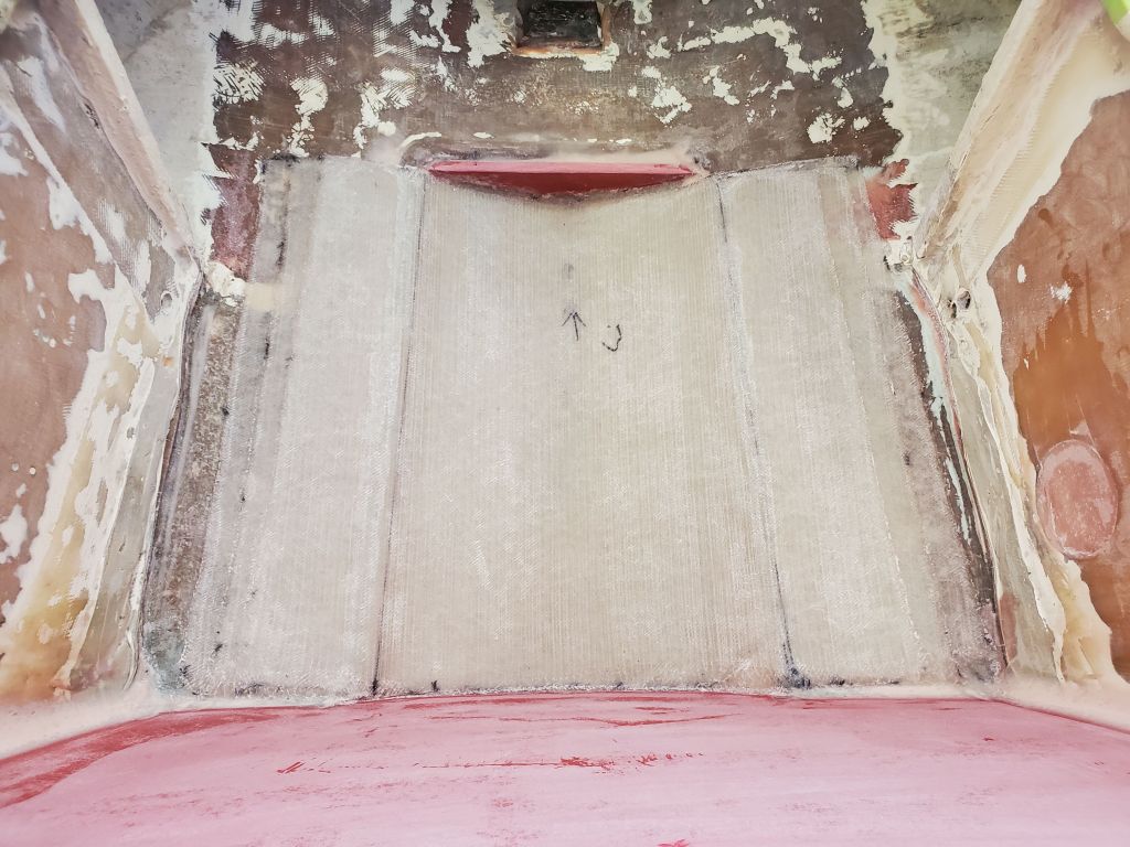
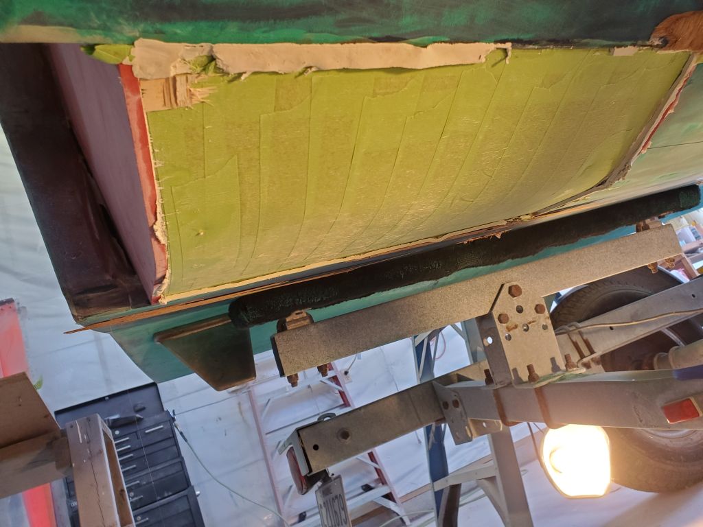
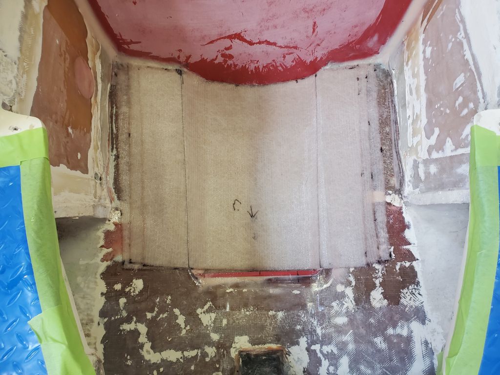
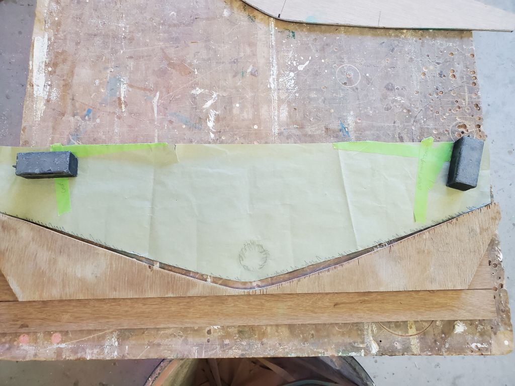
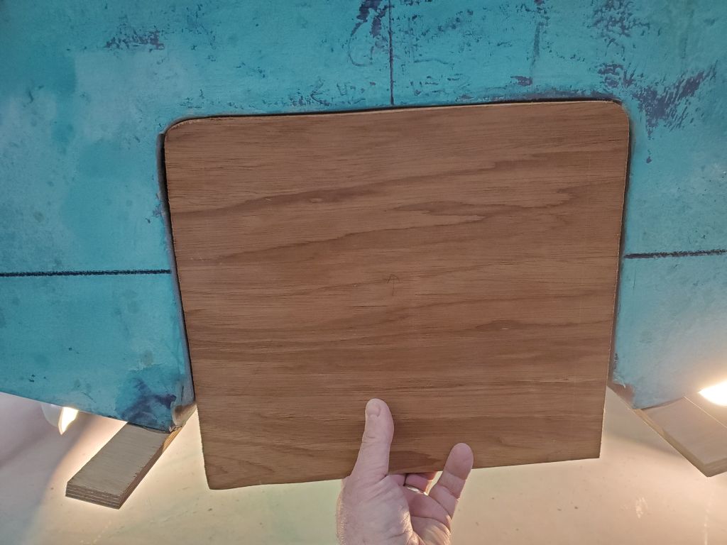
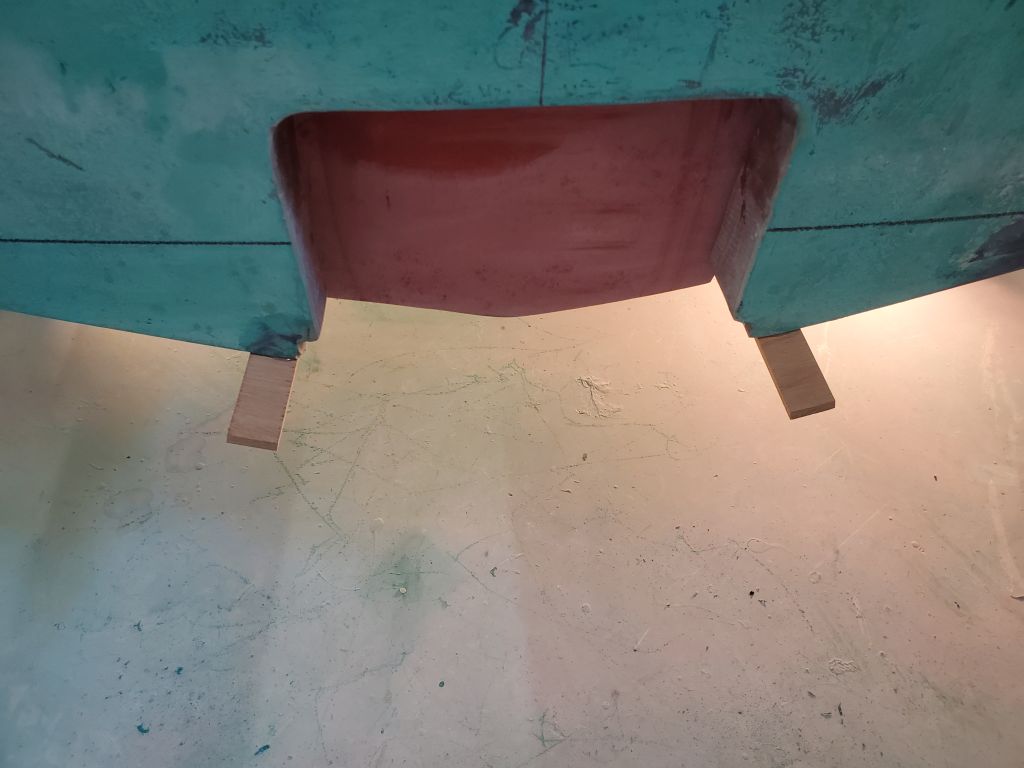
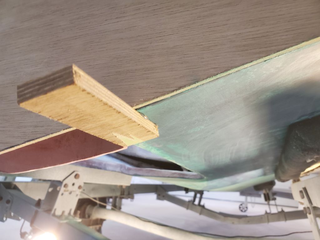
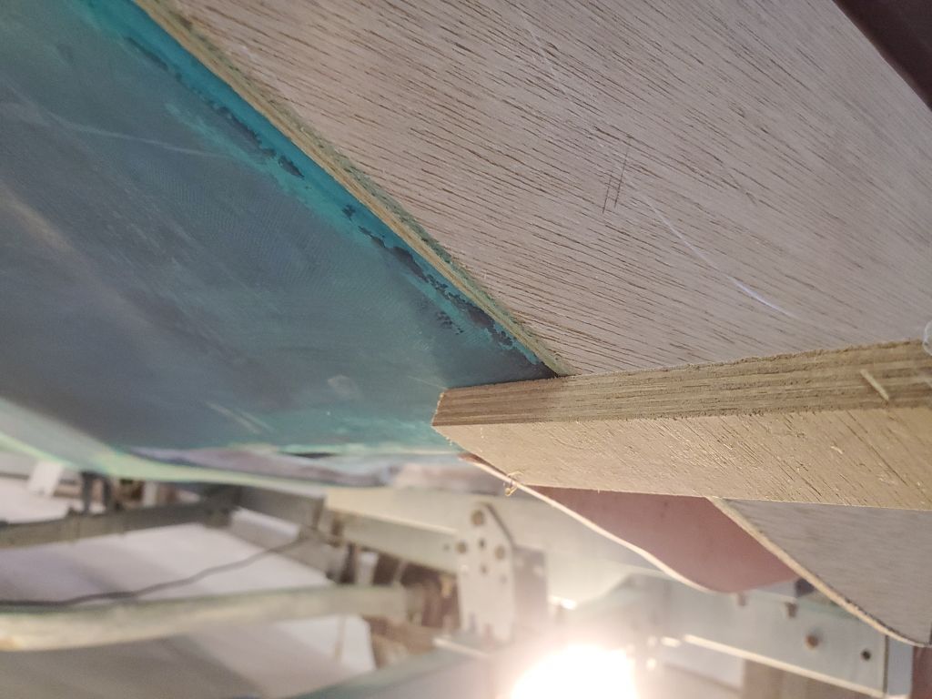
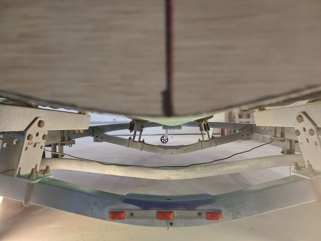
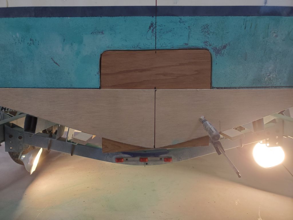
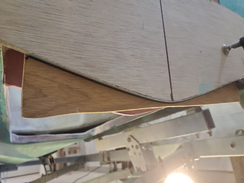
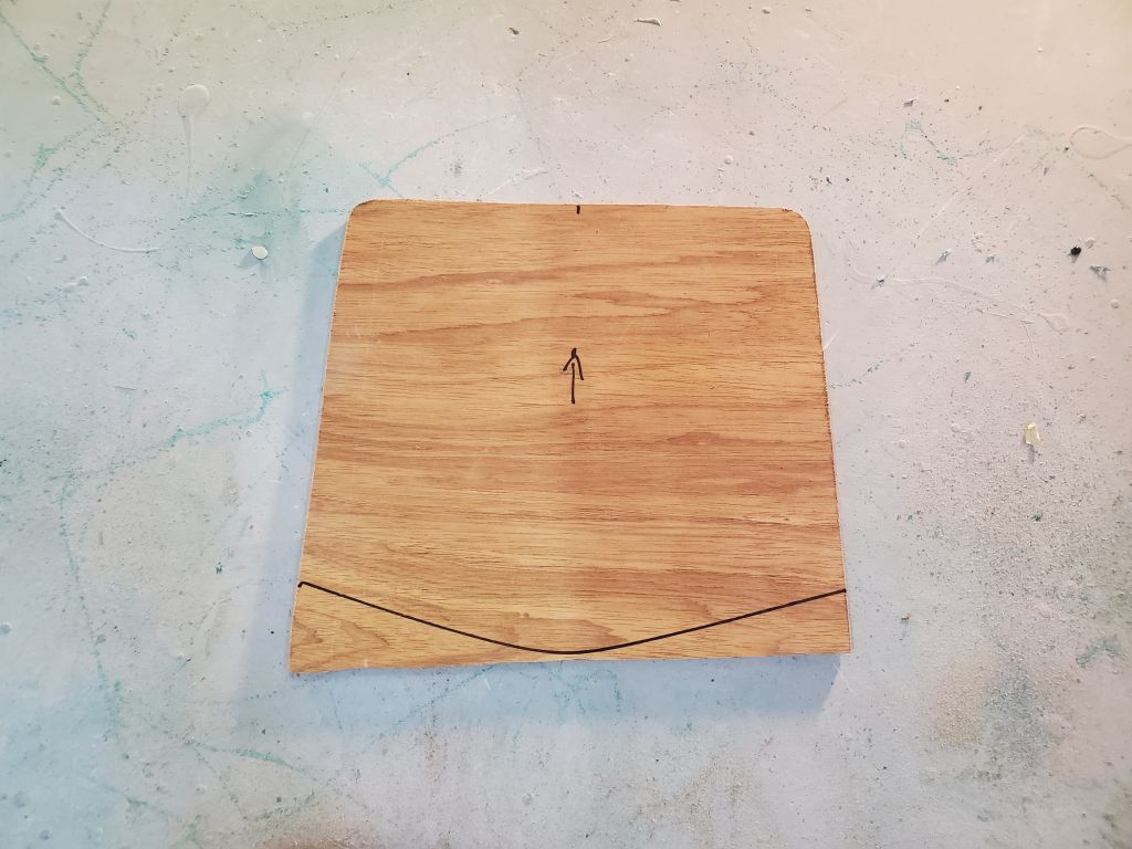
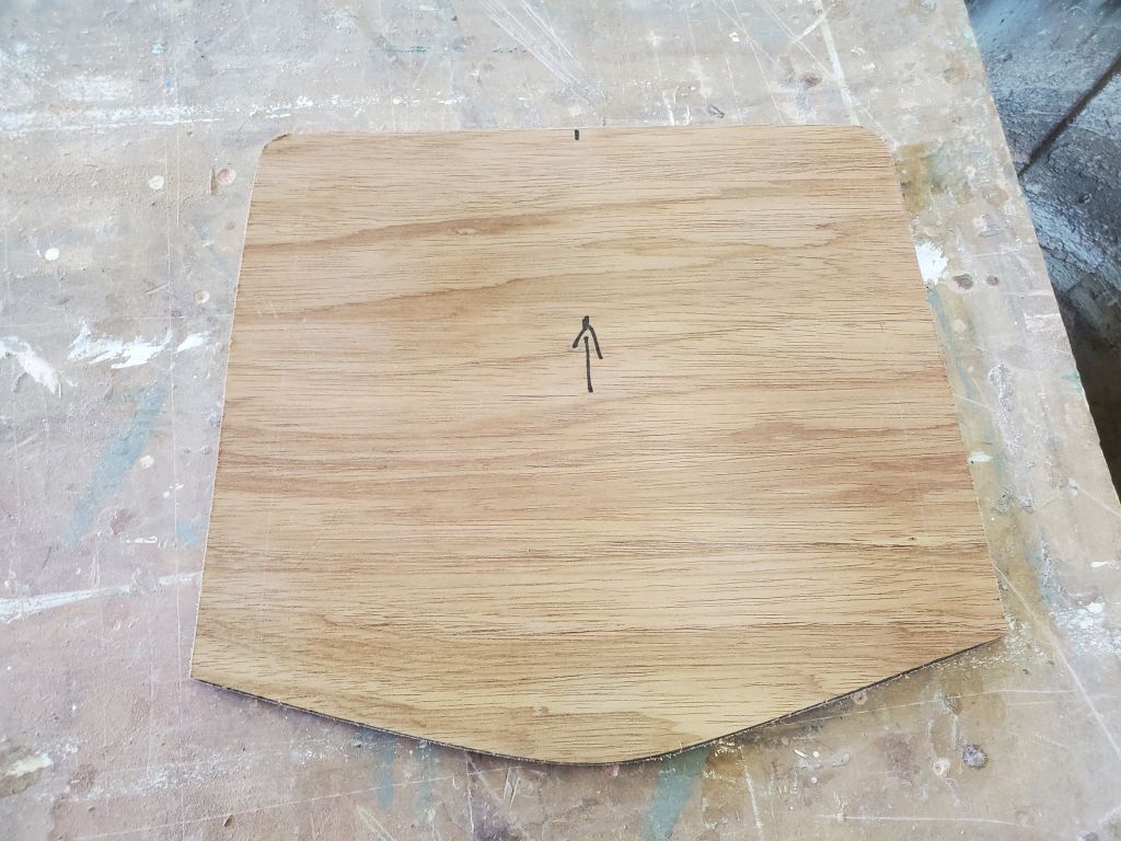
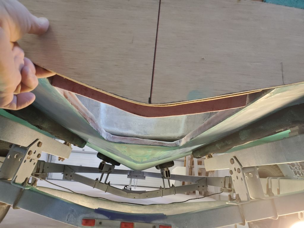
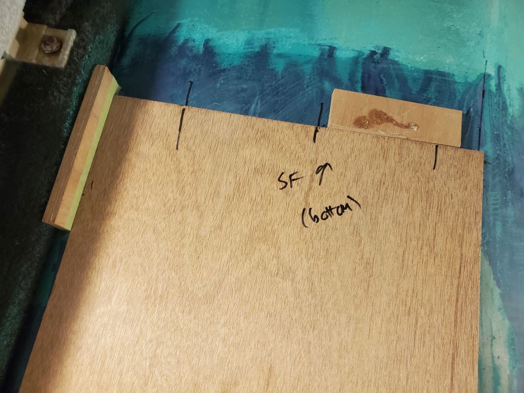
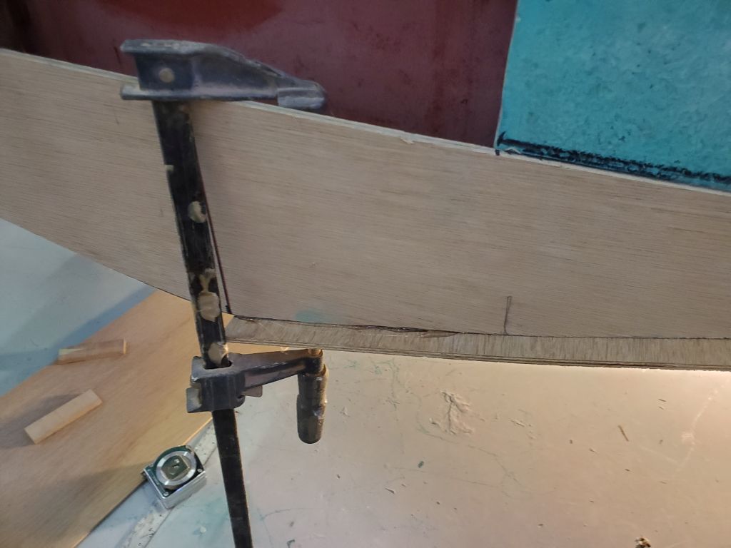
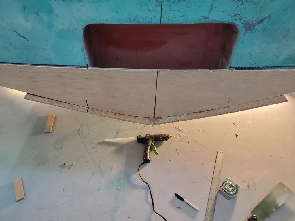
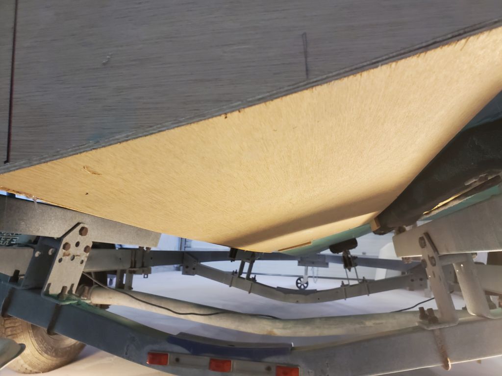
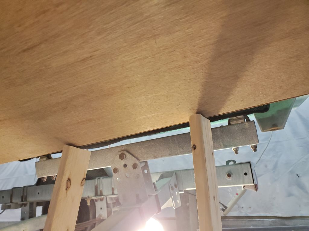
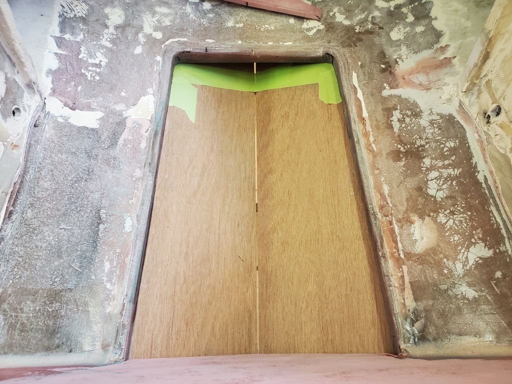
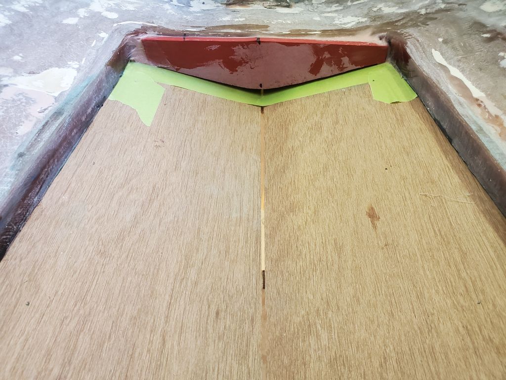
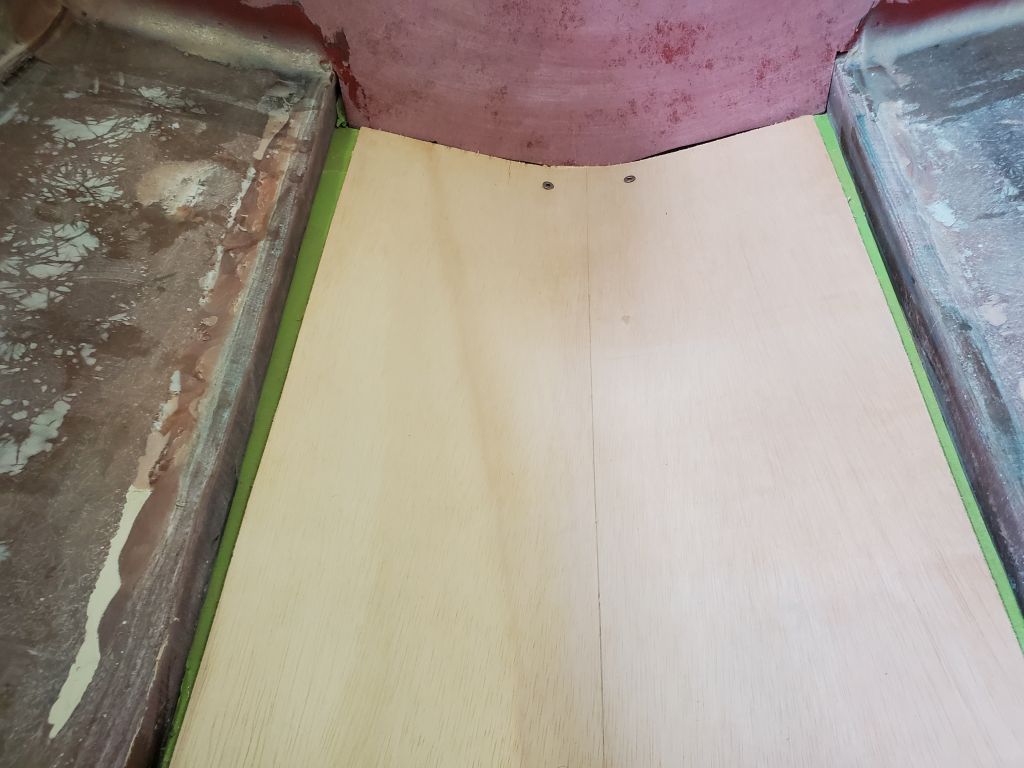
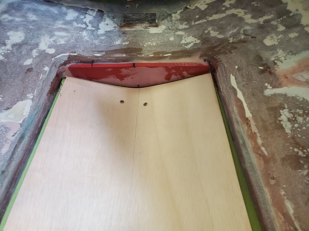
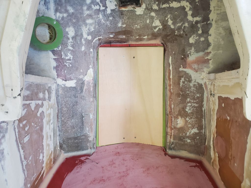
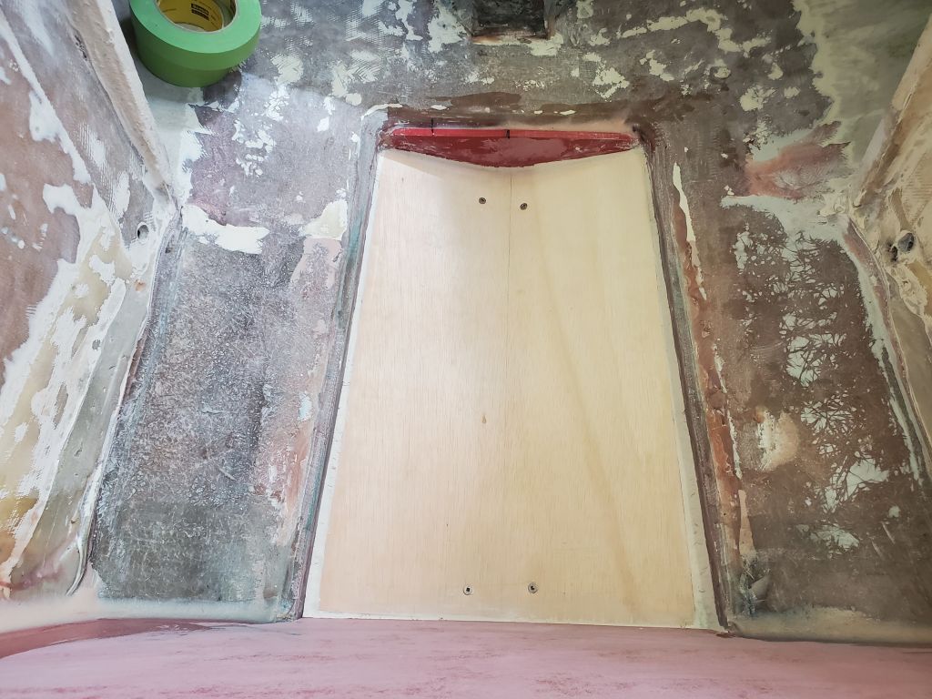
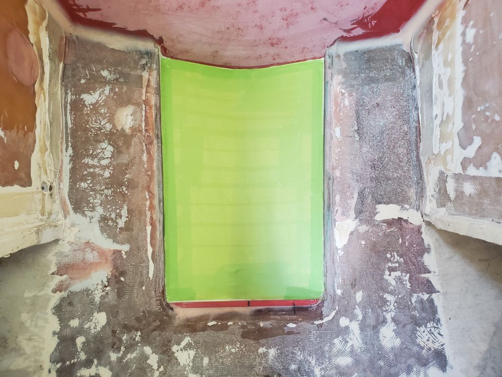
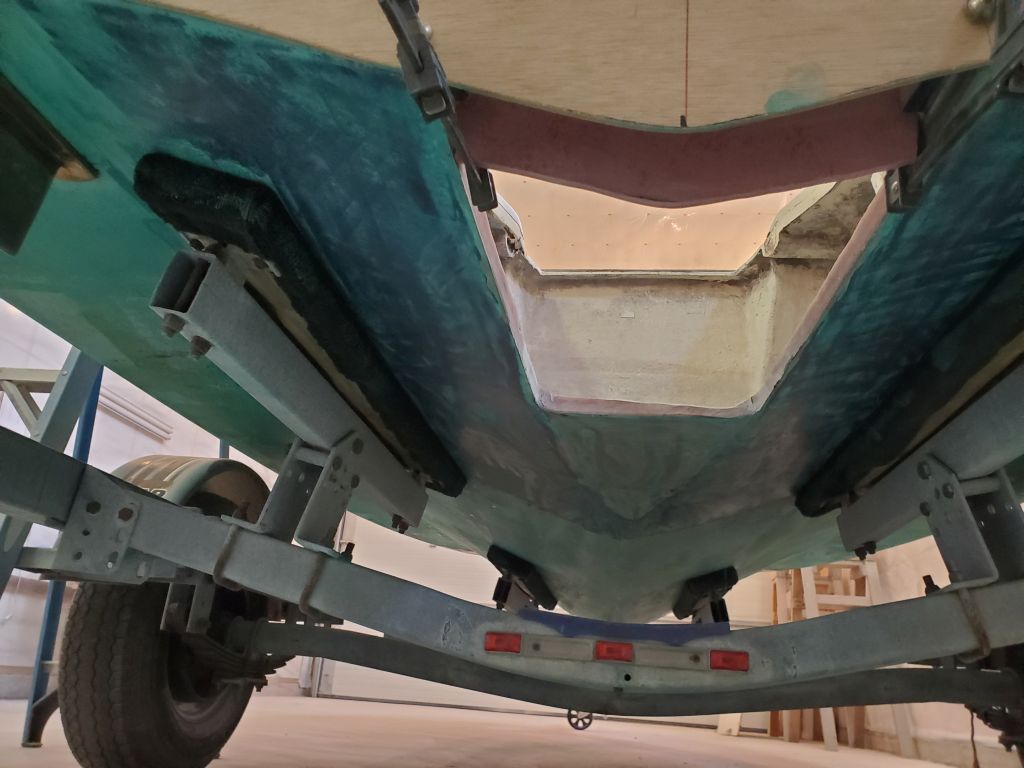
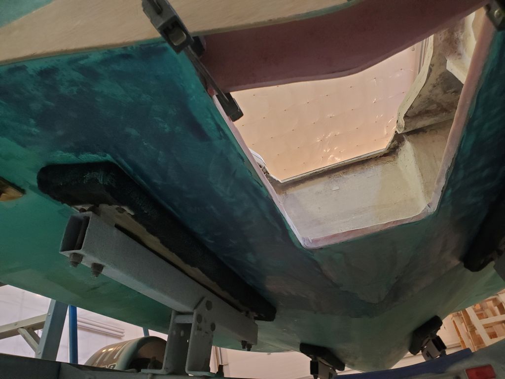
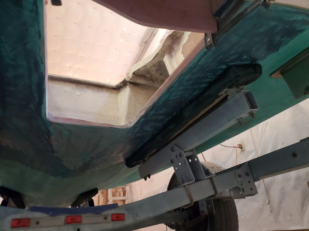
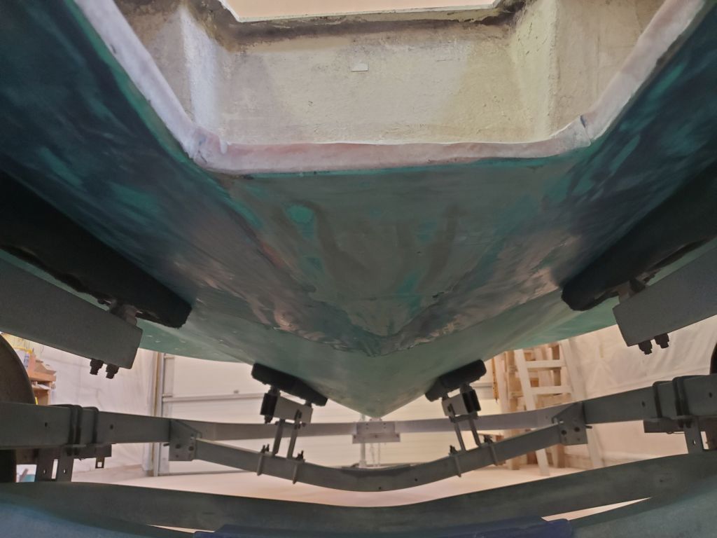
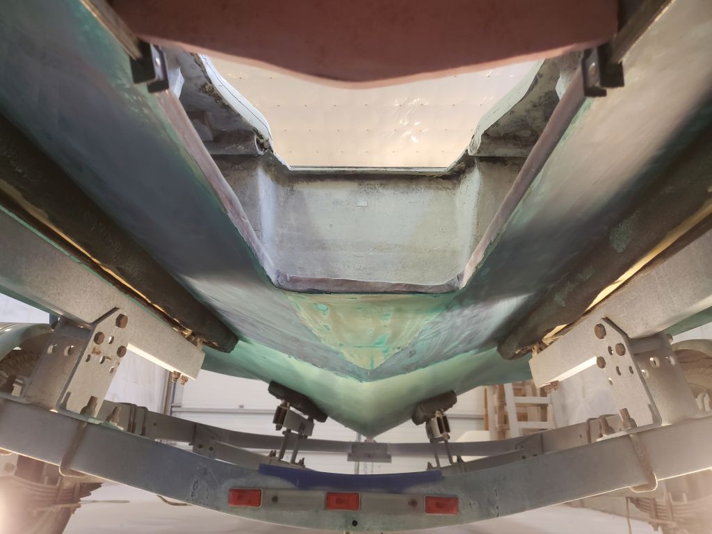
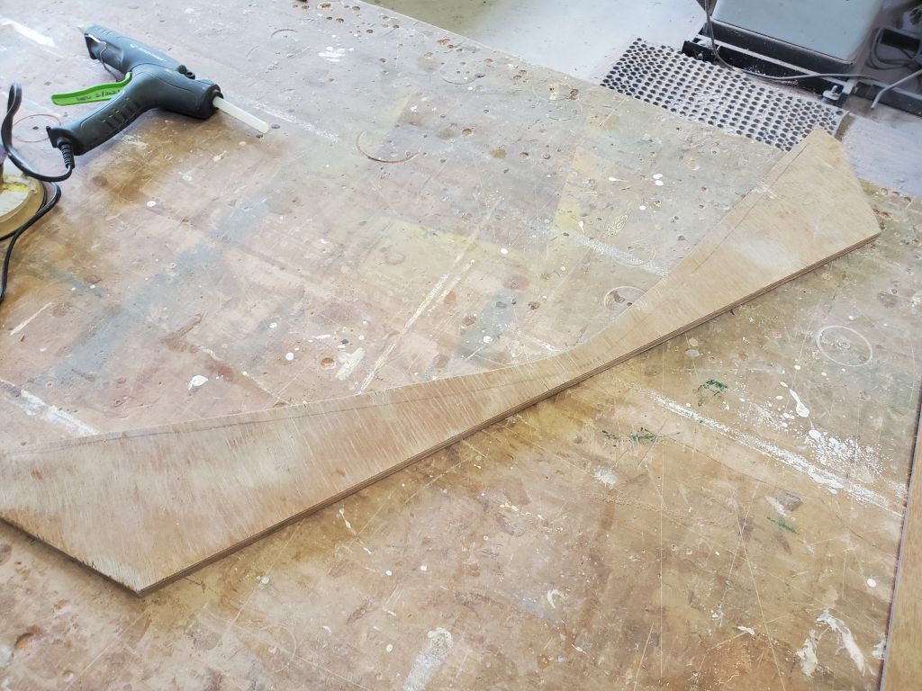
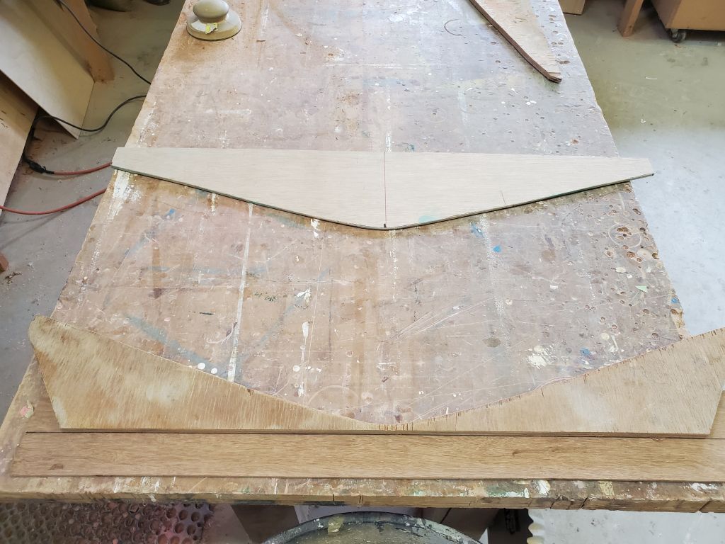
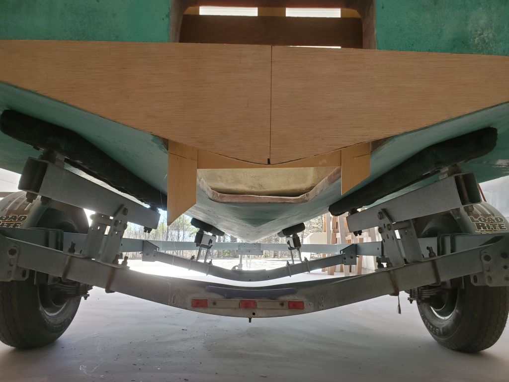
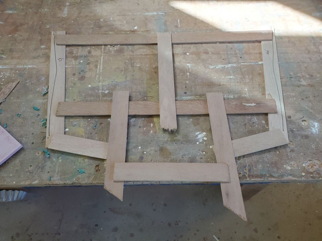
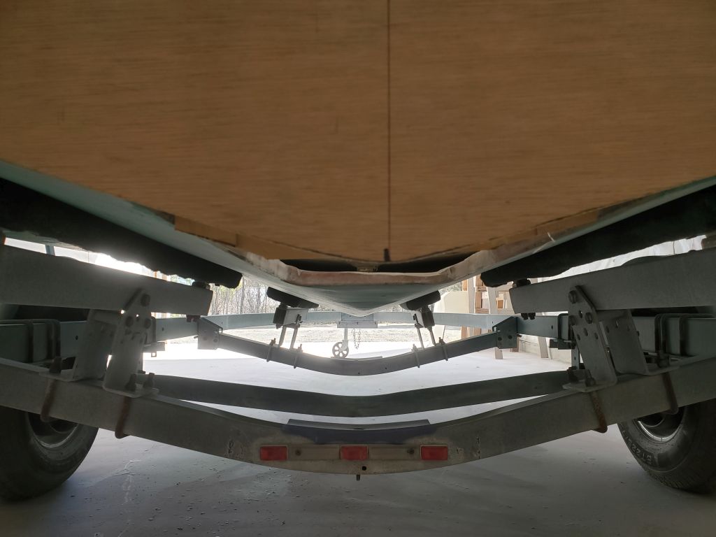
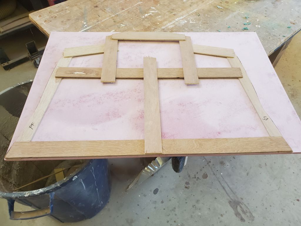
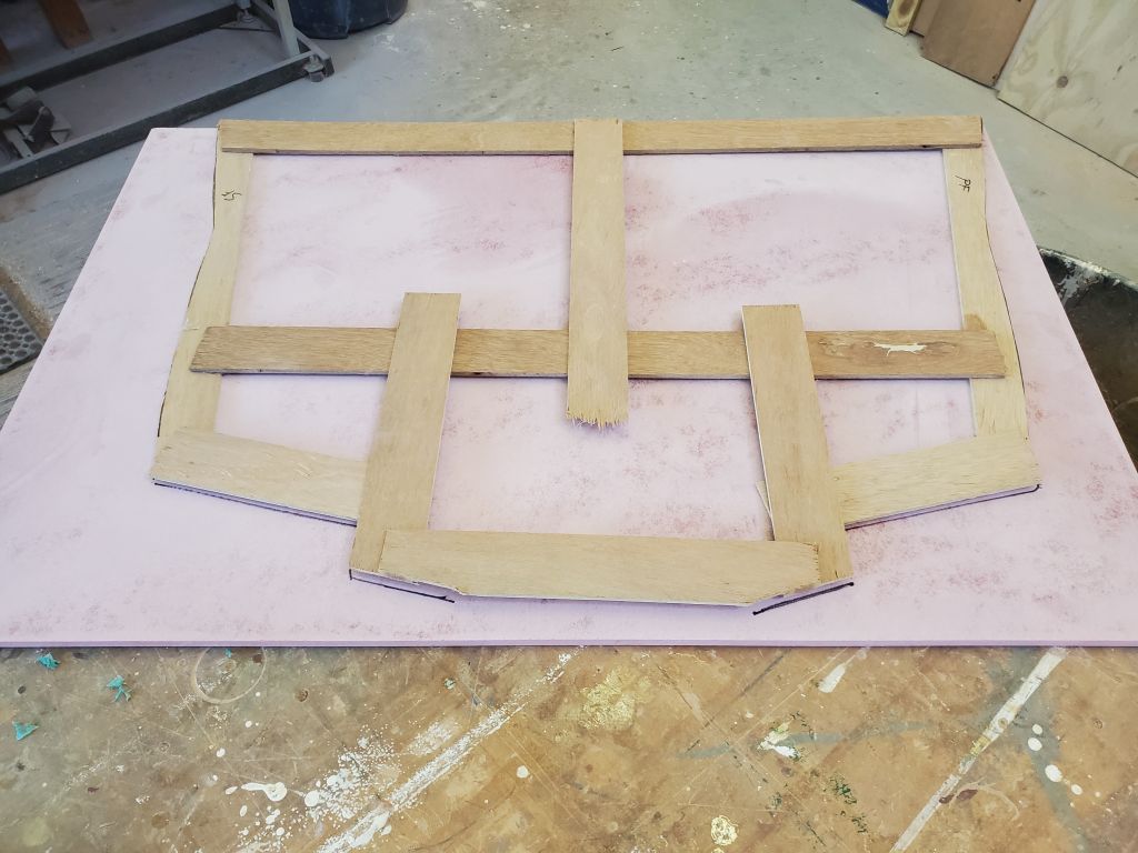
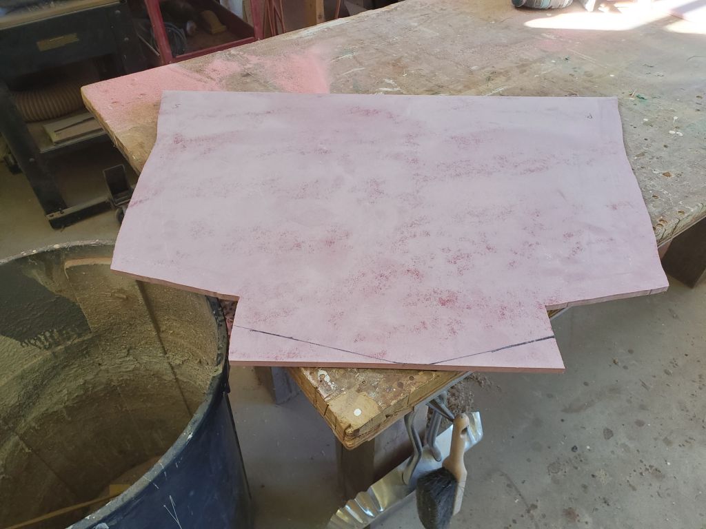
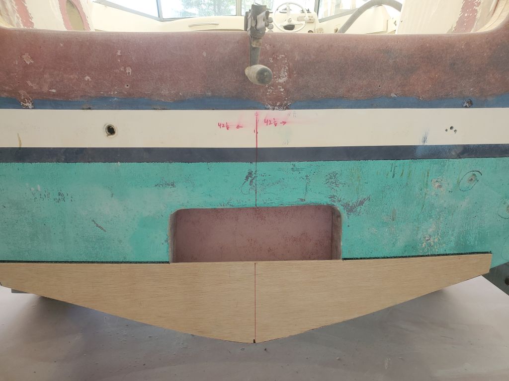
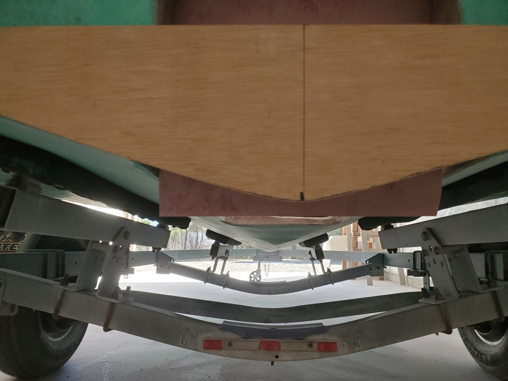
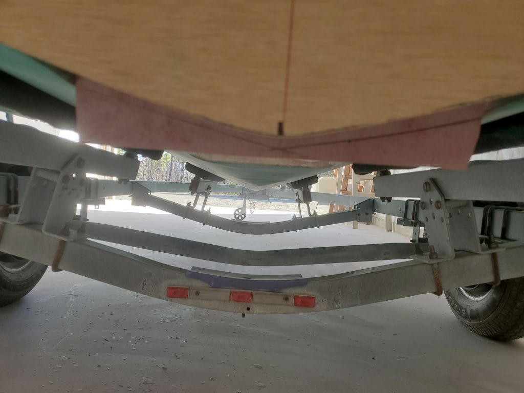
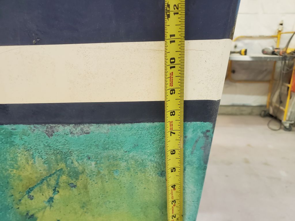
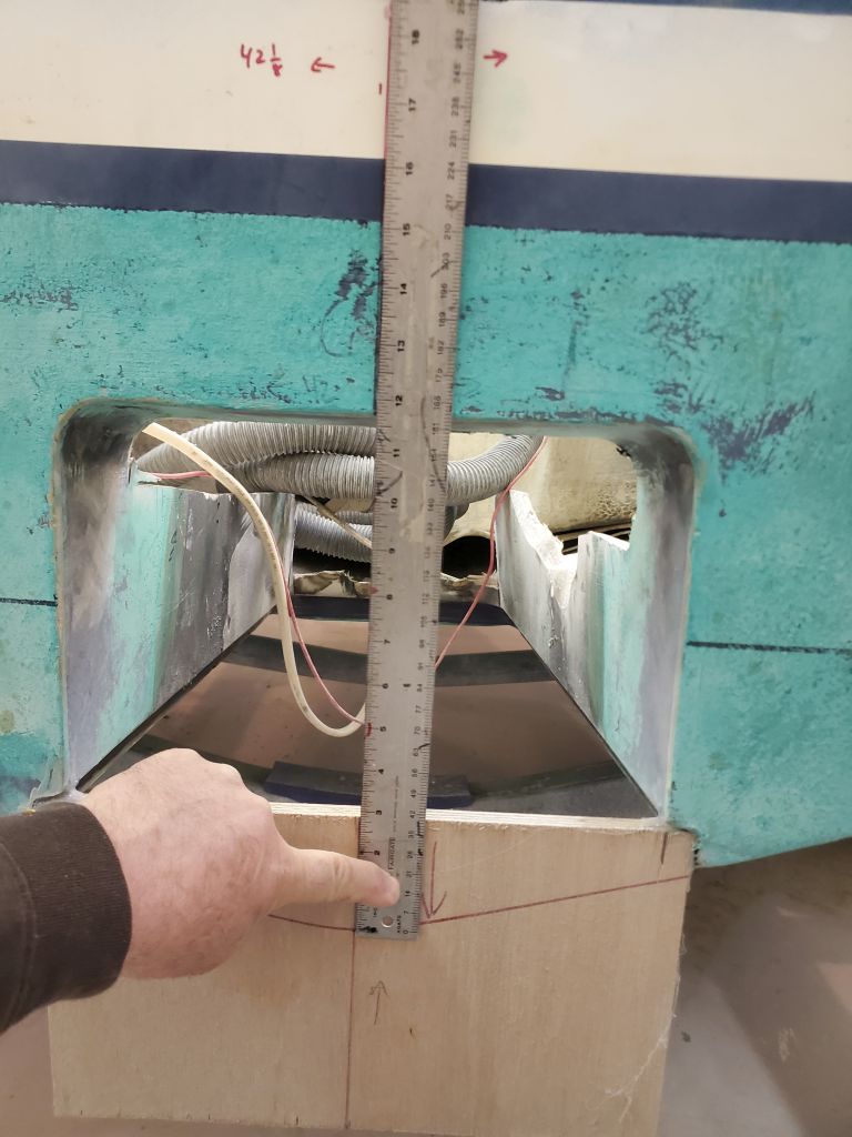
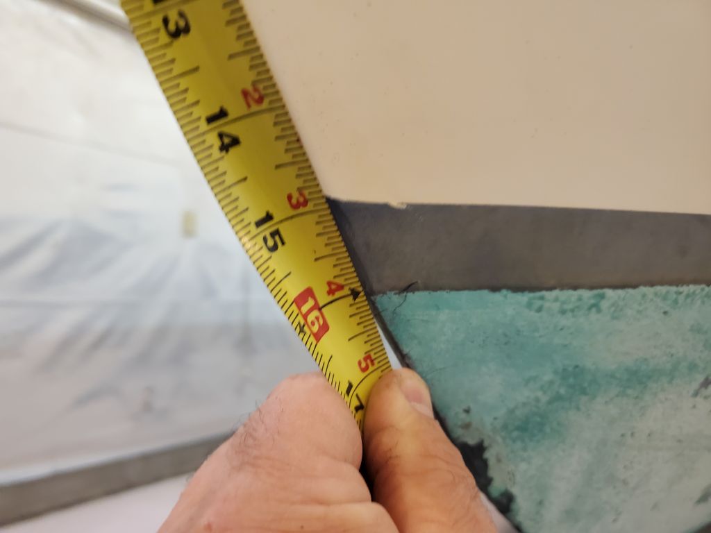
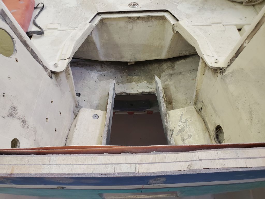
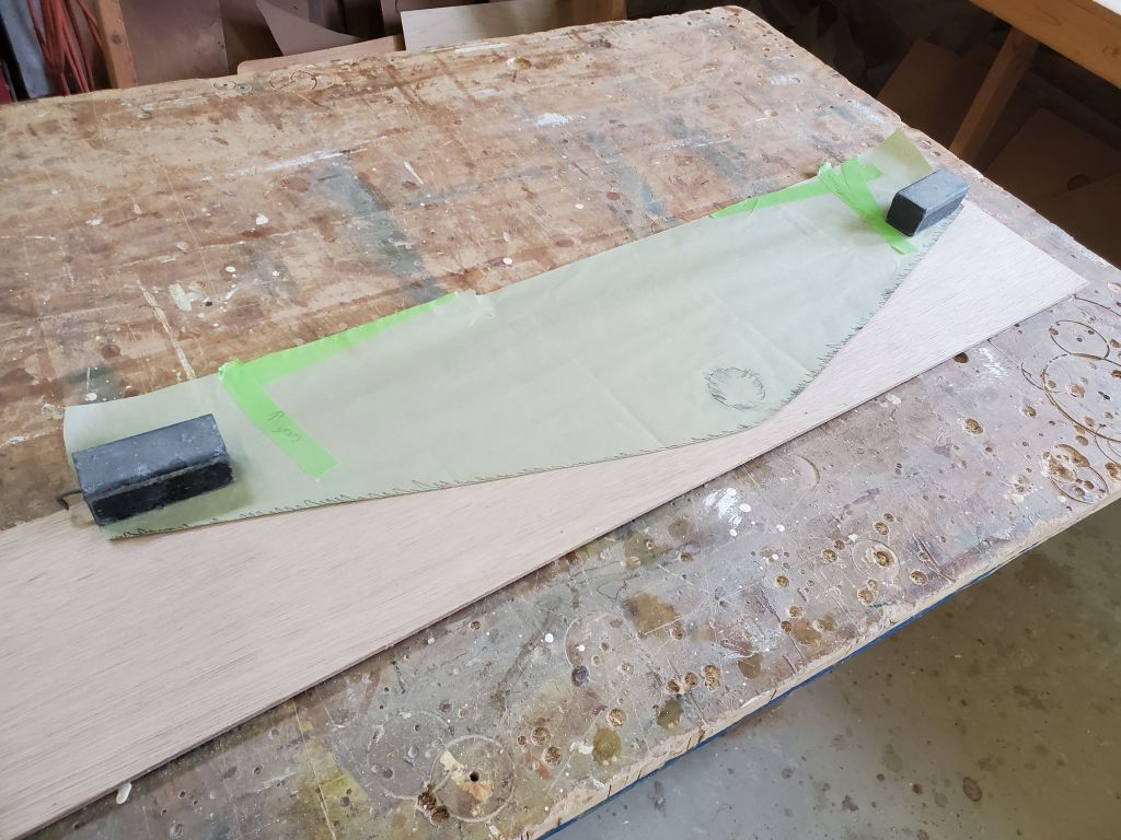
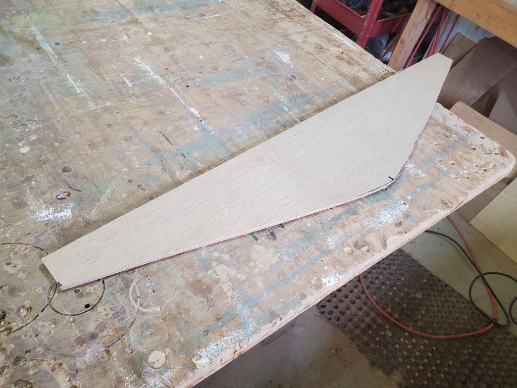
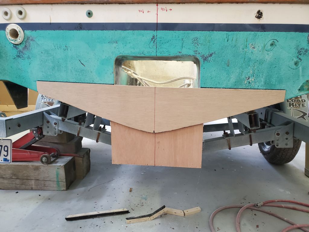
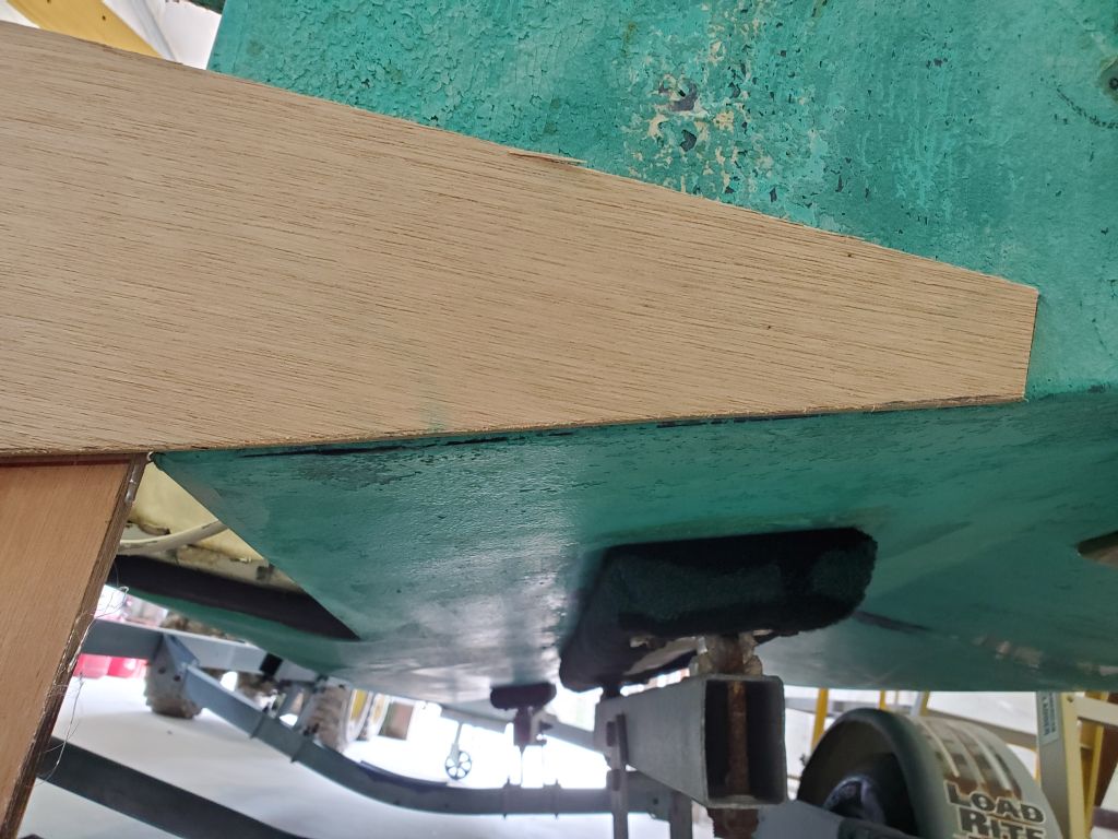
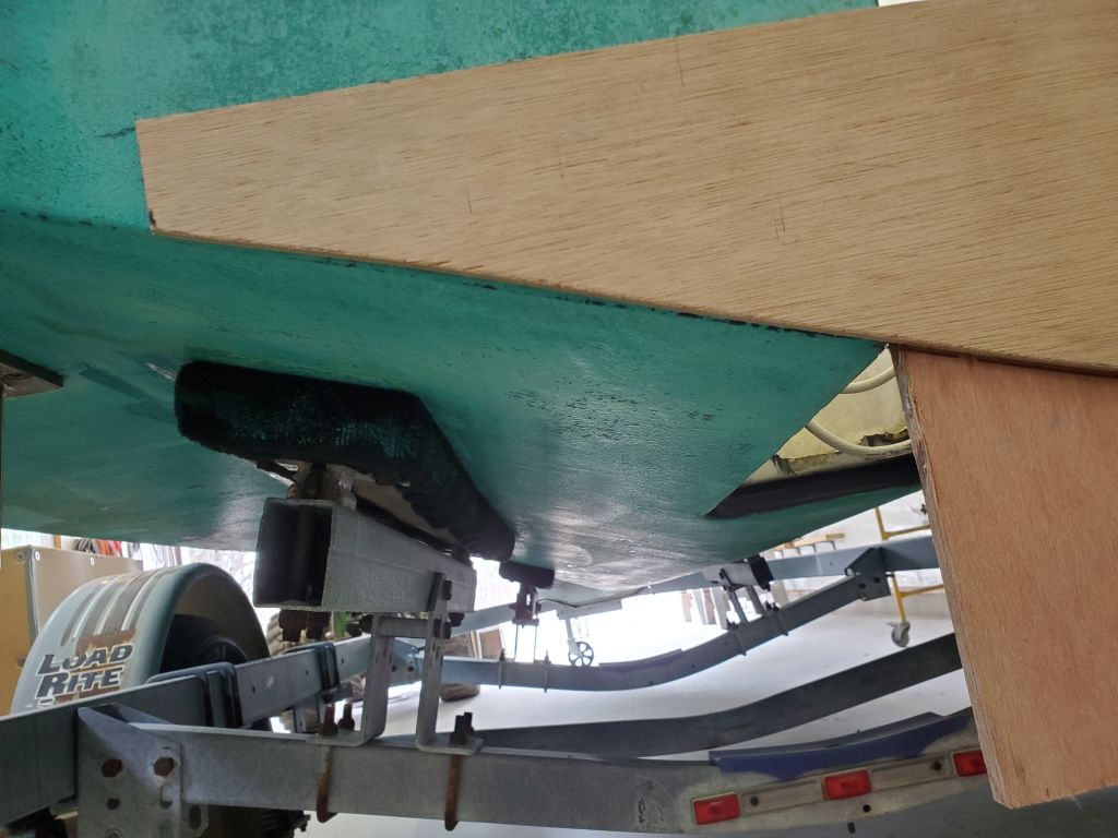
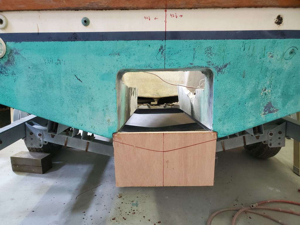
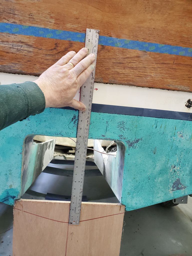
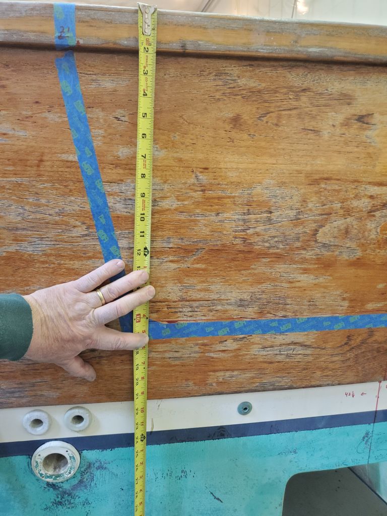
Perhaps the most critical measurement for the new cutout was the height of the cutout, which I’d measured on the sistership at 24″ from the centerline of the bottom.  To recreate that point, which at the moment didn’t exist thanks to the jetdrive tunnel, I transferred my paper template of the other other boat’s hull shape to some 1/4″ plywood and cut out and faired the shape.  I hot-glued a scrap of plywood into the gap below the tunnel, then used the new plywood hull shape template to draw on the eventual shape, temporarily securing hte template to the stern with more hot glue; the template was easy to align properly since I just had to line up the sides flush with the existing hull; it only fit one way.   In the end, all this gave me the lower point needed to determine the cutout height, which I then marked on the centerline exactly 24″ up.

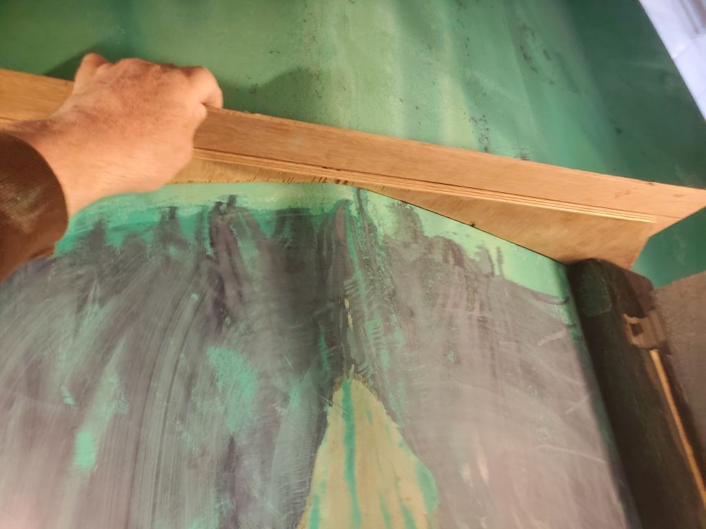
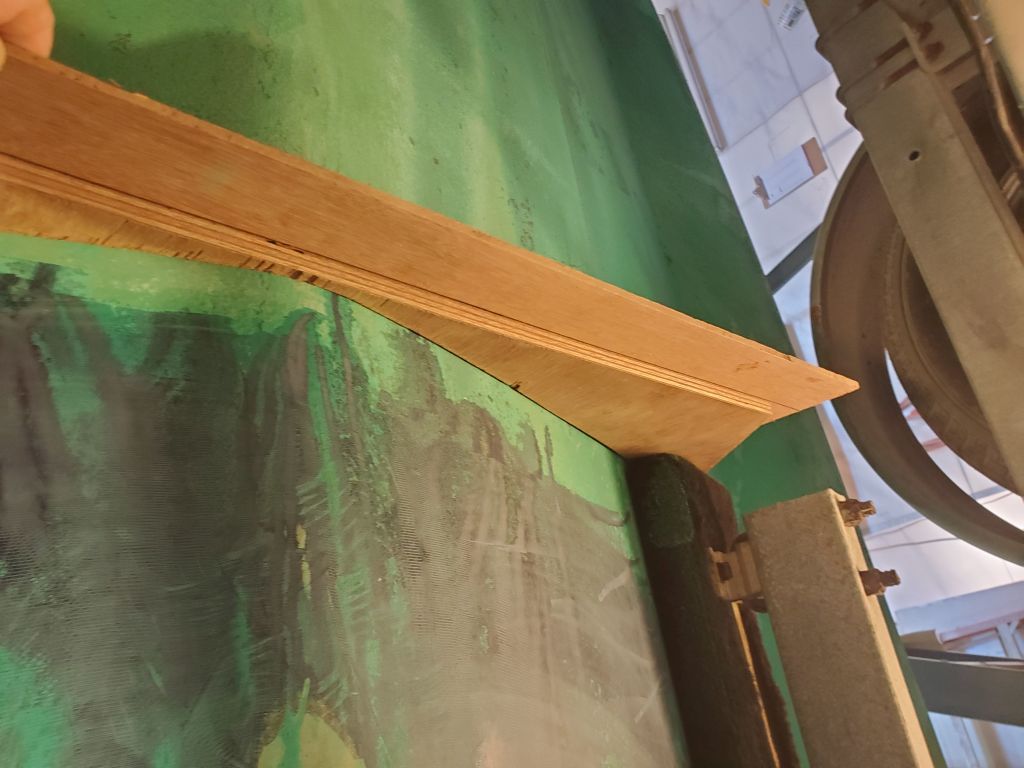
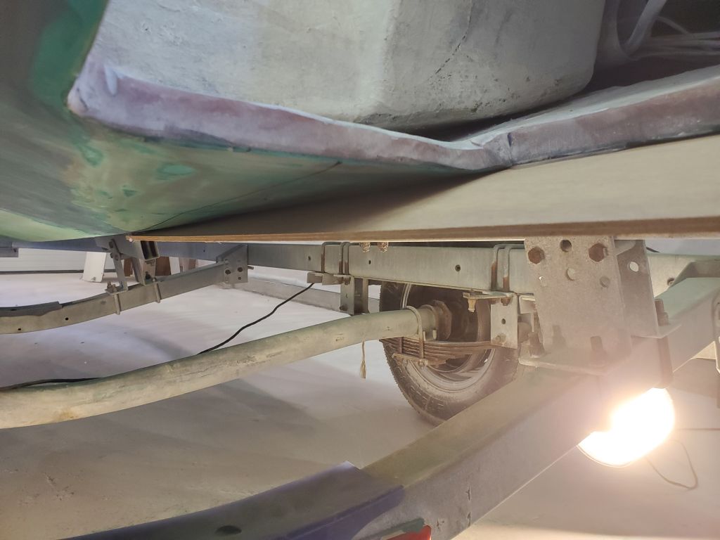
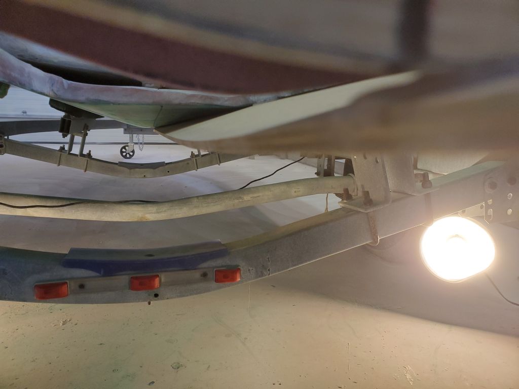
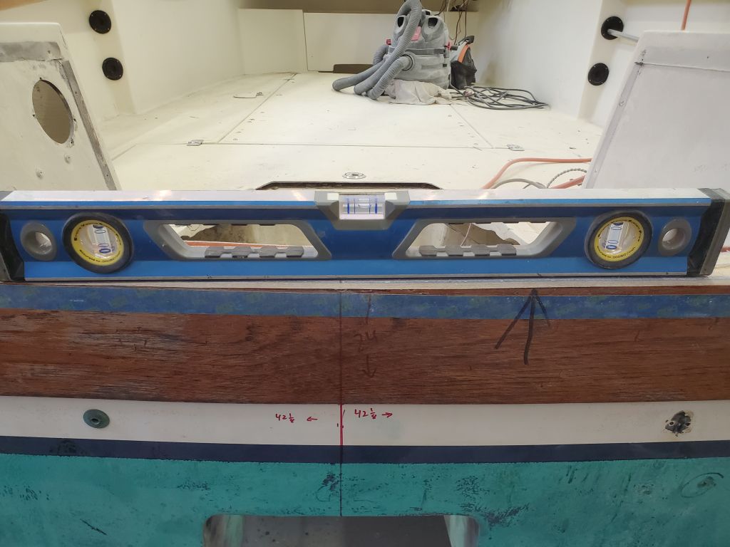
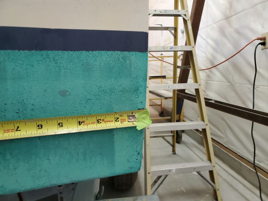
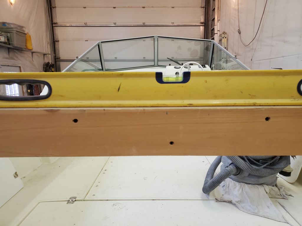
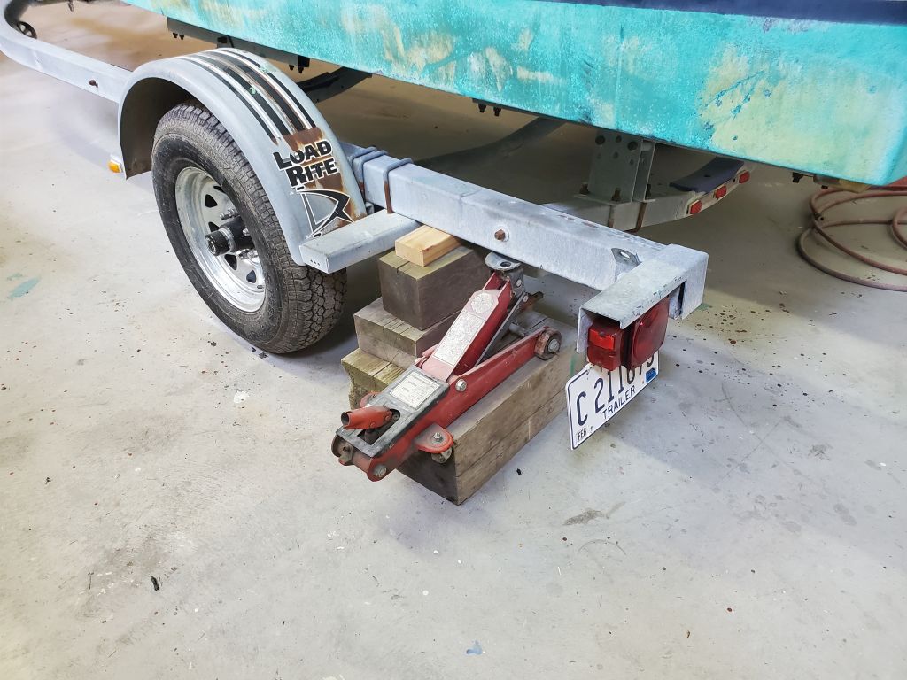
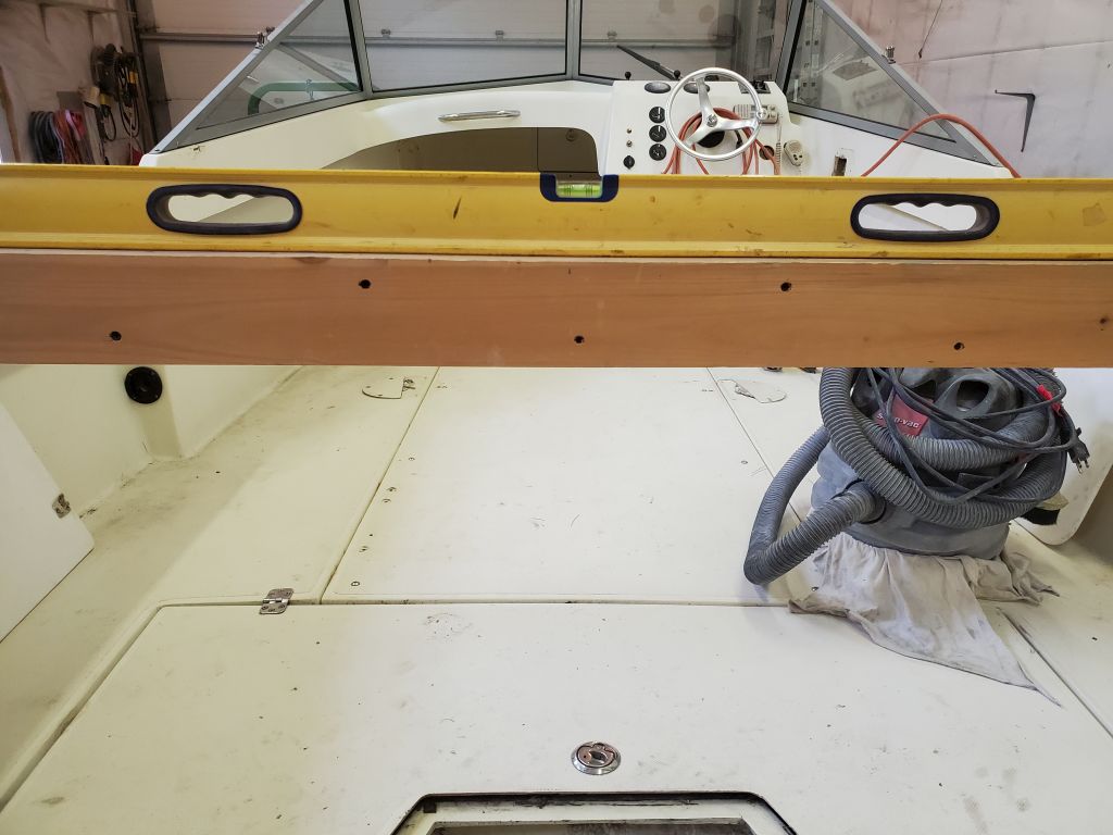
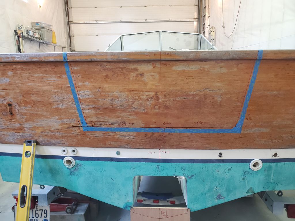
The boat was slightly out of level, so I propped up one side with a jack and blocking till she was level across both sidedecks, using a long straightedge.

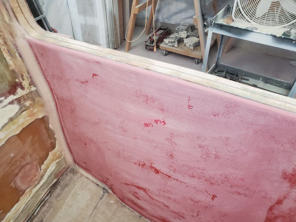
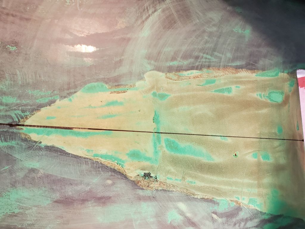
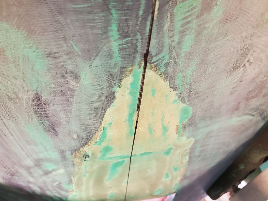
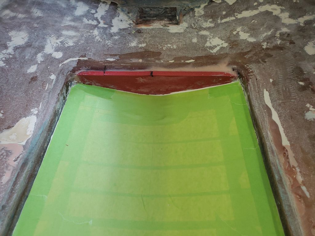
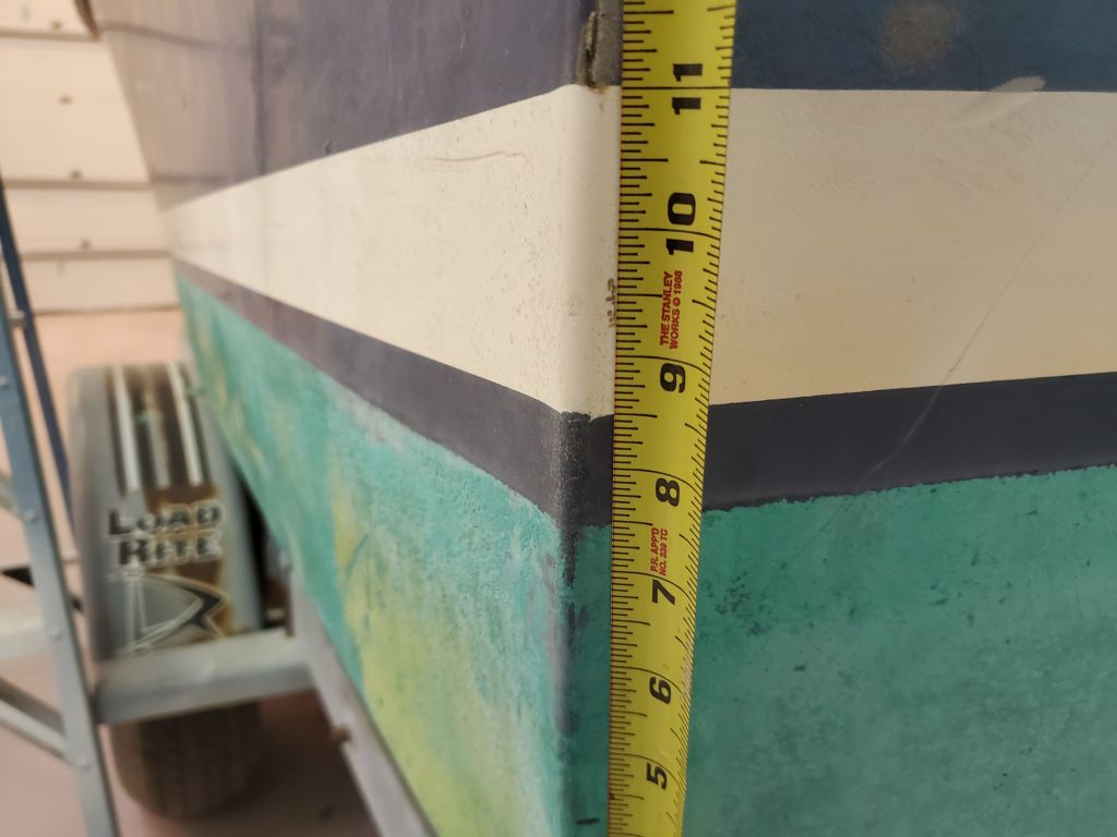
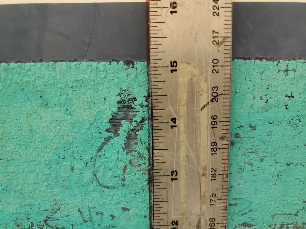
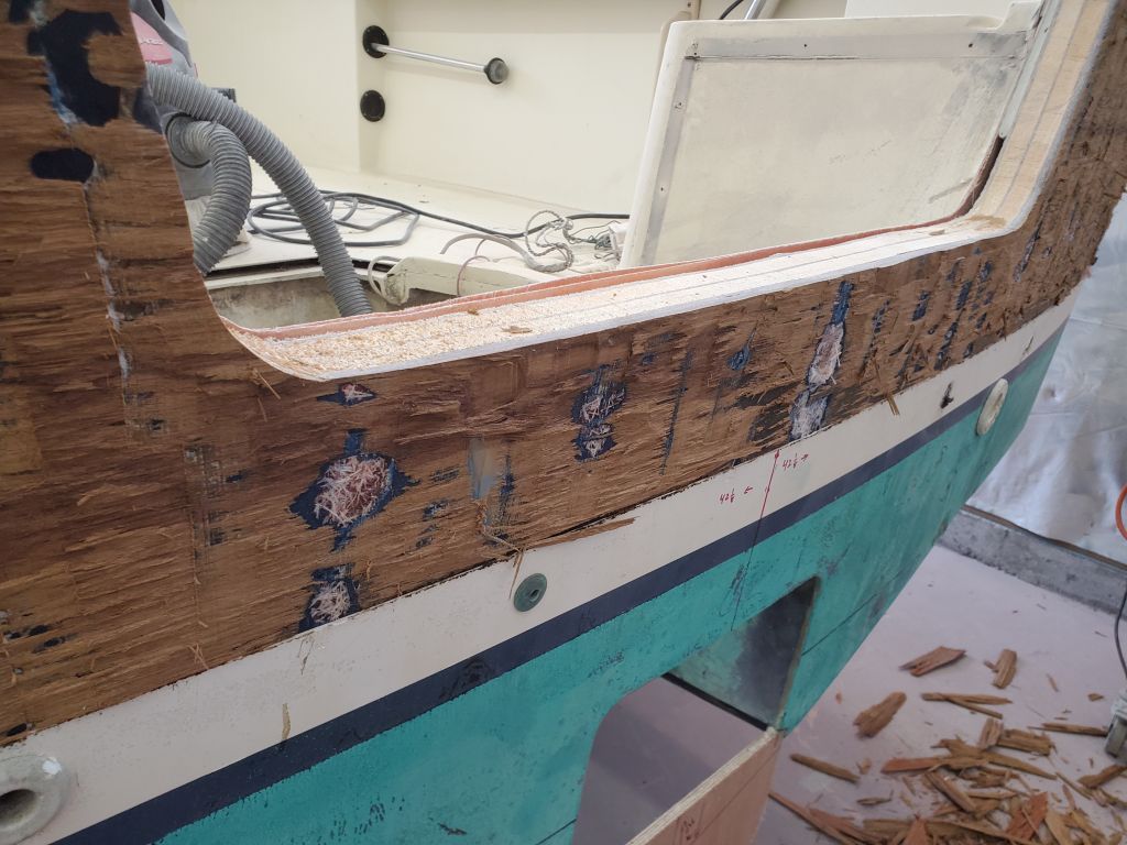
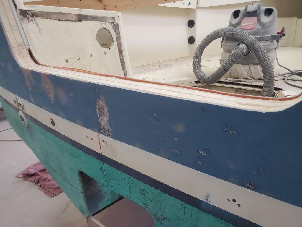
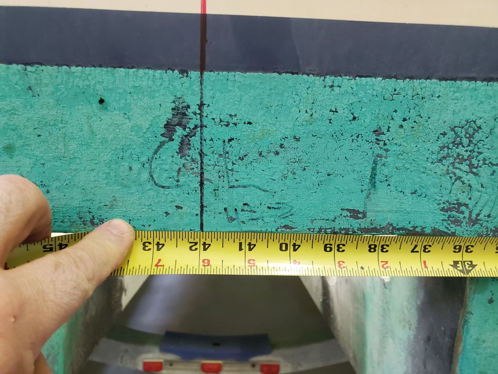
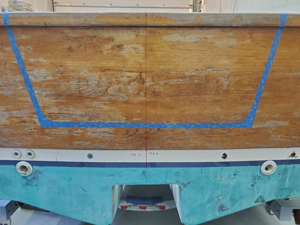
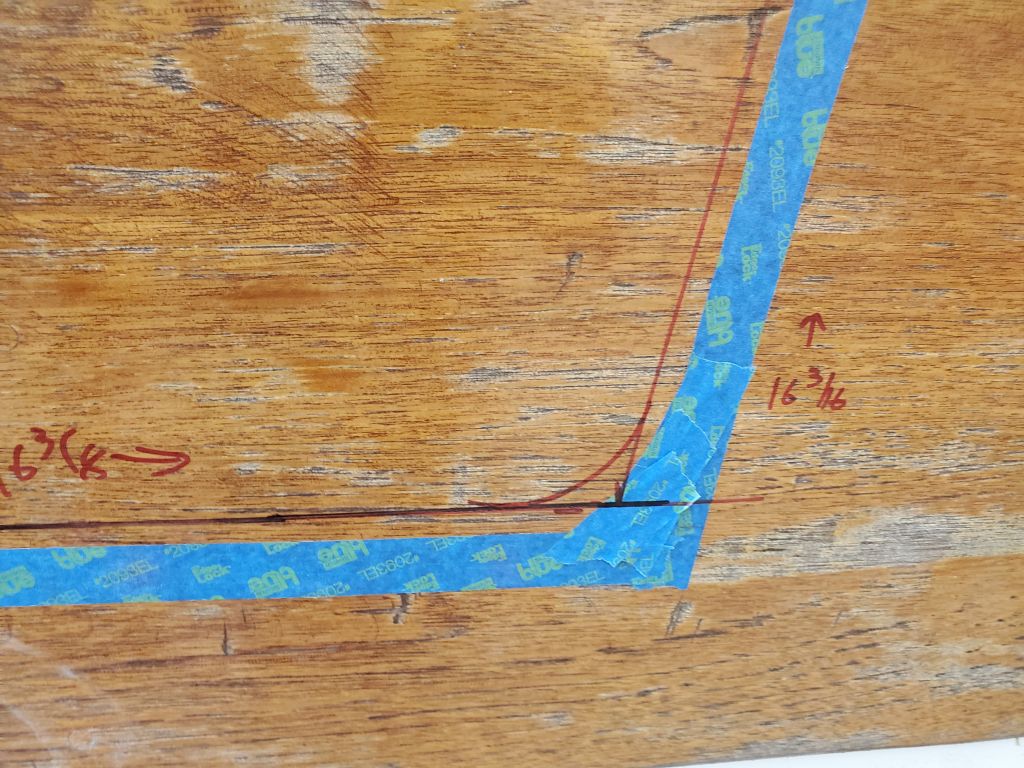
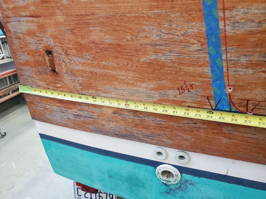
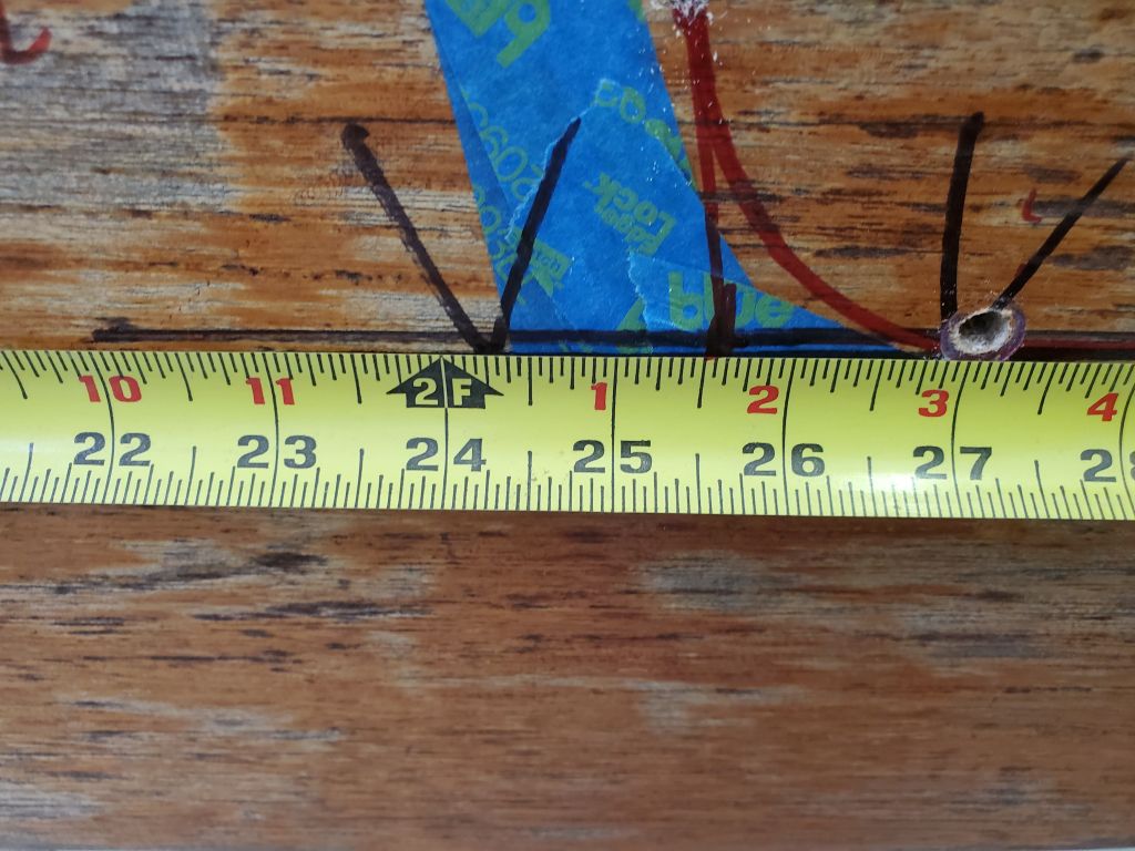
Now that the boat was level, I could transfer my most recent mark for the bottom of the cutout to each side, using a level from the center point to create a tick mark out near the edge of the existing taped marks.  Then, because the transom was slightly curved, rendering the level inherently (if slightly) inaccurate for this method, I double-checked the height of the tick marks on each side with measurements from fixed points on the boat and, again with the level, confirmed the new marks and slightly fixed the line on the port side as a result  (the black line).

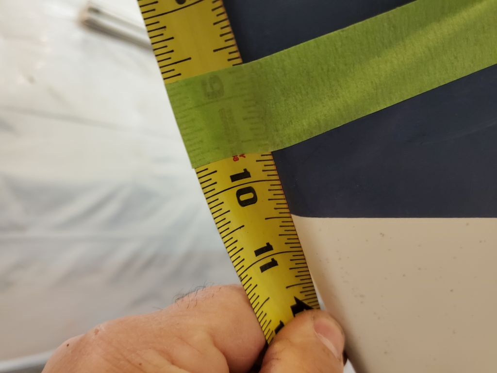
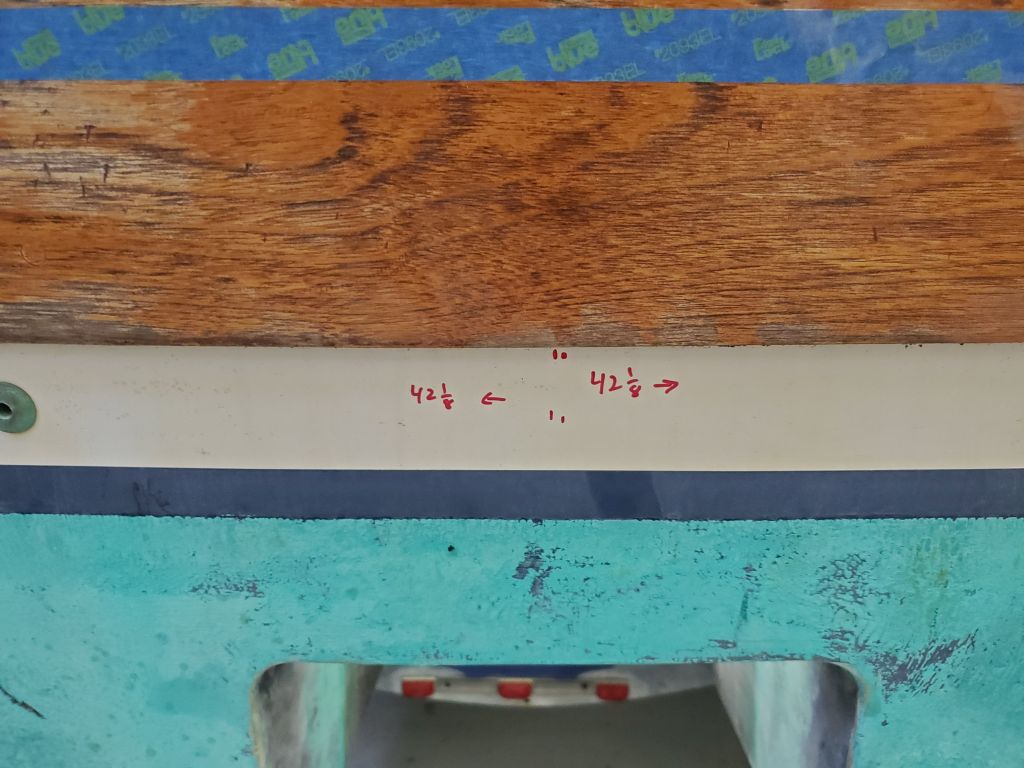
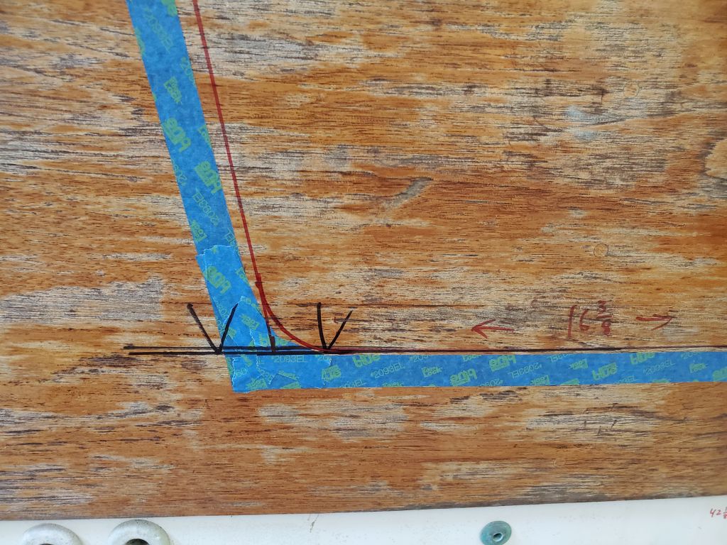
Next I could measure out from centerline the required distance as recorded from the sistership, 16-1/2″ on each side, representing the lower corner of the cutout.  I could connect this point with the measurements I’d made at the top, thus creating the raw shape of the cutout.  To finish the early layout, I marked a 2″ radius curve at each lower corner, which looked and felt appropriate and again approximated what I’d seen on the sistership.

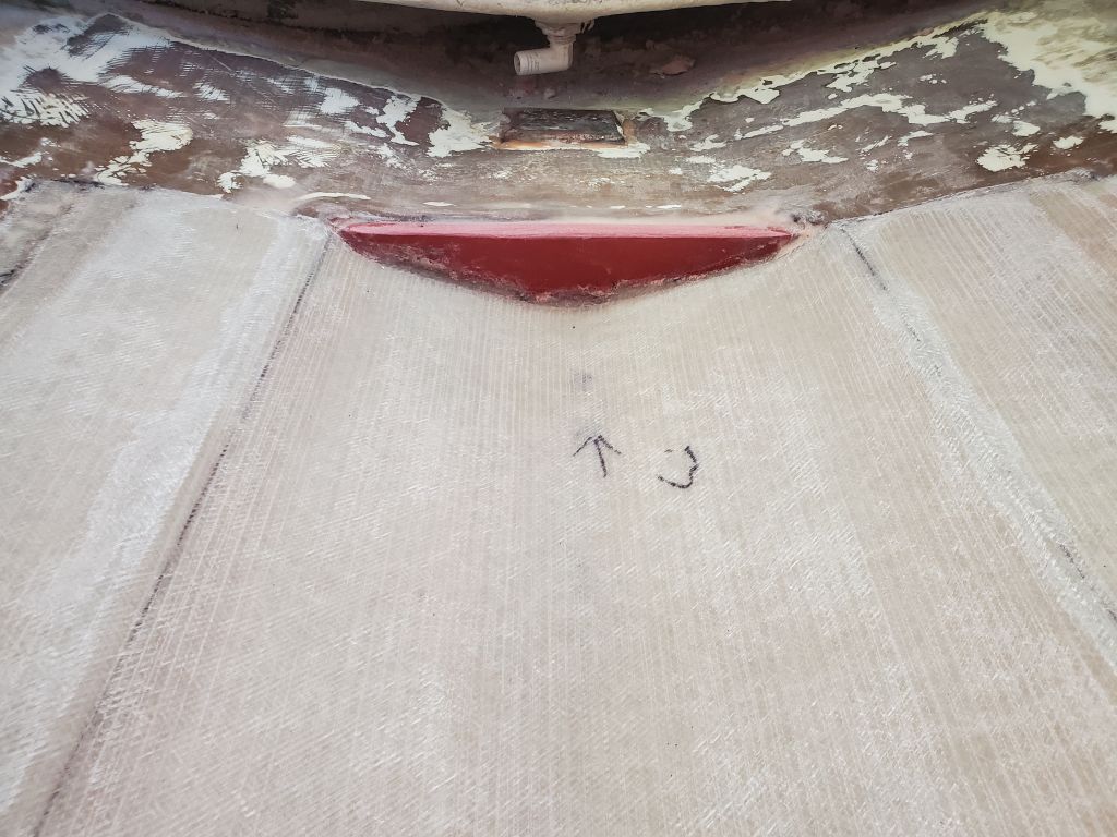
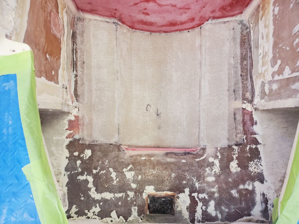
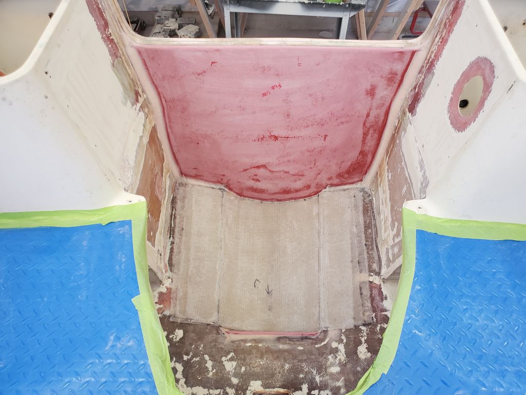
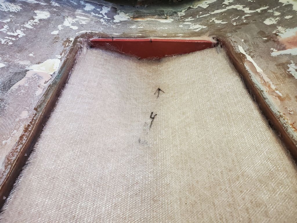
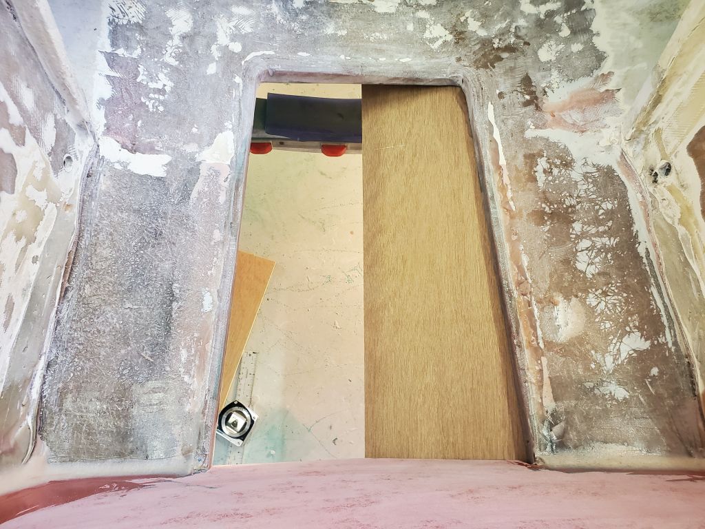
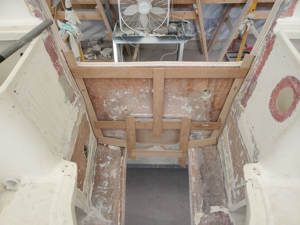
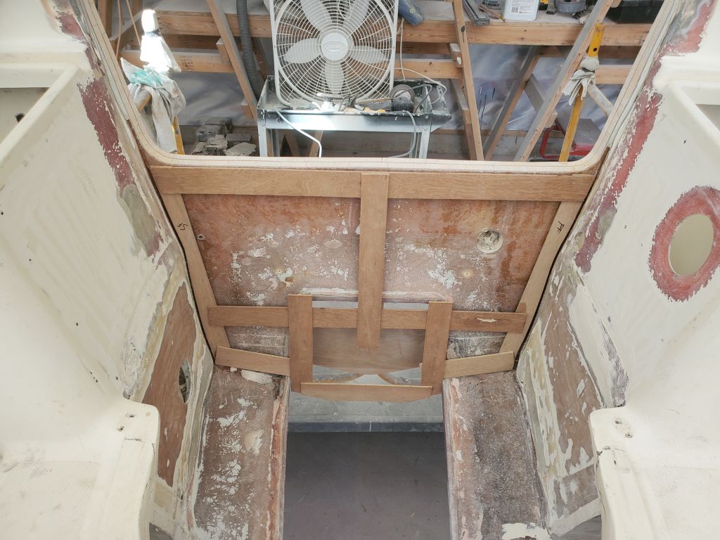
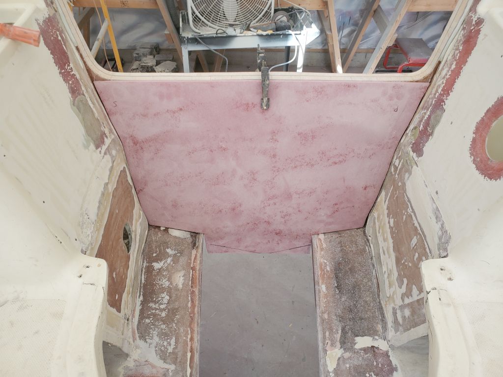
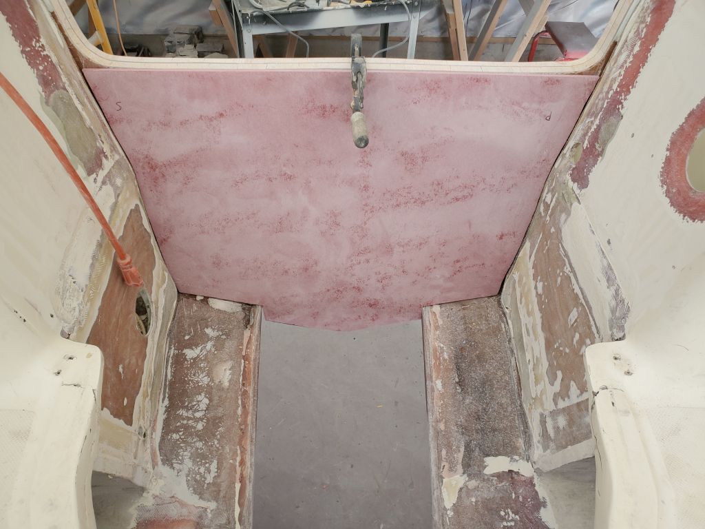
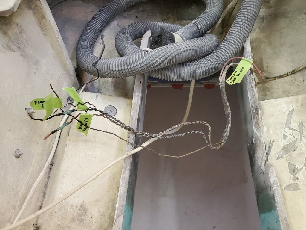
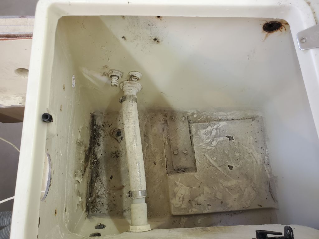
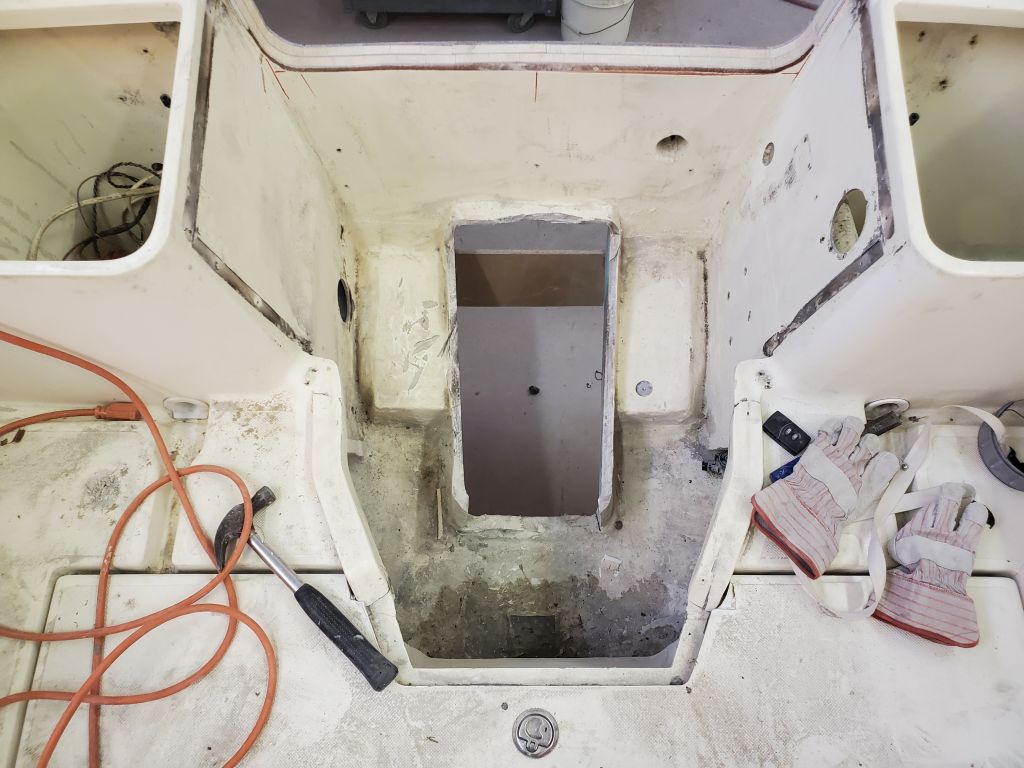
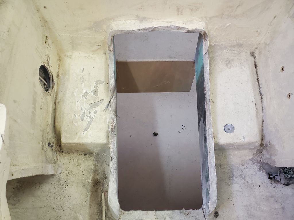
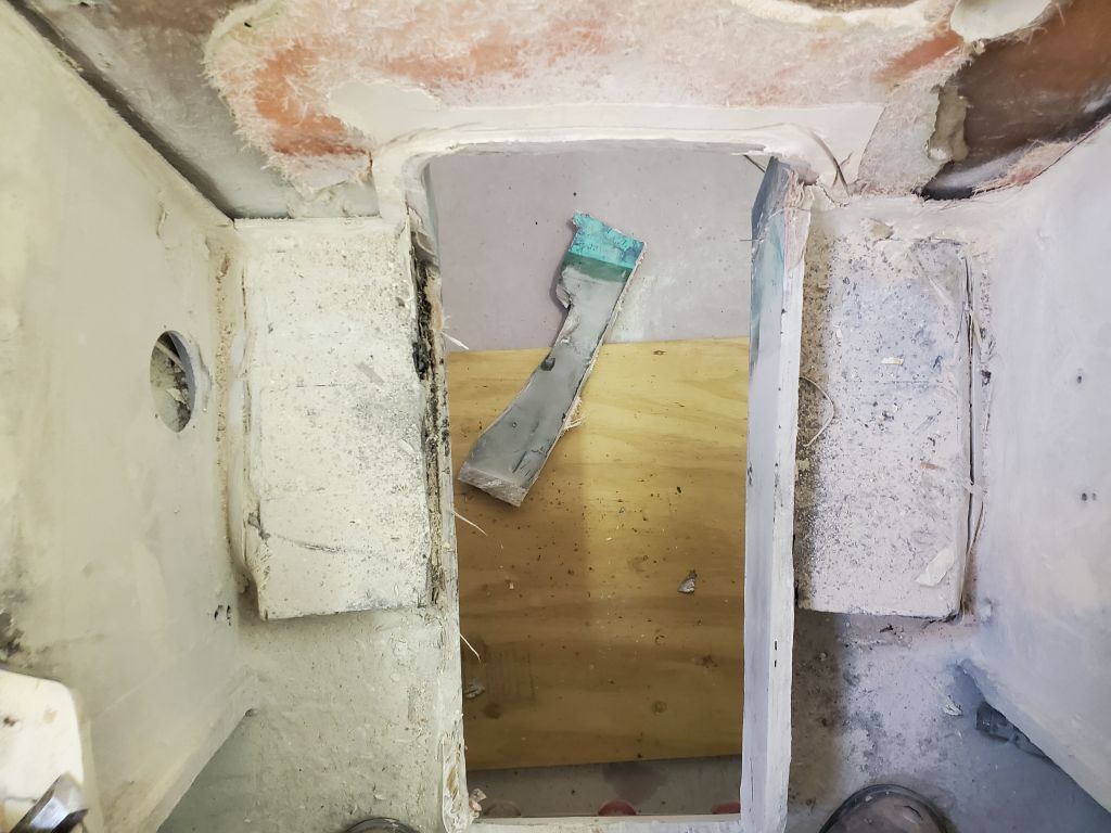
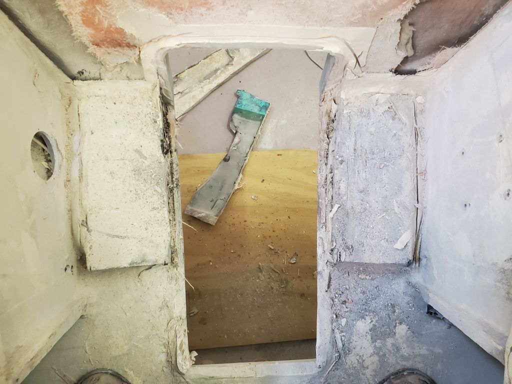
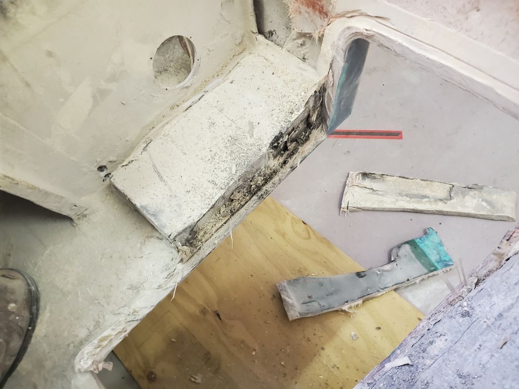
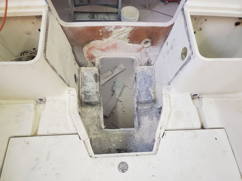
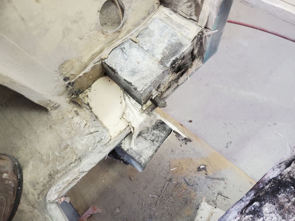
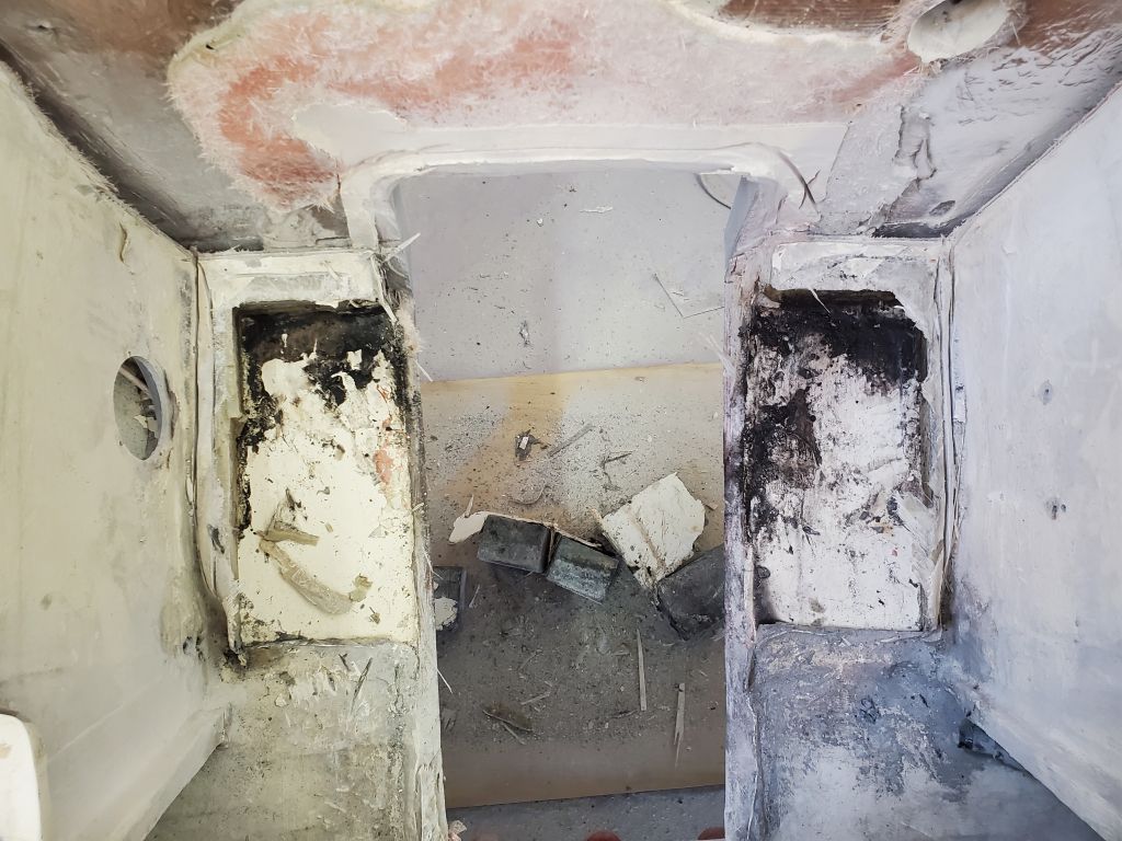
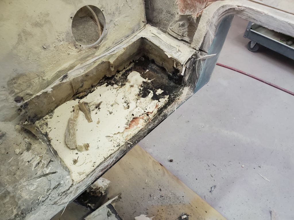
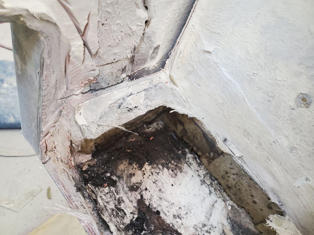
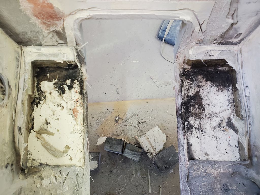
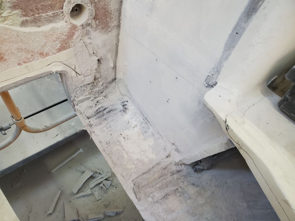
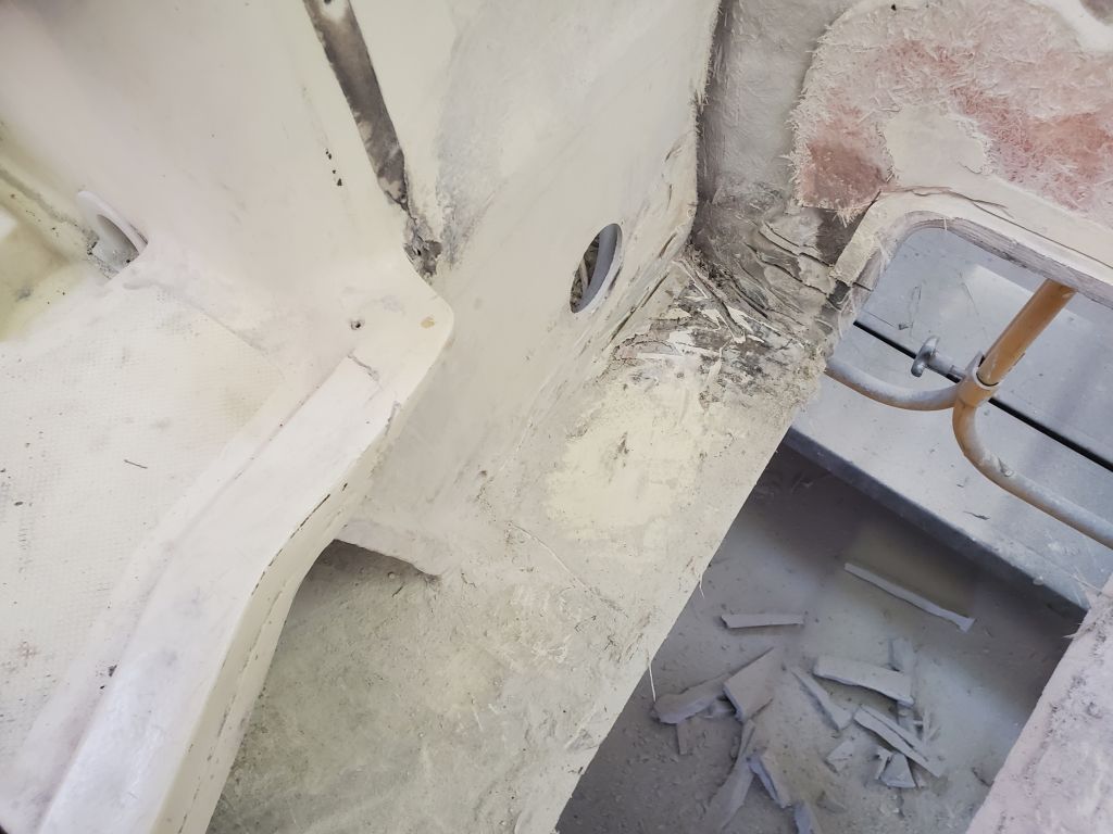
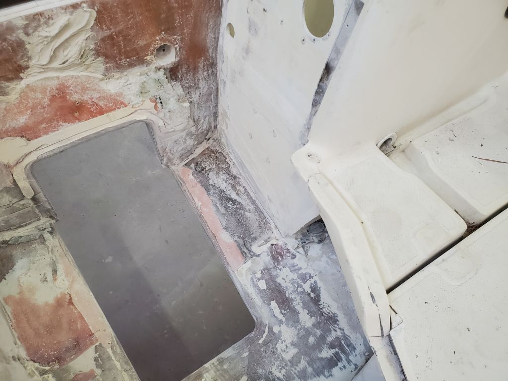
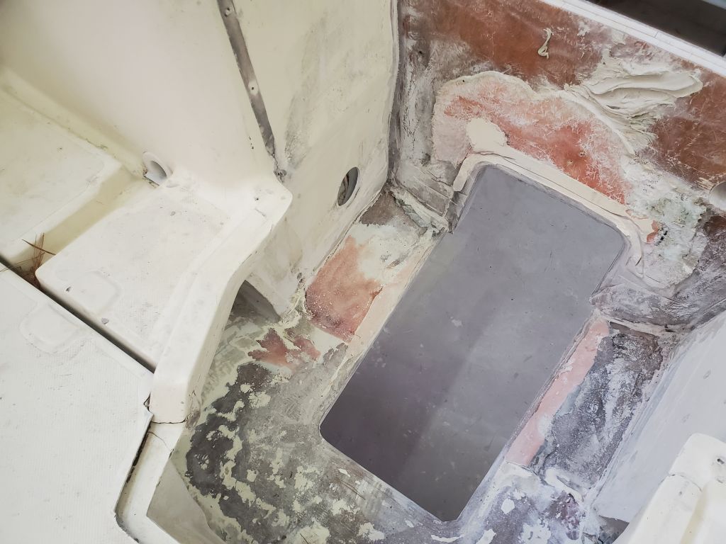
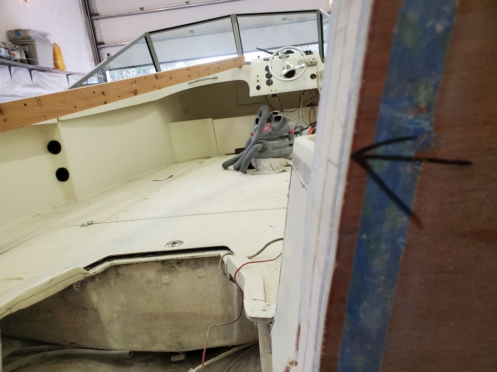
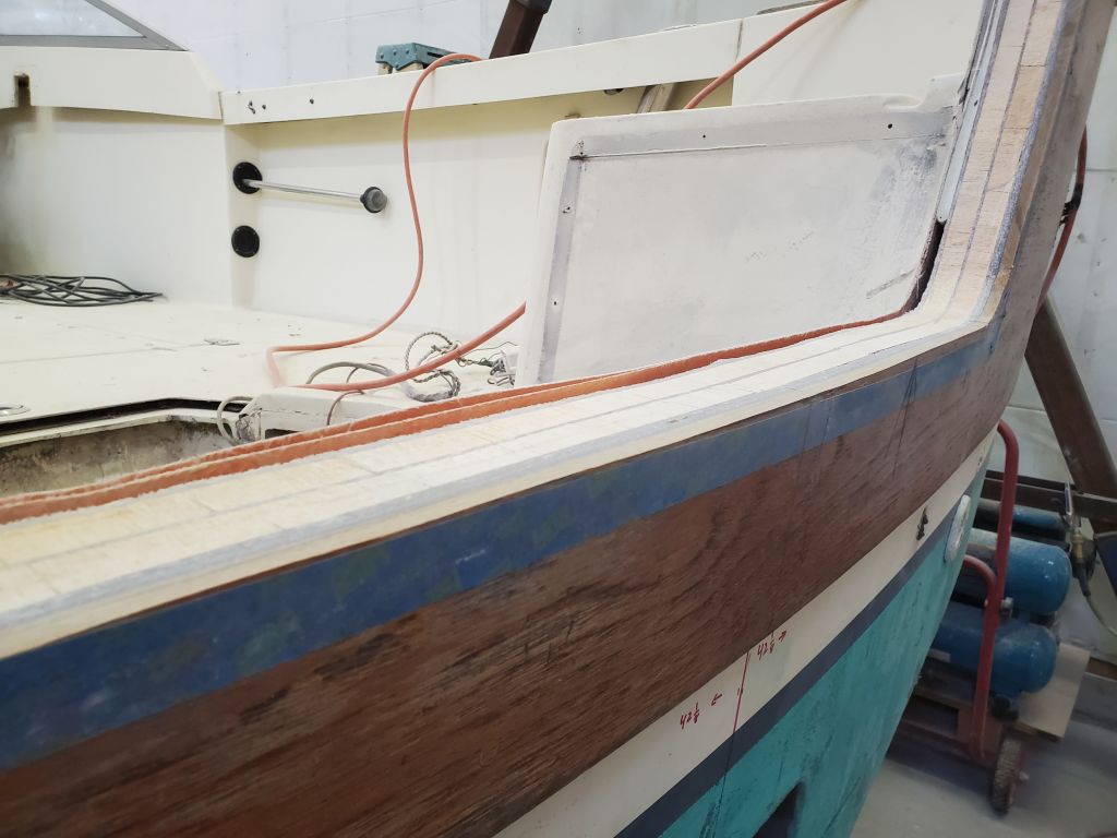
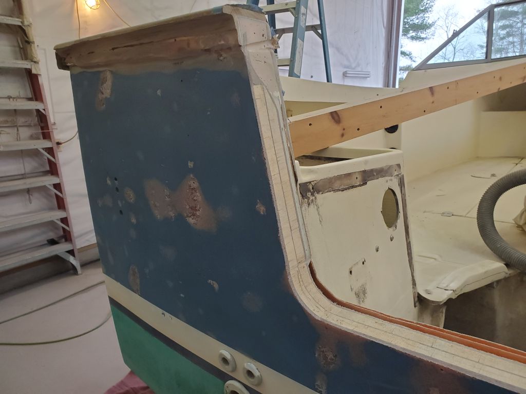
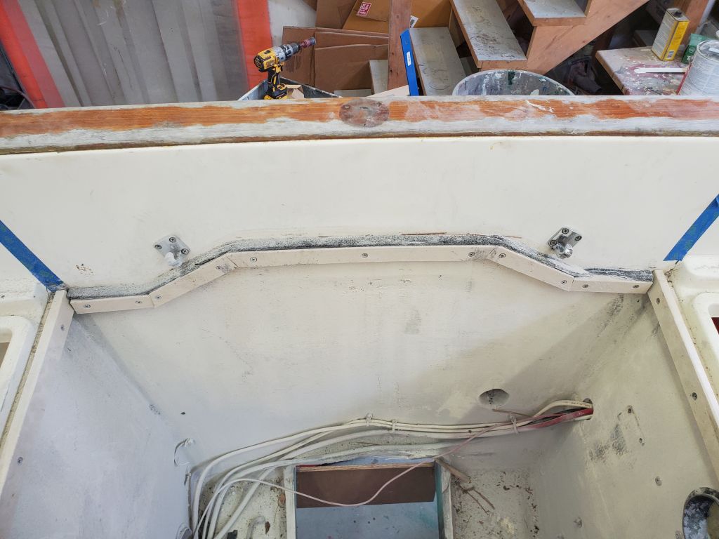
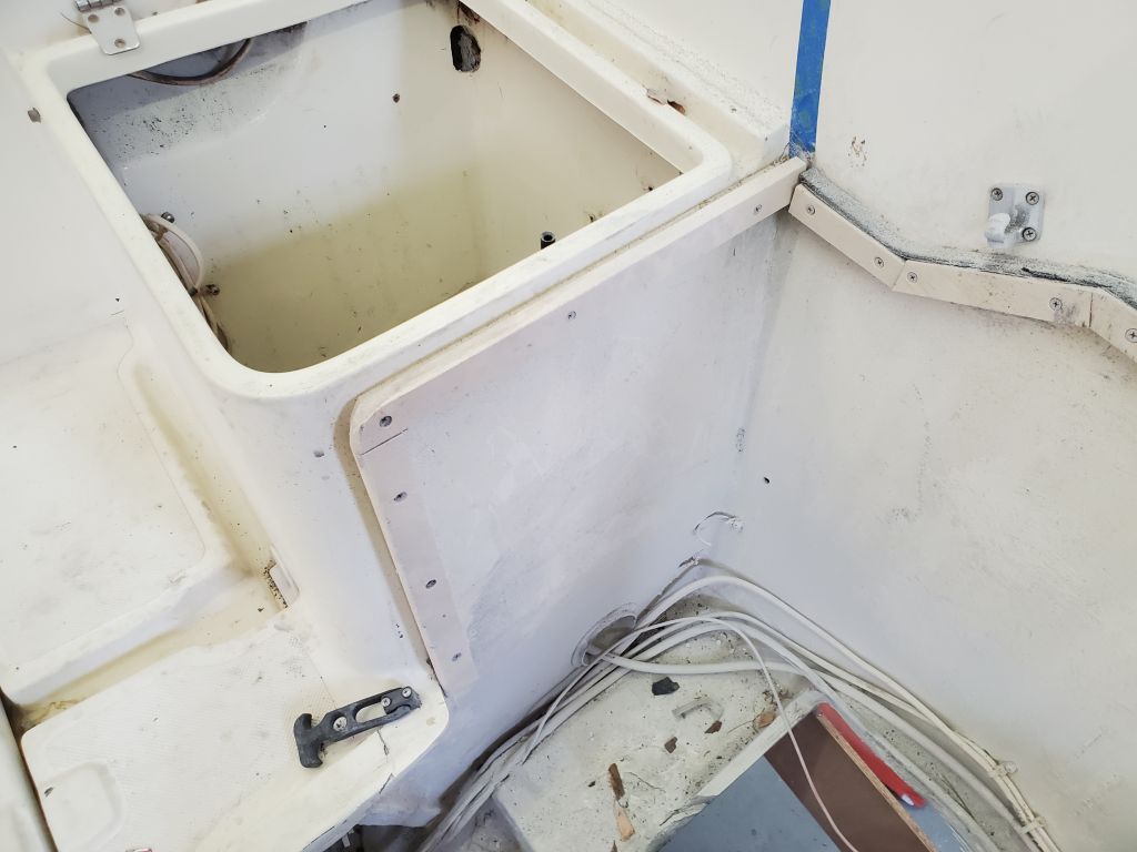
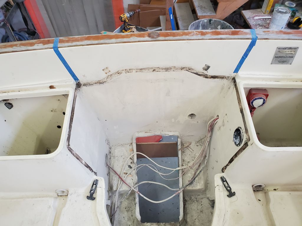
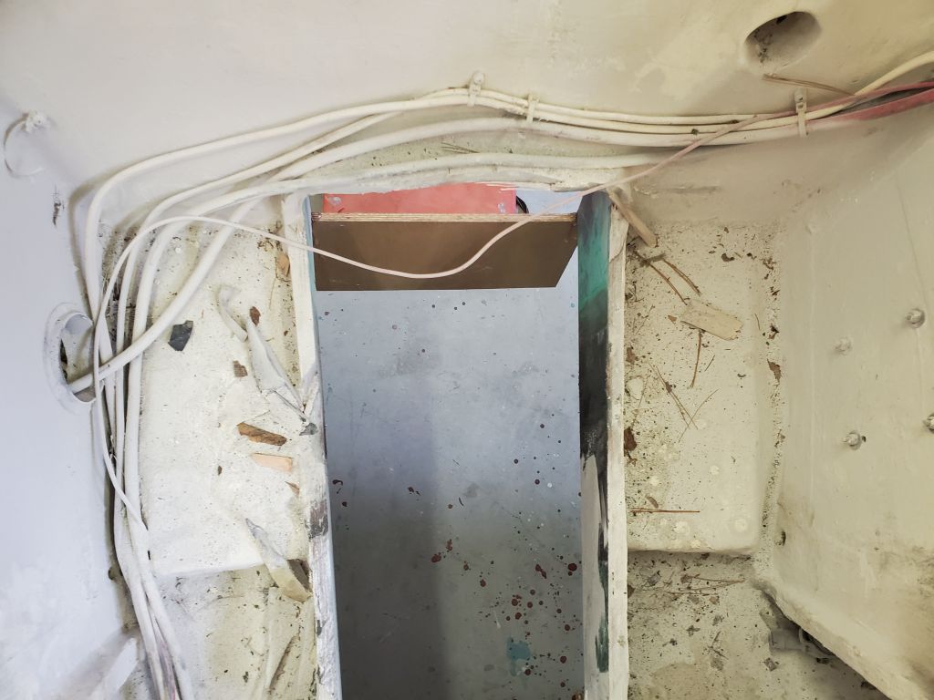
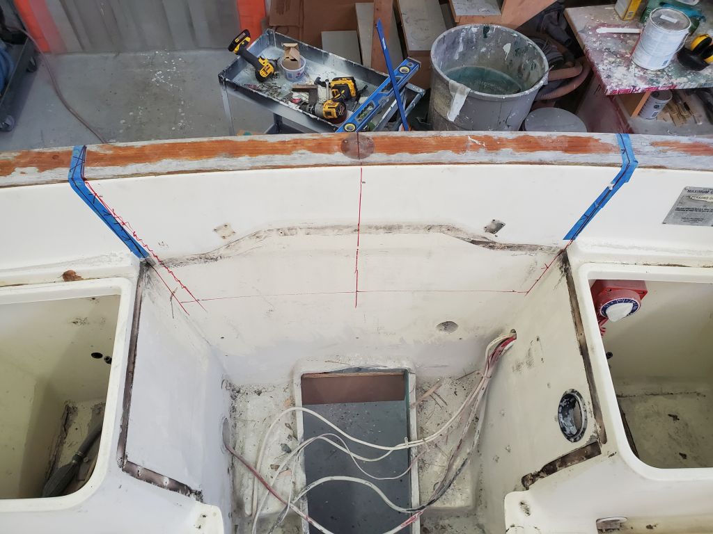
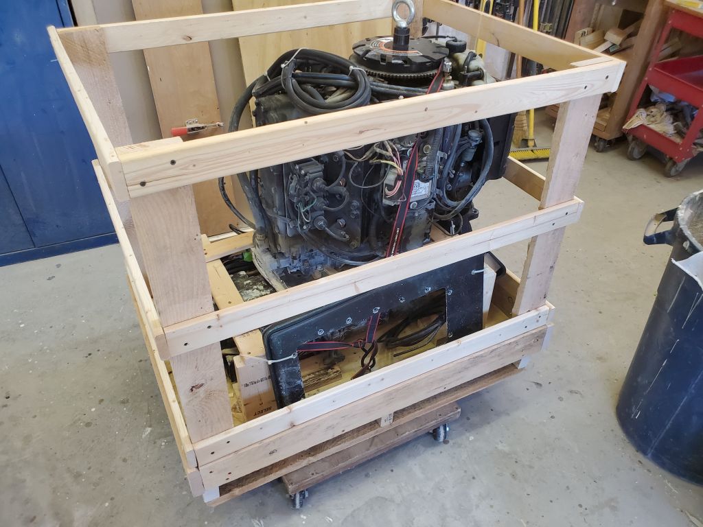
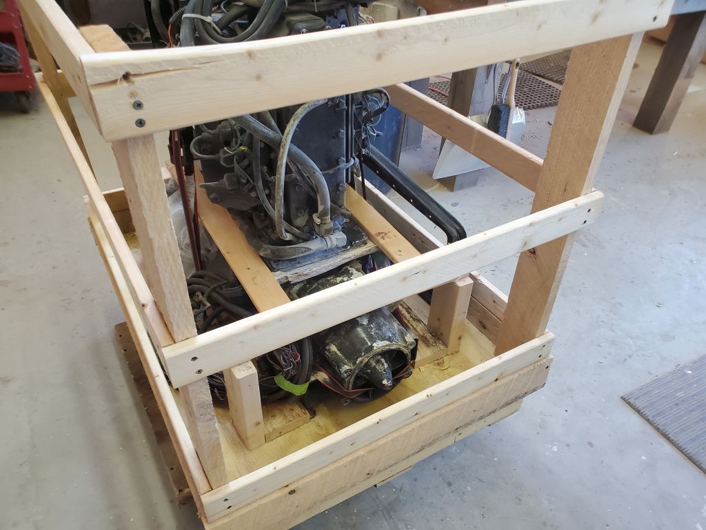
Inside the boat, I prepared for additional layout by first removing the plastic moldings that had supported the now-obsolete engine box.

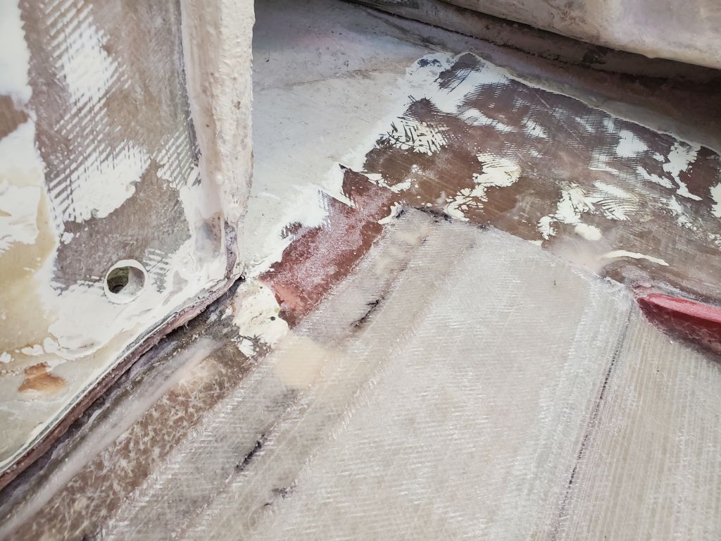
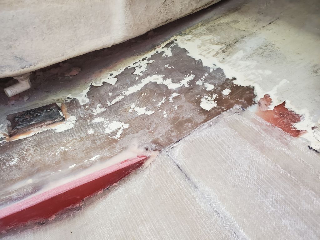
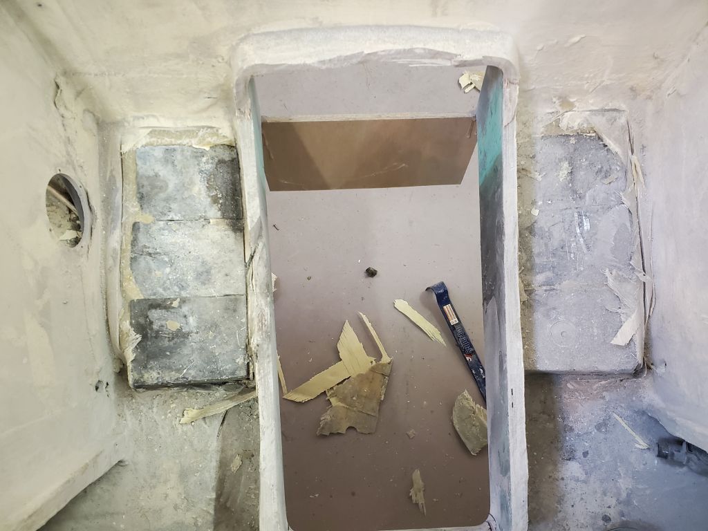
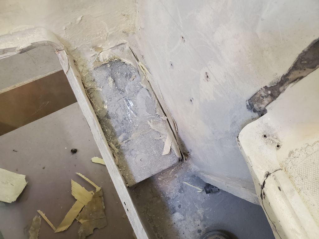
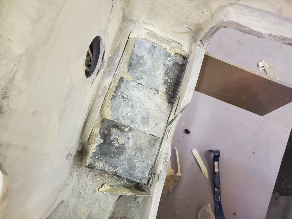
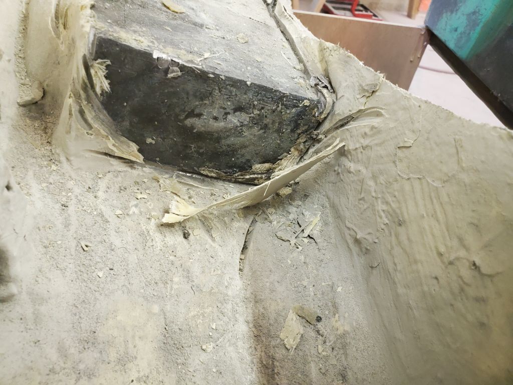
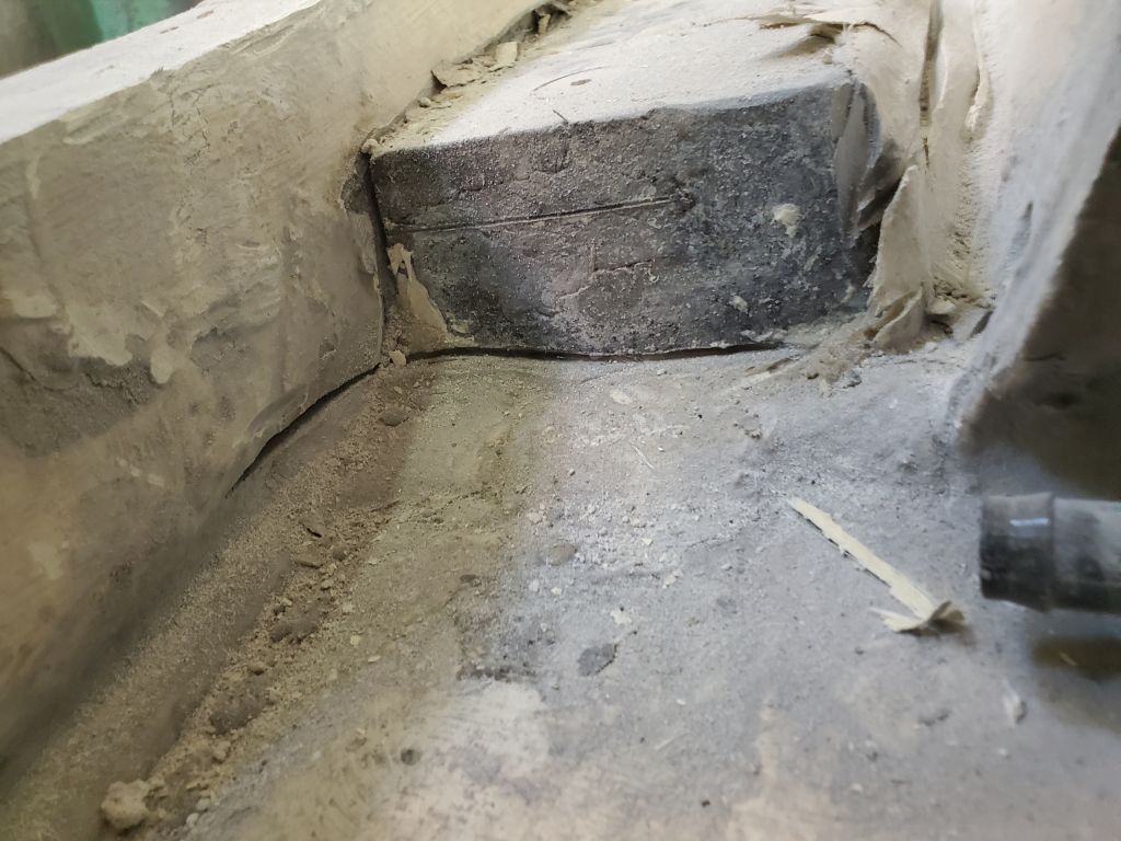
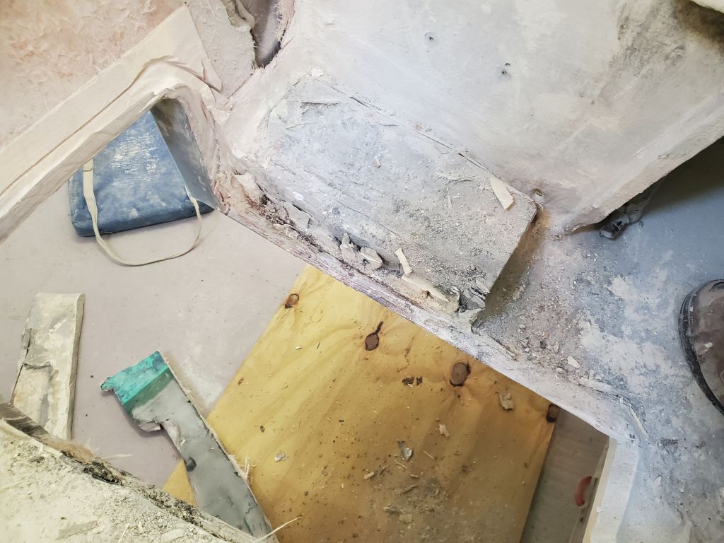
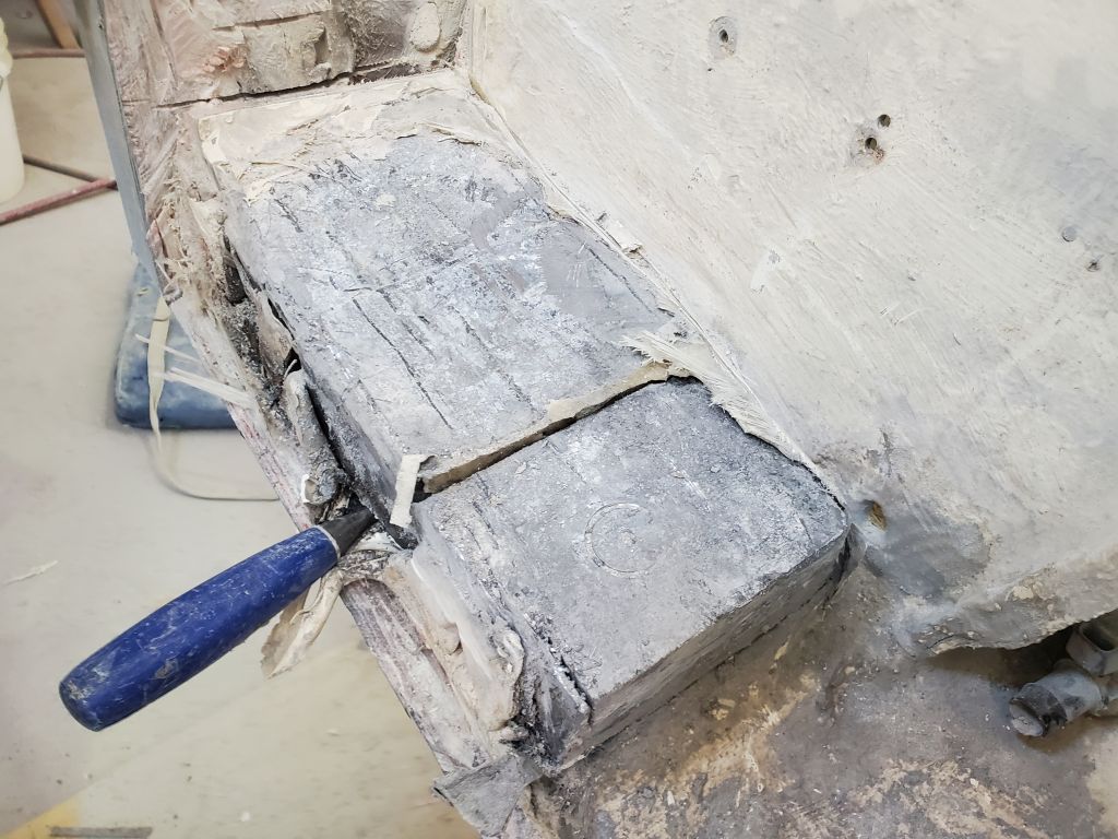
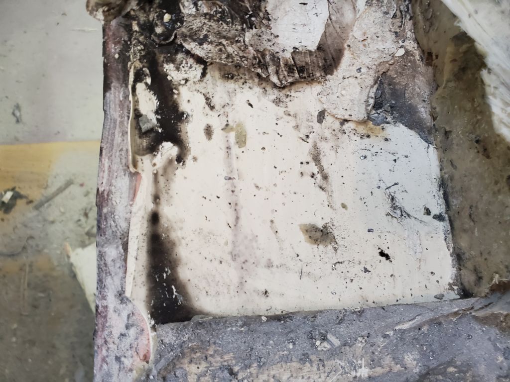
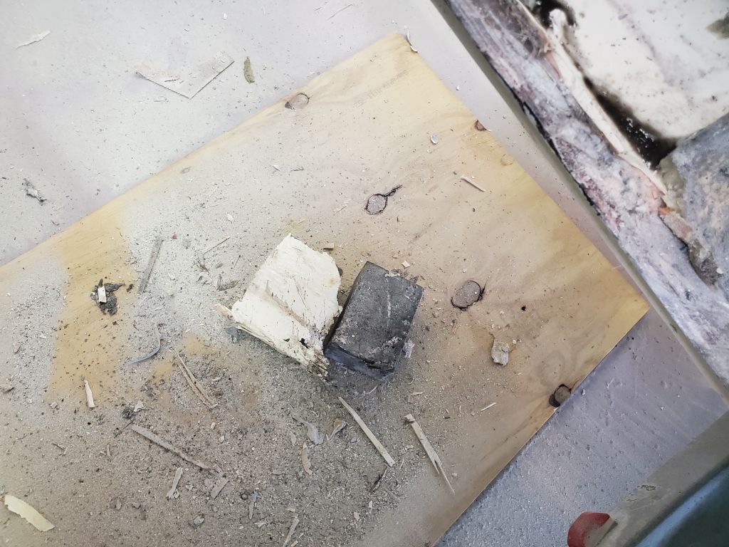
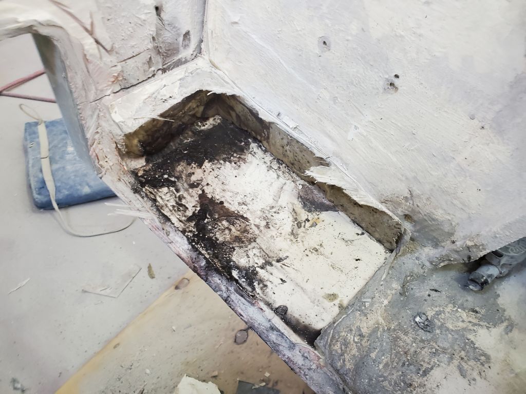
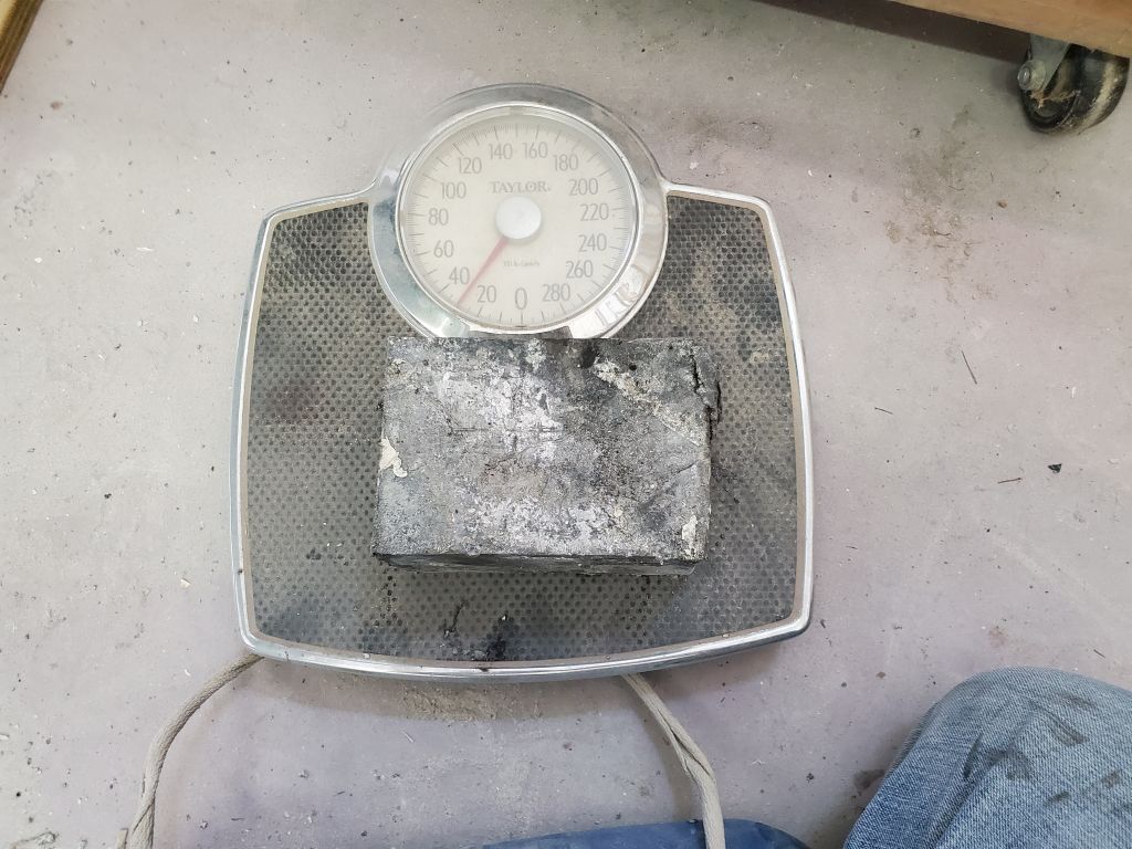
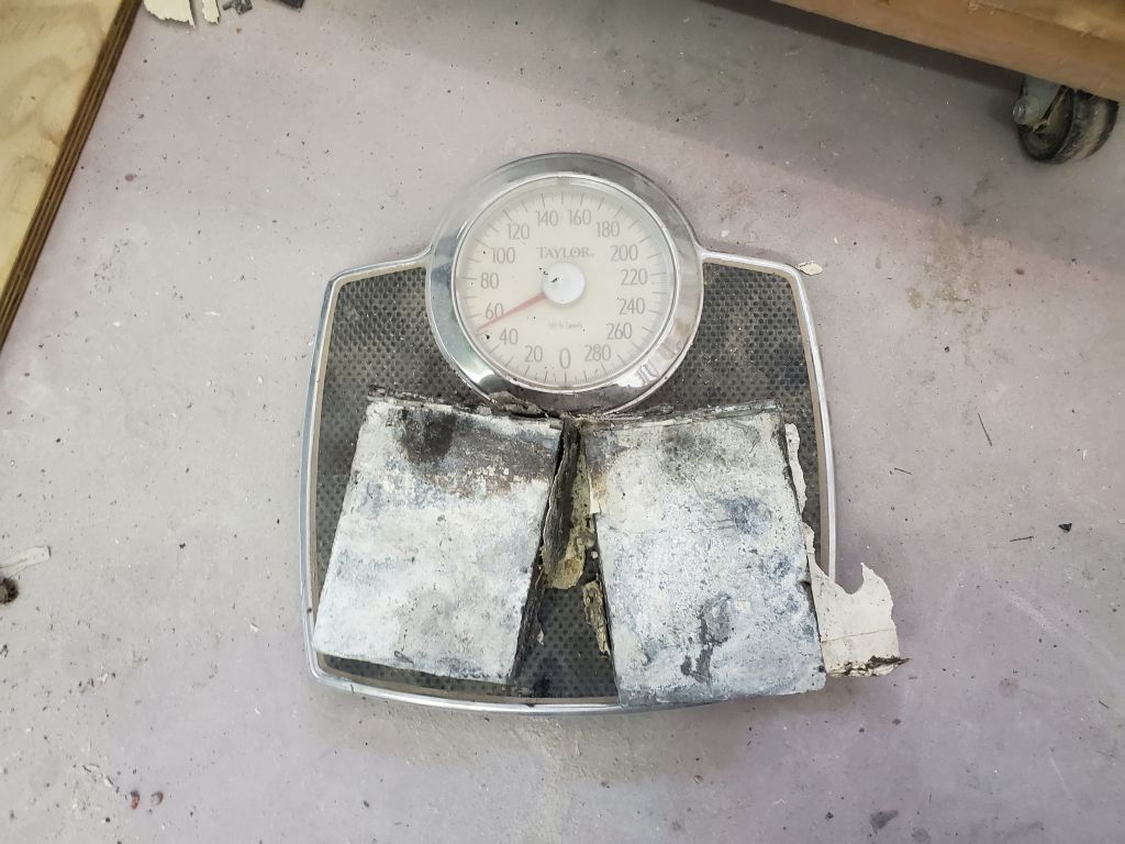
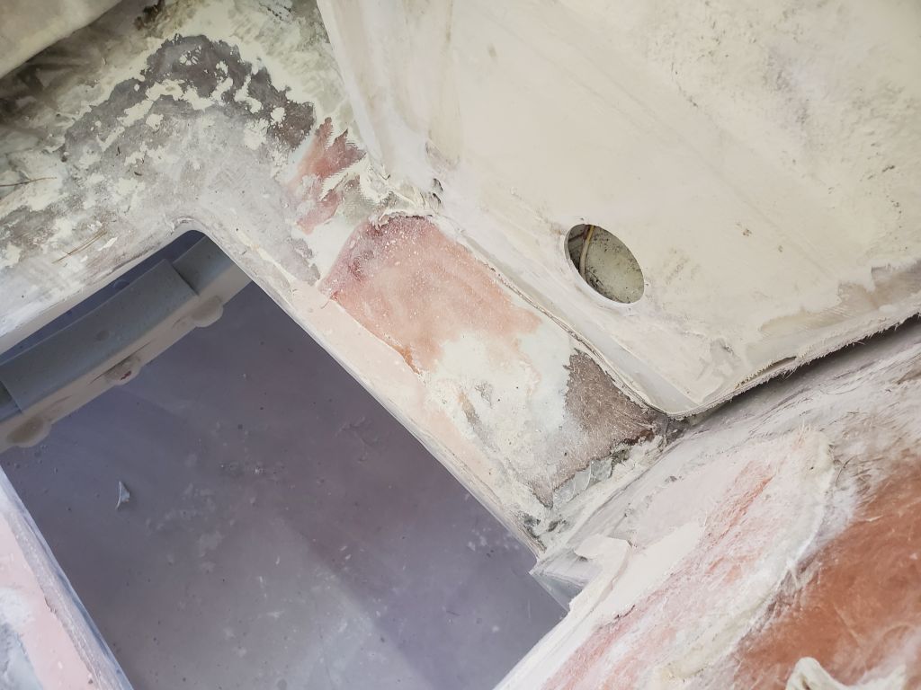
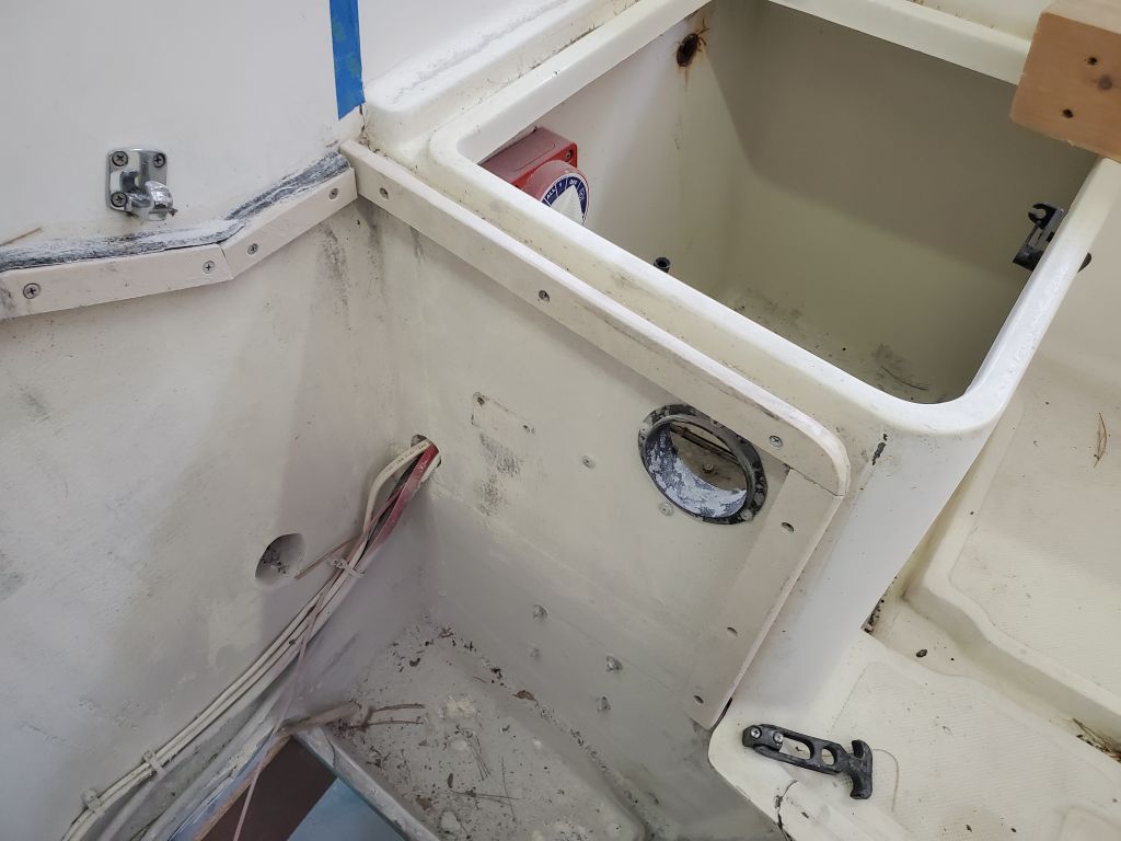
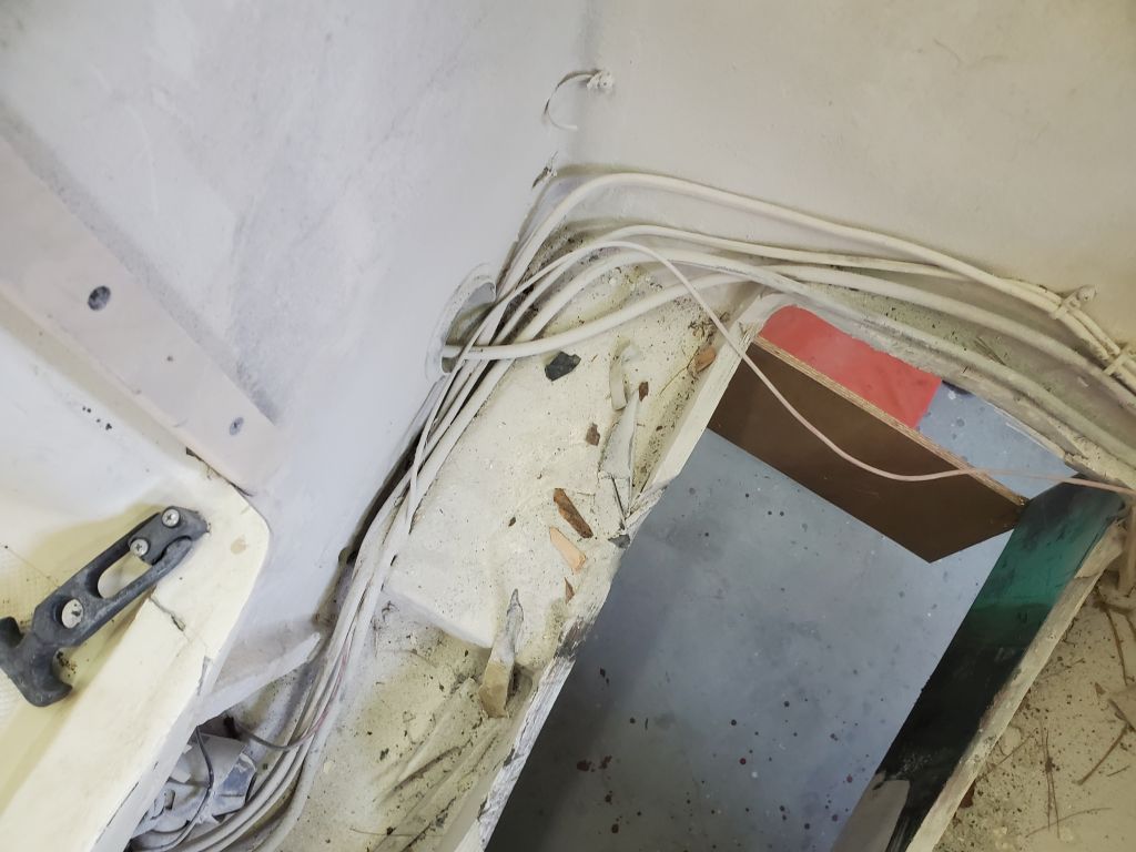
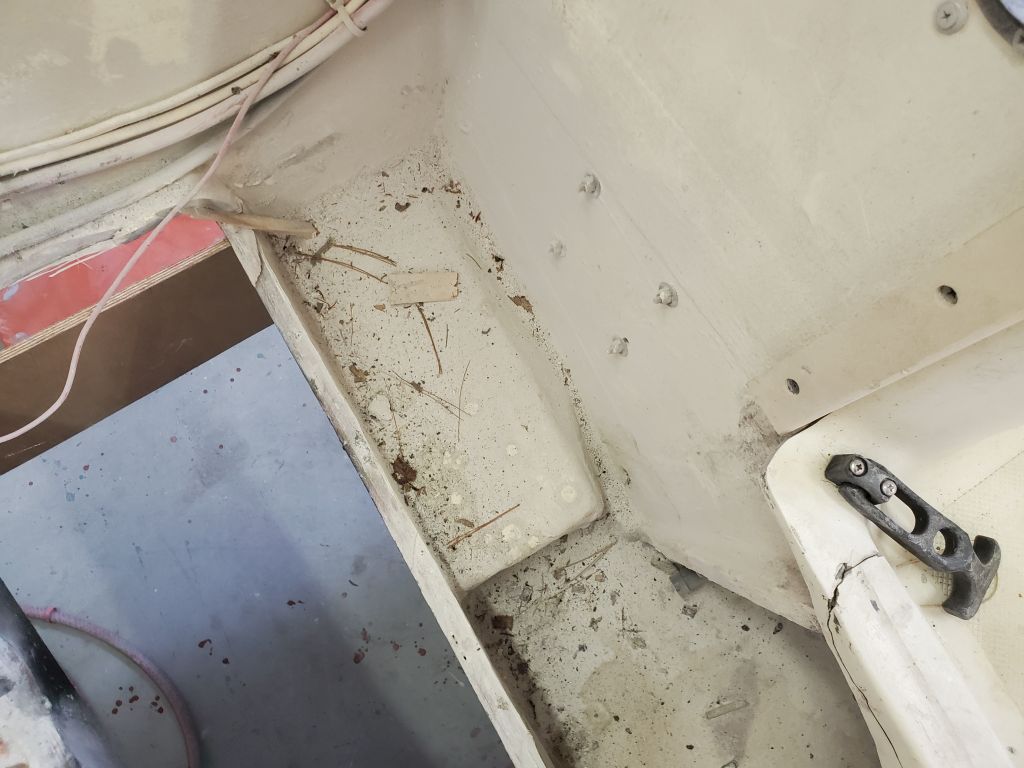
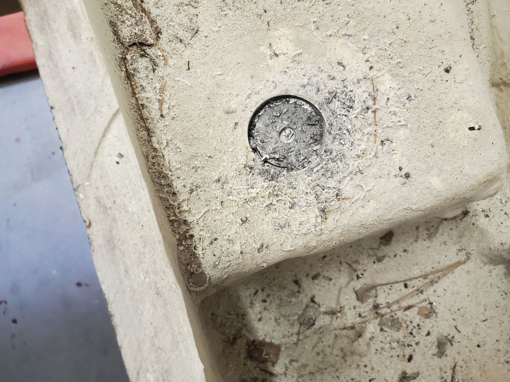
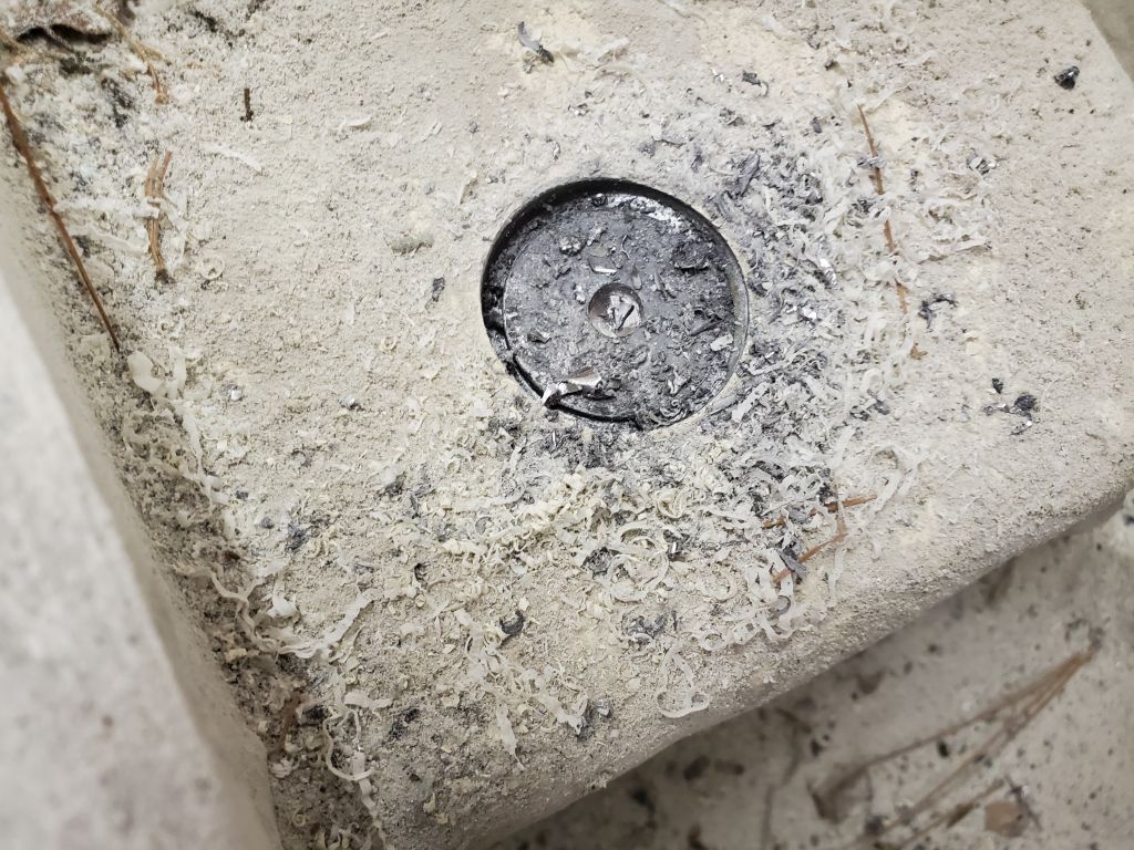
Throughout the engine removal, I’d wondered to myself about two raised areas, one on each side of the engine location right up against the transom.    I figured I’d want to remove these as I reconfigured the boat to traditional outboard power, but now I decided to drill into one and see what was inside, which would ready me for whatever might be required in its removal.  I was rather surprised to discover that these were trim ballast with lead encapsulated beneath the fiberglass–presumably something related to the engine configuration on this boat, unless the trim weight was something required due to a basic (if small) design error.  I figured I’d still probably remove these, as weight could always be added back if it turned out to be needed for trim later, and they were frankly in the way of the rebuilding work required in the bilge.  At least now I knew what I was up against.

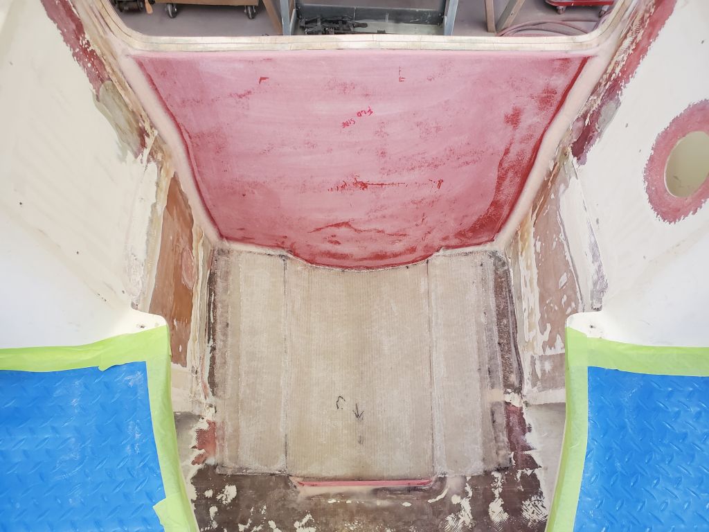
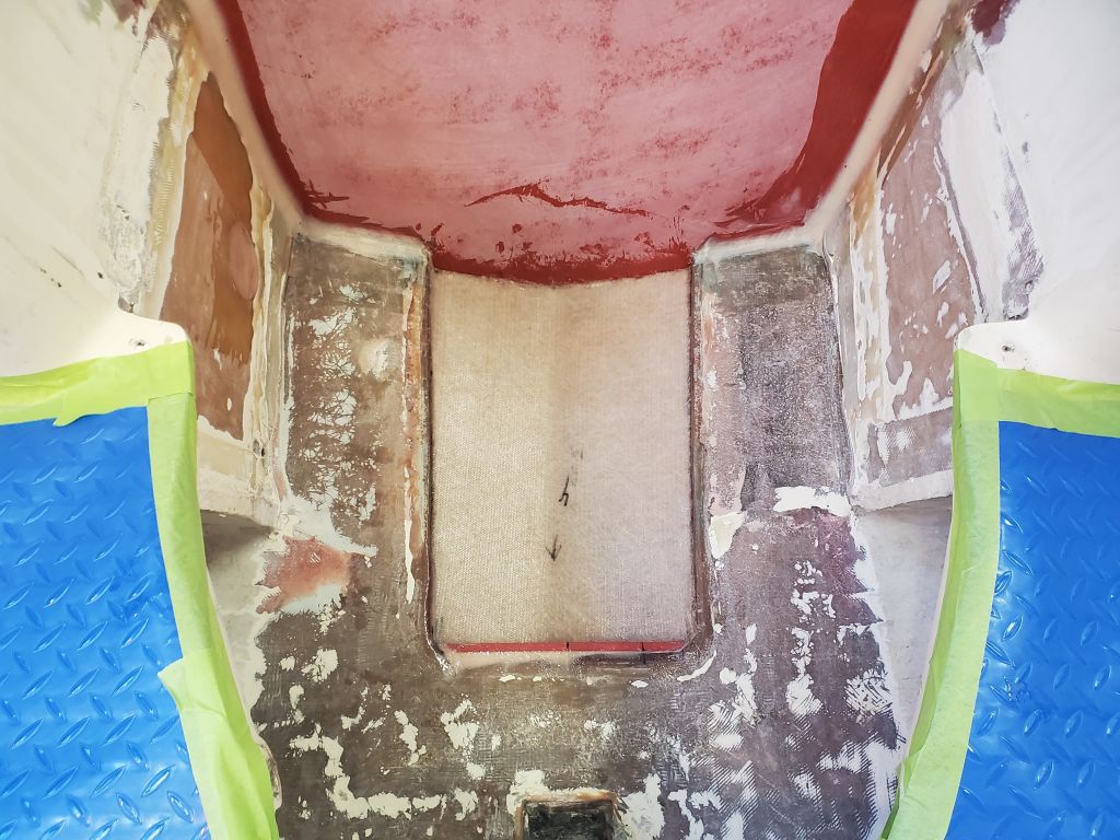
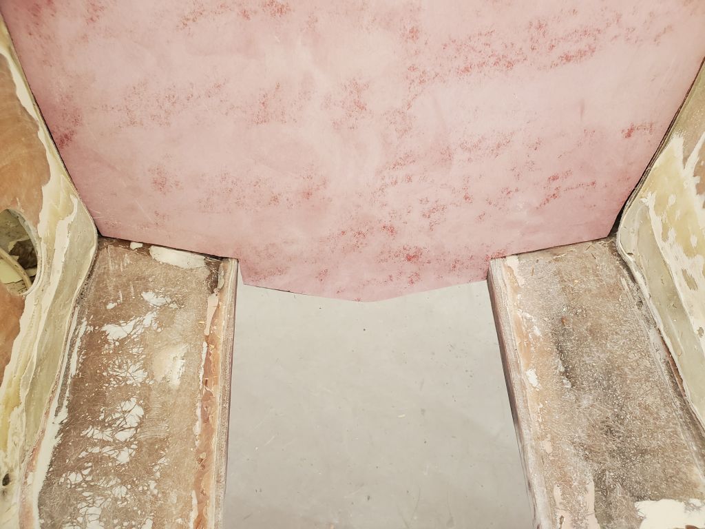
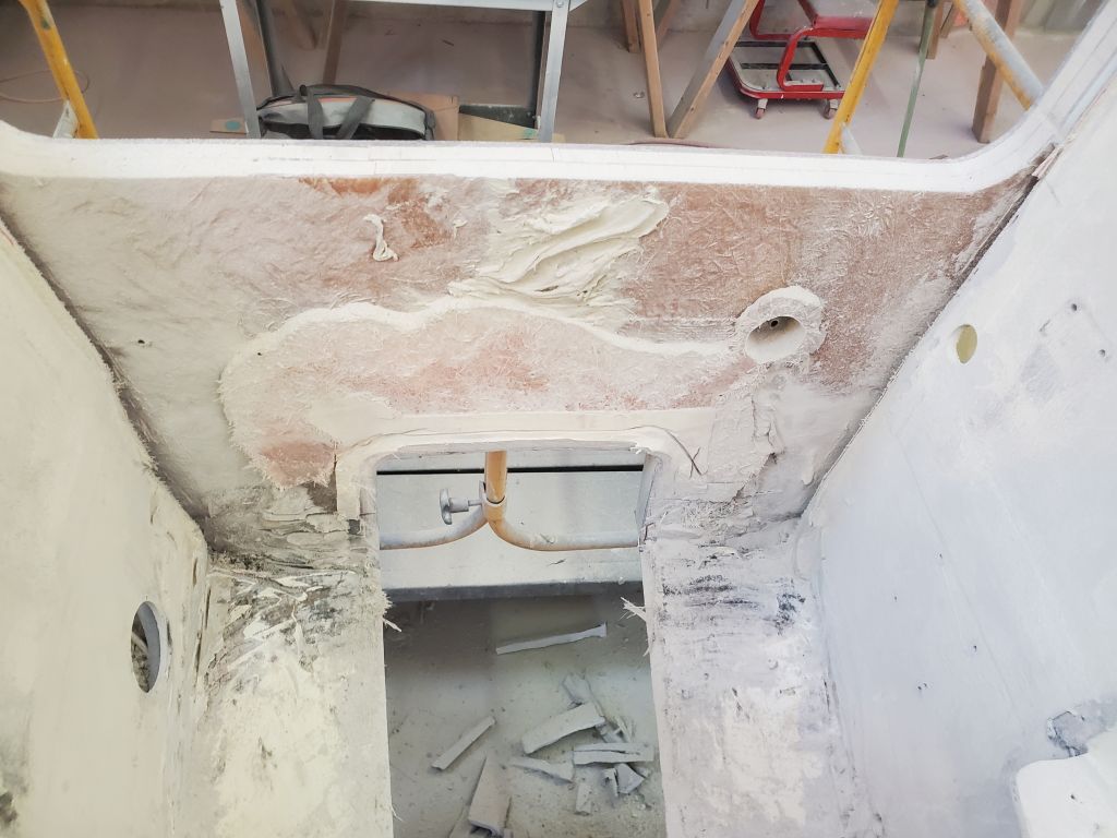
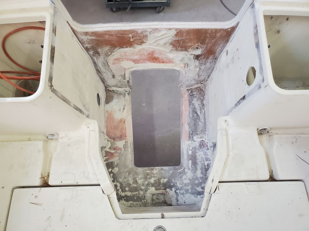
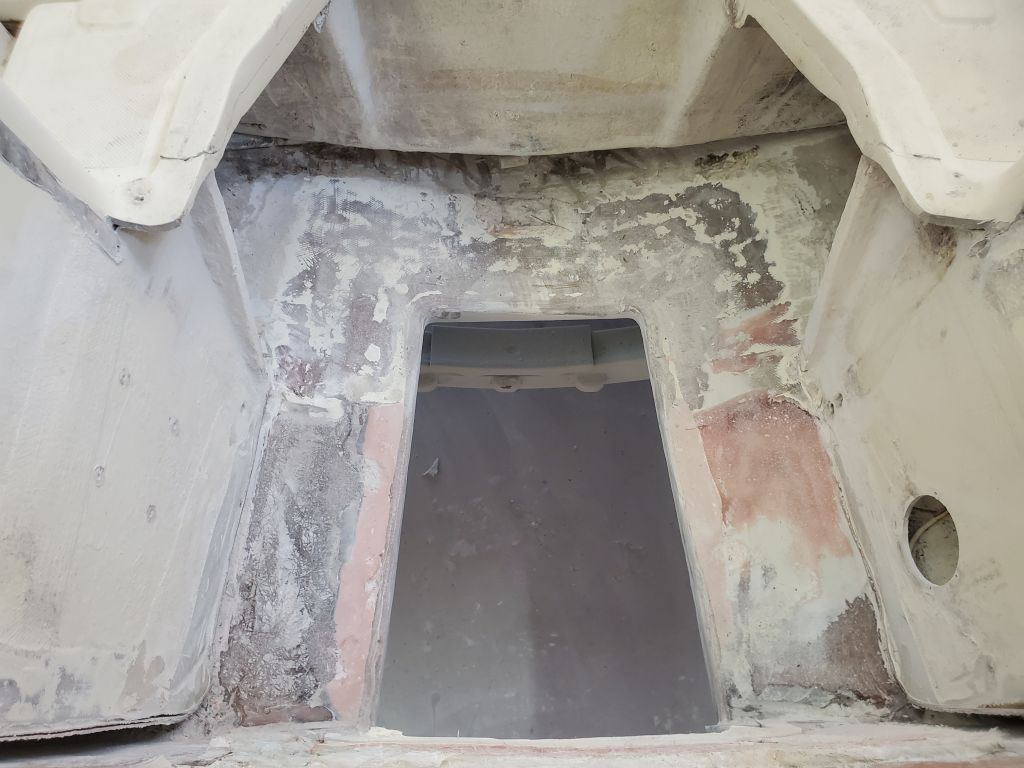
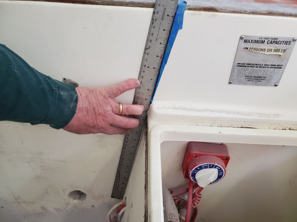
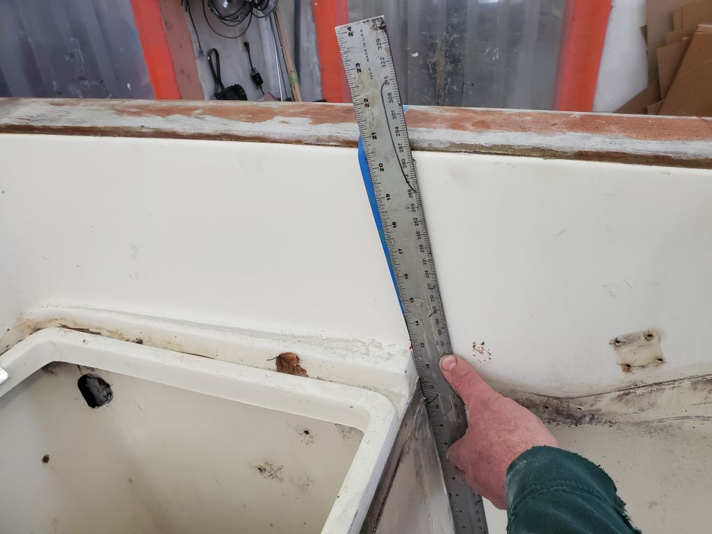
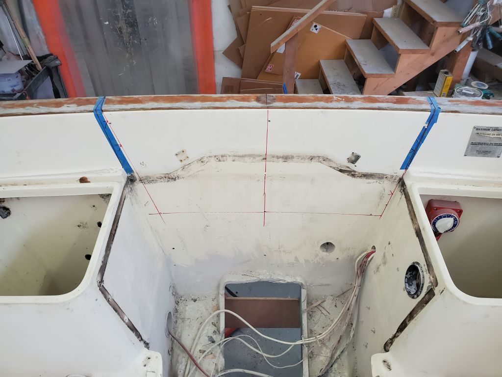
I began my rough interior layout by extending a straightedge up from the two molded seat arrangements on each side, but quickly determined that this wasn’t sufficiently accurate as a means of confirming the exterior layout.

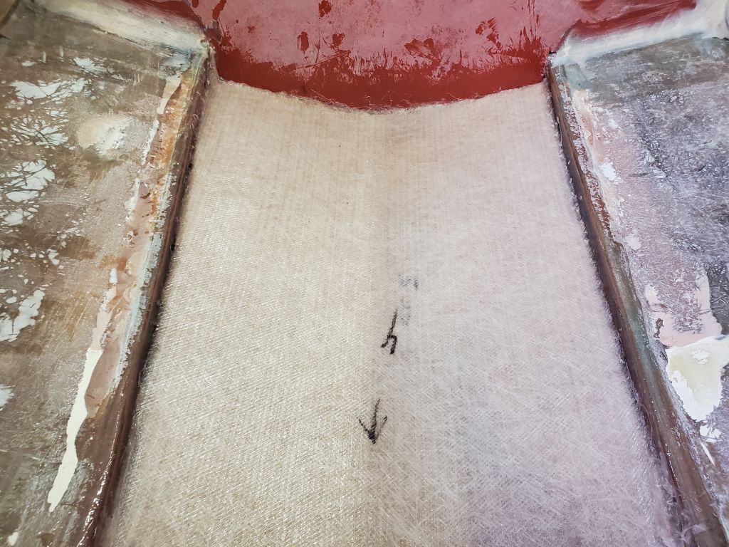
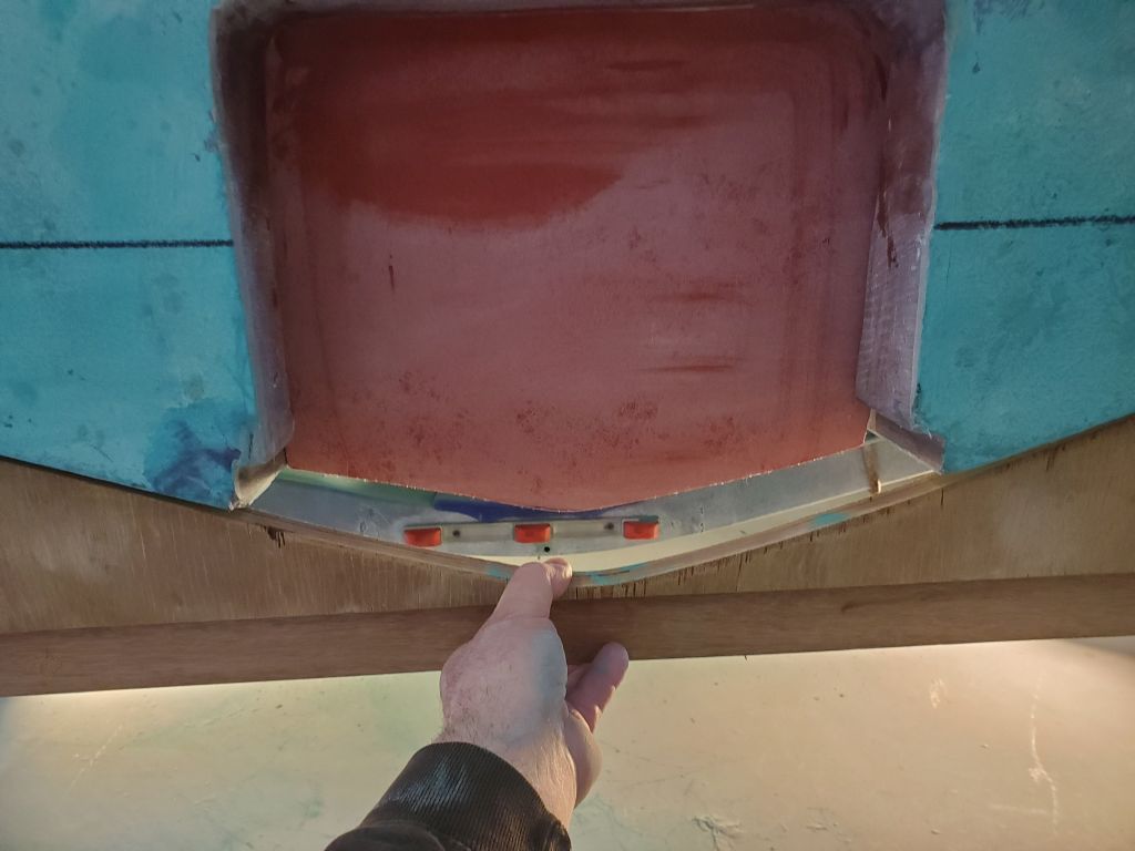
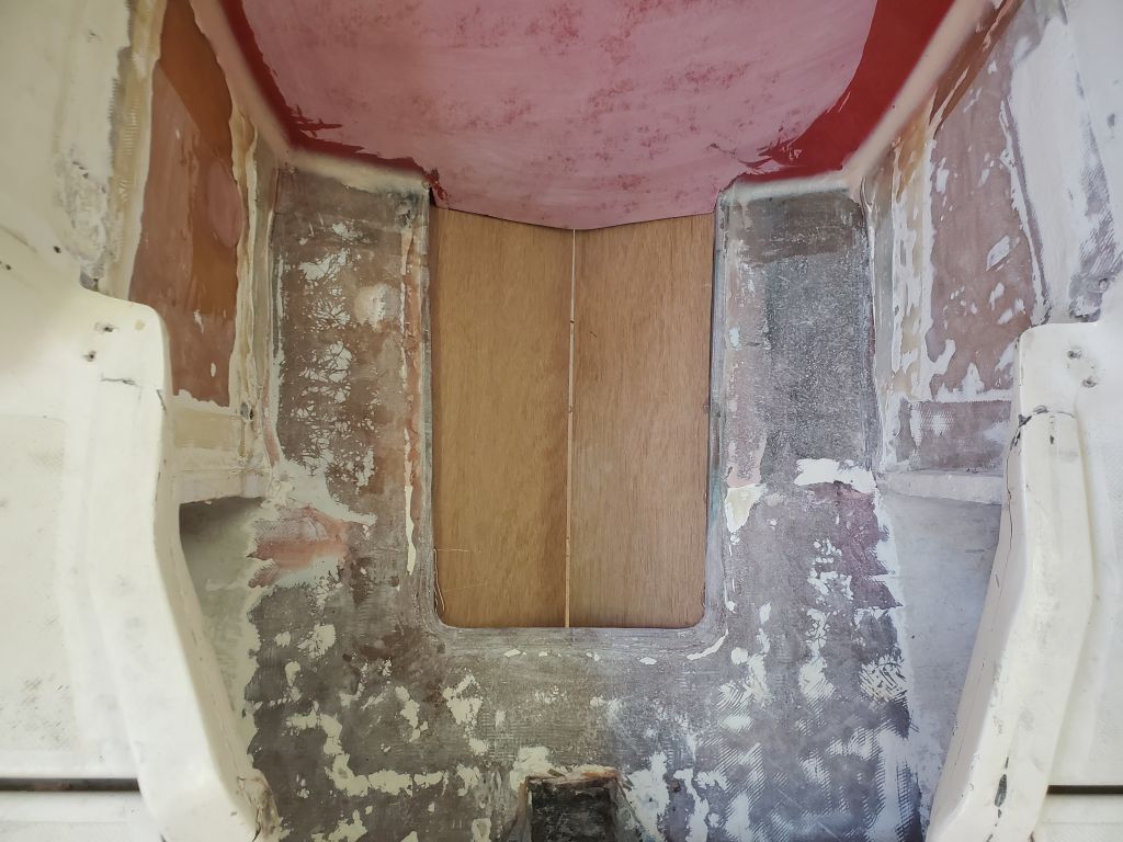
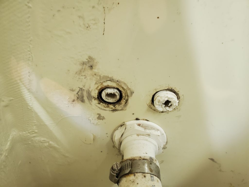
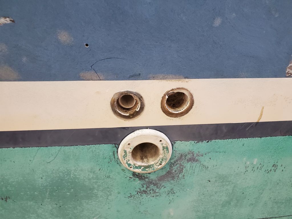
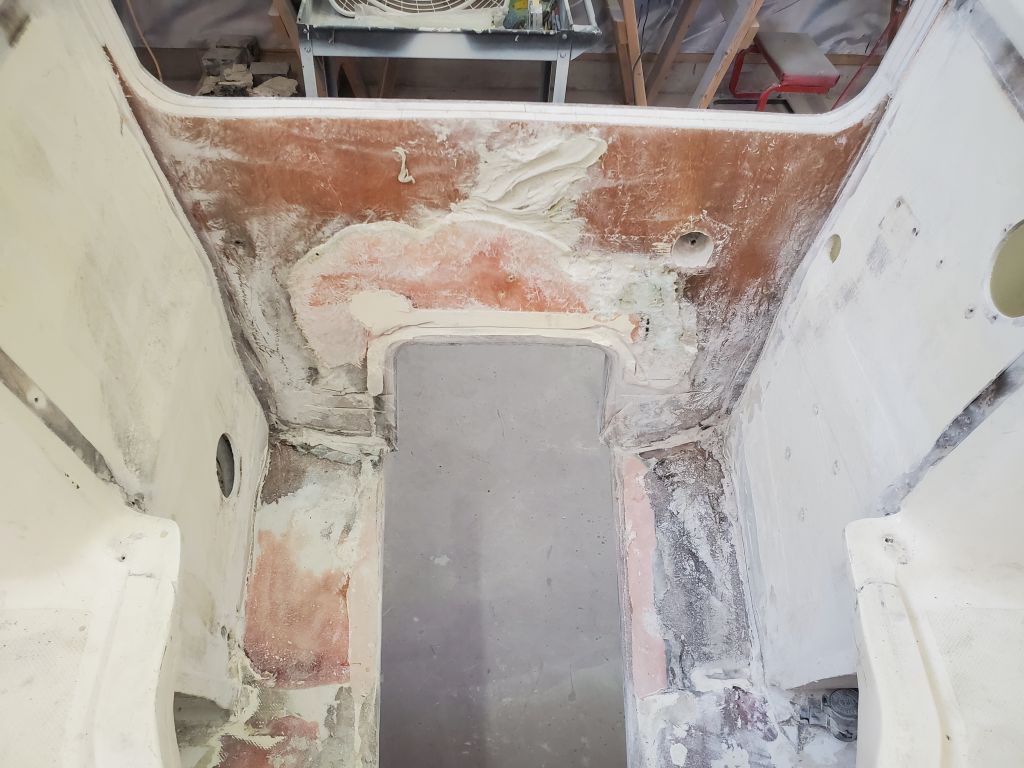
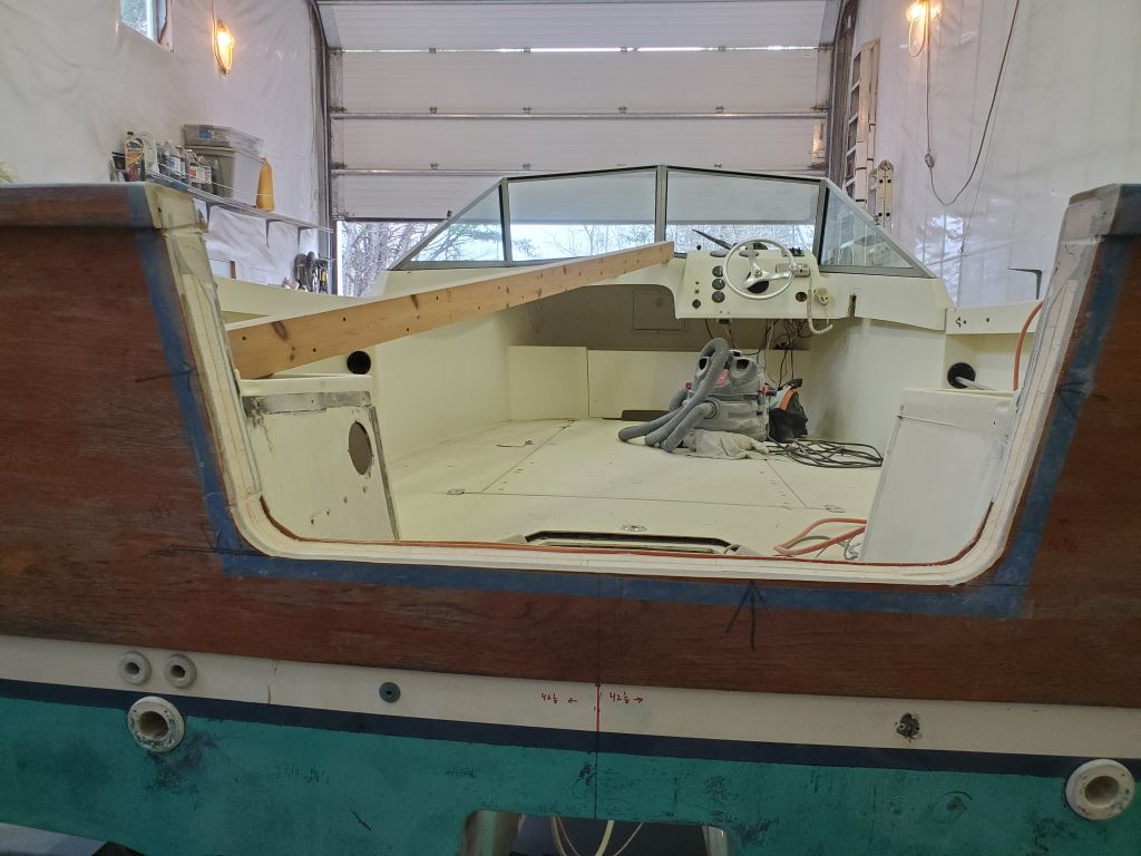
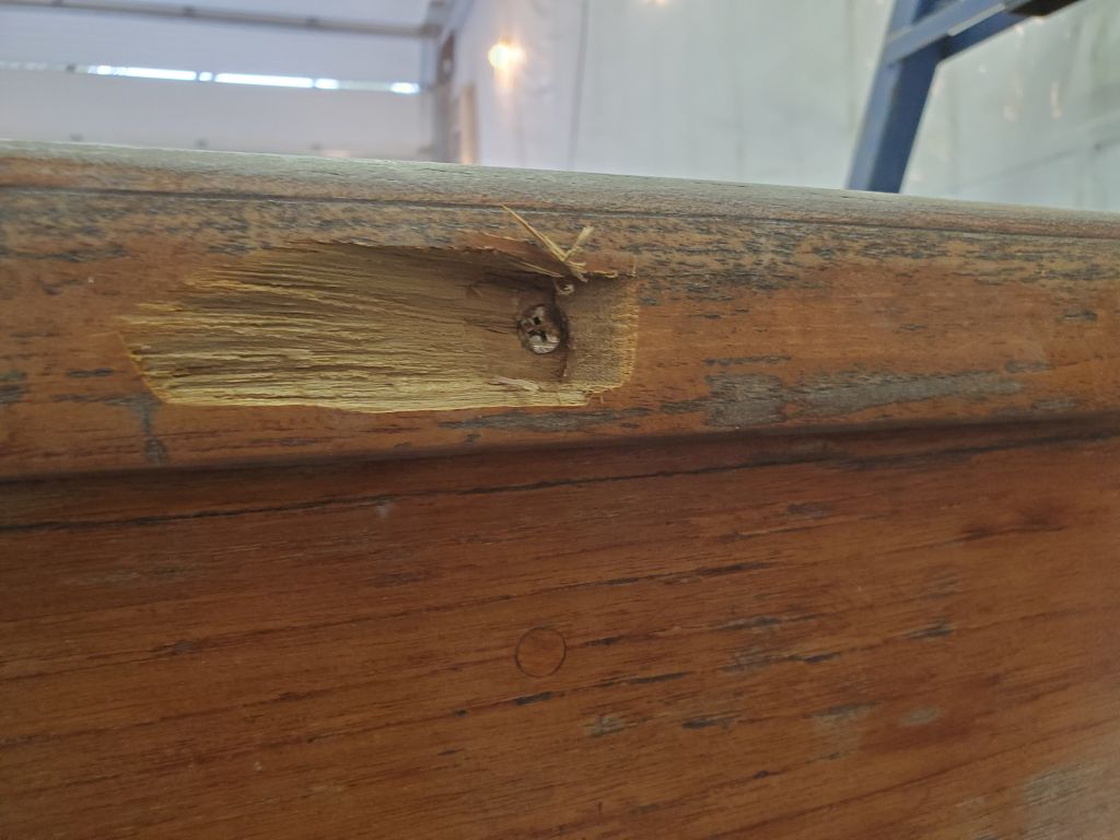
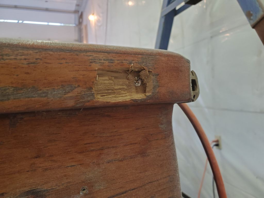
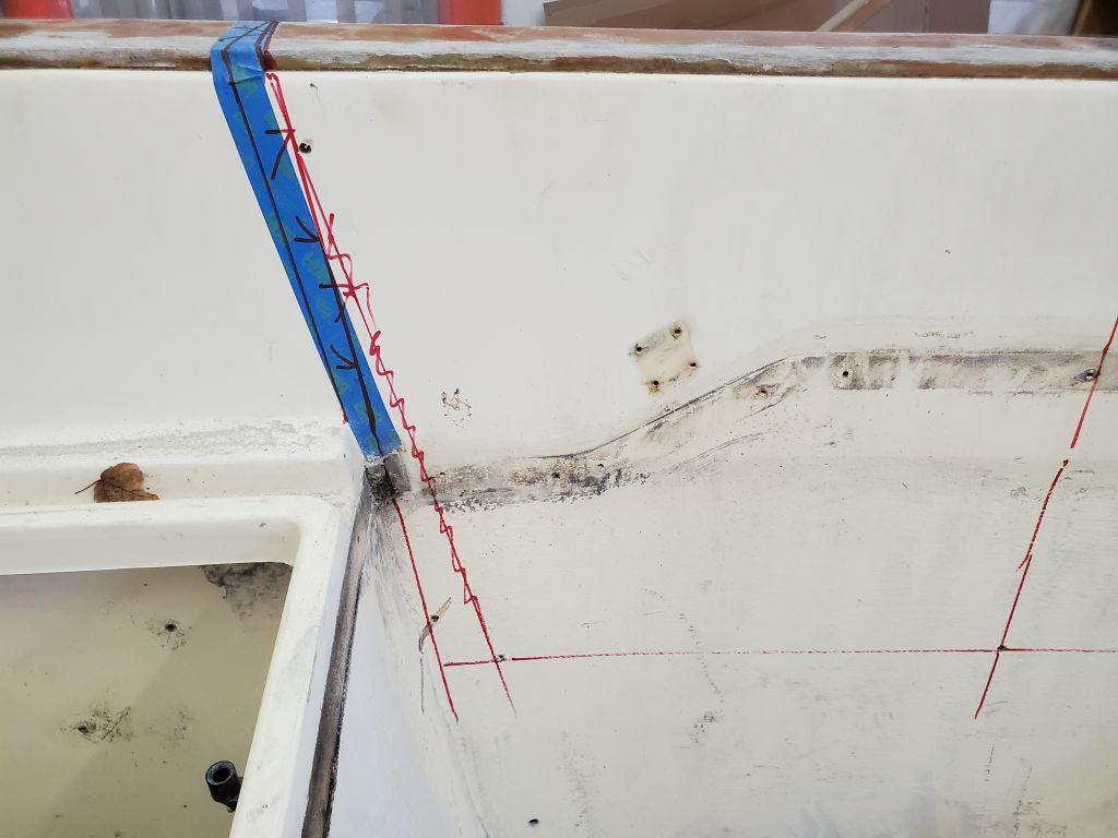
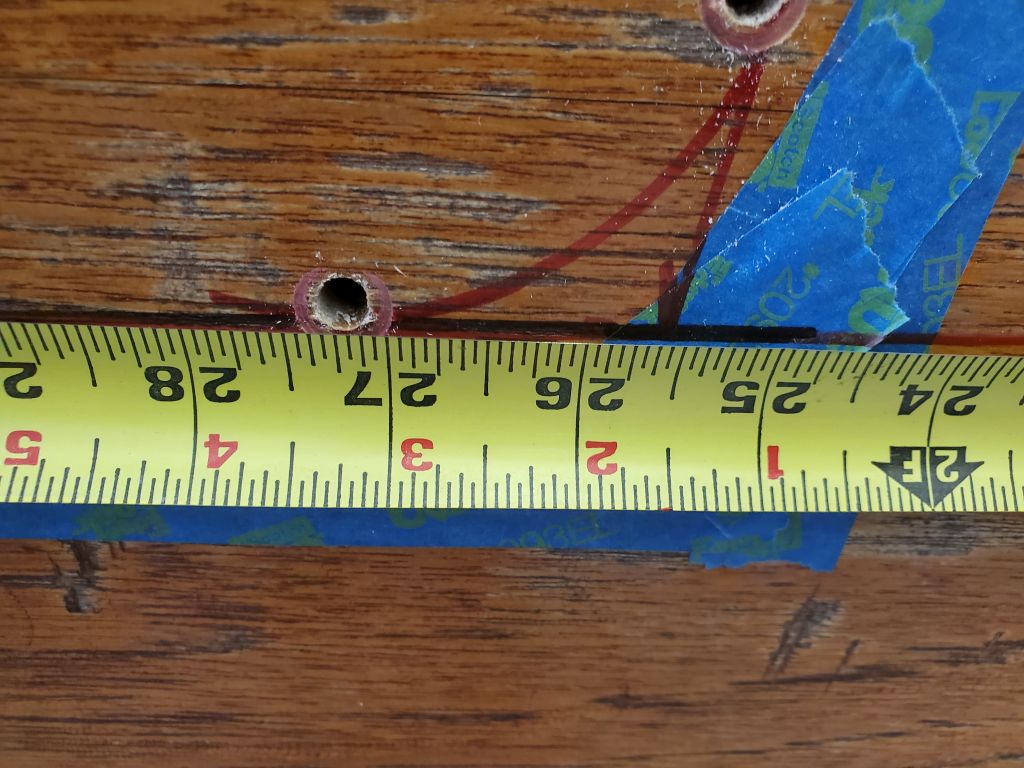
So from outside, I drilled 1/4″ holes through the transom at key points, including the centerline at the base; the beginning and end of each of the lower corner radii; and the top of the cutout just below the wooden rubrail.  These points gave me a series of references on the inside that I could use to draw out the approximate cutout, to ensure it seemed in the right place from the inside as well.  At first, my marks seemed to show an asymmetry on the starboard side, as the mark there was well inboard of the one to port, but I soon discovered that I’d missed one of the drilled holes and had connected one of the wrong points; the hole had come through, but a little flap of fiberglass had stayed affixed, hiding it.  When I corrected the layout to the proper position, it made a lot more sense.

As a final confirmation of the position and layout on the transom, I made a final pair of measurements from each side, at the height of the bottom of the cutout, to the corners on each side; these proved to be symmetrical, clearing the way for me to cut out the piece in the center.

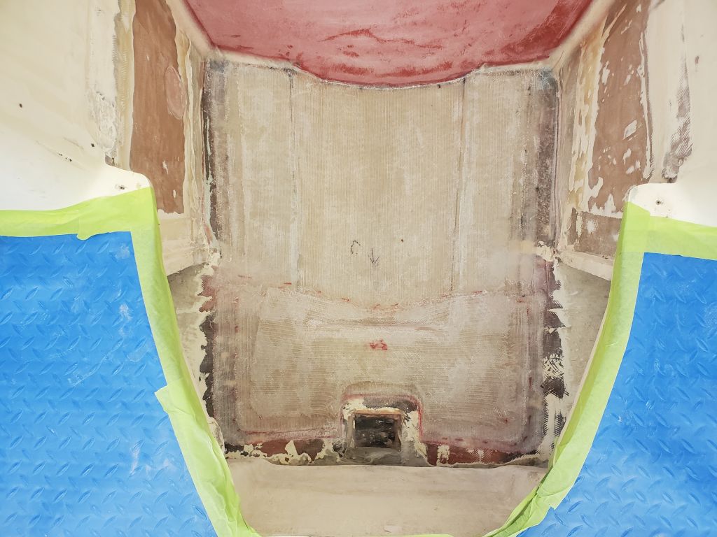
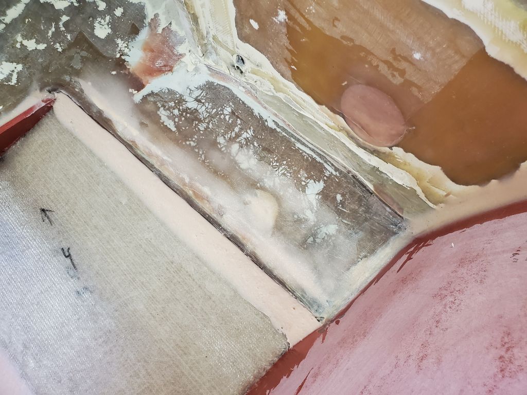
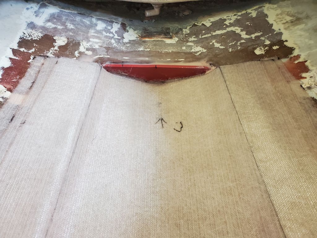
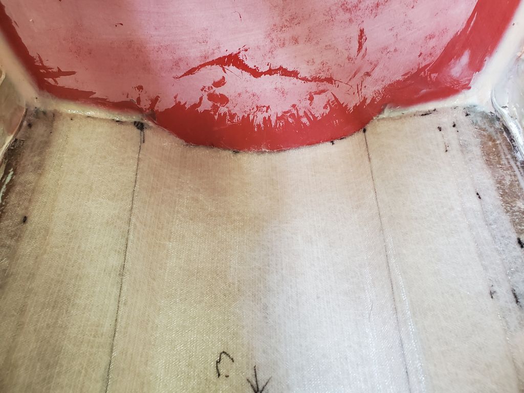
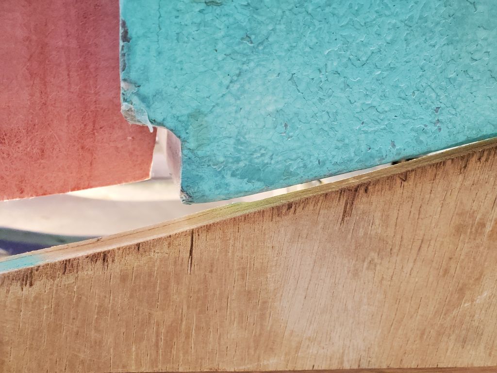
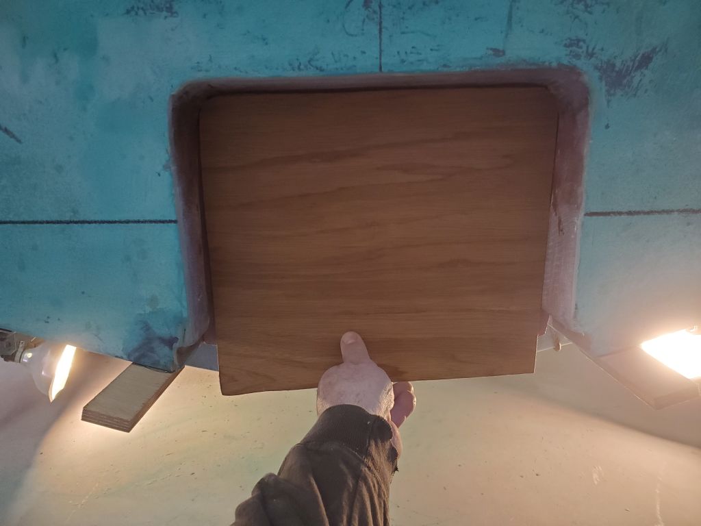
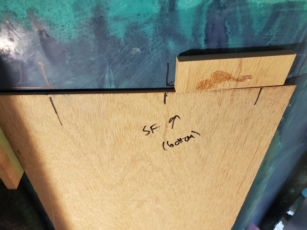
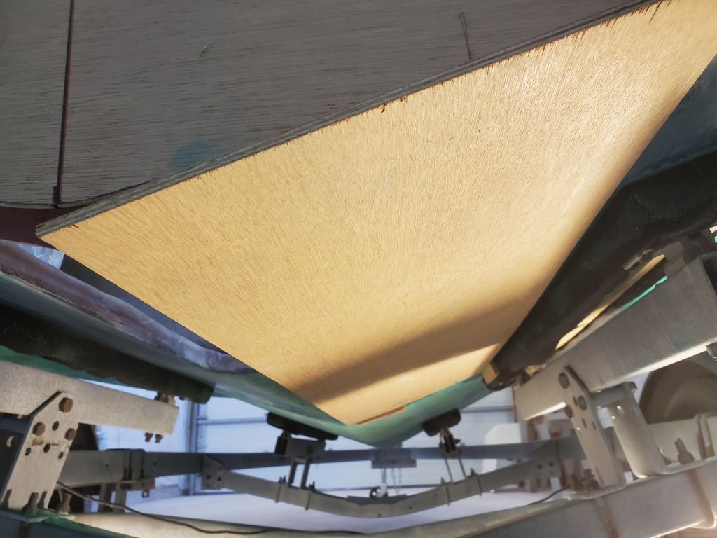
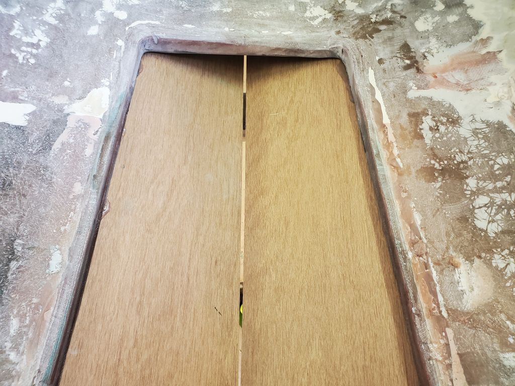
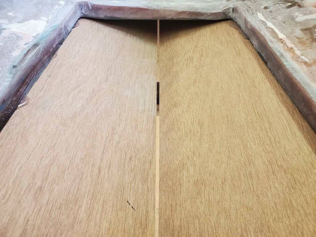
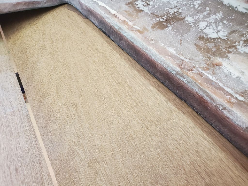
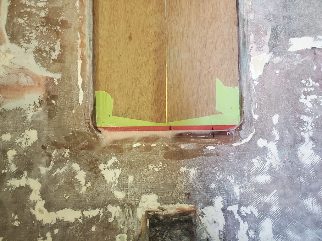
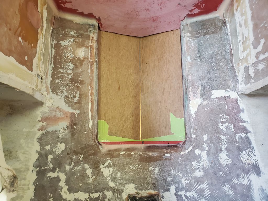
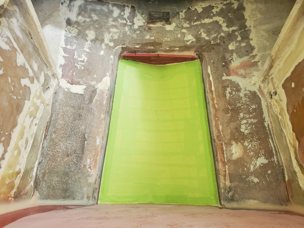
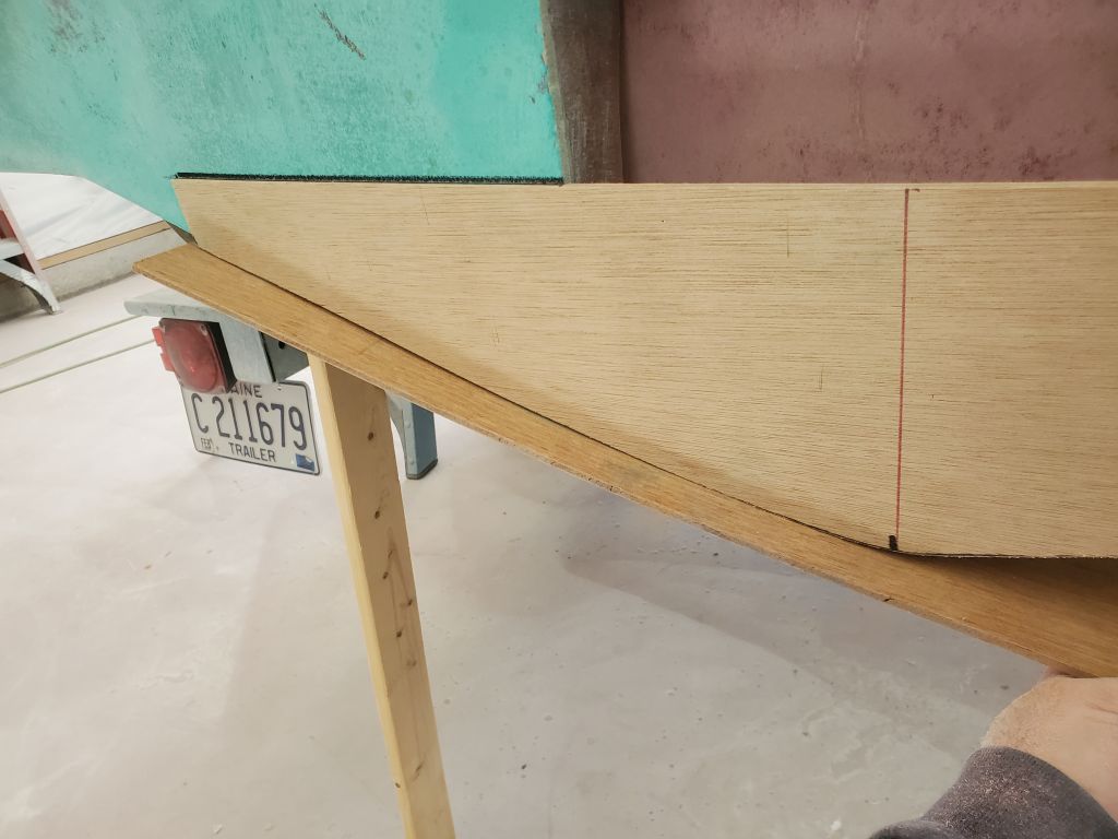
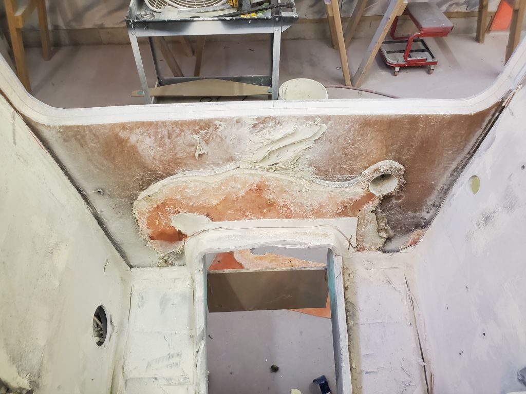
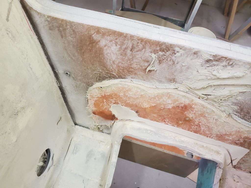
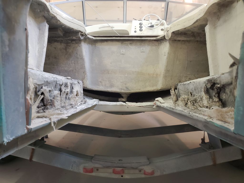
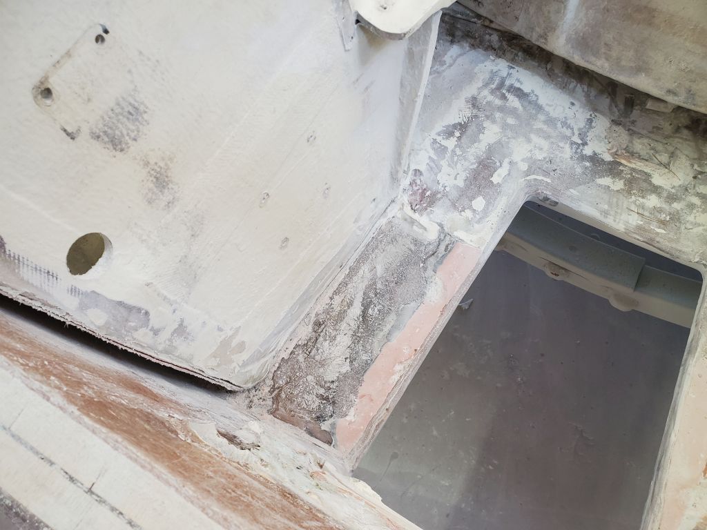
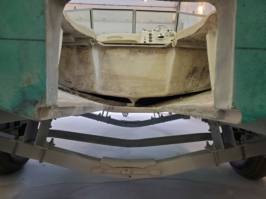
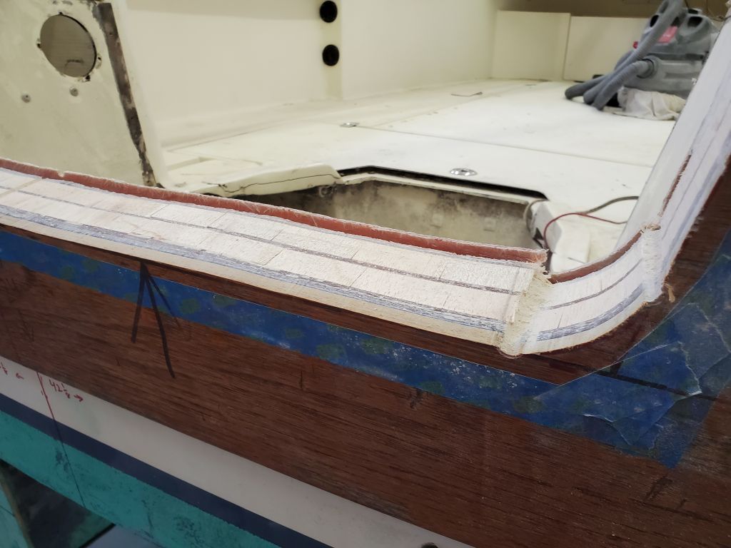
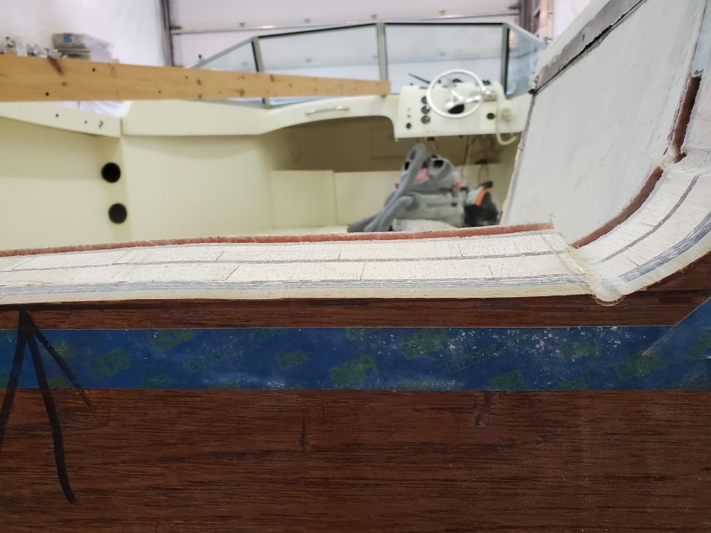
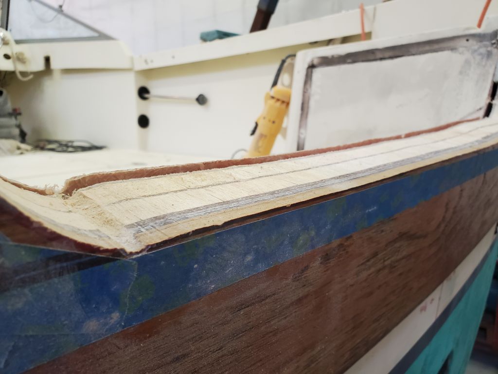
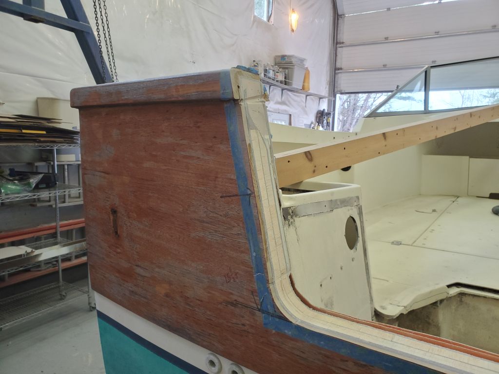
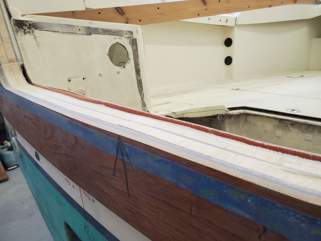
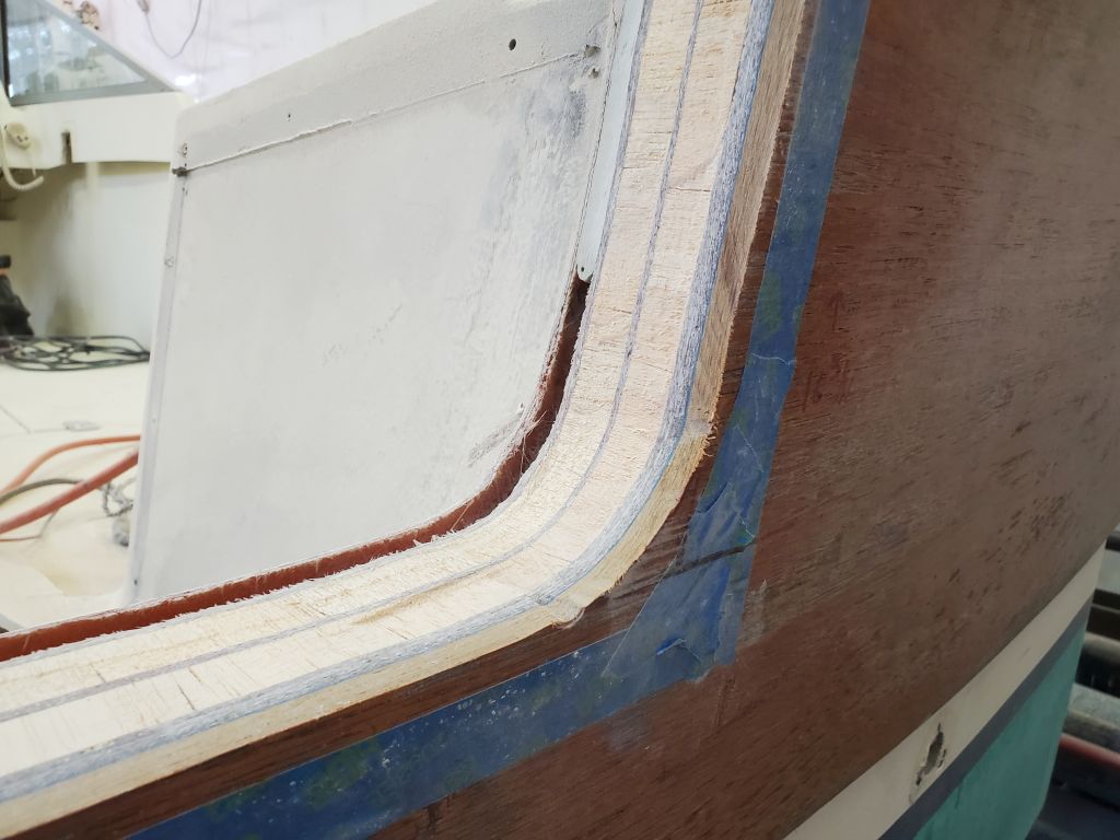
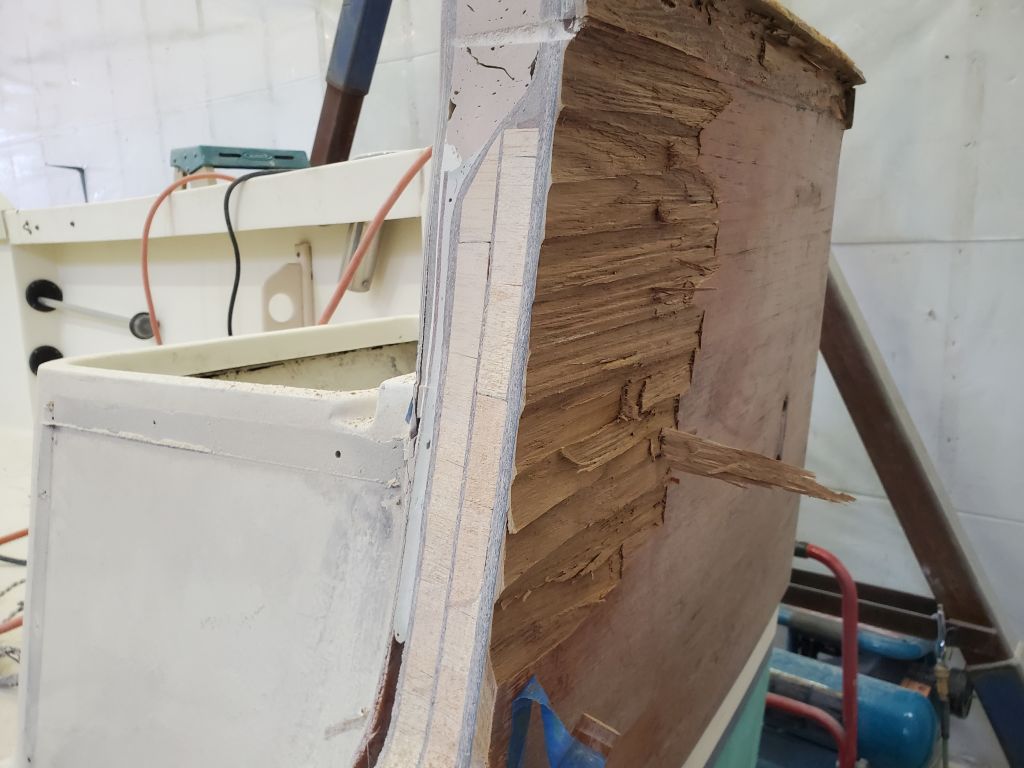
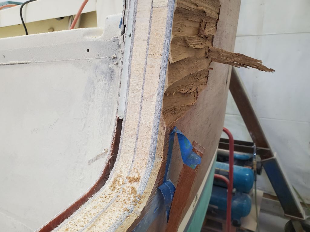
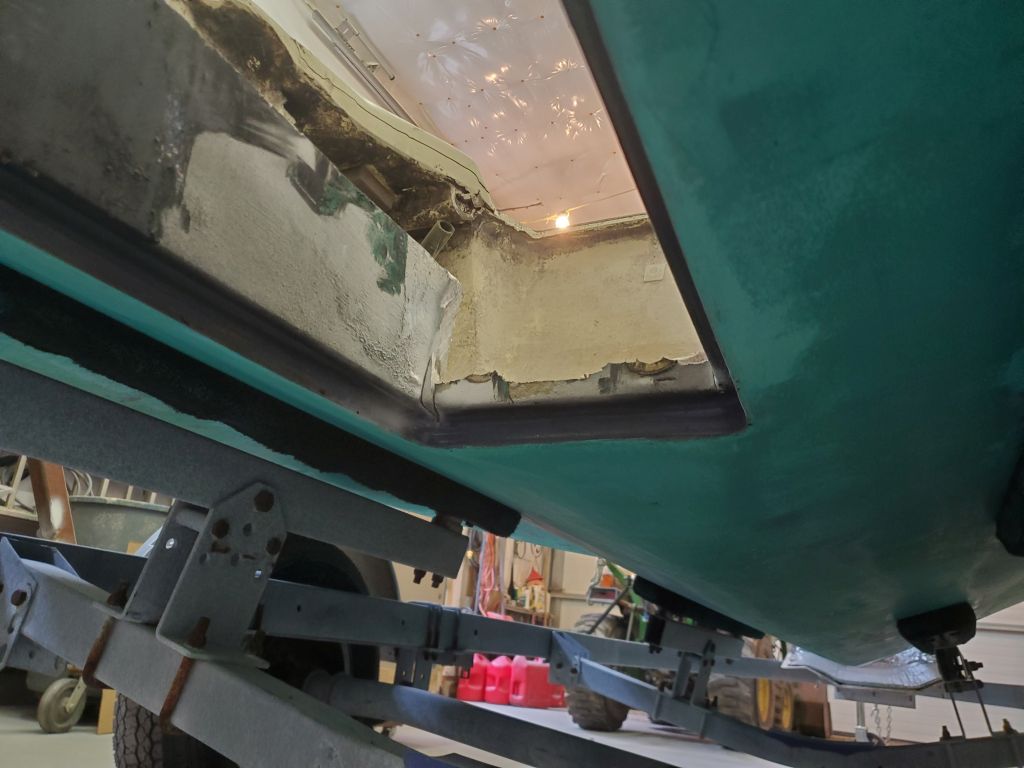
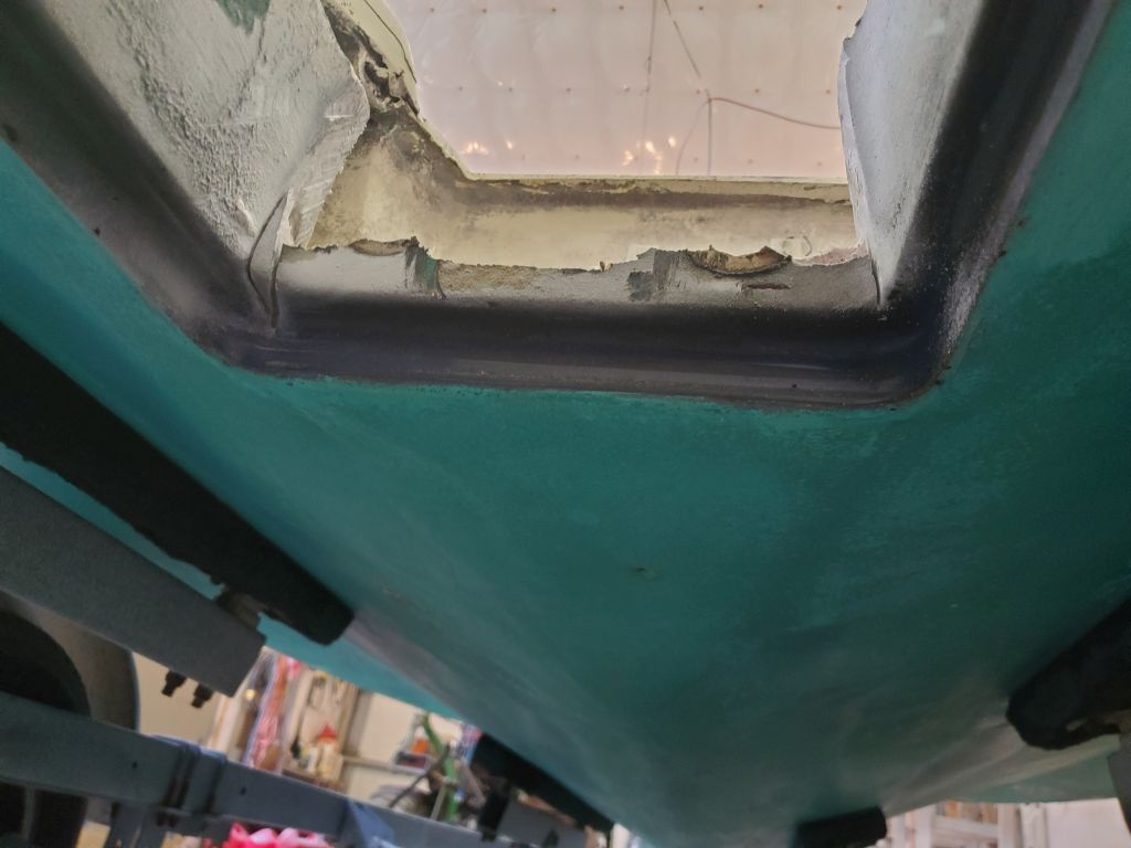
With a long blade in my jigsaw, I cut through the transom to remove the piece.  I cut just inside (waste side) of the red lines, as accurately as possible but there’d be ample opportunity for correcting minor inaccuracies later.  The transom was thick enough that I needed to use the longest blades in my current arsenal, which unfortunately weren’t the carbide ones I might have preferred for the job, but although I needed three of them for the job, they preformed admirably, and soon the heavy piece of the transom was out, revealing for the first time the inner construction.

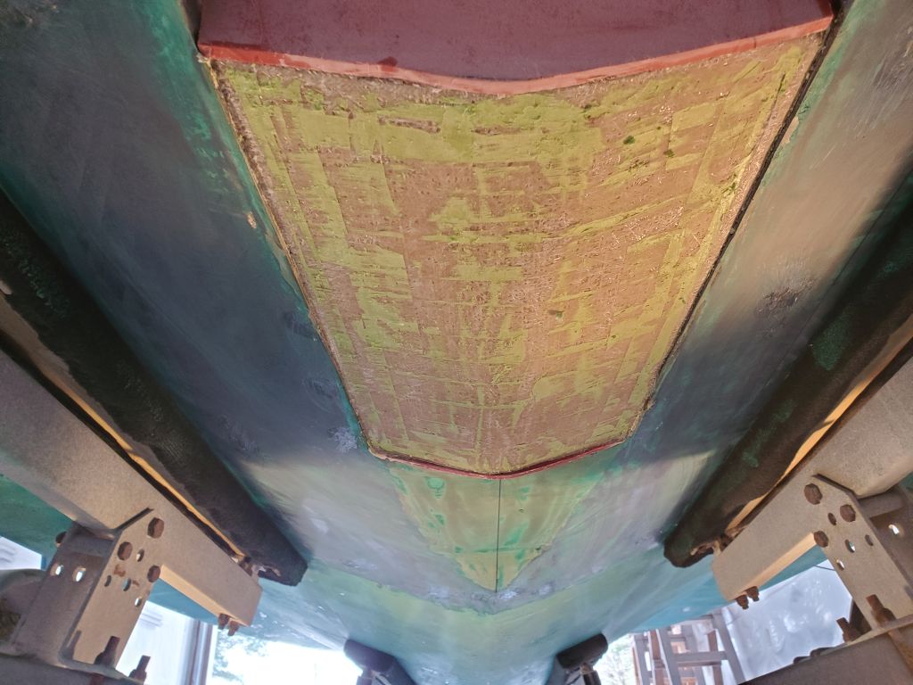
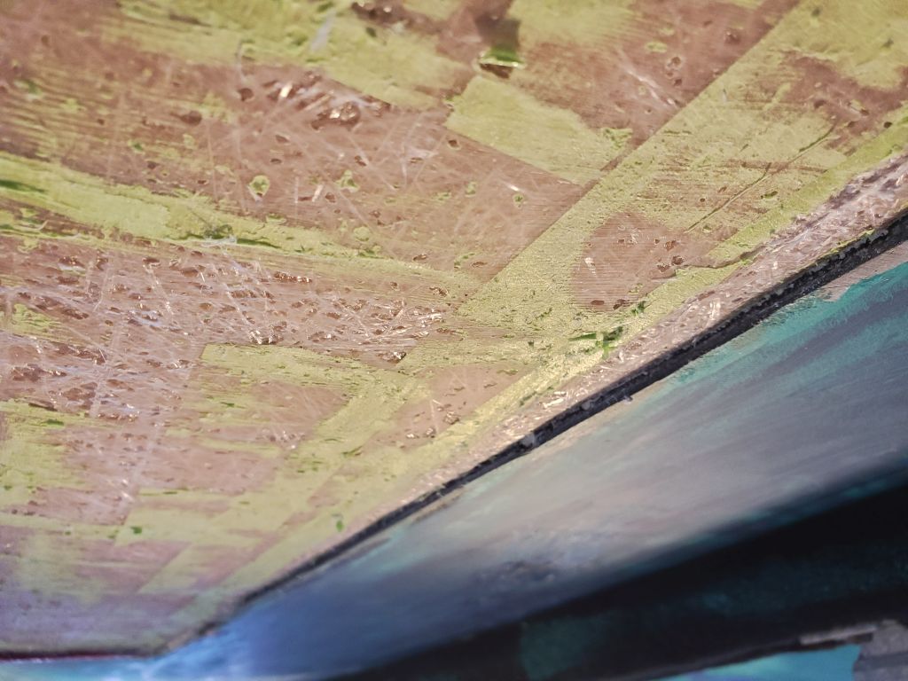
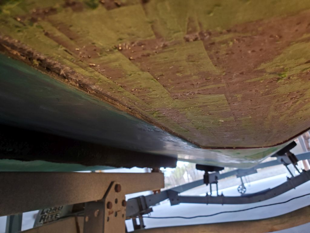
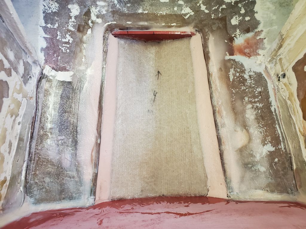
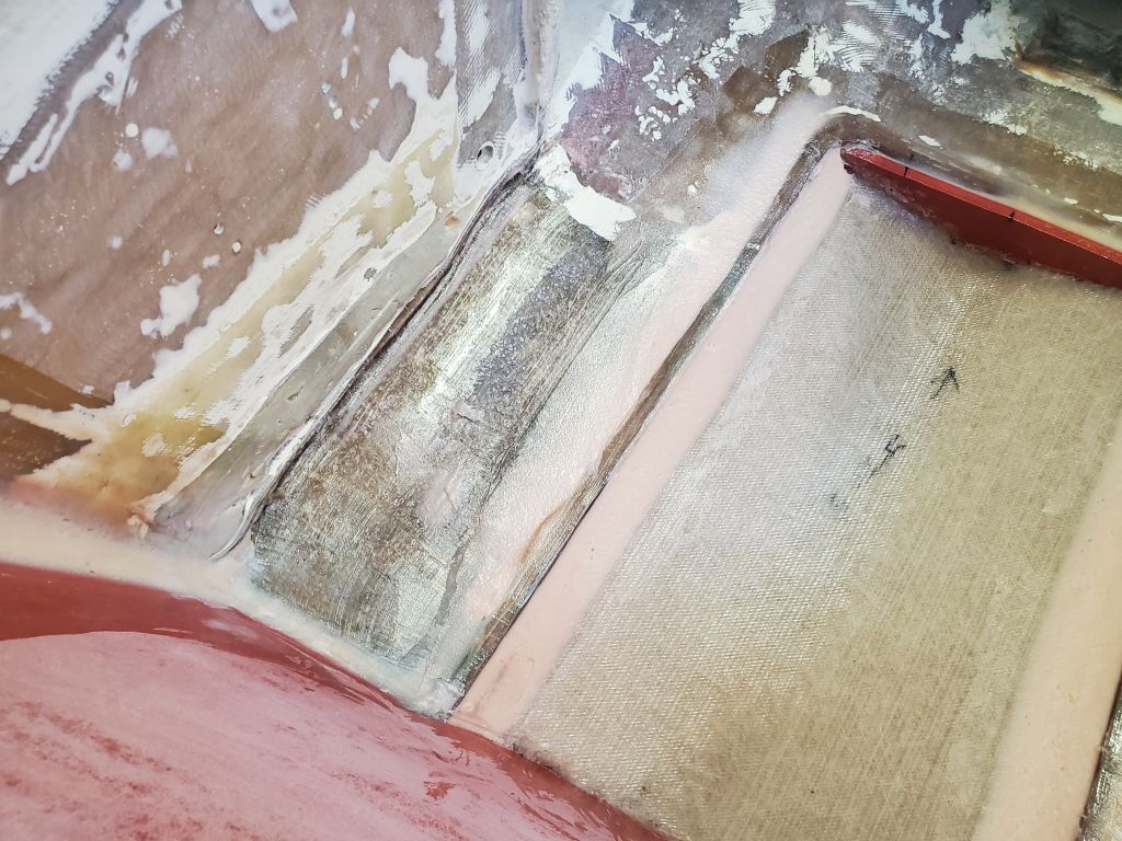
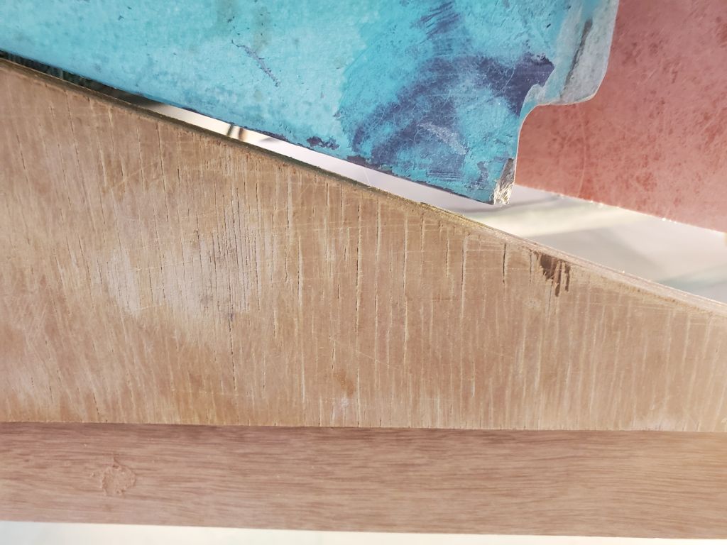
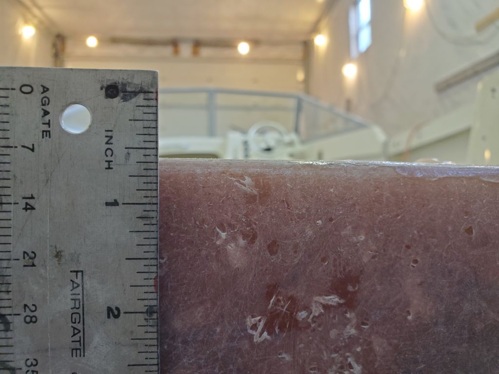
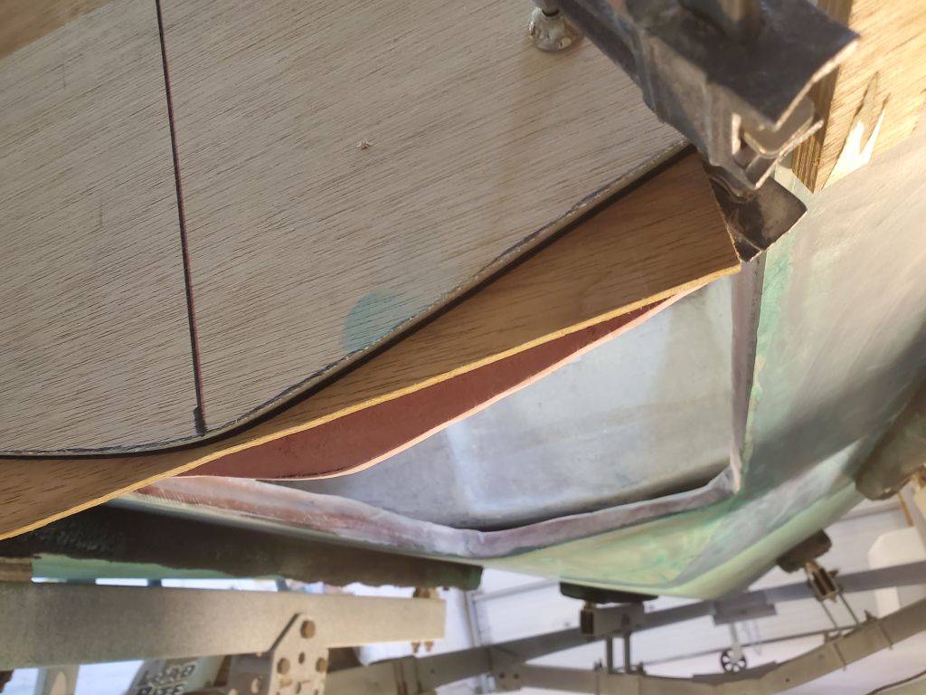
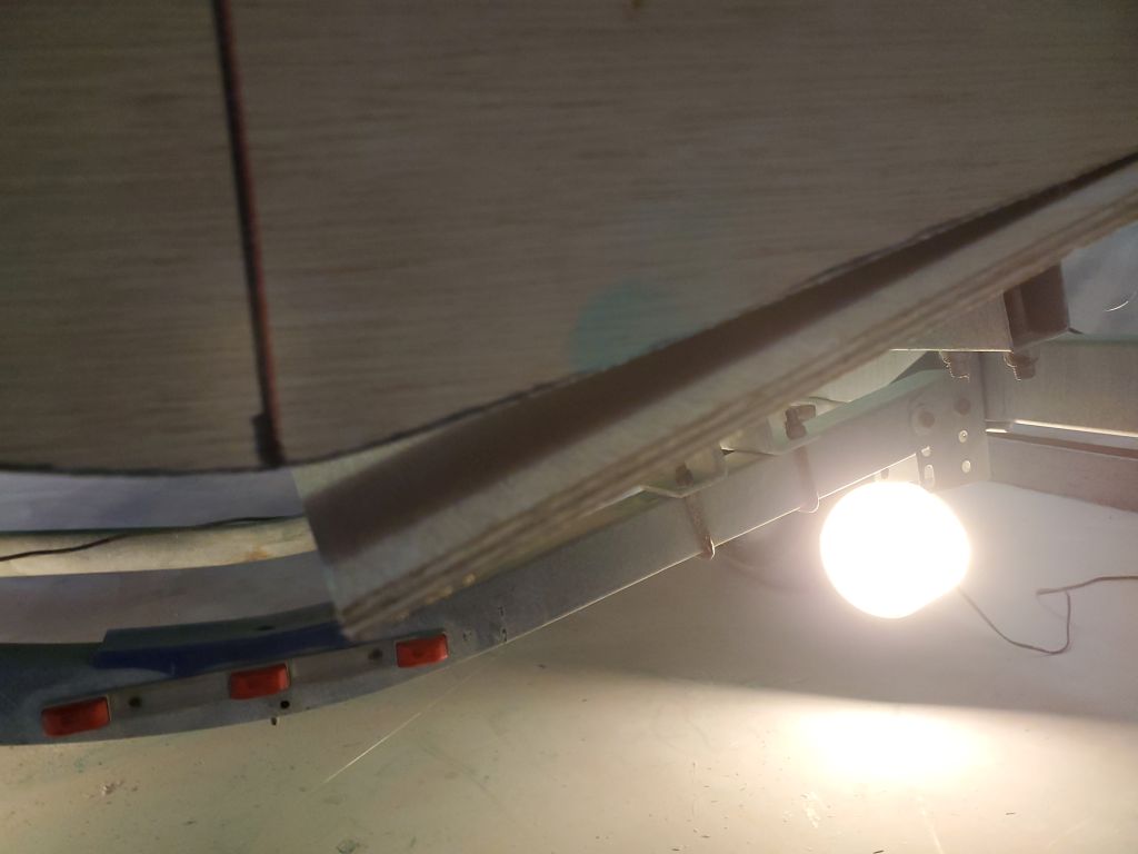
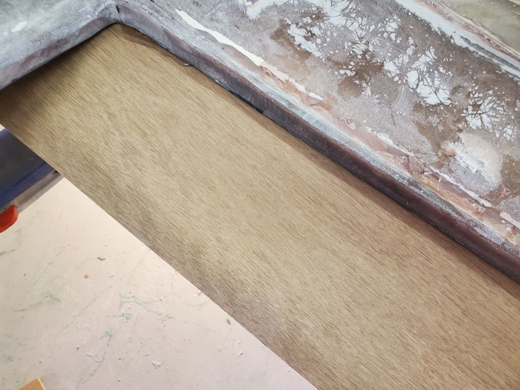
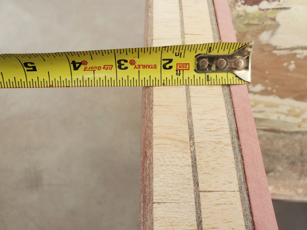
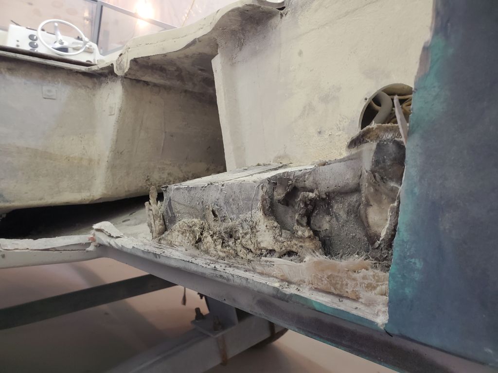
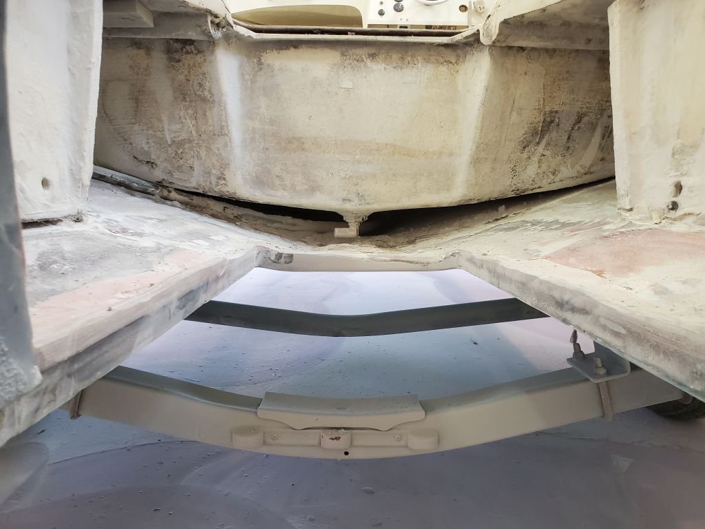
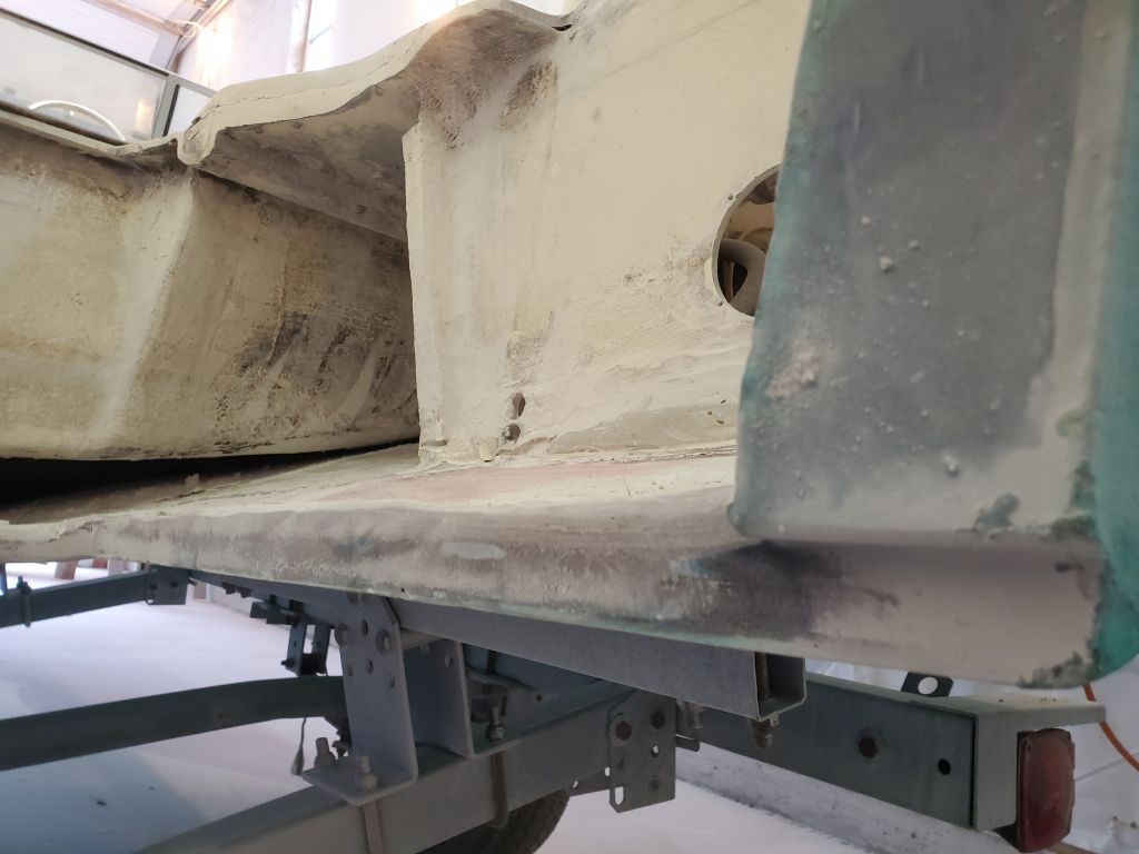
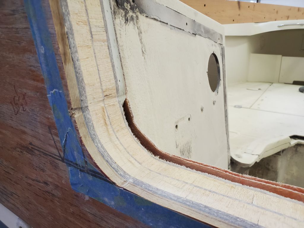
The construction featured nearly 3/8″ thick outer laminate, two layers of 3/4″ balsa separated by an additional 1/8″ laminate, and an inner laminate of about 3/16″ (plus the inner liner, separated by about 1/4″ gap and which would soon be removed as part of this process).  The exterior wooden veneer was also going to be removed later and would not be part of the final configuration.  The structural condition of the exposed transom appeared excellent, which was good news as this had been one of the known-unknowns of the project.

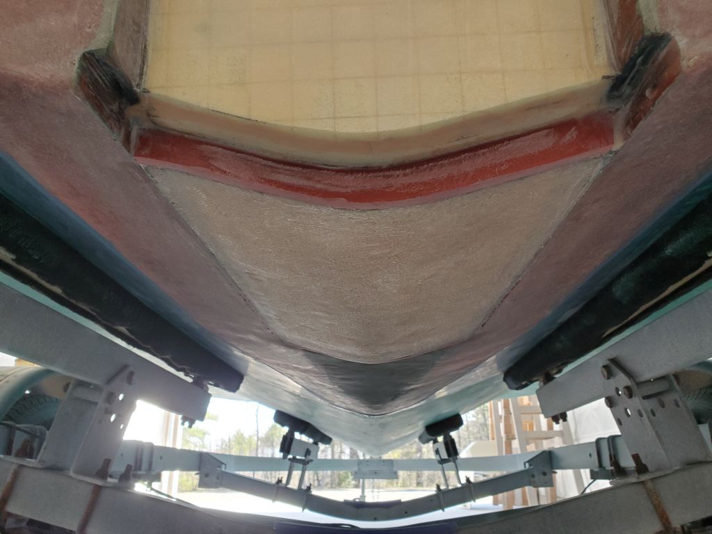
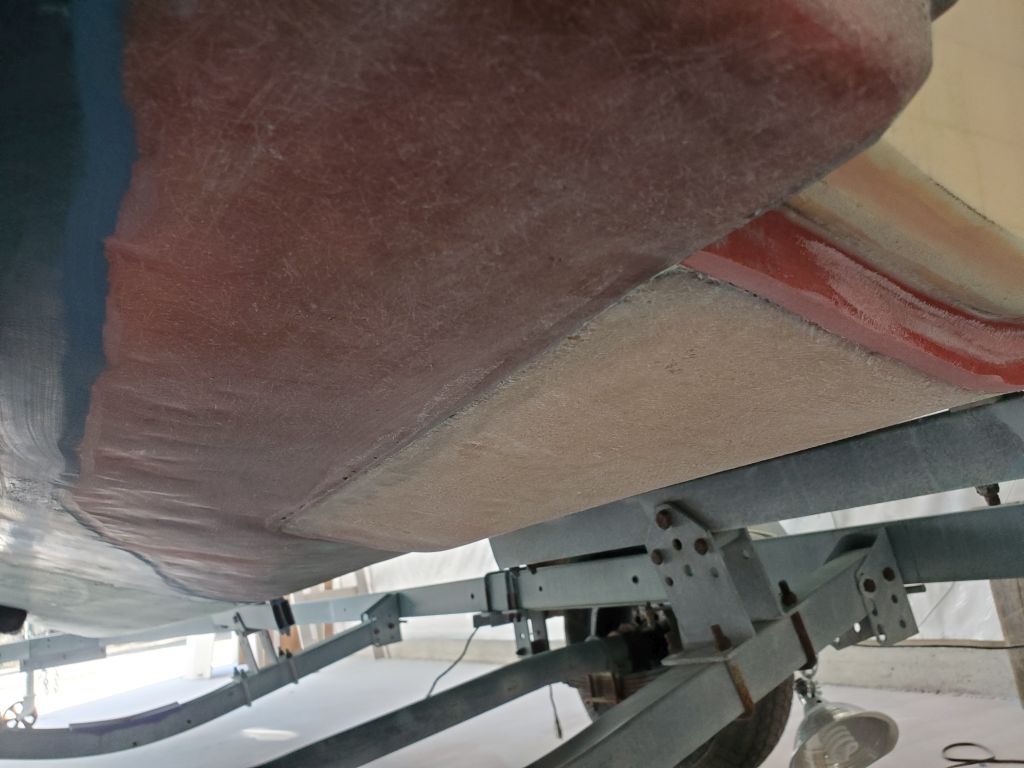
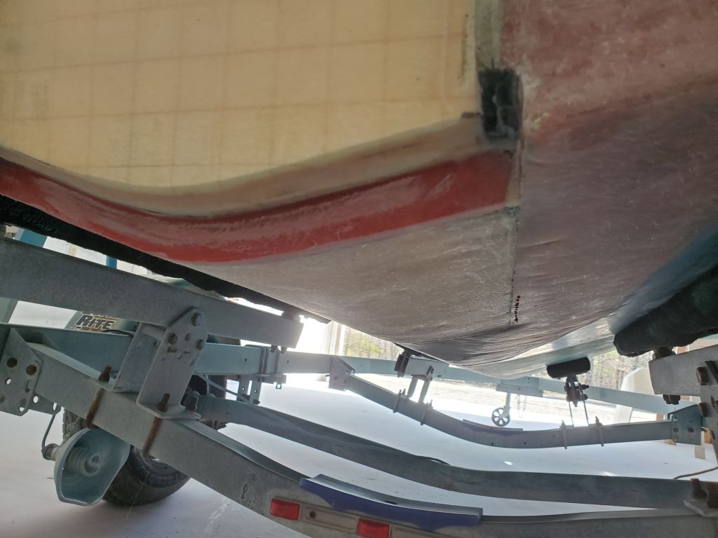
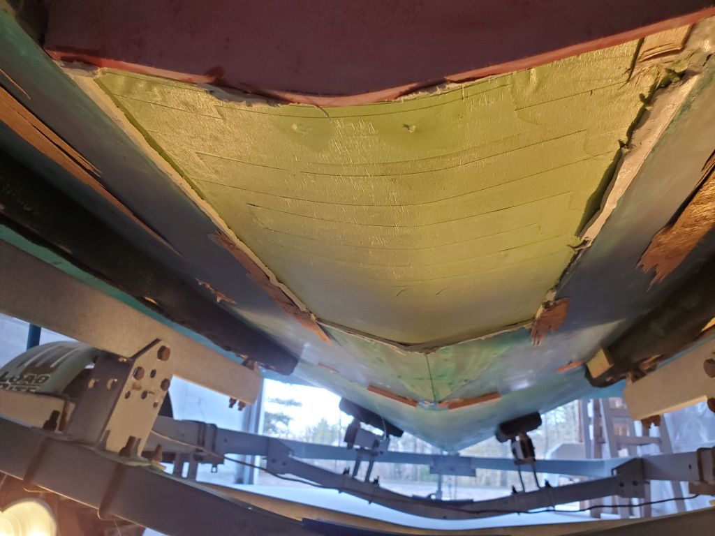
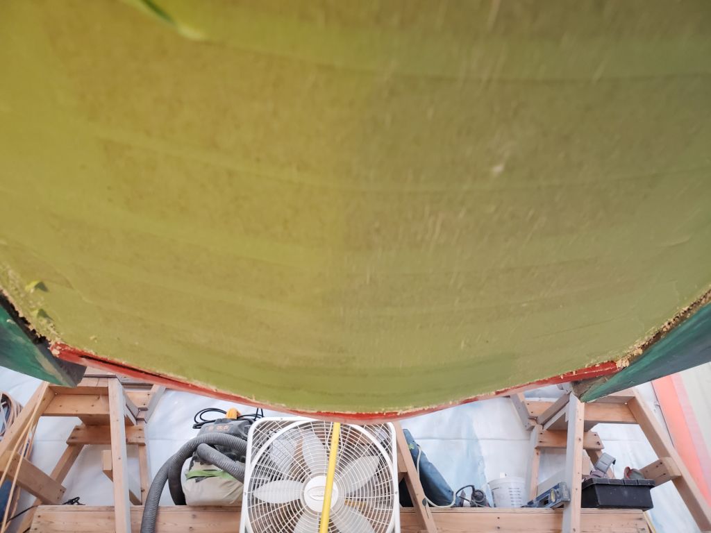
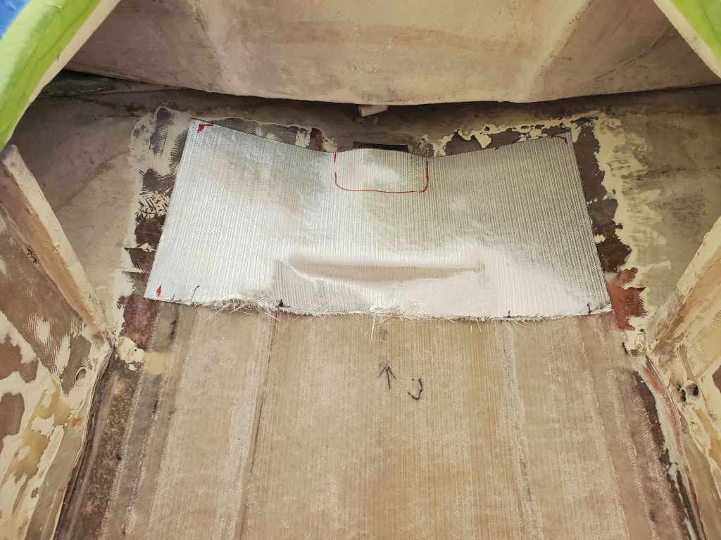
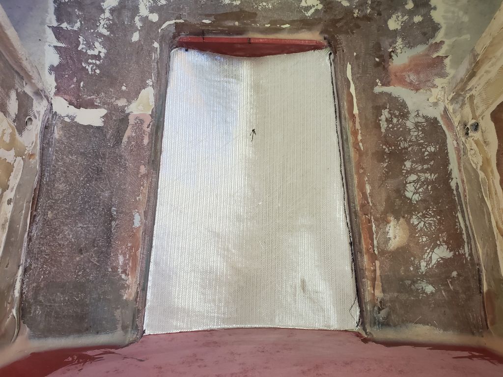
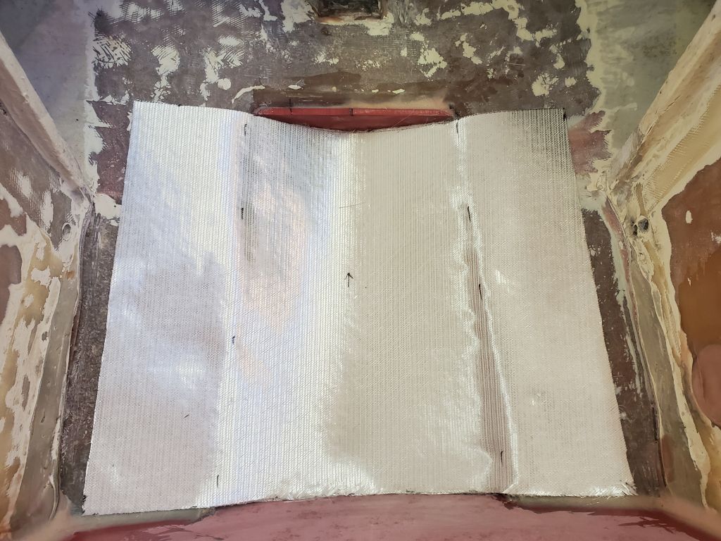
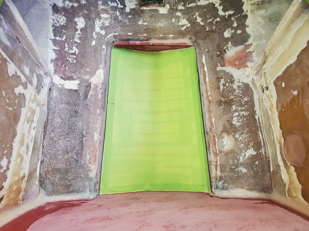
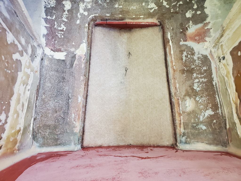
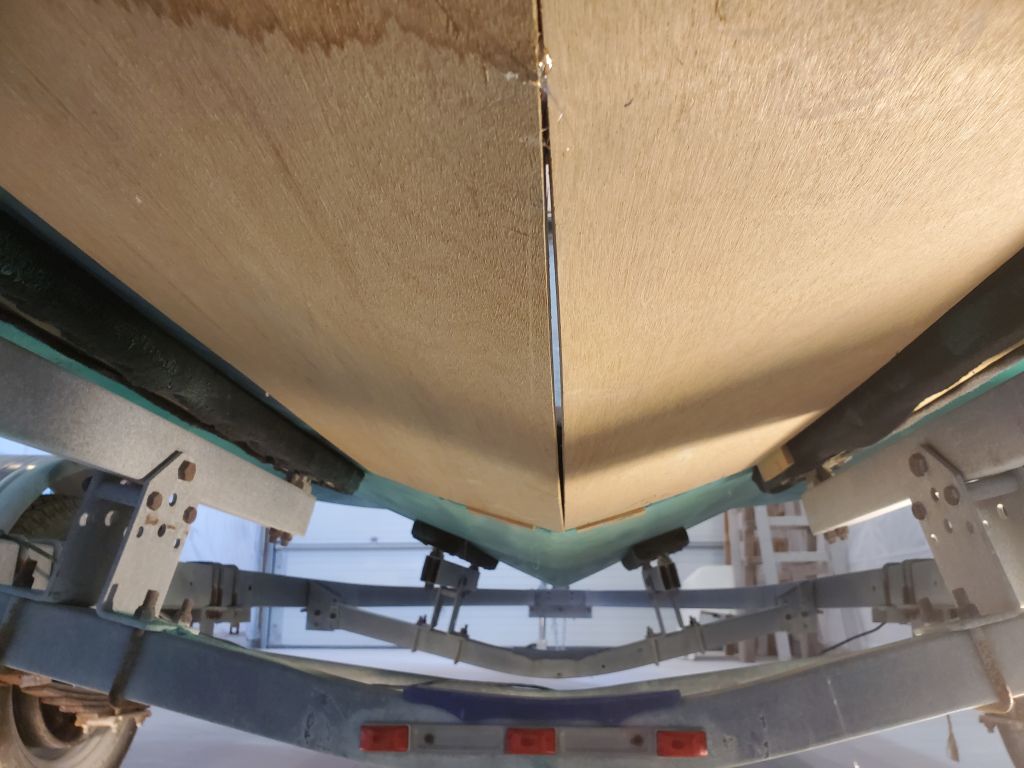
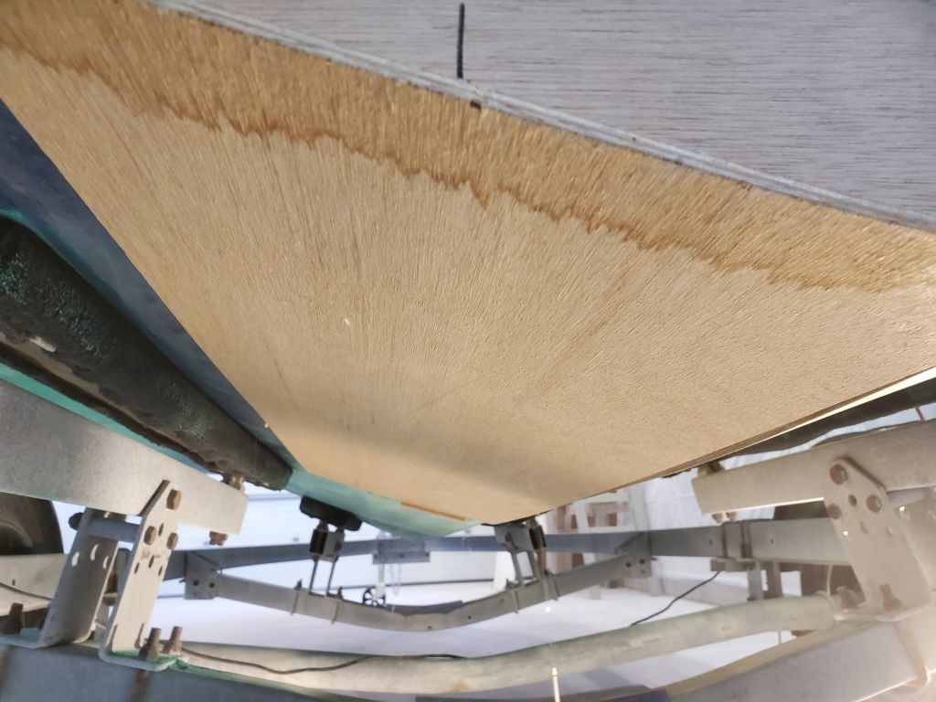
I’d measured the transom thickness on the sistership at 2-3/4″ overall (which probably included an interior liner), so I thought in this case I’d probably add a glassed-in prefab fiberglass panel to the inside to increase thickness, provide the requisite compression resistance, and add strength, all of which would be coupled with and tied to the existing structures with and around the new work to close off the old jet drive tunnel and recreate the proper hull shape.  The hull on this boat featured a slight flattened area beginning just forward of the tunnel opening, versus the rounded deadrise shape of the basic hull, so recreating this shape from its natural starting point a foot or so forward of the tunnel to the transom would be part of the work to come.  All this and more, including final shaping and finishing of the new cutout opening, would form the bulk of the work on this project in the time to come.

Holby 9

To finish up the shipping crate for the engine and jet drive assembly, I built a simple framework from scrap lumber (mainly the leftover wood from the shrinkwrap frame), enclosing the top part of the pallet with a small curb to contain the various small pieces and parts that went along with the engine, then extending the frame upwards to just above the maximum height of the engine (not including the lifting ring).  I added light cross members to complete the structure and to eventually support cardboard sheathing.  Inside, I placed all the related engine and drive components, securing them as needed.

To finish, I installed cardboard around the four sides, and cut  final piece for the top, though I wouldn’t install that yet as I still needed to lift the engine and crate one more time to load it in a truck.


Older posts Newer posts