(page 7 of 13)

Calliope Girl 67

In the main cabin and galley, I masked off various places as needed, mainly around certain portions of the overhead (plastic laminate panels that would not be painted), deadlights and ports, and where the settee cabinetry met up with the varnished bulkheads and elsewhere.

Thusly masked, I was ready to apply white primer to all areas, basically starting at the top and working down and through all areas in as logical a way as I could.

Back on the shop floor, I primed the hatches from the settees, and a few other things that needed the primer as well, such as hatch openings and the edges of some panels.

Later, I installed the two forward chainplates permanently.  I’d planned to install and bed the deck cover plates as well, but discovered as I was preparing the original four (to remove old sealant) that I didn’t have the correct little screws on hand for attaching the plates to the deck, so final work on the chainplates would have to wait till another time.

After some odds and ends and general shop cleanup, the day and the week was done.

Calliope Girl 66

The forward chainplates had been lingering on my list, so I decided to get those installed and off my mind.  After marking the width of the  chainplate inside the boat, with a drill and a long 1/4″ bit (using the long bit for this job allows a straighter and more accurate hole position next to the knees), I drilled holes through the deck at the ends of the marked space, then, from above, finished out the slotted cut with an oscillating tool.  I measured the other chainplates to see how much protruded above deck, then marked the new chainplates and, holding them temporarily at the correct position with locking pliers from above, returned below to clamp the chainplates against the knees in their final positions.

Next, I drilled the four bolt holes on each side, making sure the backing plates fit correctly and running the bit through both pieces.  I installed all four bolts on each side as I went, just to ensure the alignment would remain correct.  Afterwards, I removed the bolts and chainplates so I could prep and then epoxy-treat the slotted deck openings.  I’d finish up and finalize the installation once the epoxy cured.

The main focus of the day was surface preparation in the saloon and elsewhere.  After getting set up with tools, supplies, and breathing equipment, and cleaning out the tools leftover from the chainplate work, I got ready to sand the new cabinetry in the saloon and galley, along with the cabin sides, overhead,  and main bulkhead staving in the main cabin, plus the overhead and bulkheads in the head.  These photos show the condition of things at the beghinning.

Over the course of the day, I sanded all applicable areas with 120 grit paper, cleaning up the fresh plywood cabinetry a bit and evening the texture of the wood, and creating a smooth, proper basis on the varnished bulkheads (to be renewed with varnish), cabin sides, and overhead liner.  On the bulkheads at the forward end of the galley, I cleaned up old adhesive leftover from the staving (staving would be reinstalled on the forward sides of these bulkheads), and elsewhere made efforts to prepare for primer and paint.  The aft face of the bulkhead next to the stove would require a little more work, but for now I prepped it in kind.

With the saloon sanded, I continued in the head and hanging locker, sanding the glossy overhead liner to prepare it for paint, and also the varnished staving.  With uncomfortable access in the forward cabin, for the moment I just sanded the cabin sides and overhead, leaving the area beneath the foredeck and the staving to do another time.

Once all the sanding I planned to do now was complete, I vacuumed and solvent-washed all areas to prepare for the next steps, which would be primer on all the new wood and applicable portions of the overhead and cabin sides.

Calliope Girl 65

I got started with the final countertop hatch opening, located outboard of the sink on the main countertop.  Afterwards, I test-fit all the countertop pieces one more time to ensure everything fit correctly and as intended at this time.

Next, I removed portions of the port galley so I could prep and paint them down on the bench.  I applied primer to these panels, and the second/final finish coat on the three panels I’d been working on earlier.

In the main cabin, I removed a few things that were still installed on or in the way of the nearby cabin sides, specifically an oil lantern from the starboard side, and a couple wooden blocks covering the winch installations on the coachroof above, as well as the swing arm mount for the electronics.  Removing these items would allow proper preparation and painting of these areas, which was coming right up.  I also started to move out some of the tools and supplies from the main cabin to the cockpit or even off the boat entirely, again to make way for the upcoming surface prep and finishing in the main cabin.

Removing the port galley also gave me access once more to the locker space beyond, which was the right opportunity for me to lead in the new propane lines (two–one for the stove and one for the cabin heater) and a wire pair for the propane solenoid.  During an earlier phase, I’d cut an access hole in the bulkhead beneath the cockpit, and now I snaked in the hoses and wiring from beneath the cockpit, leading them though a length of flexible conduit mainly to keep them neat and out of the way on their relatively short run between the port cockpit locker and the galley on the starboard side.

I pulled in ample lengths of the hose for later connection to the new propane locker and tanks within, and left them in the after portion of the former quarterberth for retrieval later on.  In the galley, I secured the hoses and wires as needed to run them where they had to go:  the wires up to the clustered wiring area above the countertop, and the two hoses forward to the stove enclosure and, for the longer heater hose, through the utility space beneath and into the starboard settee, where I’d later continue its run forward to the heater.

I’d first thought of running the stove supply through a spot near the base of the enclosure, but soon decided to move it to the upper outboard aft corner, where I could be assured that there would be no interference issues with the swing of the stove, since I didn’t really know how much space there’d be once the stove was installed.  I used a gas-tight through-bulkhead fitting to run and secure the hose through the panel since it offered a convenient and clean way to install and protect the hose.  I left a good bit of extra hose to allow connection to the stove and enough slack for the motion of the stove when gimballed.  On the back side, I kept the hose clear of the area (which happened to be right where that unused wire mount is located in the final photo) where the gimbal mount would eventually (actually soon) be throughbolted.


Calliope Girl 64

I started by lightly sanding the freshly-primed panels currently underway, then, after final prep, applied the first coat of semi-gloss white finish enamel.

With the area behind now painted and ready, I installed the three faceted panels of the stove surround.  I double-checked the position of the stove on each side using my plywood template, and made a couple additional reference marks at the tops of the bulkheads since I’d be covering up most of the layout lines with the sheet metal and would need to re-create the mounting centers for the gimbal brackets.  Afterwards, I made paper patterns of the forward and after bulkheads so I could cut the side panels to the correct size and shape.

I transferred the patterns to the sheet metal, which I’d ordered cut to the basic rectangular dimensions of the space.  I kept the top and inboard edges about an inch in from the edges of the actual space defining the stove enclosure, so that I could later install trim to transition between the stainless steel surround and the adjacent surfaces.  I cut the panels to size, test-fit them and marked screw locations, then, after center-punching and drilling for fasteners, I installed the vertical panels, leaving all the protective plastic in place for now; the finished surface, seen on the back side of the panels, was typical #4 brushed finish.

With the sheet metal now in place, I could cut and install the support cleats needed at the top outboard edge to support the small countertop running across this area.

On the port side of the galley, I decided to combine the two smaller sections forming the aft part of the countertop, after considering how the whole space was going to work going forward.  I also wanted to include an additional access hatch to the space beneath, inboard of the trash container.  With little clear space available, I wanted the cleats that held  together the two plywood panels to also serve as the support cleats for the new hatch, so I spent some time on the correct layout and transferring measurements to the top of the sheets so I could make the cutout, all the while keeping the pieces pinned together for proper alignment.  Because whatever upper cabinetry we added to this part of the galley would also necessarily be removable, this meant that the hatch opening was feasible since whatever storage was placed atop (the owner was currently considering some kind of tableware/utensil storage) would be removable when or if access was required to the space beneath.  And the large opening over the trash container had to remain exposed for regular use.

I also added another support cleat to the engine side of the space, at the top of the panel leading to the refer locker.

Countertop material was on order and I expected it soon, but in the meantime this gave me time to finalize the substrates and make advances in other parts of the project.

Gearing up for some upcoming surface prep and beyond in the main cabin, I applied some lightweight filler material to various places, mainly over a few panel seams and bung locations to fill minor plywood splintering that had occurred during panel installation.  By installing some of the fairing material now, I’d have a head start once I lightly sanded all the surfaces to prepare for primer and paint.  I did the same on the cabin sides, where there were a few old screw holes to fill and some existing bung locations that required dressing; I’d also be priming and painting the cabin sides and overhead liner here.

Finally, the engine through hull bolts locations required a minor second coat of fairing compound to finish up.

Calliope Girl 63

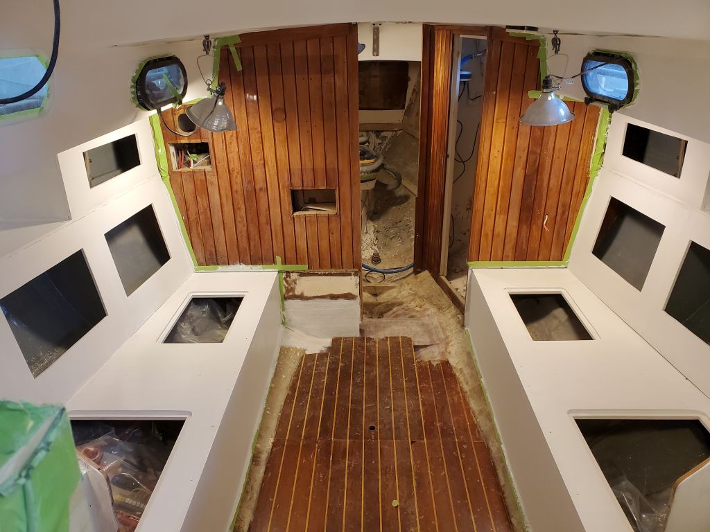
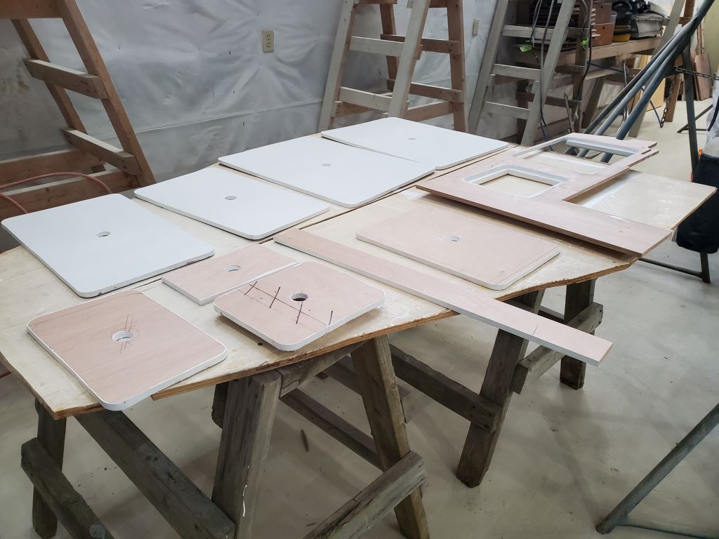
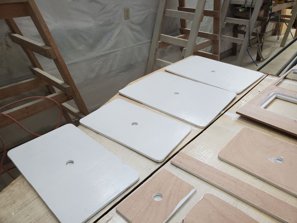
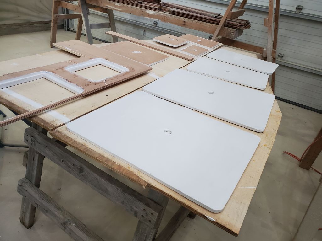
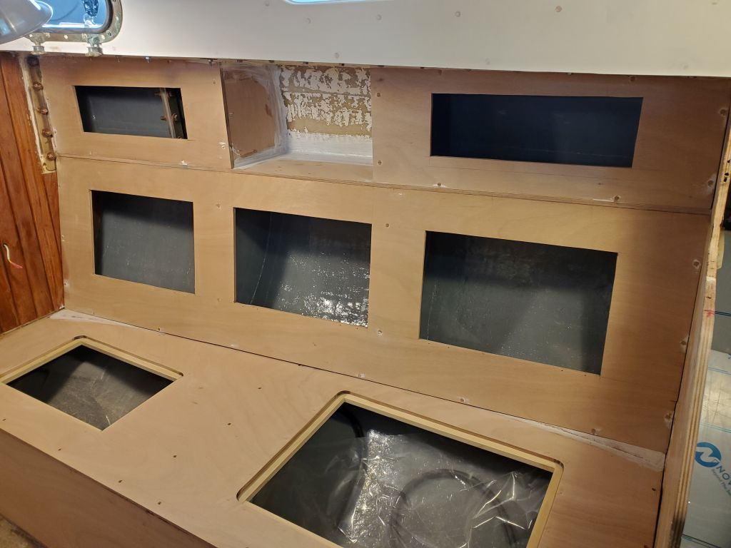
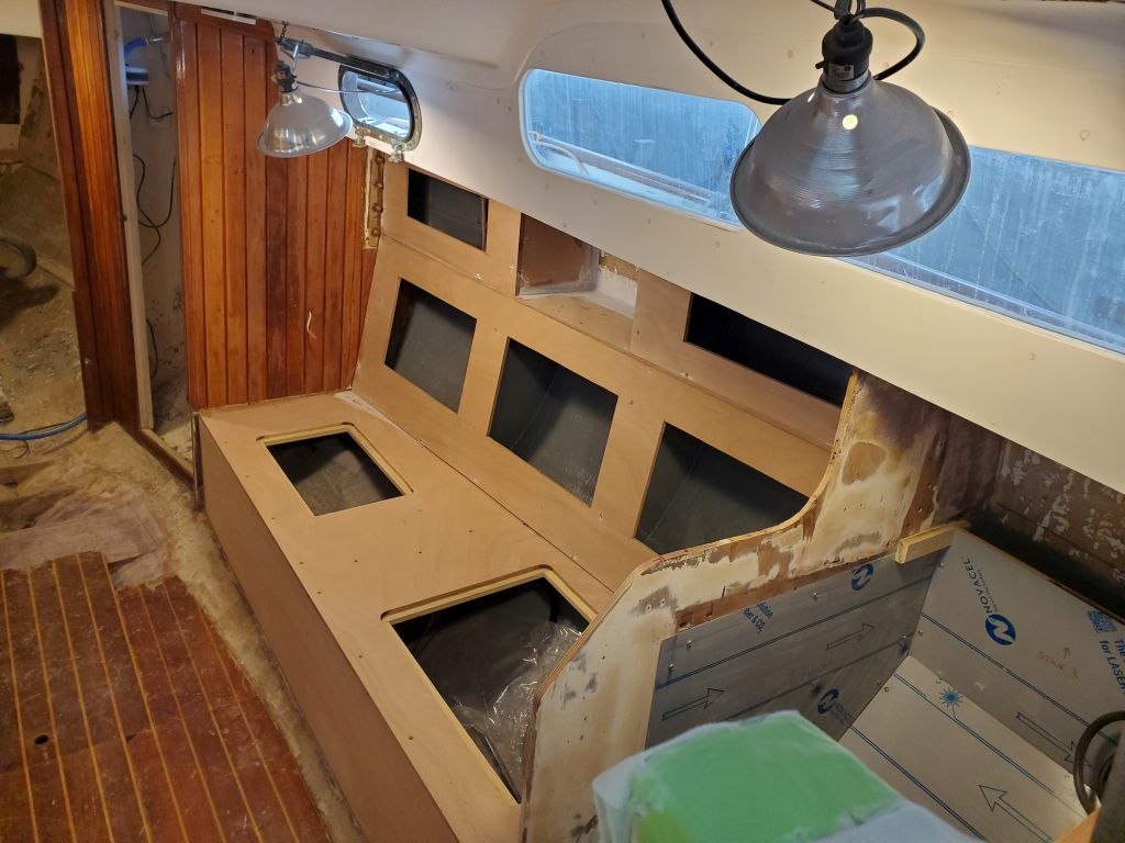
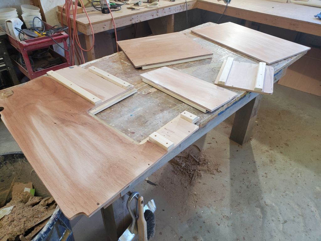
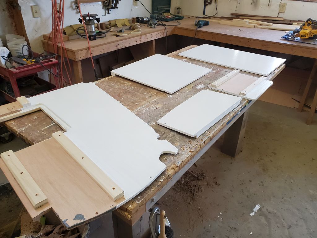
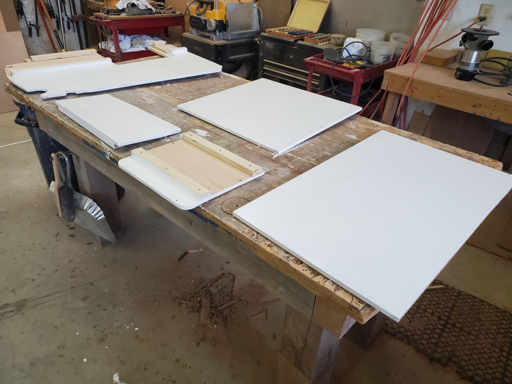
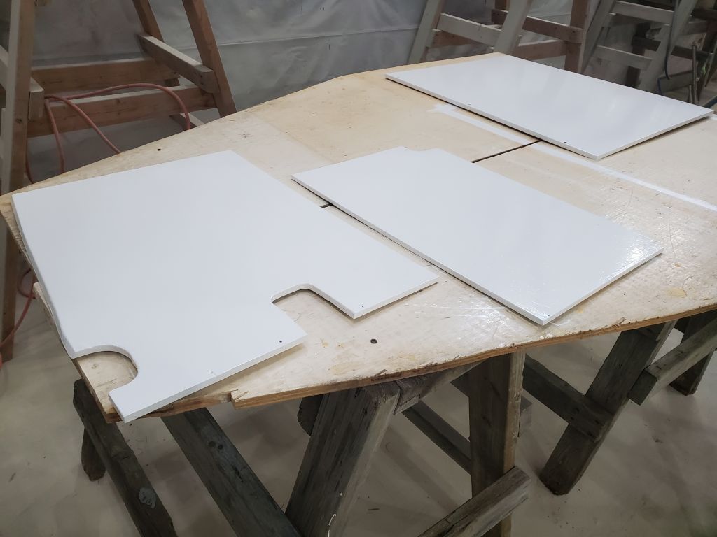
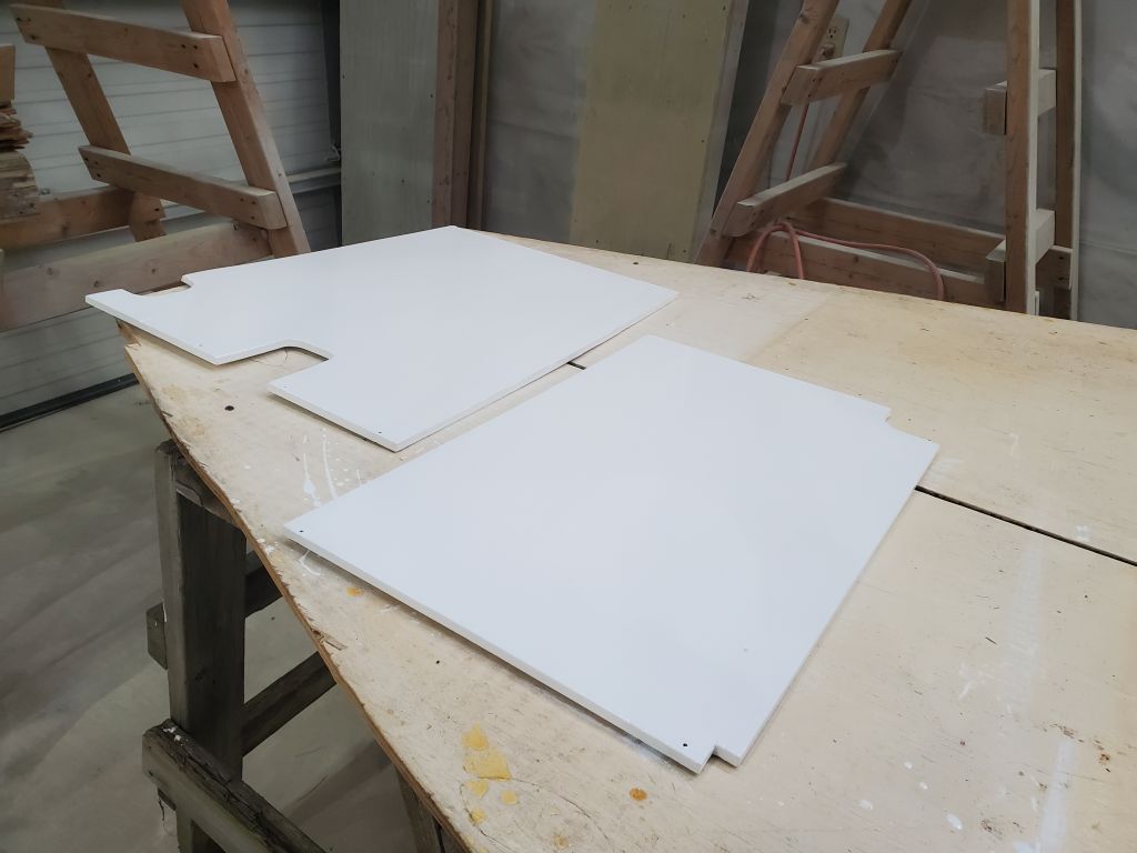
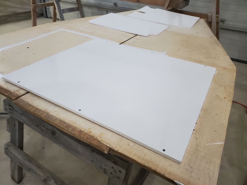
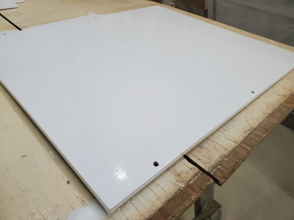
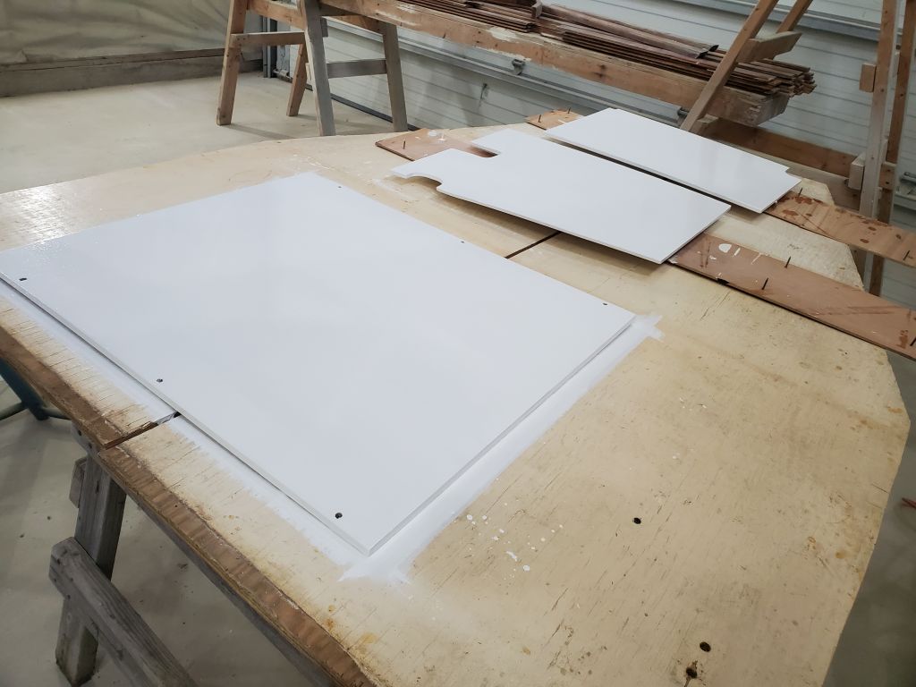
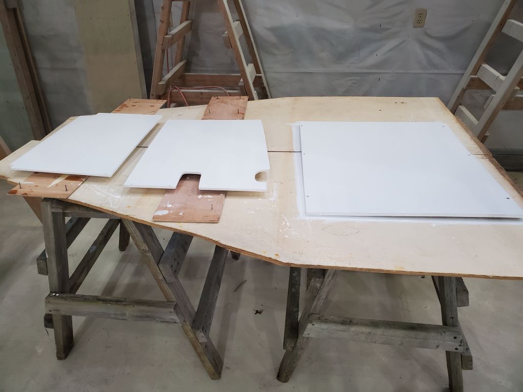
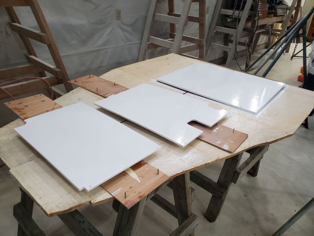
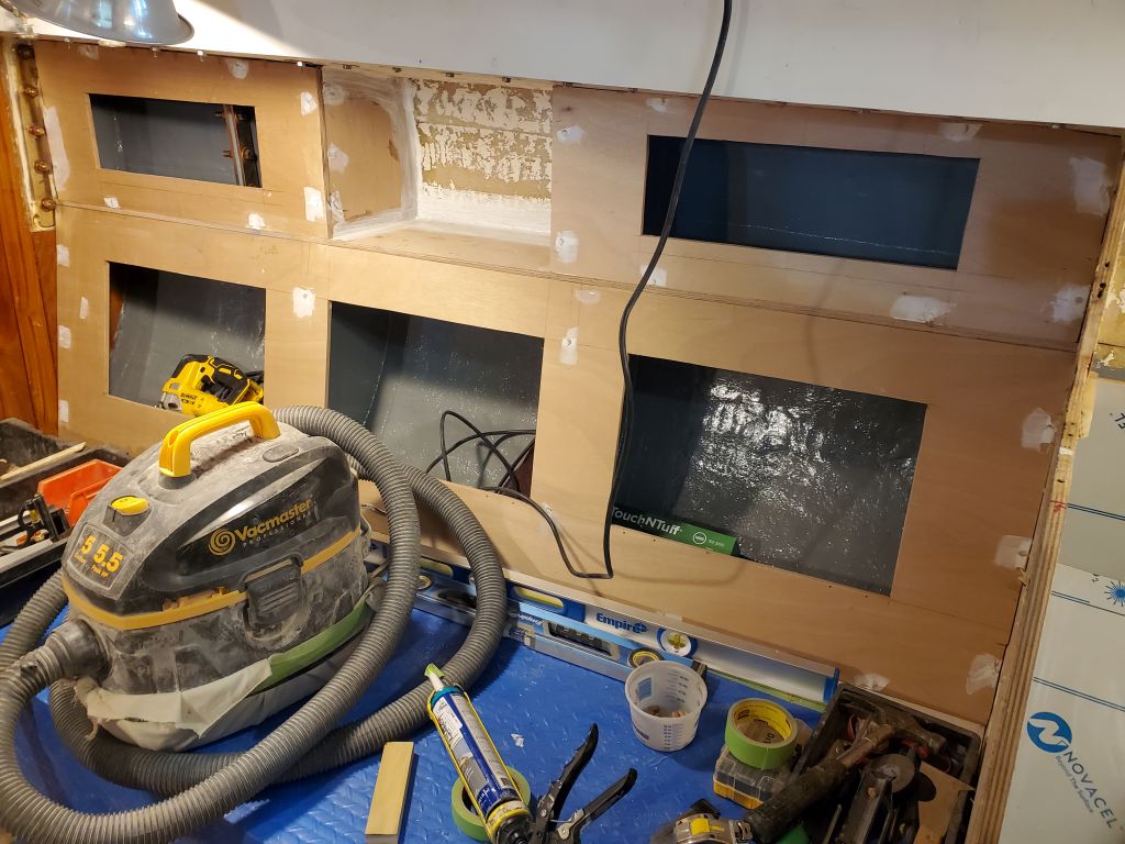
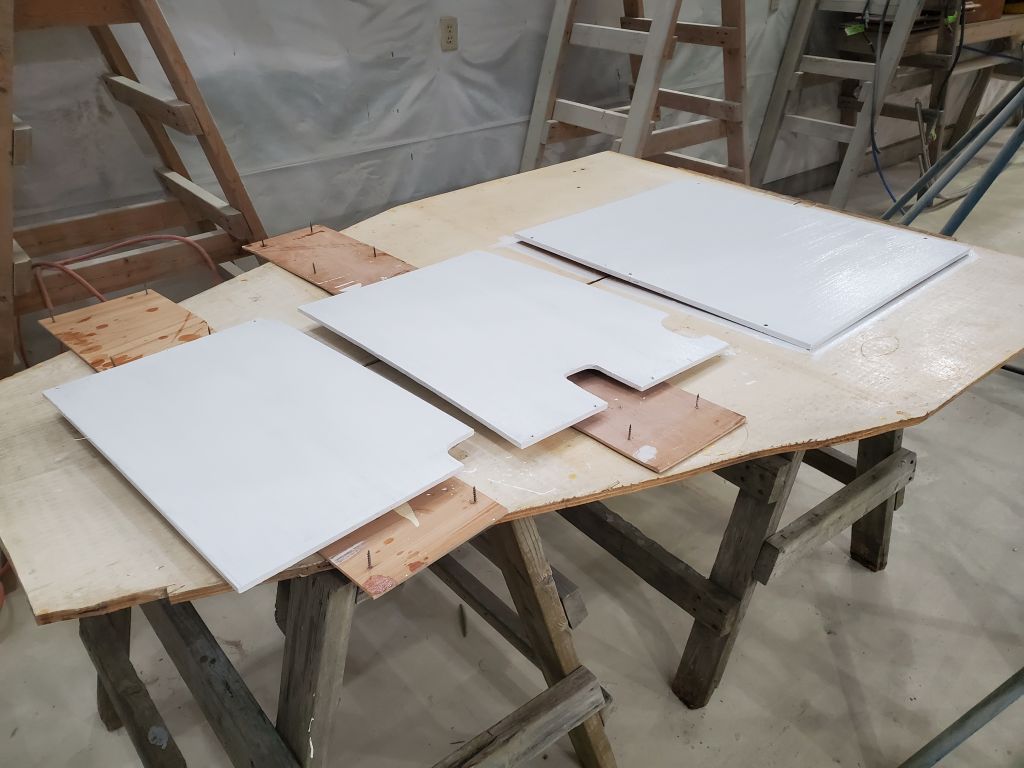
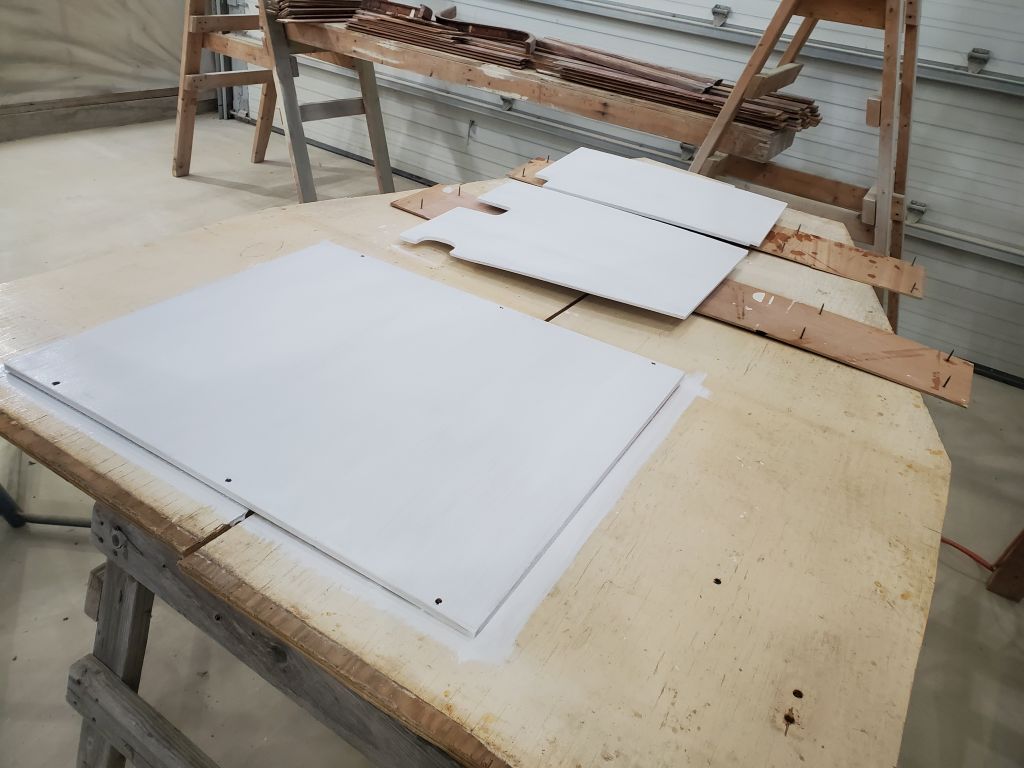
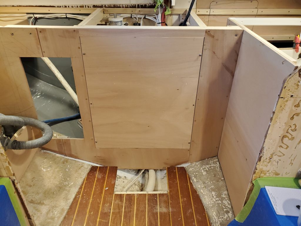
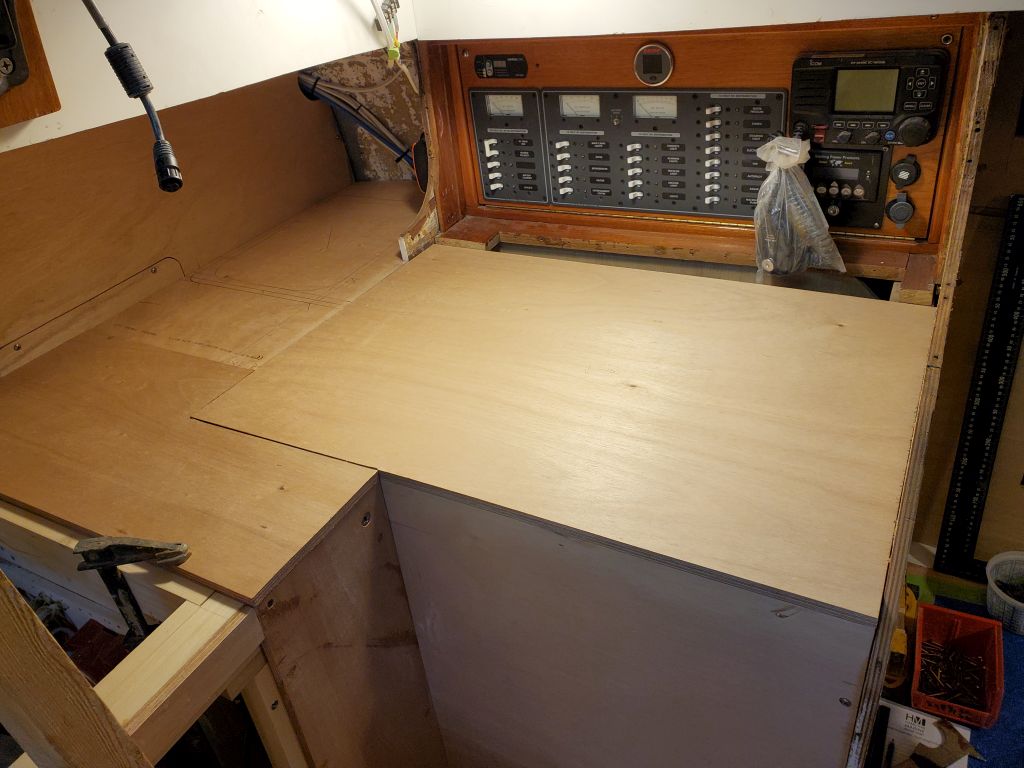
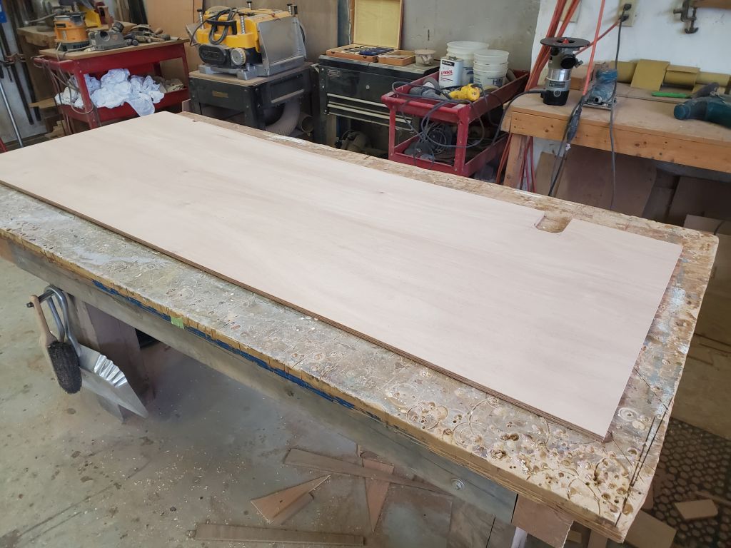
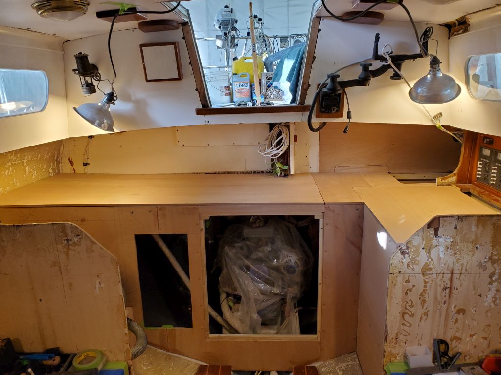
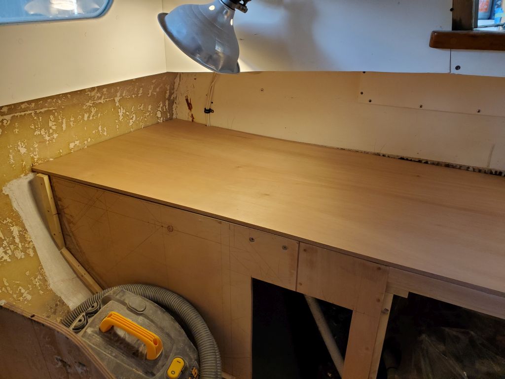
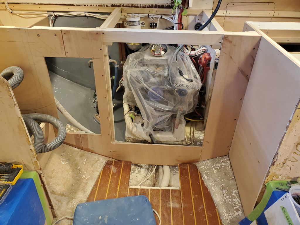
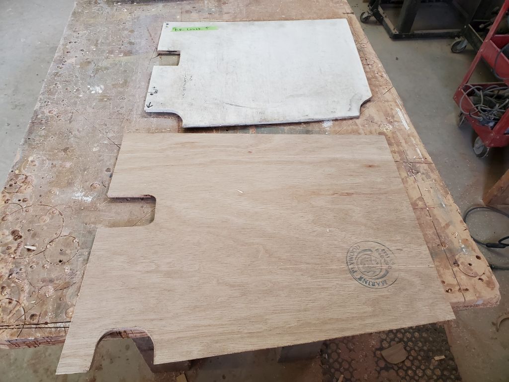
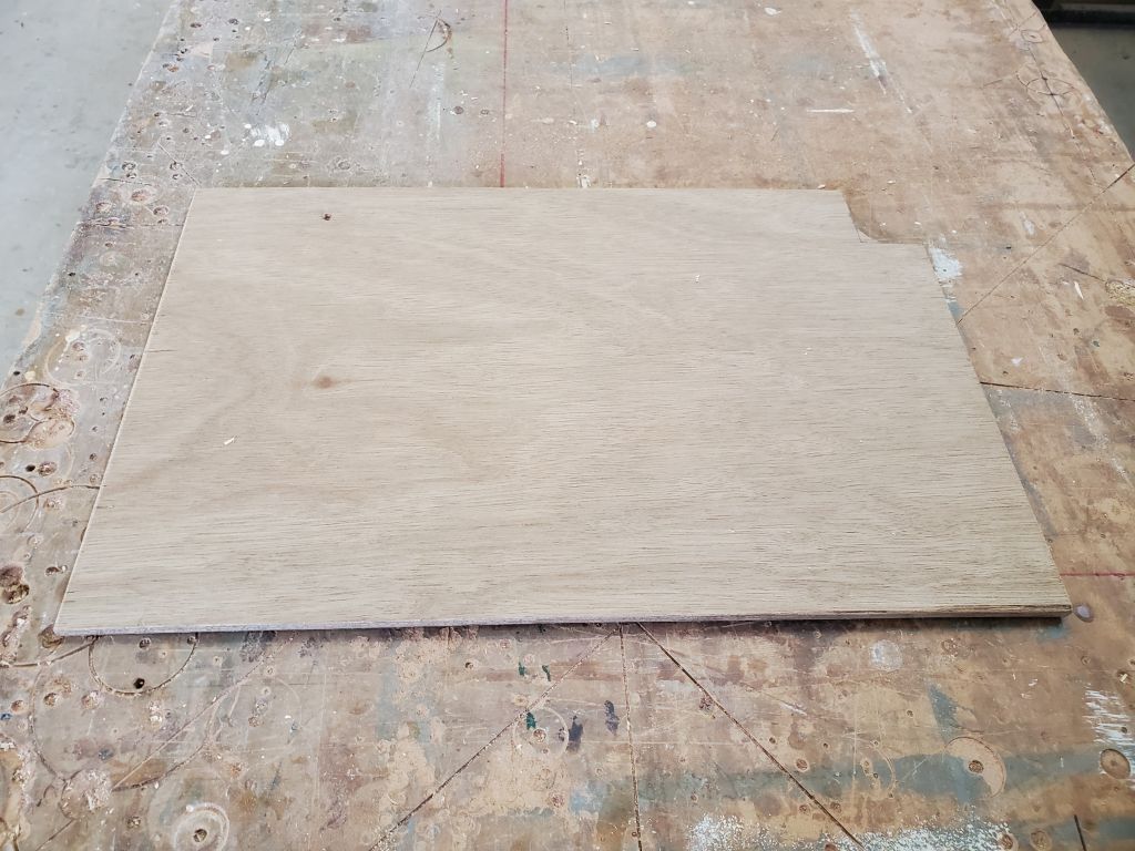
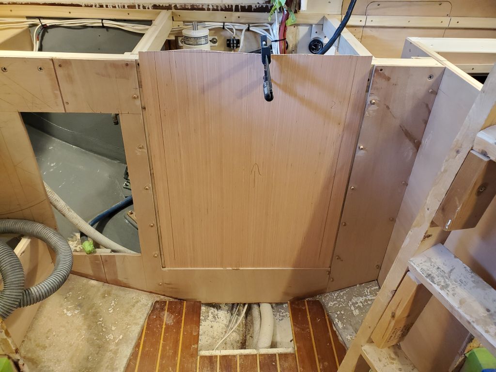
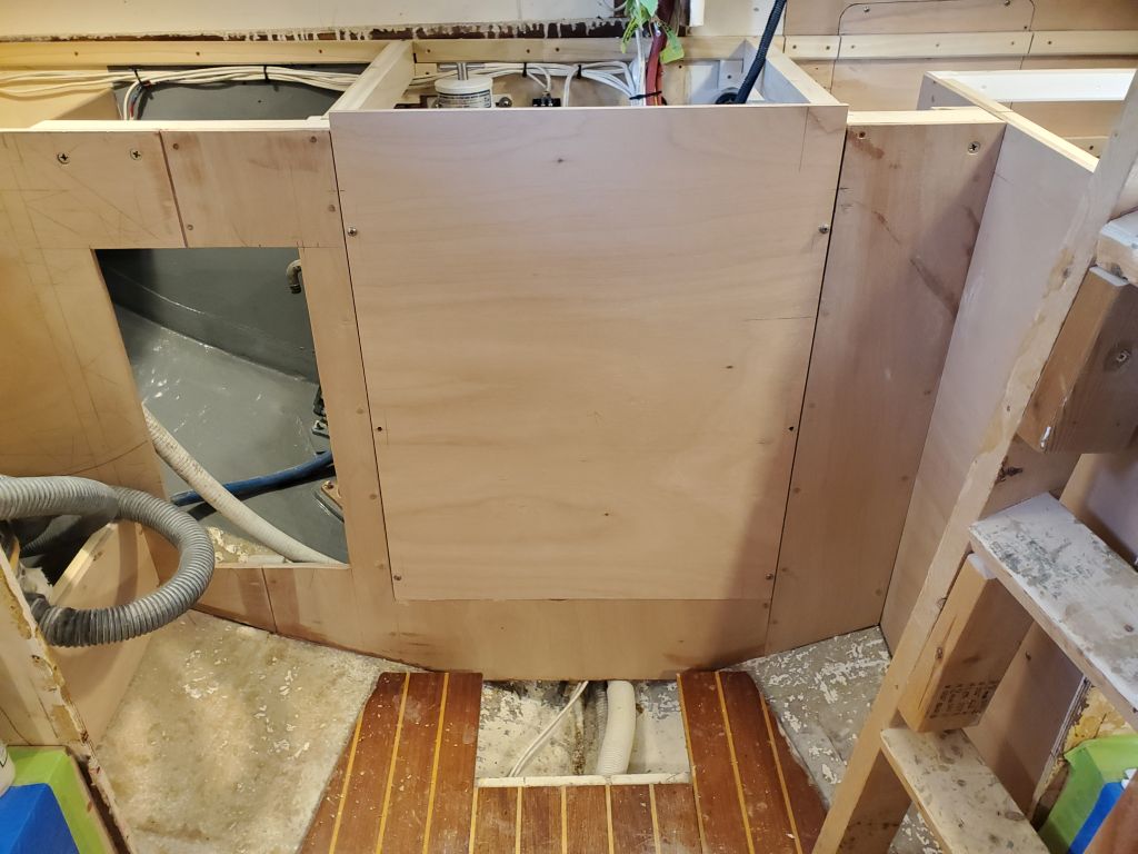
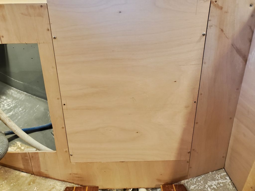
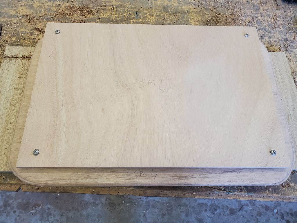
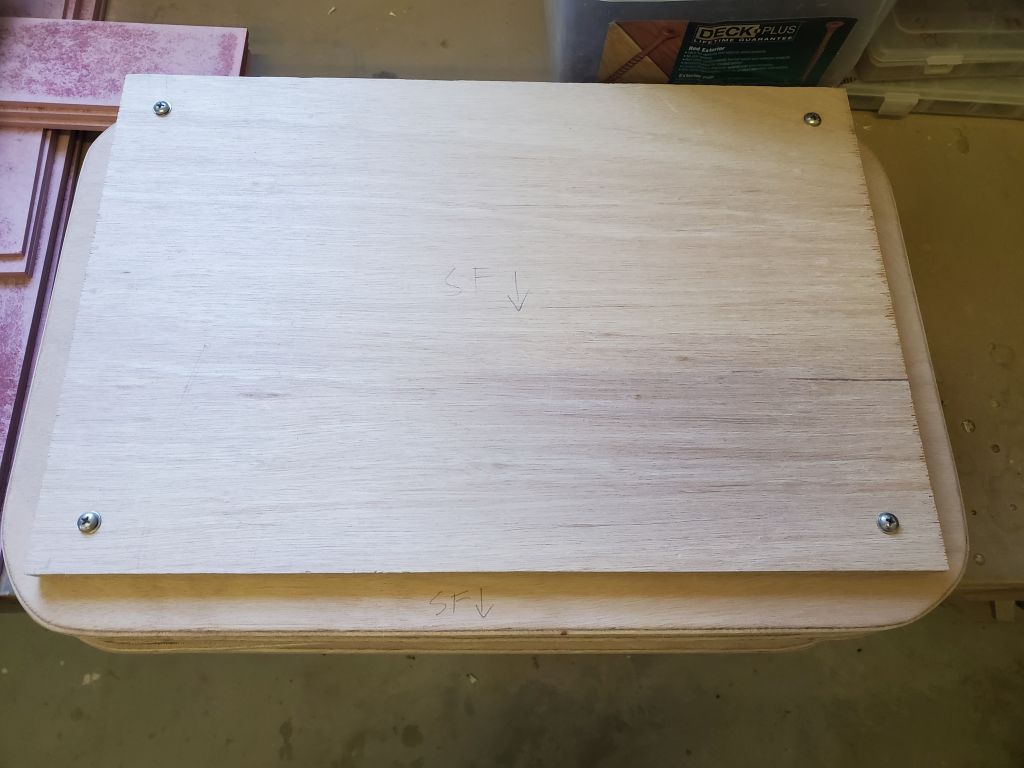
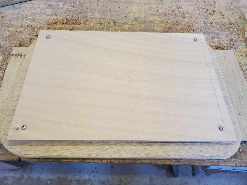
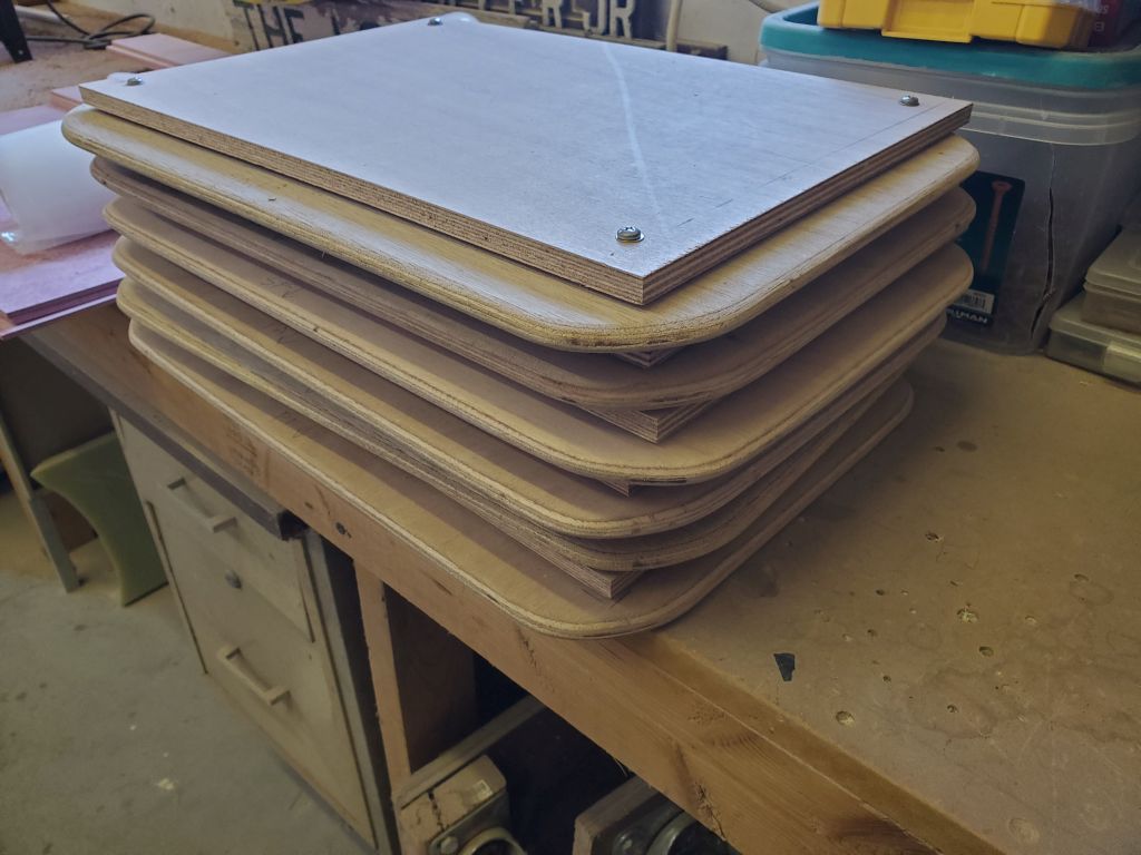
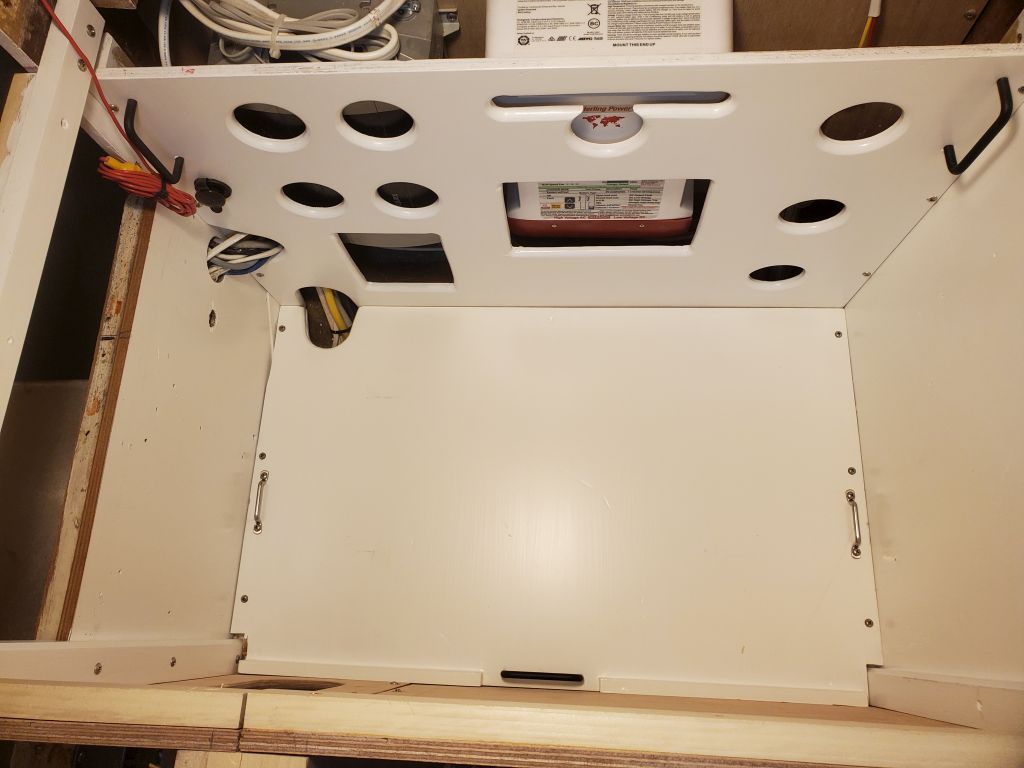
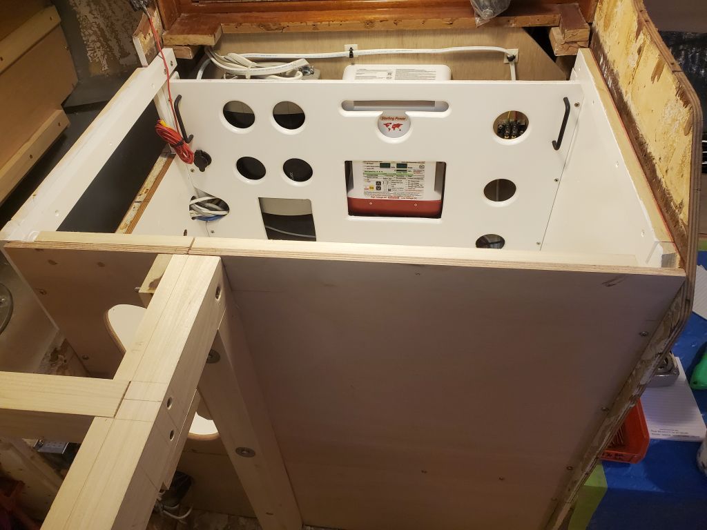
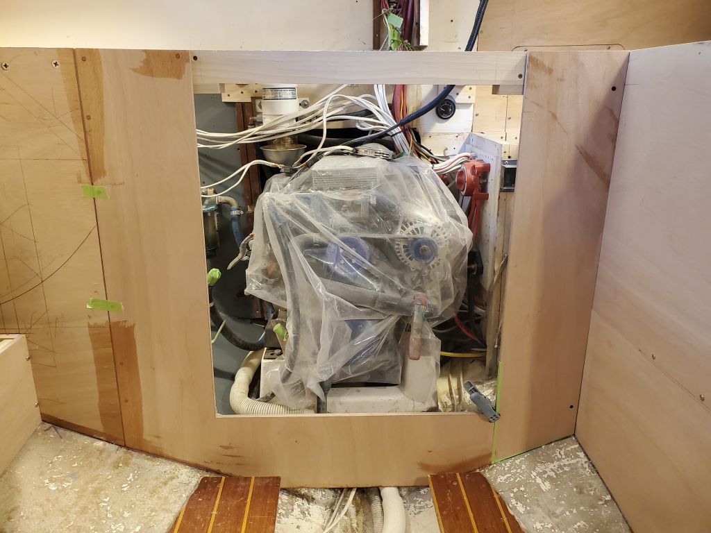
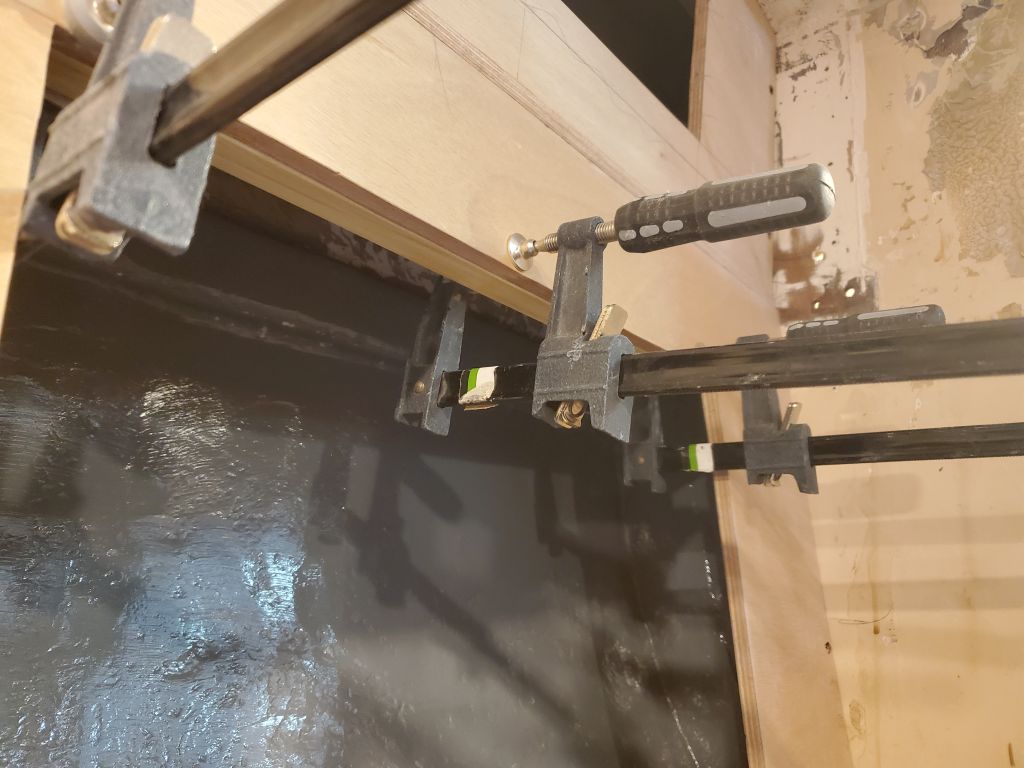
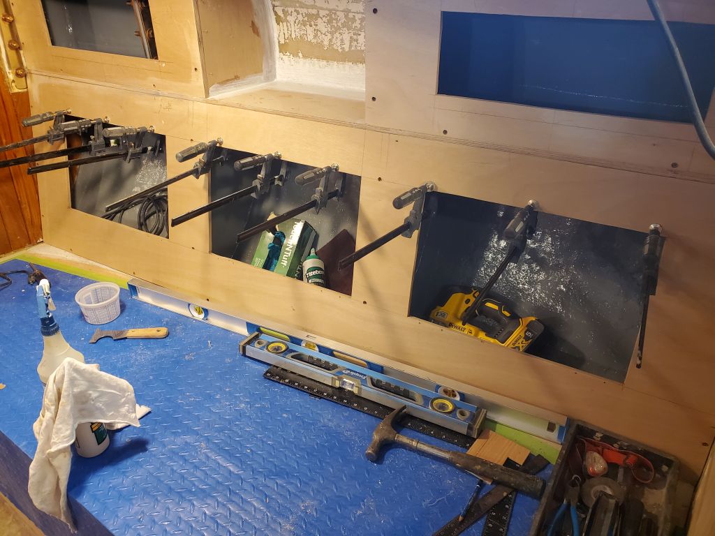
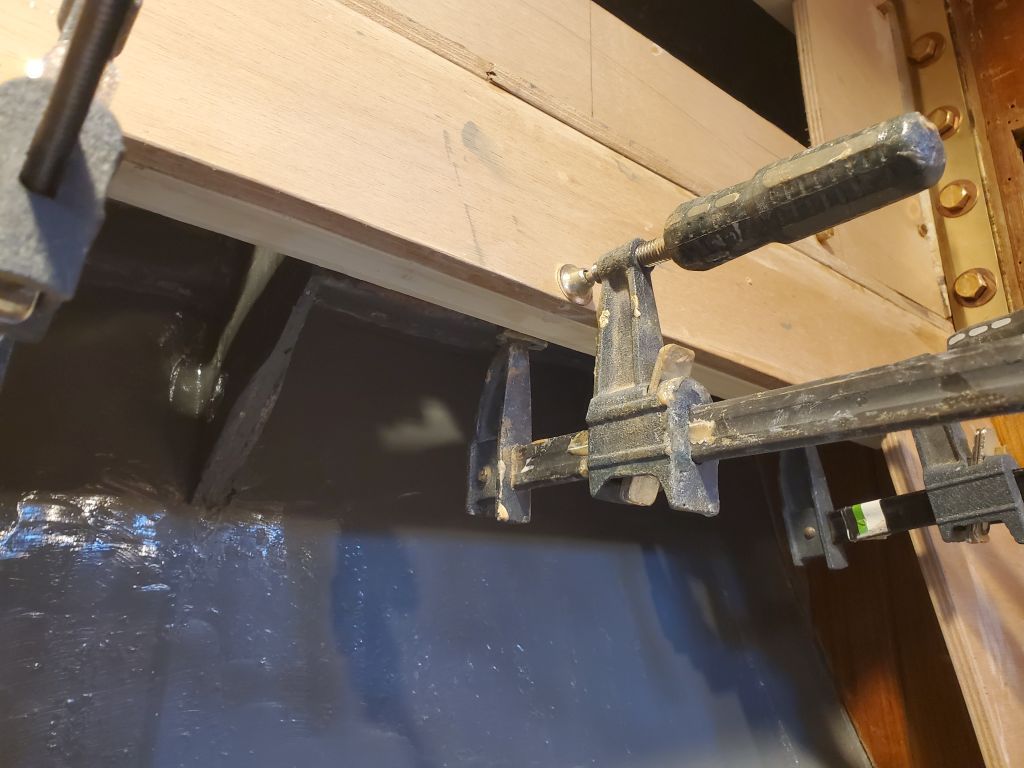
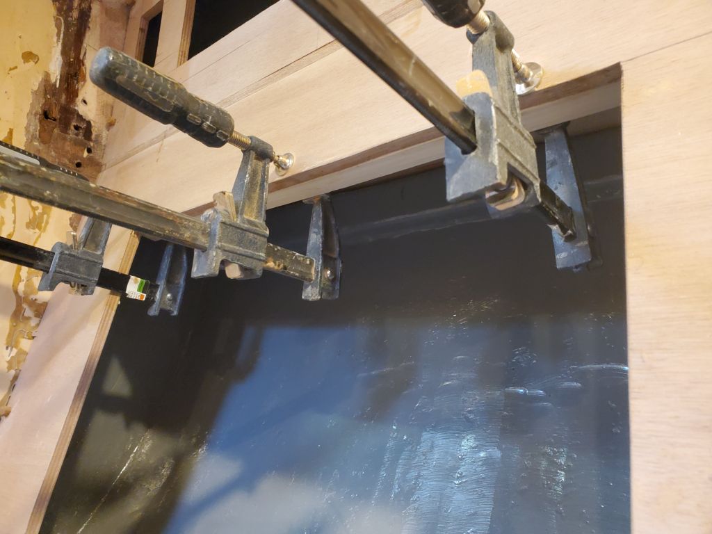
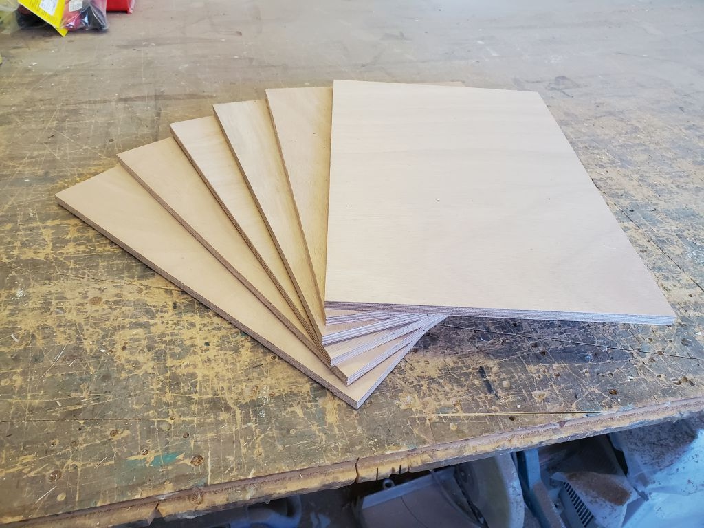
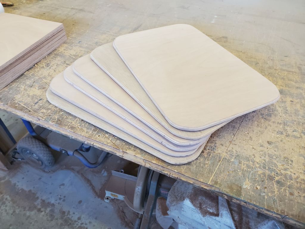
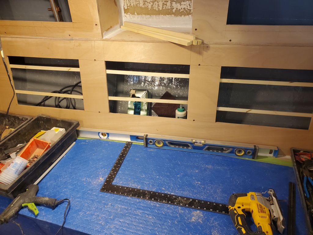
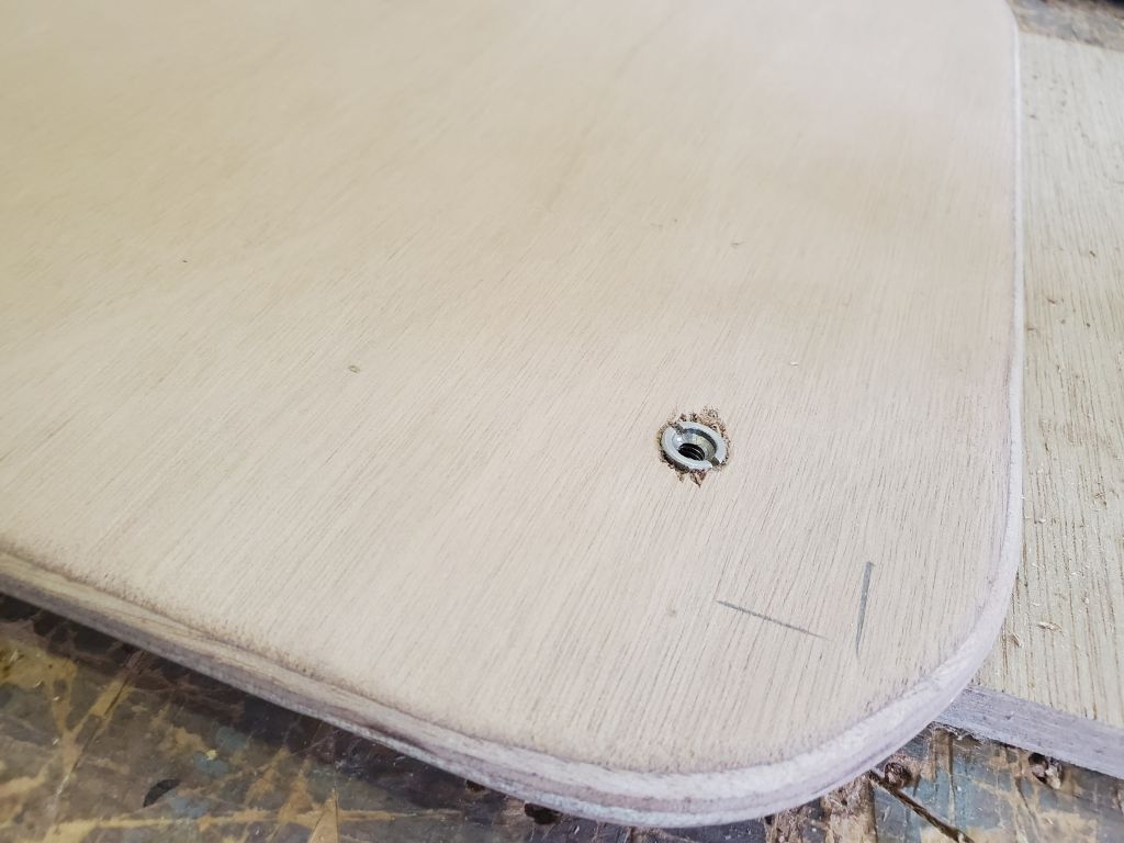
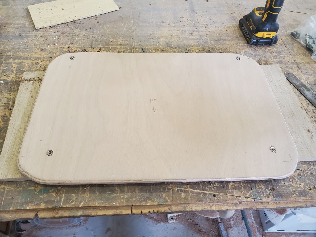
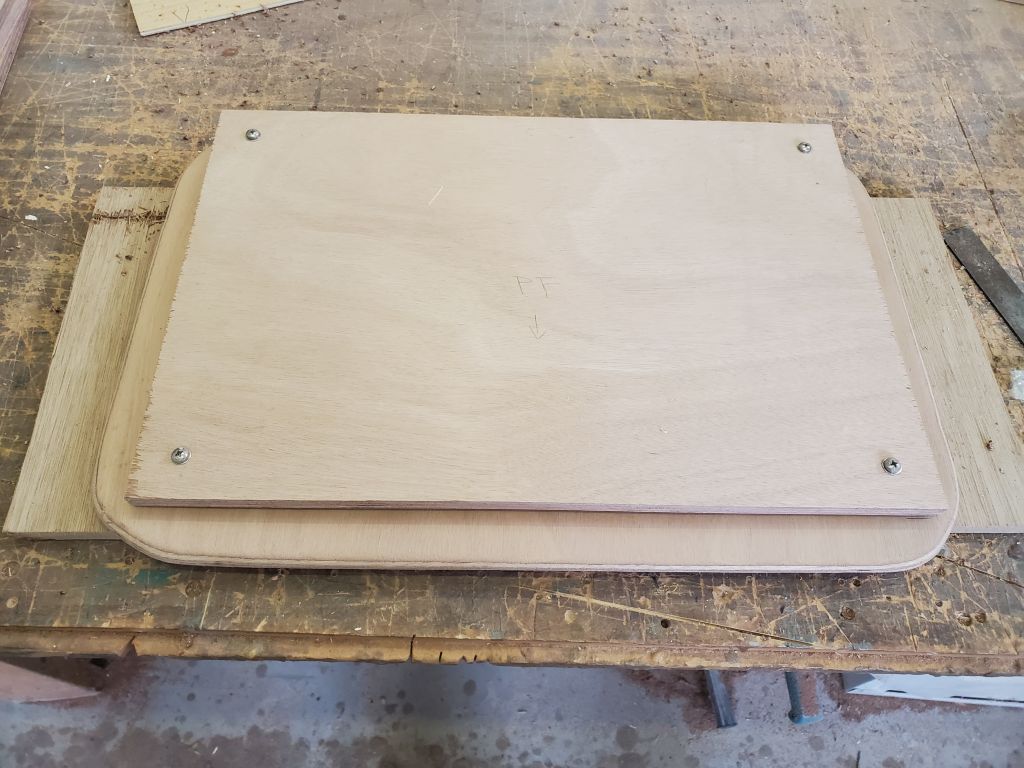
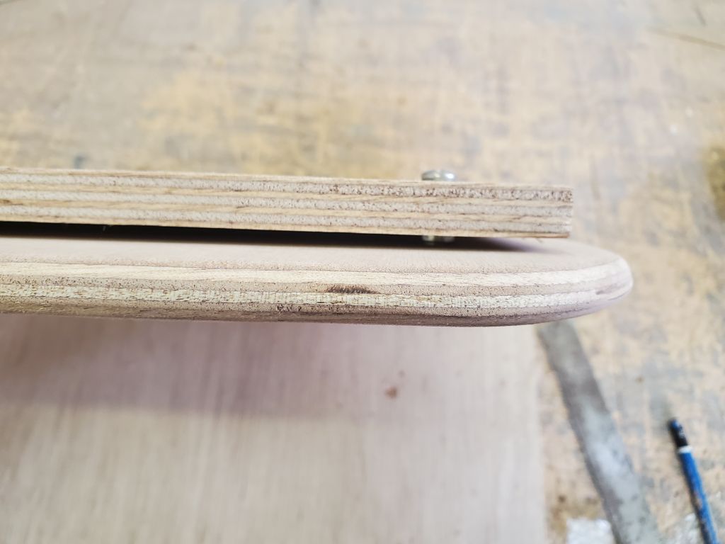
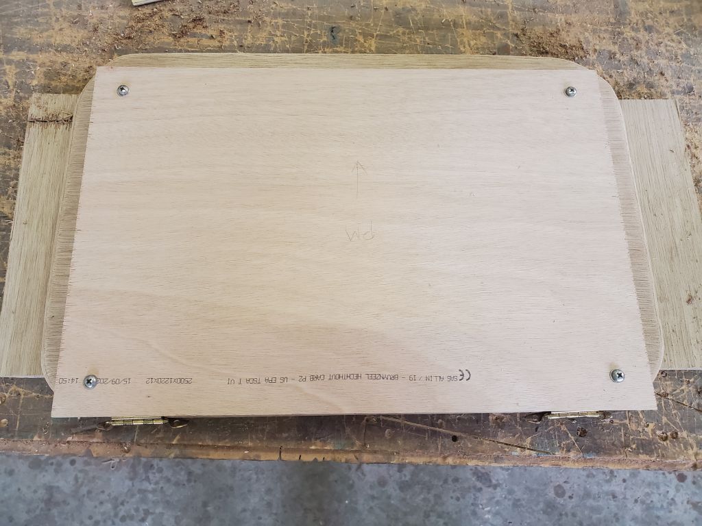
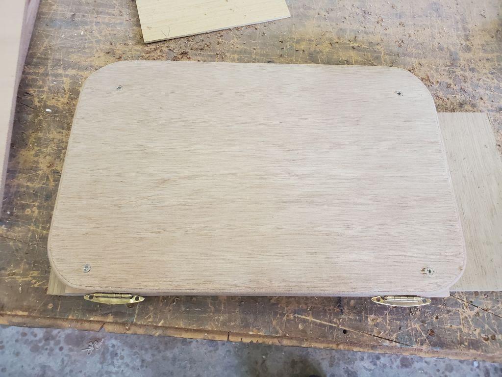
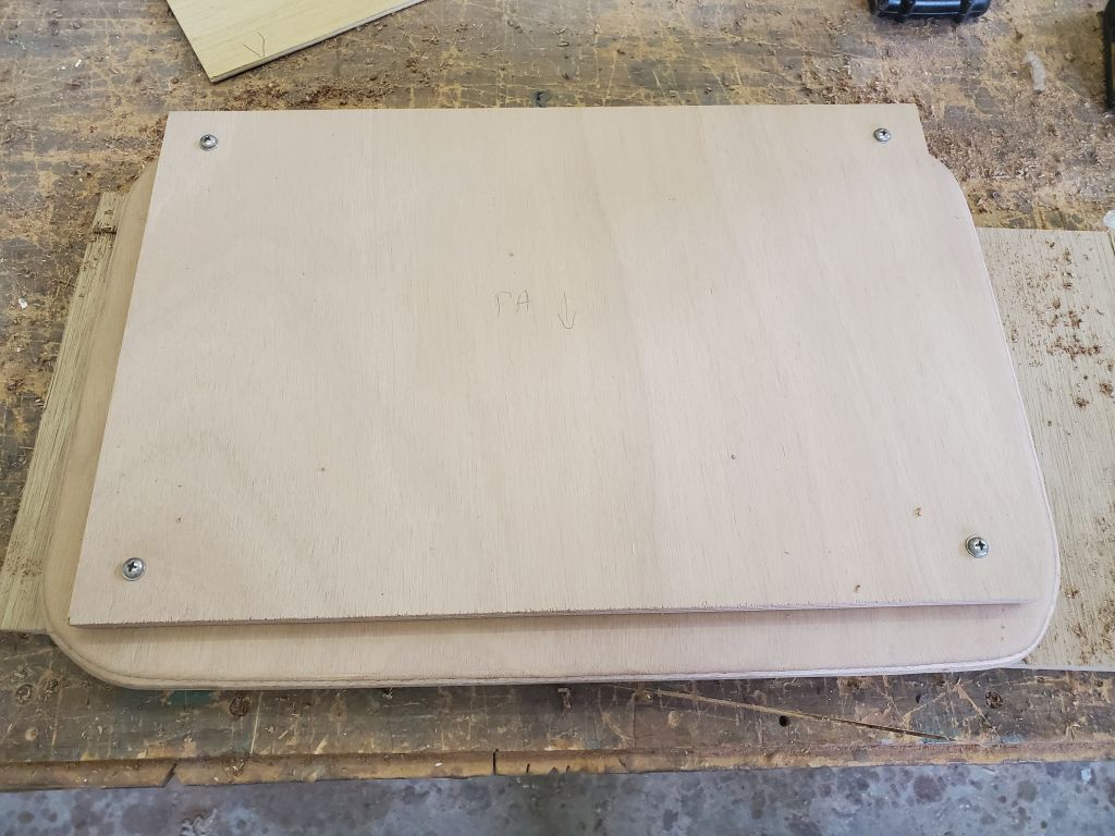
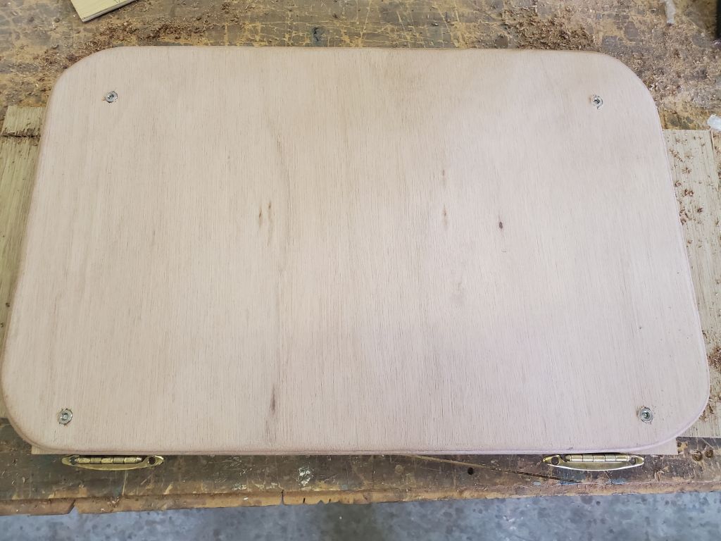
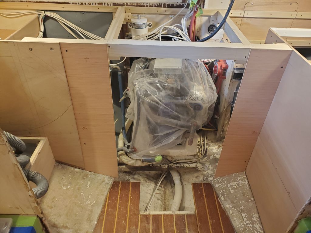
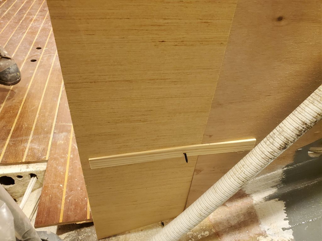
To begin the week, I set up a work station in the shop and laid out the loose plywood  panels I had so far–the two removable panels from the engine room, and the engine room front panel–then prepped and primed them, the first of three anticipated coats of paint.

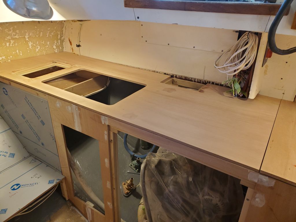
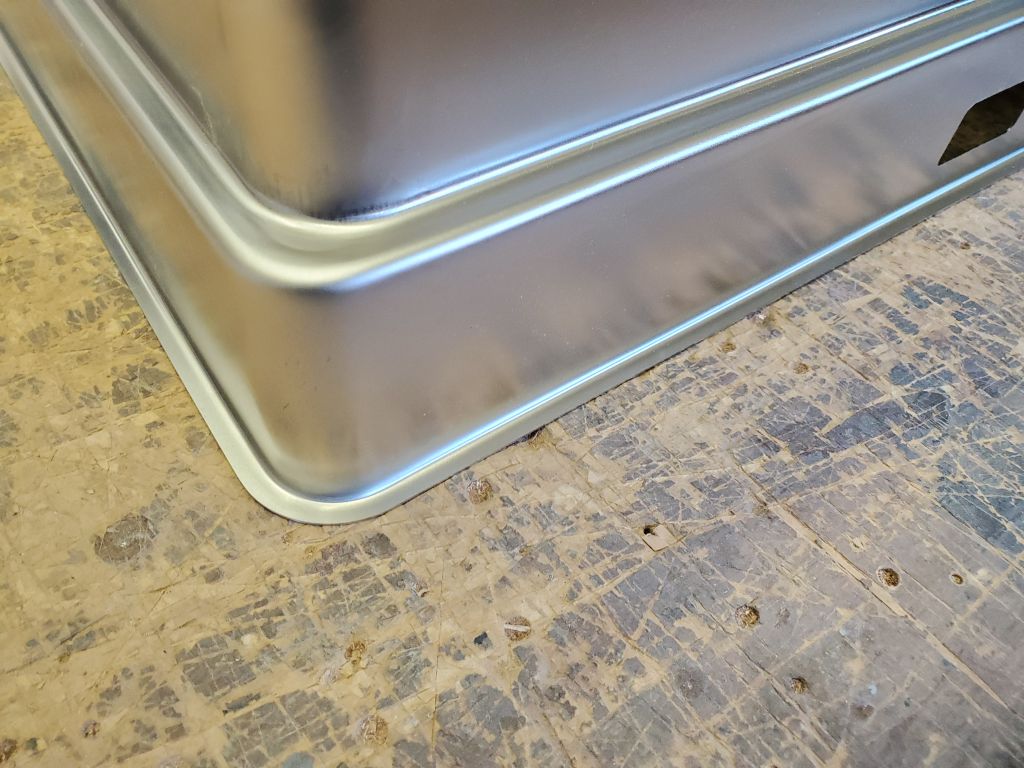
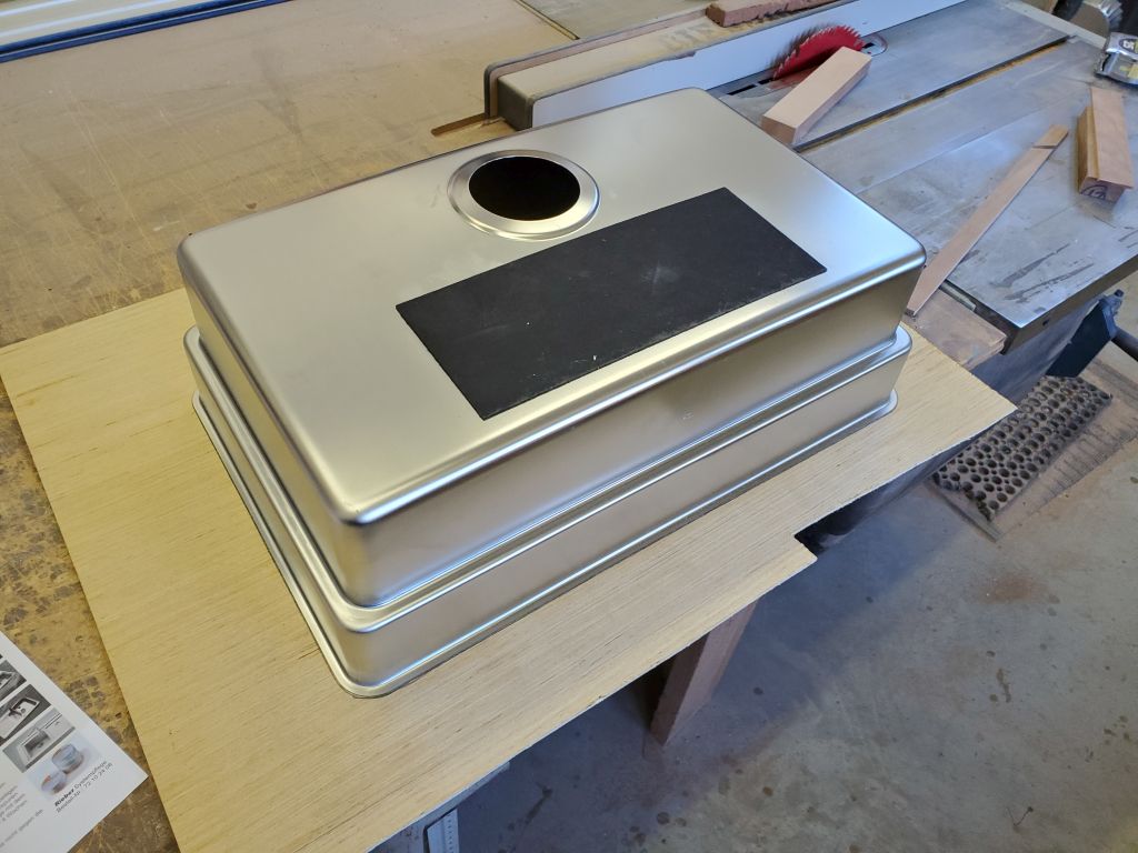
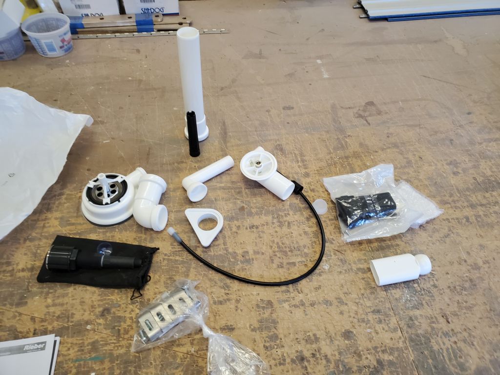
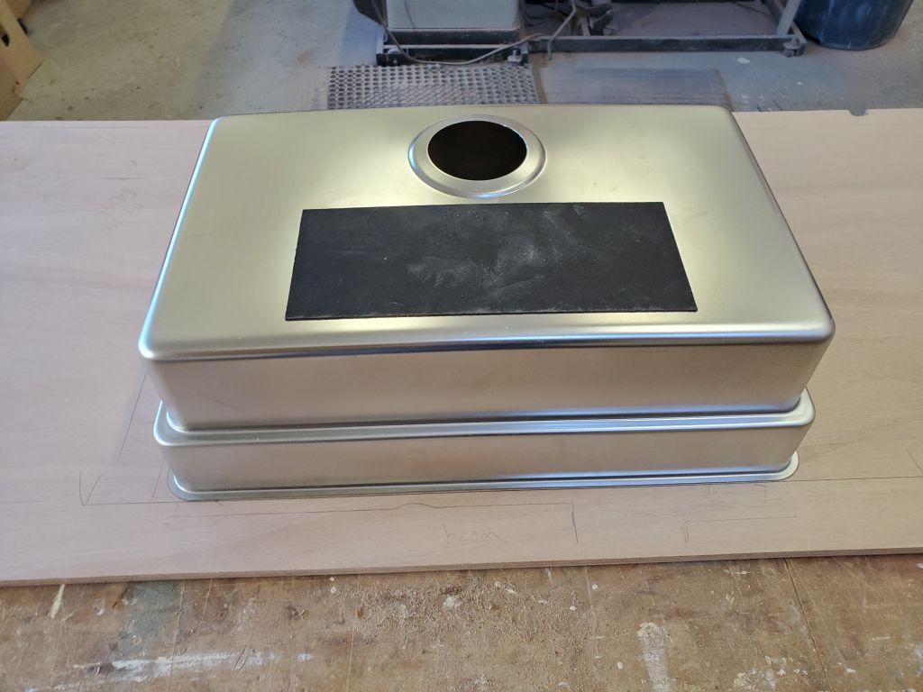
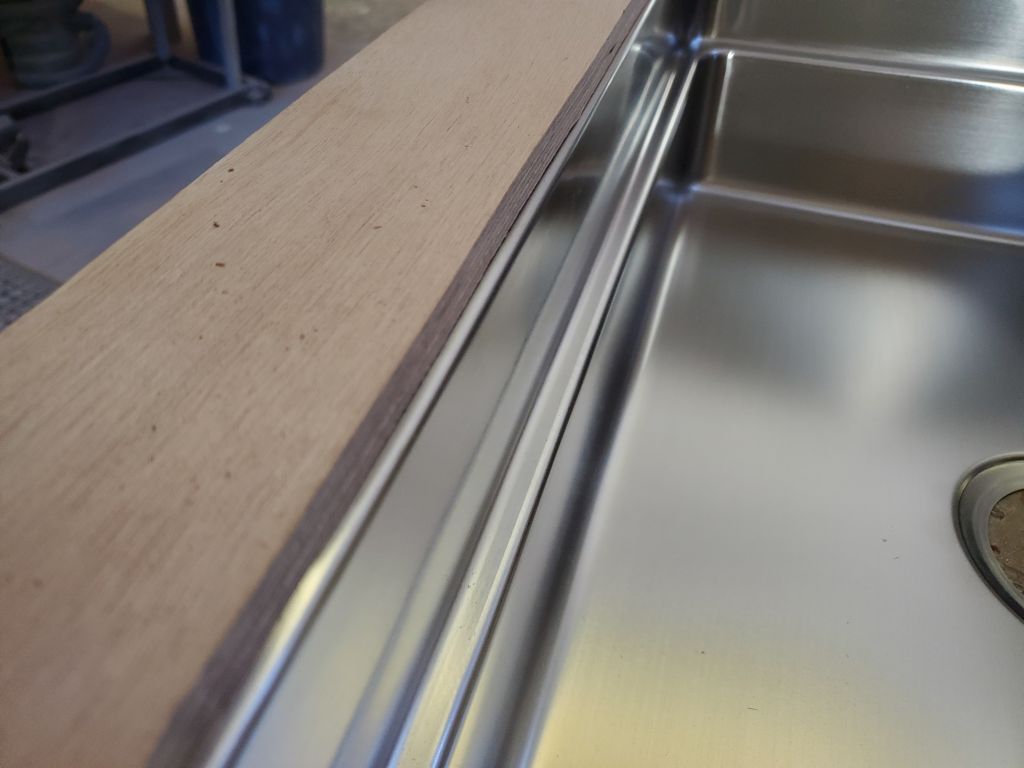
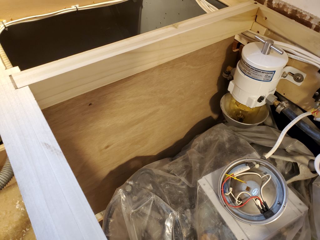
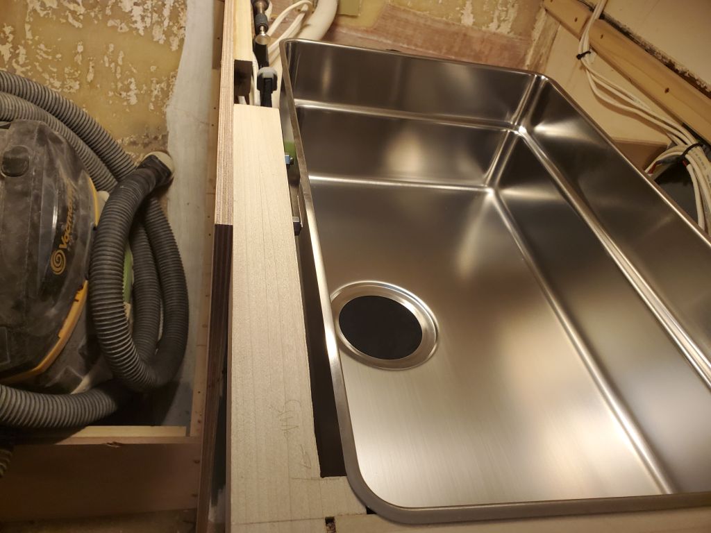
Much of the remaining detail and construction of the galley countertop and surrounds depended on the position of the sink, so next I made moves in this direction.  I’d had the sink out of its packaging a few days earlier so I could roughly determine its placement and how it would interact with structural members either already in place or being installed, but this was the first time I’d really looked at it in terms of final installation.  It was clear from the sink’s construction and the pictograph instructions that the sink was intended for under-mounting, with a narrow top flange meant to be pressed tightly to the underside of the counter with installation brackets from beneath.  I also unpacked all the related and included components of the drain system, mainly so I could figure out the overflow drain configuration.    I’d been planning a self-rimming (from the top) installation in the traditional way, and I might have continued in that direction even with the narrow support flange, but it was clear that the overflow drain would be in the way of sink installation from the top, and there was no way I was going to consider its installation and connection with the sink in place and the difficult access thereunto.

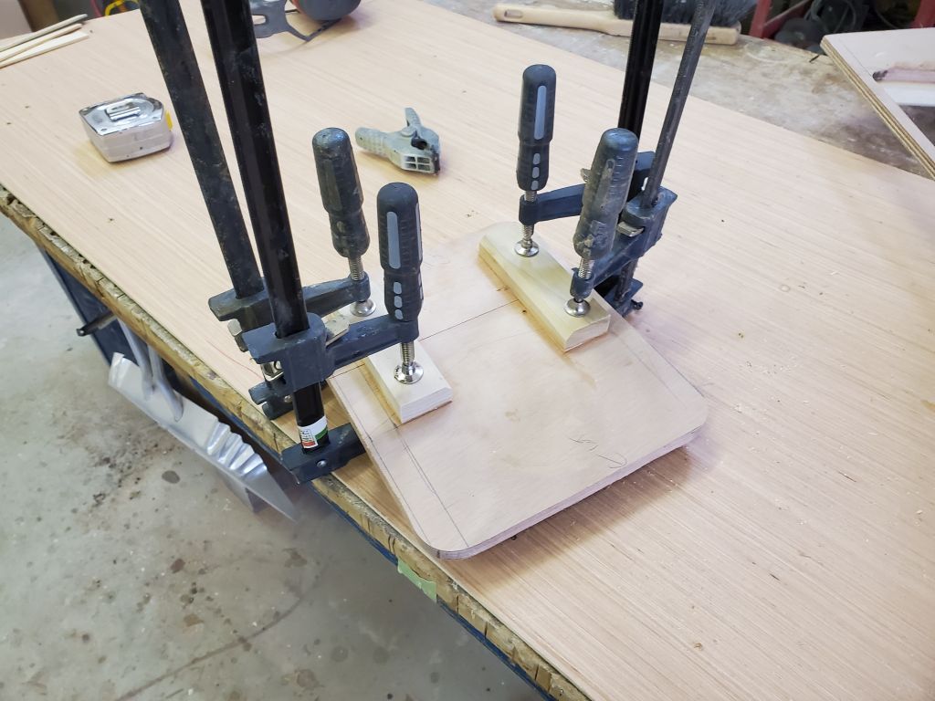
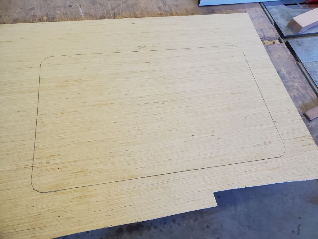
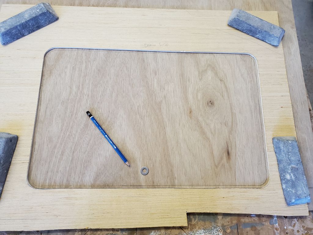
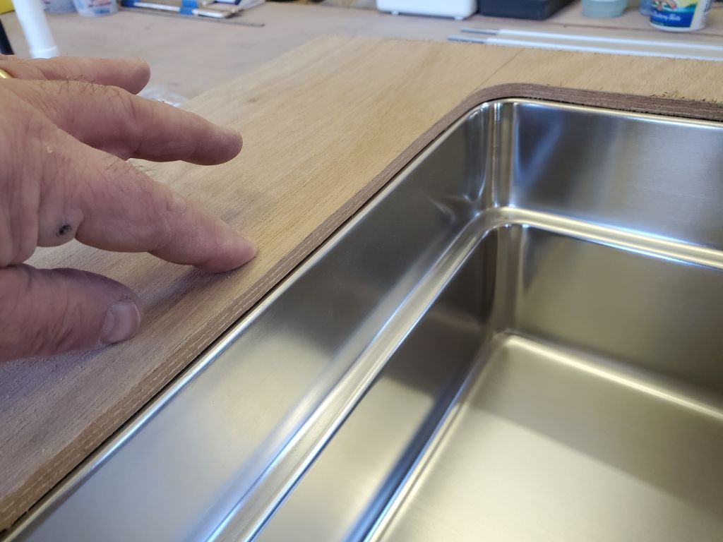
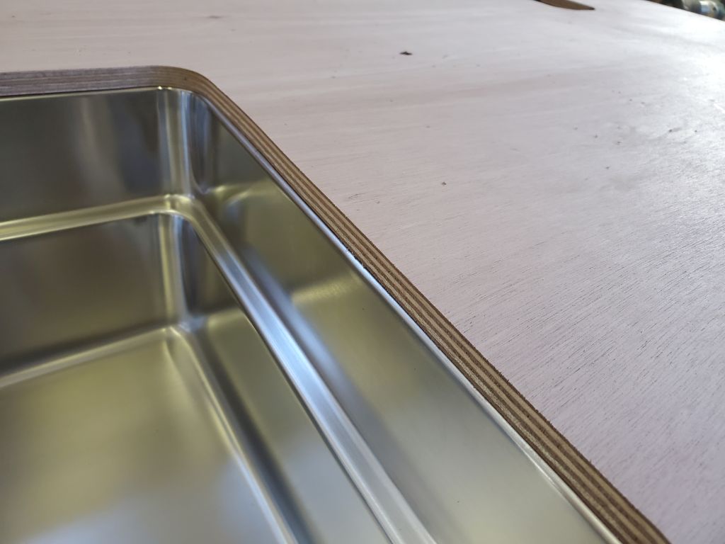
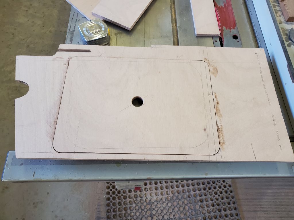
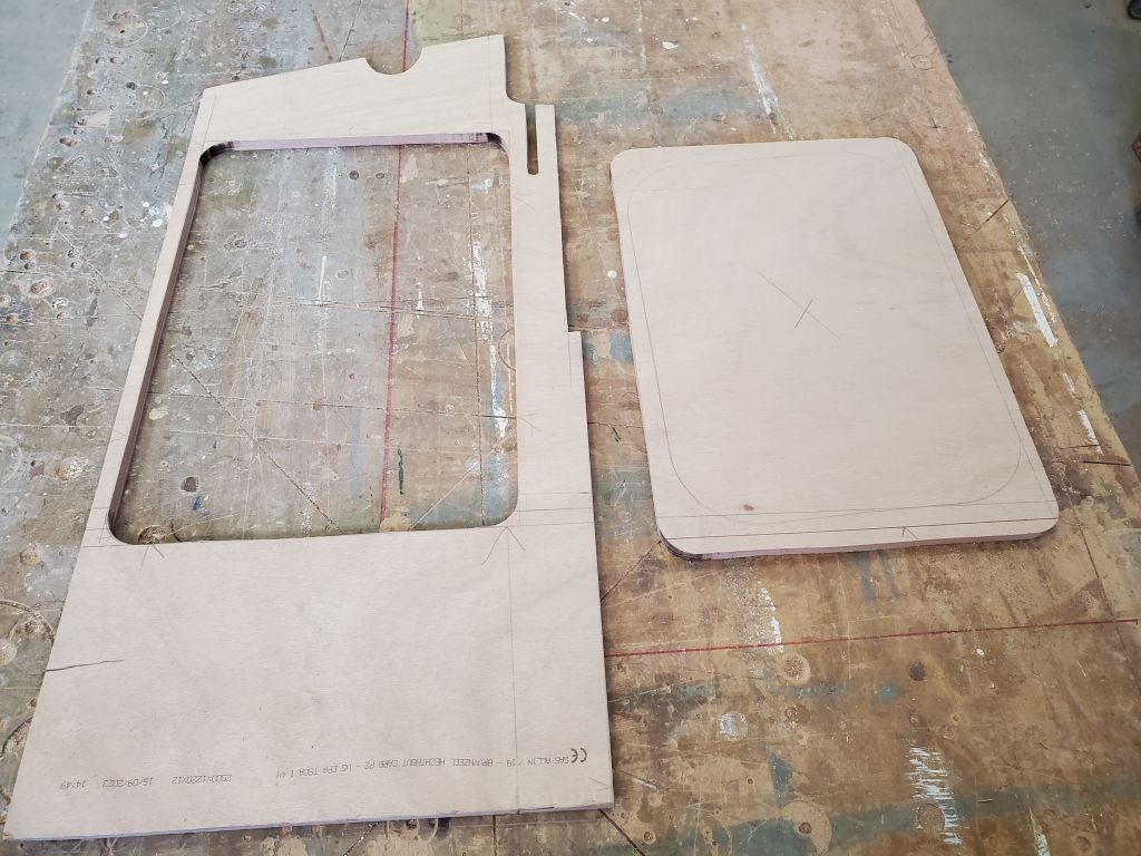
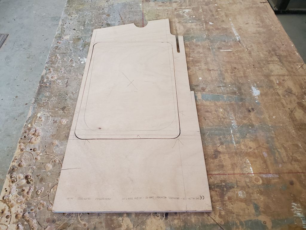
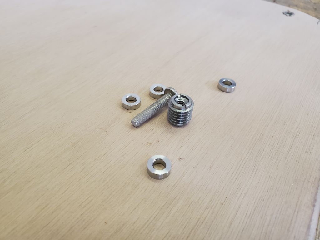
To undermount the sink meant that I required a highly accurate template, so I began by tracing the overall outline of the sink (i.e. the edge of the outward flange) onto some pattern plywood, which opening I then cut out carefully and fine-tuned till it was clean, fair, and accurate.  Then, I traced along the inside of the pattern but at a 1/4″ offset, which I’d determined would give the final opening the correct reveal at the top edge of the sink.  With the initial template held flat on a piece of 9mm plywood I planned to use for the final template, I traced the opening with a pencil inside a small washer (5/16″ ID), which gave me a nice line with the proper offset (or inset, if you will).

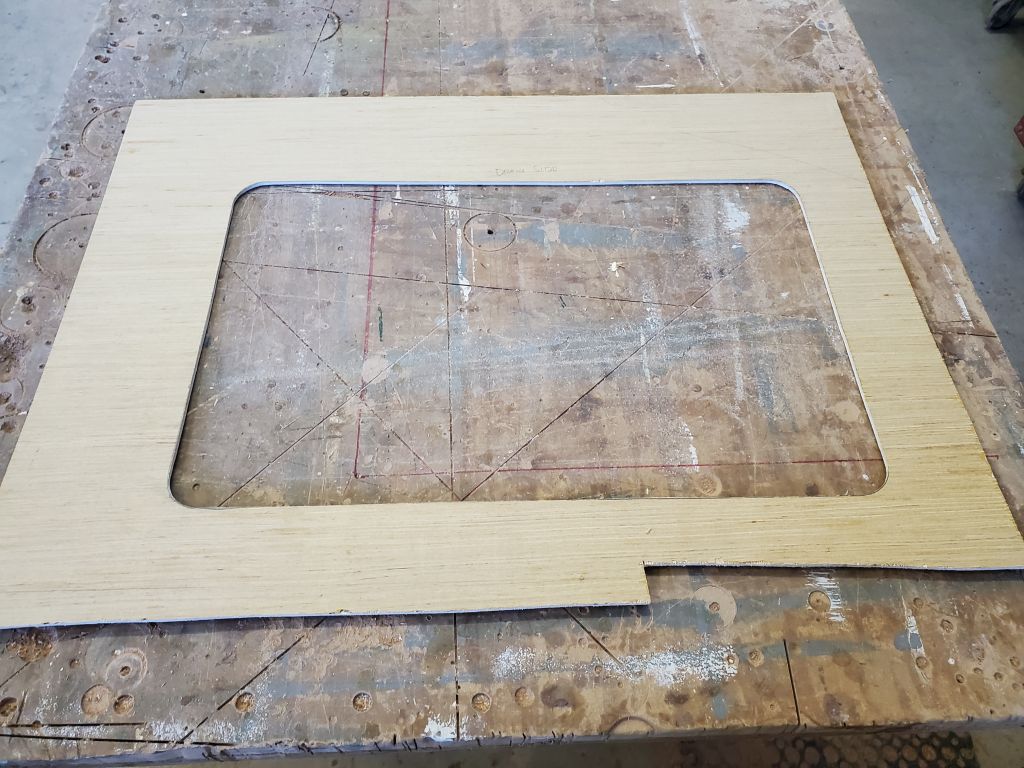
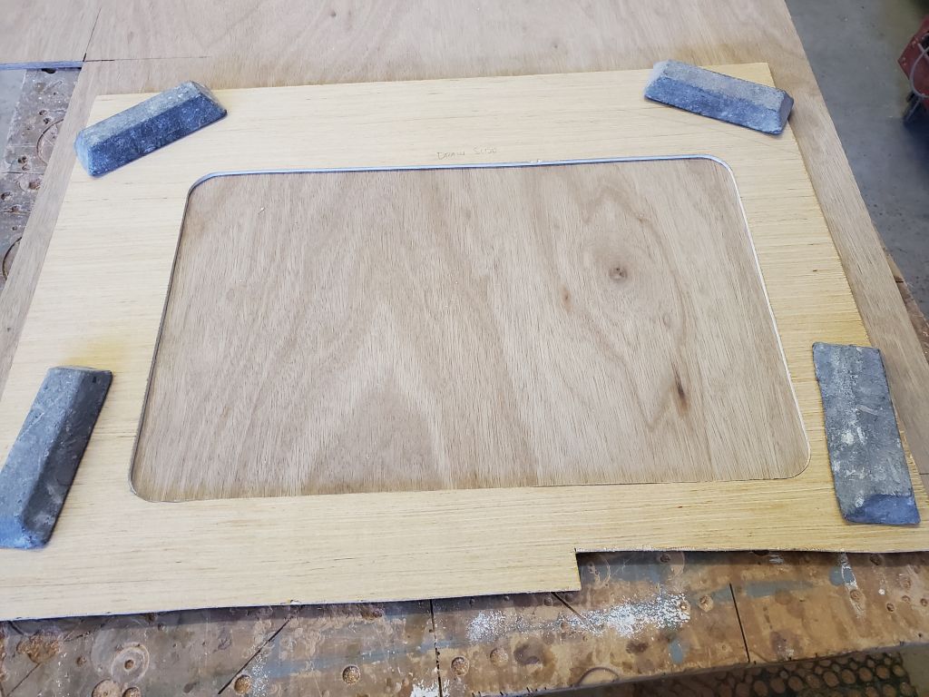
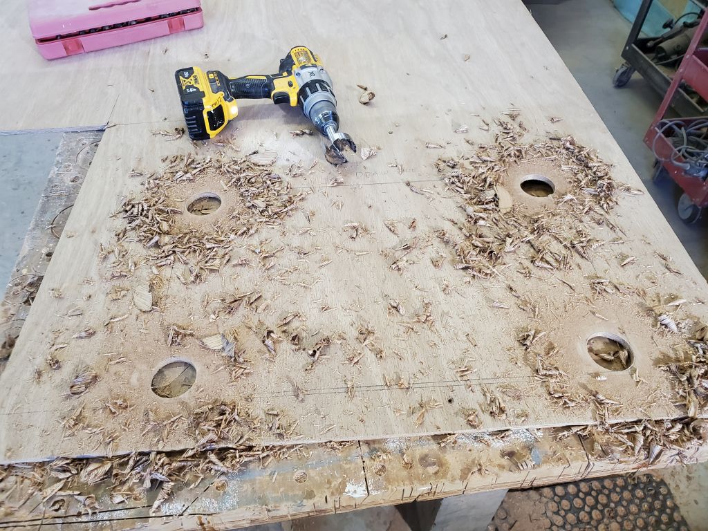
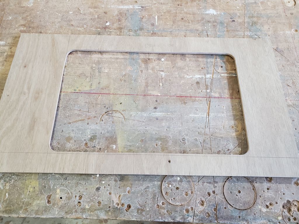
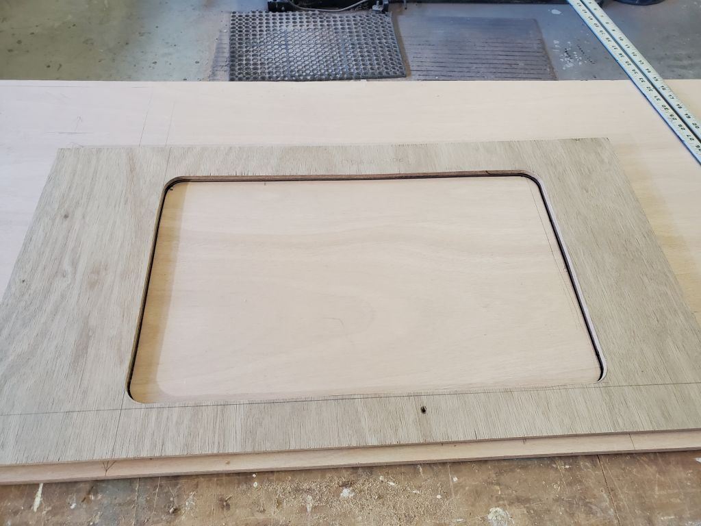
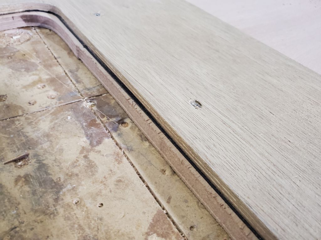
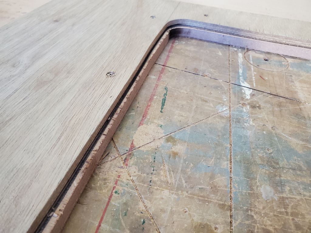
Next, I cut the new opening in the 9mm plywood, starting with large holes at the corners to create the proper radius, then connecting them with saw cuts.  After some fine-tuning and minor fairing, this created a template of the actual opening size I’d need to cut in the countertop, and which template I could use with a router to follow the pattern and make an exact cut.  The template opening sat just outside of the upper radius on the sink, as intended and as aesthetically and functionally required.

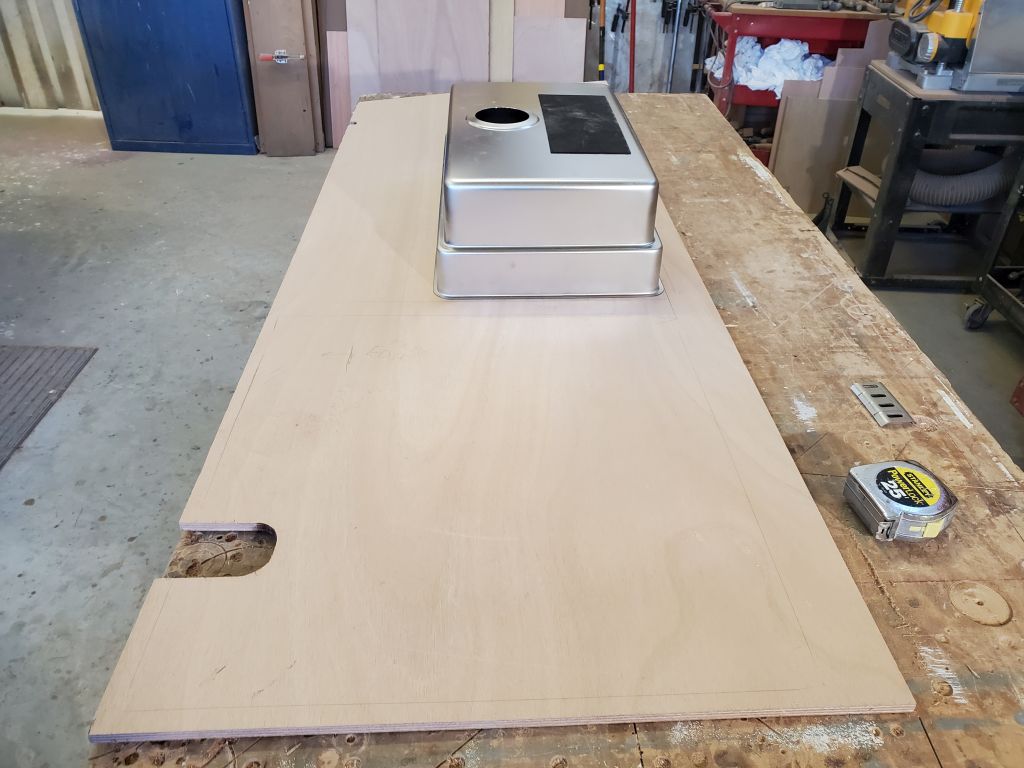
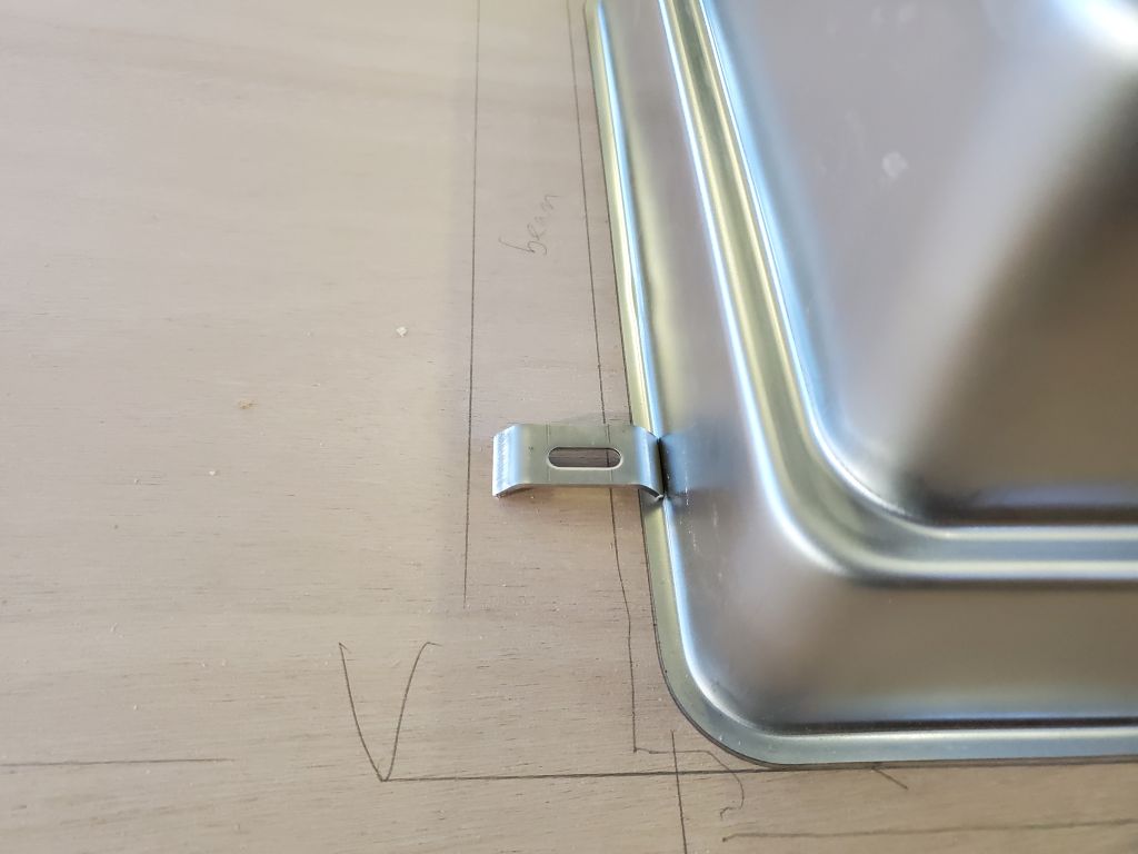
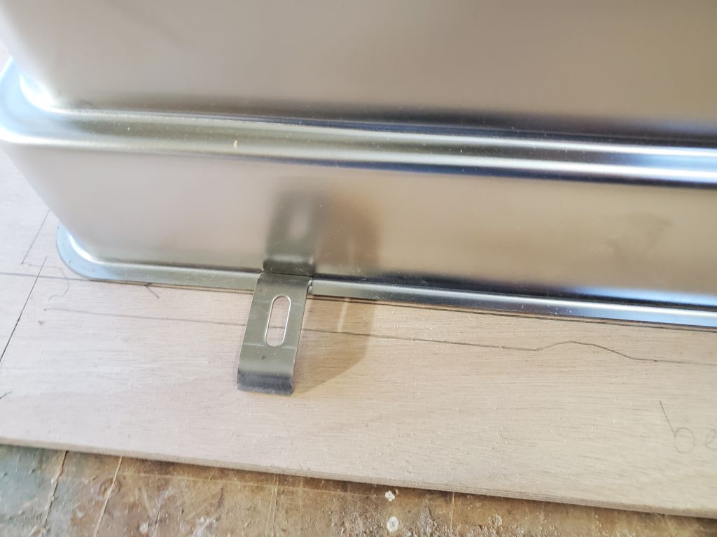
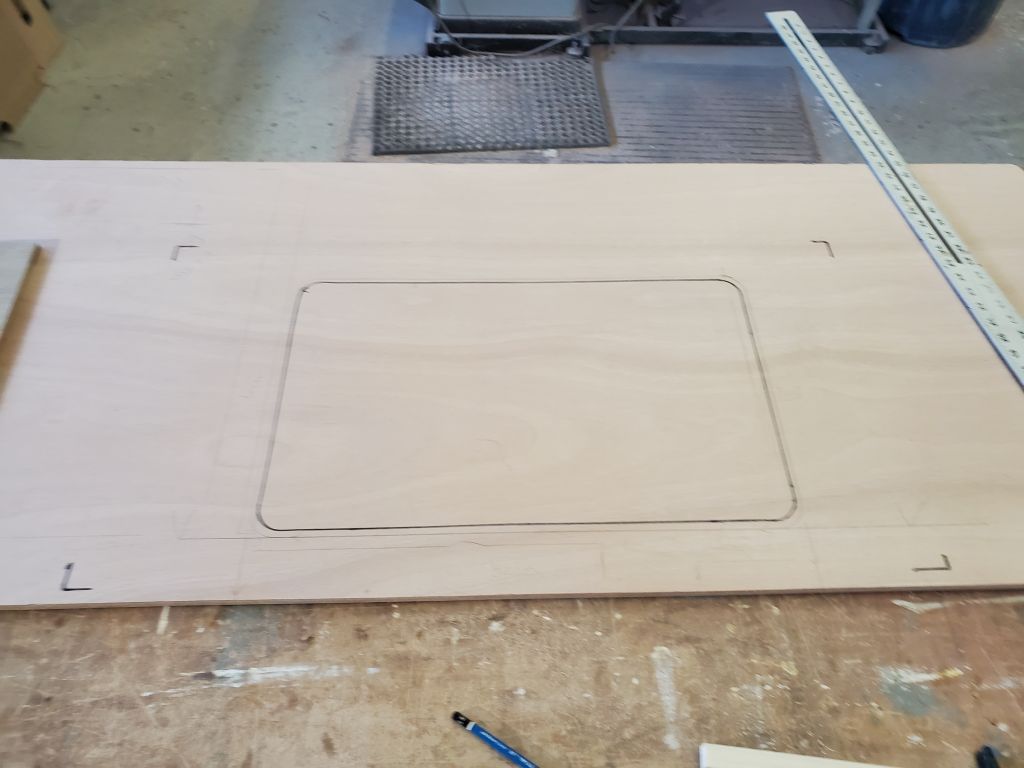
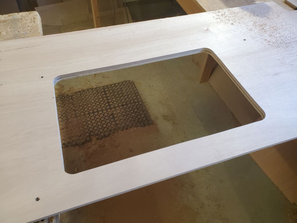
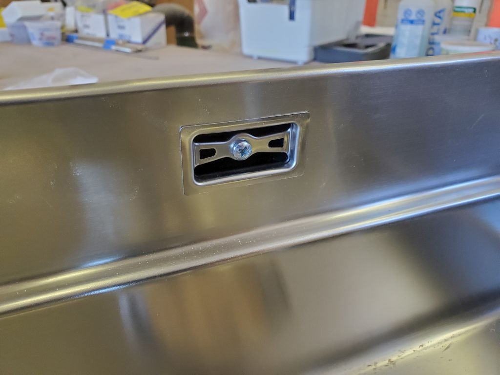
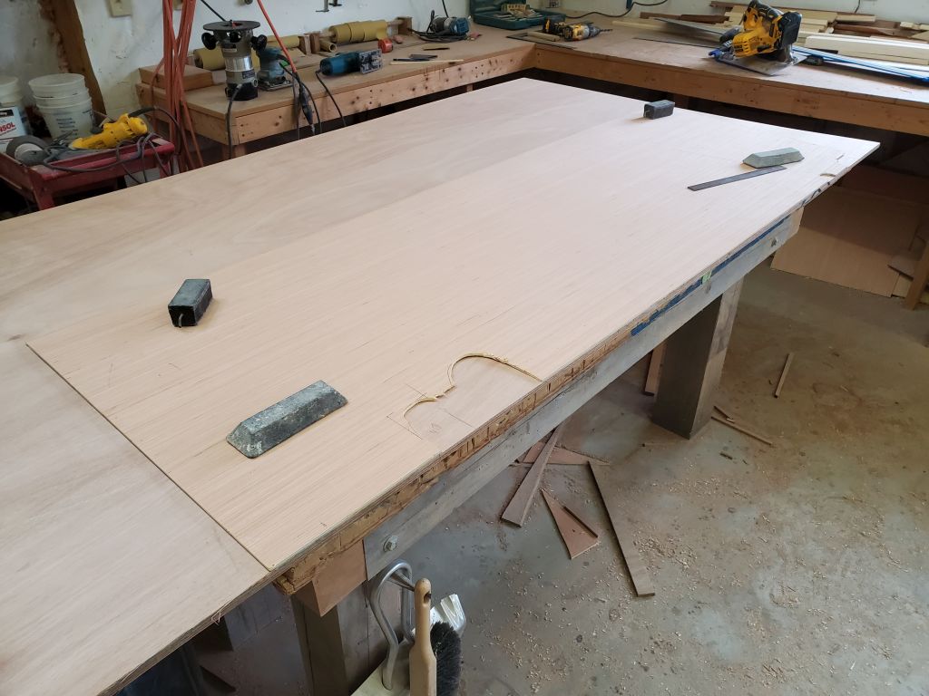
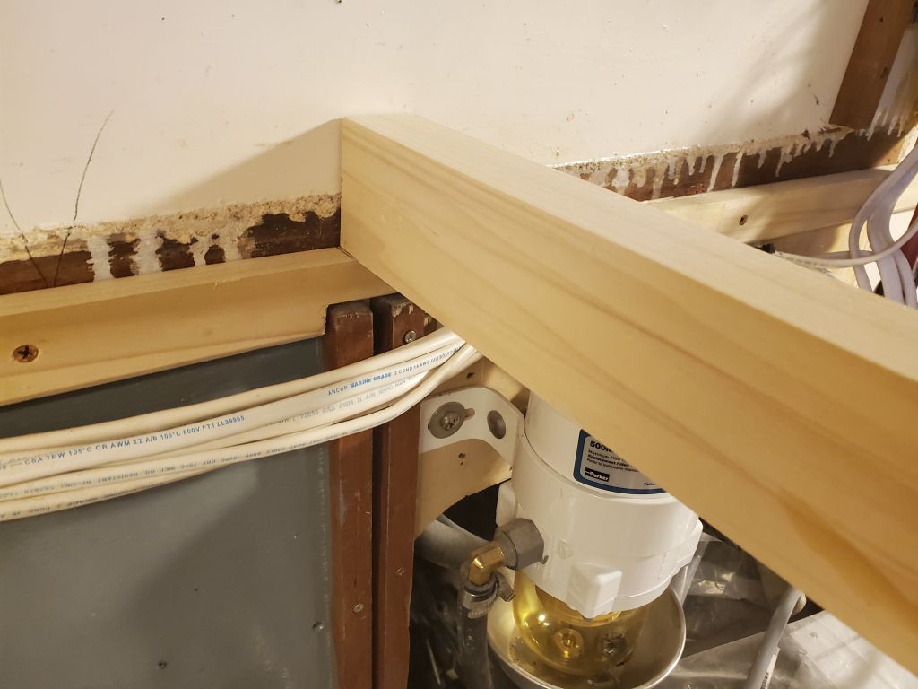
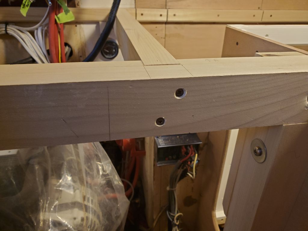
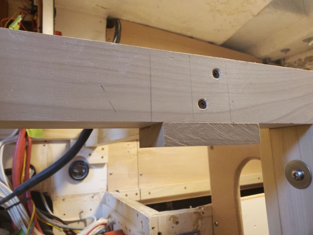
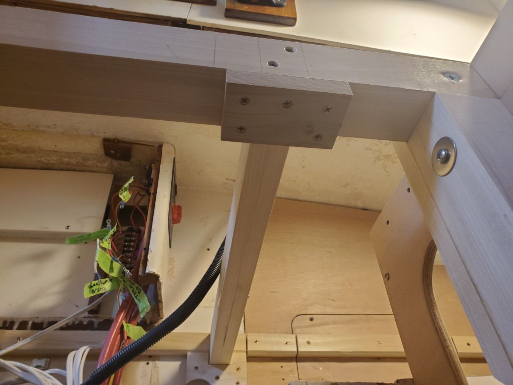
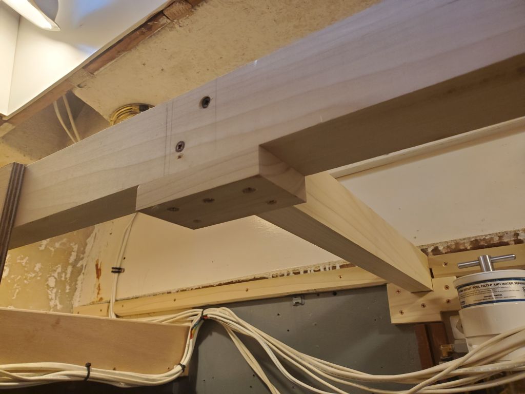
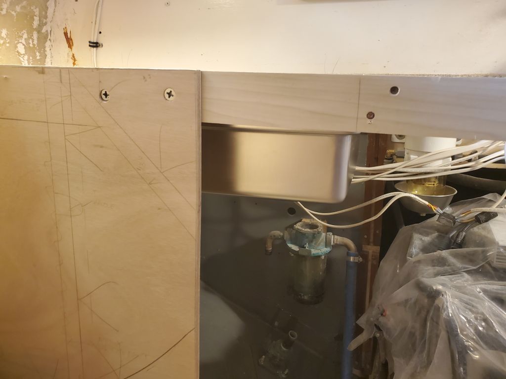
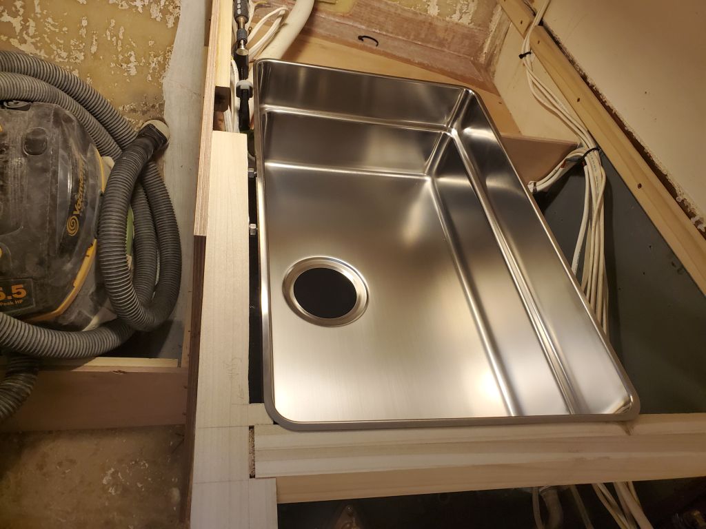
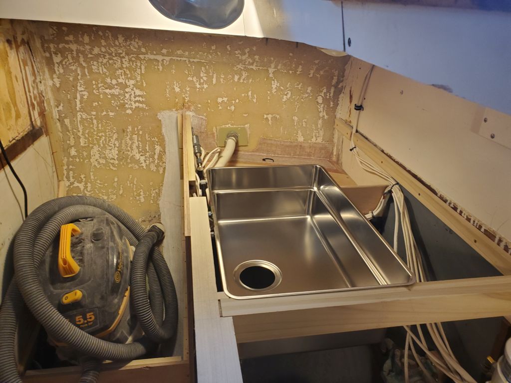
With the sink positioned upside down on the underside of the countertop, I determined its final position so I could lay out the template and make the cut.  I made sure there’d be room for the installation brackets, which would pin the sink tightly to the underside of the counter; I’d have to make a relief cut or two in the galley support beam to leave room for these clips in the final installation, but that posed no issue.  Once I’d finalized the position of the sink taking all necessary factors into consideration, I traced the outline of the pattern so I could cut out the bulk of the opening with a jigsaw.

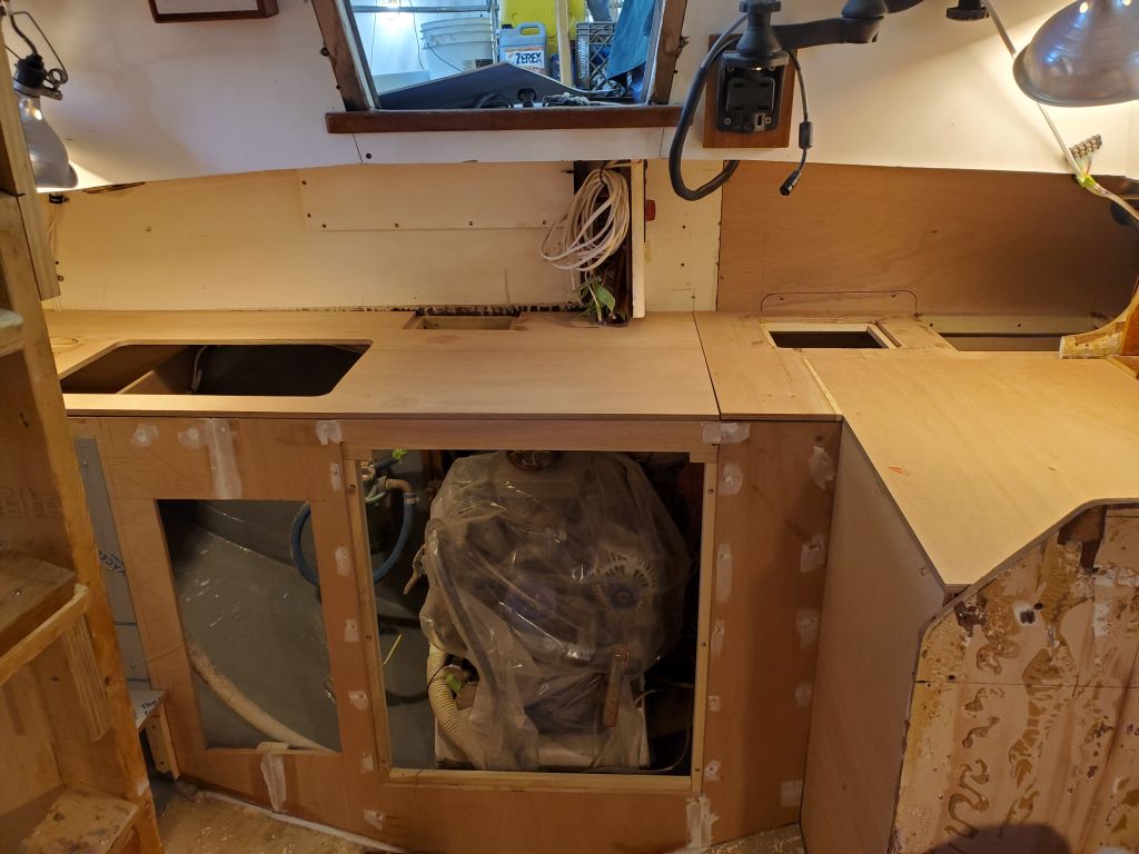
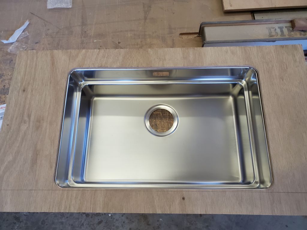
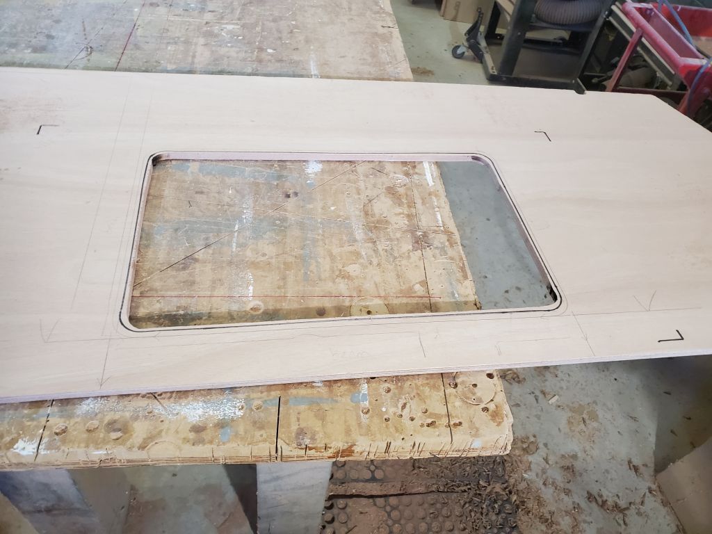
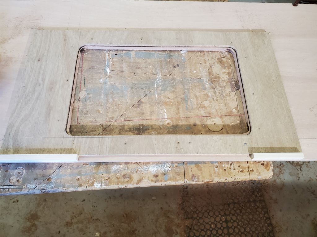
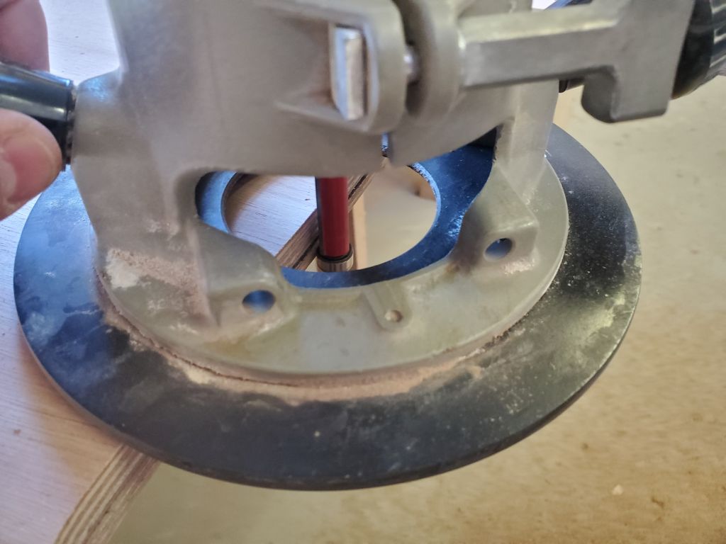
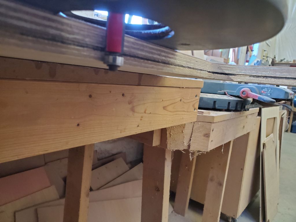
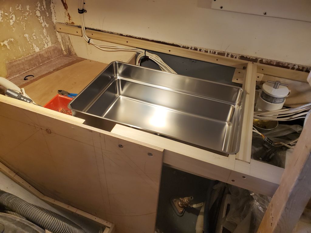
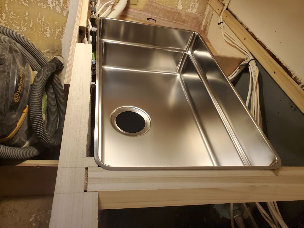
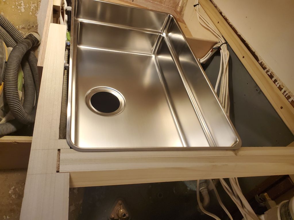
I reinstalled the pattern in the correct position, securing it with screws all around, then used a router and a pattern bit to make the final cut and replicate exactly the template.

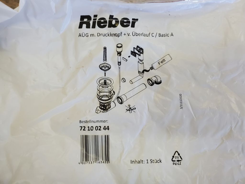
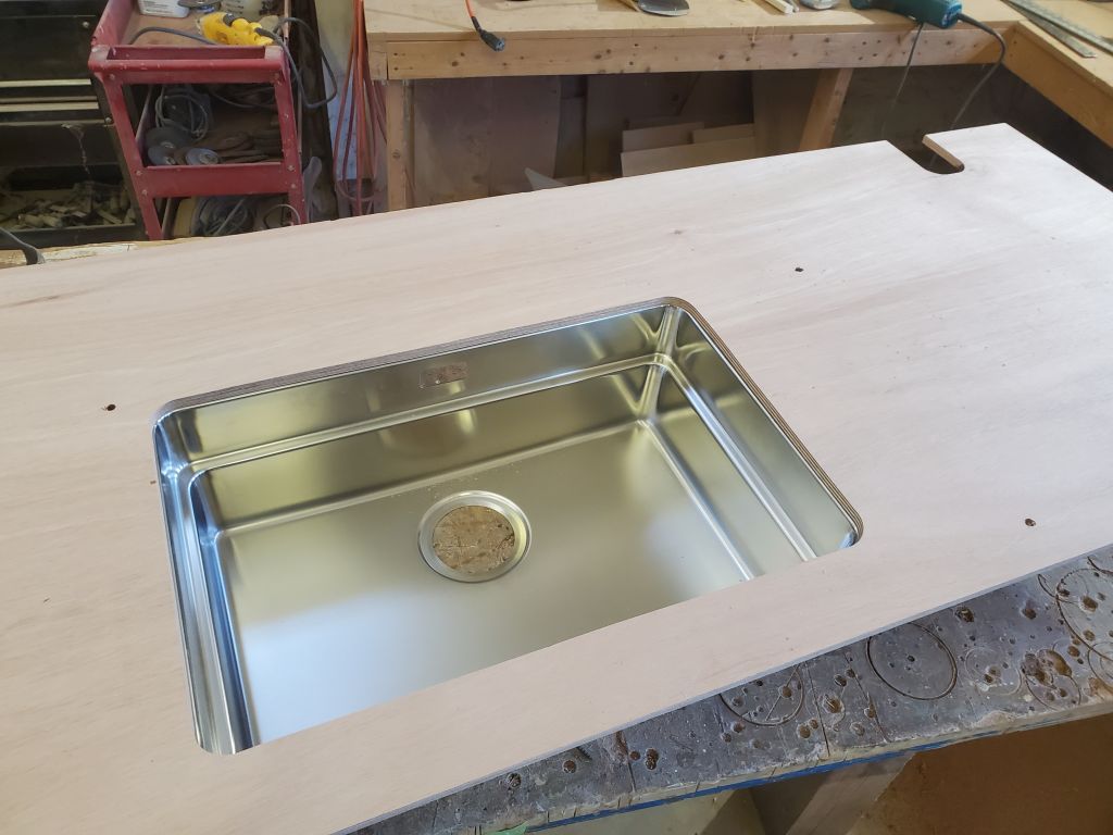
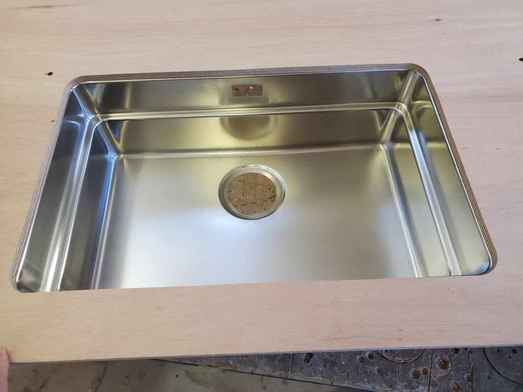
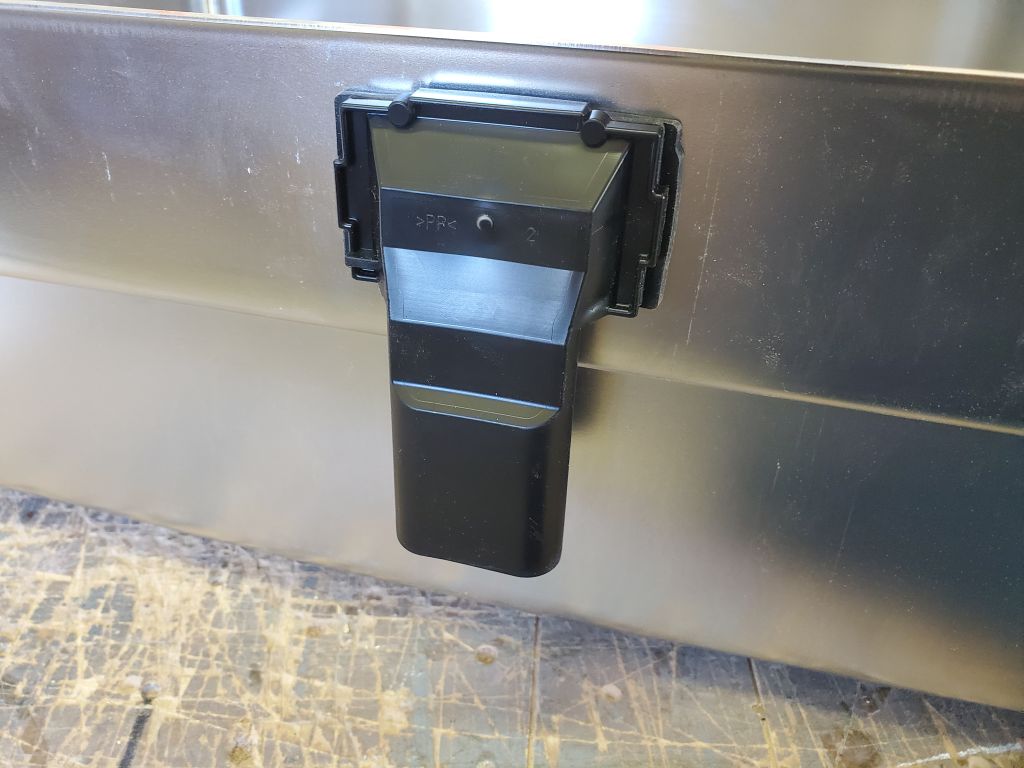
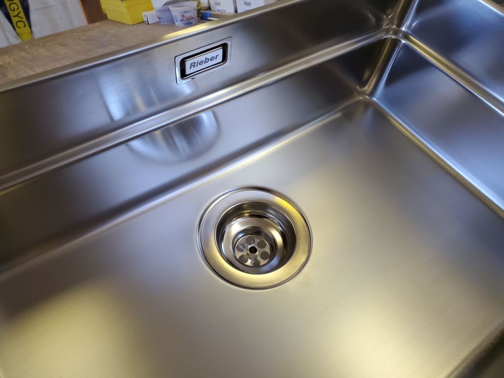
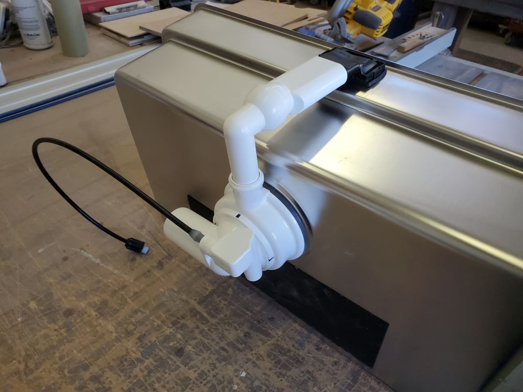
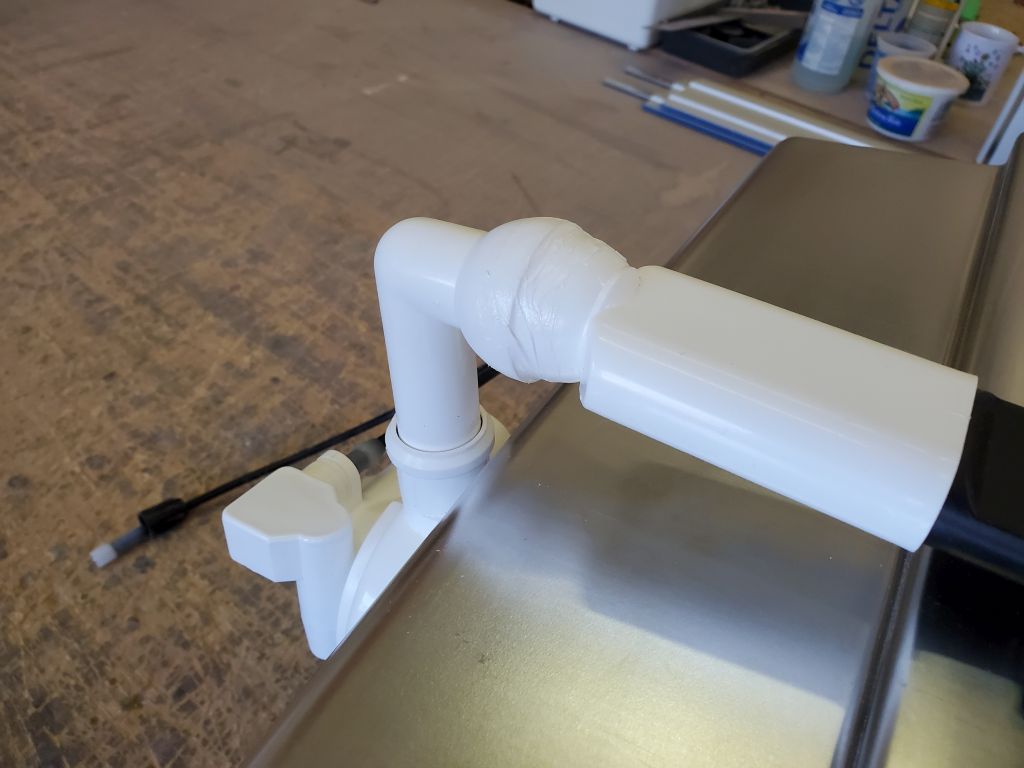
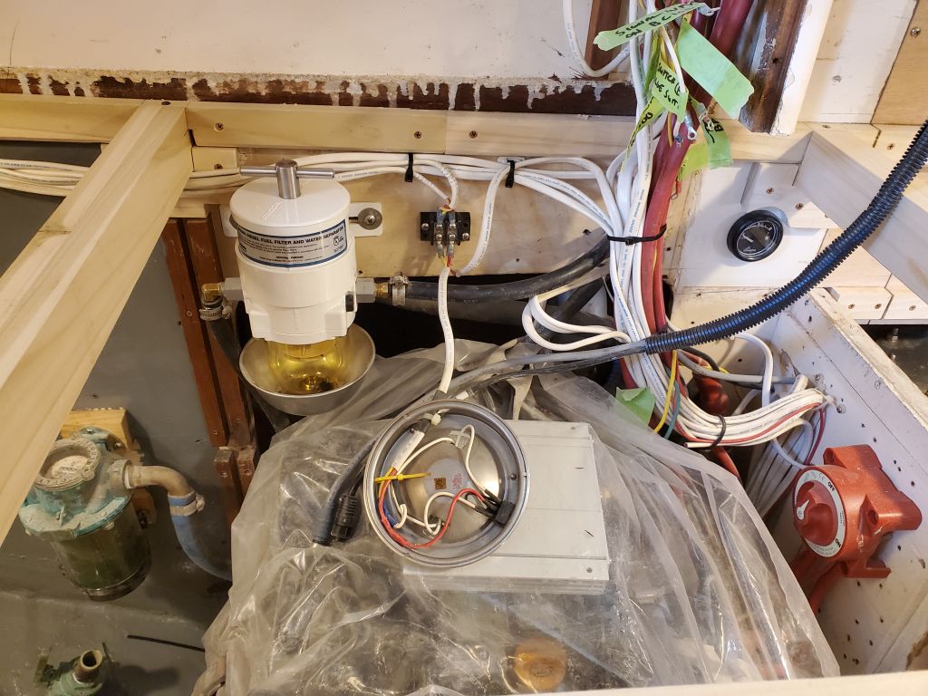
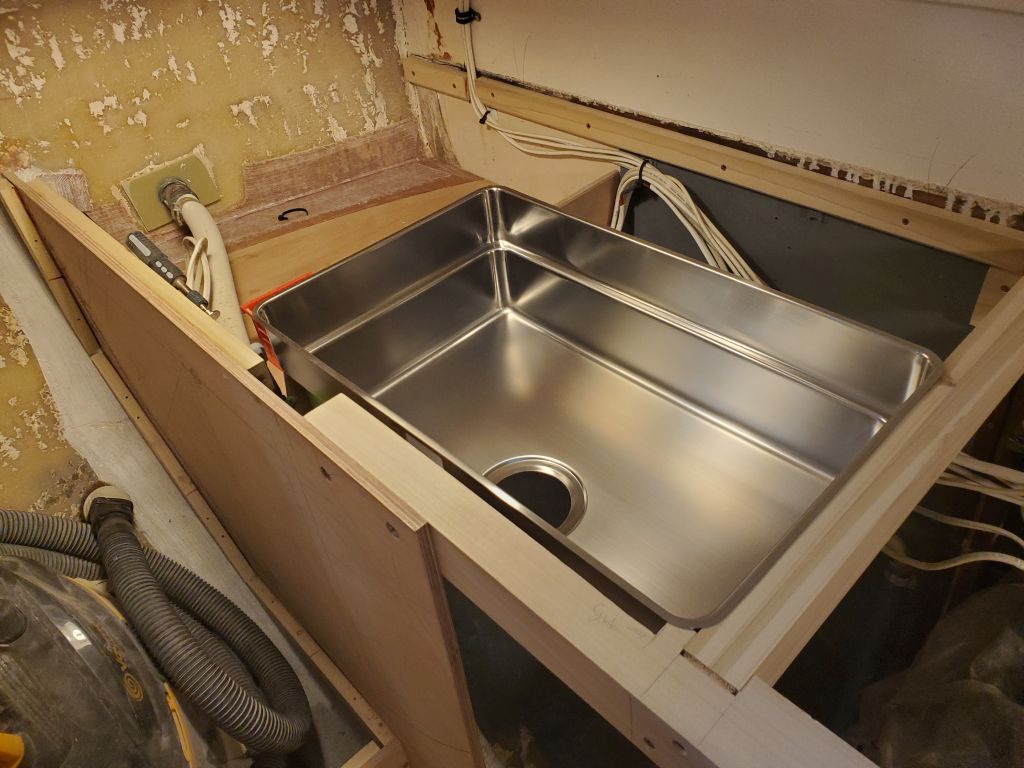
Now I had the required opening, finally, and while I had all the sink paraphernalia spread out I decided I might as well install the drain so the sink would be ready for final installation whenever I needed it.  It took a little while to puzzle out the drain components included with the sink, but once I did the final installation was pretty straightforward.  The drain system included a remote-activated push-button device (to be set flush in the countertop) for operating the (I think) drain/stopper system, and I might have avoided using this but it was integrally required with the whole setup.  The overflow drain included a sort of universal ball joint for its joint with the elbow leading to the main drain assembly, allowing leeway in final positioning, and once I had that figured out and the elbow cut to the appropriate length, it made final assembly of the disparate parts as straightforward as possible.  Per the instructions, I added sealant to the ball during final assembly.

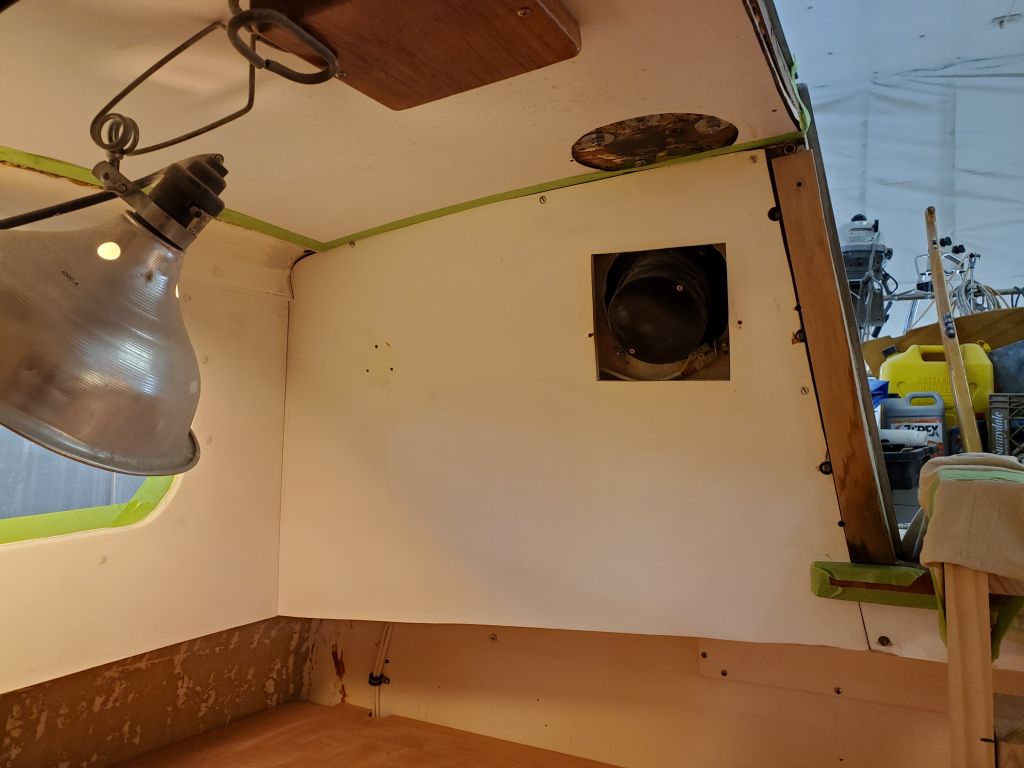
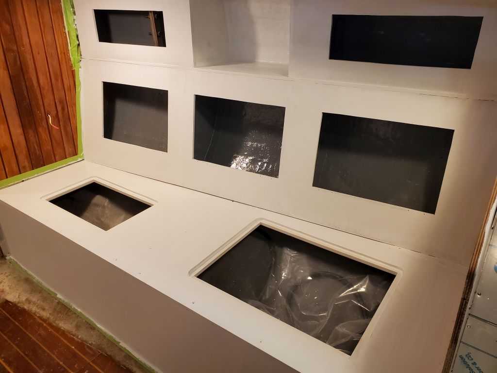
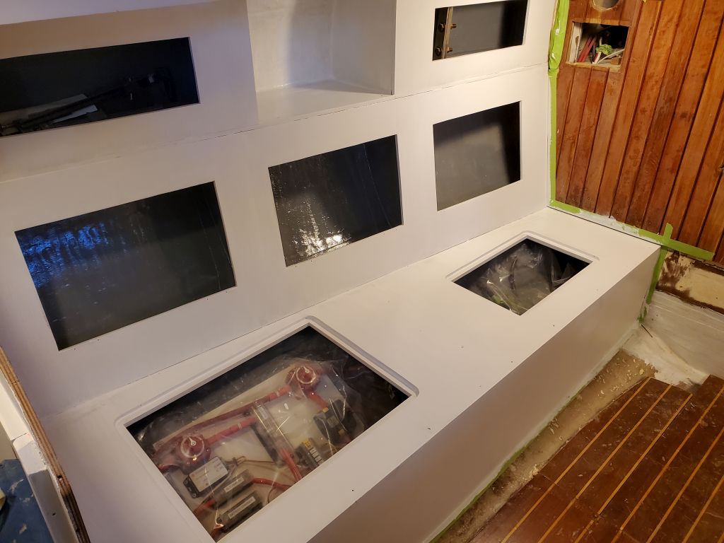
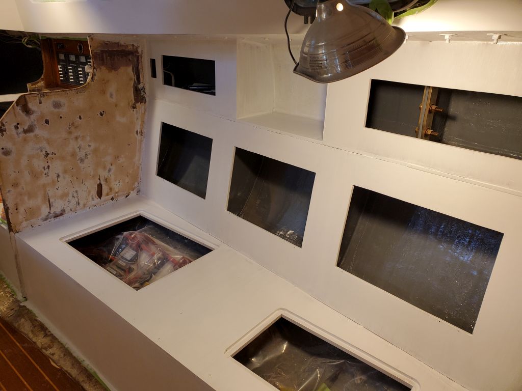
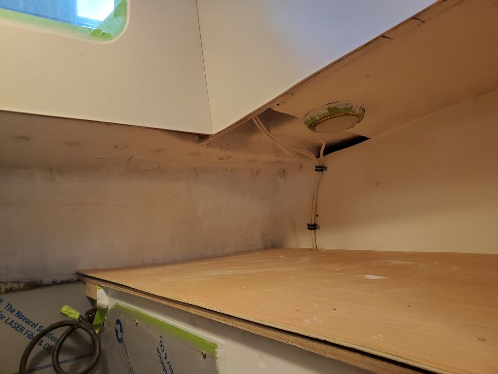
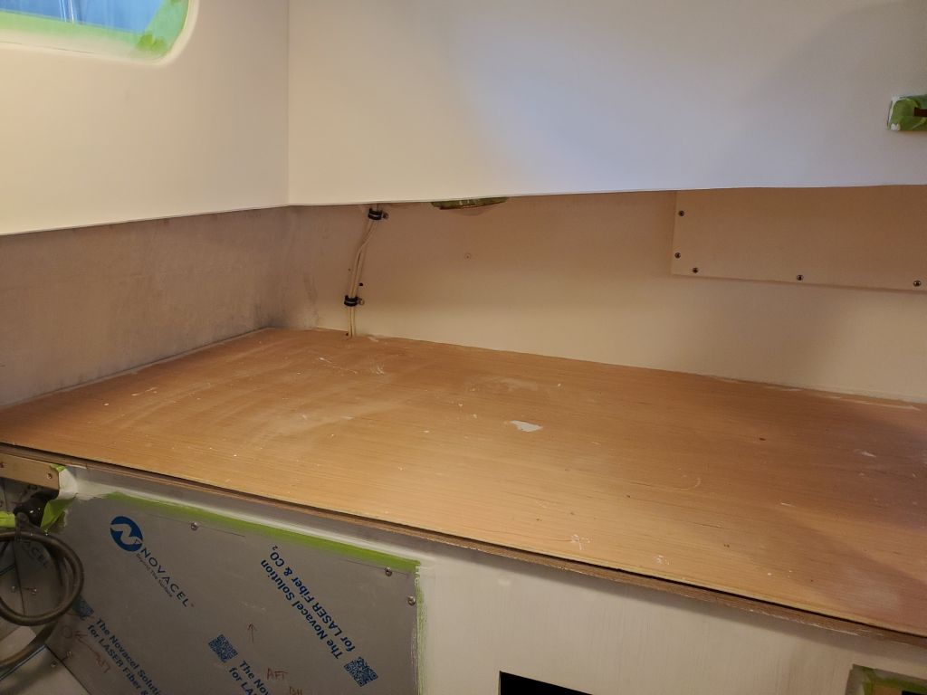
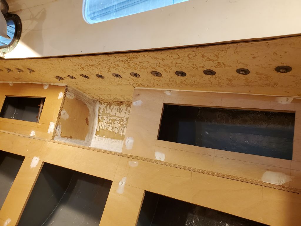
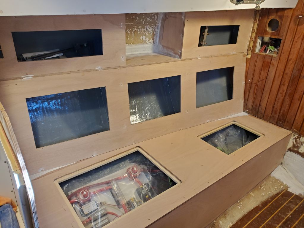
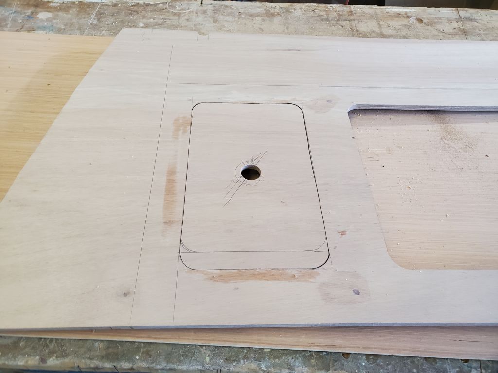
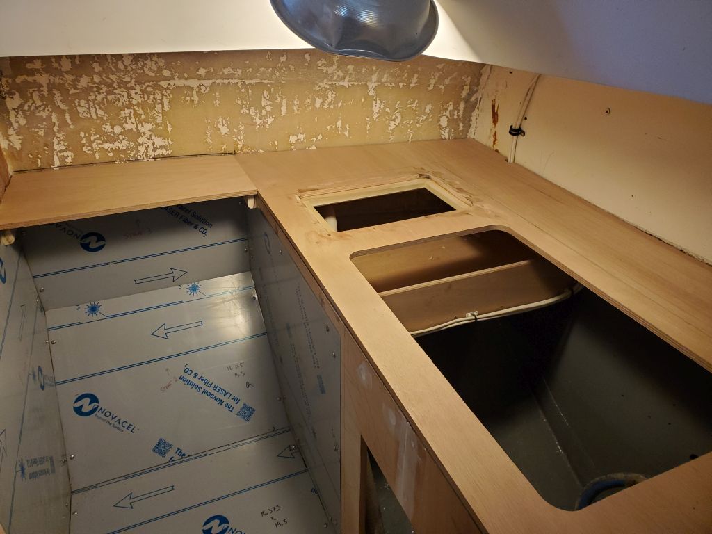
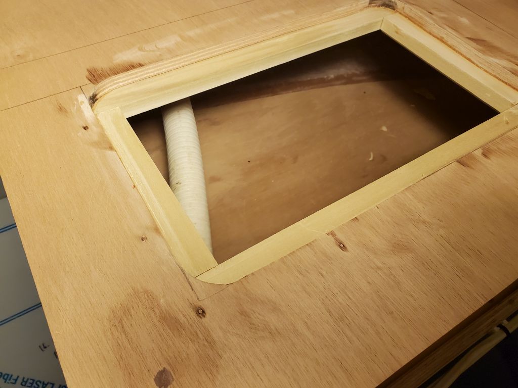
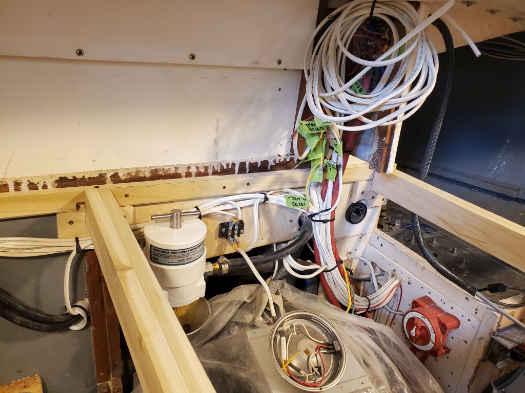
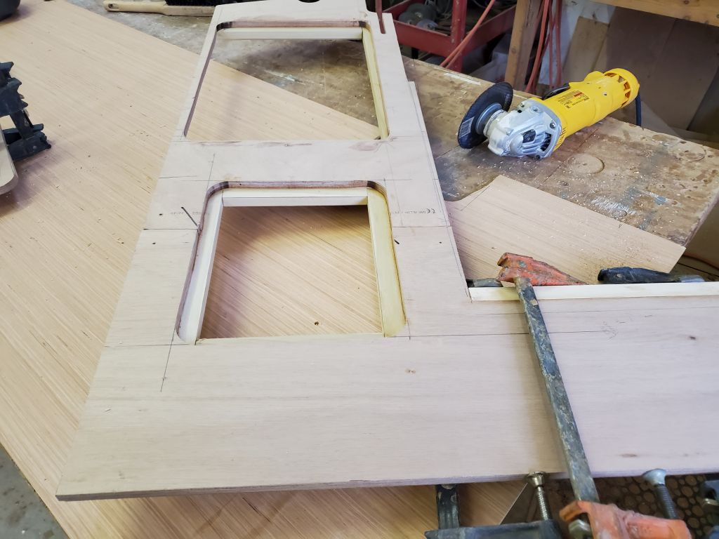
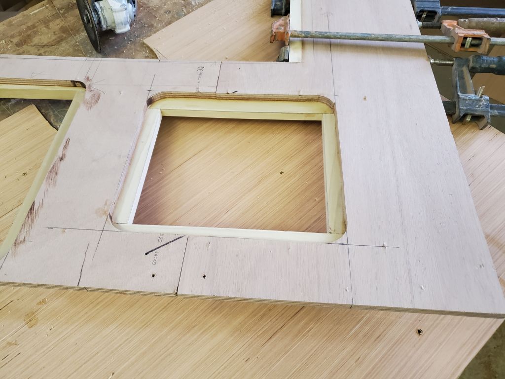
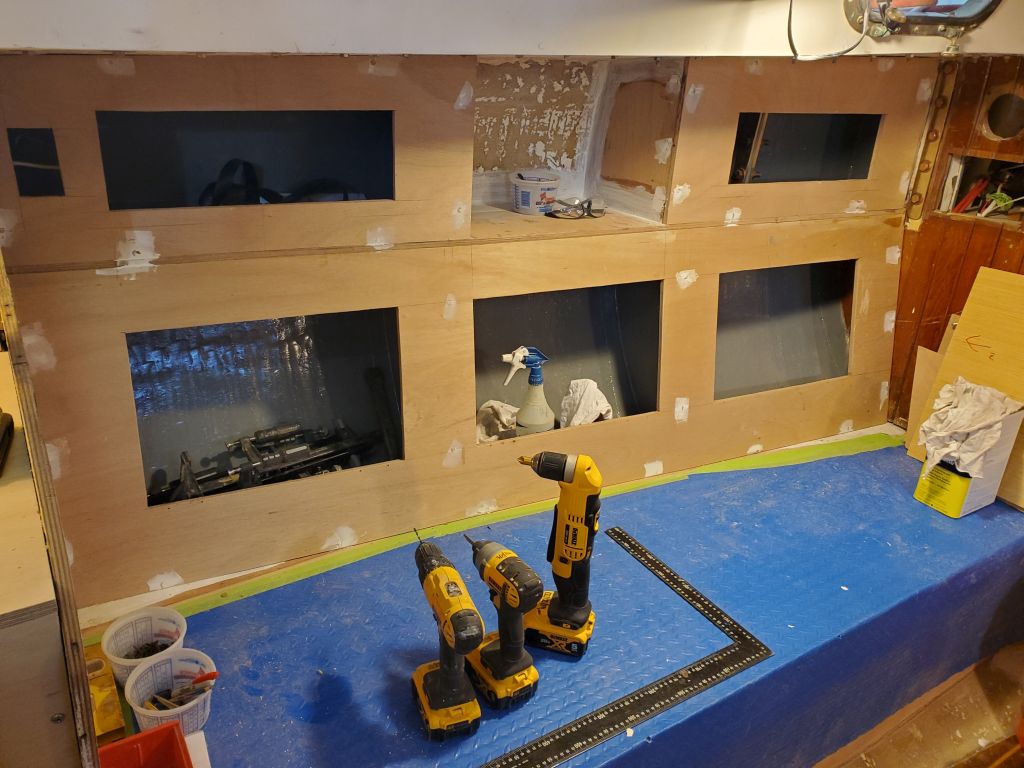
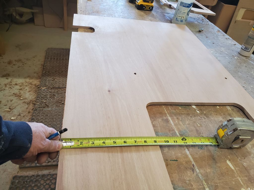
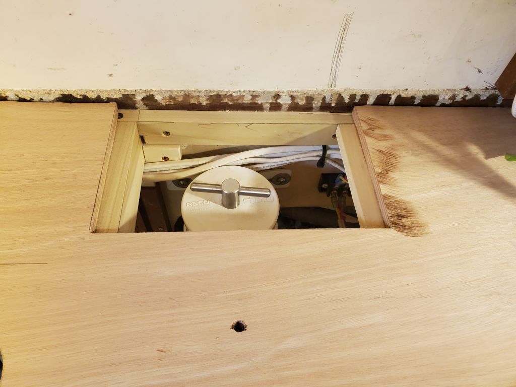
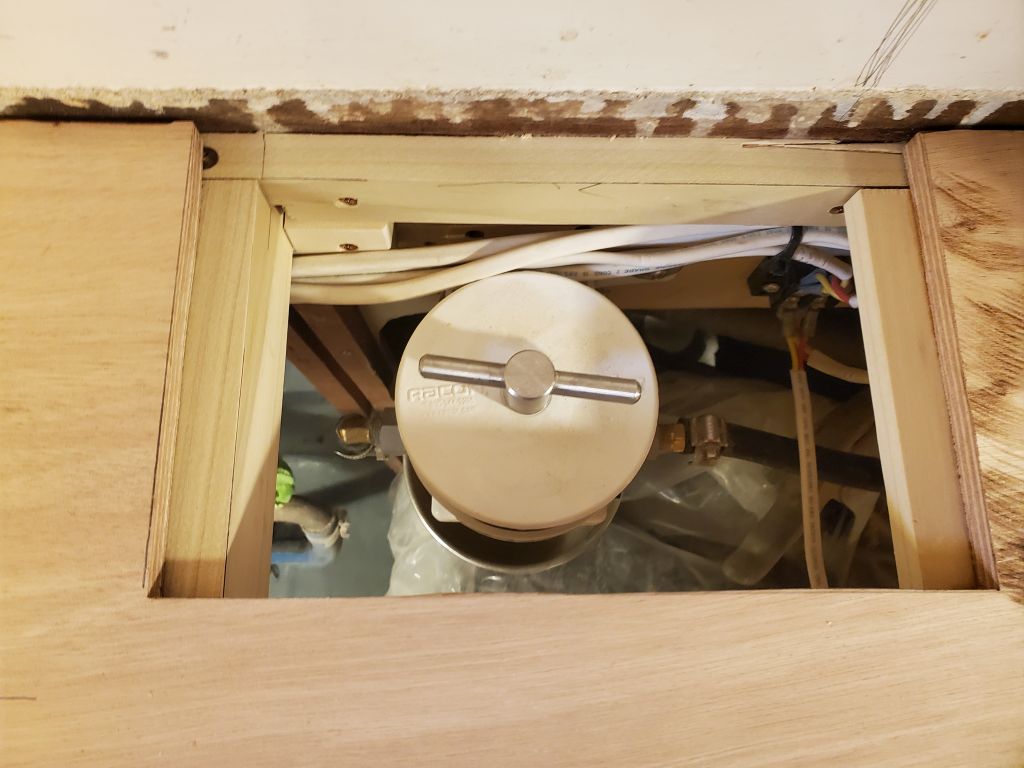
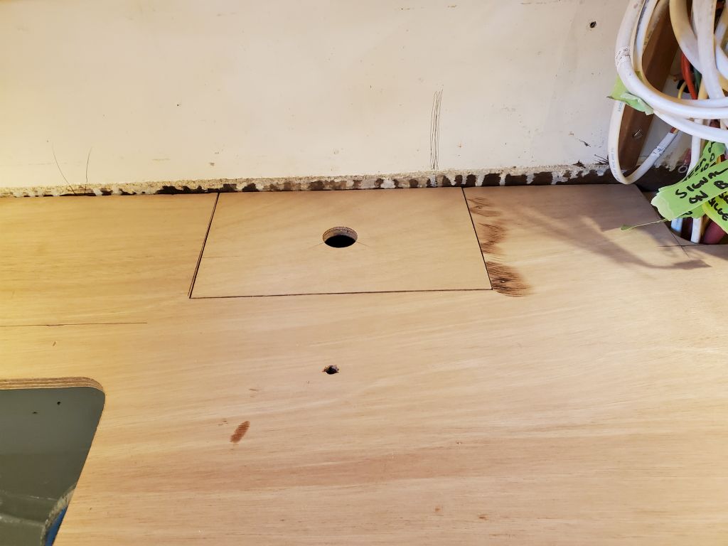
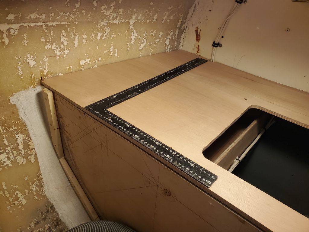
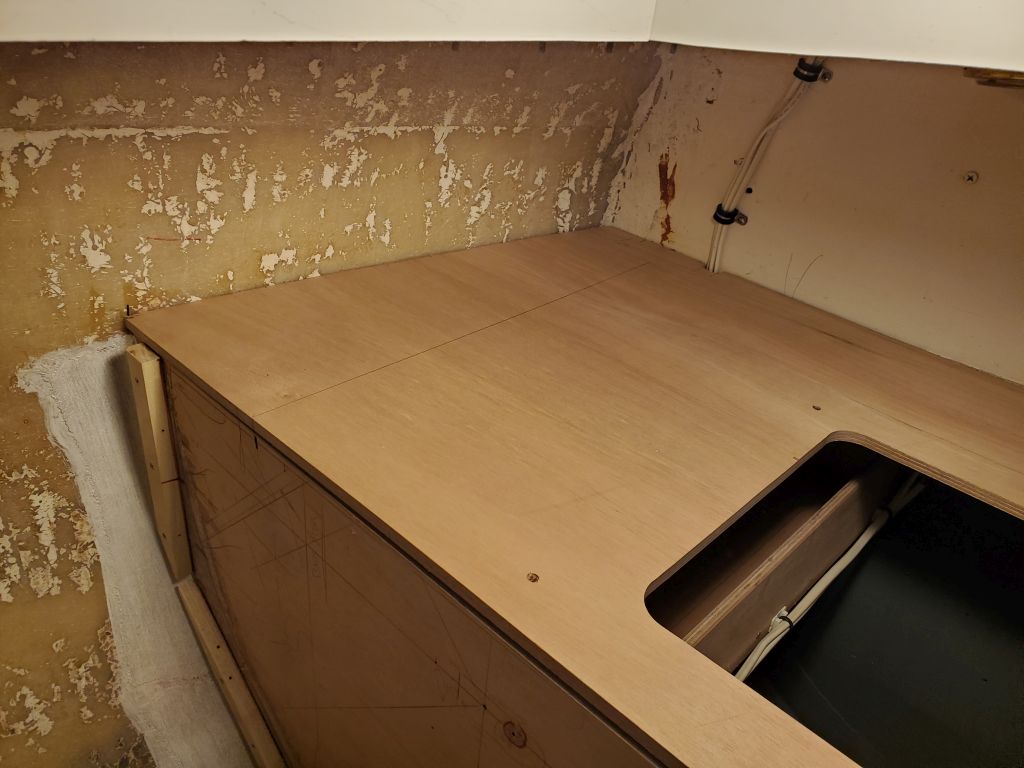
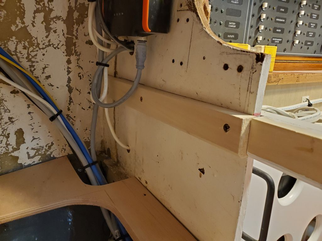
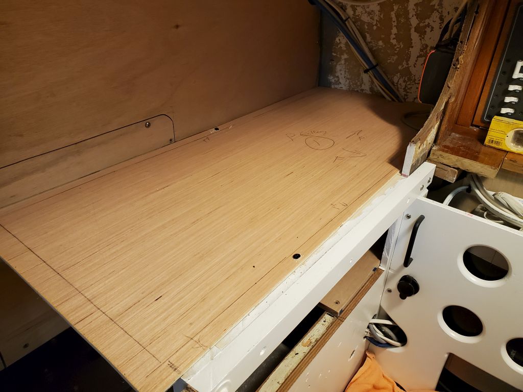
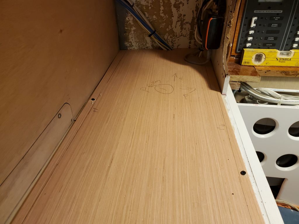
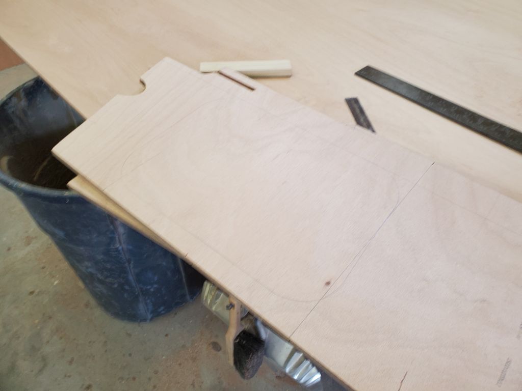
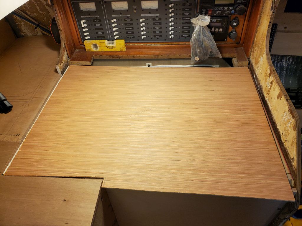
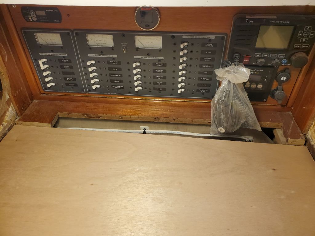
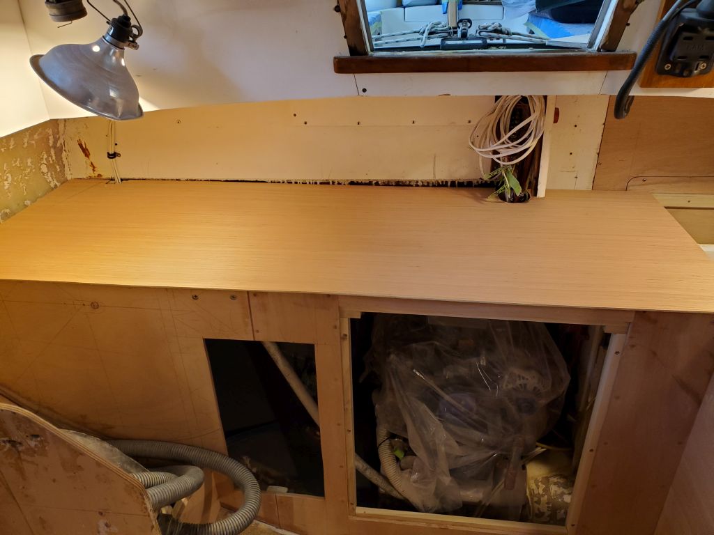
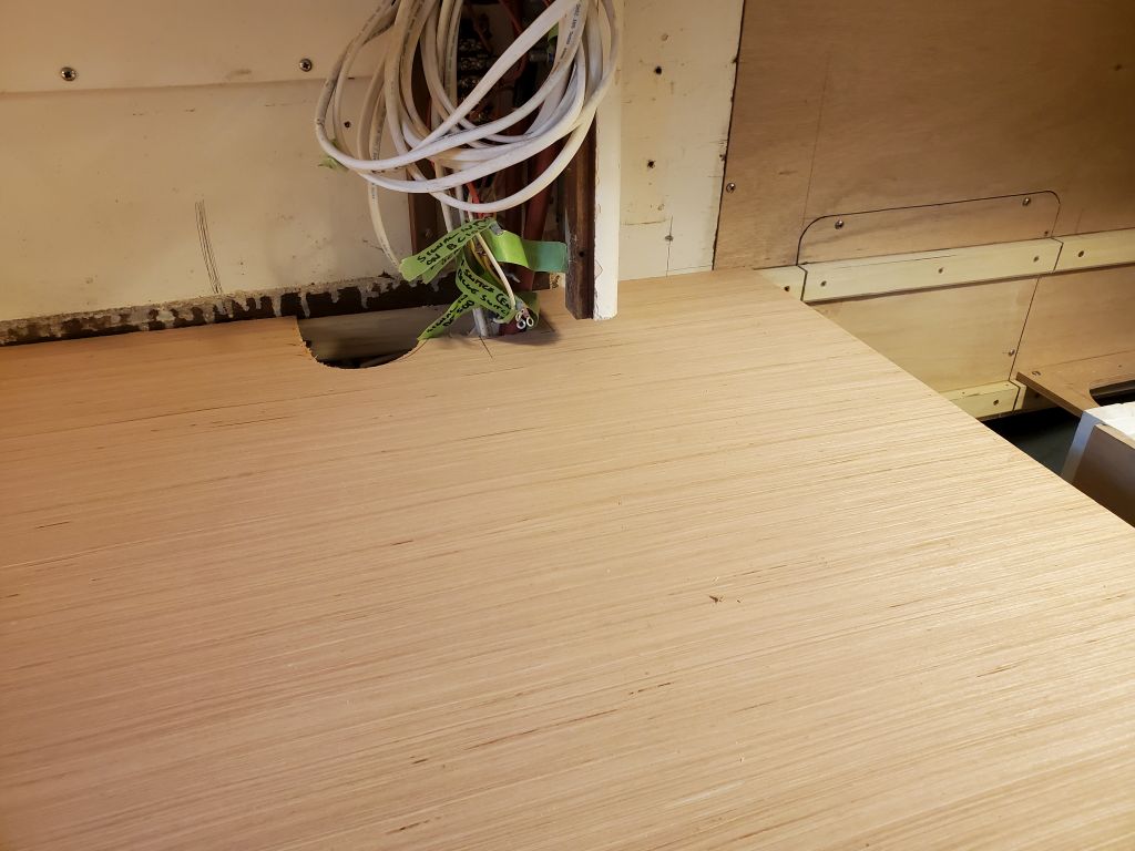
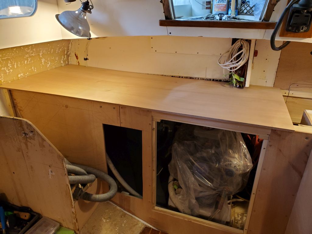
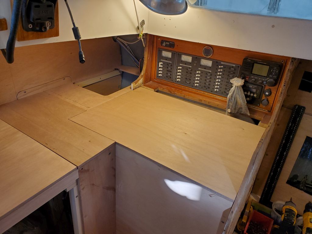
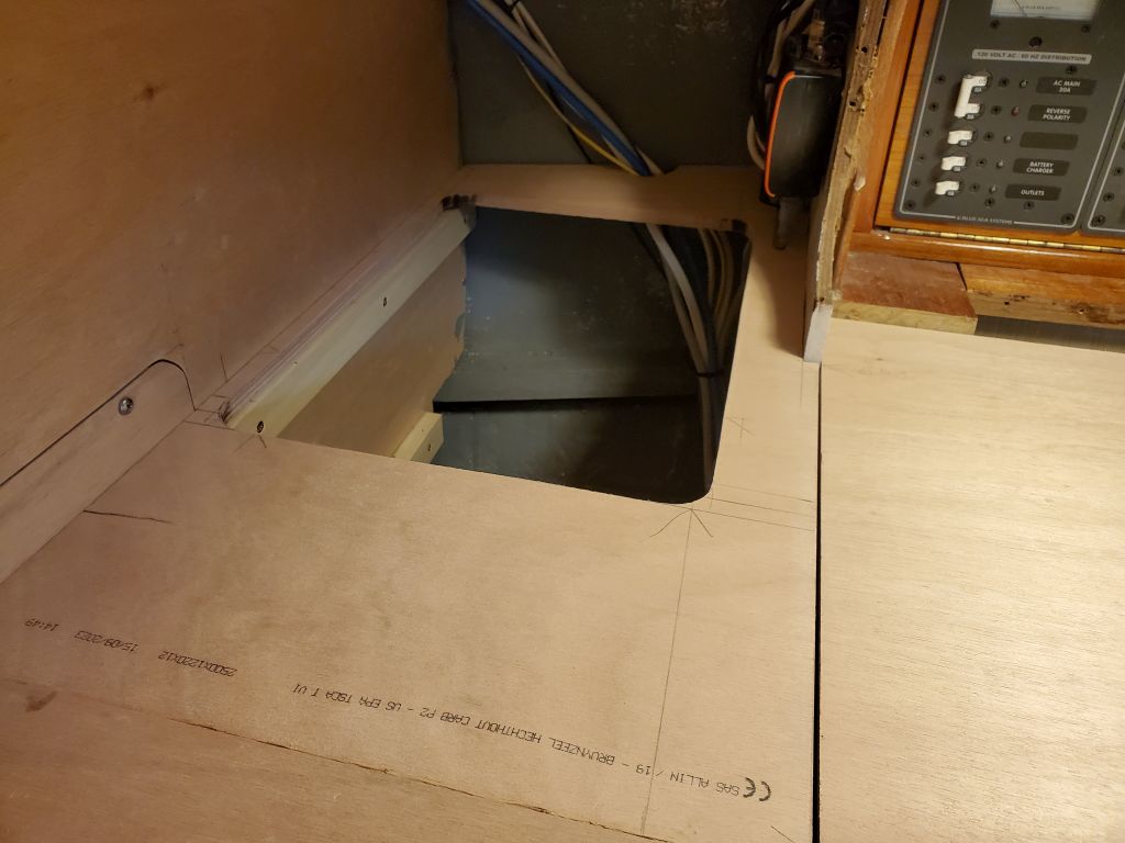
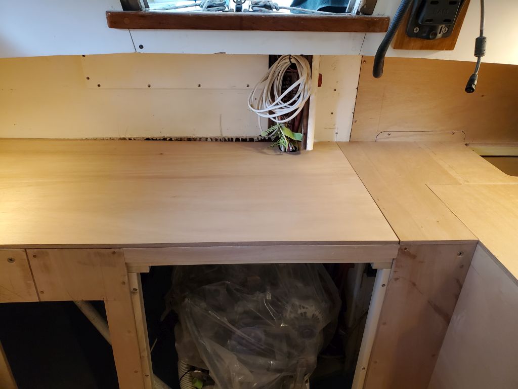
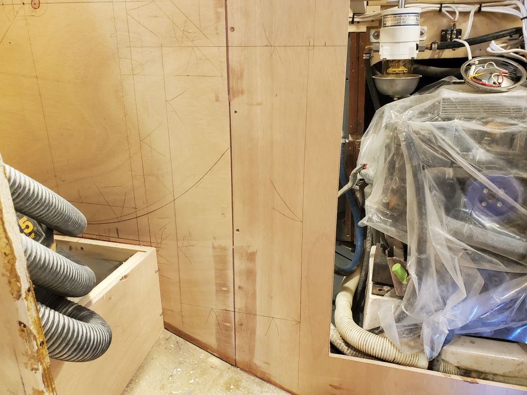
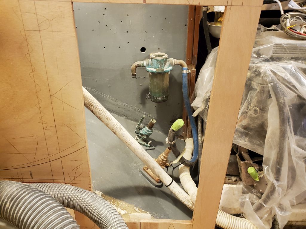
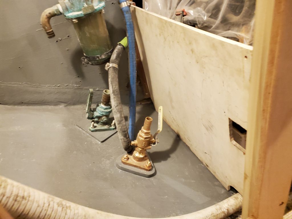
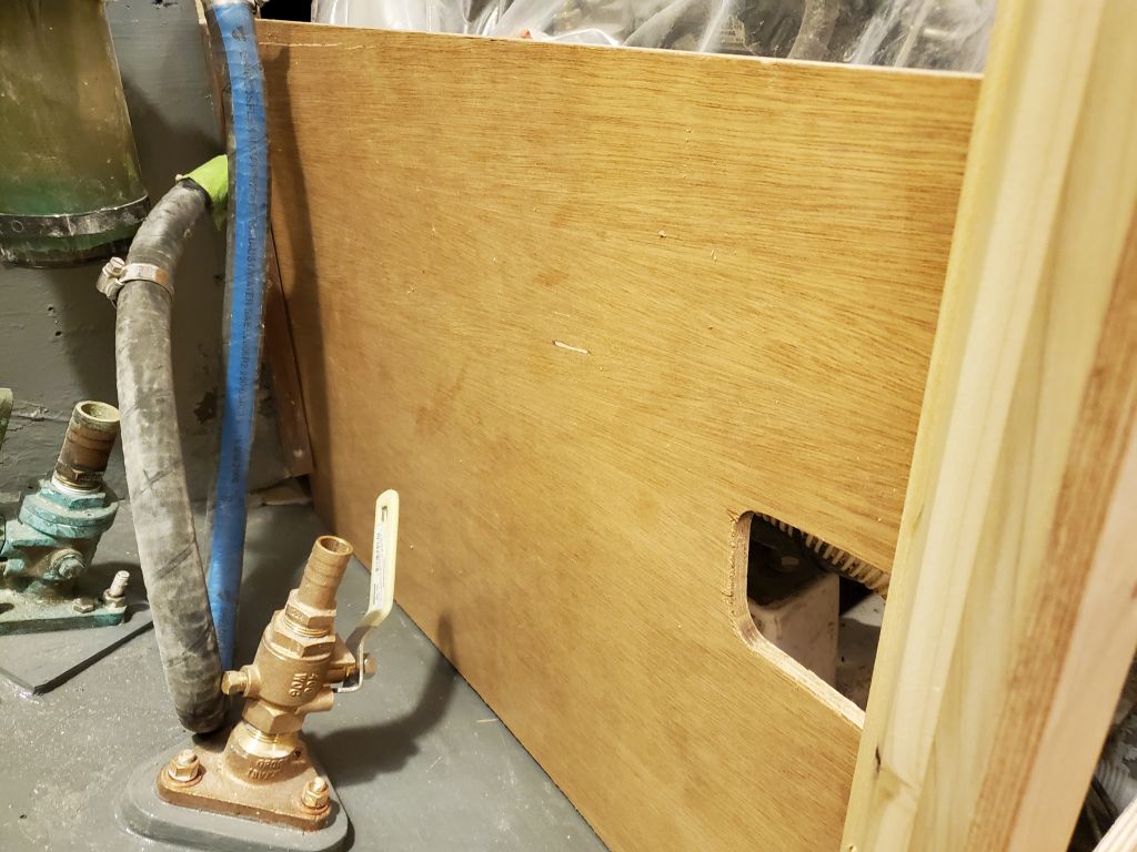
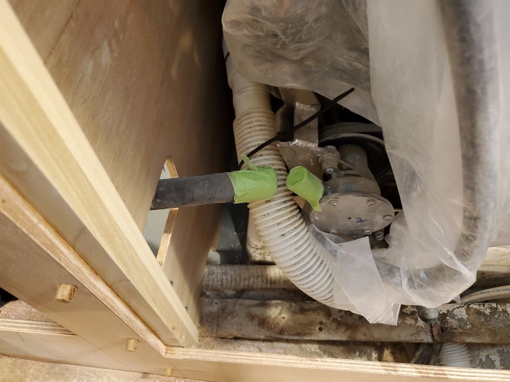
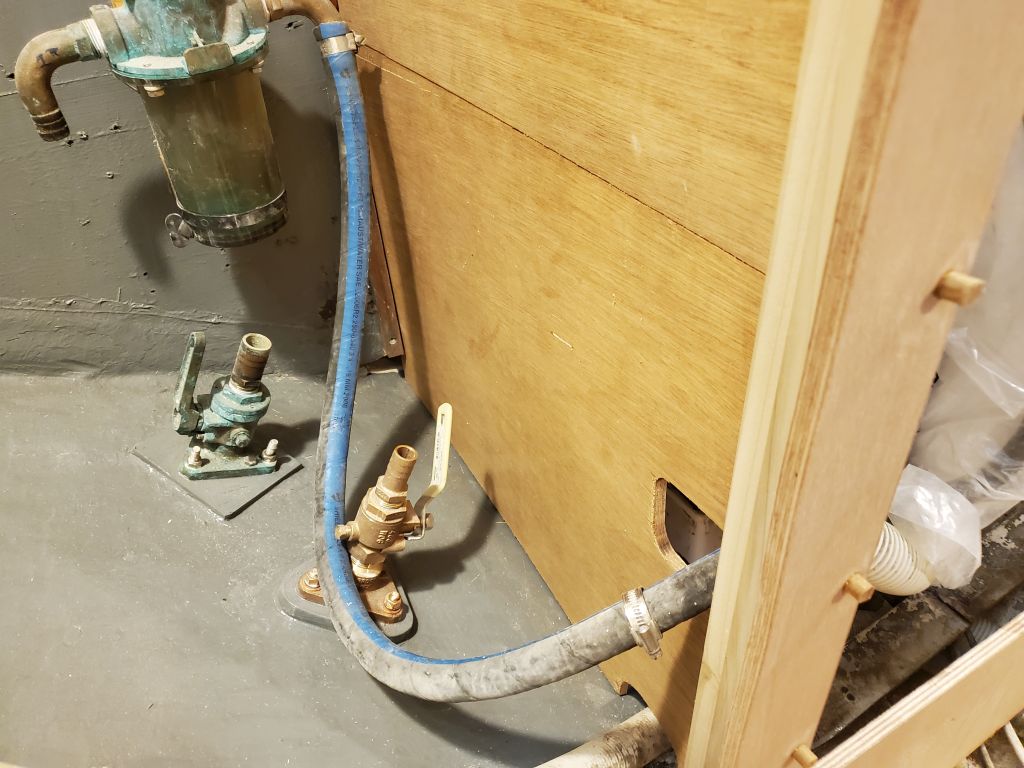
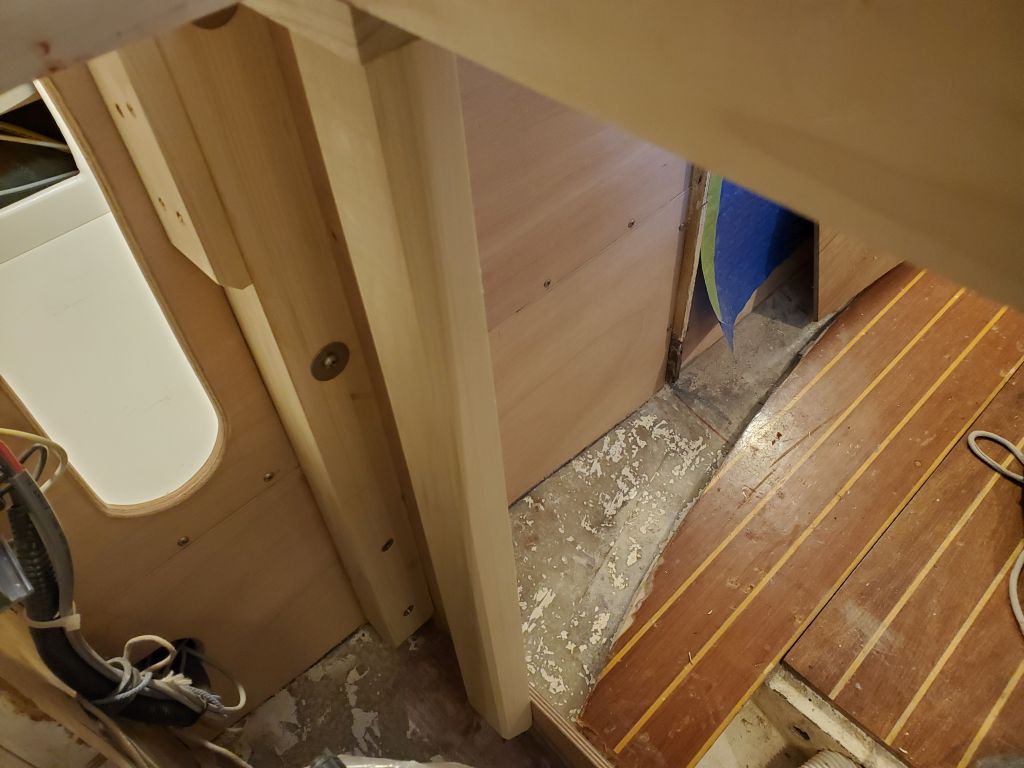
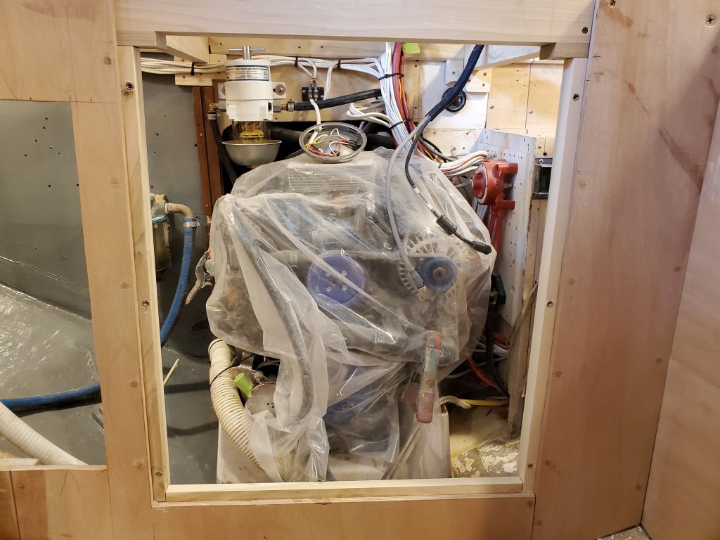
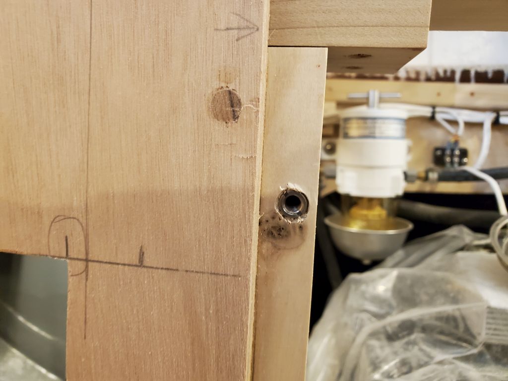
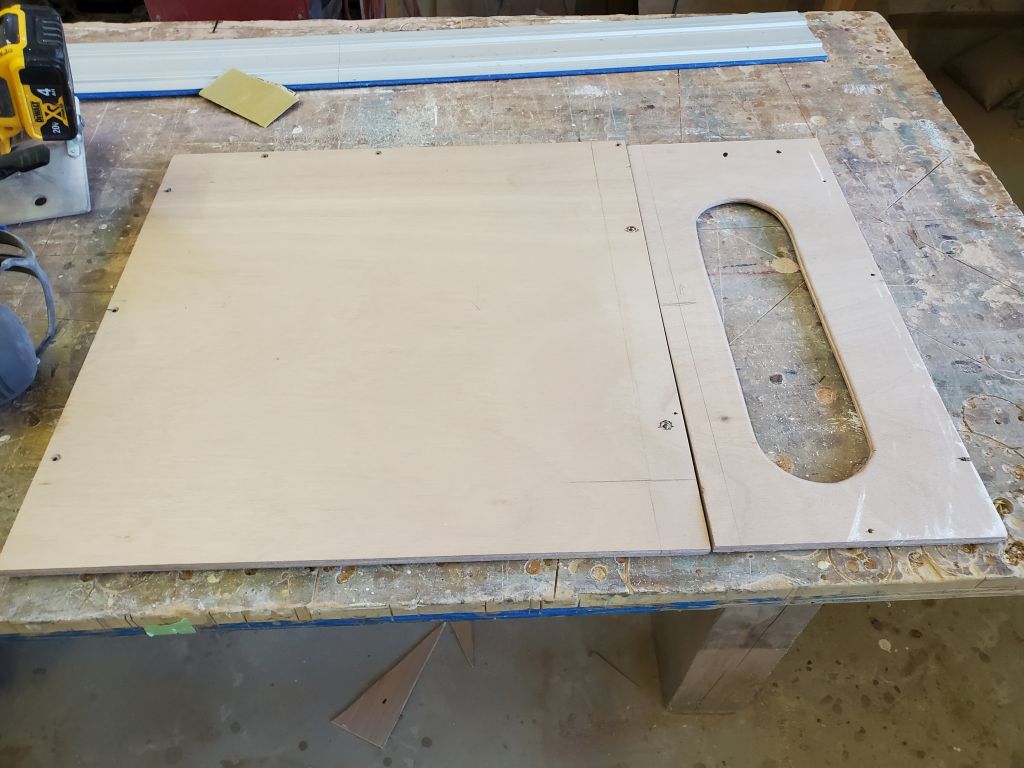
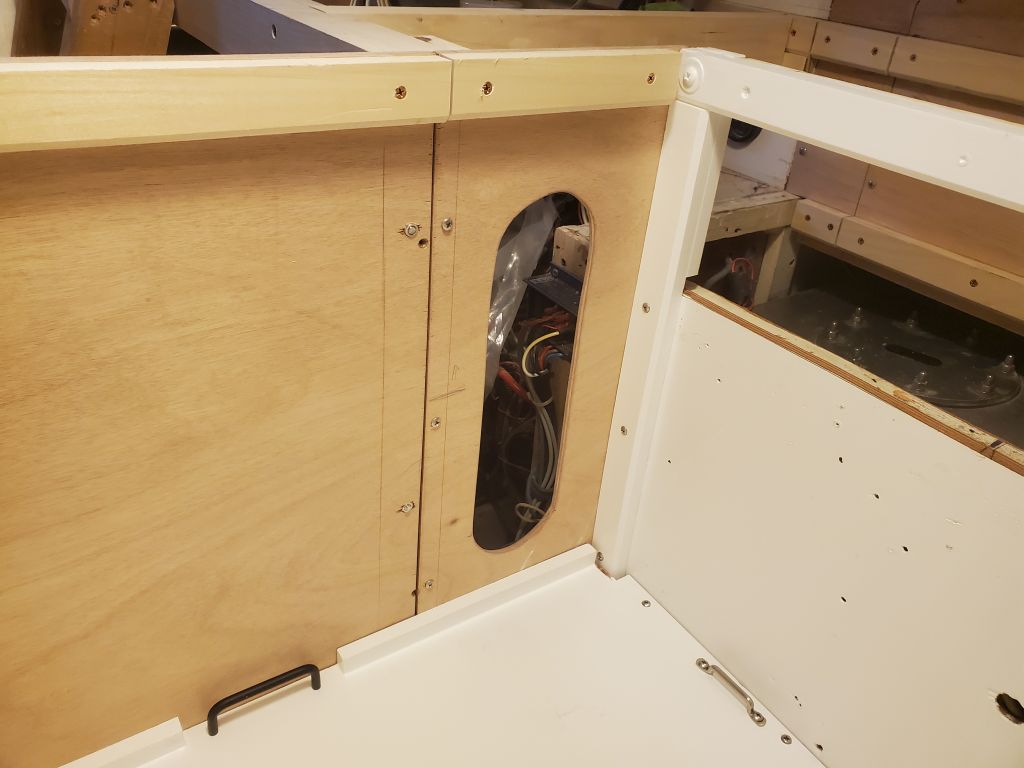
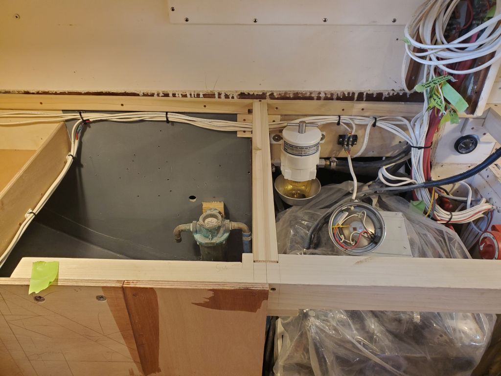
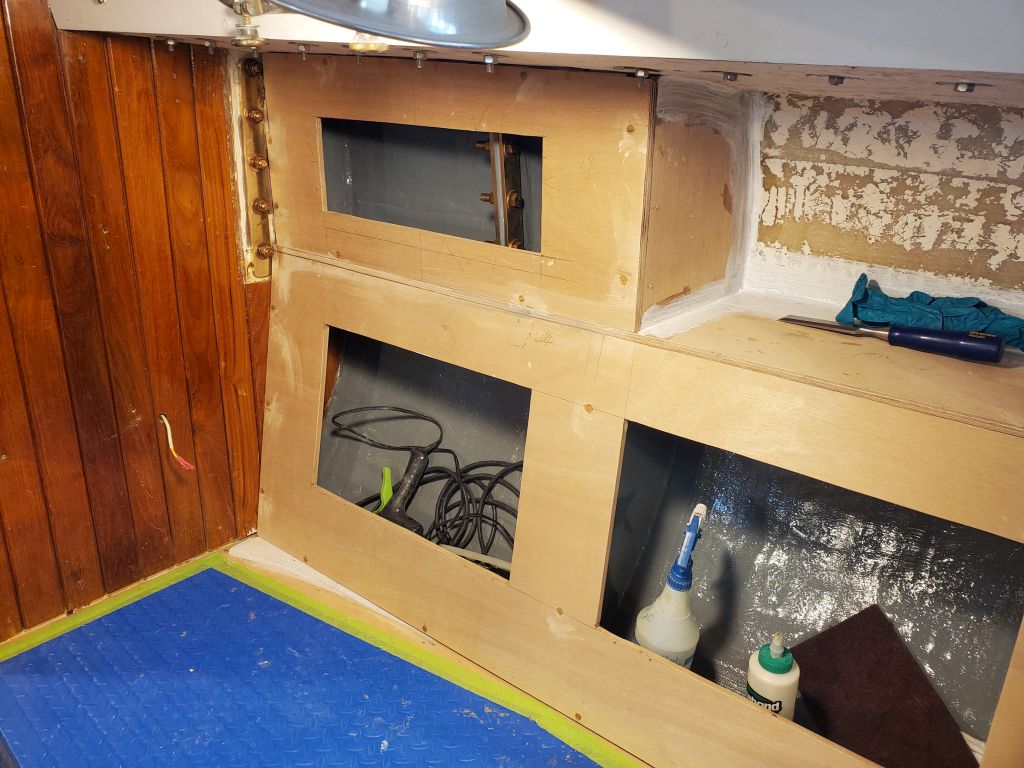
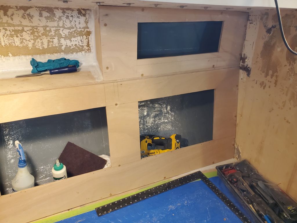
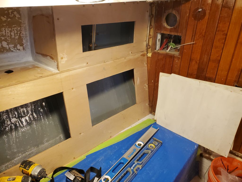
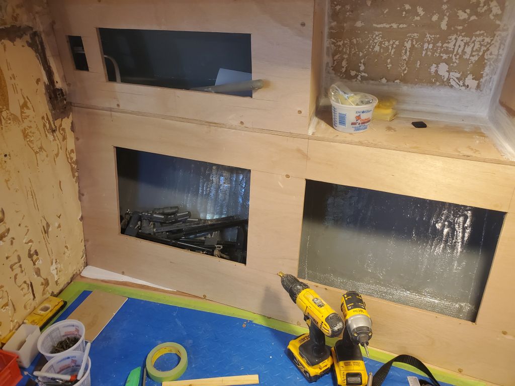
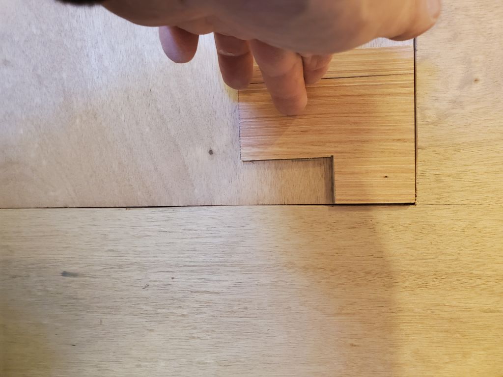
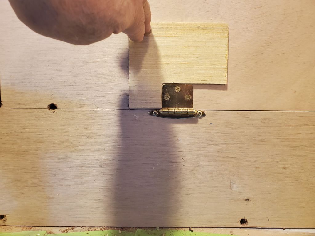
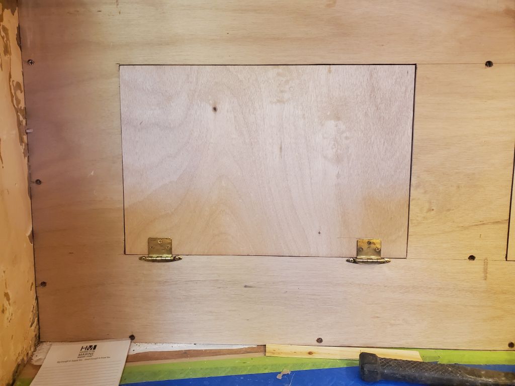
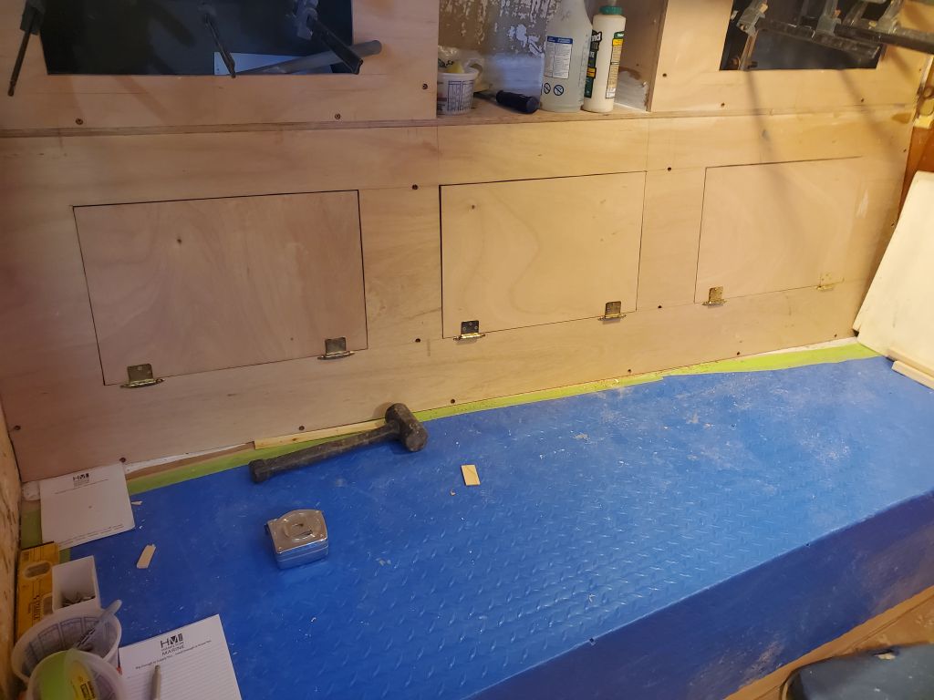
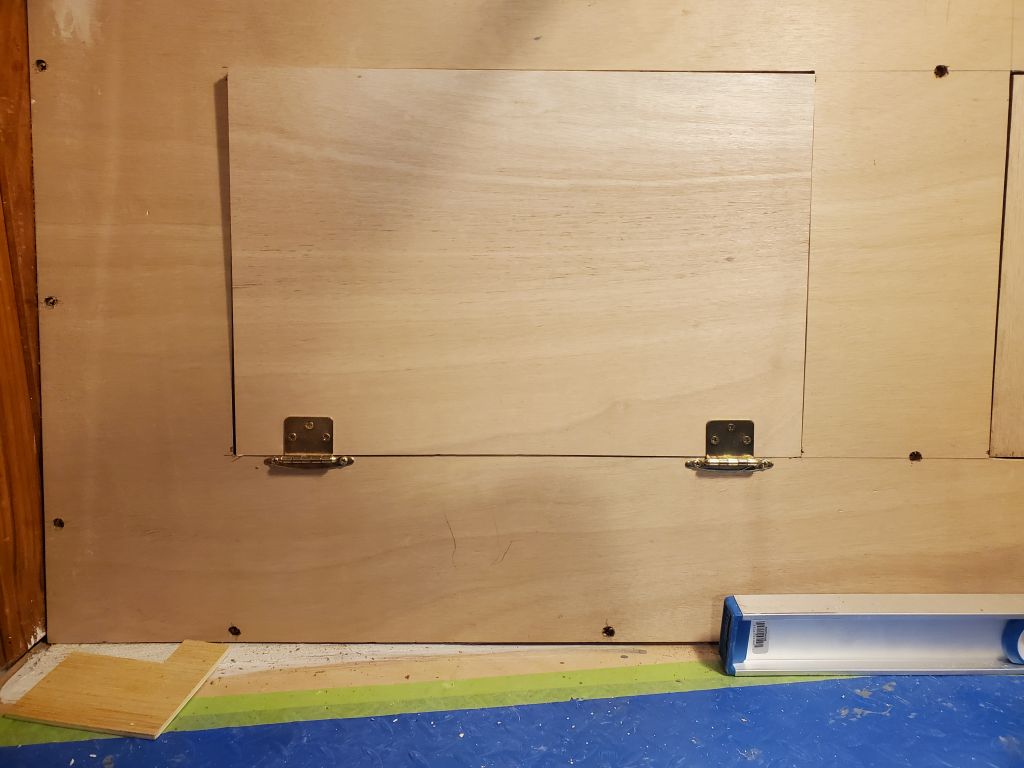
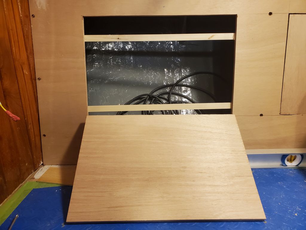
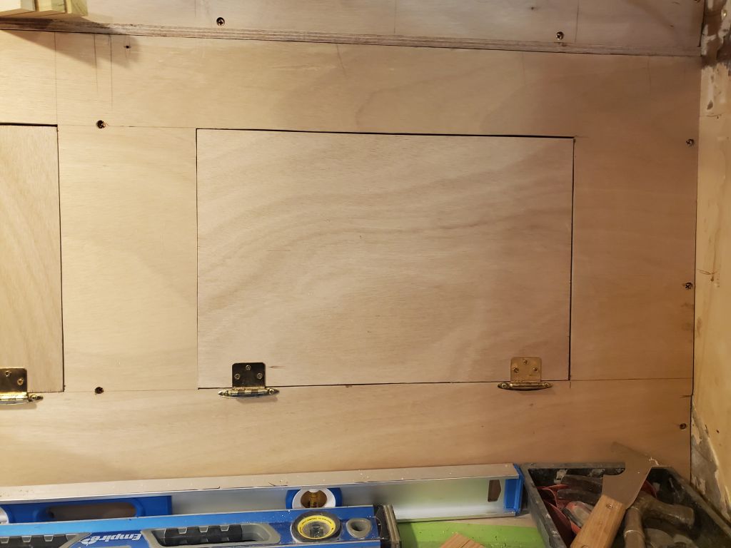
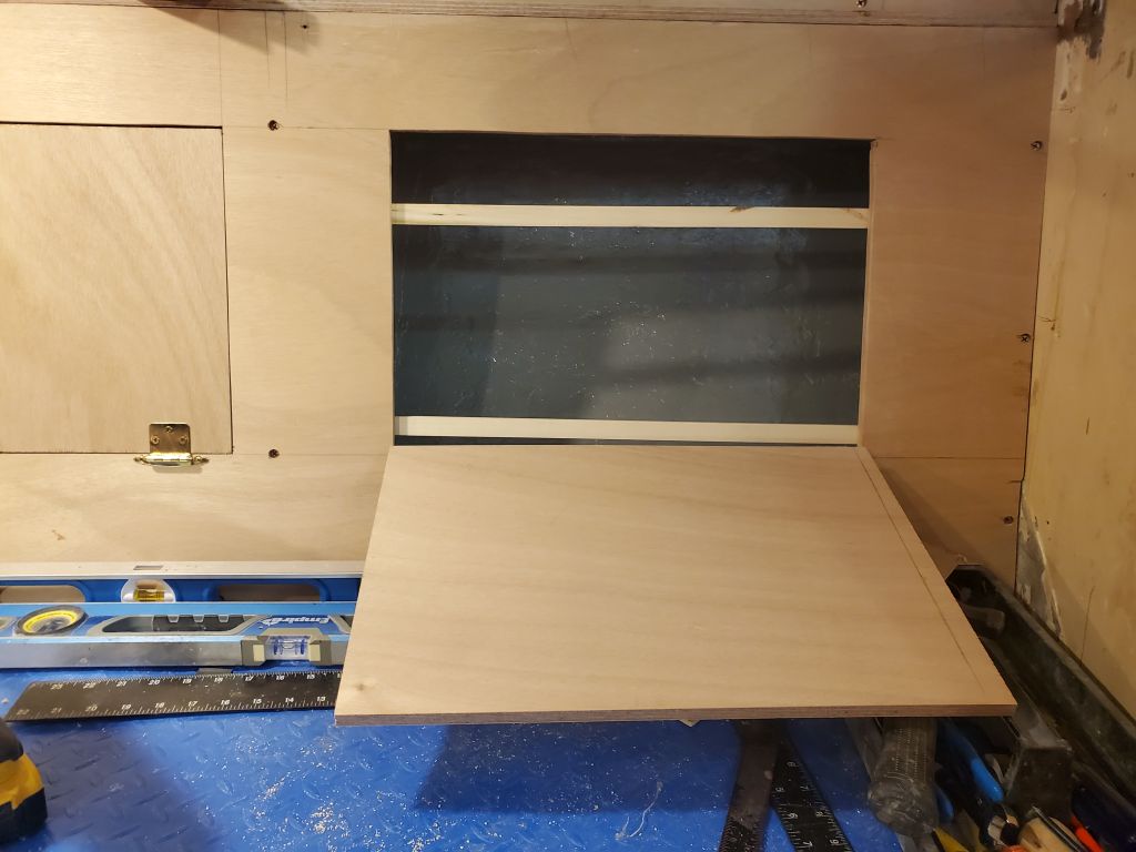
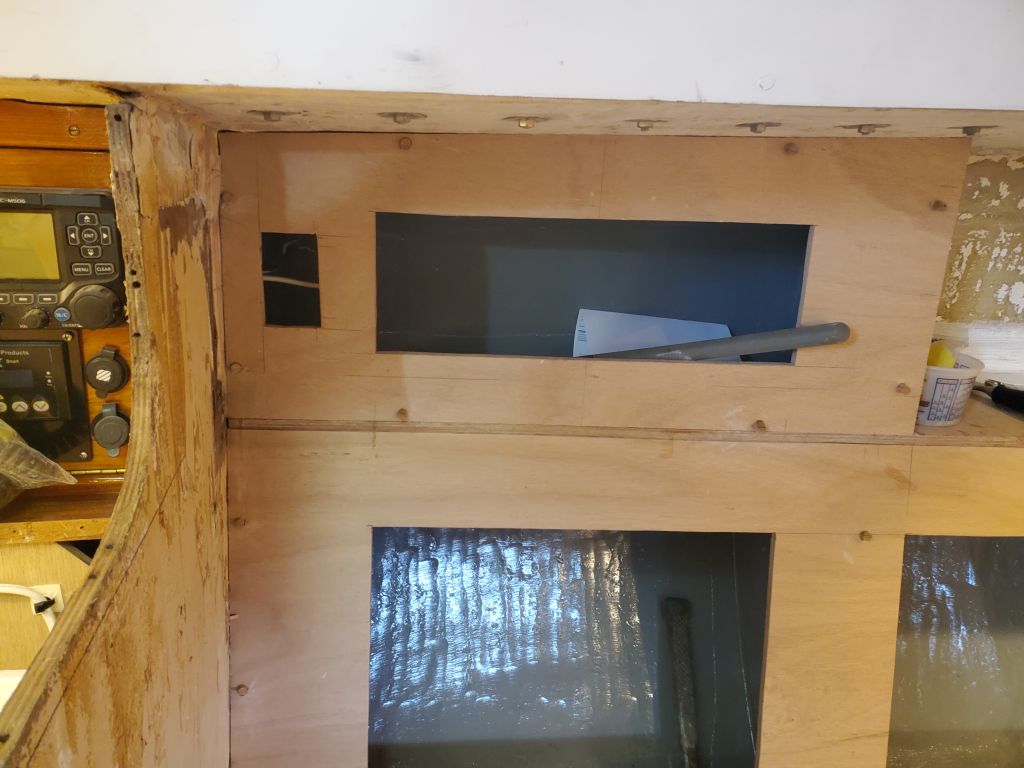
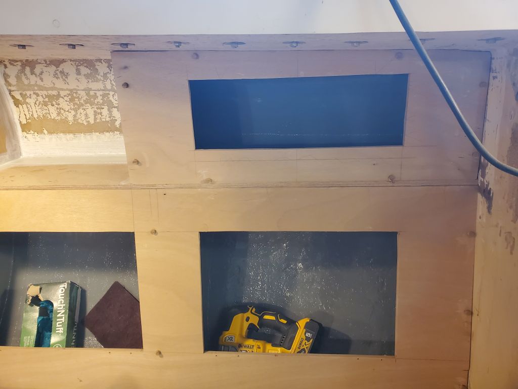
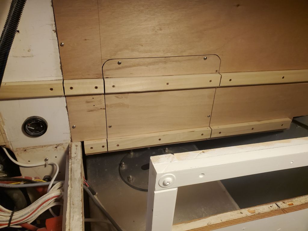
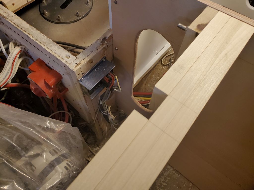
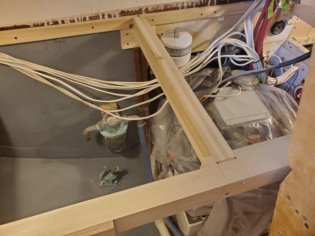
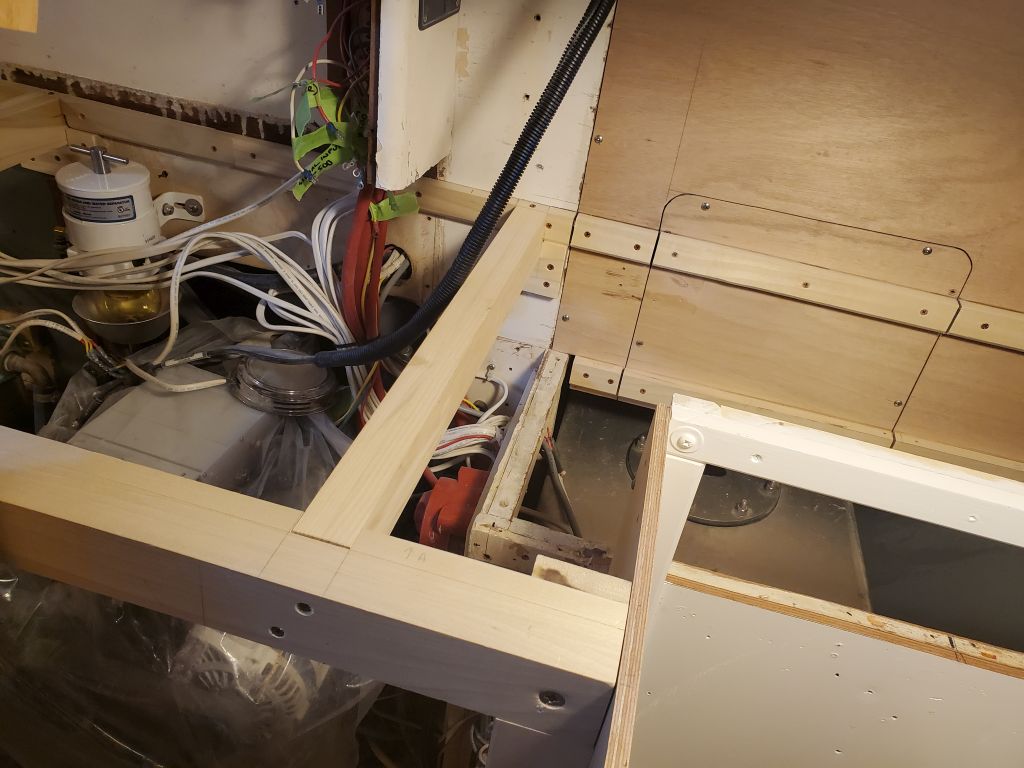
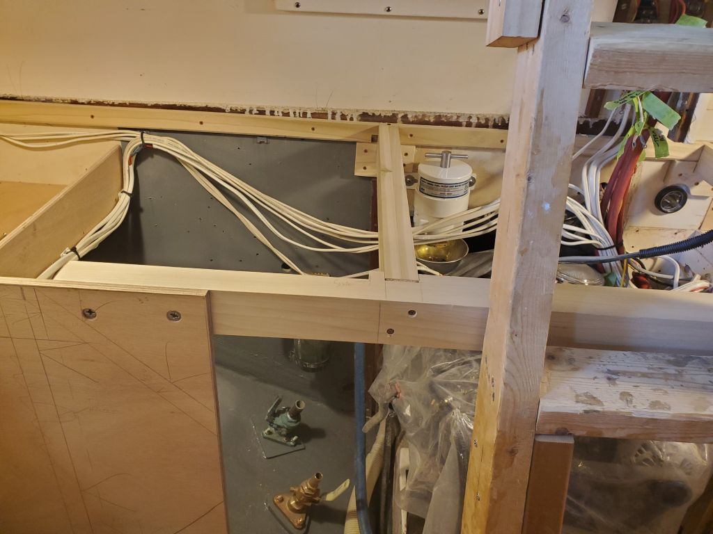
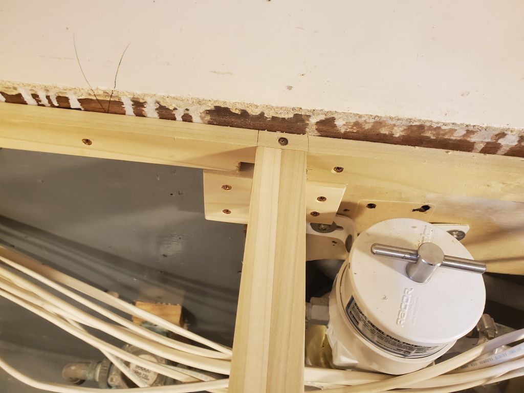
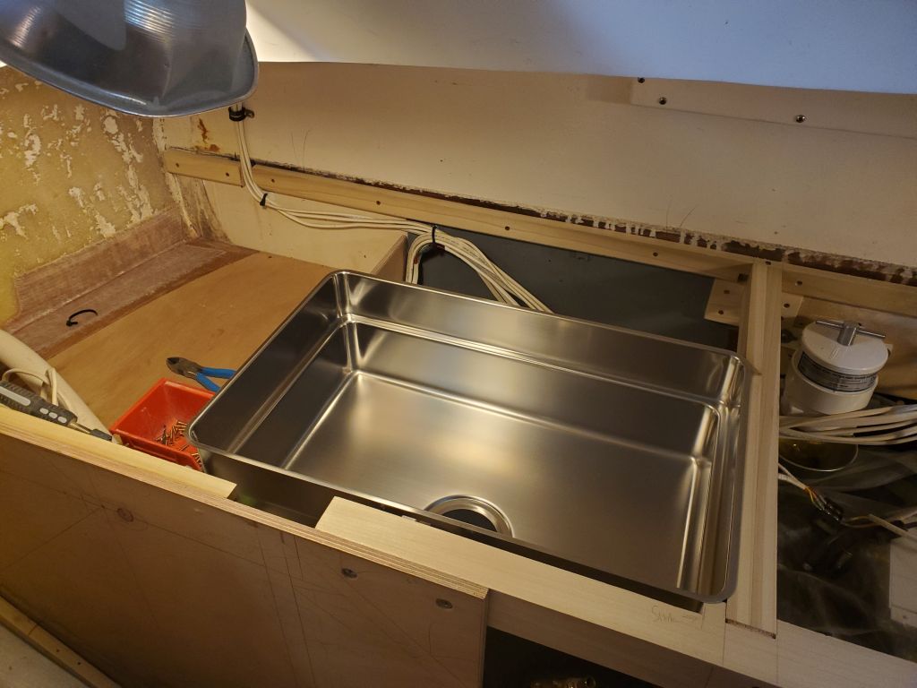
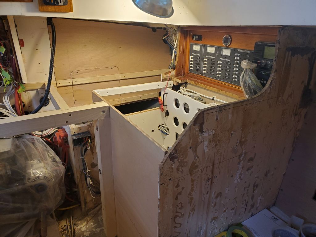
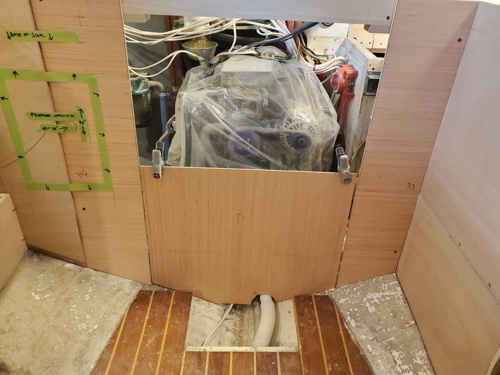
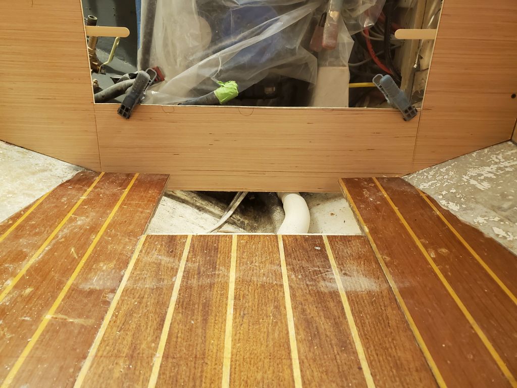
That whole exercise took up most of the morning, but now I’d accomplished the initial goal of having the sink position finalized.  This left about 9″ on the aft side of the counter behind the sink, giving me a guideline for the upper cabinets still to come, and some other considerations like the access hatch over the fuel filter, which I’d planned all along to provide the requisite–and easy–access for replacing the filter element.  Leaving a couple inches’ clearance behind the sink for faucet installation would give me as much as 7″ depth for the upper cabinets (to the inboard face), more than ample for them to be useful and also to hide the filter access hatch when all was said and done.  With some measurements and reference marks I’d made when the countertop was in place earlier, now I cut a 6″ x 9″ opening over the filter, large enough so that the longitudinal countertop beam on the starboard side could form one cleat to support the cover, and plenty of room on the other side for a support cleat without impeding filter access.

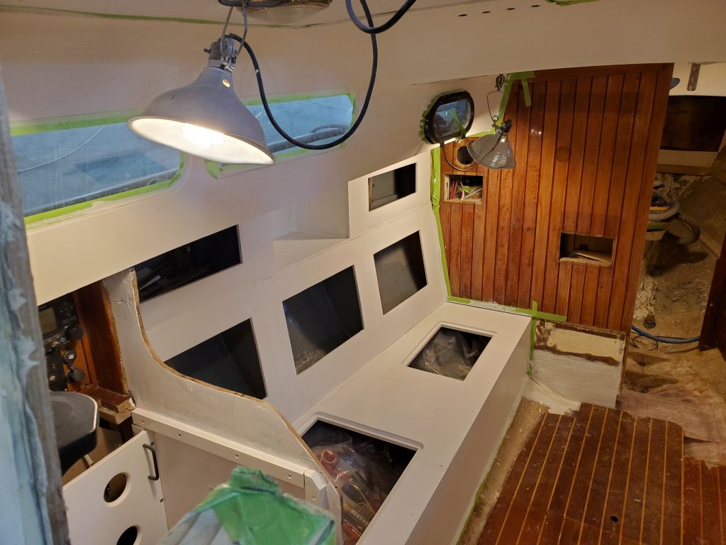
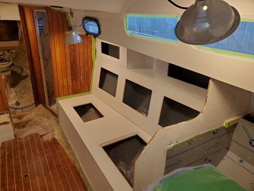
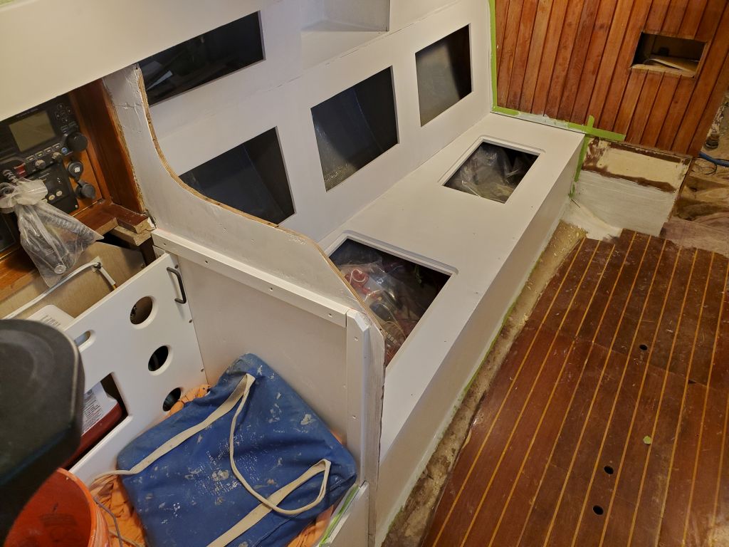
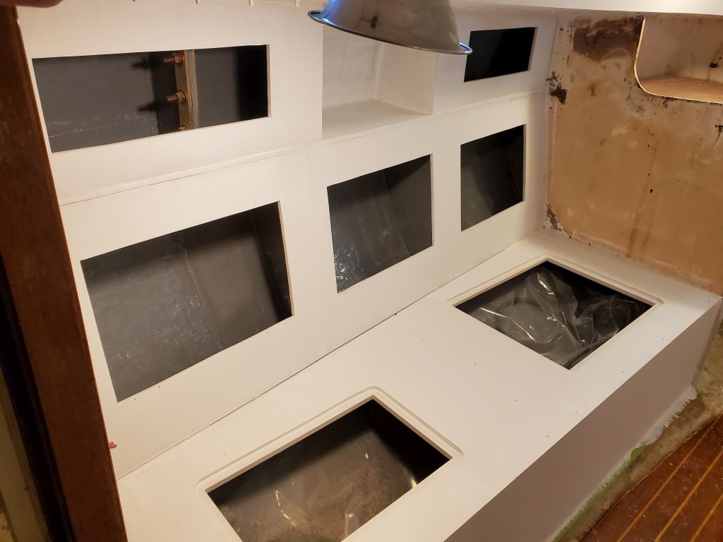
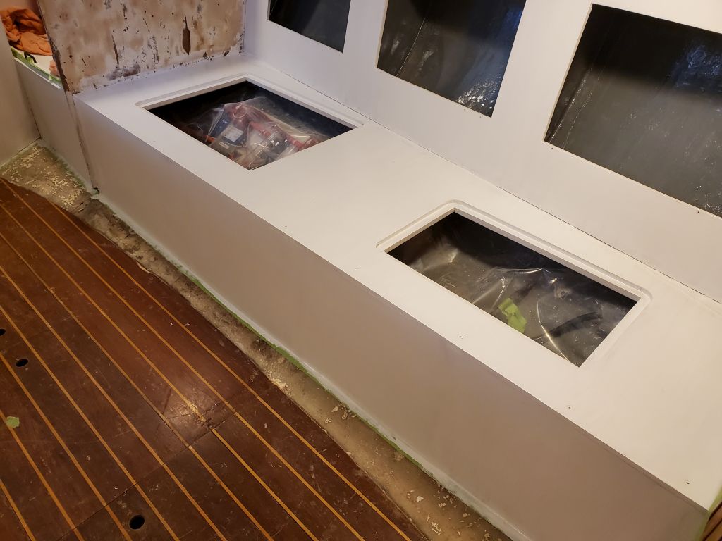
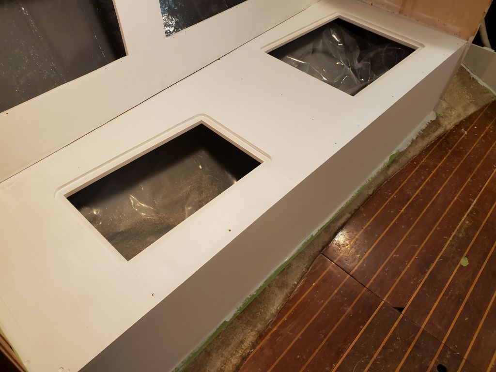
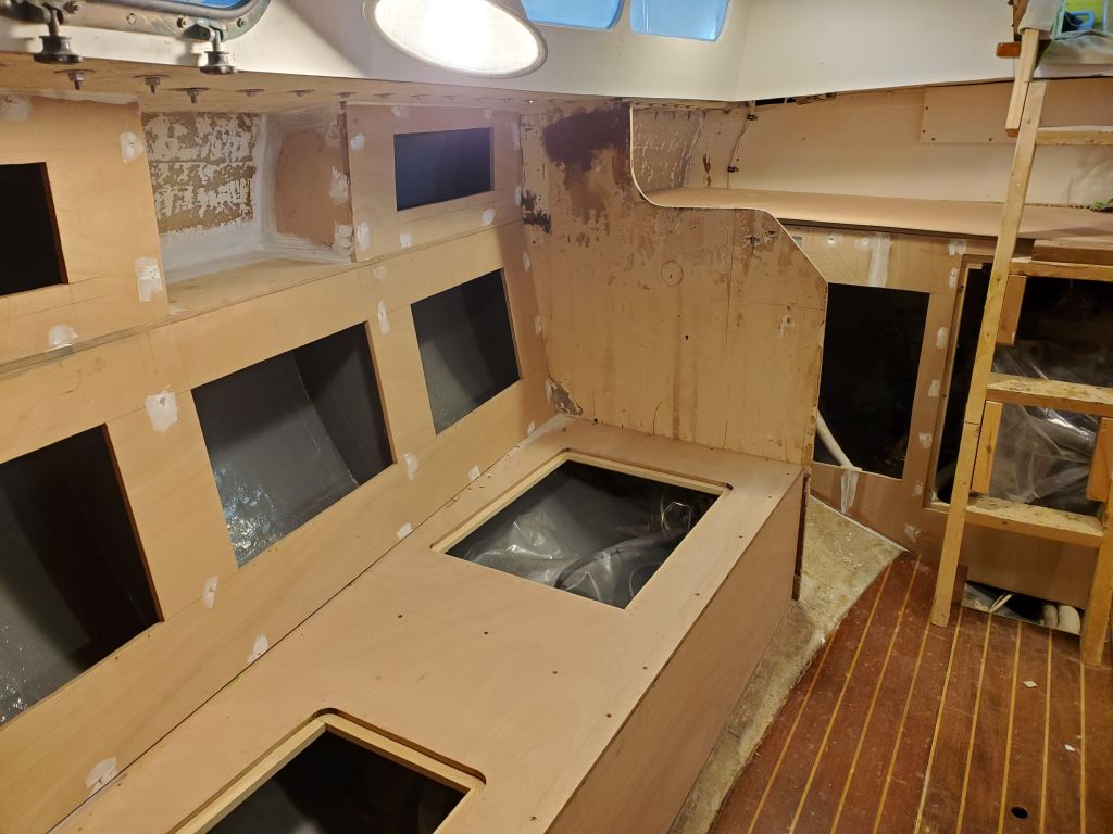
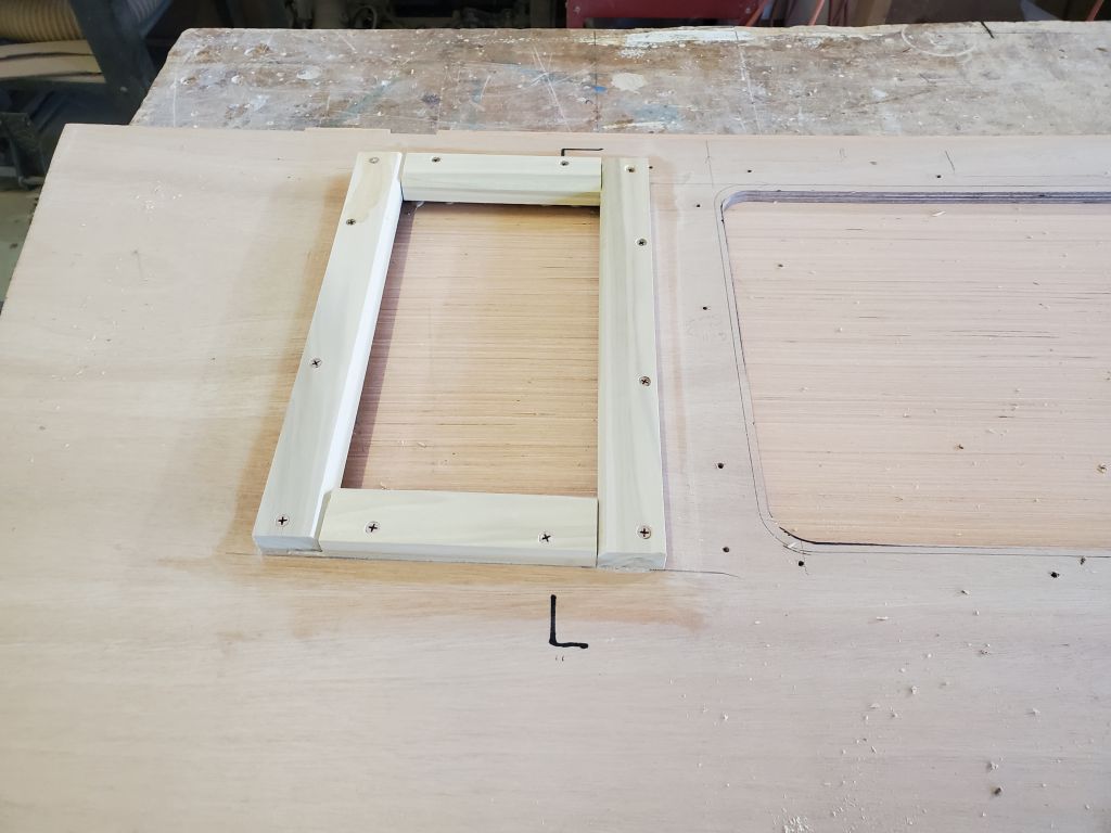
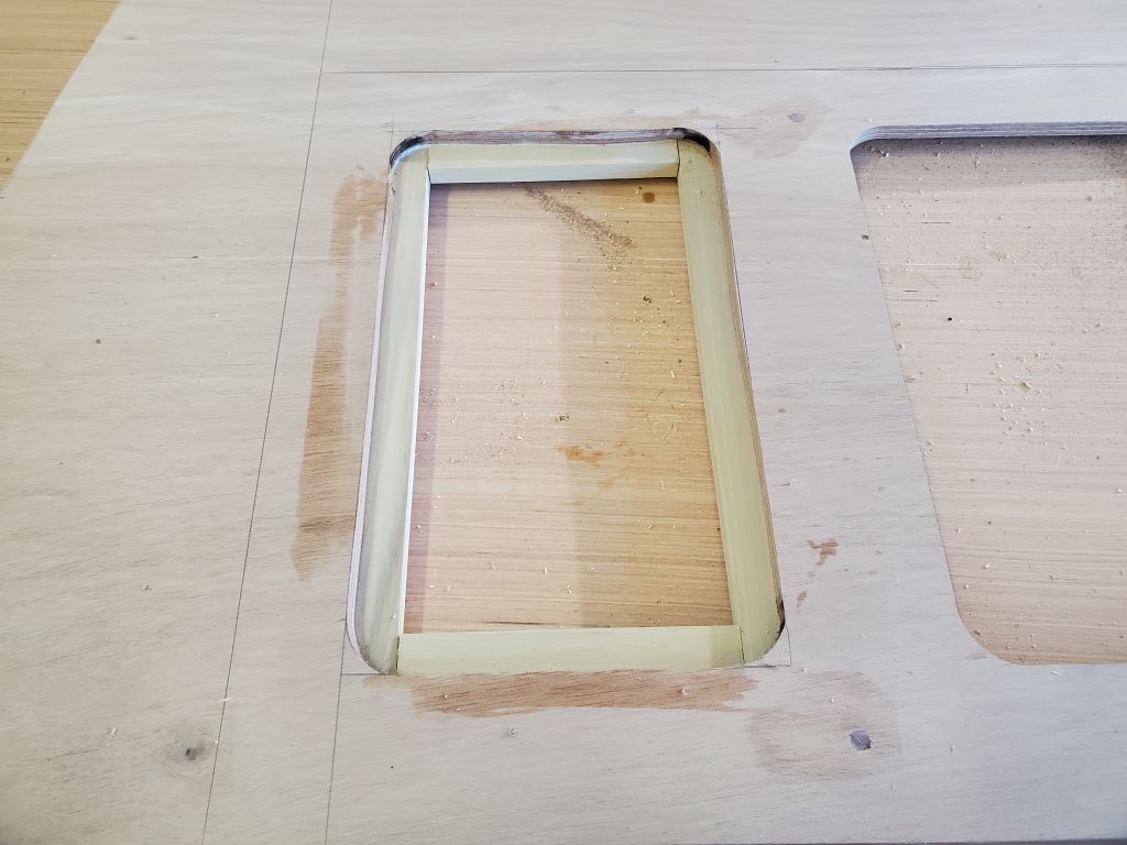
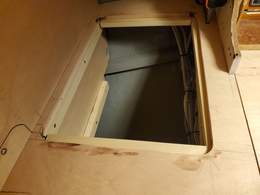
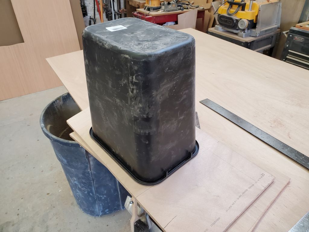
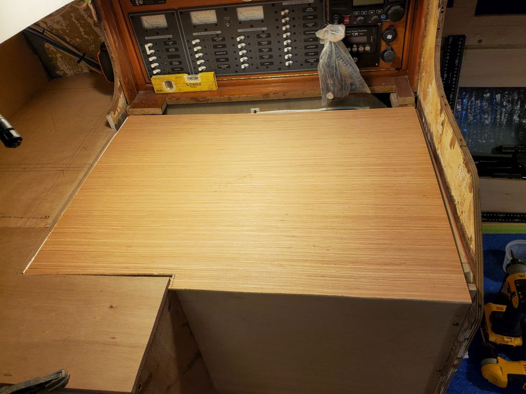
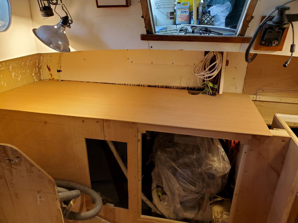
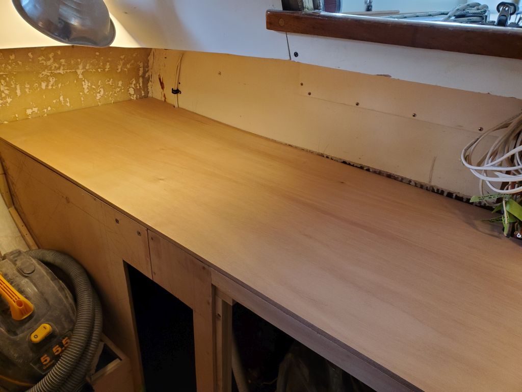
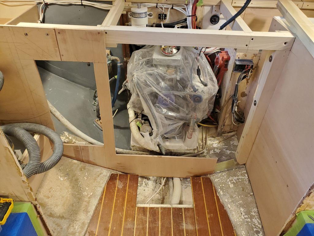
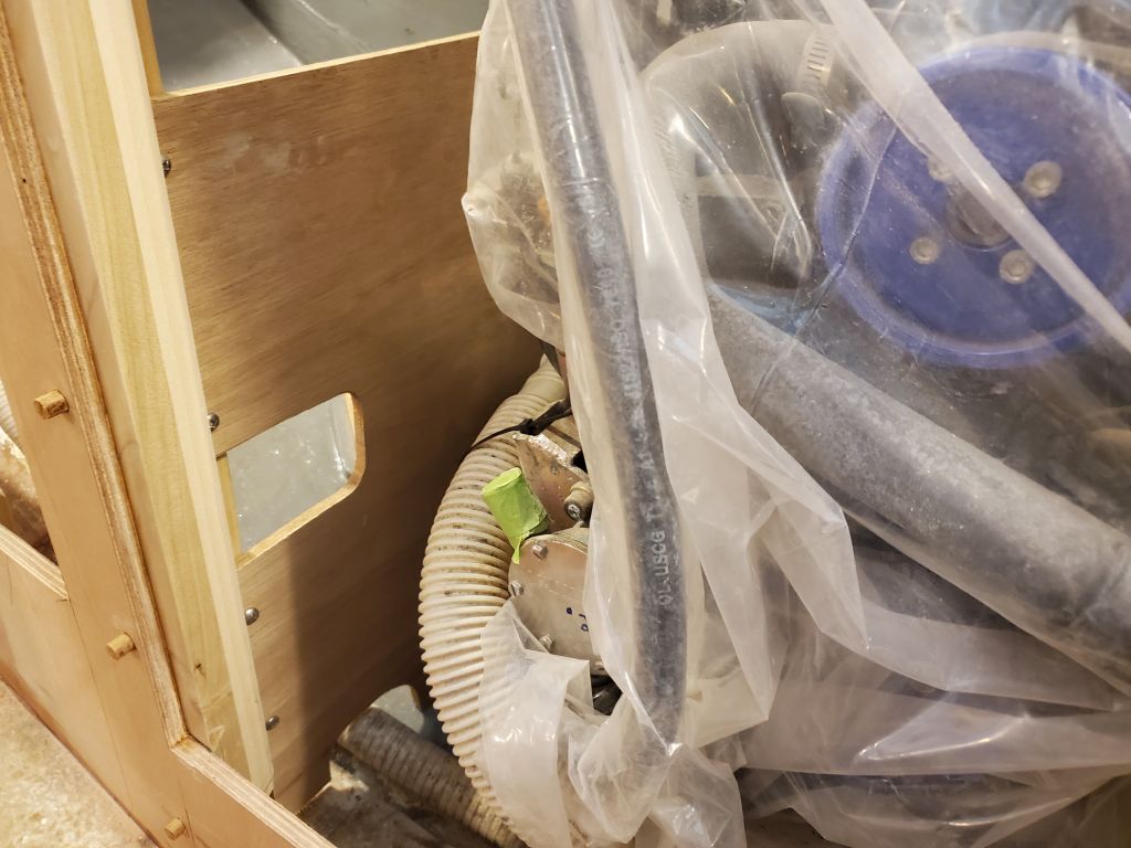
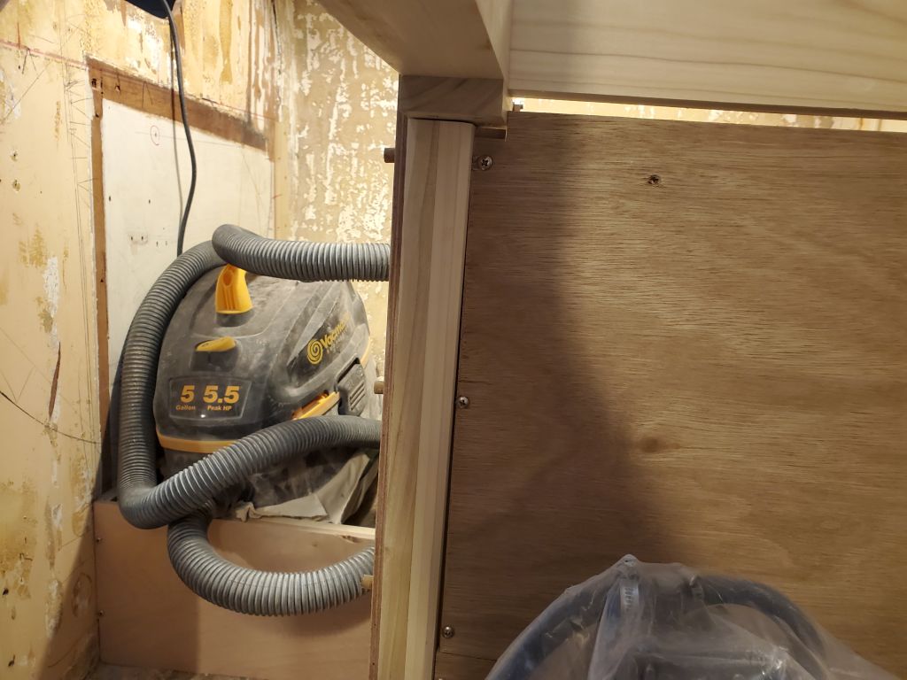
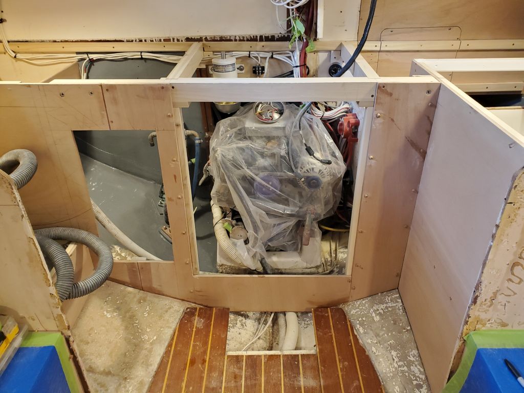
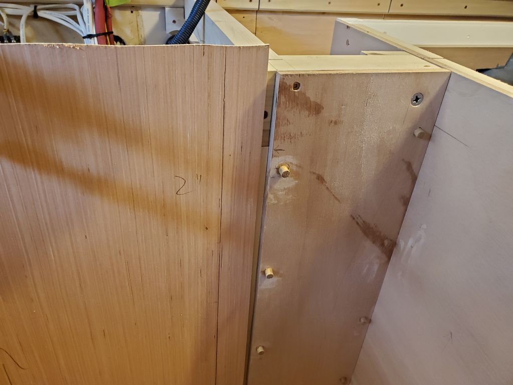
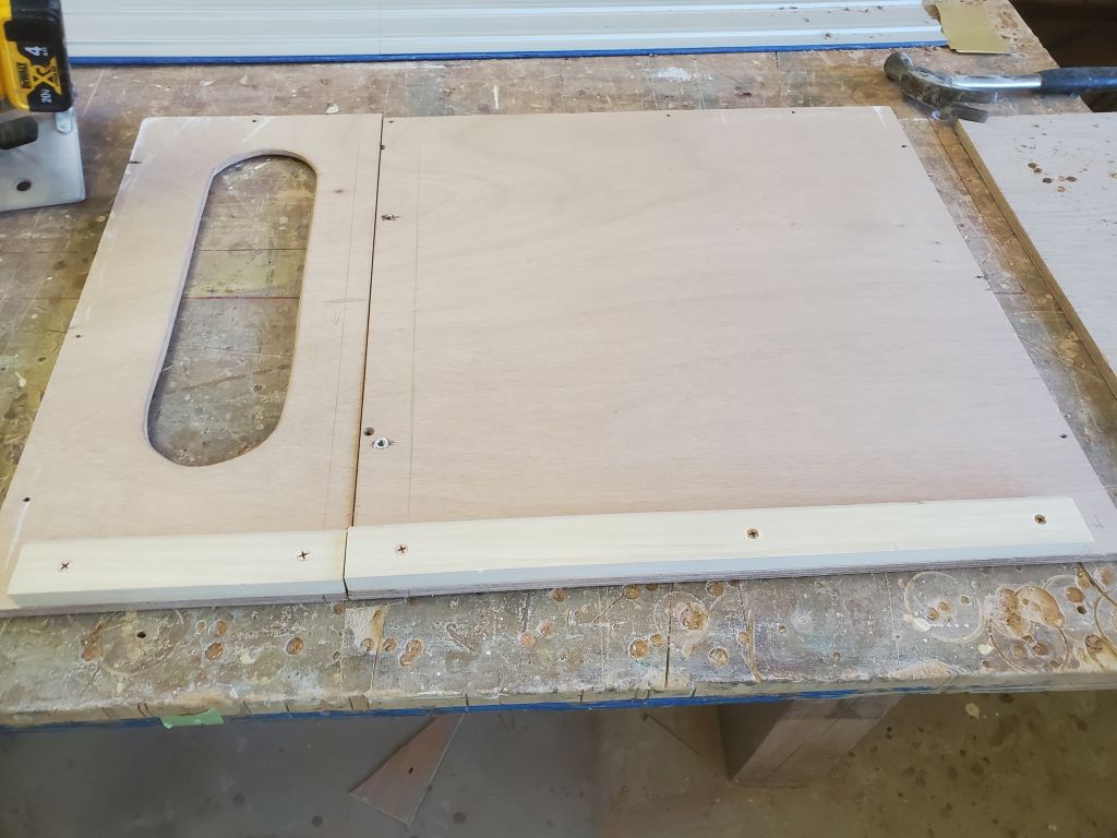
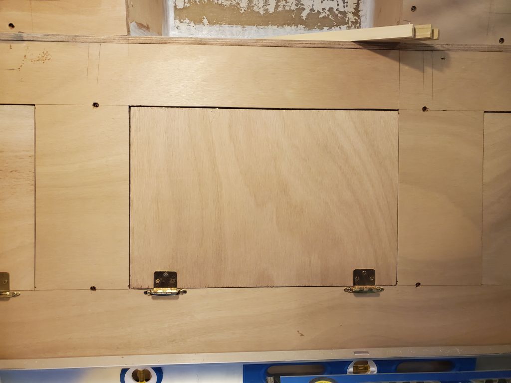
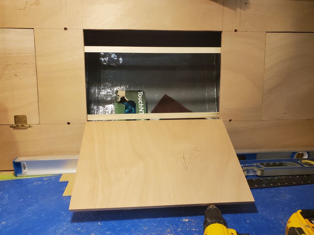
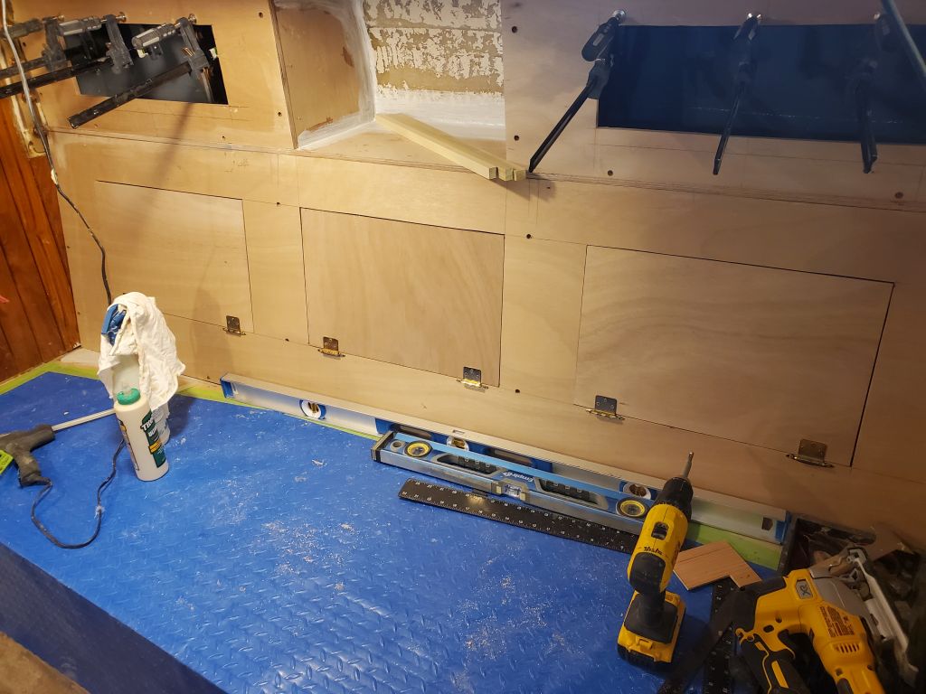
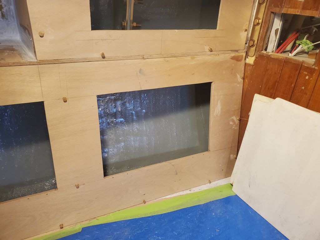
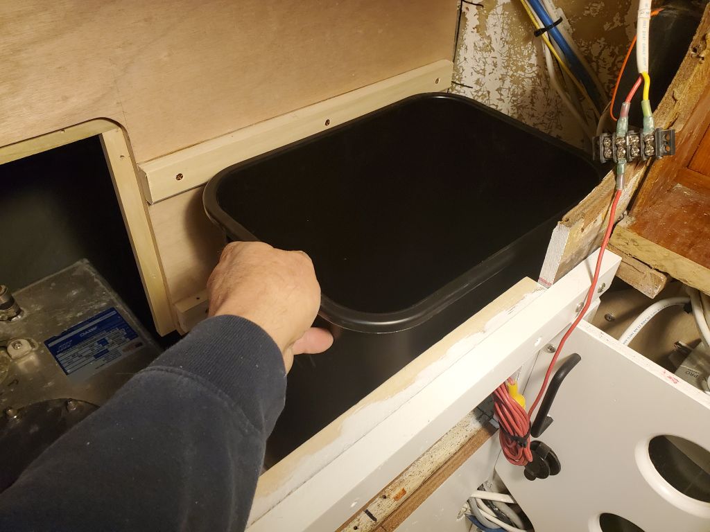
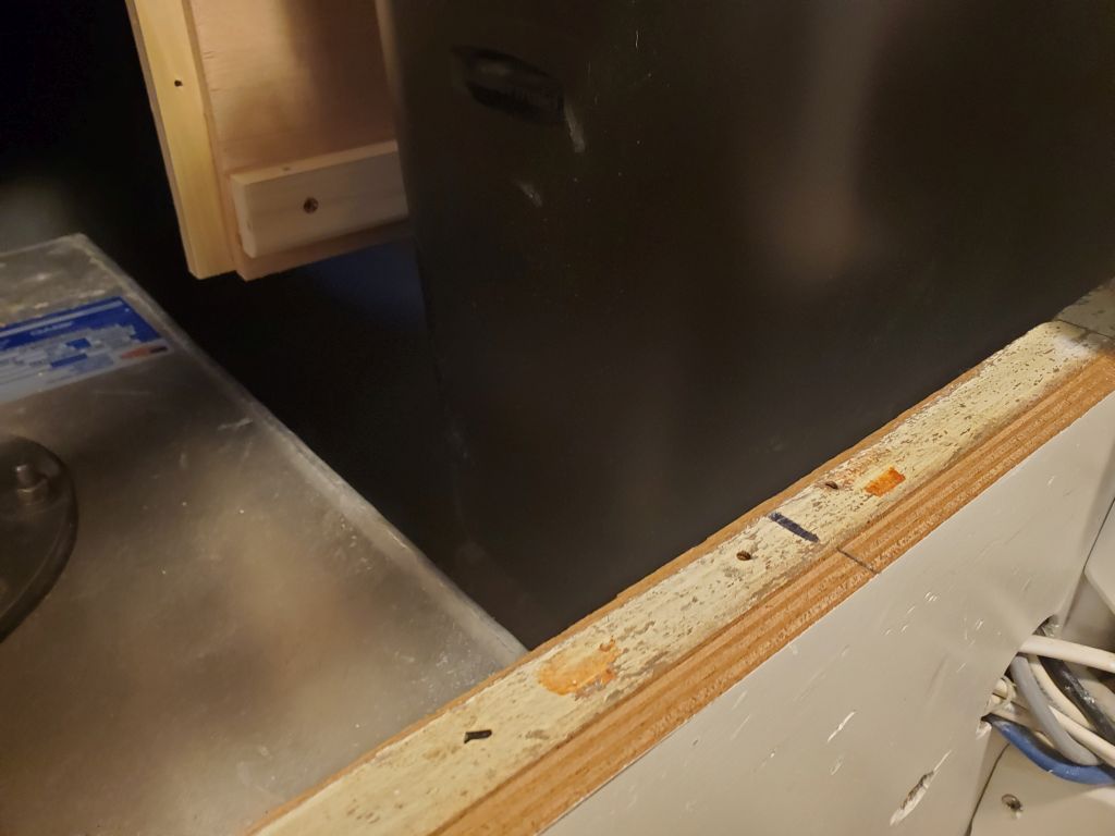
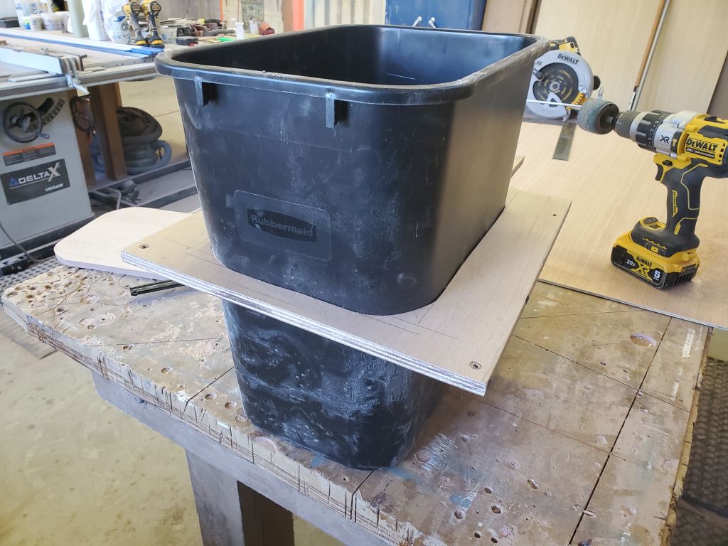
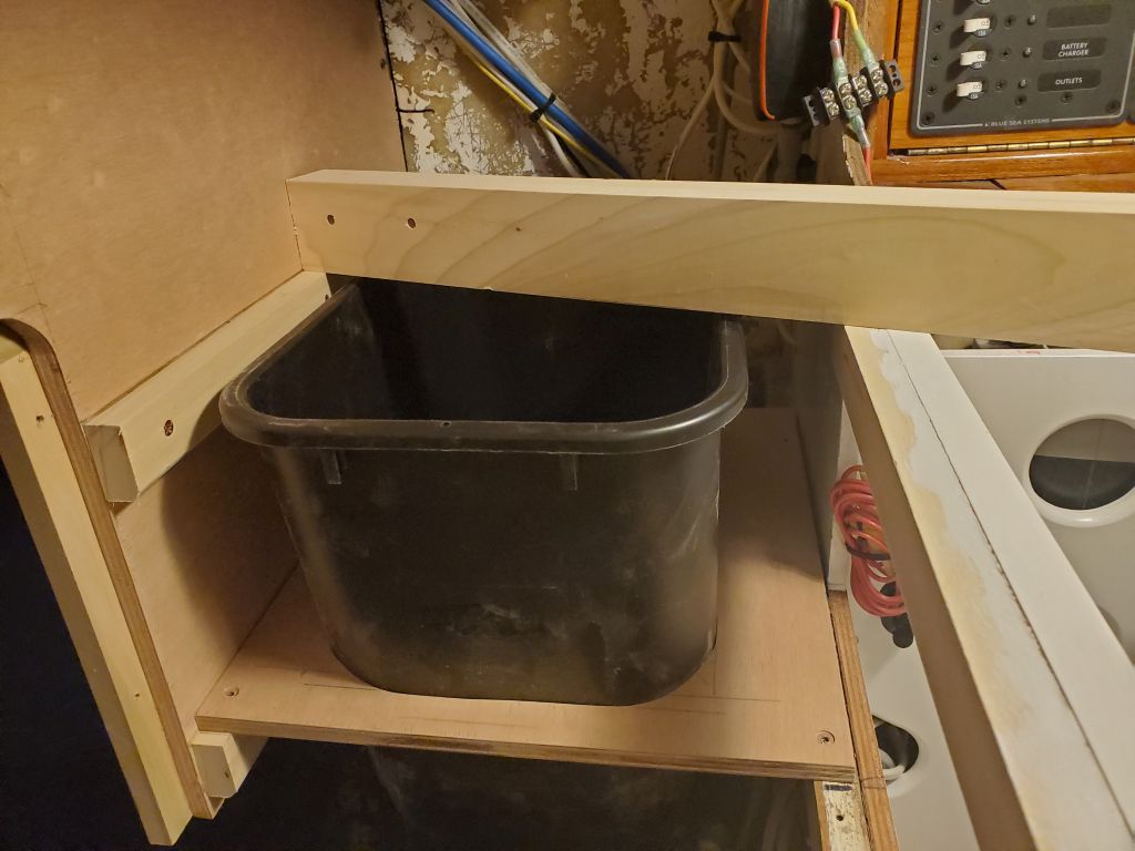
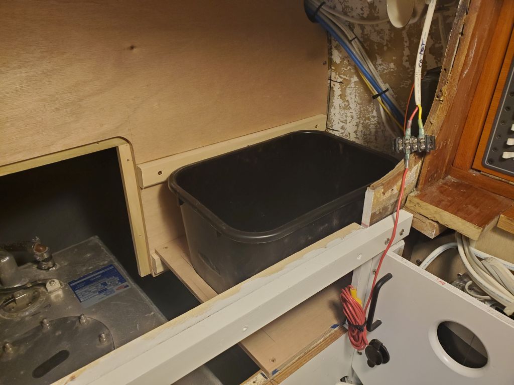
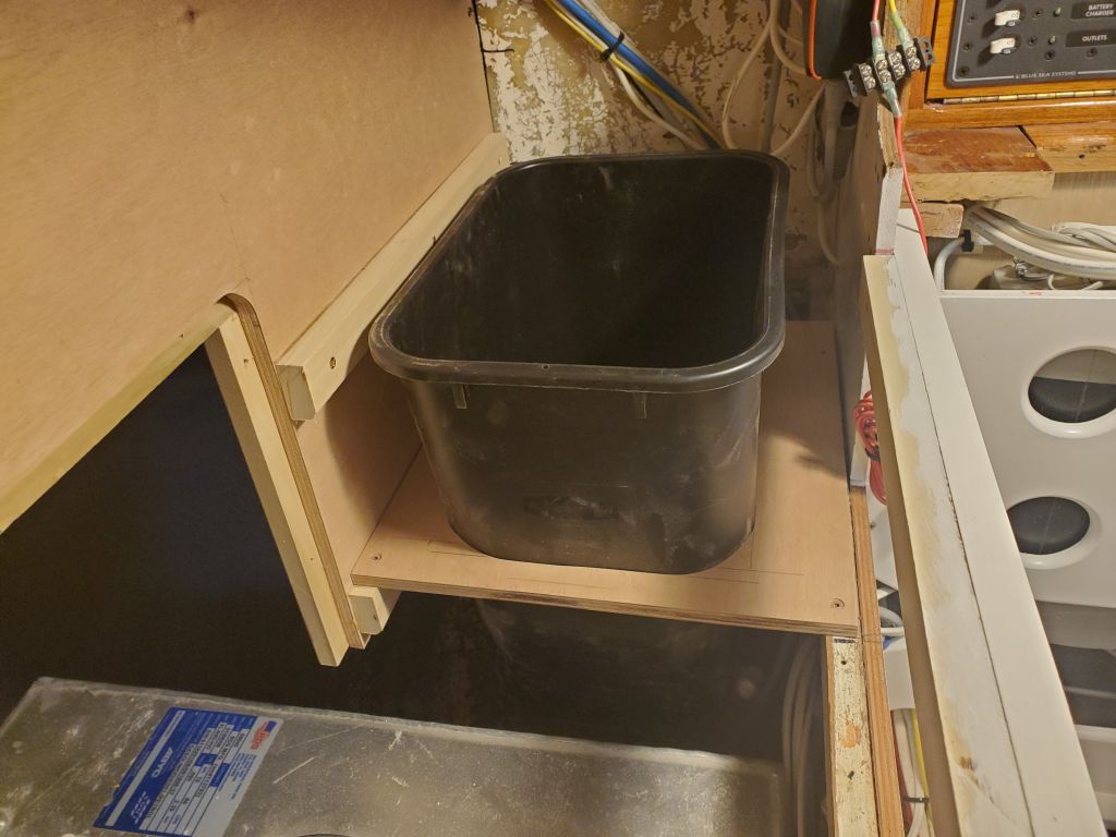
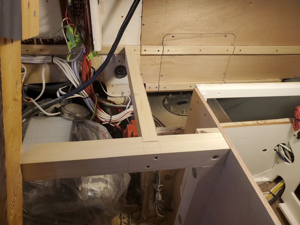
On the port side, I added support cleats as needed around the trash can opening (note that the countertop opening inside the cleats is sized to allow passage of the entire can through the top), and test-fit the panel back in place again.

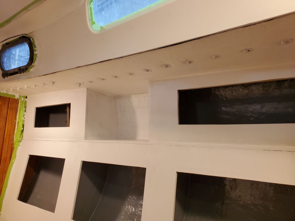
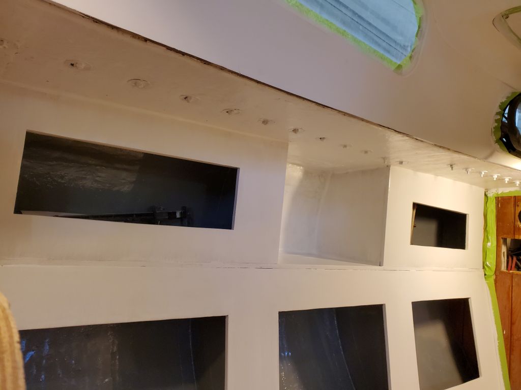
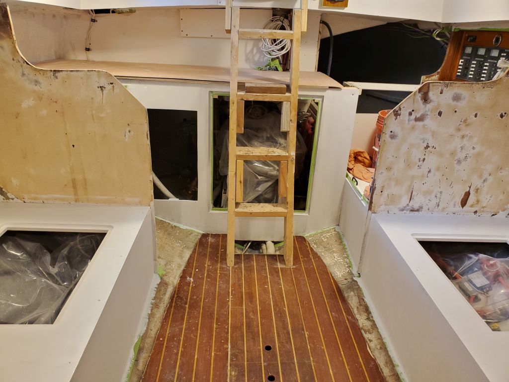
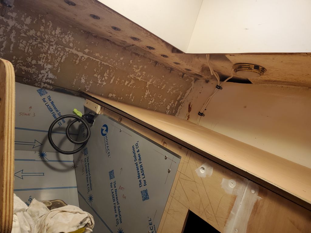
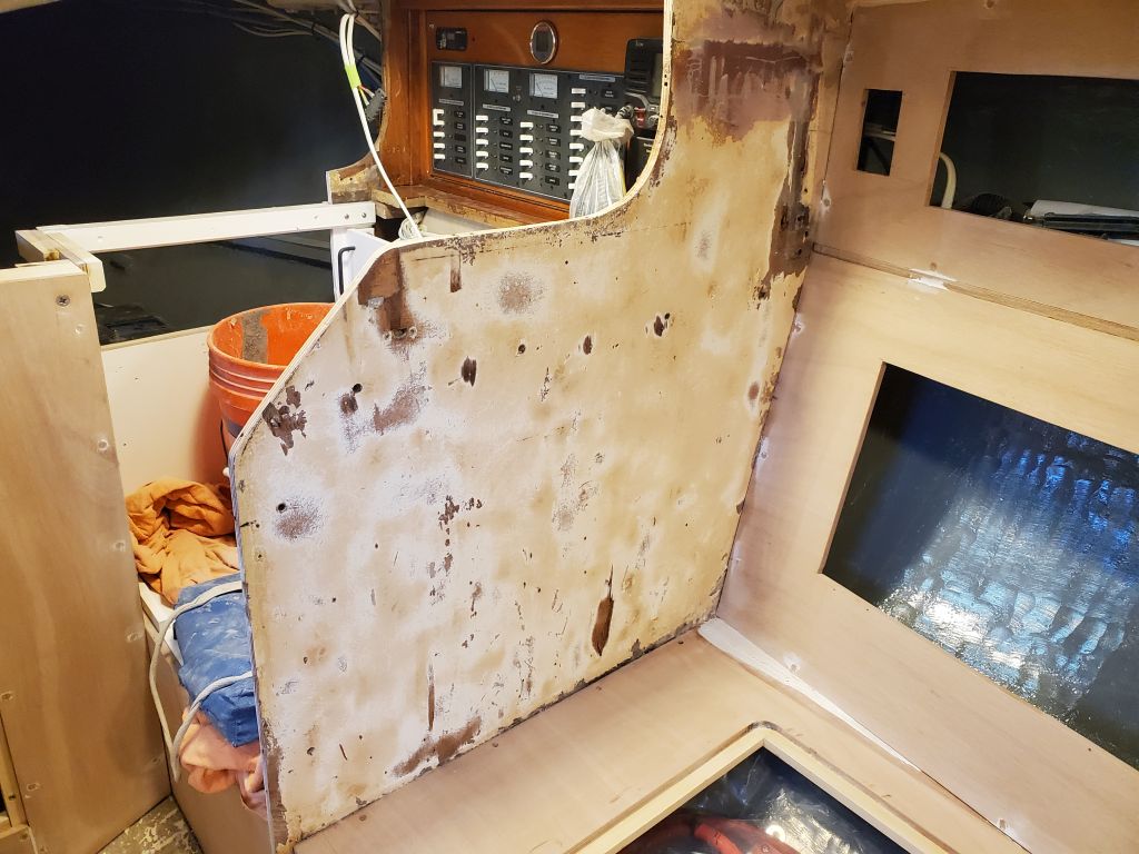
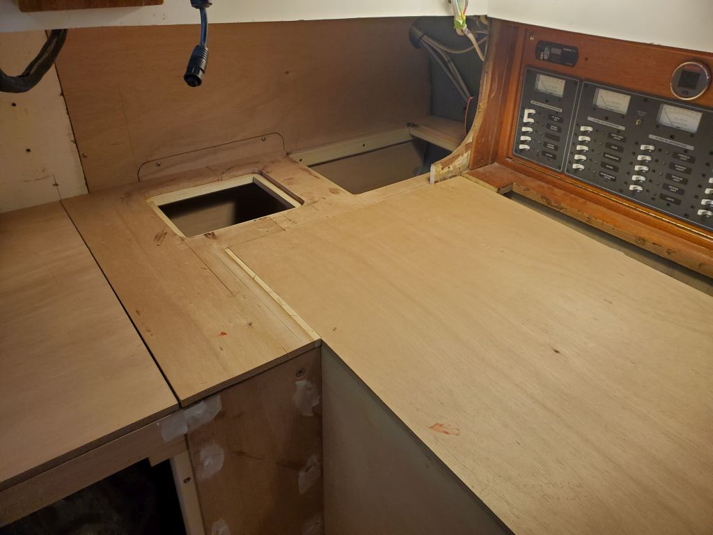
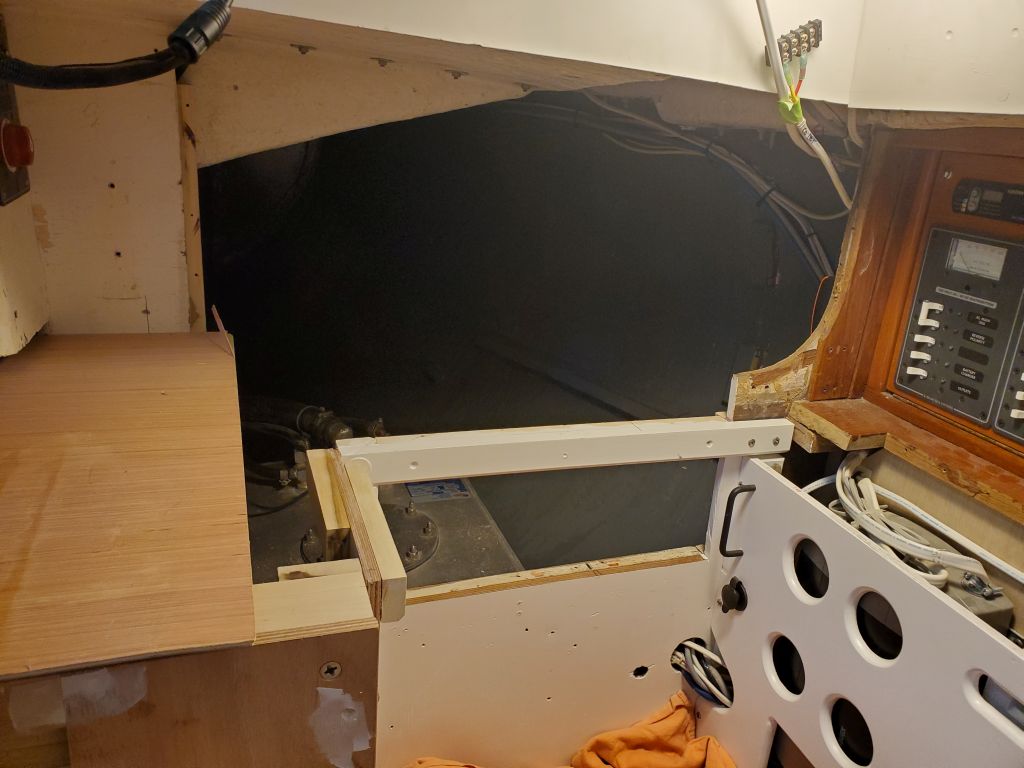
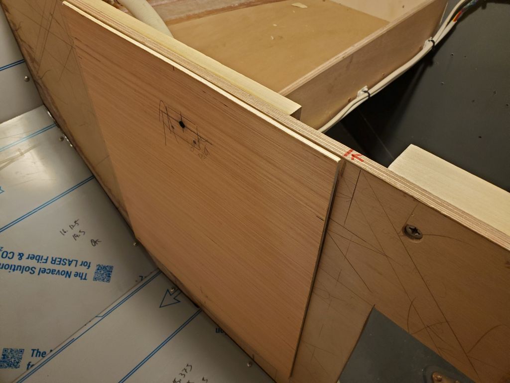
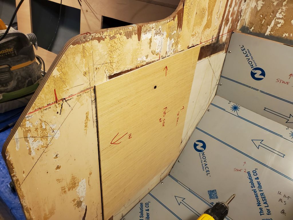
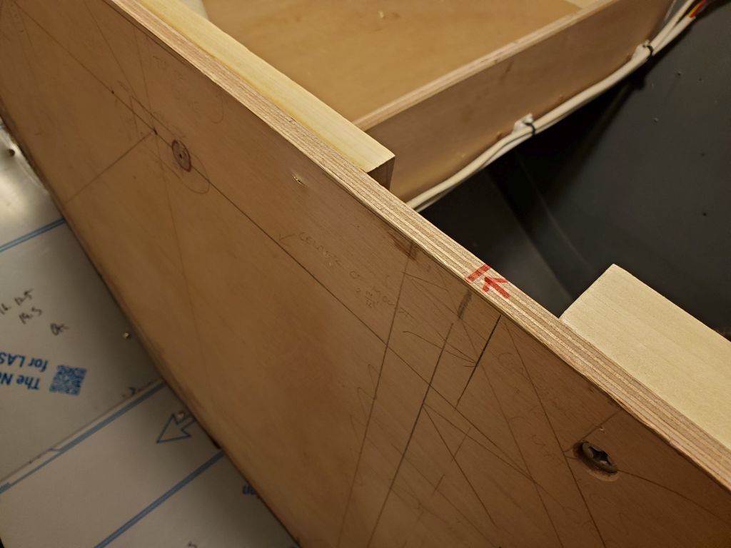
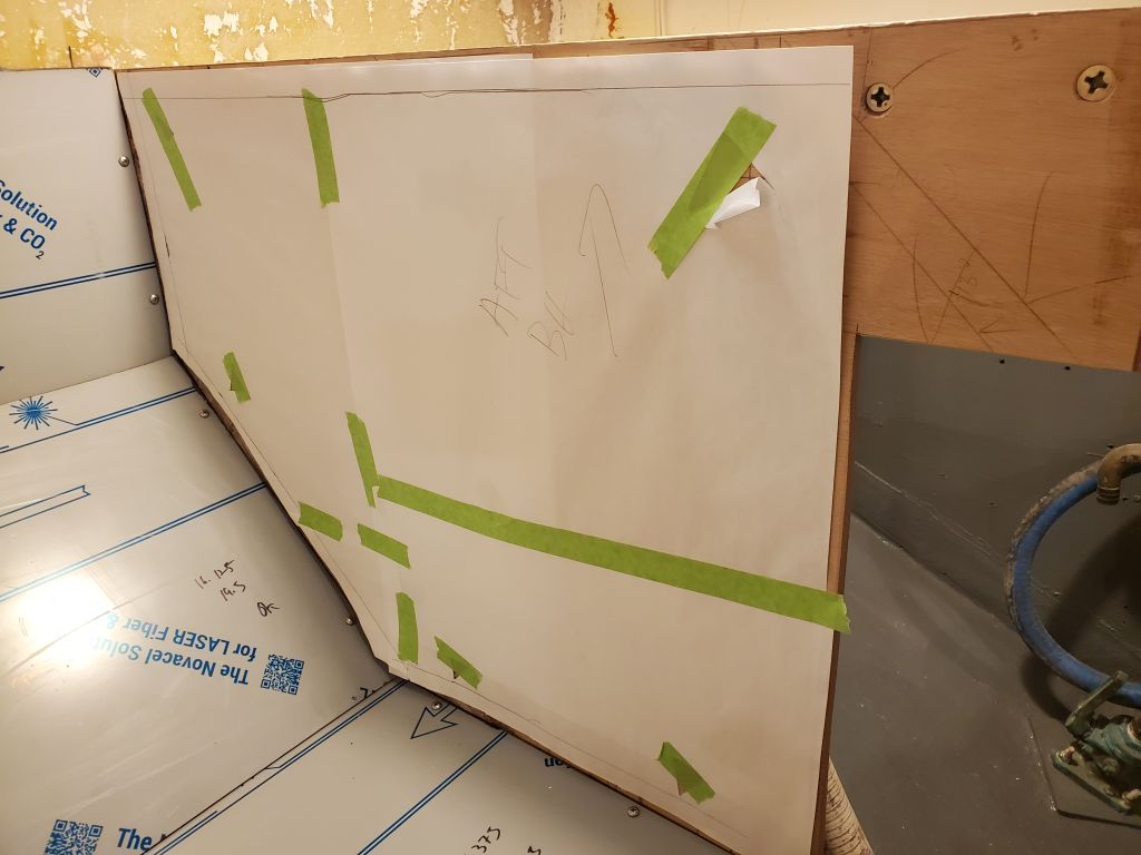
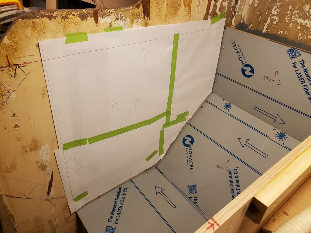
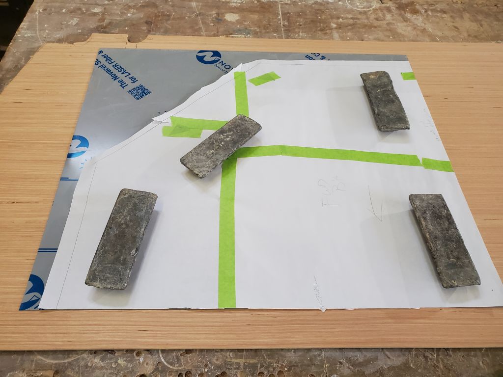
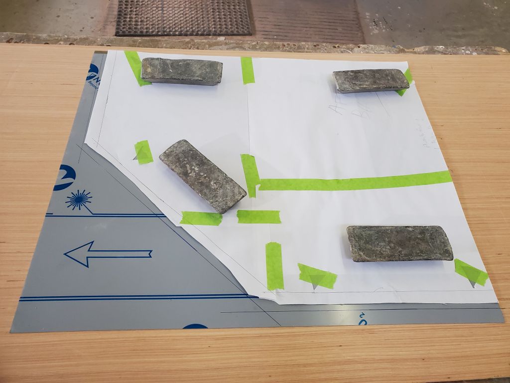
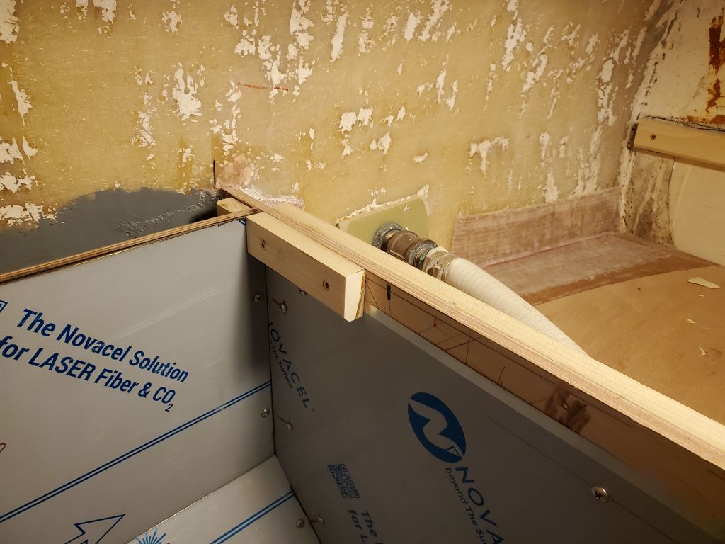
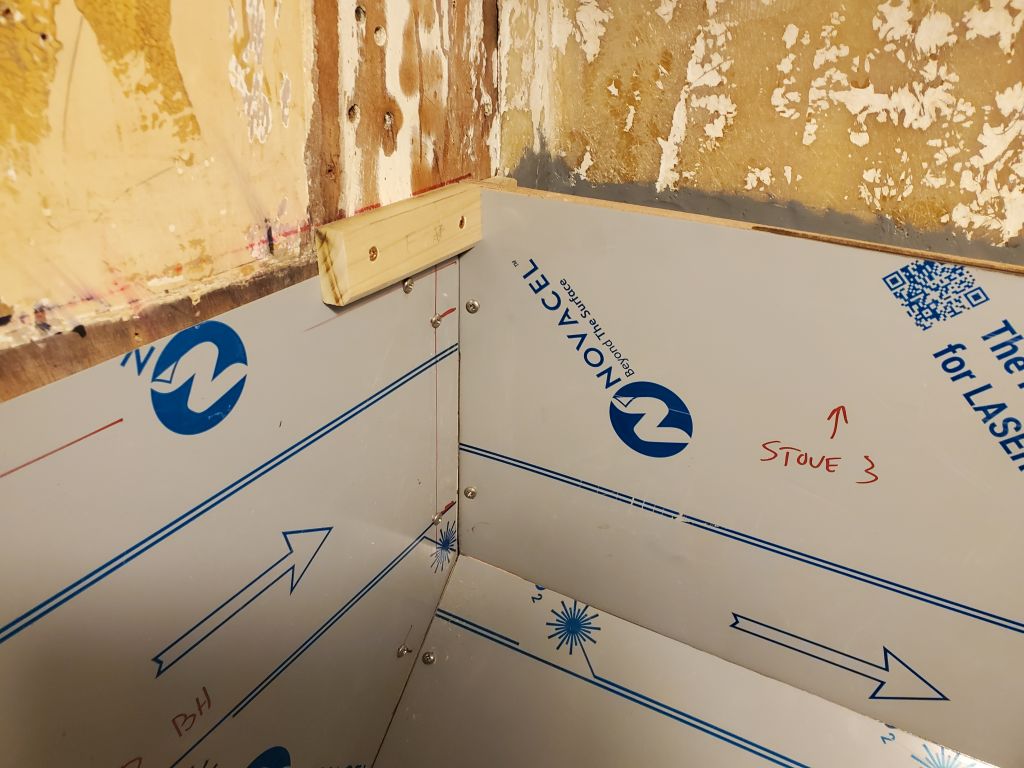
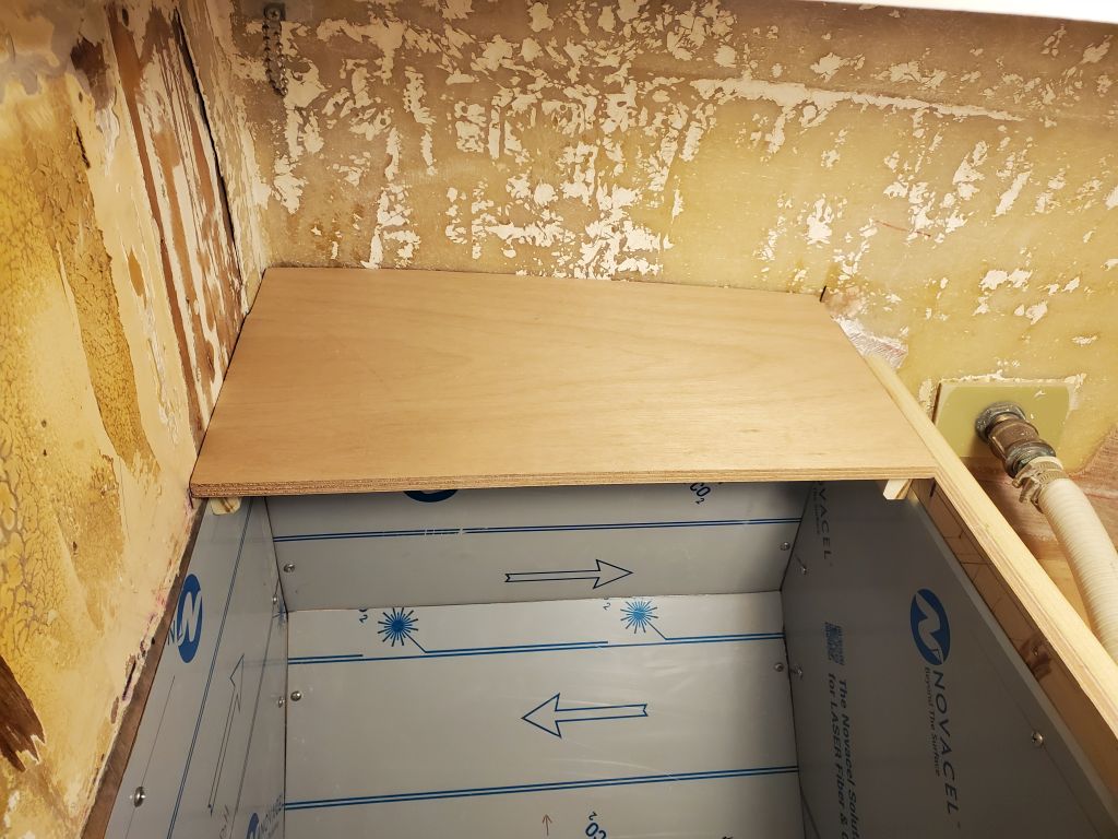
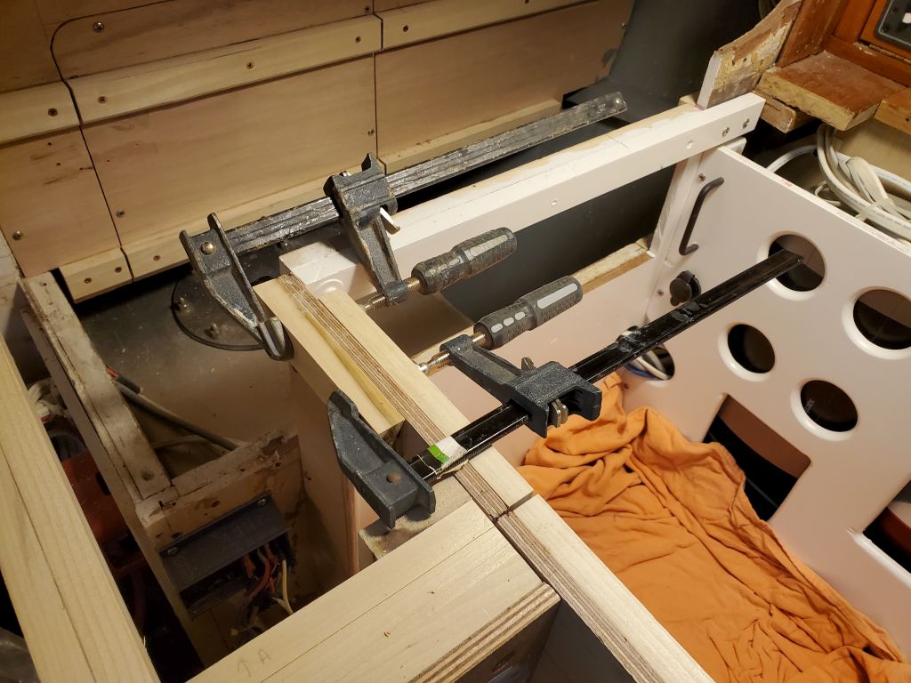
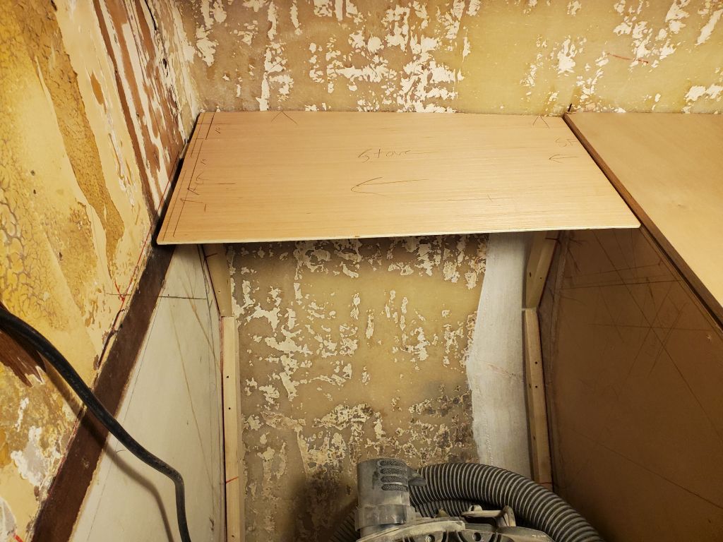
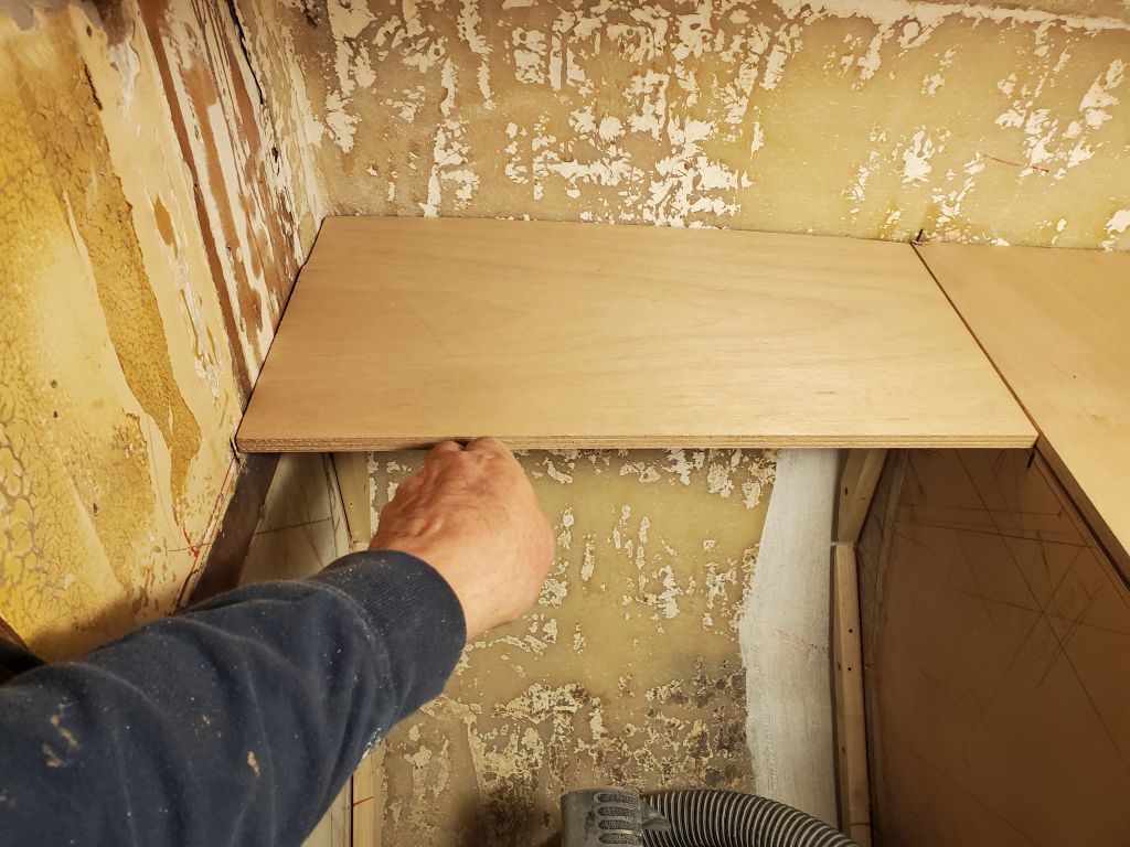
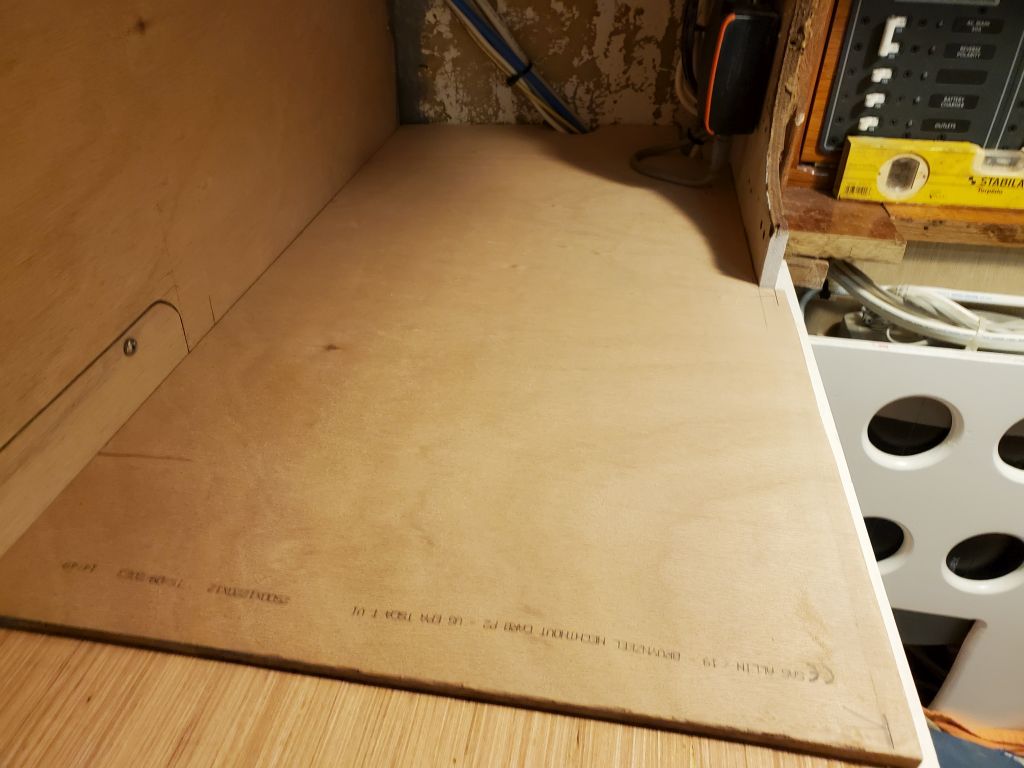
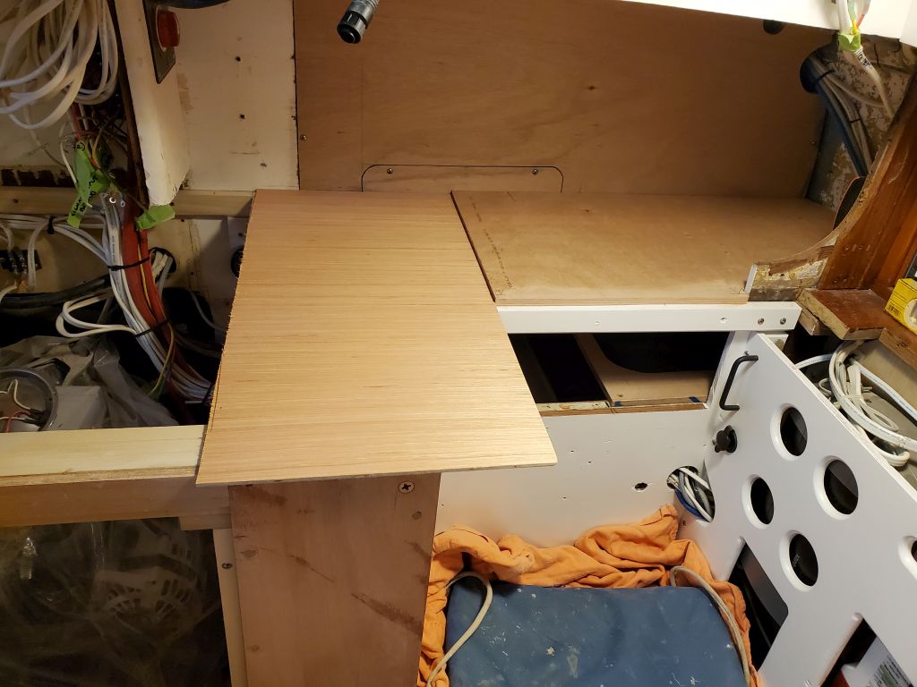
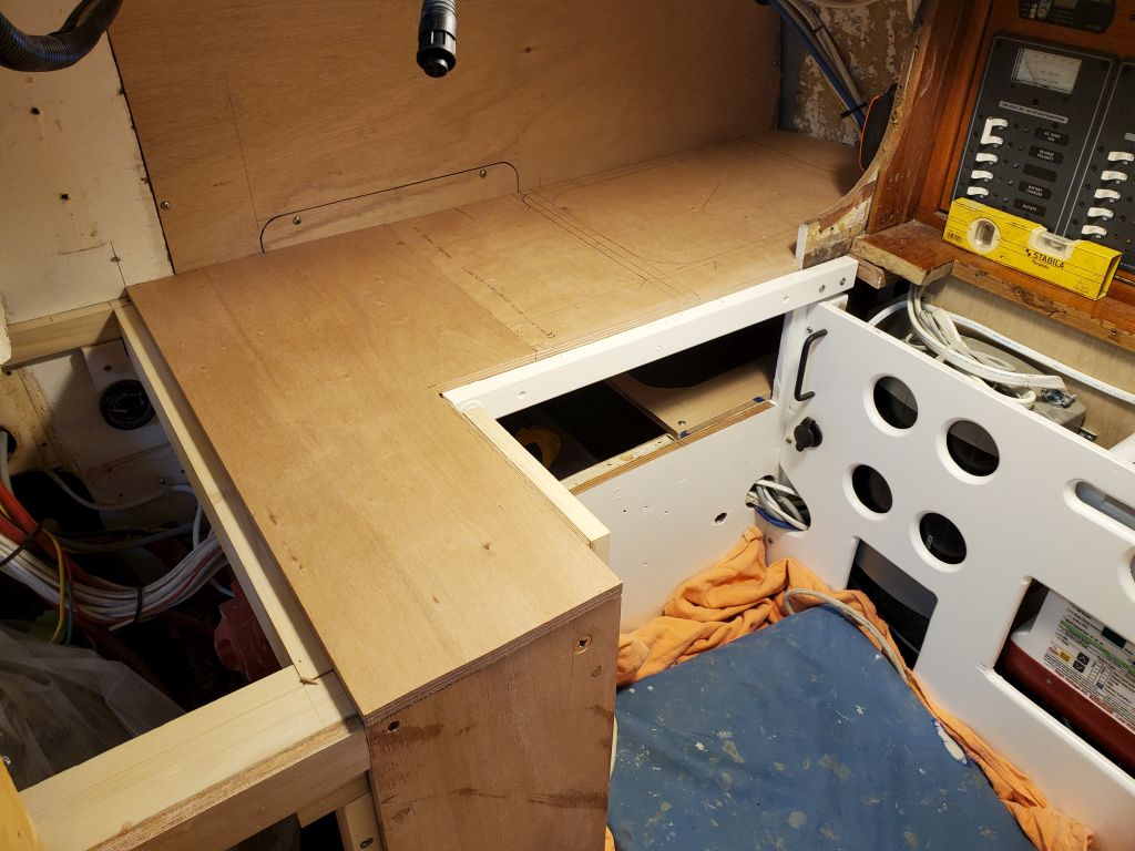
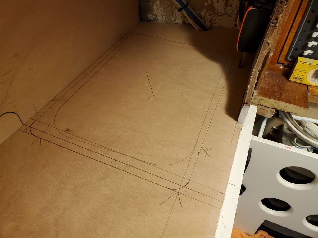
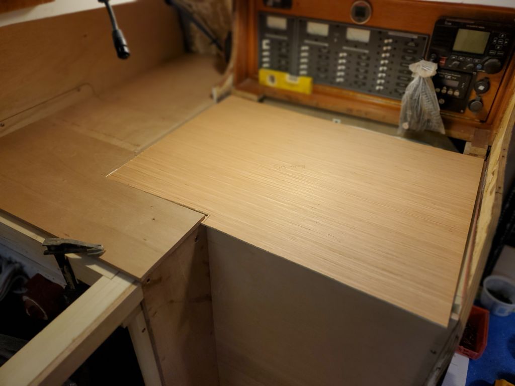
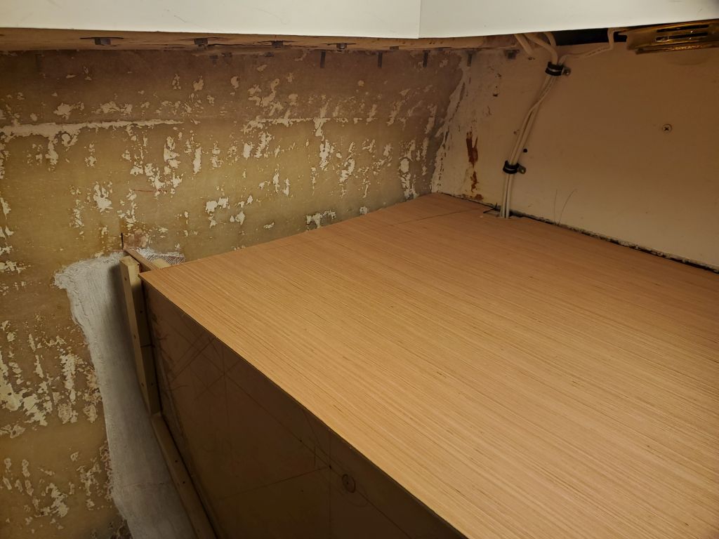
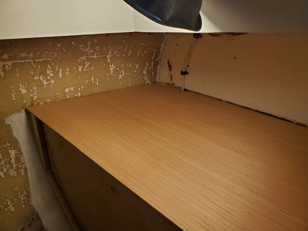
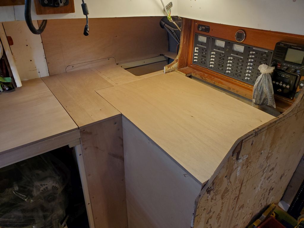
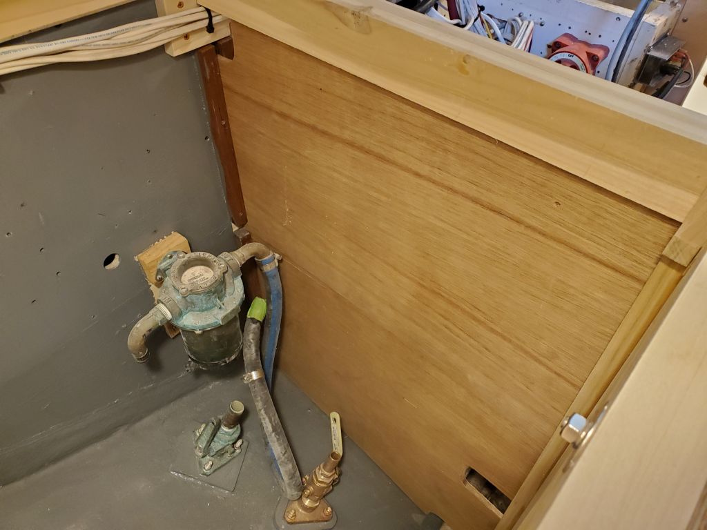
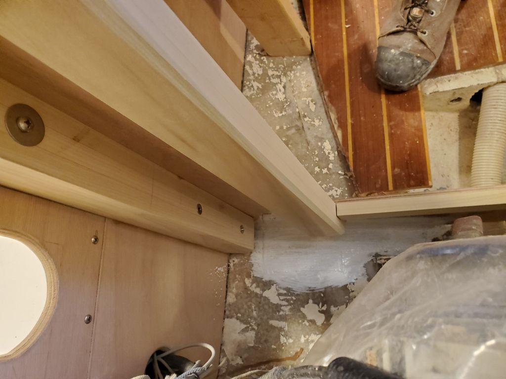
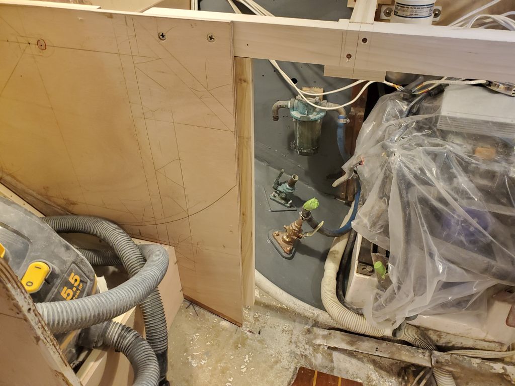
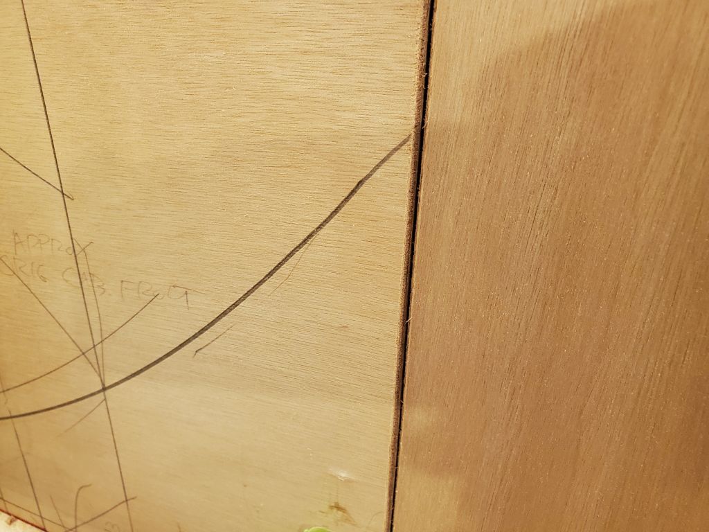
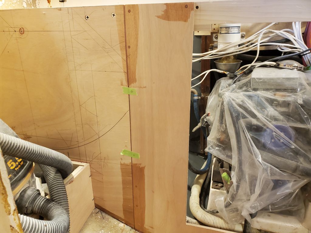
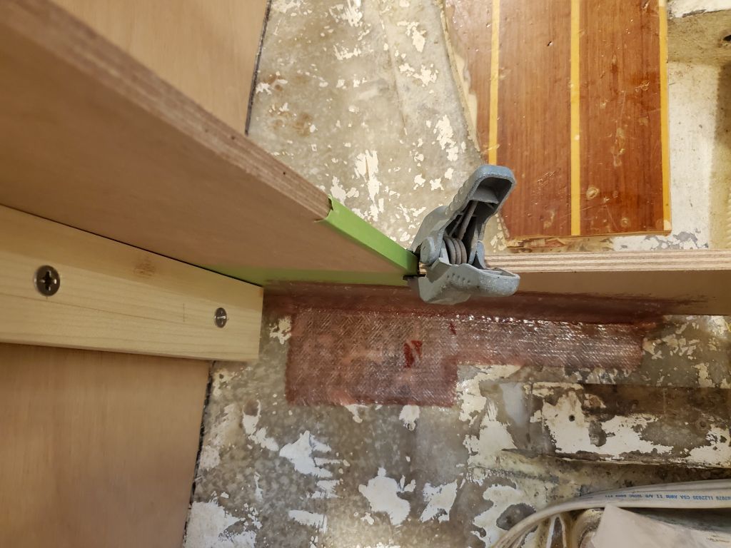
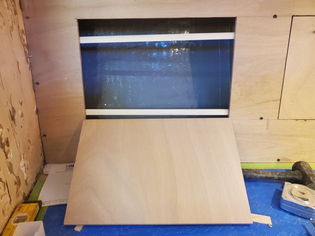
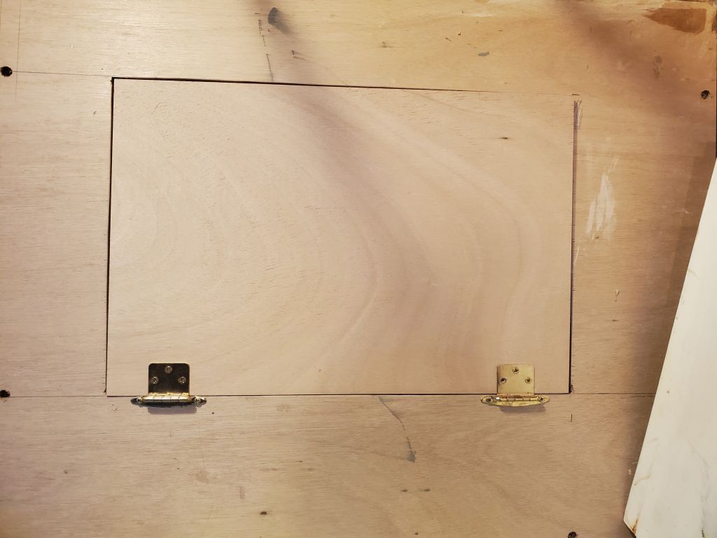
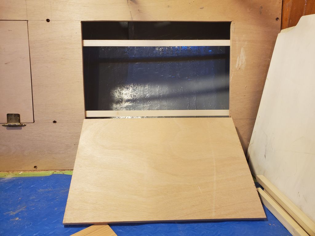
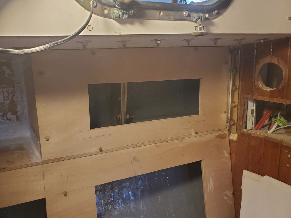
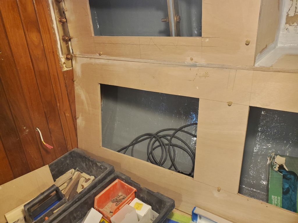
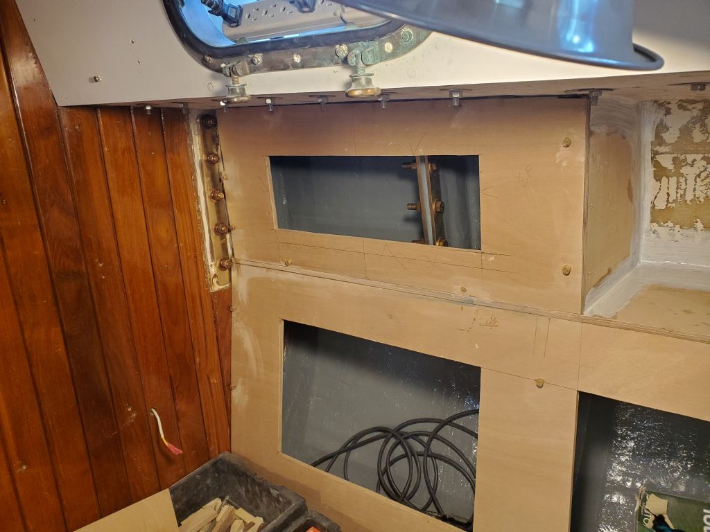
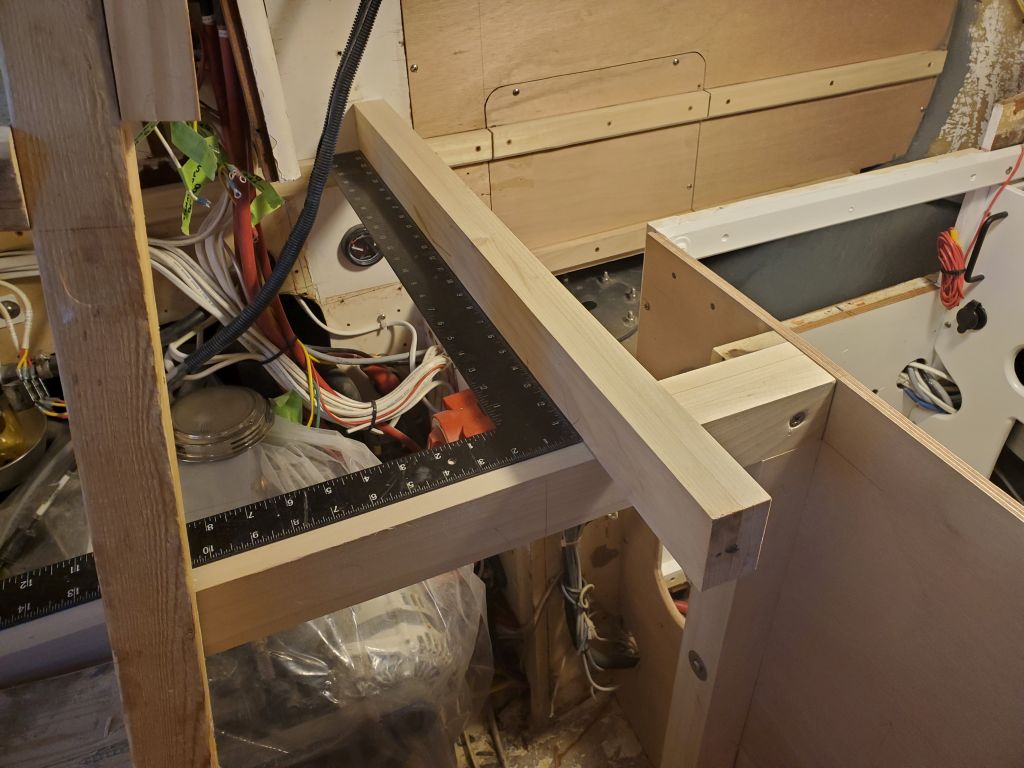
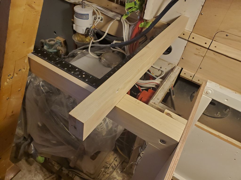
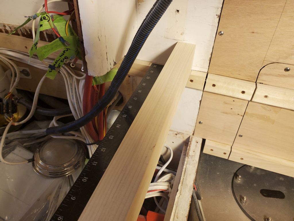
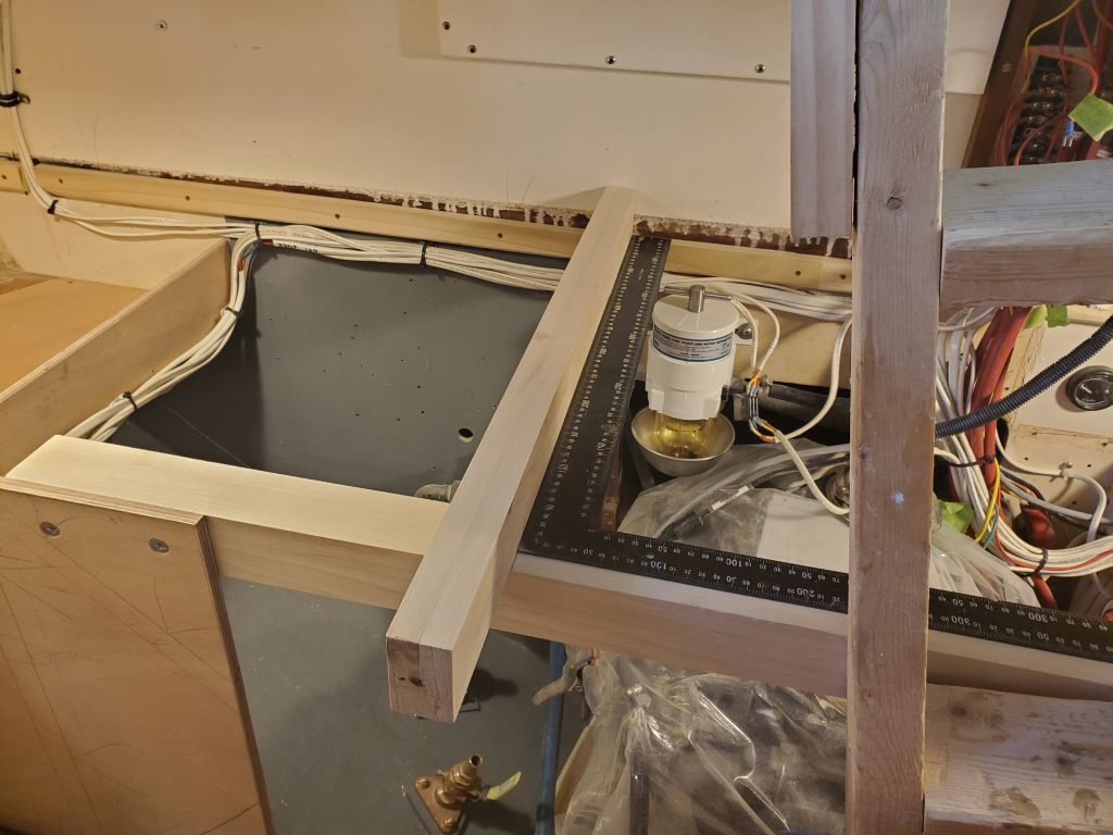
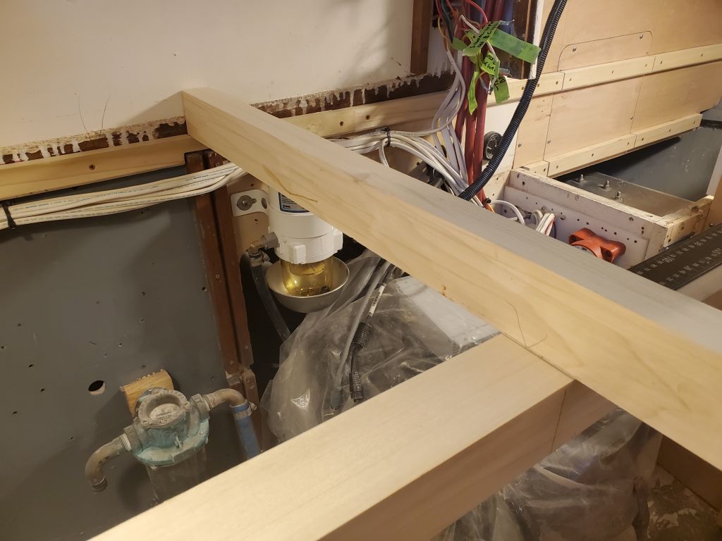
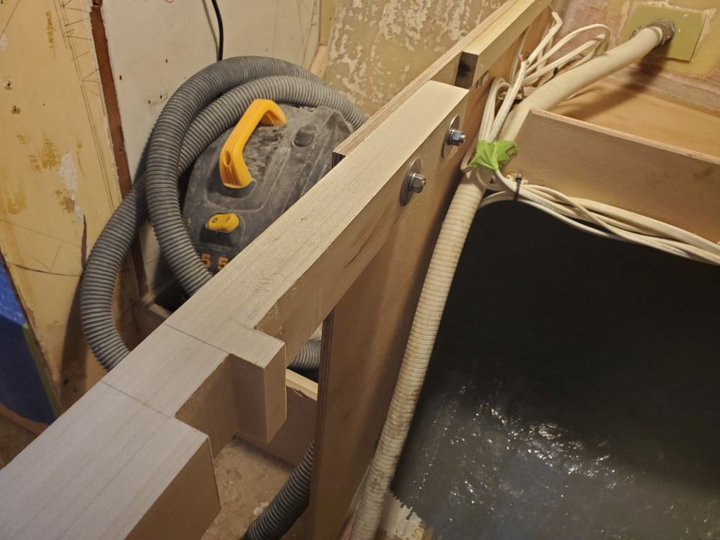
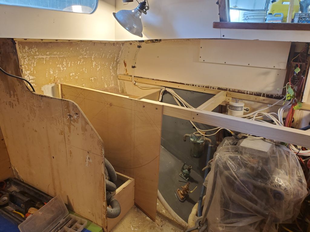
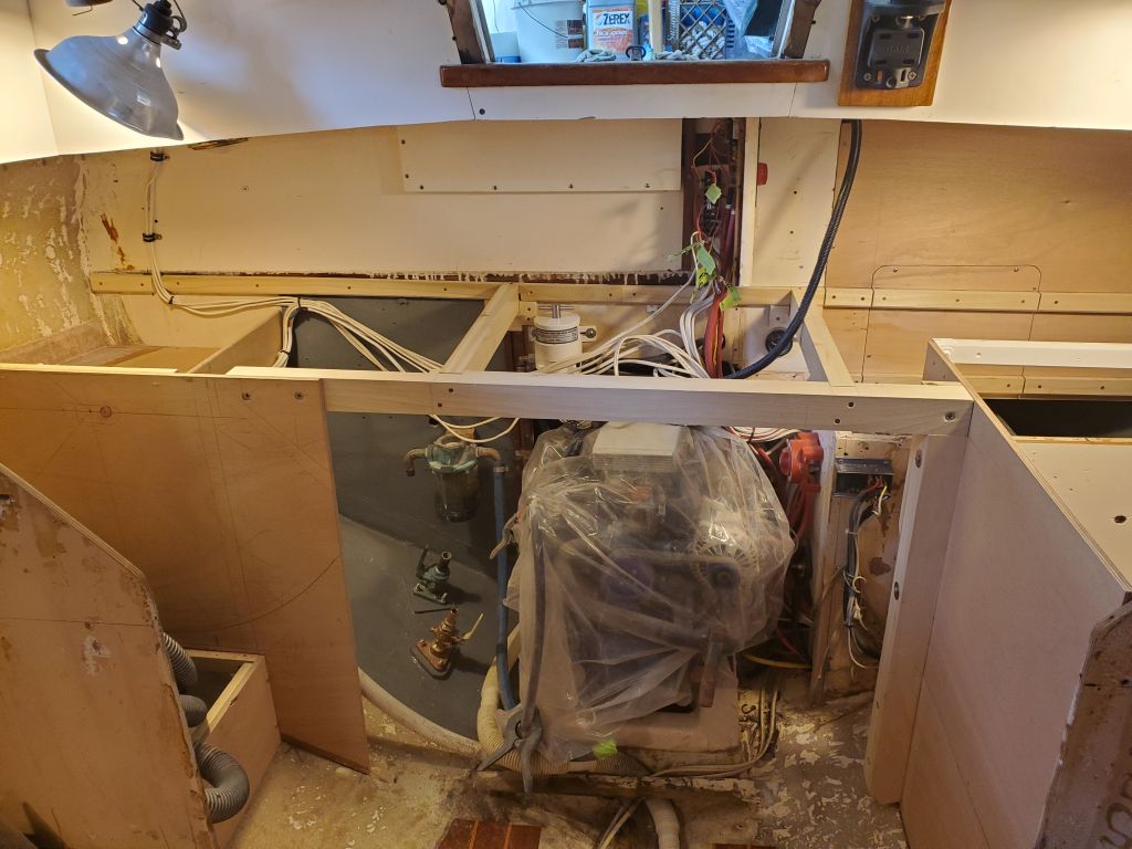
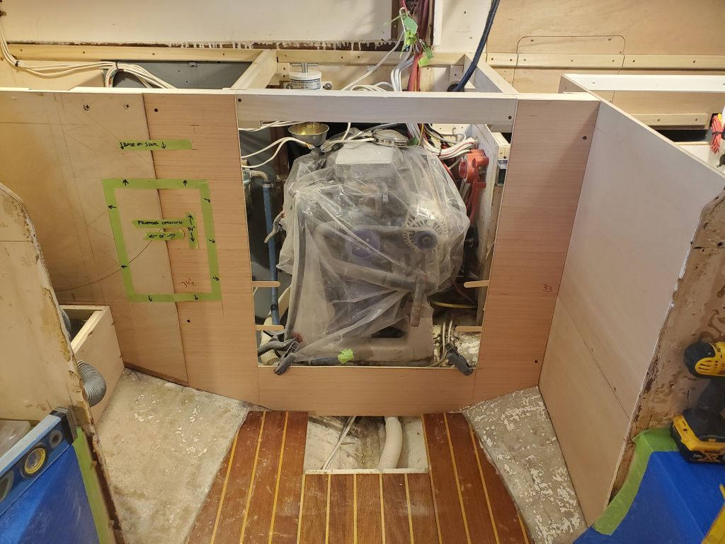
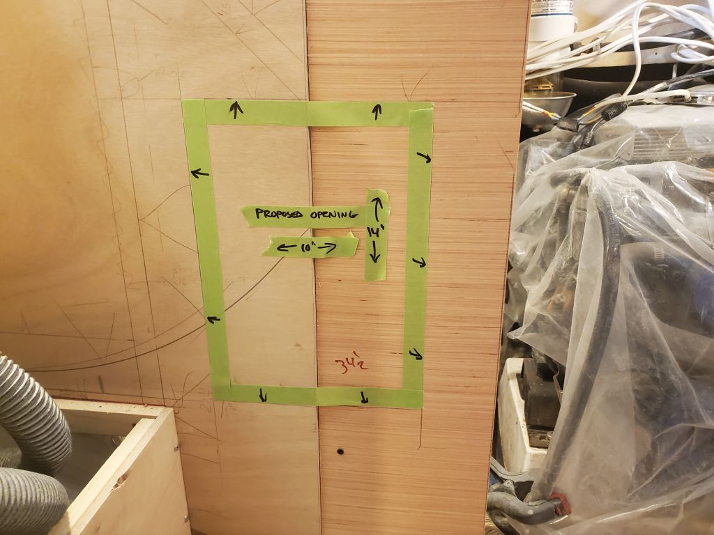
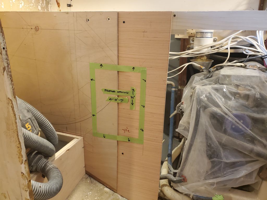
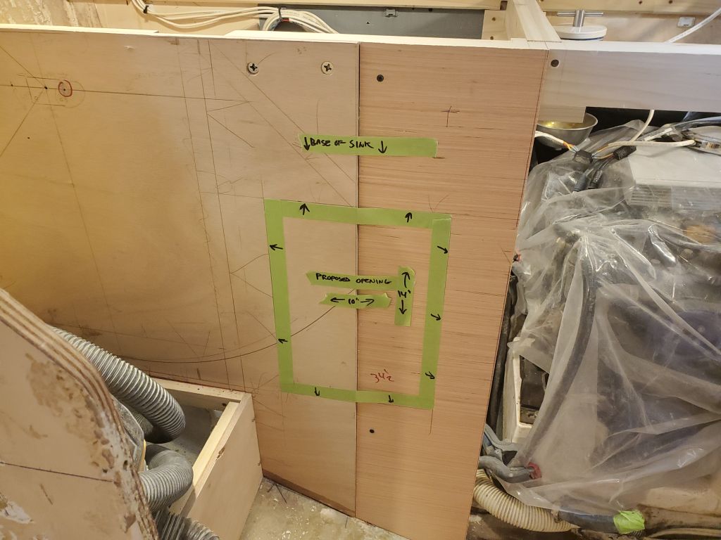
I also needed to plan an access hatch outboard of the sink to starboard, so that the large shelf I’d built beneath could be used.  Before I could determine its size and placement, I first had to work out one small remaining piece of countertop across the outboard side of the stove enclosure.  There was room here, outboard of the farthest swing reach of the stove itself, for a continuation of the counter, mainly to provide additional over-counter storage lockers in this side.  So with the swing extent marked on the bulkheads as a guide, I started with a basic cheap plywood template cut and scribed to fit, then transferred the shape to the final material, which for the moment I could only temporarily hold in place as it require additional support cleats.  But this gave me a reference to use as a maximum position for the upper cabinet to come, which in turn, along with the corresponding mark parallel to the aft bulkhead, gave me the open field area left to be available for under-counter locker access.  I’d lay out, cut, and finish that opening soon.

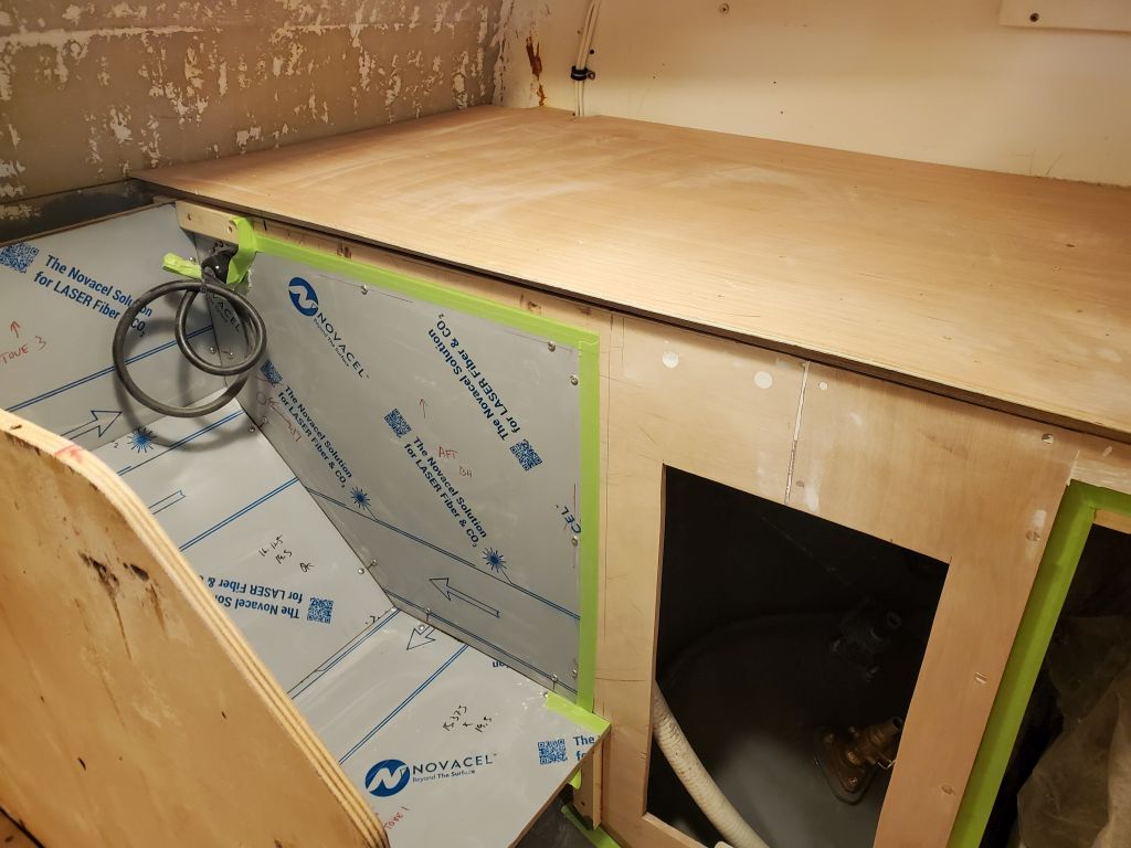
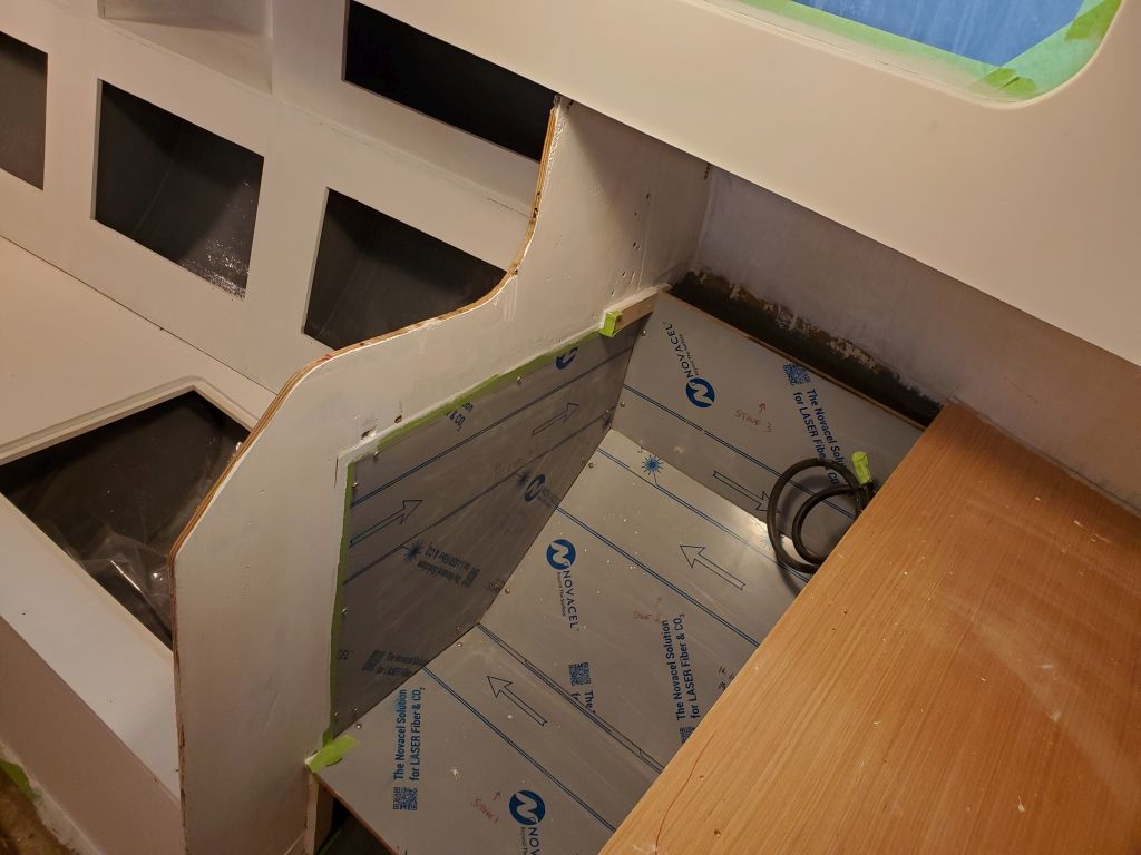
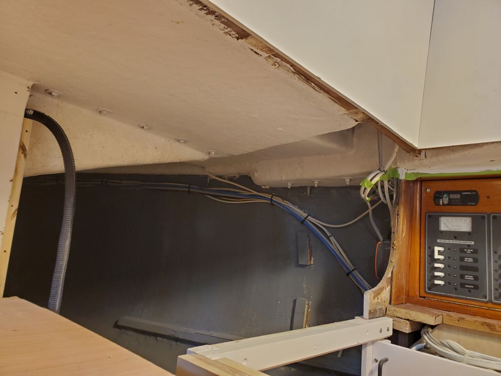
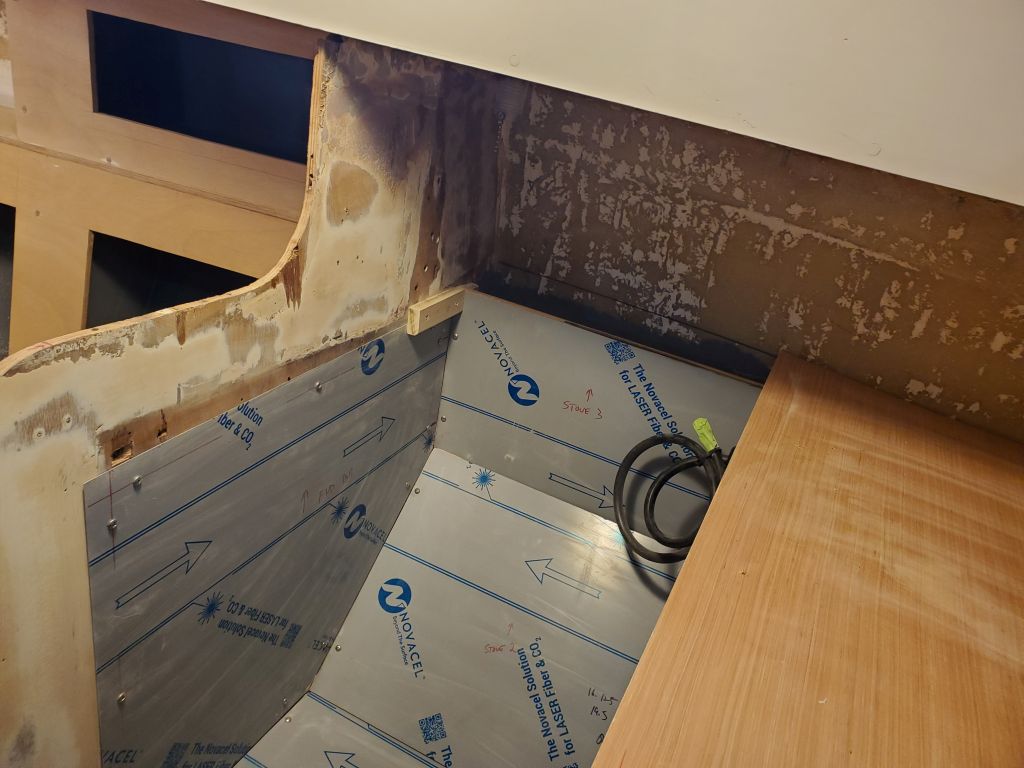
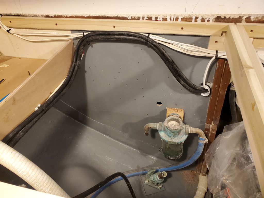
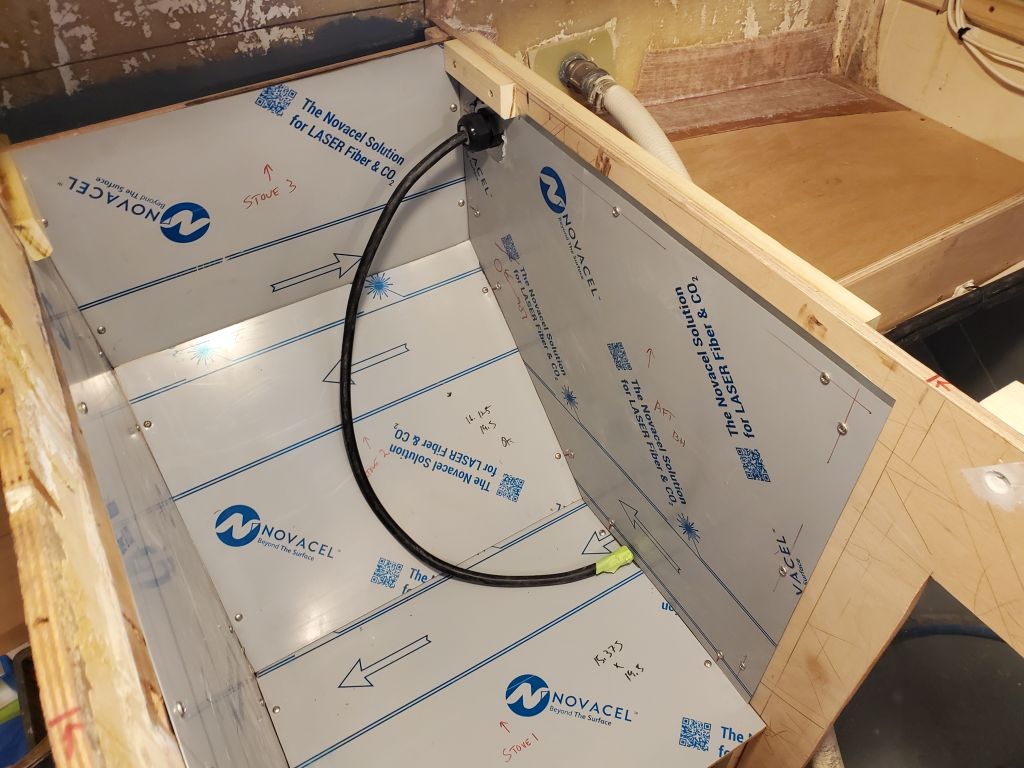
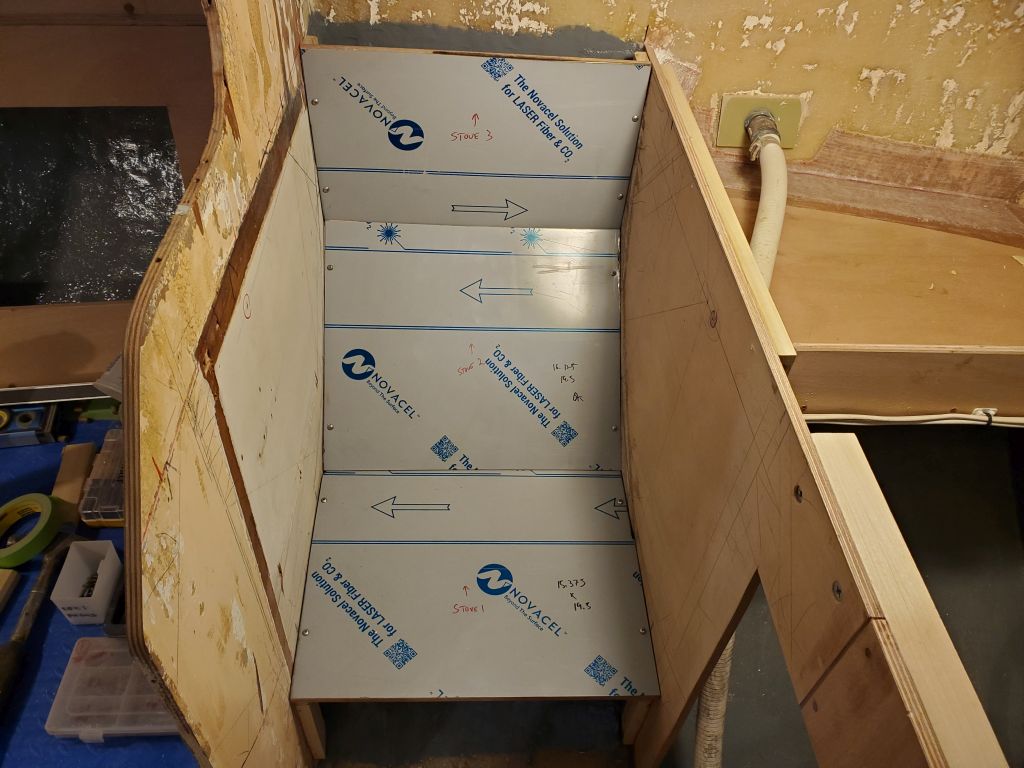
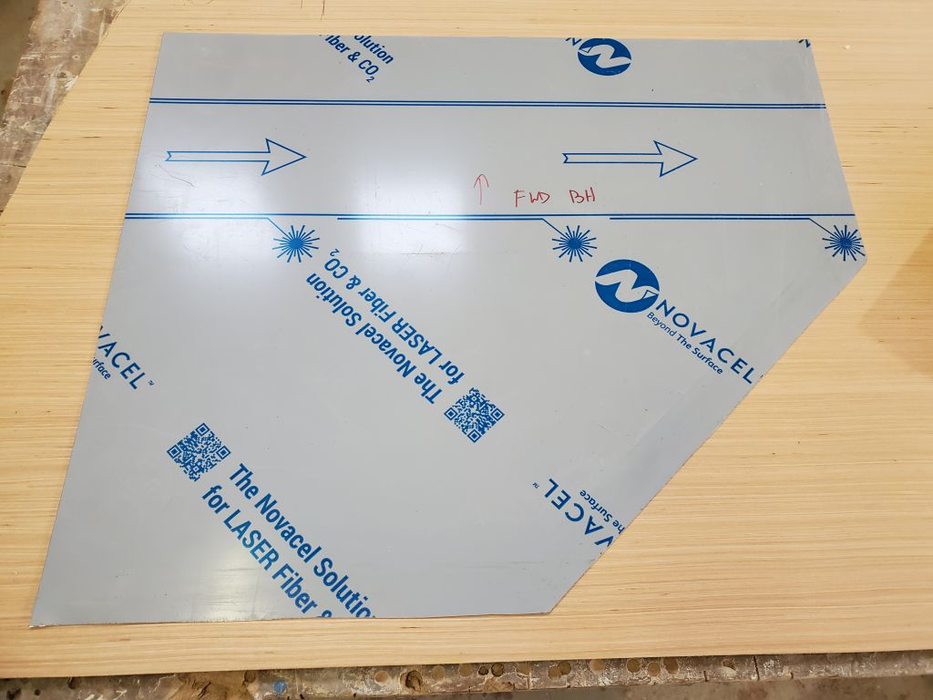
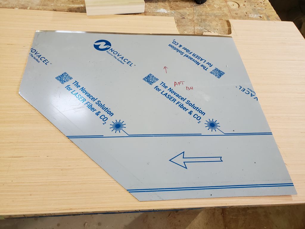
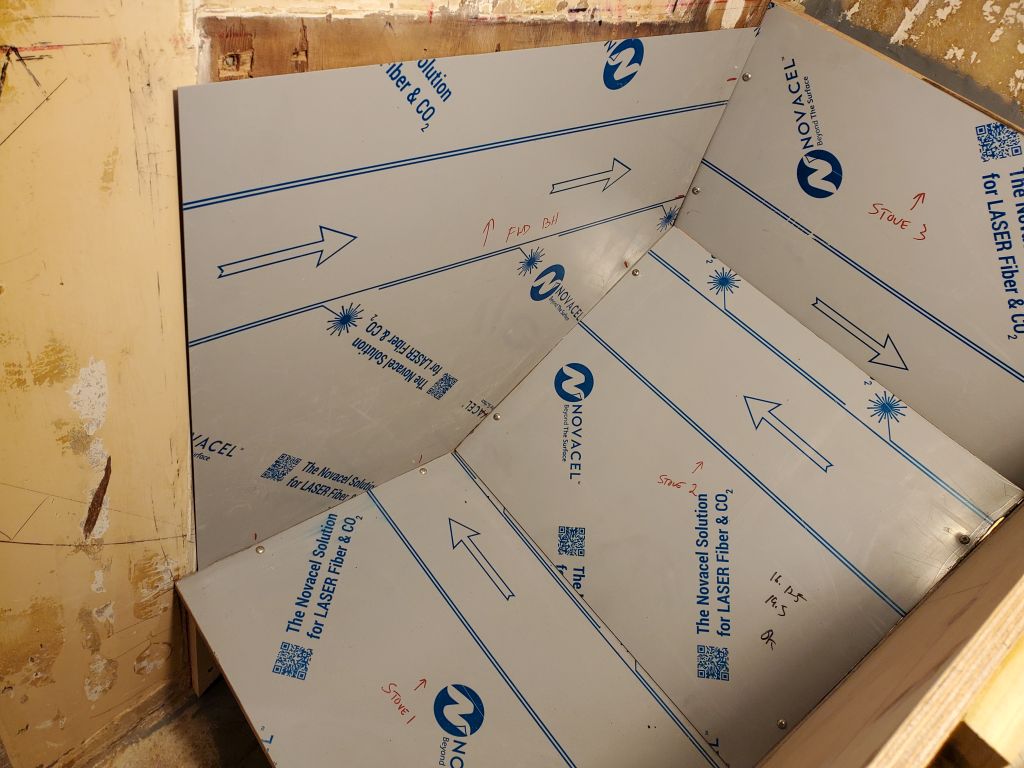
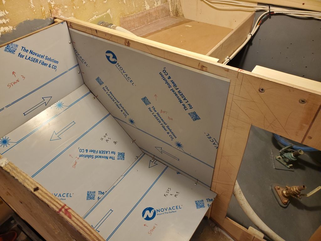
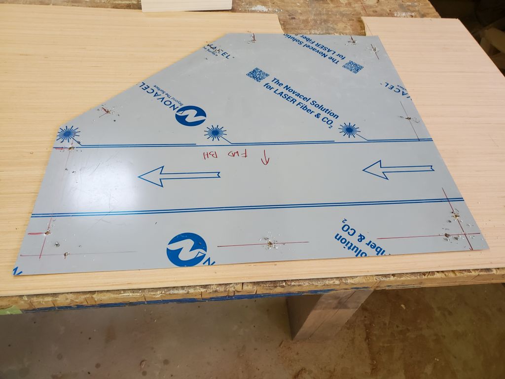
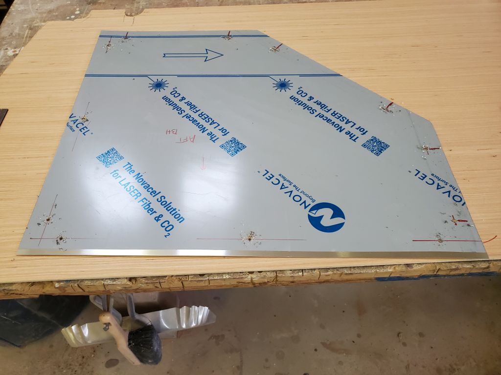
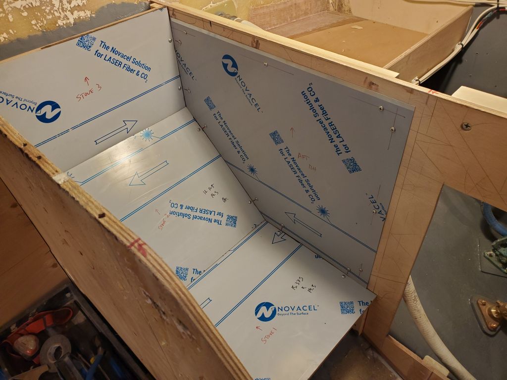
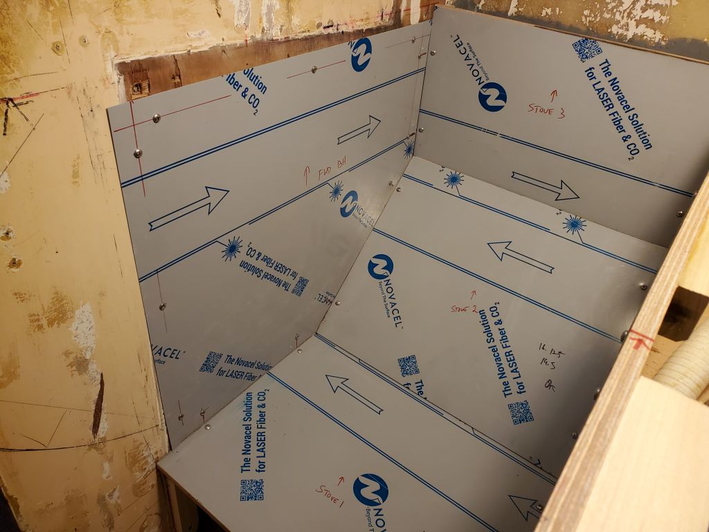
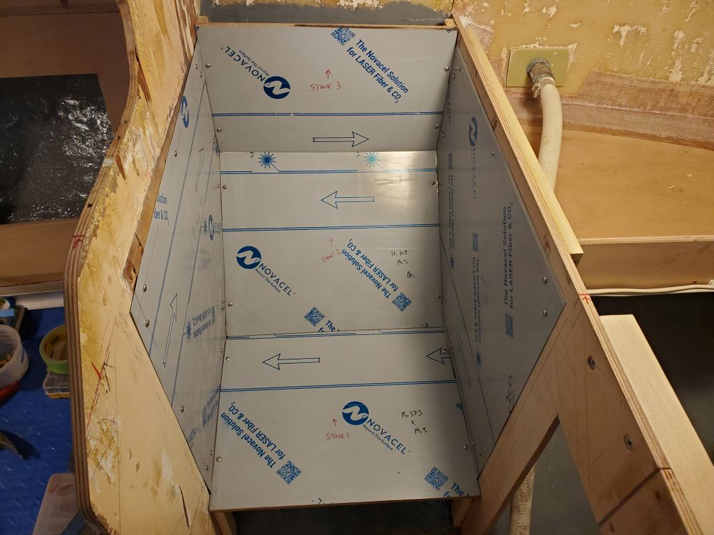
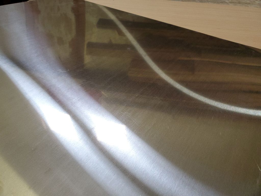
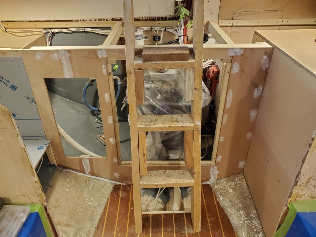
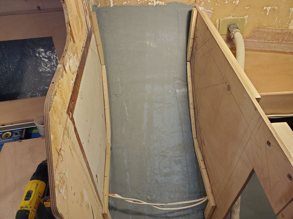
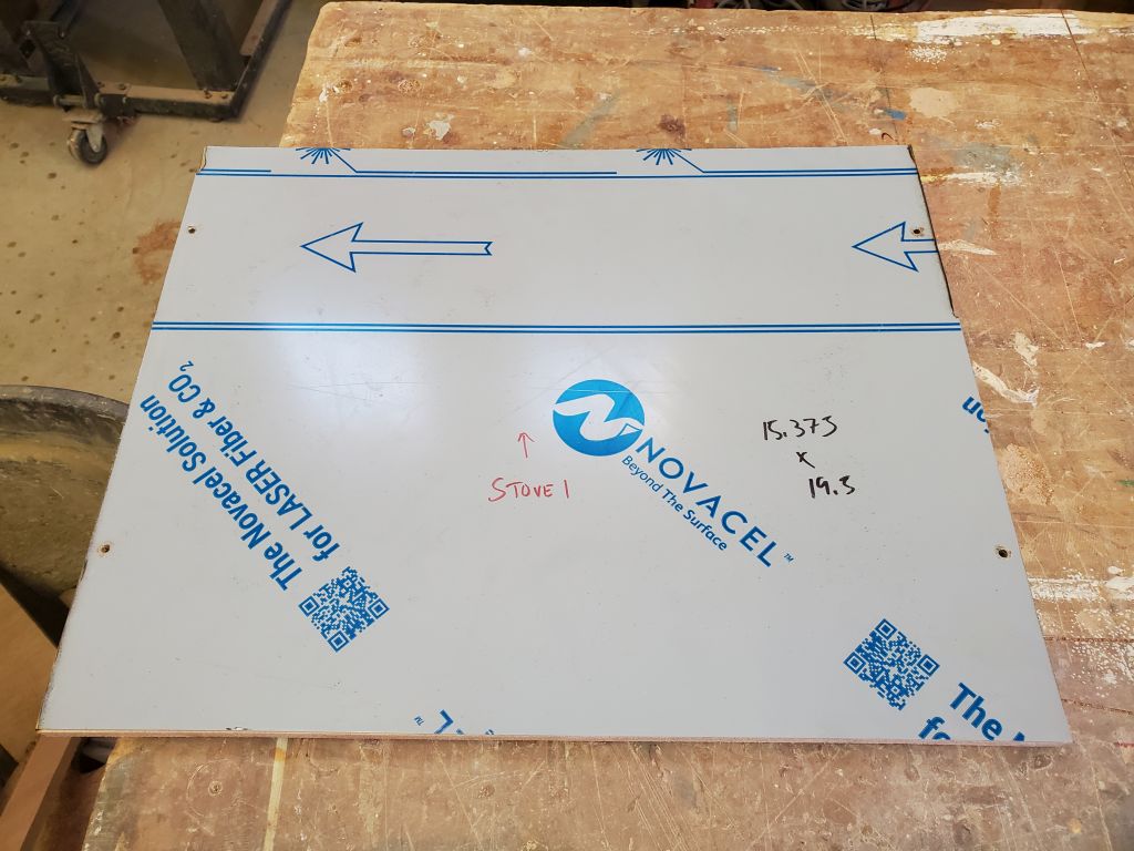
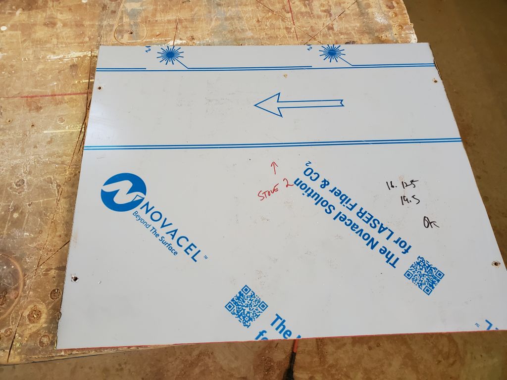
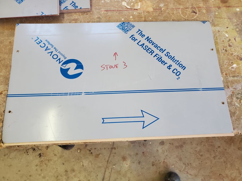
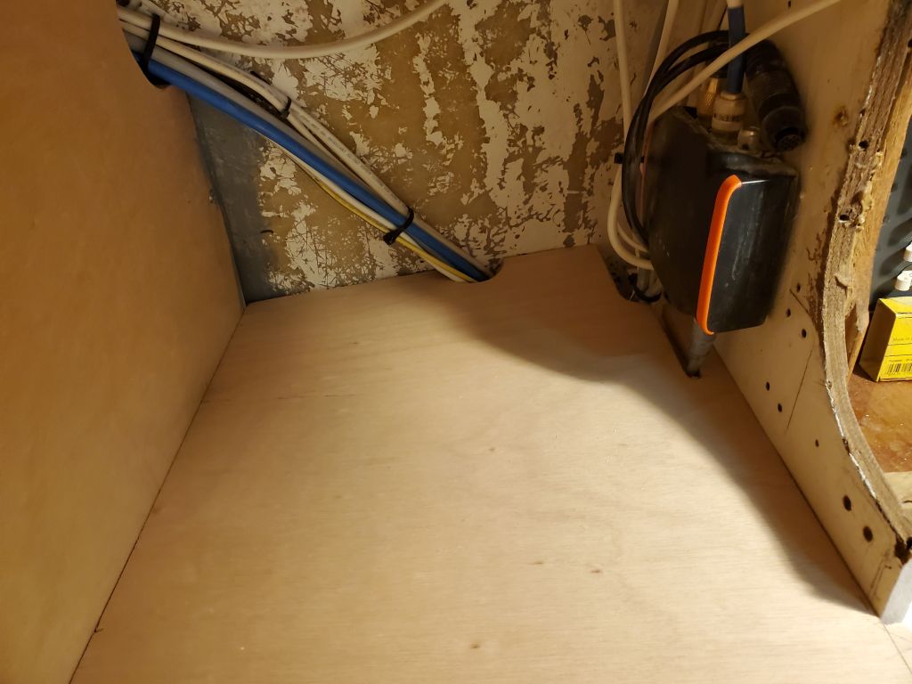
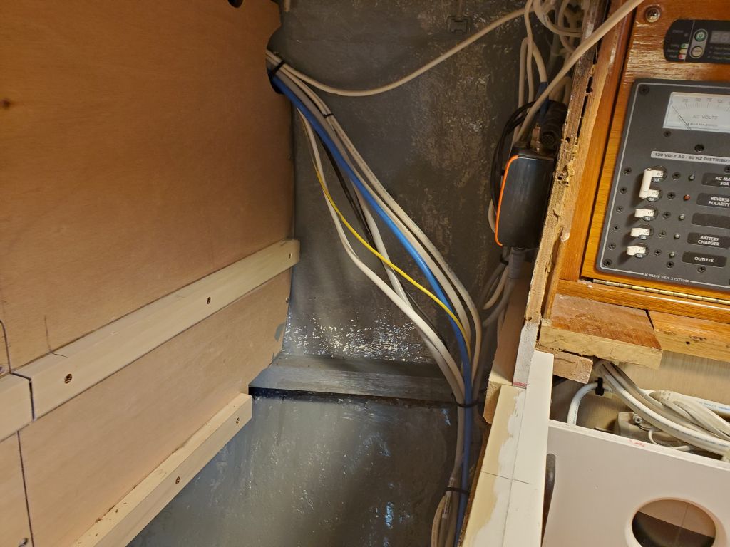
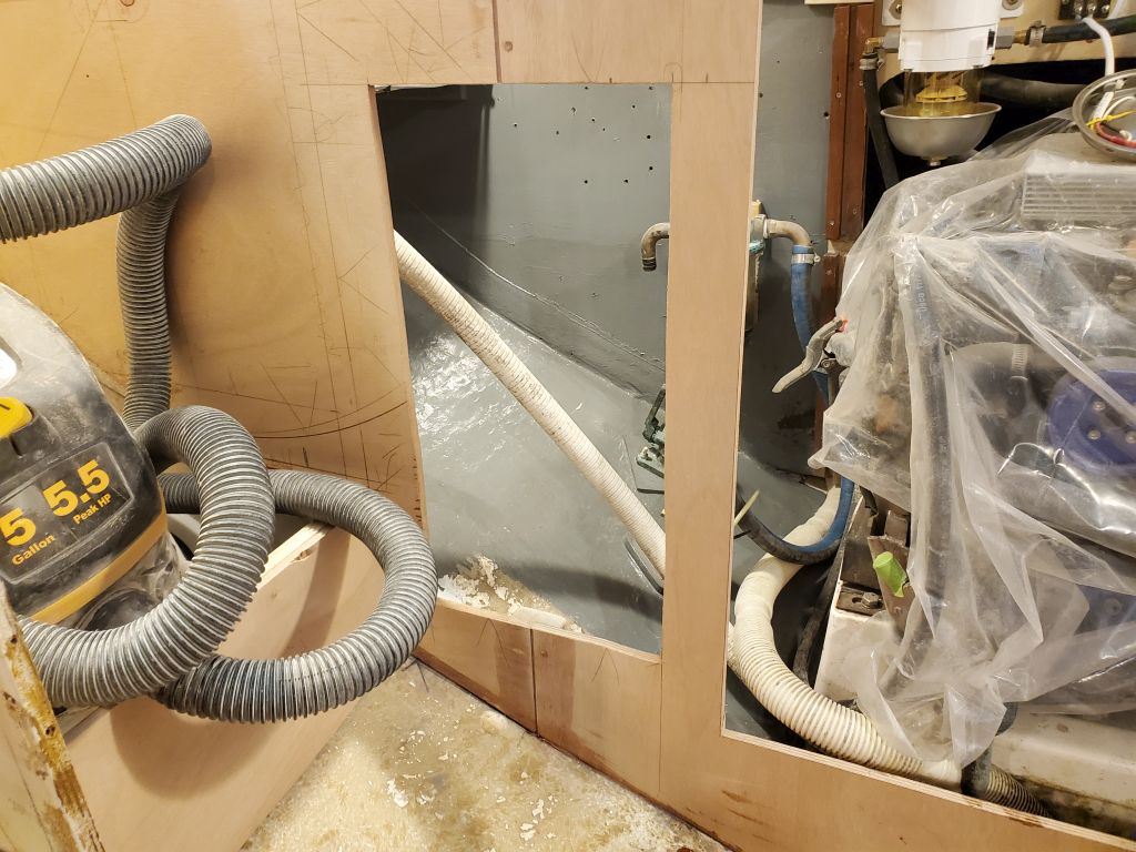
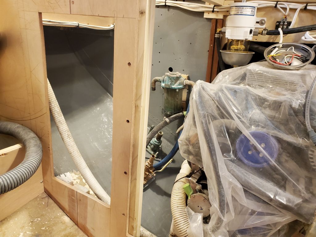
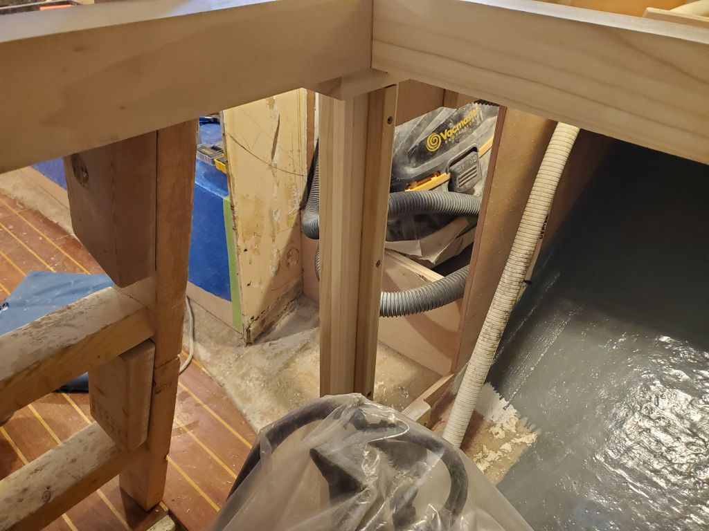
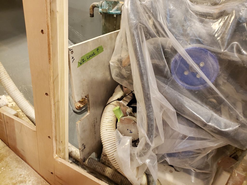
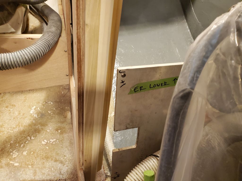
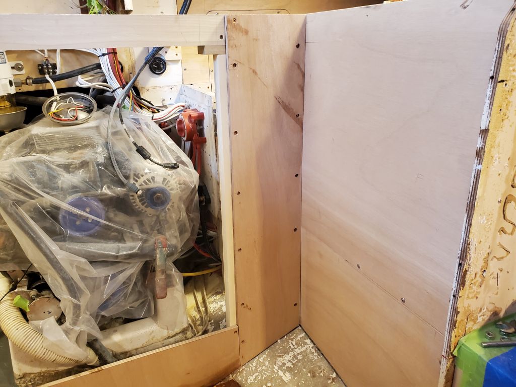
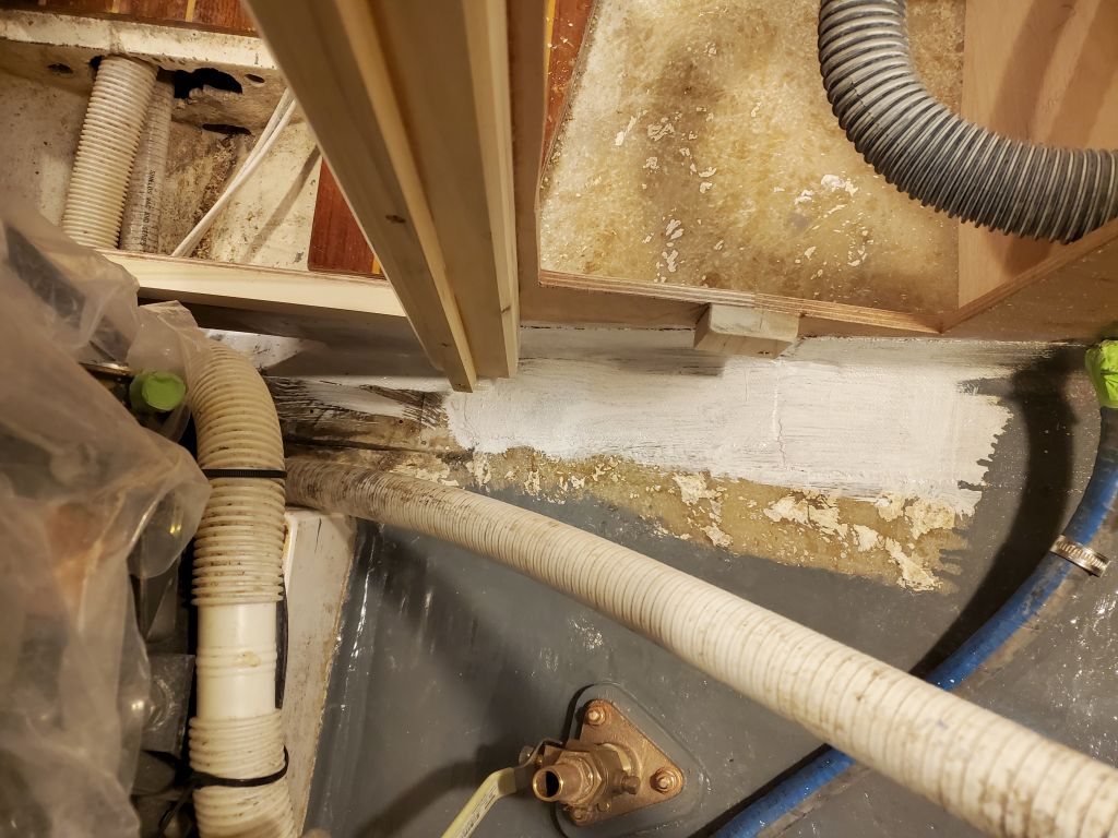
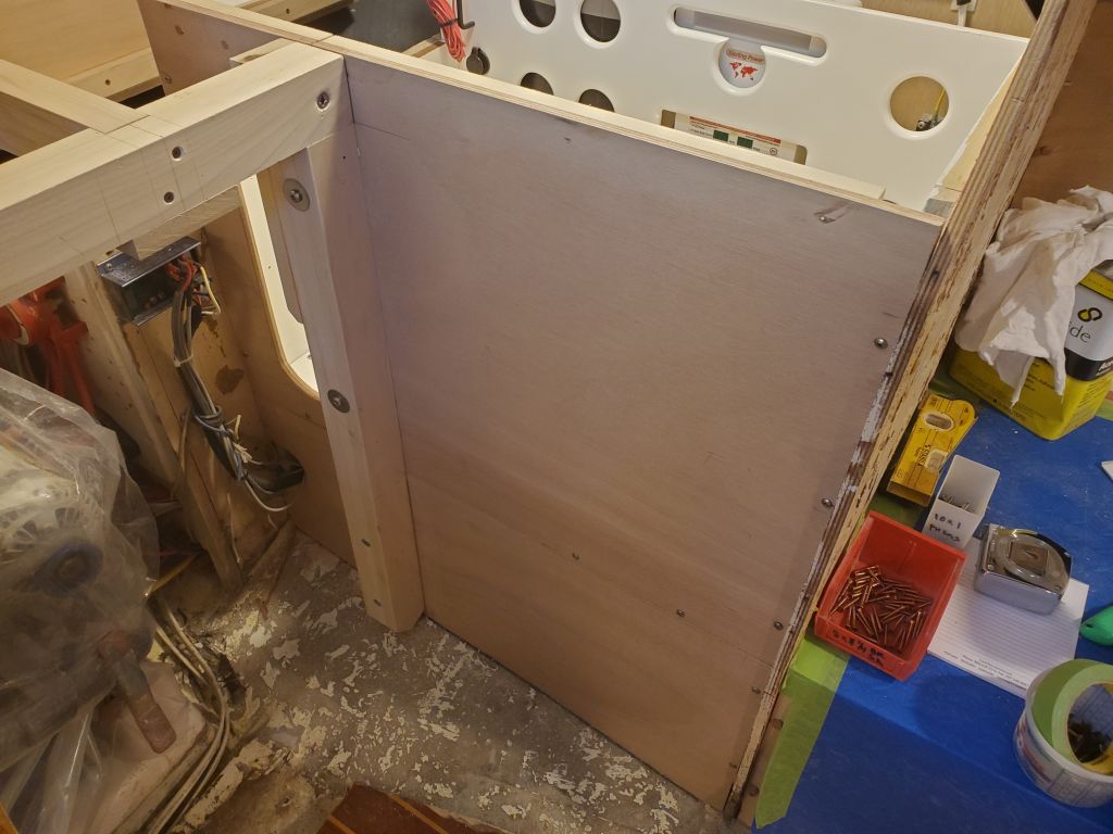
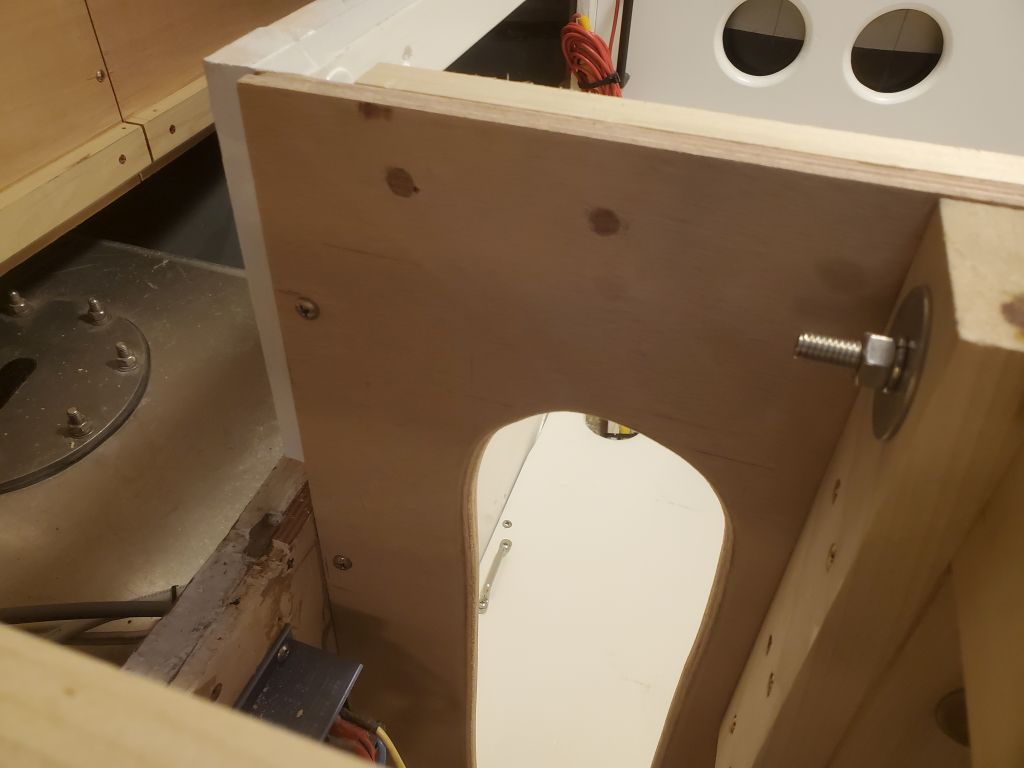
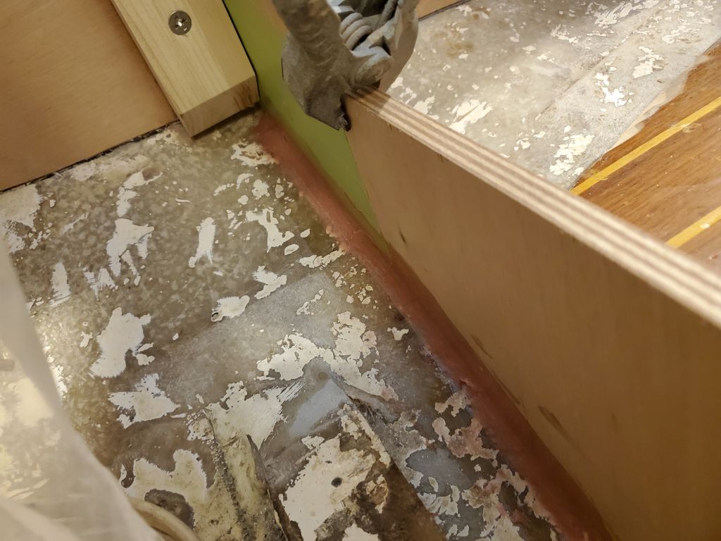
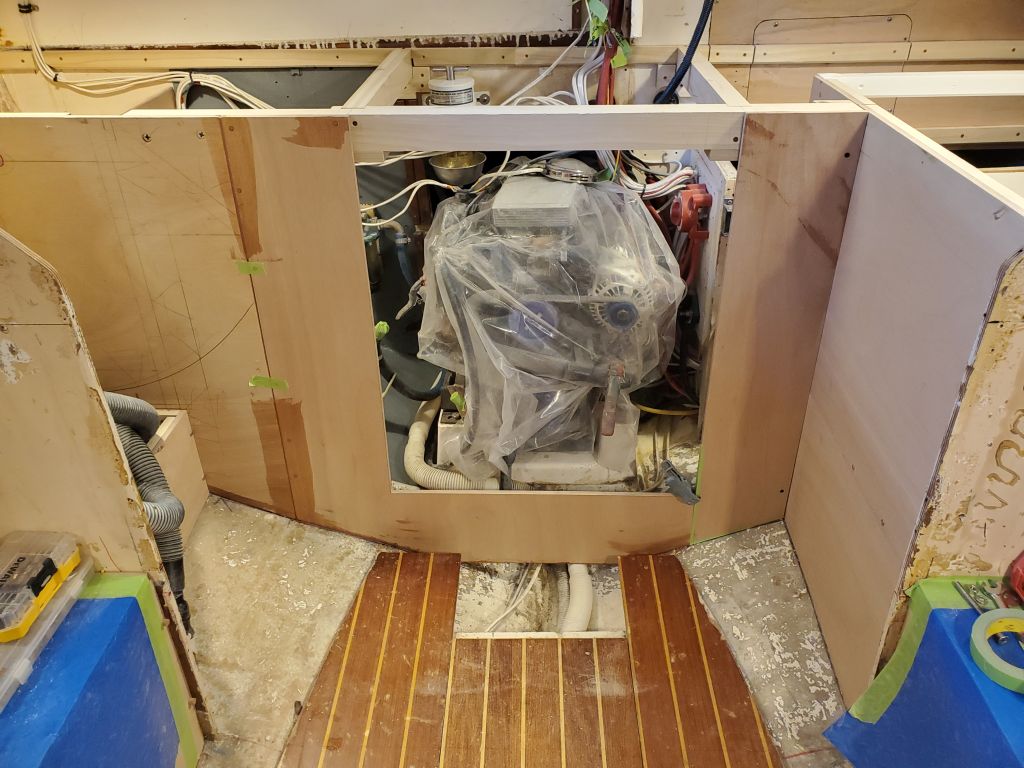
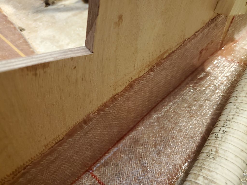
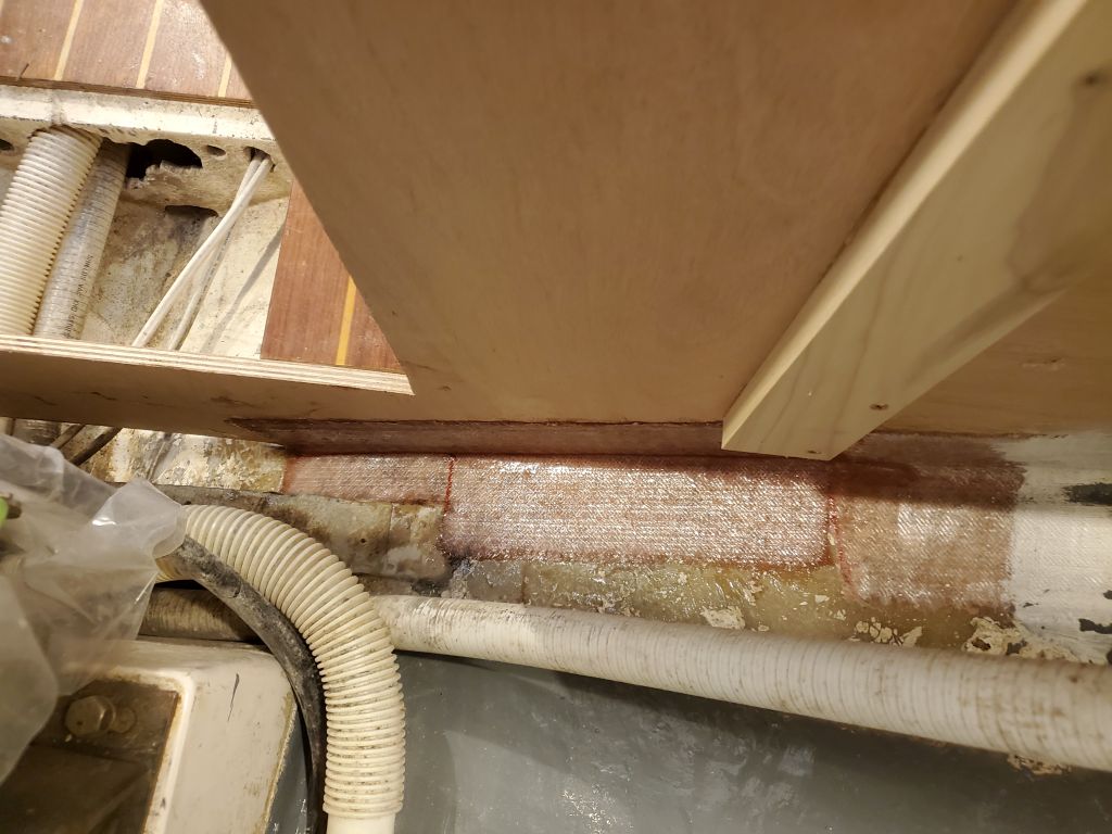
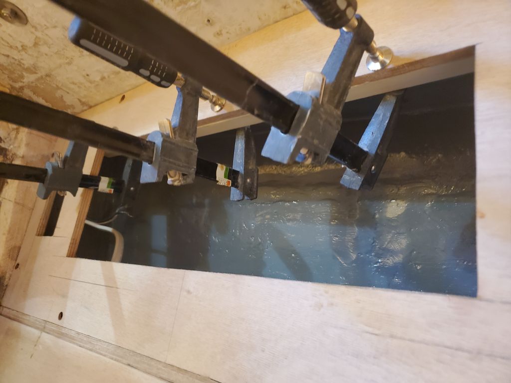
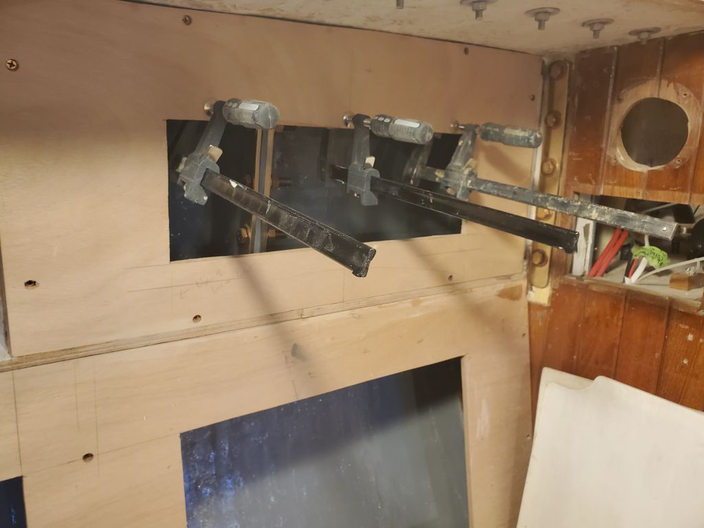
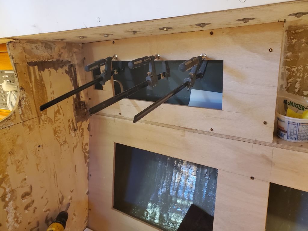
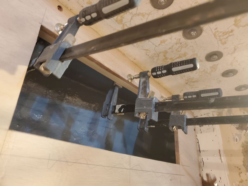
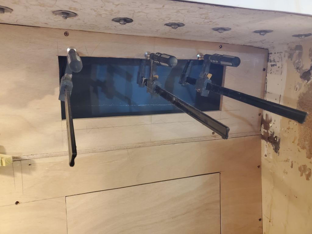
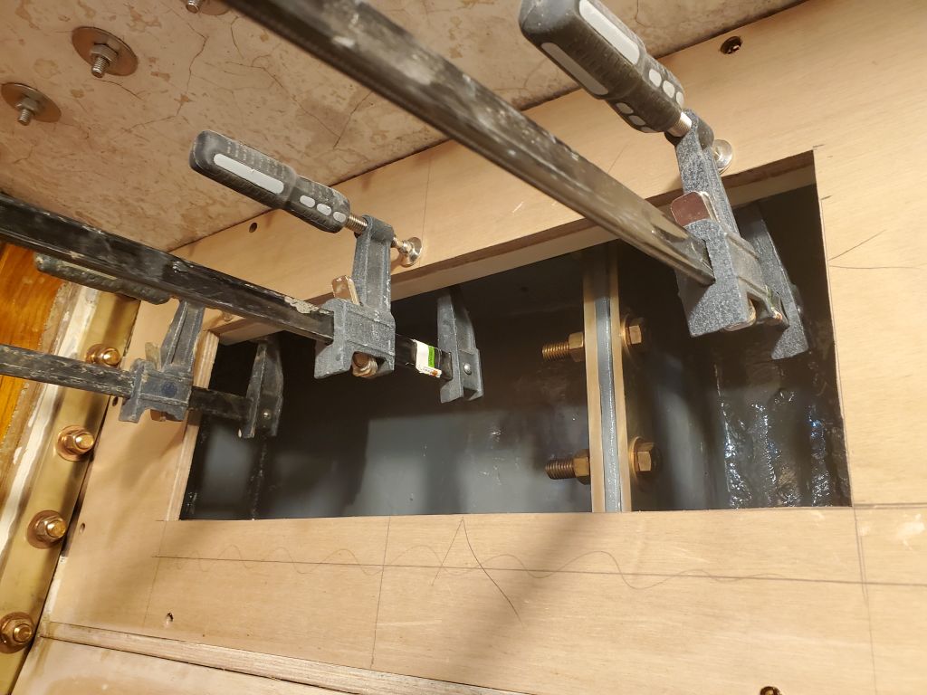
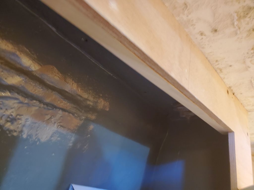
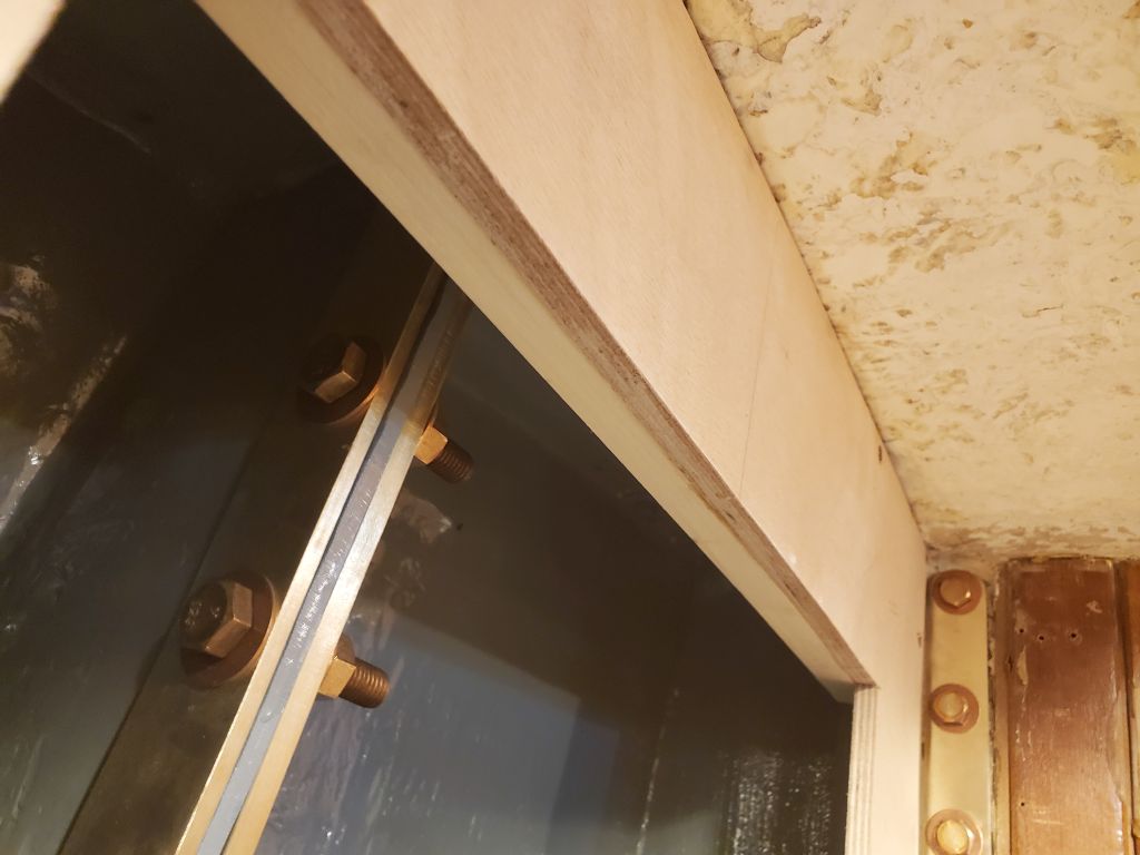
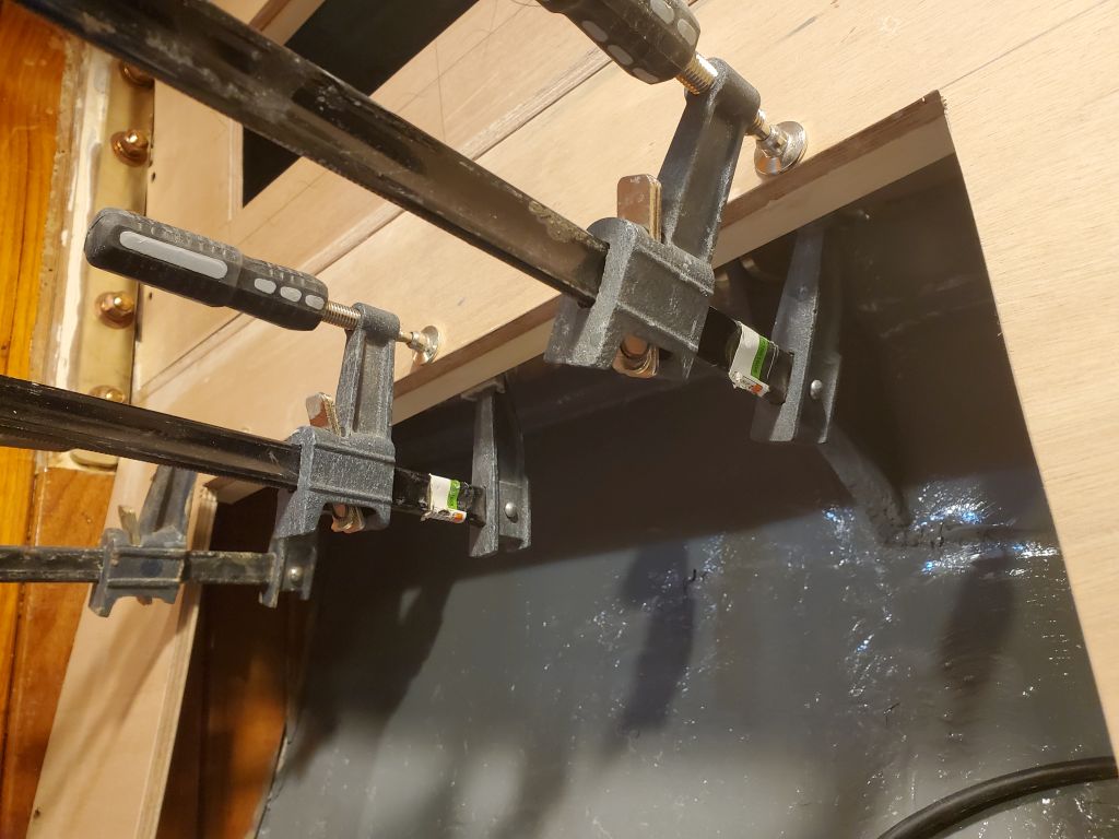
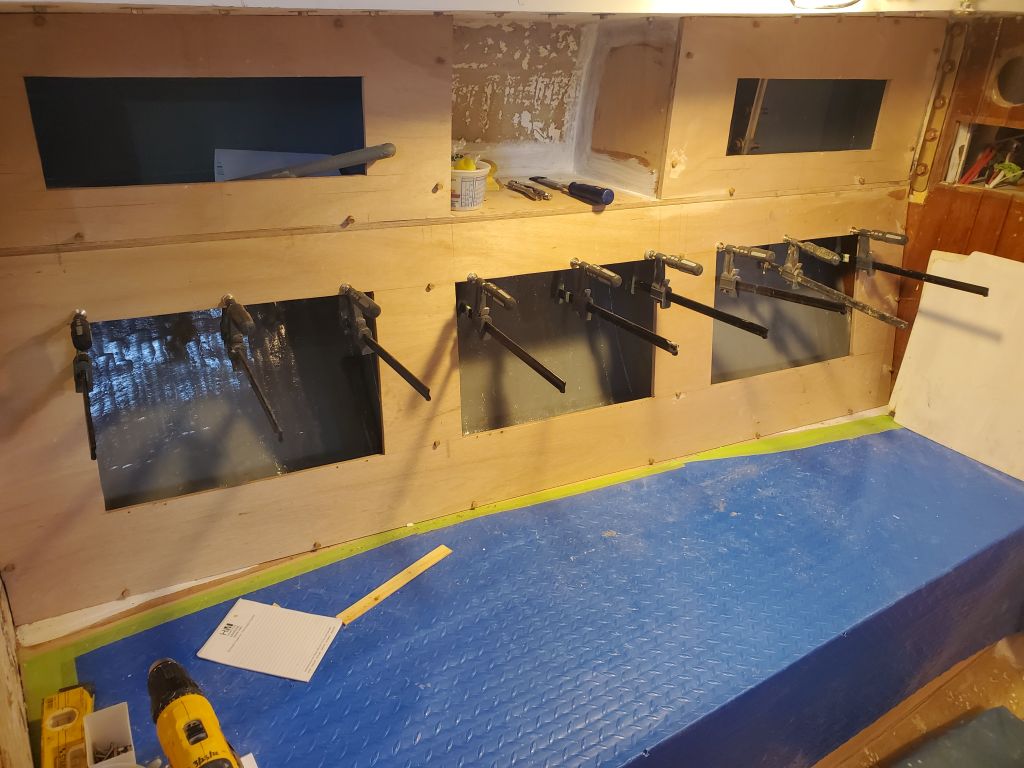
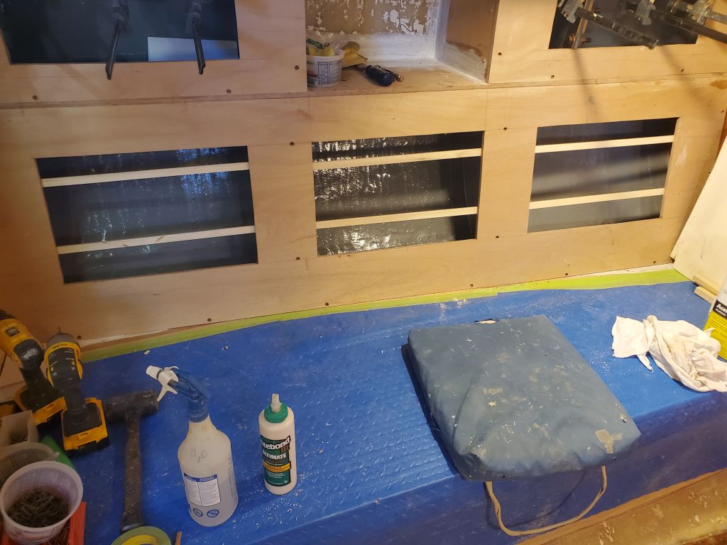
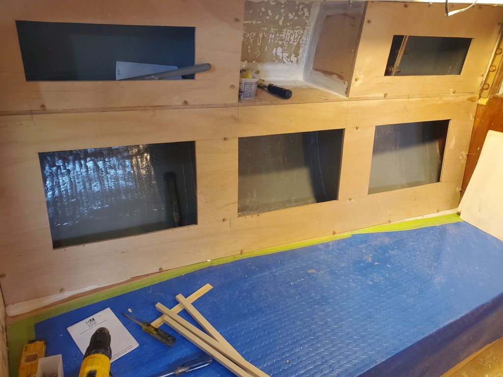
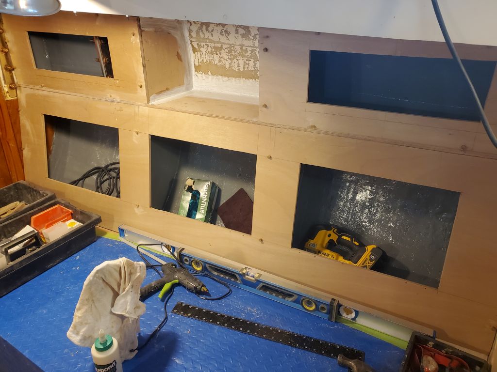
Now I couldn’t install the support cleats required for that final section of countertop, behind the stove, till I had installed the stainless steel sheeting I’d purchased to line the surround.  So to that end, I worked to finish off the opening so I could install the three faceted pieces between the bulkheads, after which I could template and cut the sheeting for the fore and aft bulkheads to shape and install it.  Only then could I finish up the support cleats above.  After cleaning up, I applied a coat of gray bilge paint to the hull inside the space, then spent the remainder of the afternoon preparing the sheeting to fit the three pieces forming the bottom and back of the enclosure.  I’d ordered the sheeting cut to the overall dimensions of each piece, but there was some minor shaping and fitting required so the stainless would fit correctly, and I had to drill for the four mounting screws that would hold the panels–and the sheeting–in place.  Once all these pieces were done and installed, and the vertical bulkheads similarly covered, I’d finish off the various corner seams with some trim, and then the space would be ready for the stove whenever it was time.  This would all make more sense once the pieces were installed.

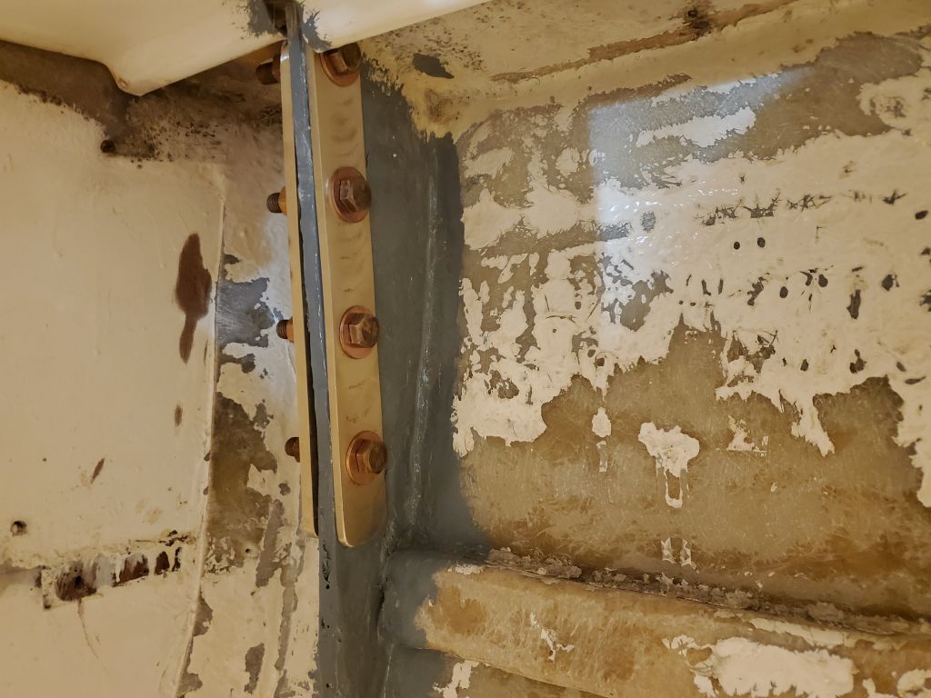
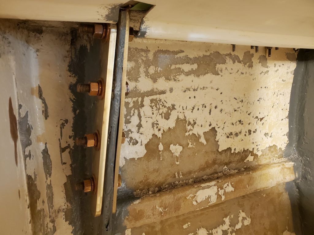
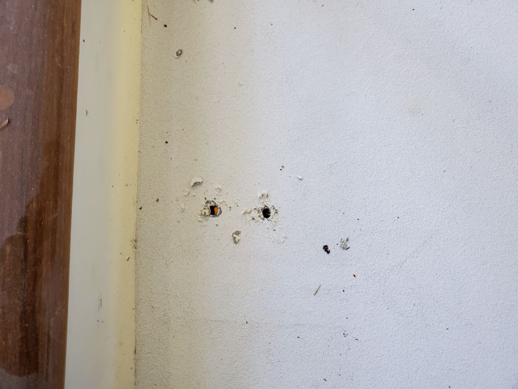
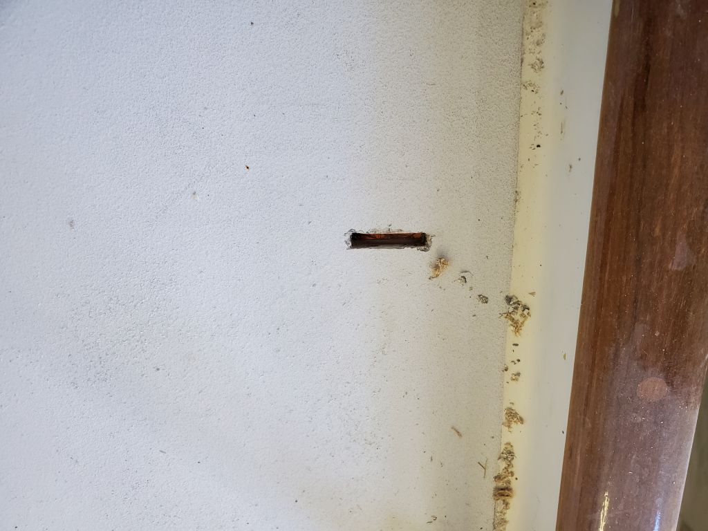
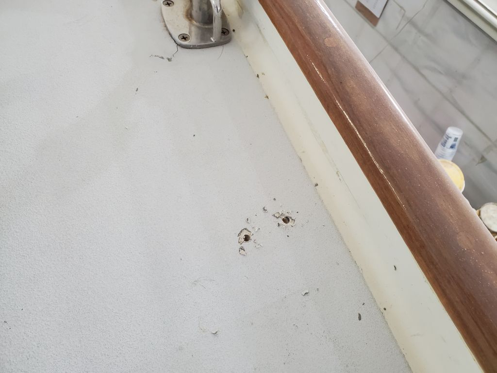
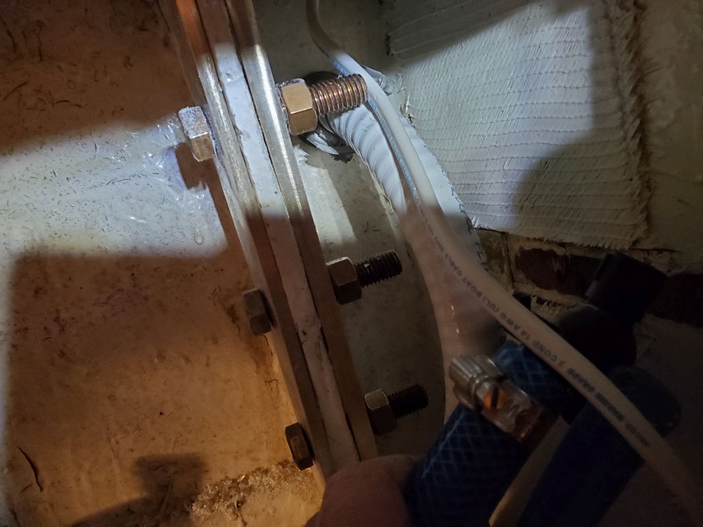
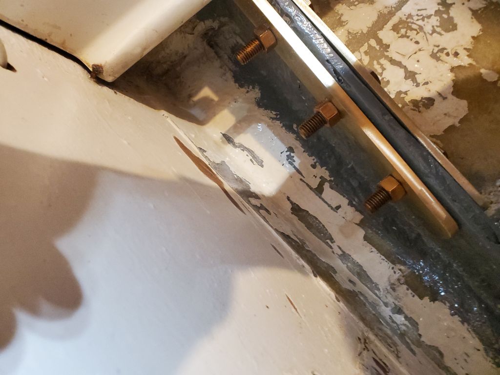
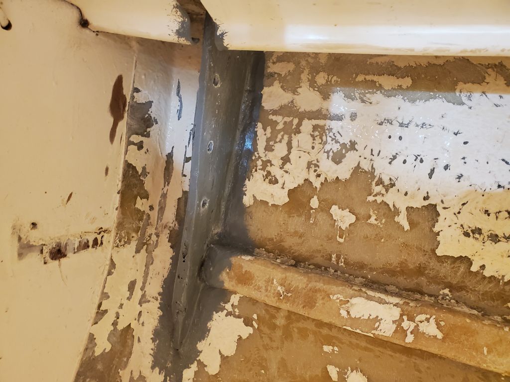
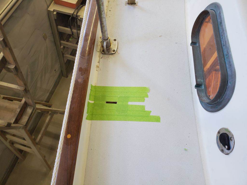
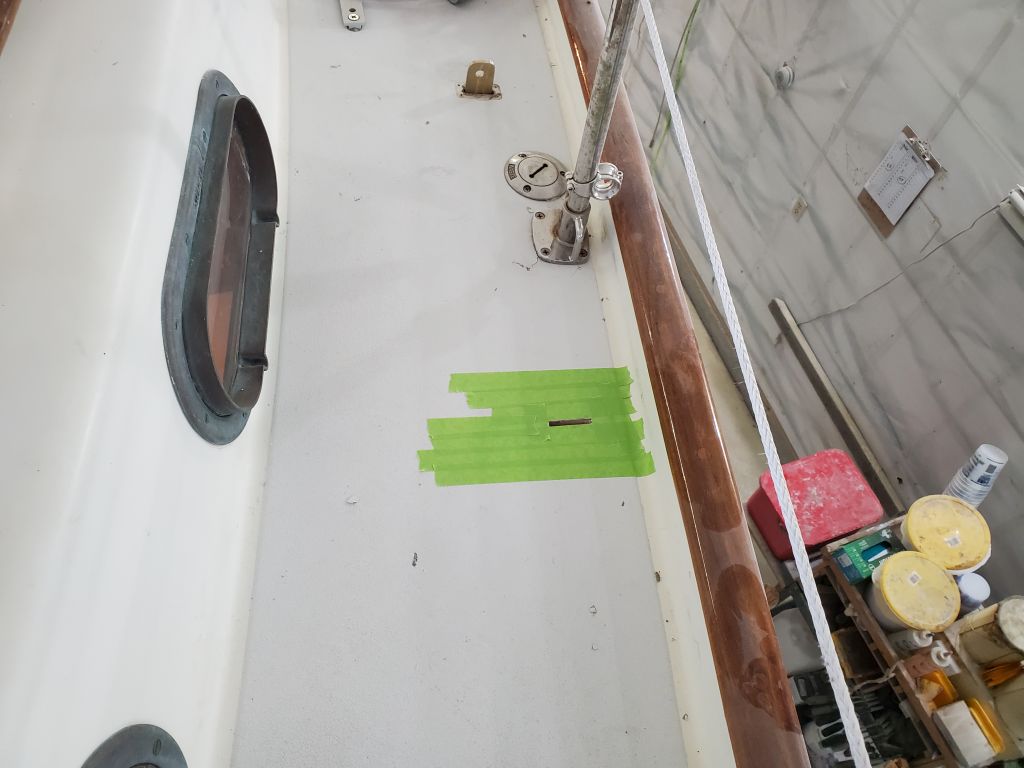
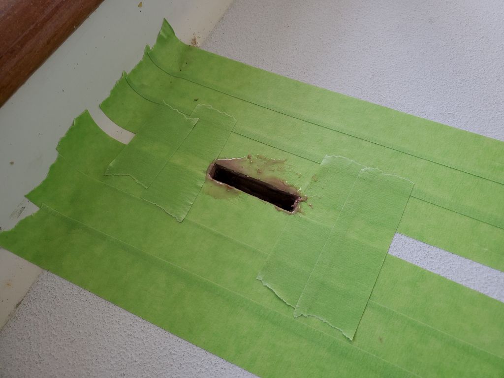
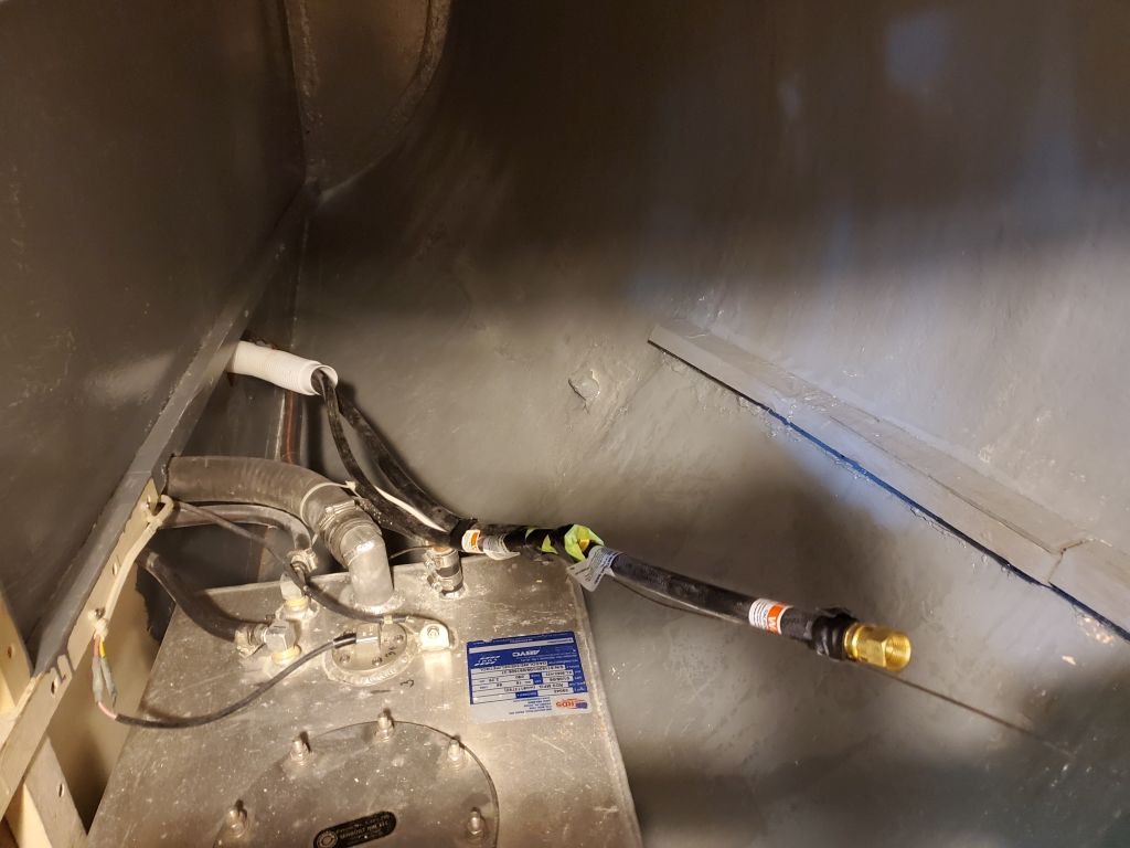
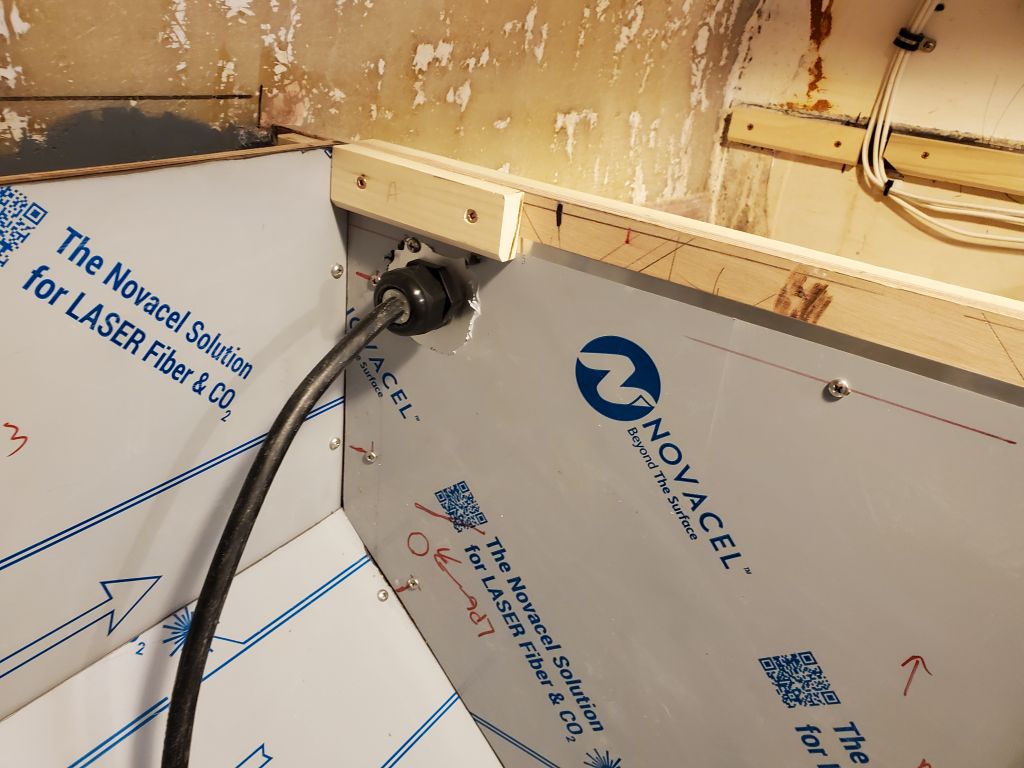
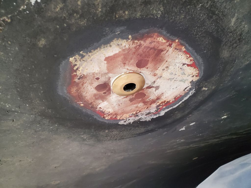
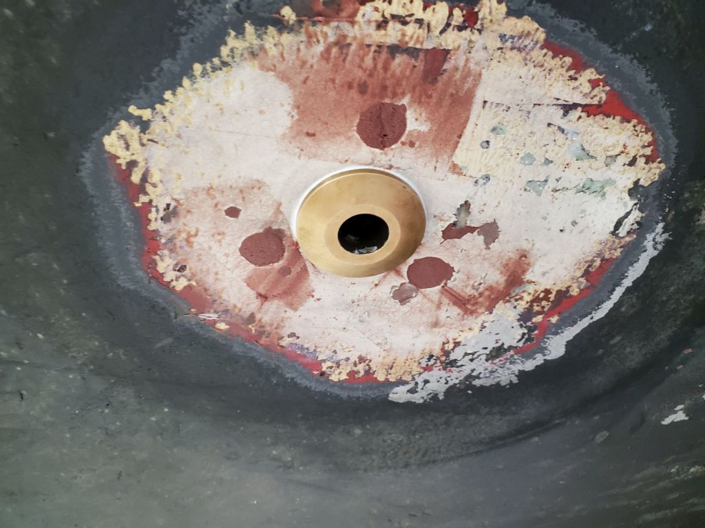
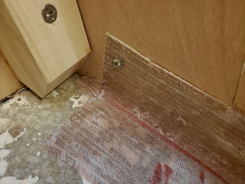
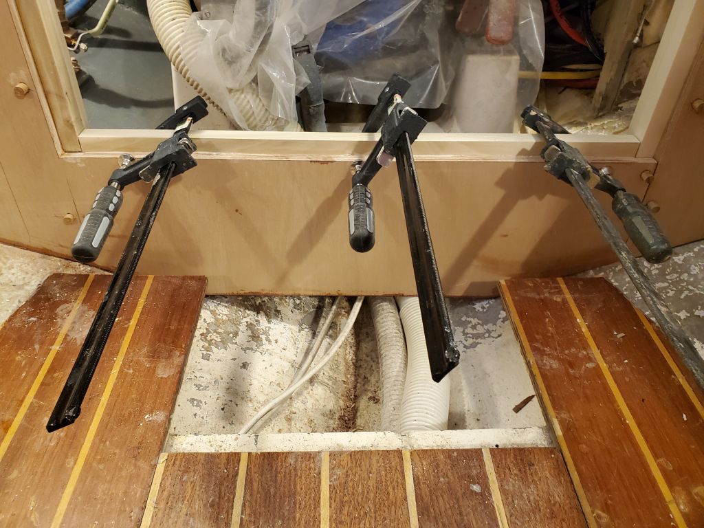
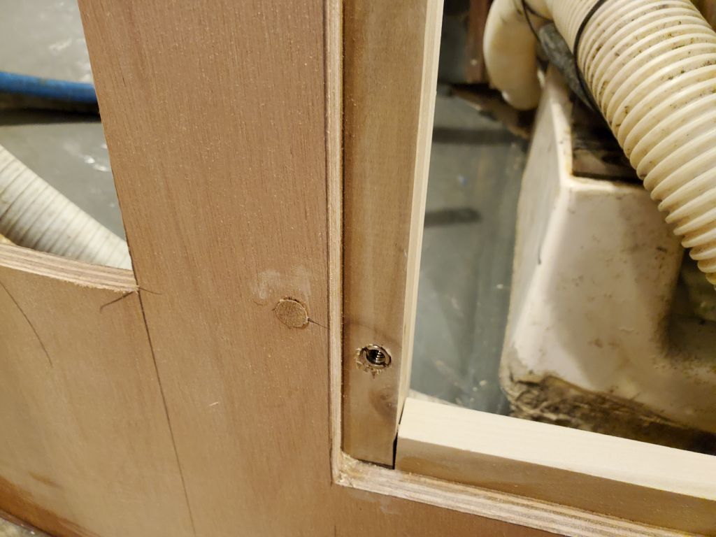
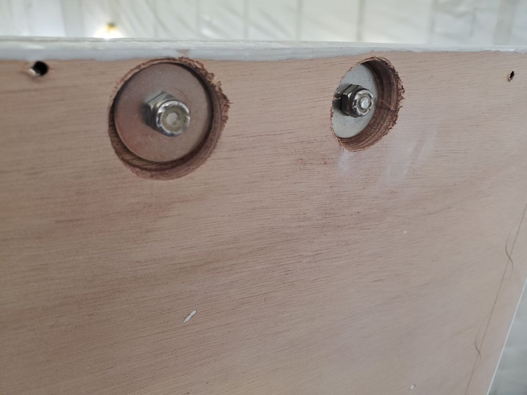
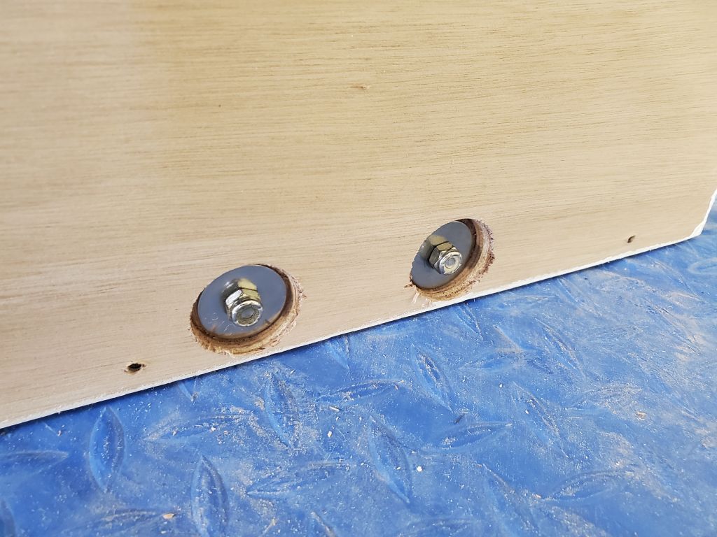
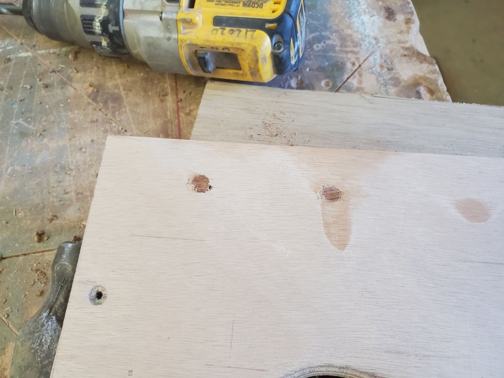
With a few seconds left in the day, I knocked another small item off my list and applied some fairing filler to the three bolt holes of the new through hull I’d installed earlier.

Calliope Girl 62

I started out by finishing the engine room pane, cutting it to the proper height (as marked in place), then cutting off a fixed section that I adhered at the top section, so that any trimwork would bypass the operating hatch.

Next, I cut several rough-sized thin plywood templates from measurements I’d made earlier for the various countertop sections; there’d be at least three separate sections when all was said and done.  I began with the port corner section, starting with a new cleat on the aft side of the bulkhead to accept the forward edge of the countertop.    After a couple iterations of scribing and cutting, so that the countertop could clear the various wires in the compartment, I cut the final piece from 12mm plywood.  With the trash can in place below, I set the countertop in place, then marked the outline of the top of the trash can from beneath, enough of a reference so that I could then trace the actual shape onto the bottom of the countertop and figure out the size of the hatch required.  I’d cut the hatch later, but for the moment my goal was to get all the countertop sections templated and cut.

I continued with the next section of countertop, running between the port side and the center of the port support beam.  This section, and the first, would remain removable when all was said and done.  I’d taken advantage of some proper-sized scraps of plywood when making these two sections, but was considering connecting them together into a single piece before installation.

Next, I templated, then cut and sized, the lid over the refrigerator compartment.  I’d eventually cut this near the outboard side to allow for hinging the lid, and I had a trim plan for the gap at the outboard side, to cover and tie in as needed the existing cabinetry below the electrical panels, so I didn’t extend the countertop into the space.

Each of these three smaller panels required multiple steps to scribe the template, transfer to and cut the actual plywood countertop, perhaps some minor adjustment, then trimming any overhanging edge to fit with the existing cabinetry.

Next, I moved on to the largest piece, which would cover the remainder of the galley and engine room.  I started by scribing my template to the hull on the starboard side, added a couple notches to clear the wiring along the aft side in two places, and fitted the template for any final marking required.  Then, I cut the actual top to size, leaving it a bit wide to overhang the forward edge of the cabinet for final marking in place.  I also marked, from below, some critical structural members and other things that I’d need to cut out for the sink opening and for fuel filter access from above, which I’d do in the near future.

Next, I cut out the access hatch for the trash can (I’d need to add some support cleats for the lid, but didn’t bother with them now), then installed all sections of the countertop for a glimpse at the entire space.

To finish up the day, I painted the forward portion of the engine room  and the upper hull outboard of the port countertop with gray bilge paint.

Calliope Girl 61

First thing, I removed the port engine room panel, releasing it from the tabbing on the aft side.  The part came away cleanly, leaving only some tape residue on the fiberglass.

On the starboard side, I lightly sanded the epoxy-filled seams between the plywood, then laid out and cut a large 11″ x 22″ opening for the locker access, the largest I could fit in the space.

To support the final panel for the front of the galley/engine room, I planned two vertical posts, one on each side of the opening.  Earlier, I’d glued up two blanks for the purpose, each from two pieces of 2-3/8″ wide stock.  Starting with the starboard side, I cut the post to appropriate length, leaving it a bit above the bottom of the cabinet and cutting an angle for clearance and appearance.  With a couple temporary screws, I tacked it in place, leaving 3/4″ exposed inside the engine room opening, and determined where the removable longitudinal engine room panels (running from the aft bulkhead forward to close the engine room off from the sink area) would land on the new post.  Then, I removed it and, down on the bench, eased the two inside edges, then installed a support cleat for the removable panels before reinstalling the post permanently with glue and screws.  The top of the post butted against the base of the countertop support beam above.

The original plywood panels that had formed the removable bulkhead were too short now, so I cut new ones from some 9mm plywood I had on hand.  These panels slipped into the existing cleats on the aft end of the space, and rested against the new cleat at the aft end of the new post, secured with screws.  As with the original, I left access at the forward end for the raw water intake hose to lead to the water pump.  With the panels cut to fit satisfactorily, I removed them for safekeeping and for some paint.

I repeated the post installation on the port side of the engine room, first installing the port panel with screws into the support post on the refer compartment, and a single removable screw through the tabbing at the base.  On this side, I did not use any glue on the post, securing it only with screws so the port panel could remain removable.  I did decide to hide the screws behind bungs, however, as I felt the circumstances requiring removal of the panel would be few and far between, if ever, and if necessary bungs could be removed with minimal impact.  I ran the bolt securing the main galley cross beam to the port post through the plywood as well; this would be covered with trim later.  I installed bungs in all the screw holes surrounding the engine room opening.

With a template panel cut just shy of the width of the opening, I scribed as needed so I could size the final panel. At the base of the opening, I installed a final cleat across the space to secure the base of the removable panel.   While I gave the glue time to set up (I used no screws in this cleat), I chiseled flush all the bungs around the opening, then went down and, using the template, cut the final panel from 12mm plywood.

To secure this panel, I used six threaded inserts set into the vertical posts, eventually to receive thumbscrews for tool-less access to the space.  For now, I used a few short machine screws to hold the panel while I marked the top edge for final trimming.

To finish up the day, I applied two-part epoxy primer to the new tabbing inside the engine room.

Calliope Girl 60

To begin, I finished up the remaining three settee locker door assemblies that I’d started last time.

In the galley, I had a couple small jobs in the refer compartment to take care of.  Over the past weeks, I’d been thinking of how to secure the portable refrigerator in place, and with sturdy handles on the case it made sense to strap it down to the base platform, so I’d ordered some stainless steel straps for this purpose, and planned to use them with some strap eyes that I recycled from the previous battery storage trays on this boat.  I bolted the strap eyes to the platform near the edges, installing the nuts and washers in recesses on the bottom side so the platform would still sit on the support cleats, and test-fit the straps; it would be tight clearance against the bulkhead on the forward side once installed, but I thought it would work itself out, as there was reasonable access on the aft side.  For now, I did this work in the cockpit, where I’d stored the fridge, but once I had countertops underway in the galley I planned to set the unit in place for good.

Making the port section of the galley removable for access to the fuel tank and surroundings had proved to be an ongoing challenge, since the entire space was something that I was conceiving even as it was built.  It’s the nature of this work.  So it wasn’t surprising that I found myself wanting to make a small change to the longitudinal panel defining the refrigerator compartment.  As it stood, the panel was removable, but it was a tight and awkward process around my vertical galley support beam and with the overhanging bridgedeck,  and as things had come together I decided to split the panel into two sections, with the post as the divider.  This would make removal much easier in the future.

With the panel still in place, I marked the position where I wanted to make the cut–just aft of the two machine screws from the engine room securing the post to the panel–then removed the panel and cut it down on the bench.  While I had it there, I plugged the bolt holes leftover from my initial galley cross beam concept, then cut and installed support cleats on the inside upper edge to help support the countertop above.  Then, I reinstalled the panels as before, except for adding three new screws into the forward side of the small after panel where it met the vertical support post.  The end result was just as rigid and strong as it had been before, but now it would be easier to remove these sections when and if necessary.  Finally, since I thought I was done with access to the wiring chase beneath the area, I reinstalled the refer floor.

Using the thin plywood patterns I’d recently made for the front of the engine room, I cut two new panels from 12mm plywood:  the starboard panel incorporated the short section traversing the engine opening itself, with a separate, smaller panel to port.  To support and secure the seam between the new panel and the existing bulkhead on the starboard side, I installed a wide cleat with glue and screws from behind.  Then, with temporary fasteners, I secured these in place to check the fit; I’d left the top edges intentionally long so I could mark the proper height in place.  In keeping with the removable port galley concept, the narrow panel on the port side would also remain removable should the post and lower section of the refer/wiring compartment ever need to be removed for access.

After marking the proper height of the panels, and making marks on the hull for alignment later, I removed them for final trimming and preparations for installation.  The L-shaped starboard section would be permanently affixed, but the port section would remain removable (though actual need to remove this panel would occur seldom, if ever).  To help secure the lower edge of the removable section, as well as tie it in with the bottom section running across the engine space, I planned to install tabbing from the engine room side, but in such a way that it wouldn’t bond to the plywood of the removable section.  For this, I applied masking tape over the edges and back side of the panel, which would give me the mold release needed.    At the flush seam on the starboard side, I sanded a small chamfer on each piece to form a little V-profile when the sheets were abutted, which would give a place for epoxy filler to smooth the seam.  Just before installation, I coated the bottom edges of the plywood with epoxy to protect them where they met the hull.

For final installation, I secured the starboard panel first, with epoxy to bed against the hull and waterproof glue and screws to secure it to the cleat on the vertical seam.  I put a couple temporary screws in the section where I planned to cut the access door later (the door opening would be somewhat larger than my mockup, as large as possible in the given space), and some permanent screws as needed to secure the piece to the cleats.  I installed the port panel dry, with just a couple temporary screws.

Once the panels were firmly in place, I applied epoxy fillets to the joints where they met the hull, then installed tabbing set in epoxy resin to finish things off.  (I’d previously sanded and cleaned the faying surface on the hull for this.)  I applied the fillet and fiberglass right over my tape-protected port bulkhead, trusting that the part would release later once the epoxy had cured overnight.

With the engine room/galley front finally in place, I took a moment to re-secure the wiring through  the engine room, which mounting I’d partially disconnected during the installation of the support beams earlier.  I also led the wiring for the AC outlet and propane controls–which in the original galley had been mounted in front of the stove–back up to the aft end of the engine room near some existing wiring for eventual installation in a new upper galley cabinet face there when the time came, as the galley as it had finally come together didn’t leave adequate or user-friendly room for these installations in the panel beneath the sink, particularly since increasing the size of the locker door opening was paramount, and actually the new location would probably be better in all ways anyway.  I also mounted a terminal block feeding the engine room light to the aft bulkhead; the light would get installed on the underside of the countertop once complete.

To round out the day, I chiseled away the excess bungs from the settee cabinets.  These cabinets would soon be sanded in preparation for priming and painting.

Calliope Girl 59

Starting the day on the early side with a planned early departure for an appointment, and with some detail questions at large regarding the galley, I decided to finish up some work on the settees in the meantime.  To support locker door catches on all the locker doors, I needed to install a backer block along the top edge of each opening–something I never think to do before installation–so now I cut a series of blanks from 3/4″ square stock (offcuts from previous milling operations) to span the top edges of all the locker openings.  Over the course of the morning, a two or three openings at a time because of the number of clamps I had immediately available, I glued these cleats in place at the top inside edges of each opening, choosing to cover the entire length to give me options for mounting hardware later.  When the glue cured enough, I removed the clamps and moved on to the next set of openings, ending up with the final three by the end of my day.

I began with the upper cabinets purposely so I could work on the locker doors in the lower cabinets without clamps in the way; as I worked through the locker doors, I continued gluing those cleats on all the other settee locker openings.

Previously, I’d cut the two blanks required for these doors:  the 12mm plywood “inserts” forming the basis of the doors, and the larger, overlapping panels which would be upholstered and form the visible component.  Now, with hinges on hand, I wanted to hang the inserts, then work on installing the upholstery panel blanks.

To hold the blanks in place in the openings, I installed some scrap wood spanning the openings, temporarily tacked in place with dabs of hot glue from behind.  Then, setting the blanks in place, I installed the hinges to both parts of each opening.  With a simple plywood template to align the position of each hinge consistently, I worked my way through the six locker openings.

I removed all the locker doors to bring them down to the bench for the rest of the operation, but while I was still in the boat I installed hardwood bungs in all the fastener locations on the settee backrests and upper cabinets.

Down on the bench, I prepared to install the two sections of the locker doors together.  For this, I used threaded inserts installed in the “insert” part of the door (the hinged sections), to which I installed the upholstery panels with machine screws and 1/8″ spacers between the two parts, which would hold them apart to leave room for the thickness of the upholstery and backing that would eventually wrap the panels.  I used a simple alignment template to drill pilotholes, then installed the threaded inserts and secured the pieces together for storage.  I completed three of the assemblies before I had to depart for the day.


Calliope Girl 58

The brass adapter fittings I’d ordered for the stove connection had arrived, and I checked them to ensure they would do what I needed.  There was one threaded adapter to convert the female 1/2-14 BSP threads on the stove fitting to 1/2 NPT female, then a second fitting adapting between the NPT threads and the gas flare fitting required to mate with the hose.  After I’d ordered these last week, I also heard back from the stove manufacturer, who also suggested that the only way to adapt between the stove and the US hose ends was with the very pieces I’d ordered, so this was good confirmation that this was the most efficient (and only) way to make this connection.

Over the weekend, I purchased a plastic trash can that I hoped would work in the port galley, and now I proceeded with some of the installation details.  The can needed to pass through the lower shelf I’d built, and extend into the open space outboard of the fuel tank to the point that the top of the can would be below countertop level.  After confirming that the can would indeed, fit, I began the day working on its installation details.  I’d eventually configure the countertop to allow access from the top for normal disposal.

The initial cross-beam arrangement I’d worked out last time wouldn’t allow the port section of the galley to be as removable as I’d planned, so next I removed the cleat I’d installed to support the aft end of the beam and turned to the beam’s new location just inboard of the edge of the port aft galley bulkhead.  I squared the beam to the transverse cross beam, and made layout marks at each end.  I planned to support the beam with a cleat at the aft end, and inside a notch in the transverse beam at the forward end.

Similarly, I laid out for a second cross beam on the starboard side of the engine.  The original engine room layout had a pair of removable panels enclosing the engine on this side, which helped provide access to that part of the engine for maintenance, and I intended to replicate that arrangement in some form, so for that and other reasons, such as sink placement and general support needs, it made sense to align the beam with this bulkhead location.  There were two pair of cleats mounted to the after bulkhead that supported the aft ends of these removable sections, so they easily demarked the correct location.  As with the port beam, I squared the beam location to the transverse beam and made the necessary marks.

Next, I removed the cross beam and, down in the shop, notched it to accept the longitudinal beams.  I also cut back the starboard end a bit so the beam would take up less space in way of the sink location, so the sink could be mounted closer to the edge of the countertop.

Next, I installed the port beam, cutting and fitting it as needed between the beam notch and the aft bulkhead, where I installed a support cleat and one screw to pin the beam to the cleat below.  At the cabin end, I secured the beam with an additional support timber below, and some screws driven in from the transverse beam.

I repeated the process with the starboard beam.

The sink fit nicely in the space aft of the stove, and with the slight modification to the cross beam nudged up fairly close to the edge of the countertop for ease of access.  Final sink placement would eventually account for faucet and drain location, particularly since there was an overflow drain at the upper edge of the sink (against the forward edge in these photos), installation details of which I was as yet unsure, but might require a bit more clearance.  This was a substantial sink bowl and would offer good access from all angles, with much of it inboard of the bridgedeck overhang (this is hard to show in photos but is most visible in the final photo below).

With the basic galley layout and construction now established and complete, I moved on to the vertical panels to enclose the space at the forward end.

My general plan for this was fixed panels on each side of the engine room (the starboard side being a continuation of the stove bulkhead already in place), with a removable center section for engine room access.  I’d initially (last time) thought of making a single pattern for the space, then dividing it up, but not only did this now seem unnecessary and undesirable, the large single template panel was too large to fit into the boat.

With the edges of the engine room now logically and conveniently divided by virtue of the longitudinal countertop beams above, which I’d just installed, it made much more sense to template the pieces separately.  So I cut template pieces slightly oversized to use on each side of the engine room, then, through the usual means of scribing and recutting, trimmed them down to fit against the hull beneath, and tightly against the vertical bulkheads on either side.  I dropped plumb lines aligned with the centers of the countertop beams above and cut the templates to this mark to define the edges of these panels and also the opening into the engine room.  I temporarily secured these templates with a couple screws into the support members and, in one instance, to a temporary support stick I glued to the back of the adjacent bulkhead.

Next, I templated and then cut a “final” template to demark the lower edge of what would be the fixed portions of the bulkhead, running across the forward end of the engine room between the two vertical panels.  This left a large opening for engine access, and a panel to which the companionway ladder could be secured (or the ladder could perhaps be a separate piece running past the countertop to the base of the companionway itself, conceptually like the construction ladder I was using now.  In the final construction, I planned vertical supports on each side of the opening, largely to accept and support the removable panel.

On the starboard side, I laid out for a locker opening, shown here as a 10″ x 14″ opening.  In this iteration, I located the opening to account for the depth of the sink above, as well as potentially space for the propane controls and an AC outlet that had been mounted in the original galley, though these might also make sense to relocate to a new vertical locker panel above the countertop somewhere for better access depending on their space requirements behind the bulkhead, vis-à-vis the sink.  The locker opening shown could be enlarged somewhat in the vertical direction, and somewhat less so in a horizontal direction.

Older posts Newer posts