(page 5 of 13)

Calliope Girl 87

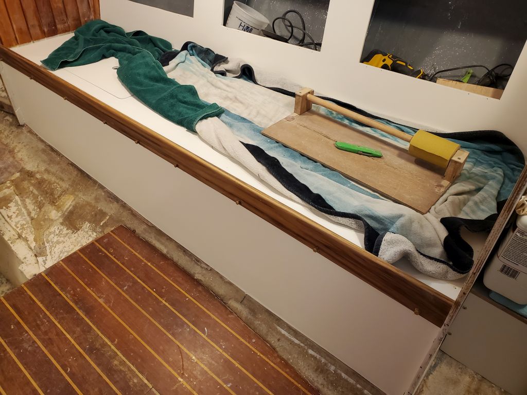
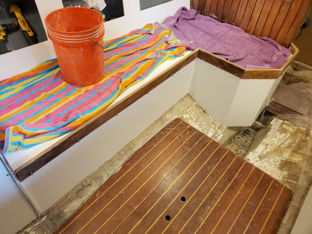
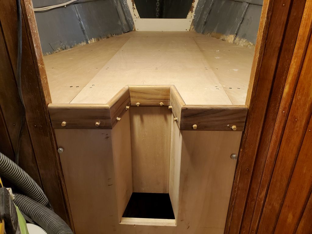
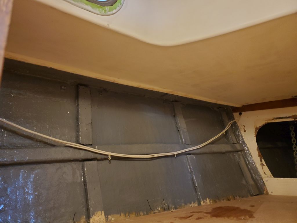
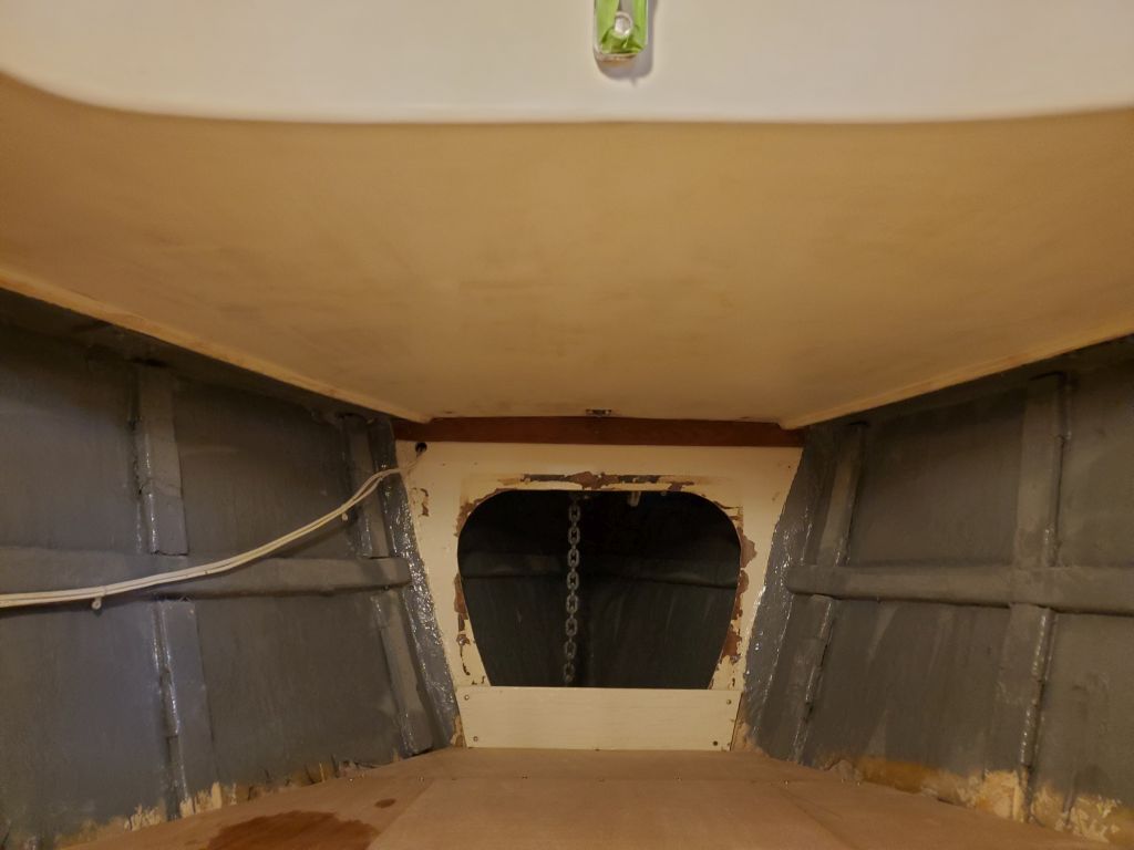
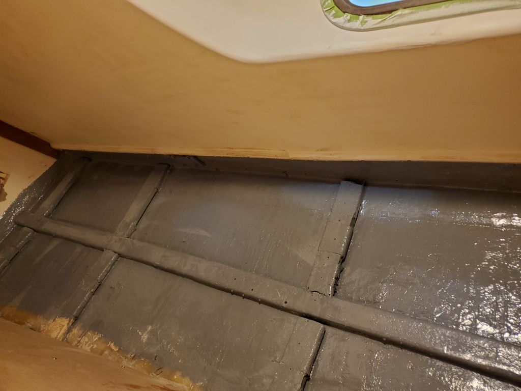
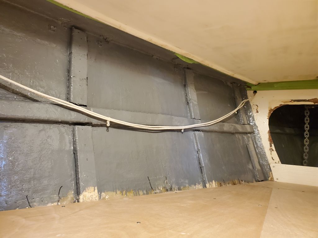
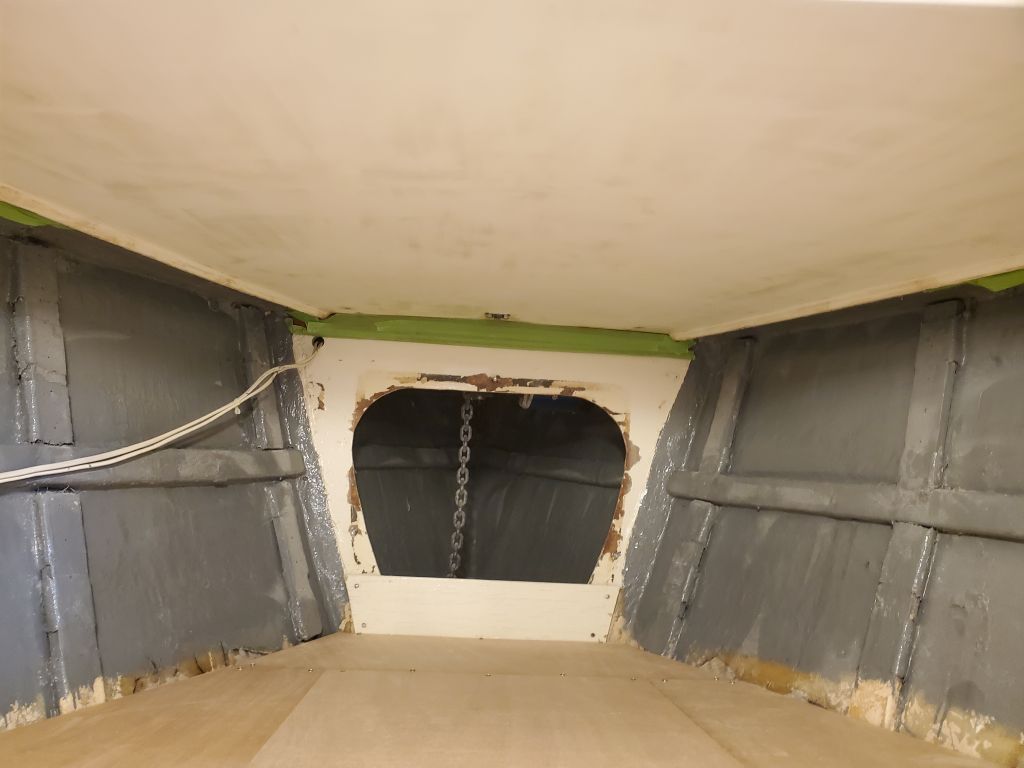
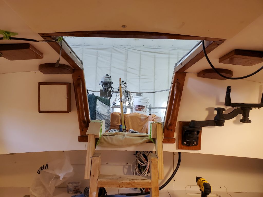
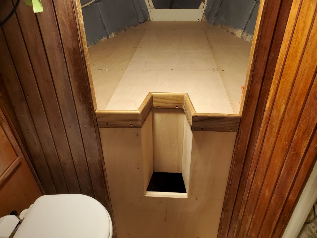
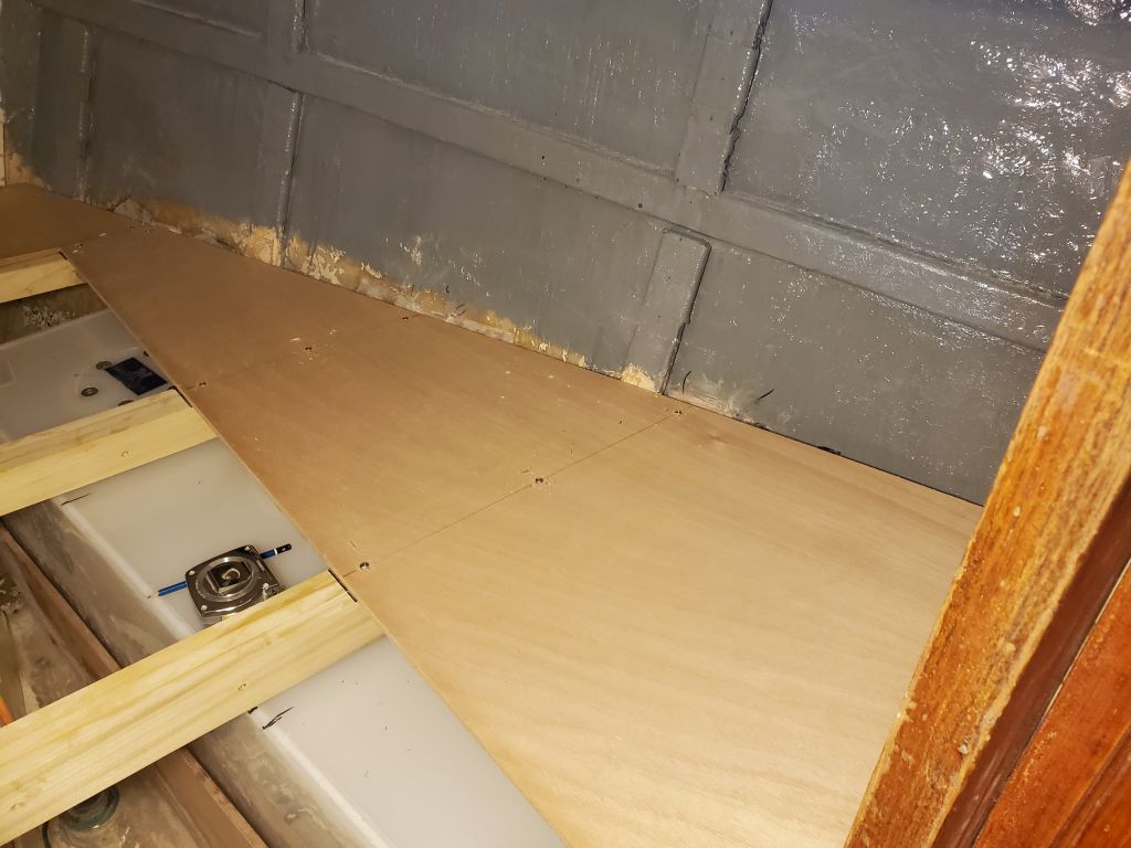
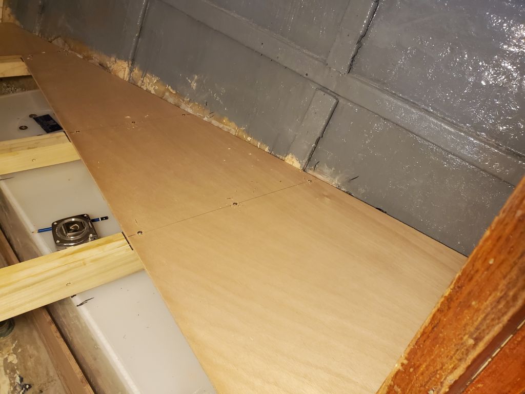
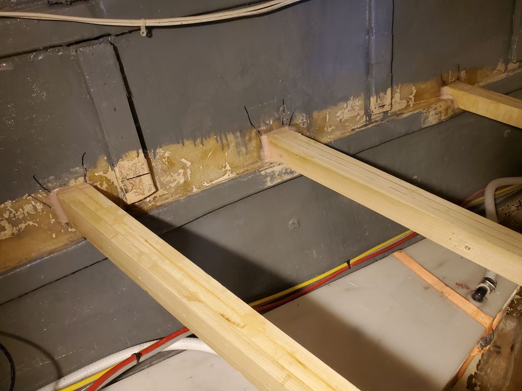
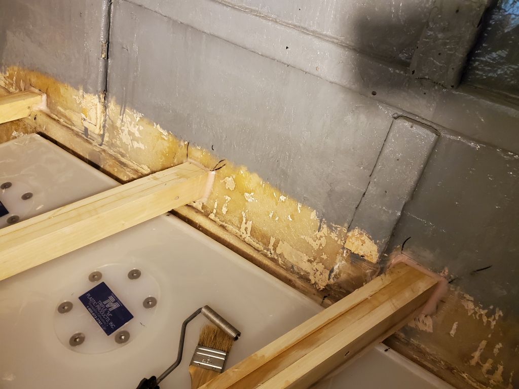
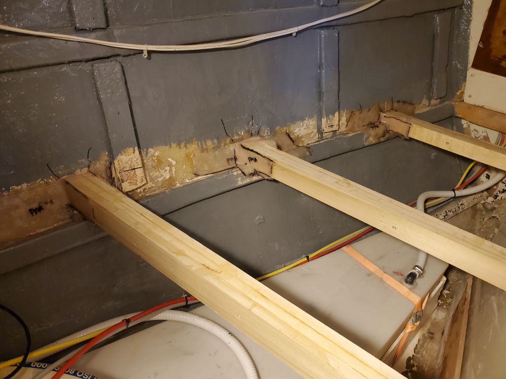
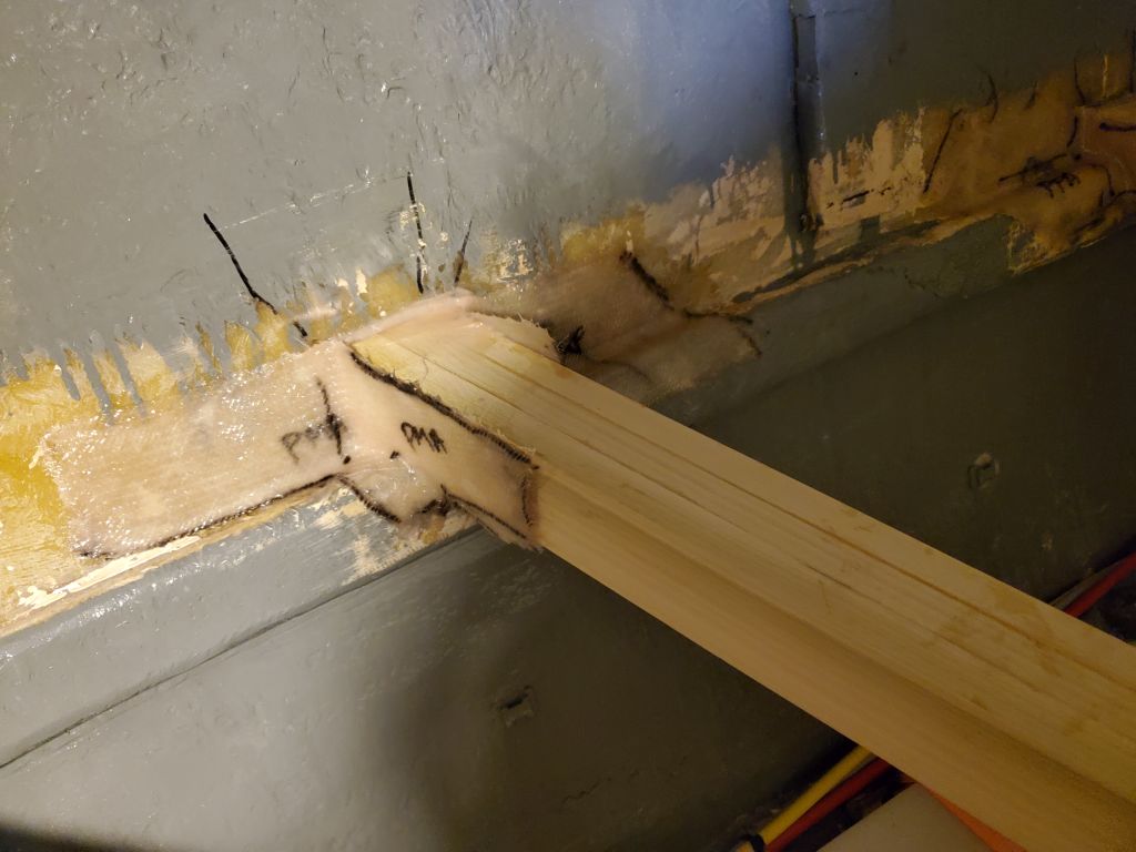
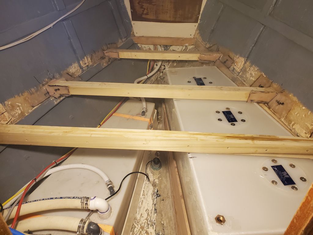
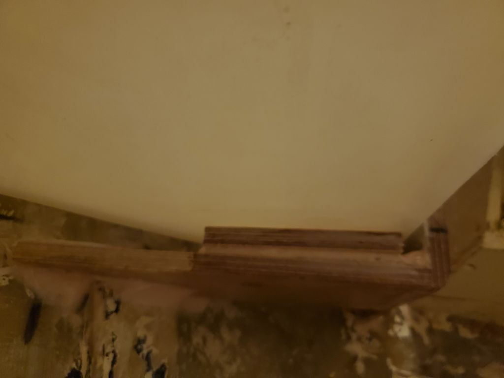
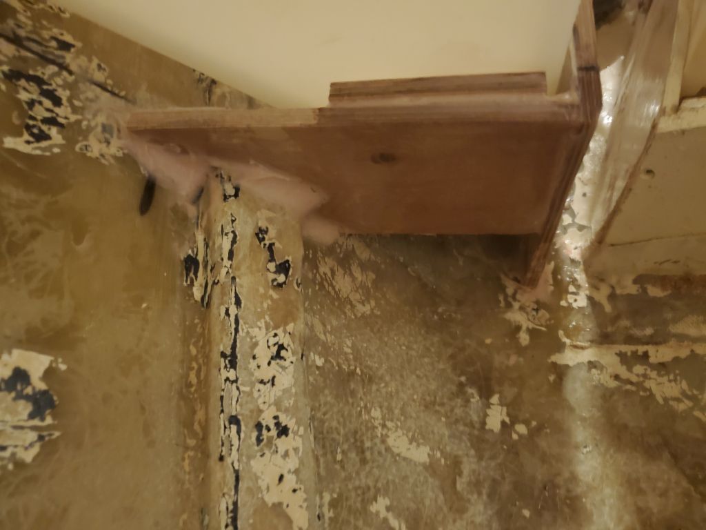
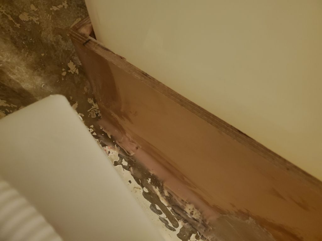
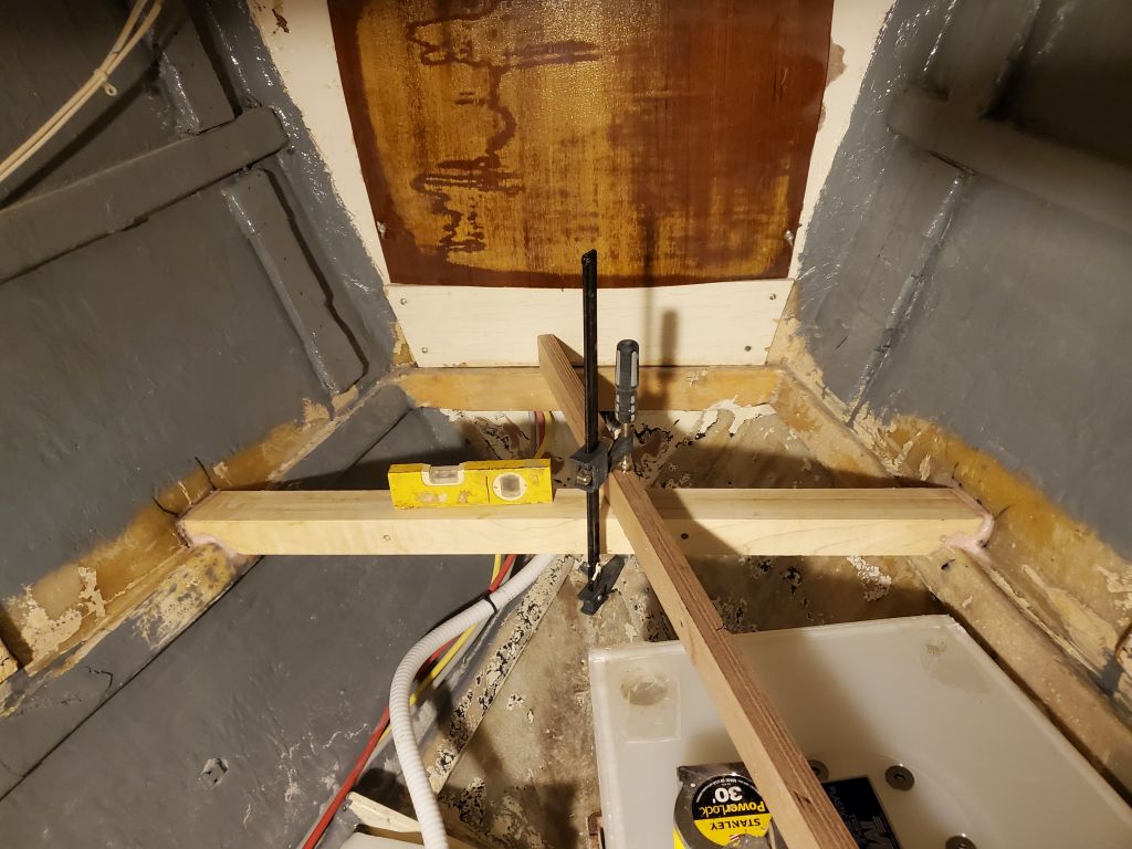
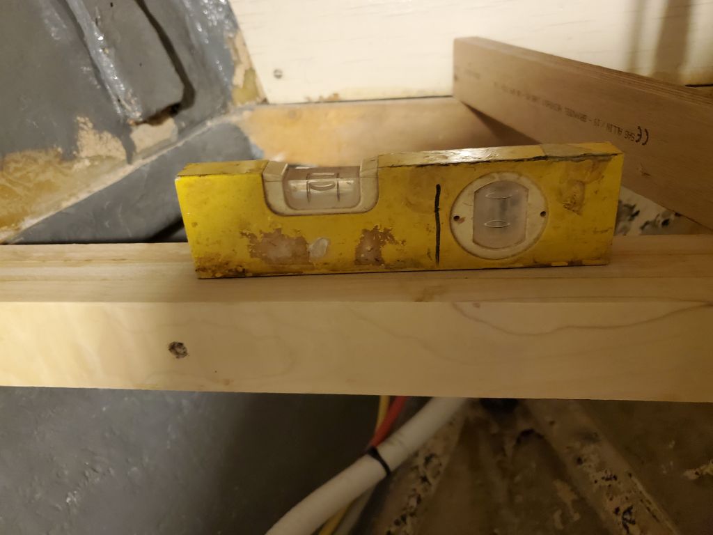
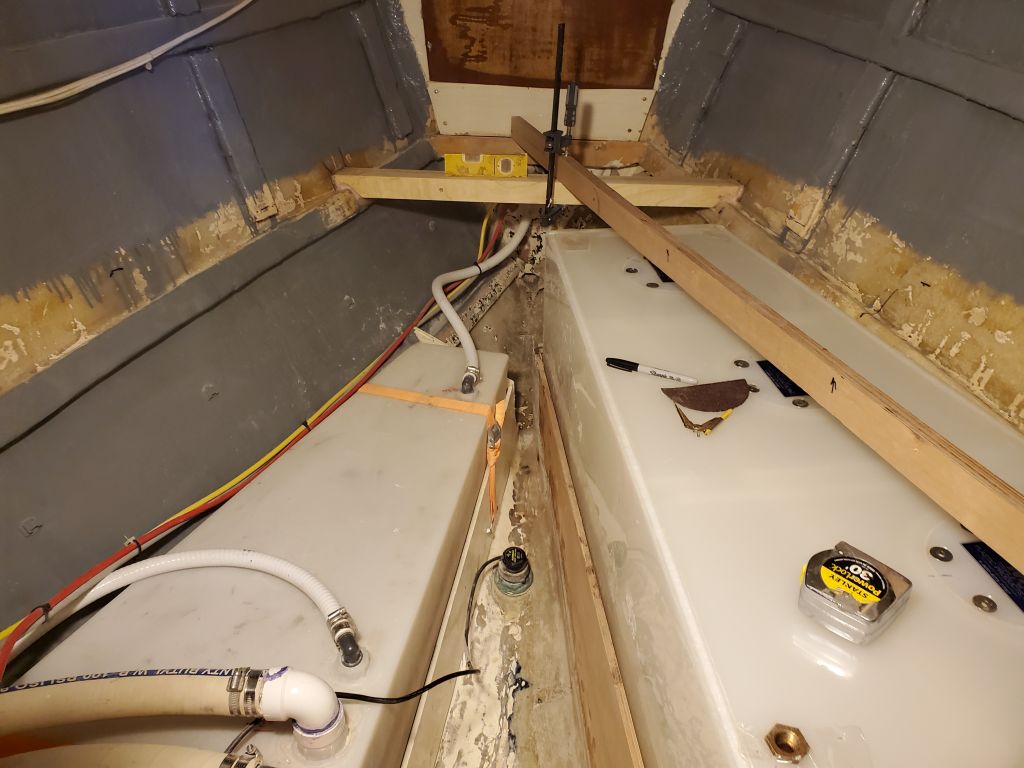
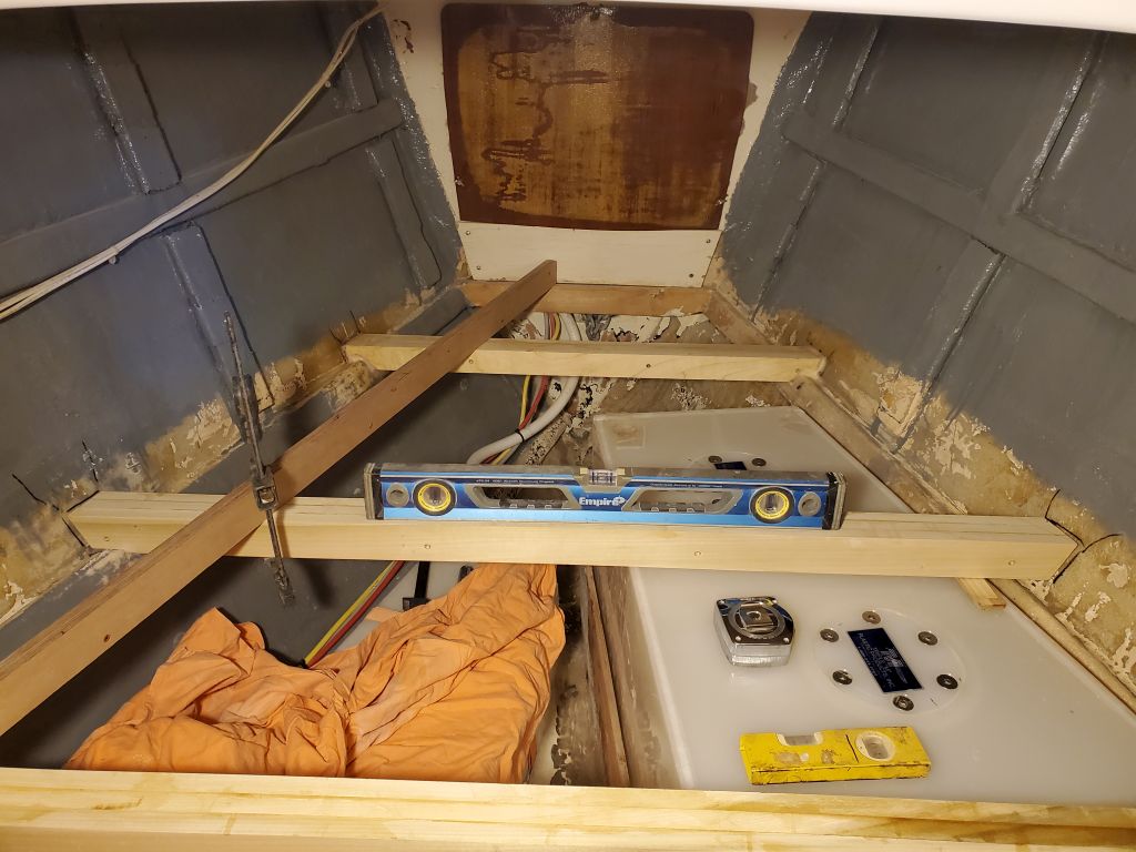
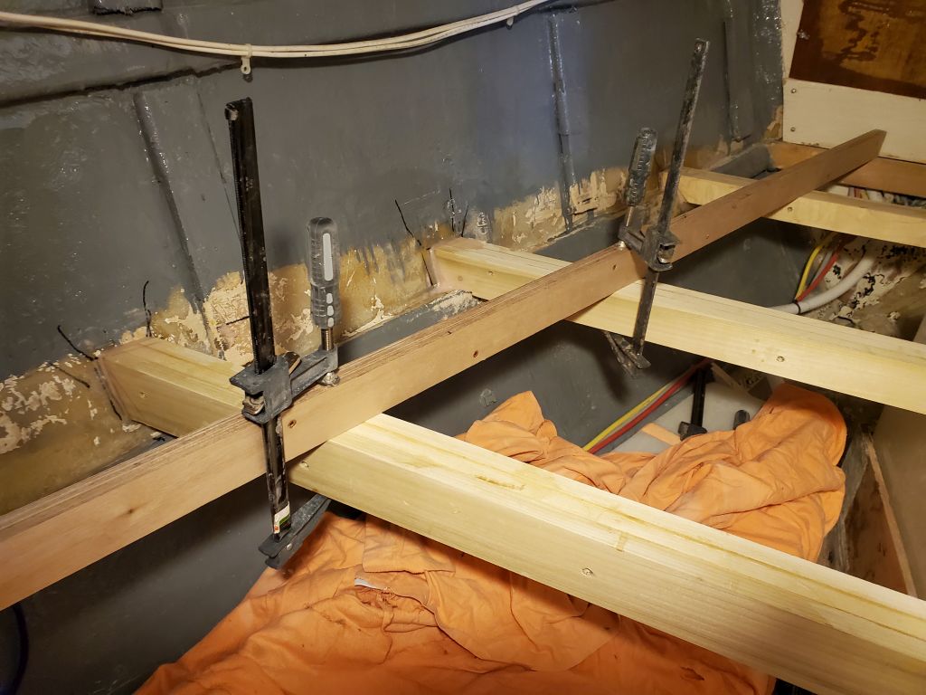
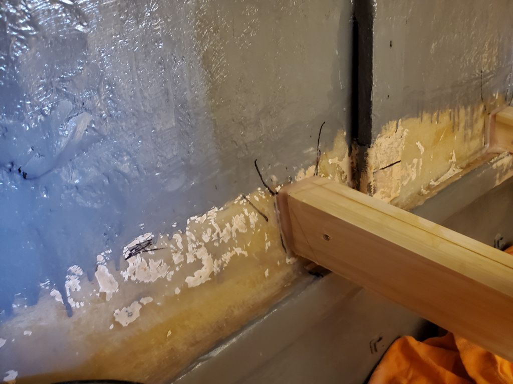
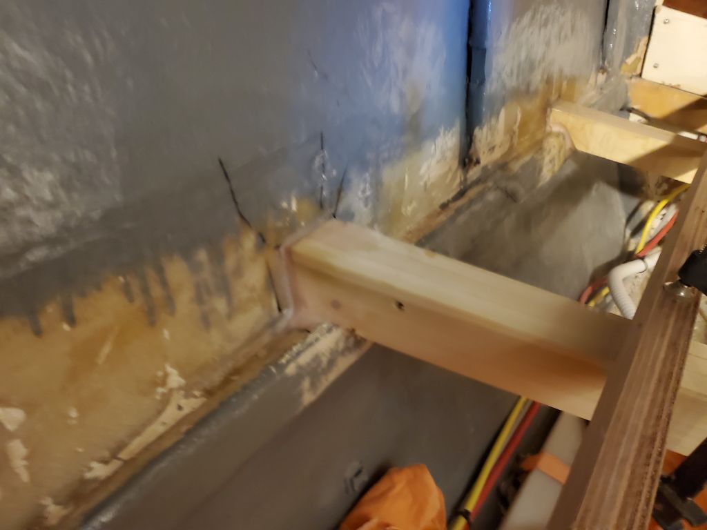
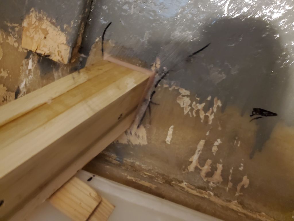
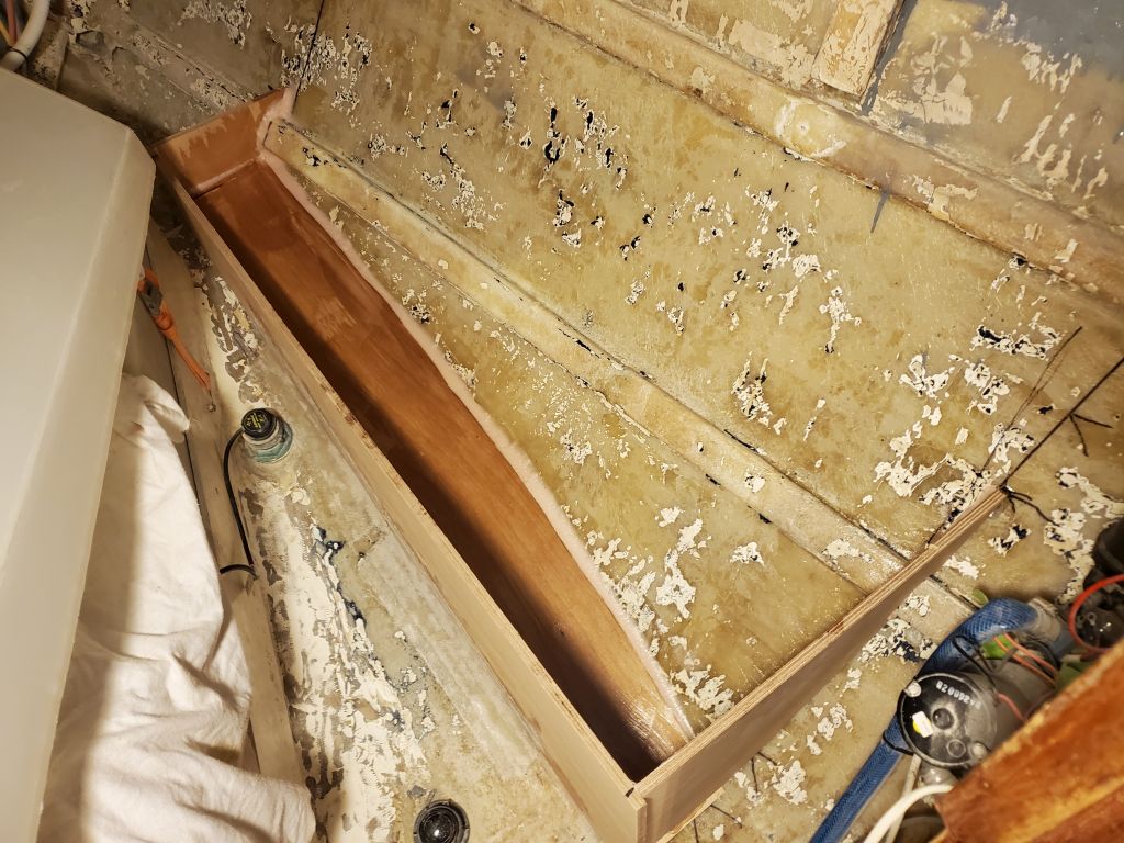
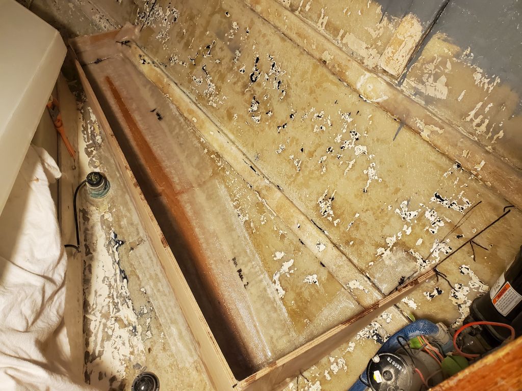
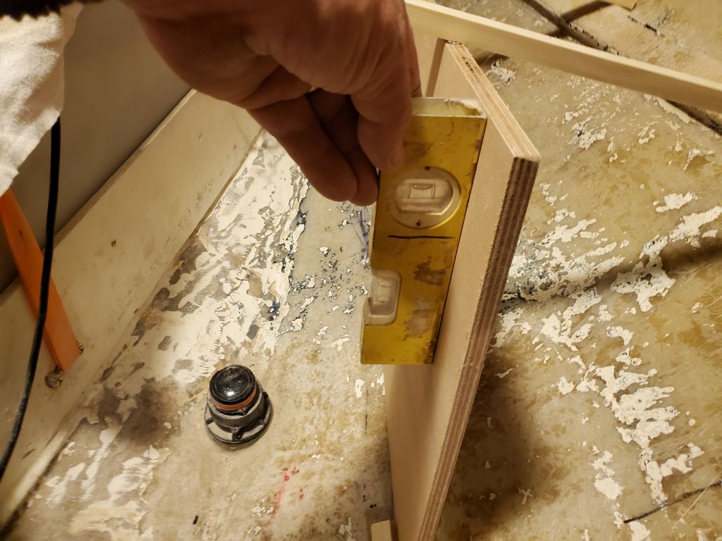
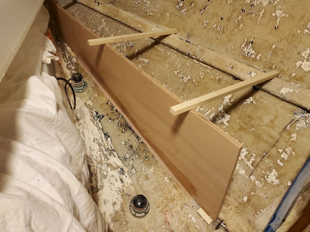
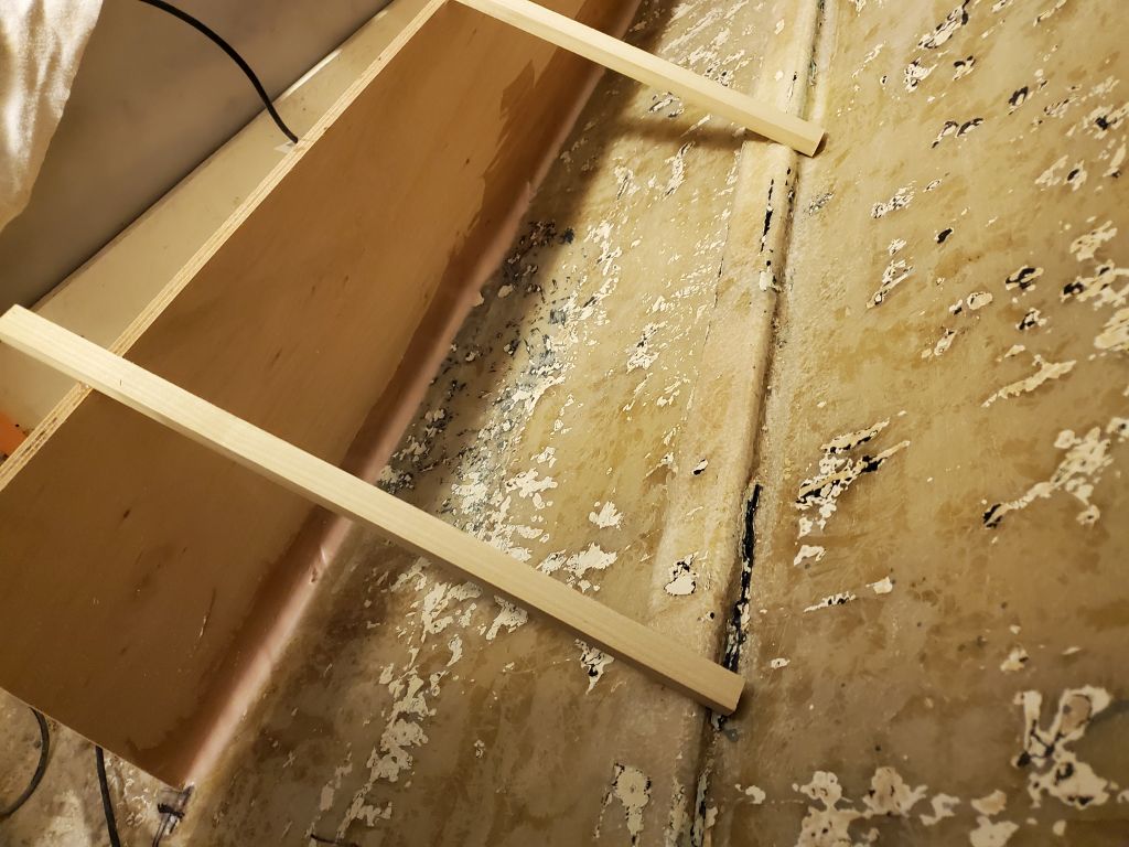
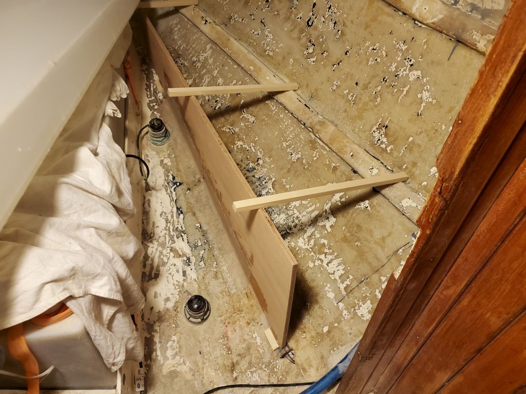
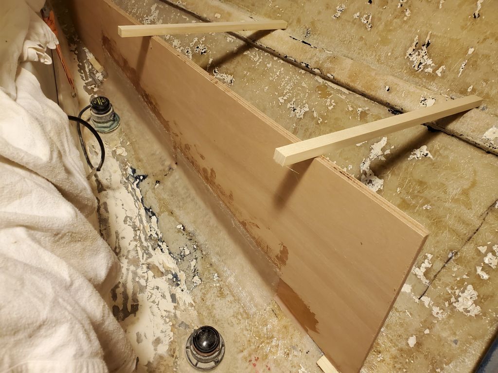
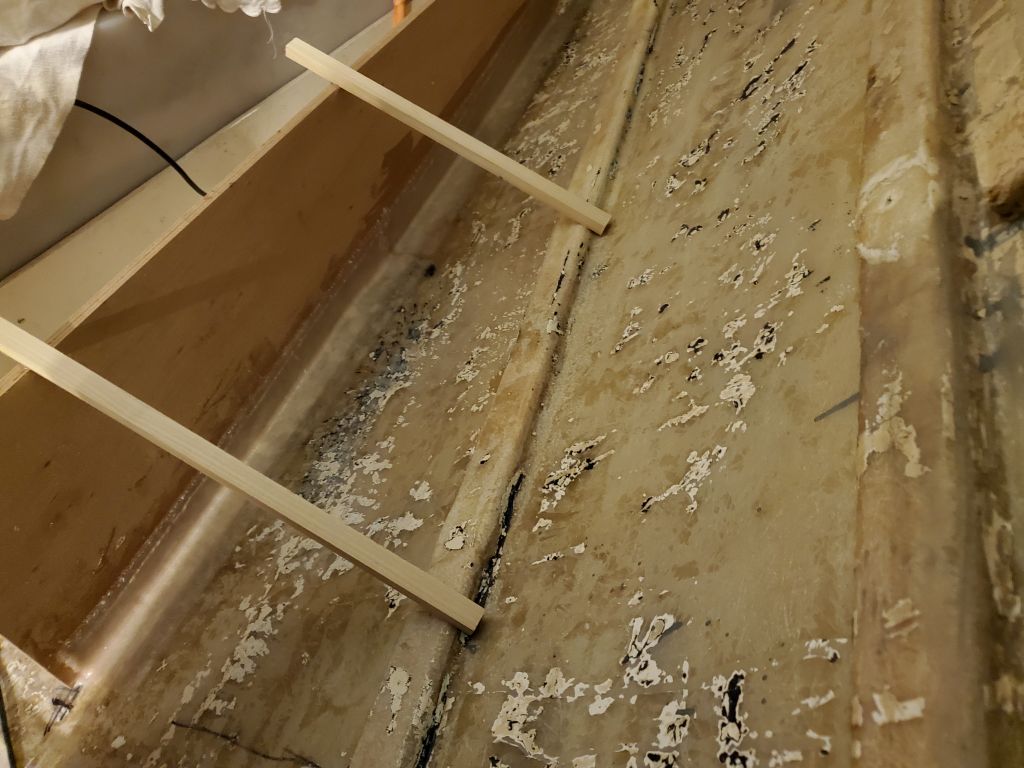
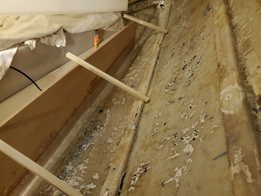
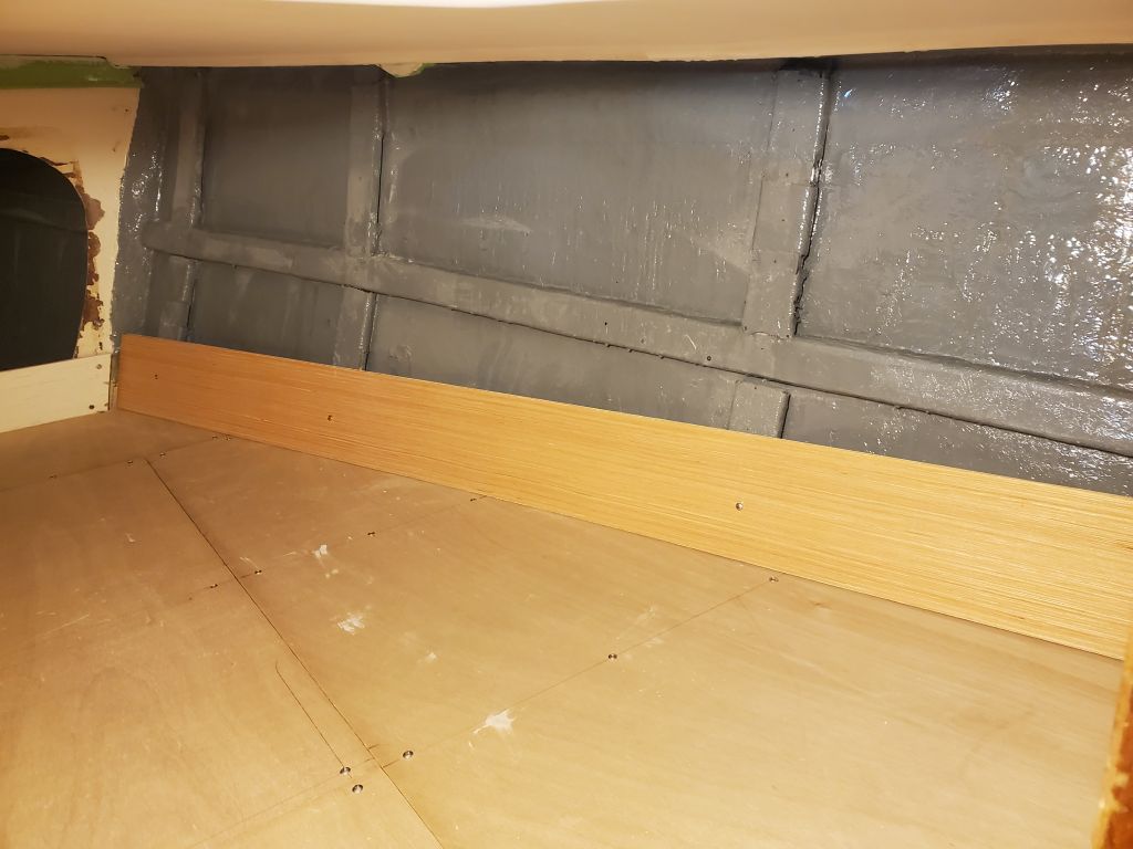
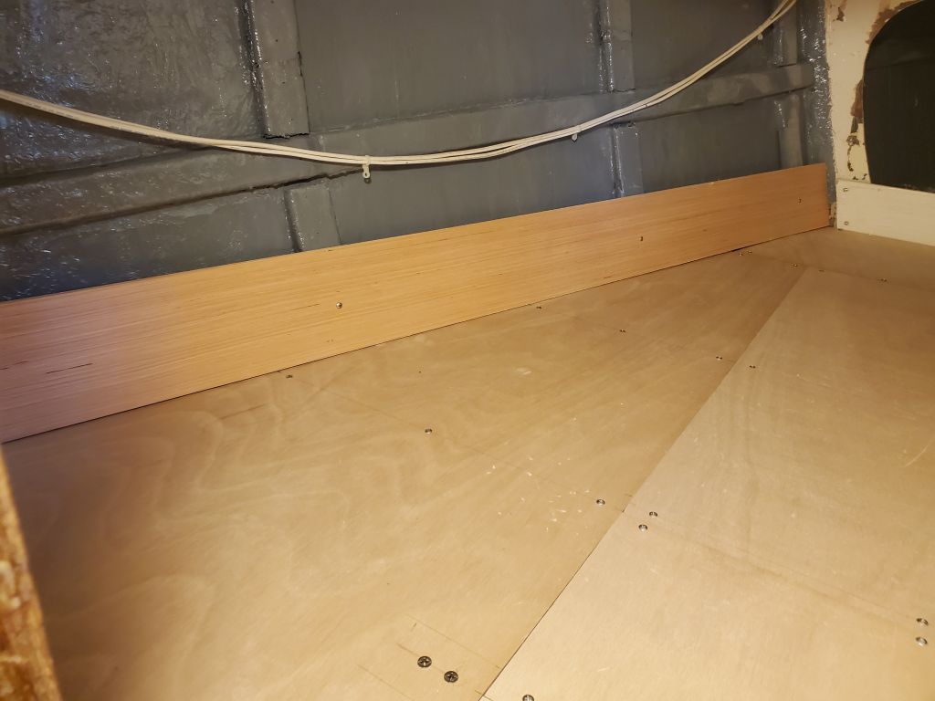
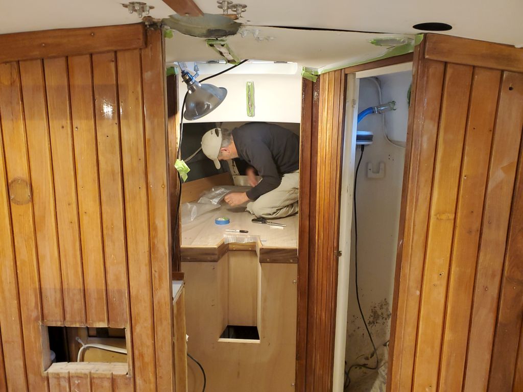
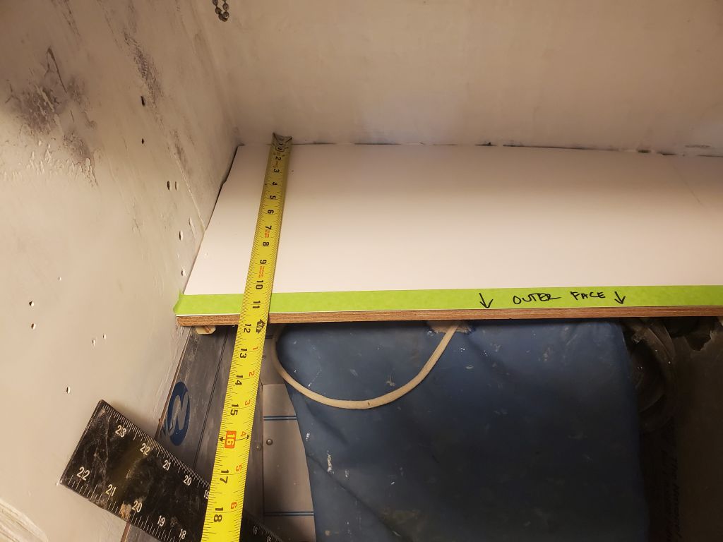
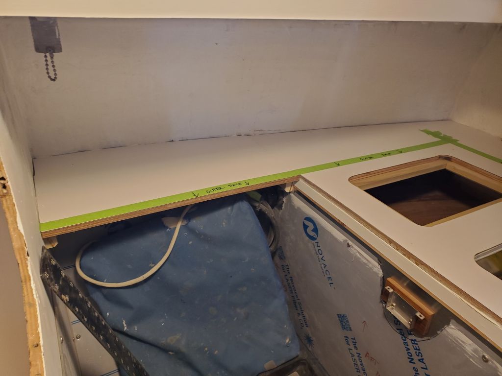
To begin, I had to get ready for Jason, the upholstery contractor, who was due later in the morning.  For his patterning purposes, he’d asked me to simulate the ceiling in the v-berth, which would add 3/8″ to the existing shape and which he needed for his bevels and edge patterning.  I quickly ripped four, 6″ wide pieces of 3/16″ plywood to a length approximating that of the sides of the berth, and tacked these in place–two layers per side–to give him the effect of the ceiling.  Then I cleaned off the settees and, after taking a moment to pare away the excess bungs I’d installed, vacuumed everything clean for his arrival.

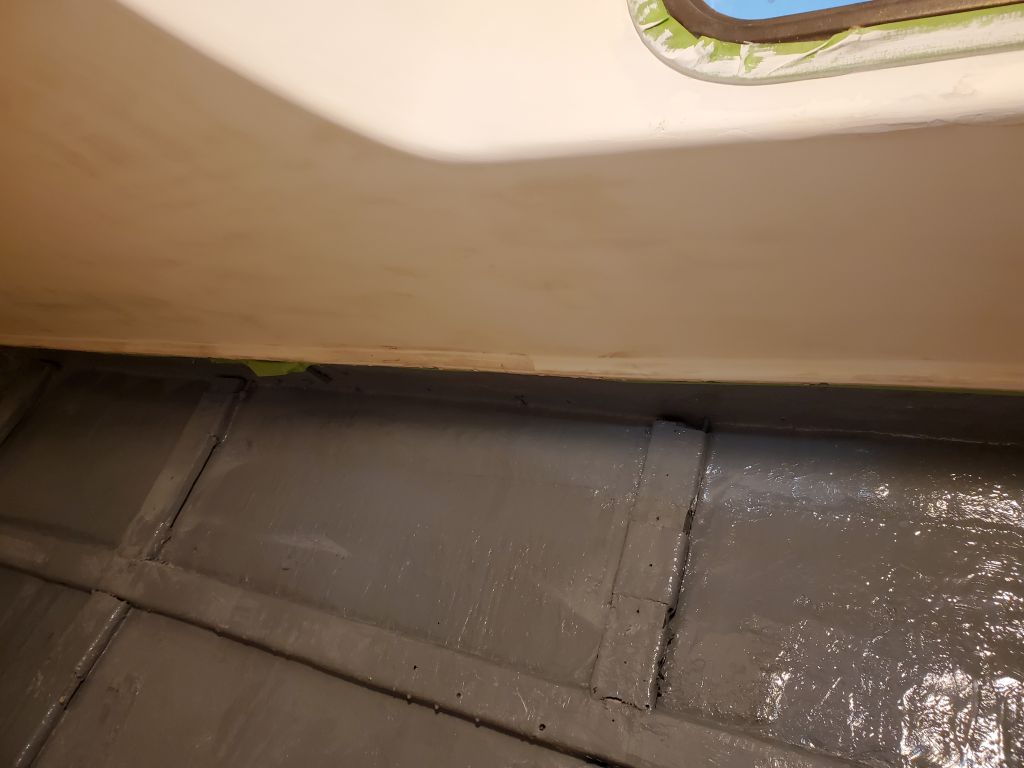
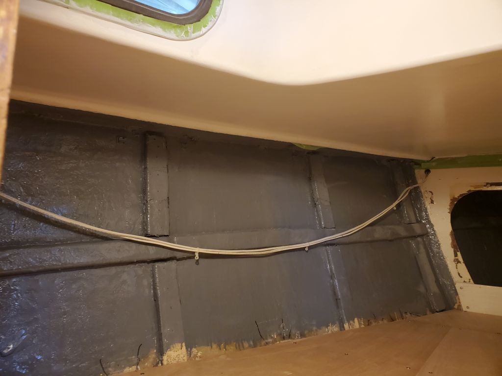
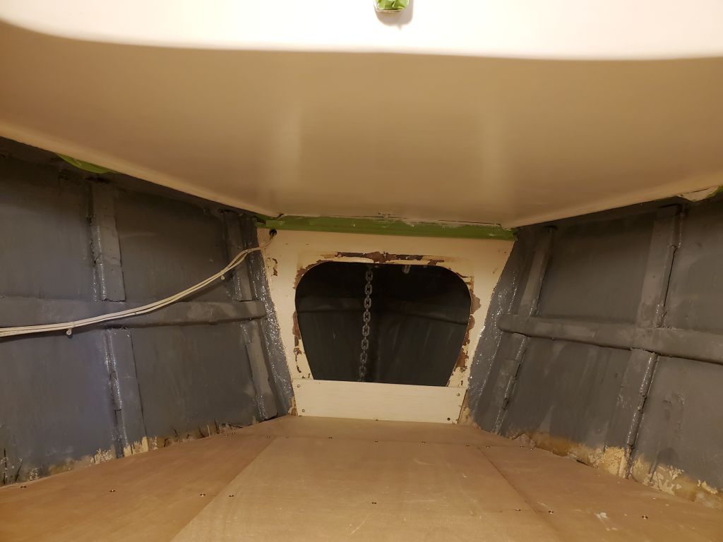
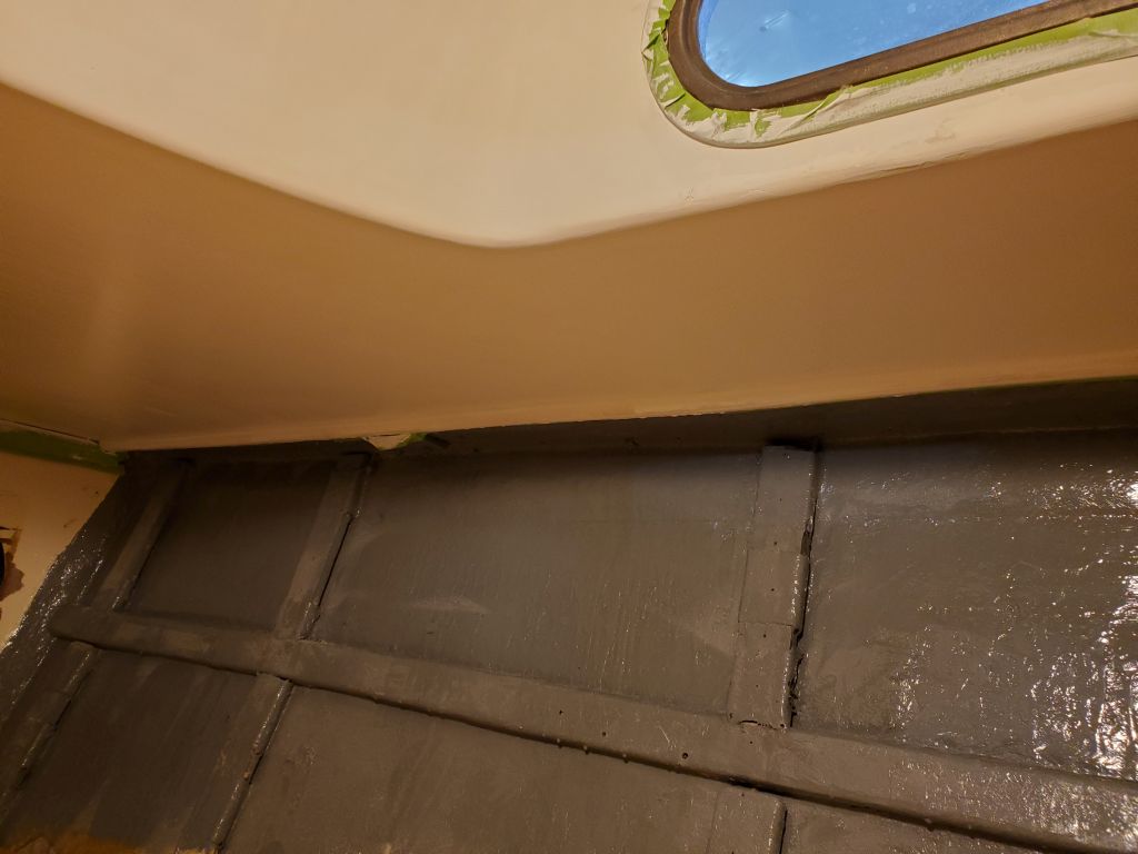
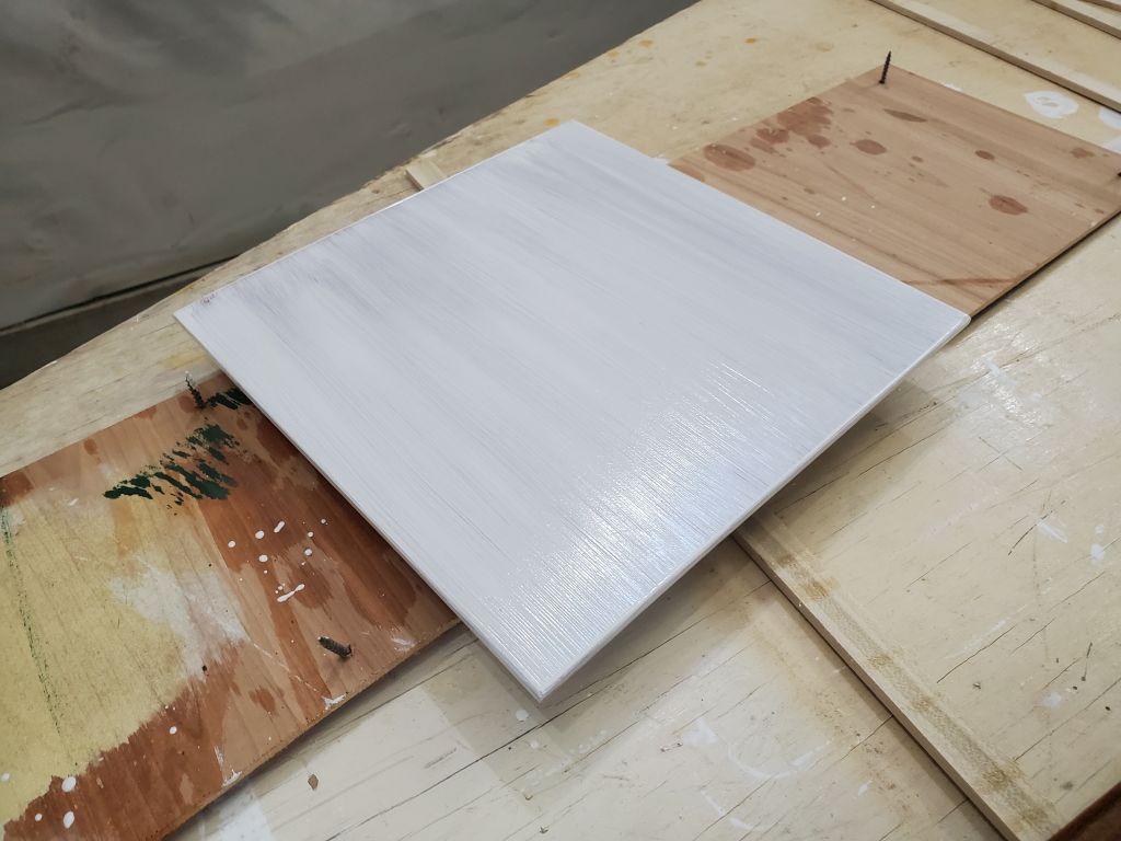
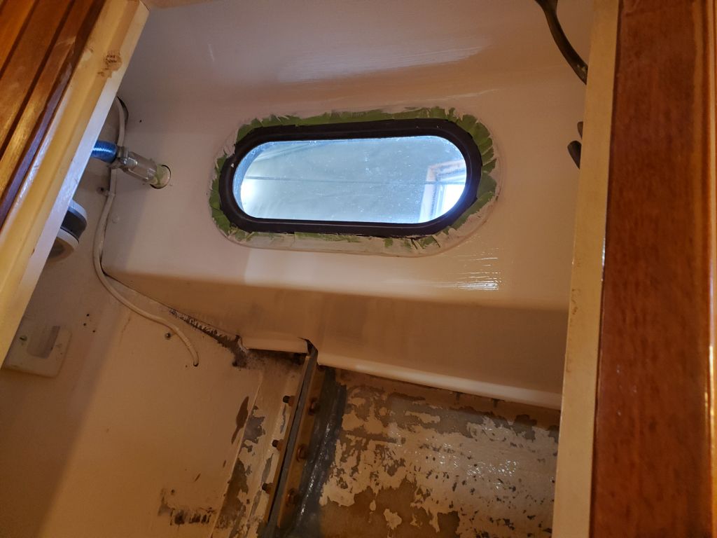
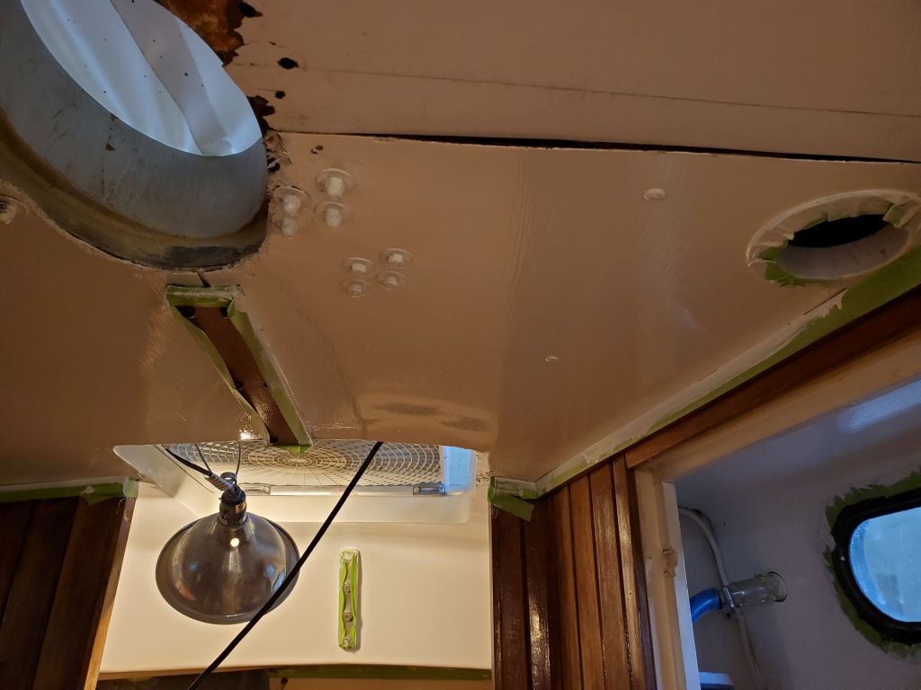
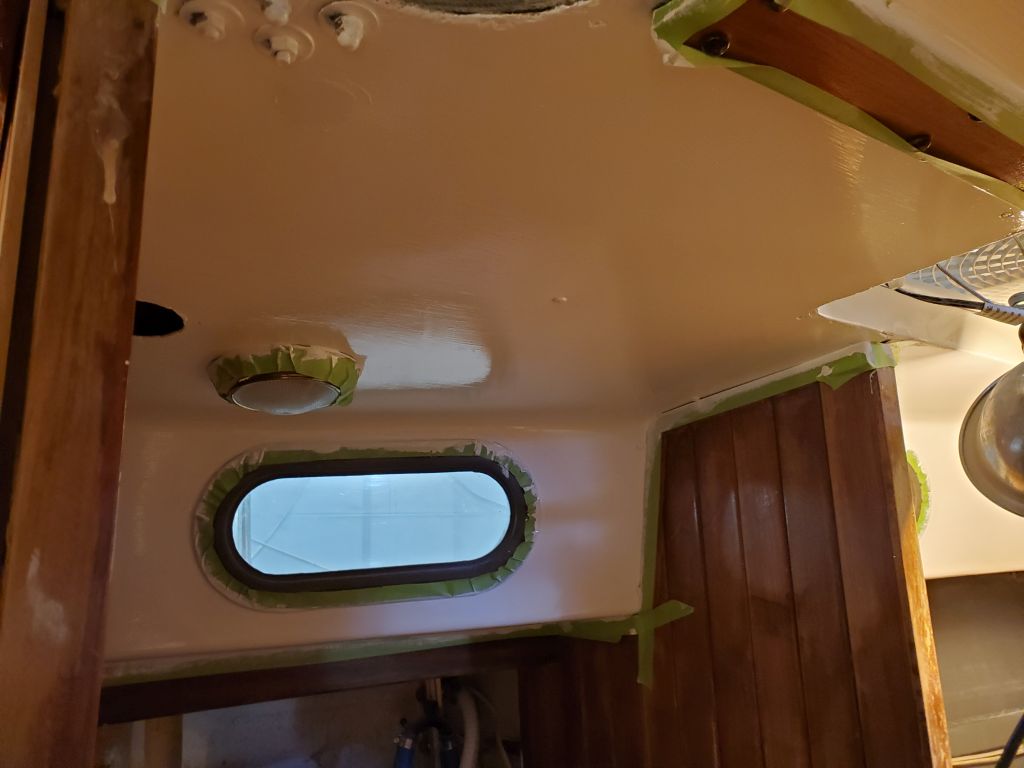
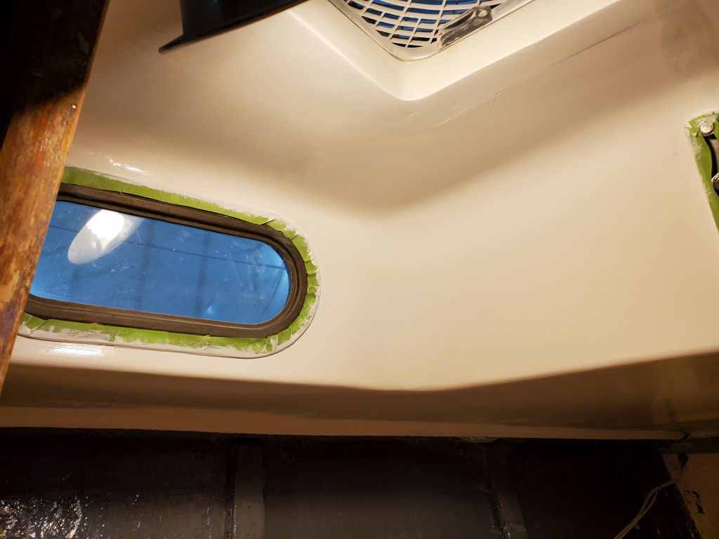
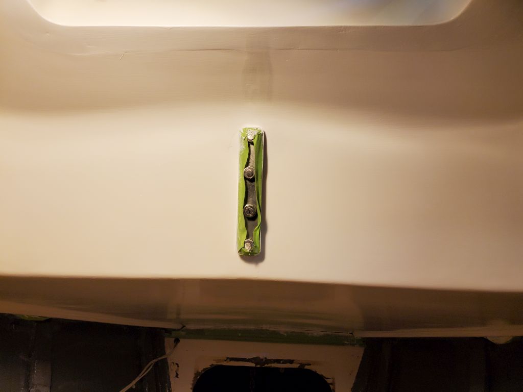
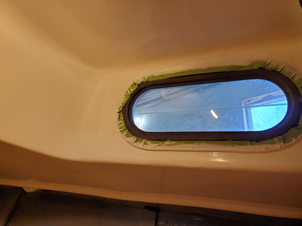
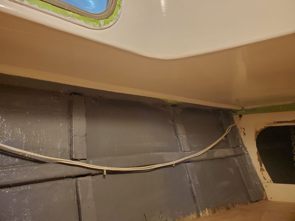
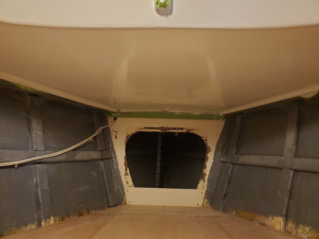
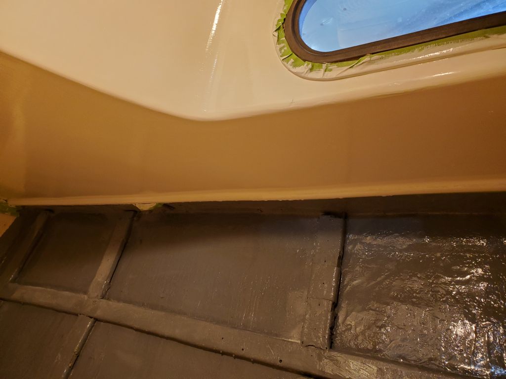
Once he was done with his work, I got back to work on the paint in the v-berth, lightly sanding the primer and then cleaning the area, including the head and hanging locker overheads.  Then, I applied the first coat of semi-gloss white finish paint to all these areas.

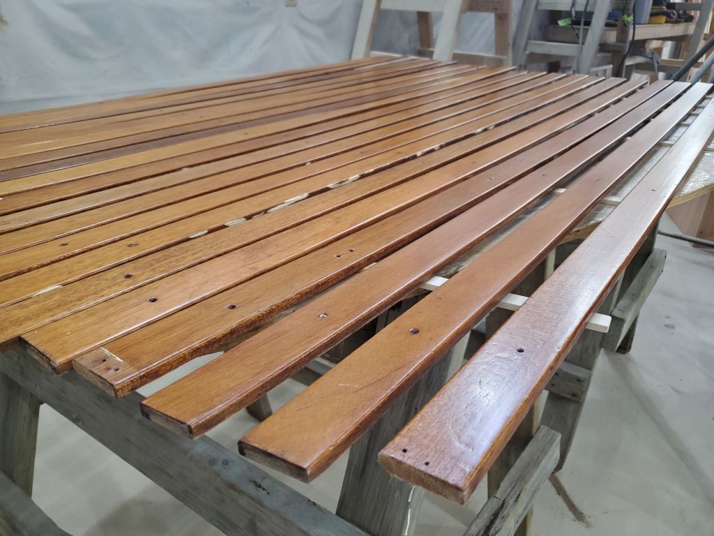
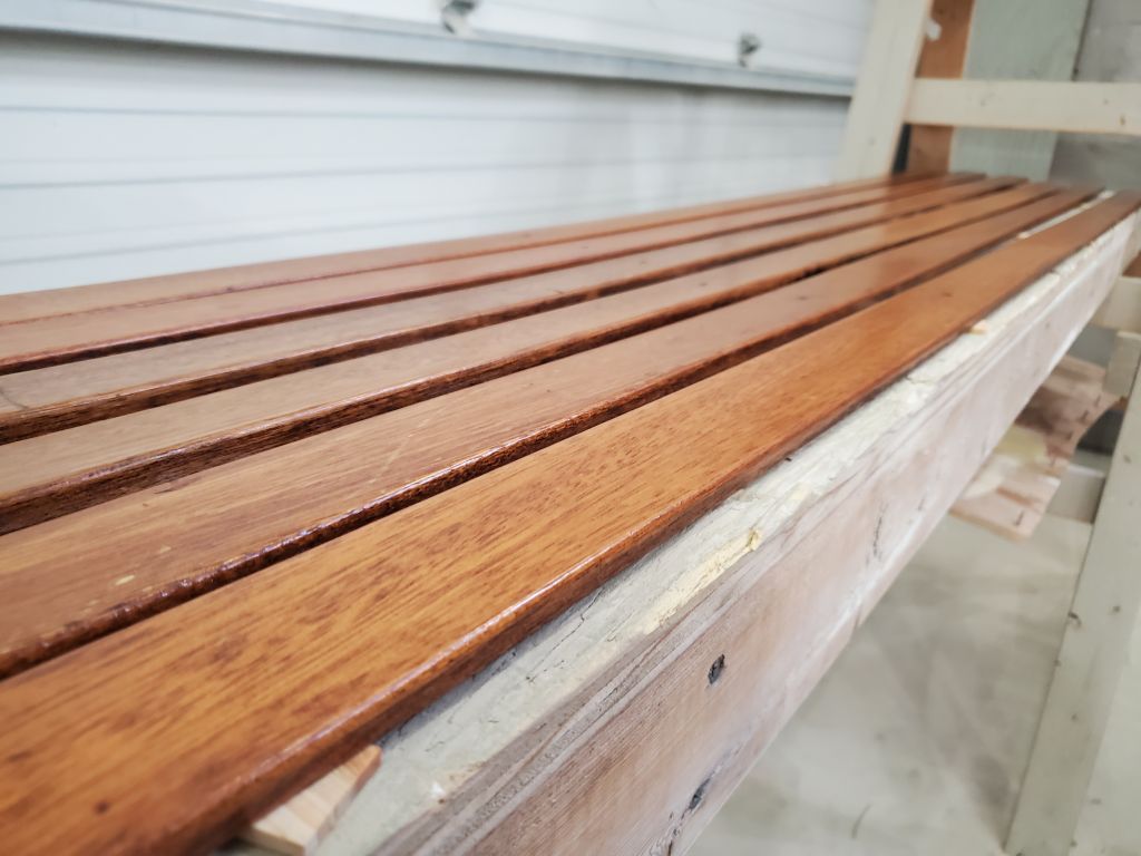
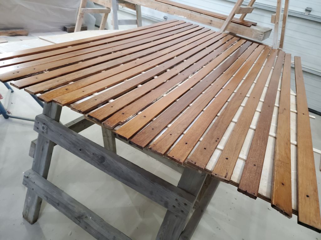
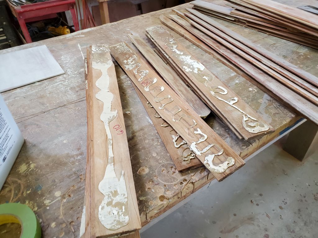
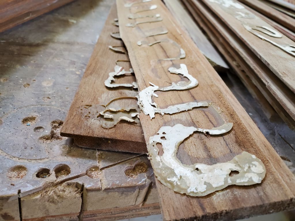
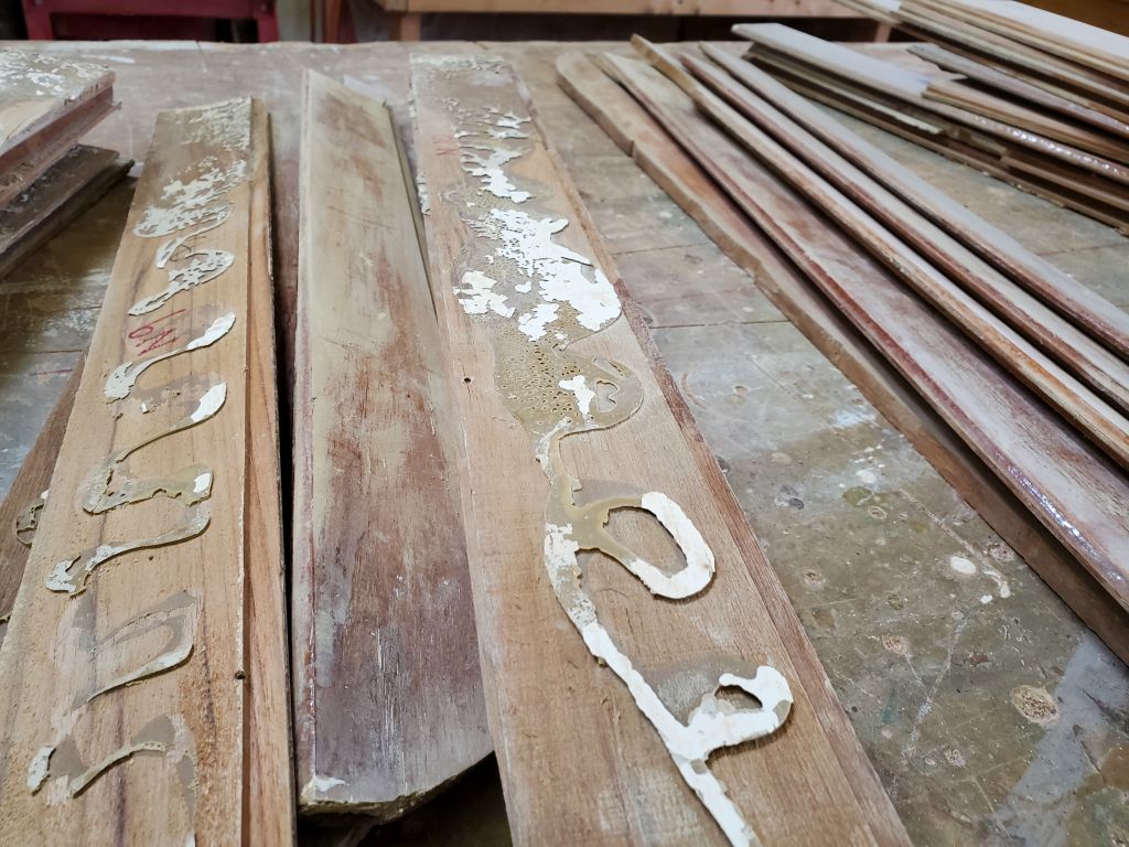
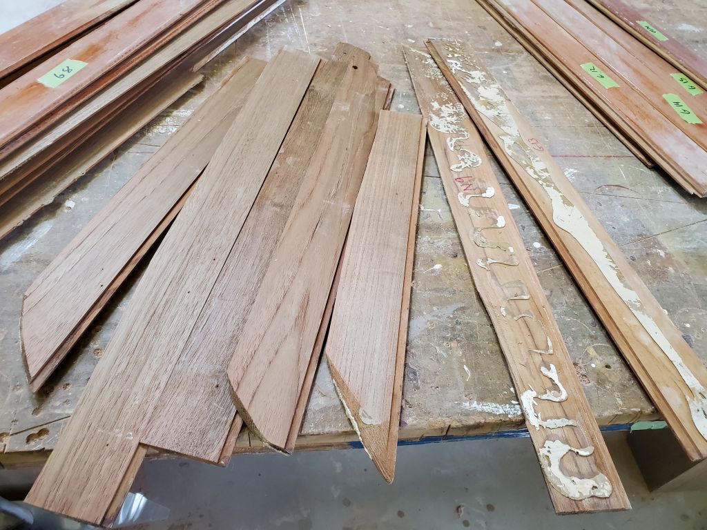
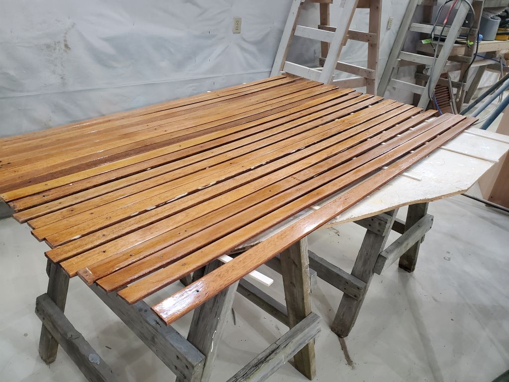
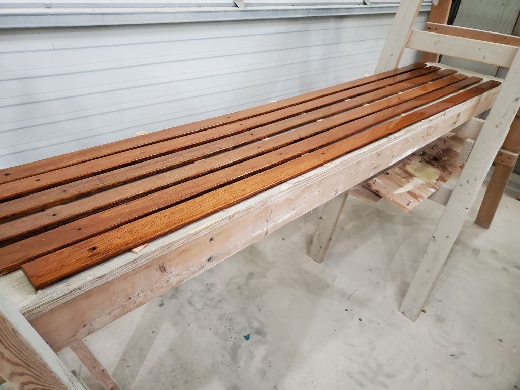
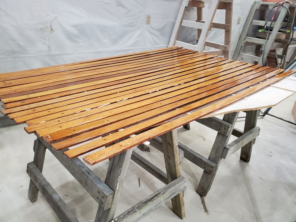
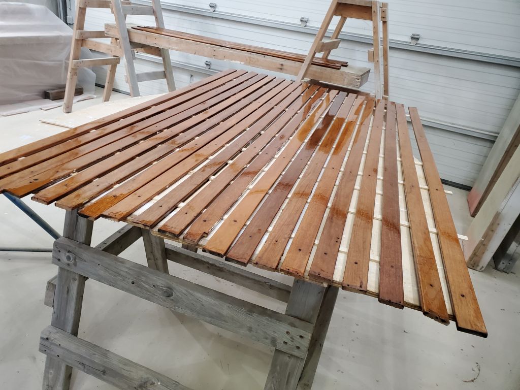
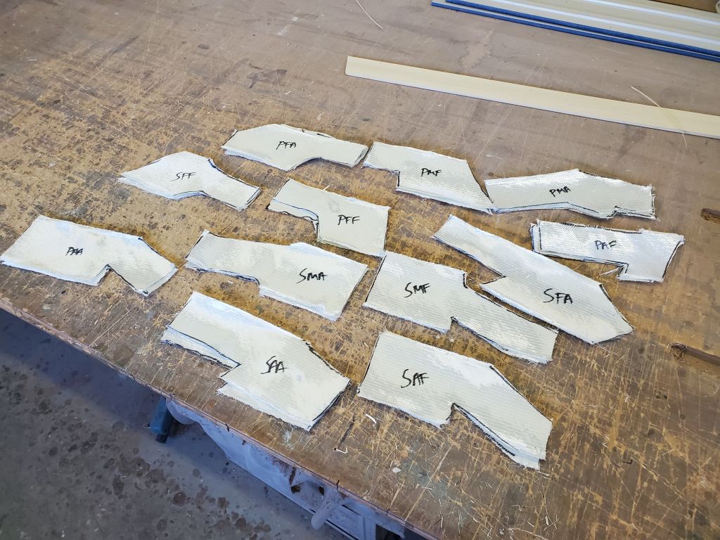
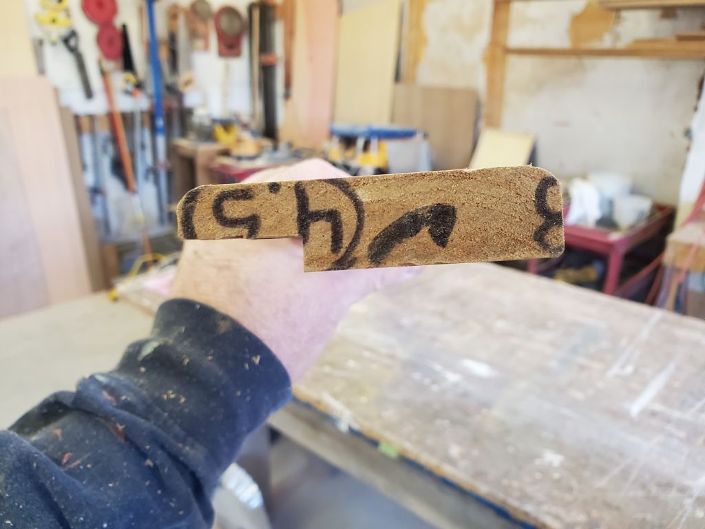
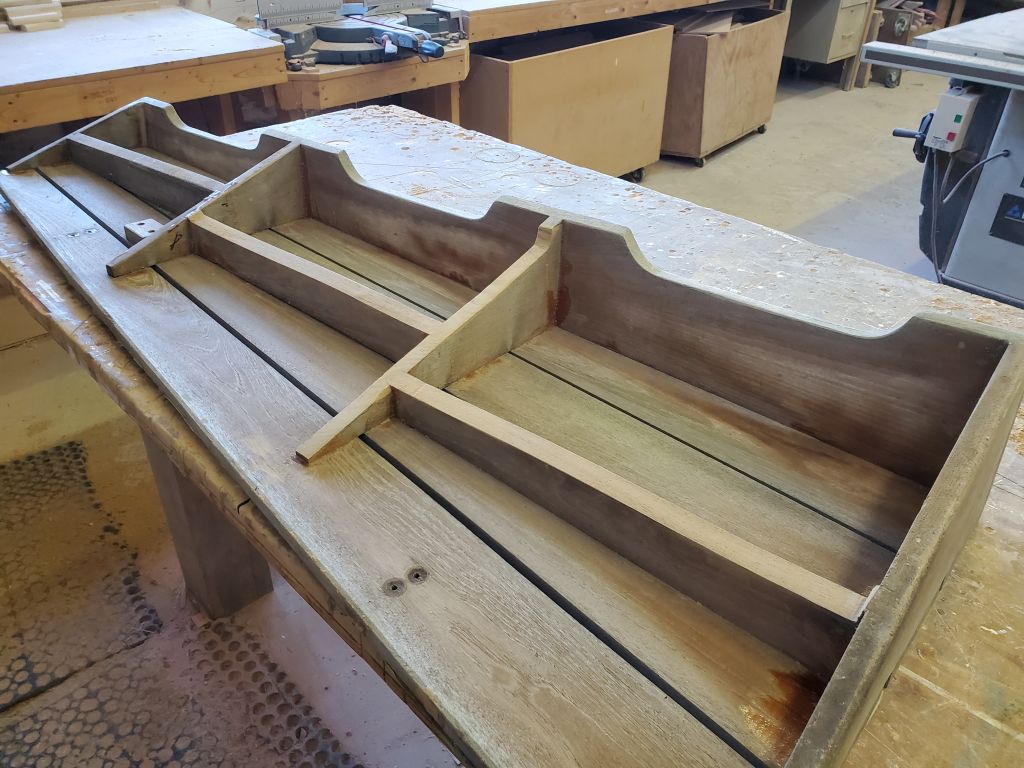
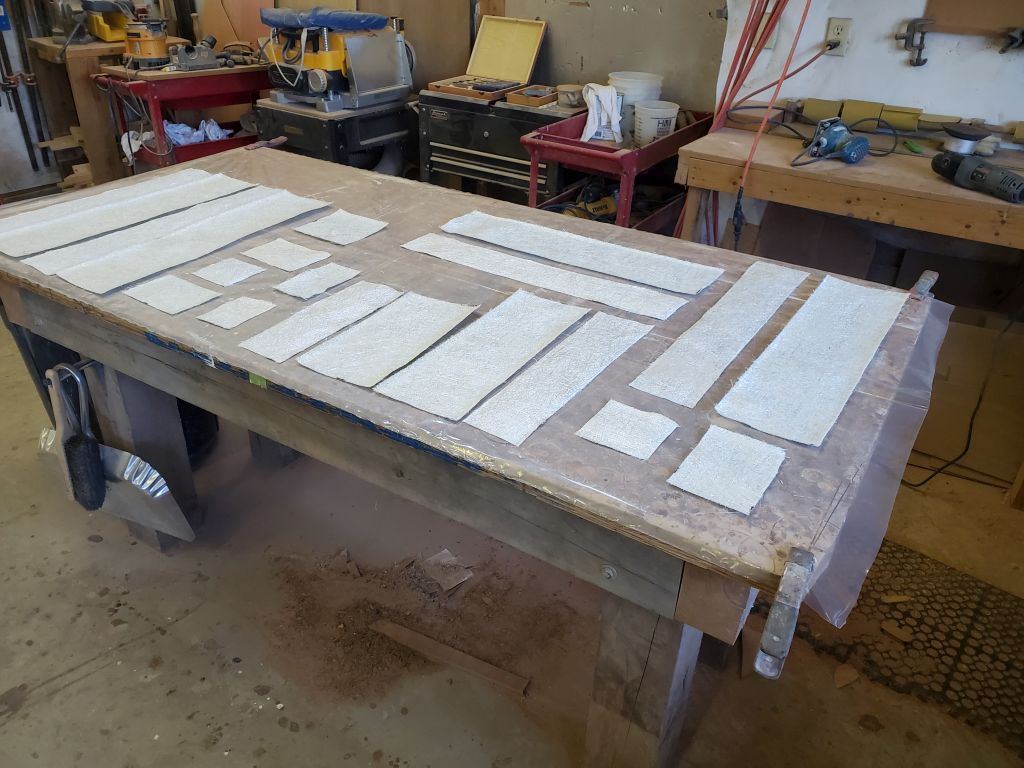
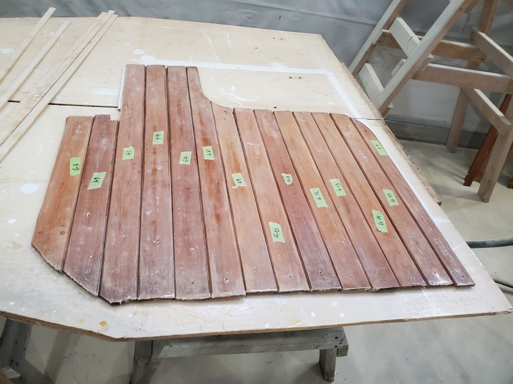
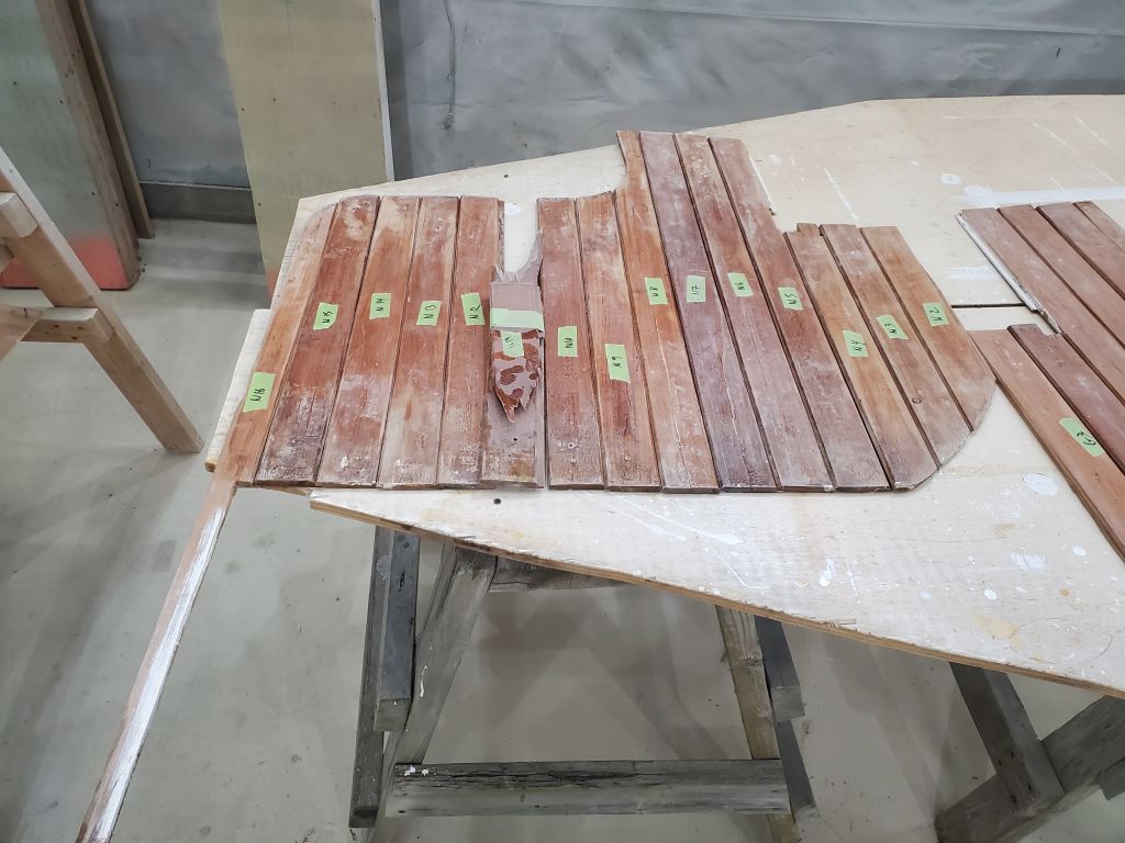
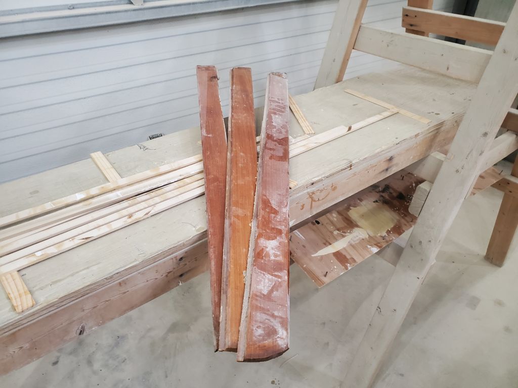
I laid out the numbered staving strips from the two after bulkhead so I could see what I had and remember how they were arranged.  There was one piece from the port side that had shattered upon removal, but I had some extra pieces I could use to fill in for it.  In any event, I wouldn’t use all the existing staving because the upper cabinet layout was different now, so there was some room for manipulation of the existing pieces as needed.  I planned to get to these installations soon.

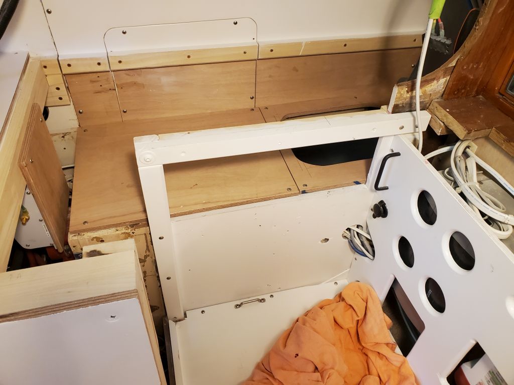
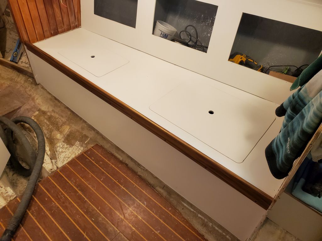
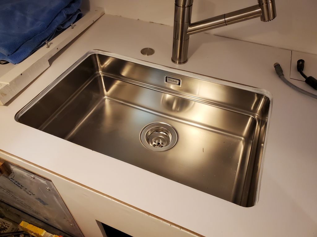
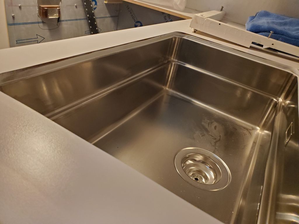
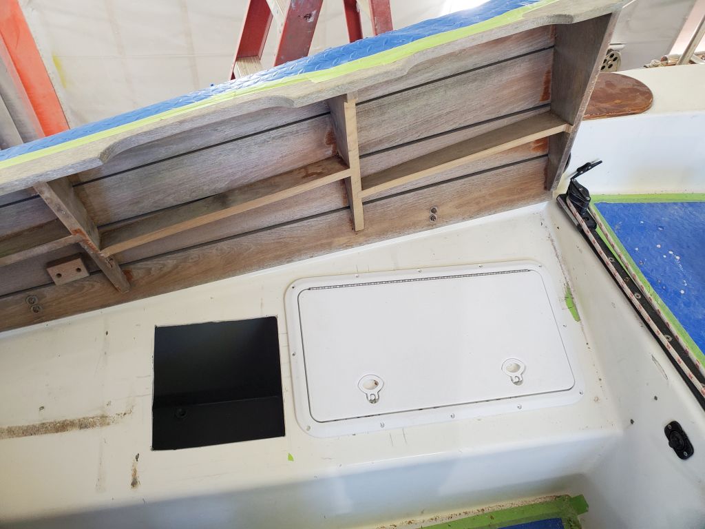
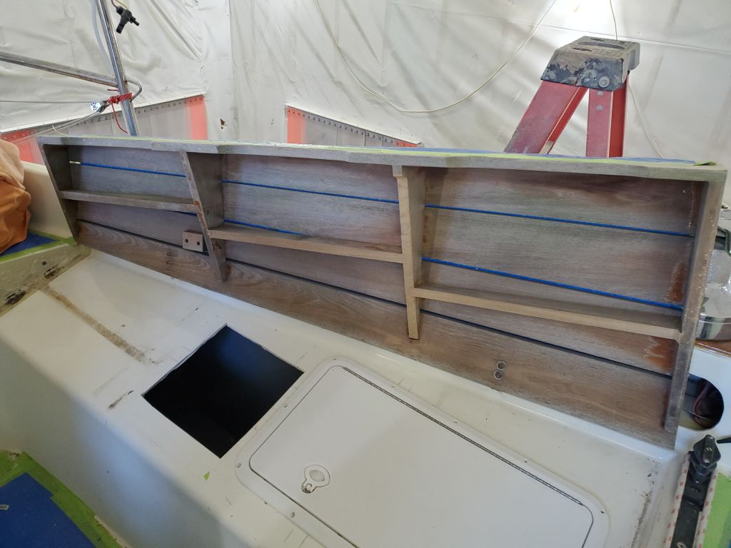
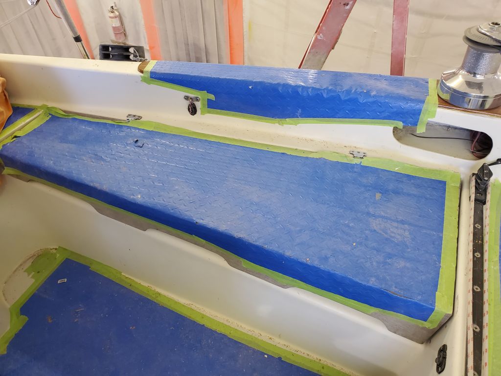
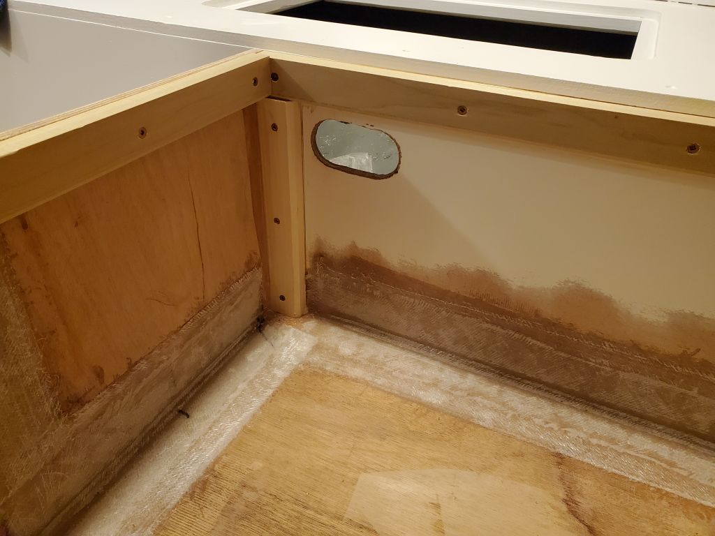
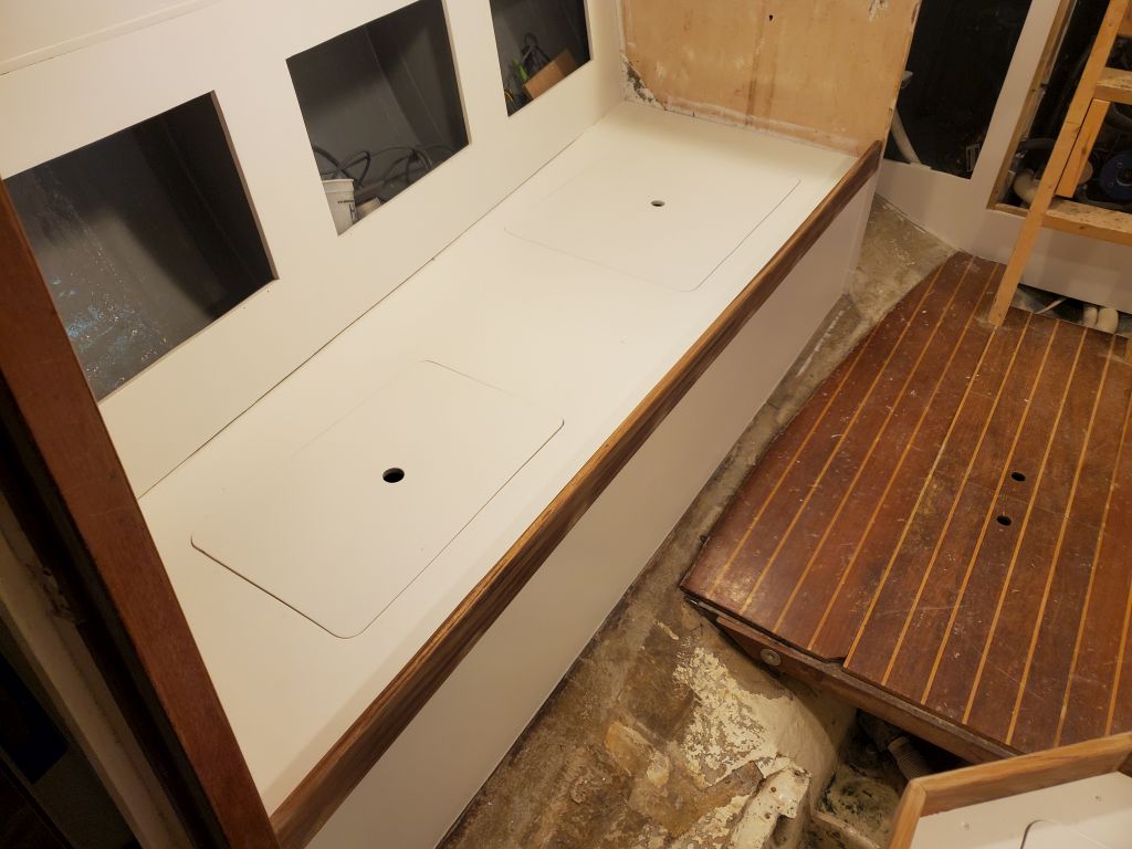
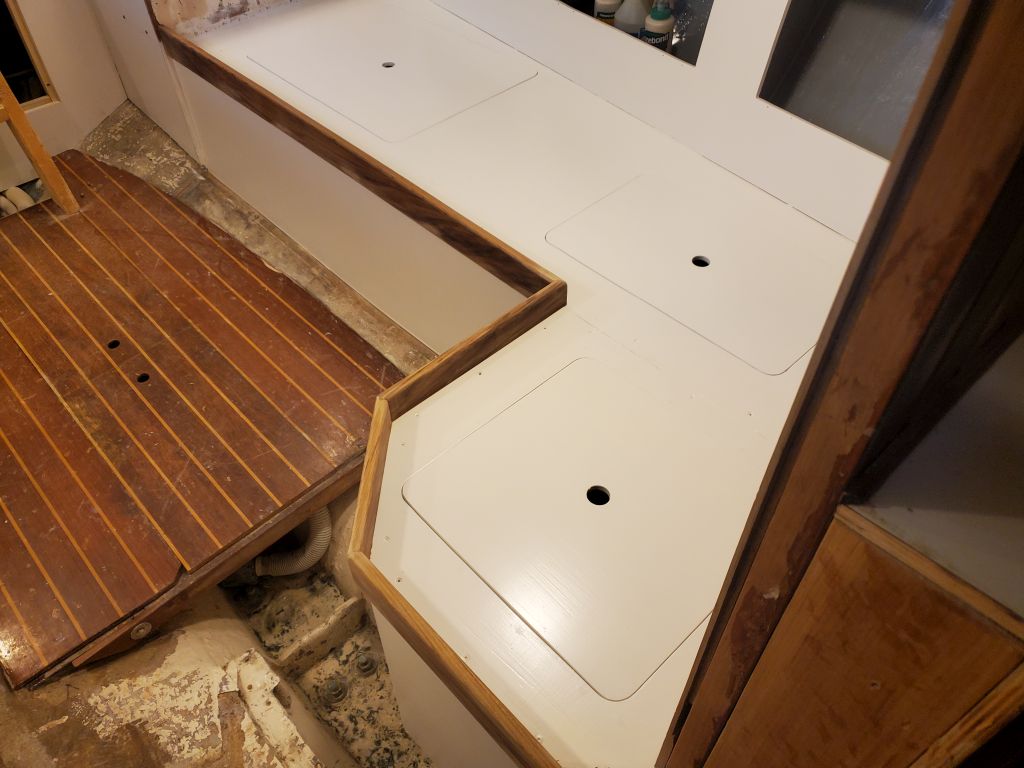
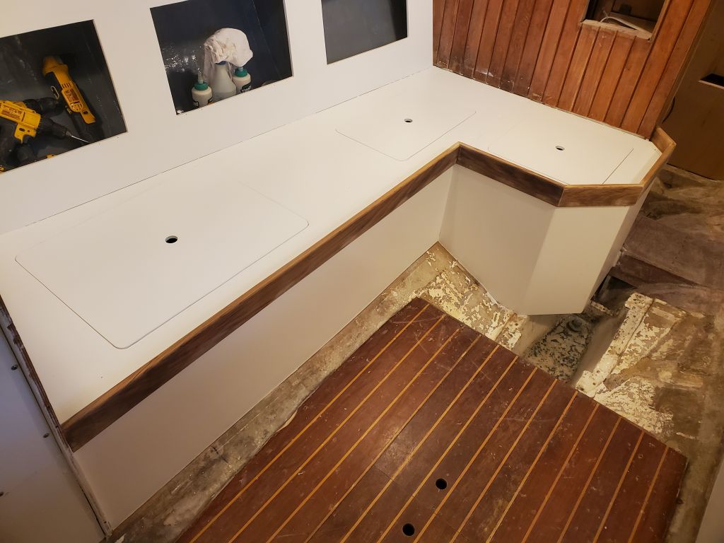
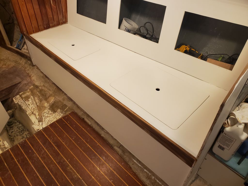
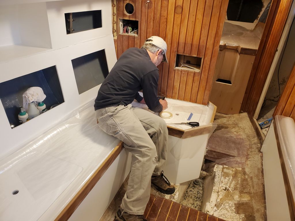
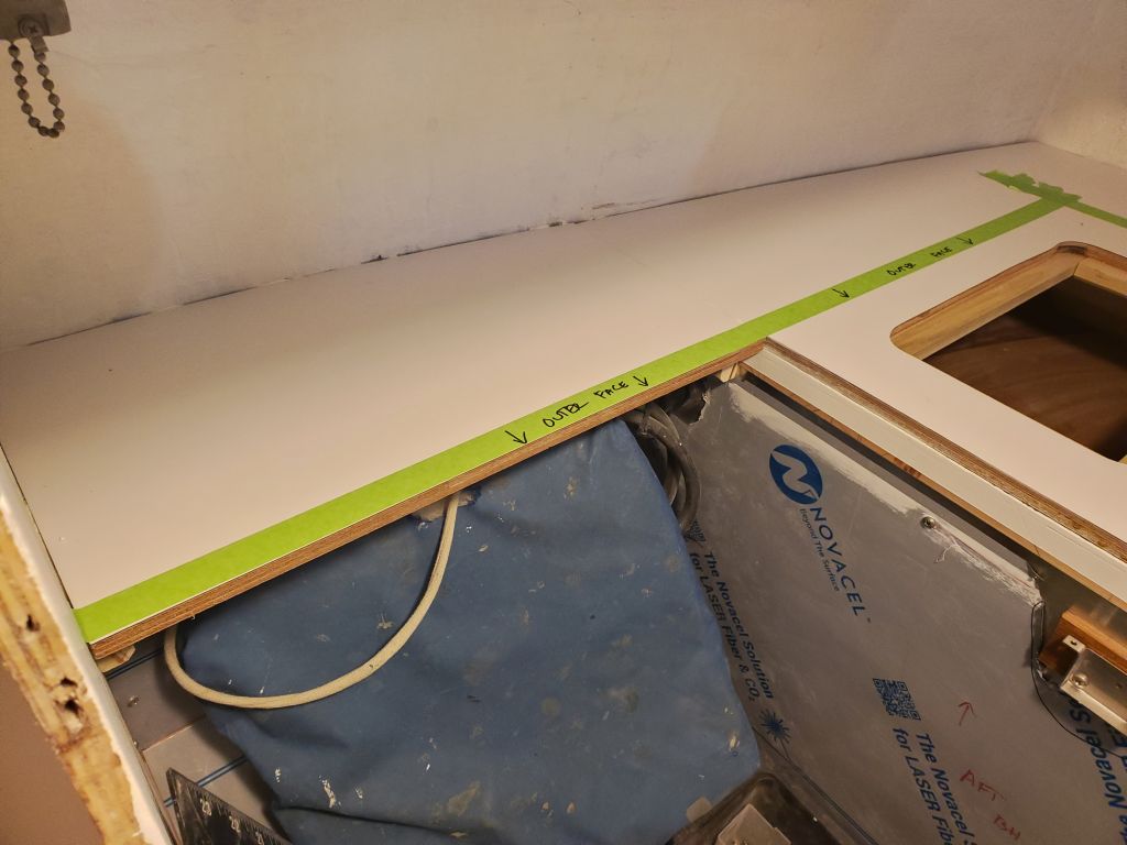
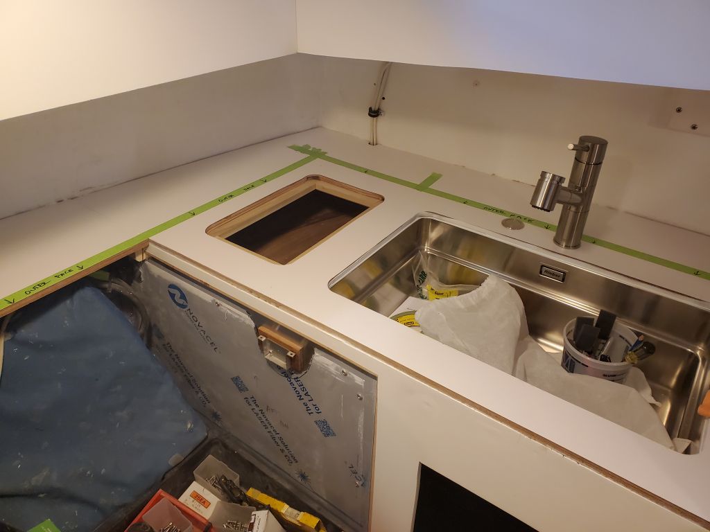
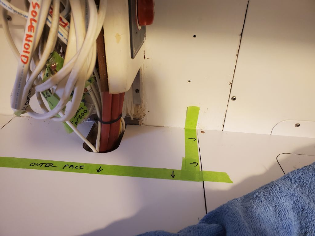
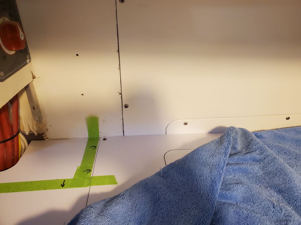
In the galley, there were still upper cabinets to be built, and some additional details, and now that the port side was reinstalled I could get down to some proposed layout.  I marked out some basic lines with masking tape to show how I’d been envisioning the cabinets, with the outboard (starboard) side flush with the edge of the small countertop behind the stove, then the after section running about 6-1/2″ forward of the aft bulkhead, or the maximum possible to pass behind the faucet.  The fixed upper cabinet would end just shy of the removable panels on the port side, as shown, and in that space, I proposed a semi-fixed (but removable) cabinet of some sort designed to fit around and hold securely the owner’s choice of plates and cups, and that sort of thing.  It would also be possible to install something of that nature outboard of the stove, even if it ultimately overhung the countertop by a bit.

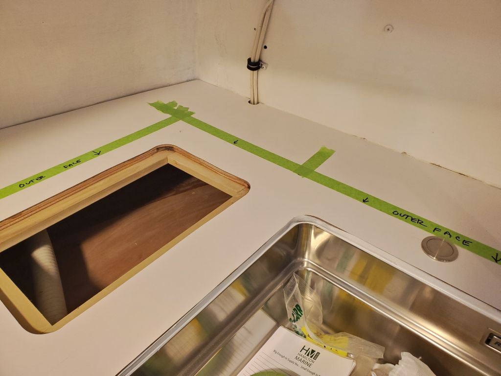
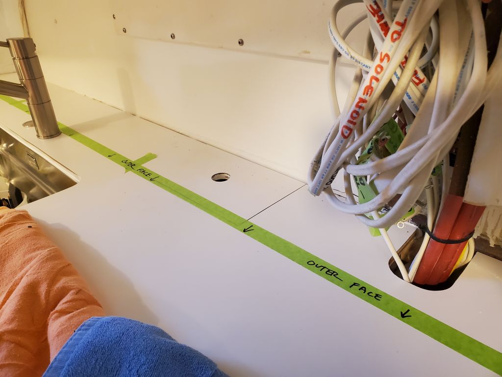
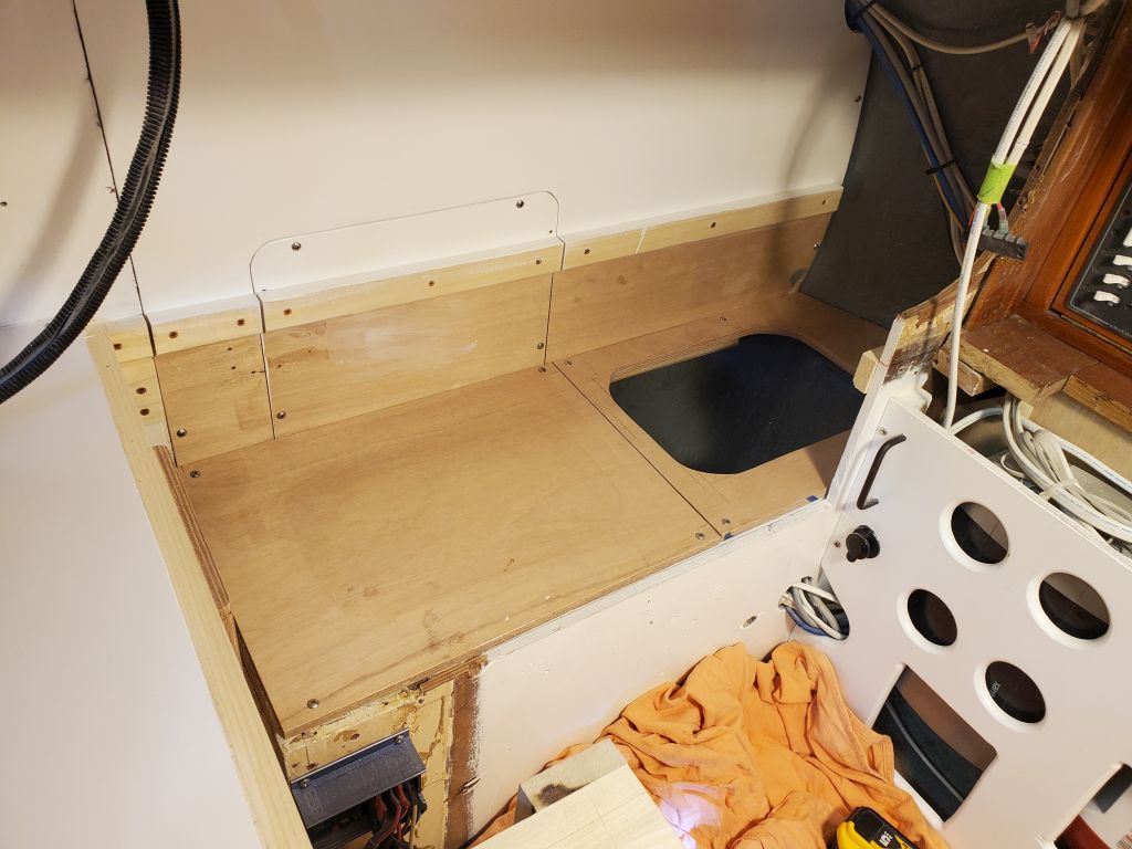
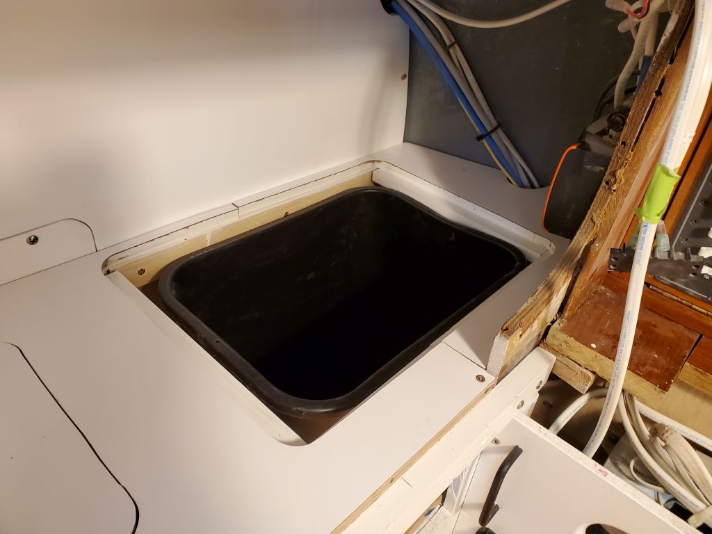
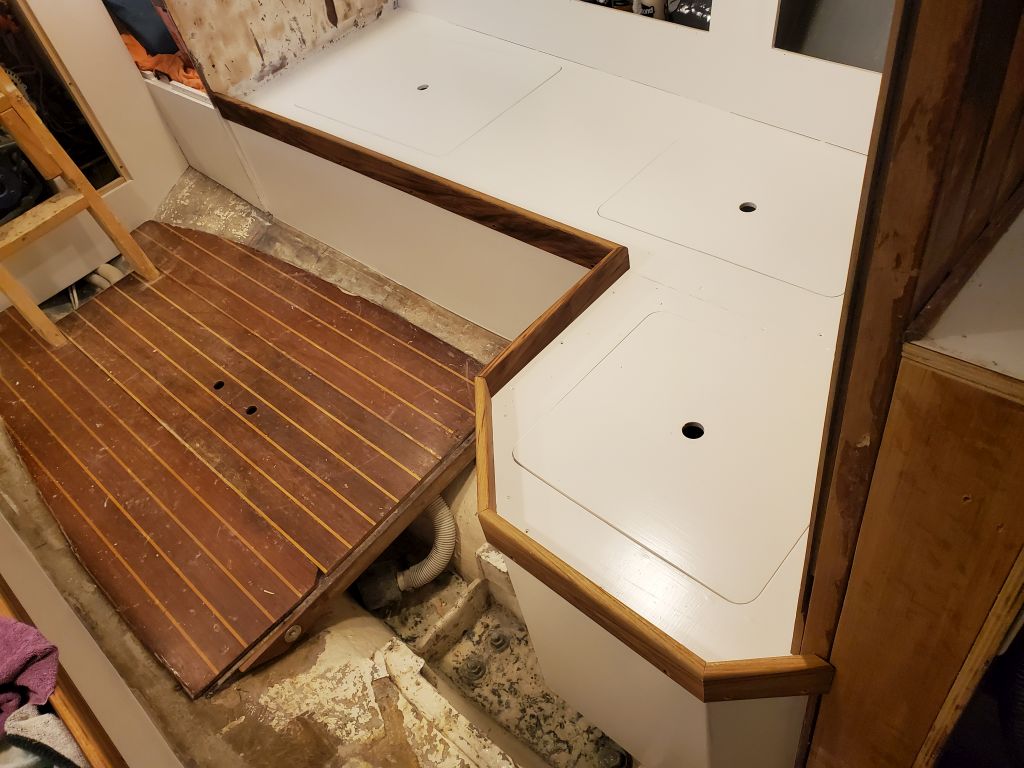
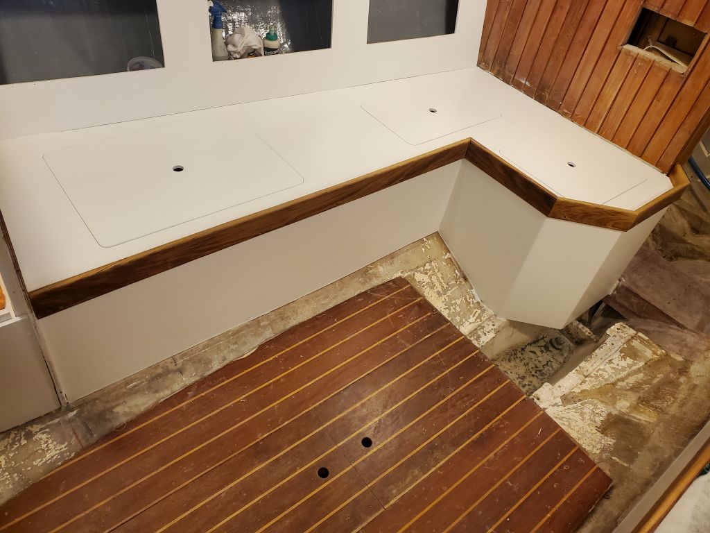
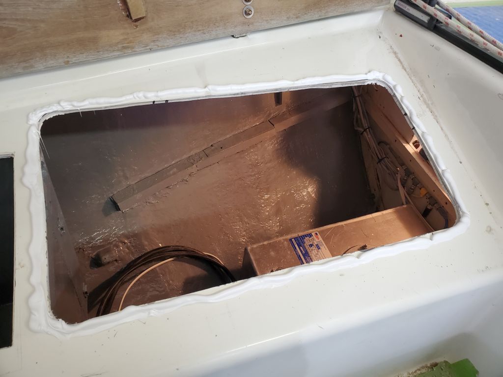
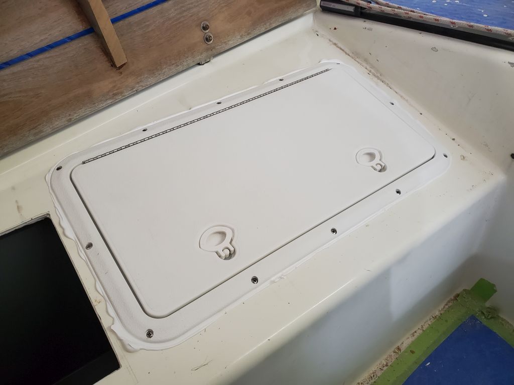
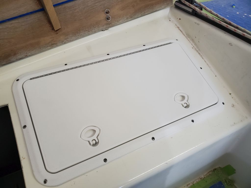
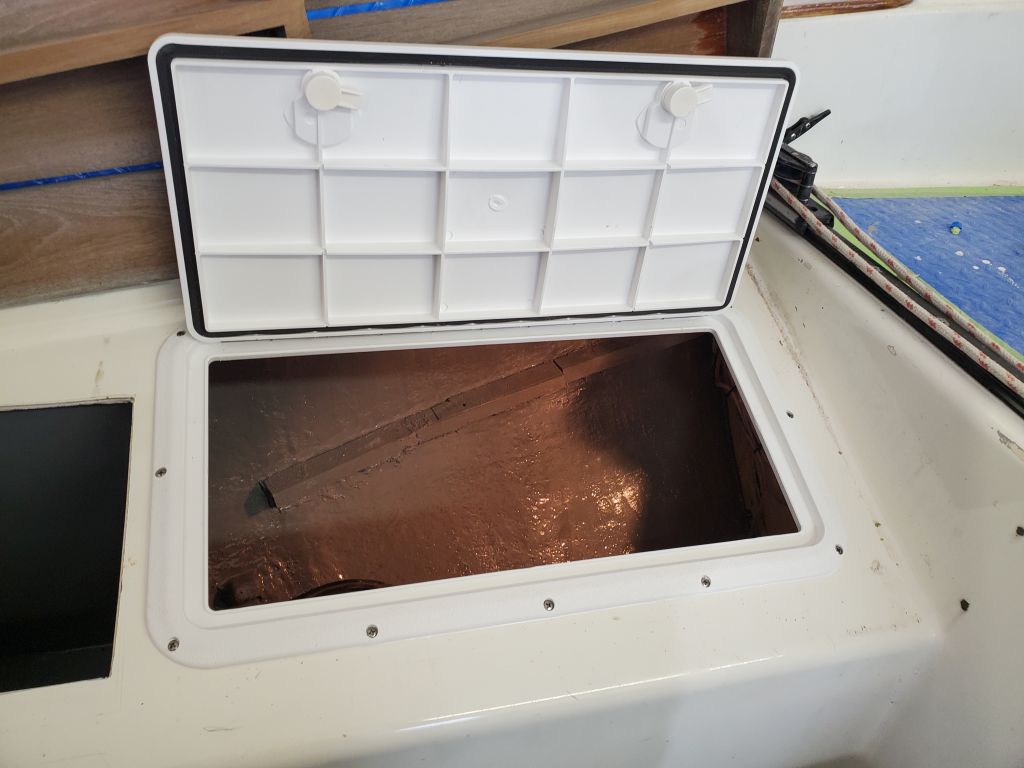
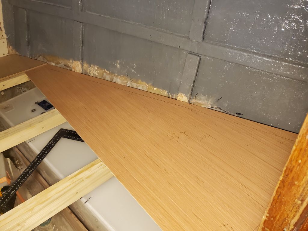
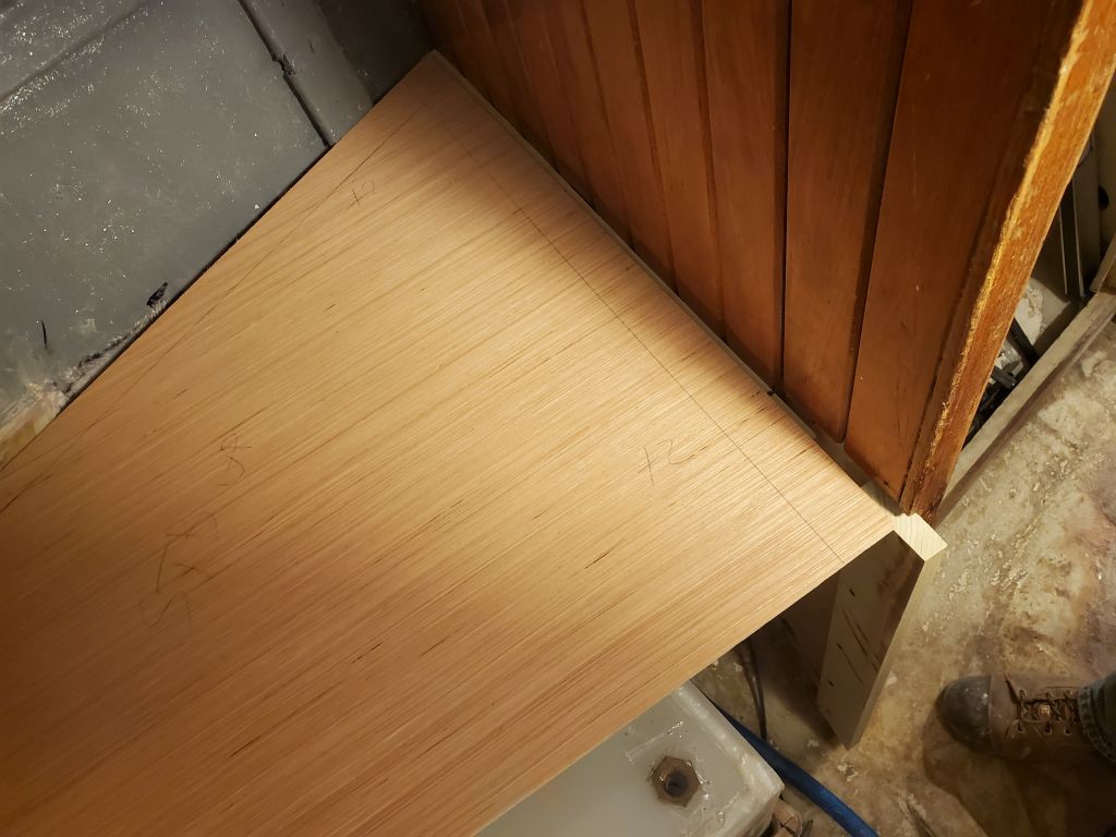
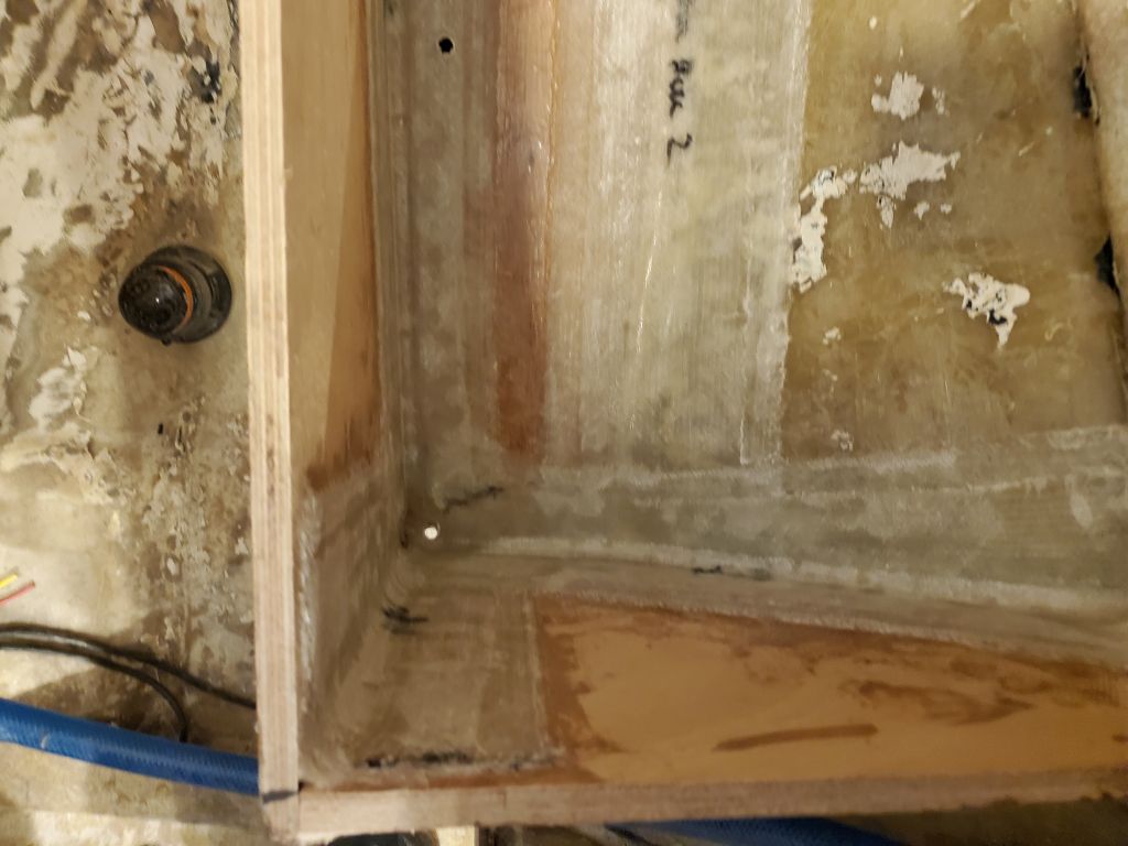
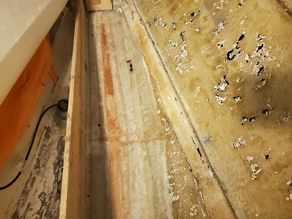
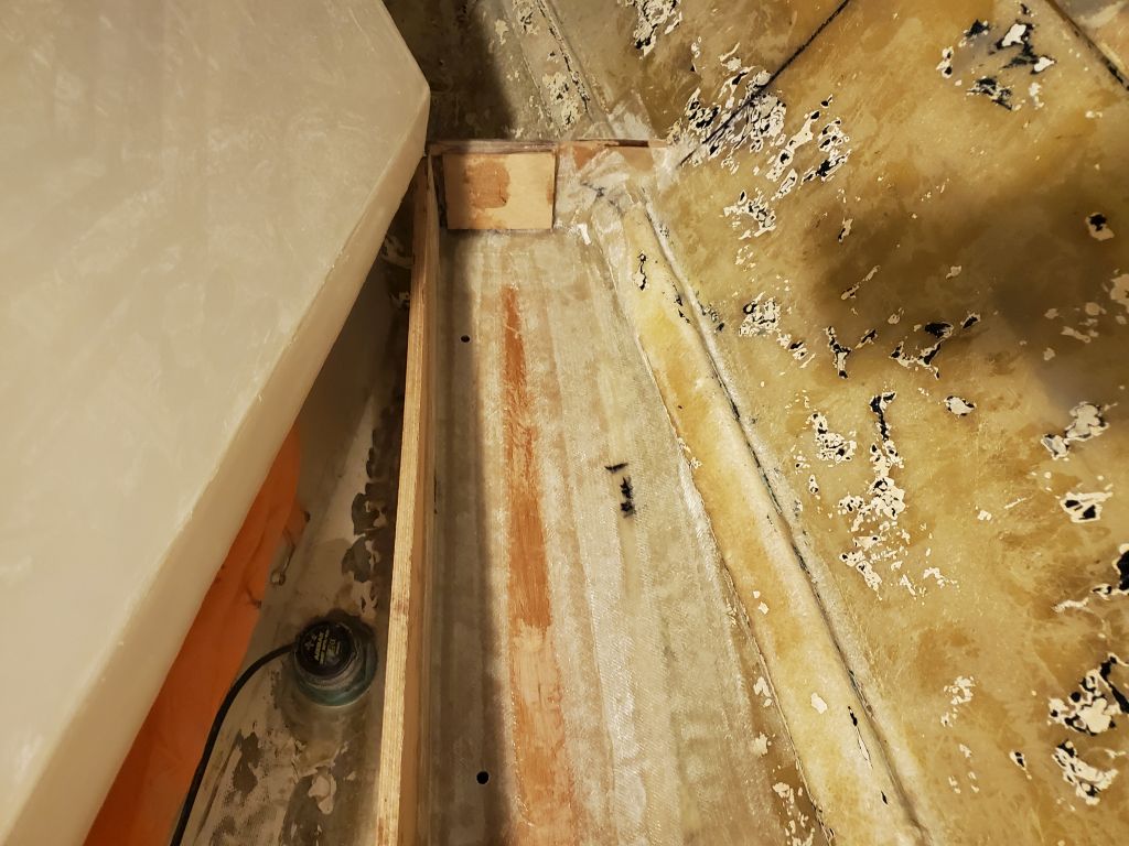
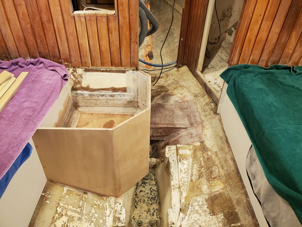
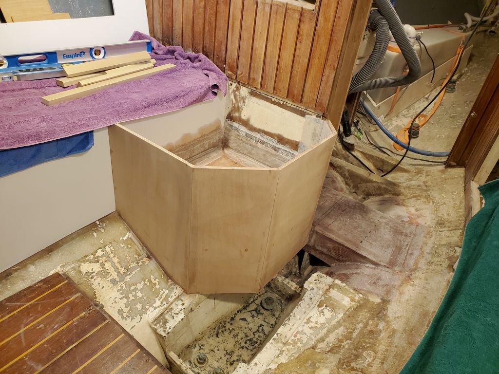
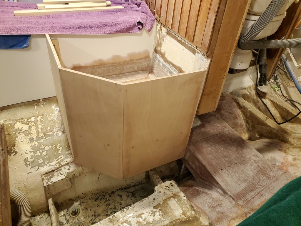
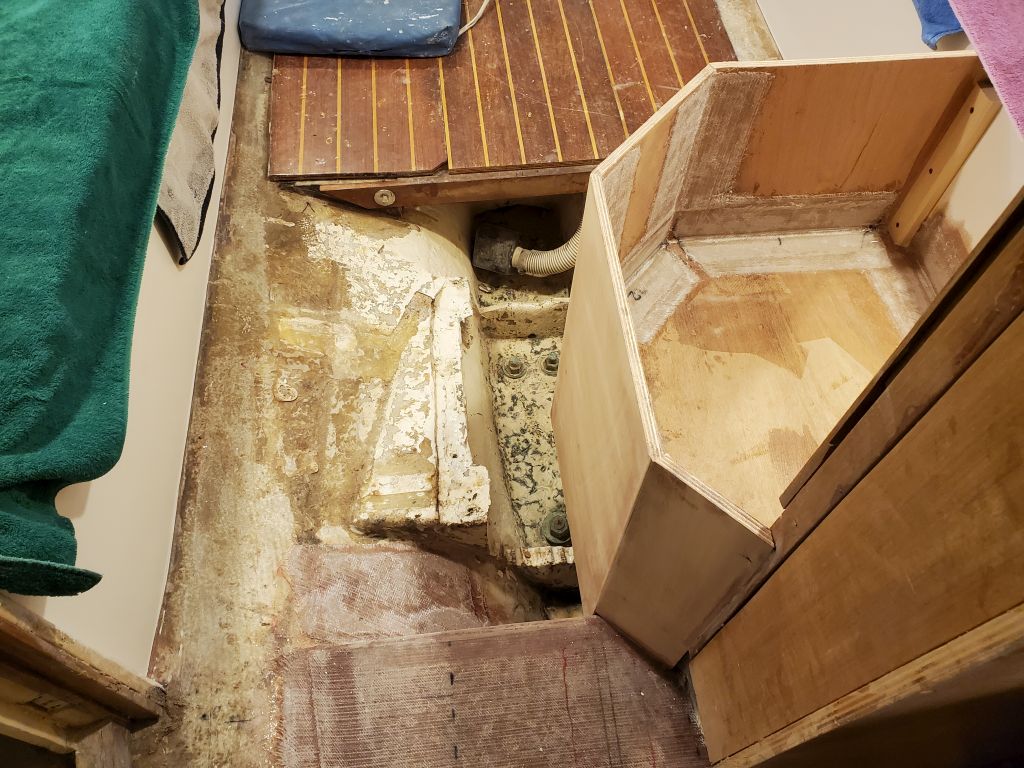
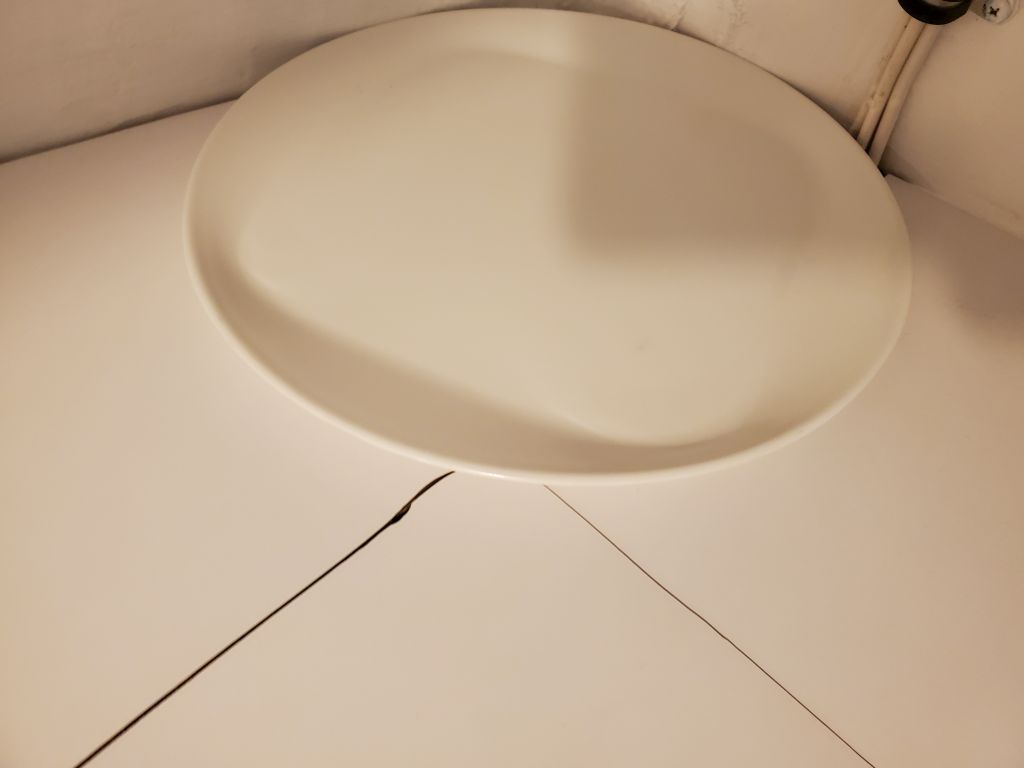
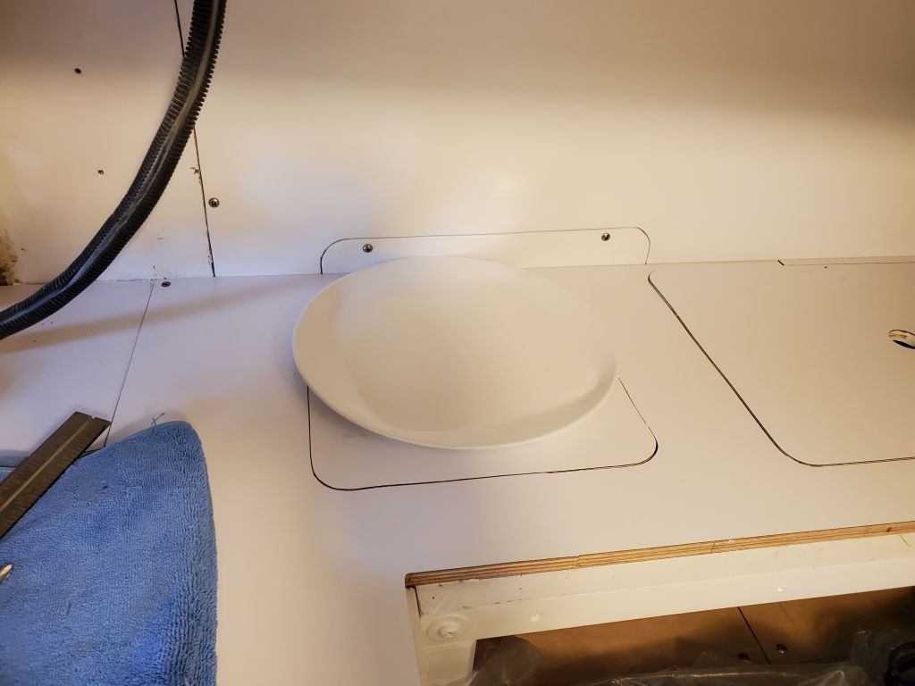
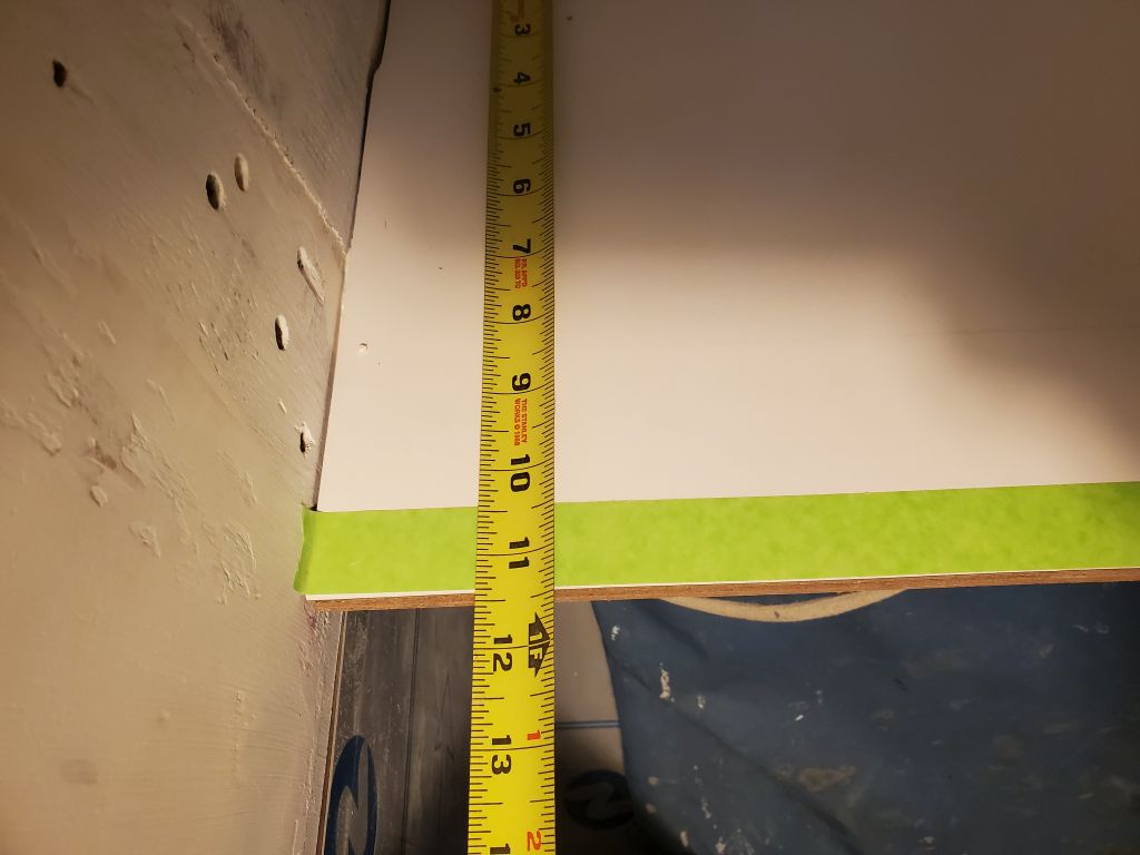
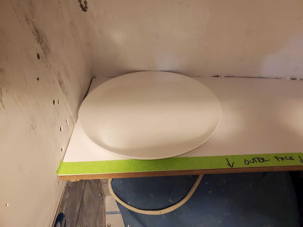
The owner had sent me pictures of a nice plate rack that fit in a corner, like the back corner of this galley.  In this case, space seemed a little tight with the existing hatch in the countertop, which hatch provided access to the large storage area beneath, but might be possible.  The shape of the hull here was also angled inward thanks to the tumblehome, so as the height increased, it would push a shelf further inboard.

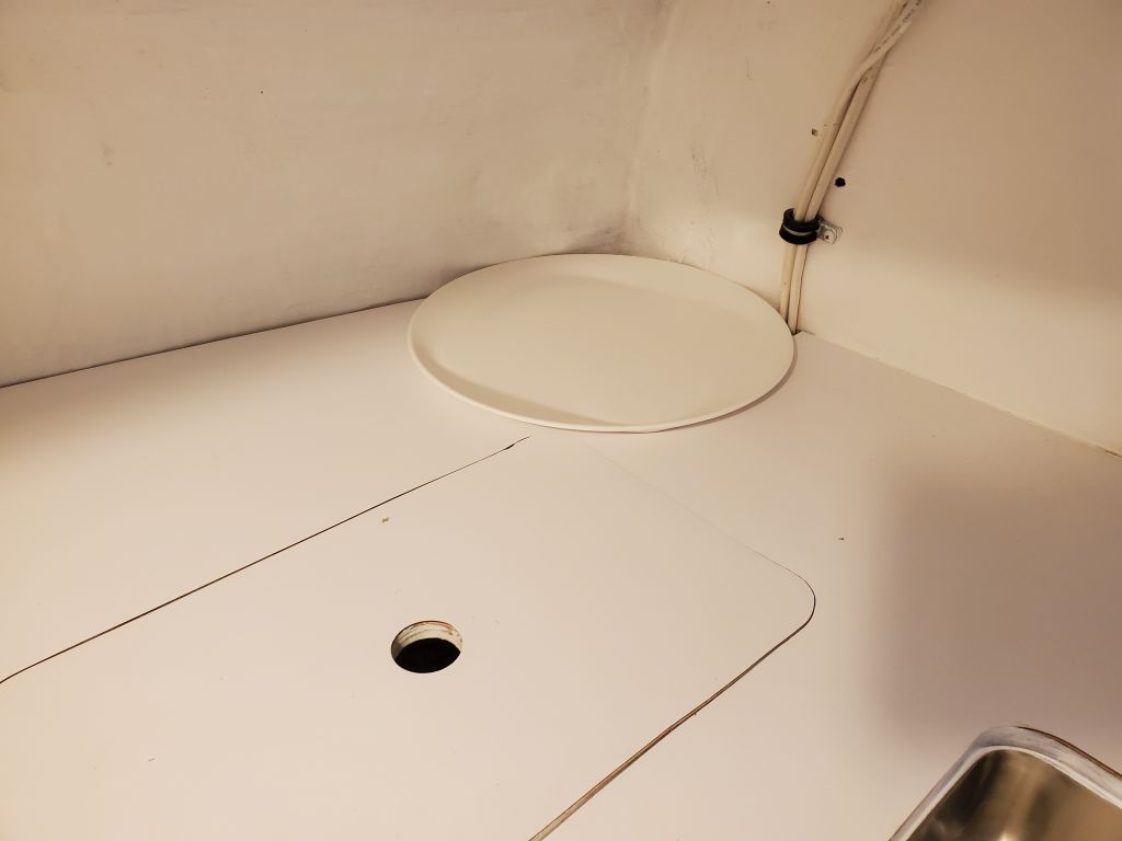
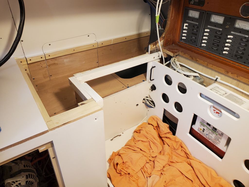
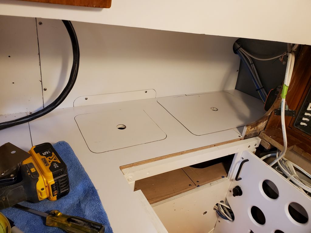
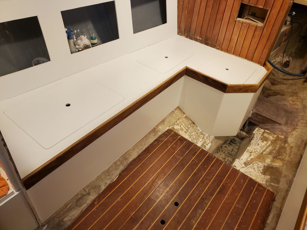
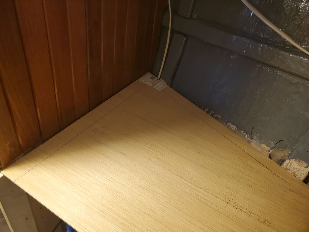
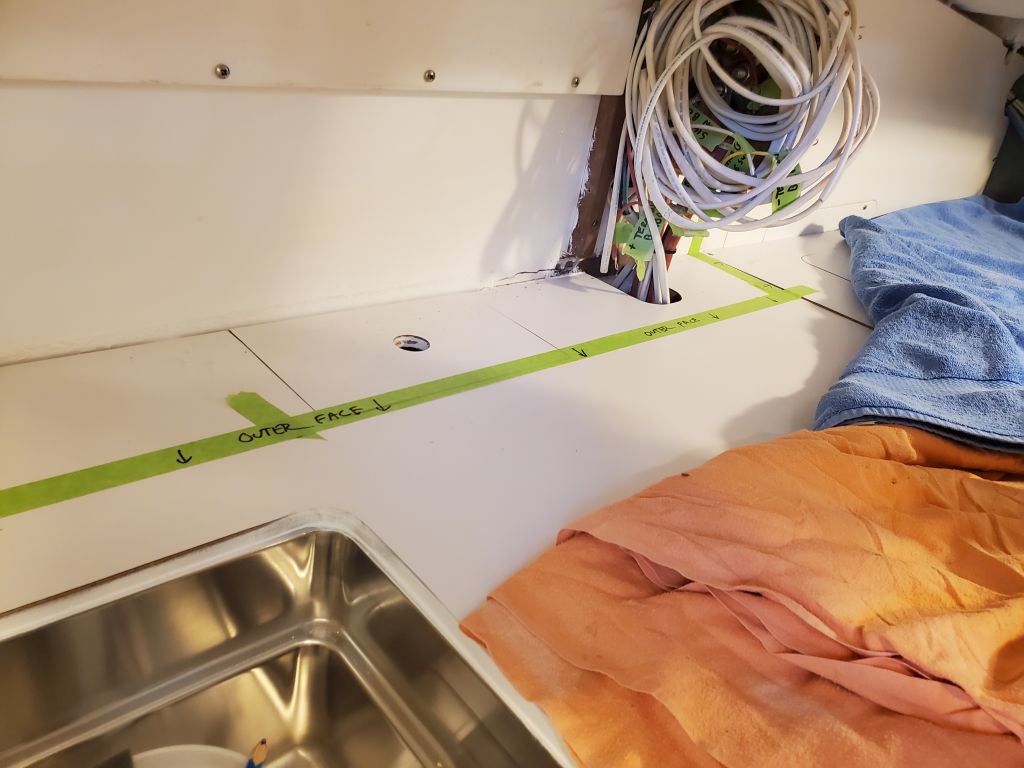
Om the port side, a storage unit would obscure the countertop hatch directly beneath, but could avoid the nearby hatch for the garbage receptacle.  Something to be built here would be easily removable as a unit.

Finally, a new possibility was something directly outboard of the stove, where there was nearly enough space, but the cabinet here could be “cheated” out a bit past the existing countertop edge with no ill effects to the stove.

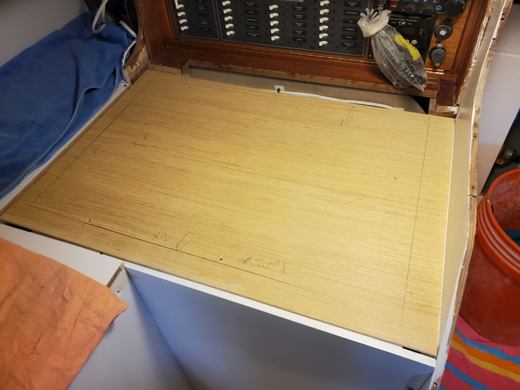
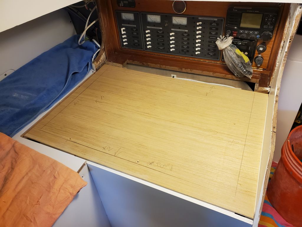
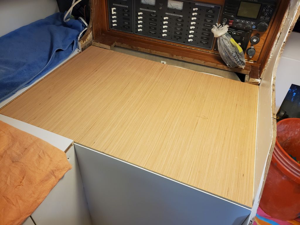
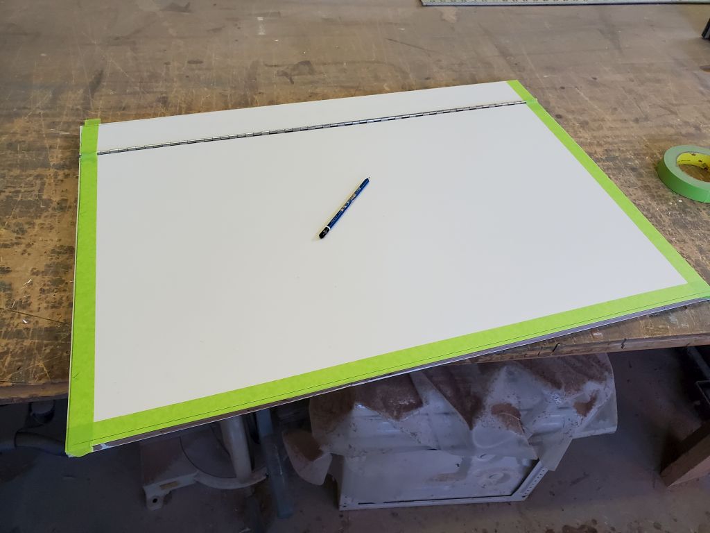
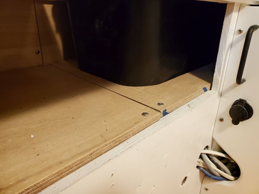
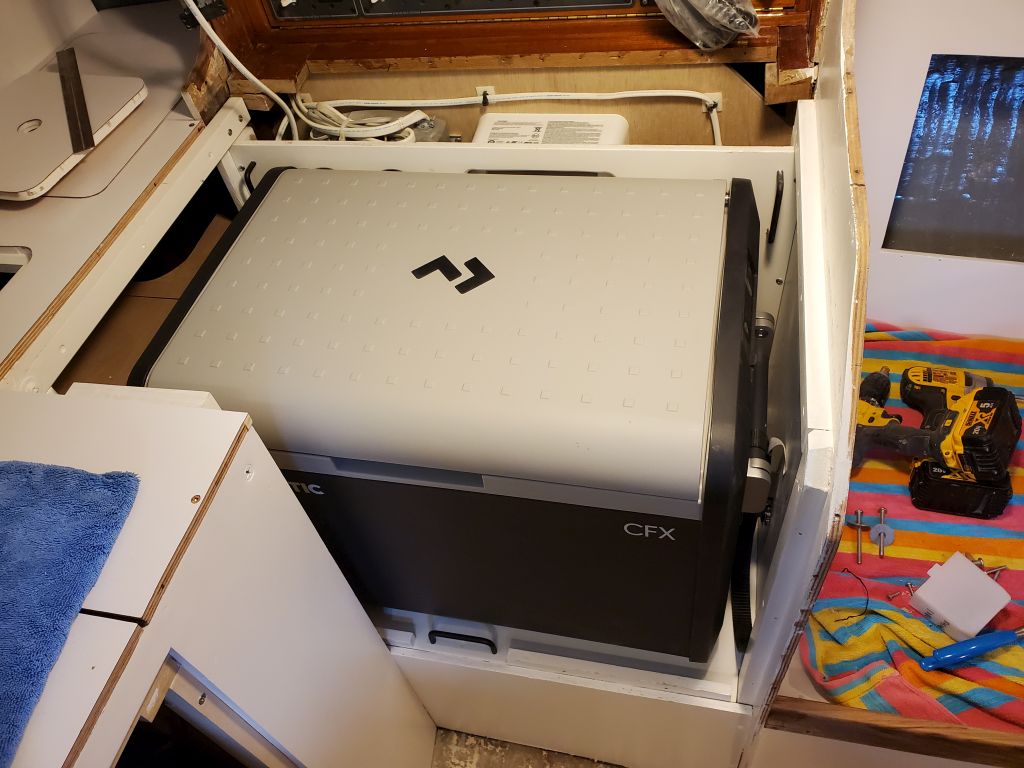
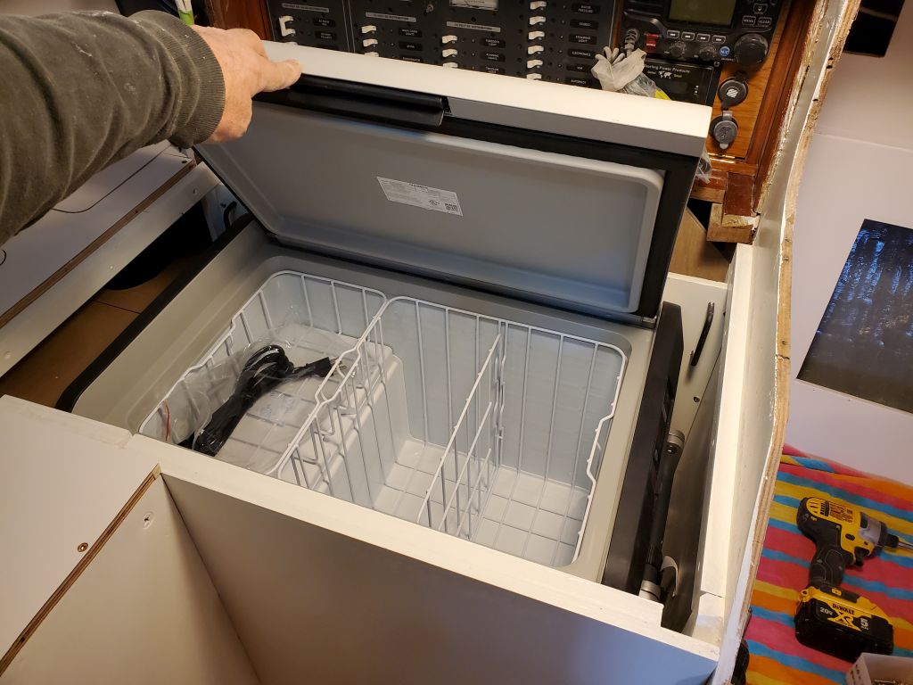
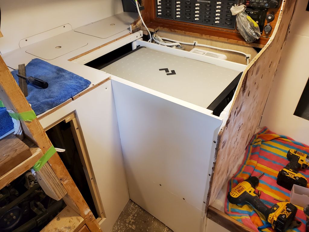
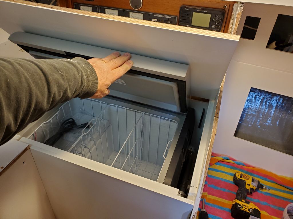
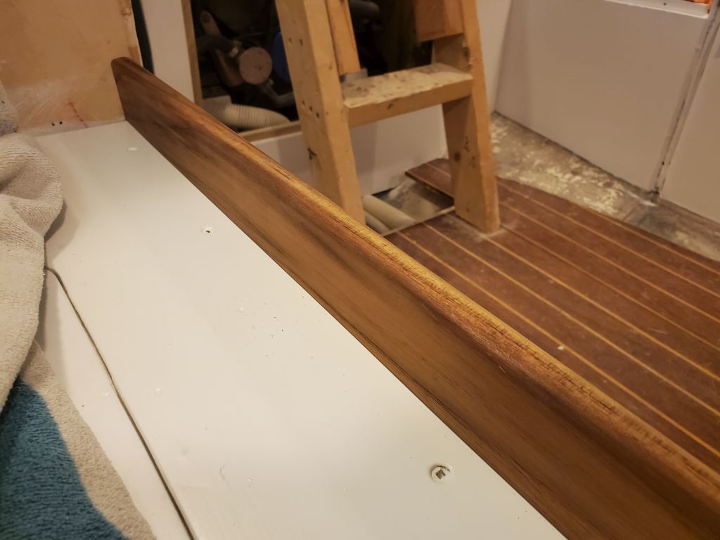
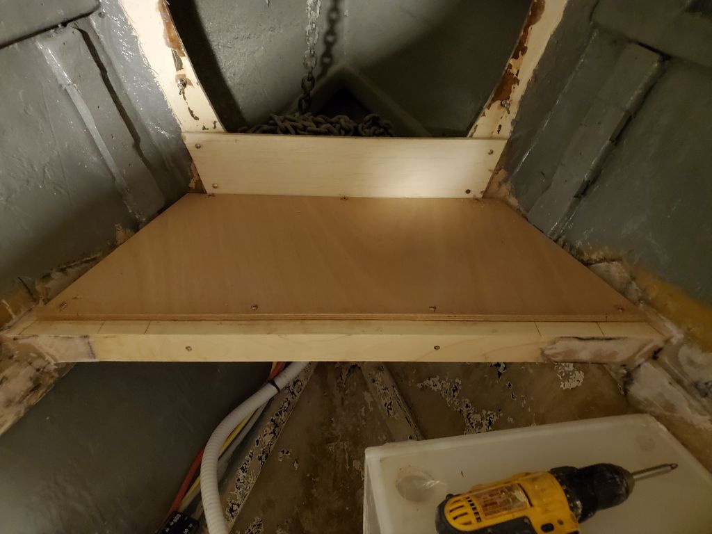
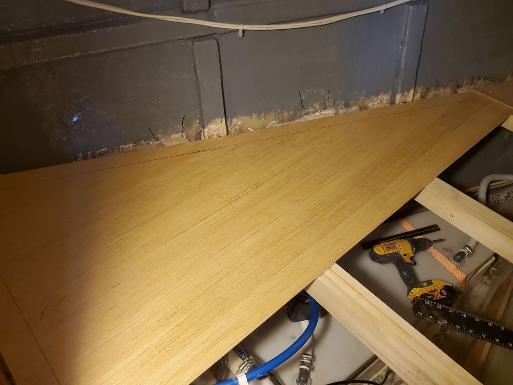
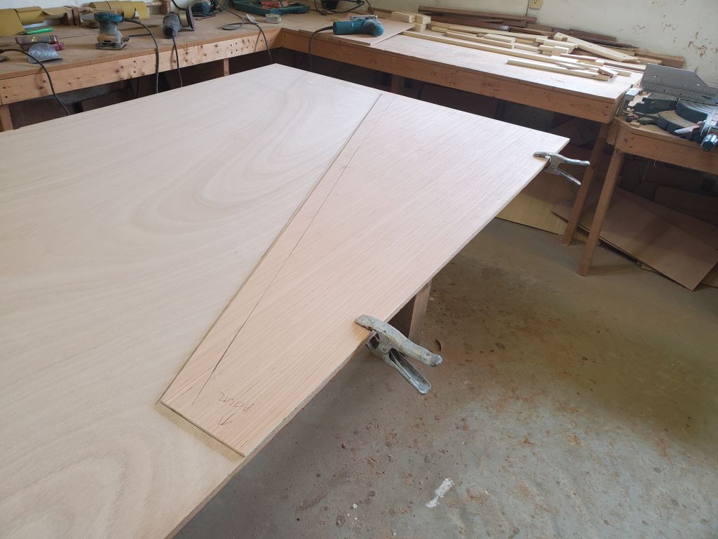
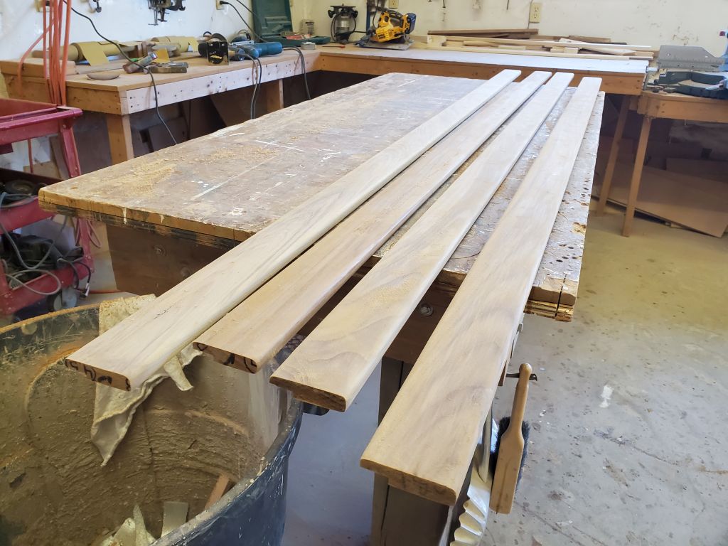
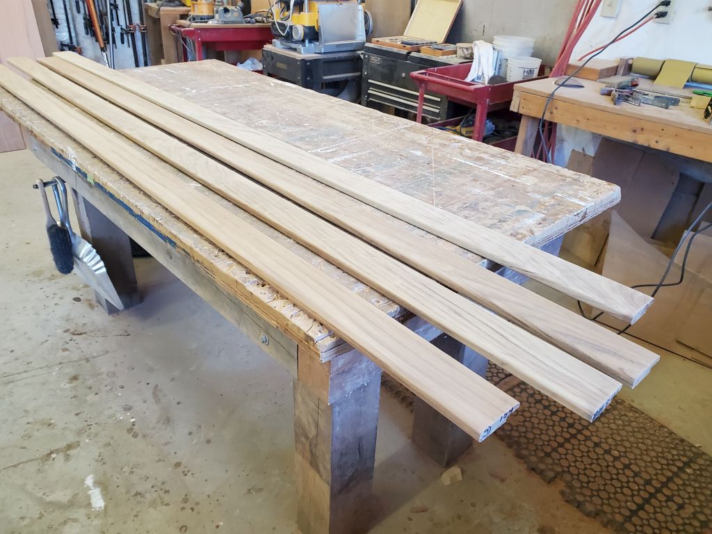
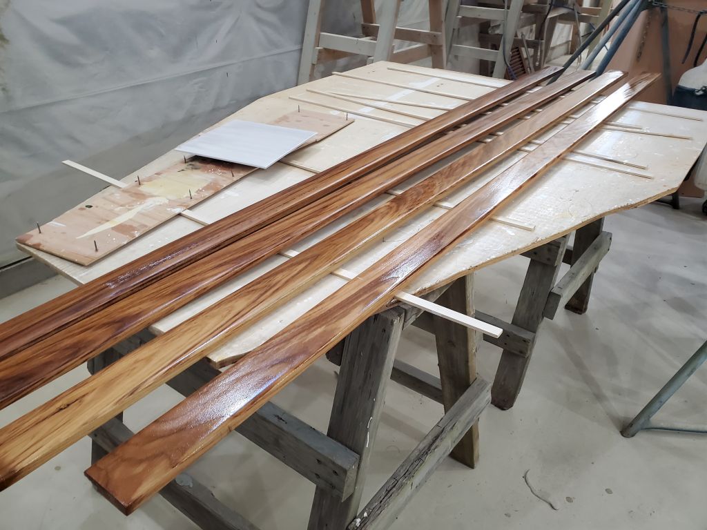
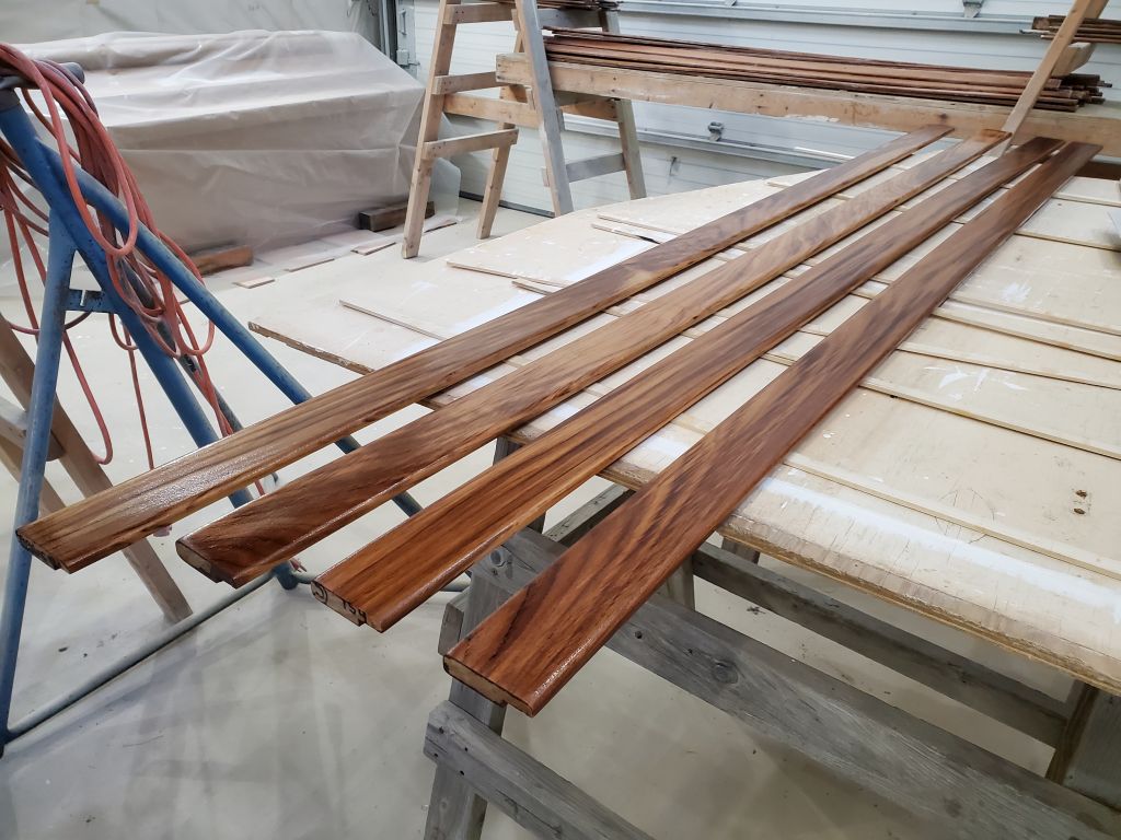
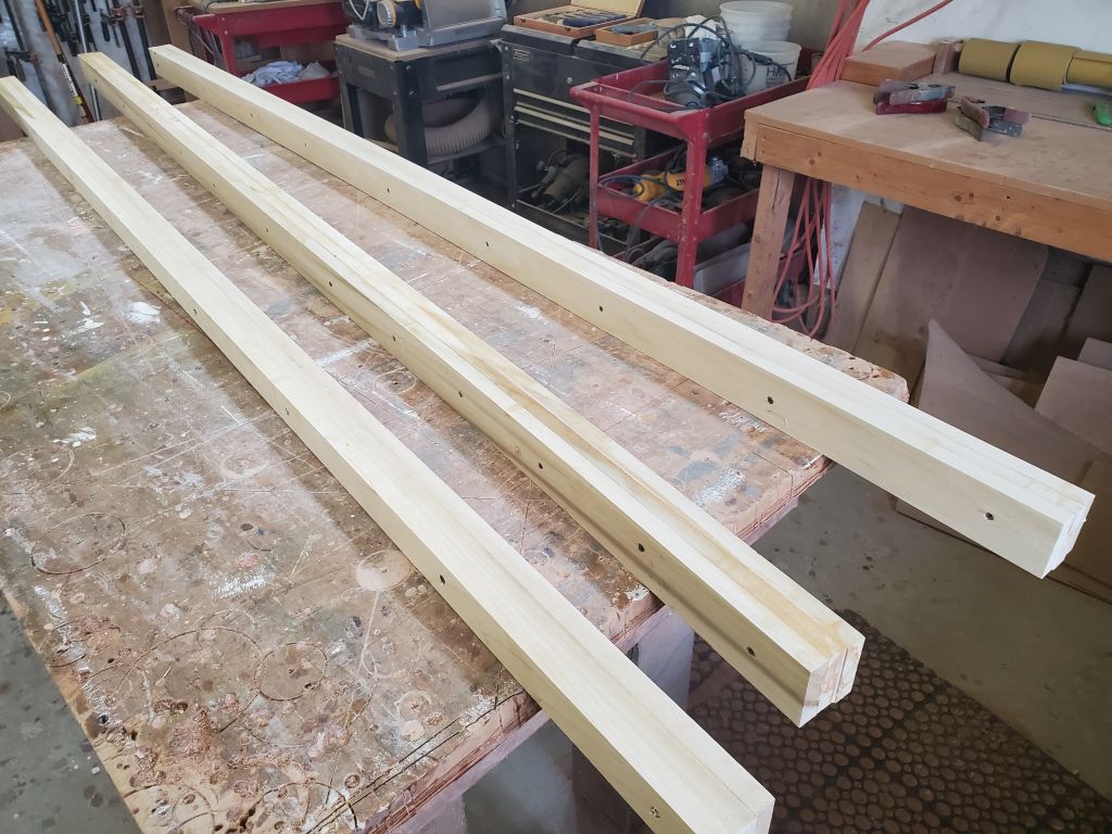
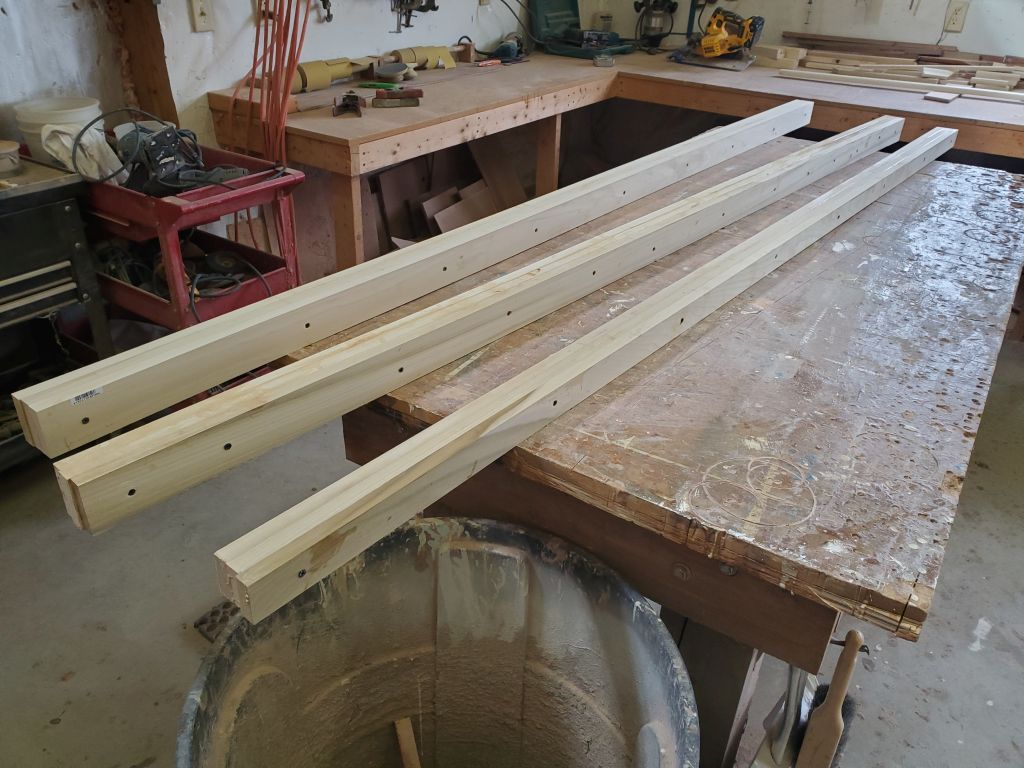
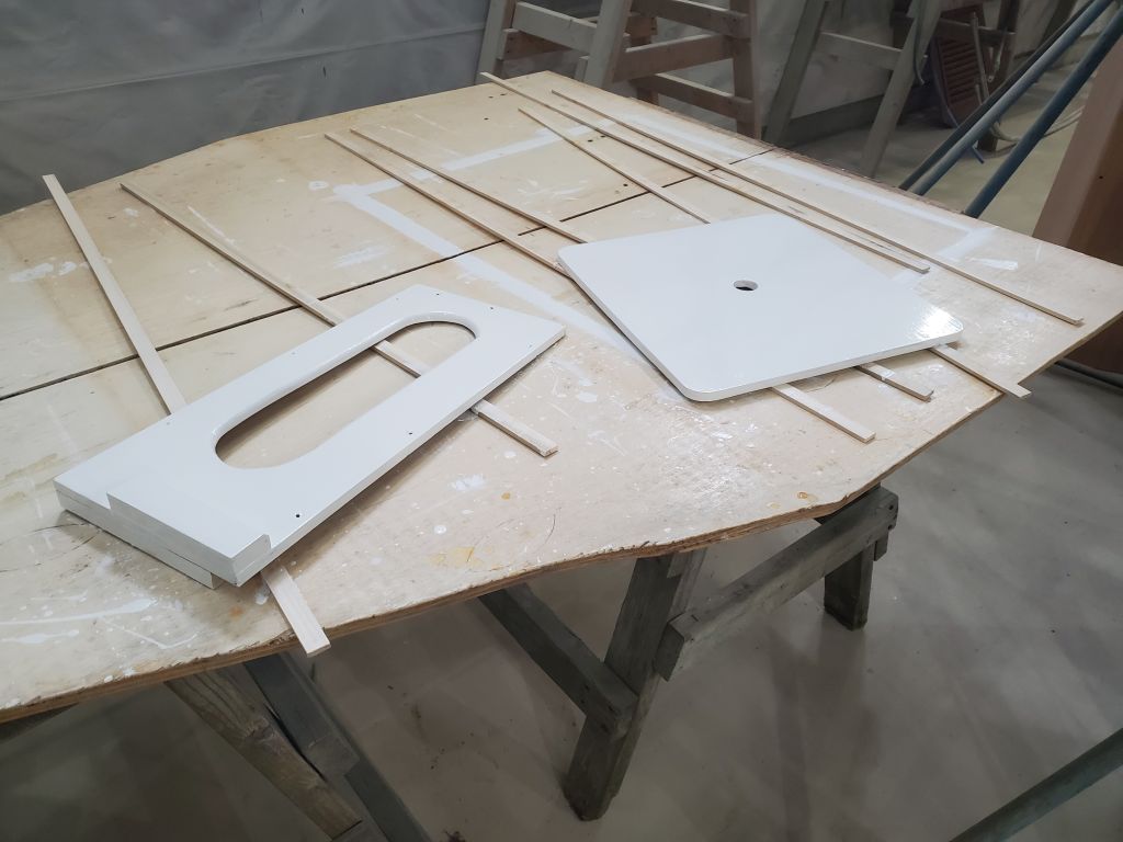
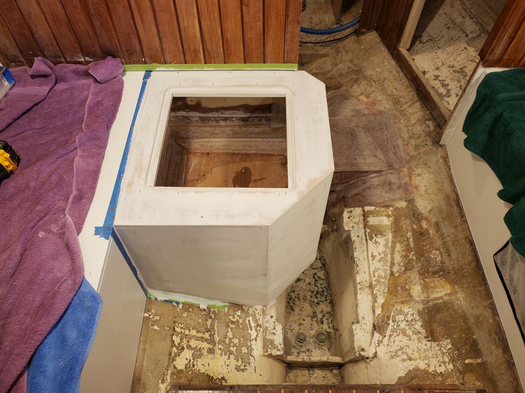
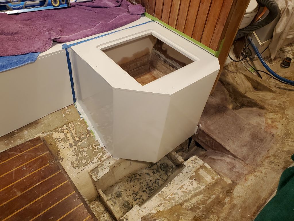
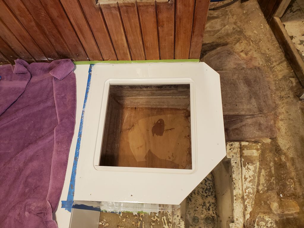
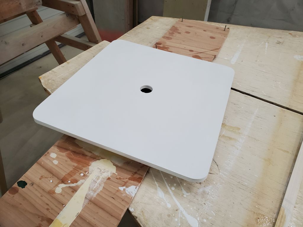
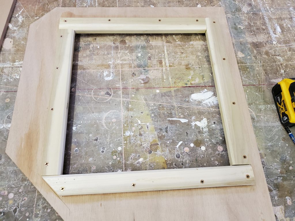
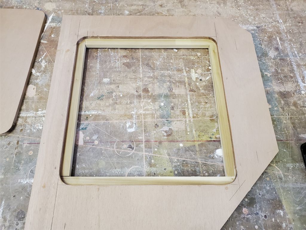
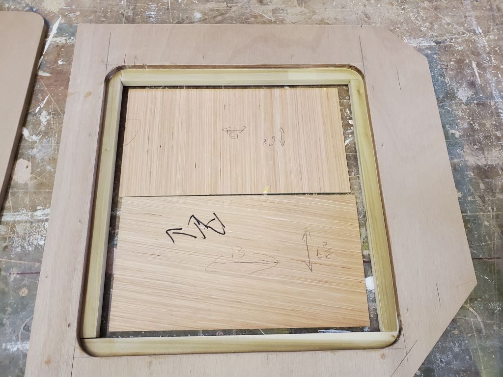
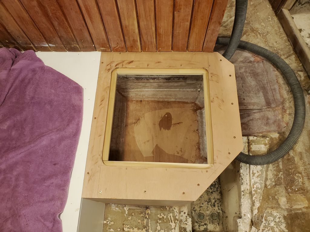
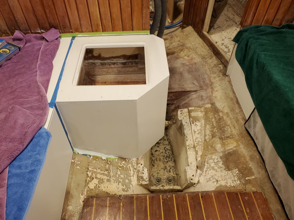
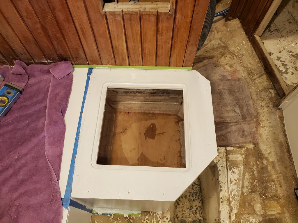
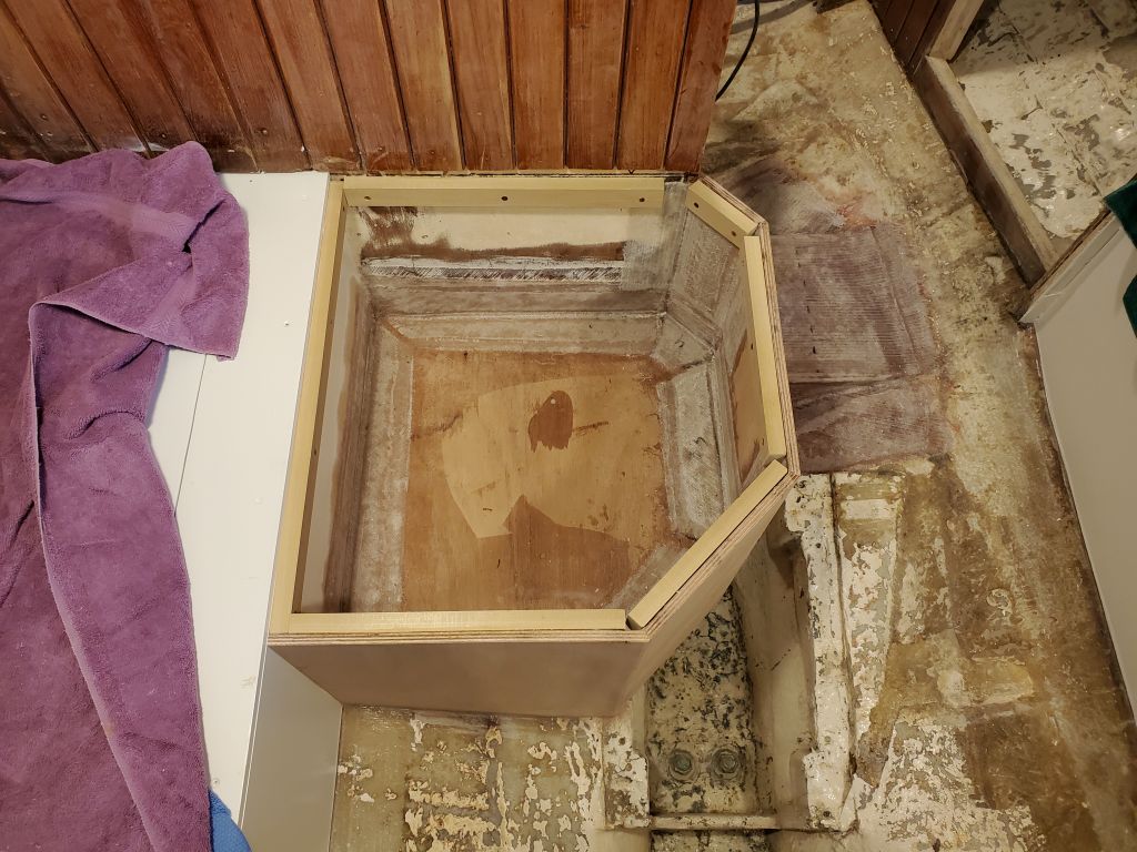
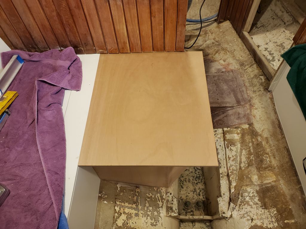
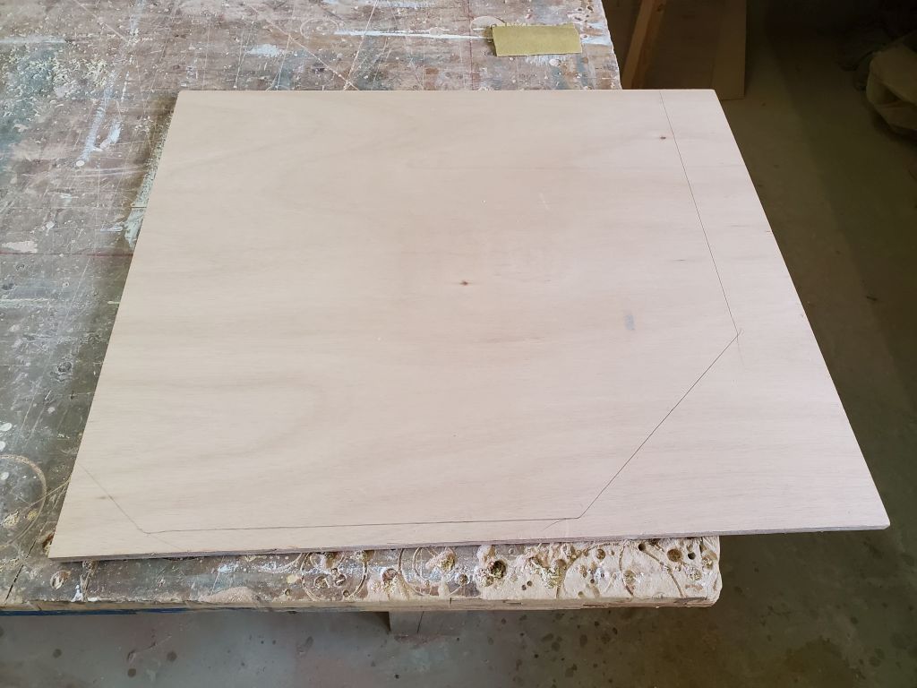
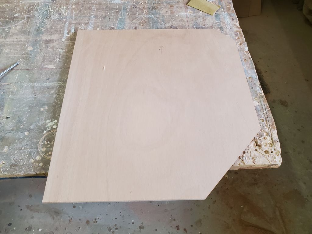
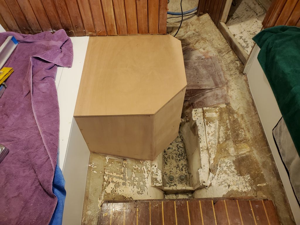
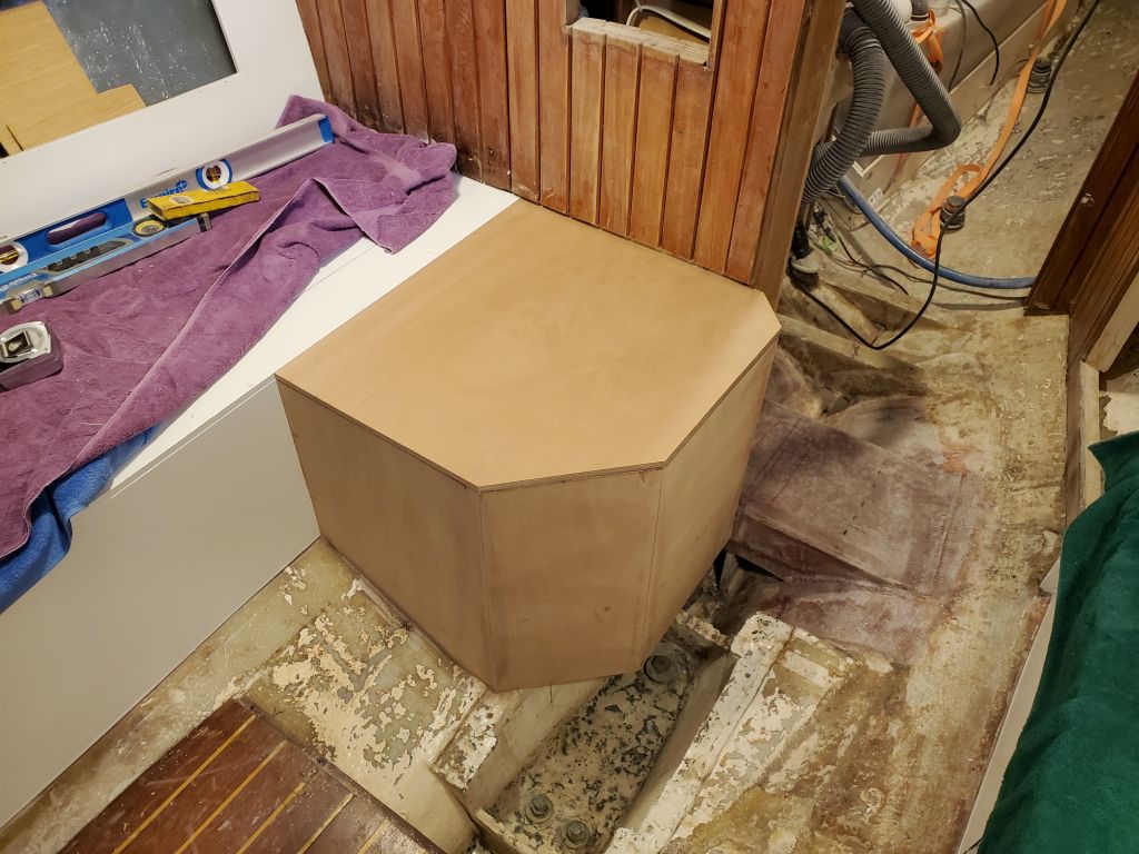
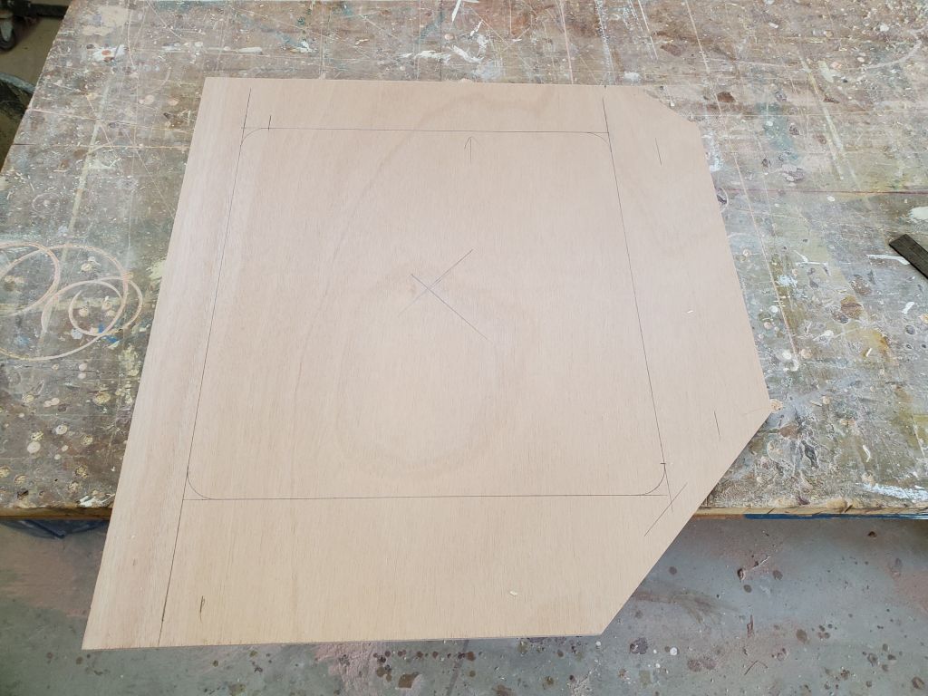
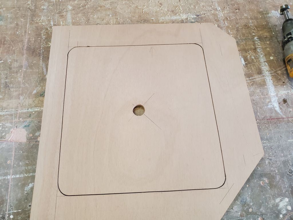
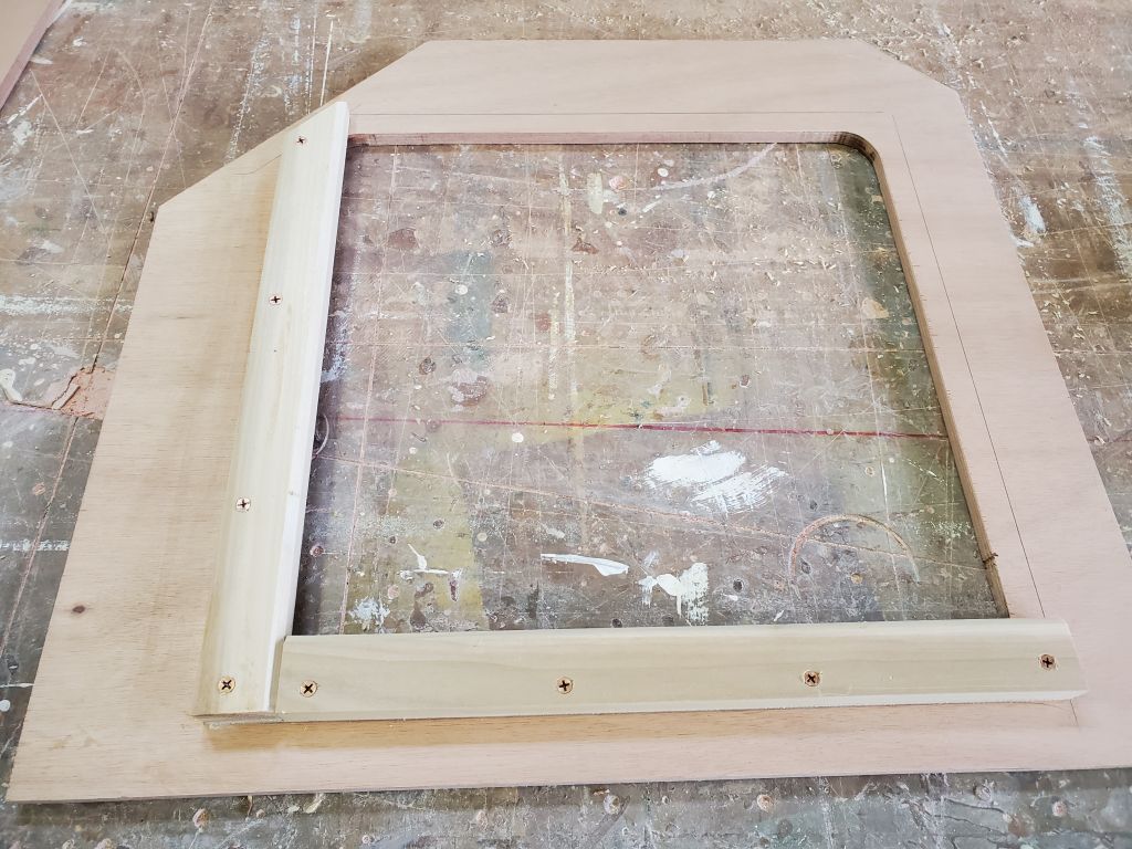
I spent some time determining what I needed to mill for trim in the main cabin, as getting the various pieces milled and started for installation was high on my list, and while I was in the area I made a new pattern of the space above the refer so I could either modify the existing lid to fit, or, if needed, build a replacement.  When I built the lid, I must not have factored in enough of a reduction to make up for the hinge space, since now the inboard edge of the lid hit the nearby countertop and didn’t close. So goes the reality of even careful planning.   It was late in the day, and after marking the existing countertop with the cutlines I decided it was a “fresh in the day” kind of cut and left it for next time.  I didn’t know how it would go cutting with the Formica in place, but I’d give it a try since it was a relatively minor modification.

Calliope Girl 86

The ceiling strips came out well with their satin varnish, and now I set them aside to await installation.

I milled another cupful of bungs, and set forth to install them in the various berth fiddles.

With the v-berth platform complete, it was a good time to set up and sand the remaining portions of the molded liner/overhead, after which I cleaned up, masked as needed, and applied a coat of primer.  This caught the area up with the head and cabin sides in the forward cabin, and over the next couple days I planned to finish up the paintwork in these areas before dismantling the v berth for its own painting, and to finish up necessary work beneath (such as finalizing the water tank installation and bracing, painting the exposed hull, and reorganizing and securing the wiring and plumbing I’d dismantled early in the project).

With work complete in the port cockpit locker and no anticipated further need for access from inside the boat, I reassembled the port side of the galley, securing the countertop with a few screws that would be hidden beneath trim later.  I also reinstalled some original companionway trim that I’d removed back in November when I was working on the water tank mockup, as the extra clearance had been required for tank passage.

Next, I installed the new refrigerator in its locker and secured it with straps to the padeyes I’d installed earlier for the purpose, then reassembled the removable front panel.  I ran in to a fitment issue with the lid/final countertop and would have to do some small modifications to get that installed properly.

With a little time left in the day, I started to sort the pieces of bulkhead staving from the forward sides of the aft bulkhead, with an eye towards their upcoming reinstallation, but remembered that they still had gobs of old construction adhesive on the back sides, which I needed to remove before they could be reinstalled.    Not excited at the prospect of laboring to remove this all by hand, I set up my planer at a height to just remove the old adhesive and clean up the backs of the board sufficiently (3/8″ stock), which made quick work of the removal.

Calliope Girl 85

Picking up where I left off, I finished up work on the removable step and access panel for the v-berth.  With all the pieces in place on board, I started by marking, drilling, and installing four threaded inserts in the support cleats to accept the thumbscrew fasteners that would secure the panel, while making it quick to remove.  I also made some reference measurements and marks on the various pieces of the platform to help me with the next step of adding a support beam and modifying the aftermost section of the platform.

With the panel and step down on the bench, I installed support cleats along the top edge to eventually accept fasteners to secure the after part of the removable platform.  While I left the glue to cure, I prepared and installed a removable support beam at the seam where I planned to cut the top panel into two sections–the forward section of which would generally remain fixed, while the after section would be permanently secured to the step panel so they would come out as a unit for good access.  I secured the removable beam with two bolts on each side, just temporarily for now since all of this would be coming back out a little later so I could finish systems work and painting inside the space.  I cut the platform panel at the appropriate spot and secured the forward section.

With the glue securing the cleats cured sufficiently, I secured the after part of the platform to the step panel with screws into the new cleats, creating a combined unit that was easy to remove and provided excellent access to the most crucial part of the space within.

Next, I moved on to the berth fiddles in the main cabin, starting with the quick and easy starboard side, then cutting and fitting the 5 angled pieces to fit around the port berth and battery box.

With the week’s and the day’s major goals of completing the work necessary before interior cushions could be patterned now met, I decided to use the afternoon to see how many of the smaller jobs I could knock off my list.  I started with the galley sink, where I needed to mask off the sink bowl and apply a bead of surface sealant along the seam between the sink and the countertop. I didn’t worry about sealant getting on the exposed plywood of the cutout, as sometime later, once the sealant was cured, I’d paint this area as well.

Next, I installed the new hatch leading to the port cockpit locker, using sealant and machine screws set into tapped holes.

In the adjacent propane locker, I installed the new solenoid switch and secured the wiring and supply hoses accordingly.  To help tame and secure the hoses the way I wanted them, I installed a wire tie mount on the back of the locker, though I had to wait for the adhesive to cure before I could install the tie.

This left me enough time to clean, position, and apply a coat of satin rubbed effect varnish to the 26 ceiling strips from the forward cabin.

Calliope Girl 84

I started with the usual quick water wash and light sanding of the tabbing securing the v-berth support beams to the hull, cleaning these up as needed.

I test-fit the vertical panel and step assembly to see how access was through the little step area.  As I’d hoped, there was reasonable access to the nearby speedo through hull, which the owner said he removed after each use to void fouling, so regular and straightforward access was a requirement.    My plans were also for quick and easy removal of the entire panel, as well as a portion of the berth platform, but the step access would be the quickest if it worked.

Over the course of the day, I installed the final v-berth platform, which I constructed in several pieces to not only maintain access to all areas of the space, with its various systems within, but also because large pieces of plywood wouldn’t have fit through the companionway even if I’d wanted.  I started with a small full-width piece at the forward end, running to the first of the support beams, going through the usual steps of templating and cutting the final piece.  I cut the platform to fit against the existing wooden supports for the ceiling strips, with no need to extend to the hull in between since this area would be hidden from view by the wooden ceiling when all was said and done.  I secured the platform with several screws, maintaining its removability in the future if needed.

I continued with the two largest pieces running from the first section aft to the bulkhead on each side, leaving the center portion open, to be covered by separate pieces.

I decided to fill the center portion with two pieces:  one larger one covering the first two openings, since I didn’t anticipate a regular need to remove this panel for access, and a smaller panel for the final, aftermost section.

I planned to leave the panels installed for now, pending upholstery patterning, but afterwards I’d remove them so I could finish up work in the space beneath, including securing the water tank, installing plumbing, and rerouting the existing wiring and hoses that I’d removed from the original berth at the onset of the project.

As I’d built this, I came up with an additional modification that would allow easier removal of the vertical access panel and improved access to the space within, which modifications I’d take care of next time.  Basically, I planned to cut the final center panel into two sections itself, with the aftermost part permanently mounted to the vertical panel so it could easily be removed as an assembly.

For how, however, this meant that I could take the small center berth panel off the boat and install the fiddle trim on the bench. which saved me a lot of trips up and down the ladder and brought me to the end of the day.  I secured the trim with glue and screws into the plywood.

Calliope Girl 83

With the v-berth beams now tacked in place with epoxy adhesive, I removed the clamps and supports and prepared two layers of tabbing for each side of each beam, each piece more or less cut to the shape required to lay into the spaces at hand.  I installed additional epoxy fillets at the edges of the beams, then wet and and applied the two layers of fiberglass at each location, leaving any overhanging bits for now.  I planned to trim them later in the day once the resin had cured enough.

From two of the teak trim boards that someone had thoughtfully planed and prepared earlier in the project, I milled four pieces of fiddle trim for the berths, since I needed this in place for upholstery patterning.  Each piece was 3″ wide, with a 1″ dado on the back side so the trim would sit 2″ above the berths, with 1″ hanging below to cover the edge.  I rounded the three exposed edges, and sanded the pieces smooth before applying a sealer coat of varnish to all sides.  I also took a moment to sand smooth and prime the fiberglass shop-made hatch for the propane locker.

Back in the boat, I installed the hatch from the battery compartment, mainly to show the completed locker now that the paint was done.

With a little time before lunch, I took care of another small project from my list that I tried to knock off whenever there was a small window of time between bigger things.  The owner asked me to either move or replace the existing fuel gauge (currently located in the engine room beneath the countertop) to a more visible location, such as the yet-to-come panel above the galley, and earlier investigation had revealed that access to the back of the existing gauge for removal was too difficult, so it made more sense to buy a new gauge than expend the time and effort trying to remove the old one.  To that end, while I still had full fuel tank access, I ran a new wire from the sending unit on the tank up to the eventual location for the gauge.

In the afternoon, I focused on the panel to enclose the v-berth at the aft end, and to provide a step for easier access to the berth.  I’d been running this through my mind for weeks, biding time till the rest of the space started to come together.   The plan that stuck was to build a simple, removable (if needed) access panel that incorporated a small step and notch above–not a true v-berth notch, since space was limited by the two tanks and in any event a walk-in notch wasn’t necessary or even desired, but just enough of one for a solid, recessed step.  I liked the idea of a removable panel to improve access to the tank and utility space at the aft end, and this also tied in to the growing idea that the v-berth platform itself would be in several easily-removable pieces to maintain good access to all areas of the space going forward.

To begin, I milled two wide cleats for the sides of the opening, which would support the panel on the aft side.  I actually repurposed the cut-off end of one of the laminated beams I’d made for the berth, since it was about the right length and width, resawing it back into two 3/4″ cleats about 2-1/2″ wide that gave me sufficient width to secure to the forward side of the bulkheads on each side of the opening with a good 1″ bearing surface left exposed for the new panel.  From there, I made a template panel from 3/16″ plywood, then transferred to a final piece of 12mm okoume.

With the panel on the bench, I laid out and cut an opening in the center for the step/notch.  The overall height of the berth platform off the sole was about 32″, and it made sense to build the step at about 16″ off the sole.  I decided on a 10-degree angle for the notch, and cut and installed support cleats and the notch sides accordingly, then closed off the back with another panel.  I secured the three pieces of the notch with glue and brads to hold things while the glue cured.  This provided a nice secure step with plenty of space for secure footing on the way up to the berth.  I planned to finish it off with a teak step to fill the base, possibly removable on its own depending how useful access through the open bottom of the notch seemed.

Finally, at the end of the day, when the tabbing had cured green, I trimmed the excess along the beams with a sharp knife to leave clean edges that would require minimal sanding.


Calliope Girl 81

Starting again with the forward cabin, I lightly sanded the latest round of tabbing to clean it up and prepare the area to accept the tank permanently, and slightly rounded the two vertical plywood edges at the ends of the tray to prepare these areas for tabbing next.

With the tank back in position in the new tray for now, and everything cleaned up and prepared, I applied epoxy fillets in the areas I needed to tab next, such as the two ends of the main longitudinal bulkhead that I’d left before, the vertical seams at the ends of the bulkhead, and where the end bulkheads met the hull.  Then, I wet out and installed two layers of tabbing in all these areas to complete the structural work required here.  At the forward end, I added a plywood spacer to fill the small space between the tank and the forward bulkhead, where I’d left a little room for the purpose.  Later in the day, with the fiberglass partially cured, I was able to trim with a knife the few areas where the tabbing extended above the plywood.

I planned to secure the tank in a vertical direction with straps and perhaps some solid bracing to come later, but for now it was time to build the support system needed for the berth platform.  I double-checked the position of the tank against the level from forward to aft and the marks I’d made previously at the aft end demarking level using the existing forward end as a guide.  There wasn’t going to be room to lower the forward support at all, in the hopes of reducing slightly the height of the aft end, as the existing clearance would be needed for the hose connections on the tank, but I planned to build in a step at the aft end to make access easier to the relatively high berth.  With positioning confirmed, I installed support cleats on both sides of the aft bulkhead.

Running my long laminated plywood stick from end to end above the water tank gave me the clearance I had to work with for installing support beams across the space, between the height of the imaginary platform and the top of the water tank–about 3″ at the aft end, and a little less forward.  I’d nearly run out of wood for cleat and support stock, so after a trip into the world for more I prepared three laminated beams that I’d cut and turn into the beams required for the v-berth platform.  I glued up each beam from three layers of 3/4″ poplar:  two each at 2-1/2″ height, and the third (which I planned to use for the shortest span at the forward end) at about 2″ height.  I used temporary screws to clamp the pieces together while the glue set up.

To finish up the day, I applied another coat of finish paint to the battery box and its hatch.


Calliope Girl 82

After the usual round of light sanding of the newest tabbing on the water tank, I wanted the main focus of the day to be the support beams for the v-berth platform, but before I got to that I thought through the options for securing the water tank.  I wanted/planned to use straps to secure it athwartships (it was already basically secure in its tray, but needed something to hold it down), but there were challenges in finding a place to secure the straps on the hull (outboard) side of the tank, where the nature of the original construction and the way the tank filled the space didn’t leave accessible space for anything to secure a strap to in a manner that was strong enough.  With no good options for securing strap eyes on the hull side thanks to the shape of the tank and lack of space in the appropriate positions for such hardware, I finally decided to build rigid supports off the v-berth support beams, and possibly add straps in a fore-and-aft direction if I felt it was necessary.

With that decision made, I could press on, but first, at the owner’s suggestion, I moved the tank once more and drilled a few small drainage holes in the bottom of the support tray; hopefully there’d never be any water in this space to begin with, but it made sense to give it a path out should it ever happen.  The base angled aft and would tend to drain that direction, so I started with a drain hole in the aft end, but added a few more along the length going forward just to give any water several paths out.  The space beneath the floor of the tray was open to the hull for drainage beneath in any event.

I planned three cross beams to support the v-berth platform, generally evenly spaced from forward to aft, but I planned the two after ones to roughly align with the baffles inside the water tank, the strongest part of the tank to use for bracing.  Starting with the forwardmost beam, with some rough width measurements and a template of the shape of the hull, I cut one of my laminated beams to size and adjusted it in place till it was level side to side and fore and aft, in line with the long plywood straightedge I’d made for this purpose.  This beam was forward of the water tank. Once I was satisfied with the fit, I secured the beam to the hull, and in this case to the protruding hull stringers on each side, in a bed of thickened epoxy.  It was nearly lunchtime, and with a couple heat lamps on the epoxy to speed its cure, I figured I could get it secure enough to remove the temporary clamps after break and continue with the remaining two beams.

In the afternoon, I cut and fit the remaining two cross beams, both of which ran across the water tank generally in line with the baffle positions inside the tank.  I also worked to ensure the beams would remain clear of the inspection ports into the tank.  To help hold the beams in their proper position, I could use some shims between the beam and the tank on the starboard side, and to port I clamped the beams beneath the plywood straightedge that ran between the forward and aftermost supports already in place.  This ensured the beams were level from side to side, and also fore and aft.

With the dry fit complete, I secured both beams permanently with thickened epoxy adhesive.  I left these to cure overnight, and next time would finalize the installation with tabbing between the beams and hull at each location.

There was nothing else I could do in the v-berth for the moment, so I turned to the propane locker.  I’d meant to add some little cleats in the bottom of the locker for the hollow bases of the propane bottles to rest upon, holding them from sliding, and it would have been easier to do so before the locker was fully built and in place, but the detail had slipped through the memory cracks.  But now, earlier I’d made up some basic cross-shaped braces from strips of prefab fiberglass that just fit within the round bases of the tanks and would hold them from any movement.  Now, I removed the paint from the bearing surfaces inside the locker, and epoxied the crosses into place.

I had time to knock one additional small project off the list:  installing a shutoff valve at the inception of the fuel supply line at the fuel tank, which the owner had asked me to do.  When I’d initially glanced at the hoses connected to the tank, it looked like a simple job to install a straight inline valve, which I assembled on the bench with two straight hose nipples, but up in the boat I discovered that the line I’d been imaging was actually the return line, and the supply line hose took a sharp bend right after the tank and required a different configuration.  This was simple enough, fortunately, as I could swap out one of the straight hose barbs for a 90° elbow, which then allowed the valve to fit well within the natural course of the existing hose.

Calliope Girl 80

First thing, I finished the modifications to the teak cockpit seat lid.  It took one more round of test-fitting and a final modification before the seat fit properly and I could reinstall it.  I’d finish up the installation of the new cockpit locker and propane locker hatches soon.

Next:  on to some sanding, first the primer coat on the new battery enclosure.

Then, I lightly sanded the tabbing securing the water tank bulkhead, just to remove hard edges, and afterwards I test-fit the tank and marked each end where the 4″ flat I’d designed into the top of the tank landed on the bulkhead and on the hull.  This was where I needed to build a support platform.  I also marked the ends of the tank so I could properly position forward and aft support bulkheads.

With the tank tipped out of the way once more, I cut a support cleat and installed it between the forward and after reference lines, then went through my normal template process to eventually come up with a scribed plywood platform to fit the space.  I secured this to the cleat with screws, then test-fit the tank again to ensure it landed properly on the platform, and to make some additional reference measurements for the small bulkheads at the ends.

I templated and eventually cut and fit the final 12mm plywood bulkheads at each end of the tank space (leaving a bit of extra room at the forward end that I could fill with a spacer later).  Then, after final preparations, I tacked these bulkheads in place above the base platform with hot glue to hold them securely, and installed epoxy fillets along all the inside edges and corners of the space, including  to bond the platform to the hull and inboard bulkhead.

While I let the fillets tack up a bit, I prepared two layers of tabbing for all of the seams and, when the time was right, wet them out with epoxy and installed them all around.  This tray would provide a strong and sturdy base to support and secure the tank.  Later, I planned to also tab the exterior portions of the two transverse bulkheads, but at the moment the tank’s awkward position made working at the forward end unnecessarily difficult, so I held of on the additional tabbing for another time, once the tank was in place in the cradle.

This left enough time to do final preparations and apply the first coat of semi-gloss enamel to the battery box.

Calliope Girl 79

I finished up the hatch support cleats on the top of the battery box, then installed it permanently with glue and screws.  Before installing the top, I cut an oval opening in the bulkhead leading to the port settee, which would give the battery wiring passage through.  I sized the hatch as large as I practically could in the space, leaving an opening large enough for two batteries to pass through simultaneously–not that that would ever happen, but it allowed plenty of maneuvering room.

With that done, I turned my focus to the water tank.  I’d been anticipating the tank’s arrival for a long time and couldn’t wait to have it installed and off my mind.  The first order of business was to somehow get the tank up into the boat.  My magic spell repertoire failed me, and I had to come up with a way to do it myself after all.  The tank was heavy, but worse than that it was awkward.  The large end was too far around to fully grasp, and the weight distribution was too unbalanced to carry it in any sort of logical way up a ladder and 10′ above the shop floor.  I had no mechanical means at my easy disposal and in any event figured by the time I’d worked something out, I could otherwise have the tank up there some other way.   I wrapped the tank in an old blanket to protect the boat (and, less importantly, the tank) and to give me some purchase on the slippery plastic surface.  I attempted to install ratchet straps or a line to give me a sort of bridle, but the angled shape of the tank just caused these to slip free.

Eventually, I set up a section of staging next to the boat, and lifted the tank up onto the platform.  From there, not without difficulty, I got the tank up over the cockpit coaming and into the cockpit to the point that I could manipulate it from above.  Then, it took a bit to get it down the companionway.  The plywood mockup had fit–just–so I knew the tank itself ought to fit, but for a few minutes it had me doubting.  Eventually, I removed the companionway hatch slide, which gave me just a bit of extra room that allowed the tank into the boat easily.

I wrestled the tank into the v-berth where it belonged, and, holding it generally in place by hand and after removing the temporary blanket, made some rough reference marks on the hull at the inboard edge to mark where I needed to build the first support bulkhead.  Then I rolled and tipped the tank across and on top of the holding tank to port to keep it out of the way.

Starting with a cheap plywood template, I went through the usual steps to mock up, scribe and cut, and eventually transfer to real plywood the shape of the hull, and cut so the ends were plumb and the top level.  I secured the bulkhead with hot glue blocks and braces along the top to hold it steady.

I installed epoxy fillets along both edges of the bulkhead (the outboard, or righthand in these photos, side was unencumbered, while the inboard side had a couple glue blocks near the end that had me stopping the fillets a foot or so short of each end for now), and, while I let the fillets set up a bit, I prepared two layers of heavy tabbing for each side of the bulkhead and then wet out and installed them.  I left this arrangement to cure overnight, and for the moment that was all I could do for the water tank.

After final preparations and masking, I applied a coat of primer to the new battery box exterior, looking to catch its construction up with the adjacent areas.

Finally, with the time remaining in the day I worked on modifying the teak cockpit locker seat/lid so it would close properly over the new locker and propane hatches.  For this, I removed the hatch from its hinges and brought it to the bench for easier working, eventually using a planer and sander to modify the underside cleats to fit.  Not wanting to take too much, I kept the changes conservative, checking the fit in plate a couple different times, and by the end of the day I was close, but there was still a bit more material to remove, as the lid was still hitting the plastic access hatch before closing all the way.  I left the final modifications for next time.

Calliope Girl 78

I started with a light sanding of the battery box inside and out:  inside to clean up the new tabbing; outside to prepare the exterior for primer and paint.

Next, I installed all the support cleats for the top that I’d pre-cut last time.  Then, from a blank slightly larger than needed, I cut the top panel to fit and began work on the large access hatch and support cleats.  I had to leave the shop before I completed the hatch, however.

During the rest of the day, I drove to the tank vendor, located in another part of the state, and picked up the new water tank, which I looked forward to getting into place soon in the forward cabin.

Older posts Newer posts