Thursday
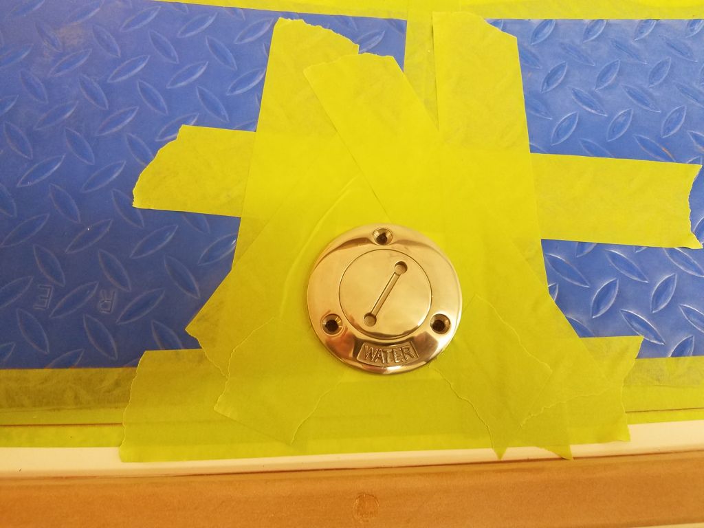
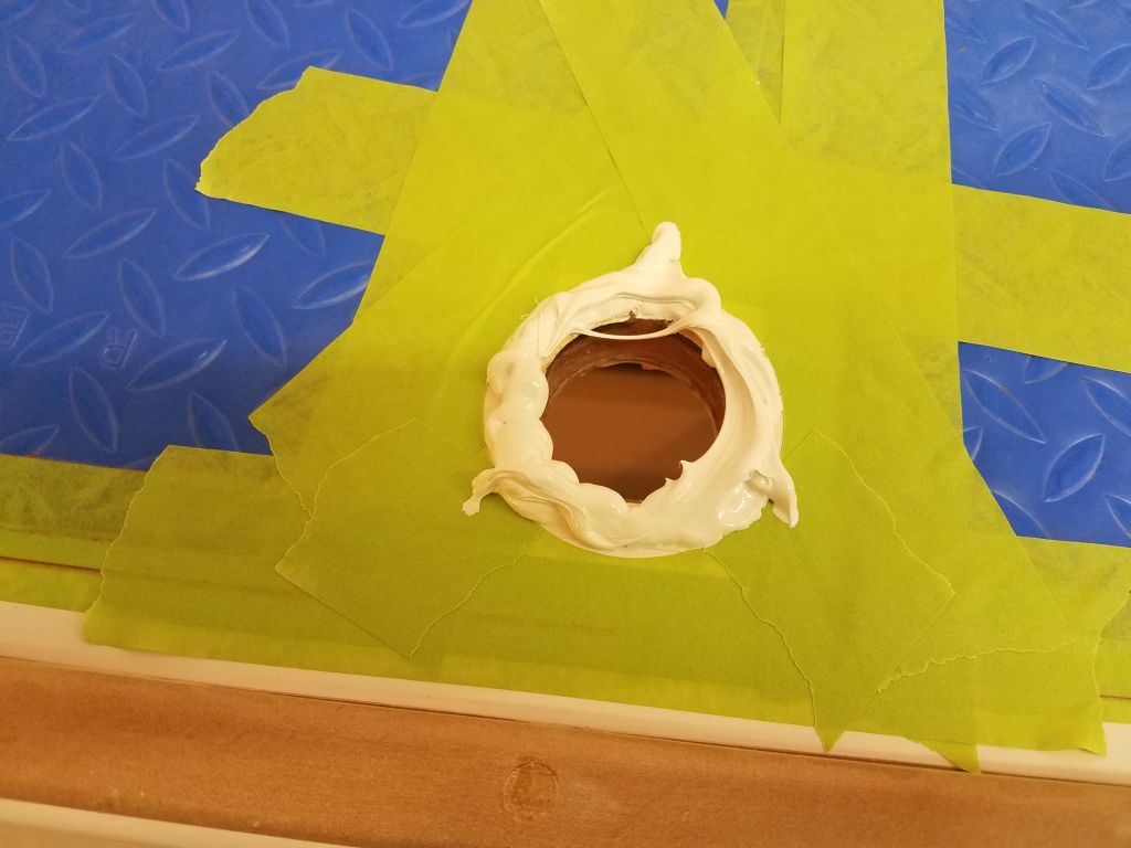
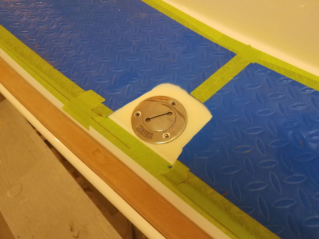
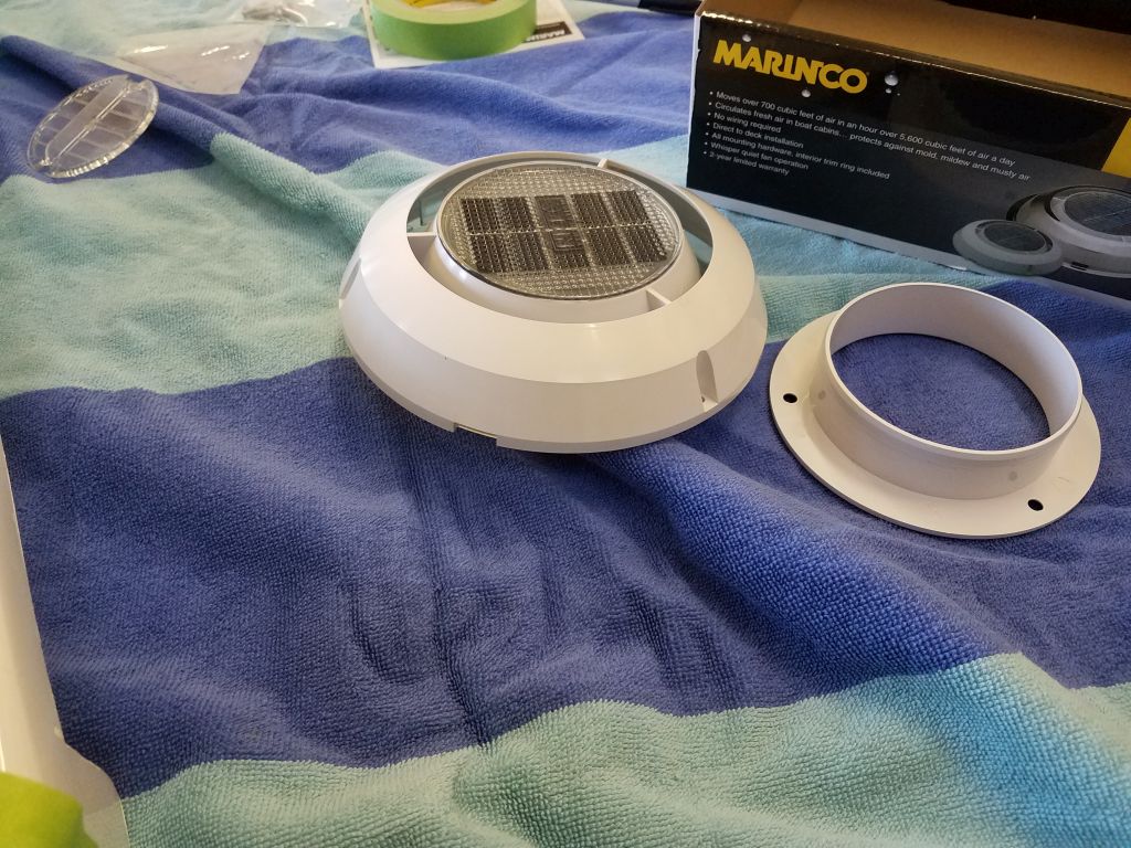
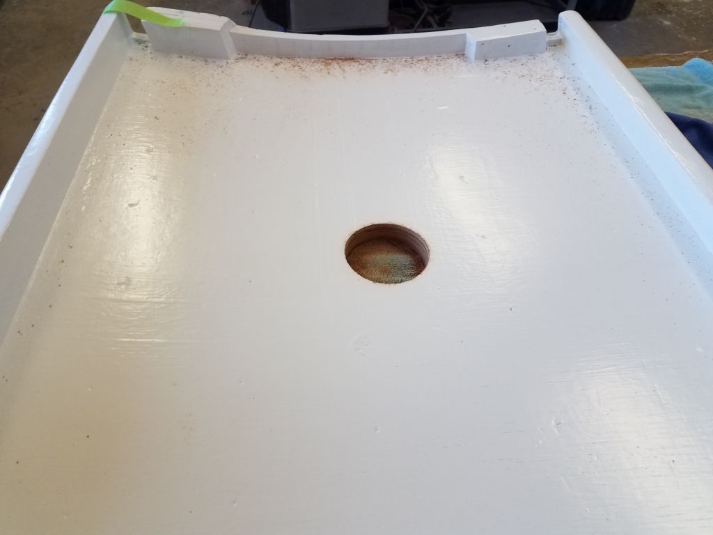
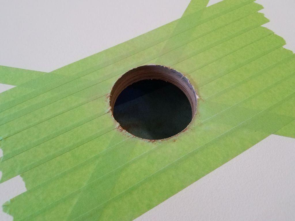
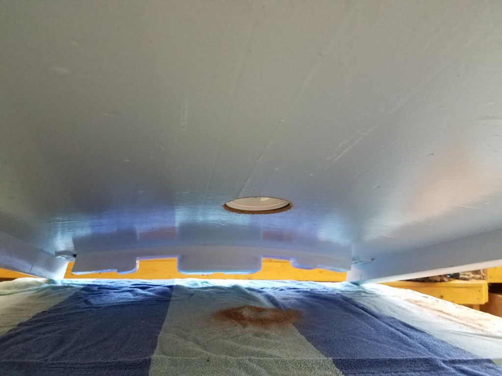
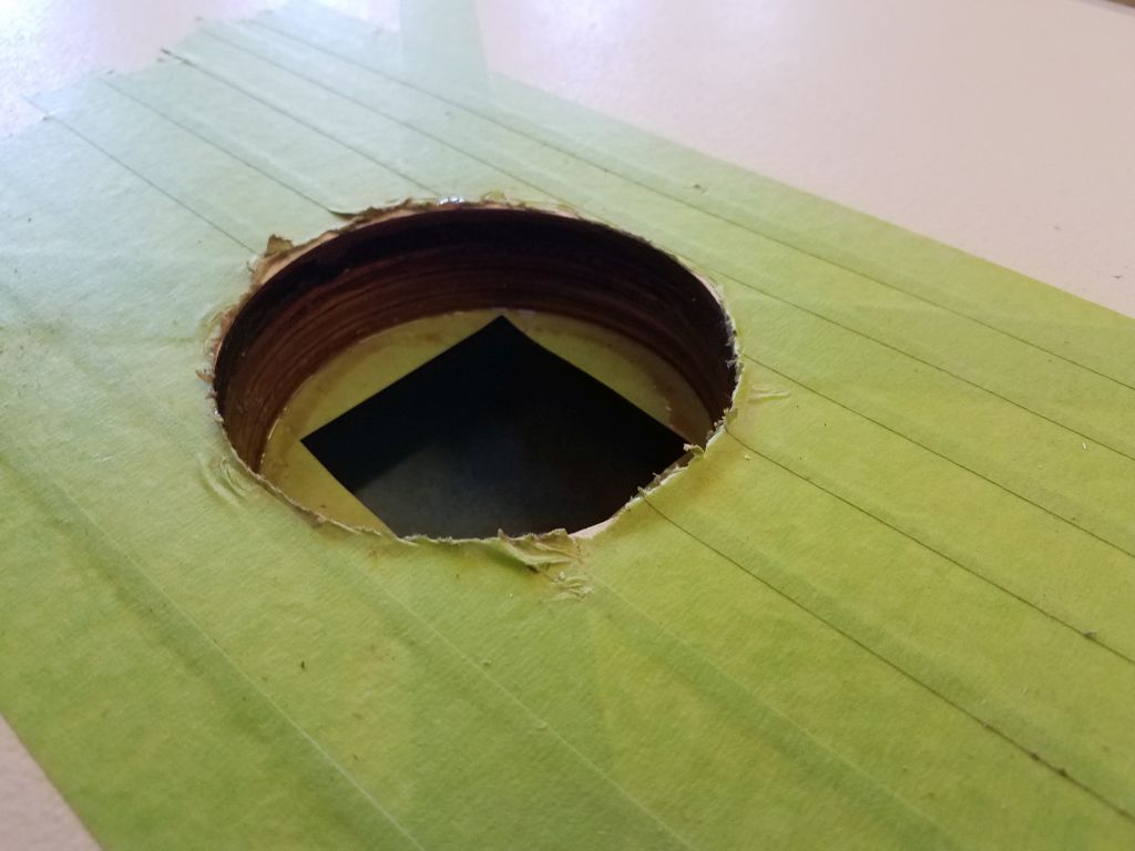
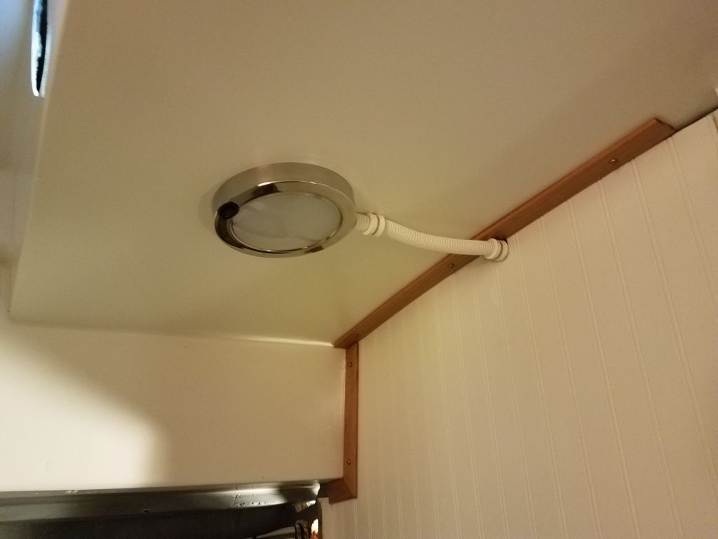
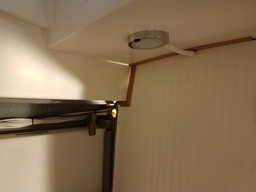
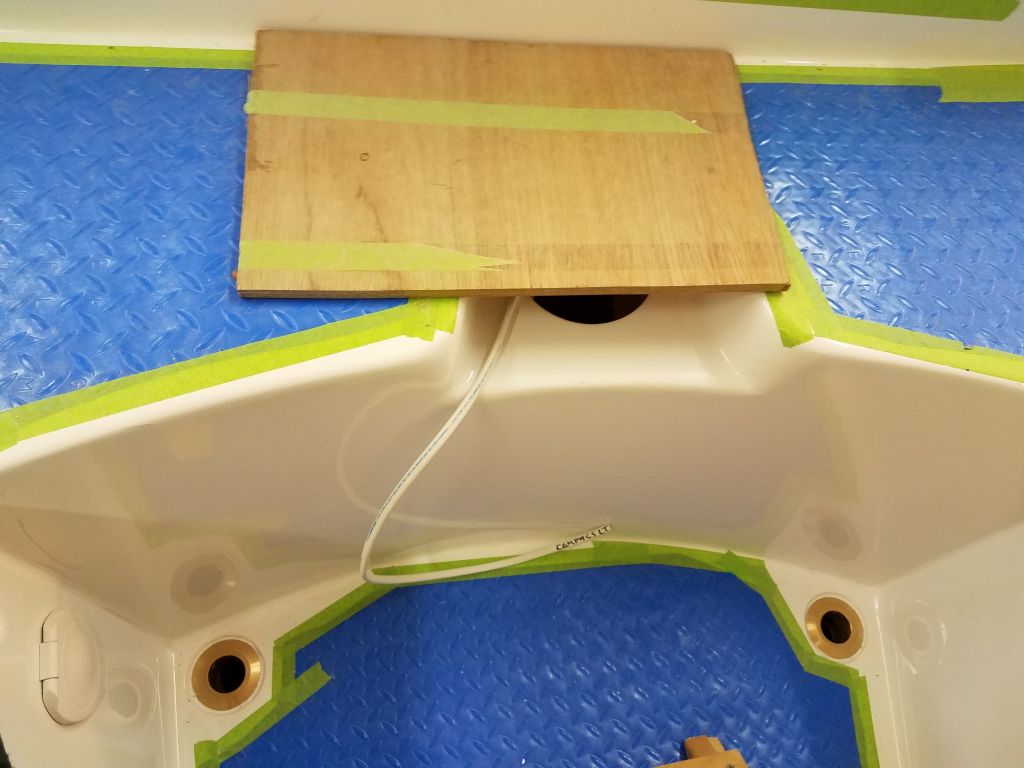
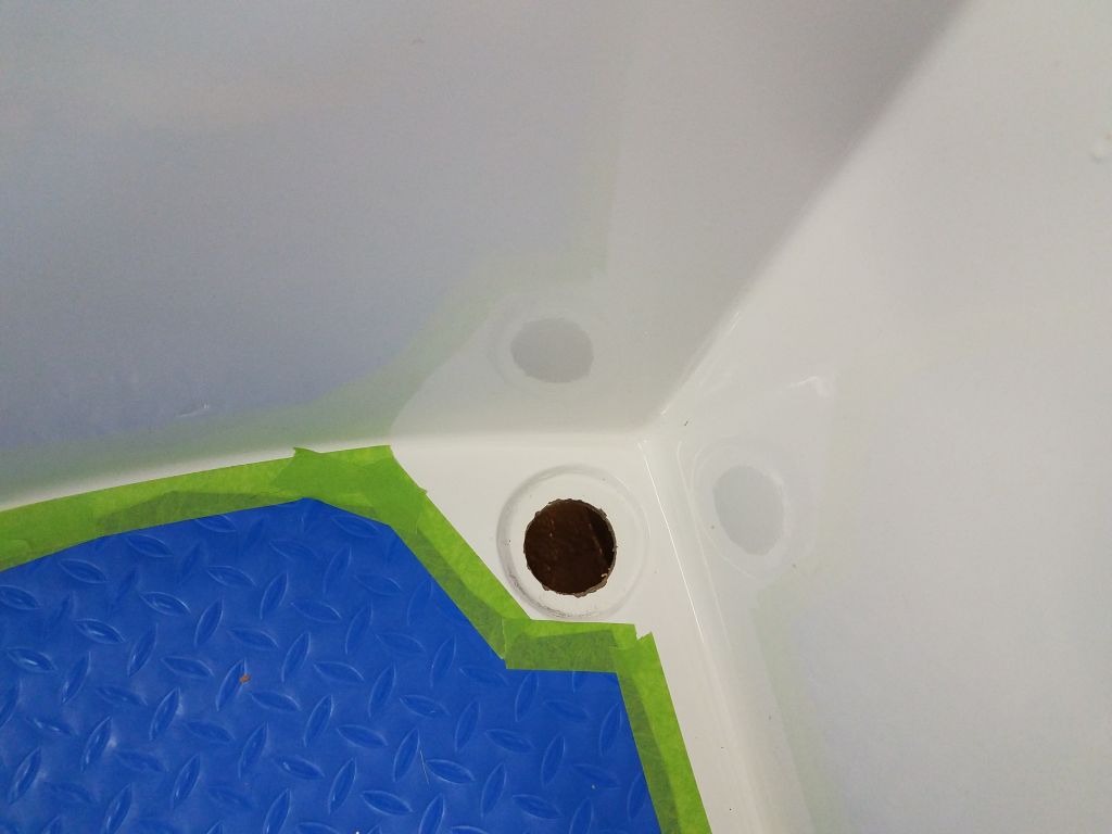
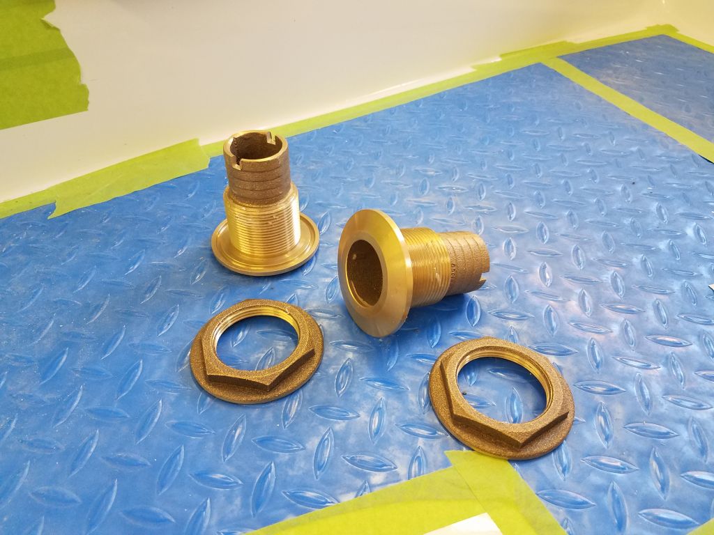
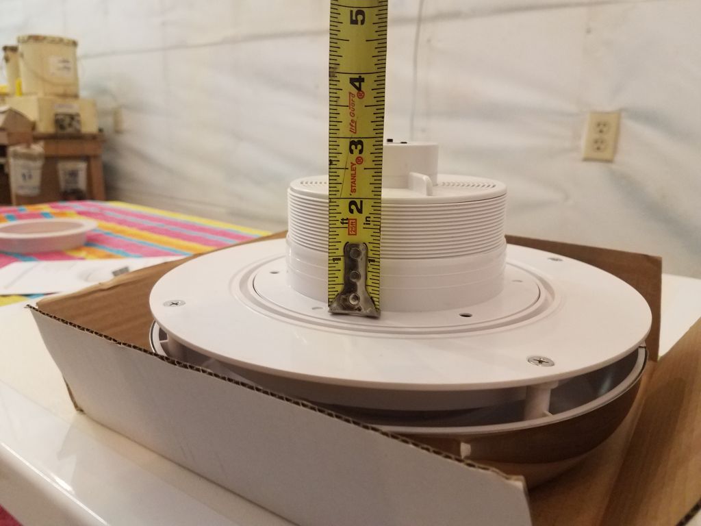
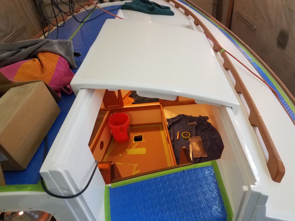
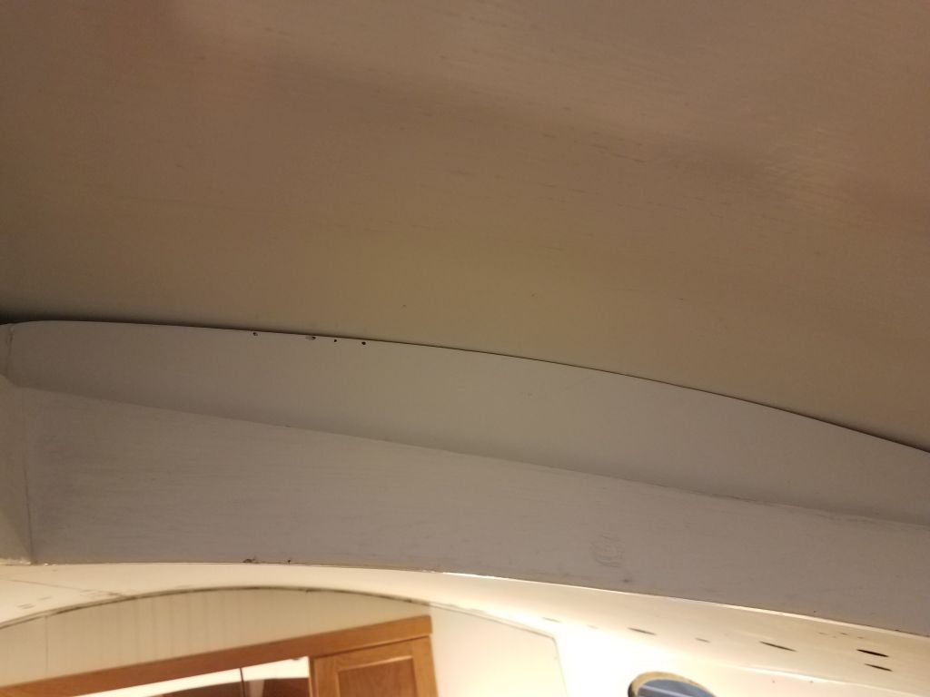
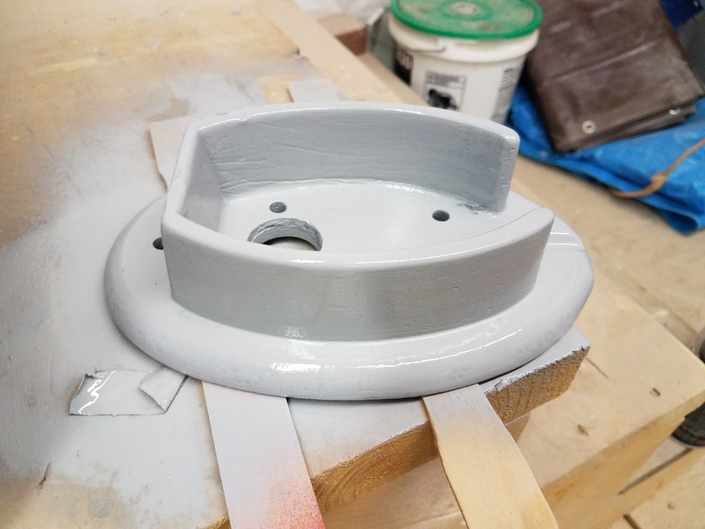
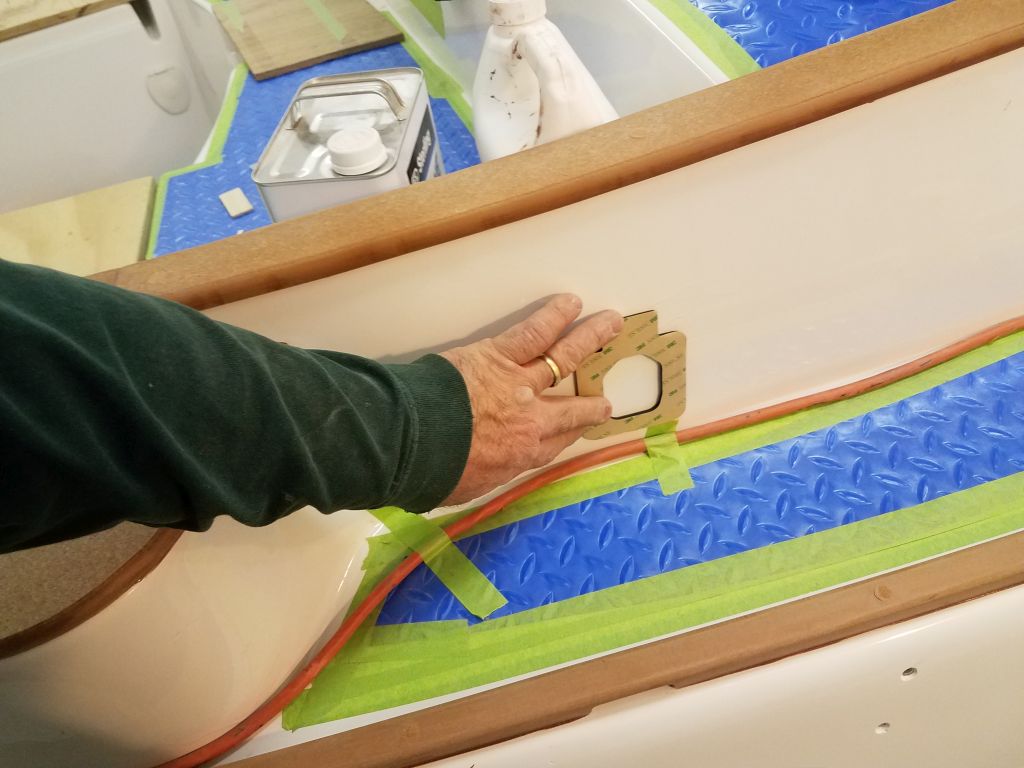
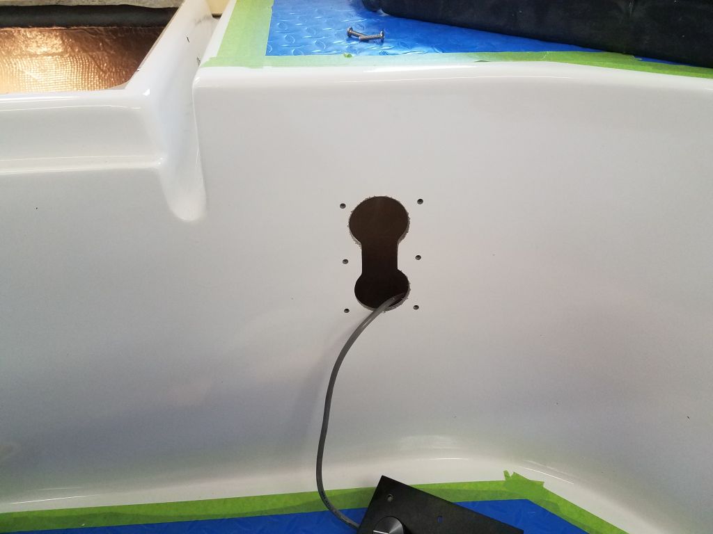
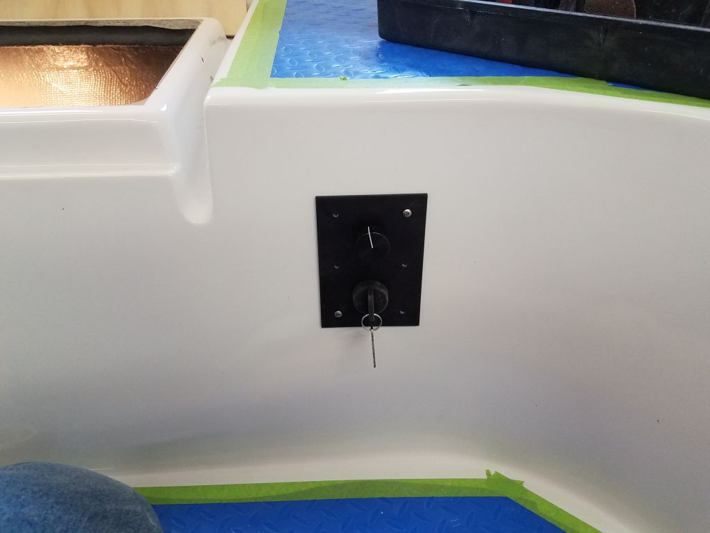
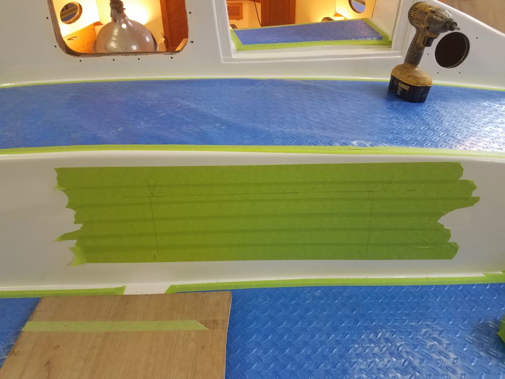
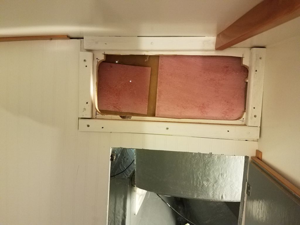
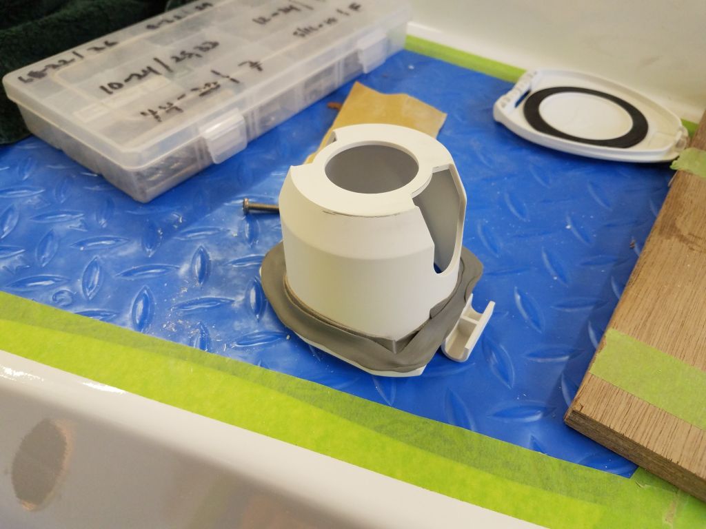
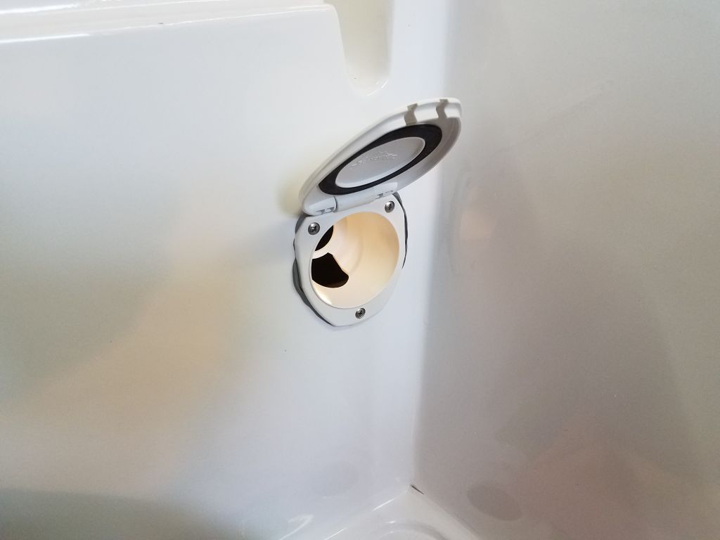
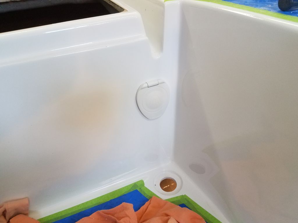
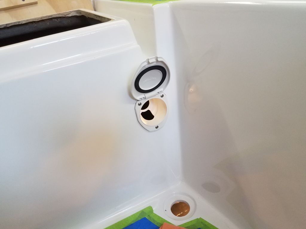
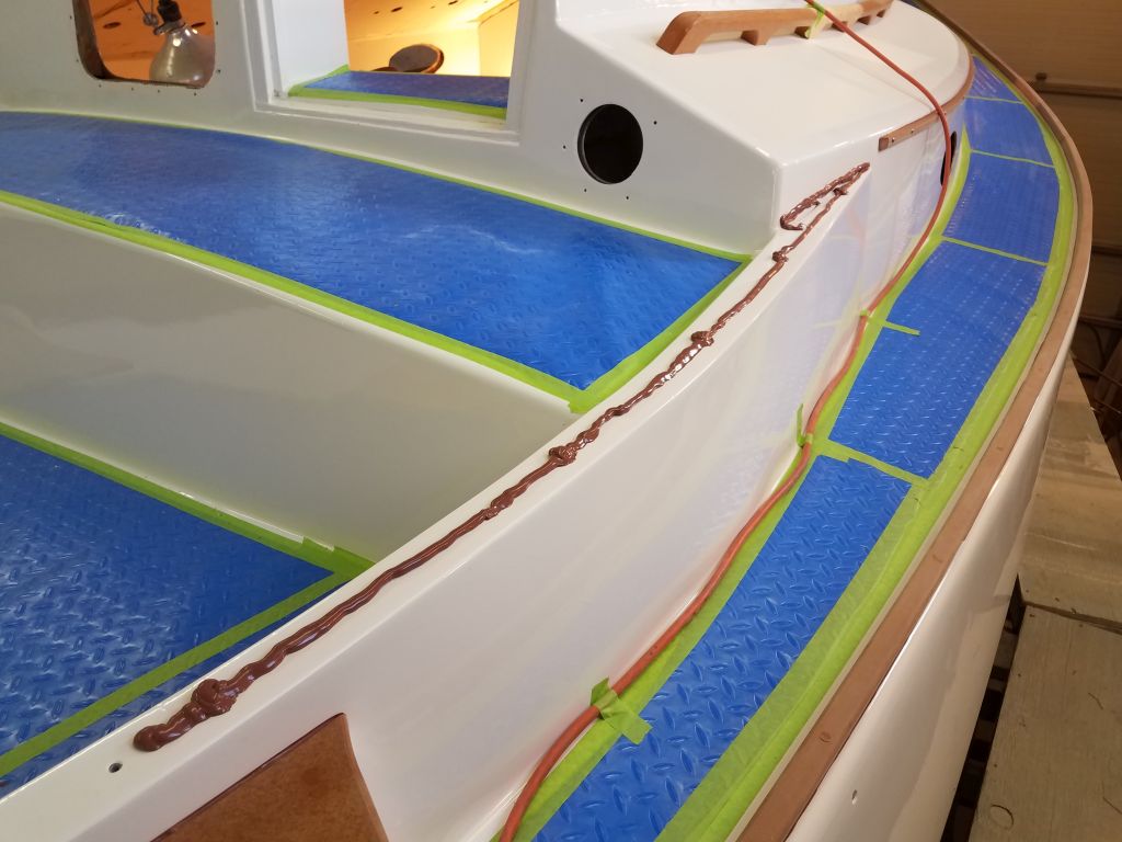
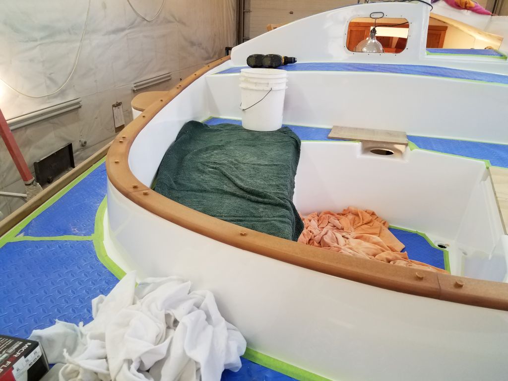
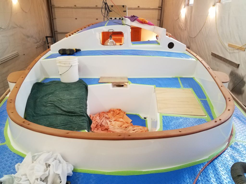
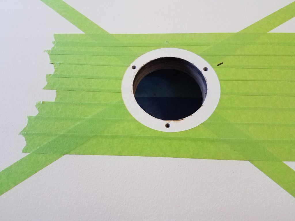
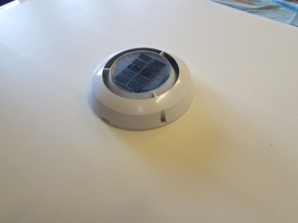
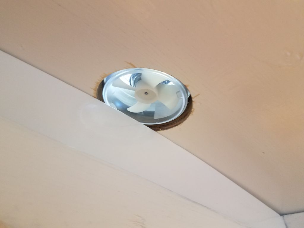
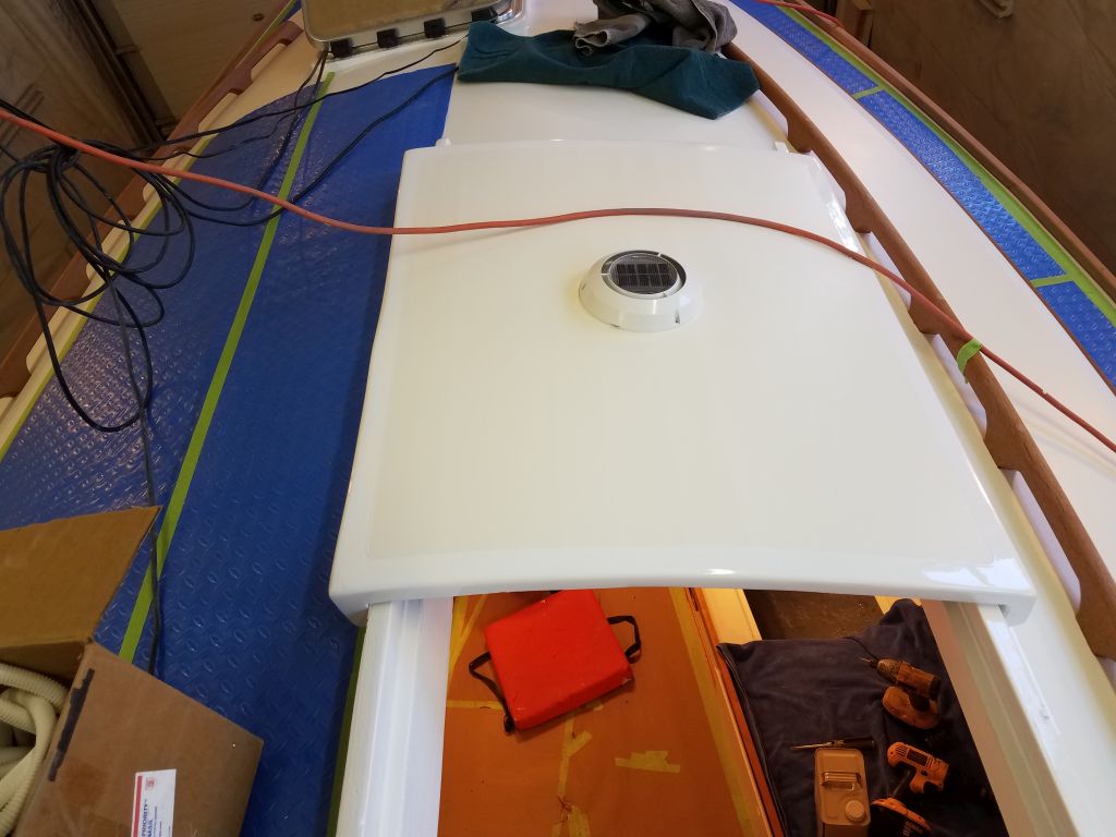
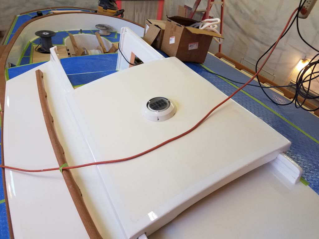
After an early morning commitment elsewhere, I got back to the shop in time to finish up the installation of the solar vent in the companionway before lunchtime. This was a straightforward installation with sealant and three screws. Because of the lack of clearance beneath the hatch when it was installed, I couldn’t use the provided trim ring at the underside of the hole, so later I planned to come back and touch up the paint a bit.


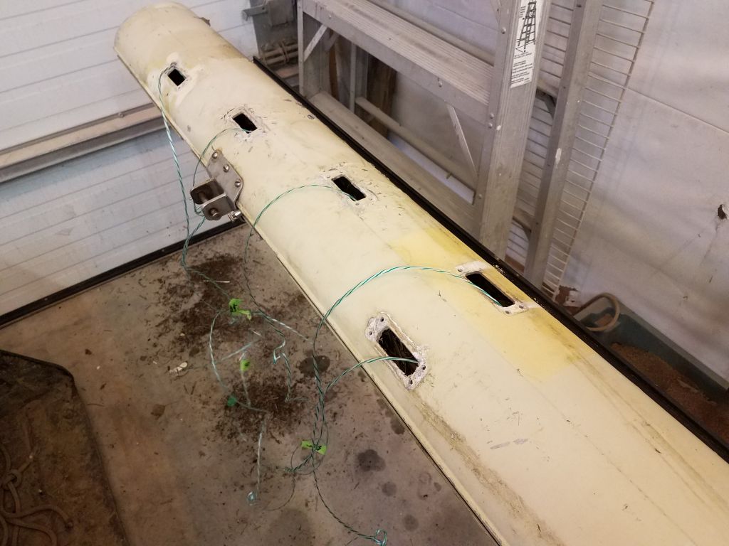
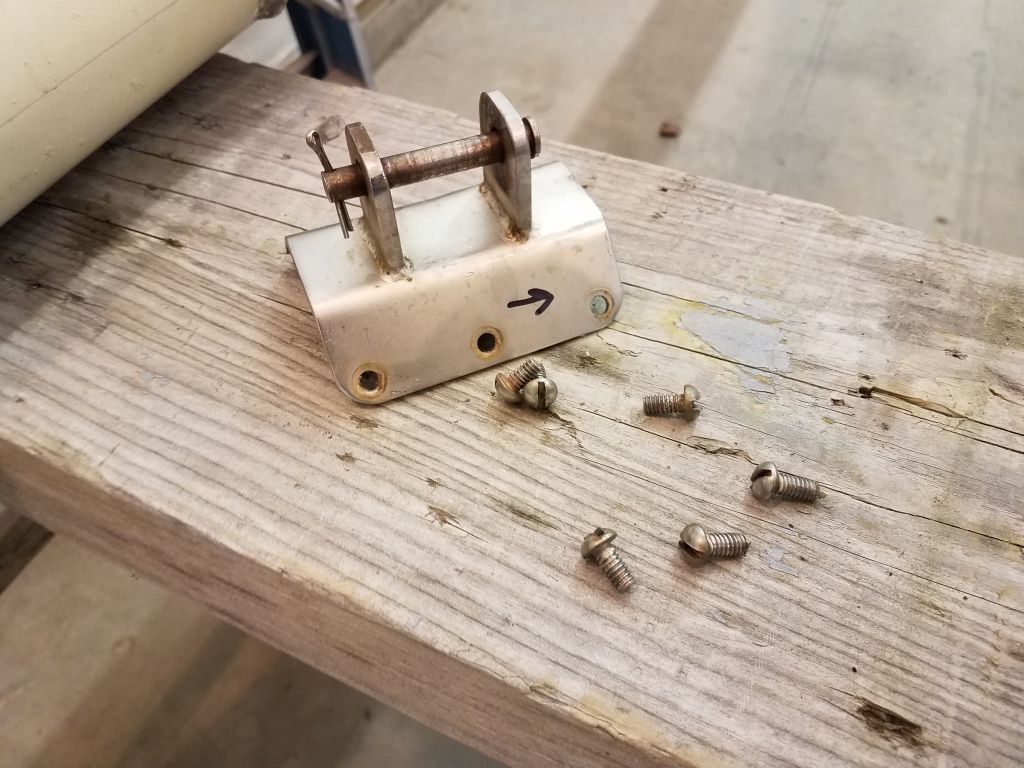
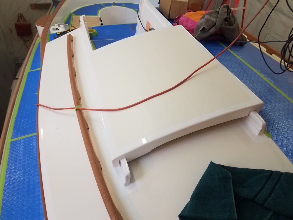
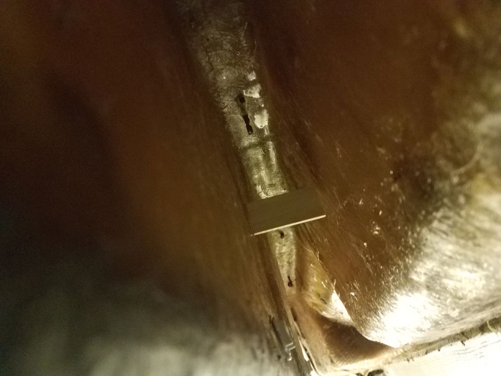
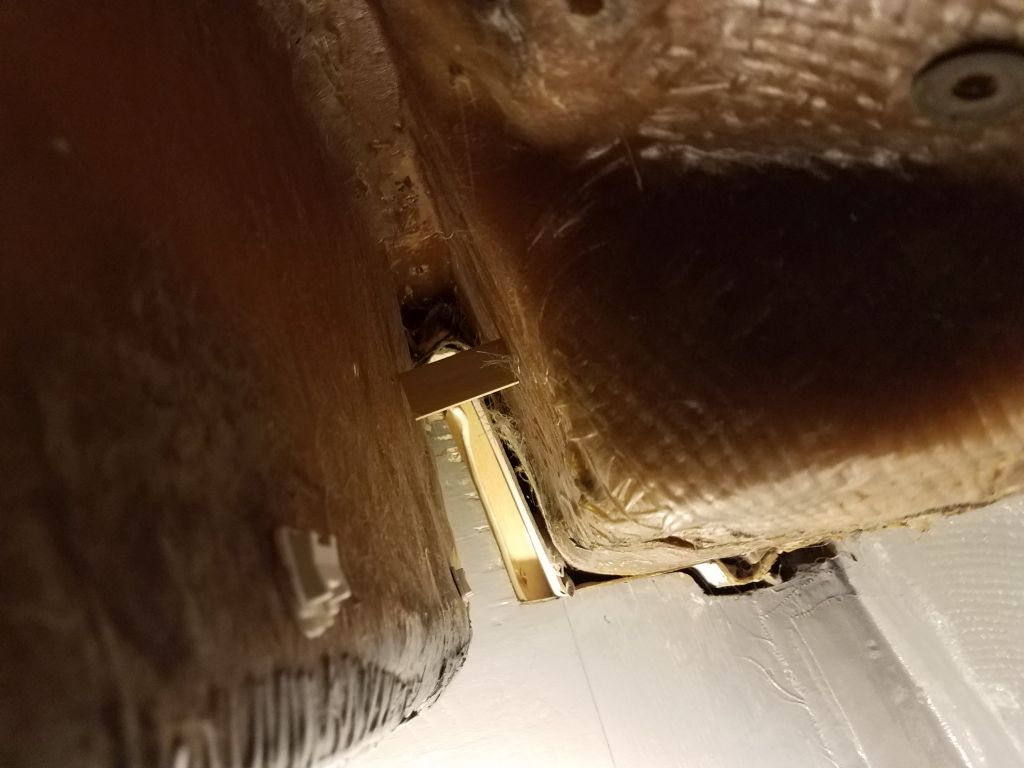
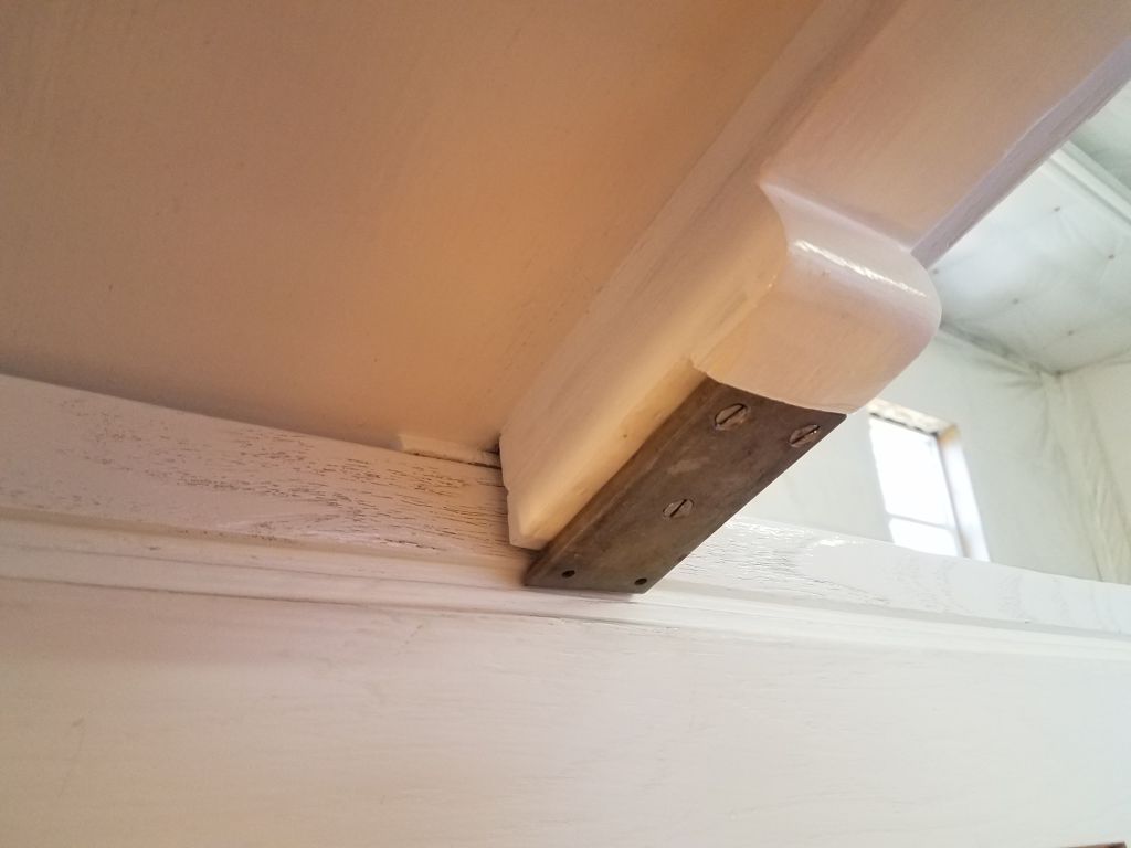
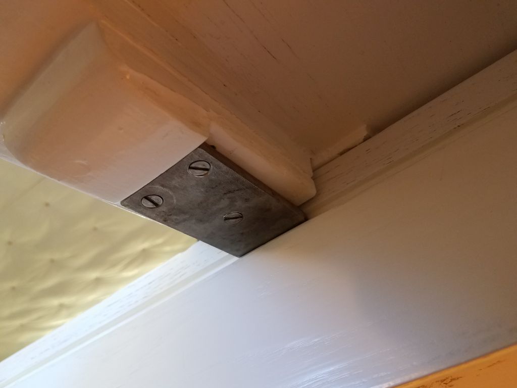
Now that the vent was installed, I could install the hatch for good by reinstalling the two stainless steel tabs that held it in place by sliding in grooves in the companionway rails.
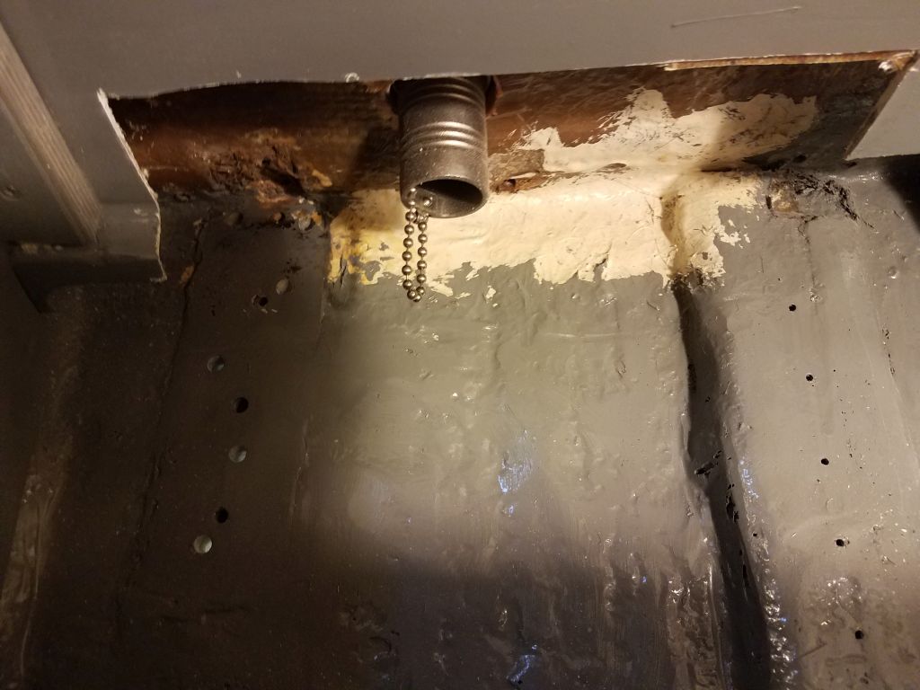
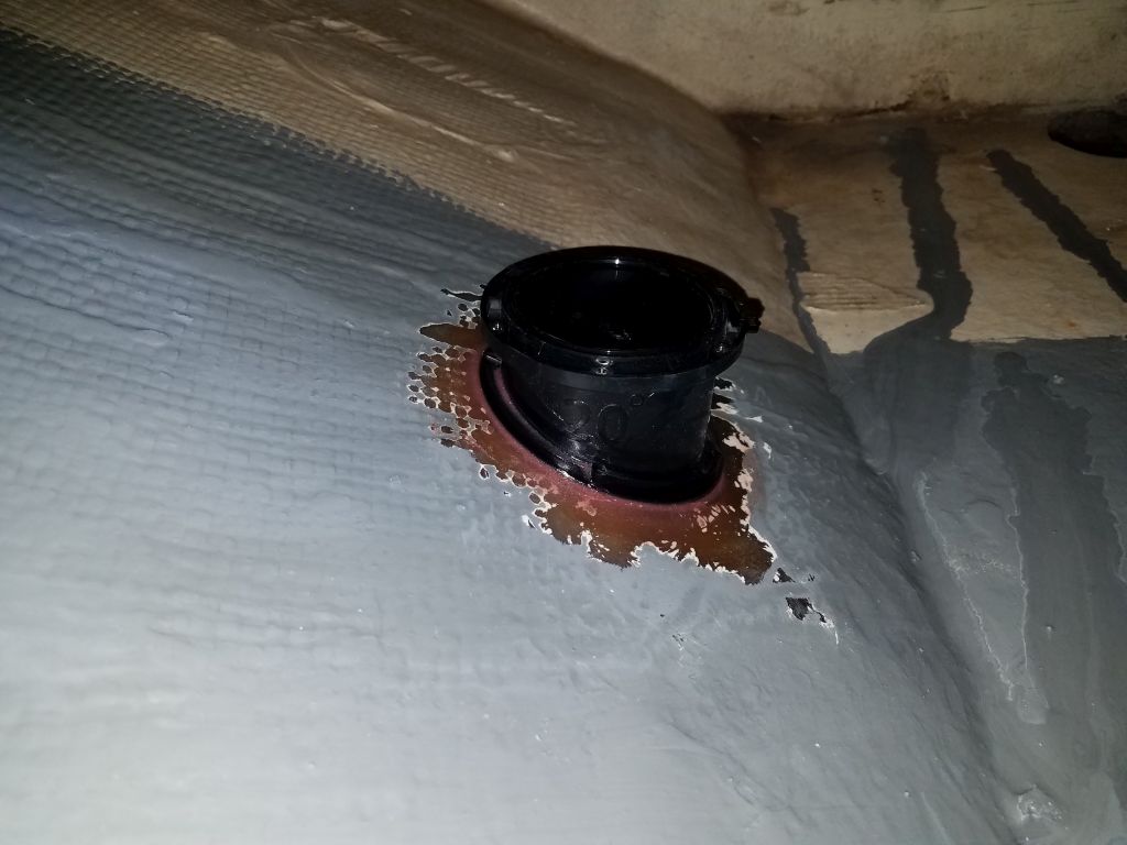
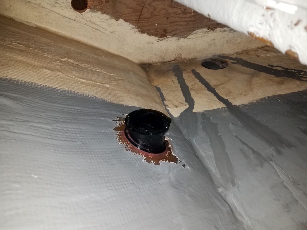
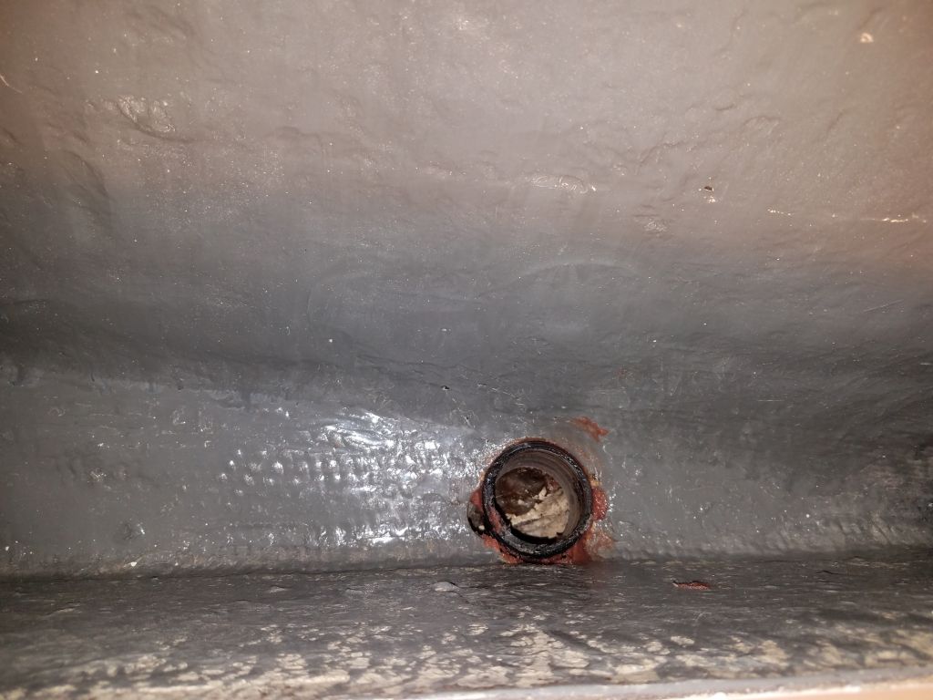
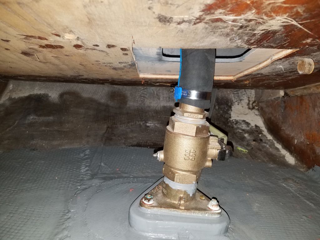
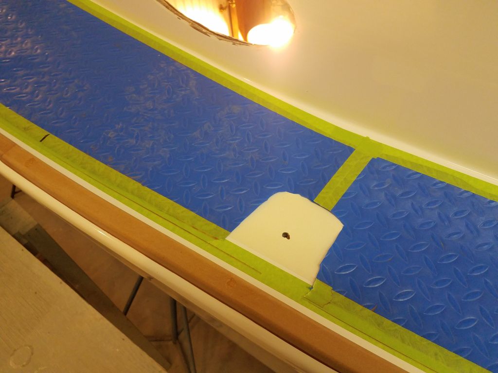
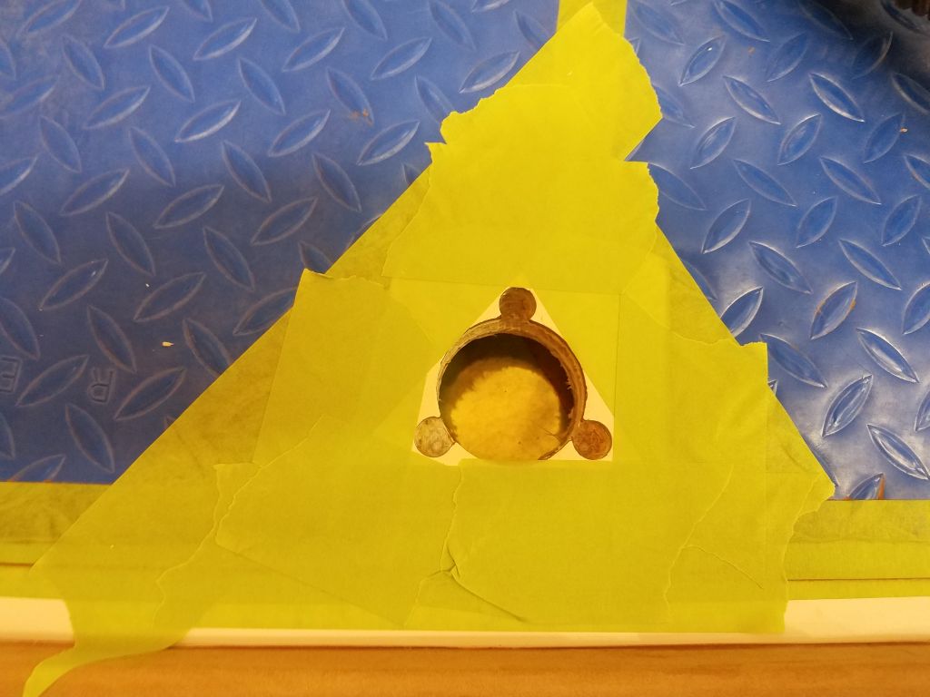
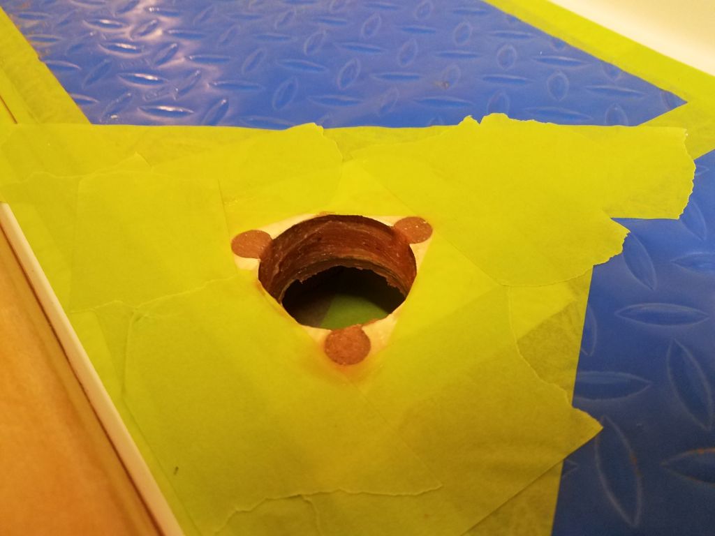
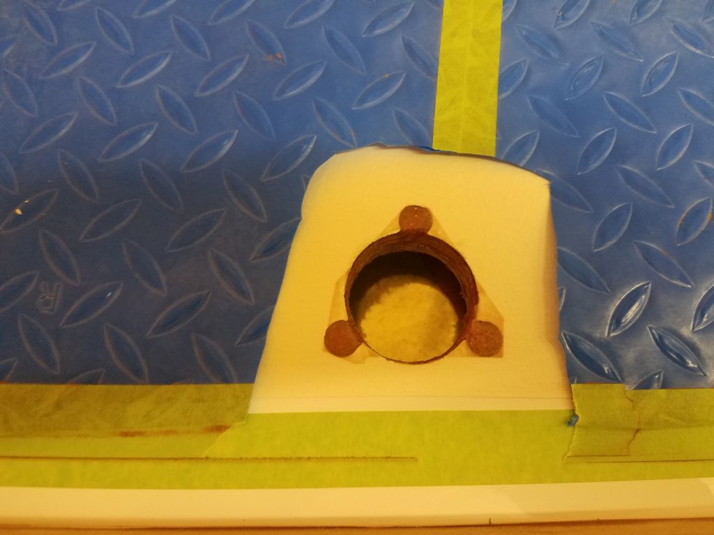
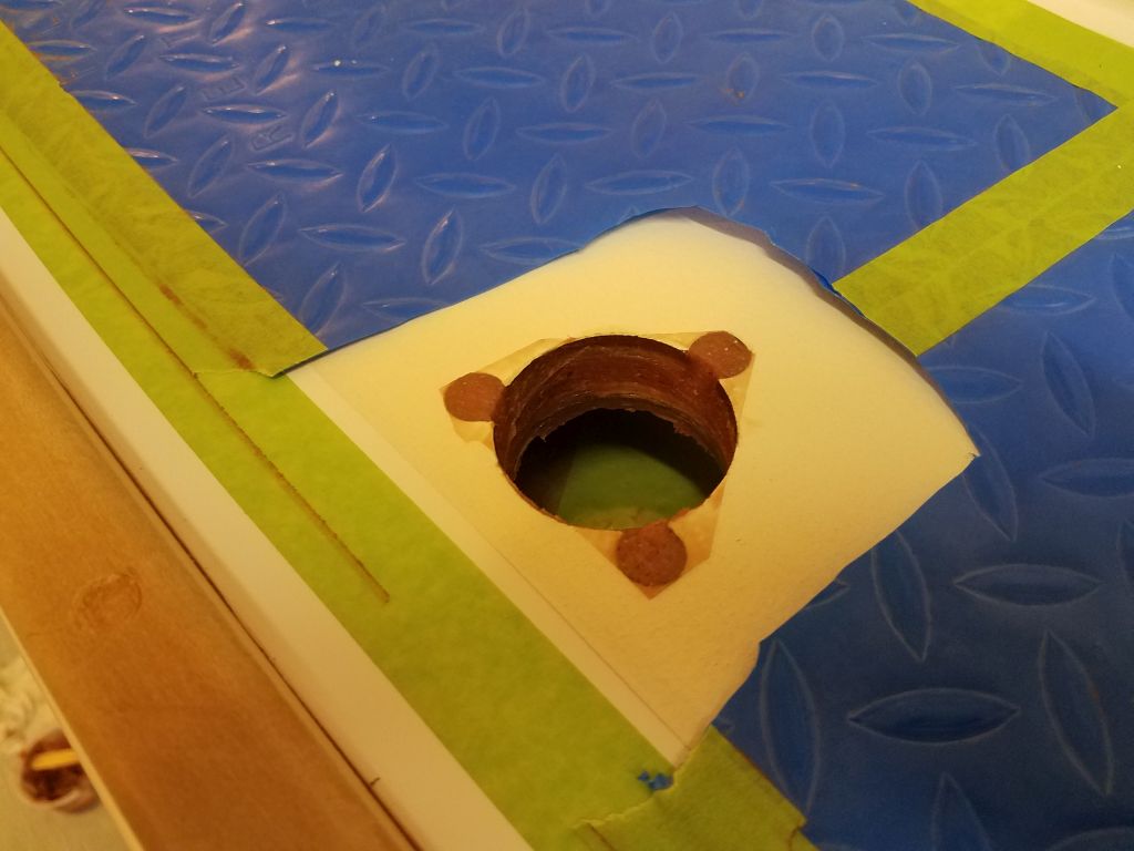
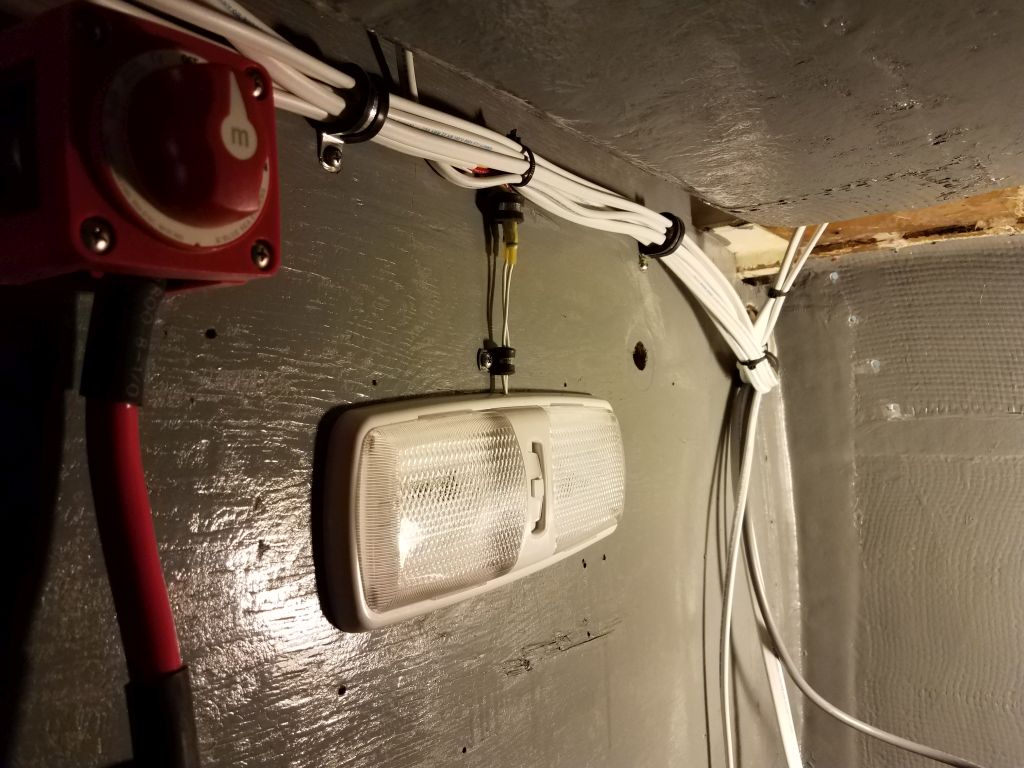
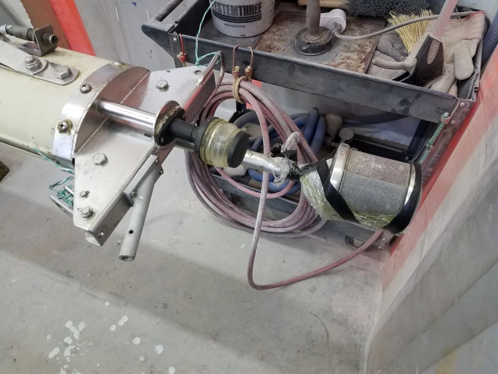
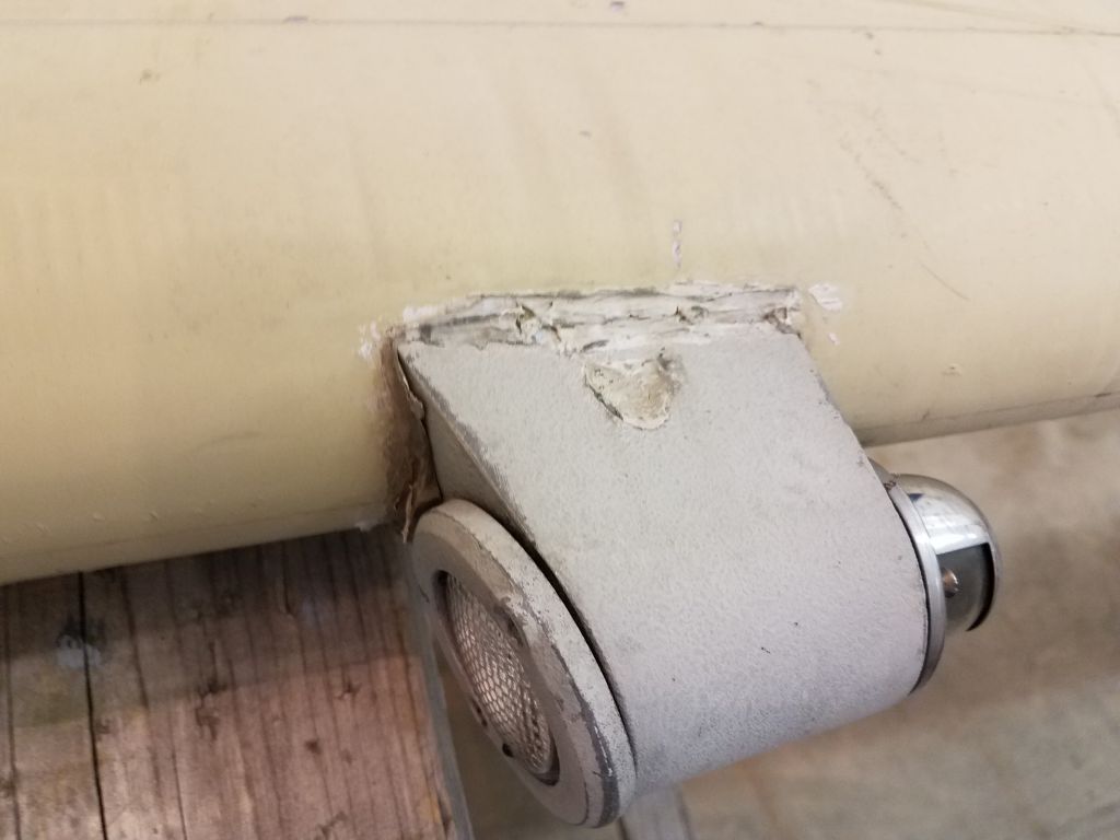
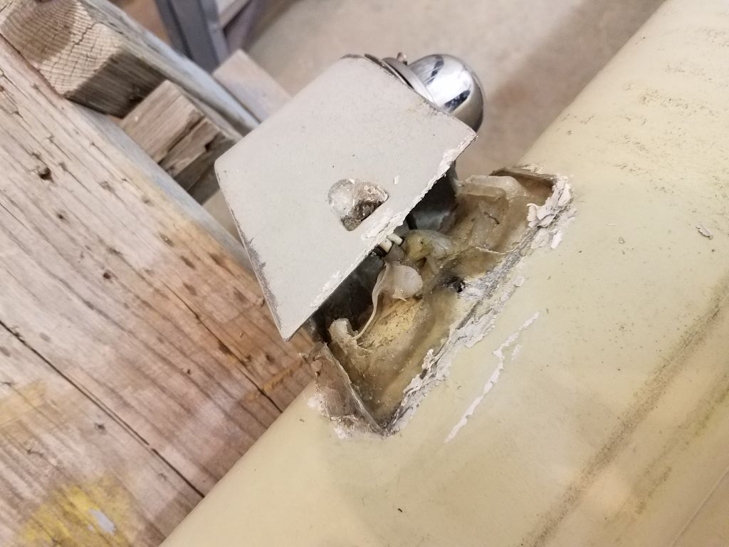
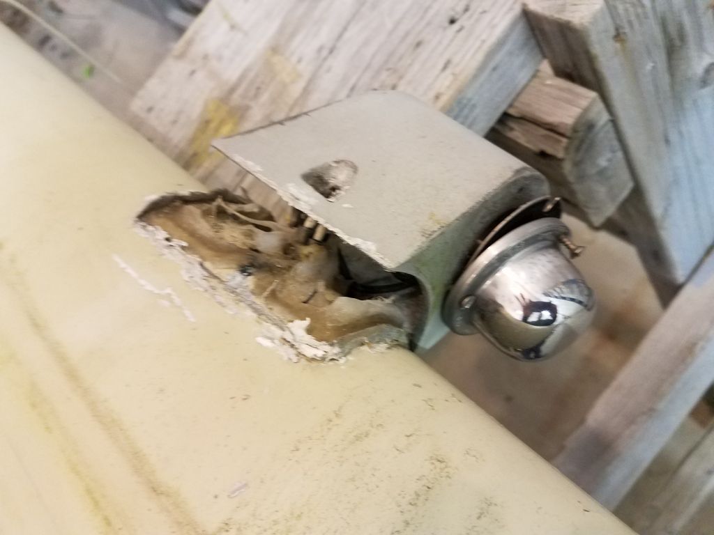
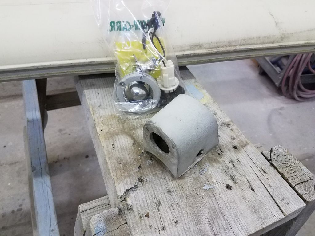
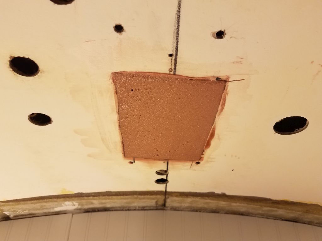
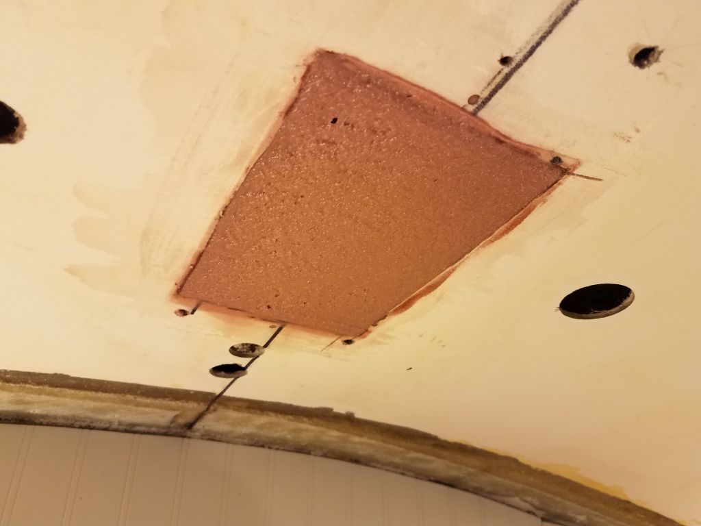
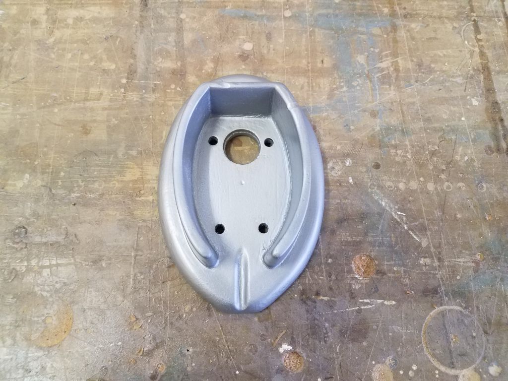
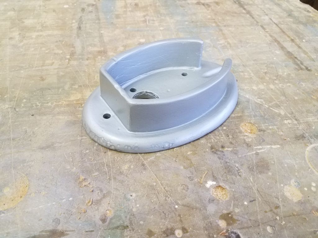
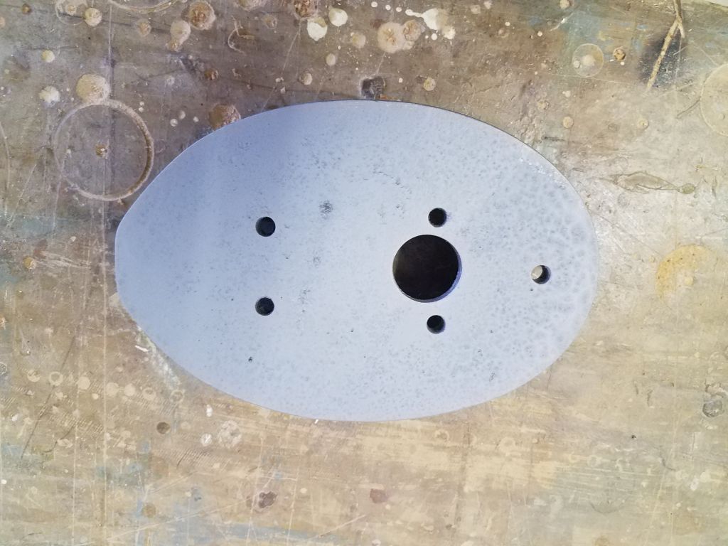
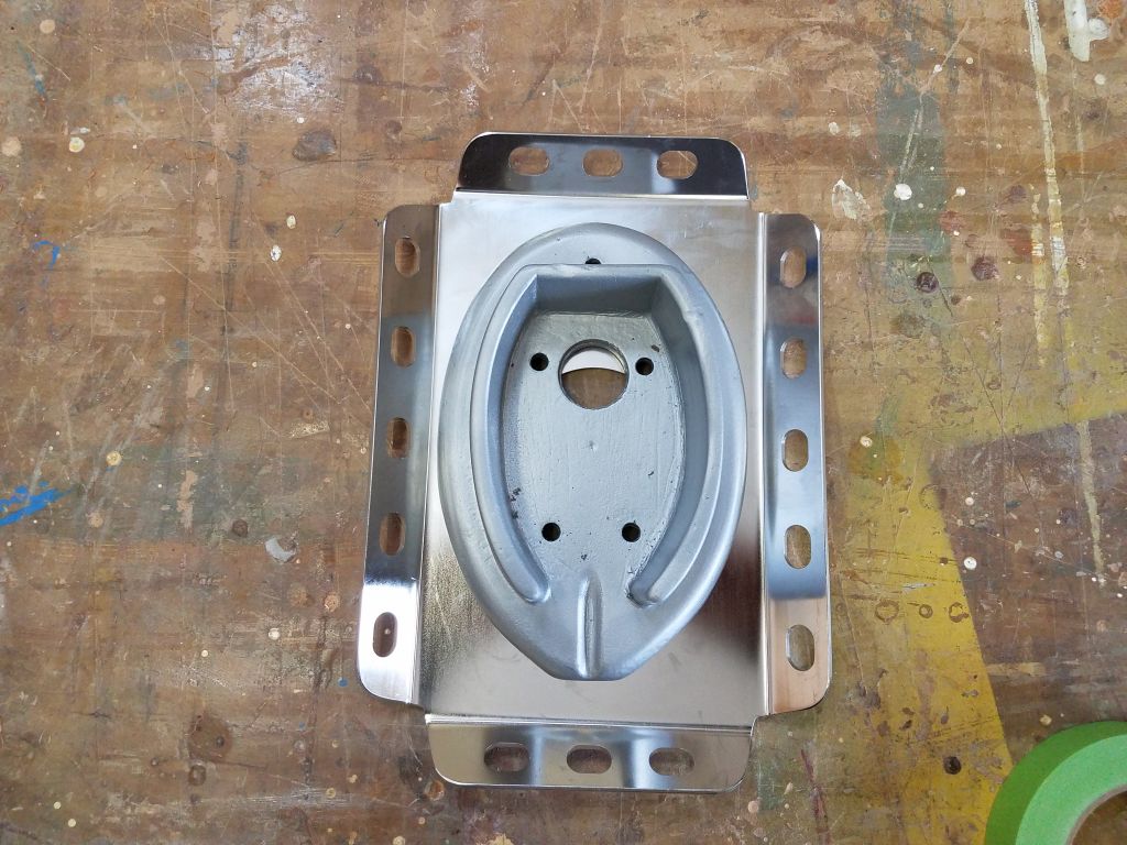
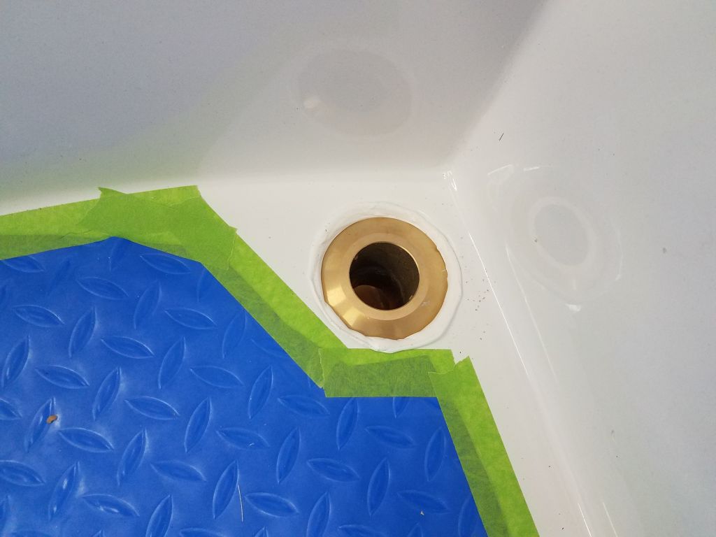
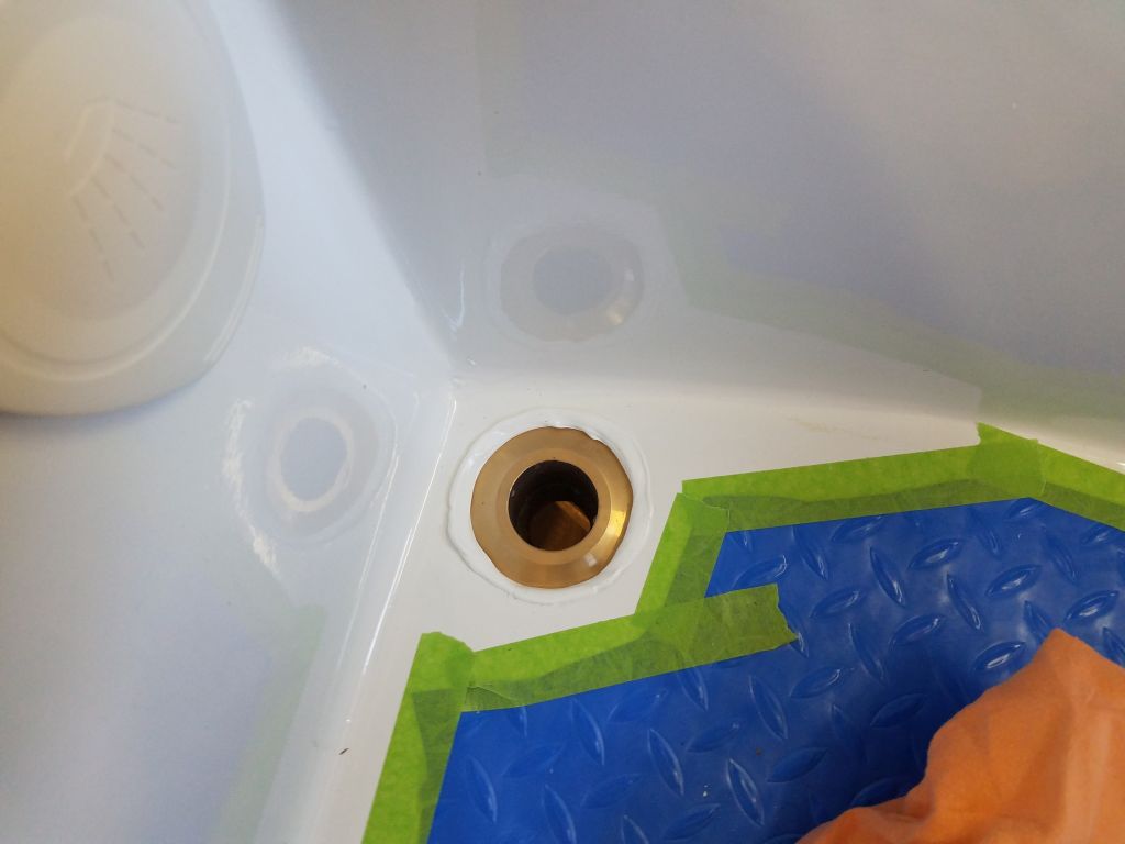
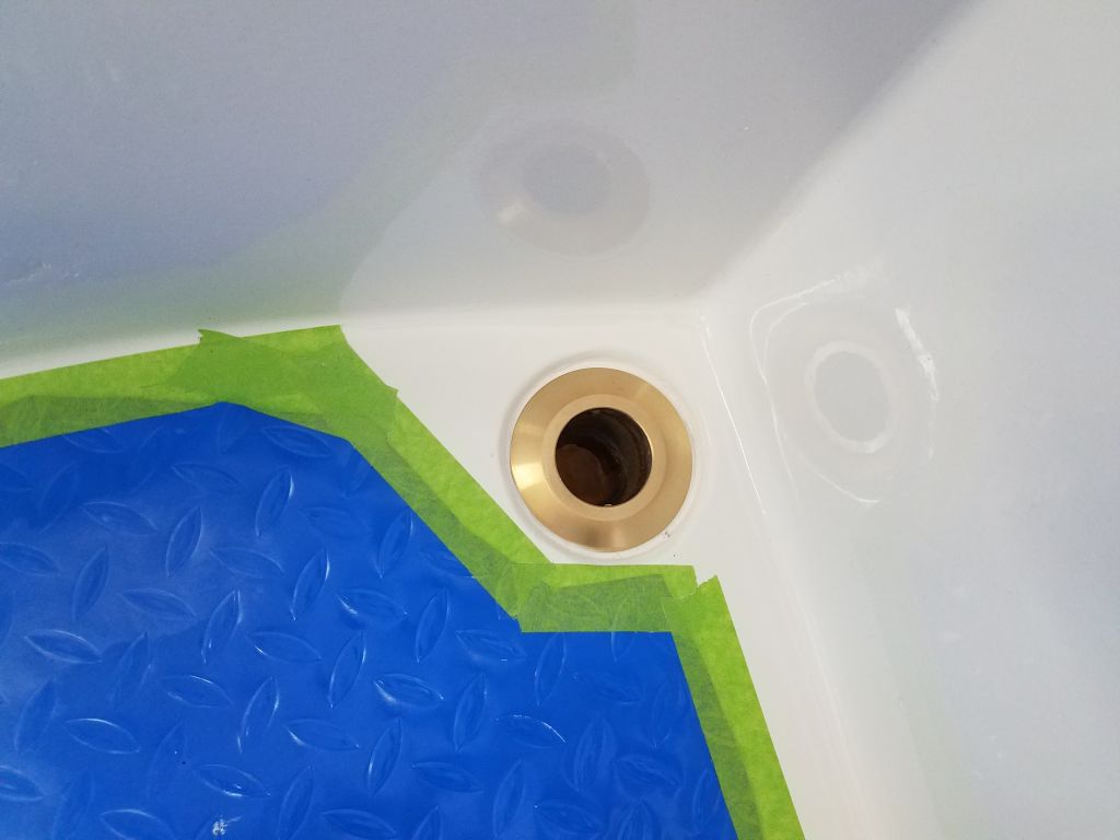
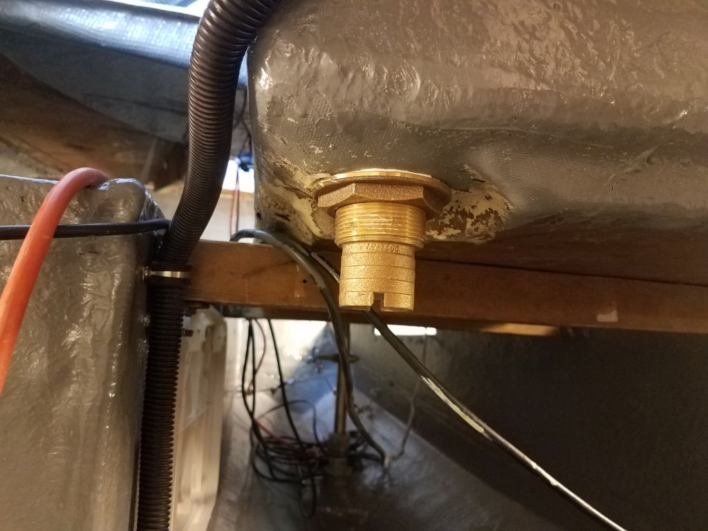
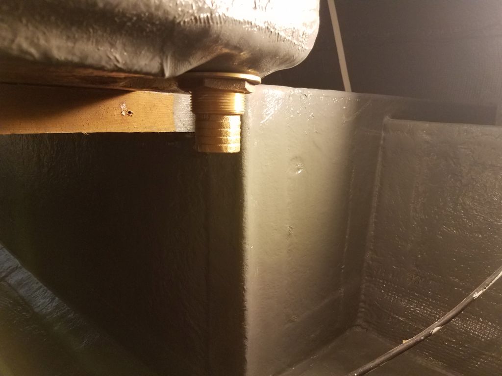
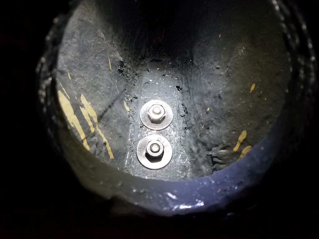
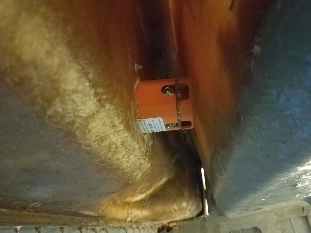
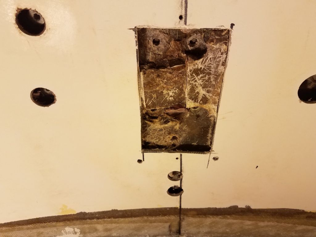
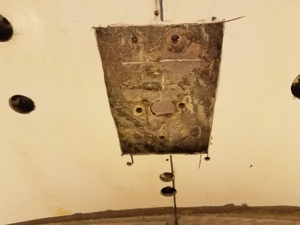
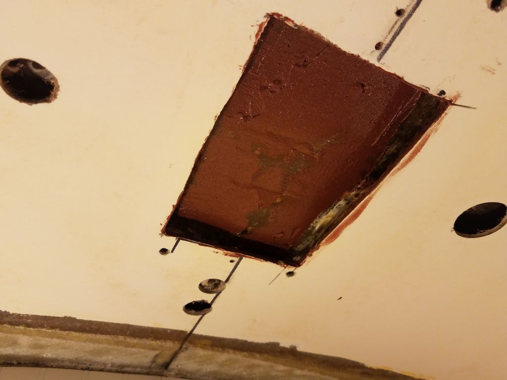
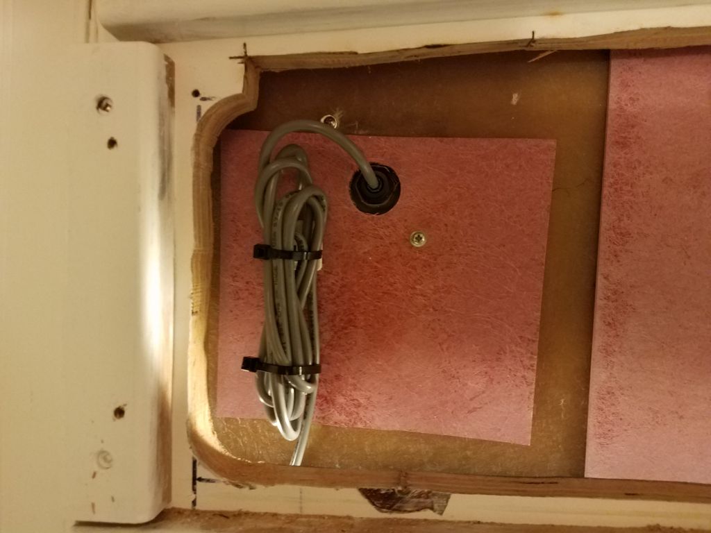
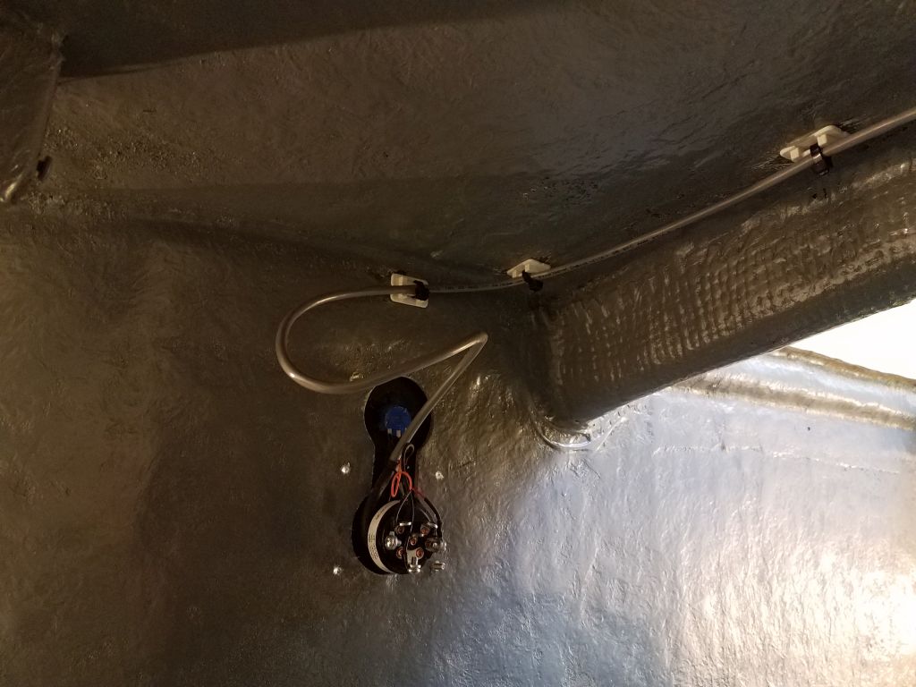
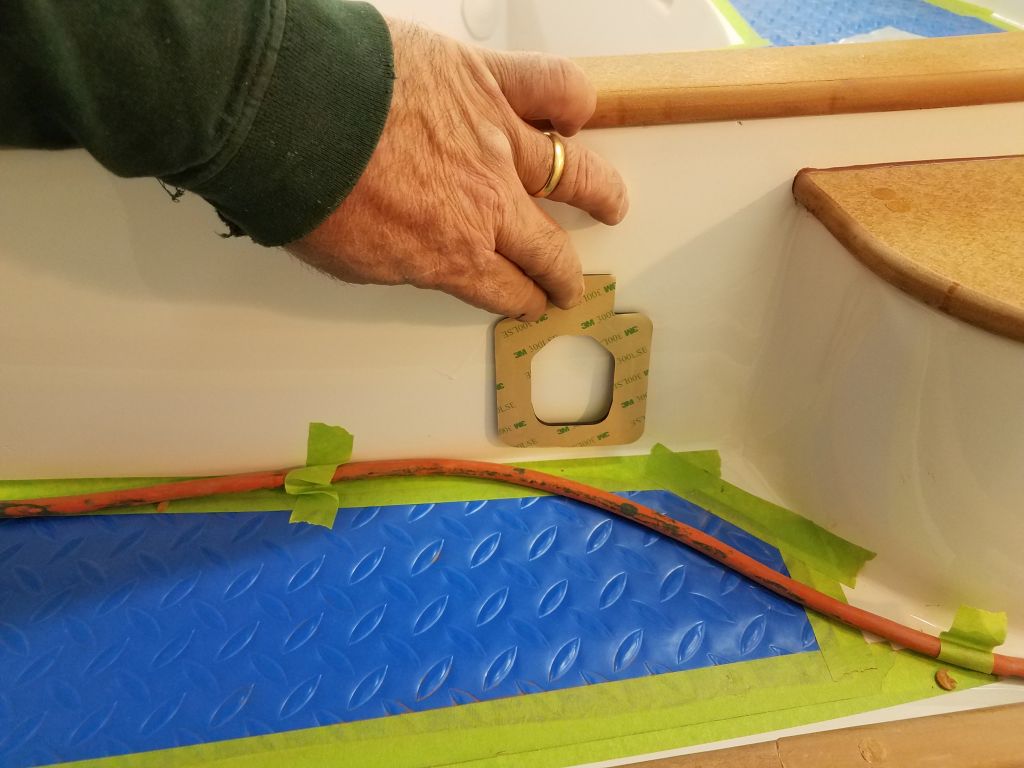
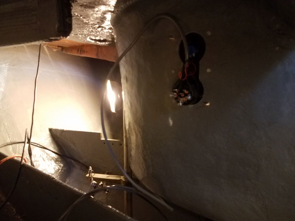
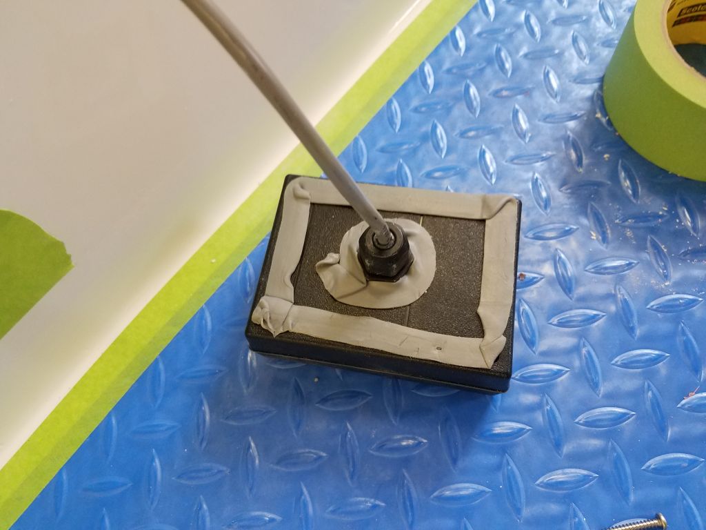
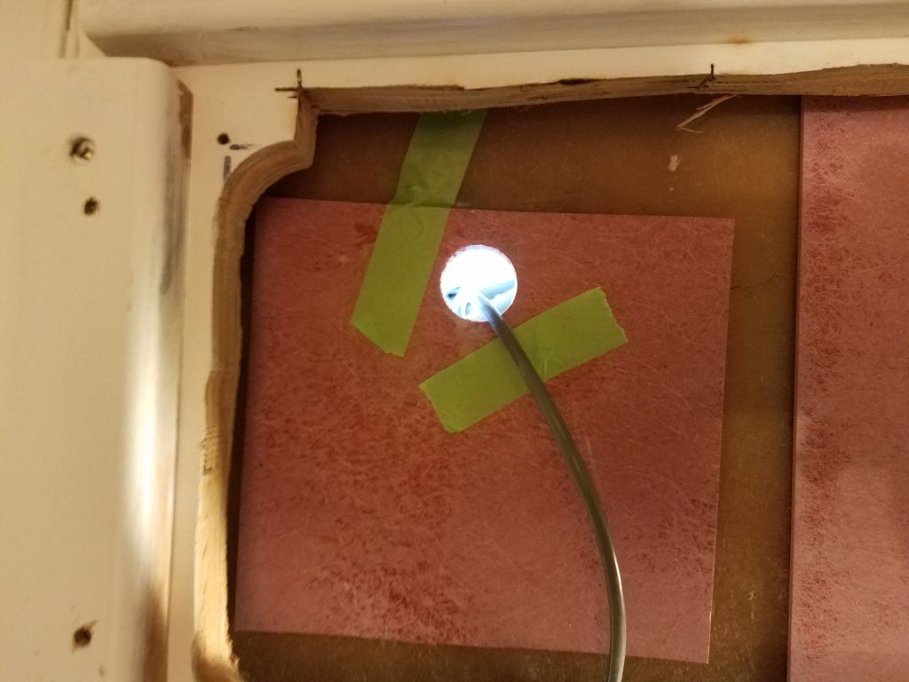
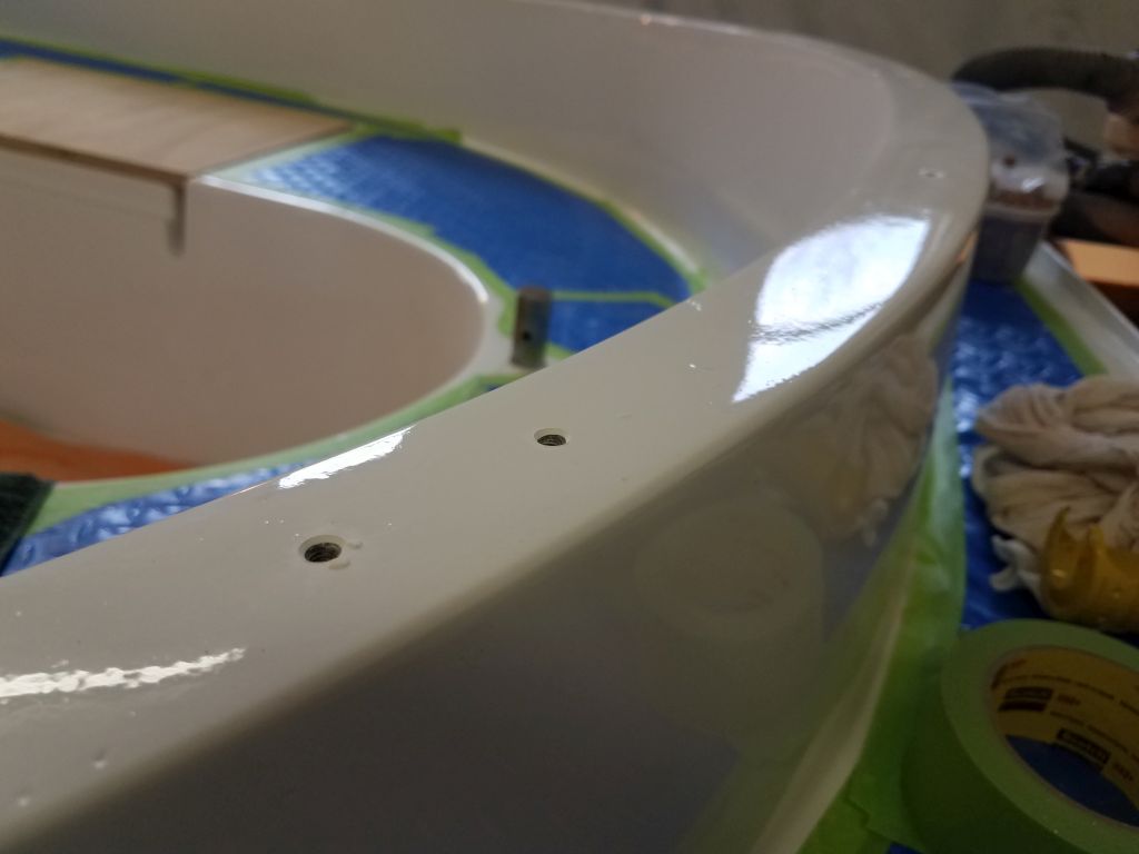
I spent the rest of the day working on the electrical system, starting again with the transducer. I wanted to give the epoxy some additional cure time before I filled the reservoir with the required liquid, but to help me run the transducer cable I temporarily installed the transducer with a couple of its screws to hold it in place.
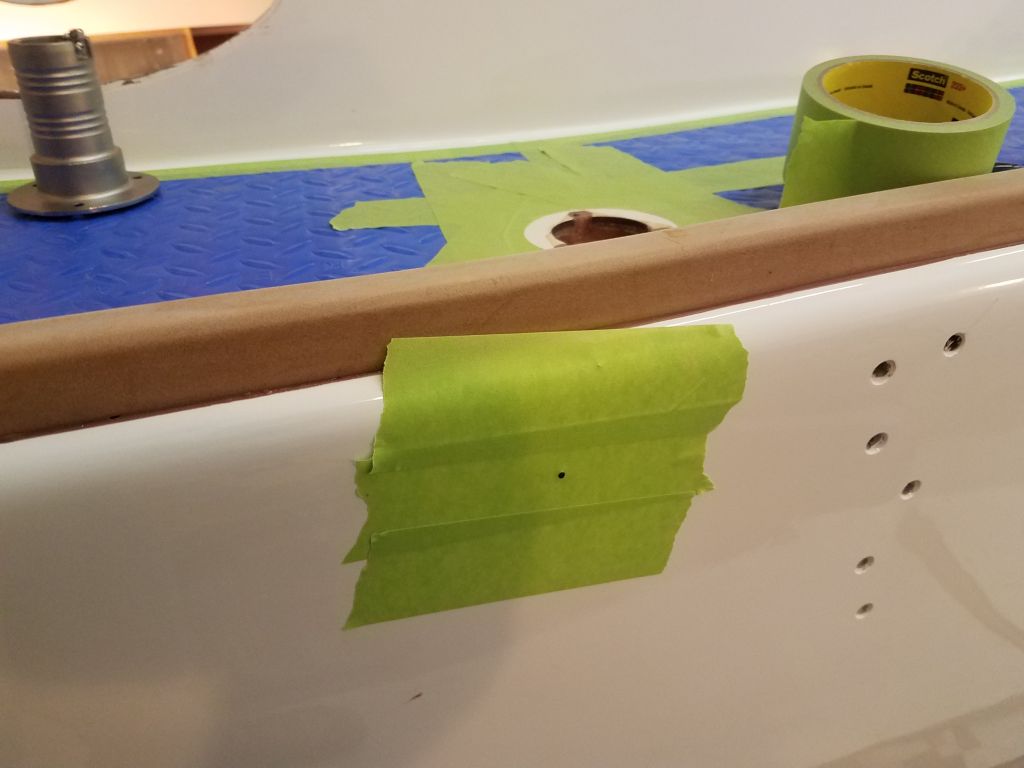
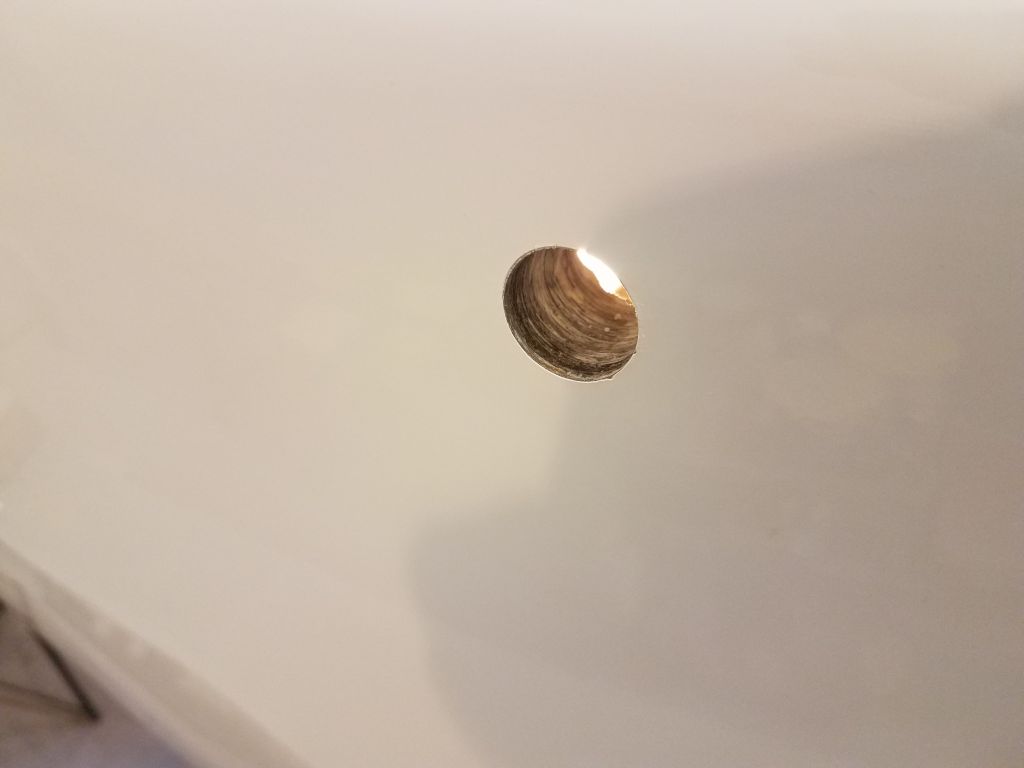
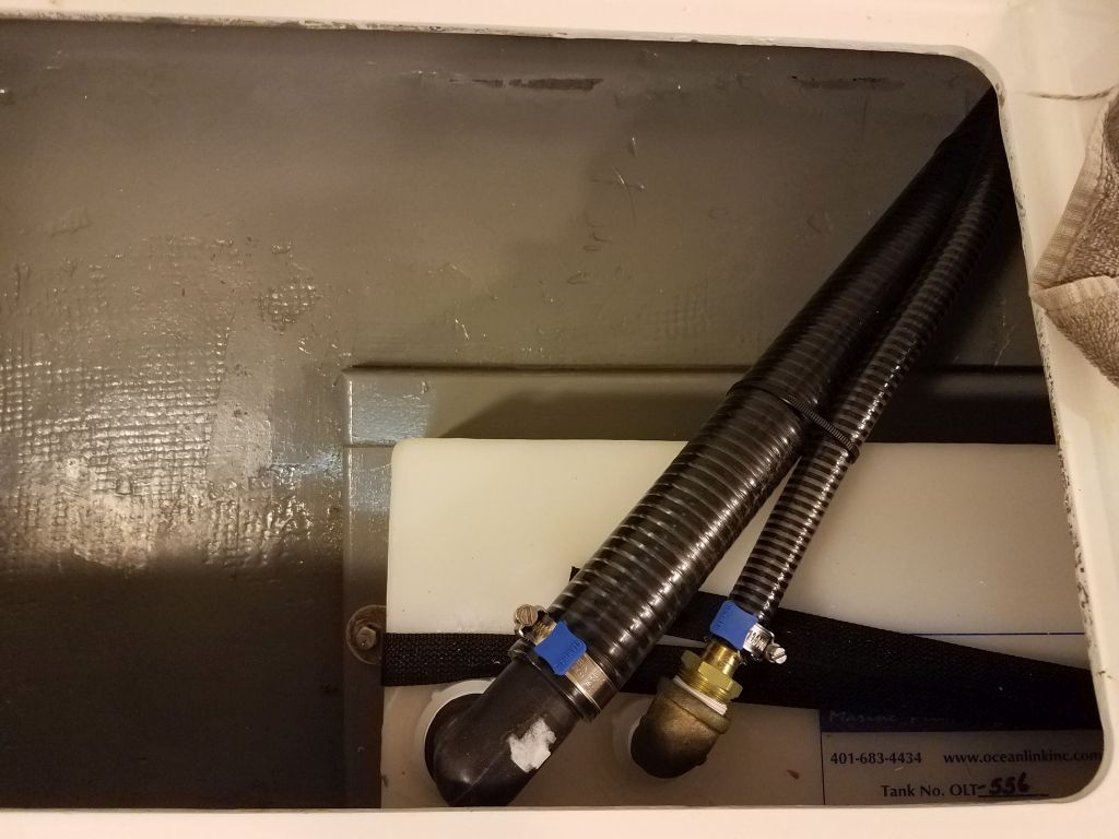
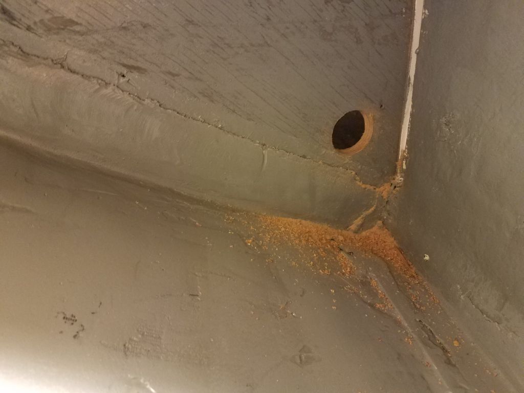
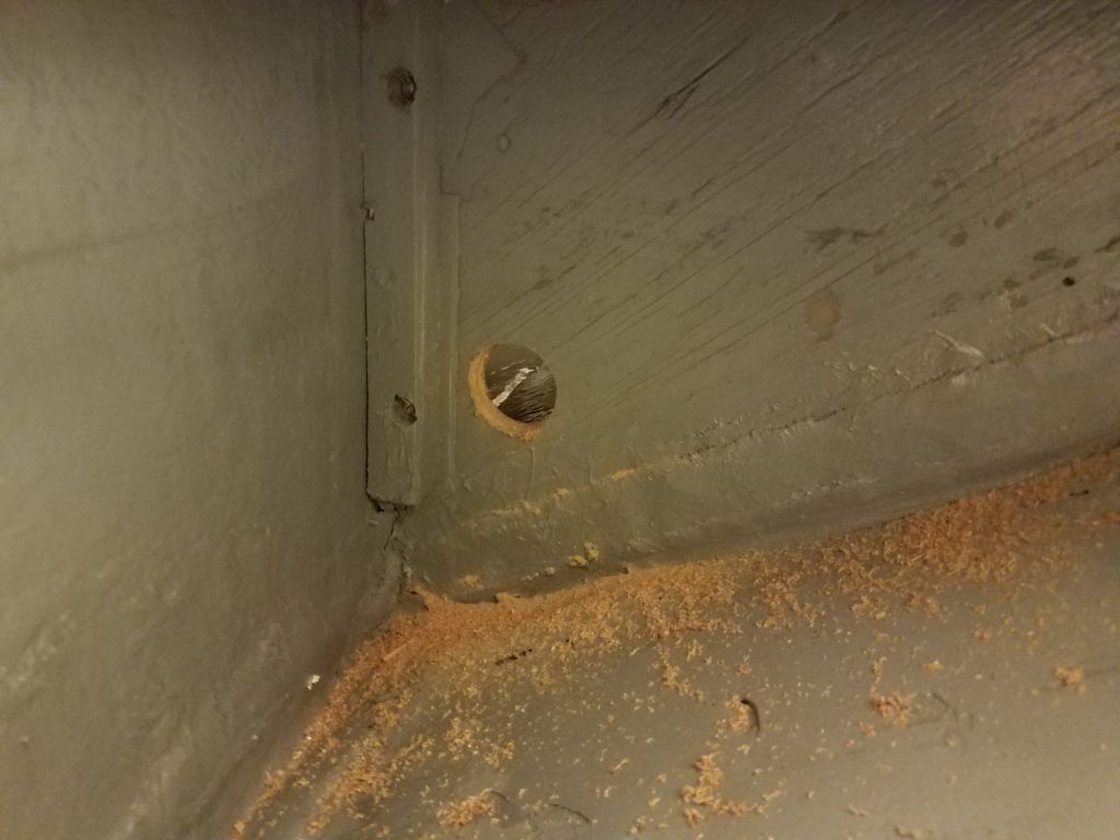
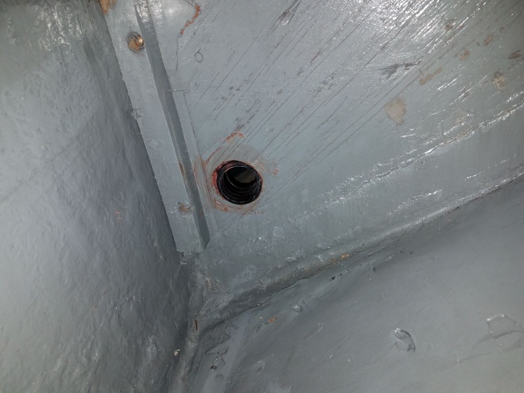
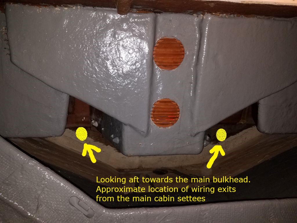
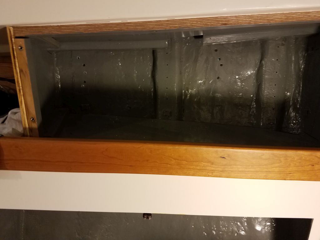
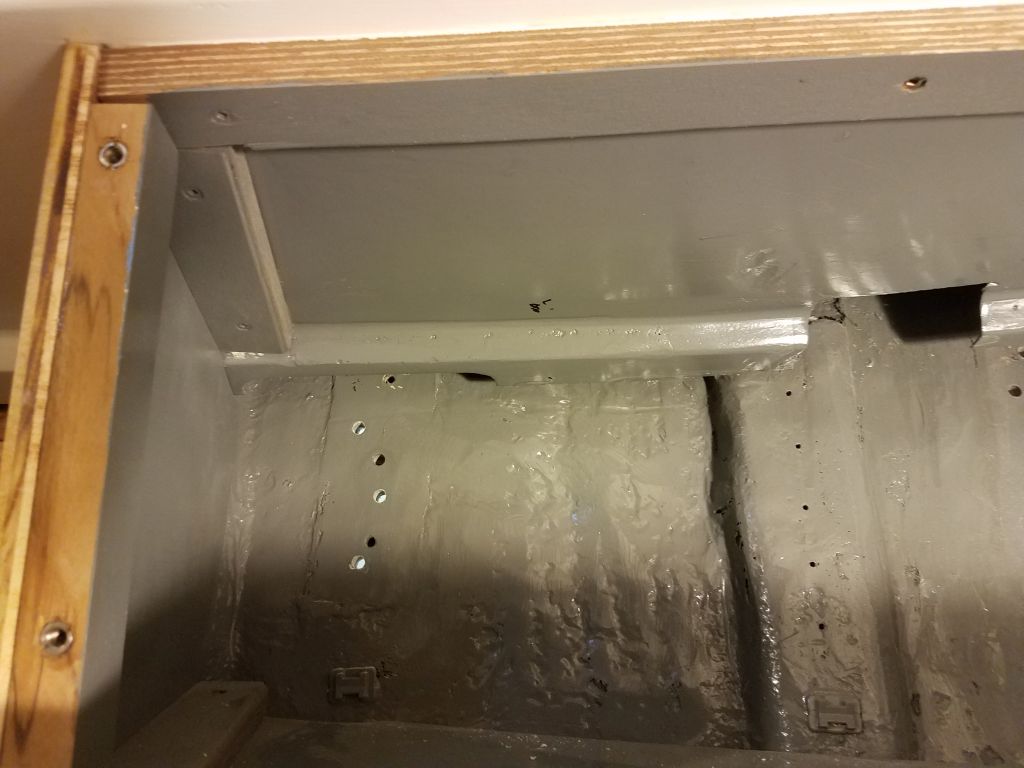
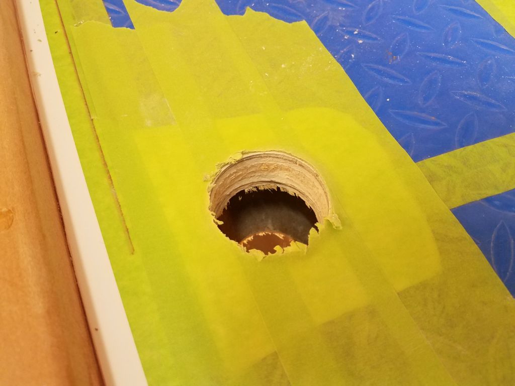
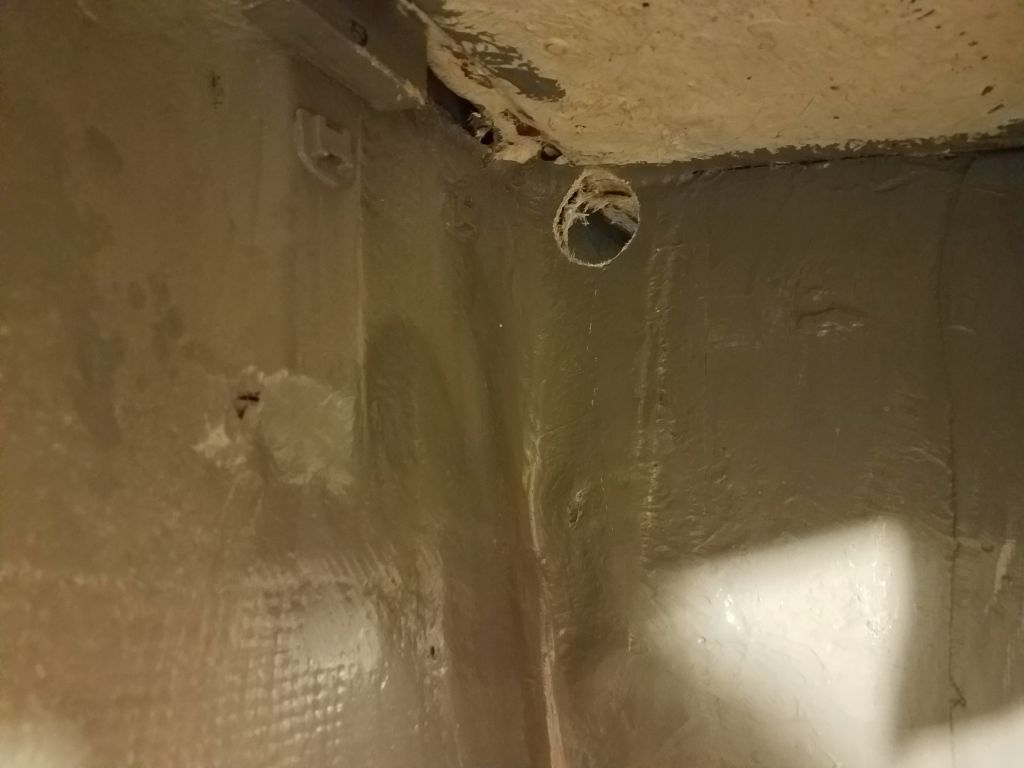
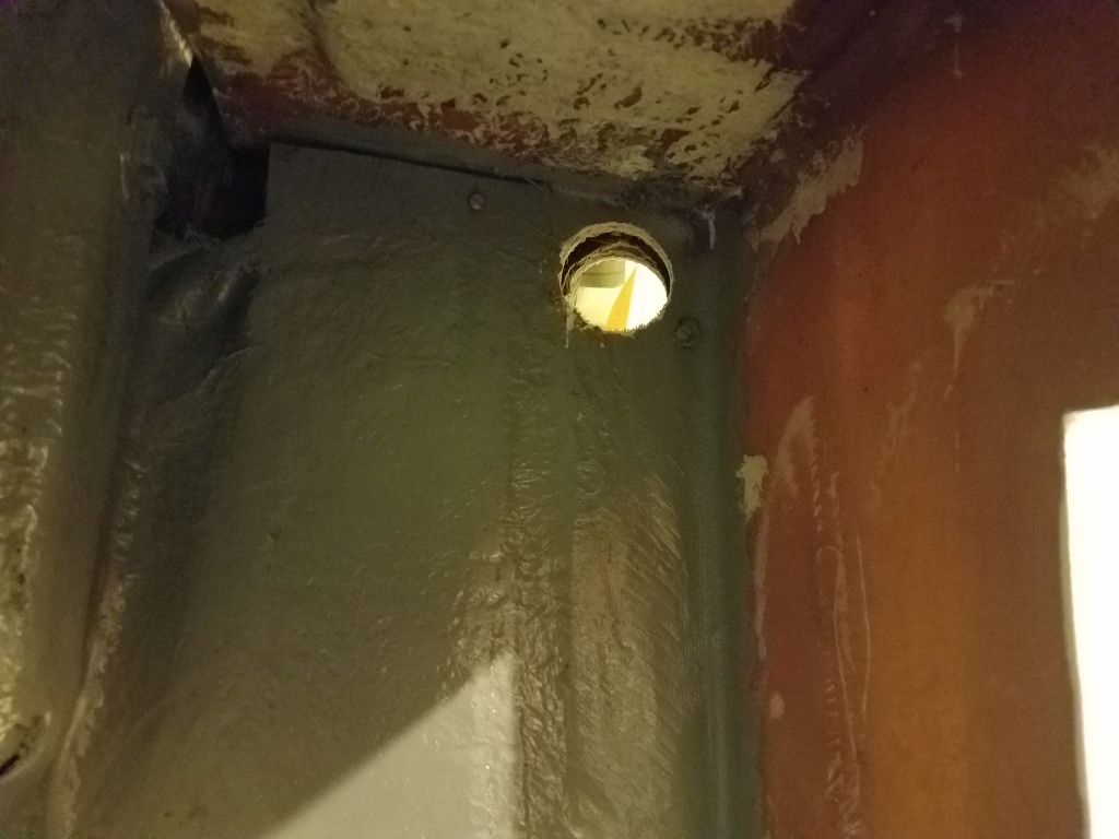
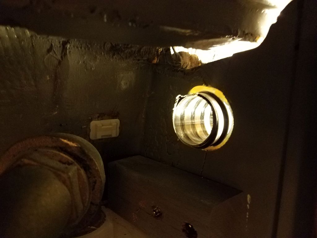
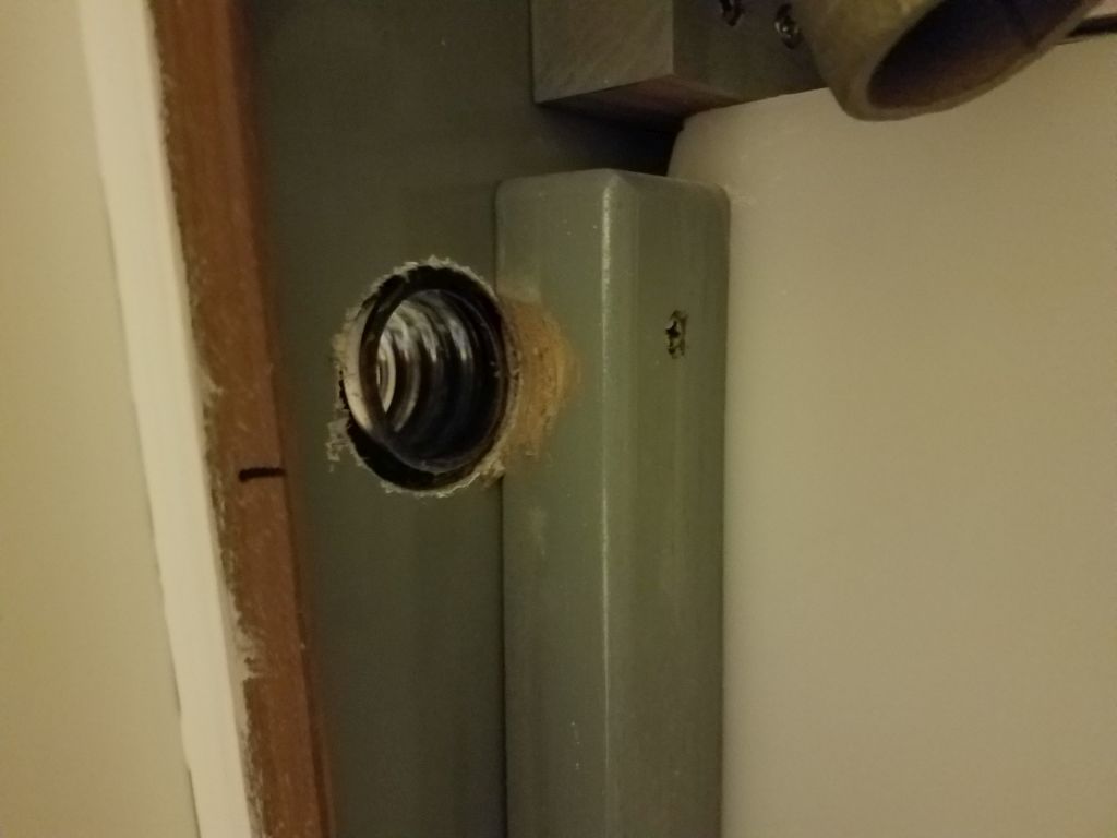
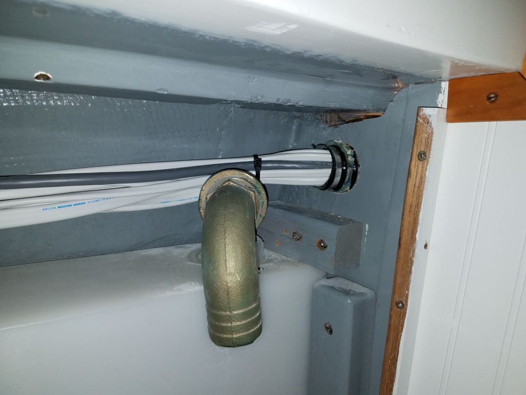
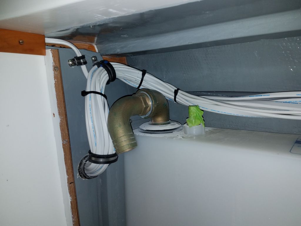
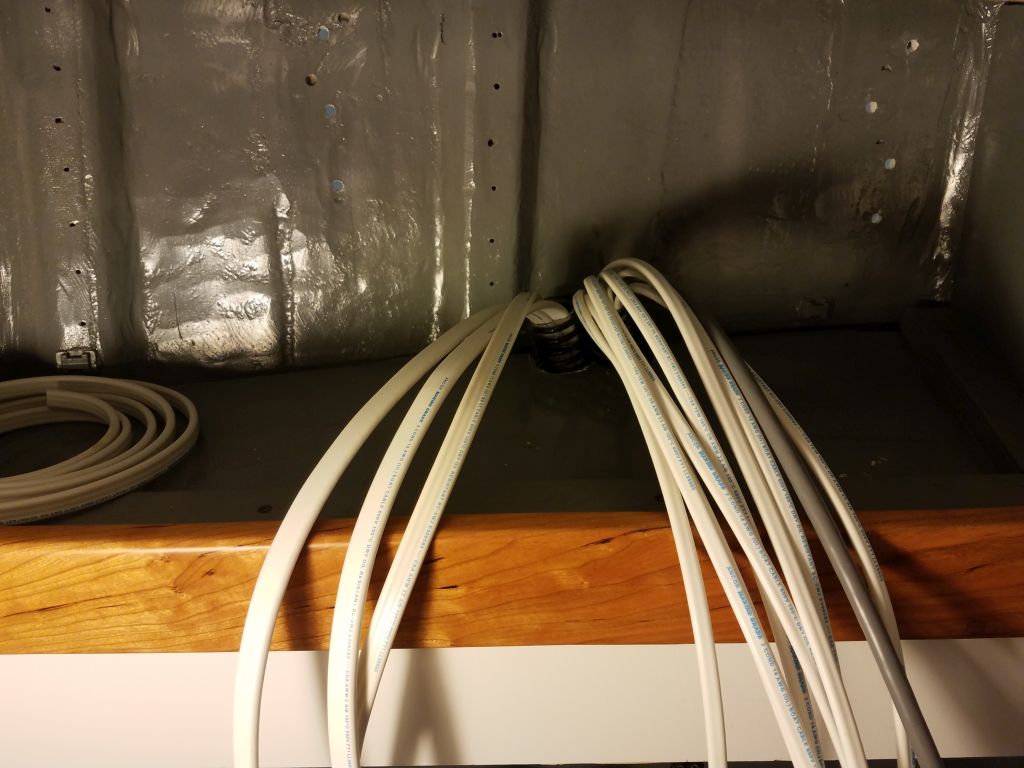
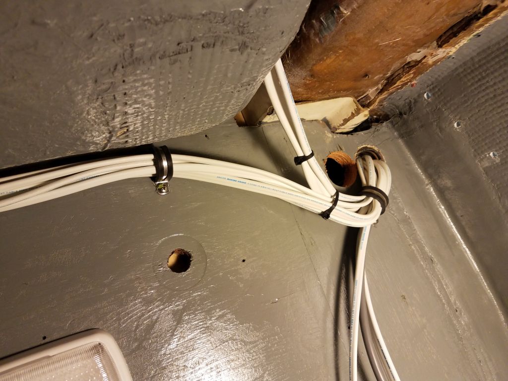
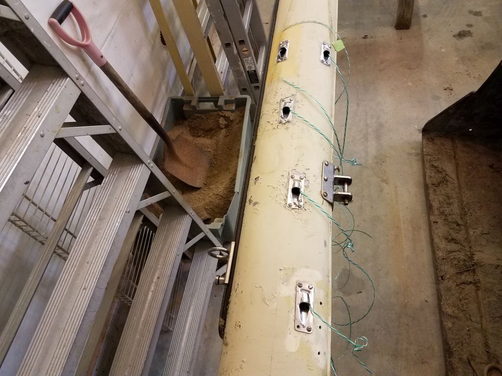
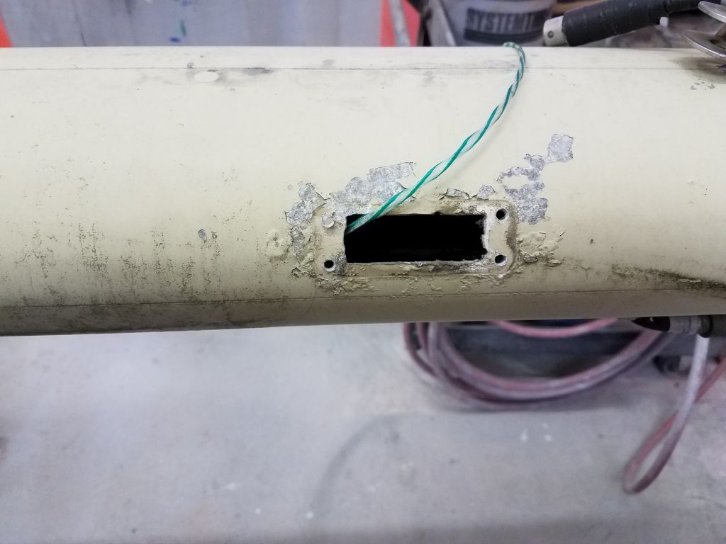
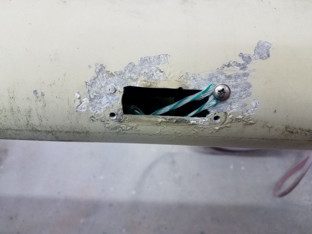
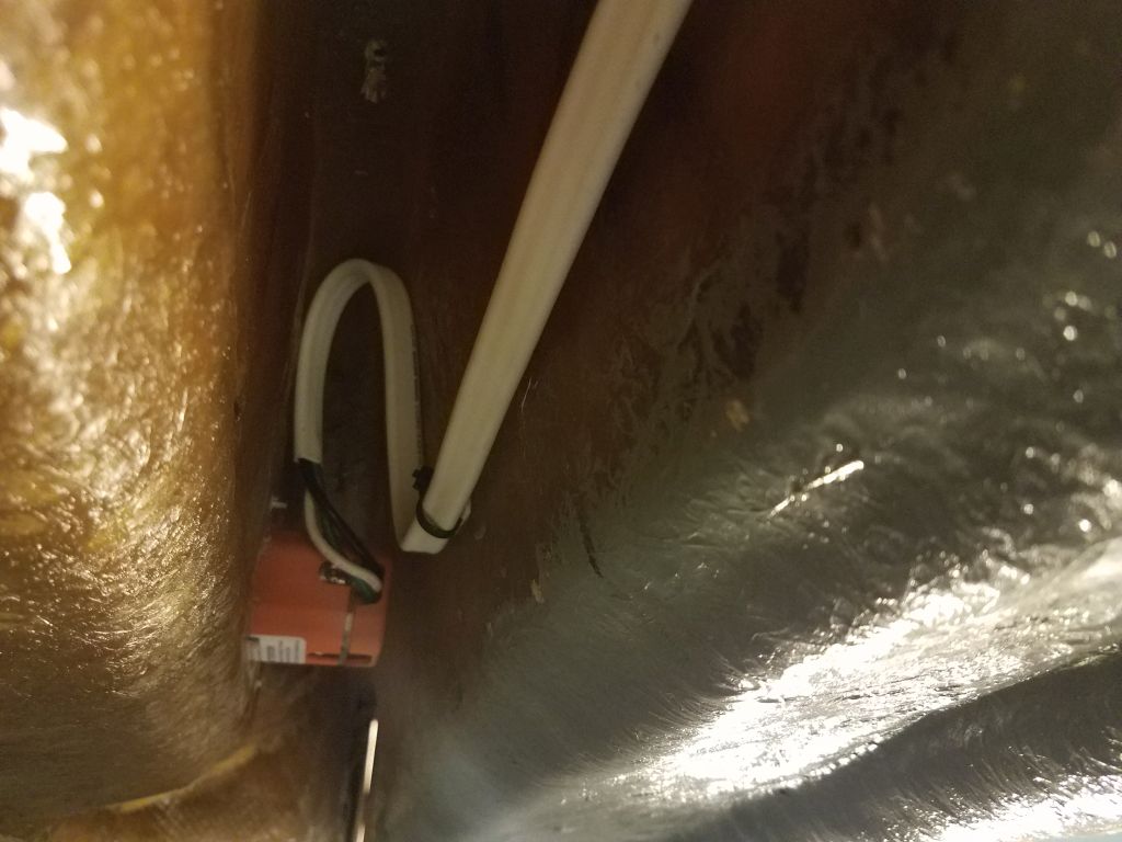
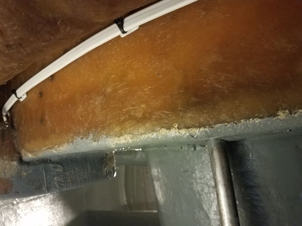
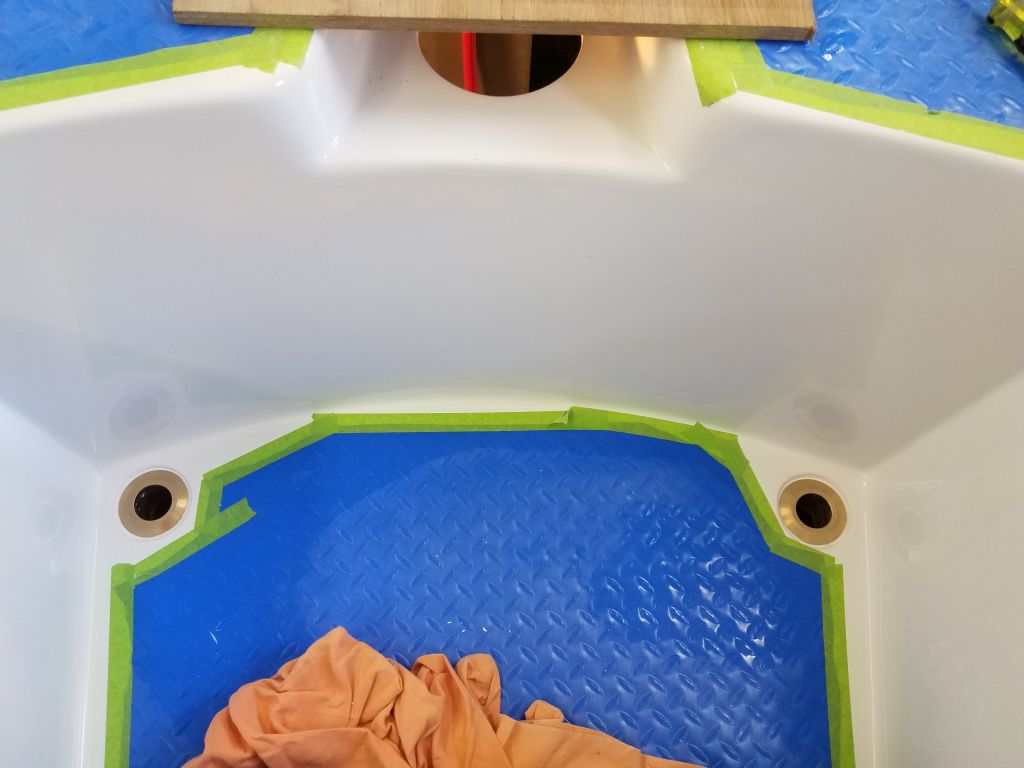
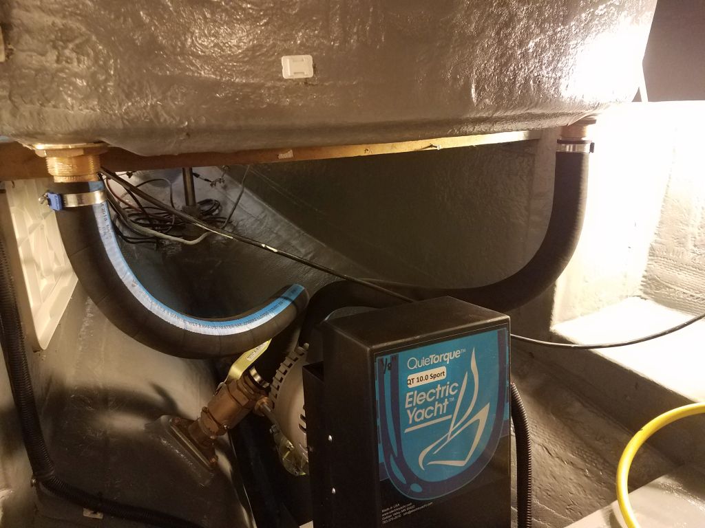
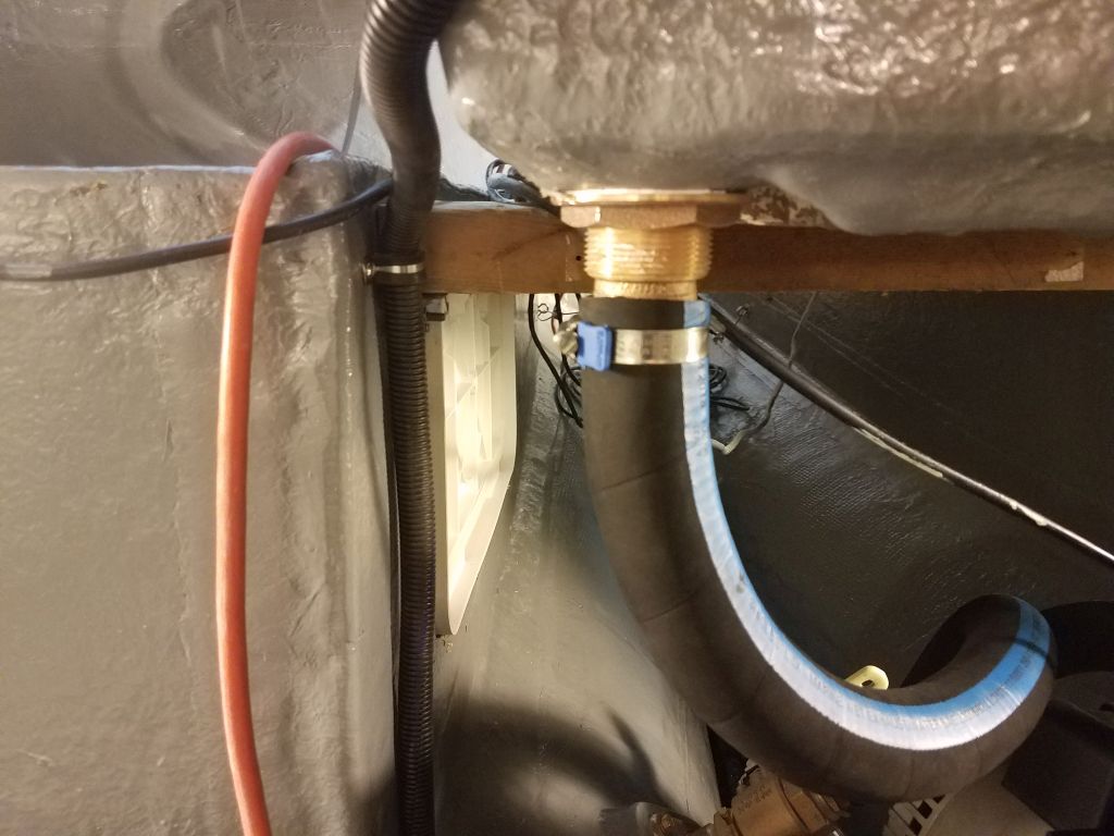
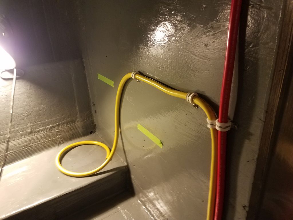
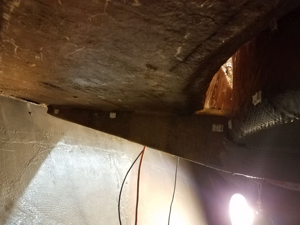
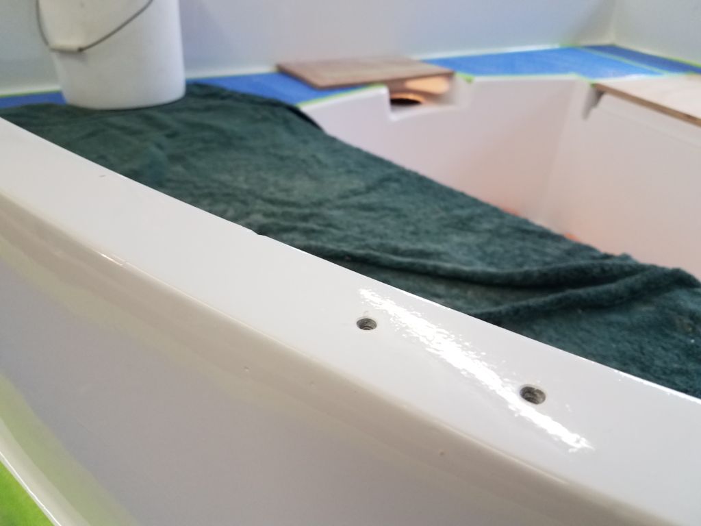
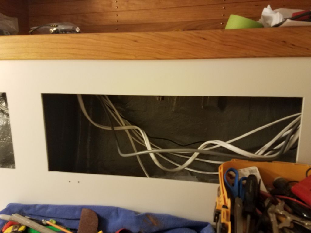
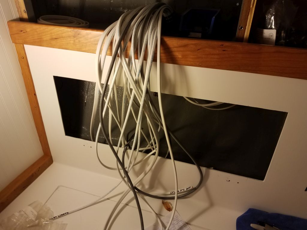
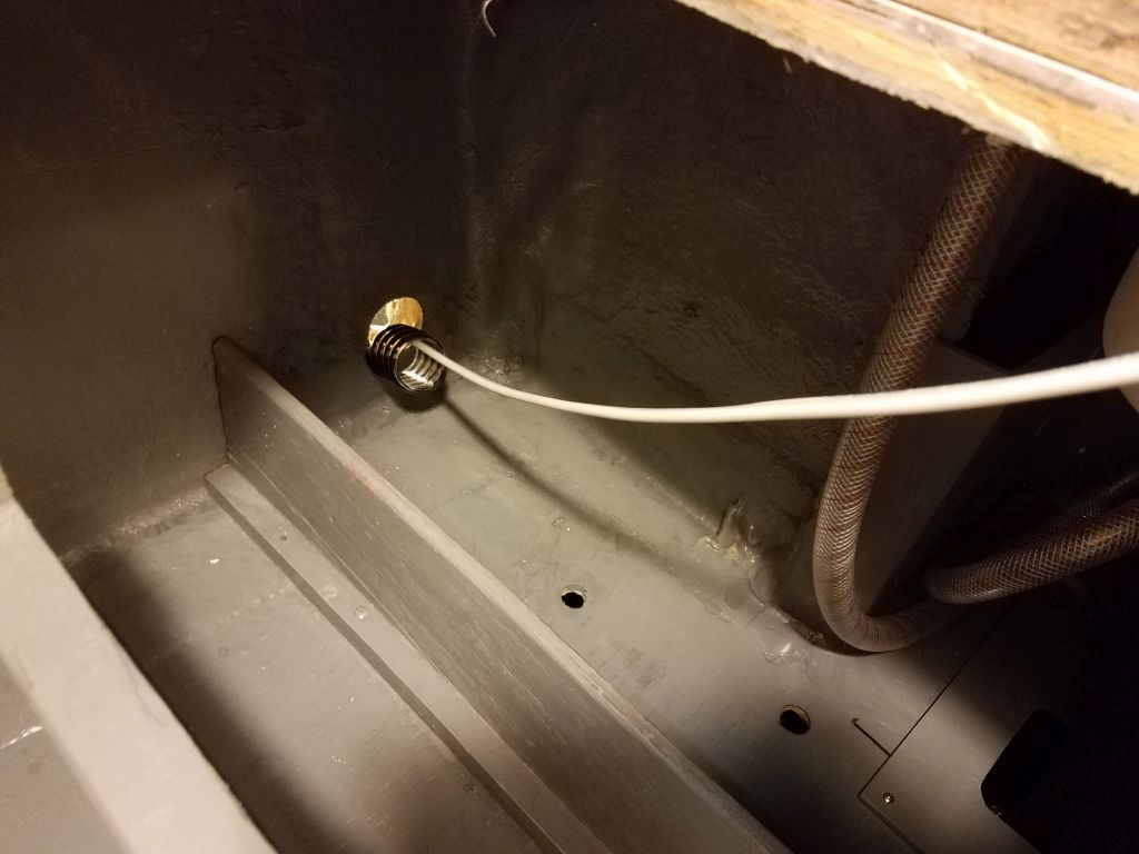
Before beginning the cable run, I drilled another set of holes as needed in the settee back and holding tank area to accommodate this and additional cable runs alongside the full run of cables from a few days earlier. I was pretty sure from the getgo that the supplied length of transducer cable wasn’t going to be enough to travel the convoluted distance between the transducer and the display, and I soon confirmed this as I led the cable loosely through the new conduits leading to the starboard settee and wiring area, then aft into the holding tank compartment, which was as far as the cable would reach (allowing ample slack in order to be able to later secure it properly). I ordered an extension cable that would allow me to lead the cable the rest of the way to the location of the display, but I’d have to wait a few days for its arrival.
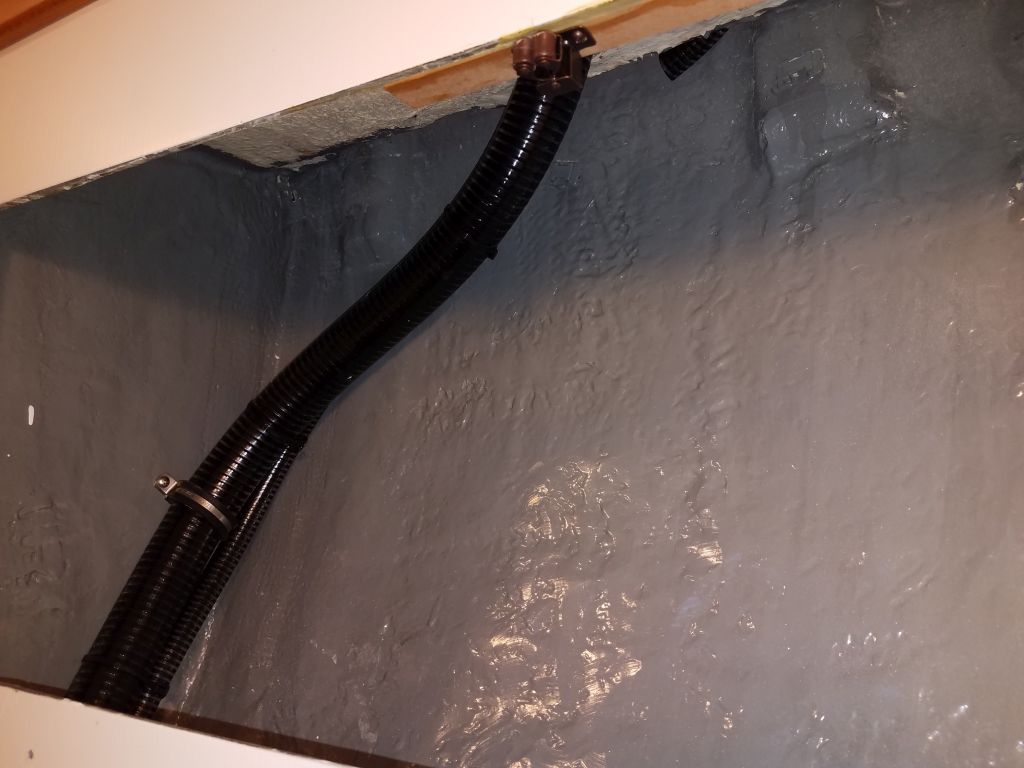
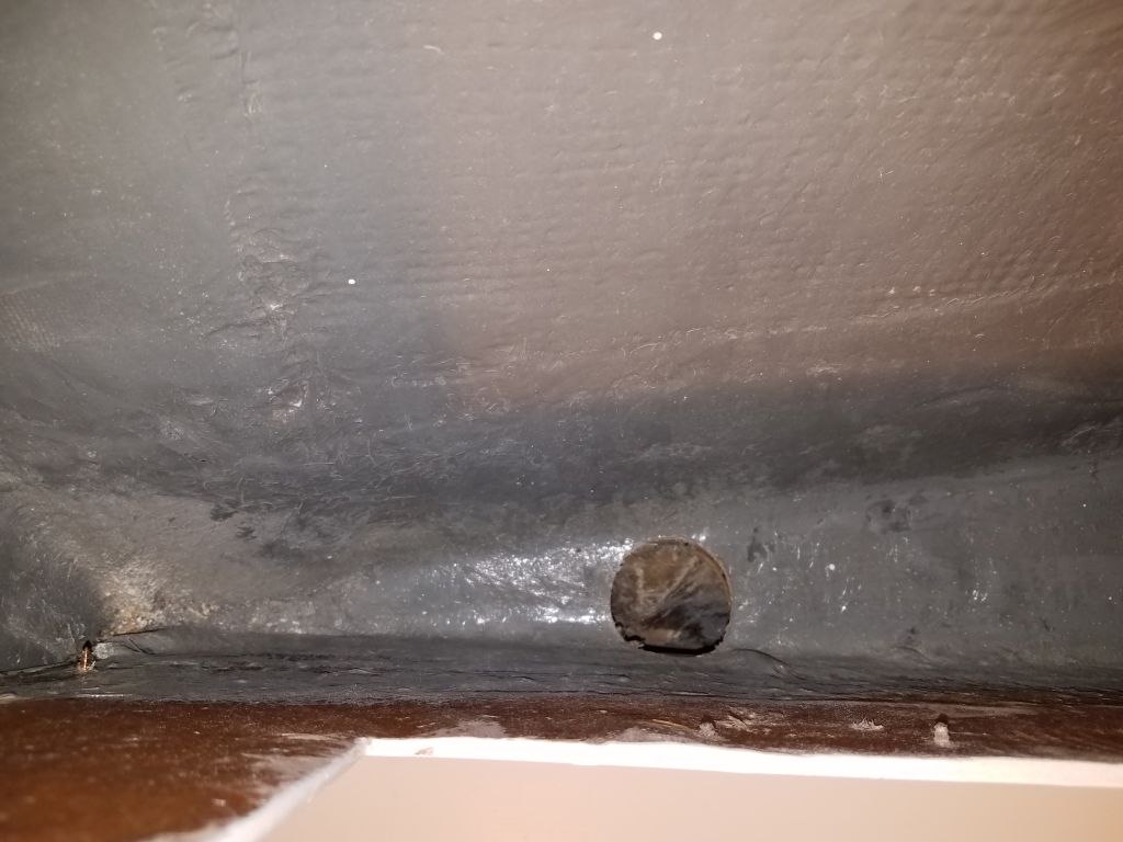
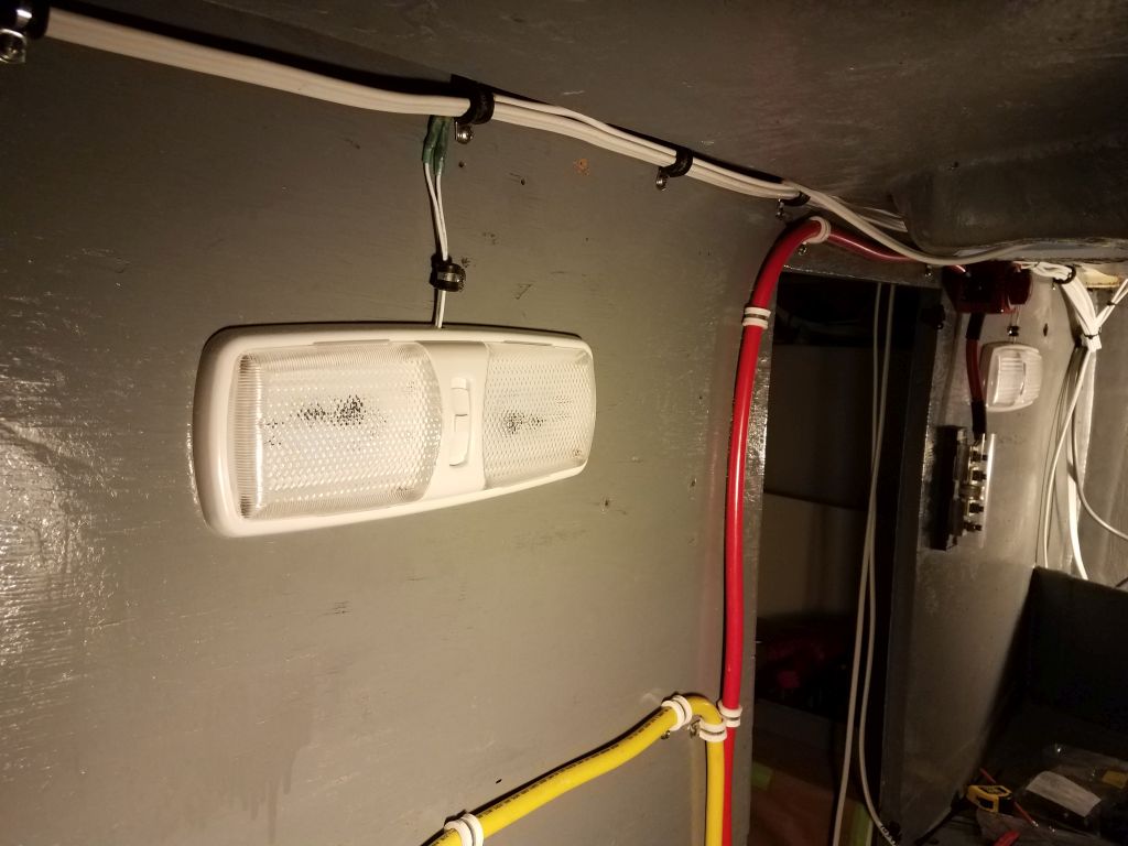
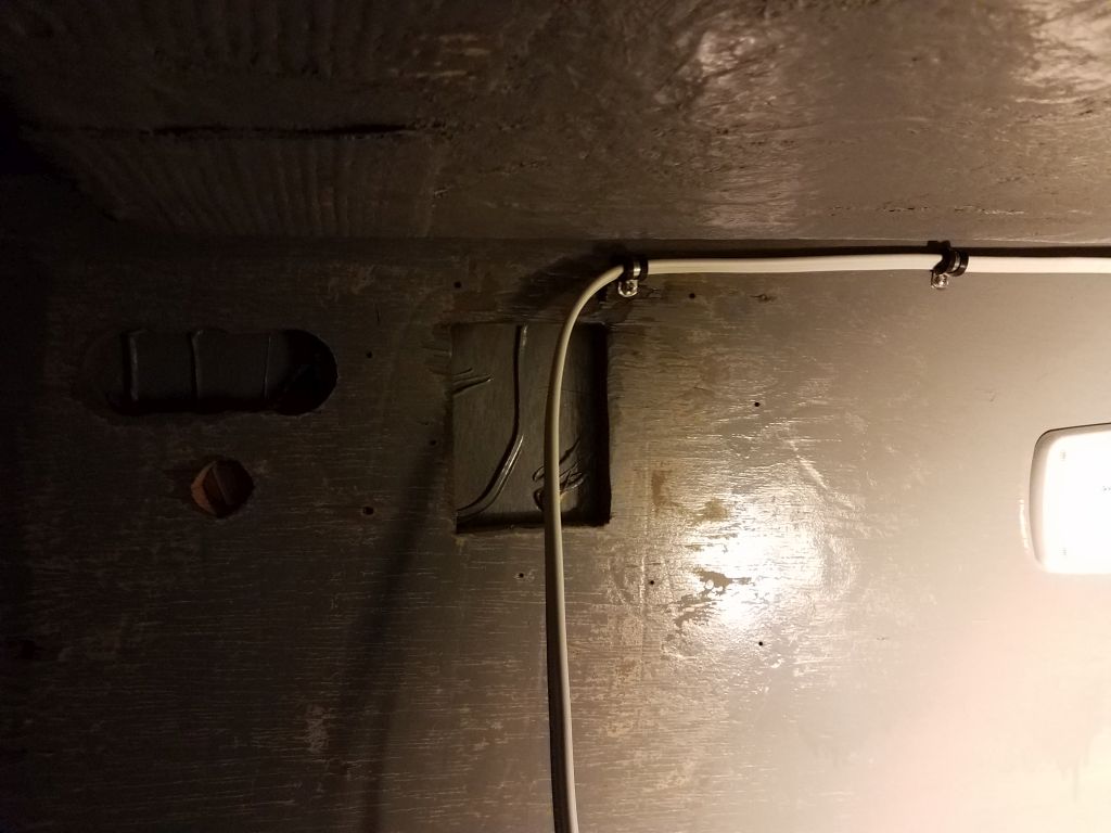
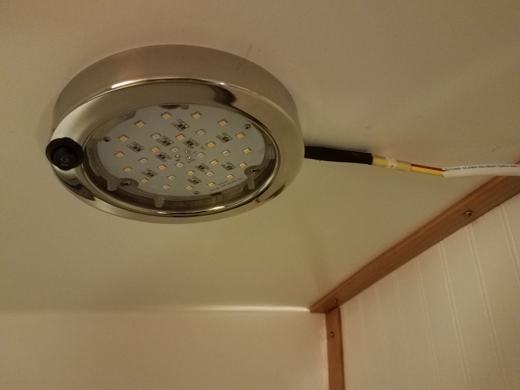
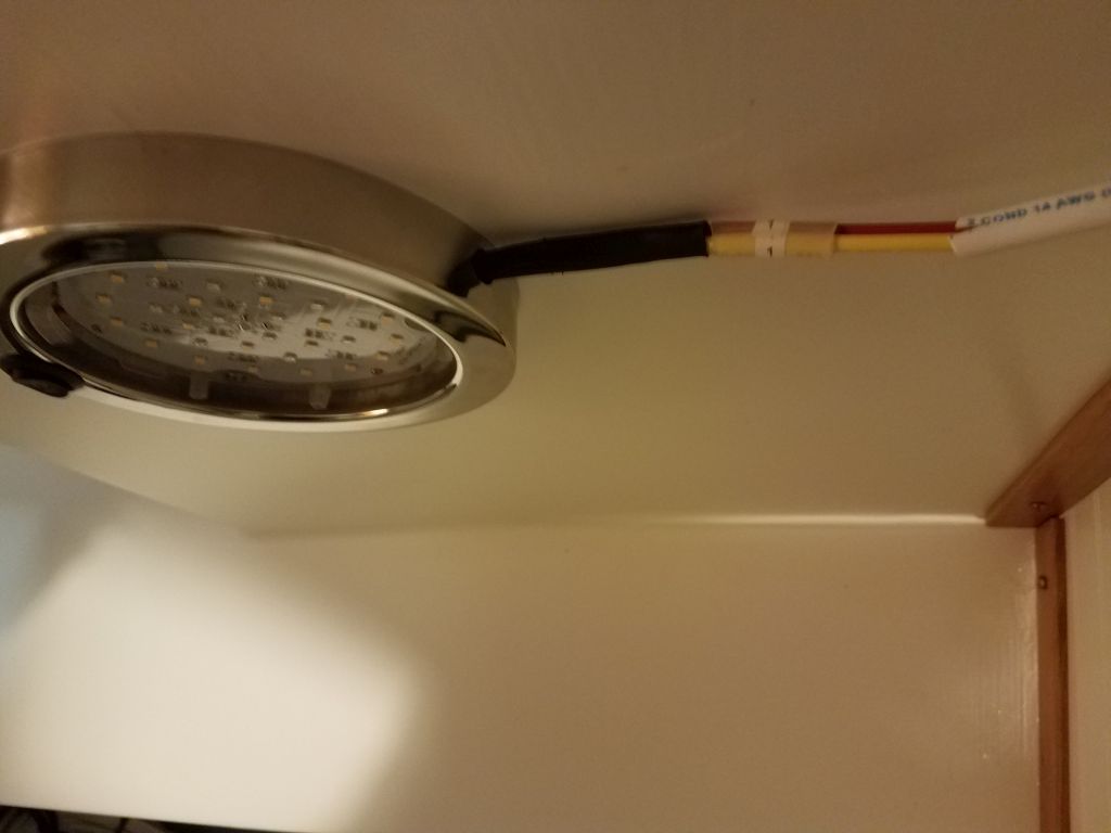
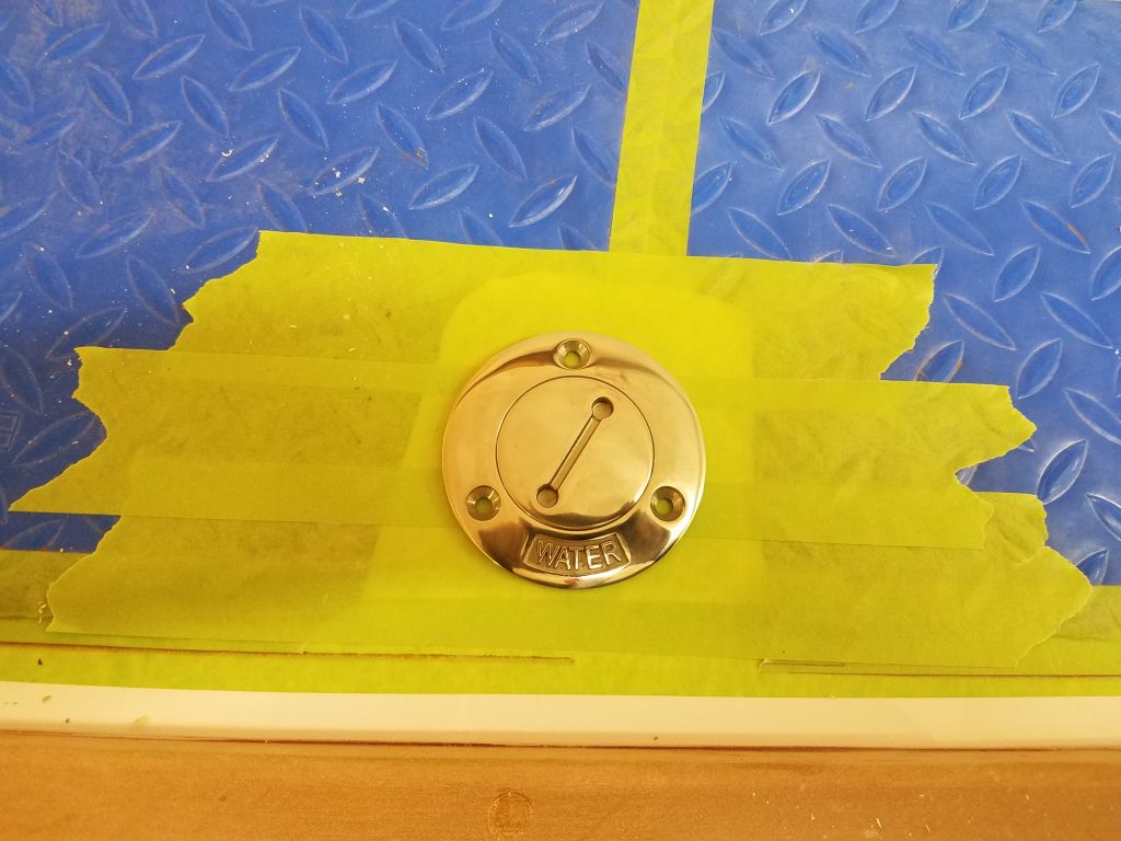
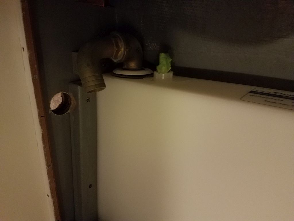
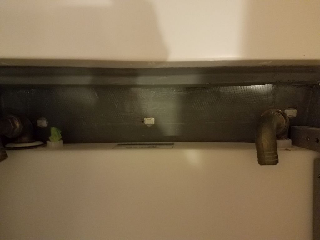
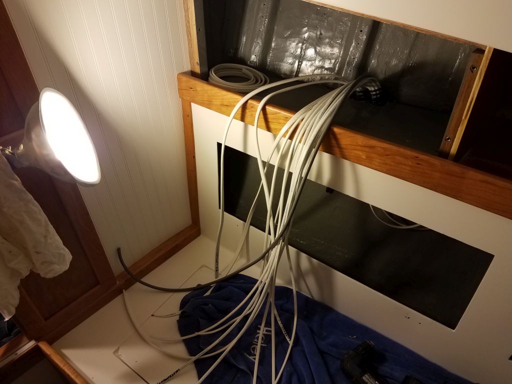
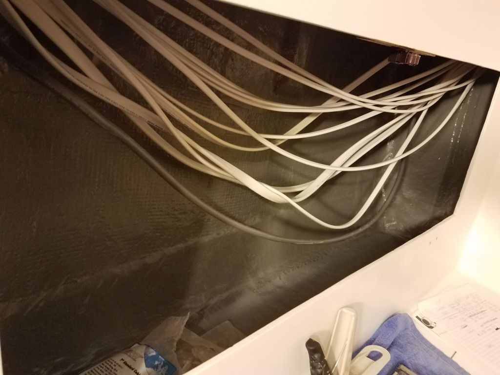
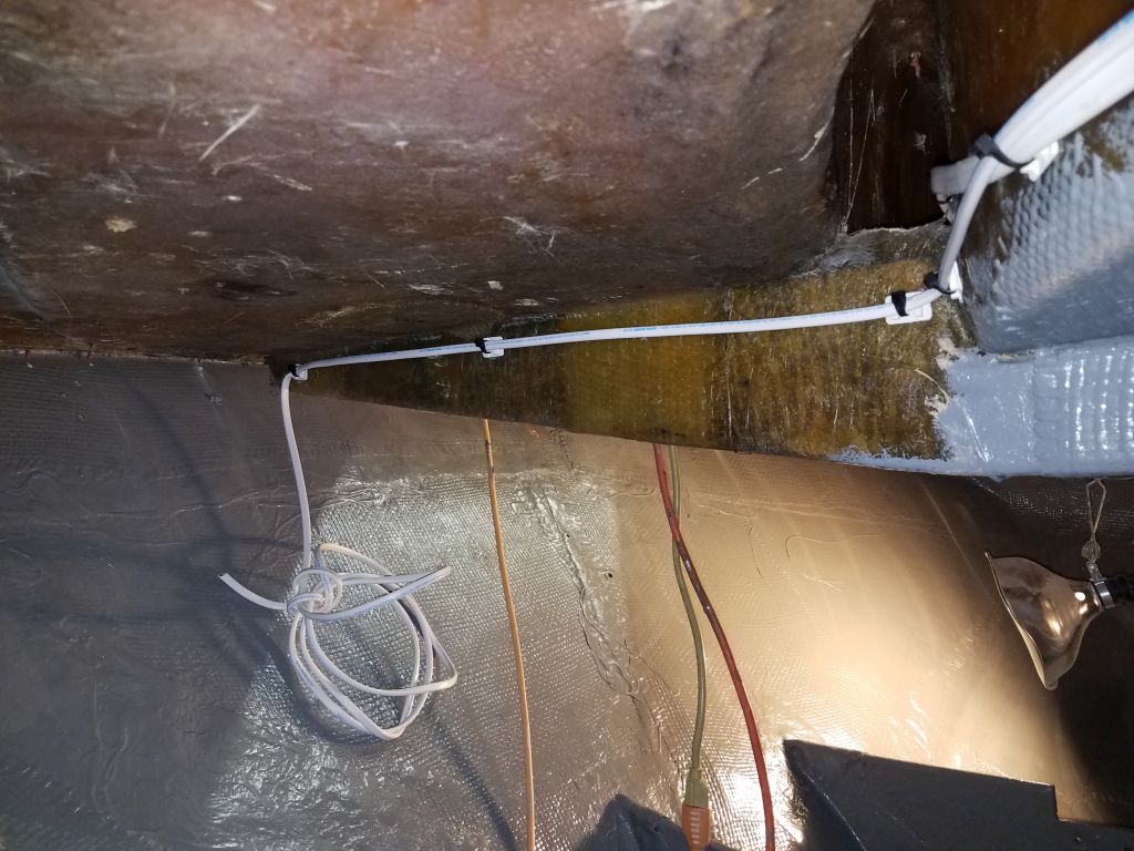
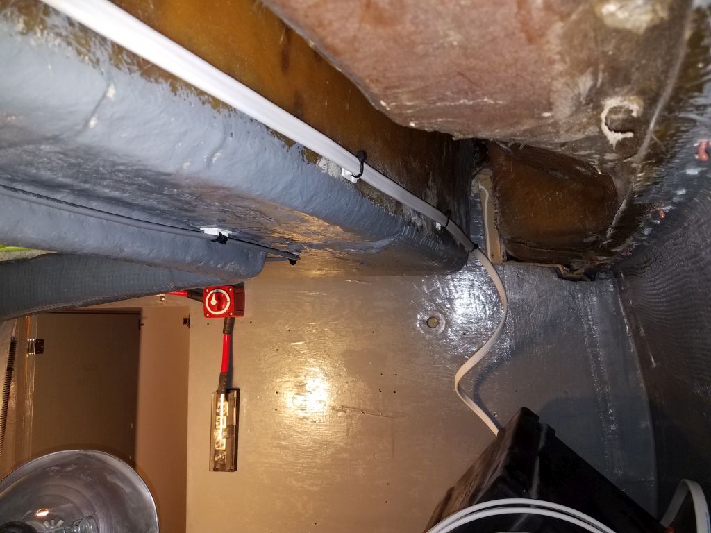
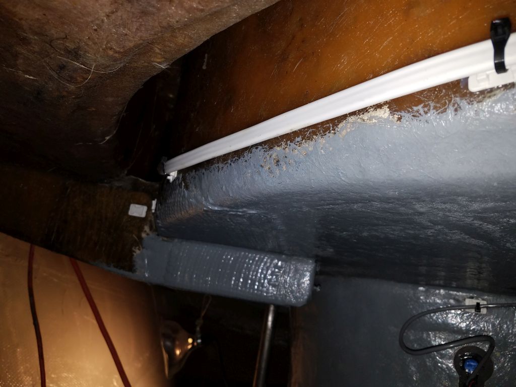
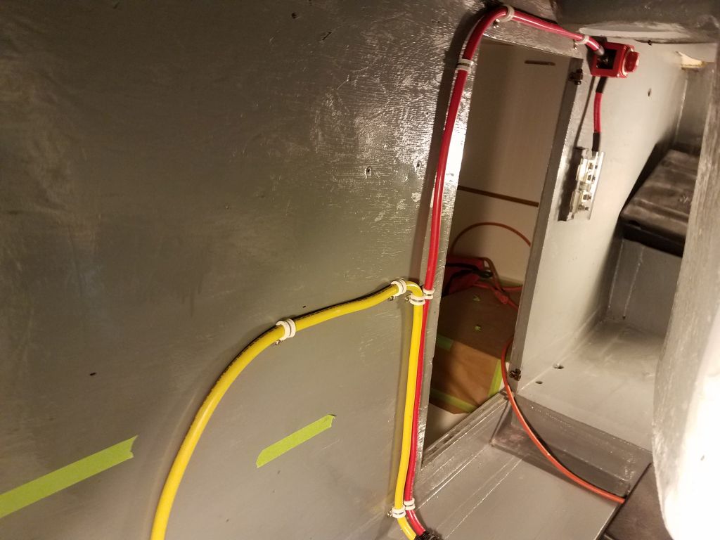
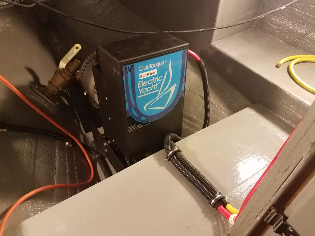
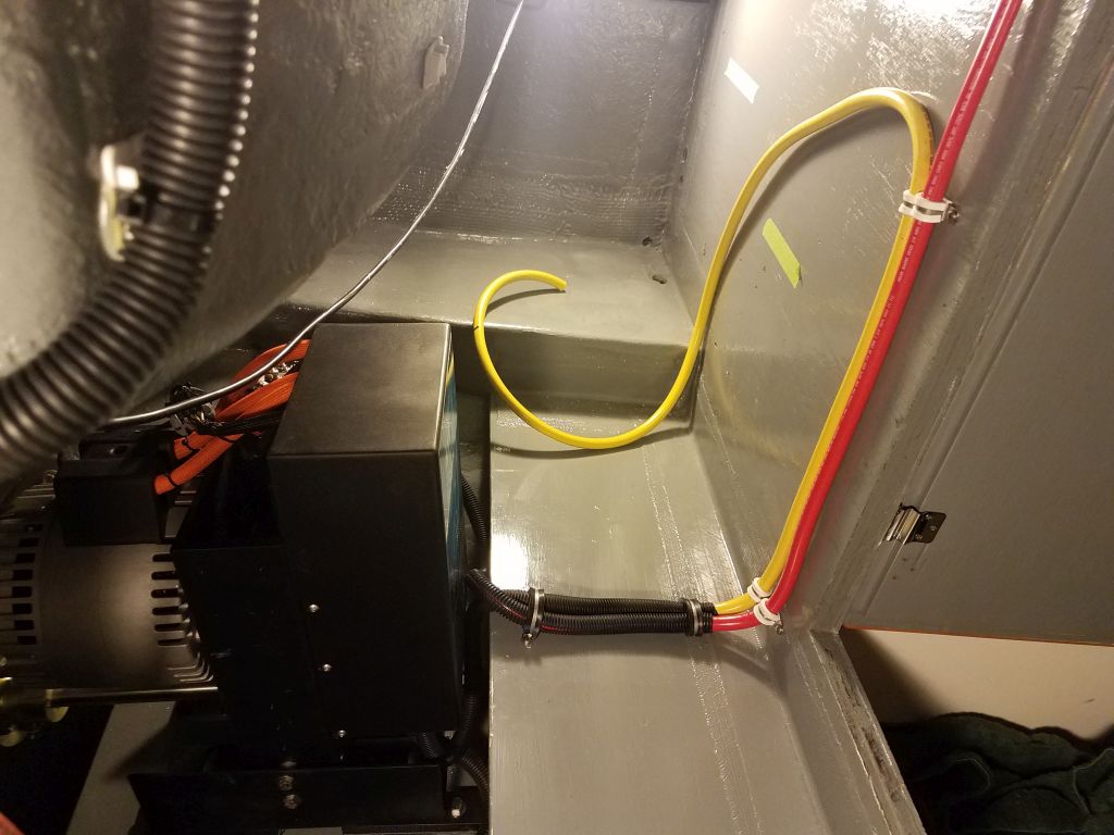
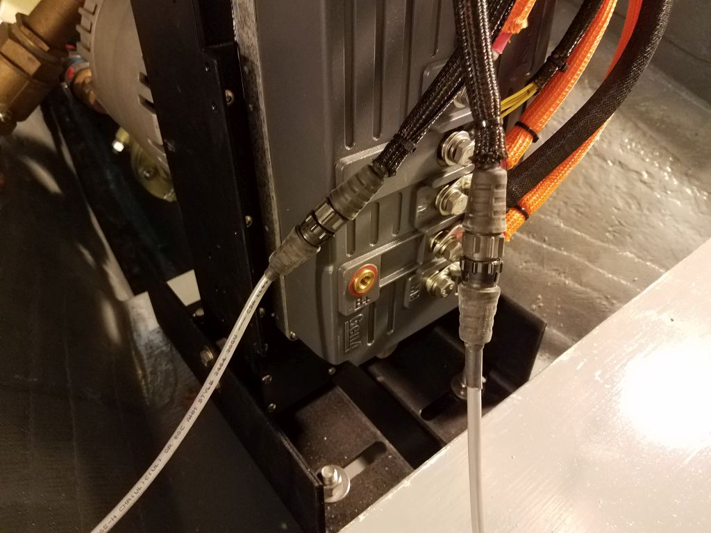
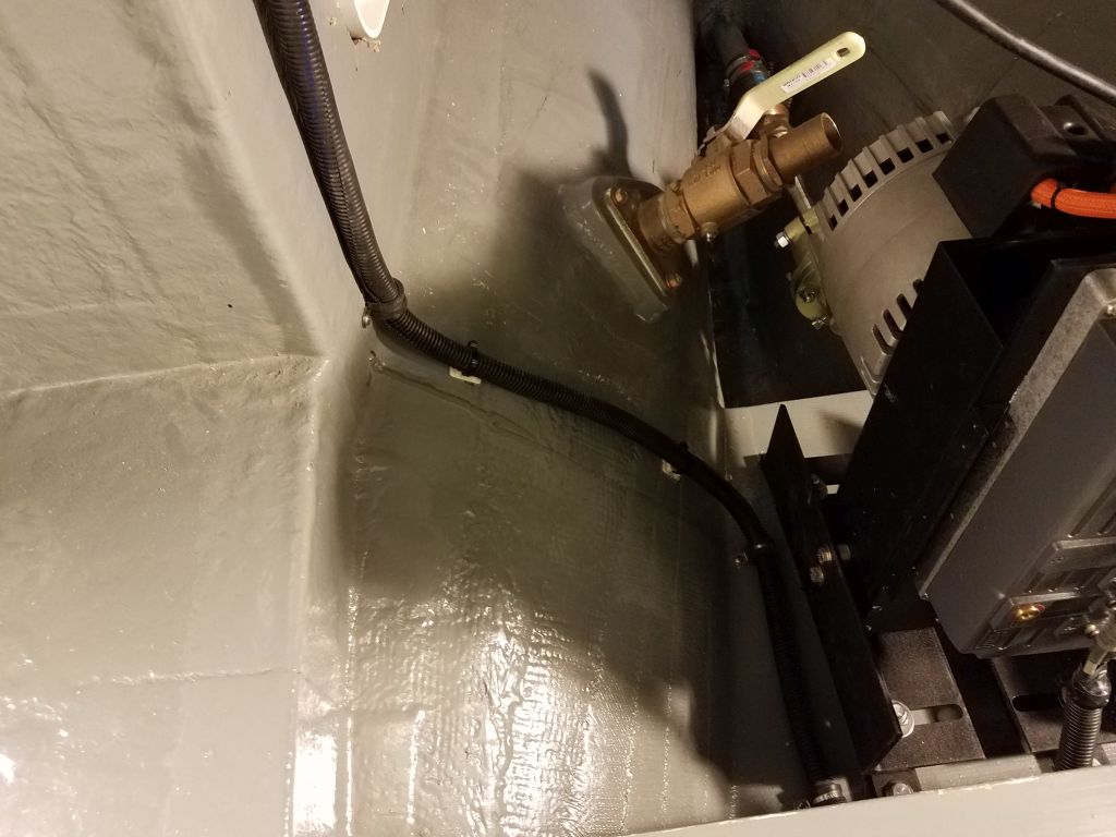
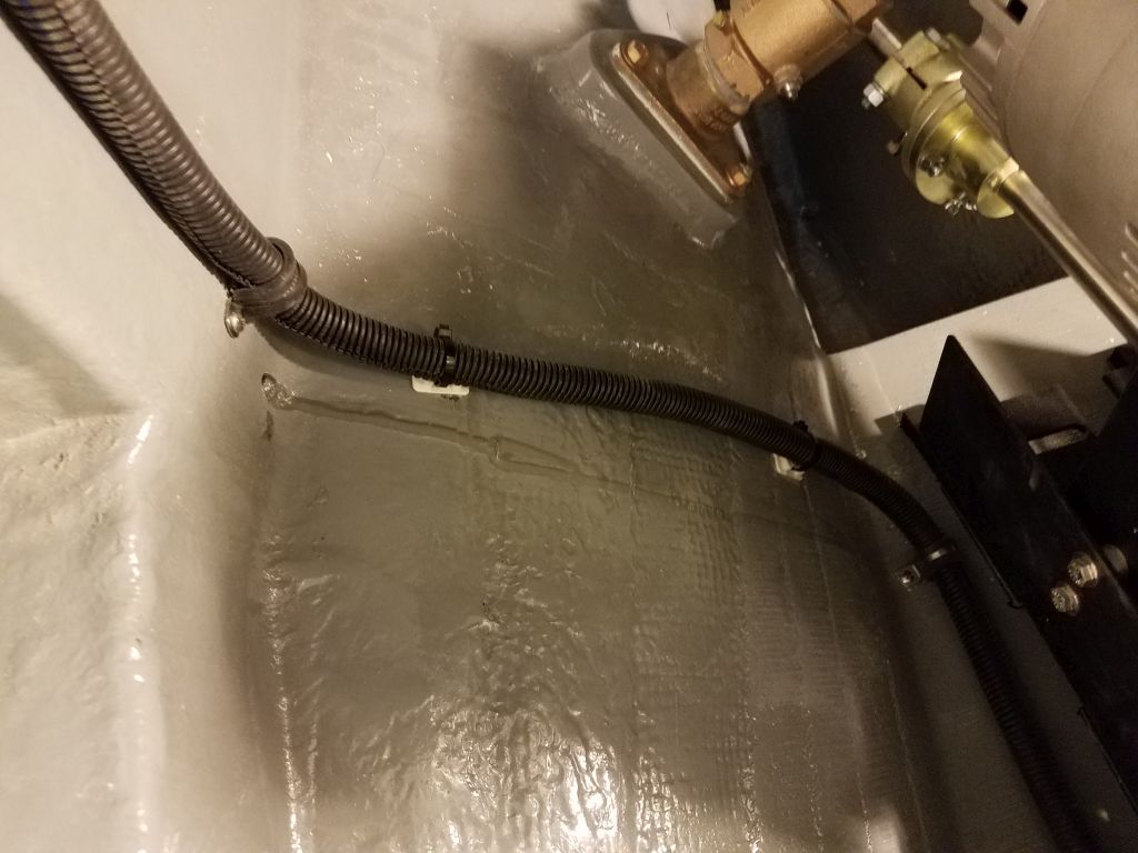
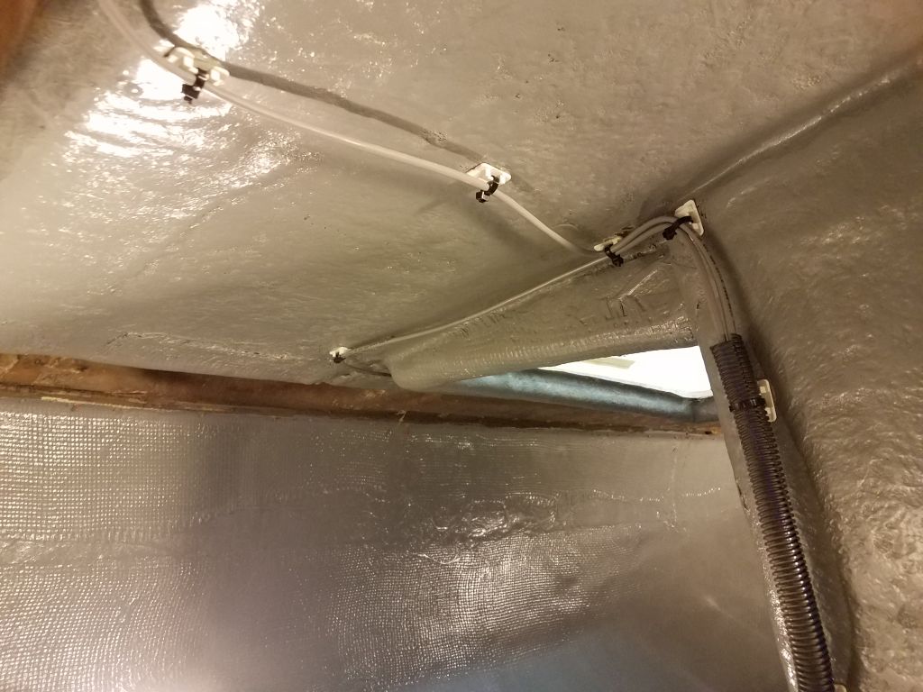
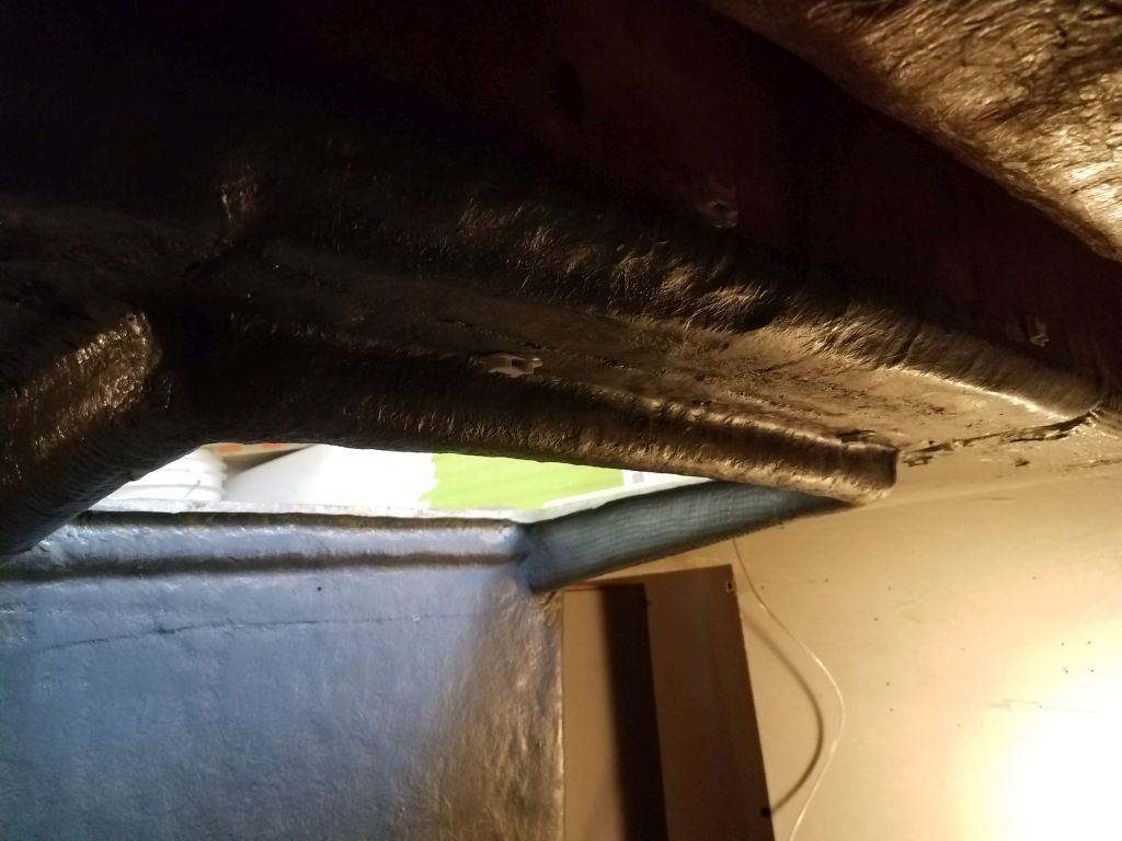
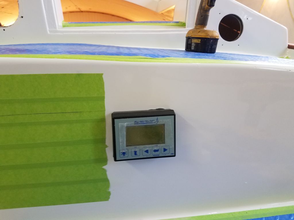
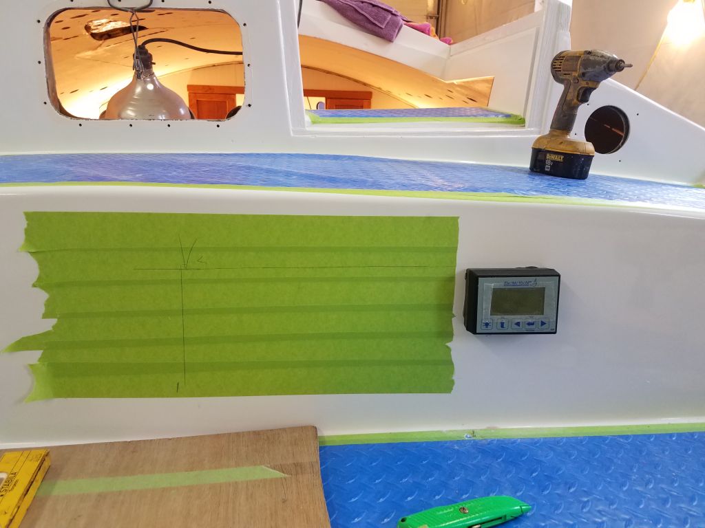
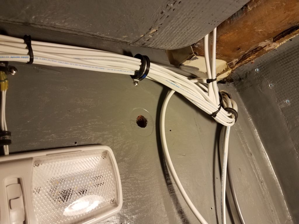
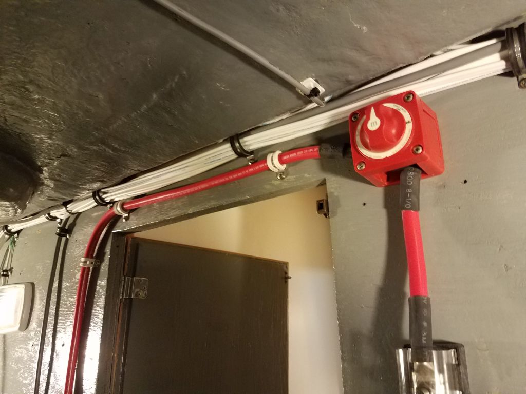
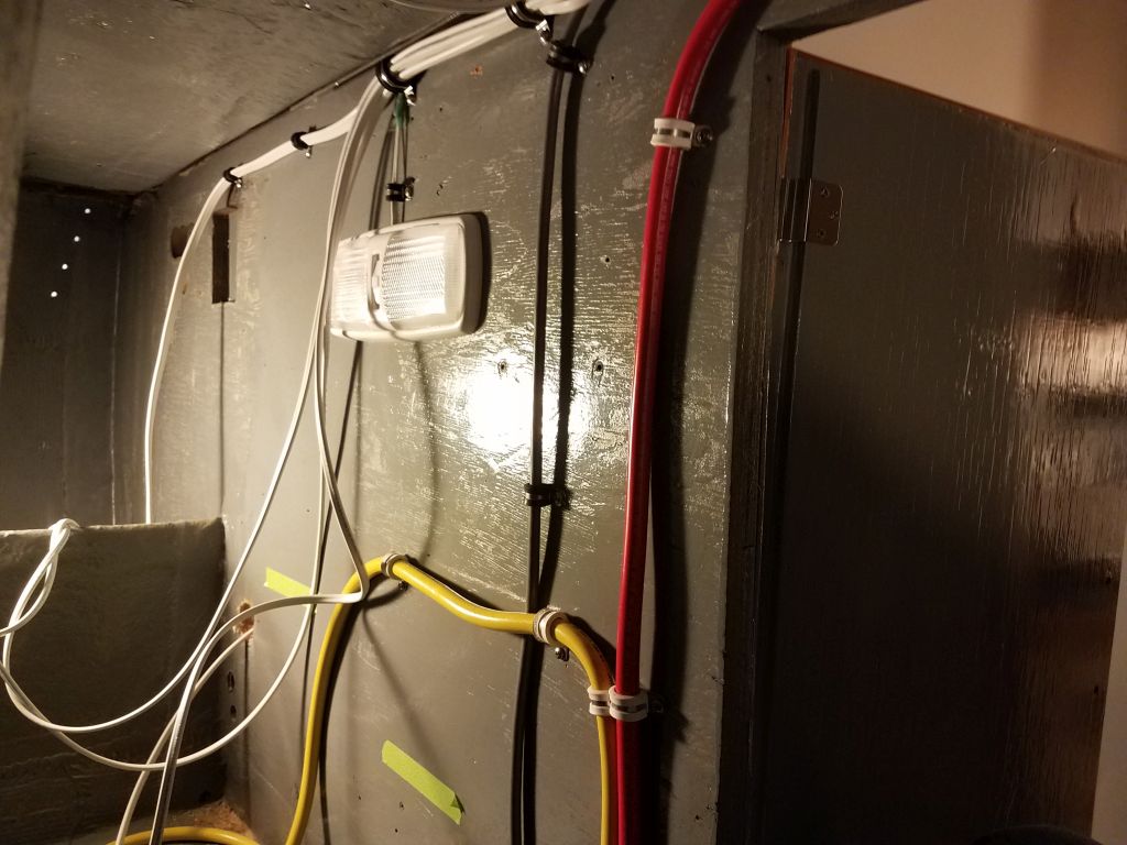
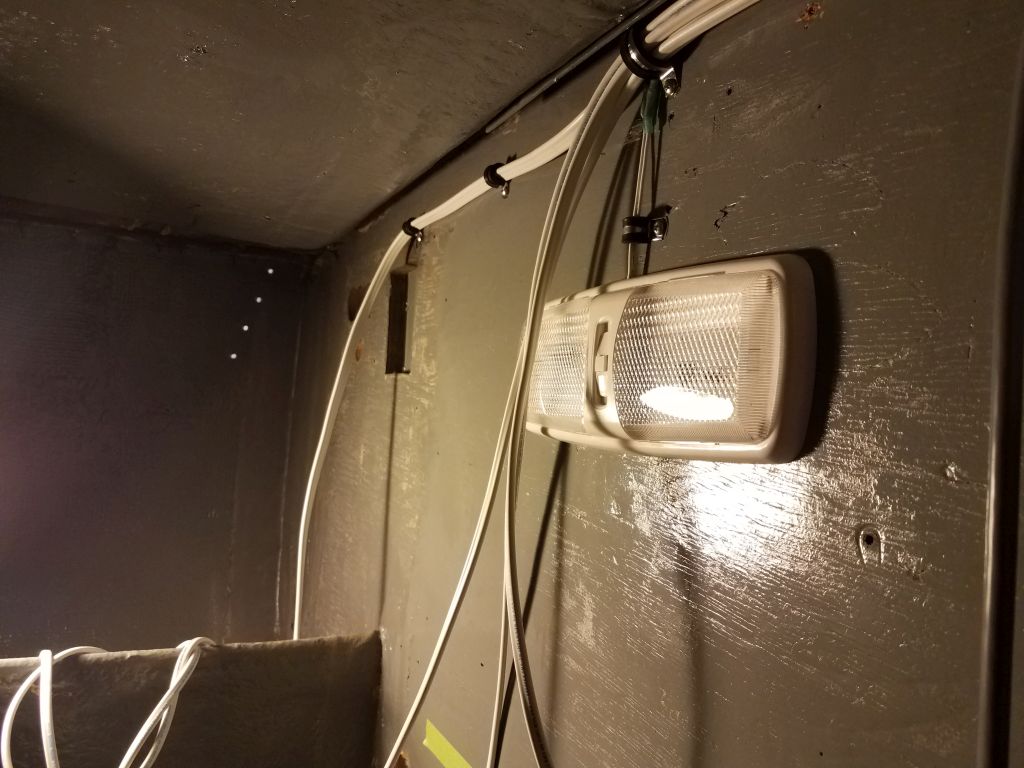
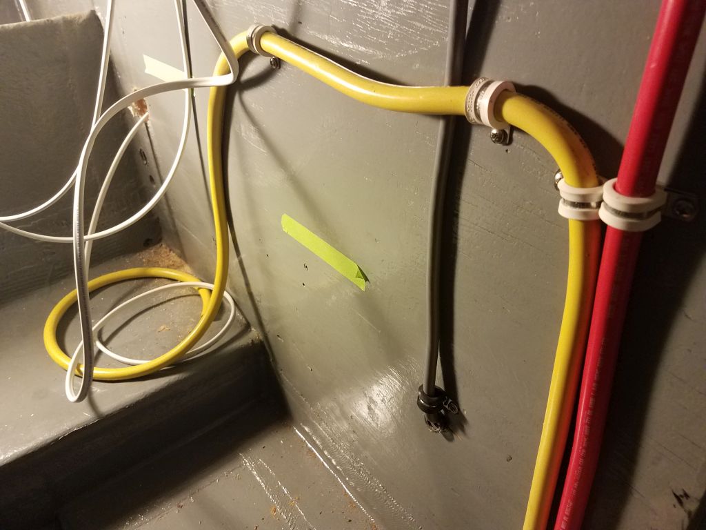
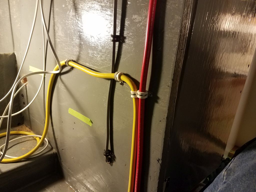
Meanwhile, I led a series of additional cables aft along the starboard side, as I’d decided that it made the most sense to string the wires needed for the galley lights, galley-mounted 12-volt outlet, and the potable water pump through this route instead of through the forward/port route. Since I already needed another conduit opening along the starboard side to accommodate the transducer cable and some large wires to power the electric head, there was plenty of room to run some of the other wires which, upon reflection, seemed the best route after all. I strung these wires leaving ample slack that would allow me to clean them up and secure them in place once all the new wires were in place. I also ran the power cables for the second electric bilge pump, which I planned to mount in the bilge beneath the galley/head area, which was accessible through a hatch in the galley.
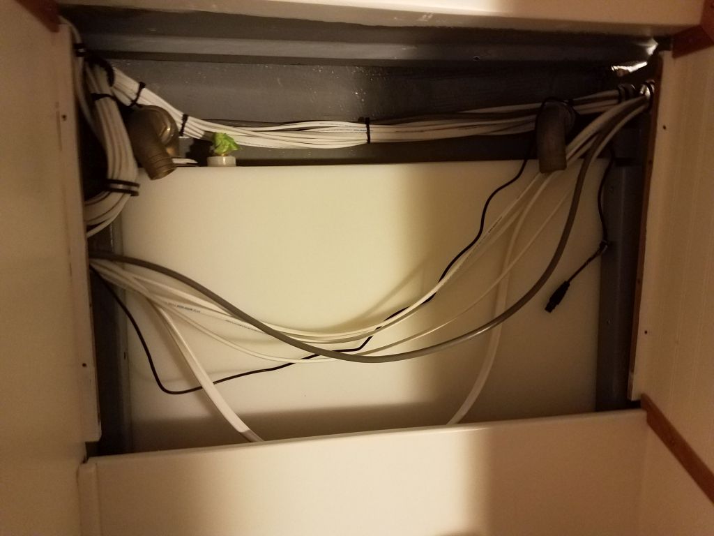
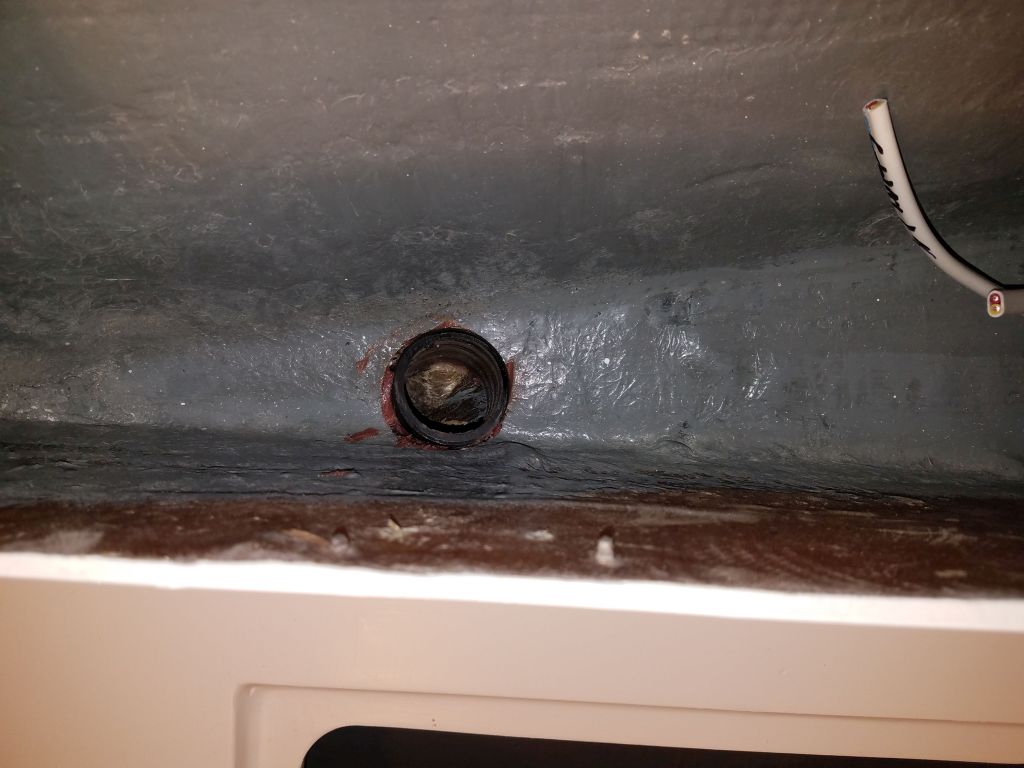
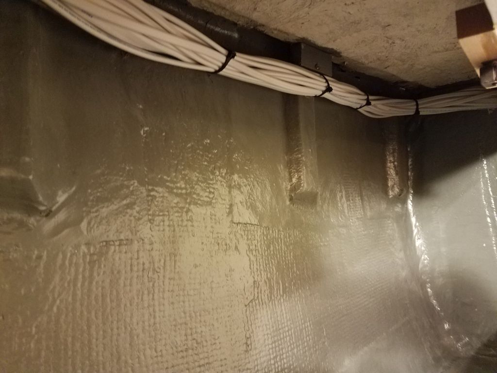
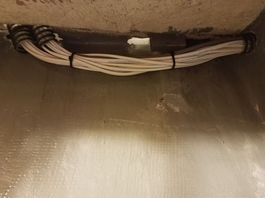
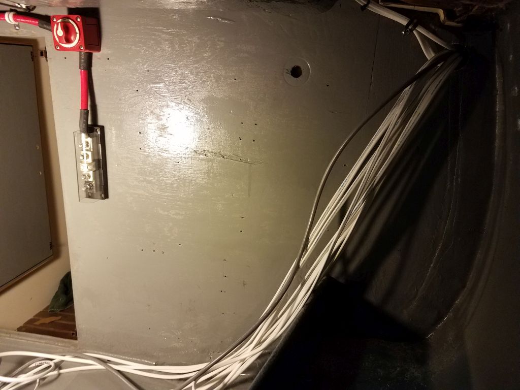
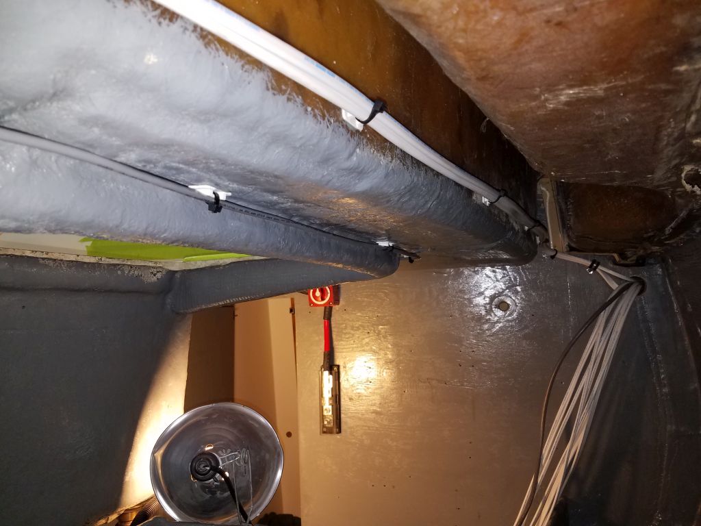
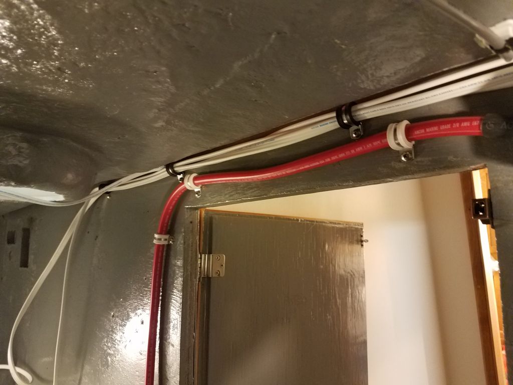
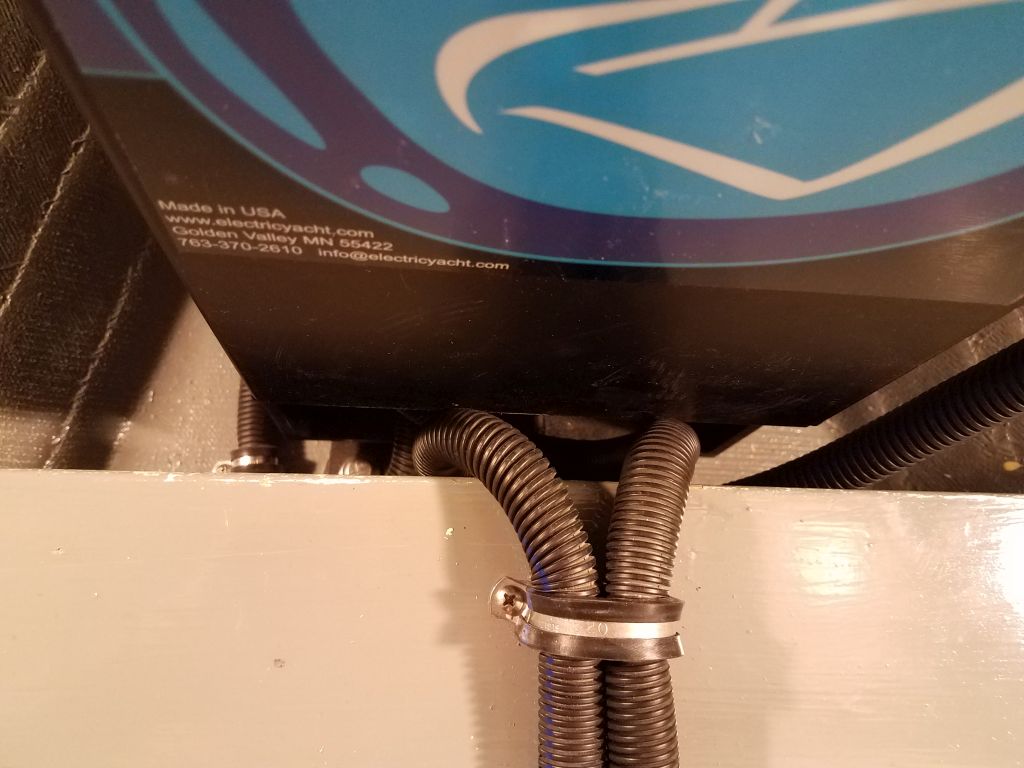
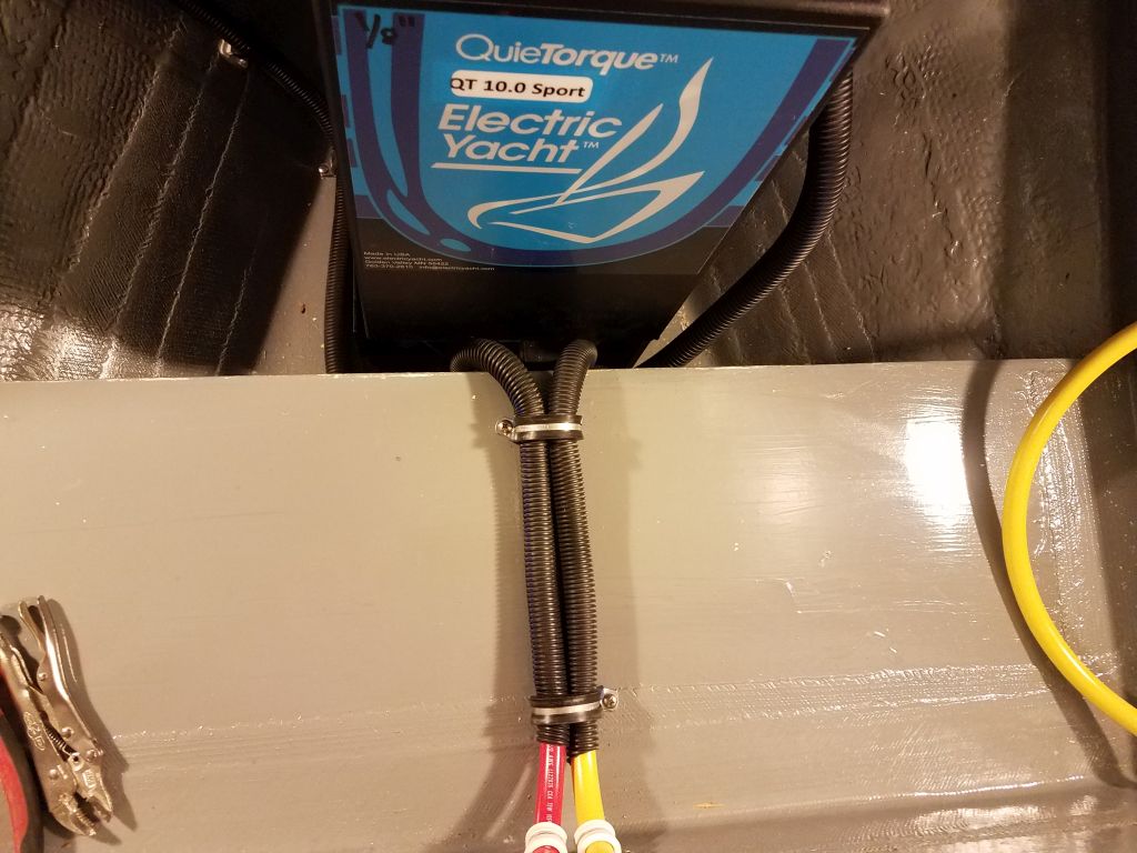
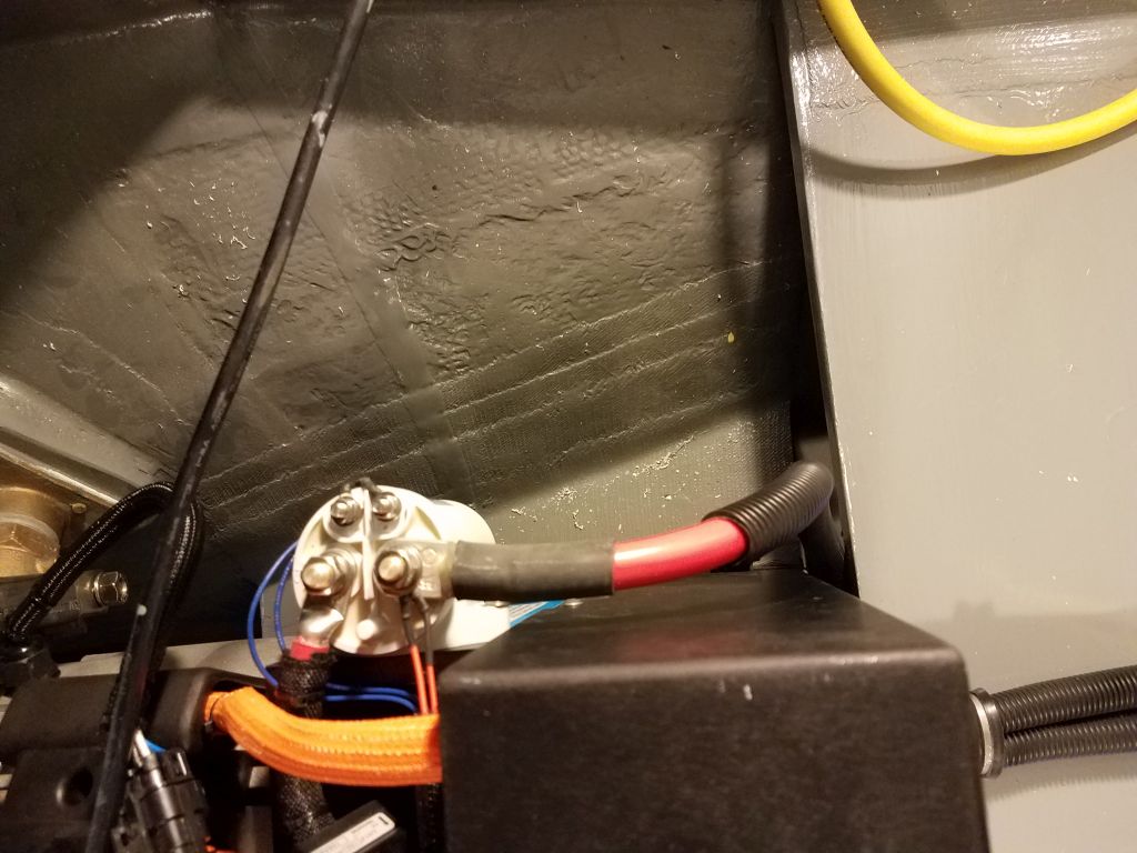
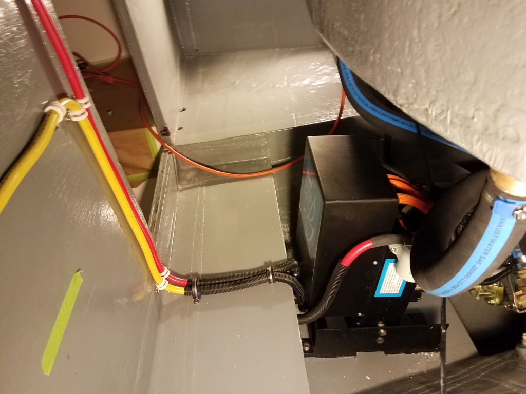
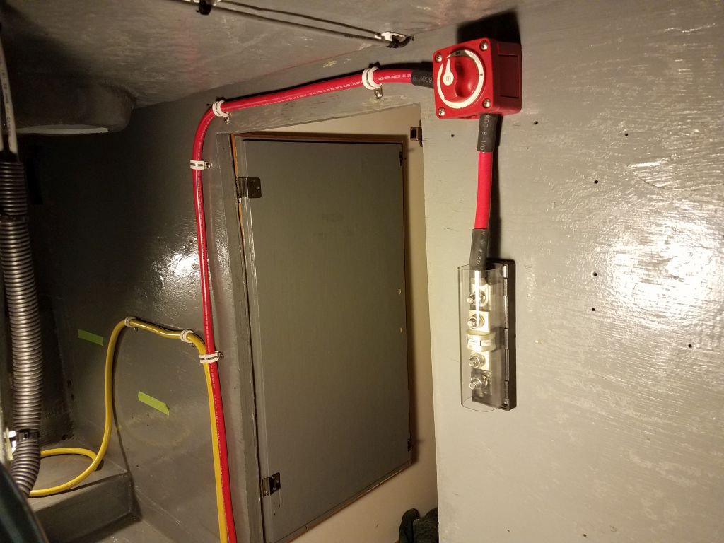
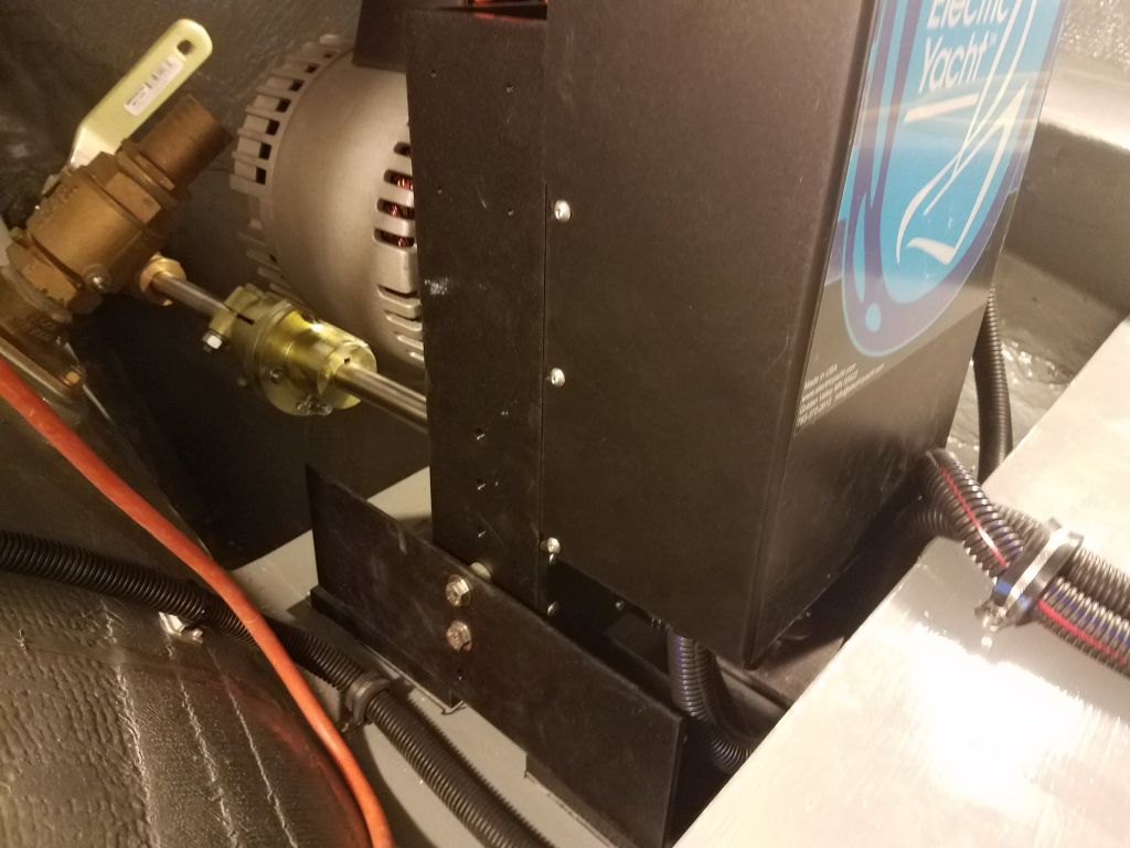
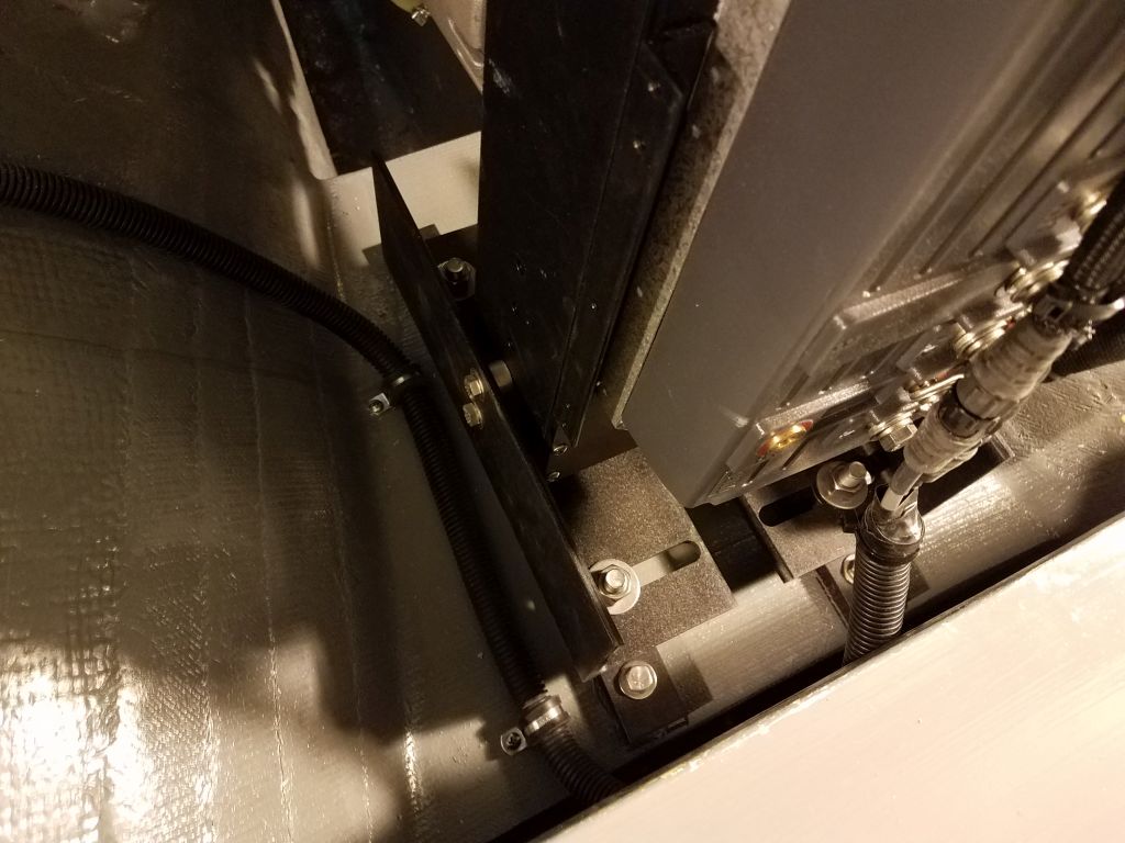
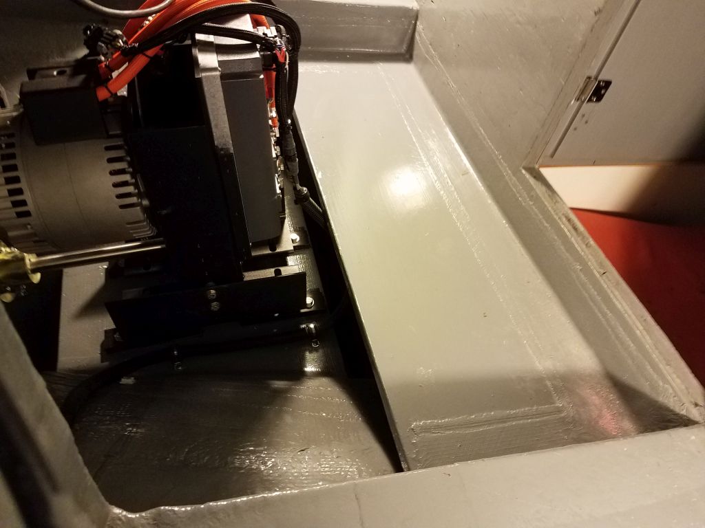
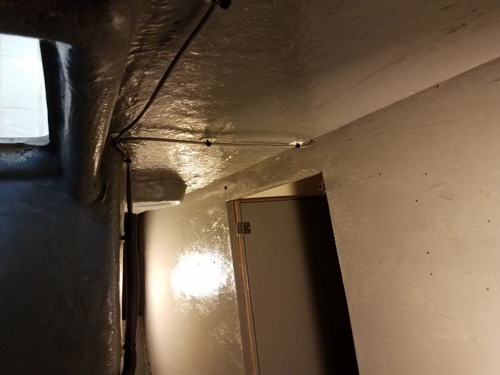
With all these new wires leading into the starboard side of the engine room, I thought my cable runs on this side were now complete, and at the end of the afternoon I finished up by beginning to secure these cables inside the engine room, using the cable run I’d already installed during the earlier wiring session. There were still a few wires from the first runs that weren’t yet made up, including a large triplex for the eventual 48-volt battery charger, plus wires for the diaphragm bilge pump I planned to install on a platform in the engine room, but for now I left those alone for later attention. To accommodate the new wires running across to the port side, I removed the existing wire clamps as I went and replaced them with larger ones as needed to hold the larger bundles, and by the end of the day I’d secured and cleaned up the new wiring in the engine room as far to port as I could reach easily from the access door, leaving just the final couple feet to take care of later from the port cockpit locker.
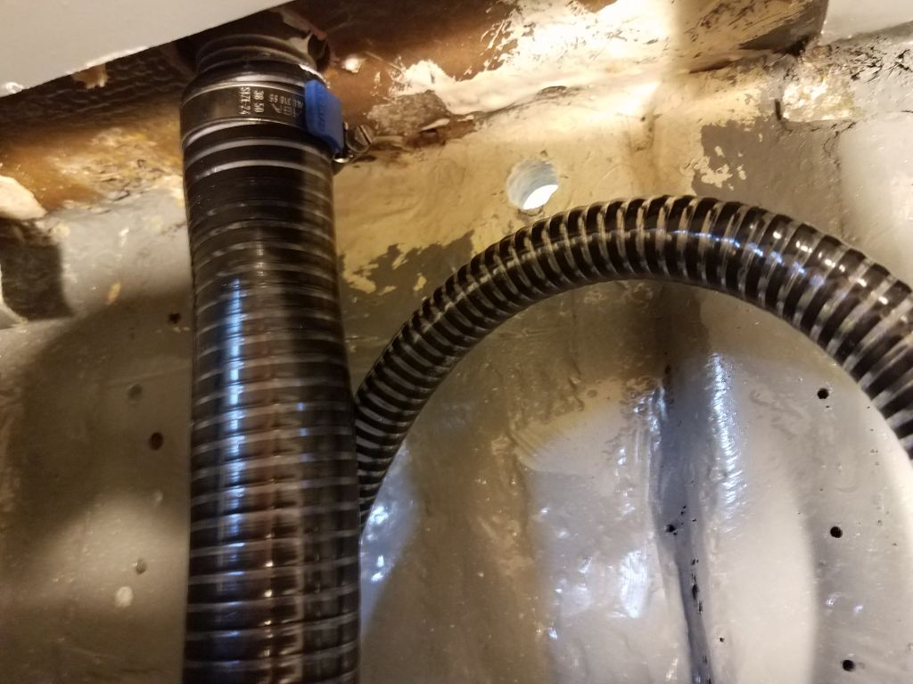
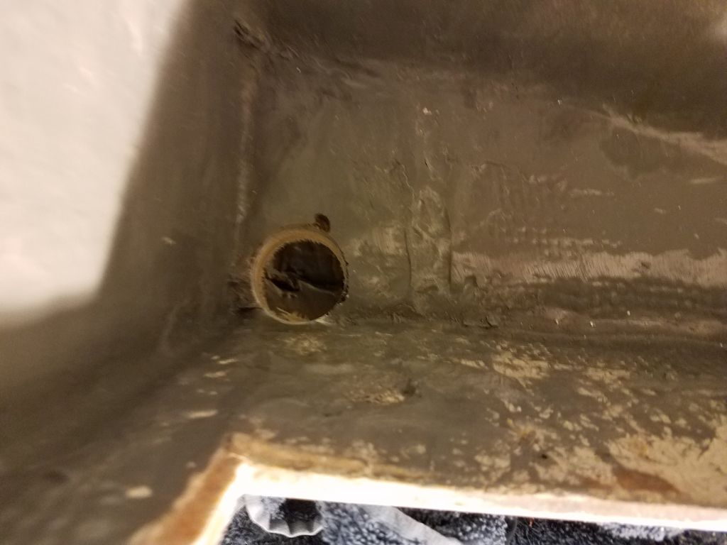
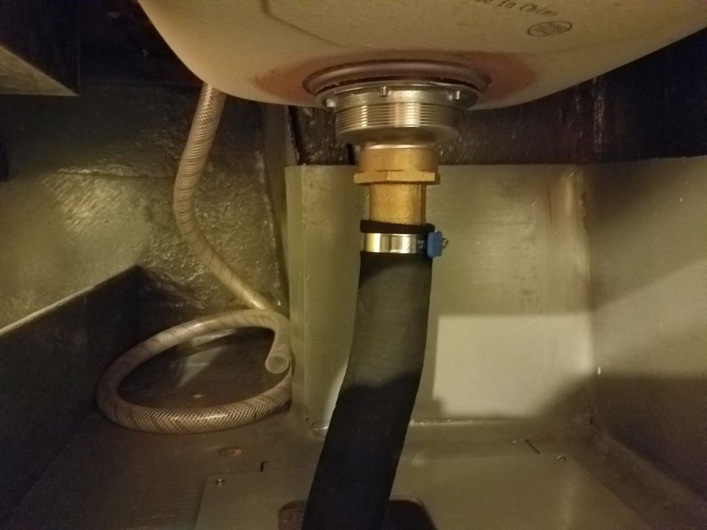
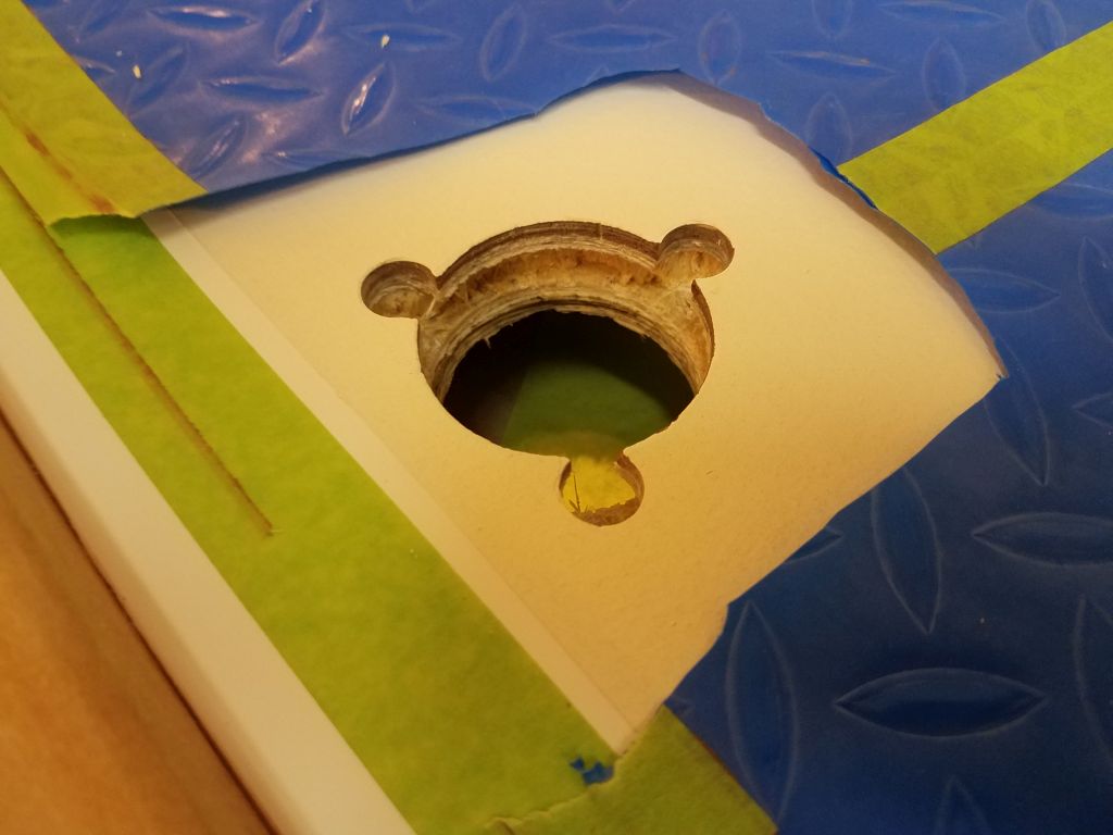
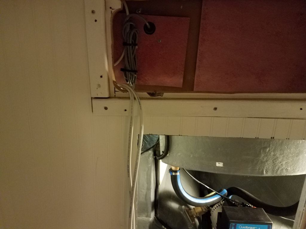
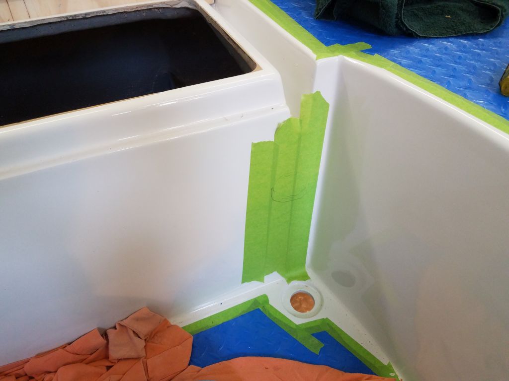
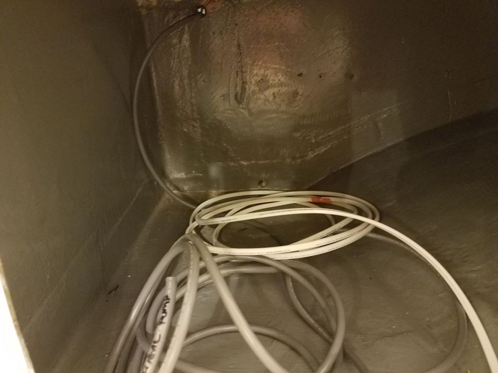
I also drilled a hole into the galley sink compartment to accommodate the 12/2 wire for the electric water pump, and this new opening would also allow passage of the water hose later. For the new bilge pump, which would be a larger pump designed more as an emergency, larger-capacity pump to kick in only if the water level got high enough, I led the wire in to the upper reaches of the cooler storage compartment beneath the galley, leaving lots of loose wire there for eventual routing to the bilge and the pump once I had it on hand.
Total time billed on this job today: 5.75 hours
0600 Weather Observation: 21°, clear. Forecast for the day: Sunny, windy, 26°