Thursday
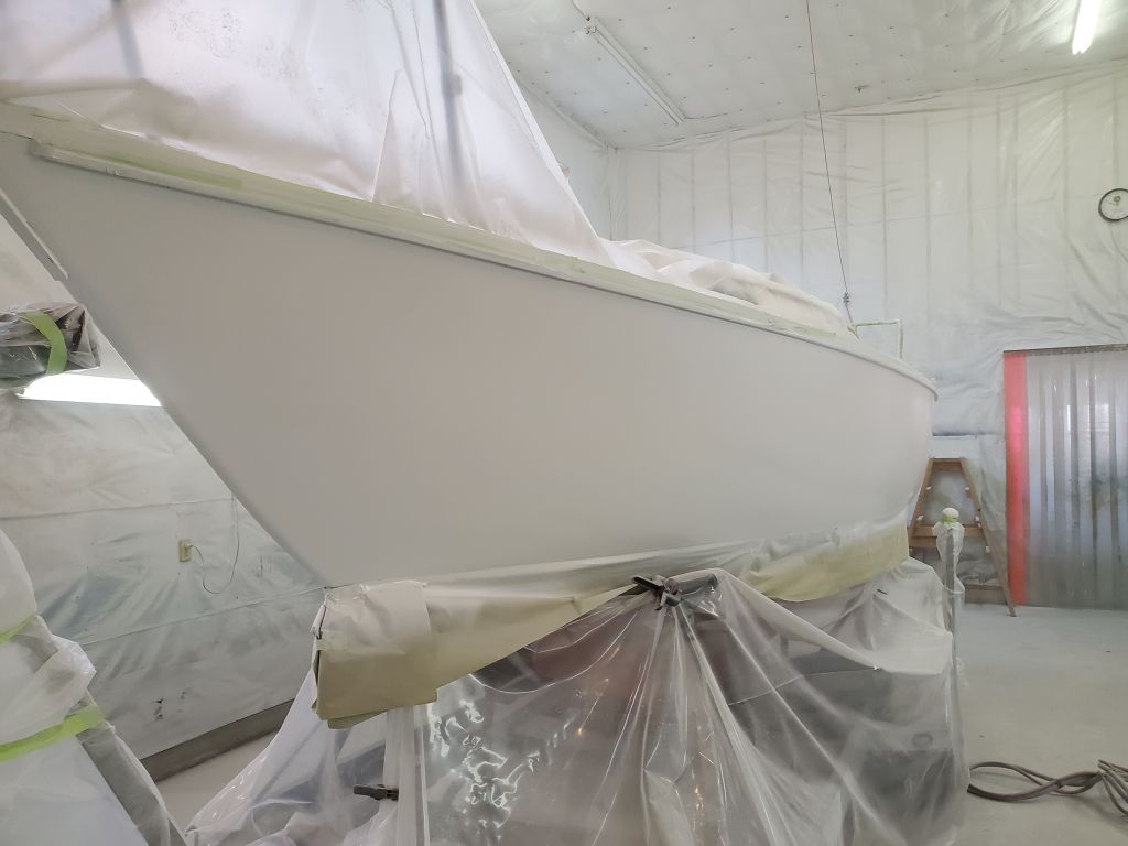
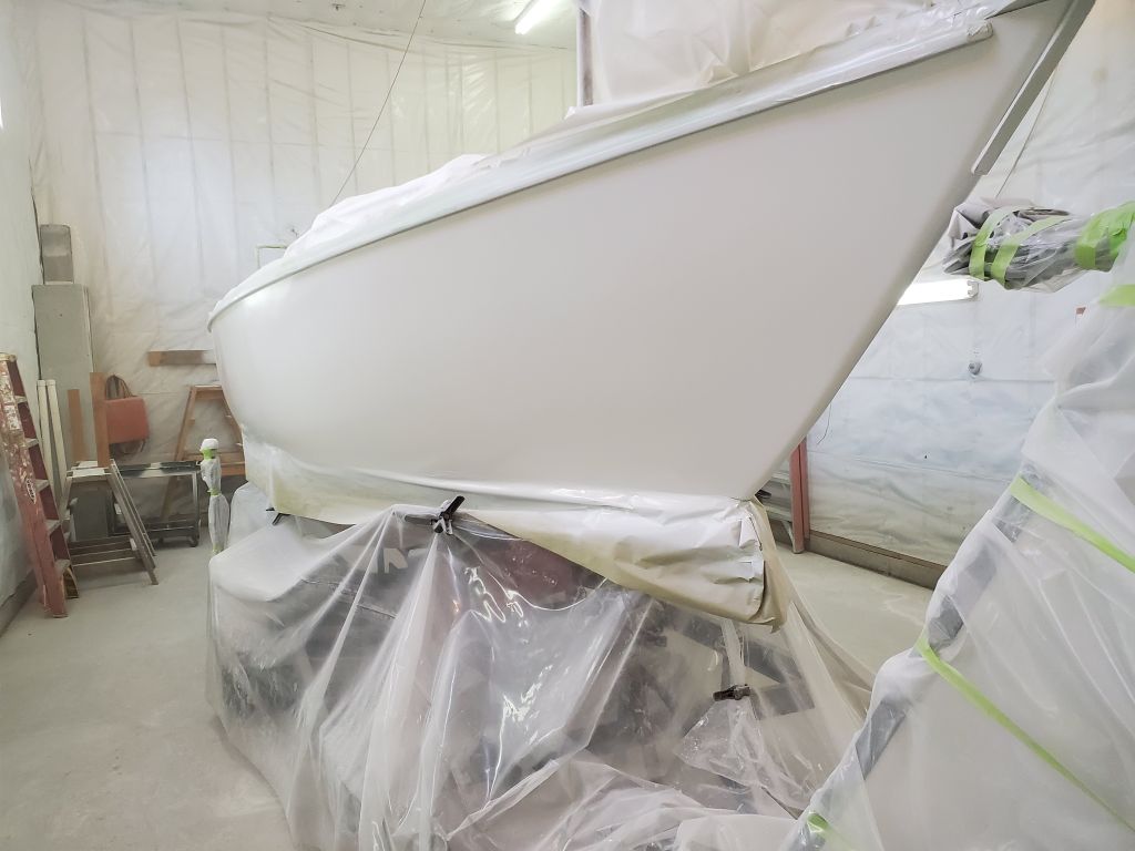
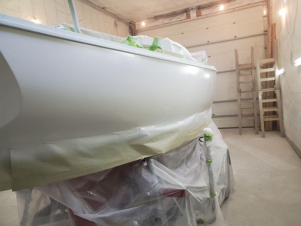
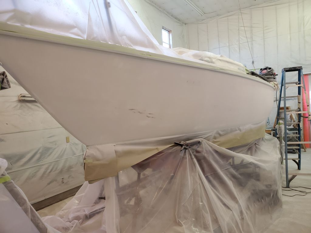
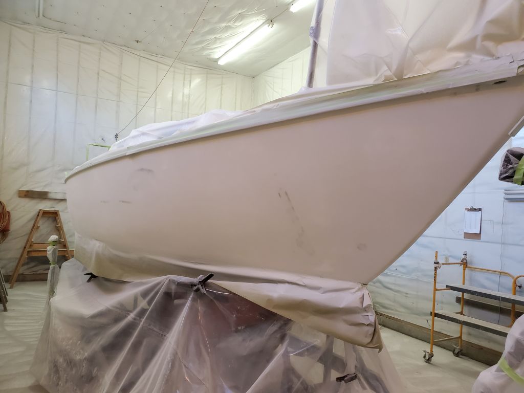
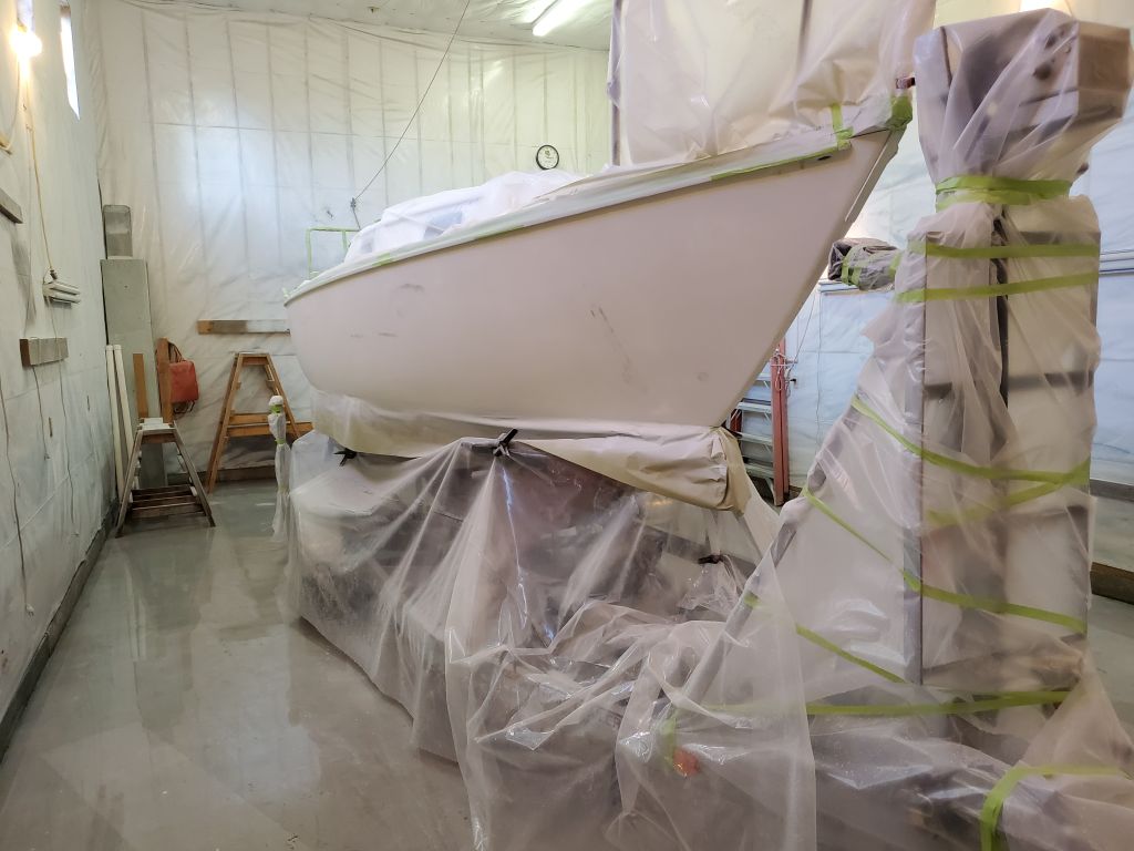
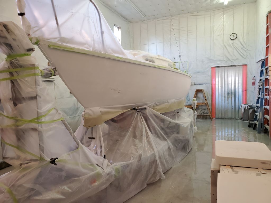
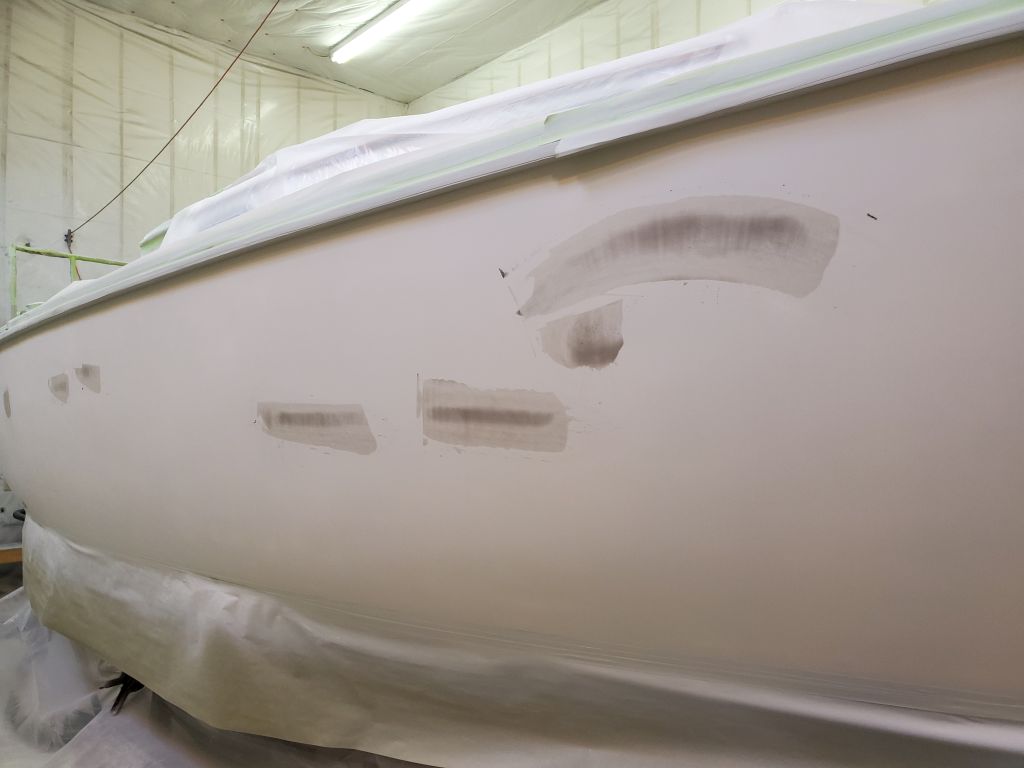
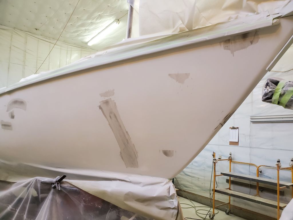
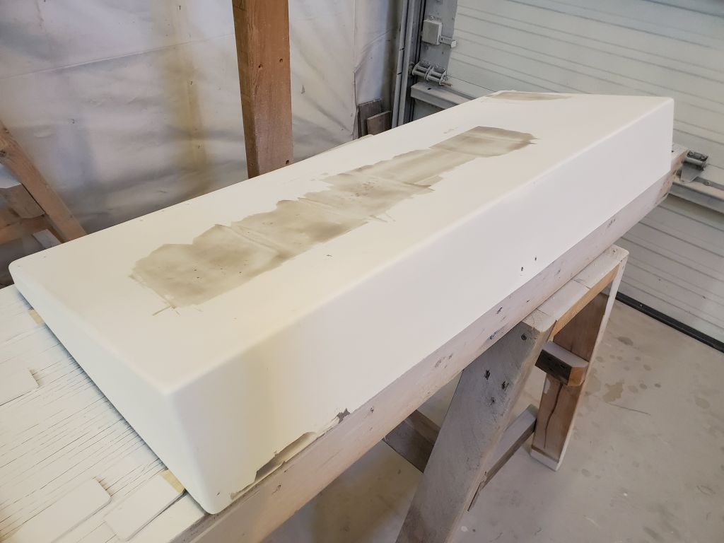
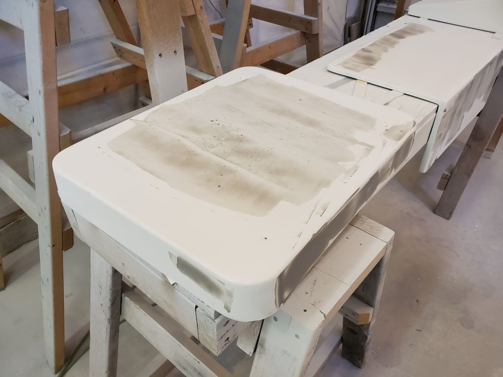
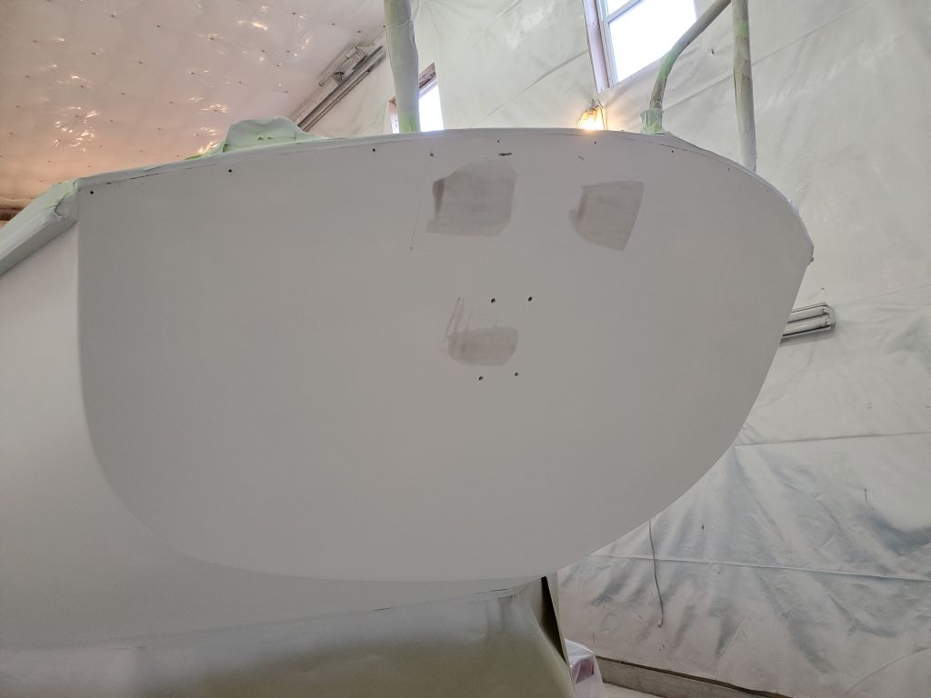
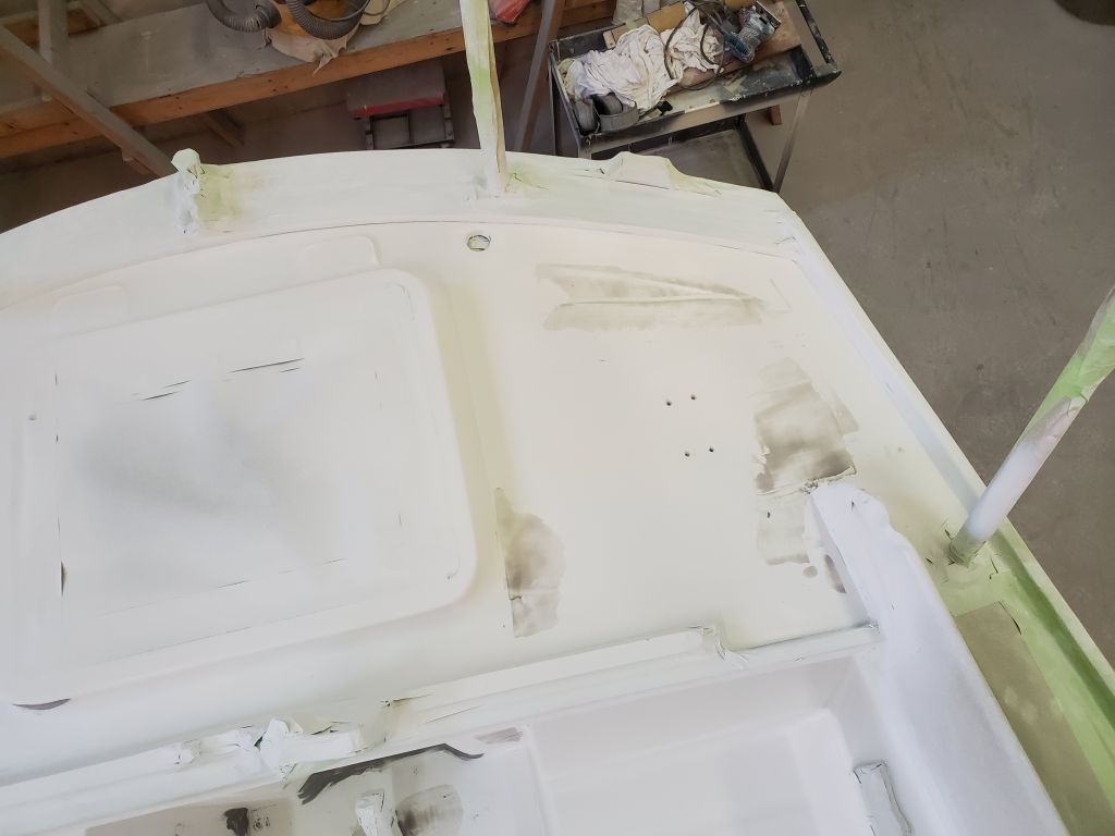
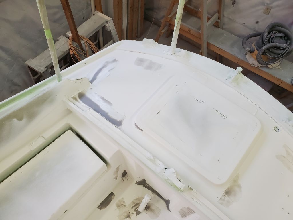
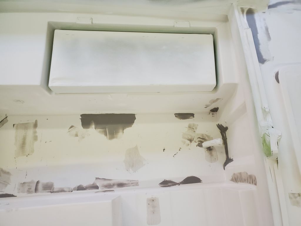
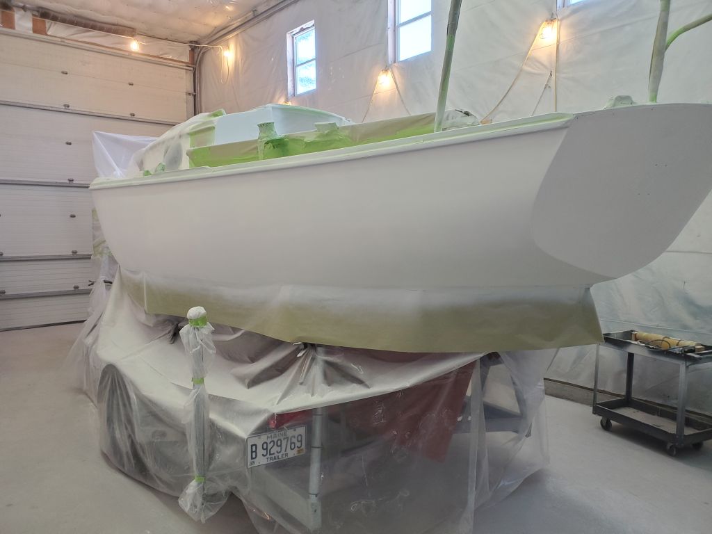
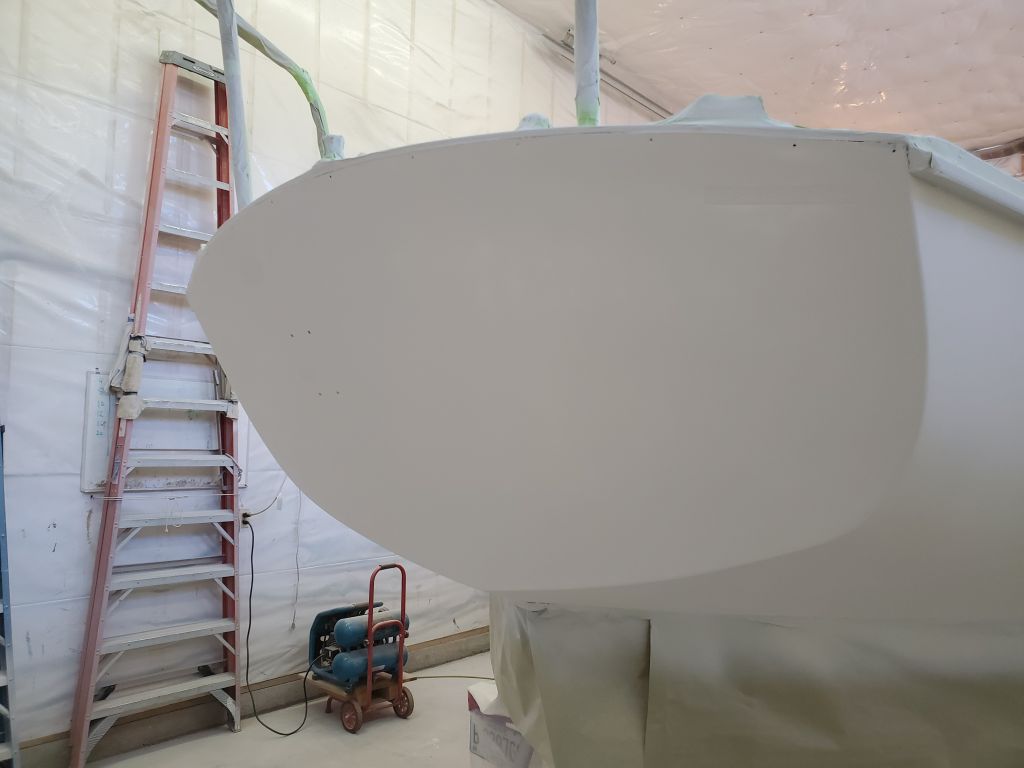
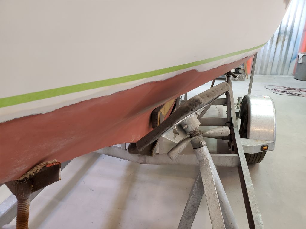
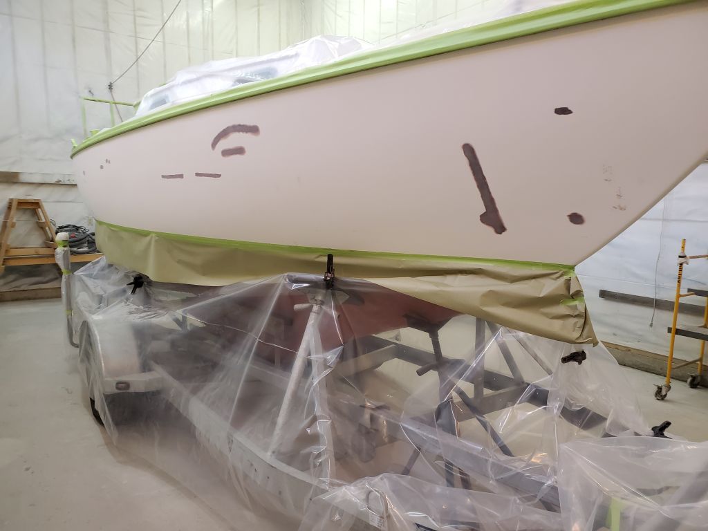
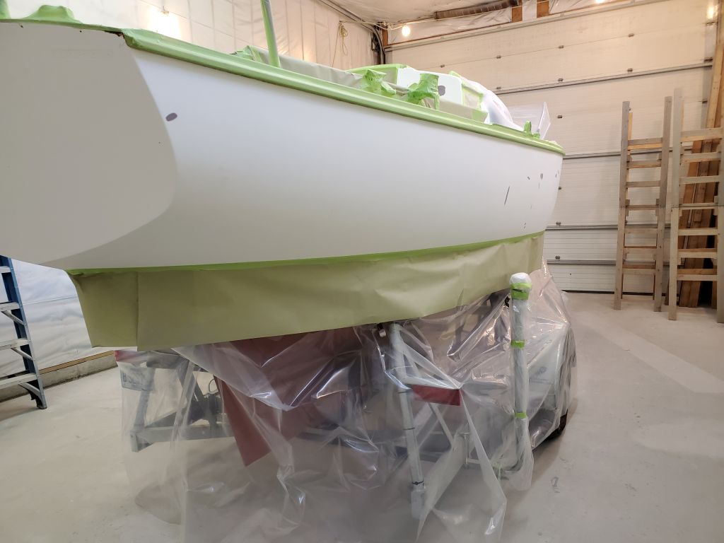
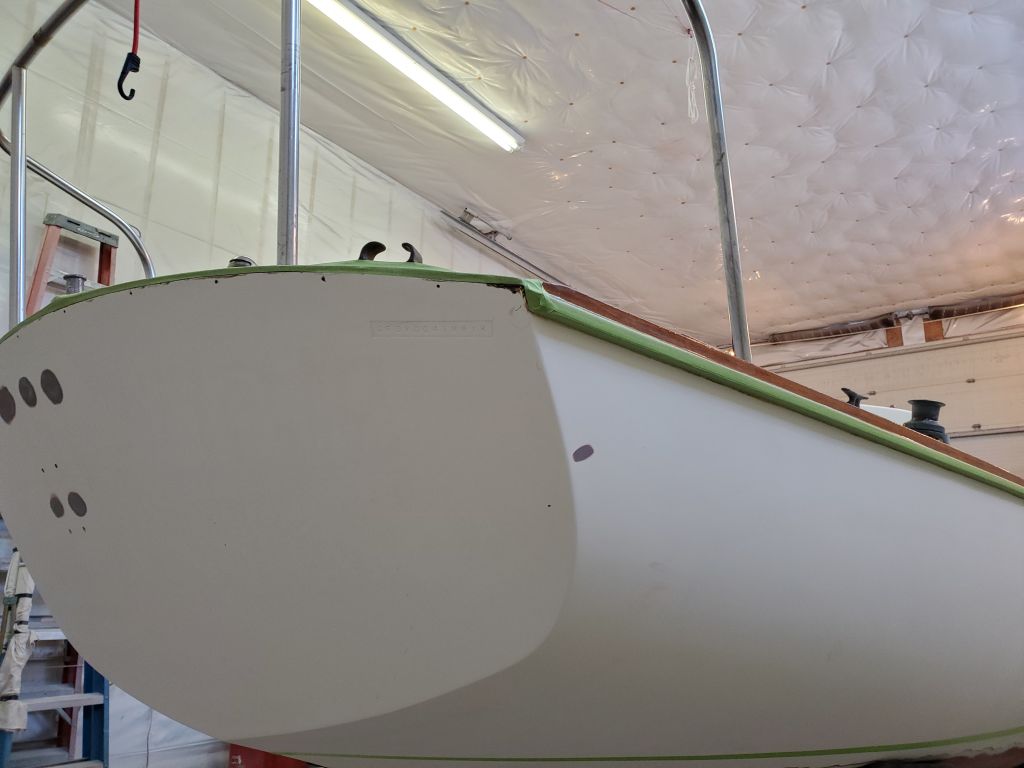
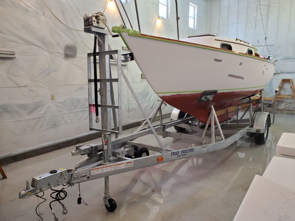
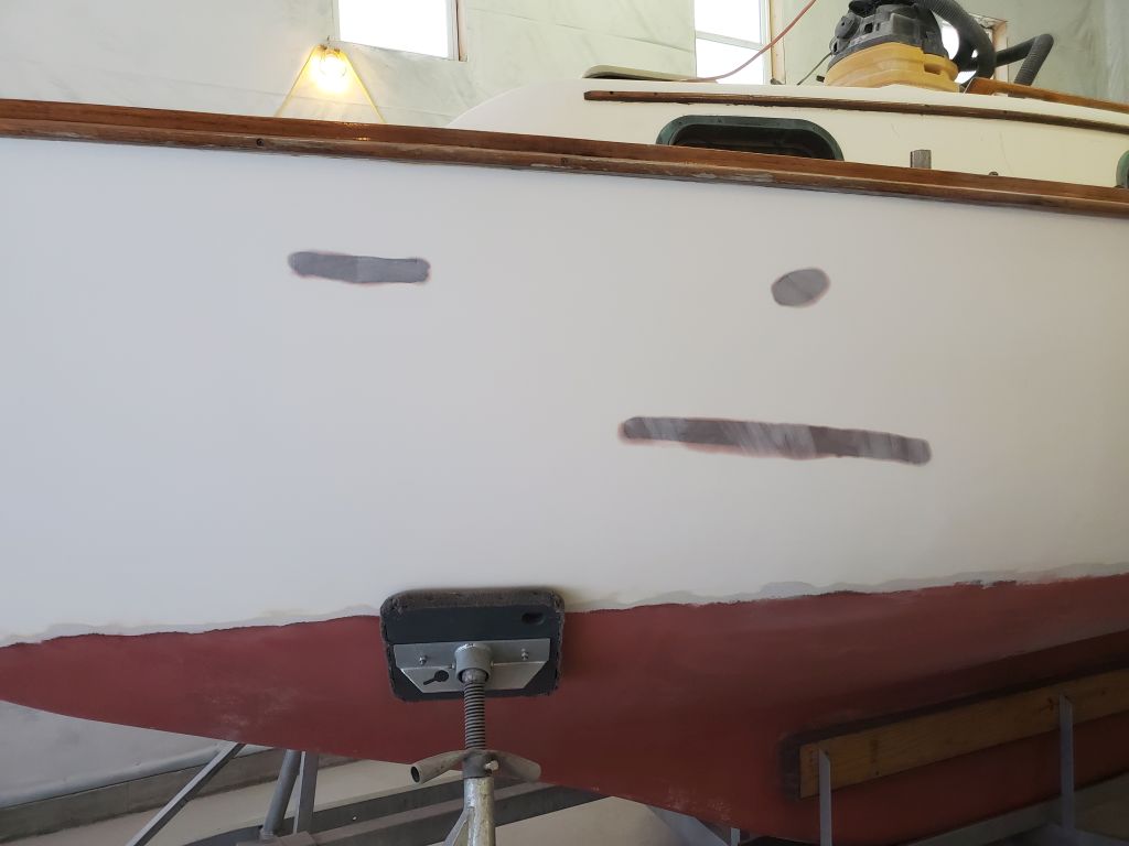
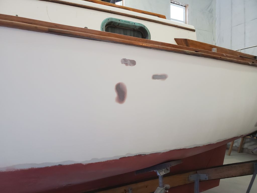
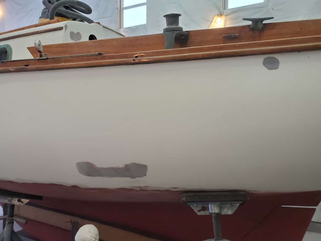
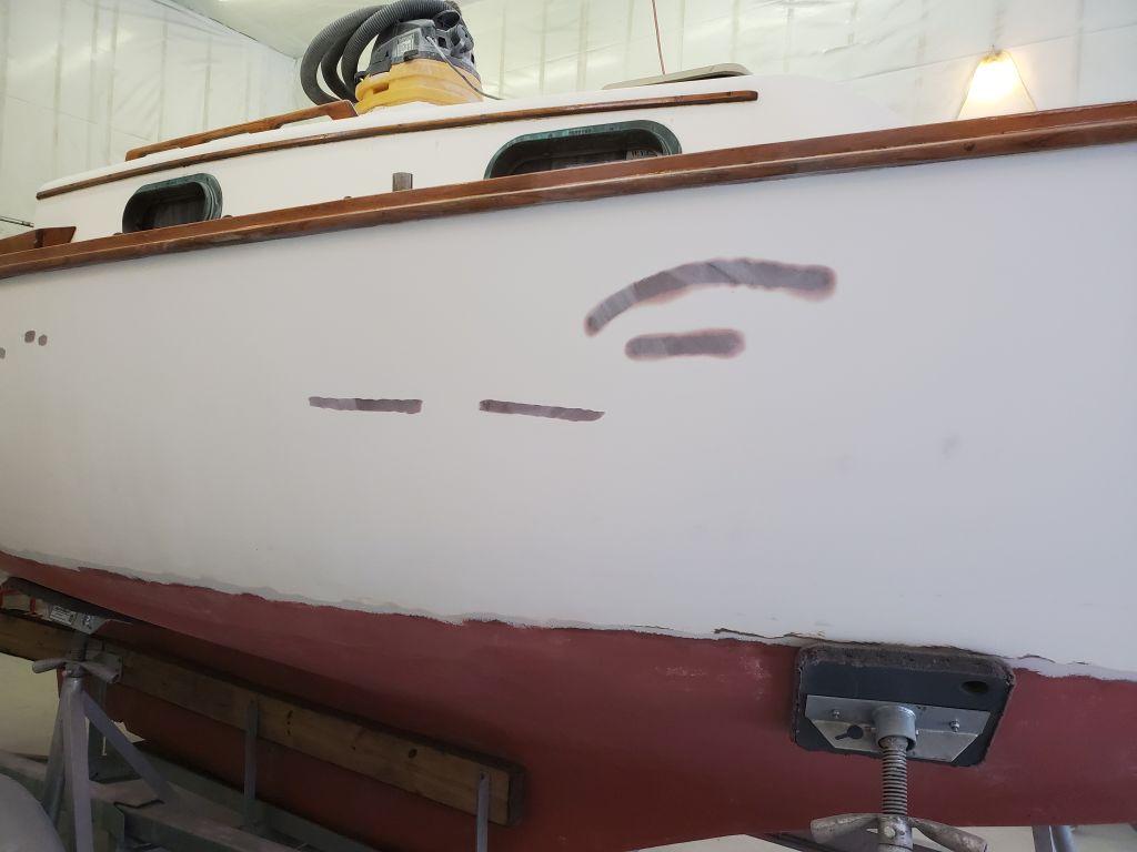
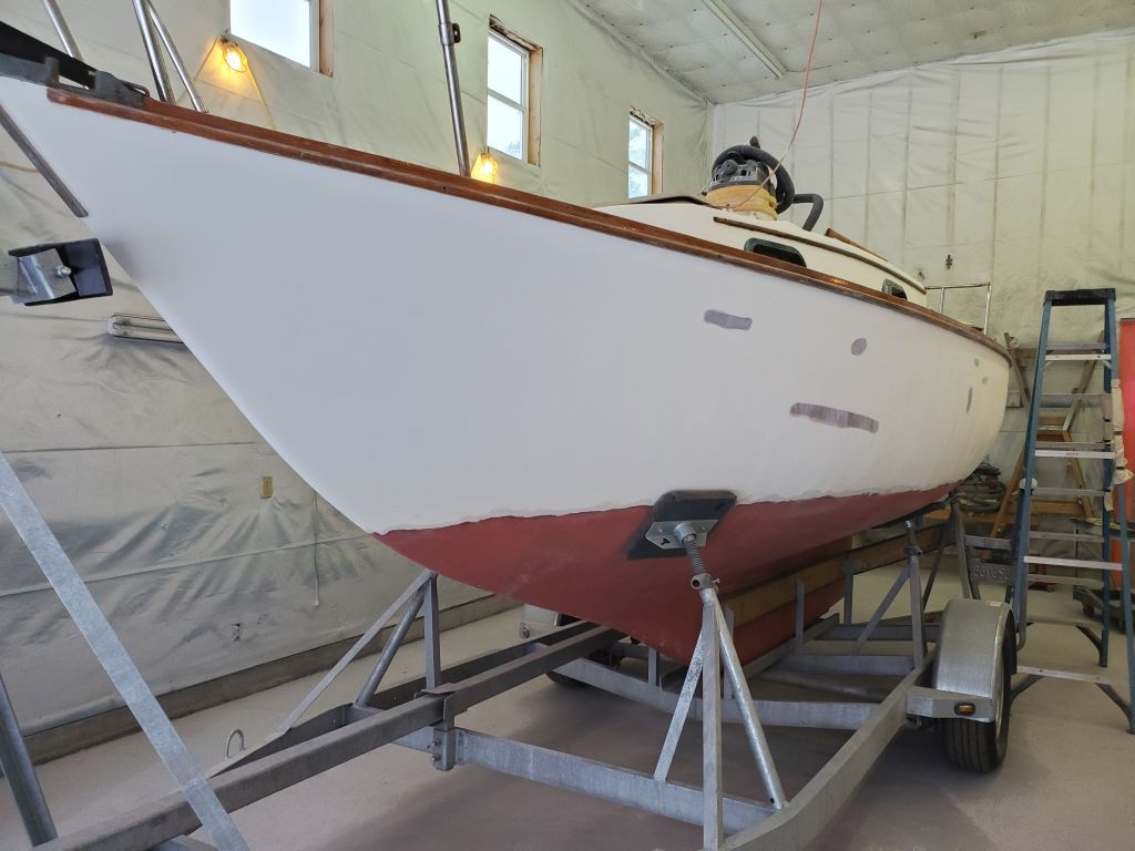
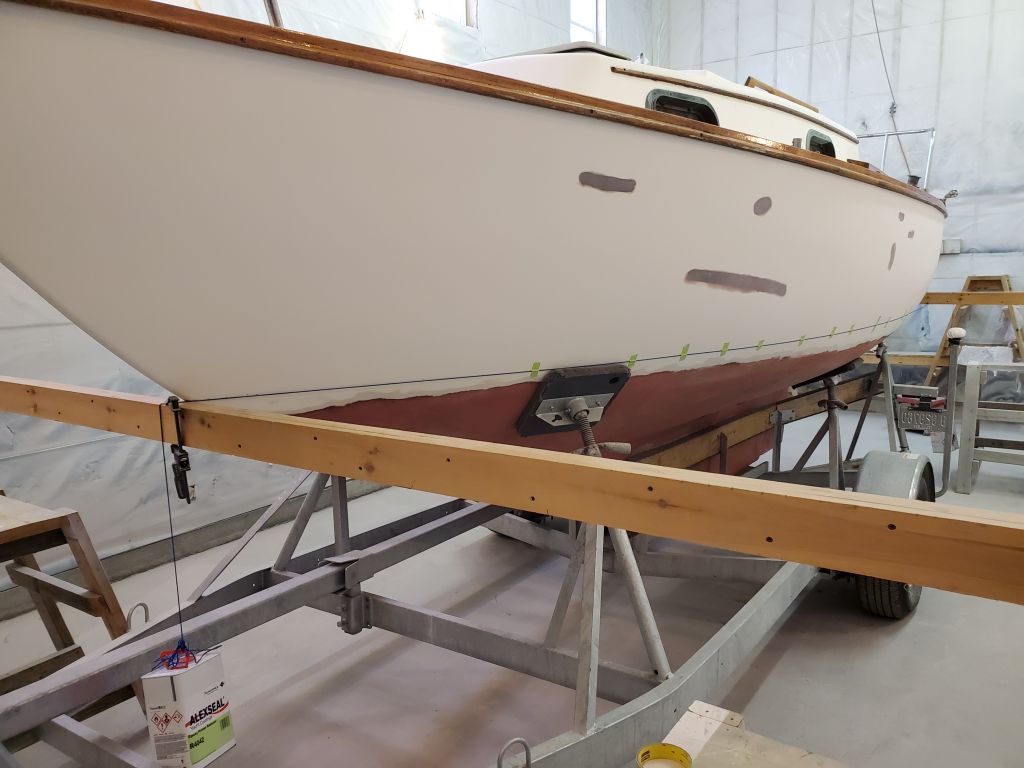
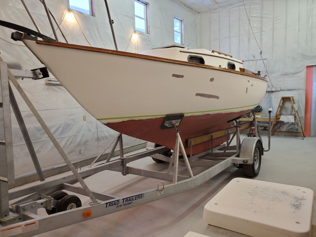
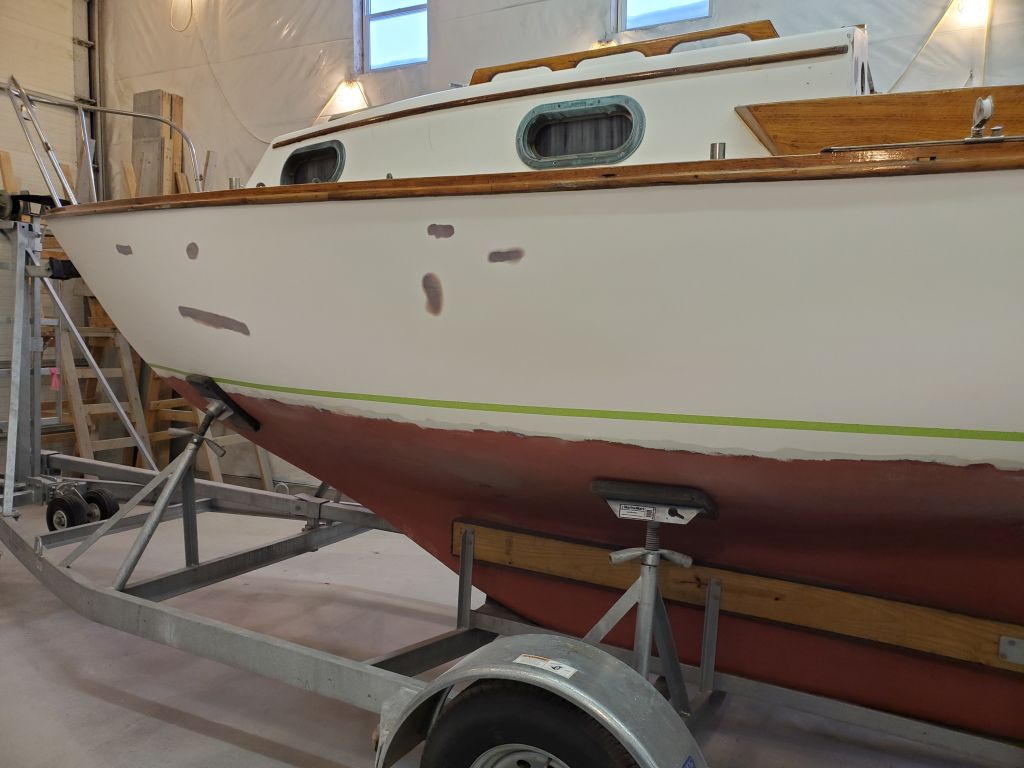
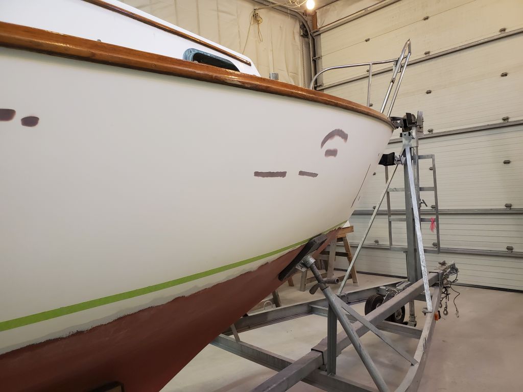
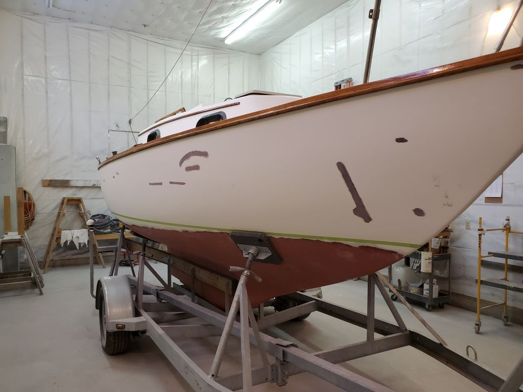
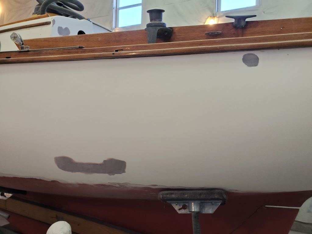
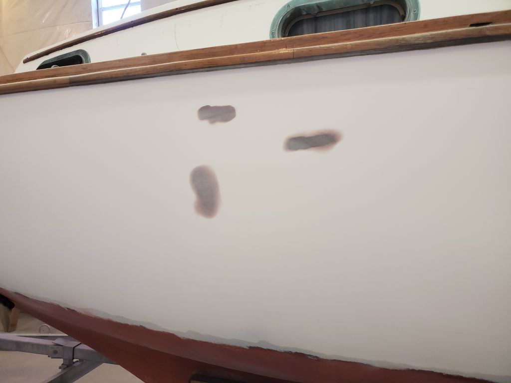
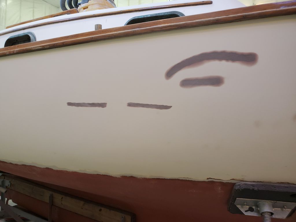
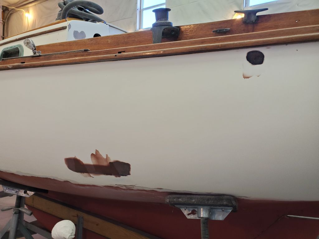
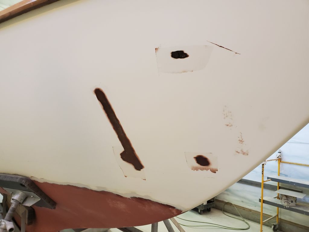
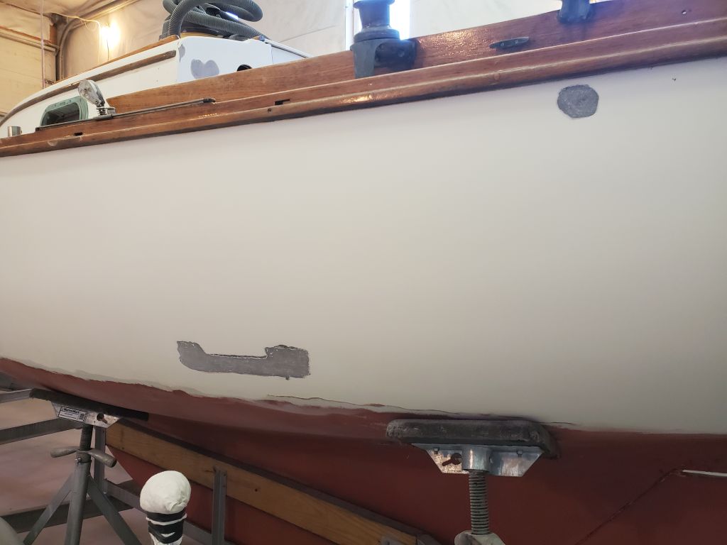
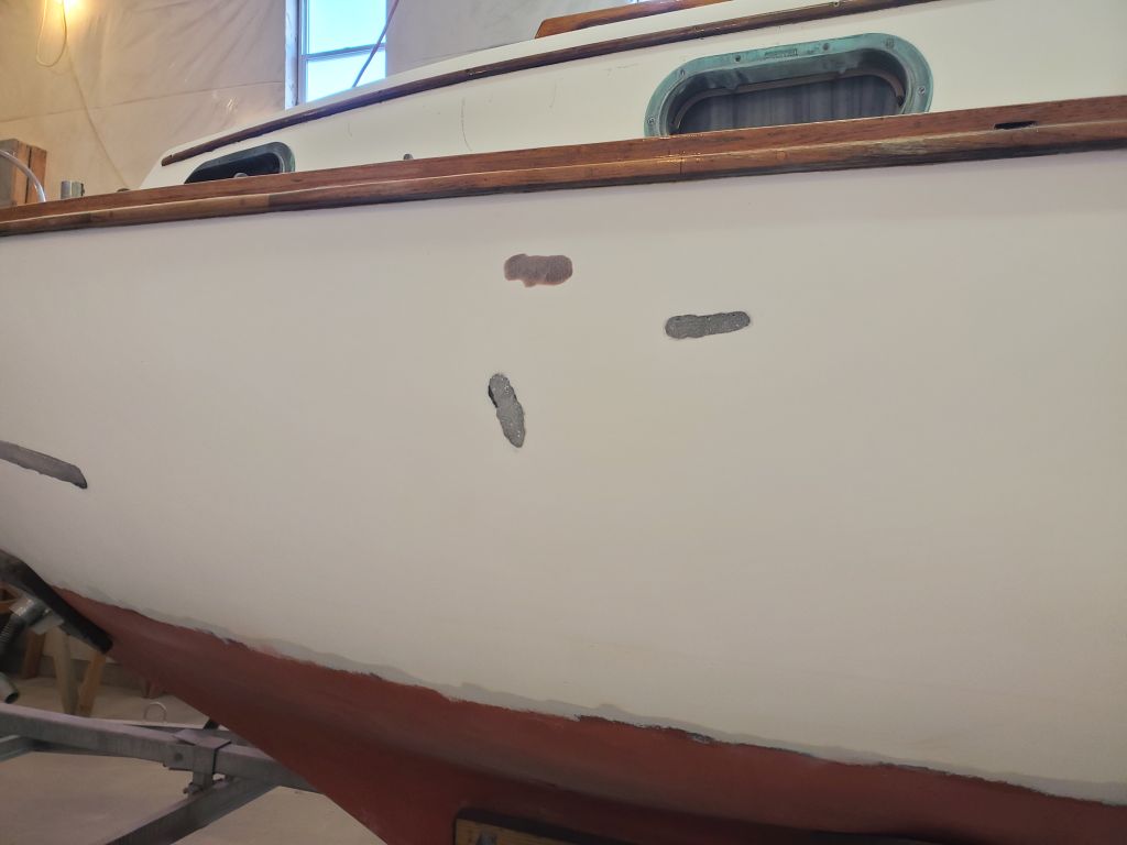
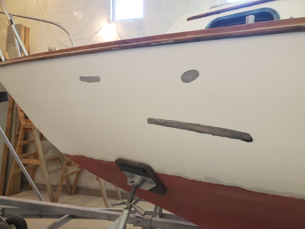
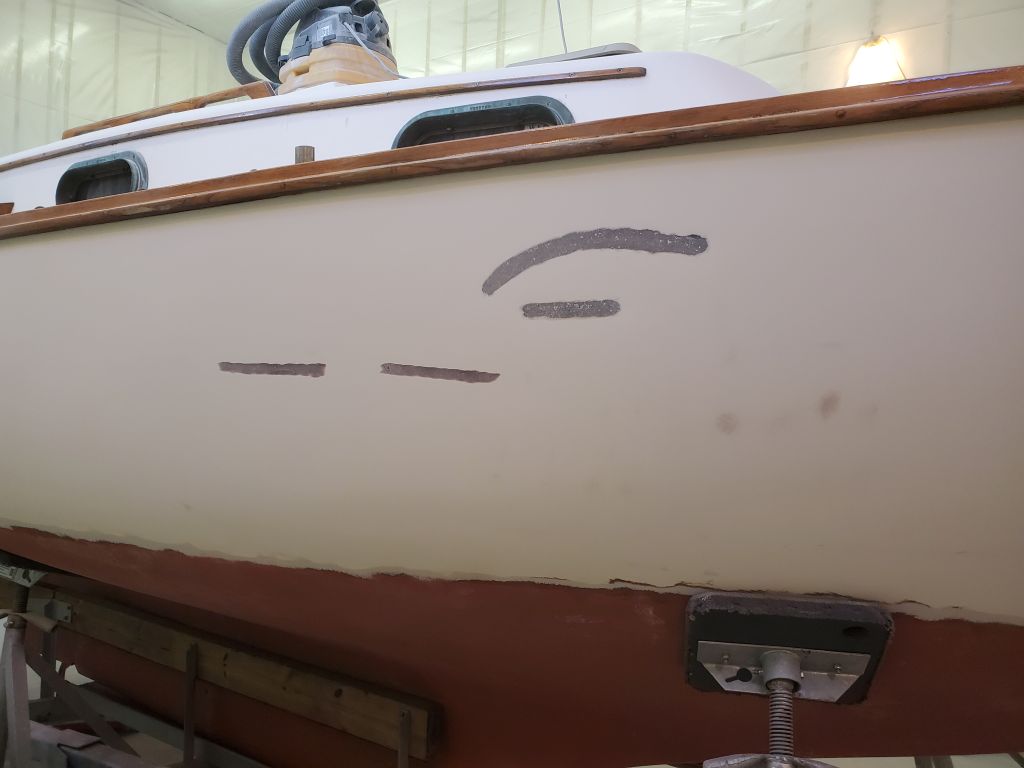
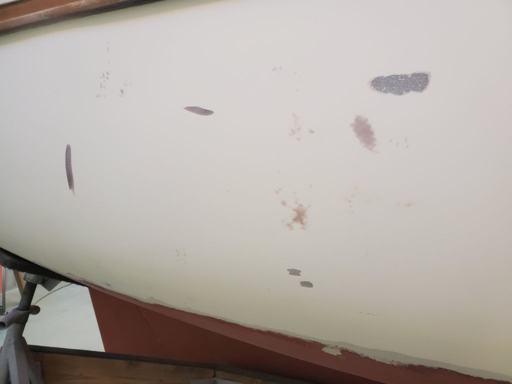
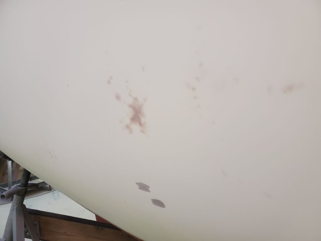
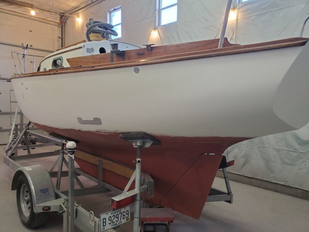
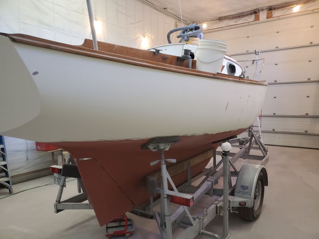
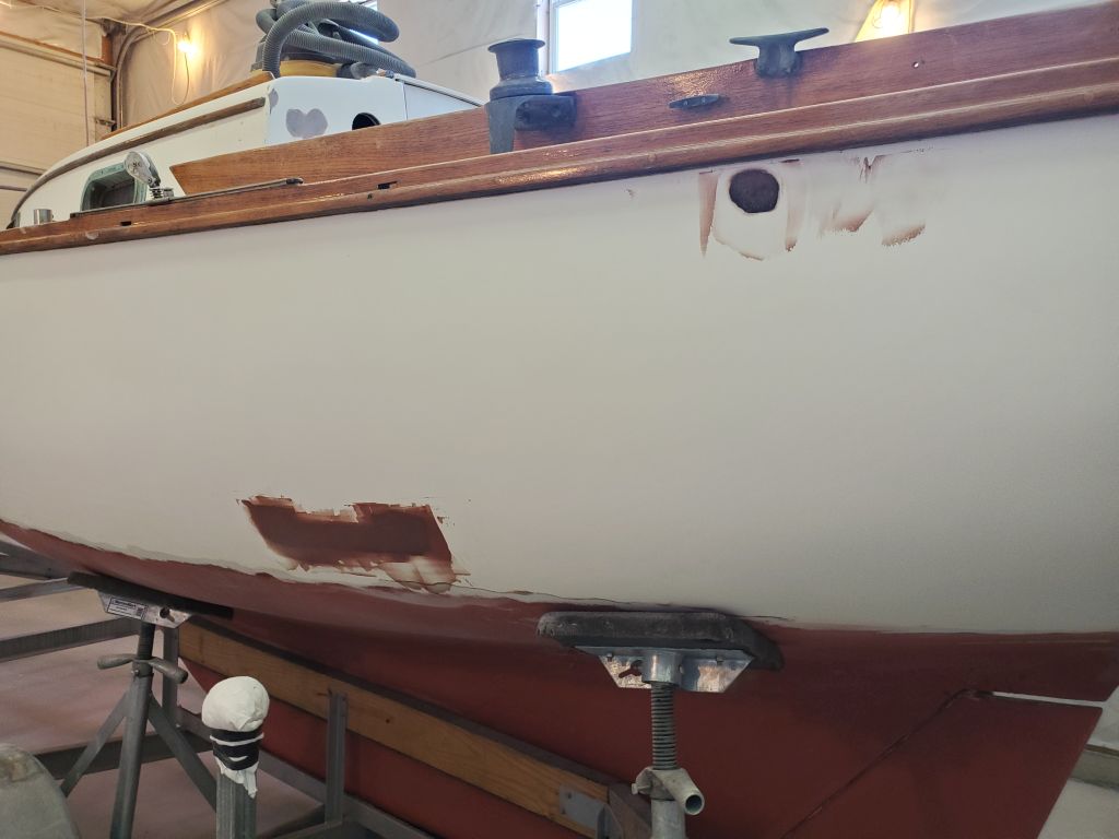
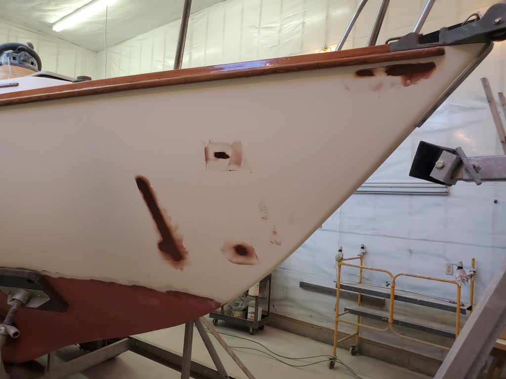
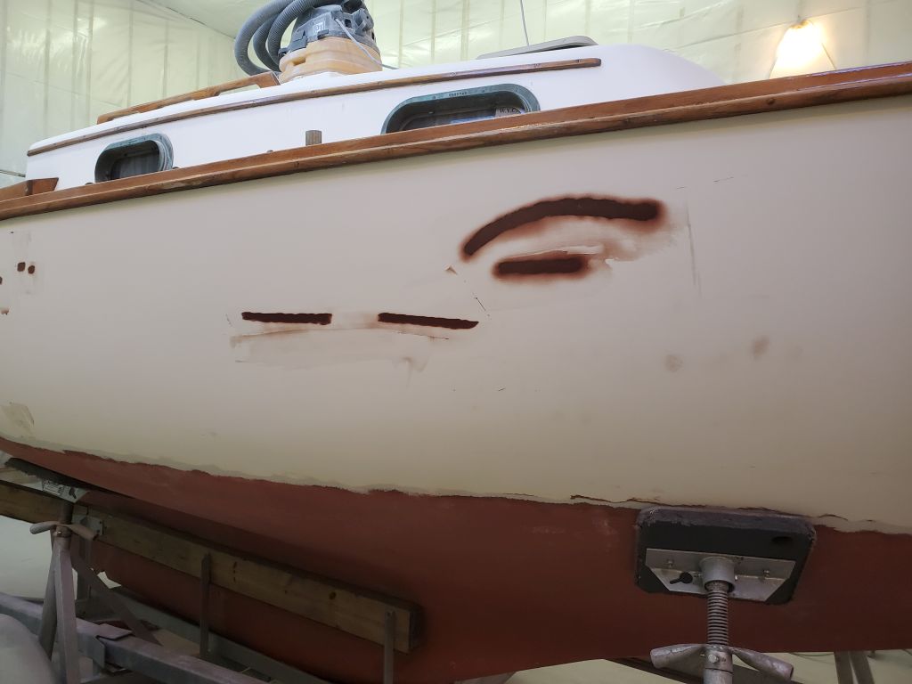
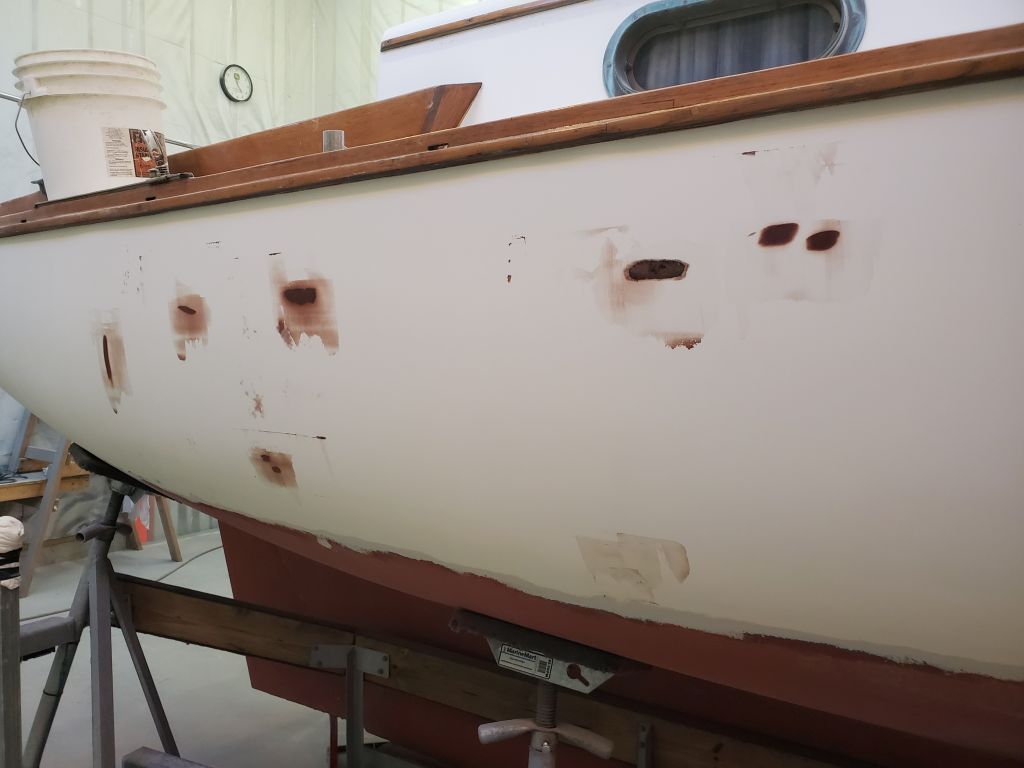
Focusing on the several patches where I’d applied a third round of filler, but going over the whole hull at the same time, I performed a final sanding of the hull, this time with a palm sander (and by hand) and 120 grit paper. Any final fine-tuning, pinhole-filling, and other detail work would now wait till after high-build primer.
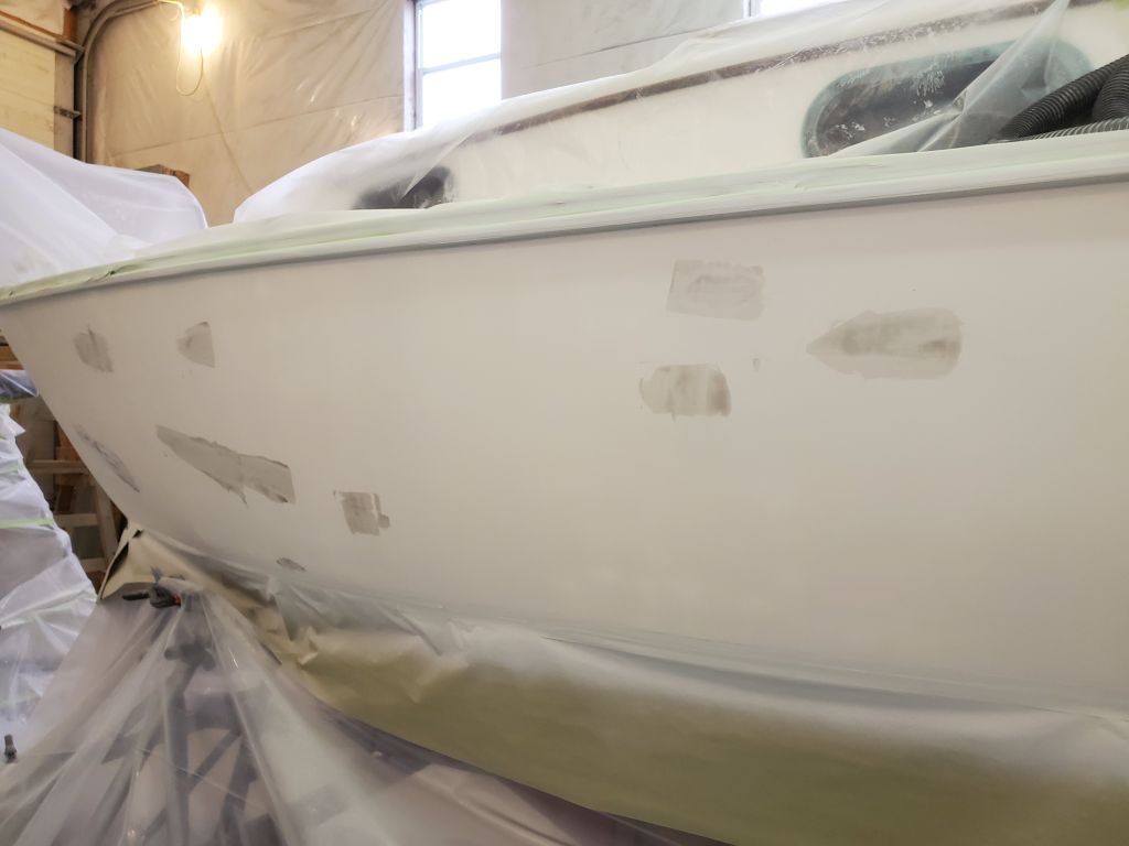
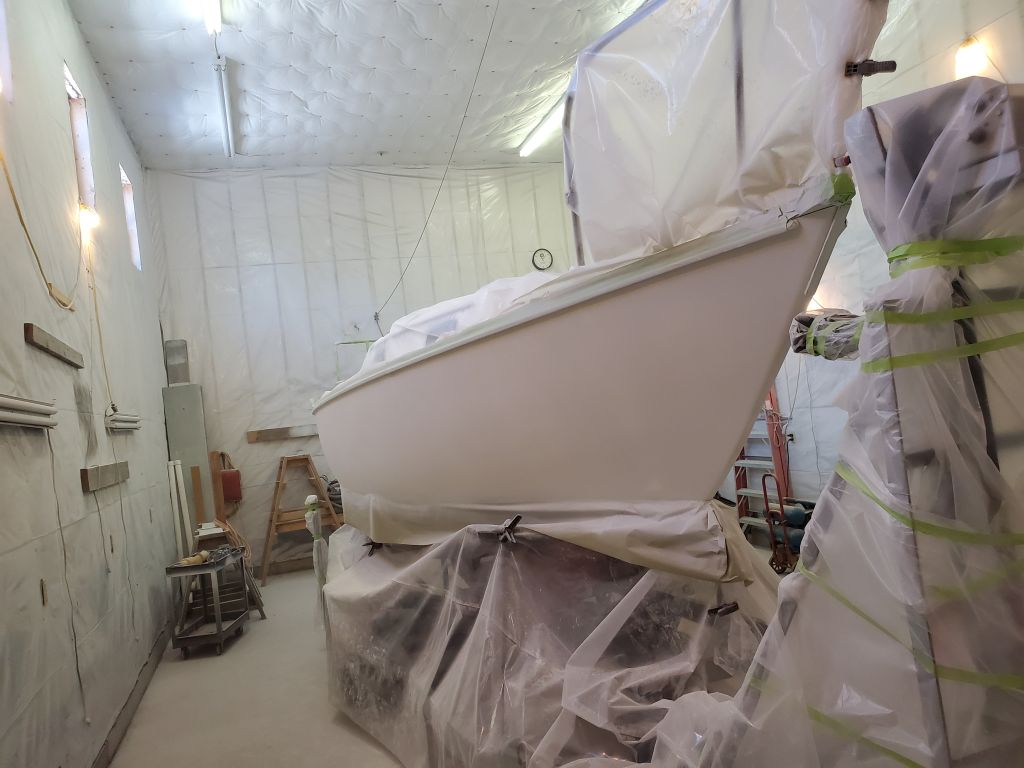
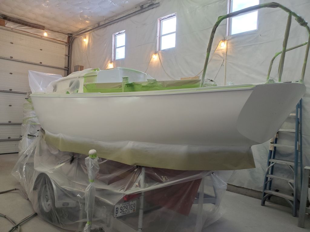
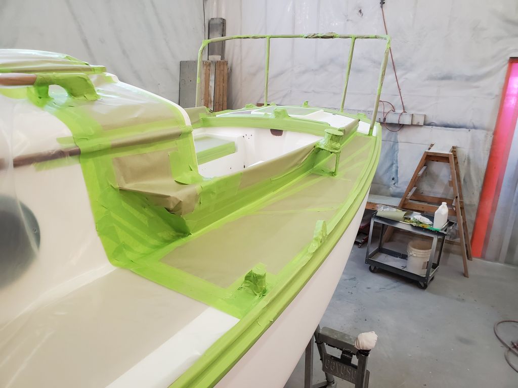
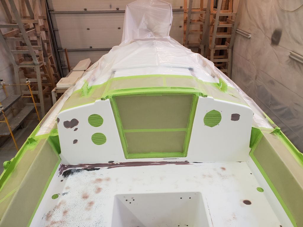
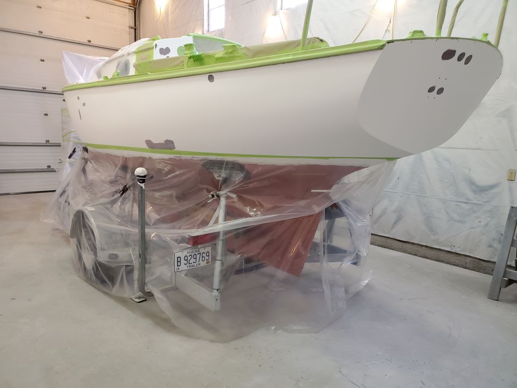
After blowing down the boat and shop, and sweeping up, I cleaned up the entire hull, deck, and (as needed) interior with vacuum and solvent wash to rid everything of dust and prepare the boat for masking and other final preparations.
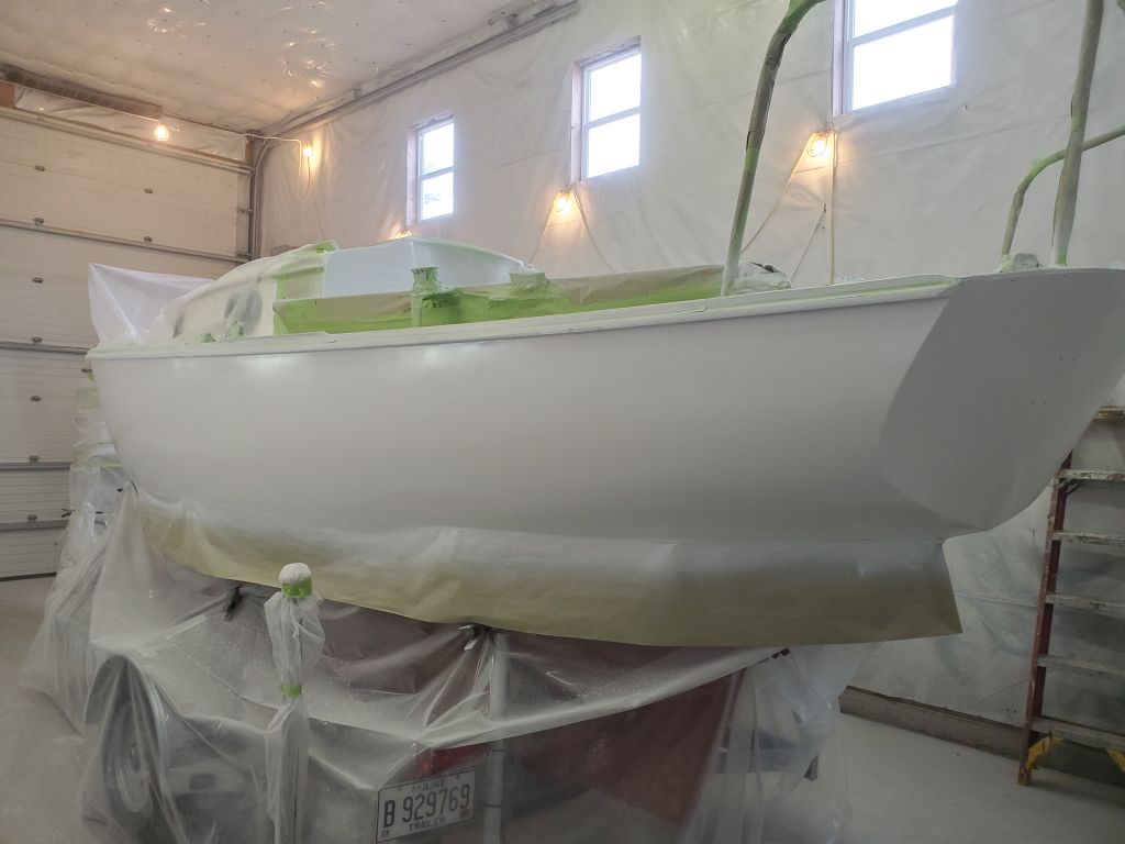
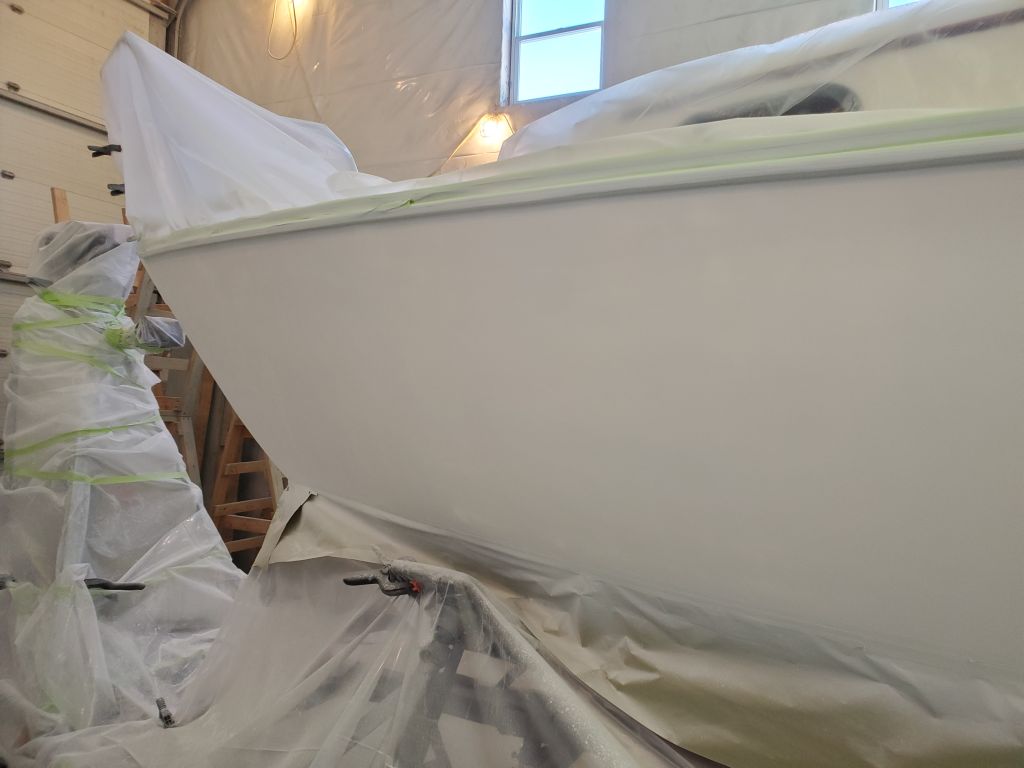
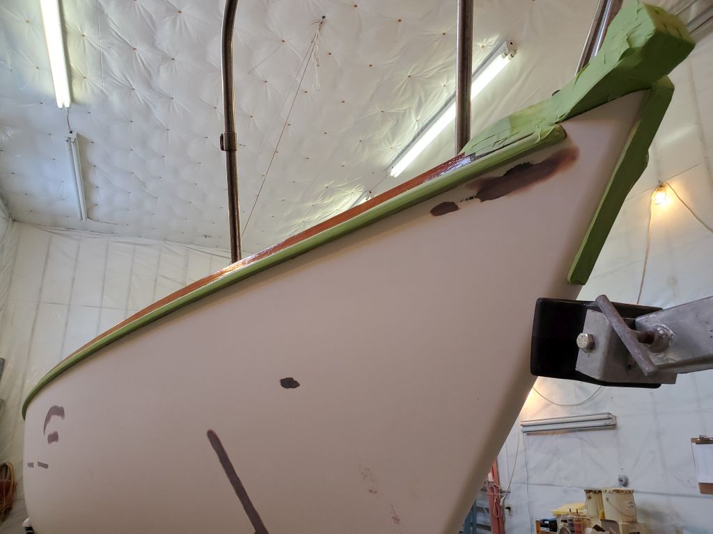
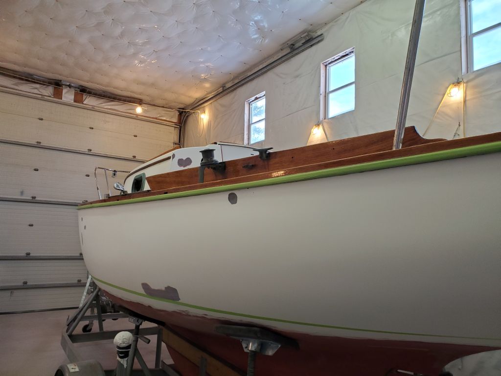
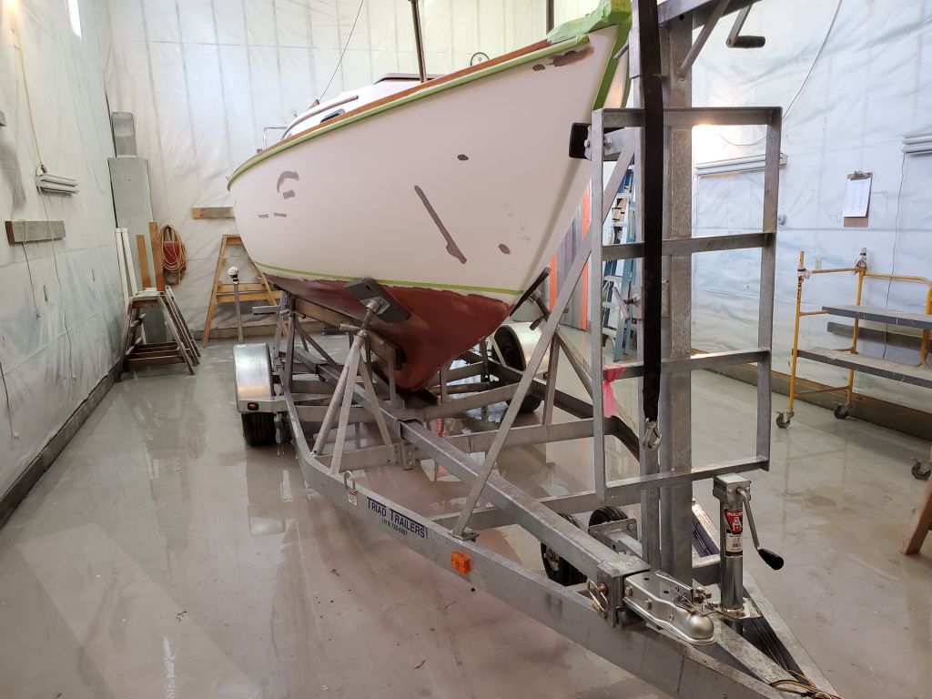
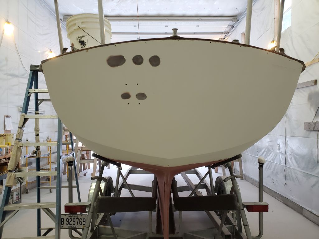
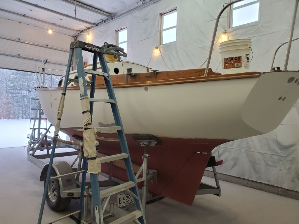
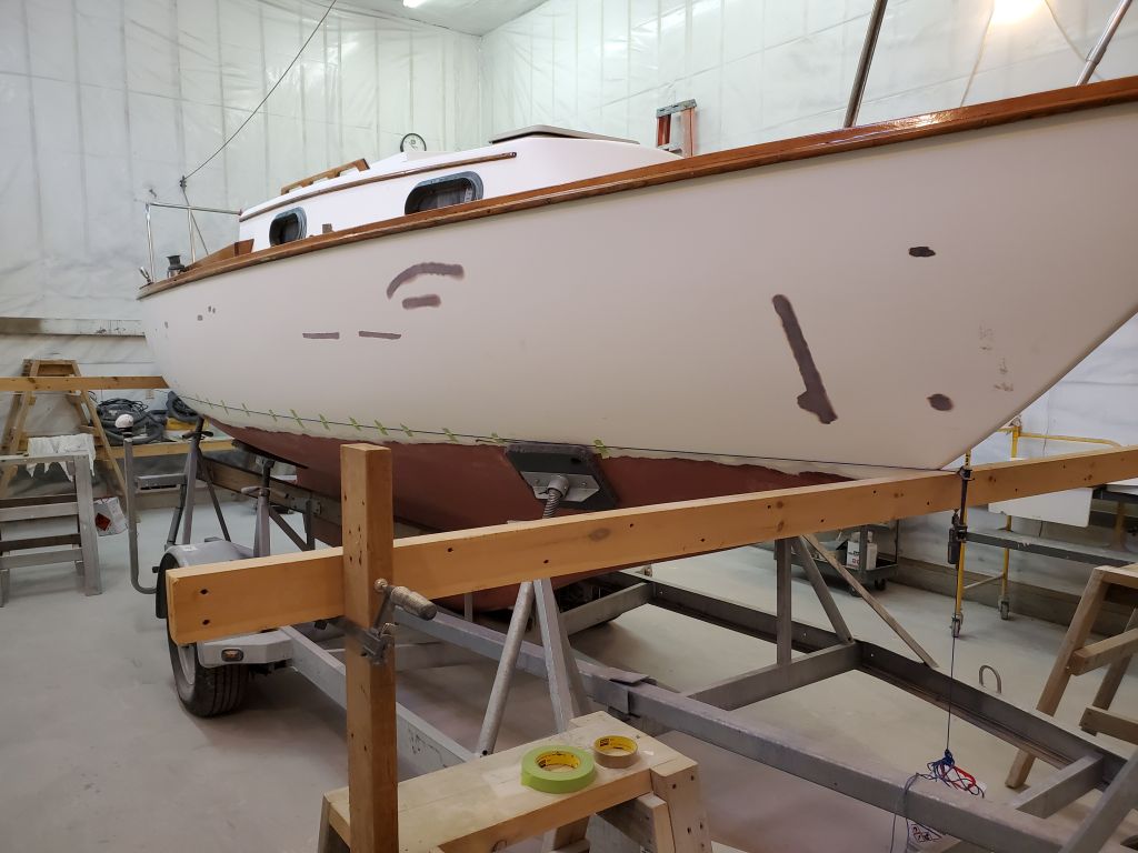
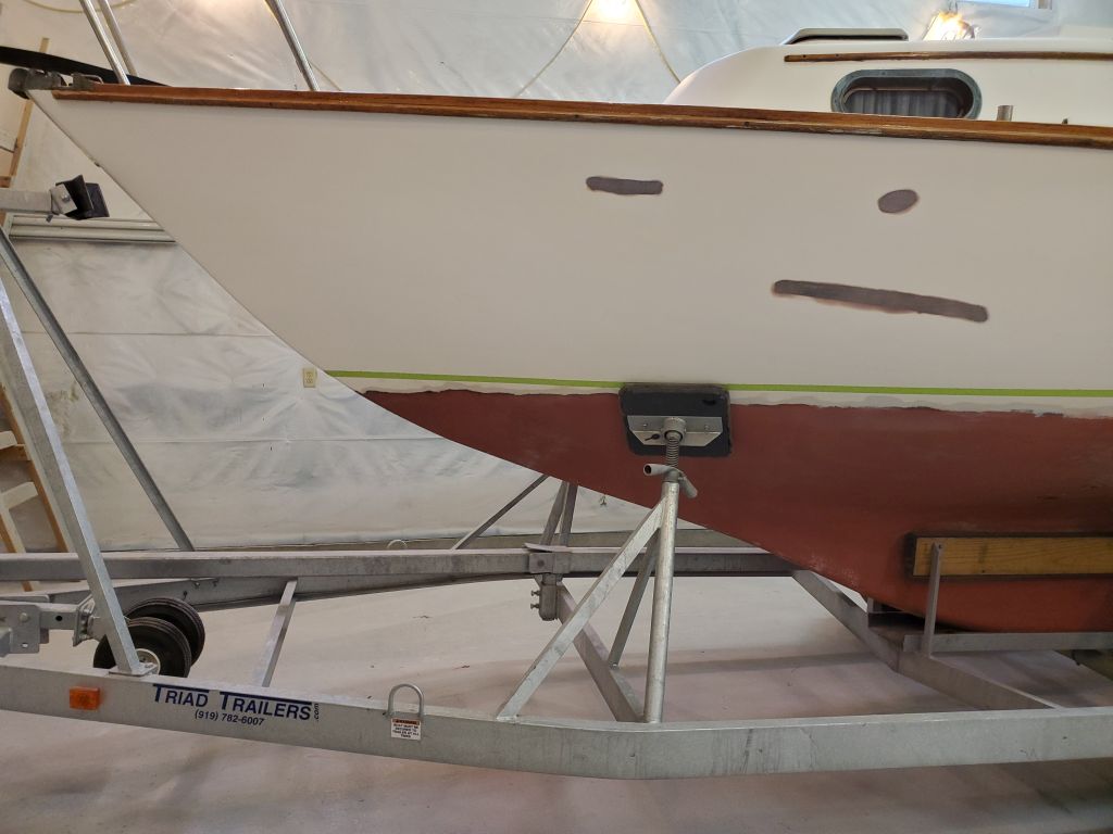
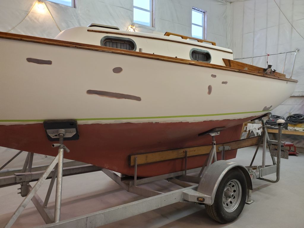
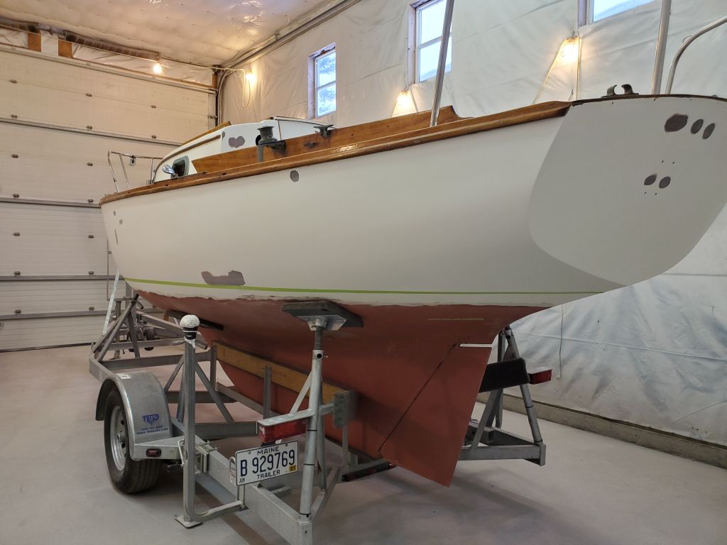
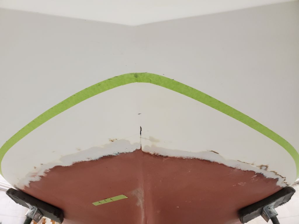
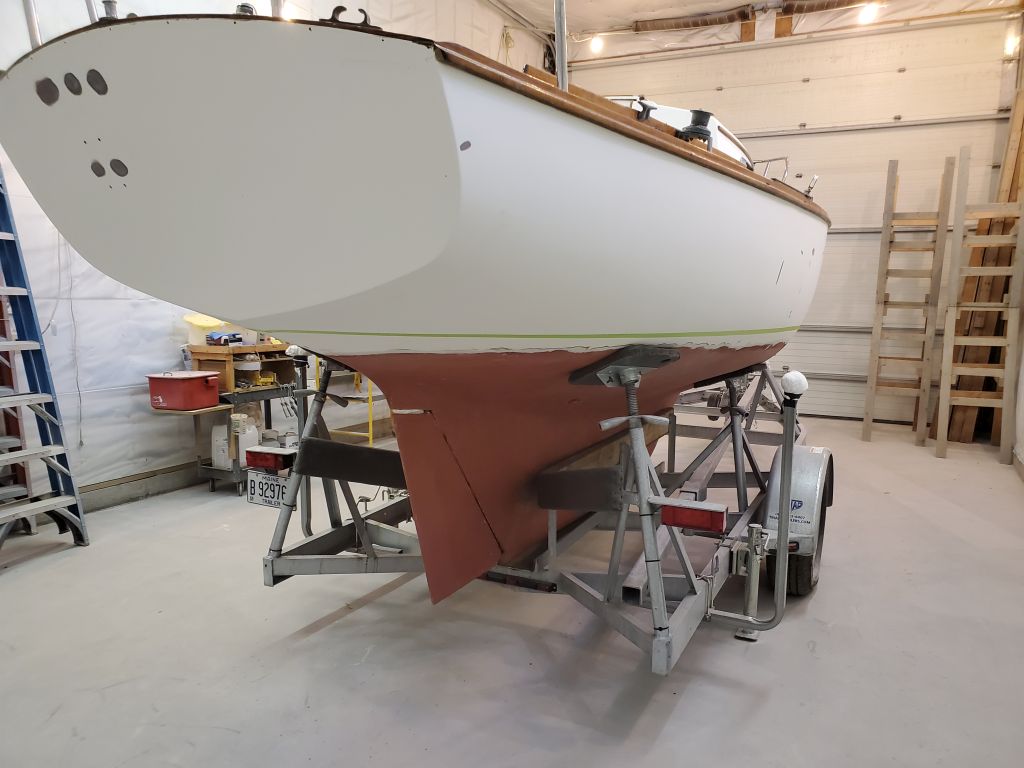
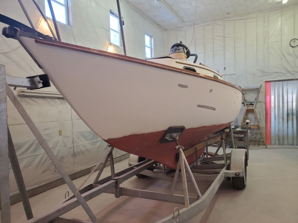
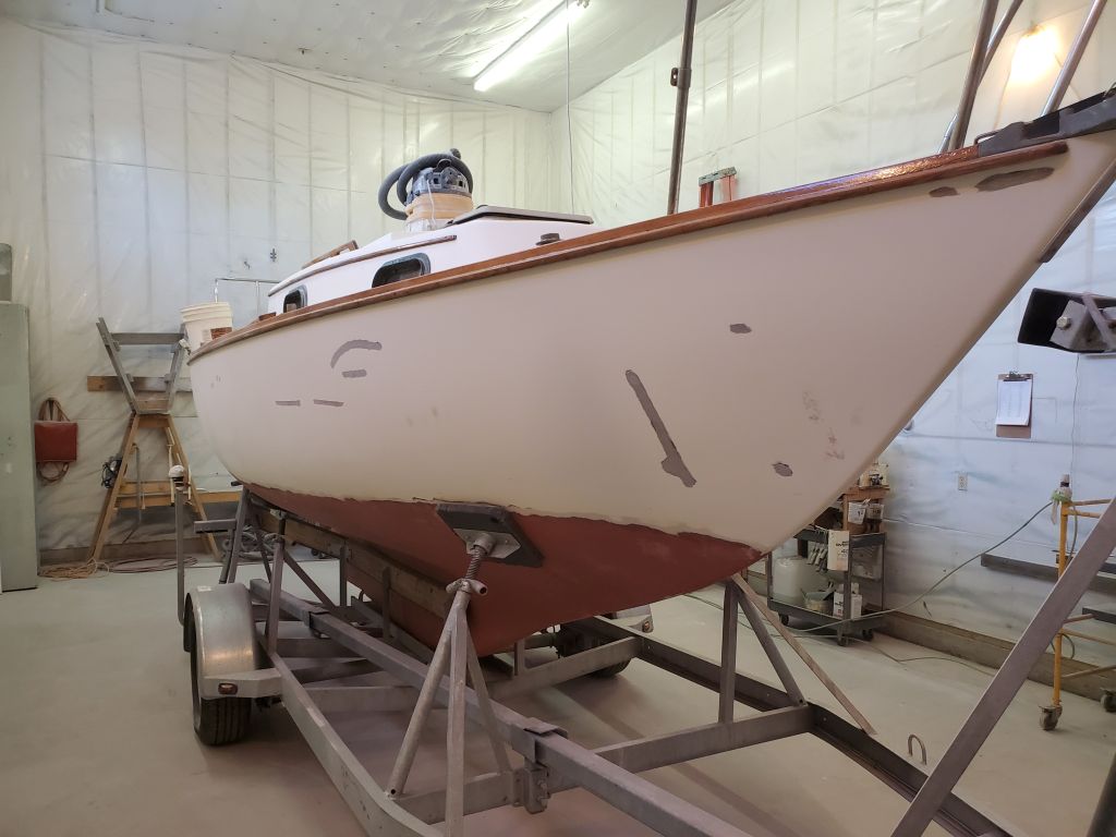
My first task once the boat was clean was to lay out and mark the new and improved waterline, by which I always mean the top edge of the bottom paint. In this case, there was a fair bit of correcting necessary, and based on the owners’ information, photos of the boat in the water, and the existing (and fairly obvious) water marks on the hull, I’d already prepared for the new waterline’s position during the sanding phase.
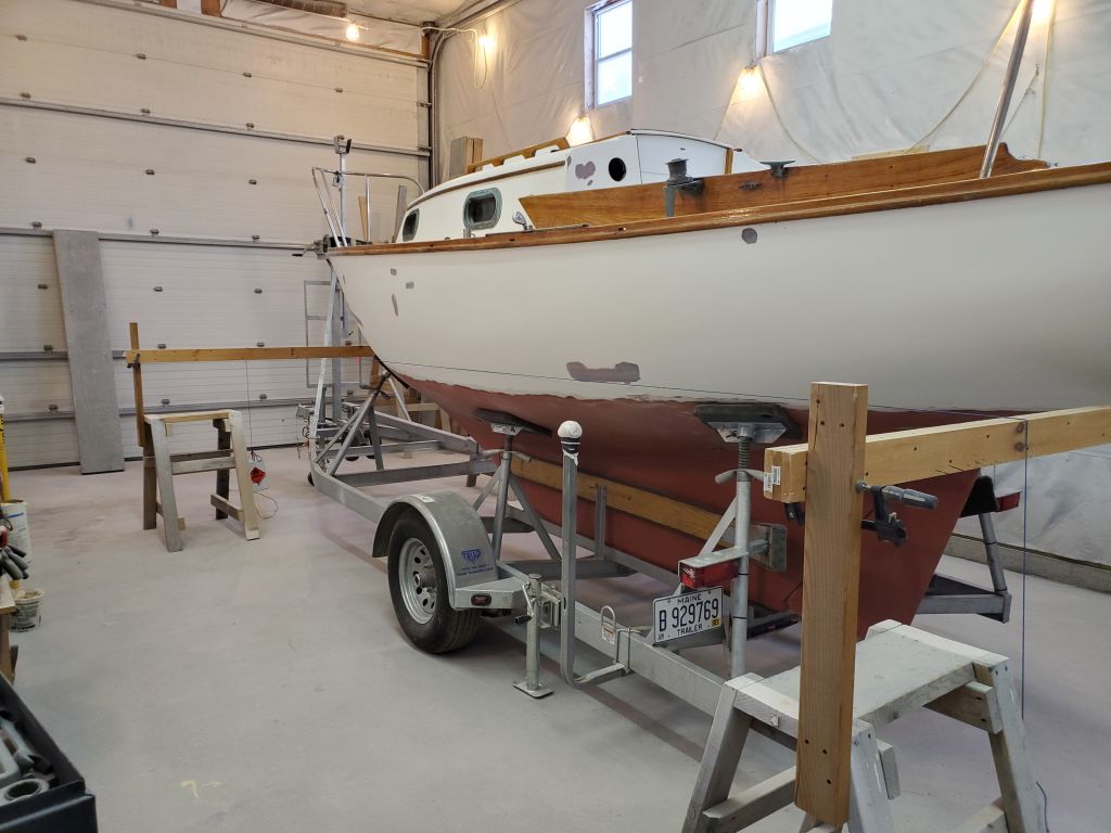
To begin, I adjusted the boat as needed on the stands to bring her level from side to side. She’d been level on the trailer when I’d started, but the work and various adjustments of the stands for sanding access had thrown things slightly out of whack.
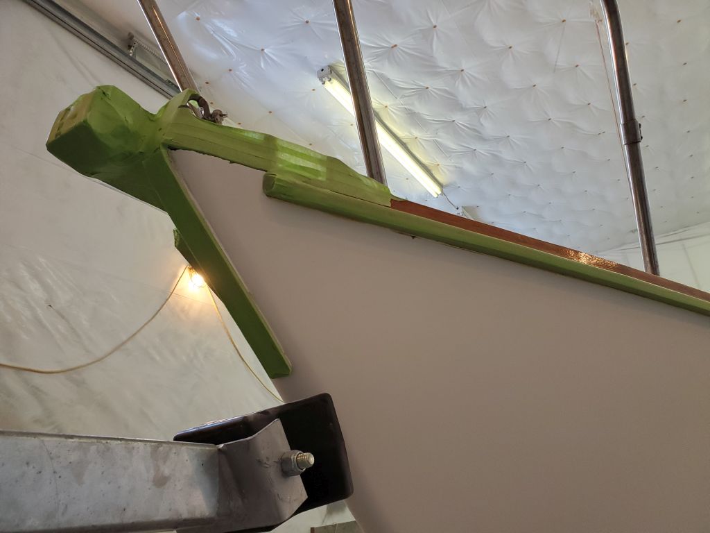
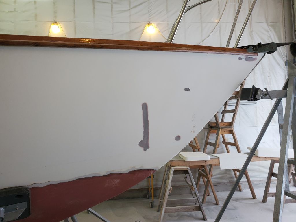
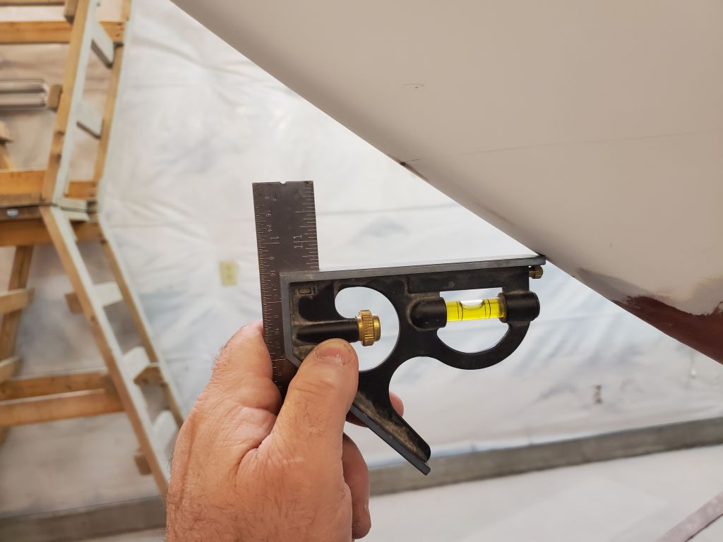
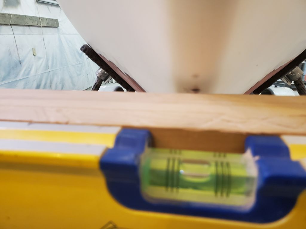
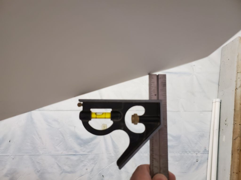
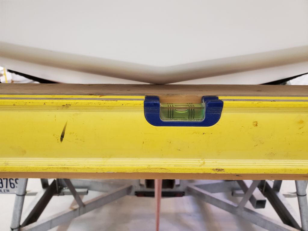
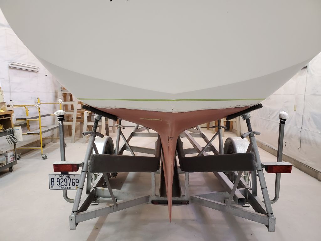
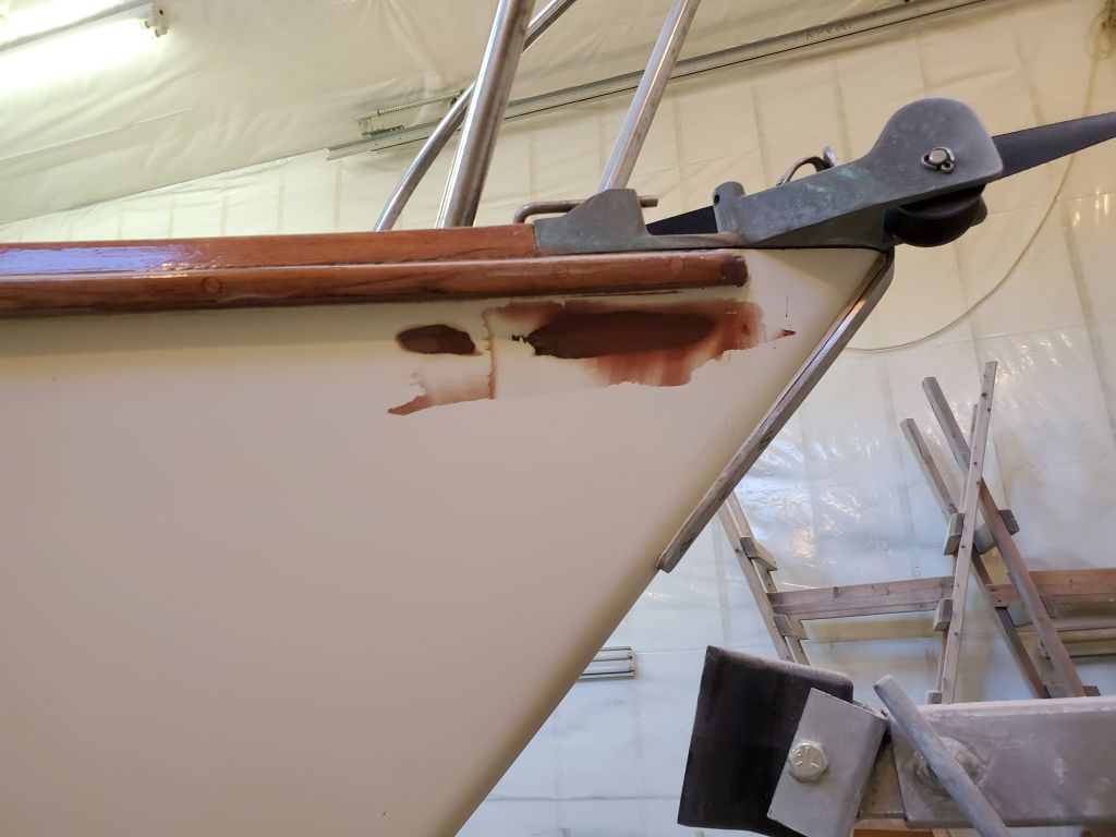
Now, armed with some reference measurements I’d taken before I removed the old paint, and starting at the bow “just because”, I recreated the position of the old, actual floating waterline (37″ down the stem from the chainplate). This represented where the boat had actually floated, but to strike the new waterline, I had to transfer this measurement up enough to allow a border of bottom paint above the water. With a straightedge and level, I made a new mark 1-1/2″ vertically above the original: This would be the level of the newly-struck waterline, or, in this case, the lower edge of the new topsides paint and striping.
Note that all pictures of me holding levels are for illustrative purposes only, to show the process; the level may not be perfectly positioned as I juggle camera and hand positioning.
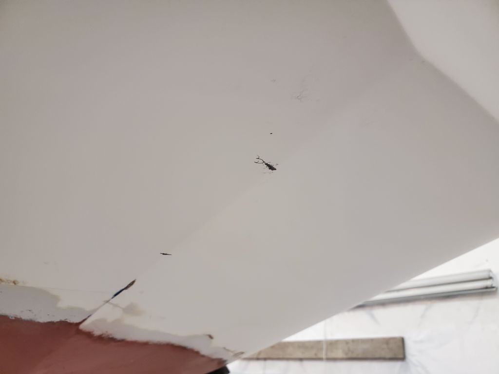
As it happened, the mark for the new waterline at the bow coincided with the faint factory scribe mark for the DWL. This made sense because at the bow, the correct paint level actually needed to be lower than the paint-as-delivered, which is why I’d sanded off several inches of the old bottom paint in the forward quarters of the boat.
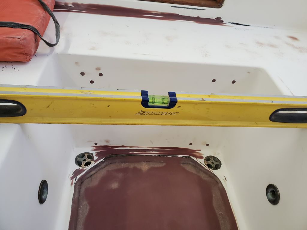
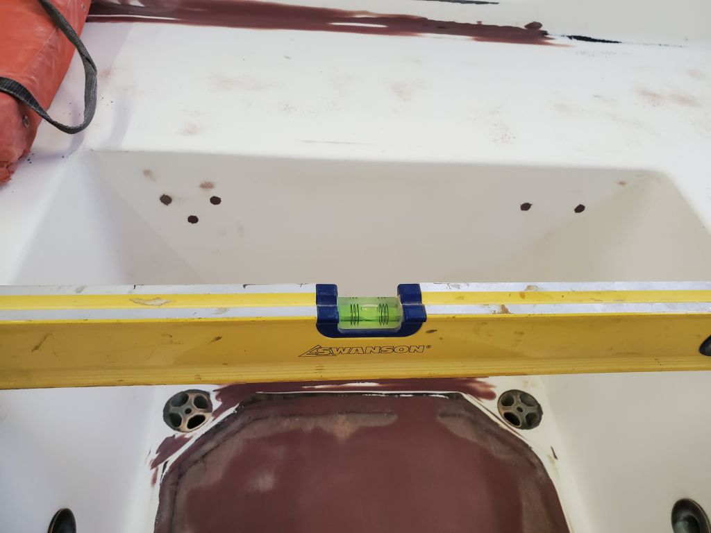
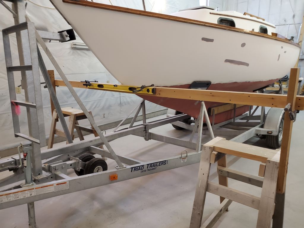
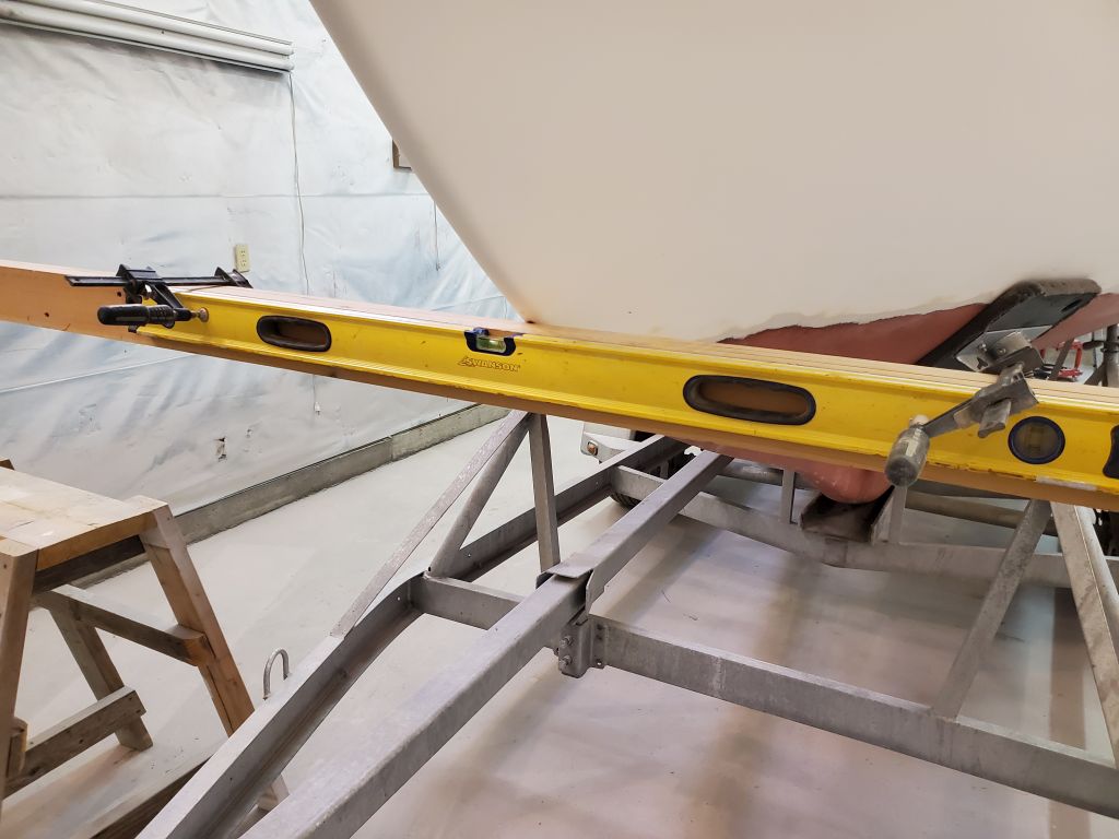
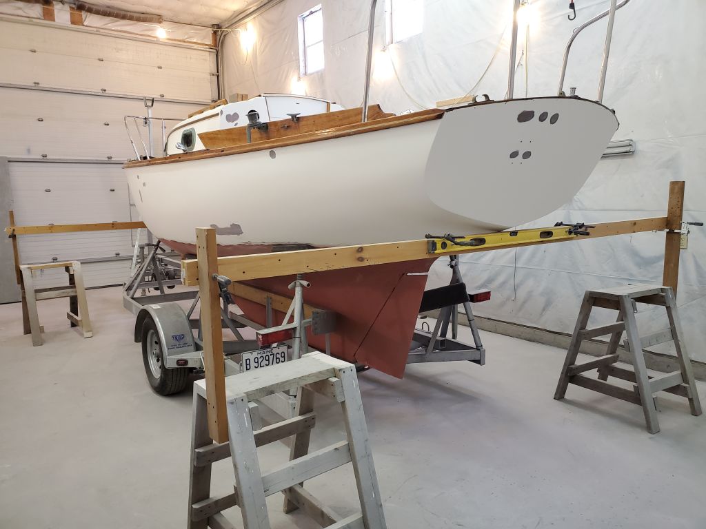
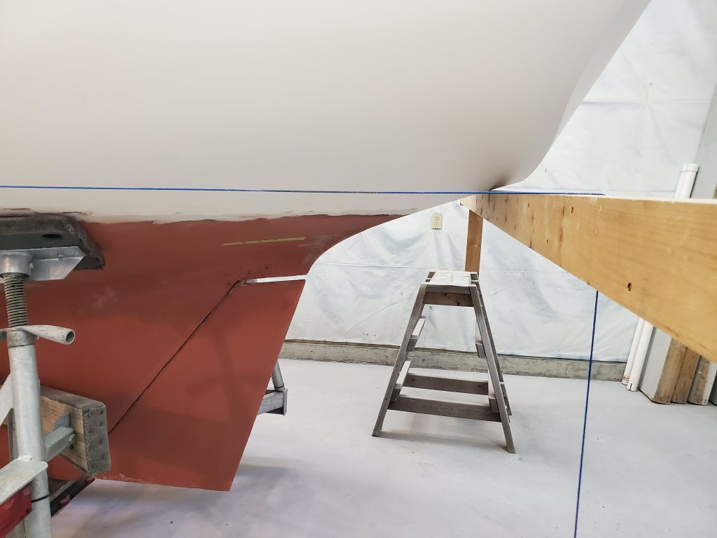
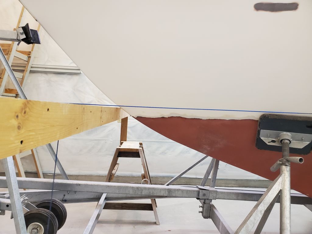
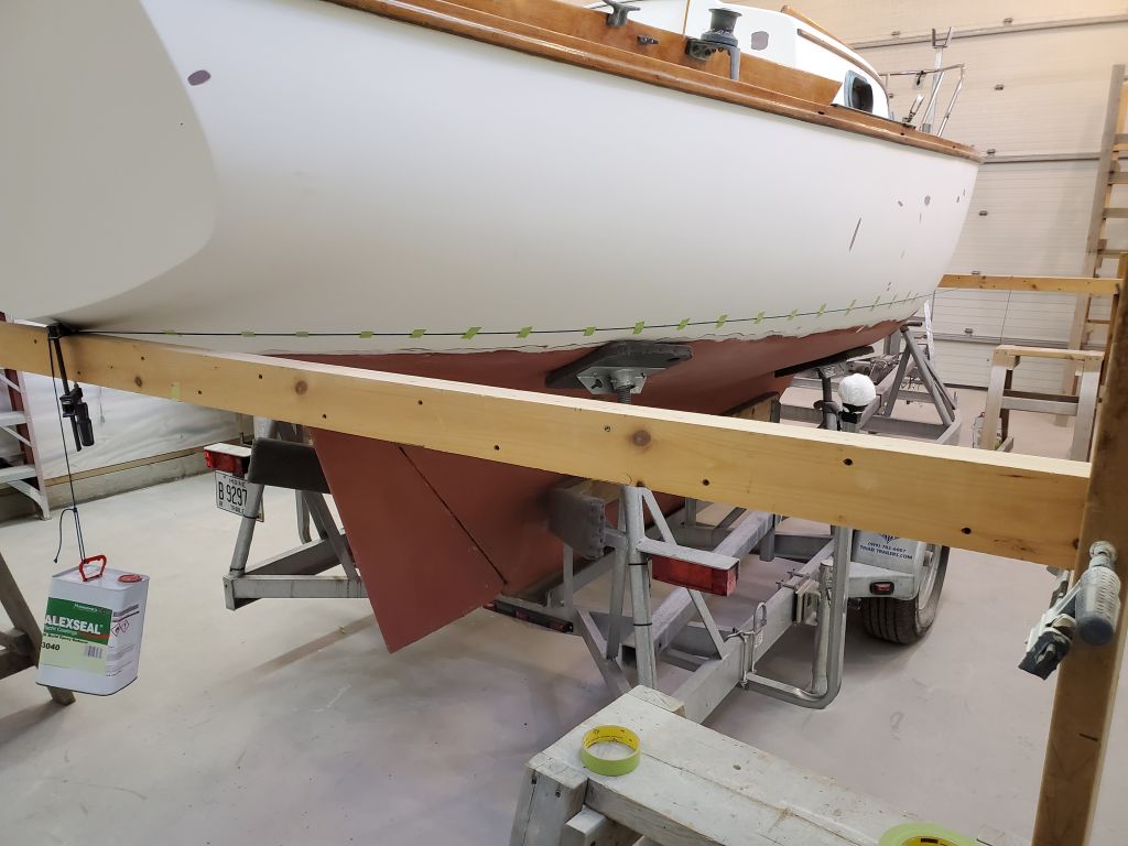
I set up a wide, straight beam at the new, leveling it side to side.
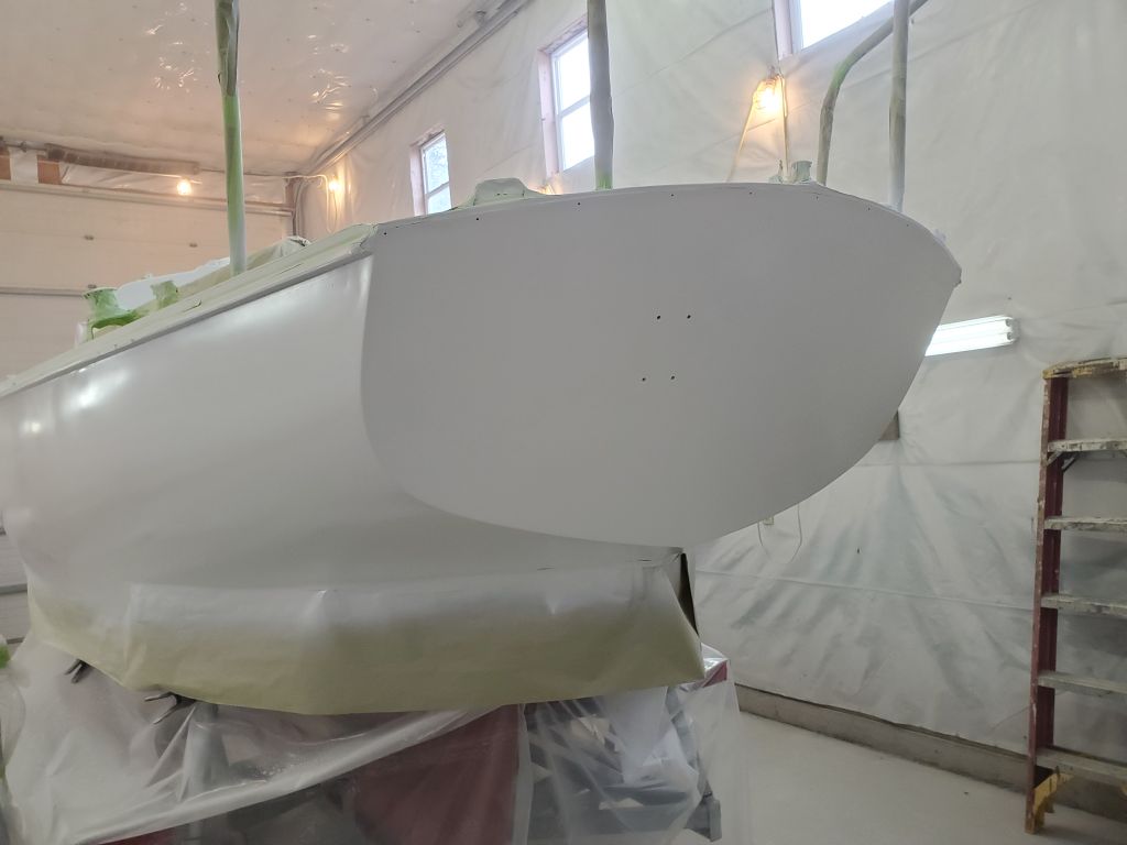
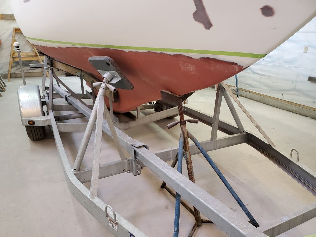
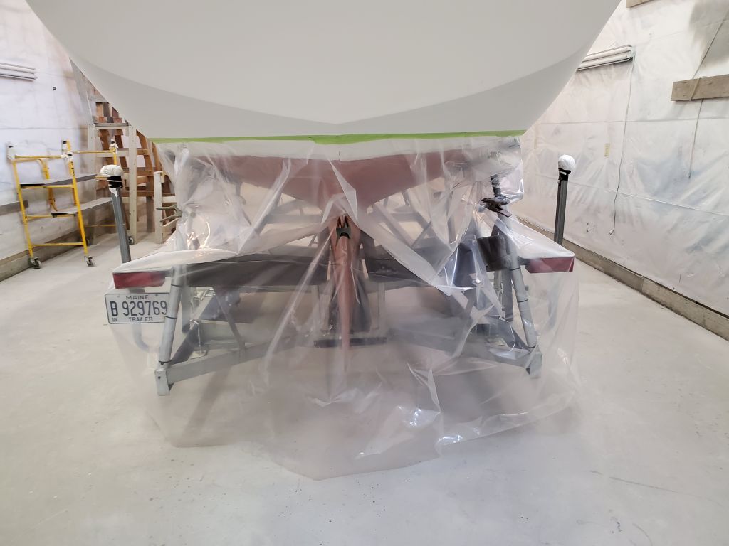
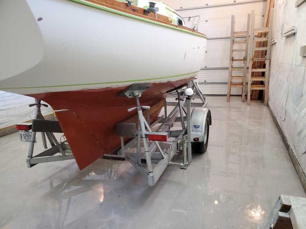
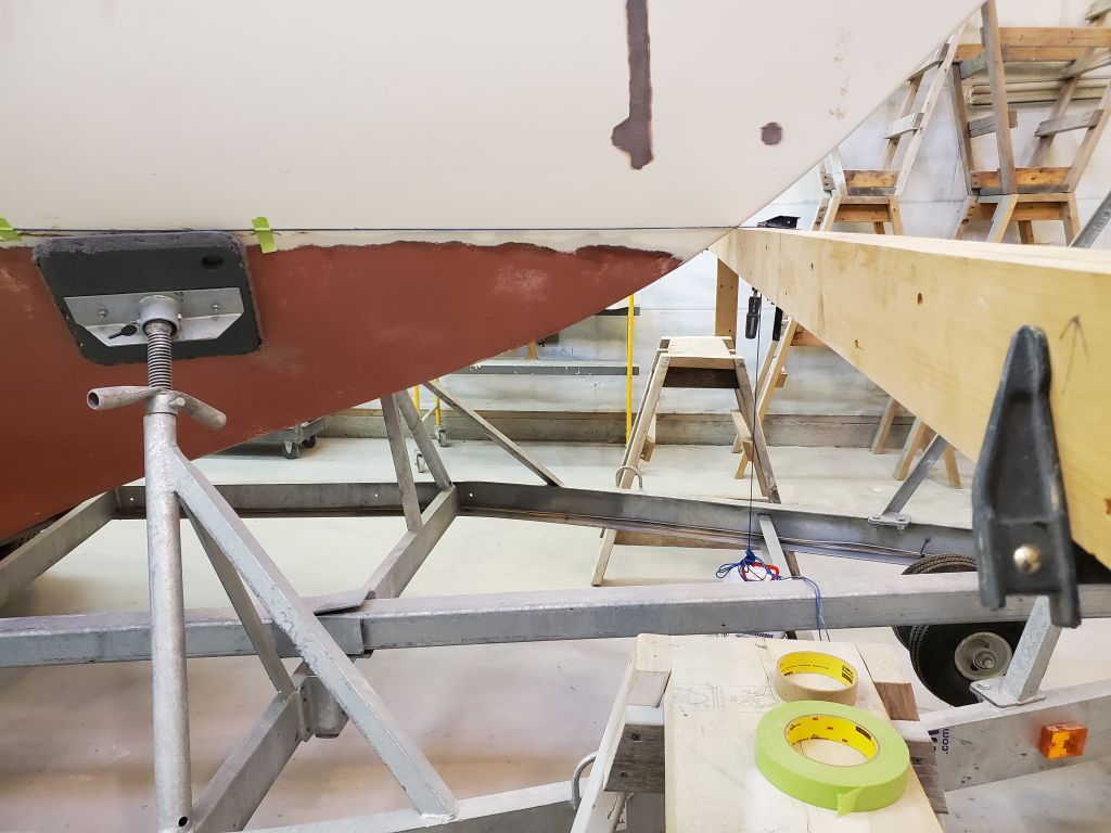
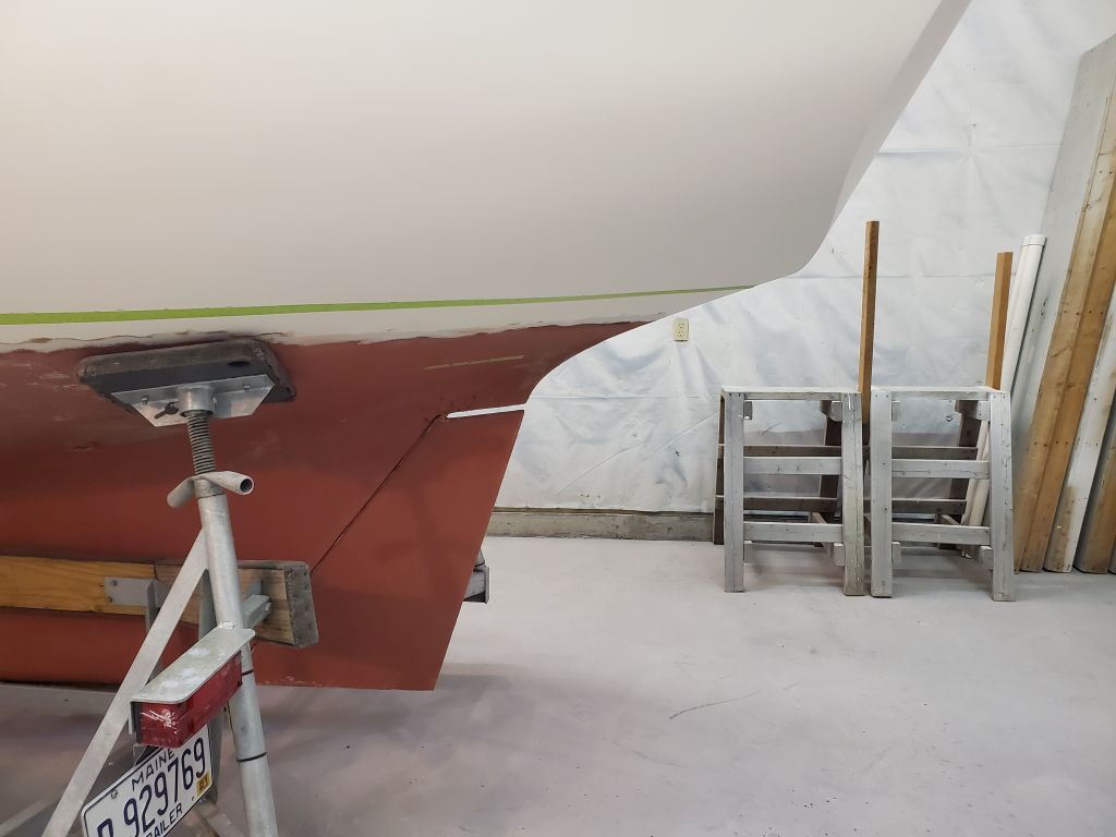
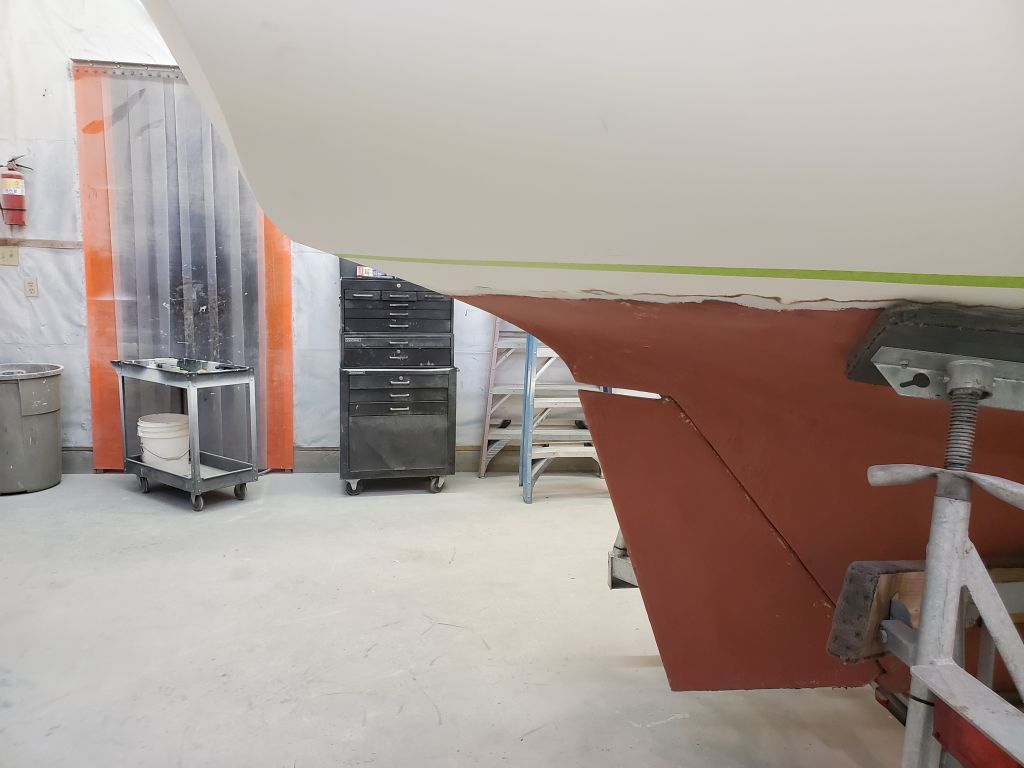
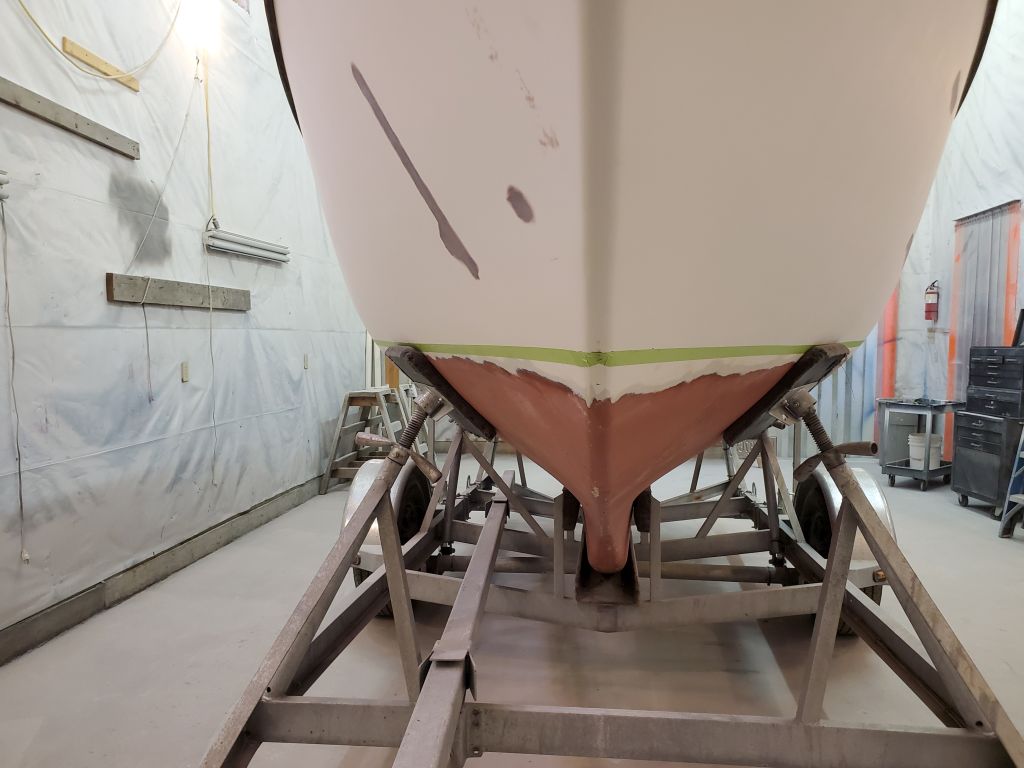
Next, I repeated the process at the stern, starting with an 8″ measurement on centerline from the transom corner, which signified the actual floating waterline according to anecdotal, visual, and photographic evidence as detailed earlier in the project. Again, I transferred the mark up 1-1/2″ vertically to create the new waterline with appropriate reveal, and set up a second horizontal beam right at this mark.
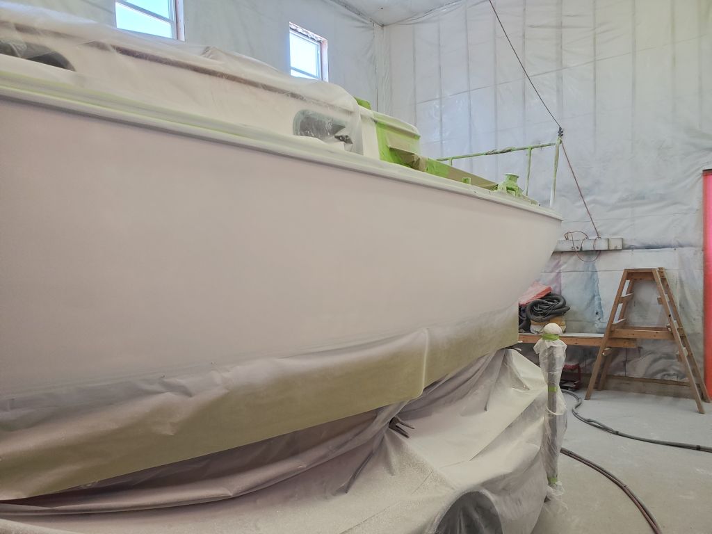
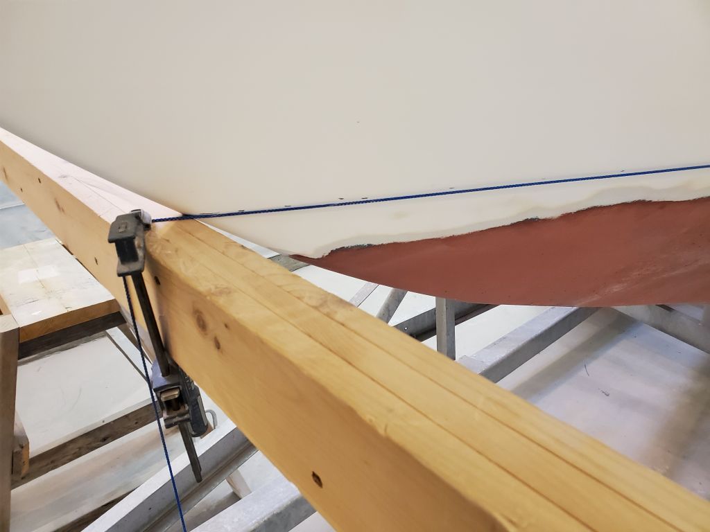
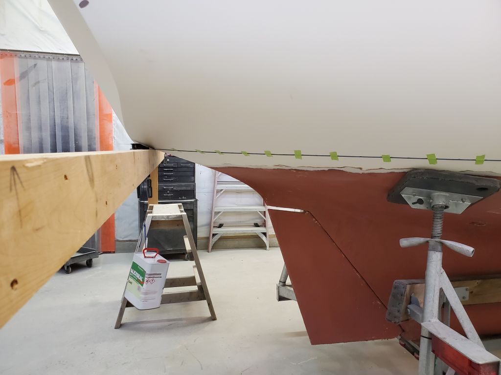
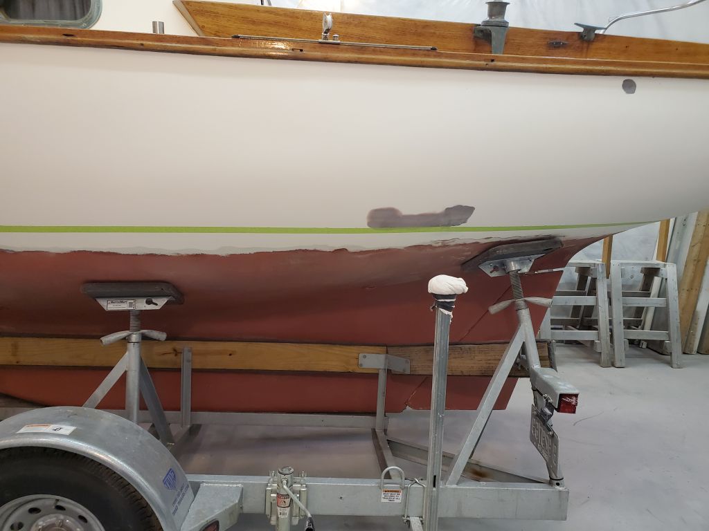
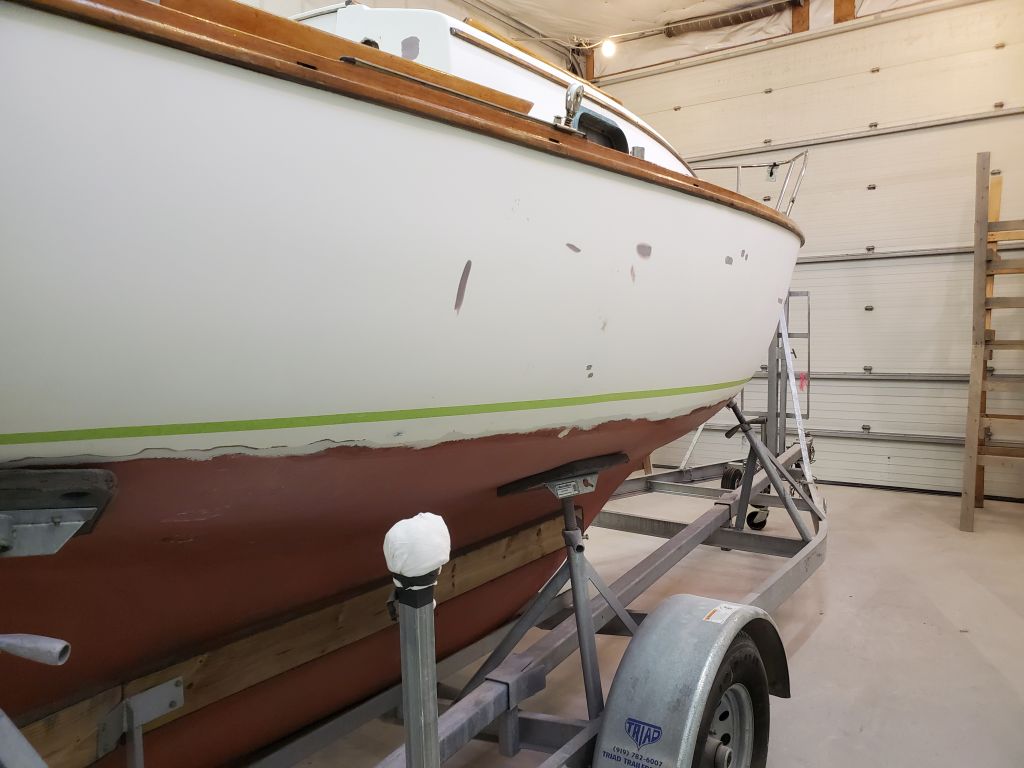
Now I went through my usual ritual to mark the line along the entire hull, using a tensioned string between the two beams. With the string just touching the hull amidships on one side, I brought it in incrementally towards each end (first the stern, then the bow) till the string touched the hull, then taped it in place before repeating. Each time, I made small pencil marks on the hull at the top of the string. This simple, visual process creates a perfect planar line between the stem and stern.
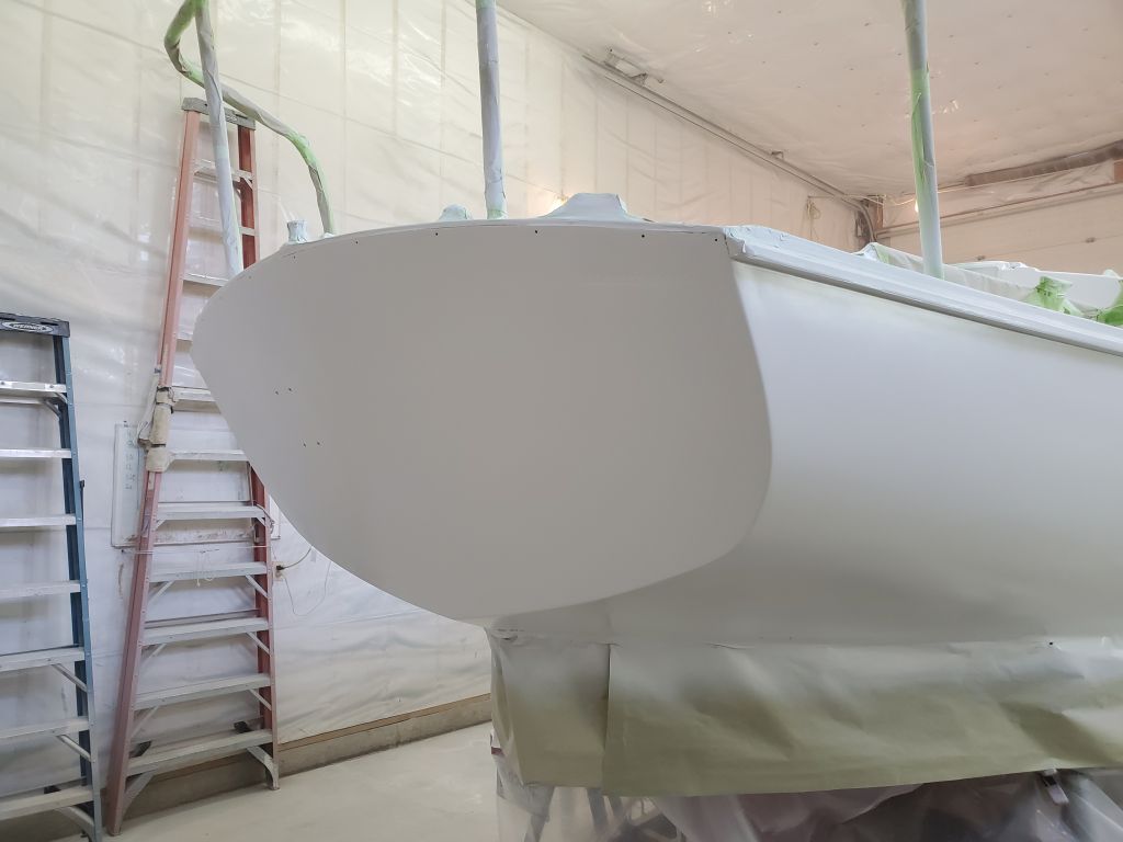
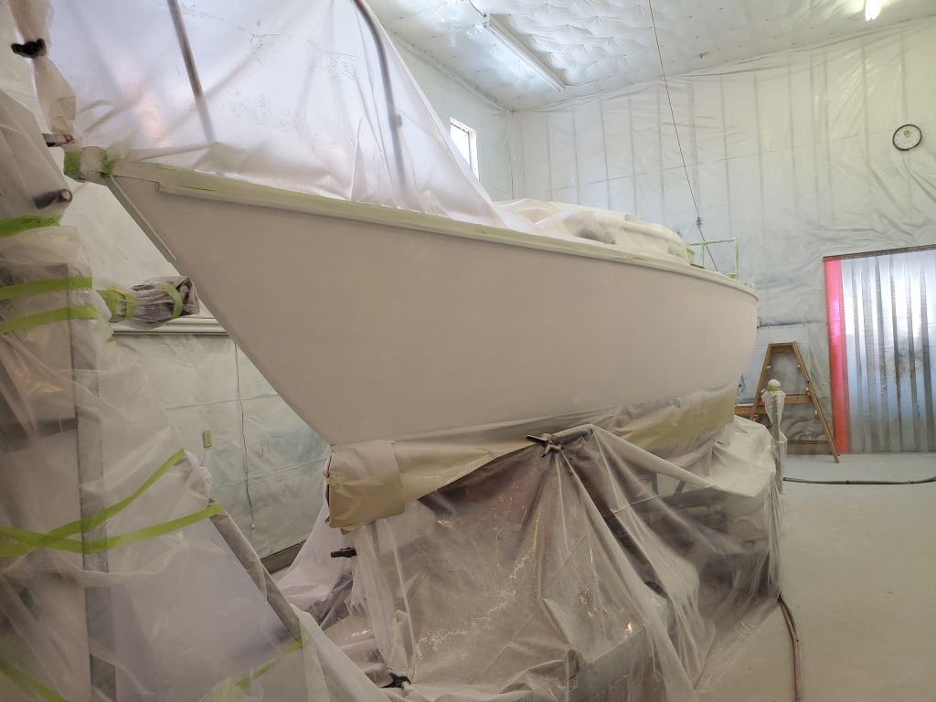
I repeated the process on the starboard side.
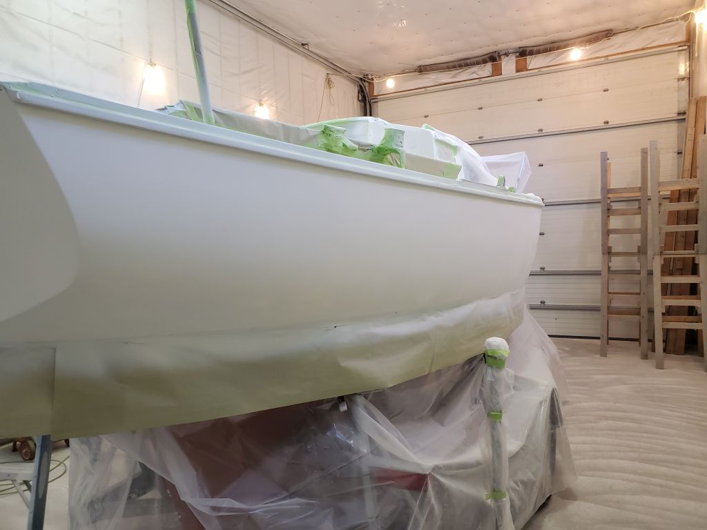
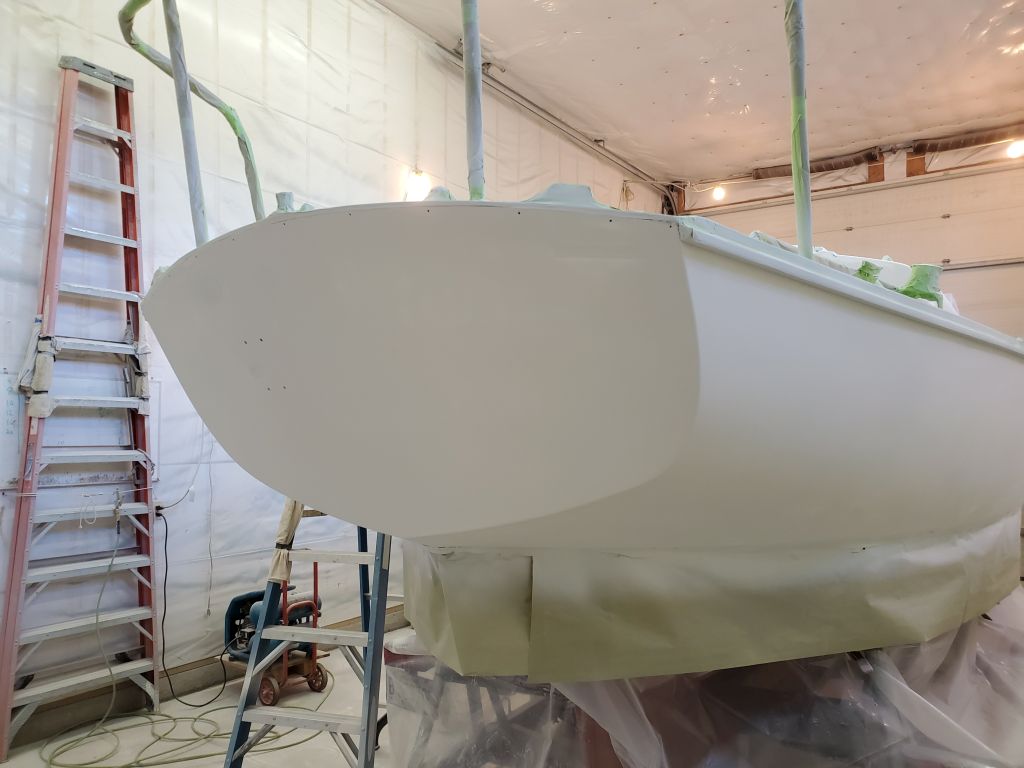
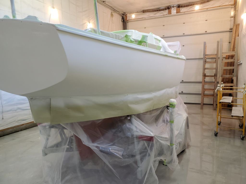
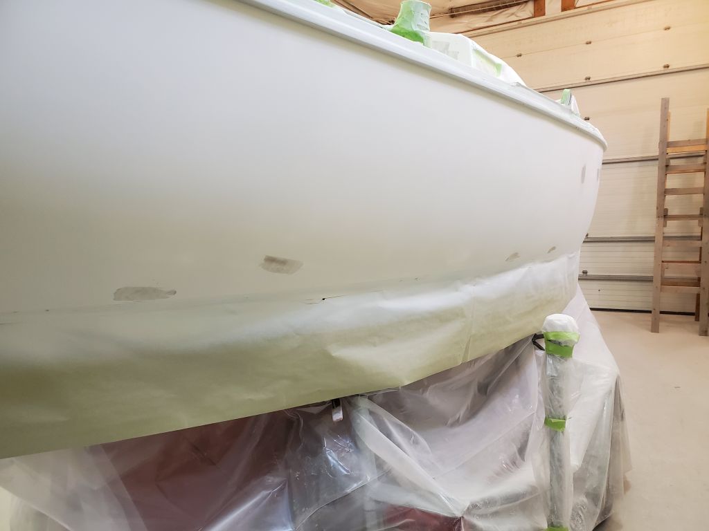
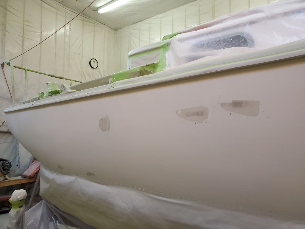
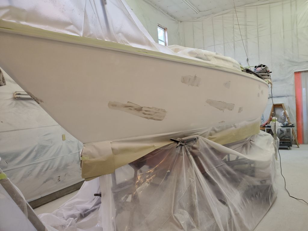
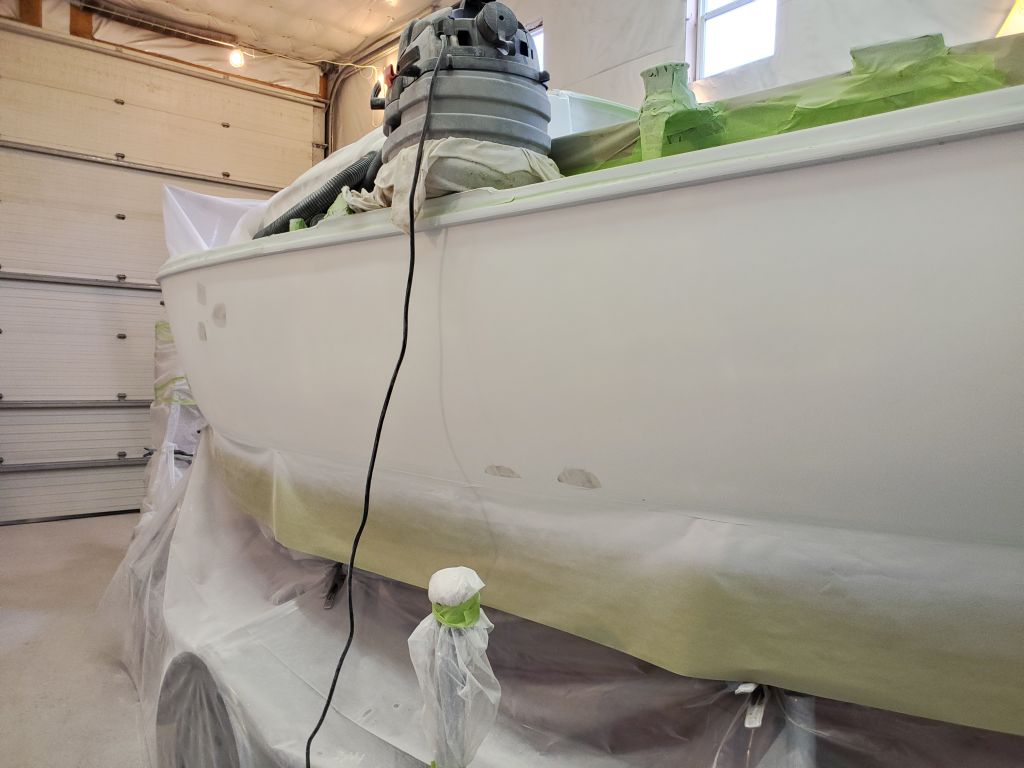
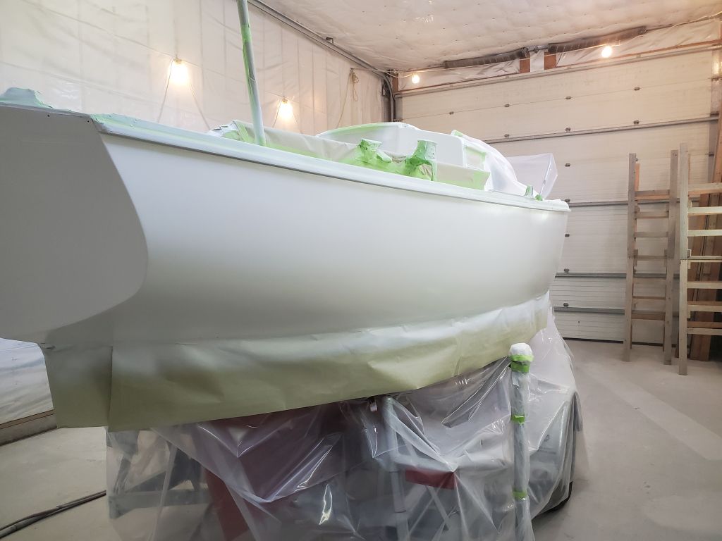
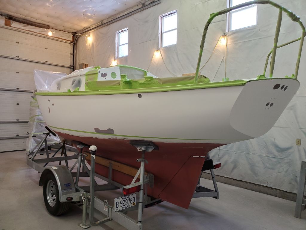
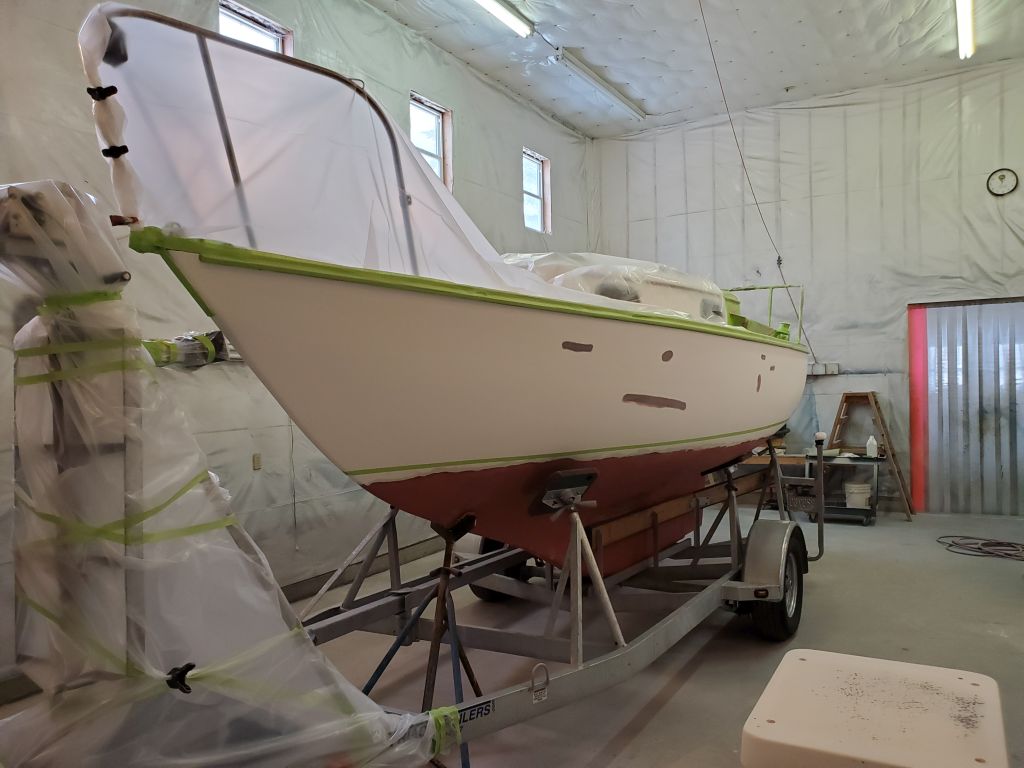
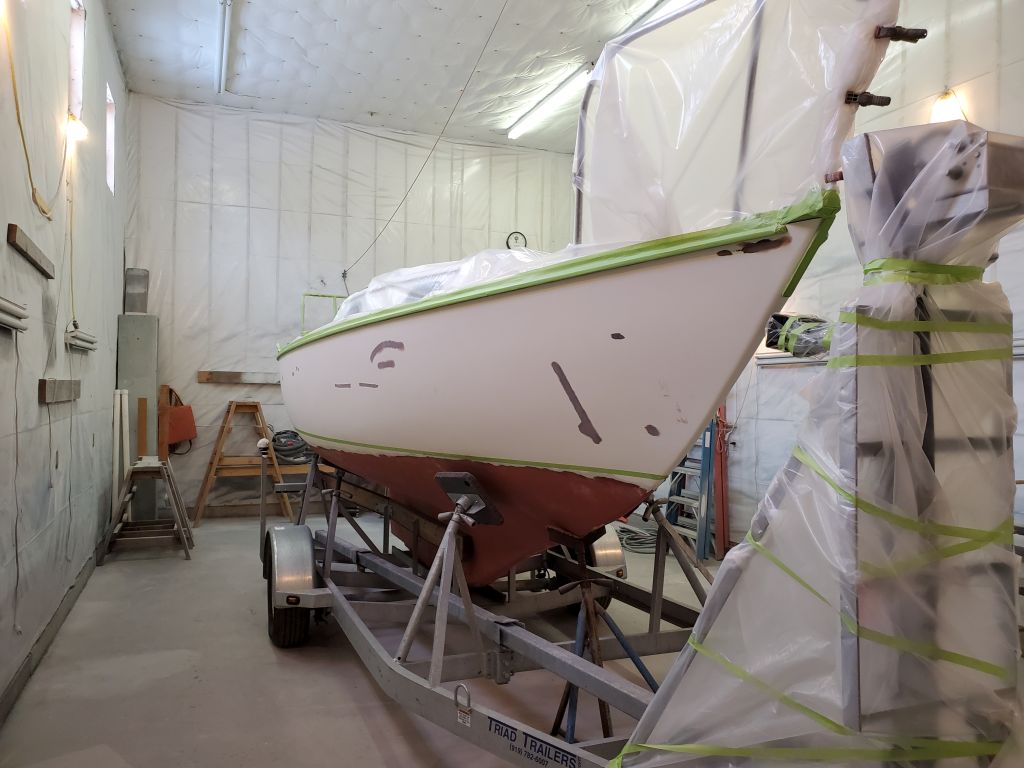
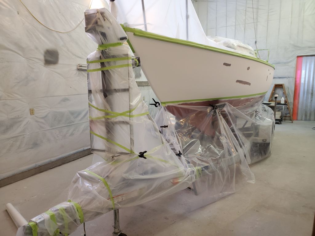
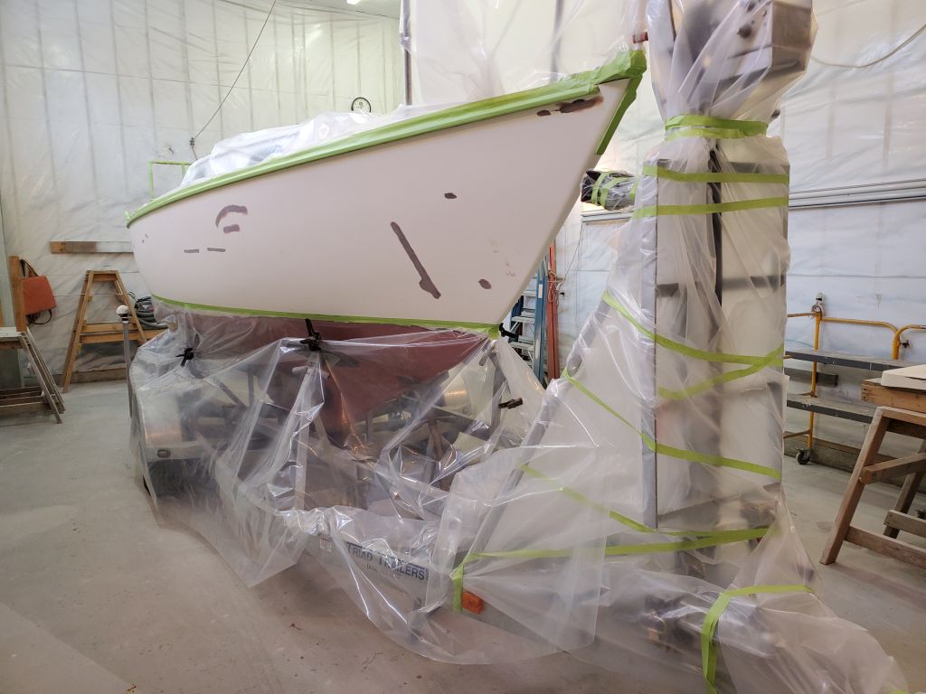
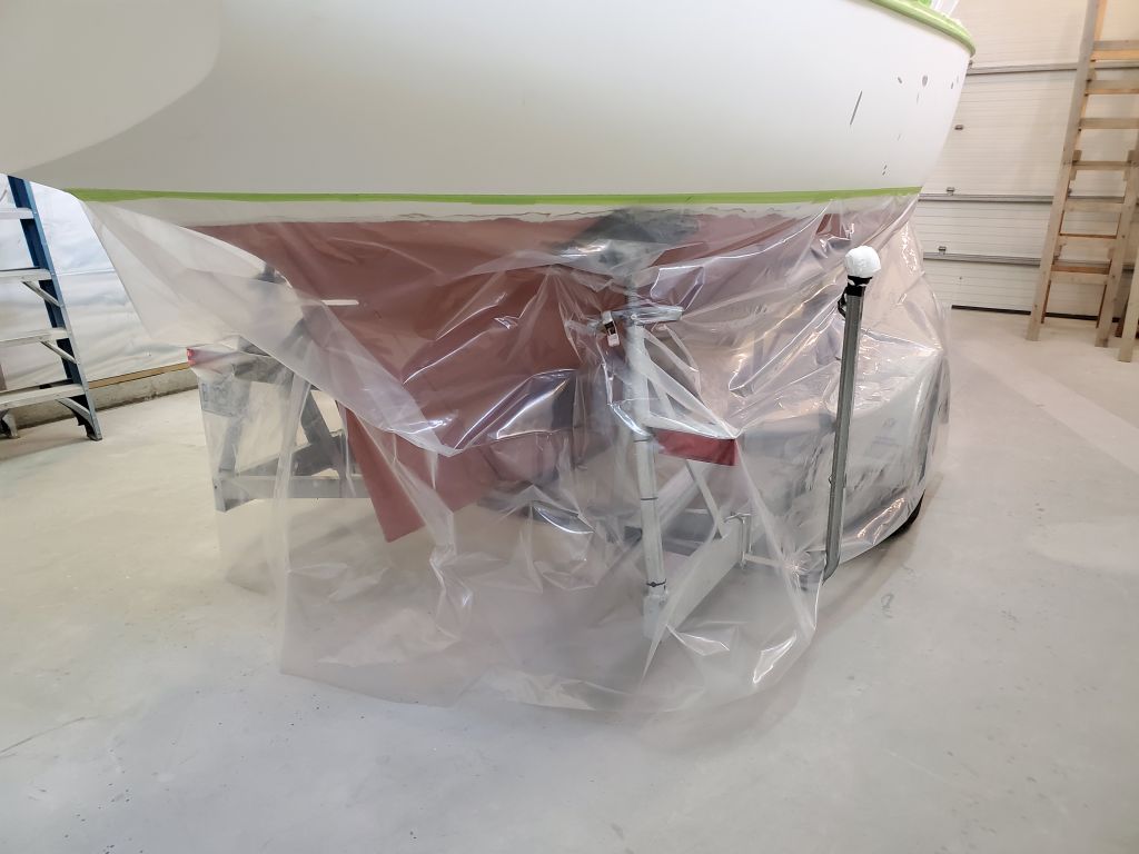
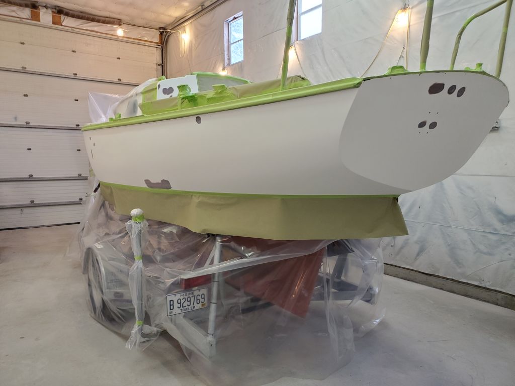
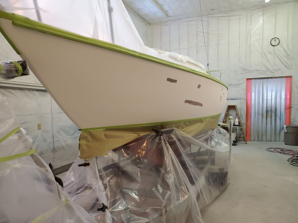
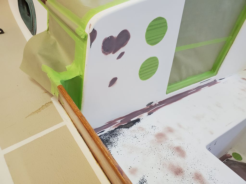
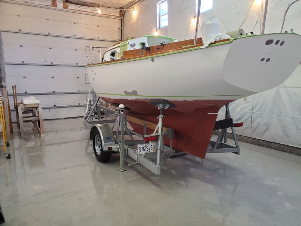
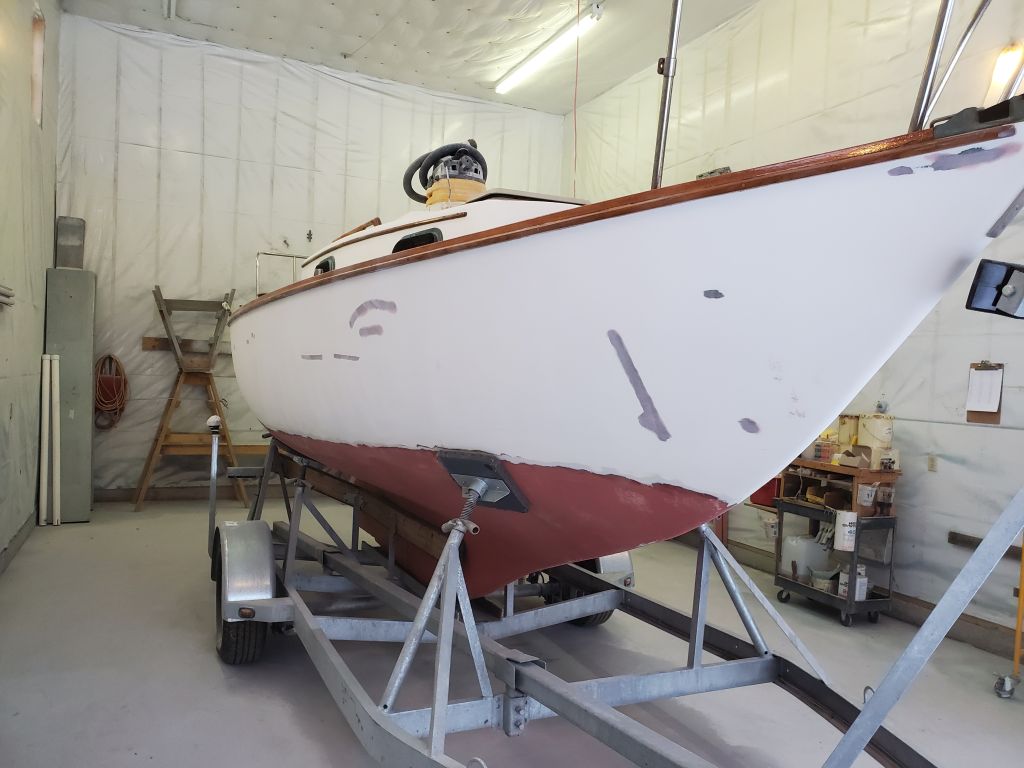
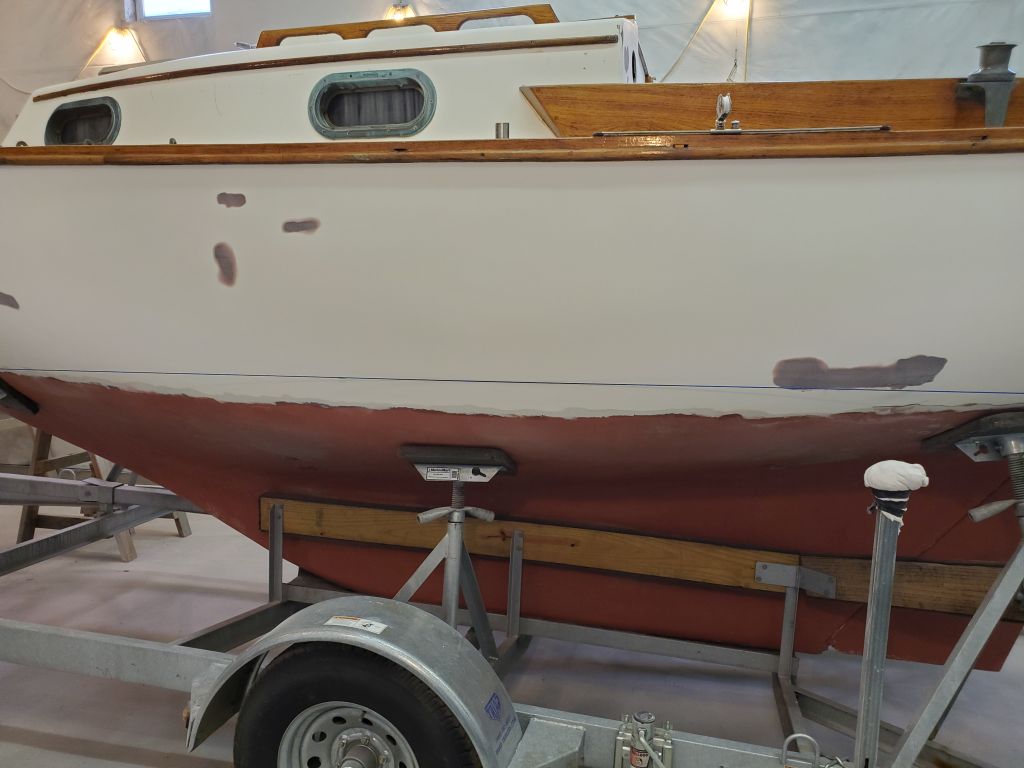
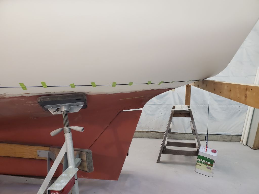
With the whole hull thusly marked, and after breaking down the beams, I masked off just below my pencil marks, creating the lower edge of the new topsides paint, and eventually the top edge of the antifouling paint. Additional lines for striping would come later in the process, once the finish primer was complete.
Total time billed on this job today: 6.25 hours
0600 Weather Observation: 14°, cloudy. Forecast for the day: Snow, 3-5″ forecast, about 8″ in reality, 18°.