Thursday
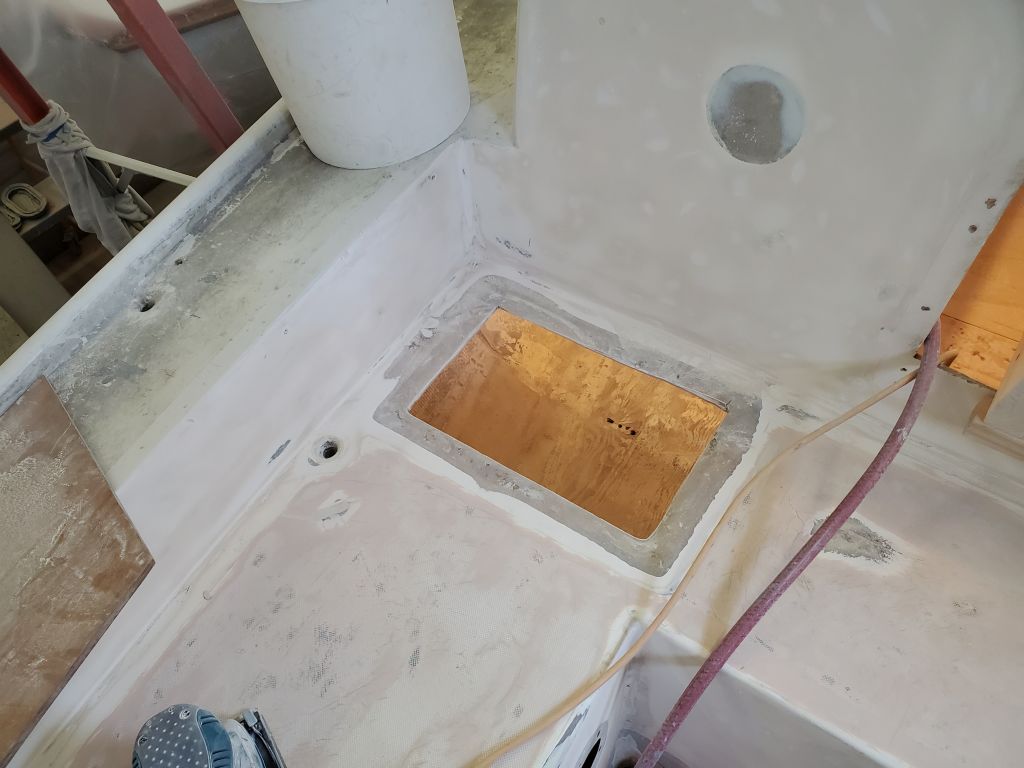
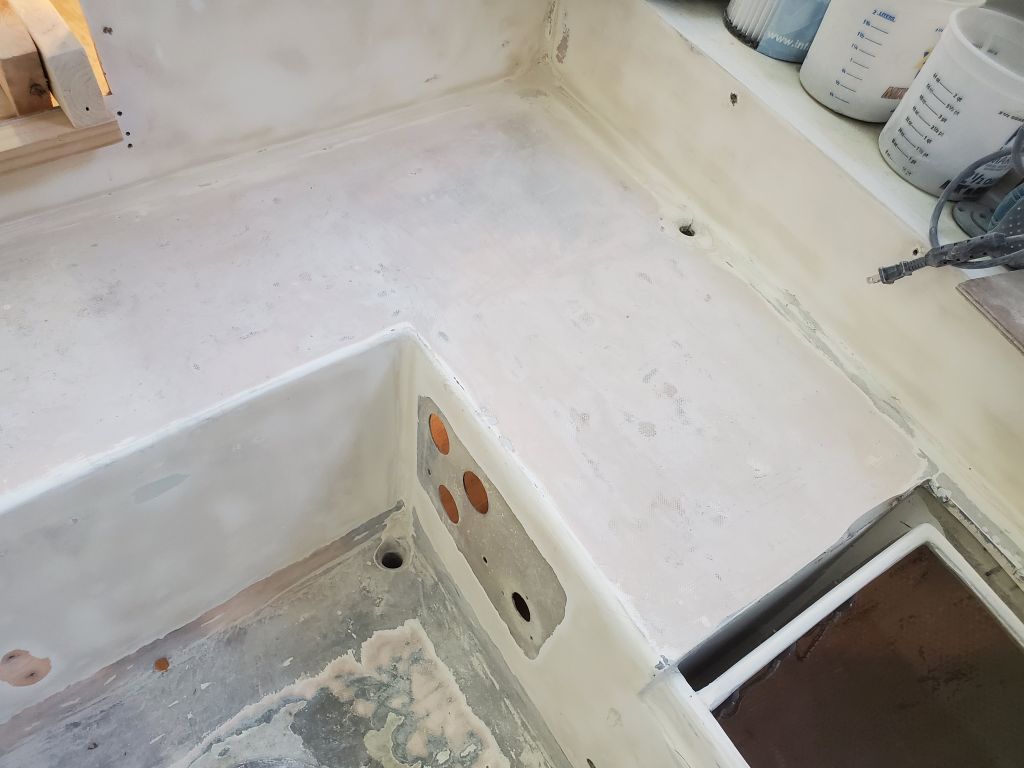
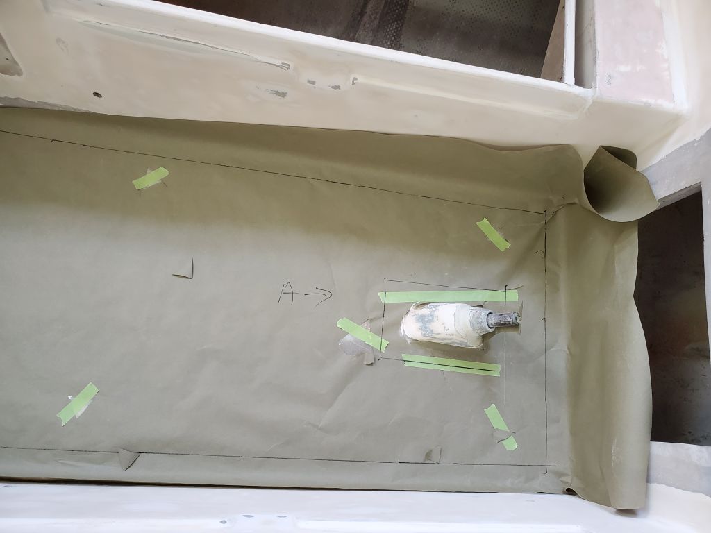
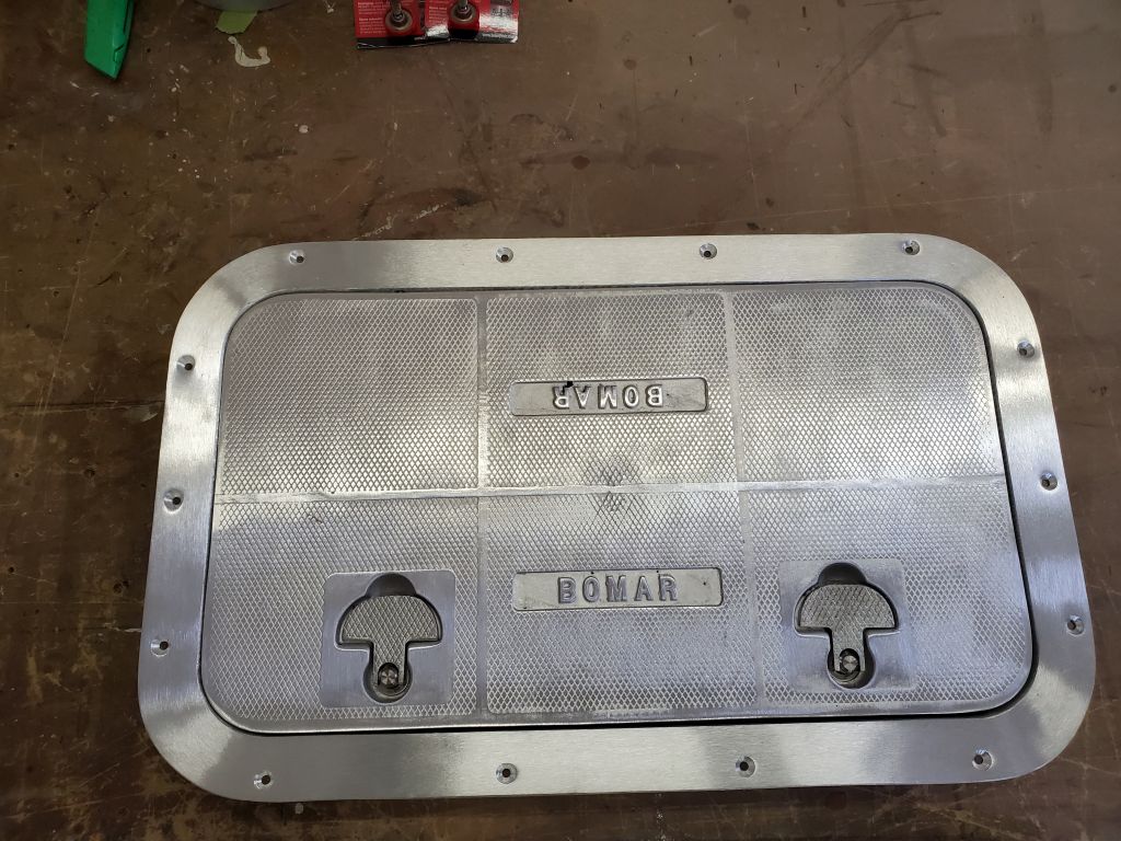
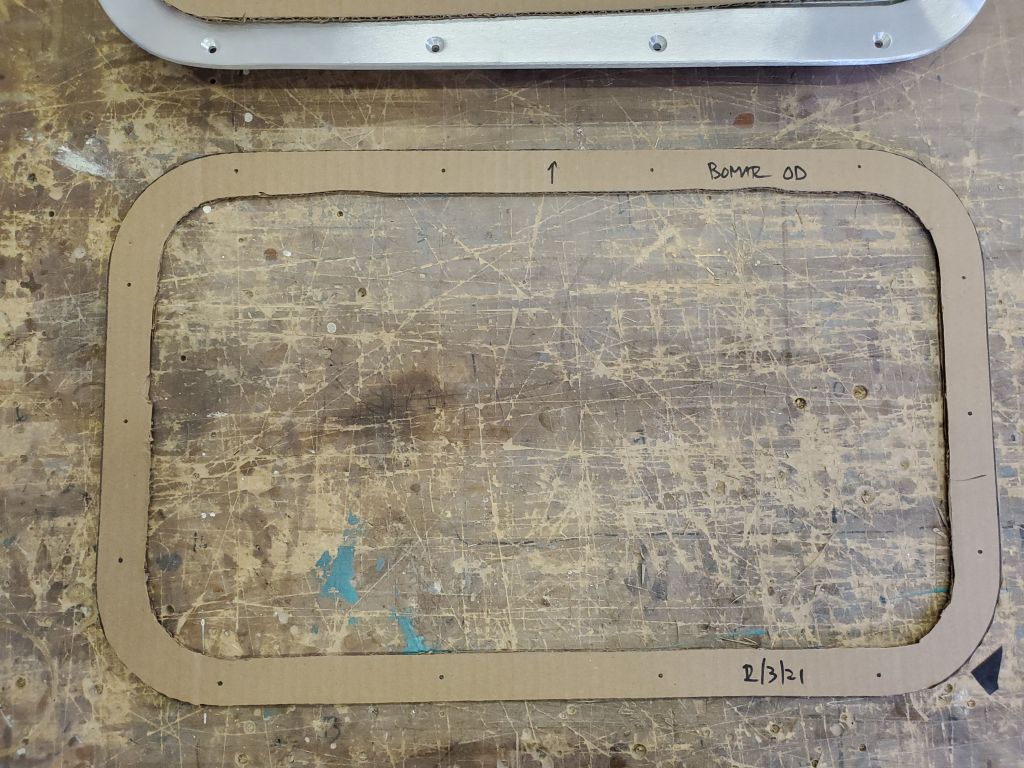
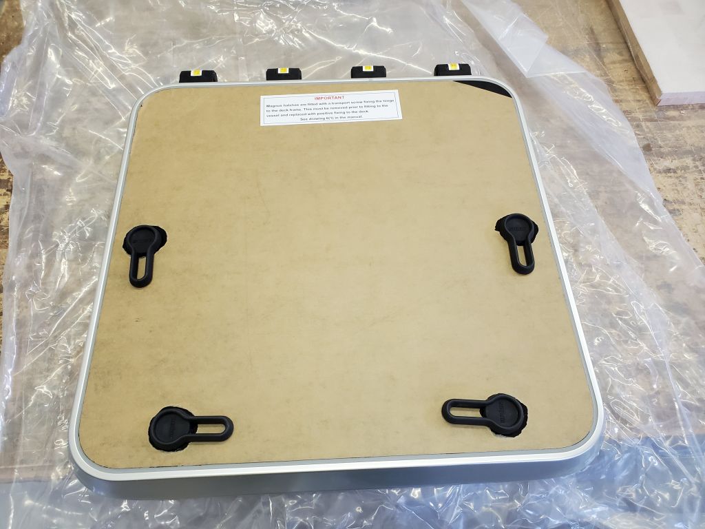
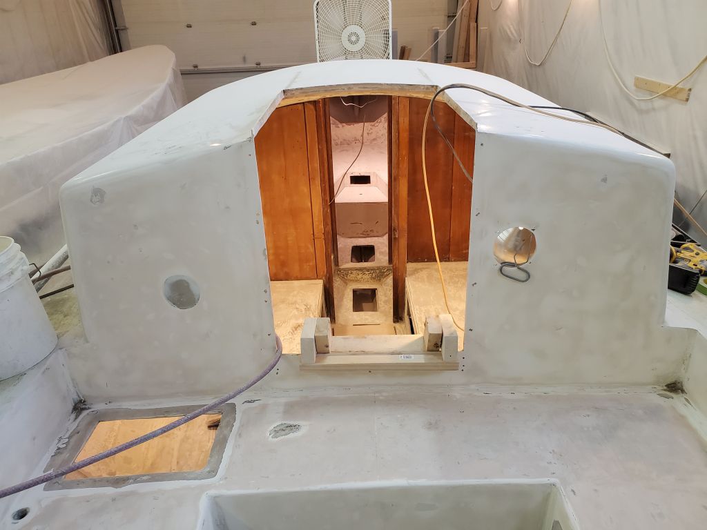
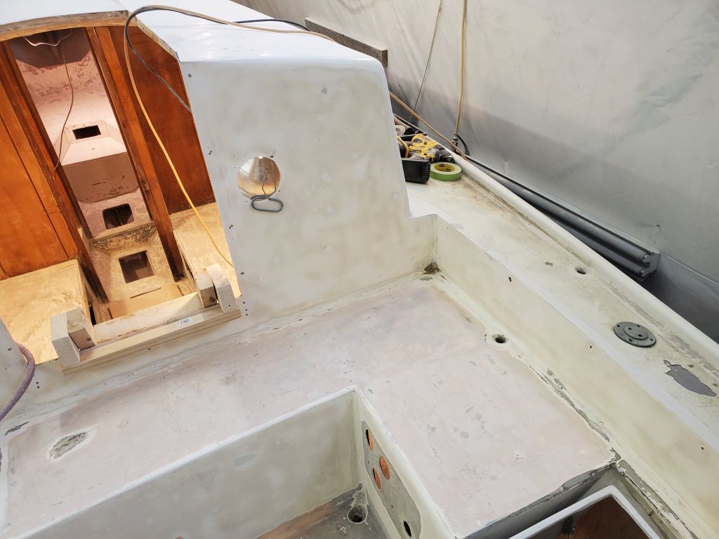
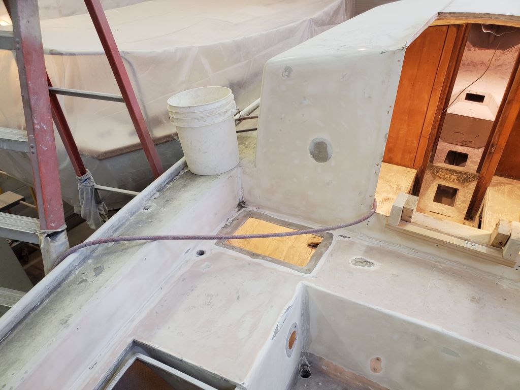
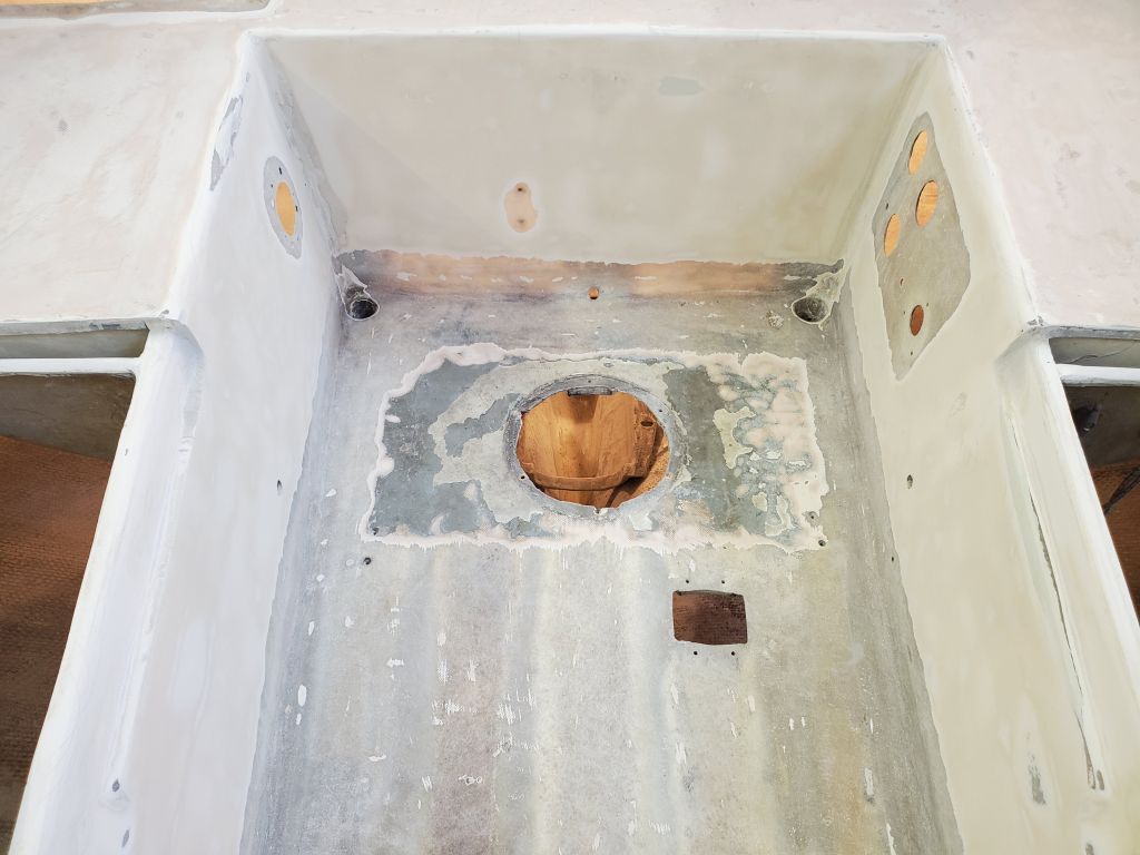
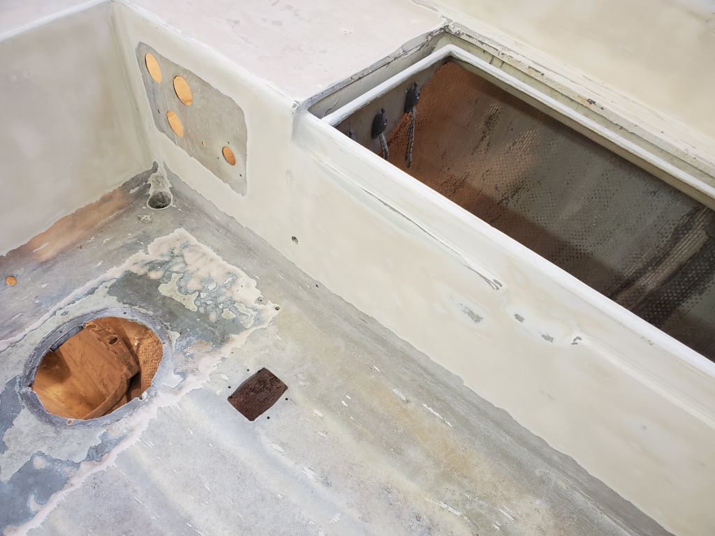
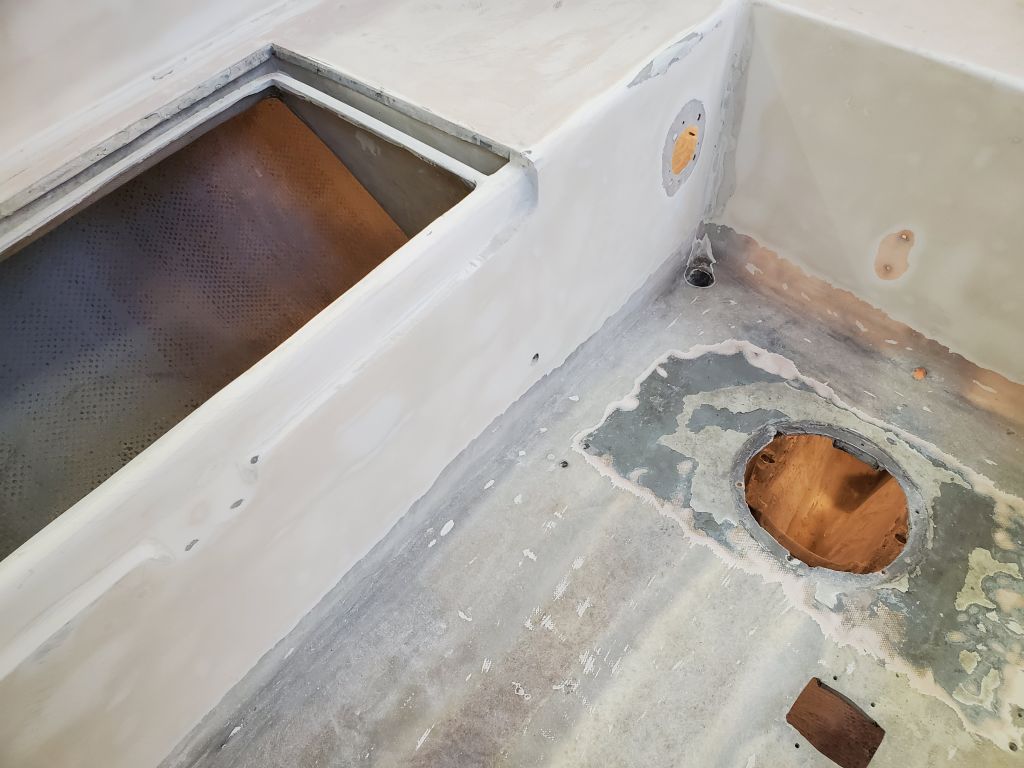
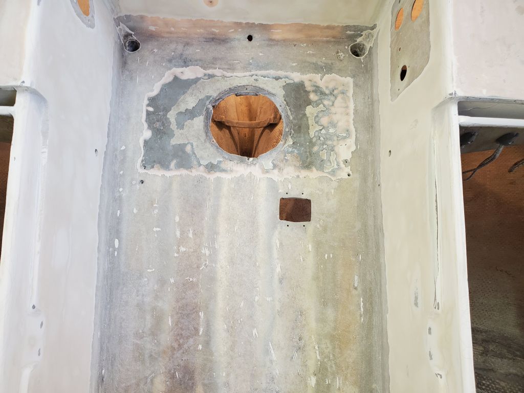
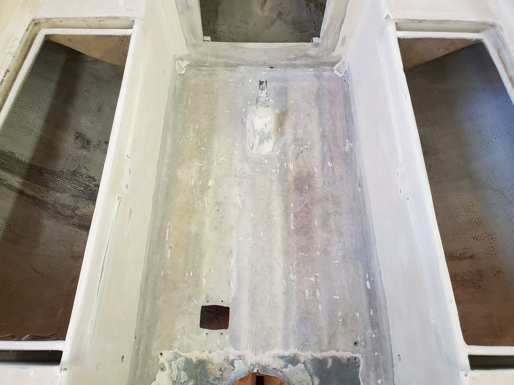
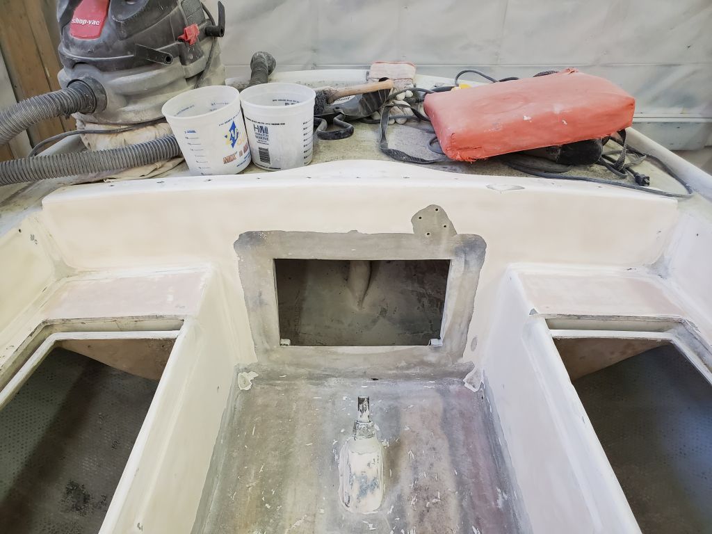
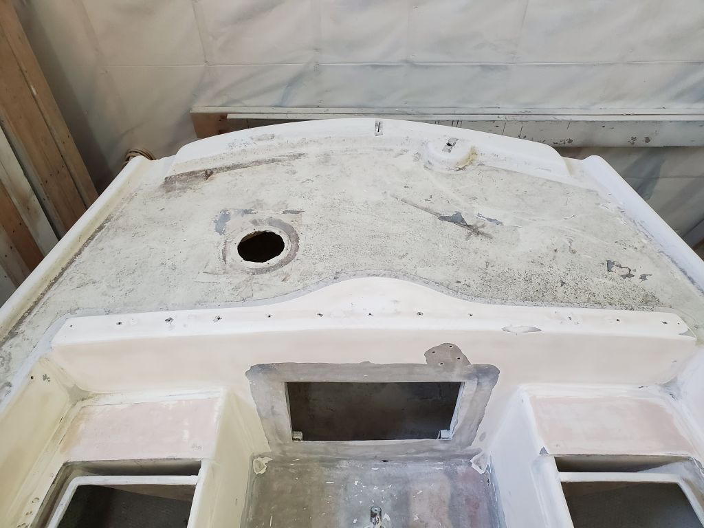
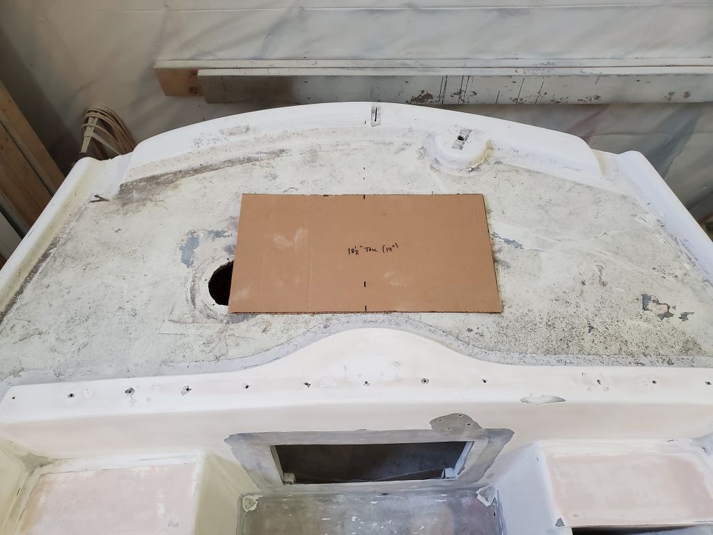
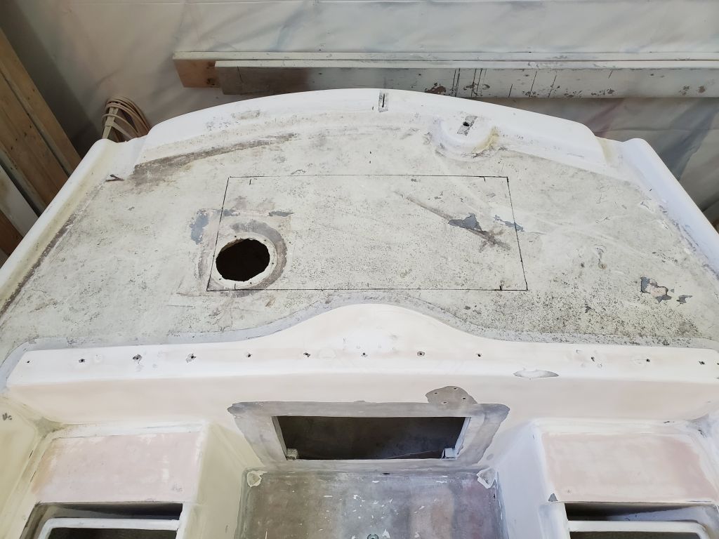
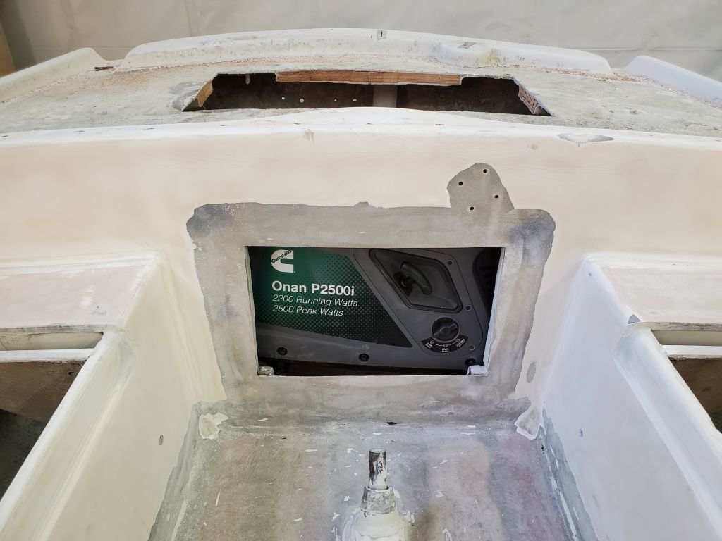
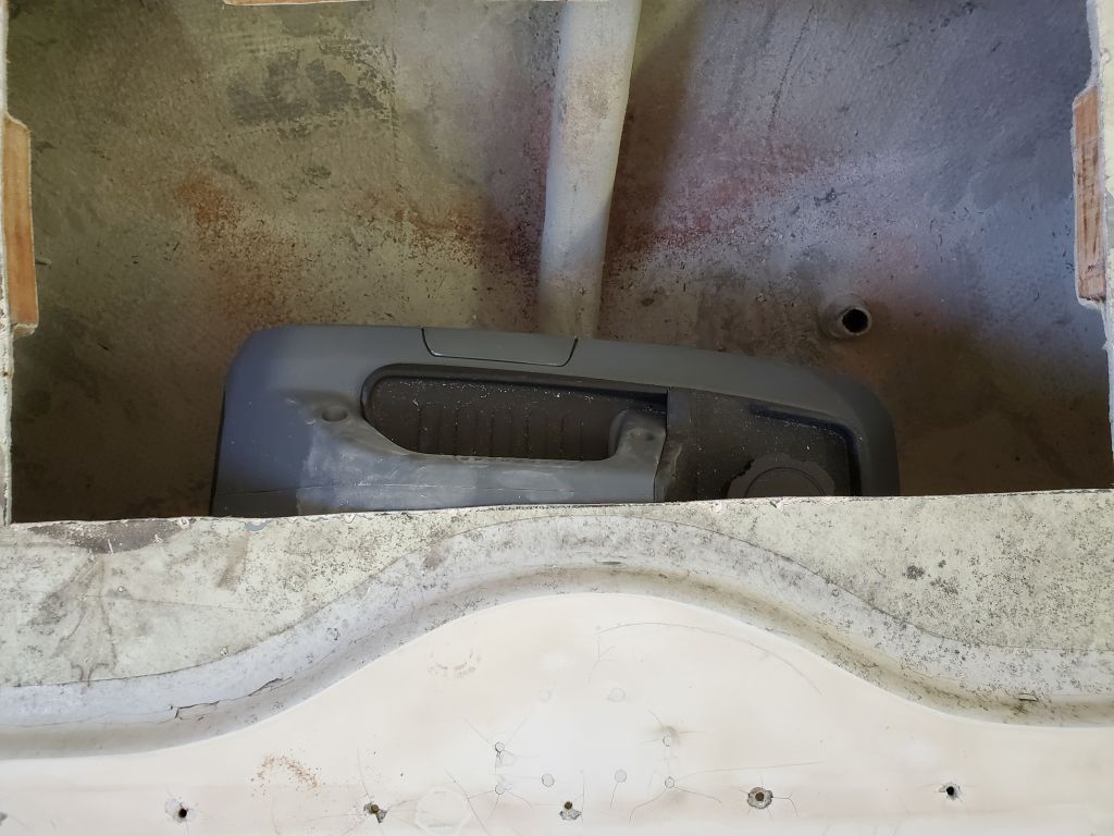
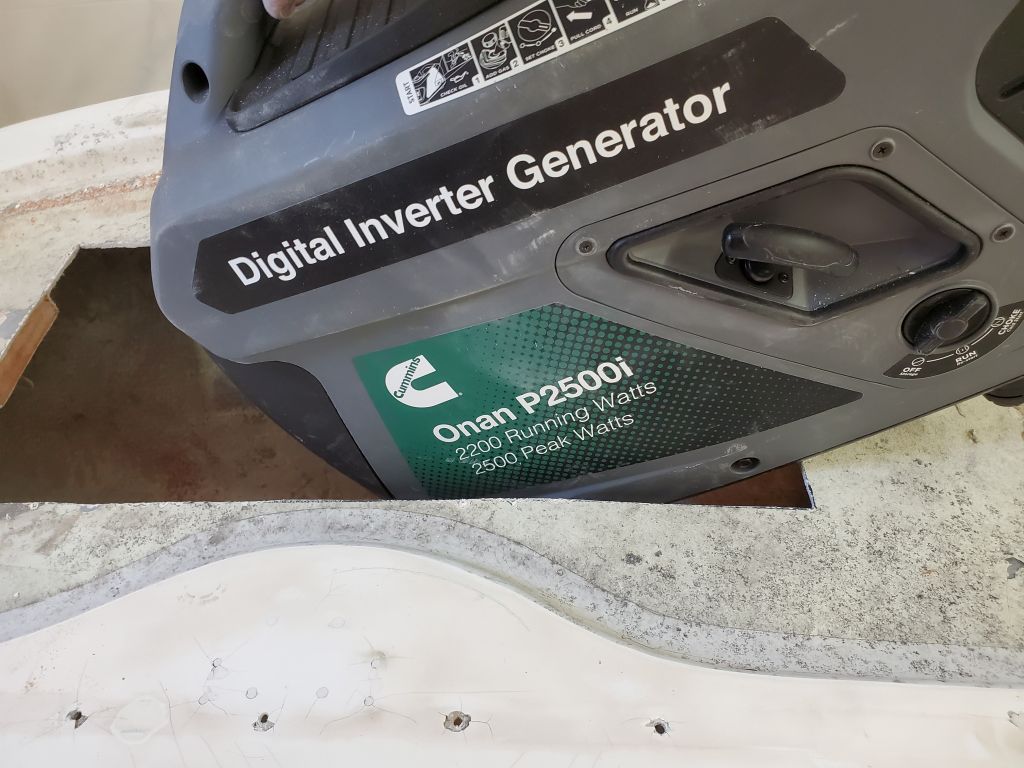
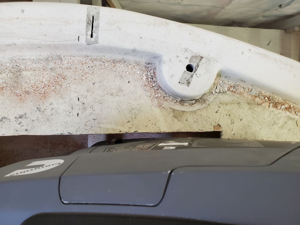
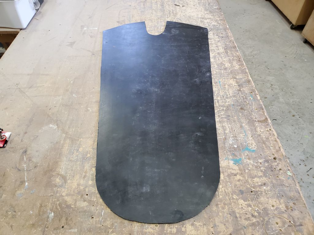
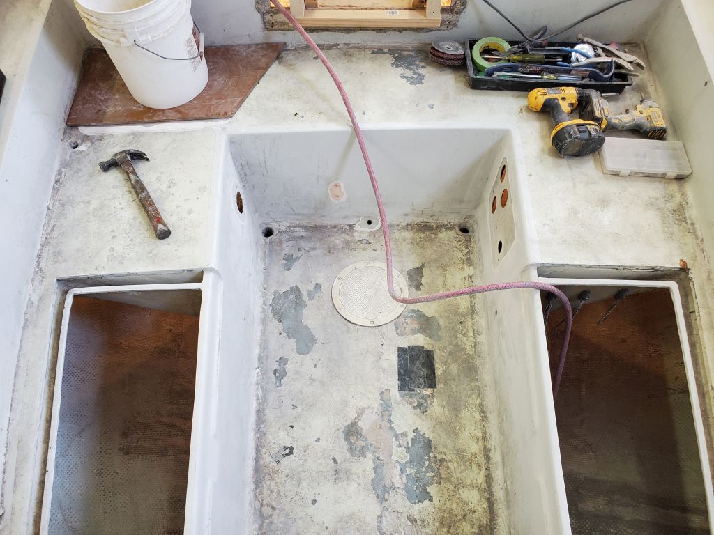
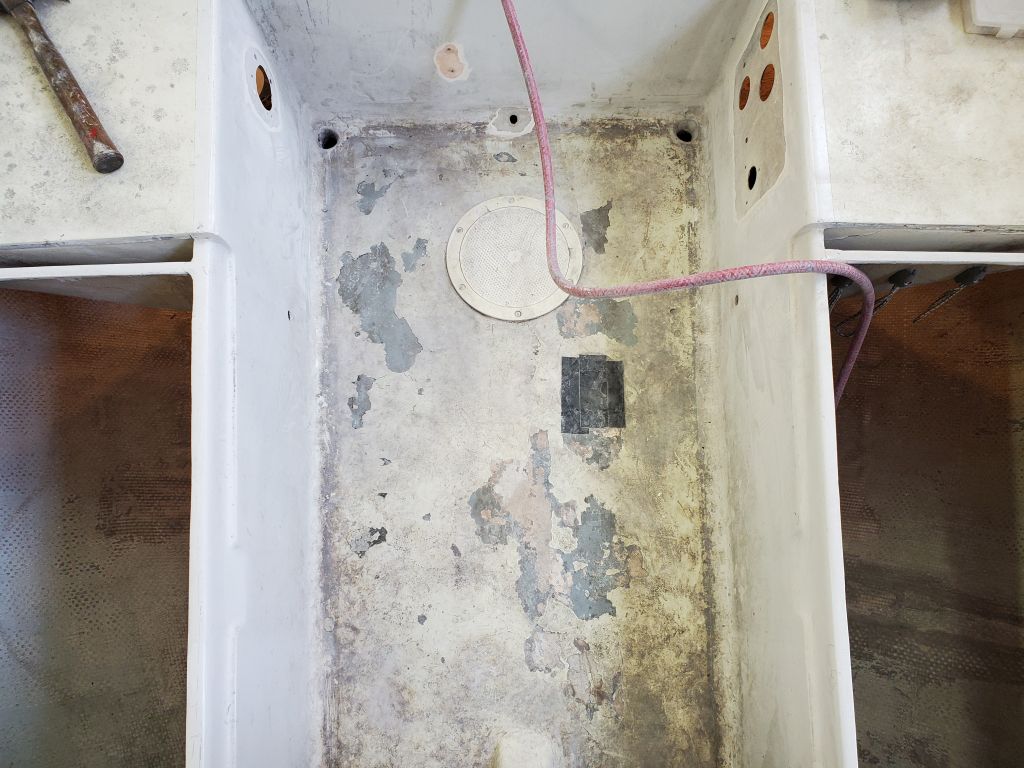
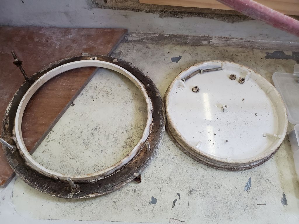
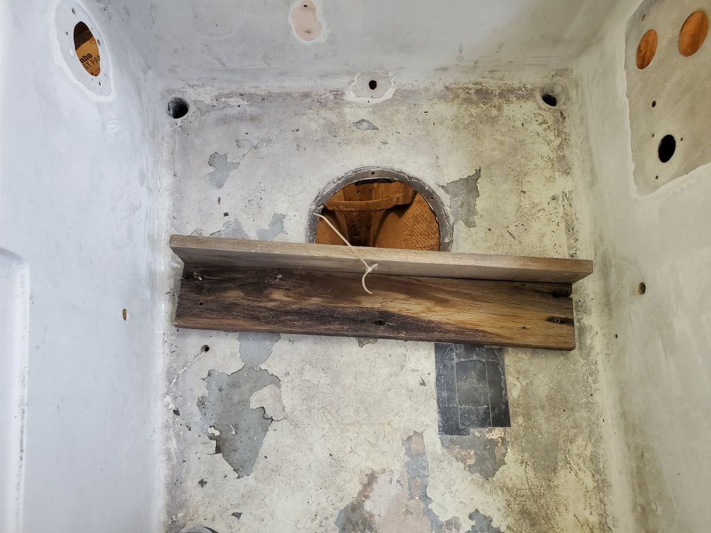
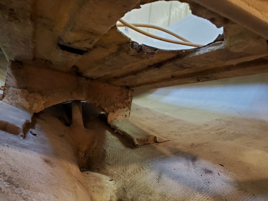
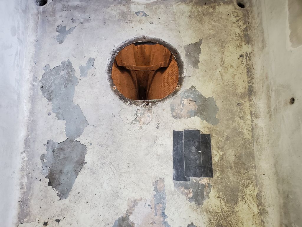
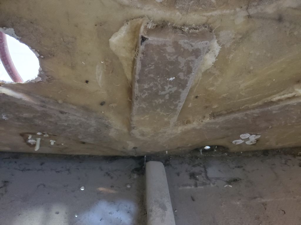
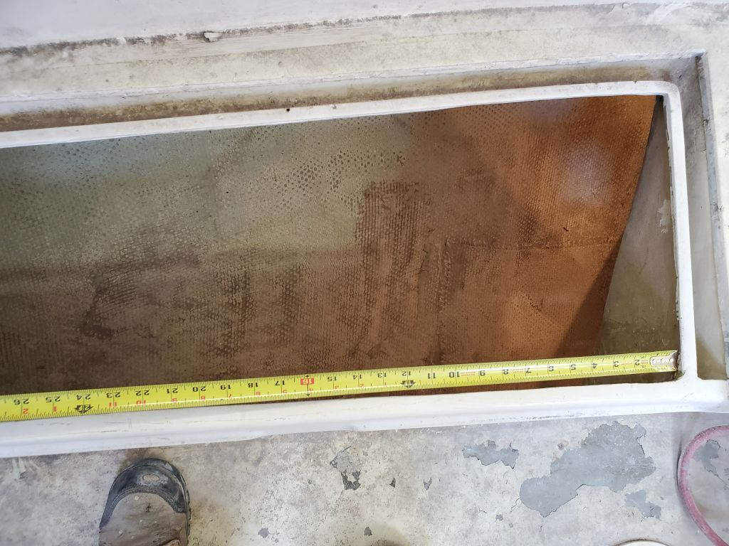
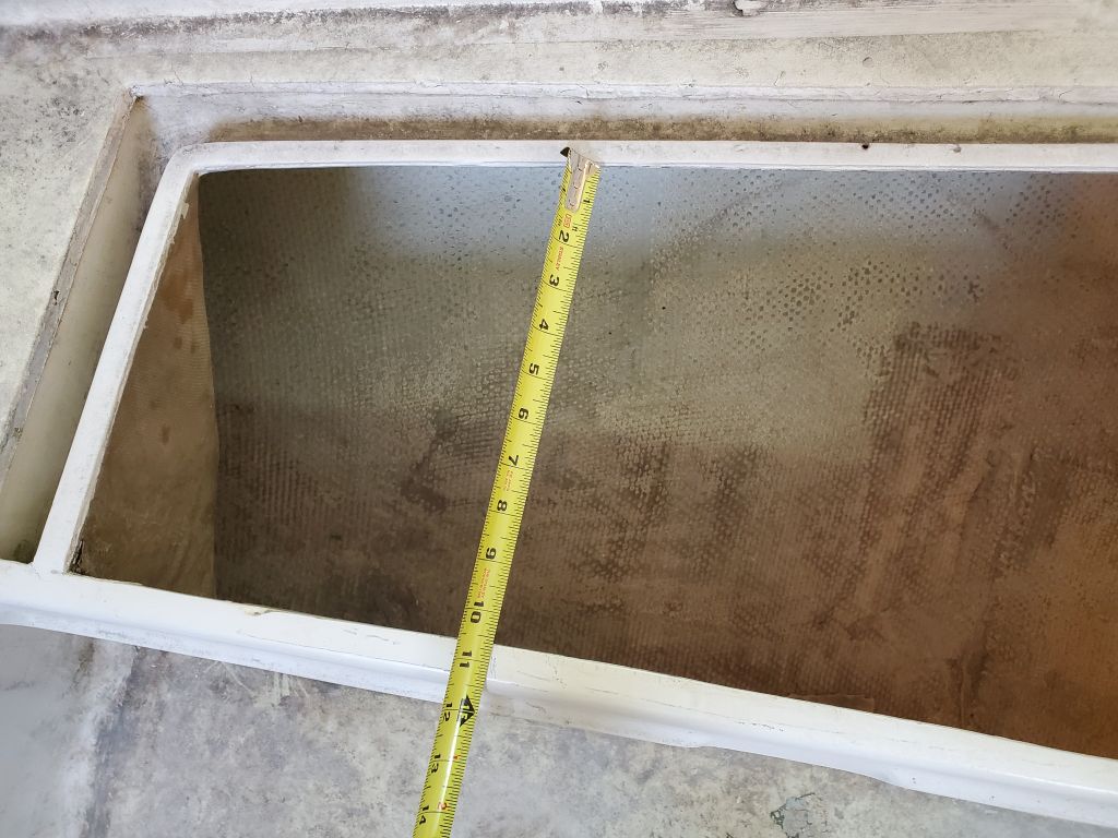
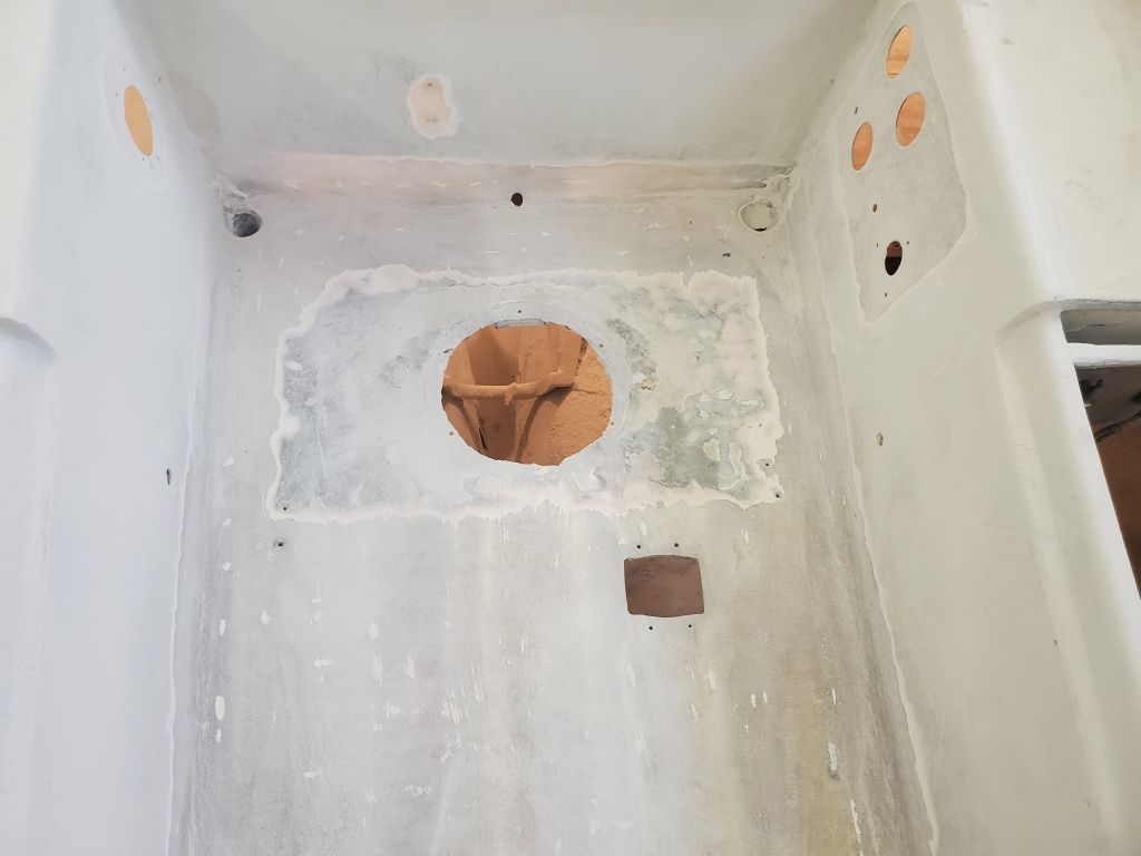
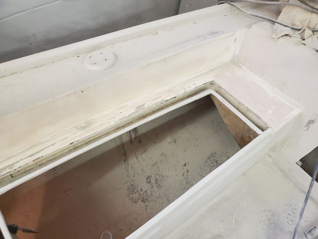
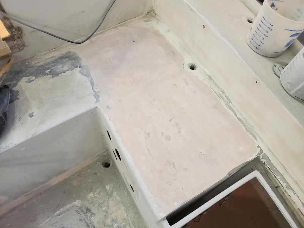
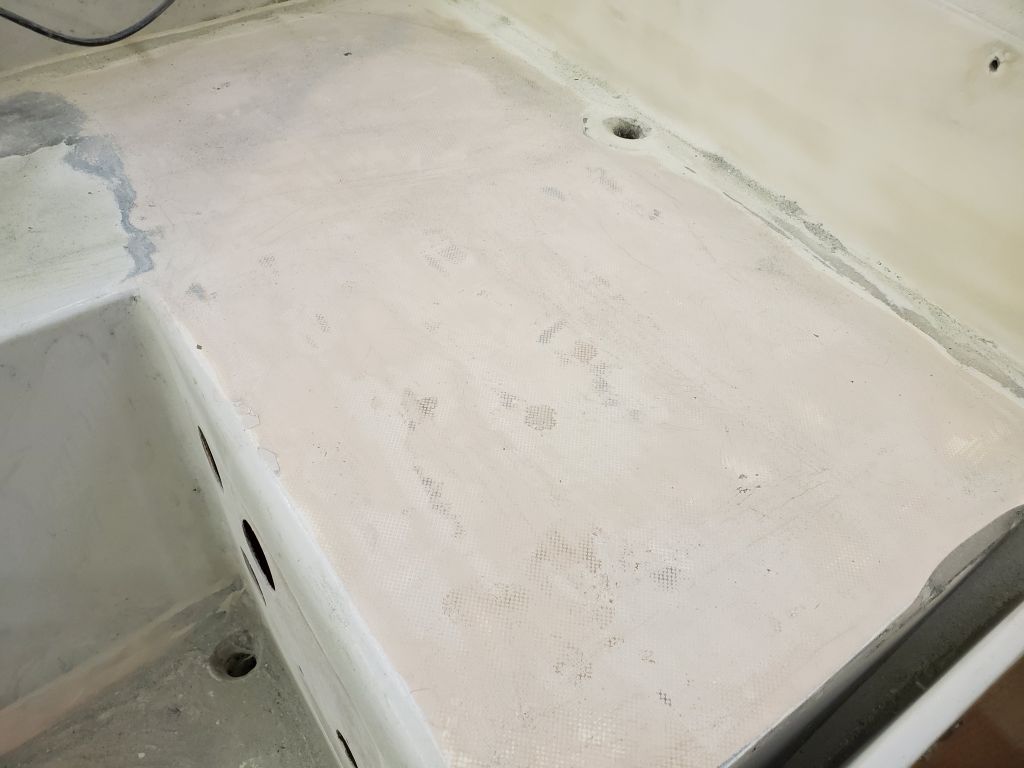
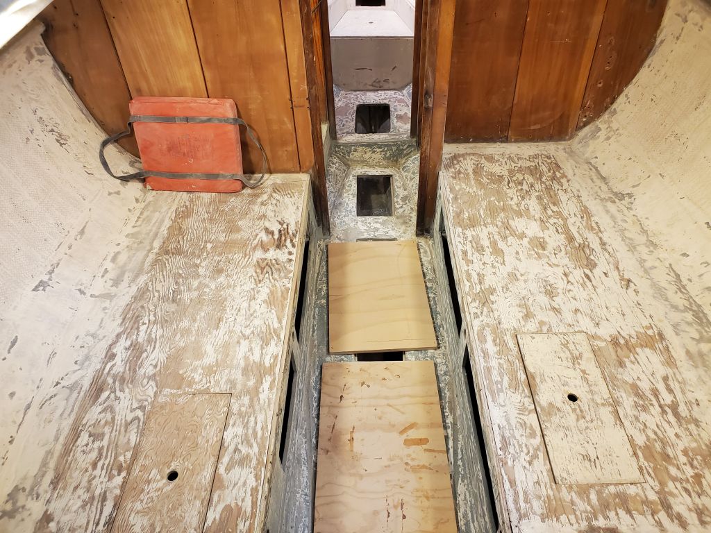
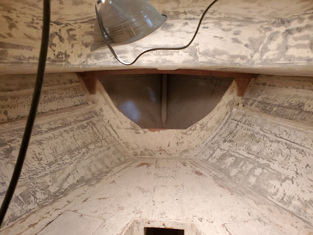
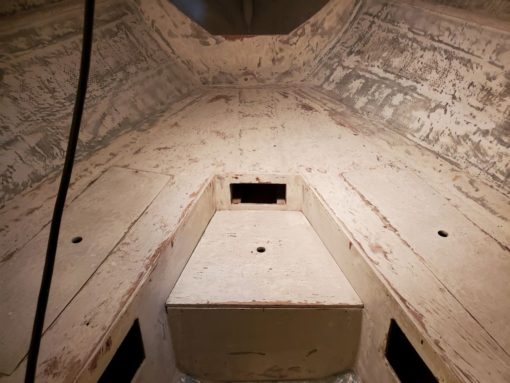
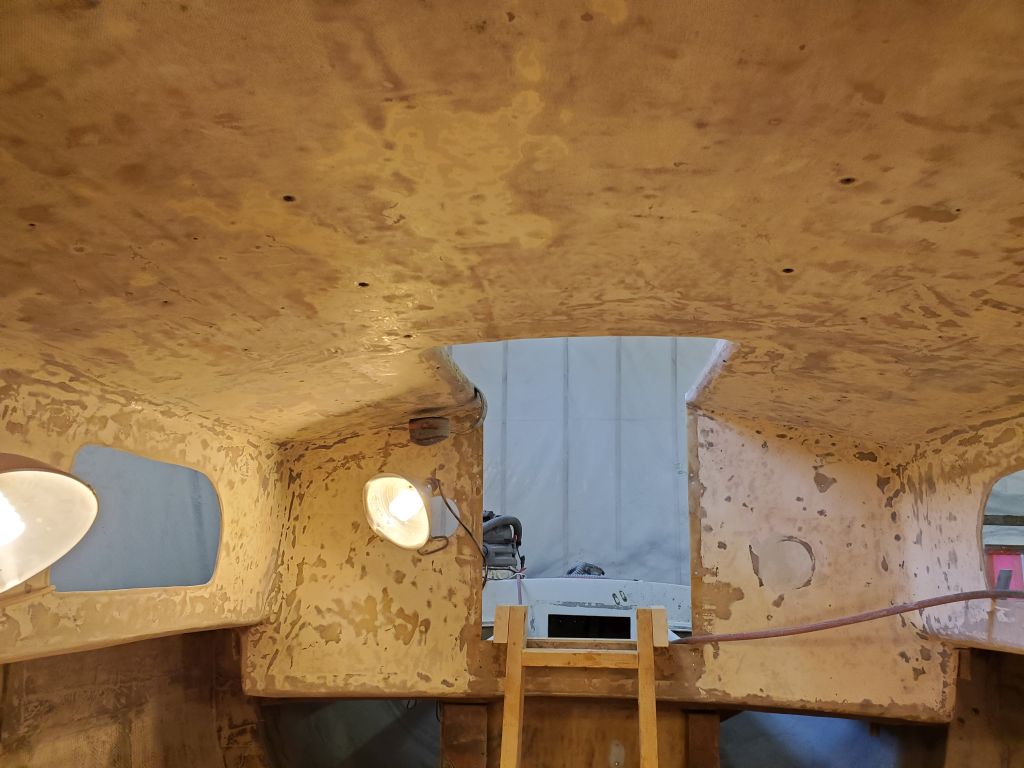
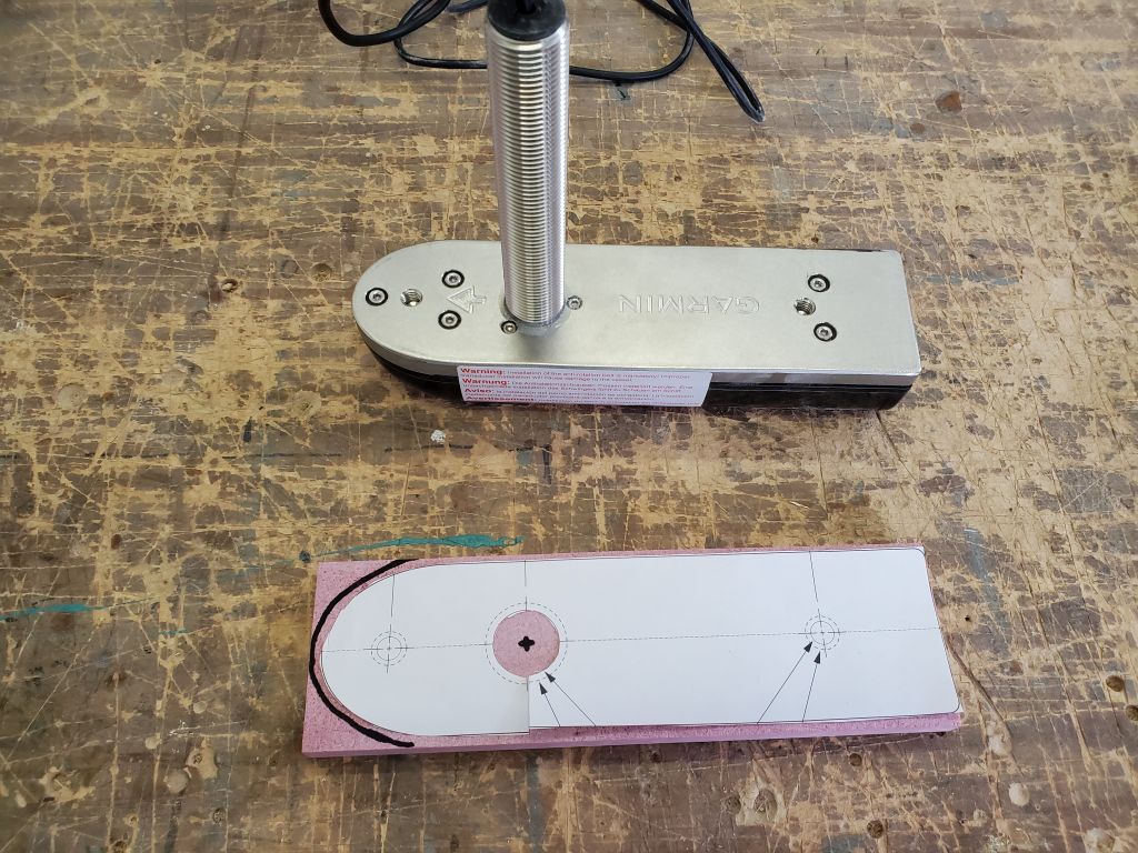
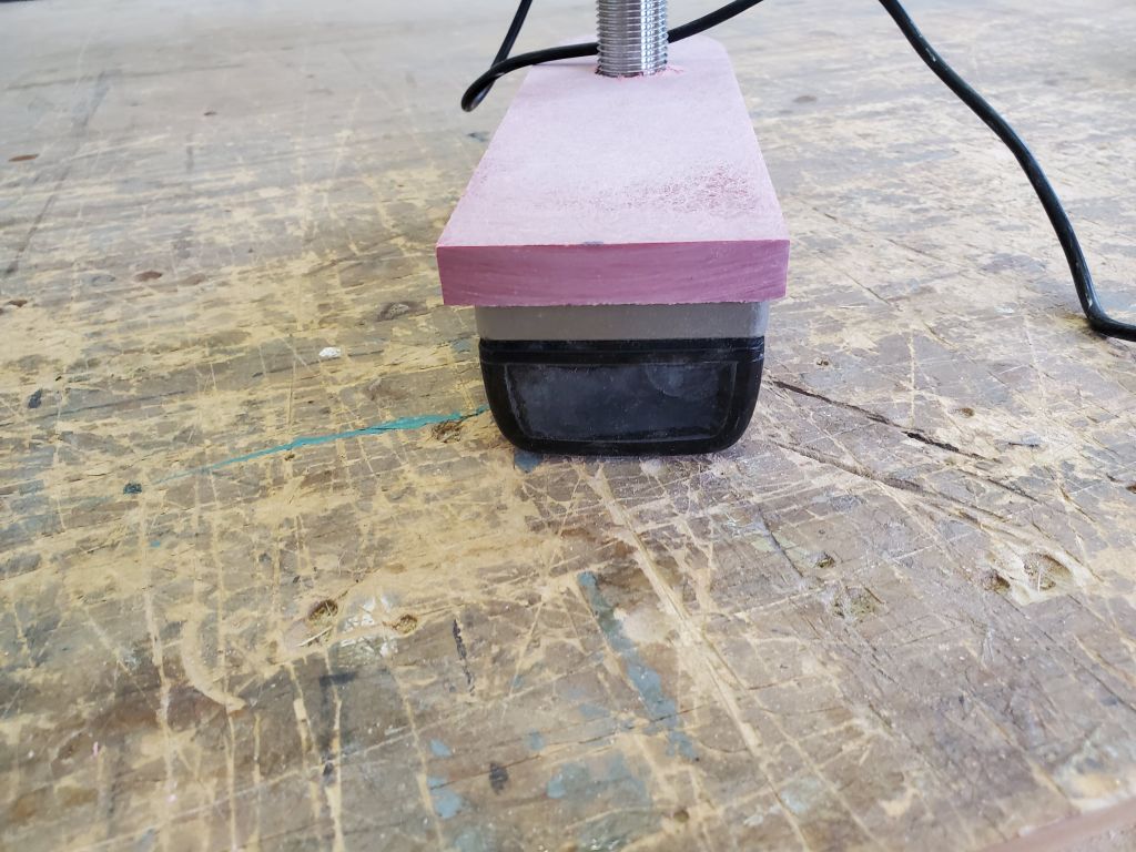
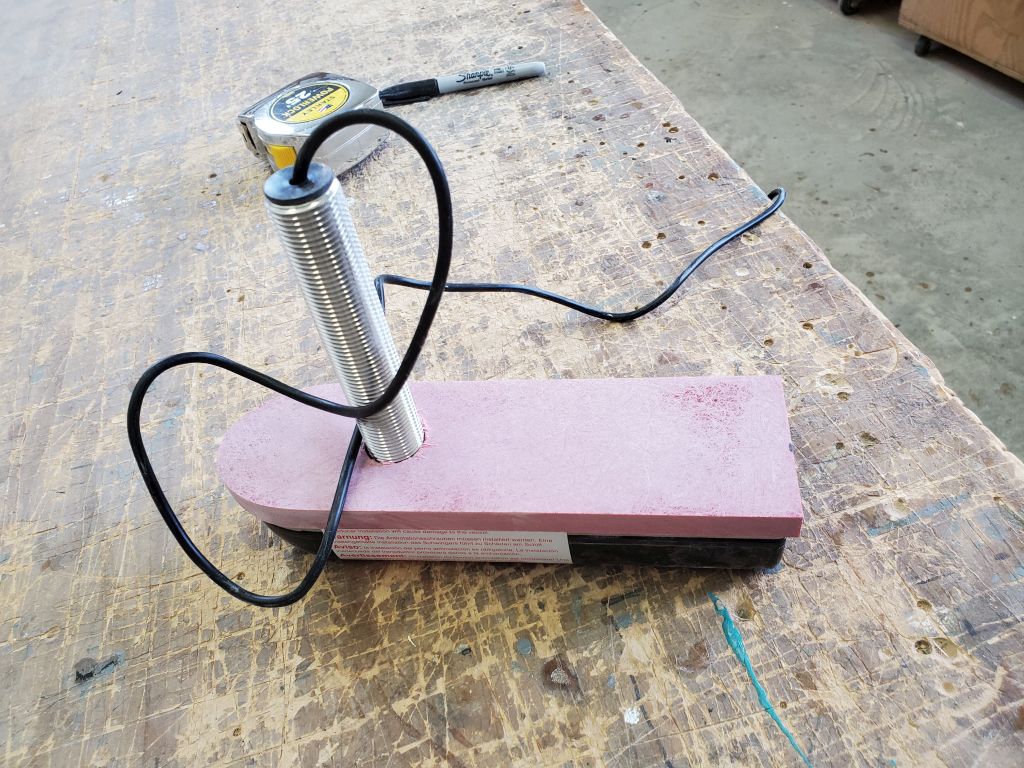
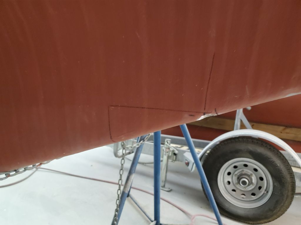
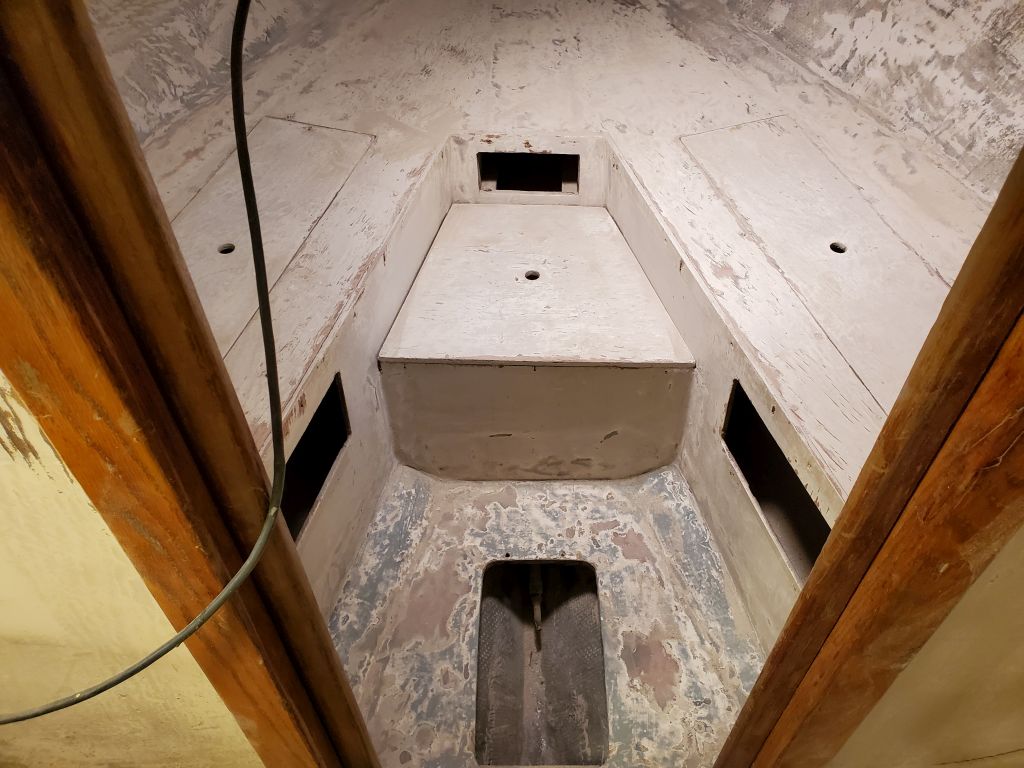
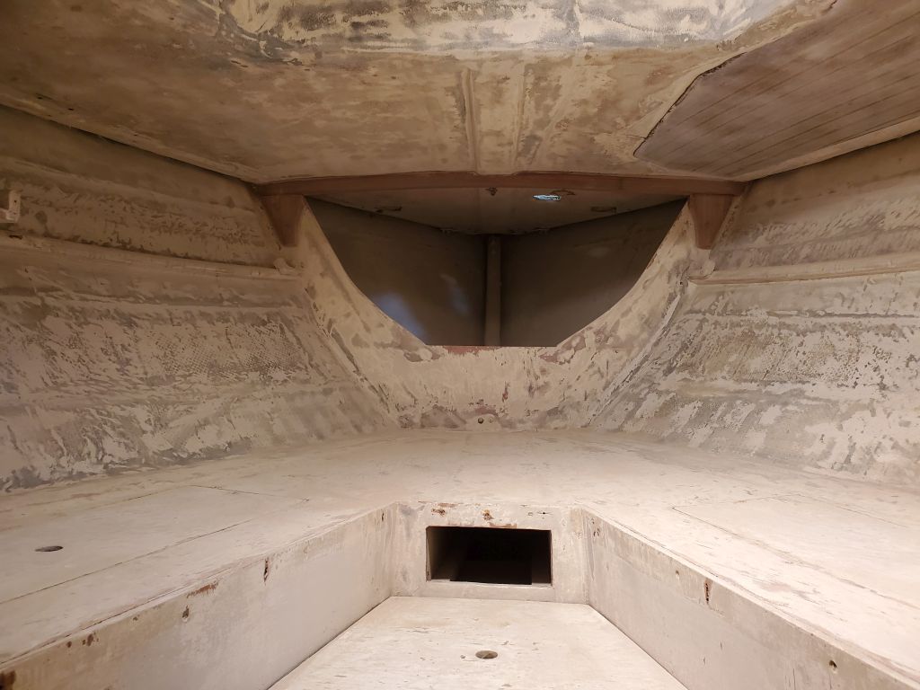
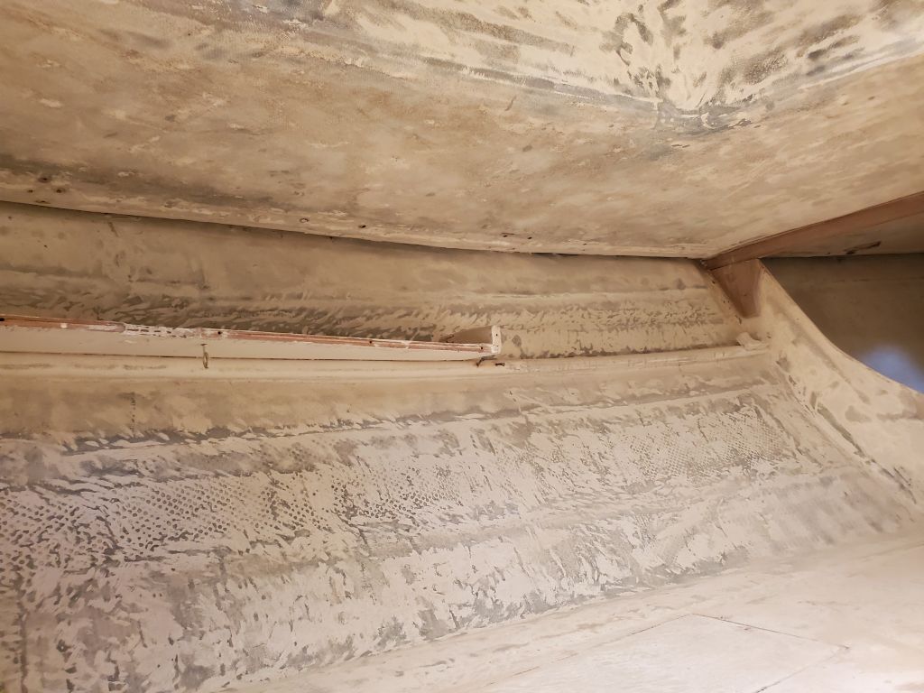
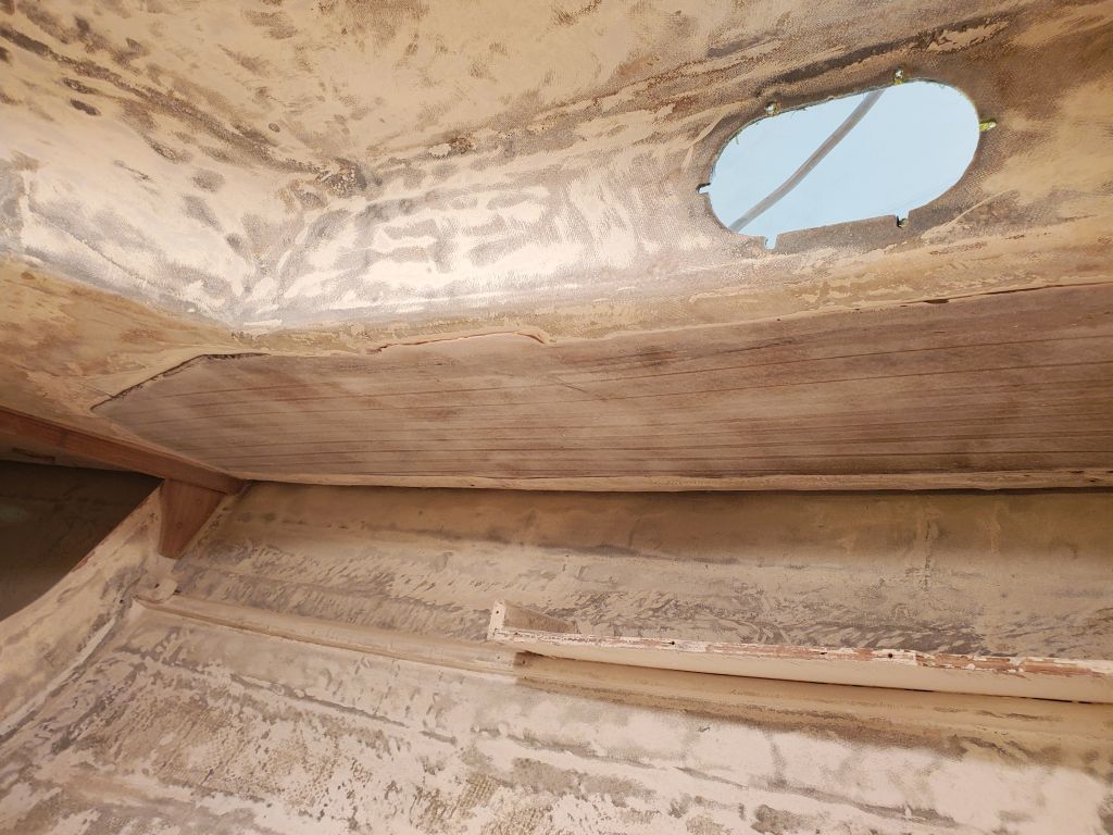
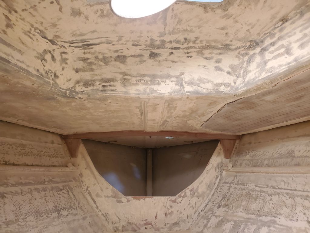
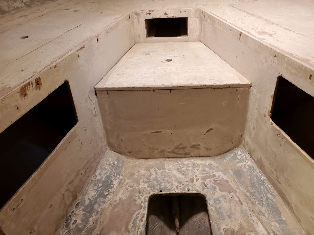
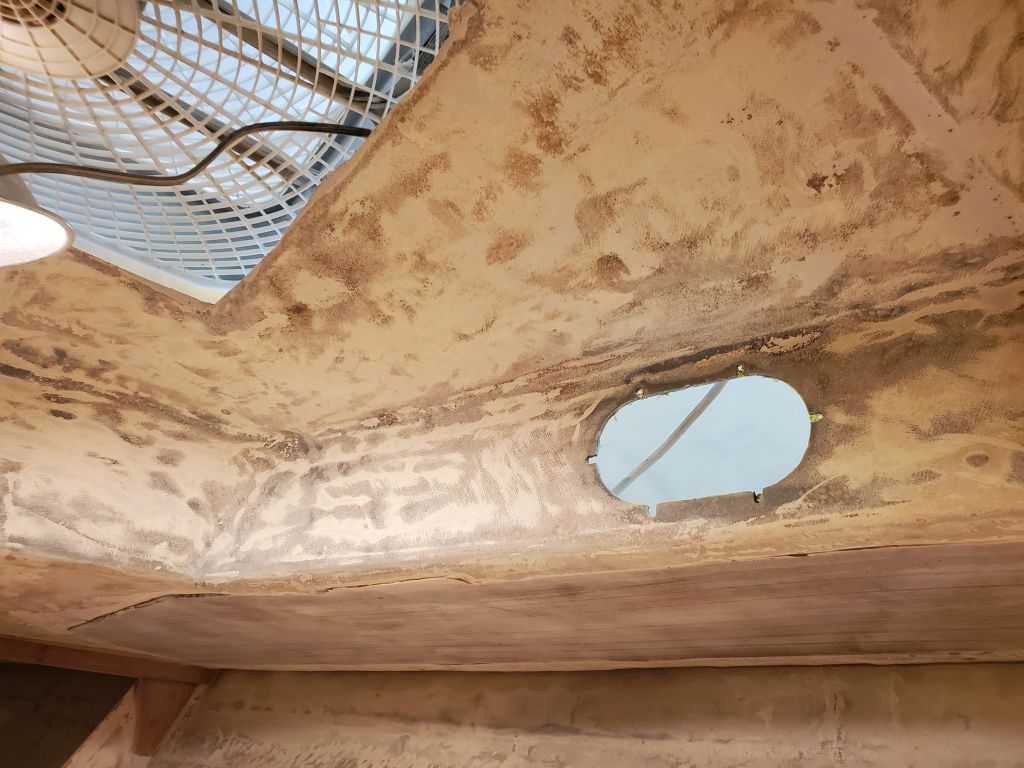
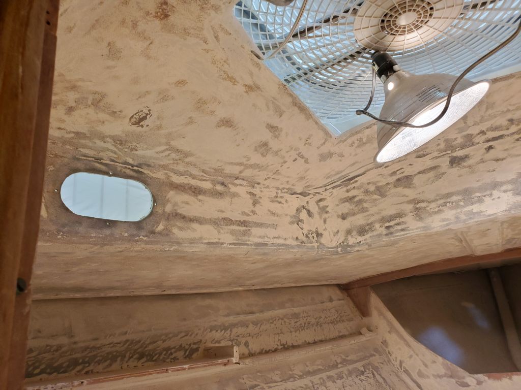
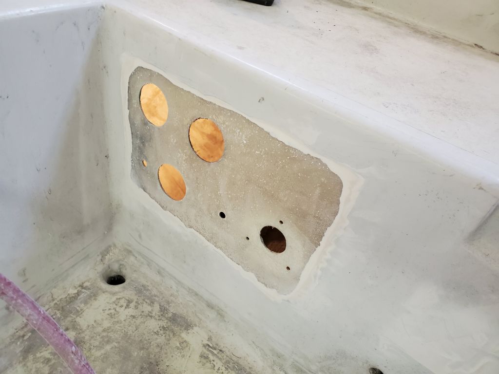
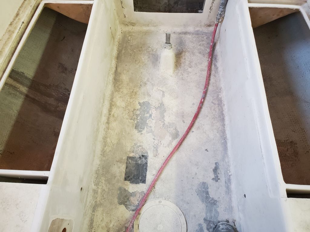
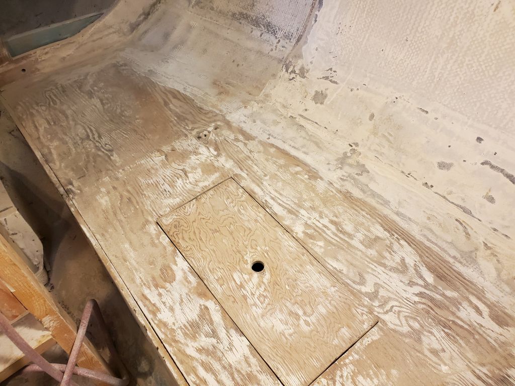
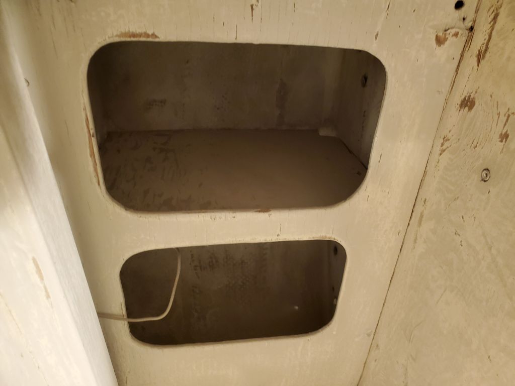
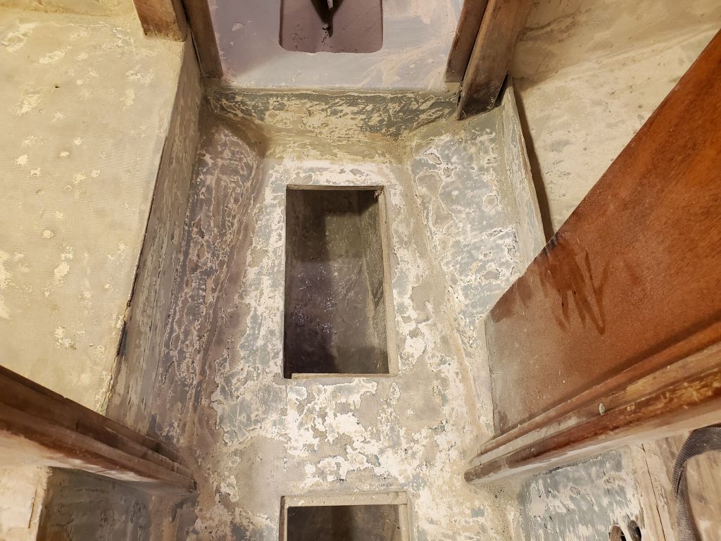
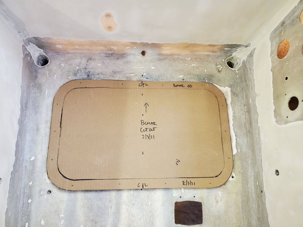
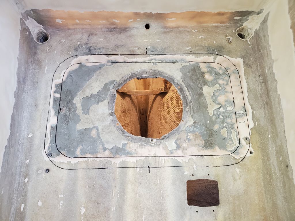
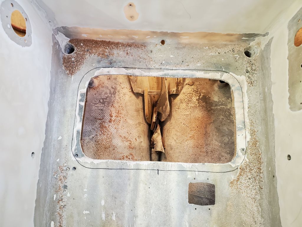
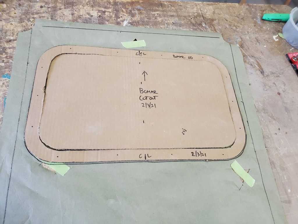
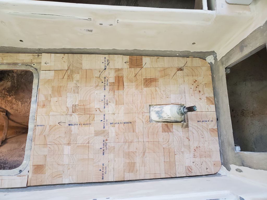
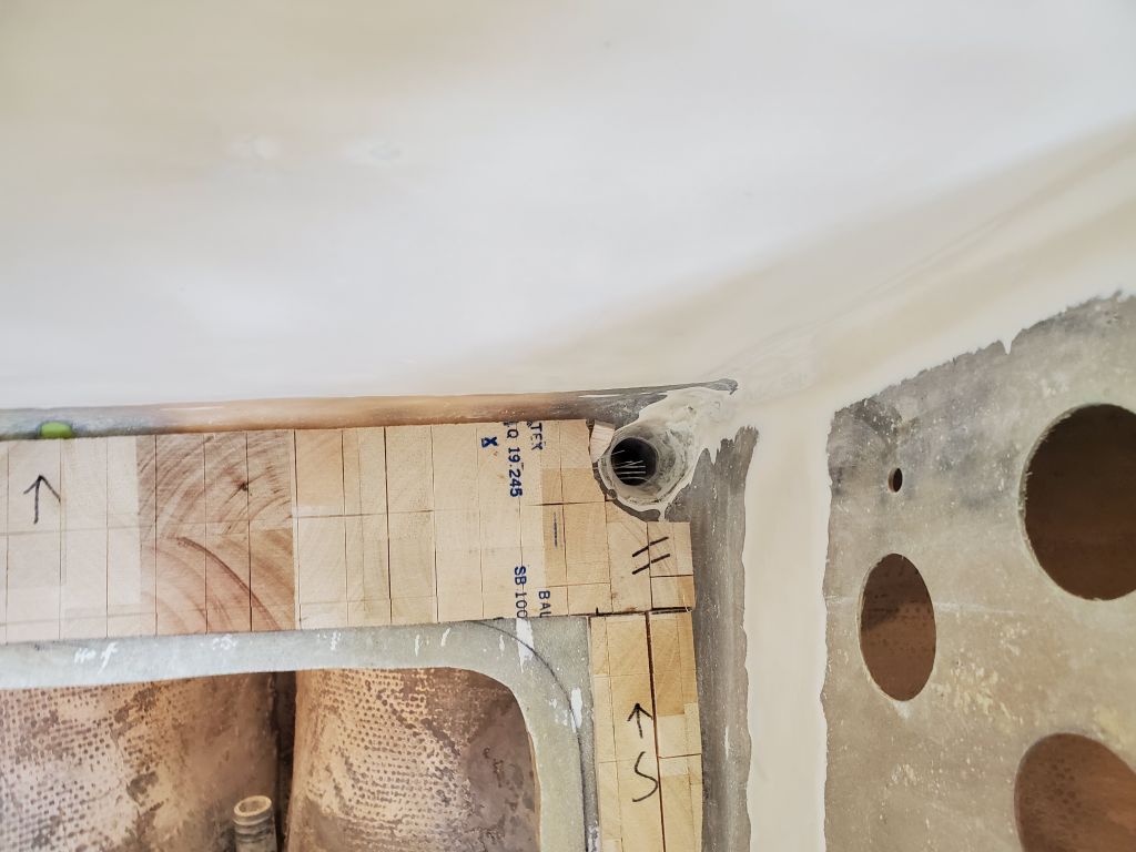
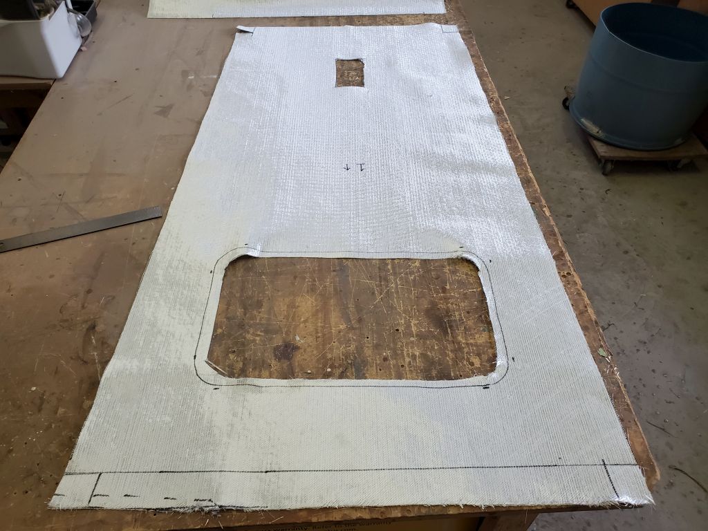
The final step before I could install new core in the cockpit sole was to make the cutout for the new access hatch. Now that I had a template (and the hatch itself), I began by laying out the position of the new hatch. There was an obstruction a little bit forward (a glassed-in wooden support near the head of the cockpit), and I strove to leave the new hatch flange far enough aft from that to allow for fasteners. In the event, the new hatch ended up more or less centered above the old opening, which of course was no terrific surprise.
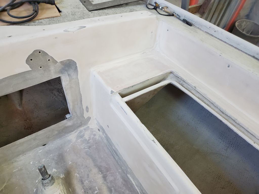
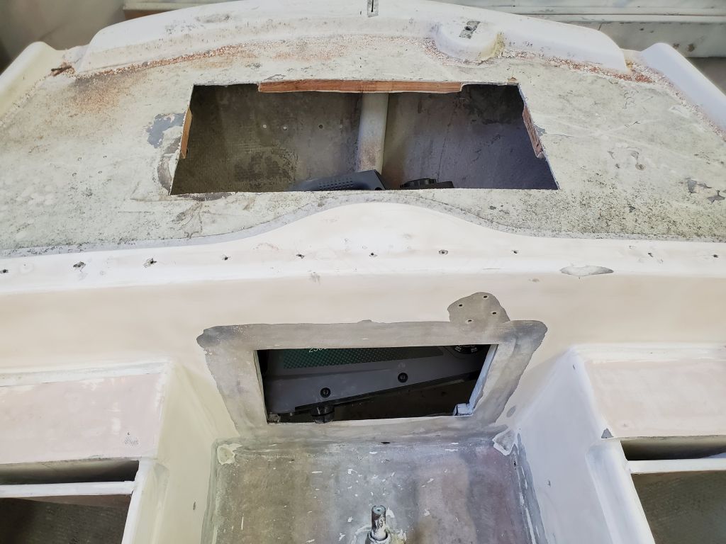
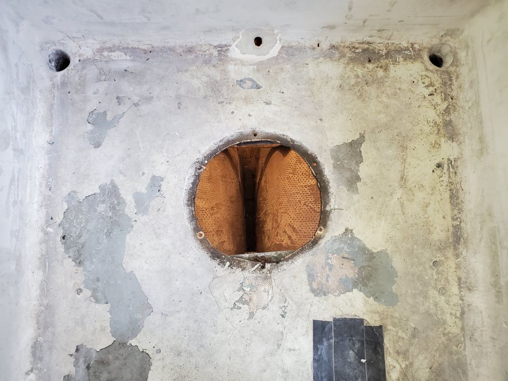
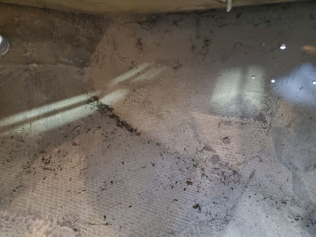
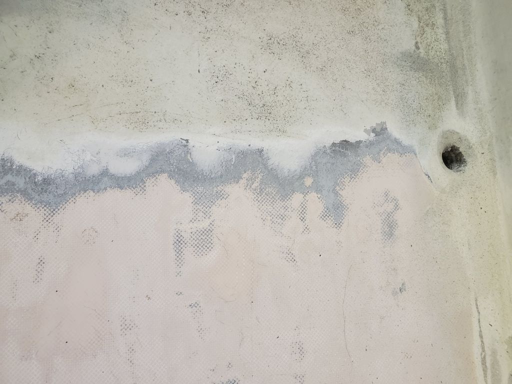
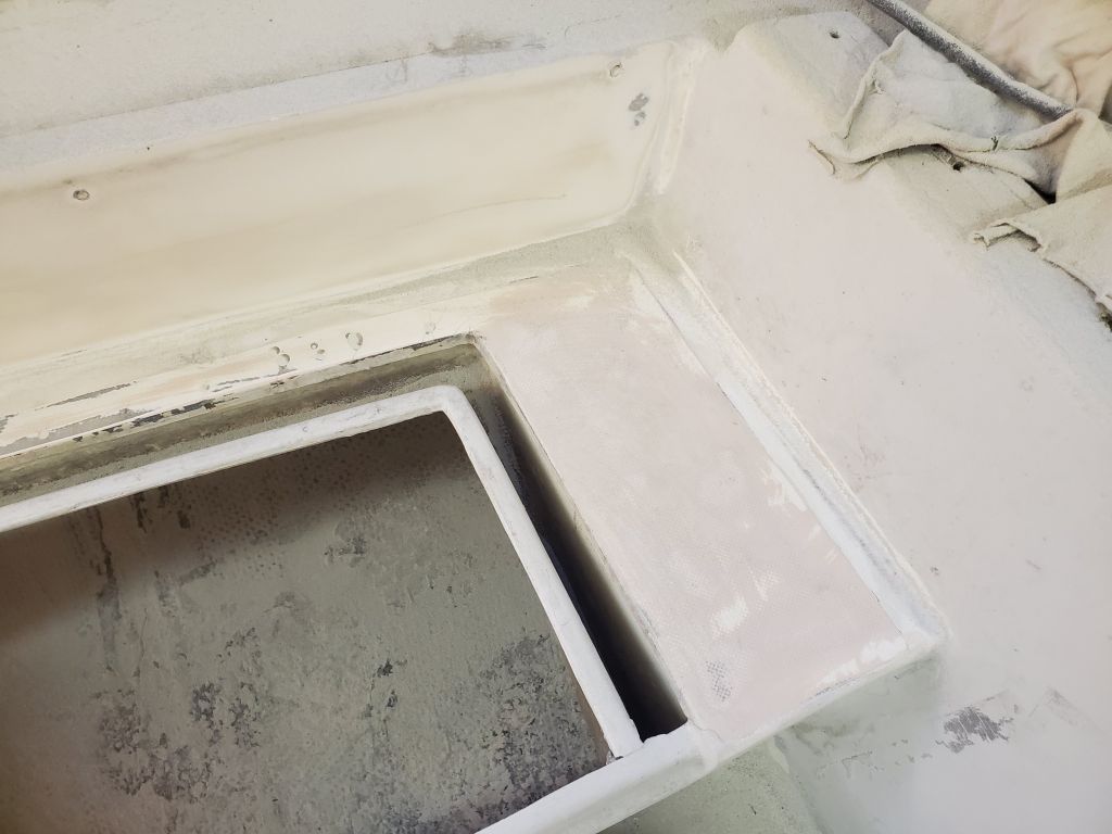
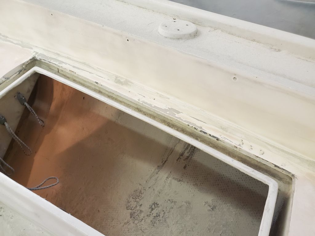
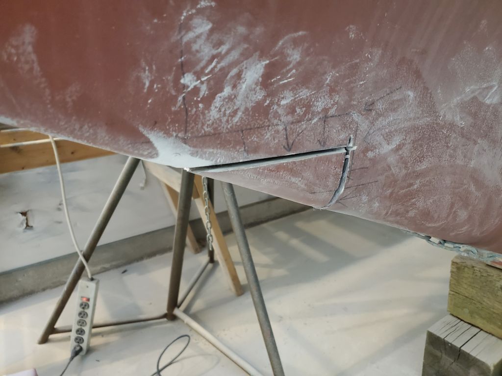
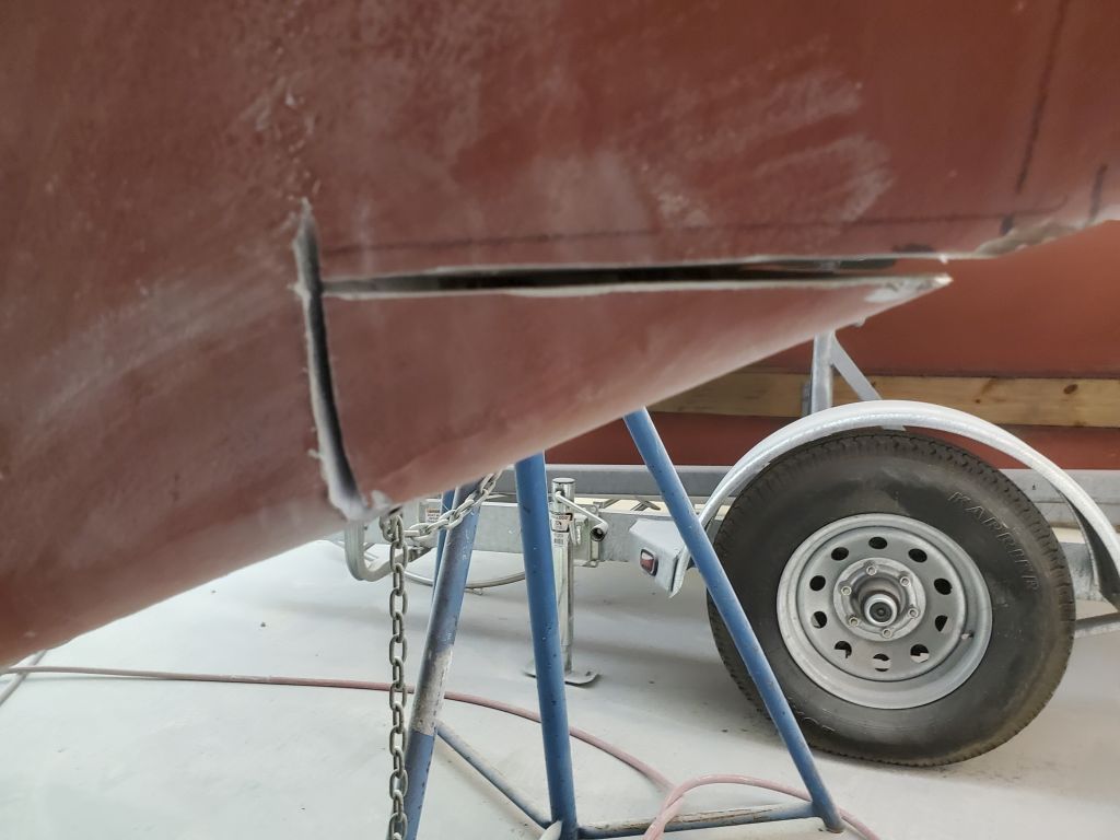
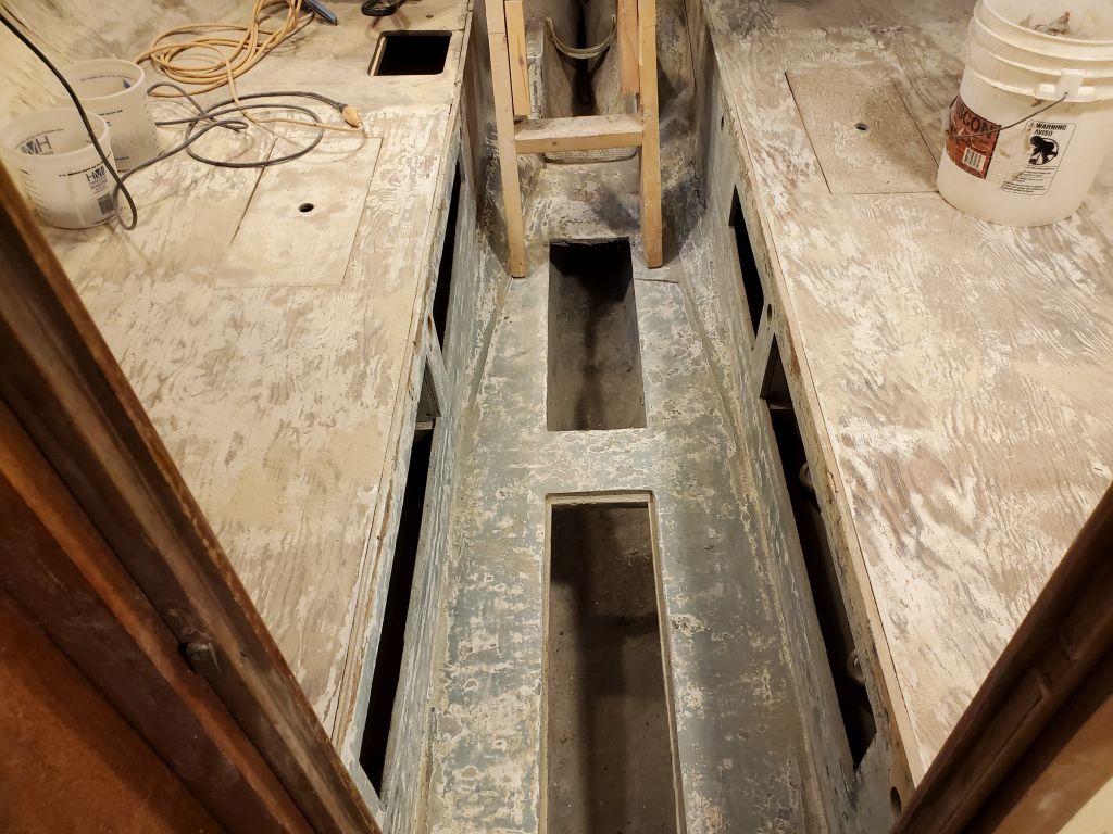
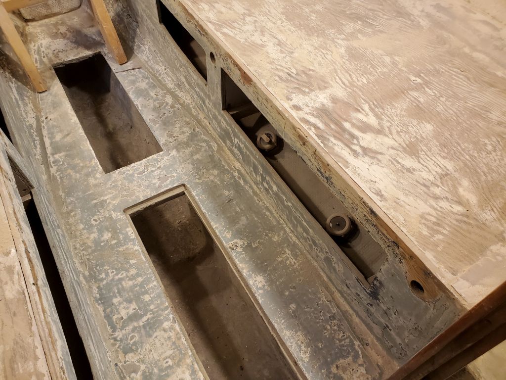
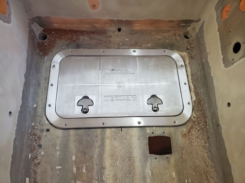
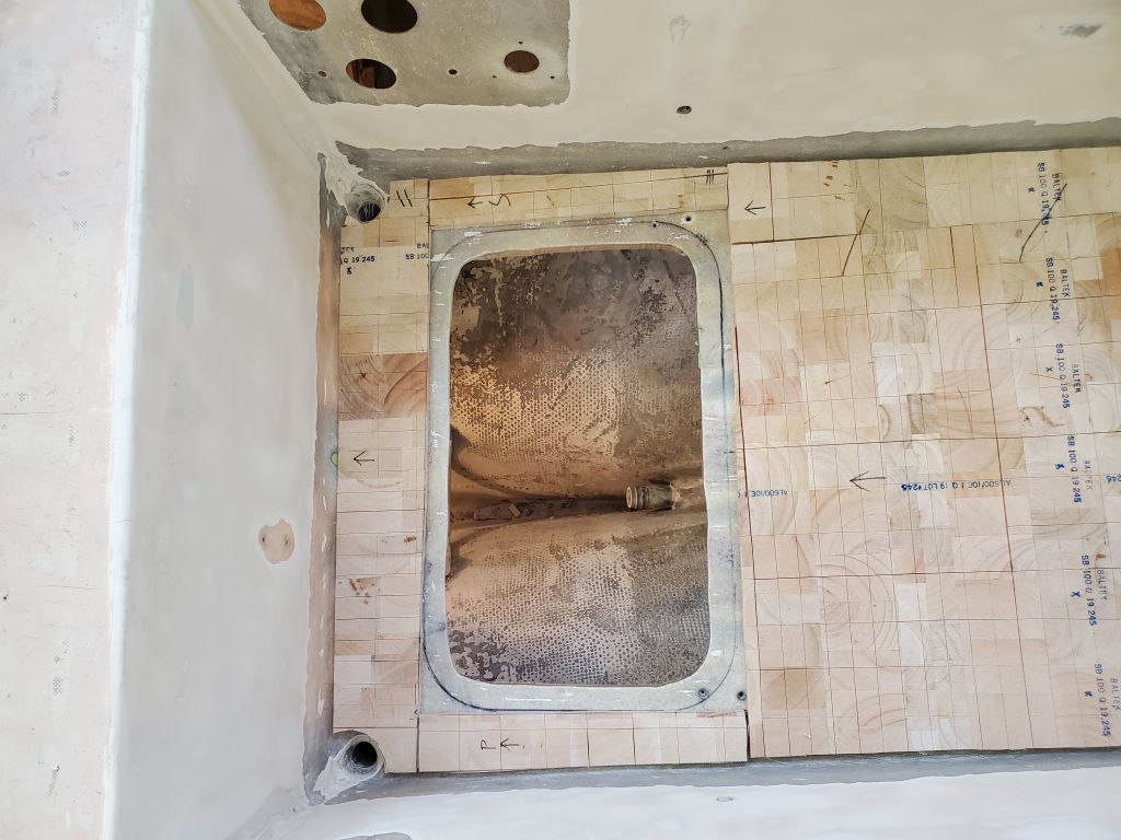
Layout complete, I cut out the center portion and test-fit the hatch. Then, I sanded away any old paint and coatings that remained around the new opening.

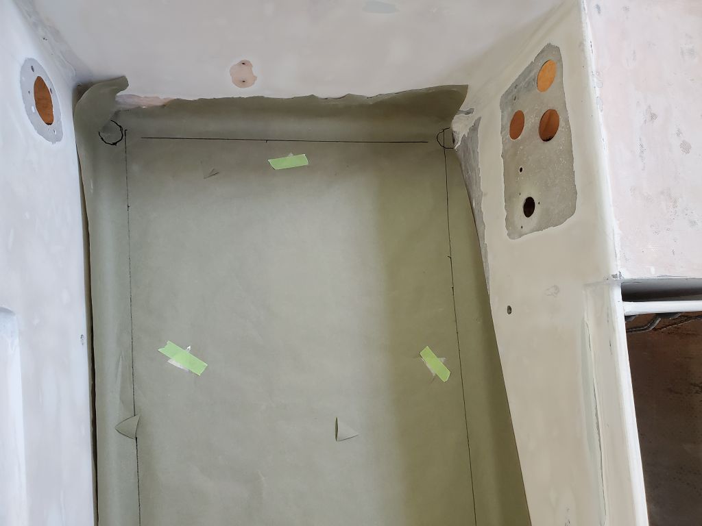
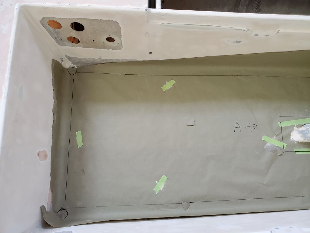
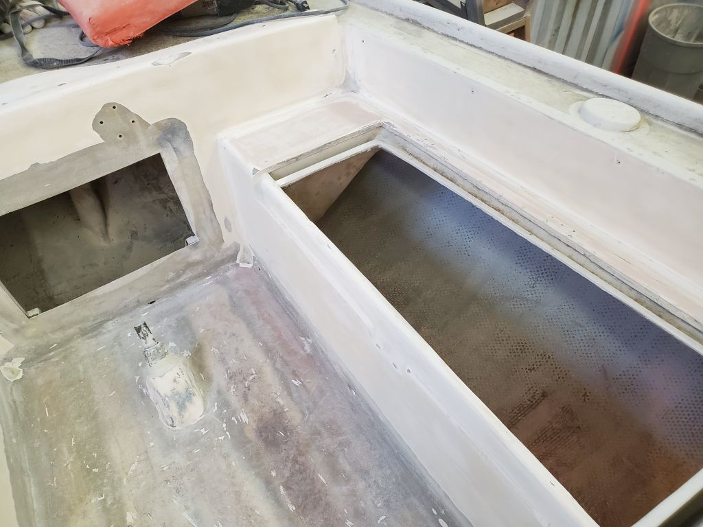
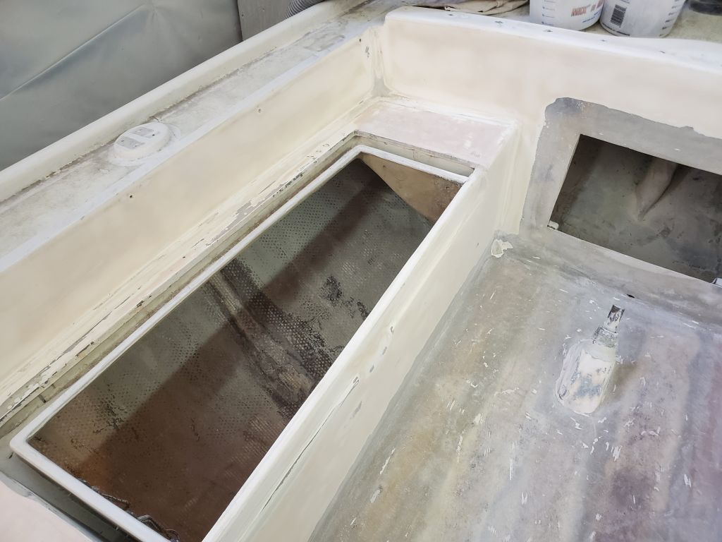
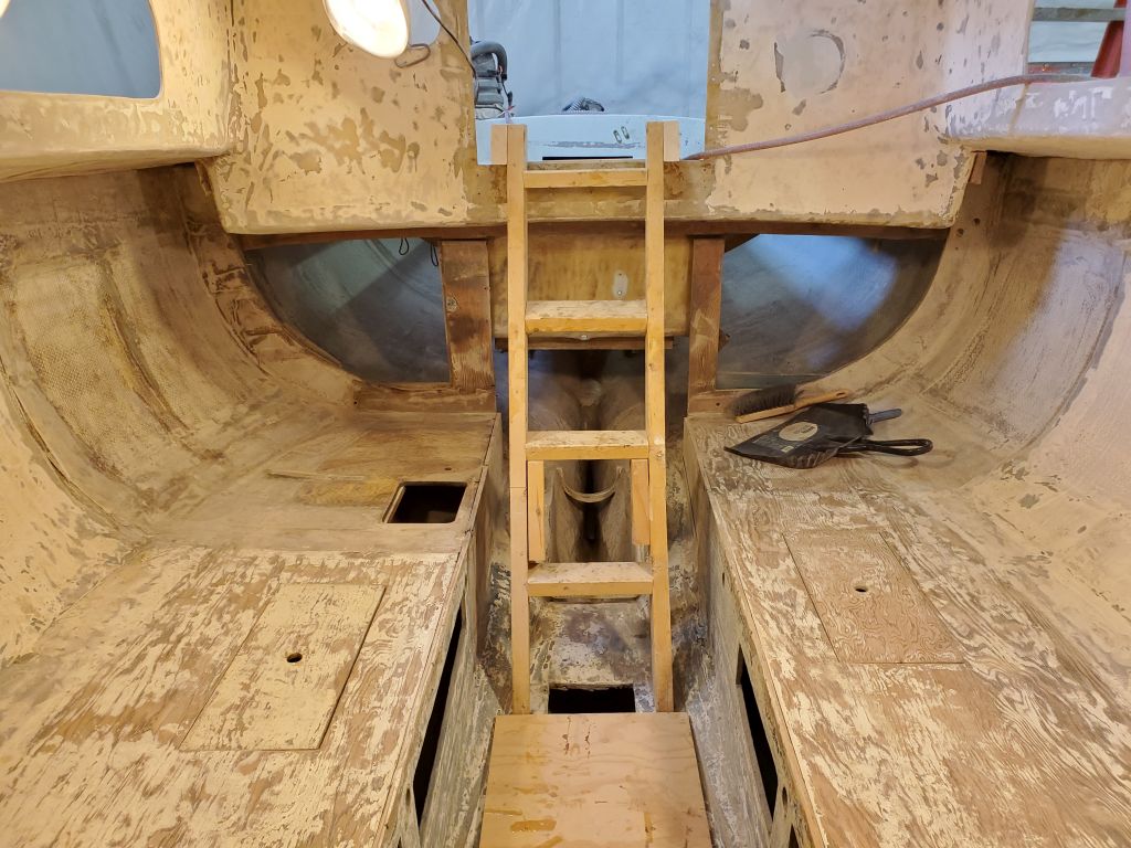
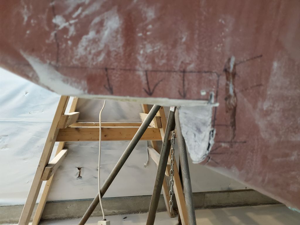
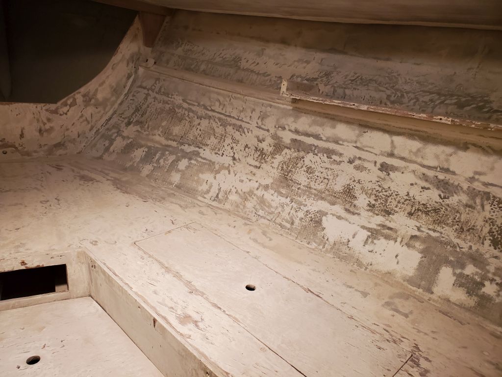
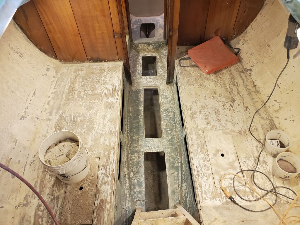
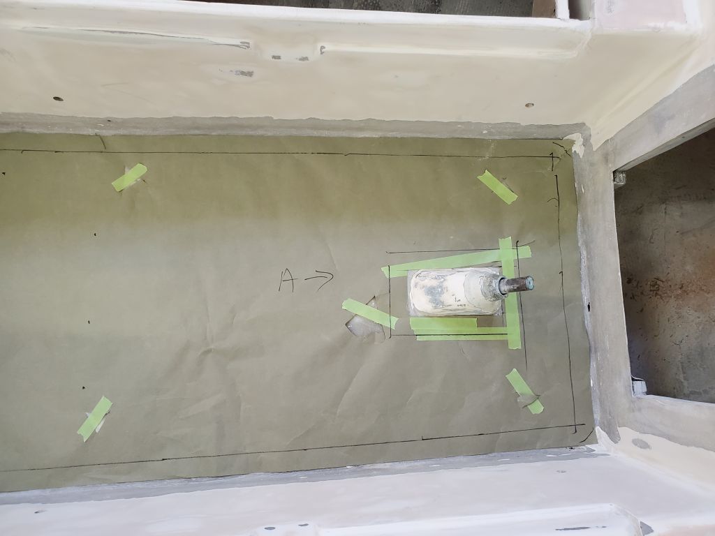
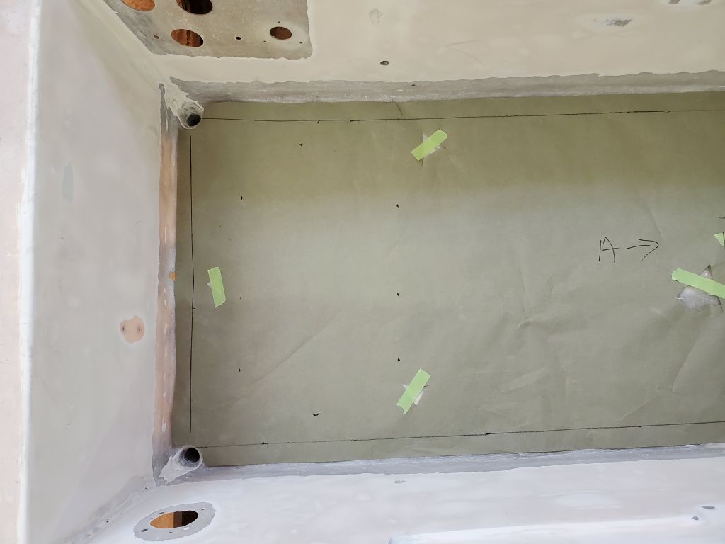
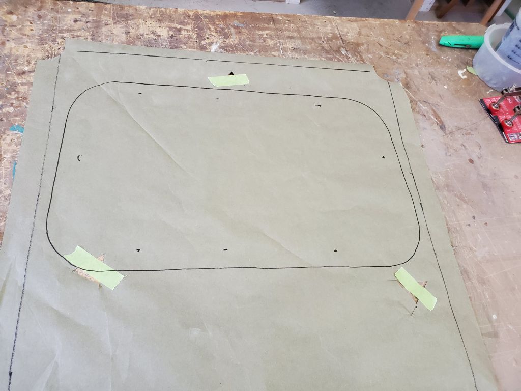
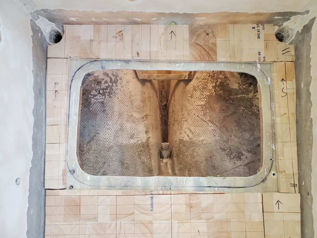
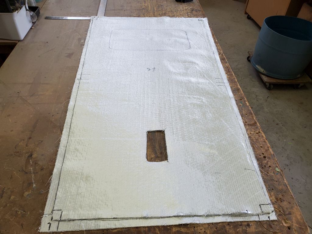
Installing the core pattern in the cockpit, I made some marks to show where the opening was, so I could omit the core around the hatch opening (and also, later, for determining the hatch location when I cut fiberglass for the sole).
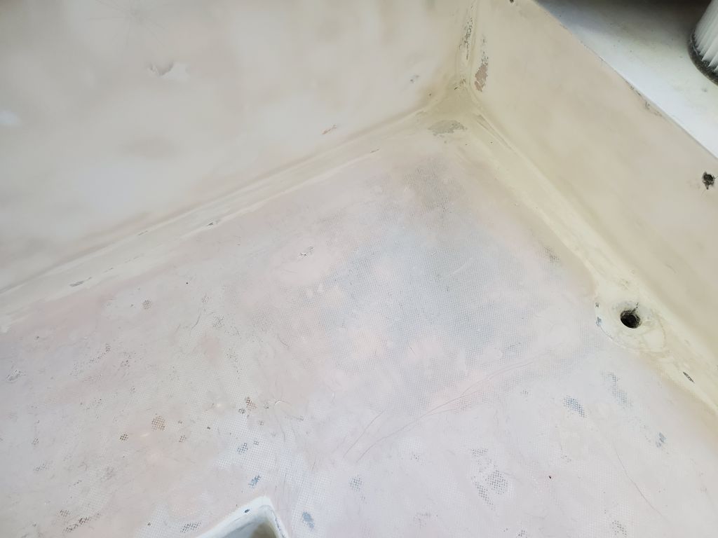
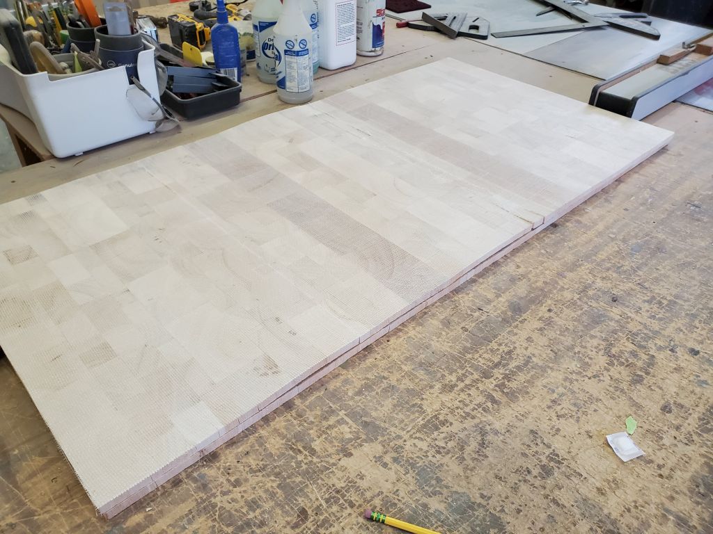
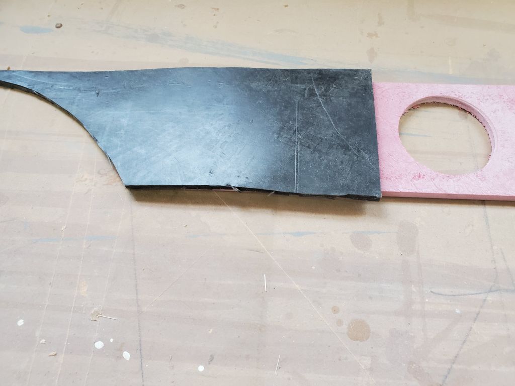
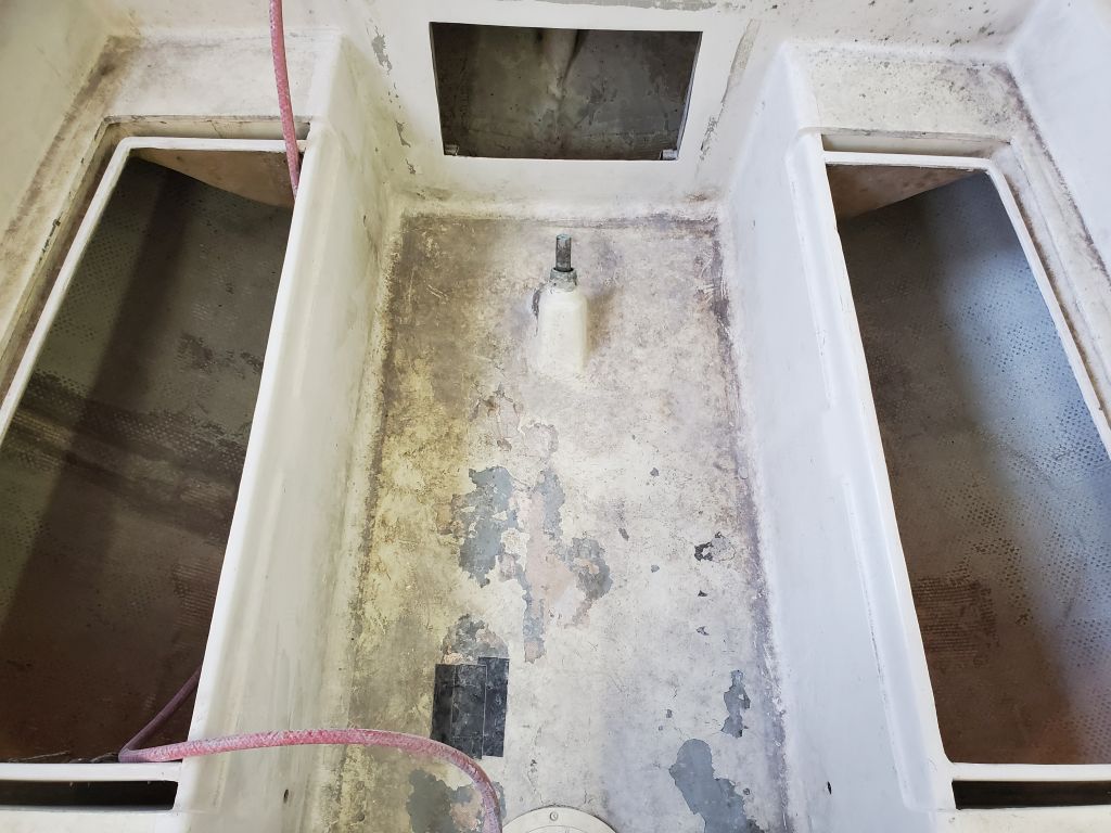
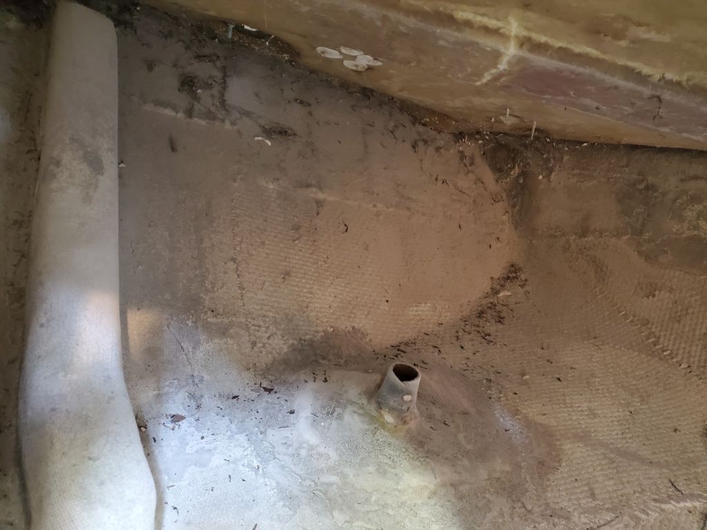
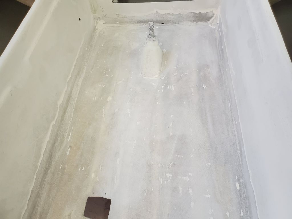
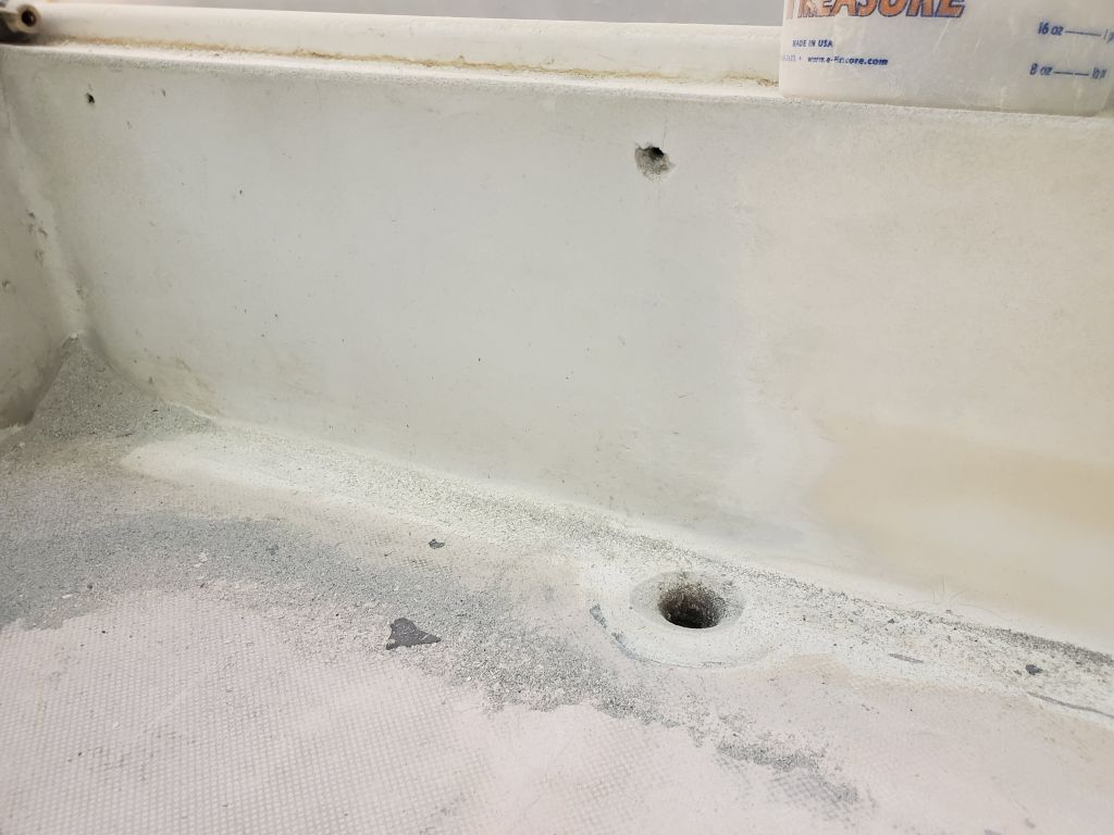
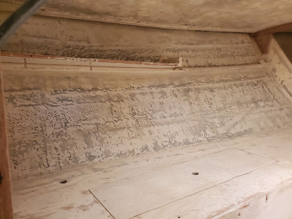
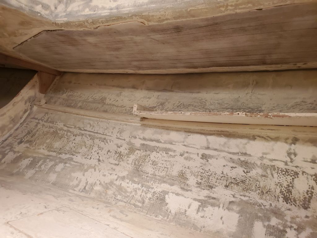
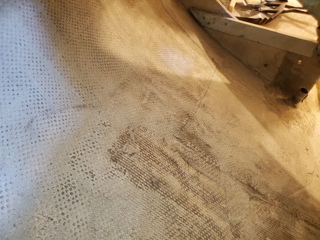
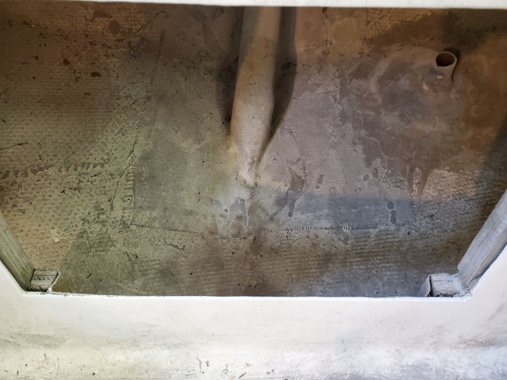
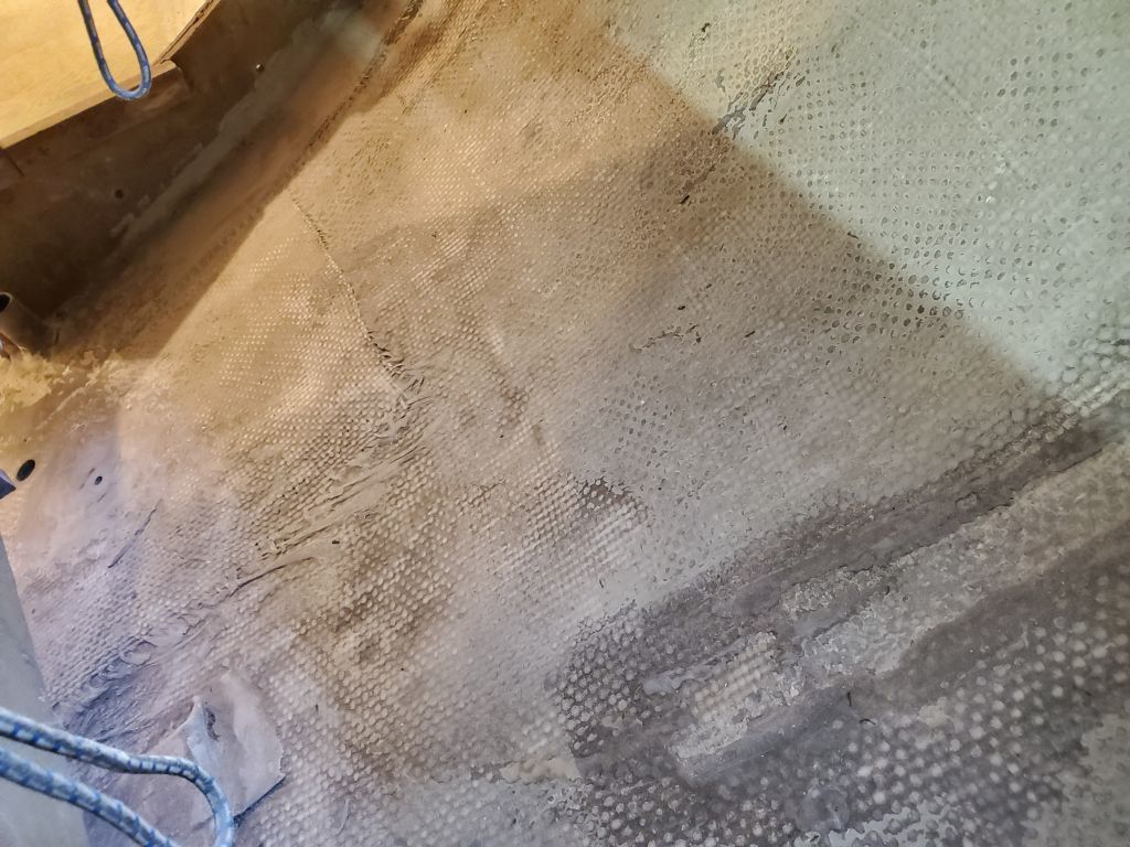
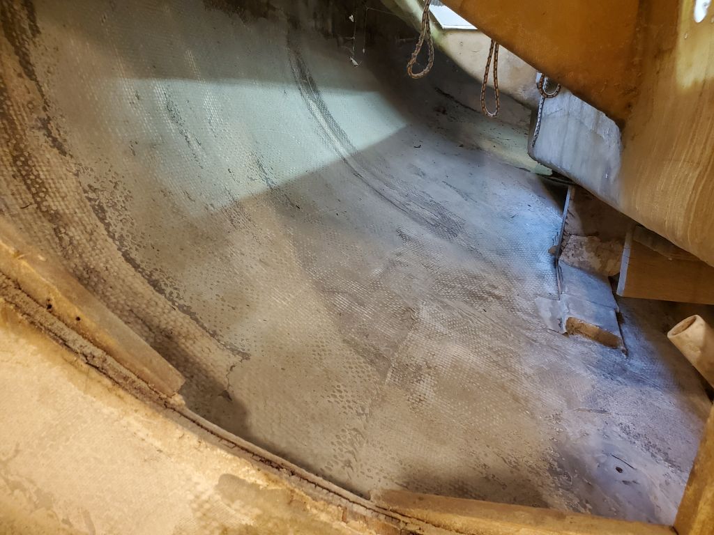
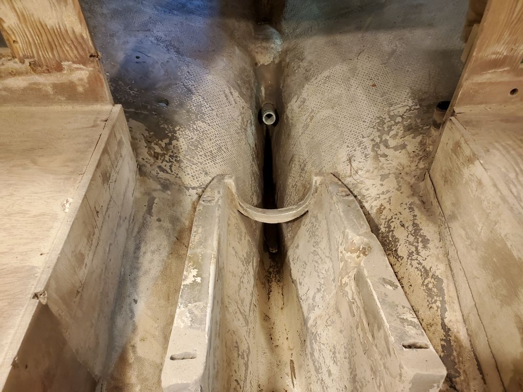
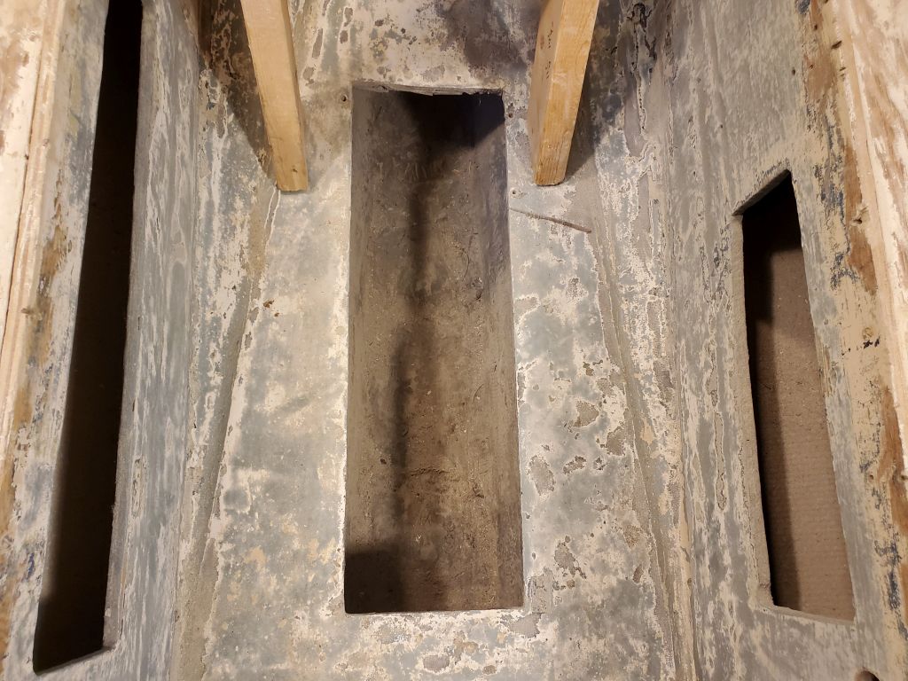
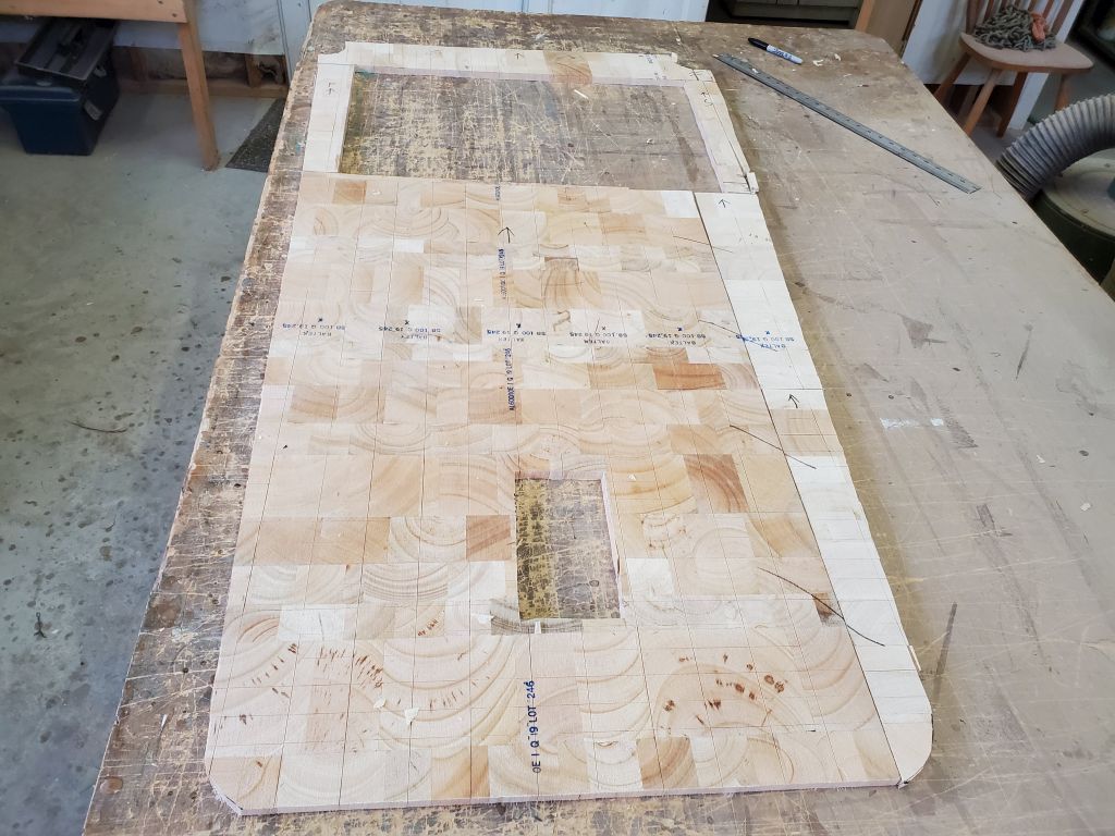
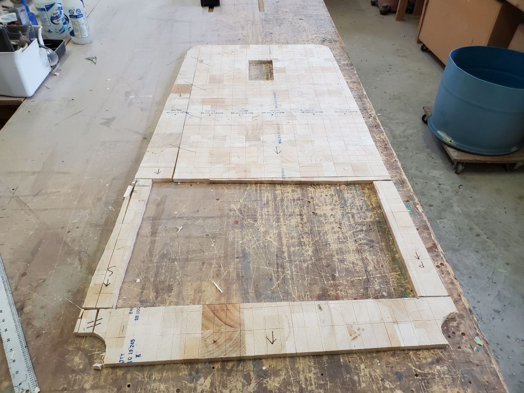
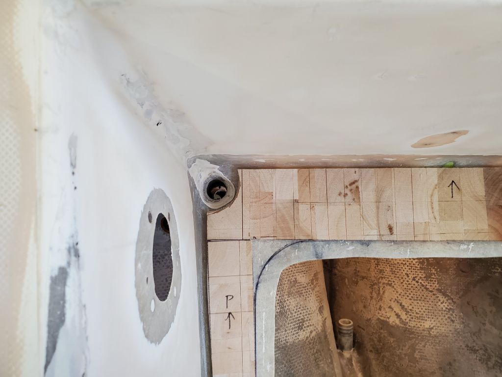
From here, I laid out and cut the core, leaving a wide-ish boundary around the hatch, which area I’d later fill with solid fiberglass. The core was in several pieces to fit around the hatch, and because the cockpit size was a bit wider than a sheet of the core. At the cockpit scuppers, I left out the core a bit back from the drains so I could manually form some new funnels from epoxy later in the process.
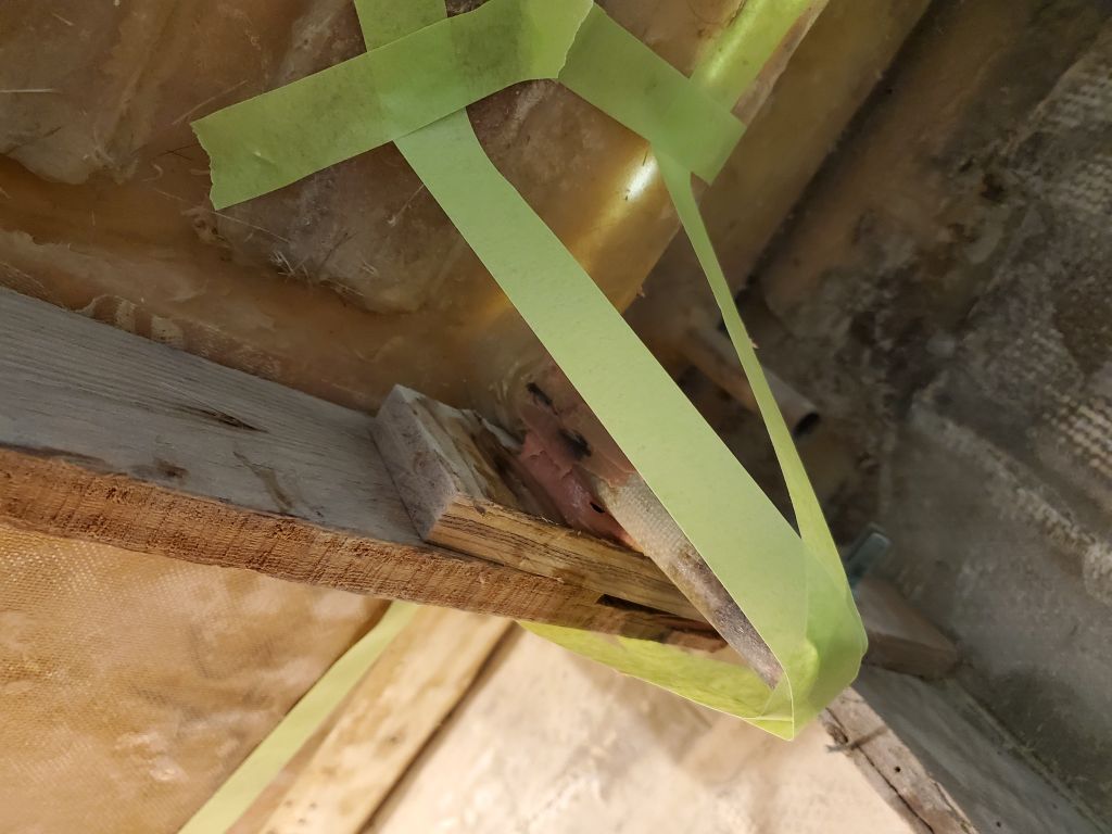
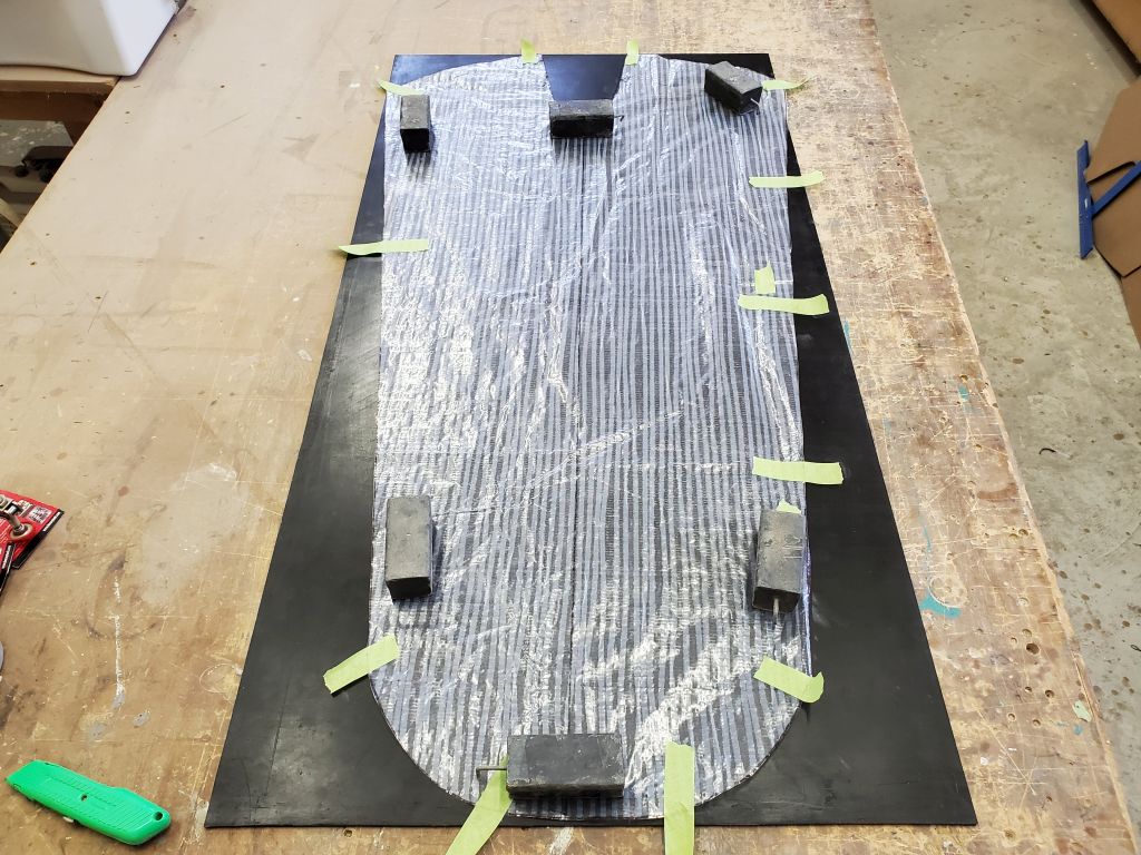
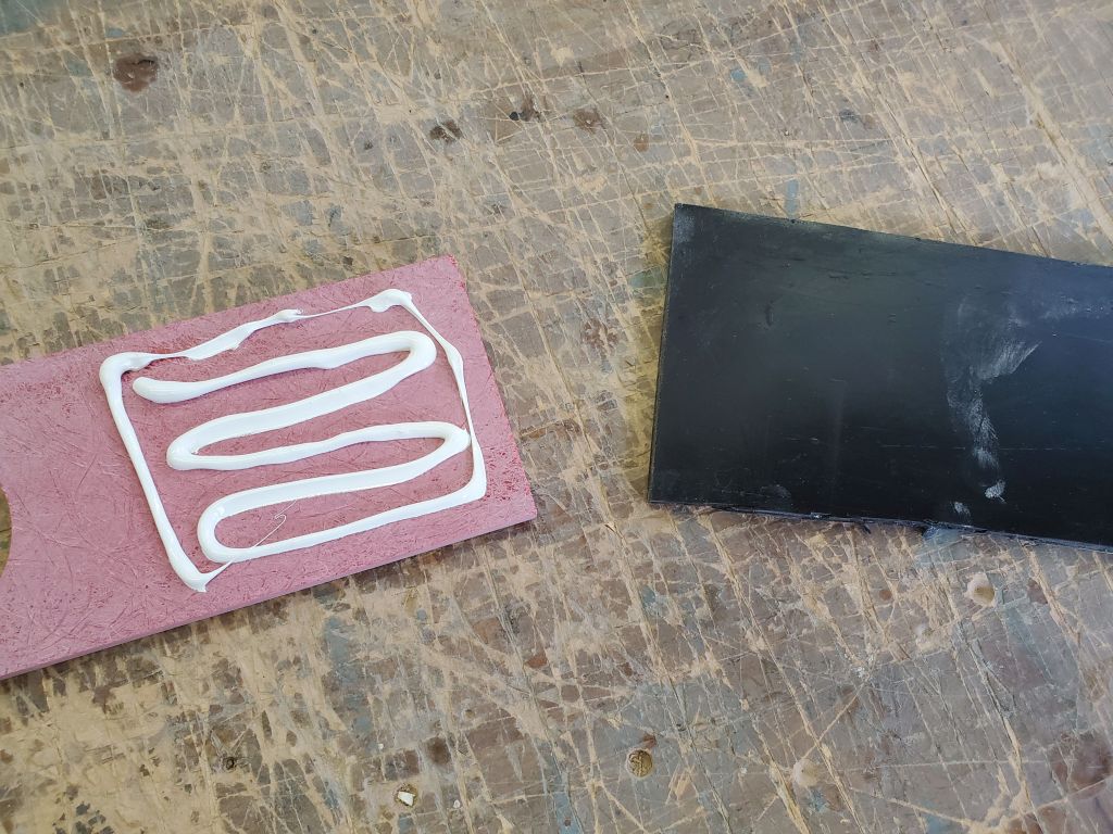
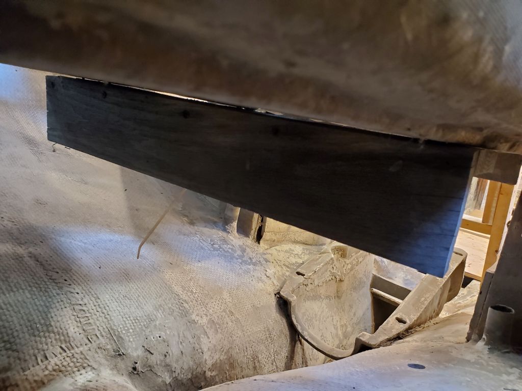
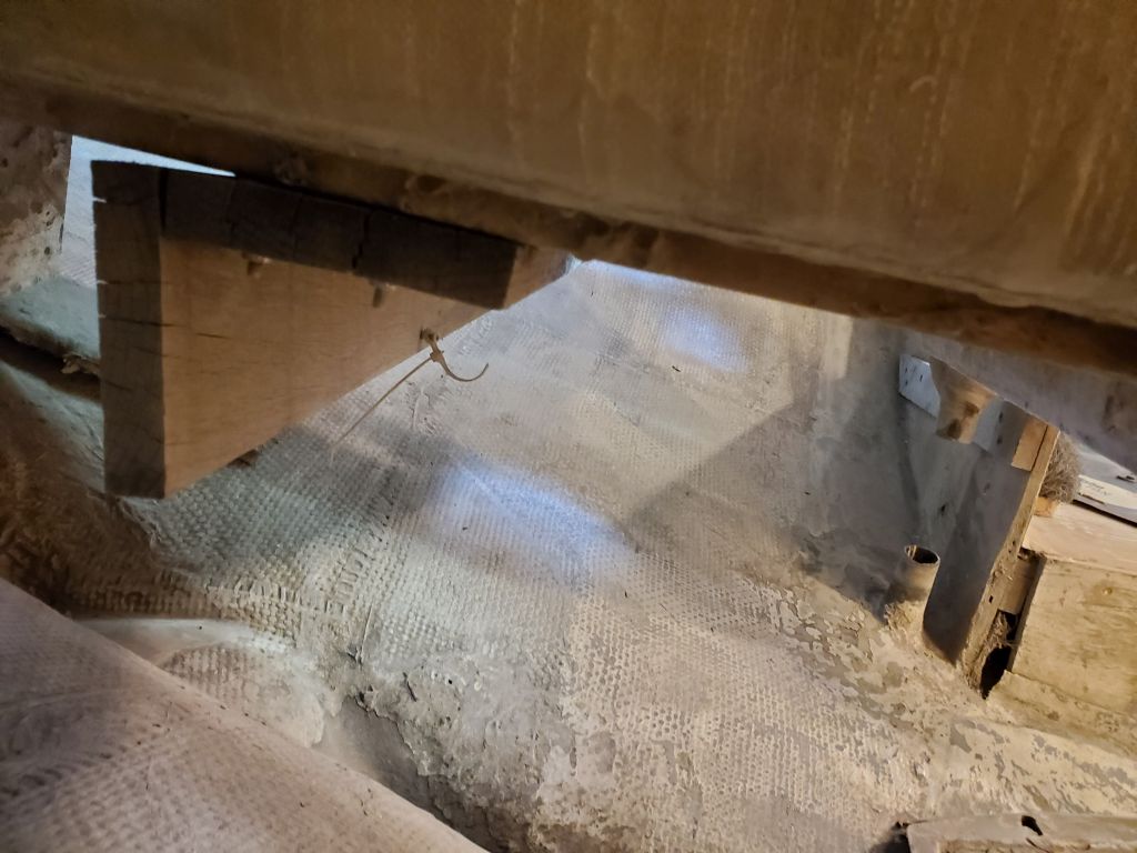
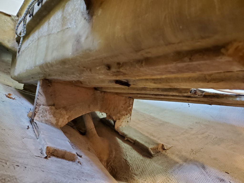
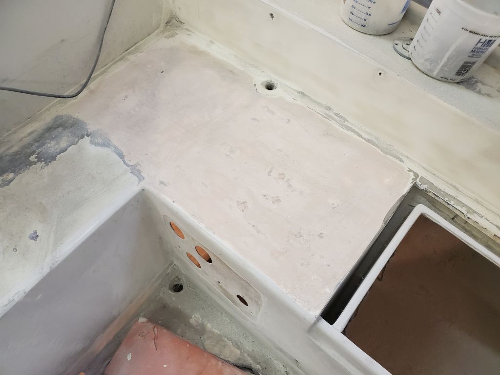
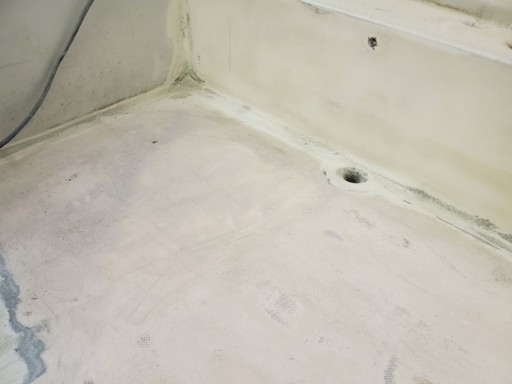
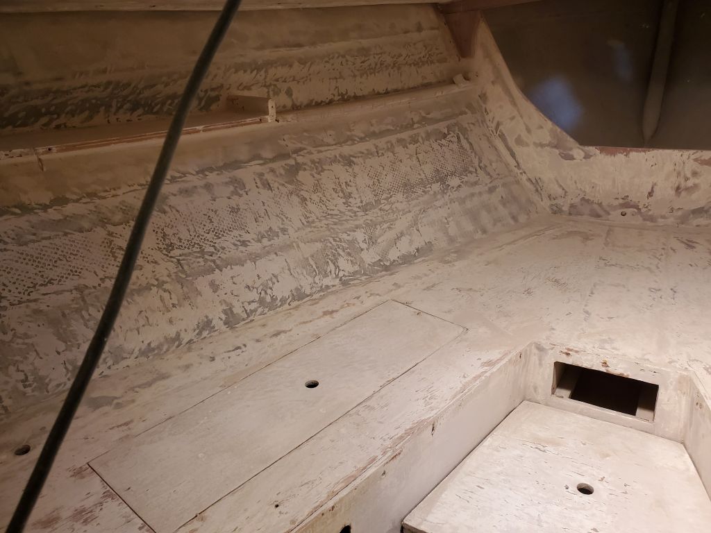
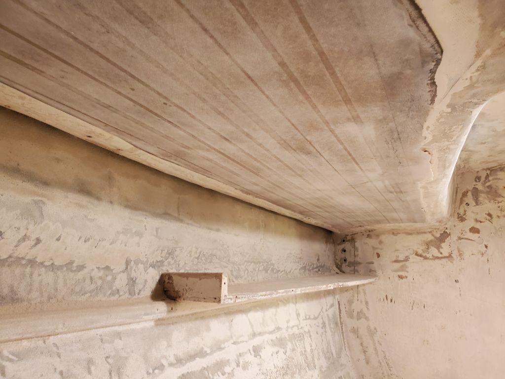
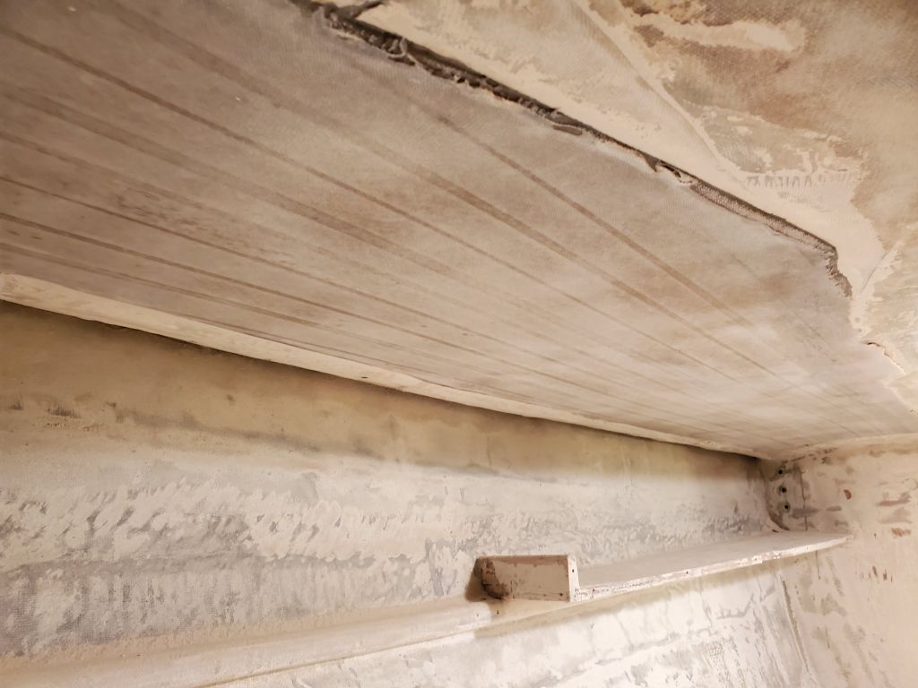
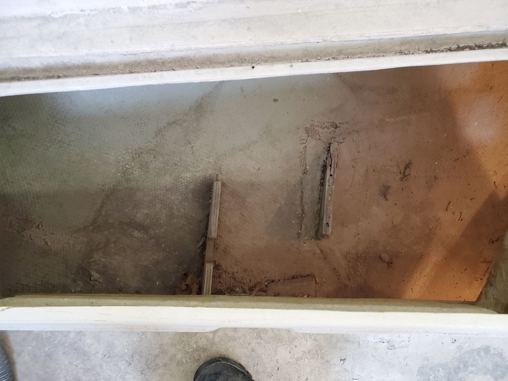
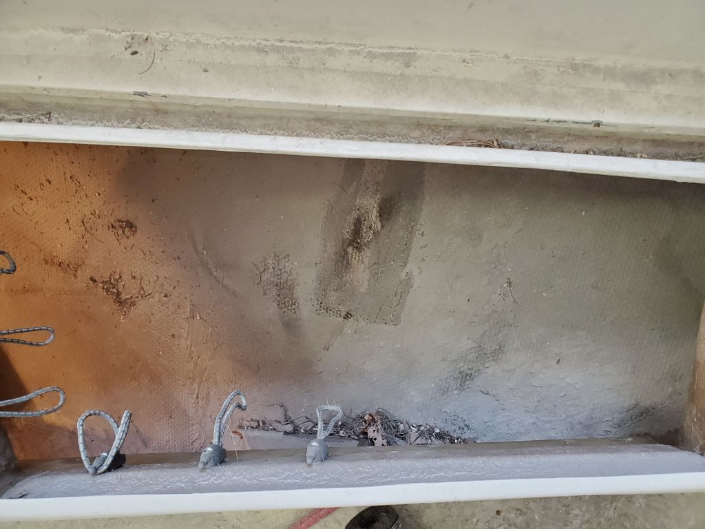
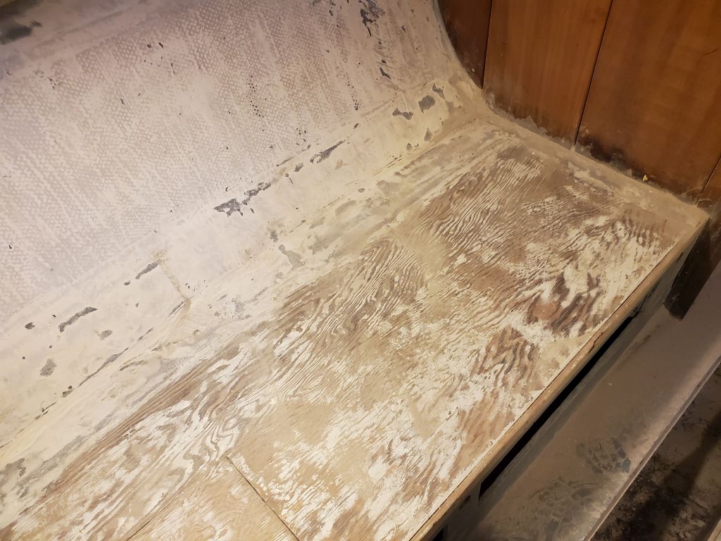
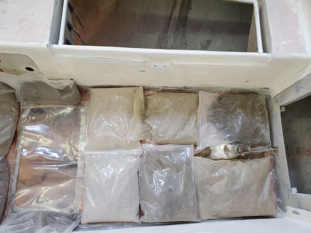
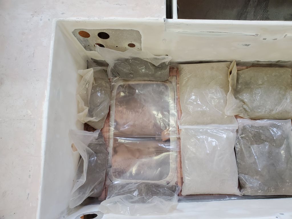
After final preparations to the sole, including adding a simple brace beneath the aft end of the hatch cutout to support the sole at its weakest point, I prepared the core by wetting out both sides and letting the epoxy soak in for a bit while I wet out the sole and then applied the notched epoxy adhesive over the whole thing. I installed the new core and weighted it down with sandbags. One of the bags opened as I put it in place, spilling some sand onto the plastic I’d laid above the core but not causing any issues. But the sand might be visible in the photos.
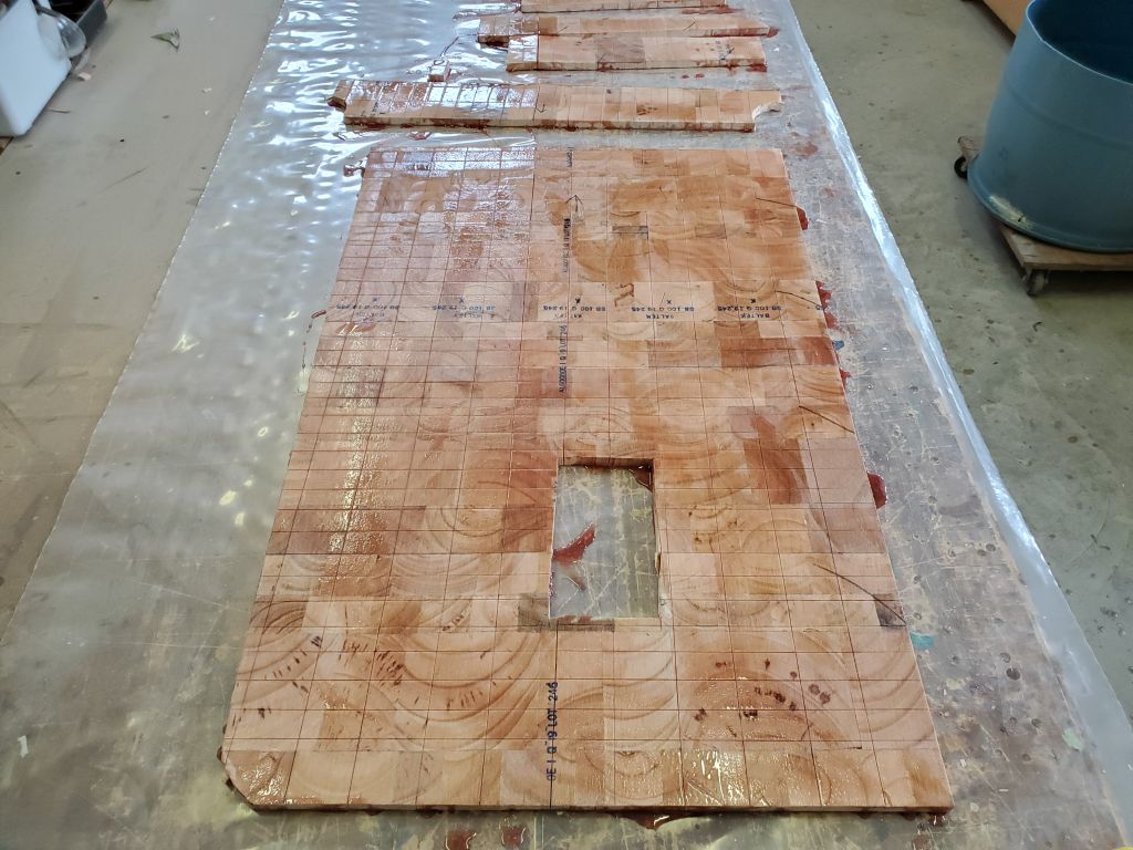

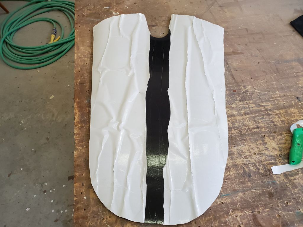
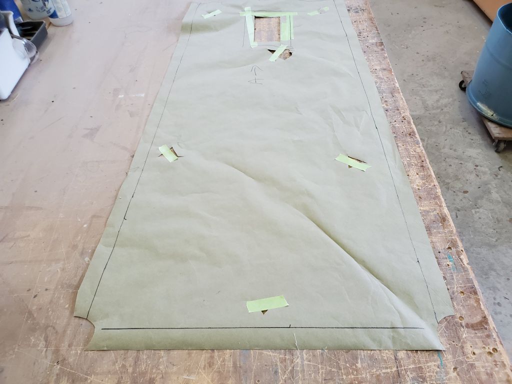
While the core cured in place, I used the same paper pattern to lay out and cut two layers of fiberglass for the new top skin, sized as needed to wrap up the sides of the sole by about 2″ (roughly to where I ground off the gelcoat) and 1″, for the first and second layers respectively. I cut out (roughly) the opening for the hatch in the first layer, but realized belatedly that this would make the fiberglass harder to handle during installation, so for the second layer I marked the hatch opening but left the cloth intact; I just wouldn’t wet out that area. The new top skin would go on next time, once the core was cured.

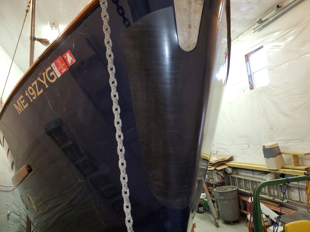
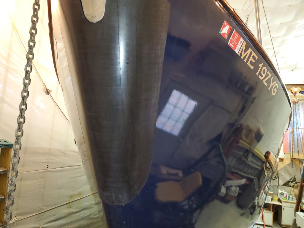
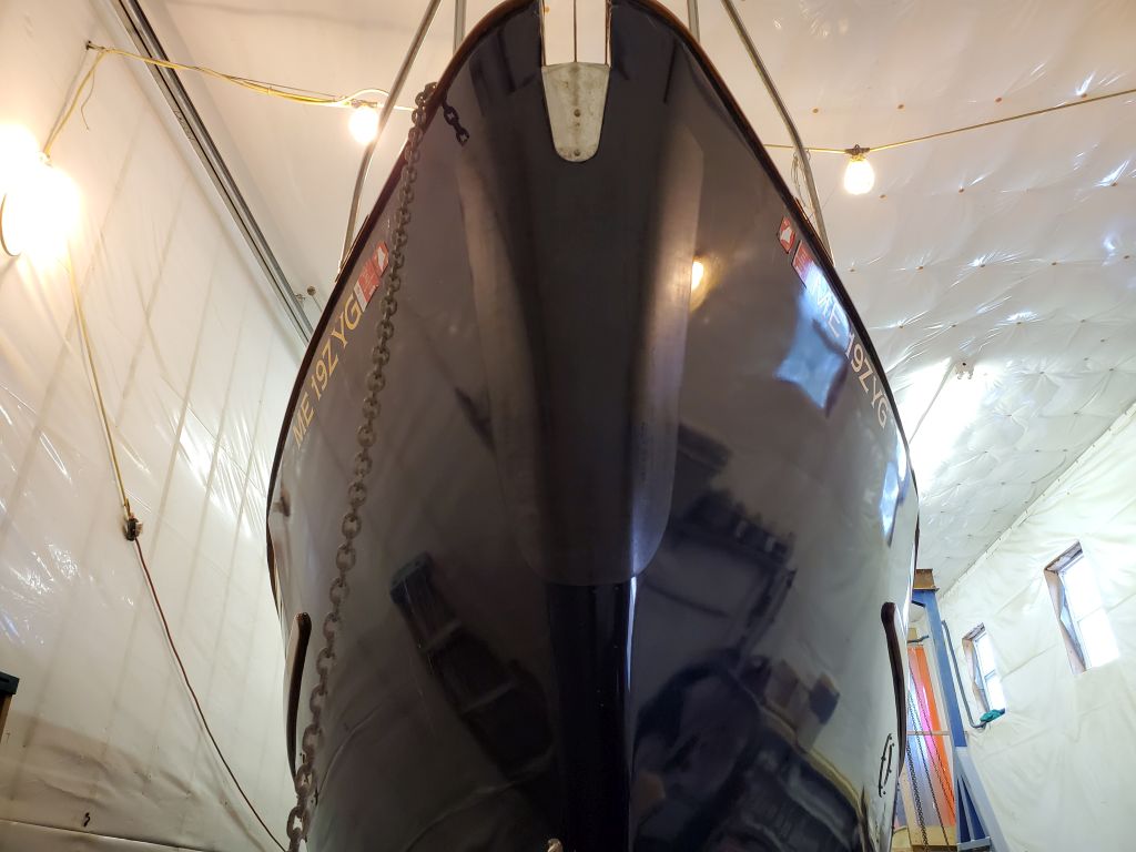
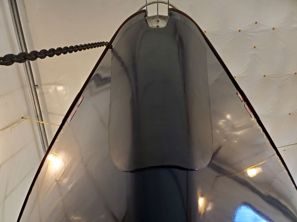
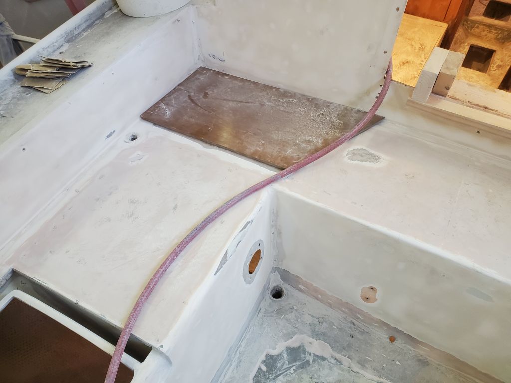
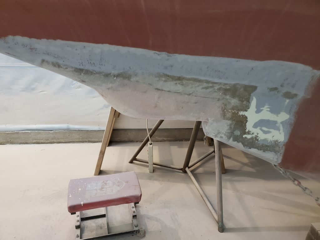
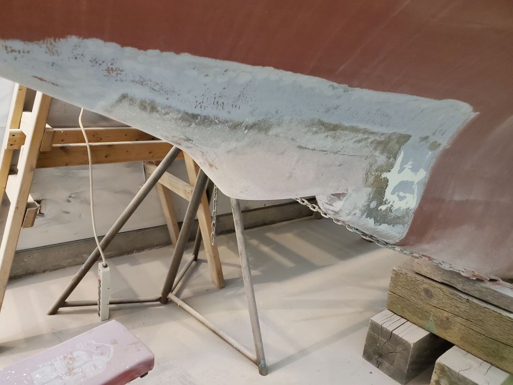
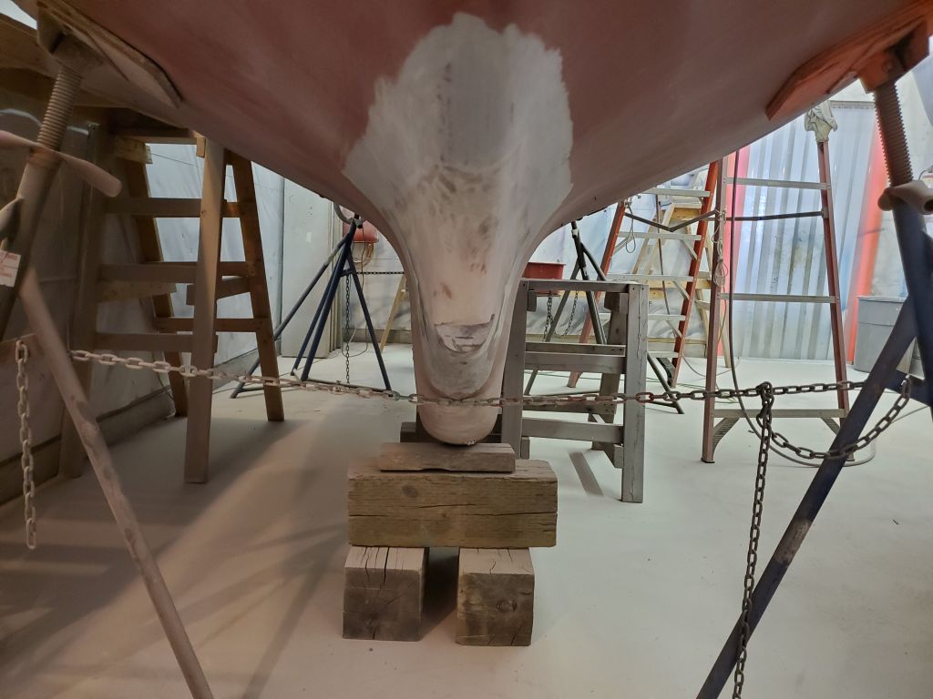
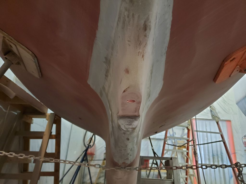
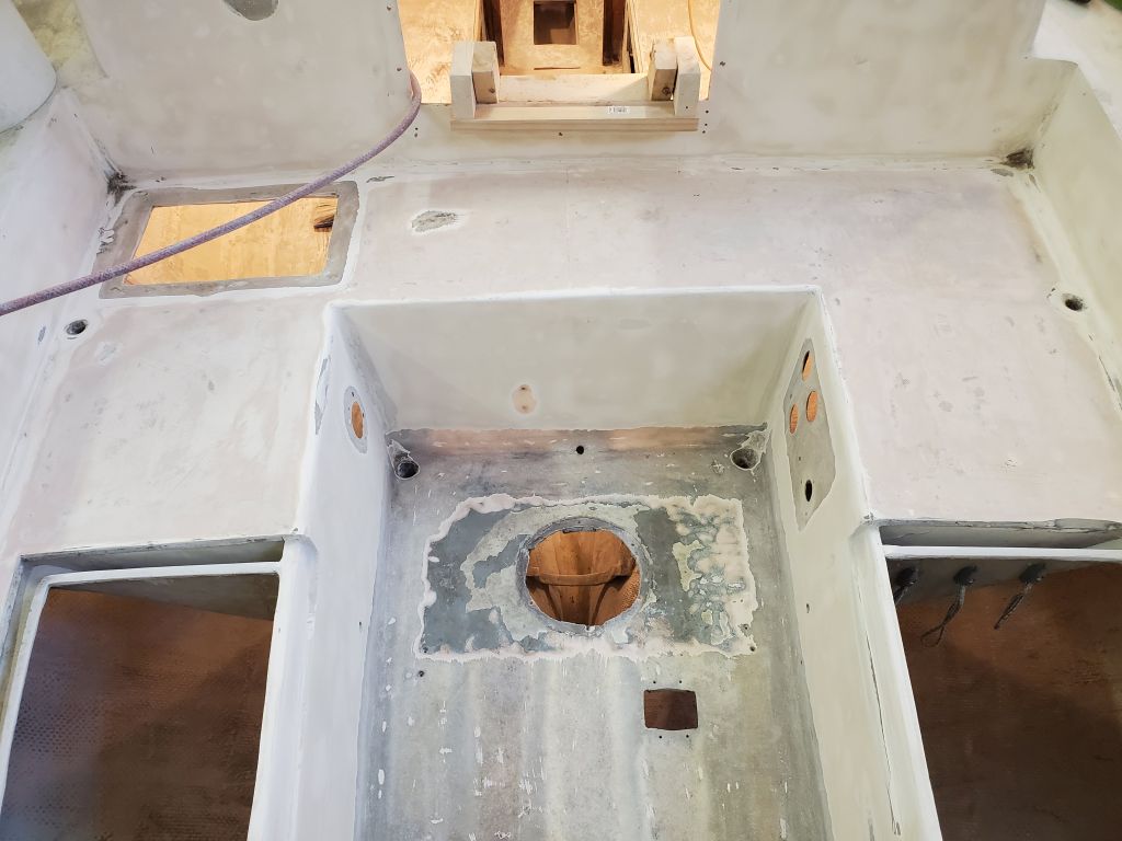
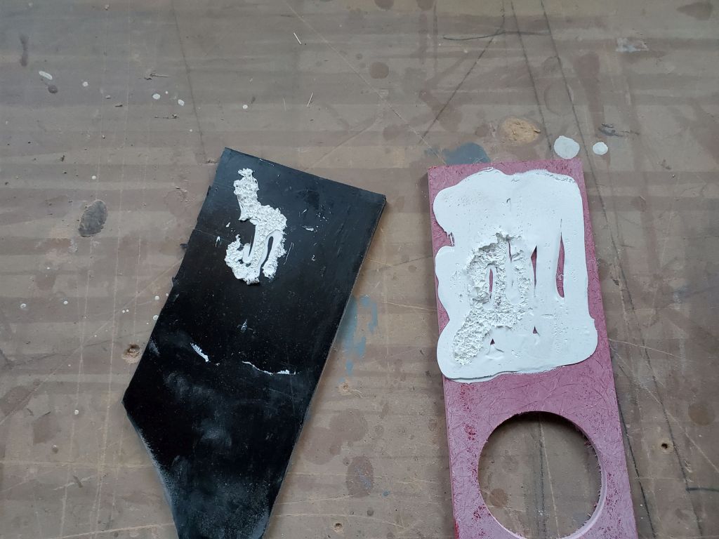
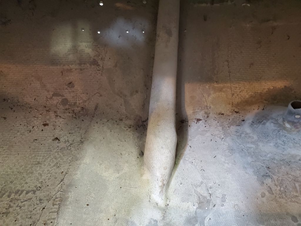
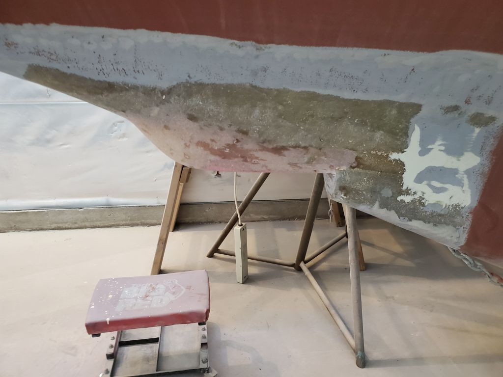
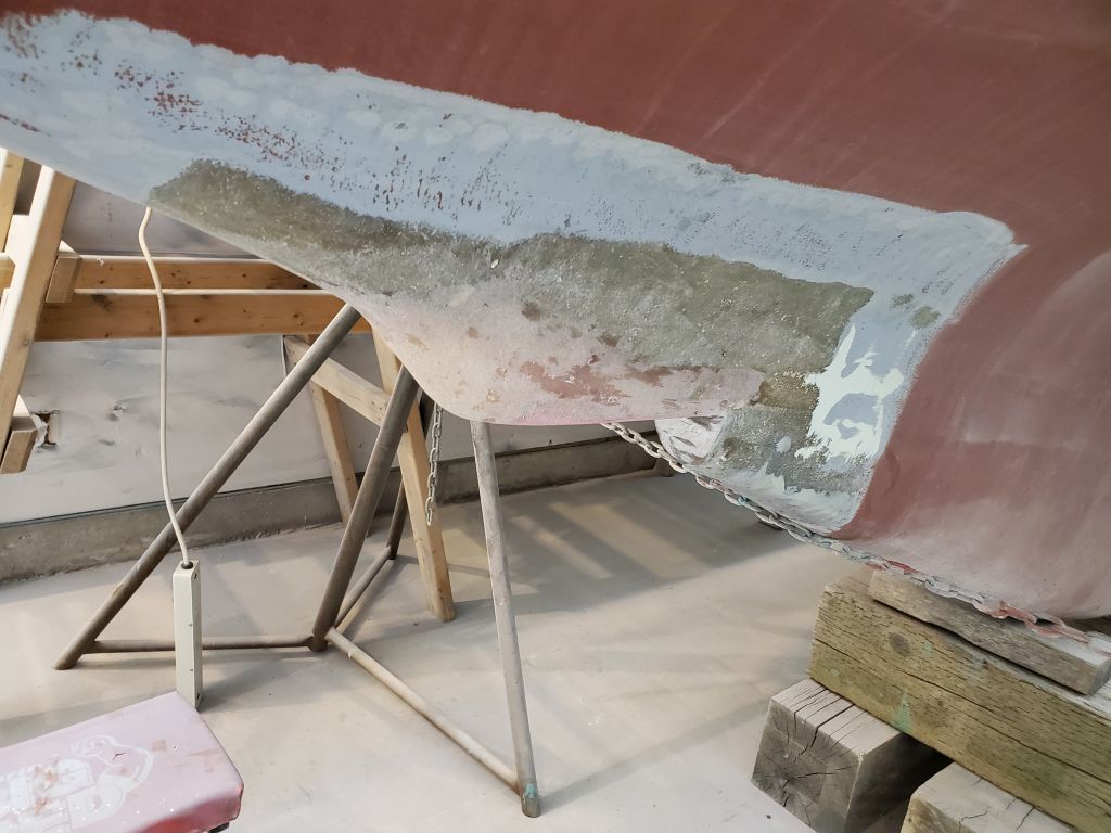
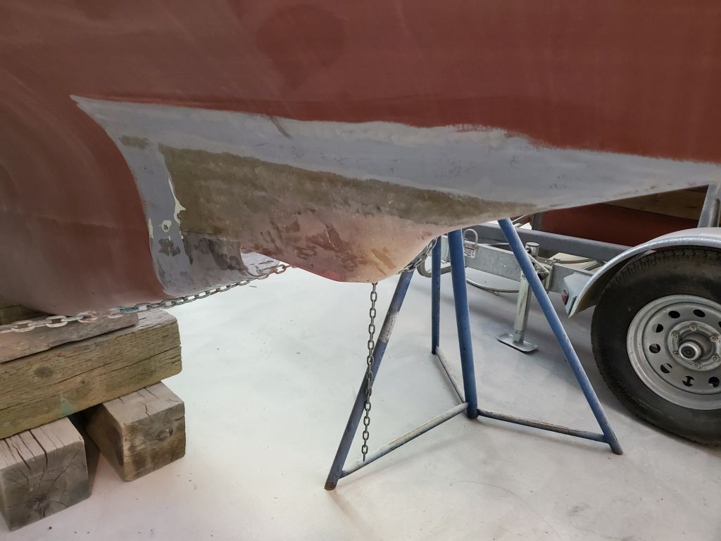
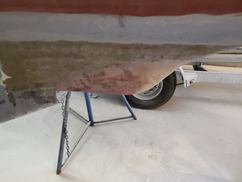
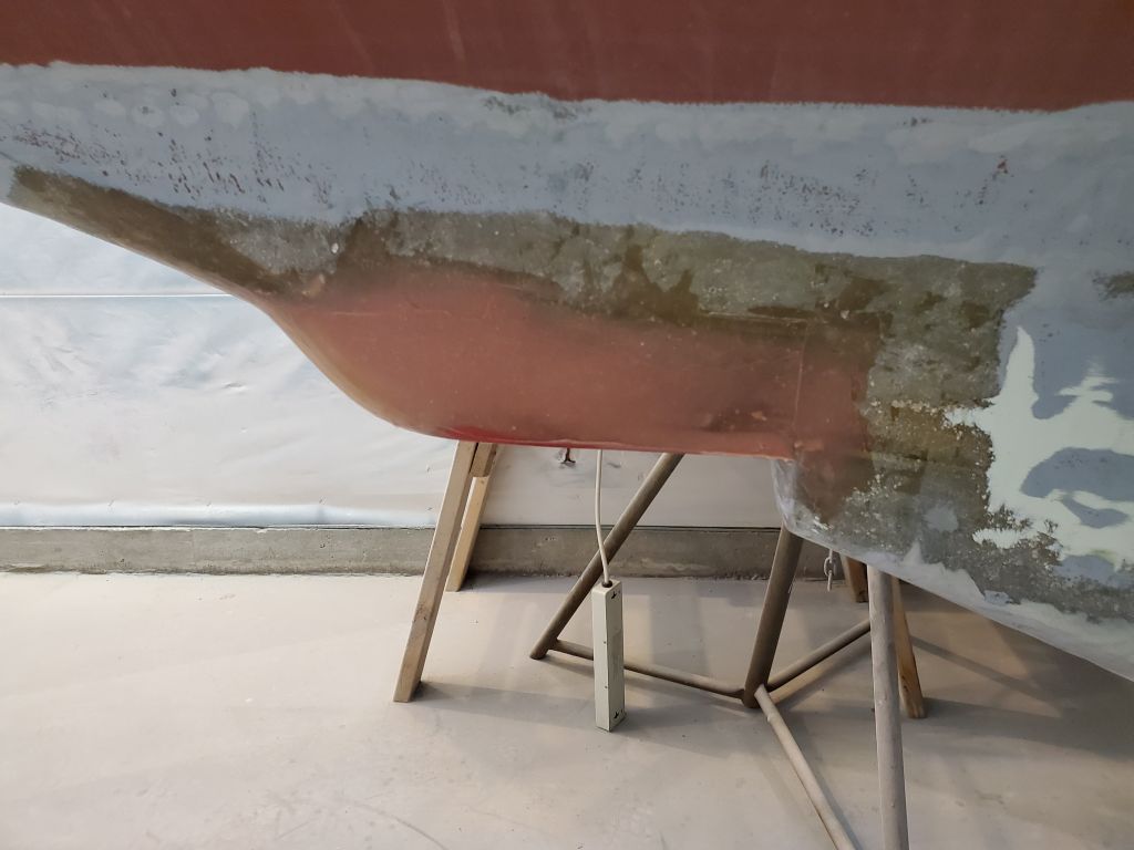
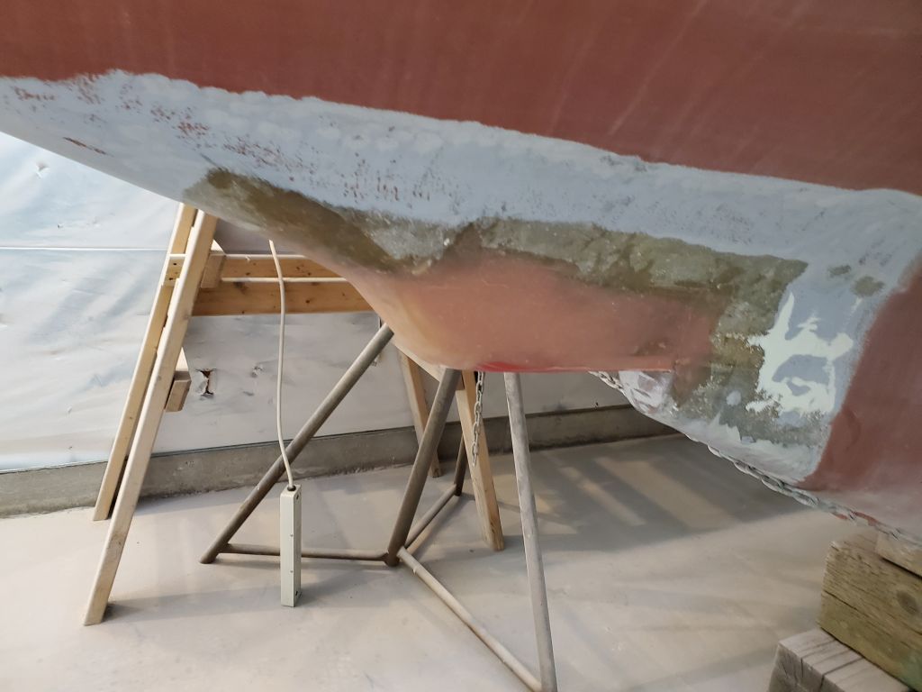
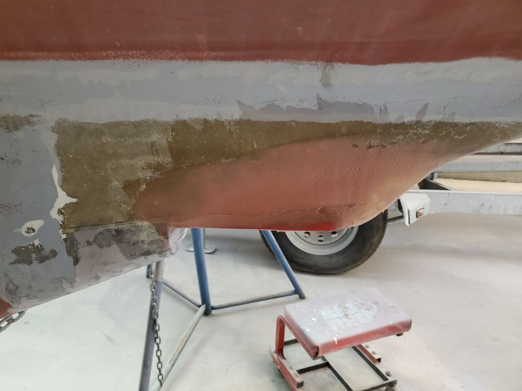
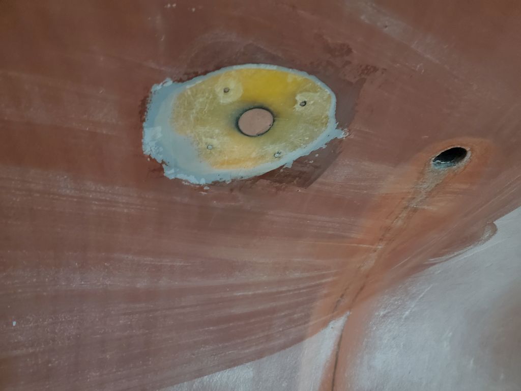
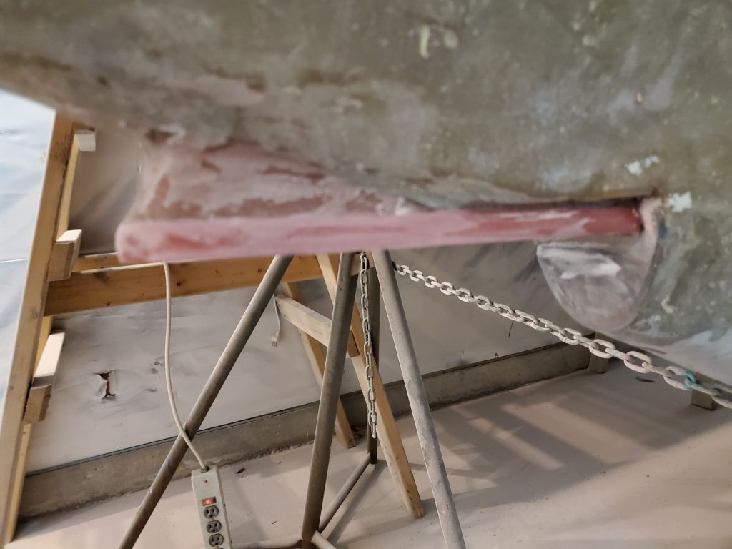
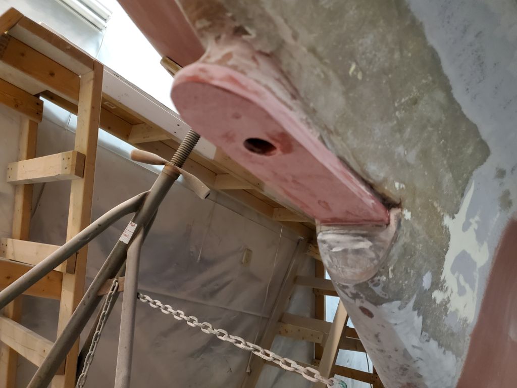
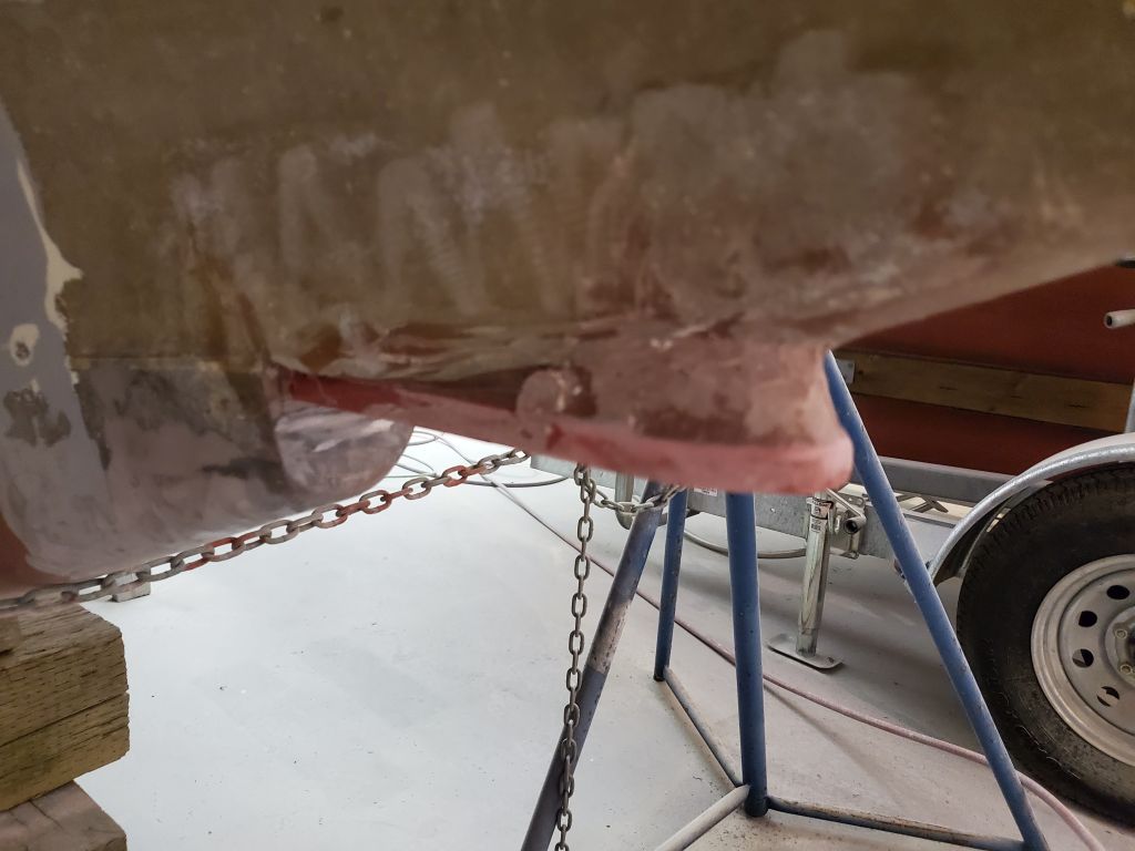
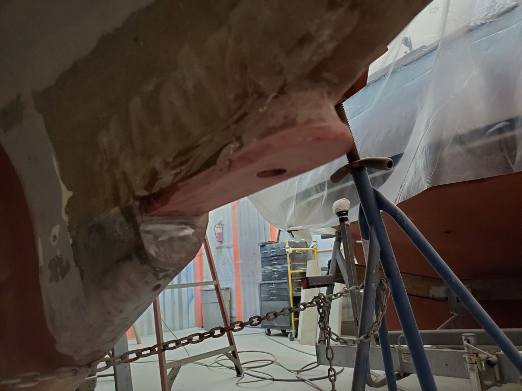
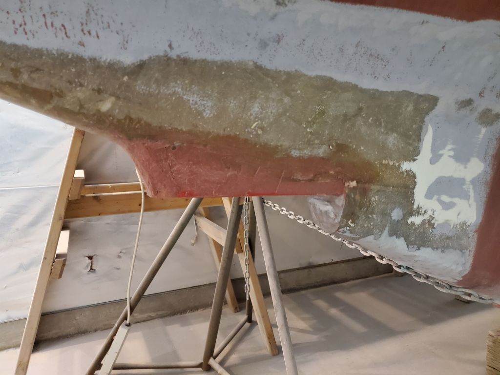
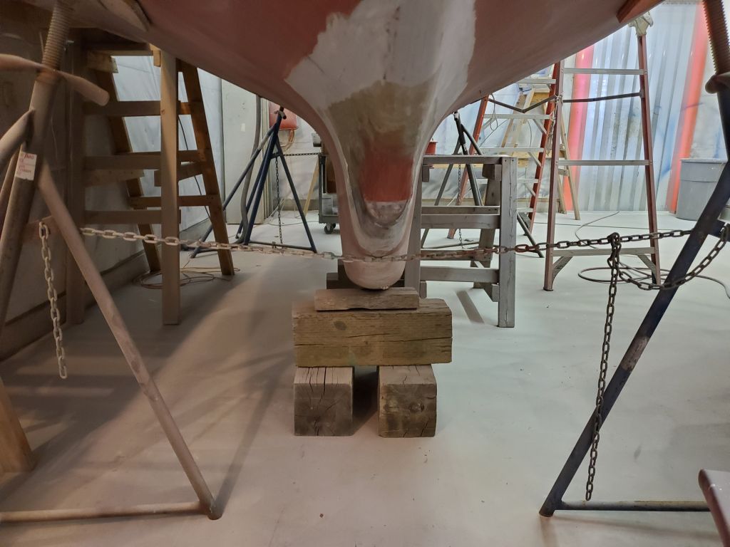
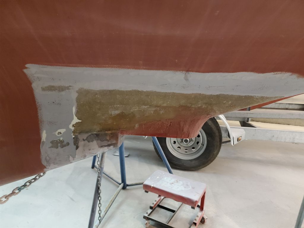
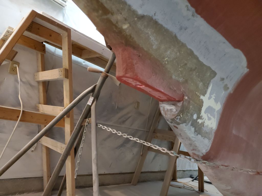
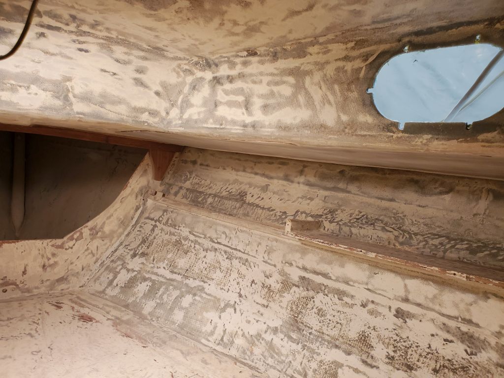
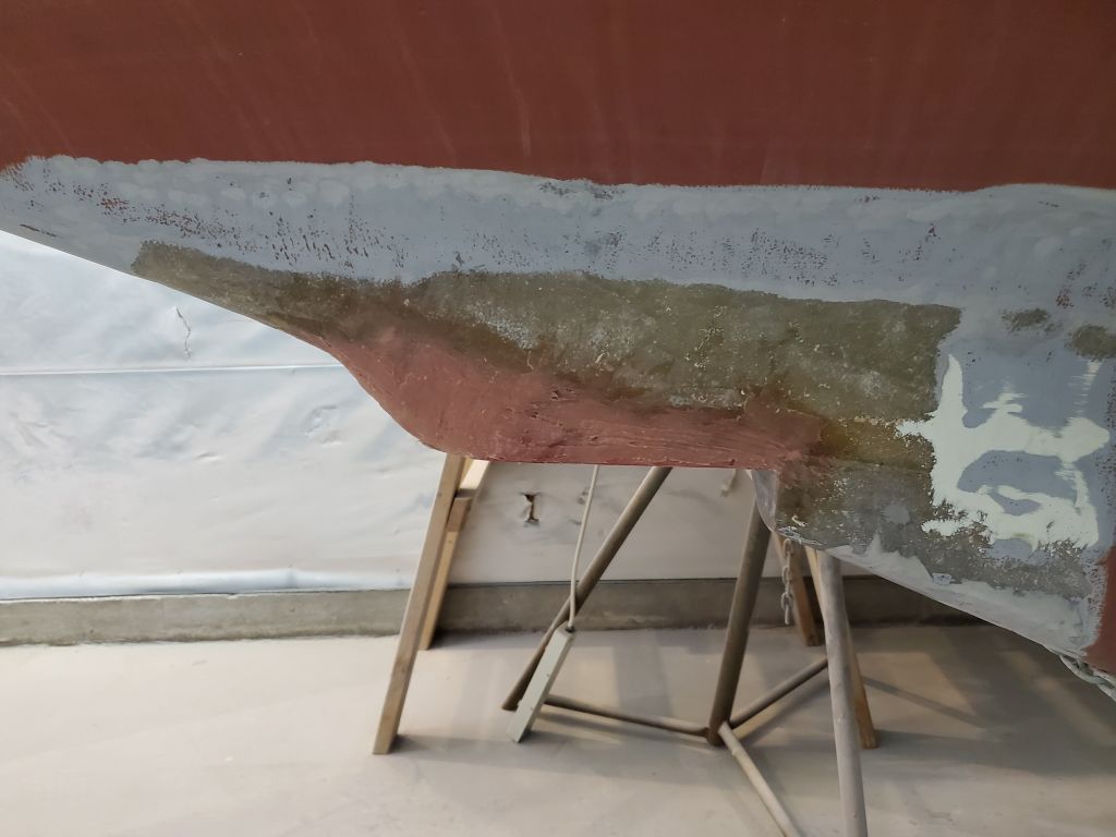
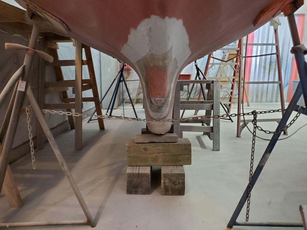
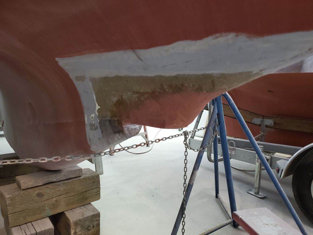
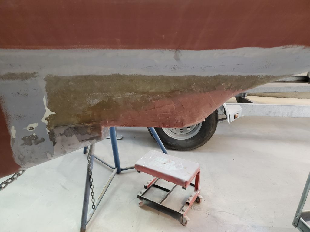
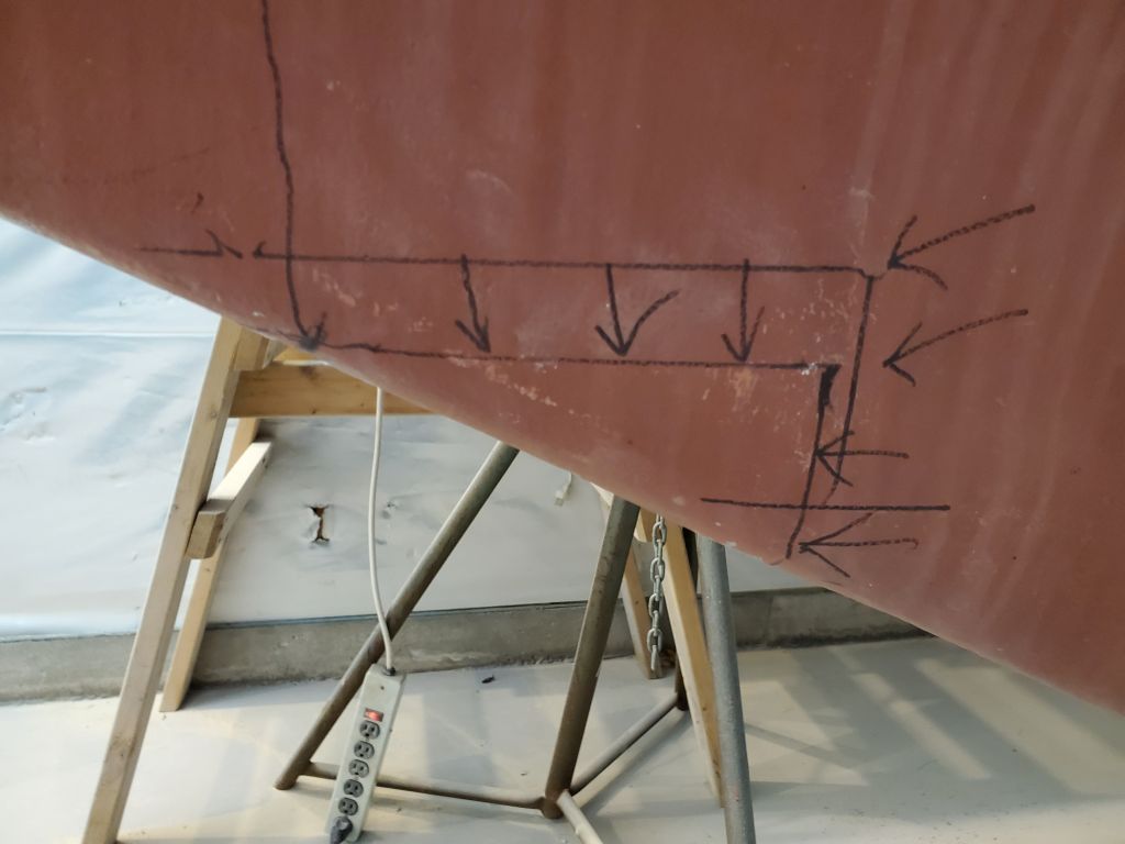
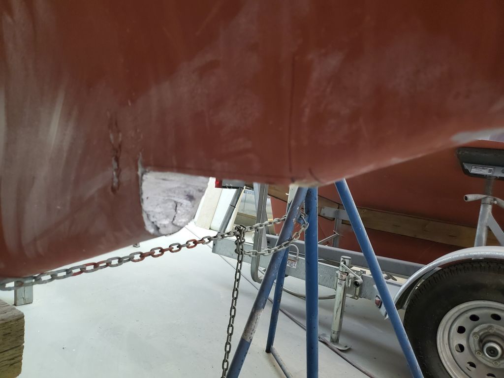
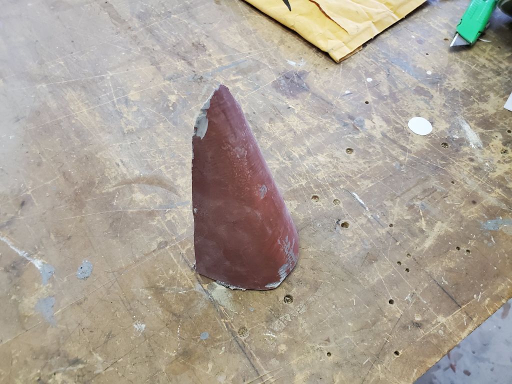
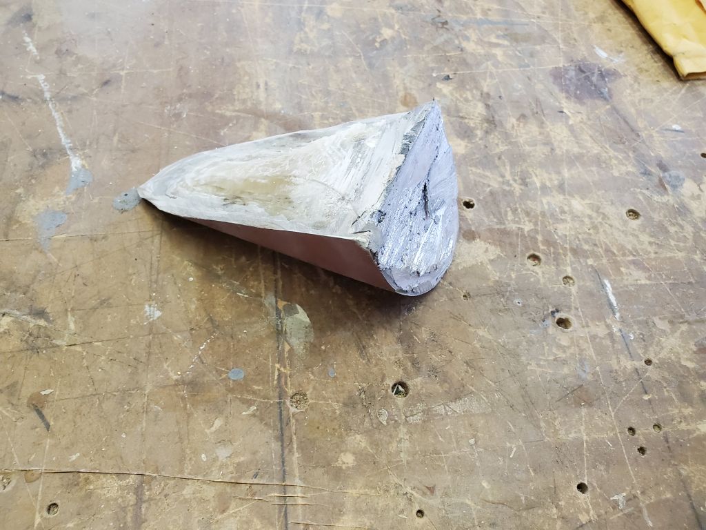
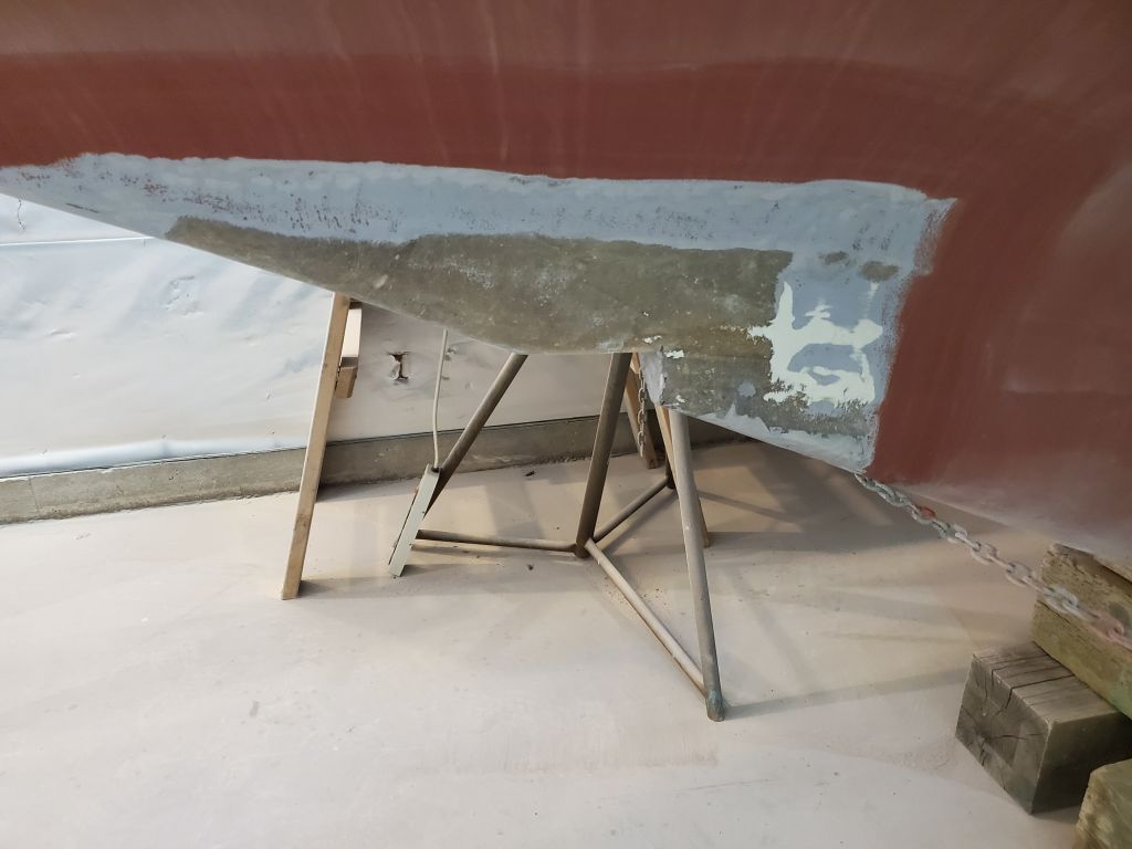
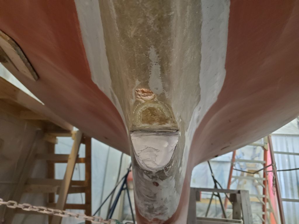
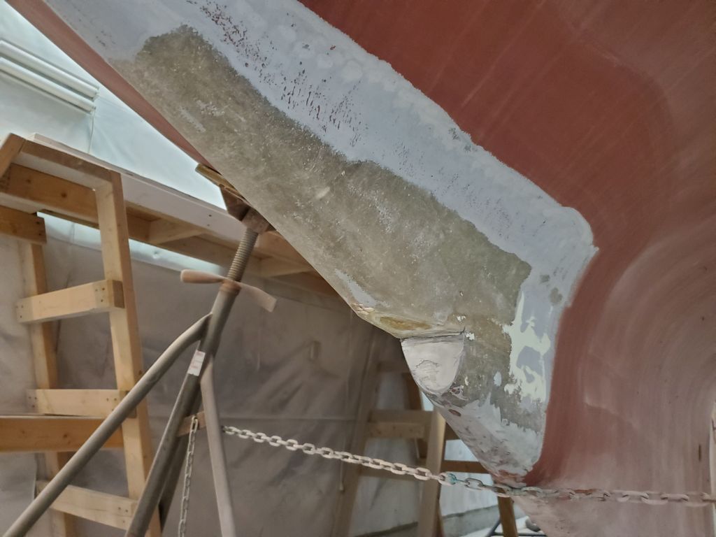
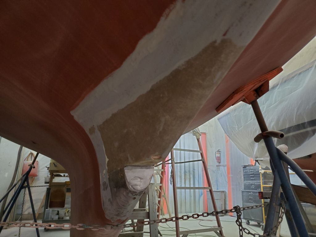
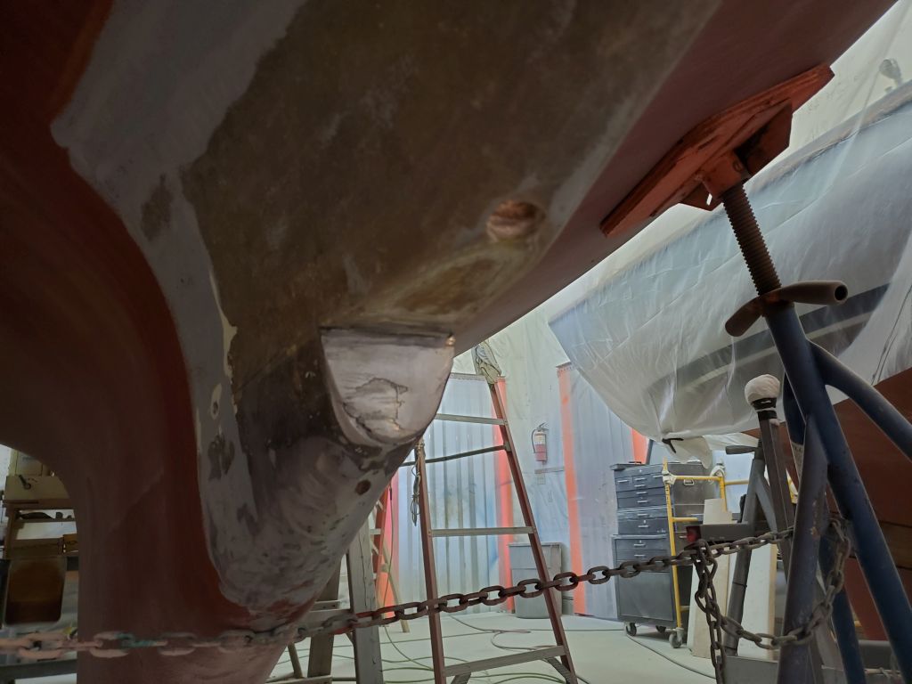
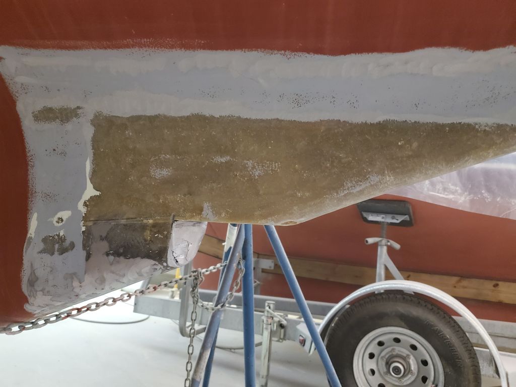
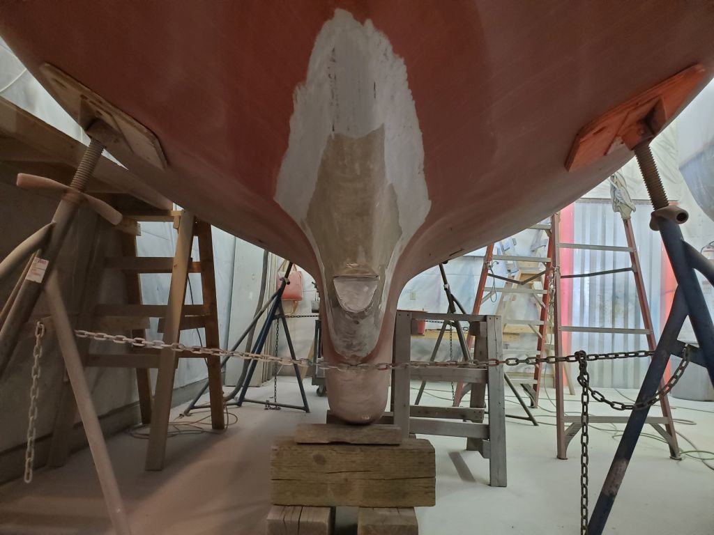
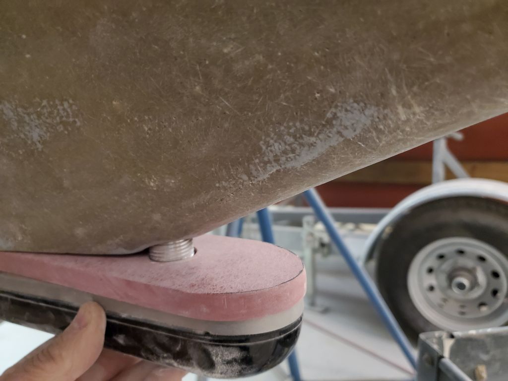
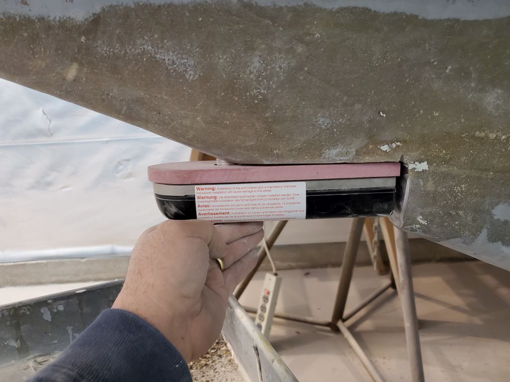
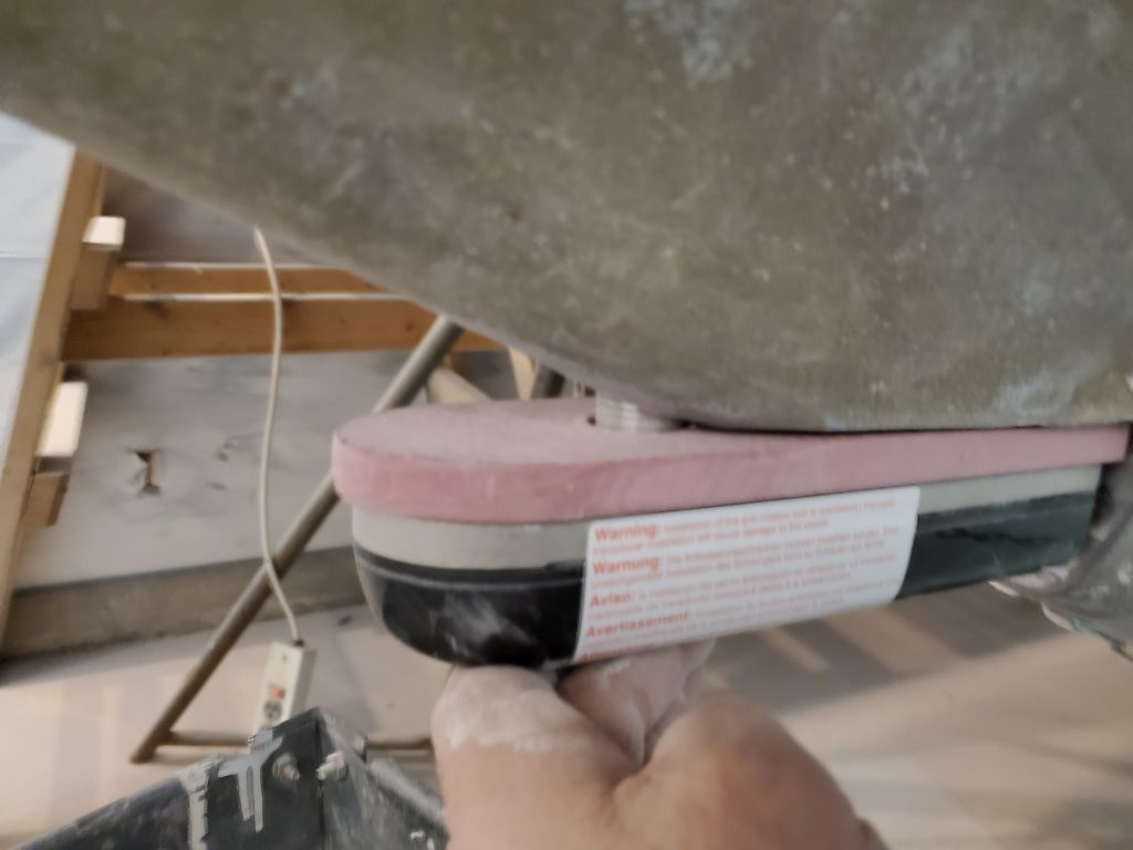
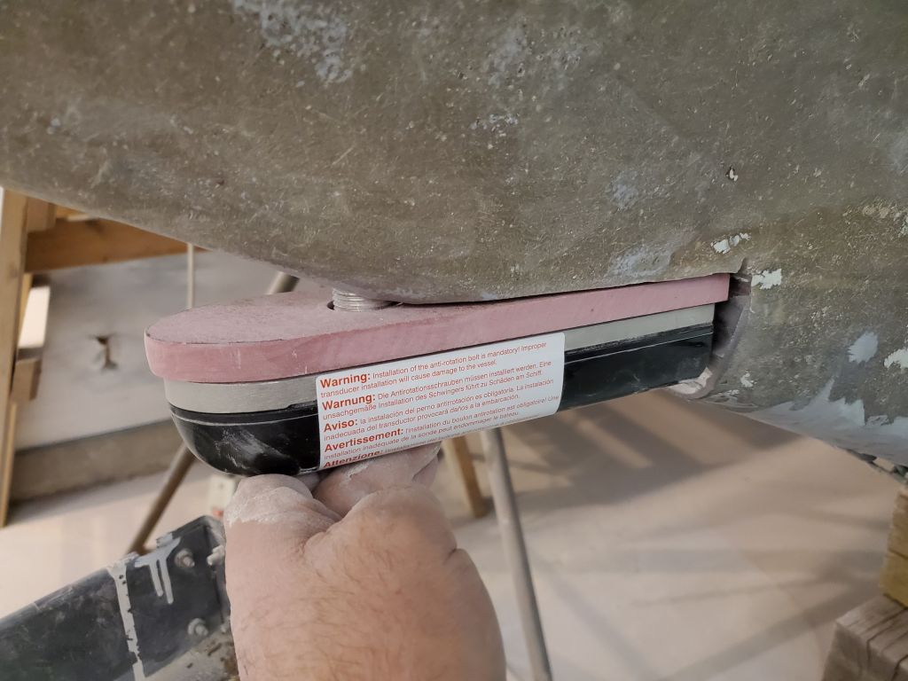
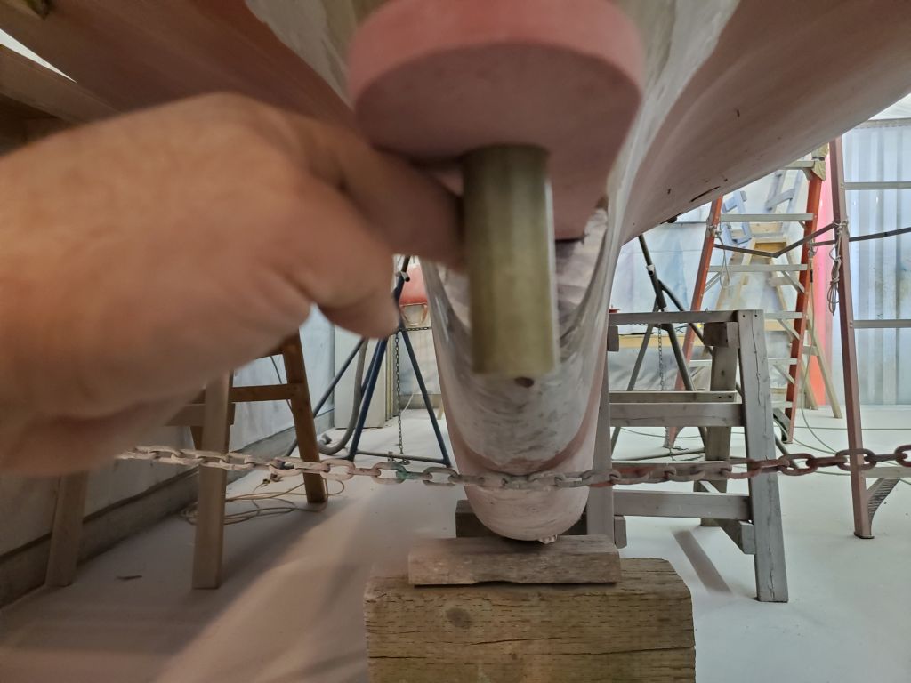
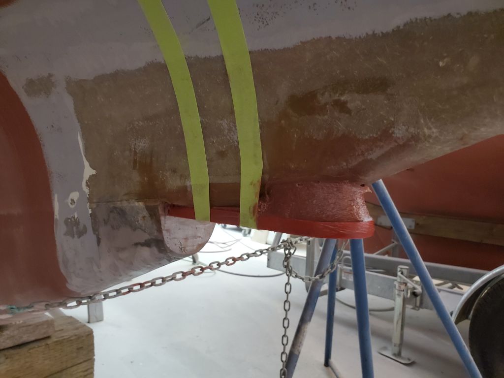
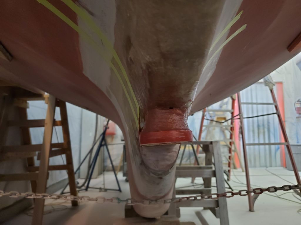
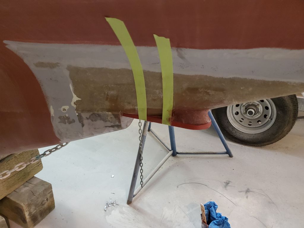
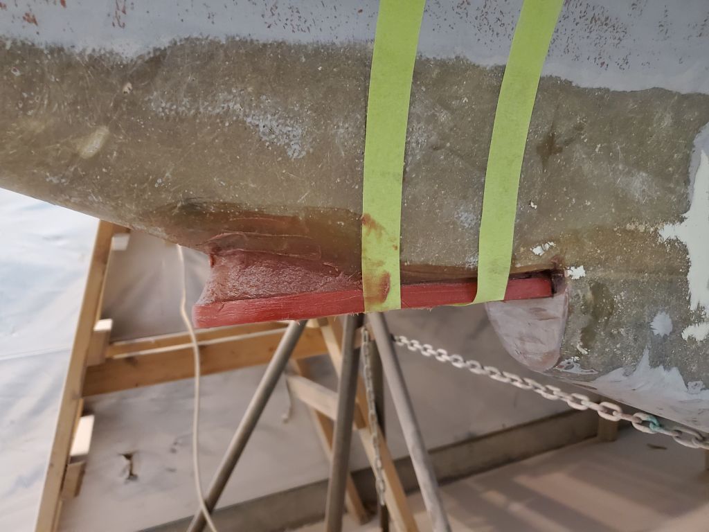
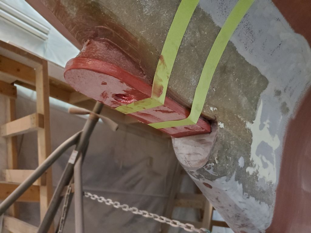
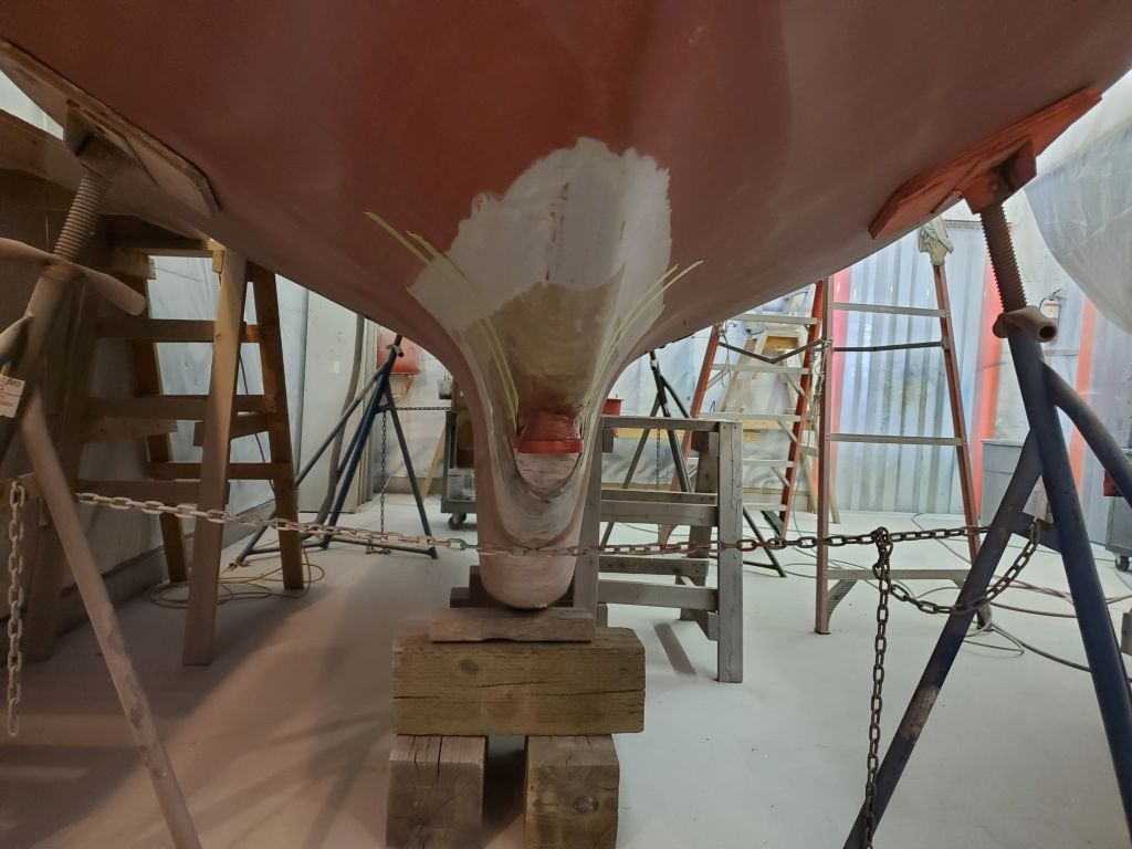
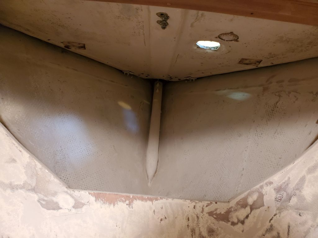
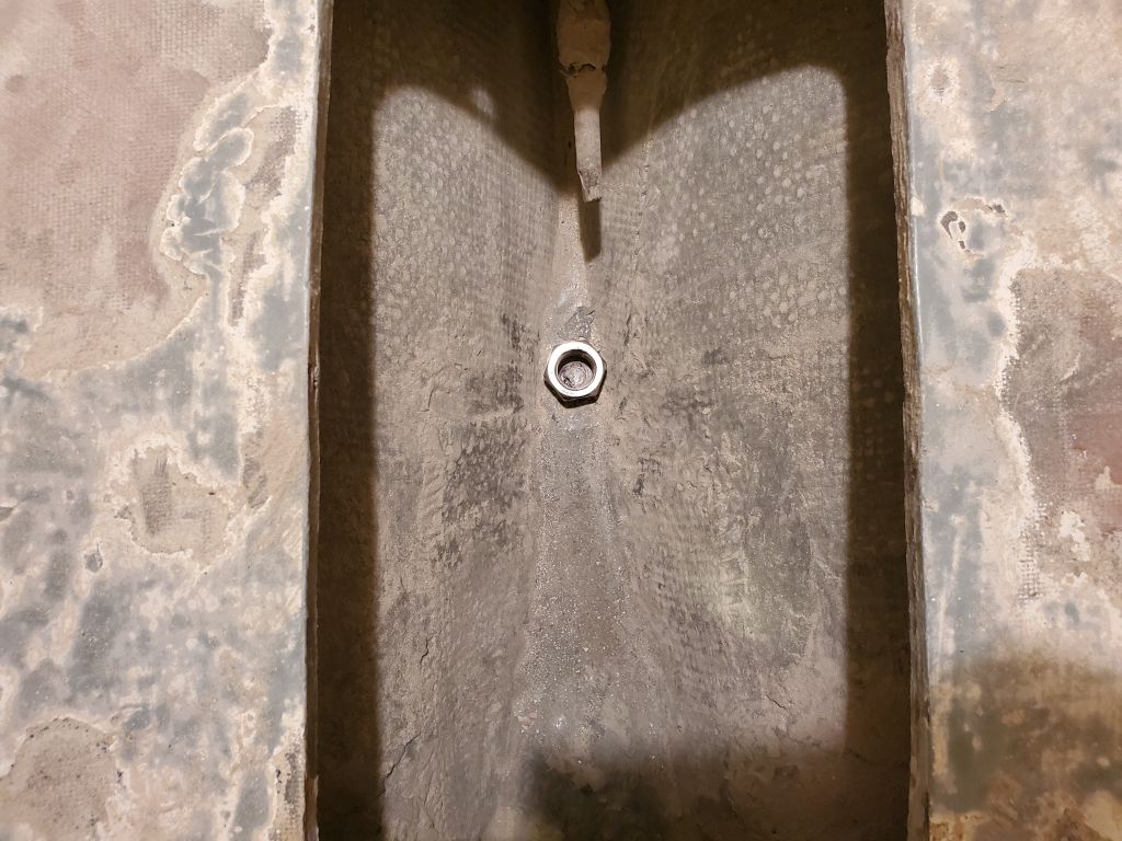
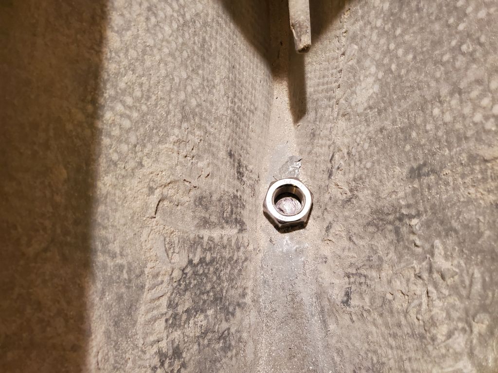
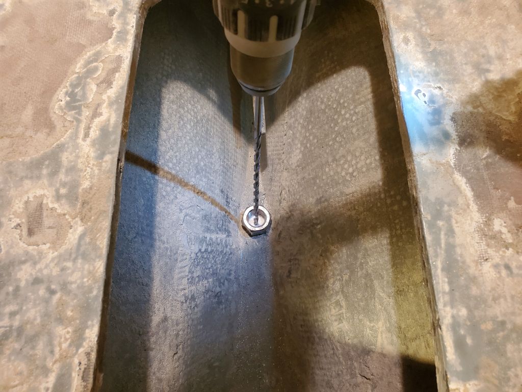
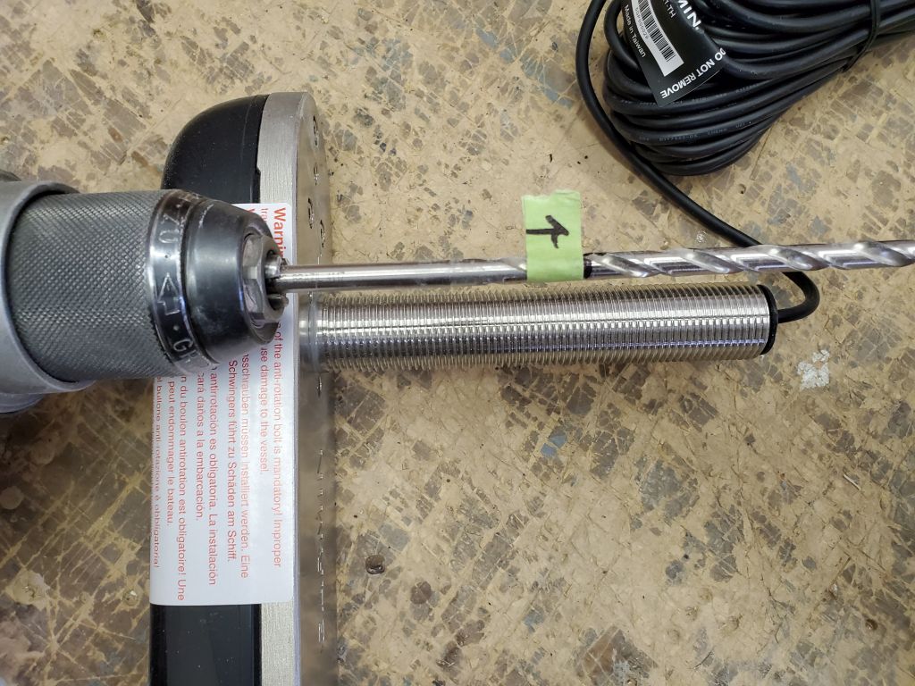
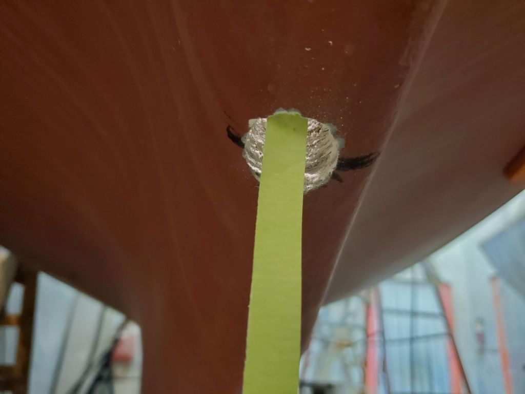
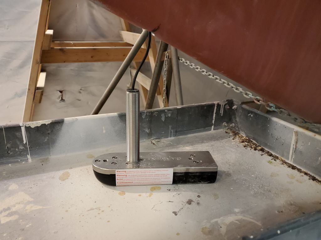
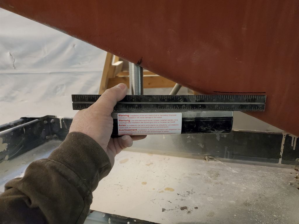
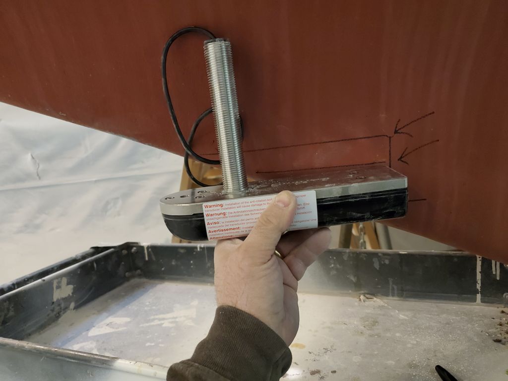
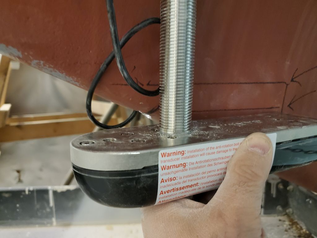
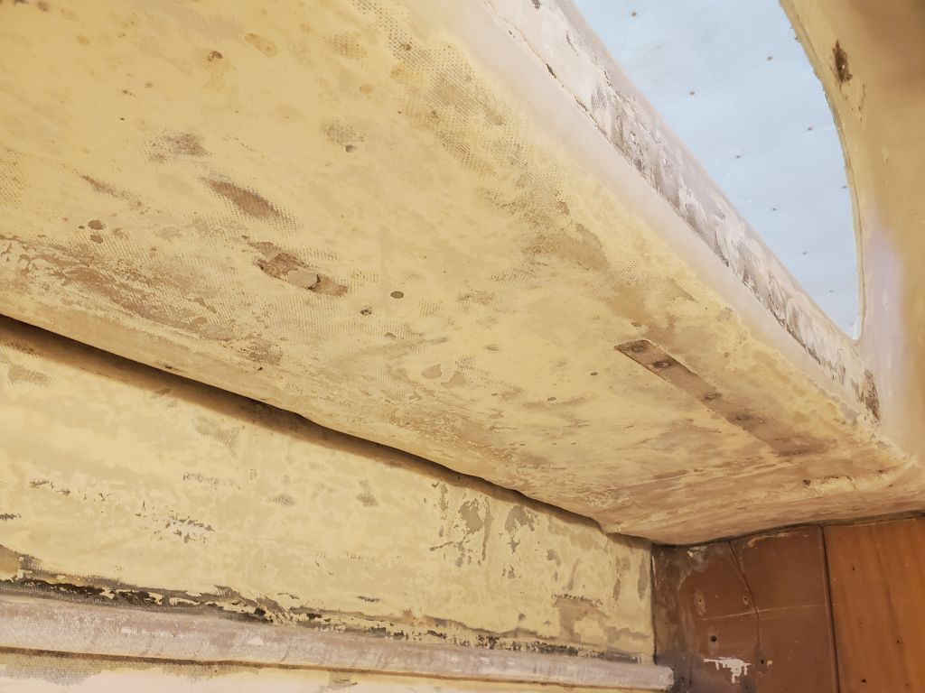
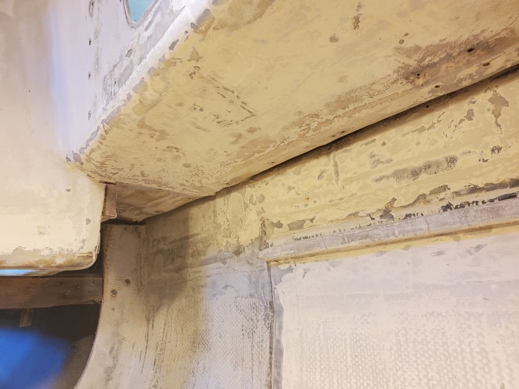
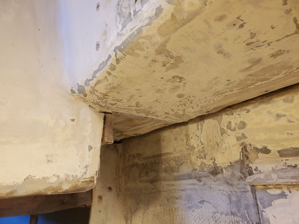
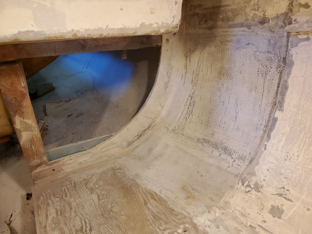
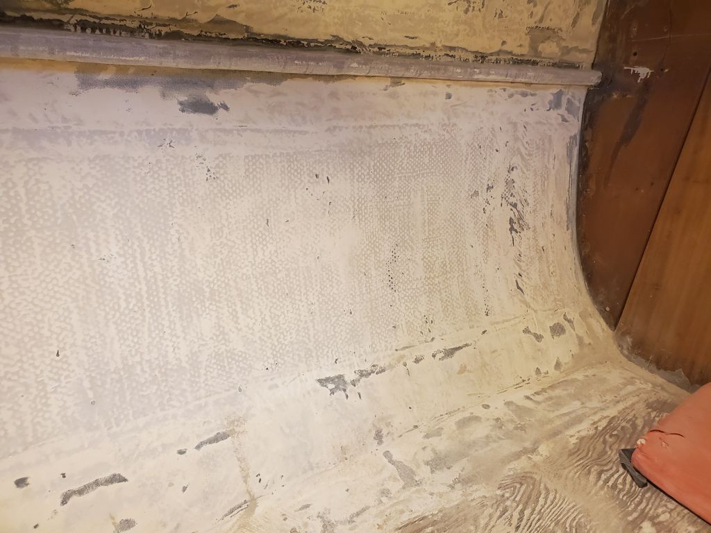
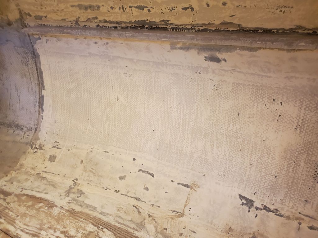
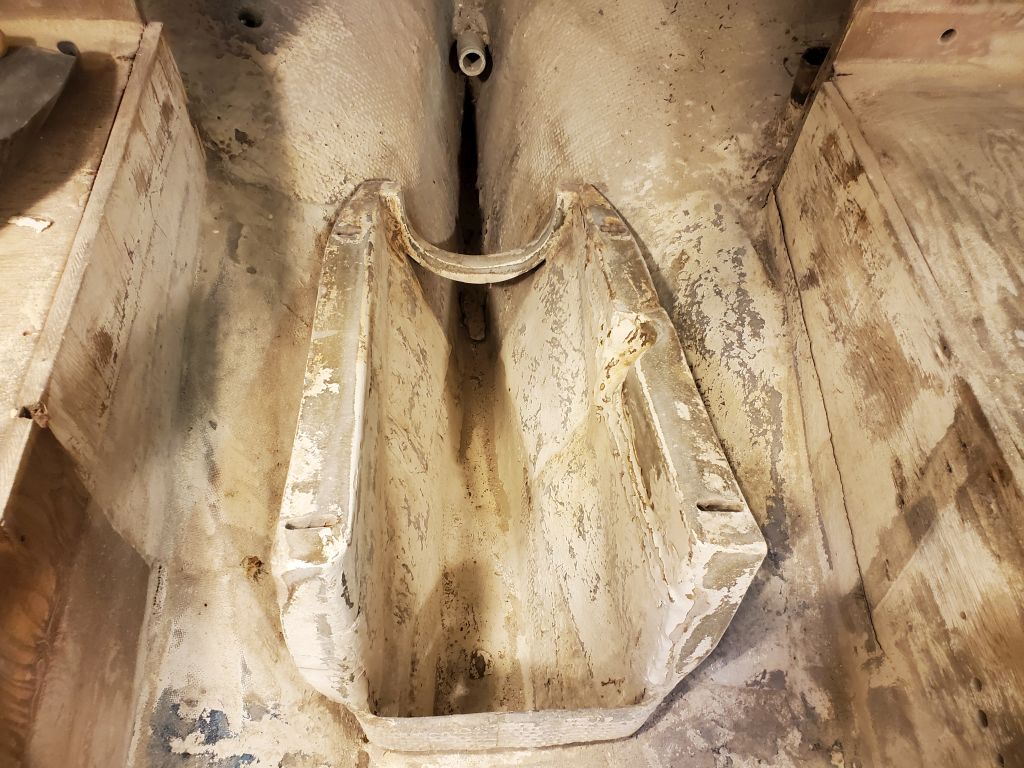
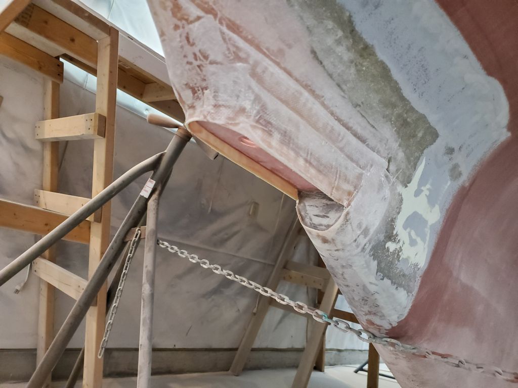
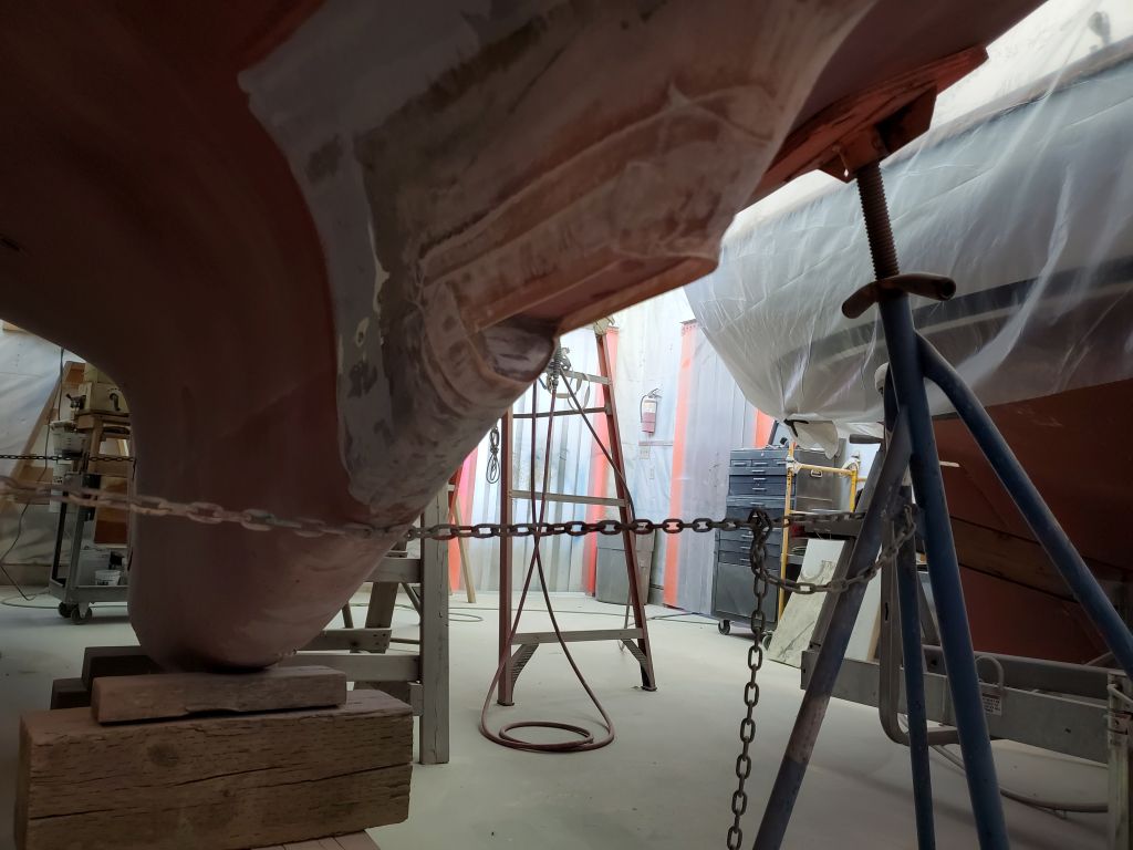
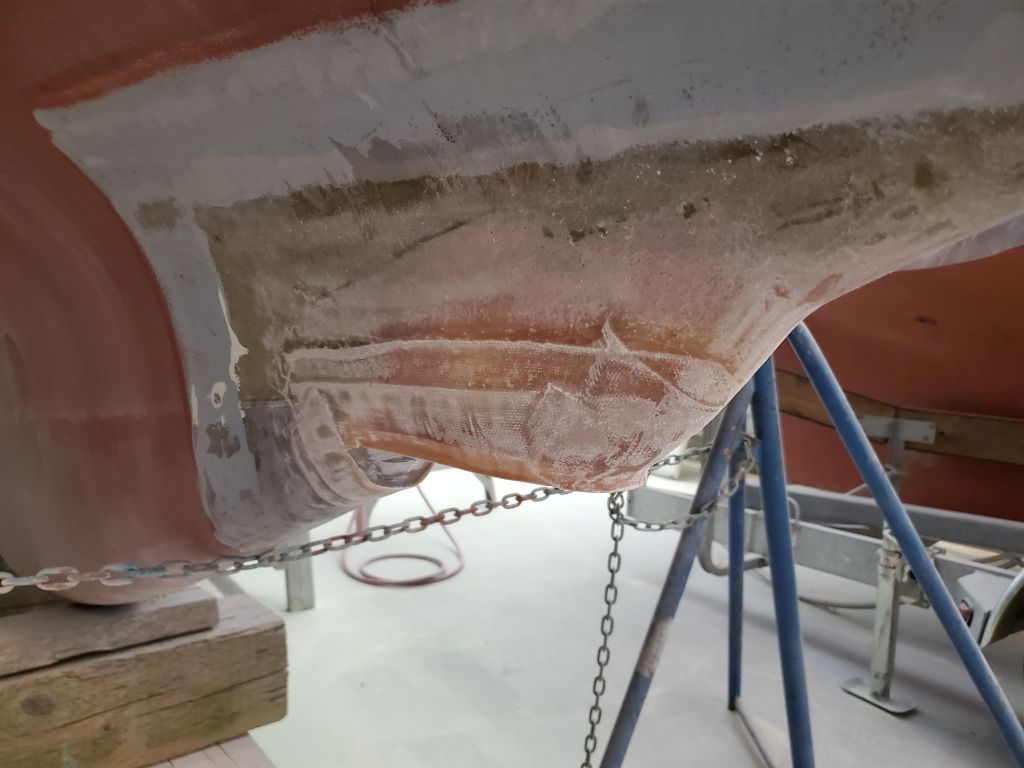
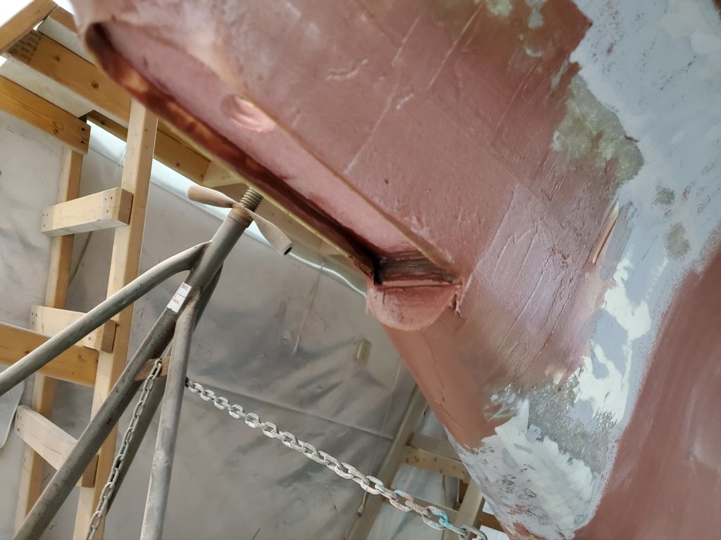
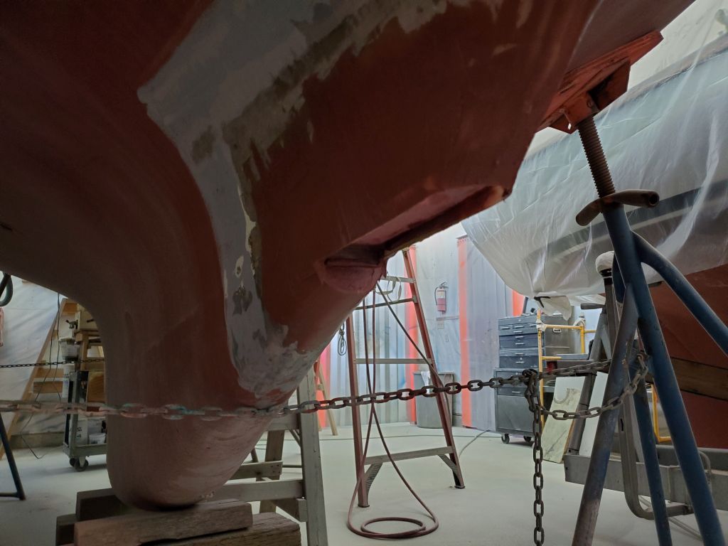
At the transducer housing, I lightly sanded the new fiberglass from last time; then, after cleaning up, I applied fairing compound to smooth the area and fill and form some of the last remaining contours to blend the new housing in with the adjacent hull and keel, which was needed before I could do the structural fiberglass and then fair the whole thing its final time(s).
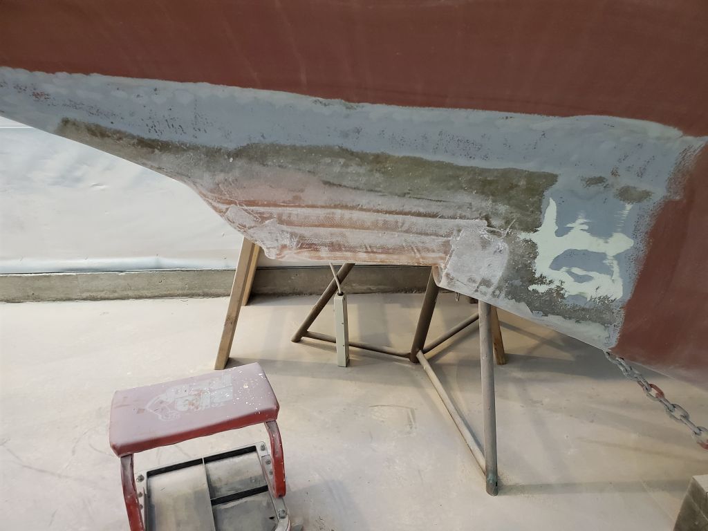

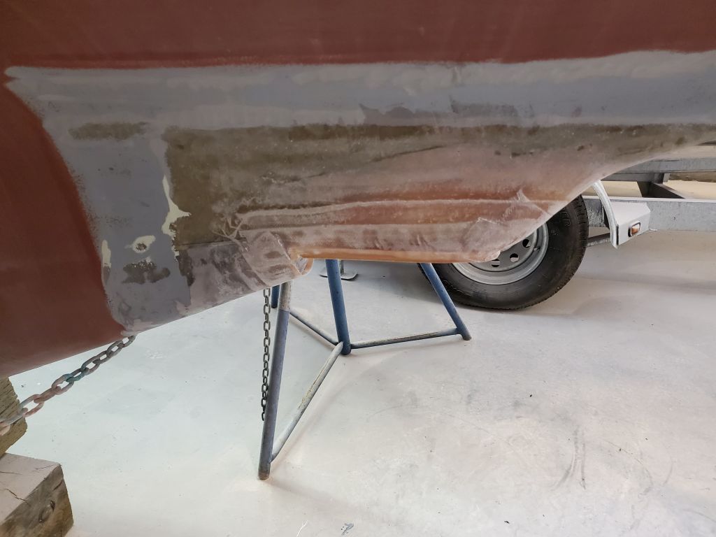


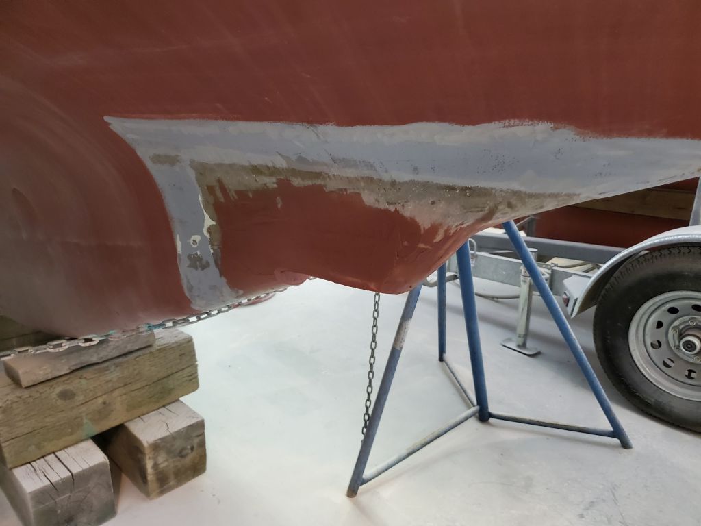
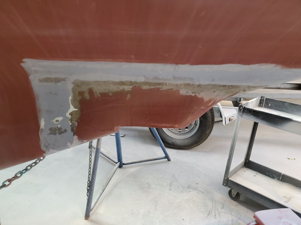
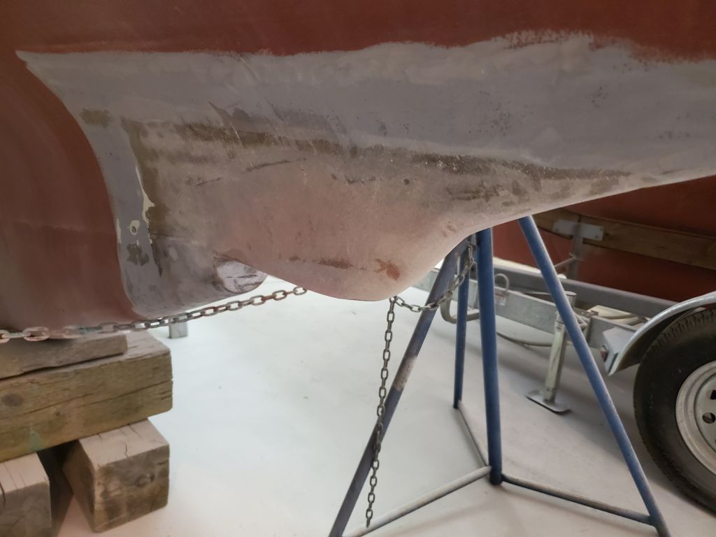
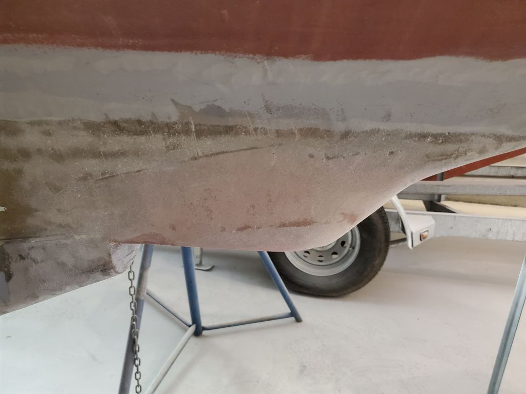
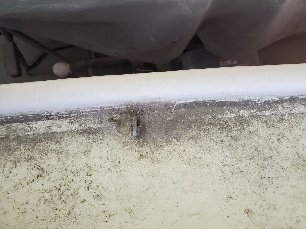
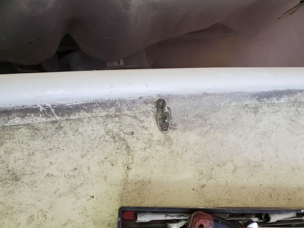
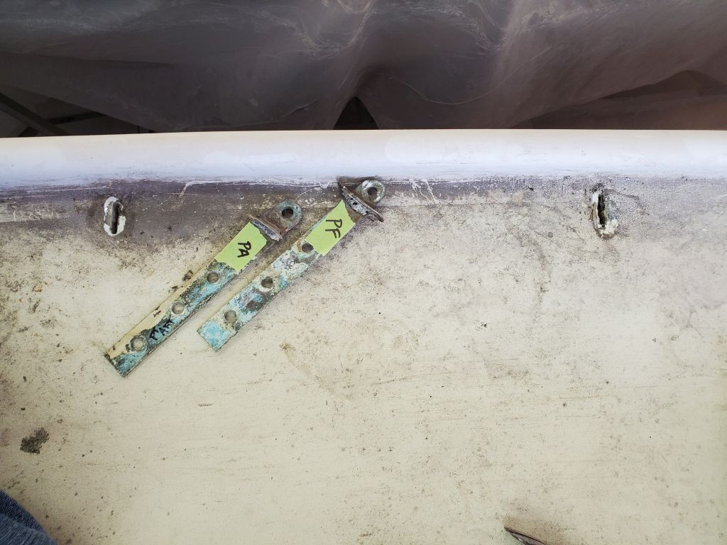
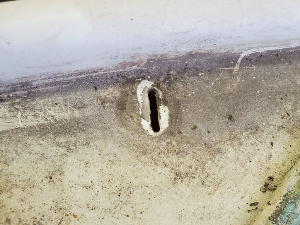
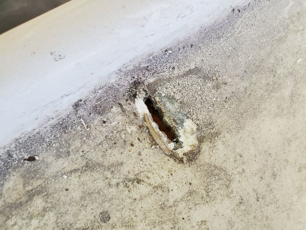
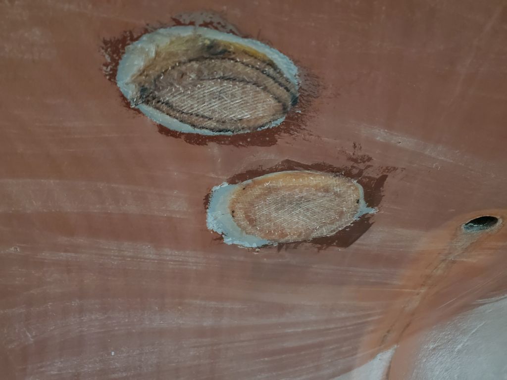
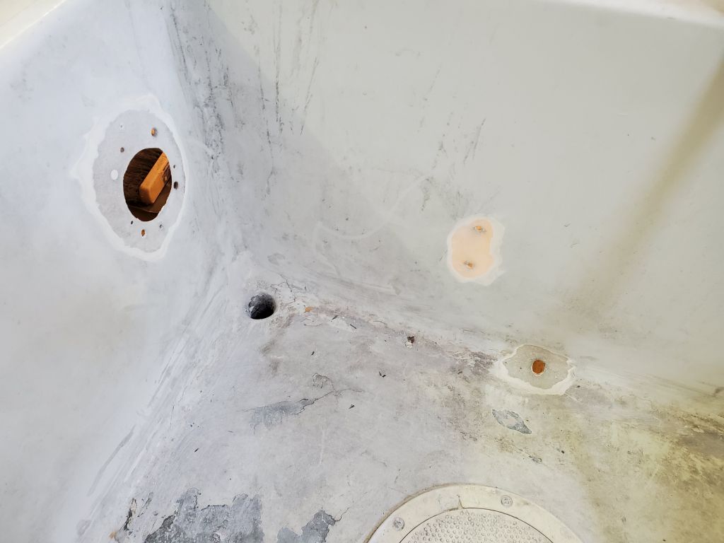
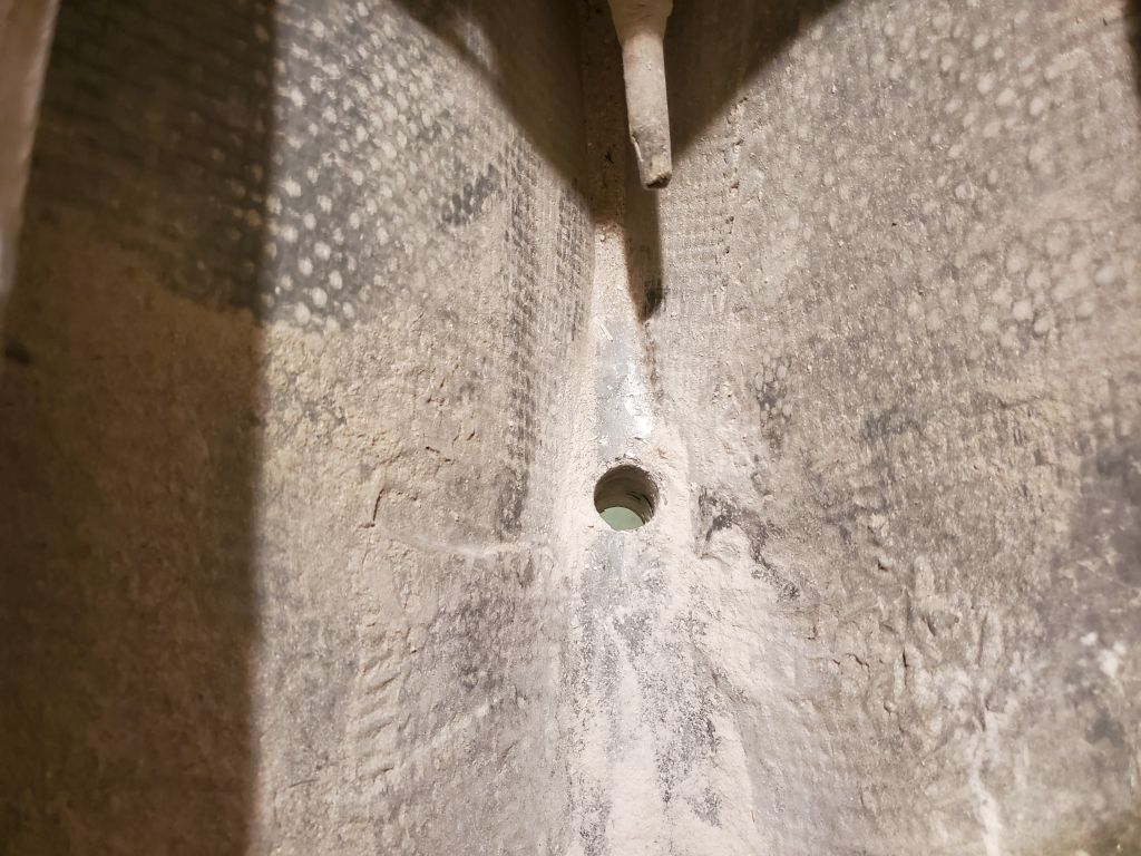
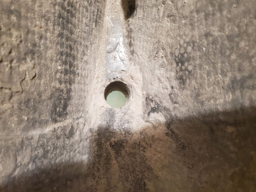
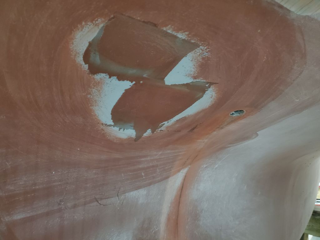
With some leftover fairing compound, I applied a first coat to the two through hulls I’d patched on the starboard aft part of the hull.
With that, it was about all I could do right at the moment, so I finished up the day working on another project at the shop.
Total time billed on this job today: 5.5 hours
0600 Weather Observation: 32°, mainly cloudy. Forecast for the day: Mostly cloudy, 36°.