Monday
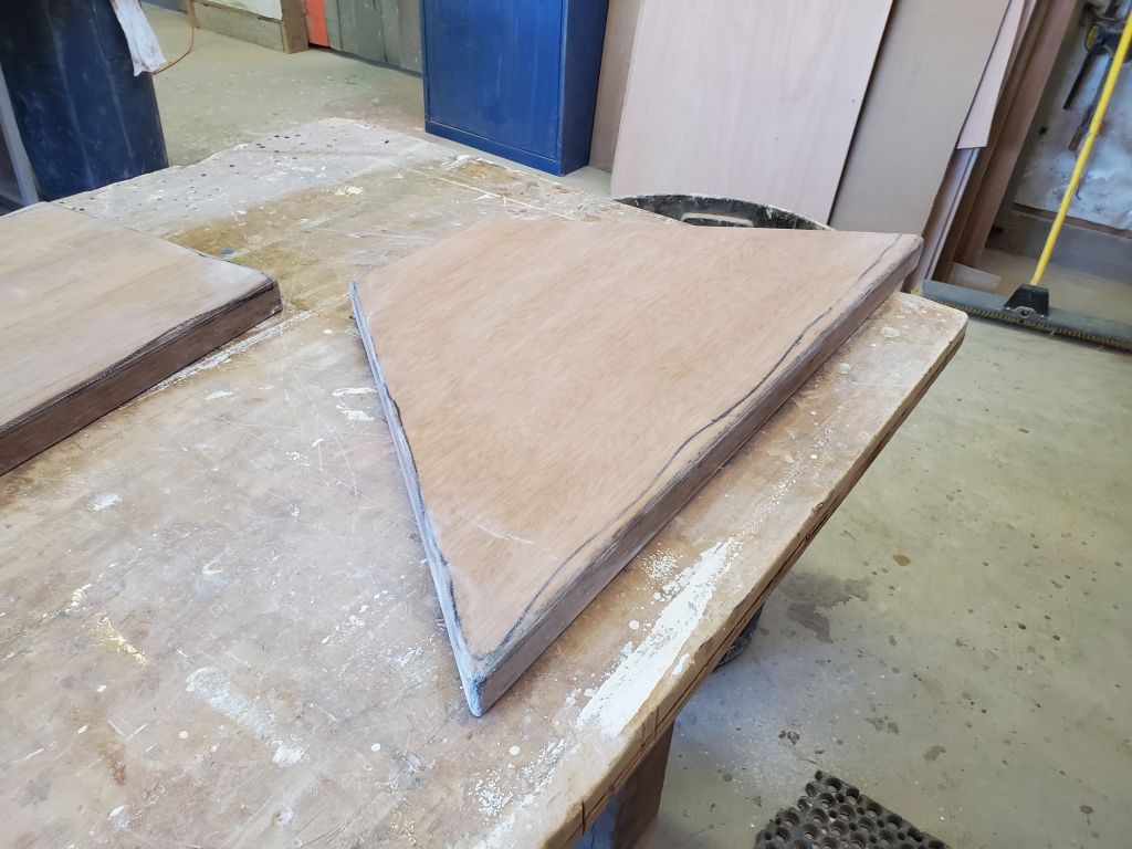
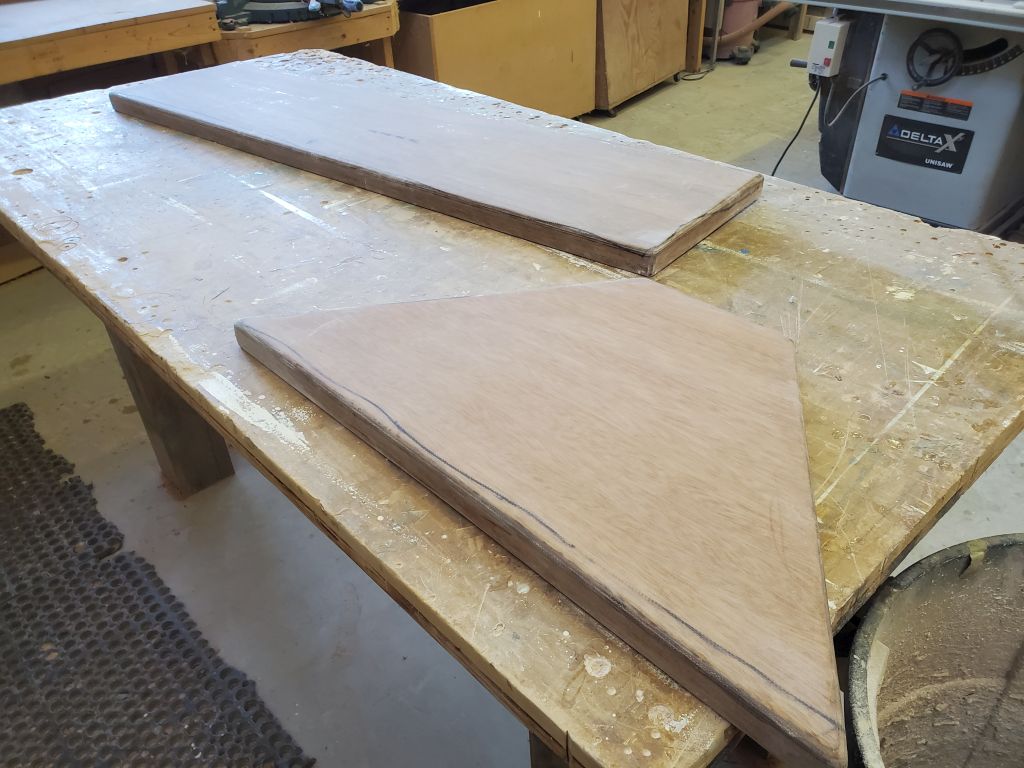
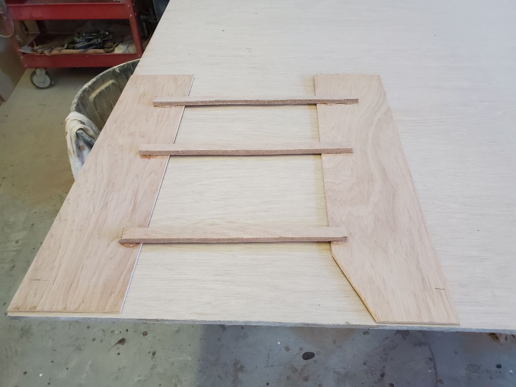
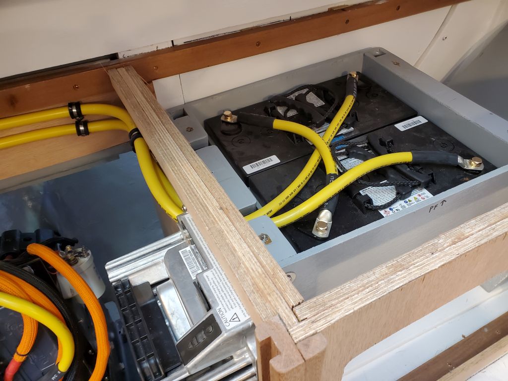
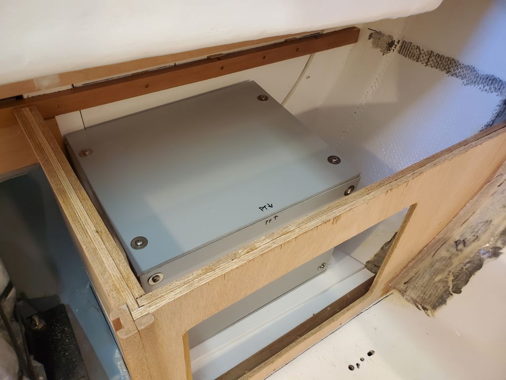
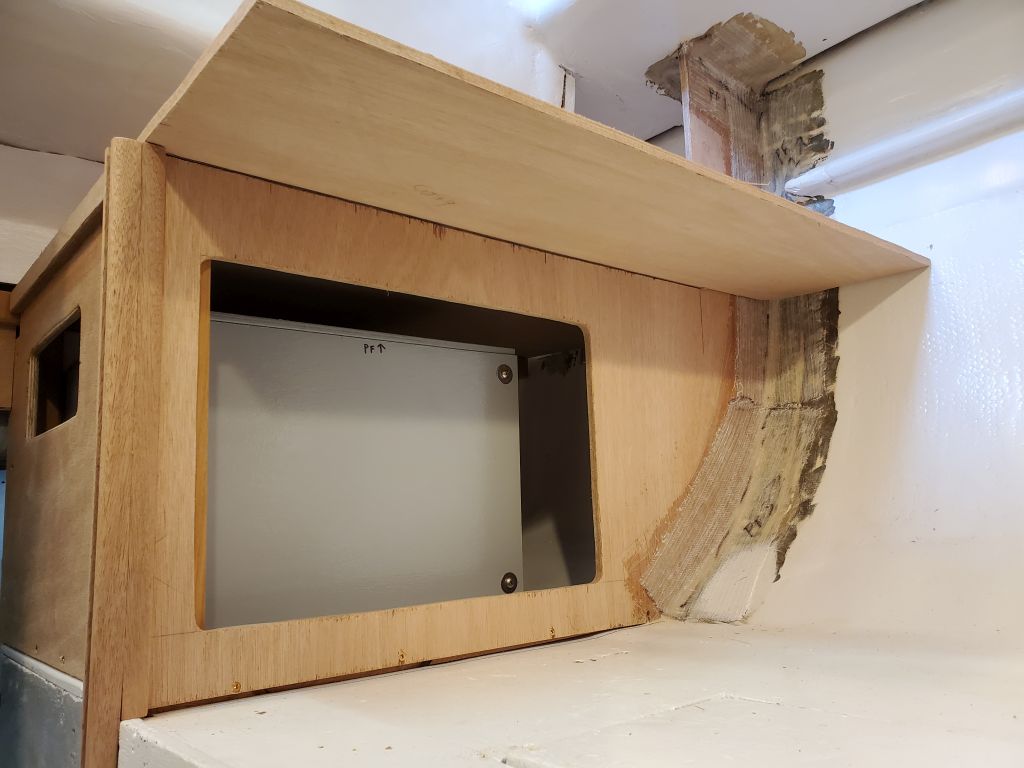
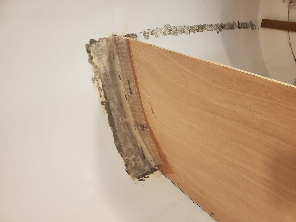
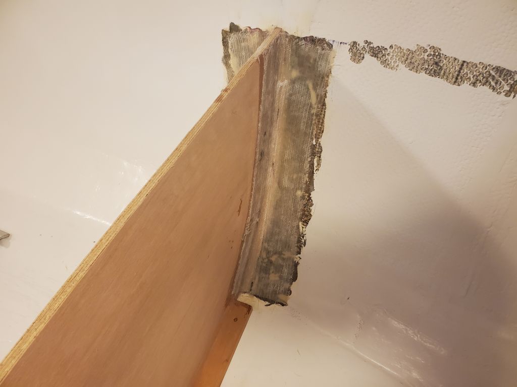
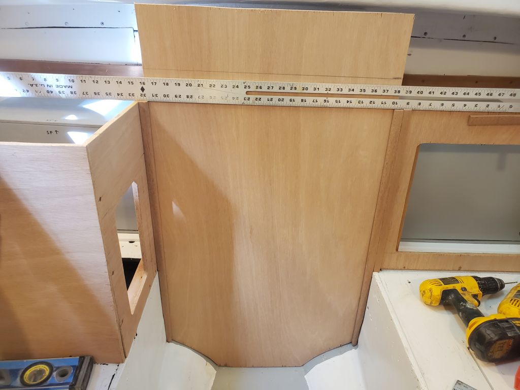
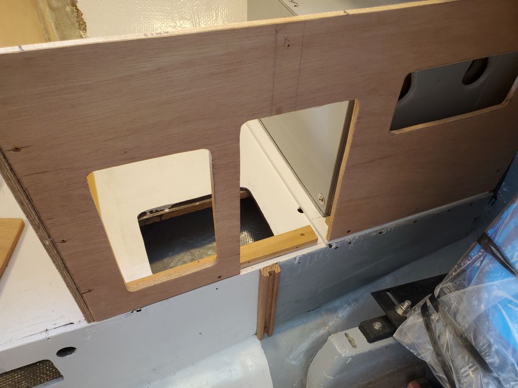
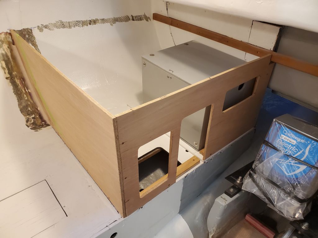
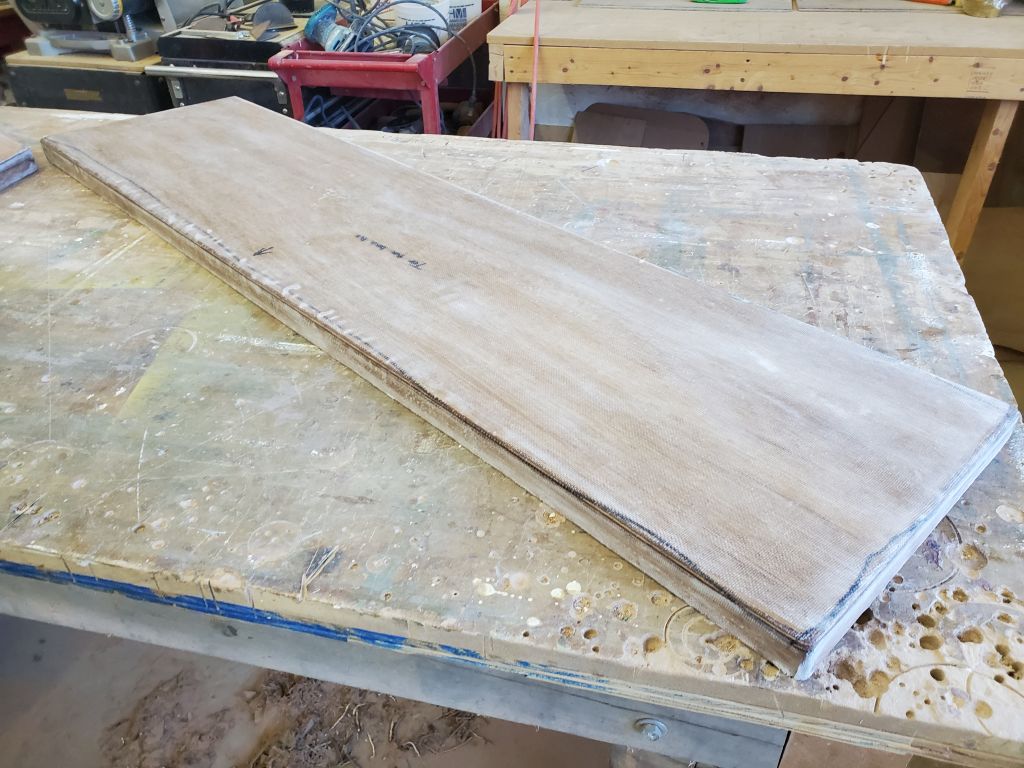
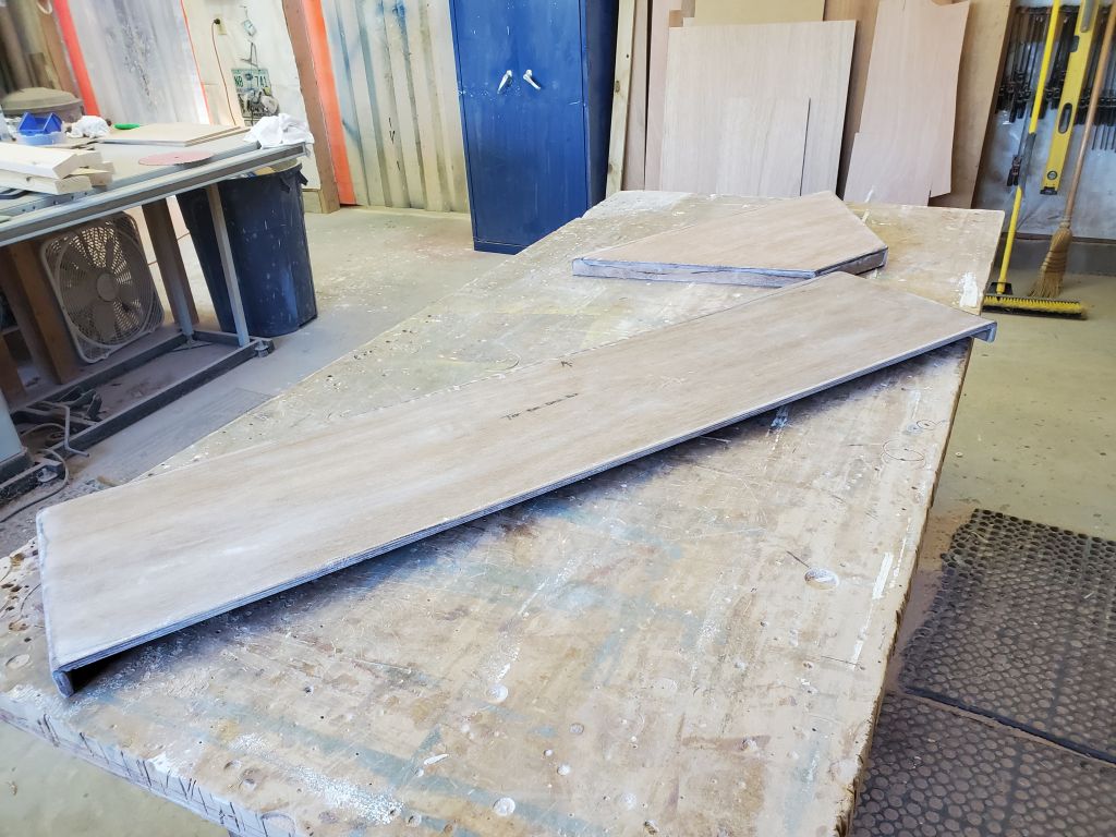
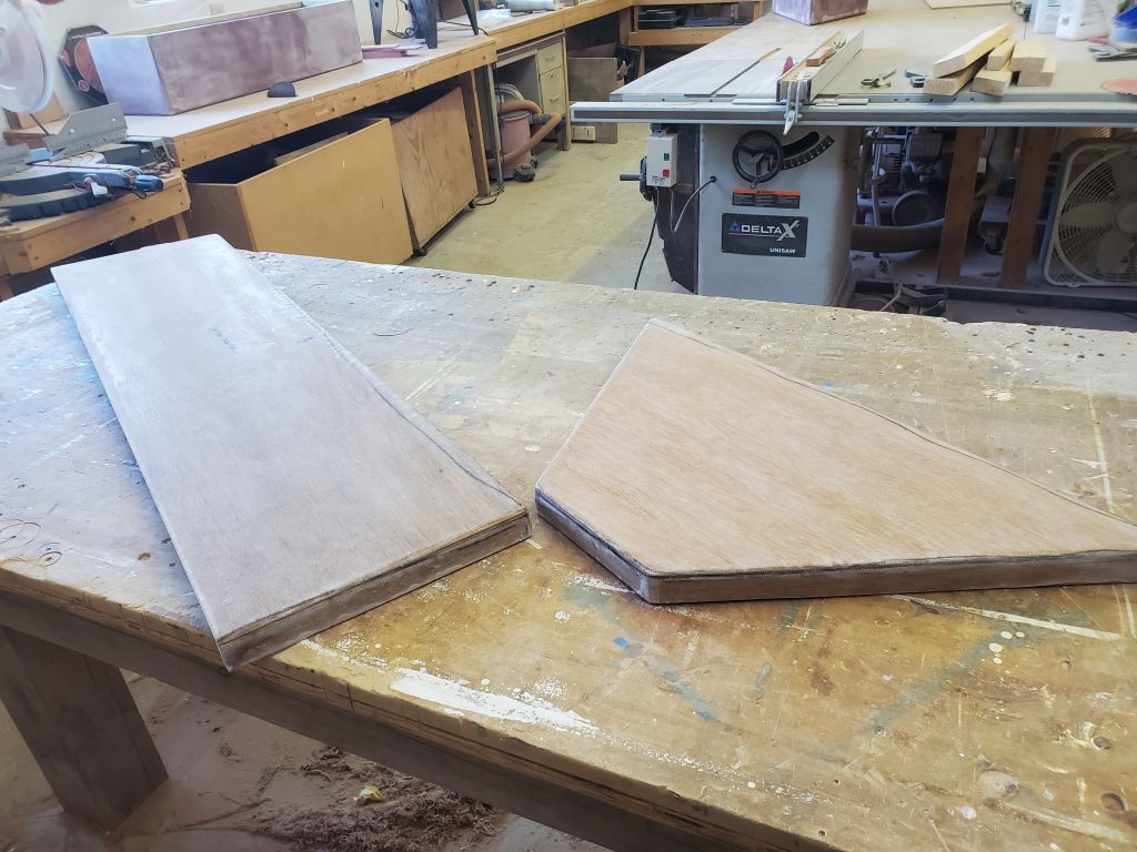
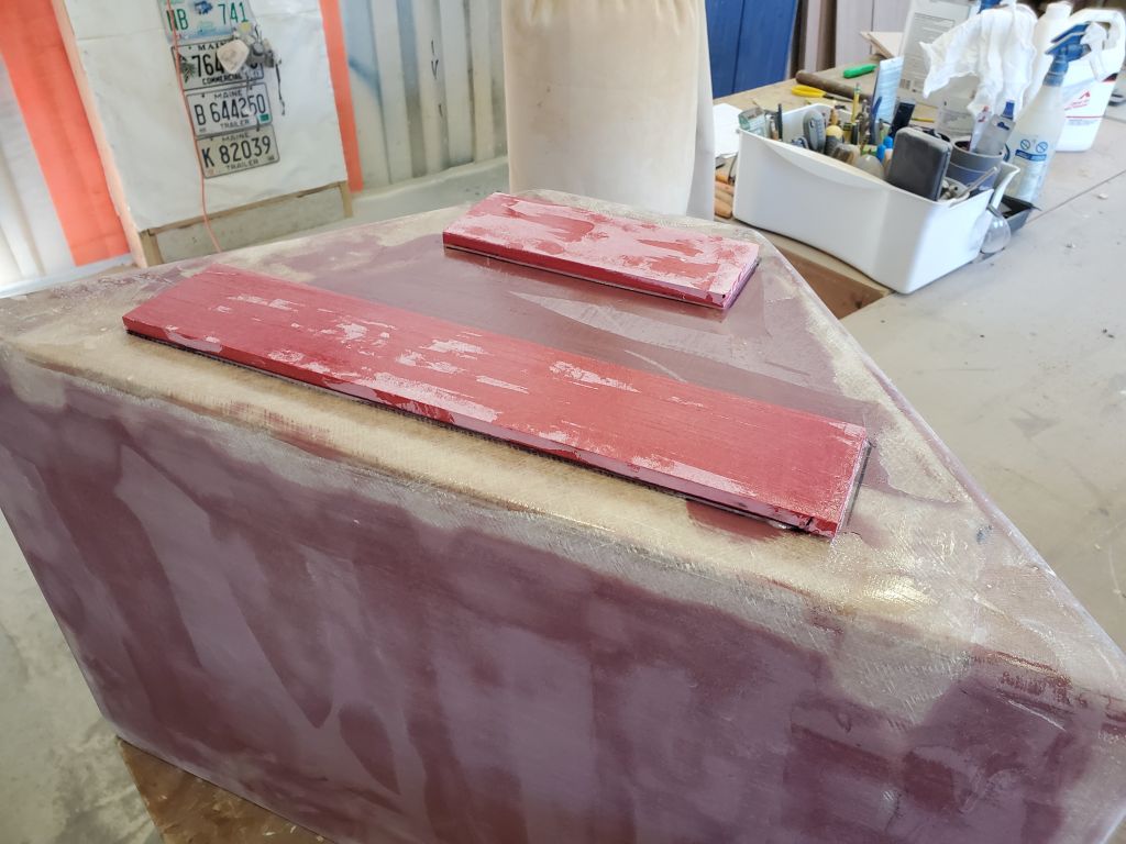
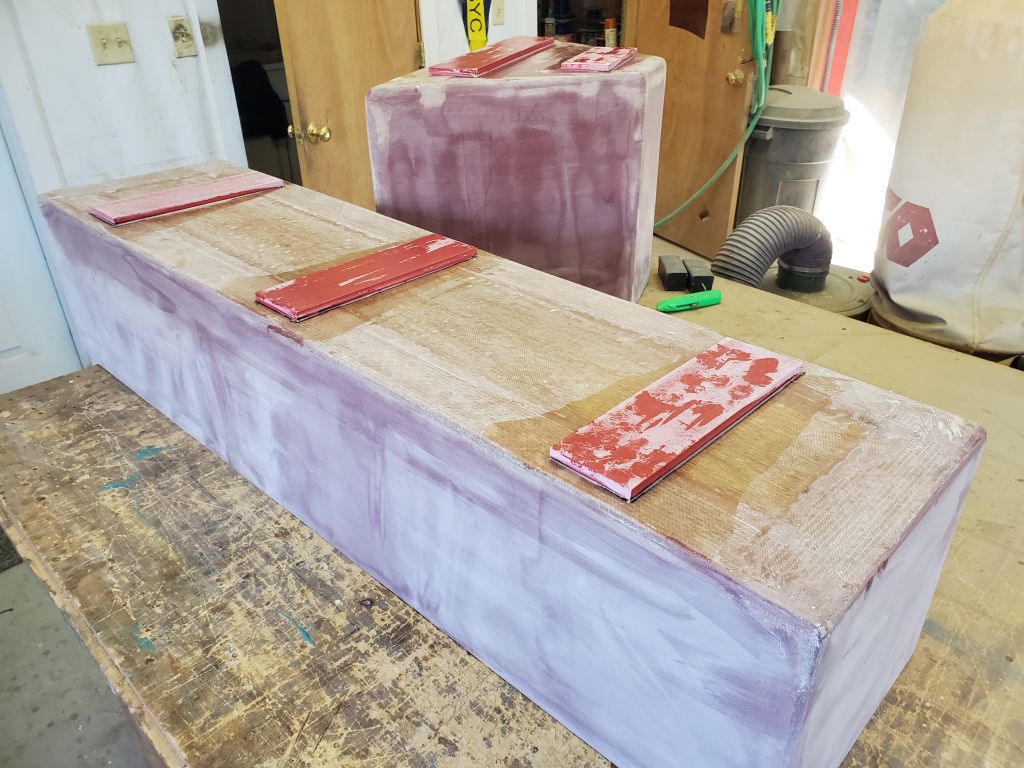
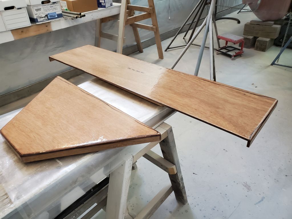
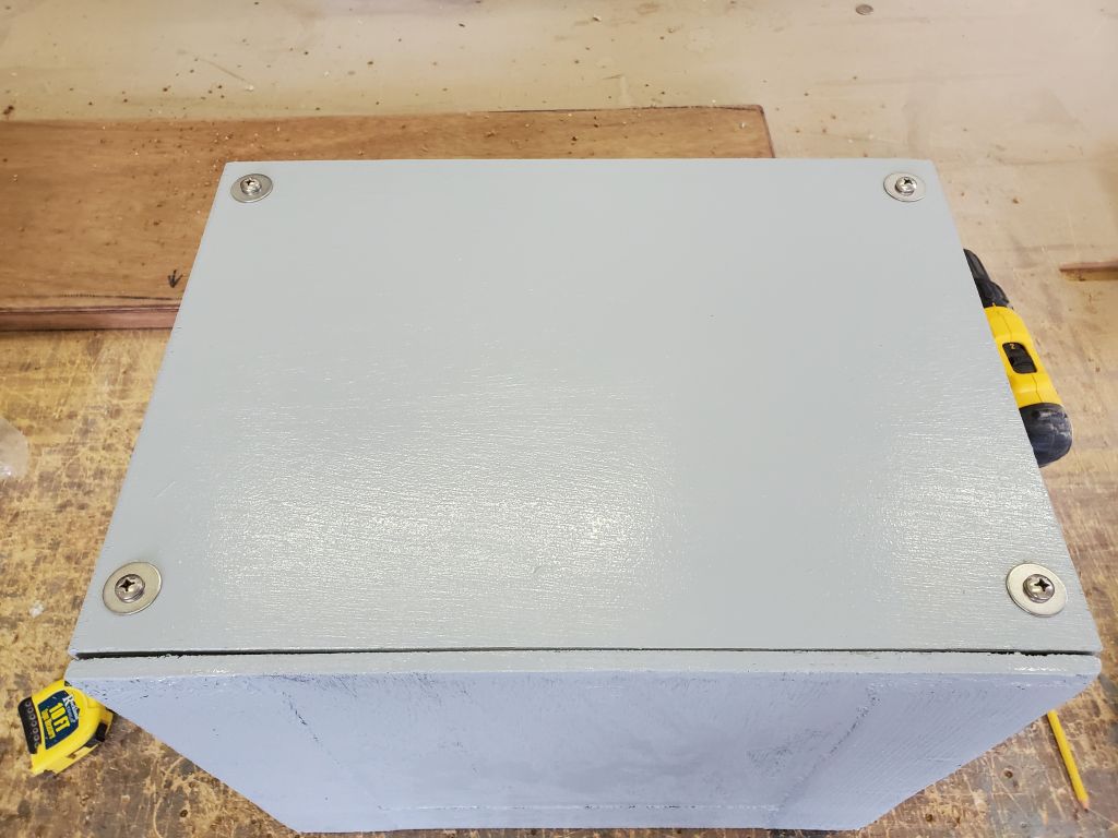
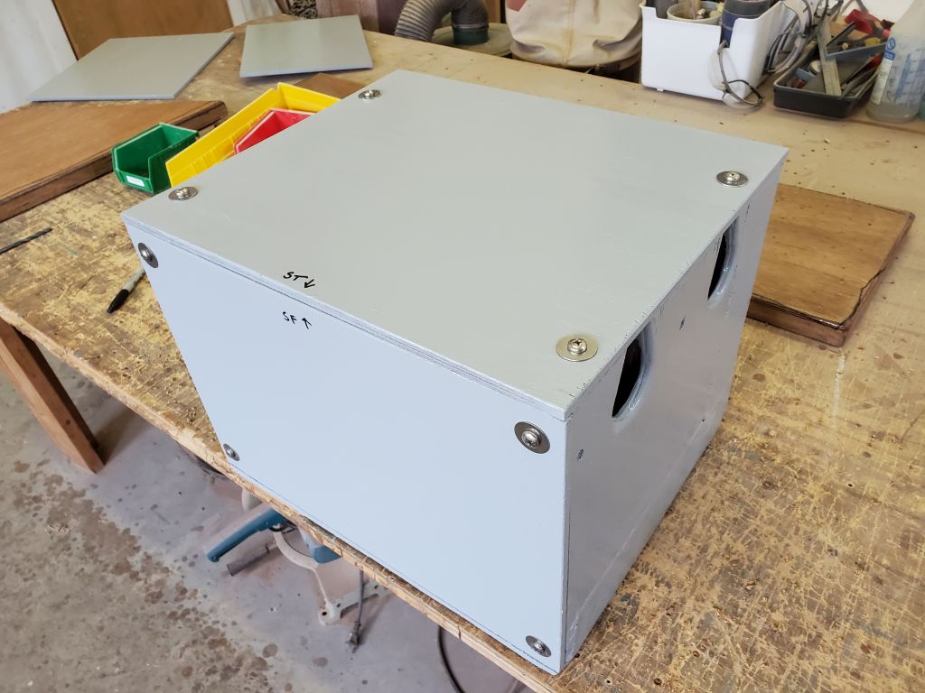
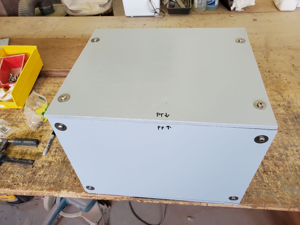
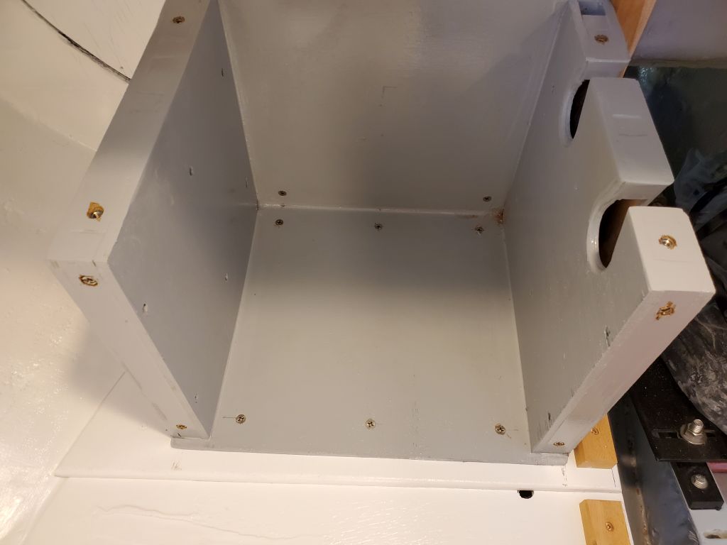
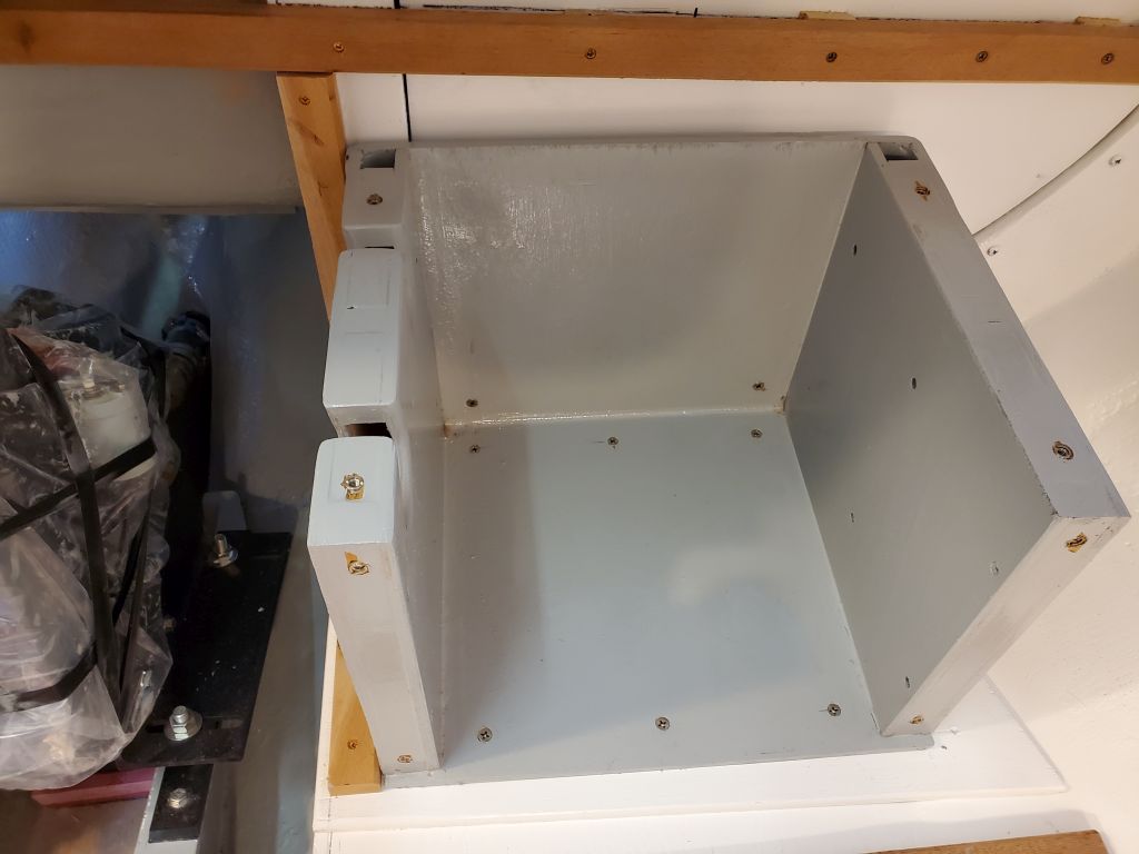
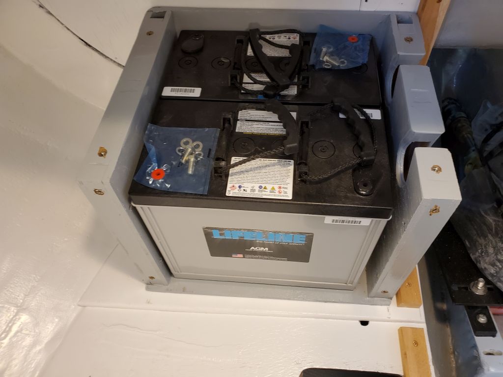
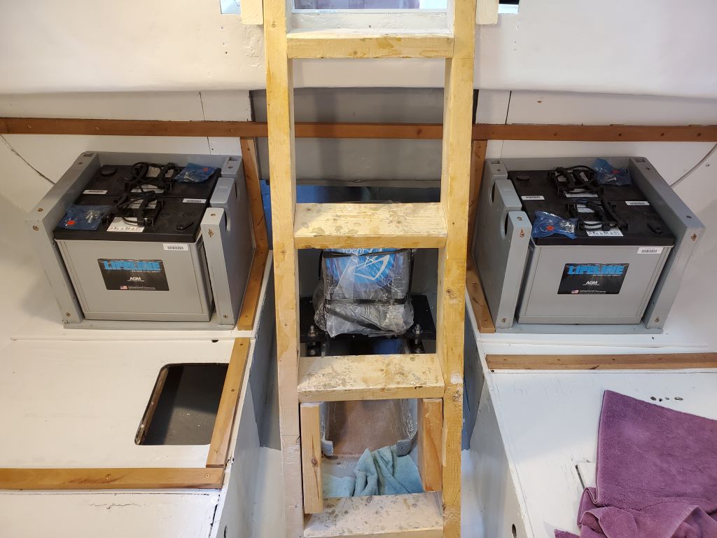
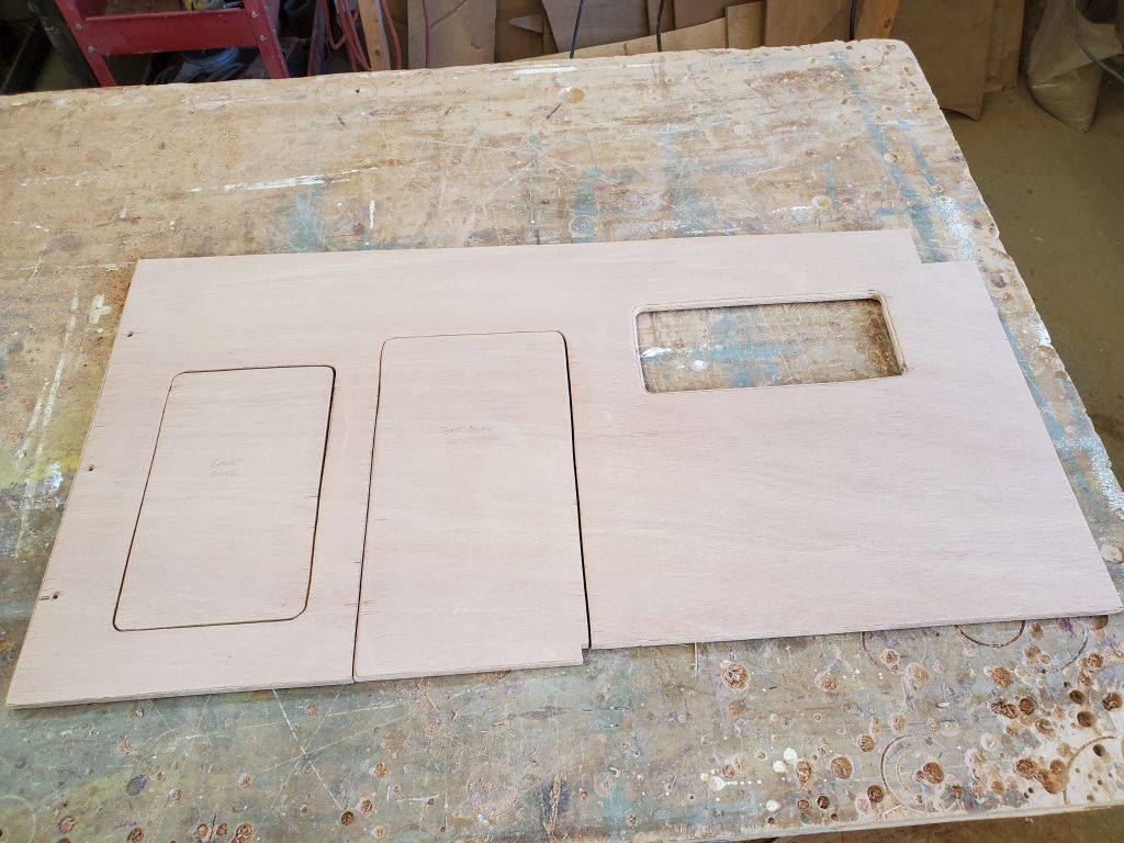
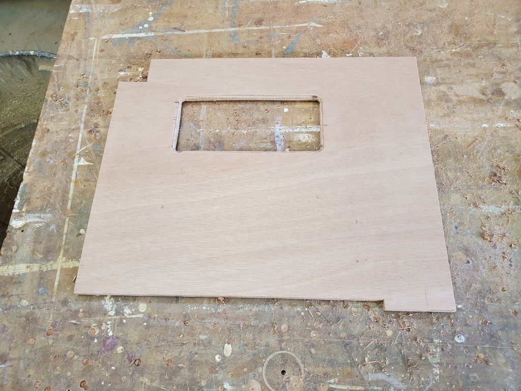
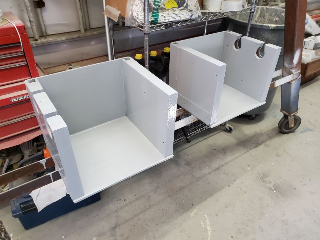
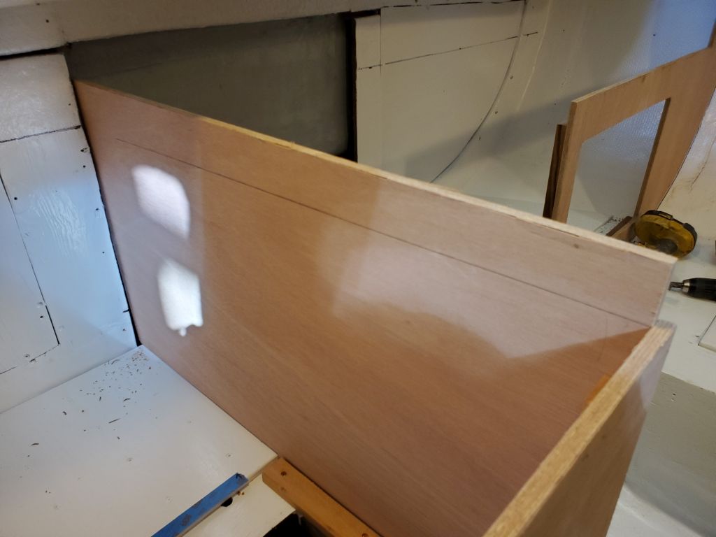
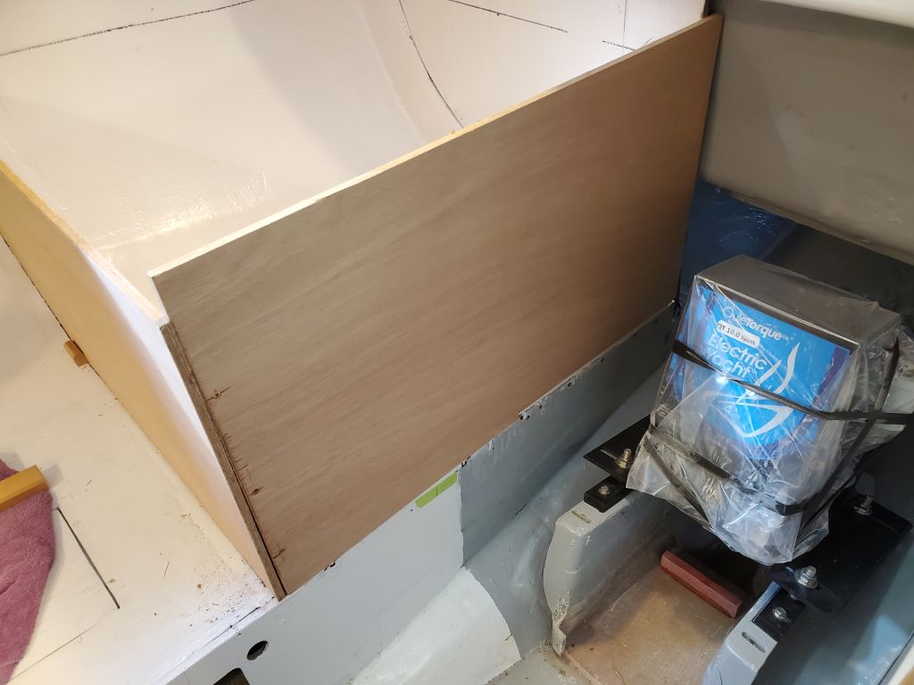
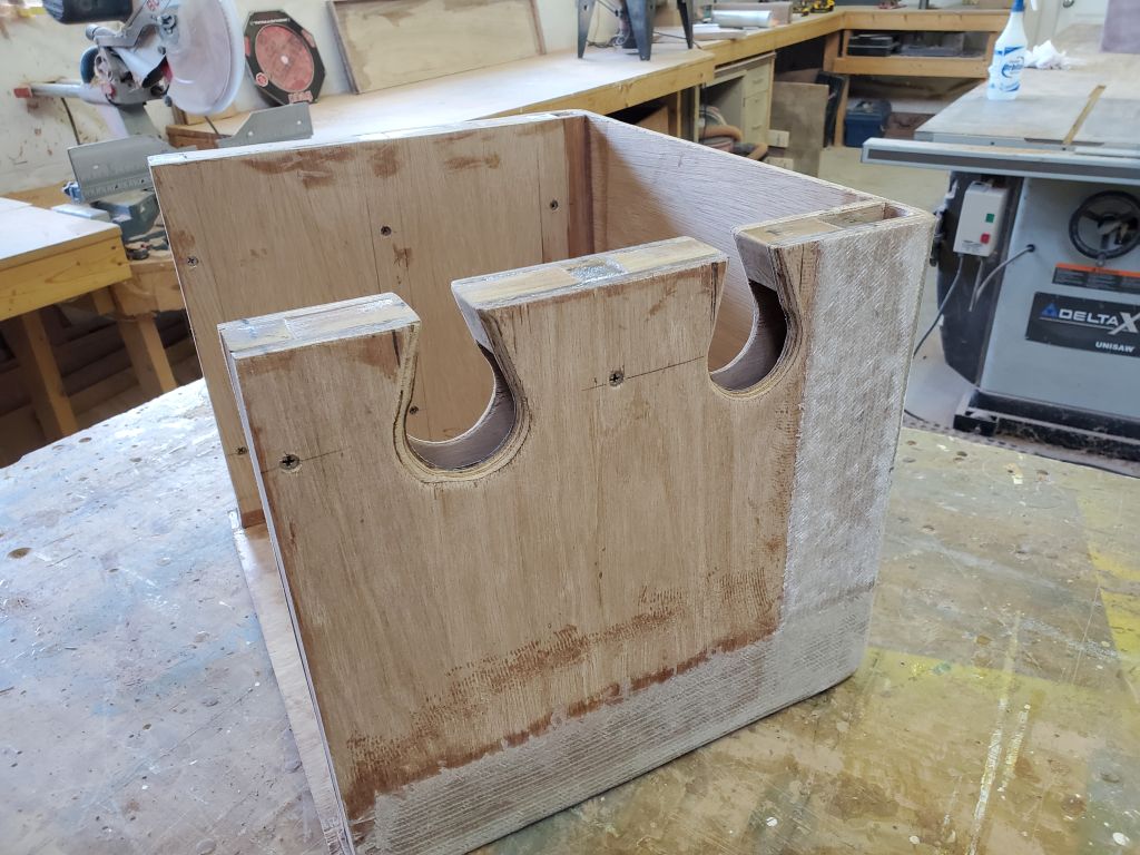
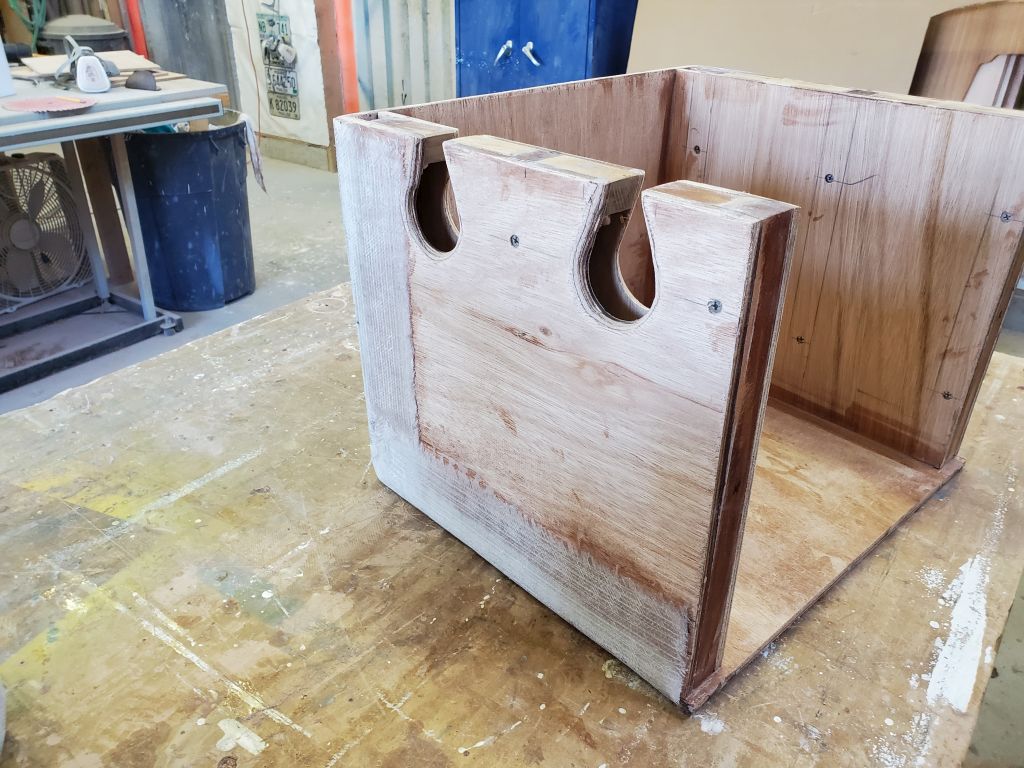
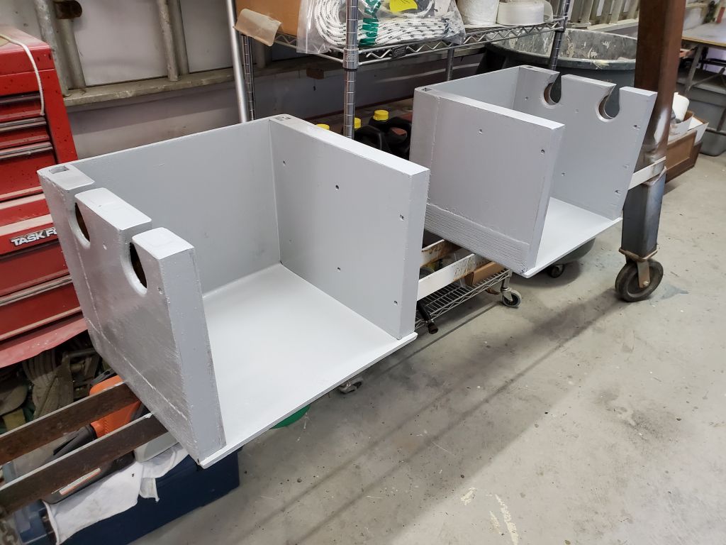
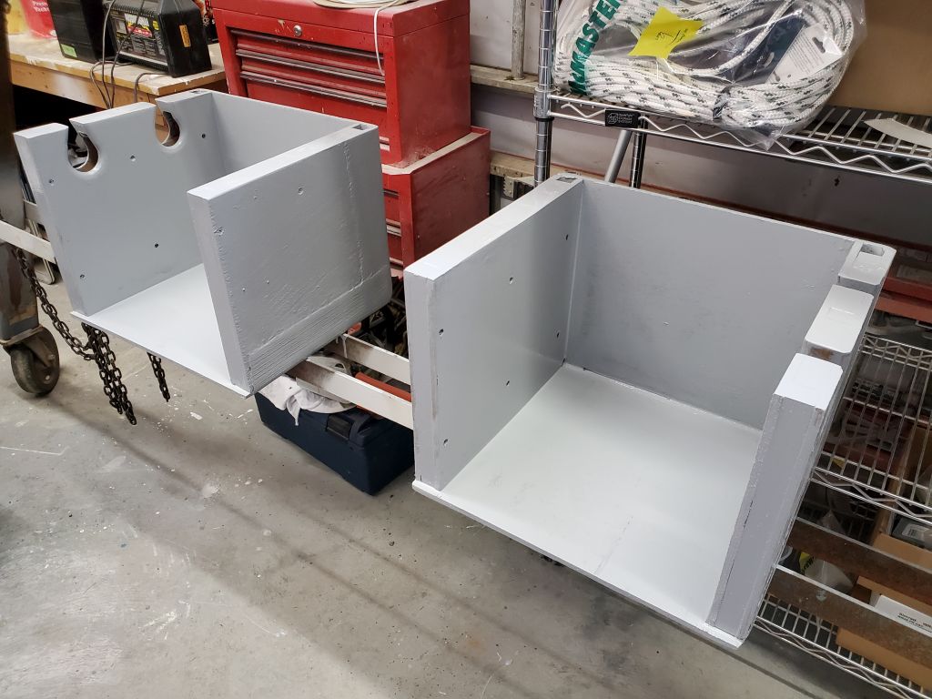
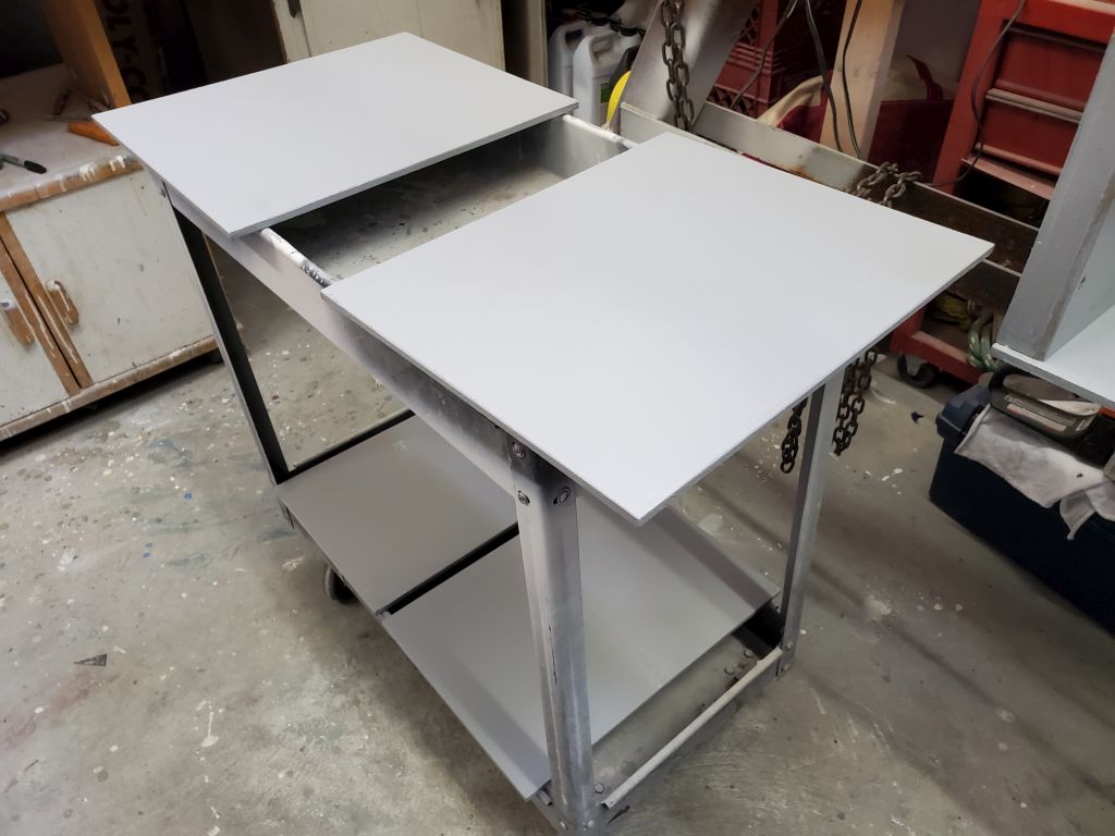
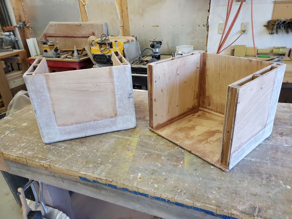
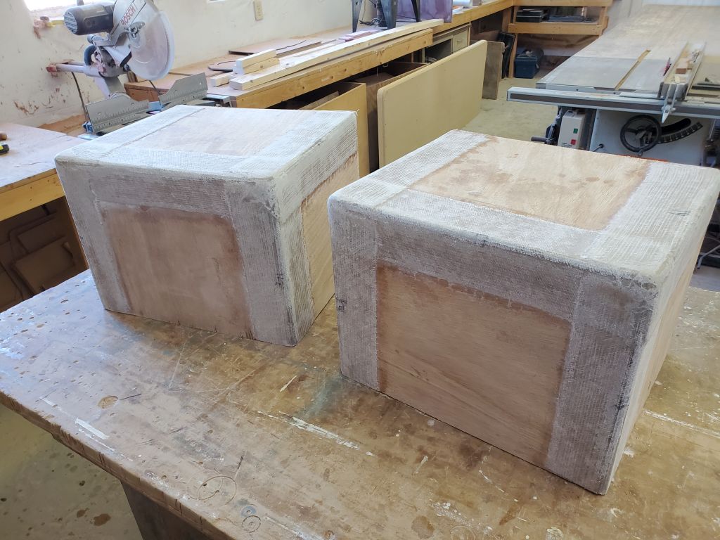
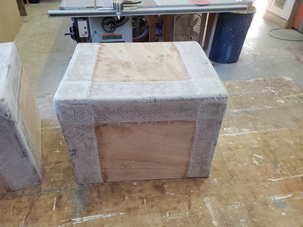
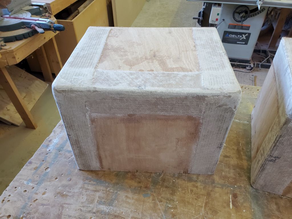
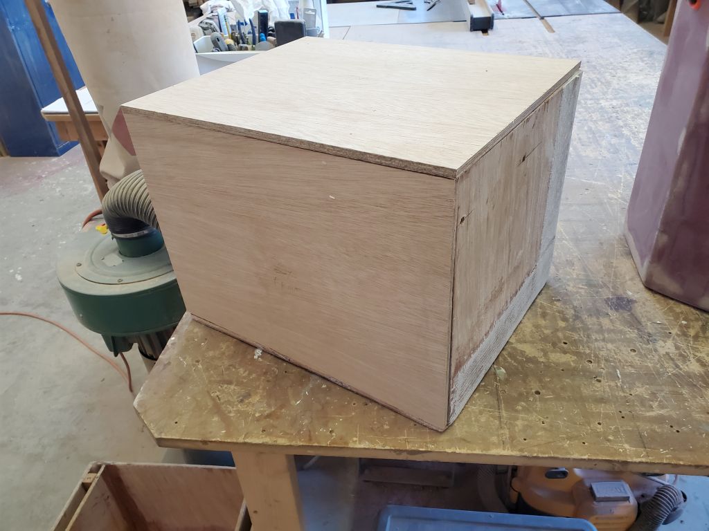
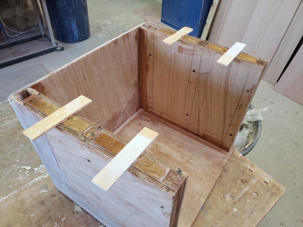
I lightly sanded the battery box tabbing as needed to prepare the boxes for their final construction steps and finishing. Afterwards, I dry-assembled the removable front and top panels to show the completed box; I’d finish the details on these panels soon, but was awaiting some materials.
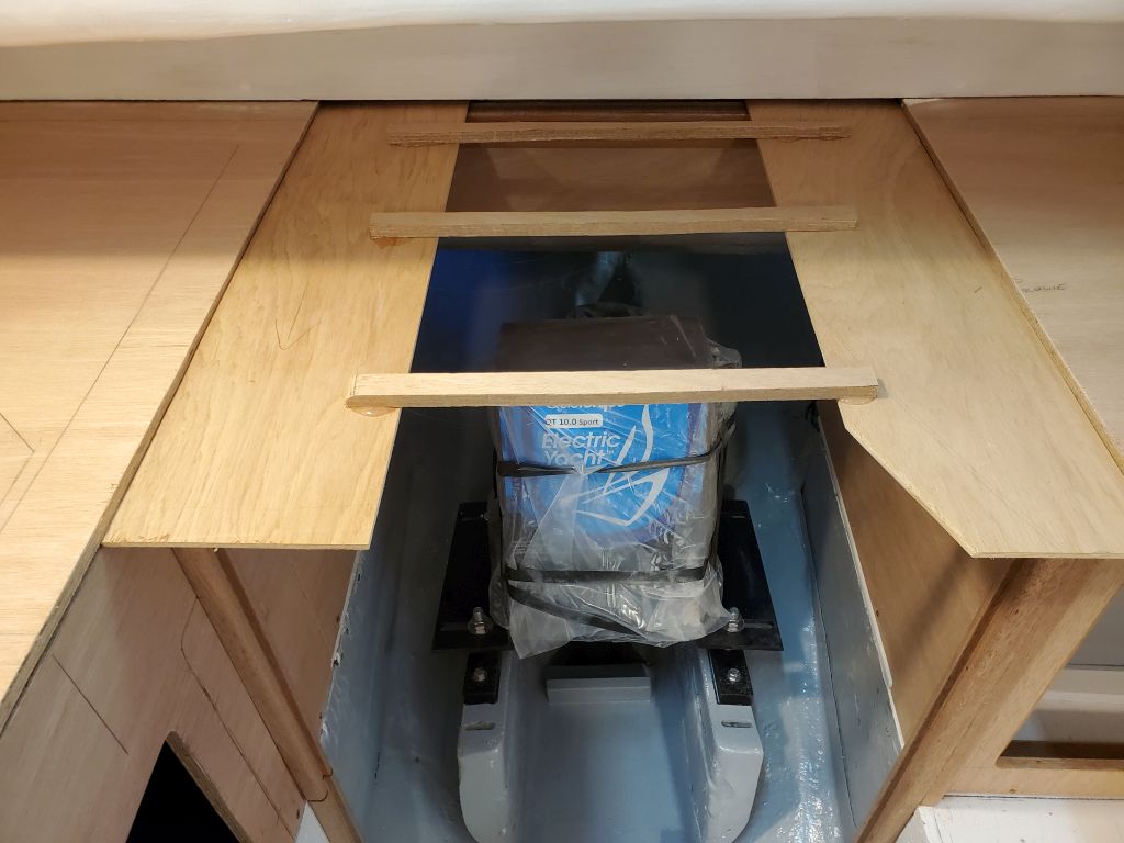
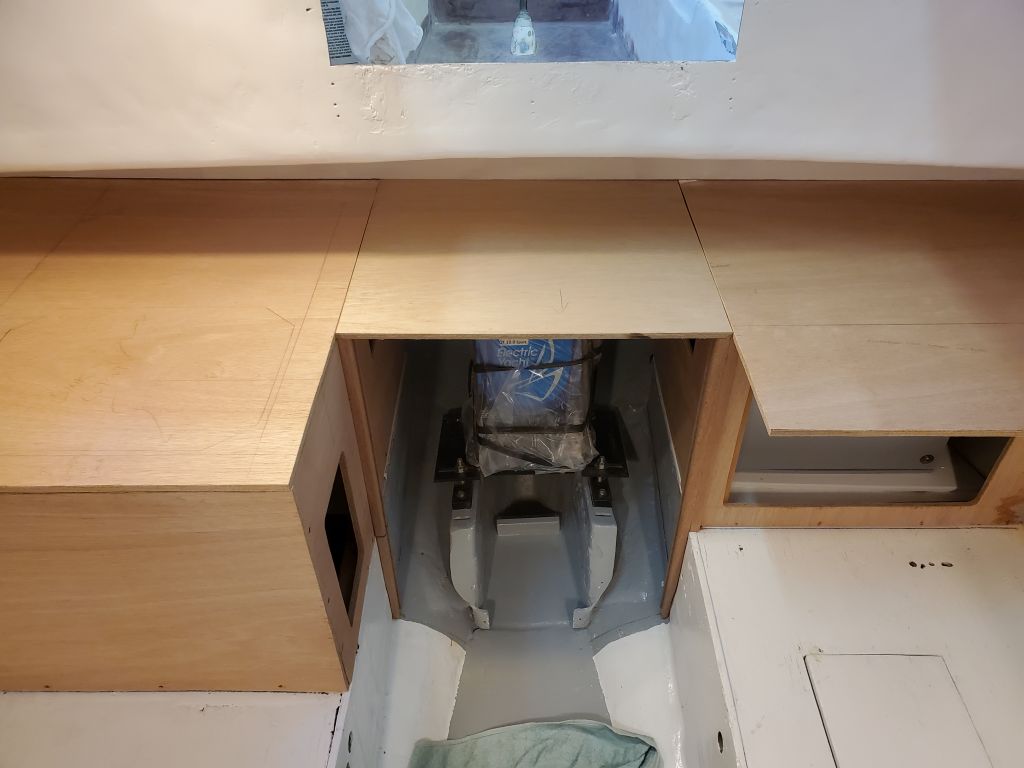
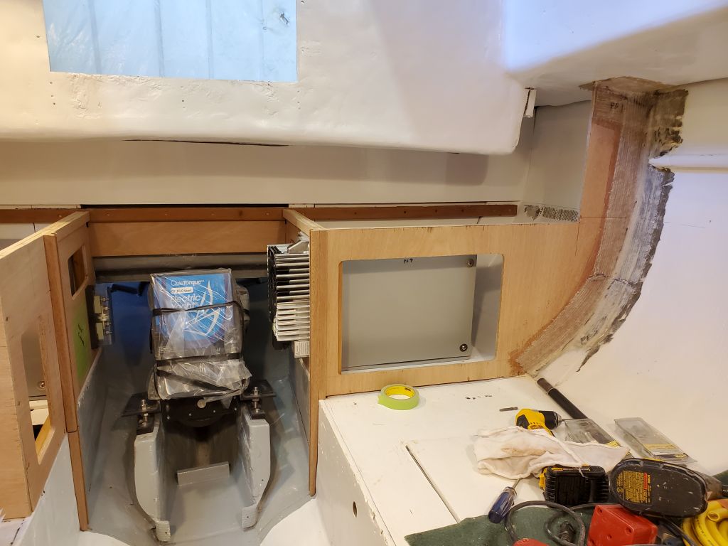
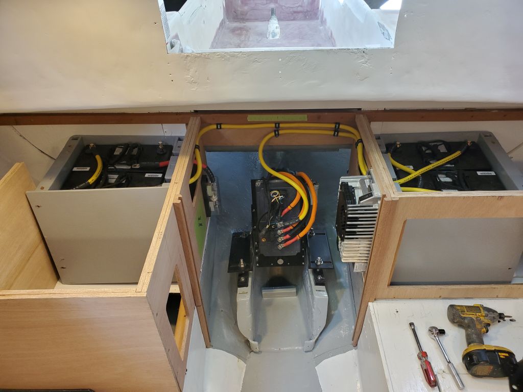
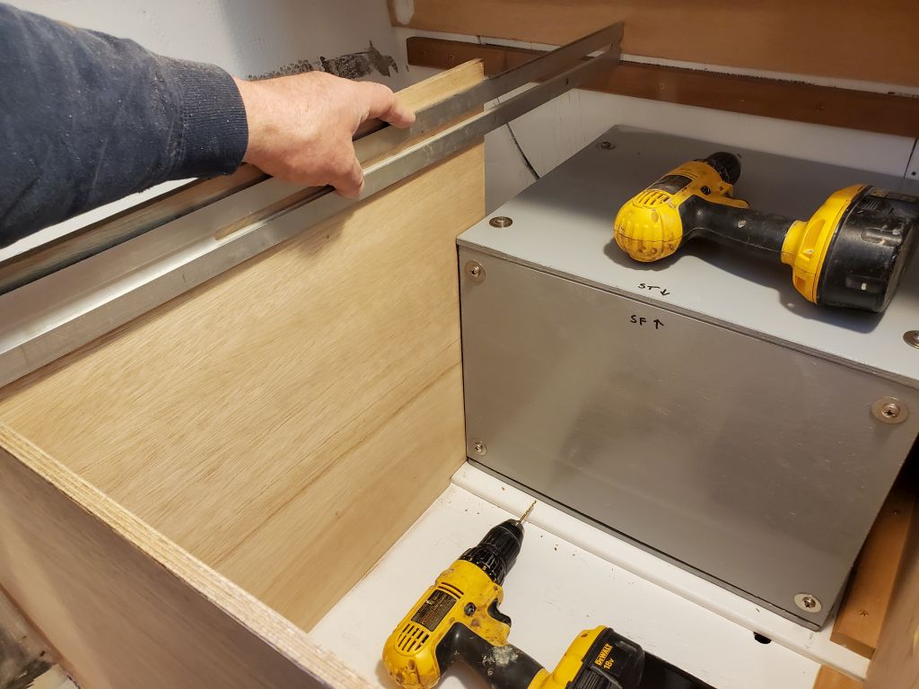
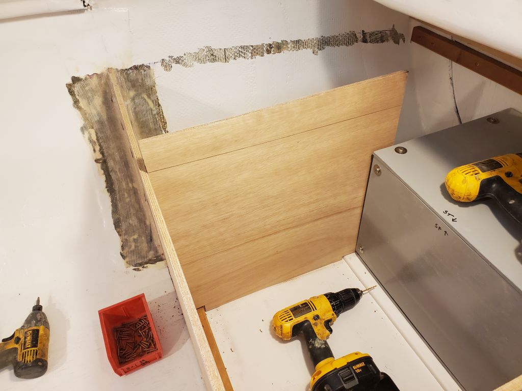
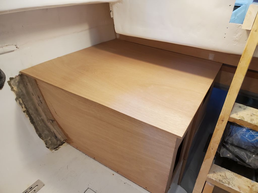
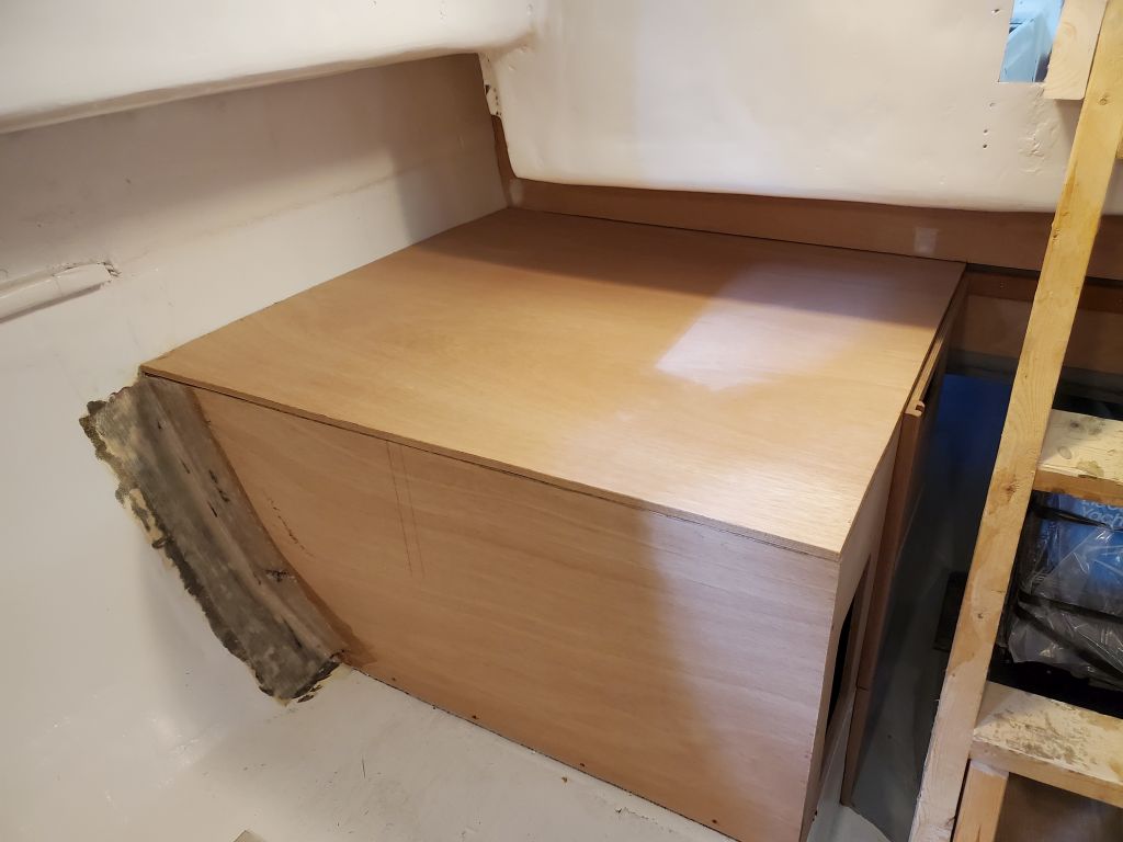
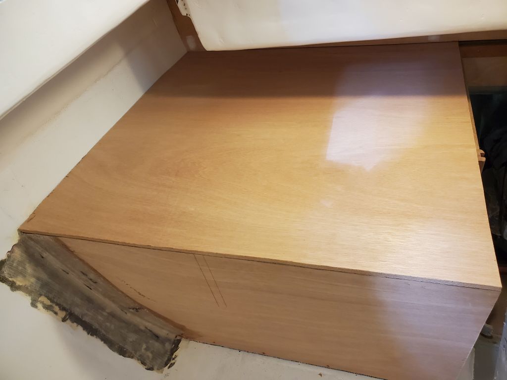
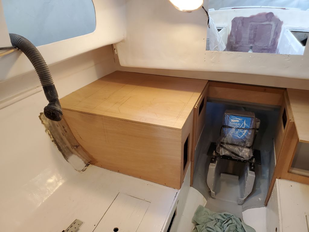
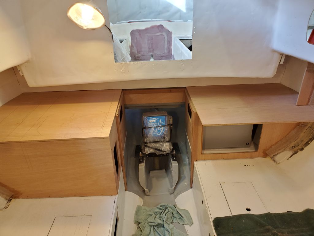
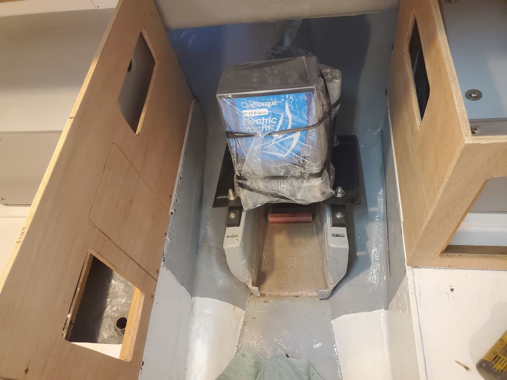
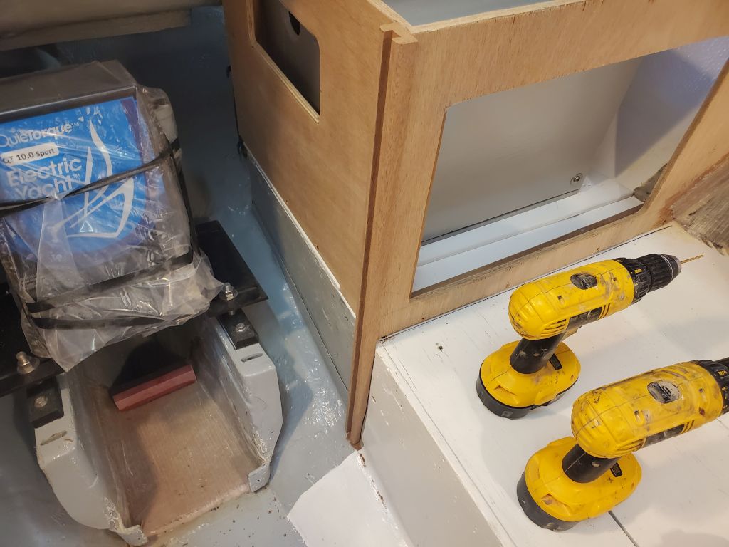
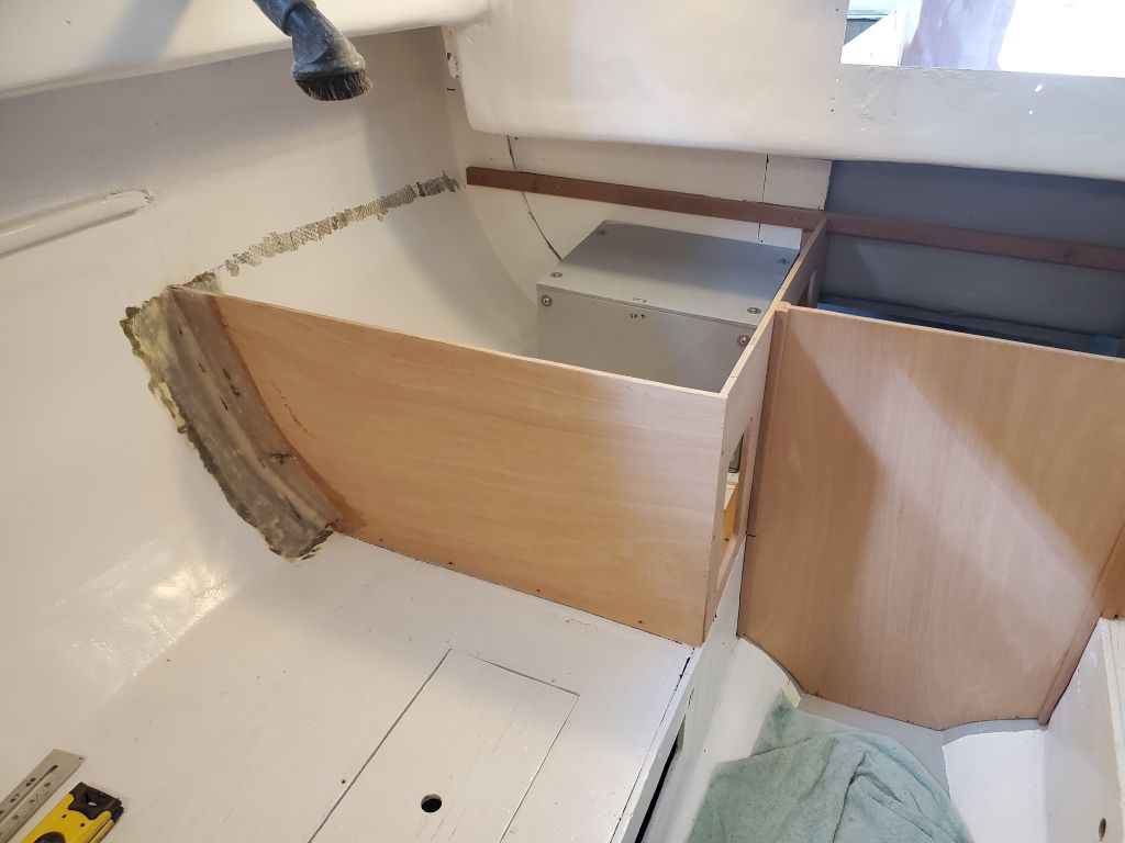
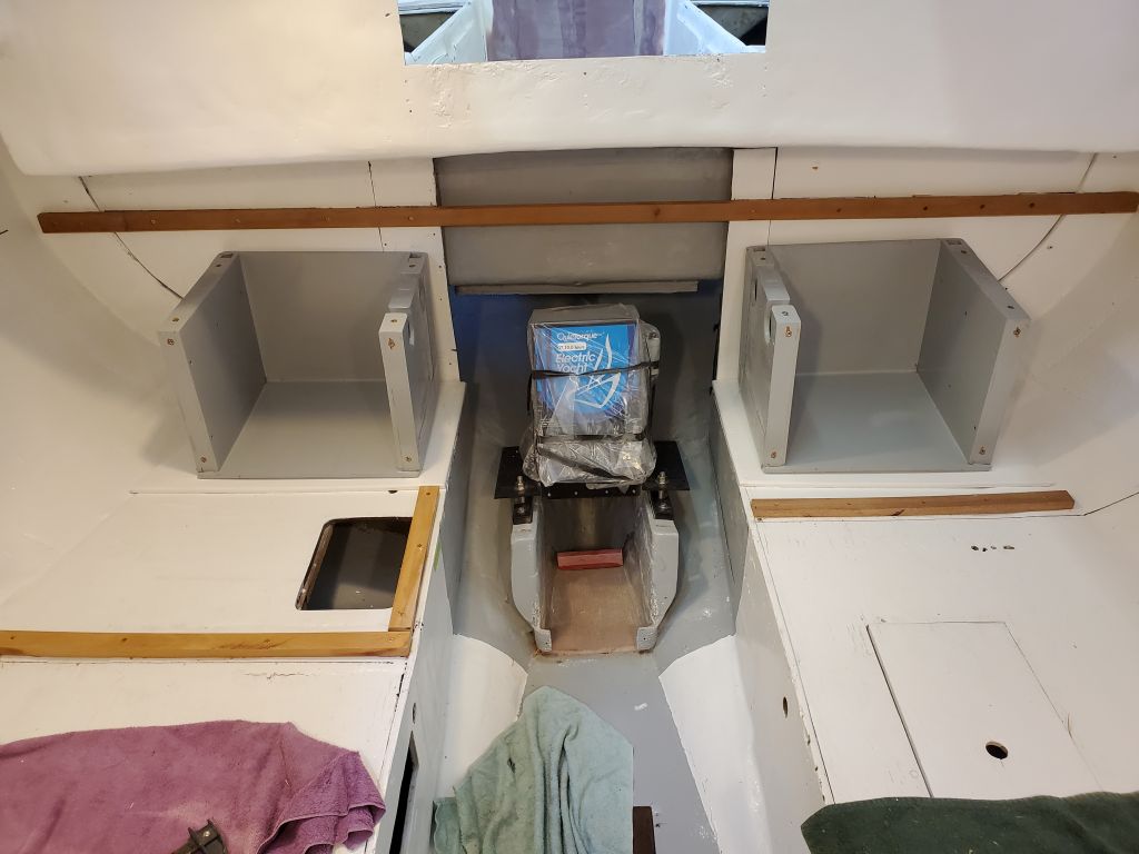
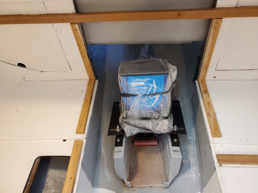
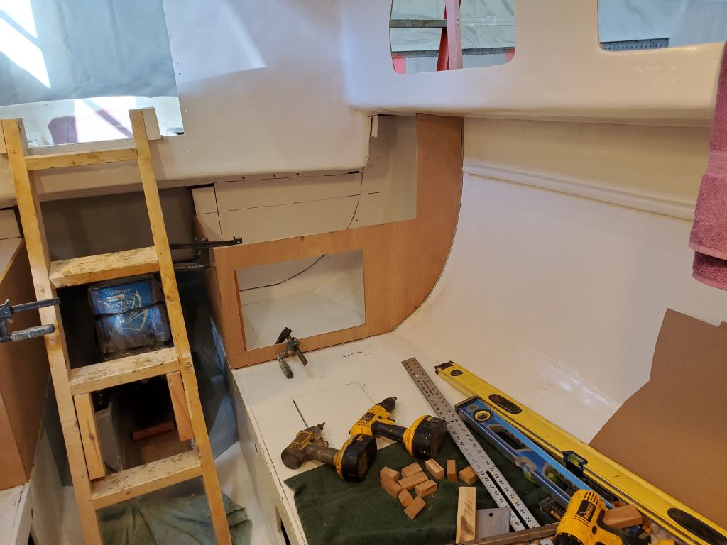
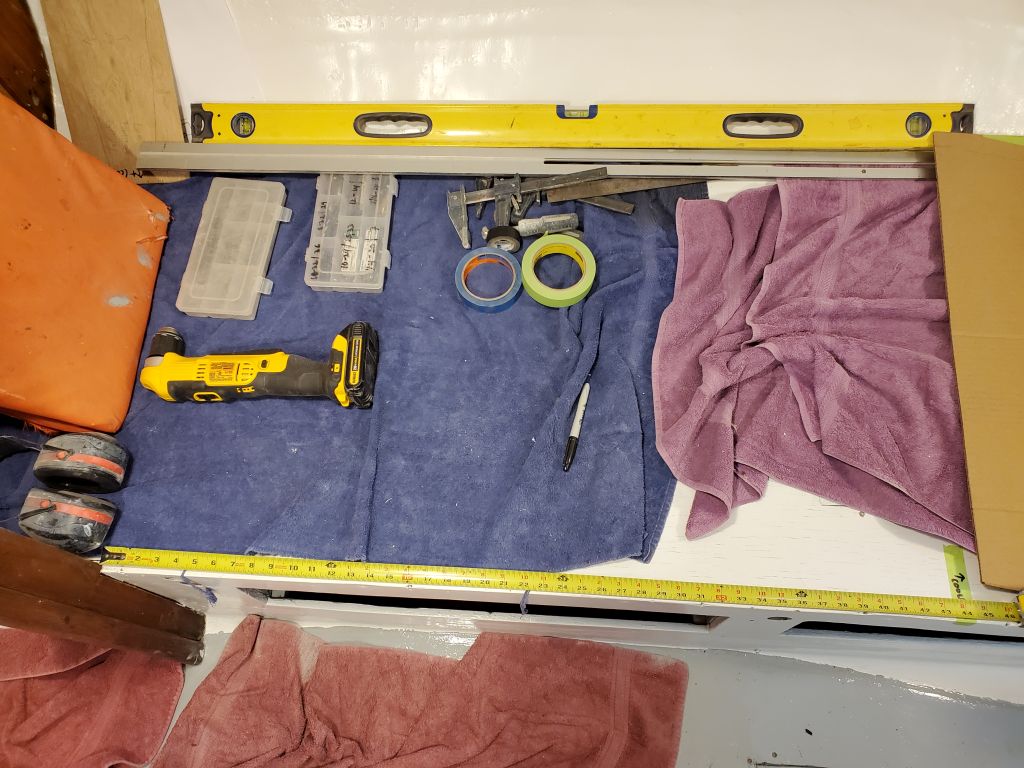
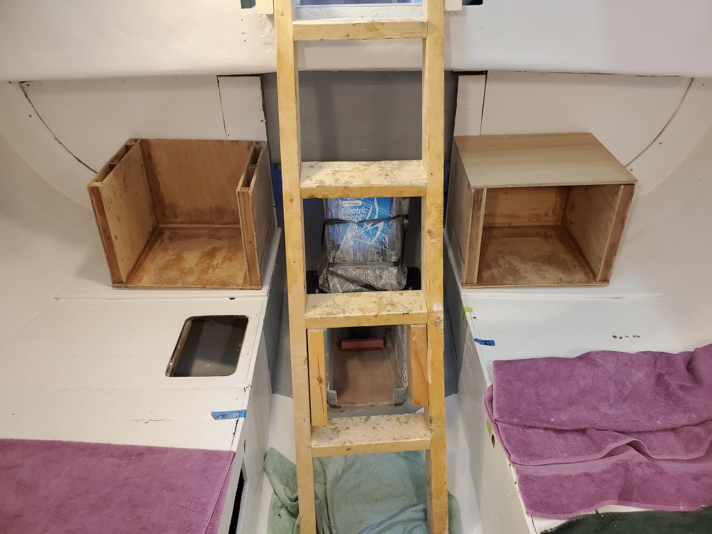
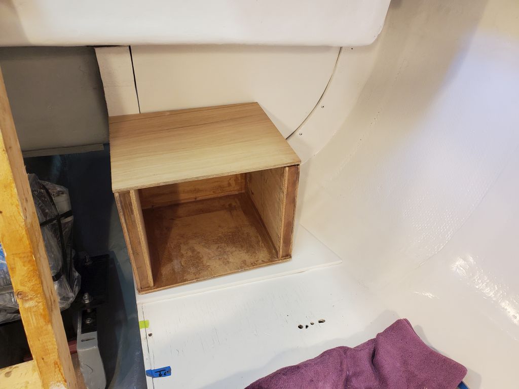
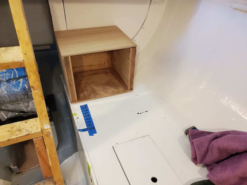
Bringing the boxes and a lid into the boat, I could begin some of the critical galley layout. The large battery boxes, and maintaining access thereunto, was to be a substantial factor in determining various details of the galley cabinetry, along with myriad other considerations, limitations, and desires.
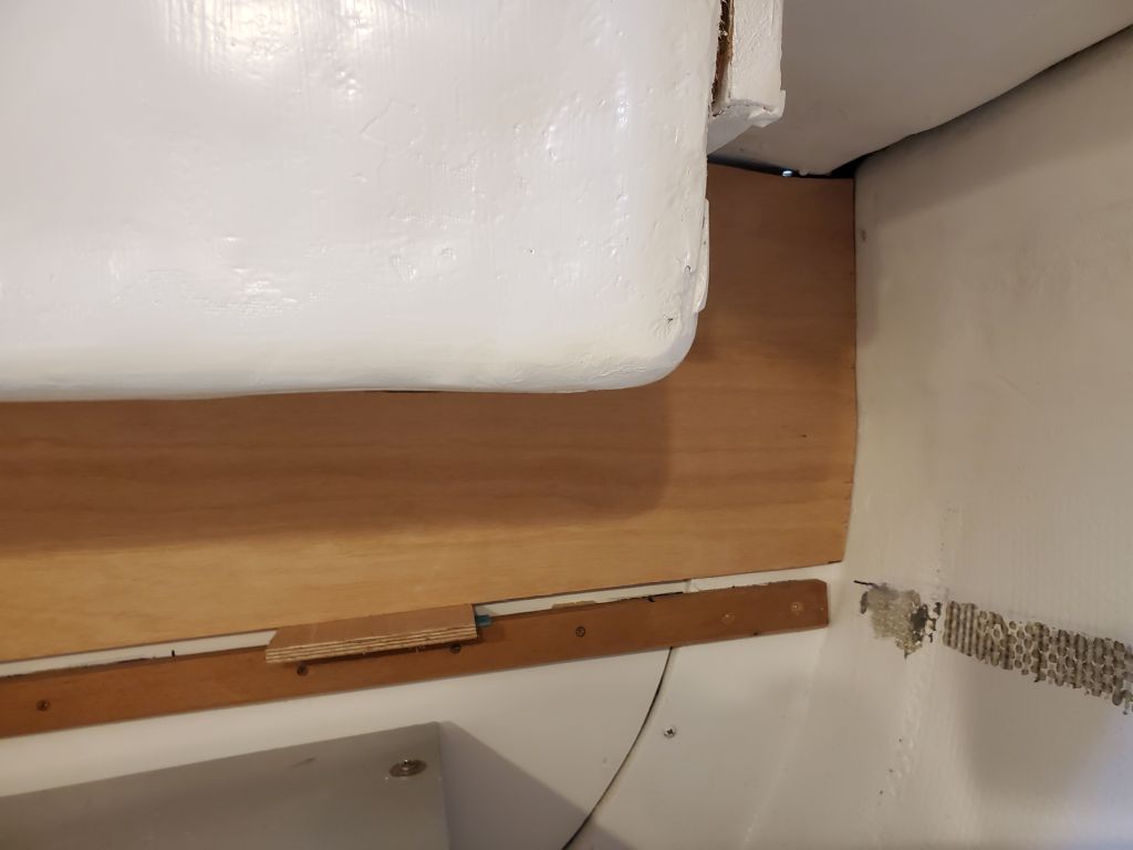
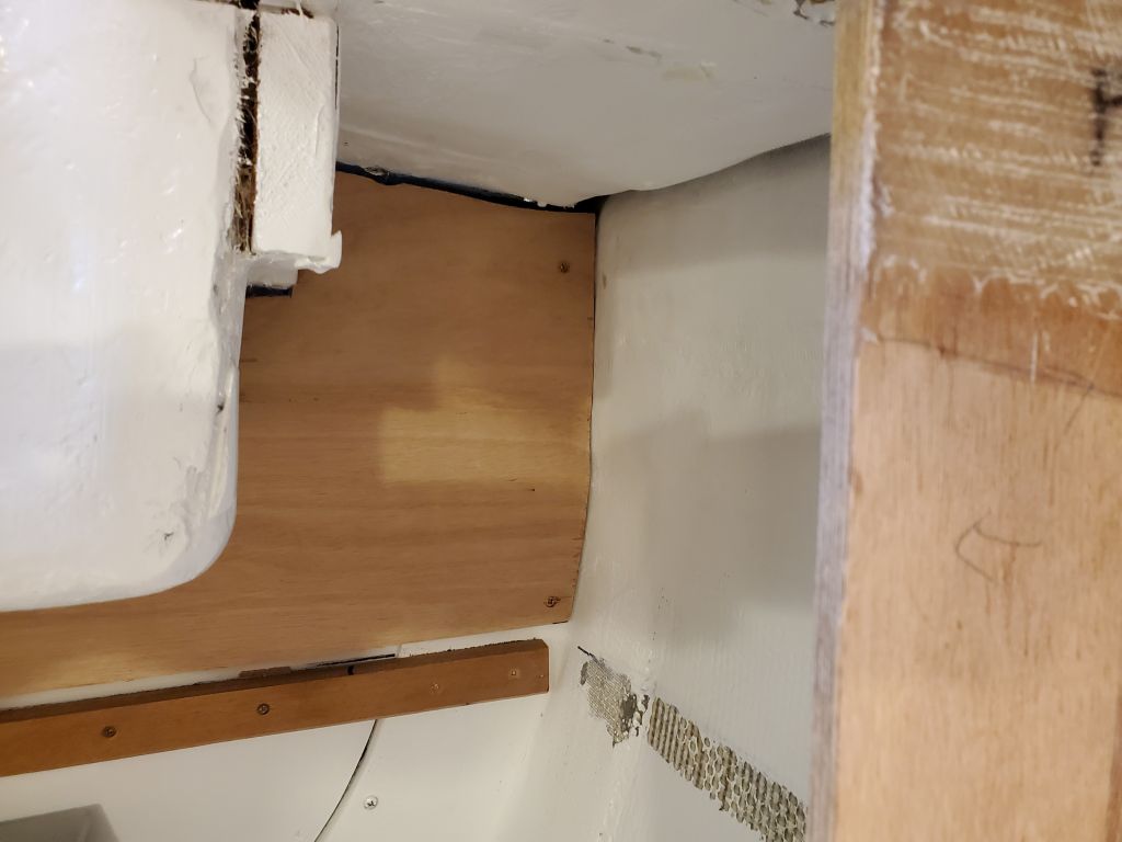
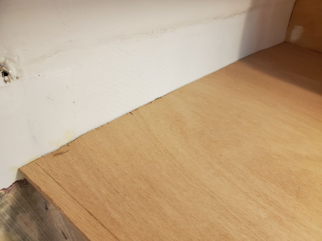
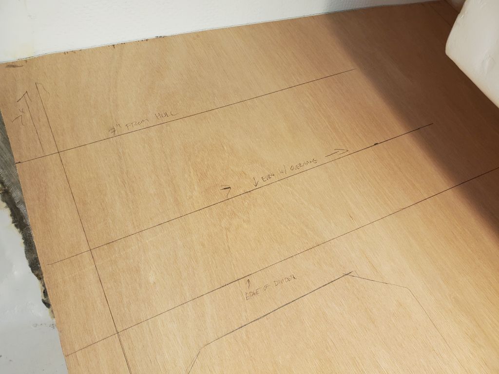
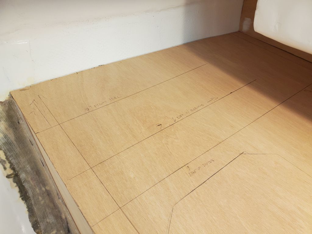
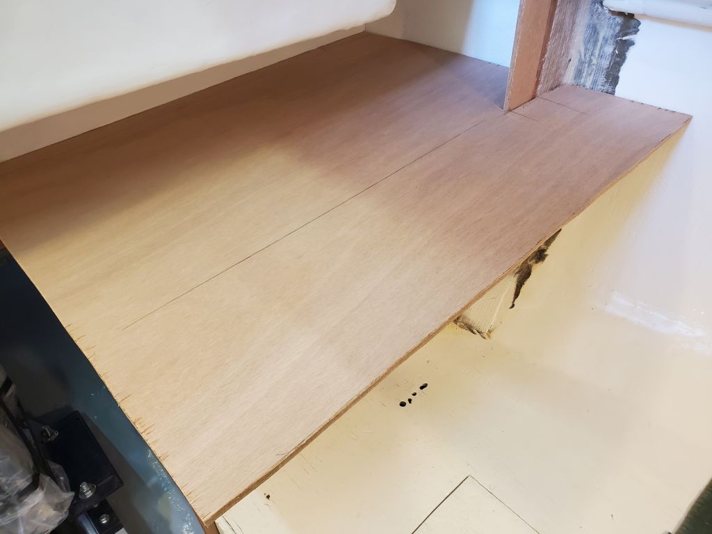
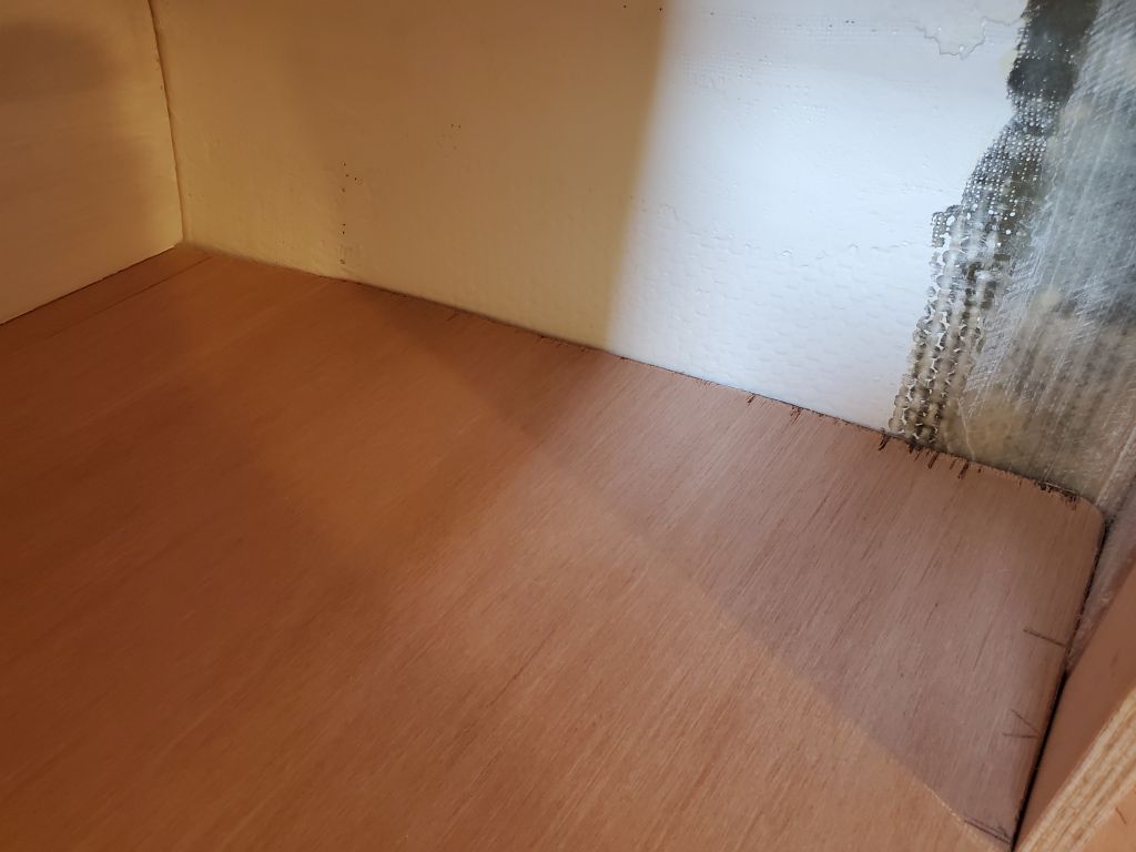
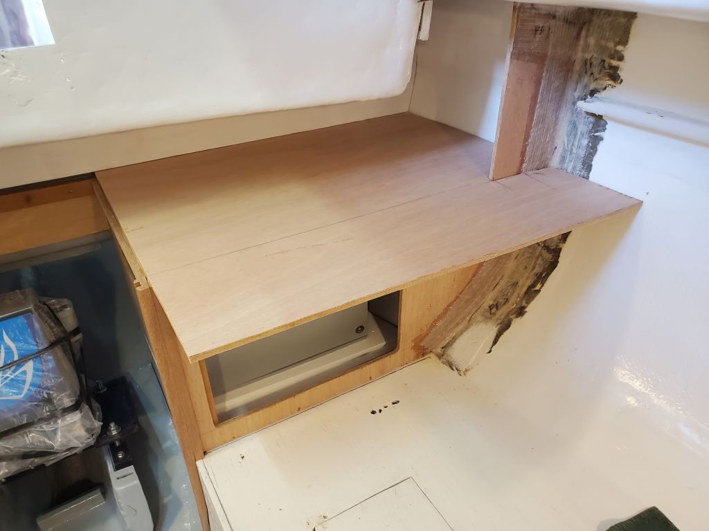
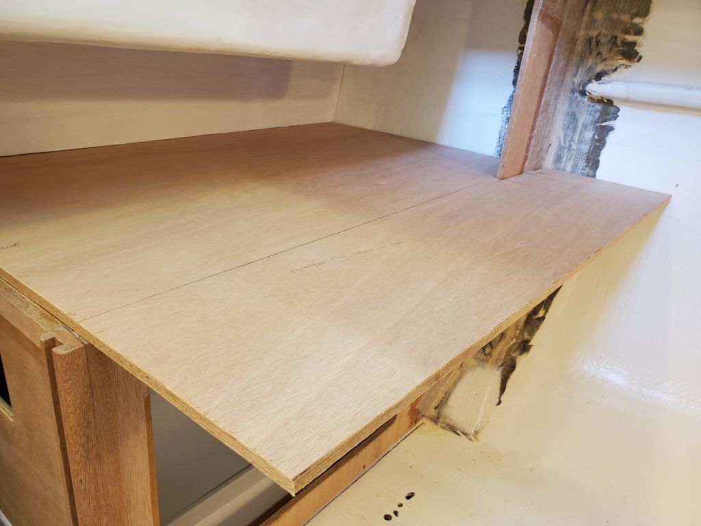
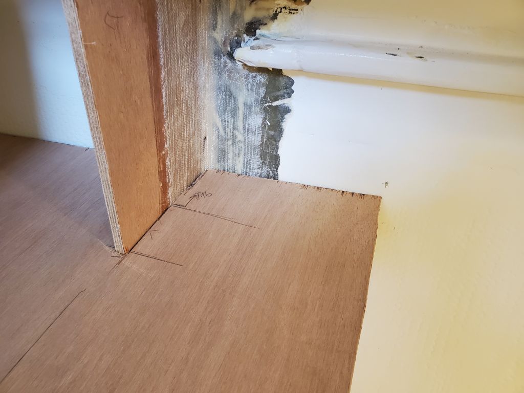
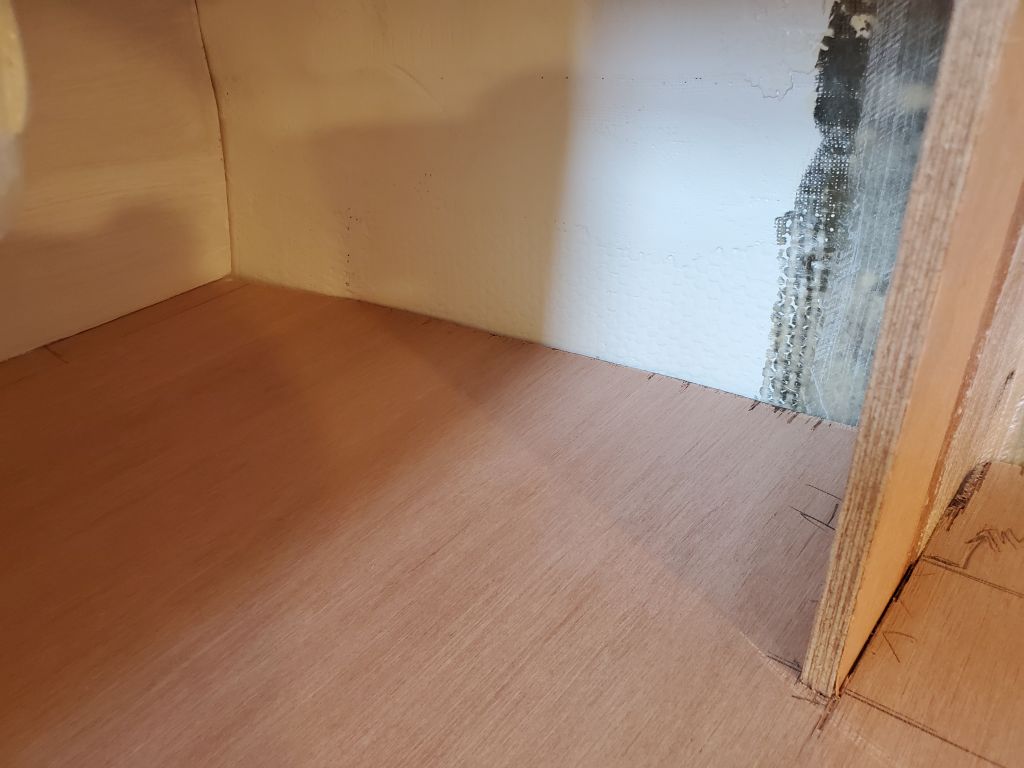
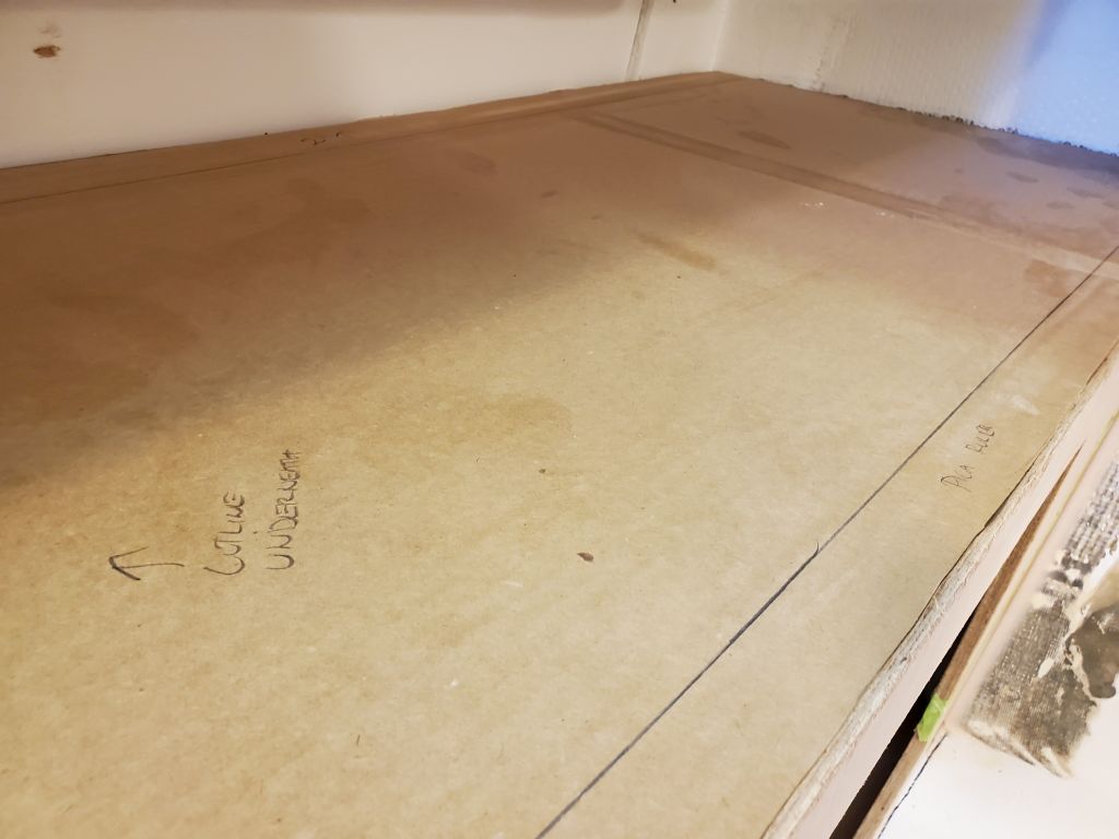
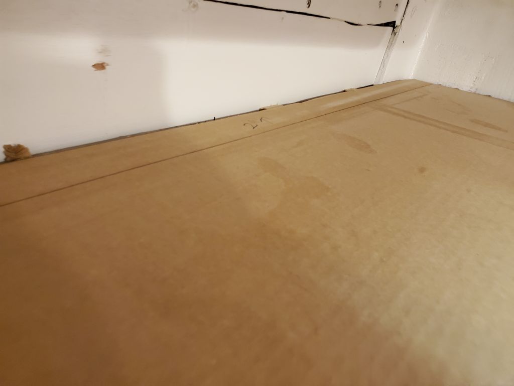
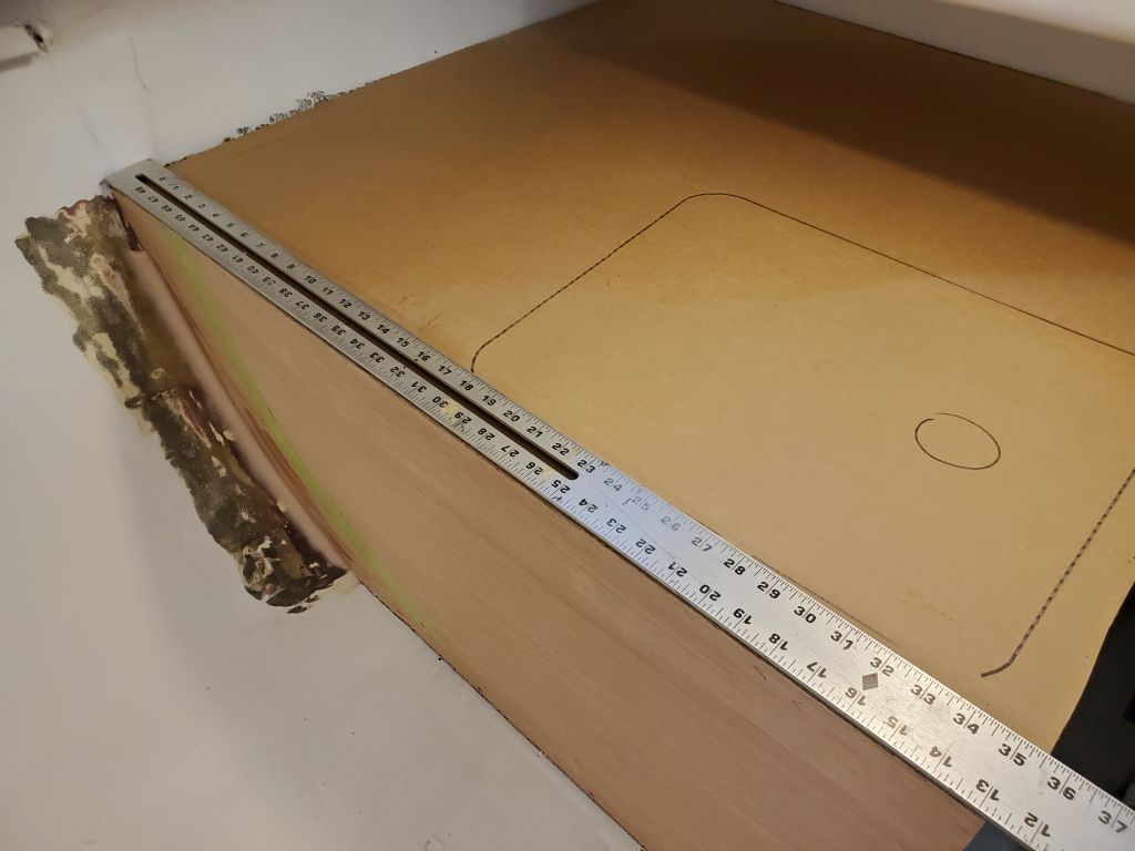
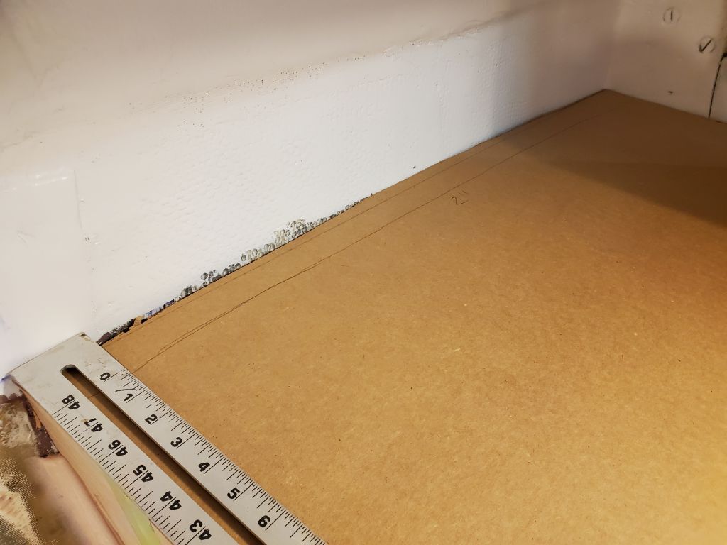
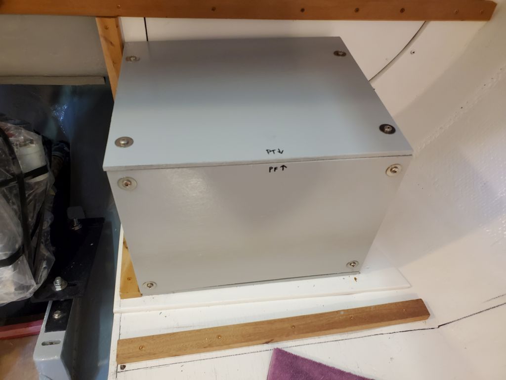
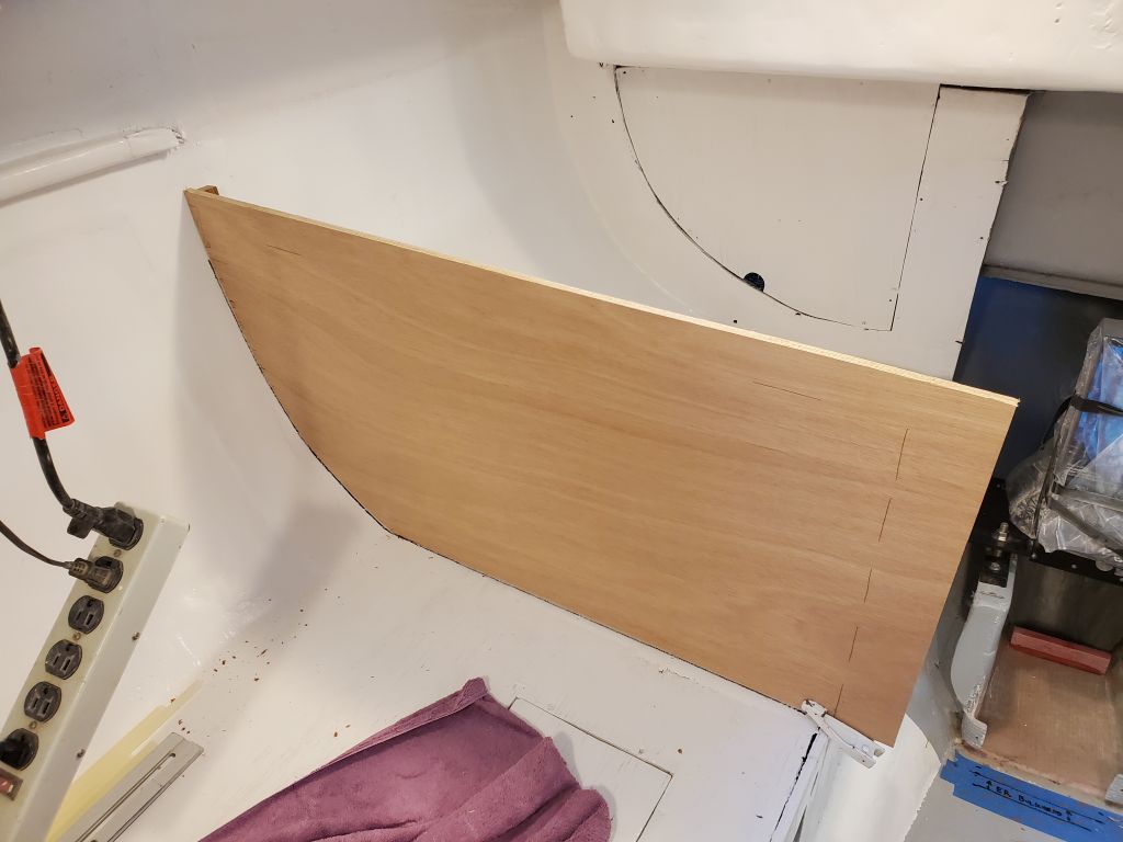
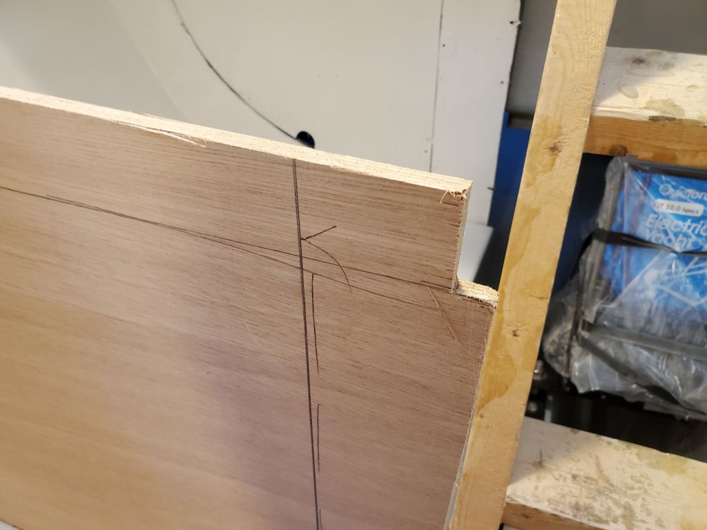
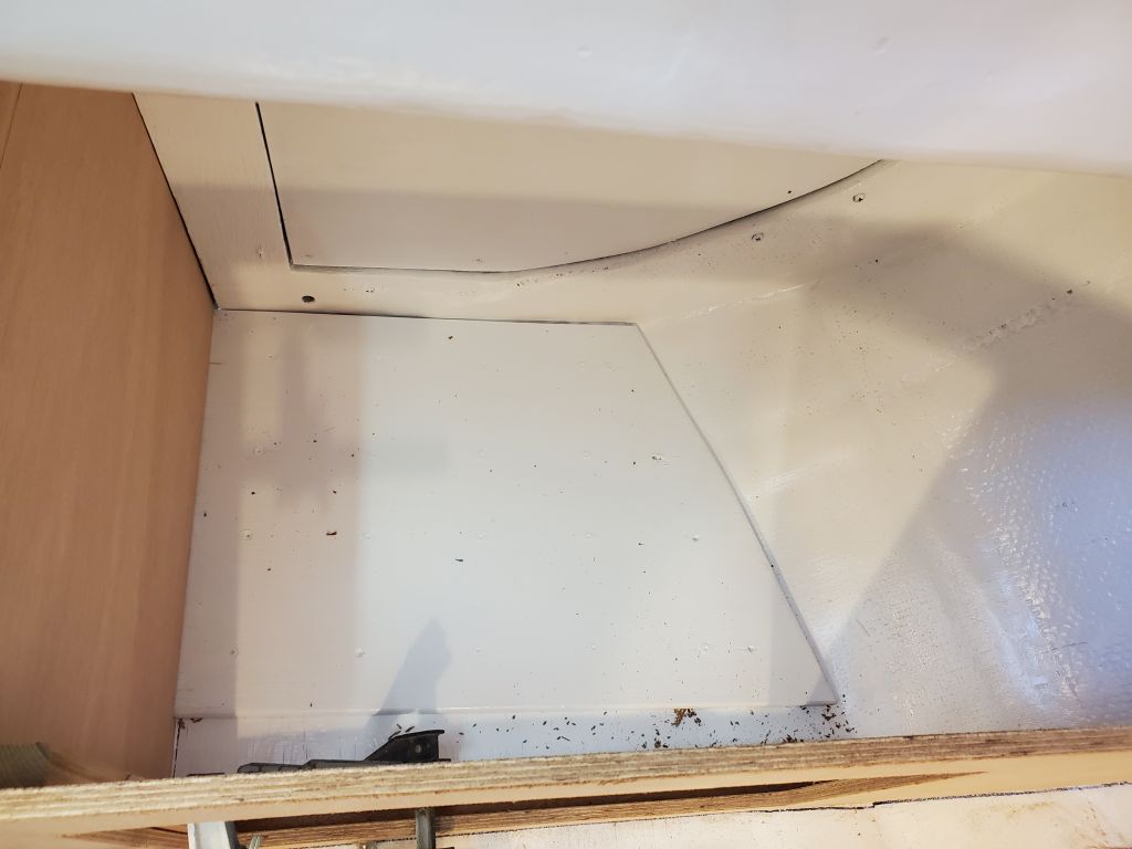
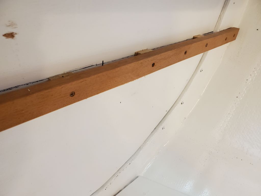
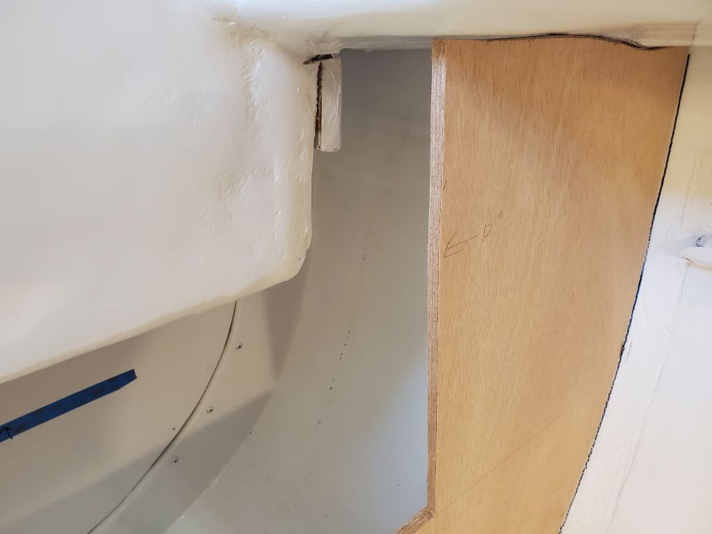
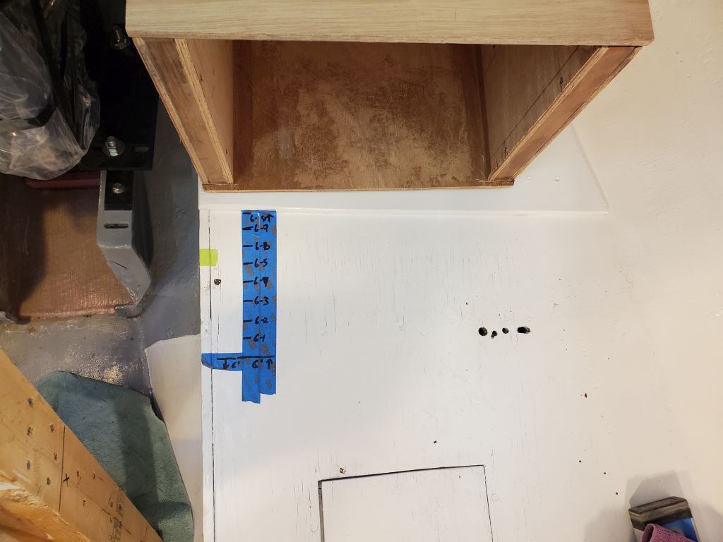
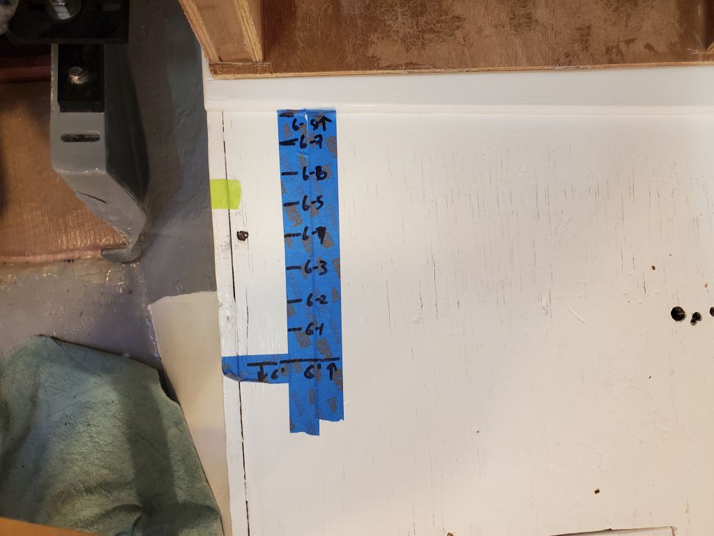
On the port side, the owner wanted to maintain a full-length berth of at least 6′-2″, so to begin I made myself a little reference guideline showing various lengths on the port settee. The secondary plywood underlayment beneath the battery box would limit the aftmost placement of the bulkhead, and the minimum berth length the forwardmost location, so that gave me about six inches of space within which to work, depending on other factors that would make themselves known as the layout continued. With clear access ahead of the battery box, it would be straightforward enough to incorporate usable access to the battery box for installation or removal of batteries; those details would come later.
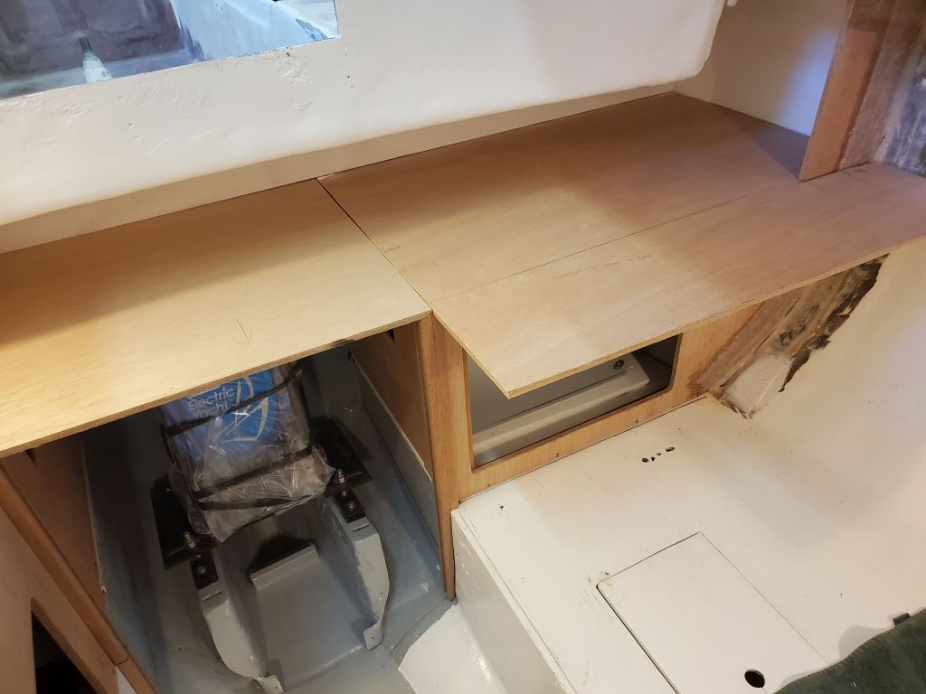
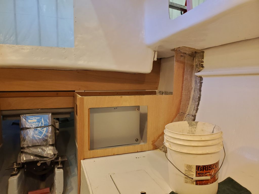
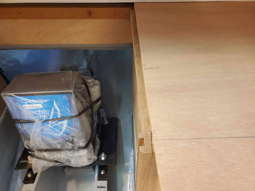
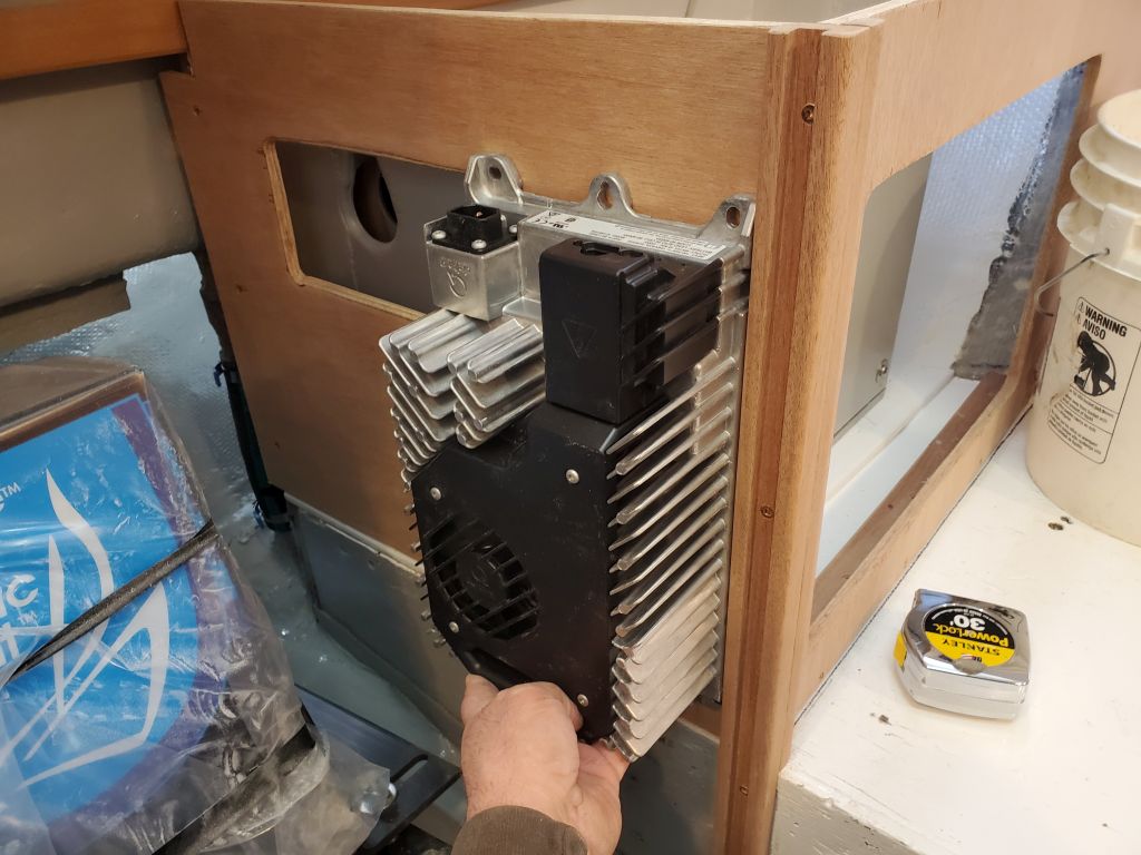
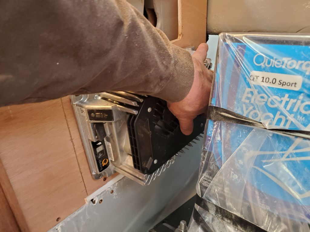
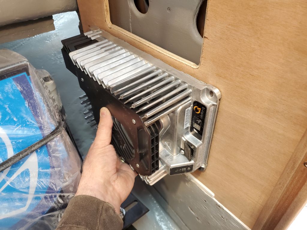
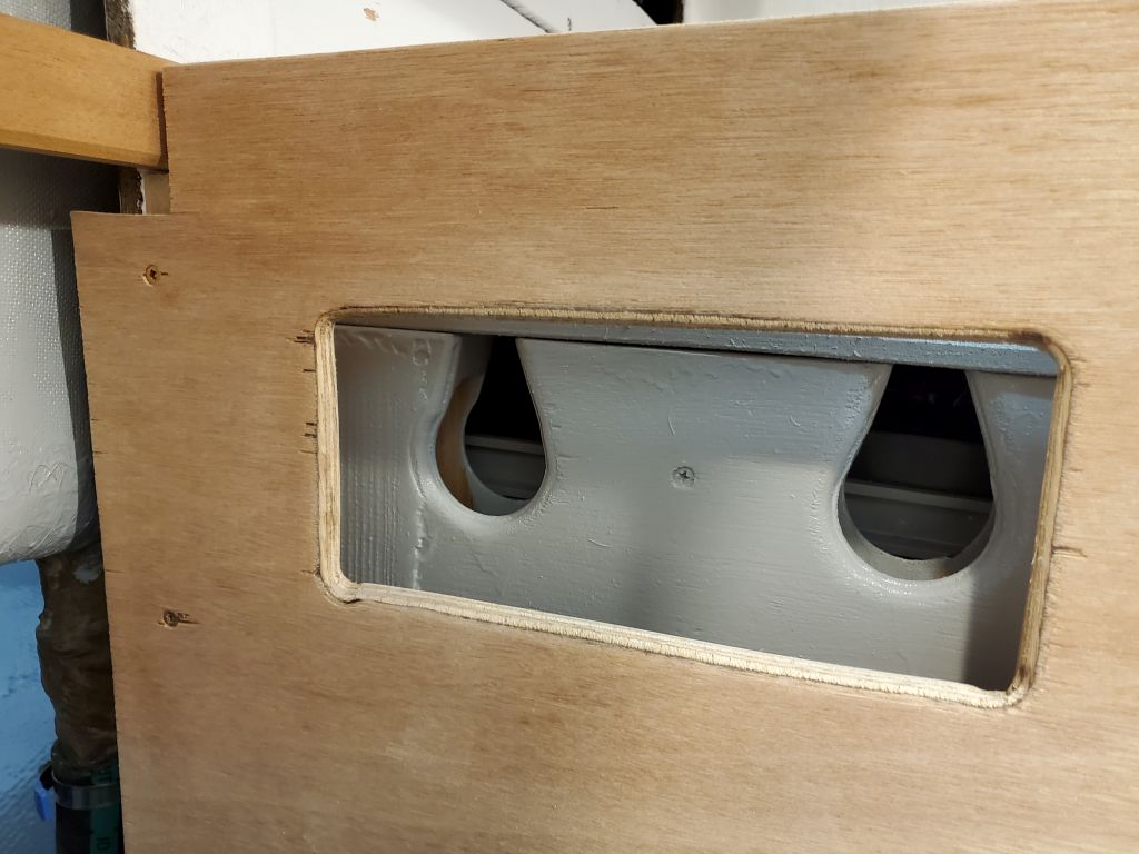
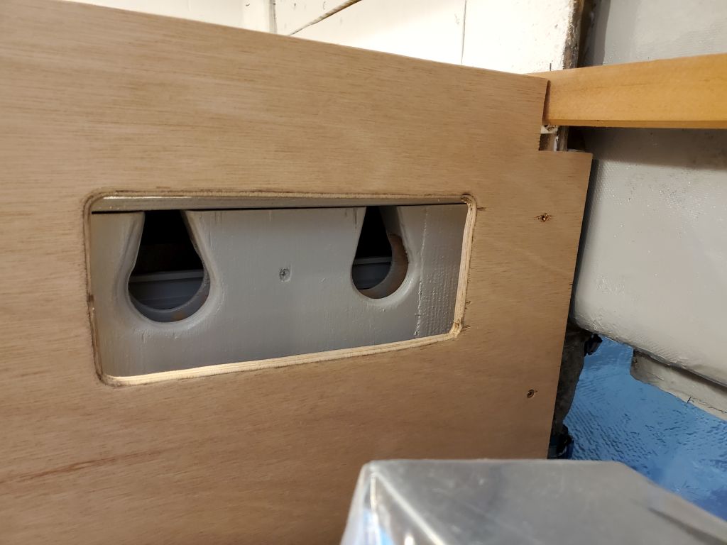
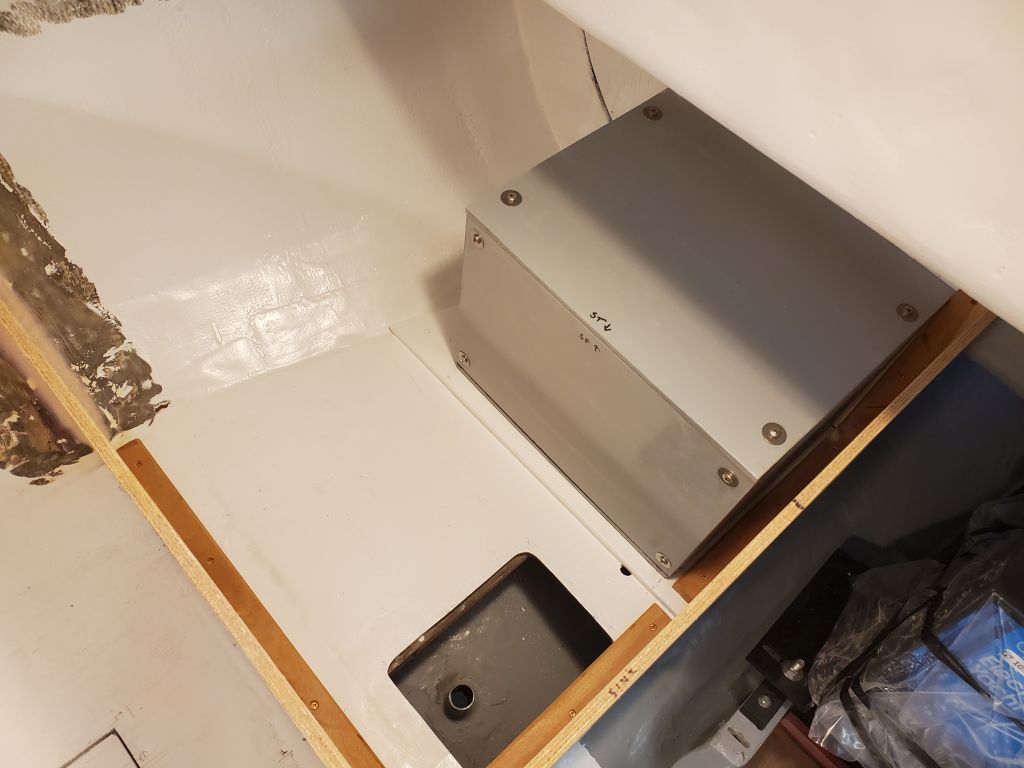
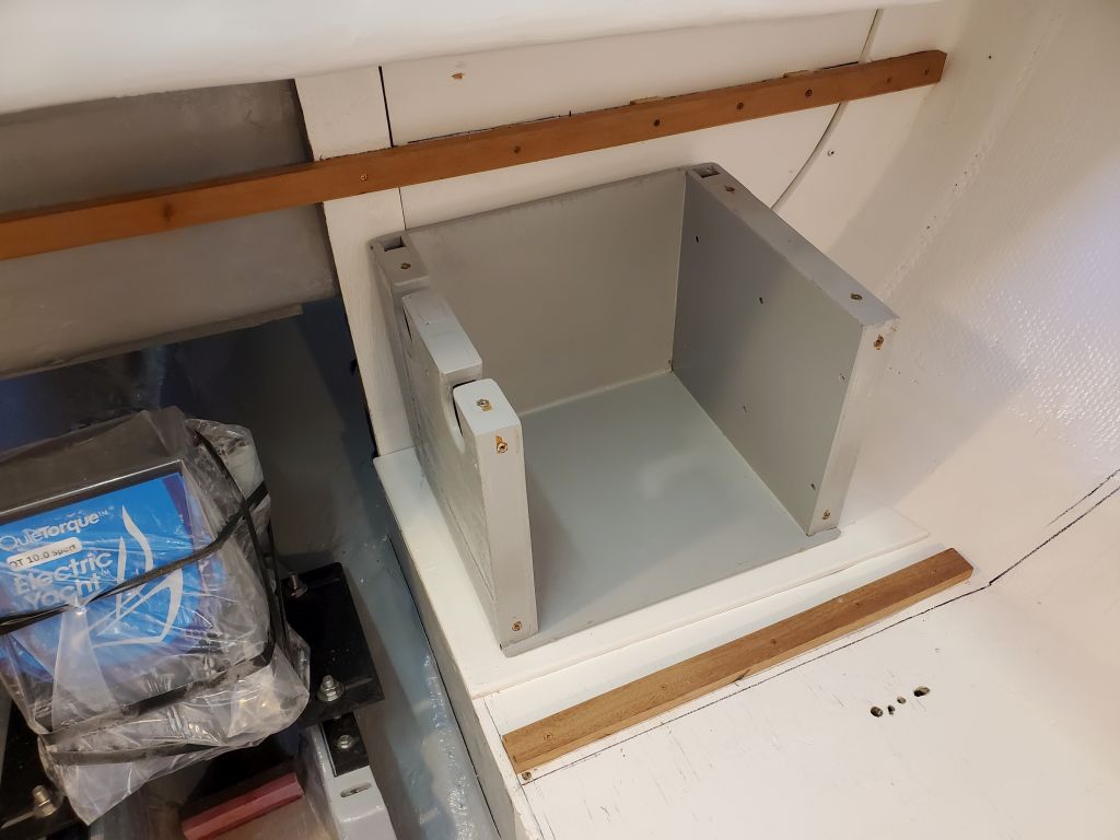
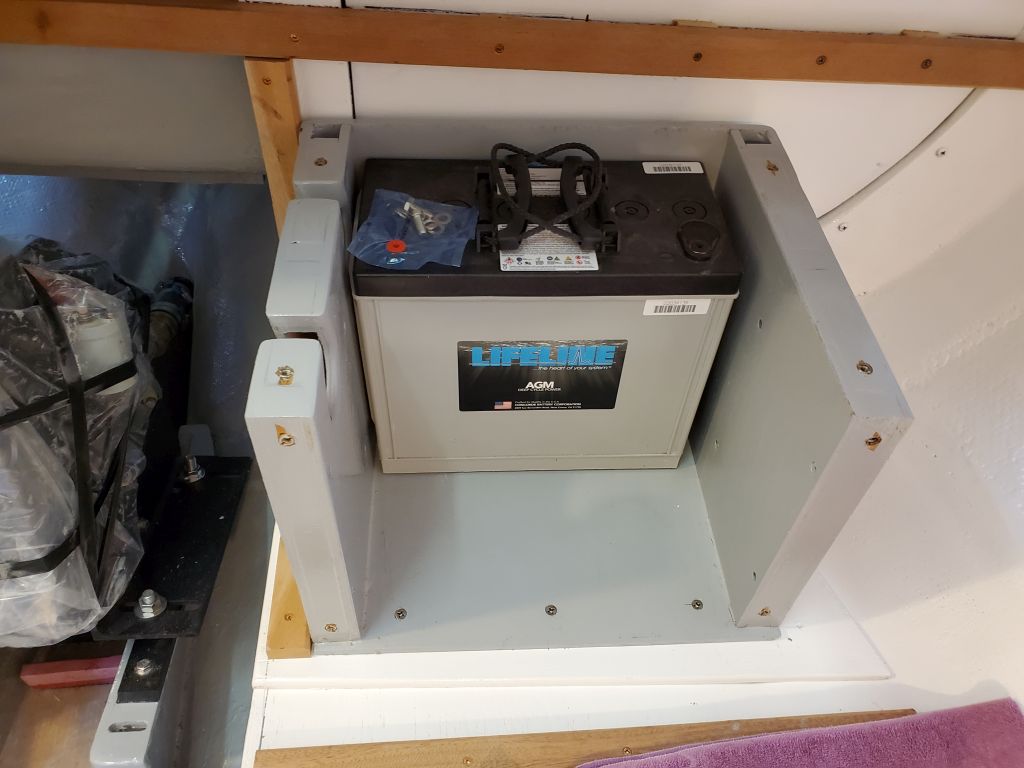
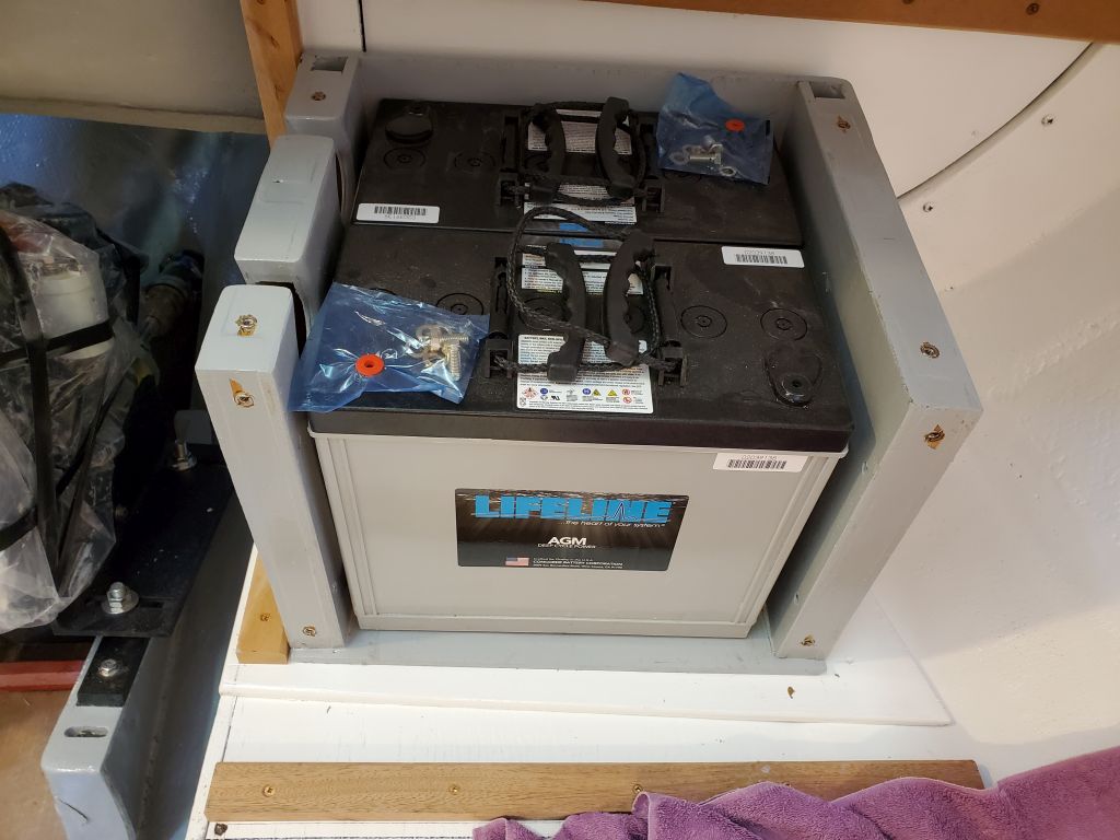
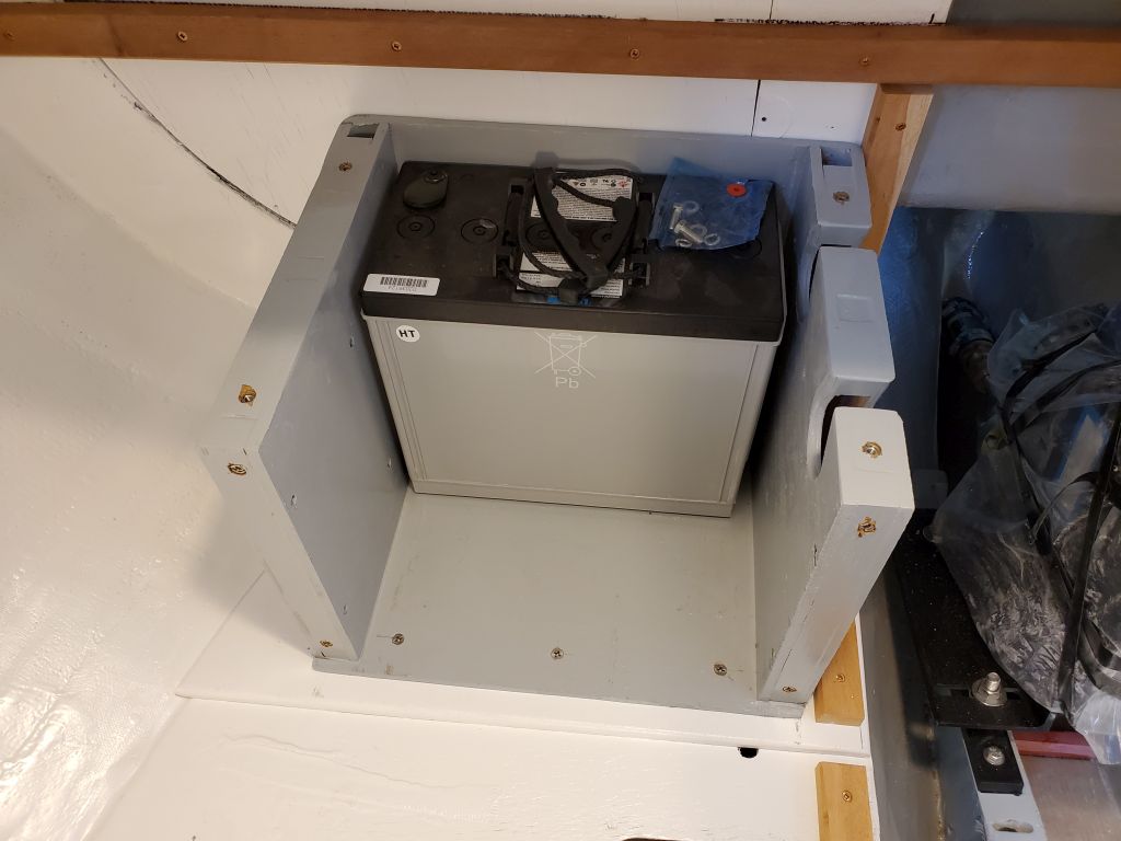
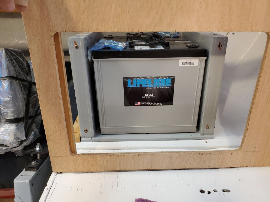
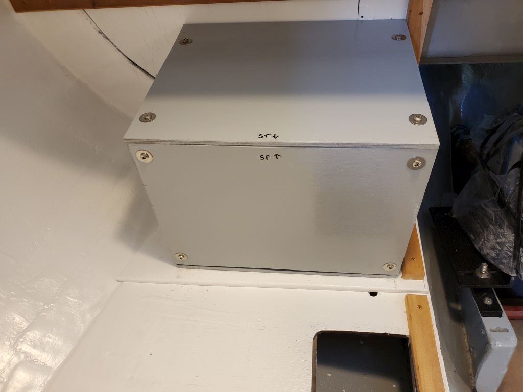
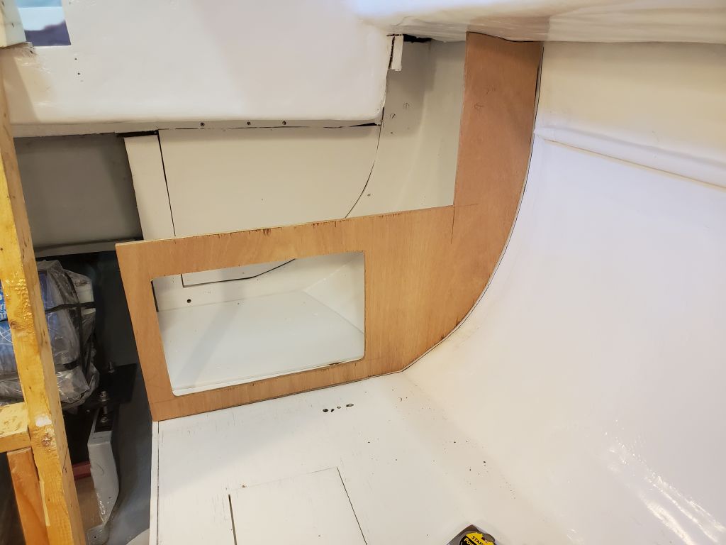
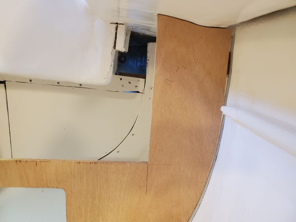
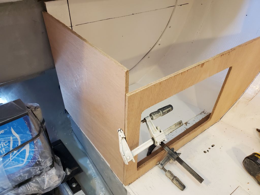
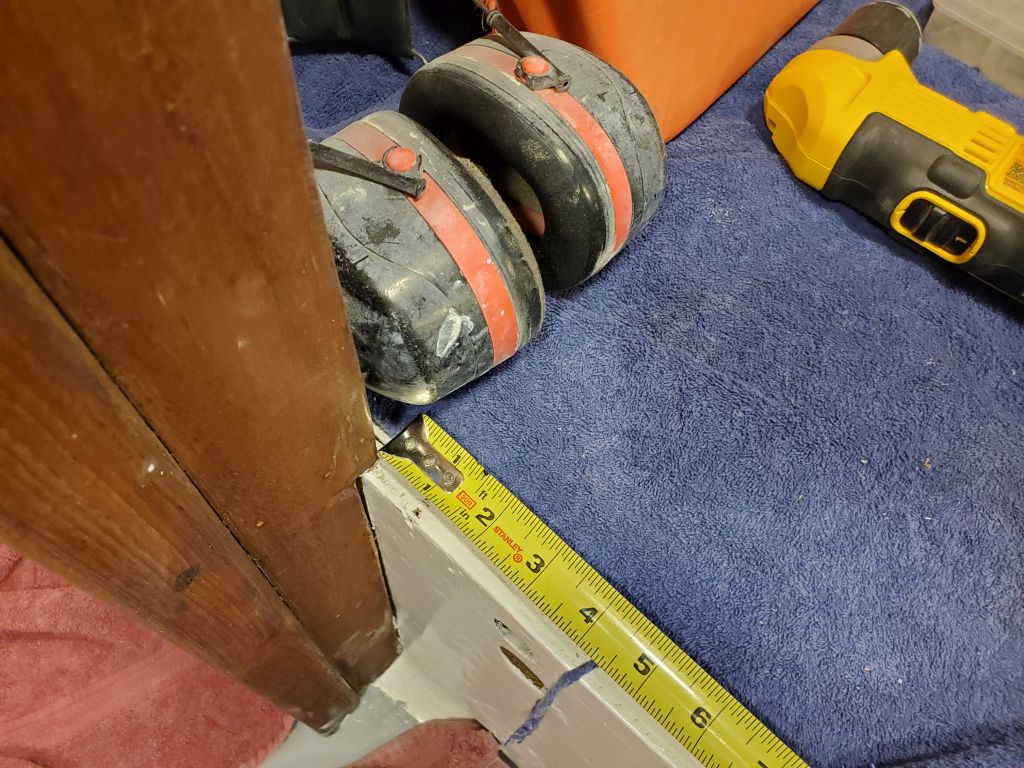
On the starboard side, which would incorporate a more typical galley cabinet and on which side the owner planned to sacrifice overall berth length in favor of galley needs, one thing I needed to think about from the getgo was a way to manipulate batteries in or out of the battery box once all the cabinets were installed. While I planned top access on both sides to allow inspection, wiring connections, and so forth, space limitations and physical impediments meant that it wasn’t possible on either side to actually lift in or out the batteries from the tops of the boxes: The bridgedeck was too low, and the batteries too large and heavy to manipulate that way in any event.
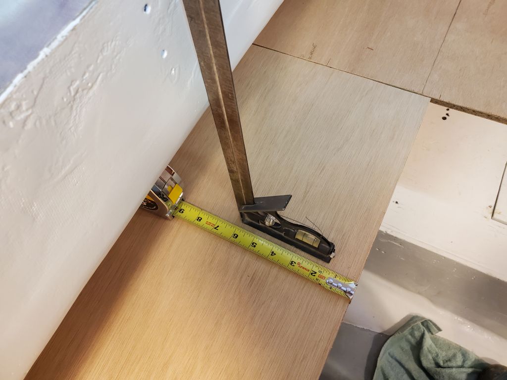
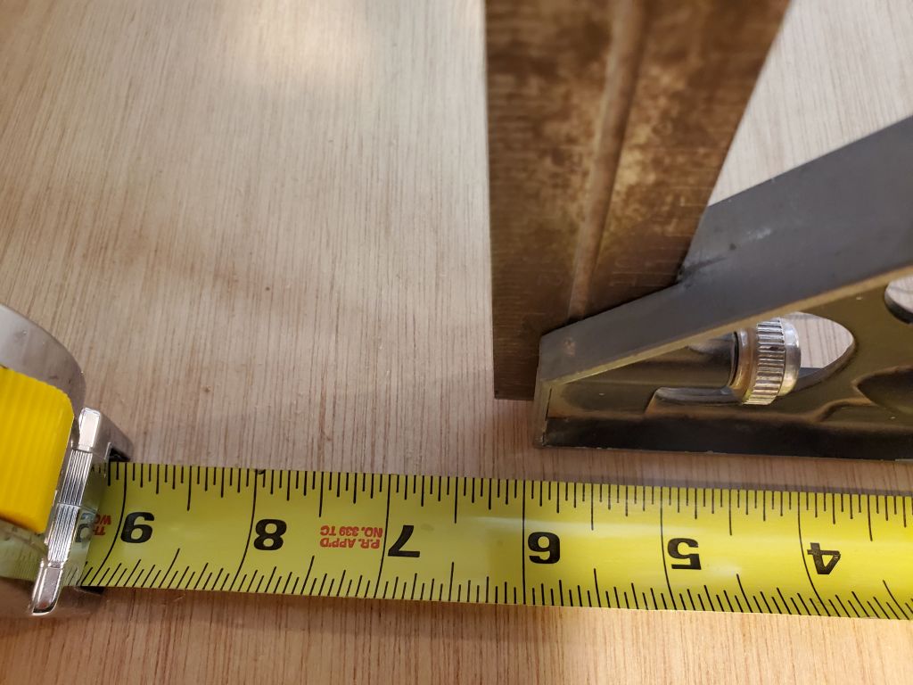
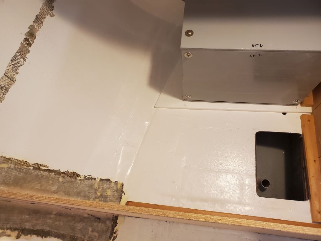
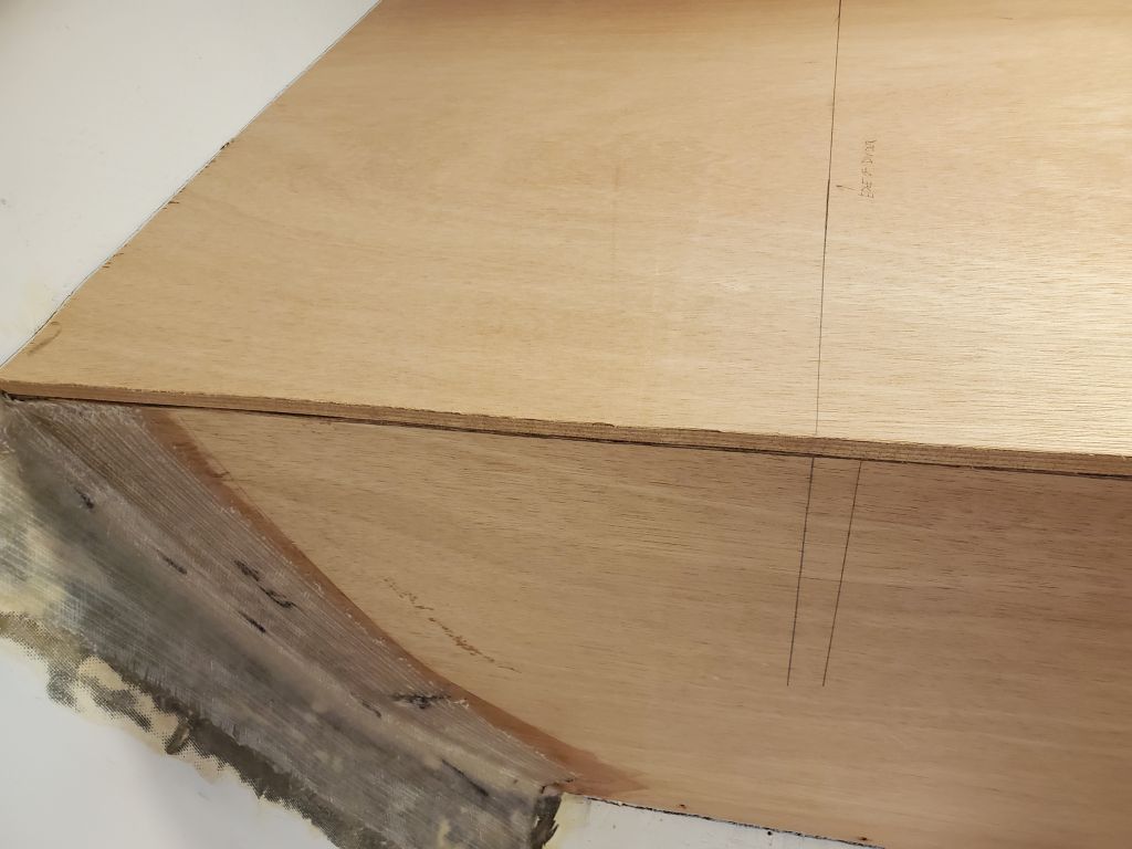
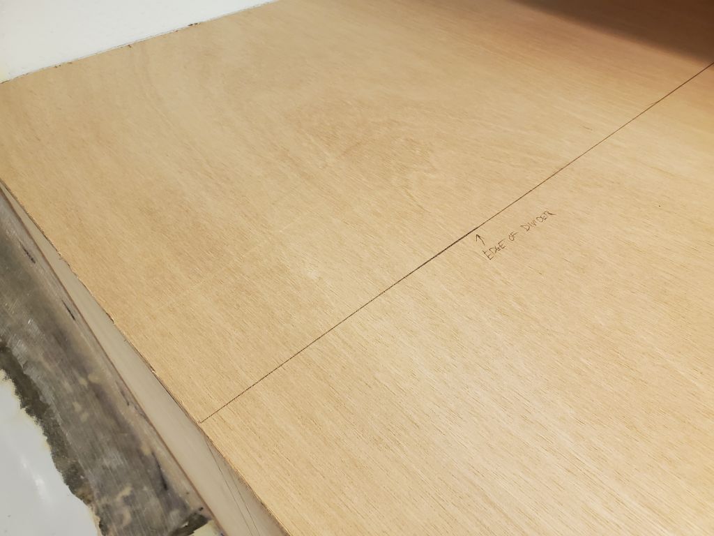
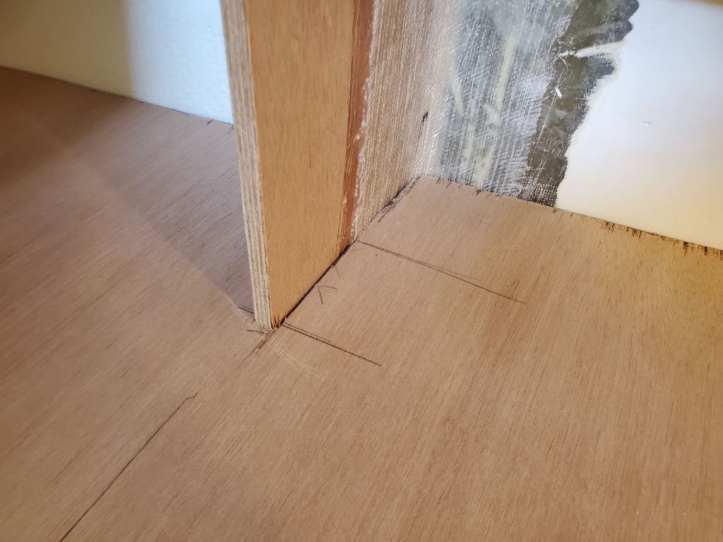
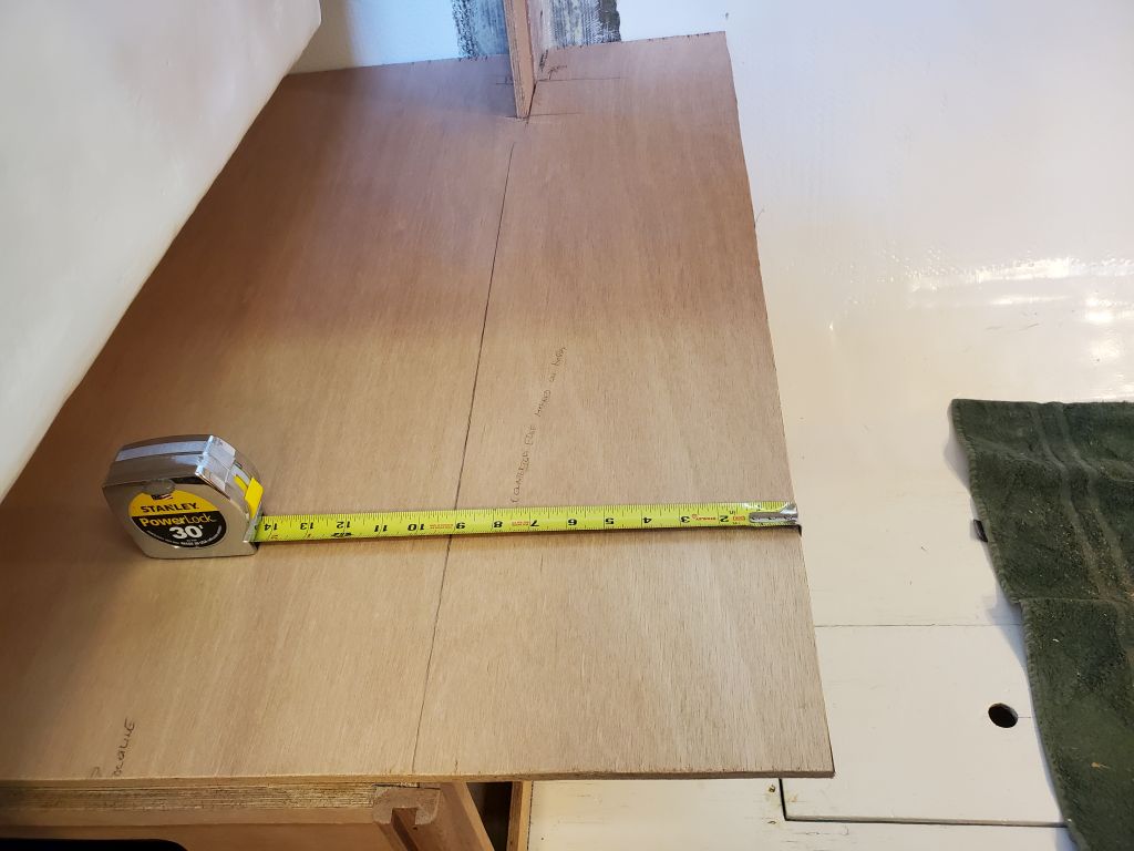
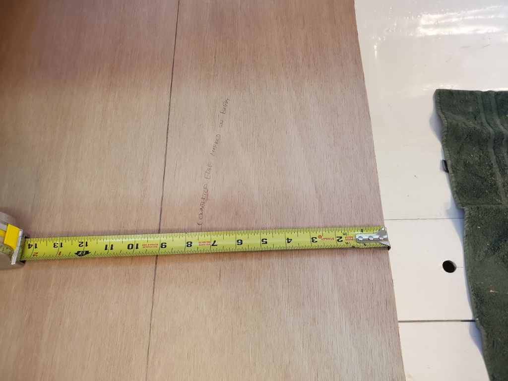
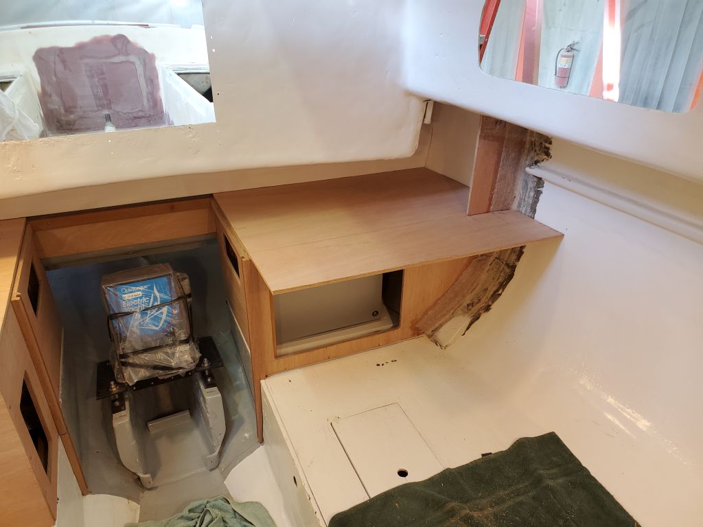
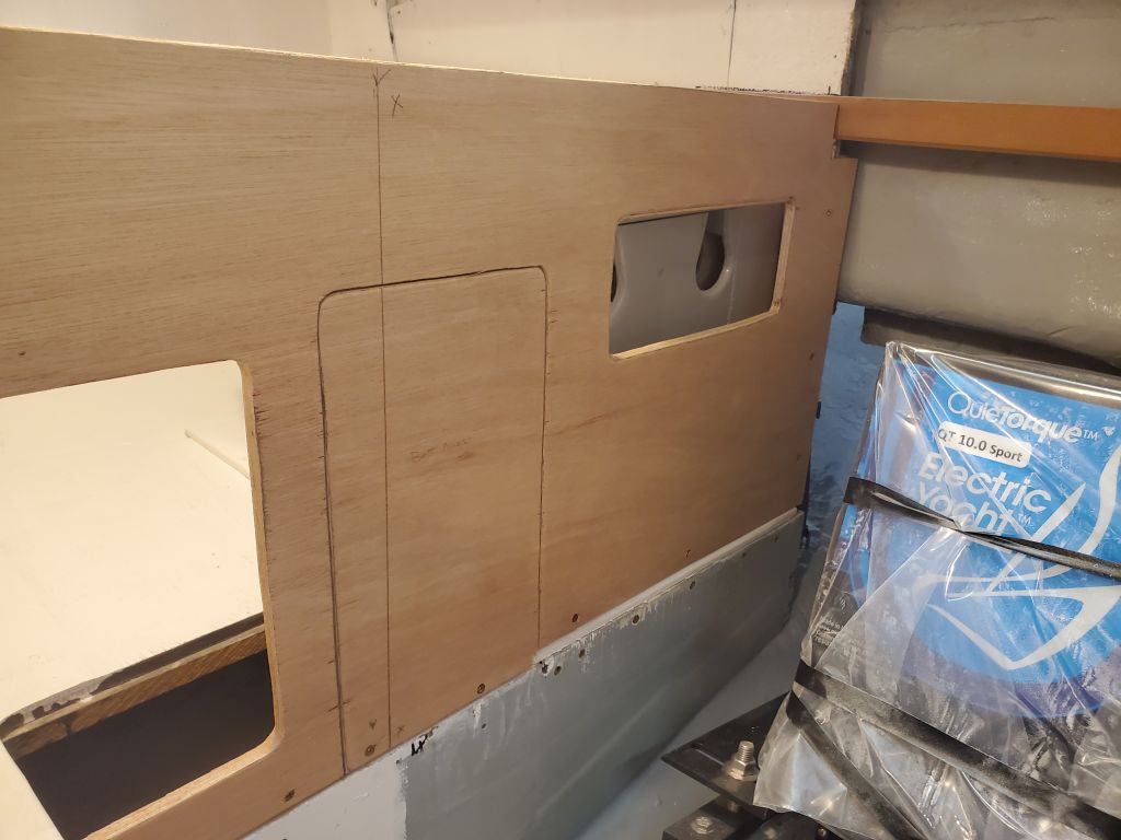
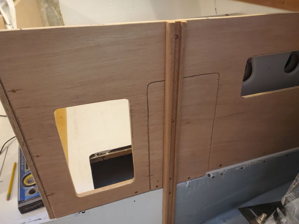
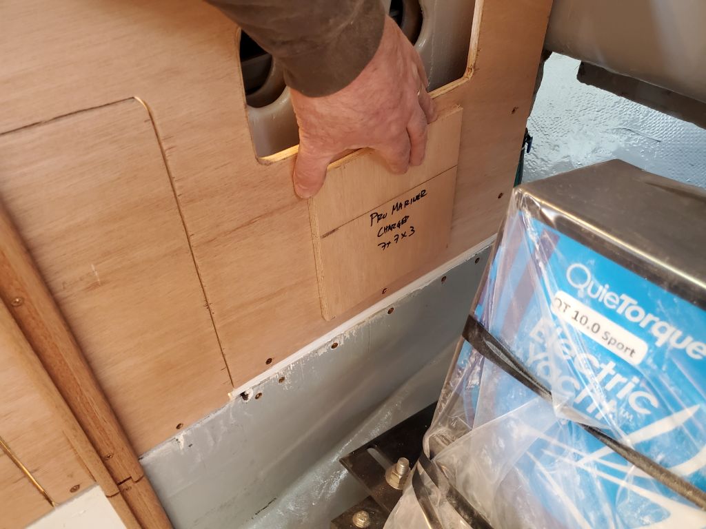
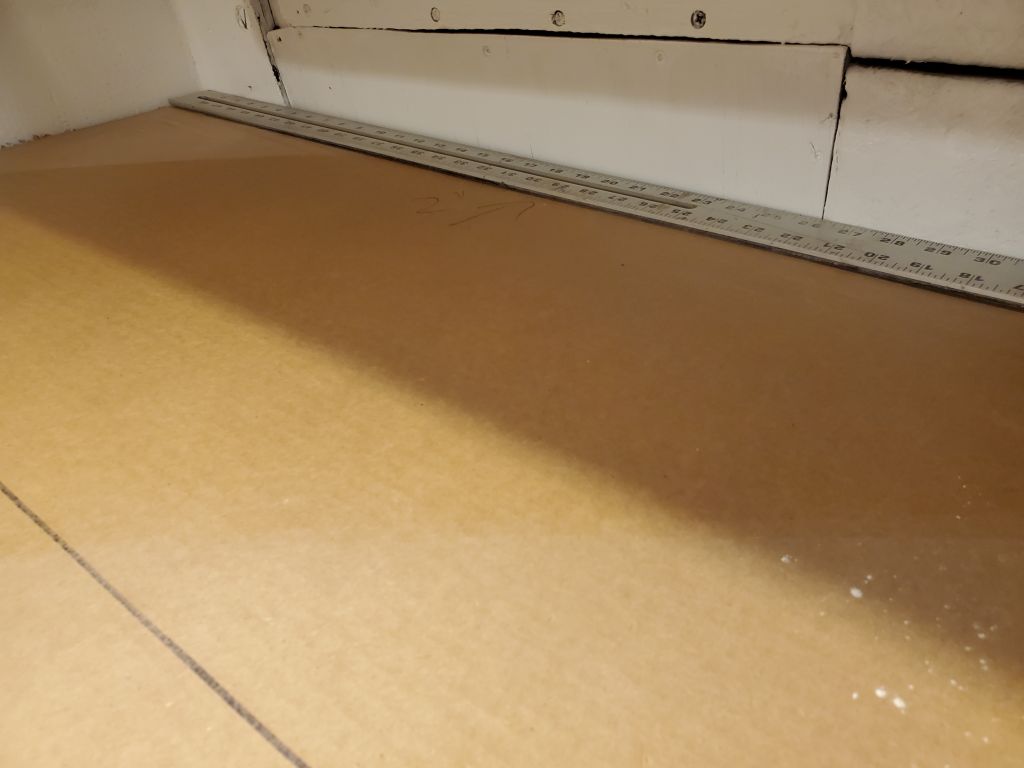
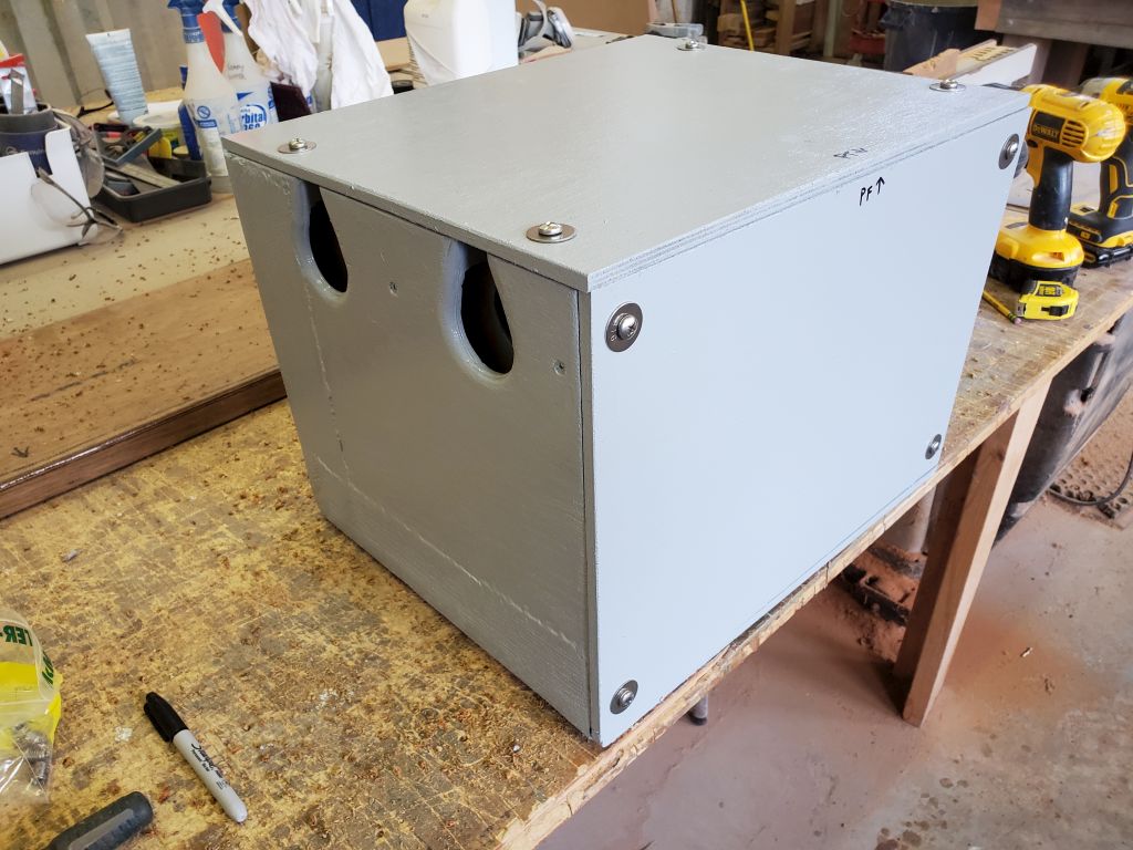
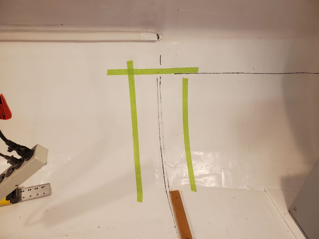
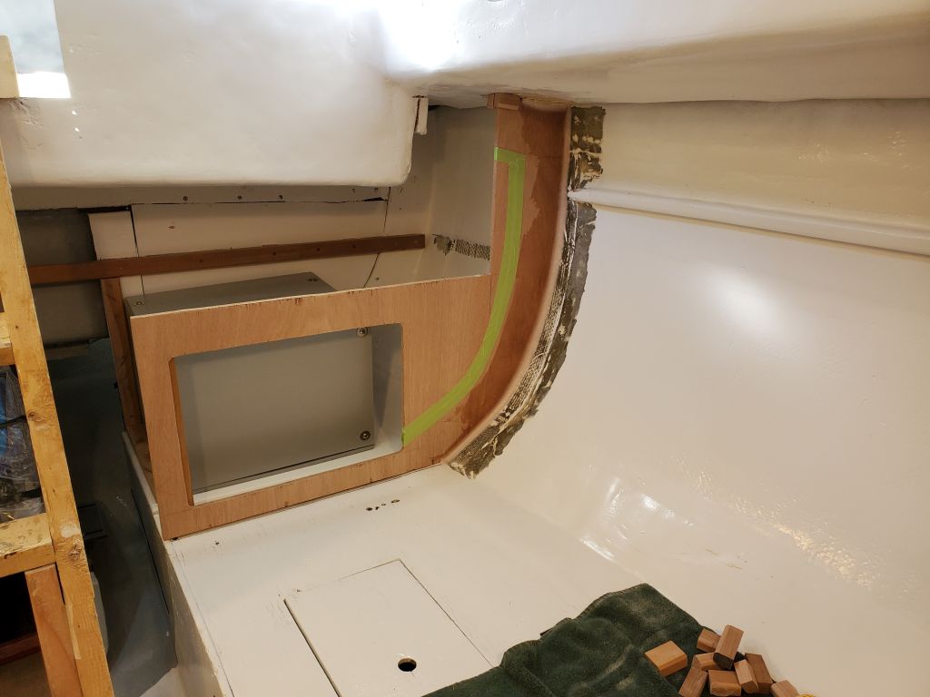
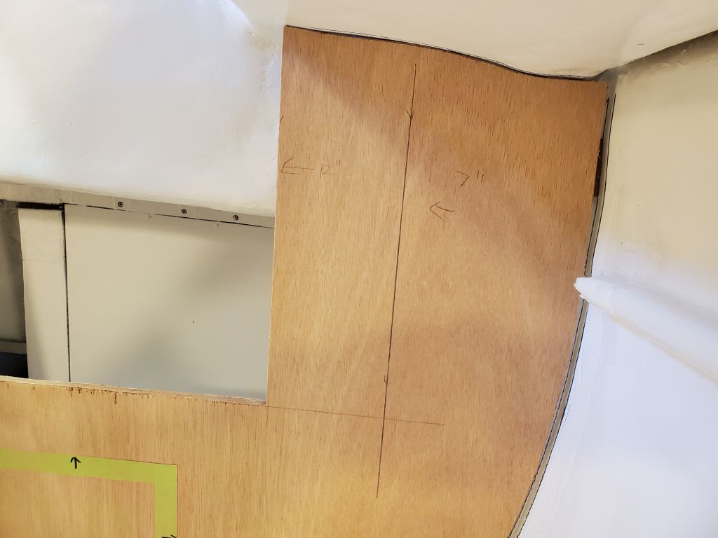
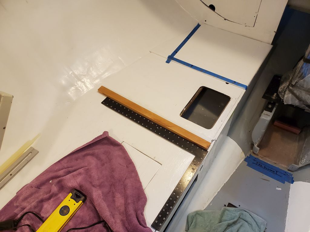
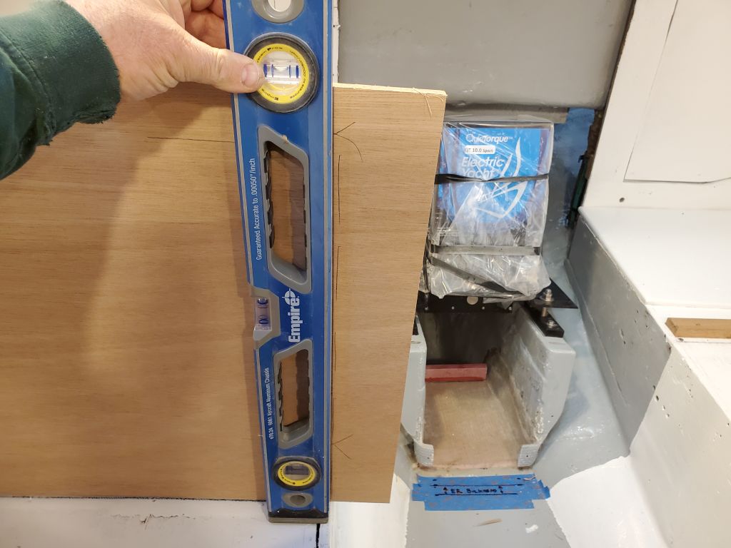
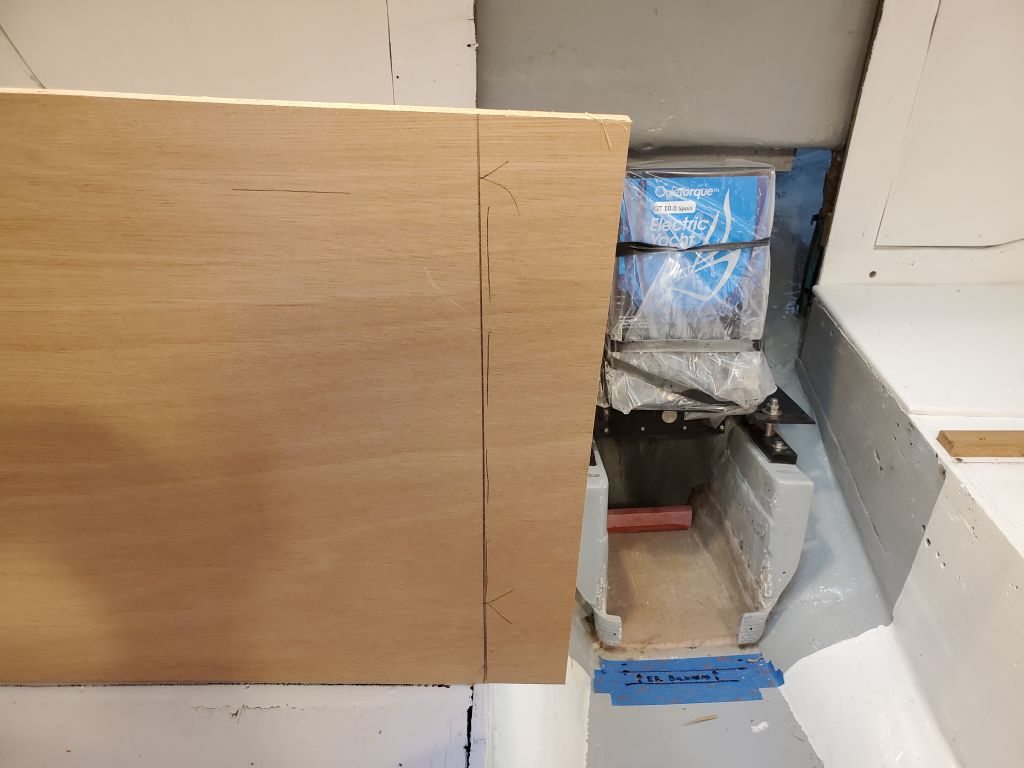
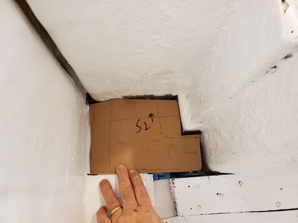
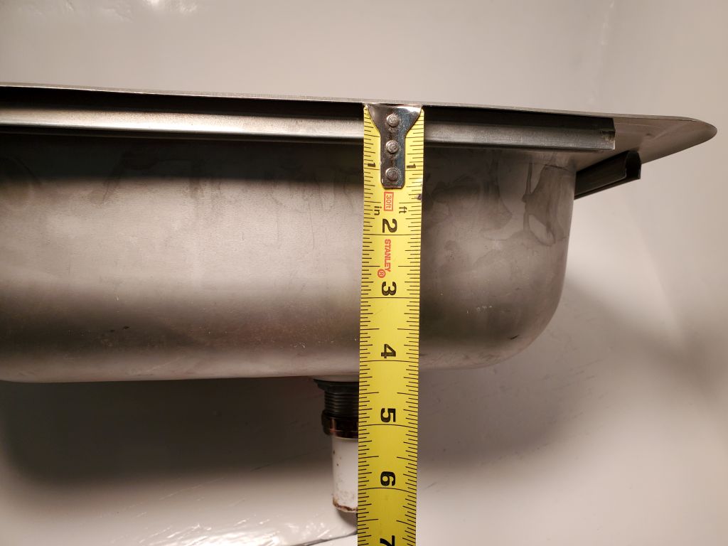
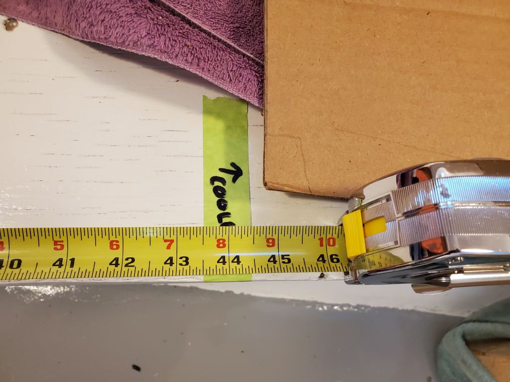
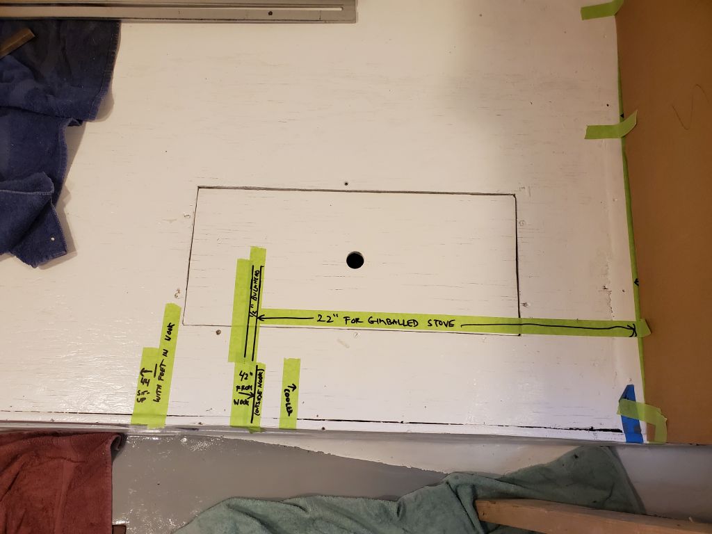
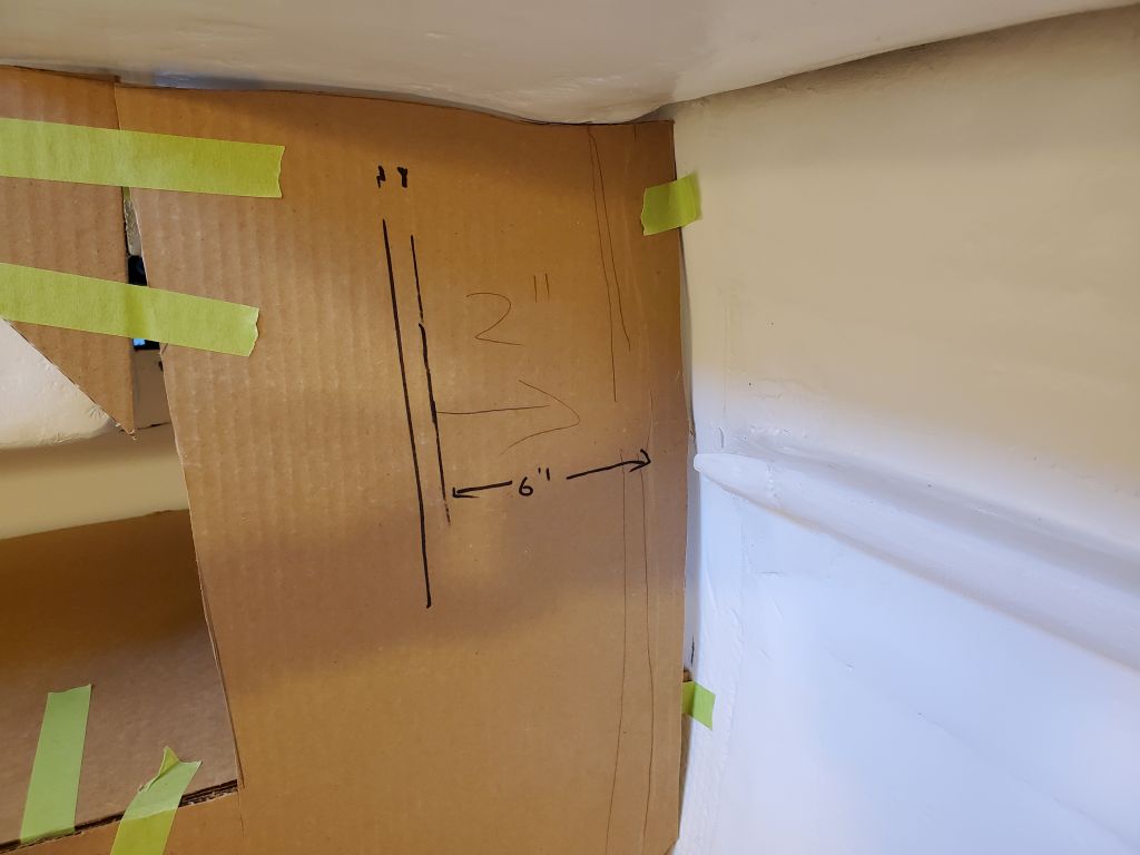
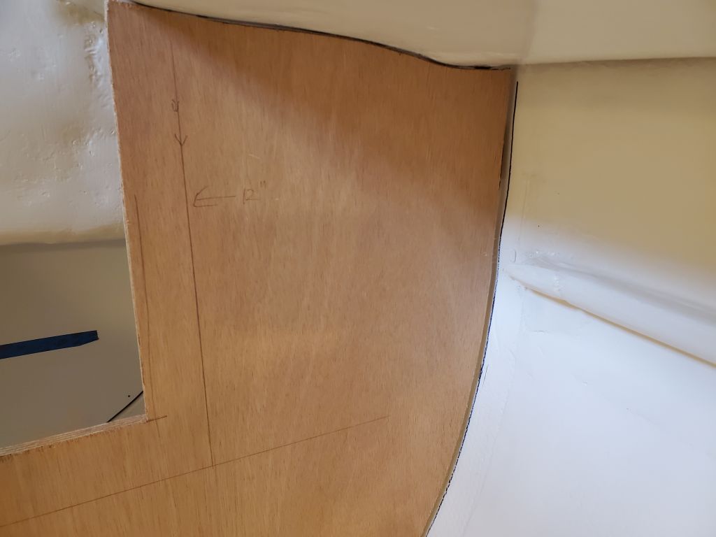
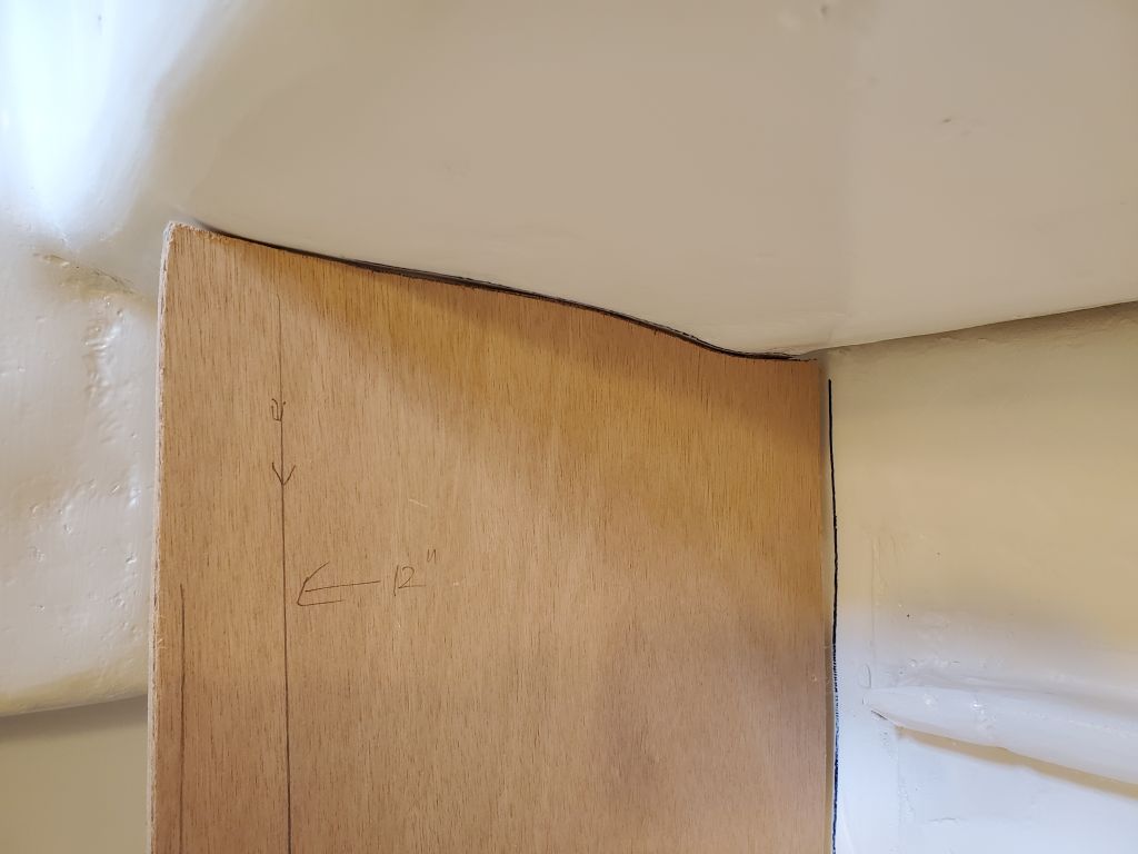
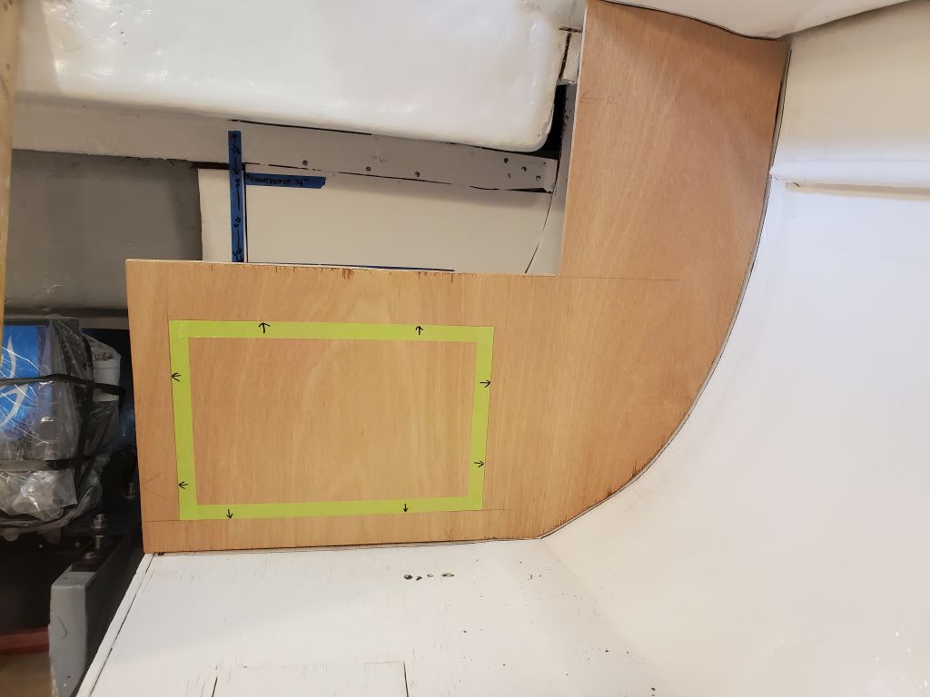
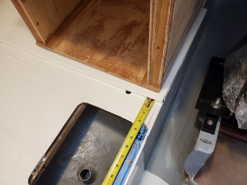
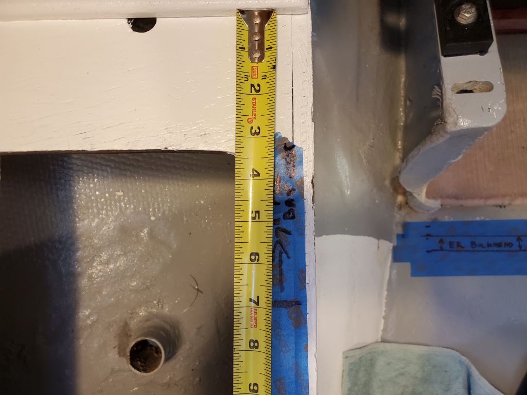
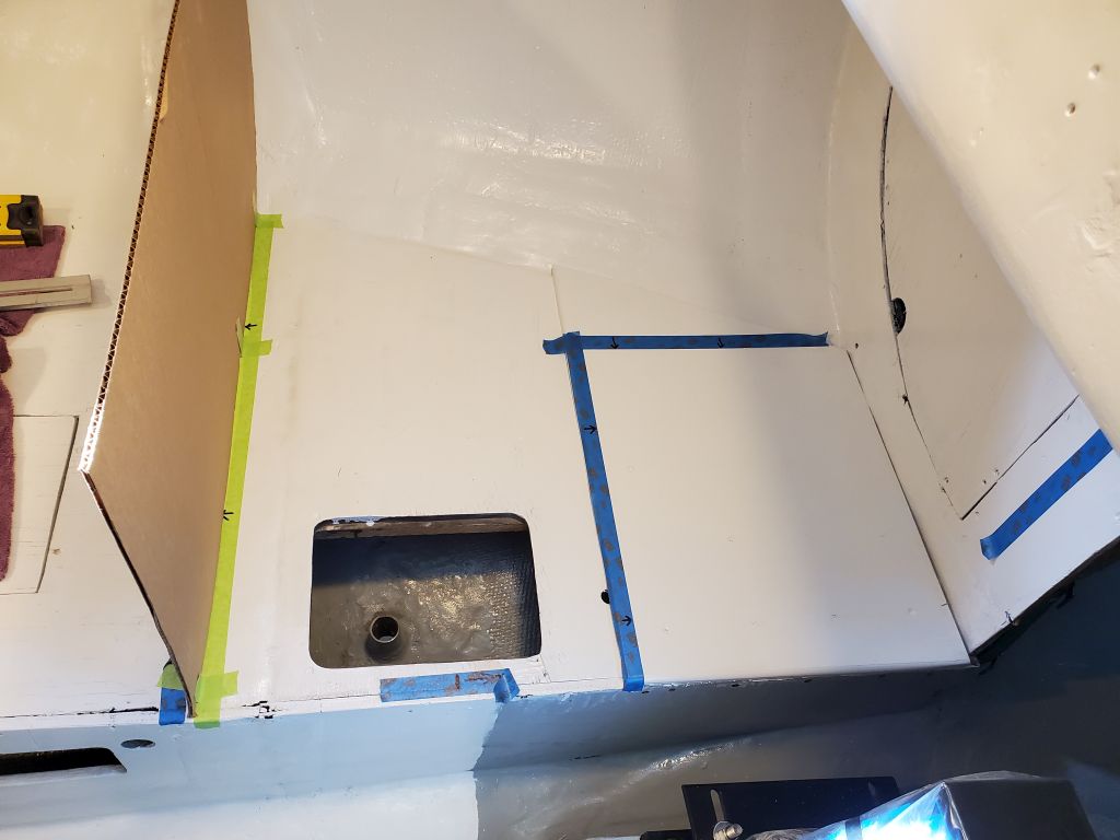
So my plan to starboard was to build an access panel or door in the side of the galley cabinet, aft of the sink plumbing, that would fit the batteries’ width dimension of just under 7″, allowing the batteries to be slid in or out of the box and through this opening. I measured forward the 7″ distance and made a reference mark on the settee for confirmation of the idea and for future reference.
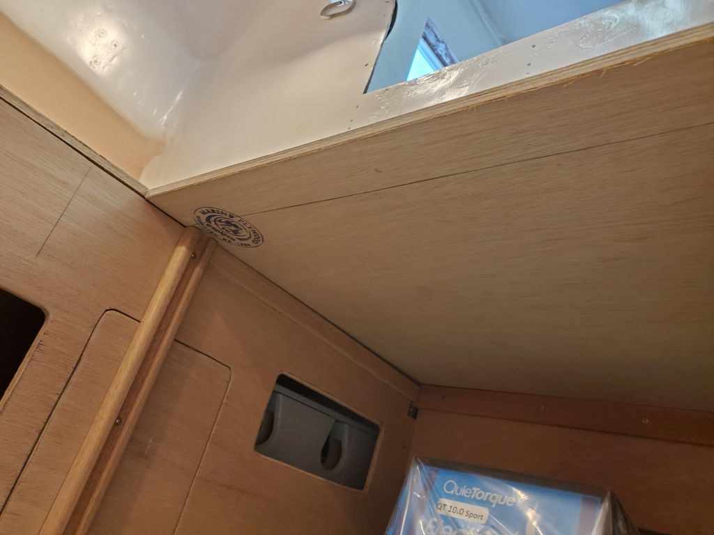
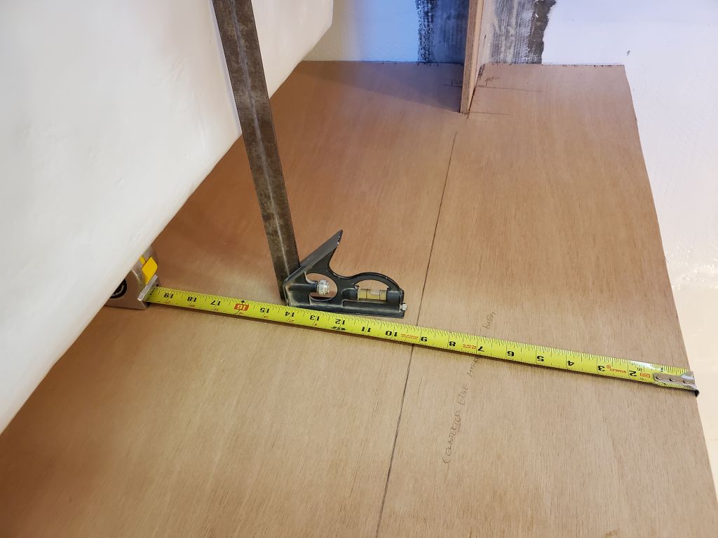
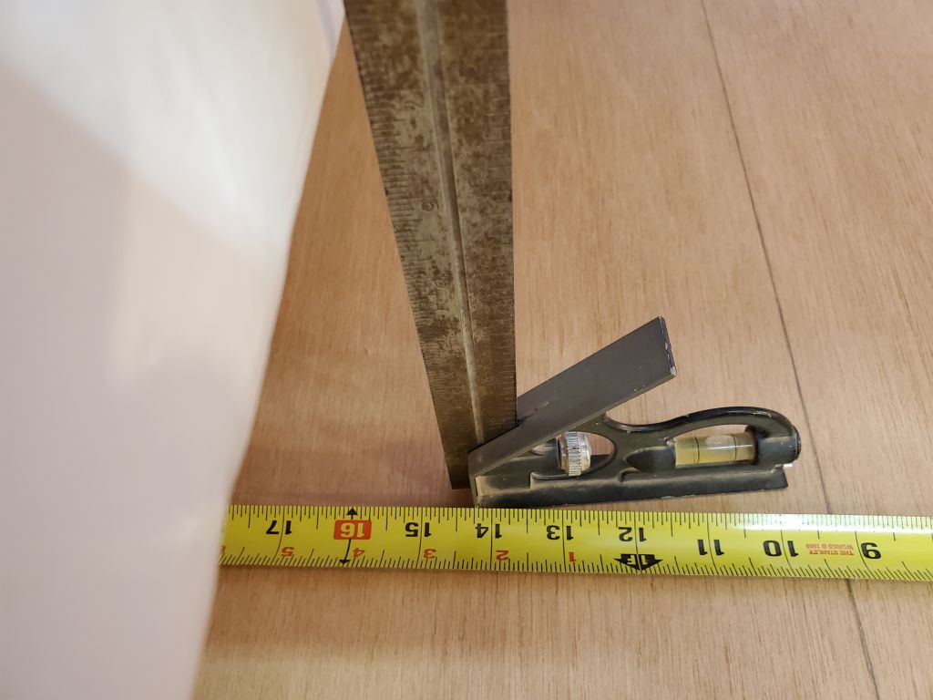
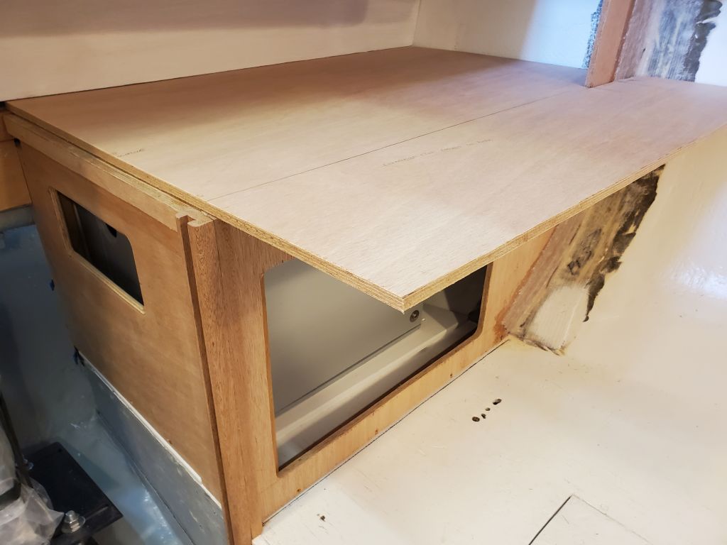
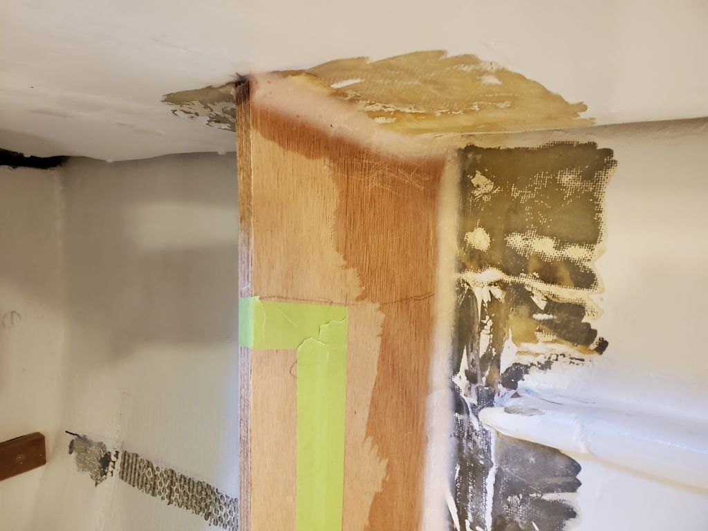
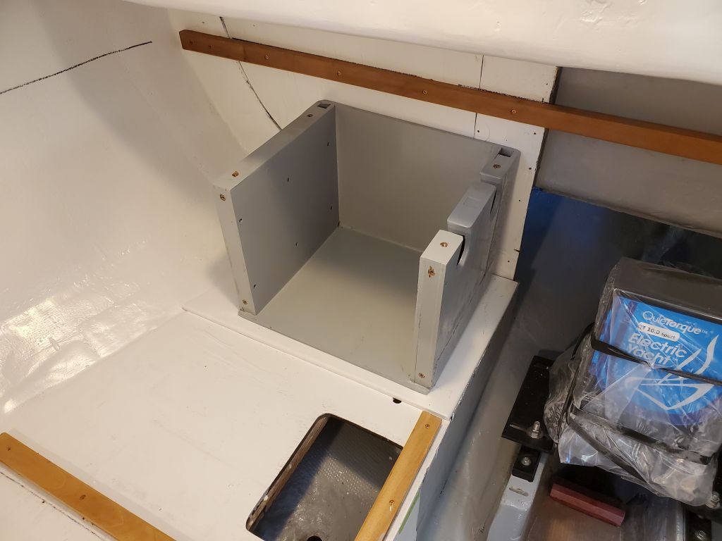
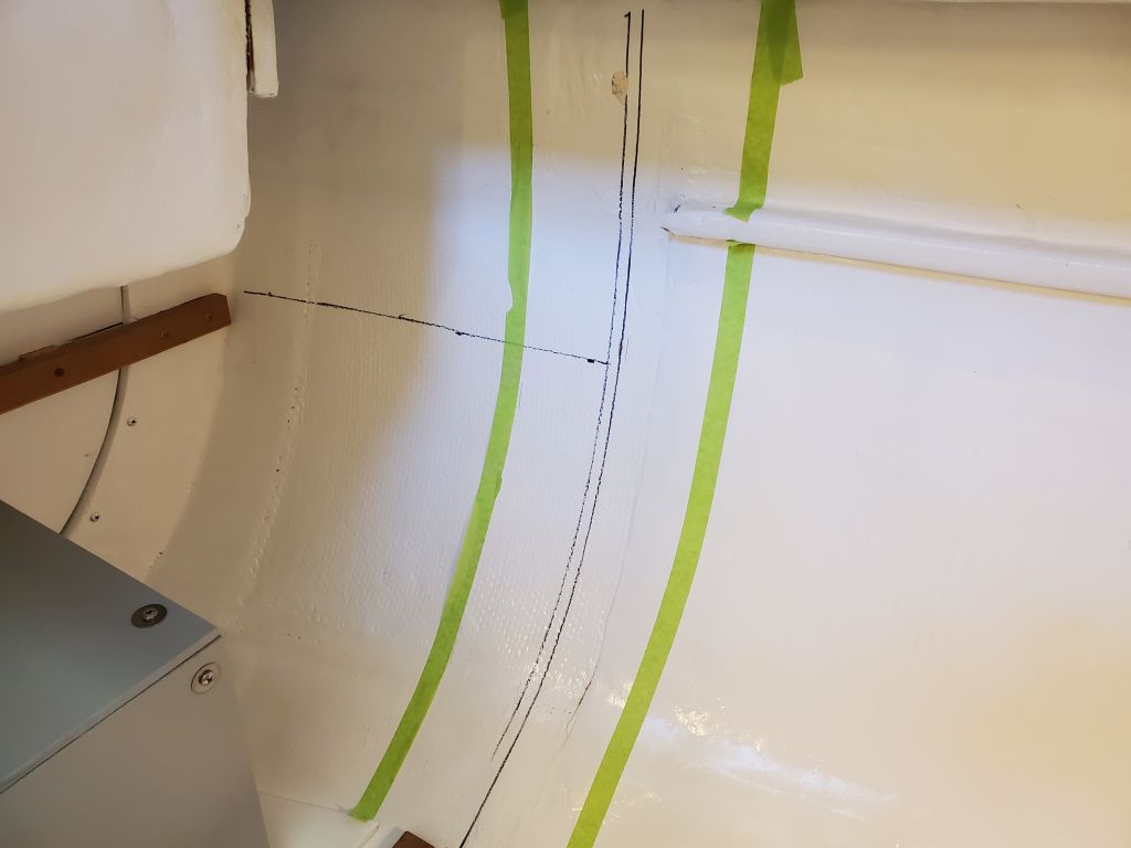
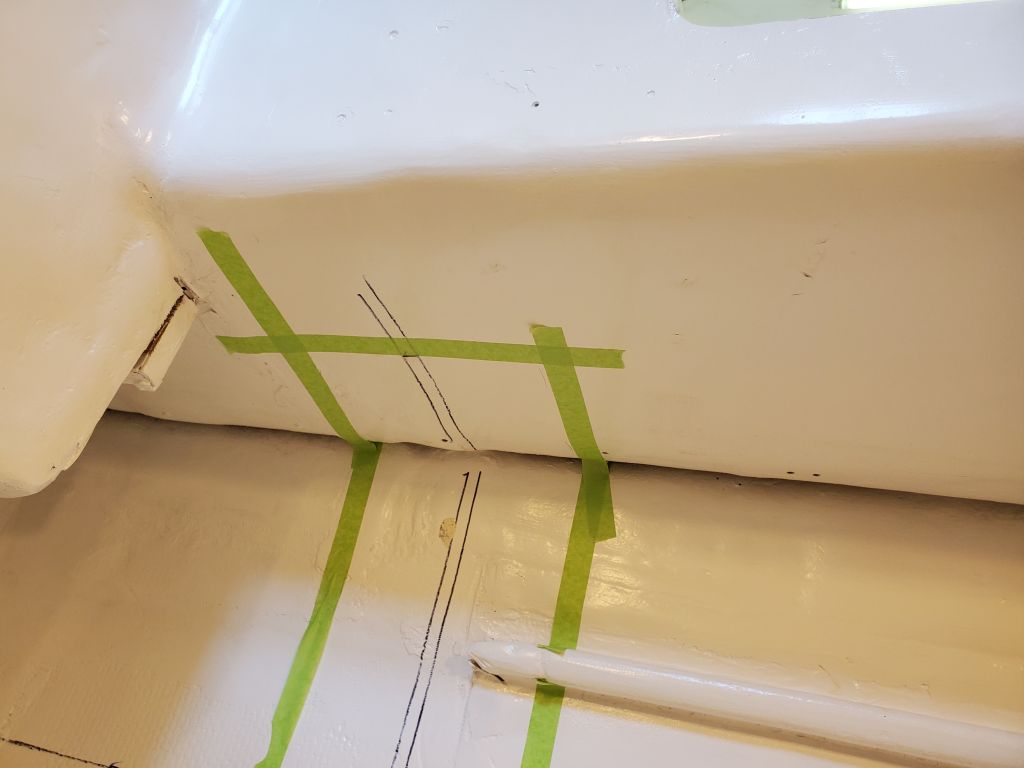
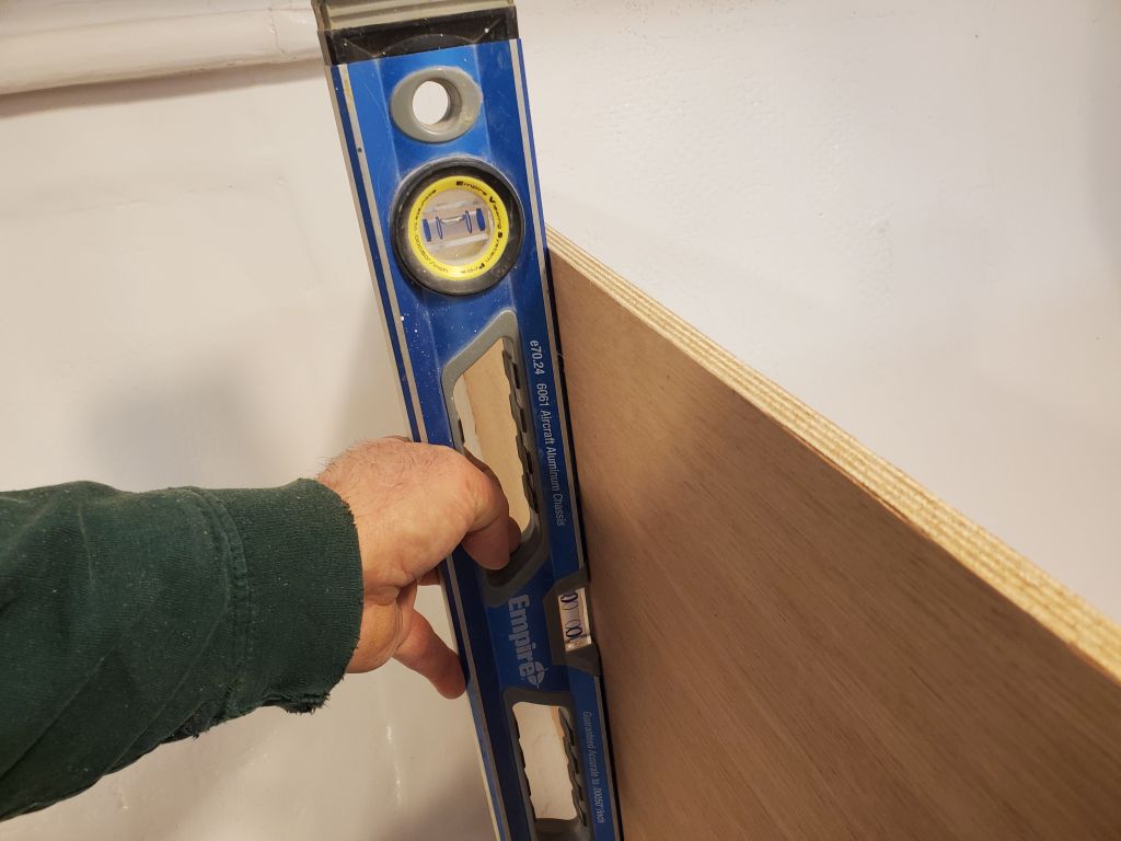
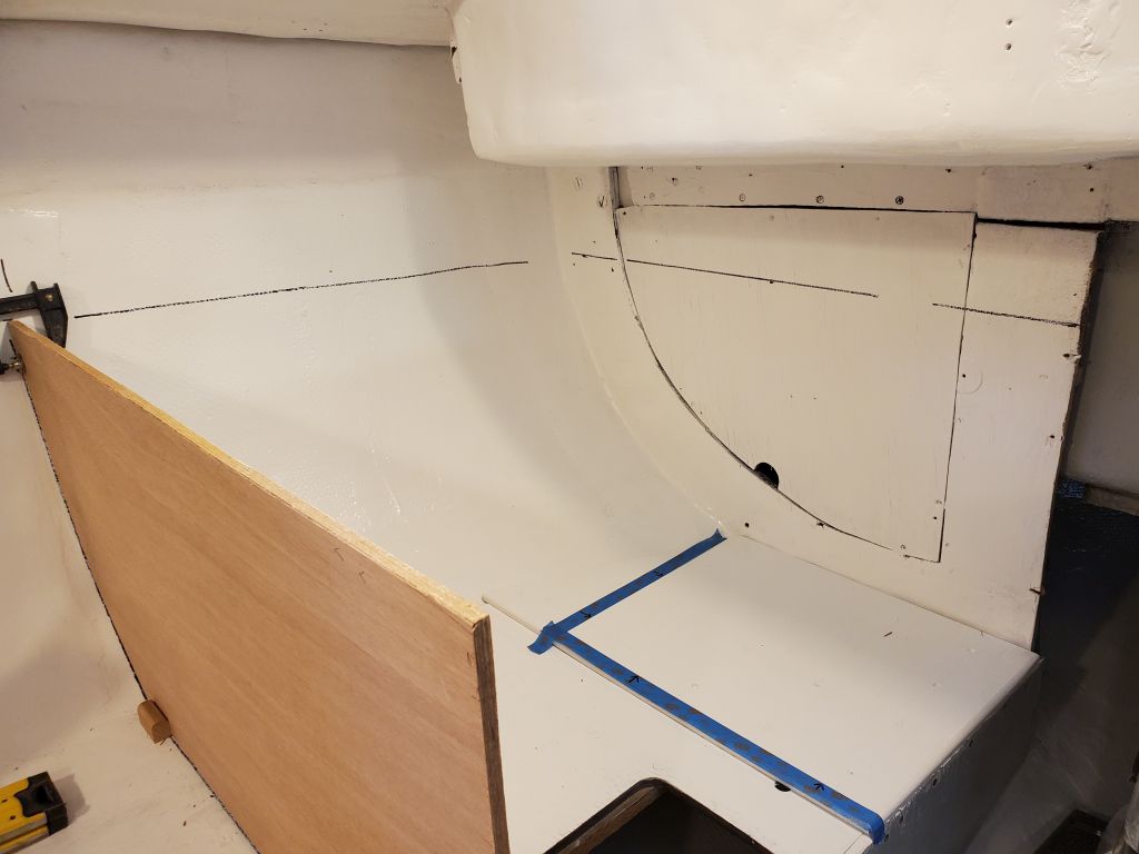
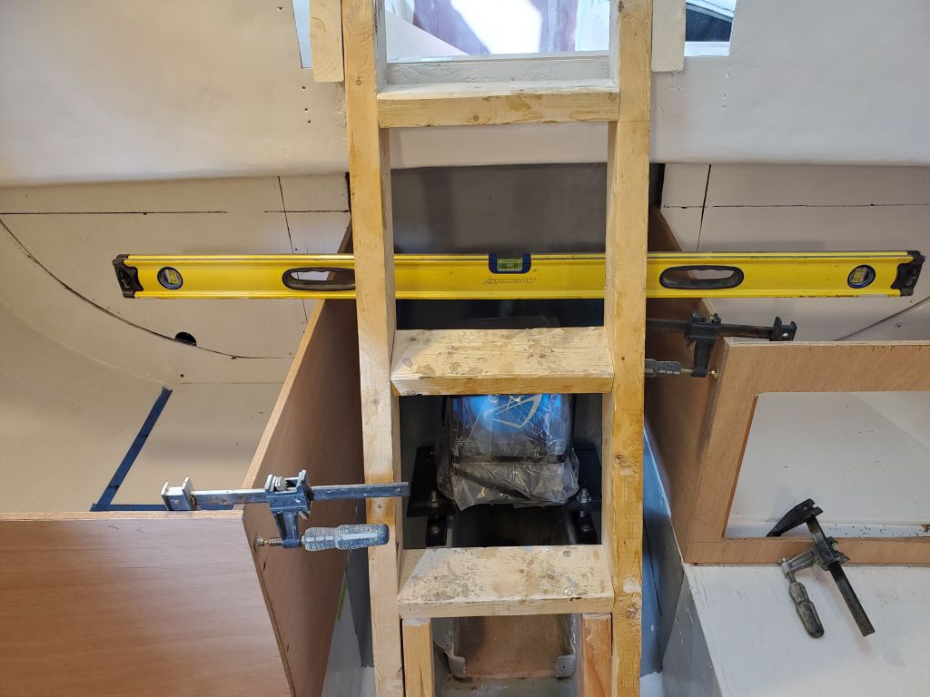
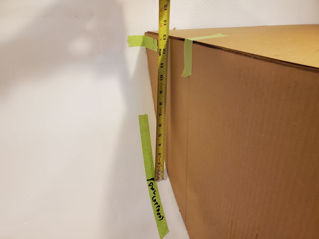
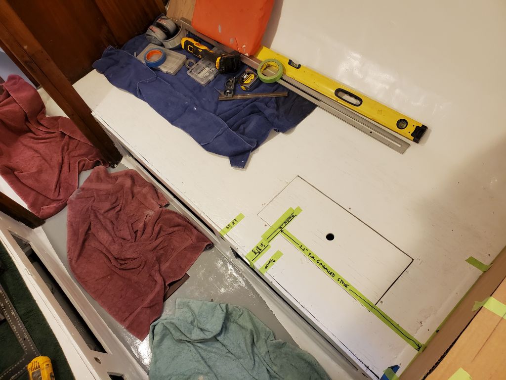
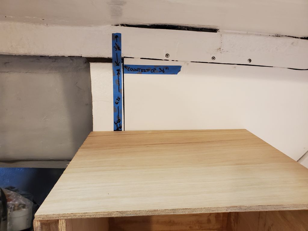
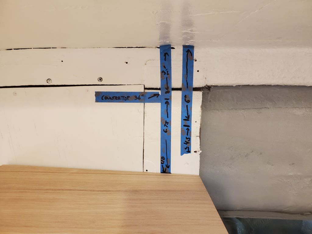
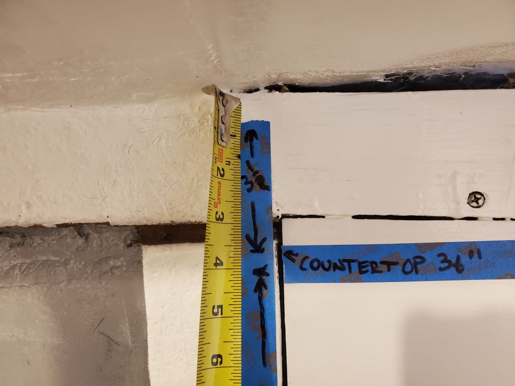
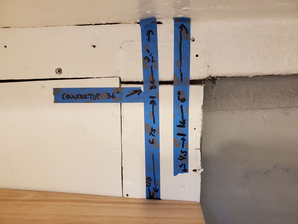
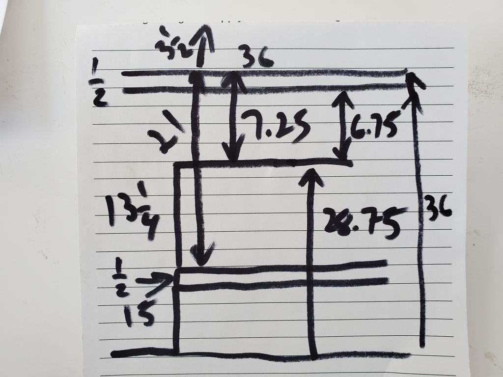
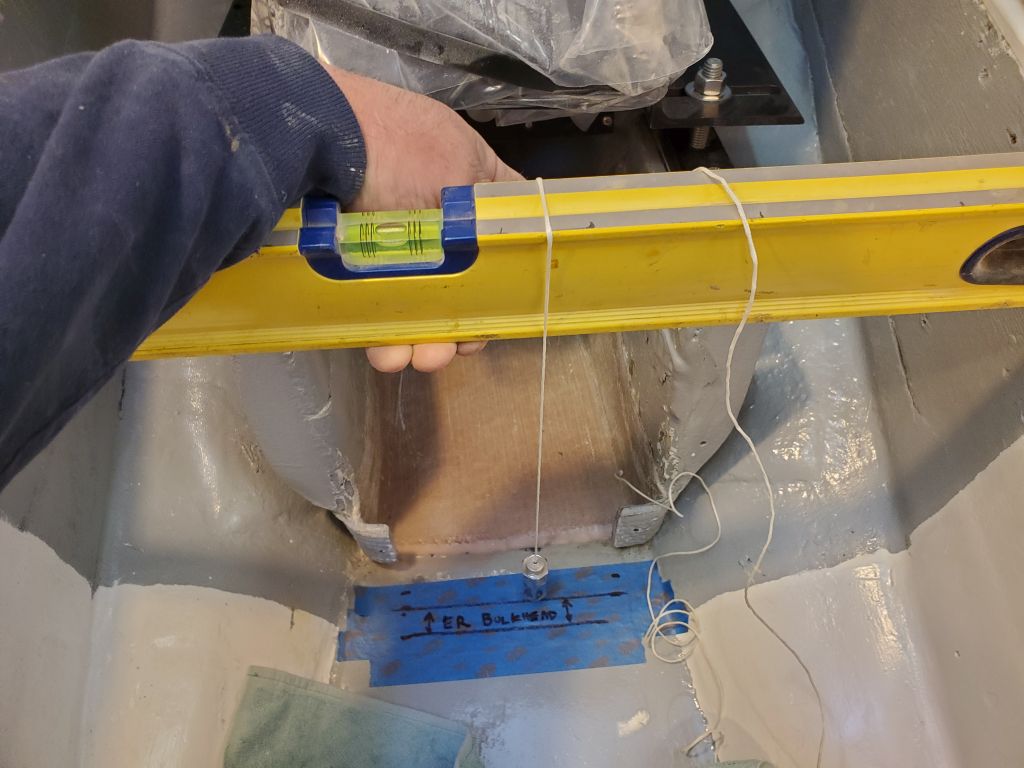
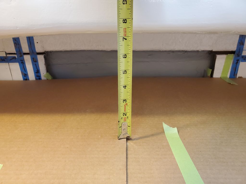
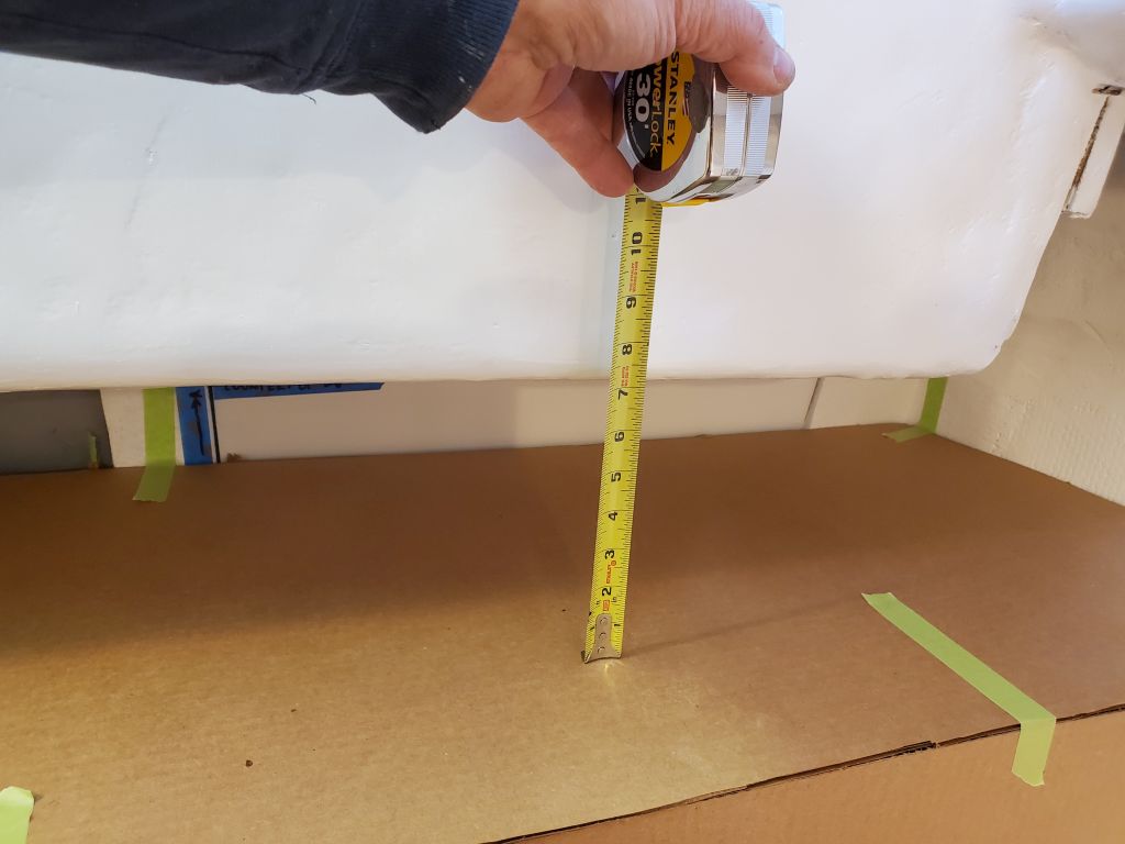
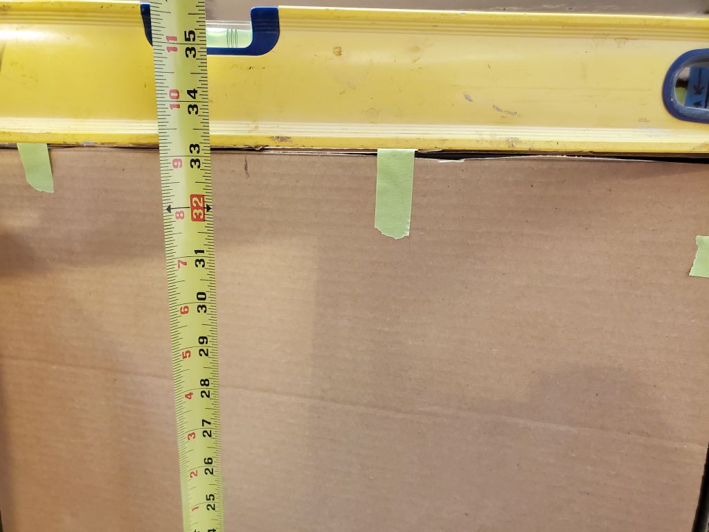
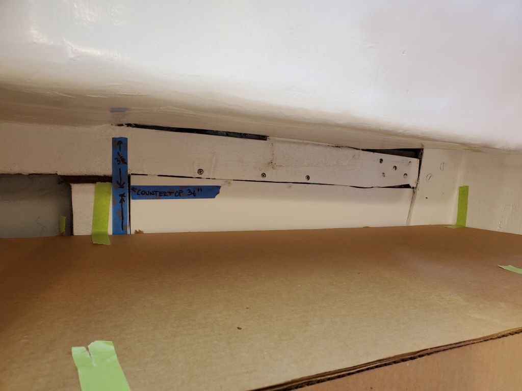
With the lid atop the boxes, I made further reference marks on the aft bulkhead on each side, aimed at determining the final height of the countertop. The boxes were about 13-1/4″ tall, plus the 1/2″ underlayment, so with a 15″ settee height above the cabin sole, and a theoretical countertop of 36″–a standard for kitchen counters–this allowed nearly 7″ clearance between the underside of the countertop (at this proposed height) and the top of the battery box. However, this left the clearance between the countertop and the bridgedeck at only 3-1/2″–far too narrow to allow access beneath or working utility. Looking for a minimum of 6″ clearance, I made some additional measurements from the bridgedeck down, marking these on the bulkhead as well. At this point, in my mind I settled on a 33″ final countertop height, which was still high enough for comfort and to clear all the requirements beneath, but allowed over 6″ of overhead clearance to the bridgedeck–a key consideration for the owner, and for the general utility of the galley.
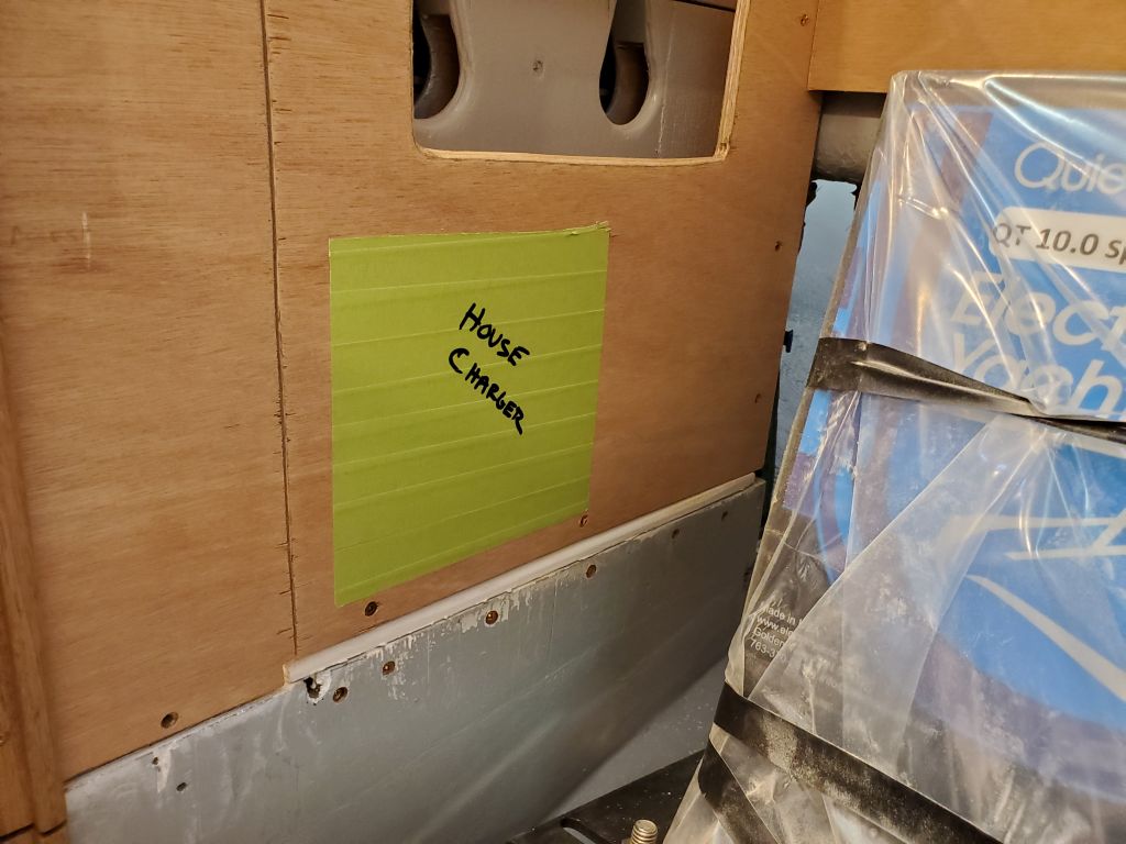
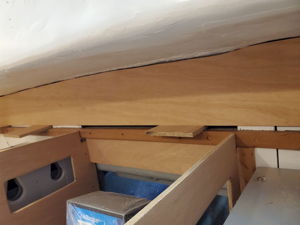
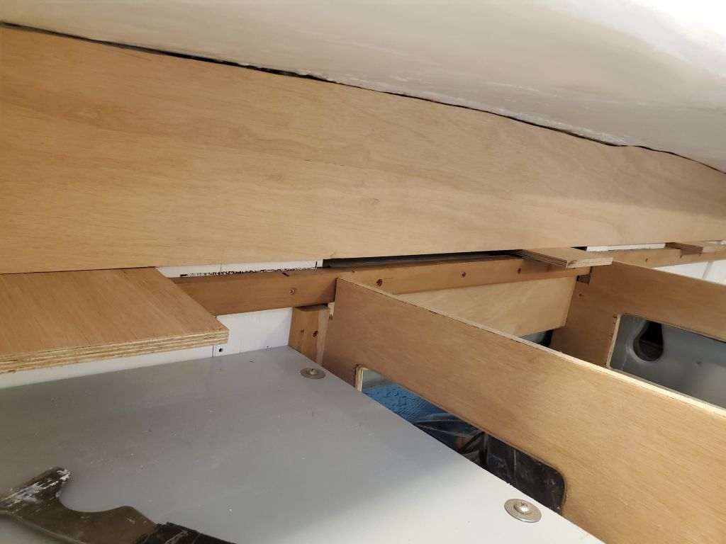
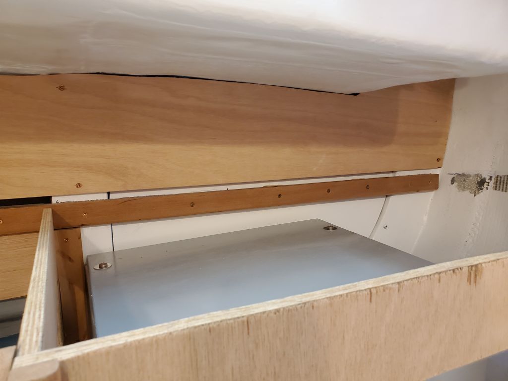
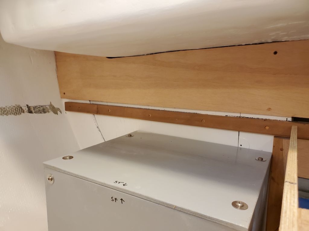
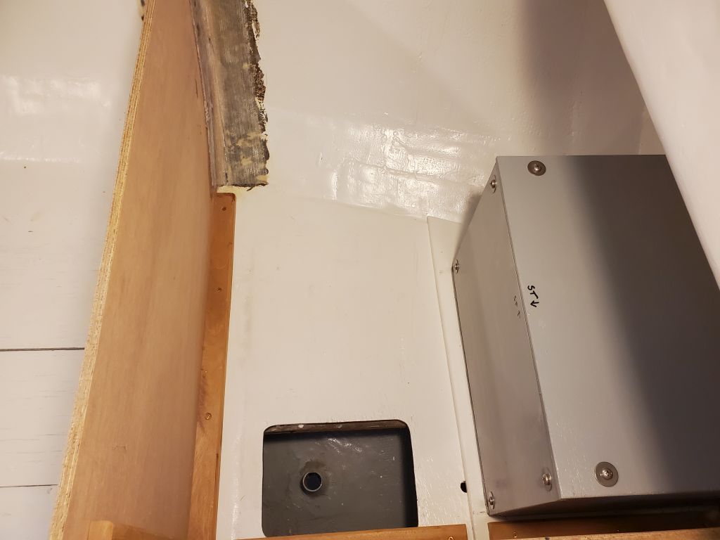
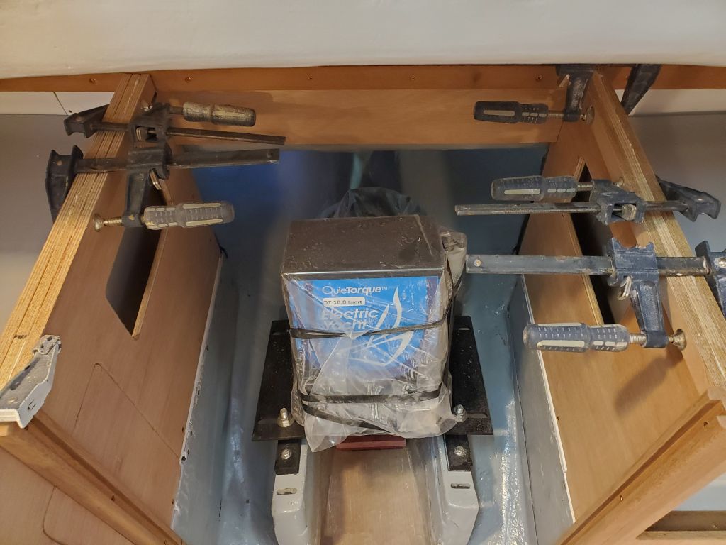
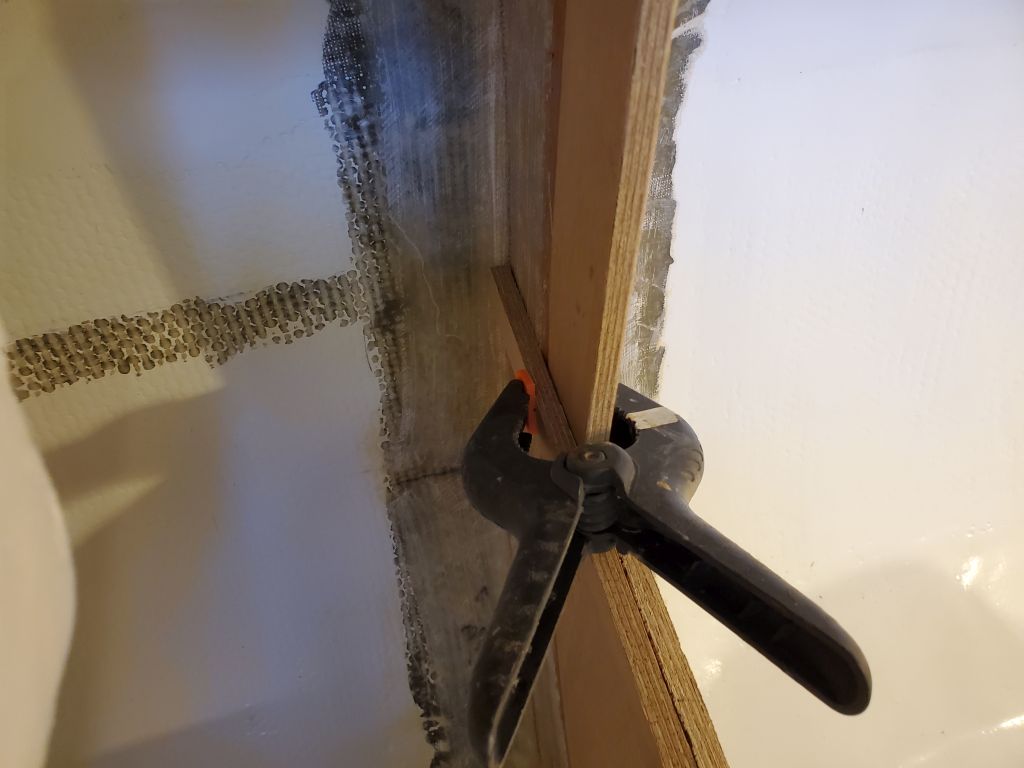
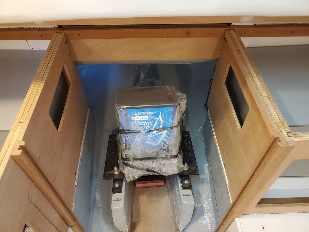
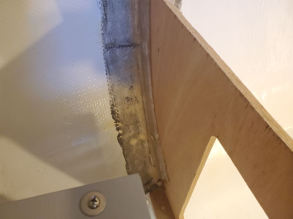
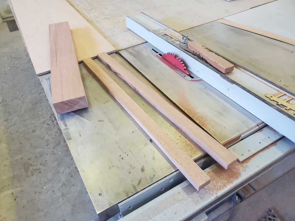
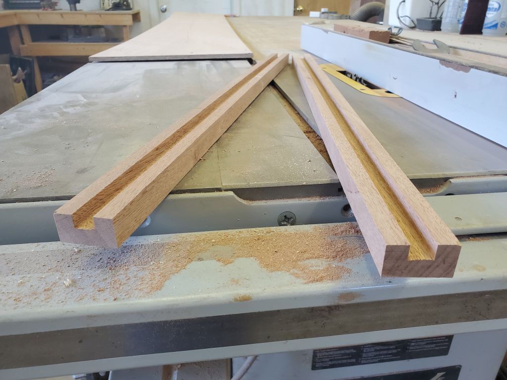
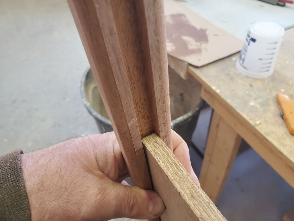
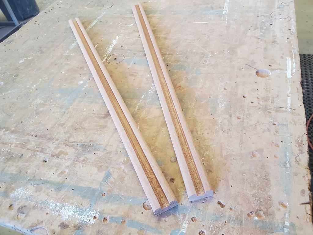
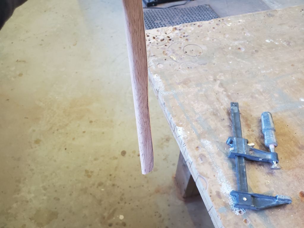
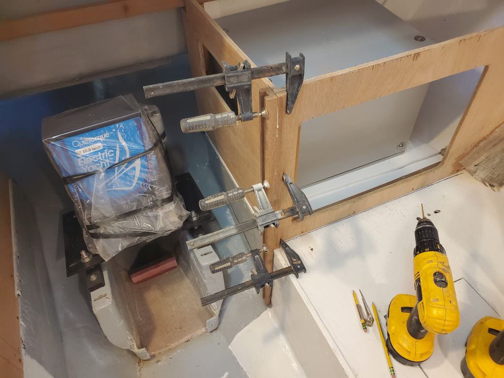
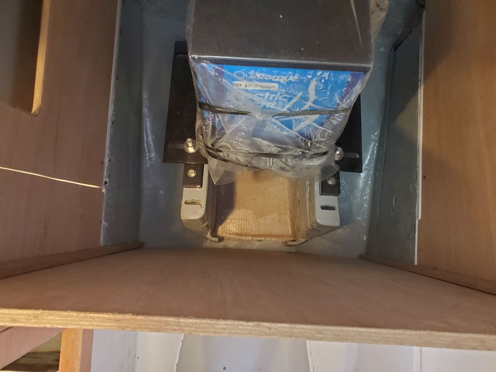
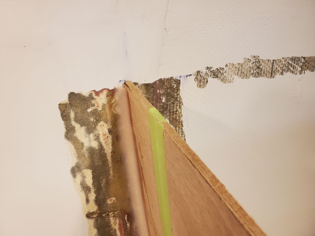
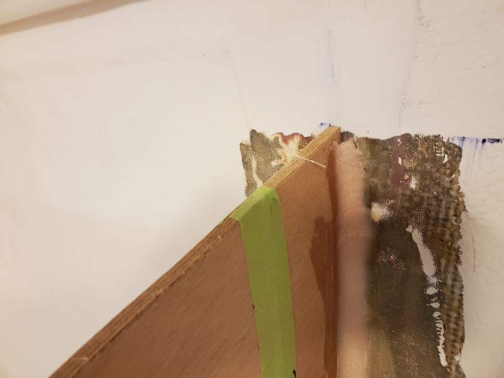
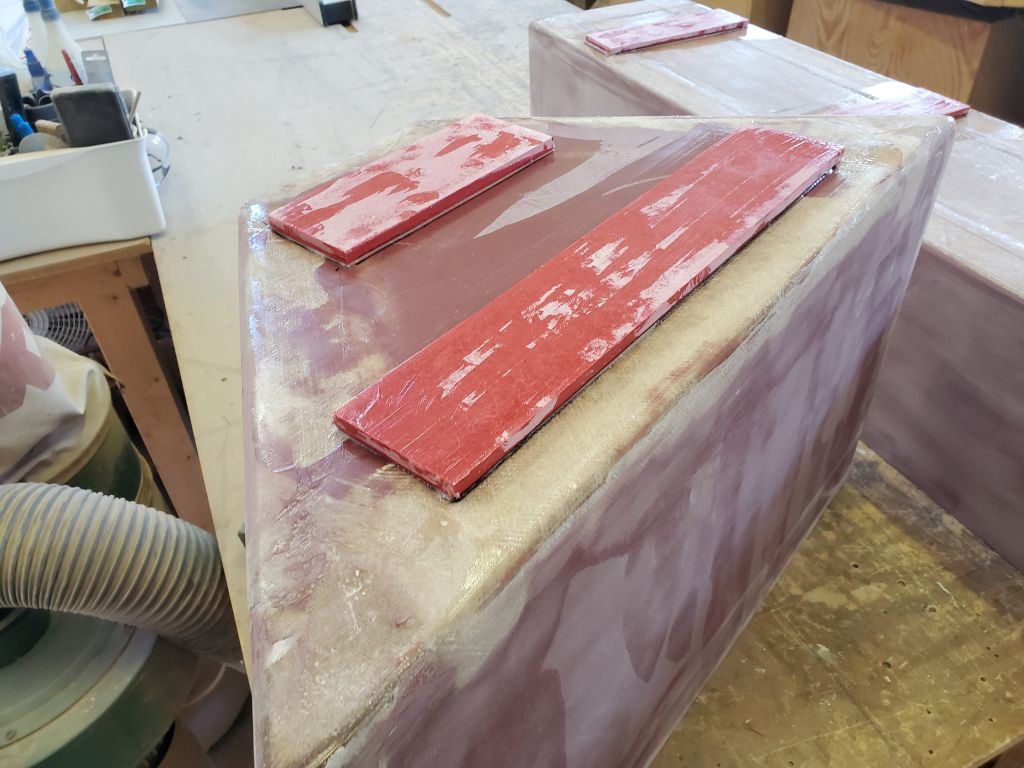
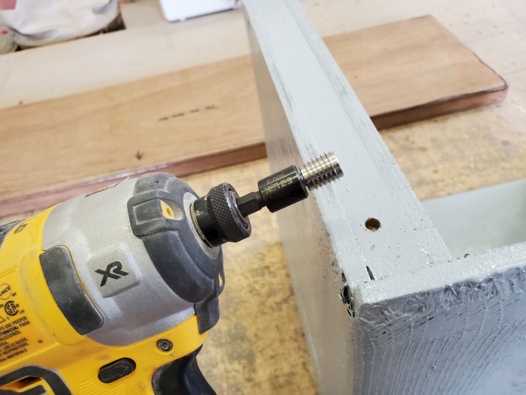
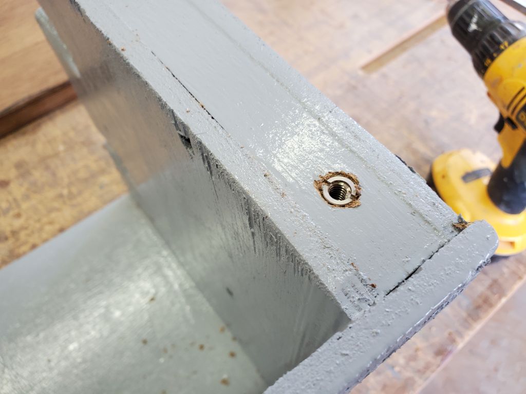
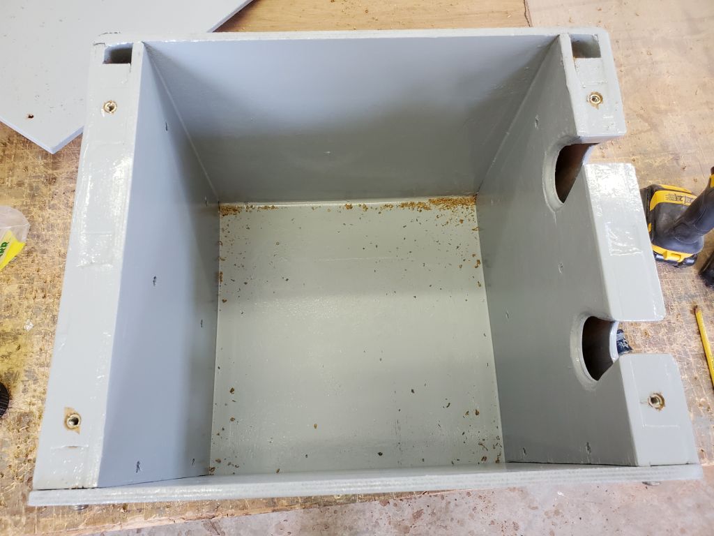
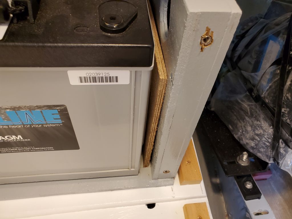
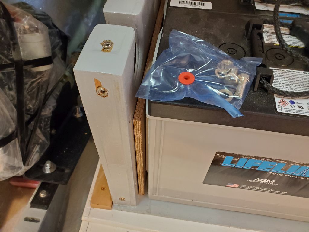
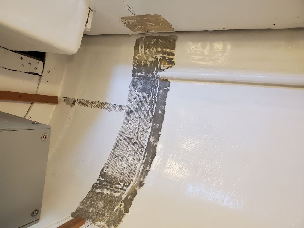
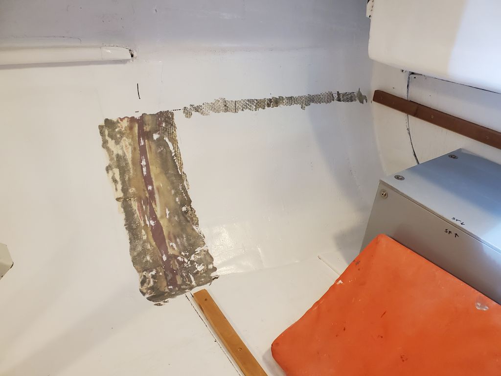
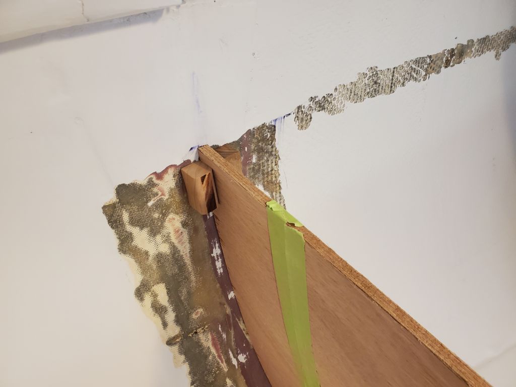
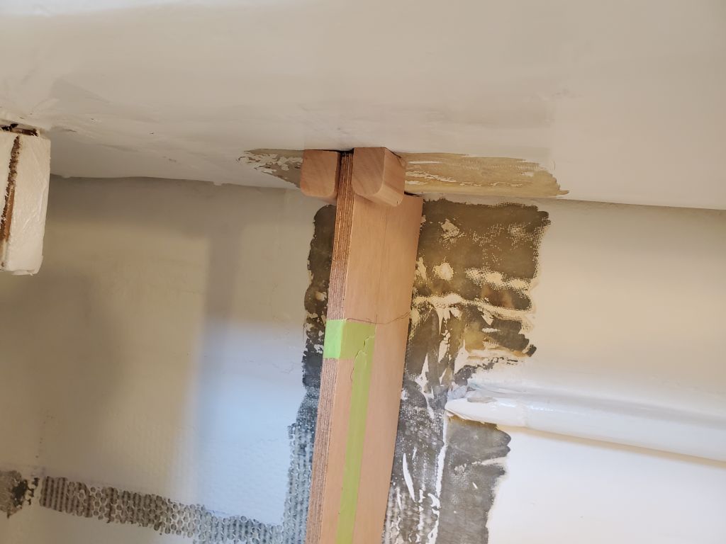
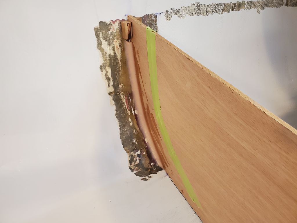
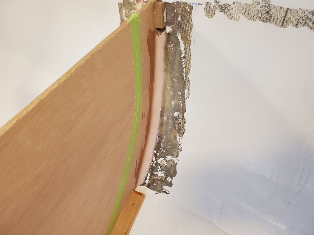
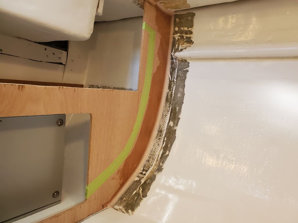
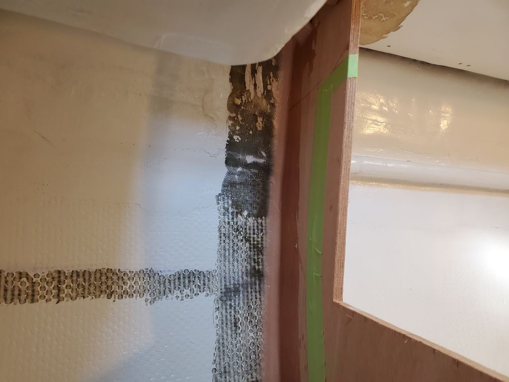
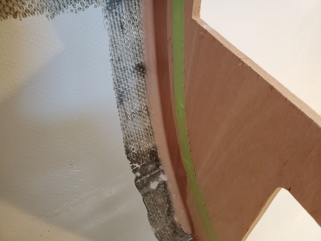
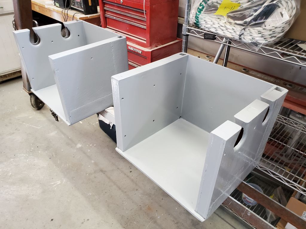
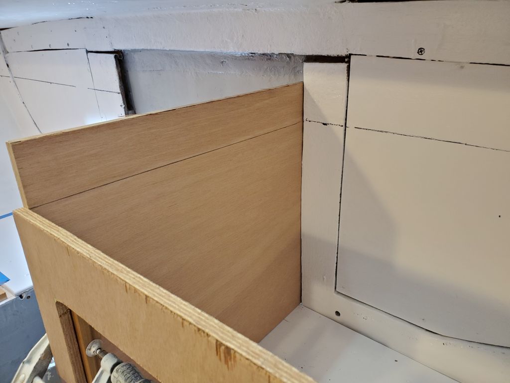
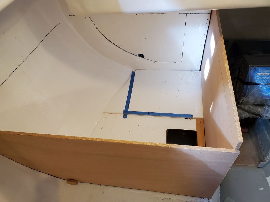
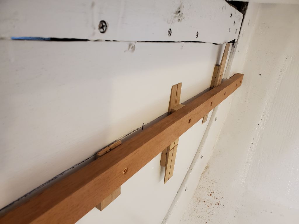
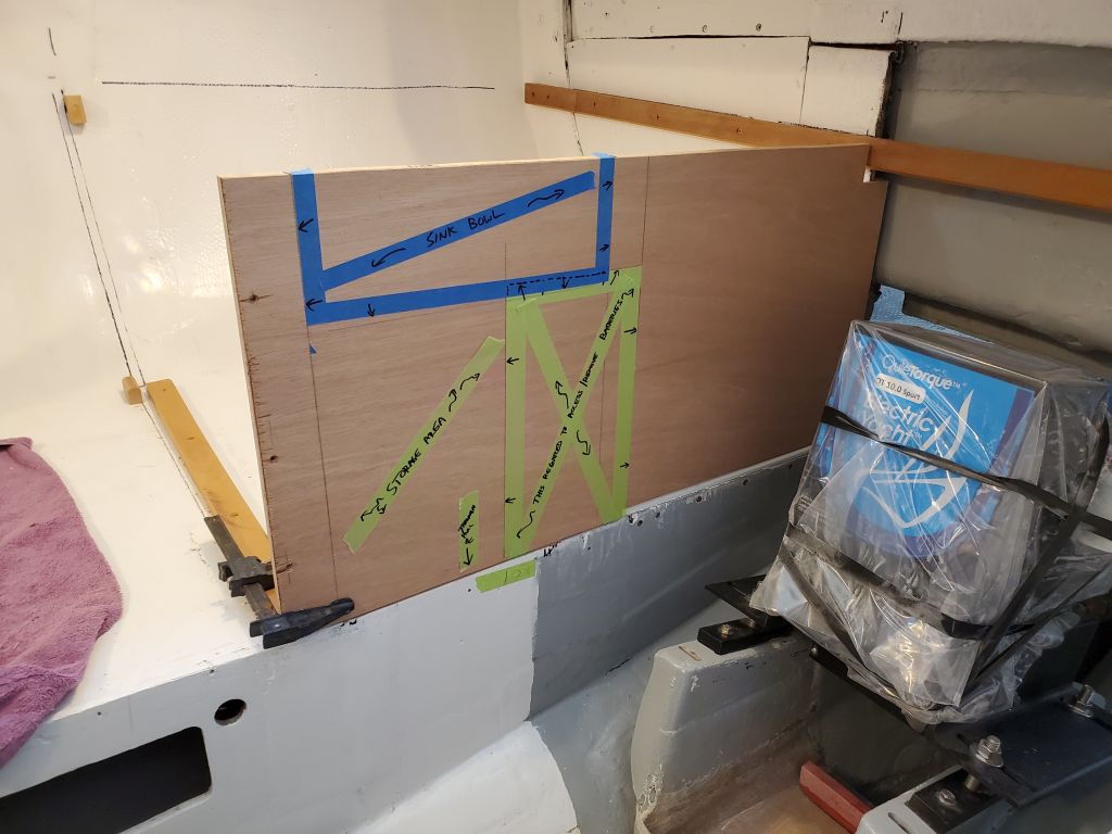
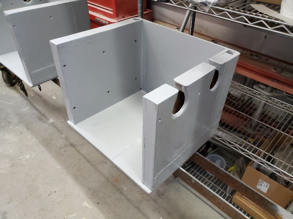
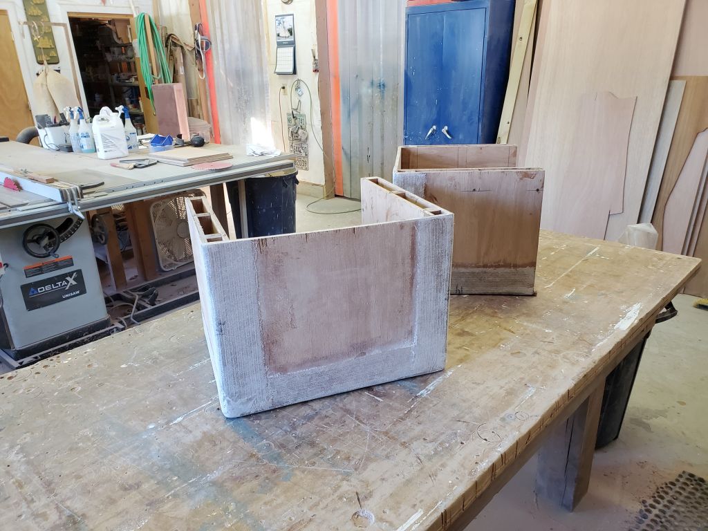
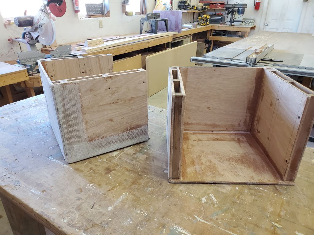
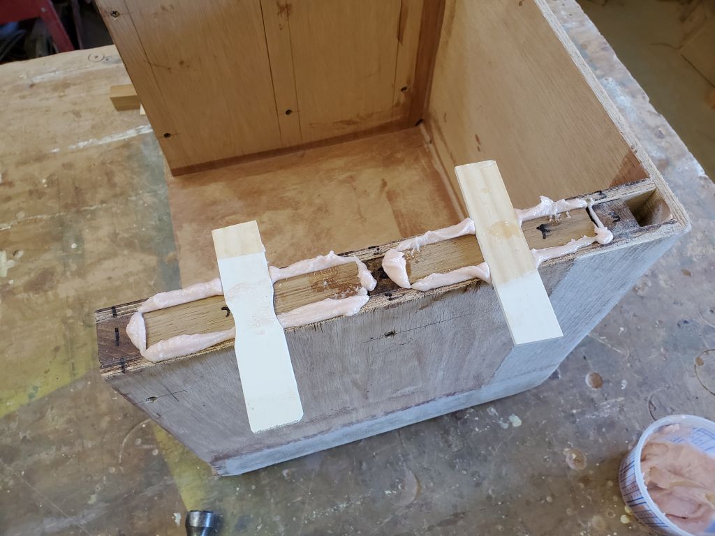
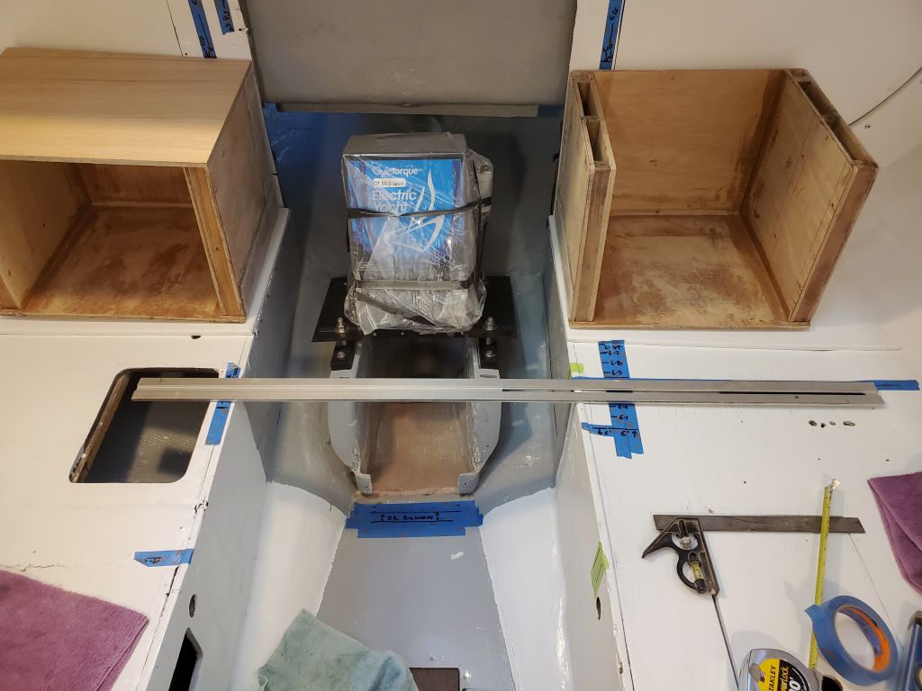
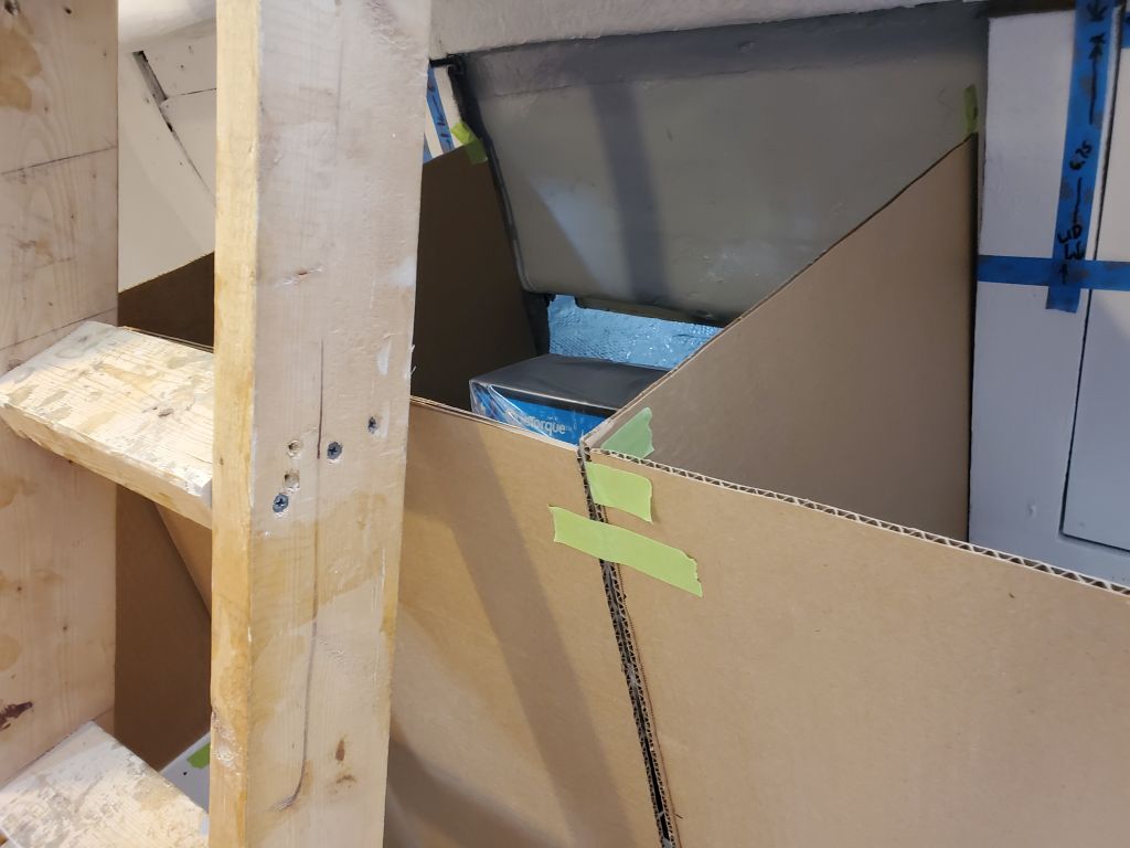
With tape, I marked the outlines of the battery boxes (footprint and height) for continuing reference, but moved the boxes out of the way for the duration, and to complete a bit of additional structural work. I’d changed my original thinking on how to secure the tops of these boxes–I’d been thinking of some hold-down clamps, but ultimately decided simply to use screws, same as my plan for the removable fronts. So to provide a landing surface for the screws (and threaded inserts I planned), now I had to add some solid wood in the voids at the tops of the box sides, a simple task with more scrap hardwood and epoxy. To prevent the new inserts from sliding down at all, I hot-glued little strips to the top to hold them flush.
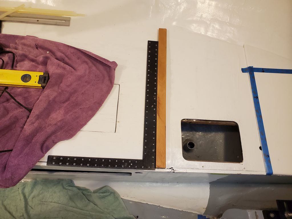
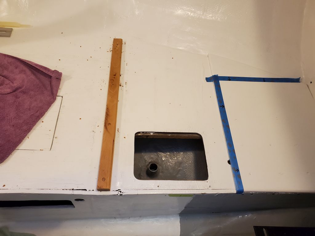
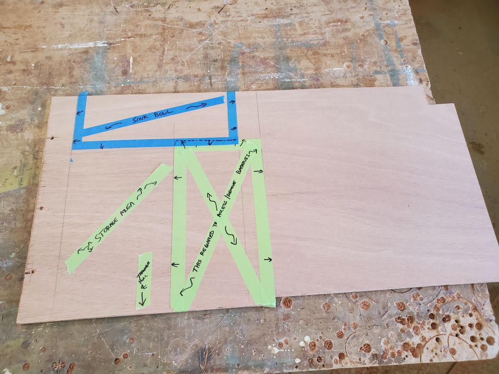
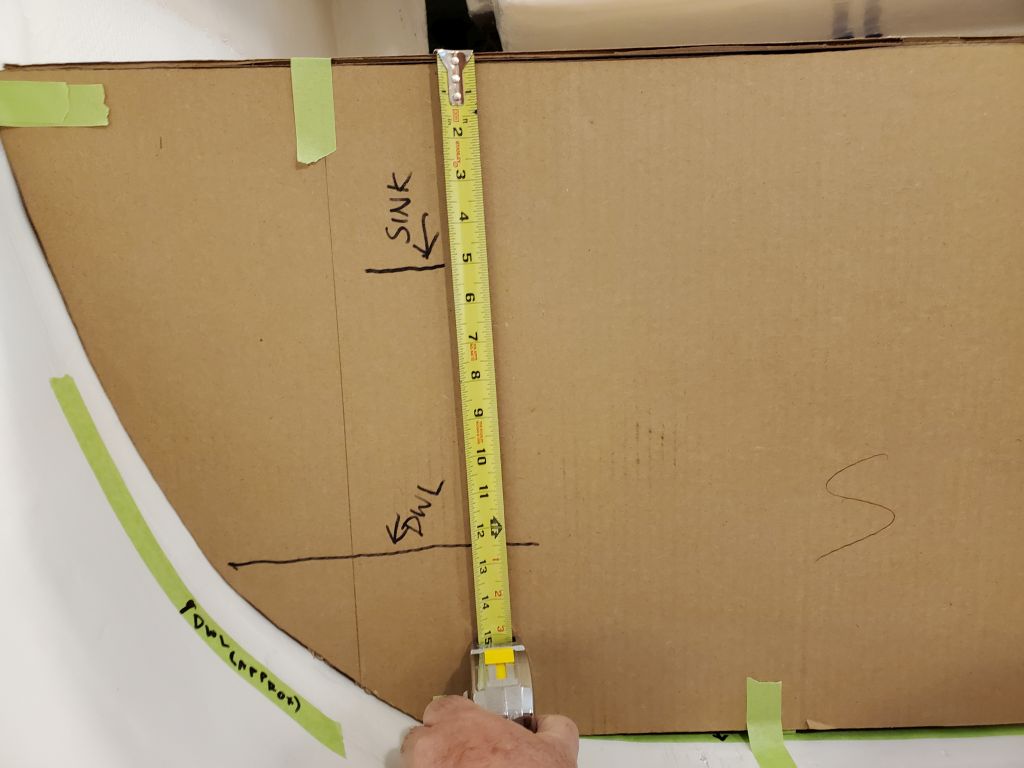
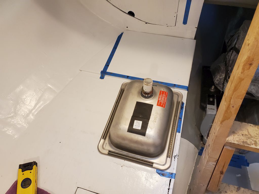
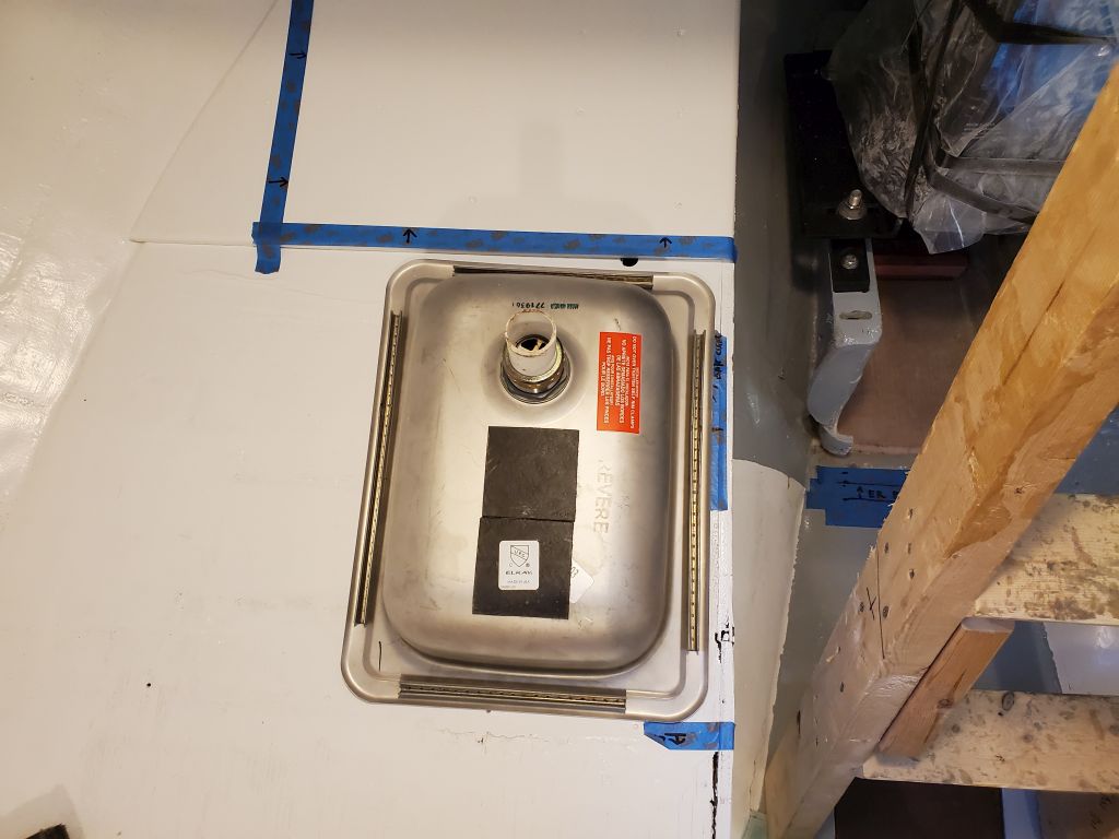
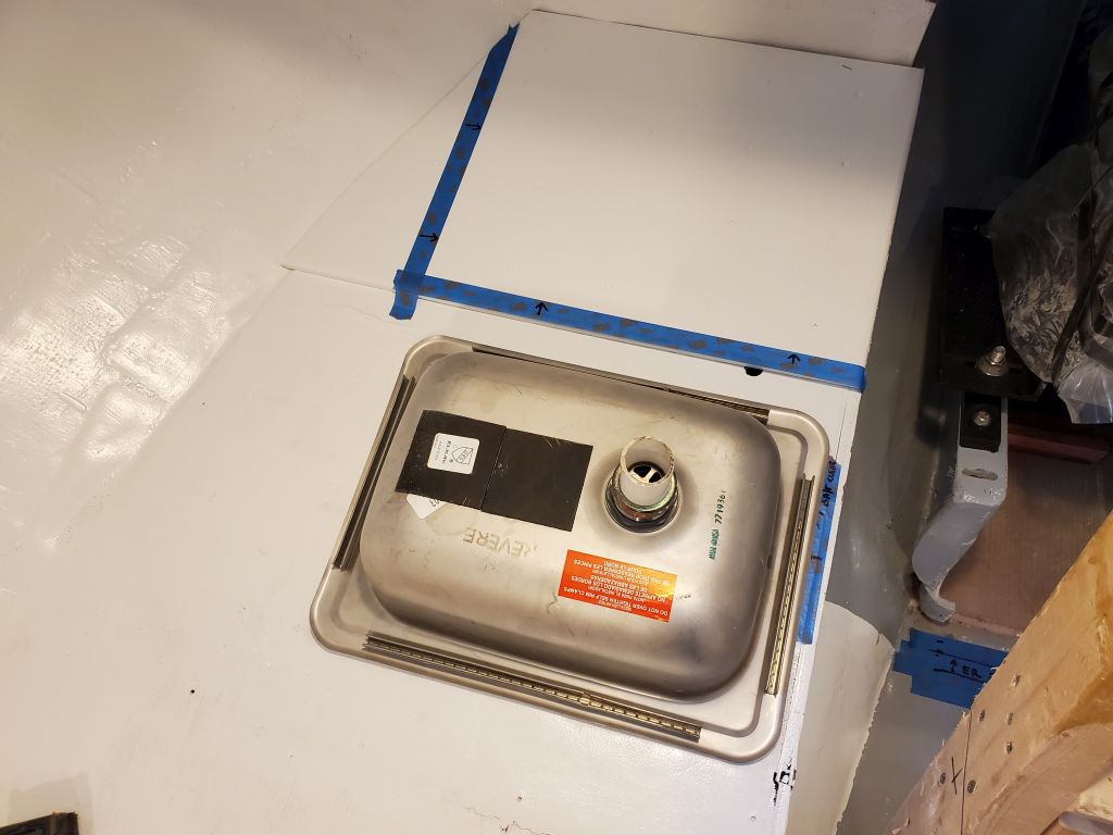
Now I could turn to the fore and aft arrangement of the two sides of the galley. At a minimum, the starboard side needed to allow room for a sink (on hand) forward of the batteries, and its overall location was more or less dictated by the drain through hull as well. I laid out the sink with its long dimension fore and aft, as well as sideways, and thought that the transverse arrangement worked better in all ways, so I planned accordingly.
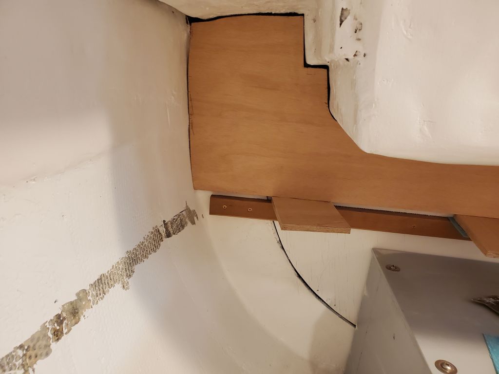
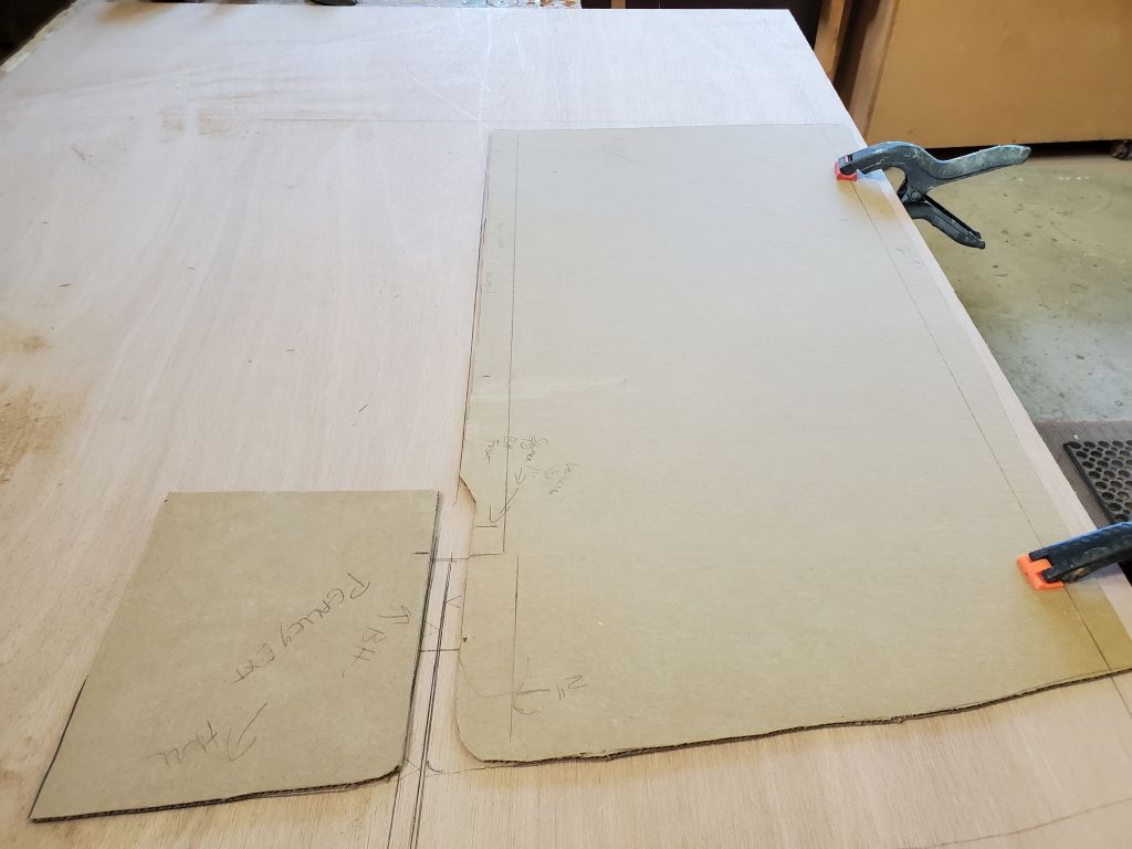
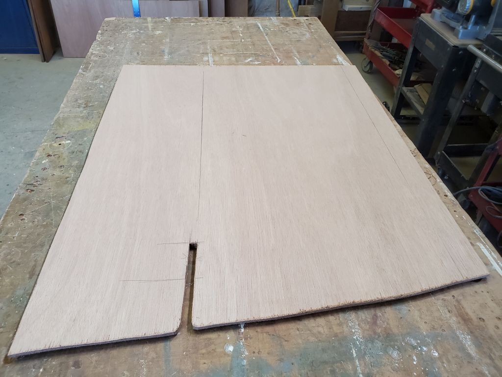
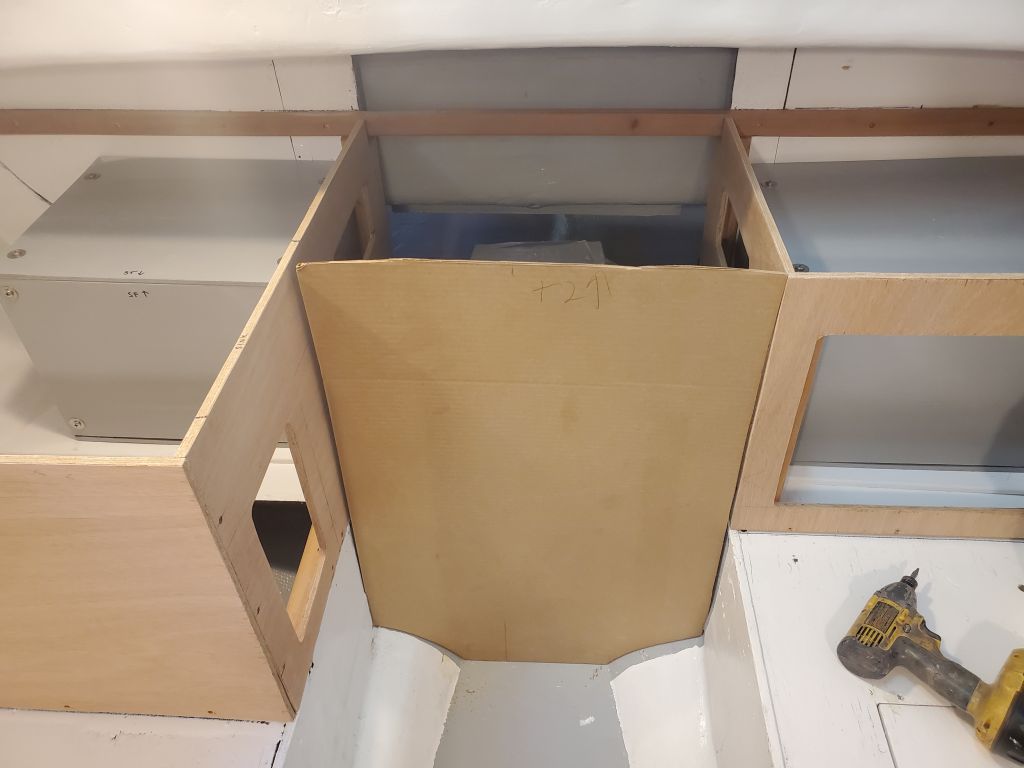
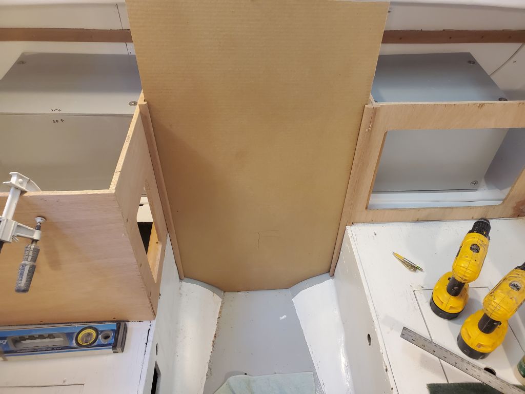
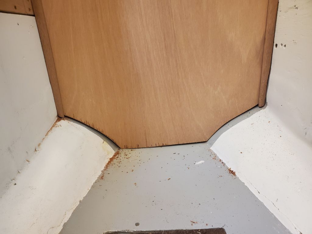
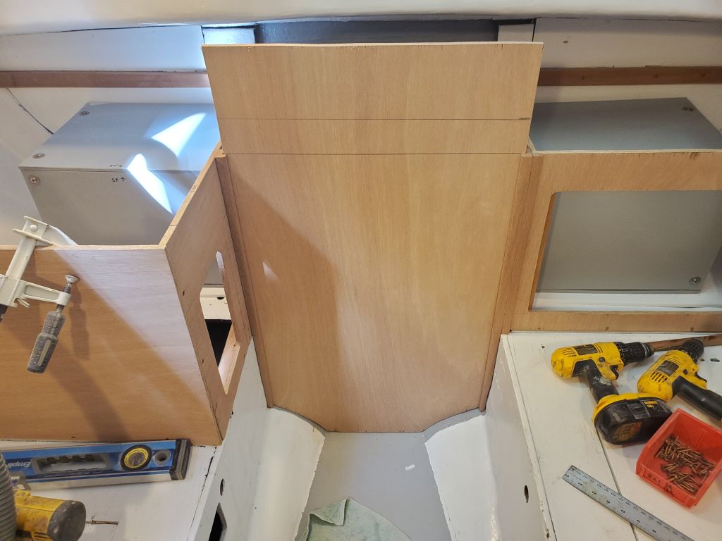
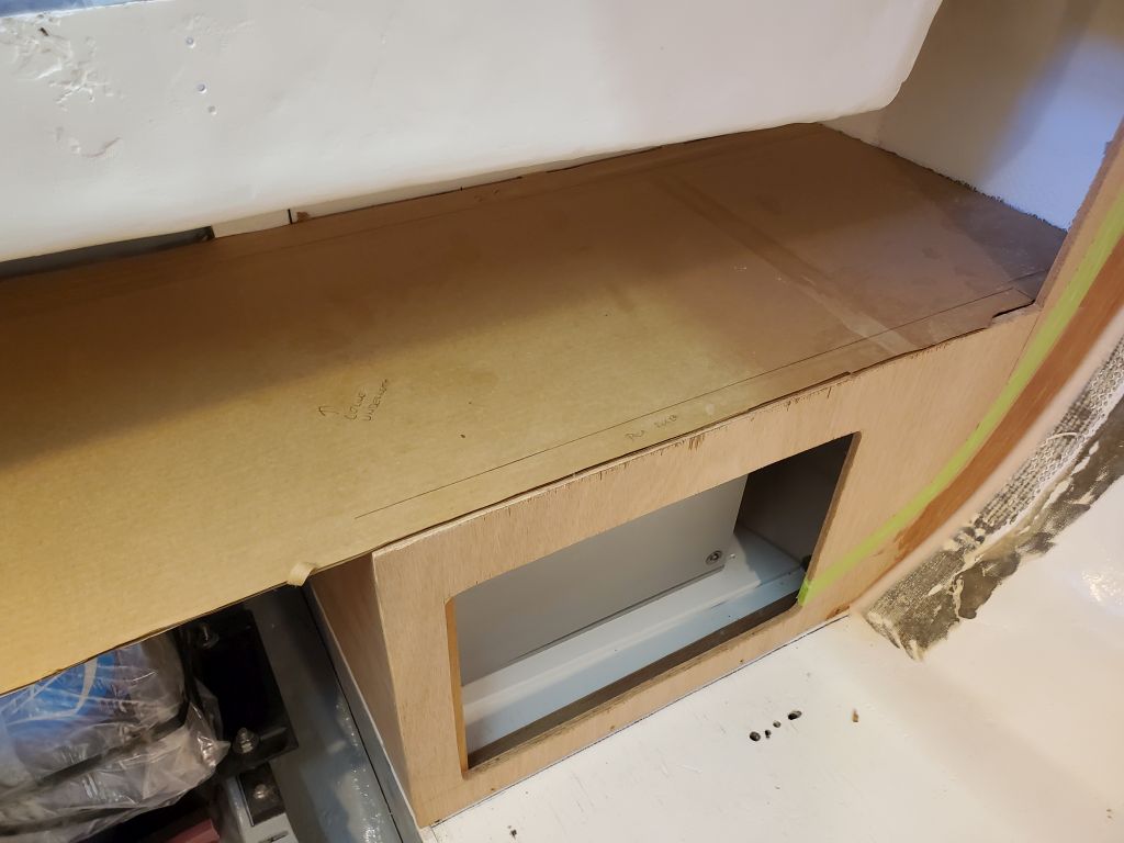
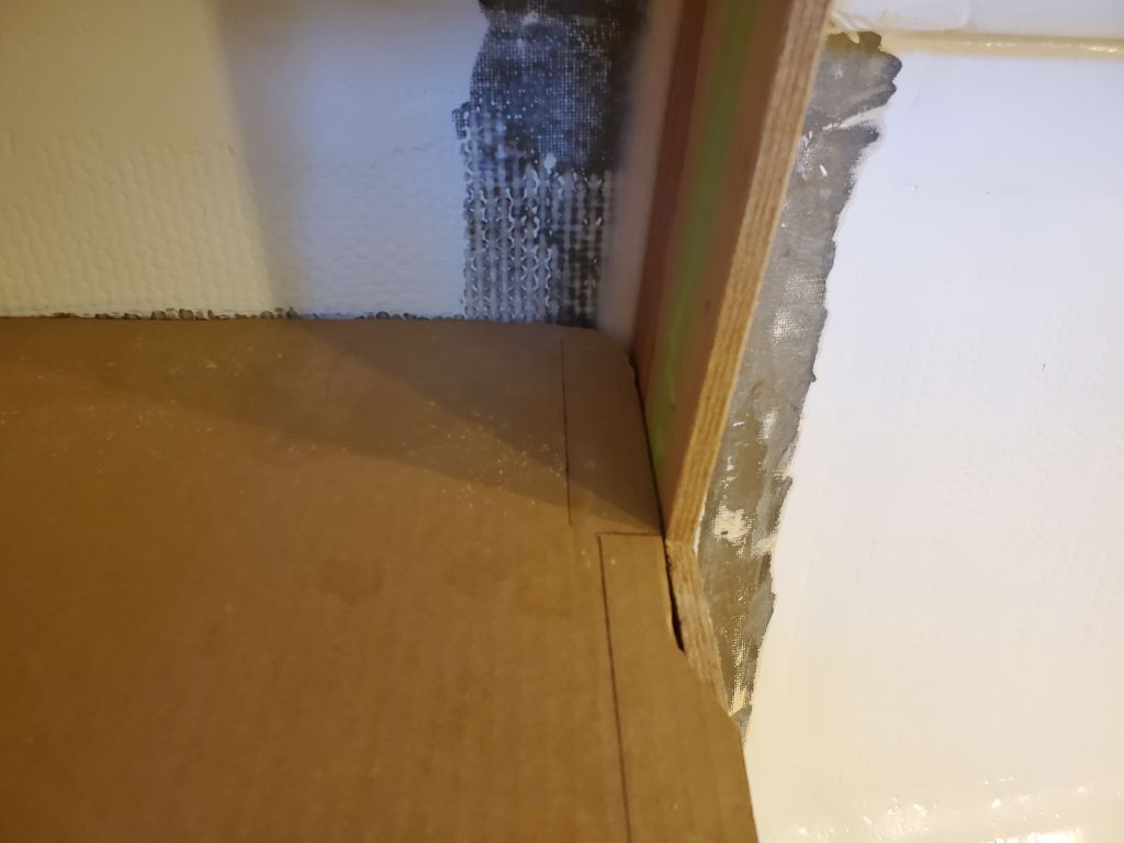
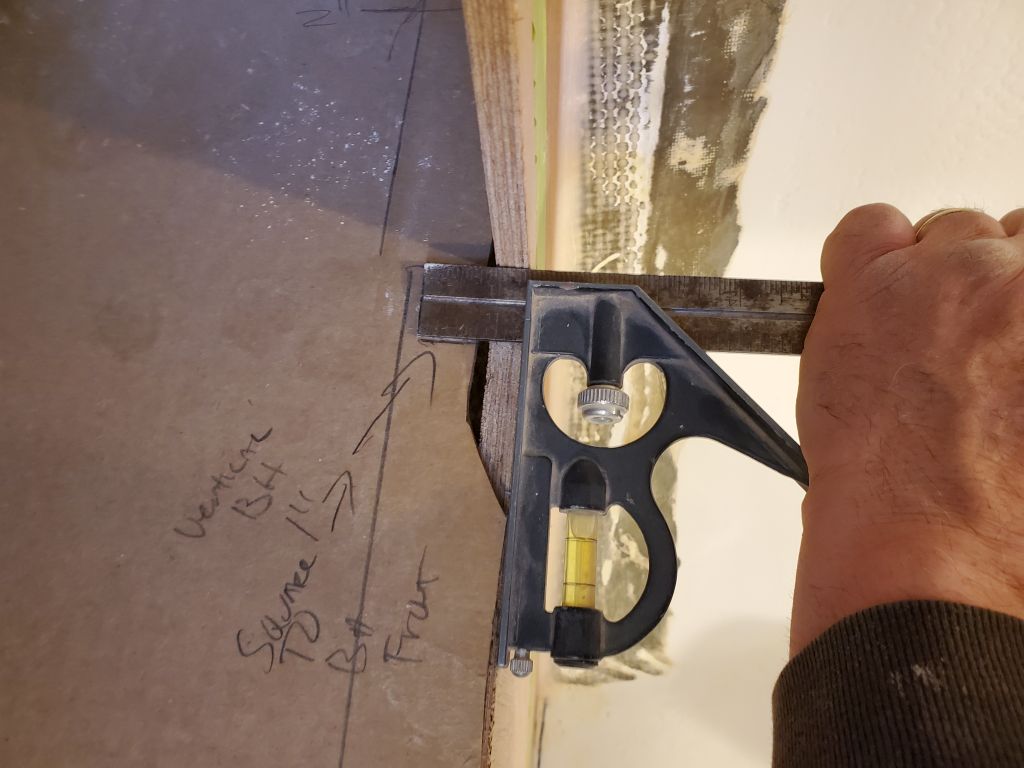
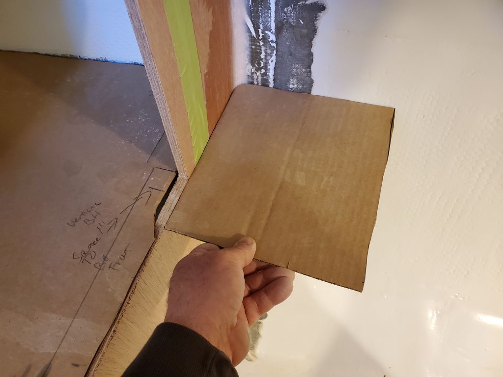
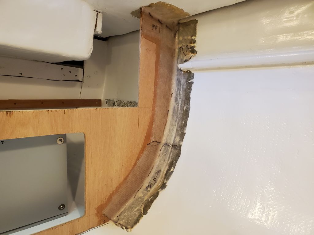
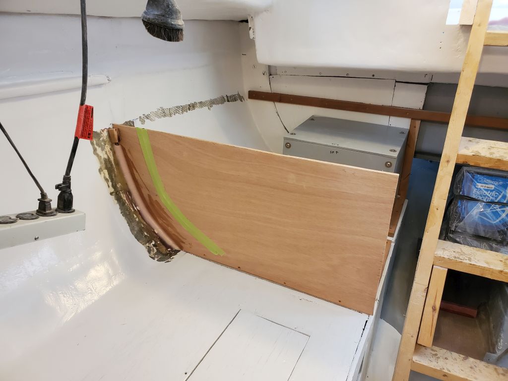
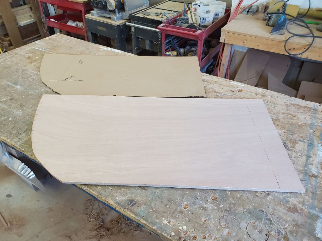
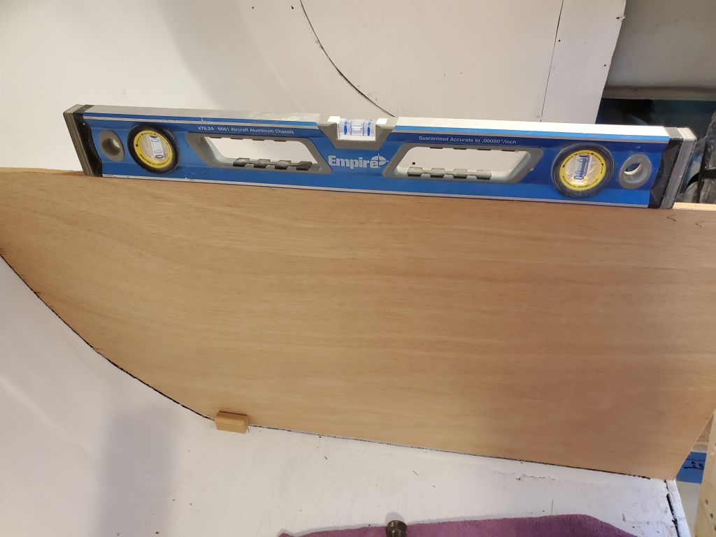
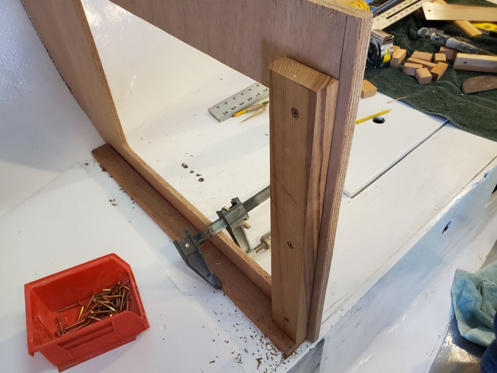
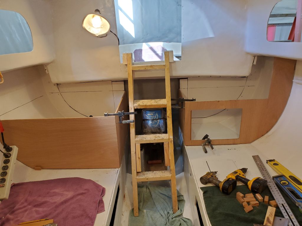
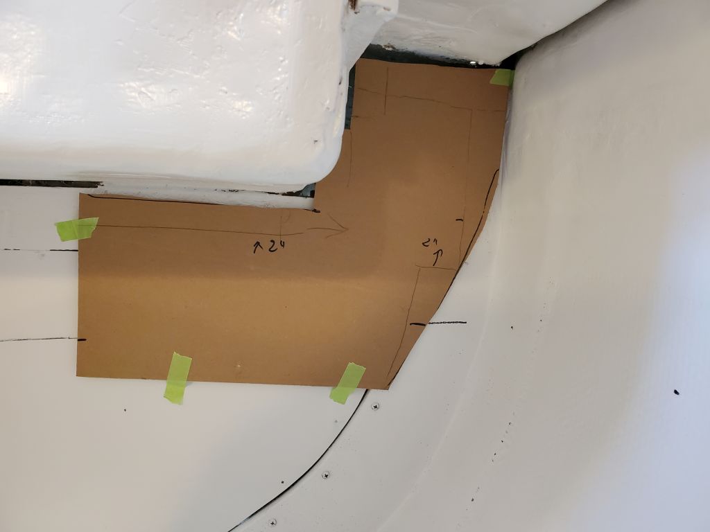
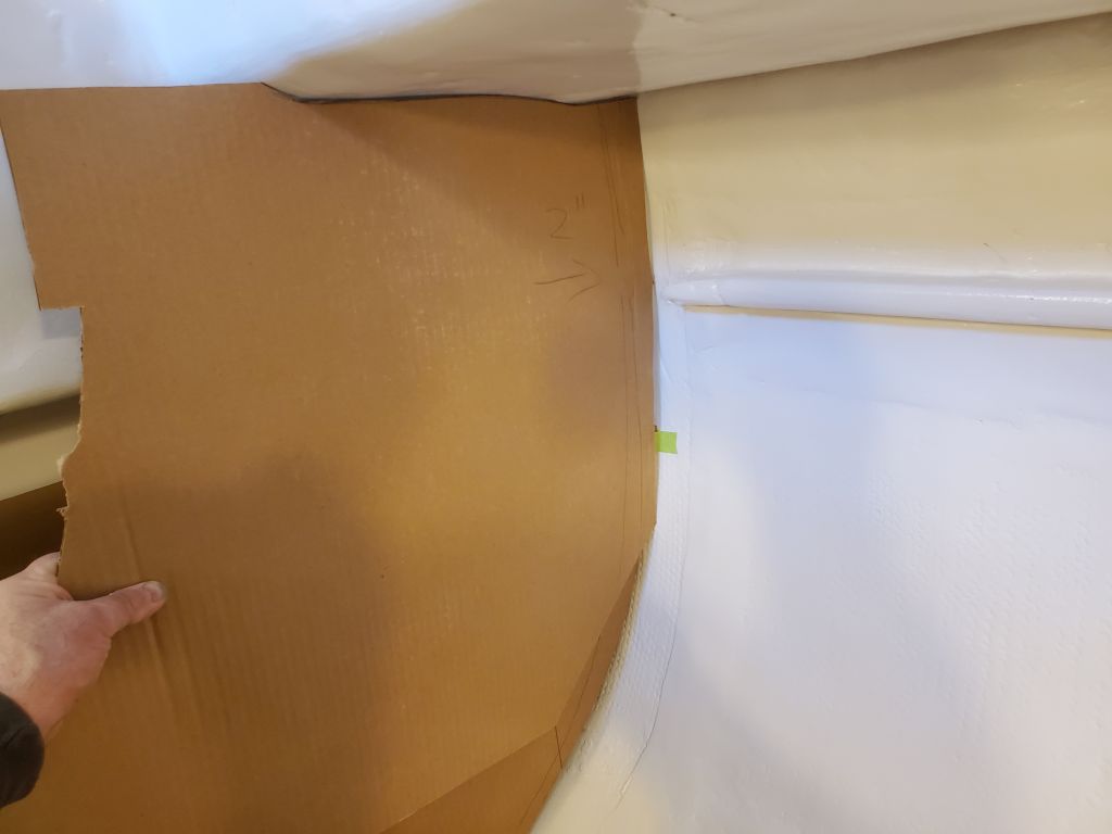
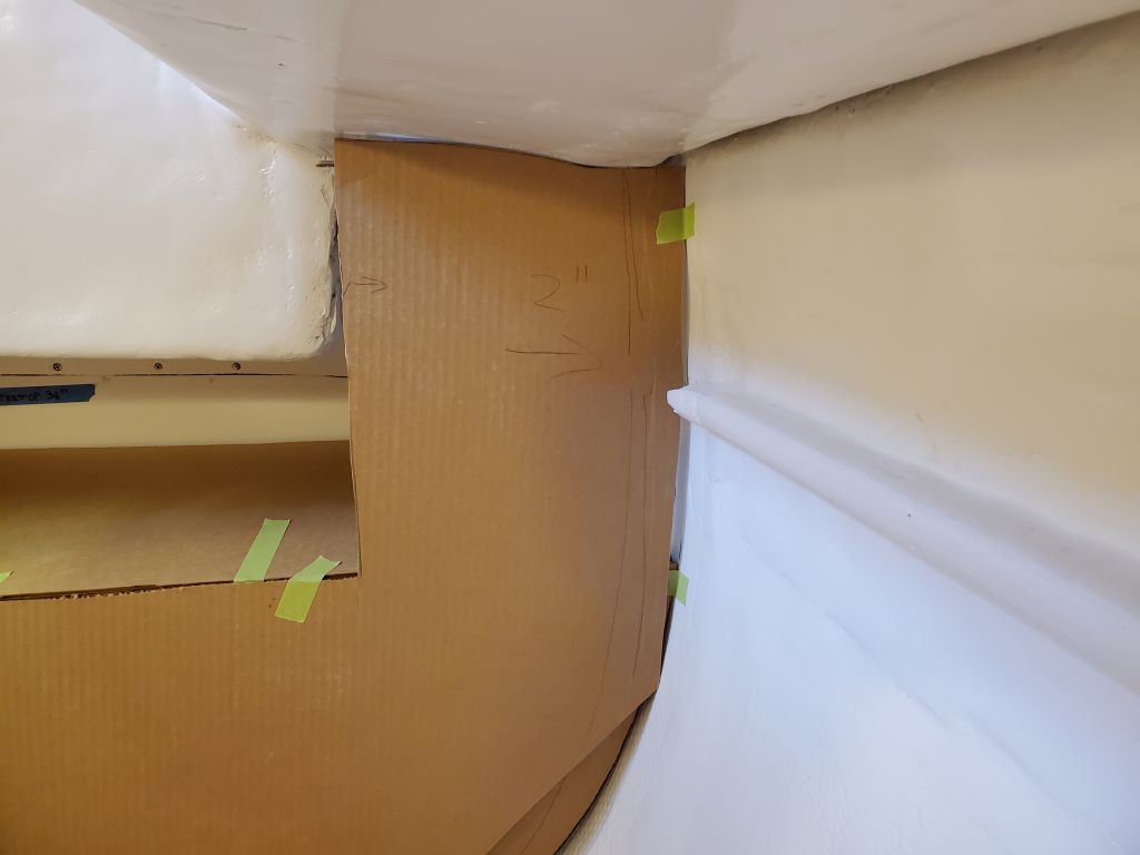
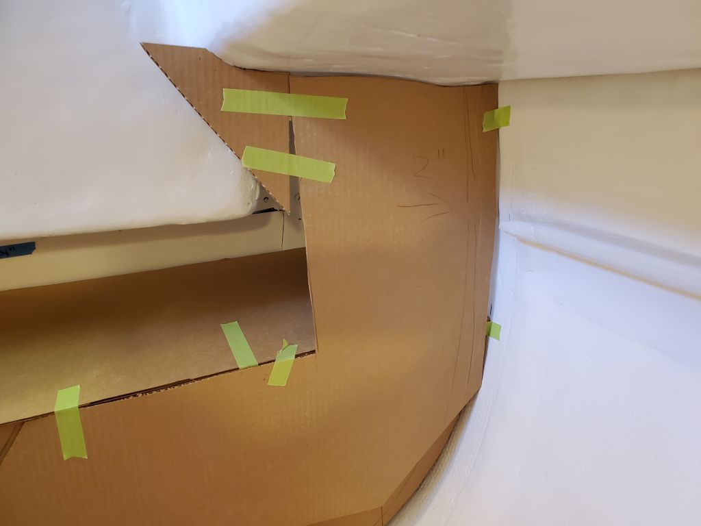
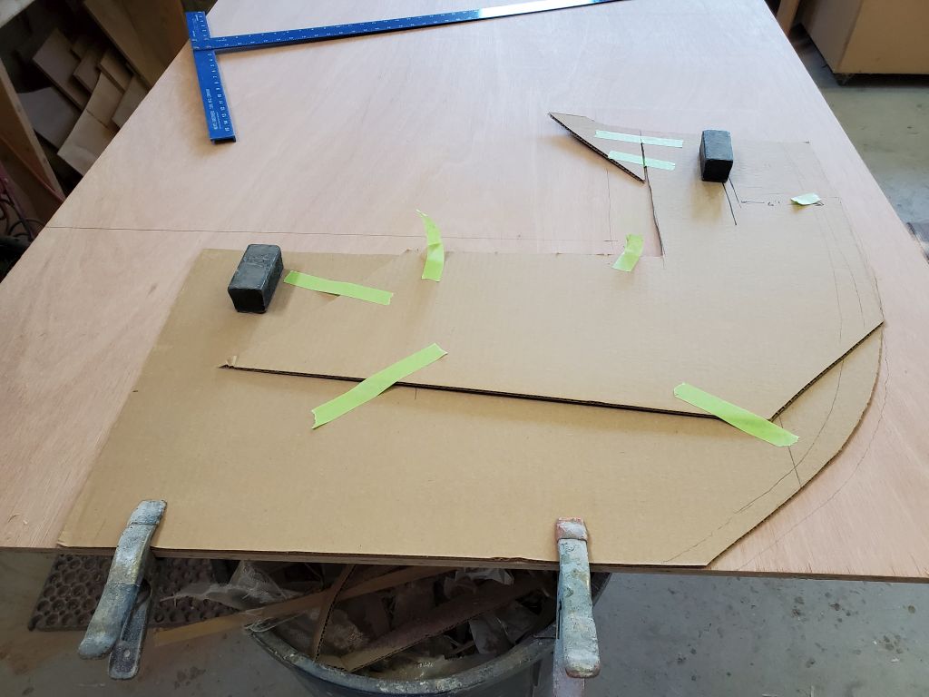
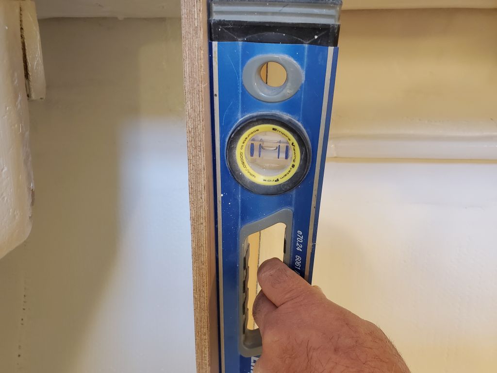
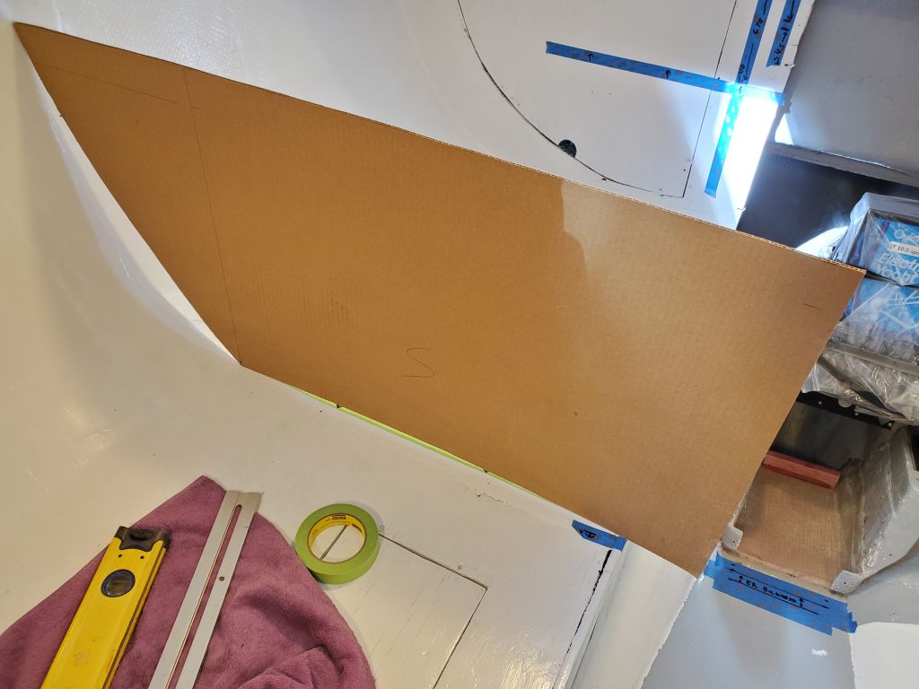
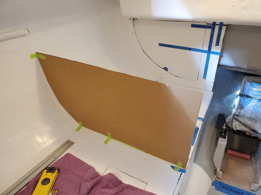
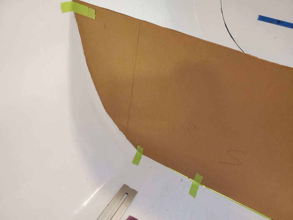
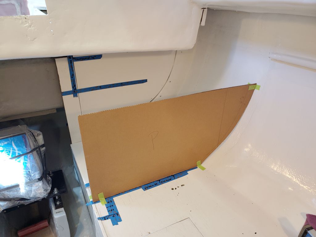
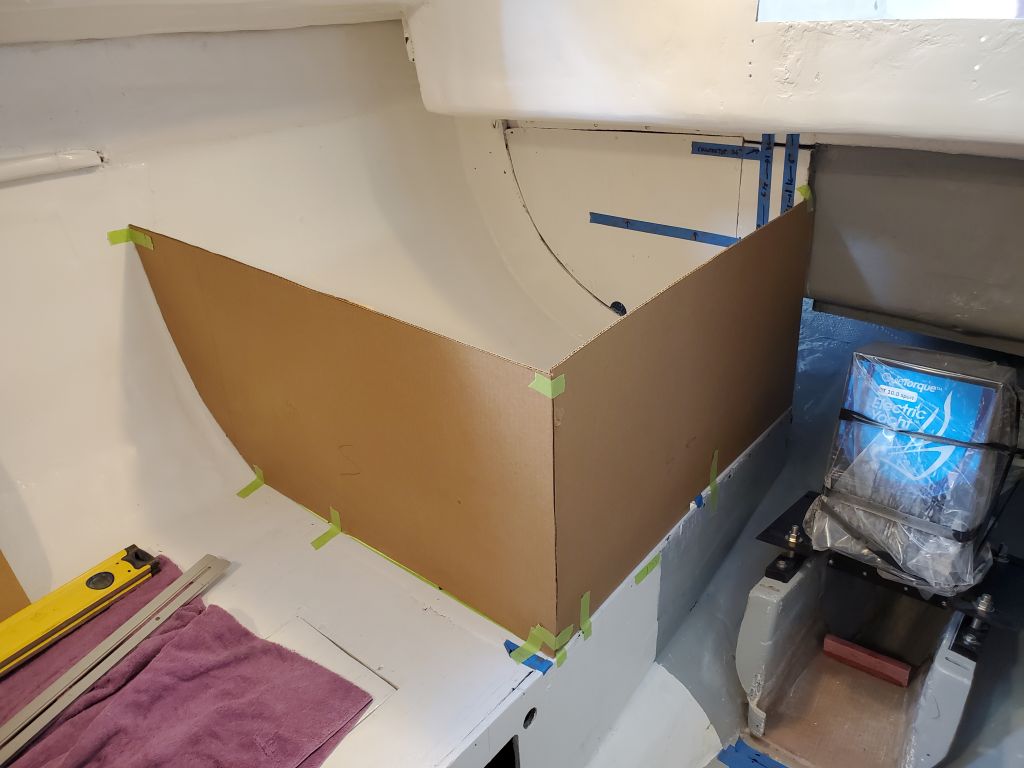
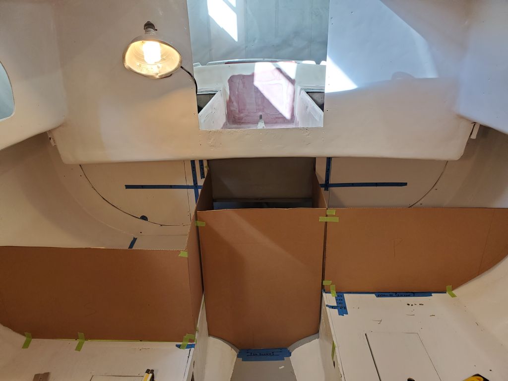
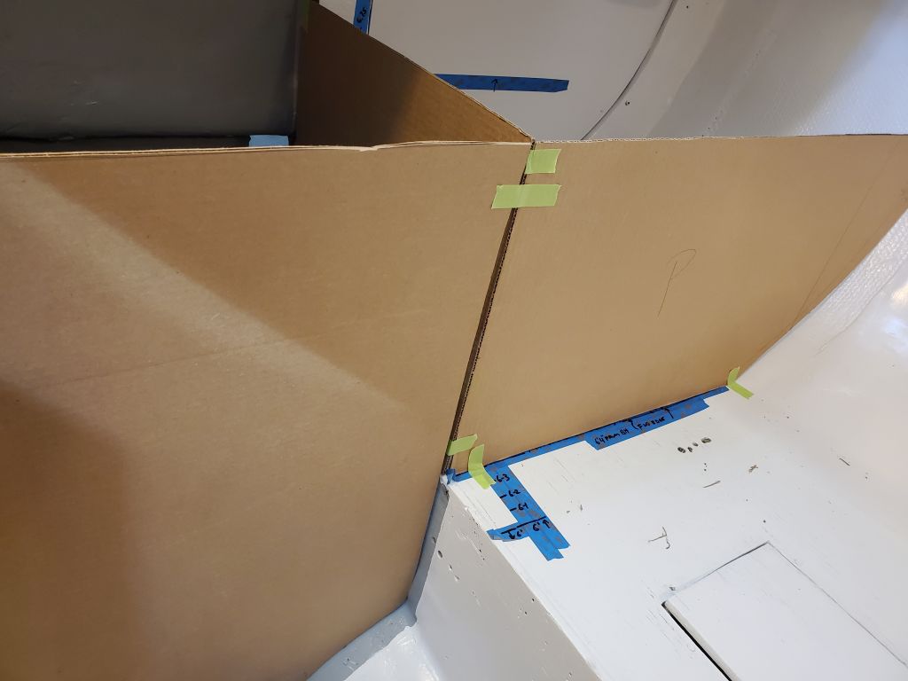
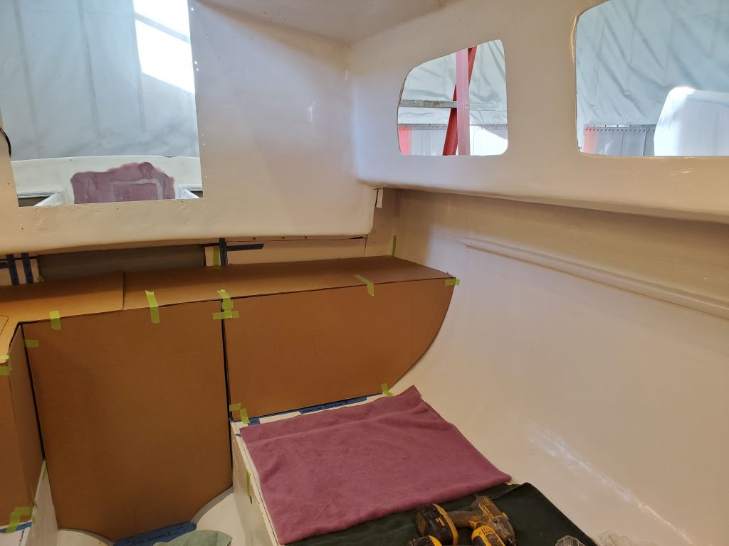
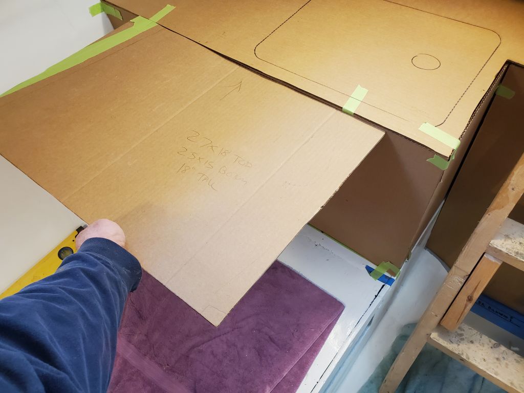
While it wasn’t on the docket right now, the owner thought he’d eventually like a stove forward of the galley, as many Triton owners have done, so for the moment, and to maximize space on the berth ahead at least at these early stages, I located the proposed galley bulkhead quite close to the sink position; this could be easily moved forward in the final construction, but one has to start somewhere. With this reference point, I used a square to mark the bulkhead position, and cut cardboard (sometimes known as “Whitefield mahogany”, a term coined by a client in years past) to fit–both as a mockup, and perhaps as a pattern going forward. I taped the bulkhead in place more or less level and plumb all around, and, to match the proposed countertop height, cut the top edge at 18″ above settee level, which was just about 33″ off the cabin sole.
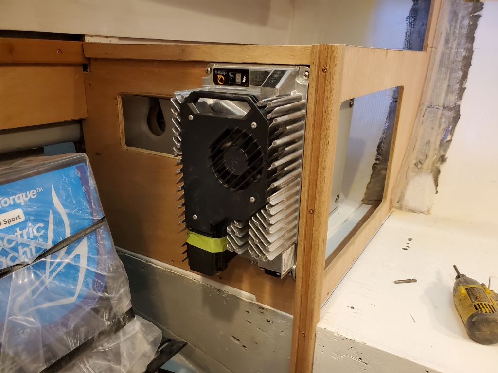
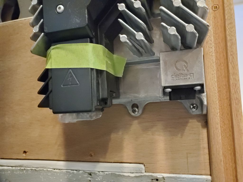
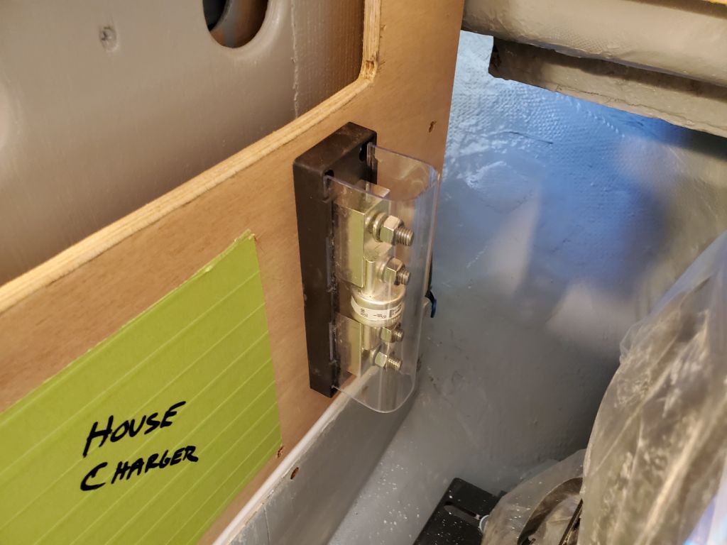
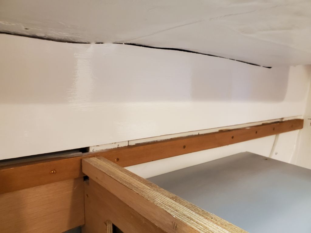
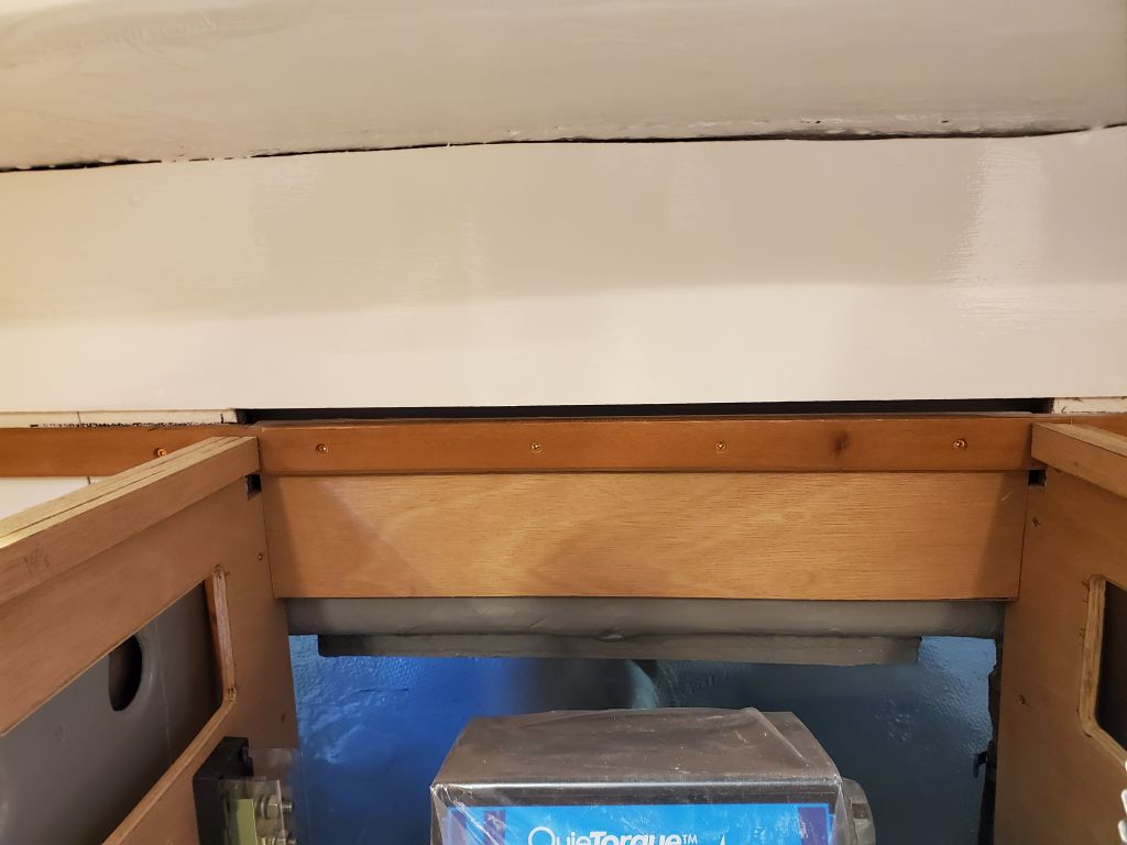
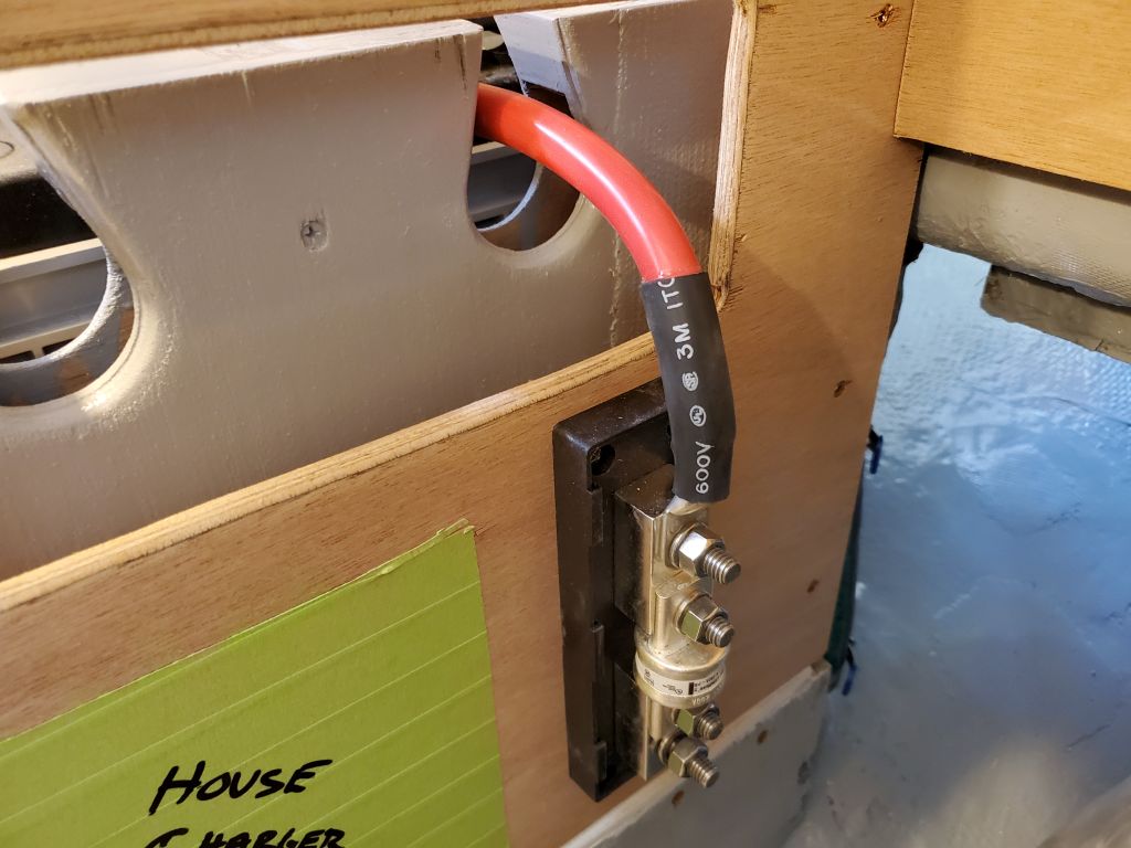
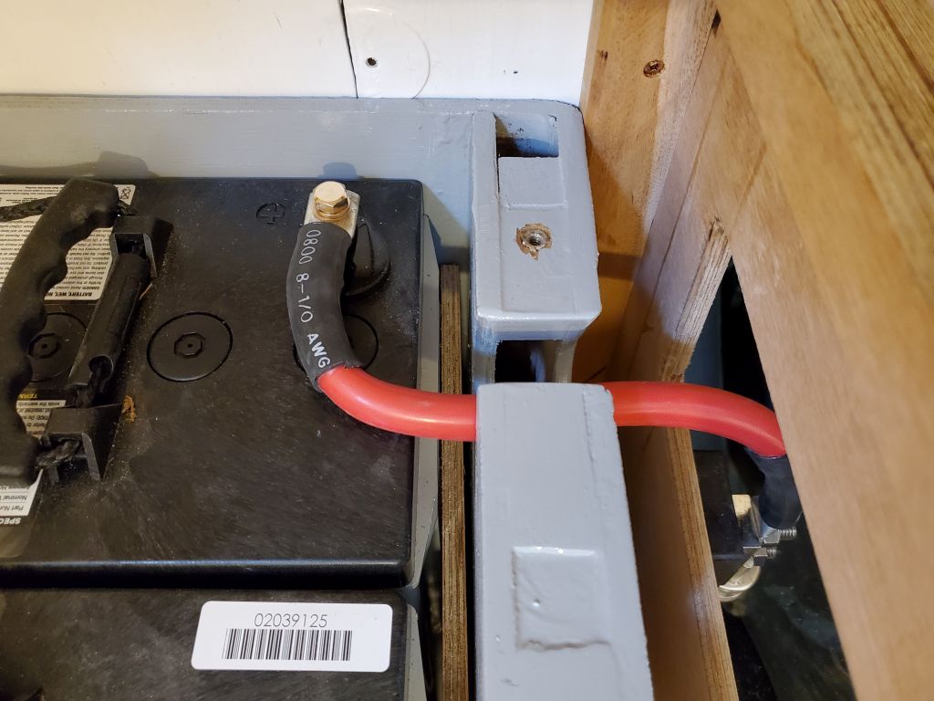
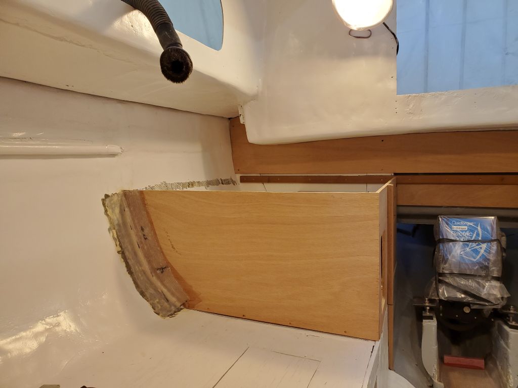
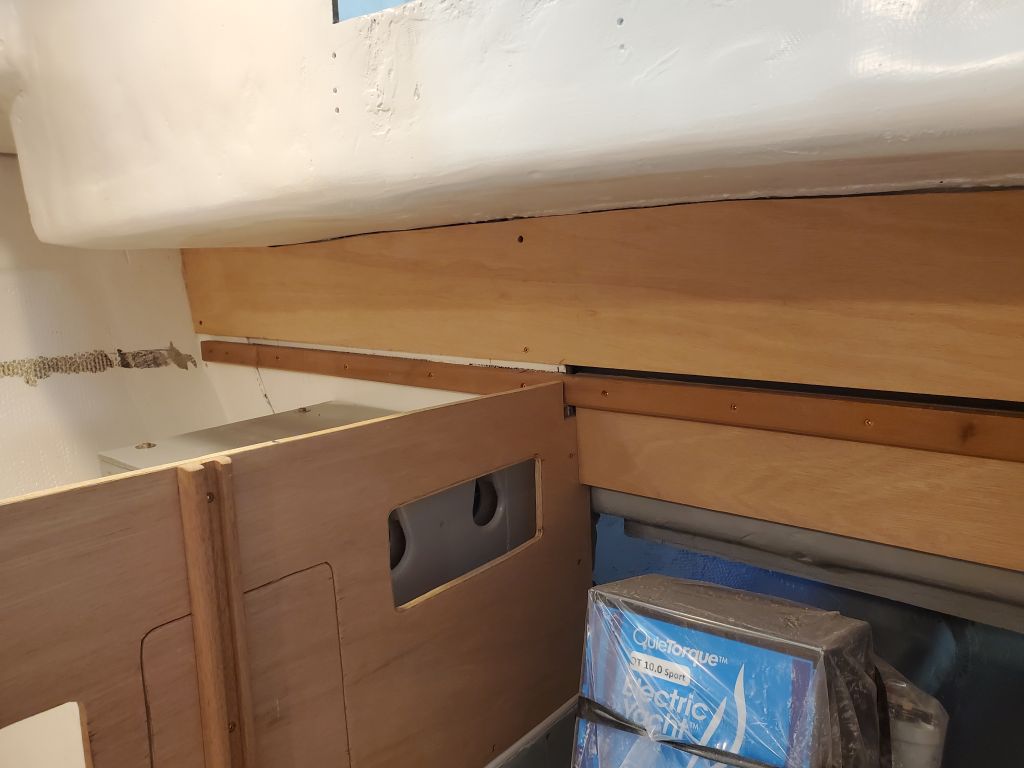
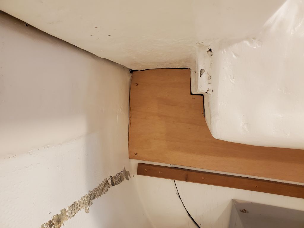
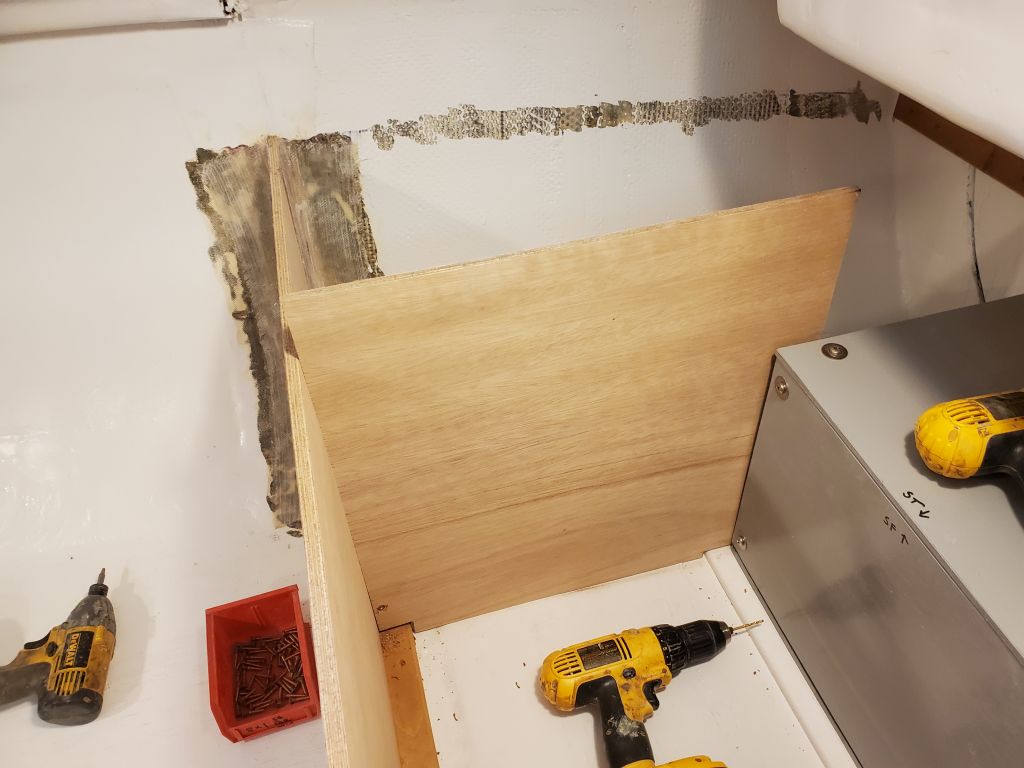
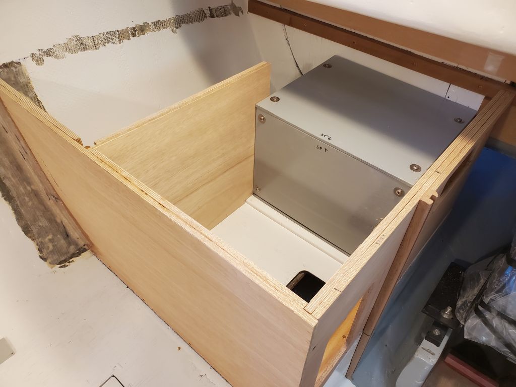
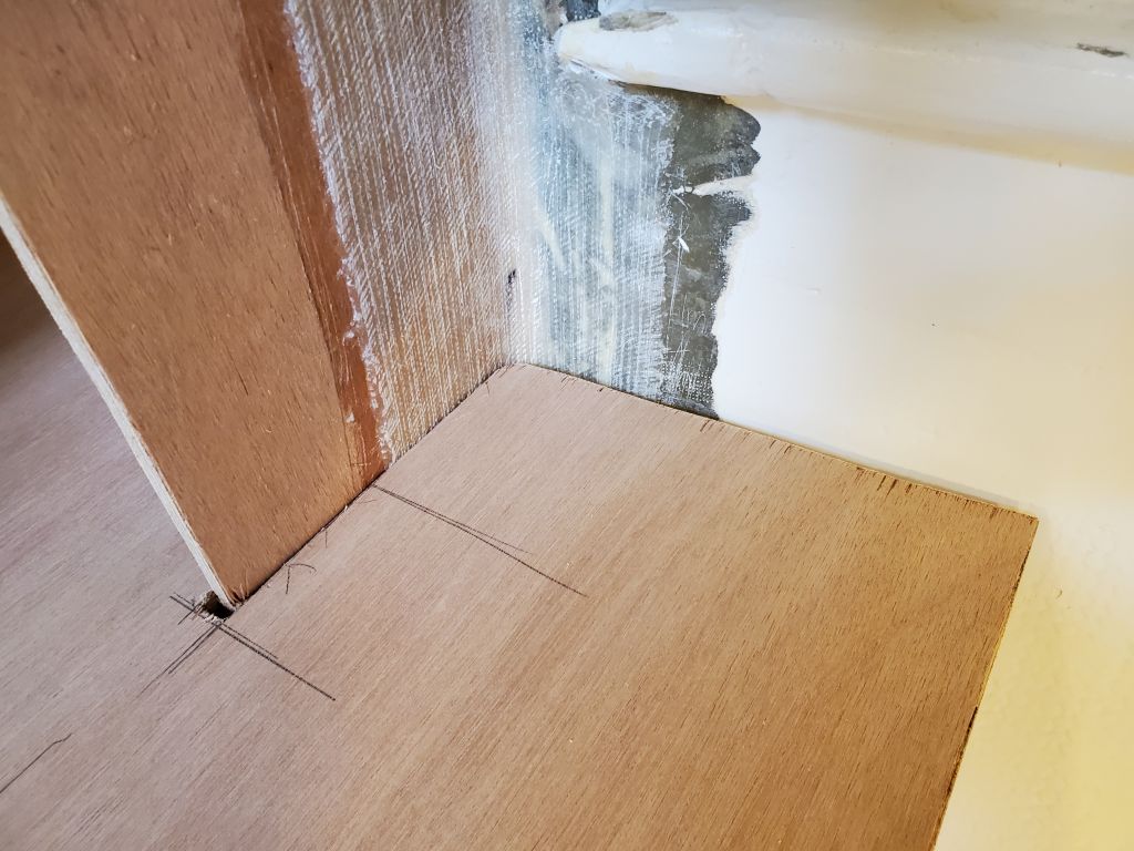
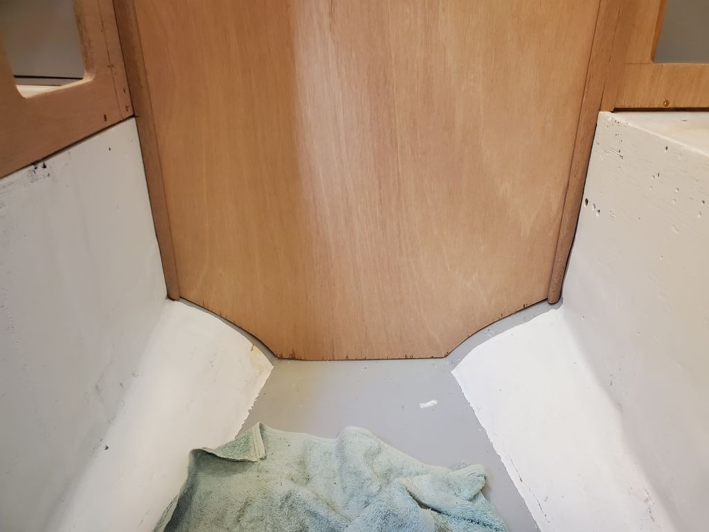
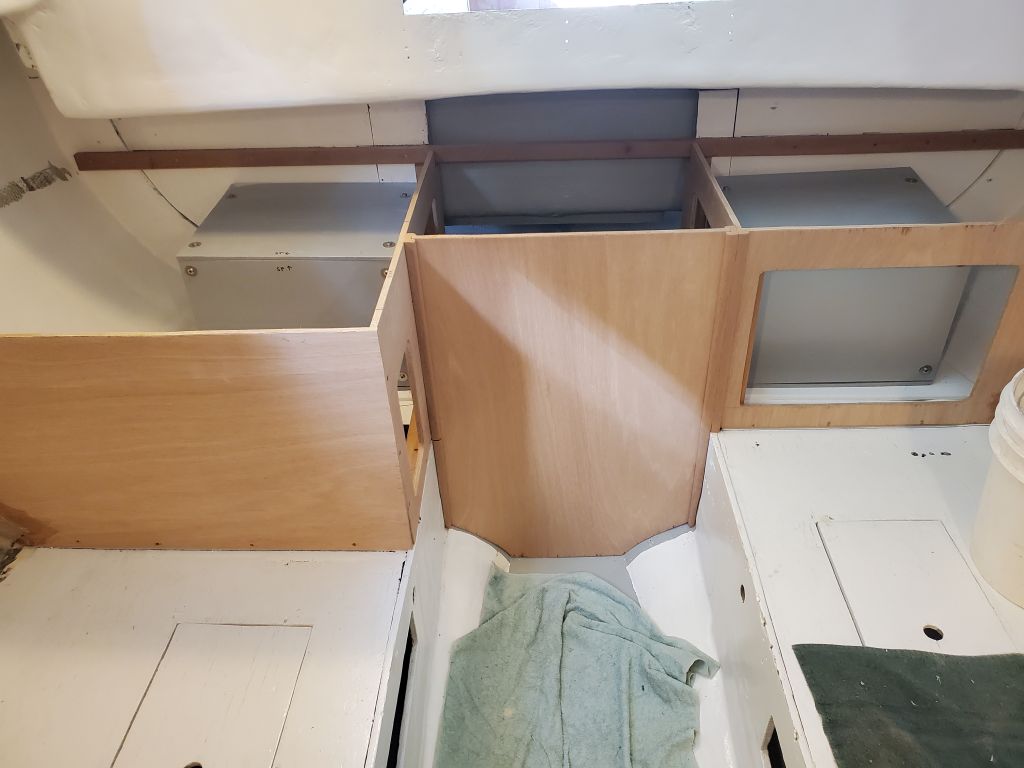
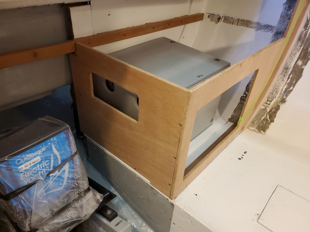
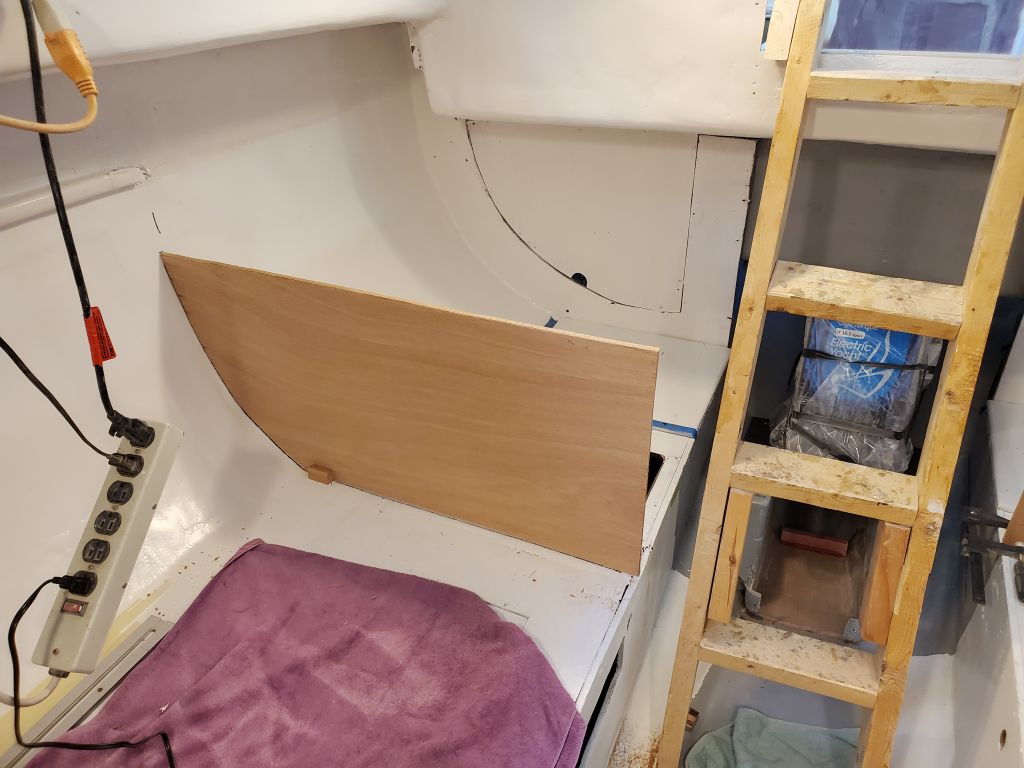
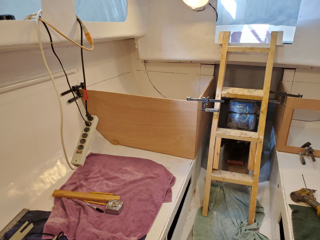
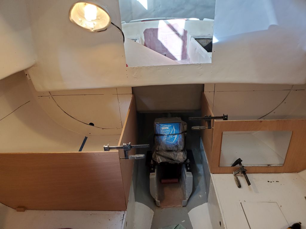
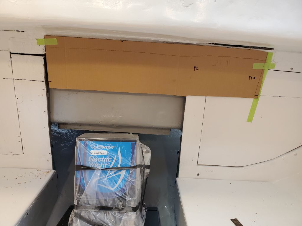
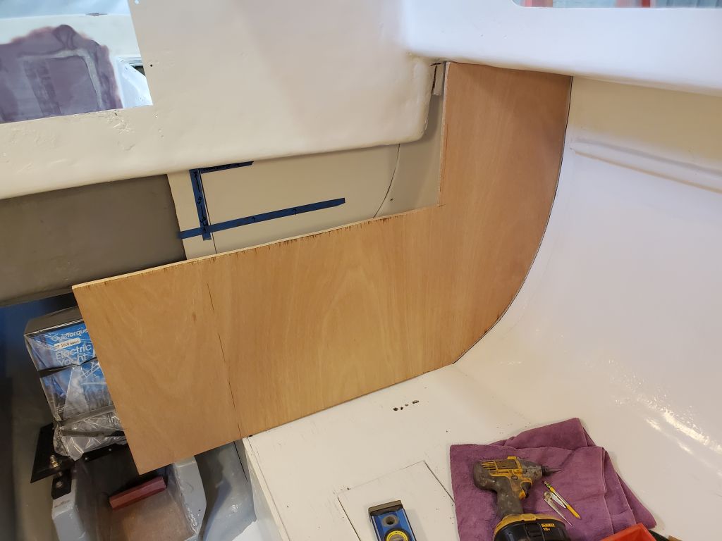
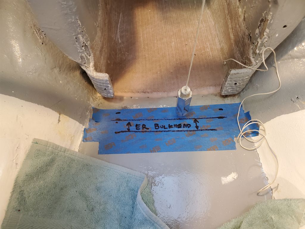
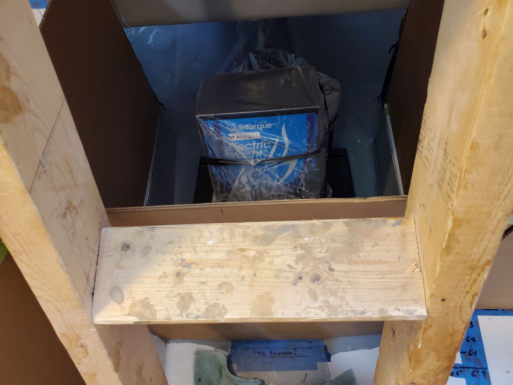
On the port side, my goal for the initial layout was to have flush cabinetry running from the engine room and across the port berth, which meant the engine room dictated the final placement for now. In positioning this, I allowed clearance for the cleat to secure the house battery in the engine room, and a bit of leeway, then transferred this measurement to the port berth so I could cut and install a mockup bulkhead on that side as well.
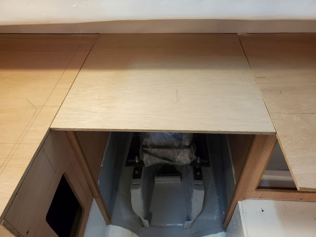
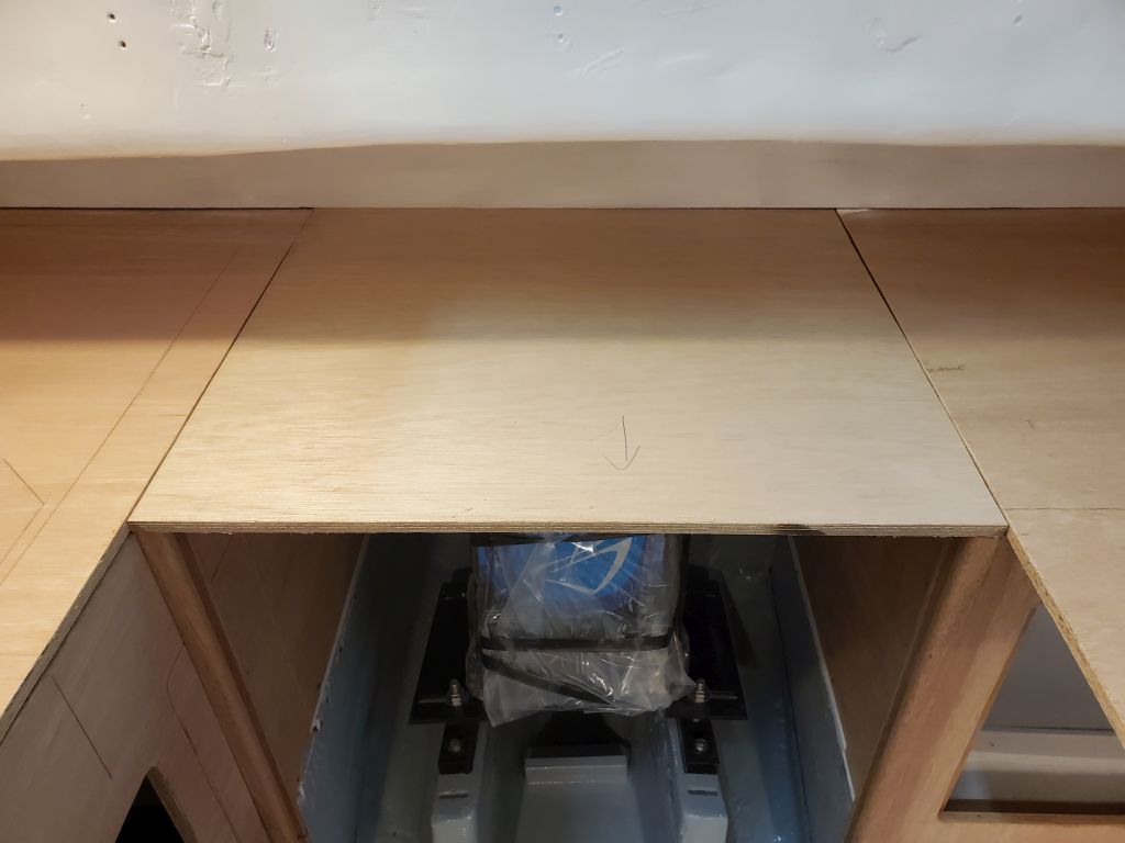
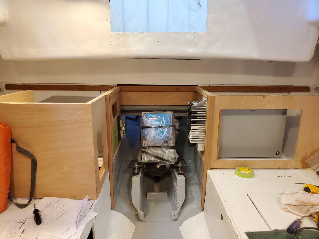
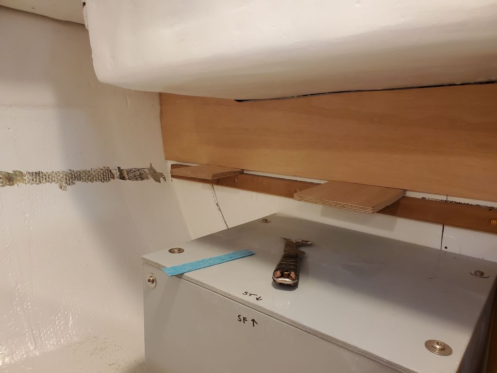
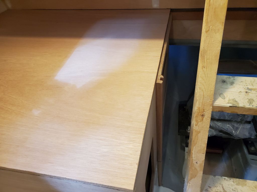
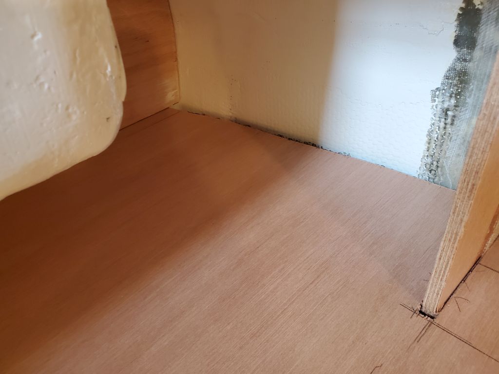
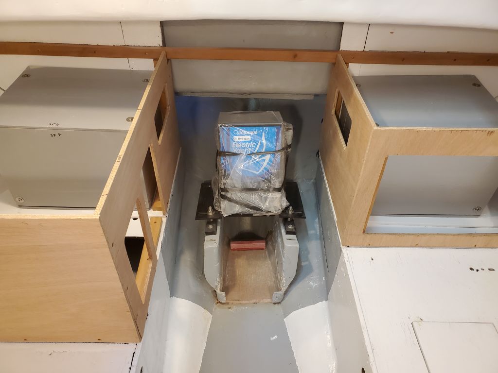
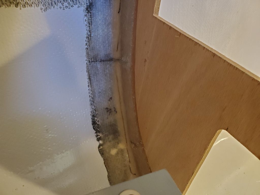
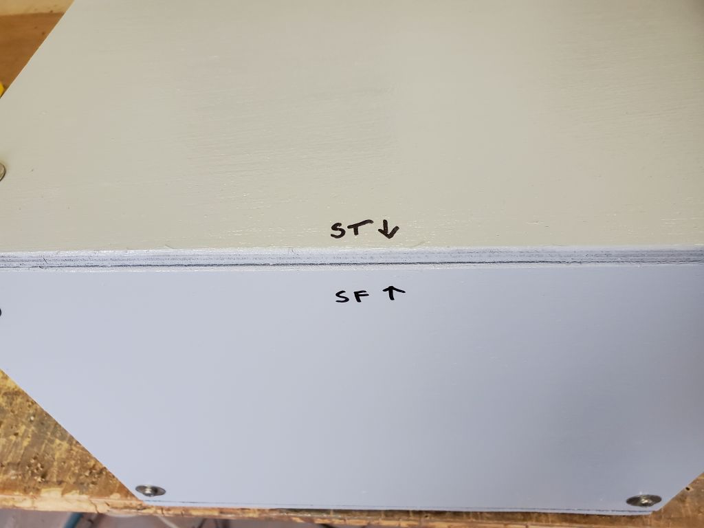
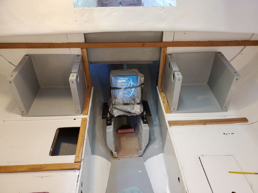
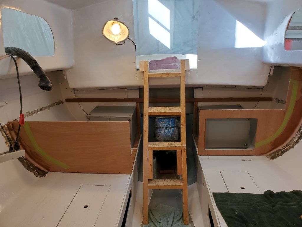
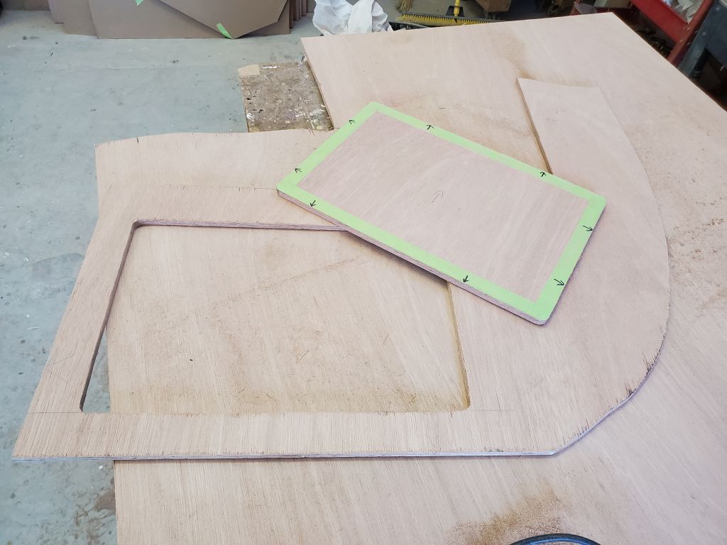
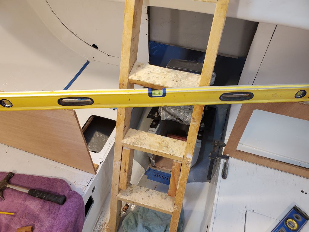
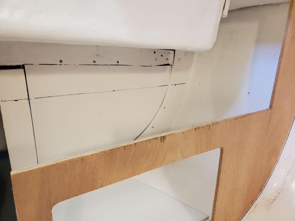
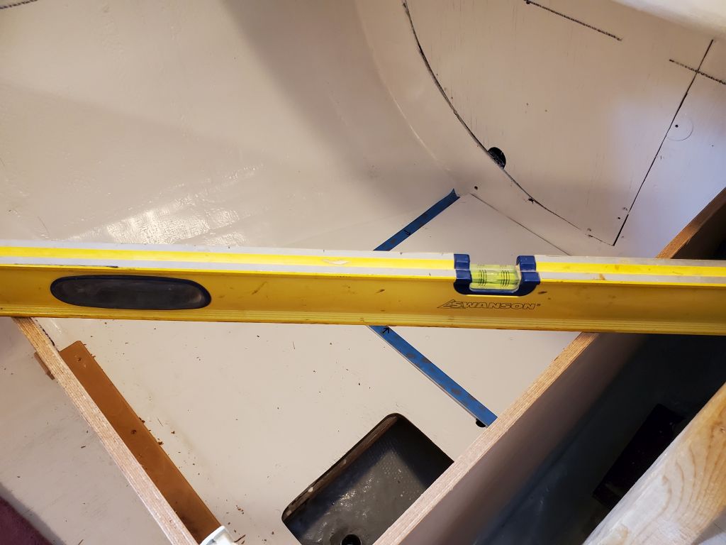
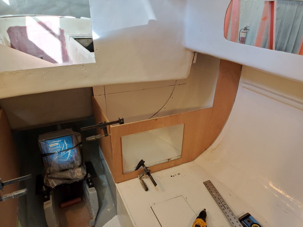
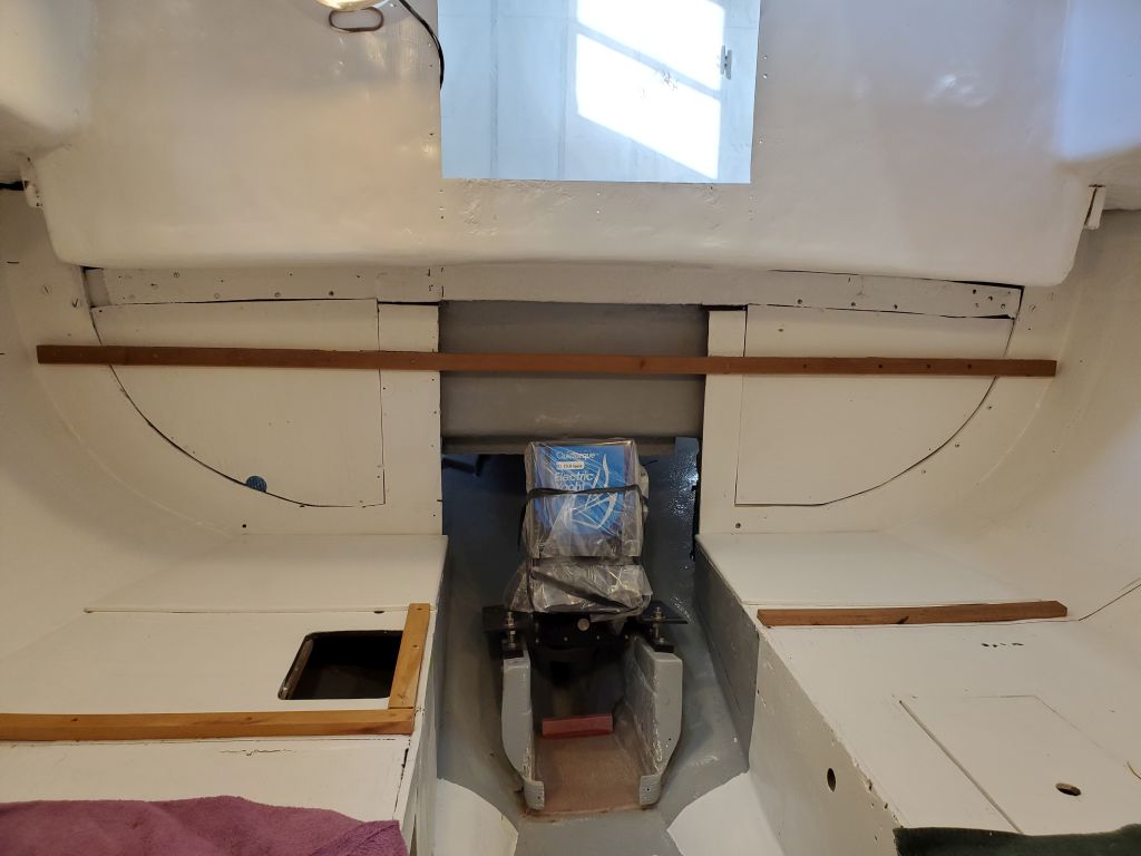
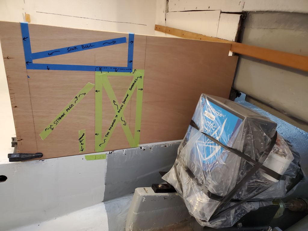
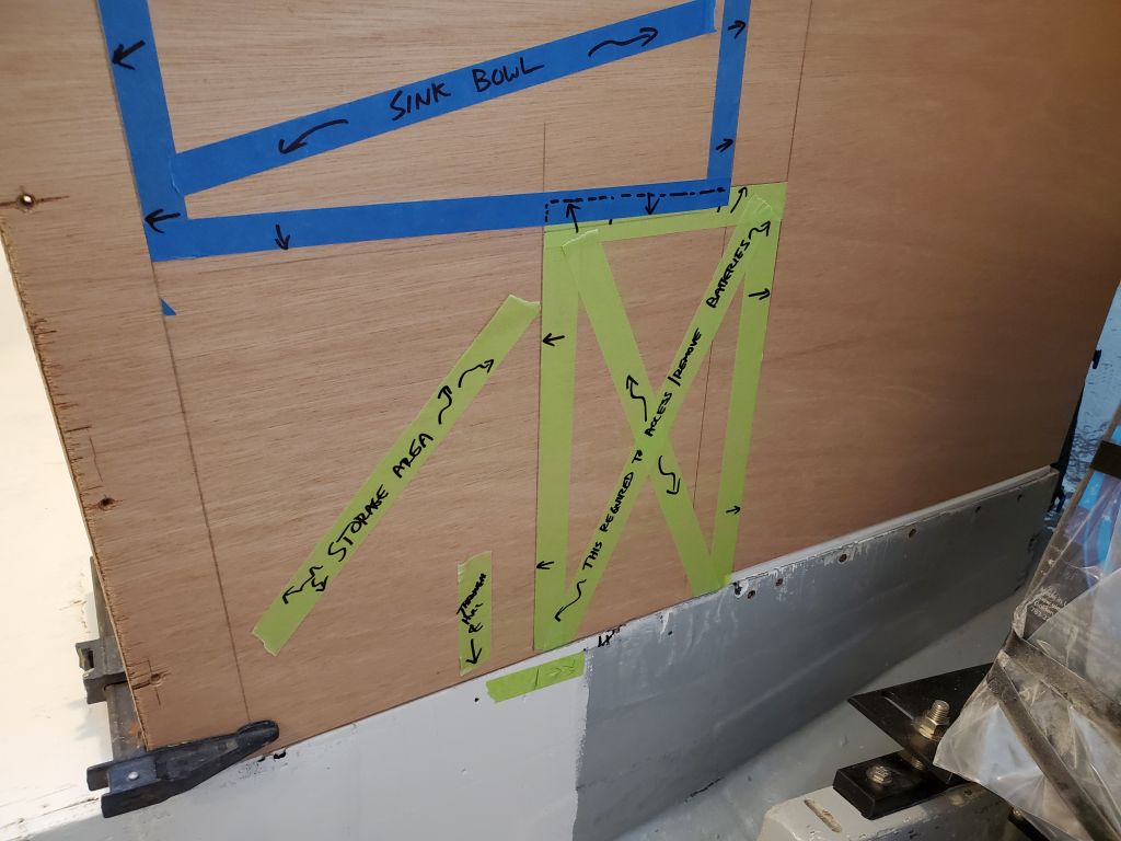
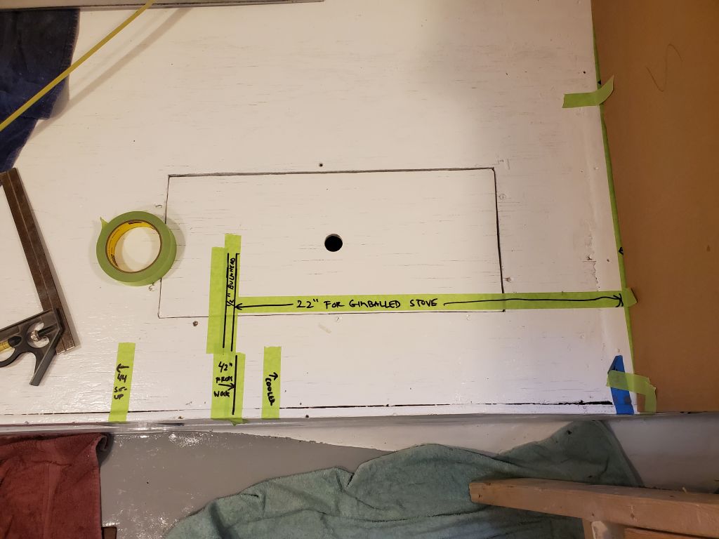
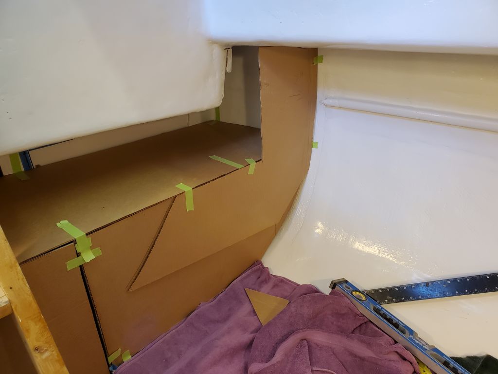
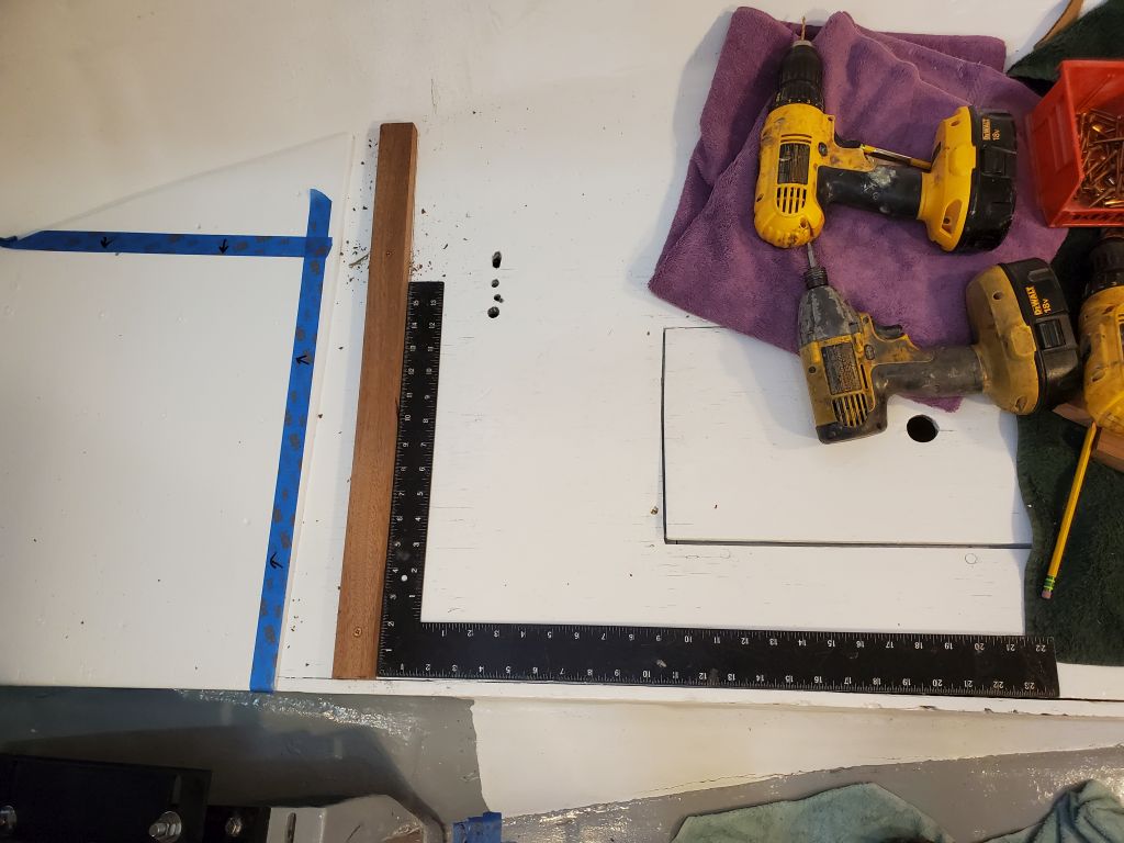
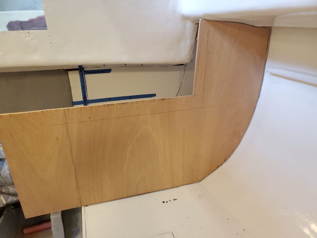
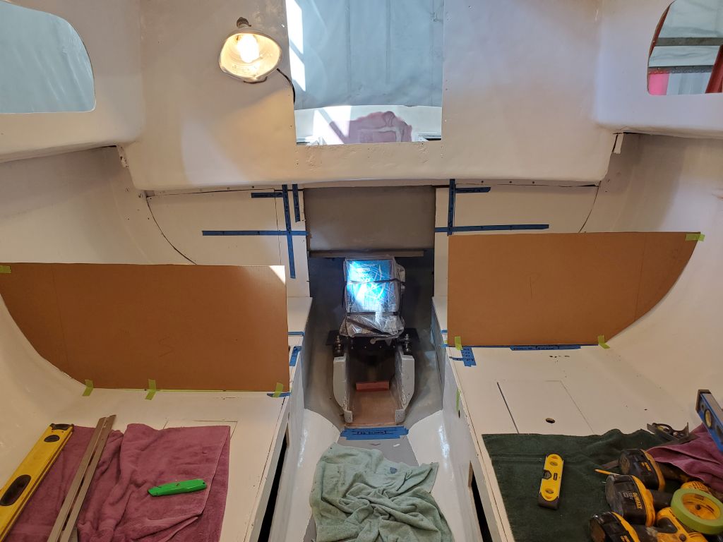
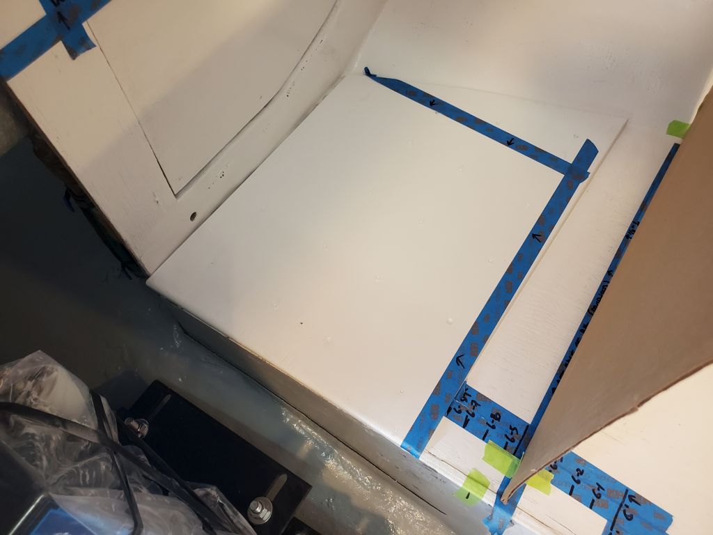
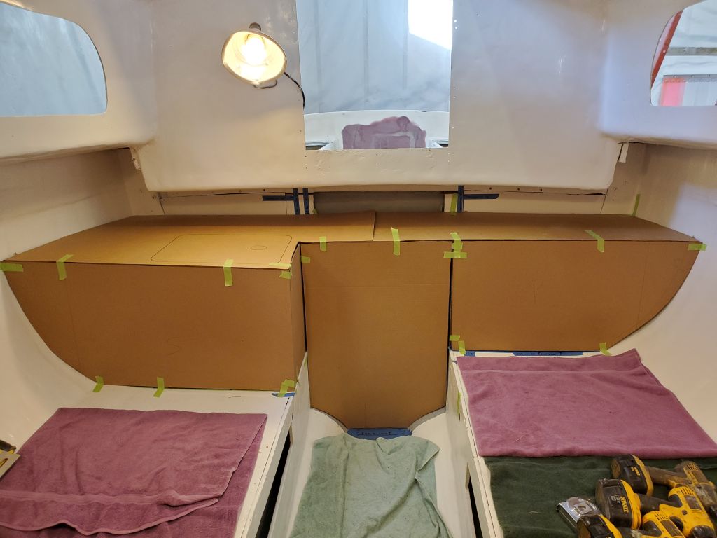
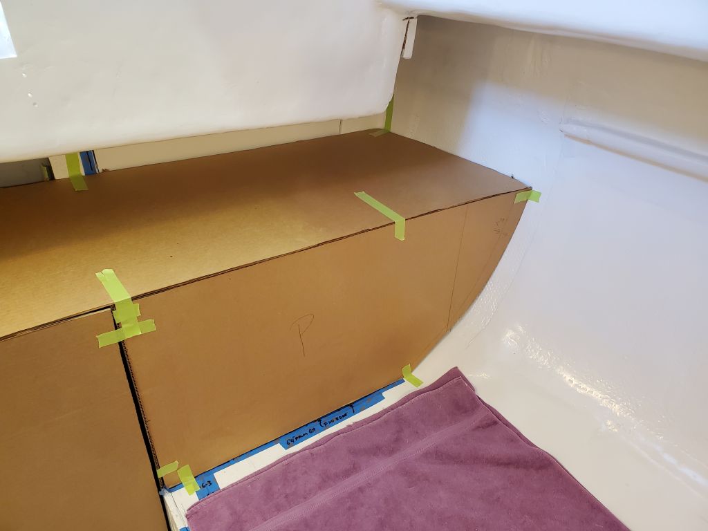
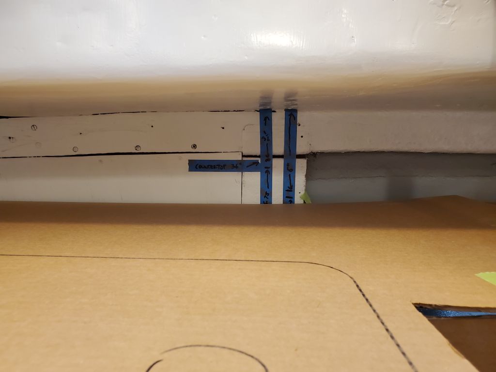
With the bulkheads in place, it gave a good sense of the space behind on each side. The blue tape and arrows represent the battery boxes. Reviewing the layout later, I noted that on the port side, I needed to factor in enough space to line up the batteries in front of the box so they could be slid in or out; the shape of the boxes probably wouldn’t allow much of an angled approach. How I laid out the access opening in the bulkhead would ultimately play a role in this, but it was something I had to keep in mind through the rest of the layout and especially in the final construction.
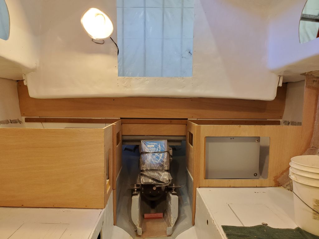
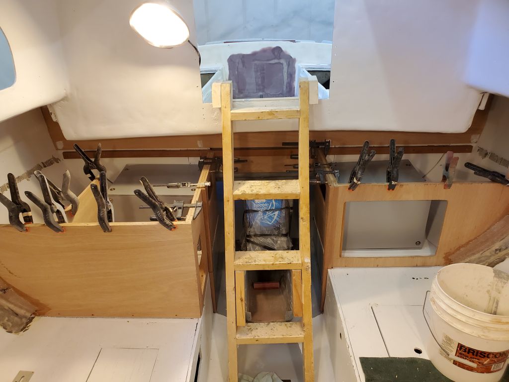
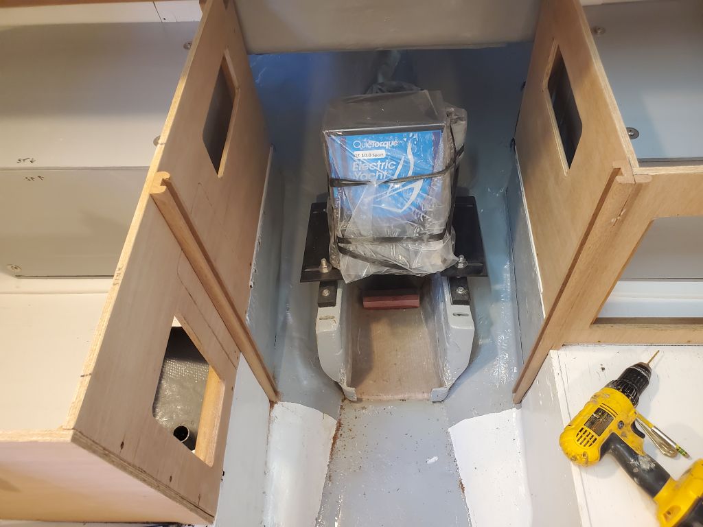
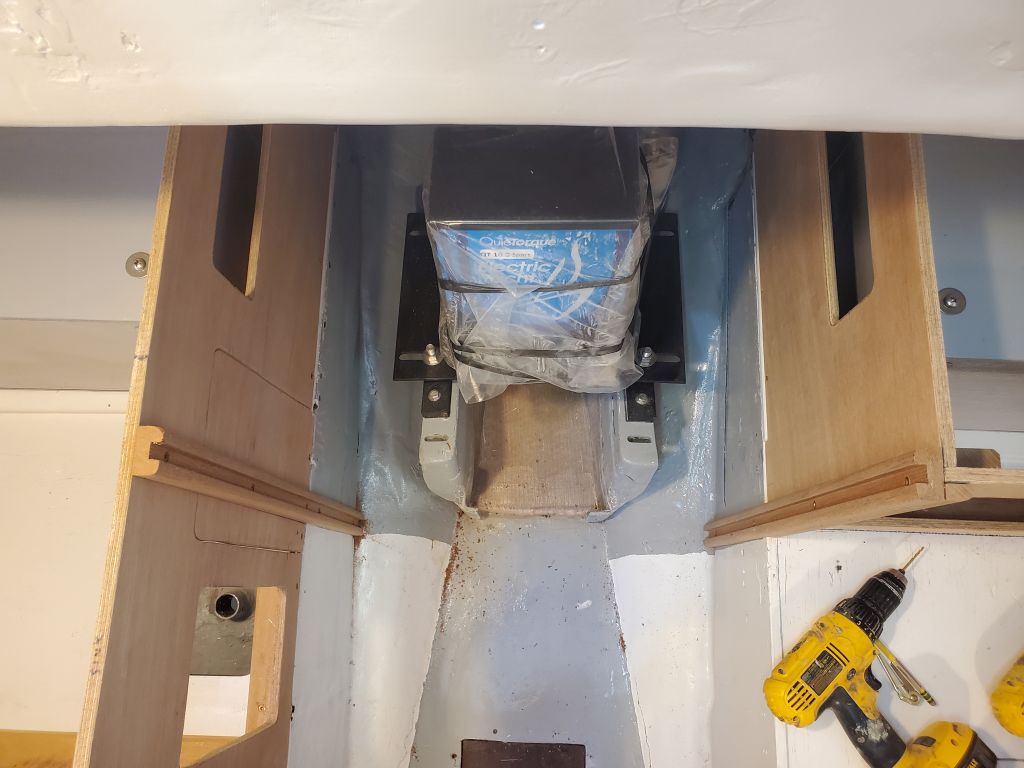
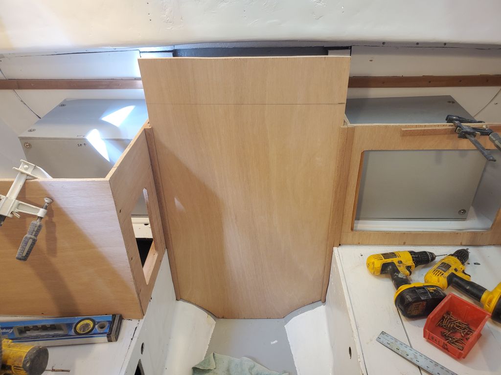
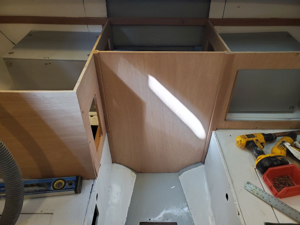
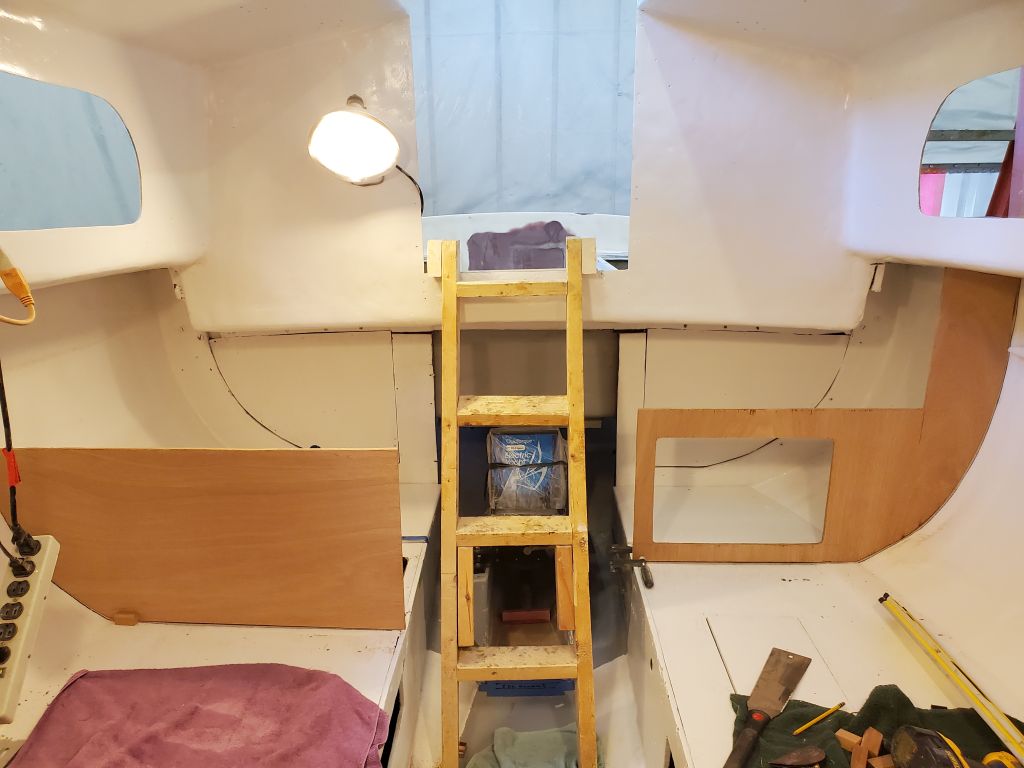
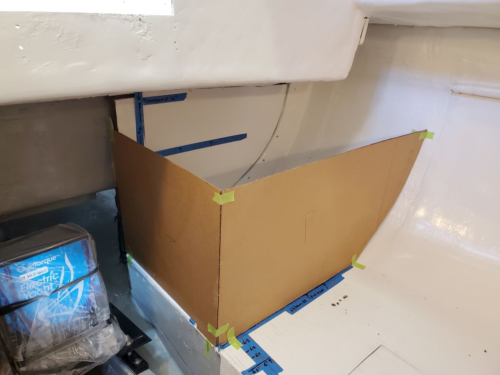
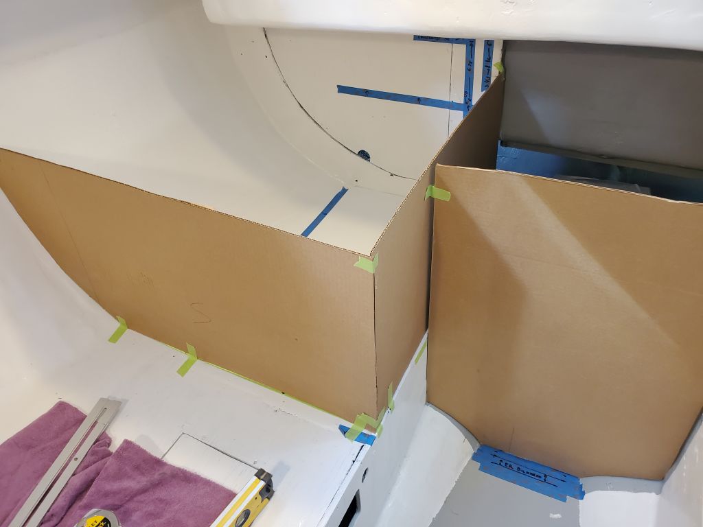
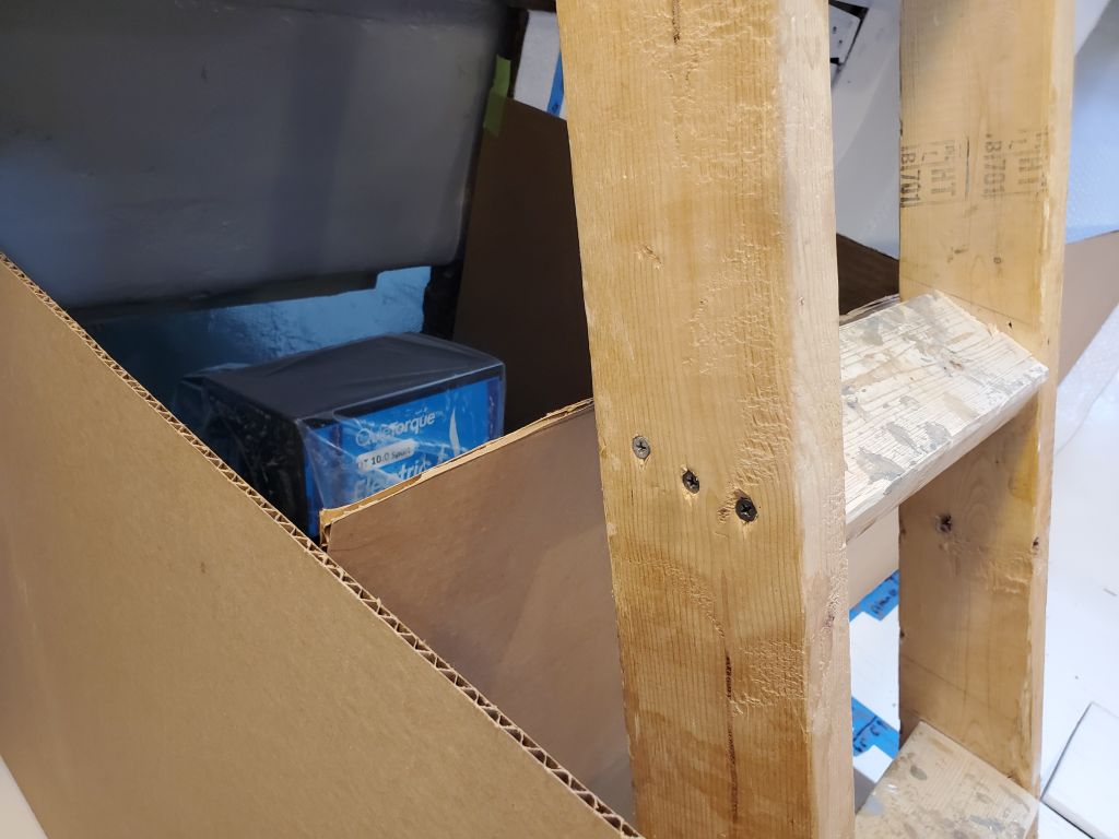
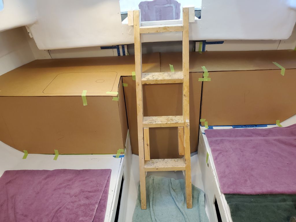
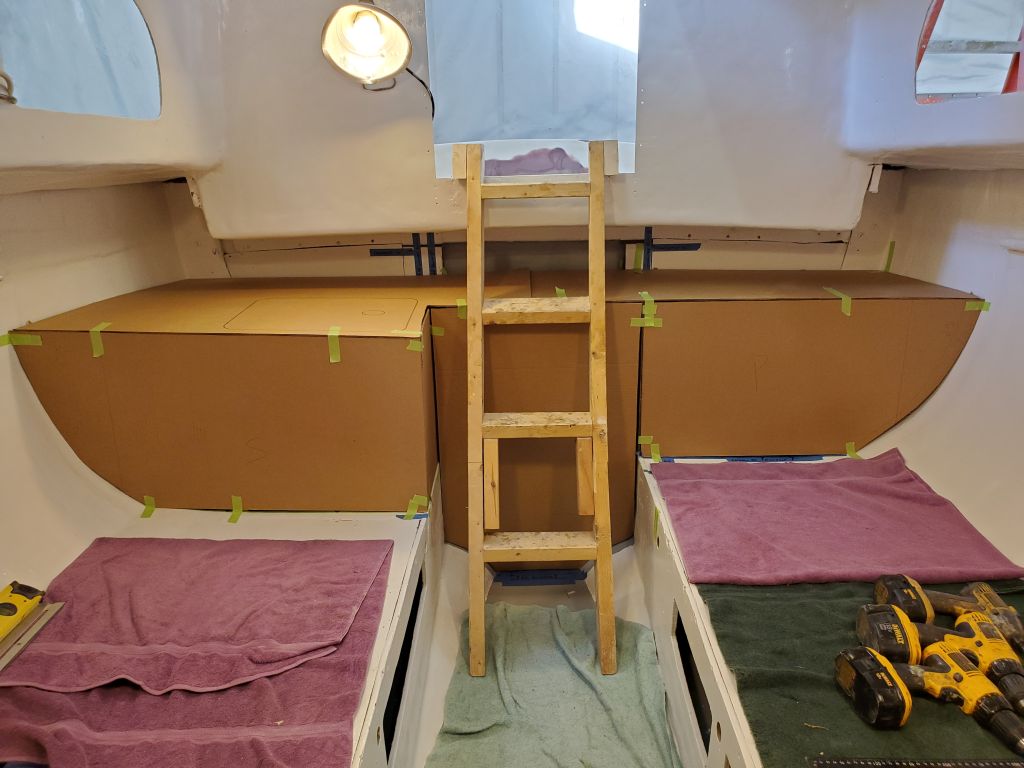
Now I cut more Whitefield mahogany to form the longitudinal panels of the galley on each side, and a vertical panel for the engine room. The working companionway ladder, which was fairly representative of what would ultimately end up here in the boat (in terms of its angle) cleared the engine room panel by a close, but adequate, margin, but the engine room couldn’t extend further forward without creating a conflict. With a desire for a flush face across the engine room and port side bulkhead, this pretty much dictated the bulk of the layout, at least for now. But even allowing for minor tweaks, so far I felt the whole thing was coming together well–more or less as envisioned, meeting most of the multiple design requirements, and looking good, and functional.
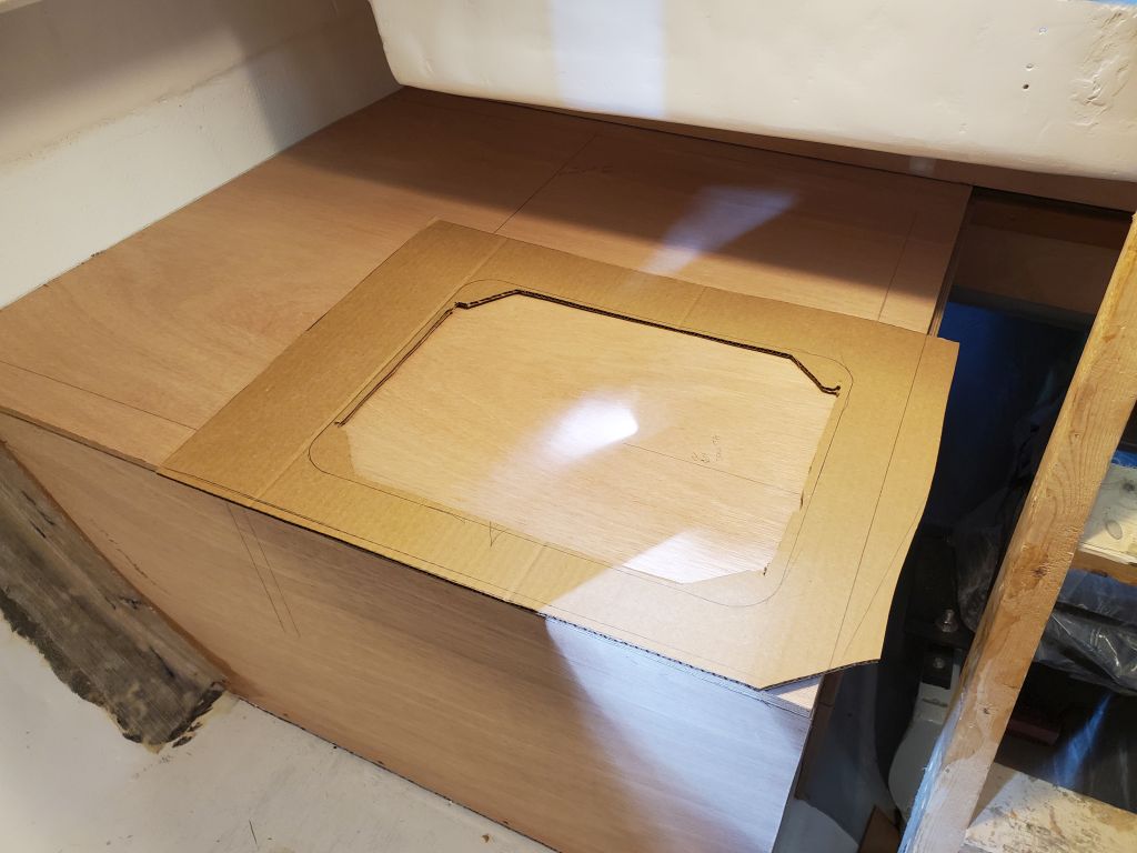
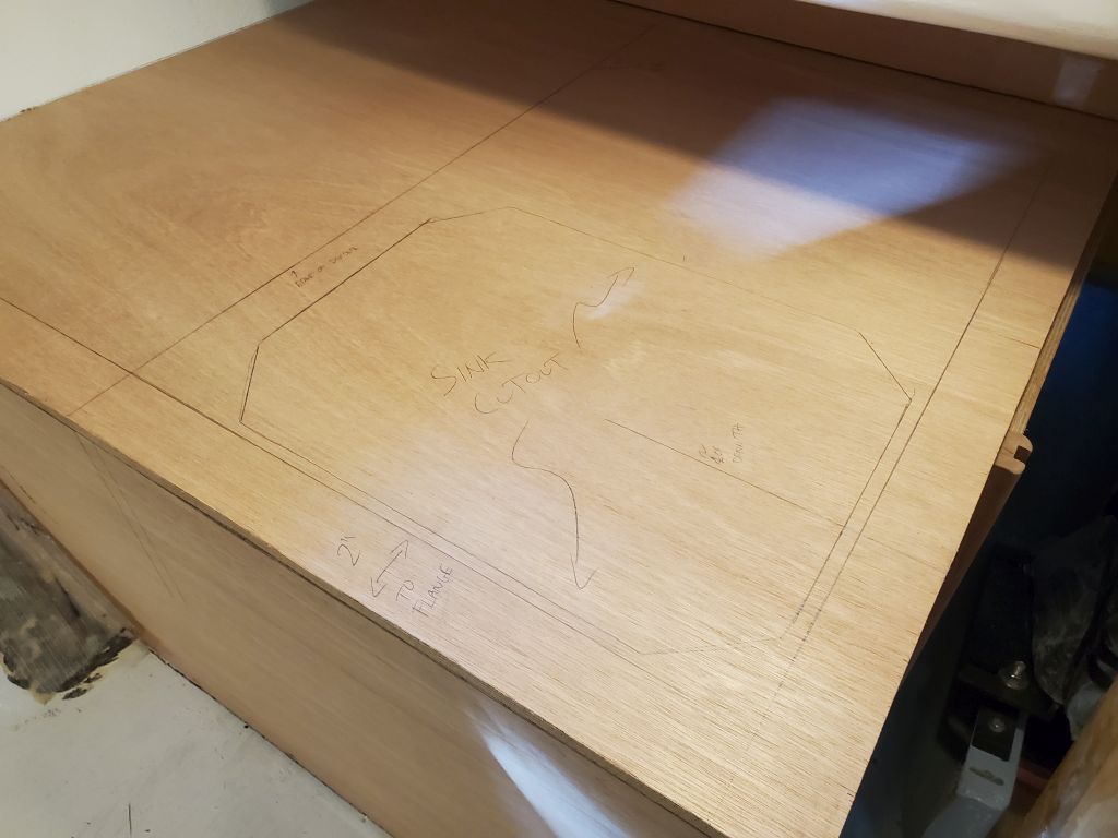
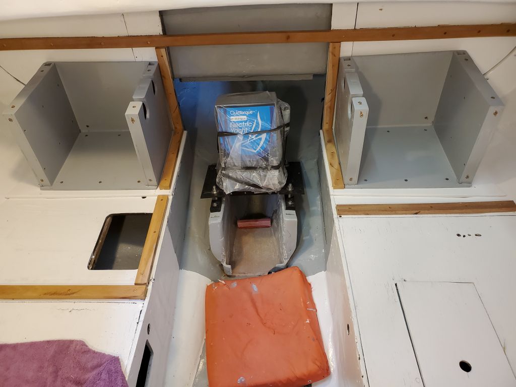
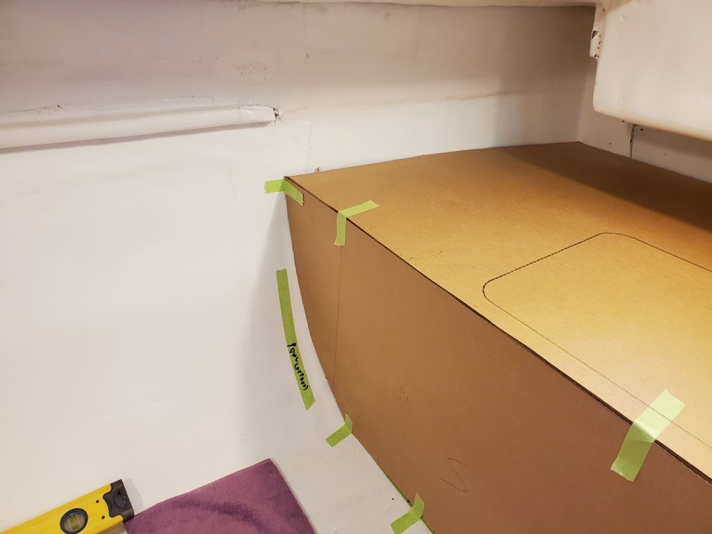
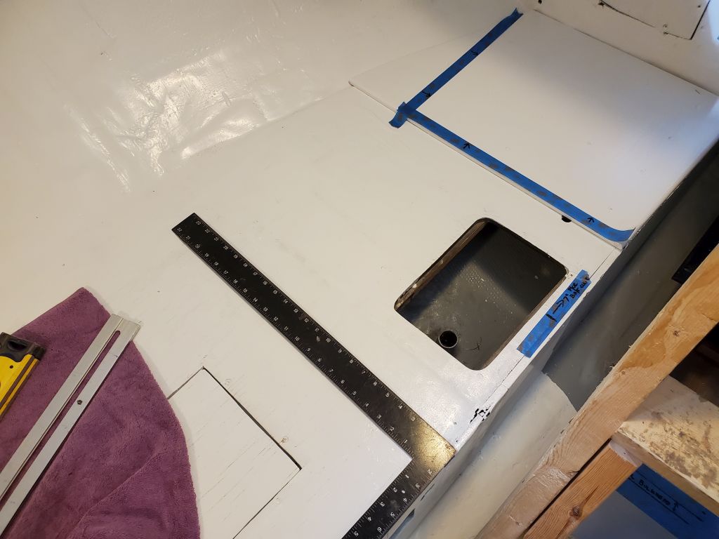
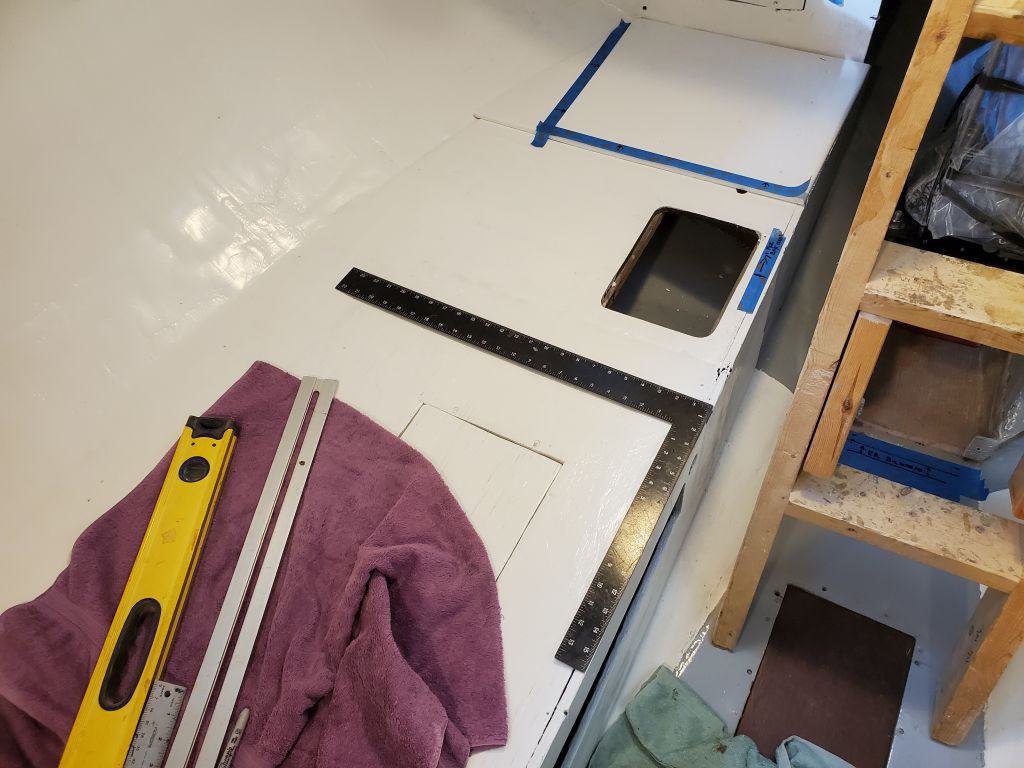
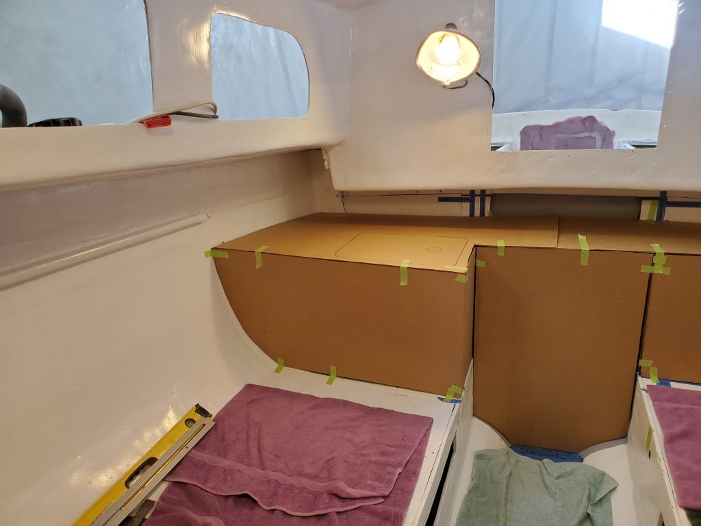
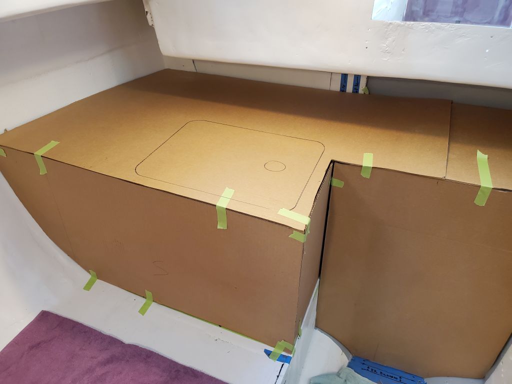
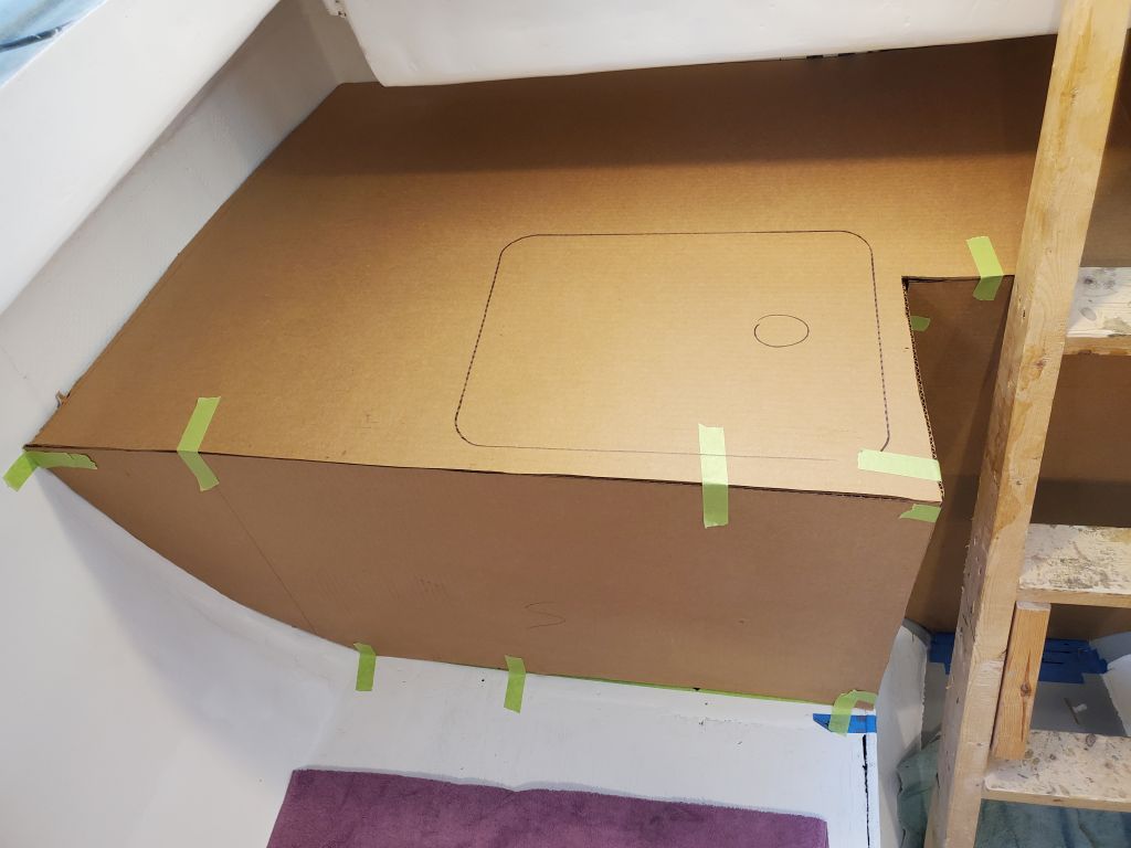
With the base cabinets in place, I mocked up a countertop from more cardboard, finishing off the mockup and giving a good sense of things to come. I made additional reference measurements and marked the sink outline on the starboard countertop.
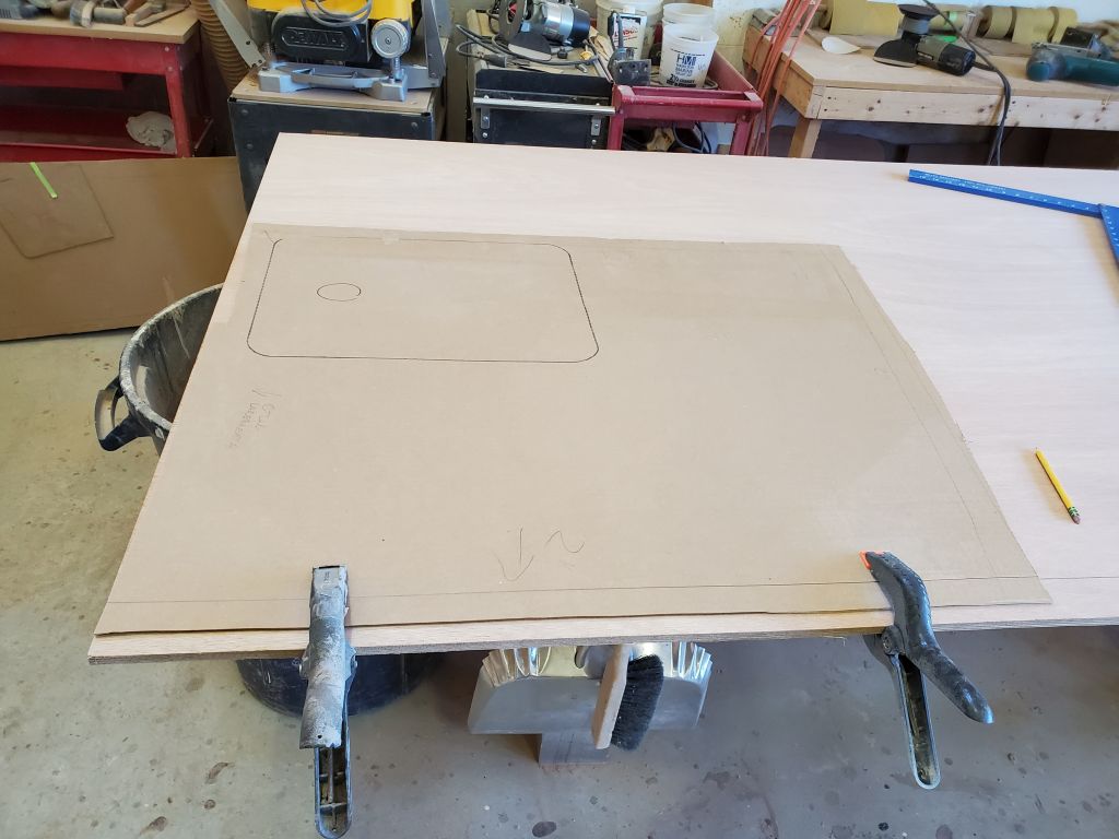
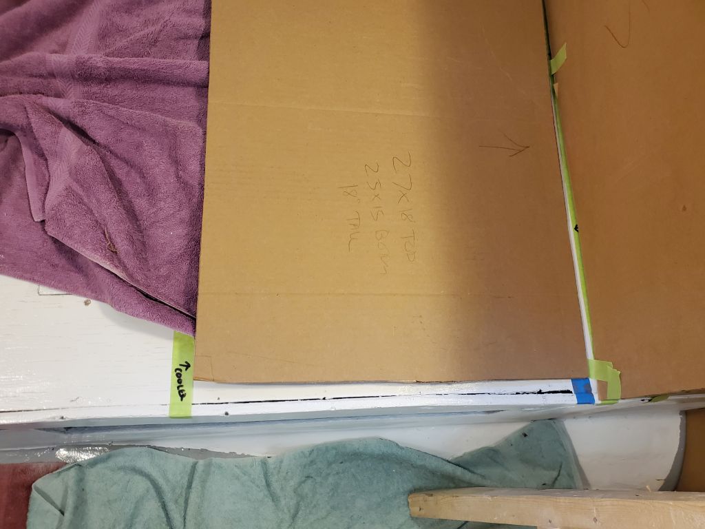
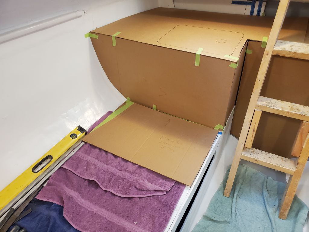
For refrigeration, the owner chose one of the modern super-insulated portable coolers, and from cardboard I made a rough template to the maximum size of the cooler, representing the top; with tapered sides all around, the base was slightly smaller. As it happened, the cooler was 18″ high, so its top would be level with the countertops. With 3″ insulation all around, the inside dimensions of the cooler were in keeping with what seemed appropriate for the boat’s intended use. The owner planned for now to use it on the starboard side, forward of the galley, where there was adequate room.
With the basics in place, it was time to let the concepts settle out and have some discussions to determine what changes, if any, should be made before building the final galley. As with all design, various questions, considerations, and potential issues had already made themselves clear, but the fundamental layout seemed to be well workable.
Total time billed on this job today: 6 hours
0600 Weather Observation: 13°, clear. Forecast for the day: Sunny, 38°