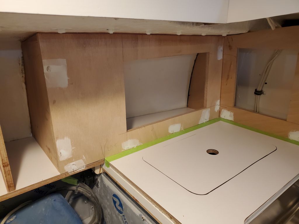
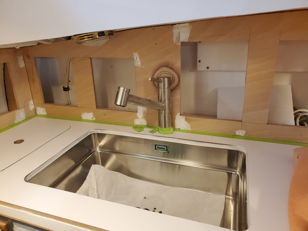
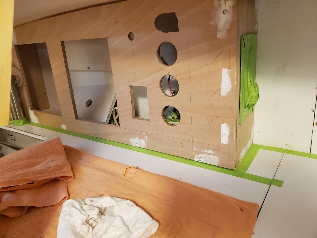
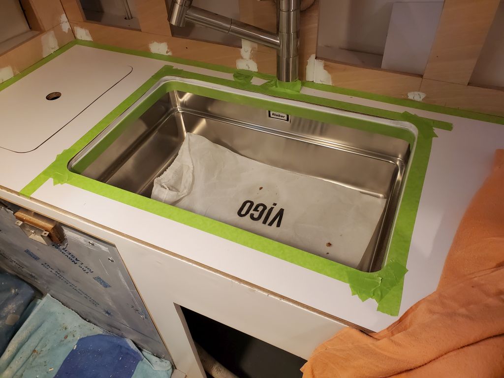
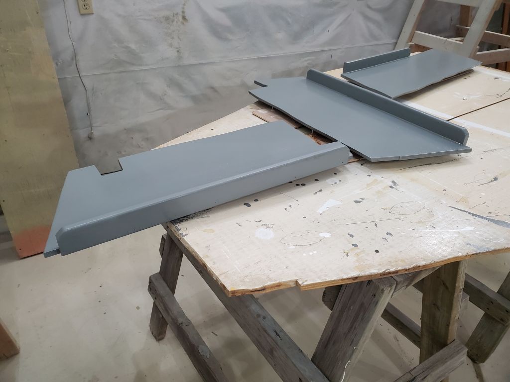
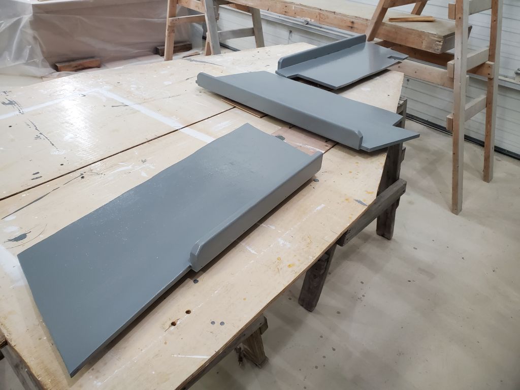
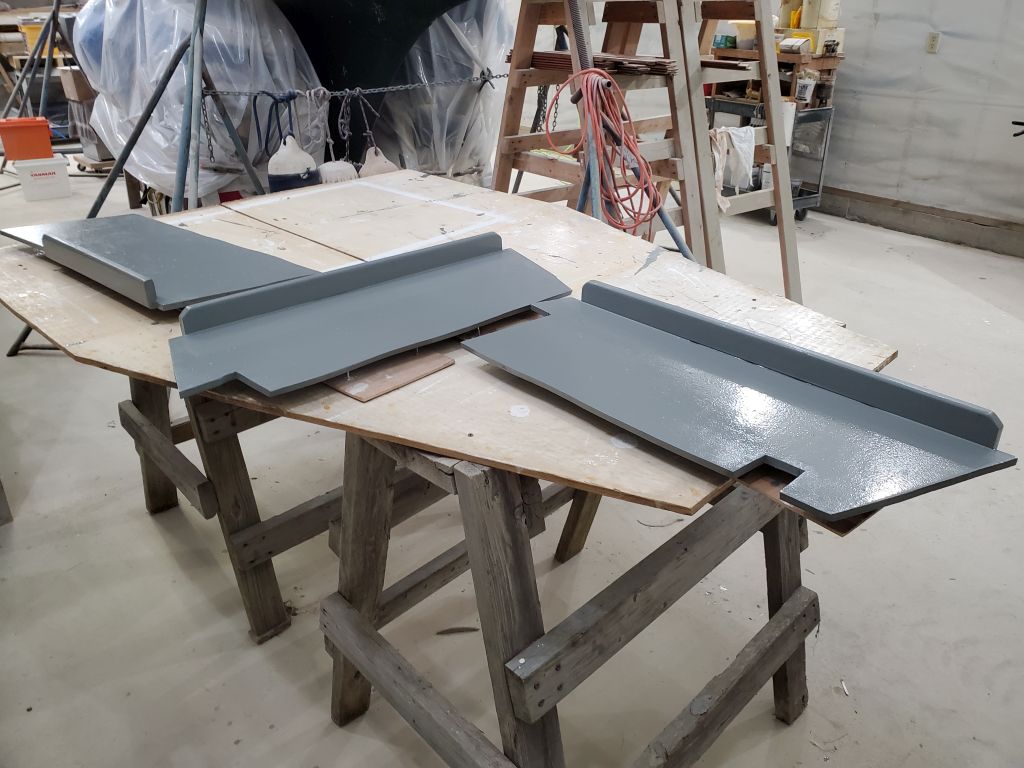
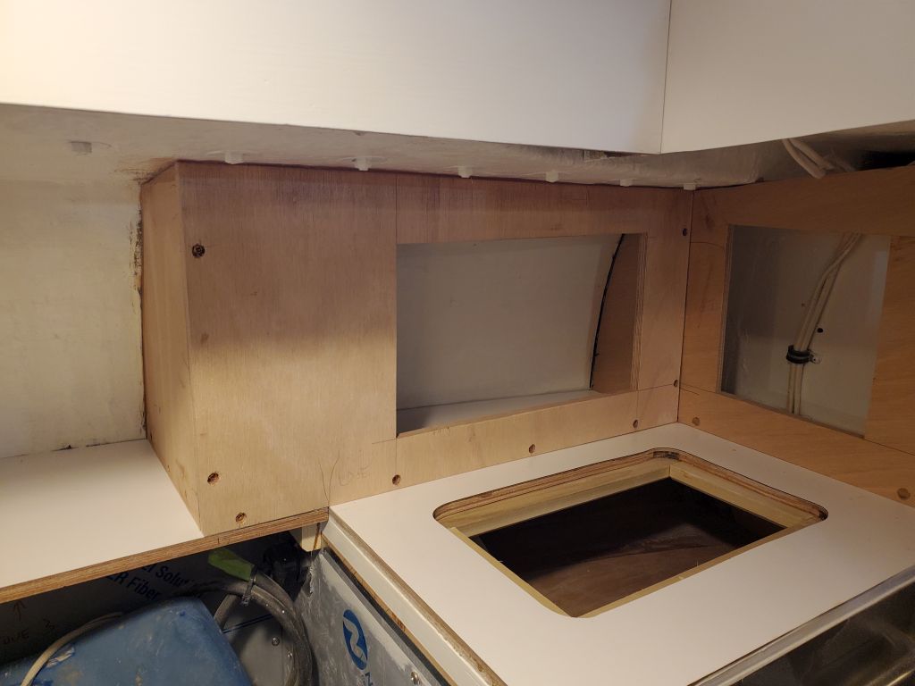
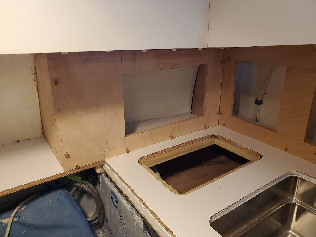
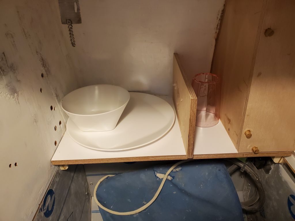
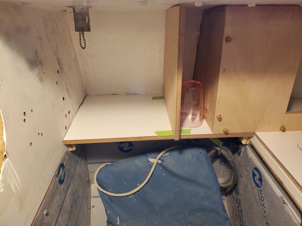
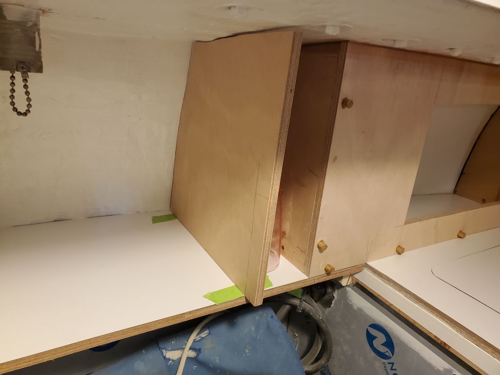
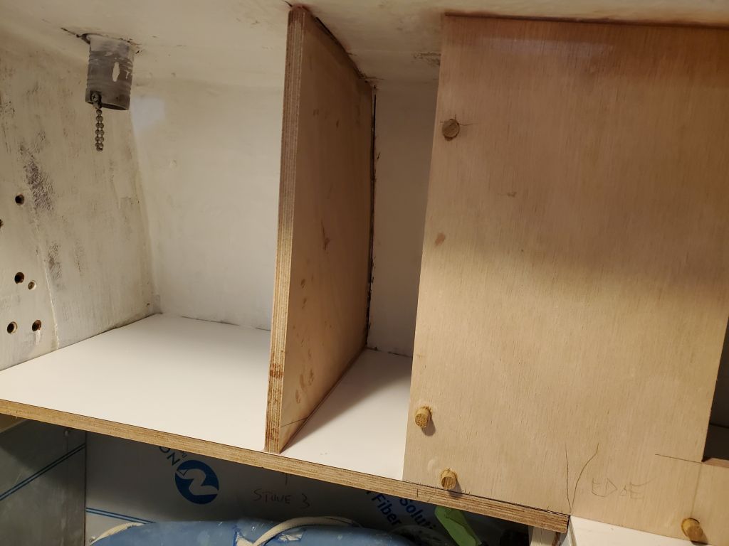
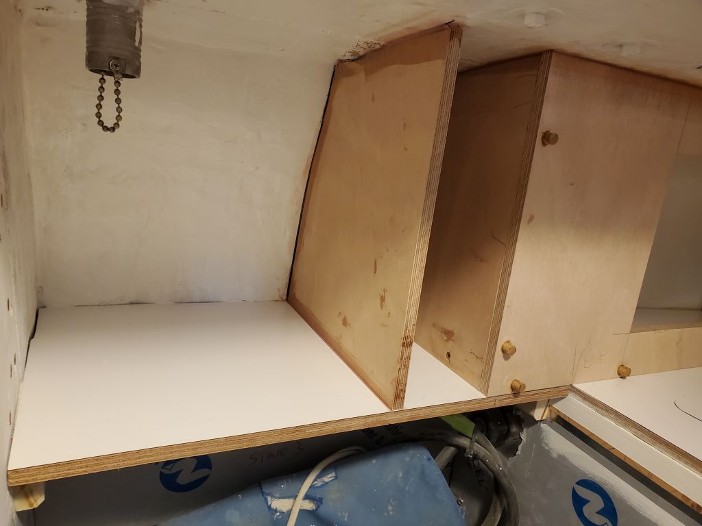
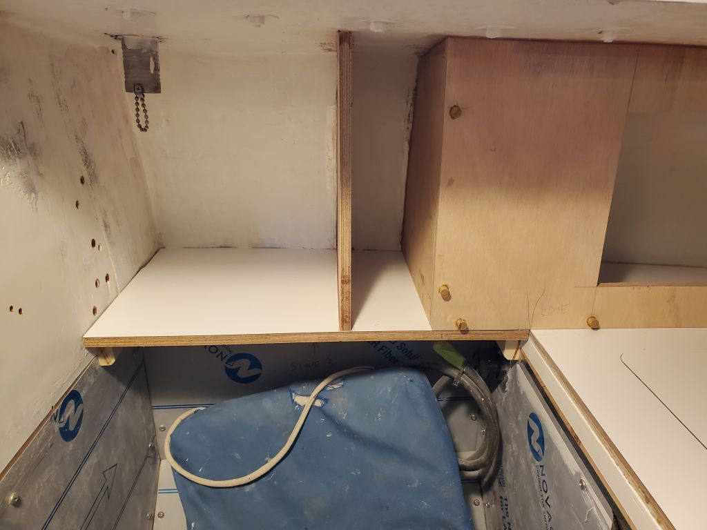
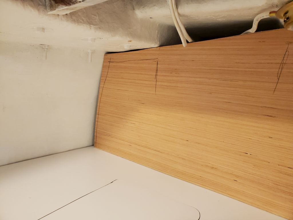
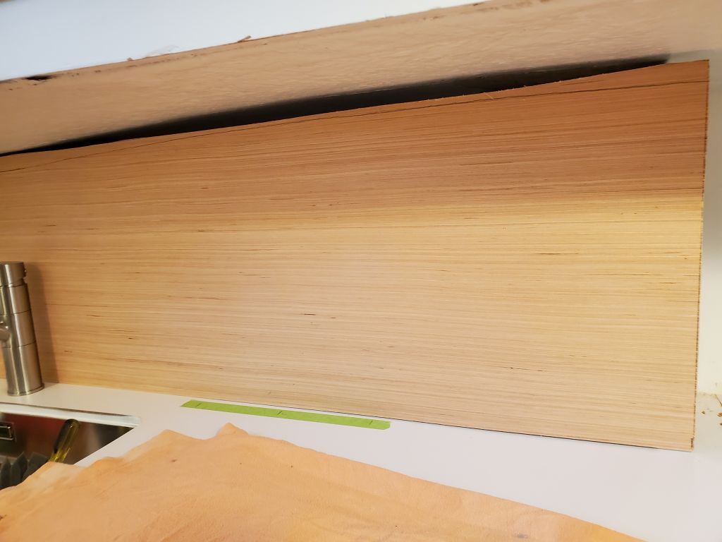
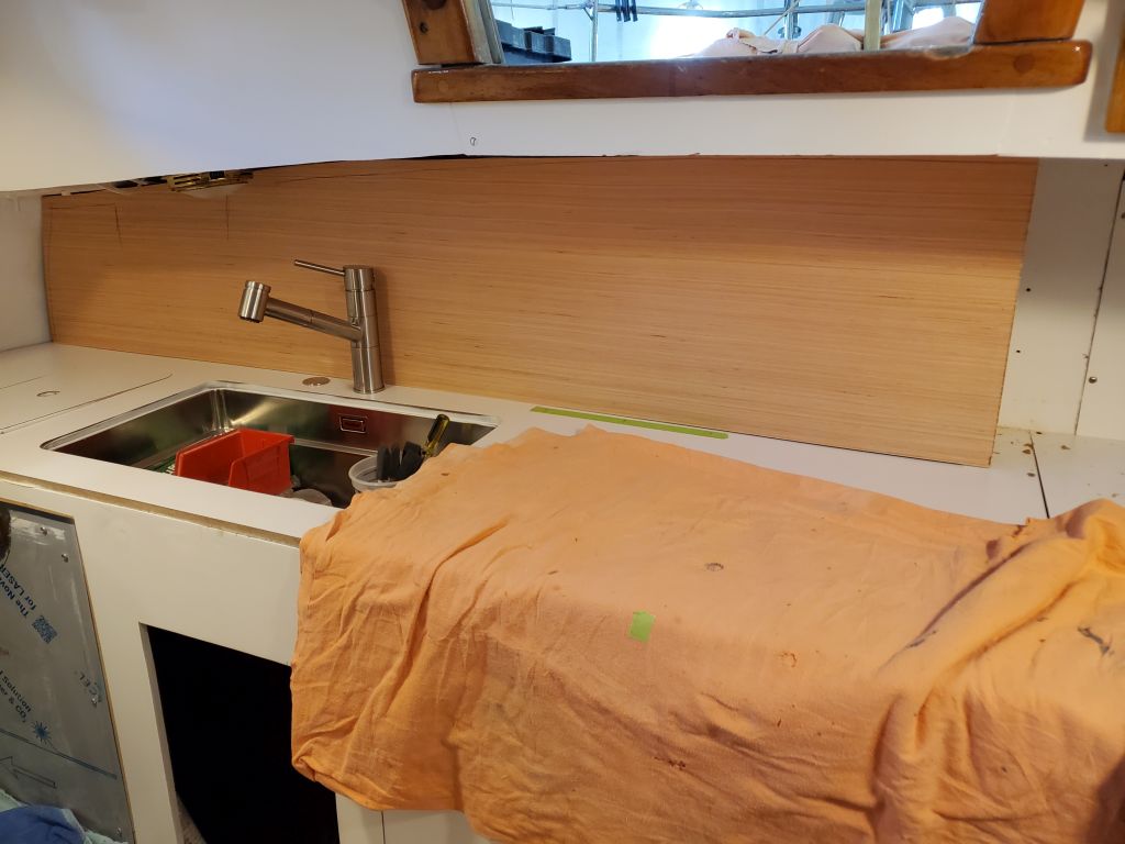
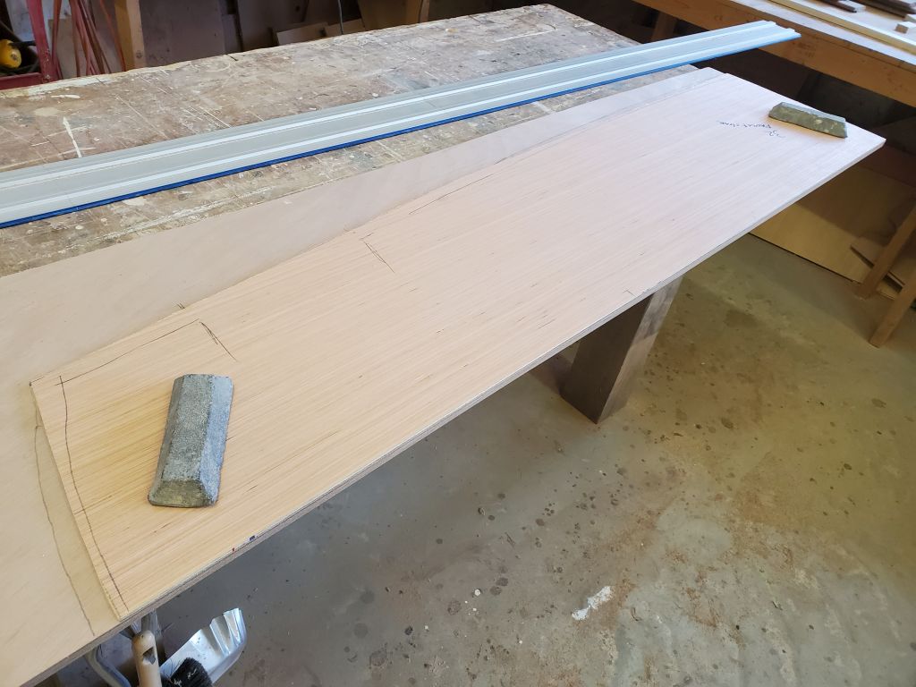
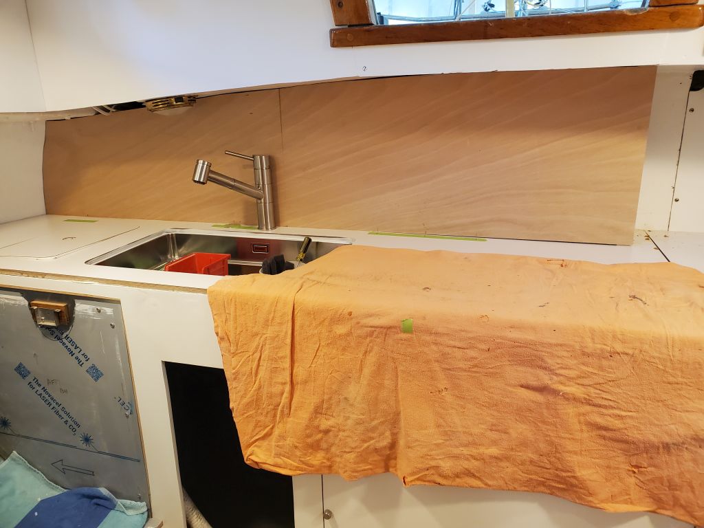
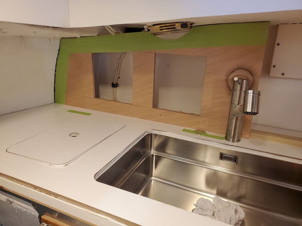
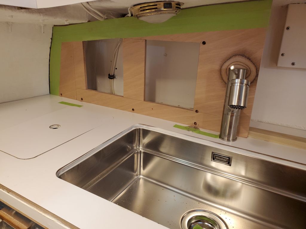
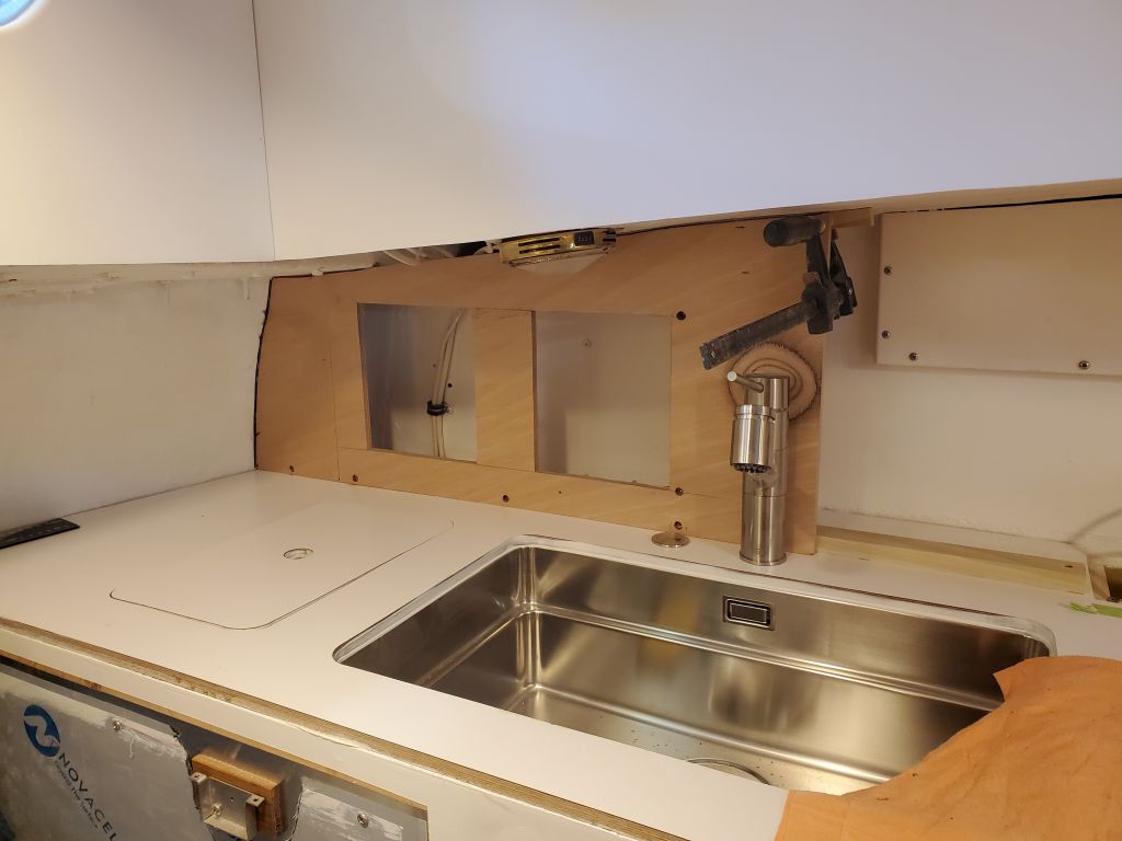
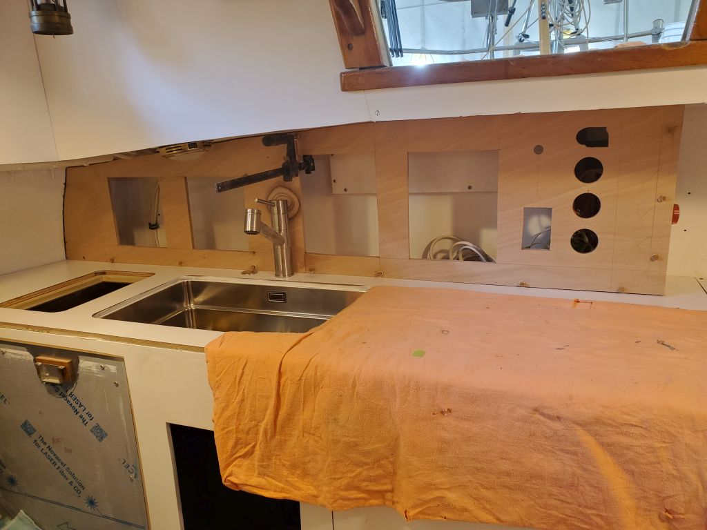
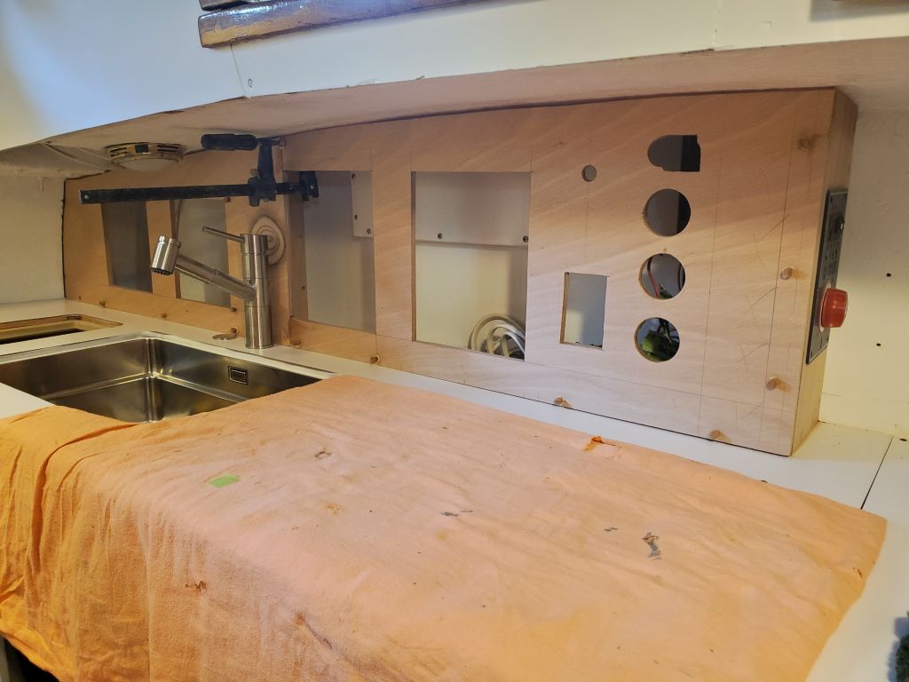
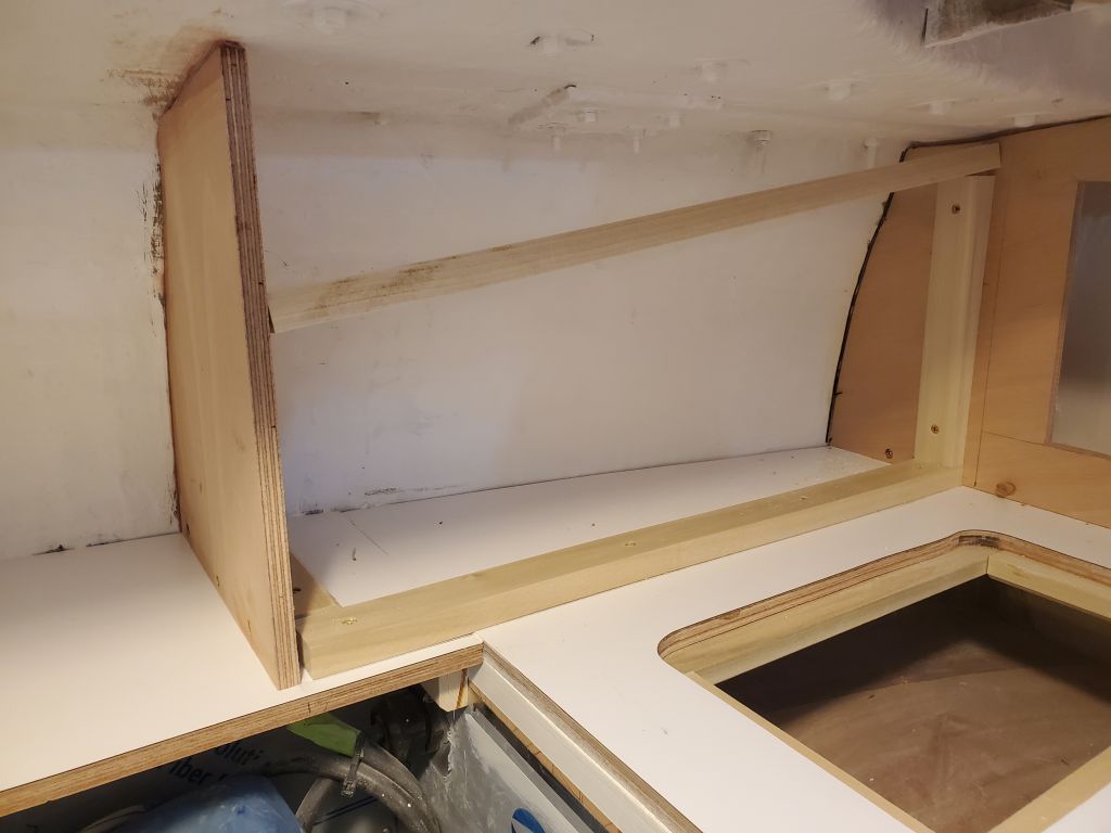
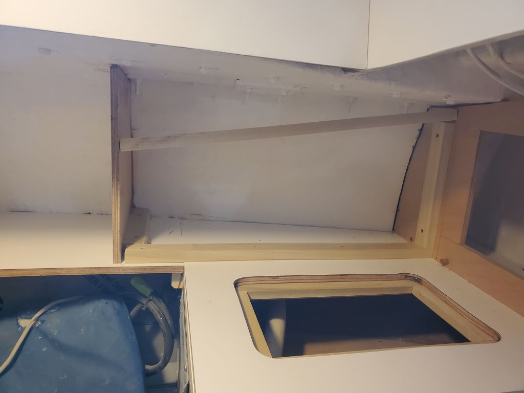
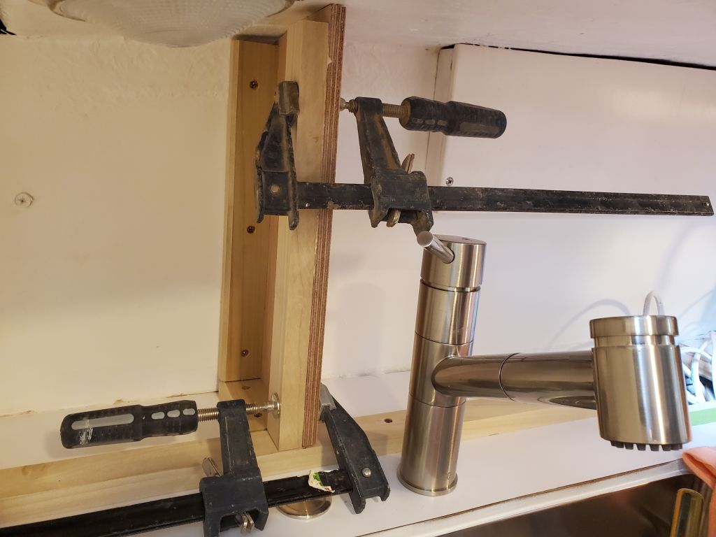
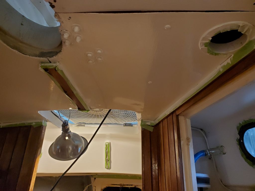
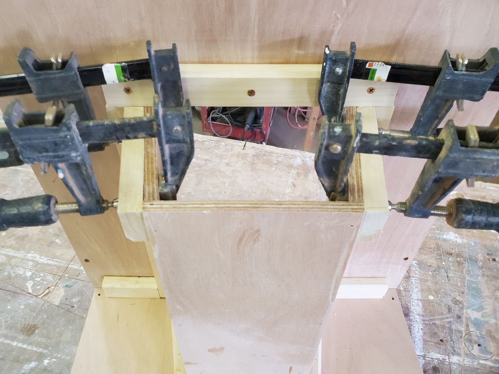
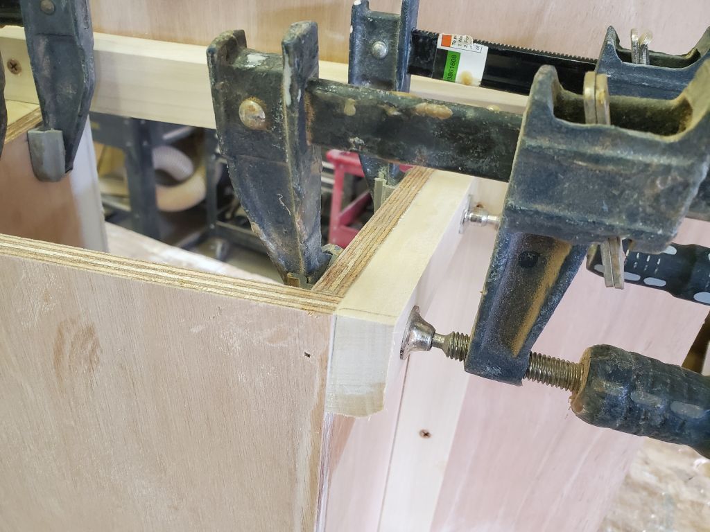
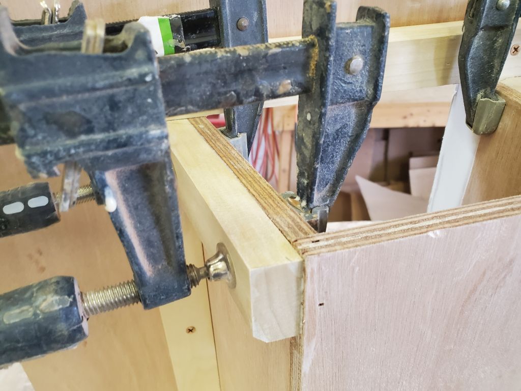
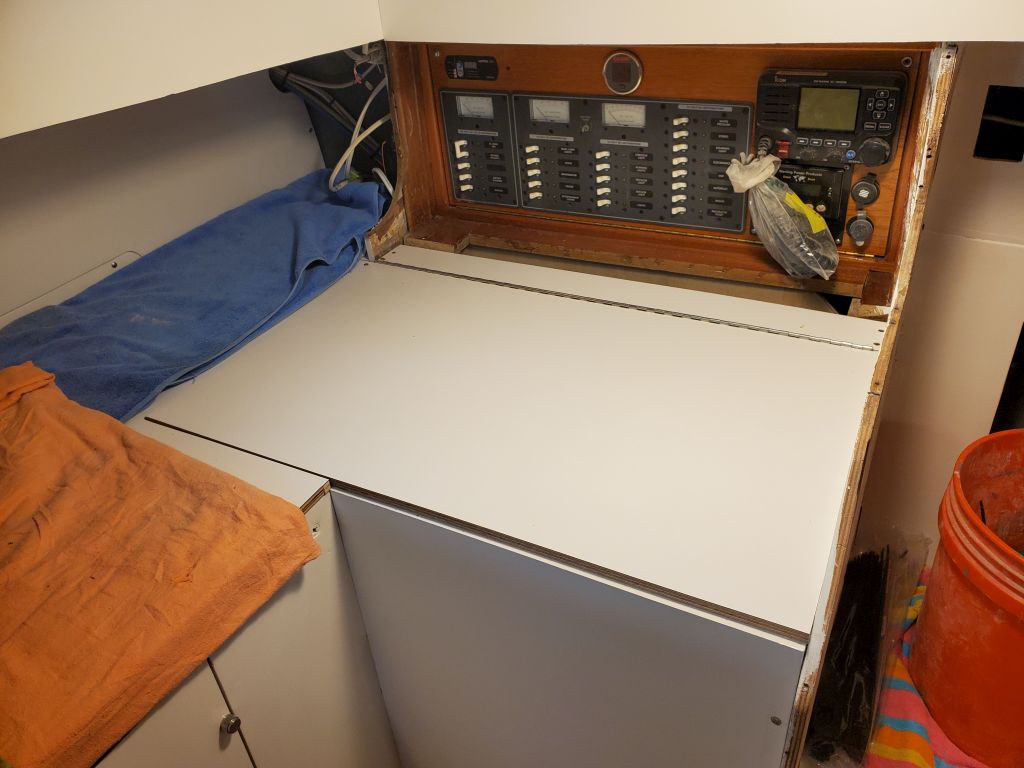
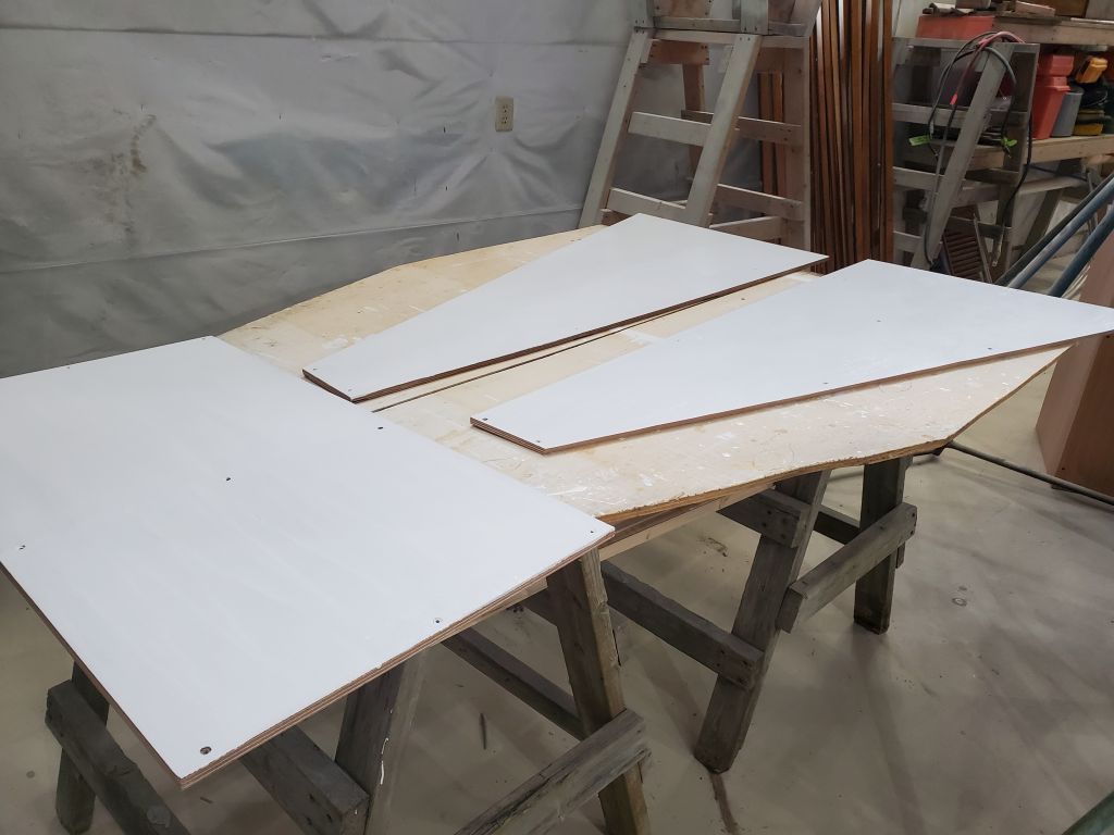
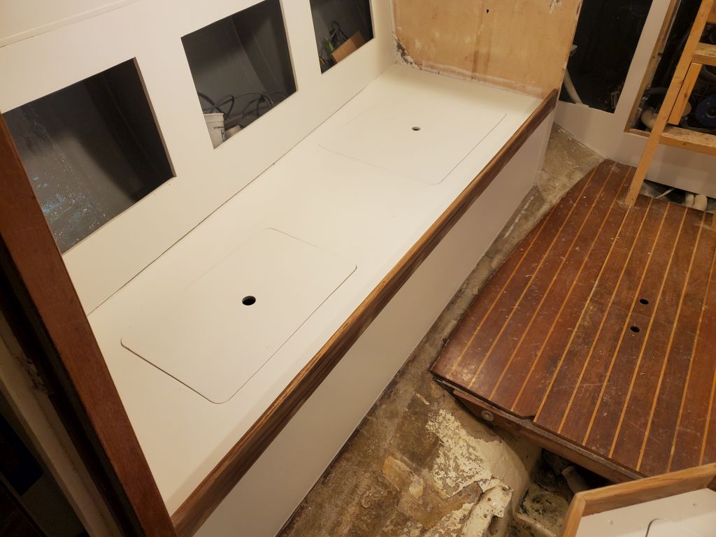
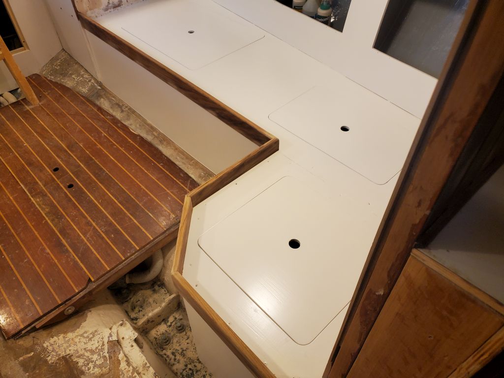
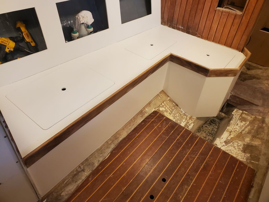
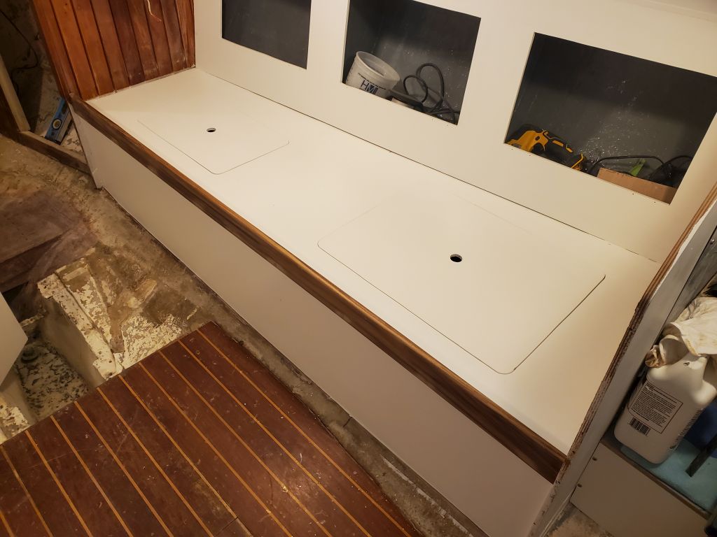
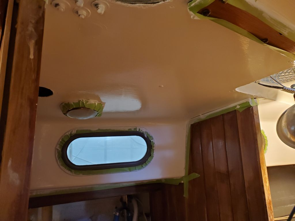
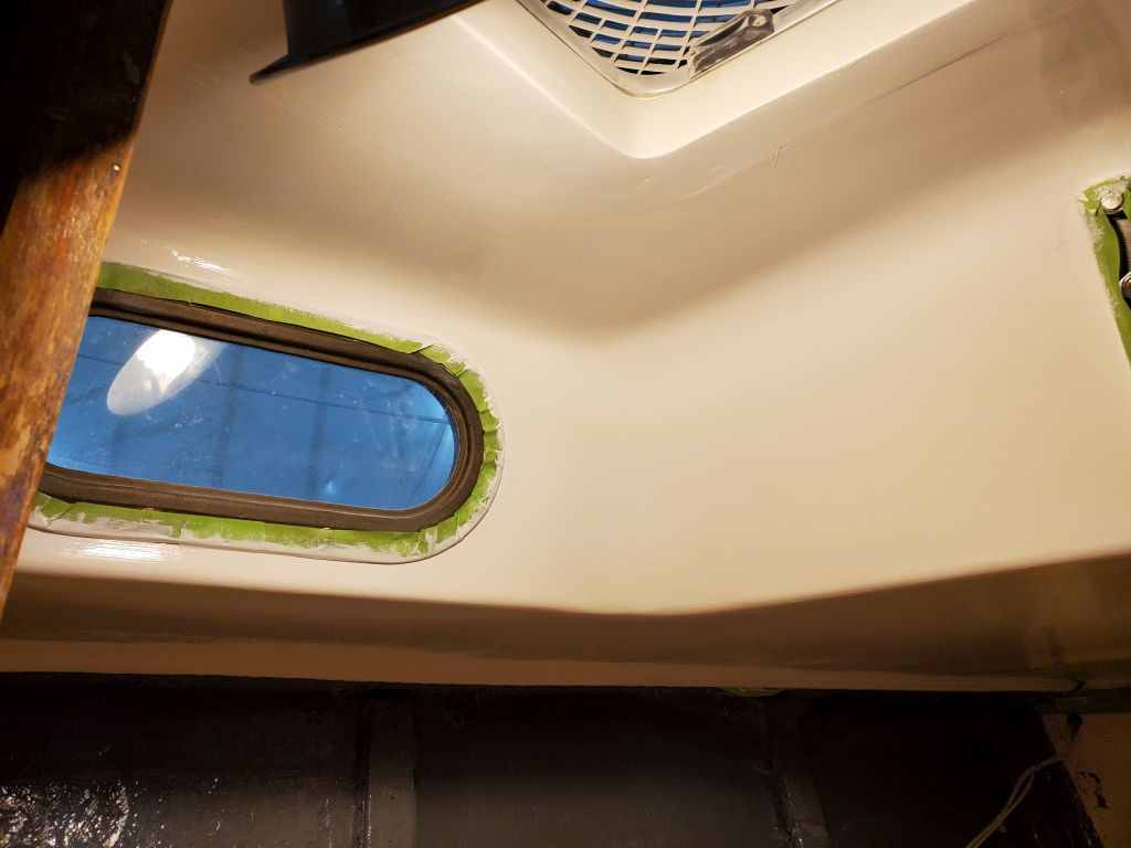
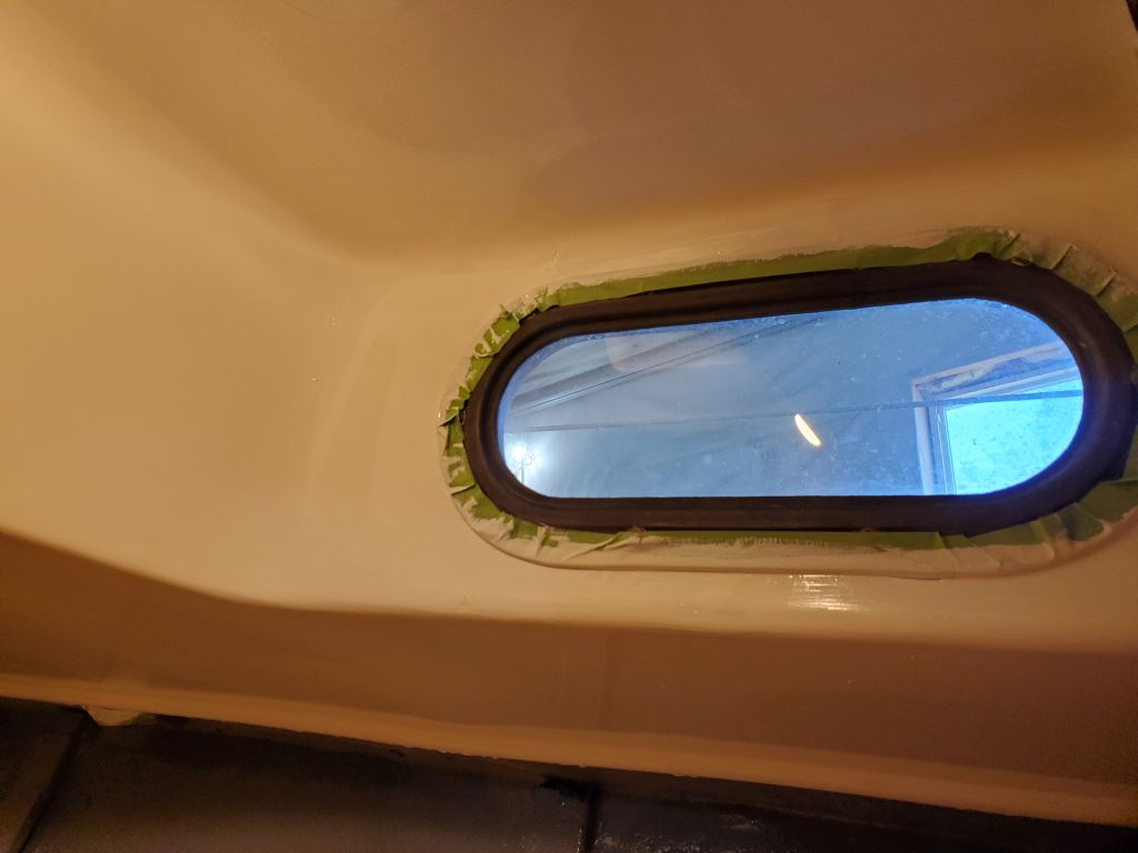
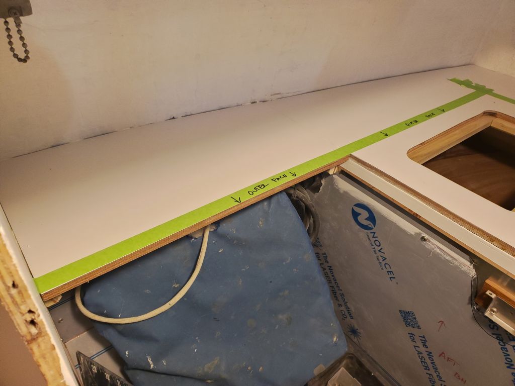
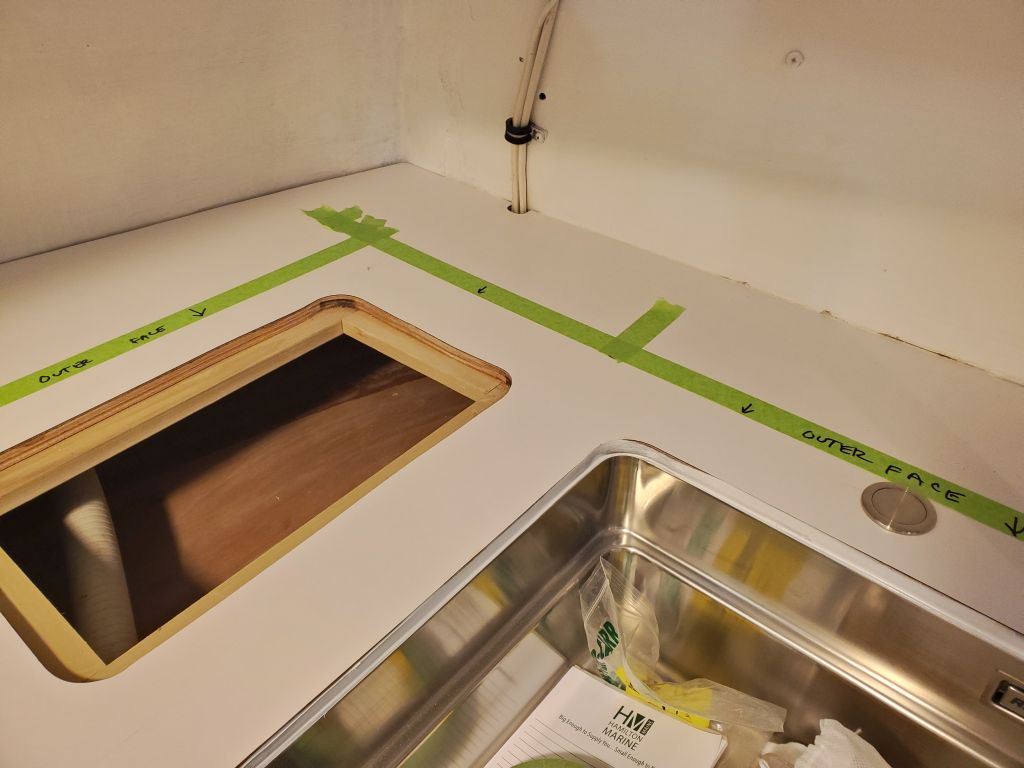
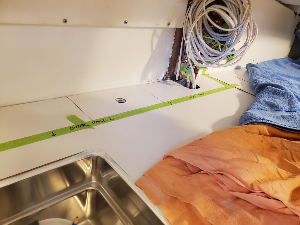
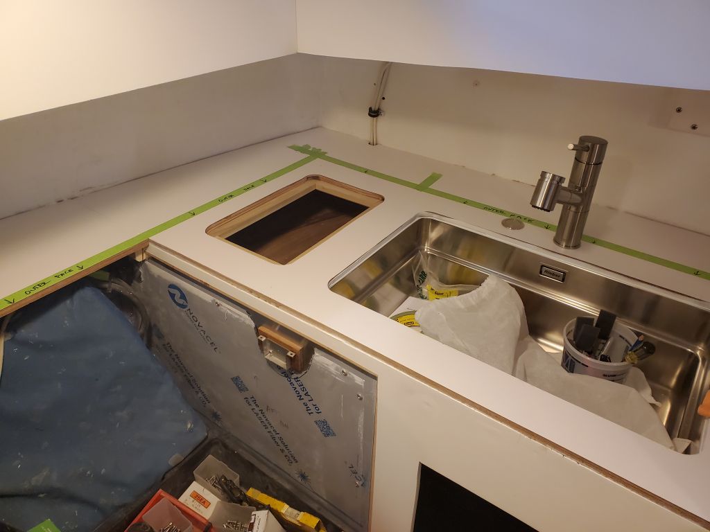
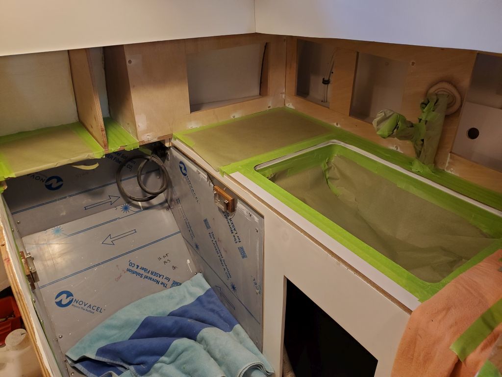
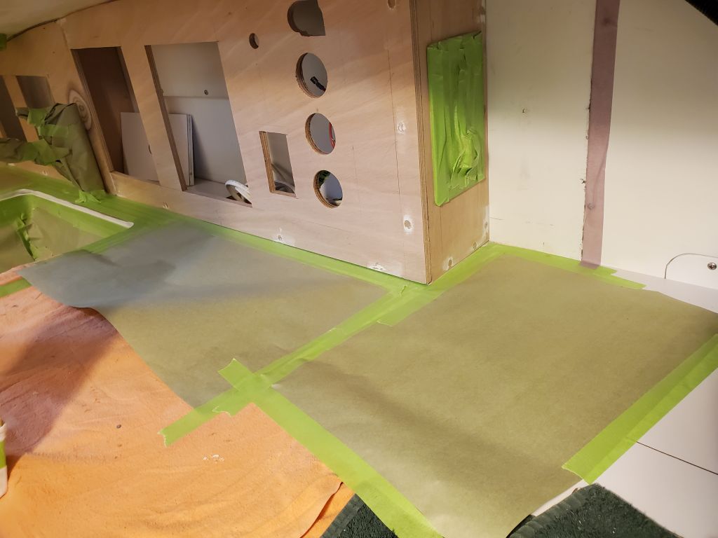
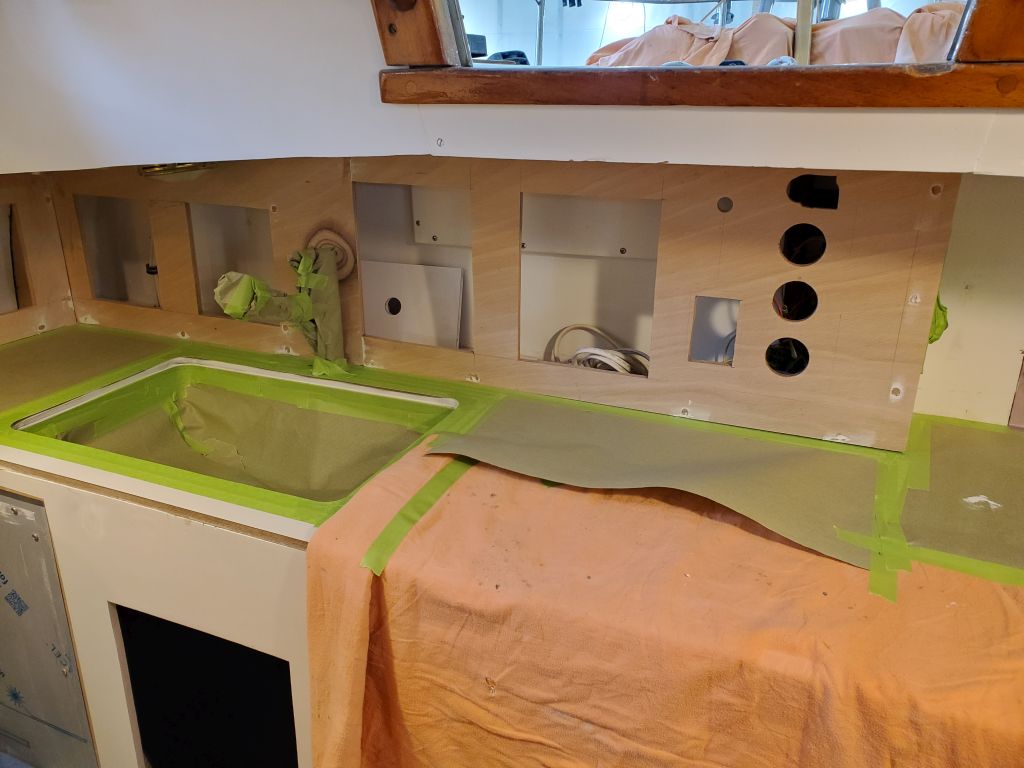
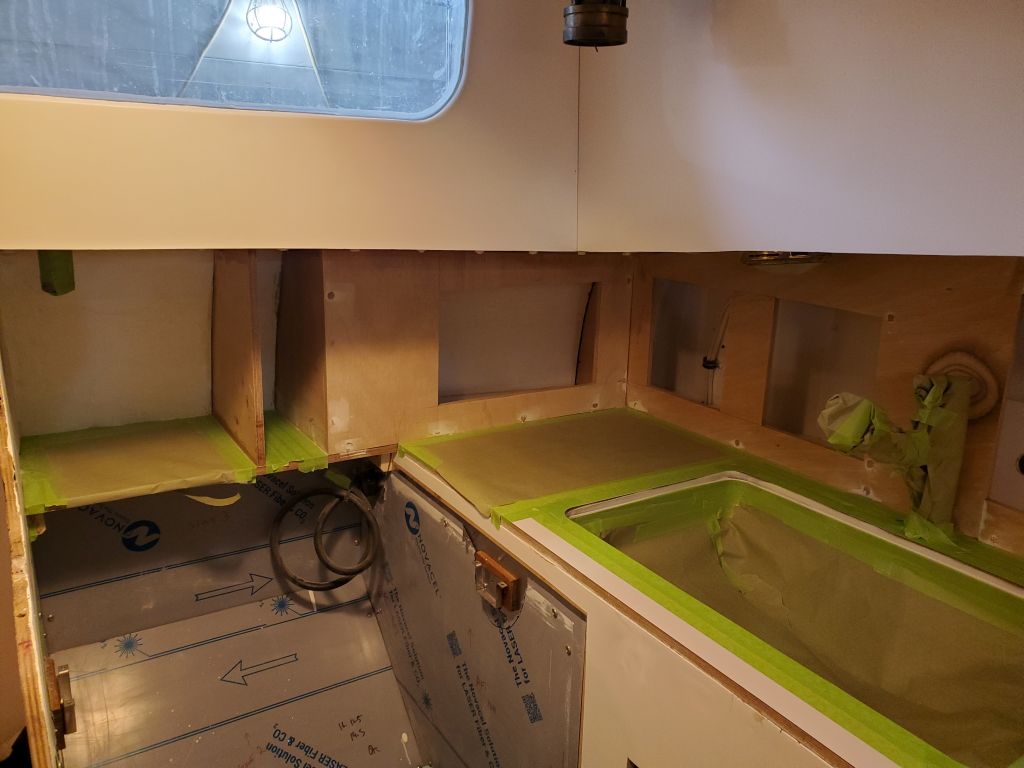
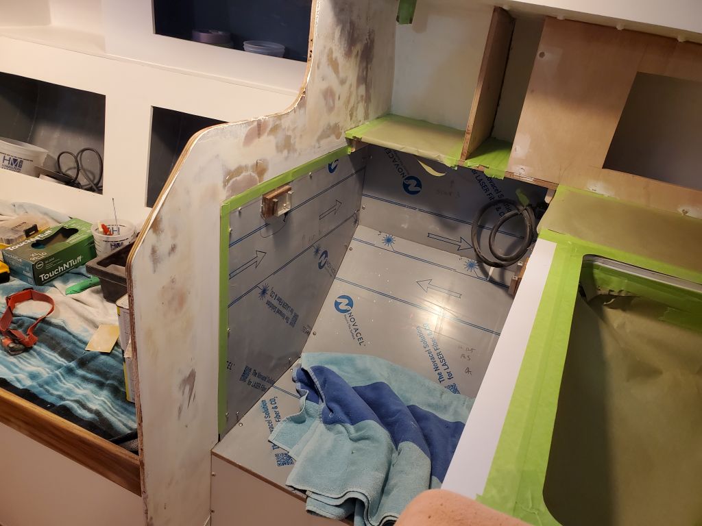
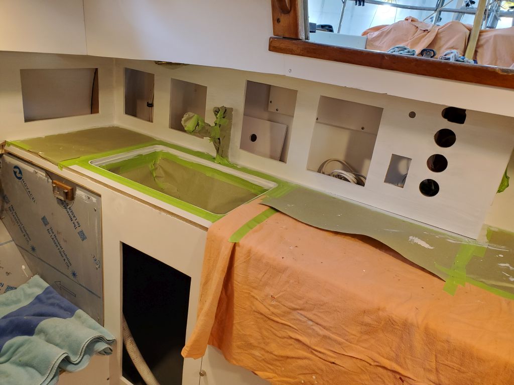
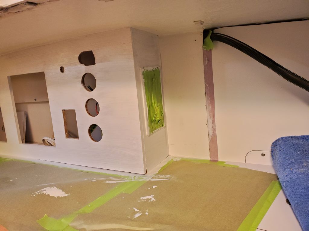
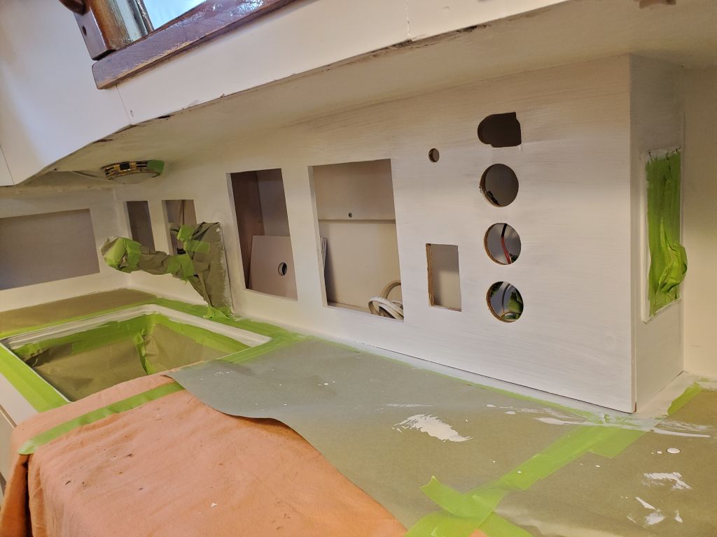
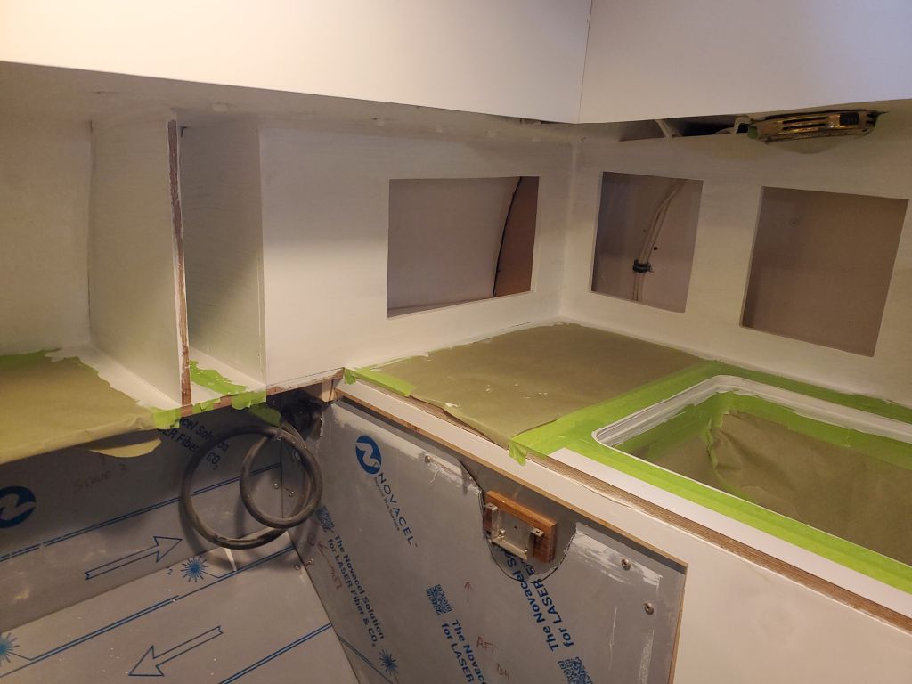
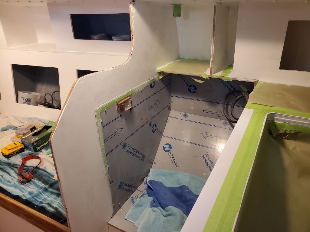
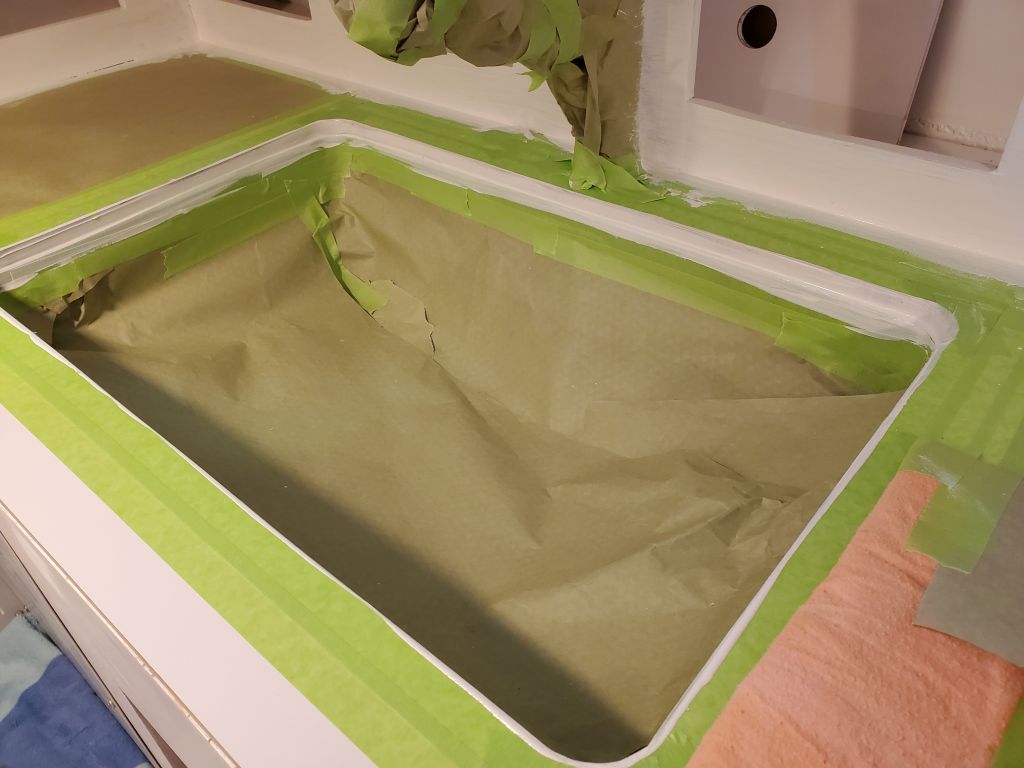
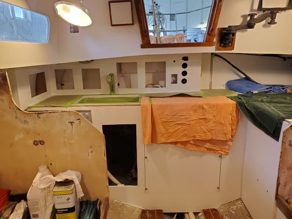
I spent the first part of the day working on the galley, with a final sanding of the new cabinets and related masking work before applying a coat of primer to all areas, including the back side of the forward stove bulkhead, which had required some minor fill and repair work.
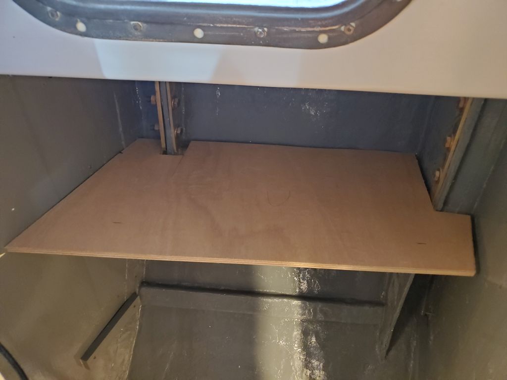
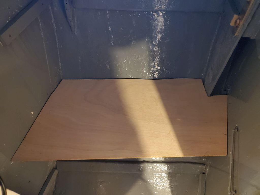
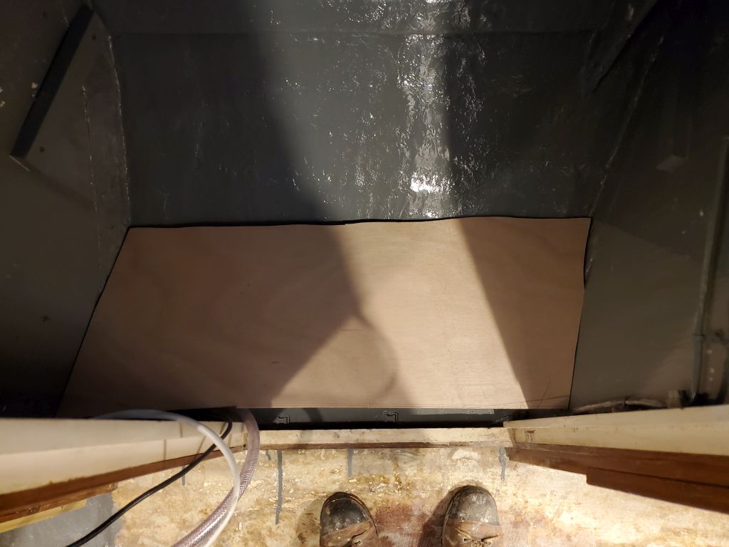
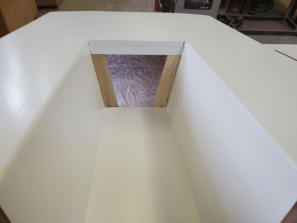
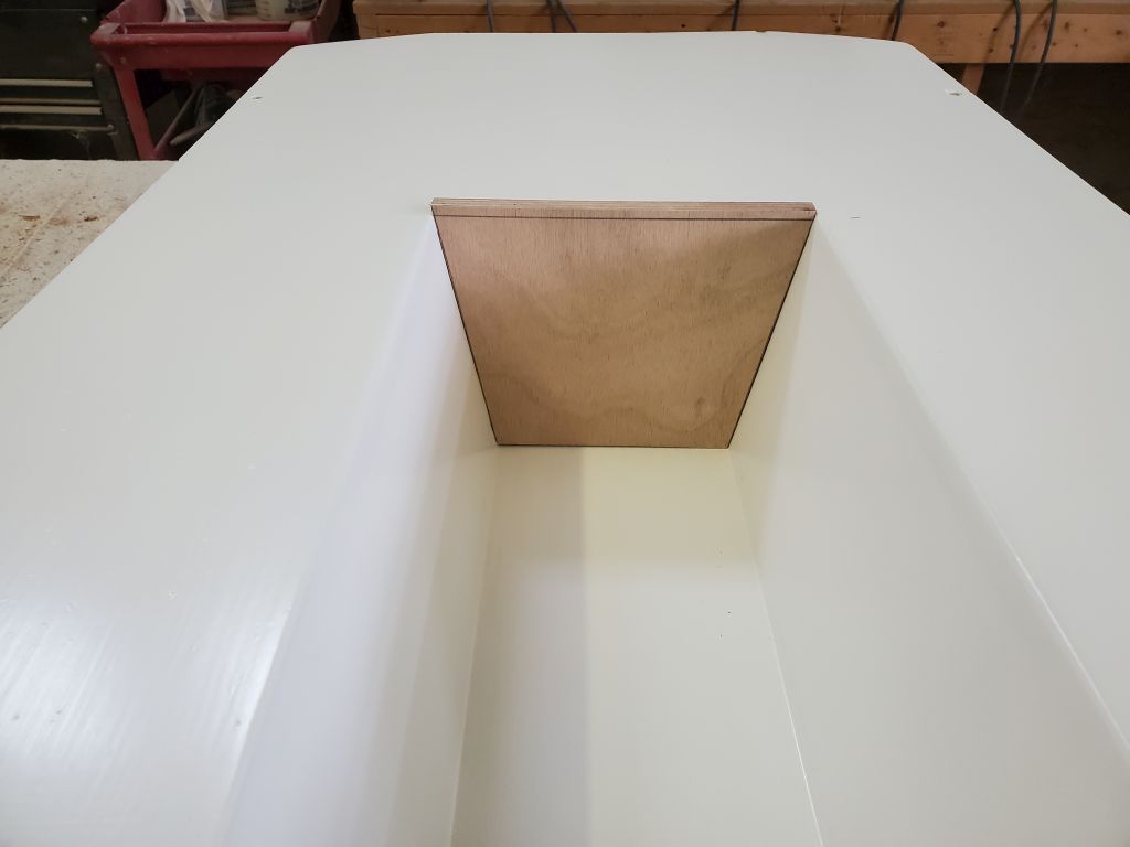
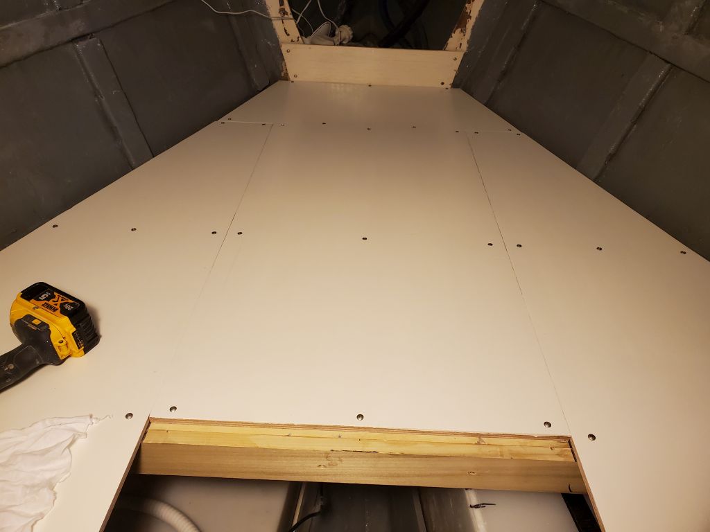
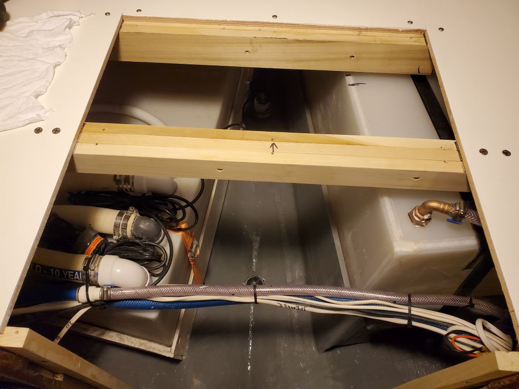
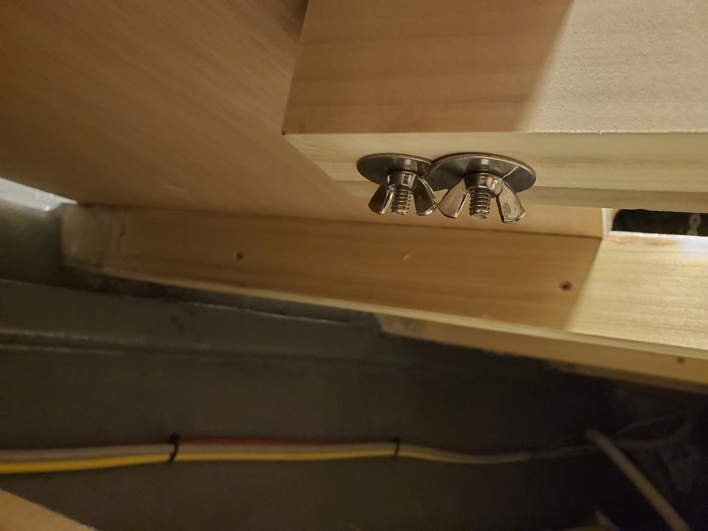
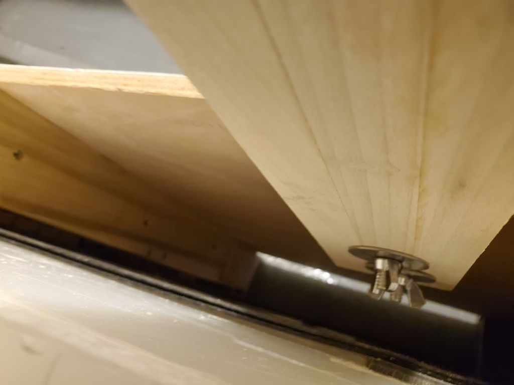
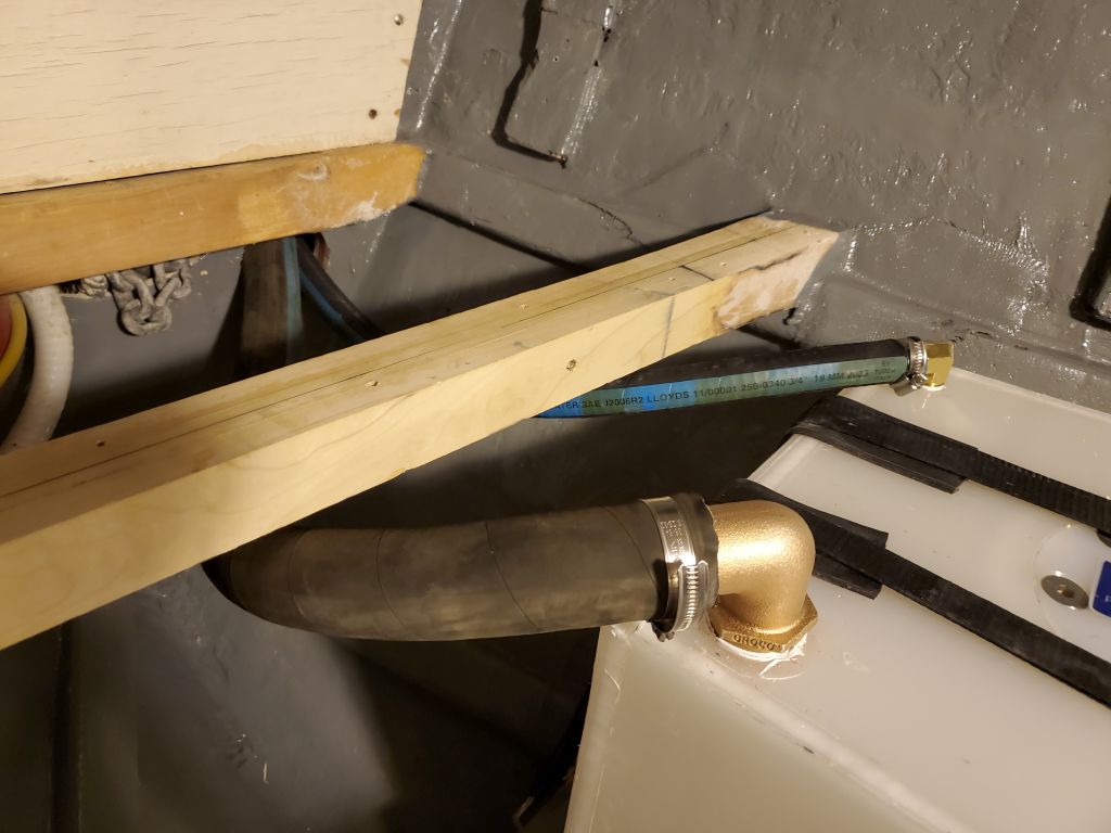
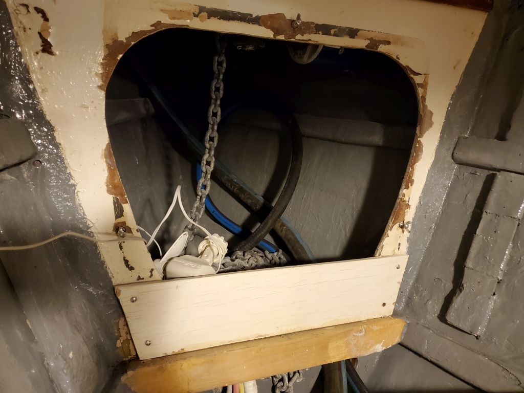
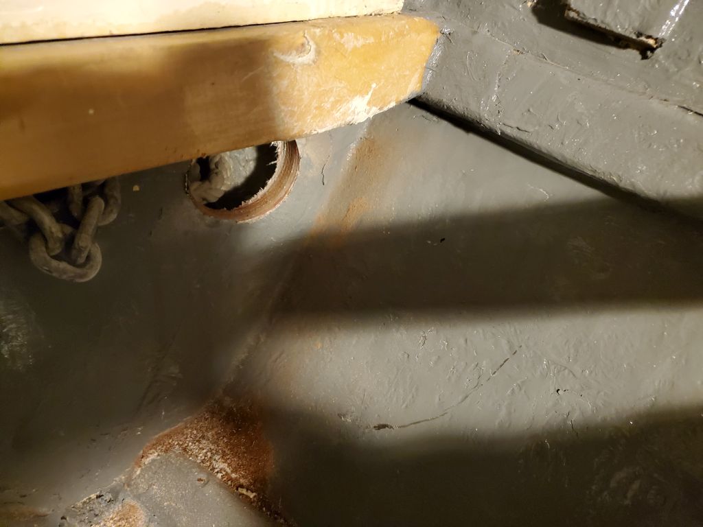
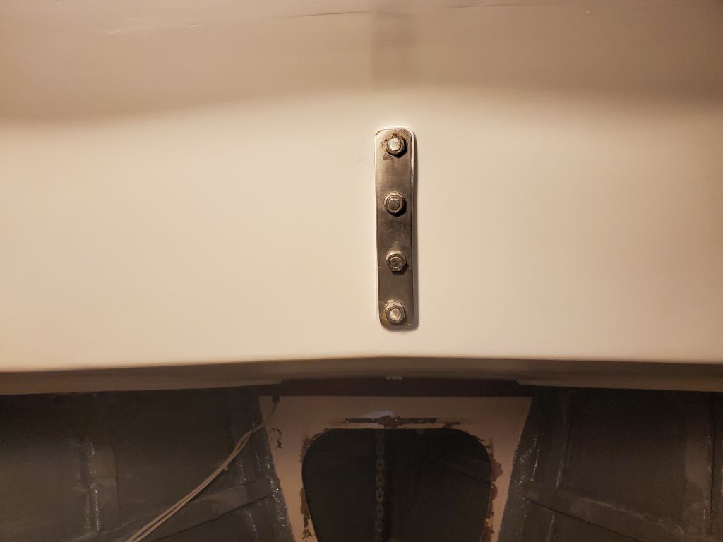
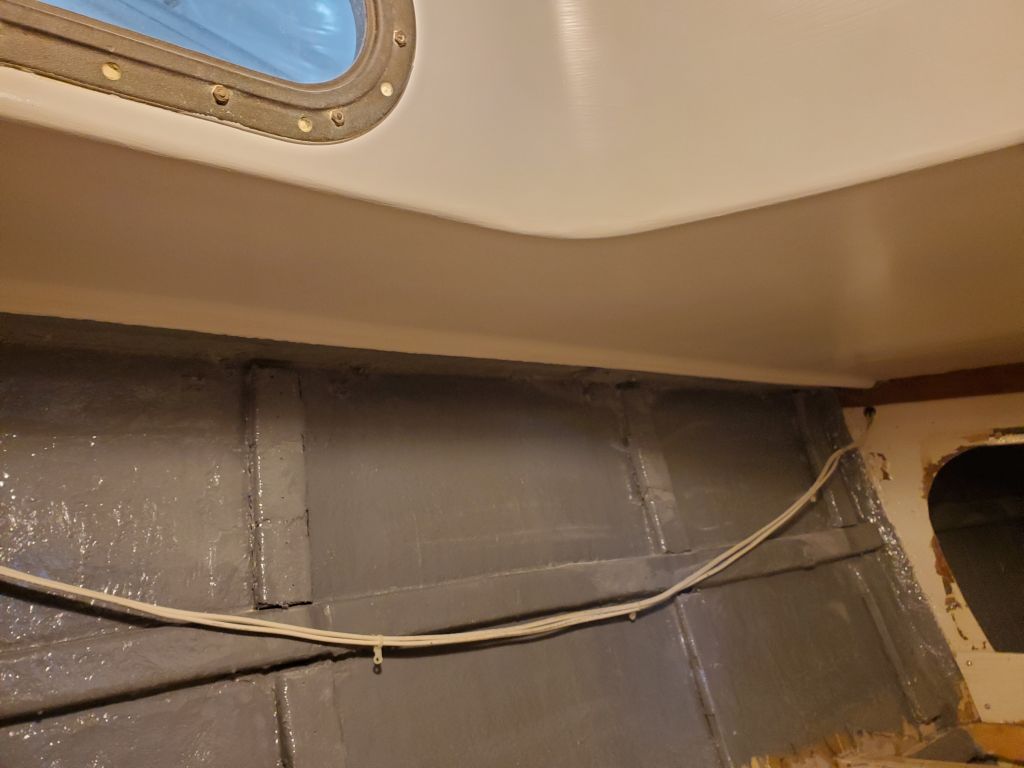
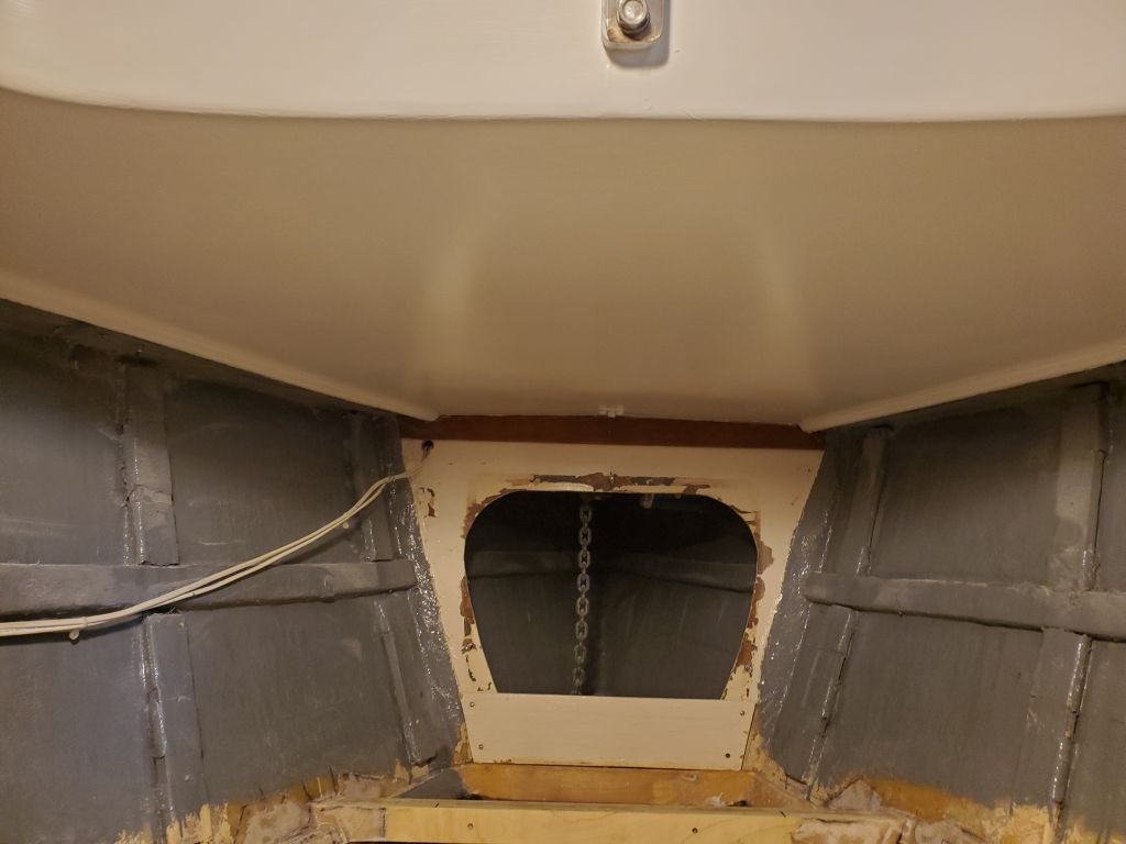
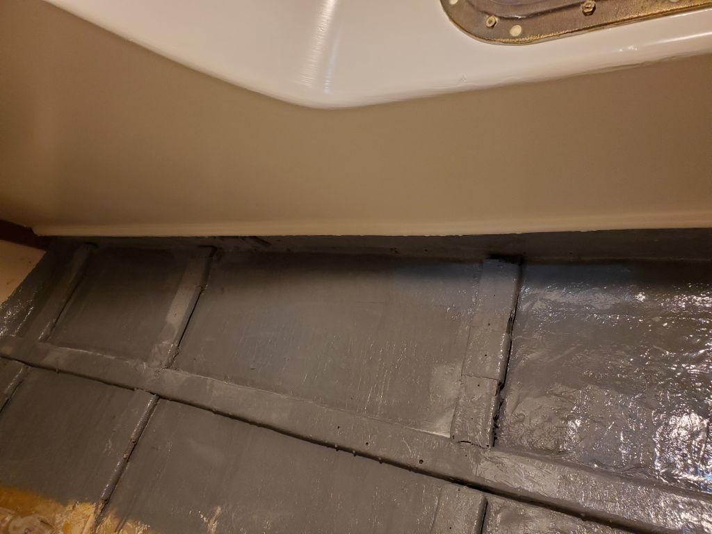
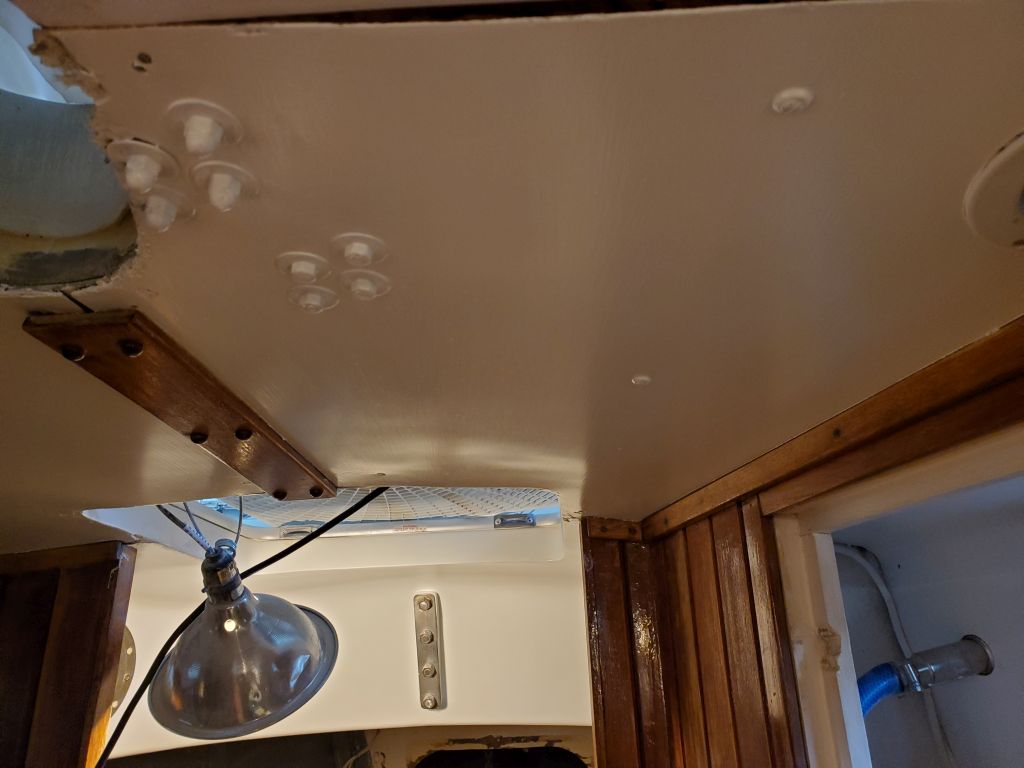
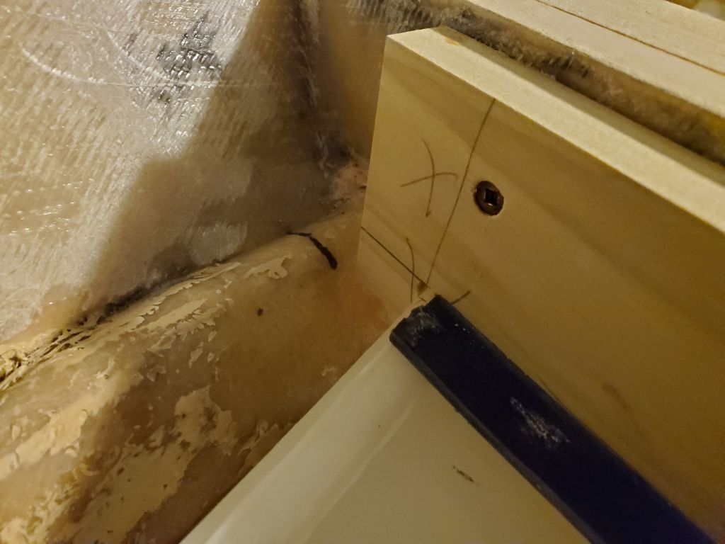
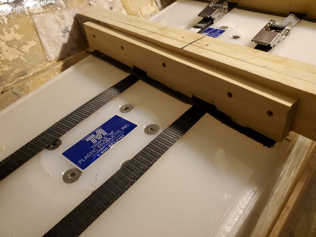
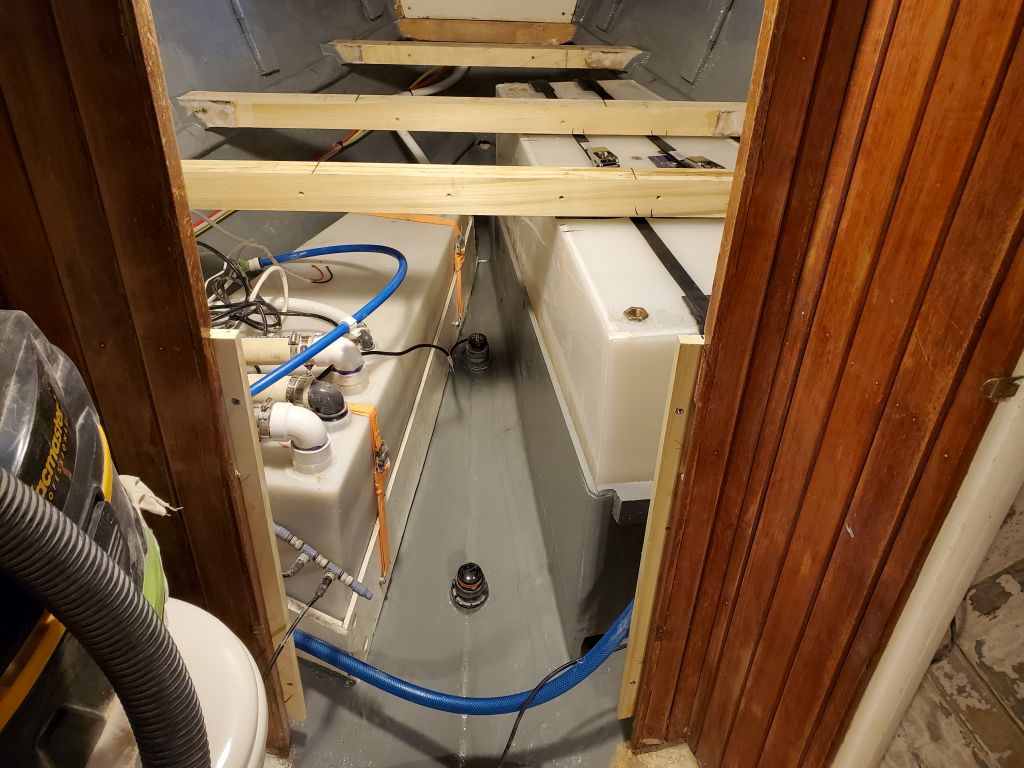
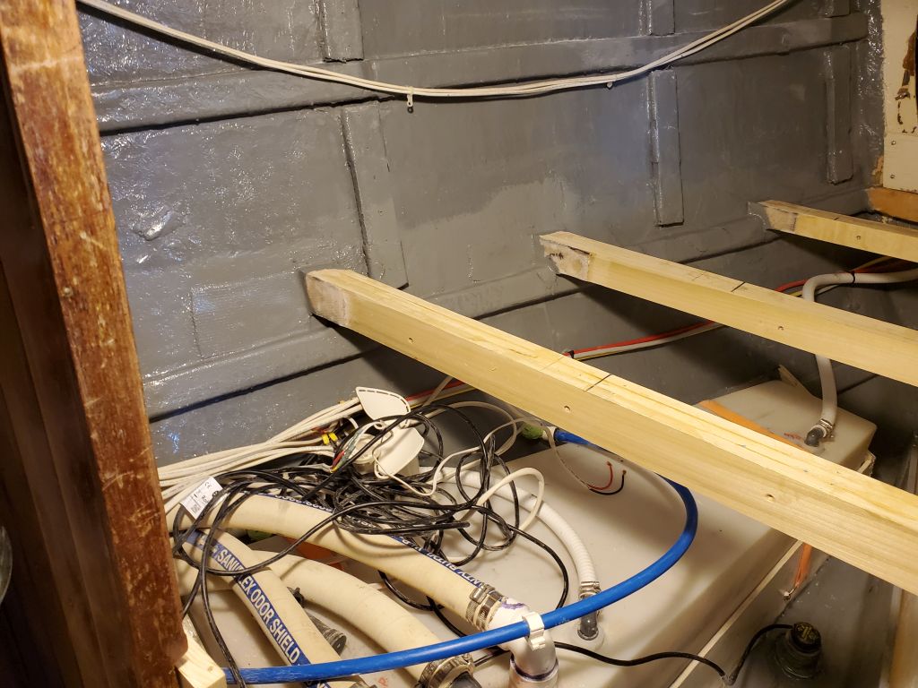
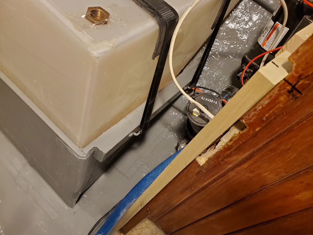
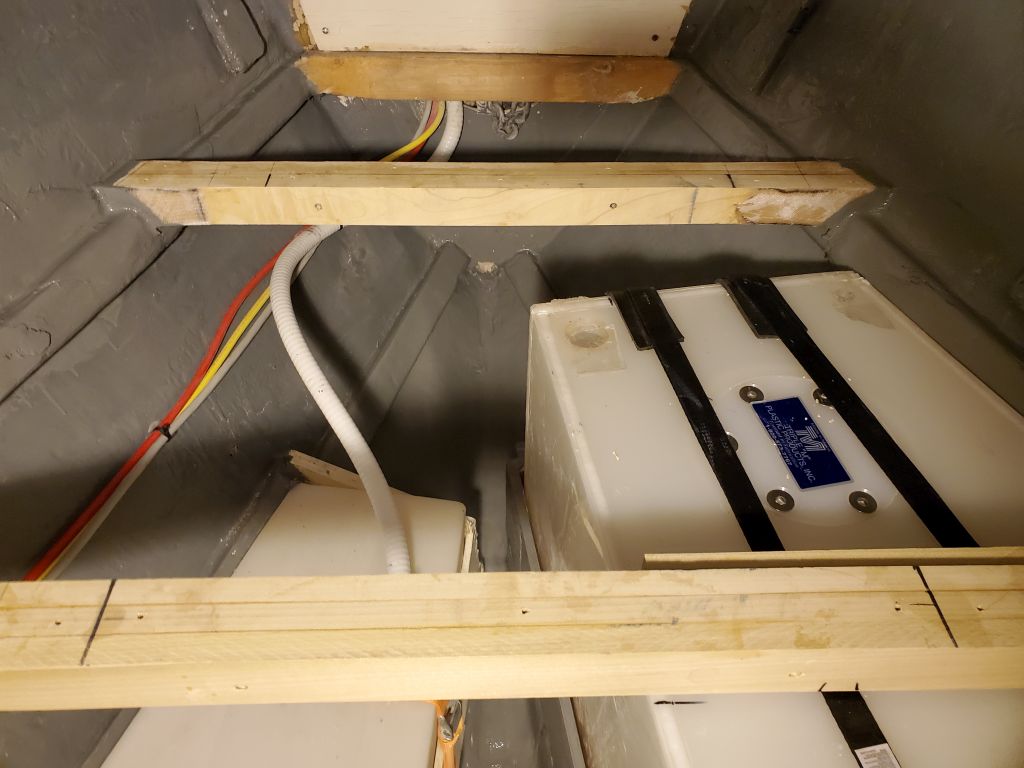
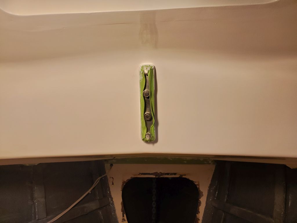
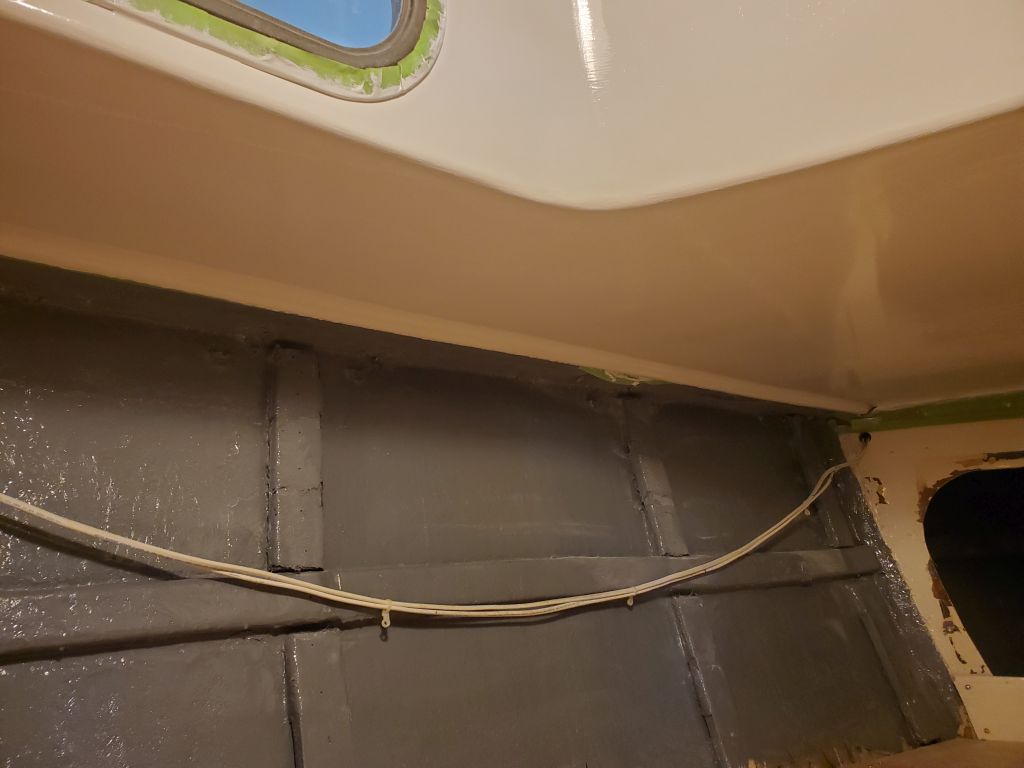
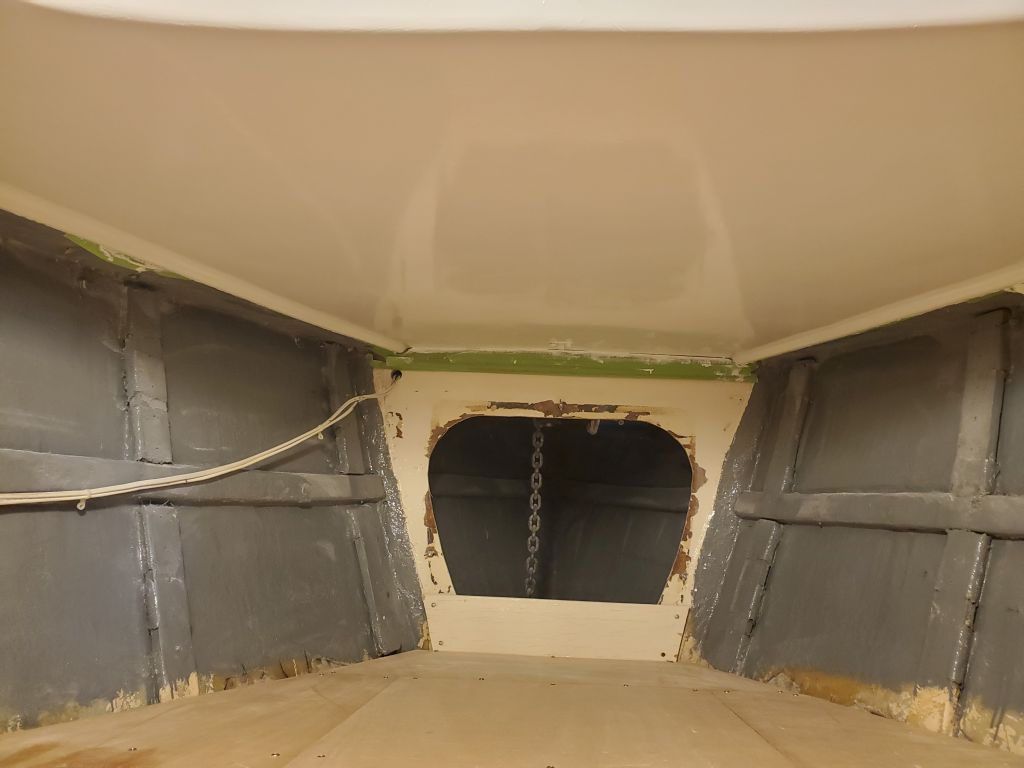
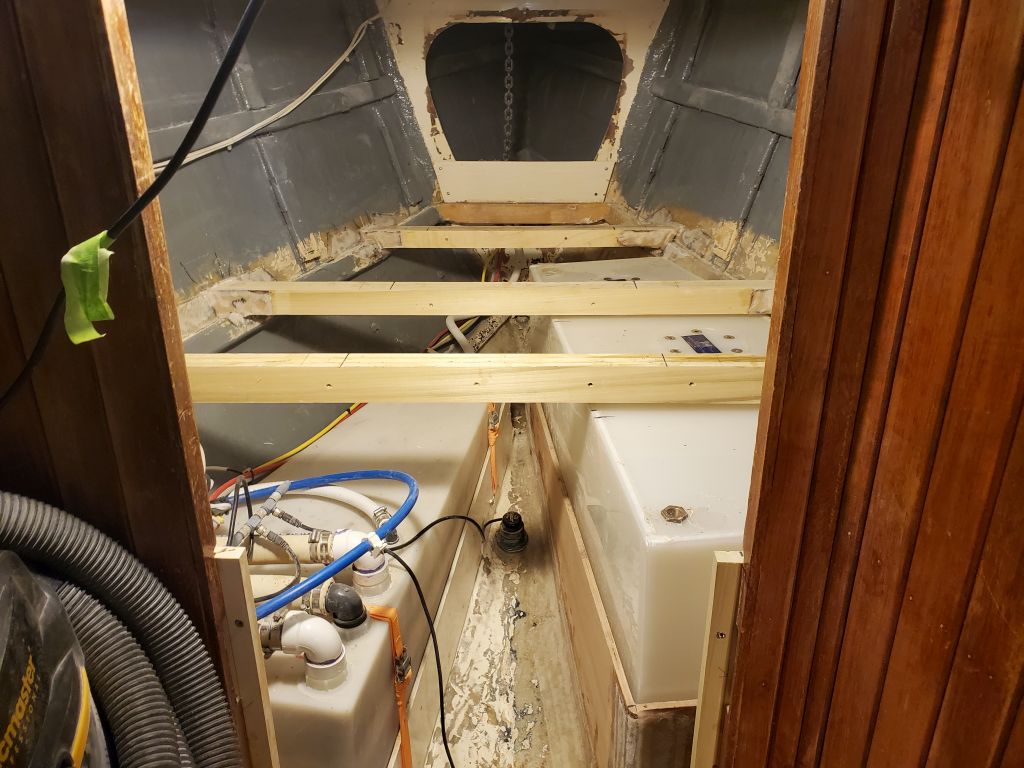
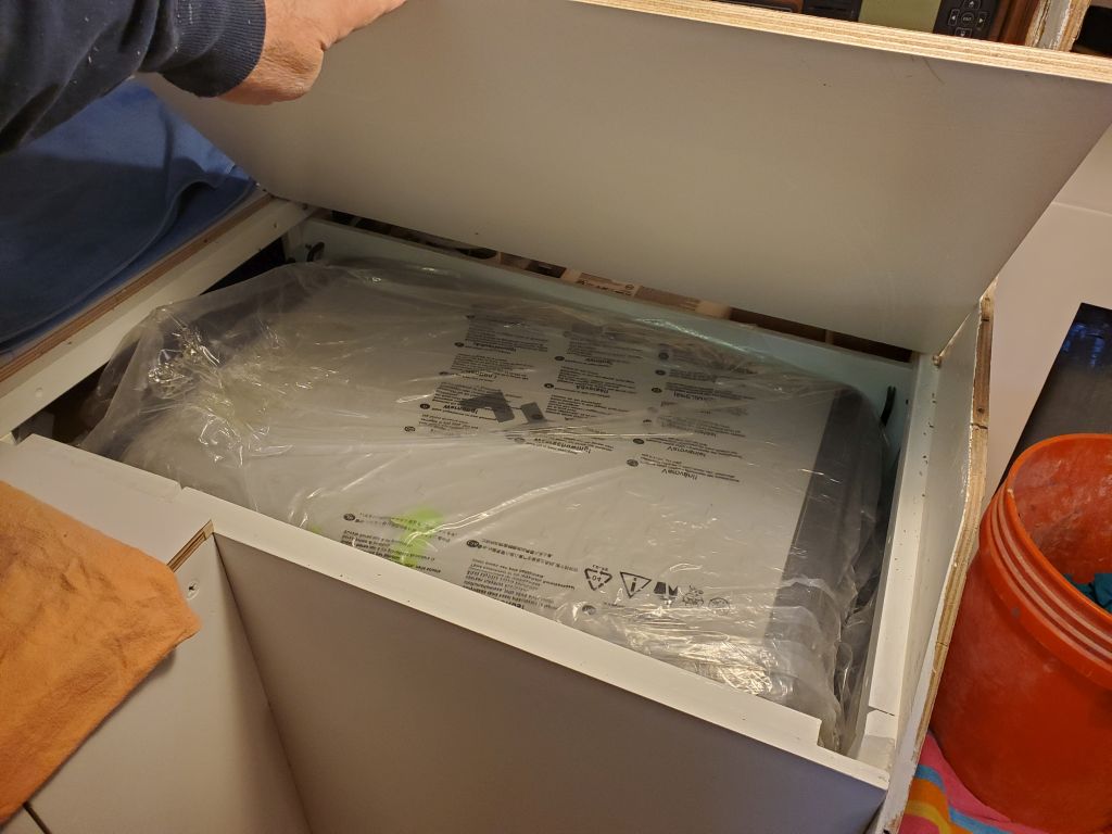
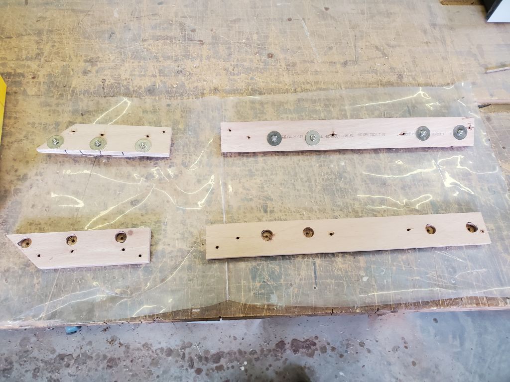
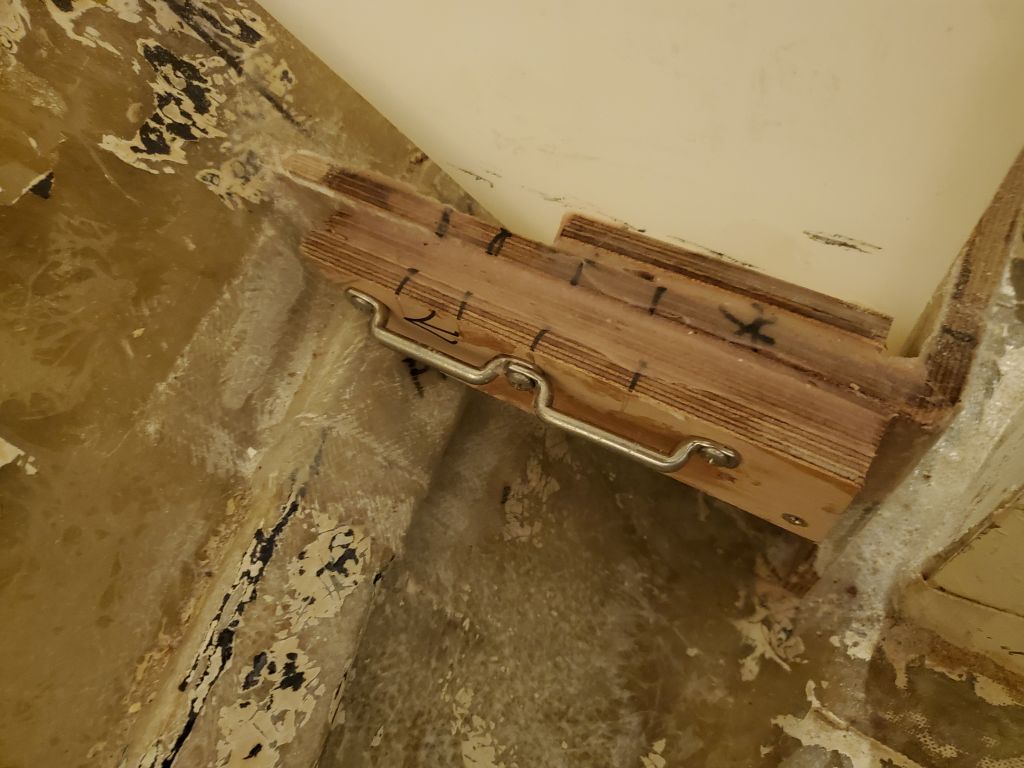
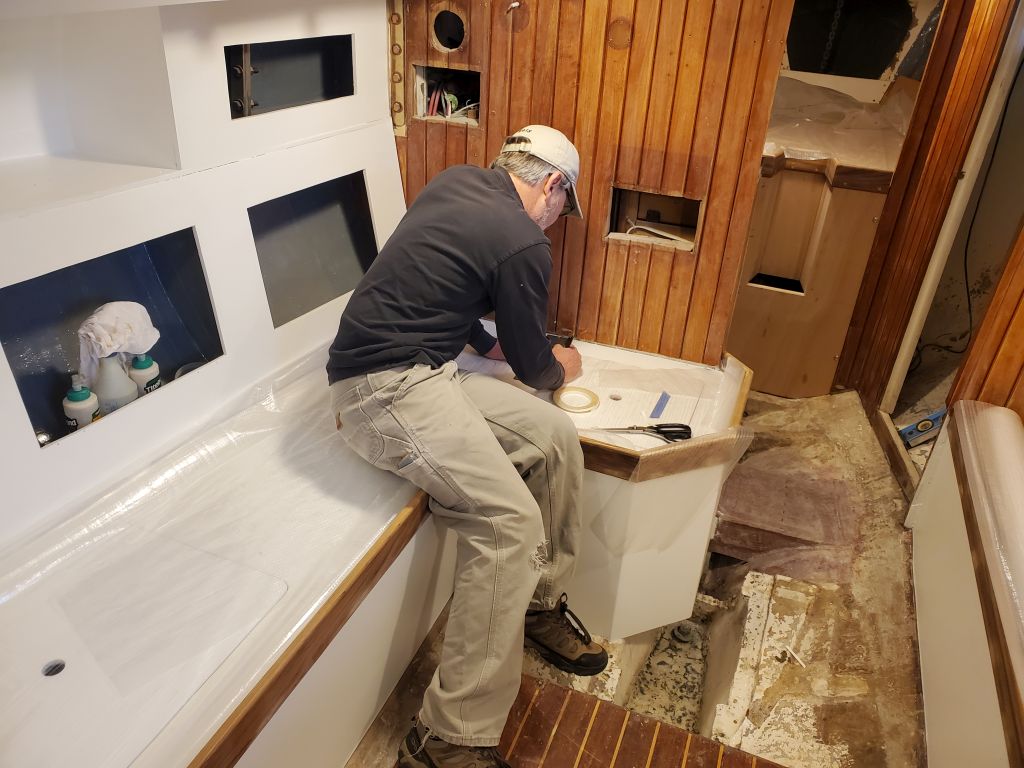
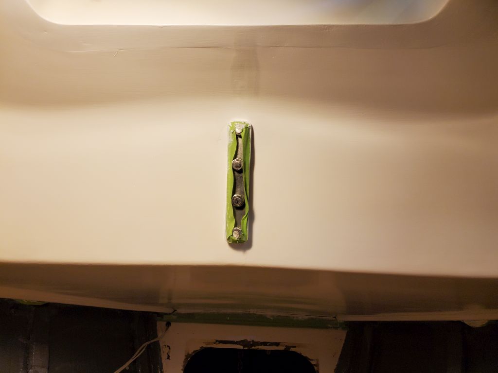
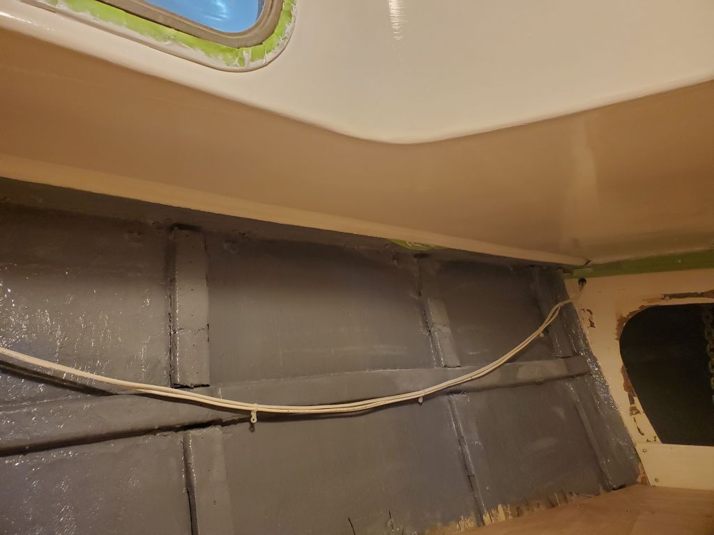
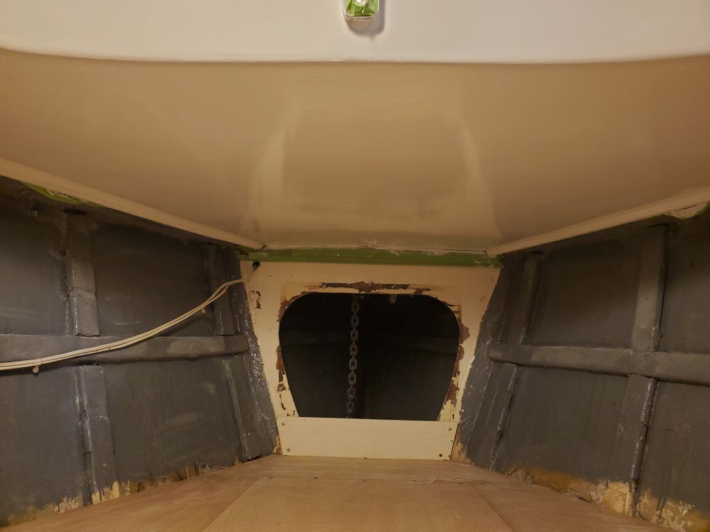
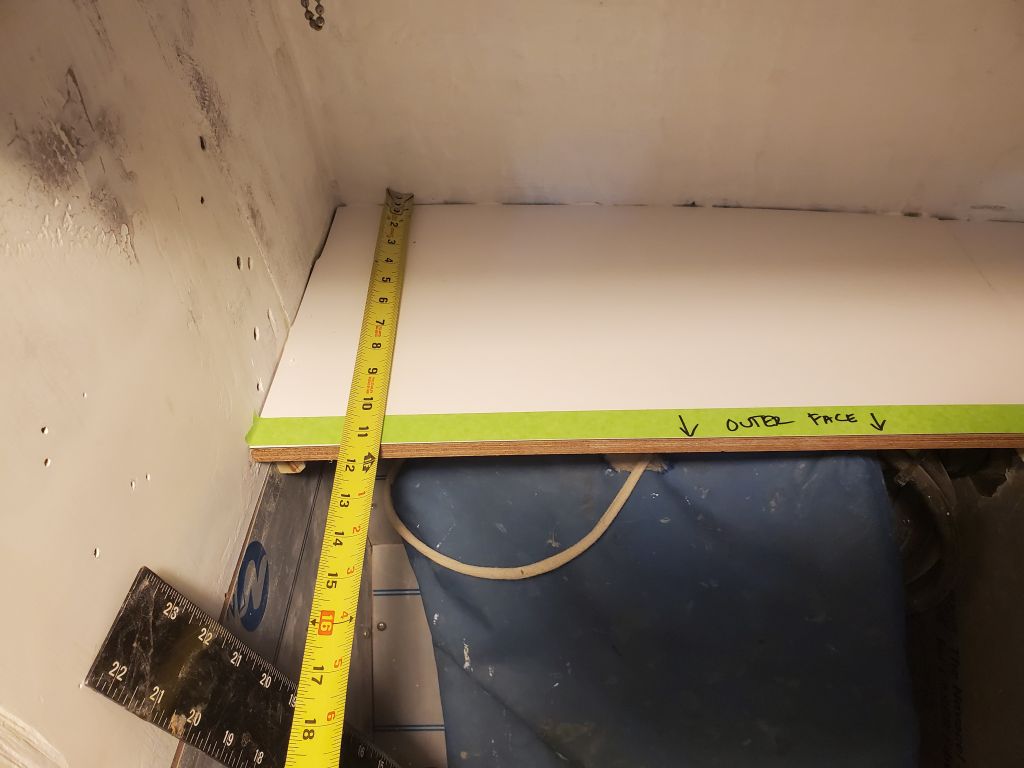
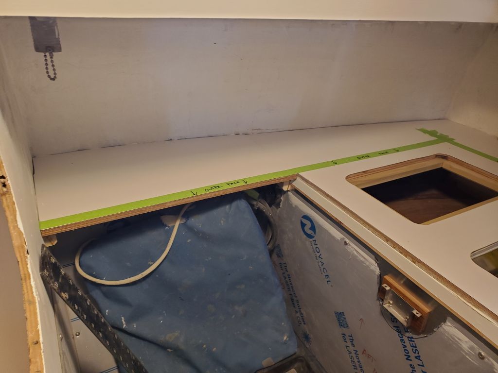
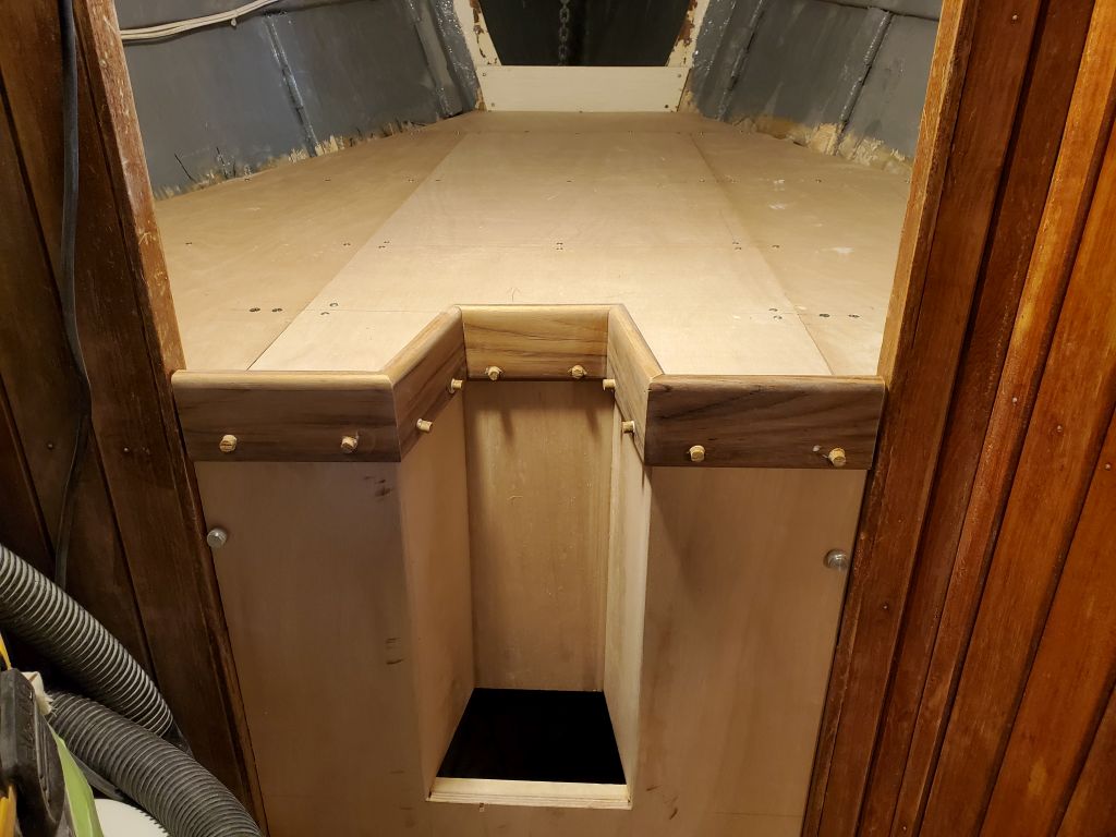
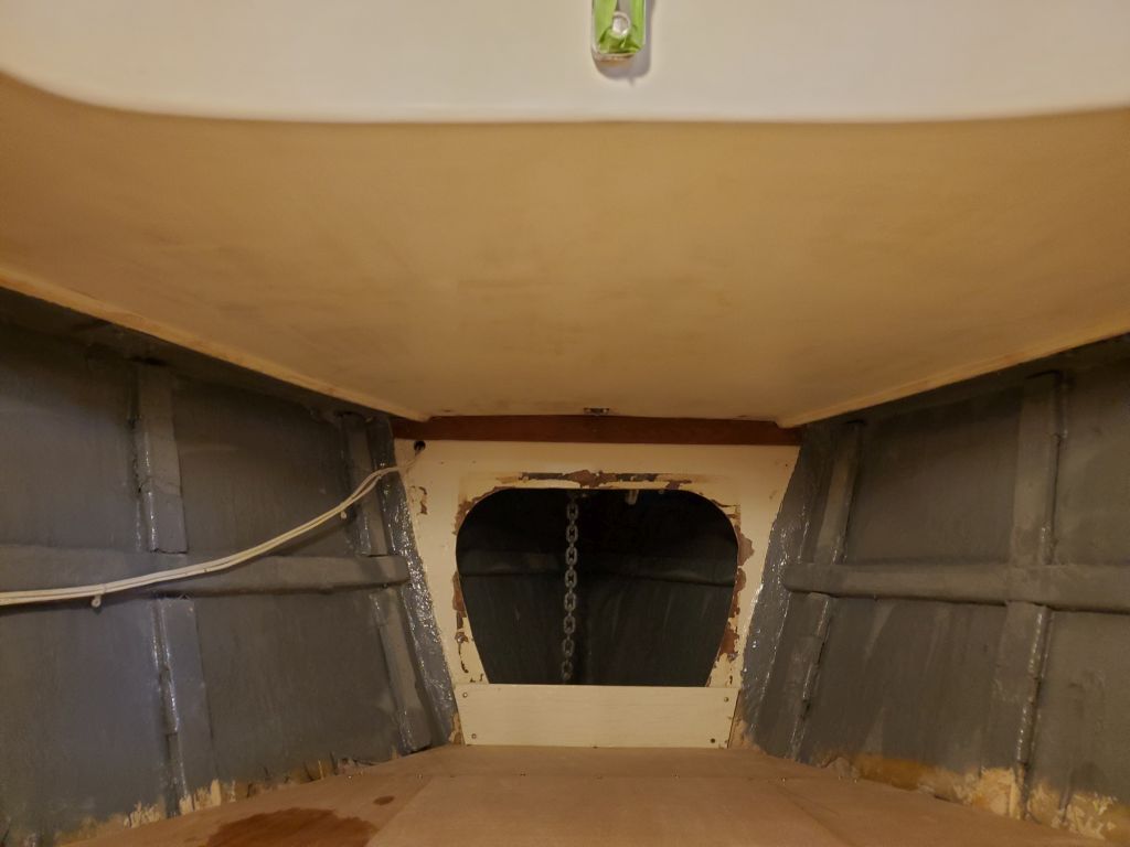
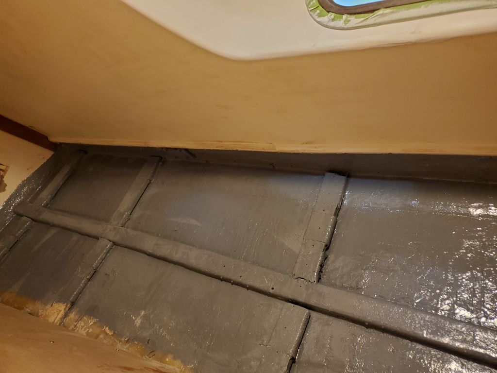
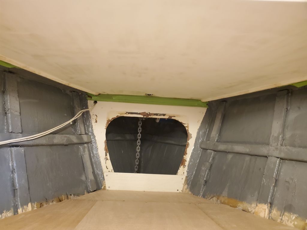
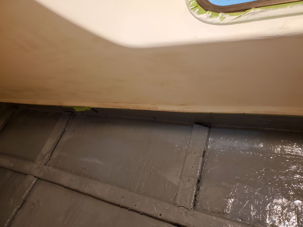
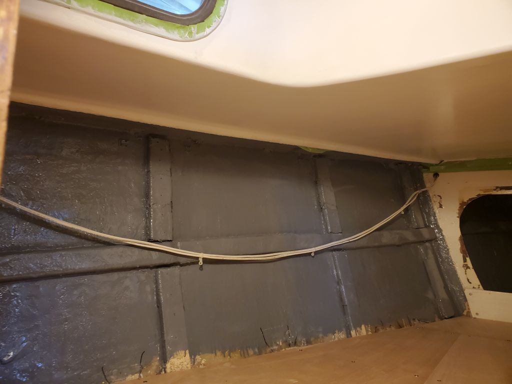
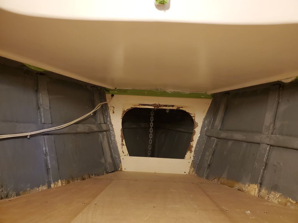
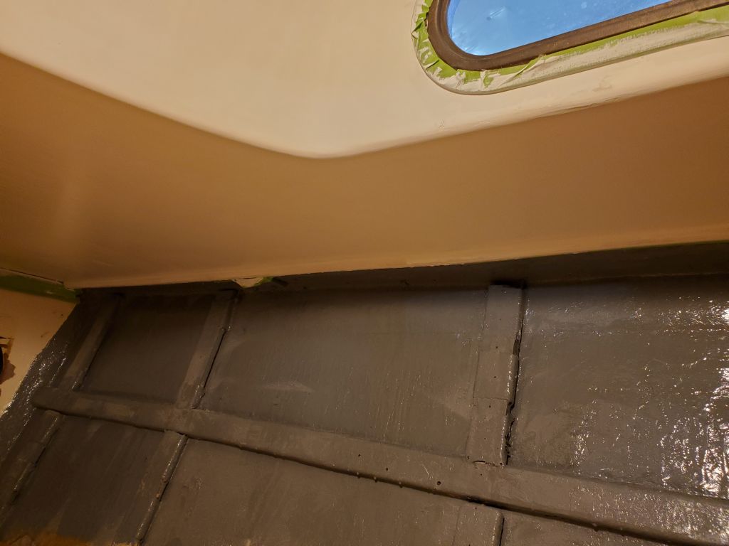
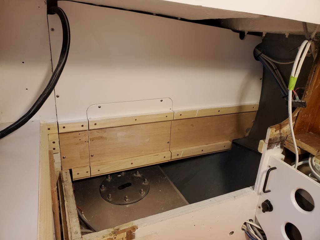
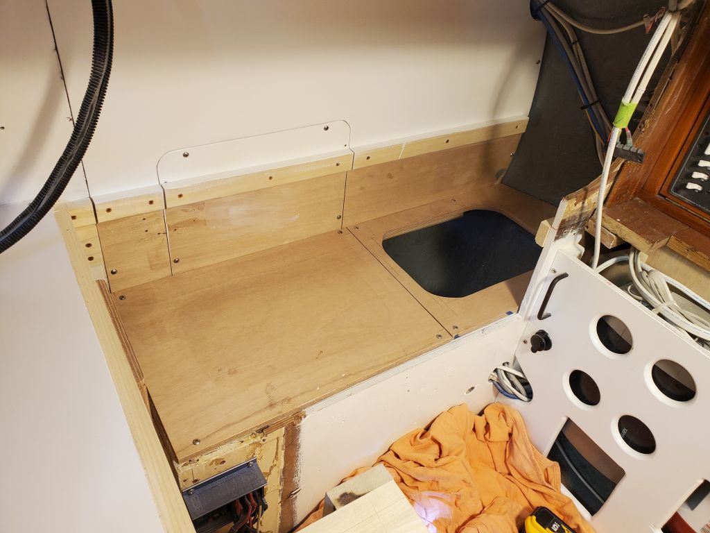
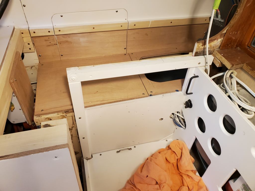
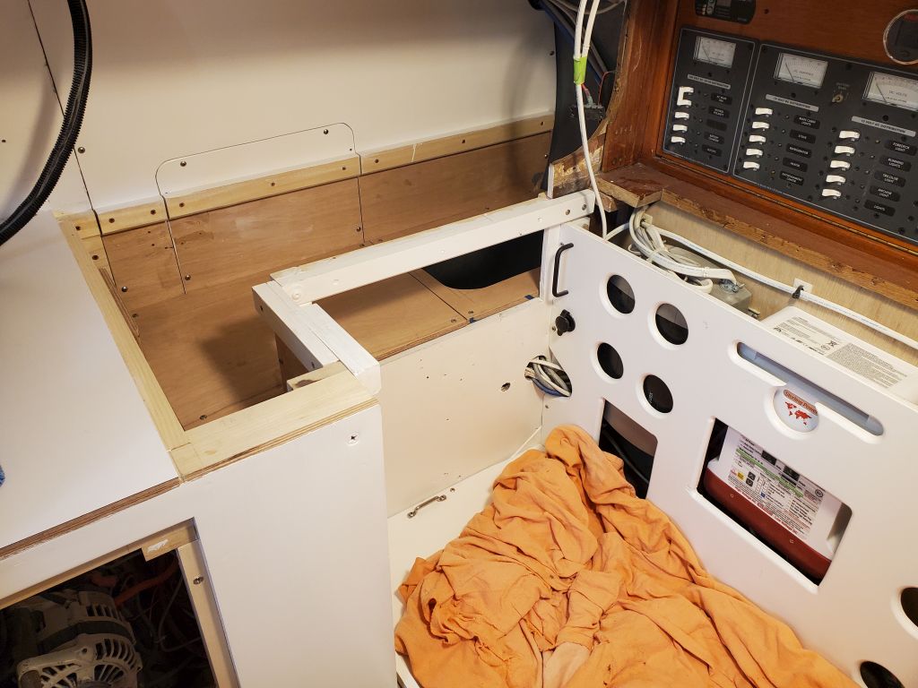
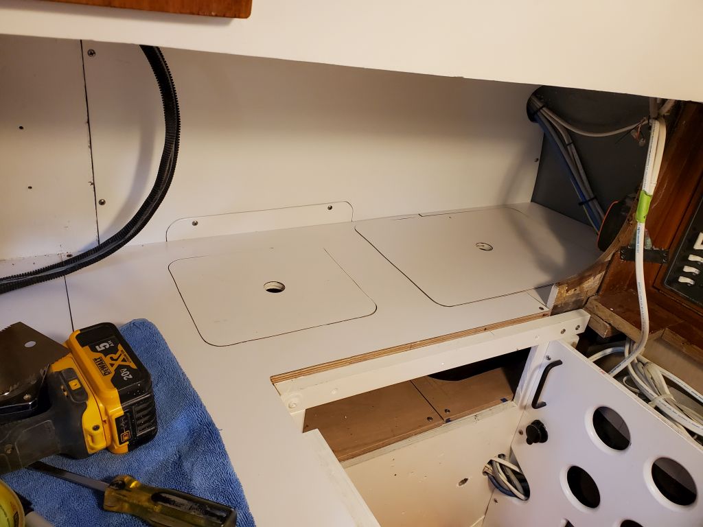
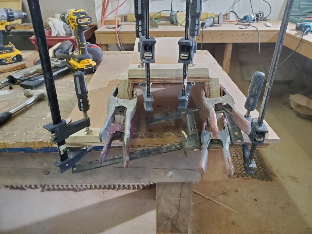
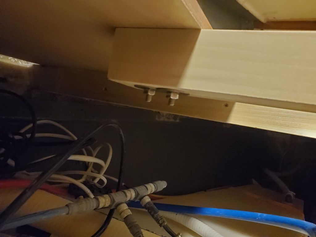
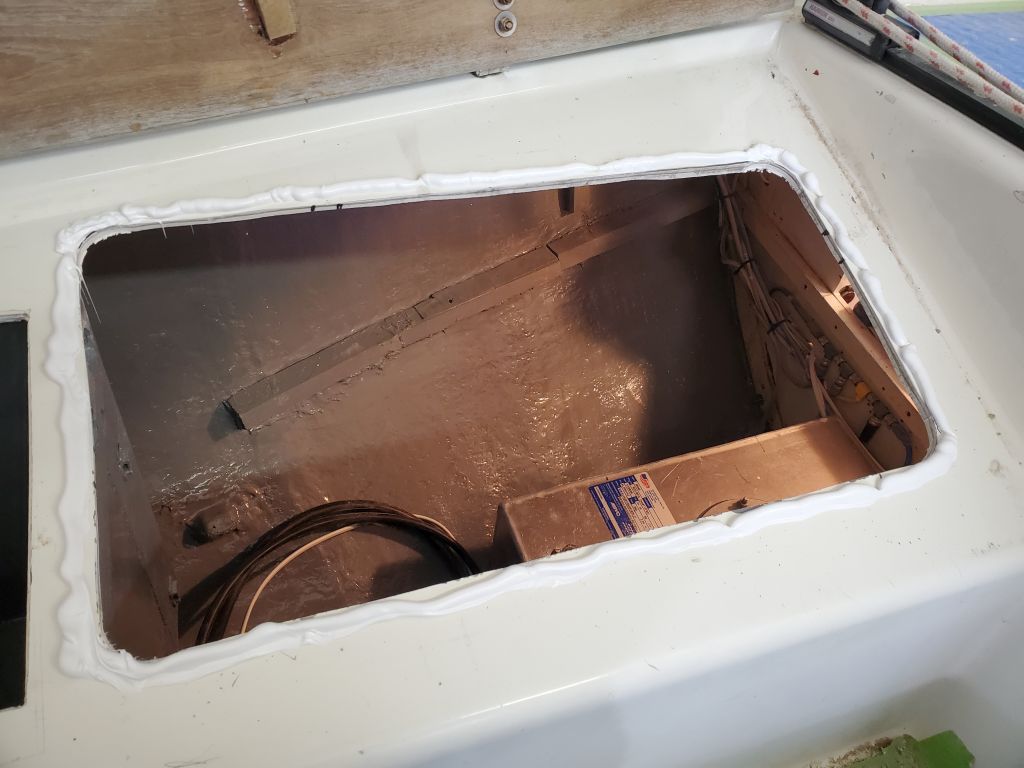
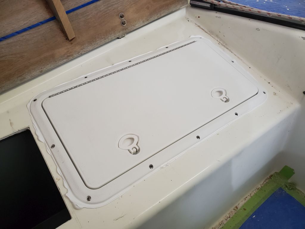
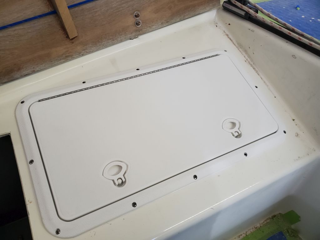
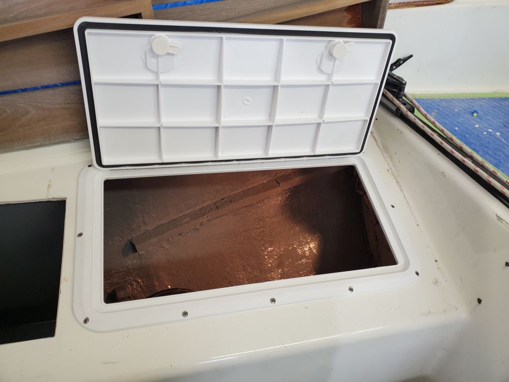
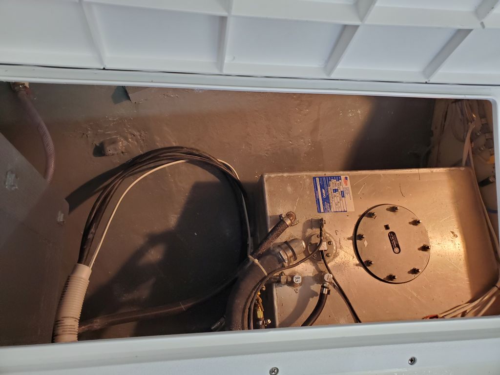
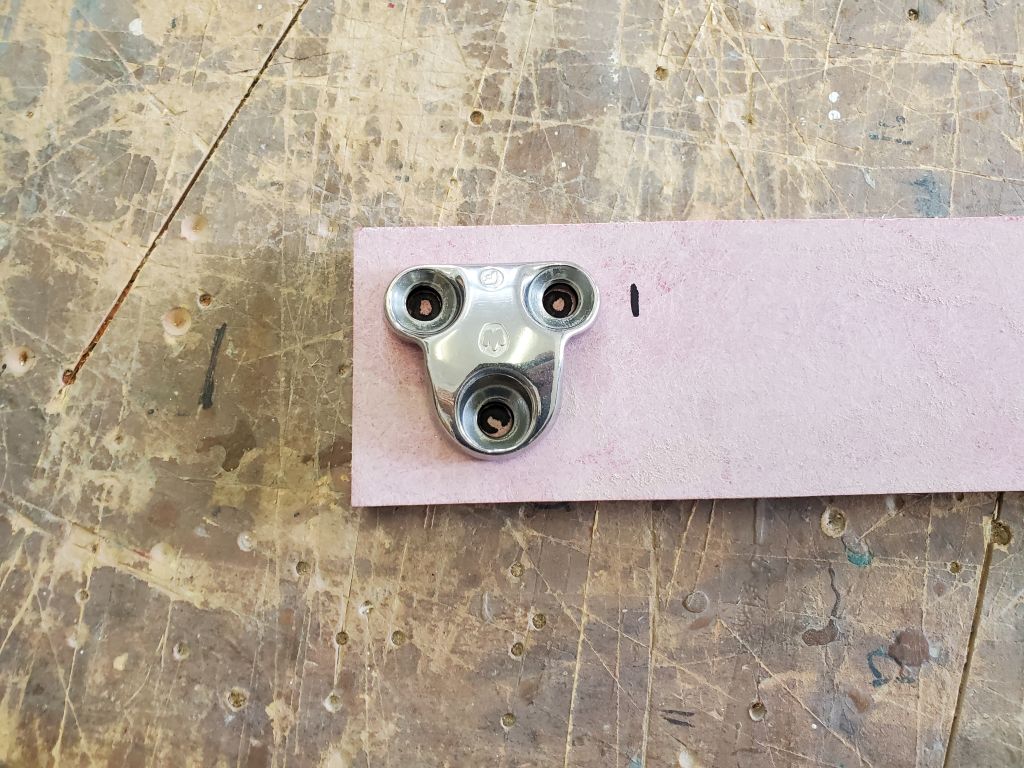
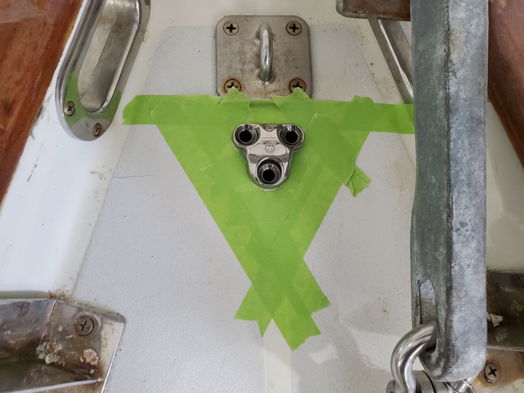
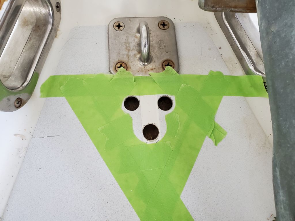
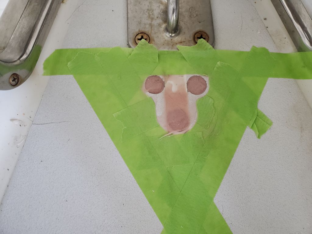
Now that I could more easily access the chain locker, with the v-berth platform back in place, I checked out the situation with existing hardware and obstructions so I could locate and begin installation of the water tank deck fill and vent, and a new padeye the owner asked me to install near the stem. I started with layout of the padeye on some 3/4″ fiberglass sheet stock that I planned to use for a hefty backing plate, and ensured that I kept the new padeye far enough from a larger padeye just ahead to provide room for the backing plate. I overbored the three fastener holes through the top skin and core with a 5/8″ bit, digging out the old core and filling the voids with a thickened epoxy mixture.
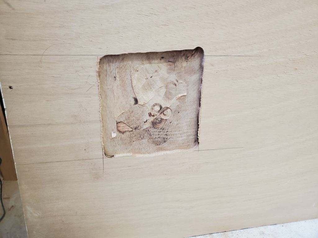
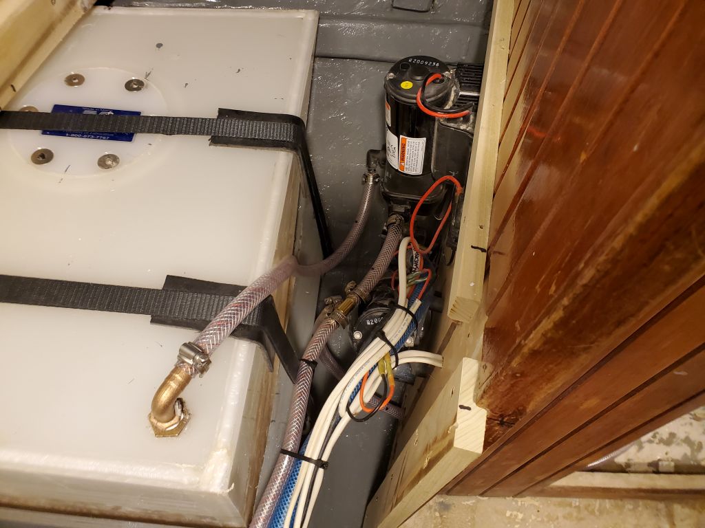
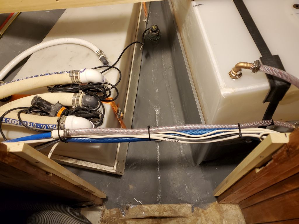
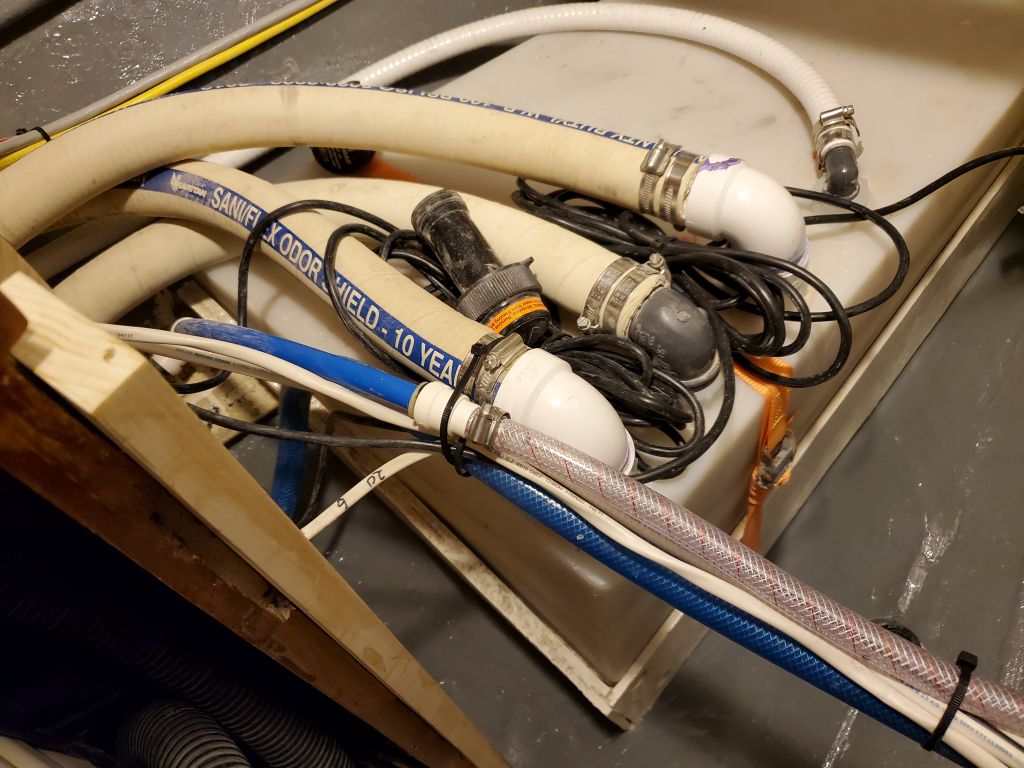
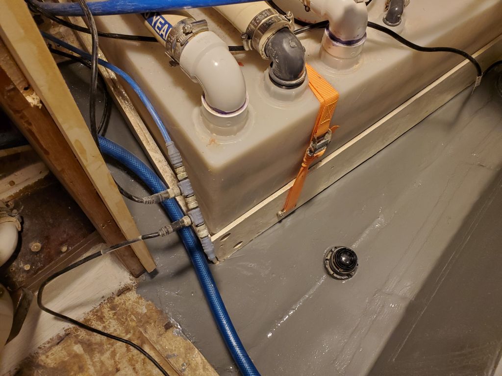
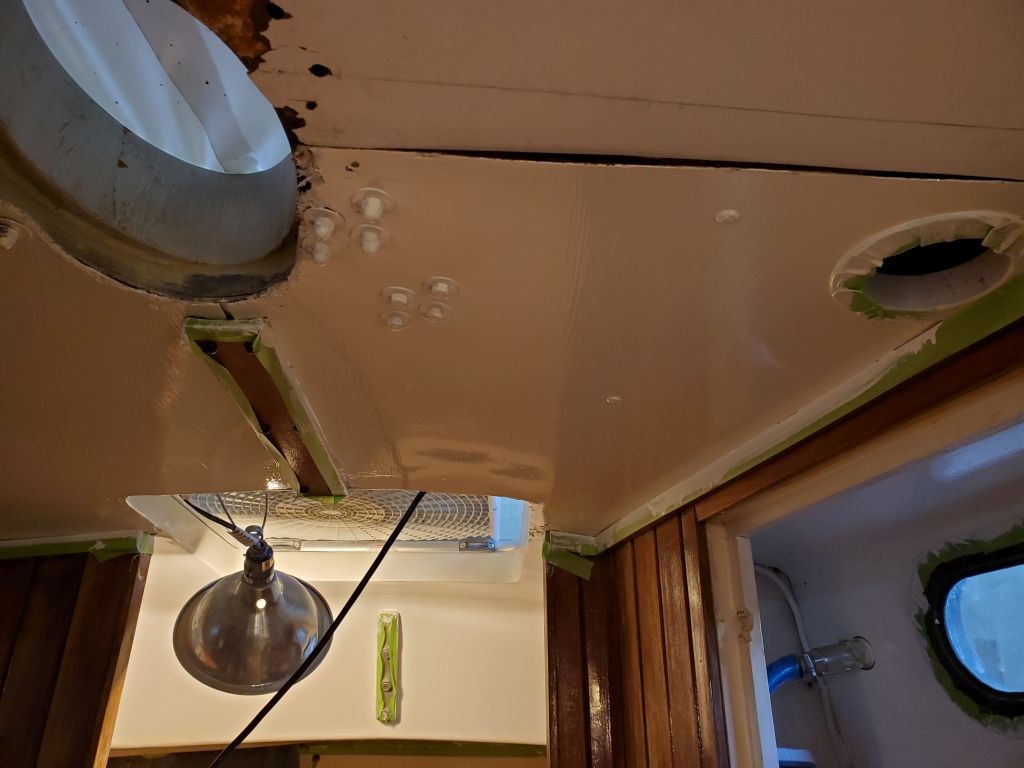
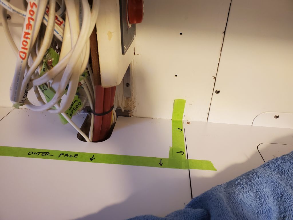
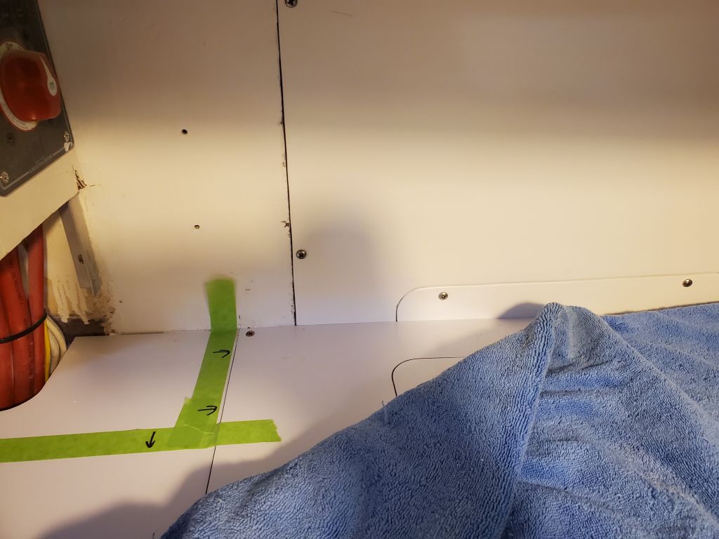
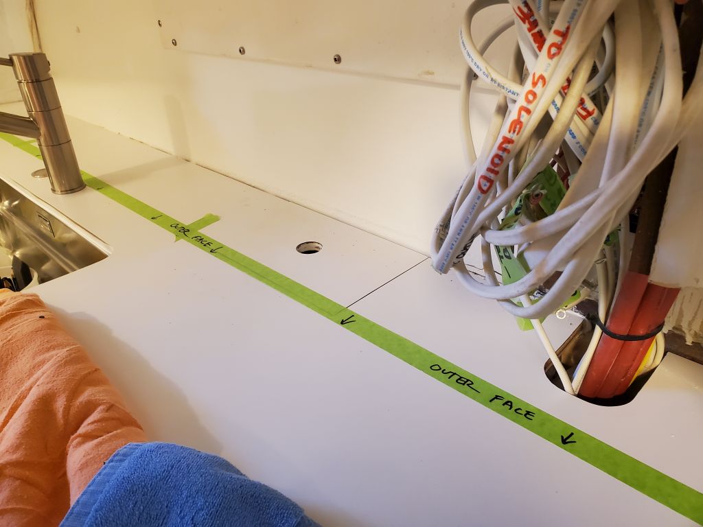
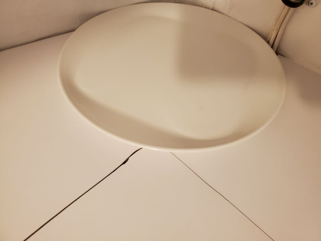
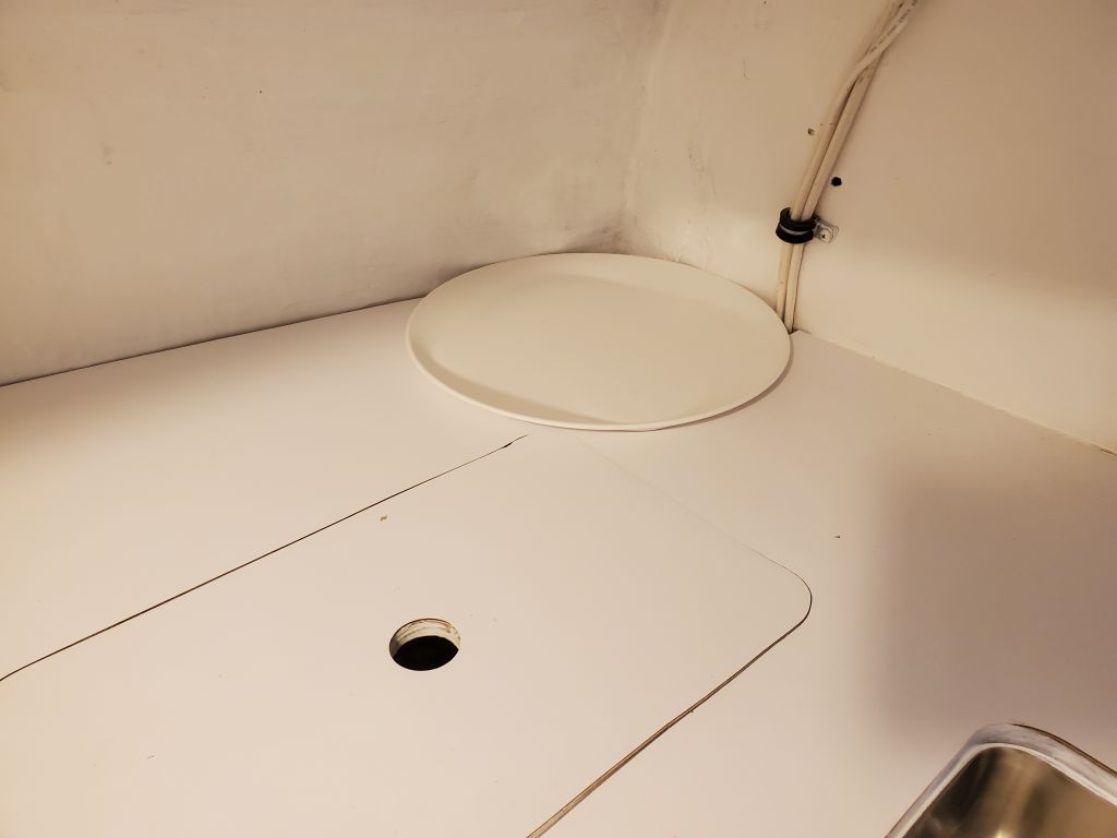
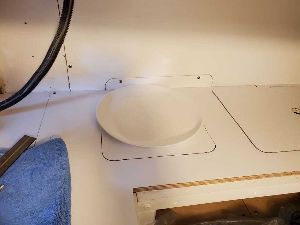
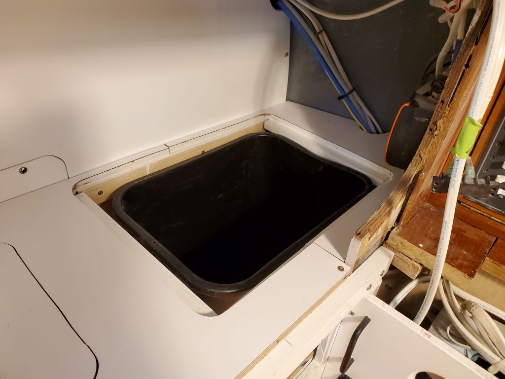
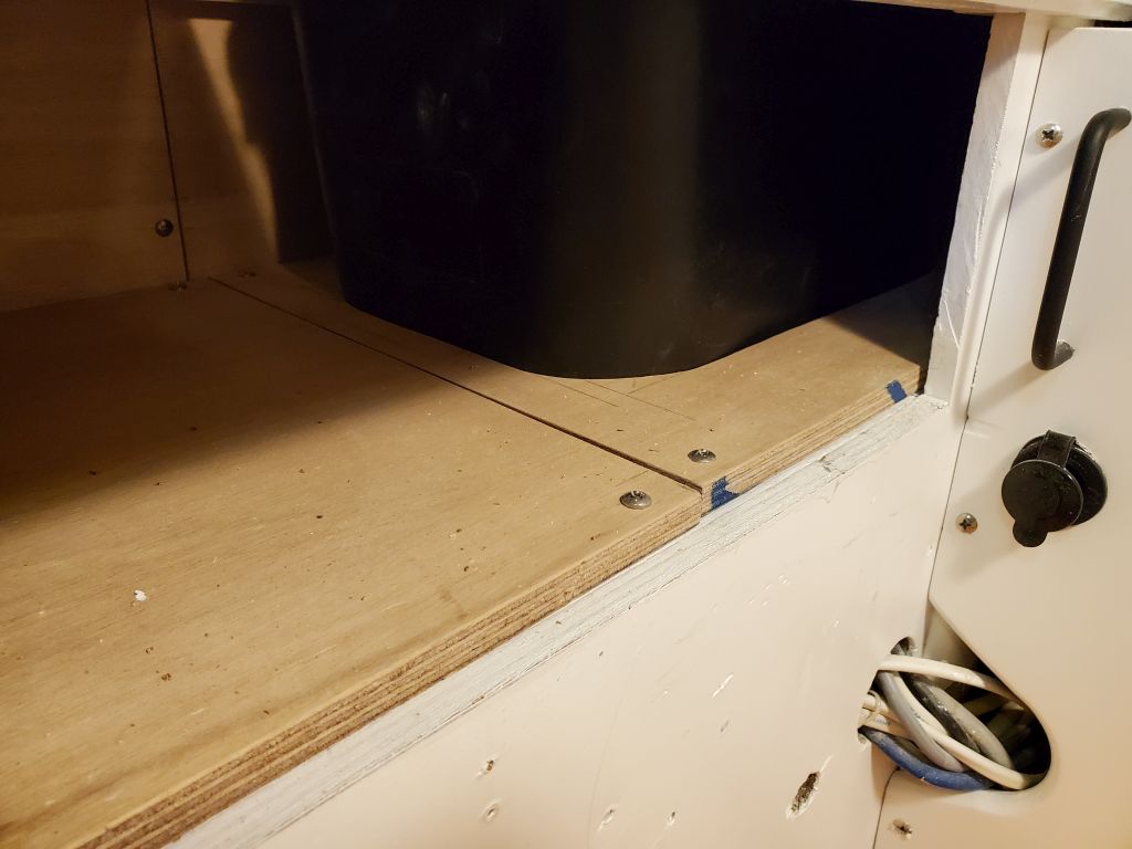
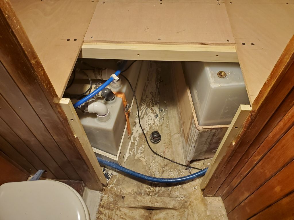
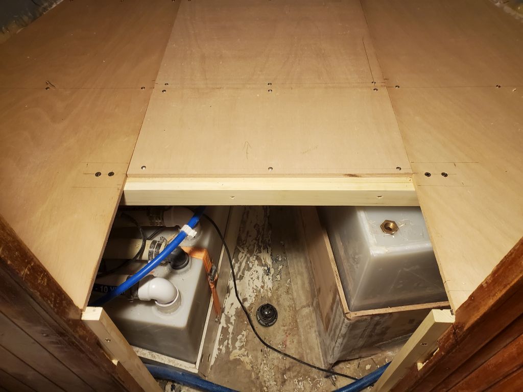
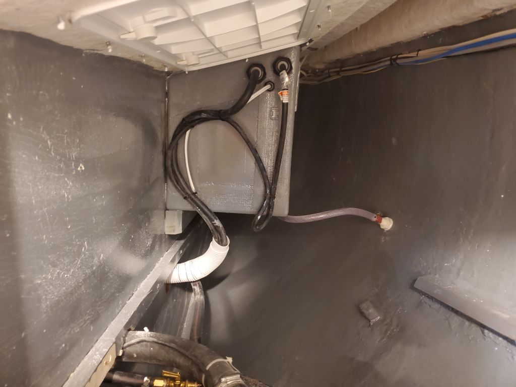
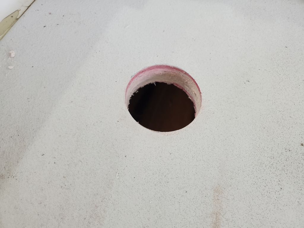
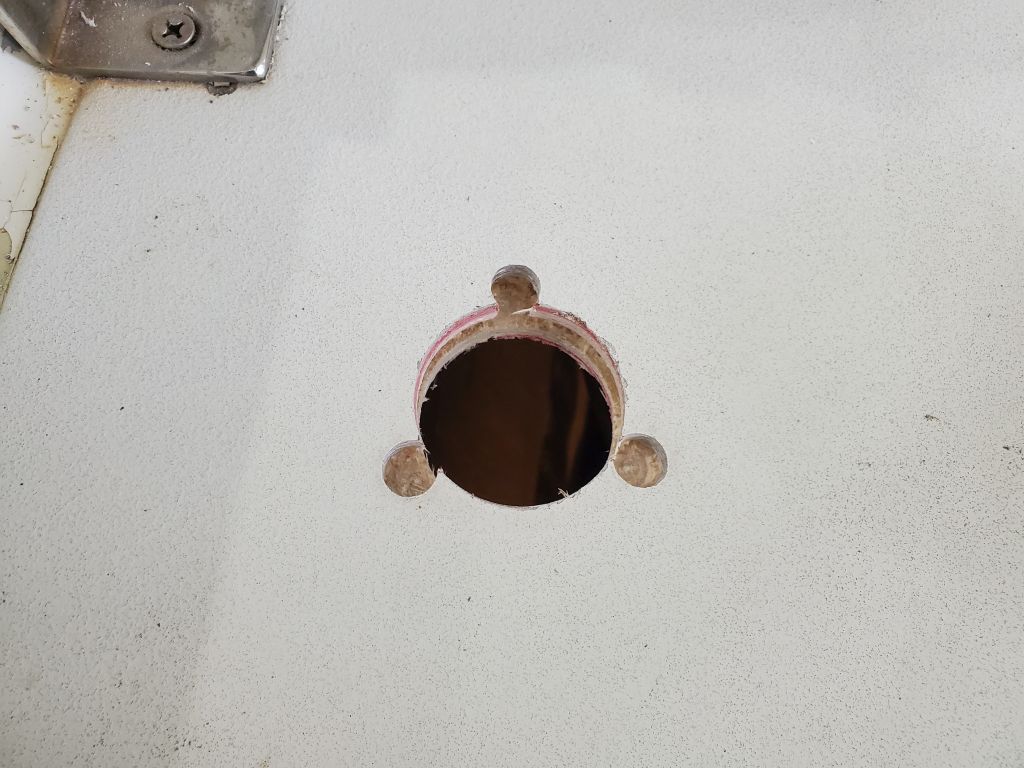
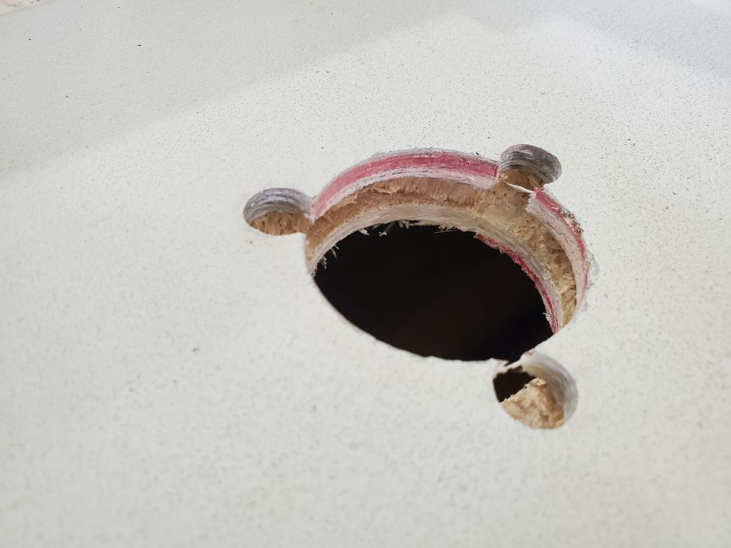
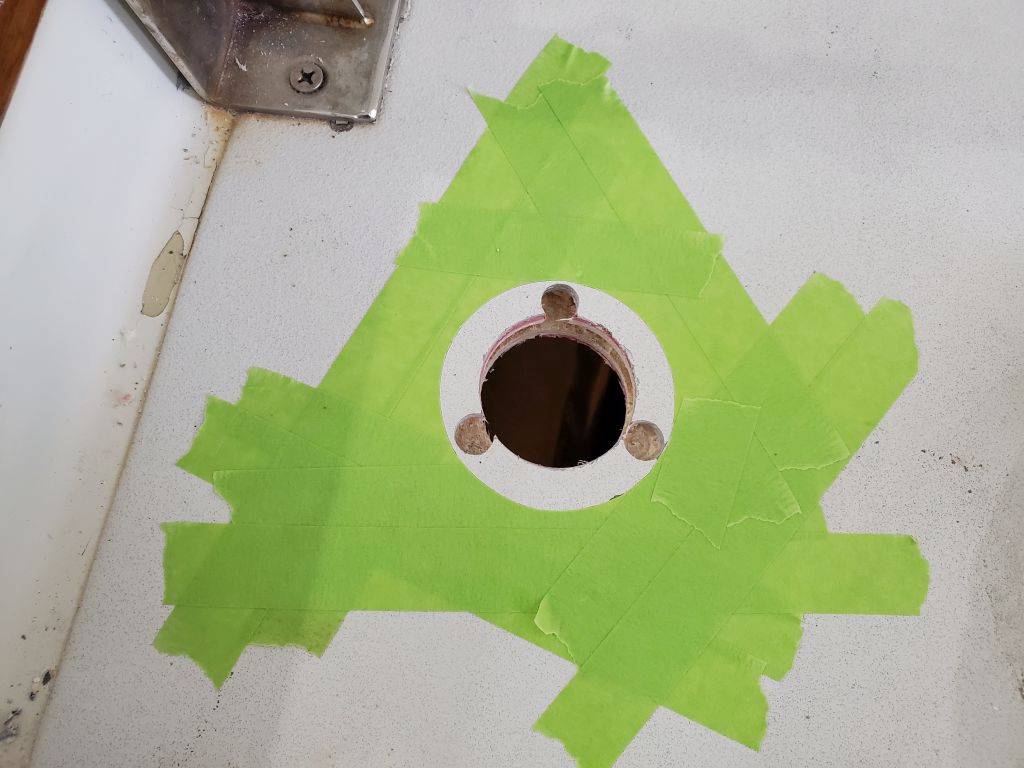
I located the tank deck fill fitting on the port foredeck, in a position generally symmetrical with a hawsepipe on the starboard side and where there was good, clear access for running the fill hose, and bored a hole through the deck, along with 1/2″ holes at the fastener locations, then reamed out the core and filled the voids with thickened epoxy after first masking over the large hole from beneath.
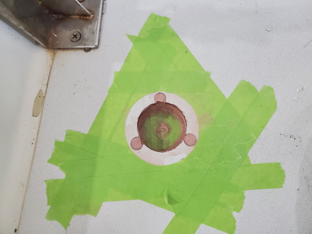
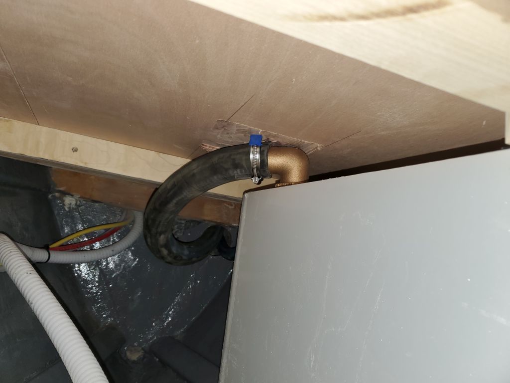
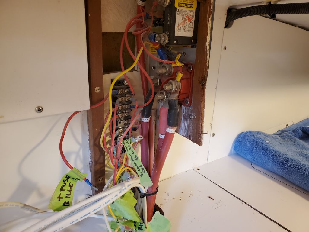
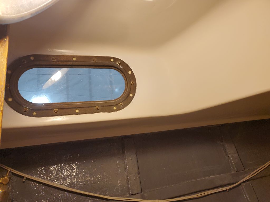
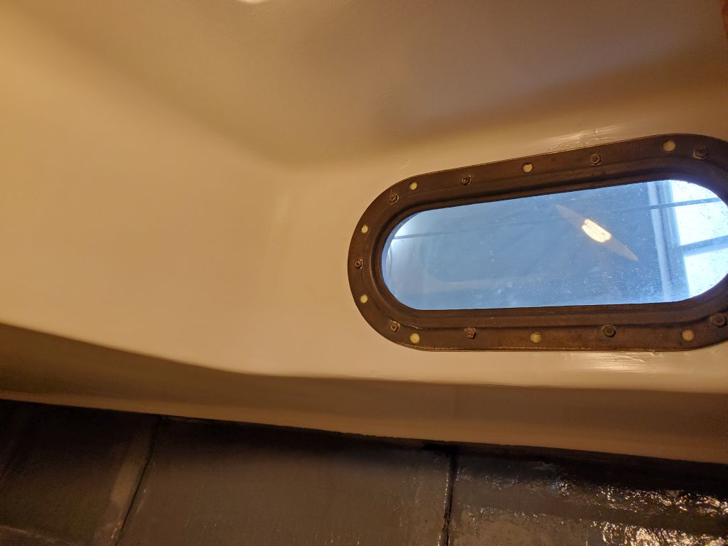
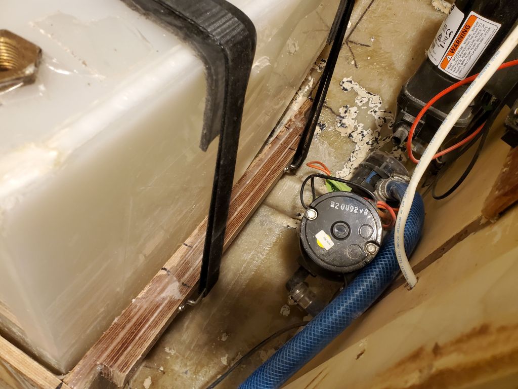
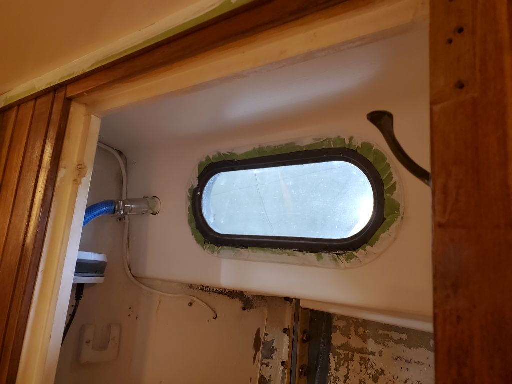
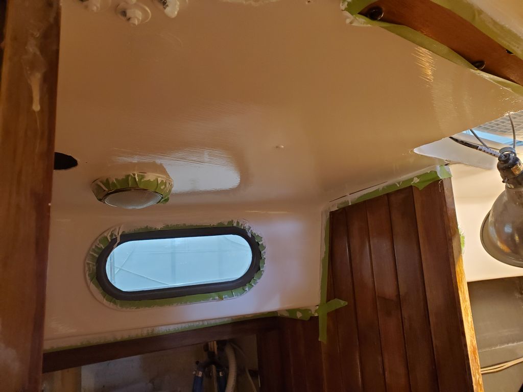
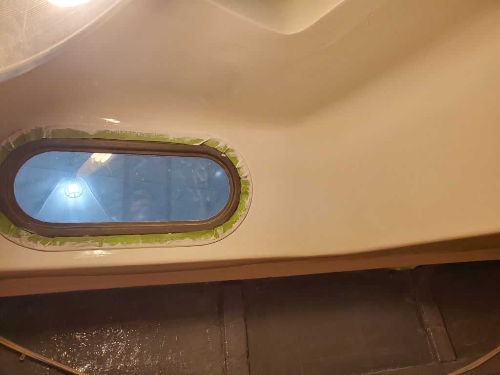
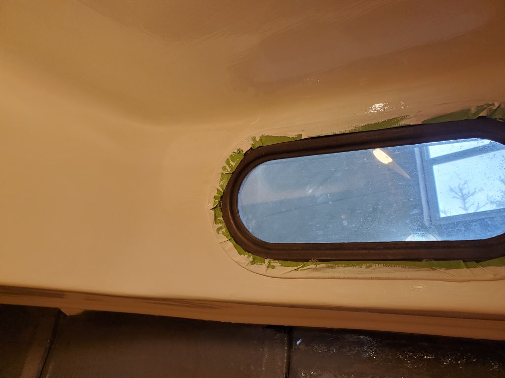
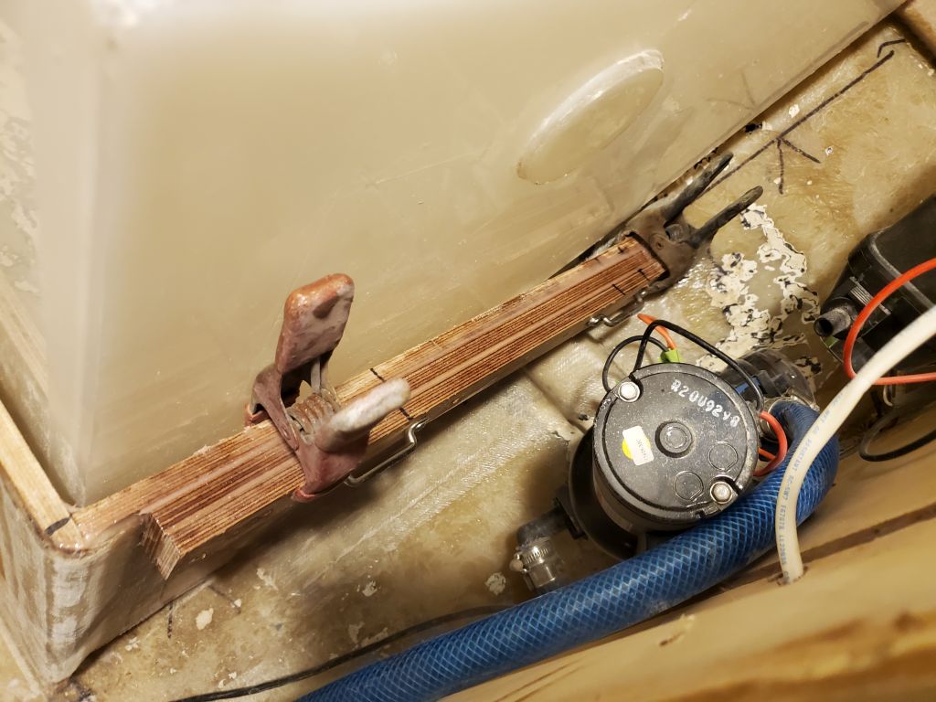
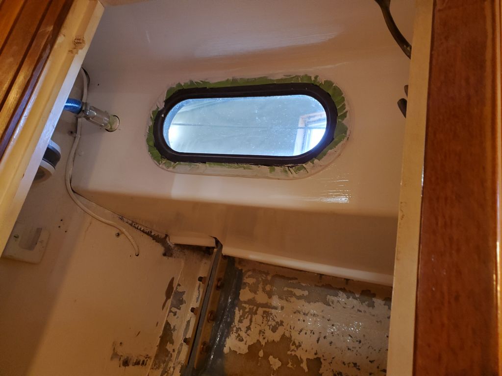
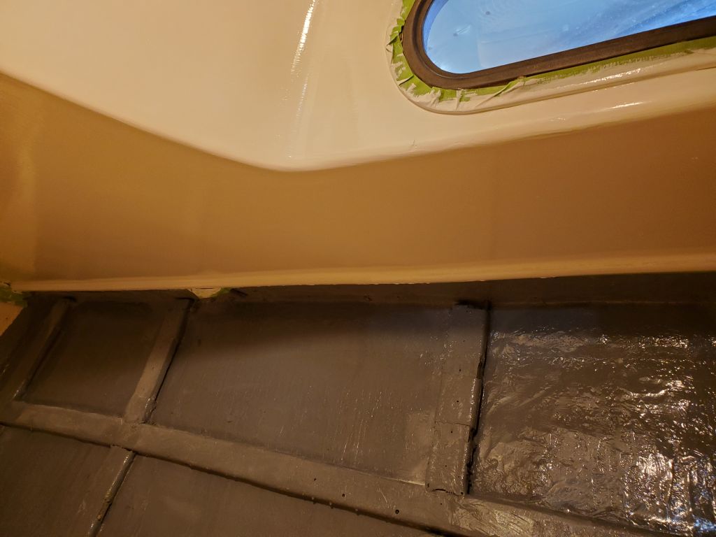
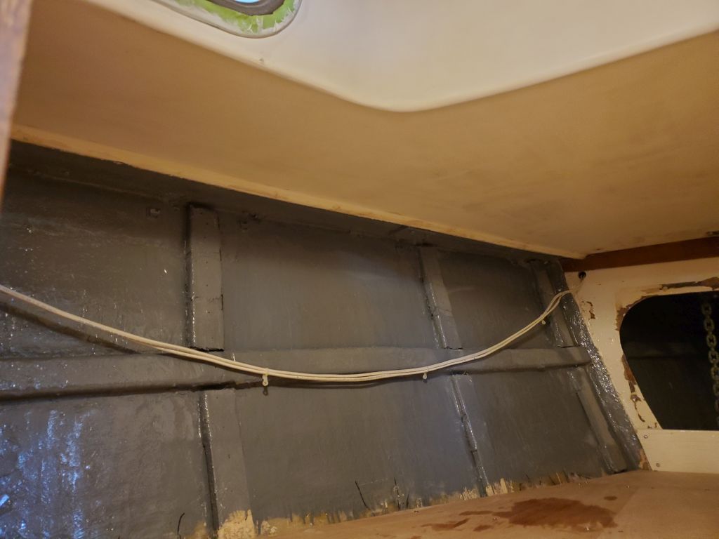
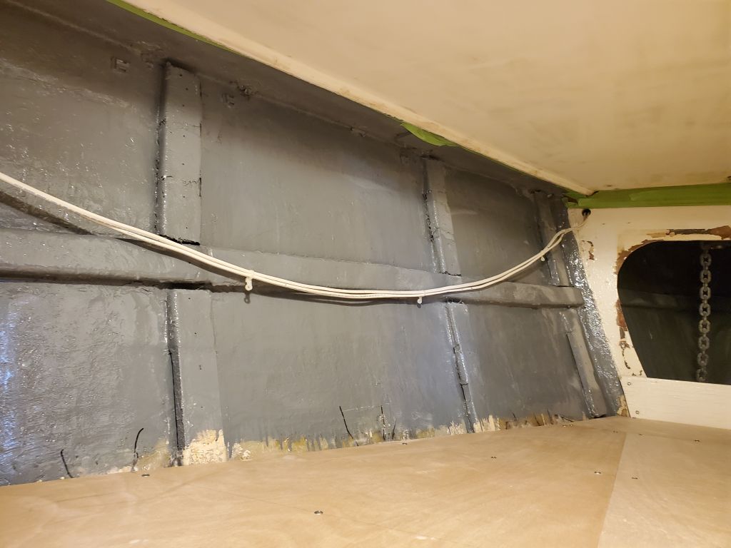
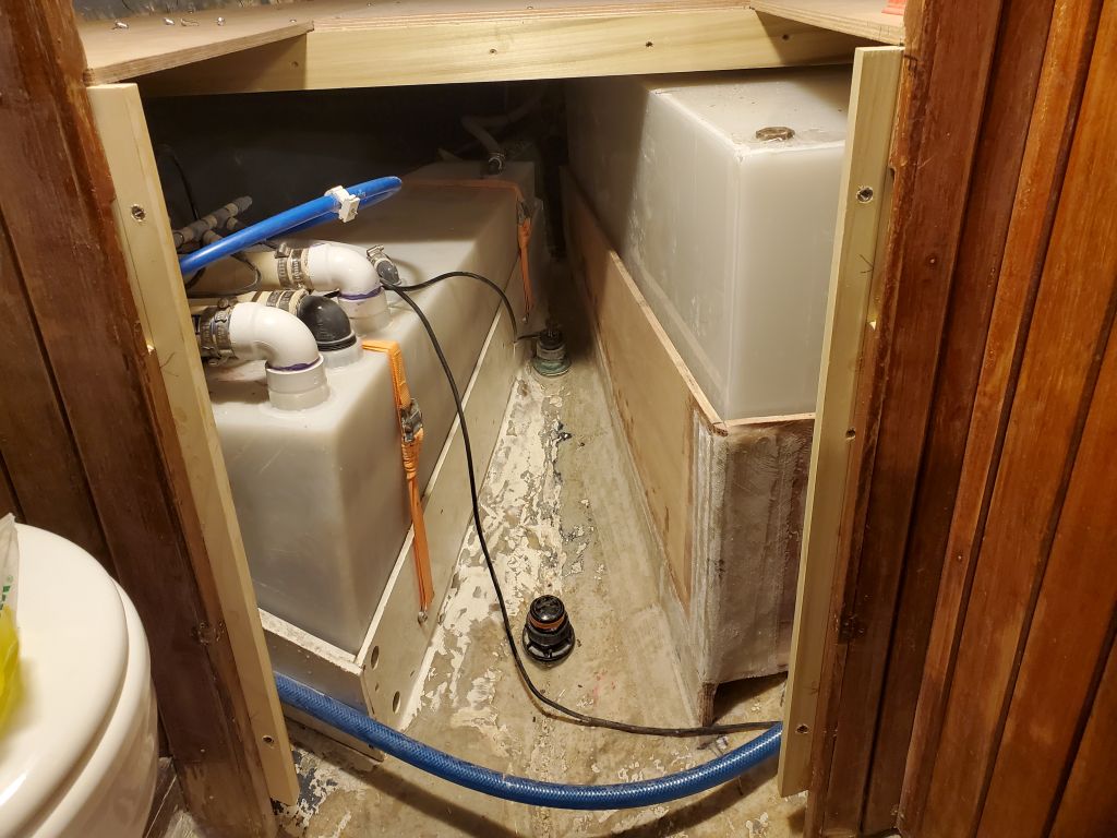
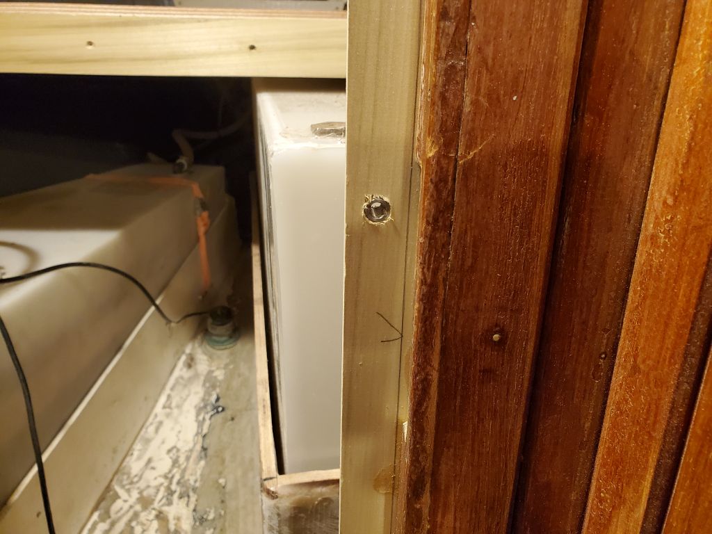
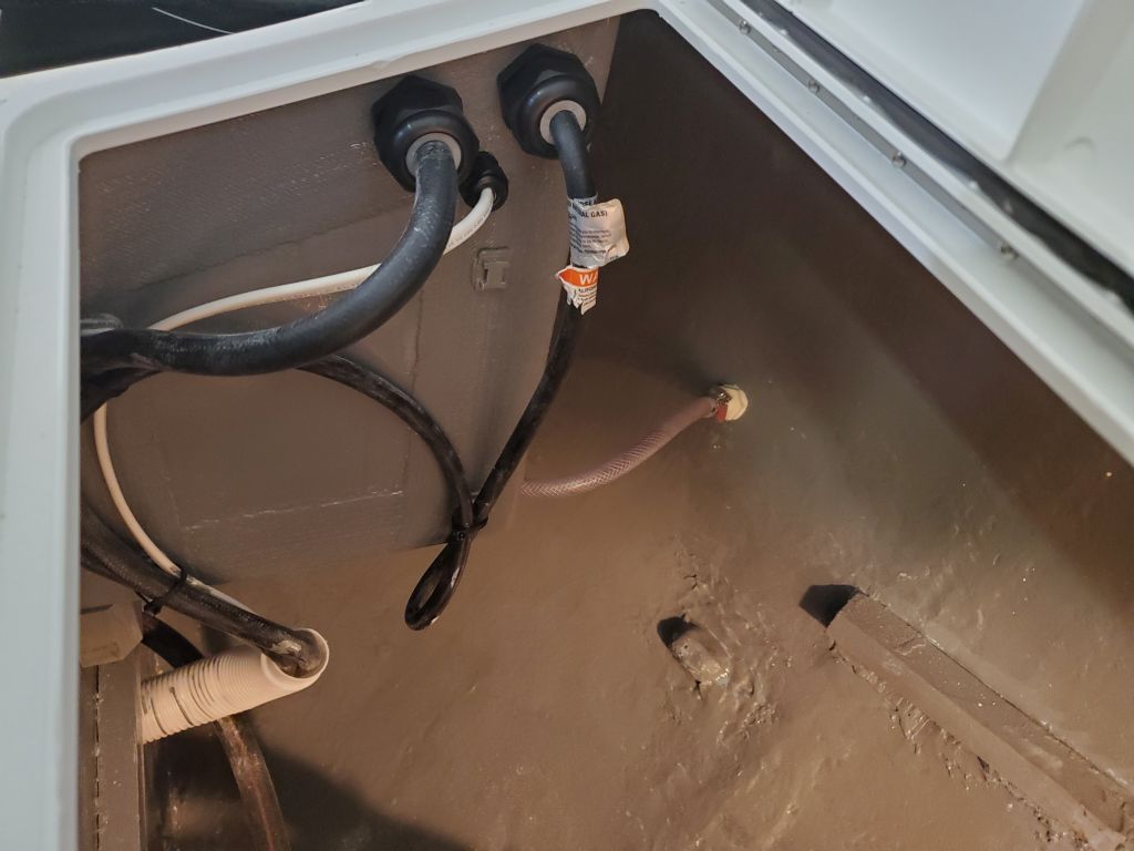
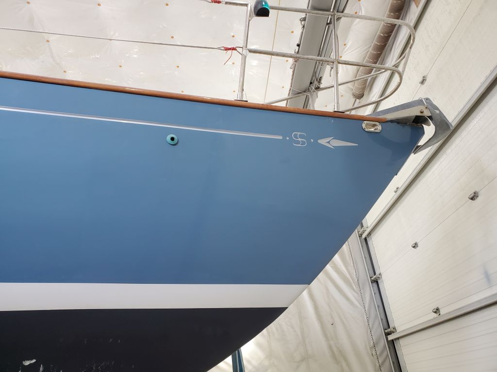
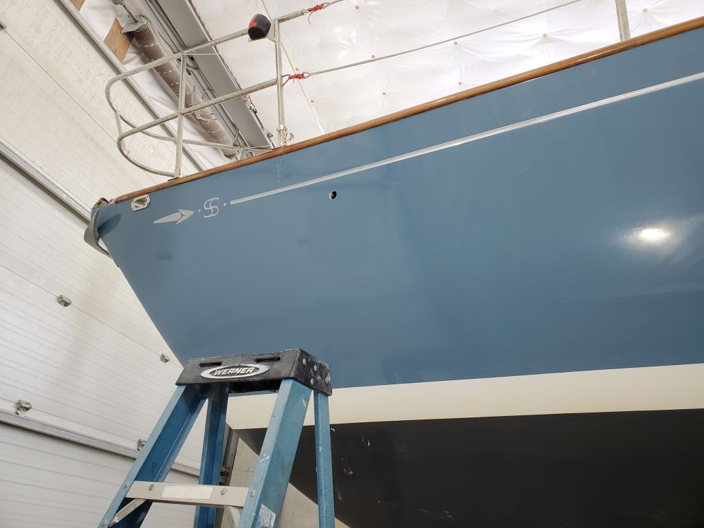
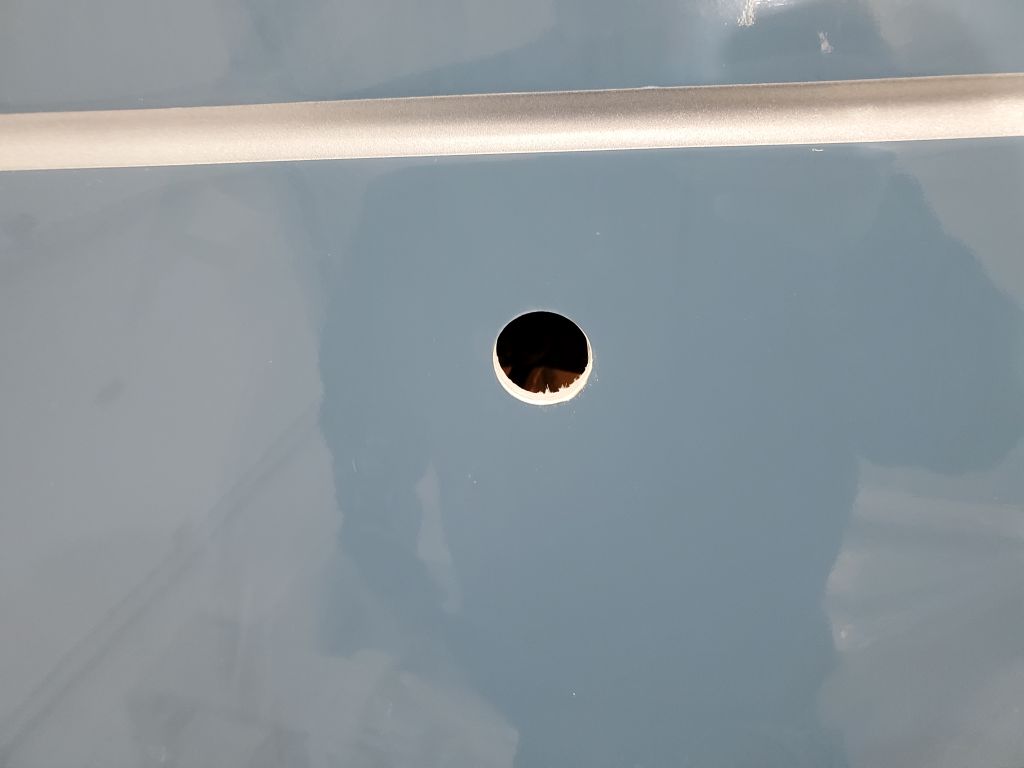
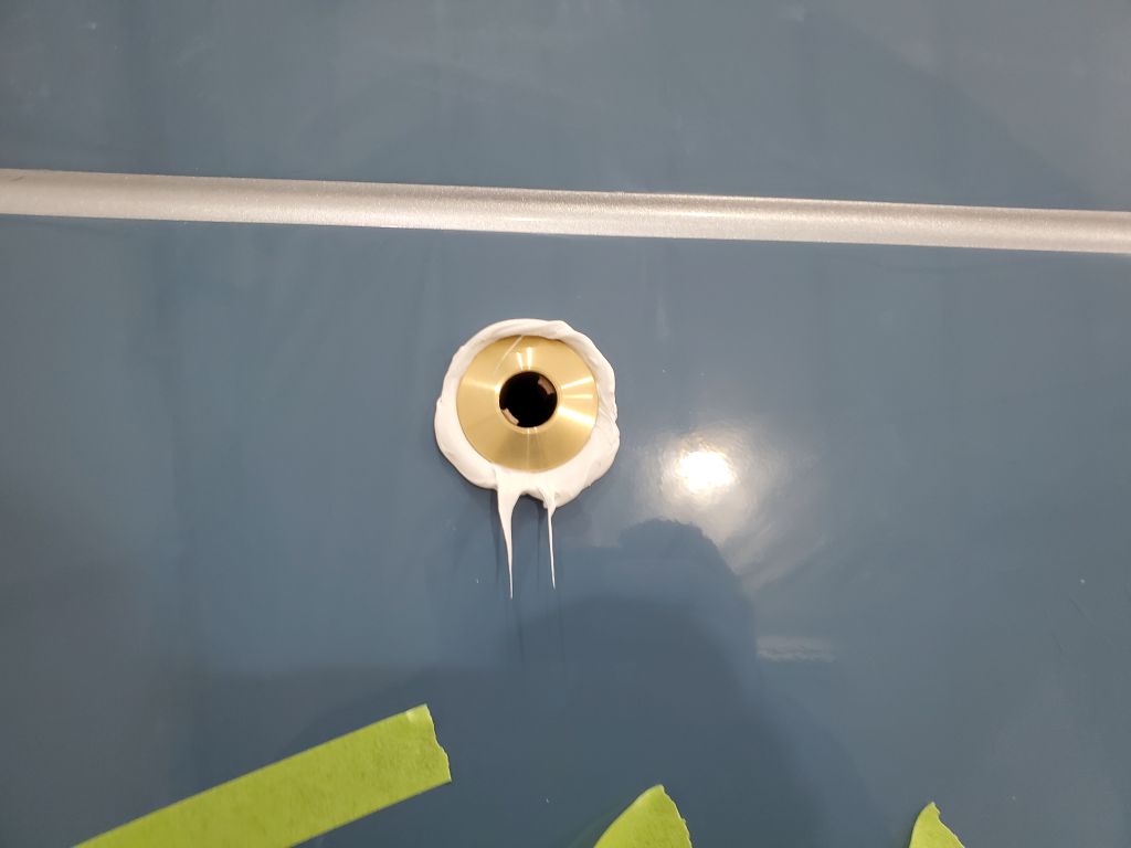
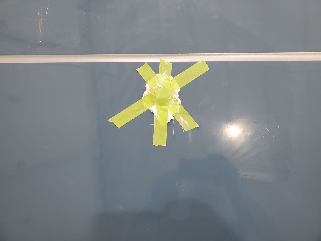
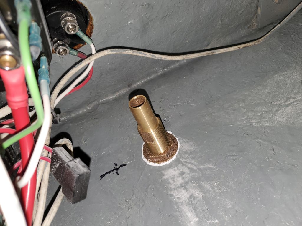
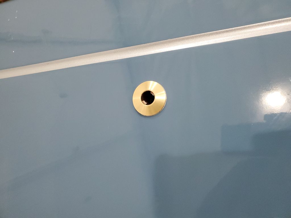
The existing tank vents for the holding tank were 3/4″ through hulls, and the owner requested I do something similar with the new water tank vent, so I located the new vent on the port bow, in the same symmetrical position as its counterpart on the starboard side, though slightly more forward to allow adequate clearance with some wiring obstructions inside. Since the hull was solid, I could drill and complete the fitting’s installation immediately.
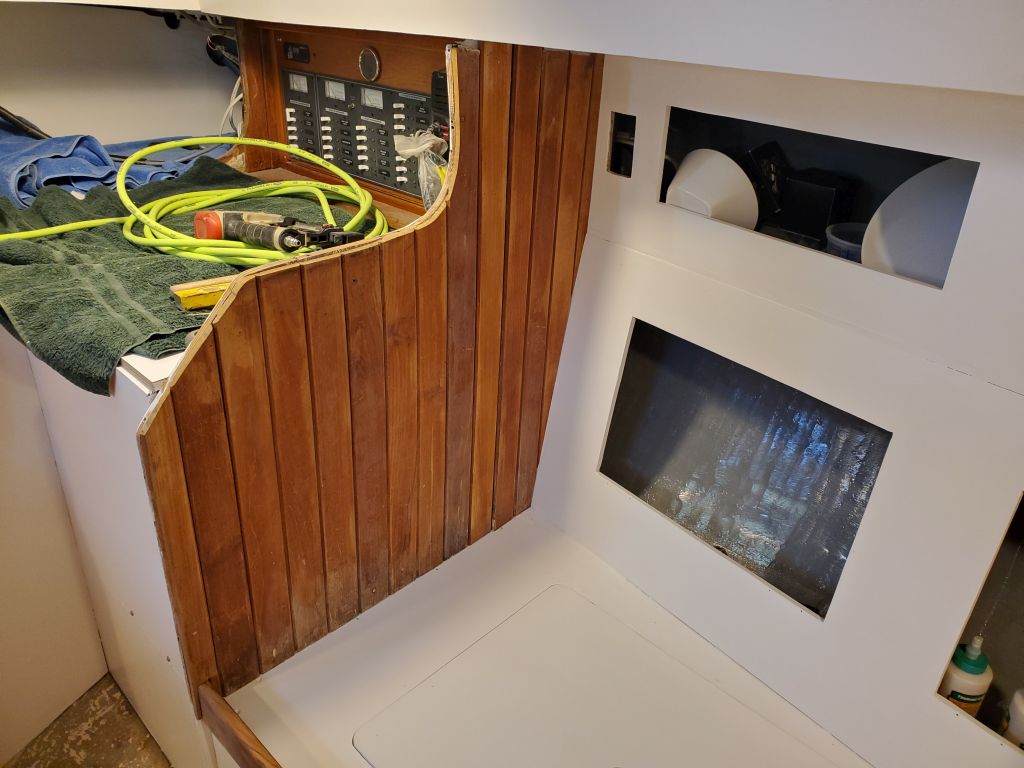
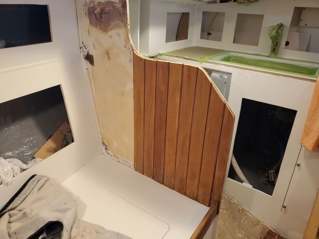
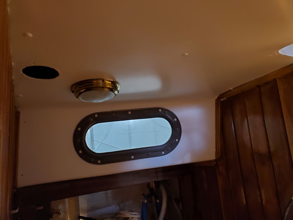
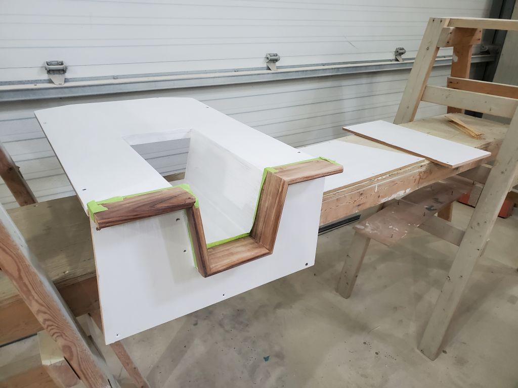
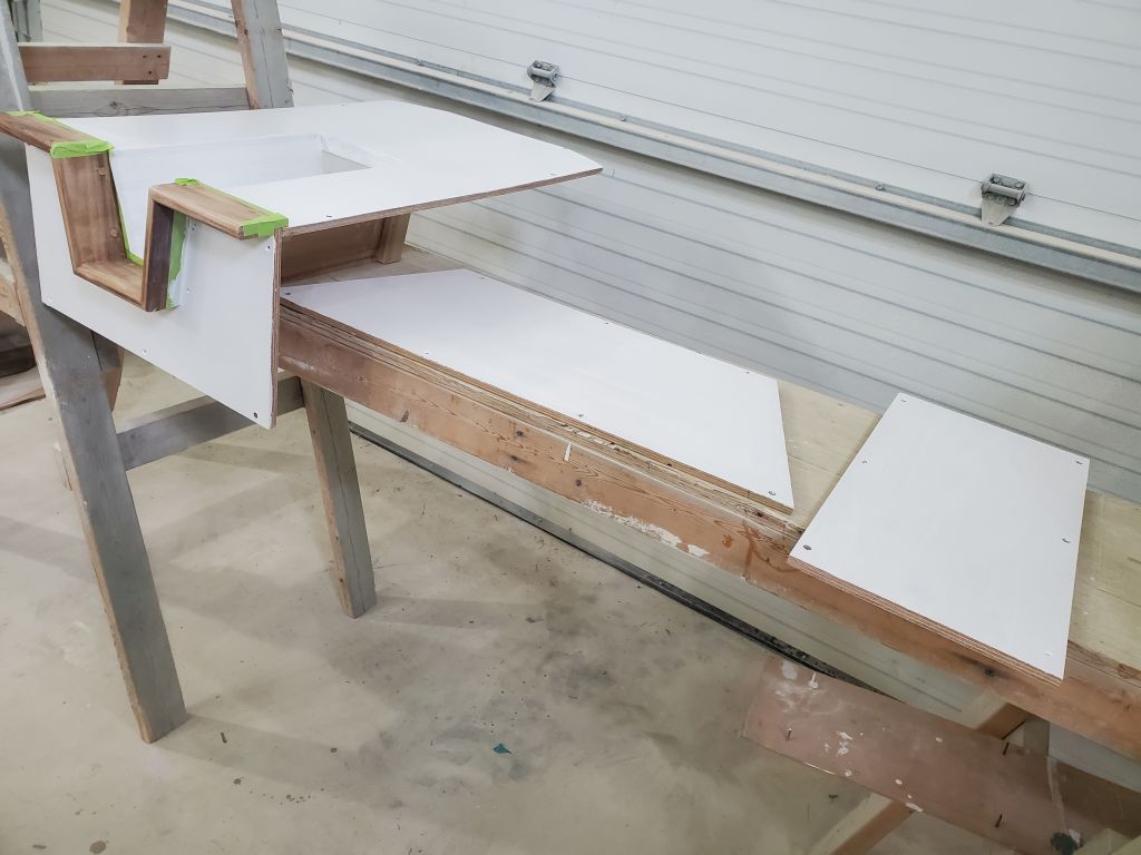
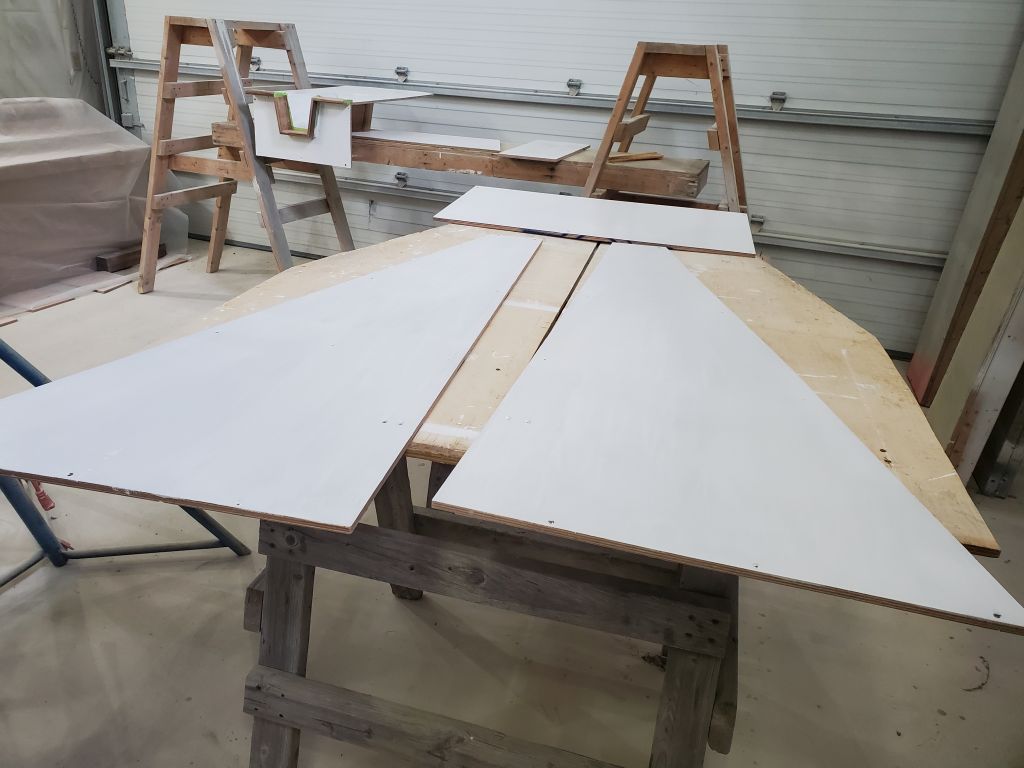
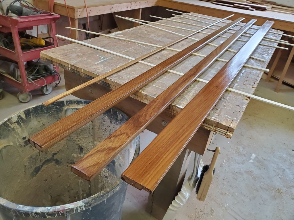
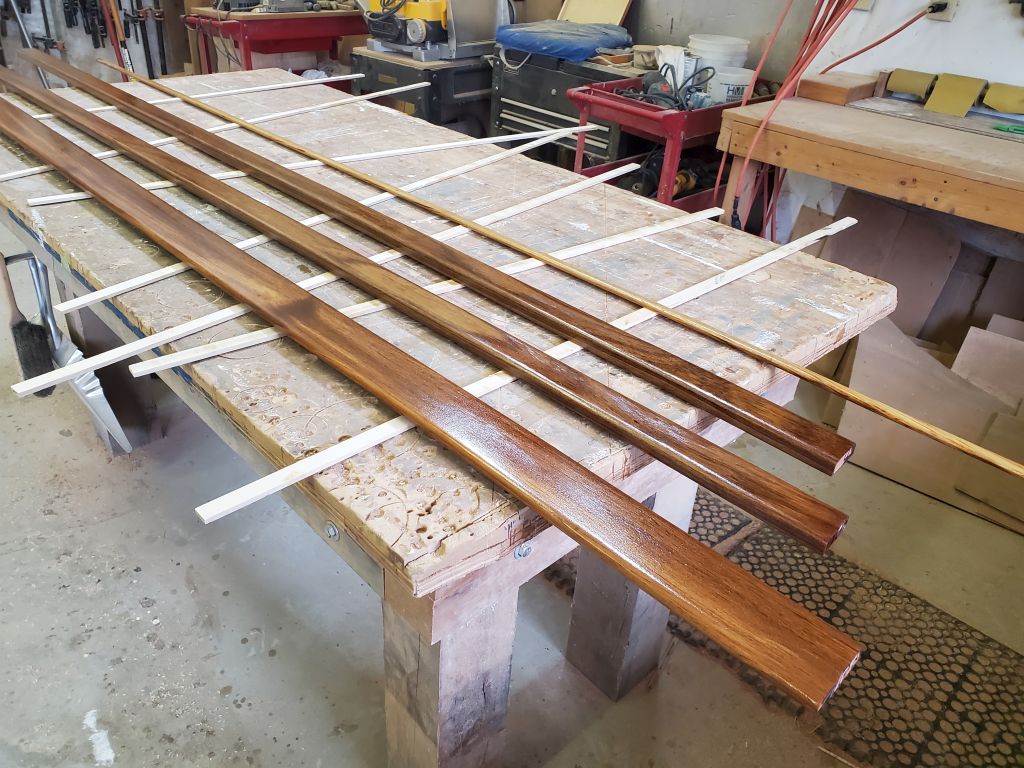
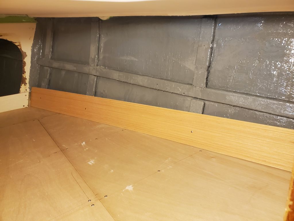
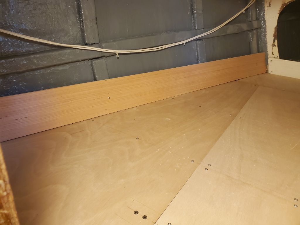
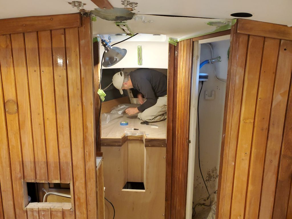
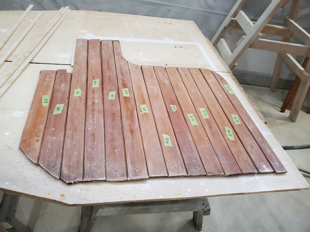
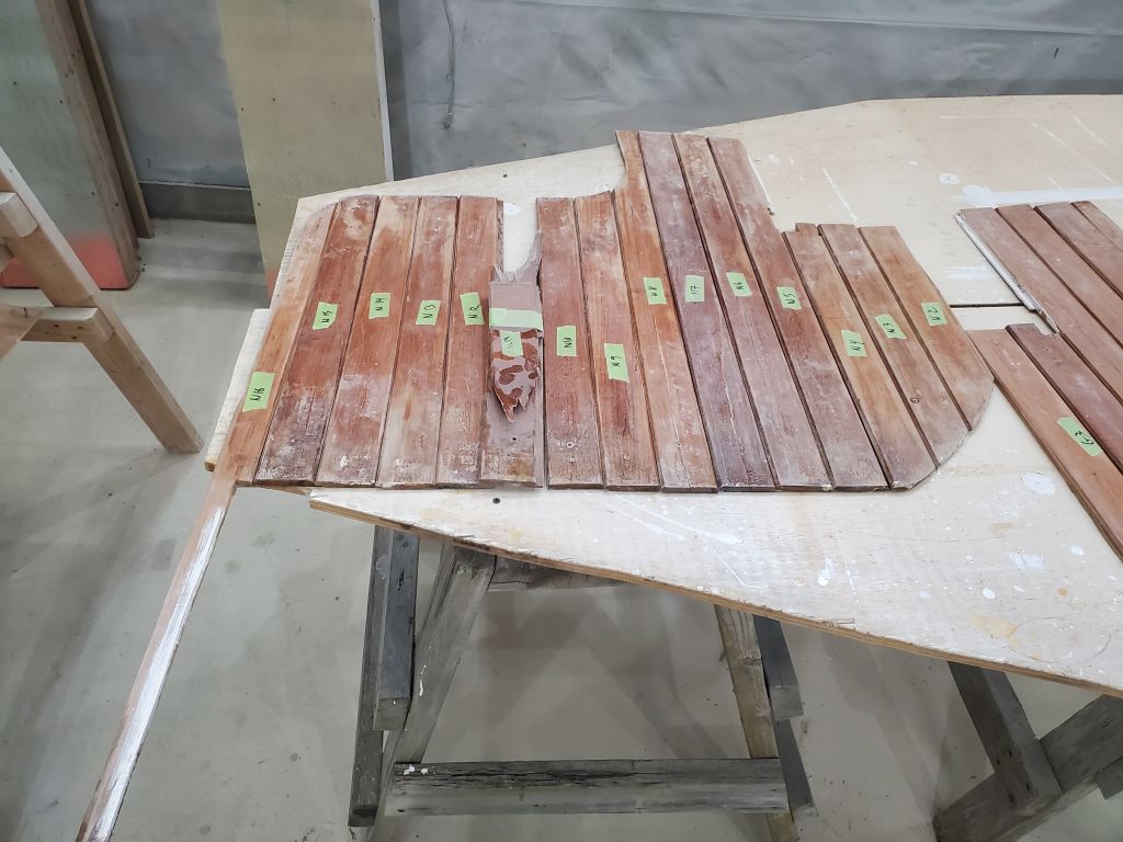
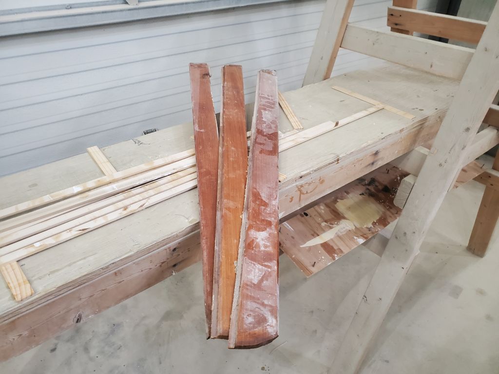
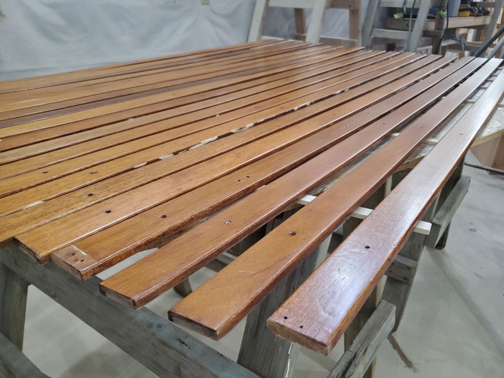
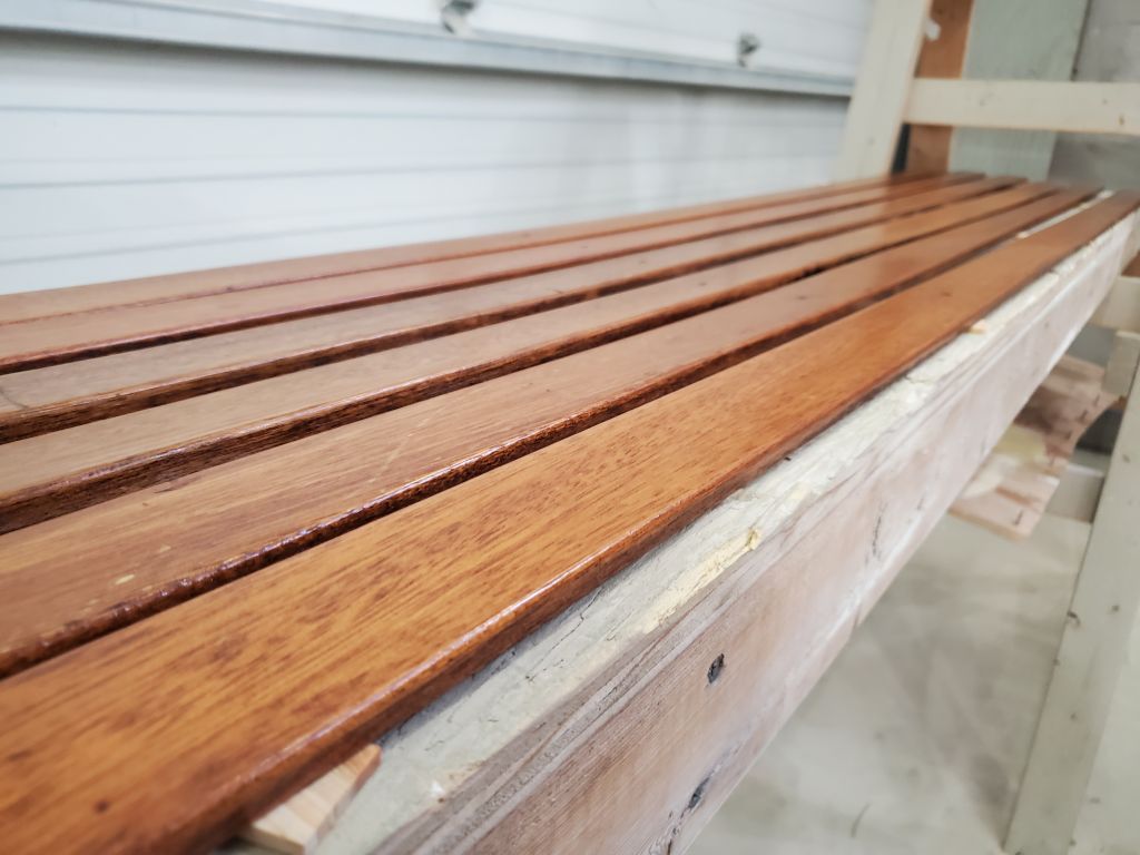
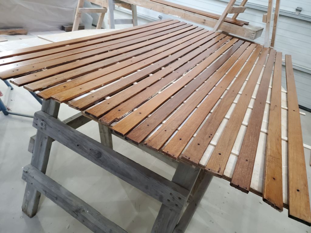
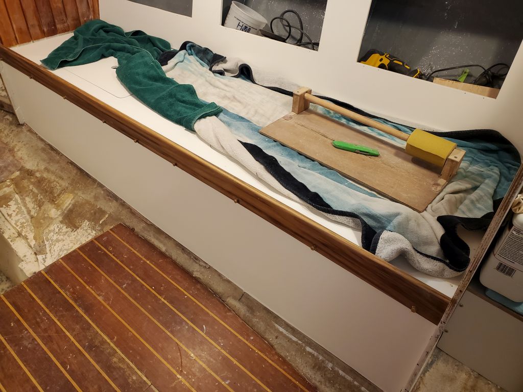
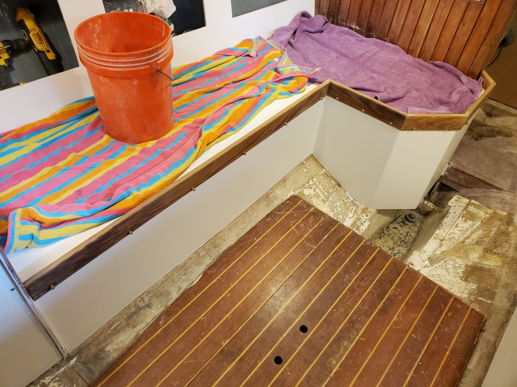
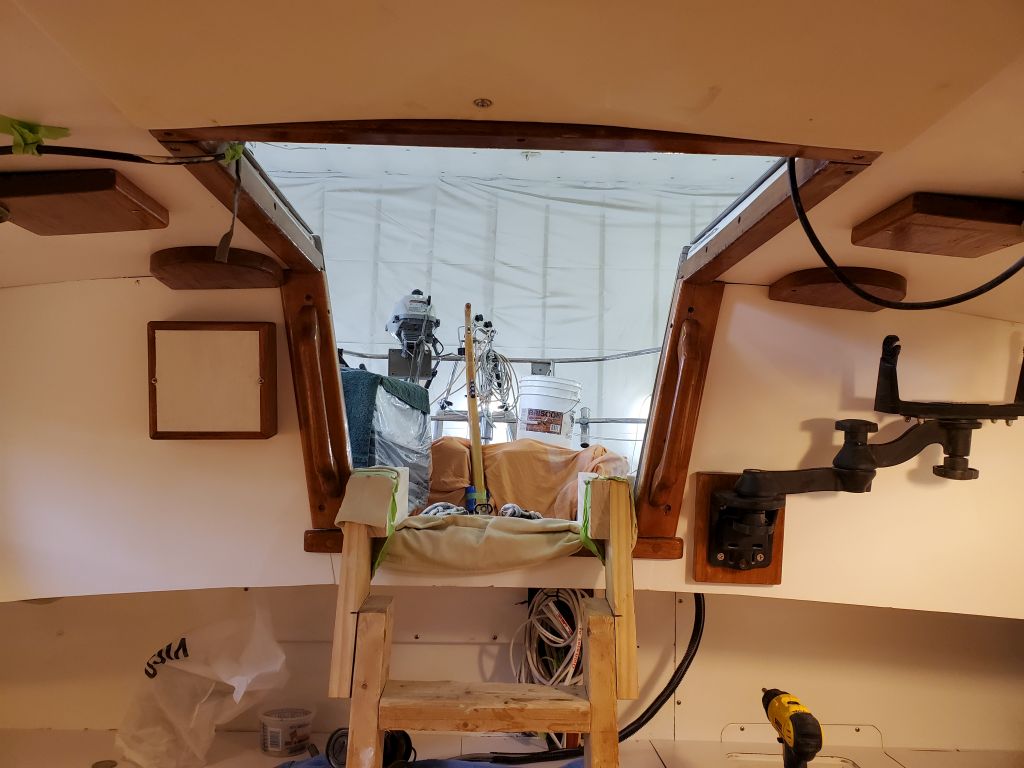
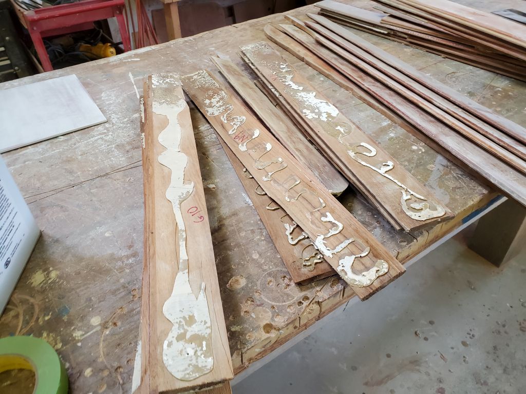
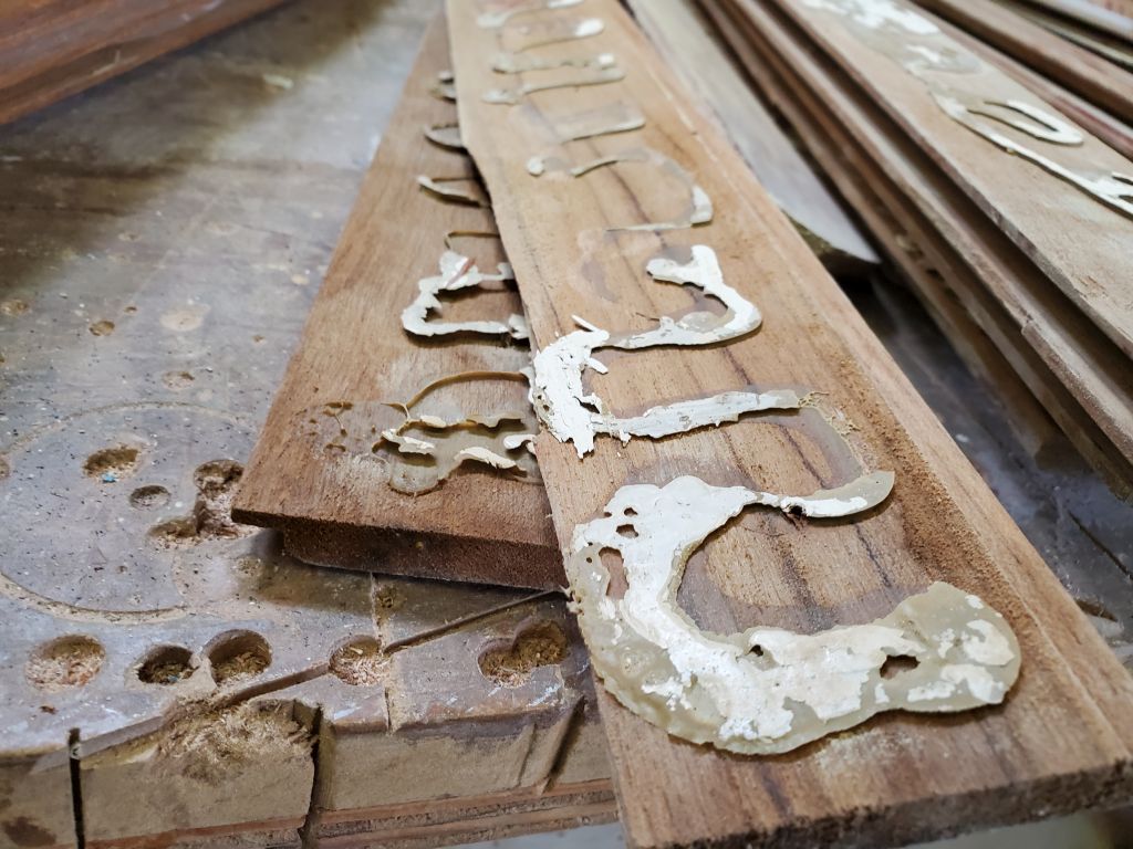
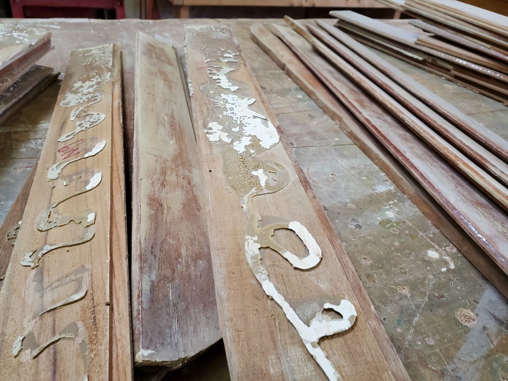
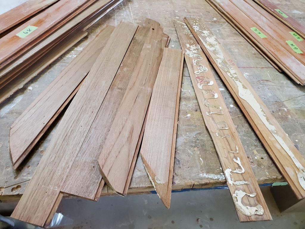
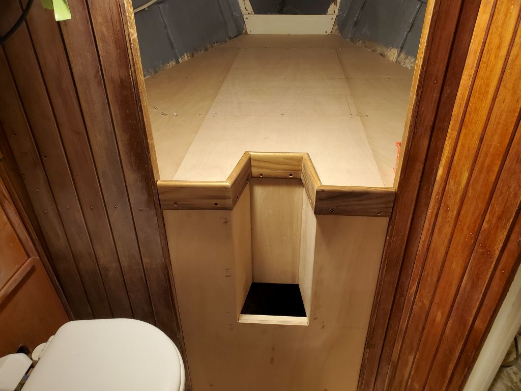
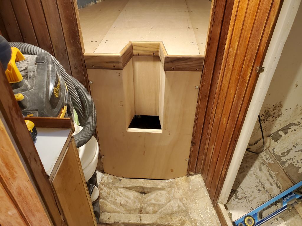
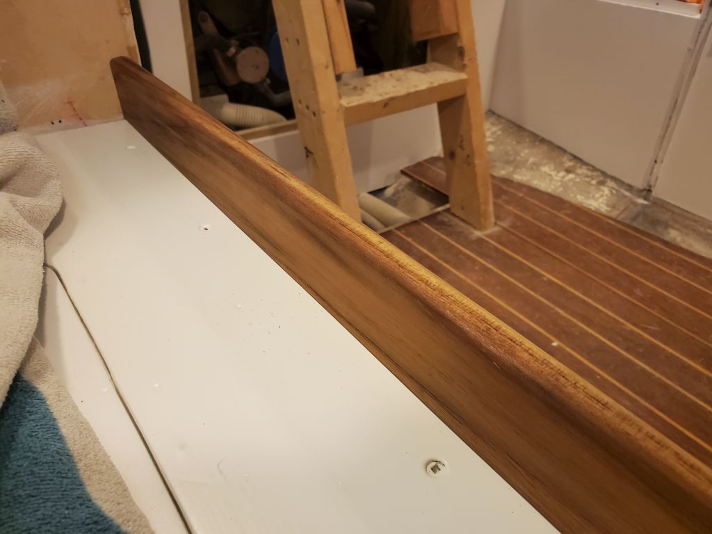
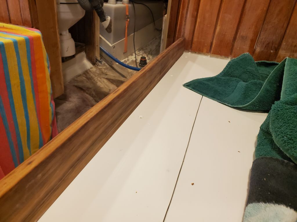
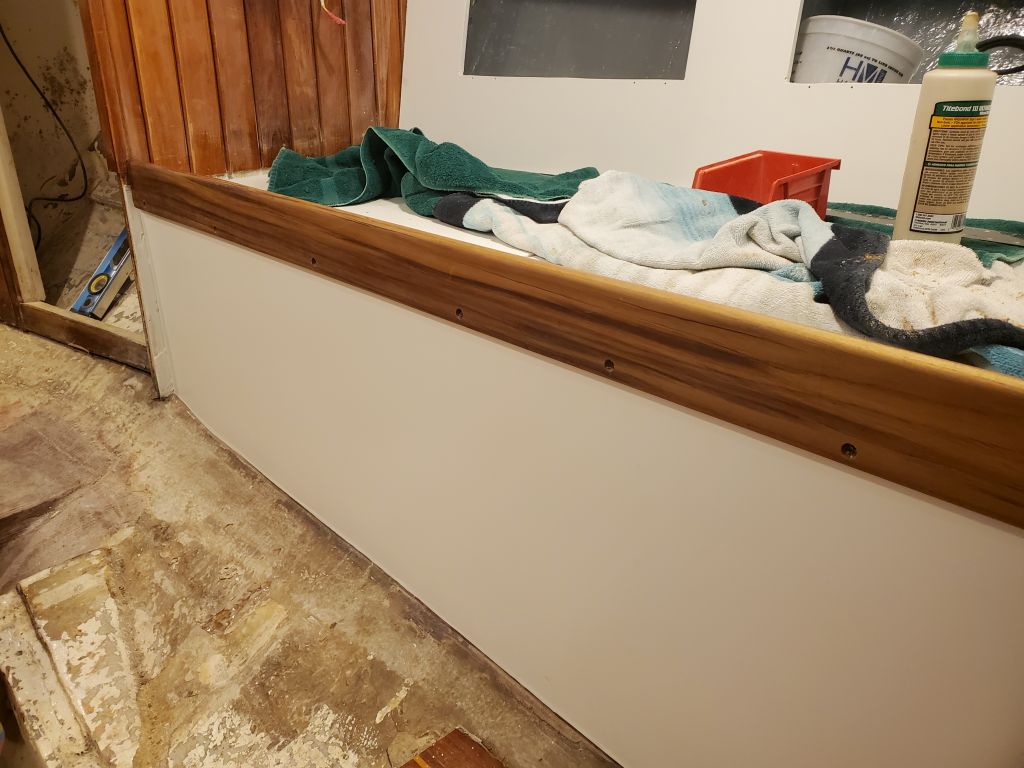
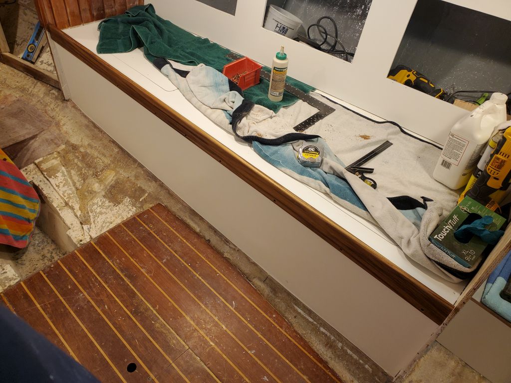
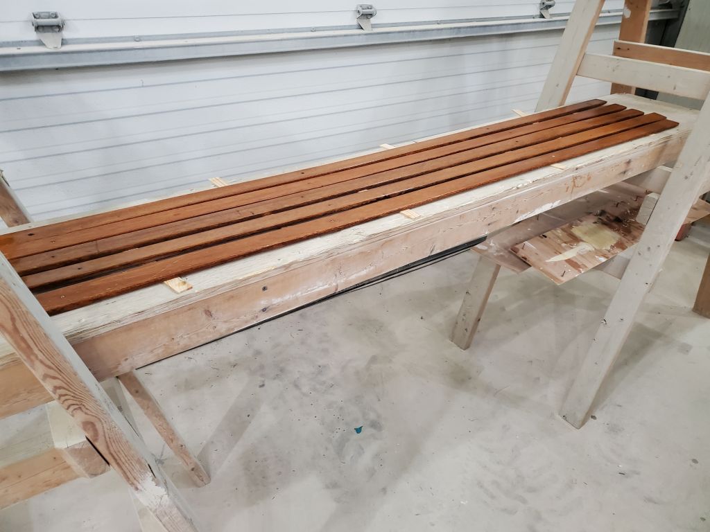
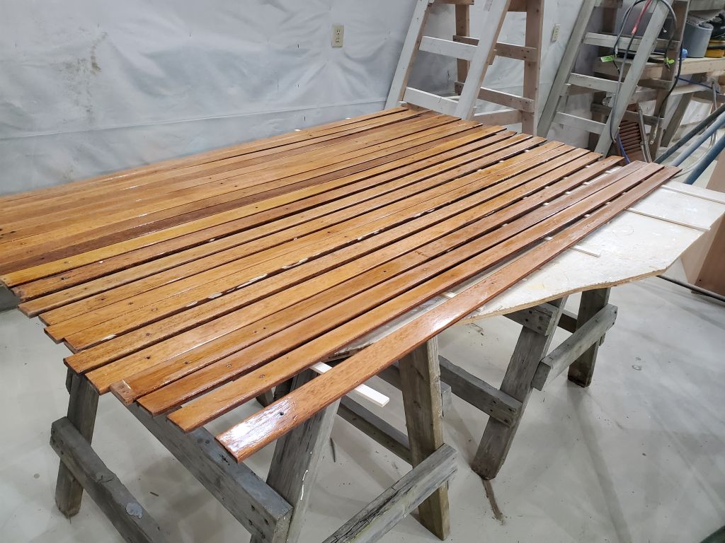
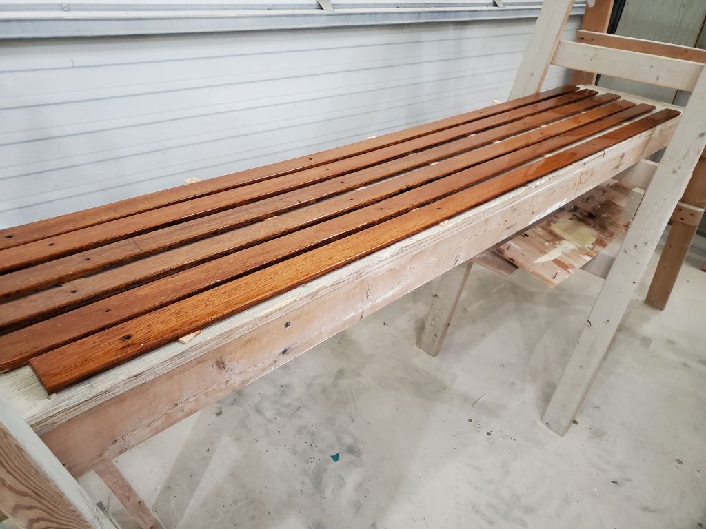
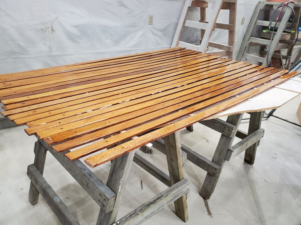
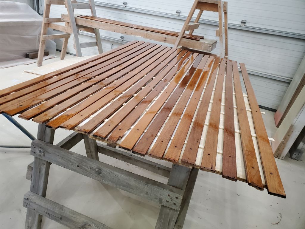
I spent the remainder of the day installing the original teak staving on the bulkheads forward of the galley, starting with the port side. This was a pretty straightforward process, since I’d previously sanded the visible side (to be revarnished once installed) and cleaned up the back sides to remove old adhesive. With some differences in the berth and bulkhead configuration and height, I had to trim many of the pieces to fit, but the installation proceeded quickly as I secured each piece with glue and brads. Once I’d completed the port side, I continued with the starboard, making it partway across before the end of the day.