< Back to Acadia
Wednesday
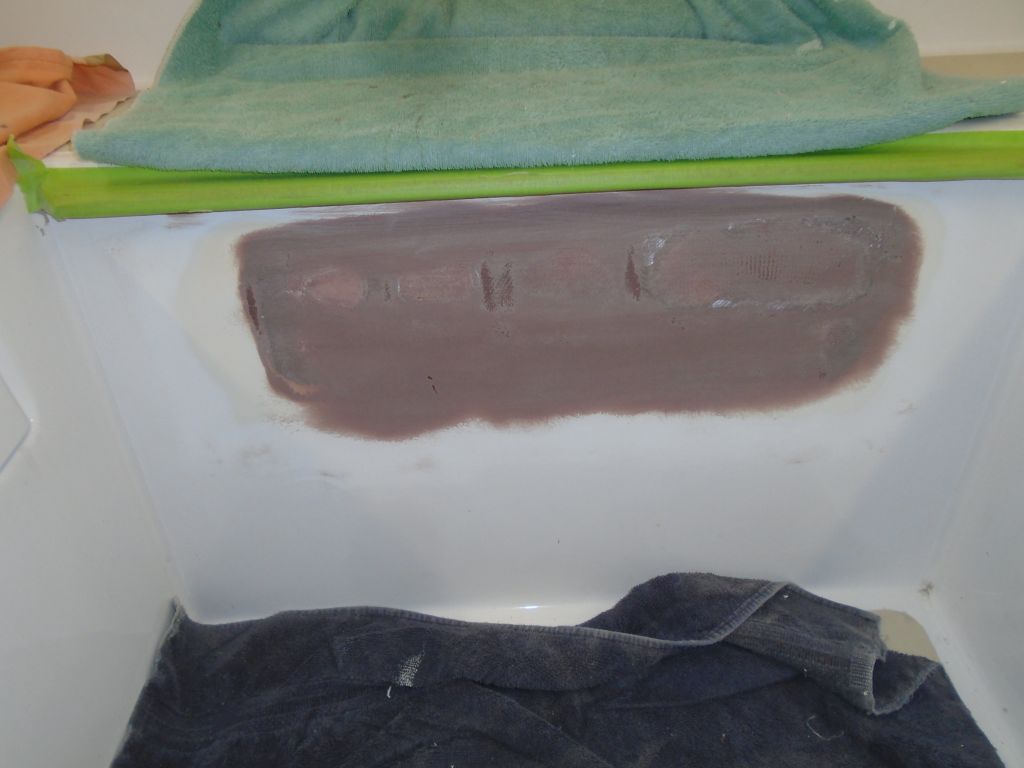
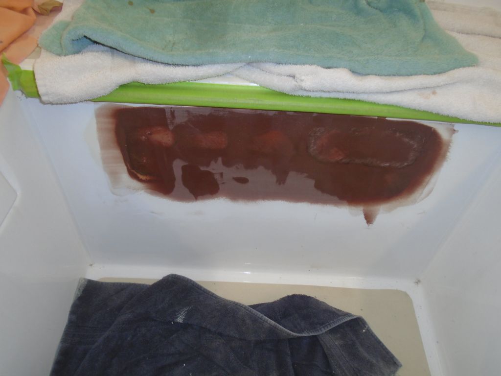
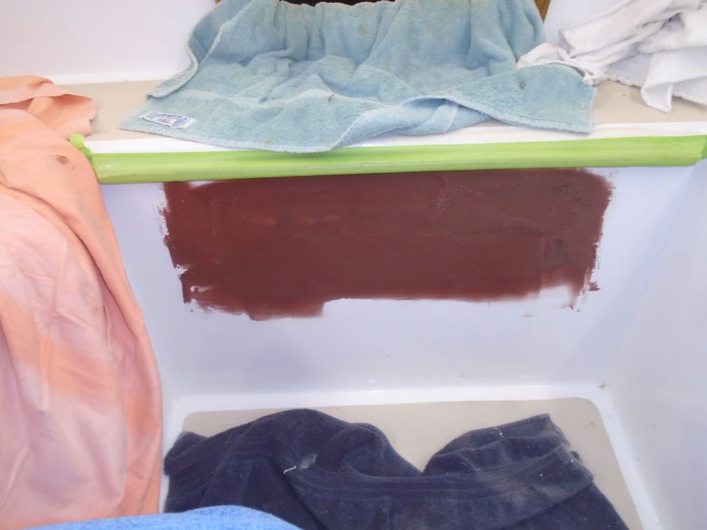
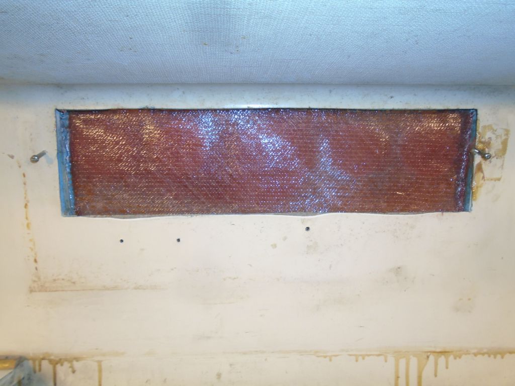
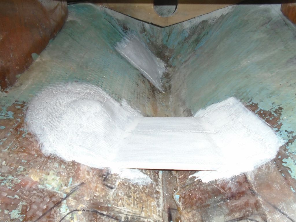
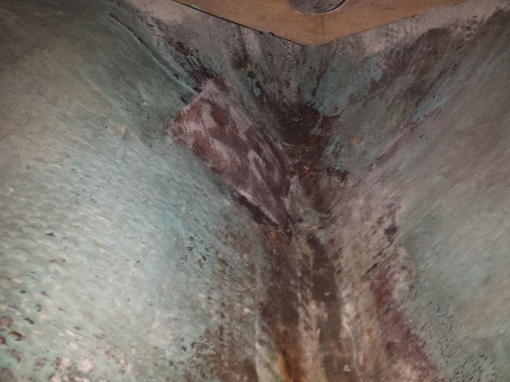
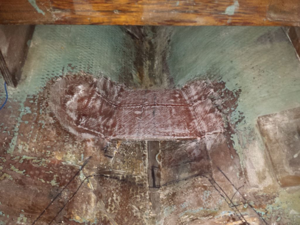
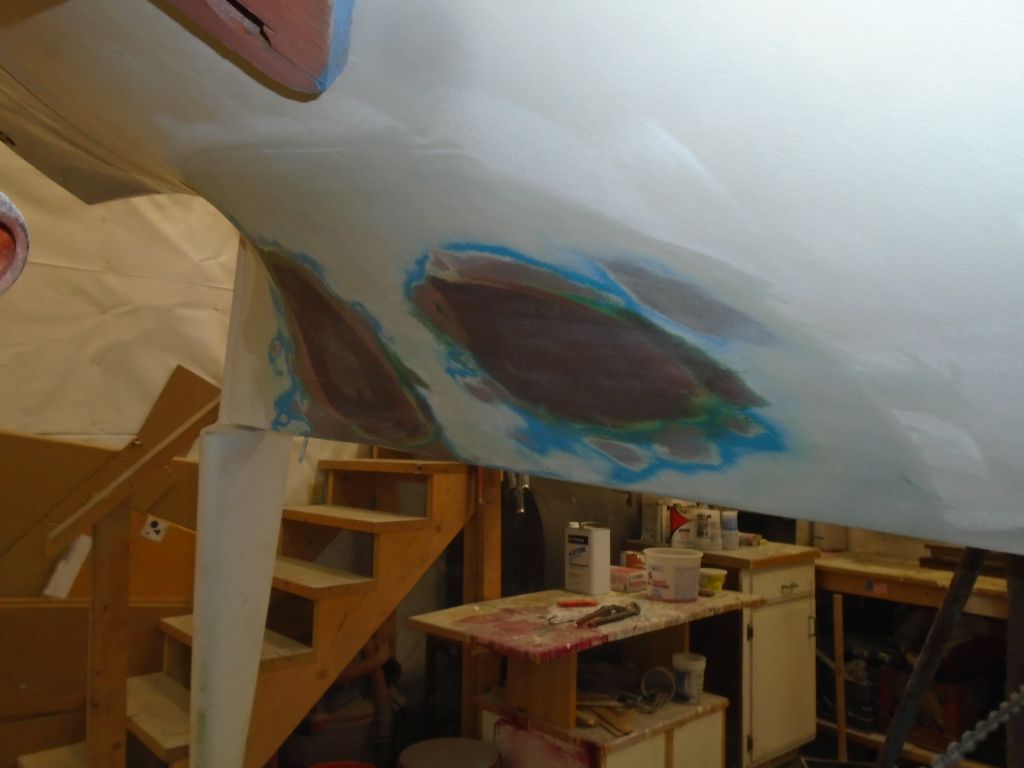
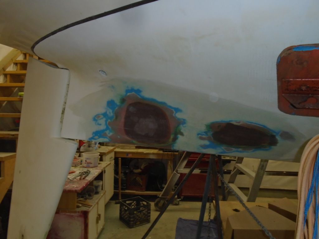
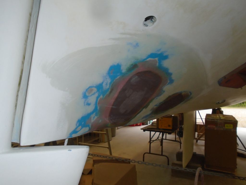
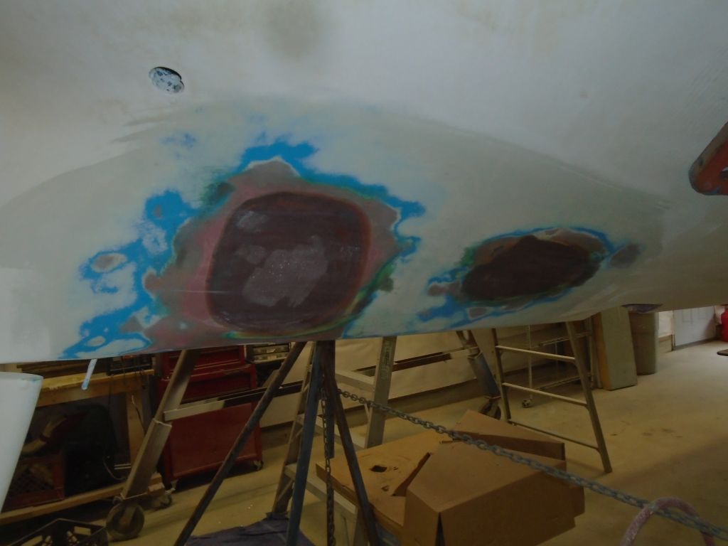
I finished up the exterior hull patches with a final washing and light sanding, smoothing the epoxy coating. Sometime later, I’d paint the area to match.
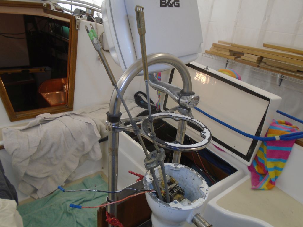
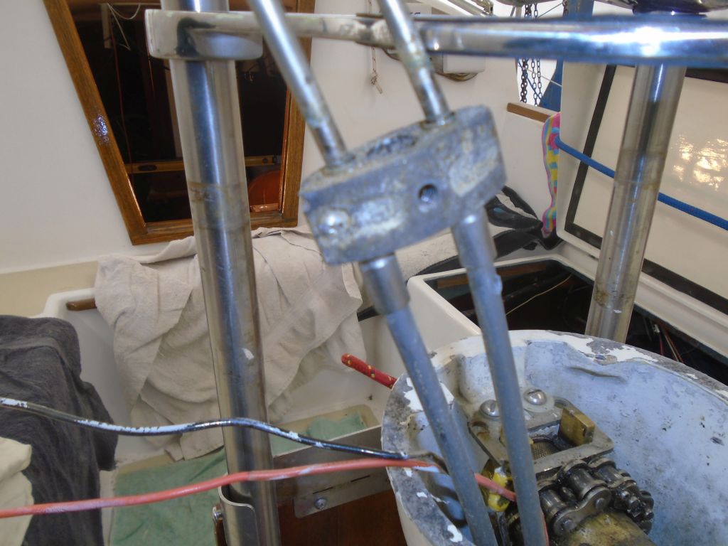
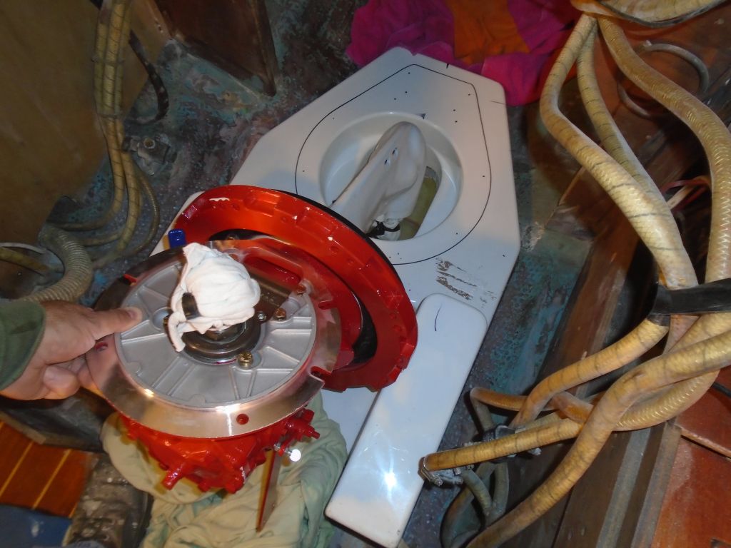
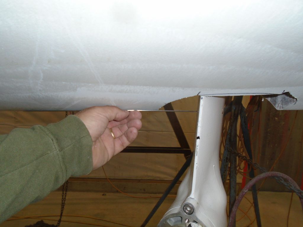
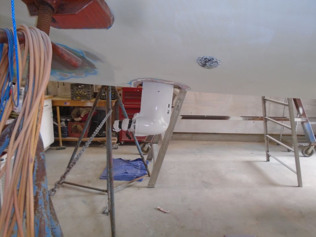
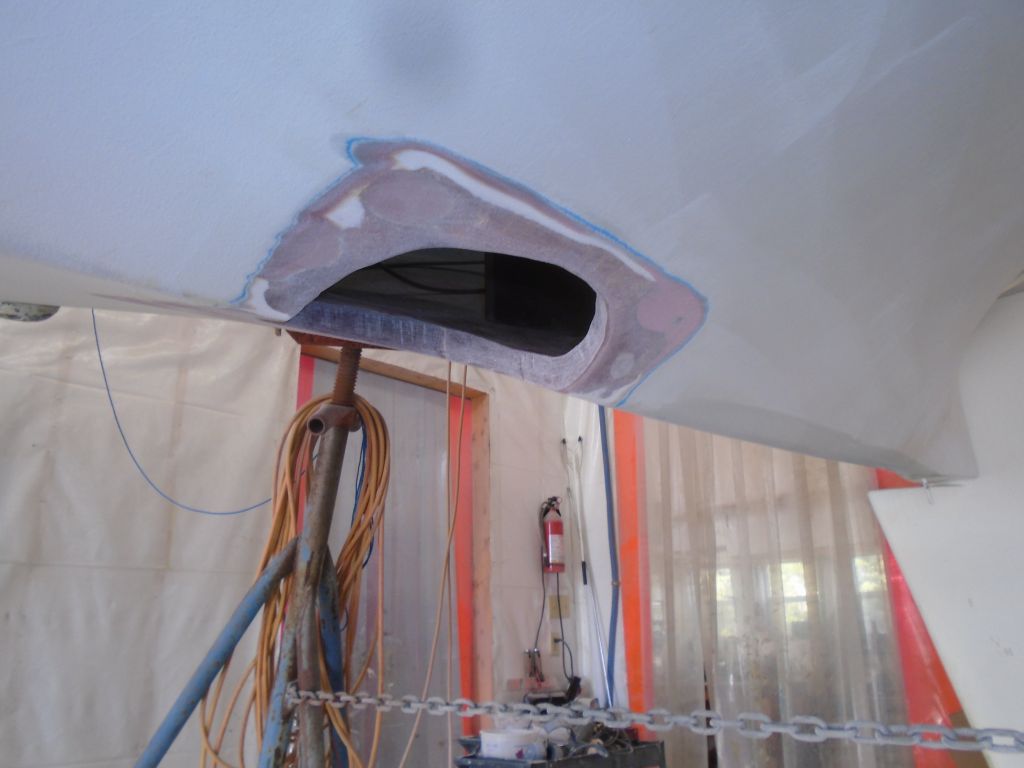
Up in the boat, I disconnected the transmission and drive leg from the hoist, as the only way I’d be able to handle it appropriately was by hand. It weighed about 75 lb. In order to install the leg, it was necessary to angle it through the hole, allowing the long shaft to pass through first, then tipping the transmission into place. There was insufficient room to maneuver the unit the “right” way, which would require tipping the whole bulky unit well aft: there simply was neither enough headroom nor manhandling room to allow this process. Instead. I reversed it and tipped the leg through the hole backwards, hoping then to twist the whole thing around into the correct orientation.
The width of the opening in the hull was narrower than the longitudinal width of the drive leg, so turning the unit was not possible. The clearance was close, but didn’t allow the twist as required.
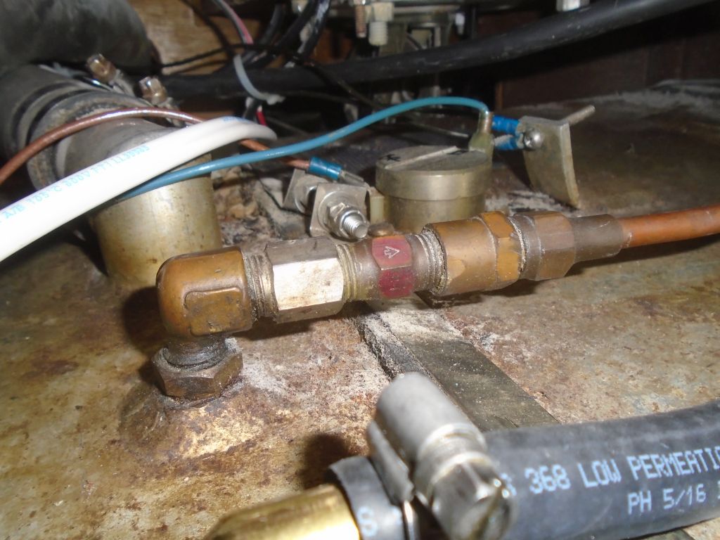
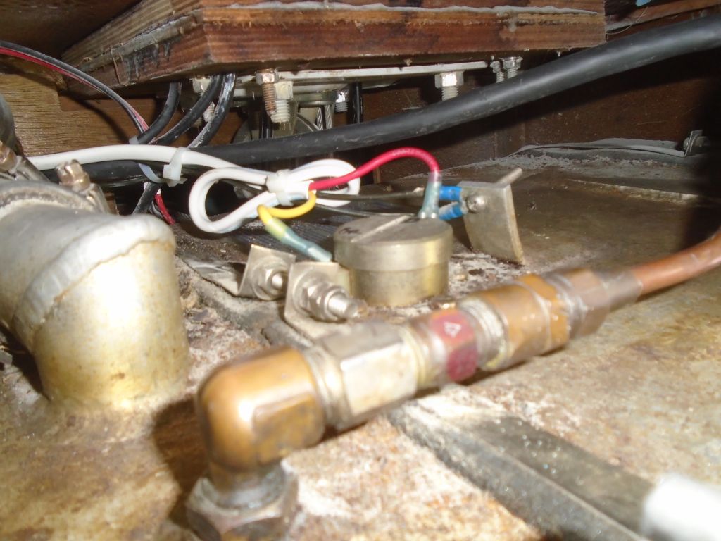
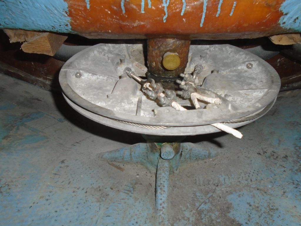
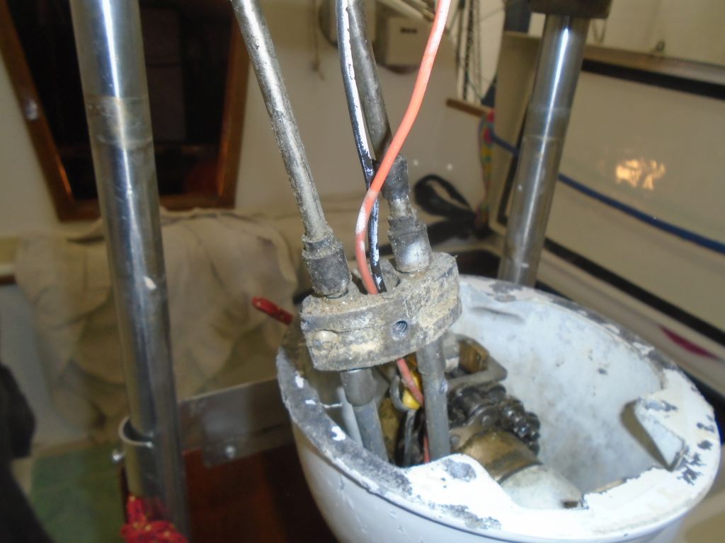
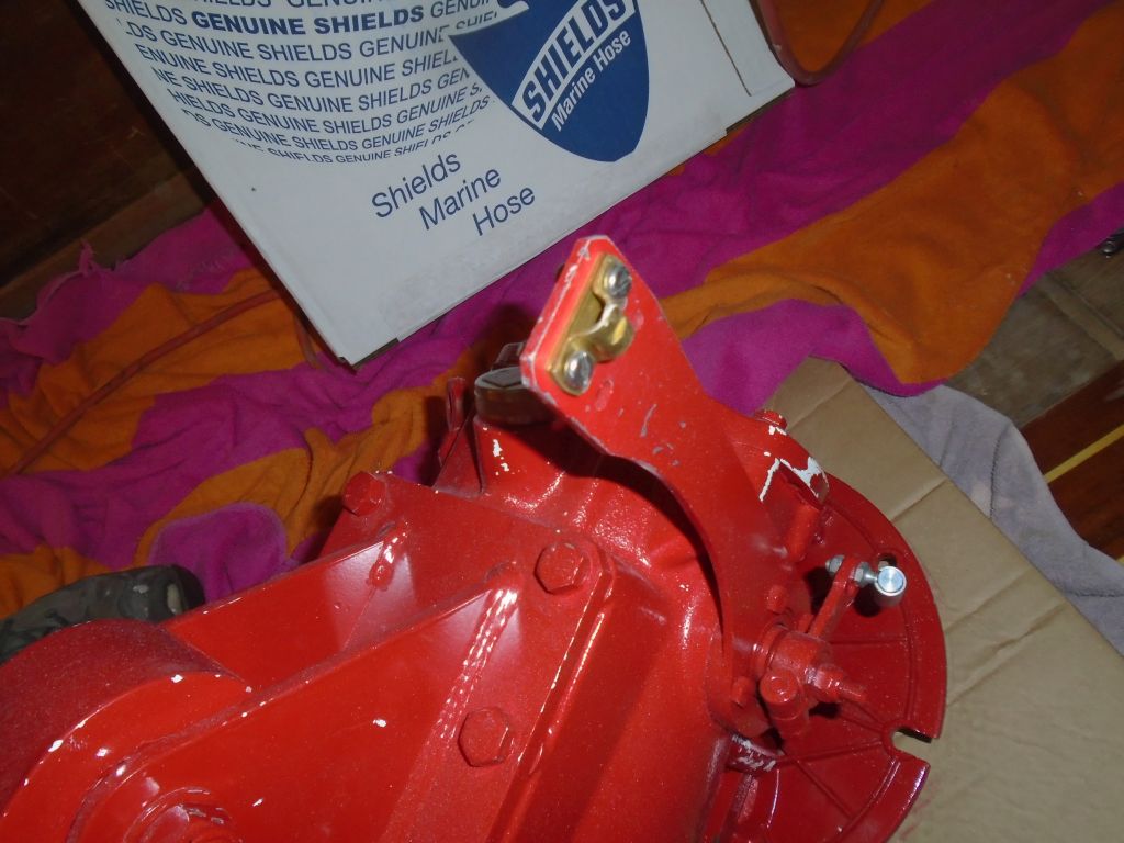
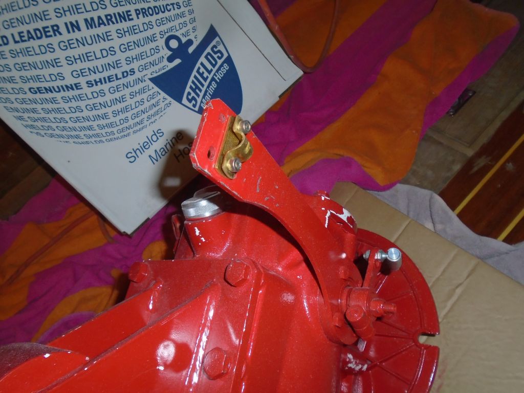
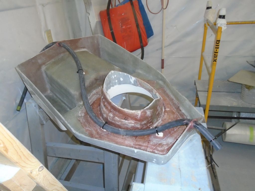
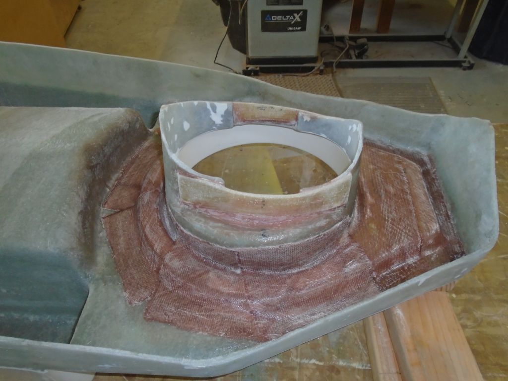
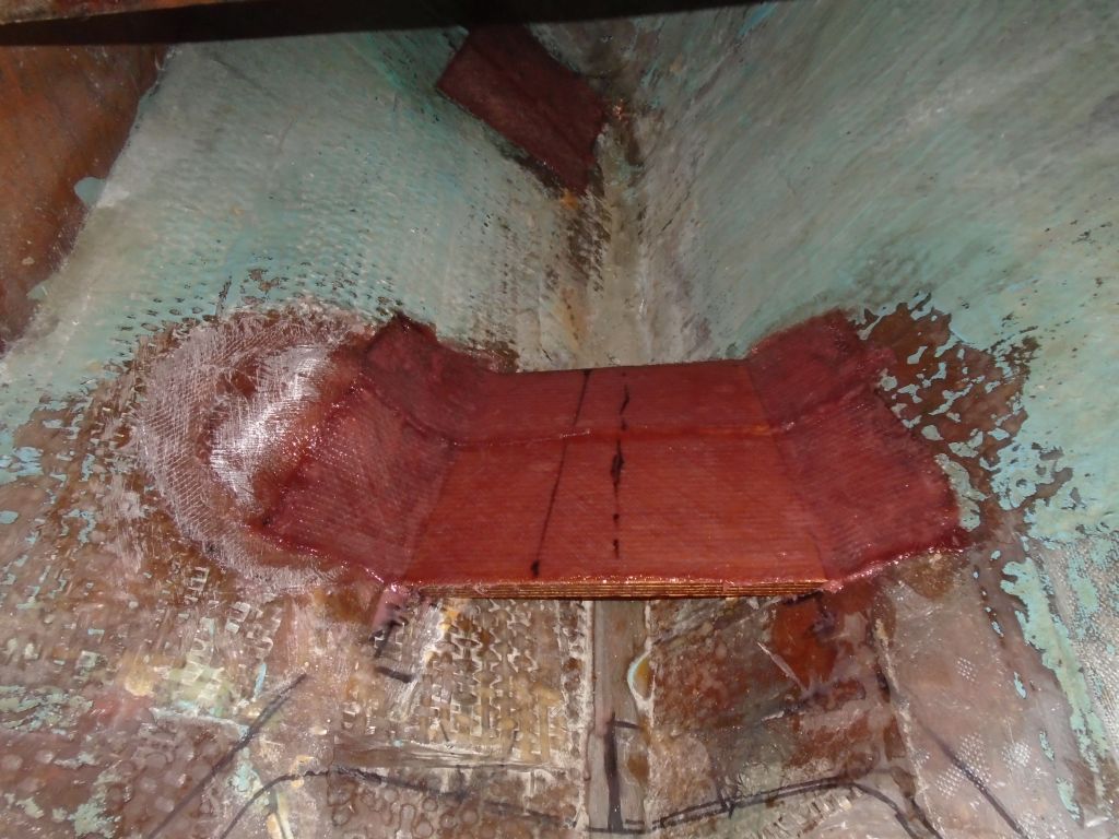
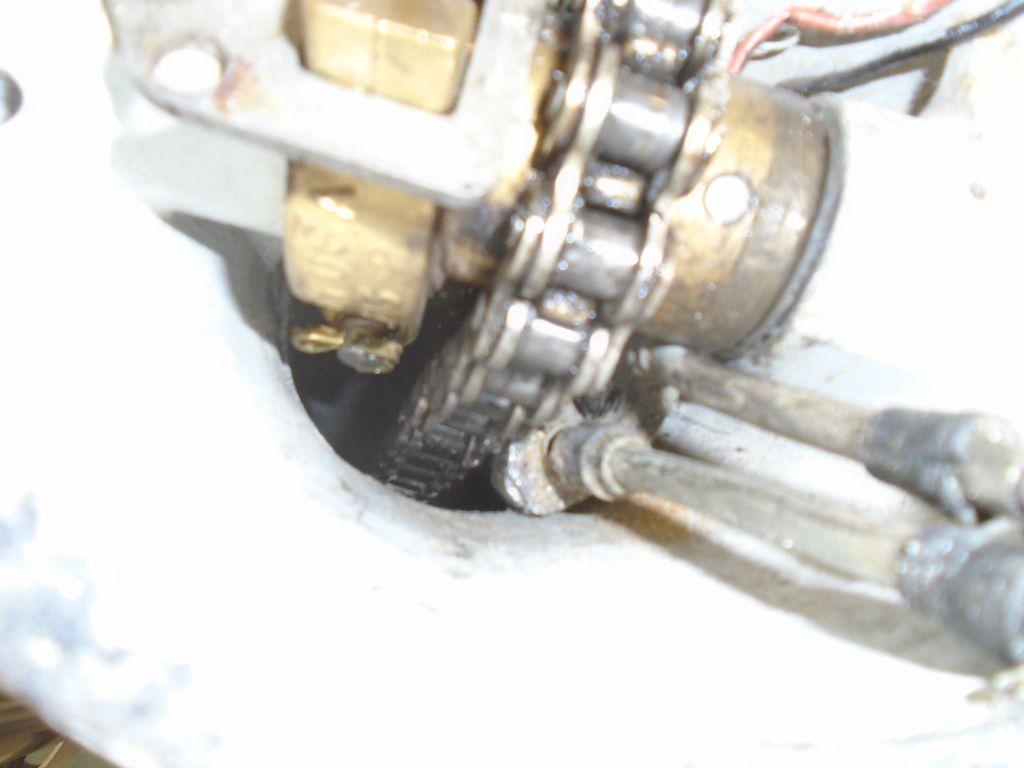
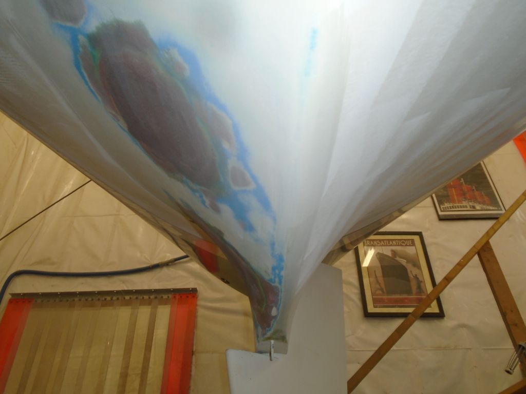
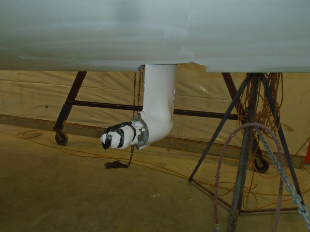
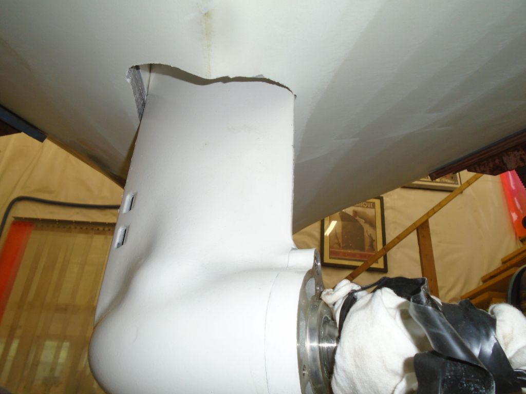
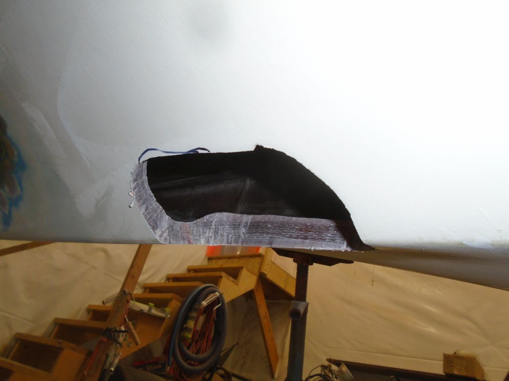
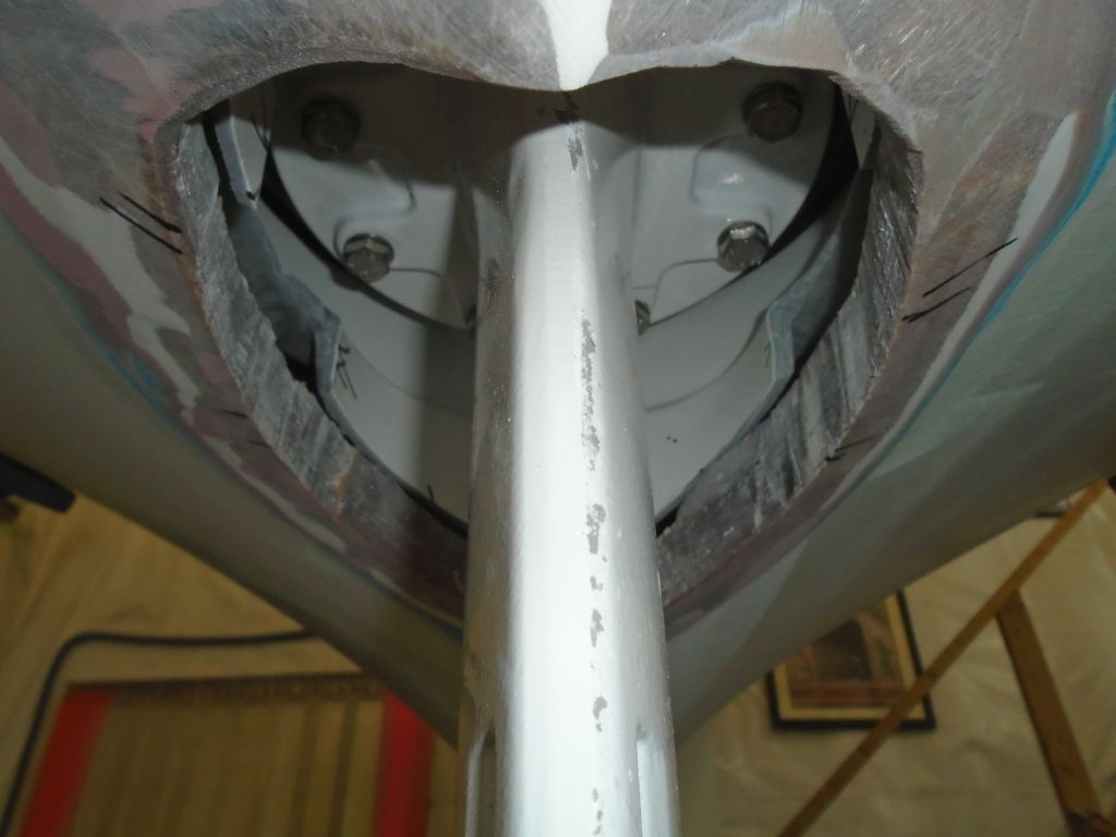
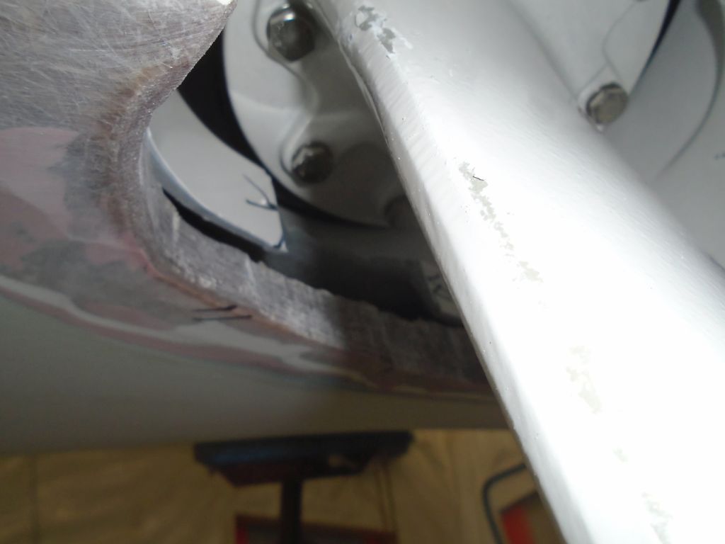
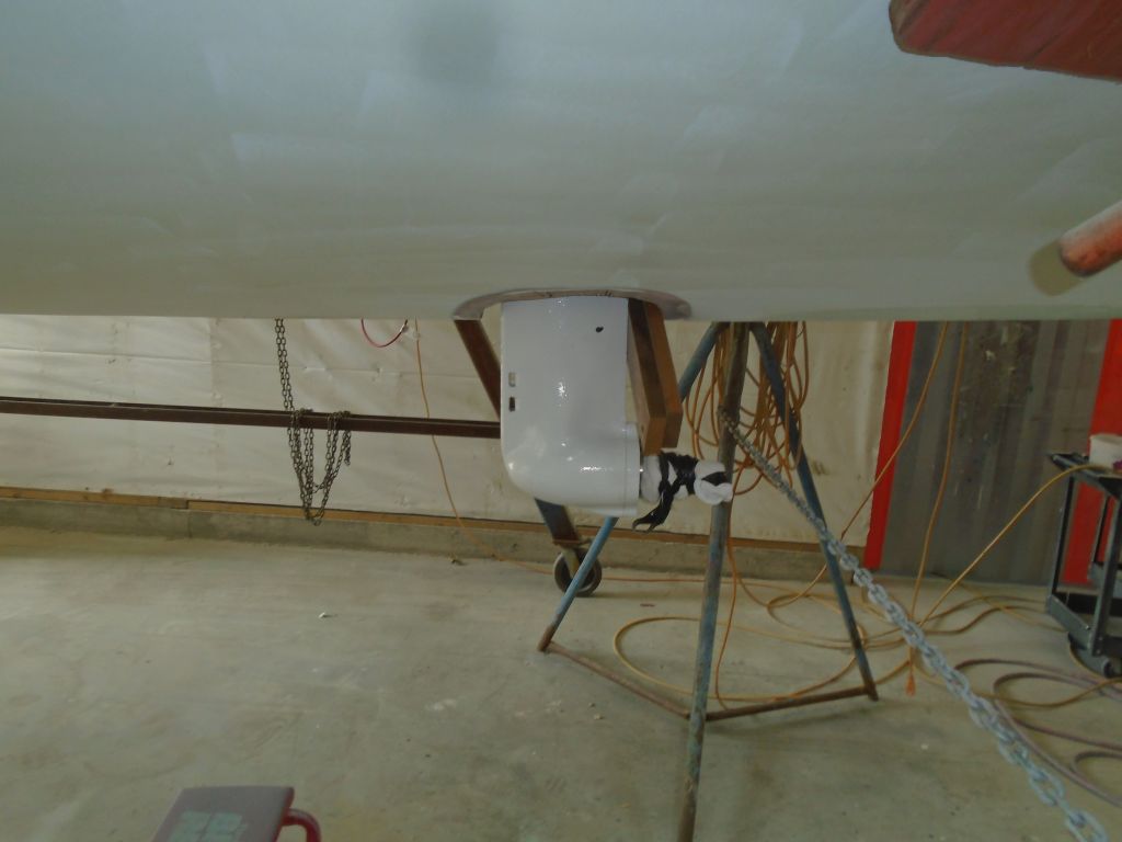
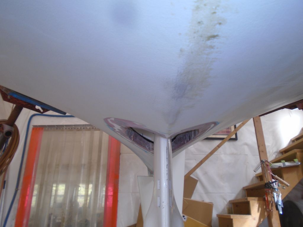
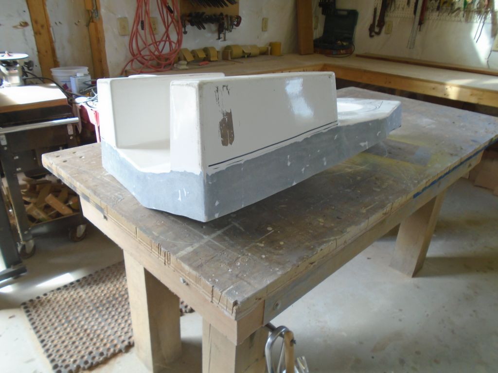
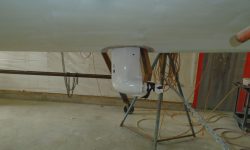
While I had the leg in place, even though it was pointing the wrong way, I did a preliminary check of the prop clearance, one of the reasons for the dry-fit. With a straightedge, I extended the line of the hull onto the leg from both sides, and was pleased to find there would be ample propeller tip clearance. The small black mark on the trailing edge of the leg (facing the camera) indicated the top of the propeller, so I had nearly 2″ of clearance.
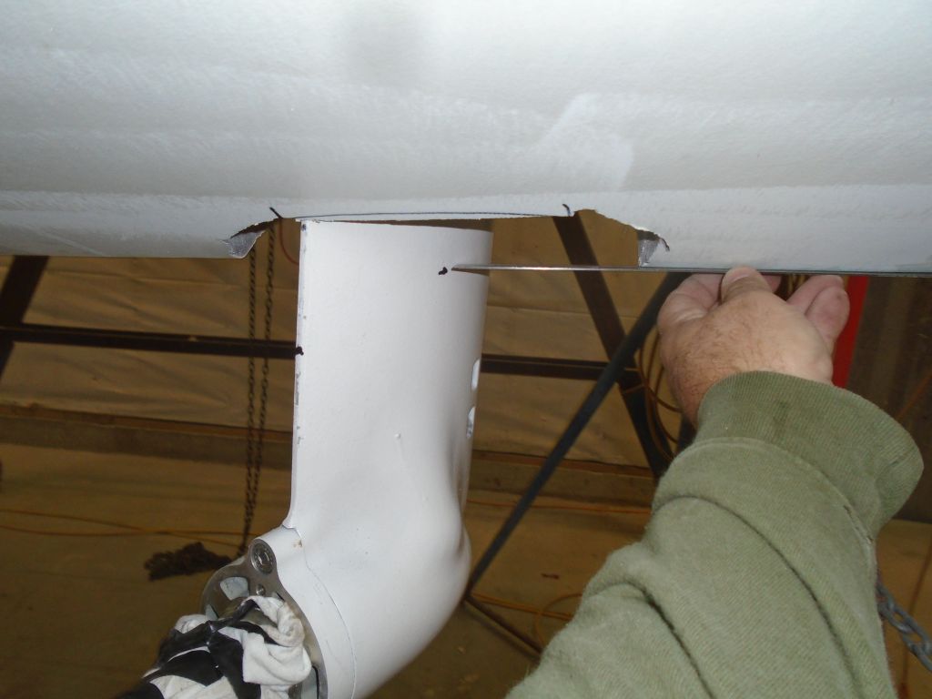
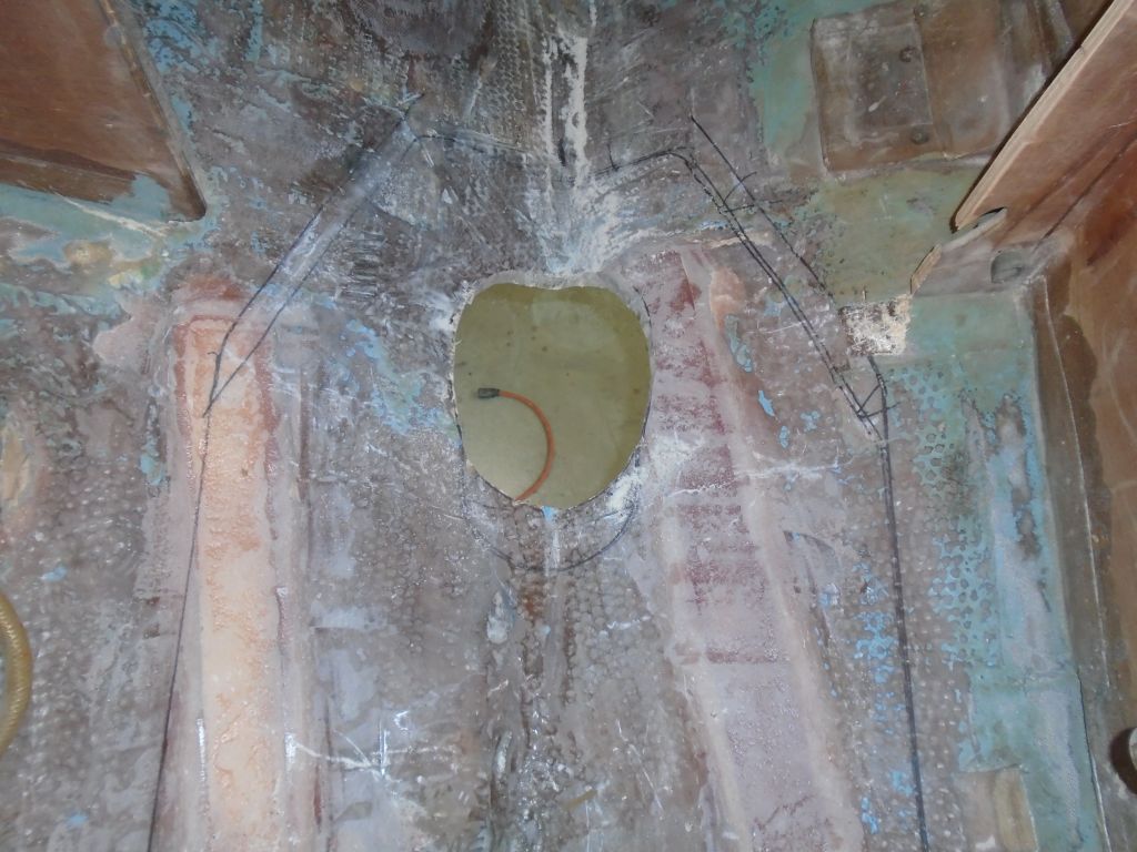
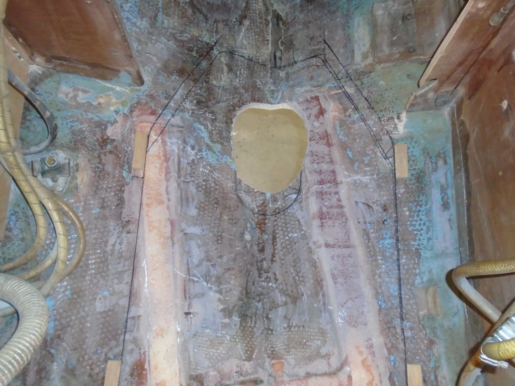
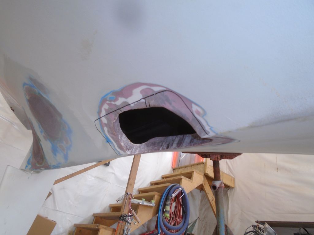
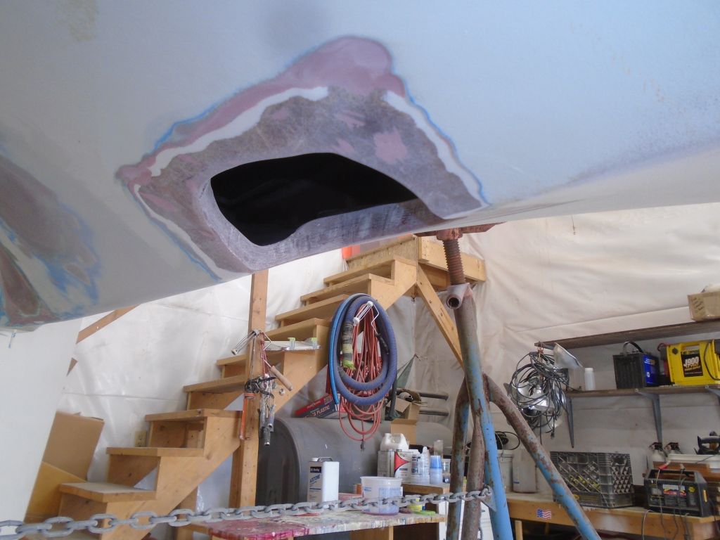
Now I made some marks on the outside of the hull to suggest where I needed to widen the opening and allow the leg to twist. Initially, it appeared that only a small amount of material, and some general cleanup of the still rough-cut opening, would be required. I removed the leg and opened the hole more with a grinder.
I went through a few iterations of this, cautious in my approach since I didn’t want to open the hole any more than necessary. Maneuvering the transmission and leg in and out of position was a chore I didn’t care for much, and the process grew frustrating. Eventually, it became obvious that the molded foundation housing was also prohibiting the twisting of the leg as I wanted, since the thickness of the laminate was too heavy to allow any bending that might let the leg move through. I loathed to change anything with the foundation without exploring every potential option first, so I put in a call to the Beta Marine distributor to see if there was a way to remove the prop shaft, which was, frankly, the only thing preventing the leg from fitting in smoothly and vertically. Having that out of the way would, in theory, obviate the requirement to tip the whole unit nearly 90° in order to angle through the hole.
Ultimately, the short answer was no: while technically the shaft could be removed, I was advised not to try, which was fine because I didn’t really want to get into that mess in the first place. I did learn that the whole leg could be removed–it was bolted to the bottom of the transmission housing–and I received a link to a video showing this process, but the problem with that was that the leg would need to be reinstalled from beneath the boat, through the hole in the bottom–a most unsavory prospect that I had no intention of trying. I considered it for only a few moments before quickly abandoning that particular notion.
So the long and the short of this exercise was that I’d need to modify the hole inside the foundation itself, a prospect well within my skill set and ability and of which I was unafraid, but which I’d tried to avoid only as long as there wasn’t a more basic, “magic” solution to the issue. Discussing the problem with Stan at Beta made me feel as if I had the appropriate permission to proceed as I’d initially, yet warily, expected, and, knowing that there really was no alternative that I was missing or ignoring, I was ready to get it done, finally. This whole thing had turned into much more than I’d anticipated, had been tiring and frustrating, and, with the way forward now clear, it was time to rock on.
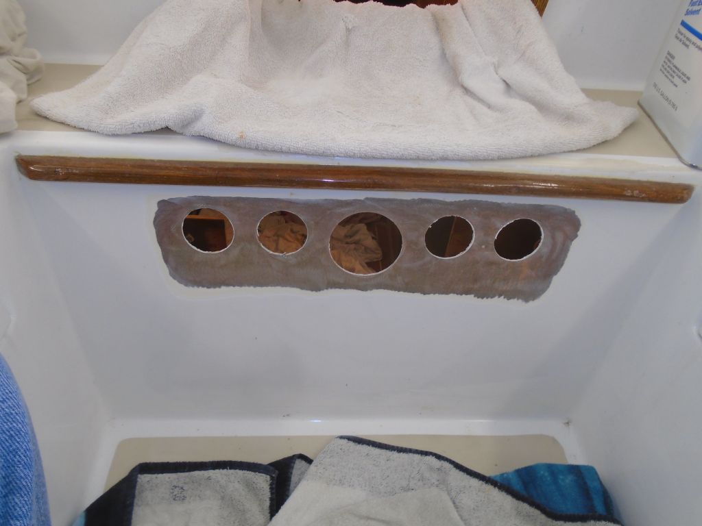
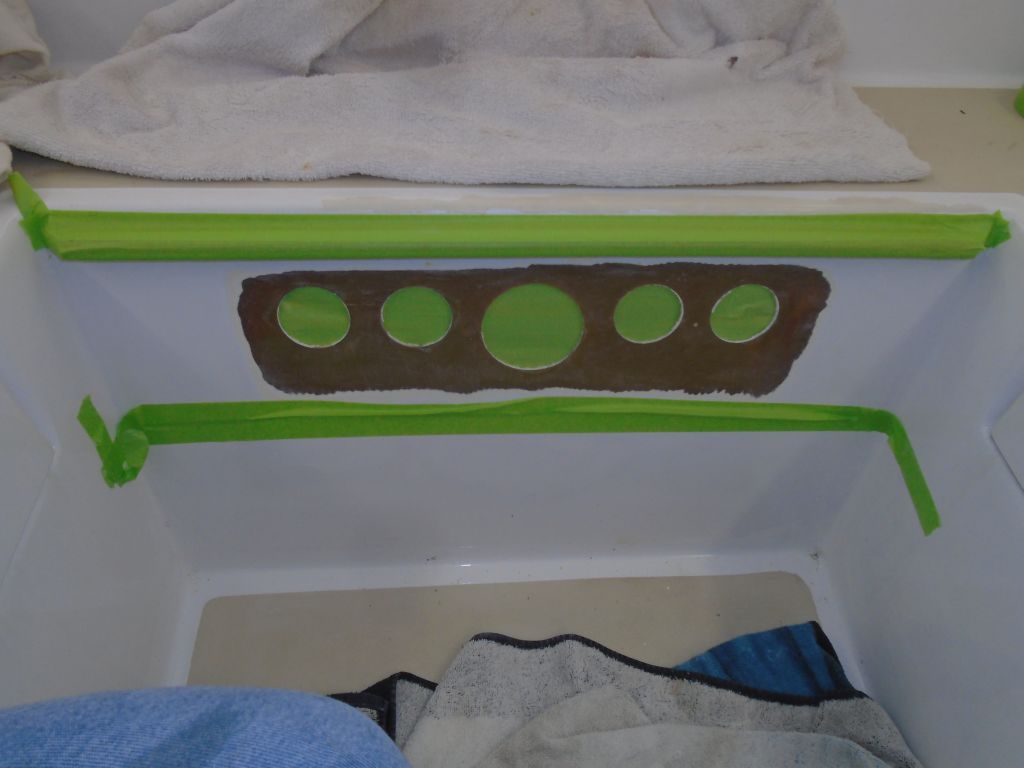
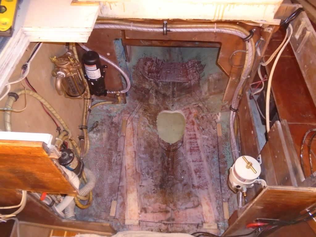
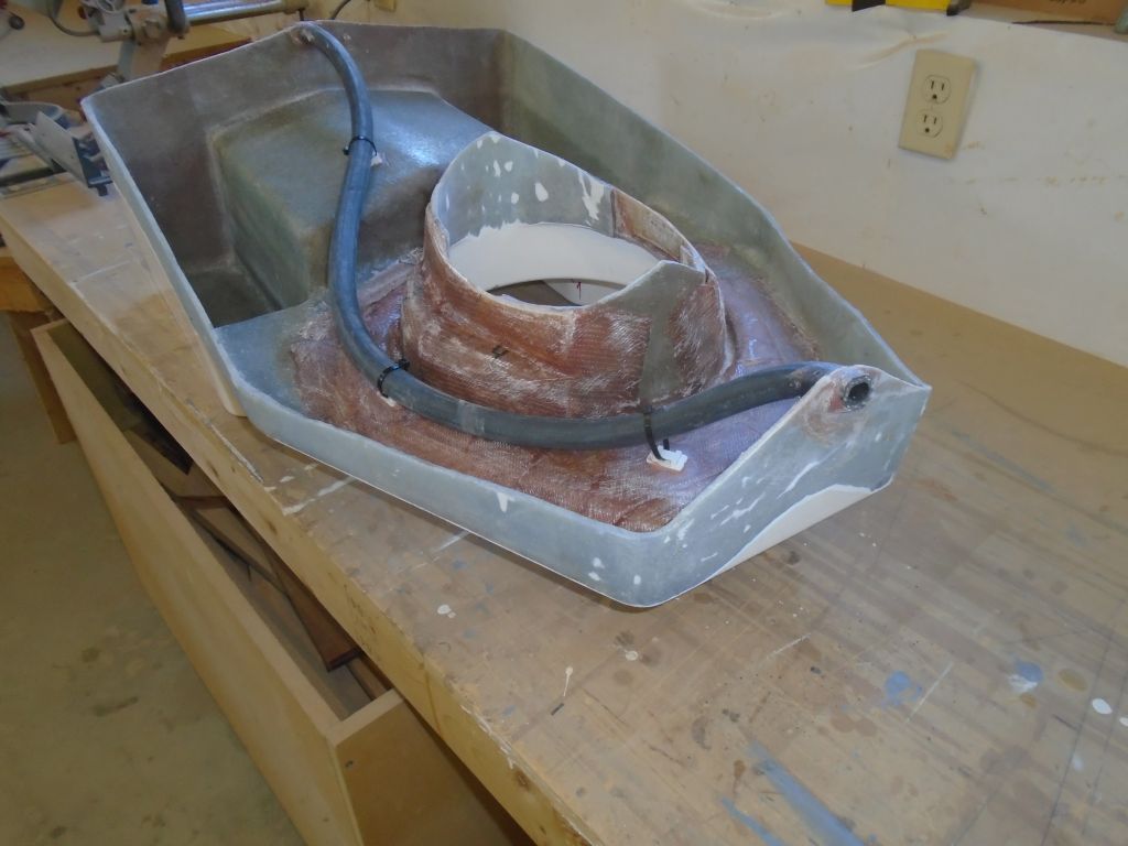
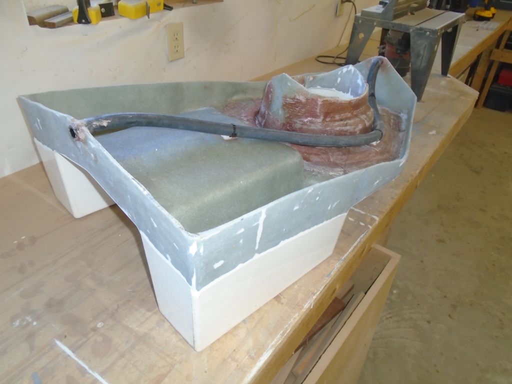
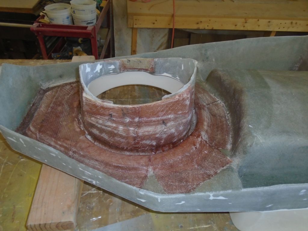
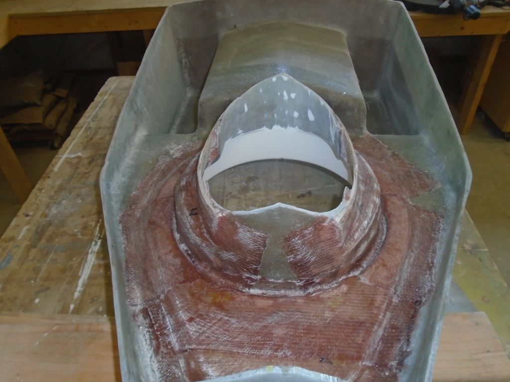
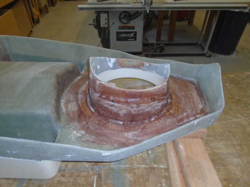
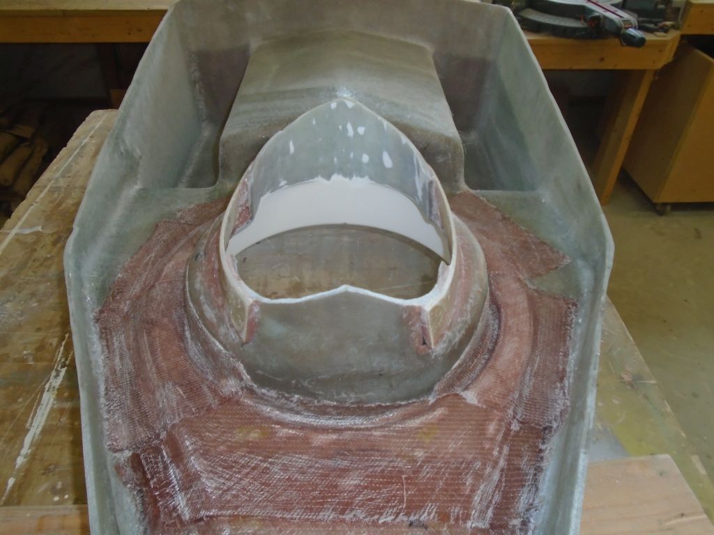
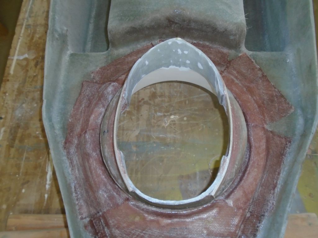
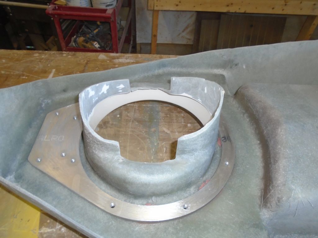
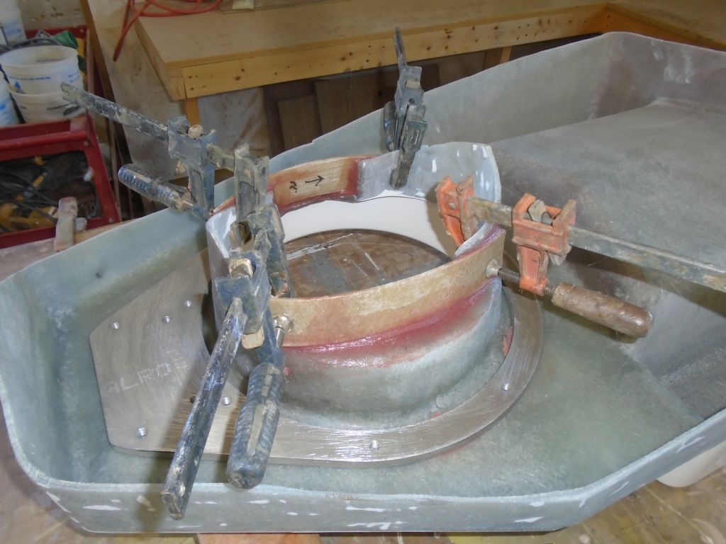
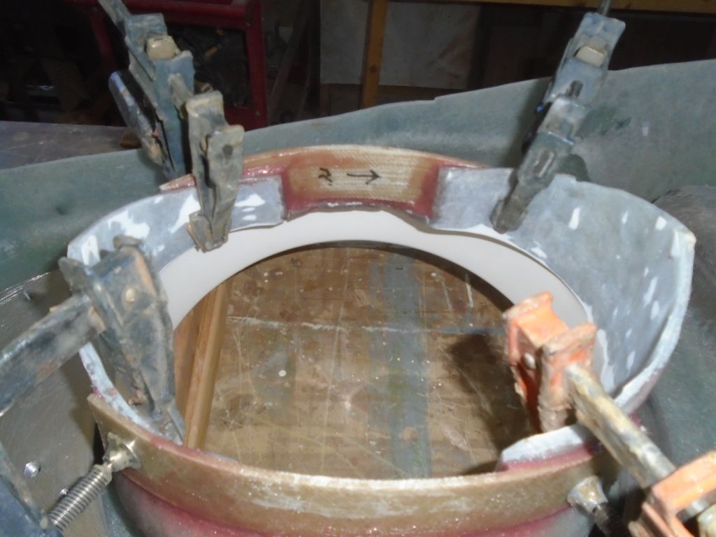
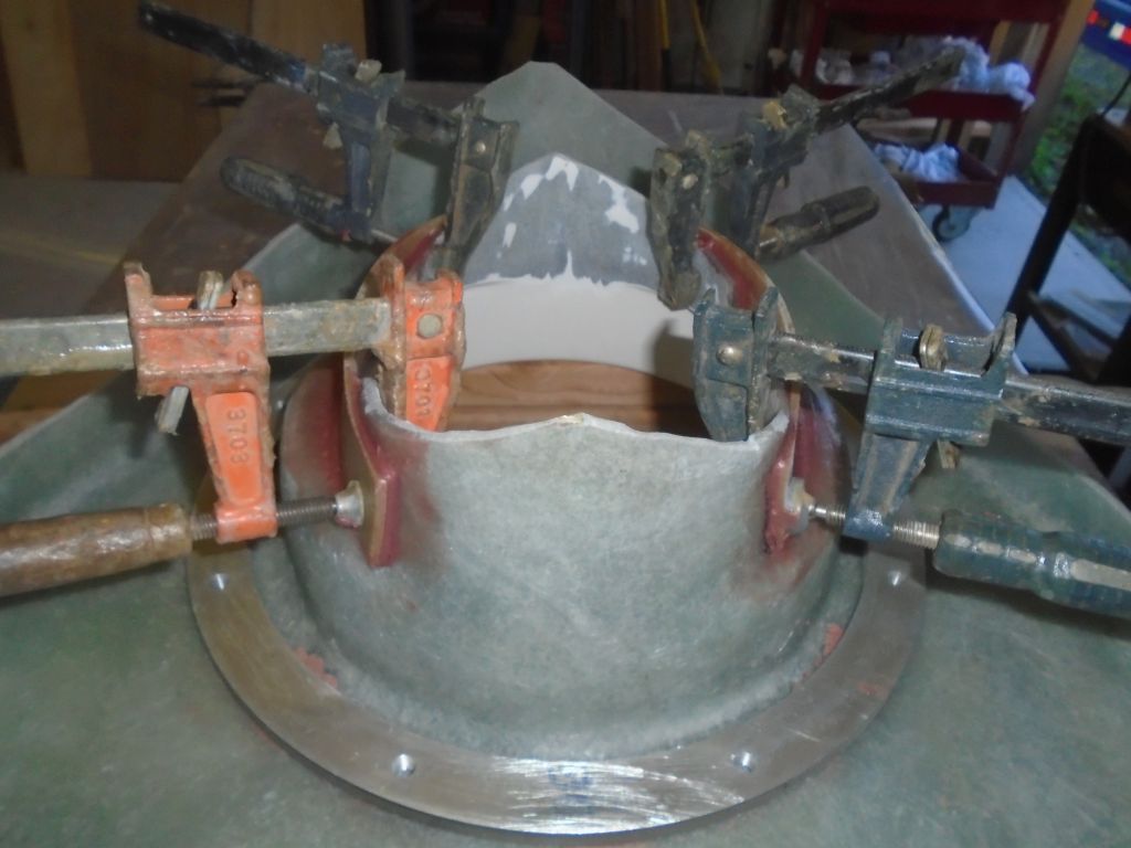
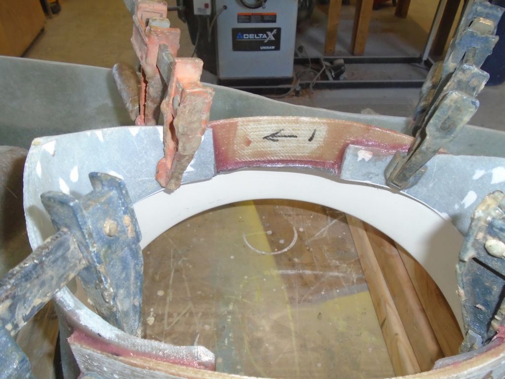
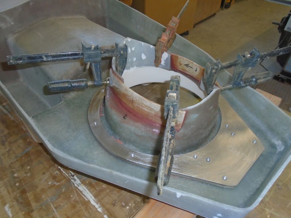
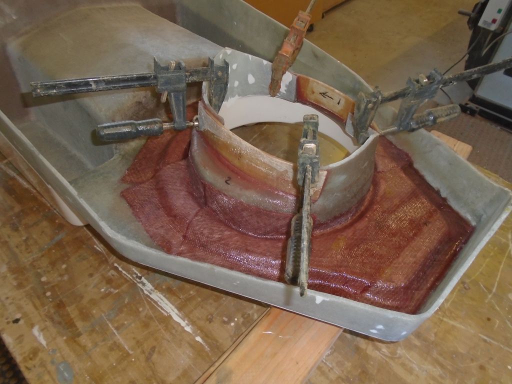
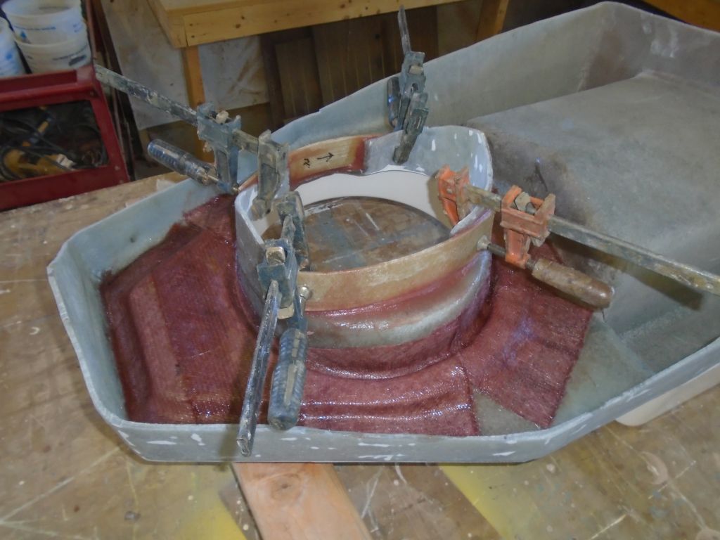
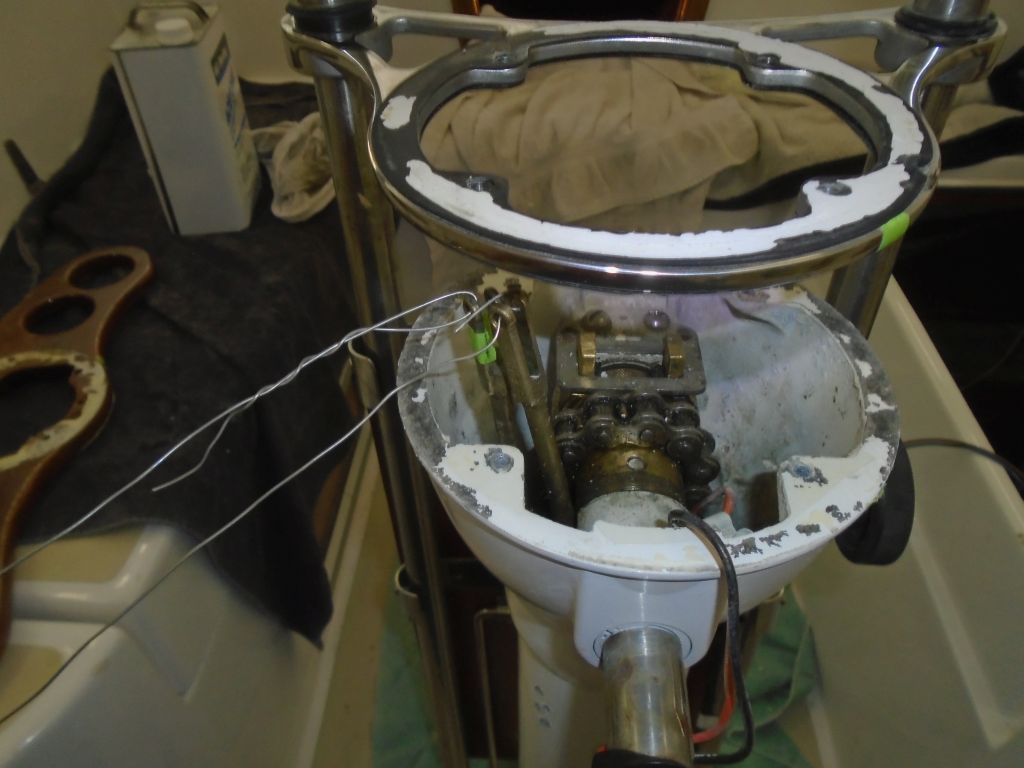
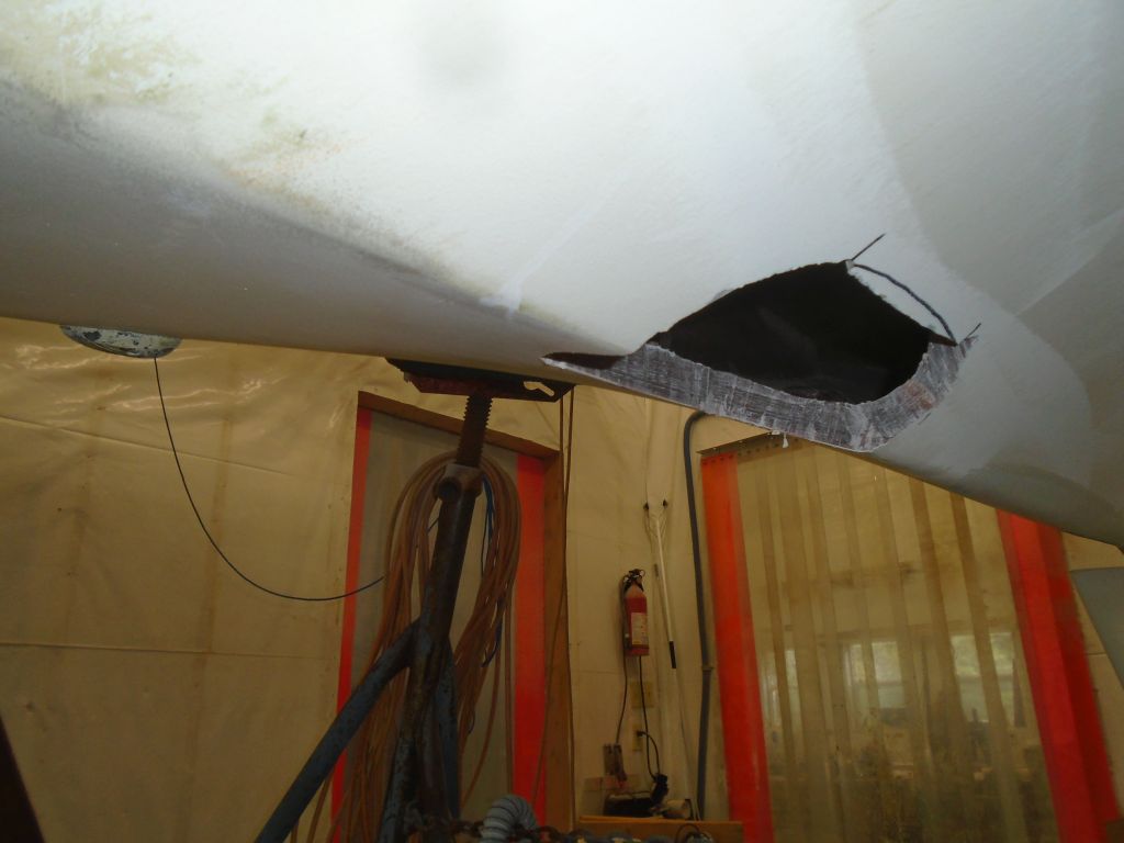
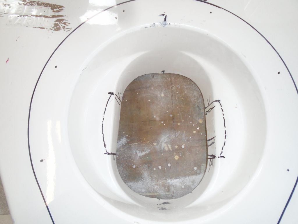
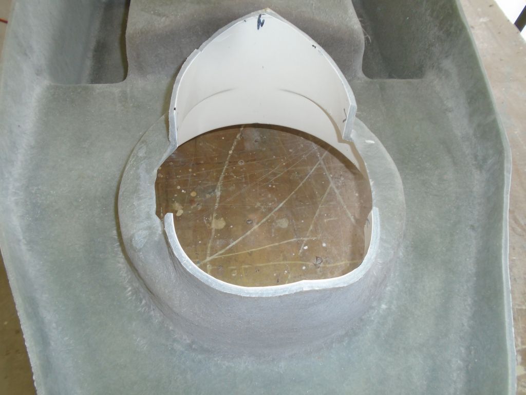
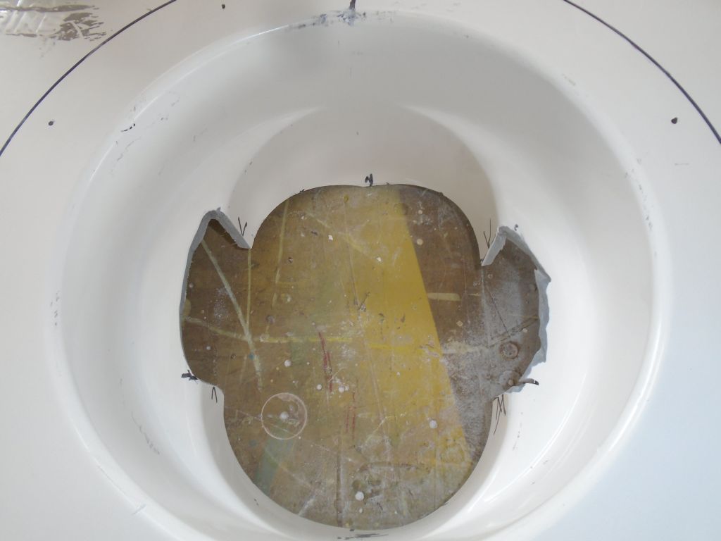
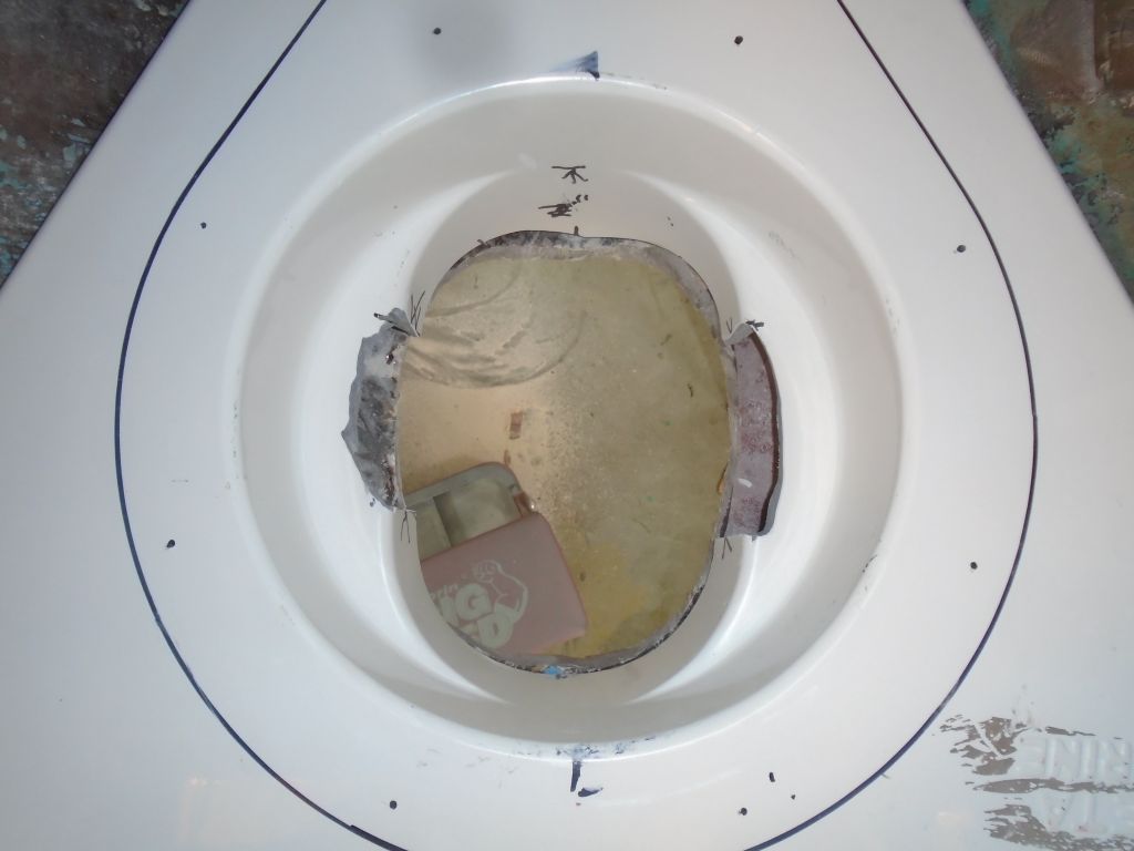
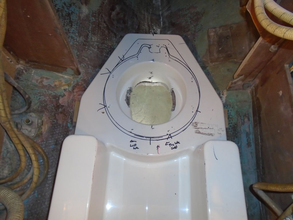
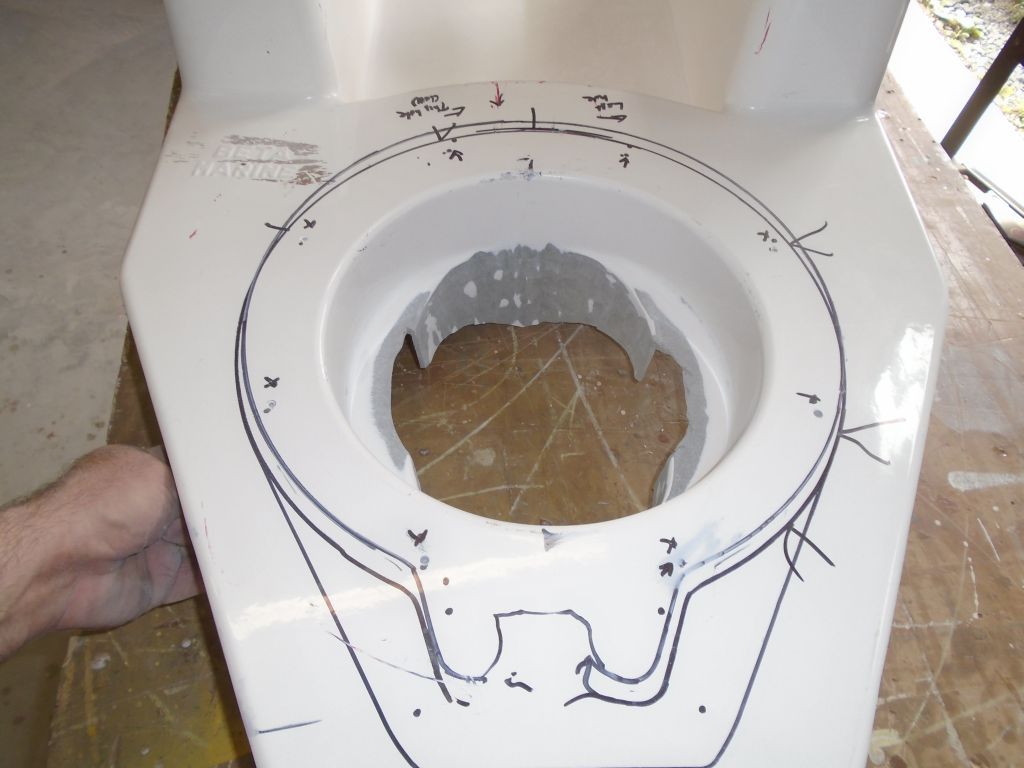
So with the leg in place–again–and angled against the boat and foundation as far as I could turn it, I made some reference marks on the inside of the foundation, demarking the area I’d need to cut out in order to let the leg twist. With the foundation down on the bench, I removed the marked areas with a cutoff wheel, leaving openings that would allow the leg to twist through, but would require additional patching later.
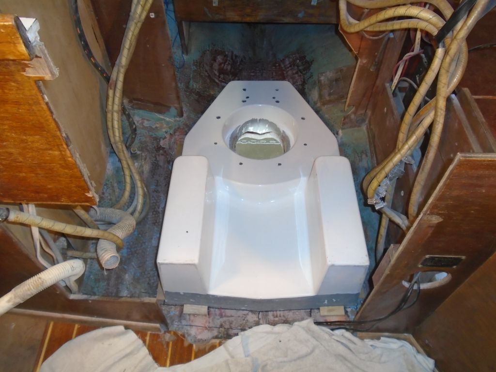
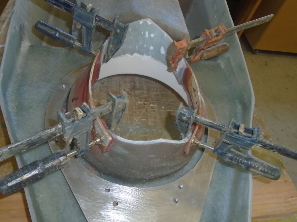
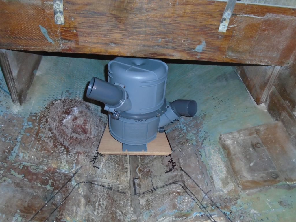
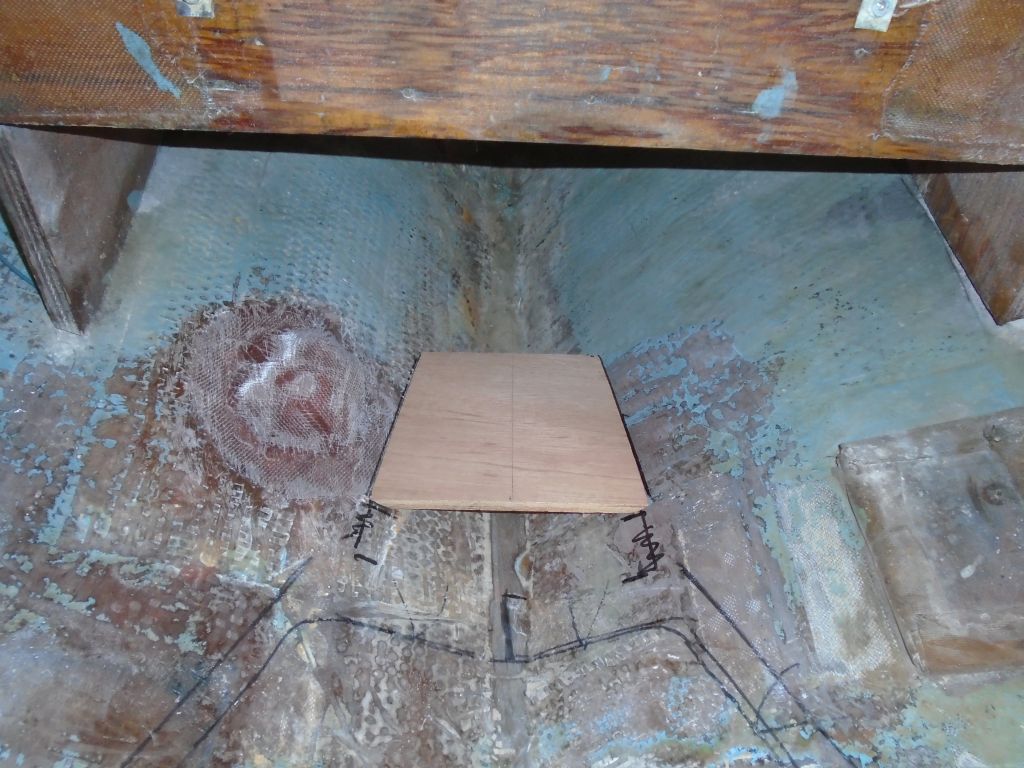
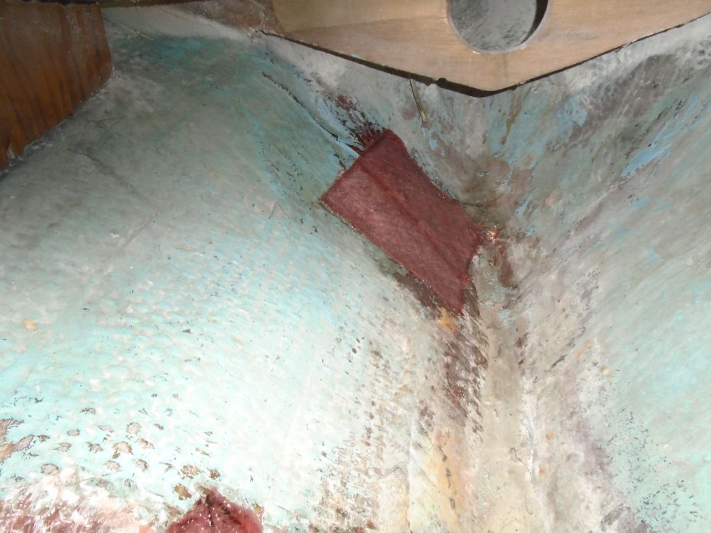
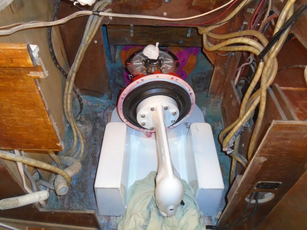
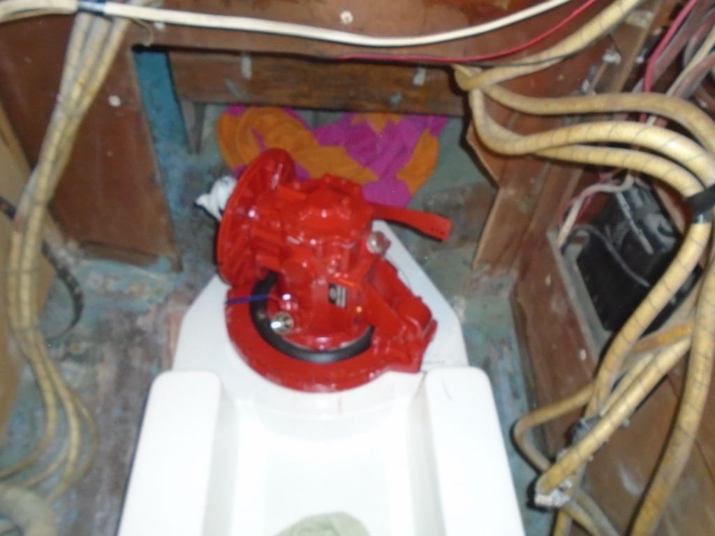
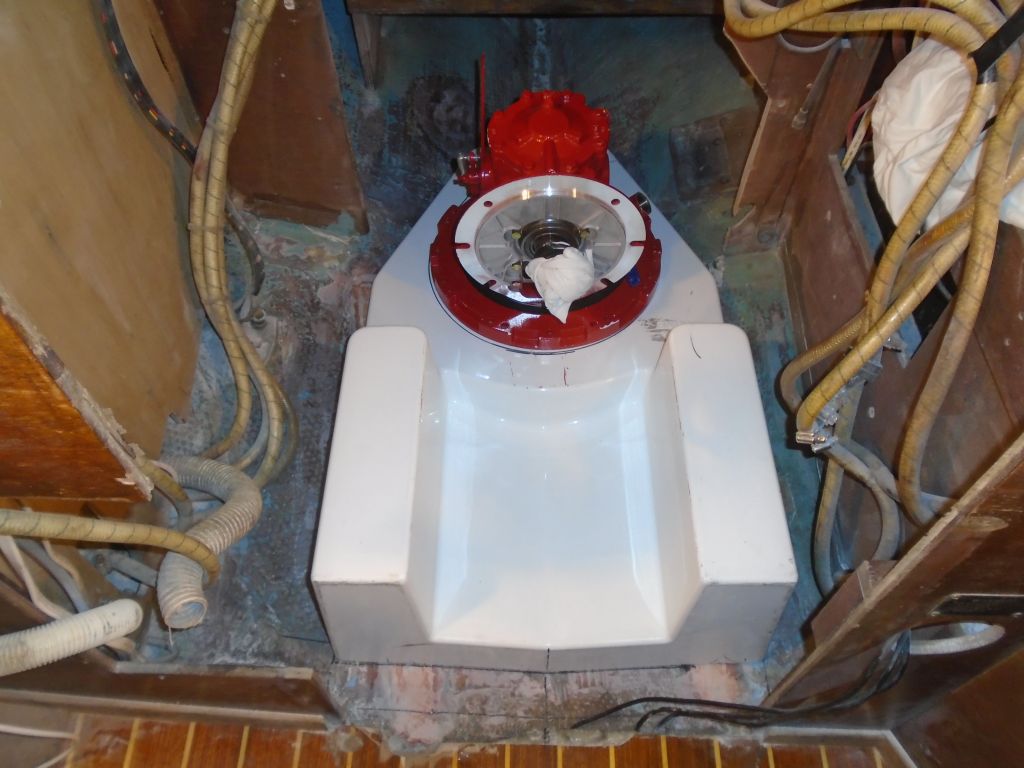
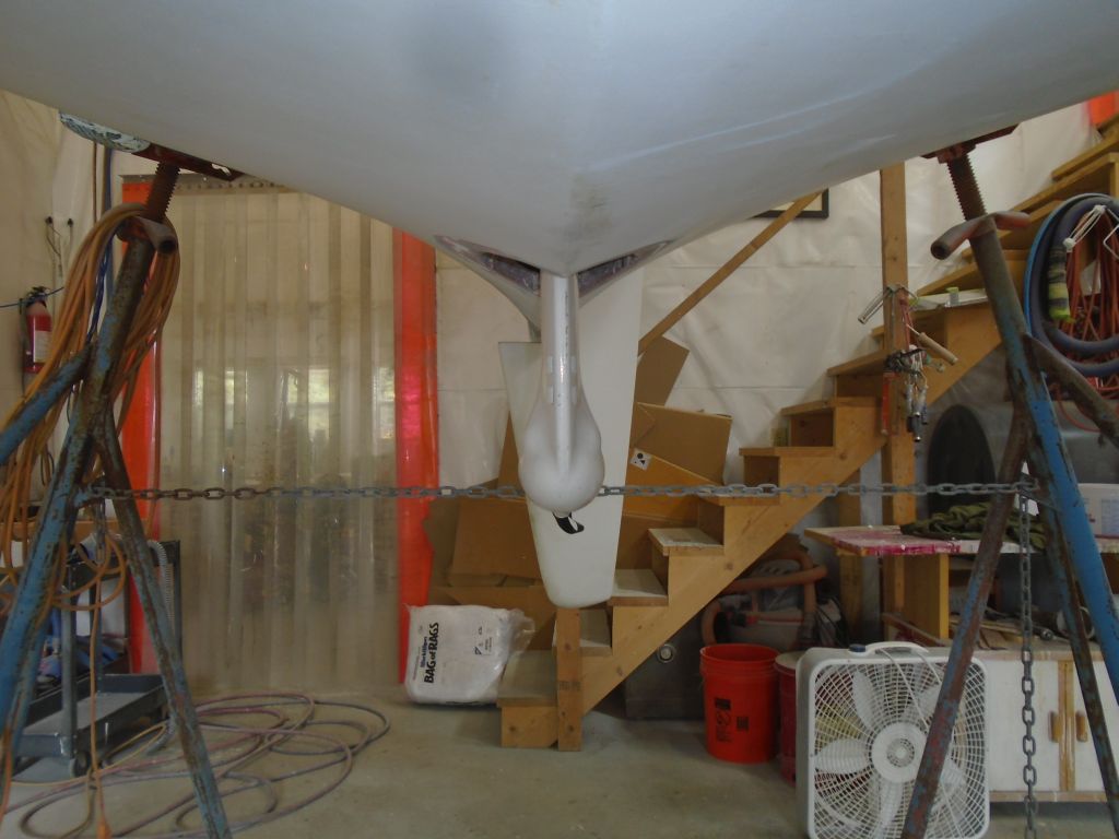
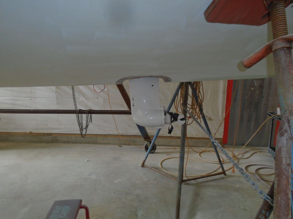
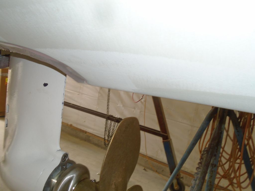
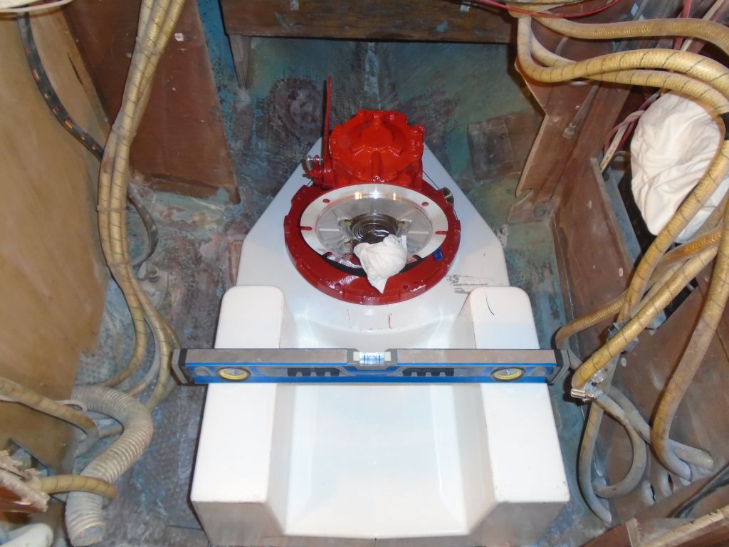
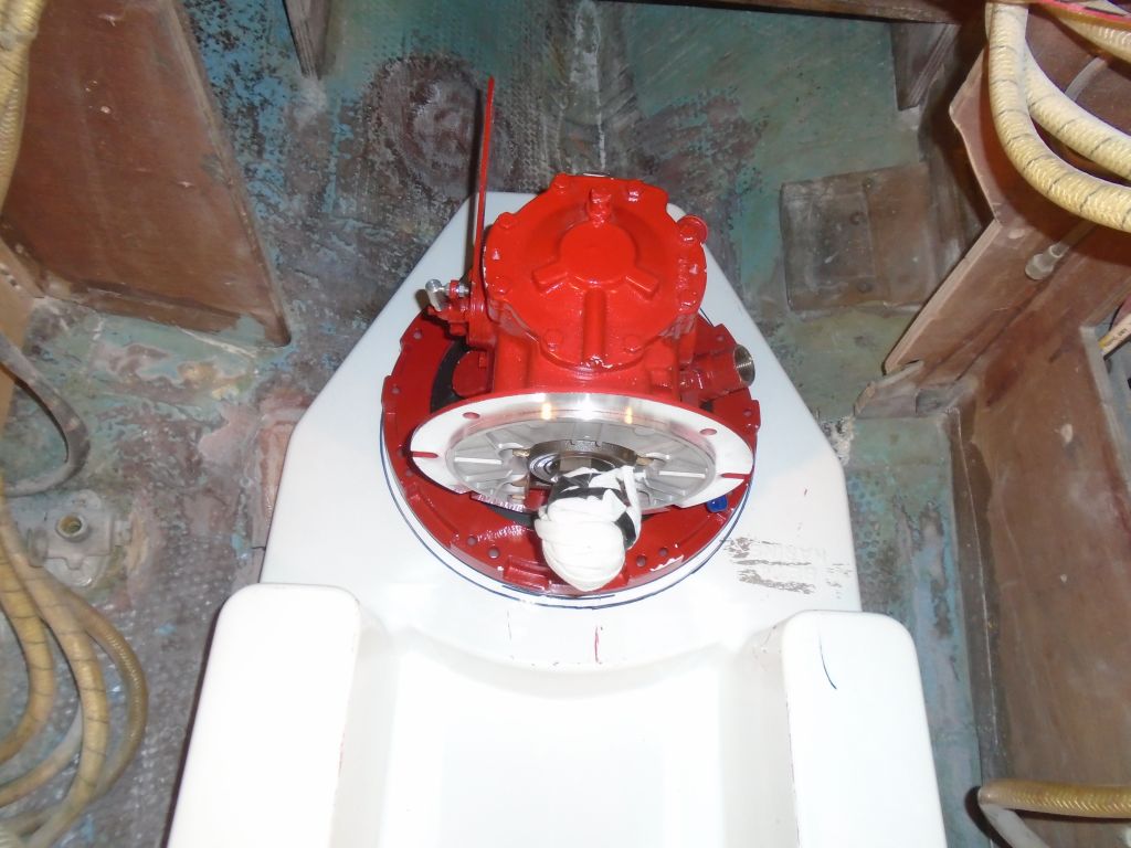
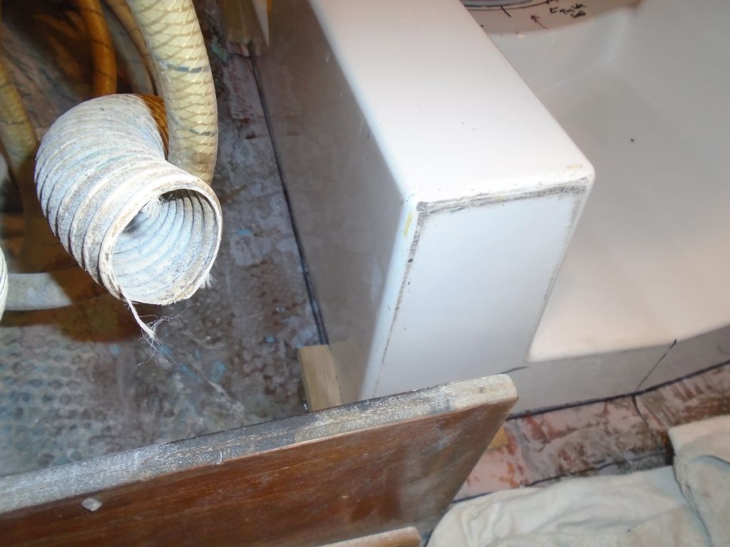
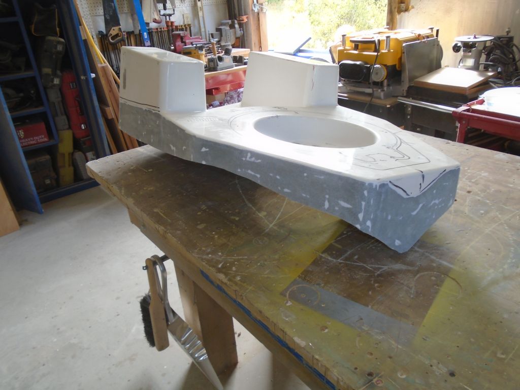
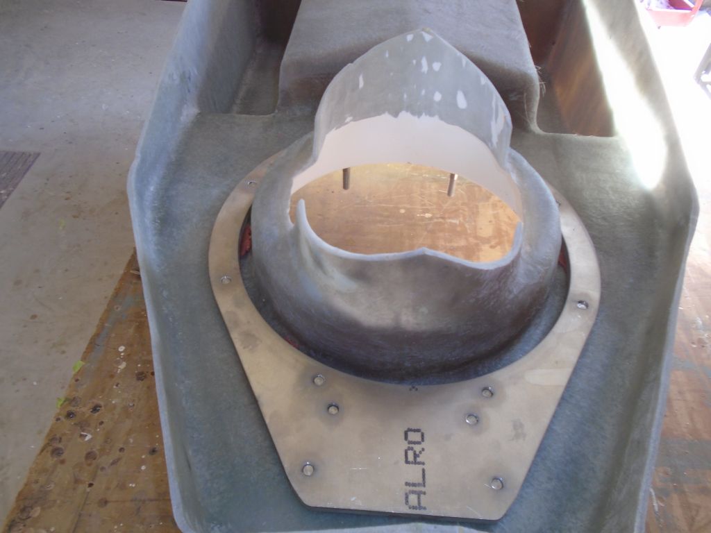
Now, with the foundation back in the boat, I dropped in the leg once more, and threw a small celebration when I could easily turn the unit into the correct position. I made sure the foundation was in the right position and level, and that the transmission housing was aligned where it needed to be before heading below the boat to check the leg position against the boat’s centerline and to ensure it was properly in line. Note that the leg is angling forward just a bit because the rubber bellows allowed the transmission flange to sag without the support of the engine ahead. This would end up vertical once the engine was installed and engaged with the transmission shaft. There was room inside the hull opening to allow me to glass the foundation to the boat after the leg was installed in this way.
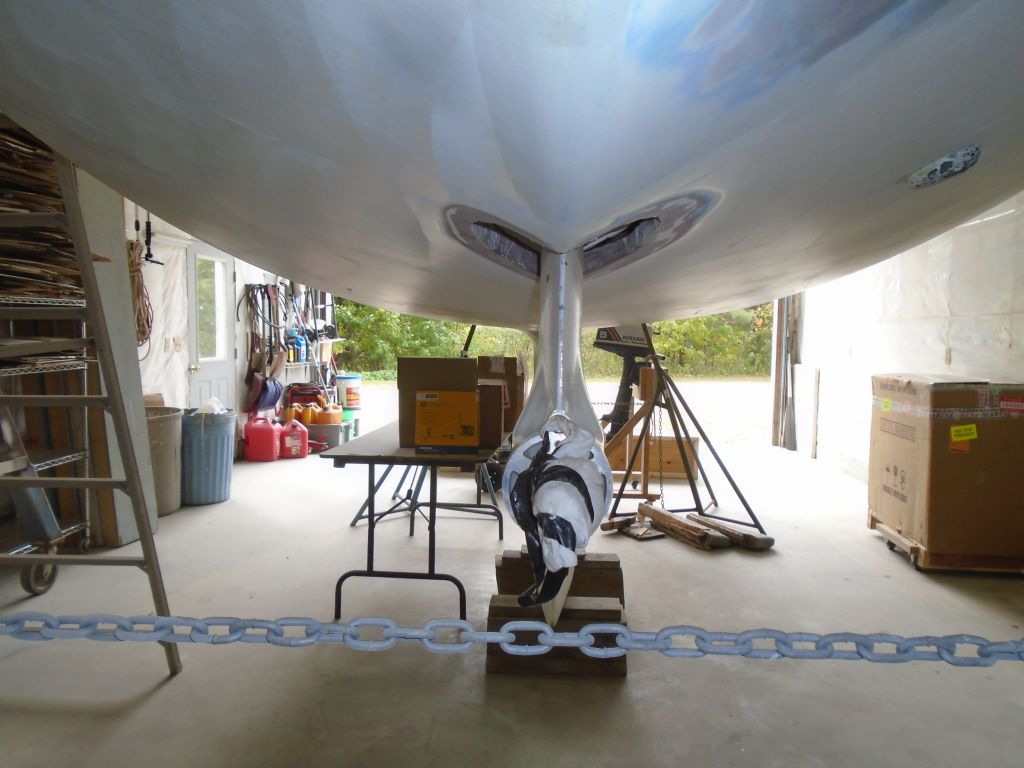
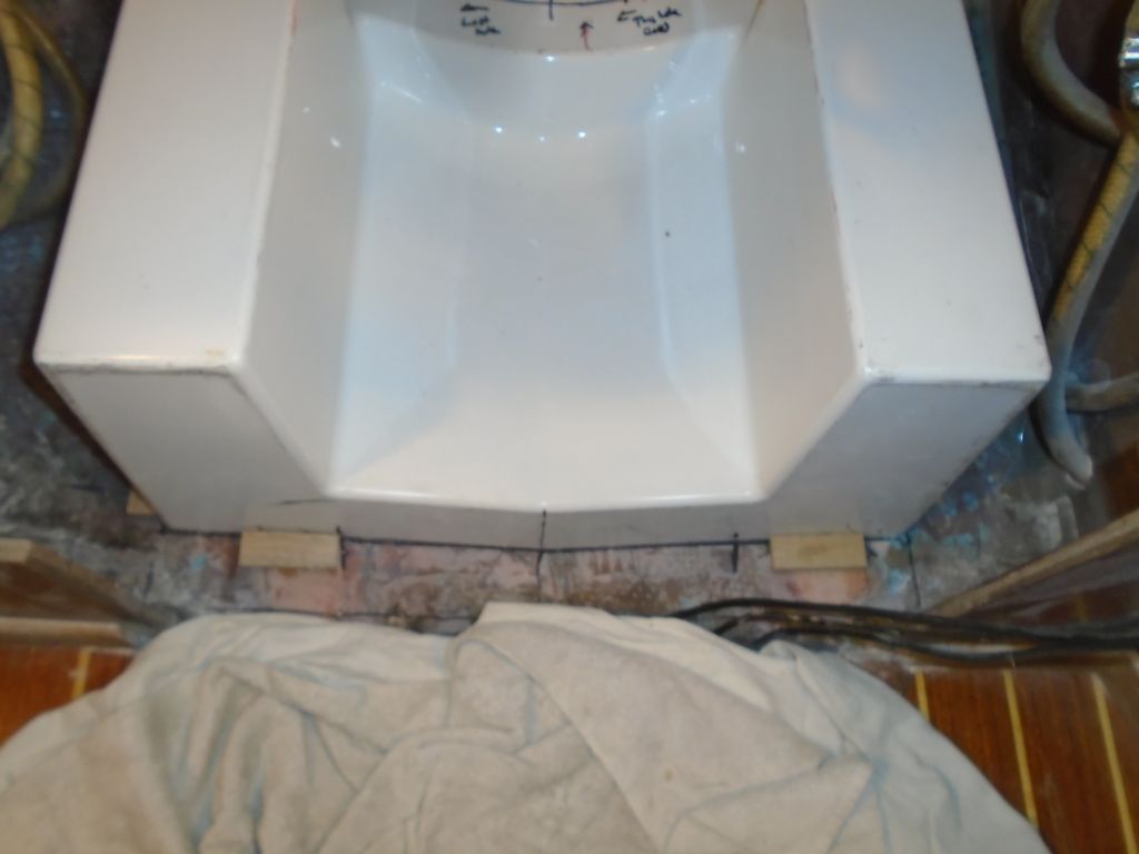
This photo shows the leg propped vertically with some wood scraps.
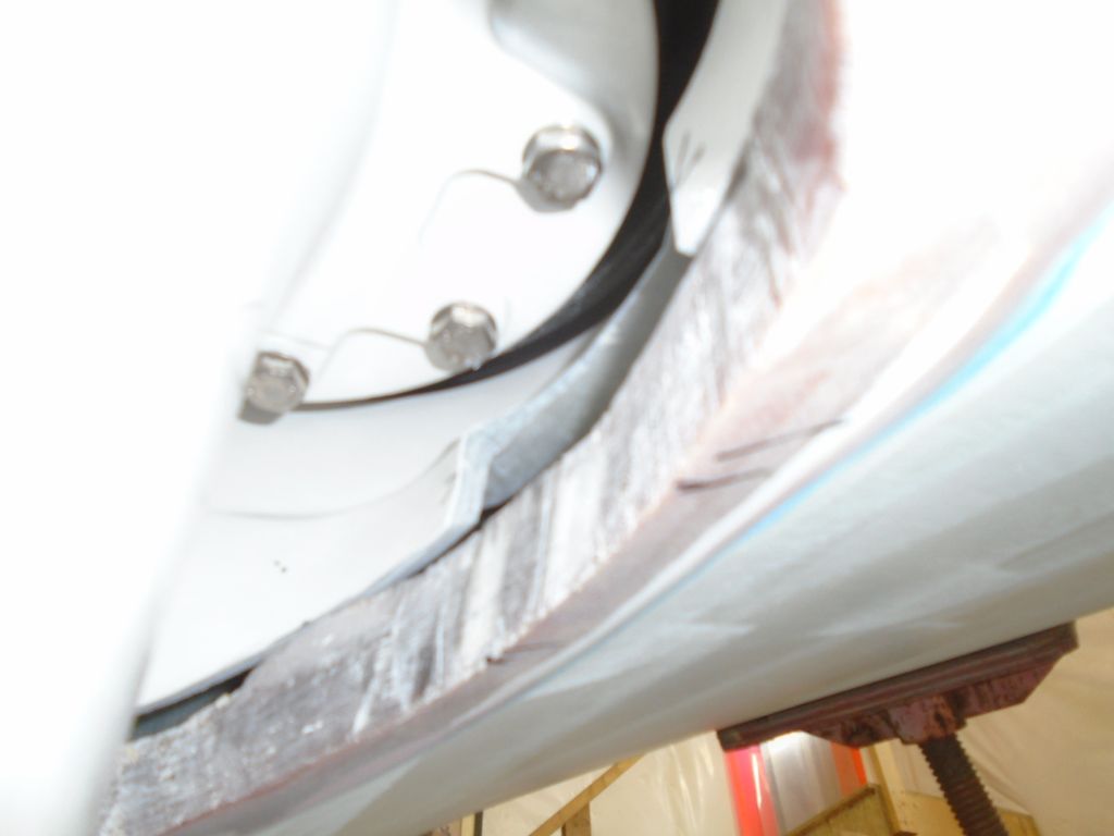
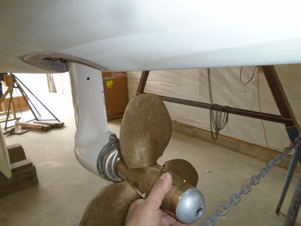
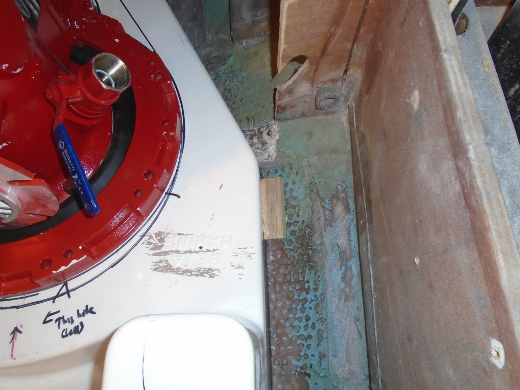
To check again the propeller clearance, there was no better way than to actually hold the propeller in place and see how it looked. Good.
Next, I fine-tuned the position of the leg and transmission till everything was just where I wanted it, and test’fit the exterior rubber boot so I could mark its position on the hull for later prep work. Inside the boat, I hot-glued some little alignment blocks around the foundation to register its position and allow me to put it back in exactly the same place. Then, I made some various reference marks and marks through the transmission bolting flange onto the top of the foundation so I could drill the holes required for the mounting studs and bolting ring before removing–for the last time, I hoped–the transmission and leg, which I stored in its original cardboard cradle on the cabin sole. I removed the foundation down to the bench for further attention.
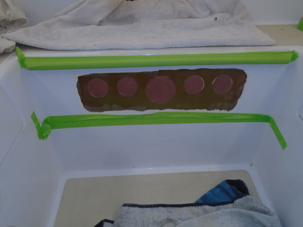
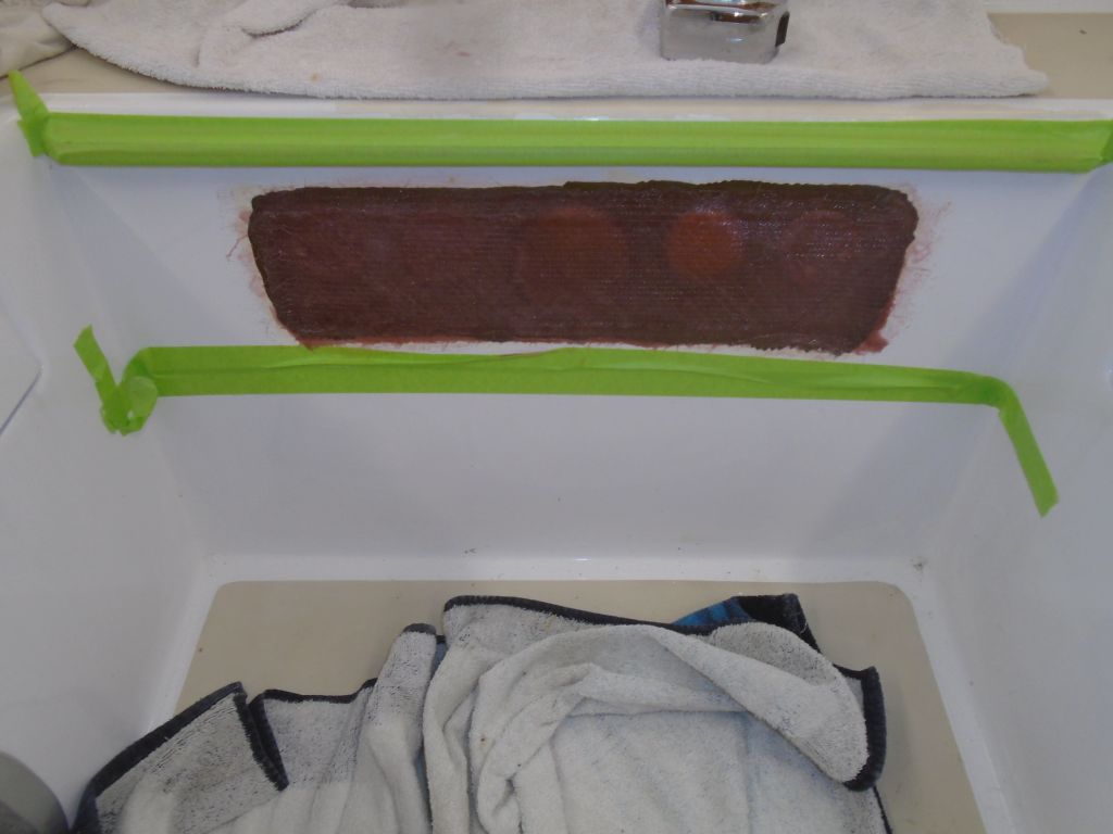
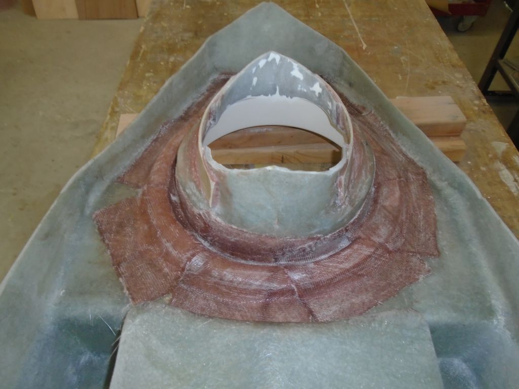
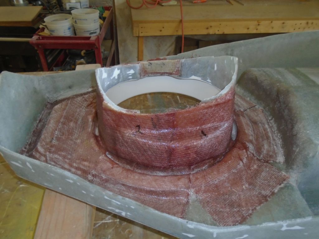
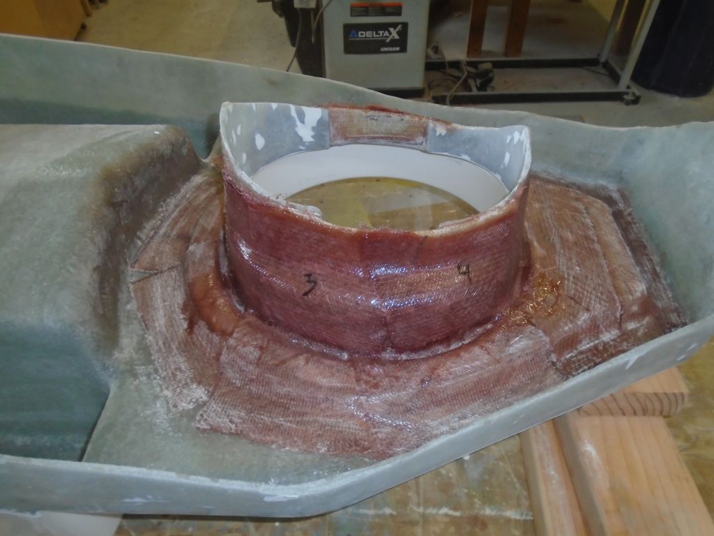
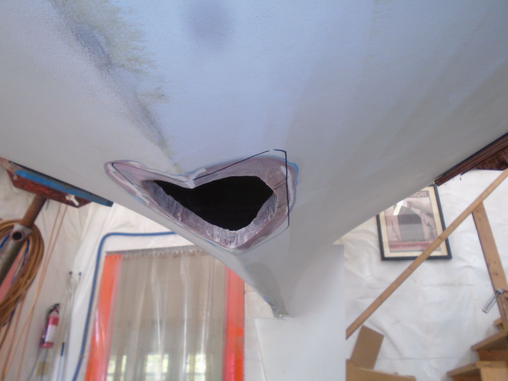
To prepare the foundation for installation, I marked up about 3″ on all sides (or equal to the height of the oil drip pan section and the flat after section), then ground away the gelcoat all around, exposing raw laminate for the best bonding, including inside the leg opening. Meanwhile, I also prepared the hull opening by cleaning up the inside cuts and removing bottom paint from around the hole to allow the rubber boot installation later. Because I planned to glass from inside the opening and foundation out onto the hull a bit, I ground a tapered opening around the perimeter of the hull hole as well. Then, hoping the heavy grinding was done with, and to allow me to work on some other related aspects of the project happily and healthily, I spent a bit of time thoroughly cleaning up the boat and shop from the day’s efforts so far.
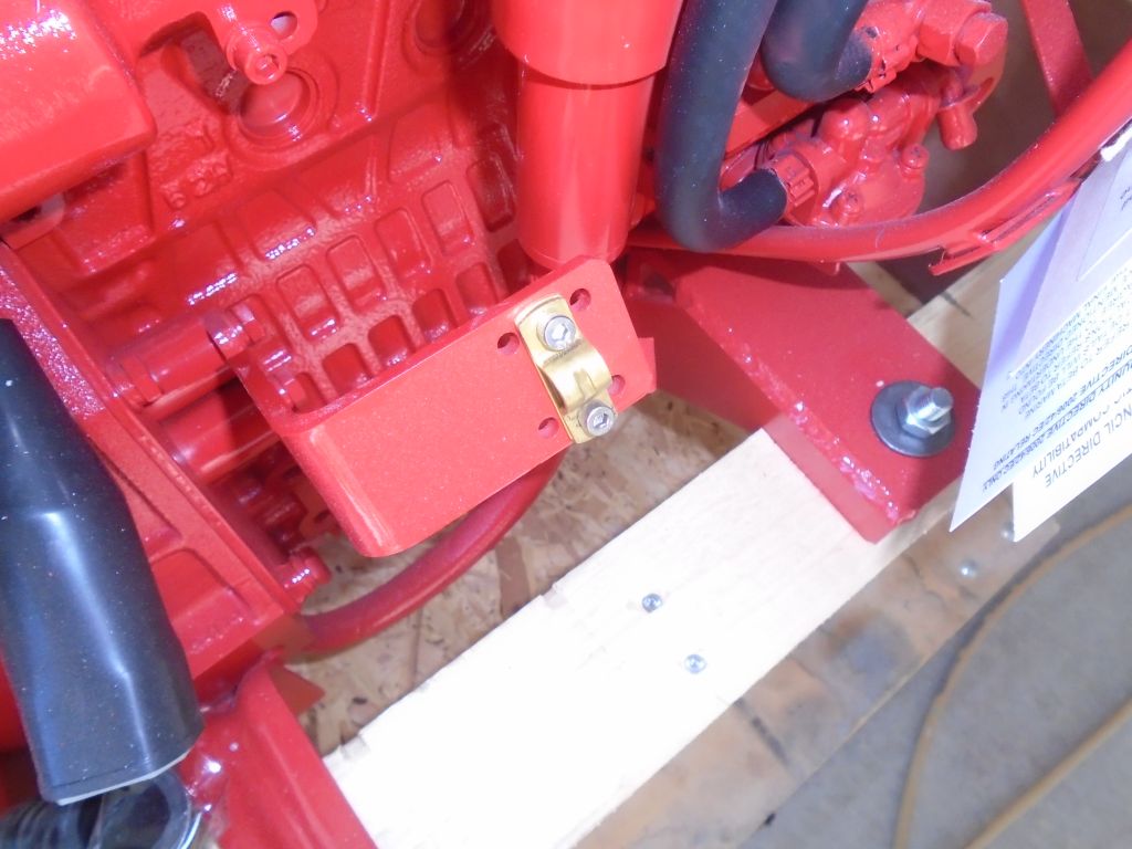
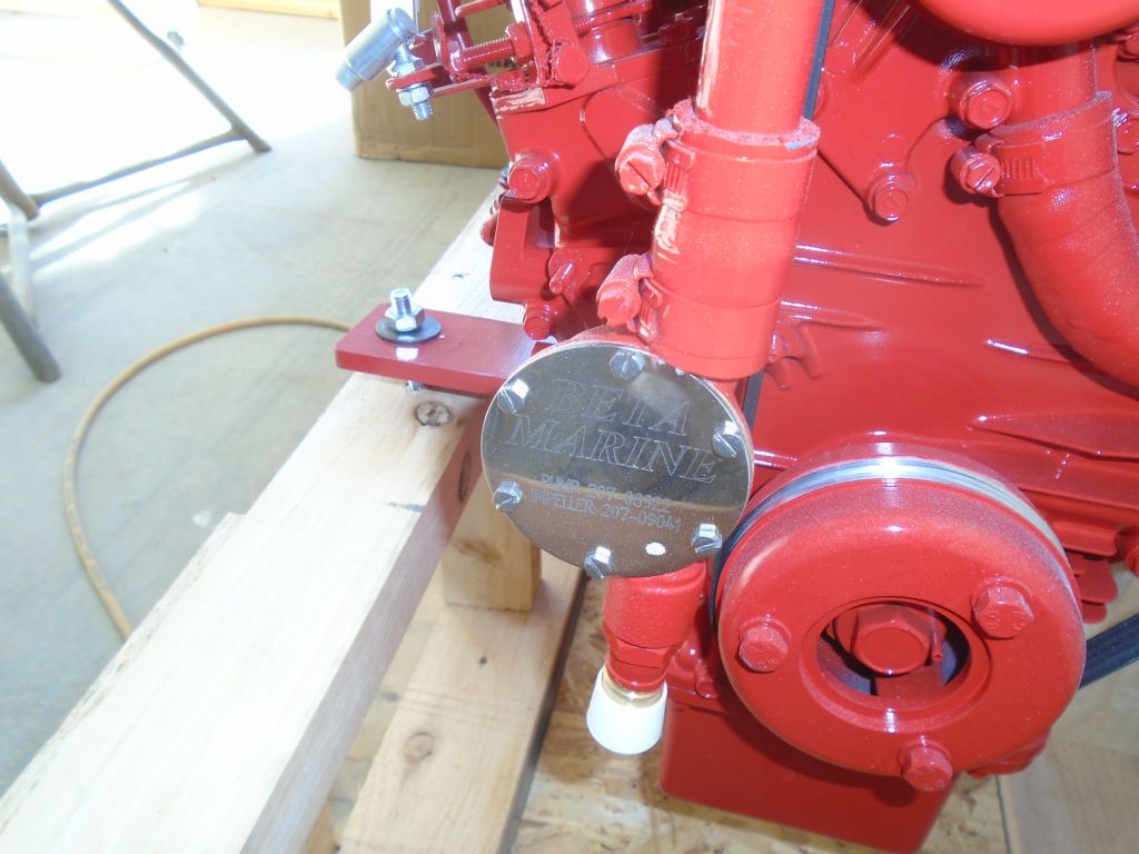
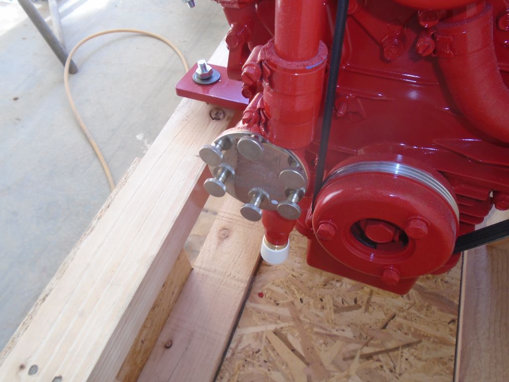
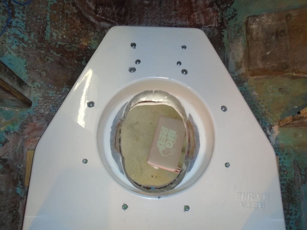
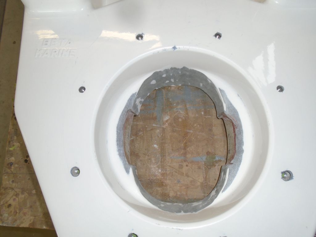
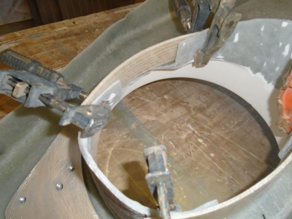
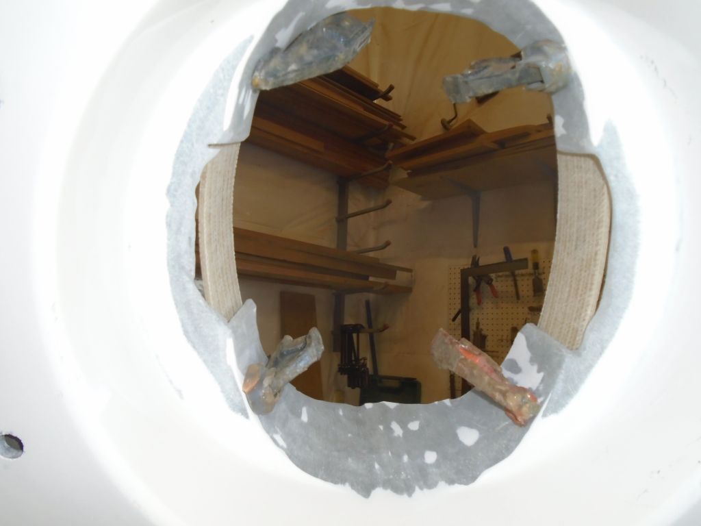
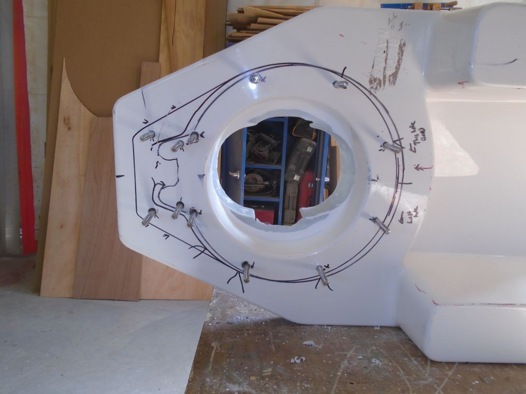
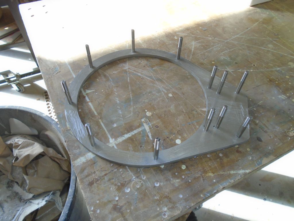
The instructions called for the transmission to be mounted with studs threaded into a supplied aluminum backing plate, which was to be fixed beneath the foundation. This alignment was critical, so I used my reference marks from the transmission flange itself to lay out and drill the holes required from the top of the foundation. I had to enlarge some of the holes till I could eventually install the backing ring–with all studs pre-installed–from beneath. I wanted to be sure the studs fit properly through the holes, as I’d need to install them from above after the transmission was in place, since with my specific installation I’d need to twist the leg around and required an unencumbered surface for this. I felt that if I could easily slide all ten or dozen or whatever studs through the holes all at once in this way, I was as close as possible to the result I needed. Later, I noted that at least a couple of the studs I’d prepared for would not be used in the final installation.
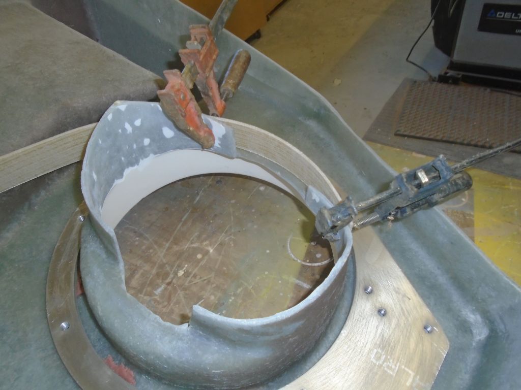
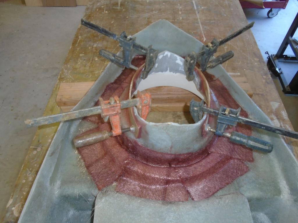
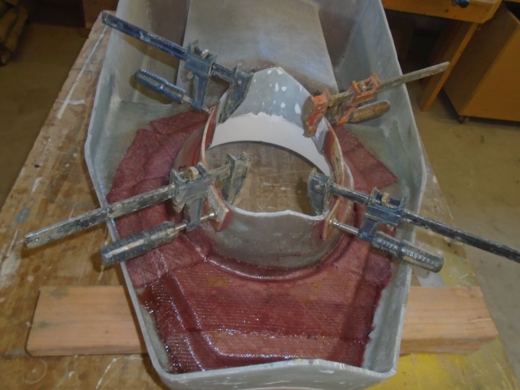
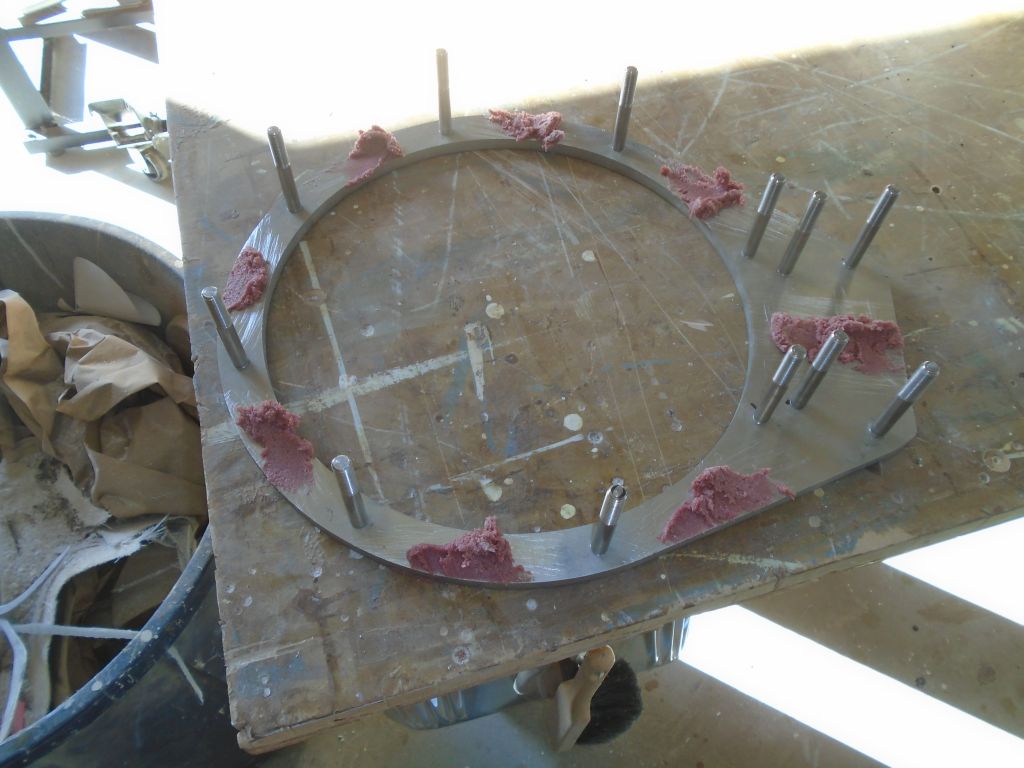
Now I needed to permanently attach the mounting plate to the underside of the foundation. I’d use the studs to hold the ring in place during installation, but because in my installation the studs needed to be removable, I didn’t want to risk their becoming glued into place. So I planned to tack the ring in place with epoxy adhesive first, and finish up the glasswork later. So I lightly sanded the bonding surface of the foundation, and scuffed up the aluminum in way of the spots I planned to tack, then applied some very thick epoxy adhesive, keeping it well away from the threaded holes and studs, and pressed the whole assembly tightly into position, leaving it to cure.
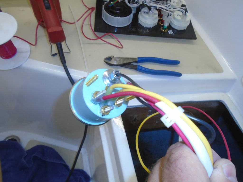
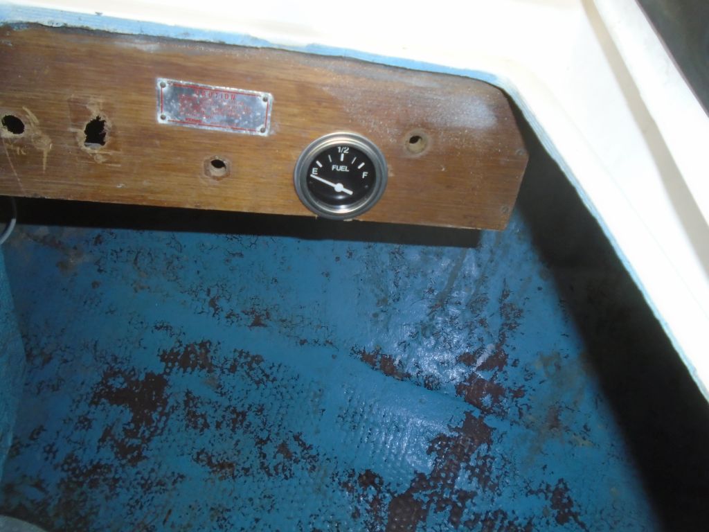
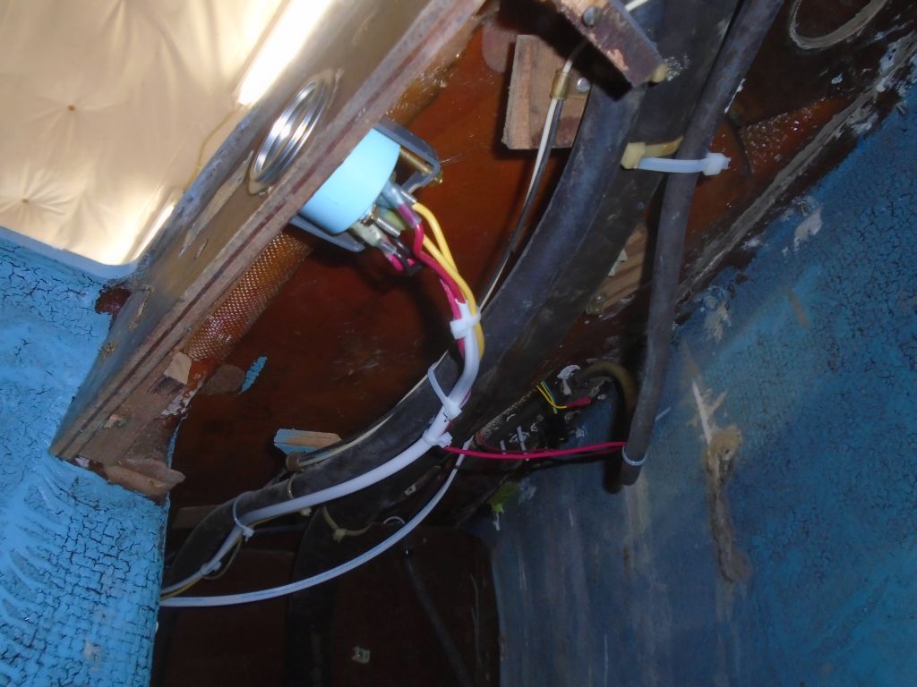
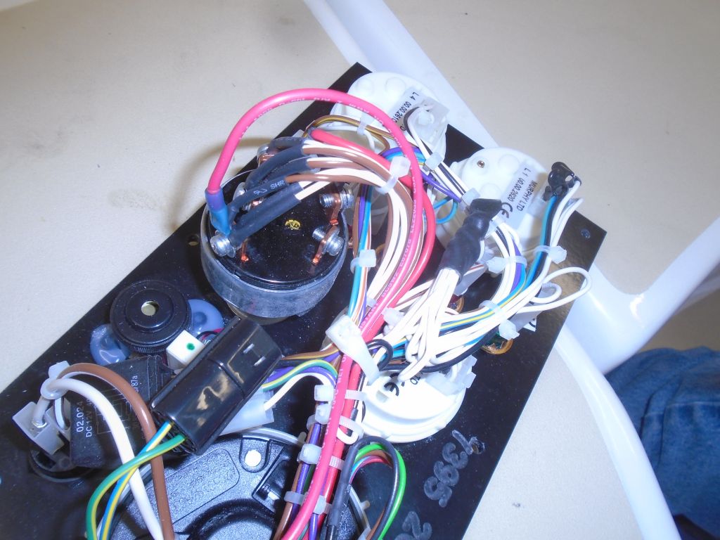
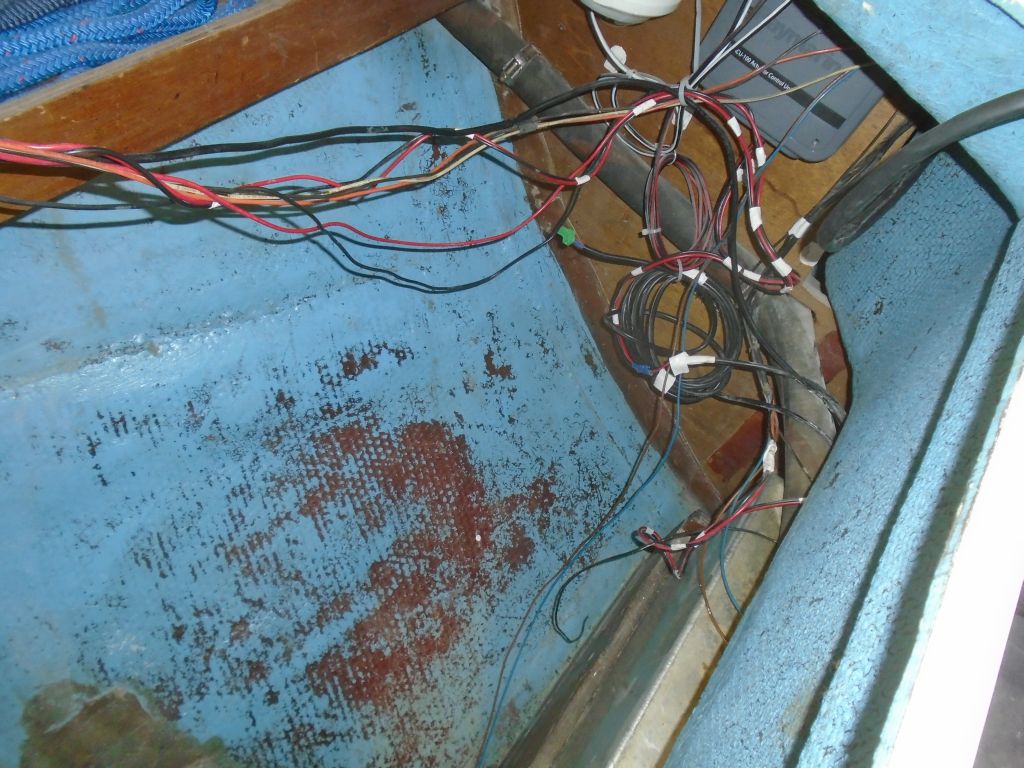
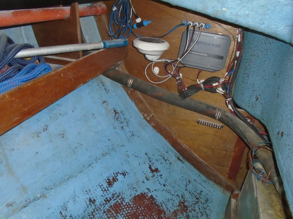
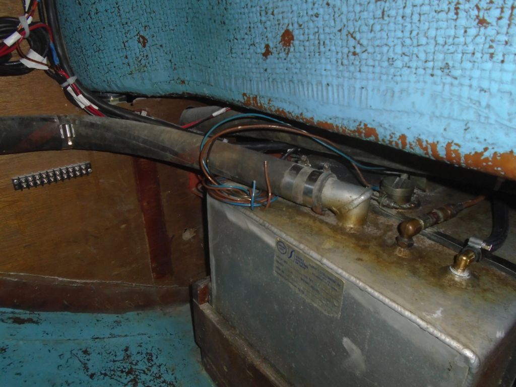
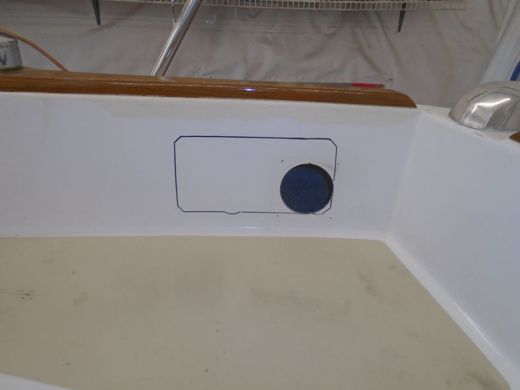
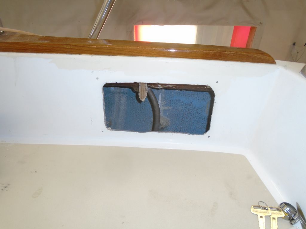
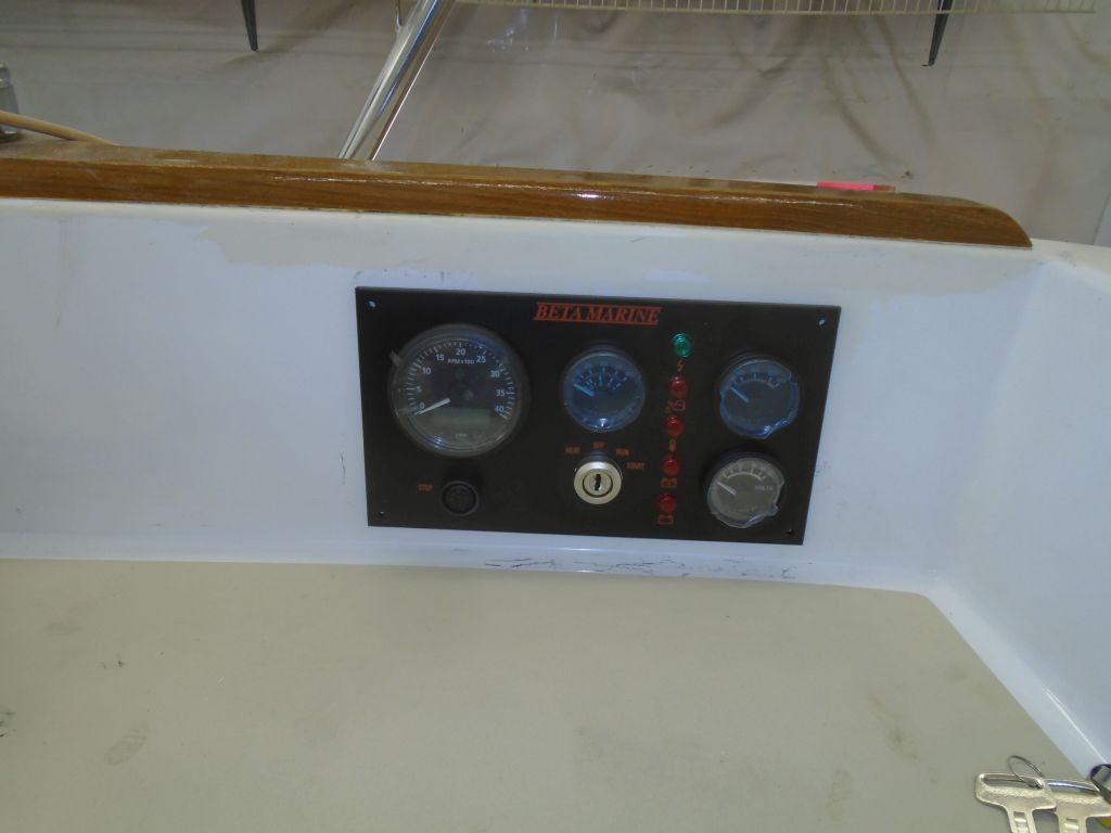
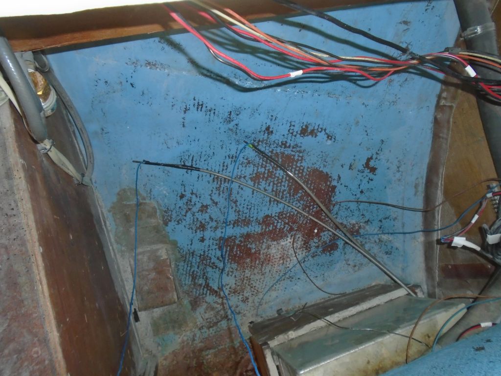
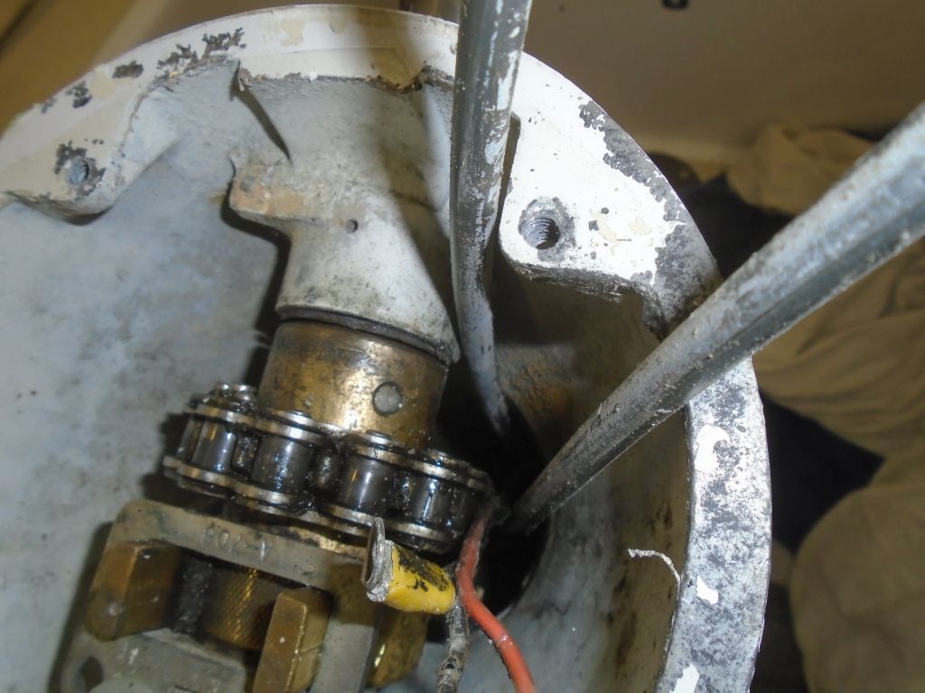
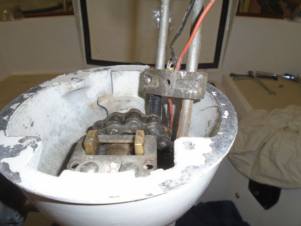
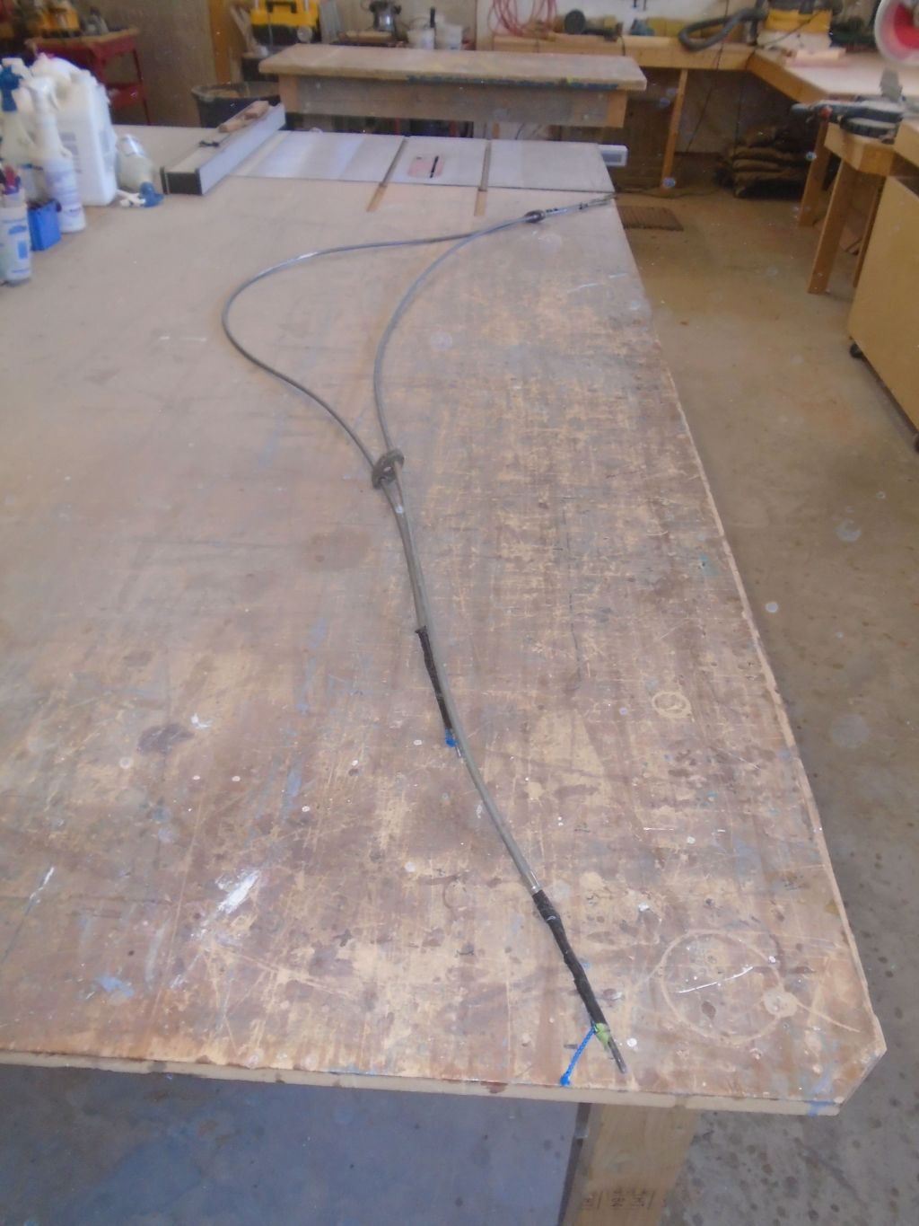
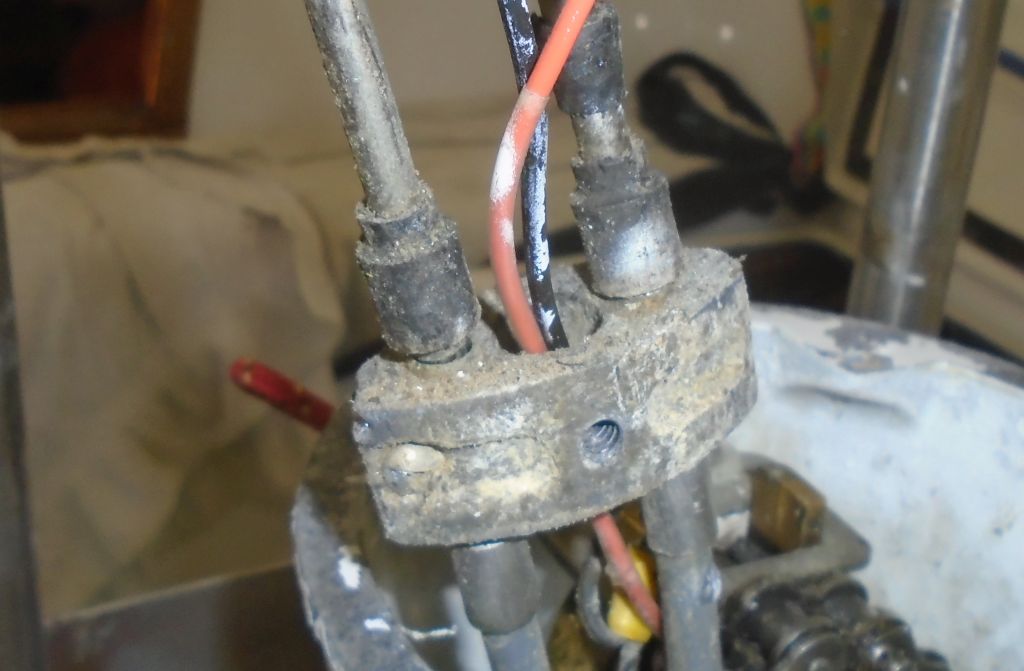
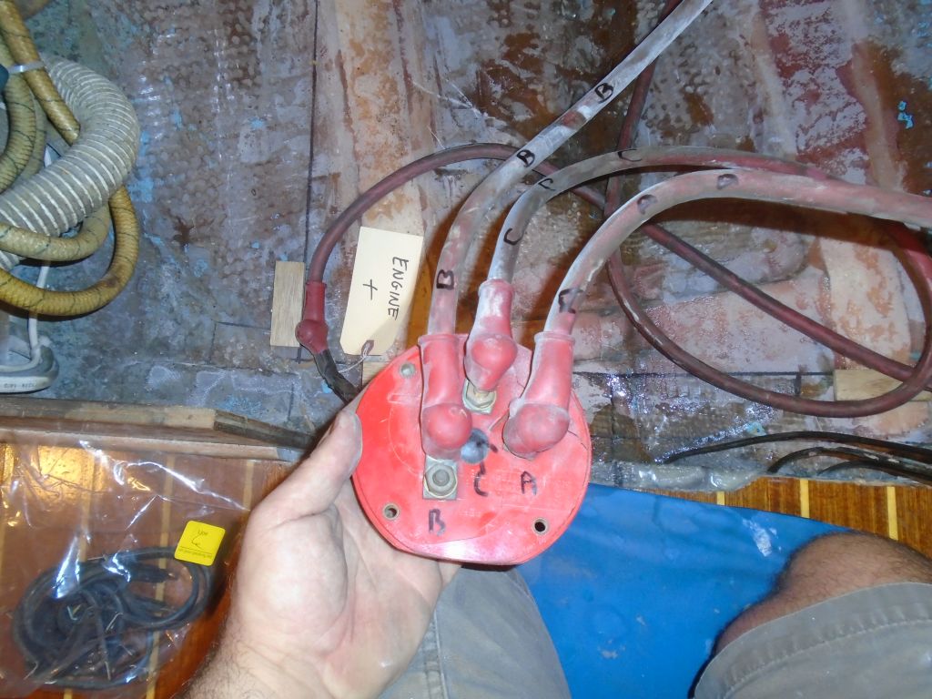
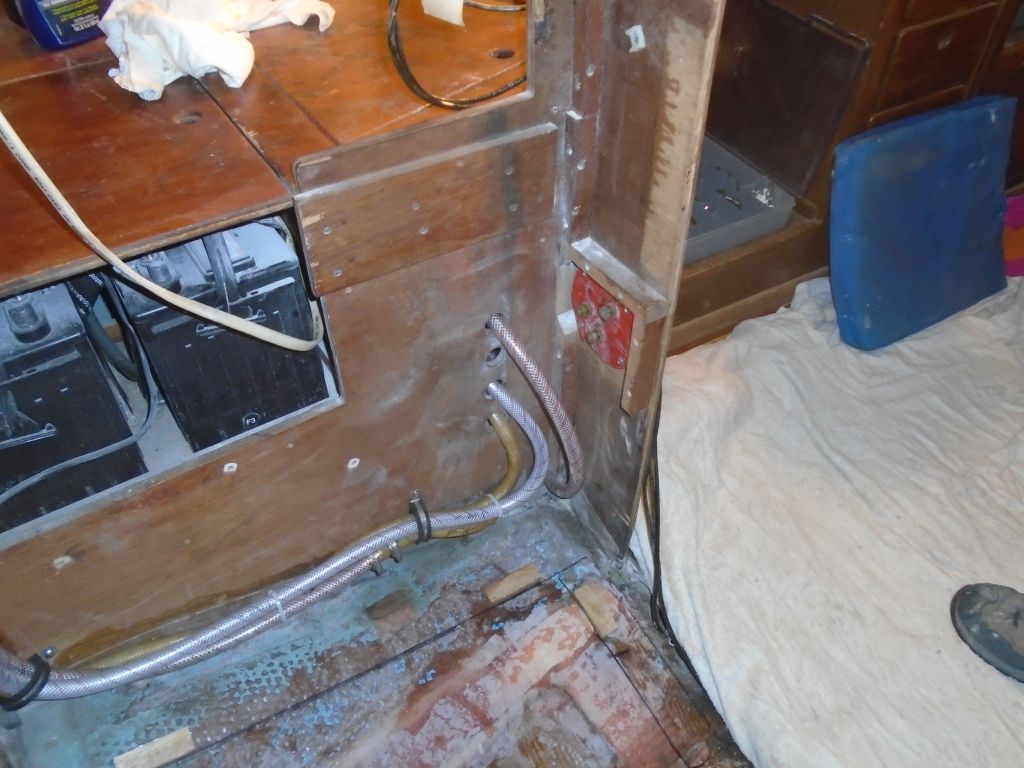
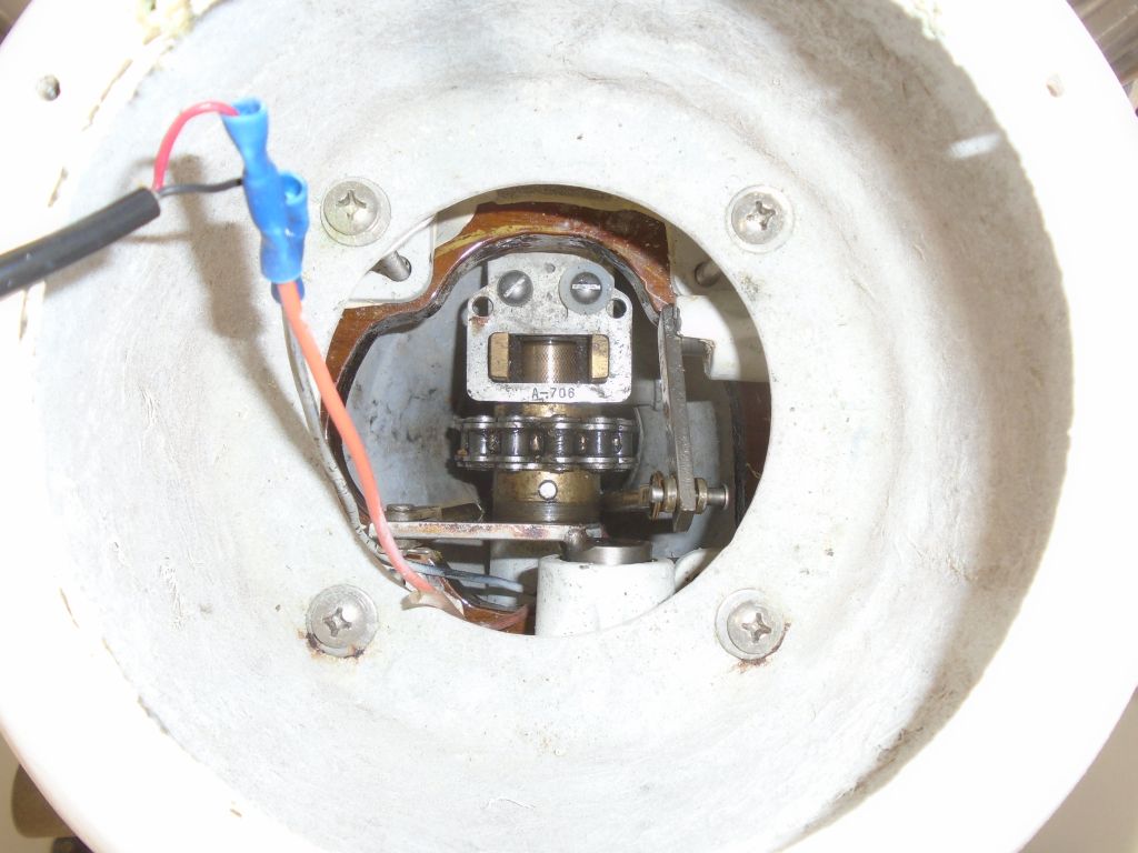
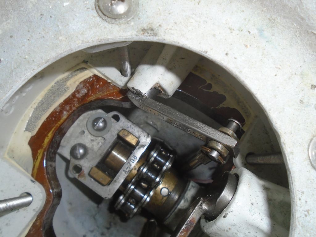
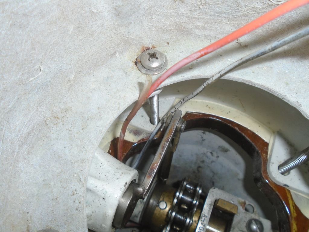
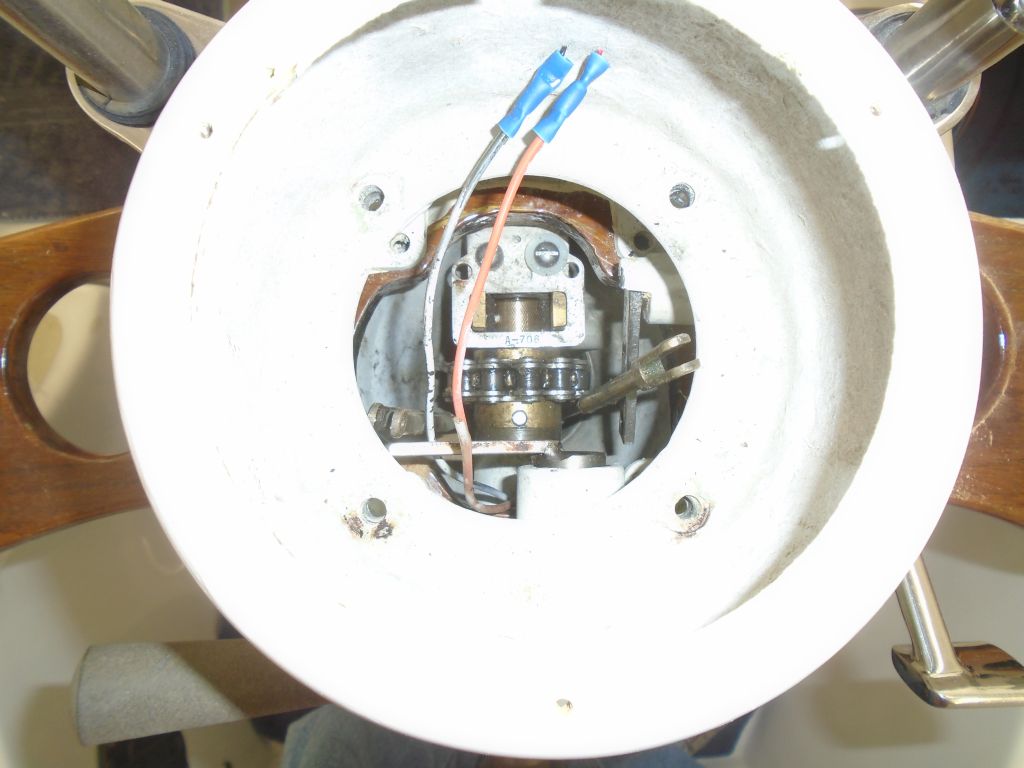
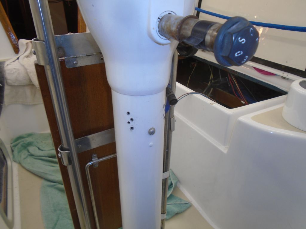
I rounded out the day’s work with some housekeeping chores on the boat, mainly removing an old wiring harness that had once led to the key switch and related items in the lazarette.
Total time billed on this job today: 7.25 hours
0600 Weather Observation:
52°, clouds. Forecast for the day: clouds, low 60s