(page 1 of 27)

Scupper 263

Wednesday

Early in the week before the scheduled and planned departure of Sea Breeze from the shop, the shipper contacted me to ask if the boat was ready (yes indeed) and if it would be OK to pick her up on Thursday, rather than the following Monday.  That was certainly OK with me, but the next day he called again and wanted to move it up to Wednesday, which was also fine by me.

So on the appointed date and time, the first stage of the transport began at the shop with the arrival of the hydraulic trailer that would bring the boat to a nearby (as nearby as anything here) yard, where they’d transfer the boat to a lowboy trailer for the long trip to Florida.

Loading the boat was without drama or issue, and before long she was outdoors for the first time since March 16, 2018, which was the true beginning of the project despite a week or so of work that I’d done the previous fall.  With several breaks in the action between then and the actual completion of the project in March 2020, the boat had regardless been in the shop throughout, and had become a familiar fixture therein.  It was nice to see her back out in full view and daylight once more.  I took a video of her emerging from the shop, but alas, something went wrong (user error) and the only usable footage was 4 seconds at the end with the camera pointing at the ground.  (I come from the pre-video era, folks.)

Once outdoors, we loaded the mast on the outriggers on the trailer, and the driver strapped down the boat and made other final preparations.

The truck departed around 1245.  From here, once past my traditional (now with barely an opening in the brush) final departure photo angle at the end of the driveway, the boat was beyond my purview, but I looked forward to hearing of her successful arrival in Florida, and her successful commissioning shortly thereafter.

Return to Scupper Home Page

Scupper 262

At the end of March and with the completion of the project, I prepared the boat generally for transport to the owner’s new location in Florida.  I packed various loose gear into several lockers in the boat, and filled the cockpit lockers with sails old and new, stowing everything carefully to prepare for the boat’s long over-the-road journey ahead.

With the country embroiled in the various lockdowns and restrictions related to the advent of COVID-19 in March, along with additional complications at the owner’s end and this country’s utter inability to better handle (or in certain circles even properly acknowledge) the spread of the virus, transportation of the boat was delayed for several months, during which time I maintained the boat indoors for protection, keeping the batteries topped off with weekly charging.

Towards the end of the summer, the owner, having moved to Florida and taken care of the boat registration  and other requirements, scheduled a transport date of August 24.  With this date a few weeks ahead, I took care of a short list of final preparations, including storing the full-length mainsail battens and main boom in the cabin, all carefully secured and chafe-protected within.  I also moved the mast around to the front of the shop where it’d be readily accessible for the truck.  Back in March, I’d wrapped the spars in plastic for protection during transportation; with the delay in shipment, I covered the stored mast with additional heavy tarps for extra protection and to keep the clear plastic from falling apart in the sun and weather, but now I removed the excess tarps.

Also, at the owner’s request I installed the garboard drain plug in advance, so the commissioning yard wouldn’t have to worry about its proper installation.  I used a small amount of sealant on the threads, and screwed in the plug tightly before coating the plug with bottom paint when I took care of the jackstand patches.  Since this particular hard bottom paint had a limited time it could be exposed before launching, the owner chose to have the commissioning yard apply a second and final coat over the whole bottom in Florida.

On deck, I made sure all the locker lids and companionway were secured properly, and added small bolts through the locking holes just to ensure the latches couldn’t spring open unintentionally.  With all loose gear, canvas covers, and so forth stowed below, and the tiller secured, the boat was ready above and belowdecks for her relocation.  Note that for transport purposes, I chose to use the ugly old plywood companionway drop board, keeping the newly-made versions safely in the cabin.

With the new registration from the owner, I had a set of numbers made up for the bow of the boat, using the same gold leaf and dark blue outline as with the name on the transom, but in a basic block to satisfy the display requirements.  With an indicated state requirement to display properly the HIN on the transom–if there’d ever been a stamped or molded number there it was long gone by the time I started the project–I had a set of the numbers made up from vinyl and installed them on the upper starboard side of the transom as well.


Scupper 261

Final Days

After many coats of varnish, the tiller was complete and ready for final installation, which I began by installing the bracket for the tillerpilot; I’d marked and drilled pilot holes earlier, so now I could just screw in the bracket.  Afterwards, I secured the bronze tiller strap, and installed the tiller in the cockpit.

Next, I installed and hooked up the tiller pilot, and gave it a quick test run from side to side to confirm operation.  With the tiller bracket now permanently in place, I checked the fit of the canvas tiller cover, which fit well around the bracket as intended.

I spent a little time loading on some of the gear that went with the boat, including new running rigging (sheets etc.), some of the mast hardware (wind transducer, Windex, VHF antenna), boom vang, and other sundries, storing them carefully in various lockers in the boat.

After multiple coats of varnish on all sides of the two new companionway swashboards, I finished up the screen unit by stapling screening to the back side of the assembly, then installing some varnished trim pieces around the perimeter.  This represented the last new work on the boat, and on the project.

Total time billed on this job over the final days:  5.75 hours

Scupper 260

Monday

At the owner’s request, I’d asked my intrepid canvas contractor to make up several covers for the winches, tiller, autopilot, and the windlass.  True to form, he exceeded expectations with some really nice work on these covers, delivering them all only a few days after he came by to measure and pattern.

The owner had also requested some simple friction-fit foam fillers to use for privacy in the small elliptical ports.  These weren’t fancy, but they did the job well.  There were enough of these for all the ports, plus an extra or two.

Meanwhile, I continued working with a local sign shop to finalize the lettering.  The owner’s choice of script for the new name meant that I felt it was worth various extra efforts to ensure that the name was the “right” size given all the considerations (transom size, individual letter size, overall appearance of the graphics), and properly matched the arc of the deck camber at the top of the transom.  To this end, the sign shop produced a cheap test version on throwaway vinyl that I picked up and tried out on the transom.  The owner liked the shape and size, so we went forward with the final version shortly thereafter.

With the final version of the name on hand in the owner’s choice of gold leaf with dark blue outlines, I finished up the installation a couple days later.

With the accessory installation brackets for the tillerpilot on hand, I could finish up its installation now.  The way the geometry of this boat worked out, the standard tillerpilot required  an under-tiller mount, plus a pushrod extension, plus a cantilever bracket for mounting the outboard side of the tillerpilot to the side of the cockpit coaming.   I put the starboard cockpit cushion in place temporarily so I could ensure the tillerpilot cleared the cushion when installed, which the rise of the tiller dictated anyway.  I installed the 4″ pushrod extension to the end of the tiller, then extended the pushrod about halfway through its stroke for the initial setup.

With the tiller temporarily in place, and measuring the required 18″ distance forward from the center of the rudderpost, I made a mark on the tiller where the pin for the tiller end of the unit needed to go, and taped the new bracket in place beneath in the proper position–both for testing and minor adjustment and because I wasn’t ready to permanently install the bracket, since the tiller needed a few more coats of varnish.  I put the starboard cockpit cushion temporarily in place to ensure that I mounted the tillerpilot above the cushion, which the shape of the tiller dictated anyway.  I installed the 4″ pushrod extension to the end of the tiller pilot, then spent quite a bit of time fussing with the overall setup to determine the final mounting location for the coaming-mount bracket, which, because of the fore and aft angle of the coaming, required an angled spacer block behind.

At length, after one failed version of the angled block and various trials, I determined the final mounting location and dry-fit the bracket so I could permanently mount it.  This location was clear above the cockpit cushion, in line with the pin on the tiller itself, and met all the other installation criteria.  The tube containing the various cantilever mounting pin locations was removable from the base, leaving a relatively clean installation when the tillerpilot was not in use; the cockpit locker lid just cleared the assembly when installed, which was fortunate but happenstance since the geometry of the cockpit and tiller arrangement dictated its position.

With the bracket permanently installed with sealant, bolts, and a backing plate, I fitted the tillerpilot and double-checked its position.  With the tiller centered, the tillerpilot (i.e. the pushrod) was at 90 degrees to the tiller, as required.  I’d await an electrical test till I could mount the tiller bracket to the tiller once the varnish work was complete.

With these final installations complete, my work list came virtually to its end, other than some final loading onto the boat and ongoing varnish work.  To wrap things up, during the afternoon I picked up the boat’s new sails from the sailmaker.  I’ll wrap up any lingering work or details in a final post as progress dictates.

Total time billed on this job today:  7 hours (Over a couple days)

0600 Weather Observation:  15°, mostly clear. Forecast for the day:  Sunny, 36°

Scupper 259

Tuesday

After a trip out into the world to drop off the transom template at the sign shop, I spent a little time aboard the boat to install new ring pulls on the table top storage bin.  The new pulls were slightly larger in overall diameter than the old, though the same as the pulls I’d installed in the cabin sole hatches, so I had to enlarge the recess by just a bit, which I did with a Forstner bit in a drill press.  Afterwards, installation was straightforward.

Somehow, the boat and table had made it 42 years without someone installing a way to secure the table leaves when lowered; the banging leaves drove me crazy in only a matter of seconds even with the boat on the hard.  To deal with this, I installed a pair of simple brass hooks to secure the leaves in place when lowered, tightly against the table frame at the aft end.

I sanded and prepped the companionway boards and tiller for their next coats of varnish, but was awaiting new varnish so I postponed the application till later.

Total time billed on this job today:   2.5 hours

0600 Weather Observation:  32°, mostly cloudy.   Forecast for the day:  Mostly cloudy, 55°

Scupper 258

Monday

Over the weekend, I applied another coat of varnish to the tiller (4) and swashboards (2).  So to start the day, I lightly sanded these again, and applied the 5th and 3rd coats of varnish, respectively.

I decided to make a simple template of the transom so I could help the sign shop make the lettering to the correct arcs.  In this case, the owner’s choice of lettering featured an interconnected font, and I felt it was worth the extra effort to ensure that the vinyl was properly cut.  With a piece of leftover pattern plastic, I marked the key points on the transom, mainly the top edge (deck camber), the centerline, and the two corners where the deck met the hull.  With these marks made, then down on the bench I could lay out a horizontal line between the two transom corners and determine the height of the deck crown (9″ over a width of 74″).  I made plans to bring this template to the sign shop in the near future to finalize the graphics.

I reinstalled the reinforced starboard cockpit lid, one of a few small and otherwise insignificant tasks I expunged from my short list this day.

I spent most of the rest of the day’s time getting the boat ready for “being complete”, picking up where I left off.  I’d gotten the interior mostly in order and put together last time, but had run out of time before I could clean up the decks.  Now, I removed most of the protective plastic I’d had in place since shortly after the paint was complete, leaving only the cockpit for now.  It was nice to see the decks fully exposed again and with the deck hardware in place.  This meant that afterwards, I could dismantle the staging to make more room around the boat, and to prepare her for a yard move later; for now, I planned to leave her in the main work bay, as current weather aside (it had been mostly warmer than usual and no snowstorms for some time), it was still winter, and I didn’t want to expose the boat to the elements just yet if I didn’t have to.

That meant that I would be working in my other bay for the upcoming projects, and to prepare that space for the other boats, I was ready to move Scupper’s mast out, which had been in the bay since mid-winter at the beginning of the mast-painting project.  Now, all spar-related work was done, and to prepare the mast for moving outdoors as well as for transportation whenever that happened, I wrapped the mast and furlers in plastic sleeves, securing the plastic and rigging within well and often with tape and small stuff as needed protect the mast (and boom).  Afterwards, I moved the spars outdoors where they’d await the boat’s departure.

Total time billed on this job today:  5.5 hours

0600 Weather Observation:  32°, mostly cloudy.  Forecast for the day:  Partly sunny, 60°

Scupper 257

Friday

The paint work on the liner cover plates was complete, so to begin the day I installed the various pieces throughout the boat.

Afterwards, I cleaned up the whole interior so I could get to work on installing the upholstered backrests/locker doors in the main cabin, and installing the other interior cushions to complete the work in the cabin.  The backrests went on quickly with four bolts each, since they’d already been fitted once before, so it was simply a matter of the final installation this time around.

Before completing the cushions, I reassembled the cabin table down in the shop, as it was still in pieces from the refinishing efforts earlier, then installed the table on the cabin sole, securing it to its original brackets that allowed quick removal of the table to access the bilge beneath as needed.  Because one of the brackets landed on the new, larger bilge hatch I’d built, I secured the bilge hatch with a pair of screws to ensure that everything was as stable as possible.  The old pull rings for the table top storage compartment were in overly-weathered condition, so I chose not to re-use them and ordered replacements that I’d install once on hand.

The table installation brought to light an unwelcome surprise:  the companionway ladder/head door didn’t clear the back of the table by about 1/4″.  This might be because the new ladder assembly was slightly larger and different in shape than the original, or perhaps the table was in a slightly different position than its original, but whatever the cause, it required me to cut away and shape the offending corner of the door/ladder so it would clear the table and operate properly.  With the table out of the boat for so long, and basically no experience in the cabin with the table in place (I’d removed it forthwith at the beginning of the project because it was so much in the way), it hadn’t even occurred to me that clearance would be an issue.  Education never ends, nor do the continuing surprises that small boats hold in store for the unwitting.

Fortunately, it was just a small modification, after which the door operated as needed, but I’d have to touch up the finish at the newly-changed corner.

With the table in place, the protective floor covering and masking tape out of the way, and the whole cabin vacuumed and cleaned up, I could now put the cushions in place to bring the whole cabin together for the first time.

This all took surprisingly long, but the project list was nearly fully expunged by this point.  I had a short list of small jobs to complete over the next week or two, but expected this to be my last day working full-time on Scupper.  After unloading most of my tools and other supplies from the boat–they’d been briefly repurposed to the cockpit from the cabin, but now it was time to clean house–I finished up by painting the new reinforcement on the locker lid, so that would be ready for reinstallation next time, along with a few other minor tasks before the boat was truly completed.

Total time billed on this job today:  7 hours

0600 Weather Observation:  22°, cloudy. Forecast for the day:  Mostly cloudy, snow showers, 40°

Scupper 256

Thursday

After a light sanding, I applied another coat of semi-gloss white enamel to the liner cover plates, and another coat of varnish to the tiller.

I finished up the toilet installation by connecting the fresh water intake line behind the toilet, and installing the other end of the discharge line to the fitting on the holding tank.  Then I ran the toilet wiring (for the intake and discharge pumps) into the engine room, where I secured it and made the connections as needed to the toilet control box.  I applied the little cover plates over the toilet bowl fasteners, and finished up work in the head by installing the panel to cover the holding tank, and cleaning up the space.

Unclamping the screen frame, I lightly sanded the new assembly as needed and test-fit it in the opening.  The screening would come later, but for now I went ahead with a sealer coat of varnish–and on the solid swashboard as well, as I didn’t want to leave the plywood unprotected, and since the companionway was small and vertical, a varnish finish on these pieces would last a long time, and provide an accent to the exterior of the boat.

After a lunch engagement, I got back in time to finish up a couple more items, in and around cleaning up the boat as I continued the transition from project to completed vessel.  The owner’s new tiller pilot arrived, and although the mounting brackets I needed were not yet on hand, I could go ahead and install the power supply, choosing a spot in the cockpit coaming just aft of the tiller pilot’s expected mounting location.  I’d planned ahead and already had a 14 gauge wire pair led to the area from the panel, so final connection was straightforward.

Finally, after a light sanding, I applied two-part epoxy primer to the fresh fiberglass reinforcement beneath the starboard cockpit seat, which would allow me to apply the final gray paint next time, one of just a few minor tasks remaining on my list.

Total time billed on this job today:  6 hours

0600 Weather Observation:  3o°, clear. Forecast for the day:  Sunny, 45°

Scupper 255

Wednesday

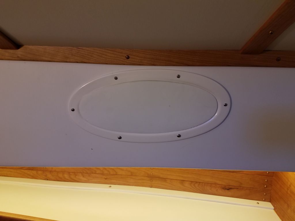
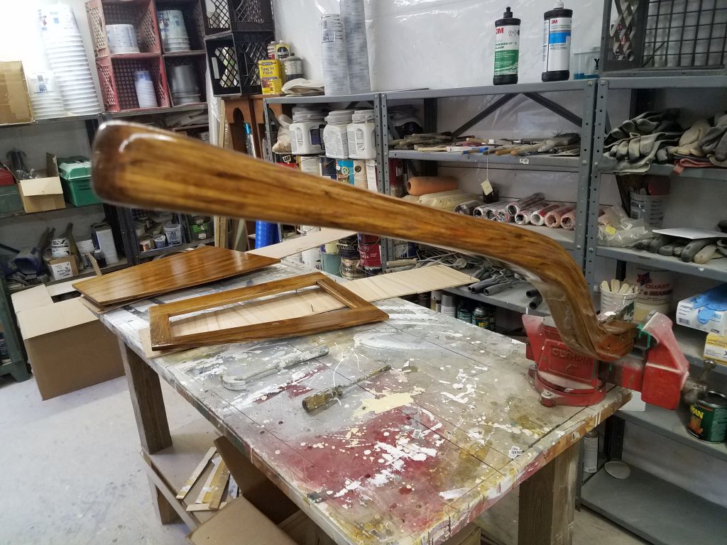
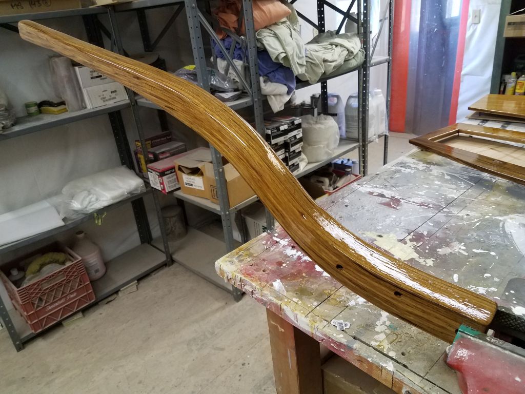
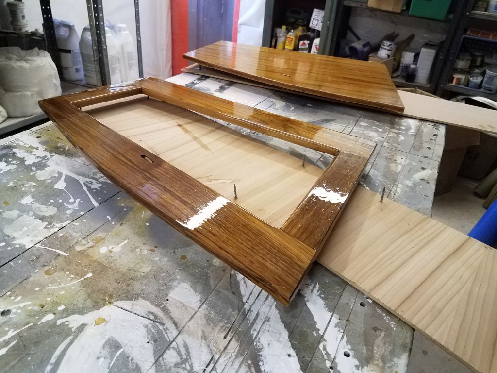
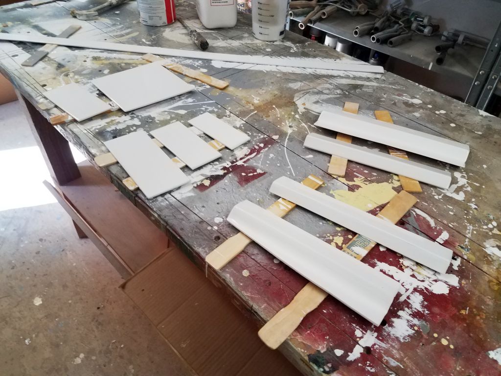
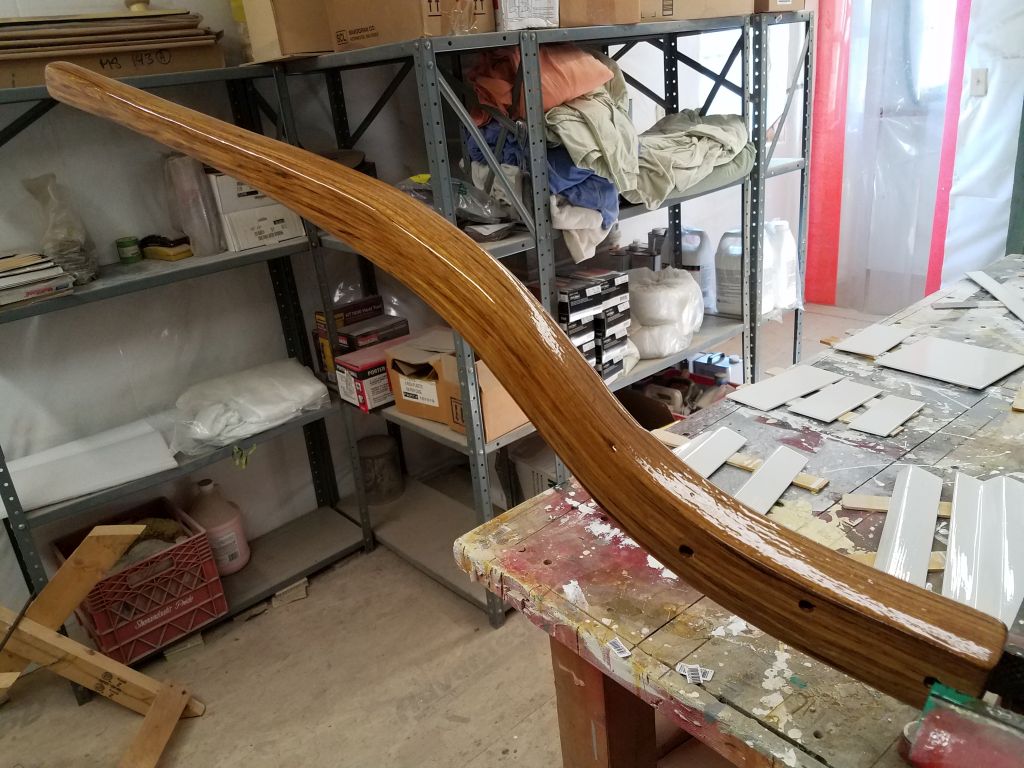
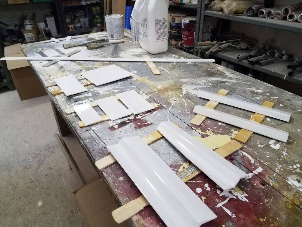
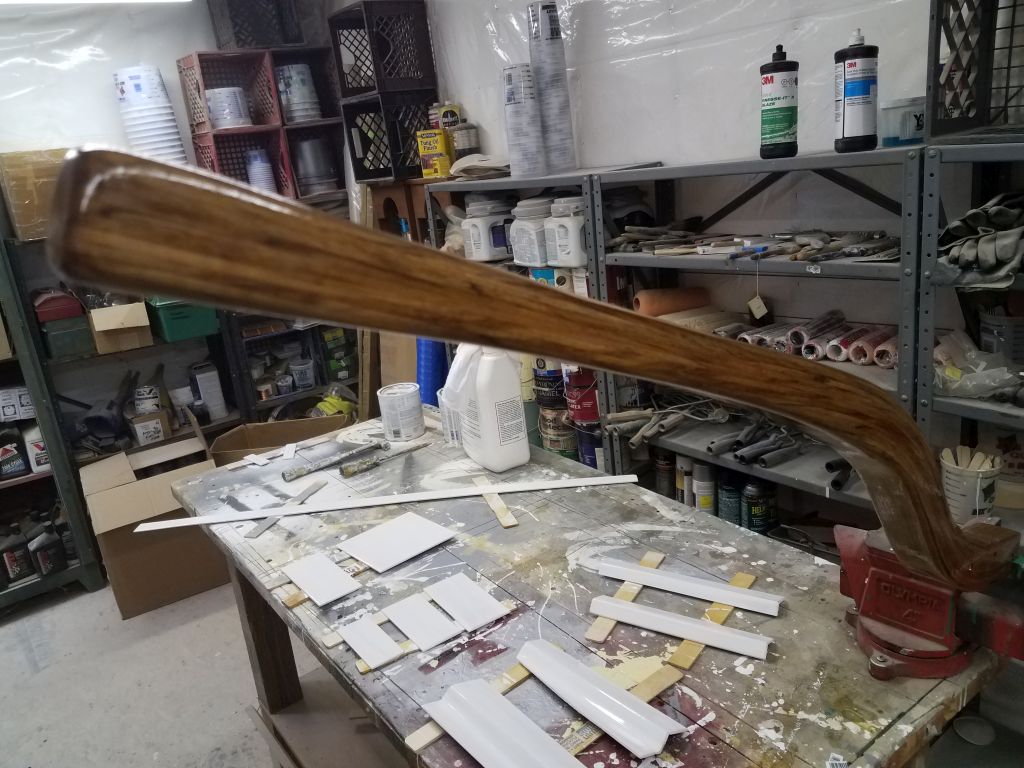
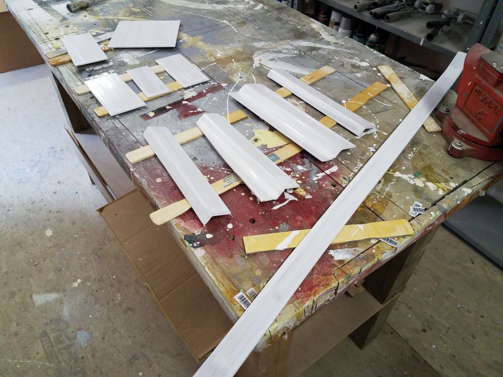
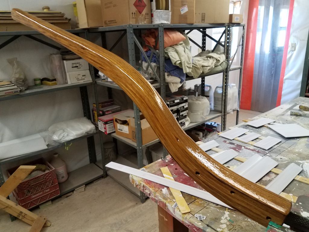
I got started with some quick sanding and another coat of paint and varnish on the liner cover plates and tiller, respectively.

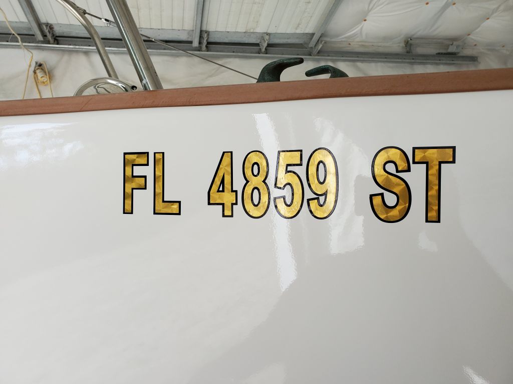
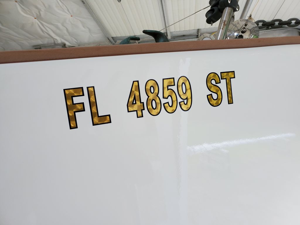
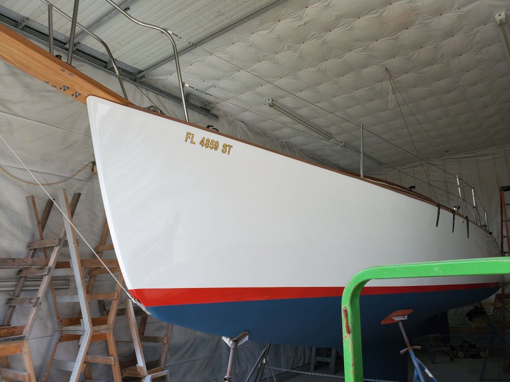
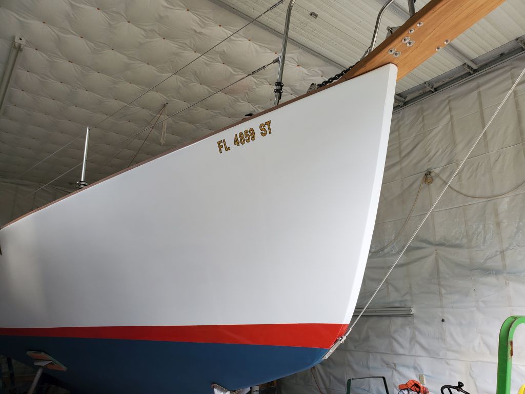
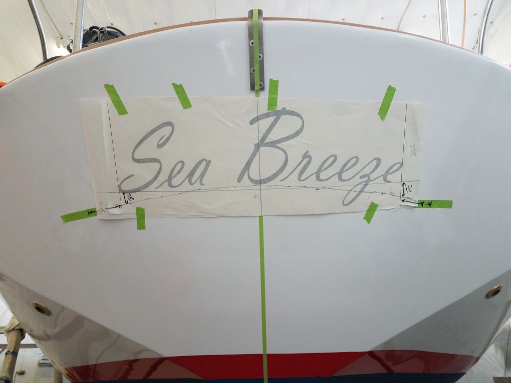
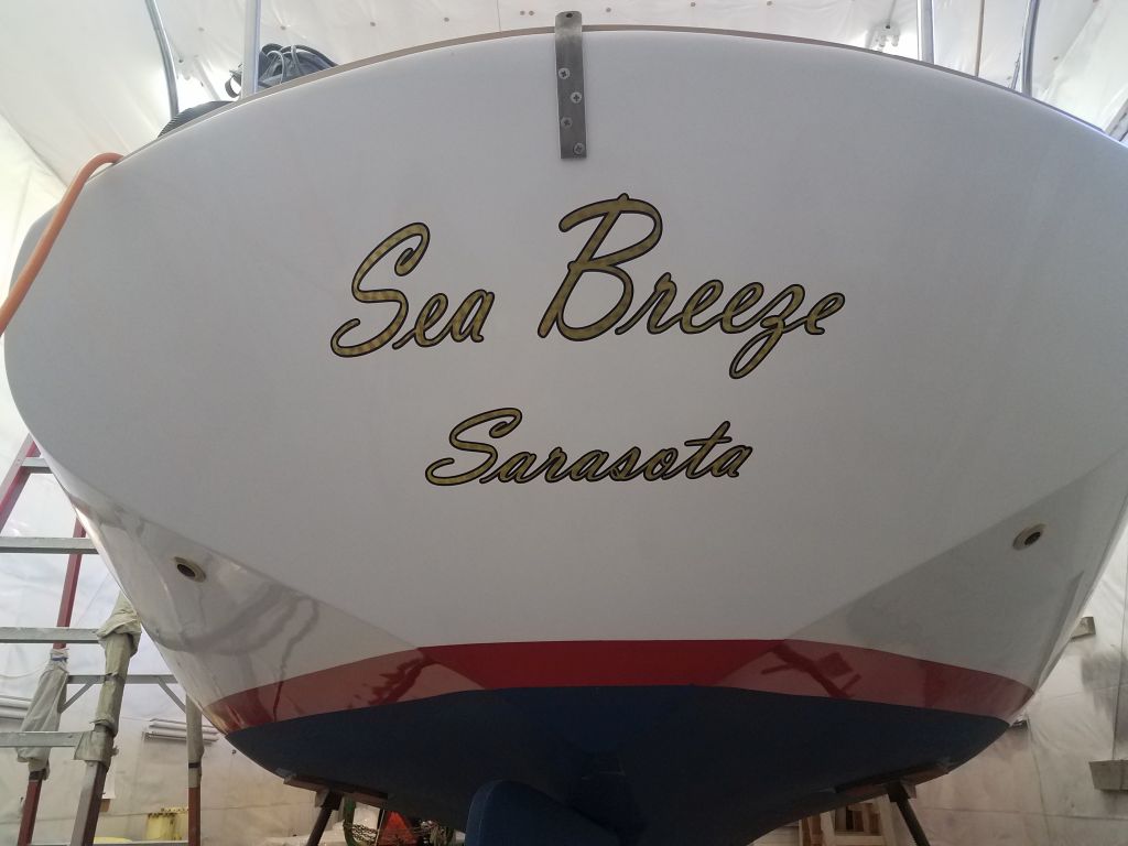
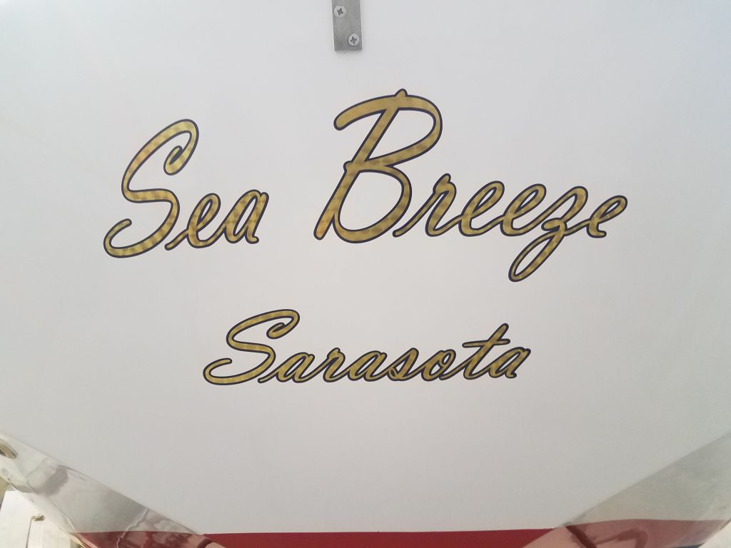
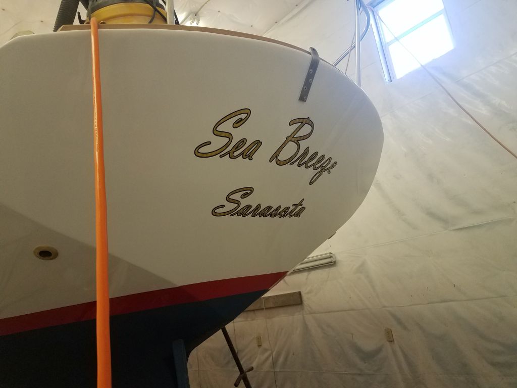
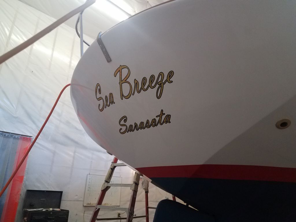
The tail end of any project tends to be filled with myriad undefined chores, and I knocked several off my actual and stream-of-consciousness lists throughout the morning in and around a couple of the more concrete jobs still underway, including working with the owner and my local sign shop to begin and finalize the lettering for the transom, a process still underway as of this writing.

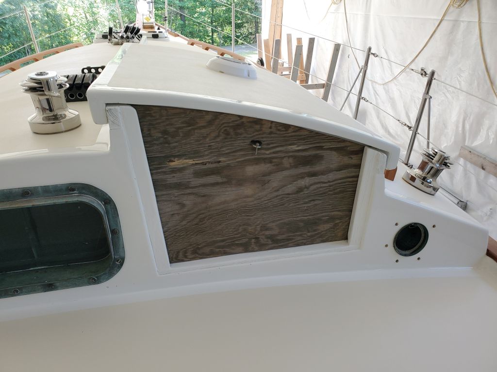
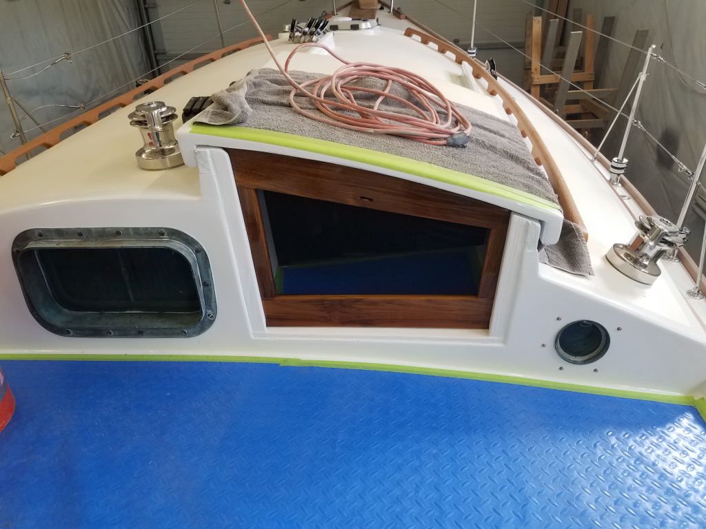
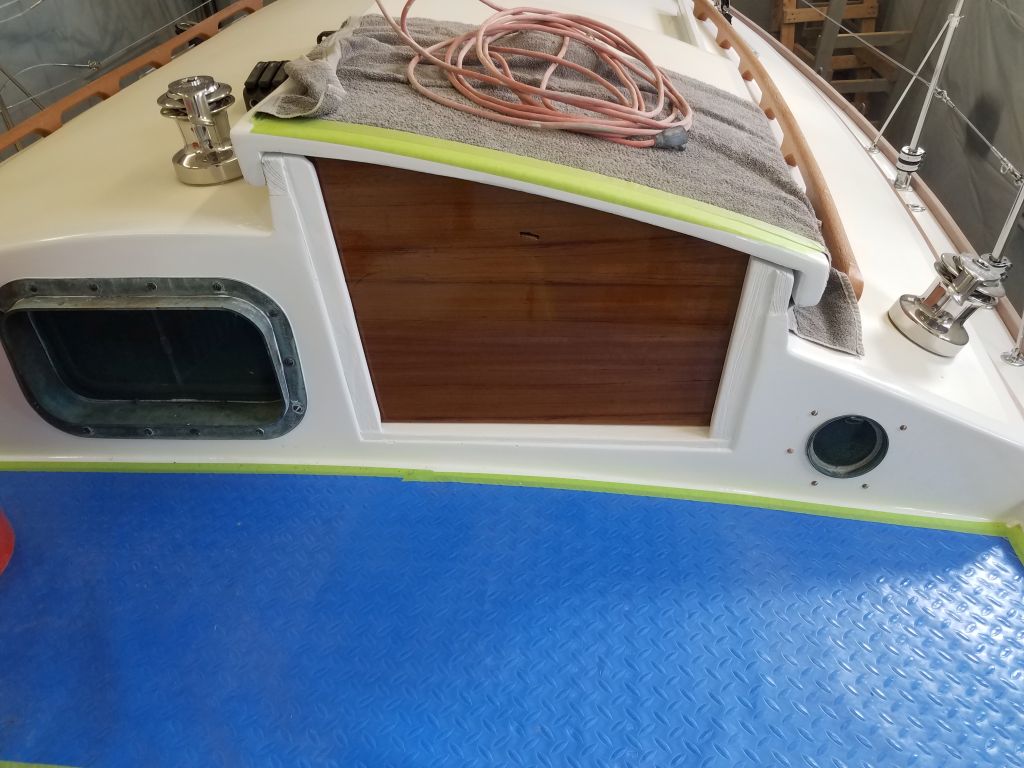
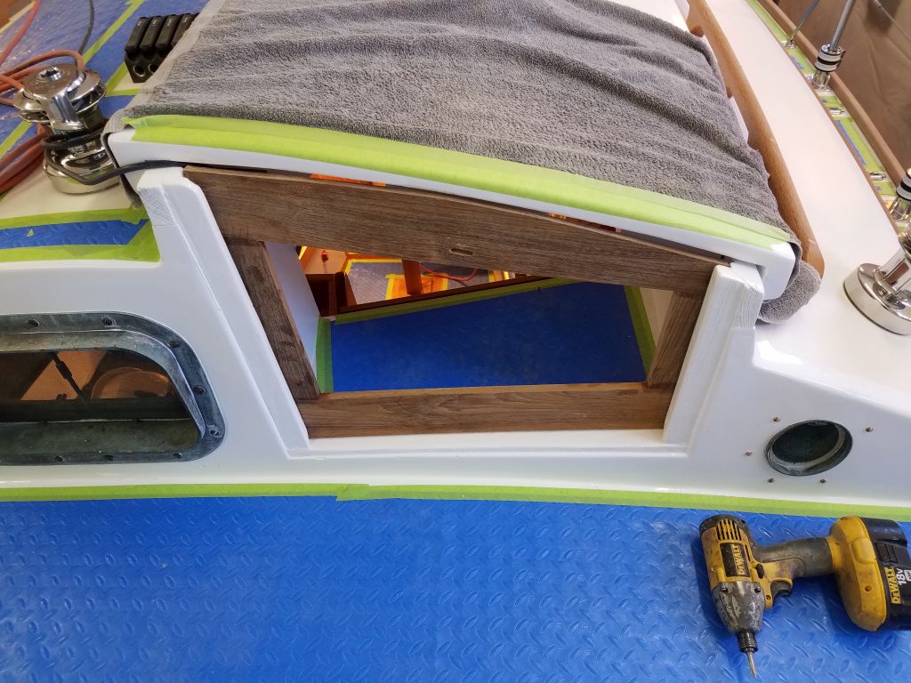
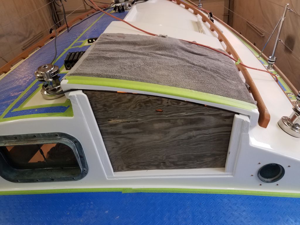
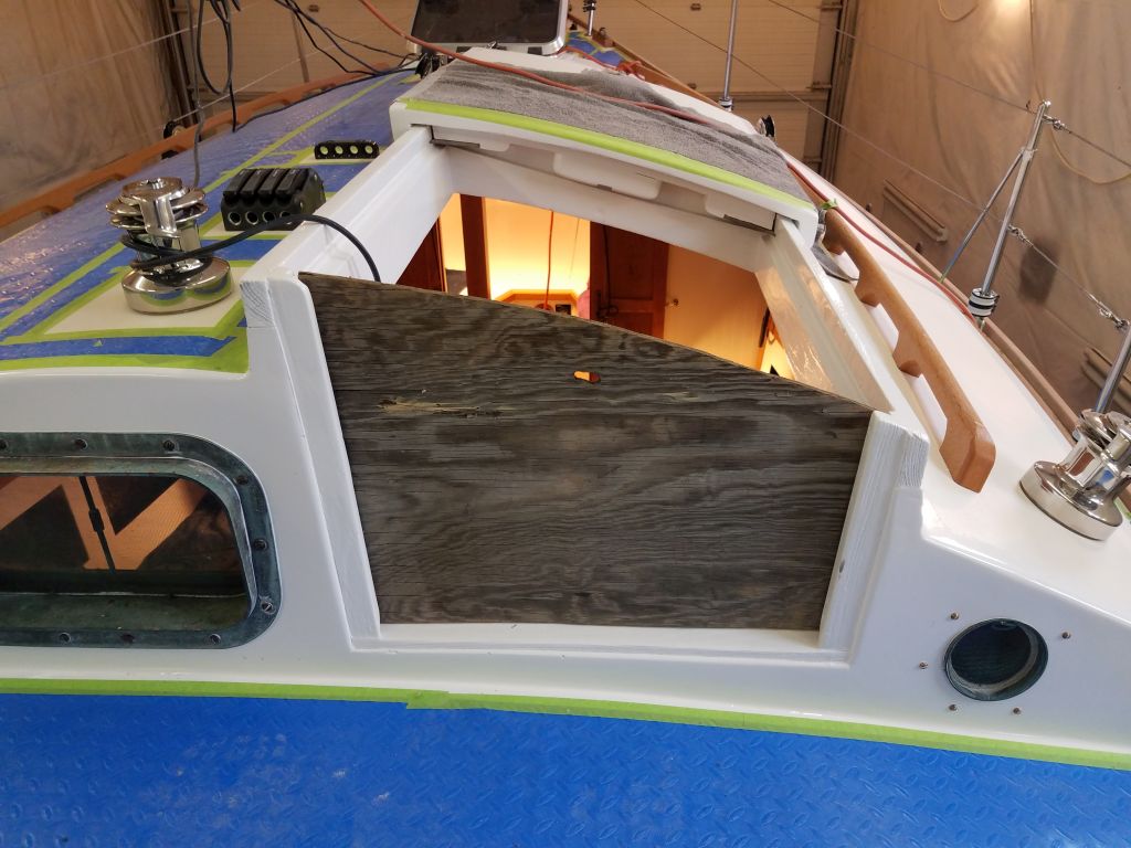
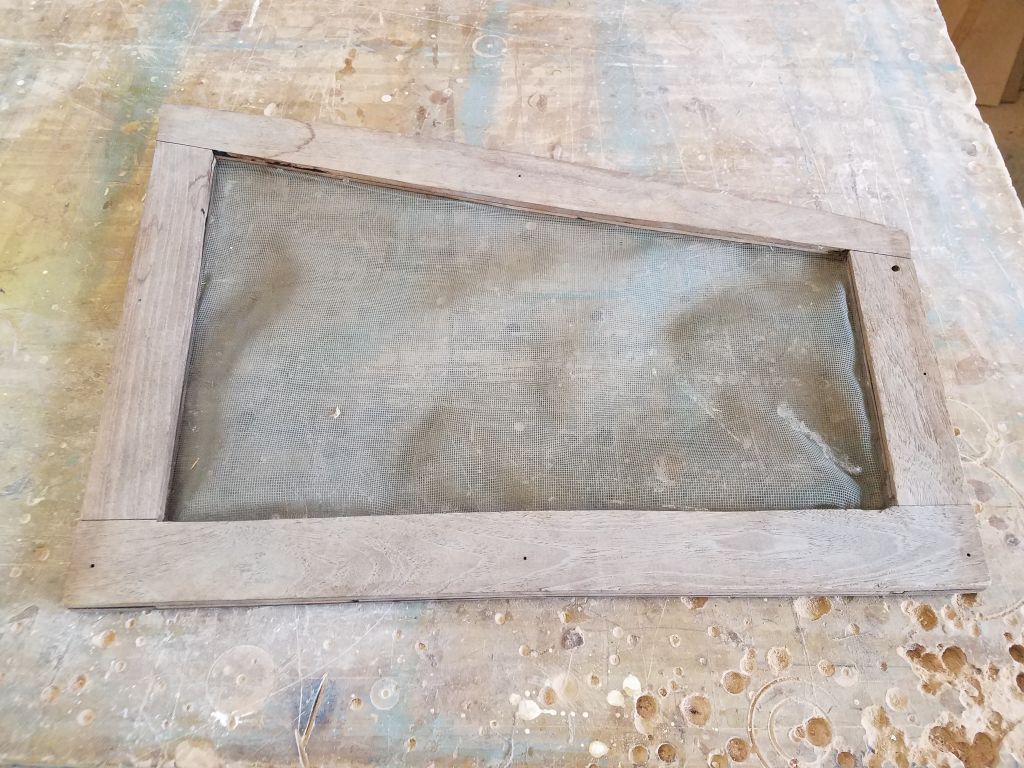
About the last “major” item on my work list, as-yet untouched, was to build new swashboards for the companionway.  The boat had arrived at the shop with several different versions, all of which were in disrepair and unsuitable going forward, even if still essentially functional.  I planned to build a new teak plywood version, plus a teak screen unit.

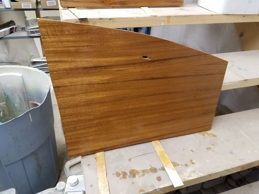
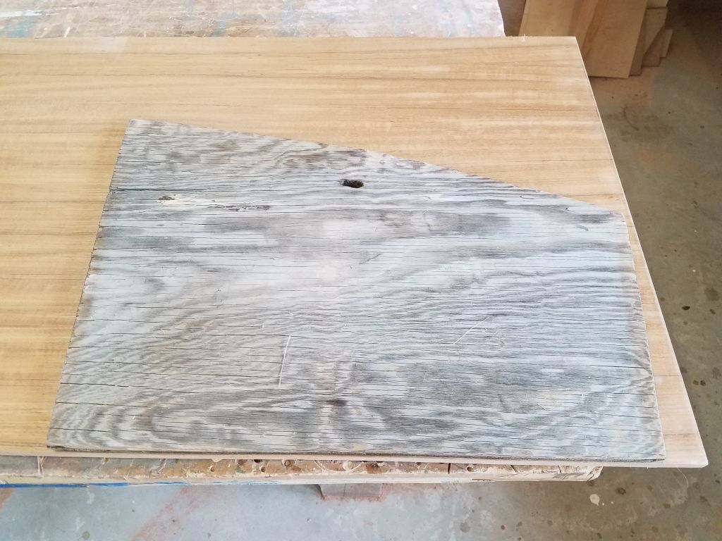
To begin, I tested the fit of one of the original boards to determine its suitability for a pattern.  This old plywood board was ugly, but it worked well enough and I could use it to help pattern the new ones.  From a partial sheet of teak plywood I had on hand, I cut out a replacement, matching the size and shape of the original.

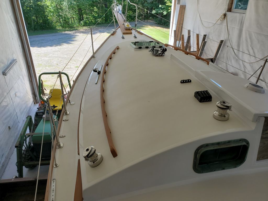
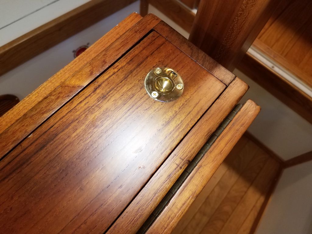
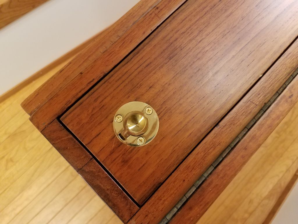
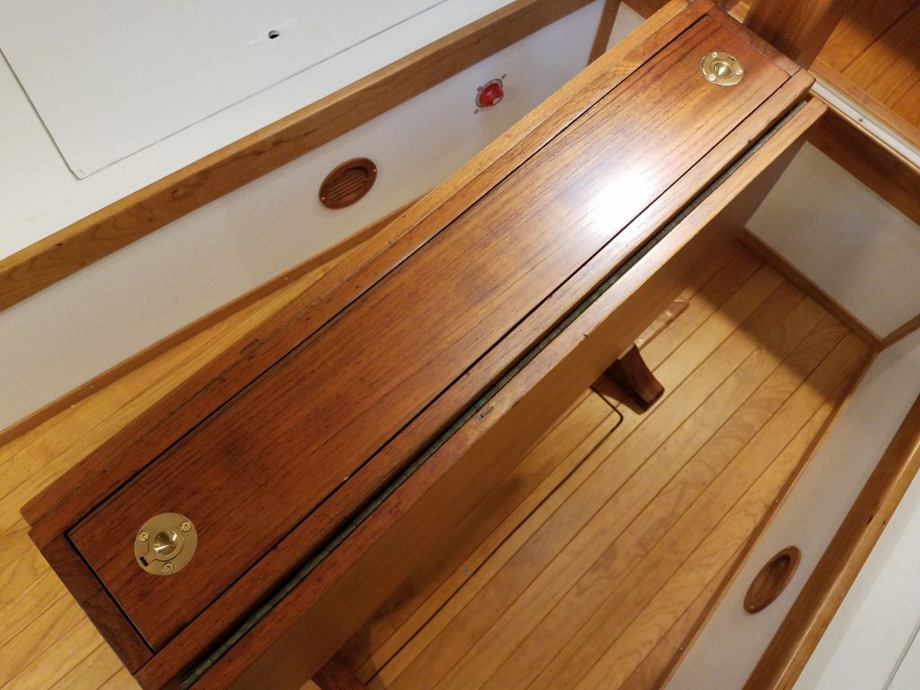
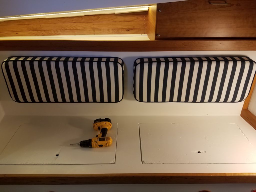
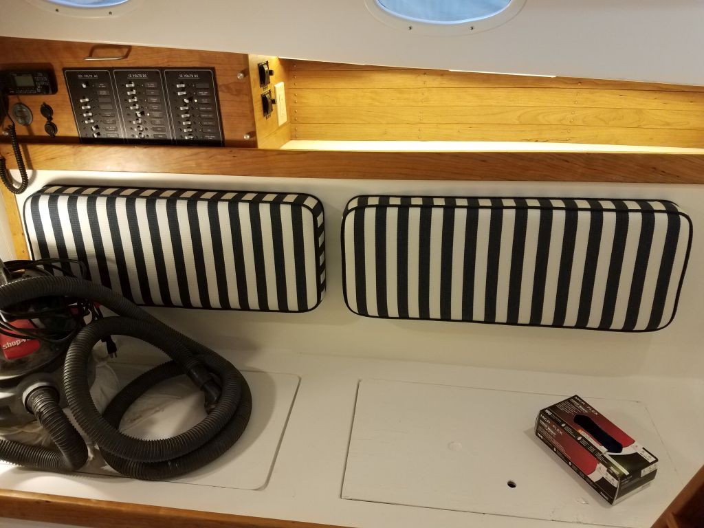
This was straightforward, but in the process it led to an unexpected job.  Throughout the project, I’d basically never stepped on the starboard cockpit locker lid; I’d removed these lids early on in the first phase of the project, and they’d been set aside in the shop for most of the time since, as I used temporary plywood covers over the locker openings throughout construction.  Even after I finally reinstalled the locker lids several weeks earlier, I never had much cause to walk on the starboard one since my path on and off the boat, and in and out of the cabin, kept me well clear.  The port locker lid, onto which I stepped every time I got on or off the boat, had never shown any signs of weakness.

This all leads up to the fact that during my companionway work, I stepped on the lid and was most unhappy to feel softness underfoot–the first time I’d noticed this or even had any inkling, as somehow this had escaped my notice for the past two years.   I did my best to pretend I hadn’t felt it, and willed it to deal with itself, but ultimately, of course, I knew it was something I had to deal with.

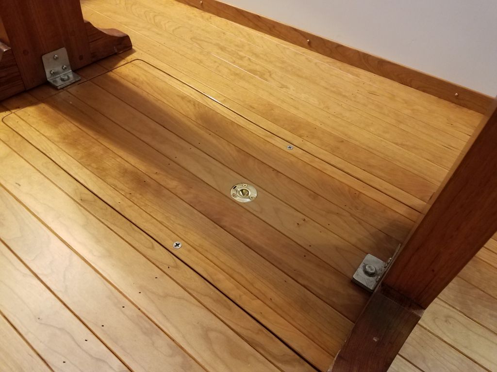
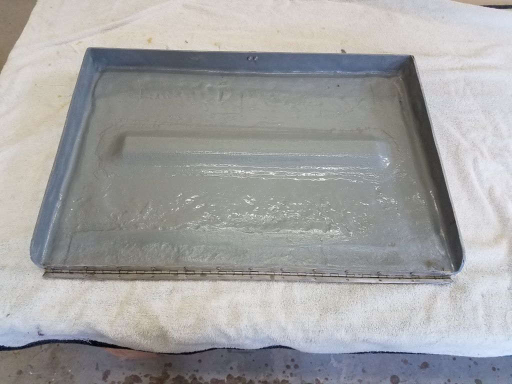
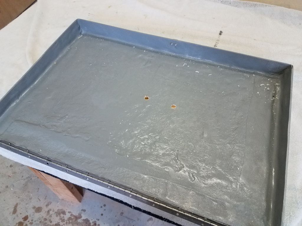
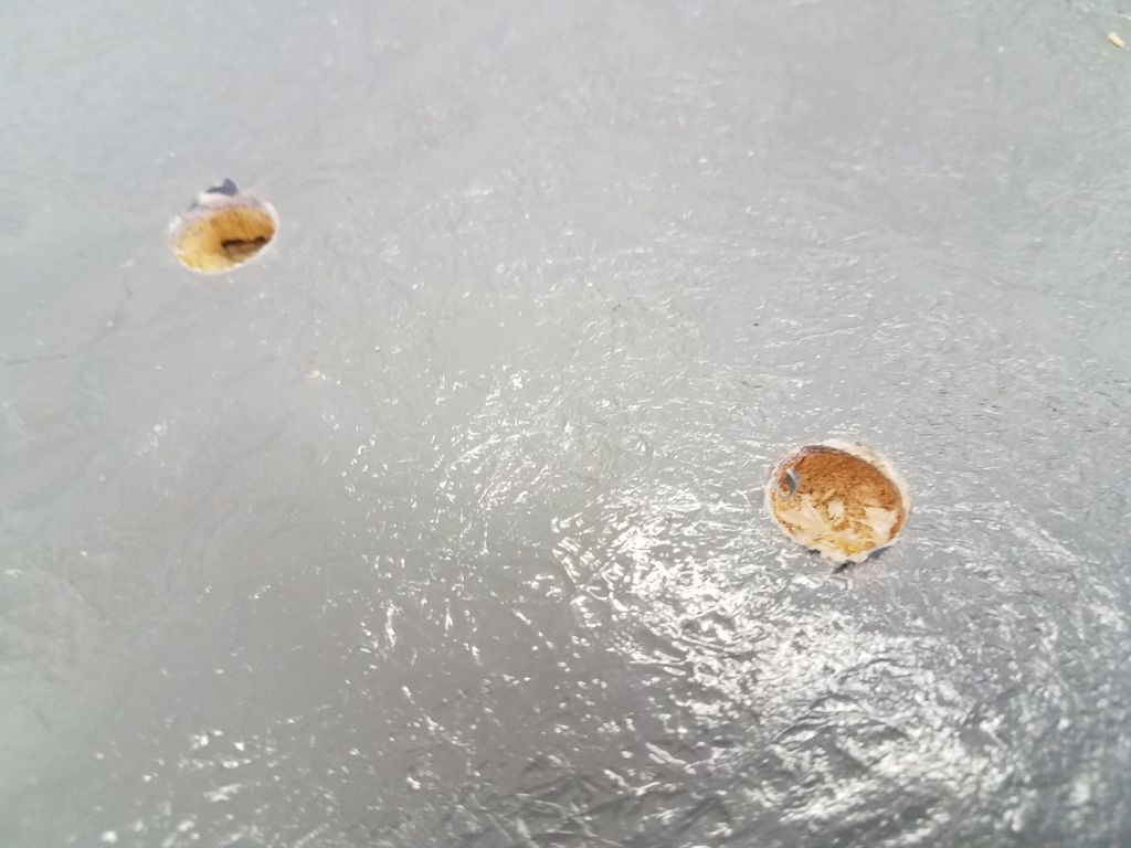
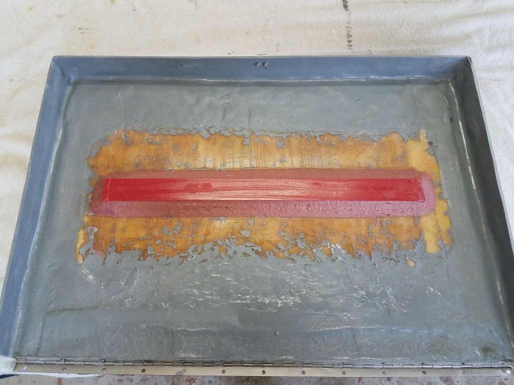
So I removed the lid from the cockpit, unscrewing the hinge, and down on the bench I did some exploratory probing with a drill bit from the underside.  As expected, the lid featured a cored construction, but unexpectedly the core in all my test holes was clean and bright.  I had expected it to be wet and damaged.  After various additional testing and consideration, I decided that the lid was simply weak and not well-enough supported, and that it wasn’t a core problem after all.

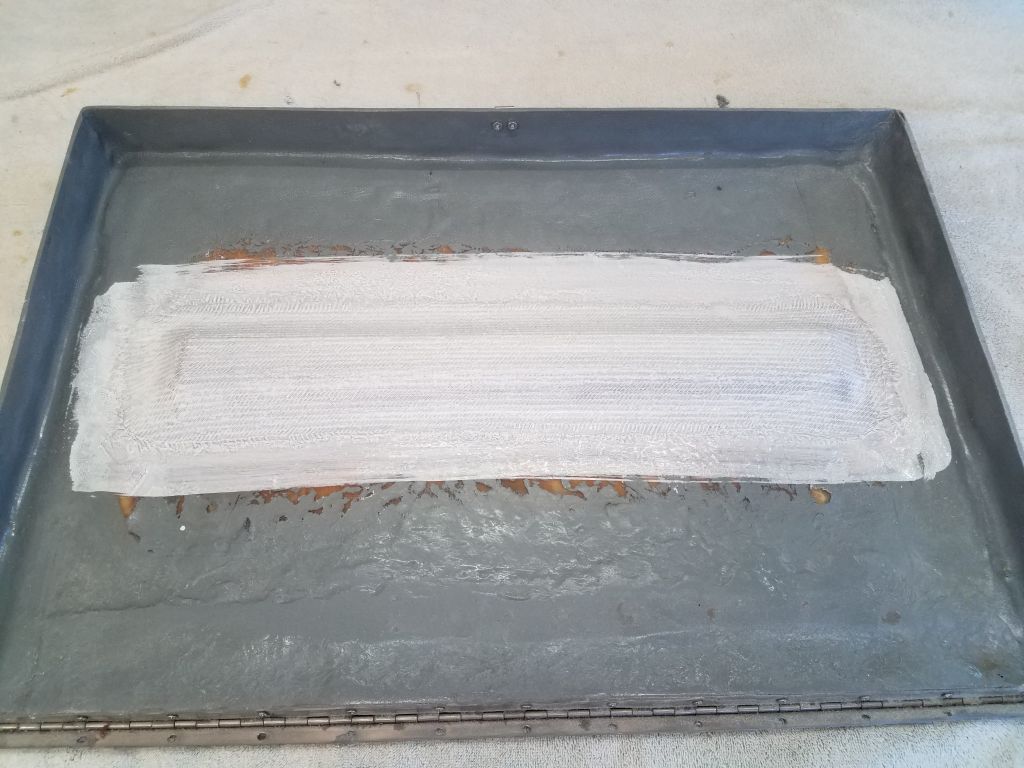
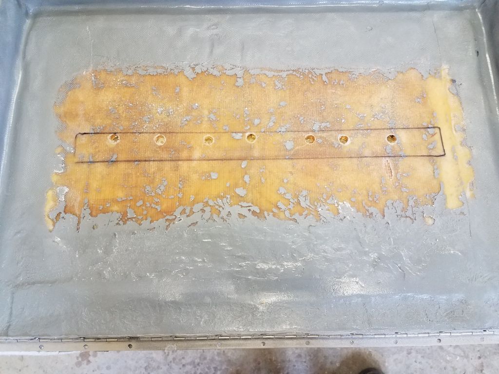
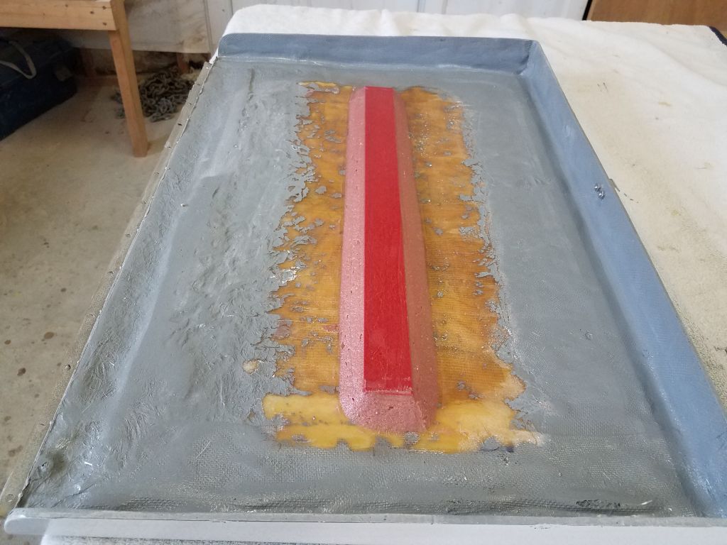
I’d been fully prepared to recore the lid, though the process could have risked damage to the finished surface of the lid, but since the core was sound, and I didn’t relish removing sound core from the top skin if it wasn’t truly necessary, I decided instead to install a stiffener/reinforcement.  I sanded away the paint from a section of the middle of the lid (all on the underside), and cut a piece of prefab fiberglass as a stiffener, which I secured in place with thickened epoxy adhesive and a large fillet all around.  In the process I also epoxy-filled my test holes, which in this case would double as additional reinforcement and a sort of “key” into the existing structure beneath the new reinforcement.

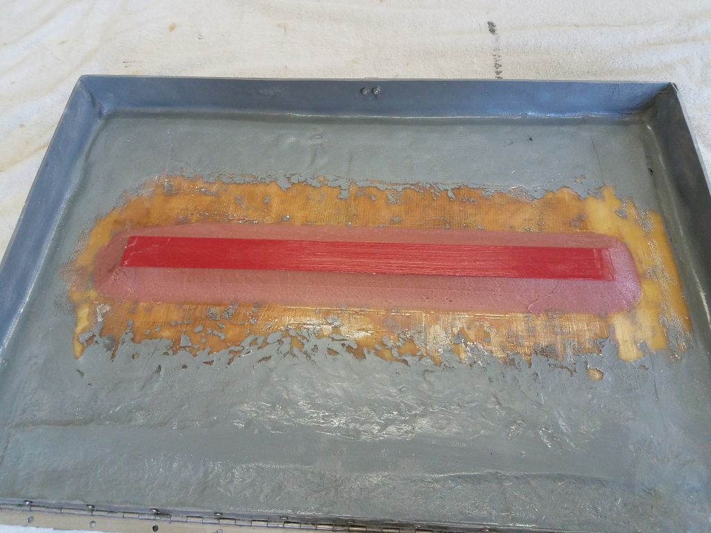
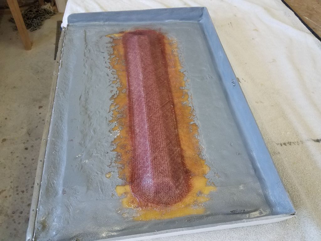
After letting the epoxy cure for a few hours while I continued work on other things (to which I’ll return shortly here), I applied a small touch-up layer of thickened epoxy to the fillets, smoothing minor imperfections from the first round, then installed two layers of 1708 fiberglass over the top of the whole arrangement to complete the reinforcement.  I’d certainly not planned to be doing this at this stage of the project, but I was glad I’d noticed the problem when I did in any event.

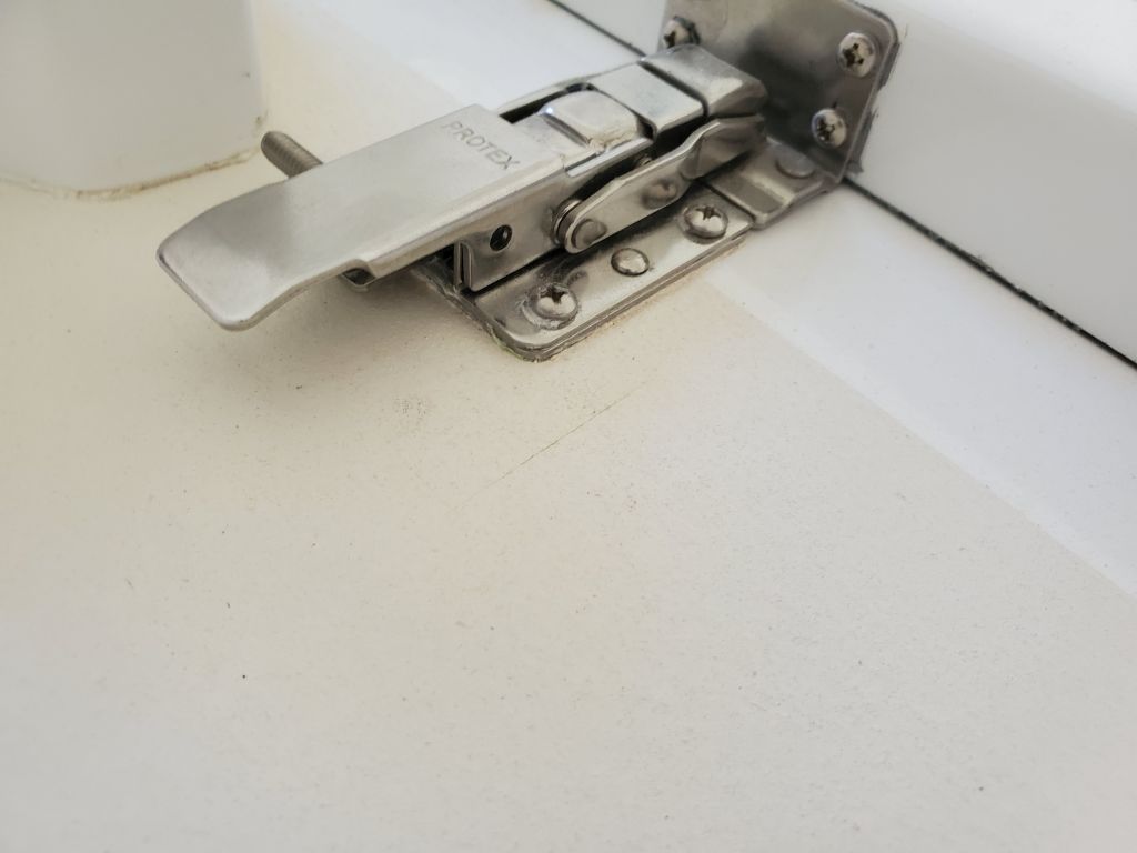
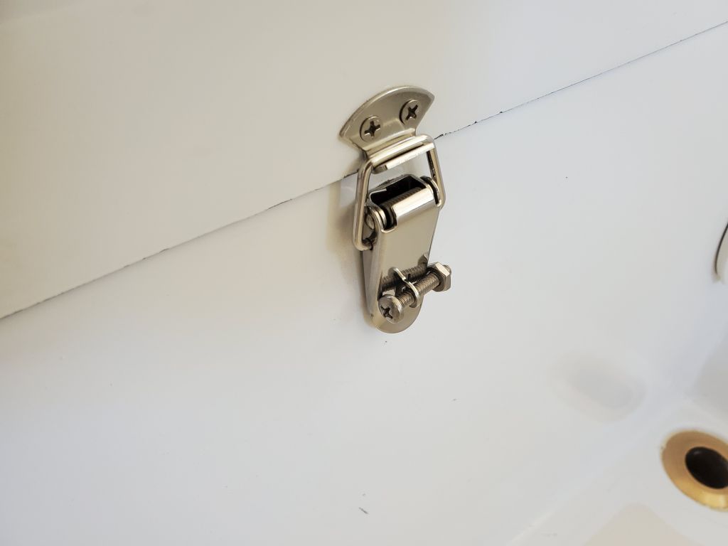
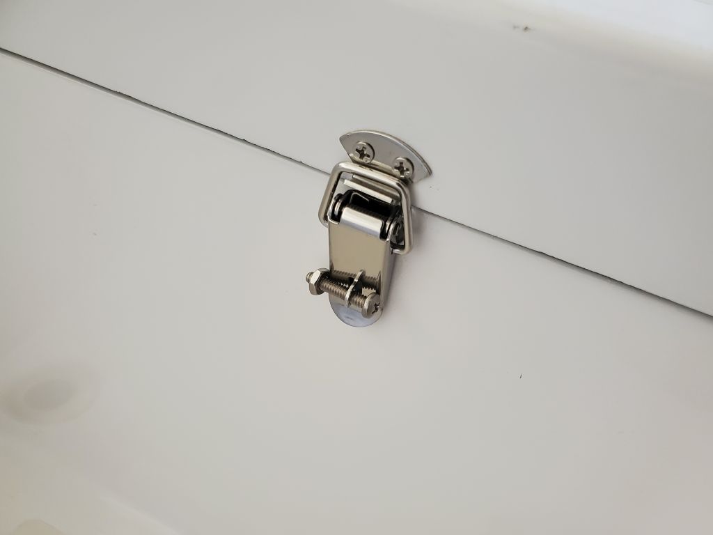
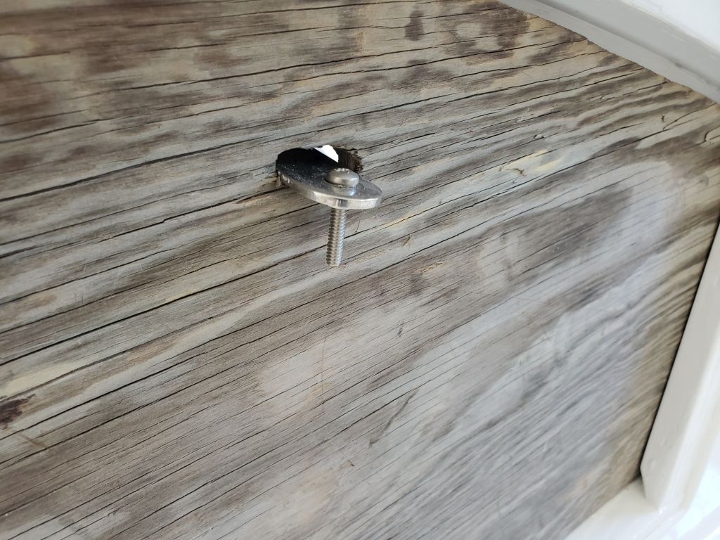
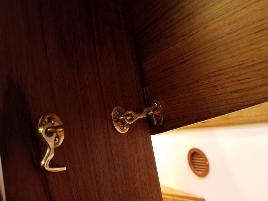
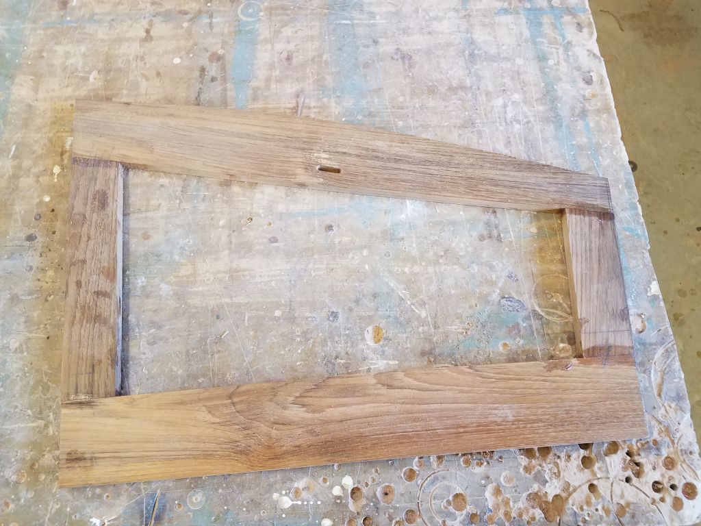
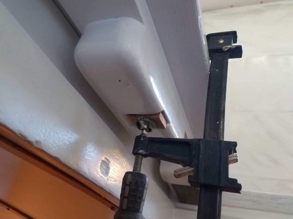
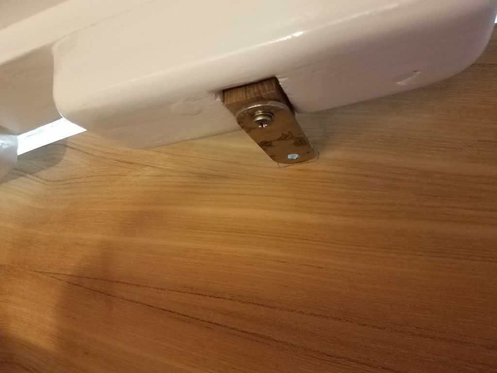
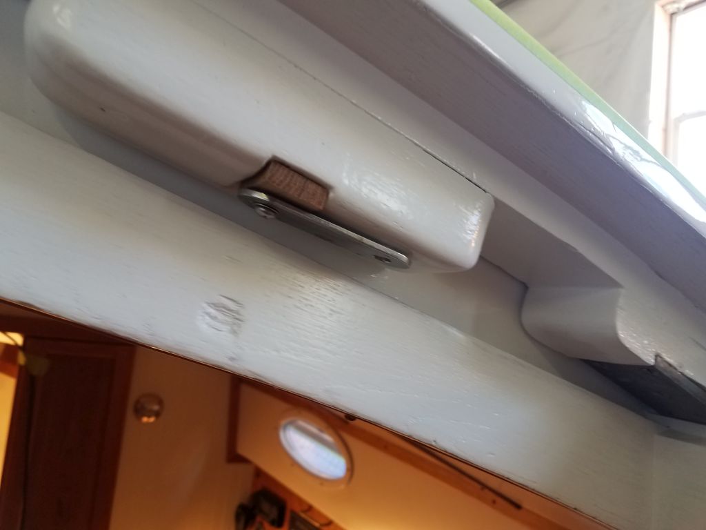
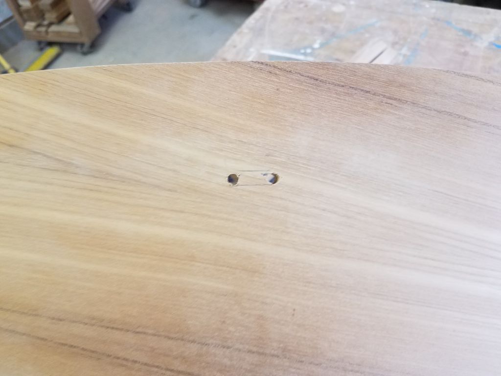
Meanwhile, I continued work on the pair of new companionway boards.  With the basic plywood one cut to shape, my next step was to cut a little slot for the companionway hasp, but as with everything that required an additional step first.  There’d been no hardware installed on the companionway when the boat arrived here, but there was a recess in the wooden part of the slide that fit a standard hasp tang perfectly–except that it didn’t allow the tang to rotate out of the way when the hatch was open.  So I made a little teak spacer to fill the space, and glued it in place before installing the little tang through the new spacer.  Then, with the hatch shut, I used the tang to mark its own slot on the back side of the new hatch board, and cut out the slot as needed.

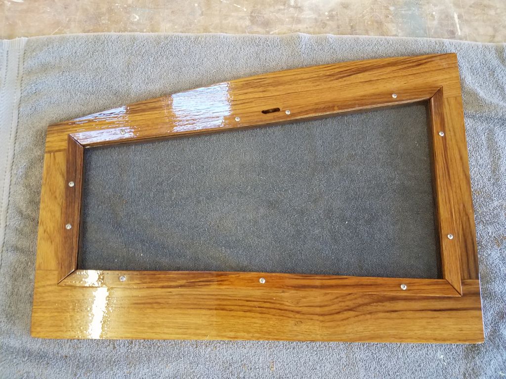
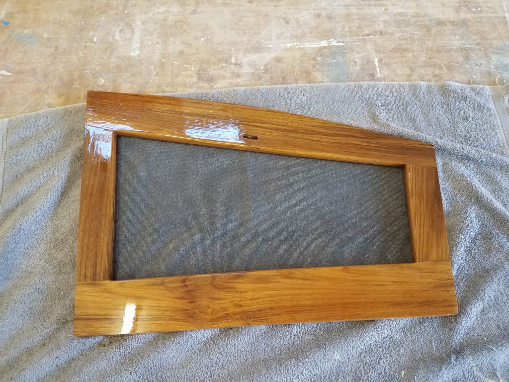
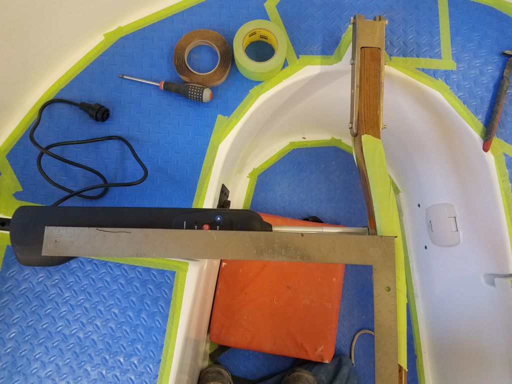
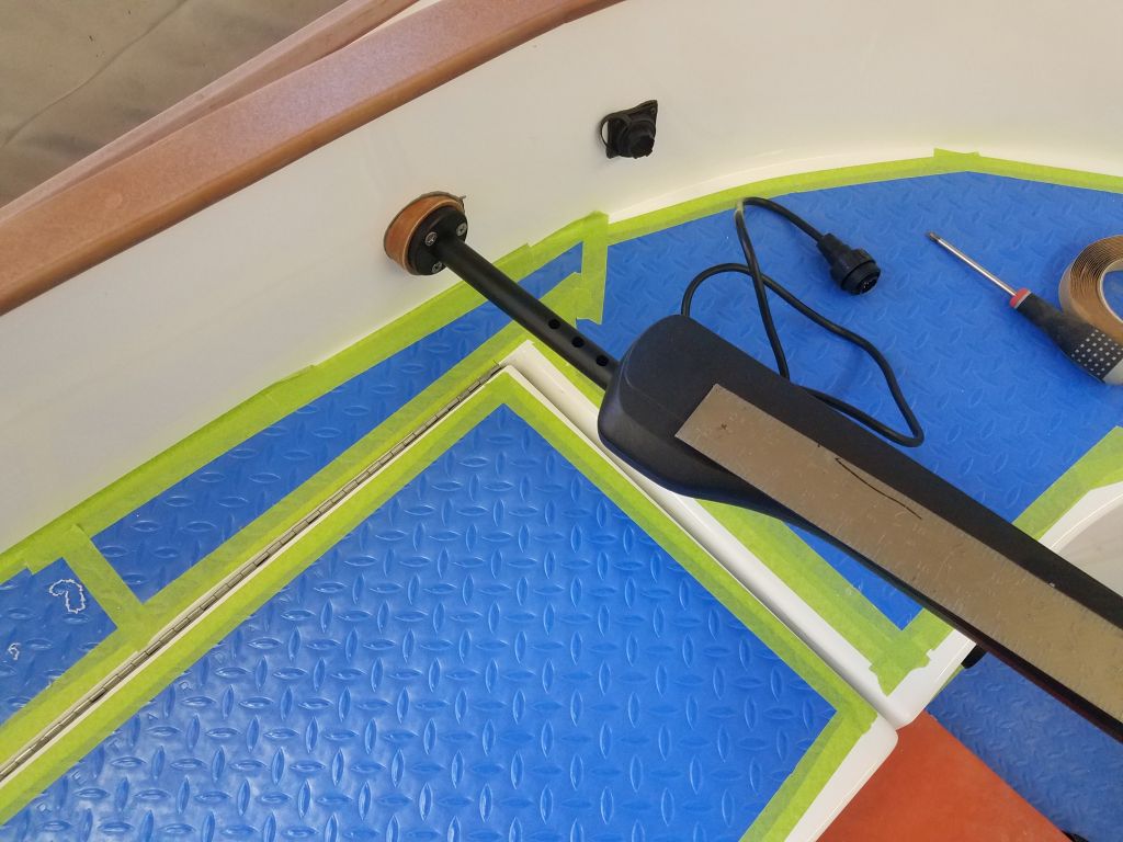
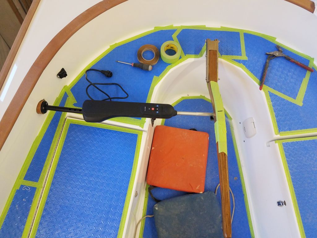
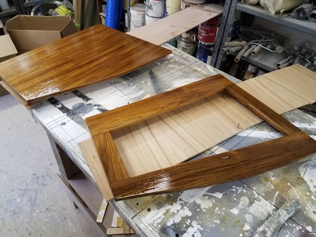
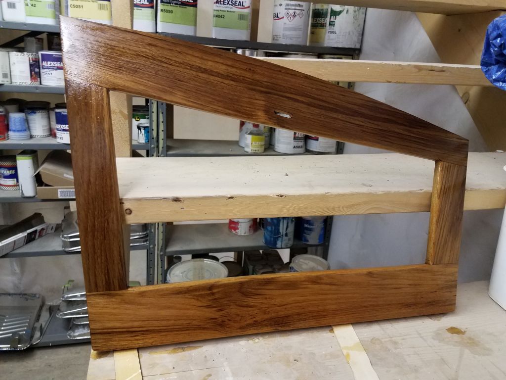
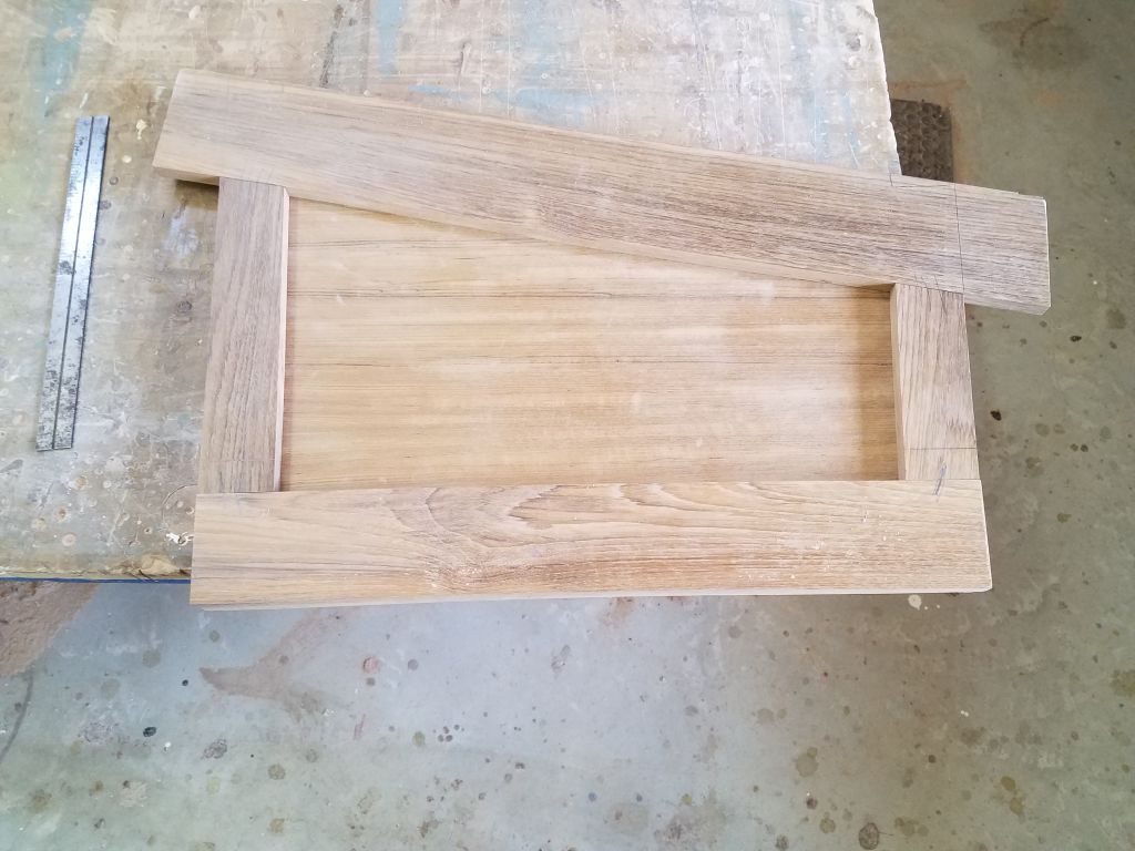
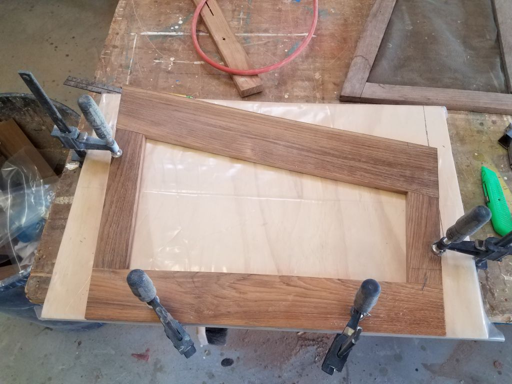
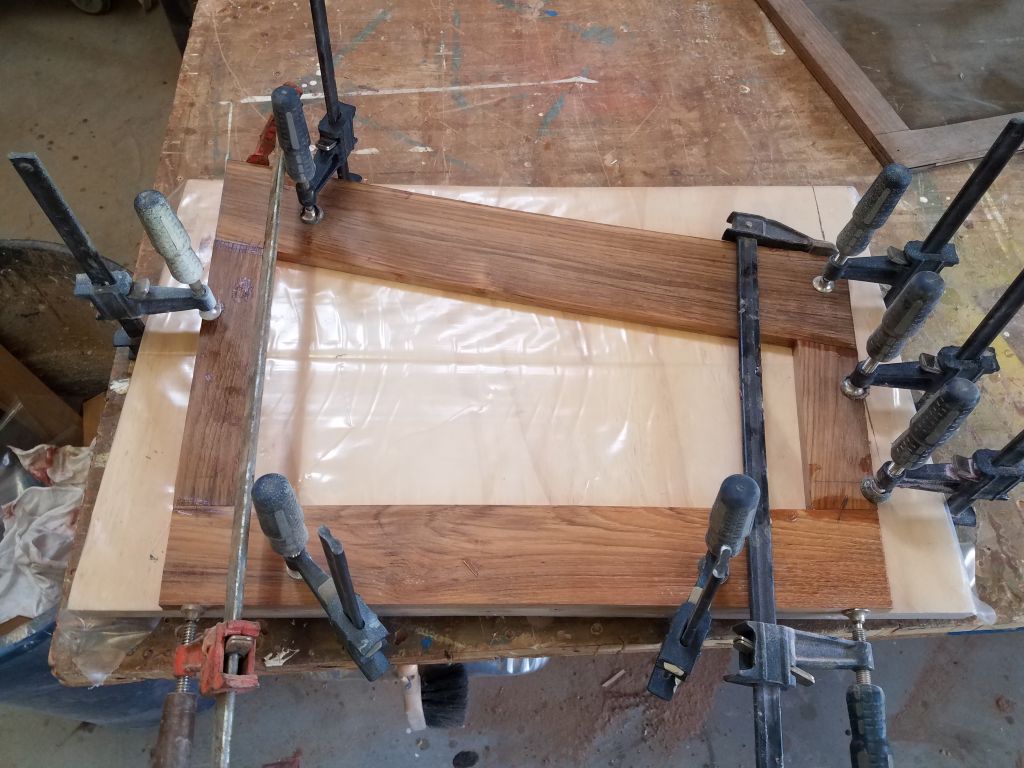
To begin the solid teak-framed screen unit, I cut several pieces of 4/4 teak to the widths I wanted (3″ for the bottom rail, 2″ for the stiles, and a wider piece for the top rail that I’d later cut into the curve required), then resawed and planed them down to a finished thickness of just under 5/8″, which fit in the slots of the companionway.  Using my new plywood swashboard as a template, I laid out and cut the frame pieces for the screen, then, on a flat surface covered with plastic, clamped and glued the frame pieces together with thickened epoxy adhesive.

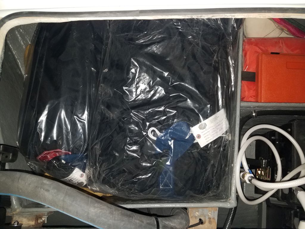
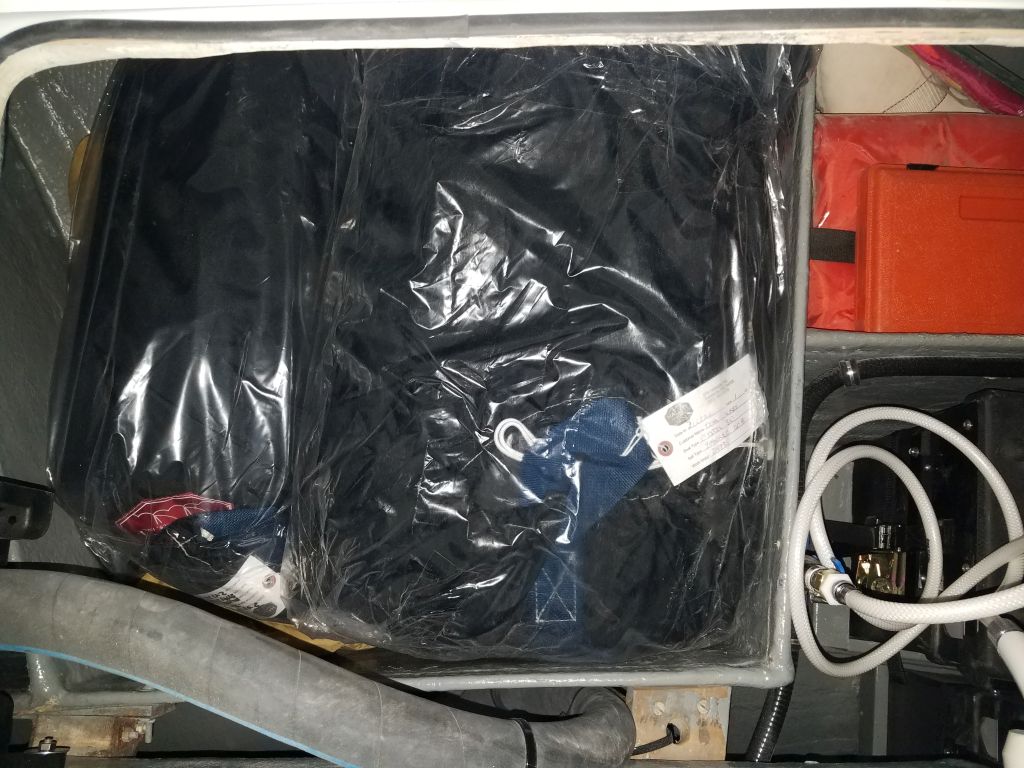
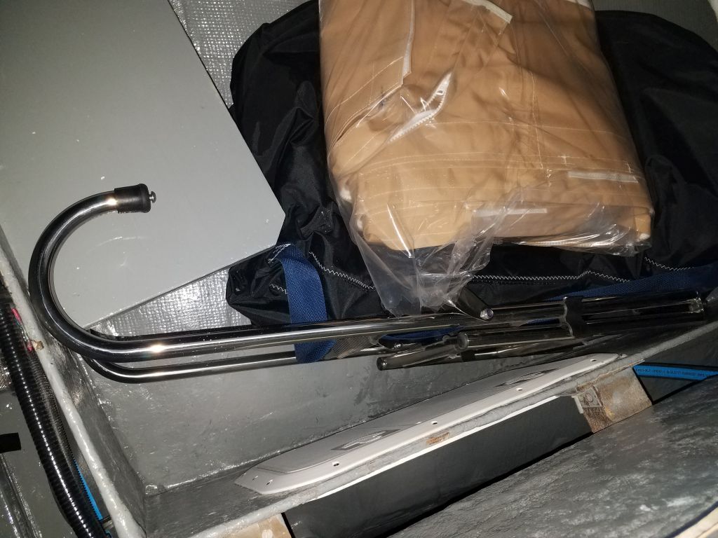
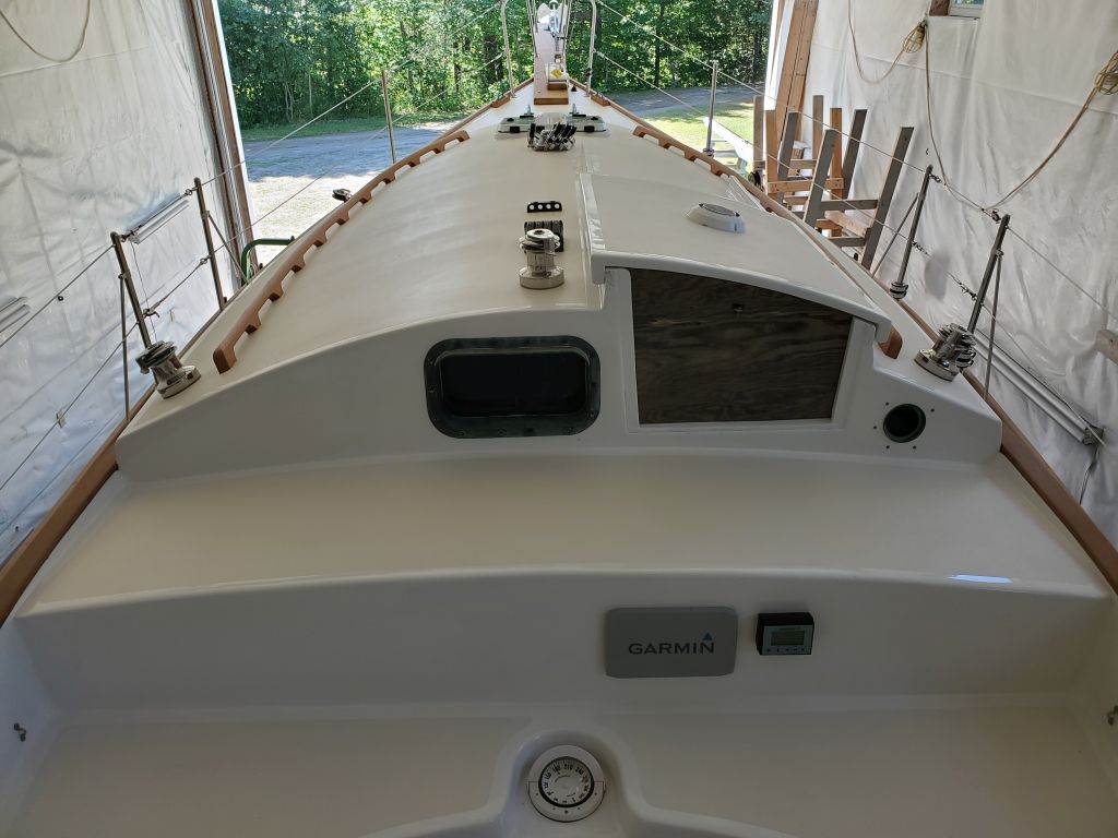
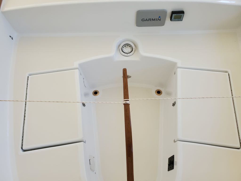
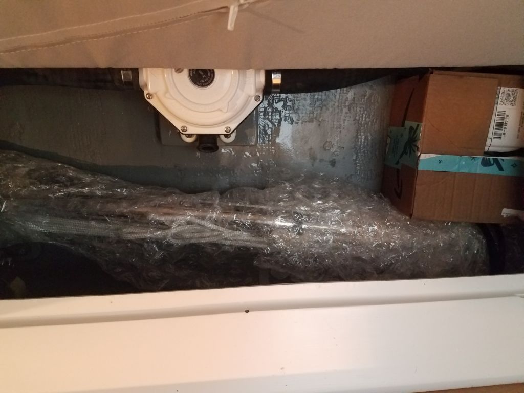
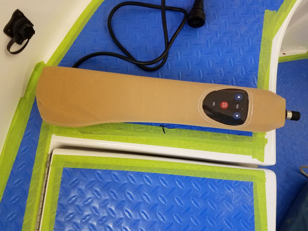
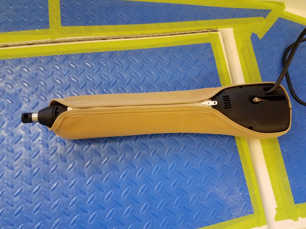
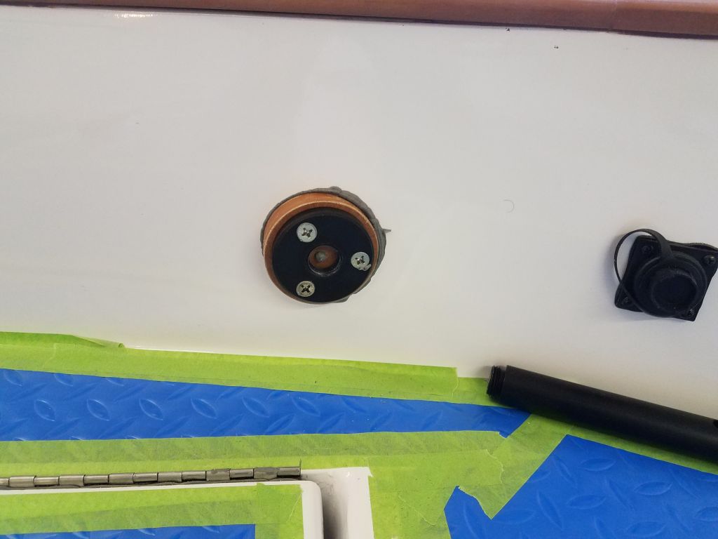
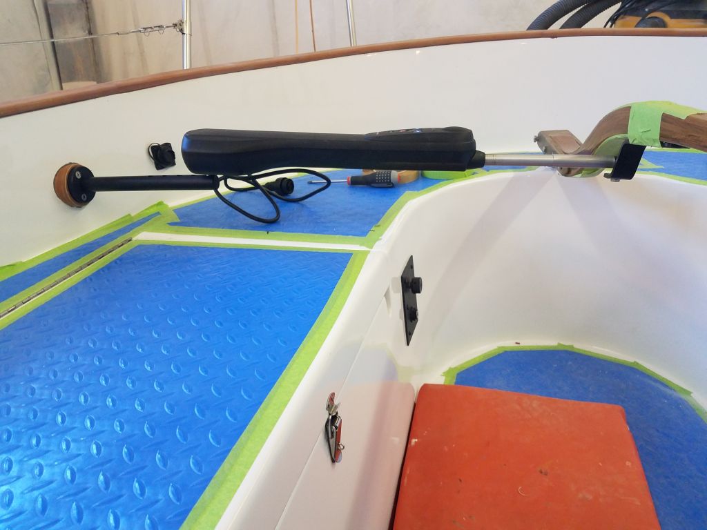
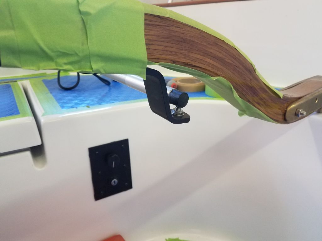
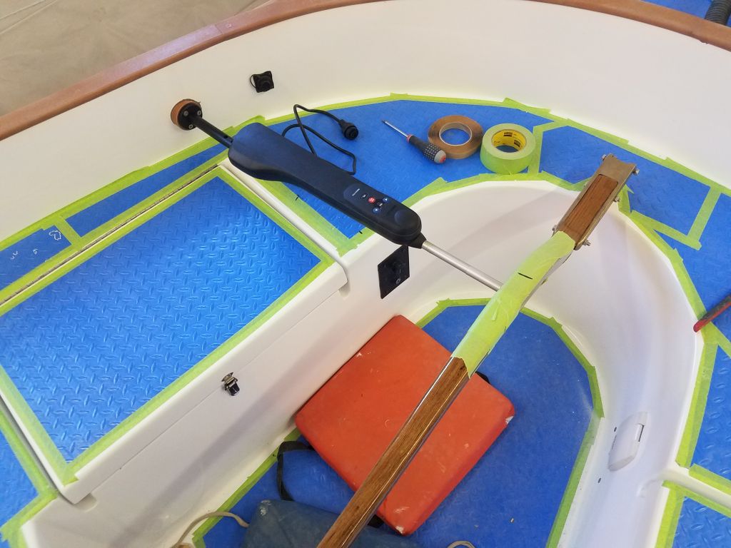
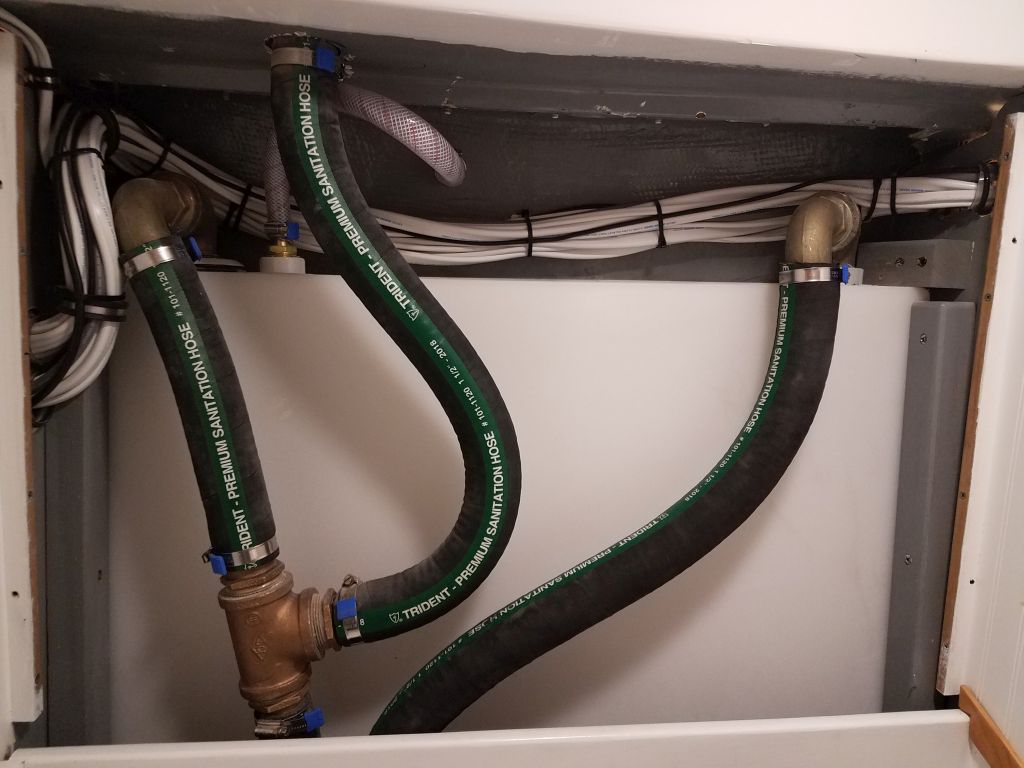
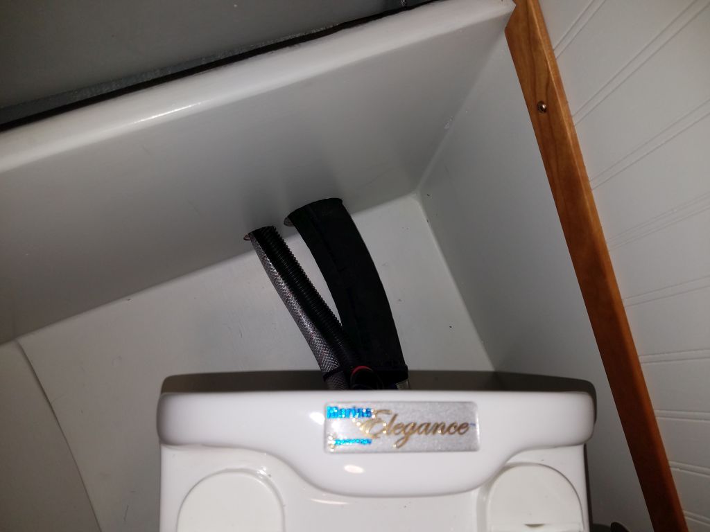
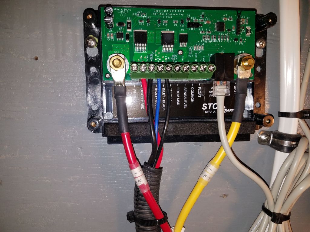
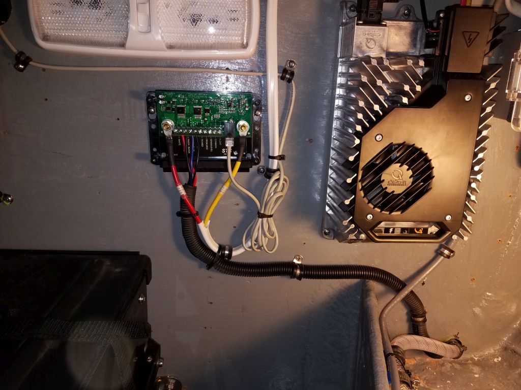
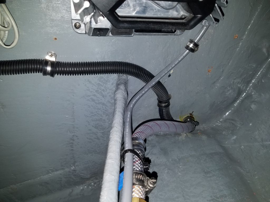
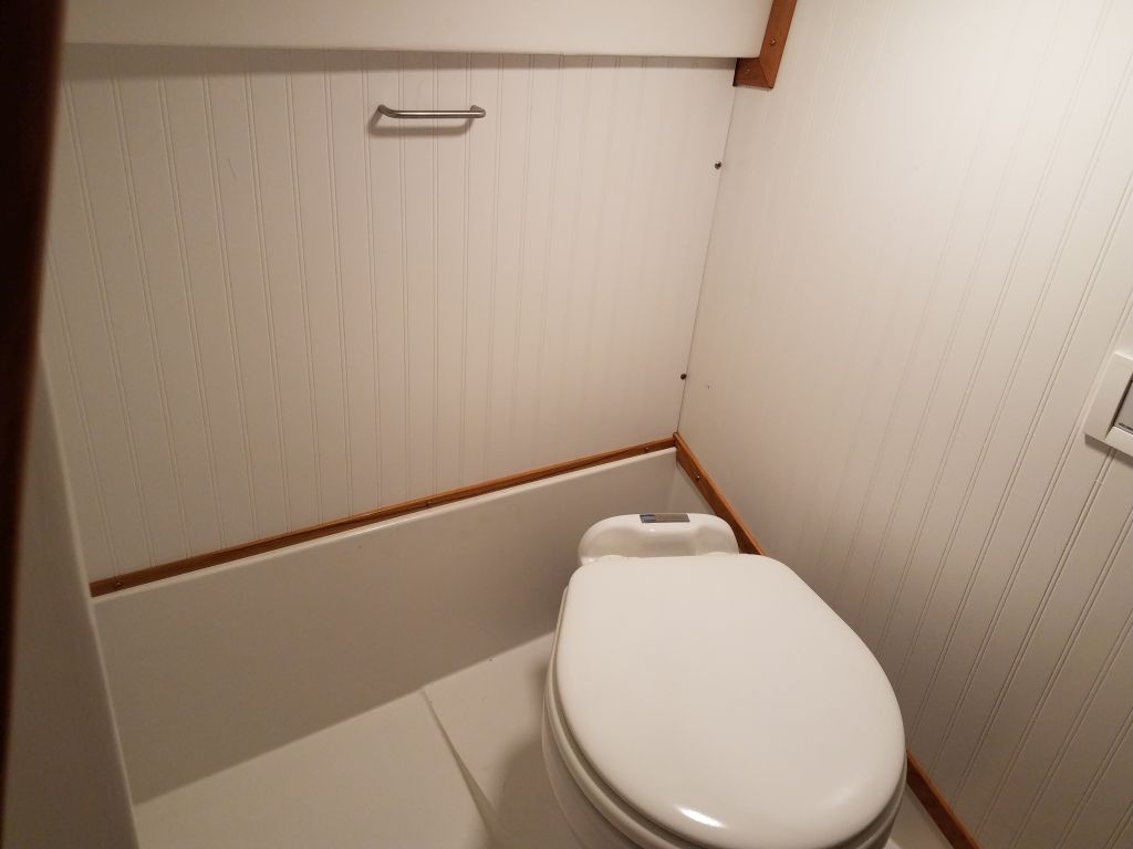
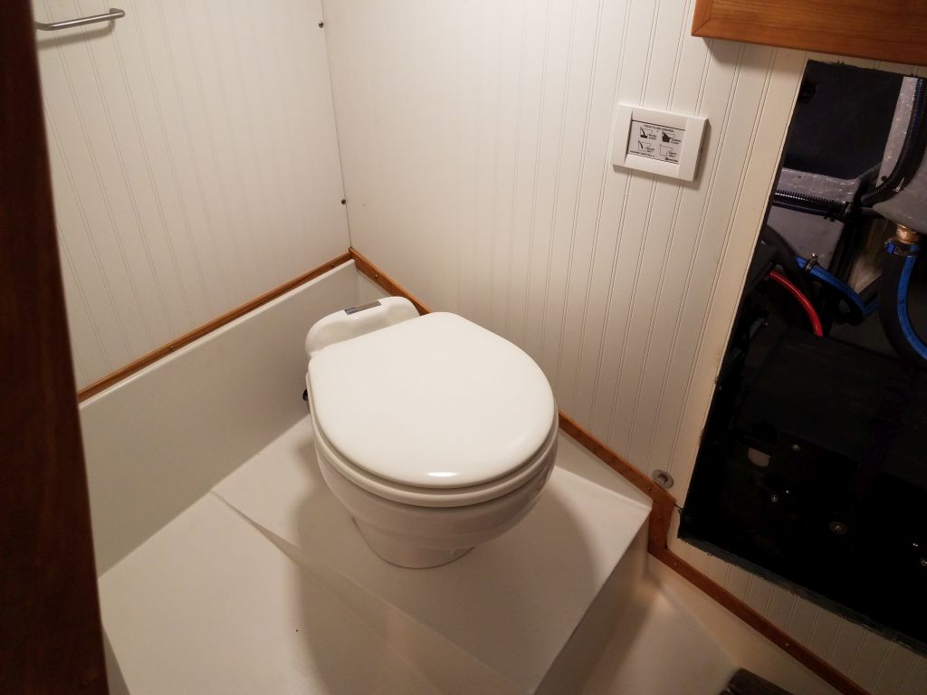
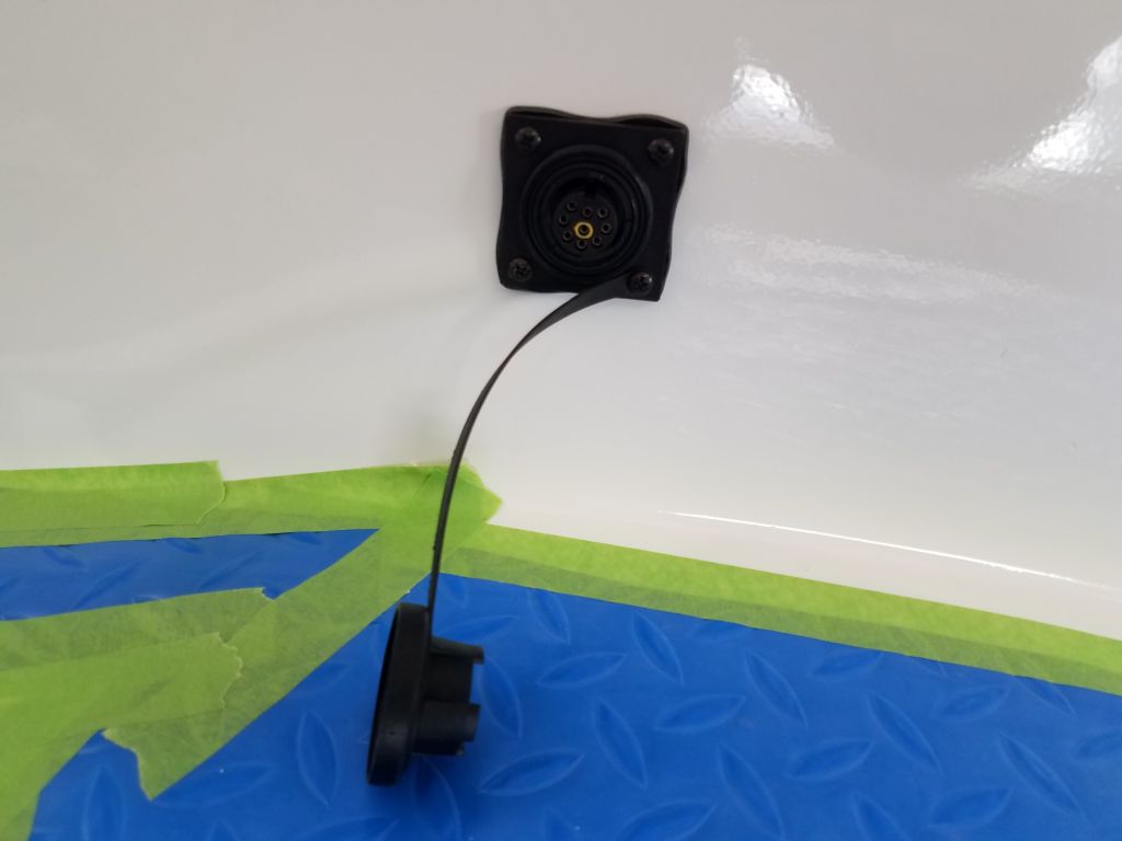
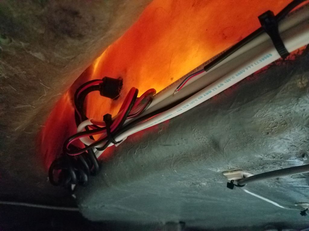
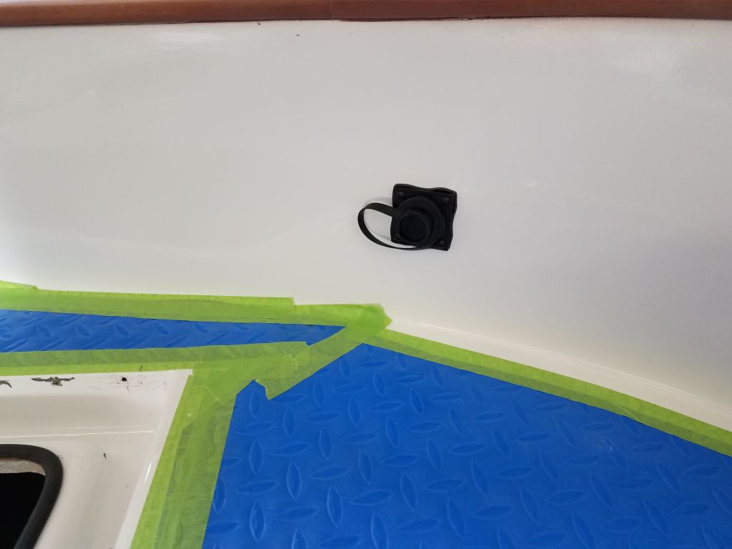
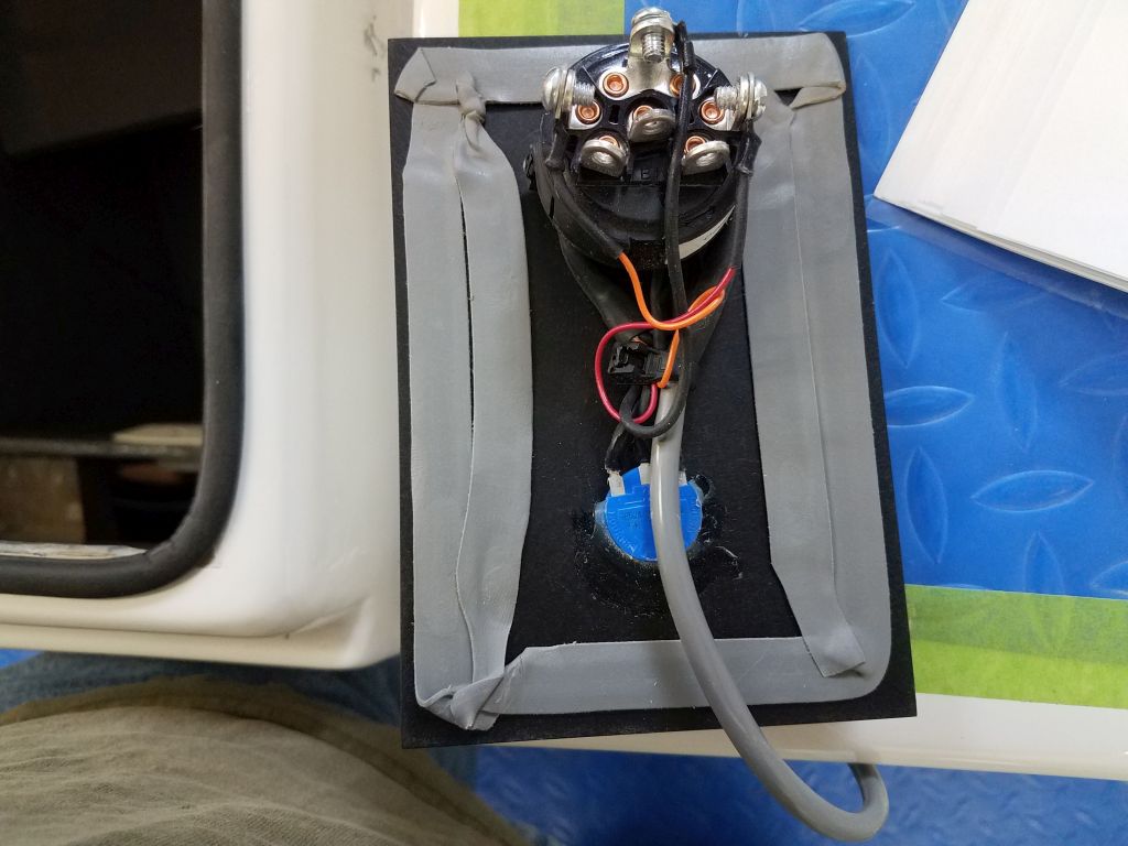
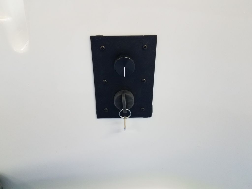
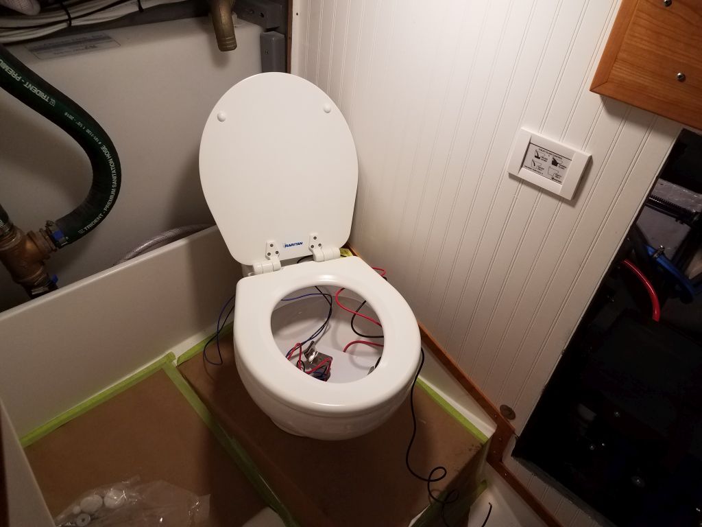
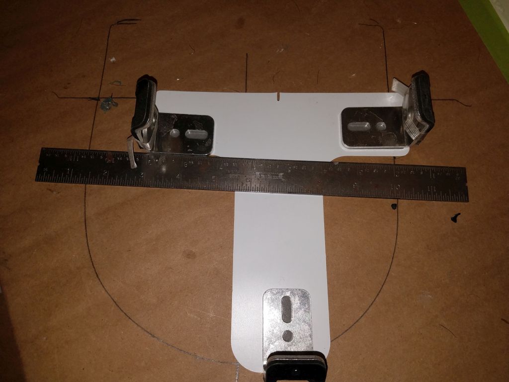
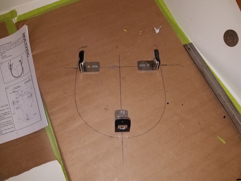
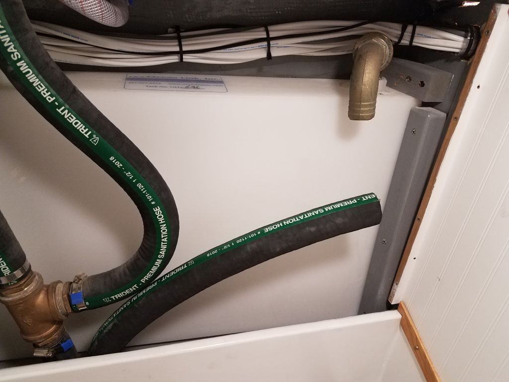
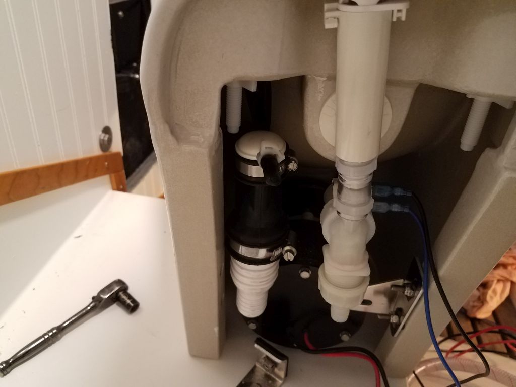
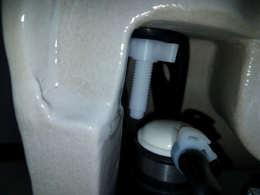
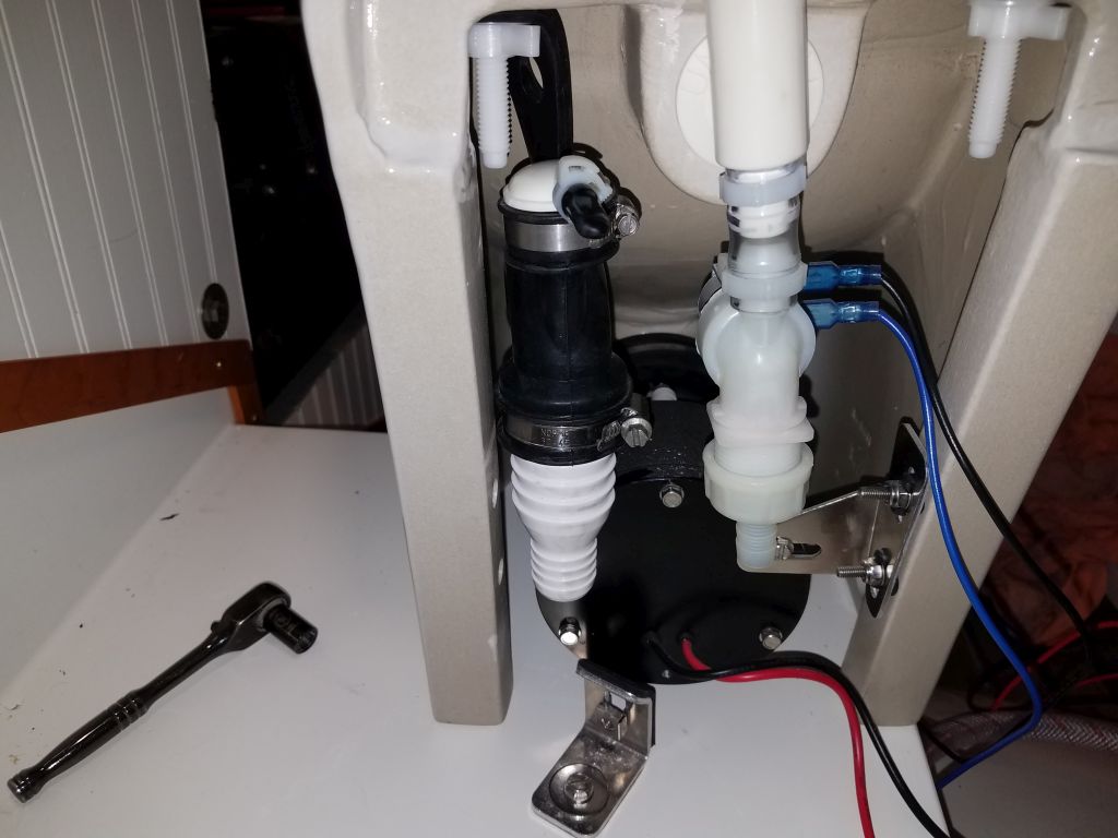
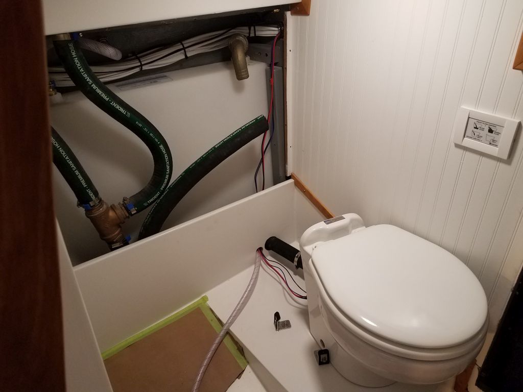
By now, it was mid-afternoon, and I’d just received the shipment containing the elbow fitting I needed for the head, so with a short stretch of time before I had to leave for the day, I thought I’d get that in place if I could.  Barbed plastic plumbing fittings tend to be annoyingly oversized–this one was spec’d out at 1.61″ OD, nominally 1.5″ pipe size, but 1-1/2″ reinforced marine hose simply does not stretch enough to fit over something oversized–a fact with which I was well familiar, so my first step was to sand away the offending barbs as needed so the fitting would fit inside the hose, removing just what I needed to from both sides of the barb before pre-installing the short length of hose I needed to attach to the discharge fitting on the toilet.  Then, up in the boat, I installed the new elbow and connected it to the discharge hose I’d installed earlier, bolting the toilet into its brackets in the process.  It was a relief to have that done, and now all that remained to complete the head installation was to connect the intake hose, and finalize the wiring from the toilet to the control box.

Total time billed on this job today:  7 hours

0600 Weather Observation:  39°, cloudy, rain shower.  Forecast for the day:  Mostly cloudy with gradual clearing, windy, 46°

Scupper 254

Tuesday

I continued work on the fiberglass liner cover plates as needed, which in this case meant lightly sanding and cleaning up the two newly-glued pieces from last time, and finalizing the sanded finish on the remaining sections as needed.  After test-fitting the newly-extended section for the port side, I applied a coat of primer to all pieces.  At the same time, I lightly sanded the tiller and applied a second coat of varnish.

I spent some time on a more involved test of the electric motor and controller, eventually figuring out how to shift from forward to reverse (it wasn’t immediately clear that the key switch was the “gear shift”, and that turning it one way or the other selected the direction of the motor).  I had to switch a pair of wires on the back of the key switch, as indicated in the instructions, in order for the key switch to work logically, with forward being forward and aft being reverse.  With the boat on the hard, I had to severely limit how much I operated the shaft for now, lest I cause damage to the Cutless bearing, but in any event the propulsion system worked as it was supposed to in both directions.

Satisfied with the engine controls and that the wiring as as it should be, I permanently installed the control panel with butyl tape sealant and six screws.

Before moving on to energize and test the charger for the engine battery bank, I took a few moments to finalize the wiring at the port outboard batteries, cleaning up and securing the charger and temperature sensor wires and securing the battery box top; I’d not been able to properly finish this when I made the final connections the other day.

After plugging in the shore power, flipping the proper switches, and resetting the GFI outlet in the engine room (these seem to come pre-tripped when new), the battery charger powered up, and all lights that should have been lit were lit, and things that shouldn’t have lit up didn’t (i.e. error lights or codes).  Once I’d confirmed proper operation, I left both this charger and its counterpart for the house battery bank energized for the rest of the day as a chaperoned test to ensure nothing untoward happened.

With the propulsion system and battery bank checked out and complete, the last major job aboard was to complete the installation of the head.  I’d already done everything I could to prepare, so all that was left (one of those funny phrases in boat restoration…) was to install the throne itself, including water supply and discharge hoses and four wires.

With the character and dimensions of the head platform and head compartment itself, I eventually settled on what I thought was a good position for the toilet bowl.  I had to factor in arm and leg room, the shape of the nearby hull, space to allow the lid to open more than 90 degrees, and also leave room for the hoses to exit the back of the toilet.  While the toilet was designed to have its hoses and wiring exit straight down from the back of the china bowl, and the bowl backed up close to a bulkhead, in this case there was no access, nor room, for this sort of arrangement, and I’d always known I’d have to run the hoses in a different way.  My final location struck the required compromise between all the factors, and I marked the outline of the bowl right on the protective paper I’d had in the head during the project.

The bowl was to be secured to three hidden brackets that fit inside, with bolts that passed through holes in the bottom of the unit.  As needed, I marked these locations to help align the three brackets, which came pre-stuck to a piece of cardboard that I supposed was to hold the brackets in the proper position and alignment, which could have been helpful if indeed the brackets were properly aligned and positioned on the cardboard, which they were not. So I removed the brackets from the cardboard (whatever they used to stick them on was extremely adhesive) and installed them according to my layout marks and in accordance with the instructions, securing them to the platform with the included screws and washers.  Then, having previously noted the approximate locations where I wanted the hoses to run, I drilled two holes through the small bulkhead behind the platform and into the holding tank space, and with some effort eventually led in the heavy discharge hose, leaving both ends detached for now pending final head installation.  The fresh water intake line I had led into the compartment some time before, and now had only to lead it out through its own new hole towards the toilet.

I had hoped and planned to complete the installation now, but I ran into difficulty with the discharge hose connection.  As I noted before, the design intended this hose to lead straight down, and the discharge attachment arrangement inside the toilet bowl didn’t easily accommodate deviation from this engineered solution.  There was flexibility in the discharge connection, but I found that with the hose attached and a fairly aggressive bend to lead out to the bulkhead, the rubber thingie inside the toilet tended to kink.  At length, after trying various things, I came to the conclusion that I needed an elbow fitting in there in order to make the bend while keeping the discharge assembly happy, and since I didn’t have one on hand I’d have to postpone final installation till a little later.  Fortunately, there was (or, I should say, appeared to be) ample vertical clearance to accommodate an elbow, so I hoped that it would work out well once I had it on hand.  I would have preferred to avoid the extra fitting, but so it goes with anything on a small sailboat (or, I imagined, any boat).

During this process, I’d found that it looked like it would be beneficial if I pre-installed the rubber bracket included with the discharge assembly, and which was designed to be secured from above by one of the bolts holding on the toilet seat, so I took care of that now to ease angst later on.

Having taken the head as far as I could for the moment, I finished up the day by installing the new aluminum bracket I’d purchased for the masthead, and completing the Windex installation.  I secured the bracket to an existing hole in the masthead unit, along with an additional screw to keep it from twisting, and bolted the Windex mount to its after end, giving the vane ample clearance with the lights forward.  I removed the vane for safekeeping.

Total time billed on this job today:  8 hours

0600 Weather Observation:  34°, partly cloudy.  Forecast for the day:  Mostly sunny, 51°

Older posts