(page 4 of 6)

Salty 21

< Back to Salty

Saturday/Sunday

Over the weekend, I continued with daily coats of varnish on the new rudder cheeks, lightly sanding between coats, as always.

varnish1-31916
Saturday (4th coat)
tiller12-32016
Sunday (5th coat)

Meanwhile, I worked on the new tiller.  Now that the lamination was fully complete, I removed the clamps, leaving me with a messy-looking blank that  I could transform into the final shape.  The side that had faced down on the gluing jig was mostly smooth, but covered in epoxy squeezeout.  To begin, I laid out the old tiller on top of the blank to determine its relative position (which I’d previously marked, come to that), and then I cut off the rough ends of the blank, where the blank had extended off the jig and left ragged squeezerout.  This  left me with one smooth surface from which I could dimension and clean up the tiller blank.

Starting with the epoxy side down, I ran the tiller through the planer a number of times, alternating sides and cleaning up the surface and smoothing it on both sides till it was bare wood and dimensioned to the correct thickness, or about 1-5/8″, according to the original tiller.

Then, I traced out the final shape of the tiller, using the original, and cut the blank accordingly.

The tip of the original tiller was tapered down over the final foot or so of the tiller length for a comfortable hand hold, and I made some reference marks on the new blank to show the extent of this taper so I could pare down the end as needed.  I took care of this quickly with a sander, then sanded the whole blank clean and smooth, rounding all corners but focusing especially on the tip end to smooth and contour it pleasingly.

I drilled the hole for the tiller pin, then, after cleaning the blank, applied a sealer coat of varnish.

tiller13-32016

Total time billed on this job today:  2 hours

0600 Weather Observation:
15°, clear.  Forecast for the day:  Sunny, high 35°

Salty 20

< Back to Salty

Friday

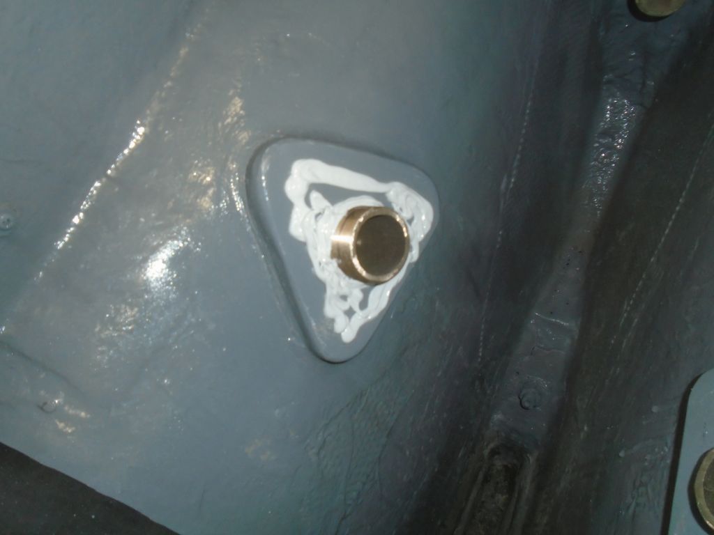
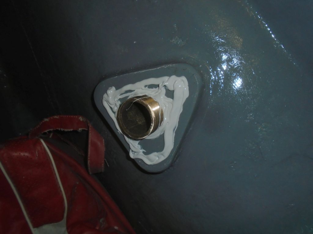
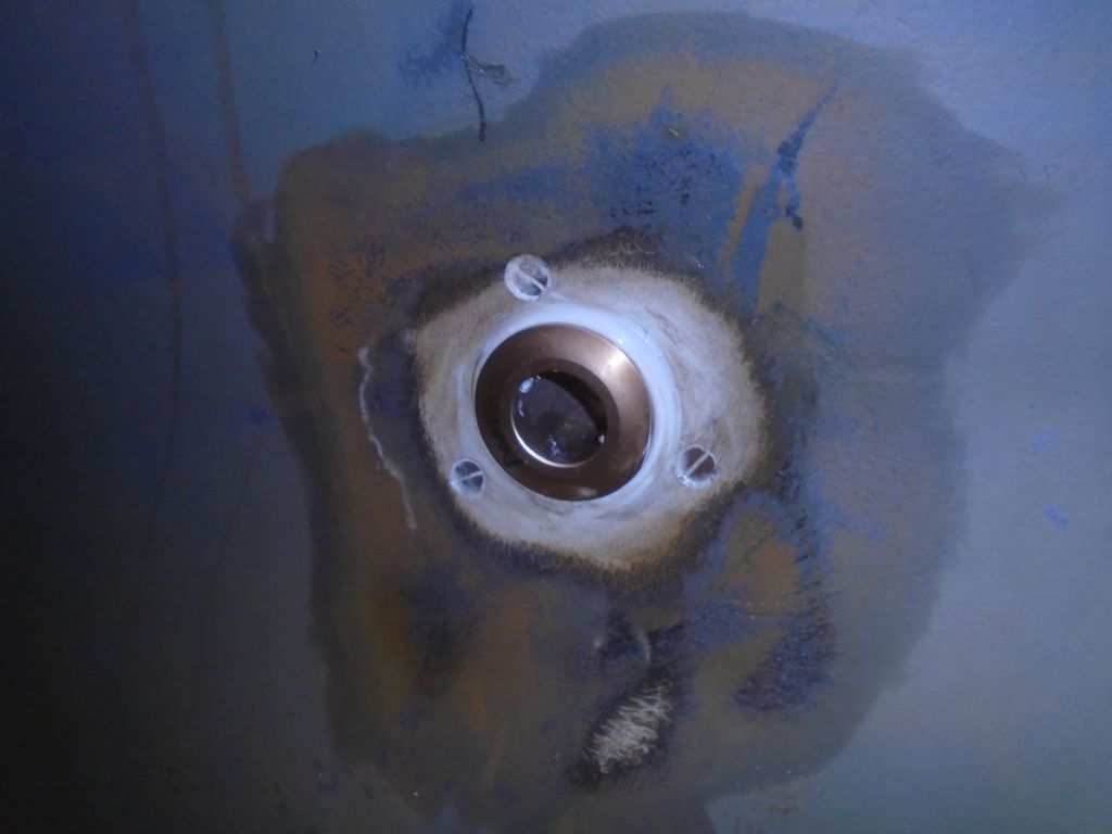
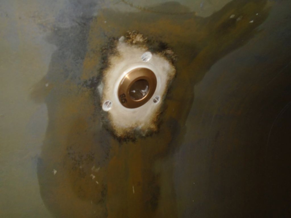
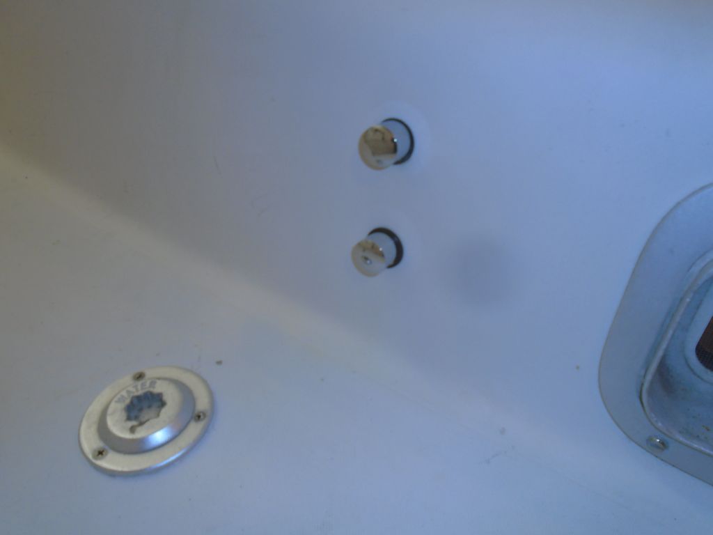
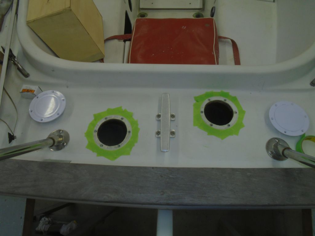
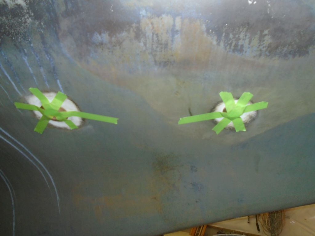
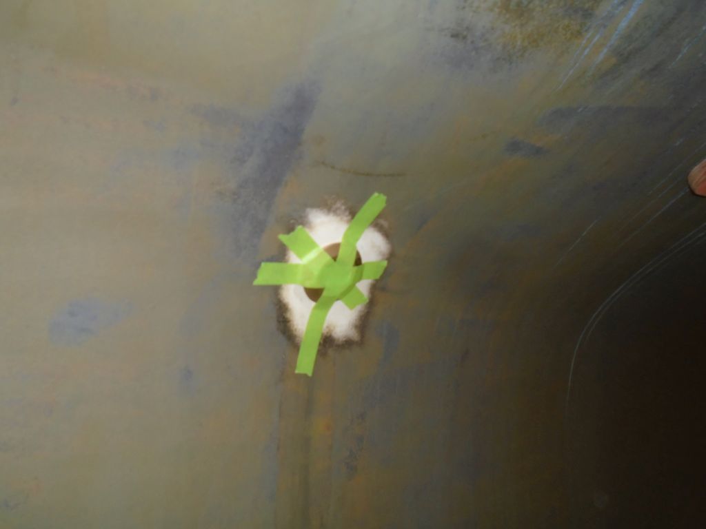
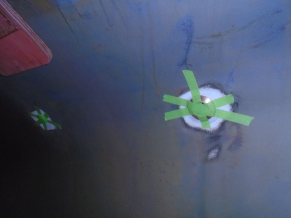
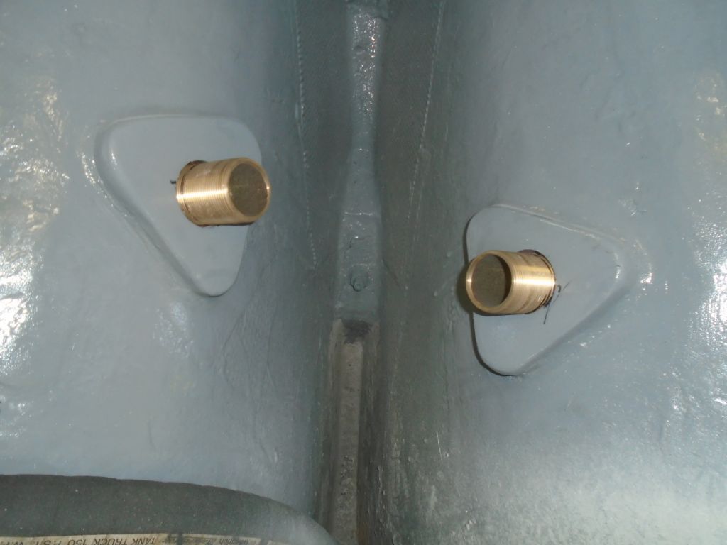
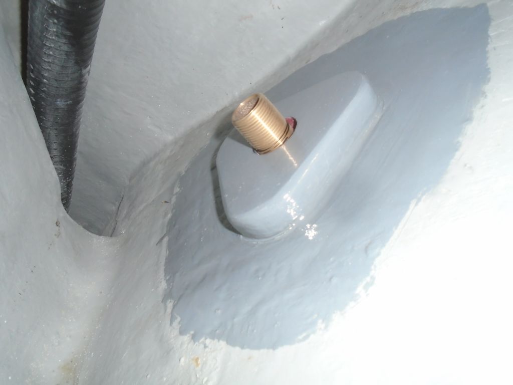
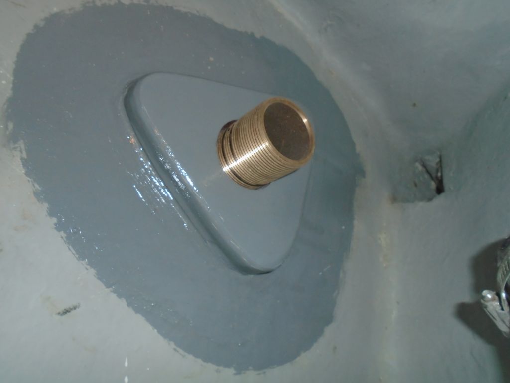
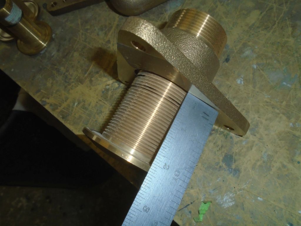
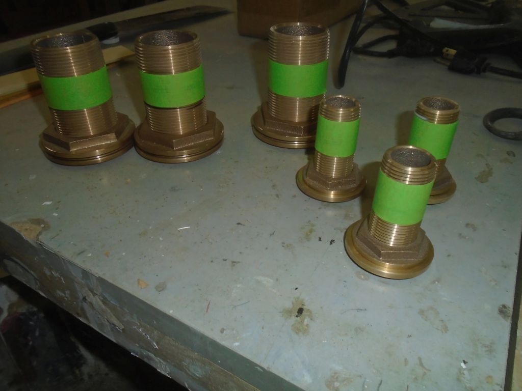
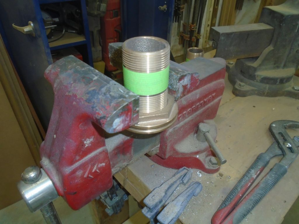
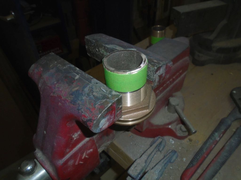
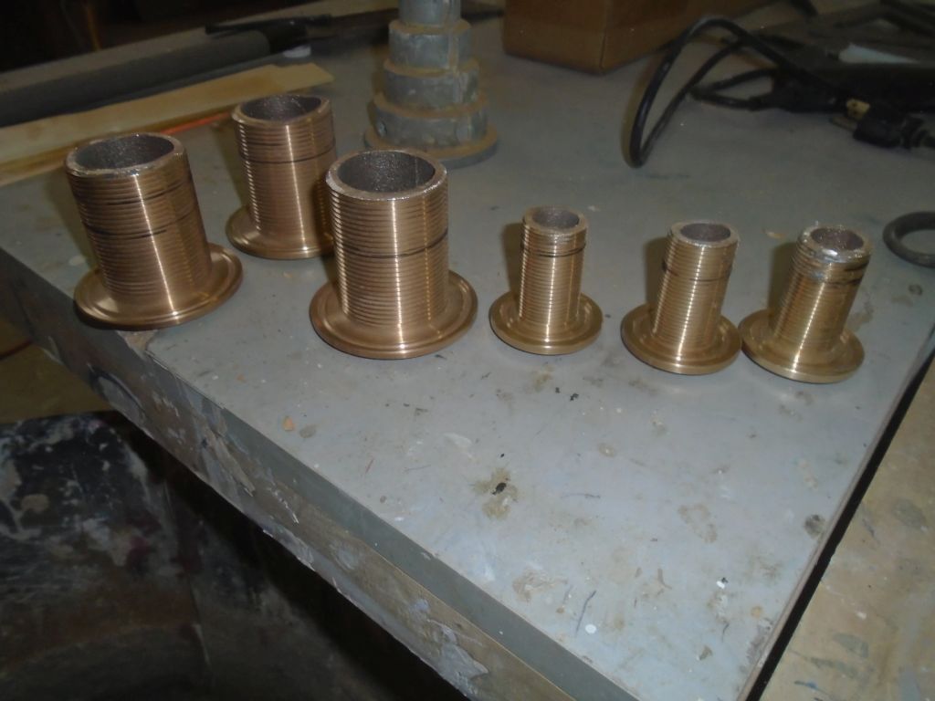
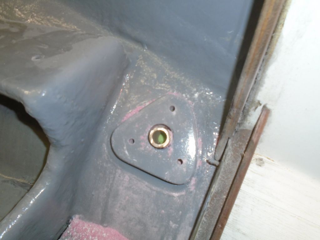
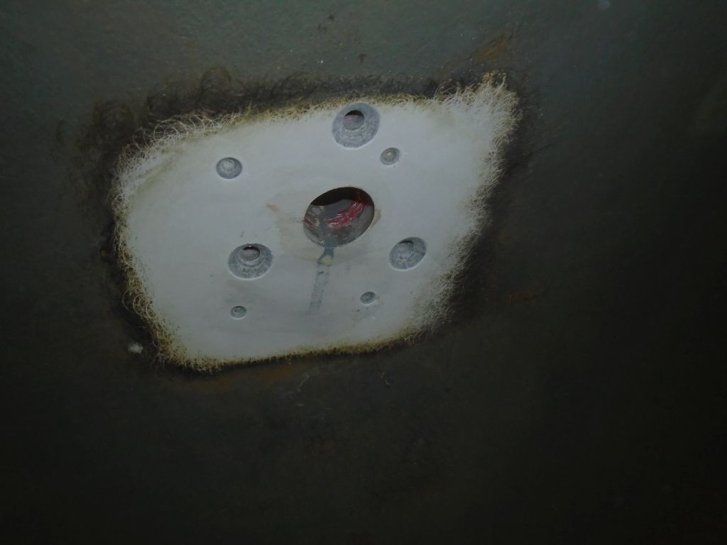
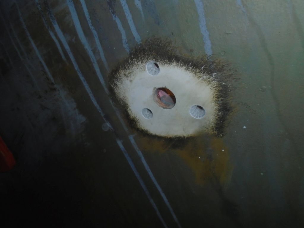
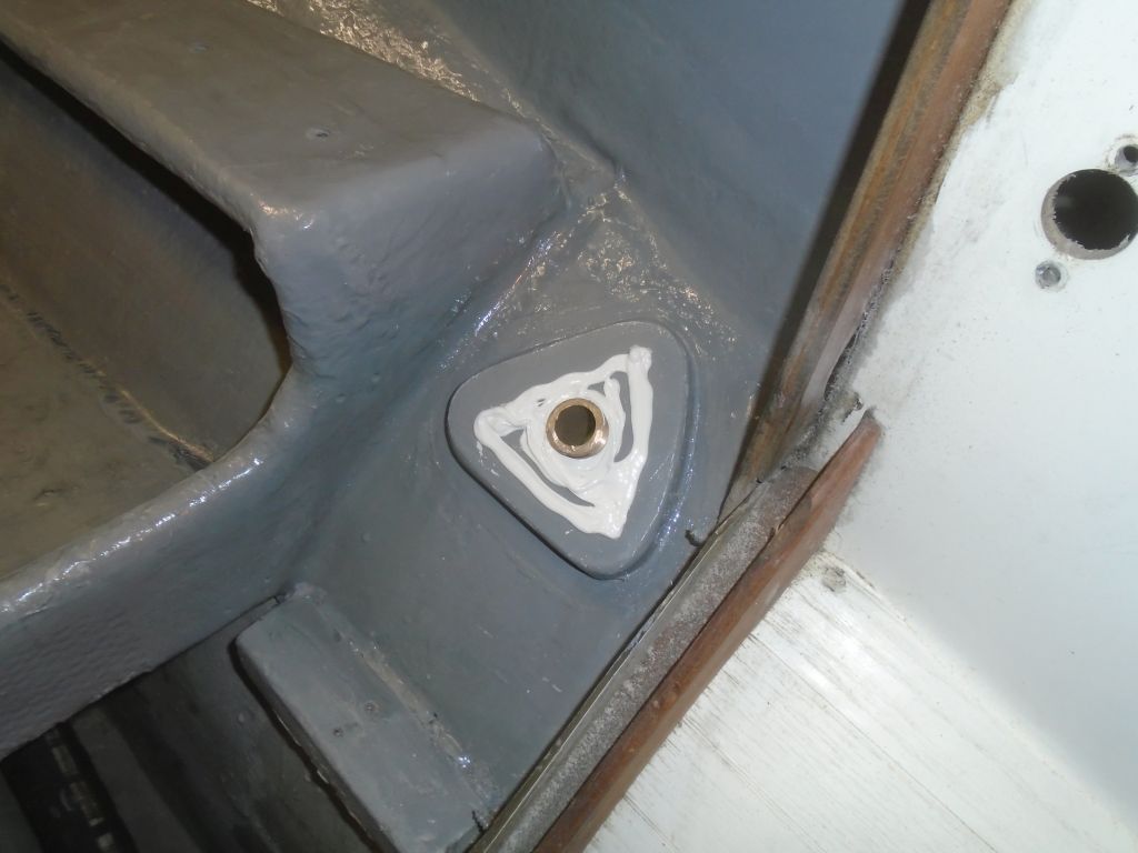
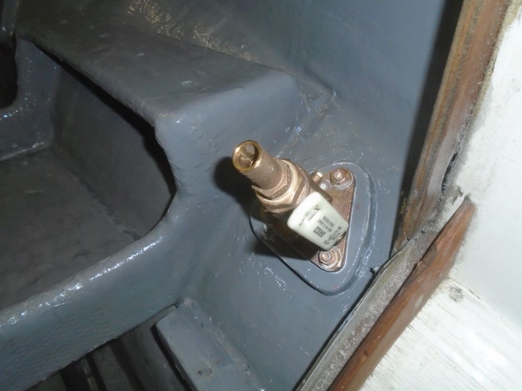
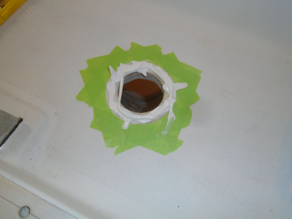
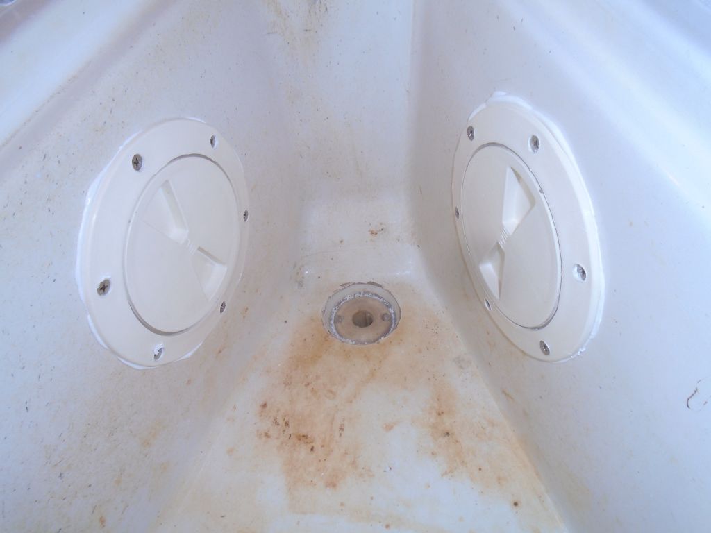
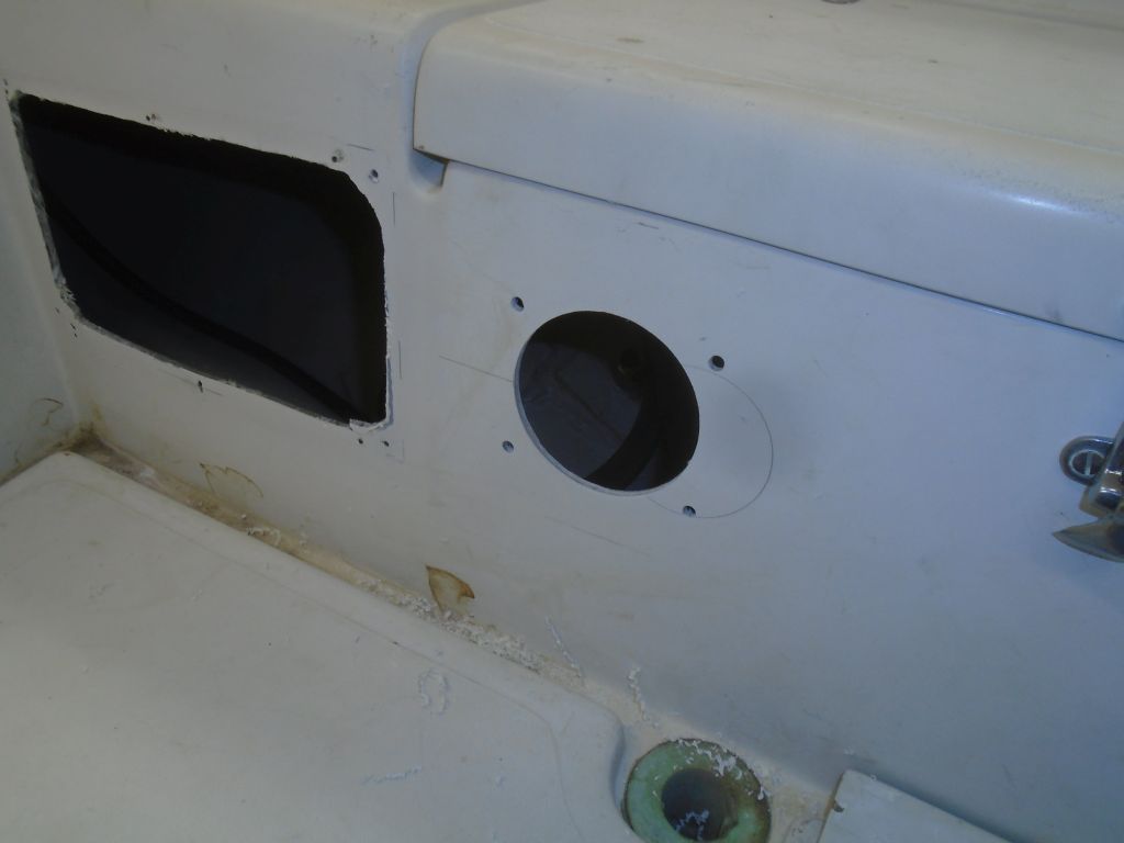
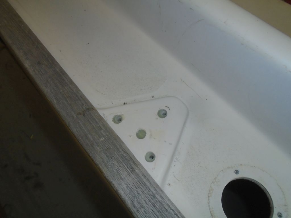
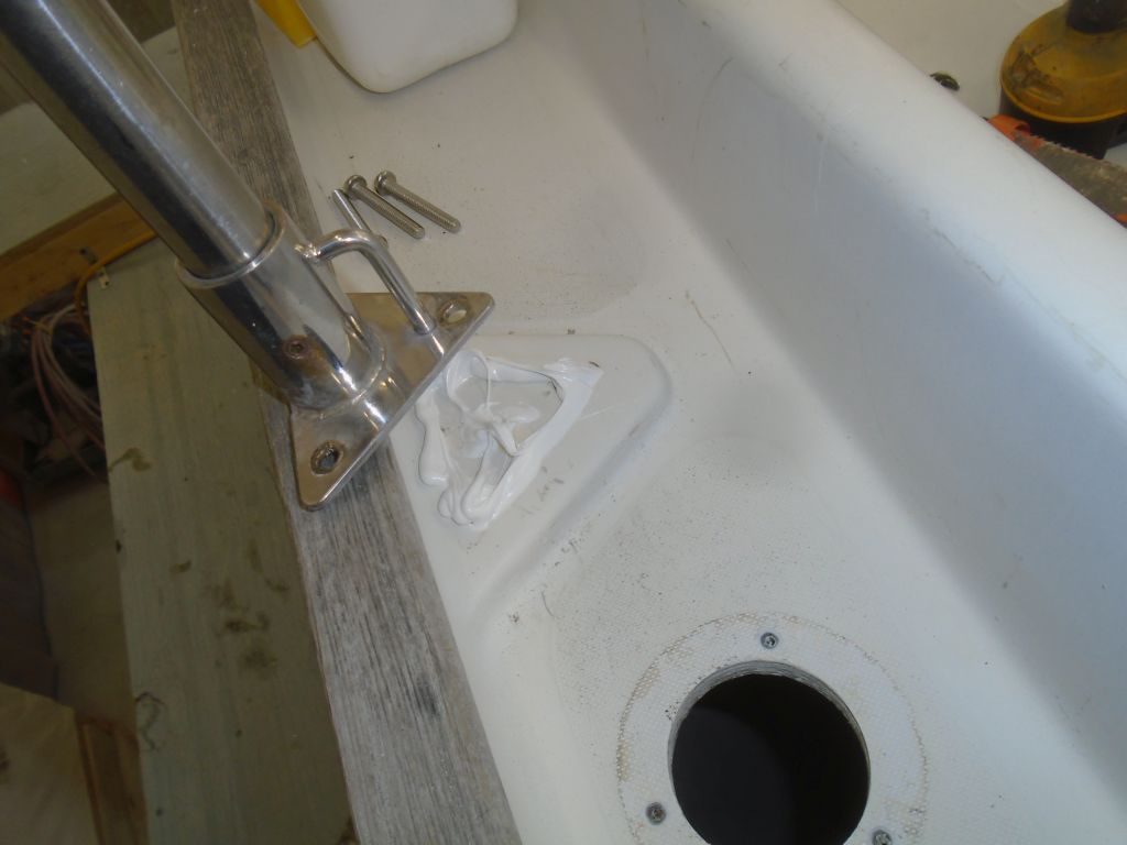
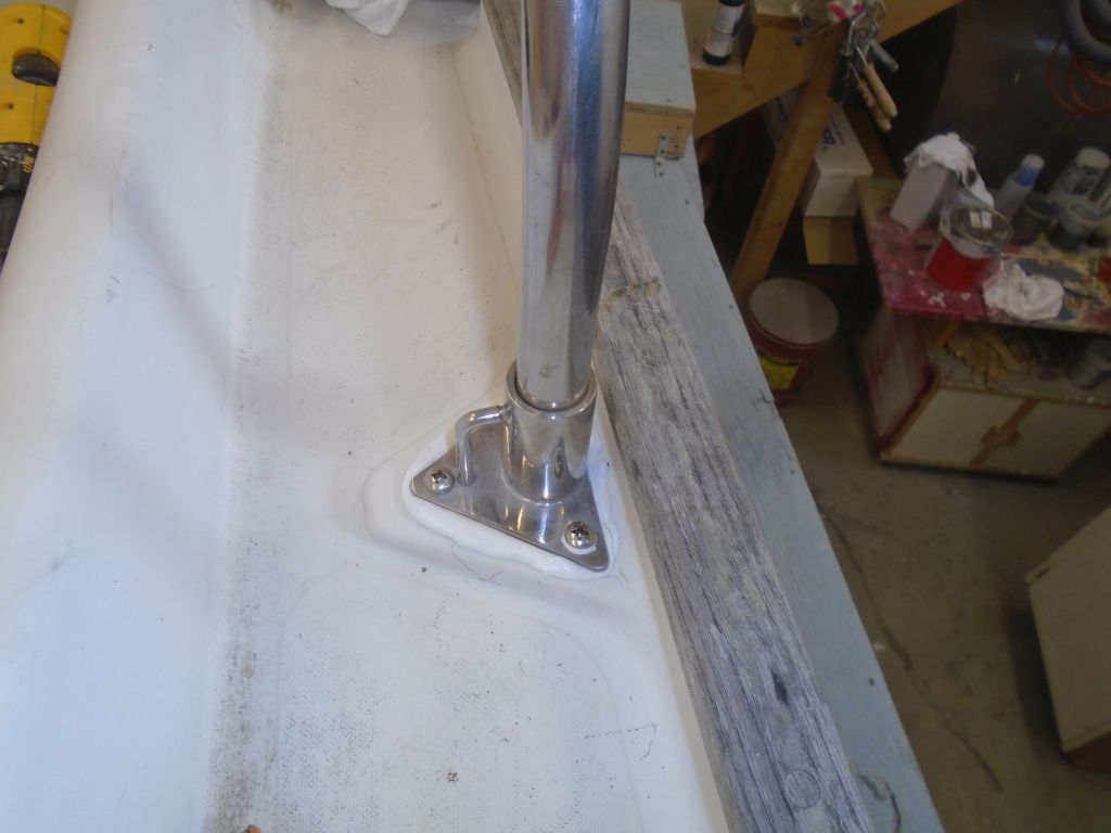
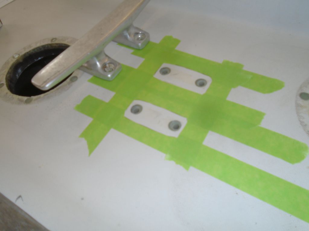
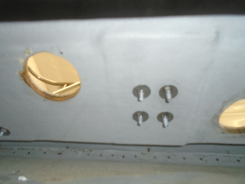
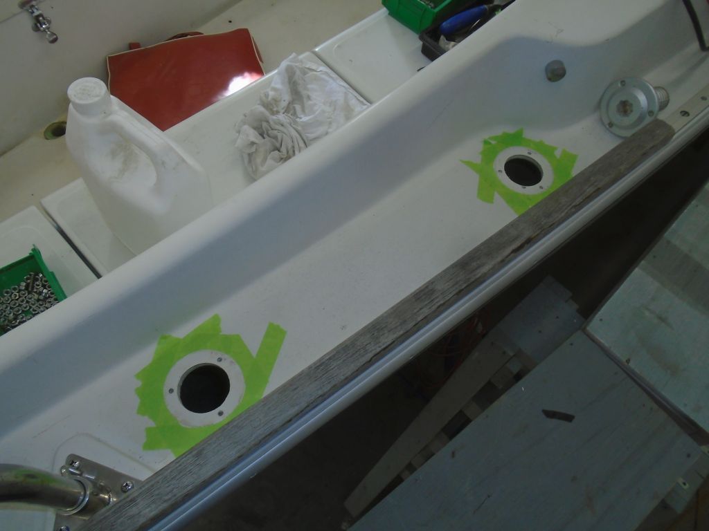
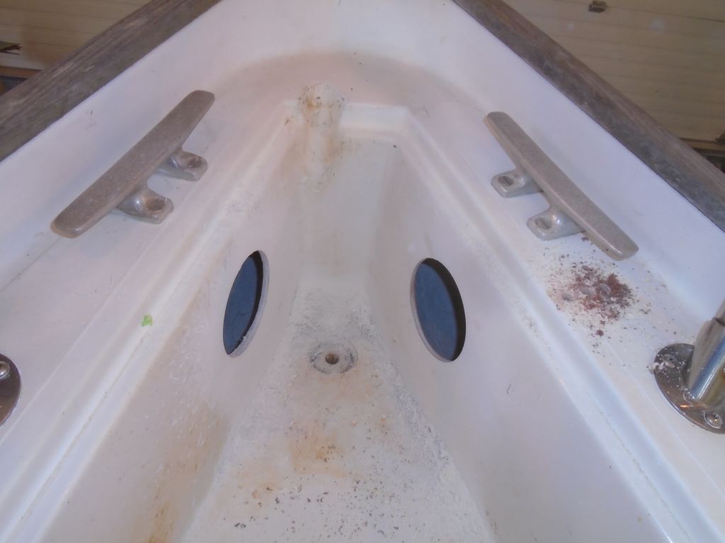
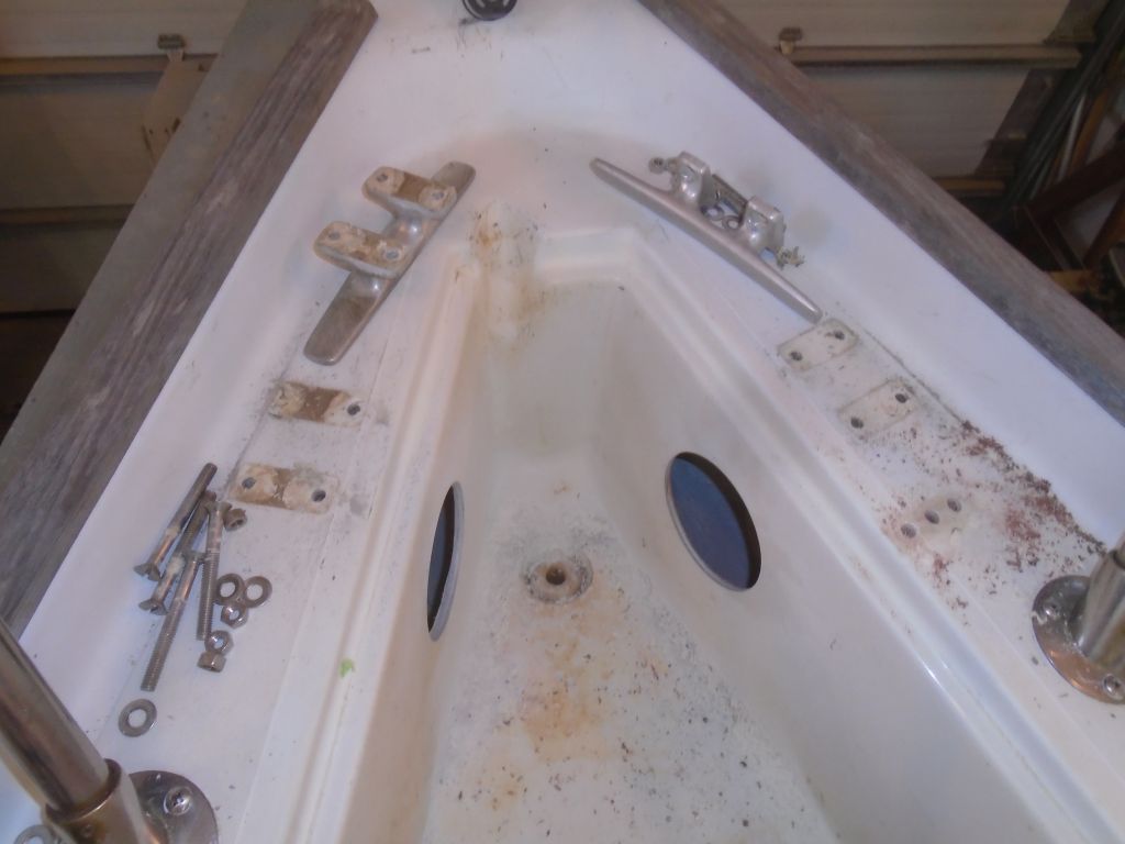
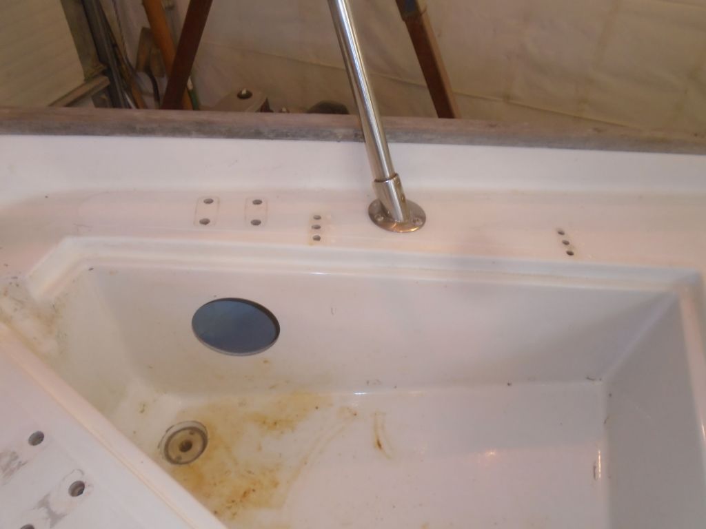
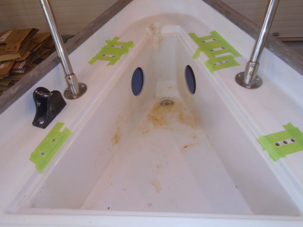
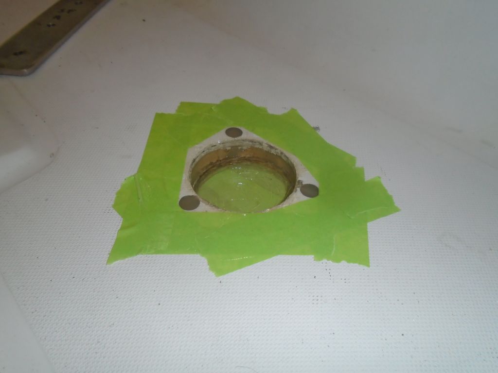
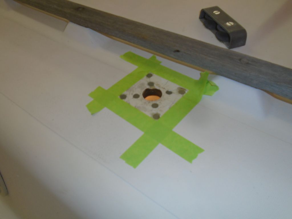
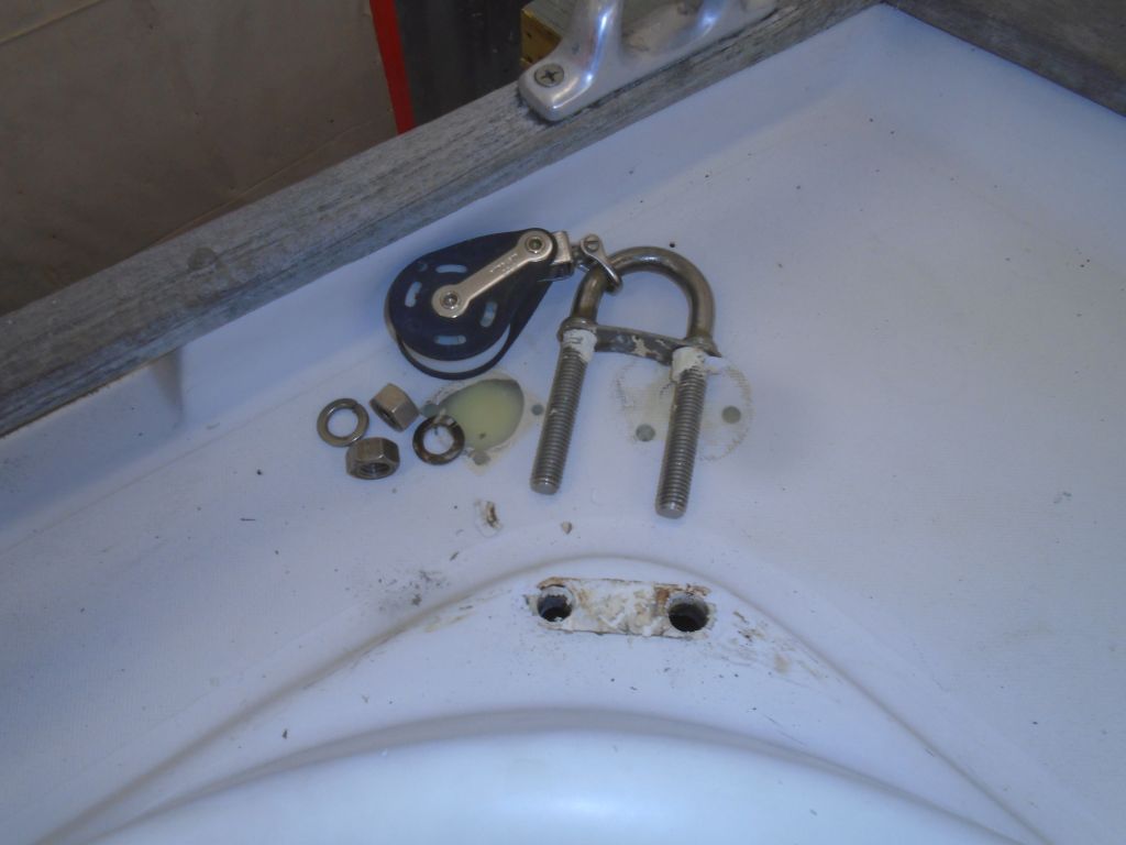
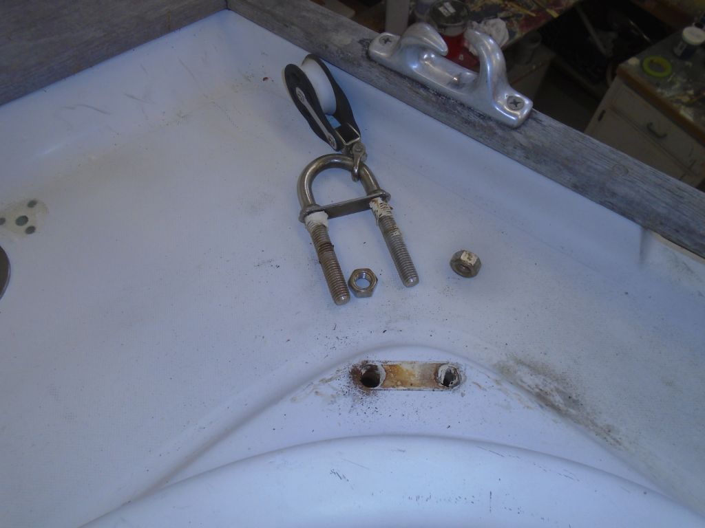
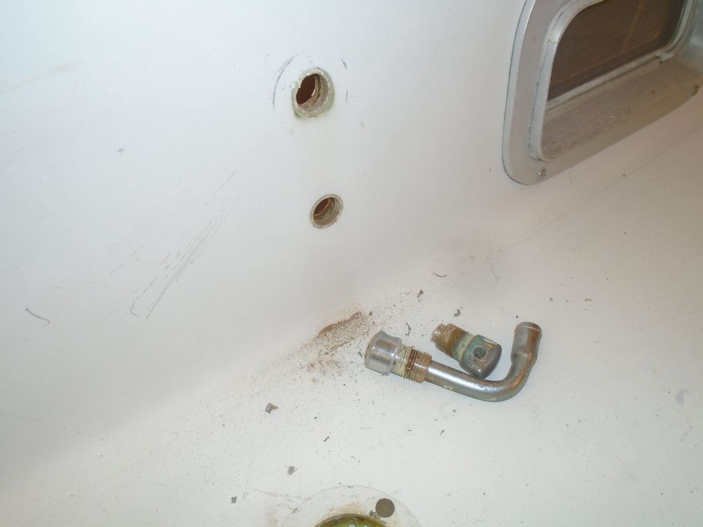
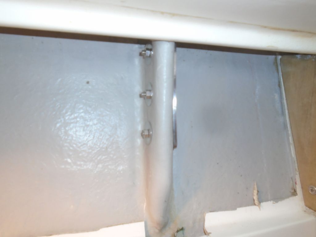
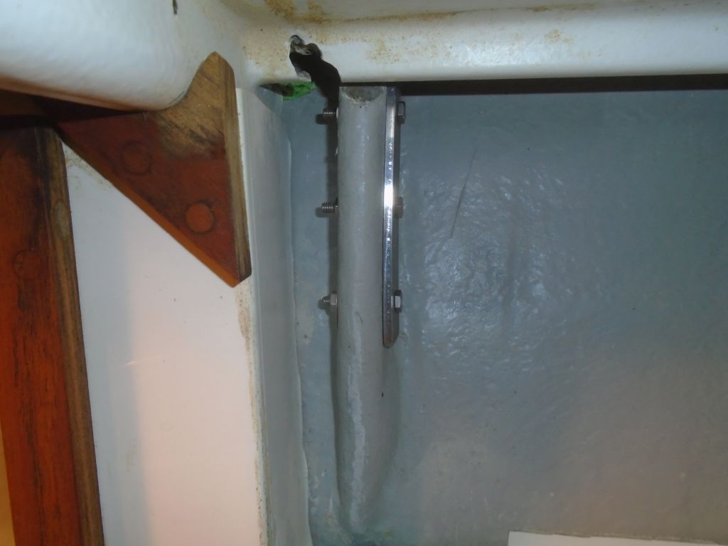
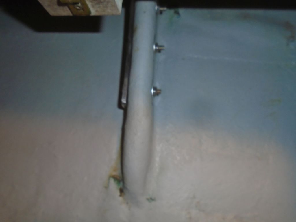
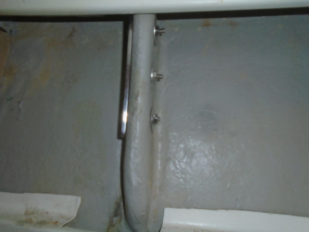
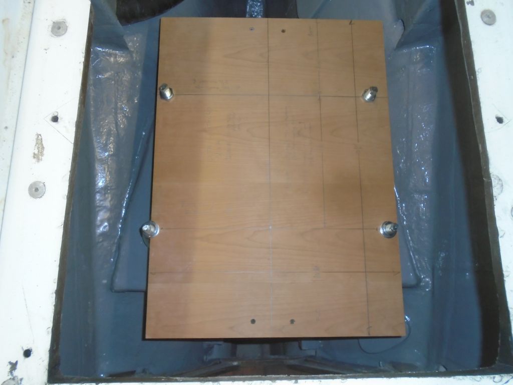
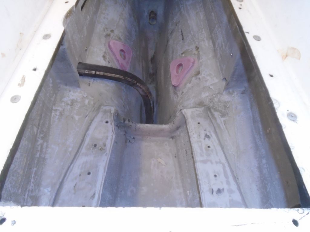
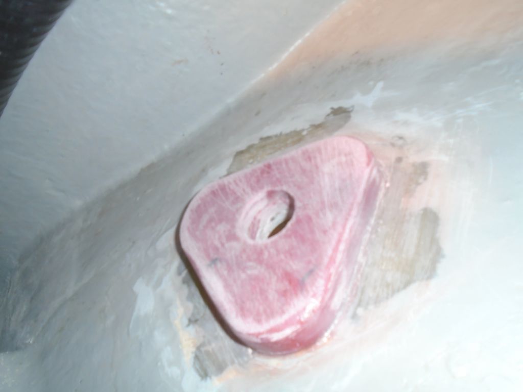
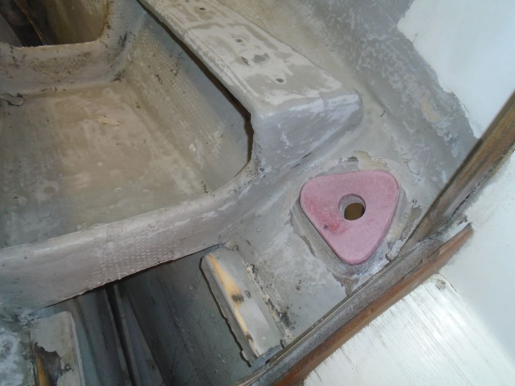
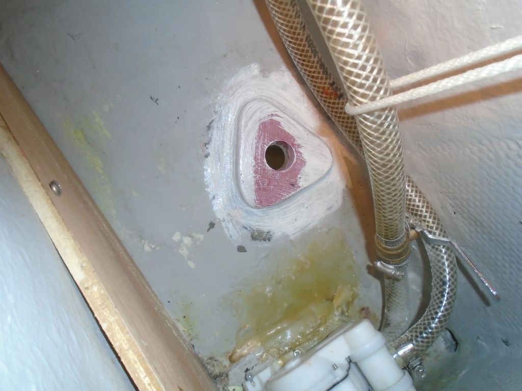
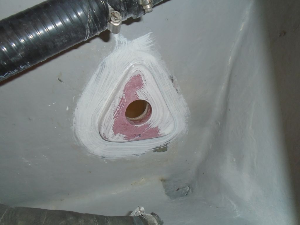
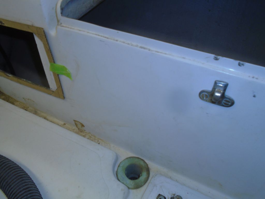
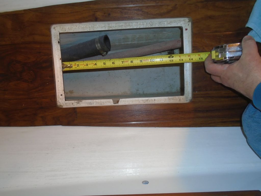
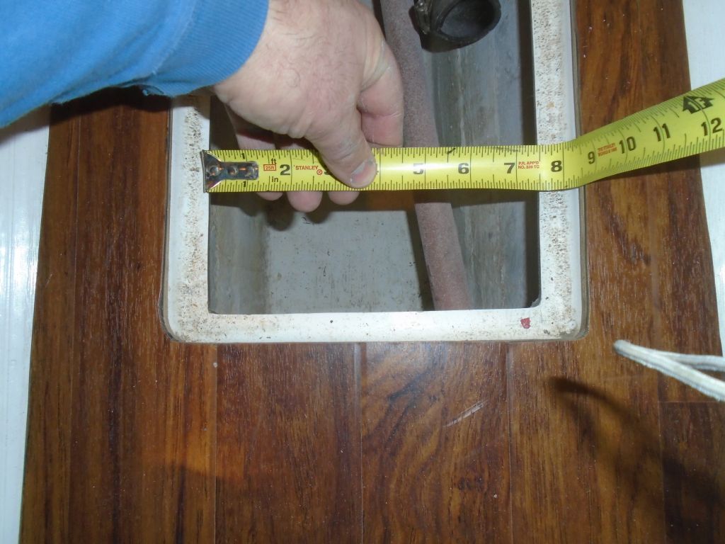
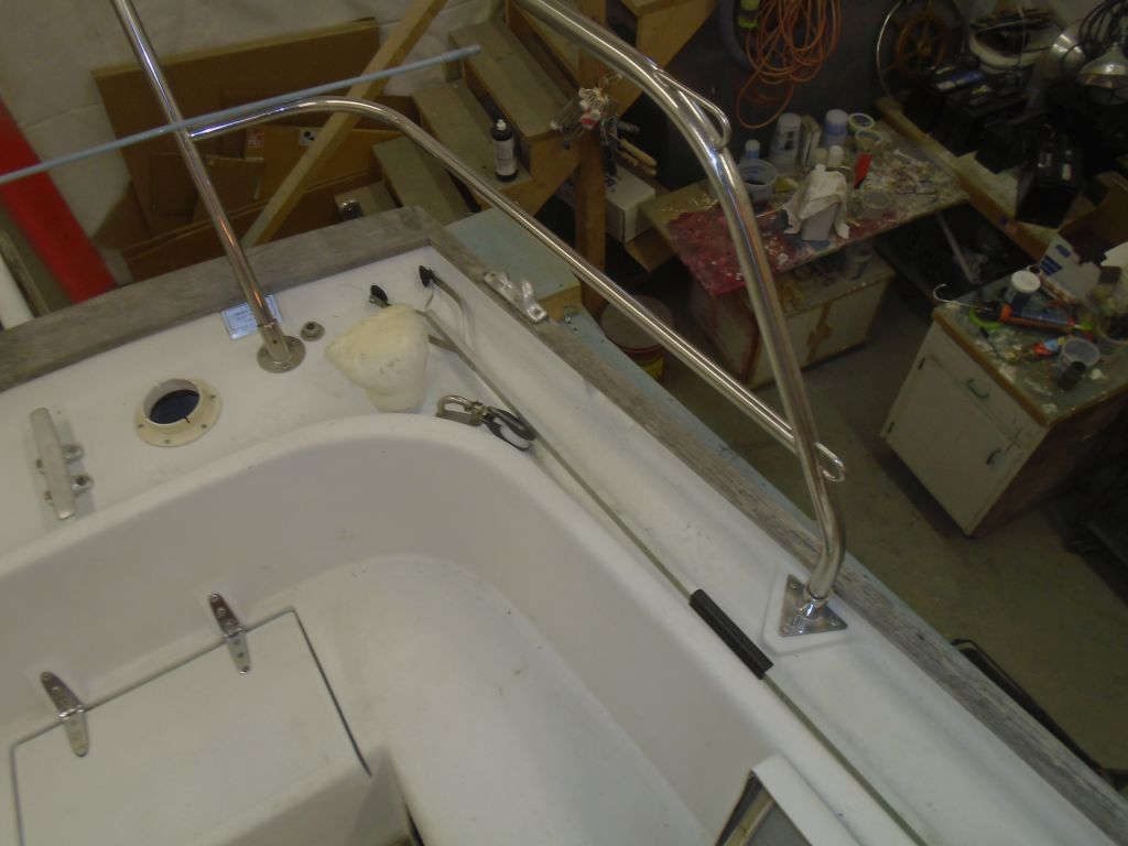
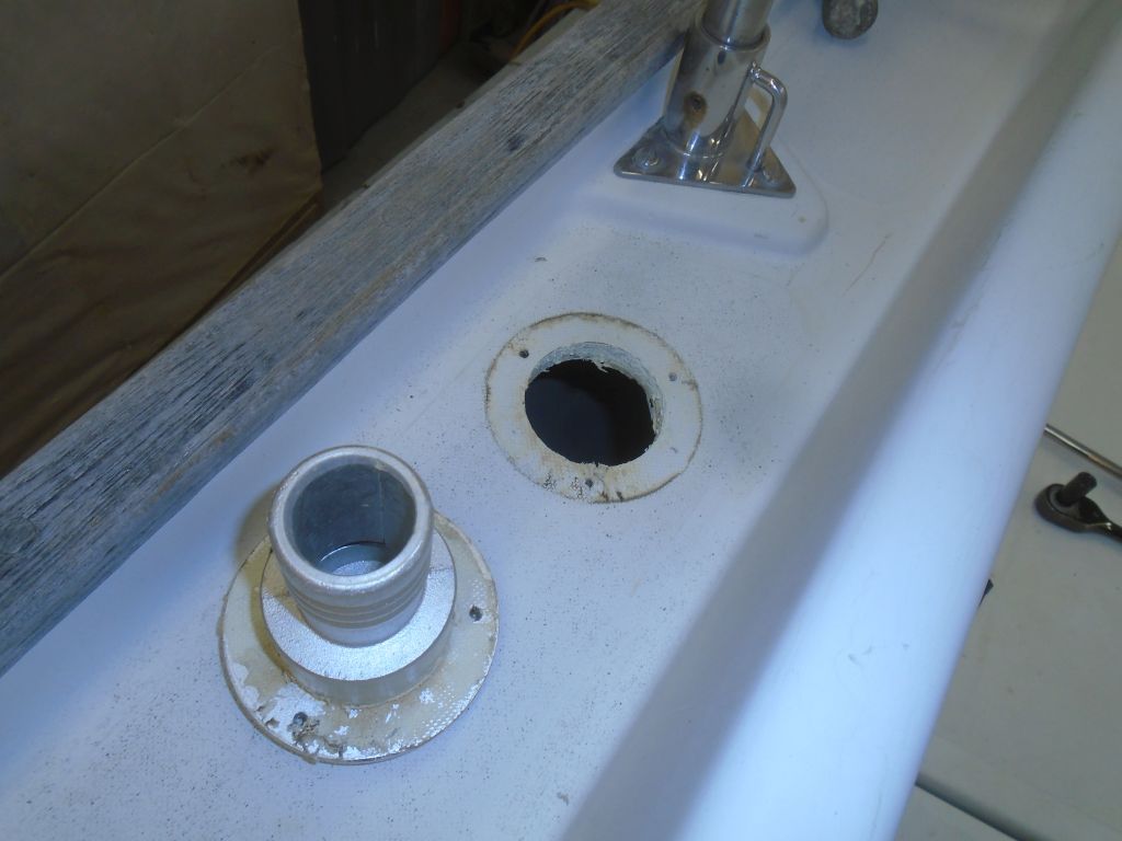
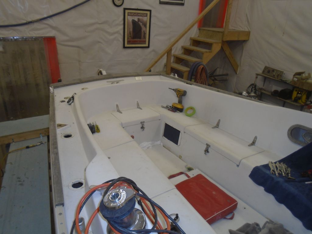
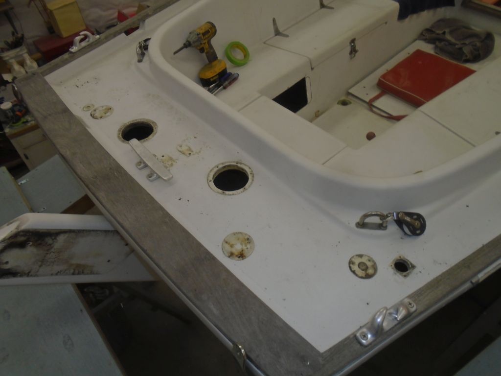
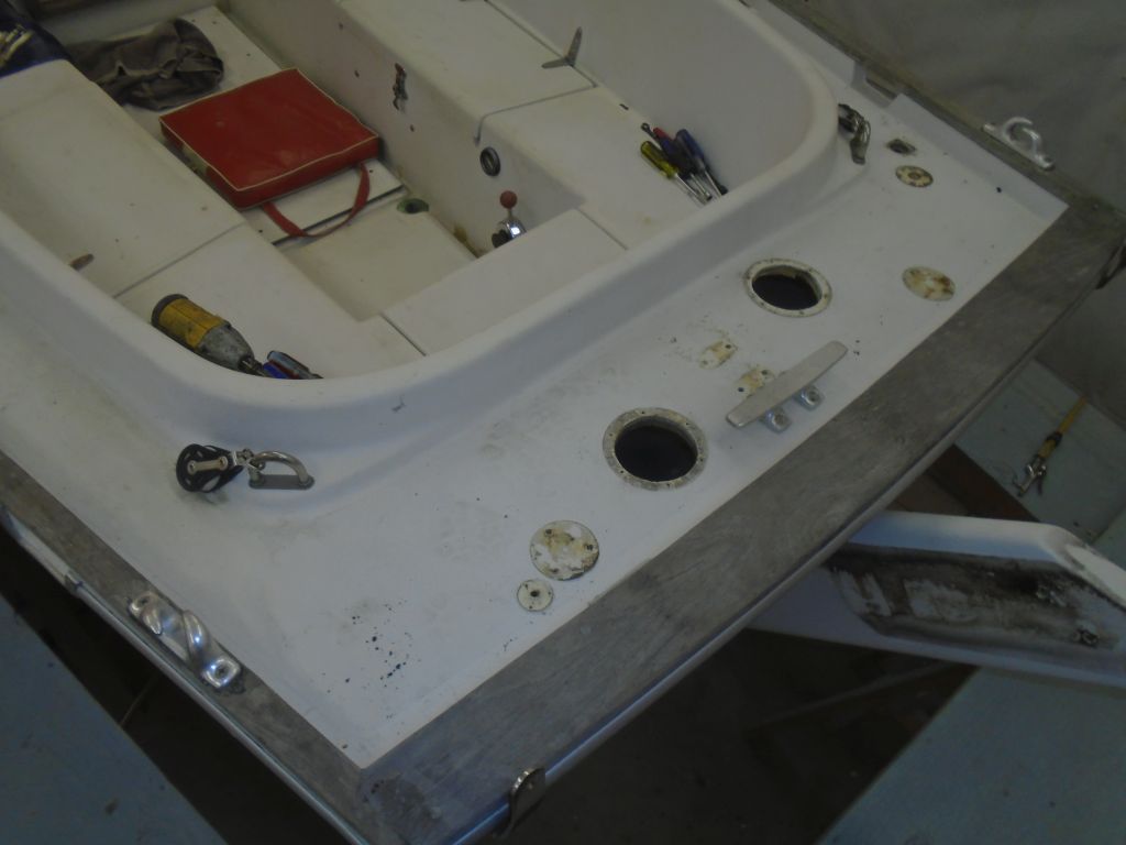
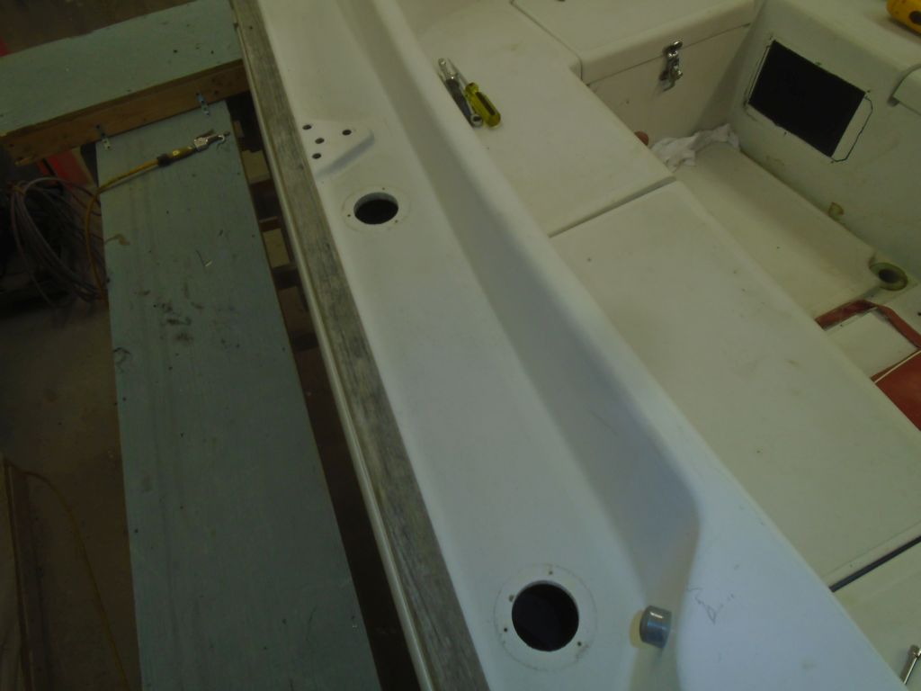
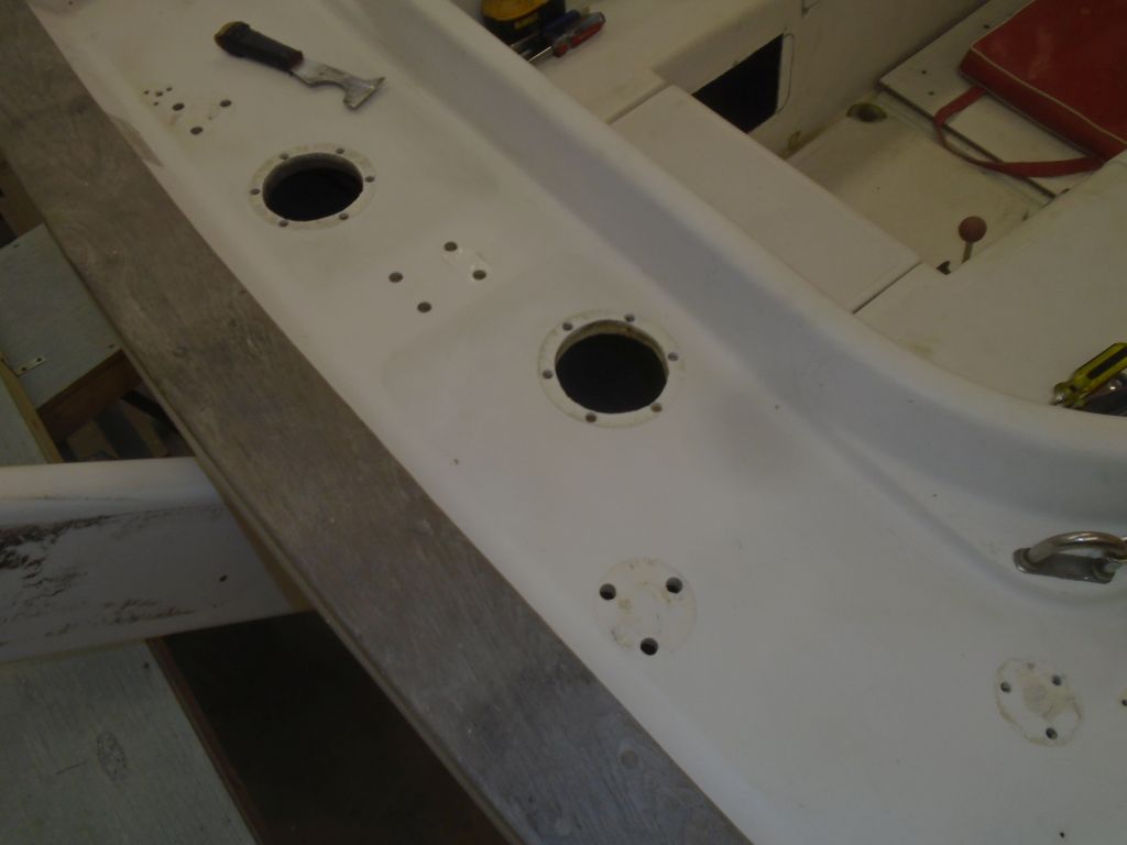
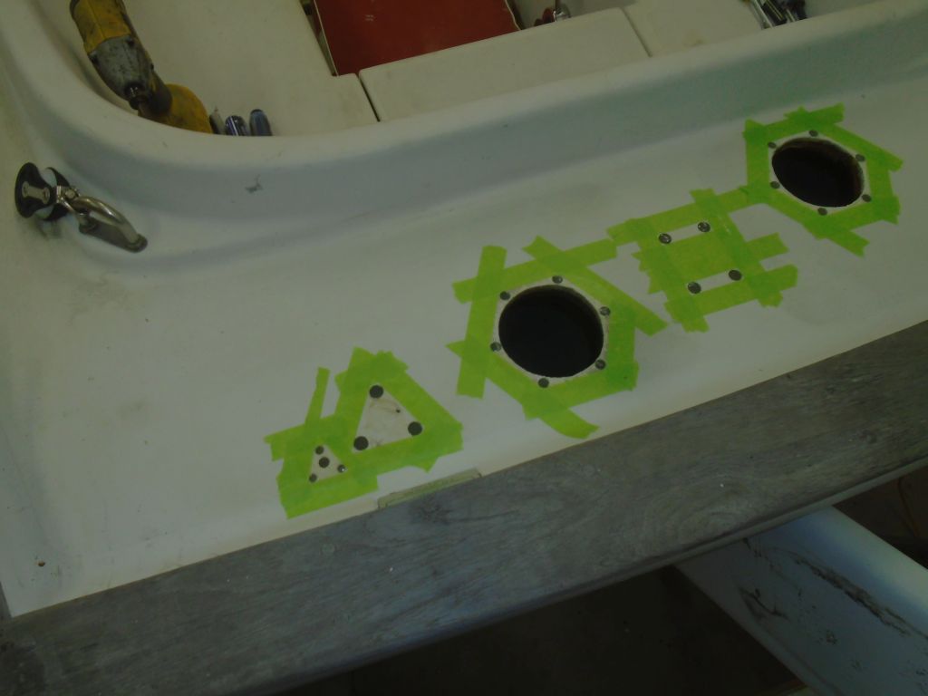
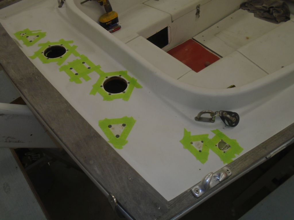
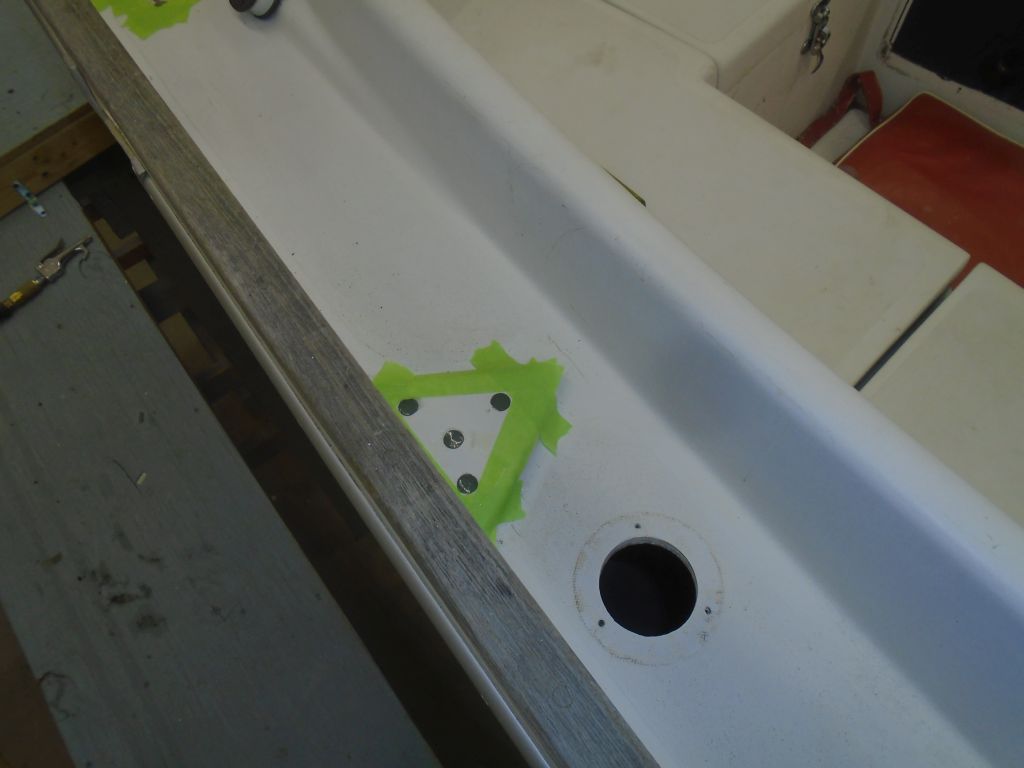
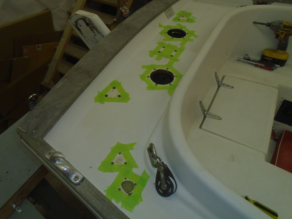
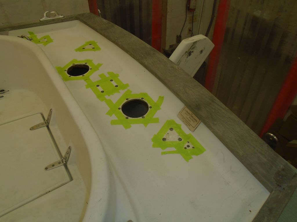
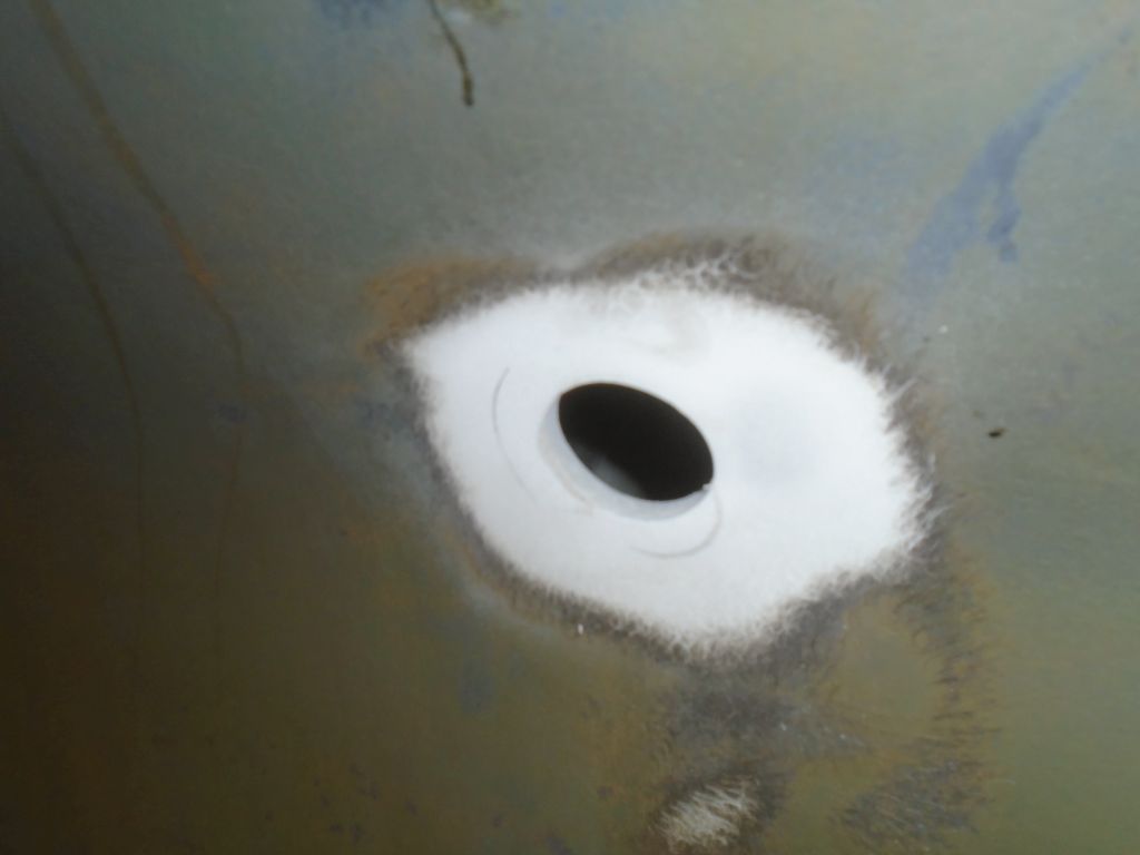
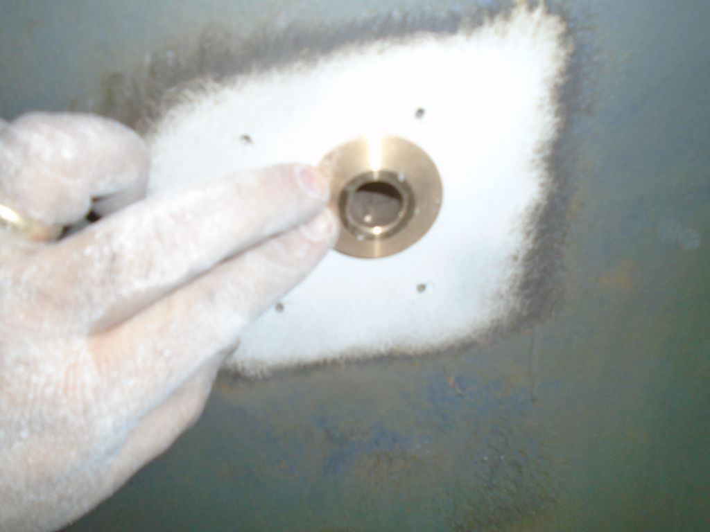
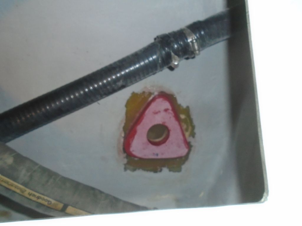
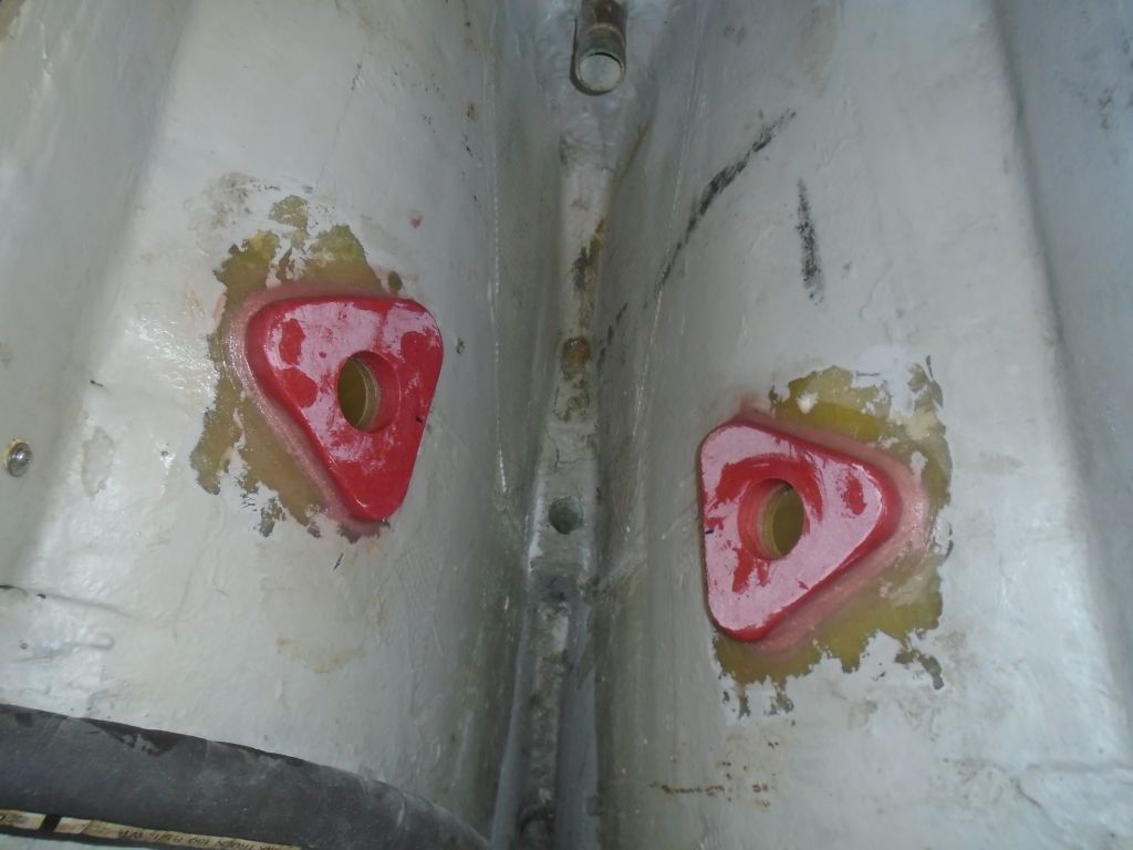
I got right back into things with the final two through hulls–the cockpit scuppers.  I’d previously cut the through hull necks to length, so I started with a dry fit to drill the bolt holes through the flange and hull.  While I had the flanges in place, I  test-fit the valves to check for clearances and to see if I could spin on the valves after the flanges were installed, or if I needed to pre-assemble them.   There was room to install both valves after the fact, and other clearances were OK (something I’d just assumed till now since the old valves were similarly arranged, but…), so I could move on with the installation.  I removed the hardware and prepared the area for final installation.

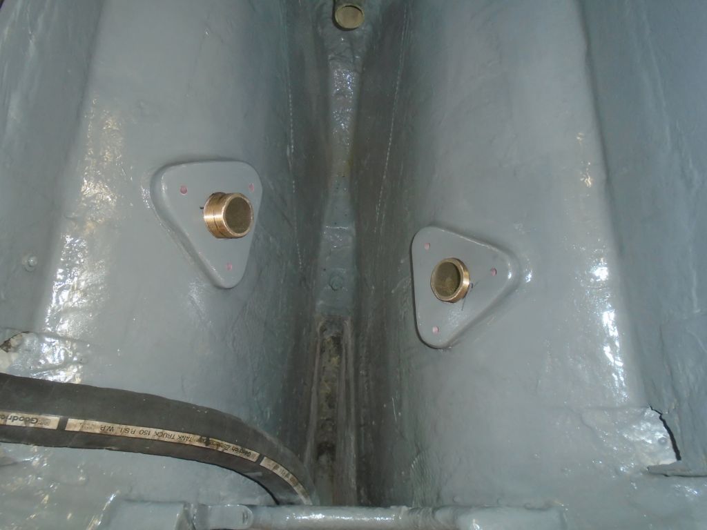
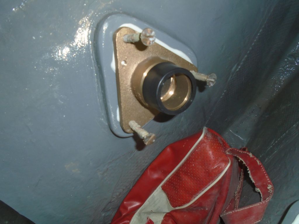
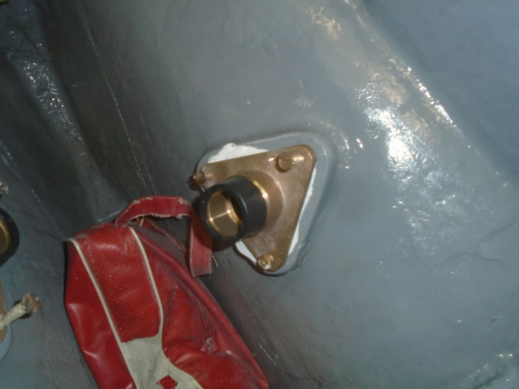
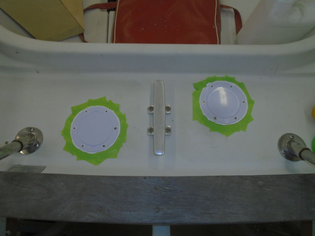
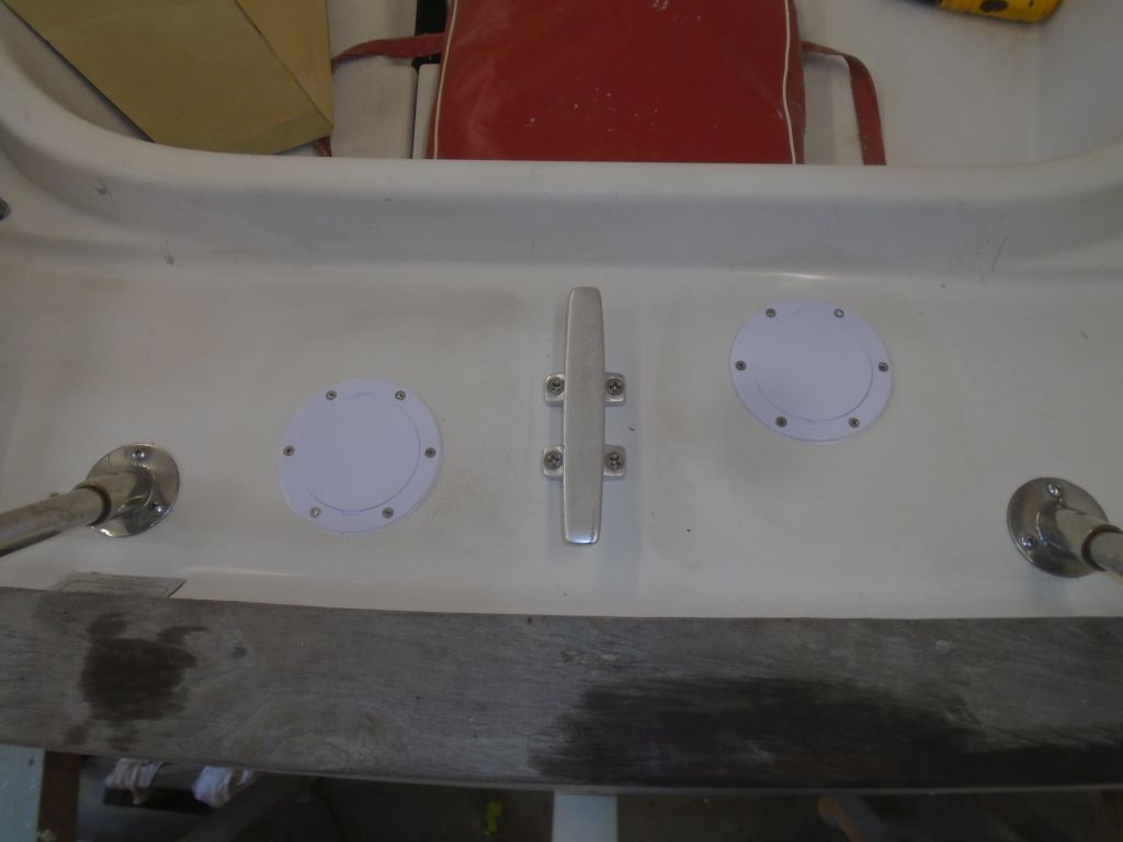
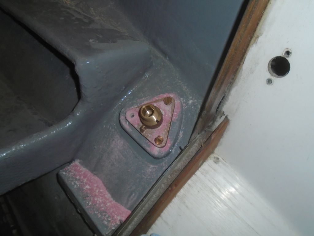
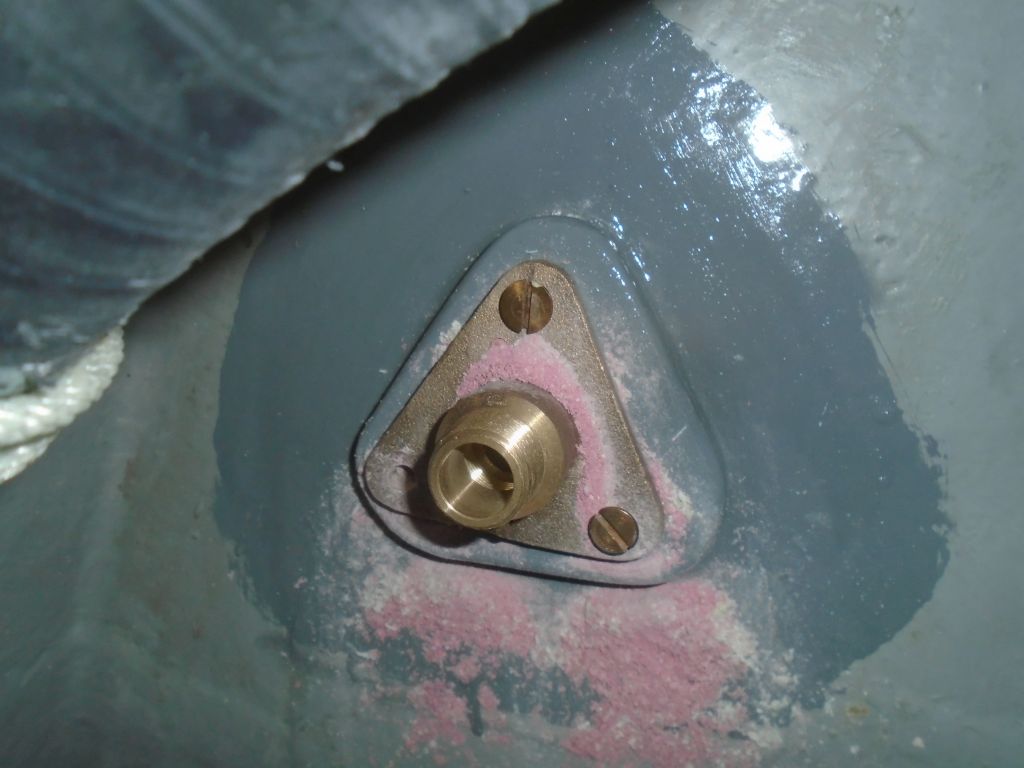
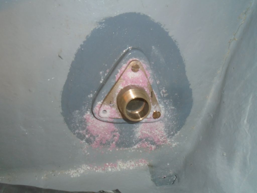
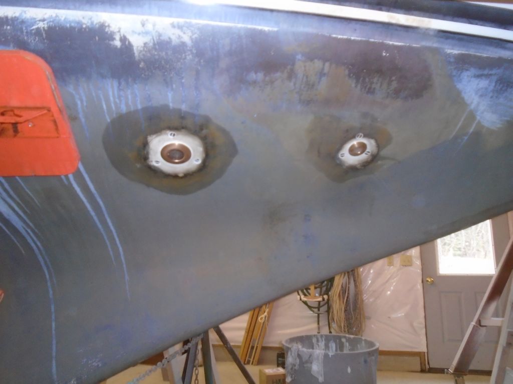
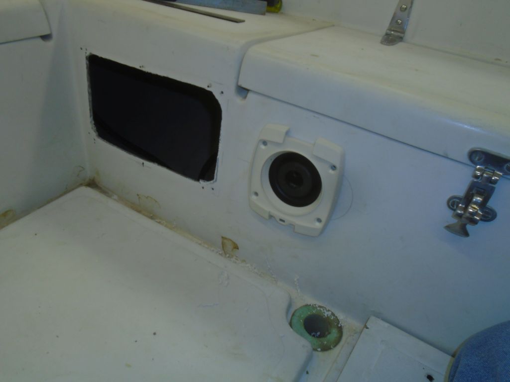
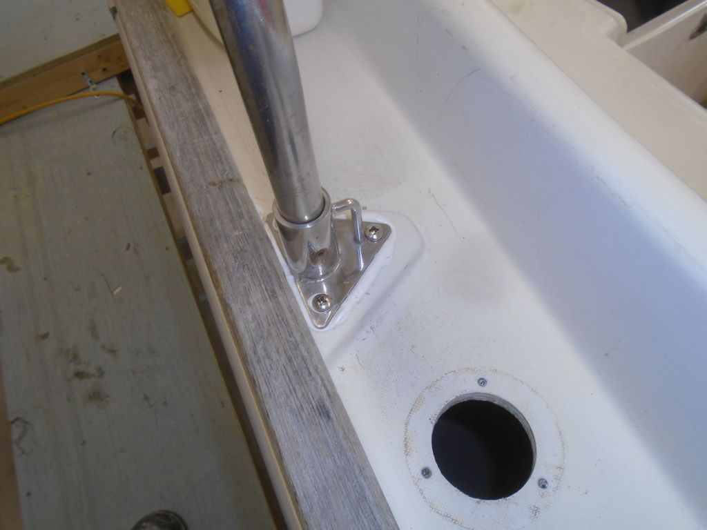
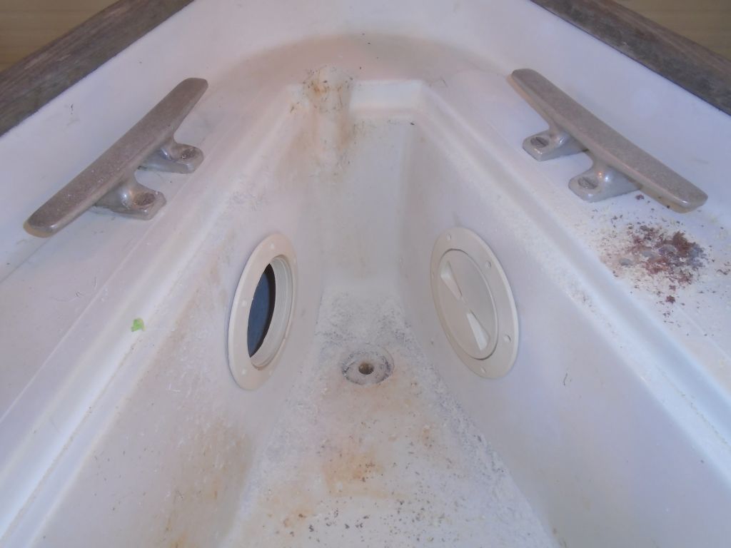
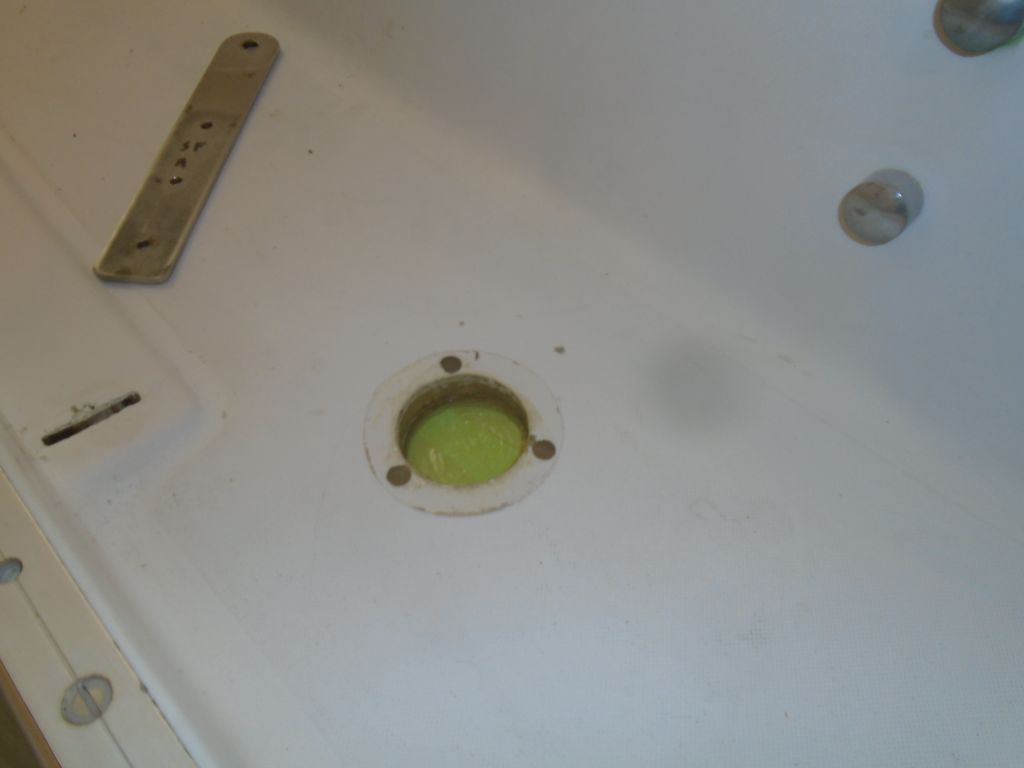
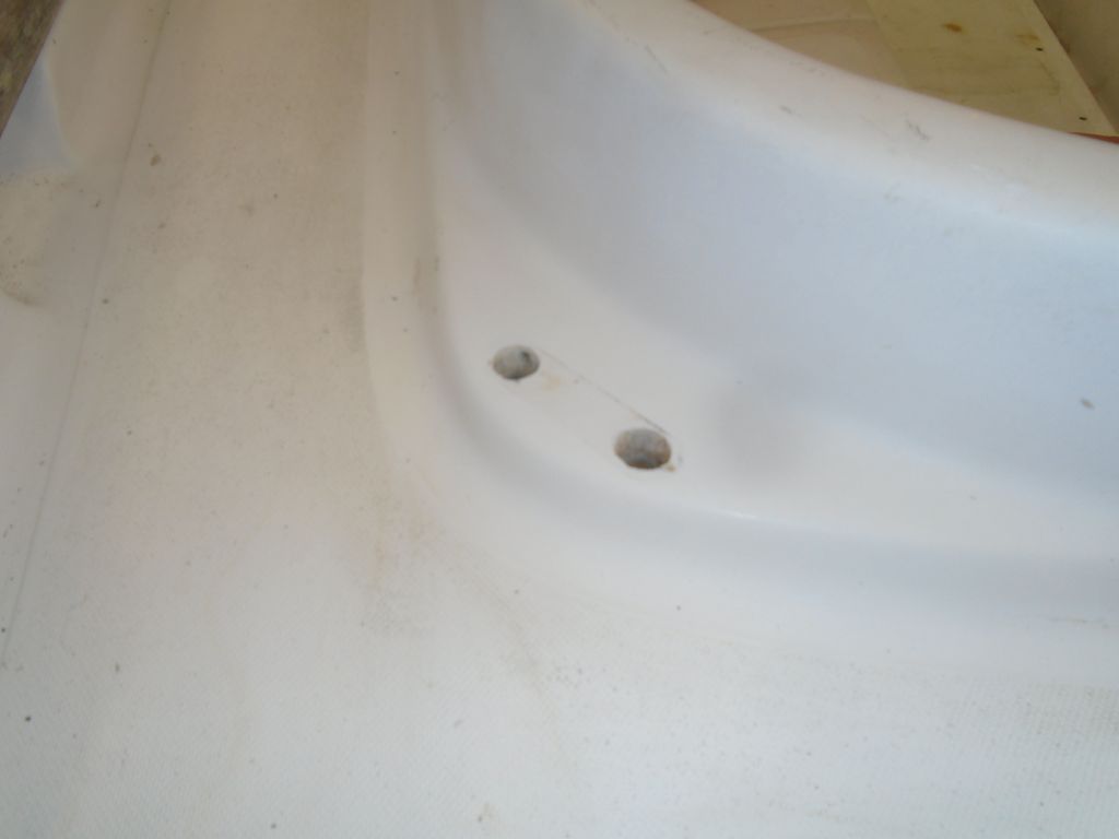
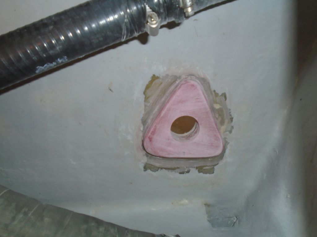
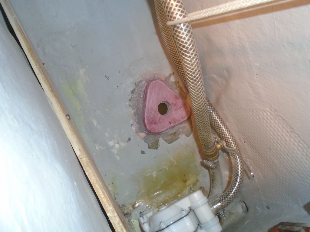
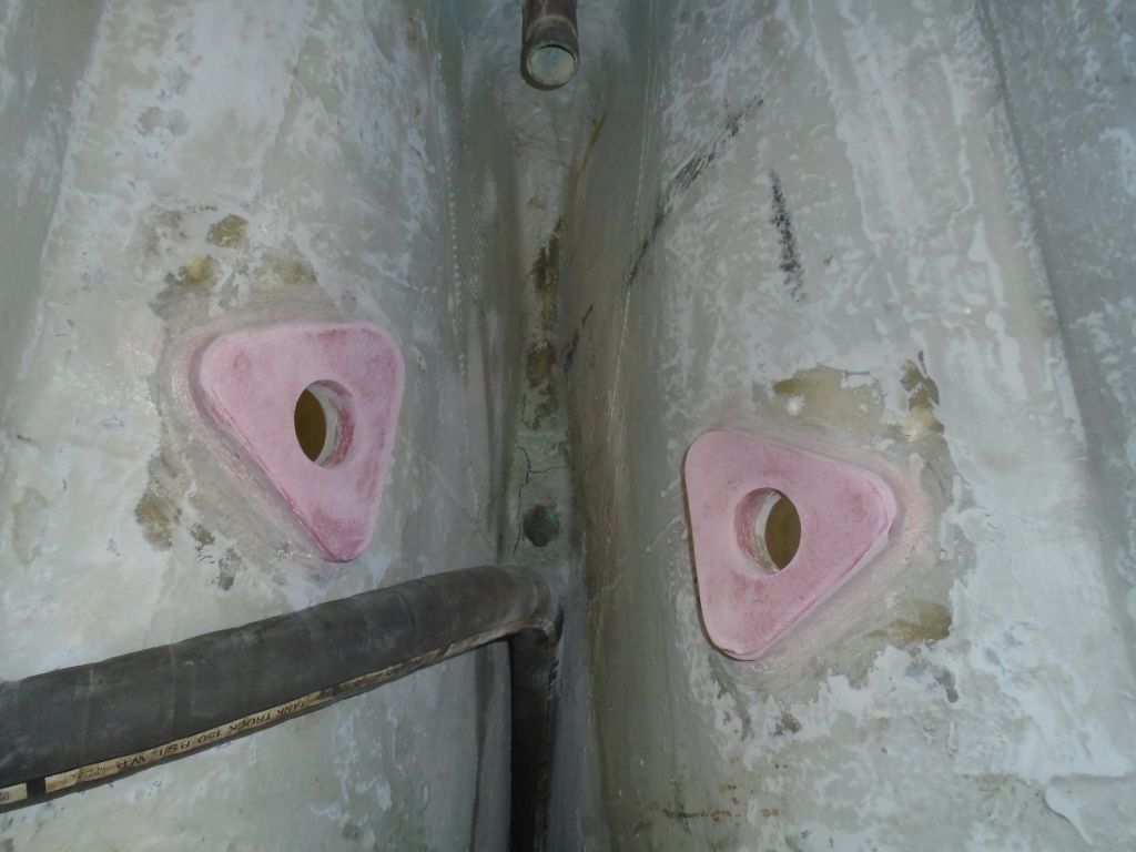
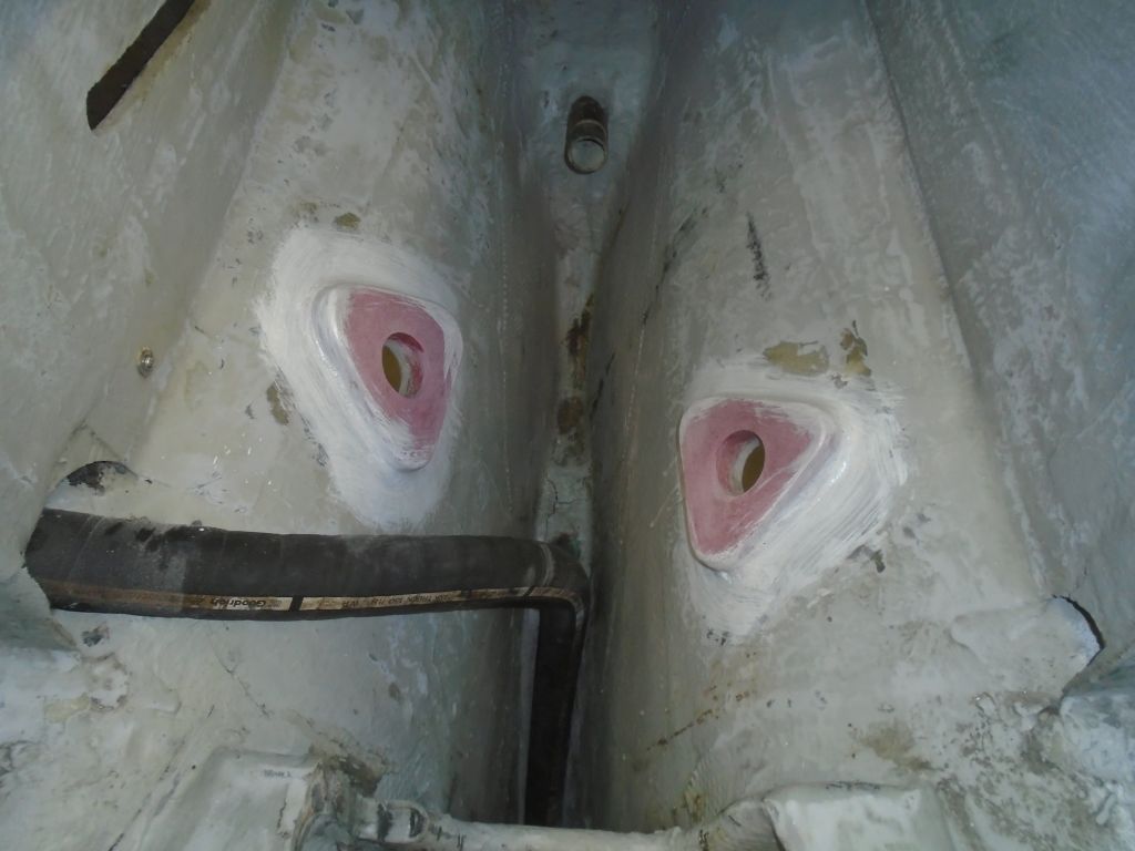
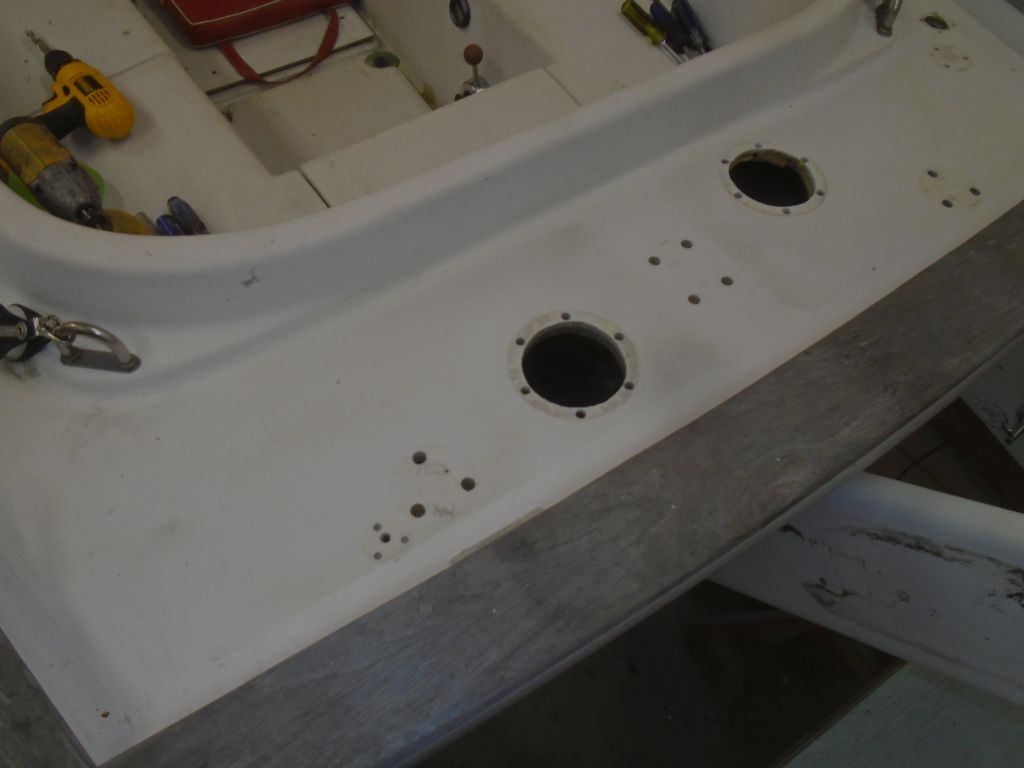
Following the usual steps that I detailed with the other fittings, I installed the final two through hulls and flange bases.

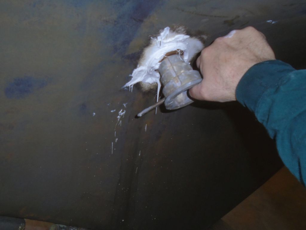
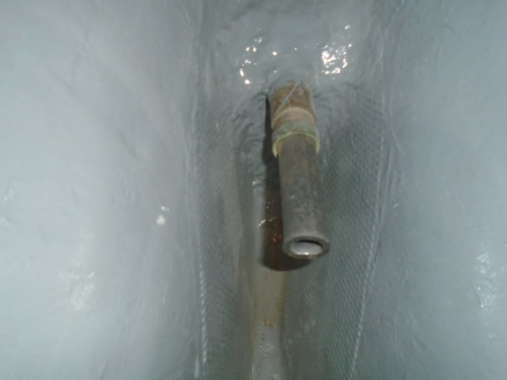
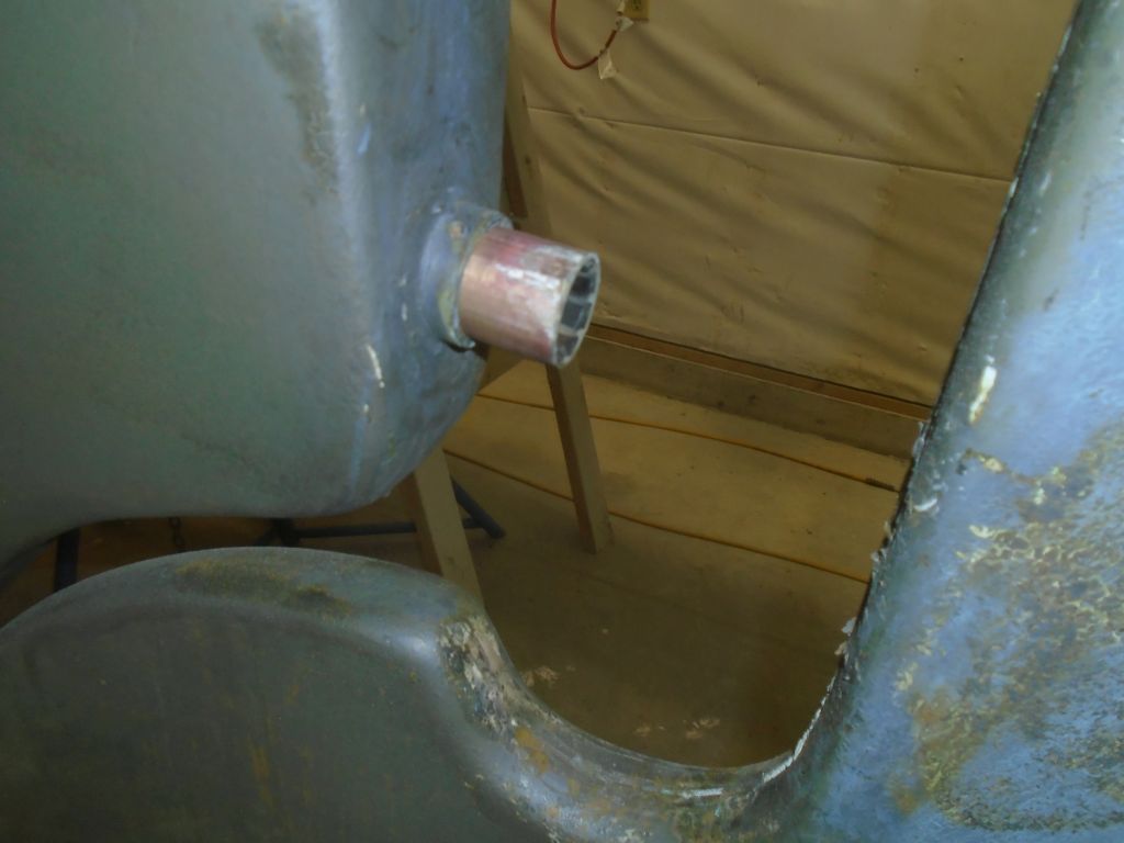
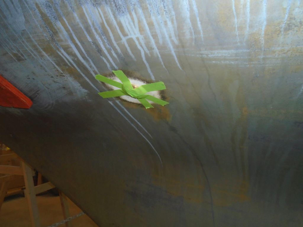
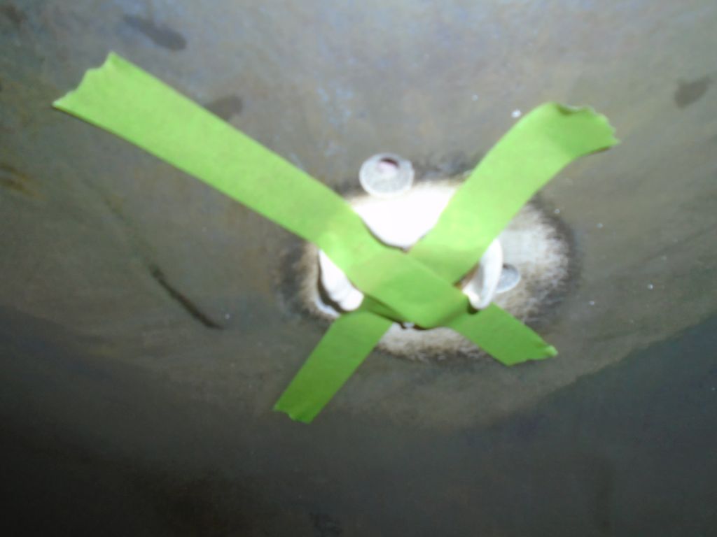
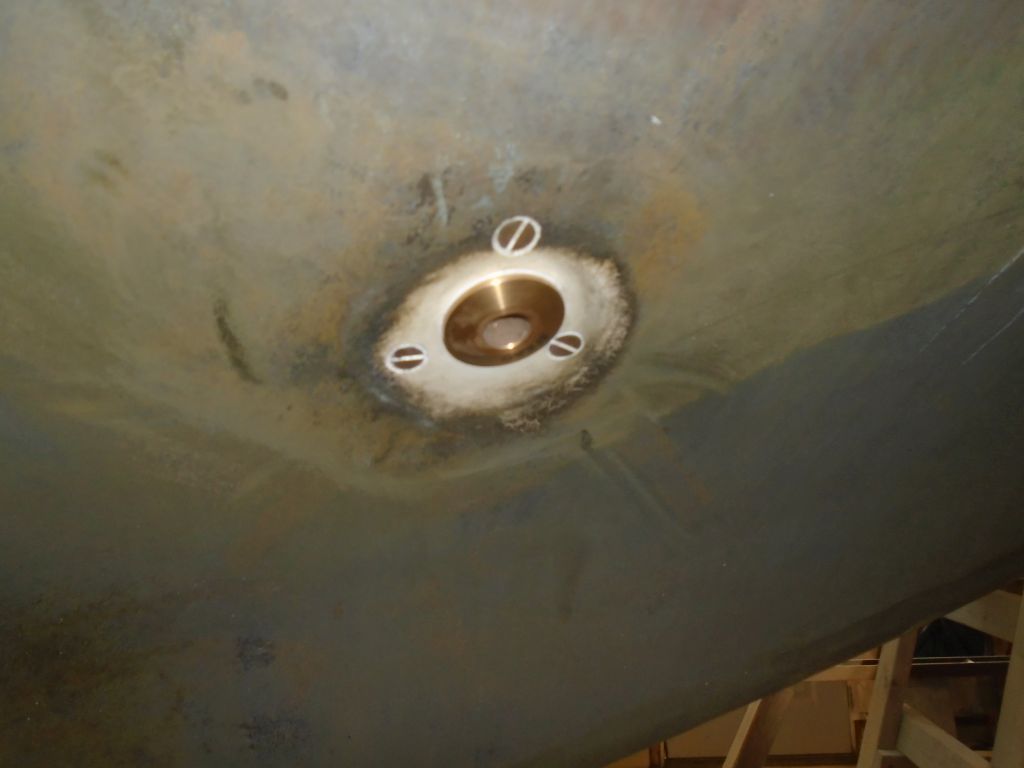
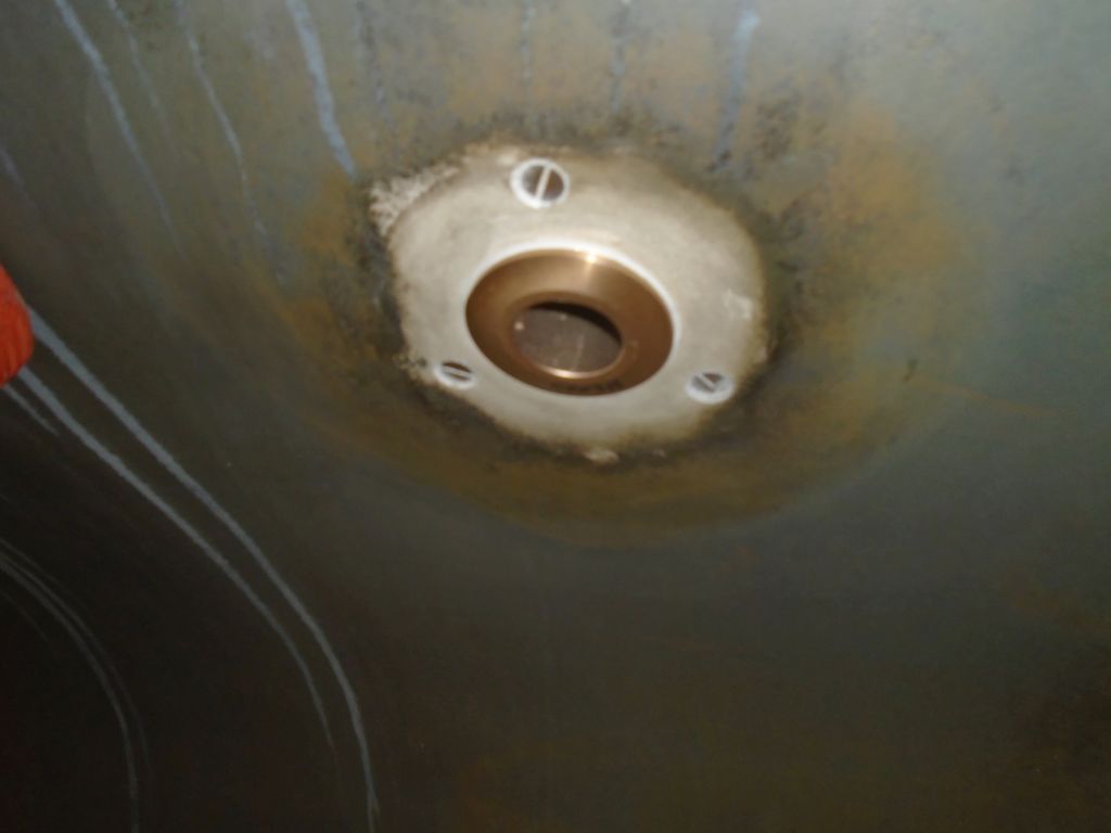
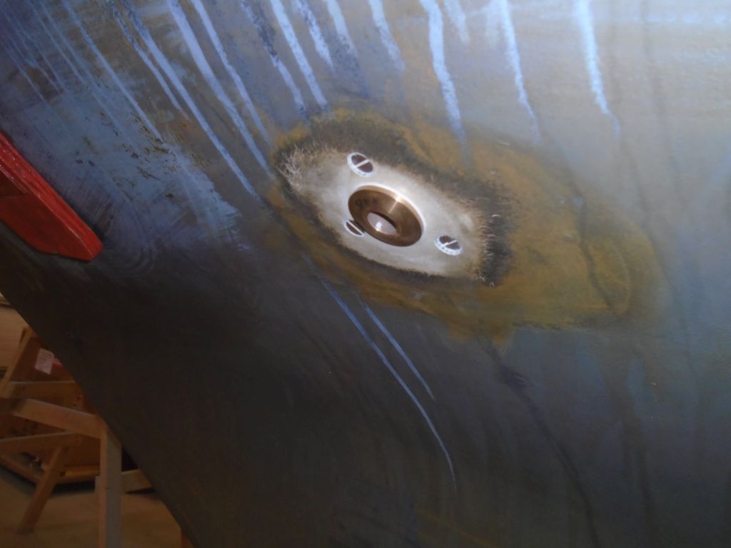
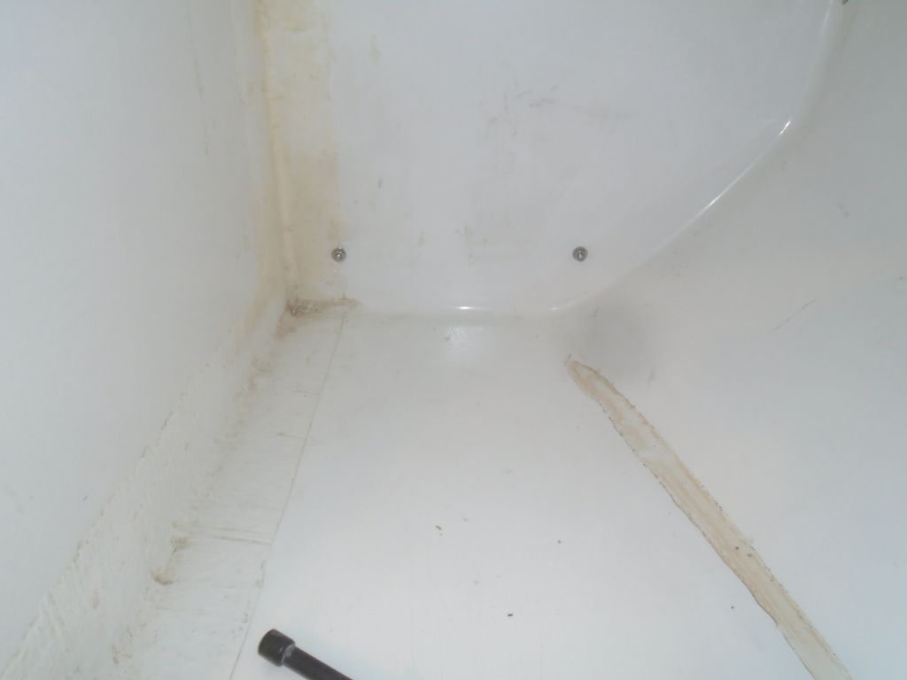
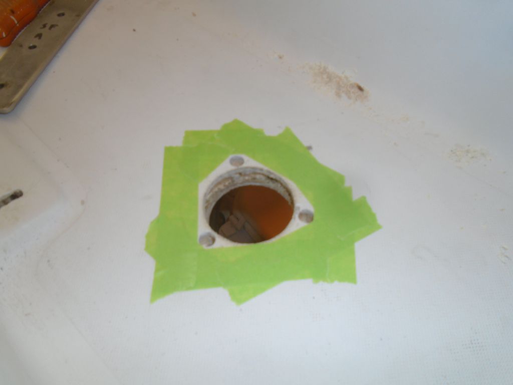
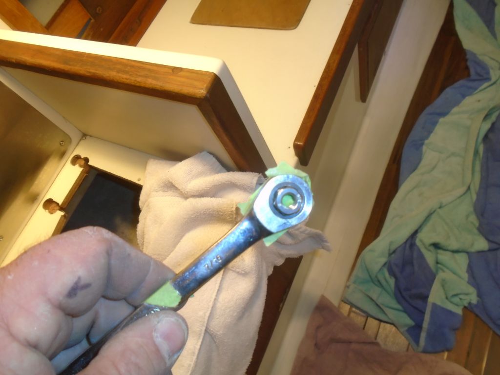
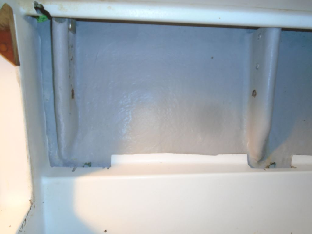
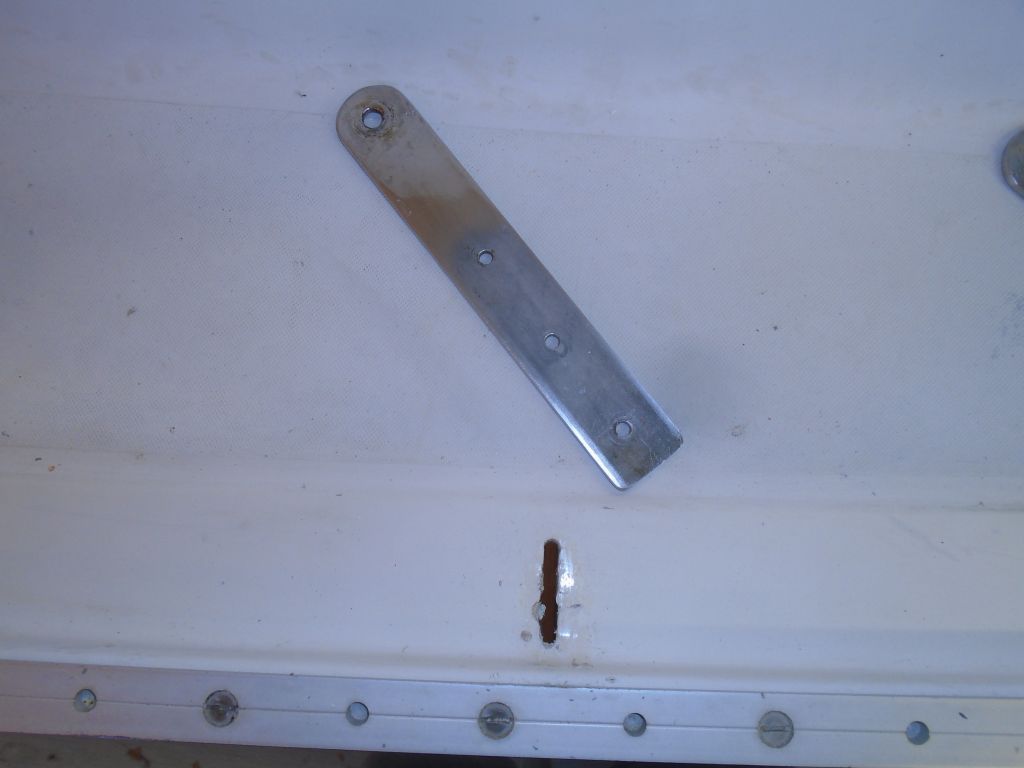
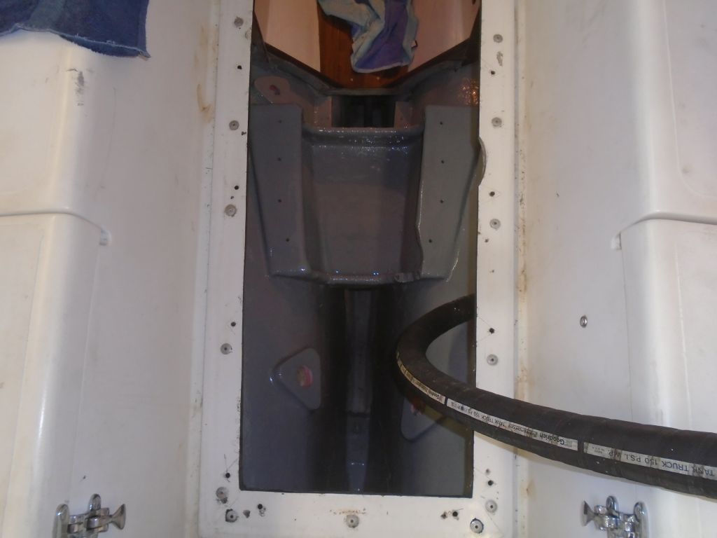
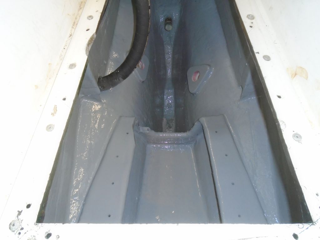
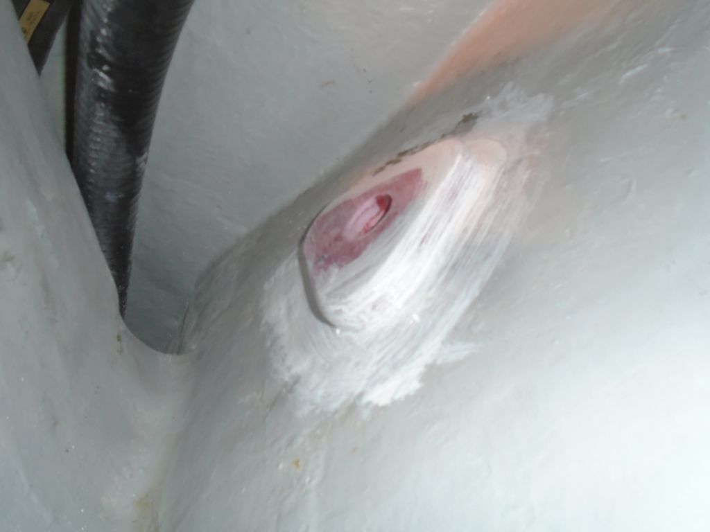
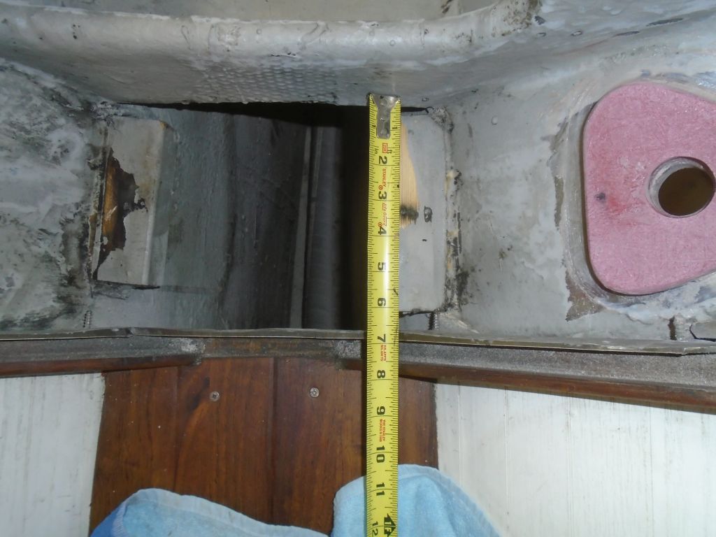
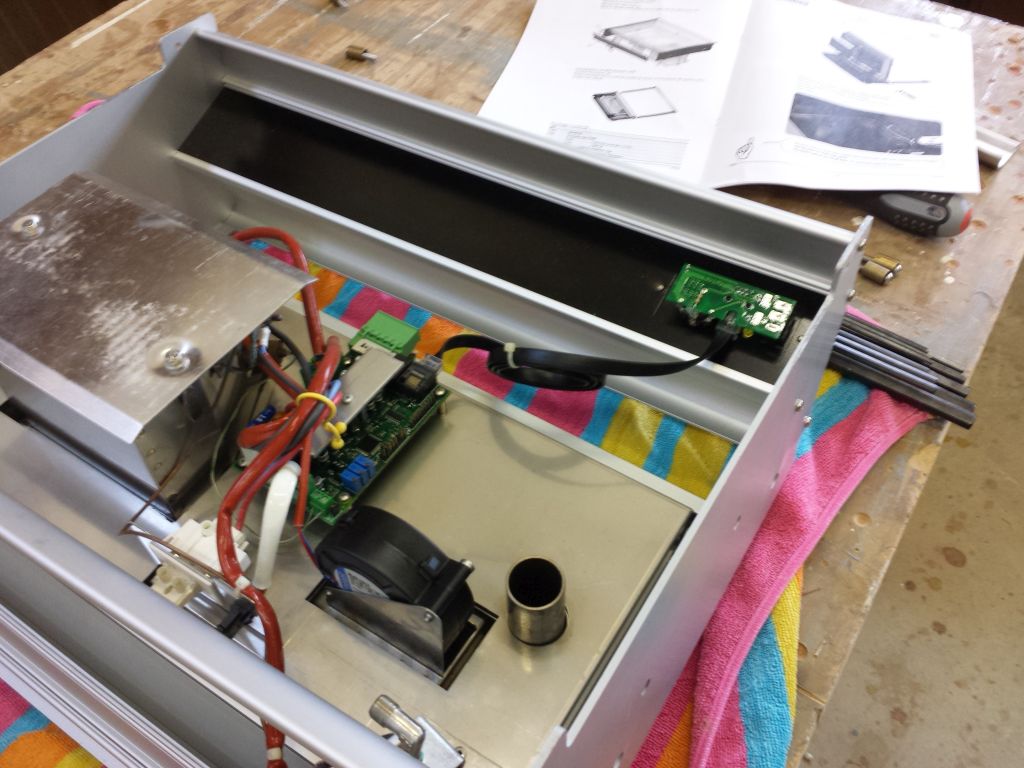
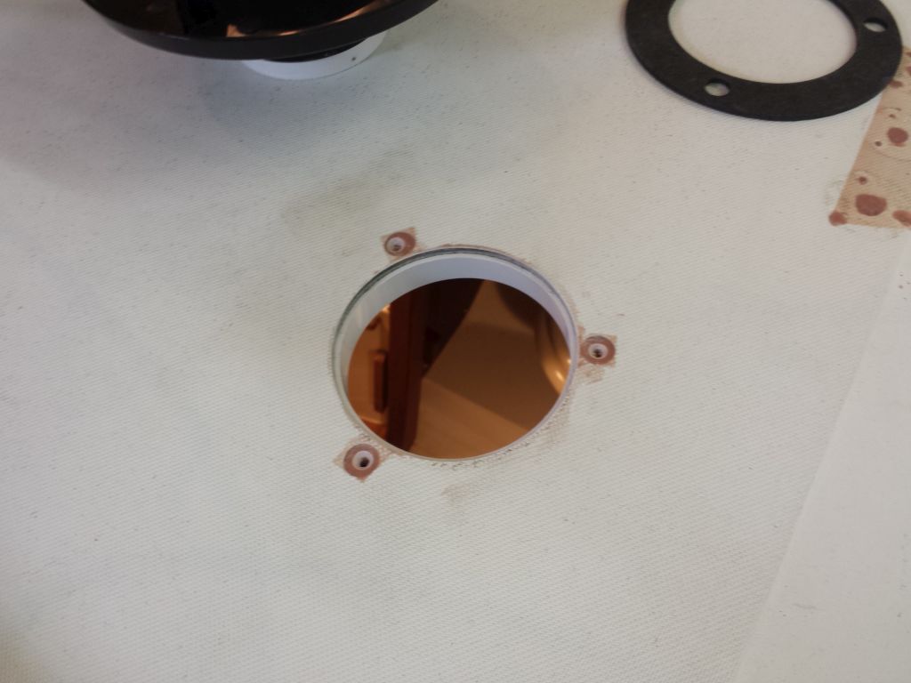
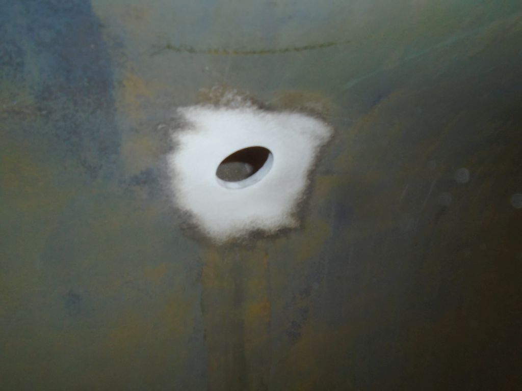
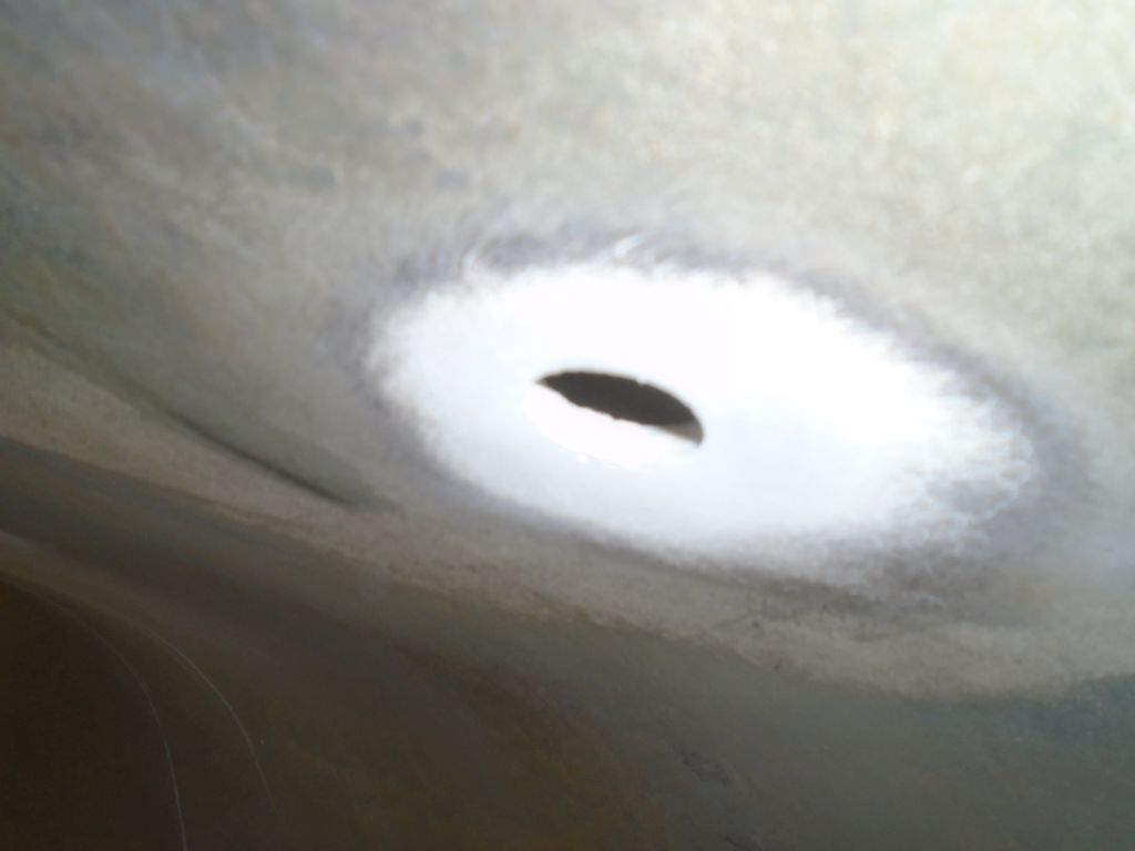
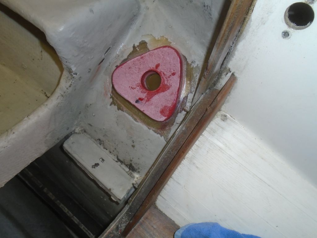
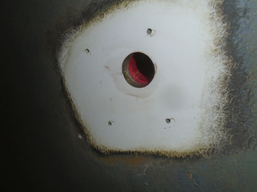
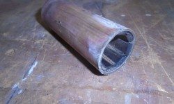
Before continuing, I wanted to address the Cutless bearing while I still had clear access to the inside of the stern tube.  The existing bearing was in fair condition, but I wanted to replace it while all other engine-related components were being refreshed.  Of course the bearing was set flush to the end of the bronze stern tube where it protruded from the deadwood, so there was no way to grab it there and twist it out.   I removed the set screws.

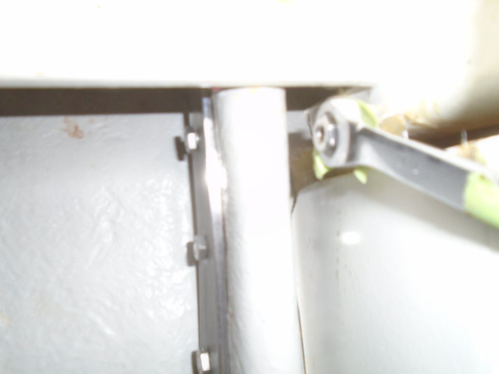
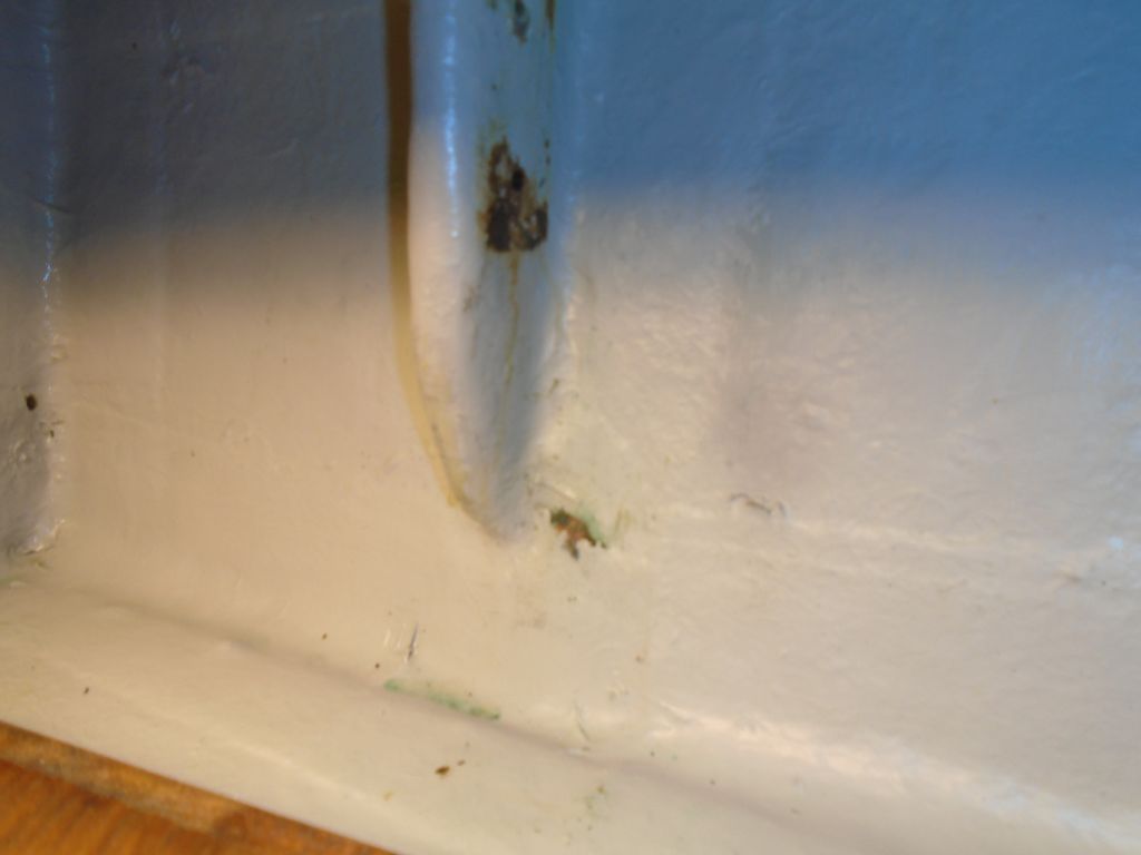
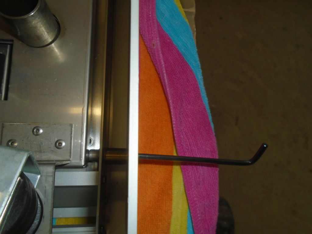
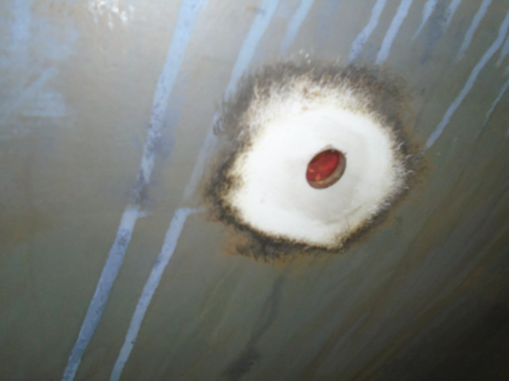
During some preliminary inspection earlier, I’d determined that I could (hopefully) push the bearing out from inside, and I happened to have a length of steel pipe on hand that fit the stern tube perfectly, something apparently left over from a similar situation in the past.   So now, while I had the most open access possible. I tried this method.  At first nothing happened; I didn’t wail on the pipe because I didn’t want to cause a bigger problem, so my first blows were tentative, and after a time I went beneath to check, but the bearing hadn’t moved a bit.  This was worrisome, but back inside I marked the pipe when it was all the way in against the bearing, for reference to see if I moved the bearing at all,

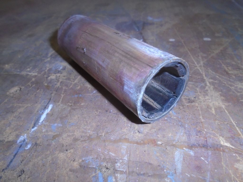
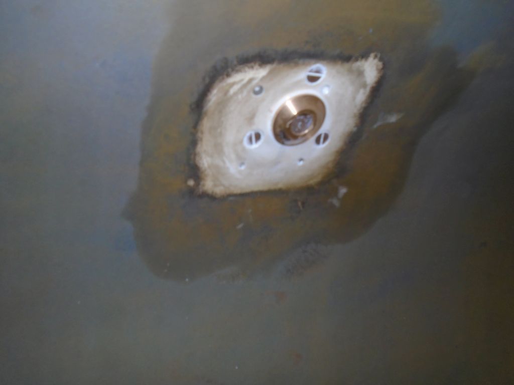
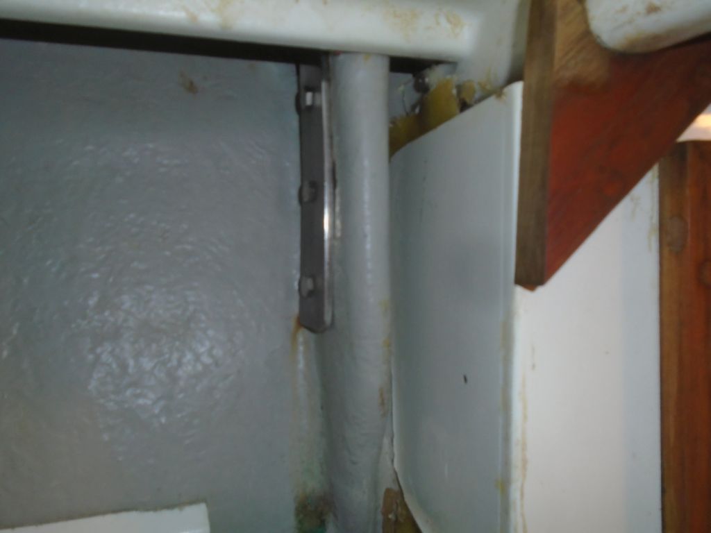
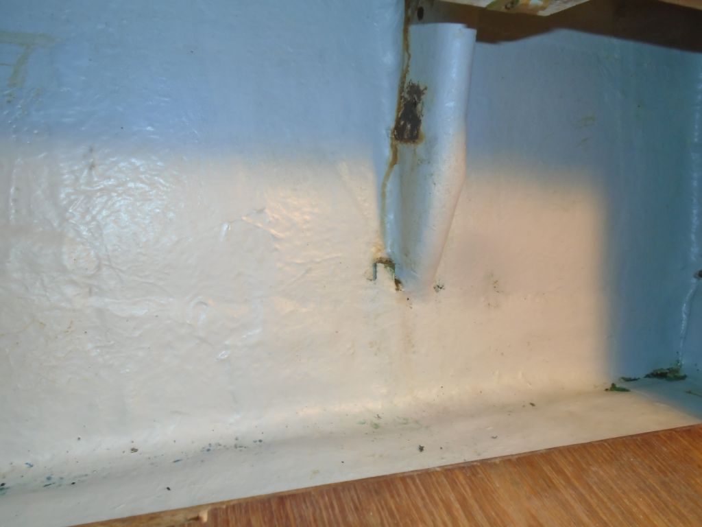
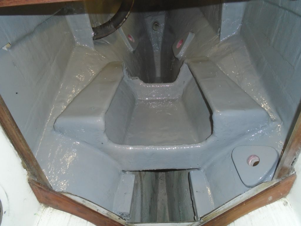
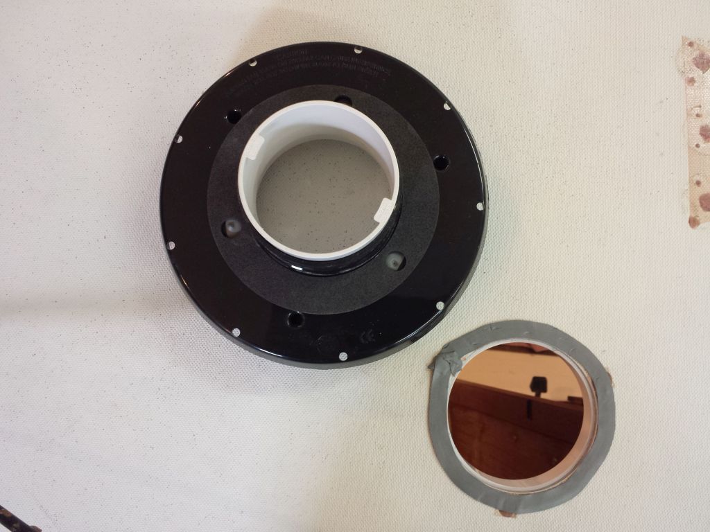
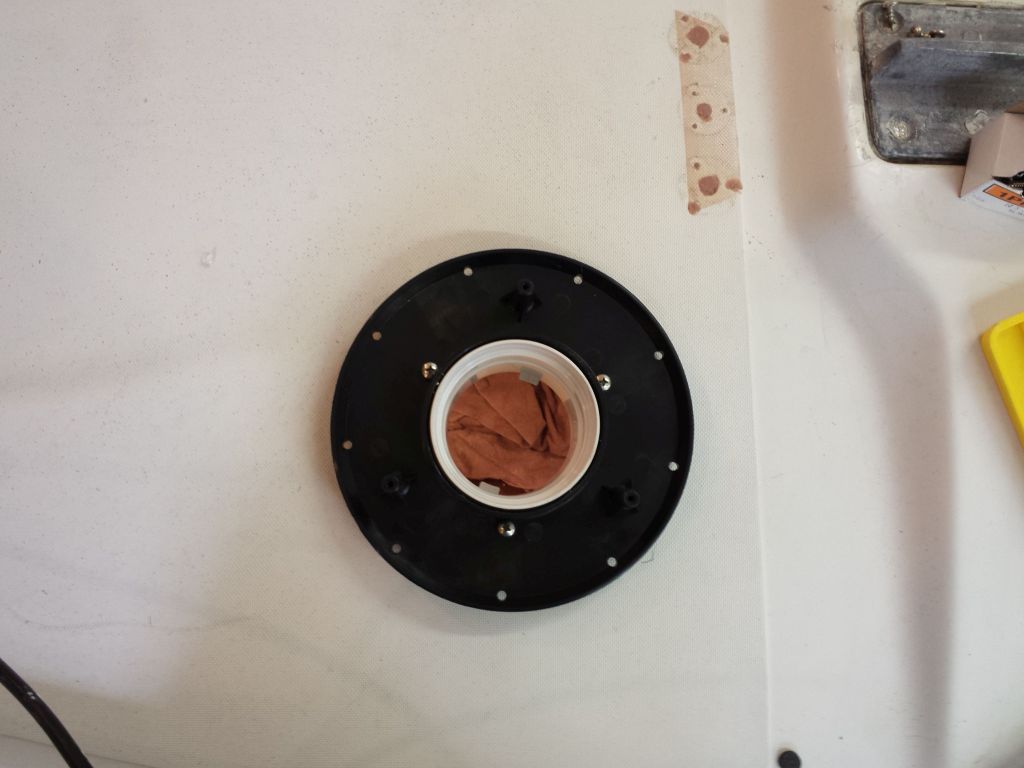
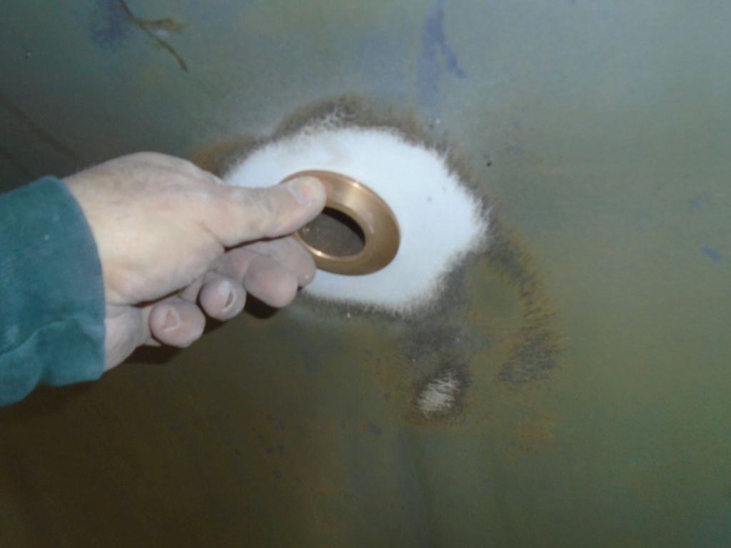
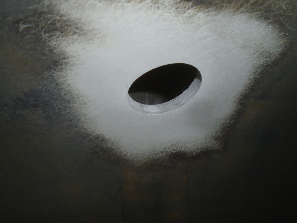
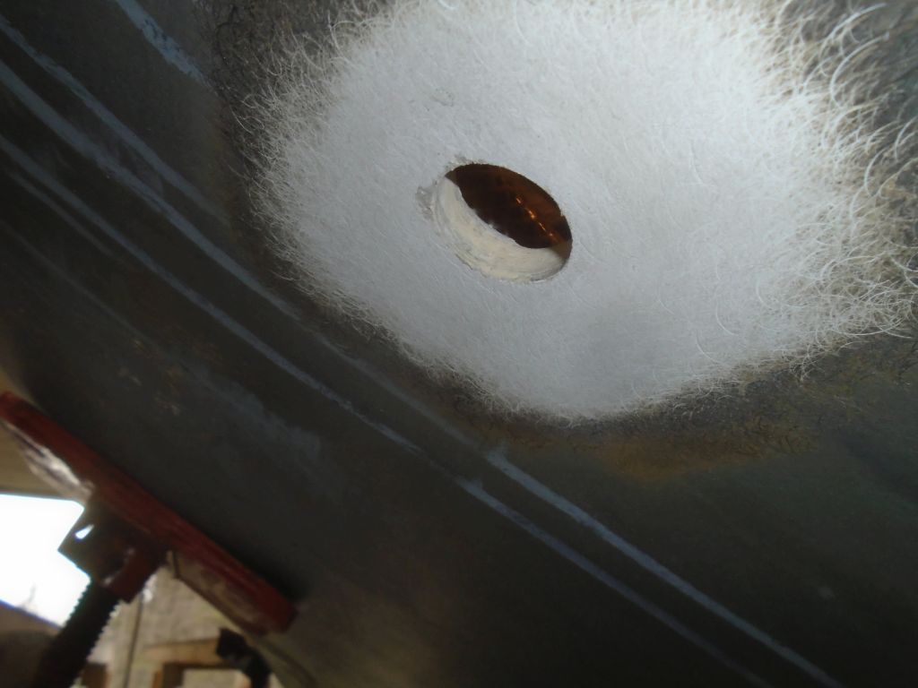
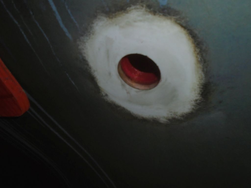
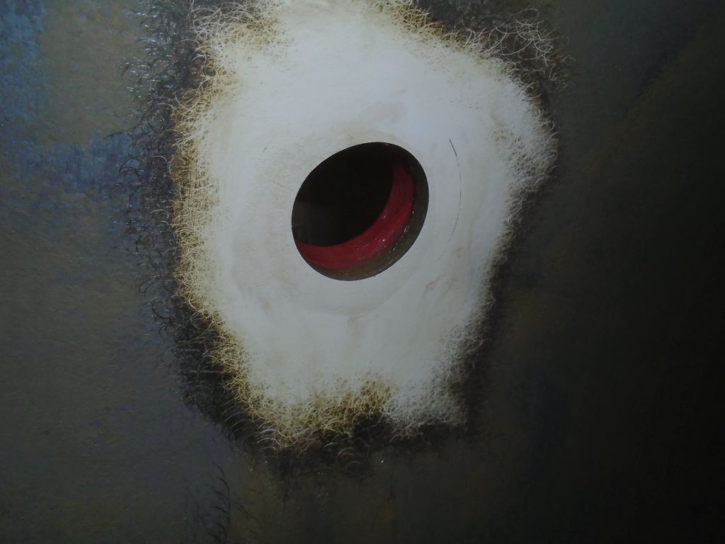
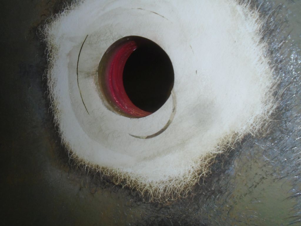
After some time, and additional blows with a heavy mallet, I thought I felt something give, and I went down to confirm it before I continued (to make sure it was the “right” something that gave).  Success!  The bearing was coming out.

cutless3-31716

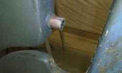
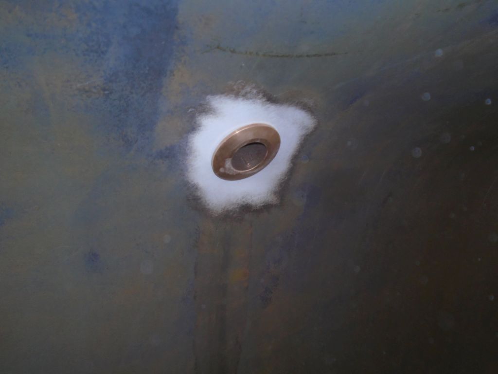
This was a relief since I didn’t relish the alternative ways I might have to get the bearing out.  While the bearing had some life left, leaving it as is didn’t seem like a prudent approach, so I was glad that it hadn’t been that tough to remove in the end.  Back inside, I hammered the bearing out the rest of the way, and noted its size so I could order the replacement.

cutless4-31716

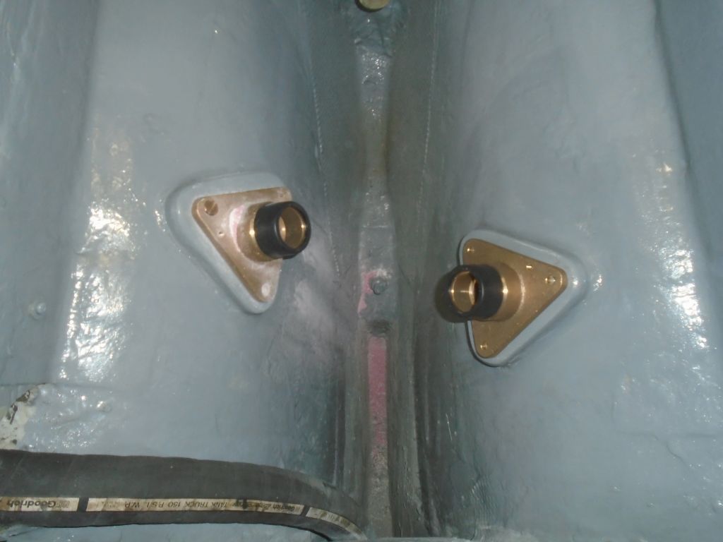
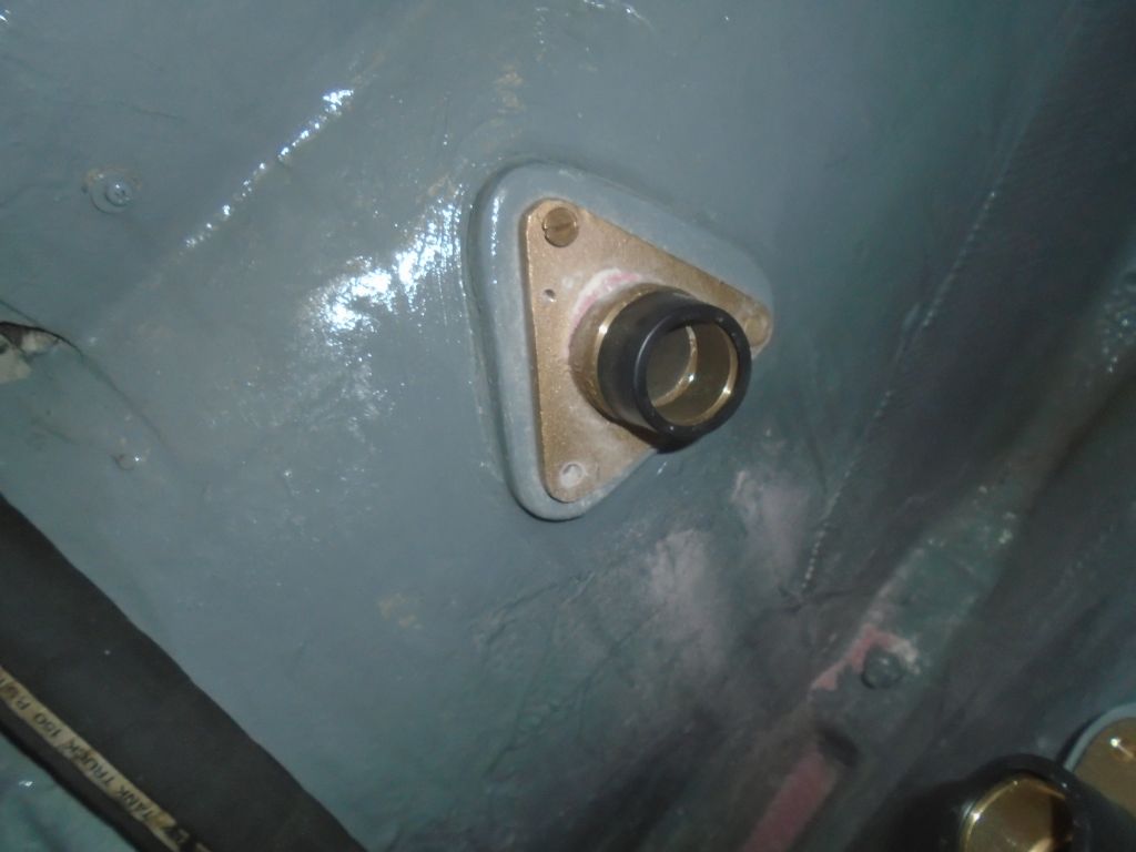
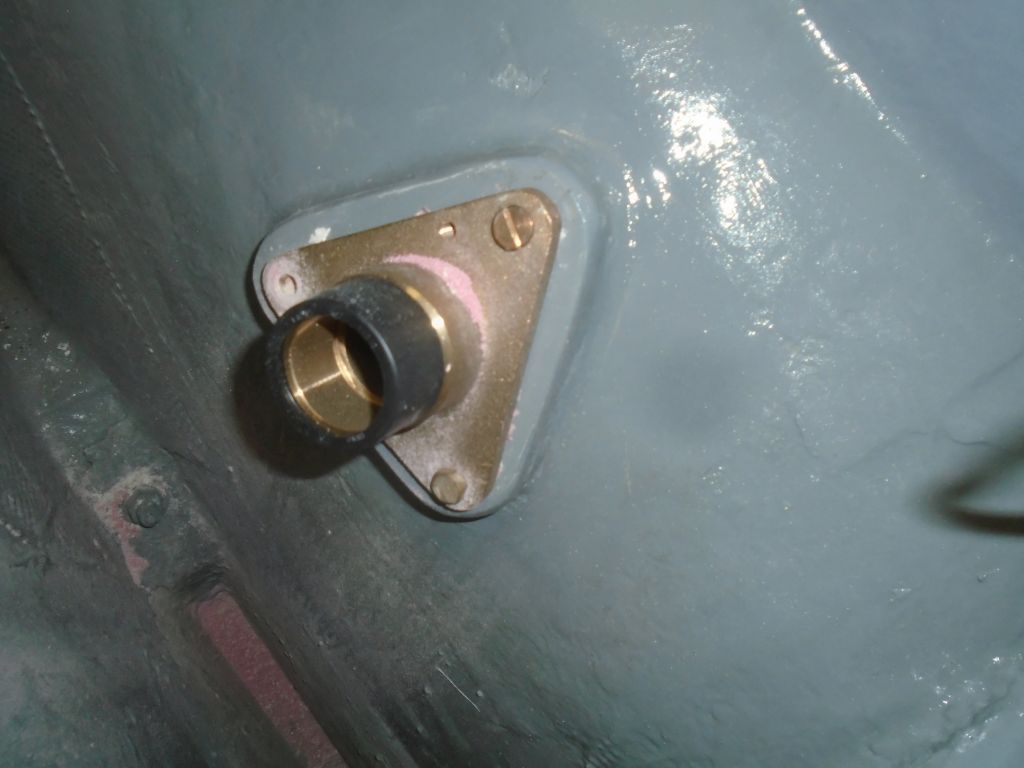
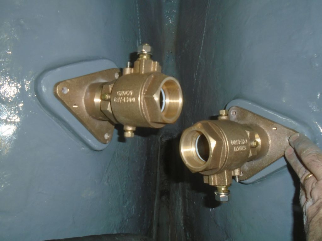
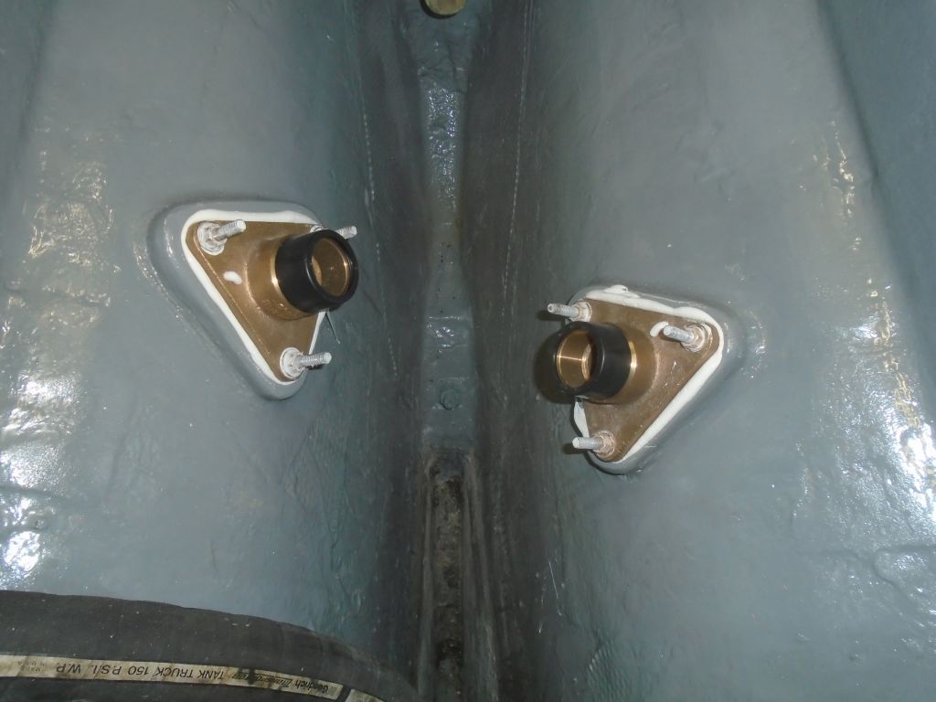
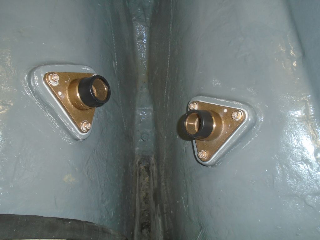
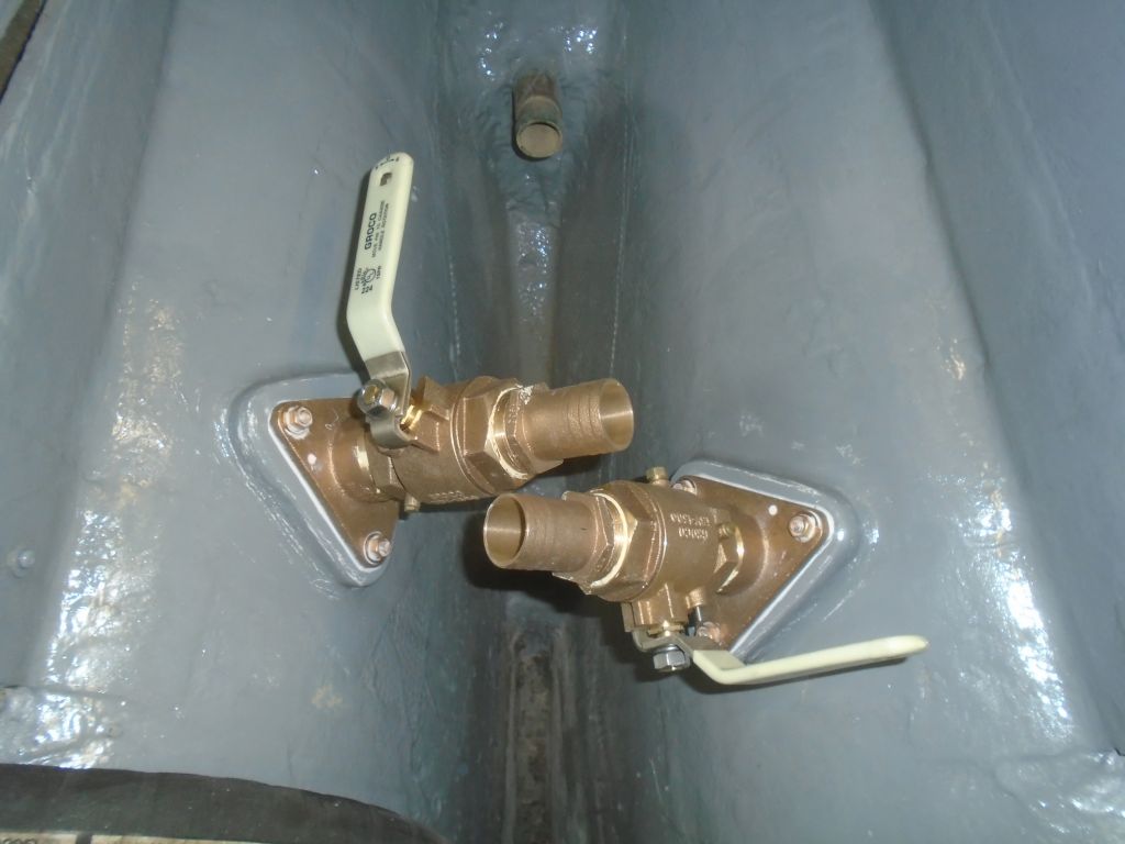
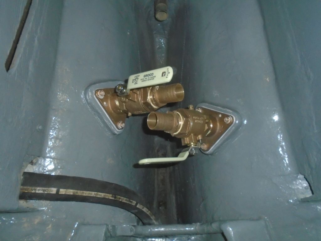
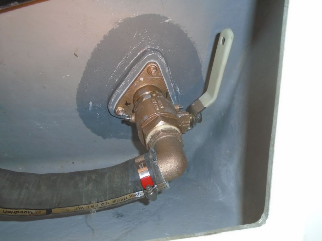
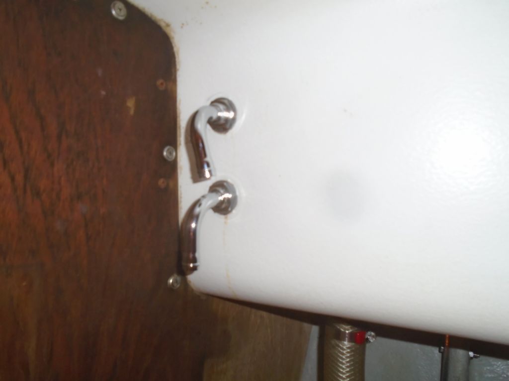
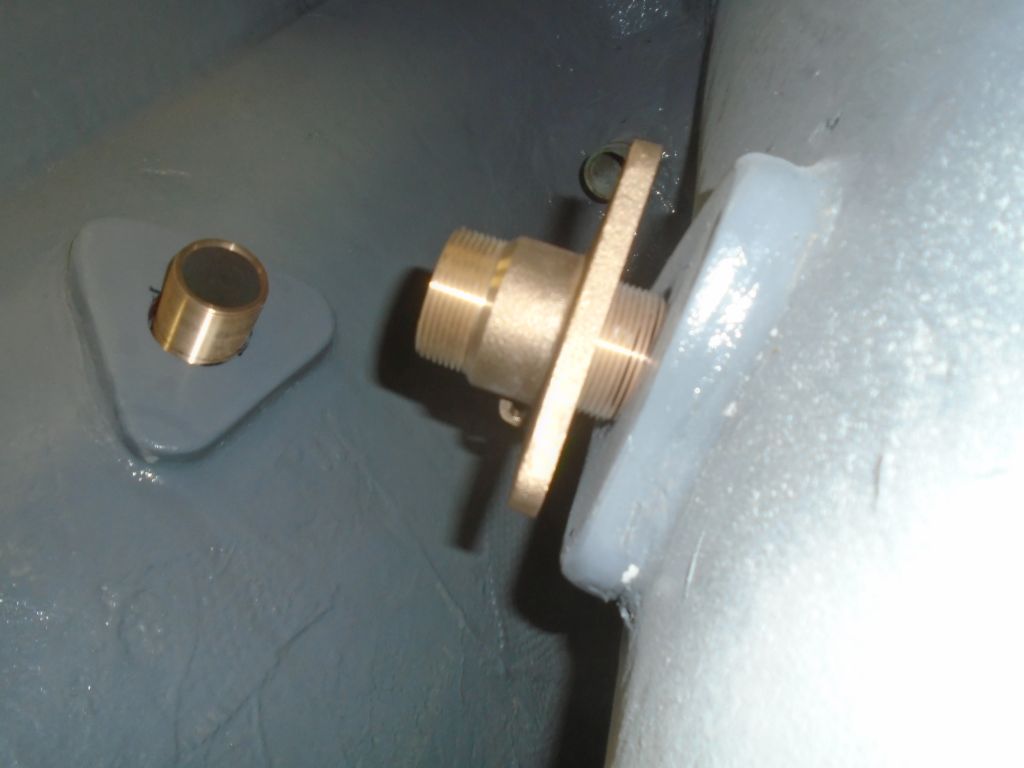
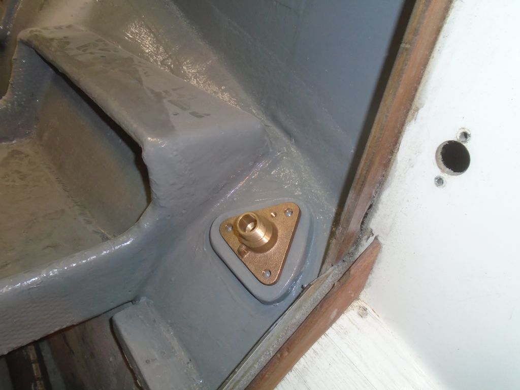
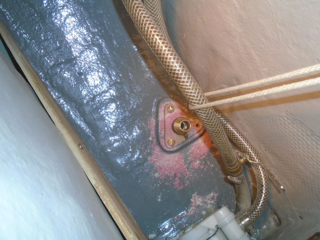
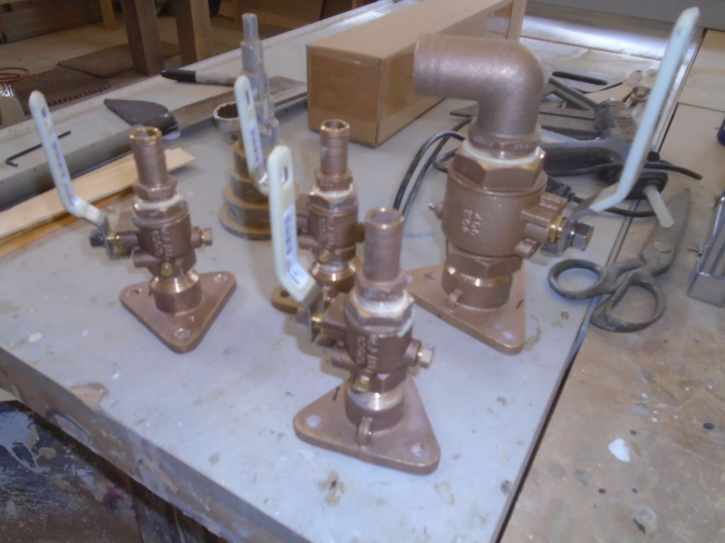
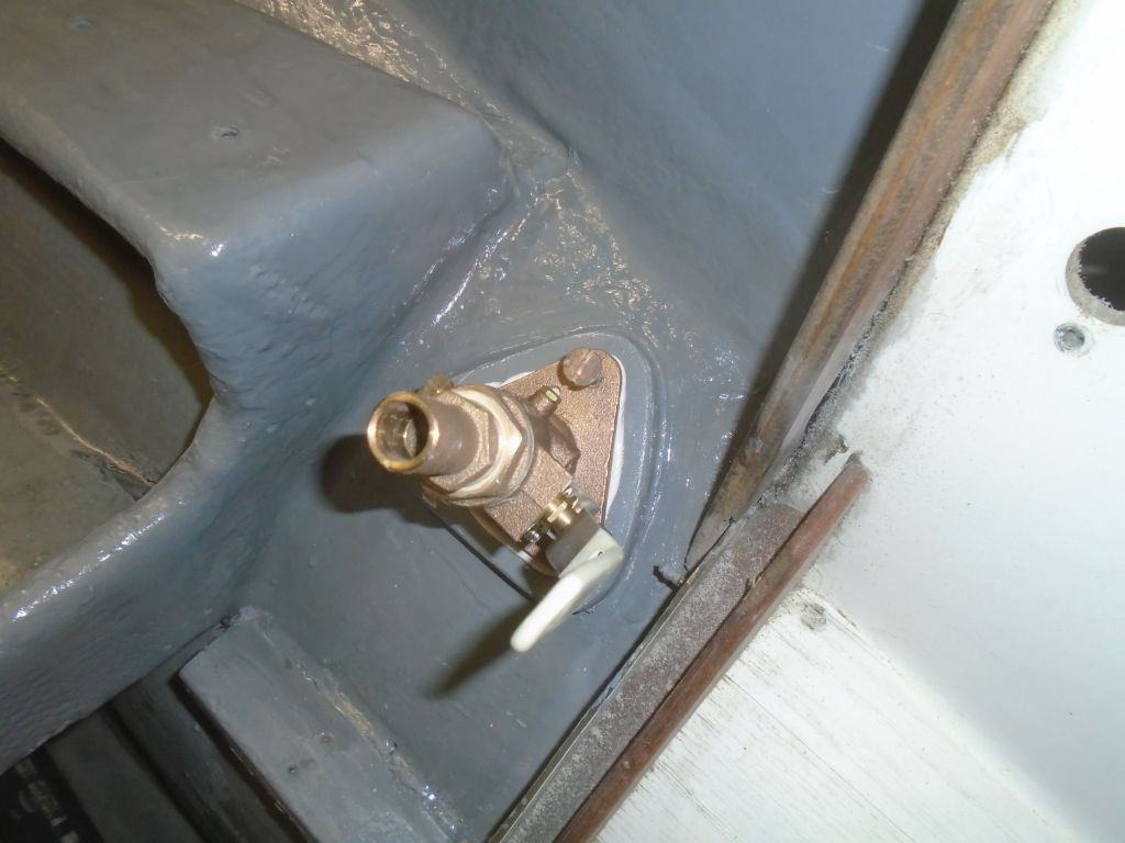
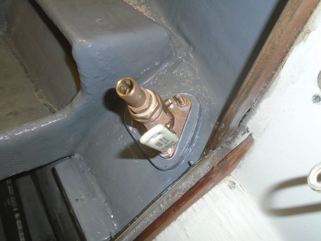
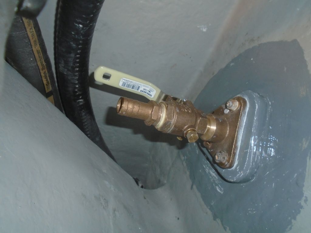
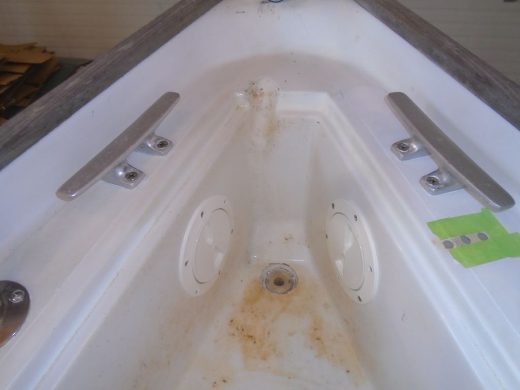
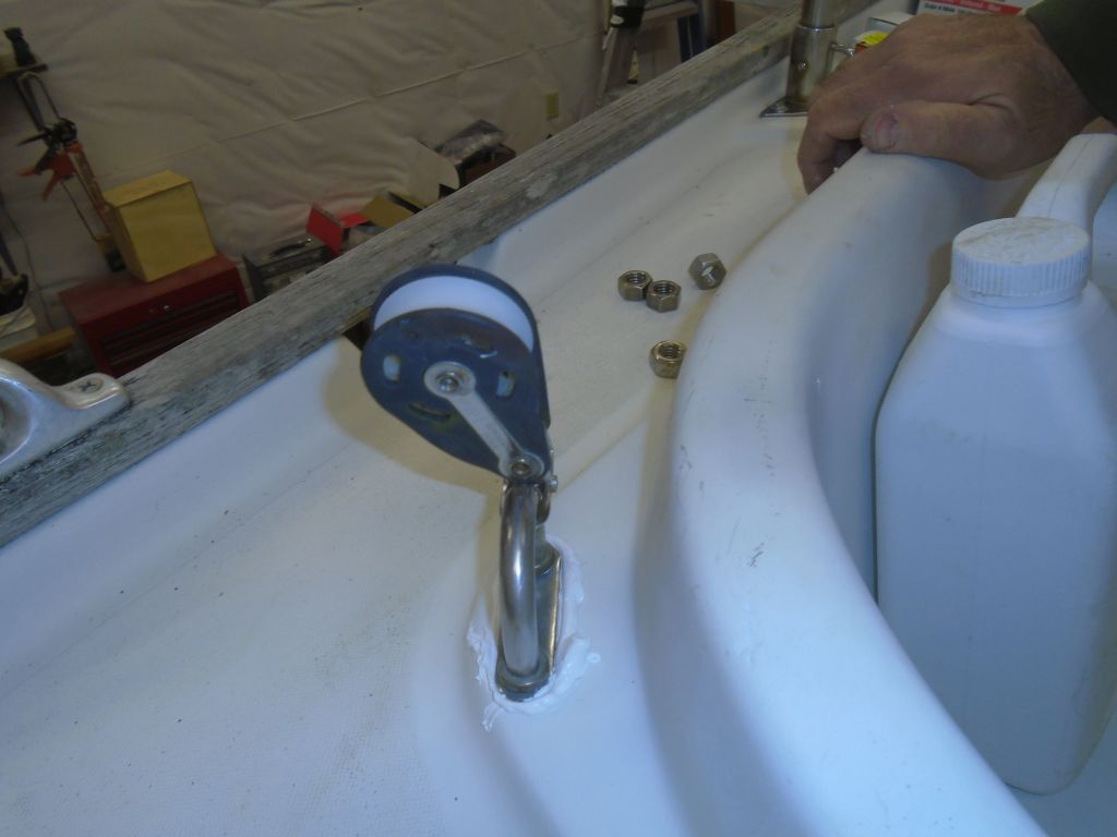
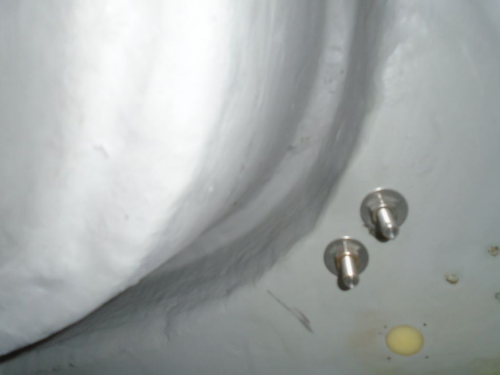
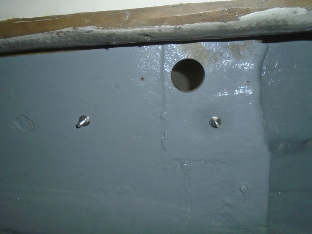
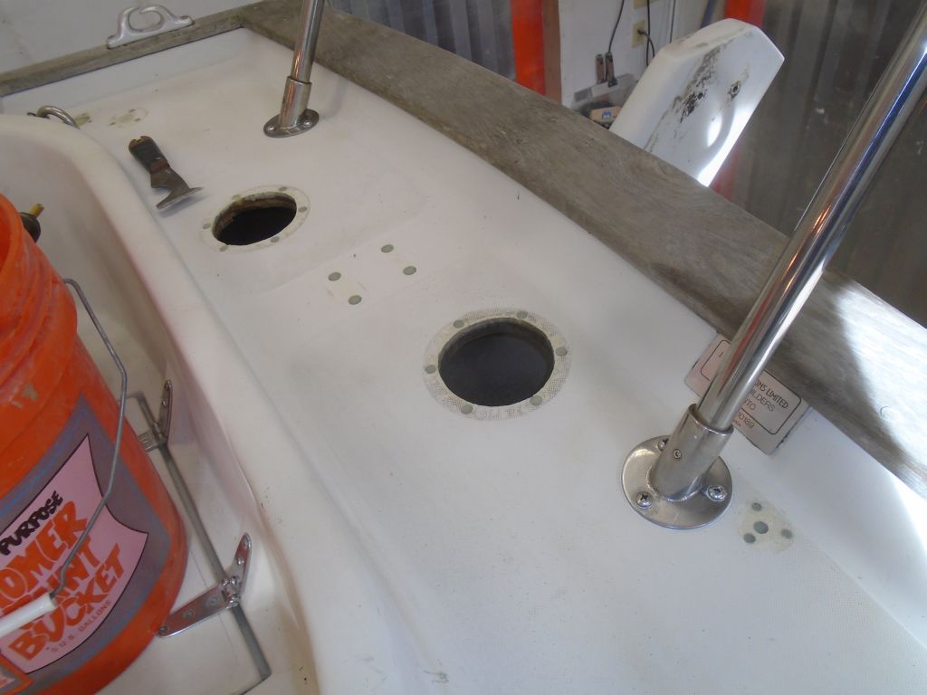
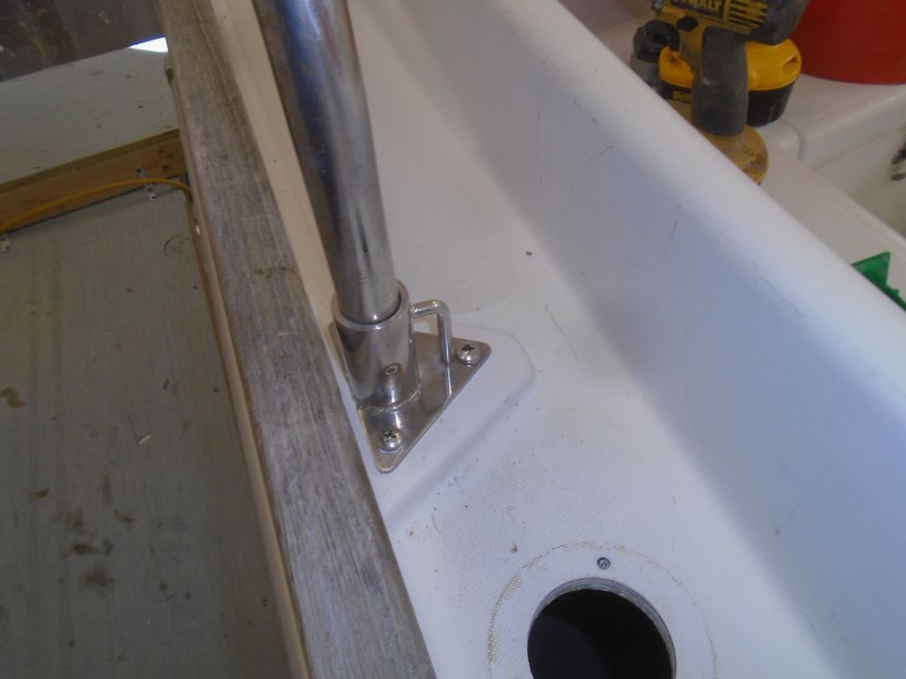
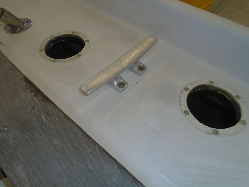
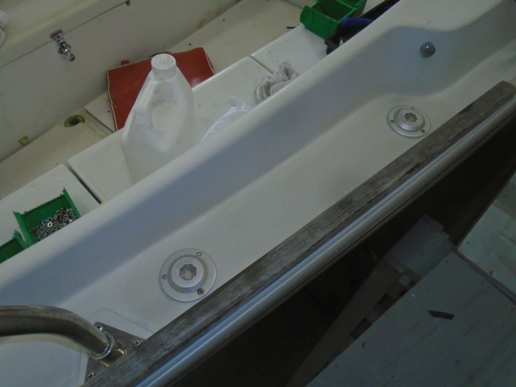
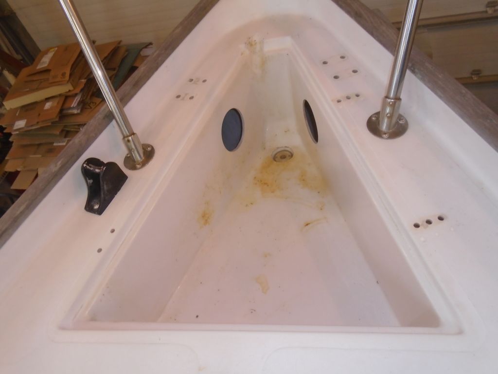
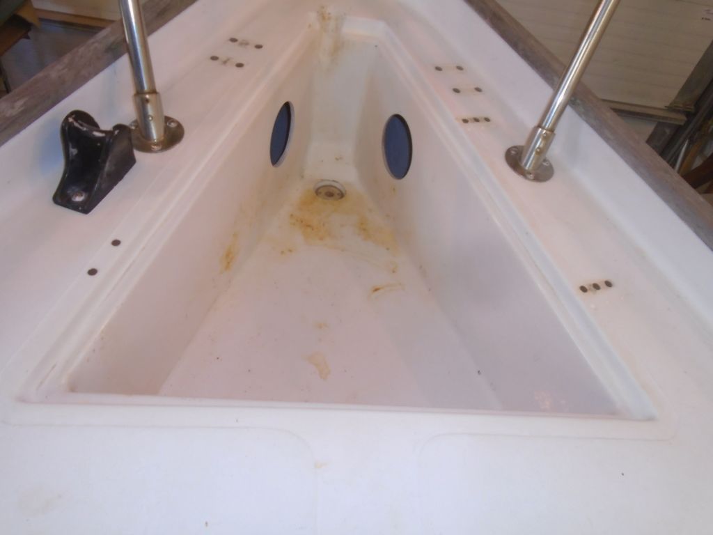
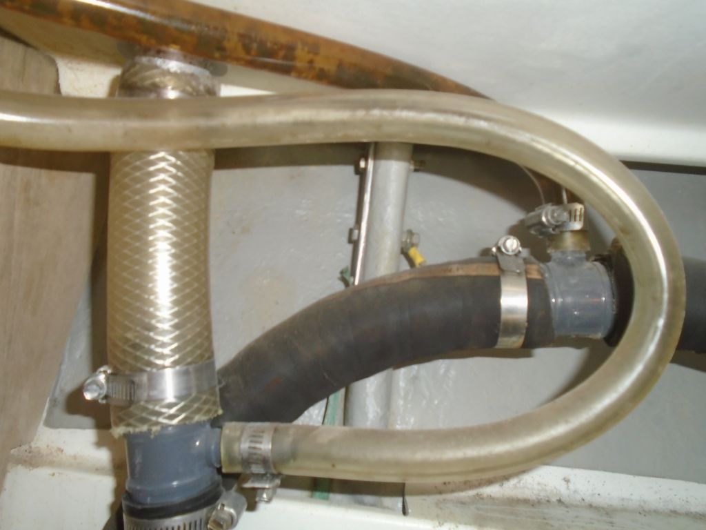
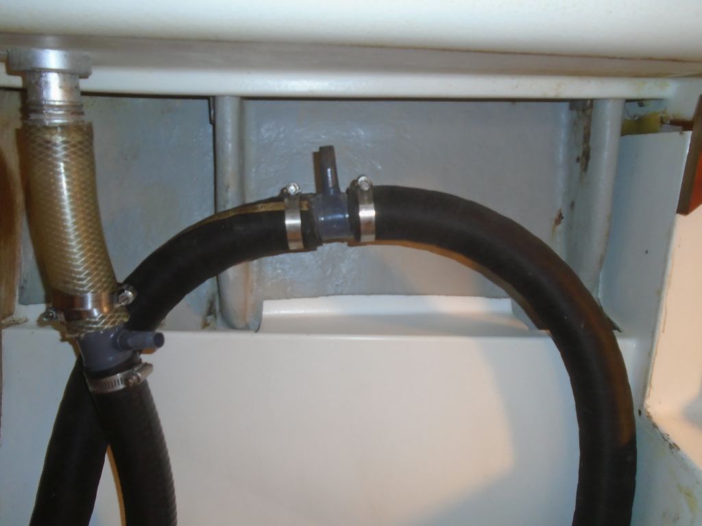
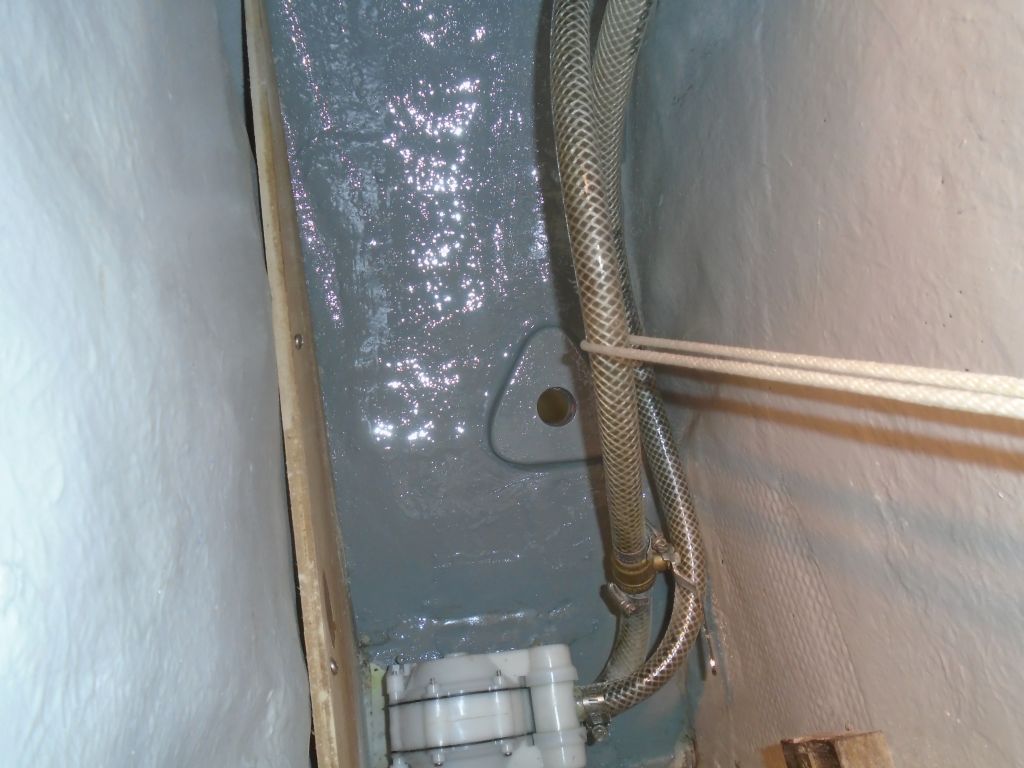
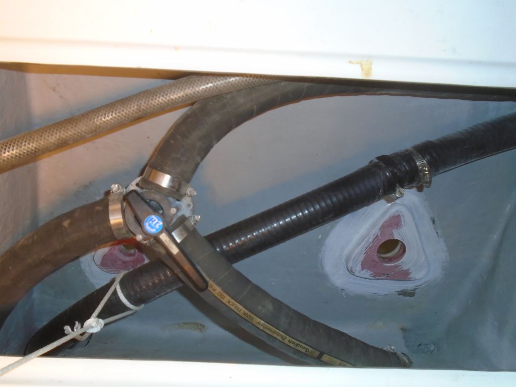
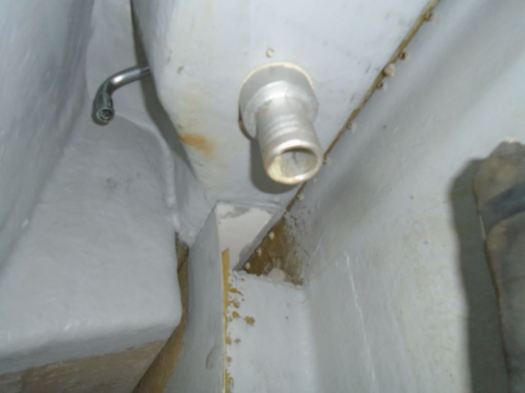
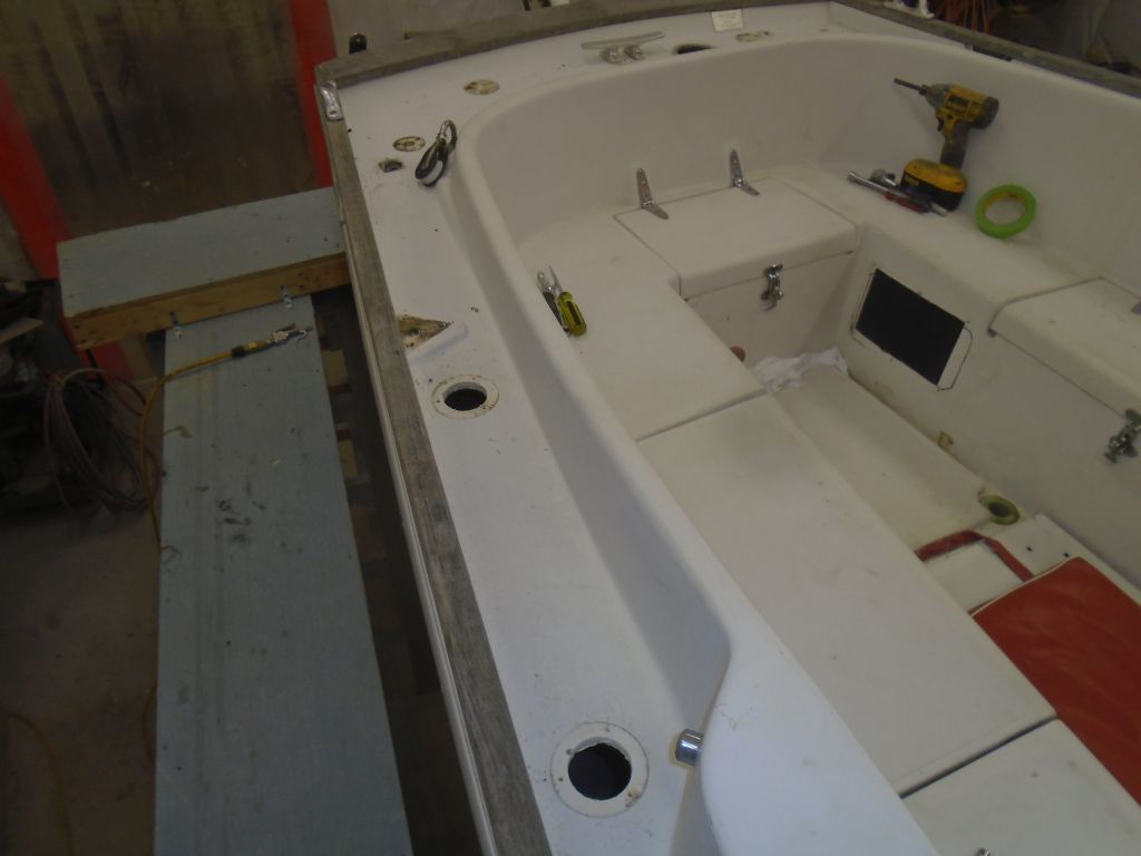
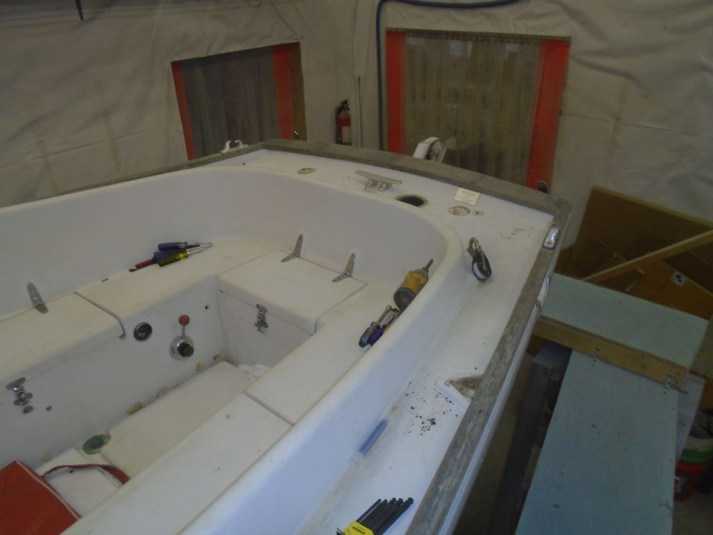
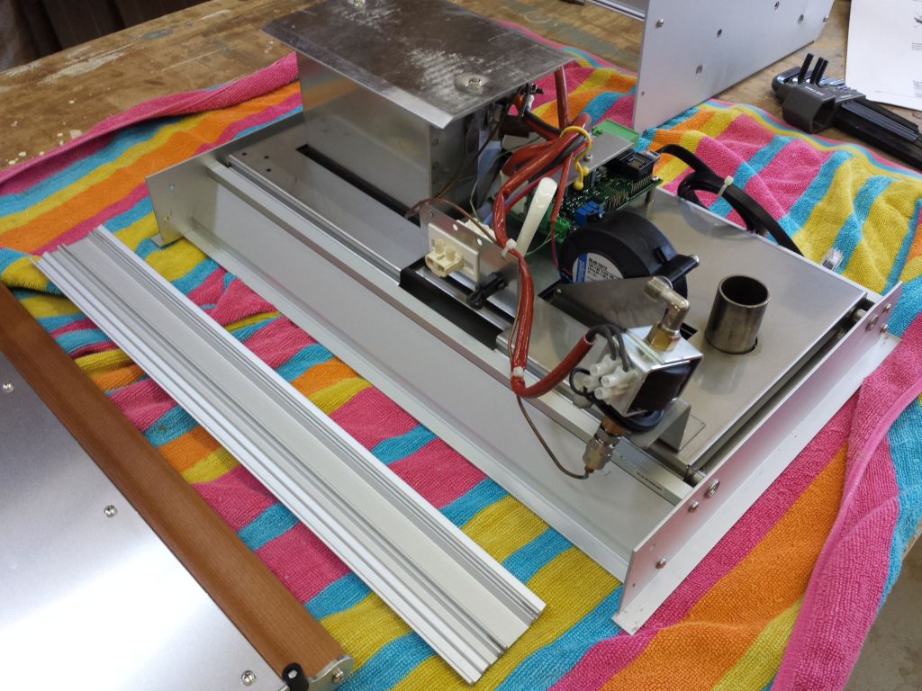
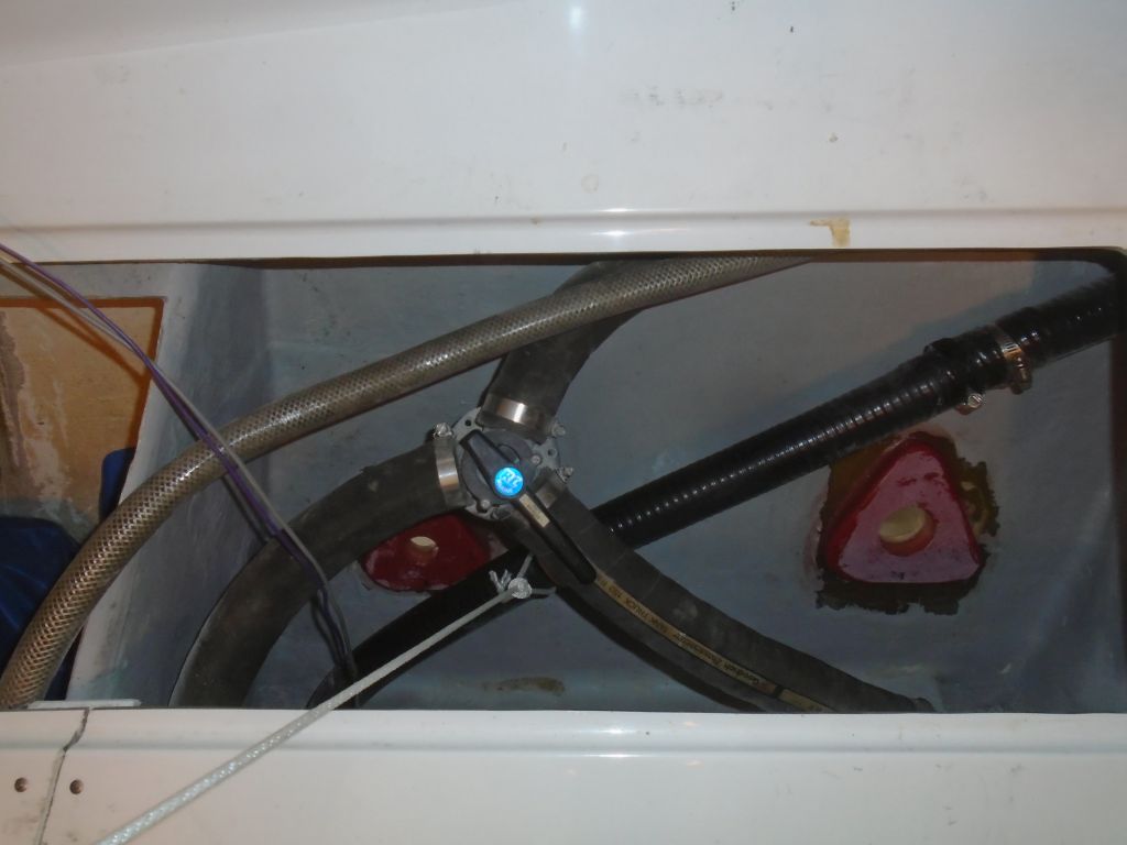
Back to the through hulls, I installed the valves and tailpieces to complete the installation.  I aligned the valves so the handles on each side could operate fully without interfering with the other valve and also remaining clear of the scupper hoses and their eventual path.

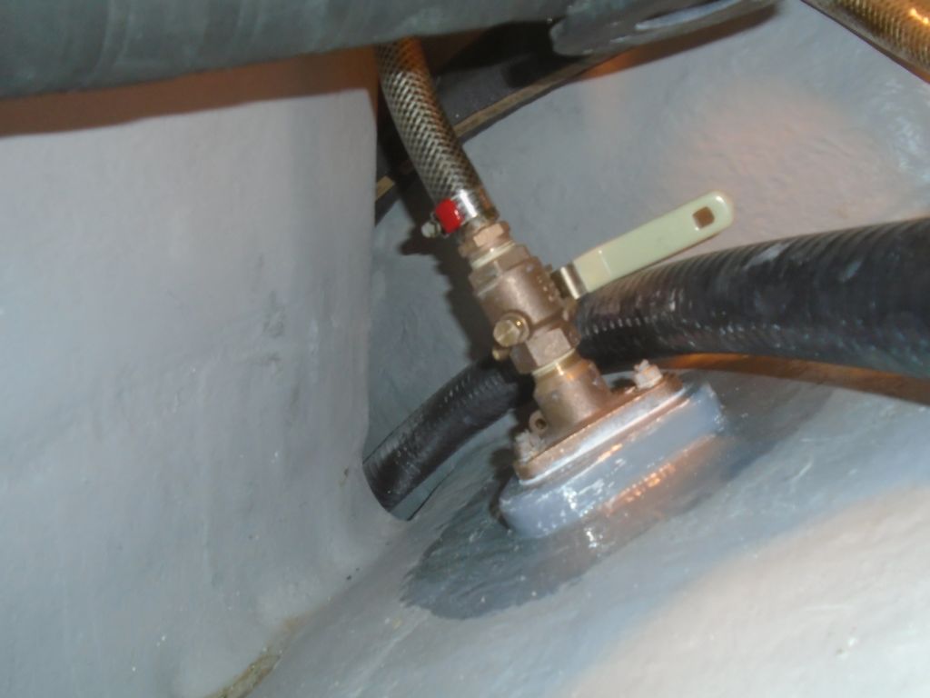
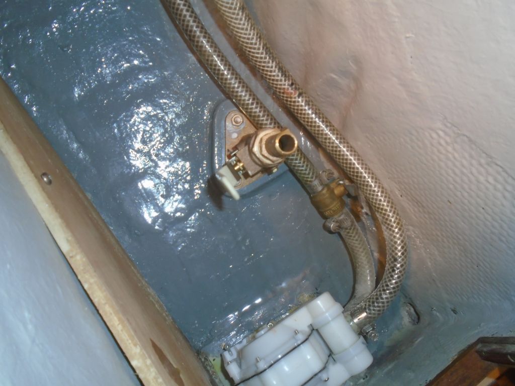
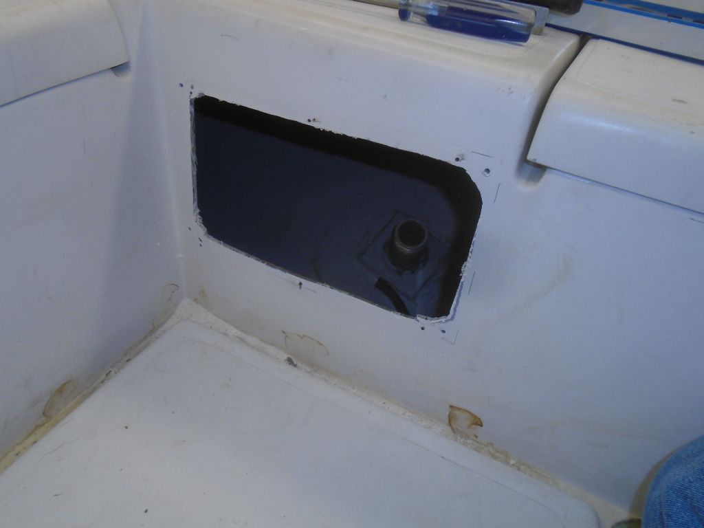
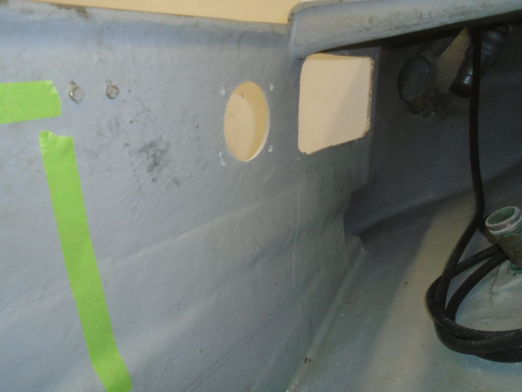
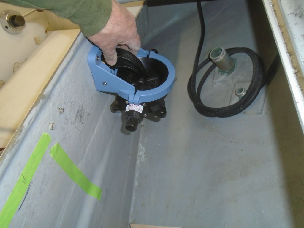
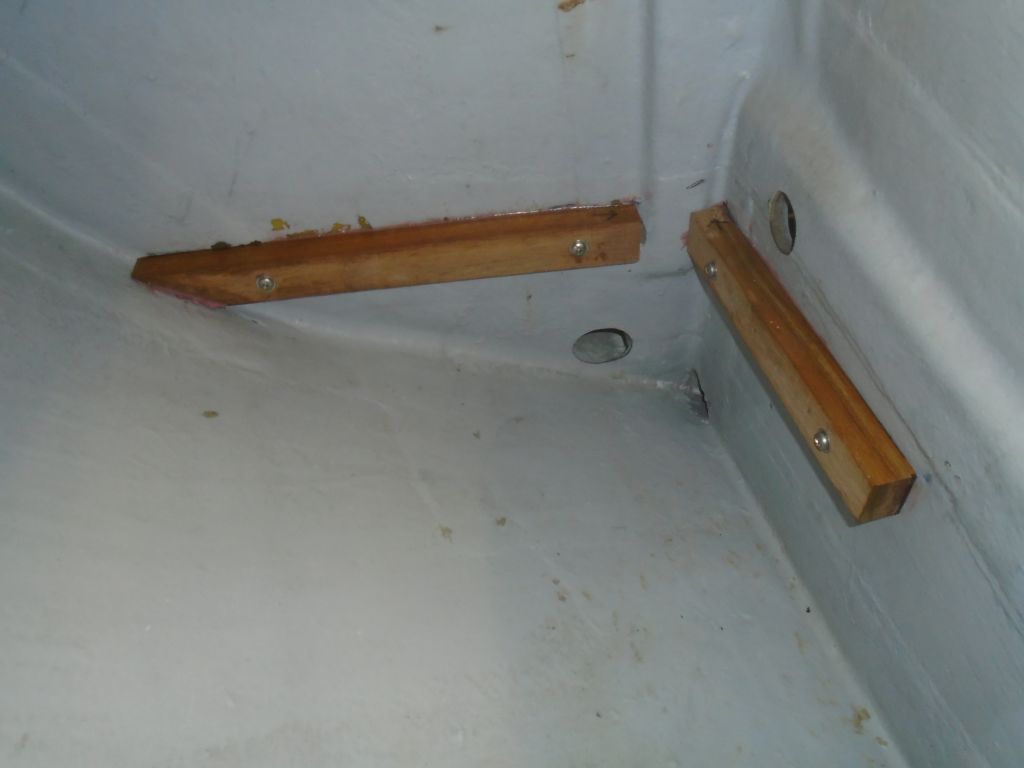
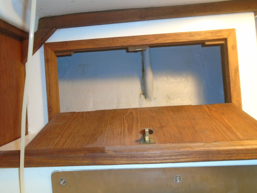
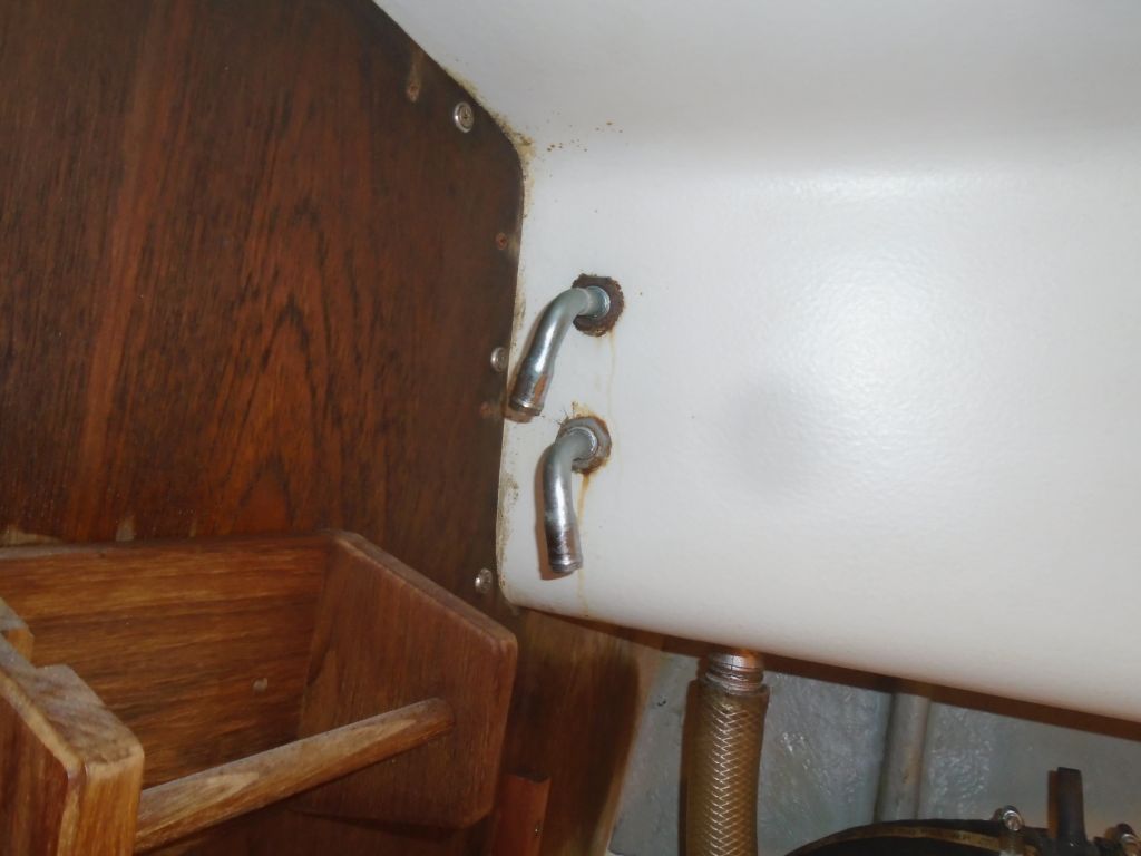
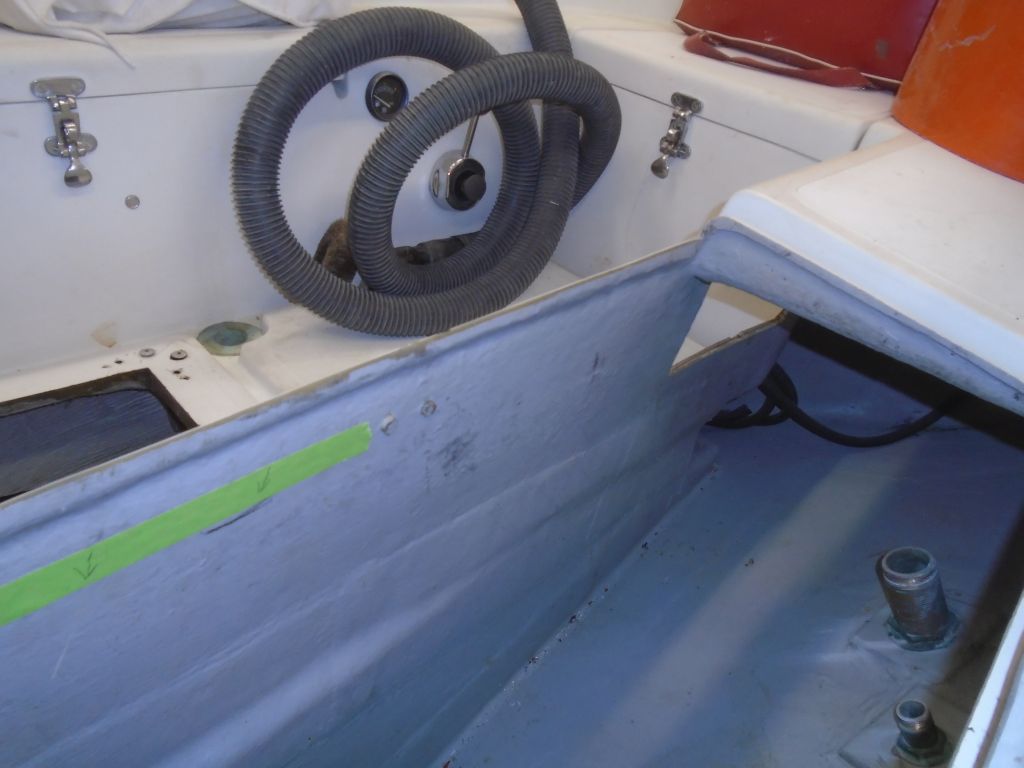
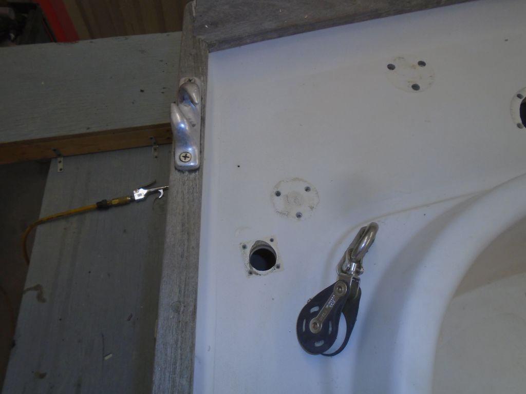
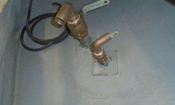
In the port cockpit locker, I installed the valves and tailpieces for the two bilge pump outlets, facing the 90° tailpiece for the cabin-mounted bilge pump (the larger fitting) towards from whence its hose would run.  Imagining how the discharge hose from the new cockpit pump might need to lead, I set up the 90° tailpiece for that pump (the smaller valve) facing towards the outside of the hull, so the hose could run easily from the pump around in a semi-circle to the valve.  Because these valves were above the waterline, after a discussion the owner and I had determined it was OK to reinstall new valves on the existing stems despite its being “wrong”.

plumbing1-31816

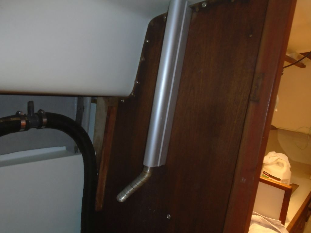
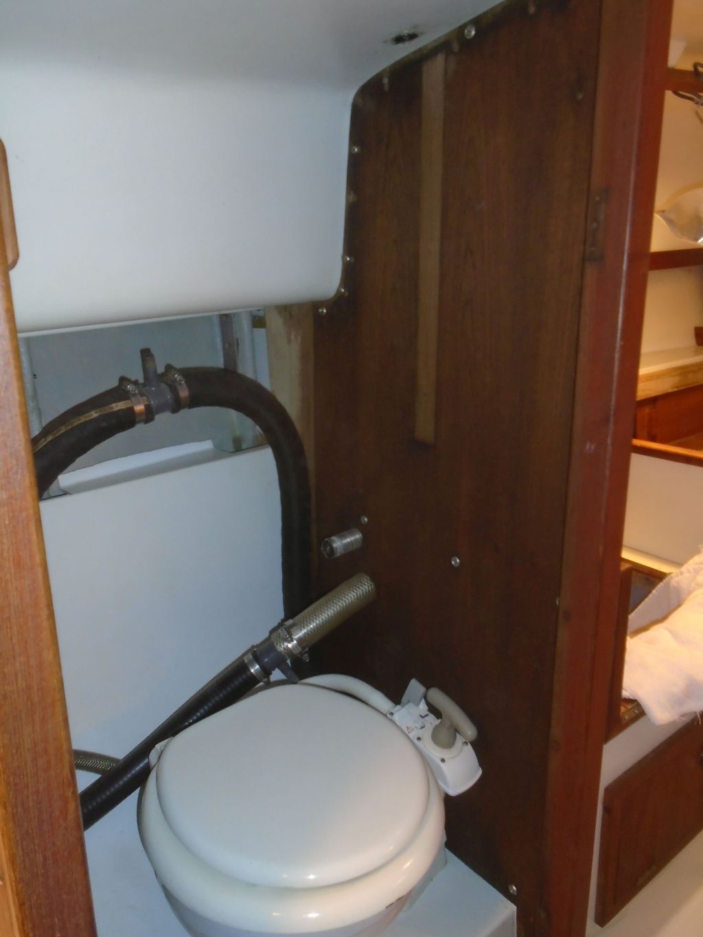
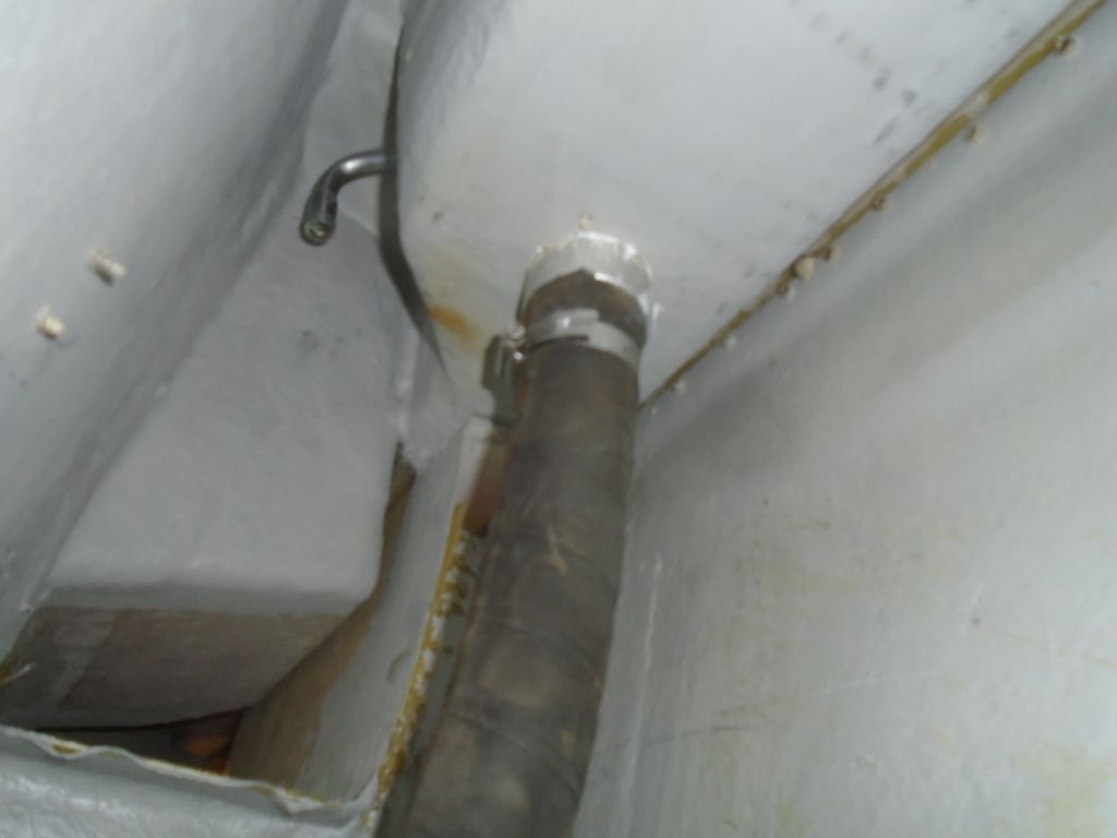
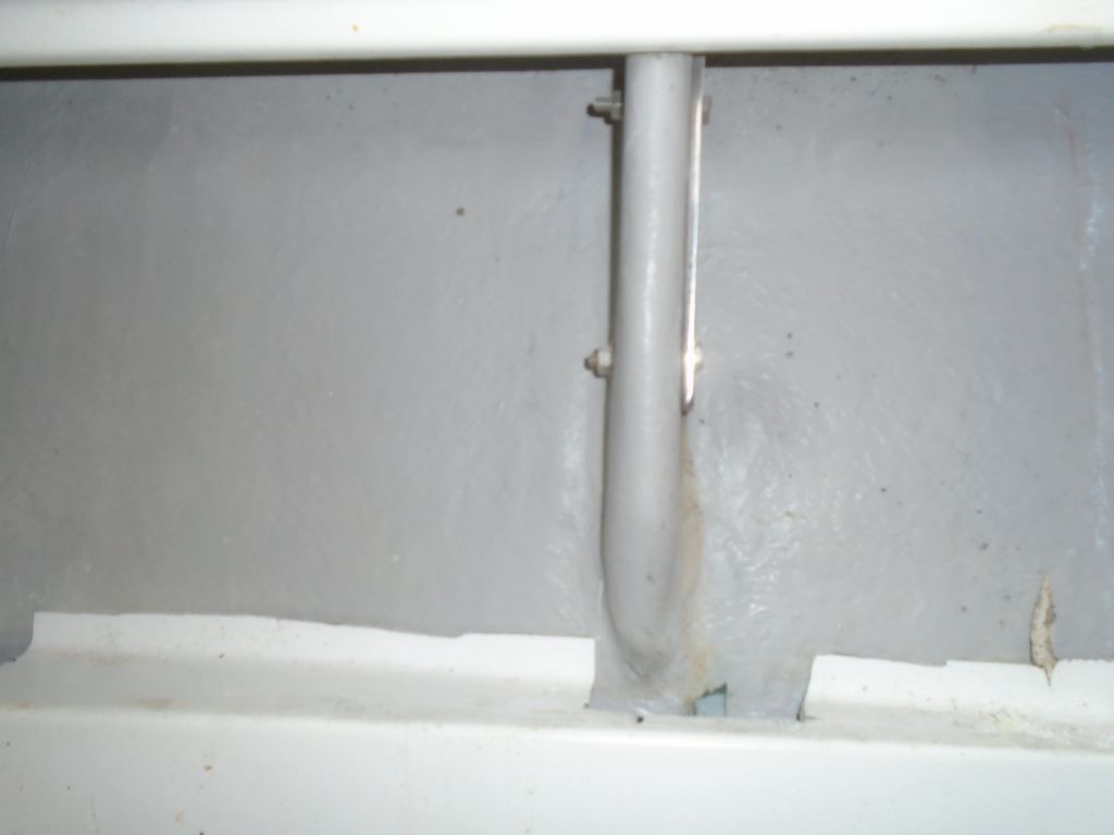
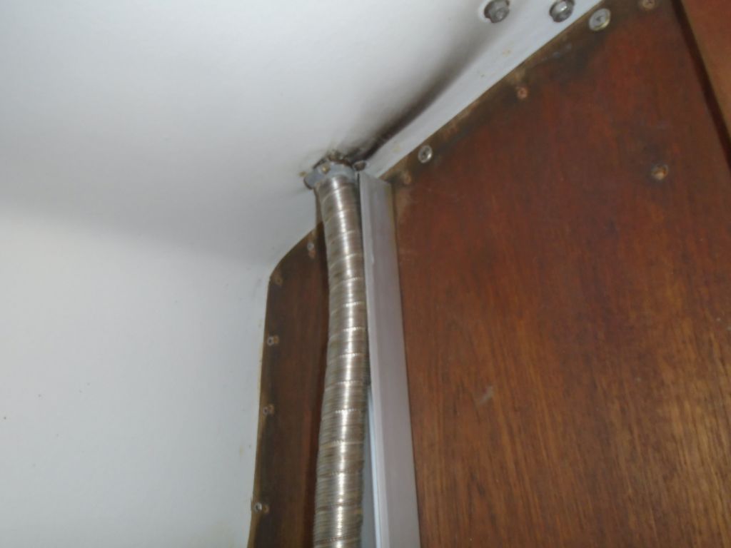
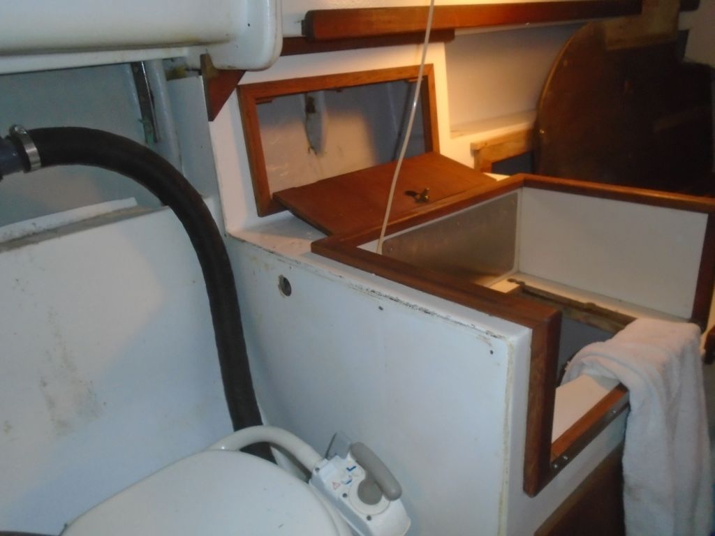
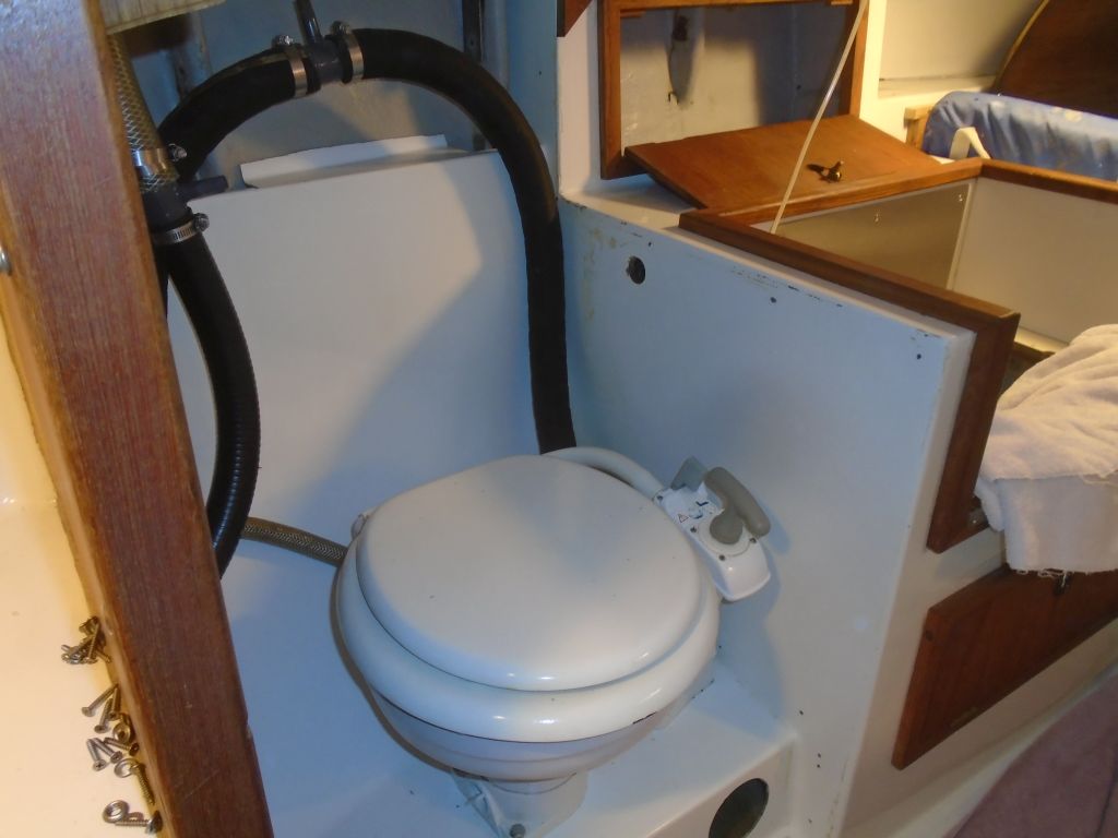
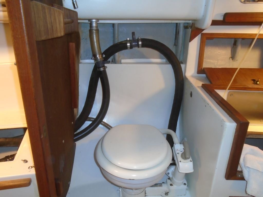
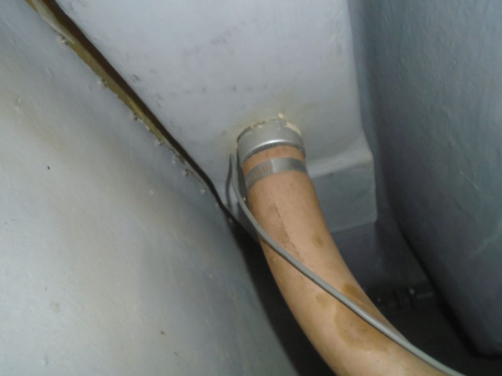
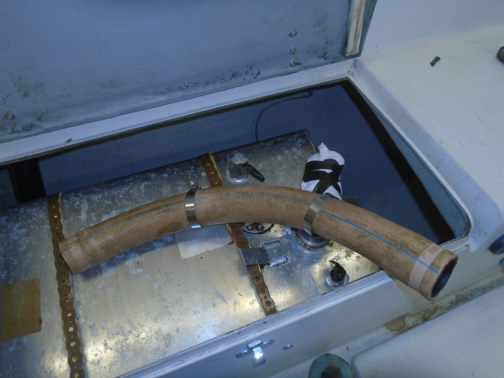
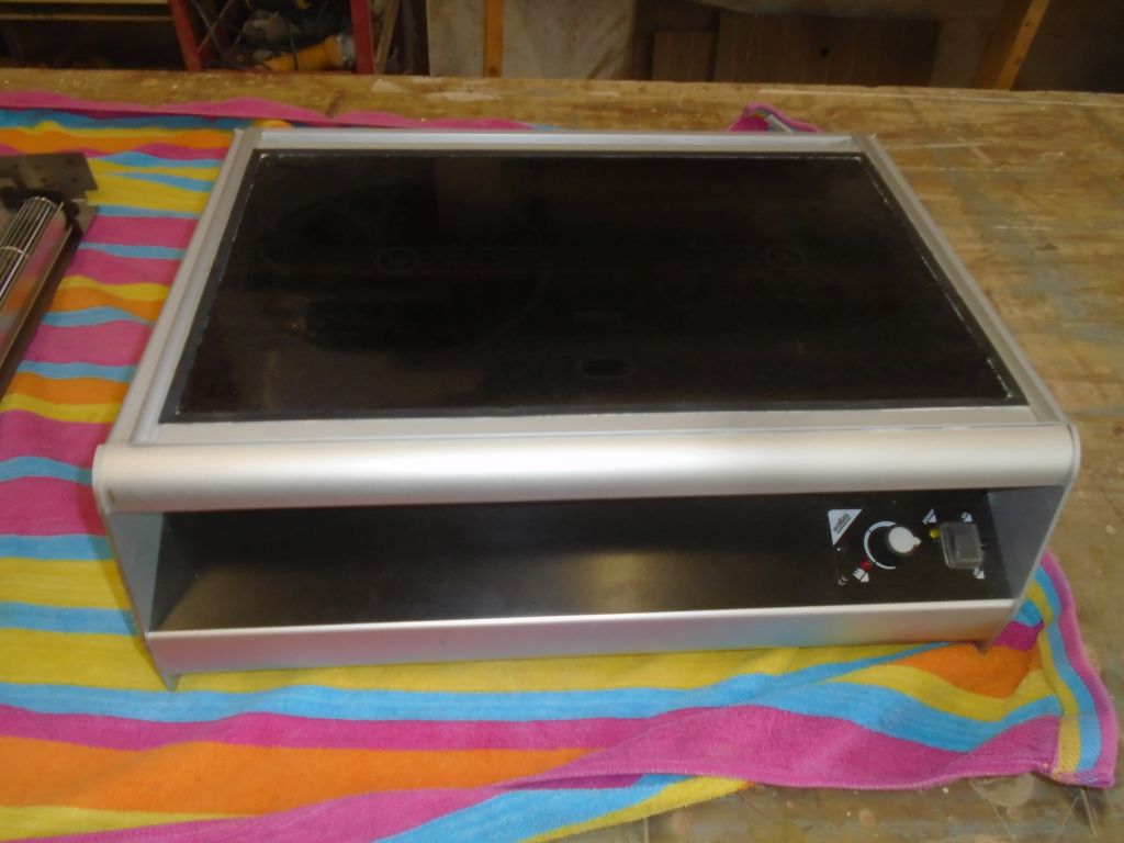
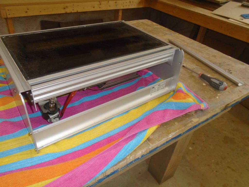
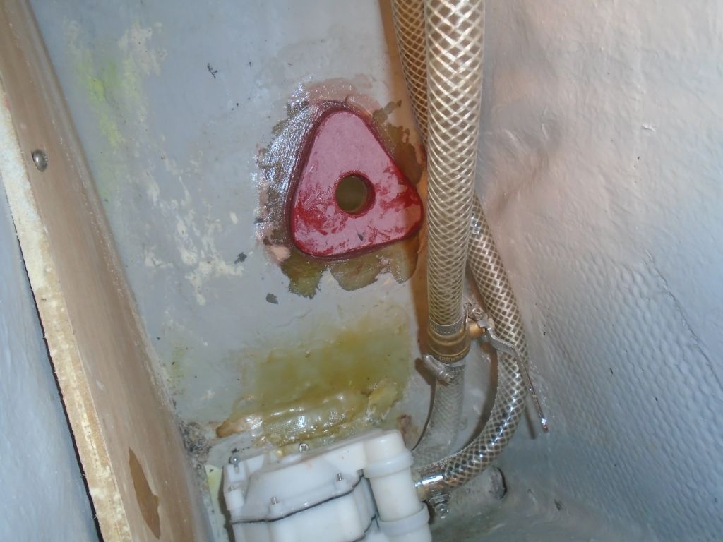
I took this opportunity to reinstall hoses up forward, connecting the existing head intake and discharge lines to their new fittings.  While I was at it, I also reconnected the water tank fill, and reinstalled the galley stove vent pipe.

Because I’d soon be at the point to start reinstalling many of these systems, I checked existing stock of hose in various required sizes, and ordered whatever I needed for the bilge pumps and engine exhaust.

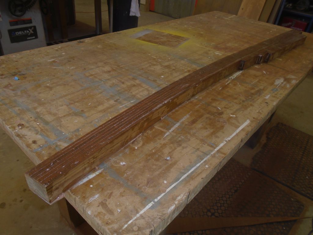
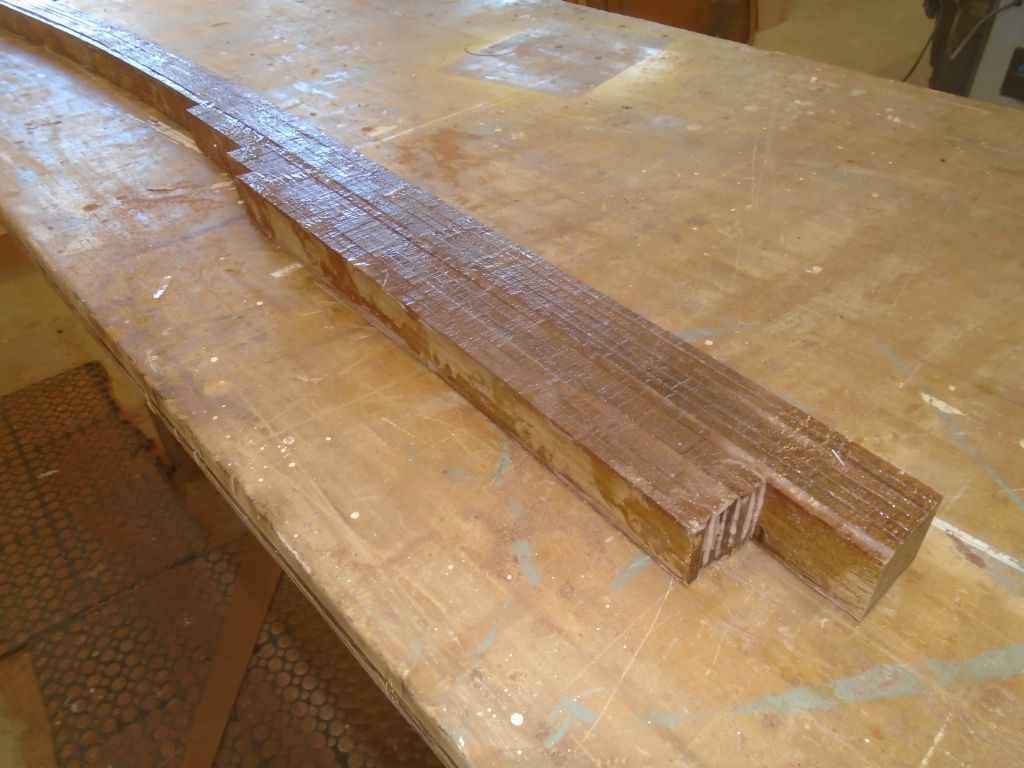
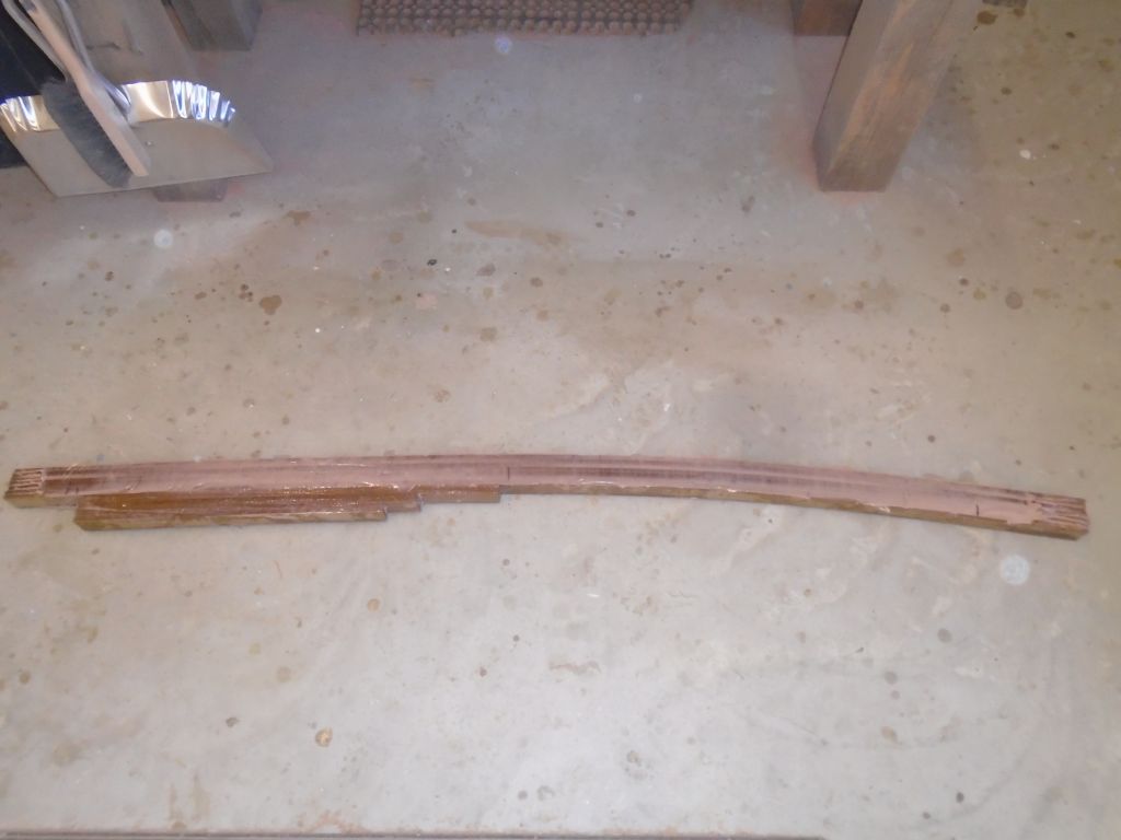
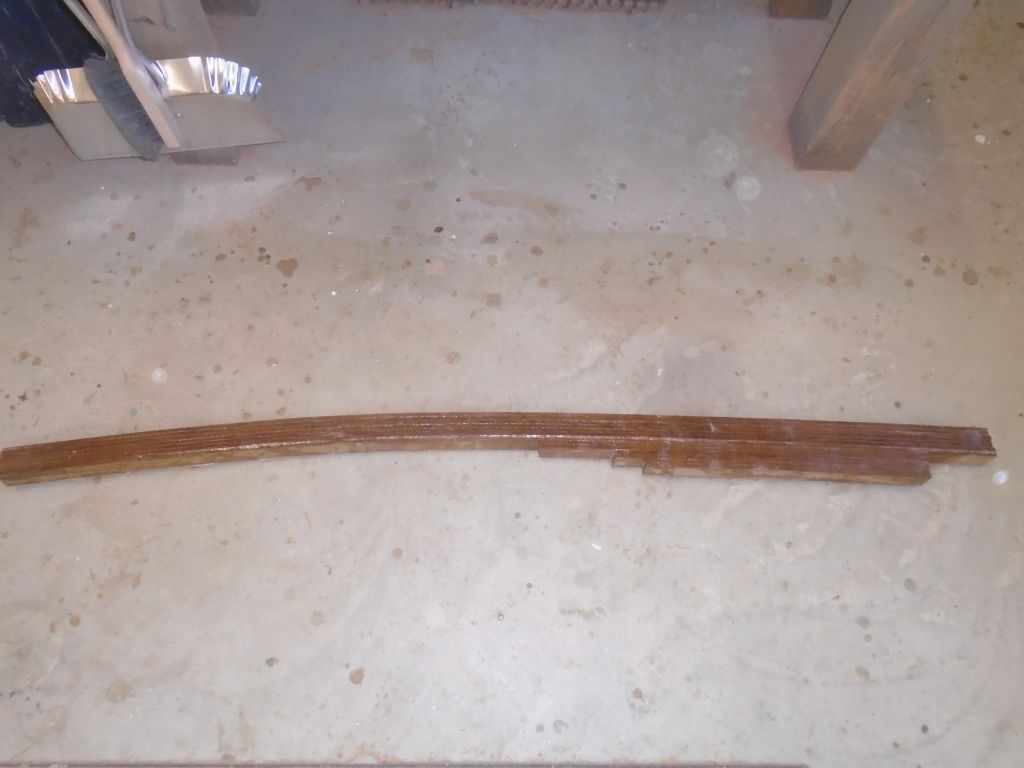
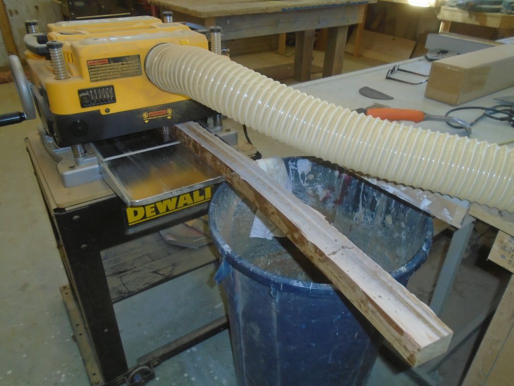
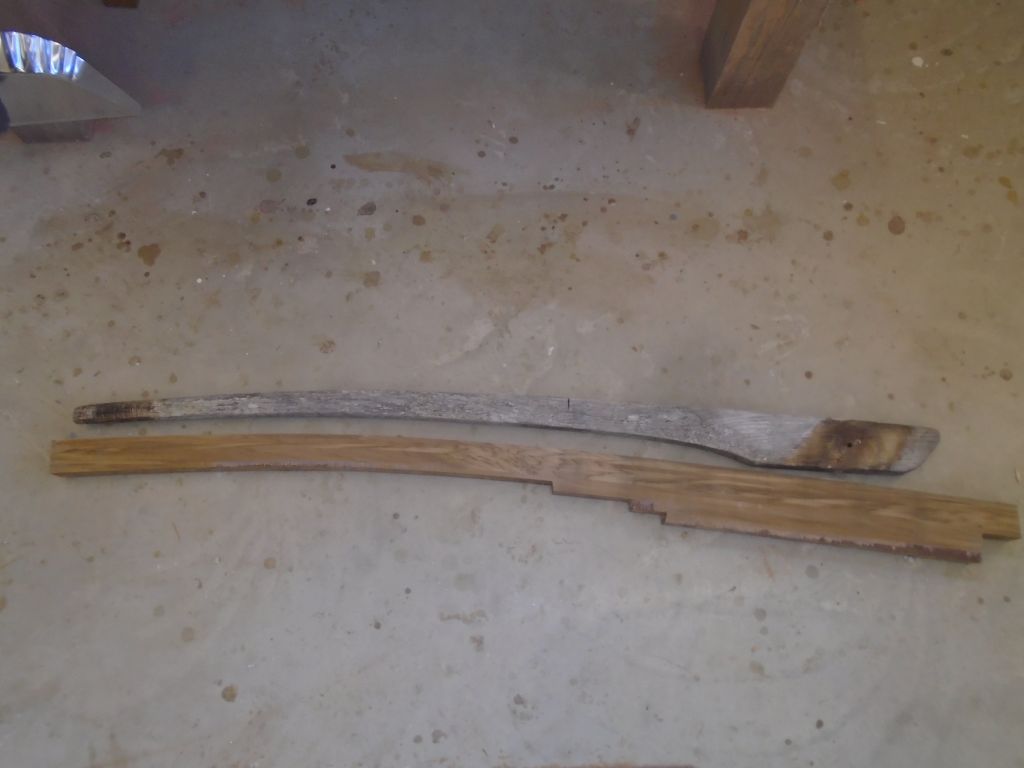
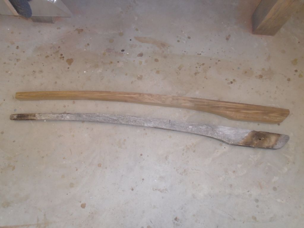
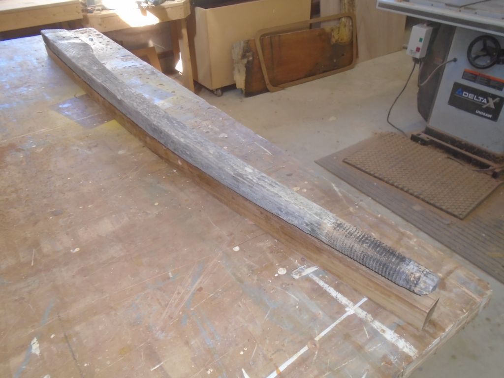
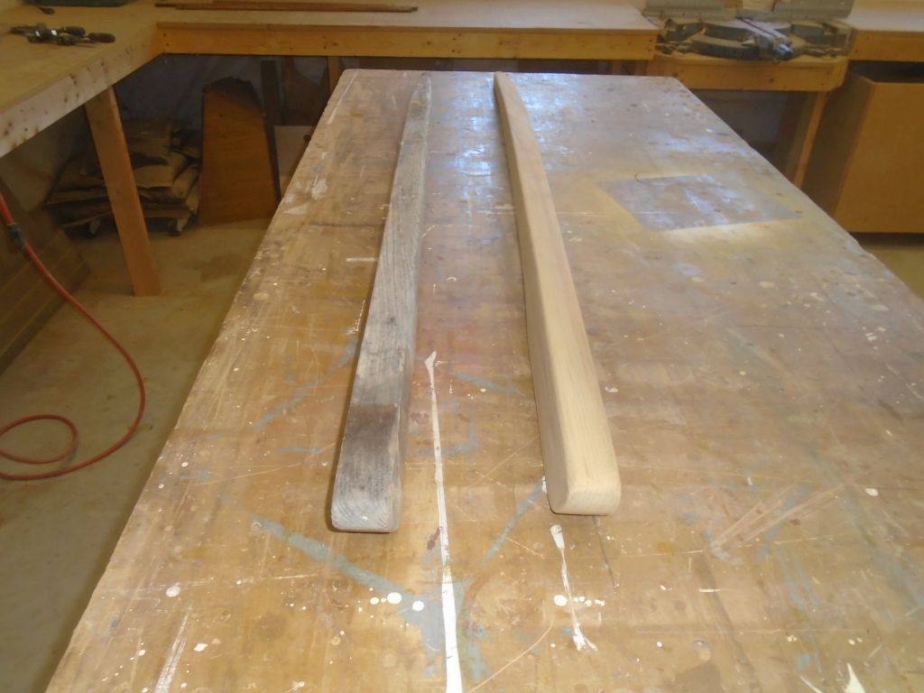
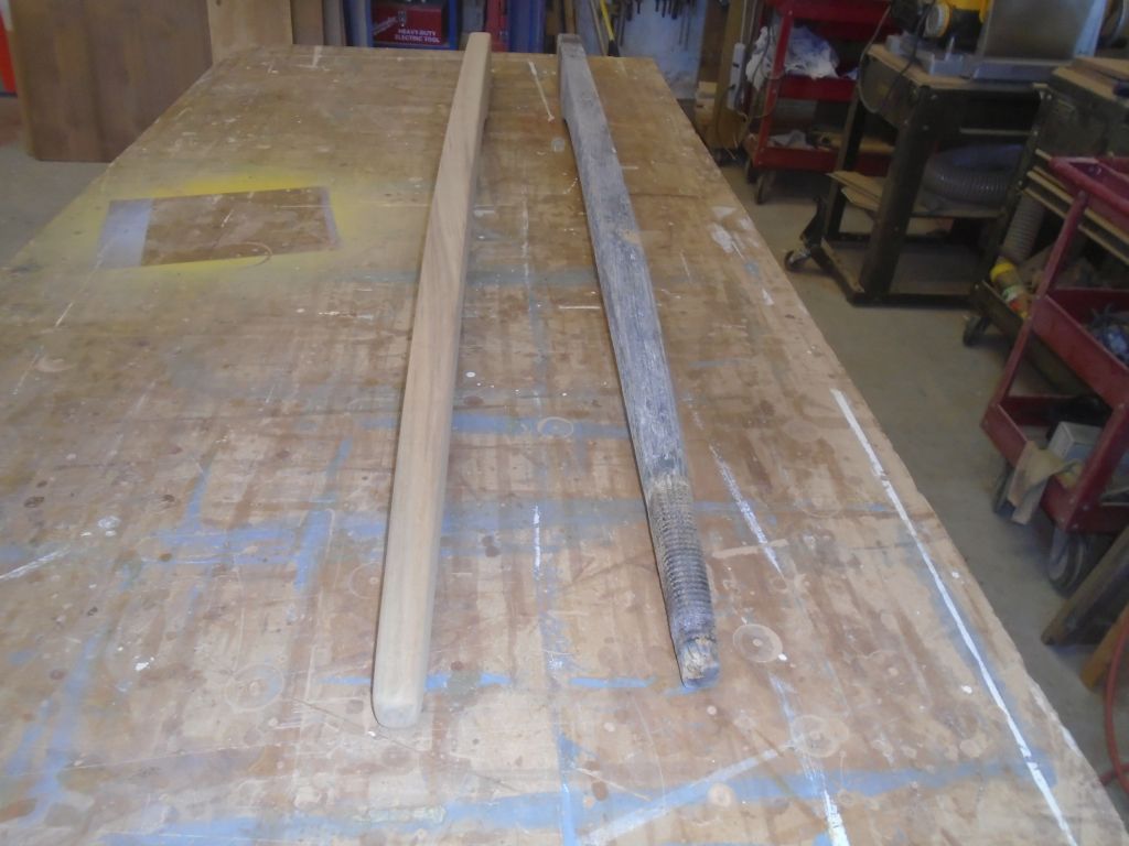
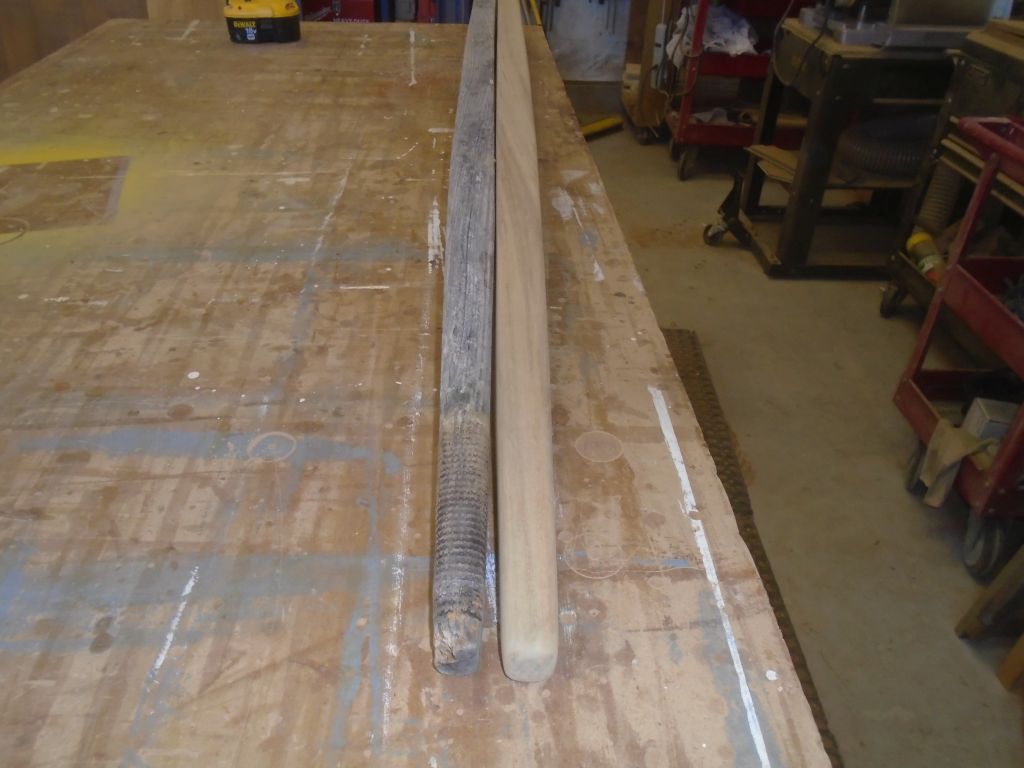
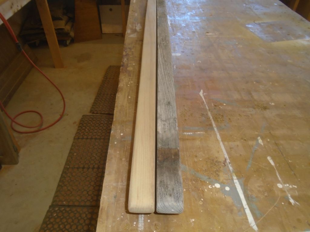
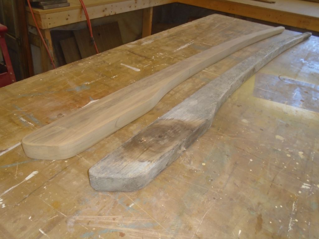
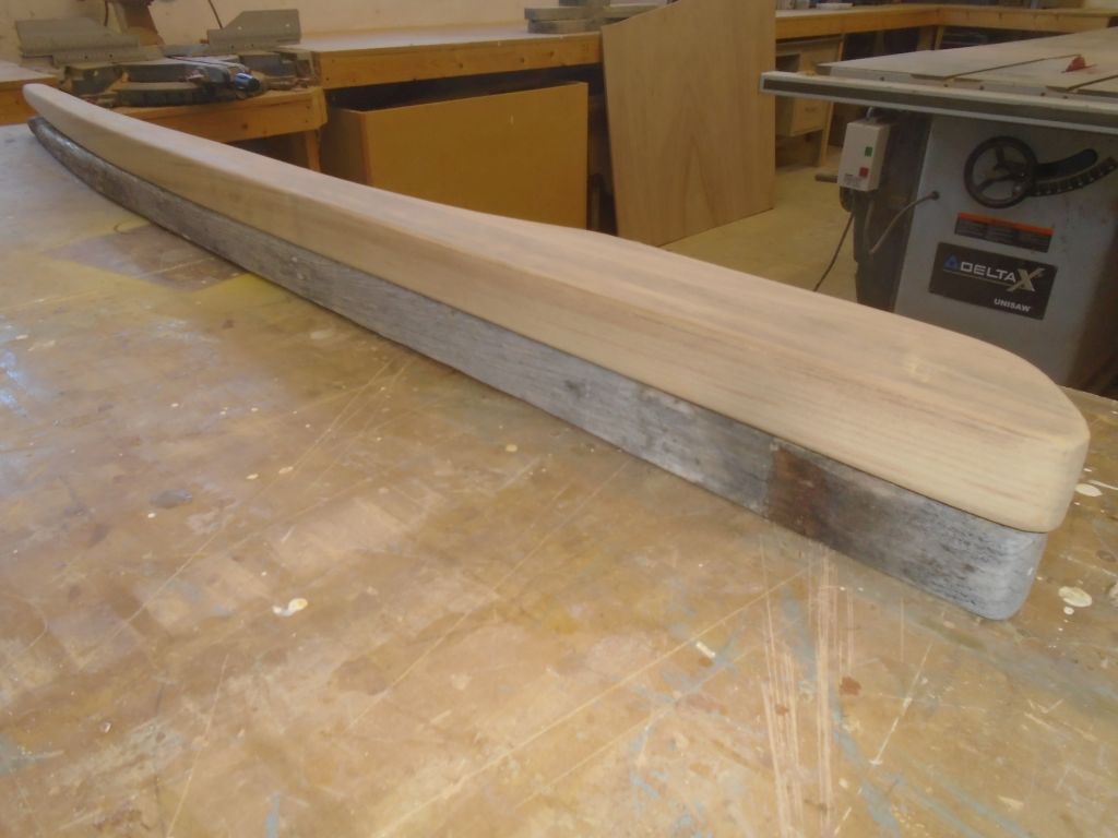
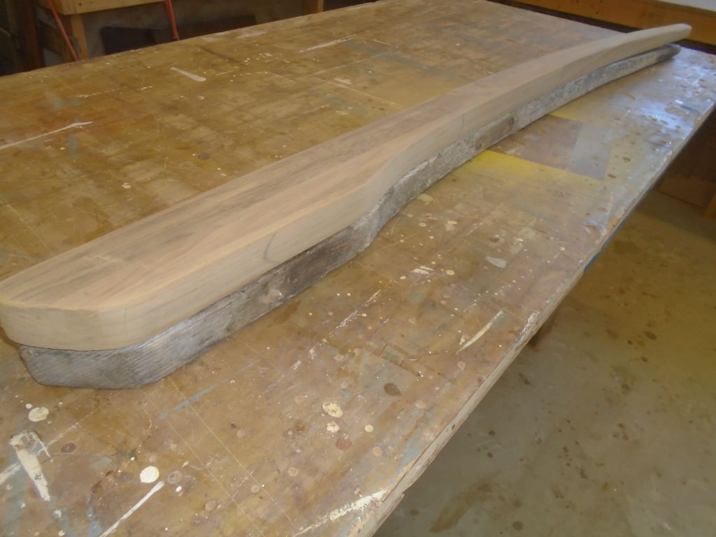
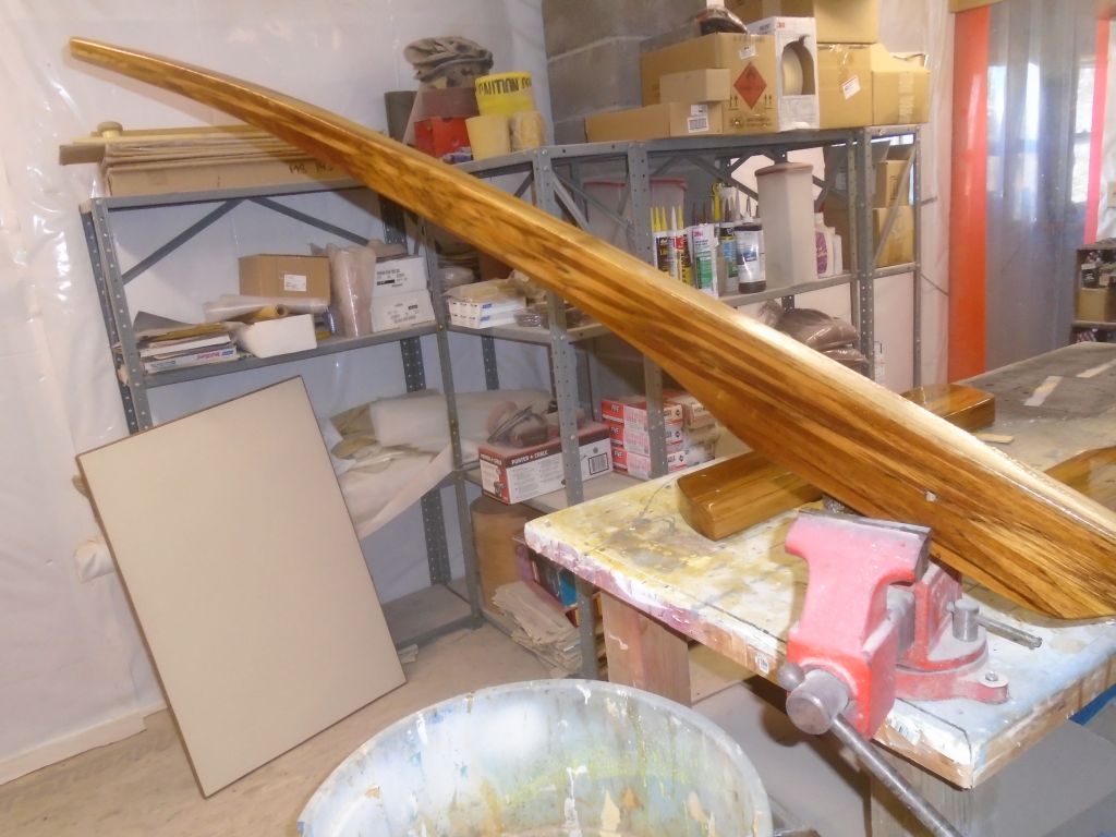
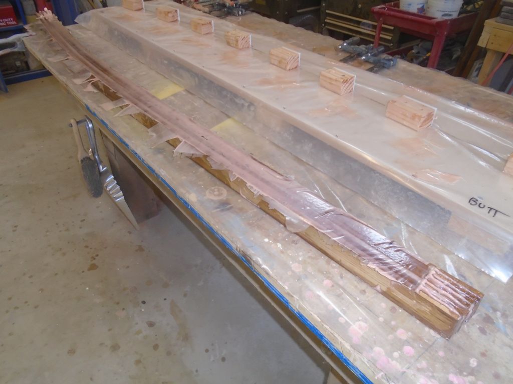
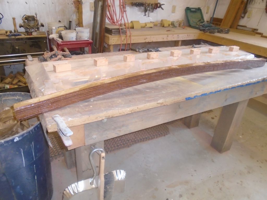
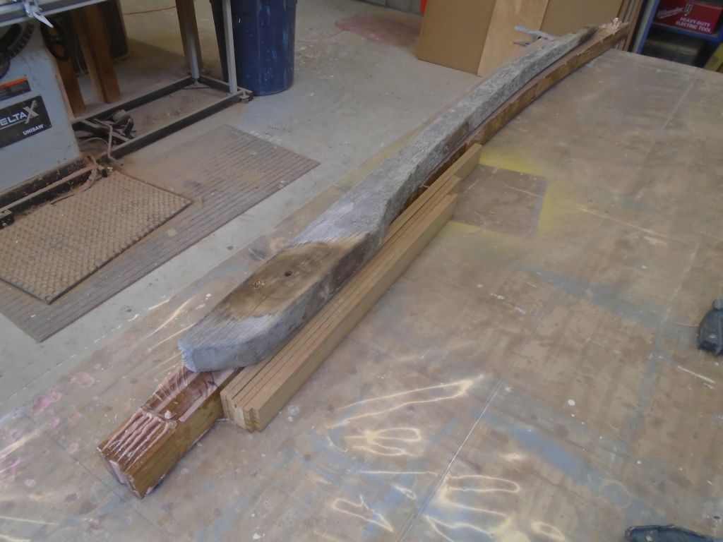
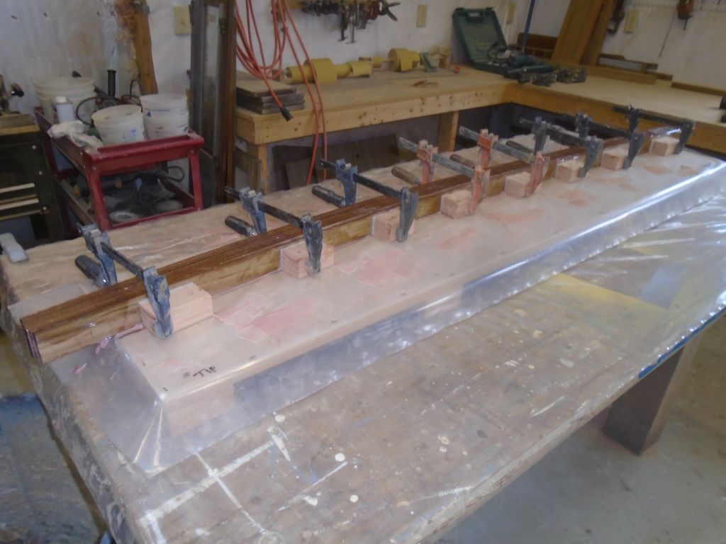
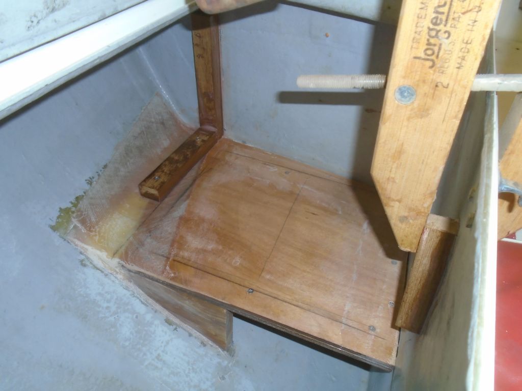
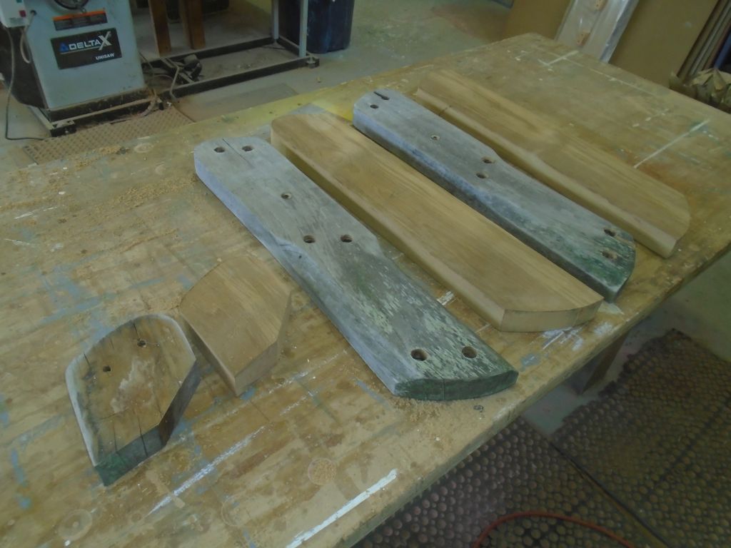
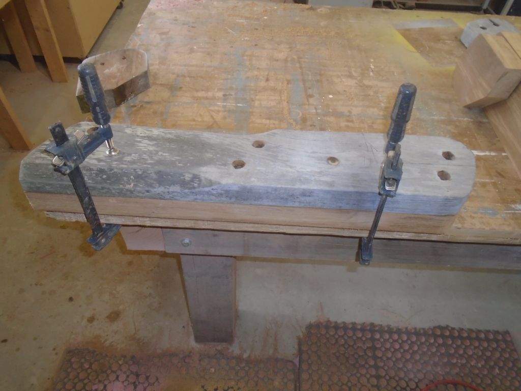
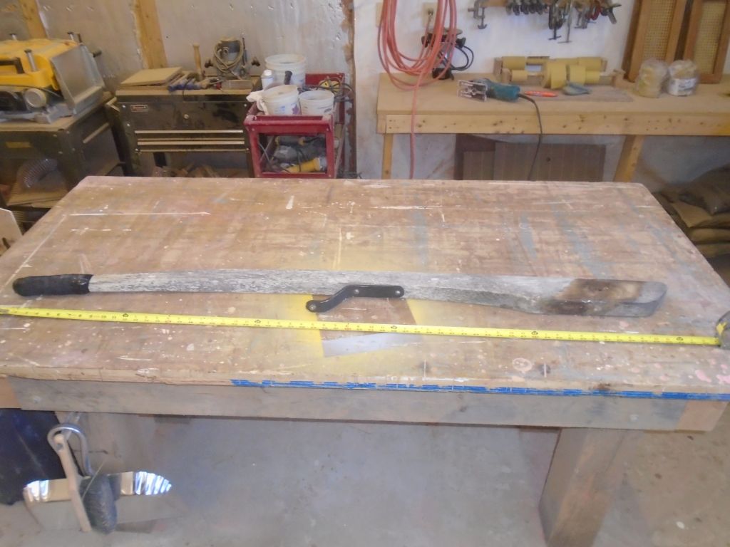
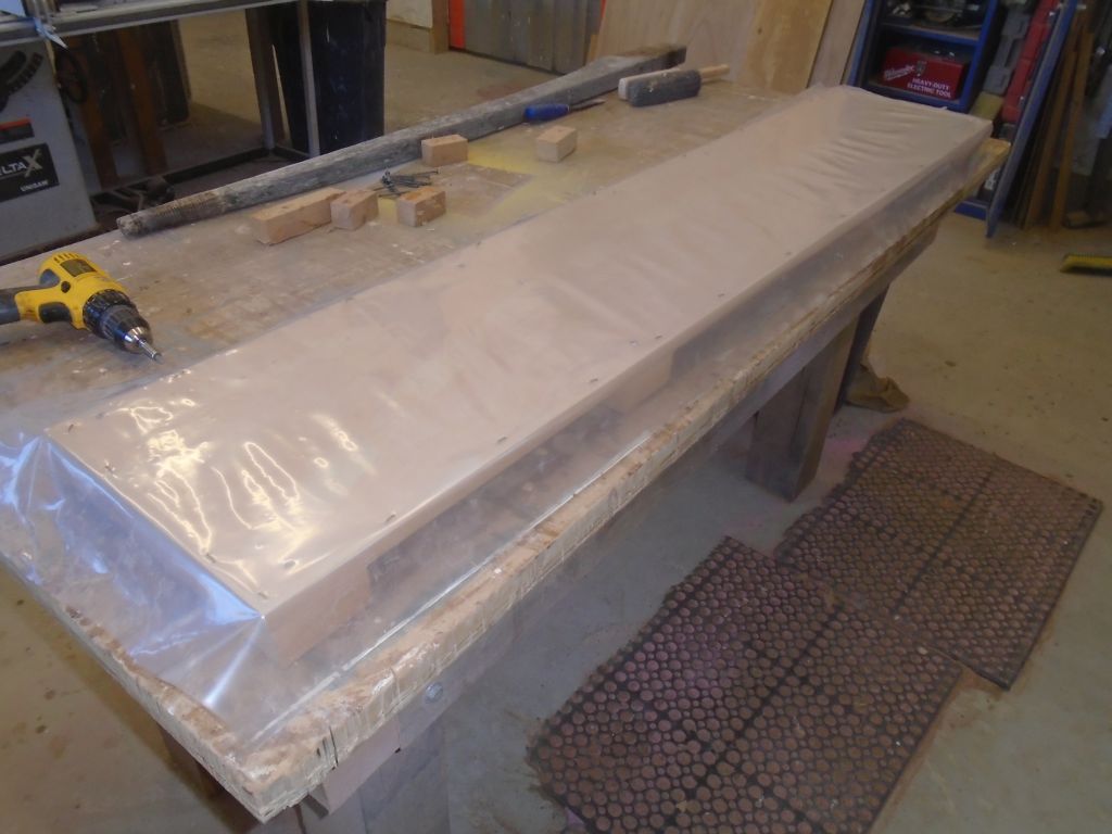
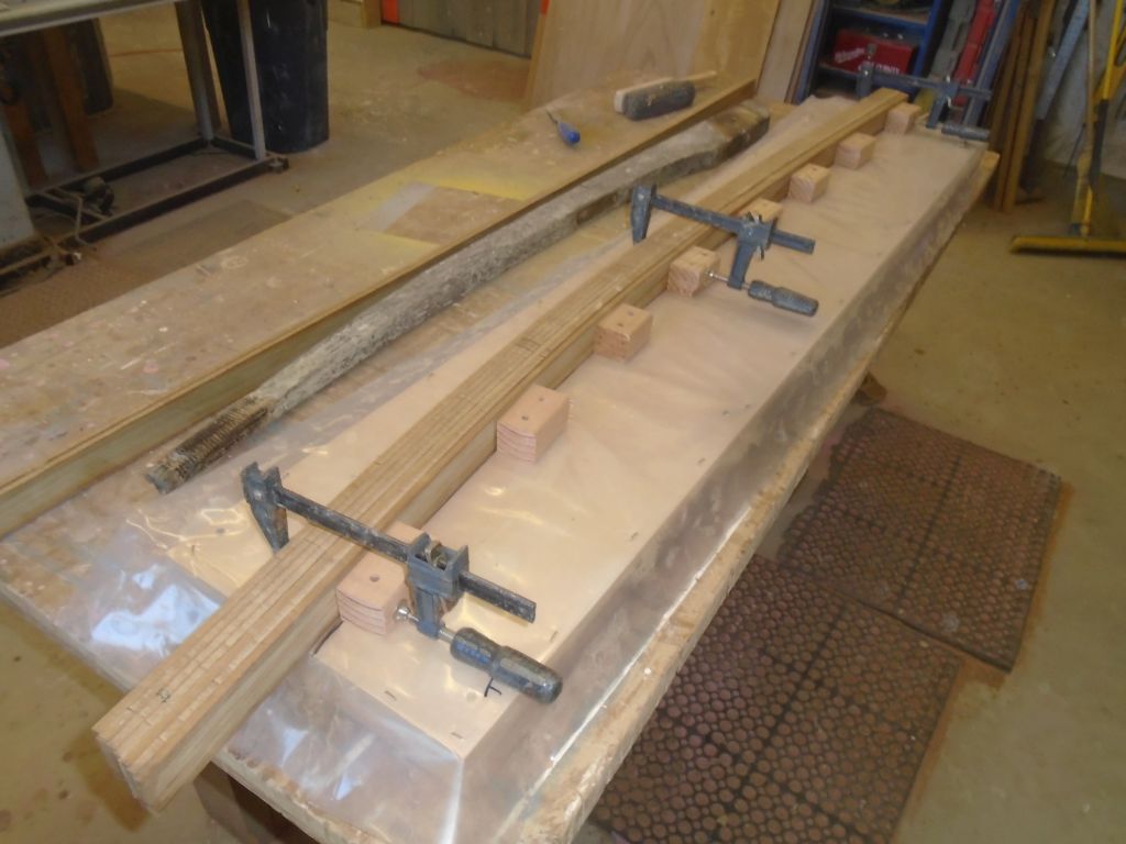
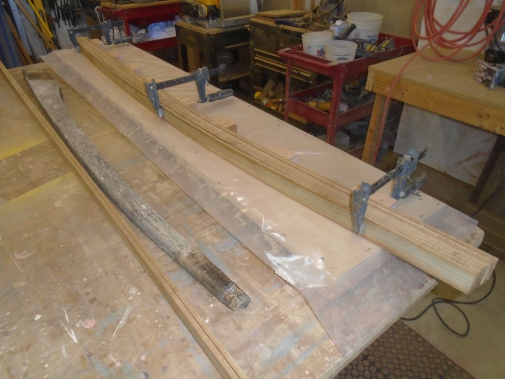
The laminated tiller was cured, and I unclamped it from the jig so I could finish up the additional laminations required at the butt end.  Had the bend been more severe, I might have left it in the clamps longer, but for this easy curve I’d no concerns after 24 hours.

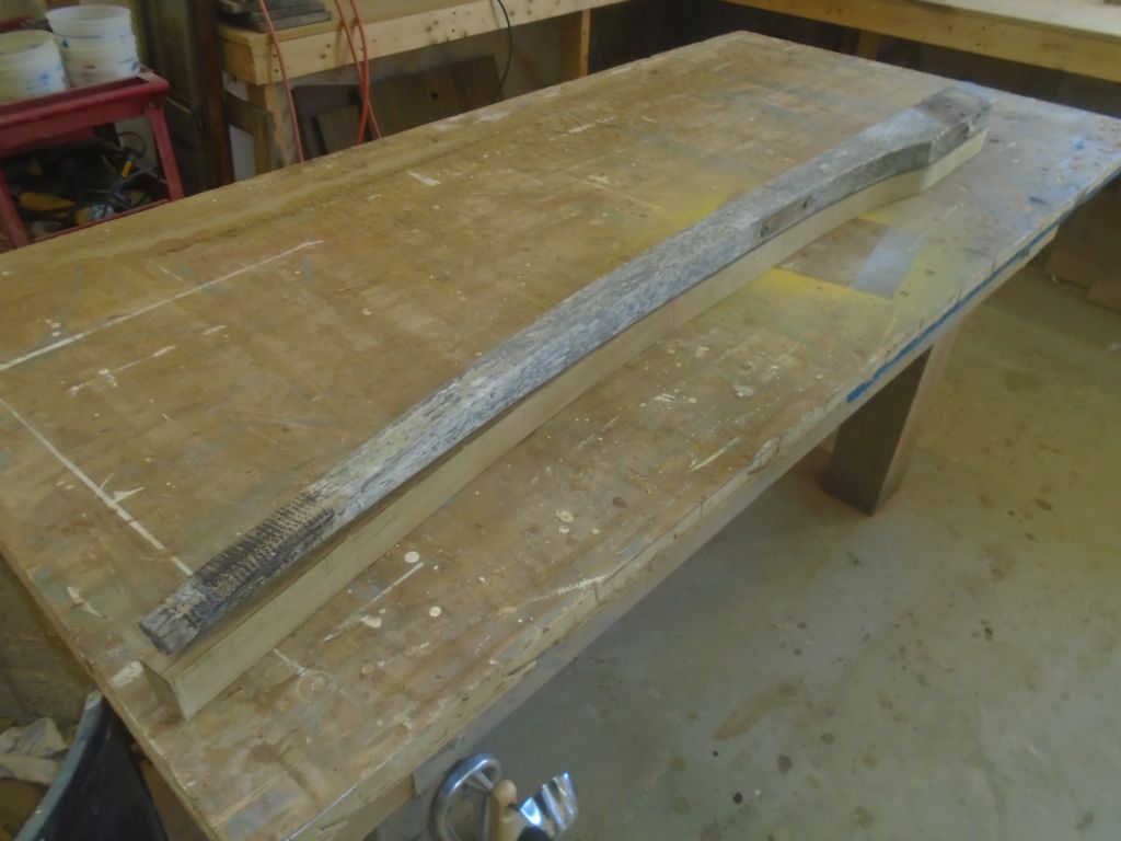
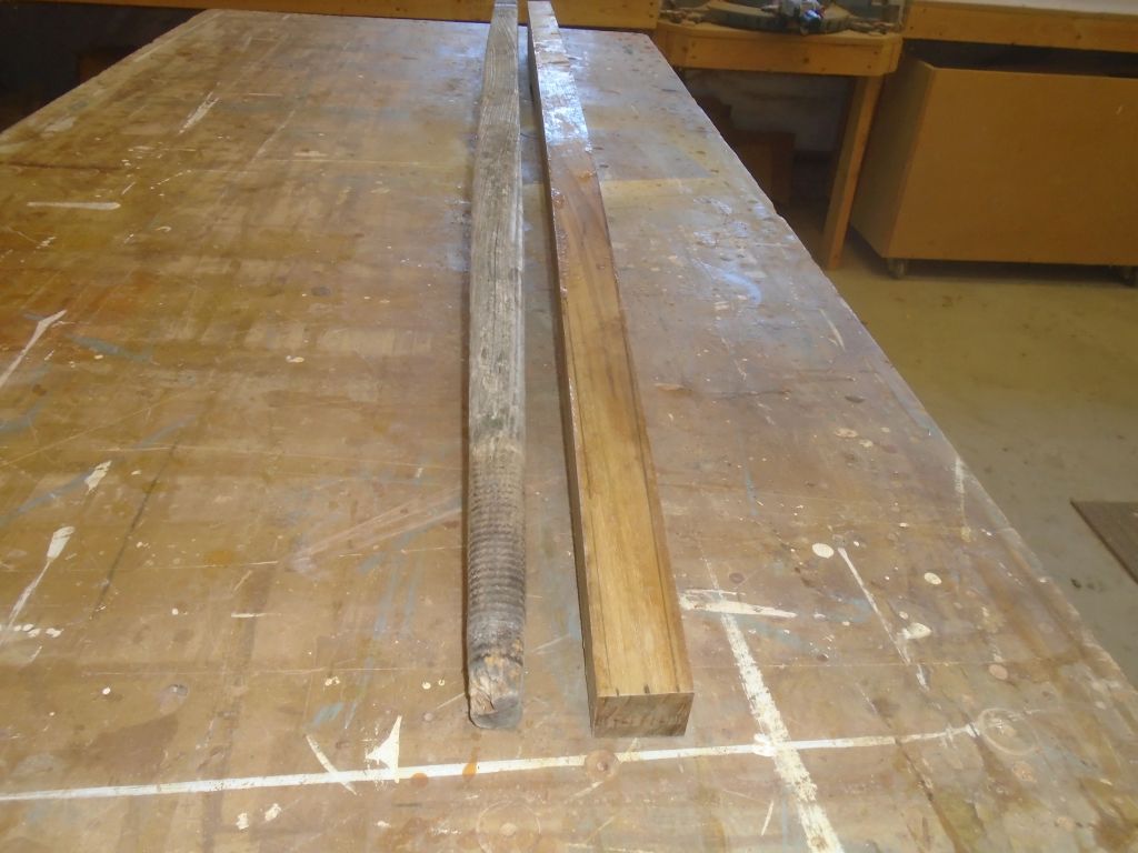
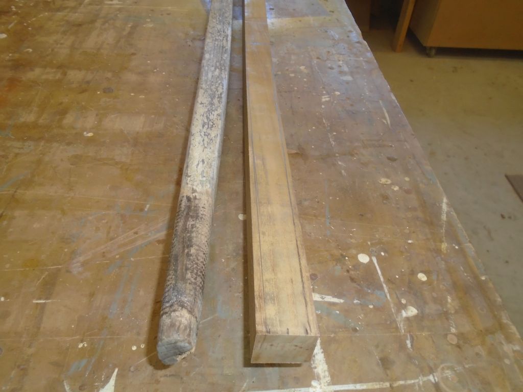
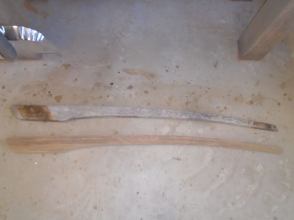
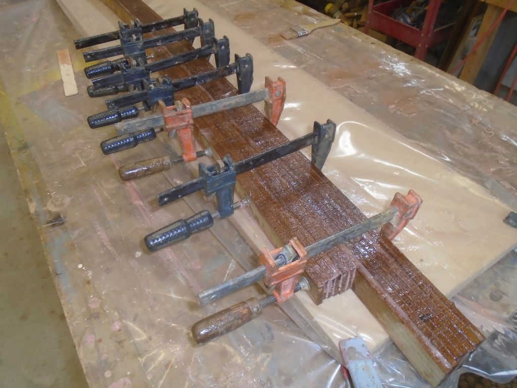
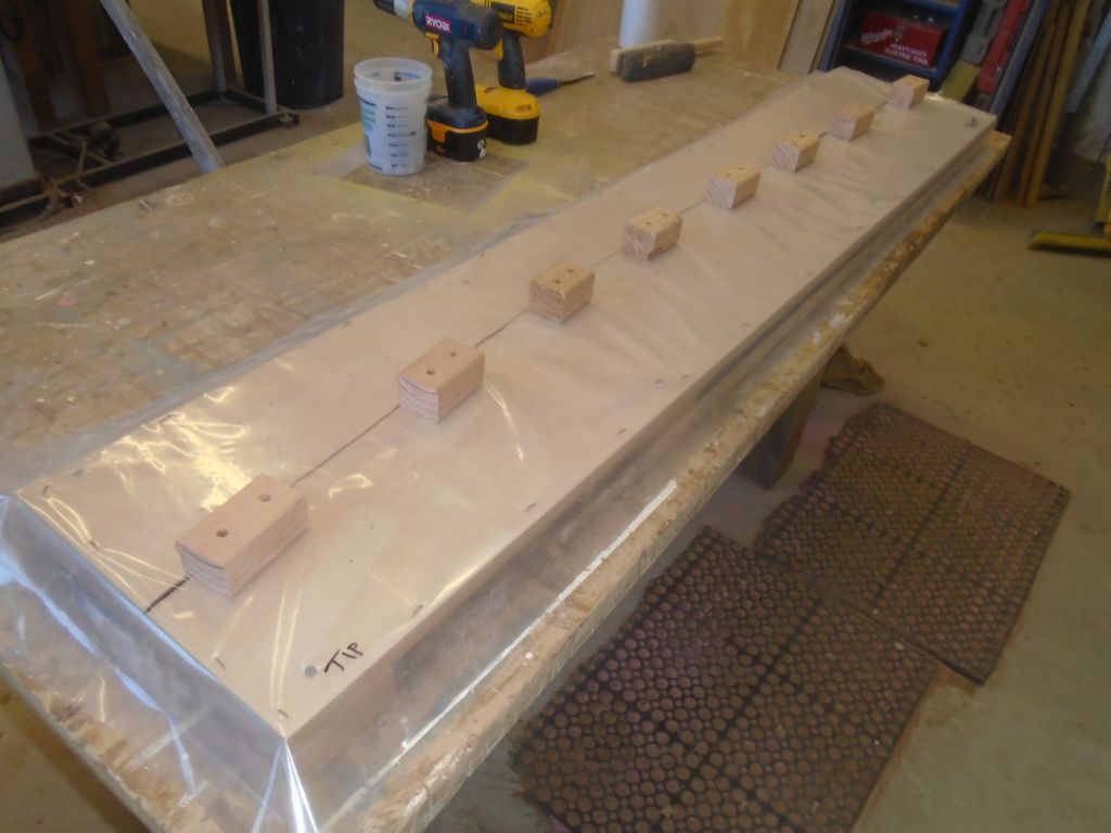
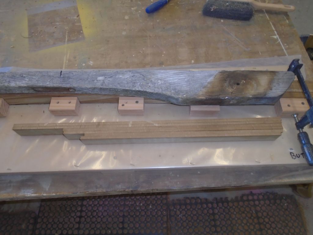
Ignoring for now most of the mess on the tiller, I cleaned up (sanded) the bonding surface at the butt end where I ‘d be adding new laminations, and, after checking the position and layout with the old tiller and making reference marks, completed final preparations and cleanup before glued the additional six strips in place.

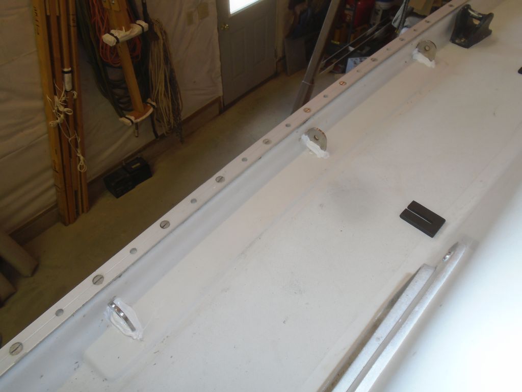
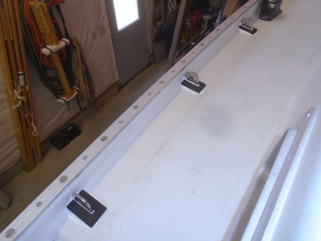
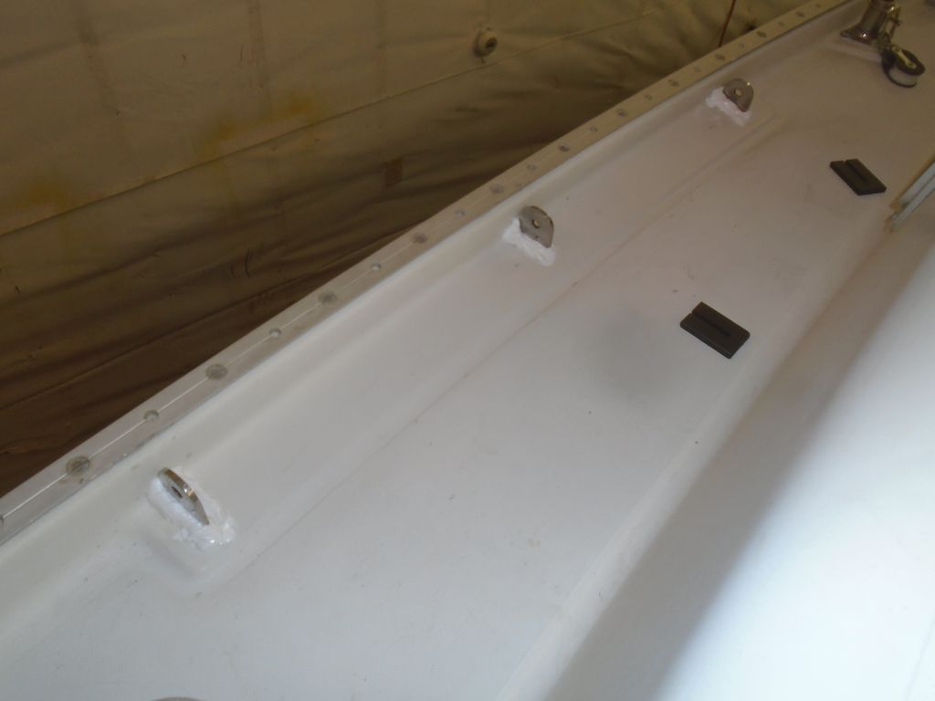
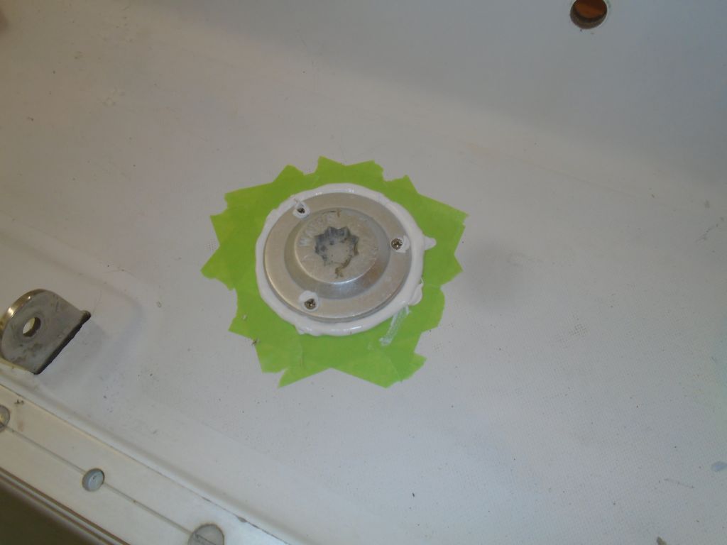
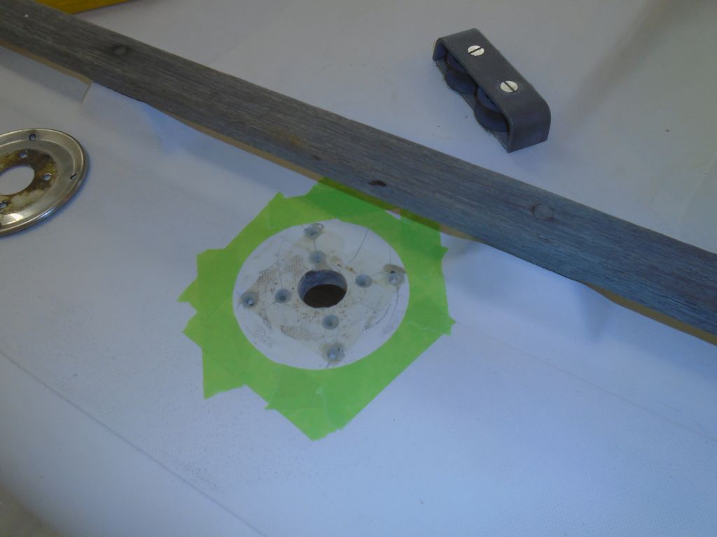
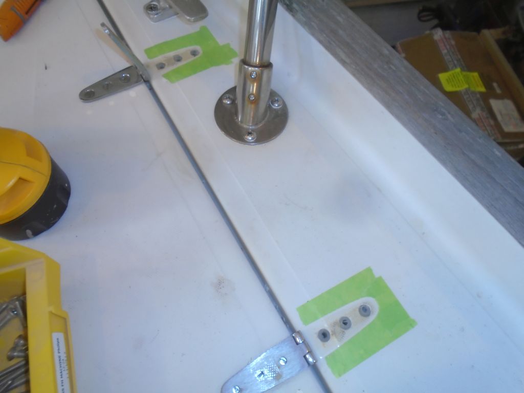
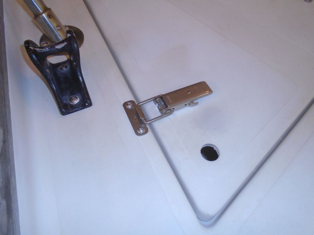
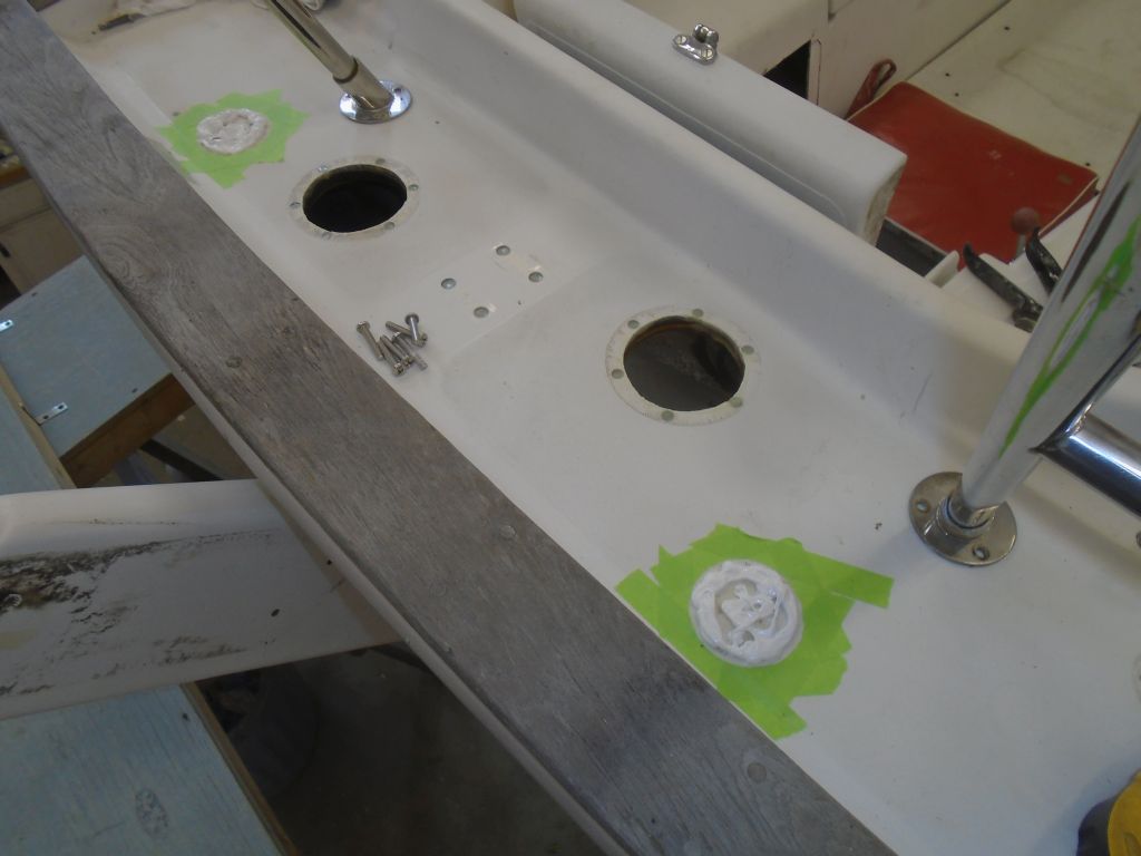
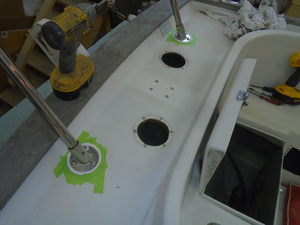
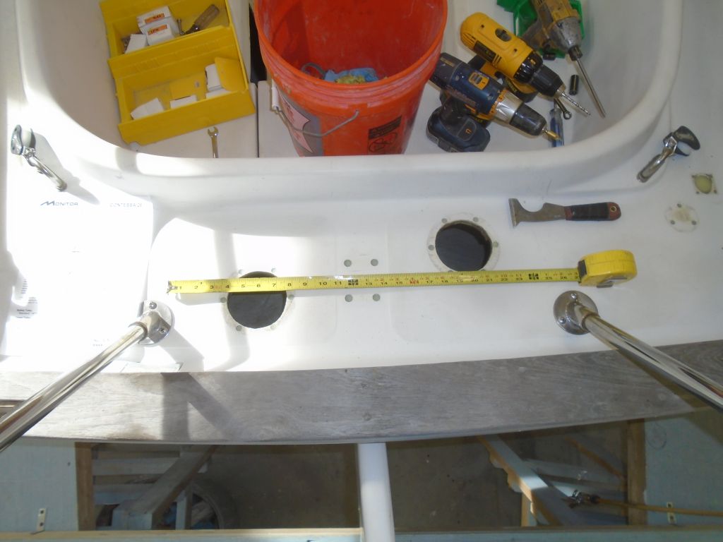
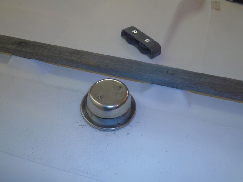
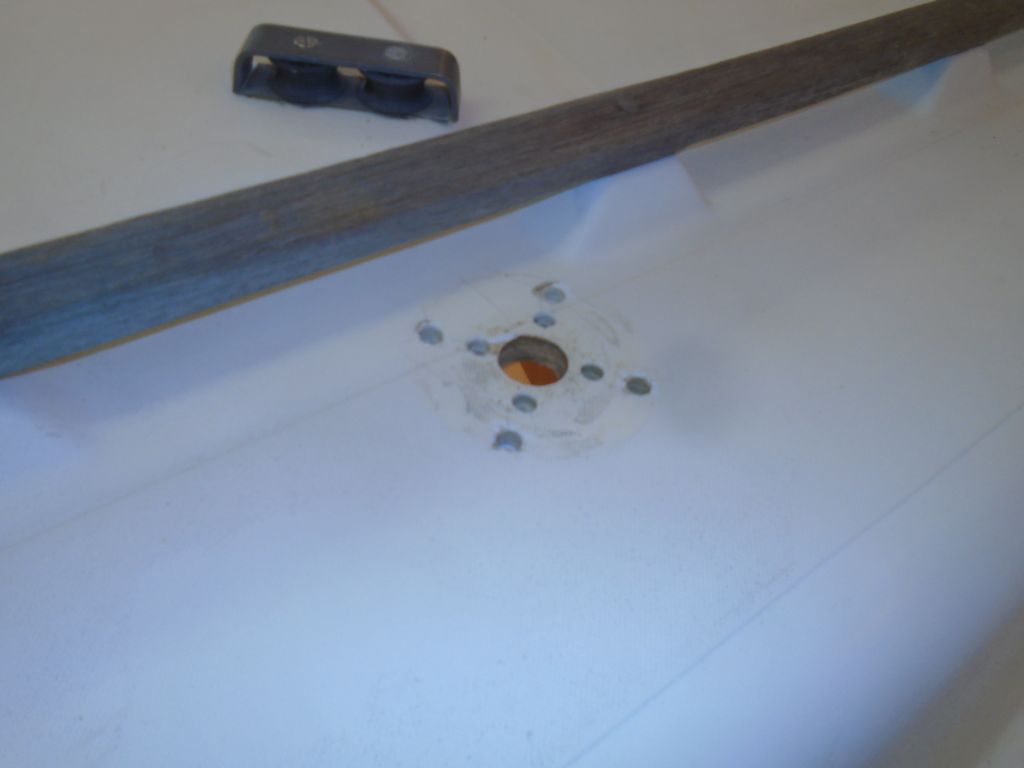
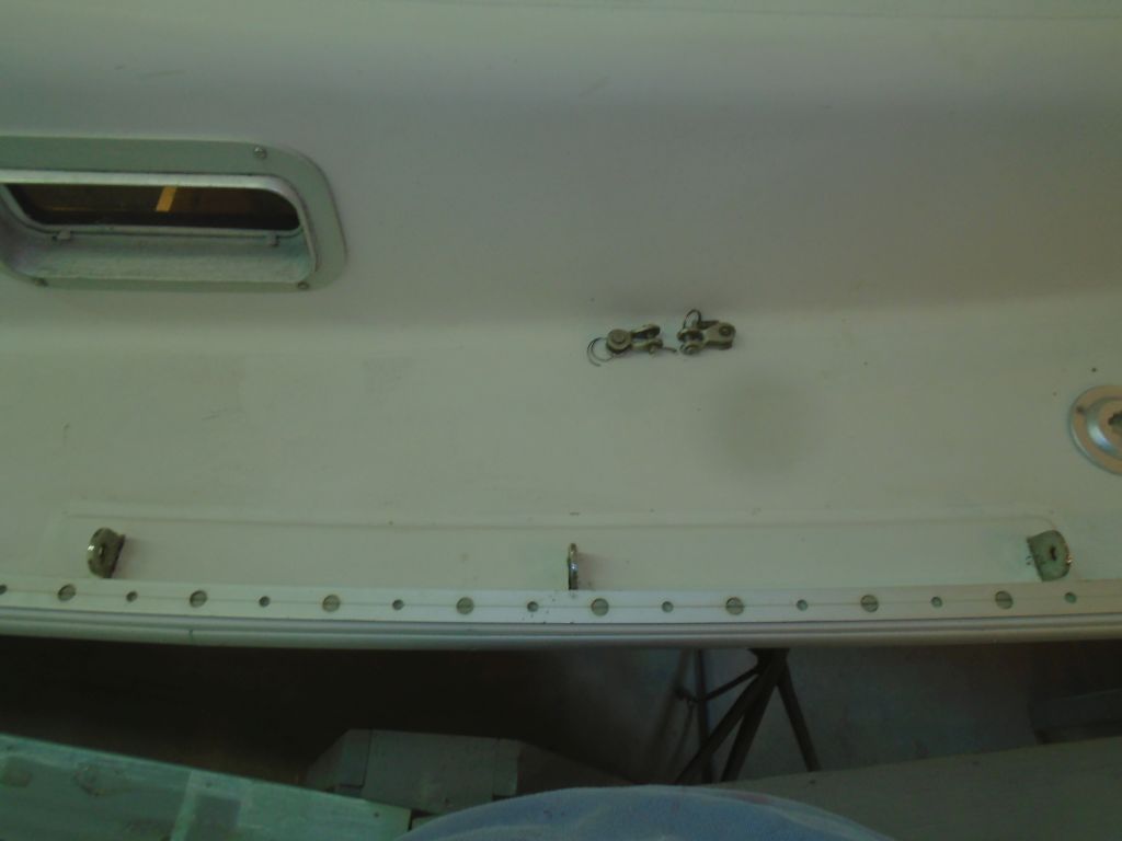
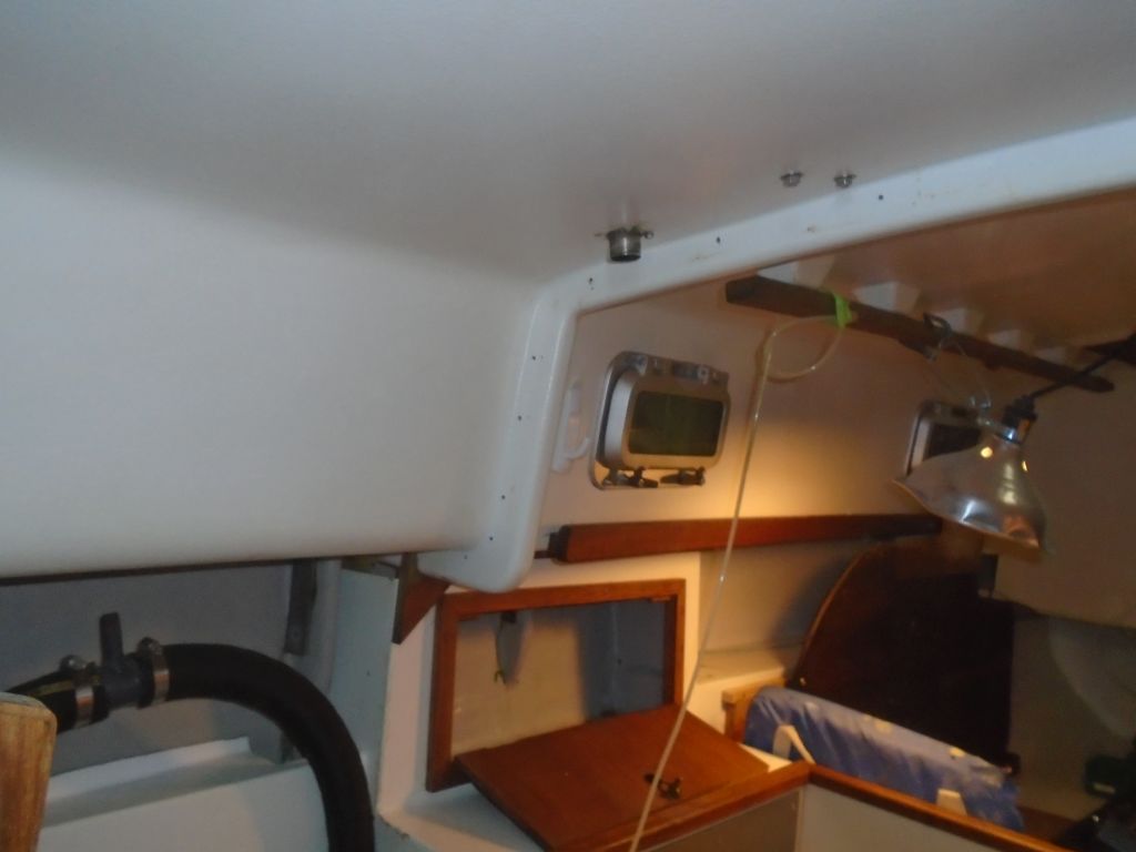
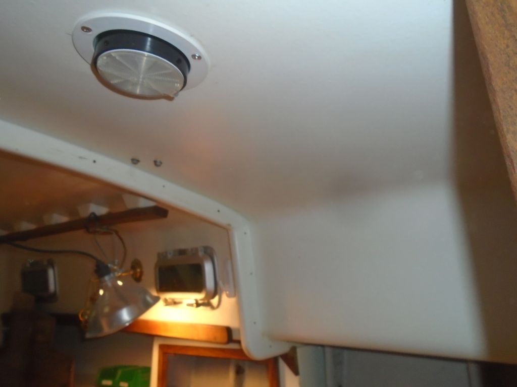
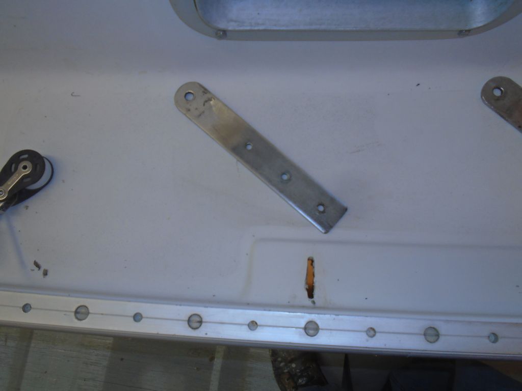
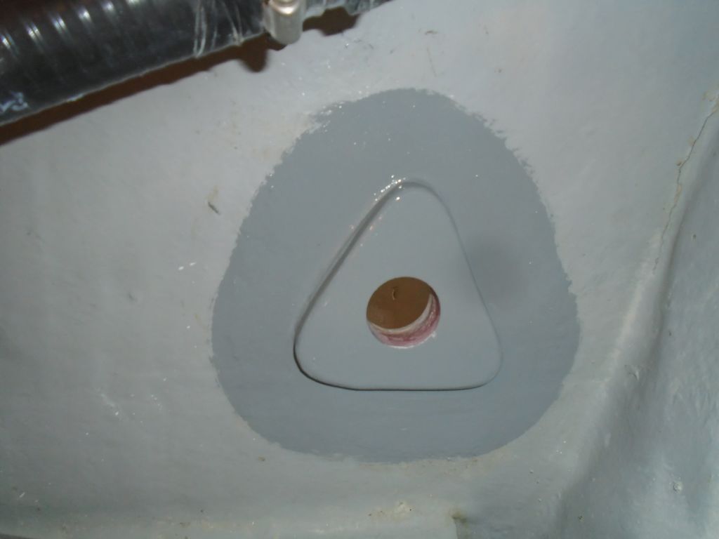
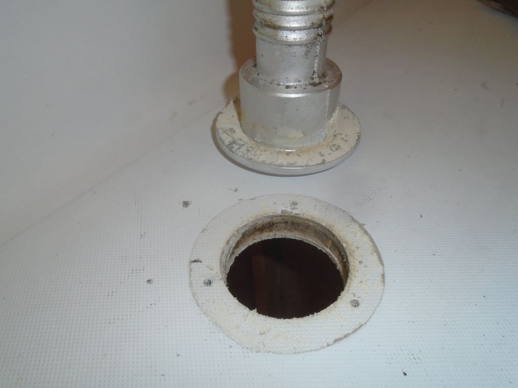
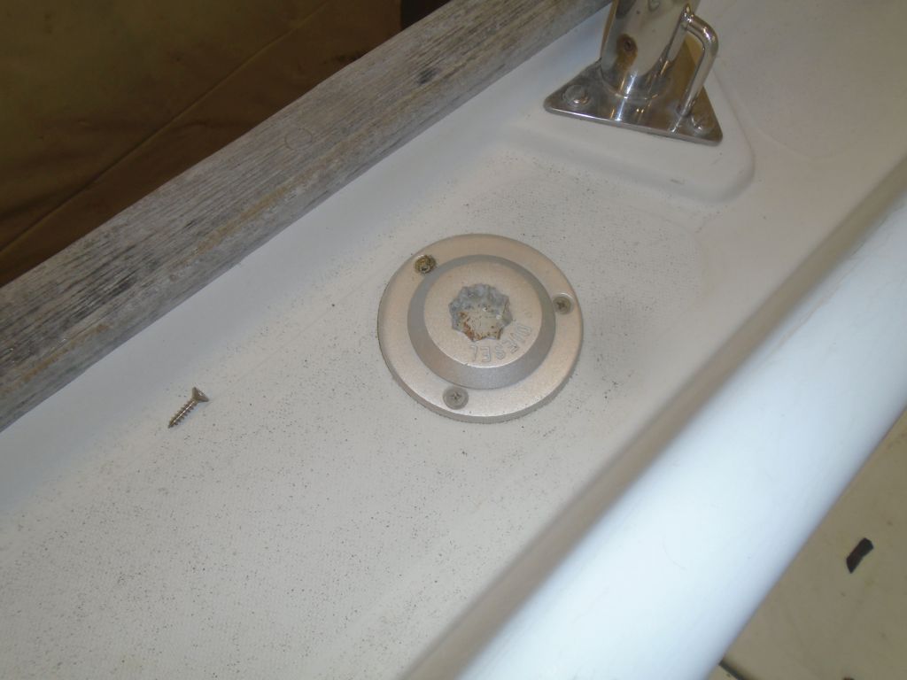
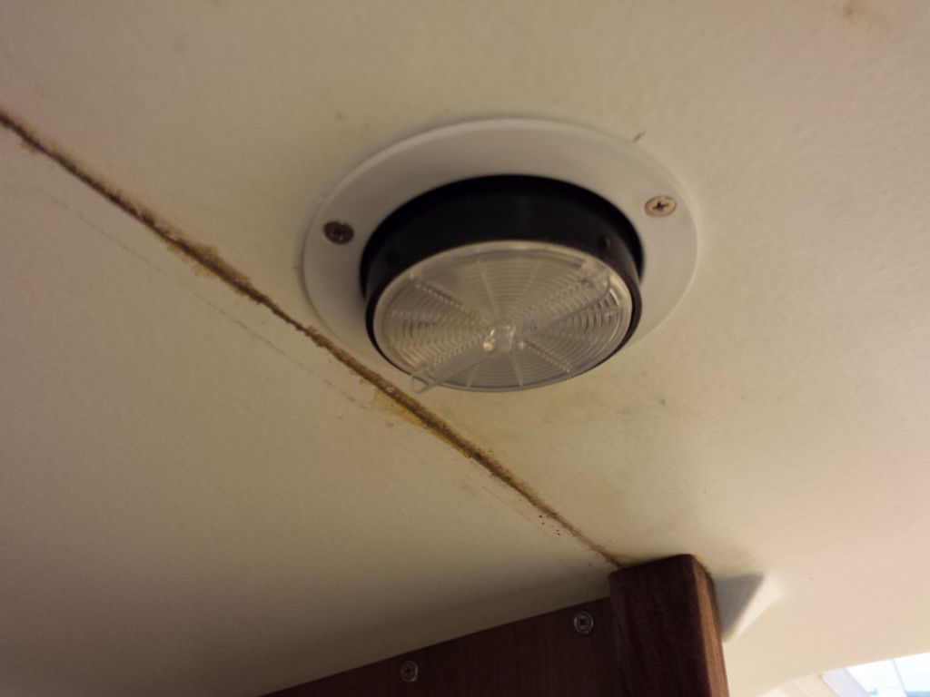
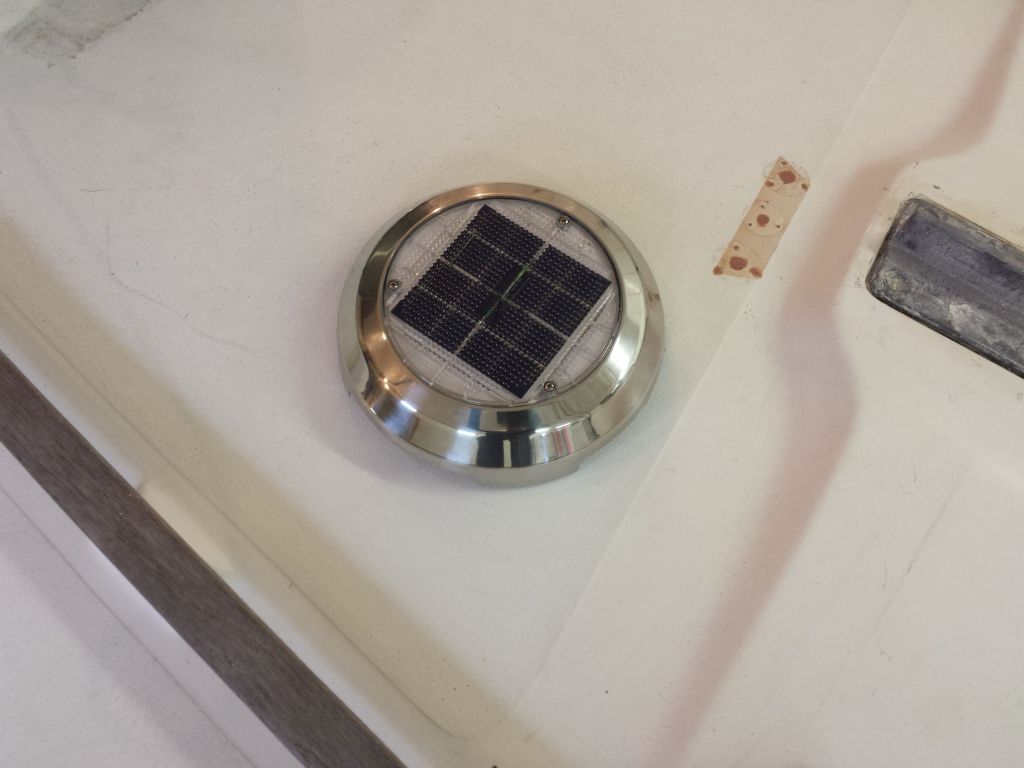
With some new hardware arrivals on hand, I turned to the deck once more, and installed new tank vent fittings in the head, as well as new deck plates aft to accommodate cowl vents.  I left the vents off in safekeeping for now.  I went through all the usual steps for installing the plates; you must know them by now.

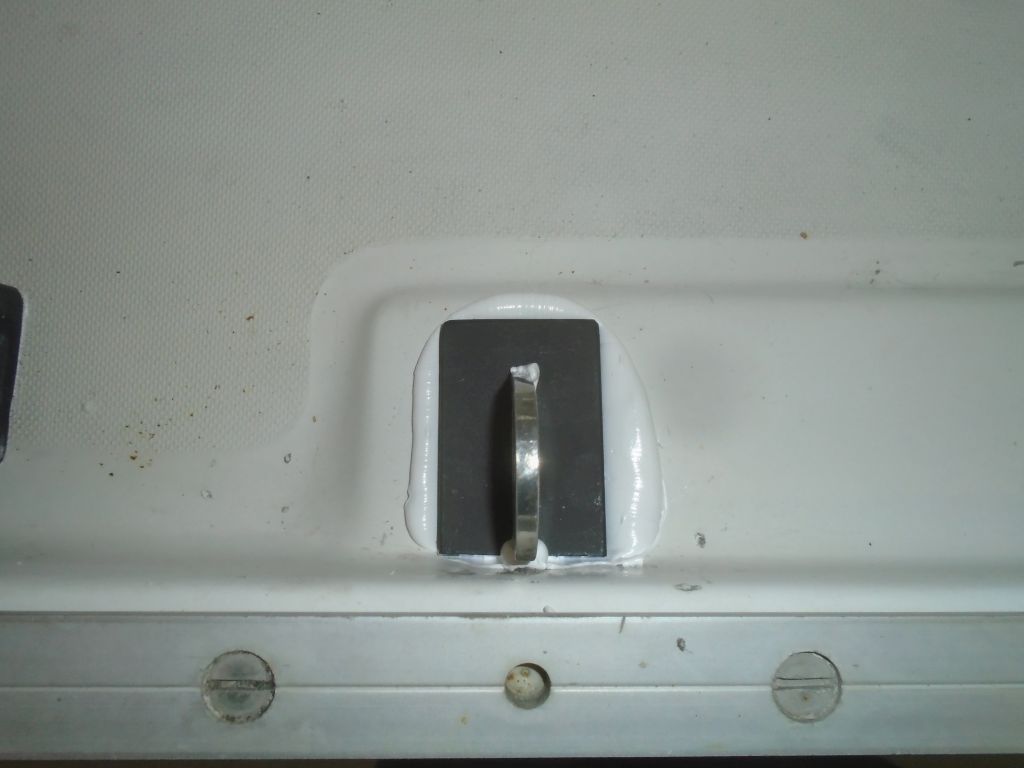
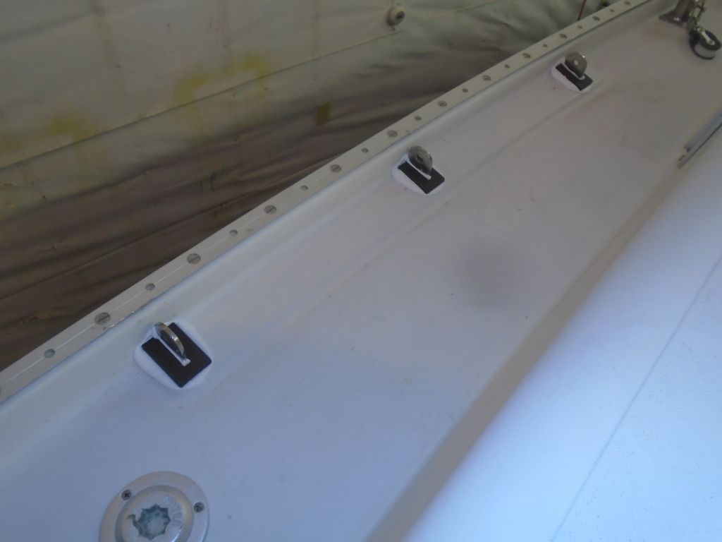
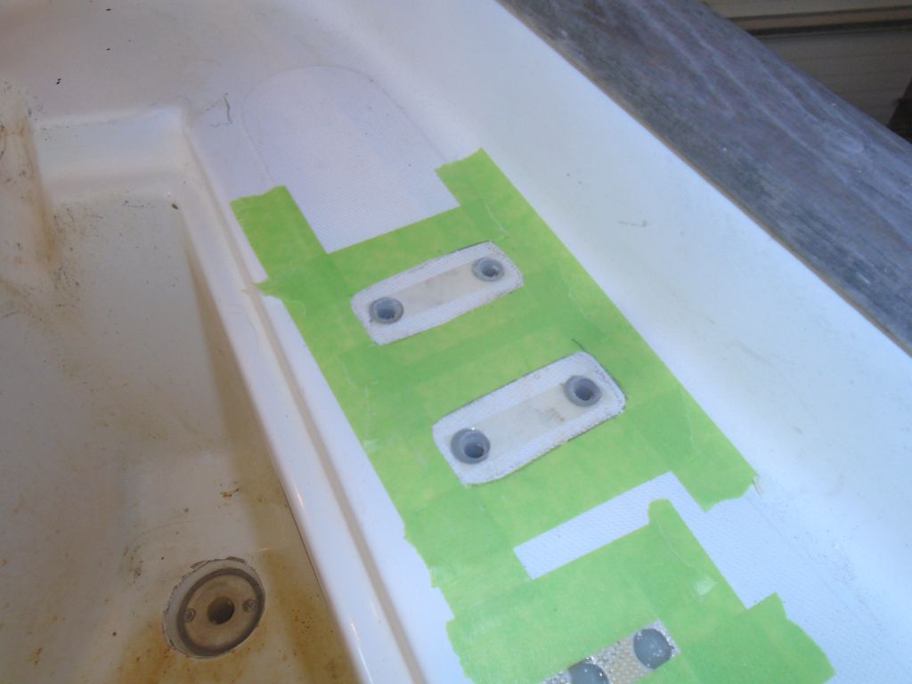
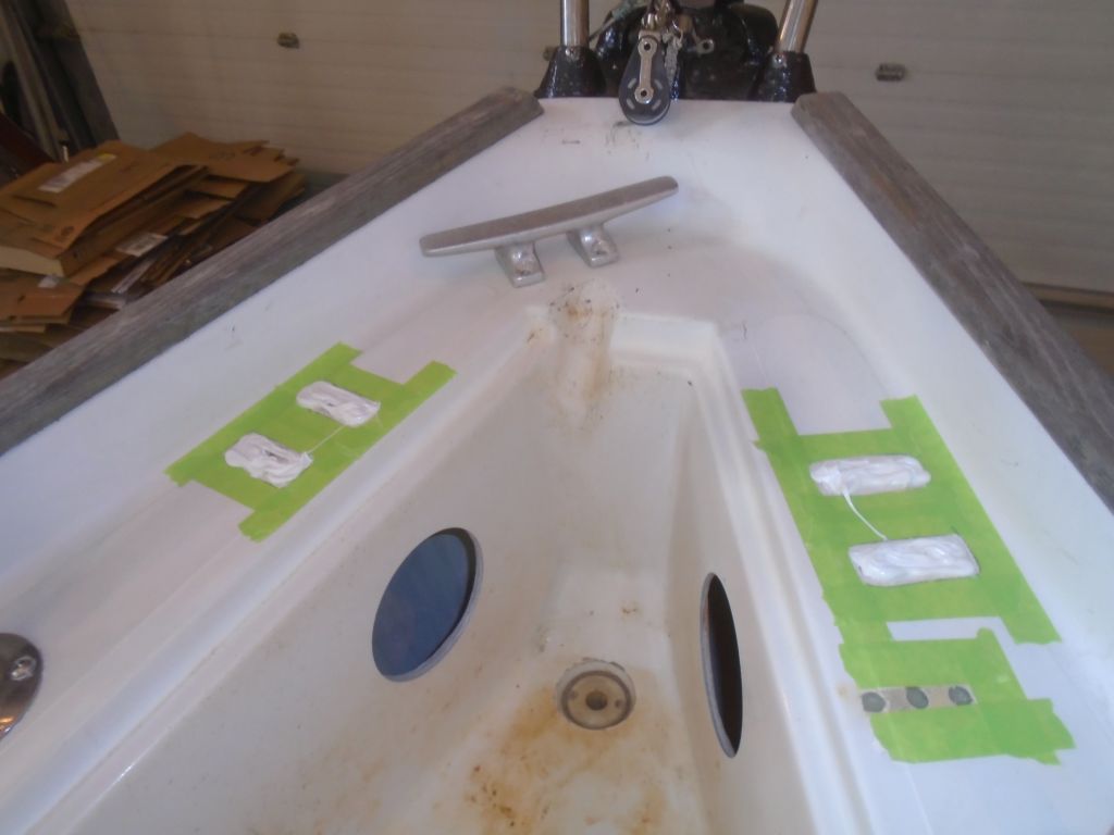
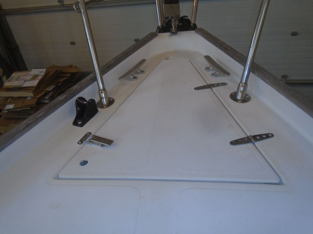
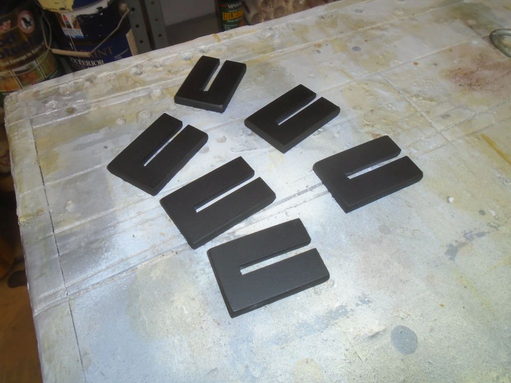
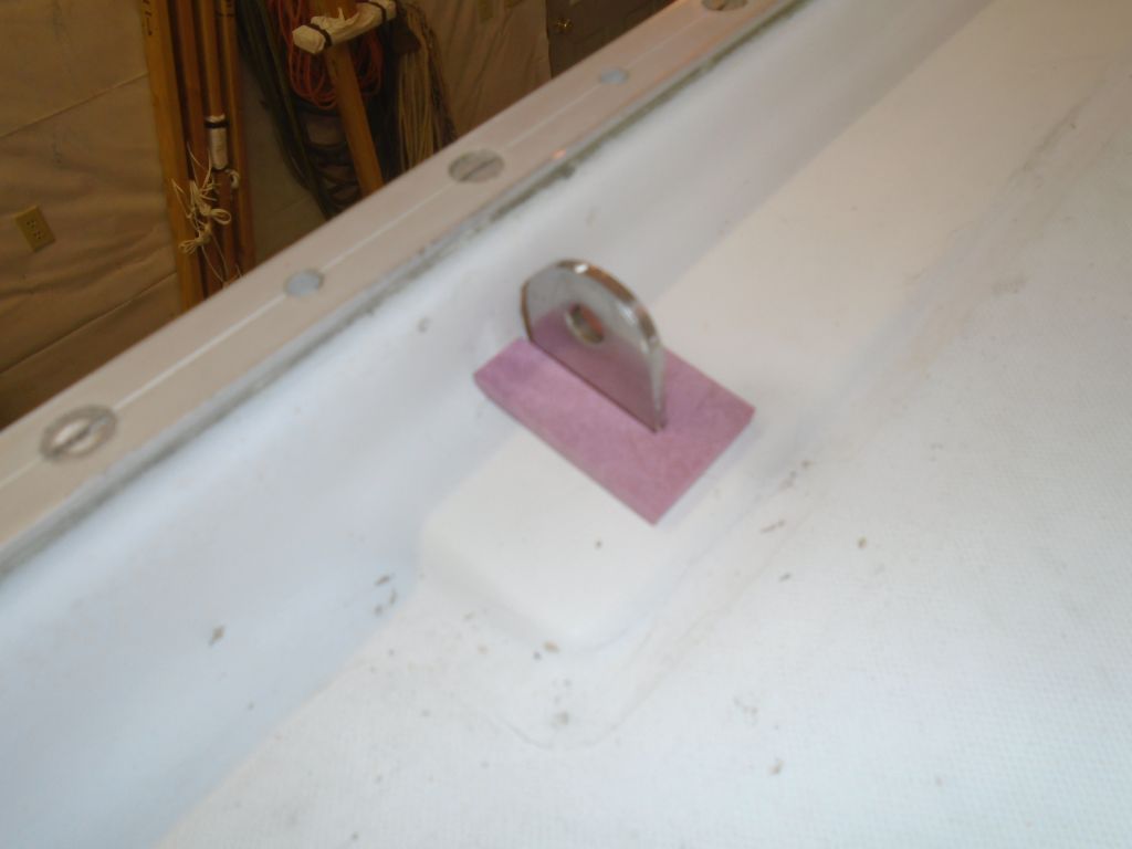
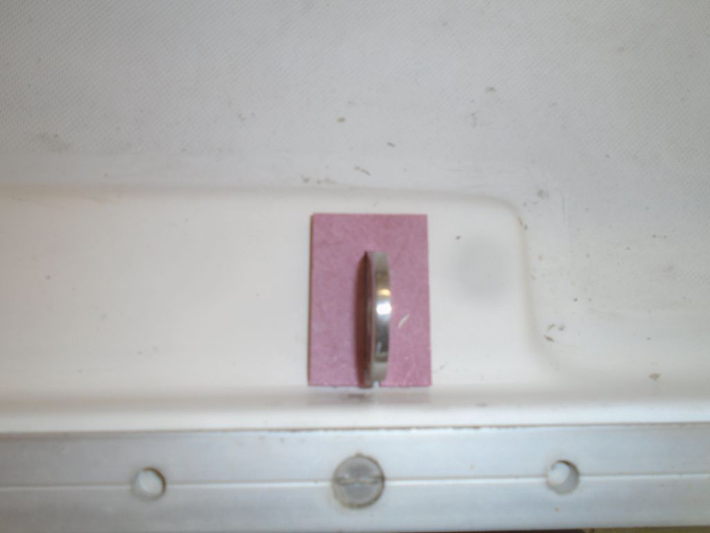
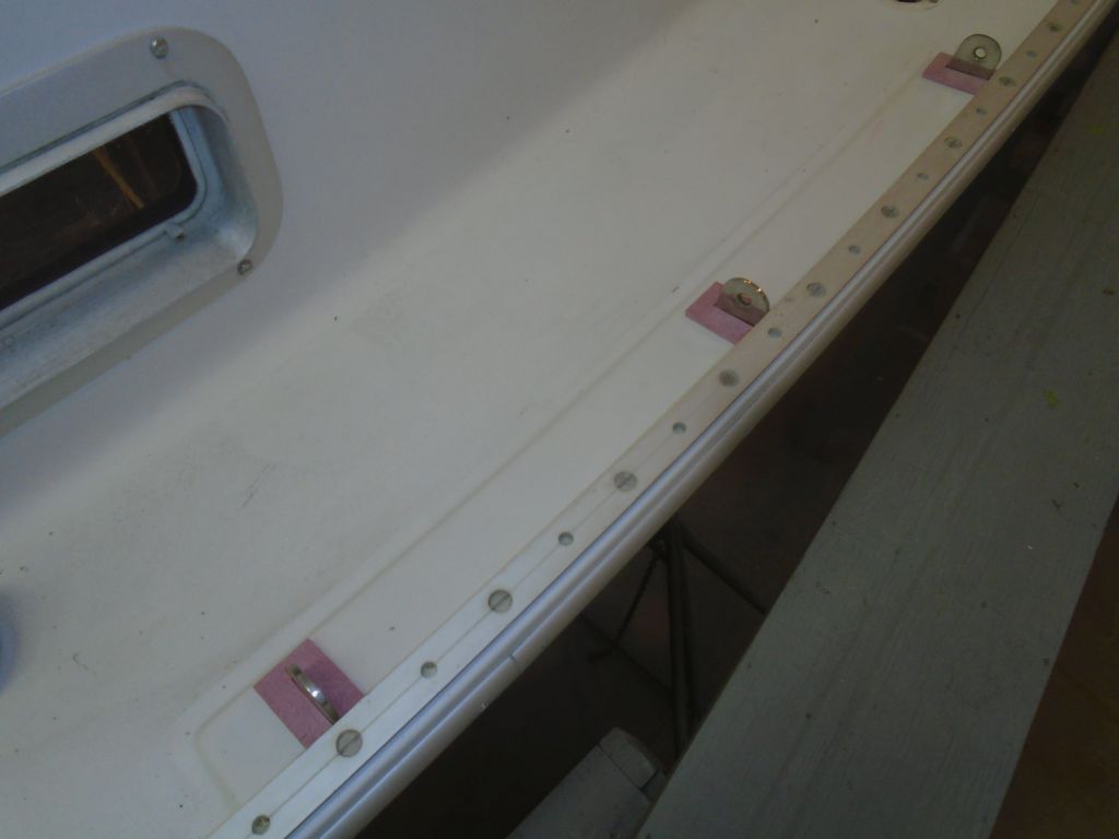
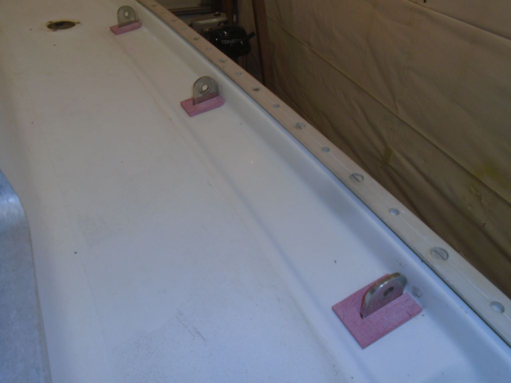
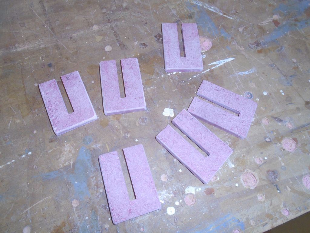
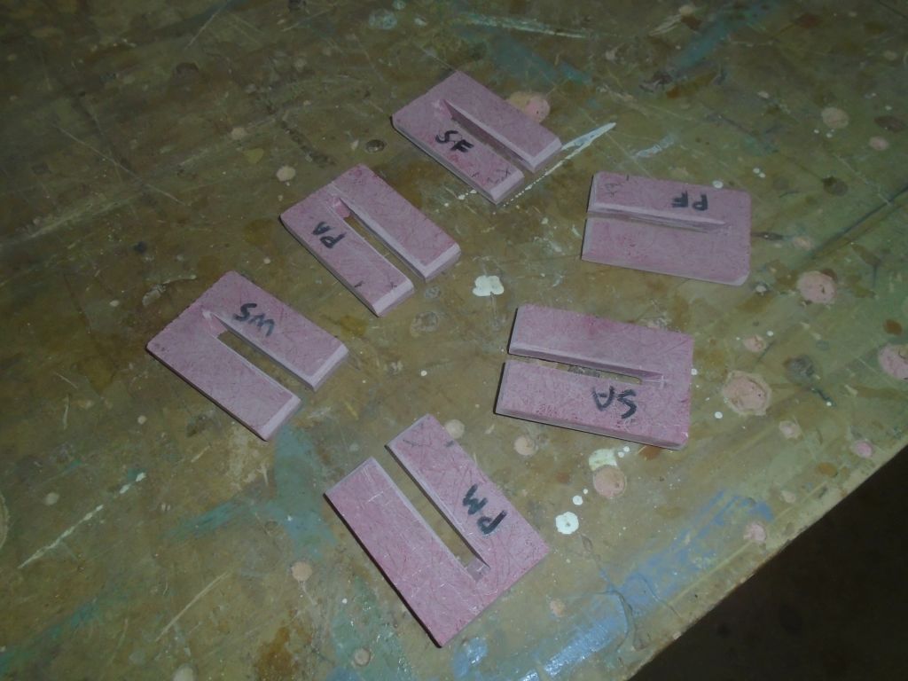
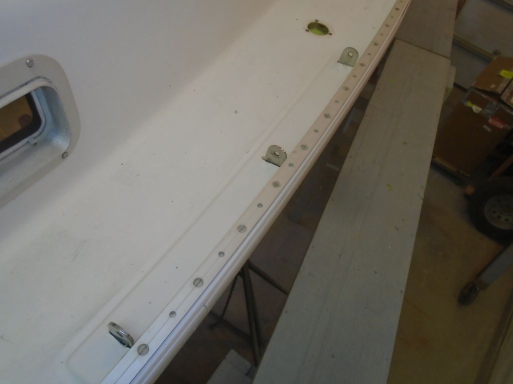
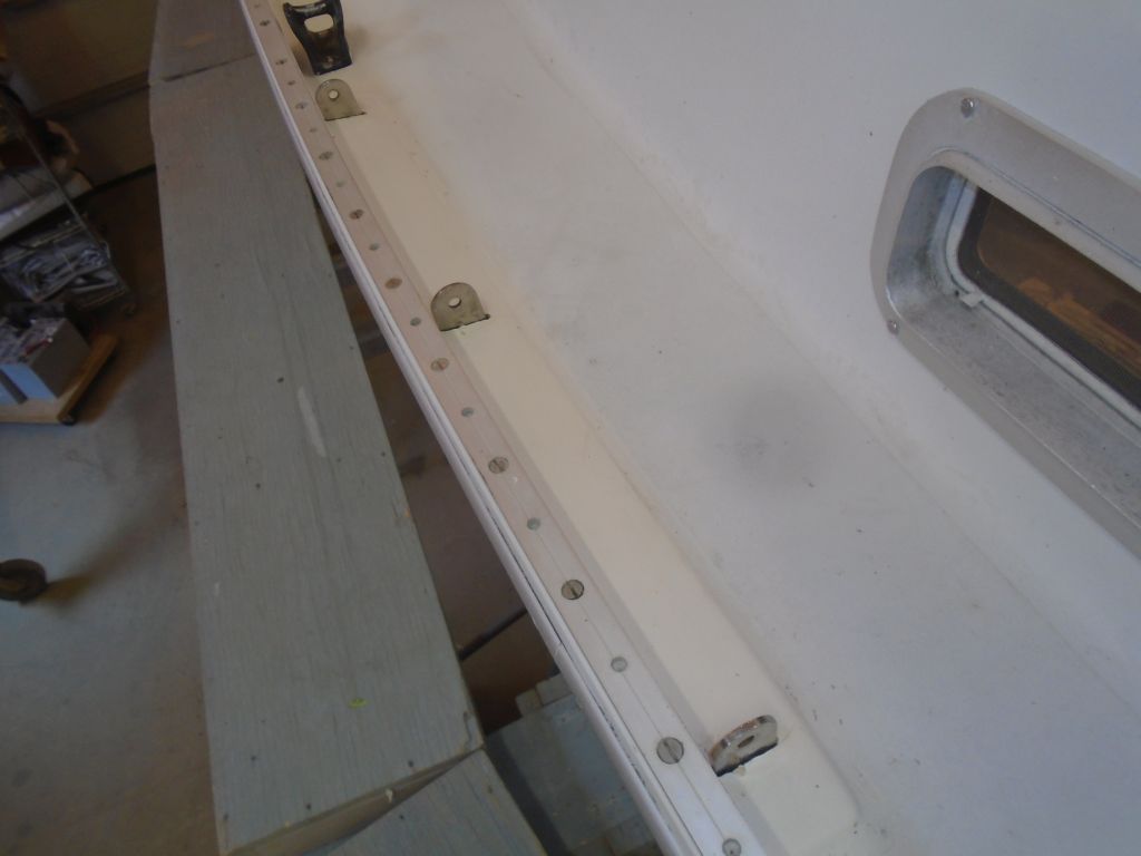
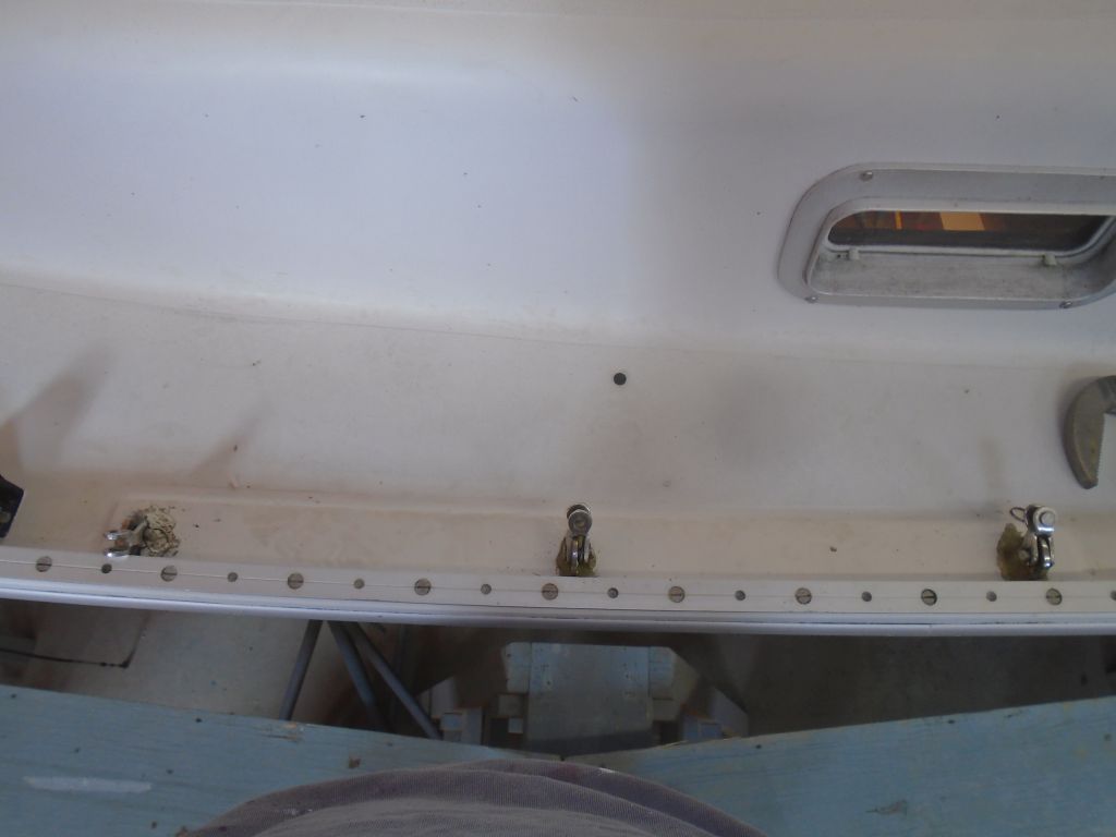
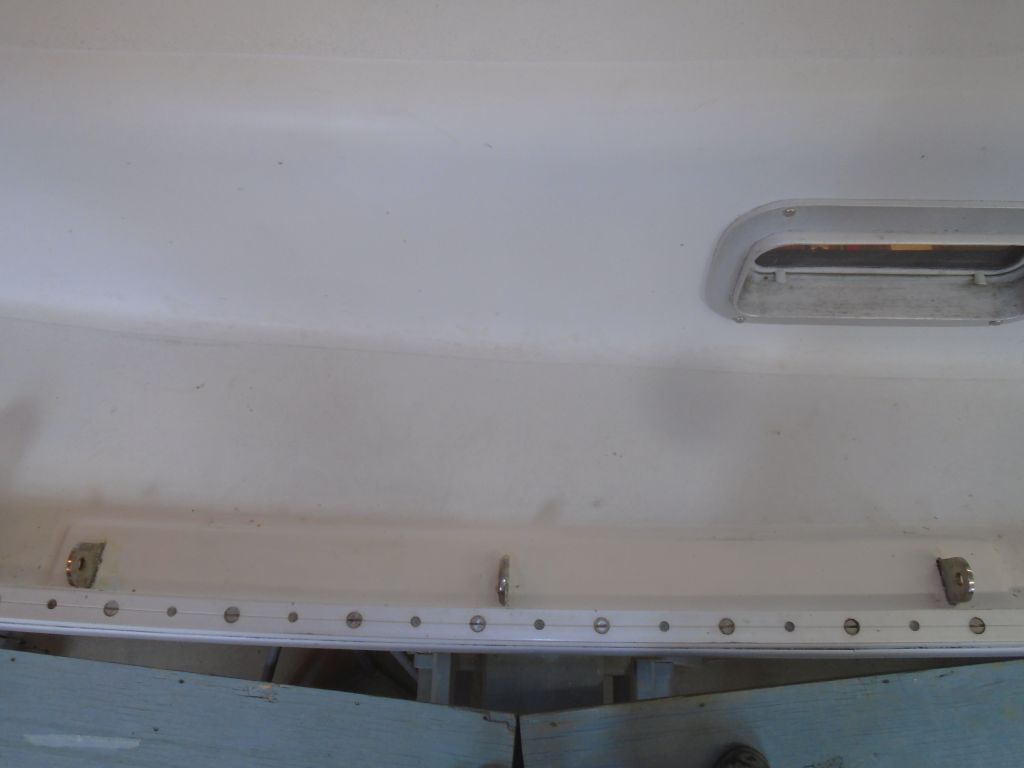
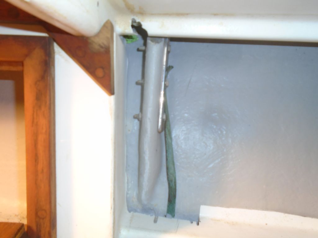
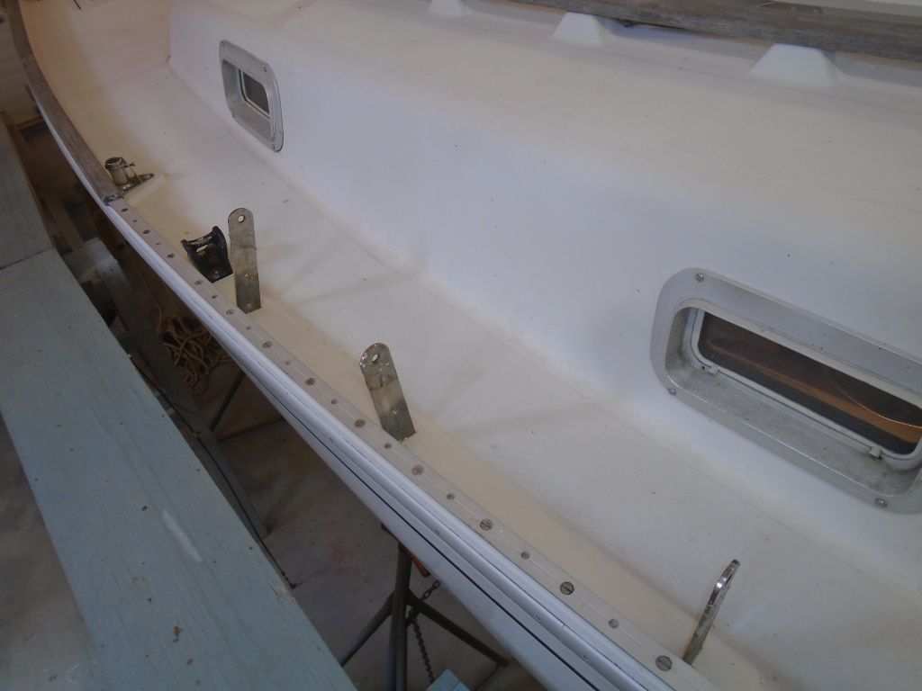
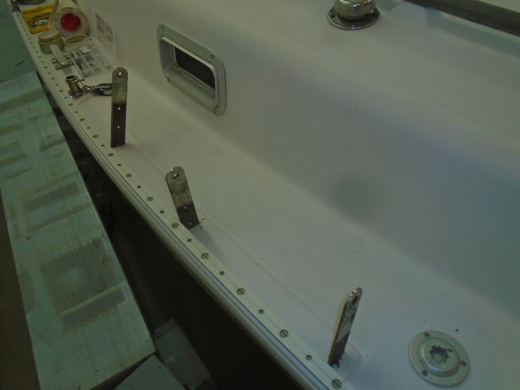
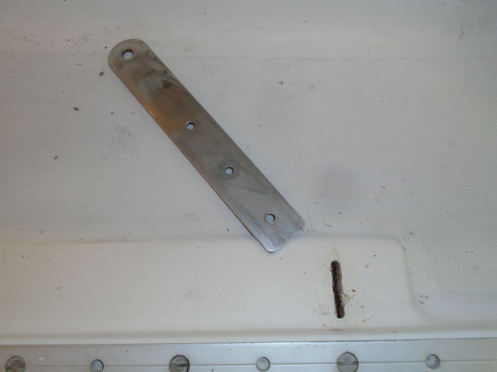
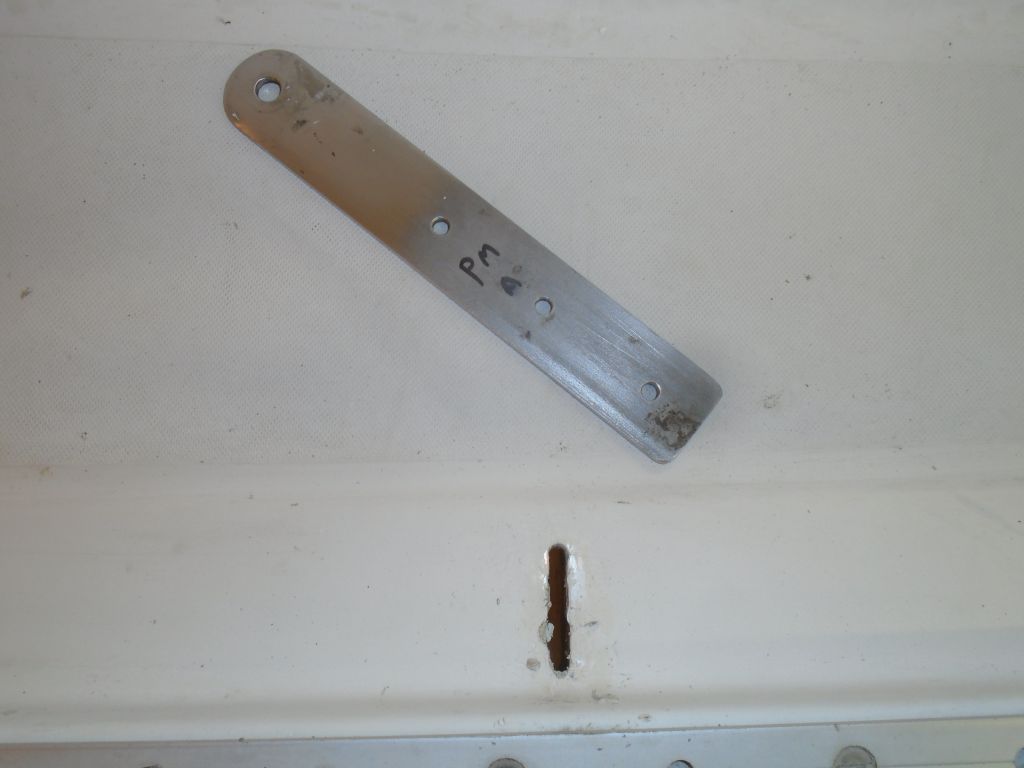
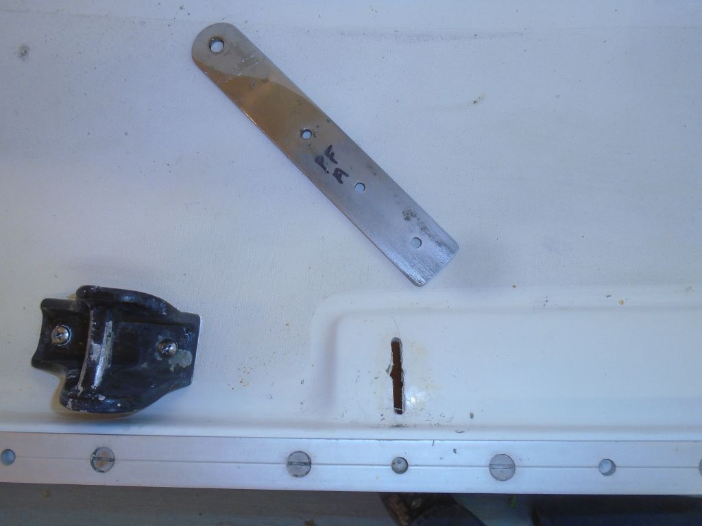
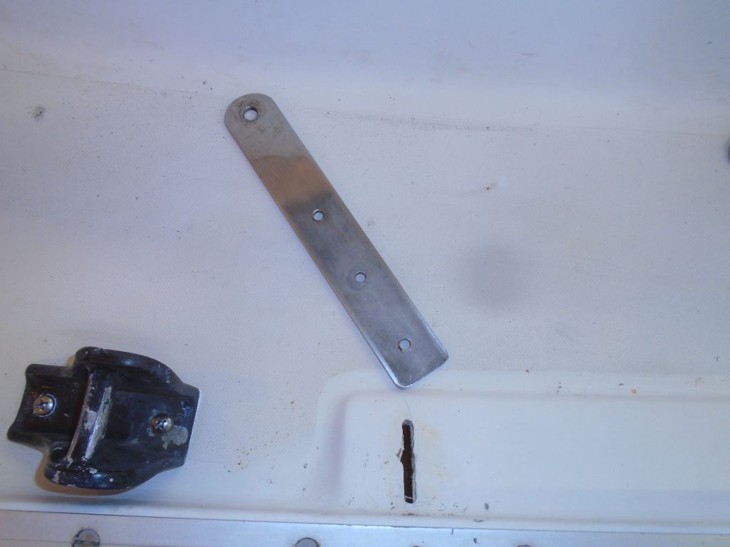
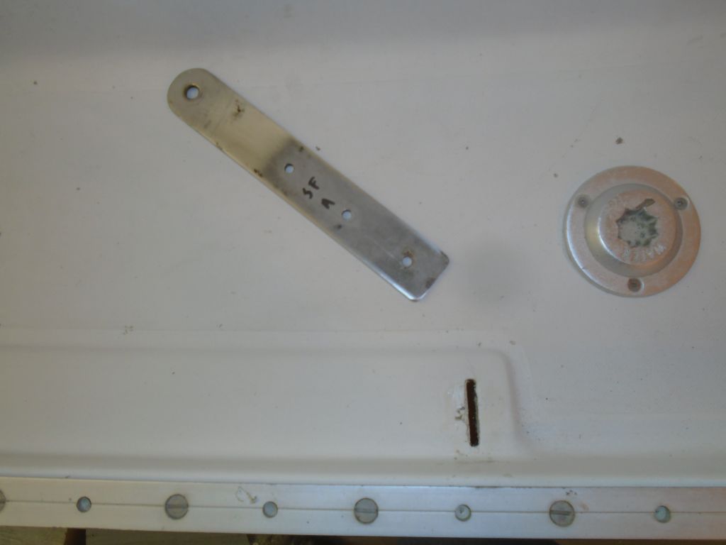
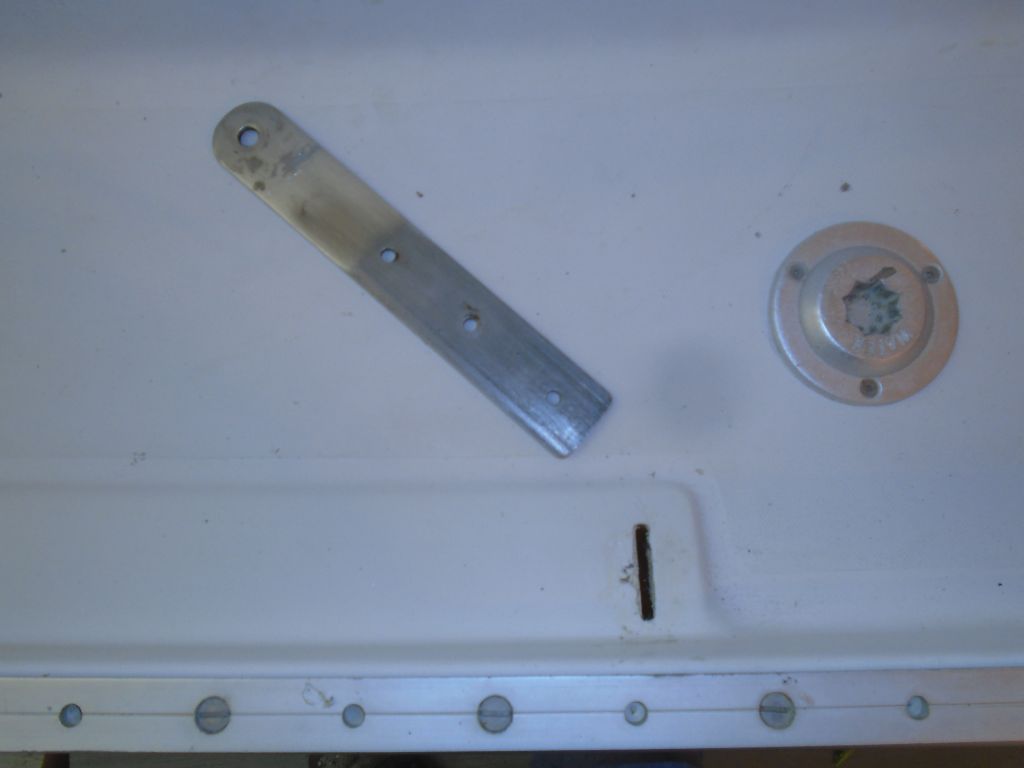
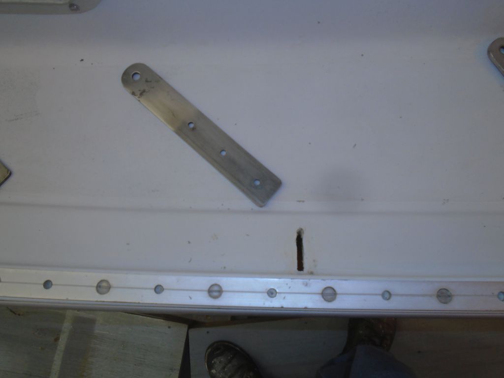
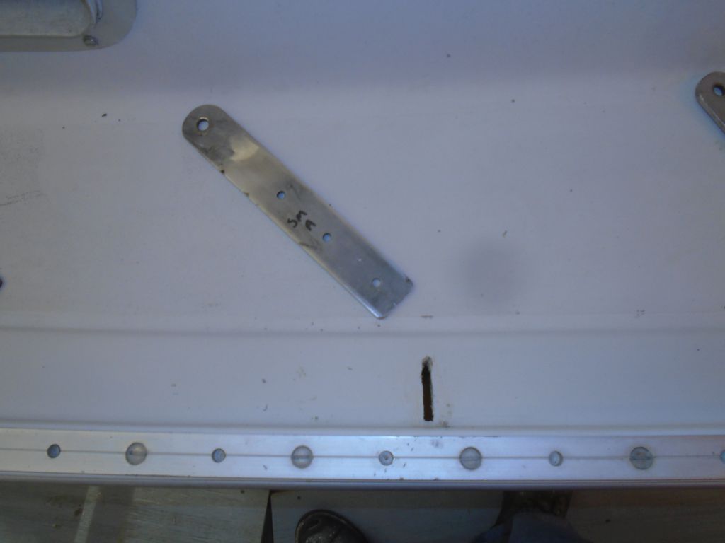
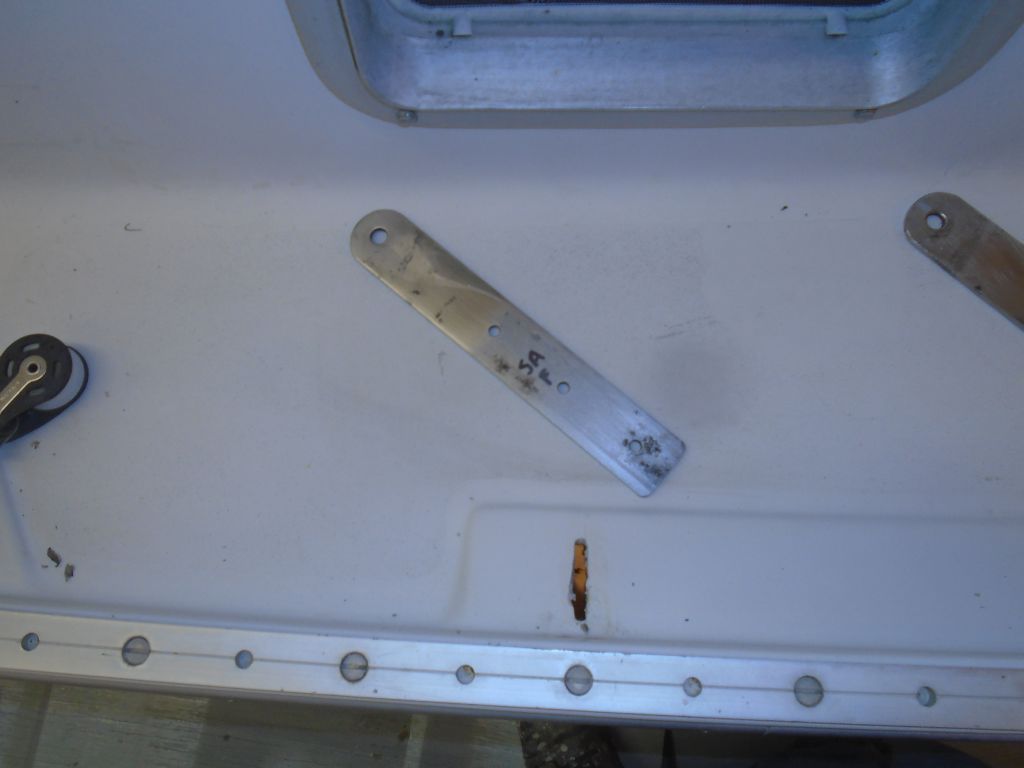
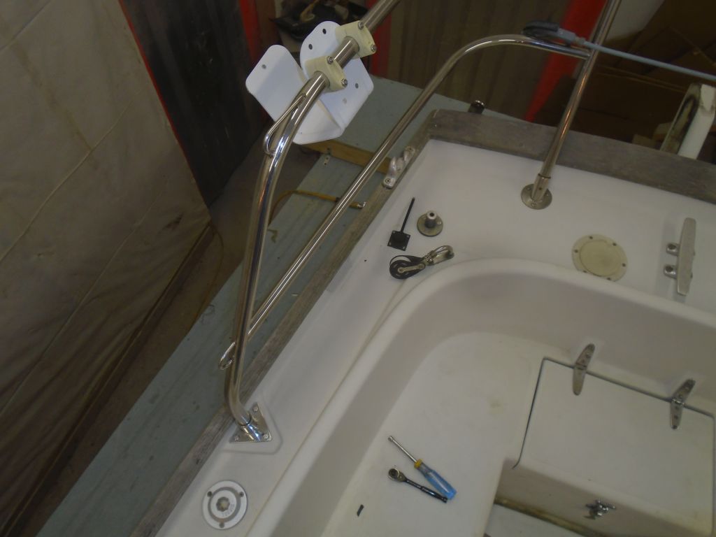
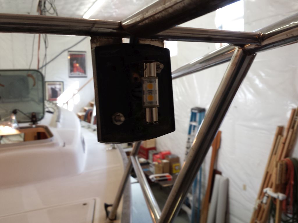
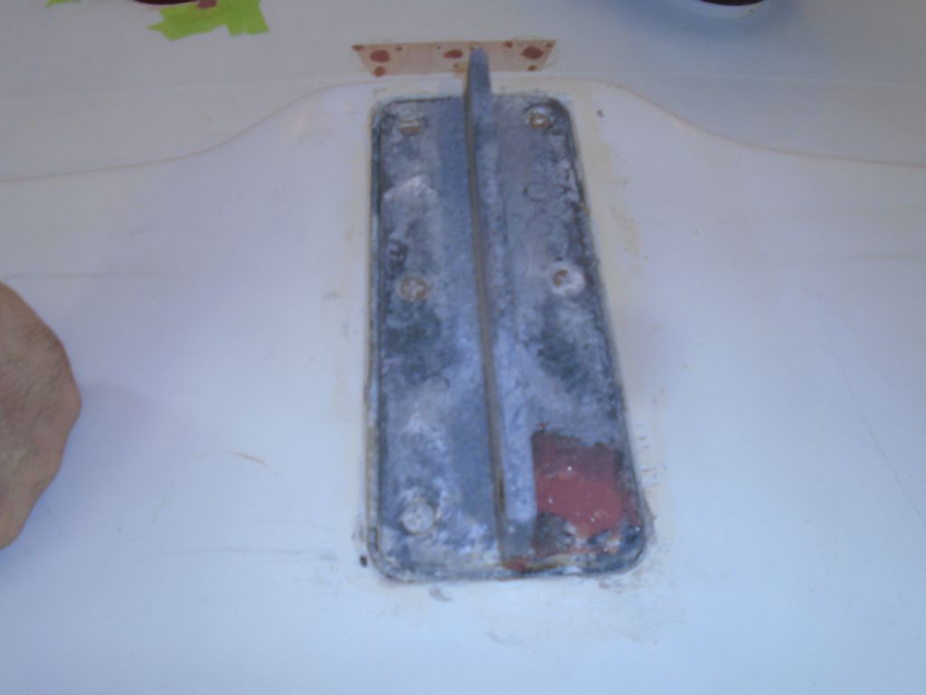
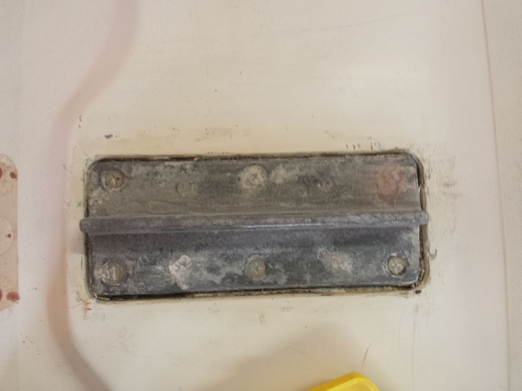
It seemed a good time also to install the chainplate deck covers,  At each location, I applied sealant fairly heavily, then pressed the appropriate cover in place.  Because I relied on the sealant itself to secure the plates in place, I left the squeezeout for now, and would clean it up once it cured.  As I pressed down, I could hear the good sound of air pockets popping as the sealant got pressed into the gaps around the chainplate in its slot, just what I wanted.  Once cleaned up, I thought these would look pretty nice.

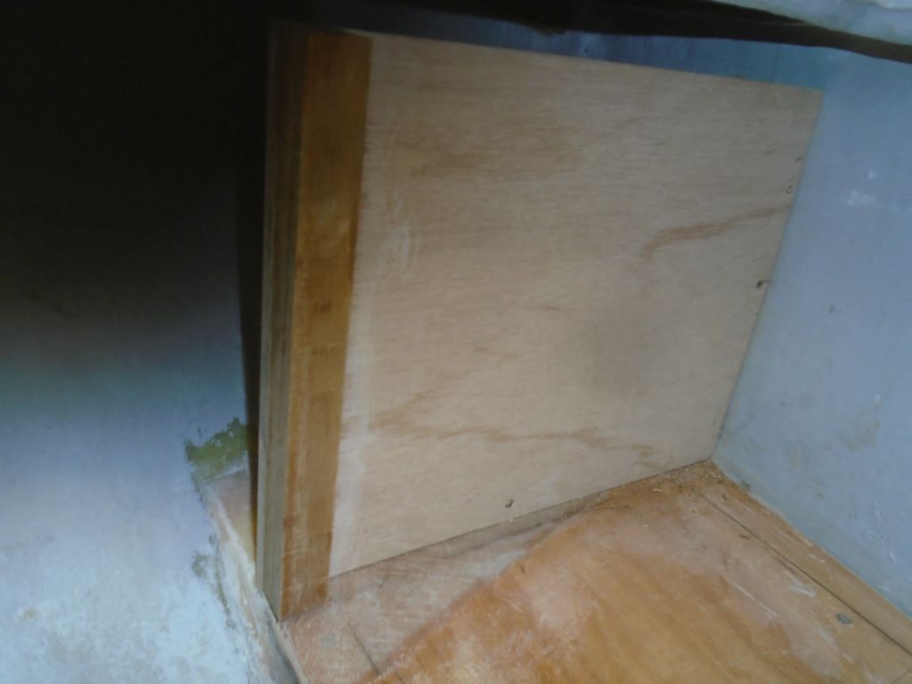
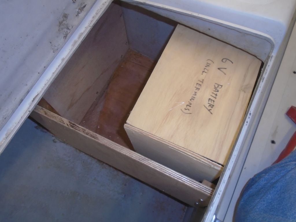
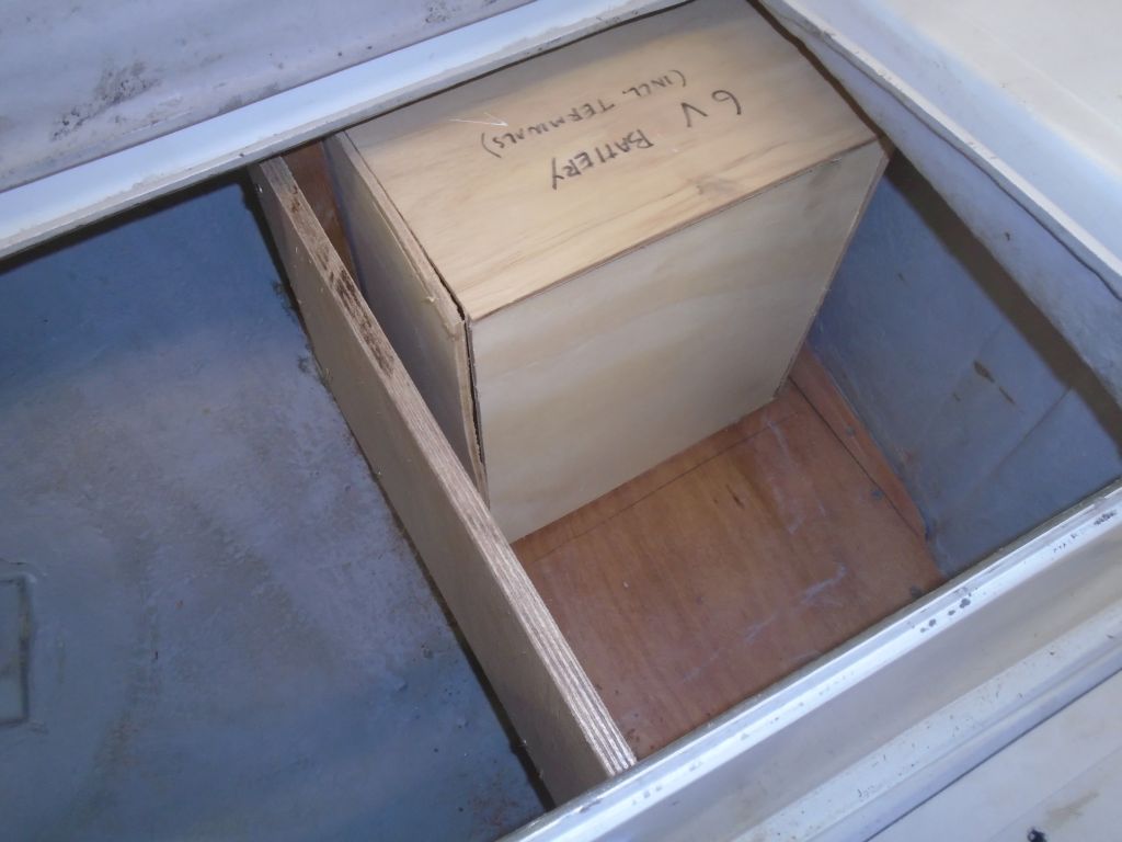
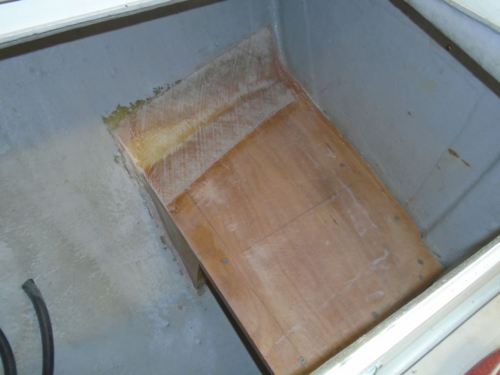
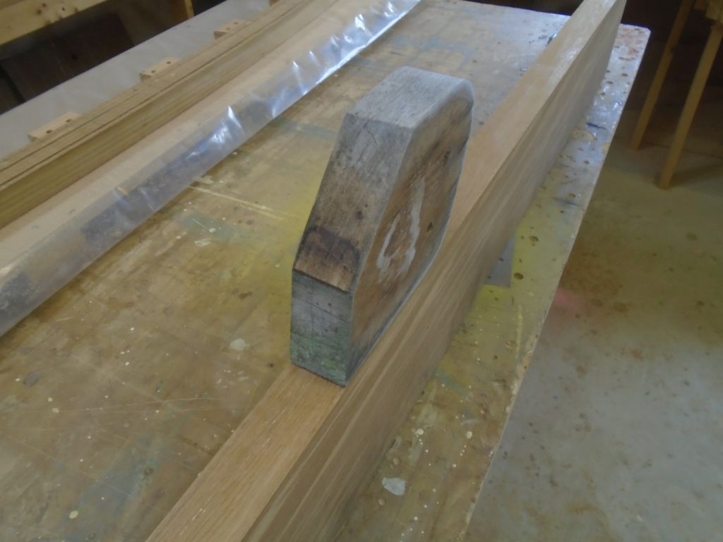
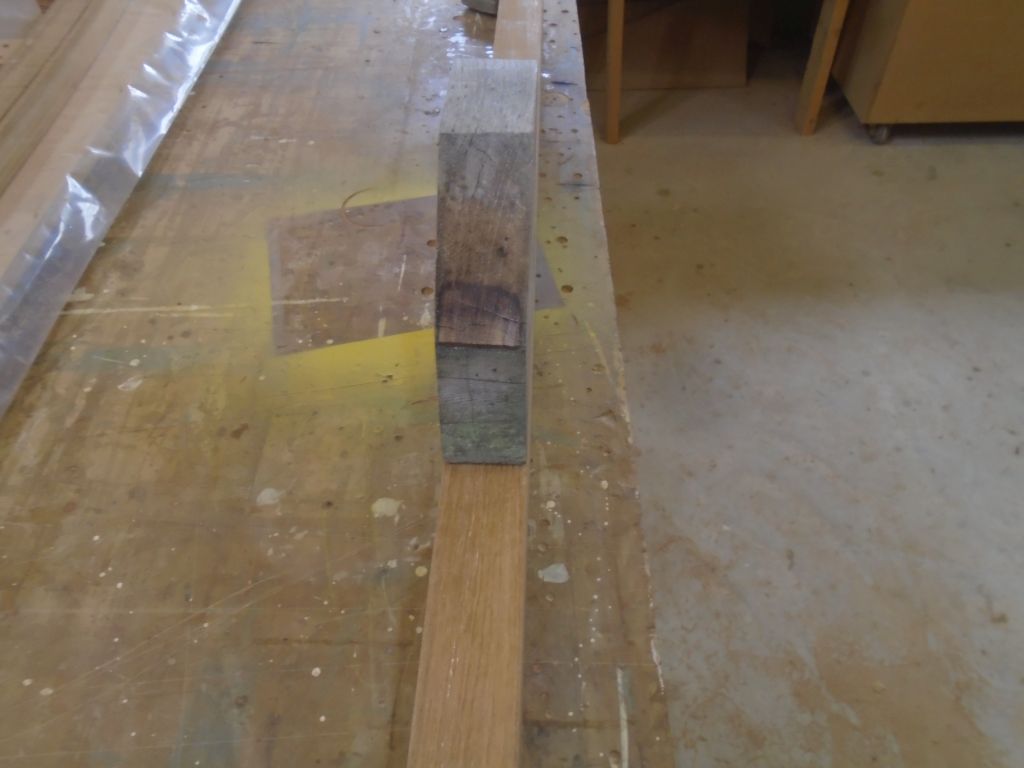
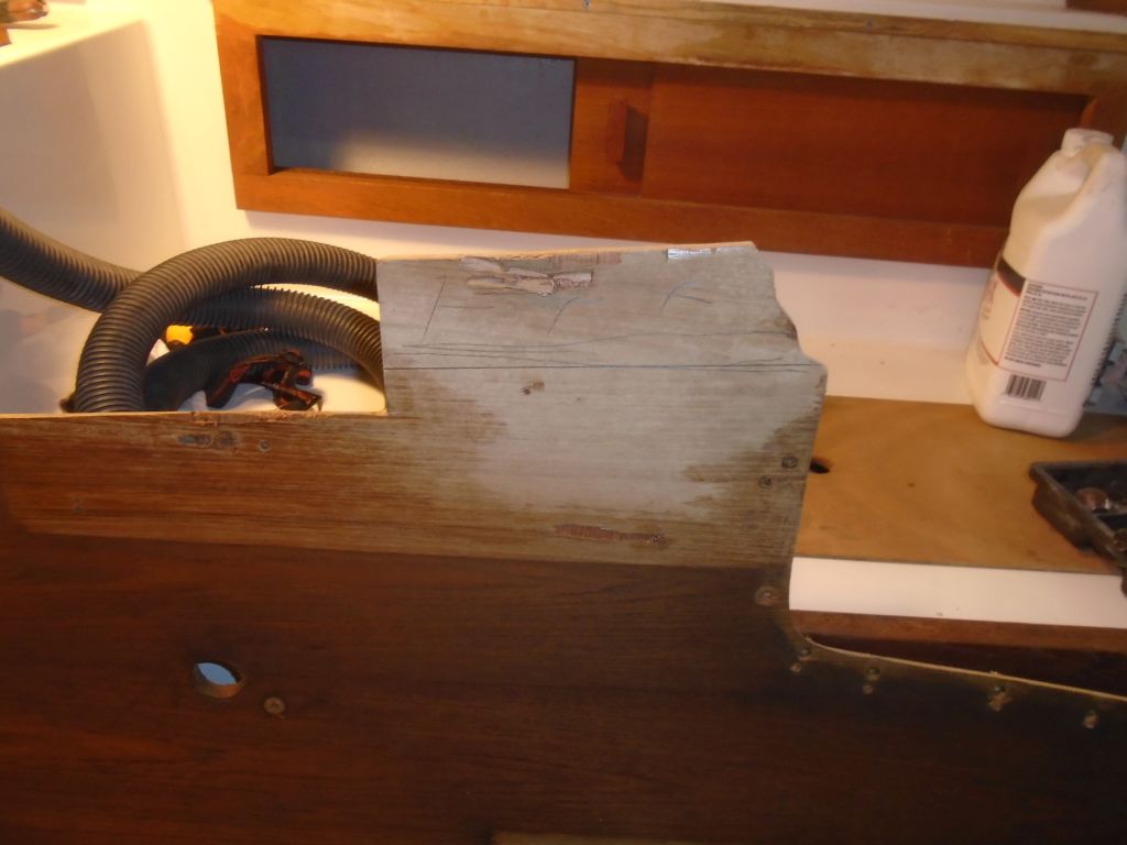
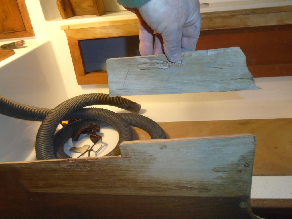
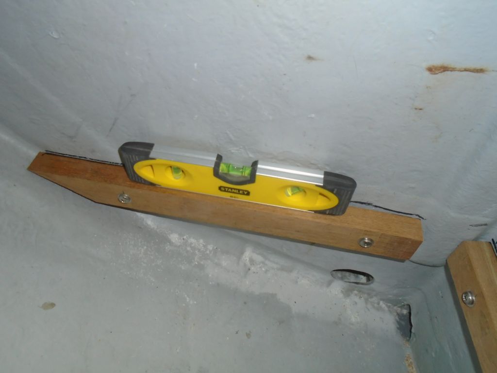
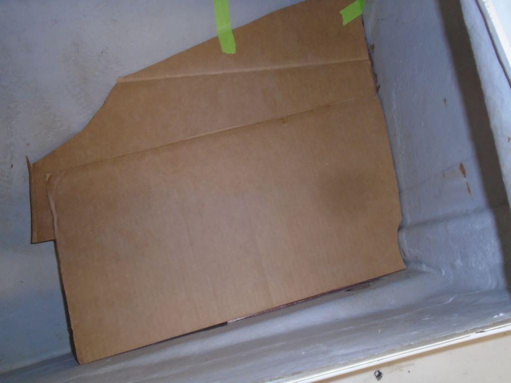
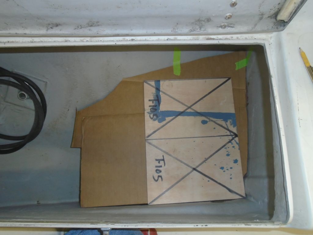
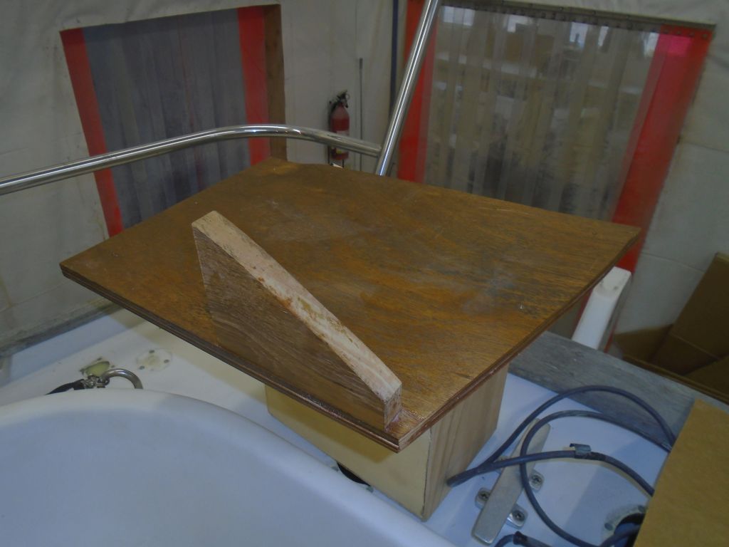
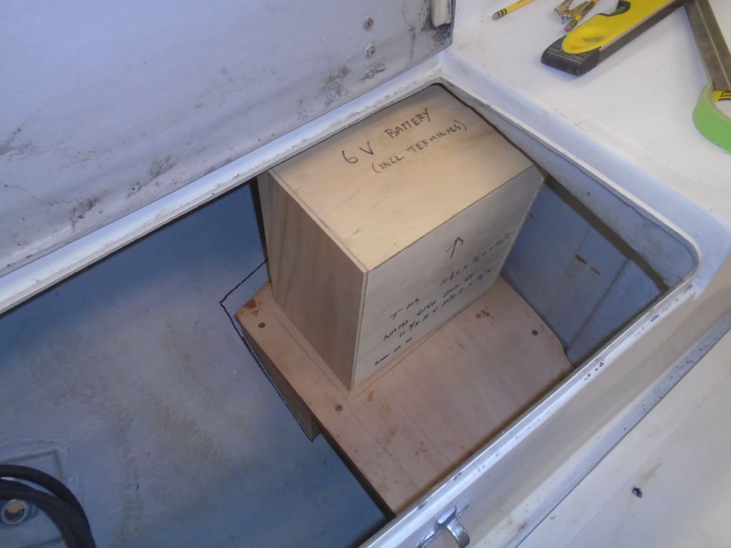
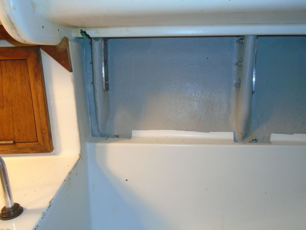
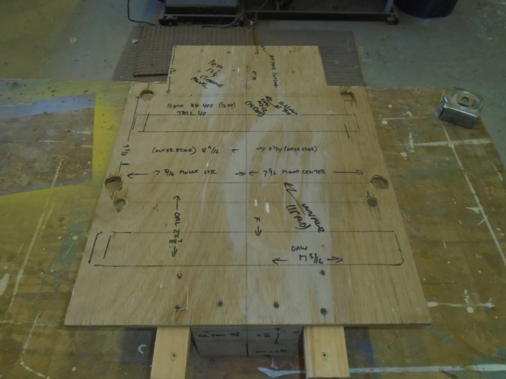
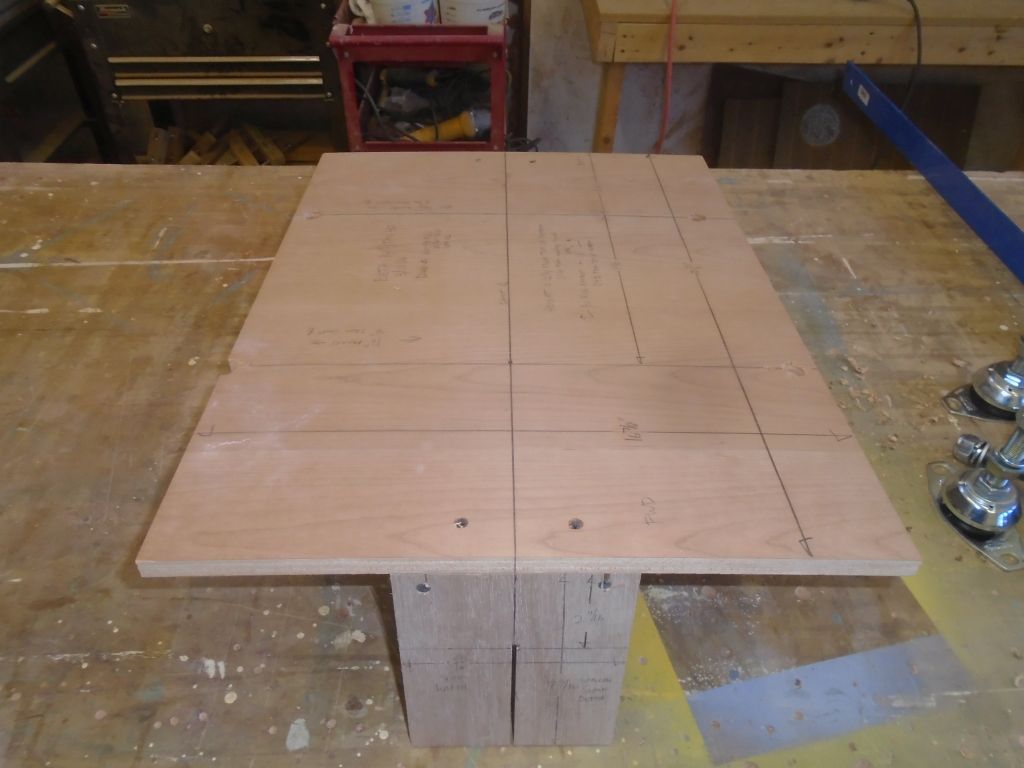
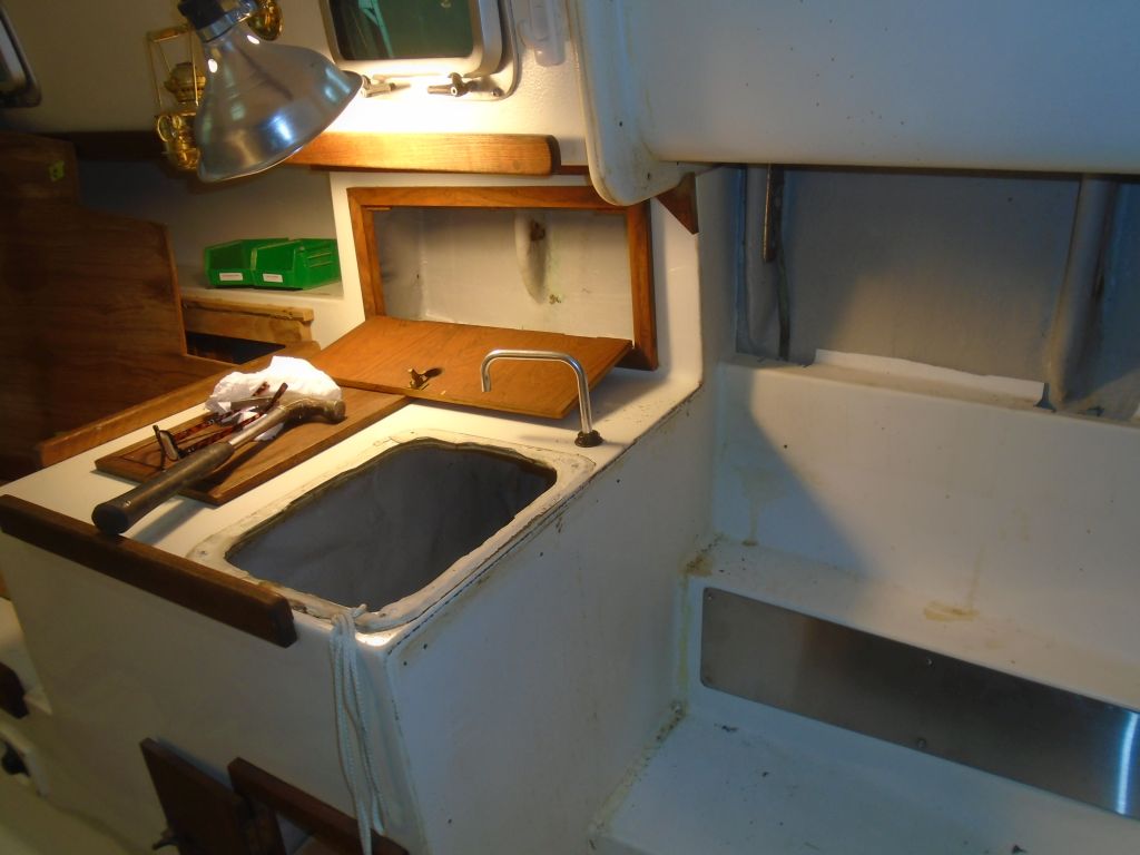
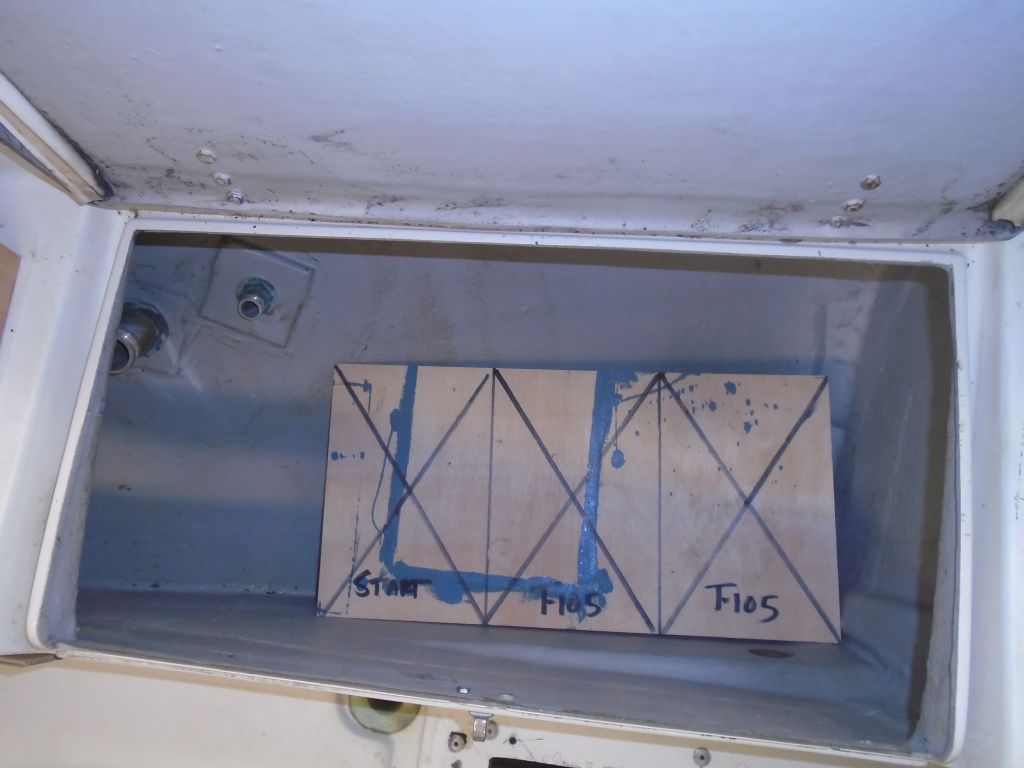
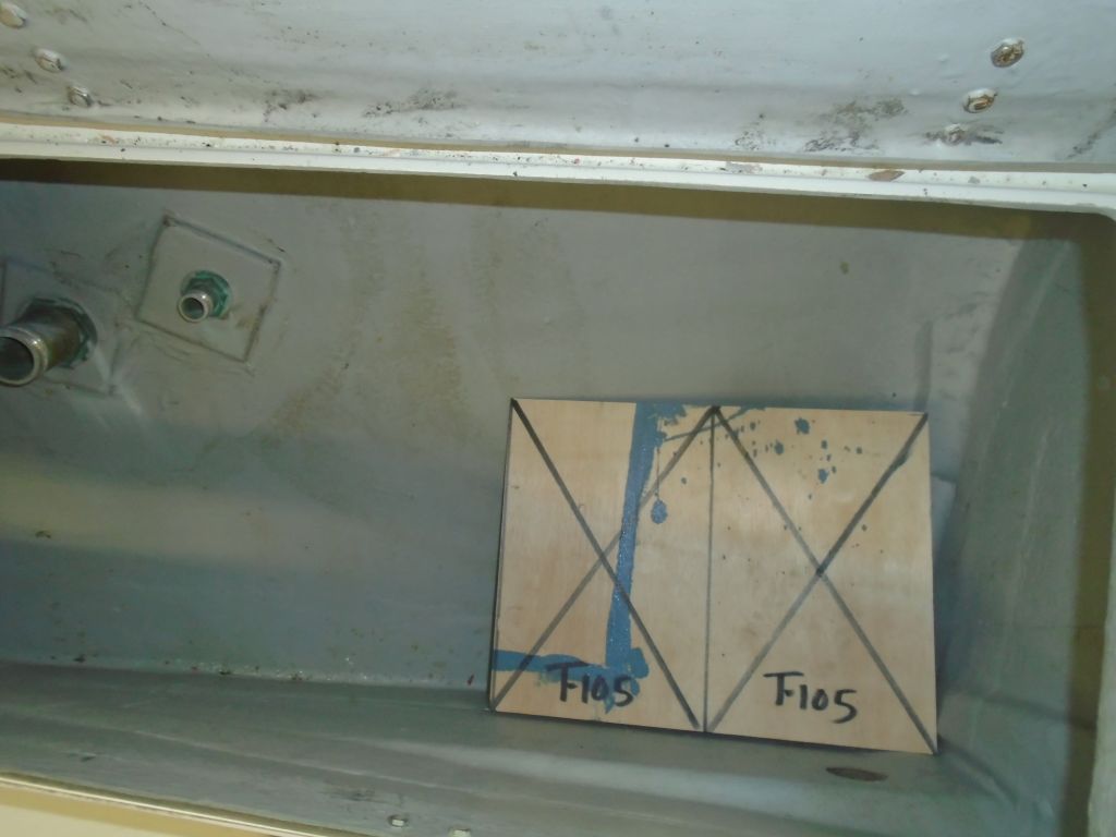
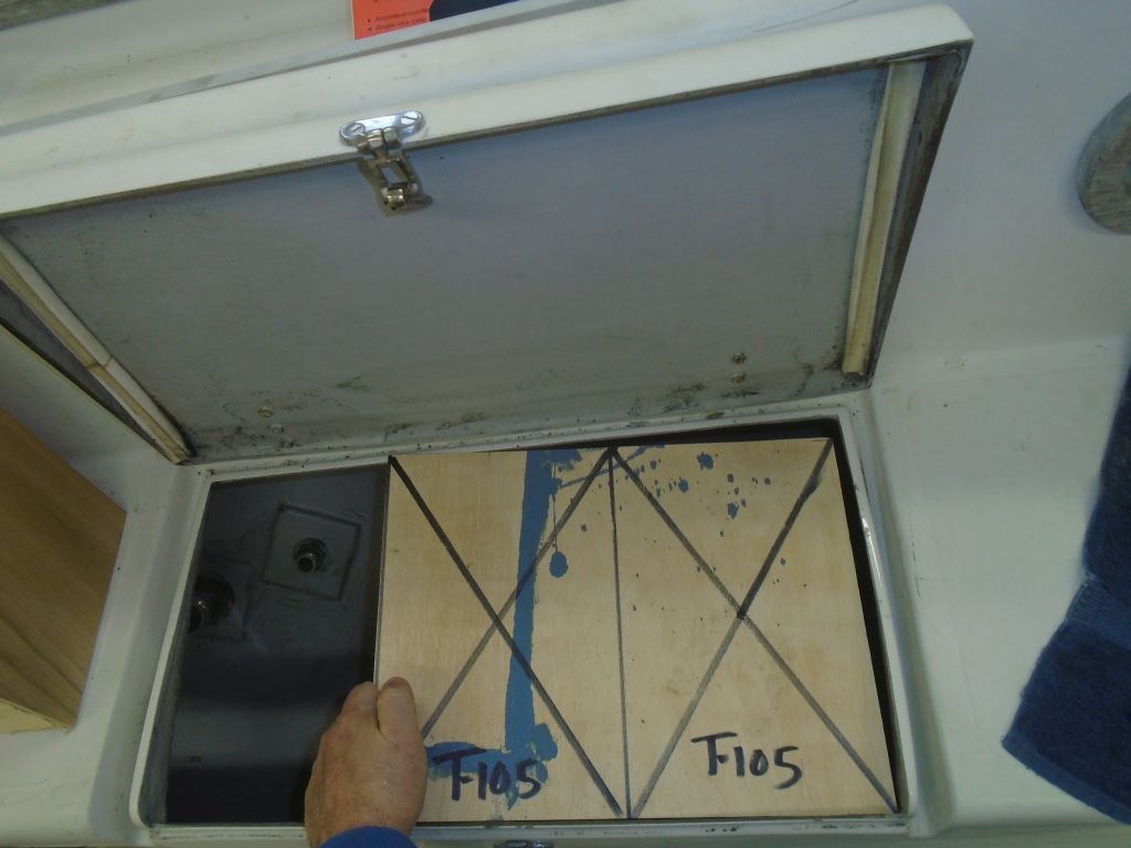
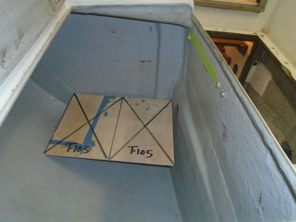
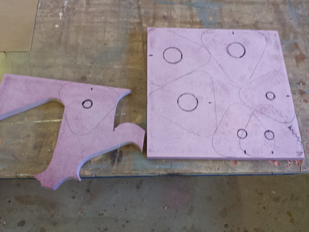
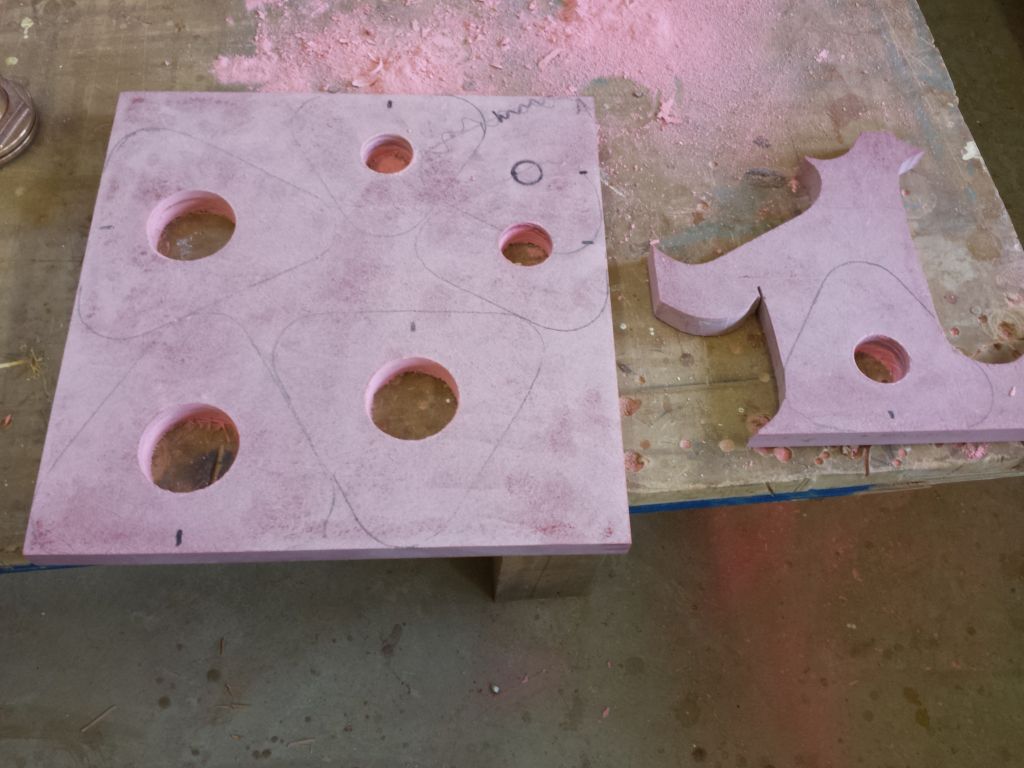
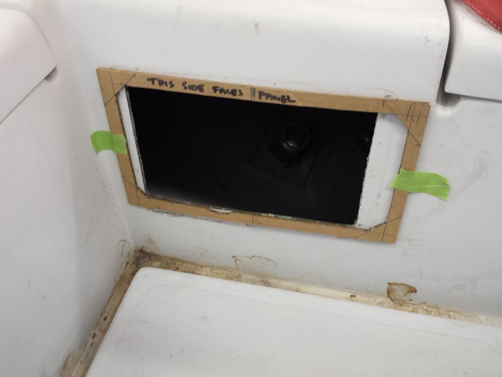
The next step on the battery box was to actually build the box, or the sides, whatever seems appropriate.  Now, I didn’t really want the box to be any taller than it had to be, since headroom was at a premium, but neither did I want to cut it at all close with the batteries, terminals, terminal fuses, and so forth.  This is when one starts to distrust templates.  Despite having the actual battery measurements on hand, and a template built to those dimensions plus some, I had to look at some past projects to see just how oversized the battery template actually was, mainly to see if I could build the box basically just as high as the template, or if I needed some extra room to be safe.  Eventually I determined that the template was generously sized and allowed plenty of adjustment room as it stood, so I chose to make the sides of the box 11-1/2″ tall, or just barely taller than the template.

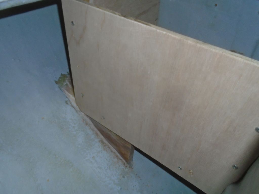
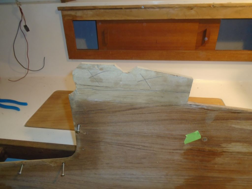
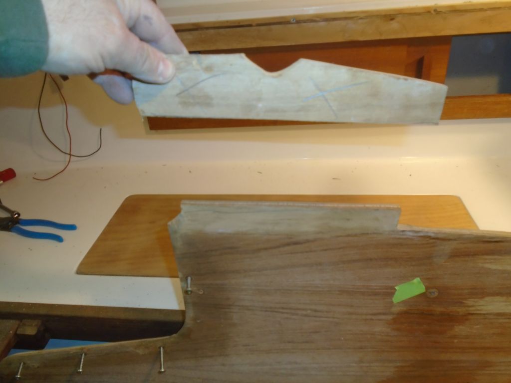
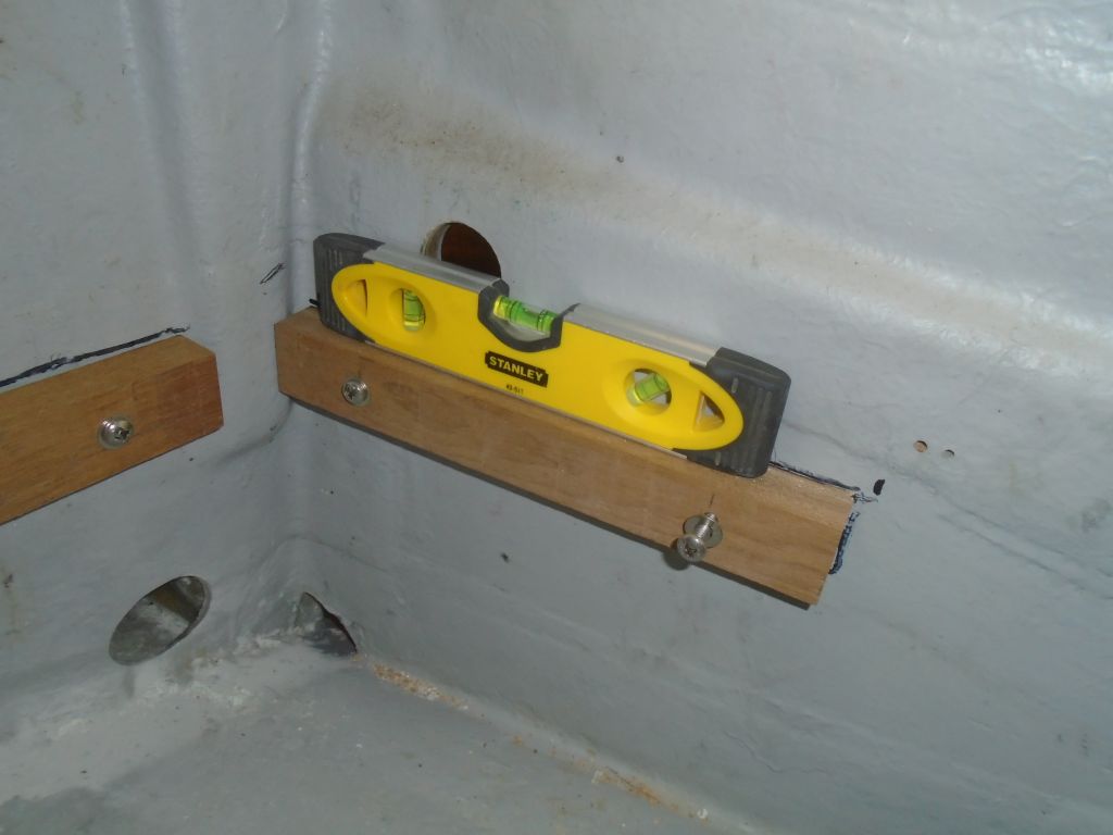
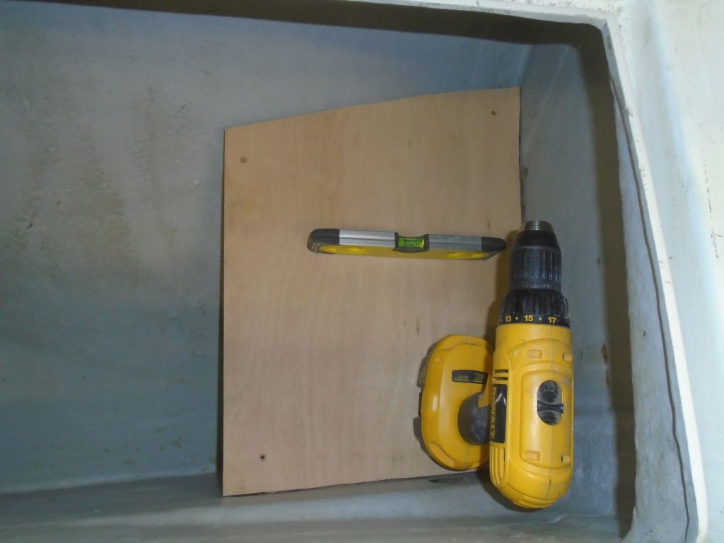
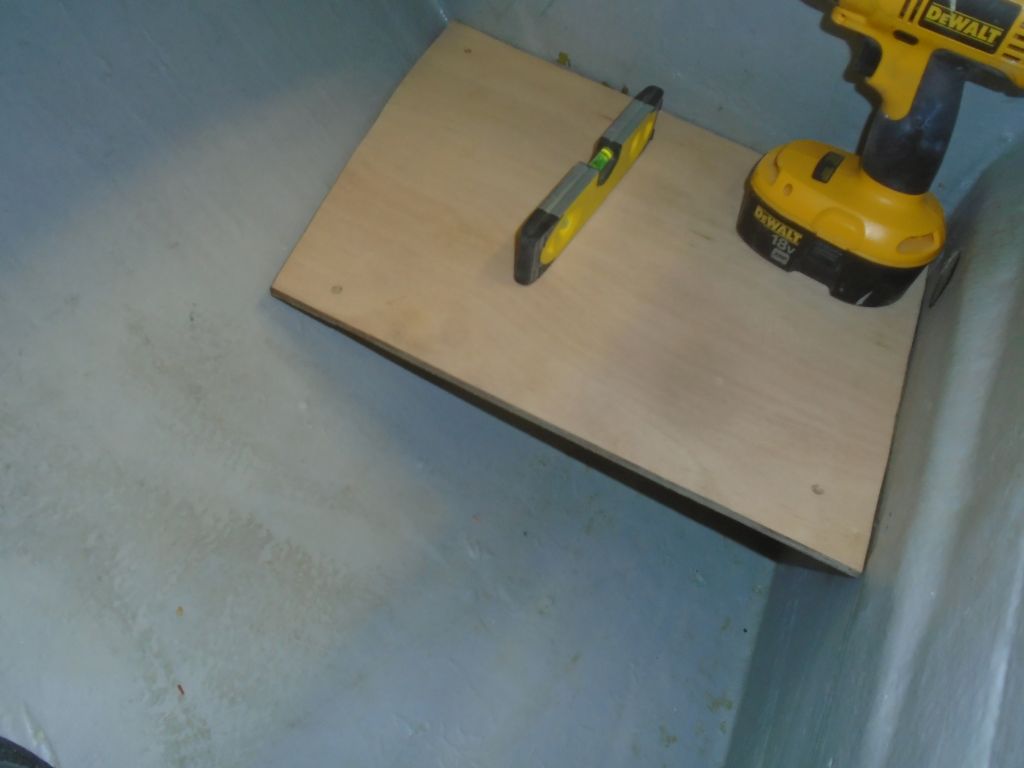
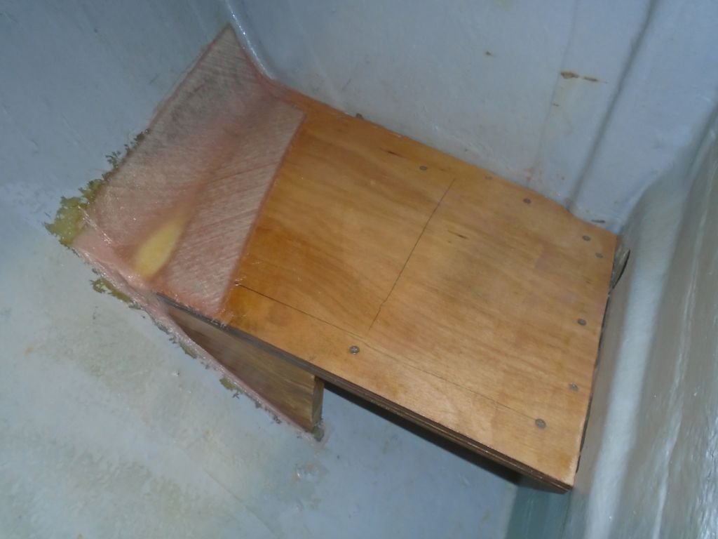
With this determined, making the two sides was mainly a matter of cutting rough blanks–first for the outboard side, then for the second side–and fitting them to whatever contours the sides of the locker had to offer–a straightforward, if time-consuming, process of scribing and cutting.  These sides would be for basic protection and shelter only, and would not provide the actual restraint for the batteries within, so I planned to install them with screws and no glue, to keep the whole box removable should better access be required, and to ease installation of the batteries.

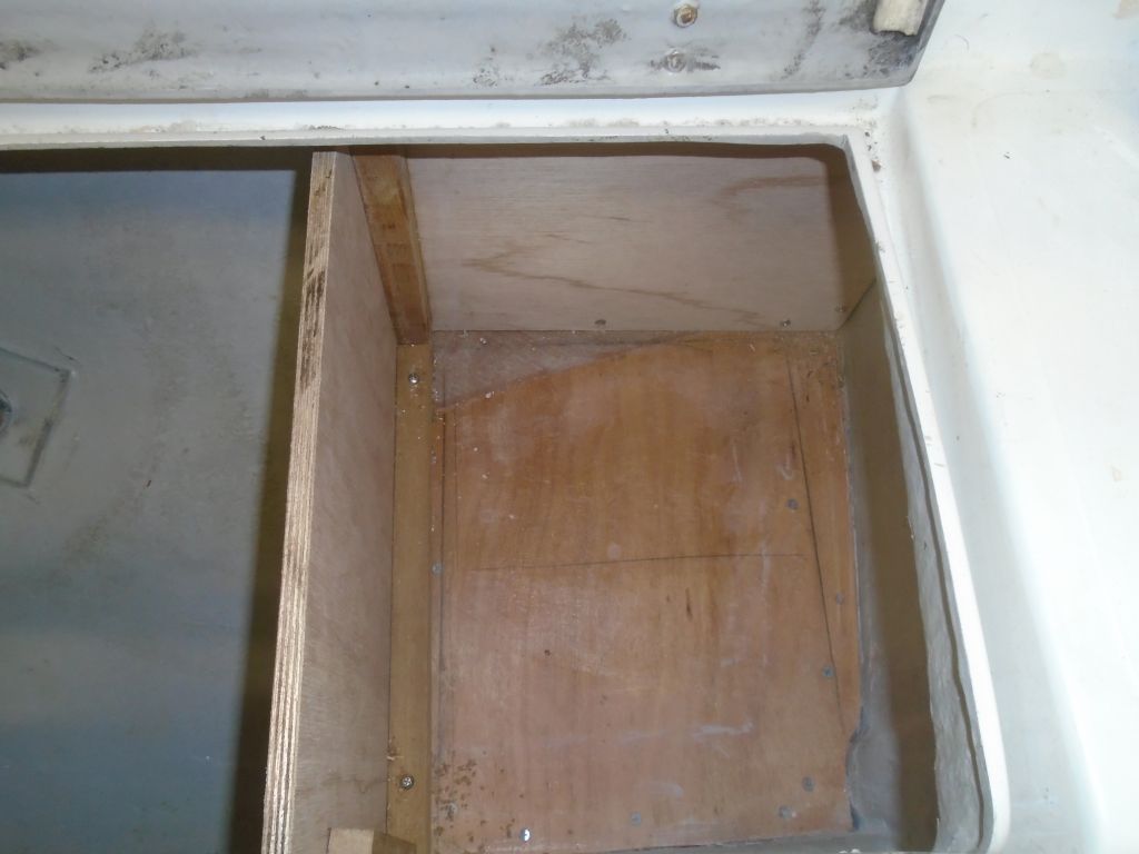
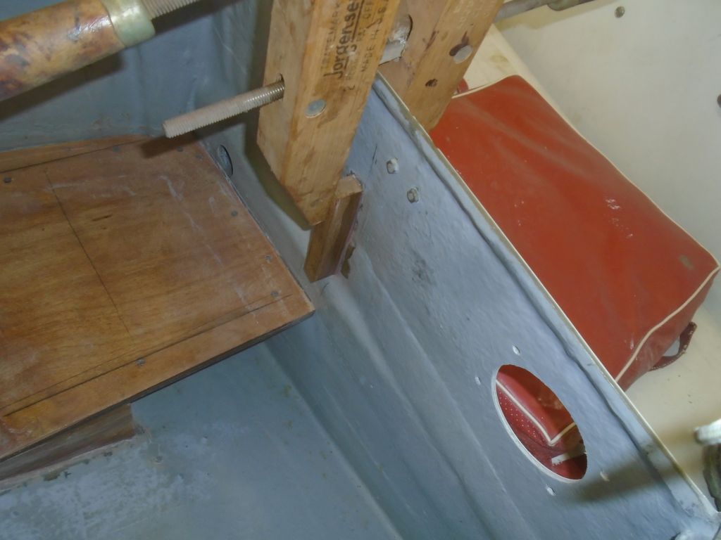
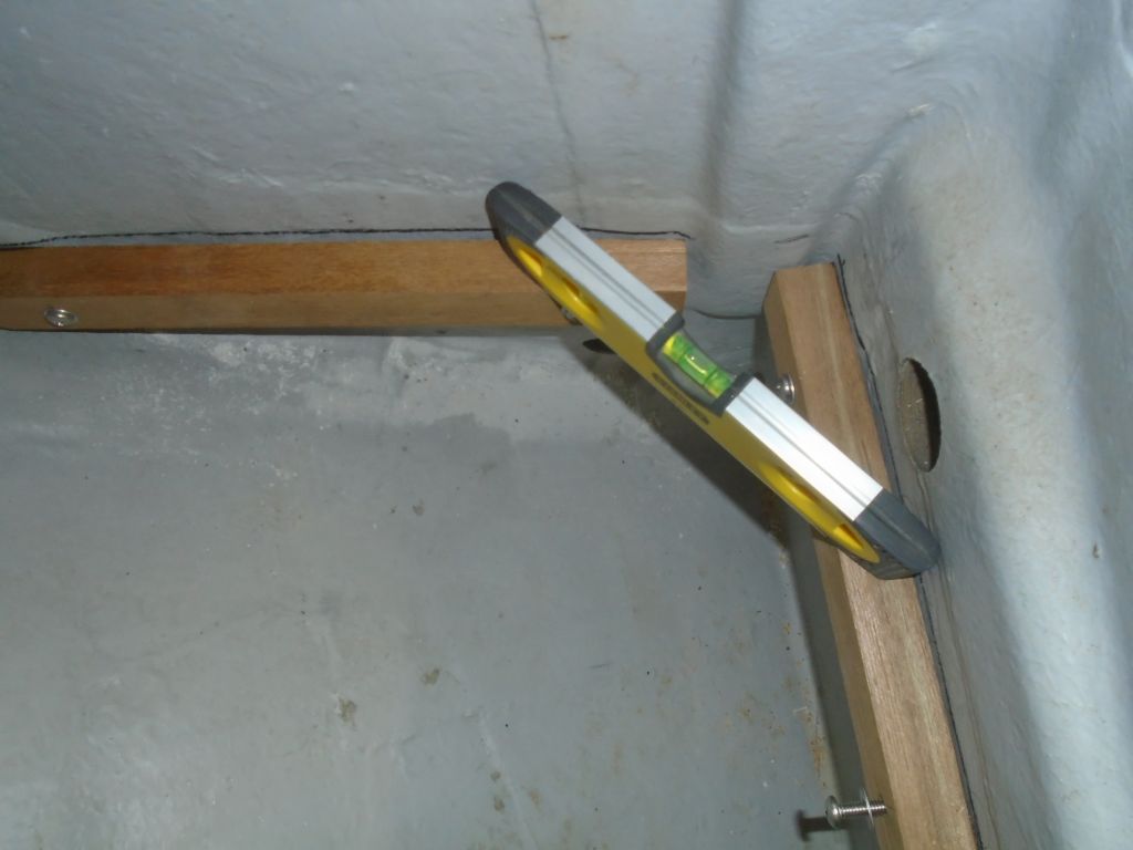
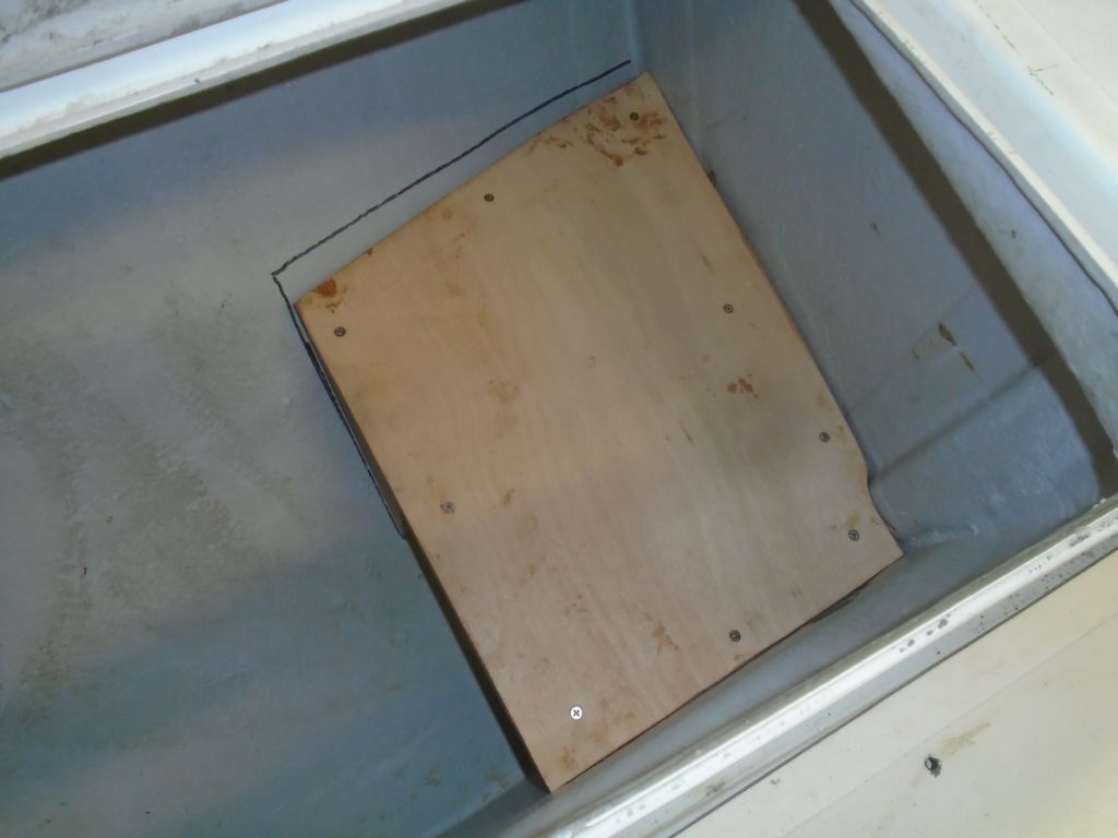
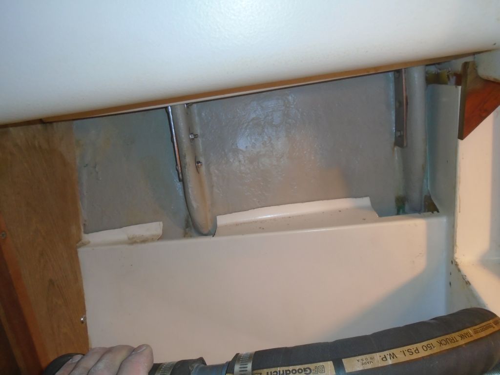
At length, I had both pieces in place and screwed together with various hardwood cleats as required.  The cleat on the battery platform along the edge of the after panel would be permanent, and later I planned to epoxy it in place, since this cleat, in addition to holding the aft panel, would also form part of the battery restraint.  All I needed now was a top, and a means of securing the batteries.

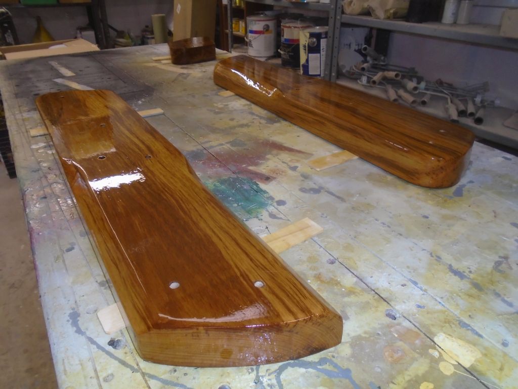
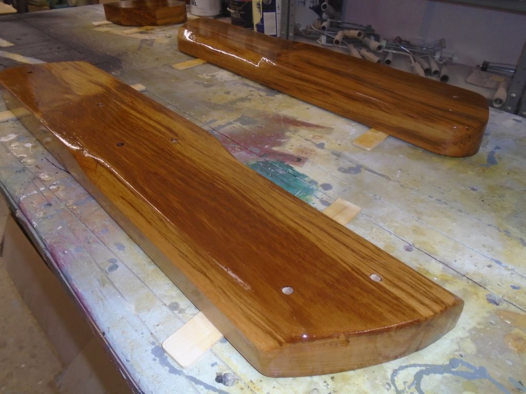
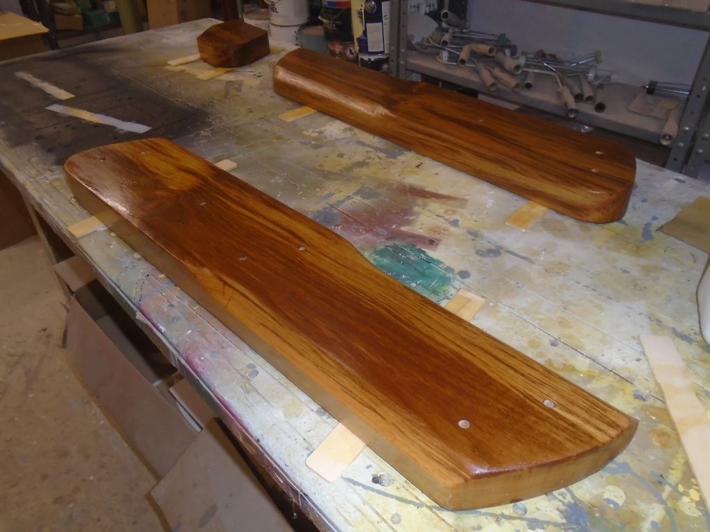
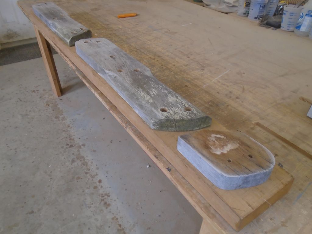
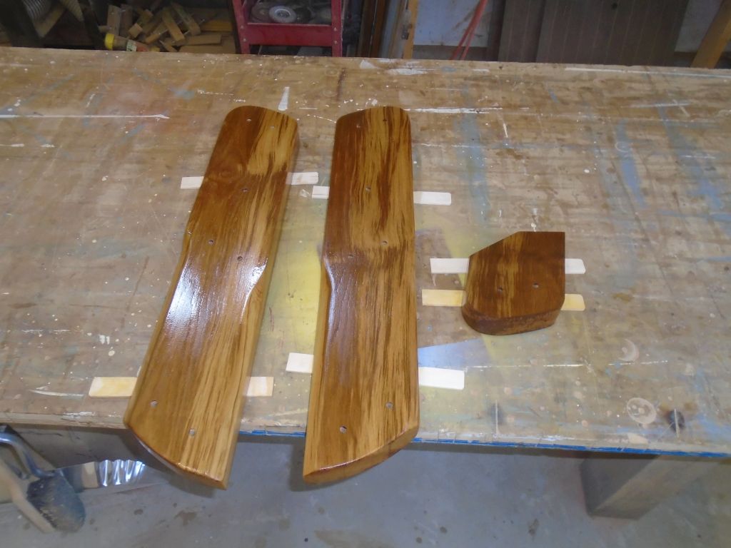
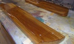
Finally, I sanded, cleaned, and revarnished (3rd coat) the new rudder cheeks.  I continued to apply varnish to all sides, including the “down” side, as the additional protection even on these hidden areas would help prolong varnish life on the external parts.  I didn’t worry about mussing the varnish on these back sides where they rested on the sticks because the coating here was just for protection and not appearance.

varnish1-31816

Total time billed on this job today:  8.25 hours

0600 Weather  Observation:
32°, mostly clear.  Forecast for the day:  chance of showers or thundershowers, high 45° but dropping with a cold front later

Salty 19

< Back to Salty

Thursday

To complete preparations to the laminating jig for the tiller, I installed with dabs of hot glue little sections of plastic on each of the wooden supports, which would prevent the tiller from sticking to the clamping blocks.  I covered the bench with plastic, and prepared all the teak laminations by solvent-washing with acetone.

tiller1-31716

Afterwards, I applied epoxy adhesive to the strips and clamped them securely in the jig, using a mallet to ensure they were flat and even on the jig surface.  I scraped off most of the epoxy squeezeout and left the assembly to cure.

Before moving on, I lightly sanded and varnished again the new rudder cheeks.

cheeks1-31716

I’d been waiting for a while for two missing and critical parts for the through hull installation–the flange bases for the cockpit scuppers. Eventually, I located two at another supplier and ordered them, as their absence was holding me up.  So with these due later in the day, I turned to the through hull preparations, starting with a dry fit of all the bronze through hull fittings so I could cut the stems to the required length in each case.  Since I had one of the three 1-1/2″ bases that I needed, I could cut all the stems now.  Inserting the through hulls from outside, I taped them in place to hold them while  I worked inside.

At each fitting, I marked where the stem came through the hull and backing block, then tested how far I could thread on the flange base.  Any gap between the two would require that I cut off some excess length in order to tightly thread the assembly together.  All of the fittings would require modification, though the three 3/4″ fittings almost might have worked as is, but I wasn’t about to chance it.  In this way I marked each through hull in turn.  In order to fully thread the stem into the bases, plus a little extra to ensure that I didn’t come close to bottoming out, I needed to remove about 3/4″ on each of the larger through hull stems, and about 1/4″ – 3/8″ on the smaller ones, just to be safe.

Threading on the through hull nuts, which I’d use to clean up the cut threads, I marked each fitting and cut off the excess with a cutting wheel.  I tried to grind a small bevel at the top of the cut, and I cleaned up the threads with the through hull nut and a little sandpaper as needed till I could easily thread on the base, which ensured that it would work as planned when I was actually installing the fittings.  I’d already marked each through hull as to its location.

Now I taped the newly-shortened through hulls back in place–this time just on the four that I planned to install right away, while awaiting my final two bases–and, from inside, threaded on the bases tightly enough so I could align the base and drill the bolt holes through the hull.  I drilled one hole, inserted a temporary bolt, and then the next, ensuring that the alignment would all work out later:  one does not want to find that there’s a slight misalignment once the fitting is gooped up.  I did this for each fitting.  Then, outside the boat, I milled countersinks at each hole to allow the machine screw head to sit flush with the hull.

While preparing the bolt holes, I’d noted where I wanted the valve handles to be to allow for access and clearance, so down on the bench I pre-assembled the valves onto the bases for each of these four fittings (head intake and discharge; sink drain; engine intake).   Access was tight enough in several of the locations that I didn’t want to have to use unwieldy wrenches to try and spin these valves on tightly and into the correct orientation in place.  Only one of the valves required a 90° tailpiece, and I’d noted the correct orientation of this as well so I could pre-install it in the direction it needed to be to match up with its existing hose, for the head discharge.

After final preparations and cleanup, I installed the four fittings, following the same procedure for each one, but I didn’t try to document each step on each fitting because the job was time-sensitive and messy.  But the photos below show the basic sequence, though they may not all show the same exact fitting.

For each fitting, I heavily applied adhesive sealant to the through hull flange and neck, and pressed it into the hole.  The sealant was fairly stiff, but still required some tape to ensure the fitting wouldn’t fall out when I started the threads inside.    Now, inside the boat, I applied more sealant around the through hull neck and the perimeter of the mounting flange area, including around the bolt holes, and carefully threaded on the flange base (with valves pre-attached in this case).  I threaded the base on till it was nearly tight, then aligned it properly with the bolt holes and installed temporary bolts from inside, to hold the alignment.

Back outside, I gooped up the necks and heads of the 5/16″ bronze flathead machine screws, and inserted them into the bolt holes, pushing out the temporary bolts on the inside in the process.  Once I had all three bolts installed, I used a special tool (not shown here) to tighten the through hull securely into the flange within, and tightly against the hull on the outside.

Scampering back into the boat, I installed washers and nuts on the through bolts, and tightened them before cleaning up excess sealant from around the flange and, finally, continuing back outside where I cleaned up excess sealant there as well.

With all four fittings installed (the two new bases arrived, but too late in the day to install), I cut off the excess bolt length inside, and the job was done.  The thinner removed a little of the gray paint in a few areas while I was cleaning up sealant, revealing a bit of the white primer beneath, so that’s what the white streaks are.

I’d finish up the two cockpit scupper fittings next time.

Total time billed on this job today:  7.25 hours

0600 Weather Report:
Drizzle and fog, 35°.  Forecast for the day:  partial clearing, high in the 50s, chance of a thunderstorm

Salty 18

< Back to Salty

Wednesday

During the morning, I went through all the my preparation steps–layout, drill, tap, mask, sealant–to reinstall various hardware, including the water fill deck plate, cookstove vent, bow cleats, access ports, and anchor locker hinges, plus the new locker lid latch.

I lightly sanded the primer on the new chainplate covers, then applied a few coats of satin black paint to complete them, just like Jerry Maguire.

cpcovers1-31616

To allow access, battery installation, and construction, the battery box that would surround the batteries on their new shelf had to be at least partially removable, and as such would be mainly for protection, not necessarily self-containment:  that is, the batteries would rely on other means to hold them in place, not specifically the box itself.   I figured the outboard side of the box would mainly remain in place semi-permanently, though the ability to remove it could be helpful someday should access be required beyond it, but the aft side would be removed as needed to install or remove the batteries from the box.  The fit for the batteries, as well as the requirement to install cables, increasingly made it look like top-only access might be unnecessarily hard.

So after the usual water wash and light sanding, I laid out several hardwood support cleats that would give me places to secure the two external sides of the battery box, and installed the cleats with epoxy adhesive, screws where possible, and clamps.  The cleats left enough room (where needed) for the side panels and additional cleats as well as the battery footprints.  I left the cleats and epoxy to cure.

I received the new teak required to build the replacement rudder cheeks, and it seemed as good a time as any to get right into their construction.  Starting with a rough board a bit wider and longer than the ultimate amount required, I first planed it smooth and dimensioned it to the same thickness as the original cheeks–or, more specifically, the center spacer piece, which truly dictated the final thickness since this matched the thickness of the fiberglass rudder itself.

Through a series of sawing operations, I cut out the three new pieces required, using the originals as exact patterns.  With the blanks cut to size, I milled the chamfers at the bottom edges to match the originals (not shown here).

cheeks4-31616

Securely clamping the old piece atop the new, I used the old bolt holes as guides to drill the holes in the new cheeks, one side at a time.  Then, I clamped the cheeks together with the central spacer, aligning them where they needed to be, and drilled the bolt holes through the spacer, before sanding the top surfaces of the assembly smooth and flush with one another.

With the segments separated once more, I sanded the surfaces as required to smooth and prepare them for a sealer coat of varnish, which I applied to all sides.  These new cheeks would be installed a little differently than originally, as I planned to use exposed hardware (rather than countersunk and bunged) to allow the cheeks to be readily removed for future maintenance.  So I didn’t create any counterbores for the new fasteners.  I ordered threaded rod and cap nuts to be on hand when I was ready to install the cheeks.

Total time billed on this job today:  8.5 hours

0600 Weather Report:
35°, clouds and drizzle.  Forecast for the day:  improving conditions, highs through the 40s.

Salty 17

< Back to Salty

Tuesday

To begin, I reinstalled the two mainsheet U-bolts at the aft end of the cockpit, with new sealant, nuts, and washers.

After marking the outline of the new opening with a pattern, I enlarged the old engine panel opening to accommodate the new panel, which I held in place temporarily with a couple screws for illustrative purposes only; I’d do the final installation a little later on, as it was too soon to put the panel in harm’s way.

Next door, I laid out the position of a new bilge pump, which would operate through the cockpit wall, and drilled the large hole and four fastener holes required.  The cover plate, when installed, would align with the bottom of the engine panel next to it.  I’d await installation on the pump till a bit later, to maintain good access in the locker to finish up some other installations first.

Now that the chainplates were back in place, I could reinstall the bulkheads and get things edging towards normal once again.  After cleaning the installation areas once more, I checked the fit of one of the bulkheads to see if I could trim some of the excess material that interfered with access to the middle chainplates on both sides.   I didn’t want to take out any material that might be important from a structural standpoint, but I found that the small tabs that extended into the narrow openings near the chainplate knees didn’t serve any such purpose.  The structural liner, which formed the main interior cabinets and structures, was well-tabbed just aft of this position, inside the lockers above the galley.  All the bulkhead fixing screws were well inboard of that area, and the bulkhead didn’t even contact the hull or molded overhead consistently in these slots, so I saw no reason why I could trim a bit in the hopes of providing someone better access in the future.

Leaving a full inch of overlap where this portion of the bulkhead passed over the last section of the molded interior liner, I trimmed the excess portion on each of the two bulkheads.

Next, I reinstalled the bulkheads.  The shortened tabs did help with access to the chainplate bolts, though on the starboard side this was still going to be a challenge, but in any event access was now as good as it could be while the bulkheads were in place.  I’d reinstall the cookstove vent and its cover once I’d reinstalled the deck fitting, which I’d only recently removed for rebedding.

Working now in the port cockpit locker, I did some final layout for the new battery platform, double-checking some measurements from my early mockup, and confirming that the boat was still level from side to side.  Then, I made some level marks inside the locker, on both the forward (transverse) bulkhead and side (longitudinal) bulkhead, which lines I used to measure and install a pair of teak (from the scrap bin) cleats to support those two sides of the new platform.  Once I had their positions set, I removed the gelcoat from the bonding surfaces, and secured the new cleats with epoxy and bolts through the bulkheads.

With these firm footings, I created a simple cardboard template of the space as needed, following the curvature of the hull outboard and the shape of the inner corners of the area.  With my battery footprint mockup, and allowing extra room for cleats and so forth, I determined the final size and shape of the platform, and transferred the template to two pieces of 9mm plywood I had on hand; I planned to laminate the two pieces to make a suitably thick base.  This design left good access beneath for locker drainage, and for access to a hole required for the bilge pump hose.

Satisfied with the shape of the platform, I prepared the bonding surfaces of the two sheets of thinner plywood, and epoxied them together, holding it secure with several screws as well.  I scribed and cut a support cleat from additional teak to hold the after corner of the platform securely, and marked the bonding area on the hull during a dry fit, so I could remove the locker gelcoat from this area for the best bonding surface.  I double-checked the fit of the “batteries” with my oversized plywood mockup, the height of which included ample room to account for the battery terminal height, so the fit appears closer than it actually is.

Preparations complete, I secured the platform with epoxy adhesive and screws to the cleats, and additional epoxy fillets where it met the hull at the outer corners, and beneath the teak “leg”.  I finished up with a layer of biaxial tabbing to secure the platform to the hull, and epoxy-coated the top of the platform as well.  The fillet got a little warm at its thickest point during curing, causing the change in color seen.

To round out the day, I built six fiberglass covers for the chainplates, each custom-fit to its respective location, as they were all just a bit different.  Because the chainplates were so close to the short raised bulwark, there was not room for traditional deck plates to slip over the tops of the chainplates, so from a strip of 1/4″ x 1-1/2″ fiberglass I milled pieces with central slots that closely fit the chainplate width without binding, leaving them open at one end, and cut the length to leave a consistent reveal at the inboard edge.  I beveled the lower edges where they met the bulwark as required to allow for a tight fit there.

With the basic fit complete, I lightly beveled the exposed corners for better appearance and coating retention, and on the insides of the slots I formed a small bevel to hold more sealant near the chainplate itself.  Then, I sprayed on some primer to begin the coating process.  I’d complete the installation once the covers were all painted.

Total time billed on this job today:  7.5 hours

0600 Weather Report:
35°, light rain.  Forecast for the day:  on and off rain and showers, high 45°

Salty 16

< Back to Salty

Monday

Back on hardware duty, I started by reinstalling the stern pulpit.  With the pulpit dry-fit in place, I marked all the fastener holes (and masked around the two after bases), then drilled and tapped the holes for machine screw fasteners.  Afterwards, I applied plenty of sealant and fastened the pulpit back in place.  The outermost fasteners on the two after mounts were beyond the extent of my reach through the lazarette hatch–I could barely touch the screw, but couldn’t get a washer and nut started–but fortunately I could manage it if I put my hand through the nearby vent hole.

I continued with the stern cleat…

…and then the diesel fuel fill and waste pumpout deck plates.  I reconnected the waste hose with a new clamp, but left the diesel fill hose for later, since access to the rear side of the engine controls was easier without the hose in place.

The old plastic deck plates and cowl vents from the poop deck were salvageable, but were faded and brittle with age, and the owner wished to replace them.  Before I ordered the replacements, however, I wanted to satisfy  a nagging curiosity or concern about the upcoming Monitor windvane installation, which would require two deck mounts for support.  My early perusal of the instructions had left a figure of 15″ spinning around my head, and I thought that was going to land the mounts right where those vent holes were.  I was right about the 15″:  that was the width between the support tubes at the top end.  But the tubes would flare out from a bend, and spread to a deck measurement of about 25″ on center.  I checked this with a tape, and it looked like it would clear the vent holes, so I went ahead with the new purchase.

monitor1-31416

With the stern pulpit back in place, I figured I’d taken care of the worst part of hardware rebedding, with all the hardest-to-reach installations complete.  But there was still more to do, and I continued now with various prepwork and additional removals.  At the bow, I needed to create access to the underside of the two bow cleats.  The design of the anchor well and interior liner prohibited any access from inside the boat, so the only way in was to cut access holes in the sides of the anchor well, which I’d fill later with screw-in deck plates.  Once I cut the access holes, removing the cleats was straightforward, though the builder used 3″ long fasteners when 1-1/2″ would have been adequate.

Once the cleats were out, I overbored the fastener holes with a 1/2″ bit, removing the core, and did the same with all the other fastener holes around the anchor locker, including the hinges (deck side) and part of the mount for the new latch.

On the side deck, where I’d removed the water fill deck plate earlier, I reamed out the core from within the opening, and overbored the three fastener holes for the deck plate, and masked around the opening to prepare for epoxy.

hwprep1-31416

I removed the vent from the cookstove and prepared the main opening and the surrounding fastener holes for epoxy filling as well.


Later, I filled all these new holes and voided core with thickened epoxy, removing any masking tape afterwards.

At the stern, I removed two 1/2″ U-bolts for the mainsheet.  I’d worried a bit about removing these, as some photos I’d taken of their undersides (there was no direct visual access through the various openings) showed some ugly rust on the port side, and I’d  run into issues with the same thing on a sistership I worked on years before.  Fortunately, though, the nuts came off easily; the rust turned out to be only from a substandard lock washer that had been in place.

After cleaning out the holes (the footprint of the hardware wasn’t large enough to allow boring them out any larger), I sealed the insides of the holes with epoxy, whatever was in there.  I couldn’t be sure whether there was any plywood in there, or just extra fiberglass in this location, but a little extra epoxy never hurt.

Ironically, the dumbest possible piece of hardware proved to be the most difficult to remove:  one of the vent fittings located in the side of the cabin trunk above the head.  The fitting itself was in fine condition, but the fixing nut on the inside was badly rusted and looked terrible, so replacement of both vents was in order.  Of course removing this rusted nut proved to be a problem, as it was corroded to the threads and spun the whole fitting when I tried to loosen it.  At first I tried to hold the fitting with another pair of pliers from inside, but all this did was crush the end of the brass fitting.  Eventually, I locked a pair of pliers on the nut so it could spin against the overhead, and, from outside, used another pair of locking pliers to turn the fitting, and this eventually loosened the nut so I could remove it.  Then, the nut wouldn’t pass over the crushed end of the fitting so to remove the fitting I had to cut through it with a hacksaw.  (And people wonder why it takes so much time to do anything on a boat.)


With new fasteners on hand after the usual afternoon delivery, I got back to work on the chainplates  Installation was straightforward except for the starboard middle chainplate, with its extremely tight access.  The way the knee angled aft just a bit towards the nearby molded/tabbed cabinet made it impossible for me to get a nut started by hand–there just wasn’t room to get nut-holding fingers in there.  So I came up with a way to hold a nut inside a box-end wrench, which I could delicately hold in to the narrow gap and, by turning the bolt head, get the nut started.  Once the washers and nuts were in place, it was no major problem to tighten them.

The port center chainplate had more room, so I could start the nuts by hand.  And all the rest were wide open, relatively, and easy to fix the chainplates in place.  I’d work on some deck covers for bedding the chainplates in the coming days.

Total time billed on this job today:  8 hours

0600 Weather Report:
20°, mostly clear.  Forecast for the day:  clouding up, high around 40

Salty 15

< Back to Salty

Sunday

With some time on hand, I thought I’d take care of a couple small jobs, starting with a new engine installation template.  I’d had on hand an older template, left over from another Beta 14 installation some time ago, but the template was in rough shape and had been modified (I’d used it for some initial engine calculations on this project as well), and there had been some changes in the design of the engine since that time.

enginetemplate12-31316

With an updated engine drawing, I prepared a plywood base that corresponded with the maximum length and width of the engine, and attached to its bottom an extension fore and aft, which mainly gave me the shaft centerline, which was the most critical dimension for proper alignment.  At the aft end, I built the extension to correspond with the depth of the transmission housing; the forward extension corresponded to the depth of the oil pan (though not the location).  This gave me all the maximum dimensions required to ensure that the engine would fit as expected.  I also noted the overall height above the platform.  I marked the engine mounting locations, using the drawing as a guide, and temporarily installed the adjustable mounts, starting with a 3″ depth, which was right in the middle of the mounts’ specified adjustment range.  In this specific instance, I’d ordered the new engine with 14.5″ mounting centers at the aft side, and 16″ at the forward, as this would work best with the existing engine foundations.  Because the “centerline” of the engine ( aka the shaft centerline) was actually not symmetrical with the overall dimensions, the starboard forward, at this wide dimension, was actually almost off the template completely, since the center of the mounting flange was wider than the overall width from engine center.

I quickly tested the new template in the boat to check the fit.  It looked good overall, but I thought my initial adjustment on the mounts was probably too high (the shaft centerline was above where it needed to be), but I’d adjust those and finalize the template (and therefore engine) position a little later on.  The template would be ready whenever I was.

Next I turned to the tiller.  The original tiller, made of solid wood, was in poor condition, and I was tasked with building a new one from laminated teak.  To start, I removed an old autopilot mount and the friction tape wrapping from the tip end, leaving the bare tiller to use as a guide for laminating the new one.

I dug out an old laminating template that I’d used on some project or another in the past, and removed the old blocking and plastic left over from that job.  With a clean, flat template re-covered in plastic sheeting, I used the tiller to mark the curvature on the plastic, then installed clamping blocks as needed against the line–enough blocking to bend the wood strips into the fair curve required, and to provide ample clamping area.  I like laminating templates built on the horizontal like this (as opposed to a vertical orientation, where the laminations are clamped on top of a form that is open on both sides) since it makes aligning the strips with one another (i.e. flush) much easier, since one can press and (if needed) clamp the whole assembly to the flat base, which ensures that the lower (template) side of the lamination will be flat and smooth.   Epoxy-coated laminations are extremely slippery, and the flat base means that one need not be fighting alignment through the clamping process.  The end result also makes shaping and dimensioning the finished piece that much easier since there’s a flat and consistent side from which to start, and it’s quick and simple to build the template.

From some leftover teak on hand, I milled a series of 1/4″ thick strips, each a bit over 1-3/4″ wide (the raw dimension of the rough stock), from which to laminate the new tiller.  The finished piece needed to be about 1-5/8″ thick.  These strips bent easily to the minimal curvature required.

The tiller was fairly consistent and relatively narrow over much of its length, but the butt end flared quickly into a depth almost twice that of the rest of the tiller.  Gluing the whole blank to that dimension would be wasteful of material, and more difficult to glue all at once, so with enough strips to complete the tiller other than the butt end, I cut some additional strips into shorter lengths, and these would become the deeper butt end later.  I’d glue up the main blank first, then add on these strips at the end afterwards.

tiler9-31316

The template would require a little more prep work, mainly some bits of plastic to prevent the blank from sticking to the template blocks, and as tempting as it was to continue and glue up the blank, I was running short on time and would continue sometime later.

Total time billed on this job today:  2.75 hours

0600 Weather Report:
50°, clear.  Forecast for the day:  sunny, high 60°

Salty 14

< Back to Salty

Friday

Next on the agenda was to inspect and rebed the chainplates.  With no deck covers over the chainplate slots–and not enough room at the toerail end to allow stock covers to fit–the chainplates had been gooped up over the years with piles of silicone sealant, which was not only unsightly but was probably of dubious effectiveness.  So to begin, I removed all this excess sealant (removing and storing aside the toggles that were in place on five of the six chainplates), which also freed up the chainplates for further work.  The starboard side is shown in the top two photos; port in the lower.

Below, access to four of the six chainplates was good, and without drama I removed the bolts securing the plates to the knees and pushed the chainplates up through the slots, so I could remove them from on deck later.  I also removed at this time the old and deteriorated  copper lightning “protection” system that had basically corroded away to dust in many areas anyway.  The knees appeared sound and in good condition.

The chainplates for the uppers (the middle set) posed a problem because the knees were located so close to the bulkheads (those that defined the forward edge of the galley) that it was not possible to access the nuts on the aft sides of these chainplates.  Past experience with a sistership had prepared me for this in advance, and for days I’d been wishing the chainplates to simply unbolt themselves and rise airily from the boat, as I knew the only other way I was going to remove them was to remove the two bulkhead sections.  This was a shame since it seems like it could have been so easy to avoid this access issue, but at least in this case the bulkheads were simply screwed to the fiberglass interior structure, so removal was possible, but it was still a lot of extra work just to access three bolts that really should have been accessible anyway–and with an inch more clearance would have been.

The port bulkhead came out without much issue, though there was one hidden screw that had been broken off during installation (I supposed), and since it had no head it was not visible, nor would it have been removable even if I’d known it was there.  But it wasn’t much of a problem to free the bulkhead from it, as there was plenty of room in the empty hanging locker forward.  Space between the knee and the glassed-in liner behind it was still tight, but at least I could now remove the bolts.

On the starboard side, there was a lot more in the way, and before beginning I had to remove the cookstove vent pipe and all its enclosure leading up to the deck fitting.  The marine toilet was mounted very close to the bulkhead at the bottom, but the bulkhead would have to come out around it since I had no intention of trying to remove the head.  Fortunately, I could access all the bulkhead screws around the toilet base; my worst fear had been that one screw could be inaccessible next to the base.

With extraneous gear out of the way, and all the screws removed, I finally got the bulkhead out, but with difficulty since I had to slide it straight inboard, as I couldn’t tip the top forward as I had on the other side since the head got in the way.  The plywood was also very tight–i.e. friction fit–with the protruding bolt ends of the chainplate, a closer tolerance than on the other side, but finally the bulkhead was out.  There was just enough room for a wrench on the nut side of the knee, and I thought I could manage to thread new nuts on by hand when I reinstalled the chainplate later.

While I had good access to everything, I cleaned up the head and hanging locker areas, removing spilled teak oil from the liner where it’d been slopped off the bulkheads, and just a general cleanup, which brightened both sides of the space considerably.

I also cleaned up around the various chainplate knees and the locker areas surrounding them; these areas, and the knees themselves, were in good condition.  While the bulkheads were out, I cleaned them up a bit and inspected them; they were structurally sound.

I ordered new bolts for the chainplates, as I didn’t have this type on hand, and since I’d found surface rust on a few of the originals (though most were in good condition).  Meanwhile, I pulled the chainplates out from above and cleaned up the stainless, which was polished only on the top half of the plates.  There was a bit of surface rust on a couple of the chainplates, but nothing significant, and they all cleaned up well and looked good.  I also cleaned out any excess sealant from the deck slots.  These photos show both sides of all the chainplates after cleanup.  I’d reinstall them as soon as the new bolts arrived, and I planned to make simple deck covers that would help more effectively seal the slots and look better than the mess that had been there before.

Next, I painted the engine room and around the other through hull pads as required, using gray Bilgekote.

To round out the day, I continued with some more hardware removal, starting with the water fill deck plate, since I’d had to remove the hose from beneath during the chainplate and bulkhead removal process earlier.  This section of sidedeck had a plywood core.

hw2-31116

The nearby vente fittings for the water and waste tanks were rusted on the inside, and I planned to replace them in kind.  The old clear vent hoses that had been installed, and which I’d removed for better access during the chainplate work, required replacement as well, for appearance if nothing else.

At the bow, I laid out the position of a new latch for the anchor well, and removed the deck side of the hinges so I could rebed those.  I’d also soon be creating access to the bow cleats so I could rebed them.

hw3-31116


Total time billed on this job today:  6 hours

0600 Weather Report:
32°, cloudy.  Forecast for the day:  Becoming sunny, high around 50


Salty 13

< Back to Salty

Thursday

I inventoried the new through hull hardware to determine what pieces I was missing, as a number of things had been originally backordered and had dribbled in over the past few days.  I still needed a few pieces before I could continue with the installation, but most of the hardware was on hand, though I discovered that according to my invoices I was supposed to have four of the 1-1/2″ valves already on hand, but only had three.  (This proved to be a picking error at the supplier, and a new valve would be sent.)

th1-31016

I hadn’t planned on repainting the engine room, but looking at the space as I contemplated the final prep on the new through hull pads, I thought there was no way I could leave it as is, so along with lightly sanding the new epoxy and through hull pads, I gave the whole engine room a quick scuff so I could give it a coat of paint later.  It didn’t make any sense to start a brand-new engine and systems installation in this space unless the space itself was truly ready.

In order to move ahead sooner than later on painting the engine room and other through hull pads, after cleaning up from the light sanding I applied a coat of my “impatience primer” to the new epoxy.  One-part paints don’t cure properly over fresh epoxy, and the options were to wait a few weeks for the epoxy to reach its ultimate cure state (impossible), or apply a quick coat of epoxy-based 2-part primer to the new epoxy, which primer would cure properly on its own and then provide a decent substrate for paint.

My goal of these first few weeks was to work on and finish all the significant fixed or structural installations that would affect–and set the course of–the remaining systems installations, so high on my mind was the new battery storage situation.  With the port cockpit locker already chosen in concept as the house bank location, I worked on a basic platform template made of scrap plywood to prove the concept and work out any final details before moving on with construction.  Thinking that it’d be nice if all three batteries (including the start battery) could fit in here, I started with a platform designed to hold both house batteries and the starting bank.  While there was plenty of room for this itself, the other requirements of the locker would preclude installing all three batteries like this, as I needed some of the locker real estate for other purposes.

battery1-31016

One reason this wouldn’t work is that I needed space on the locker wall–and also inside the locker itself–to install a second manual bilge pump, which would require clear access from both sides.  The height of the batteries and/or battery box would get in the way of the space I needed for the bilge pump, and there was nowhere else logical that the pump could–or should–be mounted.  In order for this to work, the battery platform and box would need to end further forward, so I cut off the tho

battery2-31016

Eventually, I turned the template sideways, to orient the batteries athwartships rather than longitudinally, and I liked this position best.  The platform size–not even accounting for potential sides of a box–was too large to fit through the locker opening, so I’d have to build the box in place, and this meant I hoped to keep the installation as simple as possible, so I could use the existing locker sides as two sides of the new box.  The owner also approved of this plan, and I’d move forward with construction soon.

The starting battery had two potential mounting locations:  on a platform in front of the engine (this is where the battery had been installed in the original setup), or in a locker beneath the cabin sole.  Neither location was perfect, but both had their advantages also.

One concern with the engine room location was that the battery might interfere with reasonable access to the front of the engine and related components (such as fuel and raw water filters, and the raw water pump housing), but only further time would tell whether this was an issue, since at this early stage I wasn’t sure exactly how the space would come together with the engine.  There was room for a normal group 24 starting battery here, however, and if it could be installed so as not to be in the way of normal access requirements, this might end up being the spot.

The storage space beneath the cabin sole, a bit forward of the engine room, was where batteries had been previously installed, and there was ample room, but the low location was potentially vulnerable to water problems, and while it was a good and reasonable option if the engine room didn’t work out, for the moment we were hoping to go in the other direction.  The tight access to this space also meant that the battery would have to be installed and hooked up while in the open area, then pushed back to its final location beneath the aft part of the sole.

With the important battery question now resolved–the proof of concept and a clear direction for the house battery bank–I continued work on the deck hardware rebedding, this time the stern quarters of the boat, which included the fuel fill and waste pumpout, stern pulpit, and various other hardware.

Because of the limited access through the locker lids, some of these fasteners were at (or almost beyond) my ultimate reach, at least while being required to also work the top end of the fastener.  Fortunately, despite some  fairly long exposed thread on some of the fasteners, I found that the nuts came off easily, making this job far less onerous than it could have been, a tiny moment of relative pleasure for which I was most grateful.  I even had little trouble removing the hoses from their barbs on the two deck fills, and in relatively short order I had the area cleared of hardware, other than a couple pieces that I’d attend to later on their own.  There were also several old pass-through wiring connections on the aft deck, which were abandoned but I’d have to deal with their old locations somehow.

Afterwards, I cleaned off old sealant and the like, and prepared the fastener holes (where needed) by boring larger holes at each location, removing any core material from about the hole.    The small poop deck itself, at least the center 2/3 or so, featured a plywood core–visible through the plastic vent openings–and the forward pulpit bases were on those raised platforms like the stanchions, but the sidedeck in way of the two deck fills was uncored, and I had no need to do any further preparatory work on those openings or fastener holes.

With everything prepared and cleaned up, I masked around the fastener holes to protect the deck, and filled all the enlarged holes with thickened epoxy, and coated the exposed core in the two larger openings.

Total time billed on this job today:  7.25 hours

0600 Weather Report:
55°, cloudy.  Forecast for the day:  Cloudy,  temperatures falling, rain by evening.

Salty 12

< Back to Salty

Wednesday

I got started with what could seem like an odd tangent, but earlier, I’d spread various parts for the Wallas cook stove out on my bench, so I could inspect the original stove and a new blower lid that the owner had ordered, and now these parts were still there and in the way.  Rather than pack them up as is, I decided to install the blower lid and have that job completed–it all had to be done at one time or another, after all.  It didn’t look like a major job, but it was something I’d never seen nor done before.

The idea of the blower lid is that when the stove is operated with the lid lowered, it activates a blower that forces air across the stove top (no open flames) and then into the cabin, like a mini forced-air heater.  For such a small boat, this seemed an ideal option for basic cabin heating of the type one would normal experience on those chill days during the sailing season in temperate climates.  When the lid is raised, one operates the stove top normally.

To install the lid on this cooktop, I first had to remove a few parts from the old, and initially this caused a little confusion since the illustrations were just slightly different (or so it seemed) from the stove in front of me.  But shortly I realized that the stove itself was actually installed in a stand-alone base, and that in order to install the blower lid I’d have to temporarily remove the base to return the actual cooktop to its essence.  This was easy enough with four fasteners and little spacers to remove, plus one wire connector to the control knob.

Now, with the cooktop stripped down as required by the instructions (essentially removing a couple aluminum cross bars from the back edge, where the blower would be fitted), I figured out how the blower lid fit into the stove housing, and secured it with the four machine screws provided.  Then I removed an existing wiring harness from the works of the stove, and plugged in its stead the harness from the blower lid, all as directed.

Finally, I reinstalled the external stand-alone base (which required removing one more trim piece, as it happened), and this completed the installation.  The blower lid was frankly a handsome addition to this little stove, and I hoped it operated well and did the job.

Now I could set the stove aside for safekeeping till I wanted to put it back in the boat, and with my bench cleared I could move on with other projects at hand.

Before starting in a new direction, I finished up the solar vent installation, now that the epoxy filling was cured and ready for the final steps.  From below, I installed the plastic trim ring, then, back on deck I dry-fit the vent housing so I could mark and drill the three fastener holes.  Afterwards, I applied sealant (butyl tape in this case) to the deck around the large hole, and on the housing itself, and pressed into plate the foam gasket provided with the vent before securing the base to the deck.

The vent came with an on/off switch, which was nice, but I tested it for operation before shutting it down once more.  The vent came with (I think) an exhaust fan blade installed, but there was also a second (intake) blade included to reverse the direction of flow if desired.

Back at the bench, I got ready to prepare six fiberglass backing blocks for the new seacocks.  On a sheet (plus a little scrap) of 3/4″ thick prefab fiberglass, I laid out blocks for three large (1-1/2″) bases  and three smaller (3/4″) bases, then drilled holes for the through hulls before cutting out the bases and, finally, sanding the edges clean and slightly easing the top edges for looks and tactile feel.

Now I cleaned out any old sealant from within the original hull holes, using a knife and then a drum sander.  I found that the original holes leftover from the larger fittings (scuppers and head discharge) were just slightly smaller than the diameter of the new through hulls, so I used a drum sander to open up the holes enough for the new fittings to slip in properly.  The old engine intake had been something like a 1/2″ fitting, but I found that the hole in the hull was actually larger, and only required a little enlarging to fit the new 3/4″ fitting.

After cleaning inside and out around all the locations with acetone, I installed the new fiberglass backing blocks in beds of very thick epoxy, which held the blocks in place even in the near-vertical orientation back at the cockpit scuppers.  I smoothed the new epoxy to form fillets around the bases, and cleaned out the insides of the holes.  Then, not wanting to unnecessarily shake the boat and possibly make these blocks move before they were cured, I spent the rest of the day, as it were, on a couple smaller tasks that didn’t require me clambering around on board, all punctuated by some unrelated goings-on at the shop that required my at-least sporadic attention.

One of these tasks was to check the fit of the actual engine panel.  Years earlier, I’d made a template of these panels, and I taped it in place over the old panel hole to ensure that the new panel would indeed fit.  It did.  Meanwhile I prepared the large panel enclosure for return shipment.

enginepanel1-30916

It also seemed a good time to replace the bulb in the bicolor bow light, mounted on the pulpit.  Originally fitted with a standard incandescent festoon bulb, I sourced a replacement LED bulb for the fixture, and installed it now.  The original stern light, also mounted on the pulpit, would be superseded in this case by a stern light mounted on the new Monitor windvane, and I’d remove the old light later.

While working on the solar vent installation the past couple days, I took the opportunity to prepare and epoxy-fill the cracked area of the aluminum mast step, which, after curing and sanding, cleaned up the damage and made it look good as new.  Later, after I resealed around the edges, I’d paint the step to protect the epoxy and, come to that, the step itself.

Total time billed on this job today:  5.5 hours

0600 Weather Report:
38°, mostly cloudy.  Forecast for the day:  Partly sunny, high 60°

Older posts Newer posts