Wednesday
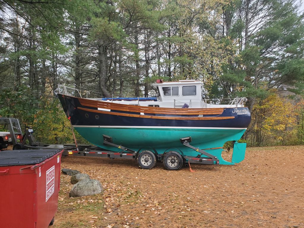
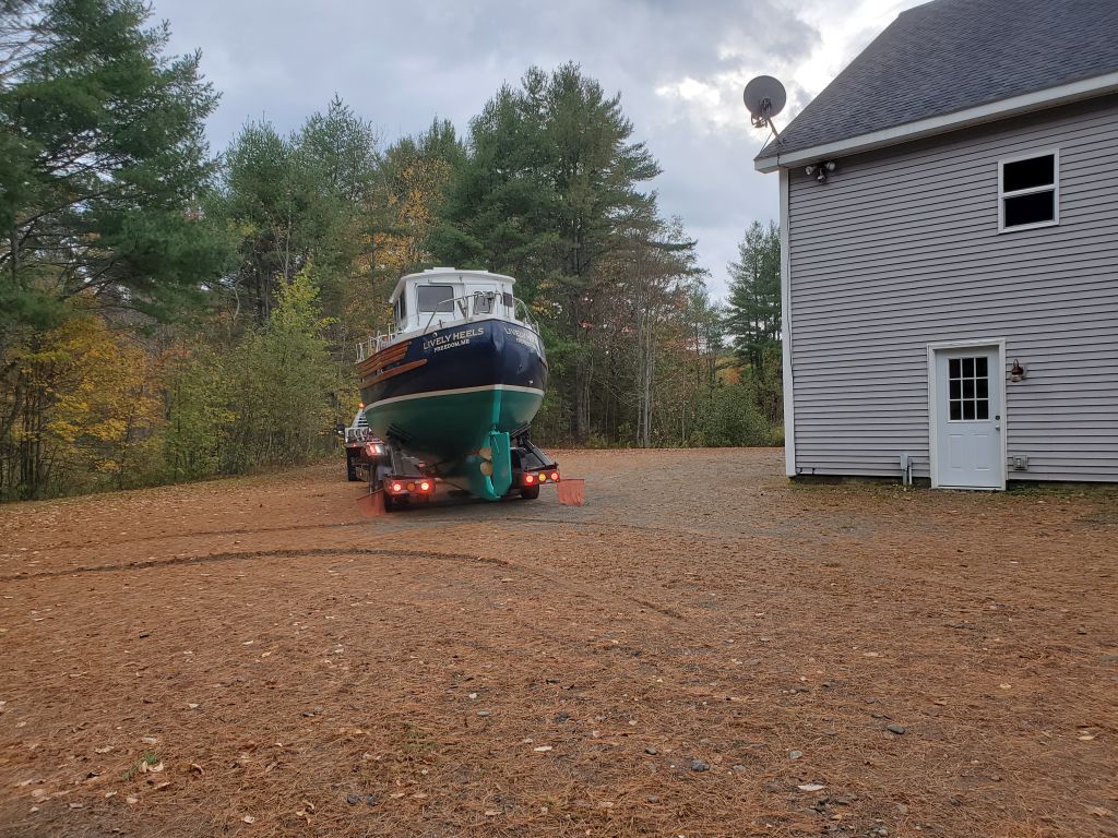
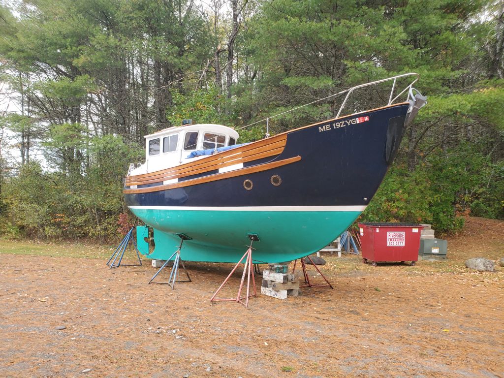
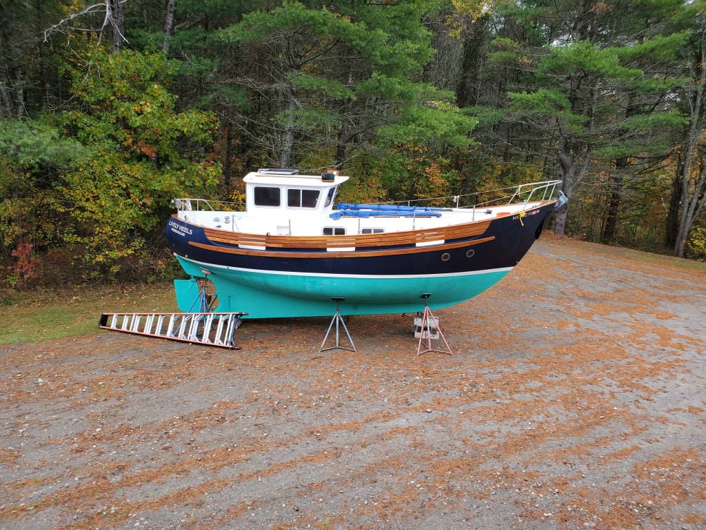
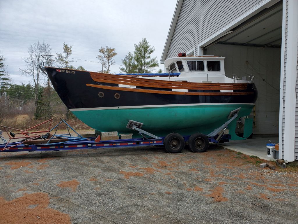
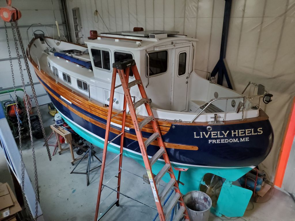
Returning to the shop after six seasons with her new owner, Lively Heels was in good shape, but the owner had come up with a list of miscellaneous projects and minor changes he hoped to make based on his own usage of the boat, as well as to address a few problems with some of the original installations.
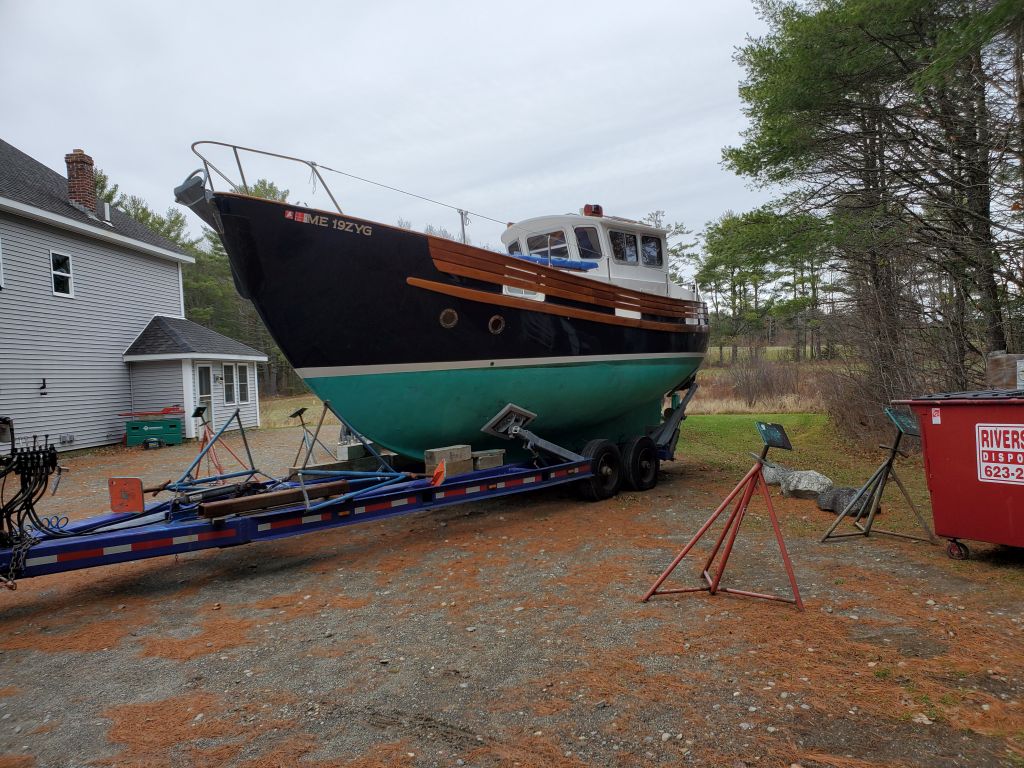
After arriving at the shop in early October, the owner went through his winterizing tasks and unloaded the boat, and once he was done, as time allowed, I moved her into the second shop bay, where we’d arranged for her to spend the bulk of the winter while I worked on the sundry task list.
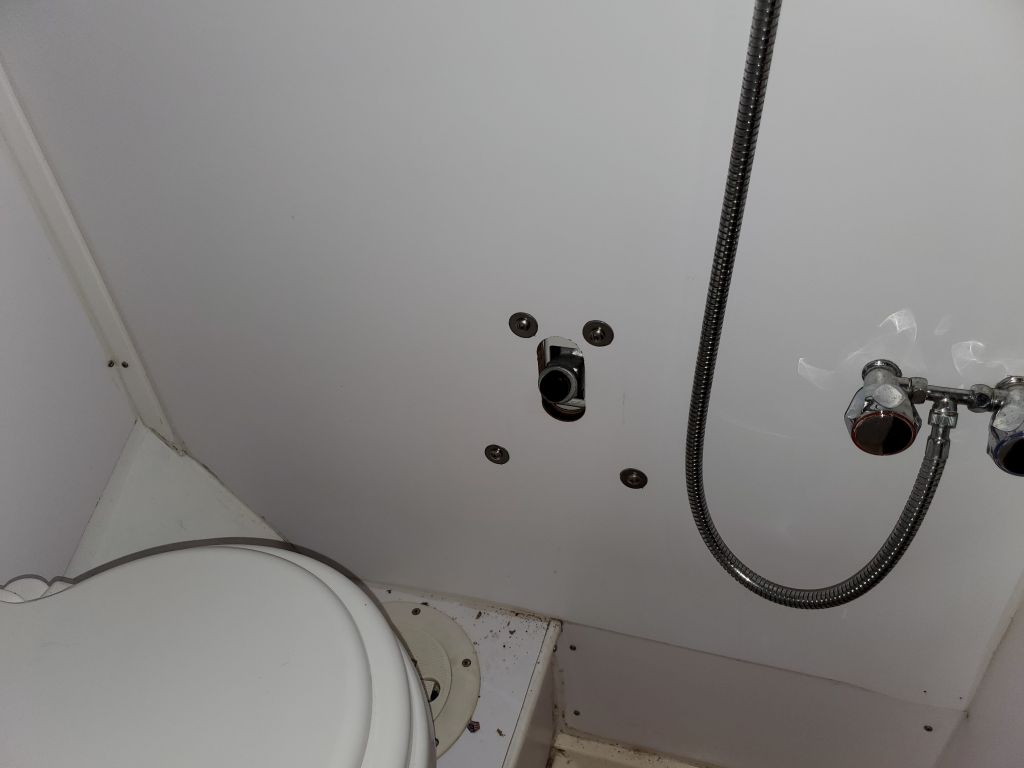
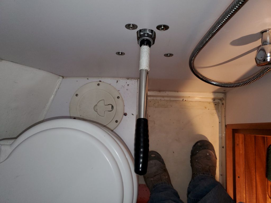
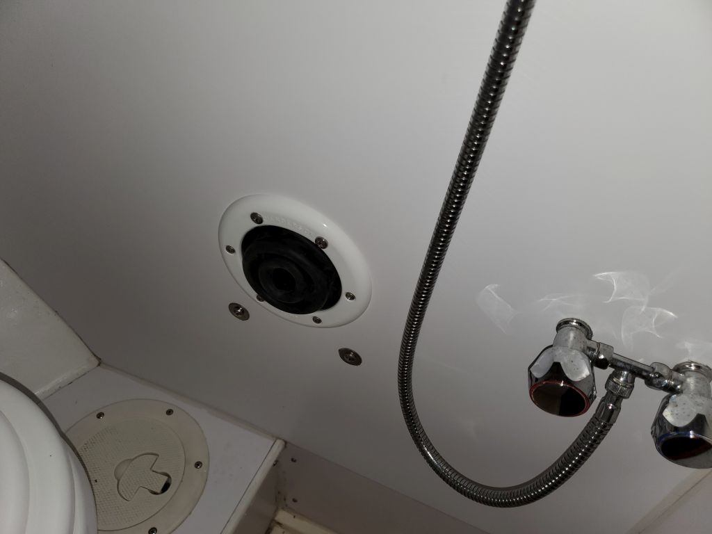
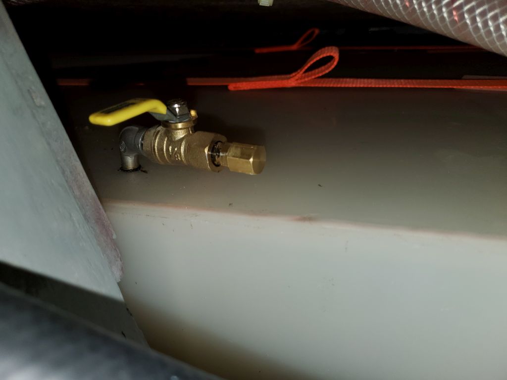
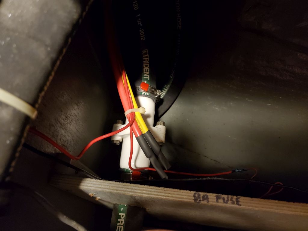
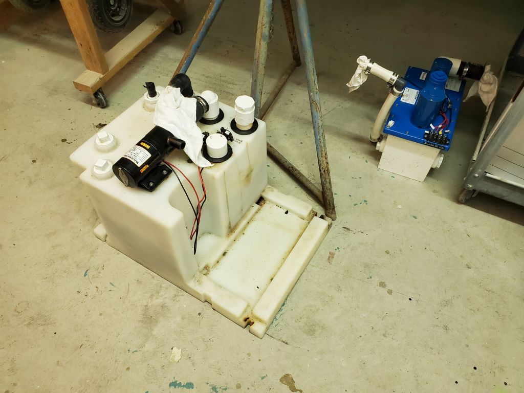
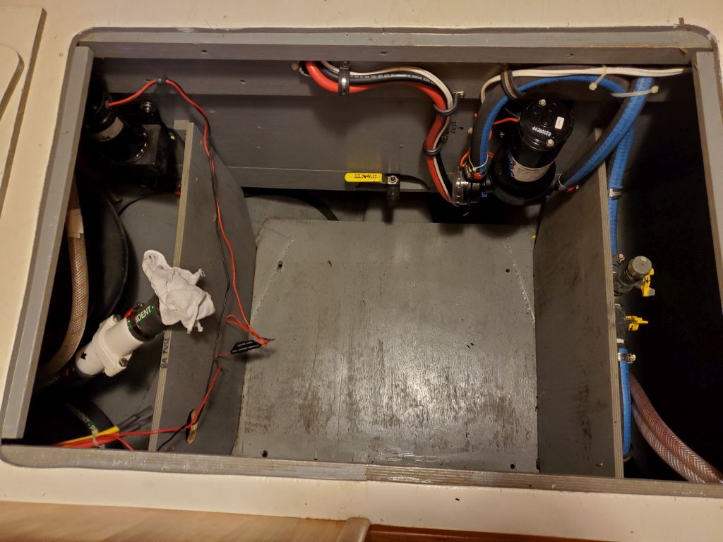
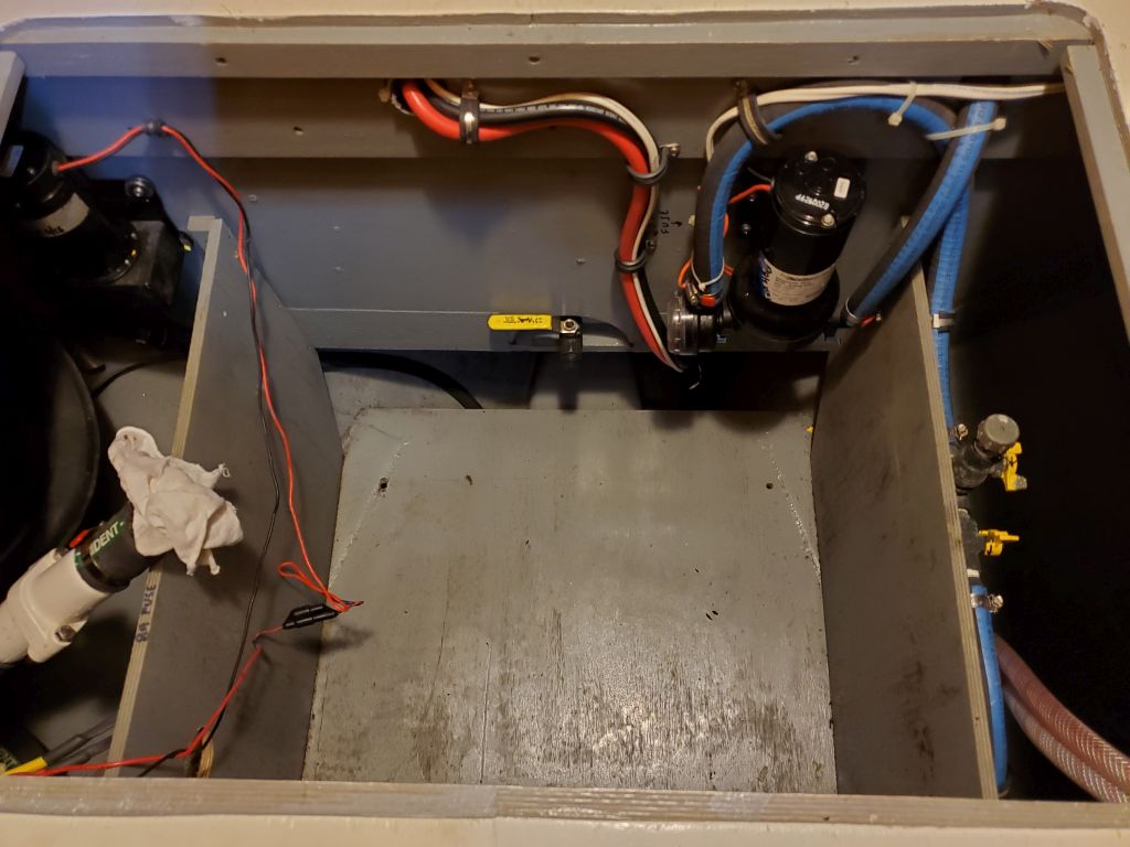
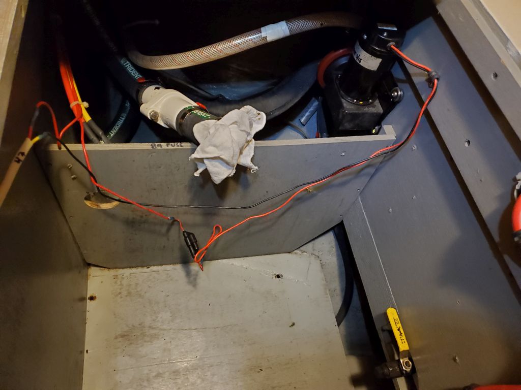
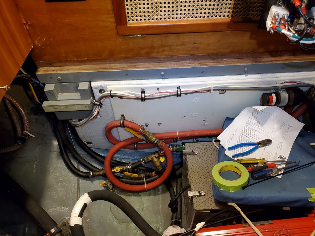
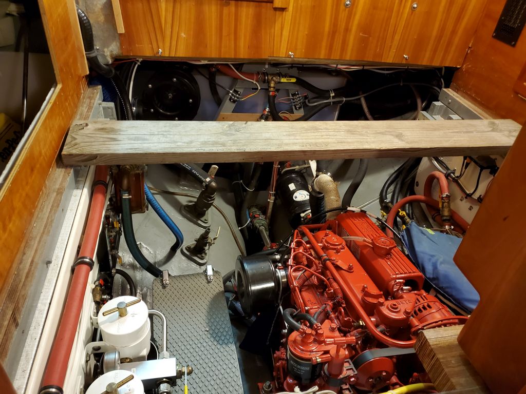
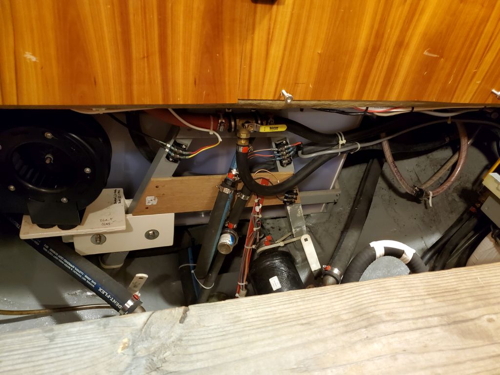
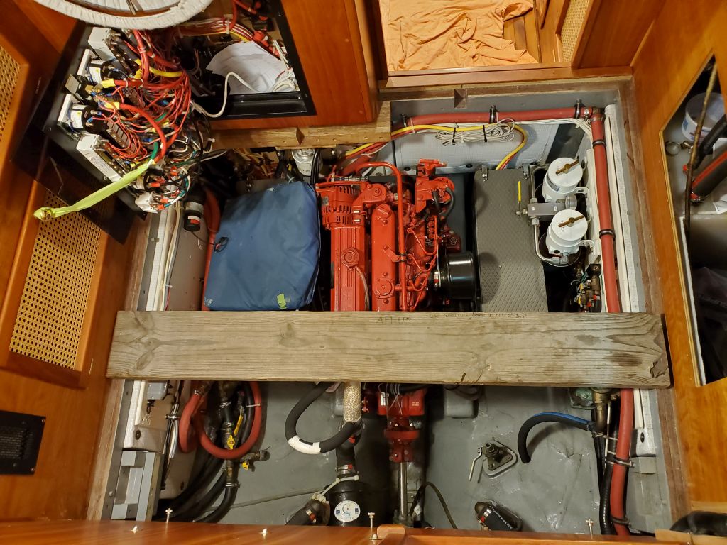
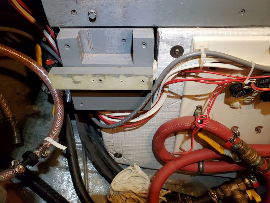
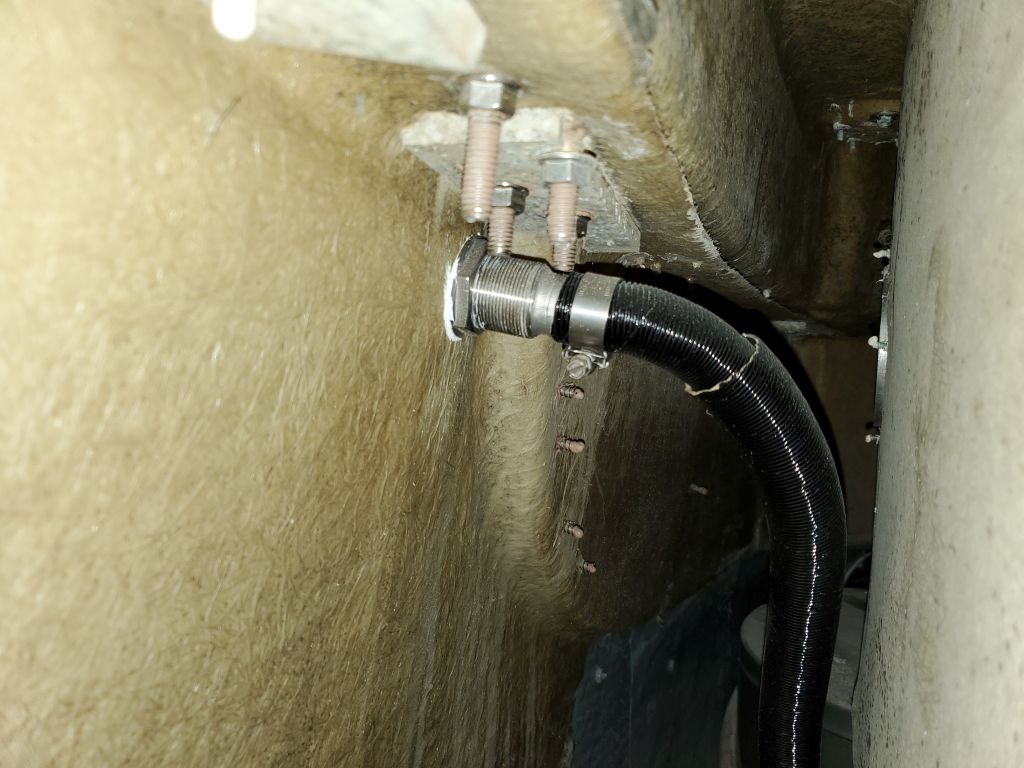
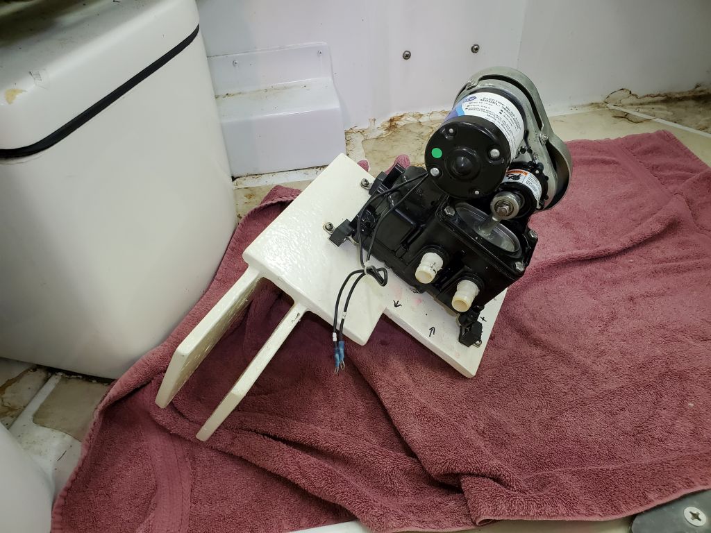
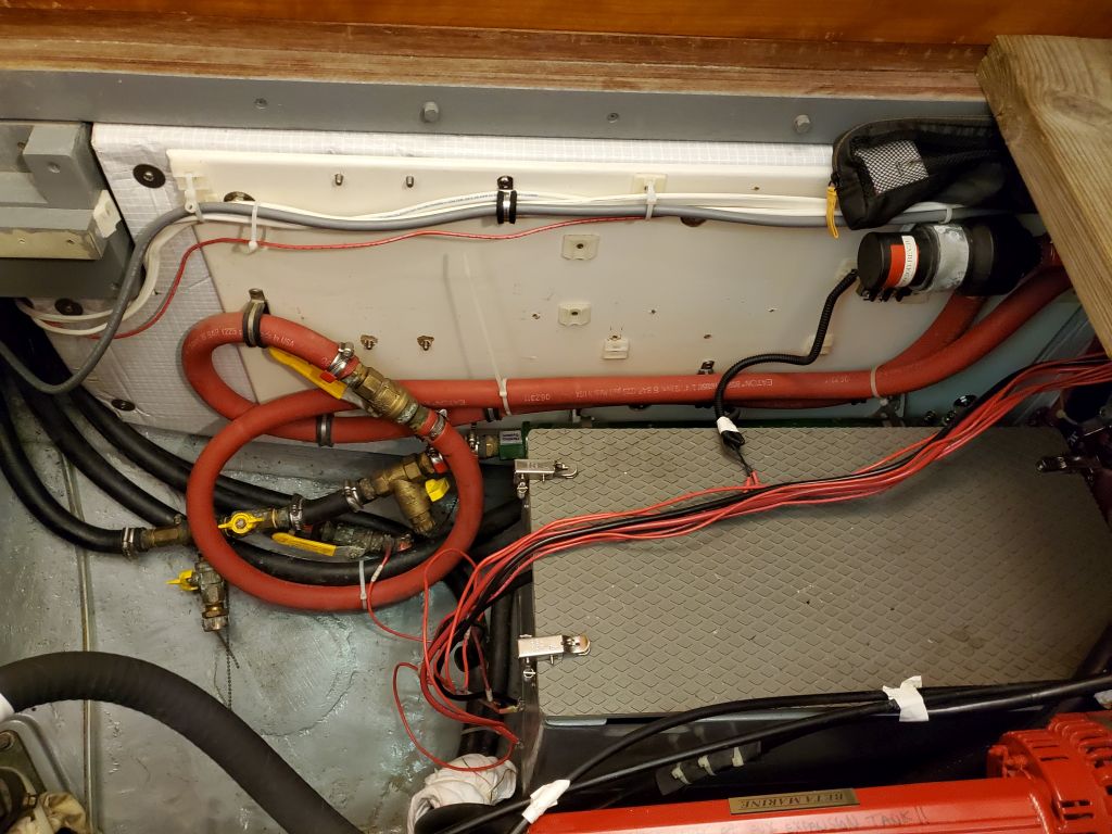
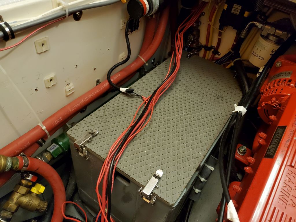
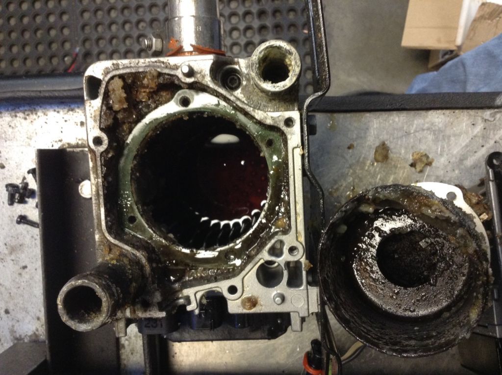
After getting set up with work lights, protective cloths and towels, and the like. the time came where I could start to look into one of the items on the list: Cabin heat. Somehow inevitably, if disappointingly, the expensive and complicated hydronic diesel heating boiler I’d installed at great length during the original restoration (which at the time I was doing for my own eventual use) had started to cause problems for the owner the year before–it had always been a fussy little thing anyway, but after experiencing problems lighting the boiler, he took it out and sent it to the service shop in Seattle.
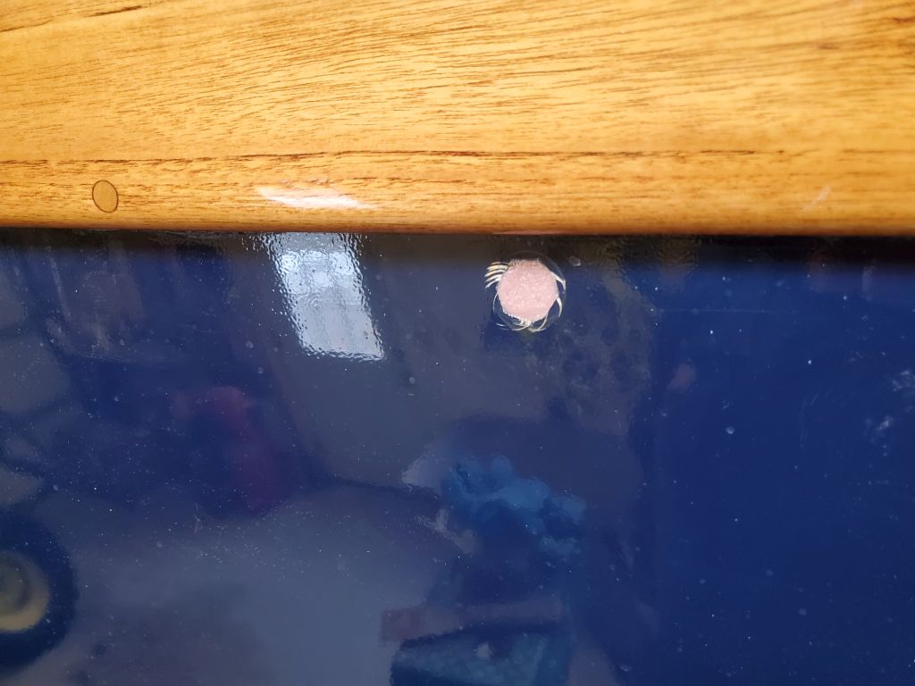
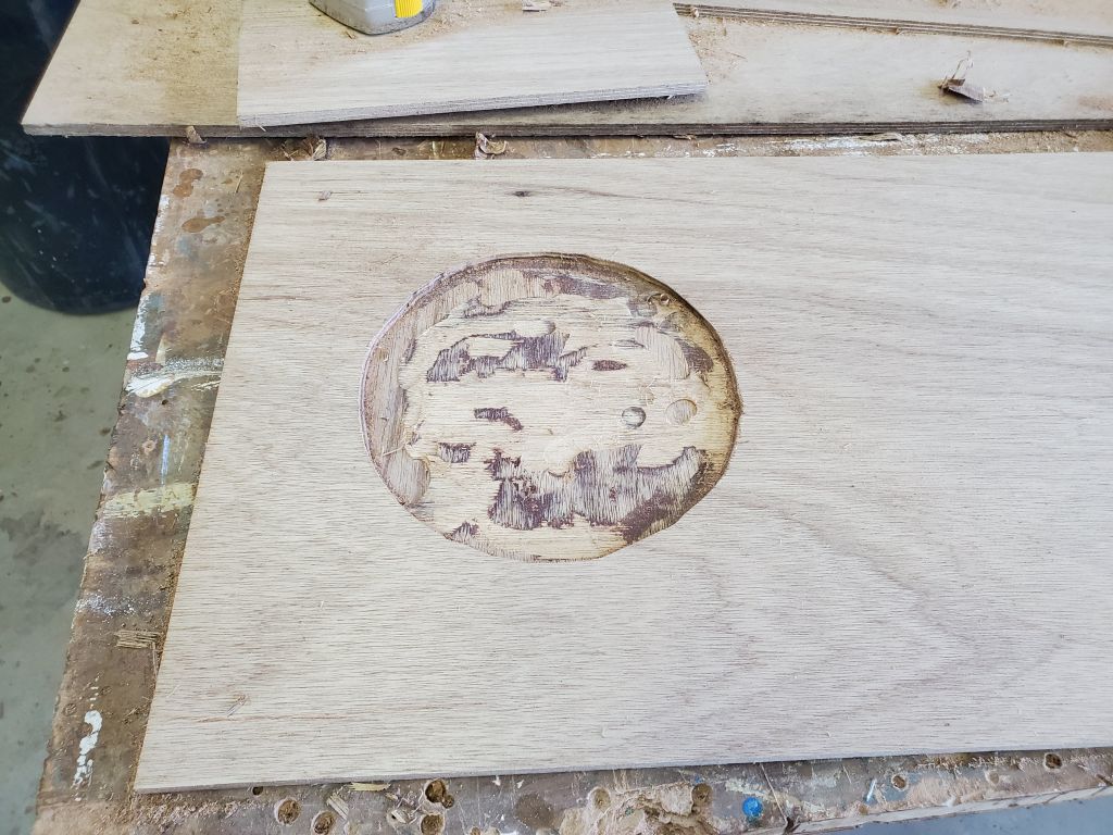
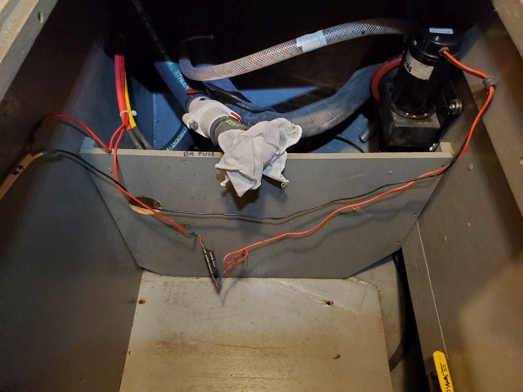
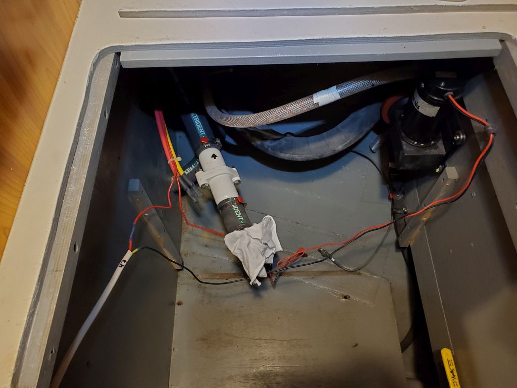
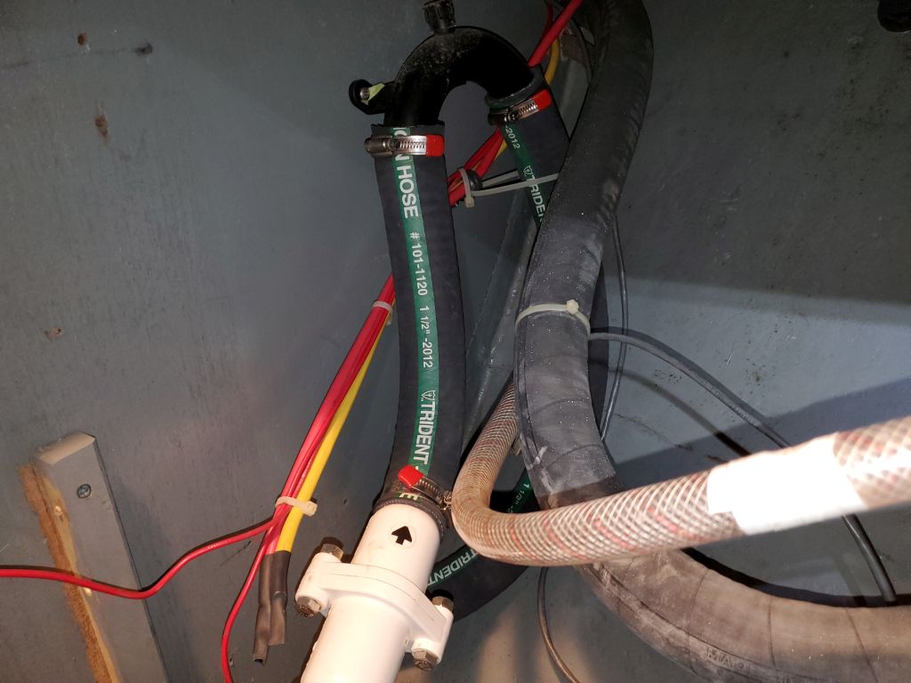
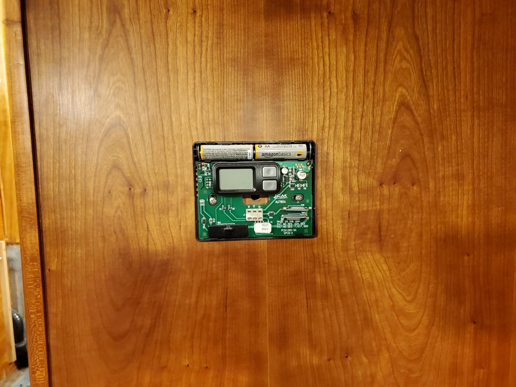
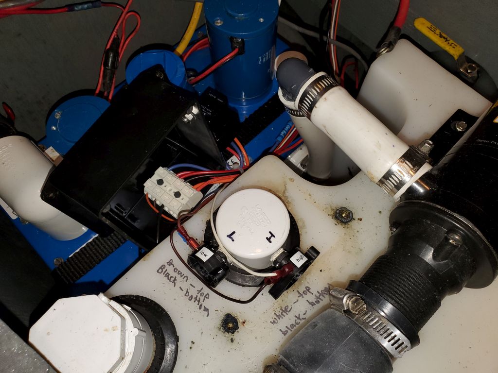
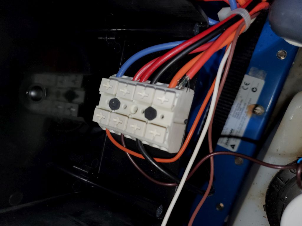
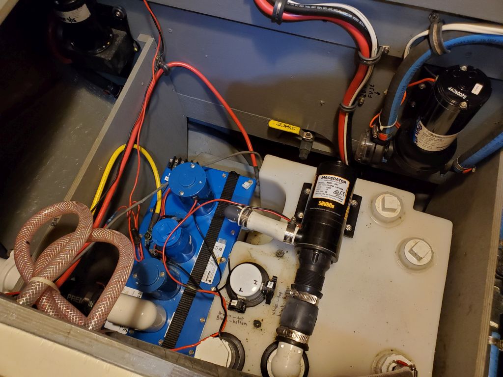
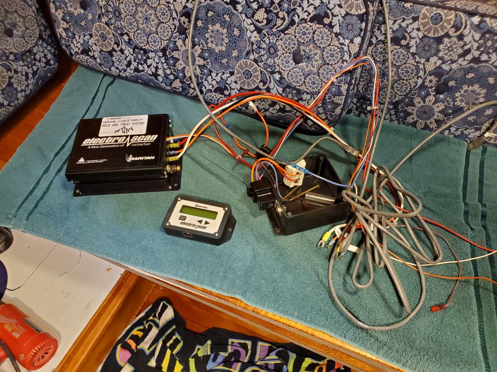
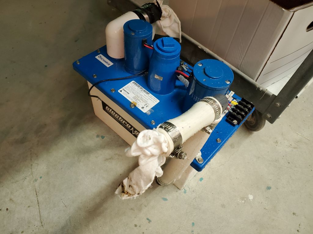
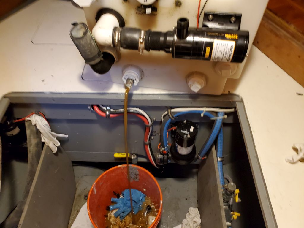
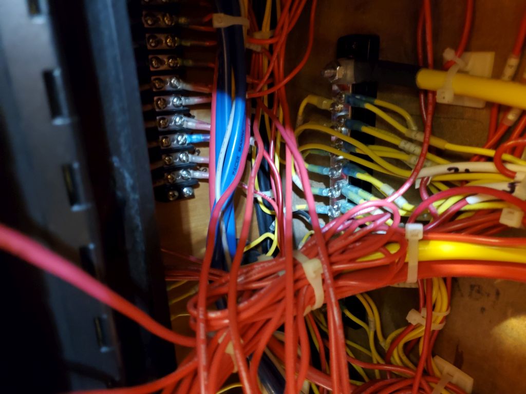
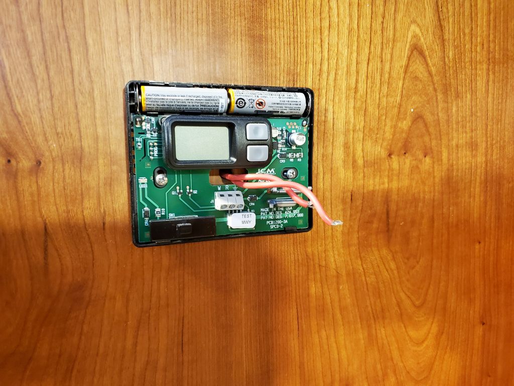
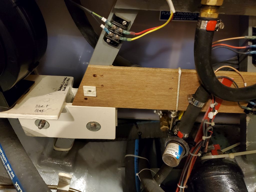
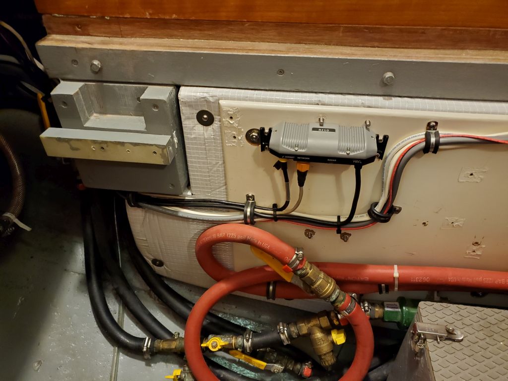
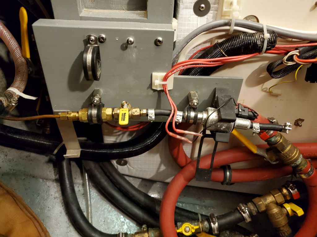
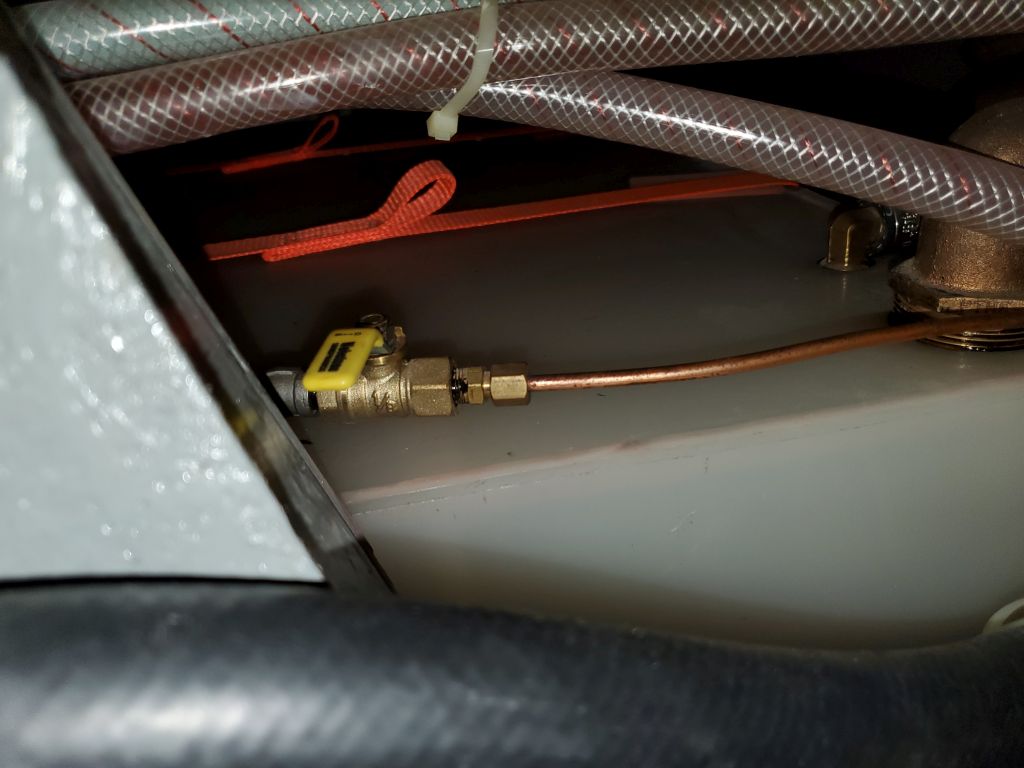
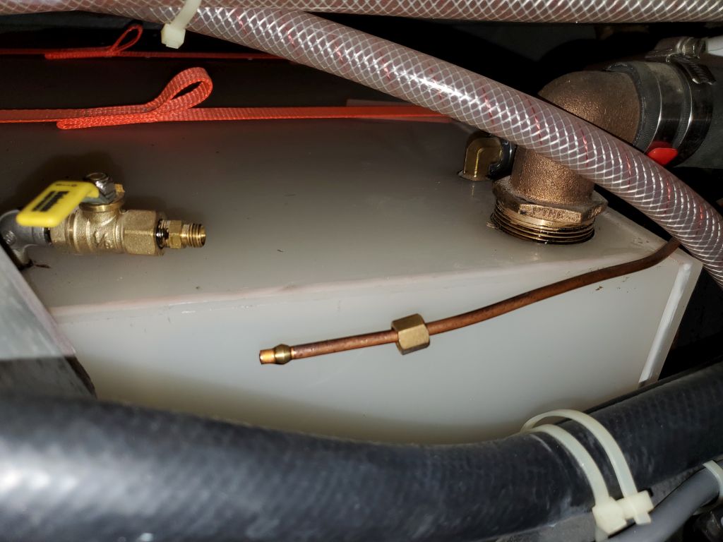
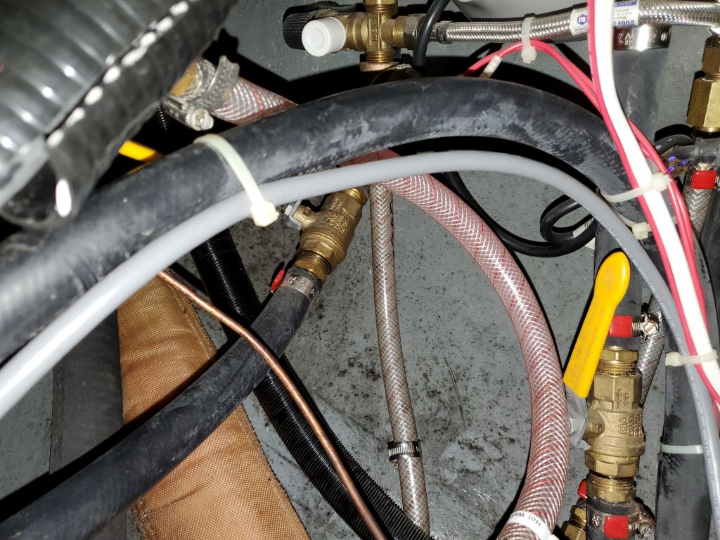
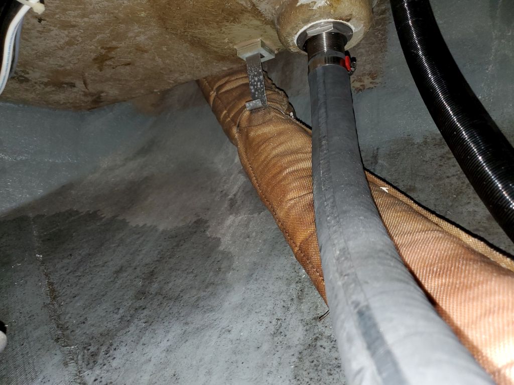
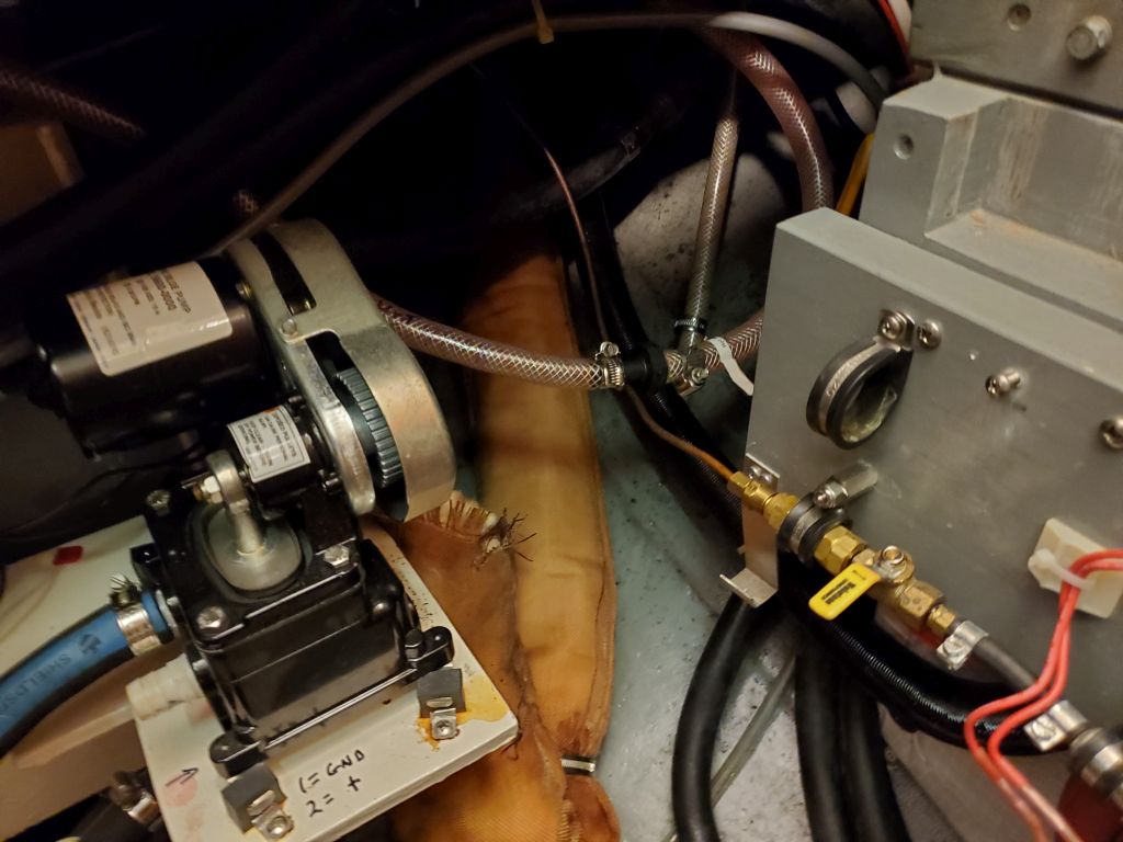
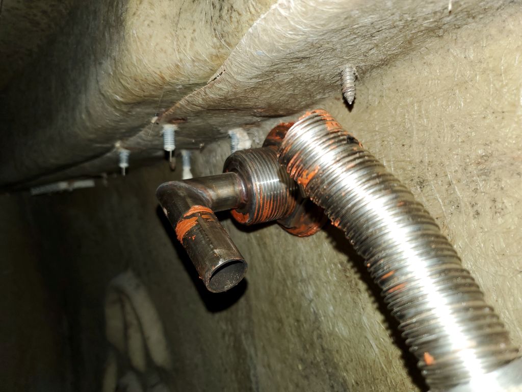
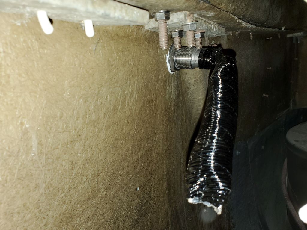
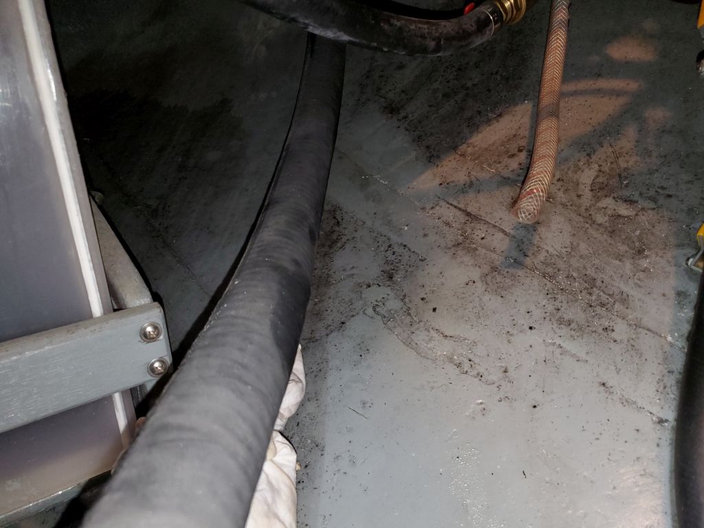
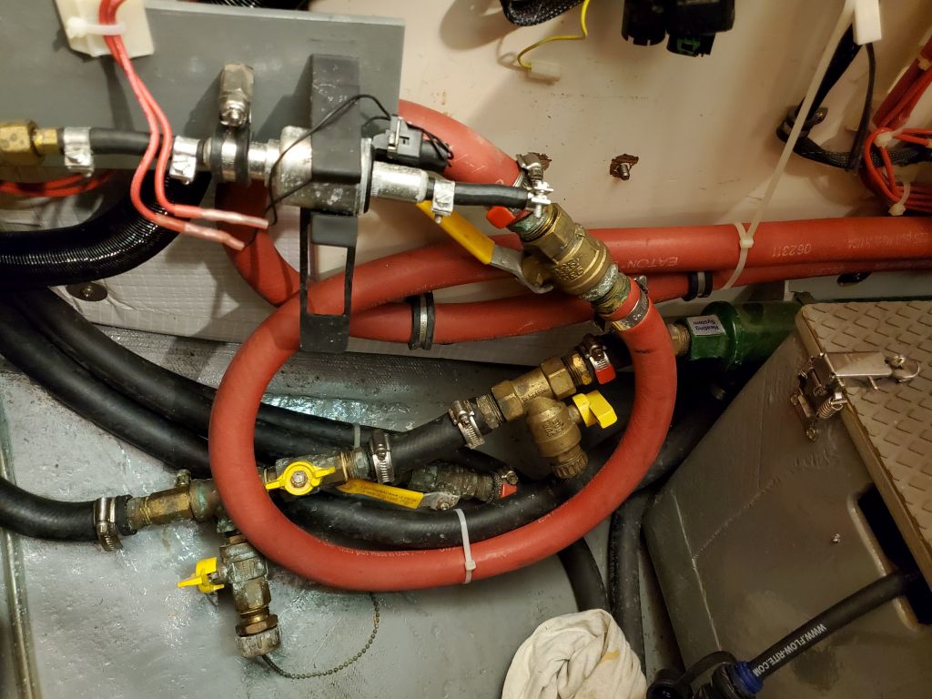
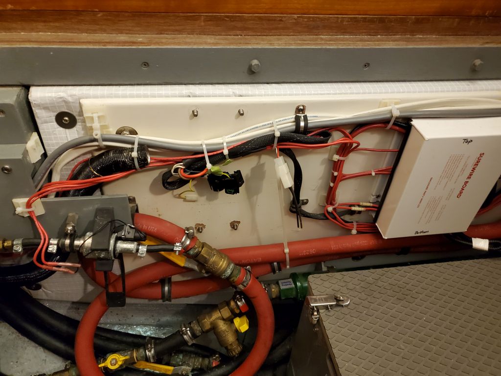
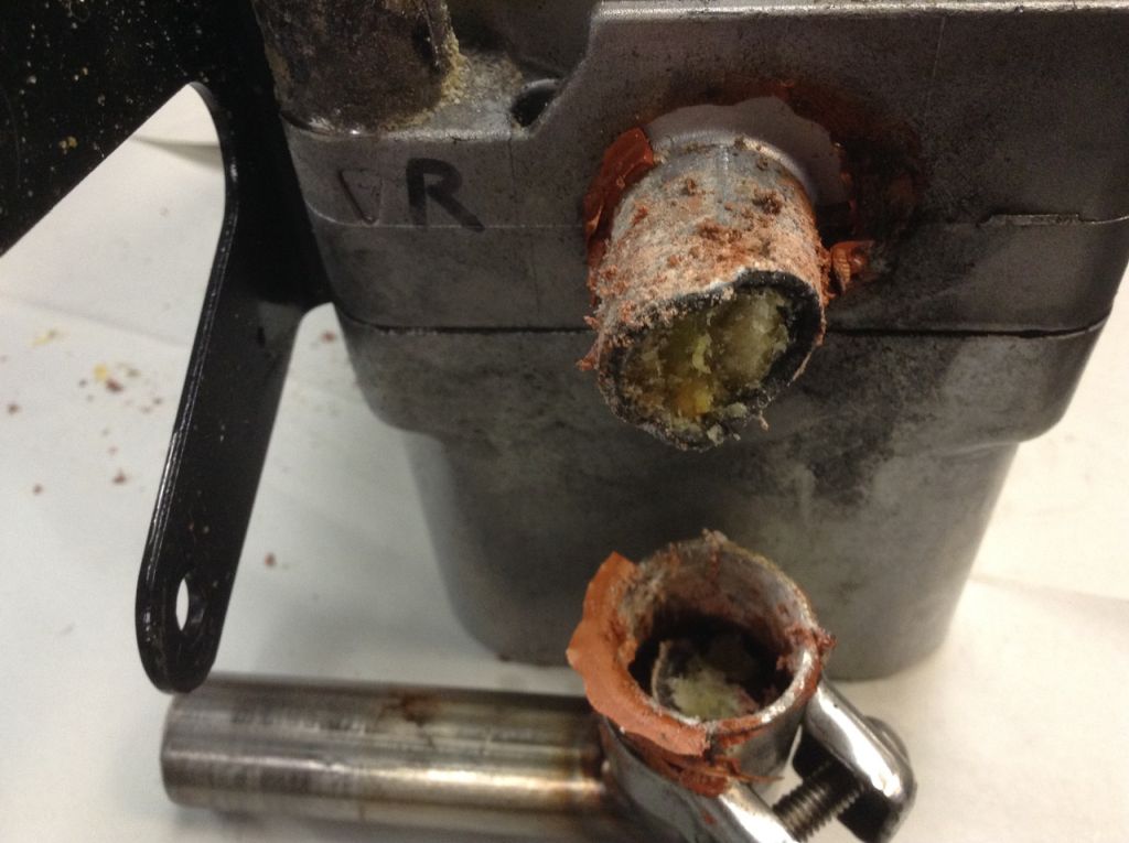
There, the technicians opened the unit and discovered extensive corrosion and other terrible damage: The white pasty material in these photos is what forms from corroded aluminum.
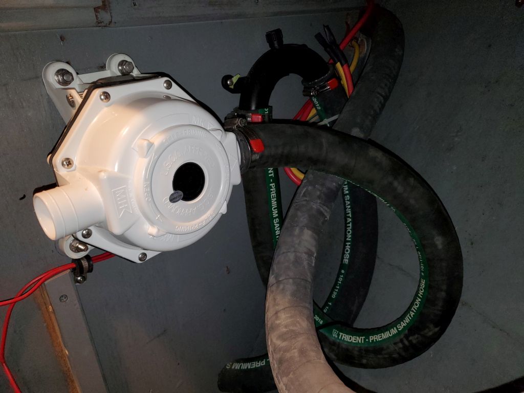
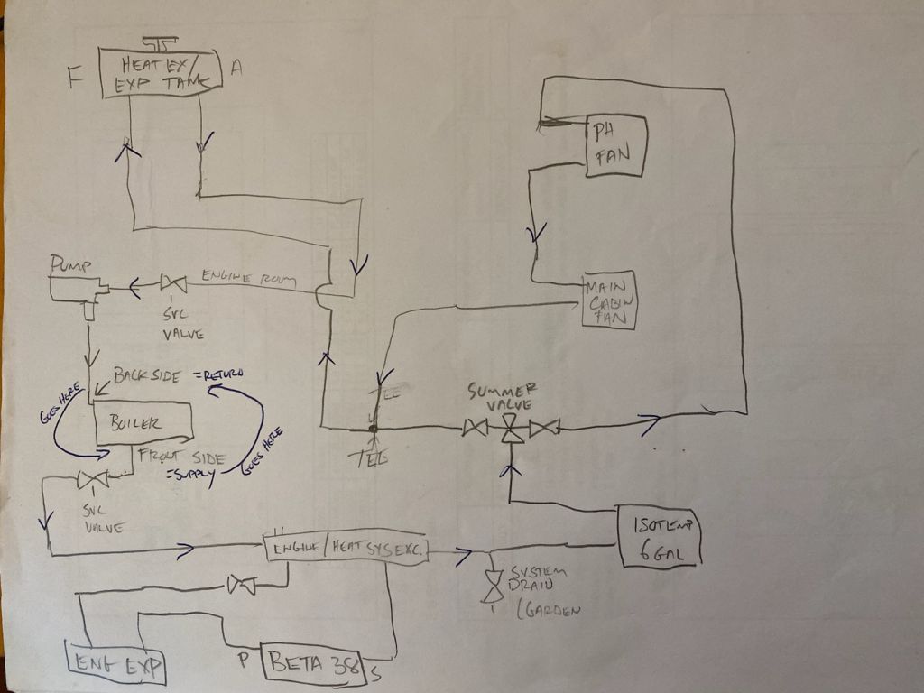
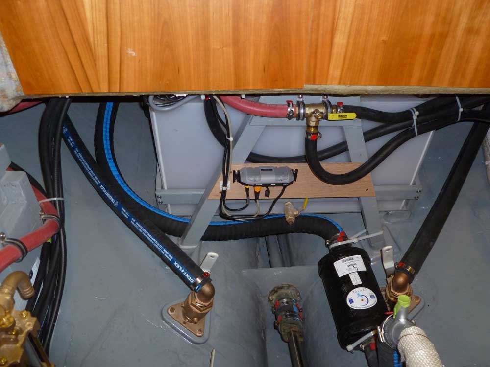
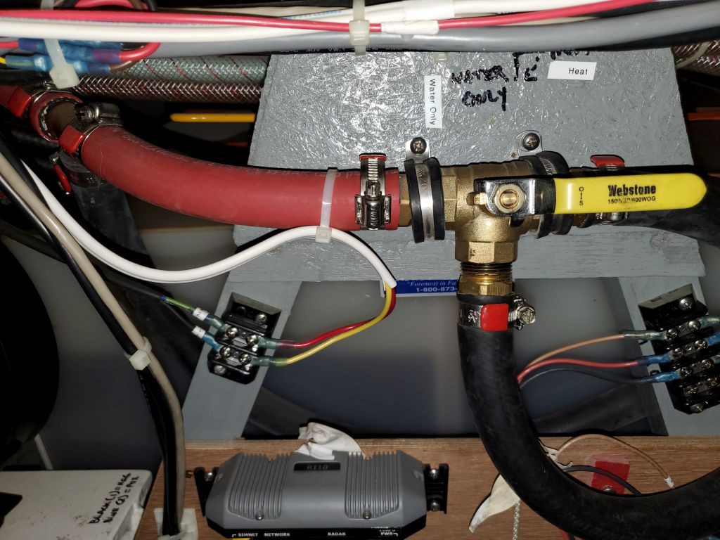
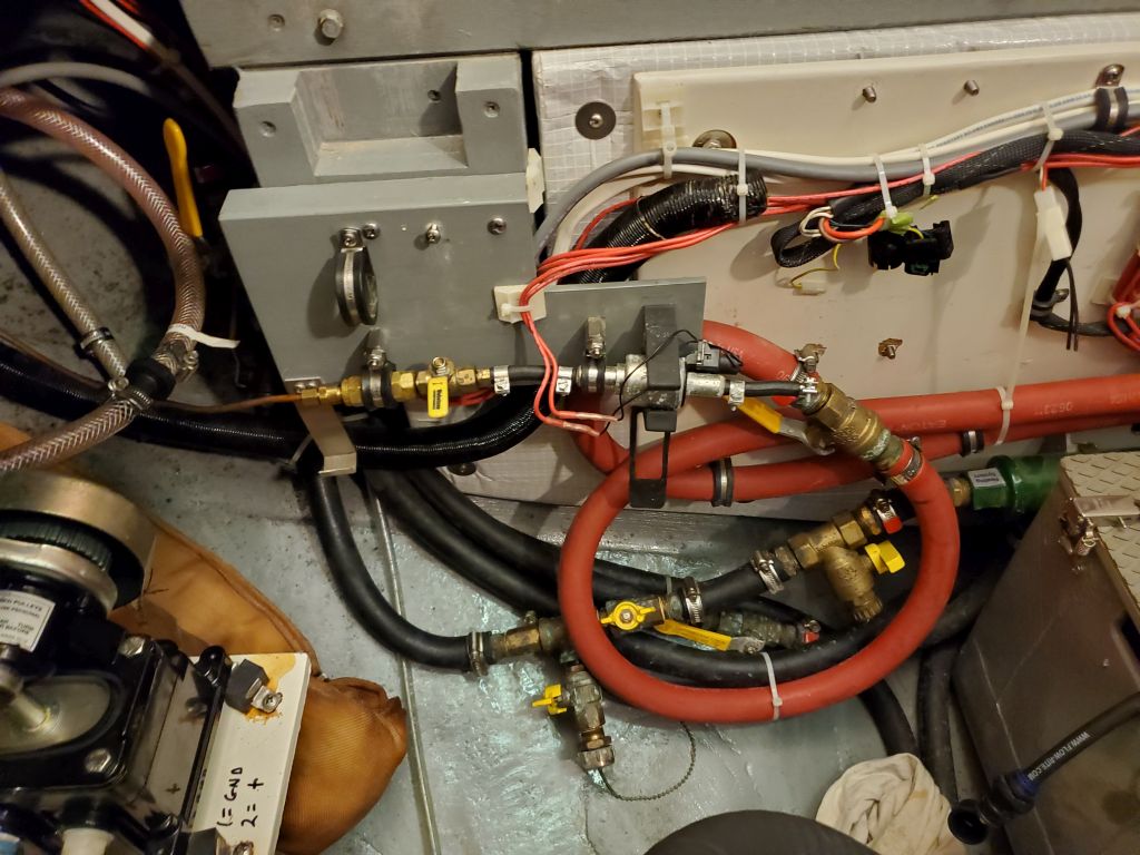
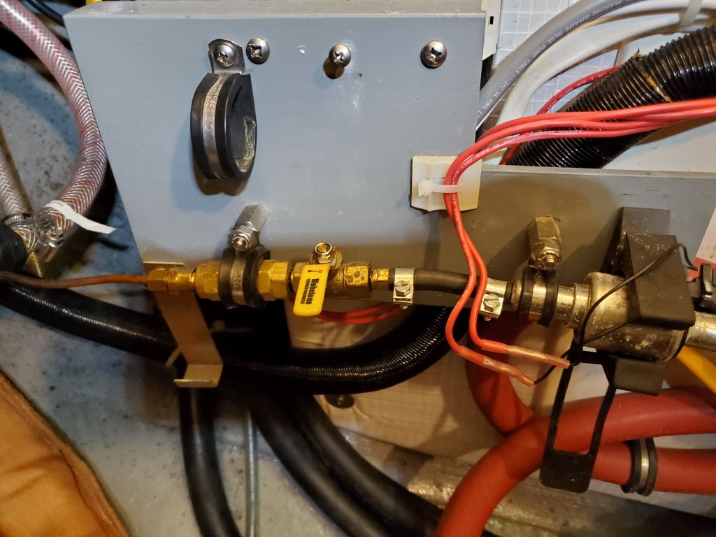
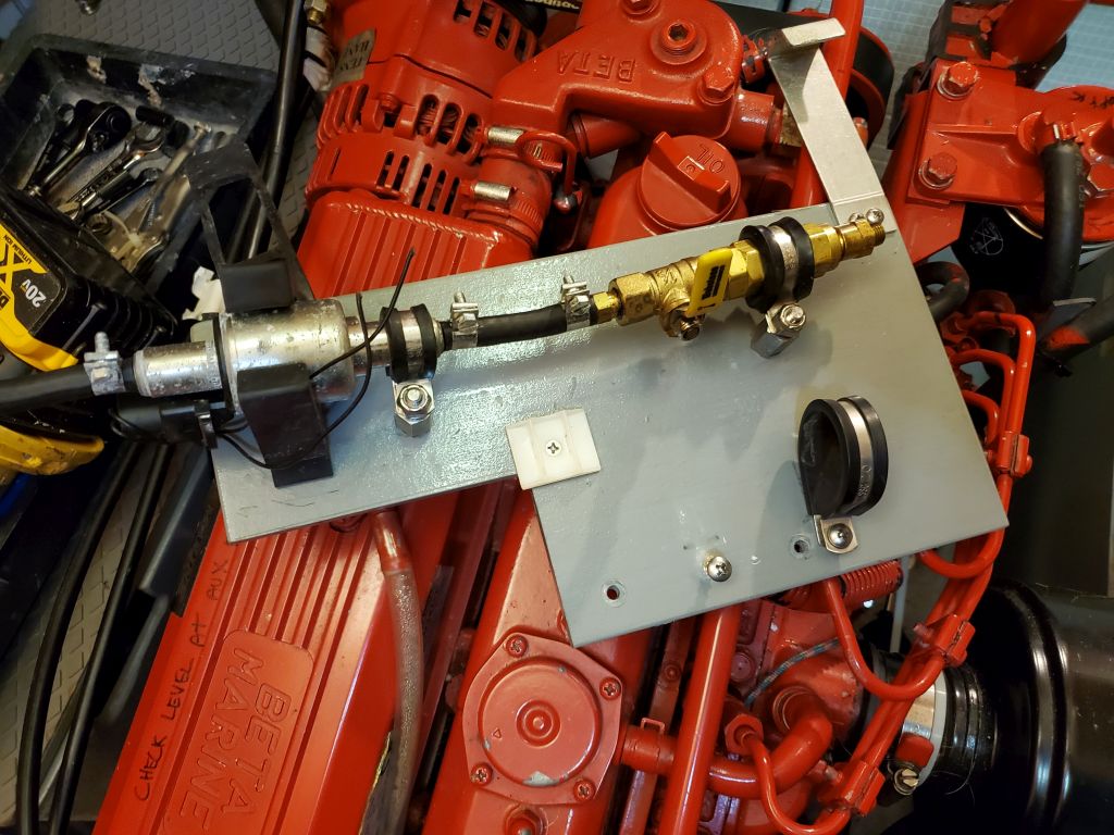
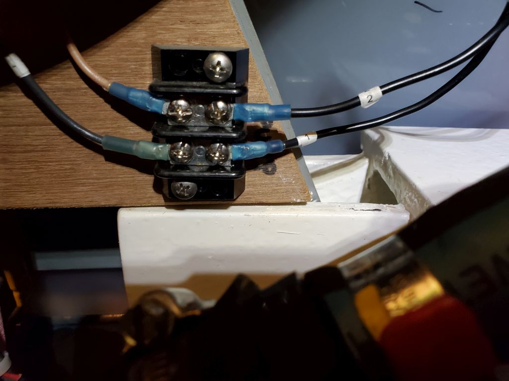
This was obviously beyond repair, and diagnostics for the problem varied between the pH level in the coolant level being wrong to galvanic problems related to dissimilar metals and marine air. Whatever the cause, it was clearly a devastating and disappointing development, but rather than attempt to install another, expensive boiler, the owner decided he preferred a simpler approach anyway. As part of the work ahead for me in the shop this winter, the owner requested that I replumb parts of the existing heating system to simplify and to allow the engine coolant to heat the hot water and the circulation lines for the two heater fans in the boat. I’d get to that in due course.
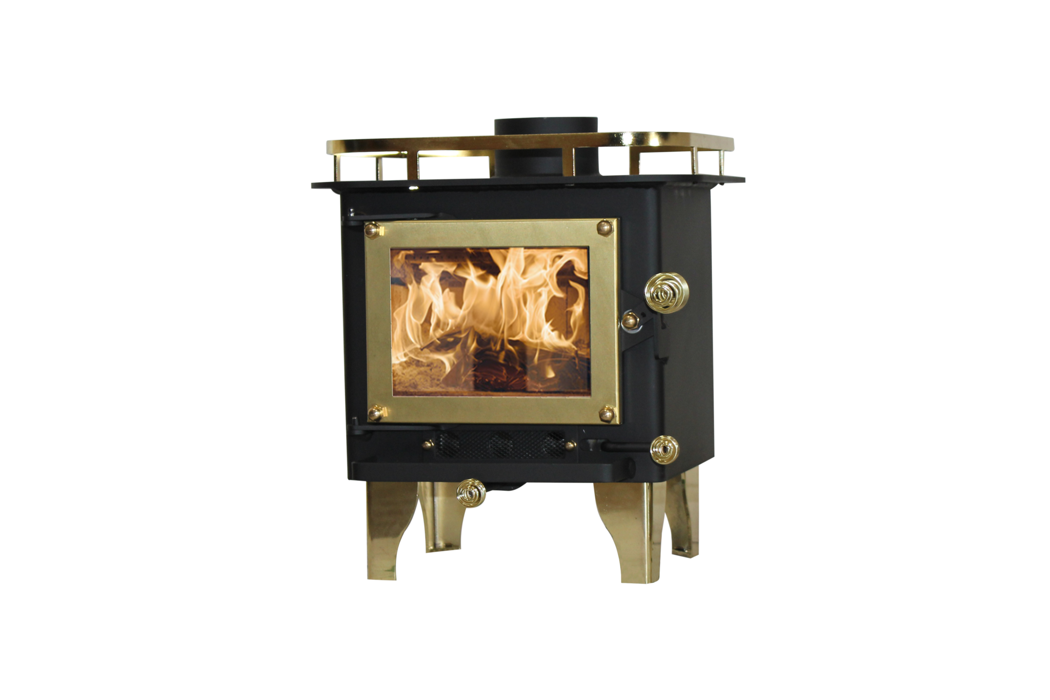
But for now my initial focus was on the other part of the new program to replace the heating system which, as requested by the owner, was possibly to install a small wood stove in the main cabin. The owner selected the Cubic Mini, a compact, well-rated stove, and to begin the process I spent a fair bit of time researching the unit and various installation options and requirements so that I could determine how, where–and if–the stove would work as the owner hoped.
Armed with useful information regarding the minimum clearances from combustible materials and nearby surfaces, I could start planning the potential installation.
- Minimum distance from the overhead: 30″
- Minimum side distance from combustible materials: 20″ as is; 3″ with a metal side shield
- Minimum safe distance to a bulkhead: 3″, which is easily accommodated by using the installation shield shown in the photos and diagrams above
- Minimum bottom clearance (below stove): 1″, also pre-incorporated into the design of the shielding above
- Minimum flue length: 40″
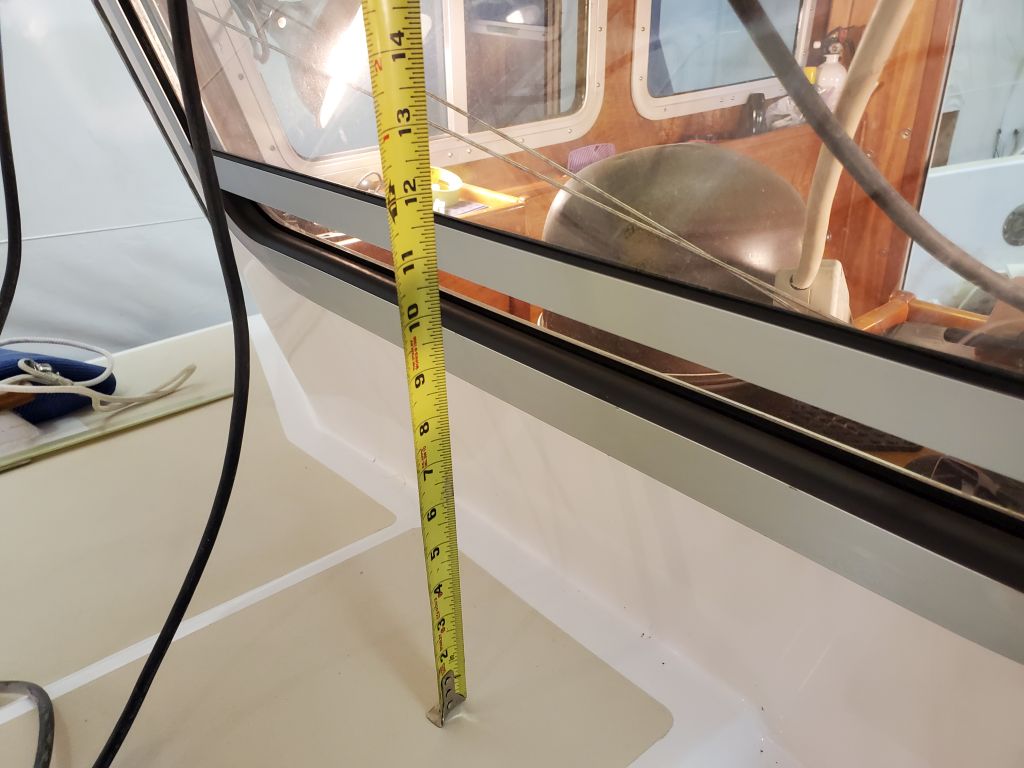
- Minimum height of pipe above deck: 12″
- The owner wanted enough space below the stove so that a person lying on the settee could fit their feet beneath the stove platform.
- Through-deck hole is 5″ diameter to accommodate the 3-1/4″ OD double-wall flue pipe, and should be lined with metal for additional combustion protection; however, fully insulated pipe was not required.
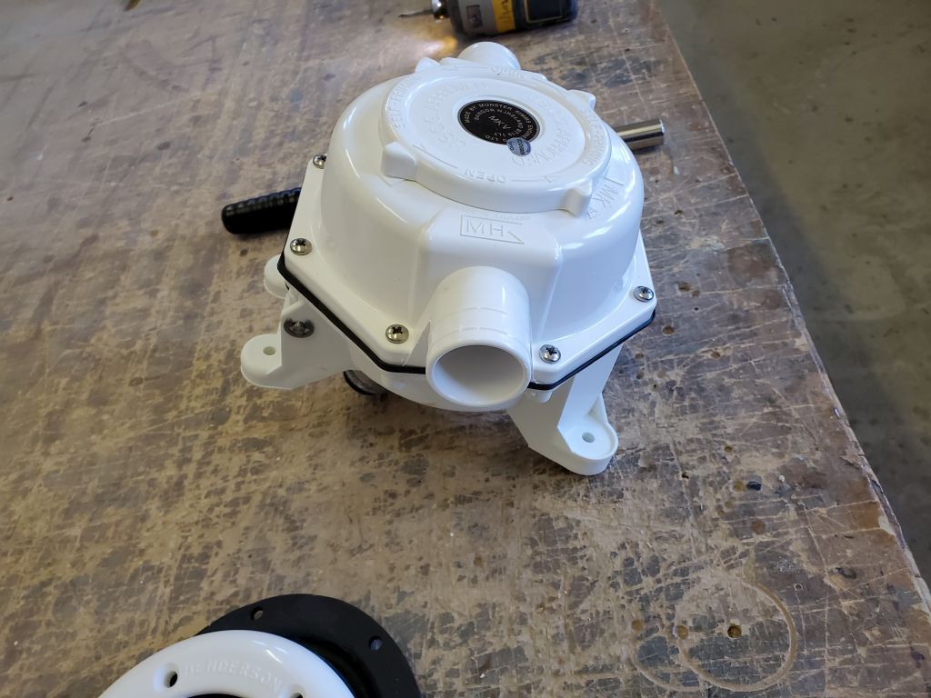
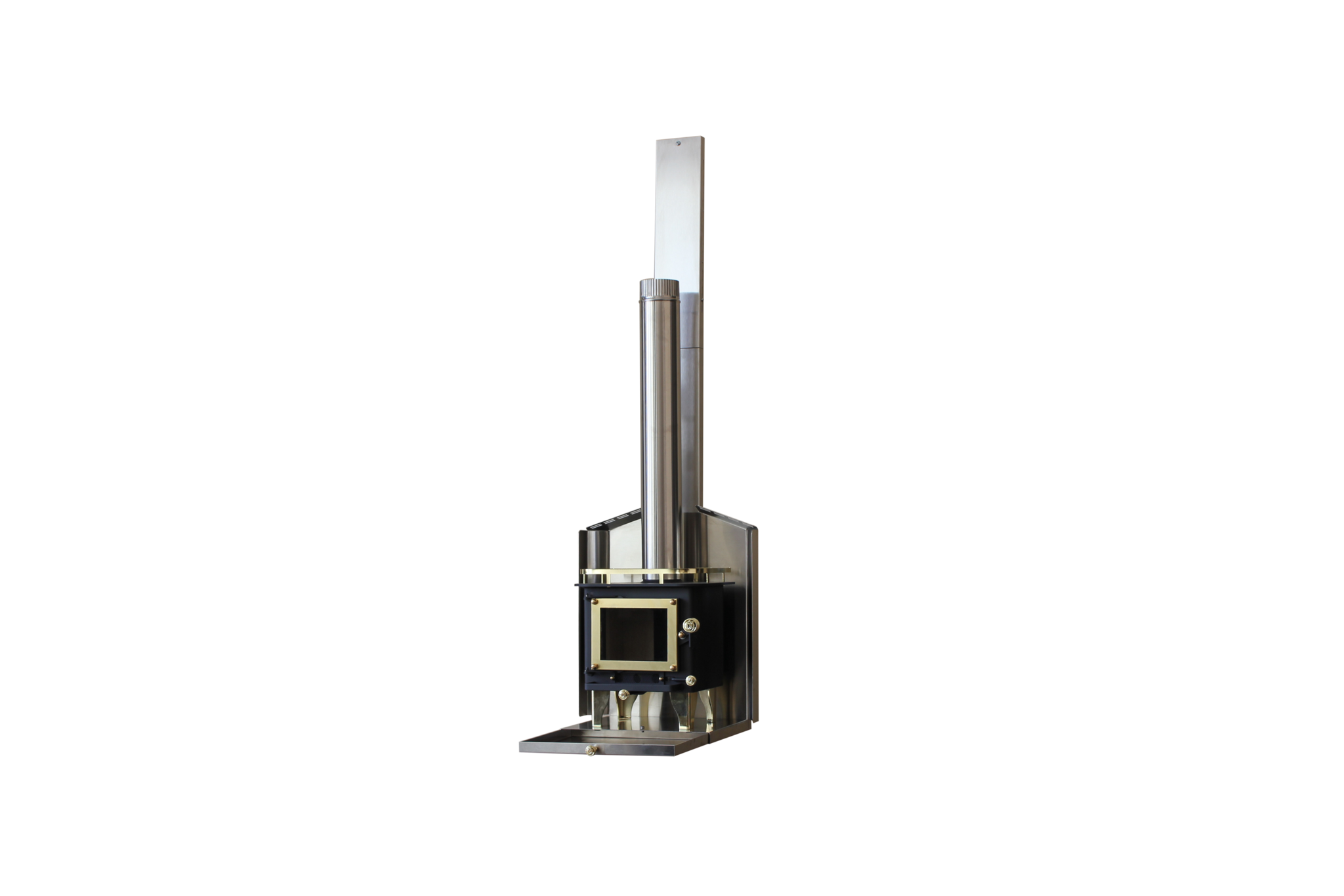
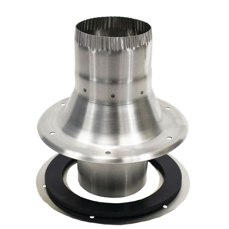
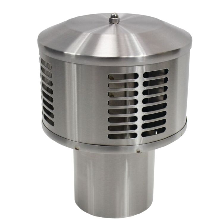
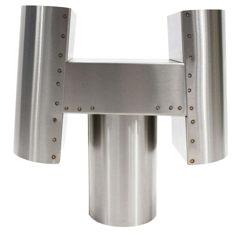
In addition to the stove and its related installation parts, for installation on a boat the flue required use of a Dickenson deck fitting and a couple different options for the Charley Noble.
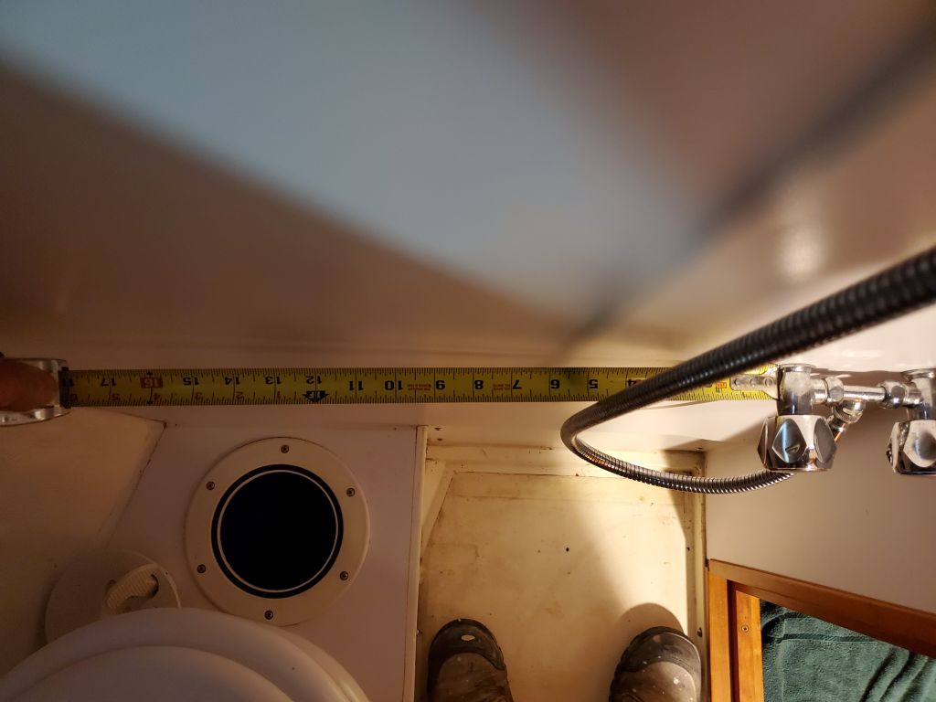
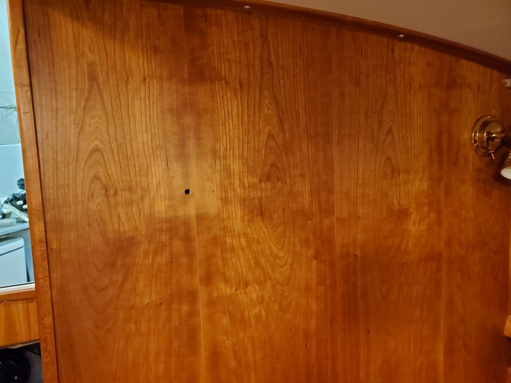
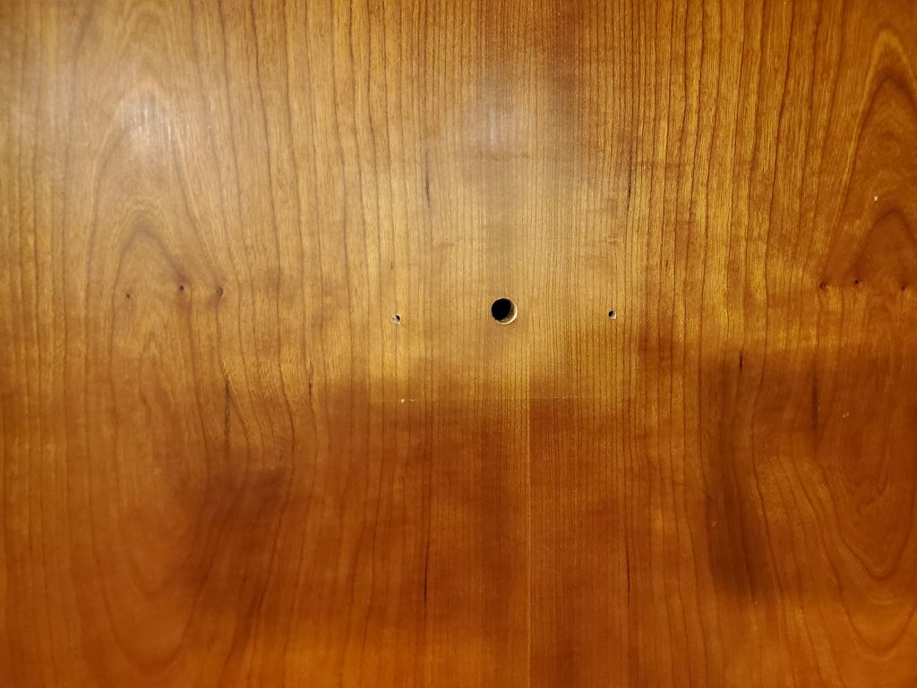
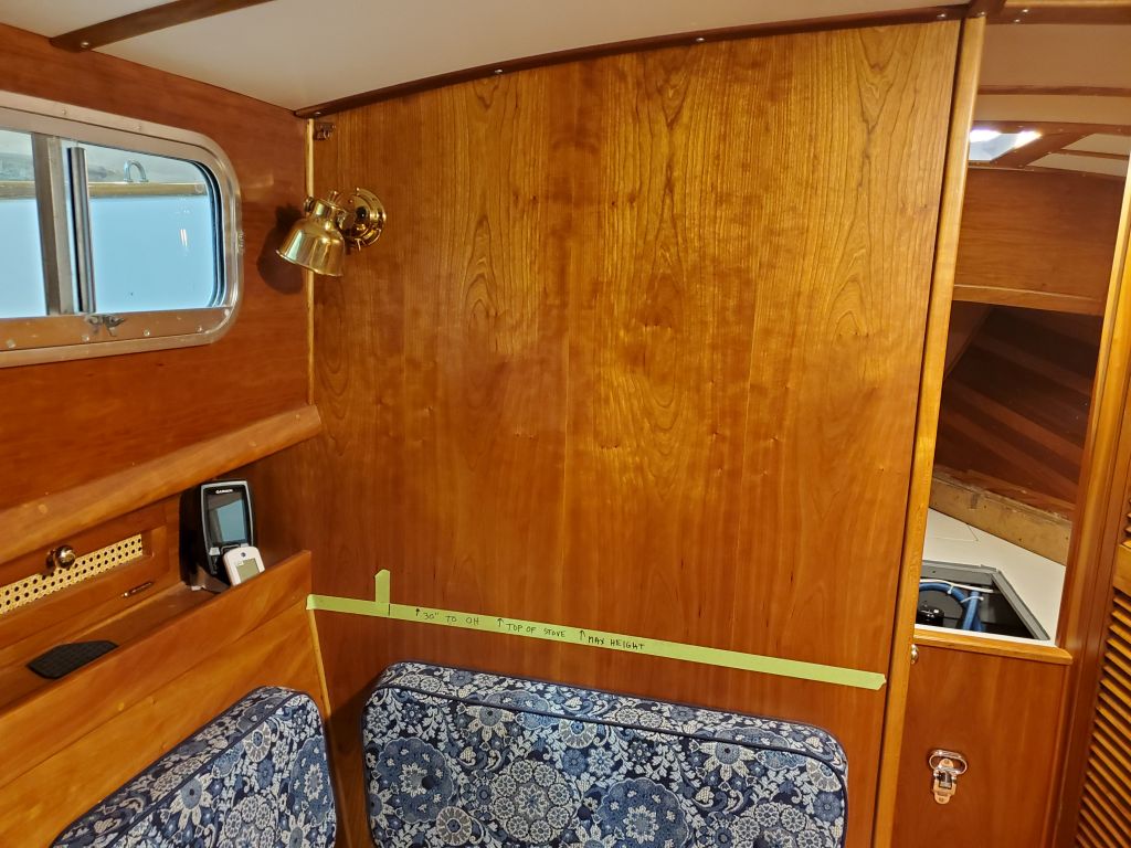
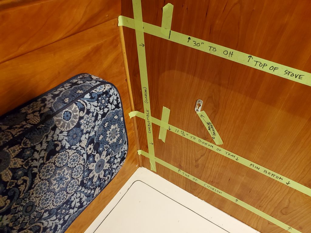
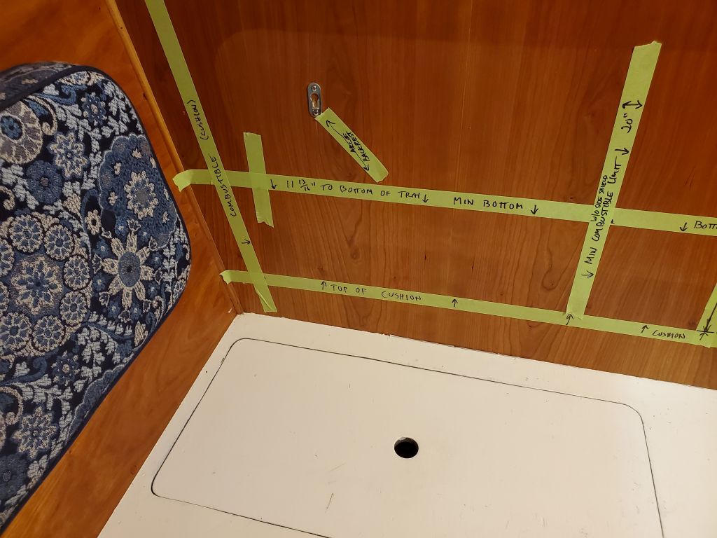
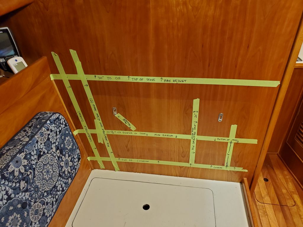
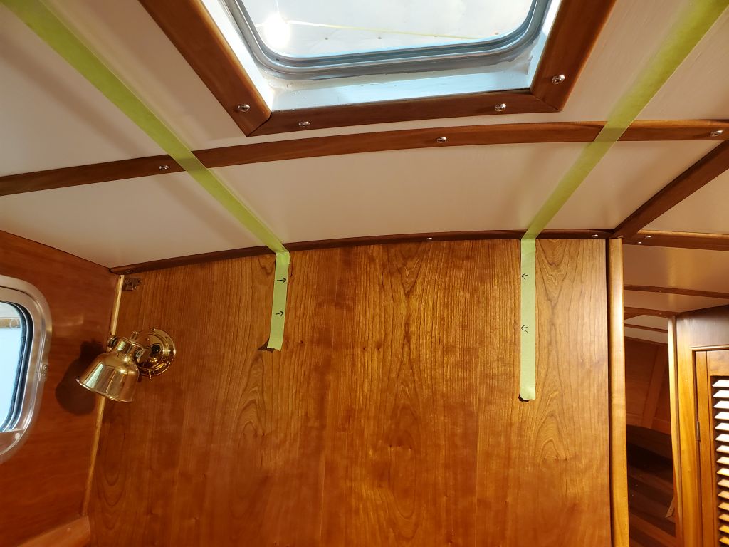
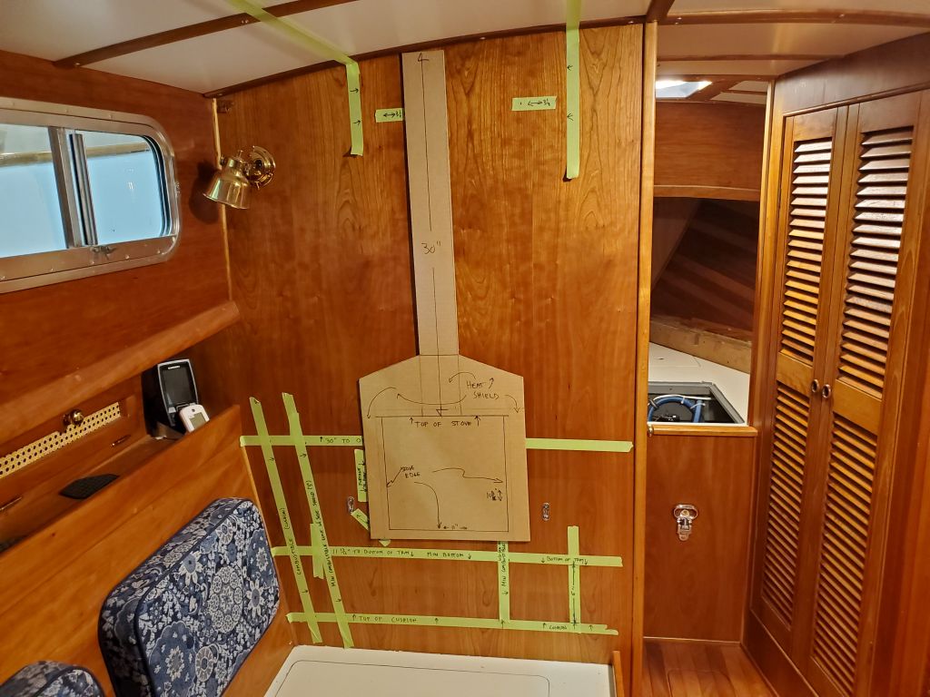
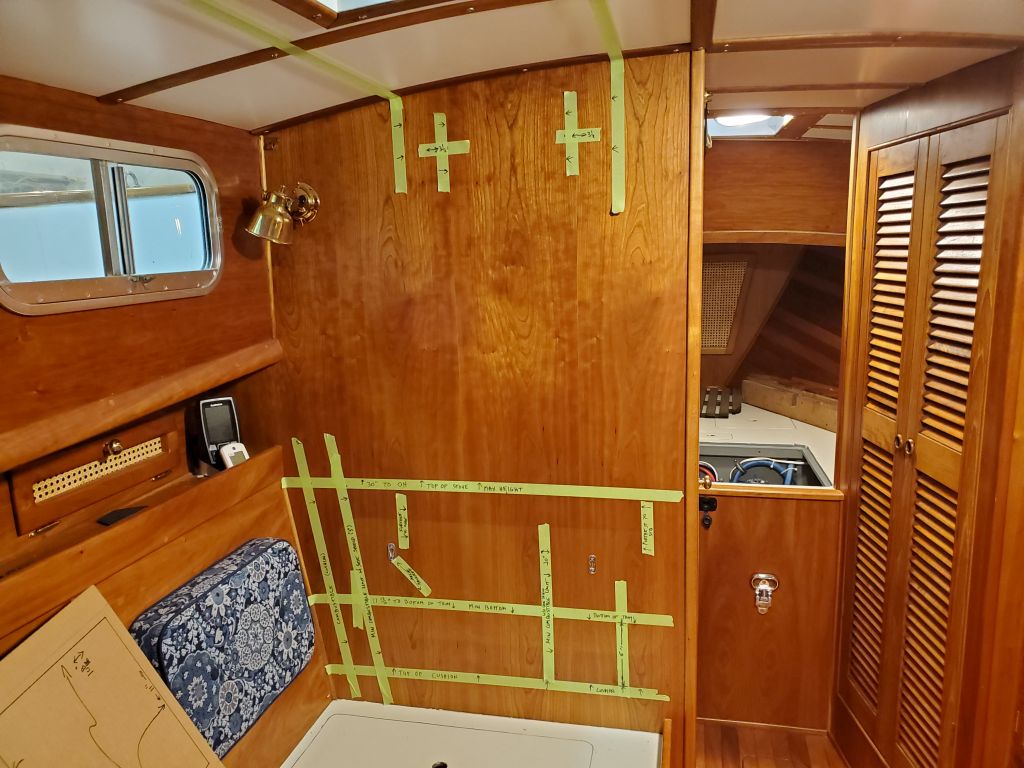
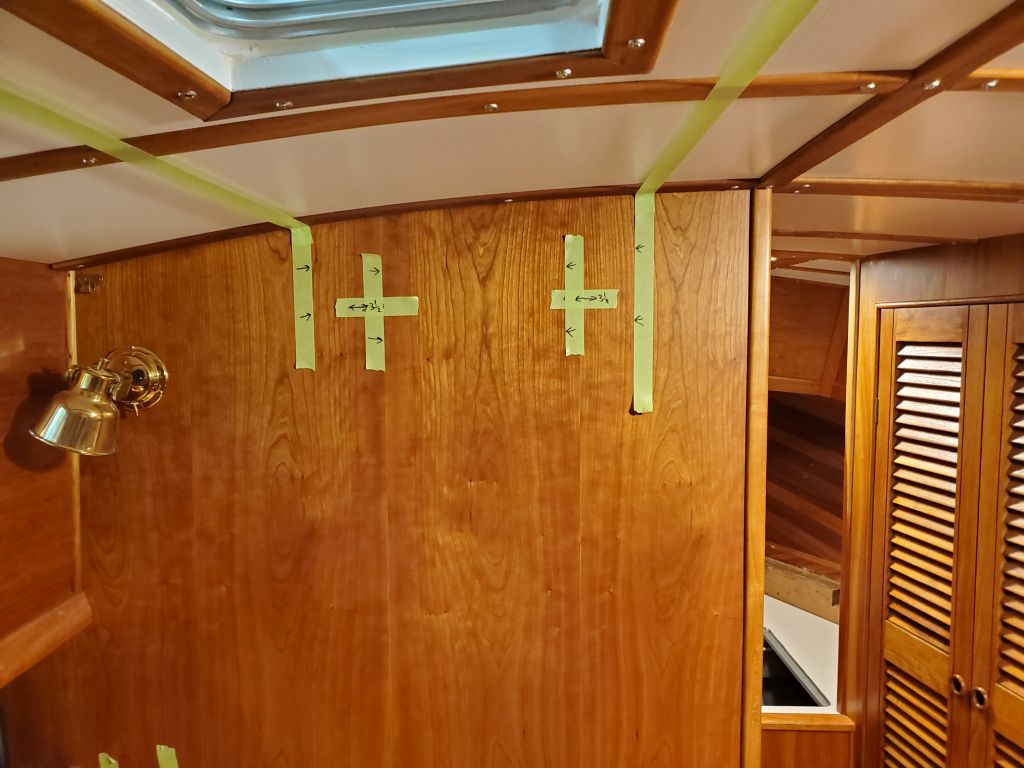
The location the owner envisioned, and frankly the only possible location on this boat, was the main bulkhead on the port side, at the forward end of the dinette. Using the basic measurements listed above, and taking into account the required minimum clearances, I laid out the various installation measurements on the bulkhead, using green tape and a marker as needed.
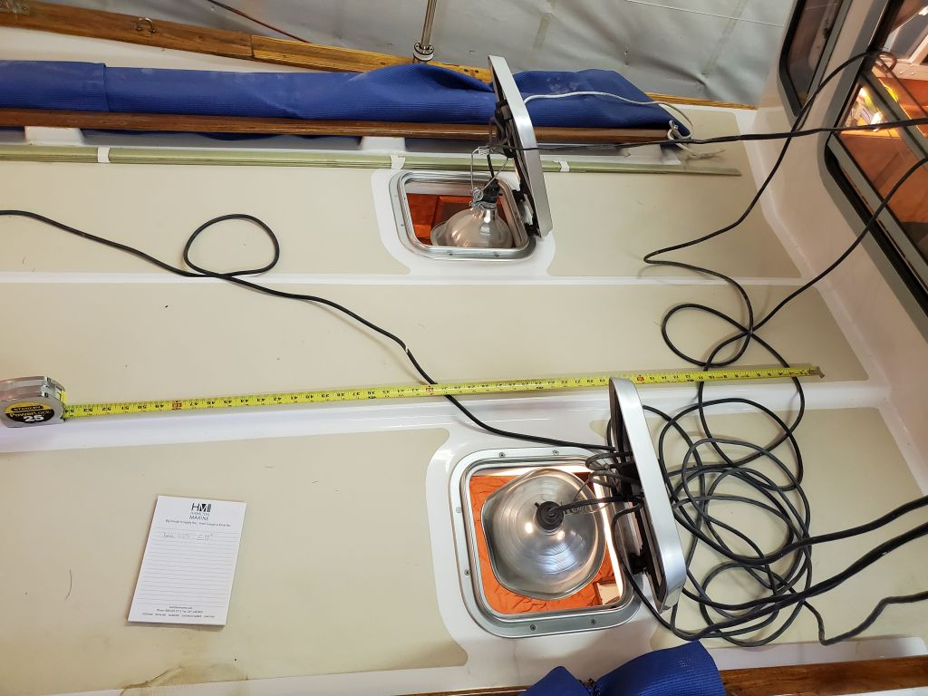
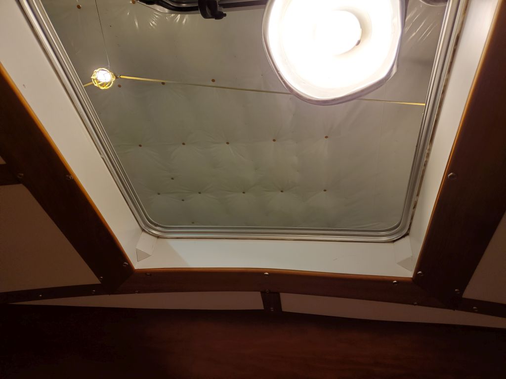
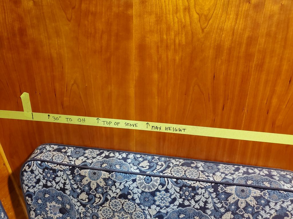
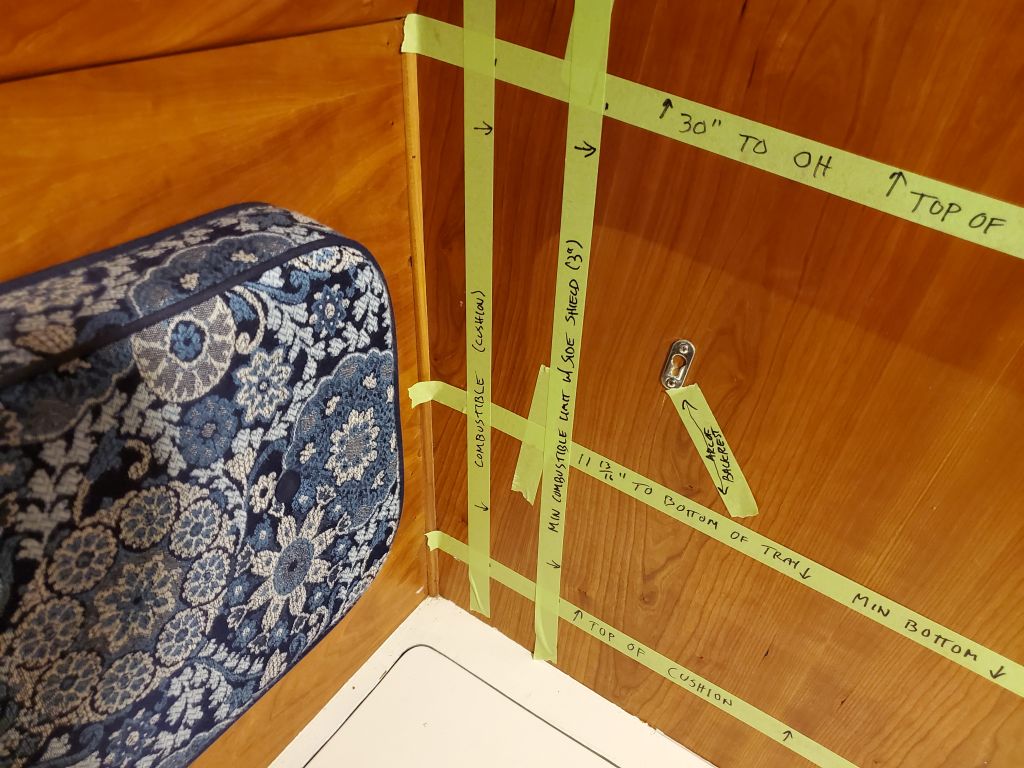
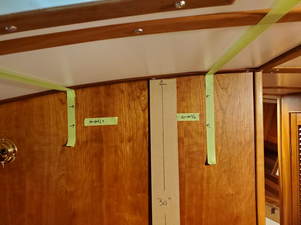
First: The minimum height of the top of the stove (i.e. the required 30″ from the overhead). For this initial line, I chose the practical low point of the overhead above–just inboard of the light fixture on the bulkhead–since the overhead featured a camber and was thus lower further outboard than towards the centerline.
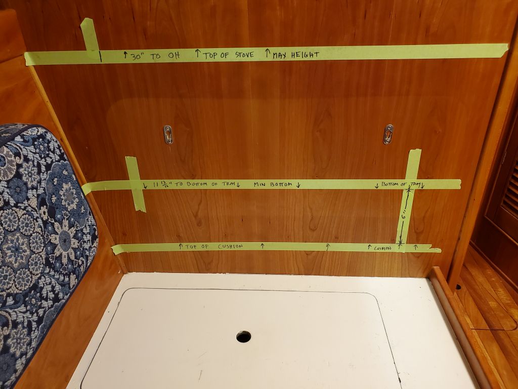
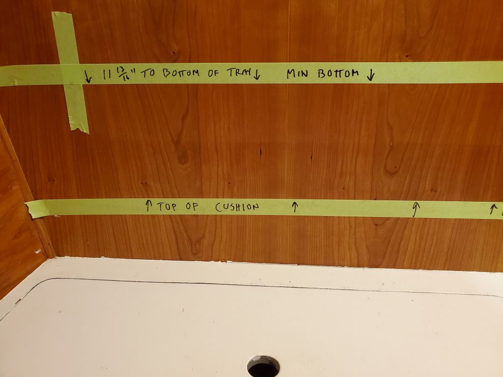
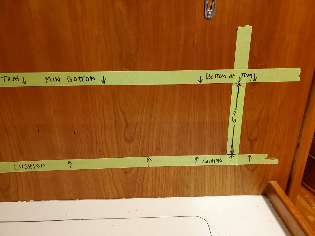
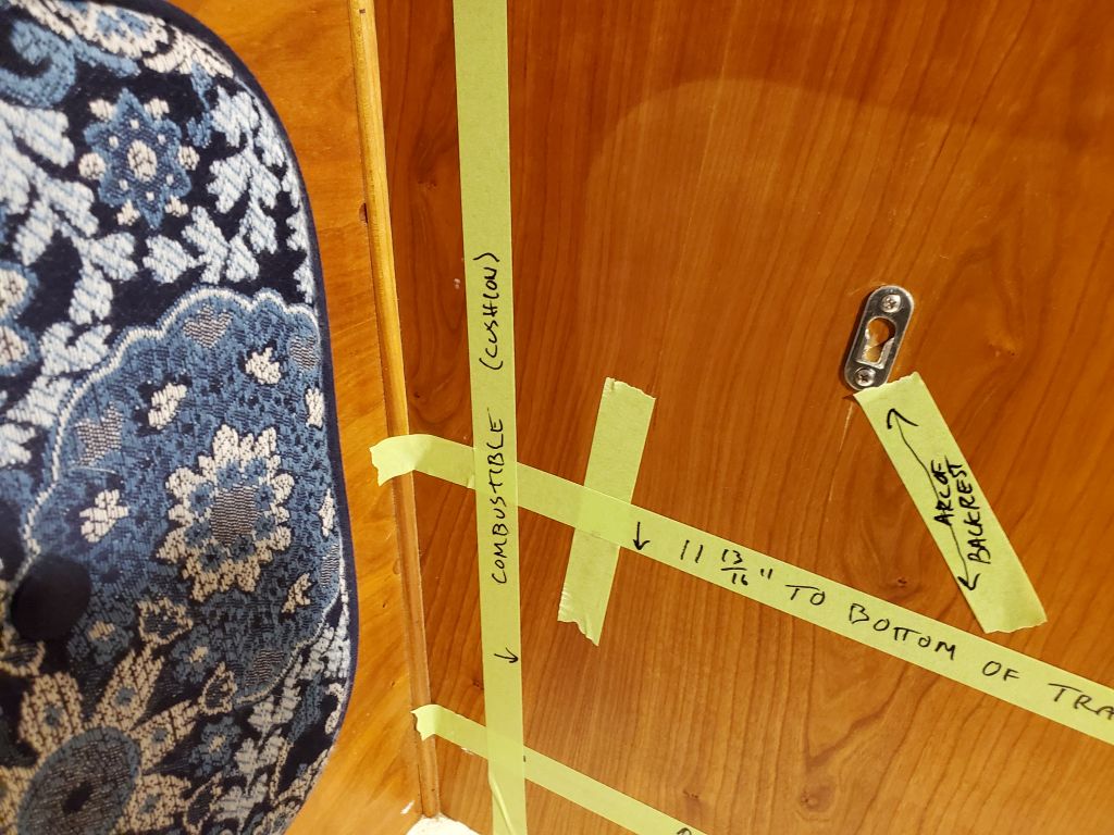
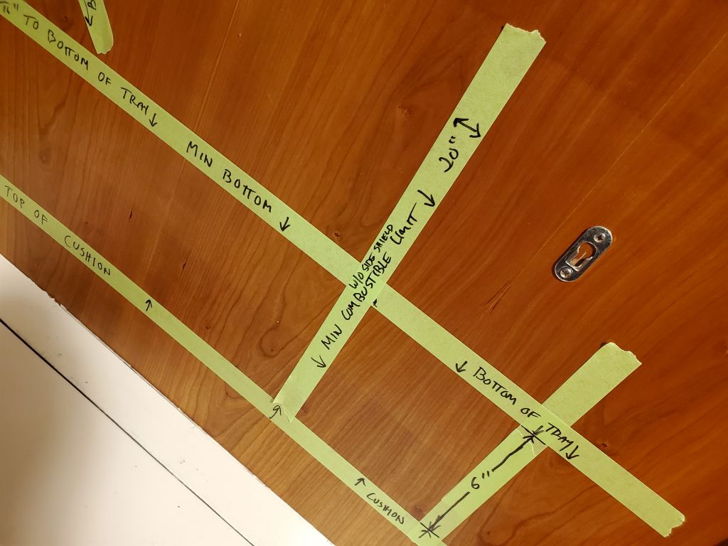
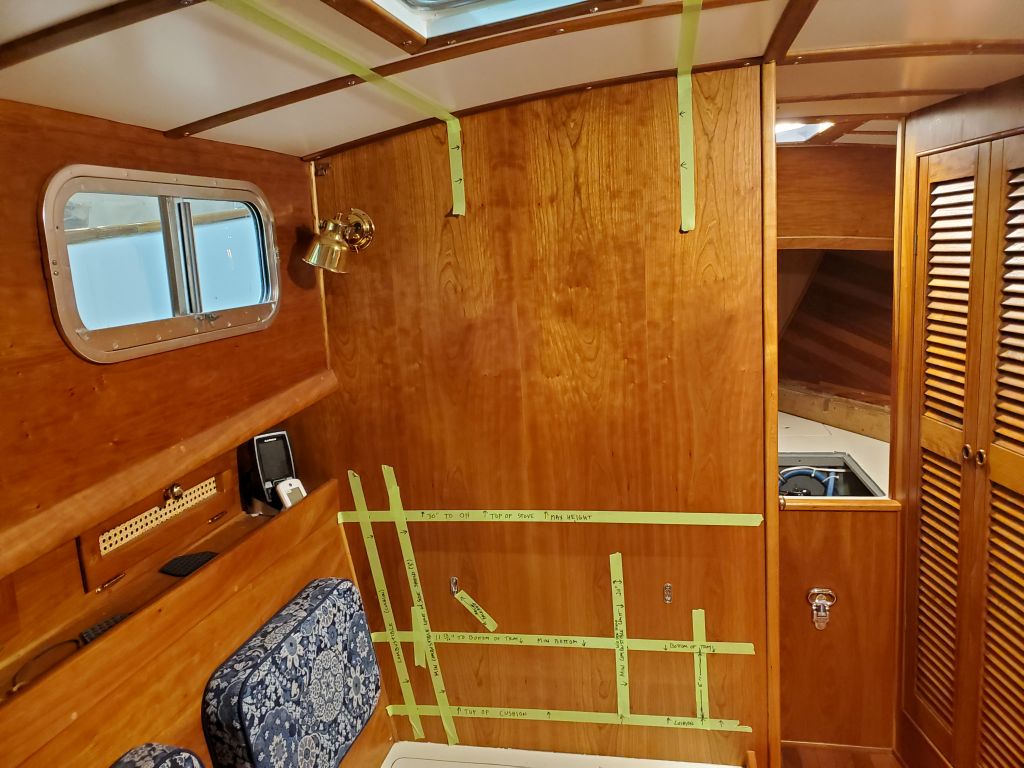
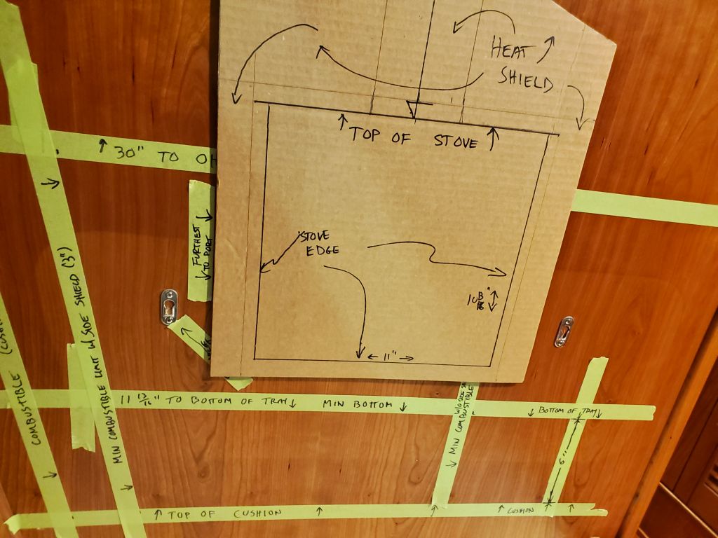
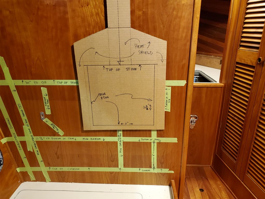
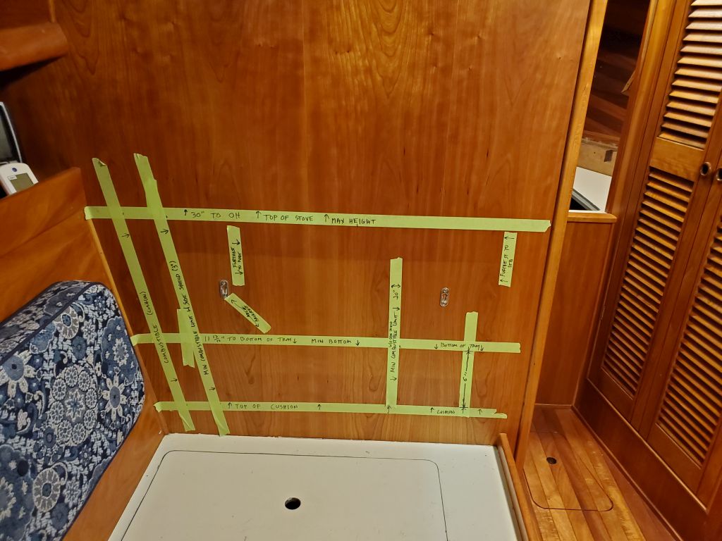
Clearly, any installation here was going to require that the existing backrest cushion be removed permanently, so I removed it now and continued with the initial layout measurements. Here, I’ve marked the overall height of the stove and its base platform, measuring down 11-13/16″ from the first line. This represented the lowest possible installation of the stove and its installation shielding based on the worst-case 30″ overhead clearance scenario I started with.
I also marked the top of the 4″ settee cushion, and measured between that and the bottom of the installation tray, which turned out to be 6″.
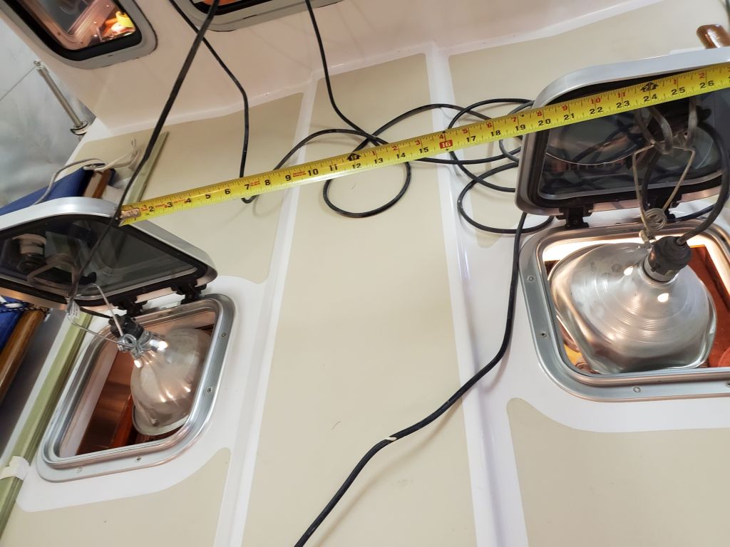
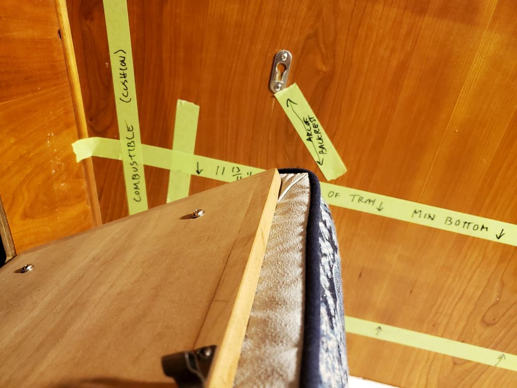
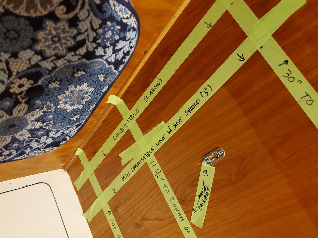
Next, I determined the nearest combustible material to the side, which in this case was the cushioned backrest/locker door located adjacent to the main bulkhead. I used tape to make a mark on the main bulkhead to represent this. Then, to ensure that the hinged backrest would ultimately clear the stove when installed, I made a mark roughly approximating the arc of the door’s operation, since the backrest was only a few inches aft of the bulkhead, and with a 10-9/16″ projection from the bulkhead, the stove would need to be located appropriately.
It was already pretty clear that the stove would require a side shield on the outboard side, but to be sure I measured 20″ from the point of closest combustible (the cushion in its closed position) and marked this accordingly. Then, I marked the 3″ distance that the side shield would allow, if installed. As expected the 20″ unshielded clearance requirement pushed the stove too far inboard on the bulkhead to fit, so the side shield would be required no matter where the stove was mounted.
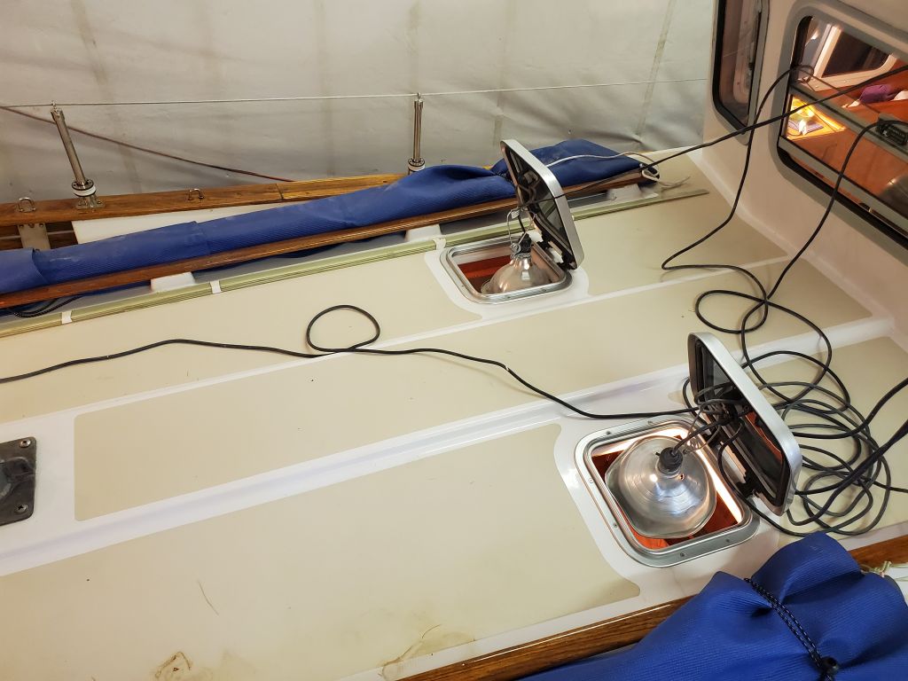
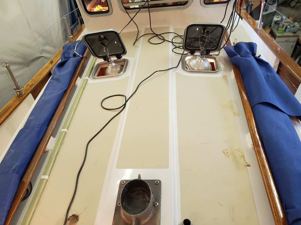
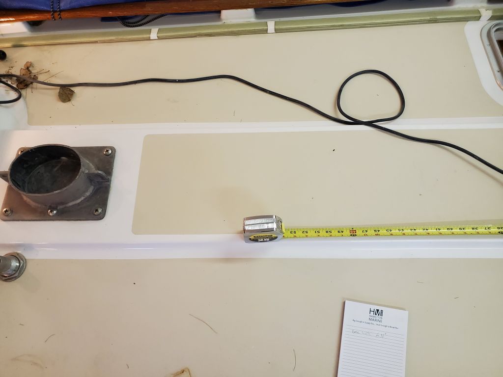
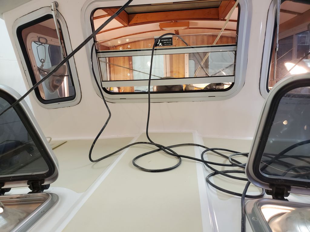
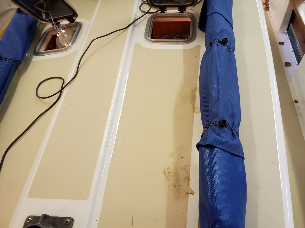
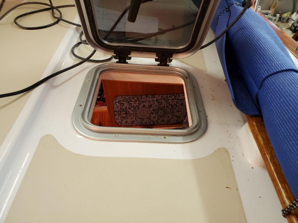
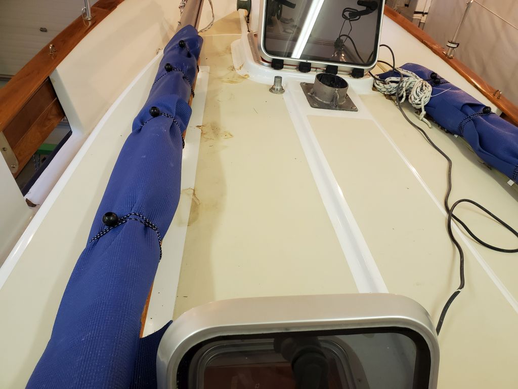
The next consideration was on deck itself: Wherever the stove was mounted, its exhaust pipe needed to extend straight up (elbows were strongly discouraged by the stove manufacturer, though some installations apparently did use them), and there were limitations on deck as to where the deck fitting could be installed. On this boat, there was a handrail with molded bases to port, and a raised section of deck along the centerline, both of which served to confine the practical mounting possibilities for the deck fitting and smoke pipe to a fairly narrow band, more or less in line with the 12″ deck hatch seen here.
Here, I saw no beneficial reason to force the stove outside these limits, since the downside of using any bends in the flue pipe more than outweighed any benefit for the potential stove location anyway (given its already strident limitations), so I planned to limit installation options to those places where the flue could remain straight.
Back in the cabin, I laid out the rough limits for the deck fitting on the overhead, and slightly down the bulkhead.
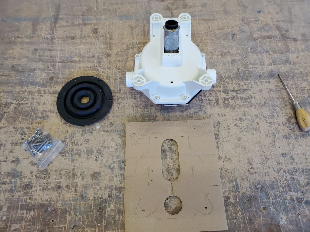
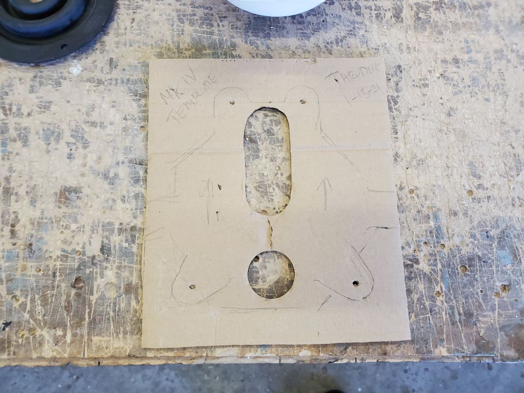
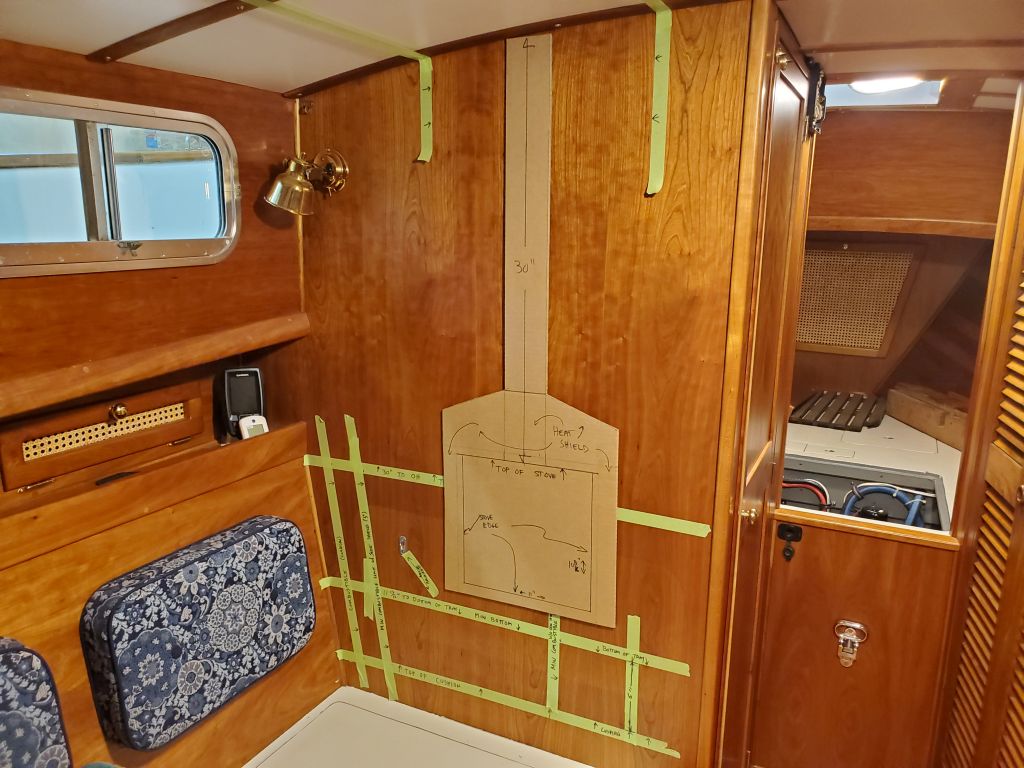
Now I made a simple cardboard template to the overall dimensions of the wall-mounted stove shield, which I could use on the bulkhead to illustrate the possible mounting locations while staying within all the required measurements and clearances I’d determined before. I started out mounting this template in the center of the space I’d marked. What the template doesn’t show is the depth of the stove, but other than appearance and functionality, there were no physical constraints to worry about in that direction. If needed, I could make a 3-dimensional box to represent the stove’s actual size from here.
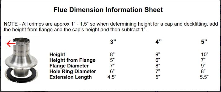
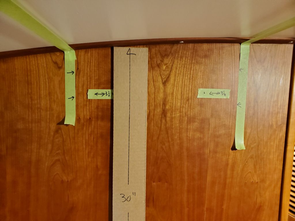
However, one final consideration that further limited the final stove placement was the overall base diameter of the deck fitting, which in this case was 7″. So that meant that I needed to keep the edge of the stove pipe at least 3-1/2″ in from the edges of the deck area I’d marked out. I made these marks on the bulkhead.
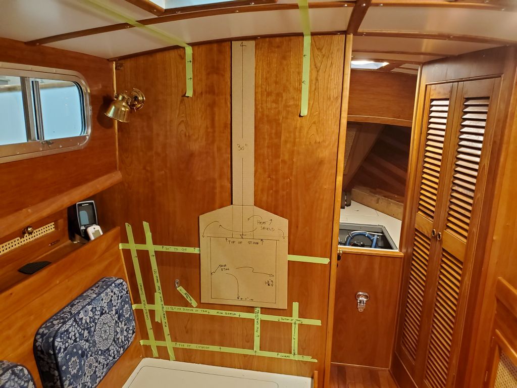
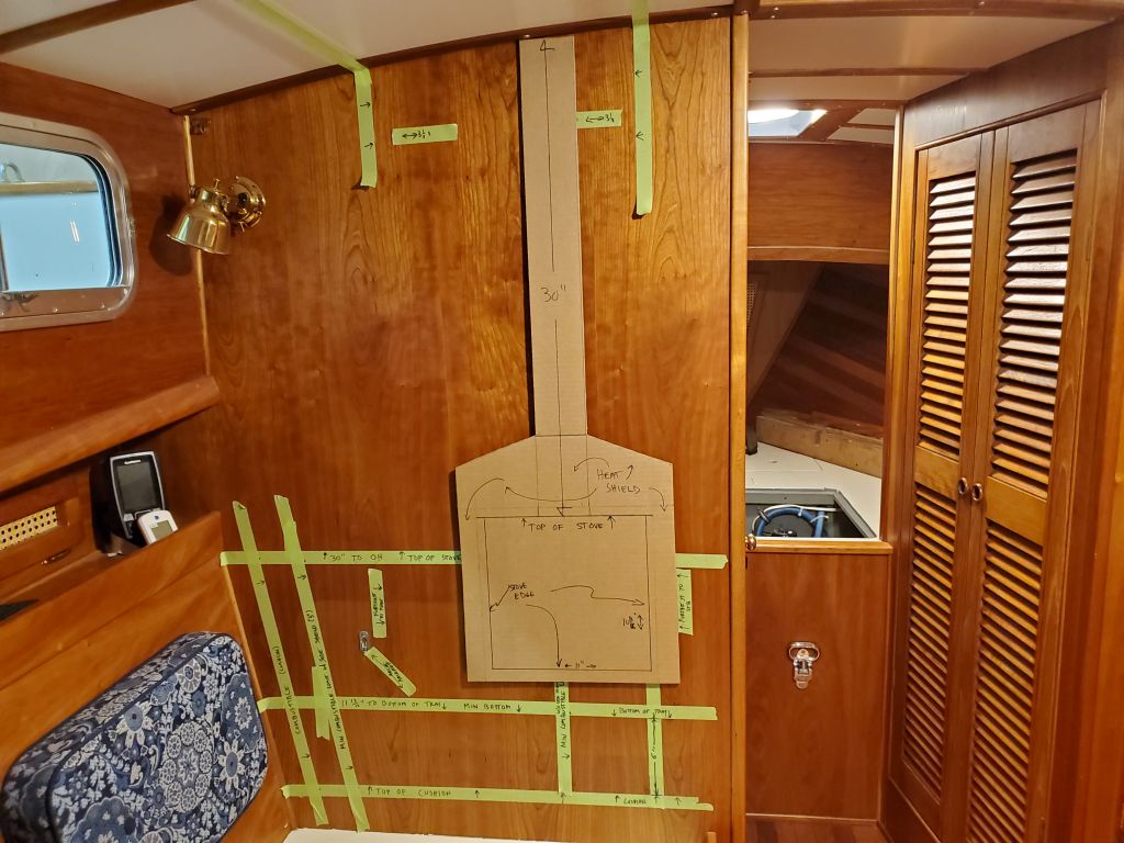
Now I could set up the template with the flue shield (and thus the flue itself) at the maximum limits of the space athwartships, given the requirements of the deck fitting flange, and with all other considerations also taken into account by default: First all the way to port (where I made additional tape marks to show the stove location); then all the way to starboard. The port-most location caused the edge of the stove shield and platform to interfere slightly with the arc of the hinged backrest, so in the final analysis and practically speaking, the furthest-to-port location would be an inch or two further inboard than shown here.
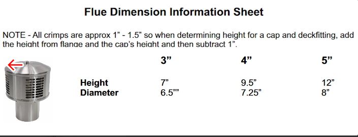
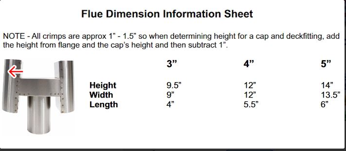
To my own way of thinking, I saw little benefit to installing the stove anywhere but the middle of the space (i.e. with the deck fitting and stove pipe in the center of the available deck area), but the ultimate height and choice of the Charley Noble and how that interacted with the boom vang or other such considerations still needed to be taken into account, even though the Charley noble would be removable and replaced with a rain cap that would minimize the height of the chimney during most sailing maneuvers. Still, we must thusly consider all variables.
With the initial layout possibilities complete, and a better understanding of how the stove and its venting would work, now it was up to the owner to decide if the proposed installation met his expectations or not. If so, we’d be able to order the stove, which had a fairly lengthy lead time, in order to ensure it arrived with plenty of time to do the installation.
Total time billed on this job today: 4.5 hours
0600 Weather Observation: 27°, clear. Forecast for the day: Sunny and windy, 31°