(page 4 of 5)

Lively Heels Phase 3-16

Wednesday

After lightly sanding the first round of fairing filler on the deck box, I applied a second layer, this time using a wide trowel to span the entire height of the box.  Because the box was fairly lightweight, I’d noted the last time that  tended to move about when working on the sides, so now I filled it with some scrap lumber to help weight it down; this worked well to allow me to trowel effectively.

Total time billed on this job today:  .75 hours

0600 Weather Observation:  0°, clear, 2″ or so of snow from yesterday.   Forecast for the day:   Sunny, 28°.

Lively Heels Phase 3-15

Tuesday

After a light sanding, I applied a round of epoxy fairing filler to the deck box, the first of a few required to prepare the exterior for the final paint finish.

Total time billed on this job today:  .75 hours

0600 Weather Observation:  8°, cloudy.   Forecast for the day:   Cloudy, light snow in the afternoon, 21°.

Lively Heels Phase 3-14

Sunday

With the epoxy fillets cured sufficiently, I trimmed and removed the temporary wire ties from the edges of the box.  Afterwards, I used a router to round over all the external edges of the box, for appearance, but more importantly to ease the corners for the fiberglass tabbing that would come next.

Next, I coated the outside of the box in epoxy.

Now I installed biaxial tabbing on all the box corners, adding the structure that would help hold the box together.  I sheathed the entire box between the tabbed corners with some 10 oz. cloth I had on hand; this would provide weatherproofing and durability.  I left the fiberglass to cure overnight before continuing.  Next would be filling and fairing to smooth the box and prepare it for finishing.

Total time billed on this job today:  1.75 hours

0600 Weather Observation:  21°, mainly cloudy.   Forecast for the day:   Cloudy, light snow in the afternoon/evening, 33°. 


Lively Heels Phase 3-13

Saturday

After various discussions in the weeks since I made up the rough idea of the deck box forward of the pilothouse, the owner requested that we make it a bit smaller, which I agreed with; I’d made it the size I had in order to try and fit the spare propane tank, but this did make the box larger than seemed appropriate, and another box–to be built in the cockpit–could hold the propane tank.

Needing to keep the box construction underway, since there were several other boxes on deck I hoped to conceive and build before the season, I milled the various plywood pieces down to the new size, taking off 2″ in overall height, and about 3″ in width.  These dimensions seemed like they’d fit the space better overall, even at a net loss of storage capacity.

With the pieces newly cut, I secured the box together with small plastic wire ties through holes I drilled at the corners of each seam all the way around–my version of stitch-and-glue.

With the sides and bottom of the box held tightly together, I installed epoxy fillets on the inside of the box to permanently glue the box together and, once cured, hold things securely enough to allow me to reinforce the joints with fiberglass.  I filled in the recess I’d milled in the bottom for the propane tank, using a round of 1/4″ plywood and epoxy to do so, rather than waste the bottom I’d cut previously.  Because the assembled box had a slight propensity to rock, probably because of a slight warp to the plywood, I added some weight on top while the epoxy cured to keep the box flat to the bench.  (After I took the photo I added weight to the opposite end also, for good measure.)

Total time billed on this job today:  1.75 hours

0600 Weather Observation:  30°, cloudy, snow shower or two.   Forecast for the day:   Clearing, 35°. 

Lively Heels Phase 3-12

Thursday

With a new rubber, self-adhesive product now on hand for the anchor pad, I turned to the final installation. After various discussions over the past weeks–covering options running from a custom anchor platform to move the anchor out further (an ideal solution, perhaps, but expensive and complicated to conceive and build, all the more so in the absence of a known and trusted metal fabricator), to a wrap-around stainless steel protector (difficult to build–again, the metal fabricator problem–and would require numerous screws to secure), as well as the inappropriate material I’d bought and tested for the job, which turned out to be impossible to install since the adhesive wouldn’t stick to it–I’d found a thicker, heavier rubber with a self-adhesive back that I thought would work.  The original piece, which was 1/8″ rubber with self-adhesive back, had worked amazingly well, and given the various issues at hand, the owner and I finally decided that this approach could continue being the right one, even if it required periodic replacement.  The replacement material was weather-resistant EDPM rubber, 1/4″ in thickness, and designed to resist UV, salt water, oil, and more.

With some time on hand towards the end of a day, I cut the new piece to size using my pattern from before–kind of an amalgamation of the original, shorter piece and the second-phase (failed) longer piece.  The new section was 36″ long, which extended further down the stem than had the original piece, and would cover the area most susceptible to damage from the anchor while raising it.

After thoroughly cleaning the hull with alcohol (other solvents can deaden certain adhesives), I applied the new rubber protector, removing a strip of the backing paper along the centerline to stick the piece in place, then securing the sides from there.  I used a roller to firmly secure the adhesive to the boat.

In other works, the new holding tank arrived.  Per the owner’s request, we planned to install custom fittings in this tank on site:  a large inspection port in the top, and bronze through hulls elsewhere to provide the necessary inlets and outlets.  For basic visual inspection and ease of winterizing, we had the tank shop install a pair of threaded fittings on one side, but the remaining fittings would be installed as we saw fit in the coming days and weeks.

Total time billed on this job today:  1 hours

0600 Weather Observation:  32°, mainly cloudy.   Forecast for the day:   Mostly cloudy, 36°.

Lively Heels Phase 3-11

Monday

One continuing problem the owner had been dealing with was a windlass oil leak.  This seemed more or less inevitable considering the windlass motor, which sealed the oil reservoir, was mounted horizontally behind the windlass, and by manufacturer design was intended to be sealed only with liquid gasket material.  I’d done this twice during the original windlass assembly and installation in 2015, when the windlass was still on the bench.  But alas, even this hadn’t made for a solid seal, and the owner reported that the leak was worse when the windlass was in use and under load.

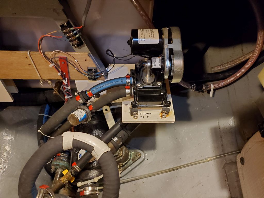
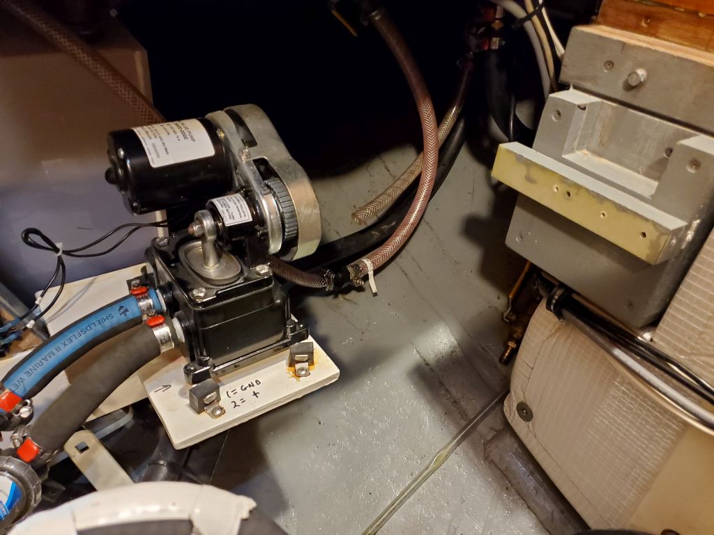
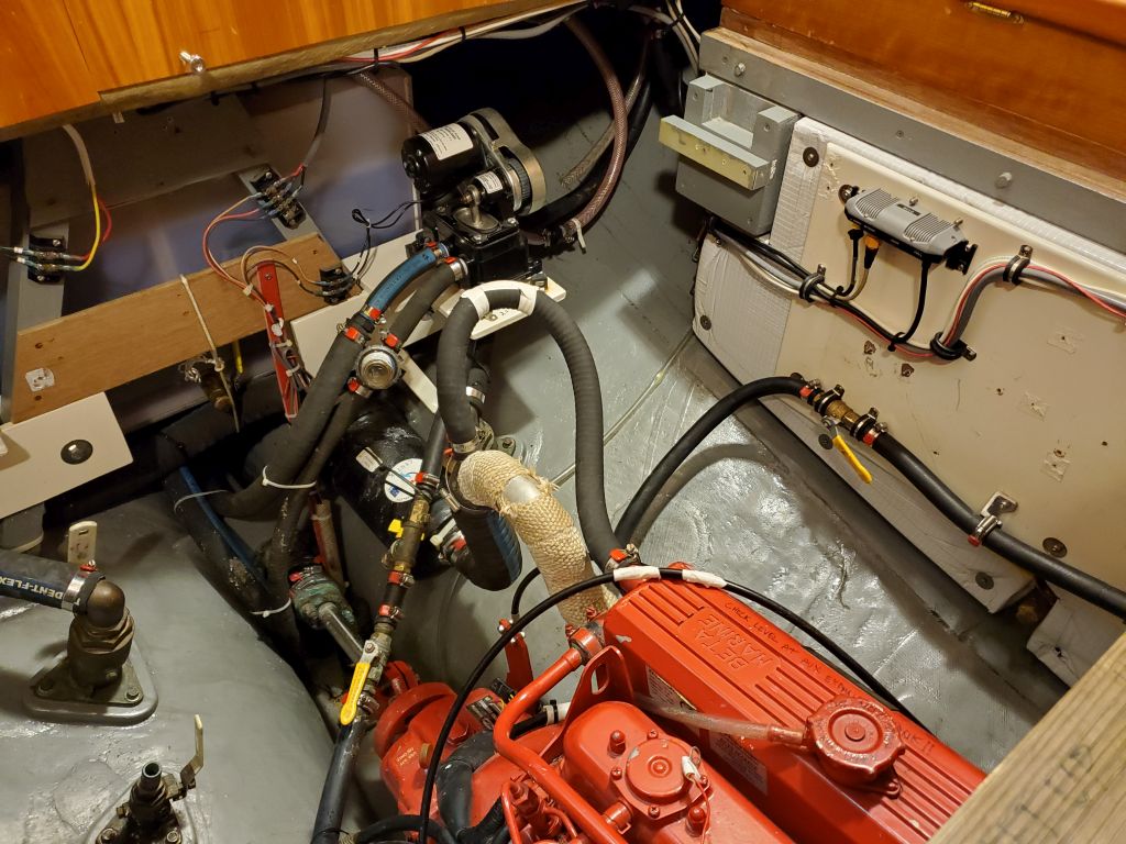
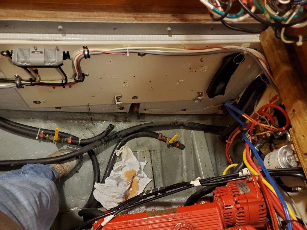
In any event, after some discussions on the subject, the owner decided to try to remove the pump motor in situ (theoretically possible) in order to revamp the gasket and hopefully stem the leak once and for all.  We discussed the process, I looked up links to the original logs for the project that, as closely as possible, covered the installation and therefore the removal.  While it had been years and I didn’t remember all the details, it seemed straightforward enough.  I knew there were just a few bolts securing the motor, and, inspecting the windlass, three were visible and all made sense:  One at the top of the housing, and two on the back of the pump motor.  Mutually satisfied this was the way forward,  I left the owner to work on the motor removal.

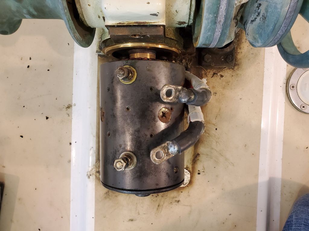
Unfortunately, it turned out that the two bolts on the motor secured only the motor cover, and in mistakenly removing the cover the brushes popped out, making the cover impossible to get back in place.  The owner let me know about this over the weekend and, in horror at the mistake, I turned right to the job in the morning.

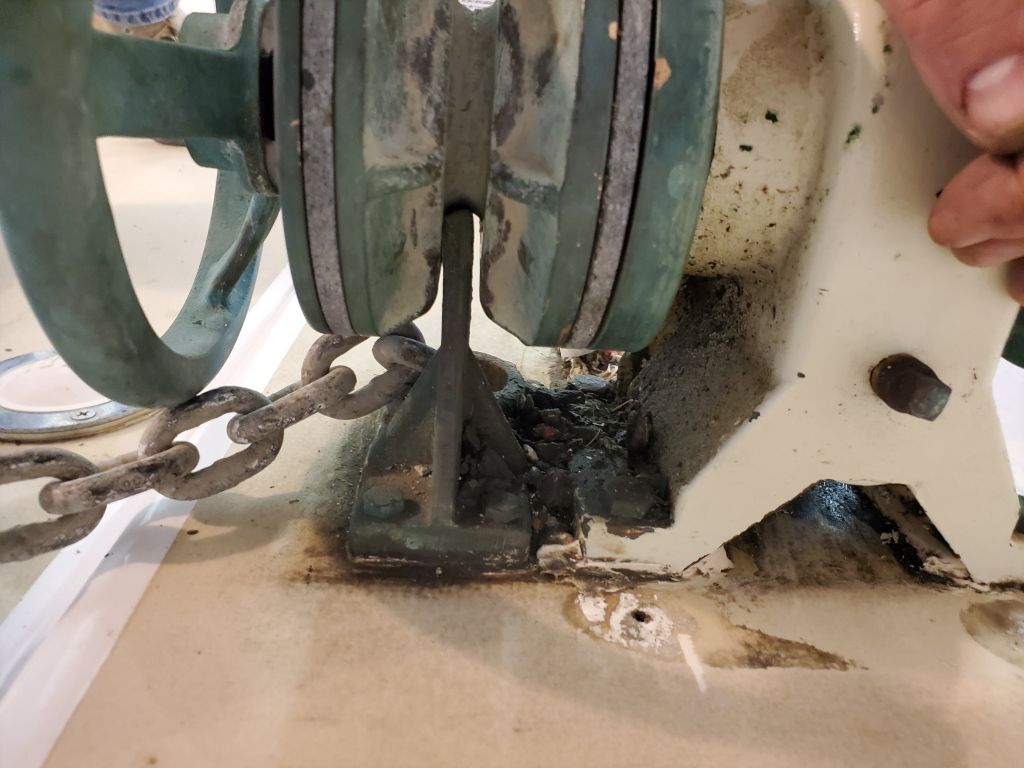
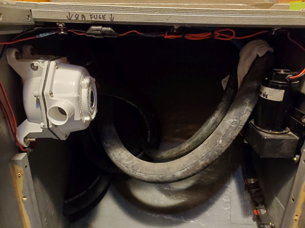
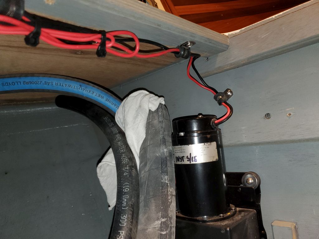
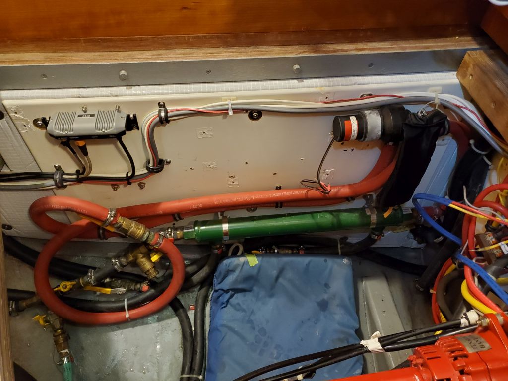
It turned out that the second two bolts securing the motor housing to the windlass body were on the forward side beneath the housing, technically accessible from slots in the side or maybe from the base opening ahead of the windlass, but these were tight spaces and the owner hadn’t had the tools to attempt removal of these two bolts.  I didn’t want to contemplate removing the windlass from the deck, and wanted to prove that the motor could be serviced in place, so I managed to remove these two bolts and then the motor itself, fortunately.

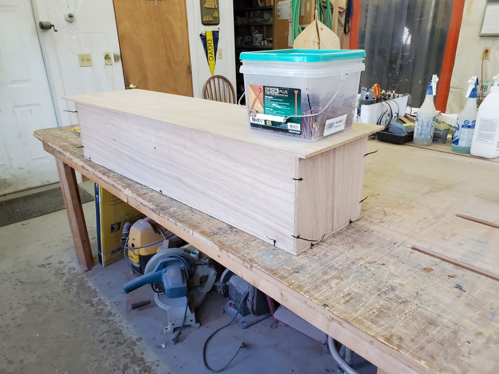
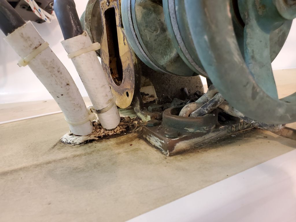
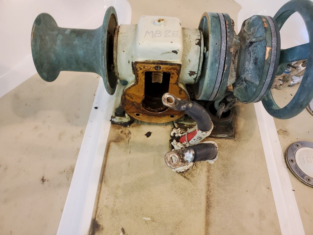
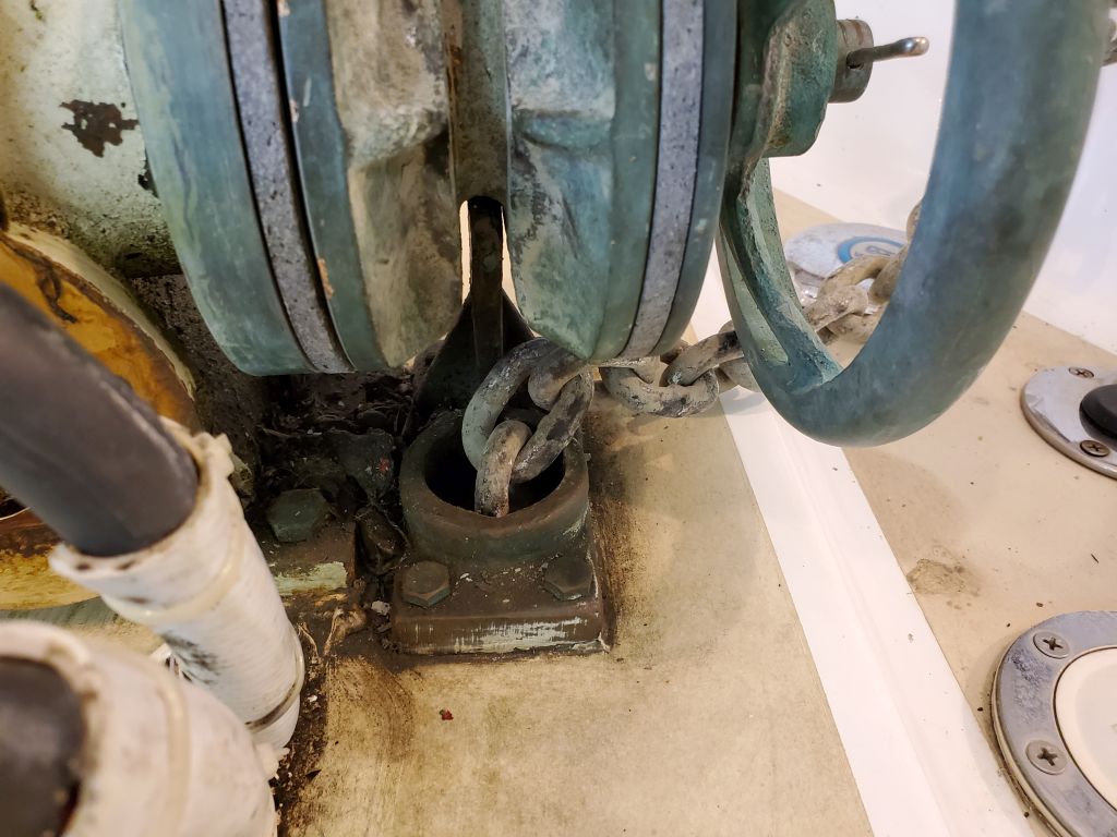
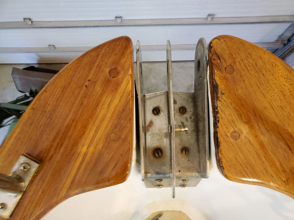
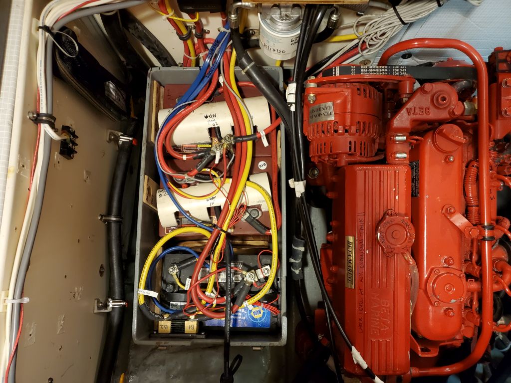
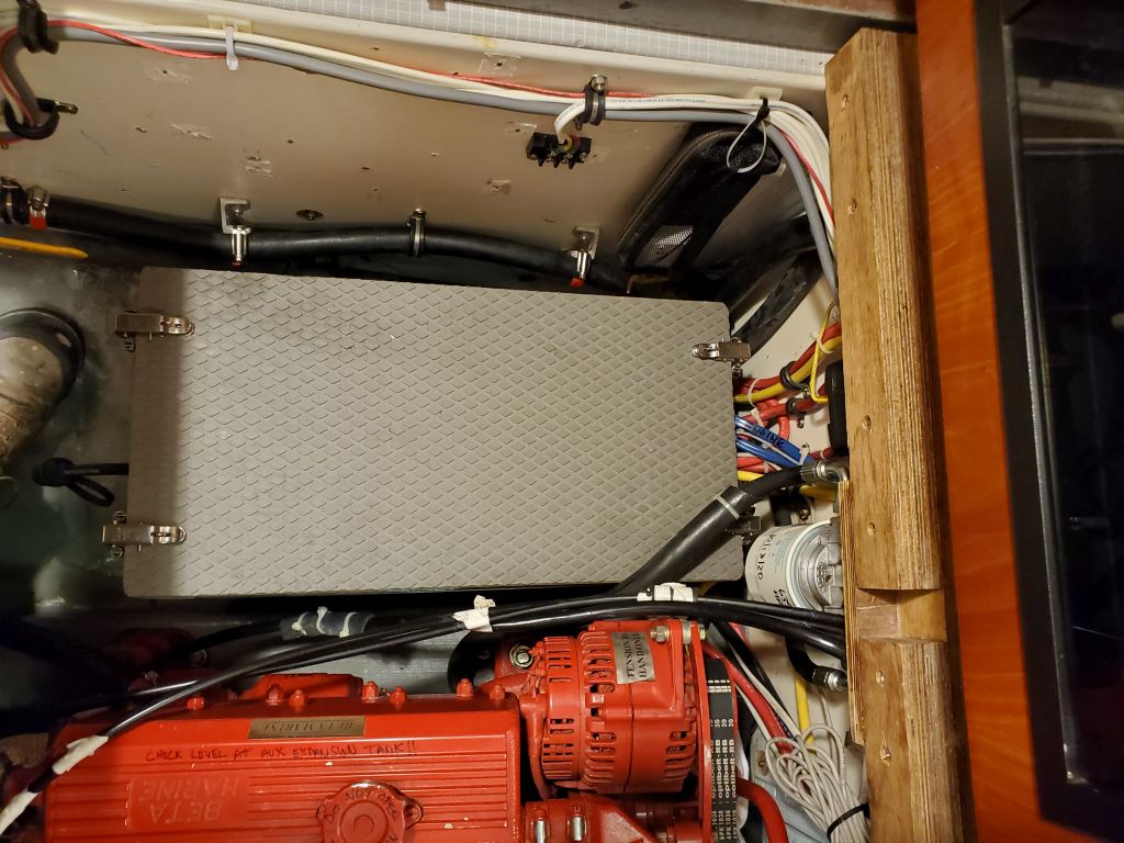
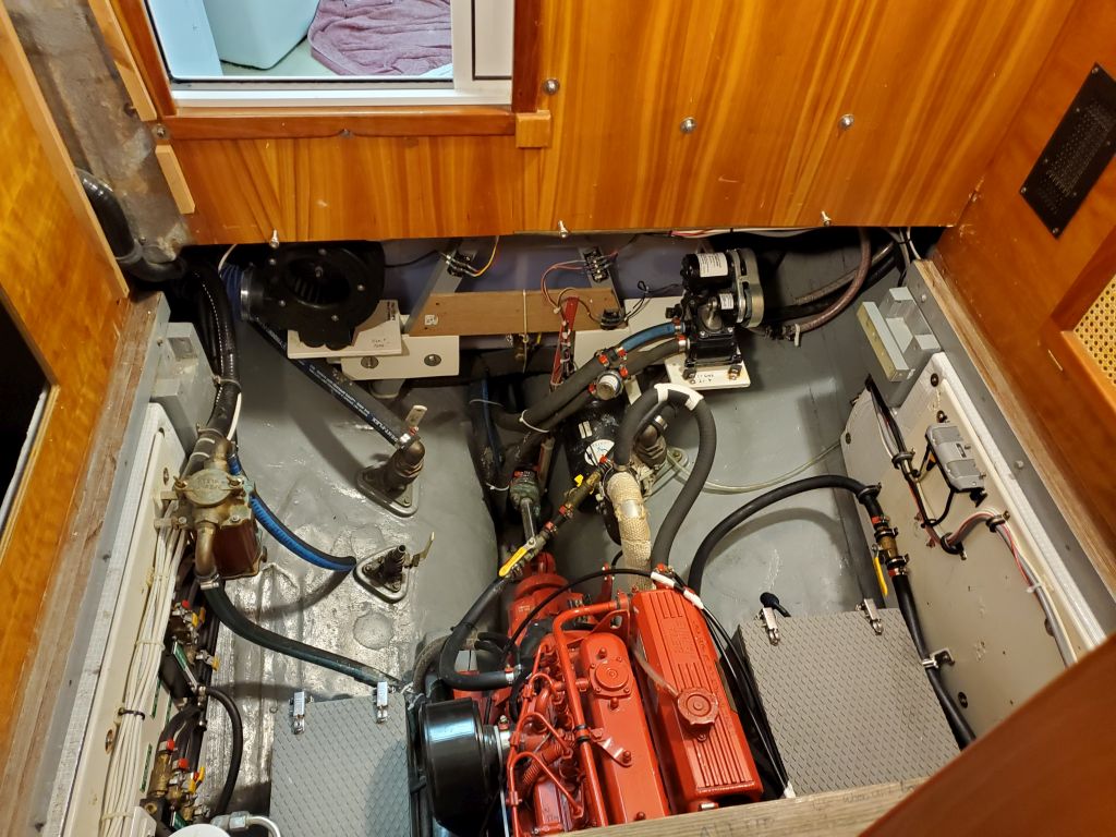
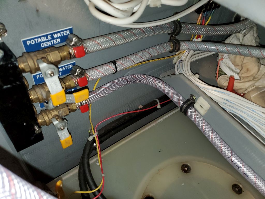
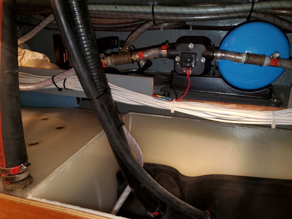
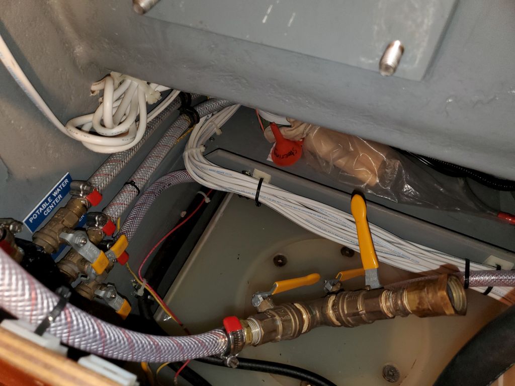
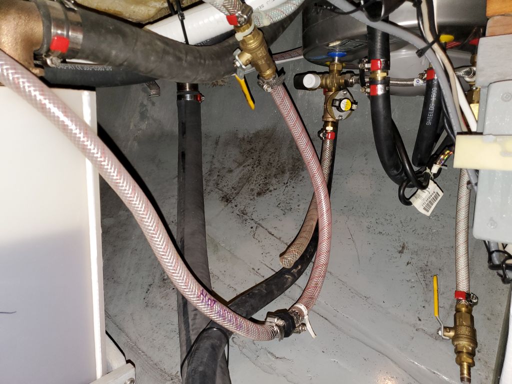
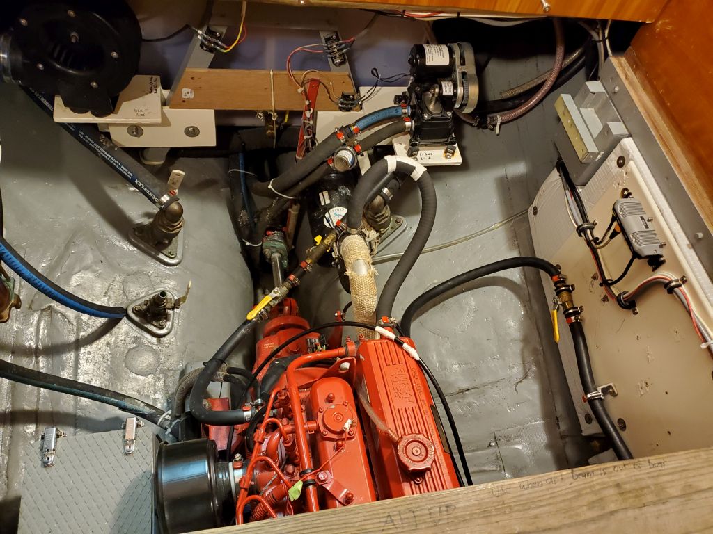
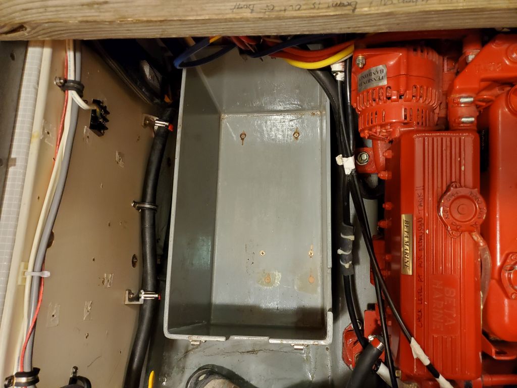
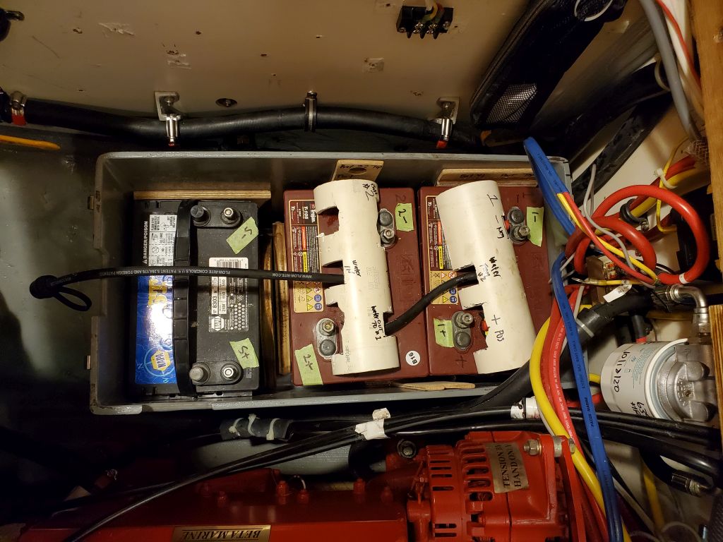
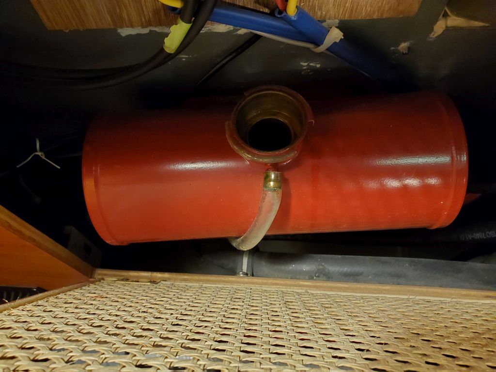
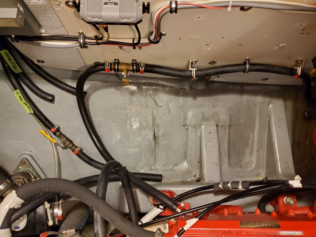
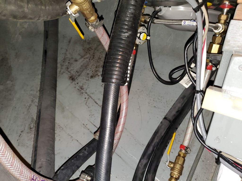
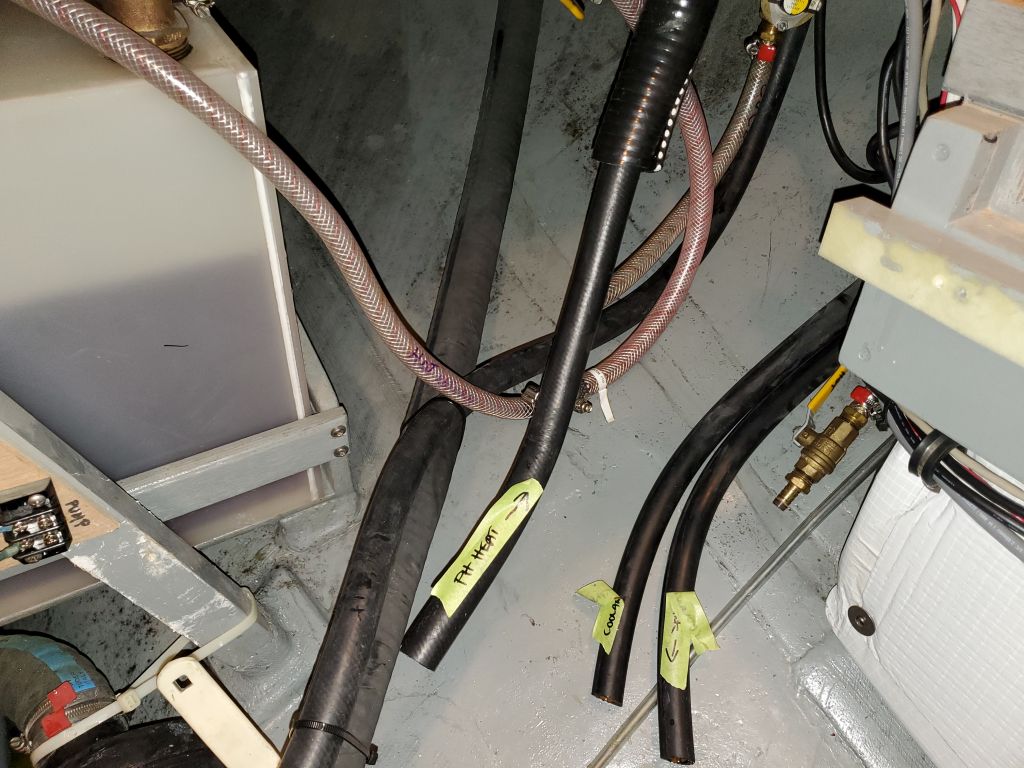
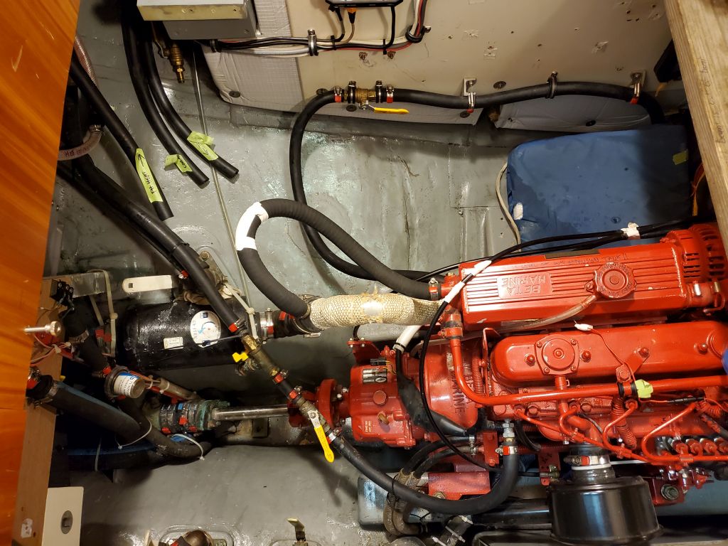
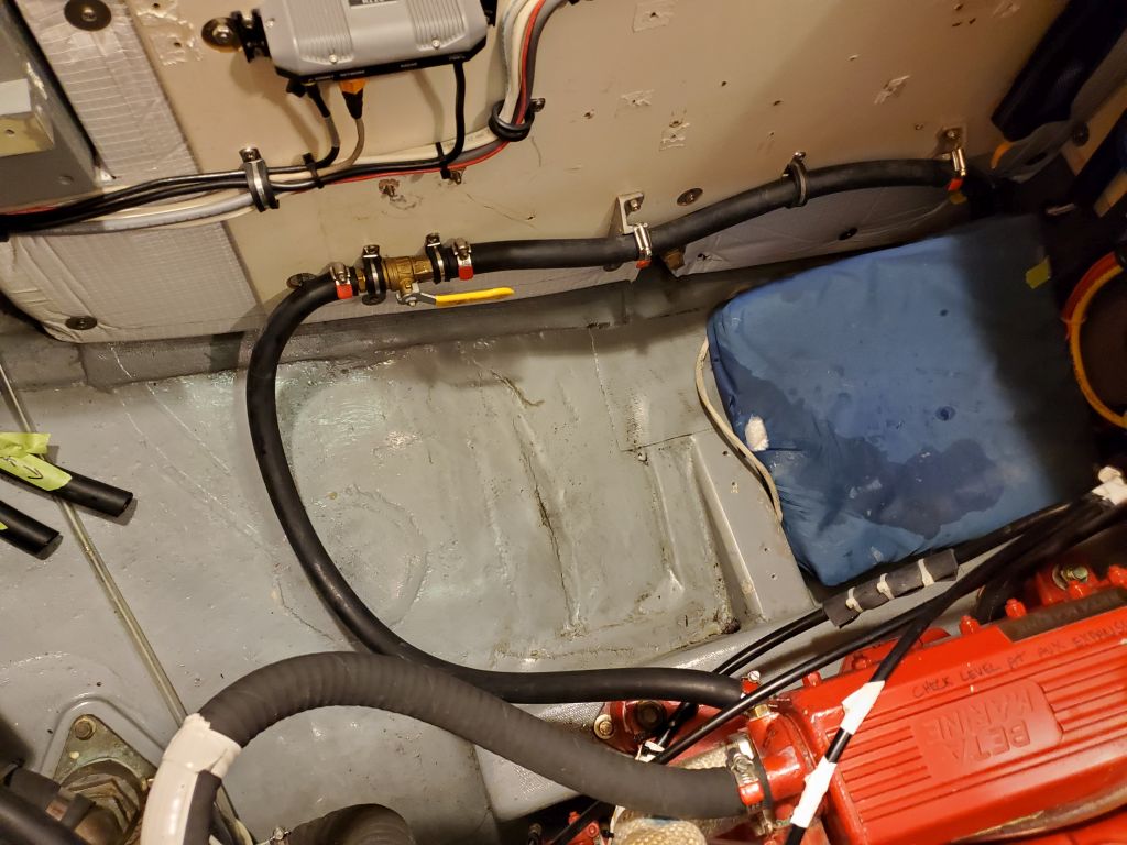
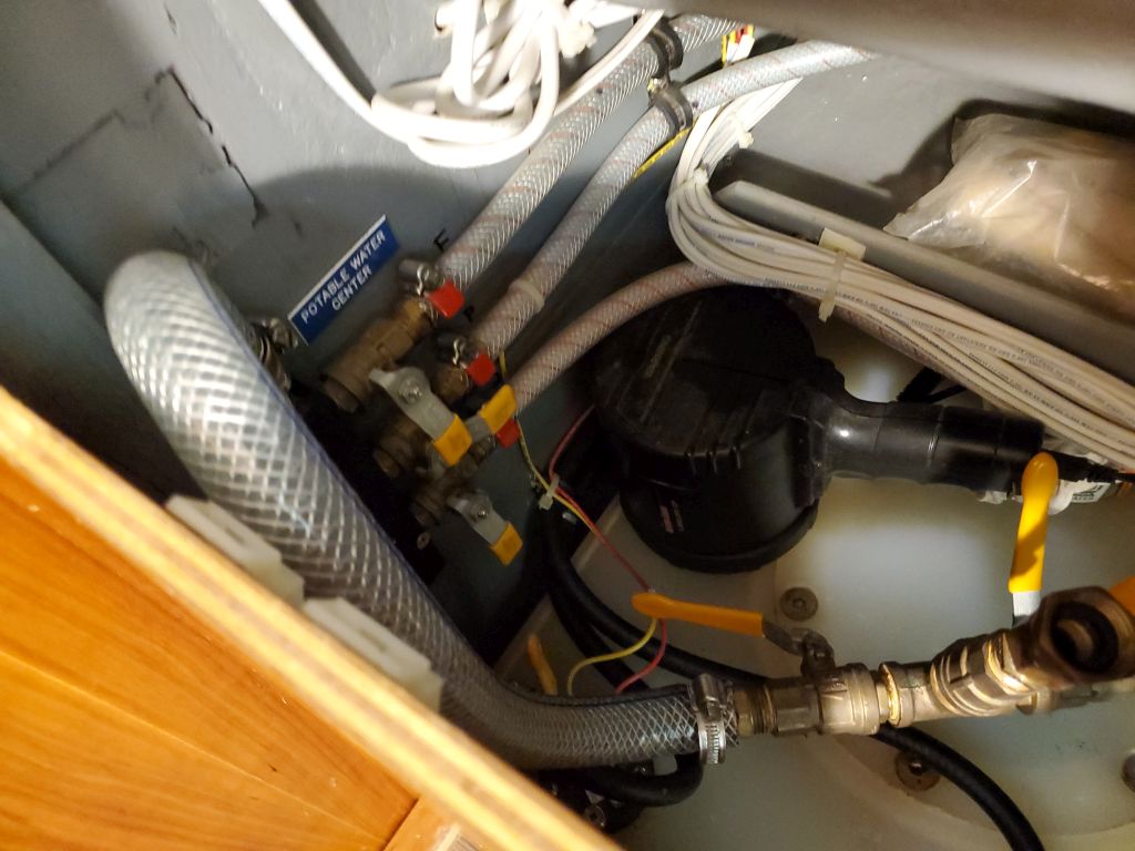
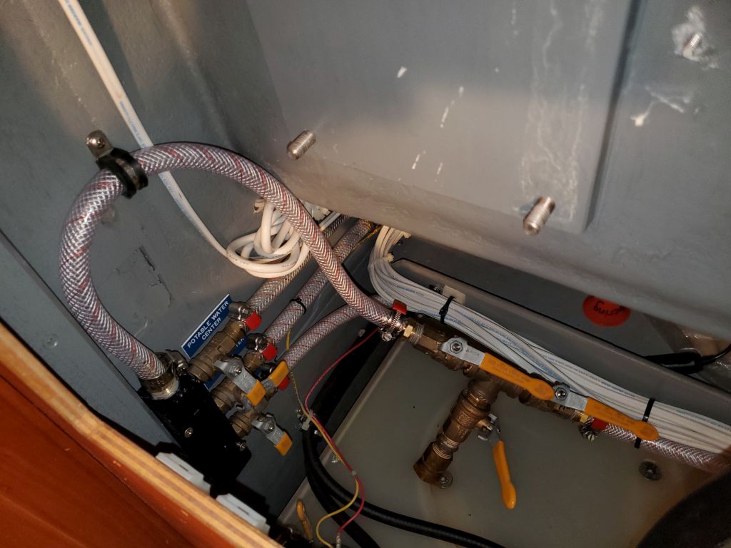
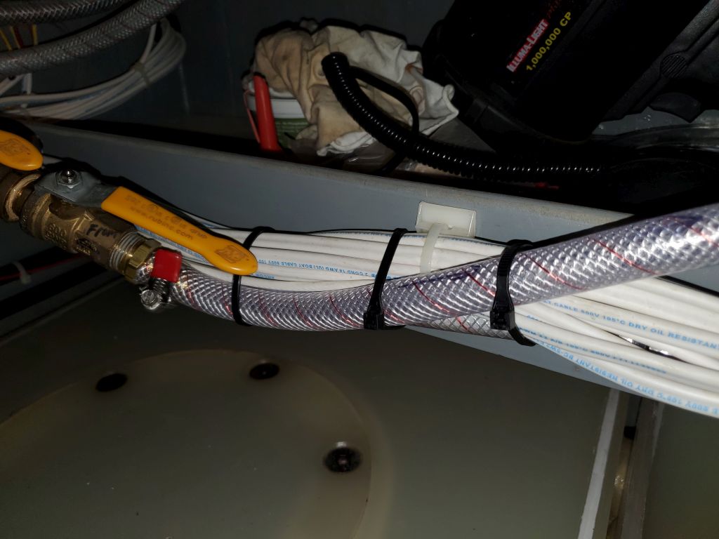
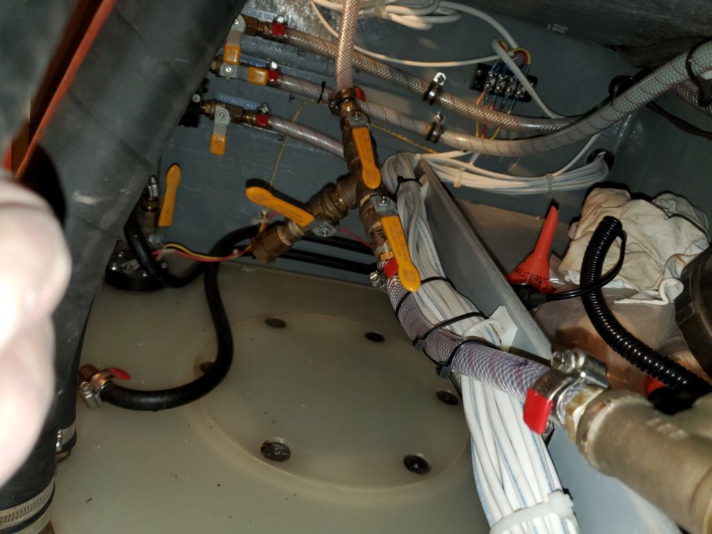
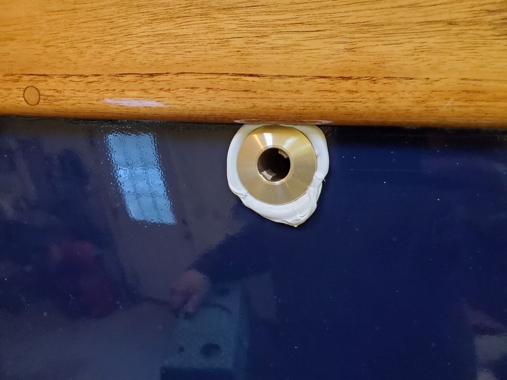
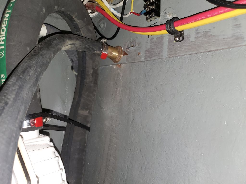
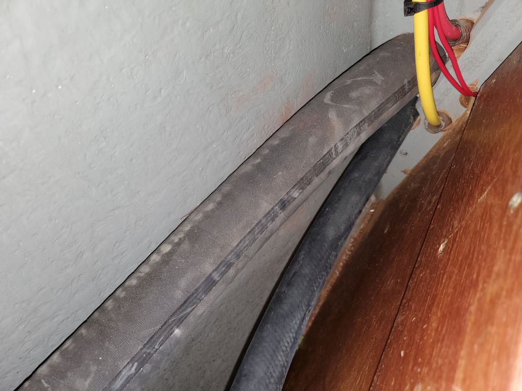
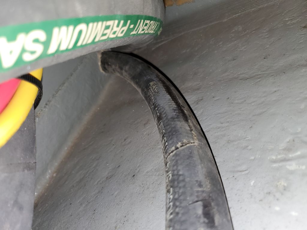
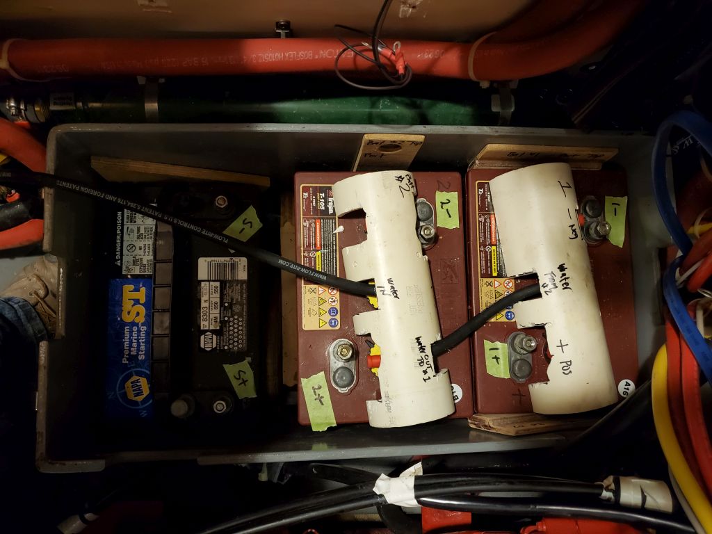
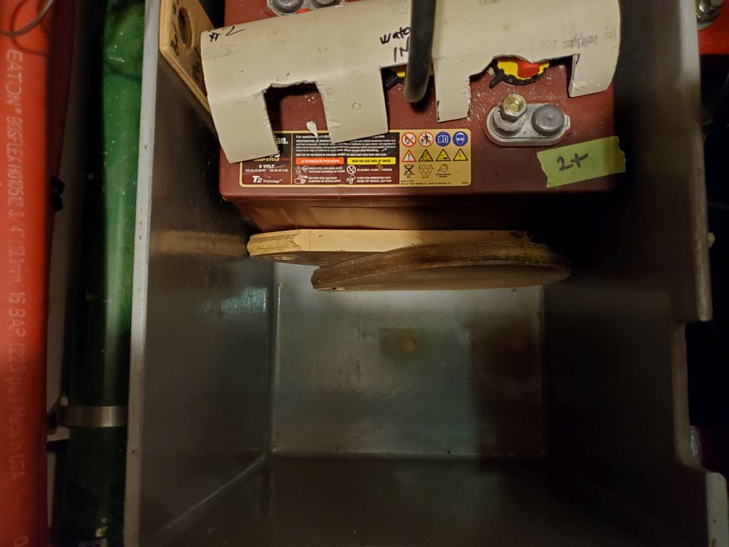
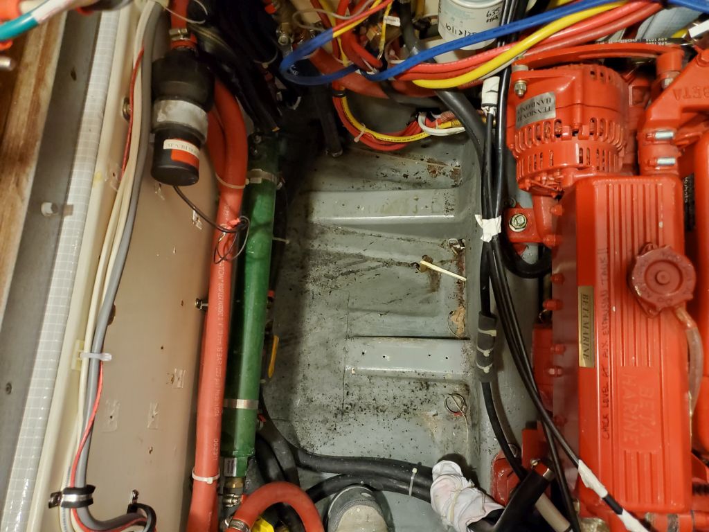
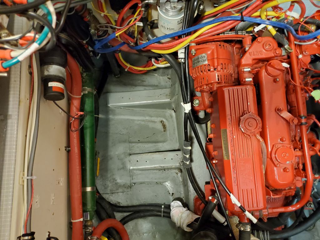
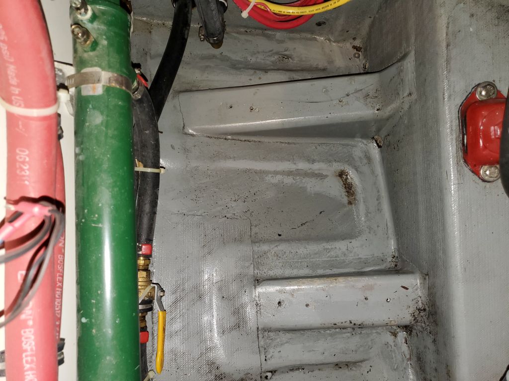
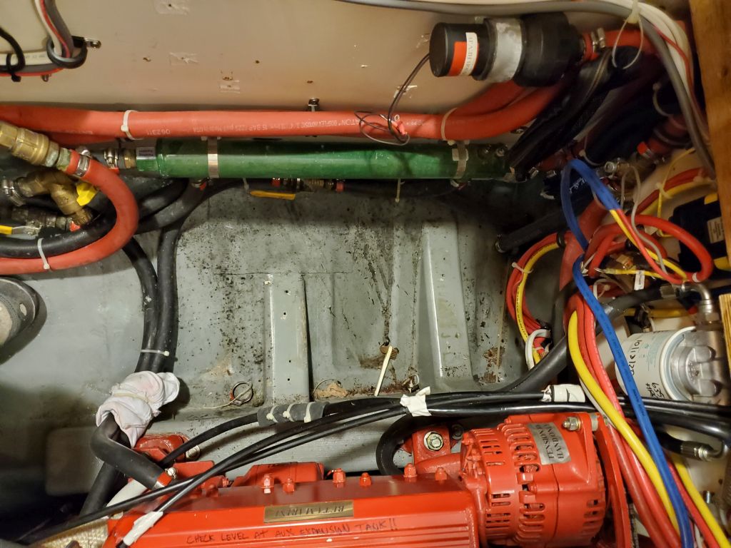
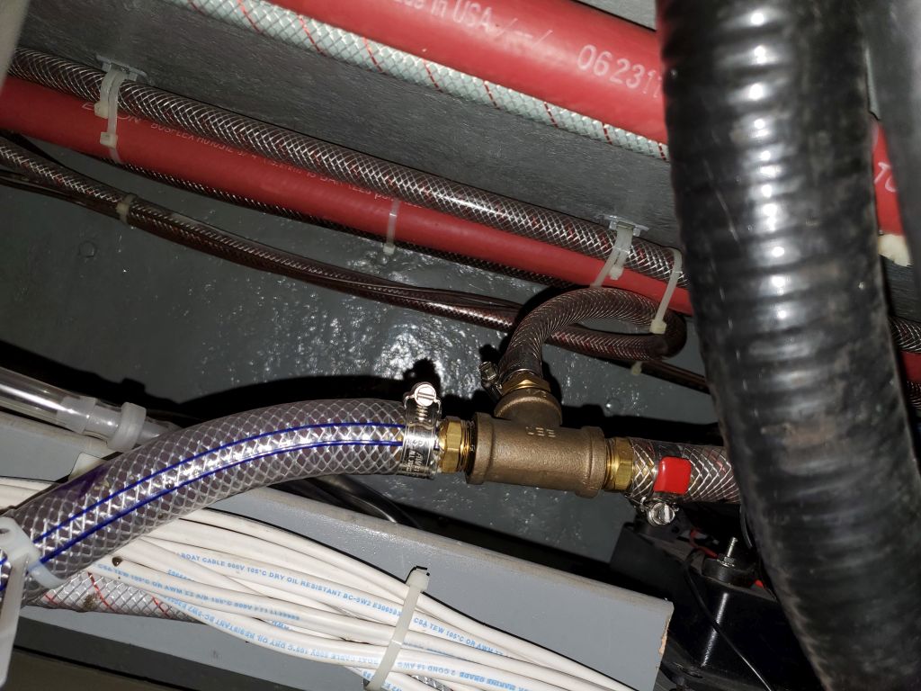
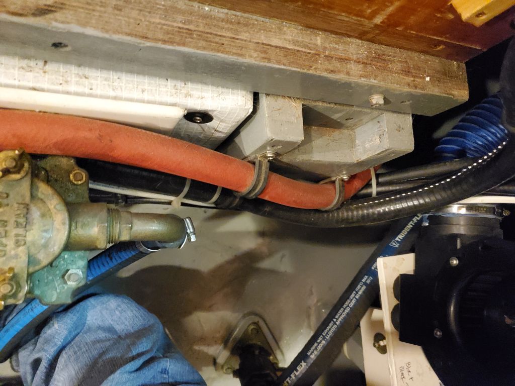
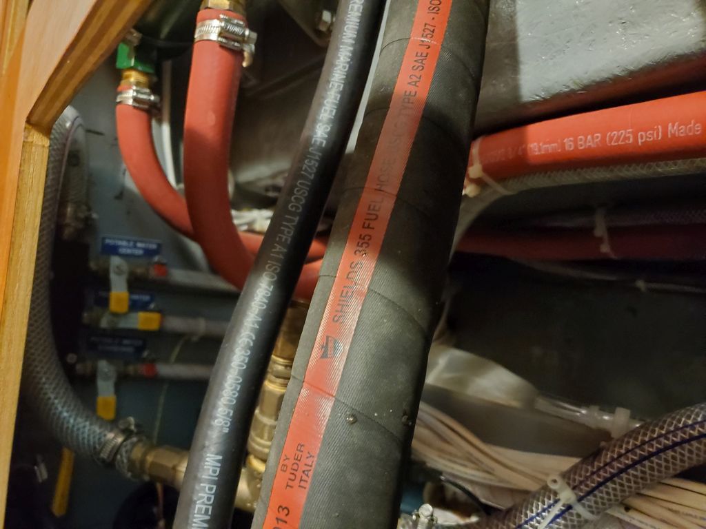
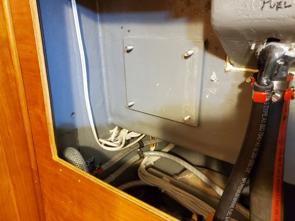
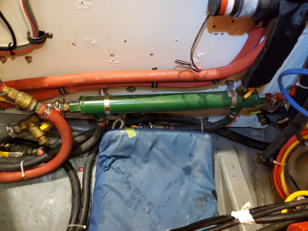
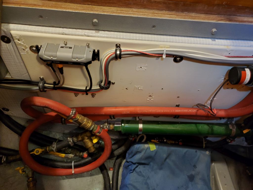
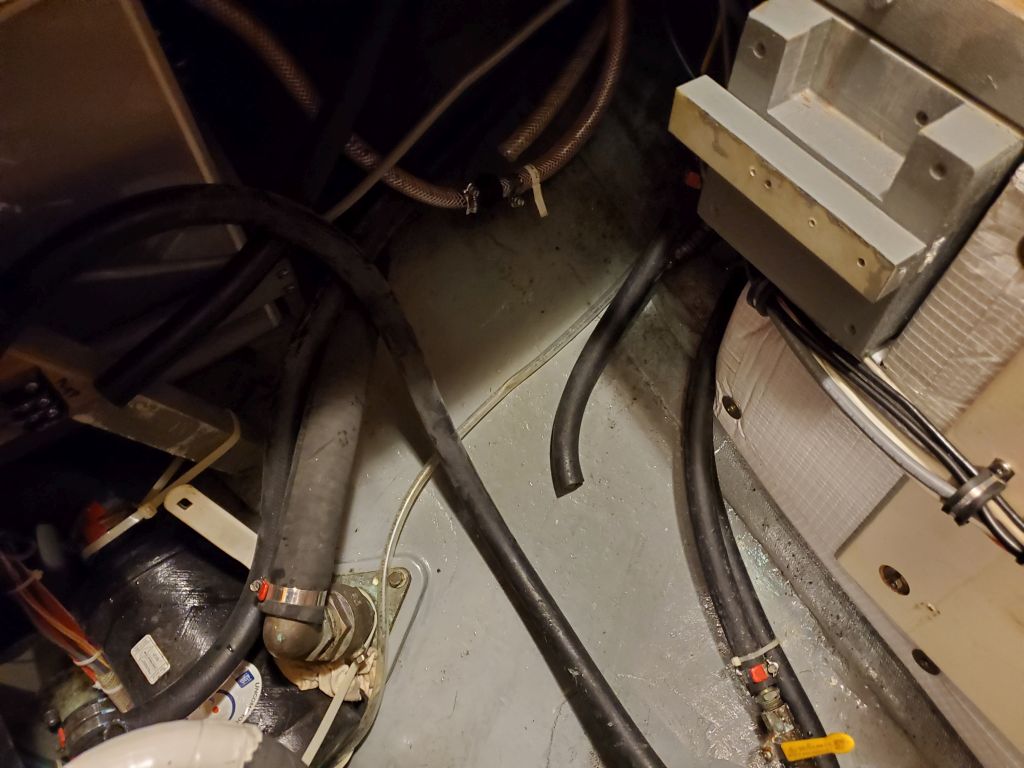
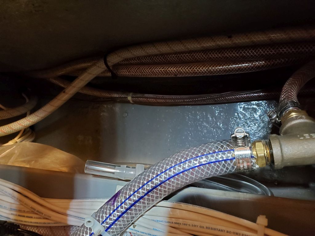
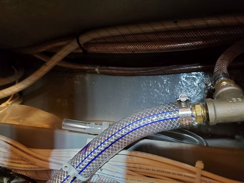
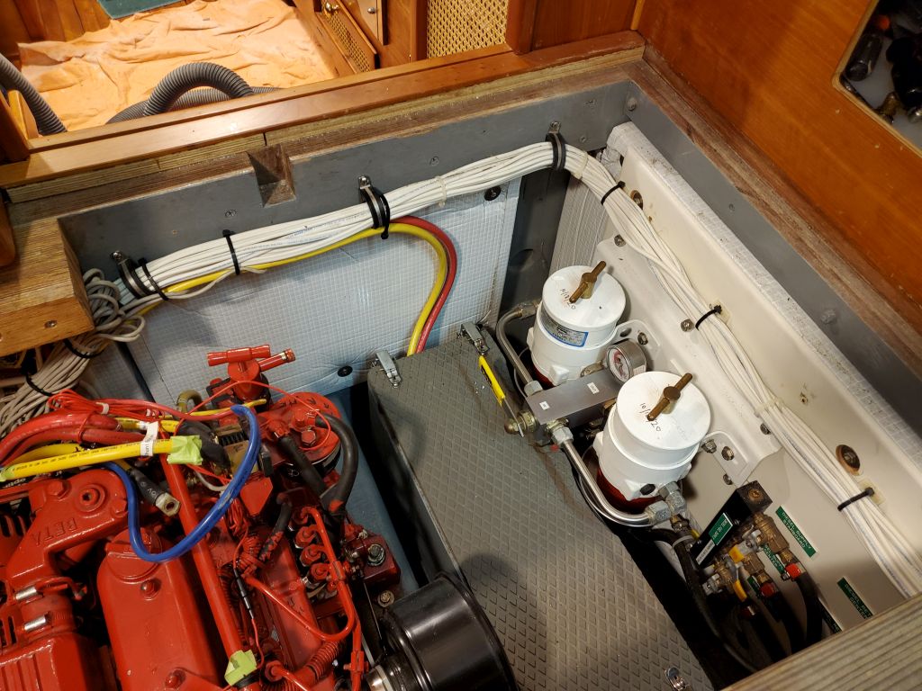
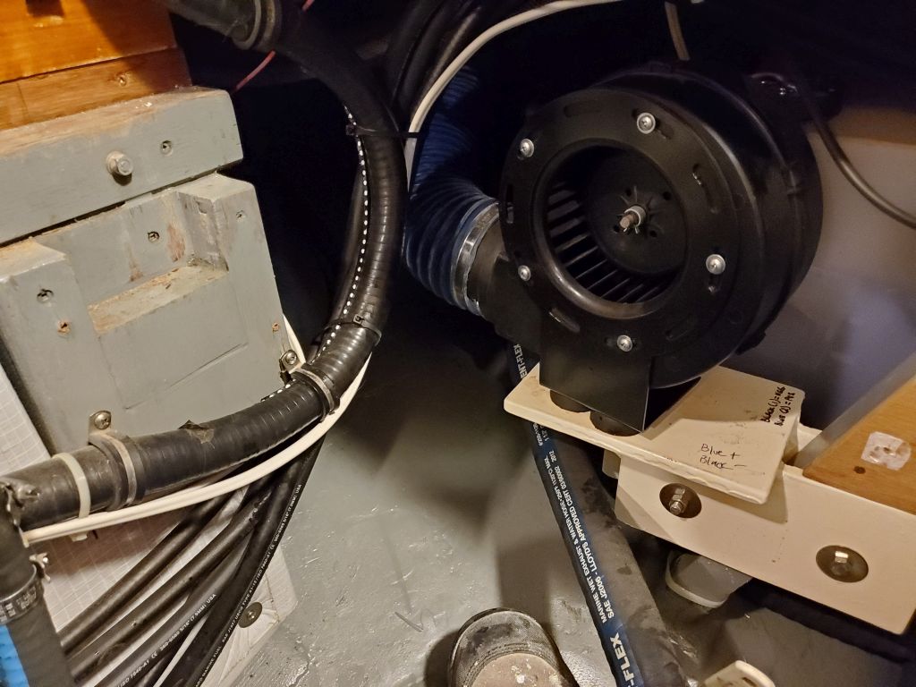
The port side bolt was relatively visible and accessible from the side, and here I used a ratcheting box end to remove the bolt without too much trouble.  ON the starboard side, the access was compromised by the wildcat, chain stripper, and all that mess.  I couldn’t remove the wildcat as I’d hoped because (duh, but it took me a while) the chain stripper was right in the middle of it, and prevented sliding it off the shaft.  The base of the windlass almost allowed easy removal of these bolts, but since the access from ahead (seen in the second photo below) didn’t allow a straight shot to the motor bolts (which would have allowed easy and logical use of a ratchet extension), and access was too tight from the side with the wildcat and all that in the way (allowing about 2 degrees of wrench travel), I ended up using a small flexible adapter on a 1/4″ ratchet to remove the bolt.

Designers so often forget the obvious things about access and maintenance.  It is frustrating, especially when it almost was thought out well.

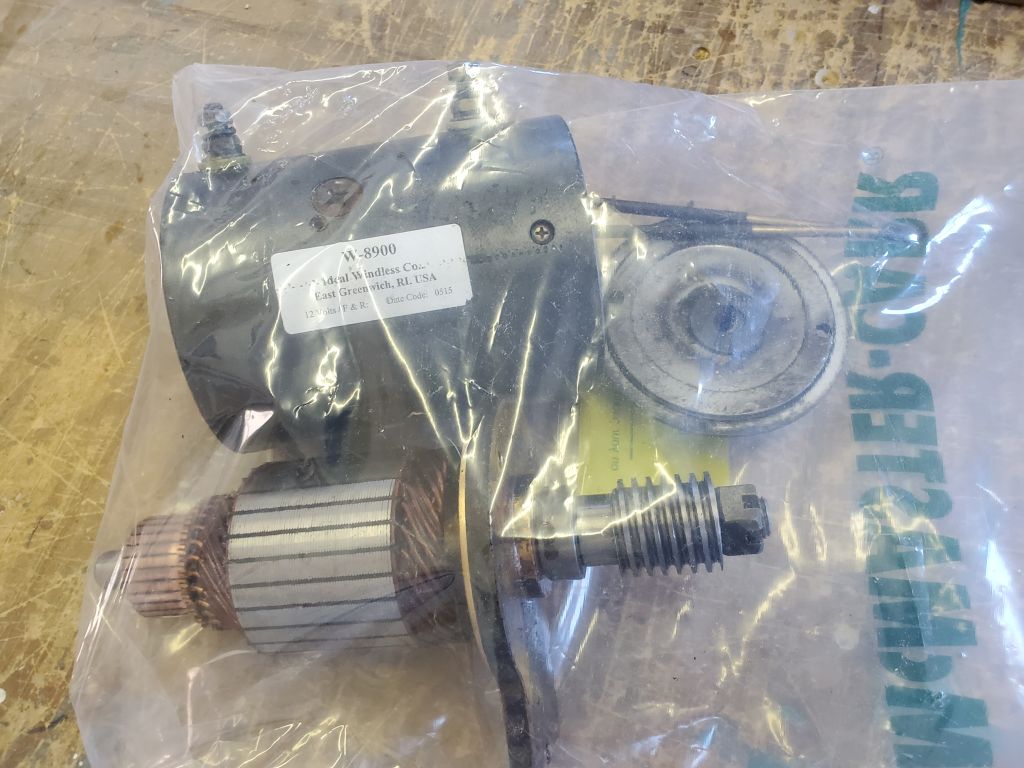
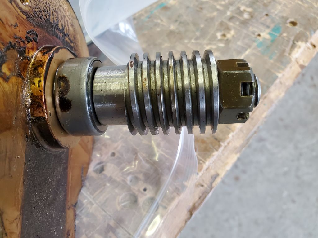
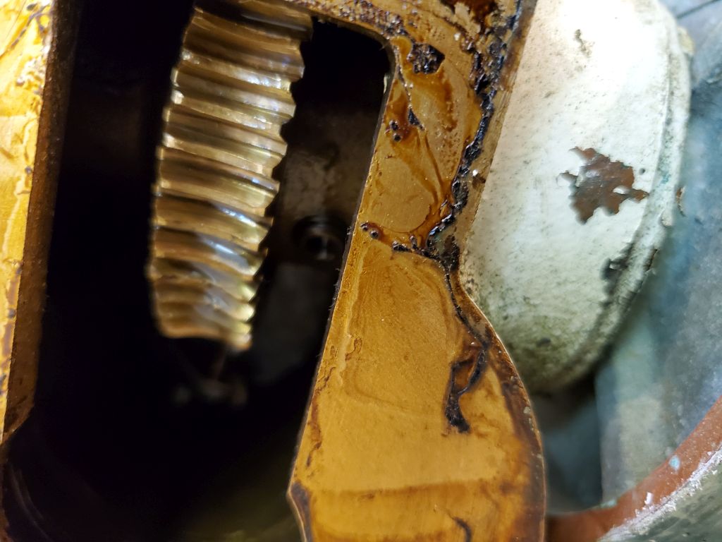
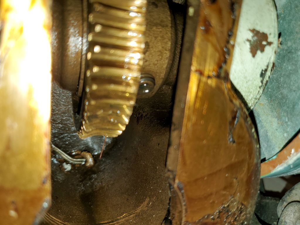
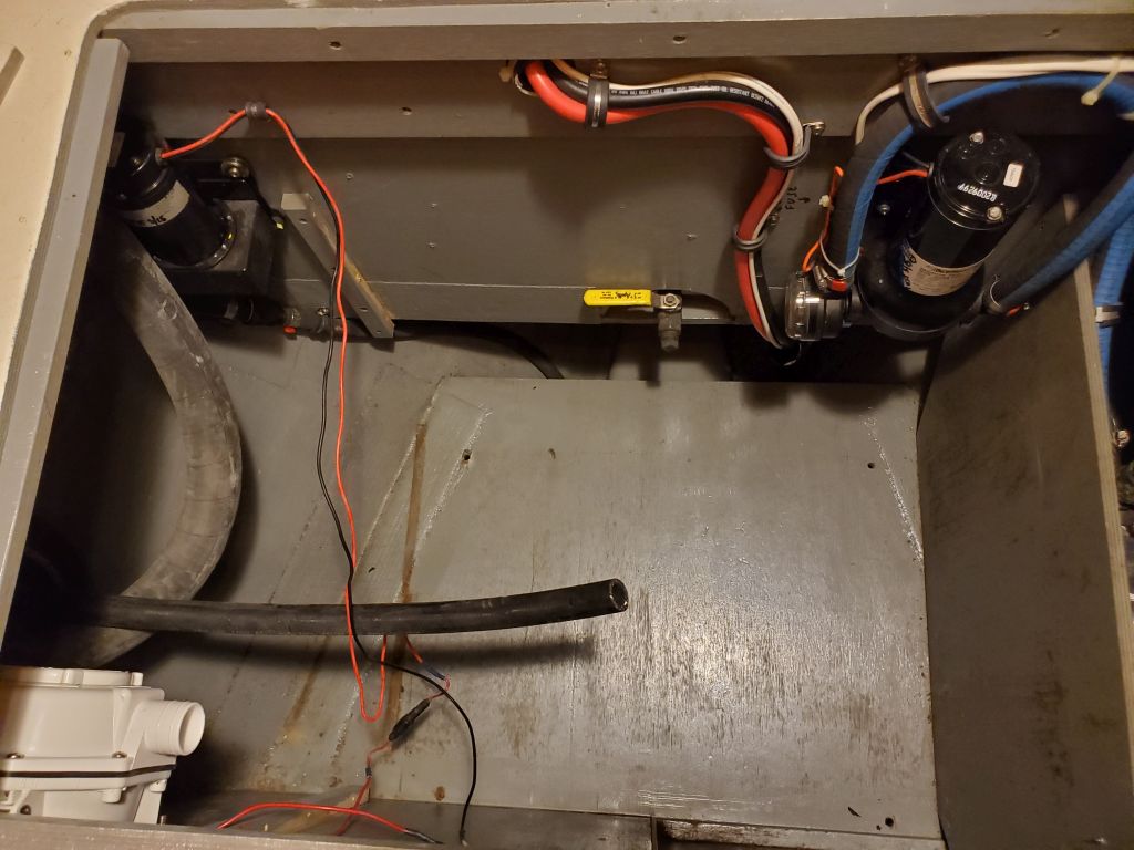
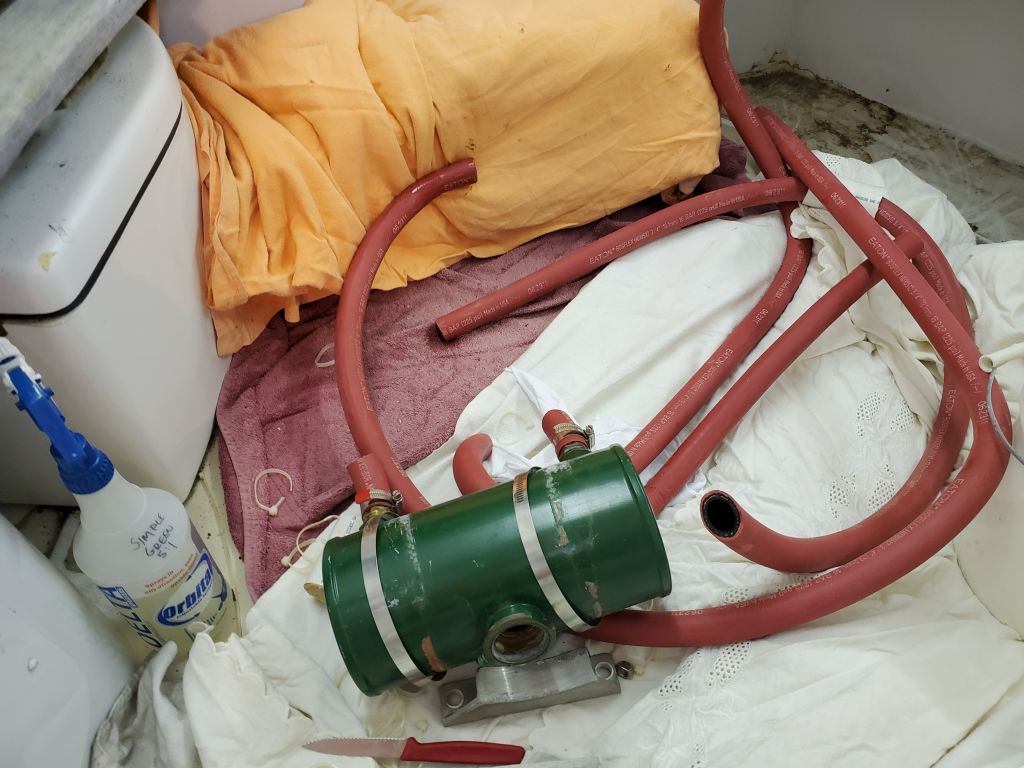
Anyway, the motor was off, and the owner would take the motor to be reassembled and tested somewhere, and later we could try the fun of reinstalling it in place:  Possible, for sure, but it promised to be an exercise in frustratingly tight spaces.  But that was for then.  For now, the good news was that the motor was off and could be repaired, and the worm gear on the motor shaft, and the bronze gears within the windlass, were all in good condition.

Shortly thereafter, I met with my canvas contractor, who stopped by to look at and template as needed some small jobs for the boat, including a windlass cover and a cover over the skylight in the pilothouse.

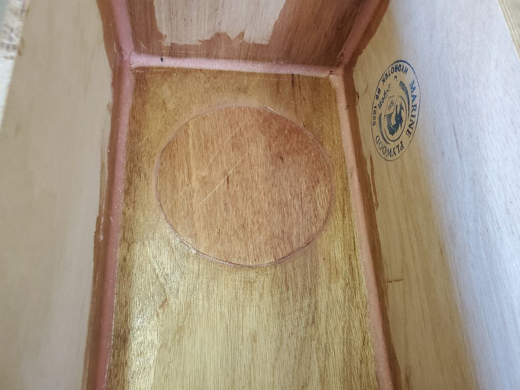
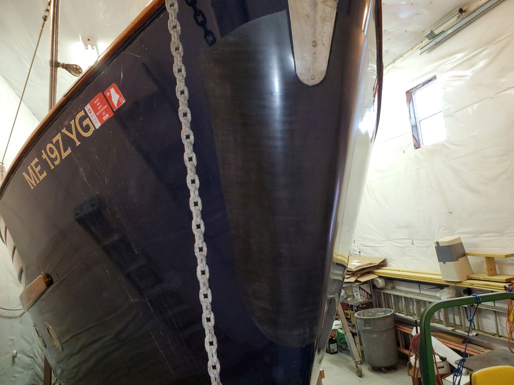
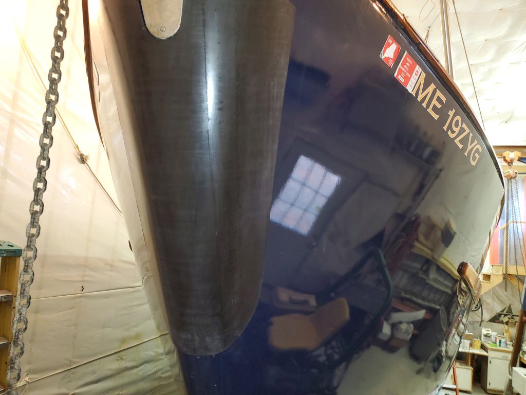
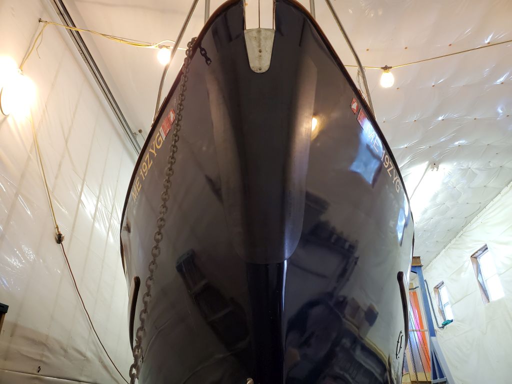
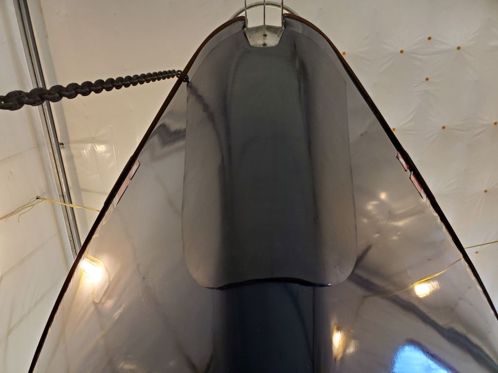
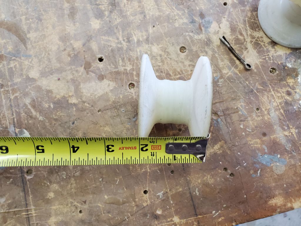
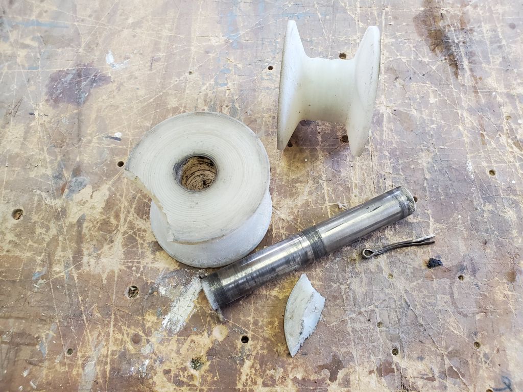
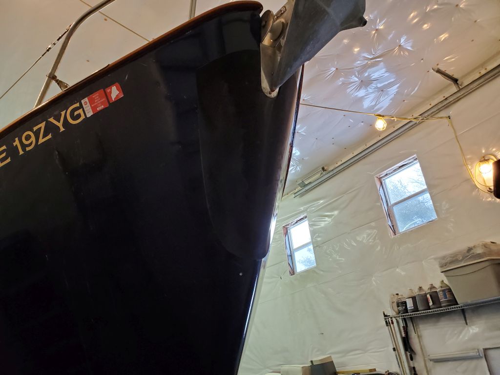
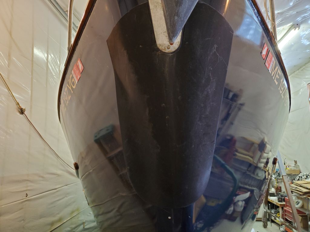
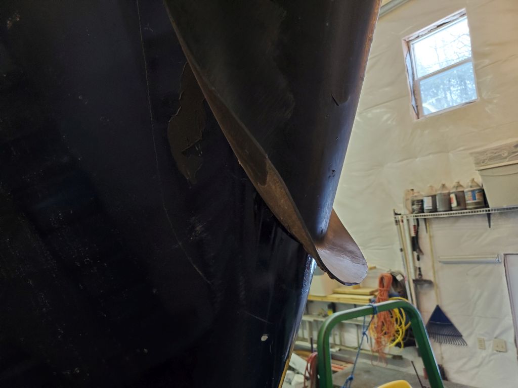
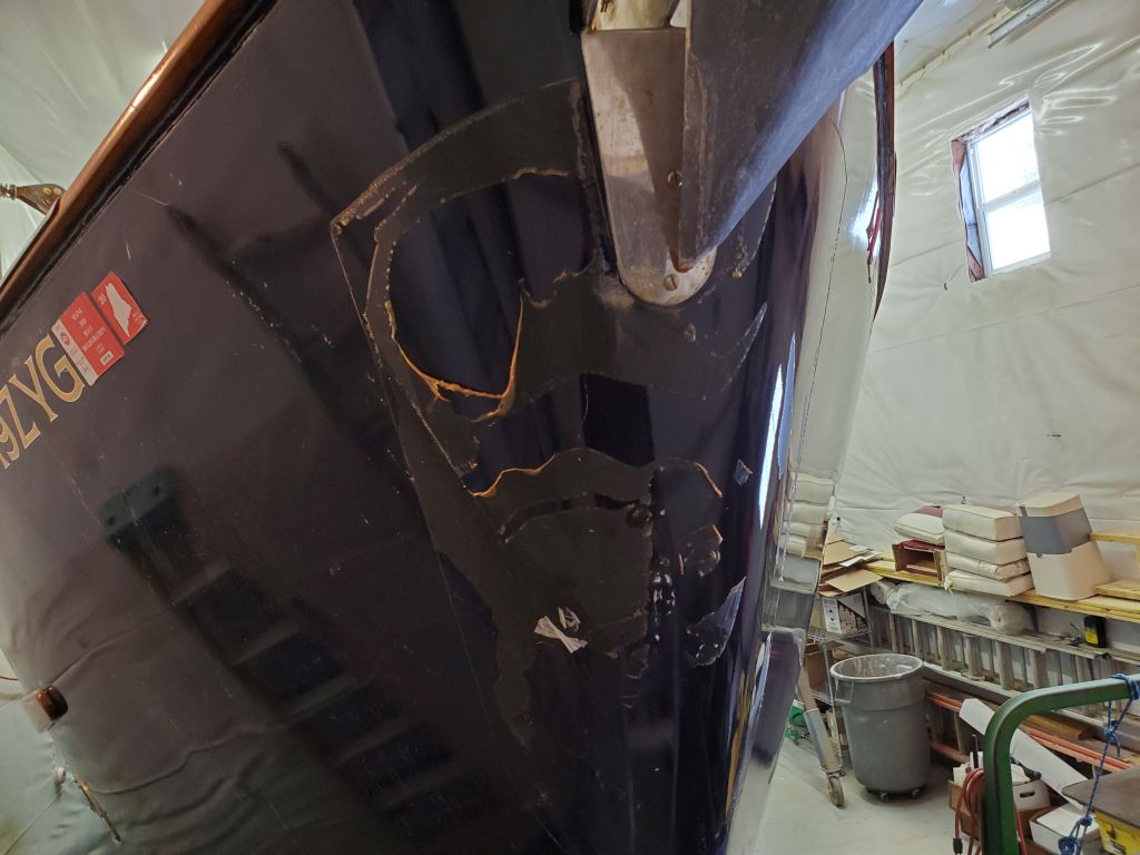
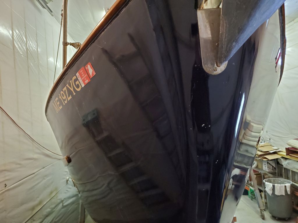
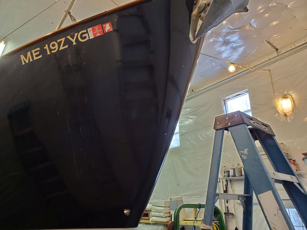
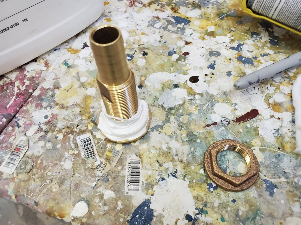
Finally, the owner had mentioned that the original rollers in the stem fitting were worn and broken, so I removed the pin and rollers so I could look for suitable replacements.

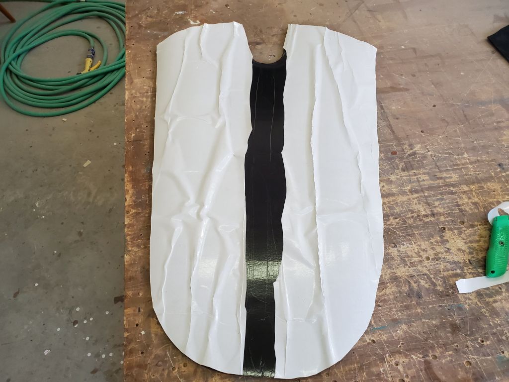
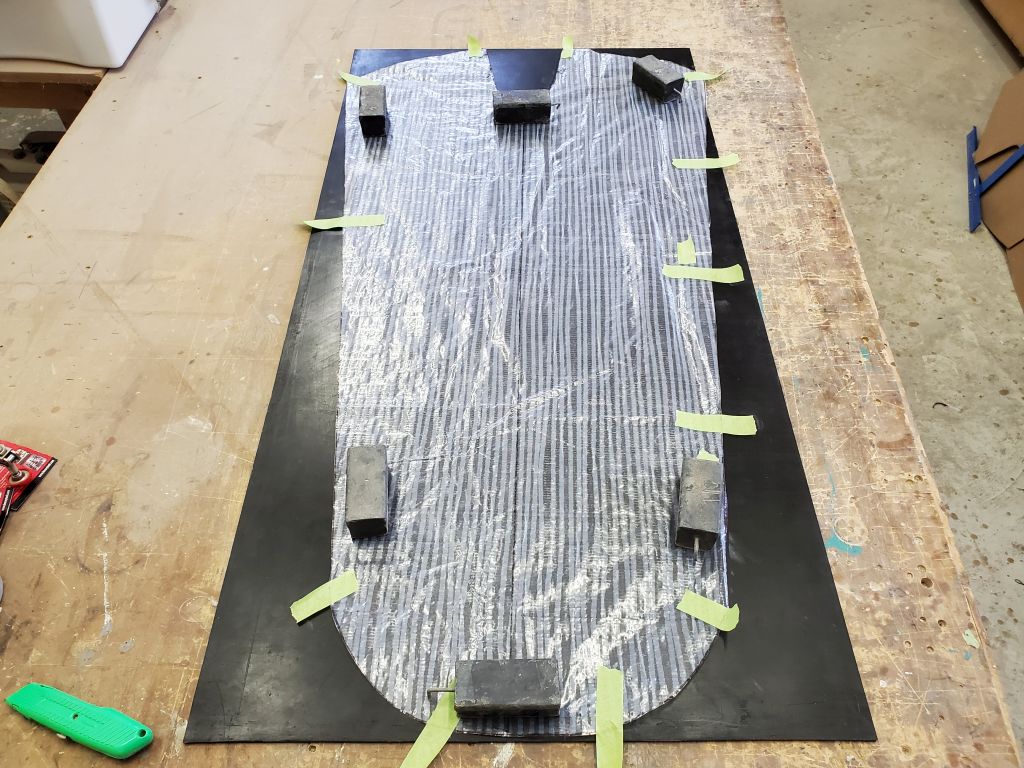
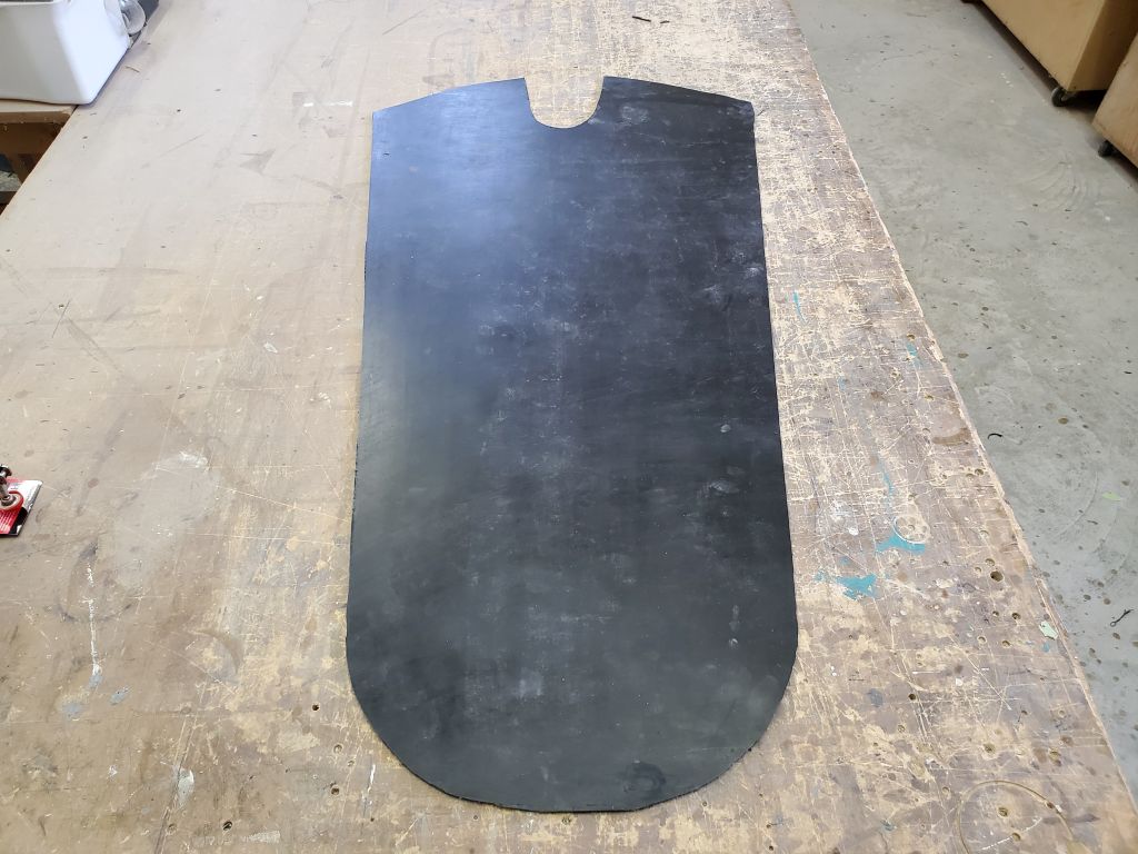
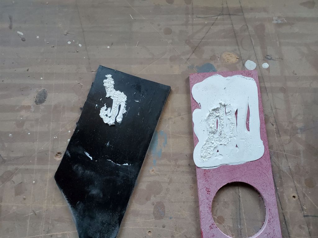
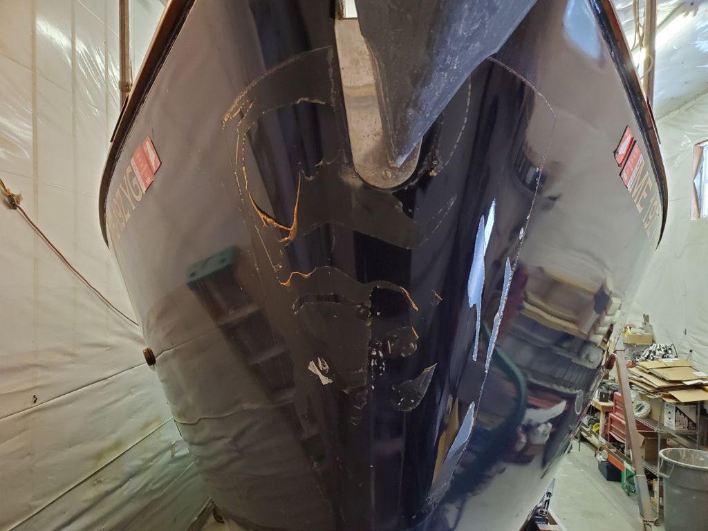
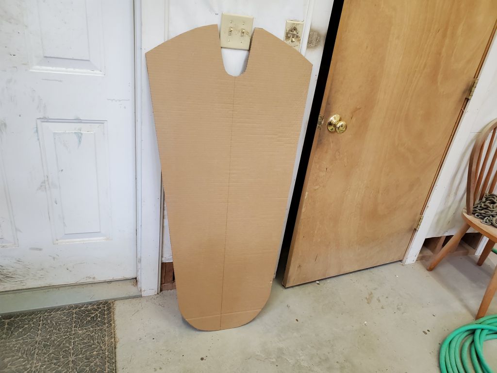
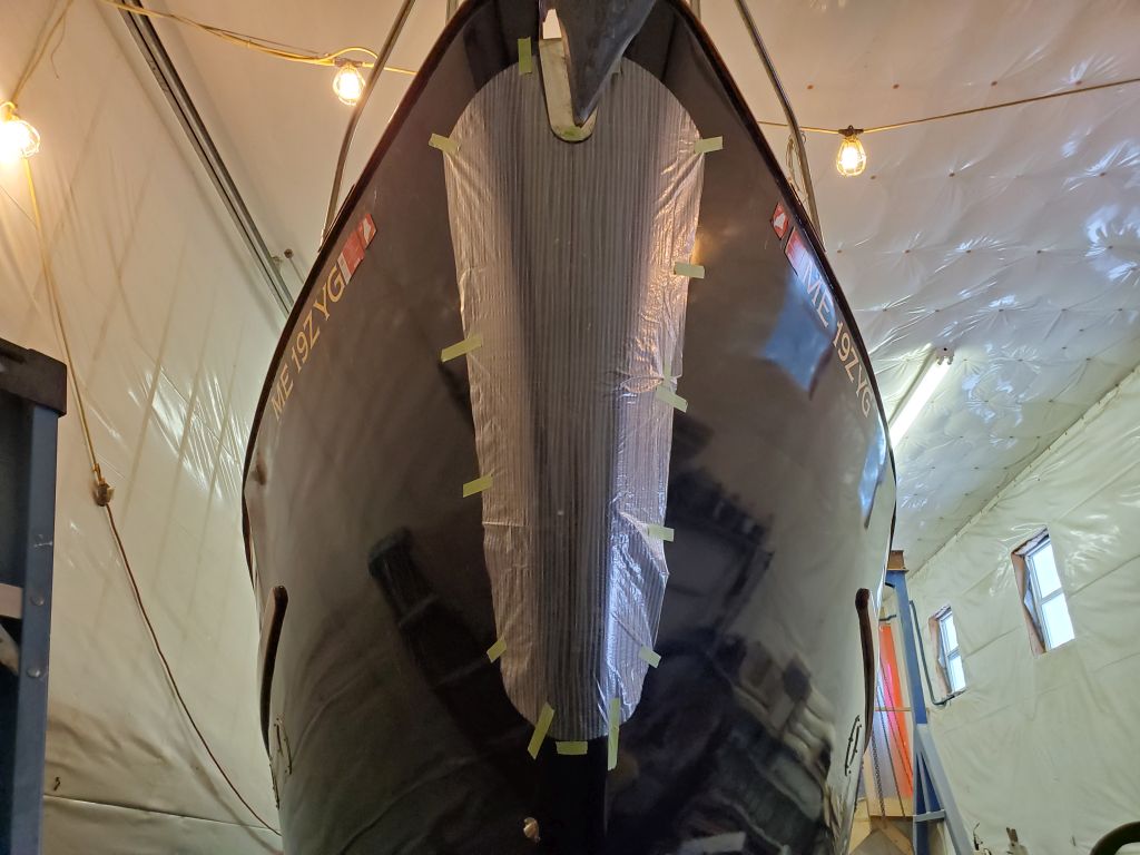
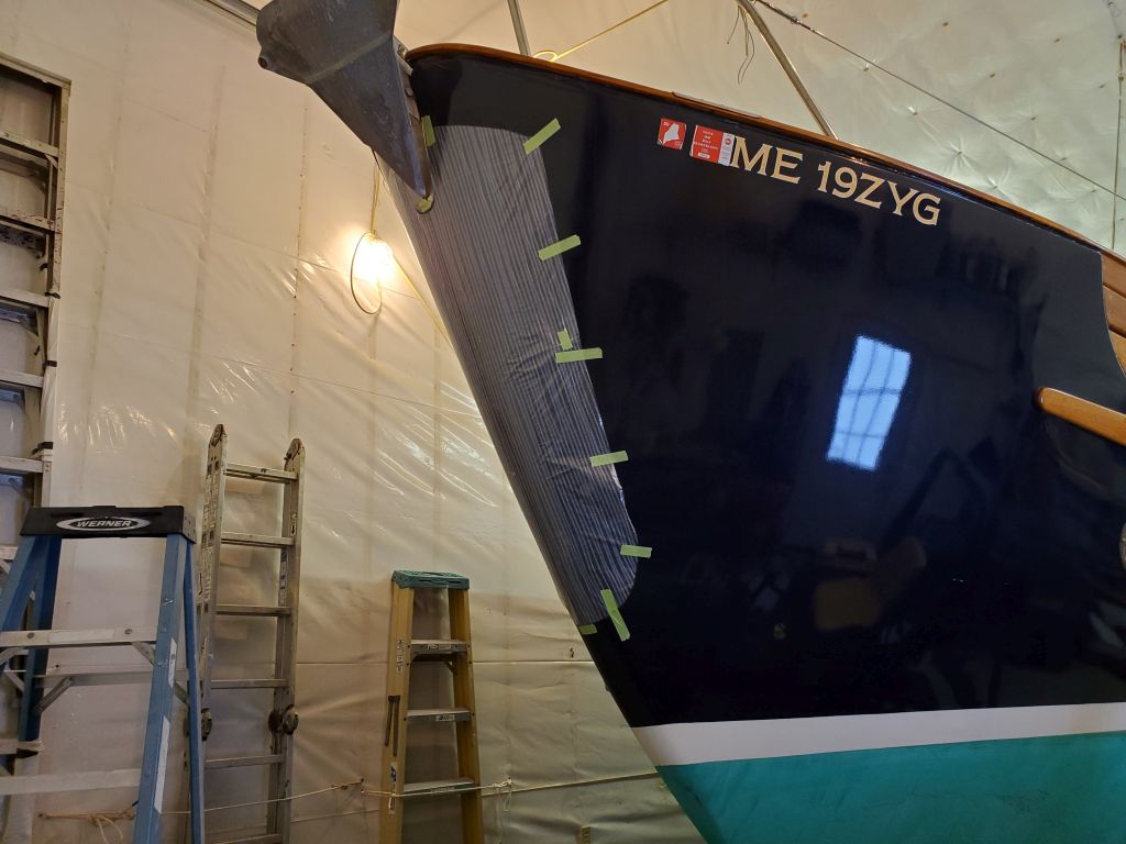
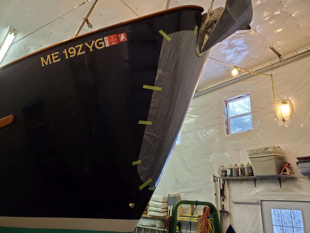
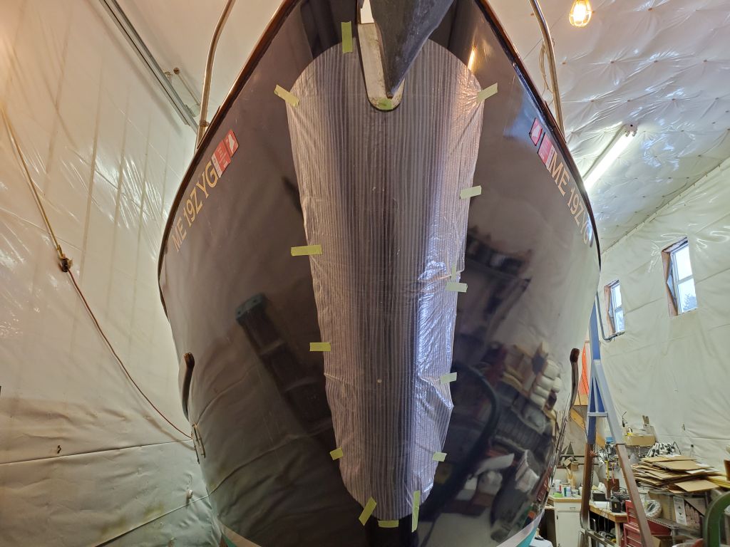
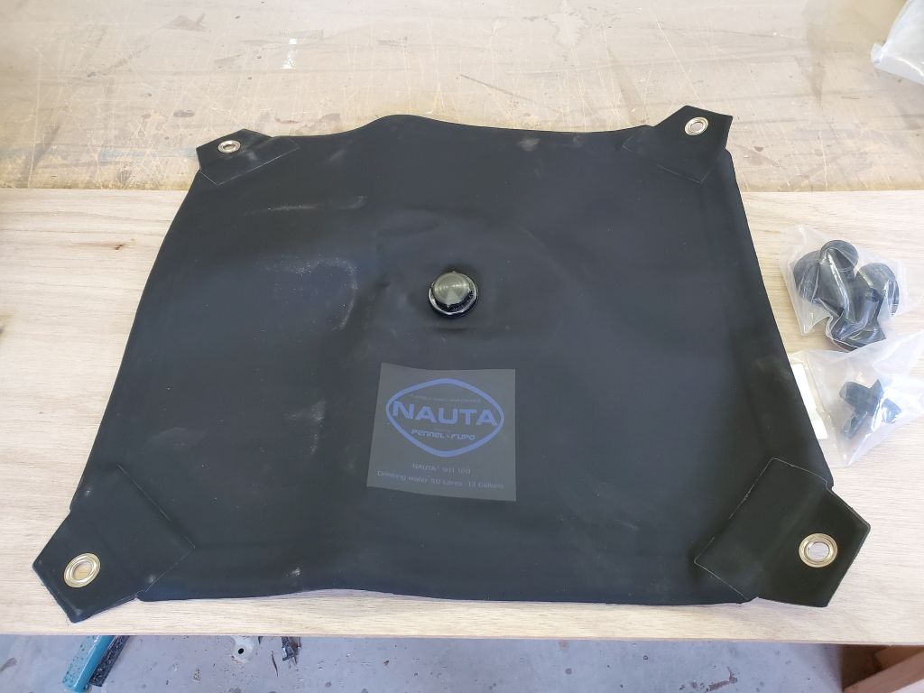
In other recent works, a few days earlier I’d begun–and then set aside–installation processes for the new anchor padding on the stem.  I cut the new material to size according to the pattern I’d made, and was getting ready to test-fit the new piece when I found that tape wouldn’t stick to the rubber.  No tape, any tape I had on hand.  I tried them all, but none stuck even a little.

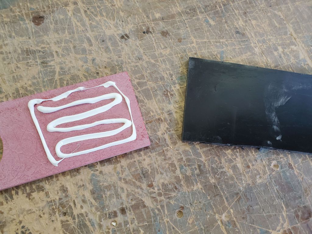
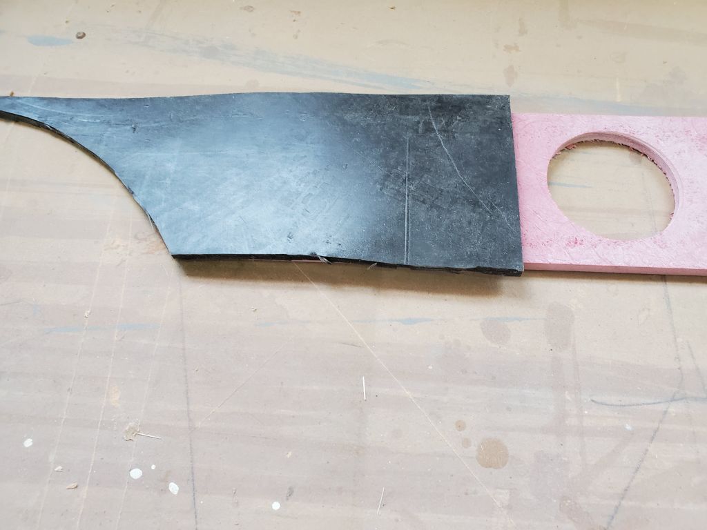
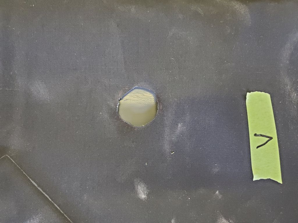
Since I would have to rely on tape to help hold the piece during installation, this posed a real problem, but worse, it called into question the ability of any adhesive to stick to the rubber.  I’d planned to use 5200 to secure the rubber permanently, since I thought that stuff stuck to anything, but, fortuitously, now I realized I had better do a test.  I happened to have an older tube of the adhesive on hand, and since it was still usable (if old enough that I’d not planned to use it for the project), I used a scrap of the rudder and some scrap fiberglass to do a test.  After allowing the adhesive to cure appropriately, I found that the rubber peeled right off; the adhesive was well-stuck to the fiberglass, but not one iota to the rubber.  That little bit that happened to remain on the rubber came right off when I touched it.

Clearly, this forced a change of plans and materials for the anchor padding, and after detailed discussions with the owner we decided to use another self-adhesive type that I’d found, with the understanding that even several years of good use would be enough given the ease and relative inexpense of the stuff.  So I ordered the new material, and we lived to fight another day.

Total time billed on this job today:  3.25 hours (including previous work)

0600 Weather Observation:  -4°, clear.   Forecast for the day:   Increasing clouds, 29°.  Snow beginning overnight.

Lively Heels Phase 3-10

Friday

I finished up the battery reinstallation by leading in the cable bundles I’d removed earlier and making all the connections.   This went more quickly than the removal.  At the same time, I replaced the terminal-mounted system fuses with 200-amp versions, instead of the 150-amp fuses that had been there originally.  This was because the owner had an issue once when the windlass overloaded, which, because the system fuses were the same amperage as the windlass circuit breaker (150 amp), the overloaded windlass blew the system fuses rather than simply tripping the breaker–clearly an unsafe and unintended situation.  The larger system fuses were well within specs for the 12-volt system as installed and used, but would ensure that any future windlass overloads would trip the more easily-resettable breaker.

With the wiring back in place and complete, I could button up the battery box and call the work in the engine room complete for now.

Next, I took care of a quick item from the list:  Installing a brass oil lamp in the main cabin.  The owner had this lamp from a previous boat, and he suggested we install it to cover the hole left from the old heating thermostat.  This was a simple installation.

Sticking with the themes–lighting and simple and leftover from other boats–I next installed an LED lamp in the large locker forward of the galley, which I might even call a closet from time to time.  This lamp had some minor cosmetic damage, but was perfect for a hidden space like this.  I wired and installed the lamp on the aft bulkhead, and ran the wires down and beneath the main shelf where there was a spare circuit and wire terminal available to easily connect to.  Once I figured out which circuit breaker in the panel was the correct one (heretofore unused), the new lamp tested operational, and I added a label to the breaker for future use.

When this owner purchased the boat six years earlier, one of the things we added was a rubber shield at the stem to help protect the fiberglass from the anchor.  This simple installation, which used a firm rubber with a self-adhesive backing, had held up and worked surprisingly well over the years, but now had come slightly loose in a couple areas near the bottom.  Years of use in the real world had also suggested that the padding might extend further down the stem as well, with one large ding in the center of the stem (just below the current padding) as visual proof of this.

Quite frankly, I would have happily chosen the same material again, perhaps thicker than the original, but I couldn’t find any self-adhesive product in appropriate sizes:  Lengths long enough to extend the protection as we wanted were too narrow, and wide enough widths were not long enough (the original piece used a full length of the material).  So instead, we decided to use a non-adhesive product and install it with a shop-applied adhesive.  I chose a material with appropriate hardness and durability characteristics and available in a precut size (24″ x 48″) that would work for the application.

With the loose edge, it was easy to remove the old rubber by hand, leaving behind some adhesive residue (not as much as I would have feared) that I removed at some length.  I found that much of the old adhesive could be rolled off by hand like rubber cement, but there were some areas that required use of solvent to clean up.

Using the old rubber as a general guide, I made a cardboard pattern to the new shape desired, extending the length to 48″ to match the new material.  Then, to test the fit on the stem, I transferred the shape to some clear pattern material, which I taped in place on the stem.  This fit fairly well, and the extra length would give greater protection when raising the anchor, but the plastic formed a few wrinkles that I wasn’t sure how they might translate to the rubber material.   I left this as is for now, and with an owner meeting scheduled for the weekend we could discuss the details before committing to final installation with permanent adhesive.

Total time billed on this job today:  5 hours

0600 Weather Observation:  24°, snow shower with a dusting.  Forecast for the day:   Scattered snow shower, 36°

Lively Heels Phase 3-9

Thursday

First thing, I reconfigured slightly the new potable water hoses and valve system to change the alignment of the hose connection for priming and winterizing, returning it to its original orientation.

Several years ago, an accident damaged irrevocably the starboard water tank, leaving it without a top.  With tank repair or replacement in kind not practicable,  the owner used the remaining plastic bin for storage in the meantime, but for his future plans hoped to add at least a bit of extra potable water storage on board to replace the  missing volume.  His idea was to install a bladder tank inside the old shell, with whatever capacity it could give.  Studying the available sizes of these tanks, we eventually settled on a 13-gallon model that would fit physically in the space; others with larger capacity were the wrong shape, too long or too wide to work here.  I test-fit the tank to be sure it would work, and to get a sense of where the fittings should go.

Before I could install the new tank, I had to install three fittings:  fill pipe, vent, and supply.  This was a straightforward, if occasionally frustrating, process involving cutting holes of the exactly correct size and pushing flanges larger than the holes themselves somehow through the holes, before installing clamp rings and washers that secured the parts together and provided a watertight seal.  I installed the fill and vent near what would be the top edge of the tank, and the fill down near the bottom.

Now I could lay the tank in the clean plastic remains of the old water tank (this would cradle the filled bladder very well, with no sharp edges or rough spots to worry about), and connected the fill, vent, and supply hoses, installing new, longer hoses as needed for the supply and vent.  After temporarily moving a wire bundle to make room for the new supply hose installation, I resecured it where it belonged.

An upcoming project on the boat was to add some shelving and improve storage in the large locker across from the head, which now had only two widely-spaced shelves.  To that end, I measured up the space so I could get materials ordered, and to give the owner some sense of the available shelf space for ordering storage bins to maximize the utility of the revised spaces.

With the regular arrival of the shipping courier, I could get back to work on, and finish up, the engine bypass/heating system plumbing in the engine room.  Specifically, I’d been awaiting a replacement hose nipple with female threads to fit the water heater coolant outlet so I could attach one of the existing hoses leading to the coolant recovery tank next in line.  I had also needed a splice fitting so I could interconnect the remaining two hose ends, which would complete the circuit from the coolant tank to the pilothouse fan heater and beyond.  This new plumbing plan greatly simplified and cleaned up the chaotic, tight space around the water heater.  Note that the clear potable water hoses still dangling are the way they are here because of how the owner winterizes the water system by bypassing the water heater when running through antifreeze; the two clear hoses dangling from the tank itself normally get connected to the ends of the loop dangling low.

After some final cleanup in the area, I could reinstall the removable platform with the electric bilge pump, and reconnect the pump’s hoses and wiring.  I’d removed this early in the process to improve access to the after corner of the engine room.

With the work in the engine room wrapping up, and a little time left in the day, I reinstalled the port battery box, then installed the batteries and their watering system.  I’d finish up the cable reinstallation next time to complete the work here.

Total time billed on this job today:  5.5 hours

0600 Weather Observation:  12°, partly clear.  Forecast for the day:   Partly sunny, 27°

Lively Heels Phase 3-8

Wednesday

I spent the bulk of the day working on reconfiguring the old heating system, picking up where I left off by beginning to make order of the remaining hoses, and working up a plan for the new and simplified engine-based system.

Considering the various components at hand, and taking the most logical and streamlined approach possible, I came up with a new plumbing plan to guide me through the physical work.  The new system would begin at the engine’s calorifier outlet on the starboard side, incorporate a system drain at the low point, and fire first the water heater, then the two cabin fan heaters, before returning to the port side of the engine at the calorifier inlet.  Shutoff valves near the engine on each side would allow the entire heating portion of the system to be shut off and isolated should it be desired or necessary.

Sorting through my abundant collection of plumbing fittings, including some that had been part of the original system, I eventually determined a few additional pieces I needed and placed an order so I could get them here soon, which would allow me to wrap up the reconfiguration work.  Before beginning, I had to drain the rest of the coolant from the engine side of the system, which I’d hoped not to, but there was simply no way to avoid it given the changes in the hoses and fittings ahead.

Working with fittings on hand, I strove to complete everything that I could while I awaited the new fittings, starting with the return line from the cabin fan heater to the engine, which led from beneath the helm console.  I chose to secure this hose to the pair of mounts leftover from the heat exchanger that I’d removed the day before, since the mounts would cradle the hose well and because I couldn’t easily remove the brackets anyway, since they had blind fasteners through the engine room panel.  I chose to mount the shutoff valve on the panel just aft, making a more convenient and cleaner installation as I finished the hose run to the port side of the engine, which was the calorifier inlet.

Note that many of the progress photos show pieces and remnants of the old system that are not part of the revised setup, and would disappear in due course.

The domestic water heater had originally been plumbed with shutoff valves beneath the coolant inlet and outlet, but along with the various plumbing changes and desire for simplification, now I elected to remove these hose stubs and reconfigure entirely how the water heater fit into the plan.  Also, I needed to change one of the outlet fittings to accommodate the hew hose connection that would lead from the water heater outlet to the coolant expansion tank, so I simply removed both threaded fittings and their attached hose stubs, since this was frankly easier than trying to remove the hoses from the barbed fittings, given the tough access to the space and the myriad other plumbing and wiring runs in the area.

The new fitting for the outlet was one of the things I’d had to order, so I couldn’t complete that side now, but for the inlet I installed a new 3/4″ hose barb on the water tank, then attached an overlong length of hose that would eventually connect with the engine coolant outlet.  Three remaining hose ends, marked with green tape, awaited final connections with the new fittings when they arrived.  For now, after a couple fits and starts as I worked out the best hose run, I secured the coolant inlet hose to the nearby cockpit scupper hose, running it down towards the centerline and the aft end of the engine.

To complete this hose run, I modified the existing (old) coolant hose by changing the position of the shutoff/isolation valve and drain fitting, again striving for simplicity, appearance, and convenience of use, as well as rerouting away from chafe points.  The drain fitting featured a garden hose attachment on the end that would allow ease of draining or even filling using the electric pump the owner had for this purpose.

For the moment, that was as far as I could take the job, but once I received the plumbing fittings I needed I could (hopefully) finish up the replumbing work in relatively short order.  In the meantime, I took a few minutes to reinstall and reconnect a terminal block in the engine room, near the forward end of the port side, that provided a circuit and attachment point for the electric coolant priming/draining pump the owner used.  I’d mistakenly removed this terminal block and wiring earlier in the dismantling process.

Next, I moved across to the starboard side, in the utility space above the tankage outboard of the engine room.  Over the past years, the owner had traced some frustrating potable water system priming problems to the potable water filter and its oversized hoses that had originally been mounted in this space, and he’d removed the filter at some point, which cured the problem.  However, some of the larger 3/4″ hose remained, and to bring the whole system back to overall spec we decided to replace the larger hose with the 1/2″ hose used throughout the rest of the system.

I removed these pieces of hose, along with the priming spigot built into the system, and took it down to the bench to rebuild with smaller nipples and new hose.  This part was straightforward, but I found that the two barbed fittings I had to changed up in the boat–at the water supply manifold and at a tee fitting just before the water pump–the pipe dope I’d used during initial installation years before was extremely tenacious and resisted removal, so eventually I had to use some heat to loosen the grip, after which replacing those fittings with 1/2″ barbs was easy.

When I reinstalled the hose and fittings section, I’d forgotten how it had been routed originally, but discovered as I reviewed photos for this log that I’d not installed things in the correct orientation; the priming nipple, with garden hose connection and which the owner used for winterizing as well, would certainly be more convenient in an up-facing direction as it had been (see photos above), so I planned to rotate and reroute things as needed to correct this small error.

Thus endeth the day.

Total time billed on this job today:  7.5 hours

0600 Weather Observation:  23°, overcast.  Forecast for the day:   Cloudy, isolated snow showers in the afternoon, 32°

Lively Heels Phase 3-7

Tuesday

I got started back at the holding tank vent, beginning by drilling a new hole for the replacement hull vent fitting.  For the new vent, the owner requested a normal bronze through hull, which not only would resist the corrosive influences of the effluent (even for the affluent), but would be easier to clean and maintain if necessary; apparently this had been an ongoing problem with the old system, though that was probably related to the supposed “treatment” of the waste with the old Electro Scan.

I installed the new 3/4″ fitting with plenty of sealant, and, once installed and cleaned up, ran new 3/4″ hose from the hull fitting into the compartment where the tank would ultimately be installed once it arrived.  Fortunately, the hole through the bulkhead, leftover from the original vent hose and located in a tight, nearly inaccessible V-shaped corner, was large enough for the new hose, so I was spared the challenge of enlarging it.

While I was in the space, I decided to re-secure the wiring leading to the head shower sump pump.  This wiring had originally been led, along with some of the cabling and wires for the old electric waste treatment system, along the top and side edge of the port partition in the locker, but now I decided to run it along the underside of the locker opening, which made sense now anyway, and also allowed me to clean up those loose wires now.

Until the new tank arrived, I was done with the head and environs, so next I turned to the other continuing dismantling/reconfiguration project to remove the remnants of the old diesel boiler system and simplify the plumbing for use with the engine alone.

After deciding, in consultations with the owner, to use only the engine coolant bypass to operate the pair of fan heaters (pilothouse and main cabin) and the water heater, most of the complicated plumbing from the original system was now extraneous and could be removed.  This would greatly clear up the clutter in the engine room and elsewhere.  In order to get at parts of the old system, however, I first had to remove the port battery box, which contained two 6-volt house batteries and the engine start battery, and blocked access to some of the components.  In theory this was straightforward enough, but in practice it was time-consuming and complicated, as there were myriad wires and cabling running through the box, along with a battery watering system for the house bank, and not only did I want to ensure it was easy to reconnect and reinstall everything, but also strove to minimize as much as possible how much I needed to dismantle.

After documenting and labeling all the connections (the wires and connections had been labeled by the owner at some point, but I did my own too), eventually I disconnected and moved temporarily out of the way all the wires and cables, leaving the batteries clear for removal.  I secured the cable masses up at the forward end of the engine room for the duration.

With the way clear, I removed the watering system from the house bank and replaced the original battery caps for now, then pulled out all the batteries.  This exposed the fasteners that held the battery box to the structural members beneath, and from here removal was as easy as one would think.  The hull beneath the batteries wasn’t as dirty or full of dropped things as I had expected; I knew I’d dropped things down there myself during past work sessions on the boat over the years.  I spent a little time cleaning up the hull and removing the minor debris before continuing.

Ready now to remove the old hoses, first I needed to drain the coolant from the heating side of the system.  For this, I planned to use a portable pump that the owner and I had set up years ago to help charge (or drain) the system, but when I hooked it up to a battery the pump didn’t run for some reason.  This was frankly unimportant at the moment, so rather than waste time troubleshooting I drained the coolant into the bilge, where it ran out the garboard drain to be caught in a bucket outside the boat.

With the bulk of the old coolant drained from the system by gravity, I started on the starboard side, removing mounting ties and eventually removing the red hoses that led to and from the green coolant expansion tank mounted there.  I cut the hoses as needed in strategic locations to ease removal and avoid fighting the hoses off hose barbs.  Later I planned to salvage hose clamps and good plumbing fittings, but for now I just wanted all this stuff out of the boat.

The photos below strive to show the existing plumbing (all red hoses) in their existing state around the forward and starboard sides of the engine room, as well as in the starboard compartment outboard of the engine room leading to the coolant tank.  Once I’d removed all the hose I could remove the green tank and its cradle, freeing space and mindset.

Continuing, I removed the rest of the red hose from the system, now on the port side of the engine room, along with the heat exchanger that had allowed use of either the engine heat or old boiler heat to run the system–the long green one that had been located outboard of the battery box.  I also removed the old line pump, no longer needed.  The black hoses left behind near the engine and in the after part of the engine room (near the not-seen-here water heater) are either parts of the engine coolant bypass system (equipped with valves that I shut off before cutting the hoses beyond them), or parts of the heating system that will be reused, and cleaning up and connecting these various pieces and parts into the new configuration would be in the docket in the coming days.

With the old plumbing out of the way, I spent the remainder of the day re-securing the potable water hoses in the starboard locker outboard of the engine (their ties had been cut in order to remove the heater hose), and securing the wire bundles along the starboard side of the engine room.

Total time billed on this job today:  6.5 hours

0600 Weather Observation:  18°, clear.  Forecast for the day:   Sunny, 28°

Older posts Newer posts