(page 3 of 5)

Lively Heels Phase 3-26

Friday

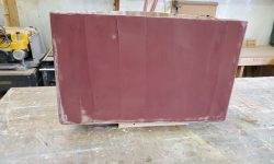
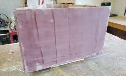
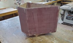
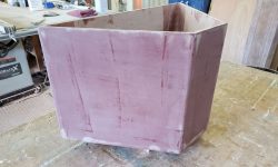
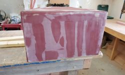
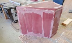
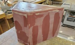
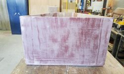
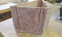
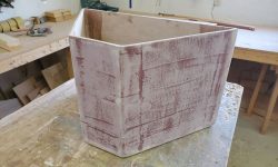
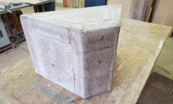
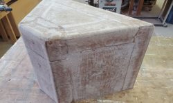
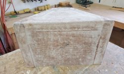
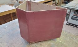
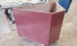
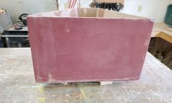
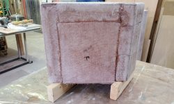
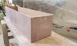
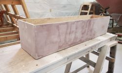
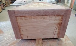
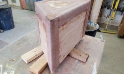
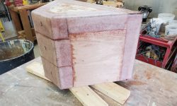
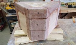
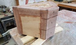
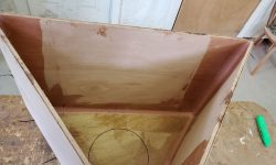
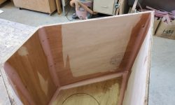
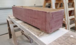
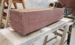
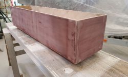
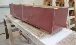
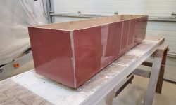
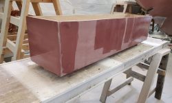
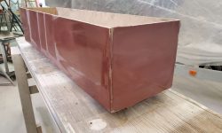
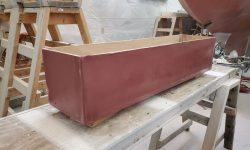
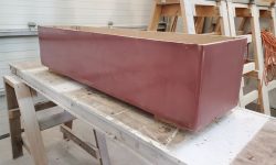
During the week, as time allowed, I continued work on the cockpit storage box fairing, starting with the newly-sanded first coat that I’d left from the weekend.

Second round of fairing:

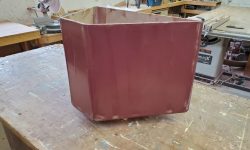
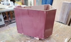
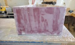
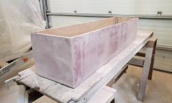
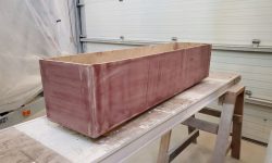
Another round of light sanding, then a third, minor, coat of fairing:

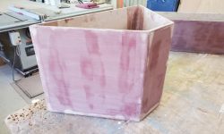
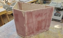
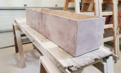
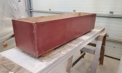
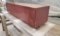
One more round of finish sanding brought the cockpit box to ready-for-primer state.

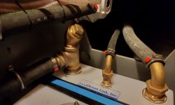
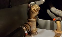
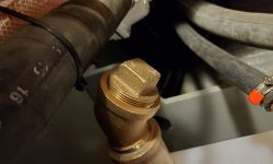
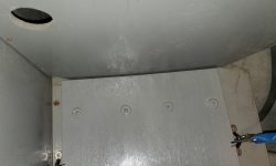
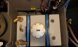
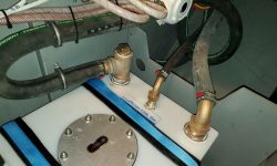
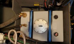
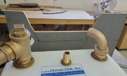
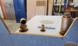
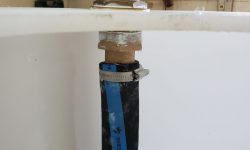
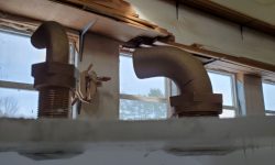
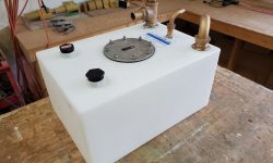
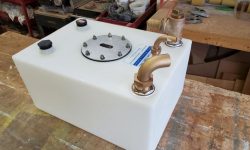
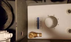
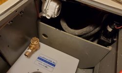
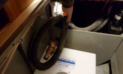
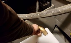
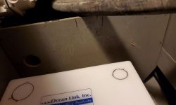
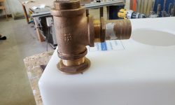
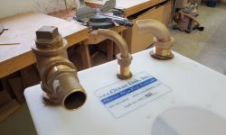
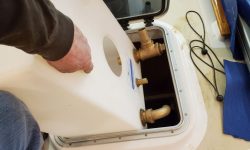
At the holding tank, I installed a 45° elbow at the top of the pumpout tee to provide better access:  The original setup  had been somewhat impeded by the hose directly above, an oversight that could easily have been (but wasn’t) avoided with a slightly different location for the fitting in the tank.  Fortunately, the elbow made for a quick and successful fix.

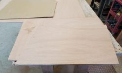
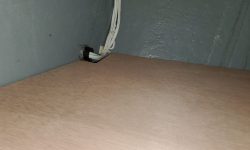
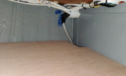
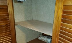
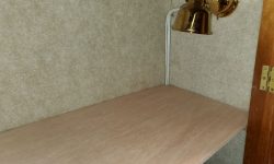
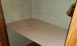
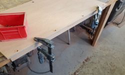
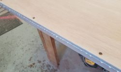
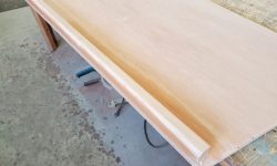
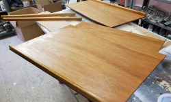
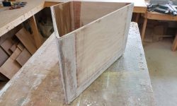
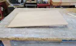
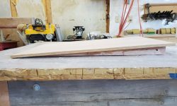
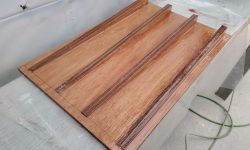
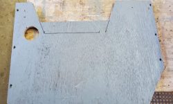
Continuing the closet shelving project, I transferred the marks from my cardboard patterns to a sheet of 12mm marine plywood and cut out the new shelves, which fit well on the first try other than needing to cut out a little corner of the top shelf to allow for some wiring to pass.

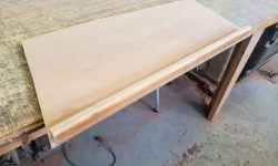
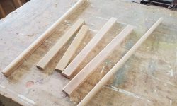
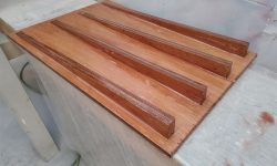
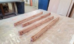
For all the shelves, to help hold the proposed storage bins in place while still allowing the bins to be removed (more of a concern with the lower shelves where clearances were tighter), I milled 1″ tall fiddles from cherry and cut them to length to span the widths of each shelves, including the two original shelves still in place.  These fiddles would also add strength and stiffness to the relatively wide shelves.  With the two new shelves available on the bench, I chose to install these fiddles now, using glue and screws.  I’d install the remaining fiddles on the other shelves in place a little later.

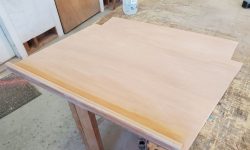
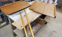
In keeping with the existing shelves, I chose to finish the new shelves with varnish, which looked pretty good even on the meranti plywood but more importantly would provide protection going forward.  I applied a thinned sealer coat of varnish to both sides of the new shelves, supporting them on some simple spikey things I use from time to time, and also finished the two new fiddles for the existing shelves.

Total time billed on this job today (and preceding days):  3.25 hours

0600 Weather Observation:  15°, clear.  Forecast for the day:   Sunny, 30°.

Lively Heels Phase 3-25

Monday

After some shipping delays, the straps I’d ordered for the holding tank arrived, and with an afternoon available I looked forward to finishing the installation.

I began by reinstalling the modified port divider in the holding tank compartment.

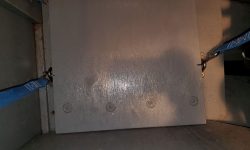
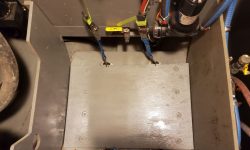
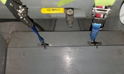
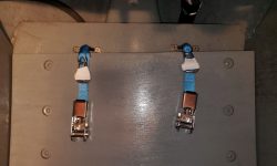
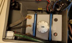
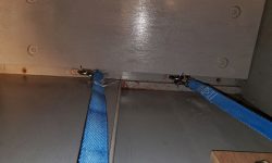
After determining how to position the new angled base platform to allow room for the stainless eye straps that would hold the ratchet straps to secure the tank, I installed the platform with eight screws, four to a side, through predrilled holes in the platform, and with slight recesses to accept the screw head and a washer.  I secured the eye straps to the sole substrate with screws and pre-attached both ends of the ratchet straps, which featured stainless steel buckles and carabiners at the ends.

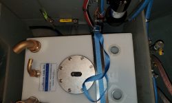
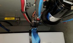
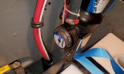
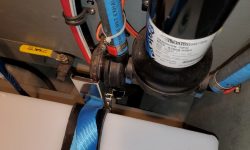
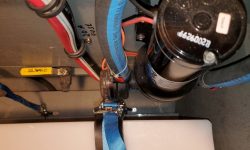
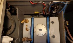
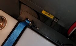
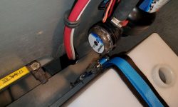
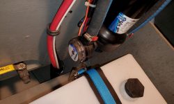
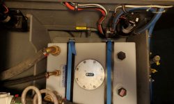
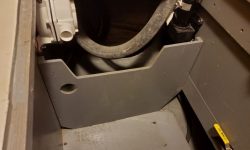
Now I could put the tank in place.  The tank fit easily through the overhead hatch, as planned, and soon it was in position.  However, I immediately ran into a problem.  Because of the various tank fittings, the hold-down straps only worked in two obvious areas where the way was clear–no problem there.  I’d used these positions to locate the eye straps and ratchet straps in the compartment.  What I’d not foreseen was a twofold problem:  First the starboard strap and ratchet buckle ended up interfering with the saltwater washdown pump and its filter housing, which were located on the bulkhead just ahead.  This meant there wasn’t clearance to operate the ratchet, and it also posed an ongoing clearance issue for the filter assembly.

In addition, the two ratchet buckles ended up closer to the top corner of the tank than I’d wanted, by virtue of the 12″ dead end measurement of these (and most similar) straps.  The starboard buckle, notwithstanding the filter issue, was more or less OK because the tank was higher on this side because of the angled platform.  But the port buckle (not shown here) ended up awkwardly and unacceptably at and just above the corner of the tank, and tensioning it in that position would likely tend to put undue pressure on the tank itself.

In a vacuum, as it happened, I could have made the starboard problem work, since the filter assembly and hose from the pump were actually easy to remove at a whim thanks to the design of the pump housing (a little plastic clip holds things in place).  So by removing the filter and hose assembly, I had enough room to operate the ratchet, and then reinstall the filter.  But this still wasn’t ideal, and in the end the fix for the port side worked a treat for the starboard as well.

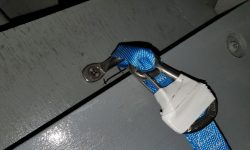
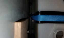
The fix was to take the carabiners on the buckle side of the ratchet out of the picture.  Fortunately, I could remove easily enough the eye straps and slip the sewn loop of the ratchet strap over the eye, then re-secure the eyes.  Because the carabiners were permanantly attached, with the webbing sewn though a closed eye in the hooks, I couldn’t remove them, so I taped them above the webbing loop and out of the way to keep them from flopping around loosely.

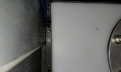
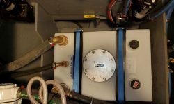
This had the net effect of lowering the buckles by close to three inches at each location, which solved both issues nicely:  On the starboard side, the buckle was now below and clear of the pump housing (check); and on the port side, the buckle was now nicely below the tank corner where it could be safely tensioned (check).  This was a relief.  Now I could strap down the tank properly and finally, using some strips of 1/4″ thick rubber (left over from the first attempt at the new anchor pad on the stem) as chafe gear beneath the straps.

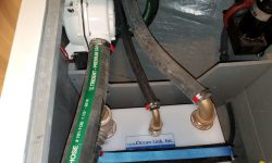
Continuing, I moved on to the hose connections, which were straightforward and didn’t take long, and went according to plan.  I secured the loop from the tank discharge to the nearby  pump with a pair of clamps to hold it securely and avoid any undue tension on the fittings at either end.  Afterwards, I reinstalled the water lines to the head shower setup, which I’d removed for access early in the project, cut off the excess strap length from the tank hold-downs, and wrapped up other details in the space to call this installation complete.

Total time billed on this job today:  3 hours

0600 Weather Observation:  12°, partly clear.  Forecast for the day:   Mostly cloudy, snow and rain in the afternoon and evening, 35 °

Lively Heels Phase 3-24

Saturday

After a brief round of sanding to the first coat of fairing filler on the cockpit box, I set it aside, planning to add the second coat of fairing later in the day, but I didn’t end up getting around to it after all.

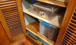
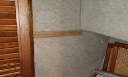
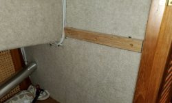
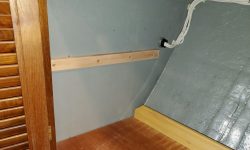
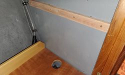
I’d hoped to use the day to finish up the holding tank installation, but alas, hub-related weather delays at FedEx had tied up the straps I’d ordered for the task, which were now days late but supposedly in my state at least, so I hoped they’d be delivered soon.  Instead, I turned to a wholly different project:  Some additional shelving in the large locker forward of the galley, across from the head.  Here, I’d originally, during the main project years before, installed just two shelves, mainly because of time constraints:  a low shelf, which had originally been intended and sized to hold an ice chest; and a large shelf about halfway up.  Now the owner was more than ready to have this space better available and more useful for the large amount of storage it could hold.

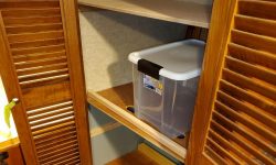
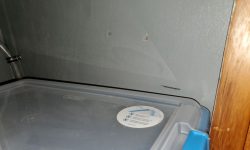
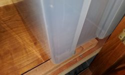
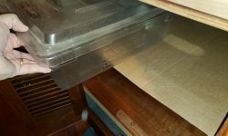
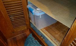
Earlier, the owner had mocked up some plastic storage bins he hoped to use in the space, and these would dictate the relative placement of two new shelves.  Using these bins as a guide, and allowing for room to pass the bins over fiddles at the inboard ends of the shelves (to be installed later), I determined the location for new shelf support cleats and made various measurements for the cleats themselves.  Most crucial was allowing room for the two bins in the lower space–the large bin (shown here) on the lower shelf, and a shorter bin to fit in an upper shelf.  There was enough room for both, but not a lot of room for leeway.

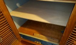
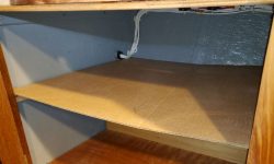
The new uppermost shelf would fit just at the space in the closet where the cabin trunk began, and would be much shallower than the other shelves below it, which extended all the way to the hull below deck level.  With the measurements complete, I milled four new shelf supports from scrap hardwood, along with some new shelf fiddles to help secure the storage bins, and prepared and sanded these all smooth before installing the cleats on the bulkheads for each new shelf.

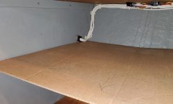
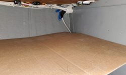
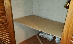
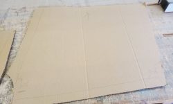
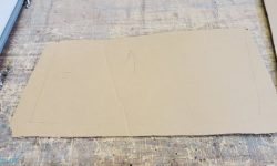
After some basic measurements, I cut cardboard roughly to size to fit each new shelf location loosely, and scribed the actual shape and dimensions of the two shelves directly on the cardboard mockups, which I would then use to cut the actual plywood shelving to fit accurately.  With the cardboard “shelves” in place, I mocked up the storage bins in the lower shelves to illustrate their fit.

That was all I had time for at the moment, but one more good work session ought to see the shelf project to completion.

Total time billed on this job today:  2.5 hours

0600 Weather Observation:  23°, cloudy.  Forecast for the day:   Cloudy, chance of show showers, 30°

Lively Heels Phase 3-23

Friday

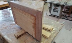
In a short work session, I lightly sanded the new fiberglass on the cockpit box and, after cleanup, applied the first of a few rounds of epoxy fairing compound over the sides.

Total time billed on this job today:  .5 hours

0600 Weather Observation:  21°, cloudy.  Forecast for the day:   Another anemic excuse for a snow event, cloudy with a chance of light snow and little accumulation, 29°

Lively Heels Phase 3-22

Thursday

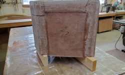
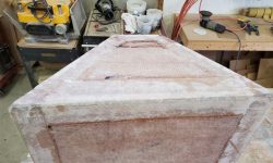
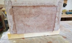
With a new supply of fiberglass cloth on hand, I cut and installed new fiberglass to sheathe the field areas of the box inside of the tabbed corners.

Total time billed on this job today:  1 hours

0600 Weather Observation:  12°, clear.  Forecast for the day:   Partly sunny, 28°

Lively Heels Phase 3-21

Monday

In a short work session, I finish-sanded the main deck box, smoothing the light 4th coat of fairing filler and pretty much completing the exterior prep work for this box.  There’d be additional worn ahead to prepare the interior, to install “feet” on the bottom that would support the box on deck, and to build a lid, before getting to priming and painting.

Meanwhile, I lightly sanded the tabbing on the new cockpit box, smoothing rough edges and preparing it for future steps.

Total time billed on this job today:  .5 hours

0600 Weather Observation:  15°, clear.  Forecast for the day:   Becoming cloudy, snow at night, 30°

Lively Heels Phase 3-20

Sunday

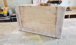
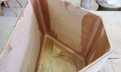
With the cockpit box securely  glued, I removed the zip ties–most of them slid out, but I cut and abandoned the rest–and then lightly sanded and rounded over all the corners of the box to prepare for fiberglass.  Afterwards, I installed tabbing over all the seams, leaving the field areas for another time since I had no appropriate fiberglass on hand at the moment (it was on the way).

Total time billed on this job today:  1.5 hours

0600 Weather Observation:  15°, cloudy.   Forecast for the day:   Cloudy, 29°

Lively Heels Phase 3-19

Saturday

Now that the wedges were securely glued in place beneath the new holding tank platform, I removed the clamps and coated the plywood edges and bottom with epoxy.  These areas would never be seen once the platform was in place.

Using some guide marks I’d made up in the boat during a tank test-fit earlier, I made a relief cut in the portside divider from the holding tank compartment, which would allow clear passage of the inlet and vent hoses to the tank.  I made the opening larger than it had to be because there was no reason not to, but left the bottom edge higher than the top of the tank so it could possibly receive a cleat to help secure the tank, or to support a shelf above.  Afterwards, I painted both sides of the divider to prepare it for reinstallation soon.

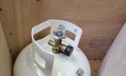
In addition to the large deck box underway for the coachroof, the owner had also requested one in the cockpit, at the aft end, to hold the spare propane tank and whatever else might fit.  I was building these one at a time at the moment because I was juggling two projects at the same time, and now was a good opportunity to begin the next box.  (There’d be two additional, smaller boxes for the coachroof to come as well.)

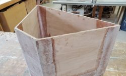
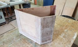
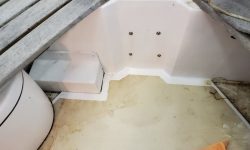
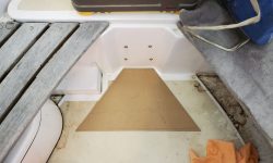
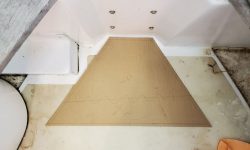
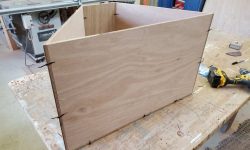
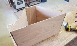
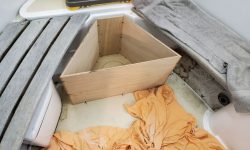
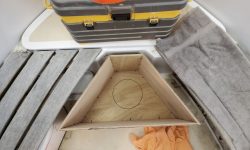
The cockpit in this boat was already small, and with virtually no good storage spaces.  The space in which the new box was to fit was at the aft end of the cockpit, which was angled steeply because of the shape of the boat herself.  To maximize useful space and make the box fit as well as possible in the cockpit, I planned for it to be angled to fill the available space, and after some measurements started with a cardboard template of the bottom.  The new box would be roughly as high as, but not higher than, the adjacent seats on three sides, and the aft end of the box could tuck into the molded recess at the aft end of the cockpit.  The small propane tank would fit nicely in the angle at the aft end of the box, and while it would take up the bulk of the room in the box, there’d be space for other small items, and possibly a removable shelf above the tank for additional storage.

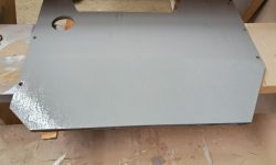
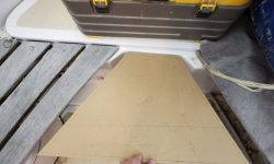
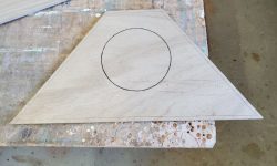
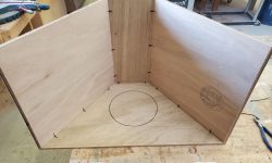
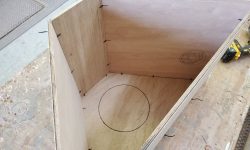
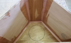
Satisfied with the template, I transferred it to some 9mm plywood and cut out the base, along with a slightly larger version that would eventually form the lid for the box (I set that aside for now).  Using some plywood as temporary stand-ins for the sides and back, I located the propane tank on the base and marked the circle at the bottom of the tank on the plywood, for later use in attaching some cleats that would help secure the tank within.  That was for later.

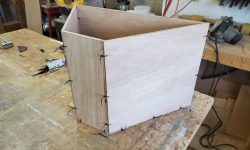
Then, I made up the four sides of the box.  Allowing for 3/8″ high “feet” beneath the box (to keep it clear of the deck), and the 3/8″ (9mm) top of the box, and erring on the short side, the side pieces ended up 15-3/4″ tall, all of which would ultimately fit within the 17″ high maximum space (the height of the nearby seats).  I secured the pieces of the box together as I went with small holes through which I tightened zip ties.

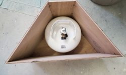
Now I test-fit the tank in the box, showing a roughly 4-5″ space above the top of the tank for an additional shelf.  Then I checked the fit of the box in the cockpit.  The floor space the box used up was not particularly valuable, and in any event the owner had kept the spare tank there in past years, covered with an overturned bucket, so this was only making better and cleaner use of the already spoken-for space.

With the box dry-assembled, I installed epoxy fillets on the insides of the box over all the seams.  These would hold the box together and reinforce the joints along with the fiberglass tabbing I’d later install on the outside.

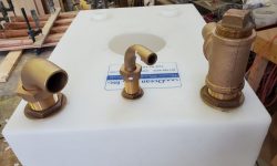
I thought I’d finish up work for the day by permanently installing the fittings in the new holding tank.  Of course this ended up being a tougher job than I’d expected, and harder than it had been doing various dry-fits, but I got it done and was happy to have it so.  I started by making up the diptube for the discharge, using trial and error to eventually get a length of hose (with bottom cut at an angle) to just about reach the bottom of the tank.

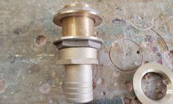
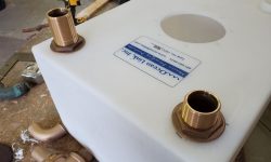
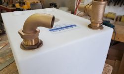
I thought I’d be able to put this hose on the internal hose barb once the main fittings were in place, so I applied 4200 sealant to the bronze discharge fittings and installed them through the tank, only to find that getting the hose on after the fact was impossible thanks to the right fit over the barb and the more-limited-than-you’d-think-it-would-be arm and hand access/dexterity through the inspection port and to the corner of the tank, so I had to remove the threaded barb fitting and put the hose on outside the tank.  Then, I couldn’t get the threads started again–once more, a simple task when dry-fitting, but somehow impossible once the sticky stuff was in play and suddenly the whole thing mattered.

So with some mutterings of displeasure, I removed the top fixing nut (covered in goop), then the entire assembly so I could thread on the base fitting with the hose, and install that whole piece (hose, hose barb, and threaded neck) back into the tank.  This worked, but it was all messier and more time-consuming than it had to be.  I threaded on the bronze tee and tightened it before finalizing the installation so I could ensure it ended up facing the right direction.

With the hard installation out of the way, the remaining two fixtures were much easier to install, also well-bedded in 4200.

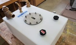
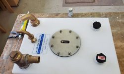
After cleaning out the inside of the tank, I saw no reason not to install the inspection port and remaining fittings.  Once work on the new platform was complete, I could install the tank and finish up the work on the head system.

Total time billed on this job today:  4.5 hours

0600 Weather Observation:  2°, mainly clear.   Forecast for the day:   Mostly sunny, 23°.

Lively Heels Phase 3-18

Friday

After a light sanding, various low spots remained on portions of the long deck box, so I applied additional fairing compound to these areas.

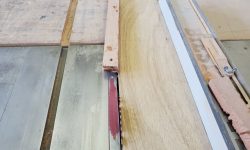
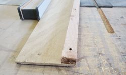
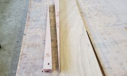
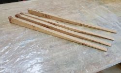
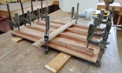
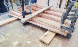
To cut the wedge shapes on the now-cured laminations I’d made up for the holding tank base, I used a long, narrow scrap of plywood to create the simplest possible taper jig.  The wedges were designed to be full height at one end, and tapering to nothing at the other end, so I screwed the blanks to the “jig” in an according orientation, then ran them through the table saw.  I set the offcuts aside in case they might be handy during the tank installation.

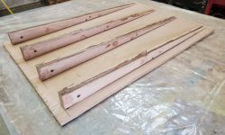
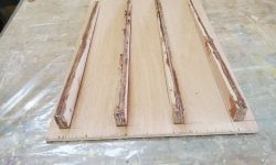
I set up the four wedges along the bottom side of the new platform, more or less evenly spaced across and designed to support the tank evenly, and glued them in place with epoxy, clamping everything securely.

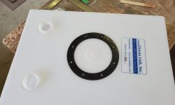
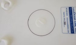
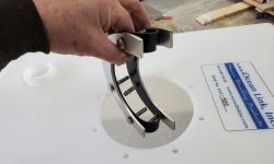
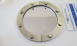
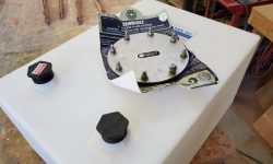
With that work complete for now, I turned to the tank itself and prepared to install the various fittings required.  Key to this whole exercise was the large aluminum inspection port, which would allow access inside the tank to install the three new fittings.  I used one of the supplied gaskets to lay out the large opening (6″), and then the bolt holes that secured the two sections of the inspection port together and formed the liquid-proof seal.  The inner portion of the assembly came in two pieces to allow fitment through the circular opening.  I test-fit the inside piece with attached threaded studs both ways (from inside and outside) to double-check the bolt hole layout, but for now I set the inspection port aside since it’d be easier to work on the other fittings before its installation was complete.

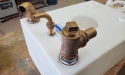
Now I needed to install three fittings:  One for the tank discharge (including options for shoreside pumpout and legal overboard discharge using the new pump I’d installed earlier, and using a bronze tee fitting); the tank vent; and the tank inlet.

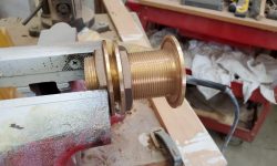
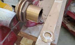
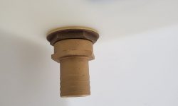
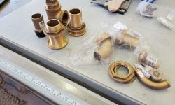
The discharge fitting would require a shop-made diptube (hose extending to the bottom of the tank), which required a hose barb on the inside of the tank; the top side of the tank required threads to which I’d attach the bronze tee fitting.  Since no such hybrid fitting existed, eventually I made up the required piece using the threads from one through hull fitting (after cutting off the mushroom head), two fixing nuts, and a female-thread tailpiece.  I had to make my own threaded nipple from the through hull because the only bronze nipple available (and it is handy at times) is a close nipple that wasn’t long enough to hold the fixing nuts and required fittings on both sides.

To ensure that I could make the required hose connections, before beginning any installation work I took the tank and the discharge and intake fittings up to the boat to test the fit and possible positions.  The height of the discharge pump on the port side, and the position of the tank, required that the discharge tee be turned 180°, facing away from the pump:  This allowed the hose to connect between the two with a wide bend.  There was no way to do this more directly given the juxtaposition of the two required hose barbs.  This is nothing unusual in boat plumbing.

The inlet was more straightforward.  With the existing hose from the head, I could estimate a clean pathway (I’d have to cut down the plywood divider some) to the elbow fitting I planned to use for the inlet near the front port corner of the tank.  I marked these two positions on the tank and returned everything to the bench.

Now I cut the holes (1-7/8″) through the tank for each fitting  and dry fit both.  I cut the stem of the intake fitting down a couple inches to reduce its height.   Then, in between the two, I installed the 3/4″ fitting for the new vent.

The tank itself was carefully dimensioned to fit easily through the forward hatch, since both the pilothouse door to the cockpit and the passageway leading to the forward cabin were too narrow for a reasonably-sized tank and fittings.  I was prepared to install all the fittings with the tank in the boat if need be, but I much preferred the idea of installing them on the bench, so although a measurement suggested the tank and fittings would fit through the 19″ opening, to ensure the fact I brought the assembly up to the foredeck to check the fit physically. It fit with room to spare even with the tall tee fitting and plug only loosely fitted, and I could easily leave the plug off (though it wasn’t necessary).

To make up the diptube for the discharge, I found a length of suction-proof hose (i.e. hardwall and wire-reinforced) in my leftover bin and brought it down from the cold attic to the shop to warm up before I tried to work with it. By now, it was late in the day, so I left final installation of the fittings for another time.

Total time billed on this job today:  3.25 hours

0600 Weather Observation:  0°, clear.   Forecast for the day:   Increasing clouds, 23°.
Lively Heels Phase 3-17

Thursday

Continuing work on the deck box, after a light sanding I applied another round of fairing filler to all four sides.

The new holding tank I’d ordered had arrived recently, and now I began preparations for its final installation.  The owner wanted to use all bronze fittings for the hose connections to the tank, along with a large inspection port, so we’d ordered the tank with only two small threaded fittings on one side, which the owner would use for winterizing and casual inspection.  The remaining fittings would all be installed here at the shop.

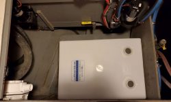
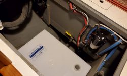
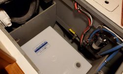
I began by test-fitting the tank in the space to ensure that the dimensions all worked out as planned.

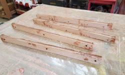
The owner wanted to install the tank at a slight angle so that the discharge side–the left side in these photos (port side of the boat)–would be lowest, making it easier to drain the tank as completely as possible for winterizing and such.  So my first task was to build an angled platform to support the tank above the actual floor of the locker.  After measuring, I cut a piece of 12mm plywood to the correct size for the space.  I figured raising the starboard side of the tank about 1-1/2″ would provide sufficient angle for drainage, and planned to cut a series of wedges to both angle and support the platform properly.  I didn’t have any suitable scrap wood on hand for this, so instead I milled a series of 1/2″ x 1-1/2″ strips from leftover plywood, and glued up four blanks that I could use to make the wedges.  I used temporary screws to clamp these assemblies while the epoxy cured, and would be able to continue work on the platform next time.

Total time billed on this job today:  2.5 hours

0600 Weather Observation:  9°, mainly clear.   Forecast for the day:   Becoming sunny, 24°.
Older posts Newer posts