(page 2 of 5)

Lively Heels Phase 3-36

Monday

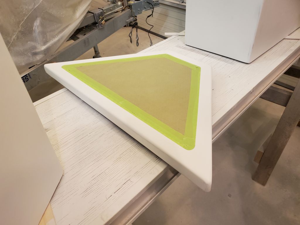
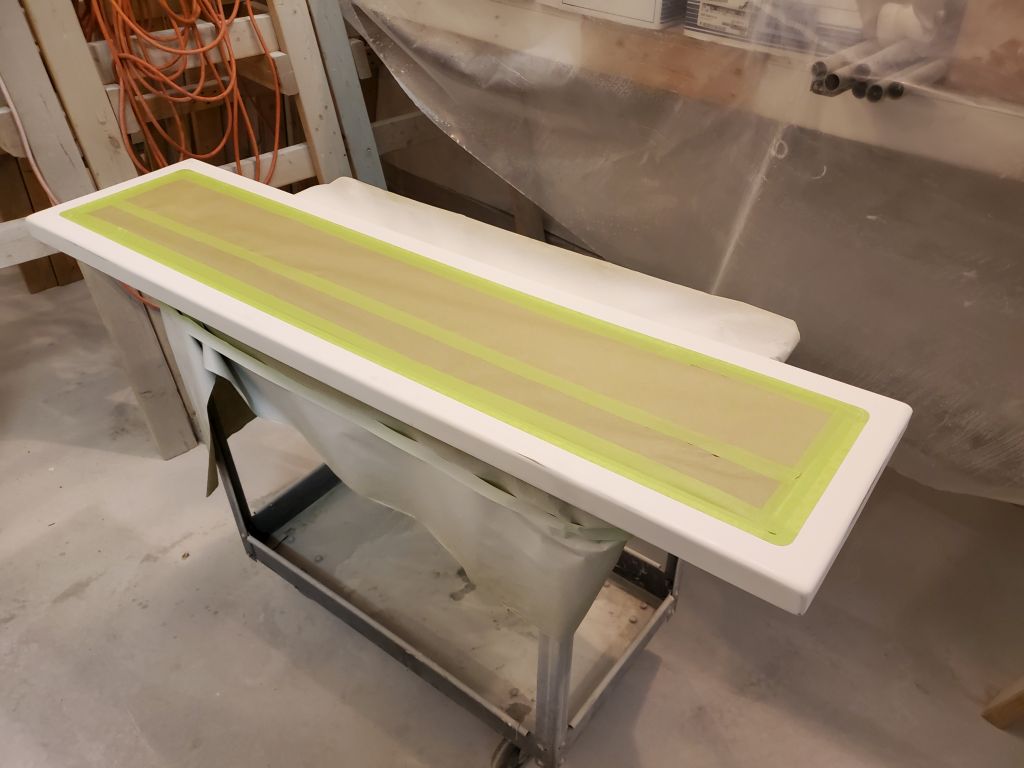
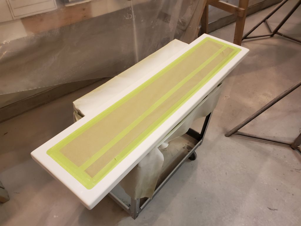
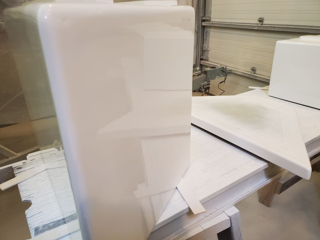
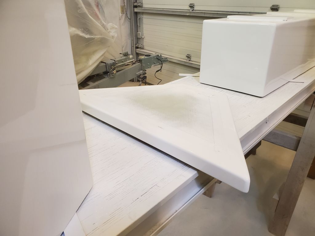
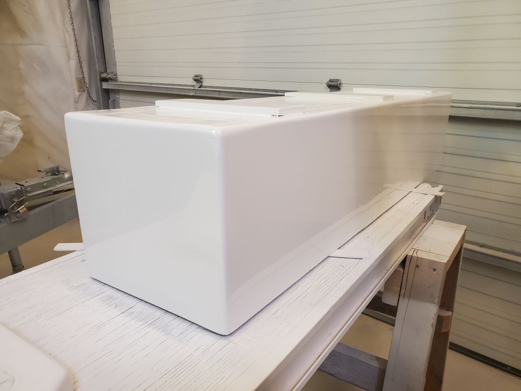
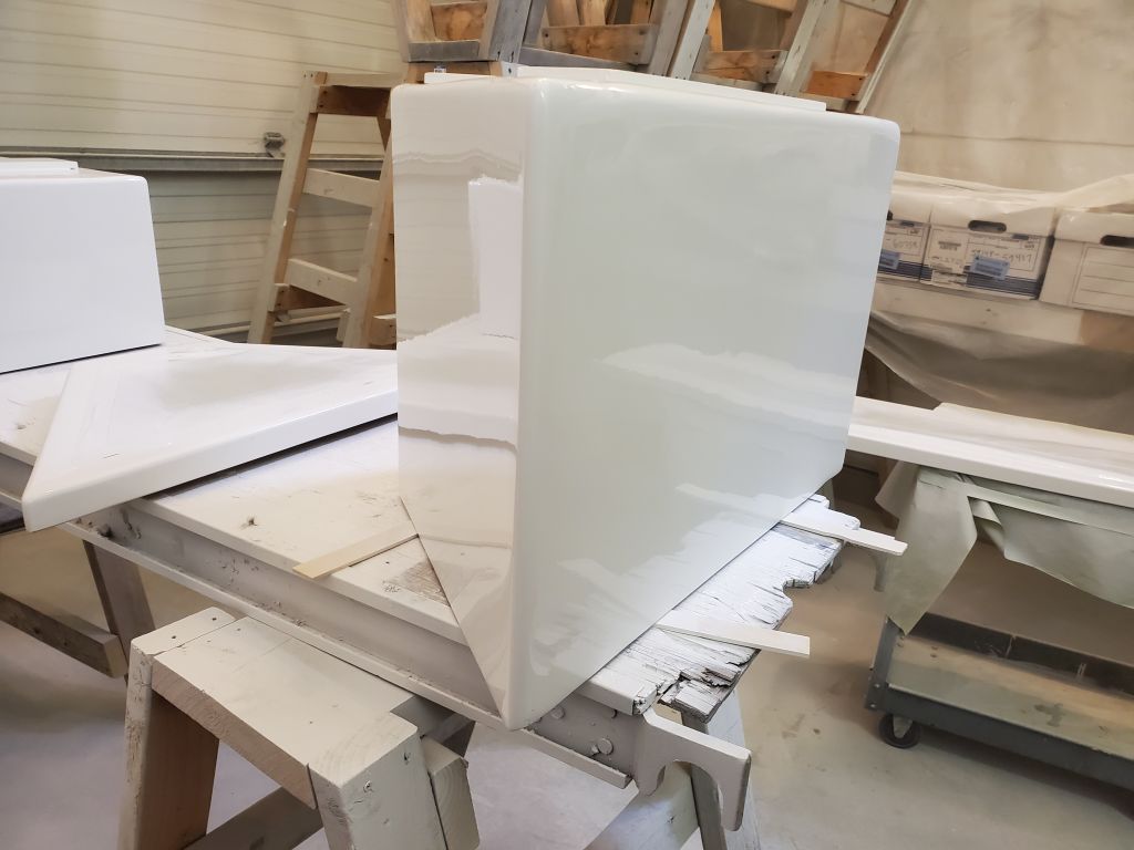
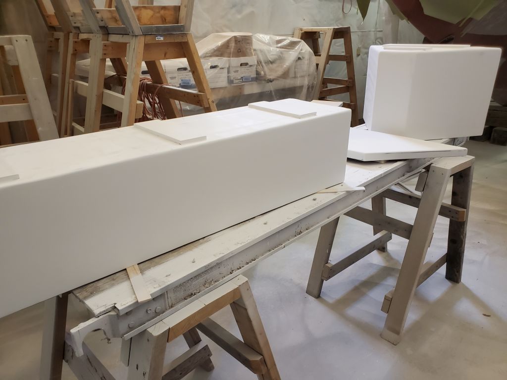
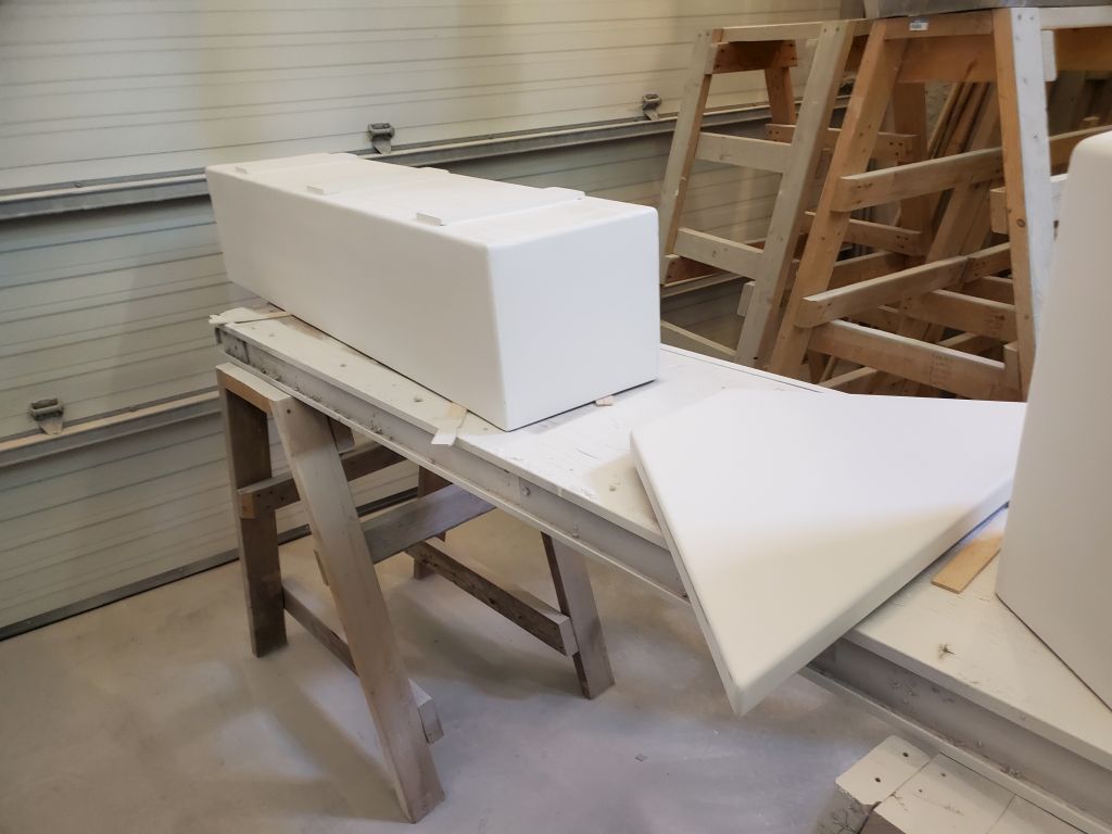
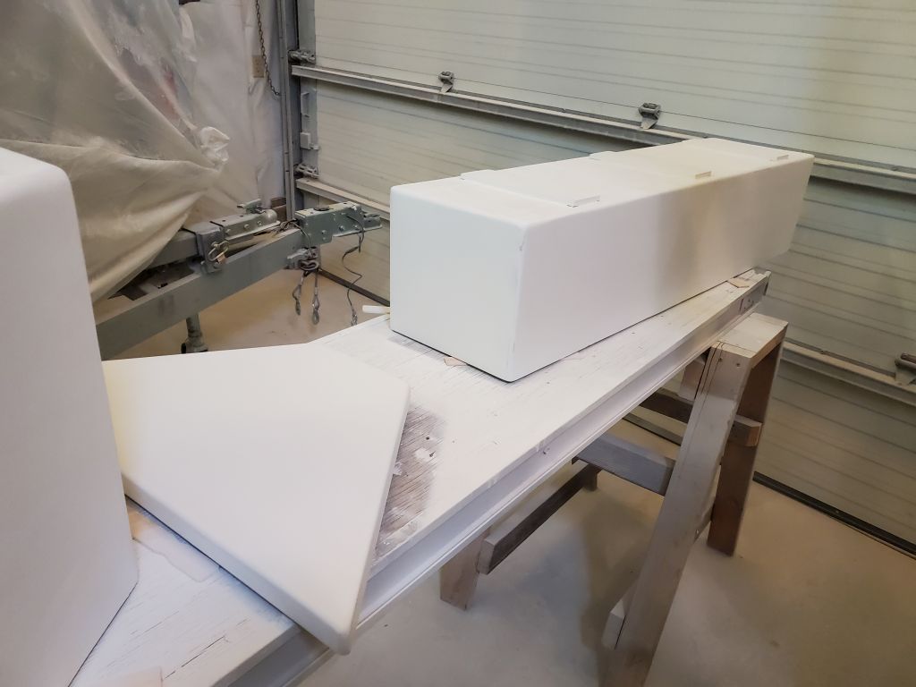
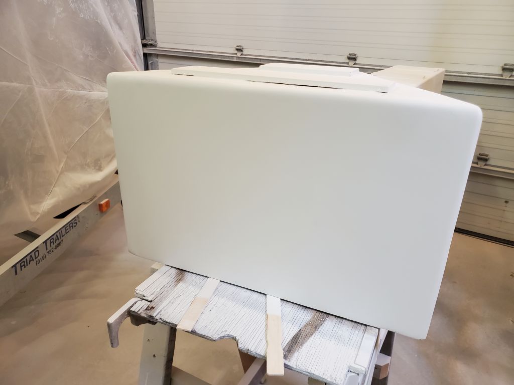
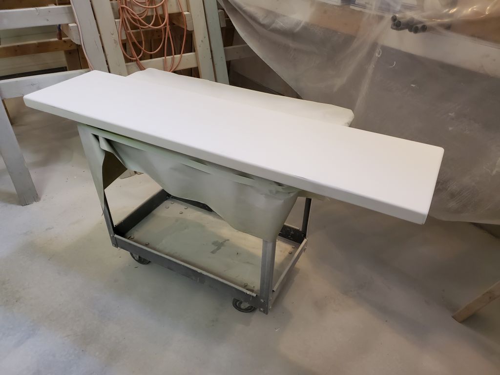
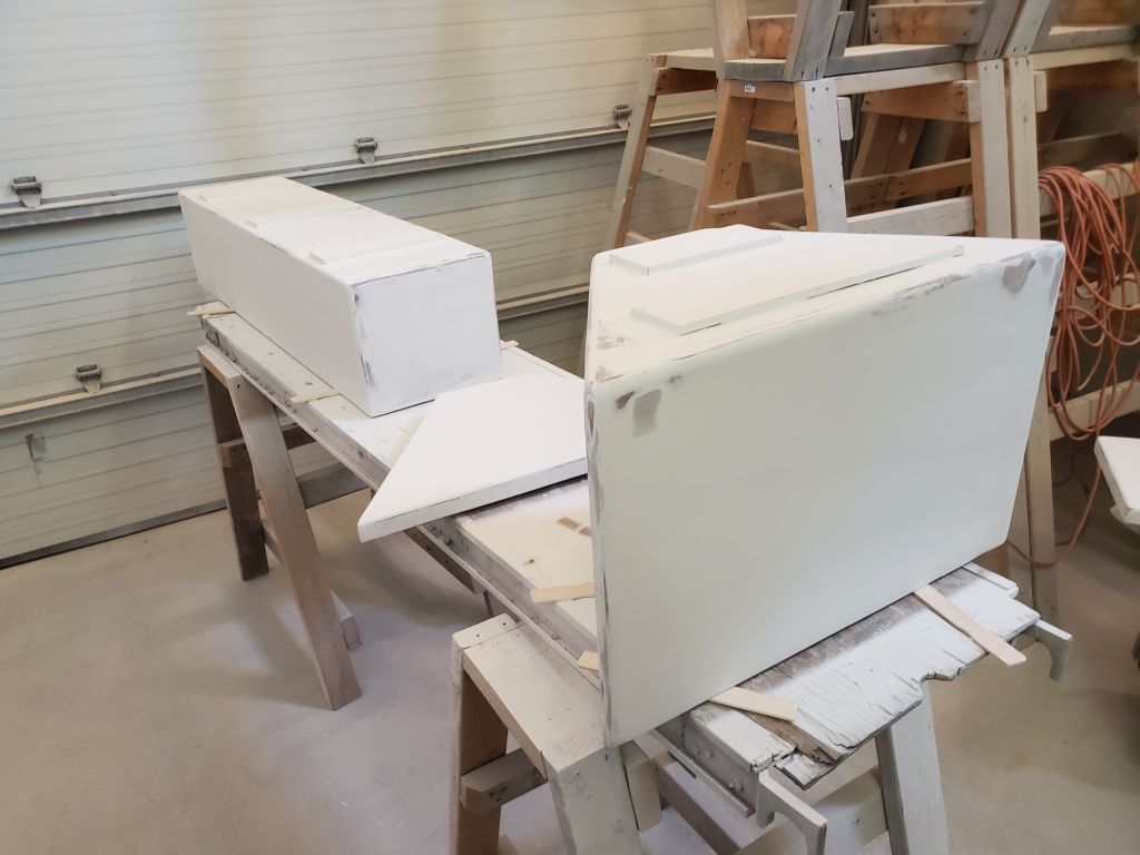
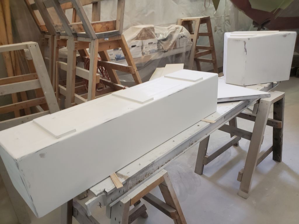
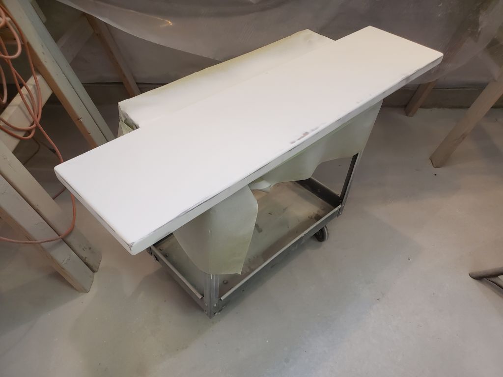
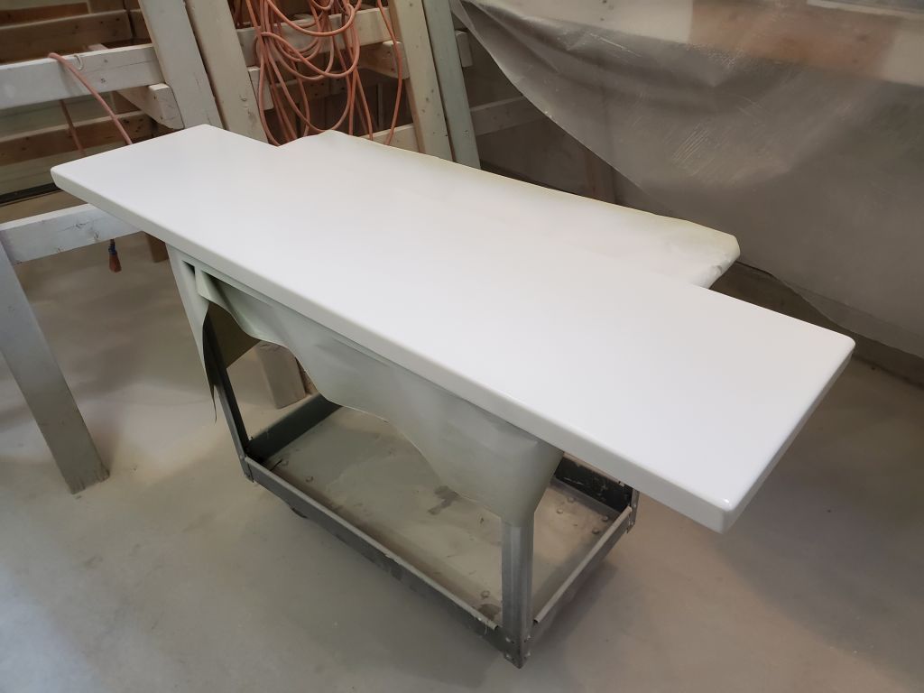
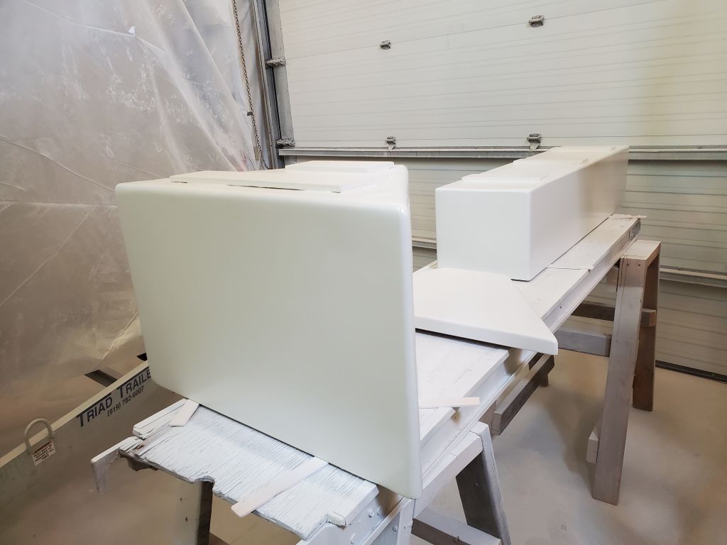
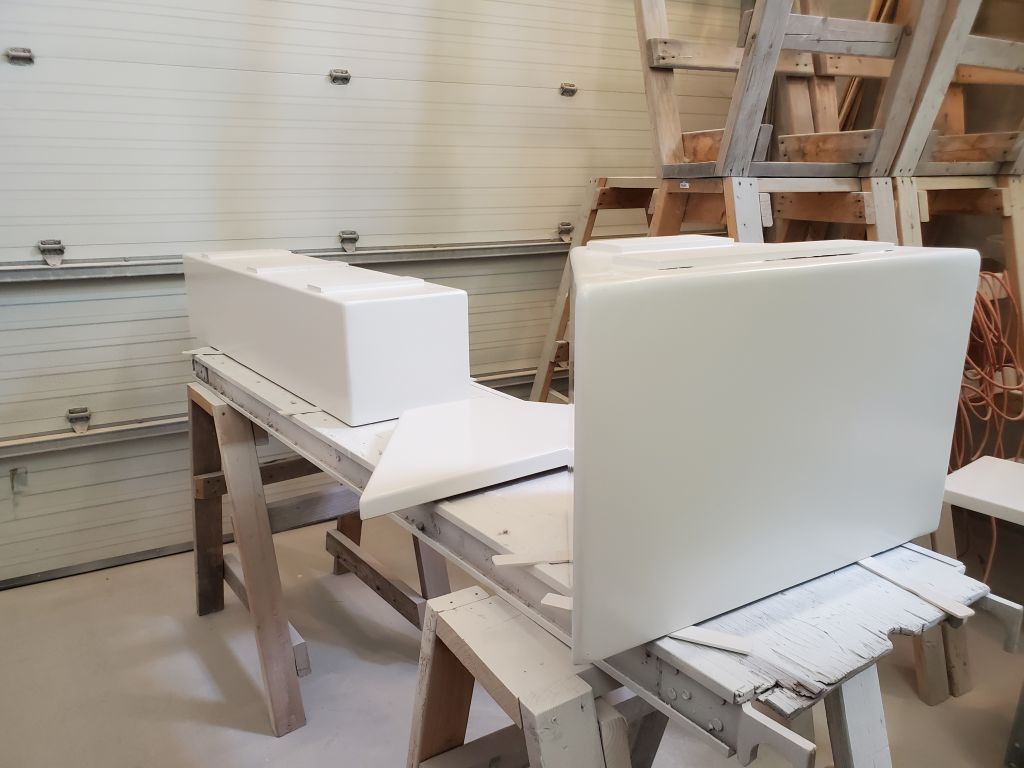
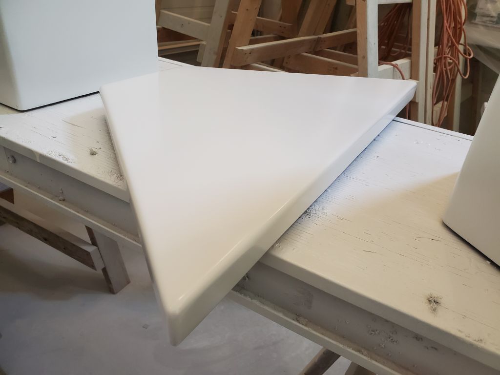
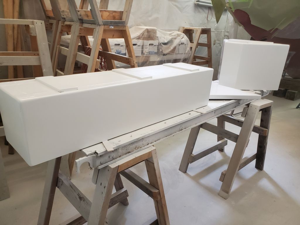
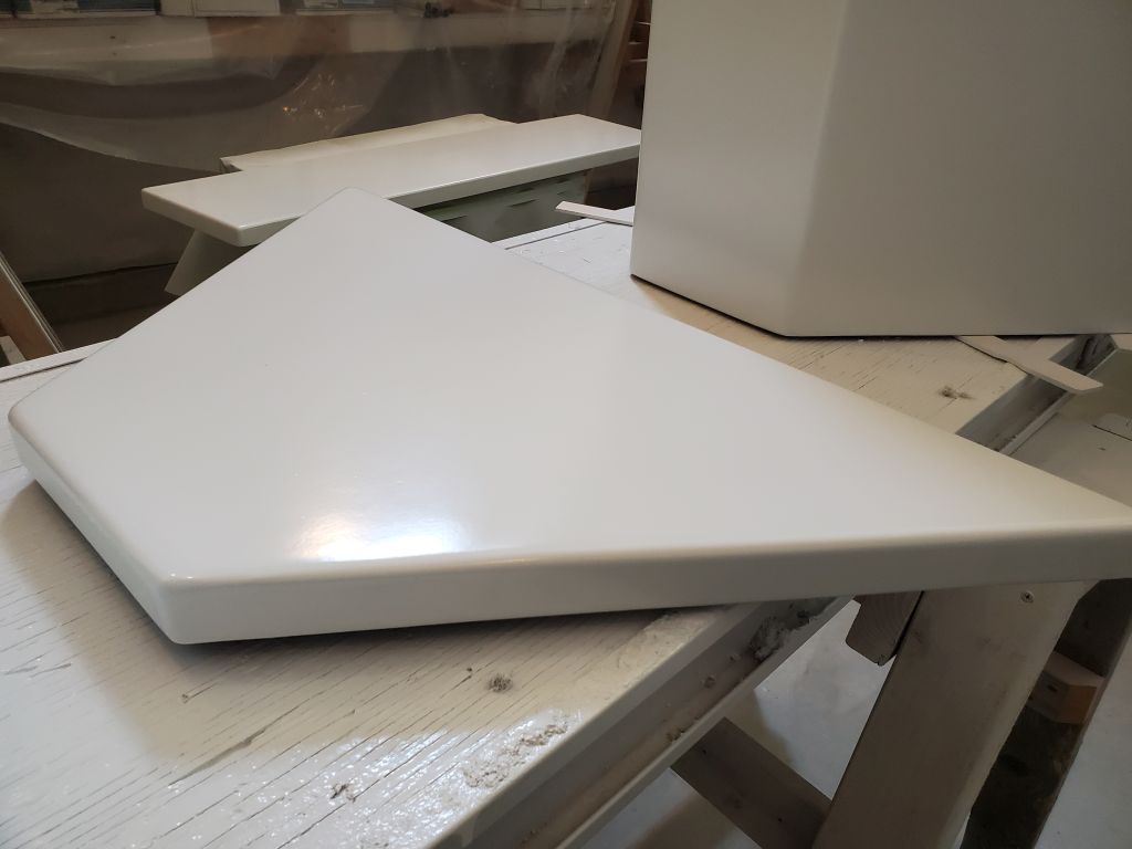
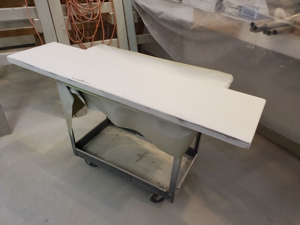
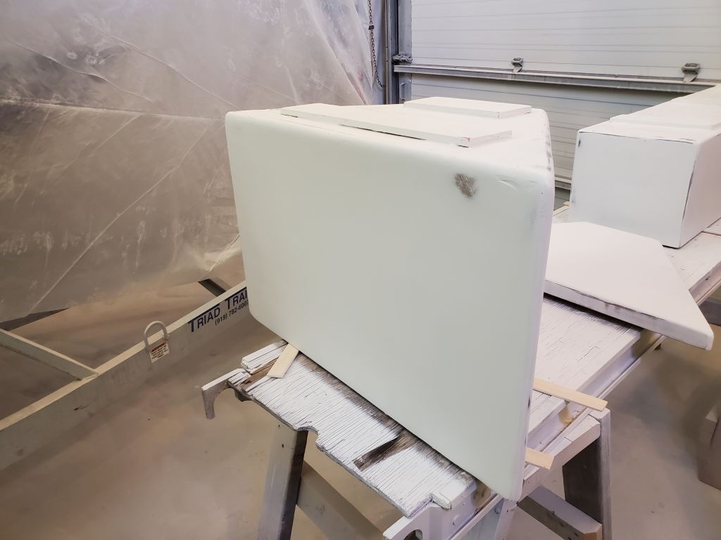
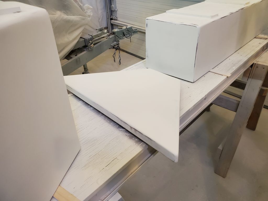
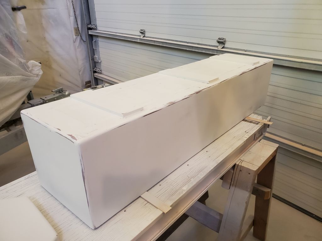
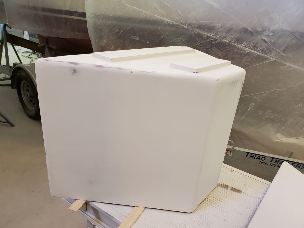
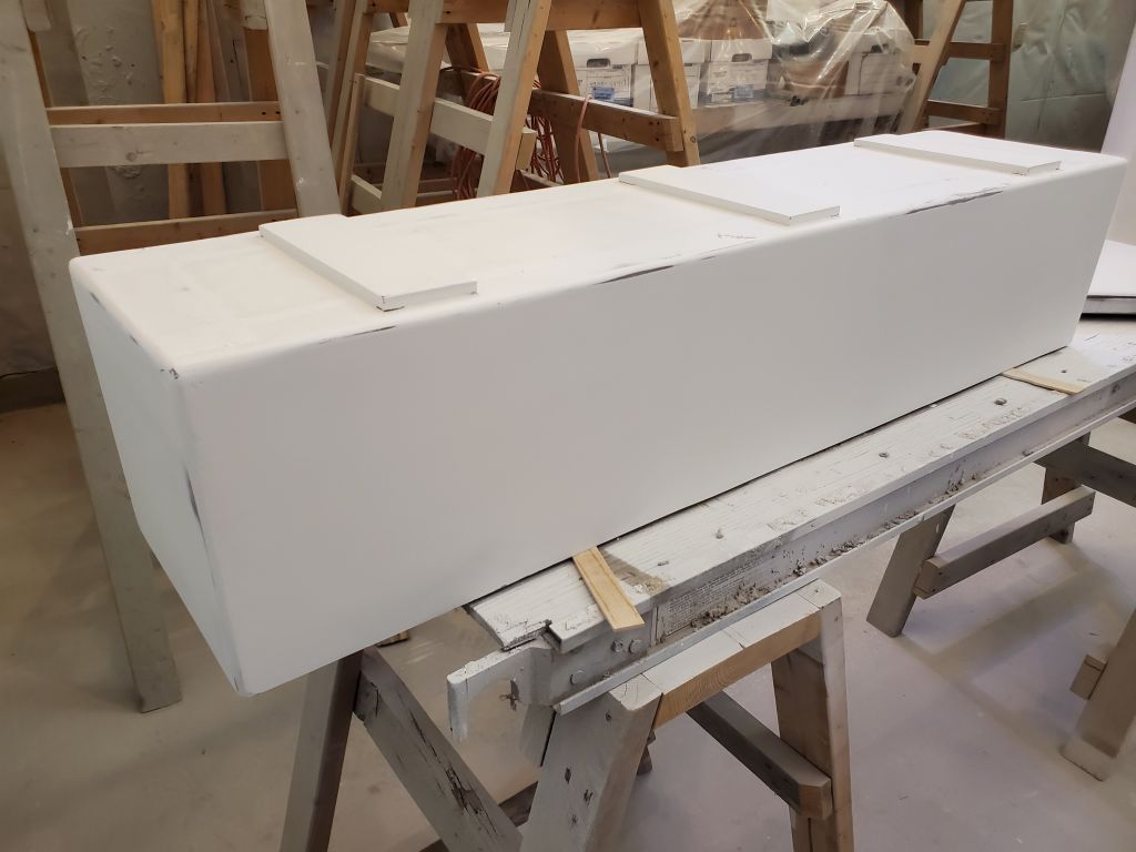
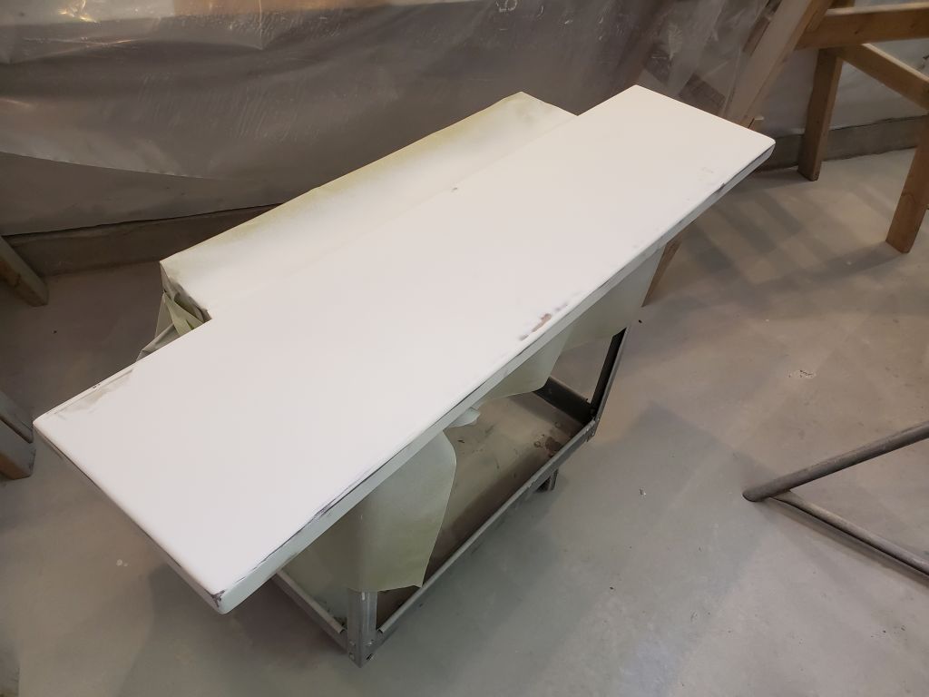
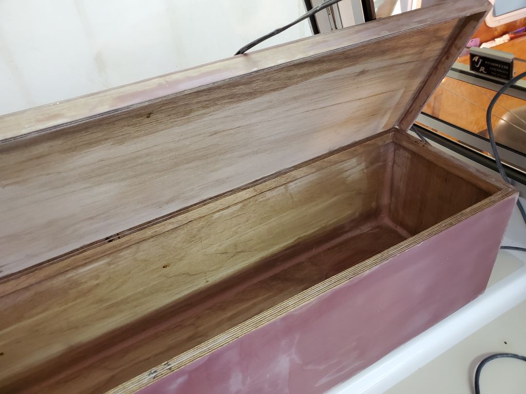
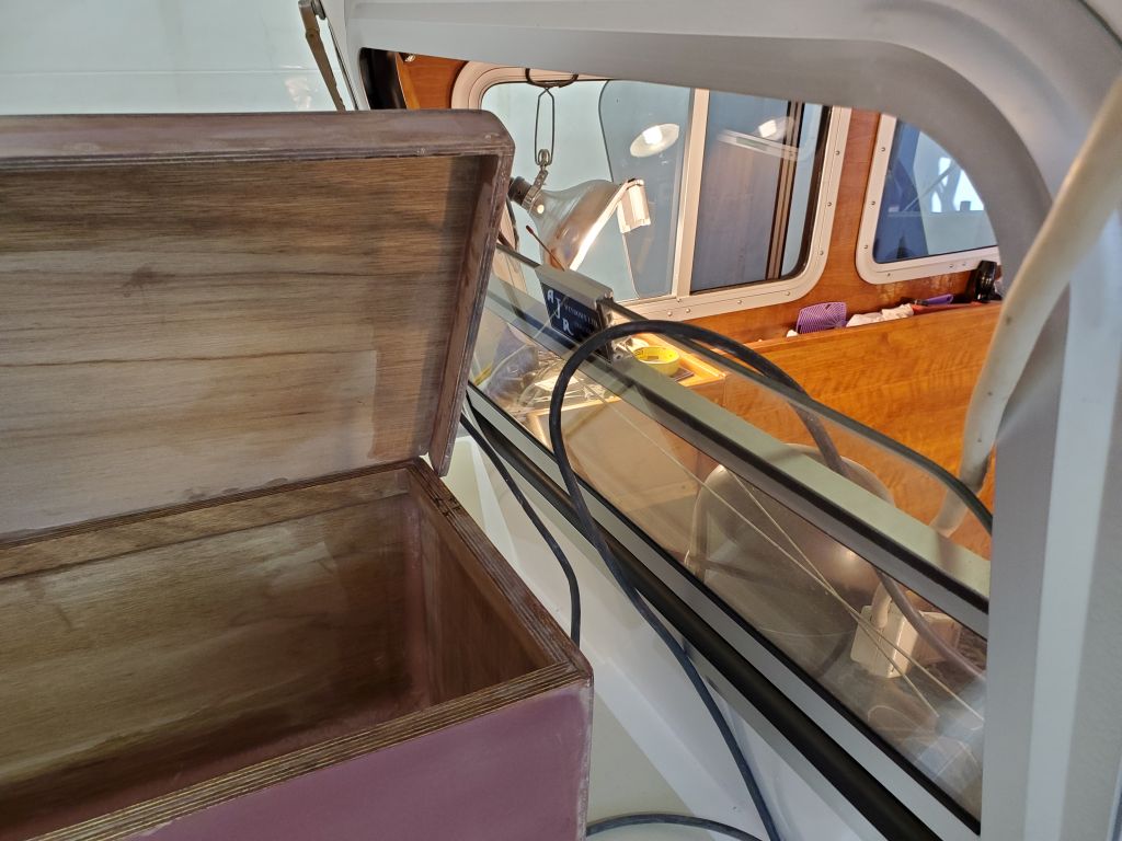
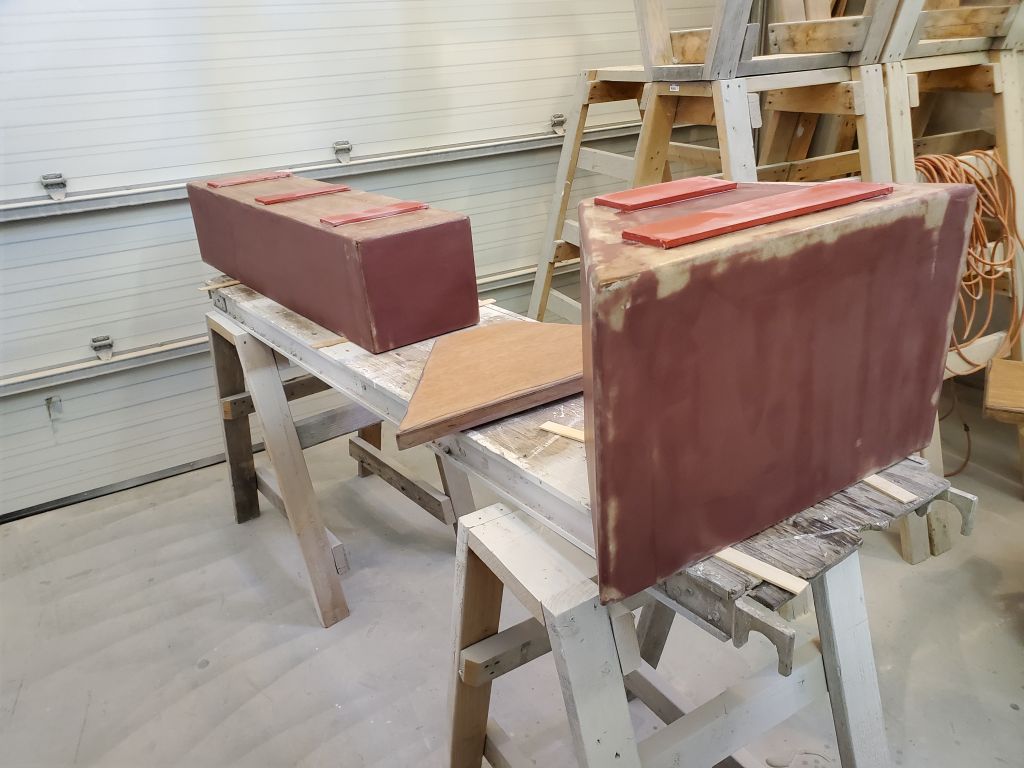
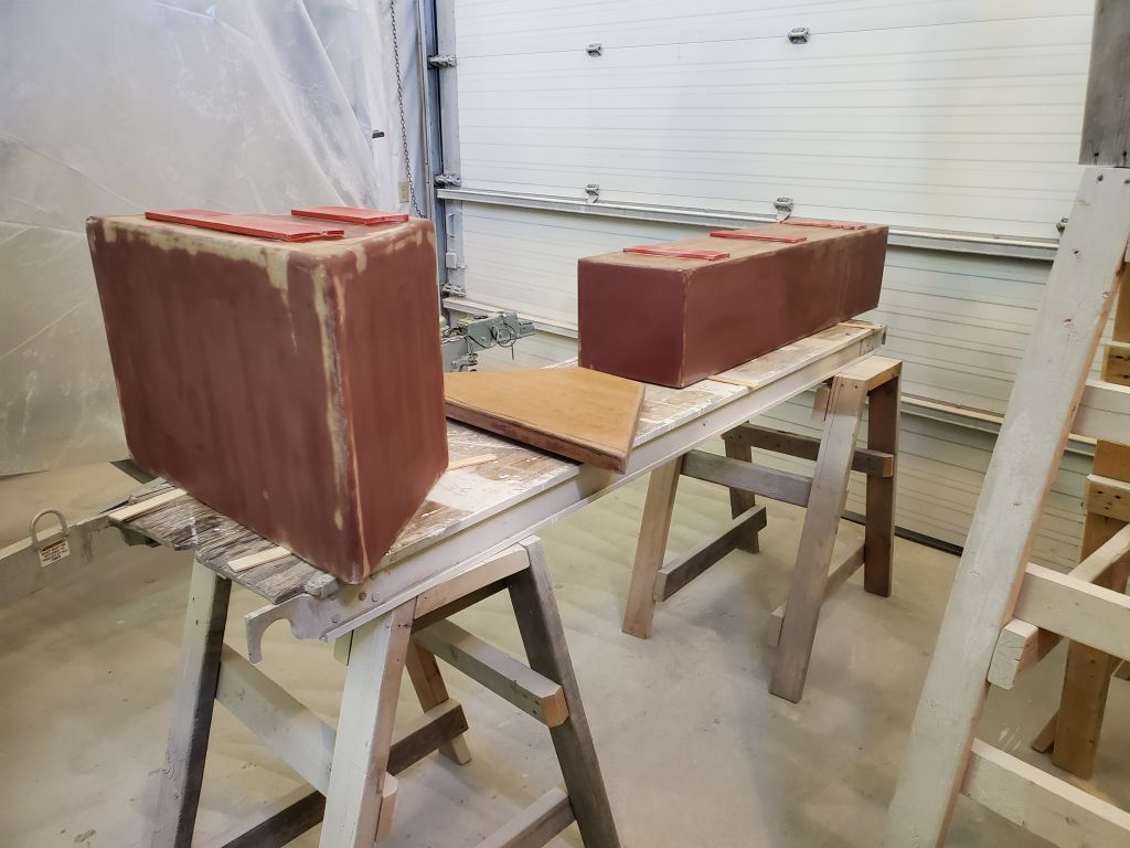
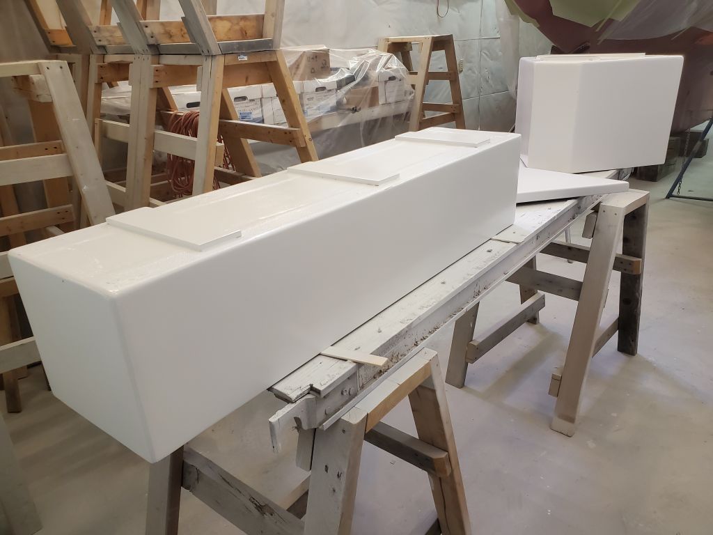
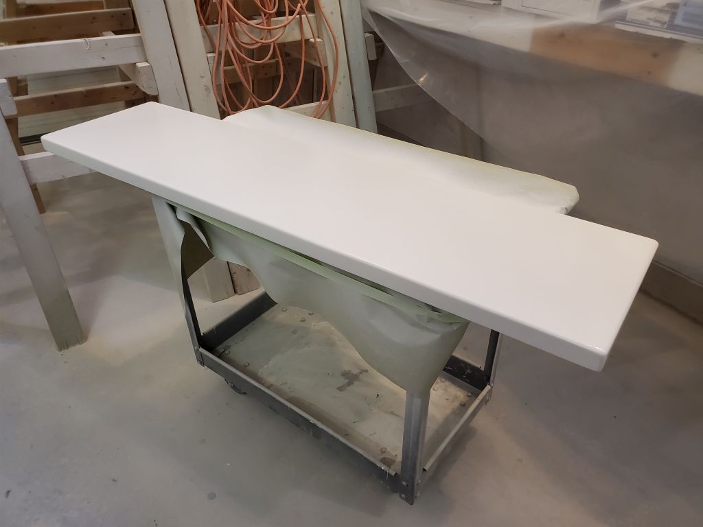
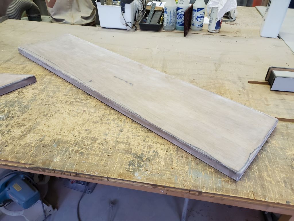
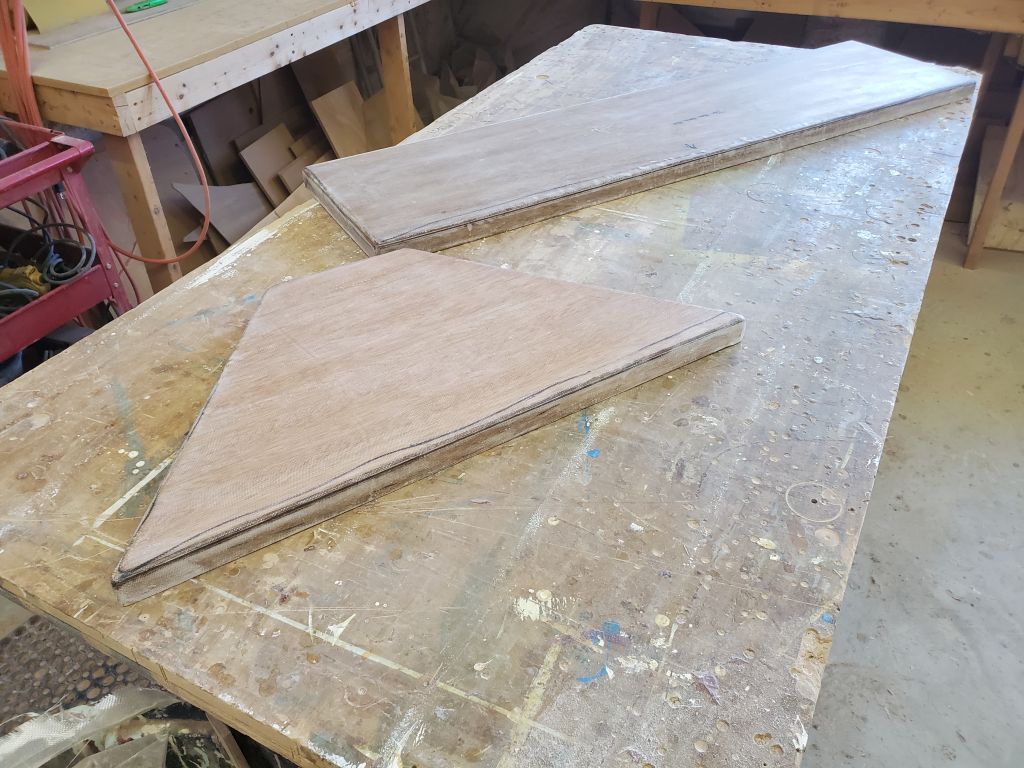
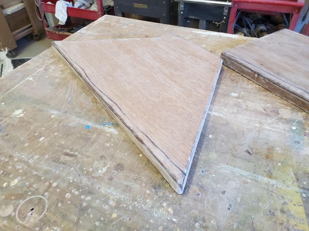
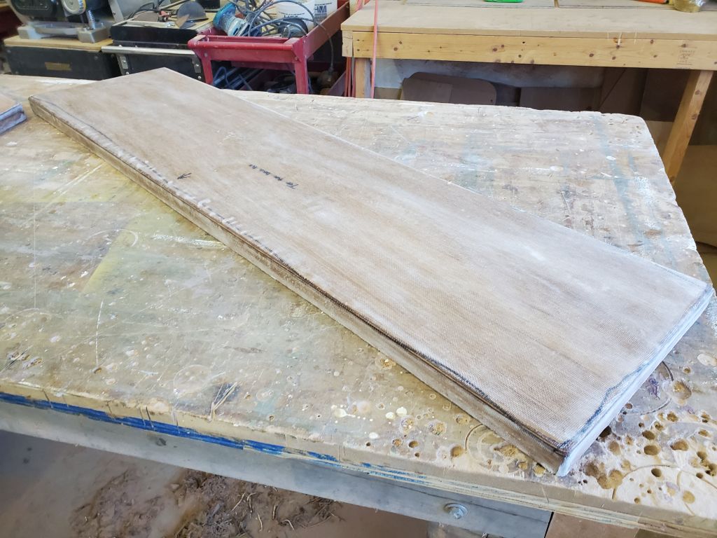
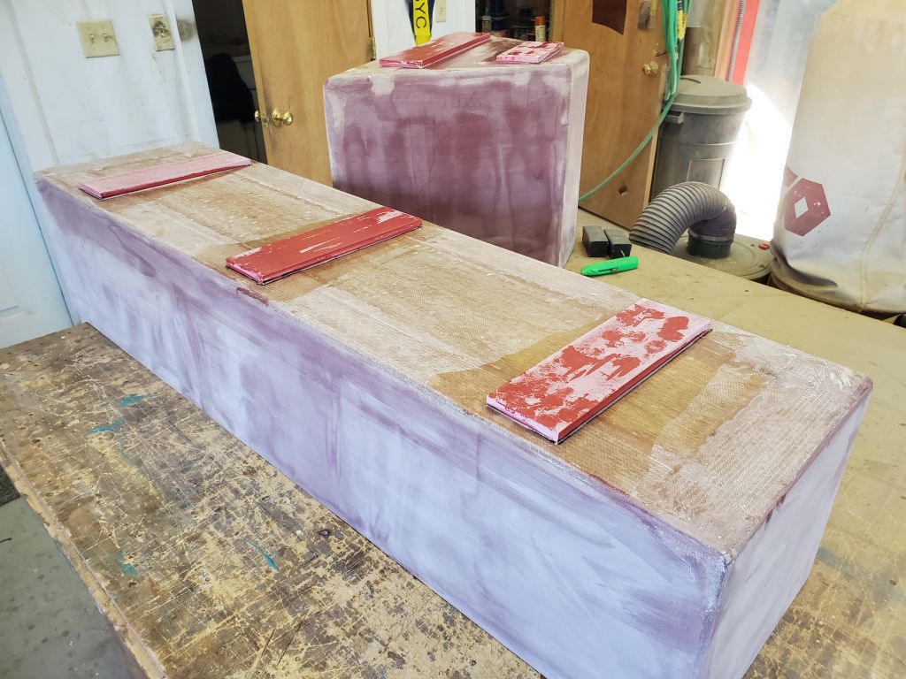
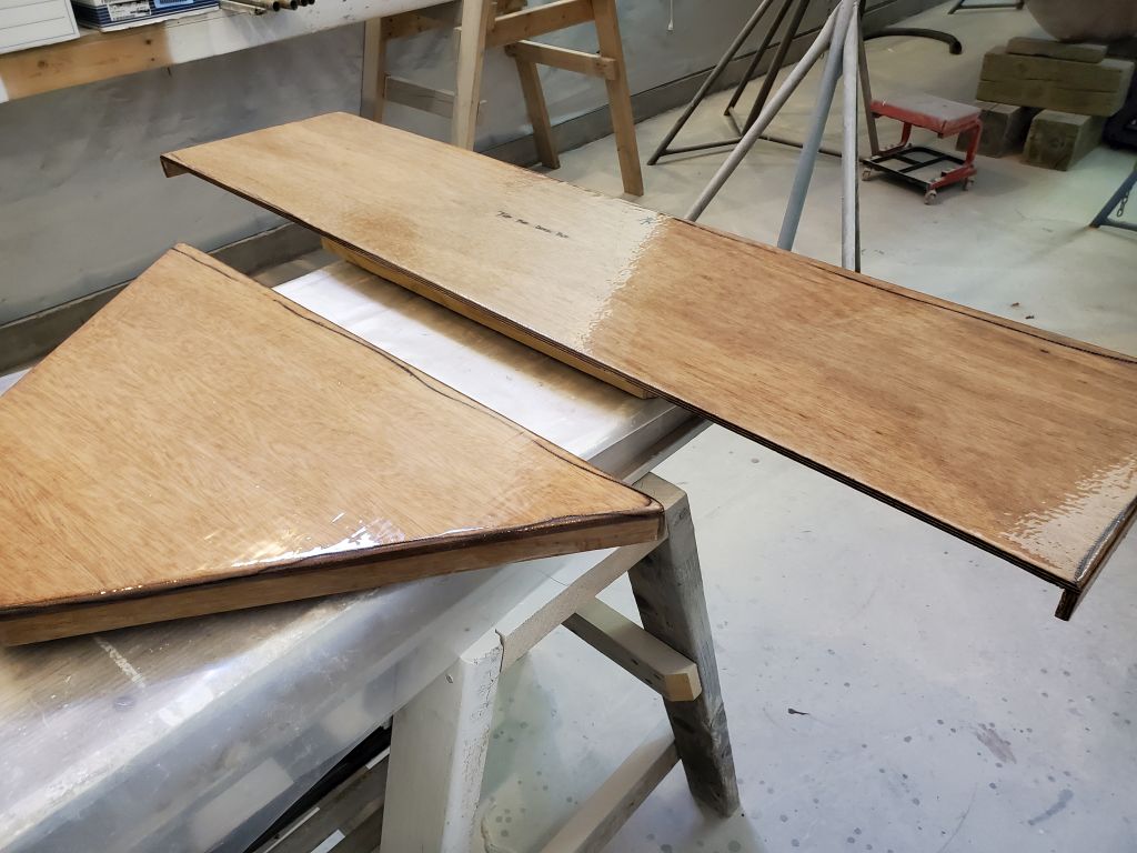
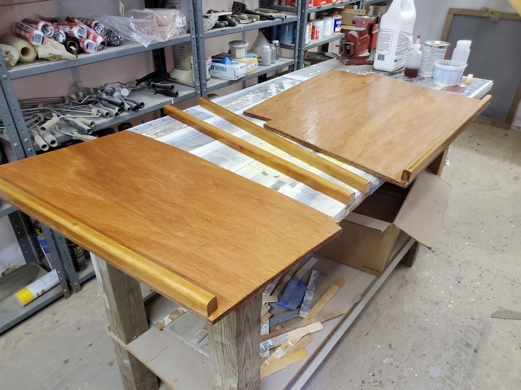
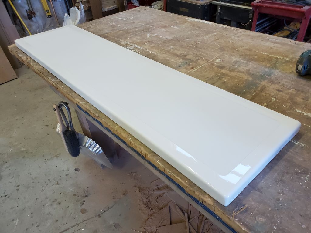
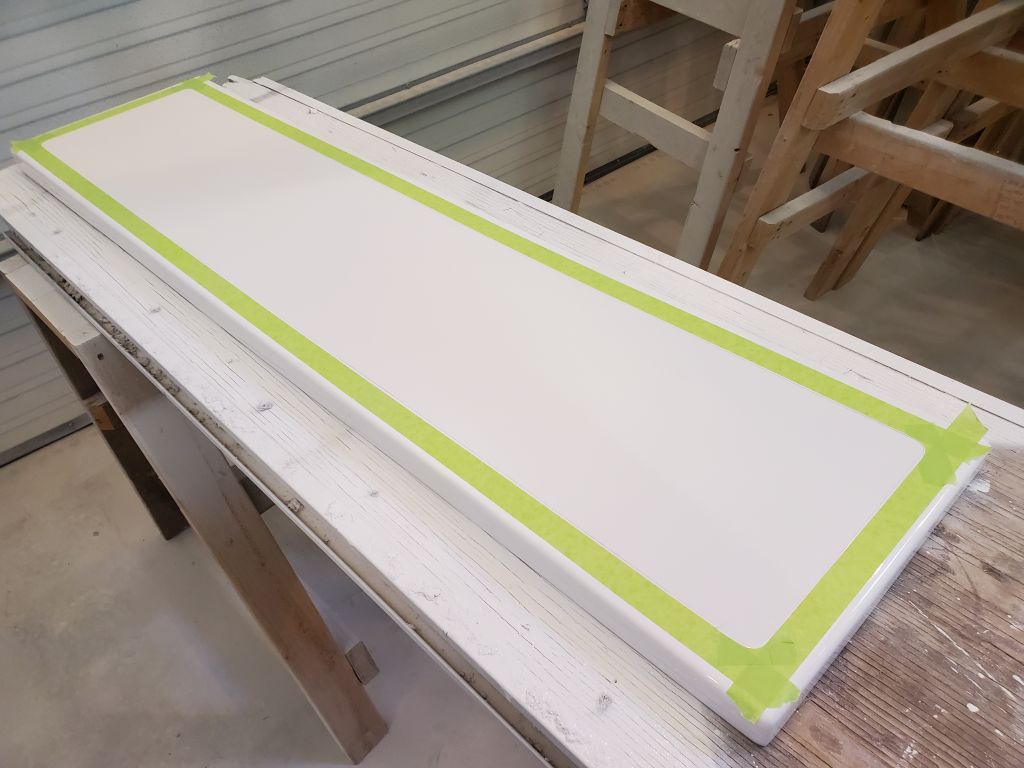
With the gloss topcoats complete on the deck boxes and lids, my first task was to remove the masking from the lids.

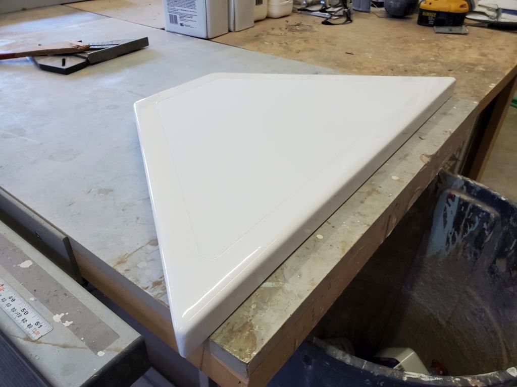
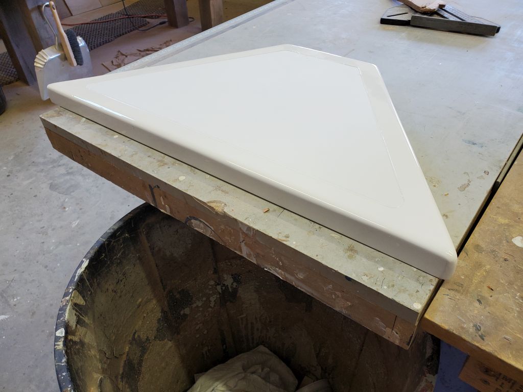
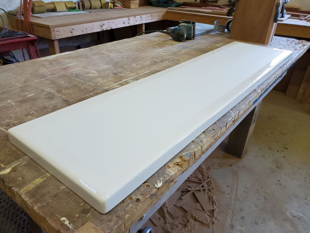
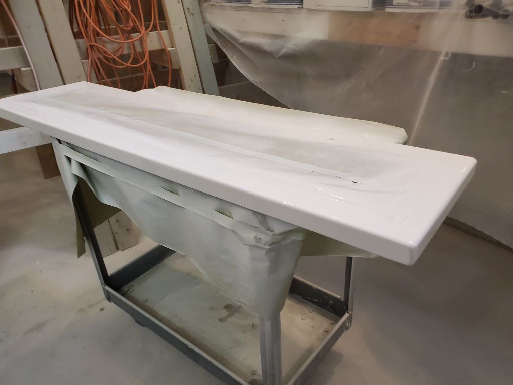
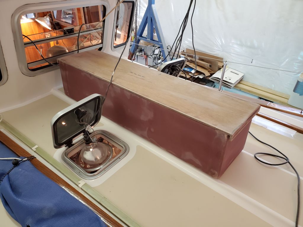
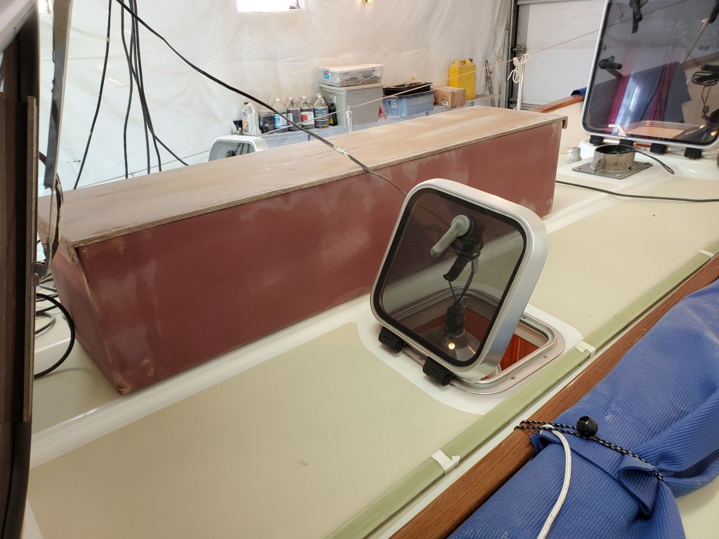
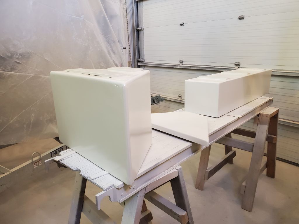
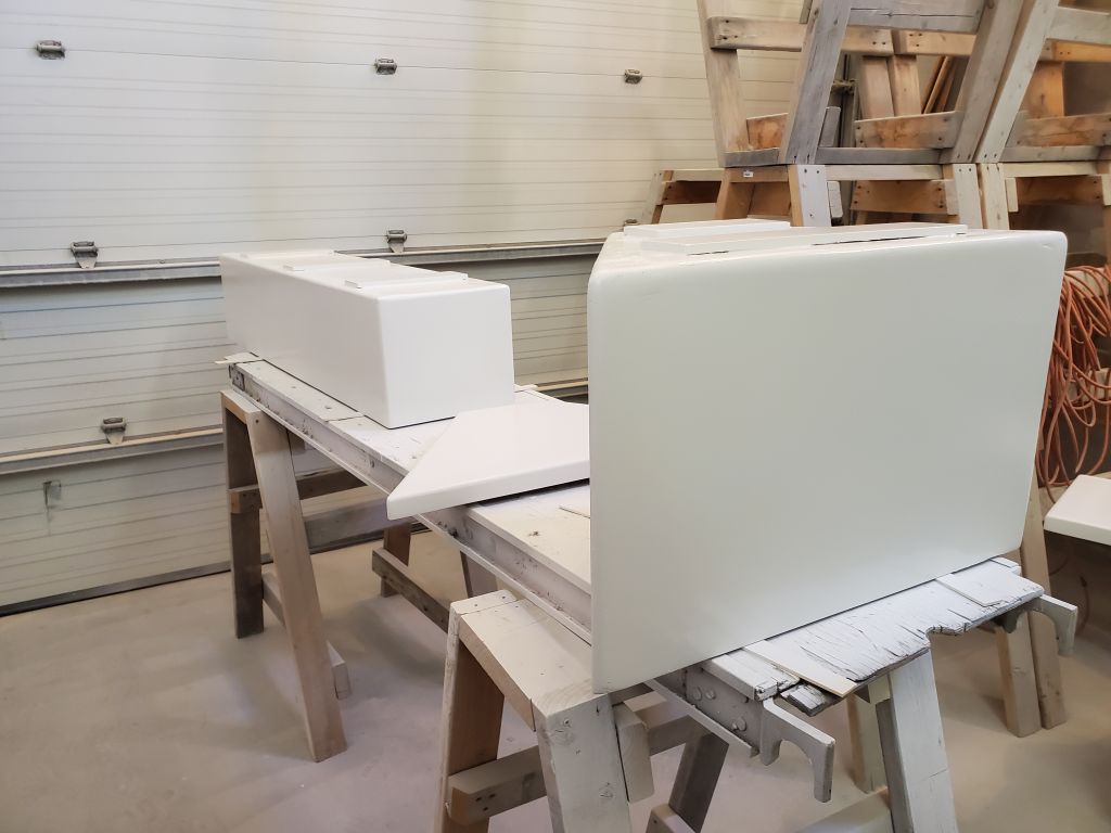
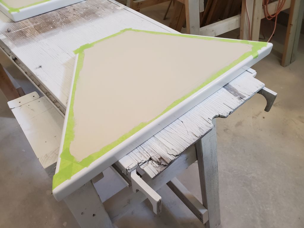
After masking over the fresh paint to protect it, I applied the first of two coats of beige nonskid to the field areas, which would match the paint scheme already on the boat.

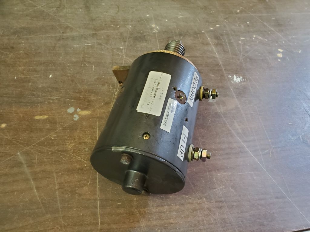
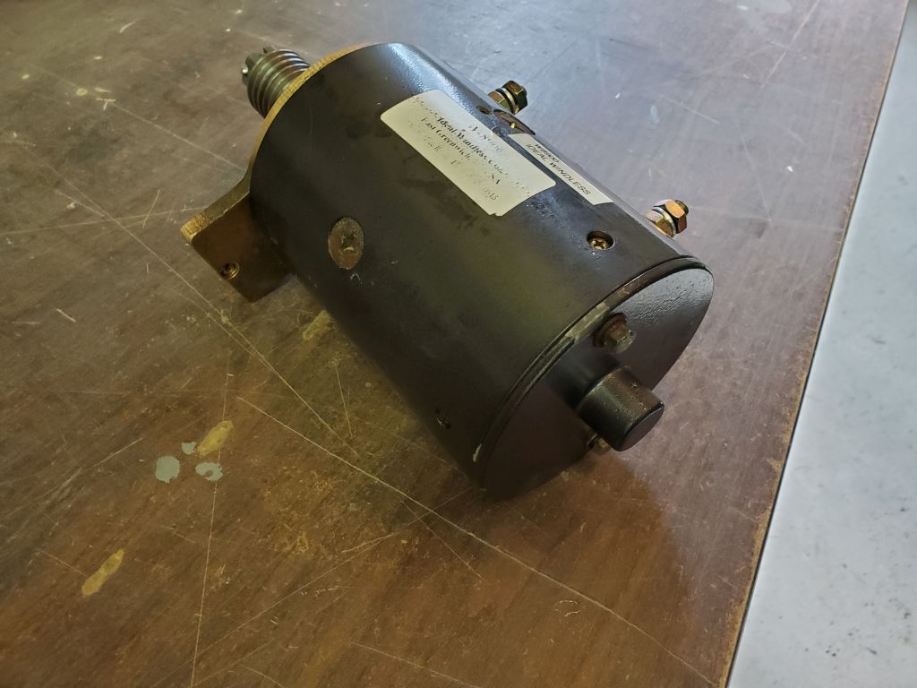
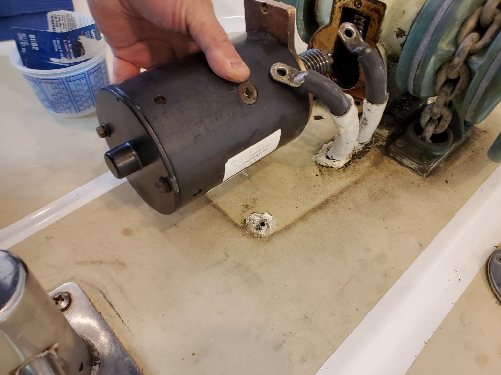
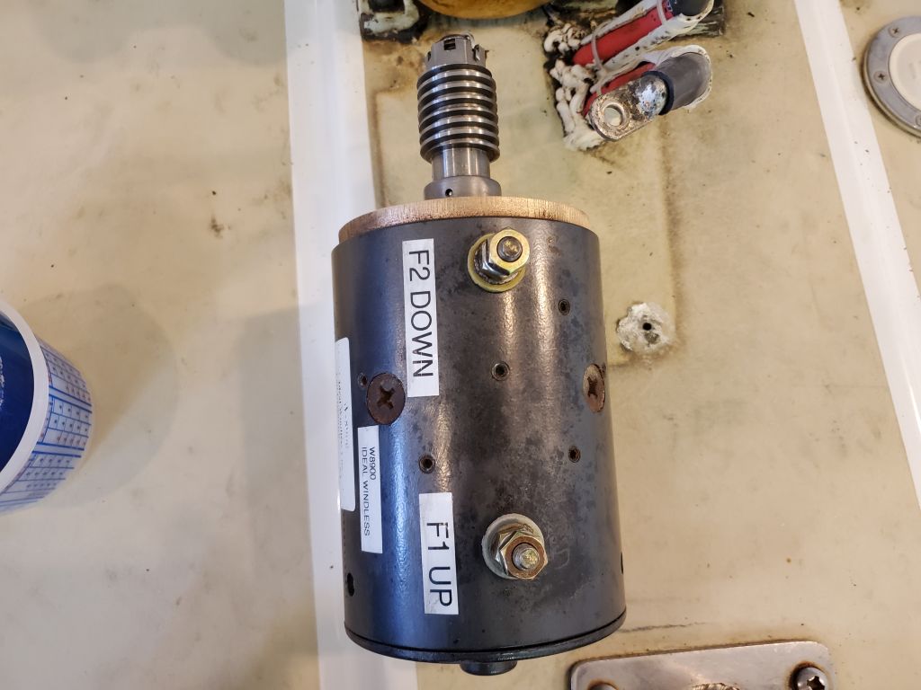
Planning to work my way through much of the remaining work list over the next few days, I thought I’d start by reinstalling the windlass motor, which had been sent out to an electric shop to be reassembled and tested after its unintentional case removal earlier in the winter.  I’d had the motor back on hand for a couple weeks, but hadn’t looked at it closely.  But as I considered the installation now, I immediately sensed a problem:  the motor casing was 180° from where it needed to be, leaving the wiring terminals on the bottom side of the motor, opposite the top part of the mounting flange.    There were only two possible ways to reinstall the case, and of course this was the wrong one, though neither I, nor the owner, who brought it to the repair shop, nor the shop owner had thought to even consider the orientation beforehand.  The design of the mounting flange was asymmetrical, and the motor couldn’t simply be turned to expose the terminals–and there was not clearance between the motor and the deck to allow installation as is.

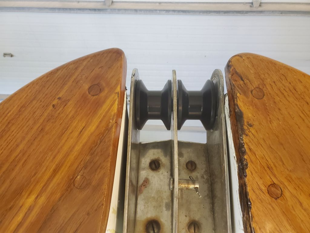
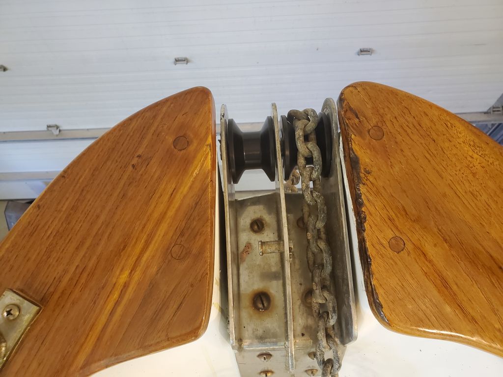
The case would need to be rotated, but whether that was something we could do at the shop or if it had to go back to the repair shop remained to be seen, so for now I satisfied myself with cleaning up the bronze face of the windlass itself to prepare it for the eventual motor replacement.

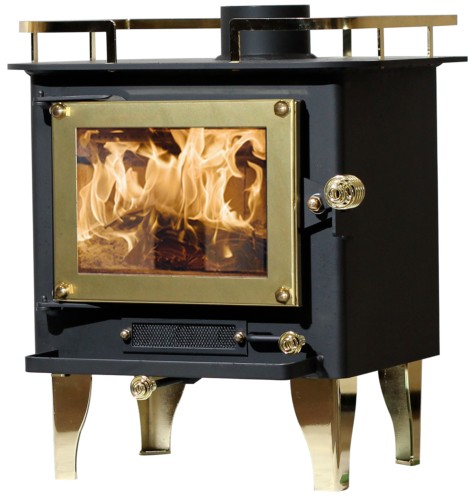
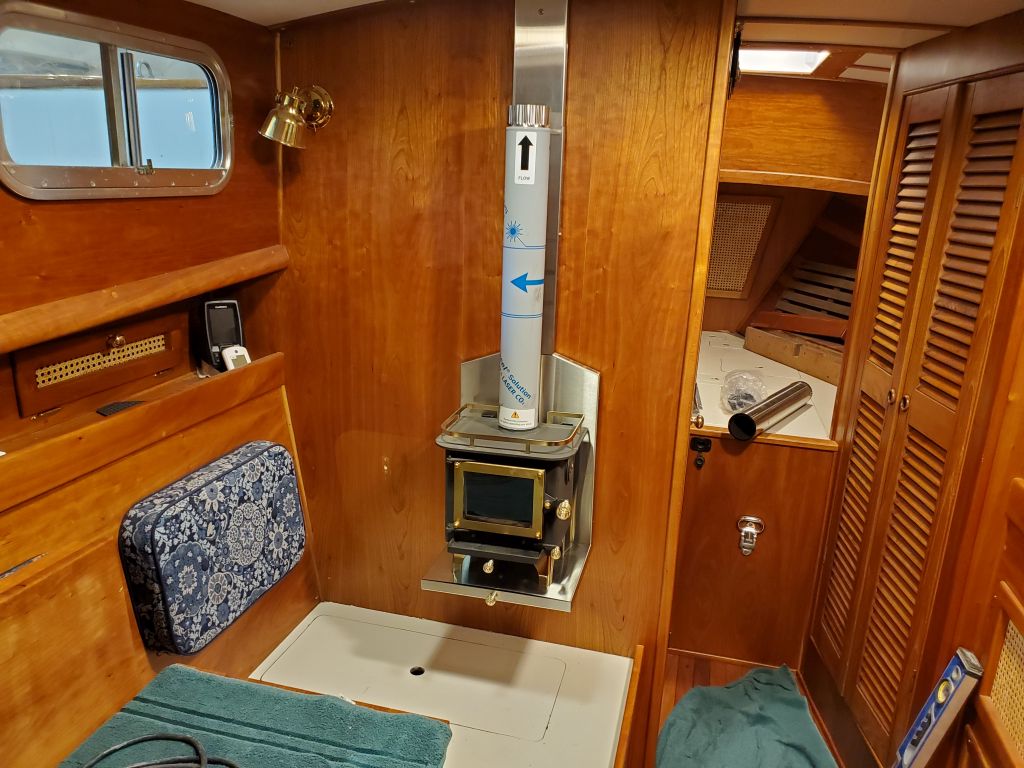
Next, I turned to what I intended as the main focus of the work over the next few days:  Installation of the new woodstove in the main cabin.  This stove is called a Cubic Mini, but I’ve been calling it the “Cute-ic Mini” because, well, it just is.  And the little fireplace tools…adorable.  You’ll see those soon enough.

Some months earlier, I’d done some substantial layout in the main cabin, and with the stove and its parts on hand since early January, now it was finally time to begin the real installation.

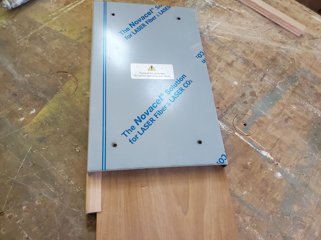
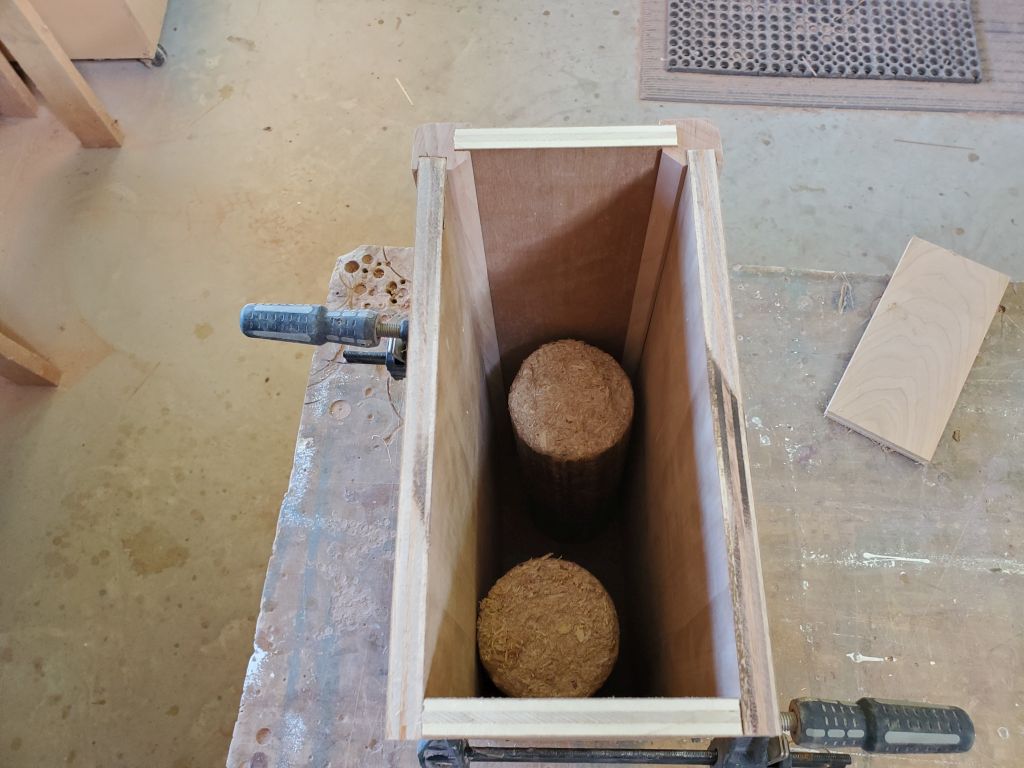
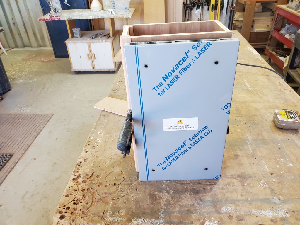
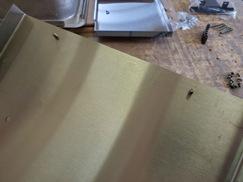
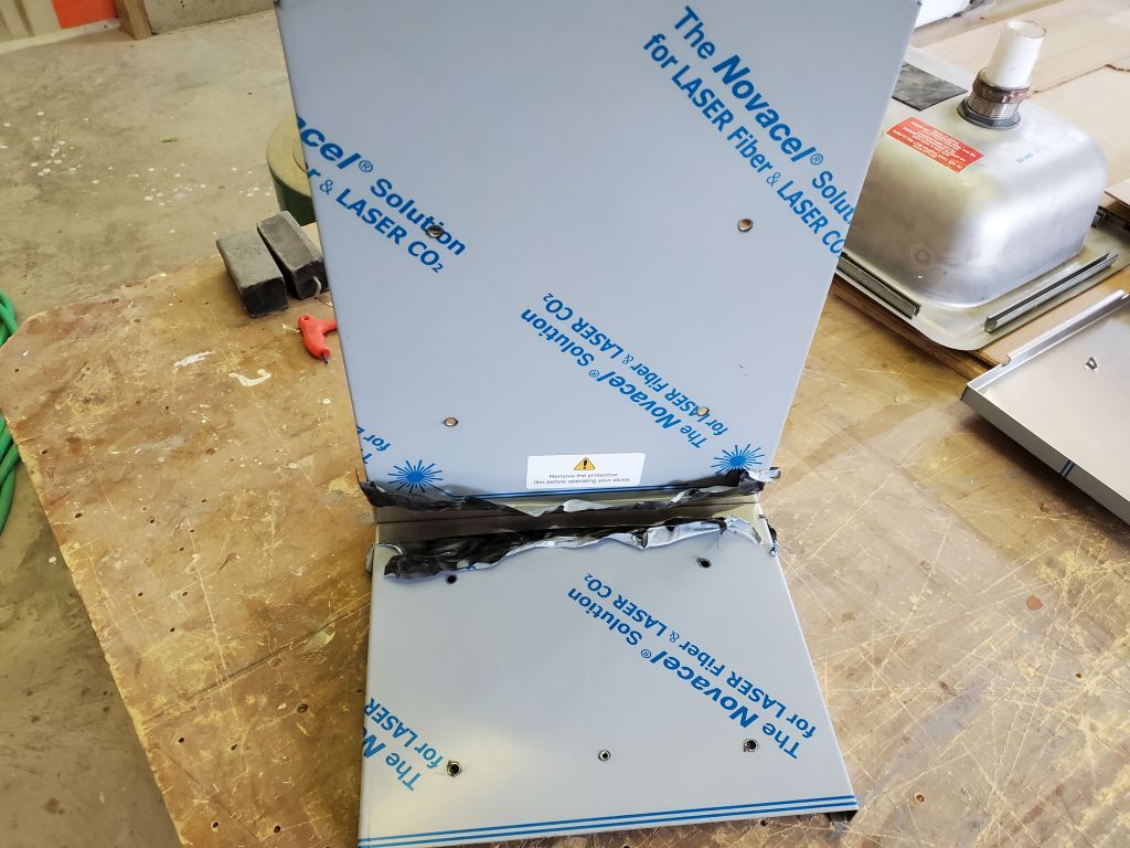
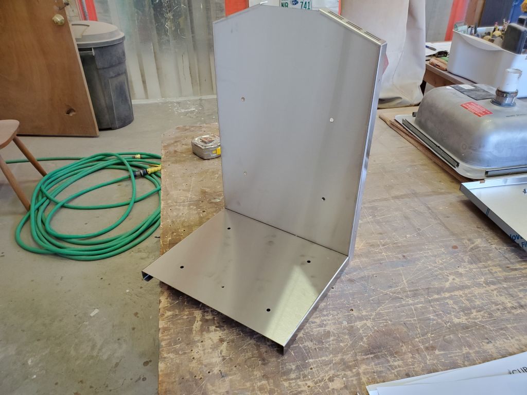
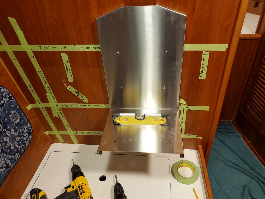
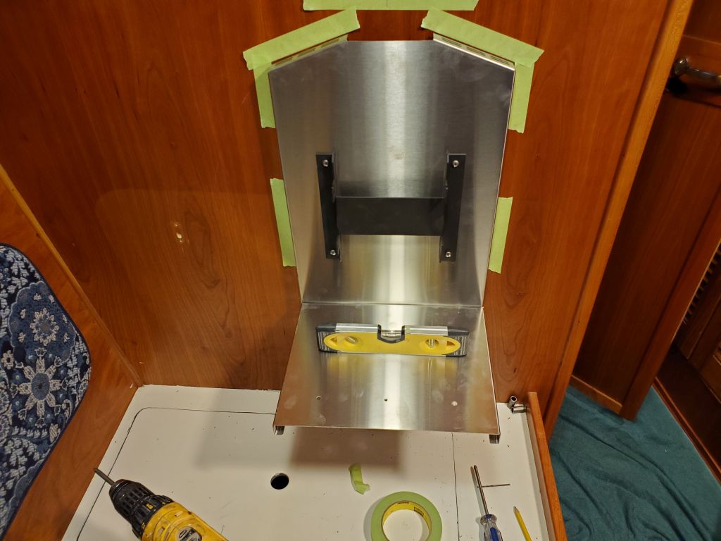
To begin the installation, I assembled the back and bottom of the stainless steel heat shield, a straightforward process involving two screws.  Removing the protective plastic from the sheet metal was the most difficult part since, as Ringo Starr sang, it don’t come easy.

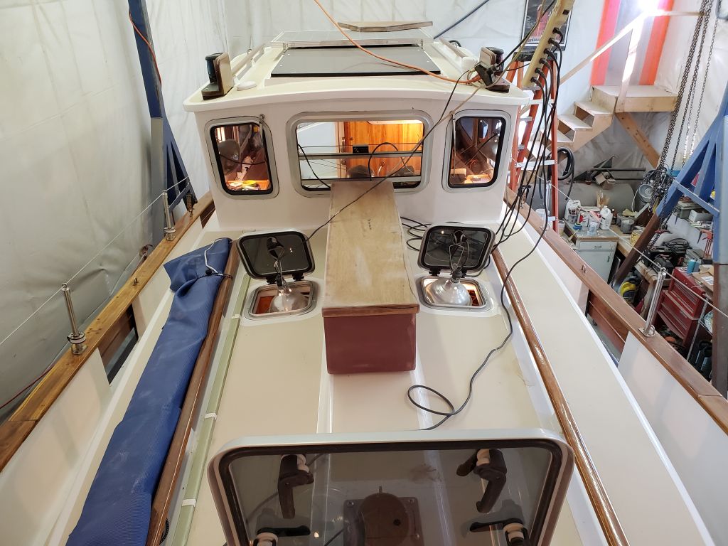
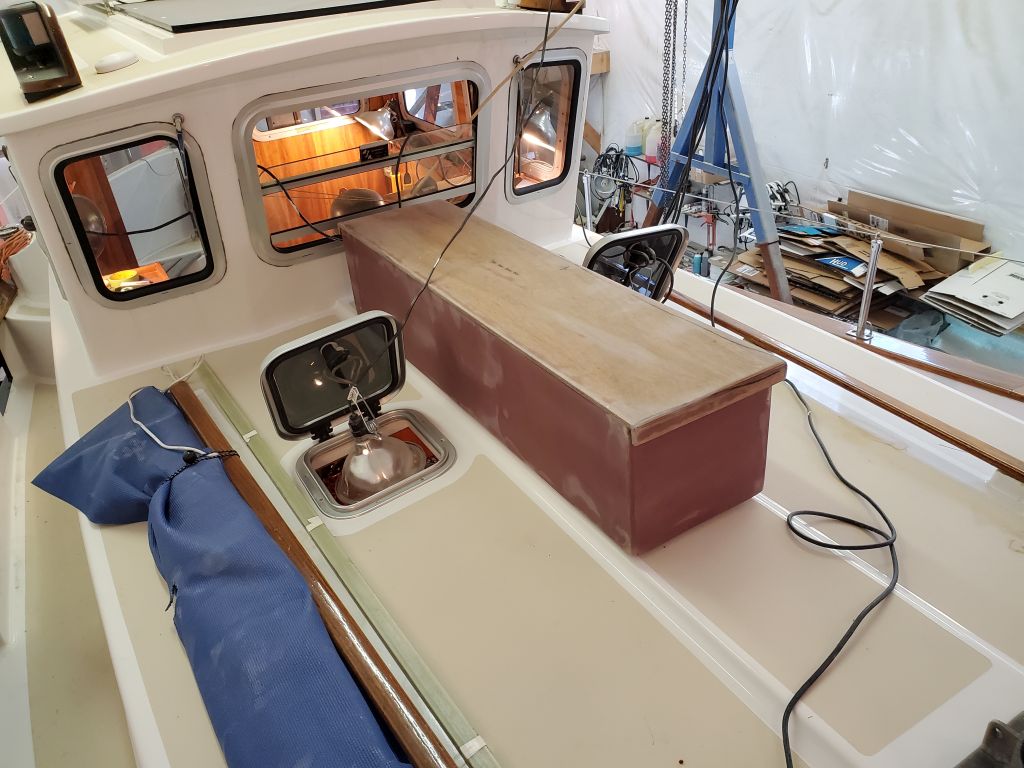
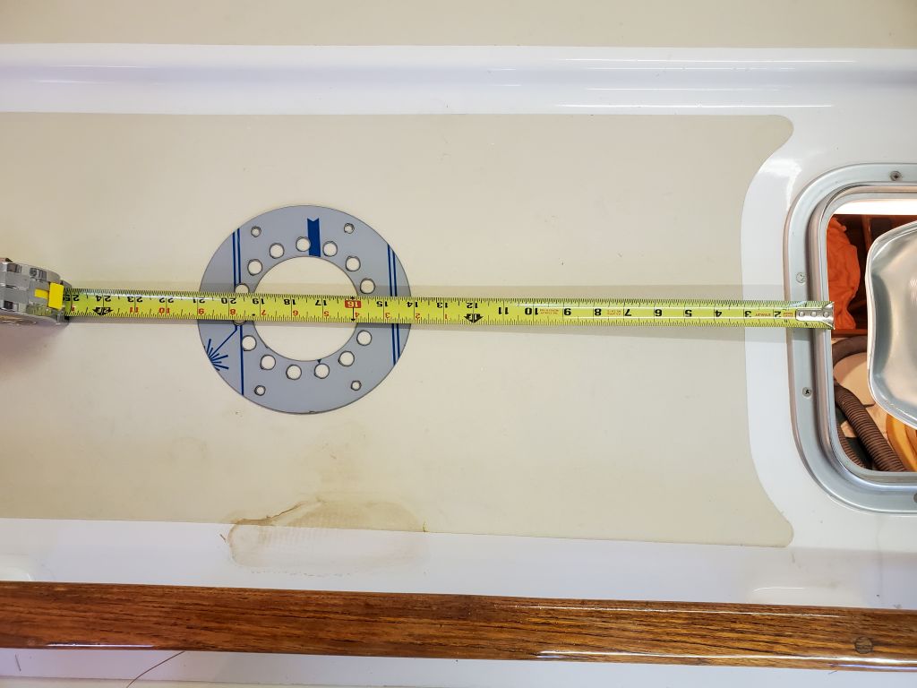
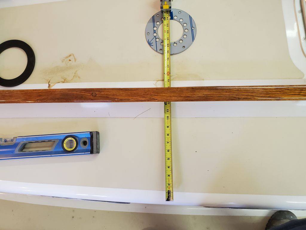
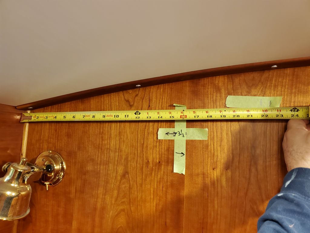
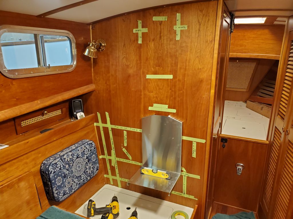
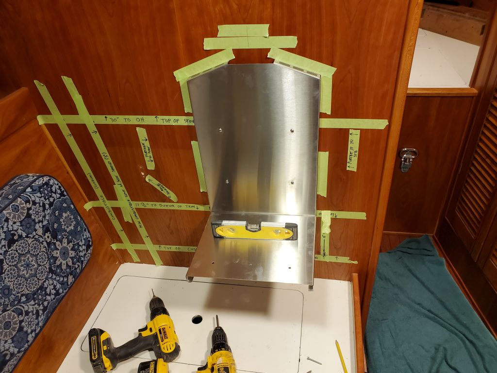
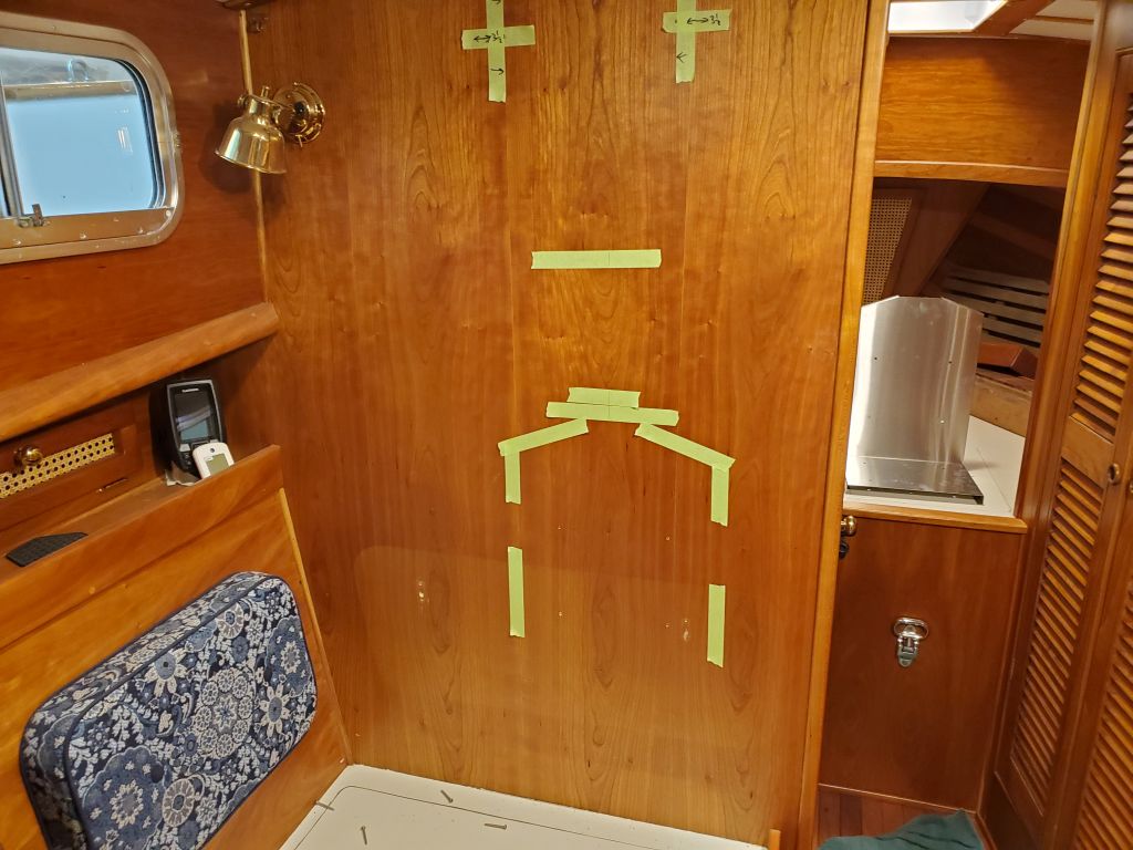
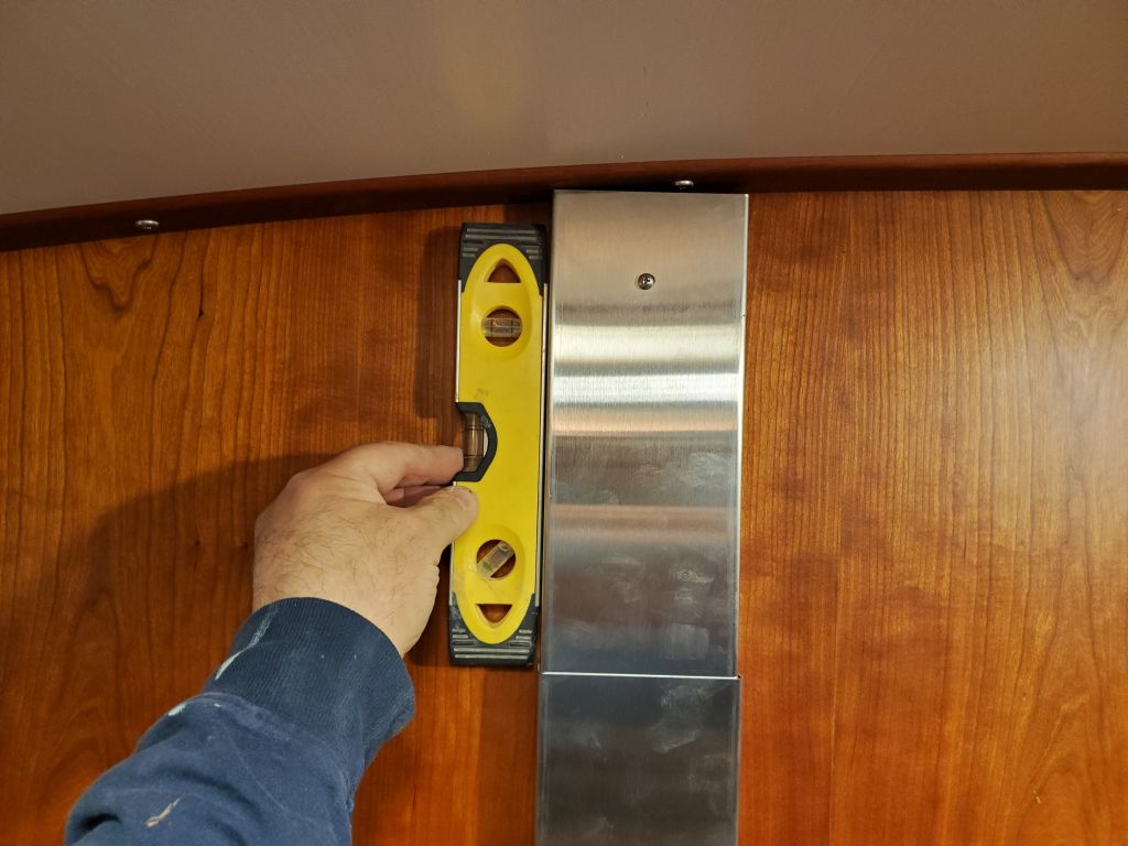
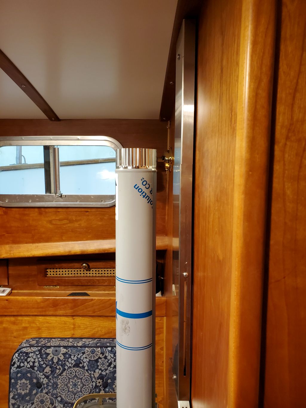
On the boat, the basic location of the stove was already determined through the various measurements and layouts accomplished in November, but now I needed to confirm that the stovepipe would exit the coachroof where I wanted it, essentially midway between the port handrail and the raised center portion of the coachroof.  This location worked naturally with the various restrictions on the stove placement in the cabin, which I’d previously determined, but before I started drilling holes and mounting things, I had to transfer the location from outside to inside.  With some ready references between inside and out, I could easily determine where I wanted the center of the pipe to be, which turned out to be 22″ from the cabin side.  From this basic mark, I used a level to plumb a line down to the stove location so I could align the heat shield and mounting bracket properly.

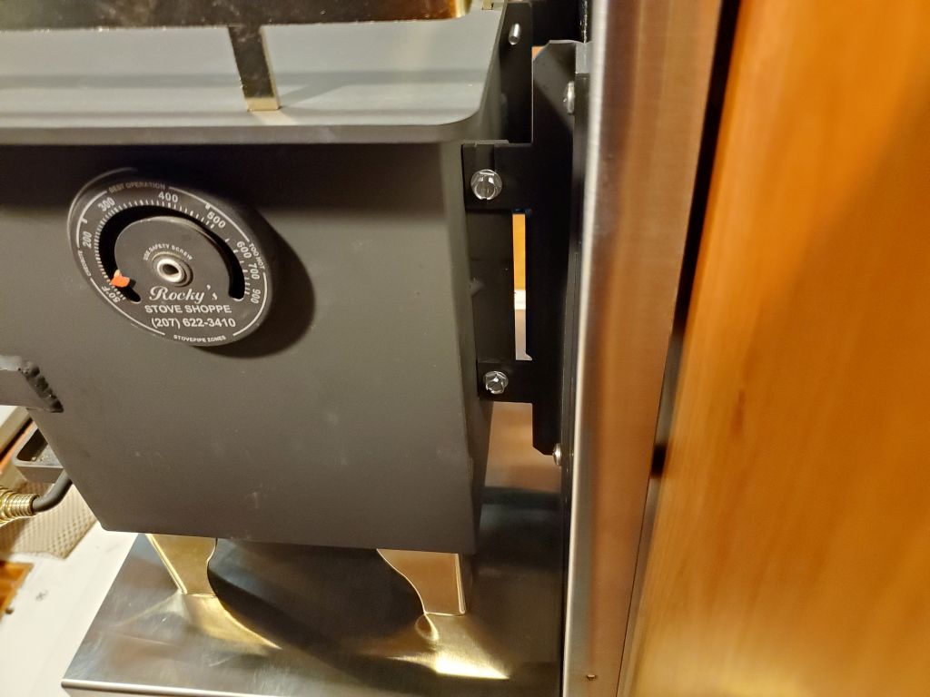
Despite appearances, the woodstove doesn’t rest on, and is not supported by, the bottom tray of the heat shield; the weight of the stove, in this installation, would be carried on the bulkhead, with a mounting bracket designed to bolt through (and simultaneously secure) the vertical heat shield.  The kit came with zinc-coated woodscrews–it’s not a marine stove per se–and obviously I wasn’t going to use non-stainless screws, but as I considered the installation more I realized I didn’t really want to rely on just screws either.  In a static installation, like a tiny house or caravan, that would be adequate, but the dynamics of a boat called for bolts, in my opinion.

To start, however, I first had to position and align the main heat shield, and mark the bolt holes accordingly.  So, positioning the shield where I wanted it, with the bottom of the shield even with a layout mark I’d made previously (as low as it could go) and centered on the desired stovepipe location, I temporarily leveled and installed the shield with four smaller screws just to get the positioning right.  This done, I used masking tape to mark around the edges of the shield to help me with final alignment when I put the shield in place shortly.  I drilled and tapped the four mounting holes for #10 machine screws that would penetrate the bulkhead for throughbolting.

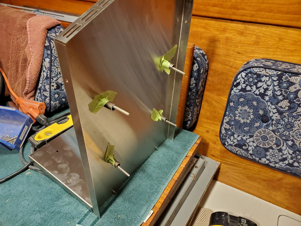
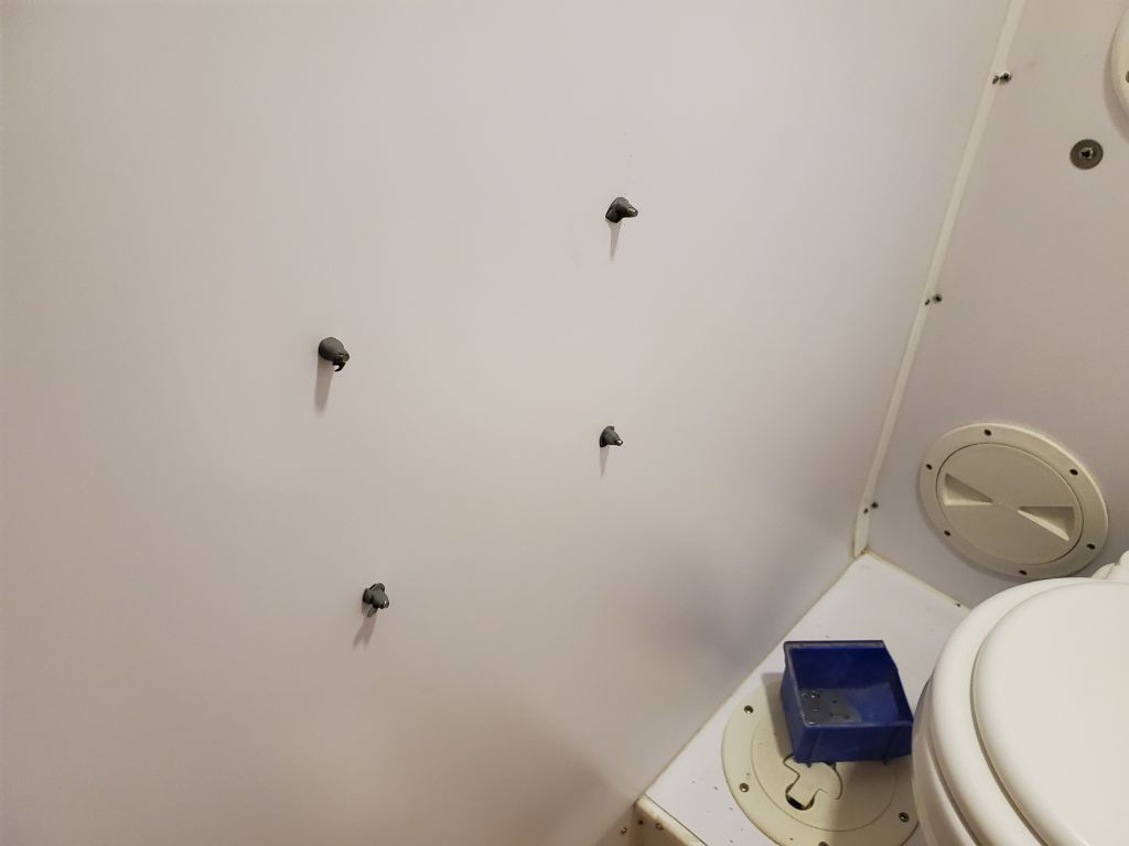
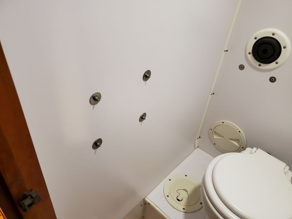
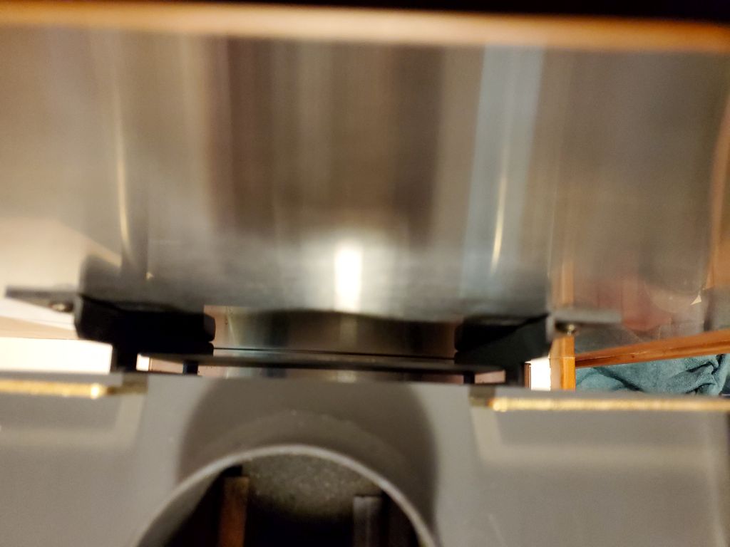
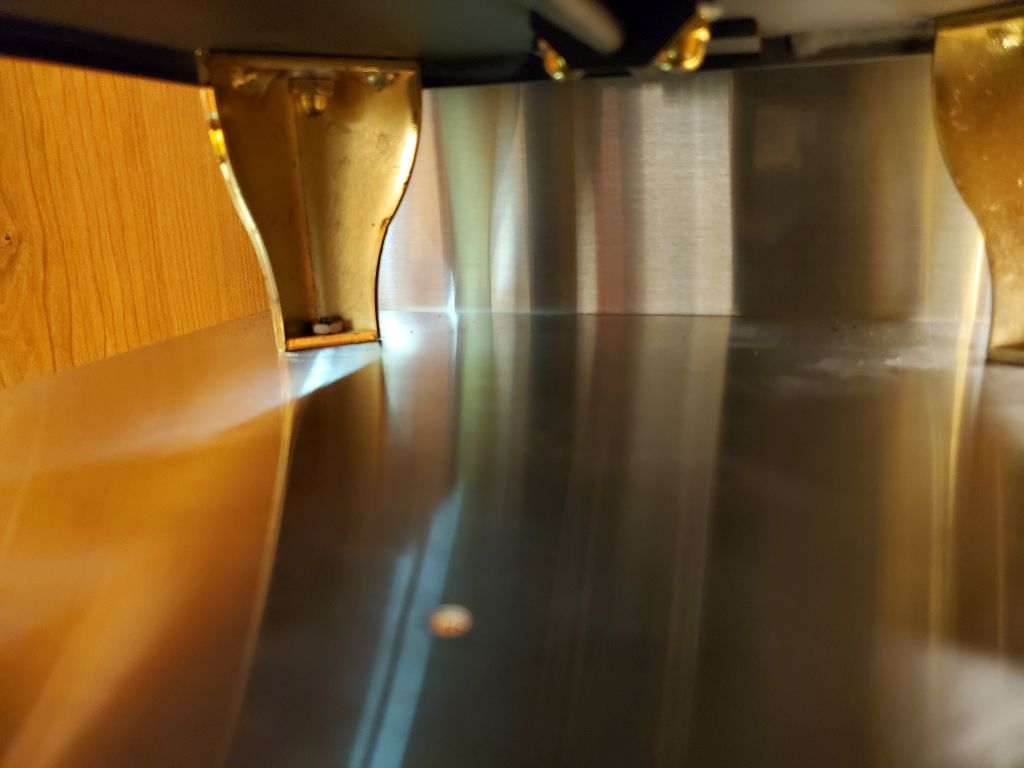
The shield was to be installed with four 1″ spacers, which held the sheet metal out just a bit from the bulkhead, and the mounting bracket for the stove–on which the weight would fully hang–also had to be installed at the same time.  This was a fairly delicate overall arrangement till installed, with lots of floppy pieces and four bolts to align and install all at once, including the spacers, so I made my life easier by taping the spacers in place behind the shield (the tape would never be seen), and as it were the installation proceeded smoothly.  On the back side of the bulkhead, in the head, I sealed the throughbolts with butyl sealant and large washers and nuts to finish off the installation.  (I’d cut off the excess bolt length before the project ended.)

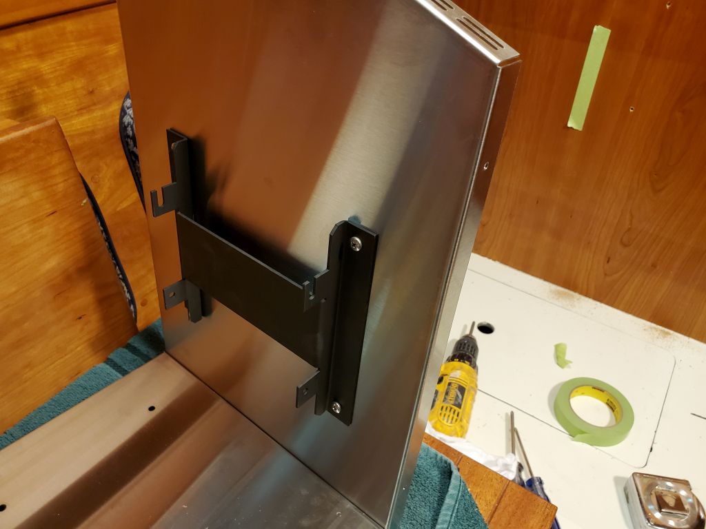
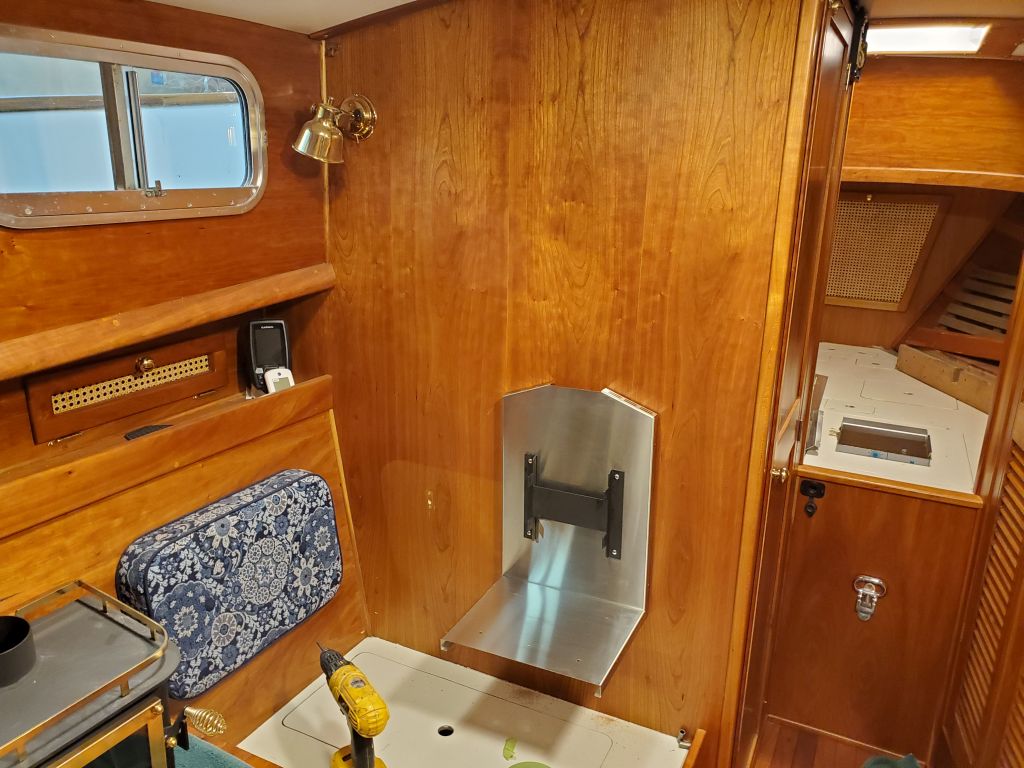
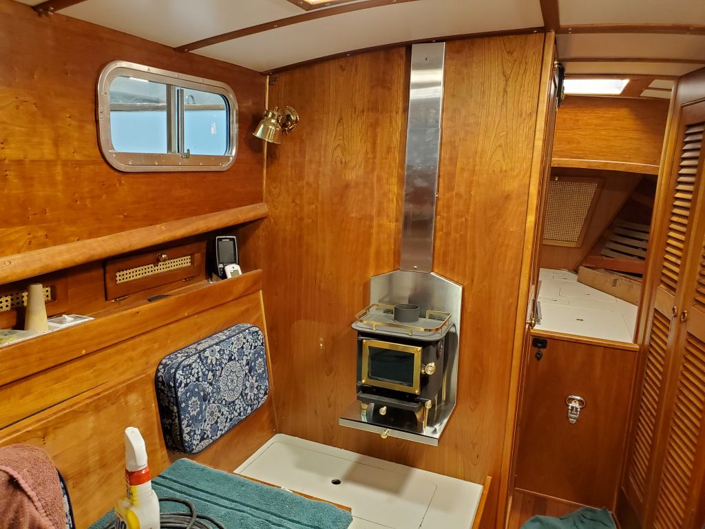
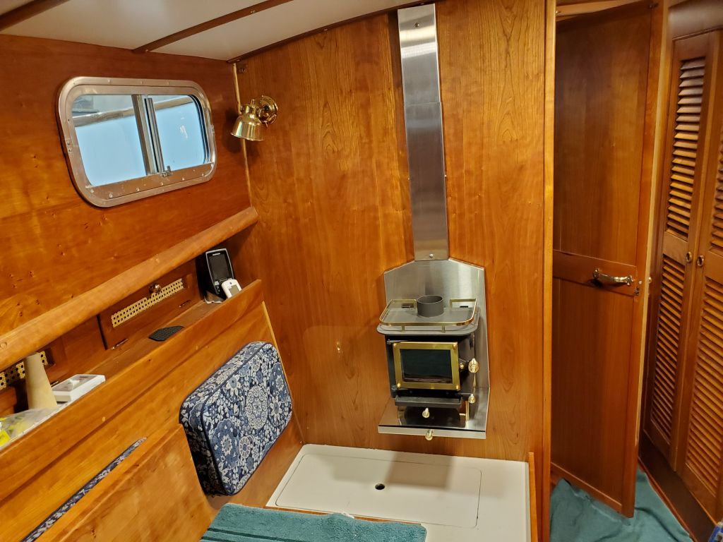
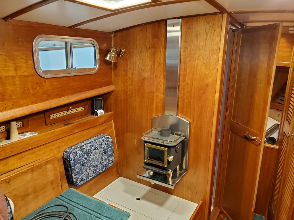
The woodstove was easy enough to install on the completed bracket, with two slots above and two fixing screws beneath.  This held the weight of the stove, and to actually hold the base of the heat shield in place, I installed four bolts to secure it to the legs of the stove, completing the illusion that this was a platform on which the stove rested.

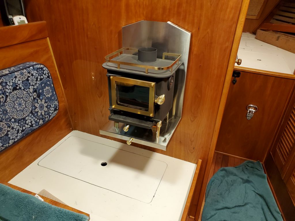
Continuing the heat shield, I installed the two slip-together sections that would back the stovepipe on its way to the overhead, securing this arrangement plumb with two screws and spacers.  No need for bolts here.  I temporarily installed one of the stovepipe sections just to see how it looked, but now it was late in the day and I’d continue the installation next time.

Total time billed on this job today:  4.75 hours

0600 Weather Observation:  35°, partly cloudy.  Forecast for the day:   Sunny, windy, 43°

Lively Heels Phase 3-35

Friday

As a final step before the final paint work, I laid out and masked off the field areas of the two lids to protect the eventual nonskid areas from overspray.  Afterwards, I solvent-washed all the pieces and parts and wiped with a tack rag.

Over the course of the remaining morning, I spray-applied three coats of snow white gloss topcoat to the boxes and lids, which paint matched the existing on the deck areas.

Total time billed on this job today:  2 hours

0600 Weather Observation:  45°, foggy.  Forecast for the day:   Fog and rain, 56°

Lively Heels Phase 3-34

Thursday

After a light round of sanding with 320 grit paper by machine and hand, the deck boxes were ready for the next steps, which included some minor masking on the lids before gloss topcoats.  Since the primer hadn’t yet had the minimum 24 hours to cure before masking atop the fresh paint, I completed all the setup I could for the work ahead, including a thorough cleanup of the shop and surrounding areas, then worked on other things during the remainder of the day.

Total time billed on this job today:  1 hour 

0600 Weather Observation:  44°, foggy.  Forecast for the day:   Mostly cloudy, 56°

Lively Heels Phase 3-33

Wednesday

The deck boxes required another round of light sanding and cleanup following the application of fine filler last time.

Afterwards, I applied three coats of epoxy-based finish primer to the boxes and lids.

Total time billed on this job today:  1.75 hours 

0600 Weather Observation:  39°, foggy.  Forecast for the day:   Mostly cloudy, 58°

Lively Heels Phase 3-32

Tuesday

I sanded the high-build primer on the deck boxes and lids, creating a generally smooth surface with only a few flaws revealed by the primer–always expected and part of the process.

After cleaning up, I applied fine fairing compound to a few areas here and there, filling pinholes in the original laminate or fairing compound and correcting  some work at a corner or two.

Changing tacks, I turned to some initial work that would lead up to the final installation of the new woodstove in the cabin.  Because the woodstove couldn’t be located the minimum required distance away from the cabinetry outboard of the mounting location (21″ minimum required), the owner ordered a side shield that, properly installed, would reduce clearance to 3″.  However, the side shield wasn’t quite what was expected–at least not by me.  It turned out that the side shield was supposed to be installed on the surface to be protected itself, not as part of the stove’s own shielding, which was how I thought it would work.

During the previous weeks, the owner and I had come up with a plan to build a tall, narrow wood box next to the stove itself, onto which the side shield would mount–satisfying that requirement–while also providing a useful storage area for the firewood.  The owner envisioned a simple box with an opening at the top, wide enough to hold some compressed sawdust wood logs he had test-burned and liked for the stove.

I started construction by determining the general size of the box, mainly directed by the size of the stainless steel side shield.  Before I could dimension the various plywood panels that would make up the box, I had to start with some solid cherry corner trim for the front corners, a basic design to accept the plywood edges, hiding the end grain and securing the corners together at the same time.  I milled the trim as needed to fit the plywood:  1″ square, with dados on two adjacent sides to accept the 1/2″ plywood, with an angle cut on the inside and roundover on the outside corner.  Once milled, I sanded the pieces smooth and clean.

Using the side shield, I determined the final width of the side panels required.  Because of the photo perspective, it doesn’t look like it, but the side panel–including the corner trim–was about 1/4″ wider than the shield, just enough to ensure full coverage without any overlap.  With the plywood partially inserted in the grooves of the trim, I could determine how wide to make the plywood now, and cut pieces accordingly.

Space was at a premium on the bulkhead, and there was no need nor desire to make the box any larger than necessary, so after some additional layout I cut a test piece of plywood to a width that would work for the front panel–wide enough to hold the fire logs the owner planned to use (as well as hardwood scraps), but not much wider than absolutely necessary.  With the front panel width determined, I cut a piece to fit properly, then measured and cut a back  panel as well.  There was no need for solid trims on  the back of the box since these edges would be tight against the bulkhead, and the back panel could butt against the sides from within.

The mockup with the side shield shows the shield slightly offset because of the clamp holding the box together at the moment.

For now, that was as far as I could take the box, but to finish it up I planned to install a bottom panel an inch or two up from the base of the side panels, not only to keep the depth at a manageable level for reaching in from above, but also to give me a way to secure the box to the bulkhead from beneath the bottom panel.    Some additional trim or plywood edge-banding would be required at the top of the box, and then I could glue it up and varnish it before installation.  All to come in due course.

Total time billed on this job today:  3.25 hours 

0600 Weather Observation:  30°, clear with fog.  Forecast for the day:   Becoming mostly sunny, 58°

Lively Heels Phase 3-31

Monday

Preparing ahead for applying the first round of primer to the deck boxes, and for a weekend meeting with the owner, I cleaned up the two boxes and set them up on deck for their first “completed” mockup, including lids.  The large coachroof-mounted deck box blended in surprisingly well given its size, and didn’t have any effect on the view forward from the pilothouse.  I located it as far aft as practicable to allow the lid to open freely without interfering with the forward-angled pilothouse.  Upon discussion, the owner and I decided for now not to proceed with additional boxes to the sides, aft of the small hatches, which boxes I’d postponed in favor of getting the two most important ones done.  There seemed not to be enough benefit for the additional bulk and time required.

The cockpit box fit well in its space, and the lid was flush with the adjacent seating areas.

Later, I brought the boxes back down to the shop floor and set them up in the other shop where I planned to spray the primer and paint in conjunction with another ongoing project.

With final cleaning and other preparations complete, I applied three sprayed coats of epoxy-based high-build primer to the boxes and their lids.

Total time billed on this job today:  1.75 hours (over two days)

0600 Weather Observation:  23°, clear.  Forecast for the day:   Sunny, 60°

Lively Heels Phase 3-30

Wednesday (and previous days)

After the epoxy coating the lids had some cure time, I sanded the coating smooth with 120 grit paper and a finishing sander.  This left a mostly smooth and fair surface, but there were a few areas requiring a bit of touch-up, so I applied a light coat of epoxy fairing filler as needed (mainly on the vertical overhangs).  The next day, I lightly sanded the cured fairing compound as needed, completing the prep work on the lids.  These, and their respective deck boxes, were now ready for primers and paint.

I received the new Delrin anchor rollers I’d ordered to match the old, broken, polyethylene ones.  The new rollers featured bronze bushings, and were identical to the originals except the channels were a touch shallower, which, at the urging of the vendor, I’d agreed to in order to leave more solid material in the centers of the rollers (for structural strength and allowing room for the shaft and bushings).

I reinstalled the rollers and pin, completing this task.

Total time billed on this job today:  1.25 hours 

0600 Weather Observation:  16°, clear.  Forecast for the day:   Sunny, 50°

Lively Heels Phase 3-29

Thursday

Once the fiberglass cured, I trimmed the excess that hung over the edges and sanded it flush, then very lightly sanded the entire surface to prepare it for epoxy coating.  In this case, I chose to fill the weave of the cloth with coats of liquid epoxy, rather than fairing compound, since the finer, lighter cloth required less work to bring to a smooth surface, and to avoid the possibility of inadvertently sanding through the cloth.  For right now, however, I didn’t have any rollers on hand, so I had to await the epoxy coating till a couple days hence.

Meanwhile, I installed some 3/8″ tall fiberglass “feet” to the bottoms of the two deck boxes, securing them with thickened epoxy adhesive.  These risers would keep the boxes just clear of the decks and promote water and air flow beneath as needed.

With foam rollers on hand a little later in the week, I applied, over the course of a day, two good rolled coats of epoxy over the two lids.  This seemed to be enough to fill the weave adequately and I decided to leave it there pending a light sanding to see how flat I could get the surfaces.

Total time billed on this job:  1.5 hours (over two days)

0600 Weather Observation:  35°, cloudy.  Forecast for the day:   Mostly sunny, 53°

Lively Heels Phase 3-28

Saturday-Sunday

When I built the deck box (and the cockpit box, but we’ll get to that a little later), I also cut out an oversized piece of plywood from which I planned to make the top and set it aside for later.  Now was later, so it was time to build the lid.

This largest of the planned deck boxes was to have a hinged, gasketed lid, and to further waterproof the top I planned for it to be a shoebox style, where short extensions on the lid would overhang the box itself on three of the four sides; the fourth side would have the piano hinge and gasket.  I’d found a piano hinge with extra clearance between the leaves that would accommodate a gasket running through.

With the box inverted on the lid blank, I laid out scrap strips of 9mm plywood for the overhang, spacing them a little away from the box itself for clearance (I used wooden stir sticks, which are about a strong 1/8″ thick).  After marking the final dimensions of the lid, I trimmed as needed.

After milling some 1″ wide strips of plywood for the overhang, I cut them to fit around three sides of the box, flush with the edge of the lid.  Then, I glued and clamped them in place with epoxy.

To provide a wider bearing surface for the gasket, as well as better area for the piano hinge fasteners, I installed an additional layer of 9mm plywood around the top inside of the box opening, cutting and fitting the strips to fit, then gluing them with more epoxy.  I rounded the bottom edges of the strips for a better in-the-box experience for the owner’s hands.

With the main deck box complete for now, I moved on to the angular cockpit box, and repeated the process with the lid, fitting and gluing the 1″ wide strips around the perimeter after cutting the oversized blank to the proper size.  In this case, I installed the overhang on all four sides, since this lid would have no hinge and would be just a lift-on-lift-off design.

Next, I laid out the additional strips for the inside of the top edge, again to accommodate the sealing gasket.  I was out of clamps (or more specifically out of clamps I wanted to use with epoxy–I have gunky epoxy clamps and clean woodworking clamps), so for the moment the final installation would have to wait until the clamps were freed up from the other lid.

After an overnight cure, I unclamped the various epoxied things and test fit the overhanging lids on their respective boxes.

Next, I rounded over the outside corners of the lids and sanded things smooth to improve appearance and prepare for fiberglass sheathing.

I cut oversized panels of 10 oz. fiberglass cloth to fit the lids, knowing it would cling tightly to the various corners, particularly on the trapezoidal lid.  After preparing a working surface and wetting out the plywood lids with epoxy, I installed the fiberglass cloth, which conformed well to the shapes and would, when cured, provide additional strength and durability.

To round out the day, I glued in the interior strips at the top edges of the cockpit box, clamping them while the epoxy cured.  The additional thickness at the top edge would better accept the gasket material to help waterproof the lid.

Total time billed on this job (over two days):  4 hours

0600 Weather Observation:  13°, clear.  Forecast for the day:   Sunny, 30°

Lively Heels Phase 3-27

Monday

After a few coats of varnish, the new shelves were ready for final installation.  With the support cleats already in place, installation was relatively straightforward, with a few screws on each side of both shelves to secure them to the cleats.

Next, I installed matching cherry fiddles on the two original shelves, using glue and screws on the main shelf midway up the compartment, and, because there was no access beneath for screws, glue only on the lowest shelf fiddle, which I held in place with clamps while the glue cured.  These fiddles were designed to help hold in the storage bins the owner planned to use, but with minimal height clearance on some of the shelves the fiddles couldn’t be too high lest they prevent the bins from being removed or installed.

Later, once the glue had enough time to cure, I removed the clamps from the lower fiddle and test-fit the three bins the owner had left, which completed this small project.

Total time billed on this job today :  1.5 hours (including varnishing time)

0600 Weather Observation:  36°, light rain.  Forecast for the day:   Showers and rain, 45°, becoming sharply colder overnight

Older posts Newer posts