(page 2 of 8)

Jasmine 65

< Back to Jasmine

Tuesday

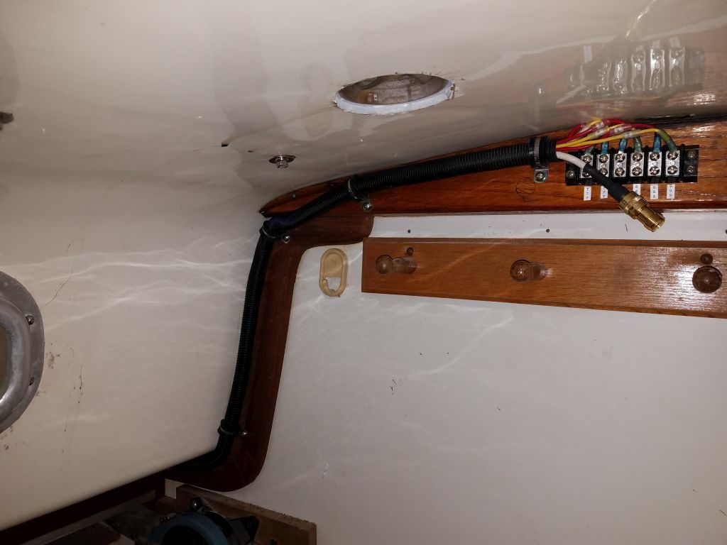
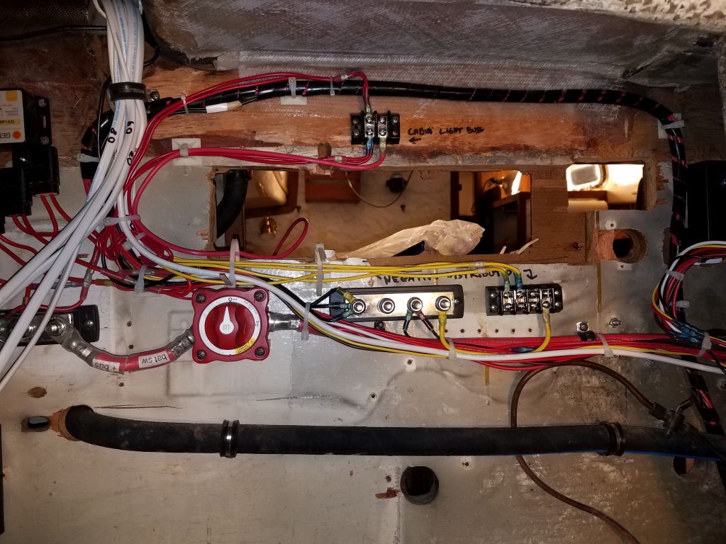
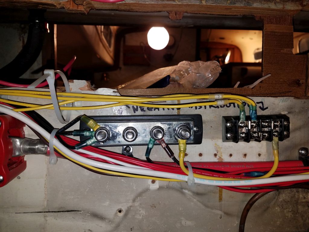
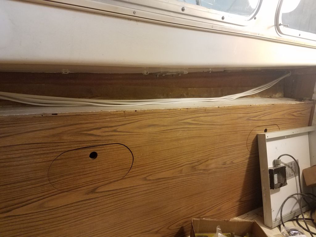
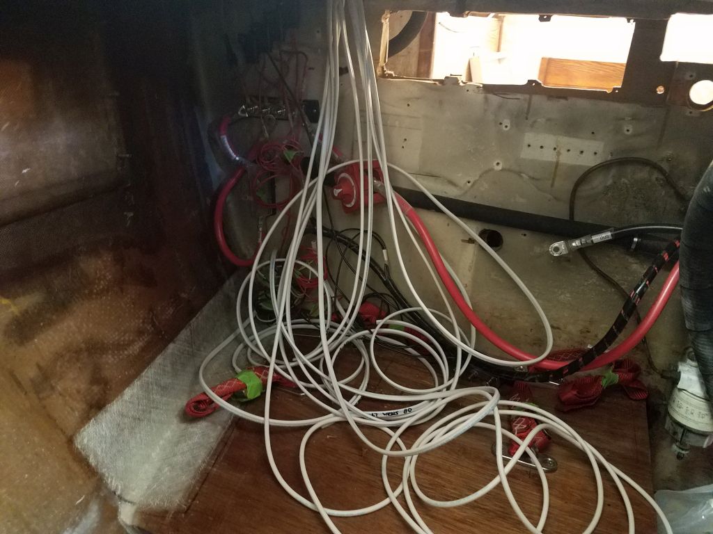
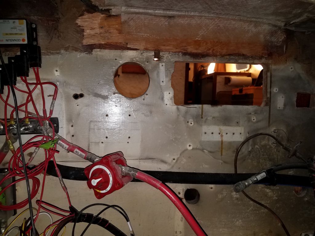
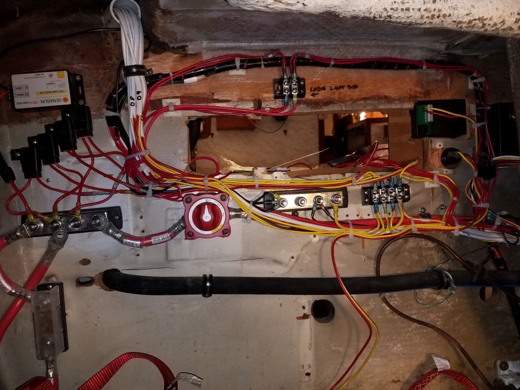
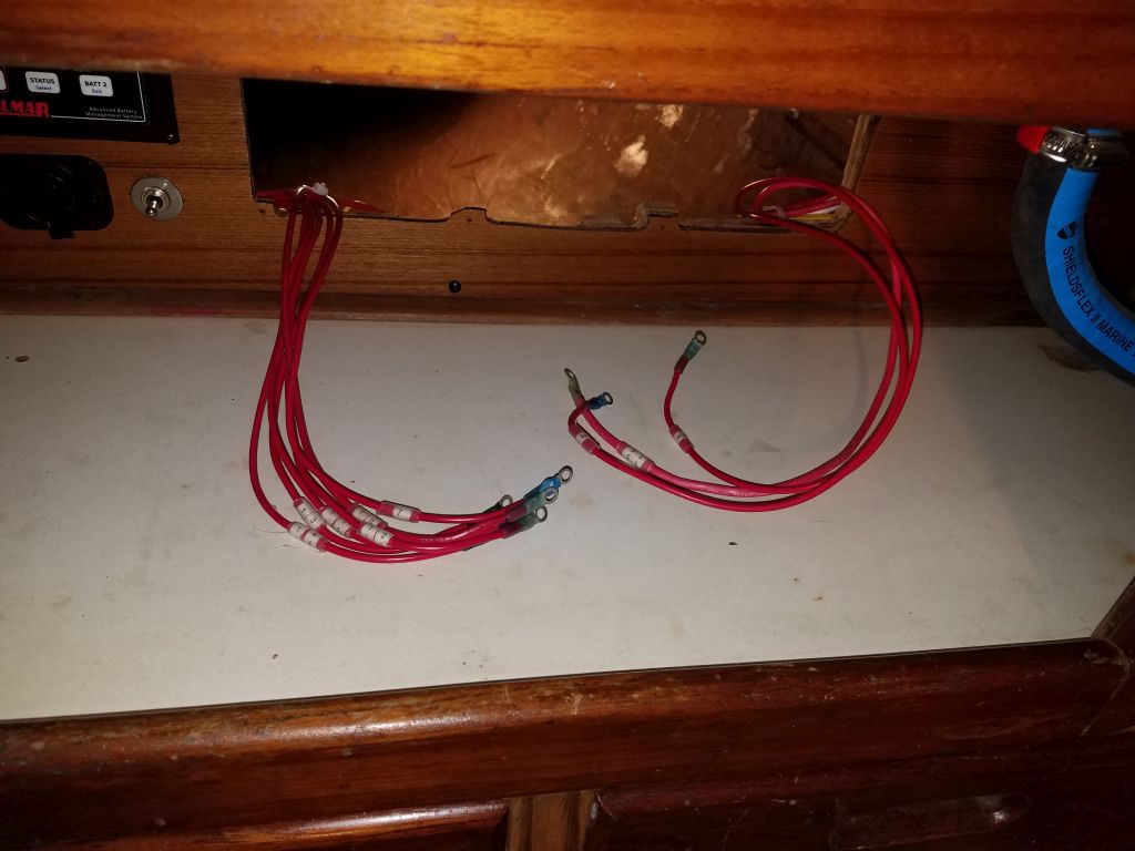
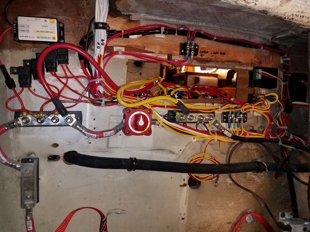
Working through the morning, I finished up the wiring in the port cockpit locker, routing and terminating the remaining 8 or 9 wires to the negative distribution buss and leading the positive ends out through the panel hole for later attention and connection to the panel itself.

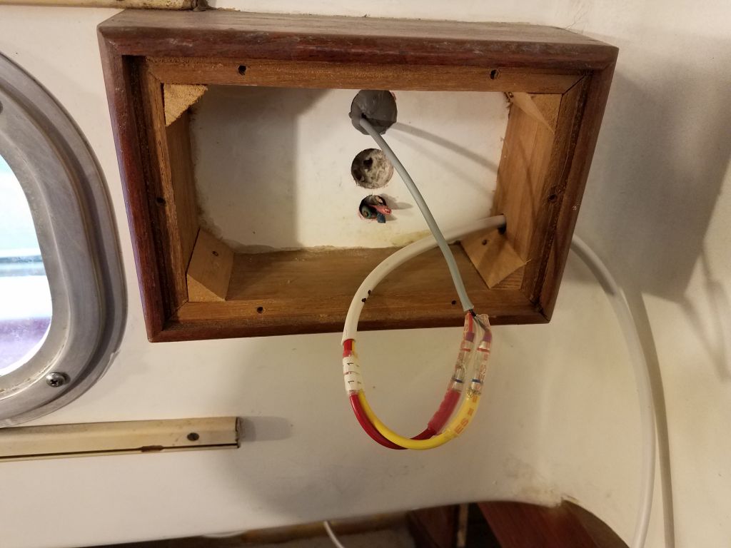
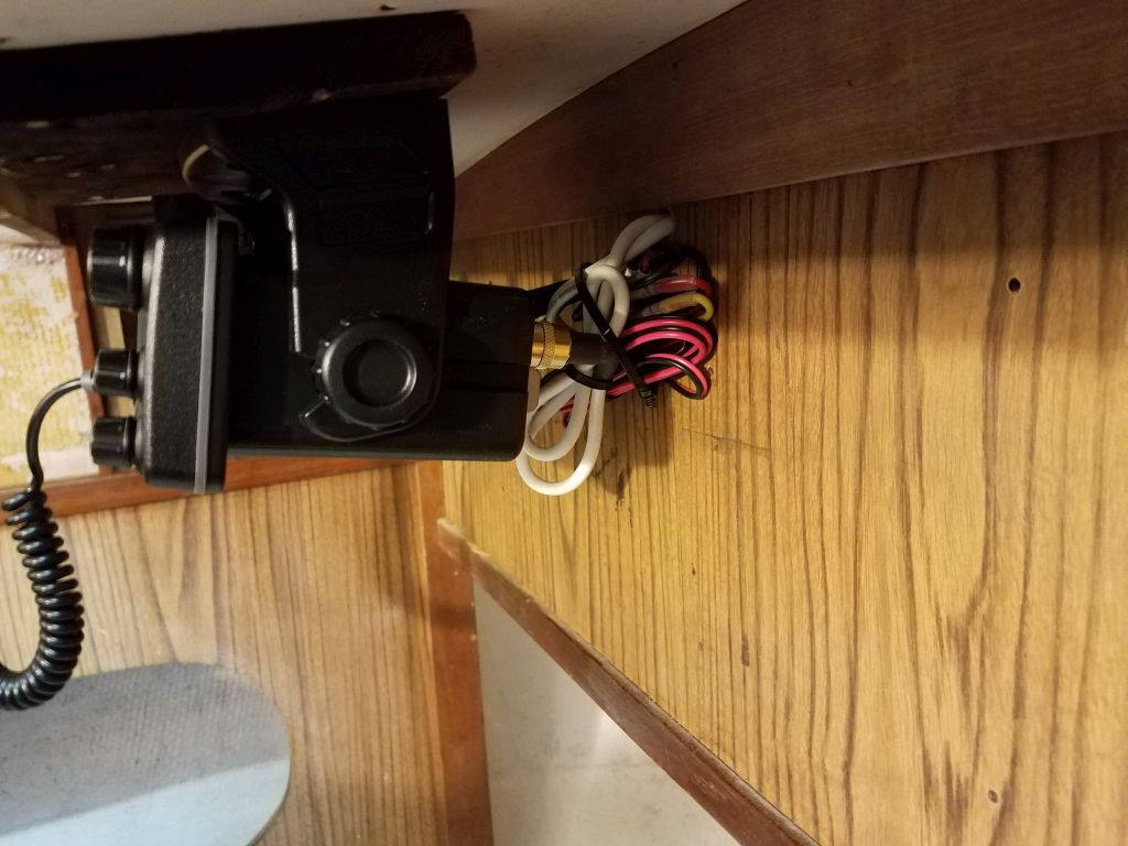
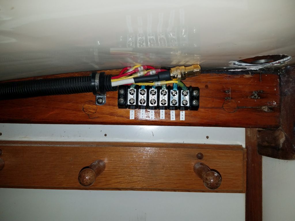
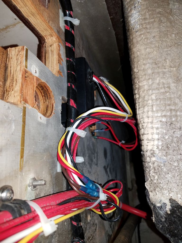
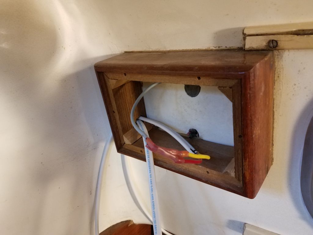
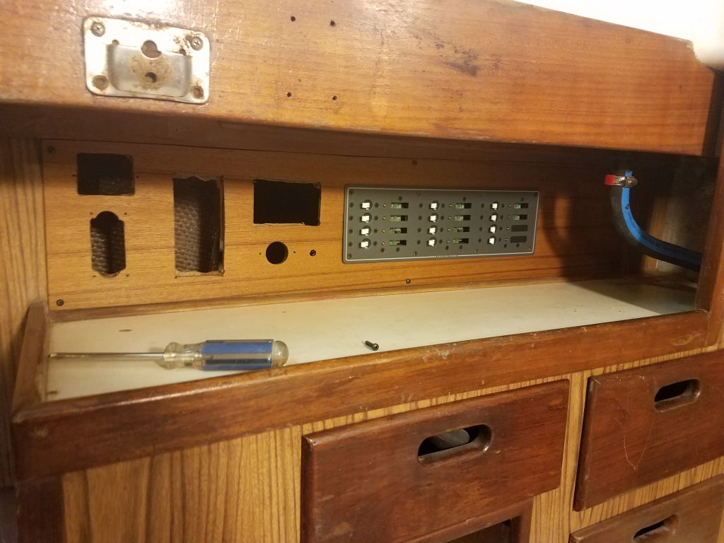
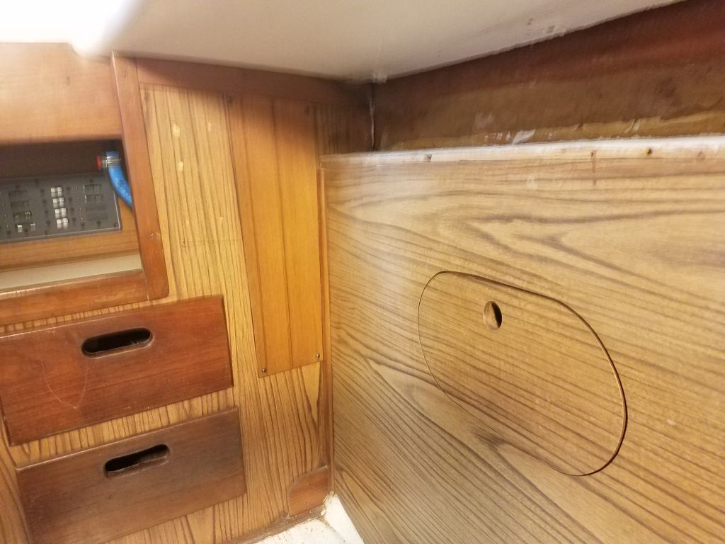
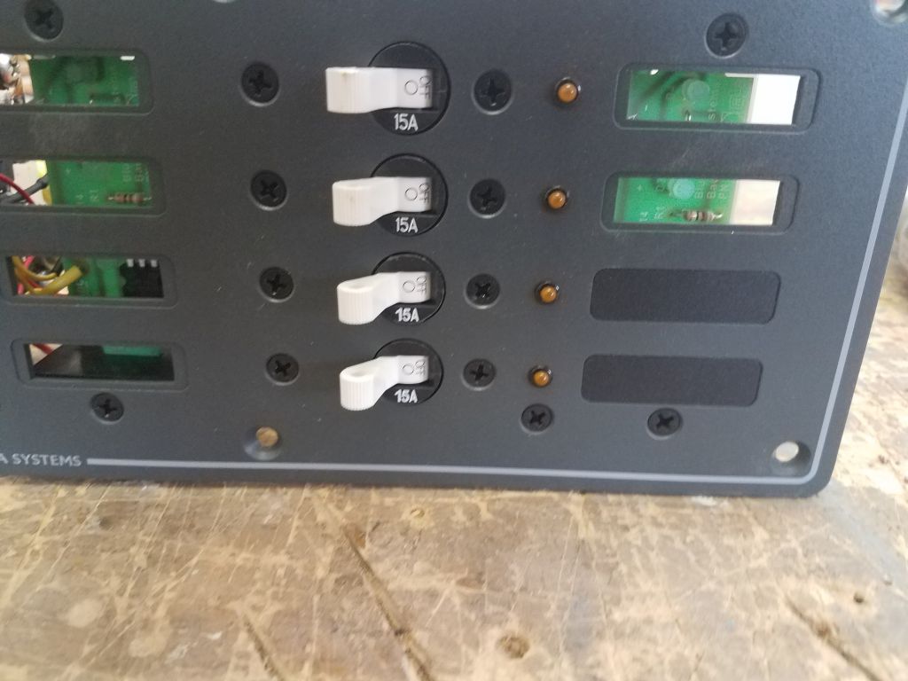
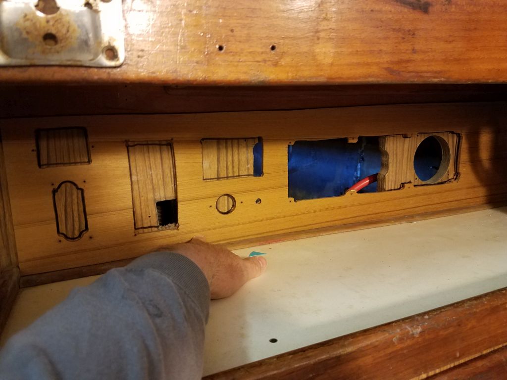
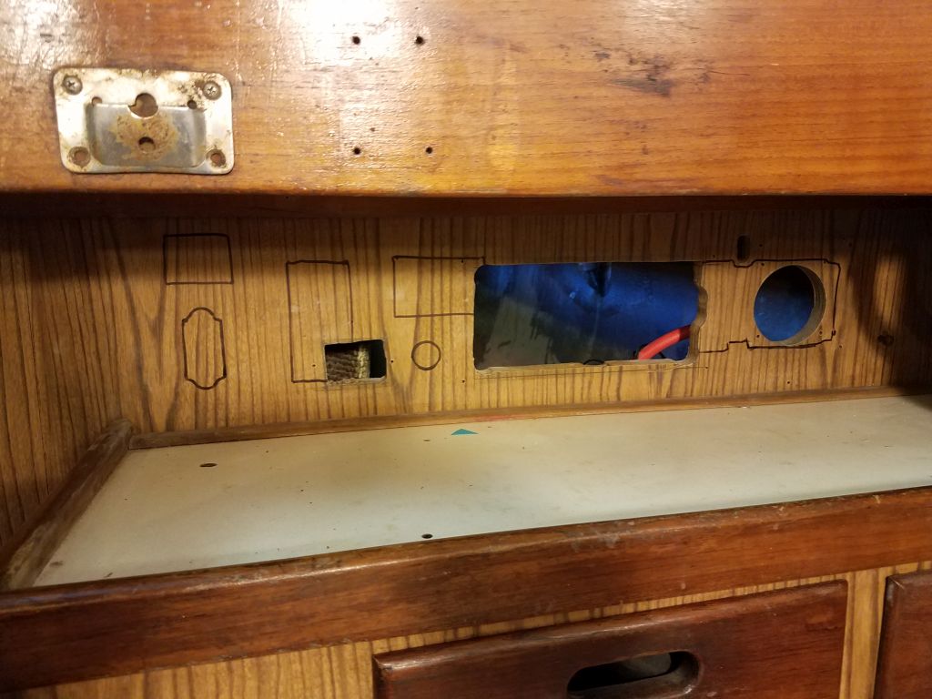
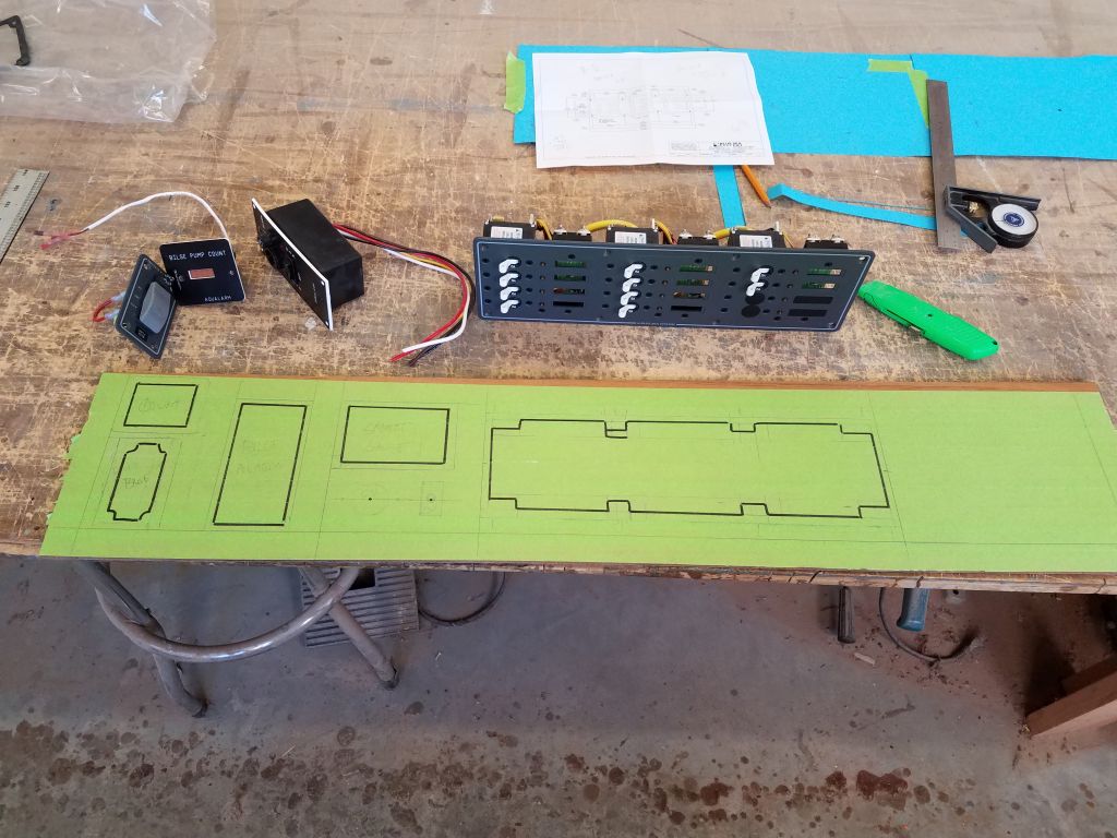
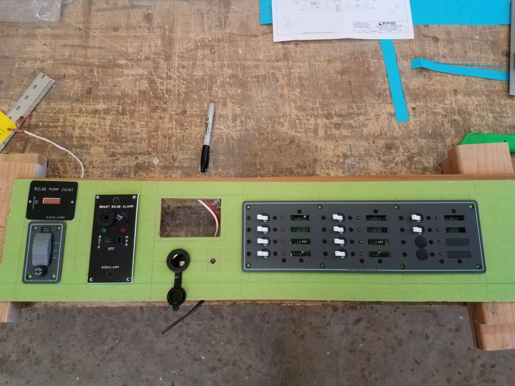
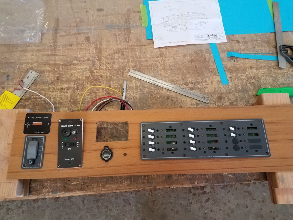
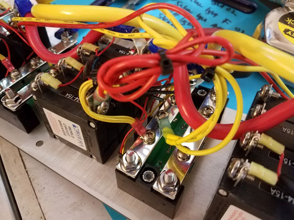
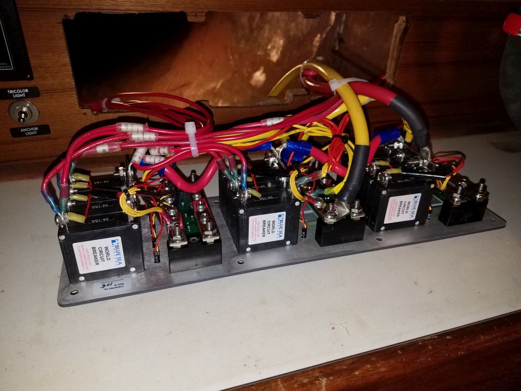
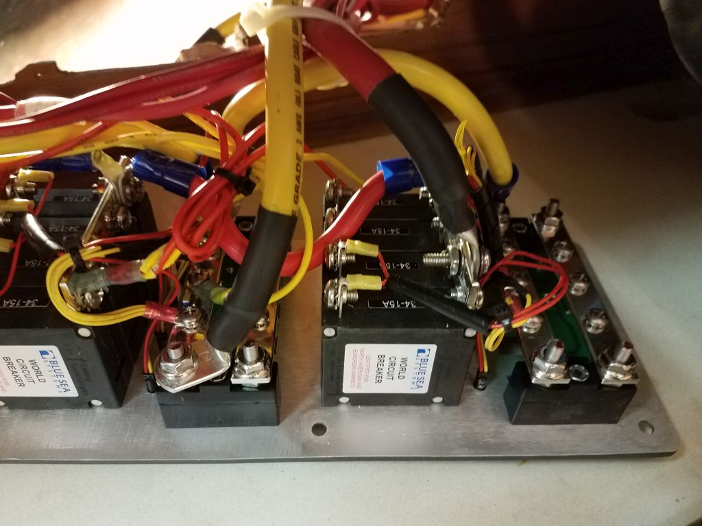
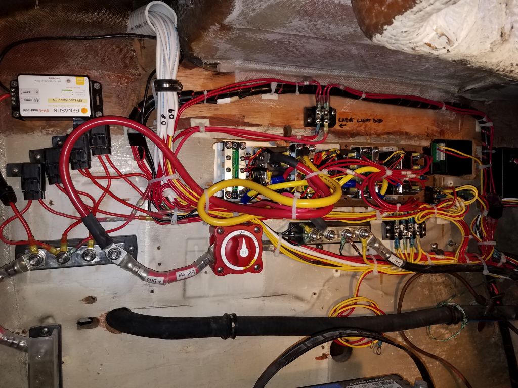
I moved my operation into the cabin, and prepared for the final connections at the new service panel.  My first step with the panel was to connect the little wires included with the panel–but left disconnected–that powered the panel’s backlight system.  These are the little bundles of yellow and red wires shown below.

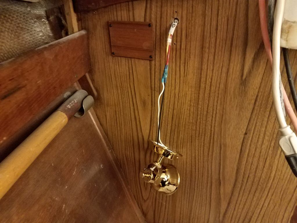
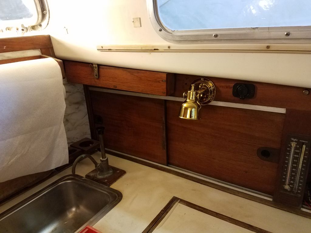
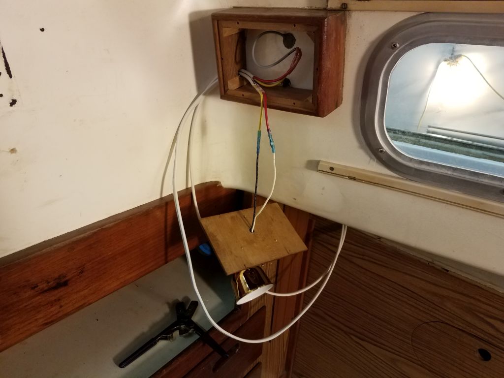
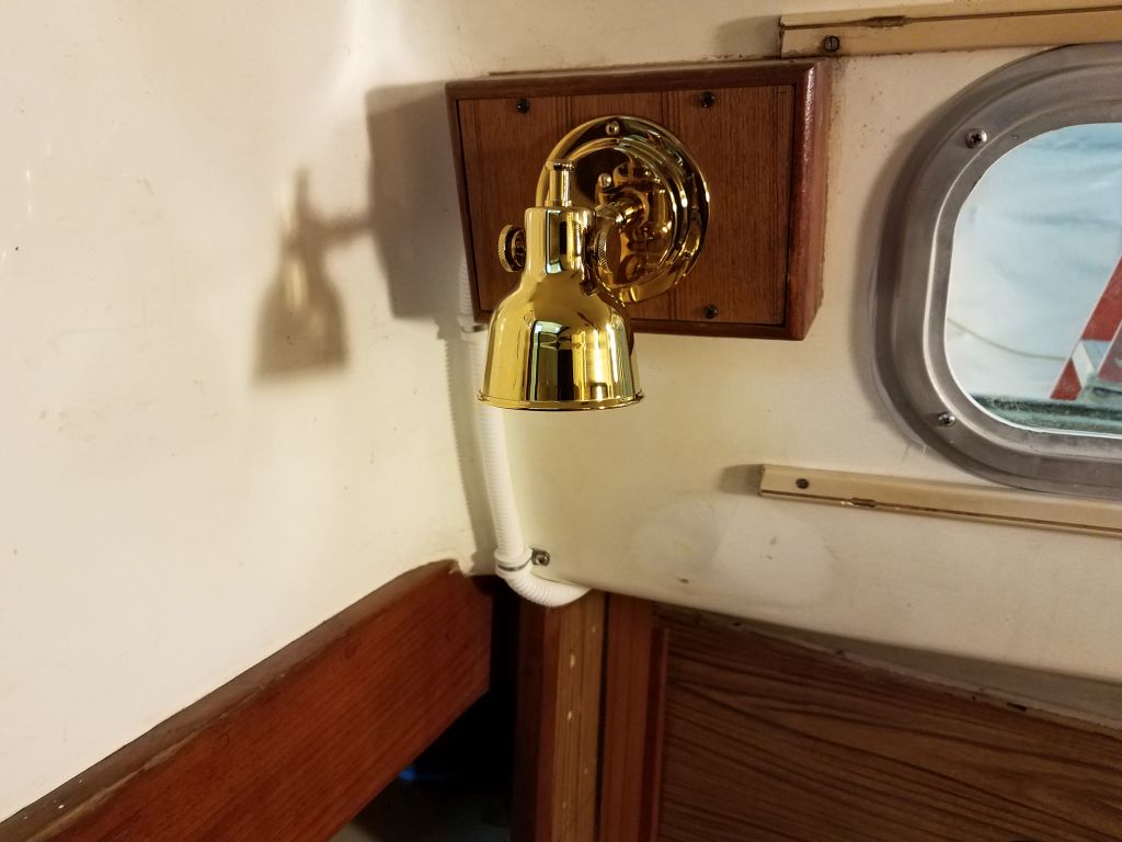
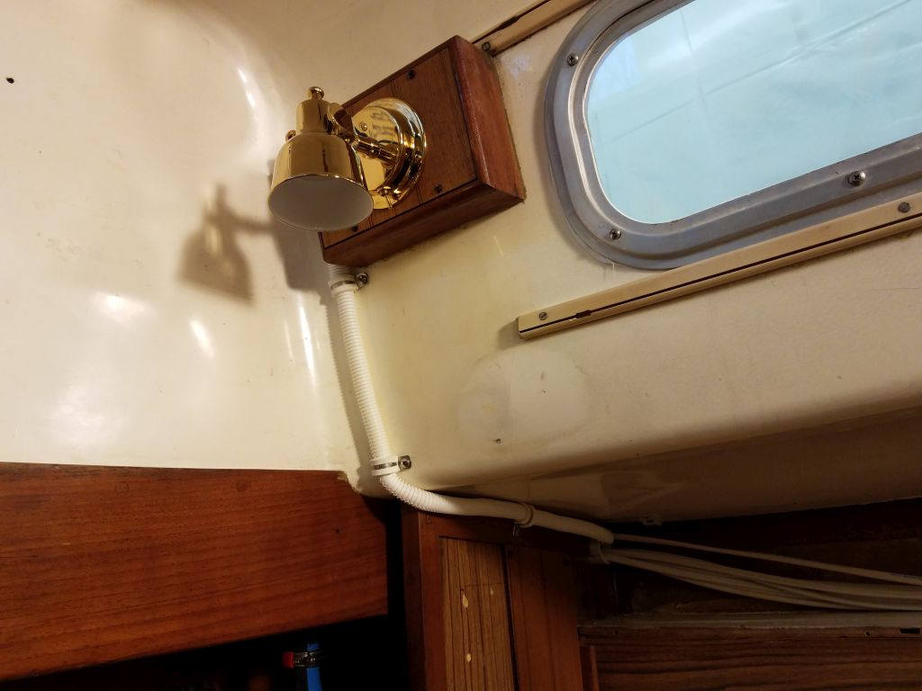
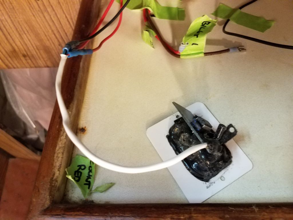
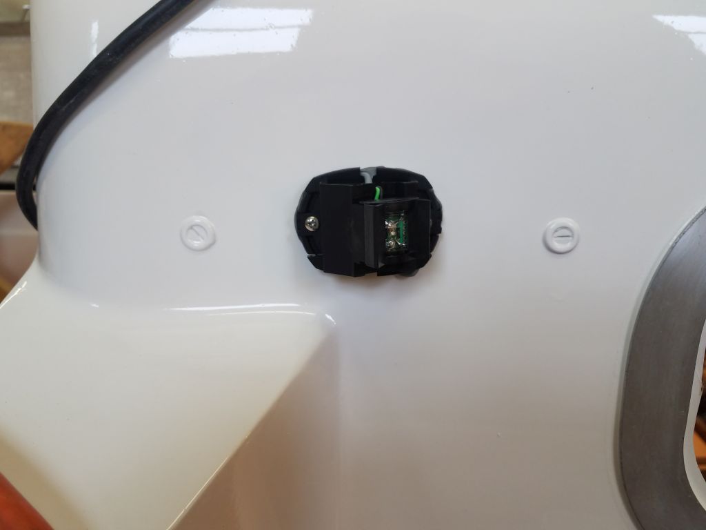
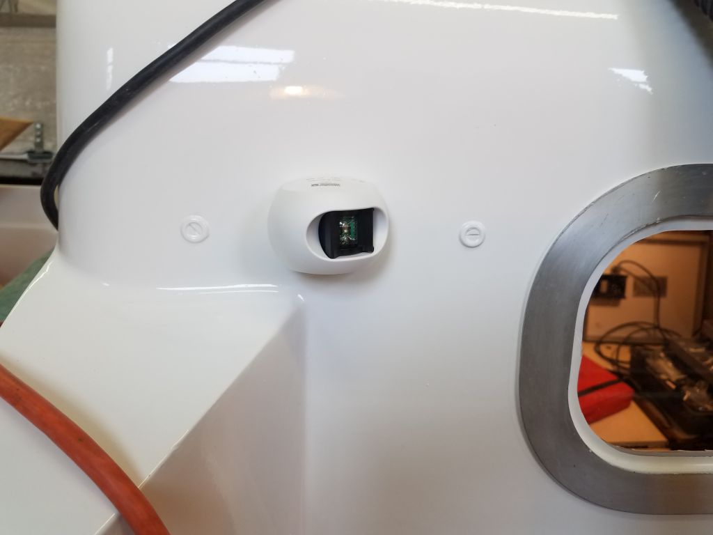
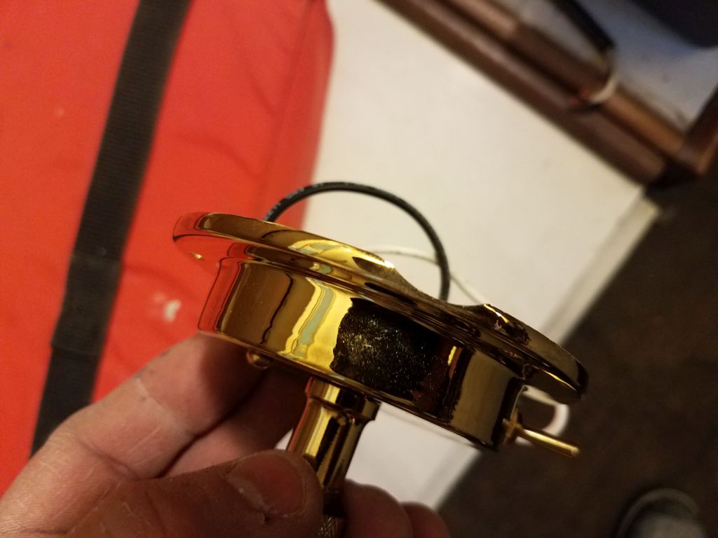
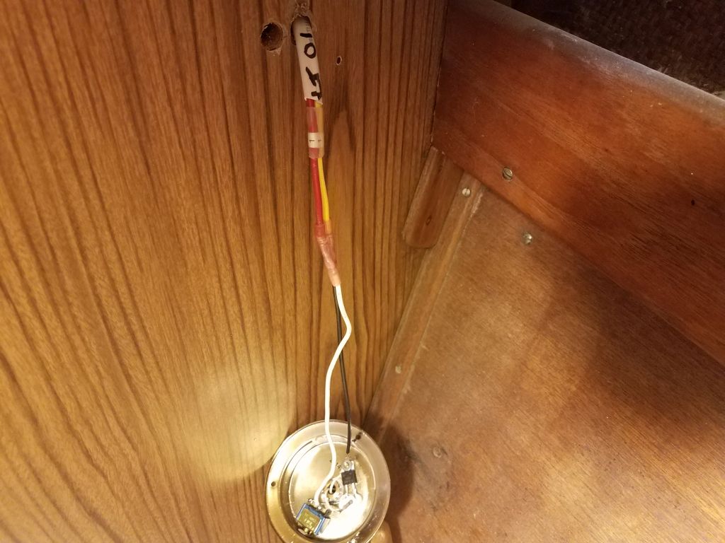
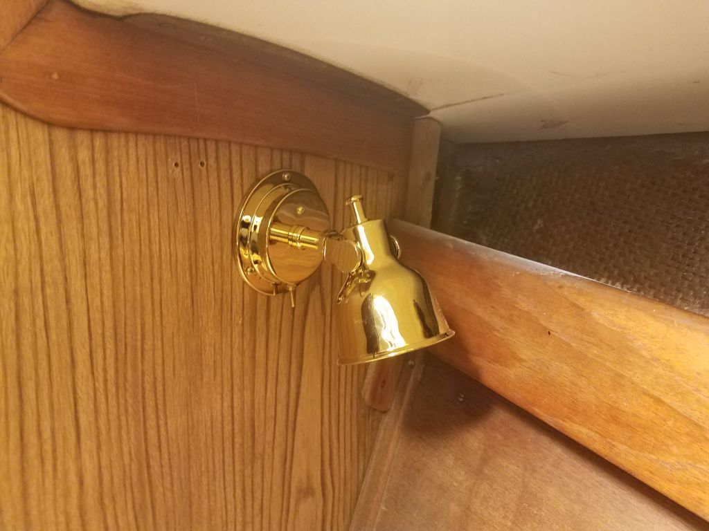
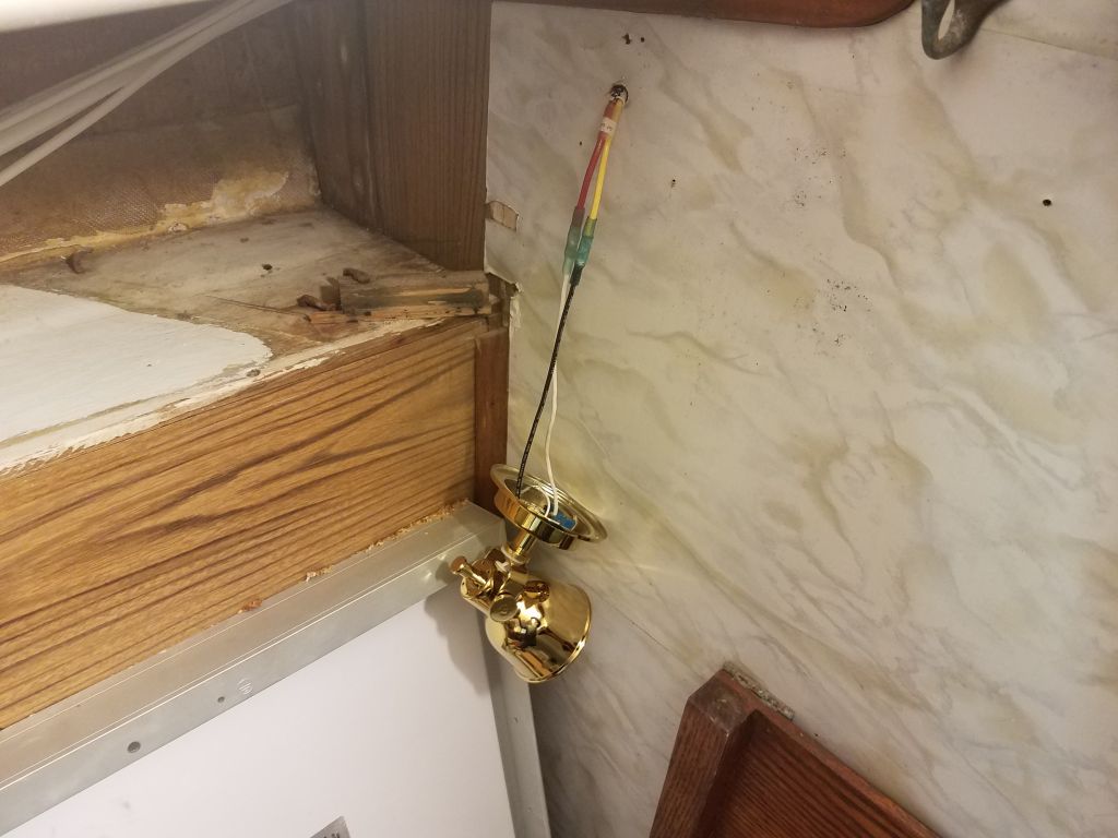
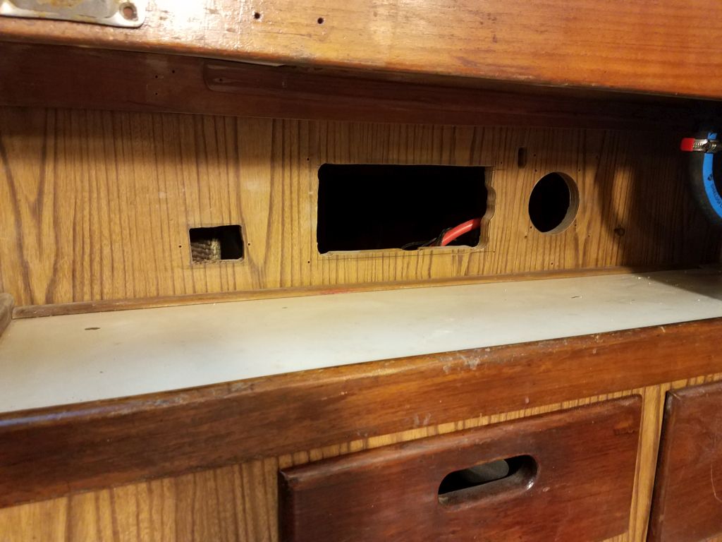
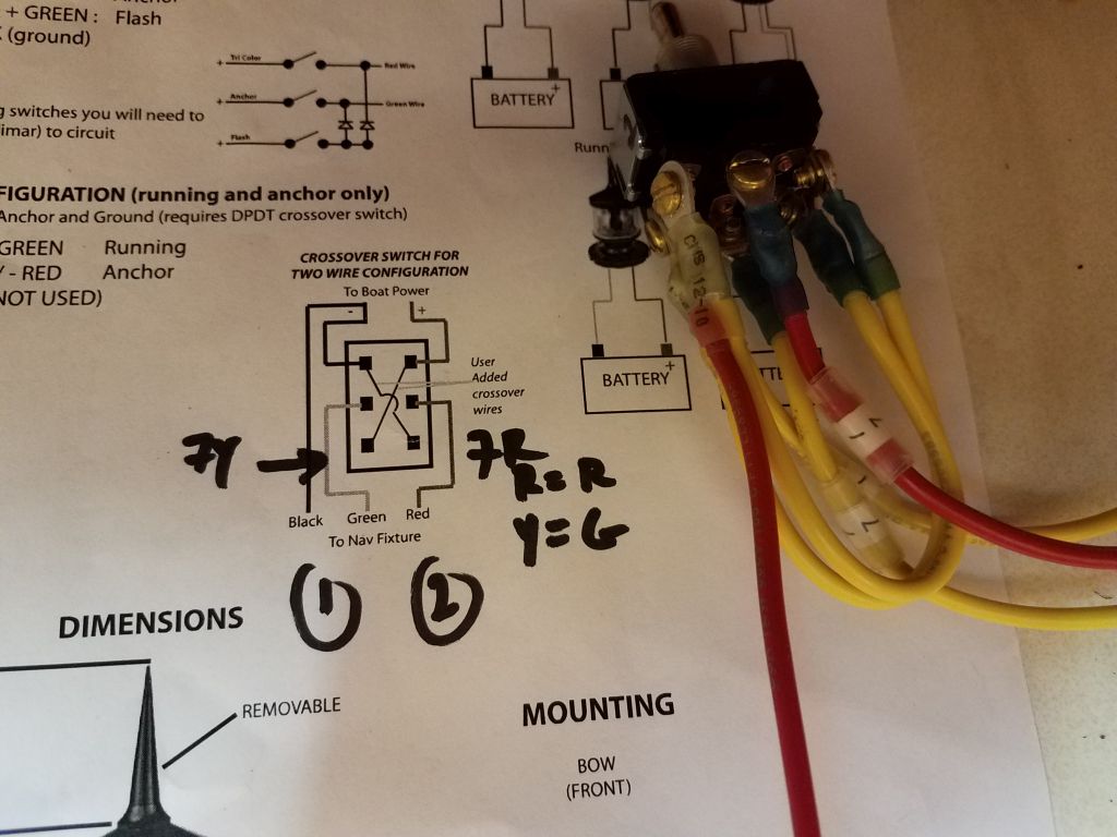
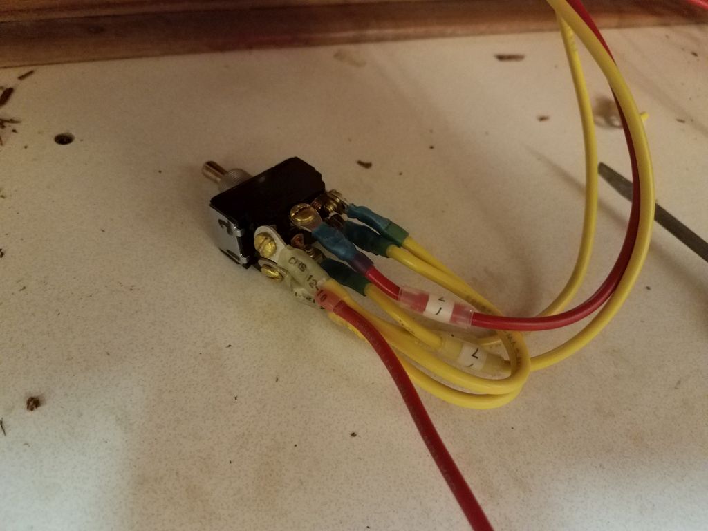
The first wiring task for the panel was to prepare a double pole, double throw (DPDT) toggle switch to control the combination masthead light unit the owner had provided.  This light, requiring just two wires to the masthead for the owner’s desired functions, would light as an all-around white light (anchor light or for use during motor operation) or a tricolor navigation light for sailing, but to make the two wires function in different ways this crossover switch was needed.  I added a ground wire from the negative buss to the wire pair leading to the mast, and, following the wiring diagram included in the instructions, prepared the switch for installation, then installed it through the small hole I’d prepared earlier in the teak faceplate.

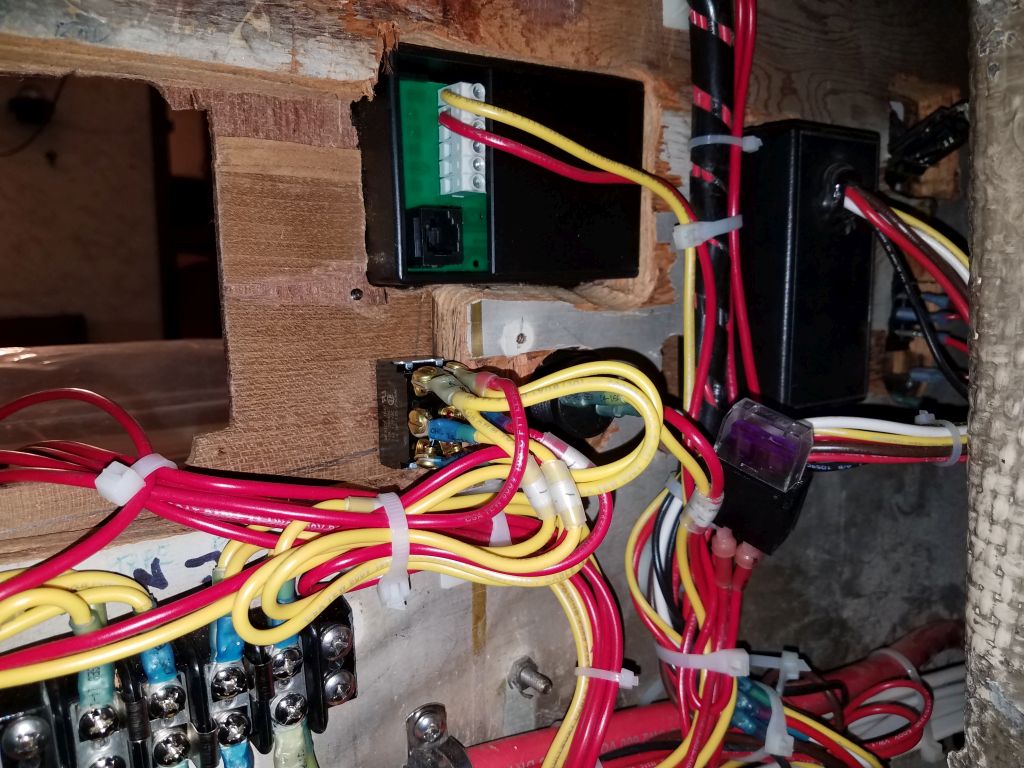
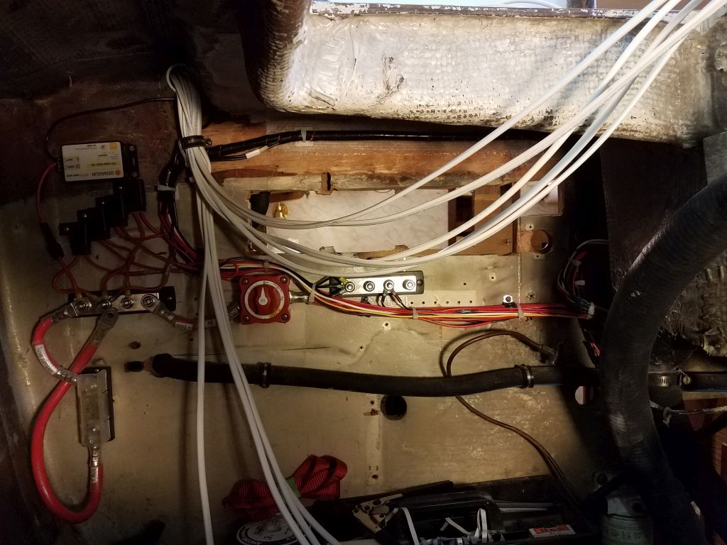
Leaving enough extra wire to allow the panel to be removed and laid flat on the countertop for service, I labeled and terminated all the positive wire ends from the various circuits.  Then, I made the connections to individual breakers on the back of the panel.

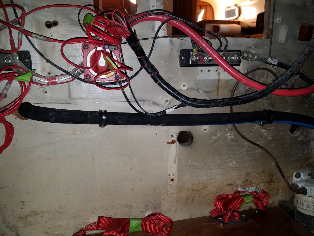
I prepared and attached lengths of #2 battery cable from the negative and positive distribution busses in the electrical area to the back side of the new service panel, then used these to help route and tie down the other wires neatly, while allowing panel removal and installation.

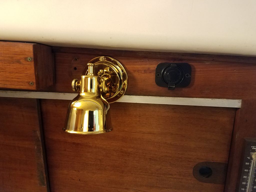
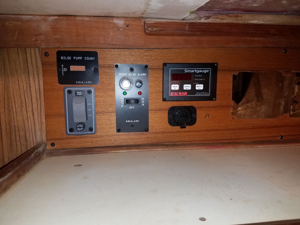
Now I could install the panel.

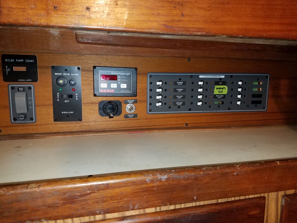
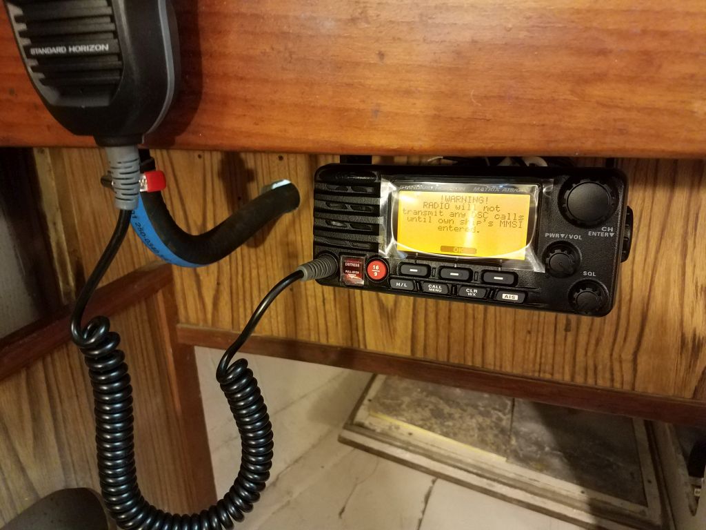
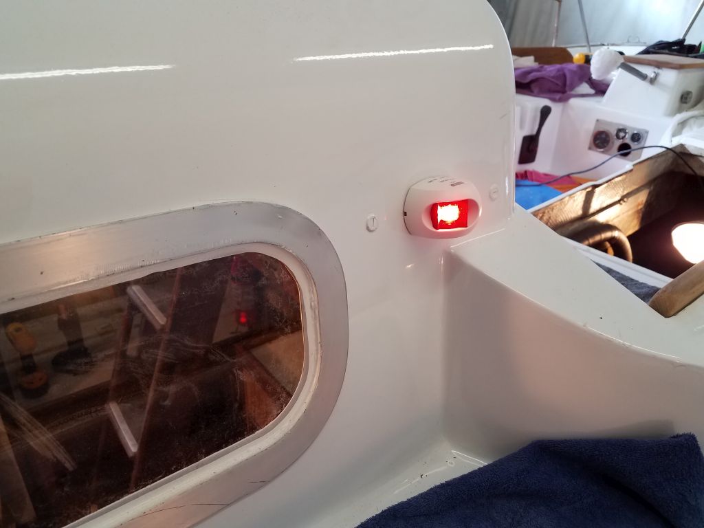
With a temporary battery hookup, I tested everything I could for now.  I didn’t bother hooking up the battery gauge for this test, and the mast lighting would await completion and a test at a later time.  I ordered a few additional labels to complete the panel and replace my temporary and ugly tape label that I installed just for my use at the moment.

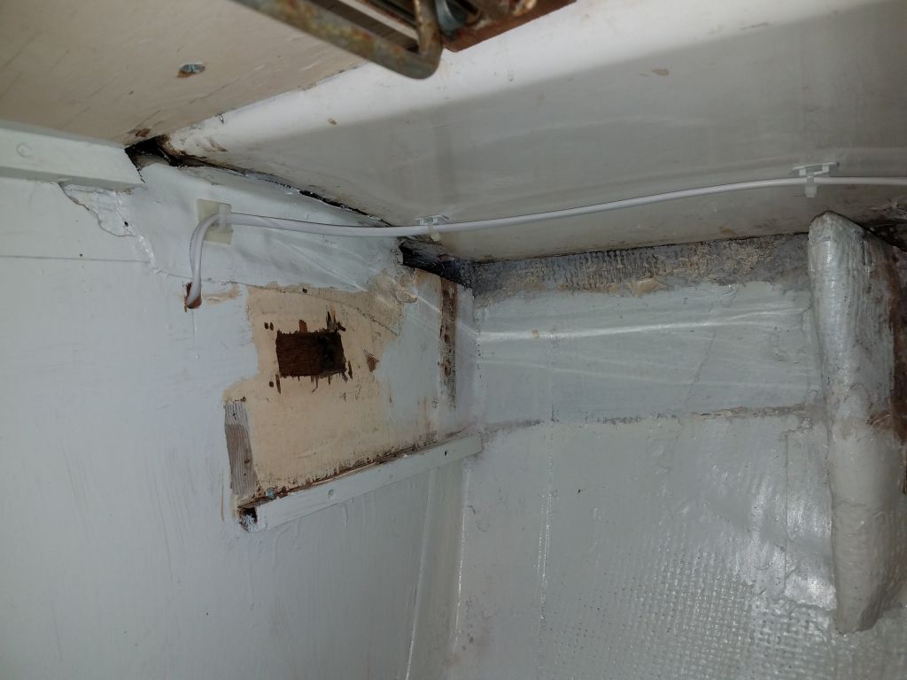
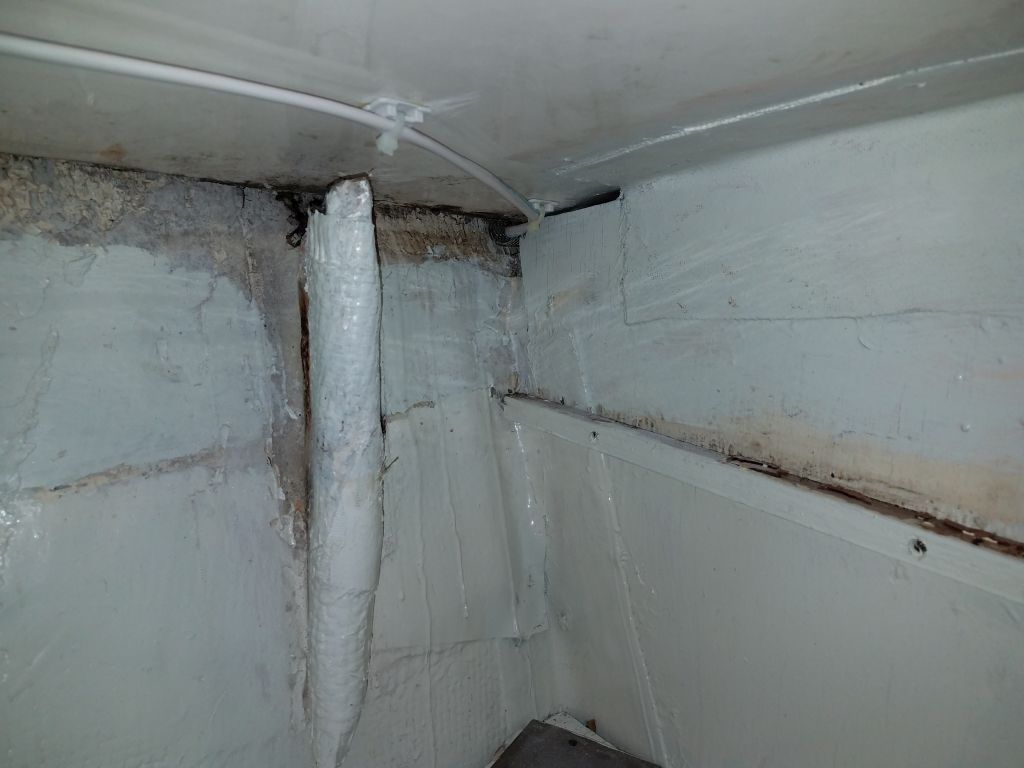
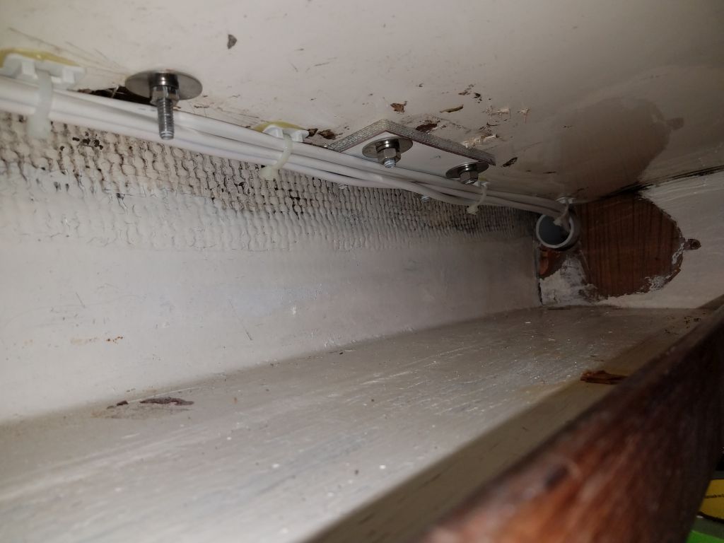
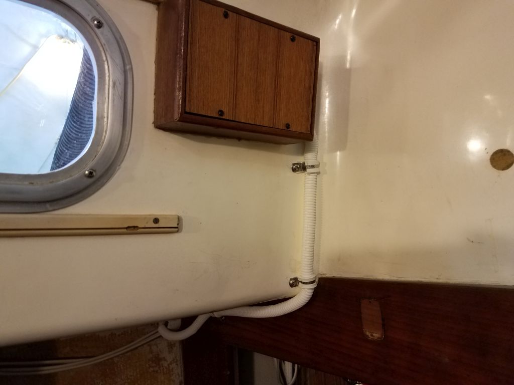
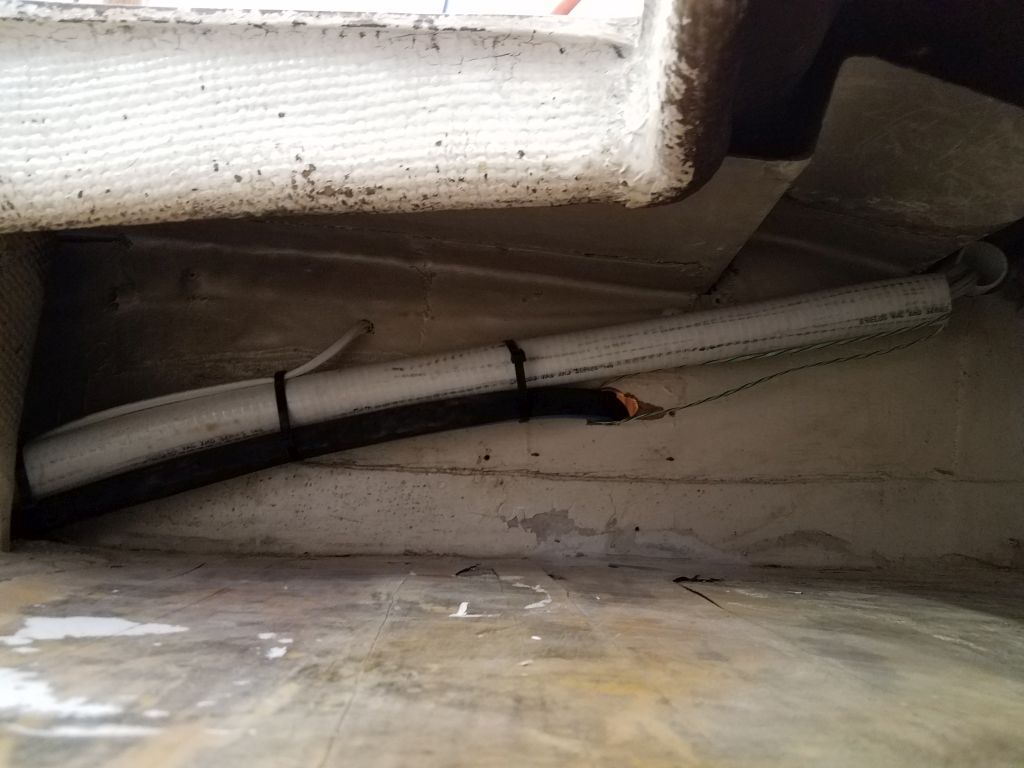
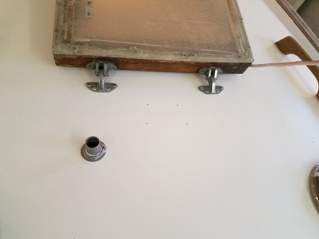
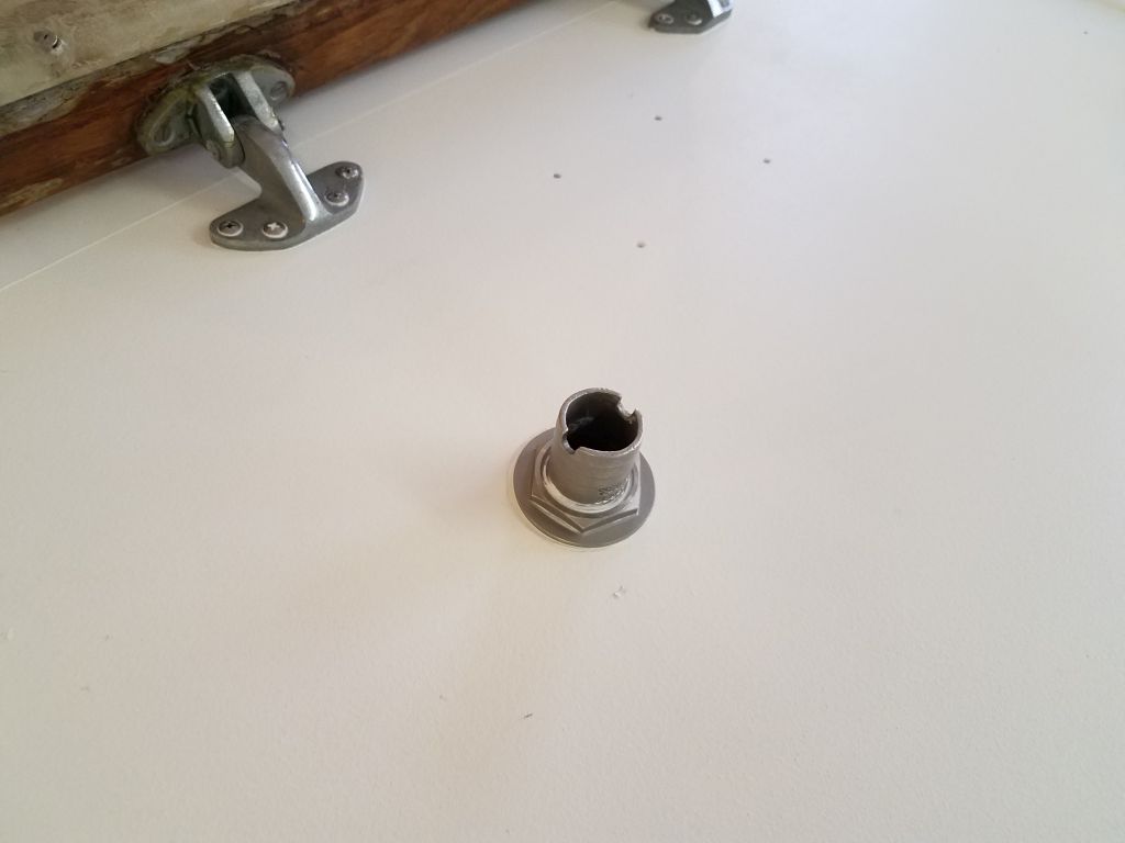
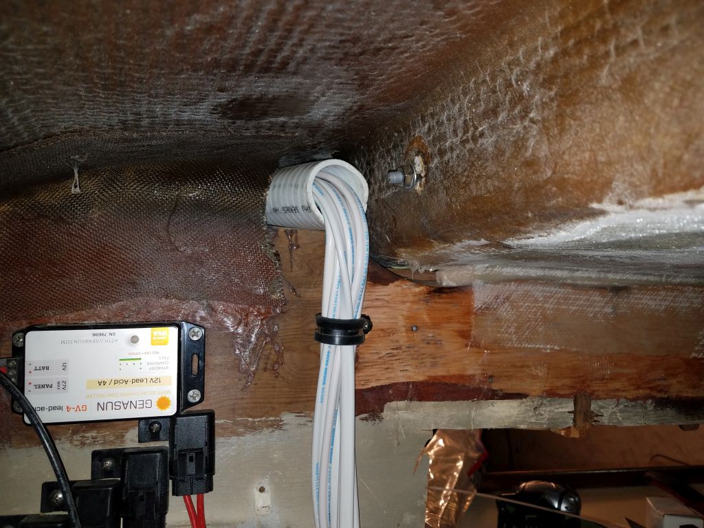
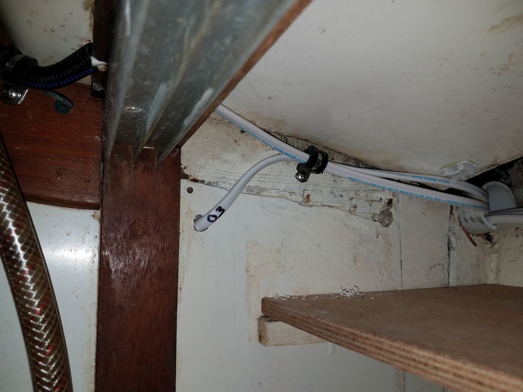
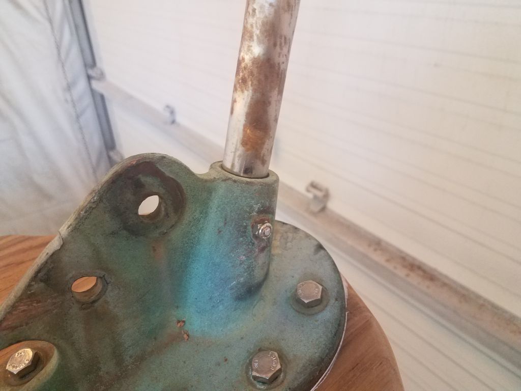
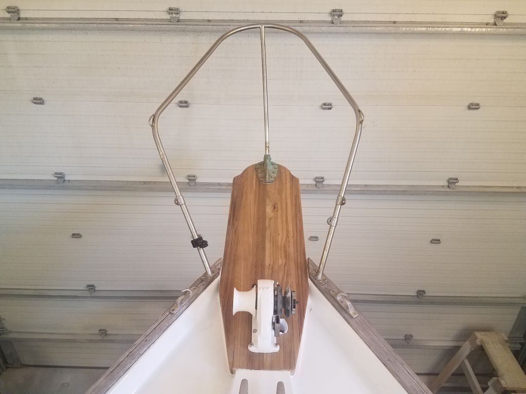
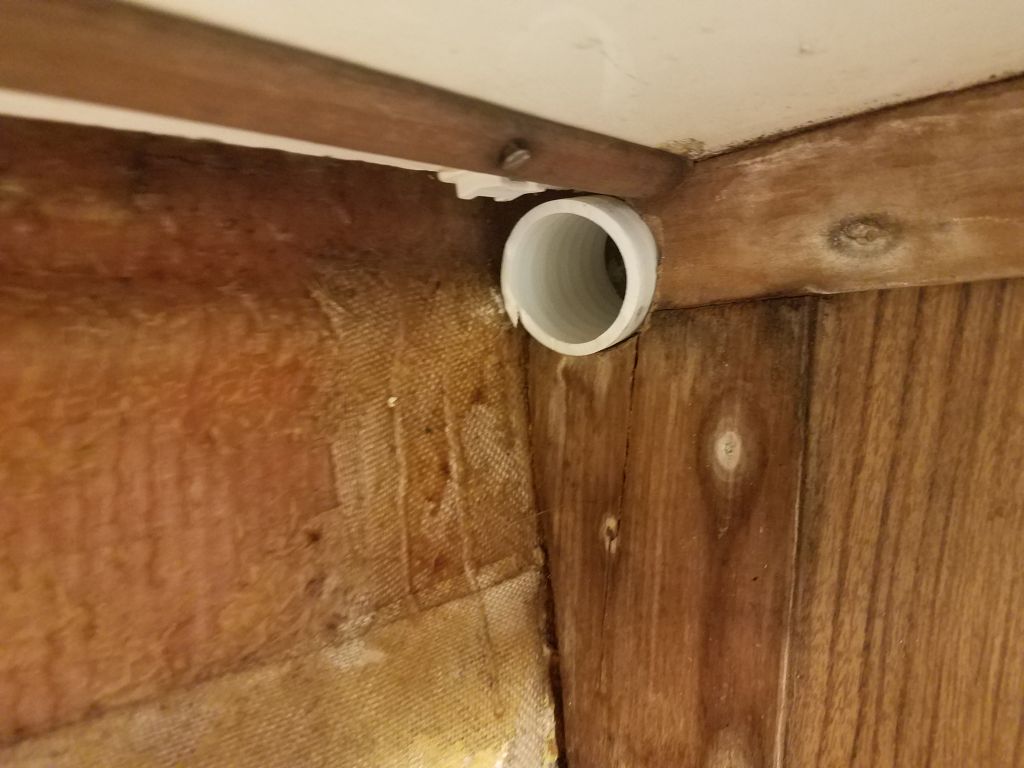
This mainly completed the wiring work on the boat, though I had the simple wiring for the solar panel still to come.  For this, the owner asked that the panel be mounted on the stern rail, using some hardware he’d already provided for the purpose, so with this in mind I went back into the cockpit locker and prepared the overhead so I could install a series of wire mounts leading aft to the transom, so they’d be ready for wiring next time.

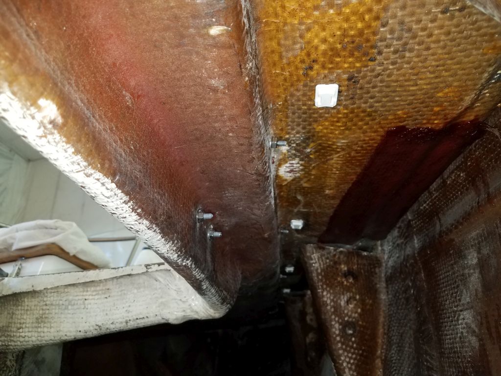
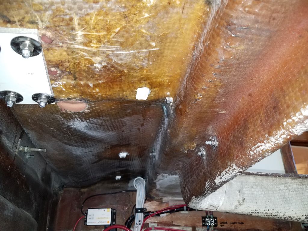
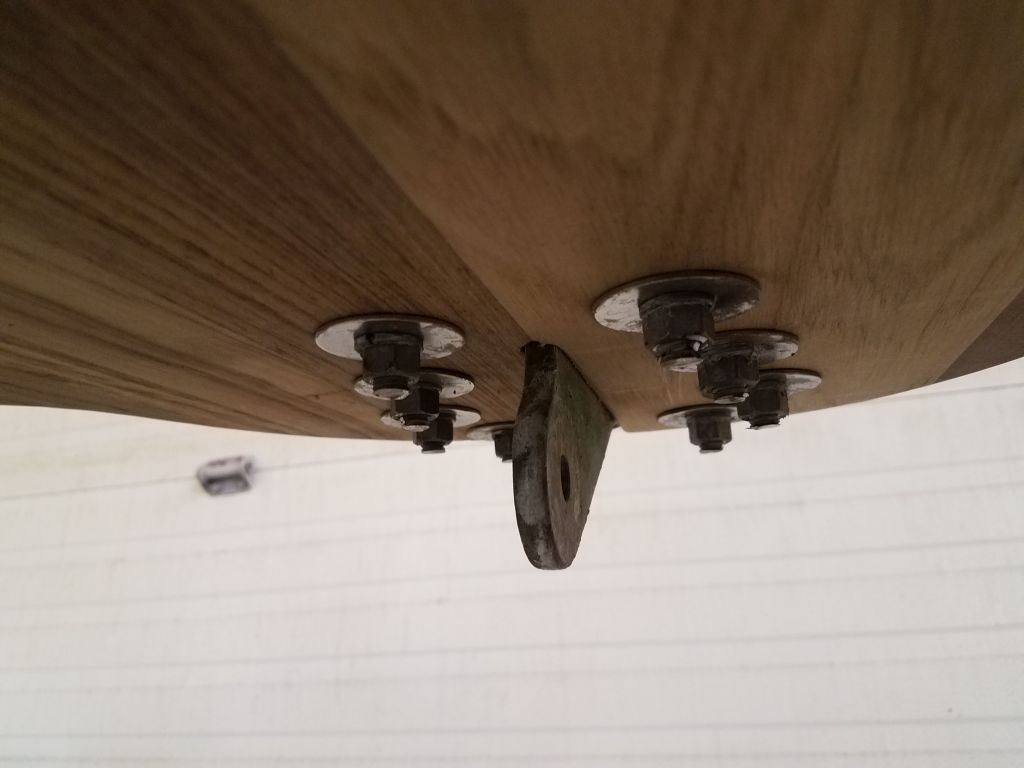
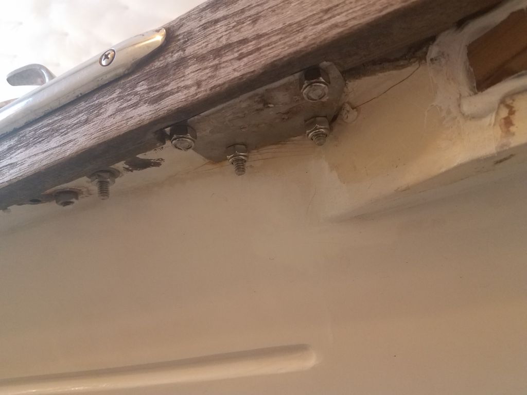
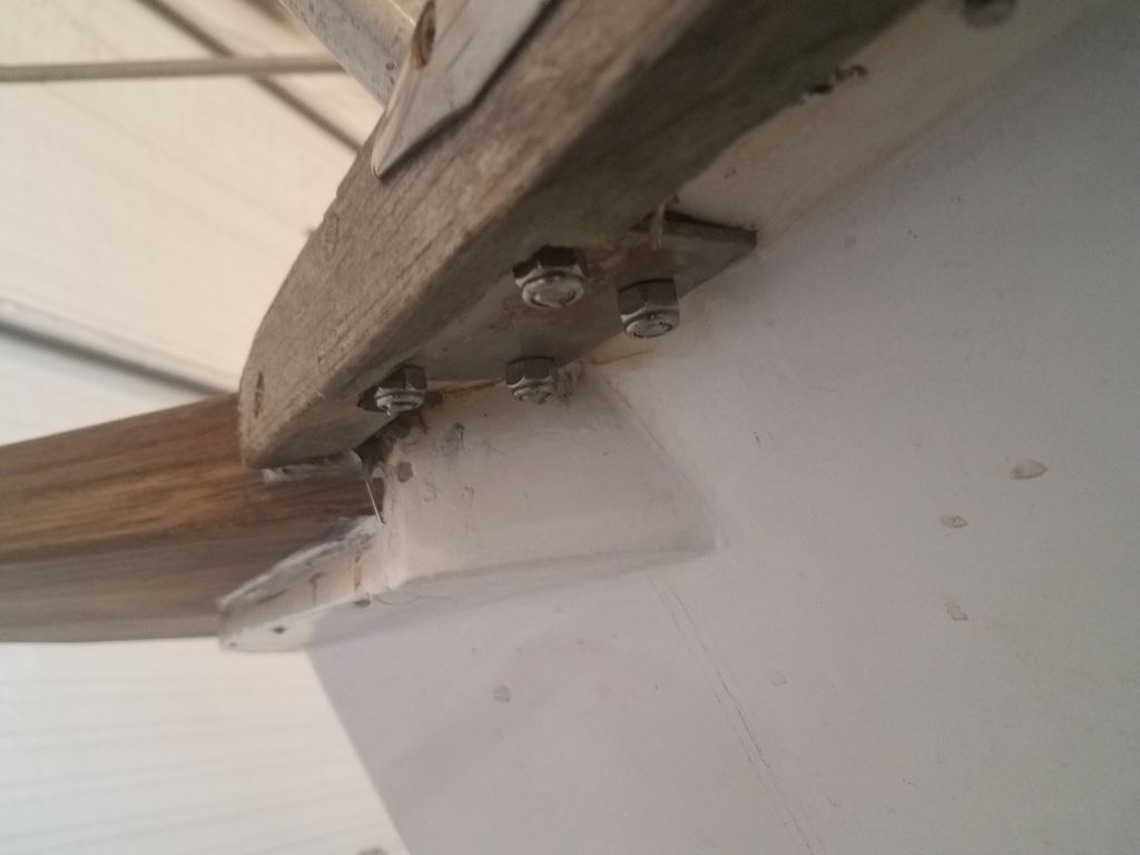
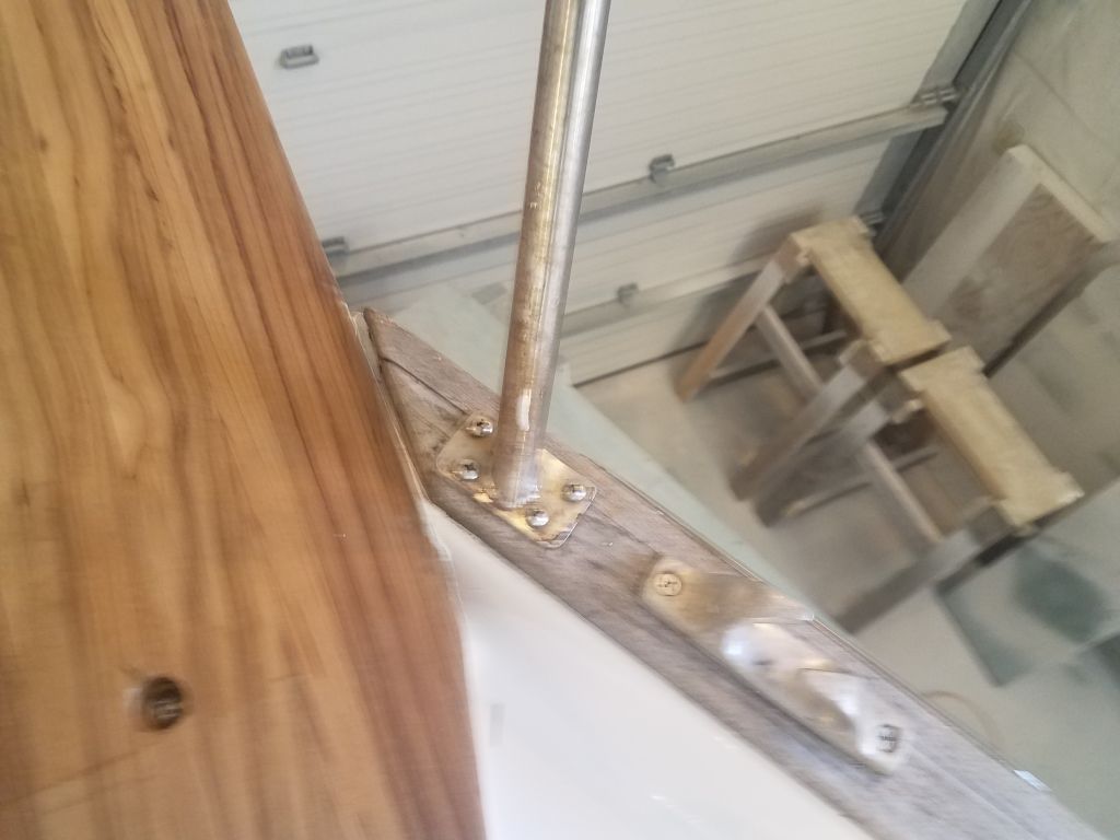
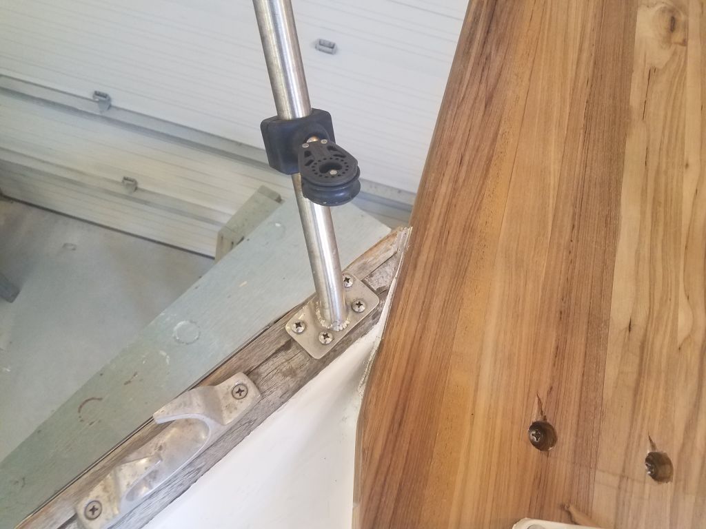
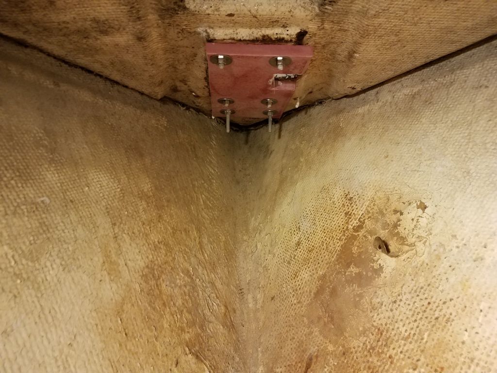
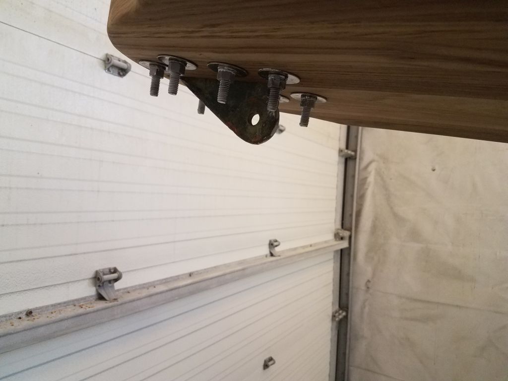
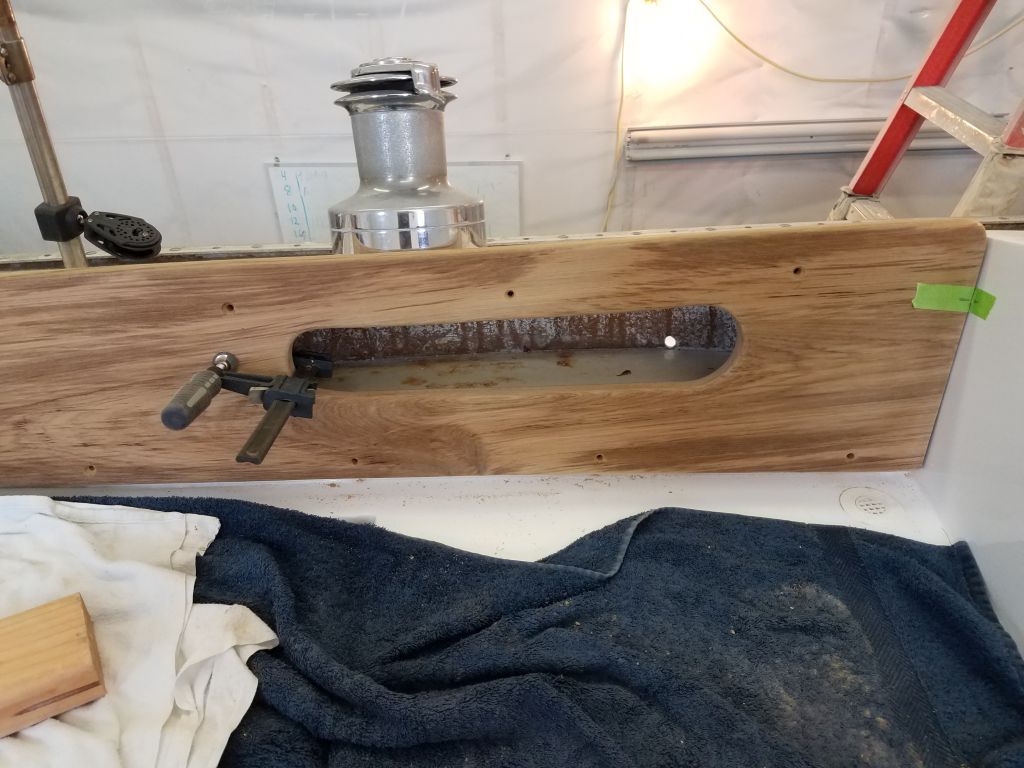
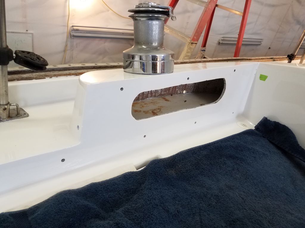
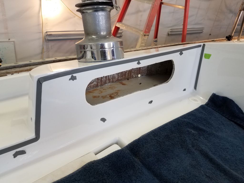
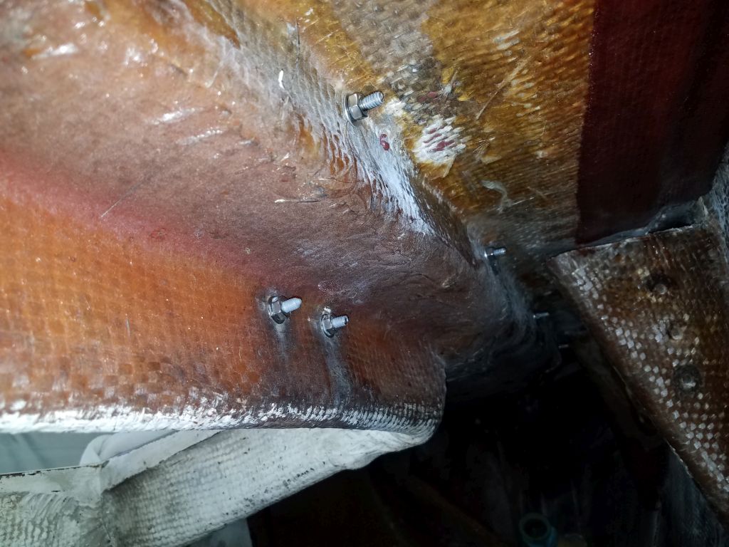
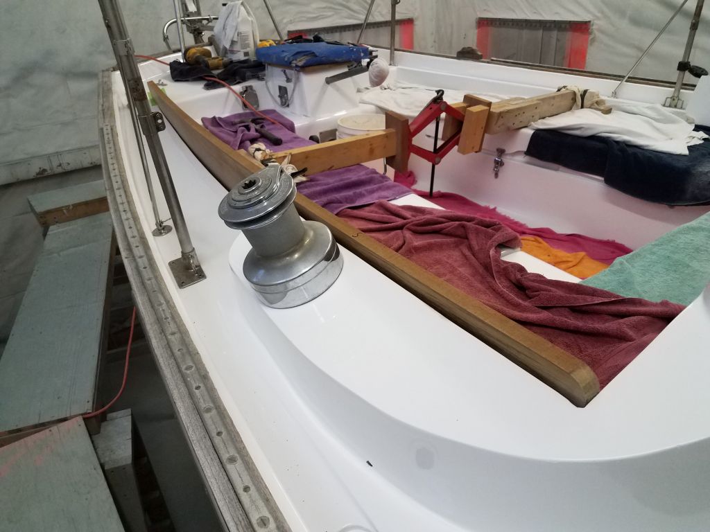
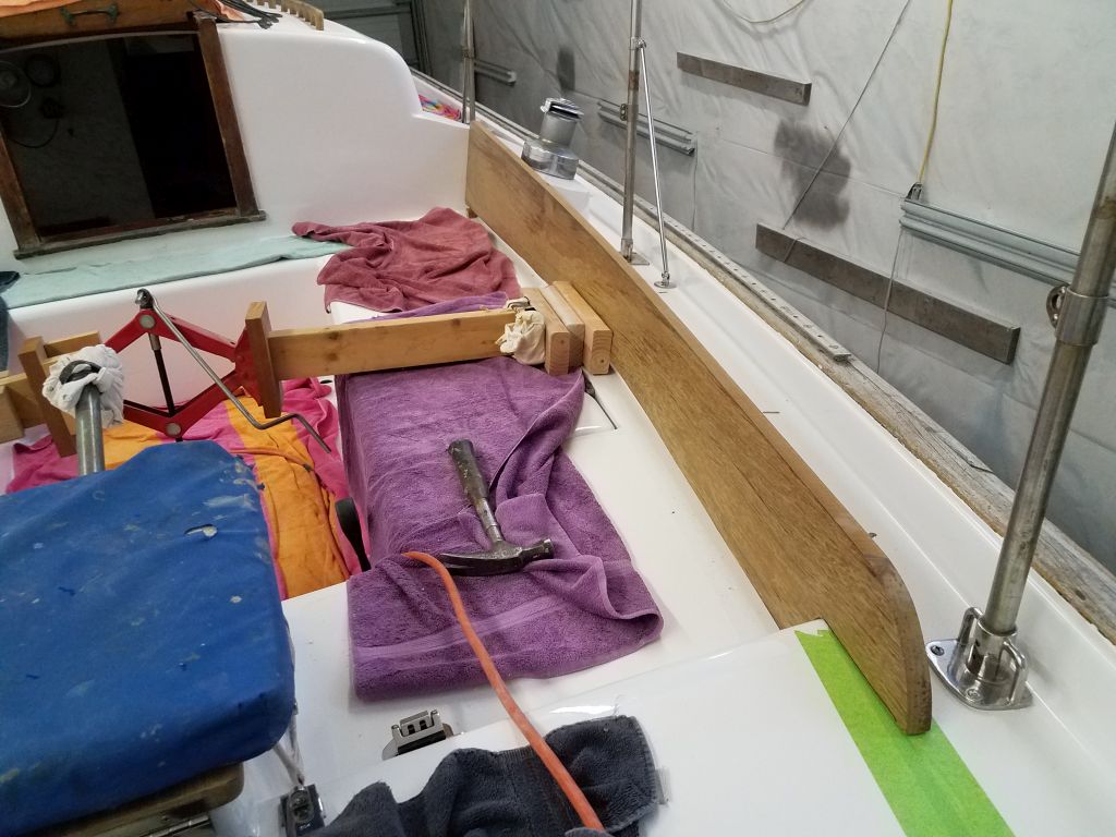
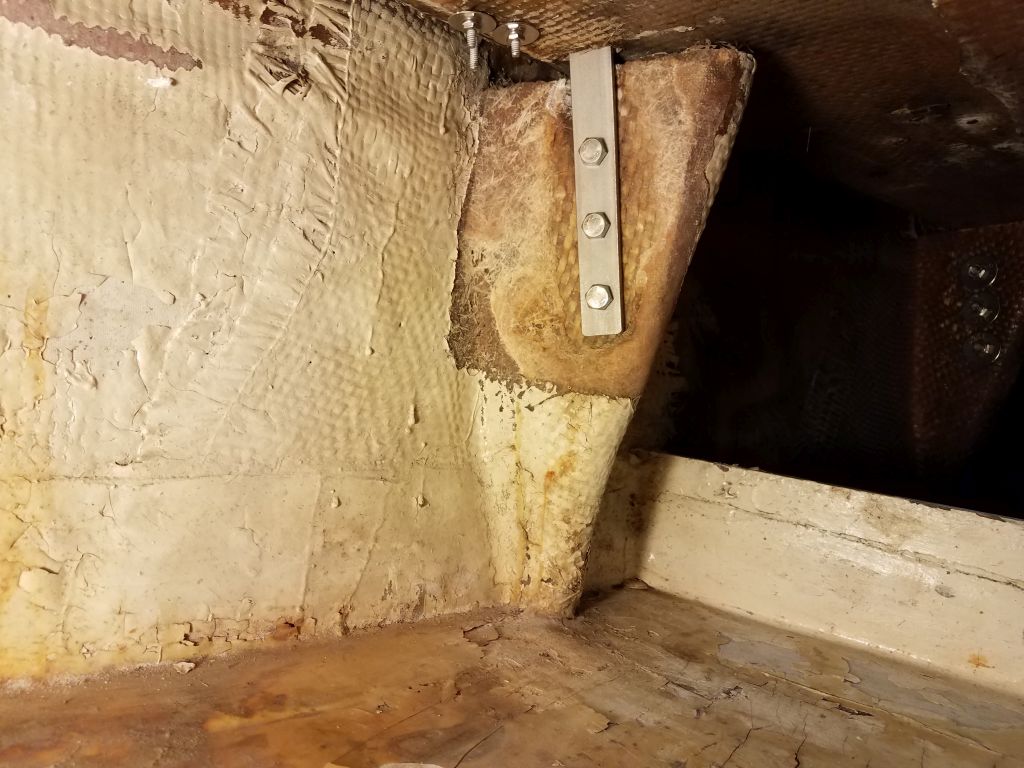
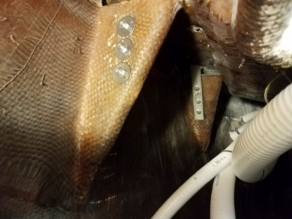
I finished up by working on the new chainplate installation, beginning on the starboard side aft, the most difficult three to reach.  Although I got these installed successfully, I decided that the bolts I’d ordered were just a bit shorter than I liked.  I’d measured the old bolts after removal and ordered accordingly, but the originals must have been cut off flush with the nuts, as new 2″ bolts were only barely long enough for the new installation.  Instead, I ordered longer bolts that I’d use to do the remaining 9 chainplates later.

Total time billed on this job today:  8 hours

0600 Weather Observation:  31°, cloudy.  Forecast for the day:  Mainly cloudy, high 30s

Jasmine 64

< Back to Jasmine

Monday

I continued the wiring work on the starboard side, leading wire runs forward from the starboard cockpit locker (to start) to the galley, v-berth, and  after part of the cabin where the running light was located.  I left ample extra wire to eventually lead over across the forward end of the cockpit and into the port side wiring area.

With the bulk wiring runs in place, I worked my way through the installations on this side:  light fixtures in the v-berth and galley; a 12-volt outlet in the galley; and the starboard running light.  As I made the connections, I neatened and tied up the wiring as needed through the existing locker spaces, and using more flexible conduit to cover and route the exposed wiring to the running light.

With the excess wiring pulled into the cockpit locker, next I led the bitter ends through a length of rigid hose as a conduit to protect the wires at the forward end of the locker where they were exposed.  I brought the wire ends into the port cockpit locker/wiring central area where I’d eventually make the final connections.

Meanwhile, I ran an additional wire, along with the antenna cable I’d started previously (leading to the mast wiring area in the head) to the starboard side of the cabin next to the companionway, where the owner requested I install the VHF radio he had purchased for the boat.  I made up the wiring and antenna connections and completed the installation.

I used up what remained of the day sorting out and beginning to make connections for the final wires in the port wiring area, working through the additional two lighting circuits and preparing others by trimming excess length and removing sheathing.  I hoped to finish up the connections and organization next time.

Total time billed on this job today:  6.75 hours

0600 Weather Observation:  32°, partly cloudy.  Forecast for the day:  Mostly cloudy, 41°

Jasmine 63

< Back to Jasmine

Friday

To finish up the mast step riser, I applied a few coats of gloss white paint, using a disposable sprayer for the job.

At the port aft cabin corner, I finished up the wiring work in the wooden trim box, installing and connecting the wires for a lighting fixture.  I secured the fixture to one of the new wooden panels I’d made to fill in the fronts of these pre-existing boxes, and, once complete, I secured the wires for this lamp and the port running light in some flexible conduit leading along the cabin side and beneath the sidedeck.

Returning to the mast wiring conduit I’d begun earlier, I used the same hole saw I’d used for the original hole to drill down from above and provide a center point through the temporary epoxy plug so I could drill the larger recess from beneath.  Then, with a 2-1/2″ hole saw, I drilled up from inside the head, eventually drilling out a plug about 1/4″ in depth to accommodate the mushroom head of the through hull fitting and leave enough threads above deck to secure the nut.

Satisfied with the setup now, I went ahead and permanently installed the fitting with plenty of sealant.

I finished up the wiring in the head compartment by terminating the ends of all the mast wiring circuits, using a terminal block to secure the boat end of these cables. Later, the mast ends of these wires could lead through the new deck fitting to the other side of the appropriate terminals, making connection and disconnection straightforward.  I hid the wires in flexible conduit and led them along the edge of the bulkhead, then neatened up and secured all the wiring beneath the sidedeck in the little locker and leading aft through the main cabin.

With all the wiring connections made up on the port side, and the wires tightened and secured, I decided I had to make some order of the wiring area in the cockpit locker before I could continue with the wire runs on the starboard side.    With the  wiring left over from the bilge pumps in temporary disarray, the numerous long wire tails from the port side wiring, and a need to make some general order of things, I started by cleaning up the new wiring that I’d led through some chafe gear at the top of the bulkhead.  I secured this bundle with a cushioned clamp, then pulled these wires out of the way for the moment.

Next, I resecured the battery switch and exisiting negative buss, which I’d removed while cutting out the panel openings above.  This led to some minor changes in the position of these items and of the engine-side battery cable leading to the switch, which I repositioned a bit to make better use of the space for the wiring that lay ahead.  From here, I focused for some time on re-securing and re-leading the wires from the bilge pump counter, switch, and alarm/switch panel that I’d removed earlier.  Eventually I sorted these out, lengthened one or two of the wires as needed, and made the connections back to the panels as required, securing the panels and the wiring behind.  This made a significant difference in the chaotic space and cleared things up for the new work.

I spent much of the afternoon terminating the cabin lighting wires (4 from the port side).  I installed a small auxiliary negative buss, which I made up from a terminal block and terminal jumpers, to help spread out the negative connections, since there was only a 4-terminal buss in place already,and also a positive buss for the cabin lighting, which allowed me to connect all the individual lighting circuits (6 total including the yet-to-be-run starboard side) without overloading any single terminal.  From the positive buss, I connected a length of larger wire that would eventually lead to the circuit breaker in the main panel.  I set aside the remaining circuits from the port side–mast wiring and running light–for later termination, as I knew I didn’t have enough time left in the day to complete these now.

To wrap up the day,  I pre-wired and installed the 12-volt outlet located in the main panel area, as well as the battery monitor, which required only two wires for the existing battery bank.  I left the wires hanging long behind the panel, where they’d await securing and termination next time.

Total time billed on this job today:  8.25 hours

0600 Weather Observation:  32°, cloudy.  Forecast for the day:  Clouds, wind, some rain later in the day, around 40°

Jasmine 62

< Back to Jasmine

Thursday

With a short day planned, I focused on a few small tasks, beginning with the running lights.  I’d left the original holes in the cabin sides near the aft end, and now I installed basic new LED sidelights here, which I chose because converting the original el-cheapo fixtures with LED replacement bulbs cos nearly as much as new LED fixtures, and the fixtures I’d removed were nothing worth heroic effort anyway.  On each side, I prepared screw holes for the mounting, then applied butyl sealant to the bases and in the wiring holes as needed before installing the lamps.  Inside, I filled the wiring holes with additional butyl for a tight seal.

For running mast wiring through the deck, I went my usual route, which involves a stainless steel through-hull fitting mounted inside out through the deck, with the hose barb pointing up.  I like stainless for this application since bronze would tend to weather and stain the deck with its runoff.   With a similar fitting on the spar, wires could run between the spar and deck inside a length of hose, creating an easy and waterproof path for the wiring, with all connections made inside the boat.

In this case, the mounting location would be in the corner of the head compartment.  With this in mind, I’d already run the various wires into the head, where they awaited termination.  After confirming the location for the wiring exit on deck with some basic measurements, I drilled a small pilot hole from inside where I wanted the through hull, then finished the cut with a hole saw from on deck.  The location I chose was within the solid fiberglass area I’d built up around the mast step during  the deck work, and between the deck laminate itself, plus the liner, plus (I think) some fill material between the two, the deck here was surprisingly thick.  The plug from the hole saw came out in two sections, but the appearance of the hole though the deck showed no apparent gap between liner and deck itself.

The fact that the deck was solid here should have streamlined installation, as originally I’d expected and anticipated the need to remove coring and epoxy fill before installation.  But so much the better to simply be able to install the fitting now–if only I could have.  I got as far as preparing the deck around the hole with masking tape, and all other steps, before realizing that the deck was thick enough that it might be wise to test-fit the through hull.  To my dismay if not surprise, I found that the threads of the fitting didn’t extend beyond deck level, which meant I’d have no way to secure the mounting nut.

To deal with this issue, I needed about another 1/4″ of thread length–or needed to recess the through hull head by a similar amount, which, given all the details of the installation, was the approach I decided upon.  To create the recess on the headliner, I needed a center point in the hole I’d already drilled.  I thought I could temporarily hot-glue a little piece of plywood over the opening, and did so, but the torque of the hole saw spun the plywood off before the teeth got any bite in the fiberglass.  I could have tried again, but I’d already spent far too long on this little installation, and with time running out before I had to leave anyway, I decided to tape over the hole and add some epoxy from above to create a temporary plug that would work better to redrill a larger hole from beneath later.

To use up the time I had left, I installed the lighting fixture in the head.  Since the wiring for this fixture needed to enter from the side, I used a drum sander to create a small opening through the side, removing part of the raised lip that surrounded the base plate of the fitting to allow clear passage for the wire.  Then, I connected the wiring and installed the lamp on the bulkhead, leading the wire through some flexible conduit secured against the corner of the bulkhead and nearly invisible.

Since the wires were already in place, I finished up my short day by wiring the port running light inside the little wooden box at the aft end of the cabin.

Total time billed on this job today:  2.5 hours

0600 Weather Observation:  35°, cloudy,  Forecast for the day:  Mainly cloudy but becoming sunny in the afternoon high near 50°

Jasmine 61

< Back to Jasmine

Wednesday

I don’t like loose ends, so first thing I finished up work around the bow platform, beginning with cutting off the excess bolt length beneath the stem fitting.  I’d sent the solid bobstay out with the riggers for inspection and recommendation, so I’d install that final piece later.

Next, I installed the bow pulpit, re-using the original stainless backing plates that fit neatly beneath the overhanging toerail.

Moving aft to some loose ends there, I installed a little draw latch to secure the hinged helm seat.

Then, I installed the mizzen step.

After some finish sanding, I applied a few coats of epoxy primer to the new main mast step riser, which would add 1-1/2″ to the height of the spar to make up for the 1-1/2″ that needed to be cut off the corroded base.

With that work out of the way, I turned to the electrical system, the last significant job on the work list for this project.  To begin, I test-fit the new face panel for the electrical control area, and found that I had to open up the area for the main electrical panel a bit so it would fit.  With this done, and after checking the other installations to ensure they fit in their holes as well, I secured the face panel with some black screws to match the general appearance of the controls that would be installed.  Nearby, I installed the quick and temporary cover panel over the old holes from the bilge pump switches; the owner hoped to do an interior rebuild phase down the road a bit.

The 12-position electrical panel came loaded with 10 circuits and two blanks, but I always like to fill out the panel immediately, which is much more convenient somewhere down the line when additional circuits are needed, so I added two additional breakers to the panel.

Installation and connection of the service panel and other switches would come soon enough, but for the moment my focus was on the bulk wiring runs.  After listing the various circuits I needed to run down each side of the boat, I started on the port side, where there were the most wire runs.  Where the wiring needed to pass through or by a bulkhead, I cut holes as needed to allow for short lengths of hose to act as chafing gear.  Then, I led wires forward along the port wire run.  For now, there was no need to lead them through the individual wire mount areas, so I let the wires drape over the shelf above the port settee.  These wires, leading forward to the head and beyond, would service a v-berth light; head light; three mast lighting circuits and VHF; and the port forward saloon light.  Mast wiring would run through the head and to a fitting I planned to install in the deck near the mast step.

At the aft end were two shorter runs leading to the small wooden box at the aft corner of the cabin, where the port running light and another saloon light would be installed.  I left the wire runs long and loose for now, leading all the wire ends back to the port cockpit locker that was and would be command central for all the connections.

With the bulk wiring on the port side complete, my impulse was to continue with the wire runs on the starboard side, which would have fewer wires overall, but my reel of wire was looking a bit thin and I figured I’d run out first anyway, so, after ordering more wire. I decided to start cleaning up and terminating some of the port wiring, starting with the port v-berth light, which I installed at the outer corner of the berth.

Moving aft, I repeated the process with the forward port saloon light, which brought things to a close for the day.

Total time billed on this job today:  8 hours

0600 Weather Observation:  26°, clear.  Forecast for the day:  Sunny, high near 50° again

Jasmine 60

< Back to Jasmine

Tuesday

My next step with the electric panel was to bring the new teak faceplate up to the boat, where I laid it over the bulkhead and traced out the openings.

Behind the bulkhead, in the cockpit locker, I temporarily unscrewed the existing battery switch and a negative buss, along with any other wiring as needed, to keep them out of harm’s way while I made various cuts in the bulkhead.

Access to the bulkhead for cutting tools was tight, but eventually, and using several different tools, I completed the new cutouts as required.

Meanwhile, I prepared a few other small pieces of teak plywood for use elsewhere in the cabin, including a section to cover the holes in a nearby bulkhead where the bilge pump controls had been mounted, and some rectangles that would fit as covers over little wooden boxes that were already in place where the running lights had been mounted at the aft corners of the cabin.  Mainly for color, I applied a coat of tung oil to these pieces now so I could continue work with them soon.

Later, after some business away from the shop, I got to work on the bow platform.  The new fasteners I needed had arrived, and I began with final preparations for installation, masking off portions of the platform and the adjacent deck areas as needed, including around the base of the windlass.

I applied sealant to the flat on deck, concentrating around the boltholes, ledges, sides, and around the windlass location, then installed the platform and secured it for now with the two bolts forward of the windlass.   I should have known, but the counterbores I’d prepared here weren’t large enough for the heads of the 3/8″ machine screws I was using, and I had to enlarge the holes to 1″ to allow the heads to pass.   3/4″ would have worked, but I didn’t have a bit that size.

Meanwhile, I applied more sealant to the top of the platform in way of the windlass, then installed the windlass and four more of the 5″ long bolts.

Belowdecks, I installed the fiberglass backing plate I’d made, and secured it and the platform above with nuts and large washers.  This pulled the platform and windlass down securely into the bed of sealant, creating squeezeout everywhere.  After a few minutes, I cranked on the nuts a little more to ensure that everything was tight and in its final position.

Afterwards, I cleaned up the sealant from around the platform and windlass in all areas and removed the masking tape.

To wrap up the platform installation, I installed more tape over the forward edge to prepare for the bronze end fitting, cutting out the tape in way of the base of the fitting and drilling the eight bolt holes through the platform.  I applied sealant, then installed the fitting with eight 3/8″ bolts before cleaning up the final sealant.  I’d cut off the excess bolt length and bung the two bolt holes later.

Total time billed on this job today:  5.25 hours

0600 Weather Observation:  20°, clear.  Forecast for the day:  Sunny, 40s

Jasmine 59

< Back to Jasmine

Monday

I unclamped the glued-up bow platform and sanded away any excess epoxy from the top and bottom surfaces.  Then, using the old platform as a guide, I trimmed the two long sides till they were close to the final width, then trimmed the after edge square.  The old platform was in such bad condition that I didn’t want to entirely rely on using it as a template, or even on measurements, so I erred on the side of caution and kept the new blank a bit wide for now–so wide that it didn’t yet slip into its opening between the bulwarks.

After measuring the opening and comparing the width of the platform visually, I felt comfortable trimming the blank down to size, taking another 1/8″ off each side, and now the blank fit properly on the bow.  I’d left the blank rectangular for now, but with it in place I could make some reference marks for the angled cuts that would taper the aft end down to meet the forward edge of the raised cleat platform just behind.

Back down on the bench, I made those cuts, and also used the original platform to layout the curves at the forward end so I could cut that as well.

While the platform was in place this time, I went belowdecks to the chainlocker beneath and made some marks up through the existing holes for the windlass bolts (4) as well as the larger hole for the anchor chain.   Although I had some paper templates of these locations, it never hurt to use reality as a guide instead.

On the bench once more, I drilled 1/8″ pilotholes through each of my marks on the bottom, thus locating them on the top surface of the platform, and then placed the windlass over the holes to finalize the layout and drill the bolt holes and chain hole as needed.  Meanwhile, at the forward edge of the platform, I laid out and cut the slot to accept the bronze stem fitting, which I wouldn’t permanently install till the platform was in place in order to save weight.  One more test fit on the boat, and I was ready to finish up the platform.

I rounded over various edges of the platform, both on the top surface (everywhere but the short sections where the platform lay against the bulwarks) and bottom edge (the protruding portion beyond the stem), and sanded the whole platform clean and smooth.  Meanwhile, I prepared a 3/4″ fiberglass backing plate for both the anchor windlass and the platform itself, and laid out another pair of bolt holes for securing the platform, located just forward of the windlass.  The six bolts, including four for the windlass, would be sufficient to secure the platform along with adhesive sealant.

Before installation, I marked off and epoxy-coated the faying surface of the platform for protection and to promote good bonding, leaving this to cure overnight.  I had the long bolts needed for the platform installation on order, and would complete the installation once they arrived.

While I had sanding tools going, I cleaned up the new mast step riser that I’d laminated earlier, removing excess epoxy from the joint and smoothing the whole thing as needed to prepare for primer and paint.

Preparing for the electrical installation ahead, I began by installing wire tie mounts at intervals along the known wire runs–that is, along each side of the cabin under the gunwales and through cabinetry as needed.  I used adhesive mounts that experience had taught are best left along for a day before putting them to use, despite claims of fast curing for the adhesive.  Most of the mounts landed on the gelcoated liner throughout the cabin, but even so I lightly scuffed each location and cleaned with solvent before applying the adhesive, as the fantastic bonding claims of this adhesive had long proved themselves caveat-worthy.

The owner wanted to centralize the electrical panels and other controls in the long, narrow space under the port bridgedeck, which also had convenient and direct access to the batteries and related components behind.  This space had apparently contained a panel and other installations previously, and had some large holes already in place.    Since it was a tight and difficult space to work in, and to allow convenient and attractive layout of the various new components as well as cover the existing holes to give me the freedom of layout I wanted, I chose to prepare a simple cosmetic panel over the top, which I patterned to fit the slightly tapered space and cut from some leftover 1/4″ teak plywood I had on hand.

With the new face panel cut to fit, I had some fun laying out the various installations, which included the following:

I covered the teak with masking tape to allow me freedom in drawing in the outlines of the components, since space was tight and I wanted it to look good.  Through trial and error, and working around–while not specifically tied to–the location of the existing large opening in the bulkhead, I eventually came out with a layout that worked well in the panel, and made the cuts required to install the various devices.  I’d use the face panel to lay out the cuts needed on the bulkhead itself before installation, but for now the day was over.

Total time billed on this job today:  7.5 hours

0600 Weather Observation:   33°, fog.  Forecast for the day:  Becoming sunny, highs in the 40s

Jasmine 58

< Back to Jasmine

Friday

I removed the clamps from the two sections of the new bow platform, then ran the pieces through the planer to remove the excess epoxy and bring the thickness of the blanks to the finished dimension.

After final preparations, I laminated the two sections together with thickened epoxy adhesive, clamping them securely and removing the excess epoxy from top of the joint.

Earlier, I’d removed the old drain hoses and mismatched plumbing fittings left over from the original cockpit seat drains, and now, with new 3/4″ hose and bronze replacement parts on hand, I prepared to finish up the drain lines to the new drain fittings I’d installed.

The drains had led into a tee fitting on the starboard cockpit scupper hose.  There was a short section of older hose still attached to the tee, and although I briefly considered leaving it be, I just couldn’t.  Of course the clamp was well rusted, so it took some effort to remove it by awkwardly cutting and eventually prying it loose, but it didn’t make sense not to replace the full length of hose.

Drilling larger access holes as needed, I led the new reinforced drain hose from the two deck fittings and down into the engine room along the route the originals had followed, and eventually connected everything with the new bronze tee fitting below the cockpit sole, completing the drains’ installation.

Sticking with plumbing for the moment, I took care of the reconnections in the head for the waste tank vent and deck pumpout fitting, as I’d had to remove these hoses earlier in the project.  The vent was a cinch, but the short original section of waste hose leading from the Y-valve to the deck fitting was now too short to reach the new deck plate, which had a shorter barb length than whatever mess had been cobbled together before, so this meant I had to install a new, longer hose.  This in turn required that I remove what remained of the little shelf (I’d already cut out half of it early in the job to gain access to the nearby chainplate), and with little finesse I busted out the remains so I could access and replace the hose, which was straightforward enough when all was said and done.

Afterwards, I made up a quick shelf replacement, using the pieces of the original as a guide,  and installed it loosely for now, just in case I needed to remove it for the chainplate when I could finally reinstall it.

Standing in the cabin later, looking around and considering various aspects of the electrical system–and contemplating getting started on that–I found my attention drawn to the deadlight openings.  I’d been thinking for a while that the deadlights’ design/installation details were such that, unlike in many cases, I could install them alone, and before I knew it I’d gone off in that direction, even though I’d originally had no intention of installing them today.  But test-fitting one of the assembled outer frames, now ready for further work with all the sealant well cured, I found that, as I’d anticipated, it ought to be possible to install the frames permanently with only some simple bracing from outside, just to hold the frame as necessary while I installed the trim ring inside.  Here, the tall bulwarks were my friend, as I found I could easily brace from there and hold the frame in place during a dry fit.

Anxious as always to continue knocking projects off the punch list, I went ahead and made preparations for the frames, cleaning up the area (beginning on the port side), covering the deck with plastic, and preparing tools, fasteners, and the trim rings.  I thought I’d just take it one frame at a time, and if I ran into issues I’d stop and regroup.

Ready for the first installation, I gooped up the back side of the aluminum frame heavily with sealant, using way more than I knew was necessary since it always pays to have a ton in there in this sort of installation.  I pressed the frame into position and braced it again to hold it.  The fit was such that the bracing may not have been strictly necessary, though it certainly helped.  Inside, pleasingly, it was surprisingly straightforward to install the trim ring, and all the screws–the originals, which I’d saved in their removal order throughout the process–drew in tightly and well, swelling me with confidence.

The frame had drawn up tightly all around, and after removing the bracing I cleaned up the abundant excess and removed the protective paper from both sides of the new lens.

That didn’t take long, and happy with how the project was going, I continued with the port forward frame, which was also happily uneventful.

I moved my operation over to the starboard side, and continued with the starboard after frame.  Here, I ran into some more difficulty, as the nature of the interior liner in this particular spot was such that the outer frame actually protruded too far into the cabin in some places (the forward side) and not enough in others (the top center).  So while I didn’t have any outward issue pressing the frame in from the outside, I found that the fasteners bottomed out before holding things tightly at the forward side, and others couldn’t even reach the frame as needed.  At one point, thinking it was an issue with the outer frame, I added a longer brace to the shop wall to press in the trouble area, but this was before I understood the nature of the problem.

In the end, I prevailed, switching out the forward fasteners for some temporary (and longer) screws that I fitted with nuts on the inside, so that I could drive in the screw, then use the nut to press the trim ring in and pull the assembly together, a technique I’d used many times in the past.  This would hold things till the sealant cured, and later I’d replace these temporary bolts with new, shorter screws that wouldn’t bottom out before holding things tightly, but I didn’t have these on hand.

Fortunately, this trouble was an anomaly, and the final deadlight installation went quickly and smoothly with no issues, bringing the day–and the week–to a successful close.

Total time billed on this job today:  6.5 hours

0600 Weather Observation:  16°, clear.  Forecast for the day:  Sunny, then increasing clouds and chance of minor snow/mixed precipitation late in the day.  High around 35°.

Jasmine 57

< Back to Jasmine

Thursday

I continued where I left off on the starboard cockpit coaming, beginning with removing it from its temporary position in the boat.  Down on the bench, I aligned the old coaming over the top of the new blank so I could mark the cutout for the storage pocket in the winch island.  Prudence dictated that I start with a smaller hole and another test fit to ensure that the final hole was in the proper position before committing to the final cut.  With the coaming pressed back into position on the boat, I reached through my narrow cut and made a few reference marks on the back side of the coaming to indicate the extent of the opening in the fiberglass.

Back on the bench, I compared the maximum size of the raw opening in the winch island to the outline of my patterned cutout and, satisfied that the marks were correct, went ahead and cut out the final opening.  This was by design a bit smaller than the opening in the fiberglass, so that the wood hid the rough edge of the opening.  Afterwards, I milled 1/4″ roundovers on both edges of the cutout, as well as the applicable edges of the coaming itself, then sanded the coaming clean and smooth.  Along the bottom edge and at the top of the winch island,  I laid out for the boltholes to secure the coaming and milled the holes and countersinks for the flush, exposed fasteners.

Back in the cockpit, I dry-fit the coaming and held it securely with a clamp in the storage pocket and my coaming jack in the center.  With the coaming properly positioned, I drilled a pilot hole through each hole in the coaming and through the fiberglass behind.  With the coaming out of the way, I finished off each fastener hole with a 1/4″ tap and small countersink.

Since the coamings were to be left bare, I could proceed with installation immediately.  To allow for the coamings’ removal, should it be desired, I chose to use butyl tape sealant along the top edge of the coaming (to prevent the passage of nuisance water from the sidedecks) and in way of the bolt holes.  Then, I installed the coaming with 1/4″ flat head machine screws into the tapped holes, and added nuts and washers from behind wherever I could; the minimal clearance for the fasteners against the underside of the moldings limited room in a few places.

Now I repeated the process for the port side.  This time, when I laid out the basic coaming shape, I also marked the outline for the storage pocket and made the initial rough cut there, which saved some time.  The initial test fit was a success, and I didn’t need to make any modifications to the basic shape of the coaming.

Back on the bench, I finished up the cut for the storage pocket, then milled the rounded edges and sanded smooth the coaming before doing my final dry fit and preparing the fastener holes.

I completed the final installation in the same way, with butyl tape and machine screws.

Next, I turned to the bow platform, and got started by milling up the various teak strips I needed to glue up the platform, essentially replicating the original platform and its construction.  Note that the aft end of the platform, shown in the center photo, should be solid material through the center; the shape shown is the result of catastrophic rot that crumbled during removal.

With the blanks prepared, I separated the strips into two halves to begin the lamination.  I planned to glue up 5 pieces on each side now, then glue together the two halves in a separate operation, since doing all 10 pieces at once would be too difficult.  After cleaning all the teak with acetone, I rolled on a coat of plain epoxy to all the mating surfaces, then returned with thickened epoxy adhesive to do the glue-up and clamp the blanks securely.  By the time I took these photos, I’d already squeegeed off much of the epoxy squeezeout from the top surface.

Total time billed on this job today:  7.5 hours

0600 Weather Observation:  33°, mainly cloudy.  Forecast for the day:  Clouds and sun, around 35°

Jasmine 56

< Back to Jasmine

Wednesday

To finish up the handrails, I chiseled and sanded the new bungs smooth.

The new teak stock for the bow platform and coamings was rough and unplaned, so my first task was to dimension and smooth the new lumber with a thickness planer.  I started with the 8/4 stock for the bow platform, and without much drama brought it down to just under 2″ thick from its rough thickness (2-1/8″).

The planer had trouble with the long (10′) and wide (10″) coaming boards, which started about around 1-3/16″ in thickness.  It took many, many passes through the planer and several blade changes to eventually bring this stock to a finished dimension of about 15/16″, as I had to take tiny bites with each pass.

Once I had the boards ready, I laid out the old coamings on top and used them as templates, marking the new boards accordingly.

We had an afternoon of abnormally high temperatures (60s), and I had to take advantage of the nice weather for a couple hours to take care of some outdoor projects while I could, but once I was through savoring the taste of “fool’s spring”, I got back to work in the shop.

Beginning with the starboard side, I cut out the coaming to the marks, and then worked to finalize the fit in the cockpit, trimming and paring away a bit of material at the aft corner till I could push the coaming more or less into position.  I used a little block at the forward end to help hold that end at the right height for this process.

Once I was satisfied with the basic fit, I used my old coaming jack system to press the coaming more tightly into the curve–the curve here was not extreme–so I could do a final check of the fit and also mark where the coaming met the adjacent decks to ensure I located the fasteners correctly.  I left the coaming in the clamp overnight.

Total time billed on this job today:  5.75 hours

0600 Weather Observation:  34°, foggy.  Forecast for the day:  Fog slowly lifting, eventually growing abnormally warm into the upper 50s or low 60s

Older posts Newer posts