(page 3 of 8)

Jasmine 55

< Back to Jasmine

Tuesday

I got the day off to an early start with a visit from the riggers, who came to measure for the new lifelines and to remove the old rigging from the spars for replacement.  I consulted with them as needed to ensure that the extensive rigging work list was attended to as we expected.

Meanwhile, I continued work on the battery platform, now that the laminated plywood base had cured overnight.  In the cockpit locker, I installed a teak cleat on the bulkhead to support the forward end of the platform, using epoxy and screws to secure it against a level line I’d made earlier.

Dry-fitting the platform, I made some measurements for a support at the after inboard edge, then made up a support system from additional plywood and cleats that I secured temporarily for the moment.

Before installation, I wanted to lay out and install the padeyes from the old battery platform, since there wouldn’t be good access to reach the underside of the platform once installed.  These were sturdy padeyes and straps and worth reusing.   With an empty battery box in the boat and set up on the platform, I determined the positions required for the first set of batteries, and made reference marks as needed.  Then, down on the bench, I set up the two battery boxes and marked for, then installed, the padeyes and straps with bolts and large washers beneath.  This left ample room on the platform for a future addition of another pair of these batteries and boxes.

Now I permanently installed the support foot, epoxying and screwing the cleats in place and epoxying and screwing the support as well.  Then, I installed the platform permanently in the boat, securing it with epoxy and screws at the bulkhead cleat, and additional epoxy adhesive at the support foot and long the hull; I created fillets in both places to allow for tabbing, which I installed an hour or two later when the thickened epoxy had cured to the gel stage.

On the steering room hatch, I installed a little hatch that would keep the hatch closed when not in use.

After trimming the back edge straight and square, I too the glued-up blank for the helm seat up to the cockpit so I could mark it for final cutting.   Keeping the back edge square with the back side of the steering box, I traced the outline of the box on the bottom of the seat.

Down on the bench, I trimmed the seat to final size, allowing 1/2″ overhang on the sides and an inch at the forward edge.  I rounded the edges and sanded the part smooth before installing a short length of piano hinge at the aft side and securing it to the fiberglass steering box with bolts.  I’d purchased a hasp for the forward edge to hold the seat in place, but the one I tried didn’t work correctly in this configuration, so I’d find another one that would do what I needed.  Otherwise, this little project was complete.

Along with assorted odds and ends, including a quick trip to a nearby machine shop where I expected to pick up the new chainplates I’d asked them to make a few weeks earlier, only to find they weren’t ready as promised, I spent much of the remains of the day on the interior handrails.  To align the rails and drill the holes required, I held each section alongside the protruding bolts in the cabin, and made marks at each bolt location.  I also noted the length of the bolt so I’d know how deep to drill the 5/8″ counterbores.  Down on the bench, I drilled slightly oversized holes for the 1/4″ bolts, stopping after an inch or so of depth, then used a small bit to extend the hole up to the top of the rail so I could have a reference point to start the large counterbore.

Getting these rails installed was tricky, as even with a 5/8″ hole it was a tight fit for a 7/16″ nutdriver, the only way to insert and install the nuts.    I learned a couple things the “harder” way on the first rail that made the second side go a bit easier, but with zero tolerance inside the holes for even a slight angle on the bolts, it was an effort to secure the rails.  Eventually I completed the installations.

To wrap up the handrails’ installation, I installed 5/8″ teak bungs in all the screw holes inside and out.

Total time billed on this job today:  8 hours

0600 Weather Observation:  33°, clouds, drizzle, fog.  Forecast for the day:  Clouds, fog, into the 40s

Jasmine 54

< Back to Jasmine

Monday

I got started with the deadlights, and applied a bead of sealant along the outer edge of the new lenses and into the outer groove of the frame, smoothing it out for a pleasing external appearance. The top of the bead was flush with the face of the deadlight frame, and the inner edge tapered away at the edge of the protective paper still on the lens.   I left the new beads to cure for a couple days.

On deck, I removed the now-cured excess sealant and tape from around the handrails on the coachroof.

Earlier in the project, I’d removed the existing–and rotten–battery platform from the cockpit locker, as the owner had requested not only replacement, but also enlargement to accommodate another pair of the 6-volt batteries he had.  So back then, over a couple separate days while working on other things, I’d removed the batteries and the old platforms, and cleaned up the hull and bulkhead where the old platform had been installed.  It had remained in this ready/clean state since then. and now it was time to turn to the new platform construction.

I determined the footprints (base of the battery box) and “airprints” (the overall shadow of the larger top of the box) of the existing battery boxes and used this information, along with the restrictions of the space itself, to create a cardboard template of the new platform, which I planned to make in a single level to hold all four batteries.  I trimmed the hull edge to fit as needed.

Template complete, I transferred the shape to some leftover 7mm and 9mm marine plywood that I had and laminated two layers together with epoxy to make up an appropriately thick section for the platform, aiming for at least 18mm (3/4″) thickness.  I used two thinner layers since that’s what I had available.  I set the glue-up aside for the epoxy to cure.

I was expecting new teak to arrive soon  for the coamings and anchor platform, but in the meantime I planed smooth and dimensioned a piece of leftover teak that I could use to make a cover/seat over the steering gear box in the cockpit; the original one had been lost long before.   This required changing the planer blades, which were dulled from the last time I used the planer on teak some time before, and while I was set up I took the opportunity to plane some rough cherry for another, unrelated, project in the works.

The piece was overlong but underwide, so I cut it in half to create two shorter pieces that I glued together with epoxy, setting it aside to cure.

The new teak stock for the project arrived in mid-afternoon, and I looked forward soon to getting to work on the new construction.

Earlier, looking at the mast base, I’d determined that we could cut off 1-1/2″ and be past the corrosion problem at the base, and this worked out well since I happened to have a sheet of 3/4″ prefab fiberglass on hand and–wouldn’t you know–two layers of this would perfectly match the amount needed to cut off the base, so I chose to use the material on hand to build up the mast step accordingly.  Though I strove to keep the extra height to a minimum, of course I would have goner higher or purchased other material to build it had it been necessary.

From this sheet, I cut out two circles of material just a bit larger in diameter than the original mast step, since I thought a stepped arrangement would look better than keeping the diameter consistent.  I laminated the two discs together with epoxy, clamping securely while the adhesive cured.  I’d continue work on the blank later on.

Most of the old electrical system had already been removed, either by the owner during last summer, or by me during earlier parts of the project.  But there were still a couple little rats’ nests of wiring at the aft end of the main cabin on both sides, and on the port side I needed to remove–and later rearrange–some wiring that we planned to keep and reuse for the bilge pumps, including a switch, counter, and bilge alarm panel.  The owner had installed these things temporarily for last season, but now wanted the moved to the panel above the countertop, beneath the deck overhang.  In any event, I needed to pull the existing wiring back into the cockpit locker (where the essentials of the electrical system were located) so I could work from scratch to lead the existing and new wiring as needed.

I removed obsolete wiring that led through the space, and noted for future reference the wire positions on the switch, alarm, and counter for ease of reconnection later.  I had to cut the wiring leading to both the counter and alarm, since the panels were hardwired and  the other ends of these wires led to the bilge itself, so I couldn’t otherwise remove and reposition the units.  I led the remaining wires (to be kept and reused) back into the cockpit locker, where I loosely secured them for the moment.  The existing main battery and engine wiring would remain more or less as is going forward, as it was new and in good condition, but I’d make some minor changes as needed to reposition things for the new circuit breaker panel and other installations as time went on.

On the other side of the cabin there was a similar mess of old wiring, but nothing needed to be saved, so in short order I had that cleared out as well.  I also removed the old hoses from the obsolete little cockpit seat drains, and I’d be replacing that with new 3/4″ hoses to the new fittings in due course.

Total time billed on this job today:  7.75 hours

0600 Weather Observation:   10°, clear.  Forecast for the day:  Sun, then increasing clouds, mid-40s

Jasmine 53

< Back to Jasmine

Friday

During the morning, I continued work with the handrails, dry-fitting the remaining three sections.  The process went more quickly now that I’d worked things out on the first section, but since I chose to mill the counterbores and bolt holes down on the bench to save the mess on deck, it required many trips up and down.  The bend in the rails was minimal enough that I could do two holes at a time.

With all four sets of handrails now attached, I traced on the masking tape around their bases, then removed the rails so I could cut away the tape in way of their bonding areas and finish preparing the holes through the deck.

I had the proper fasteners already on hand for the forward rail sections, which didn’t need to mate up with handrails belowdecks and required shorter bolts, so I got started by installing those two sections.  I’d masked off the bases of the handrails themselves to protect the bare teak from sealant stains, and although I normally preferred to clean up excess sealant immediately upon installation, here I chose to leave the squeezeout till it cured,  rather than risk getting it on the bare teak.

Since the fasteners went through tapped holes, the handrails were easy to secure from above, and at my relative leisure I went belowdecks and installed fender washers and nuts at each location as needed.

A bit later, once UPS arrived with my longer bolts for the after rail sections, I completed the installations there as well.  Here, I installed temporary nuts and washers on the long bolts belowdecks, since I didn’t plan to install the inside rails just yet; I’d originally planned to use the original rails I’d removed, but found it impossible to remove the remaining bolt studs without causing irreparable damage to the rails themselves, and with new teak rails so reasonably priced, it only made sense to start fresh.

I’d ordered the rails, but they weren’t in yet.   Later, once the sealant was cured and I was ready to install the interior rails, I could remove the nuts and slip the rails over the existing bolts.  I sized the bolts at 4-1/2″ long to leave enough extending within to properly secure, yet remain buried inside, the interior handrails.

The new handrails brought an air of completeness to the deck’s appearance, as nice wood trim is wont to do, and I looked forward to cleaning up the sealant and tape in a couple days.

Now I turned to the deadlights, which had had a couple days’ cure time and were ready for the next steps.  Removing the weights, I exposed the back (inside) of the frames and lenses, where there was excess sealant squeezeout to trim away.  This was easy to do, and the cured sealant came away in a nice intact rubbery string leaving the frames and (paper covered) lenses clean.

Before final installation, I had to complete the sealant on the outside of the frames.  While the frames could be installed as is, and the adhesion and weatherproofing of the lens installation was already accomplished during the first crucial stage of the process, it would look a lot better with a cosmetic bead along the outside of the frame–a peculiarity of this particular frame design.  To that end, I began by masking off the aluminum frame face to protect it from sealant later.

Now I had to expose some of the lens around the edges, to give a place for the cosmetic sealant bead to bond.  I marked a line around the perimeter about 1/4″ from the edge, then carefully cut to the line with a sharp knife, removing narrow strip of paper afterwards.  (This also happened to expose, through the lens, the nicely consistent and well-bonded bottom side of the lens on the frame beneath.)

I really would have liked to install the sealant beads now, which would have given ample cure time over the weekend, but it was growing late and I didn’t want to rush the process, which frankly I was unsure how it would work out, so I chose to postpone that process till another day.

Total time billed on this job today:  6.25 hours

0600 Weather Observation:  33°, cloudy.  Forecast for the day:  Cloudy, low 40s, slow clearing, then growing colder and windy late in the day.

Jasmine 52

< Back to Jasmine

Thursday

My little fiberglass winch part had cured through the night, and now I cleaned it up, cutting the side ears to the correct shape with a saw and fine-tuning with a chisel and sandpaper till the part fit in the winch top properly.  I reassembled both winches.

I was fortunate to have a new U-shaped support bar made quickly at a local shop, with legs 6″ longer than the original.  The bend radius on the new part was larger than the old, but this frankly looked better and had no adverse affects on performance or function.

Interestingly, in browsing around online earlier I’d found my way to the website for the sistership with a similar installation, and discovered a photo that clearly showed that in their installation, the U-shaped bracket had indeed been bolted through the raised bulwark, as would have this one had I used the original tubing.  Functionally, that was fine, but less aesthetically pleasing.  And in any event, a greater angle to the transom was inherently stronger.  Fortunately, the part was simple 1″ tubing that was easy to come by and easily replicated.

I got right to work installing the new bracket, which was the final piece required to complete the windvane installation.  The extended length meant that the bracket now landed on the transom well below the gunwale, where the location would be strong and easily accessible from within.  There was no need to cut nor further modify the new brace.


I marked each leg for orientation so I could drill the holes for the 1/4″ bolts that would secure the tubing to the bracket insert, and did the milling down in the shop.  With the brackets bolted in place to the tubing, I aligned the brackets on the hull, made a reference mark, and drilled/tapped one hole for a temporary bolt.

I marked the remaining bolt holes, then removed the brackets and prepared all the holes with drill, 3/6″ tap, and countersink in the usual way before applying sealant and installing the brackets permanently with fiberglass backing plates and large washers within.

This completed the Norvane hardware installation.  In these photos, the servo arm is swung up 180° into its storage position, and I removed the servo rudder for storage.  To complete the installation and make the unit usable, all that remained was to make and run the control lines as needed.

Now that the vane was installed, I could wrap up the installation of the steering room hatch and its hinge.

Now that the paintwork was complete, I reassembled the anchor windlass with the (I think) 5/16″ chain gypsy commandeered from the identical parts windlass I’d discovered at the shop.

Next on my agenda was the new teak handrails for the cabin top.  To replace the original long length, I’d chosen two lengths of 5-loop rail per side, which filled the original space the best.  During deck preparations, I’d prepared and marked the bolting locations, so I had to align the new rails to the original hole locations–easy enough, but it required a somewhat longer installation approach.

The owner requested that the new teak be left natural/bare, so to protect it during installation I masked off around the bottom of each loop, and also masked the deck for protection and marking purposes.  In order to ensure that the bolt holes in the rails matched up with the locations on deck, I had to prepare each hole more or less one at a time (sometimes two at a time), marking the rail for each location, then drilling, down on the bench, a 5/8″ counterbore for the bolt head and bung and 17/64″ pilot hole for the fastener, and then, back on deck, a pilot hole and 1/4-20 tap through the deck to hold the rail.  With each fastener sequentially in place, I could bend and position the rail properly for the next mark, and so forth, till I had the first section dry-fit.

The first part of the after rail sections would be opposed in the cabin by lengths of 4-loop handrail, which would accept the ends of the bolts from above; the other locations would simply be bolted through the coachroof as needed.  I had to order bolts of the right length for the first section, so in the meantime I’d continue dry-fitting the remaining three sections next time before permanently installing them once complete.

Total time billed on this job today:  7 hours

0600 Weather Observation:  20°, clear.  Forecast for the day:  Increasing clouds, about 45°

Jasmine 51

< Back to Jasmine

Wednesday

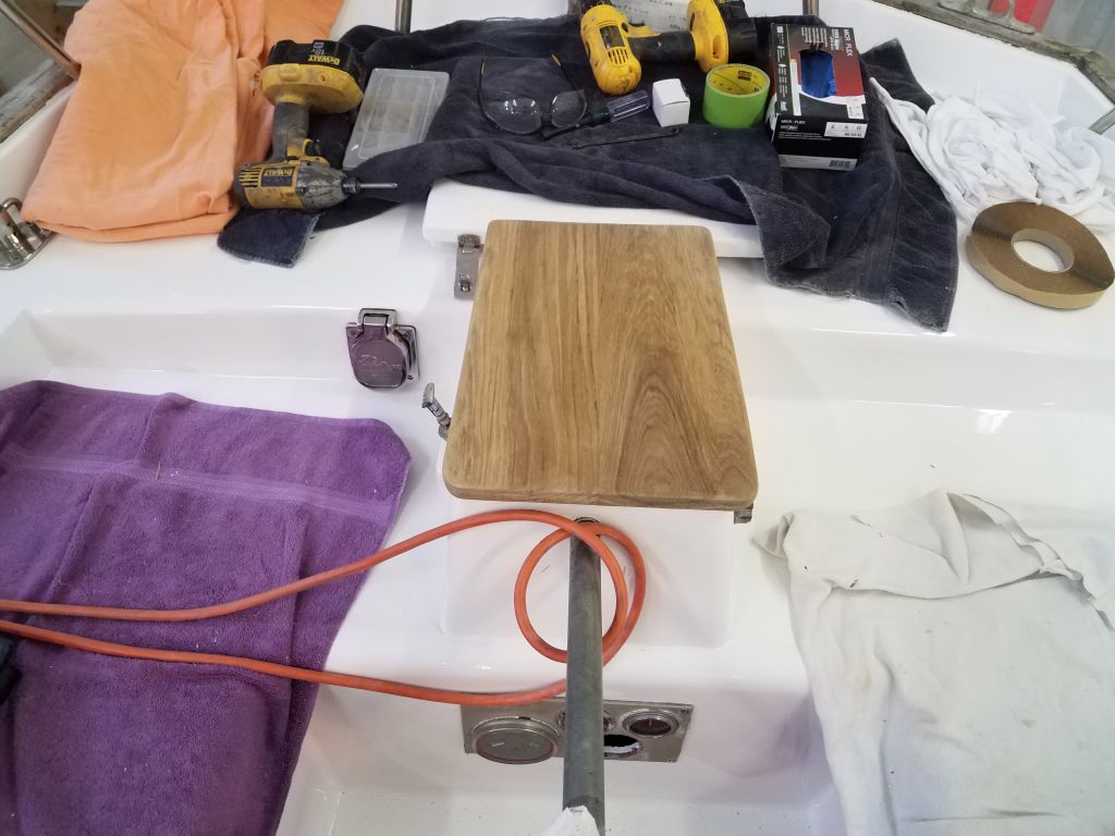
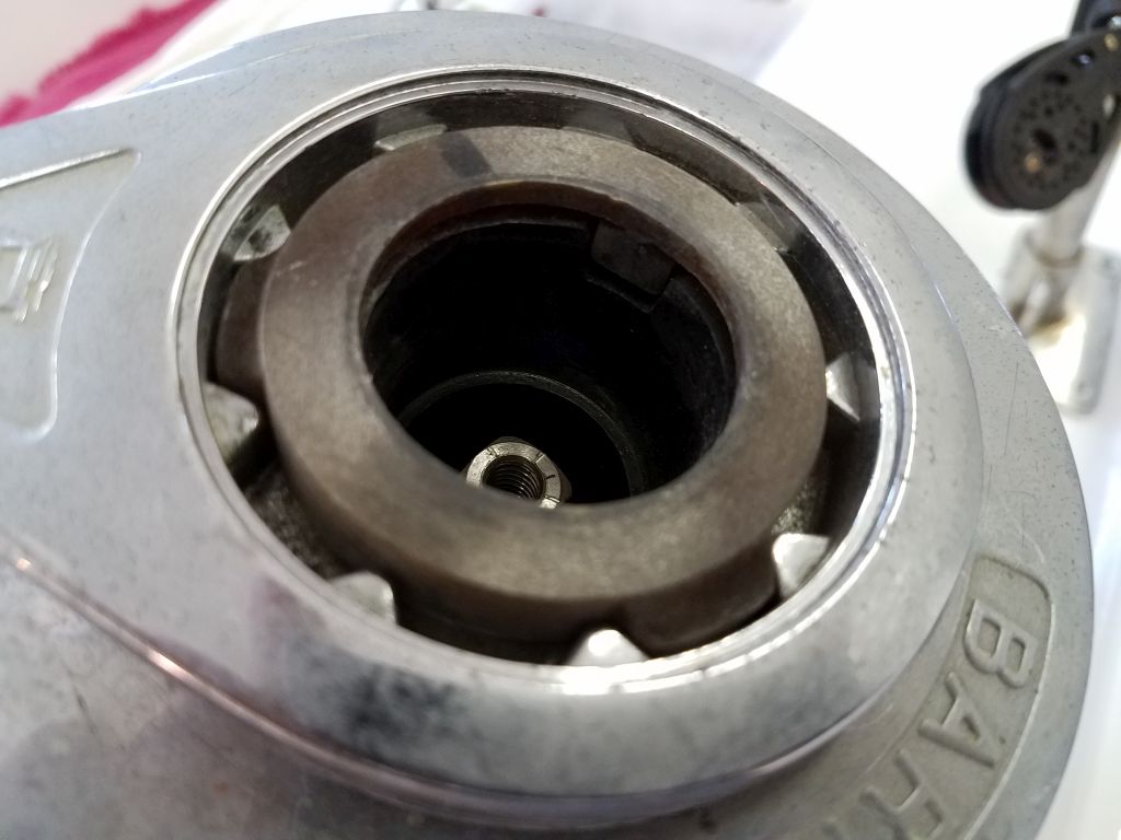
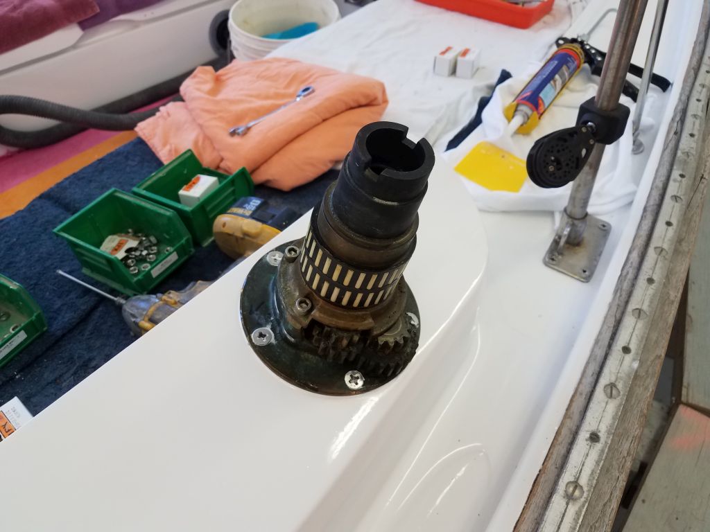
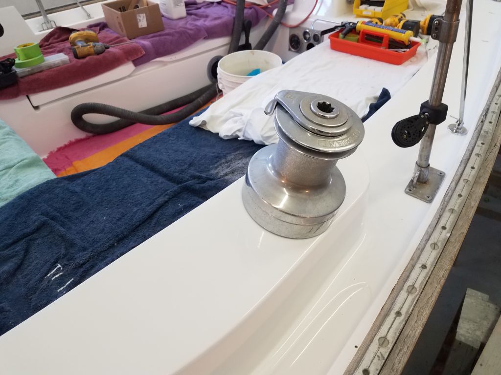
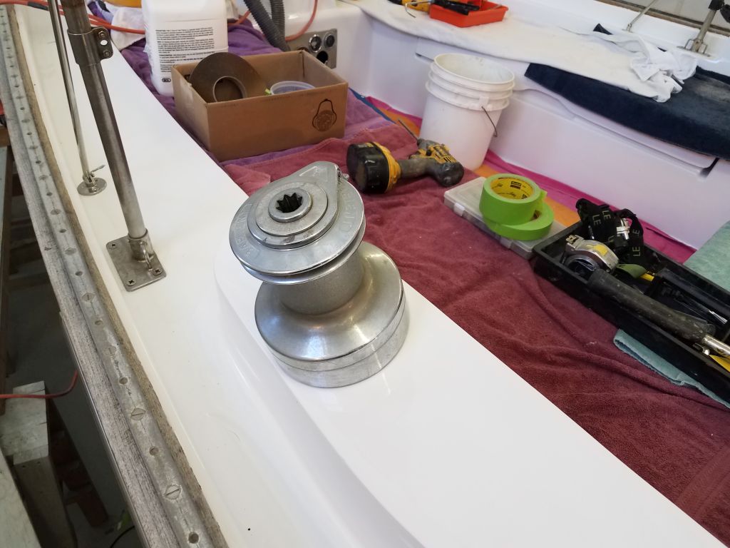
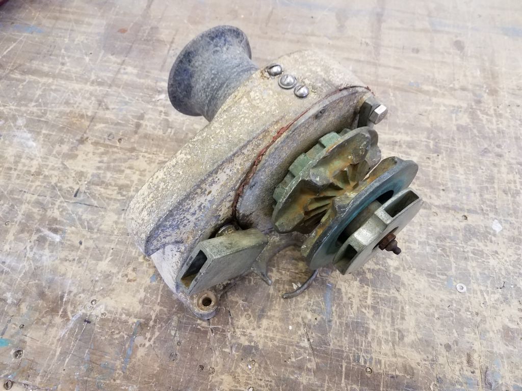
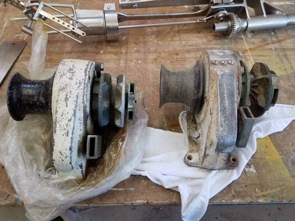
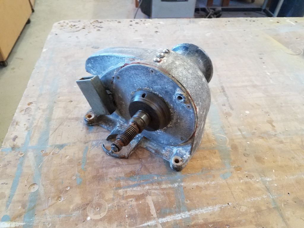
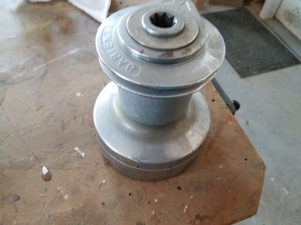
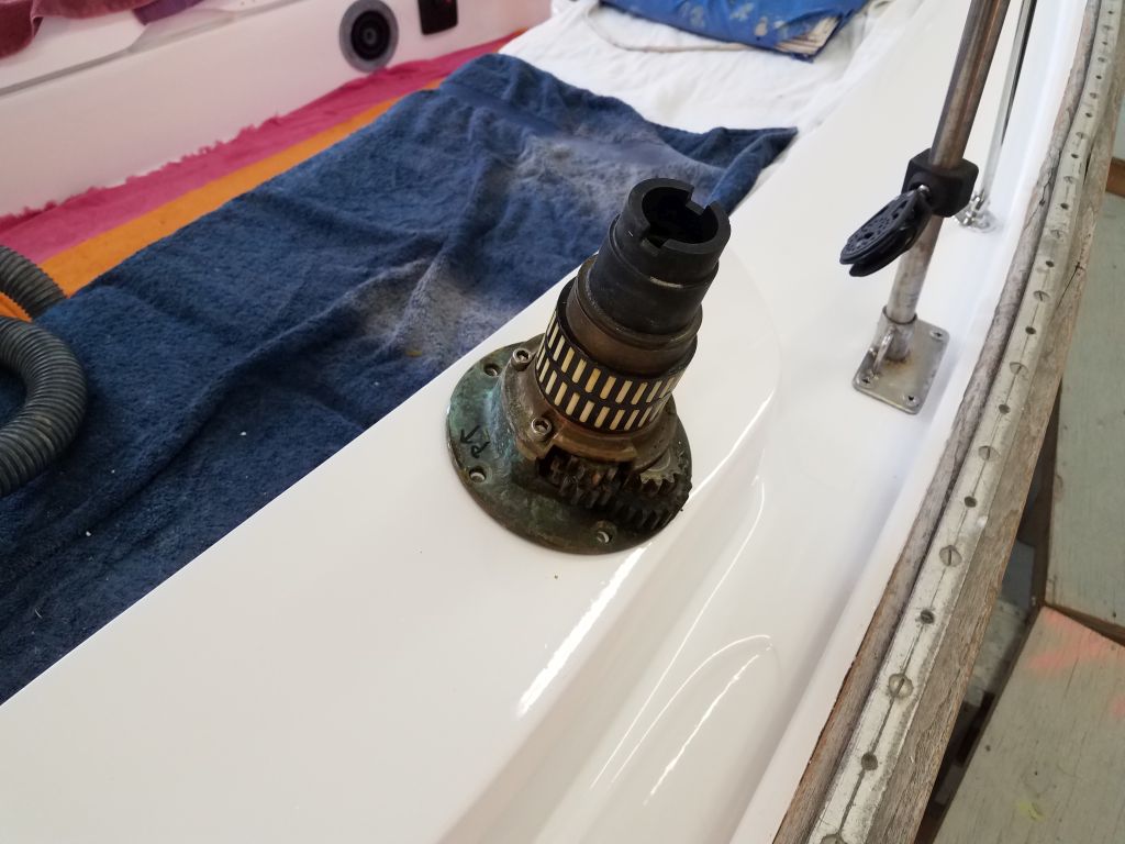
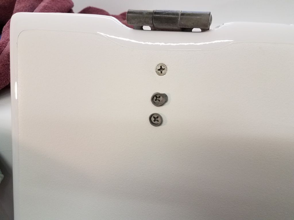
When I permanently installed the “new” sheet winches, I’d discovered to my dismay that one of the winches was missing a simple–yet critical–piece, something that had clearly gone missing when the original owner of the winches removed them from the donor boat about 16 years earlier.  I’d had no idea about the missing piece since I’d had the winches in storage ever since I obtained them (as well as the original donor boat, back in the day, but that’s another story –one that I’ve told before),  and for various reasons I’d never had cause to take them apart before now.

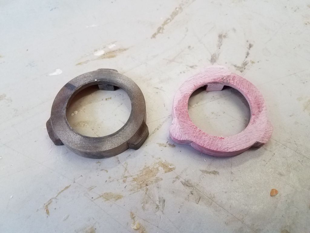
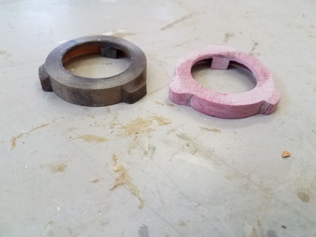
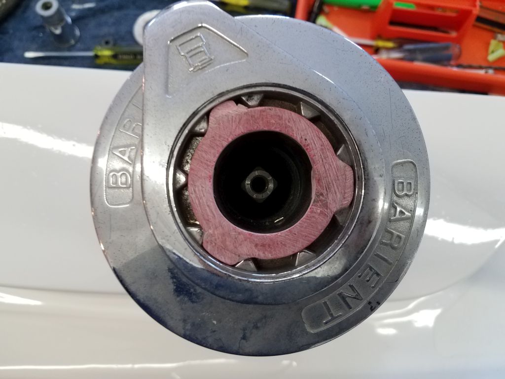
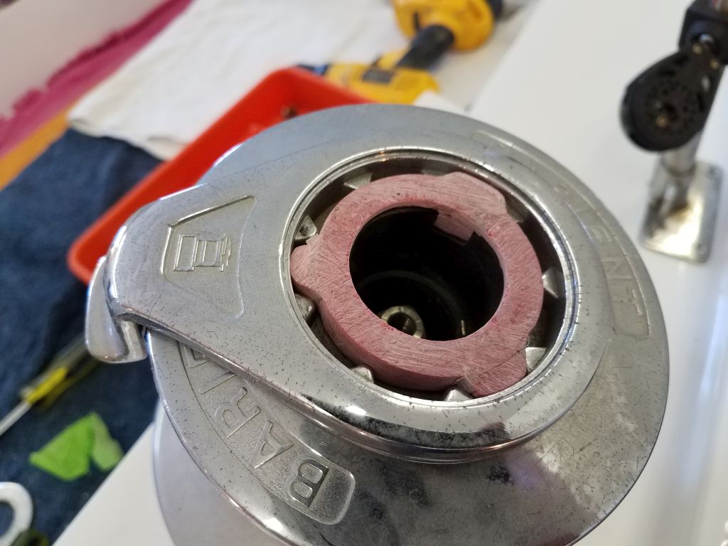
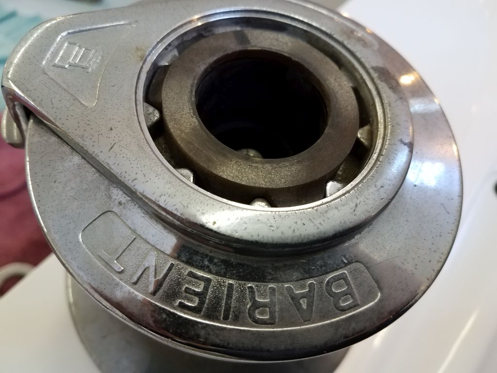
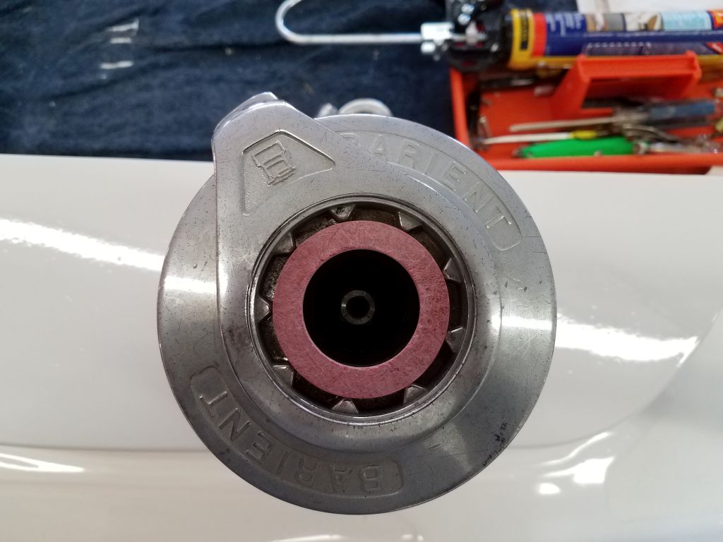
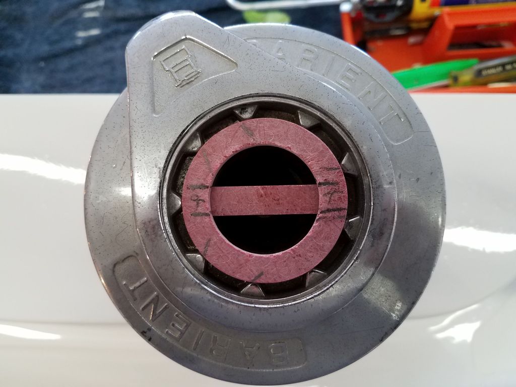
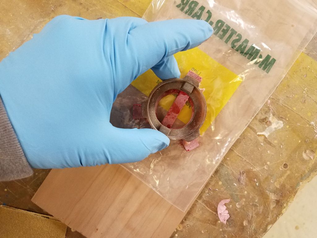
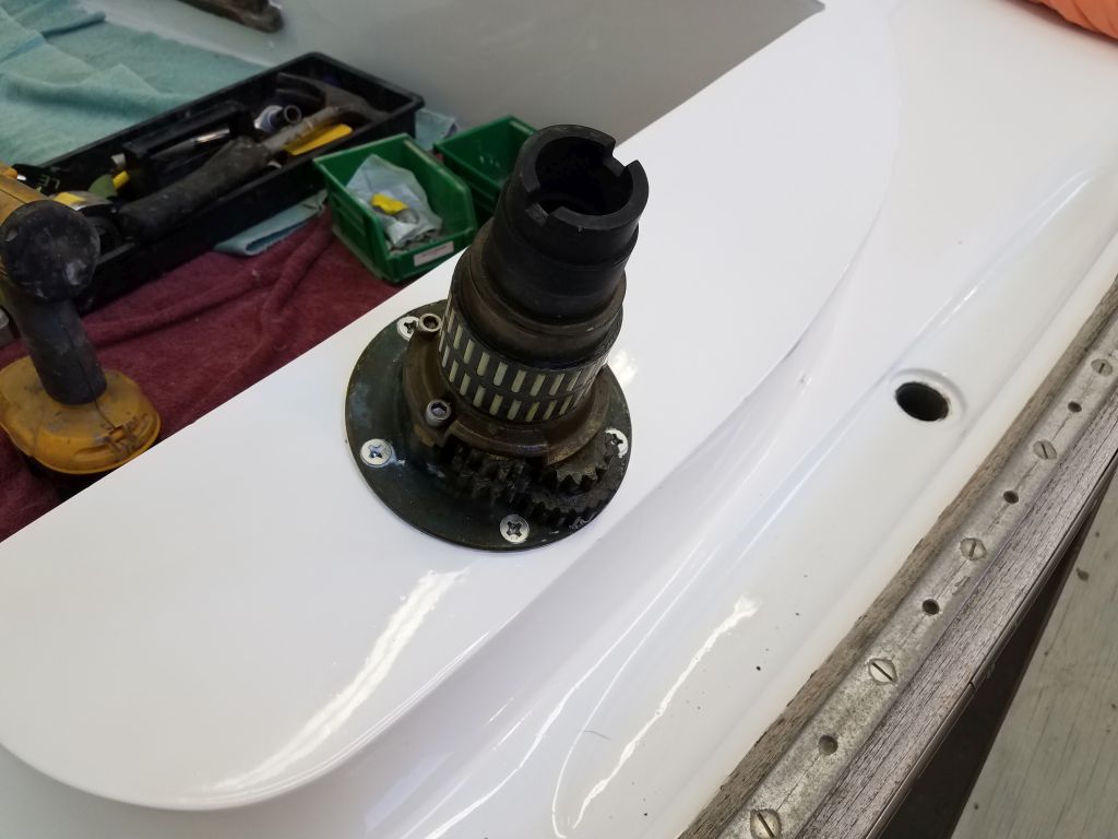
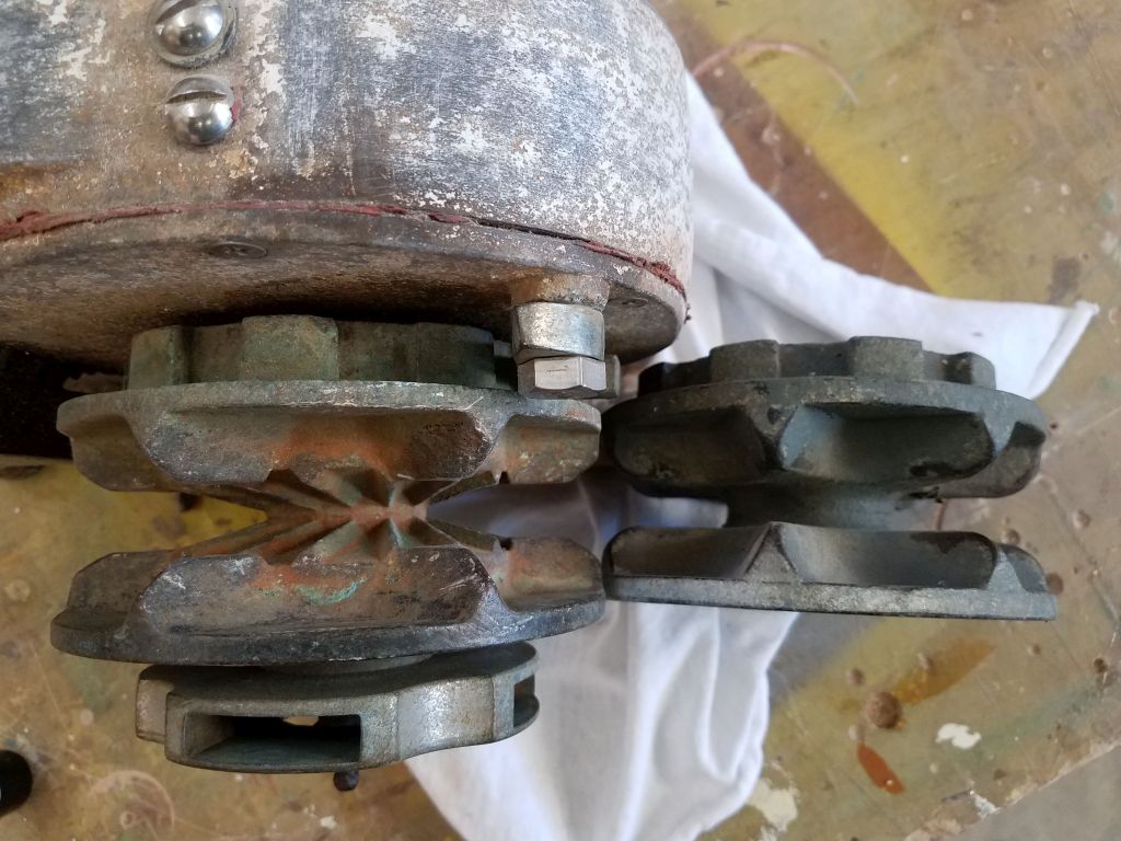
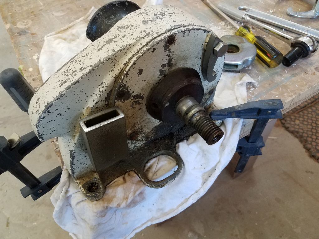
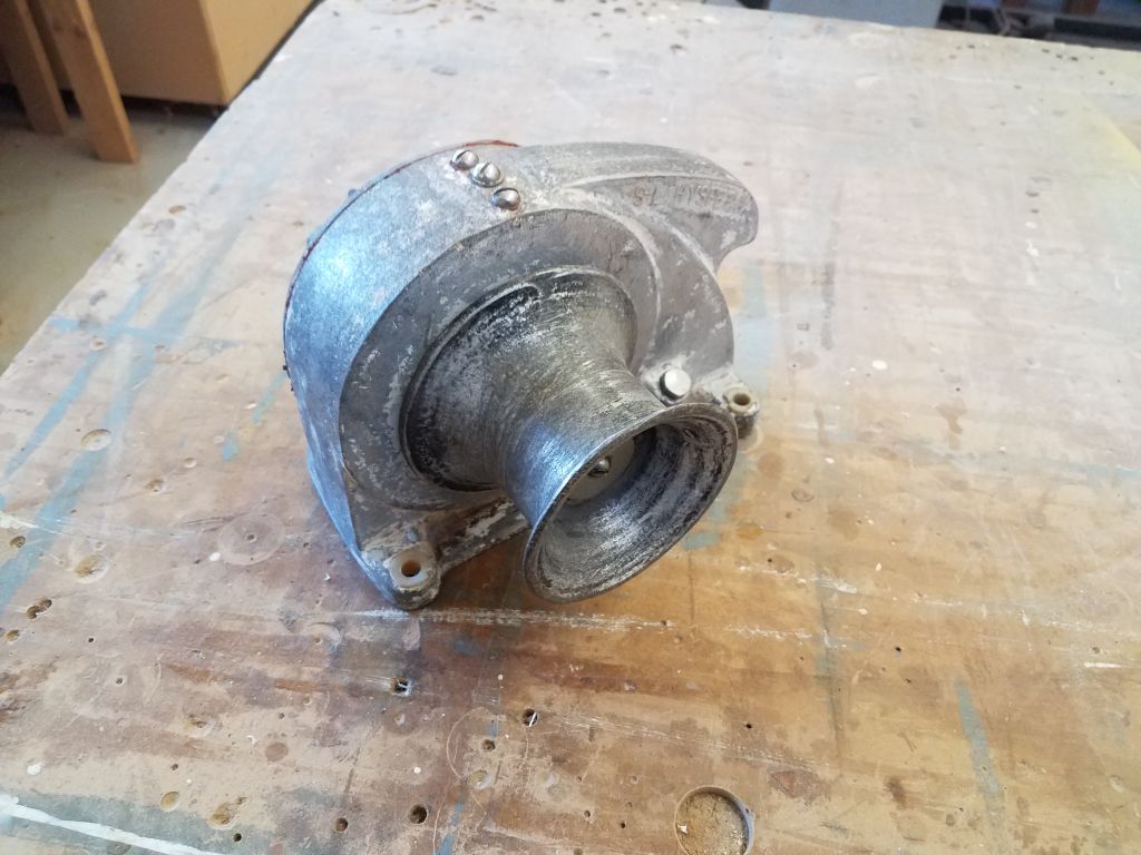
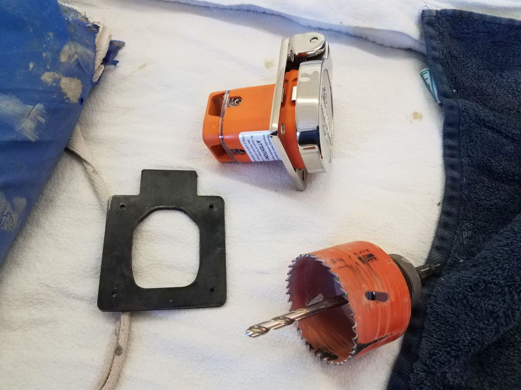
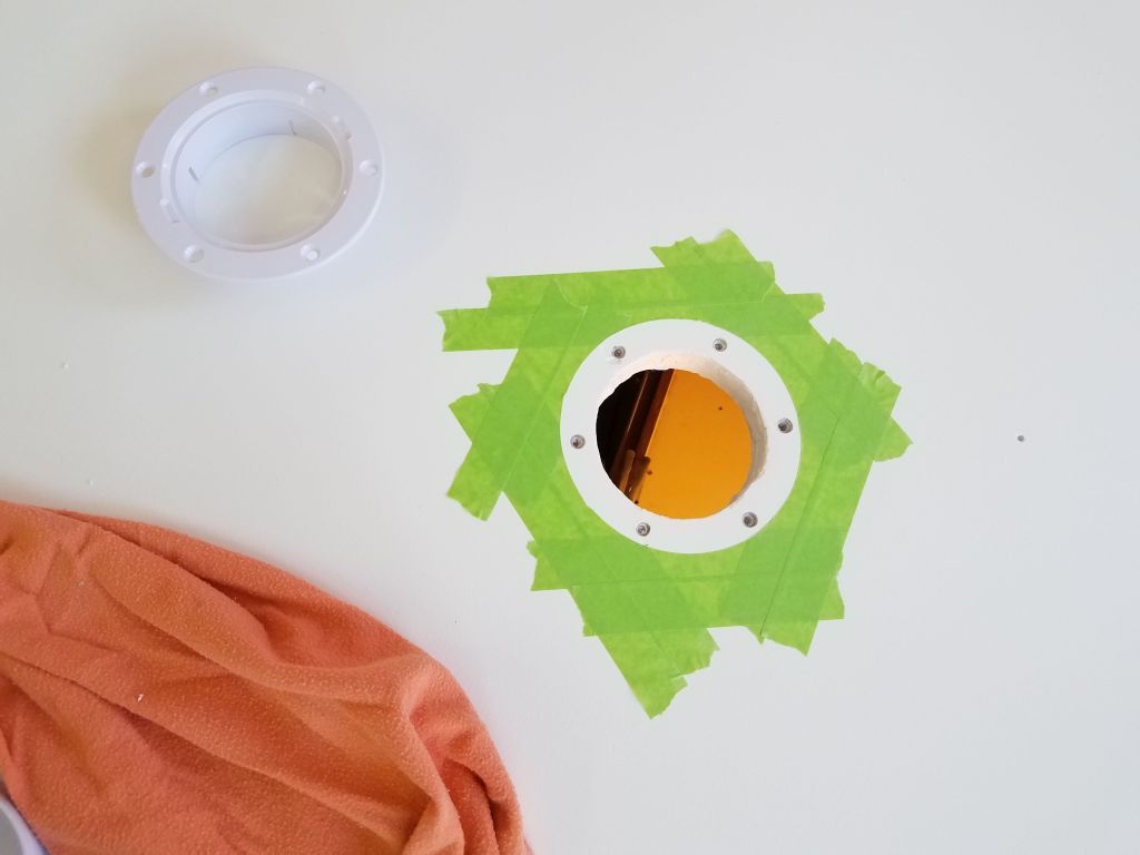
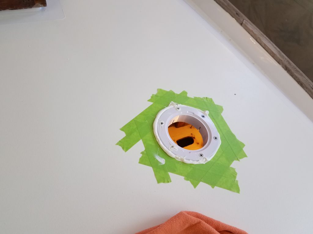
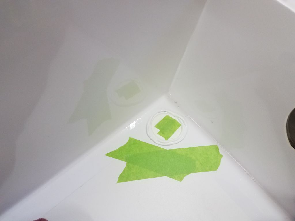
The piece in question was a little plastic do-dad that helped hold the self tailer stripper arm in place by locking into the top of the winch shaft, as well as the little teeth on the stripper arm assembly itself.  It’s the circular piece seen inside the chrome body of the winch here.

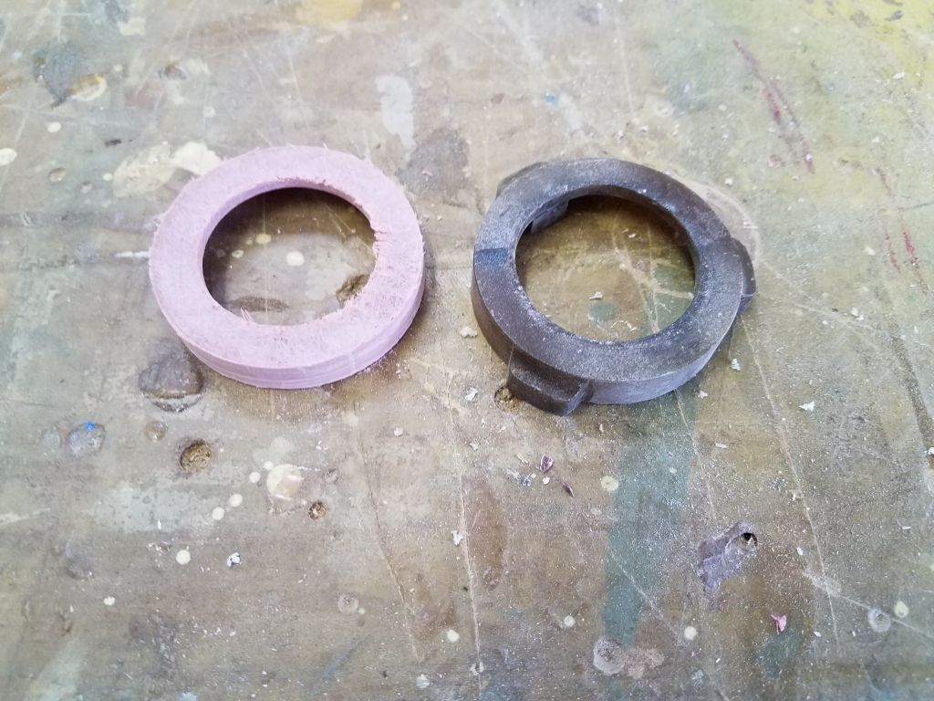
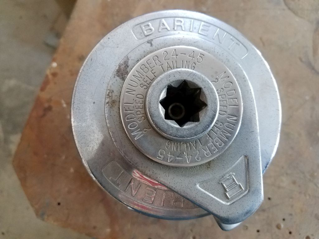
These winches were long obsolete in that the manufacturer was long gone, but of course good winches really seem to last more or less forever, as long as one can find the occasional replacement part.  I didn’t think finding this piece (I didn’t even know what it was called) was highly likely, but looking at the original, it seemed that I could make a replacement in the shop without too much trouble.  After all, its function, while critical, was quite straightforward, and the original piece was just plastic.

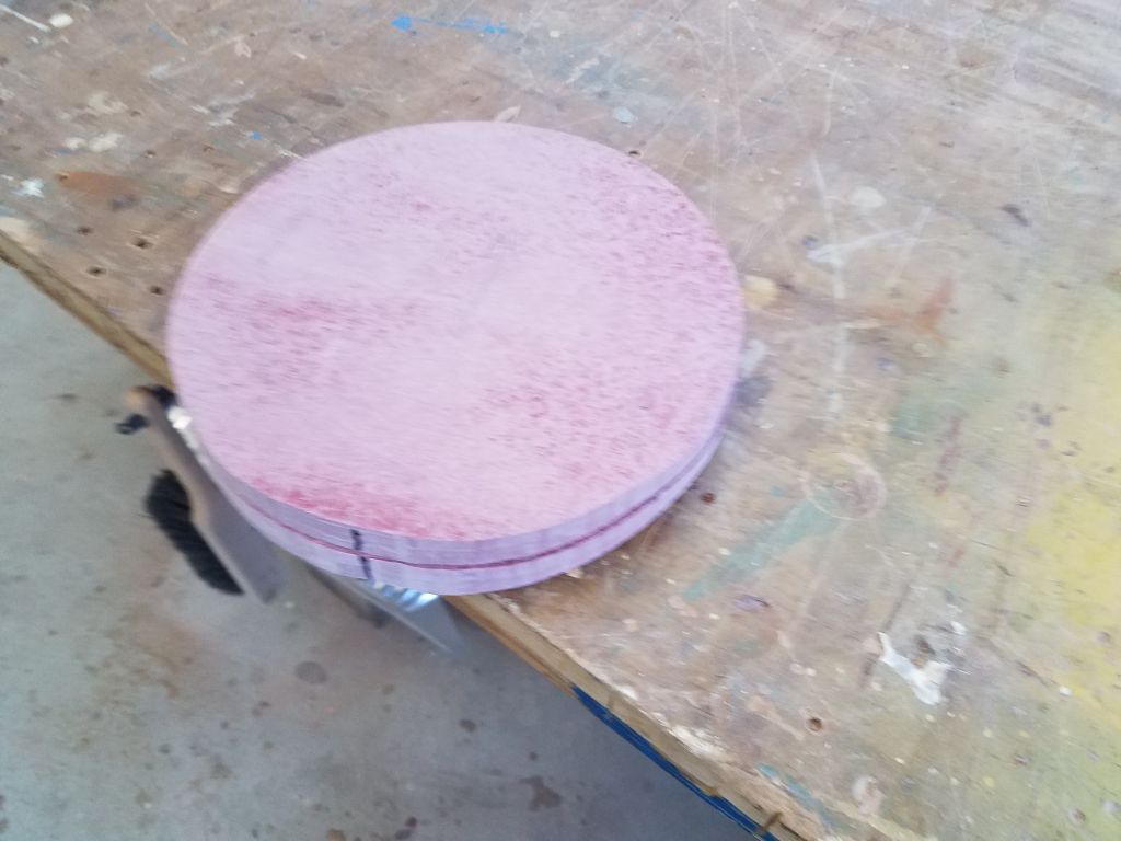
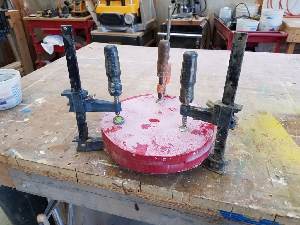
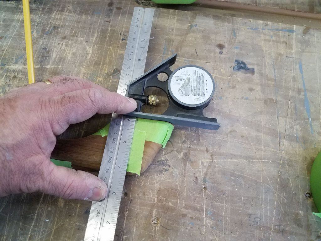
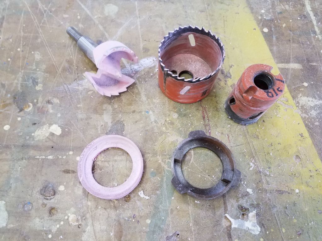
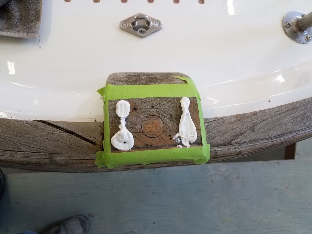
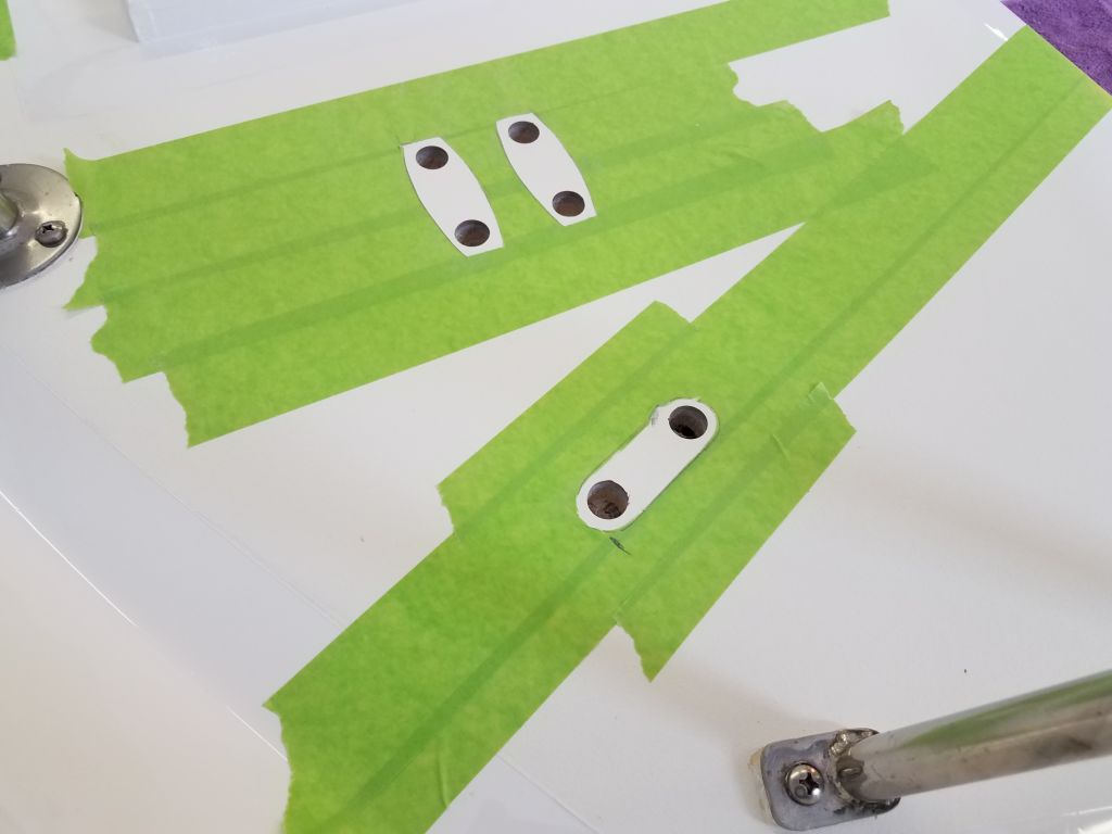
I chose some 3/8″ fiberglass sheeting that I had on hand because ultimately I decided it was the easiest and most logical thing for me to work with.  With a combination of three drill bits, I formed a basic disc that approximated the shape of the original piece.

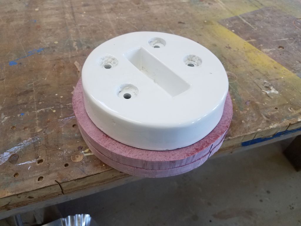
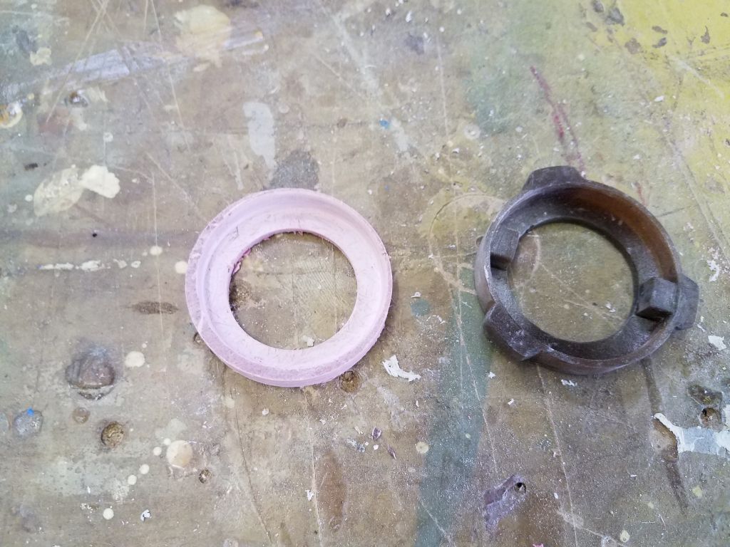
It took just a little fine-tuning with a portable drill  fitted with a drum sander to fit the new disc to the top of the winch as required, as I had to trim down one of the inside edges till the disc slipped over the winch shaft properly.

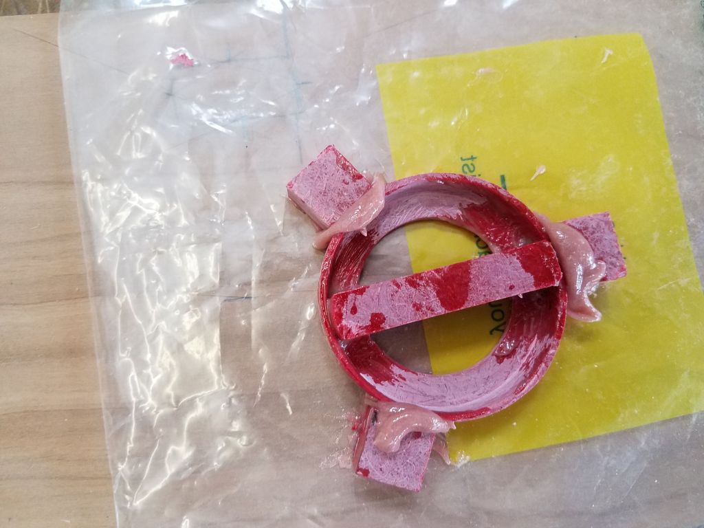
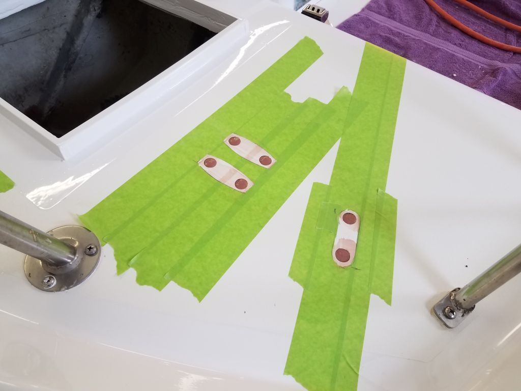
The main reason I chose fiberglass for the replacement part was because I couldn’t come up with an easy way to fabricate the part including its various little ears and nubs, all of which were critical for the part to function as needed; with fiberglass, I could easily epoxy little pieces together as needed to make the final shape.  I started with the nubs on the inside of the part, which needed to fit in a slot in the top of the winch shaft.  I cut a little strip of the fiberglass to fit across and through the slots, marking its position clearly on the top of the ring.  I’d leave the crossbar whole during glue-up, and would cut out the center portion later.

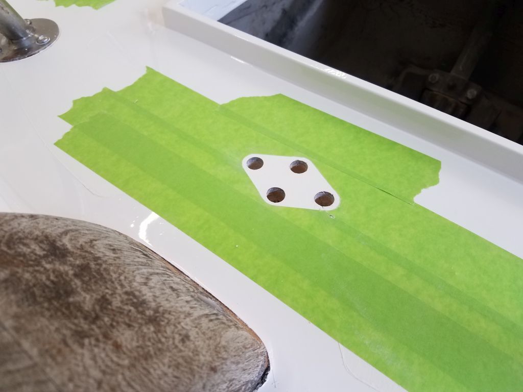
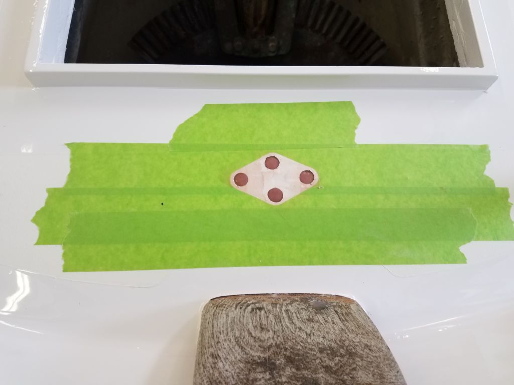
For the three nubs on the outside of the disc, which would ultimately fit into the teeth of the stripper assembly, I cut some slightly oversized bits of fiberglass that I could glue on in the correct position, then trim to the correct size and shape later.  Then, I epoxied the various pieces together and set the assembly aside for the epoxy to cure.

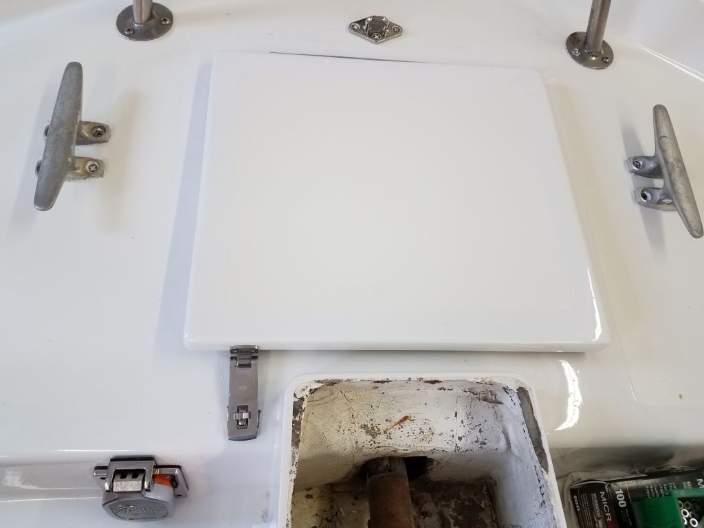
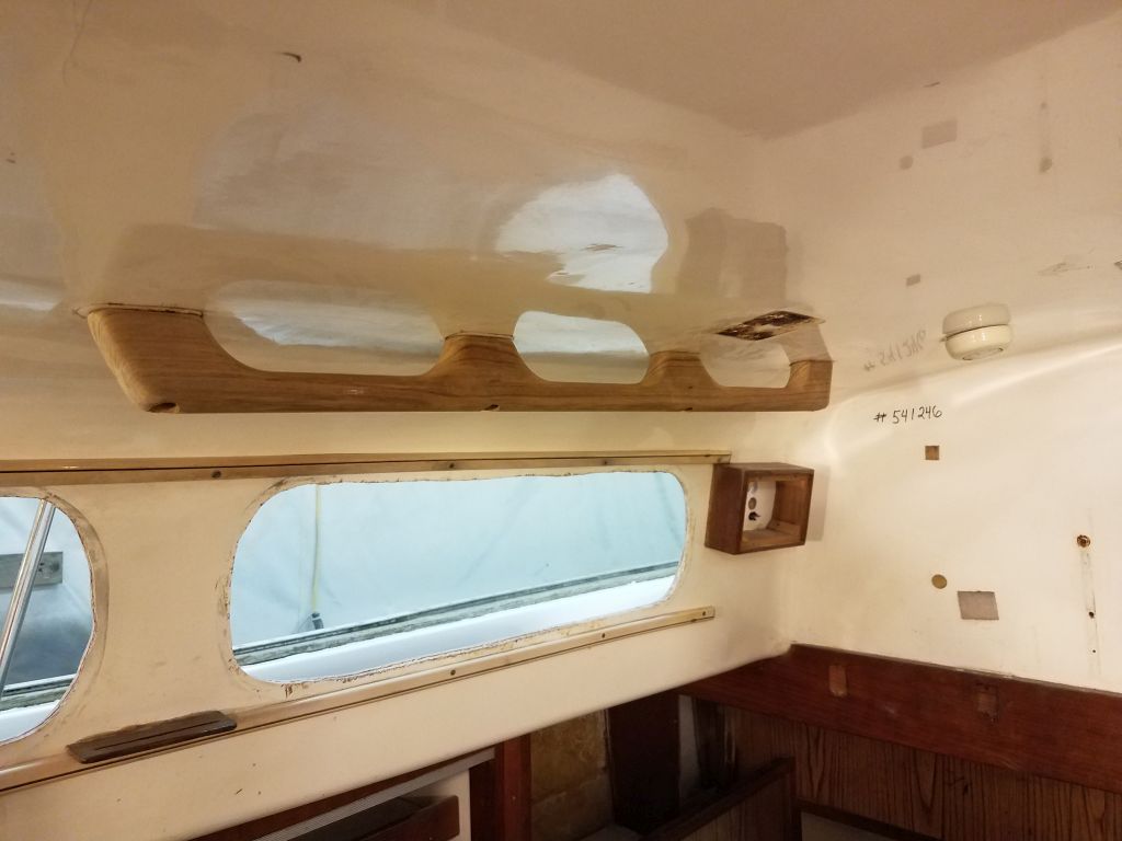
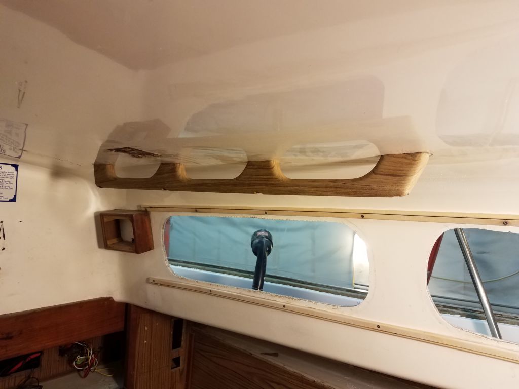
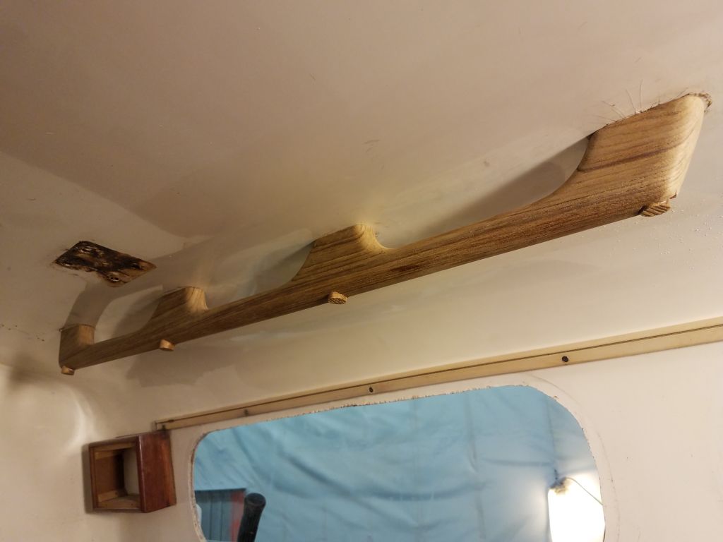
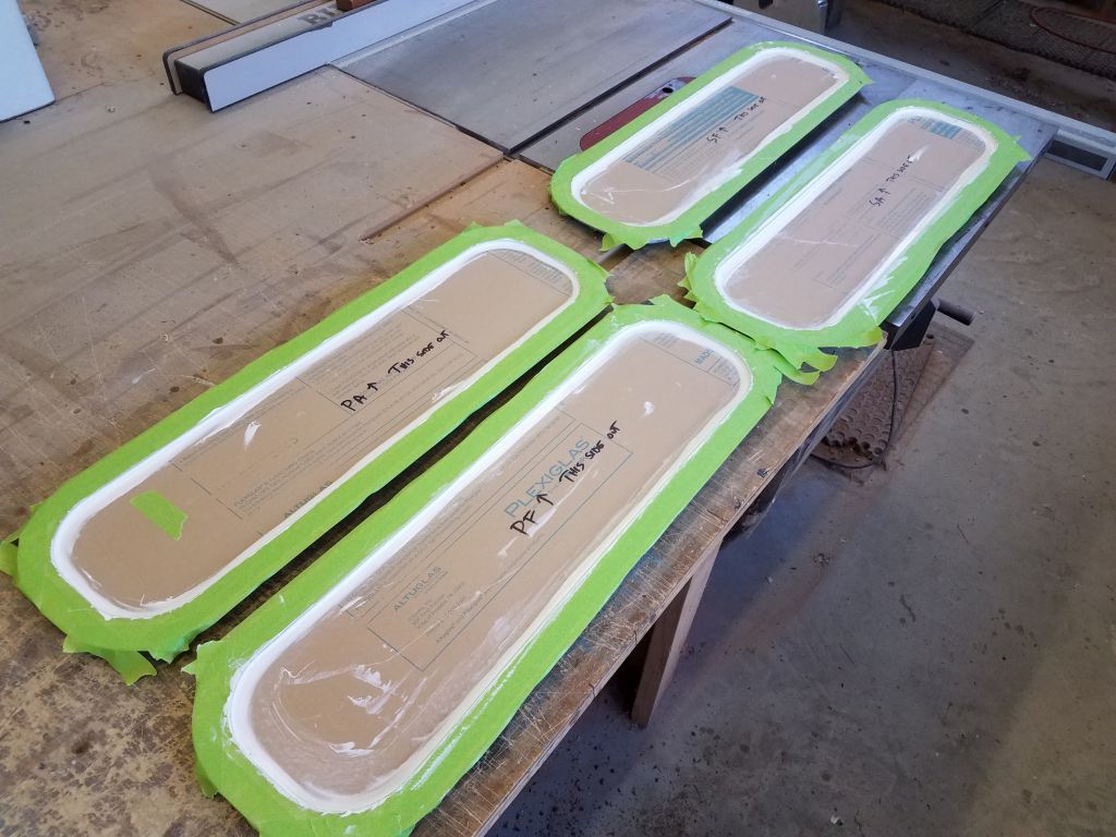
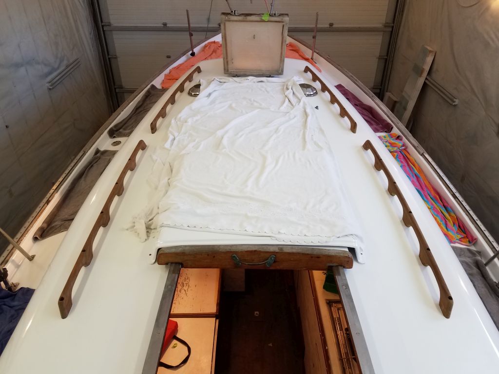
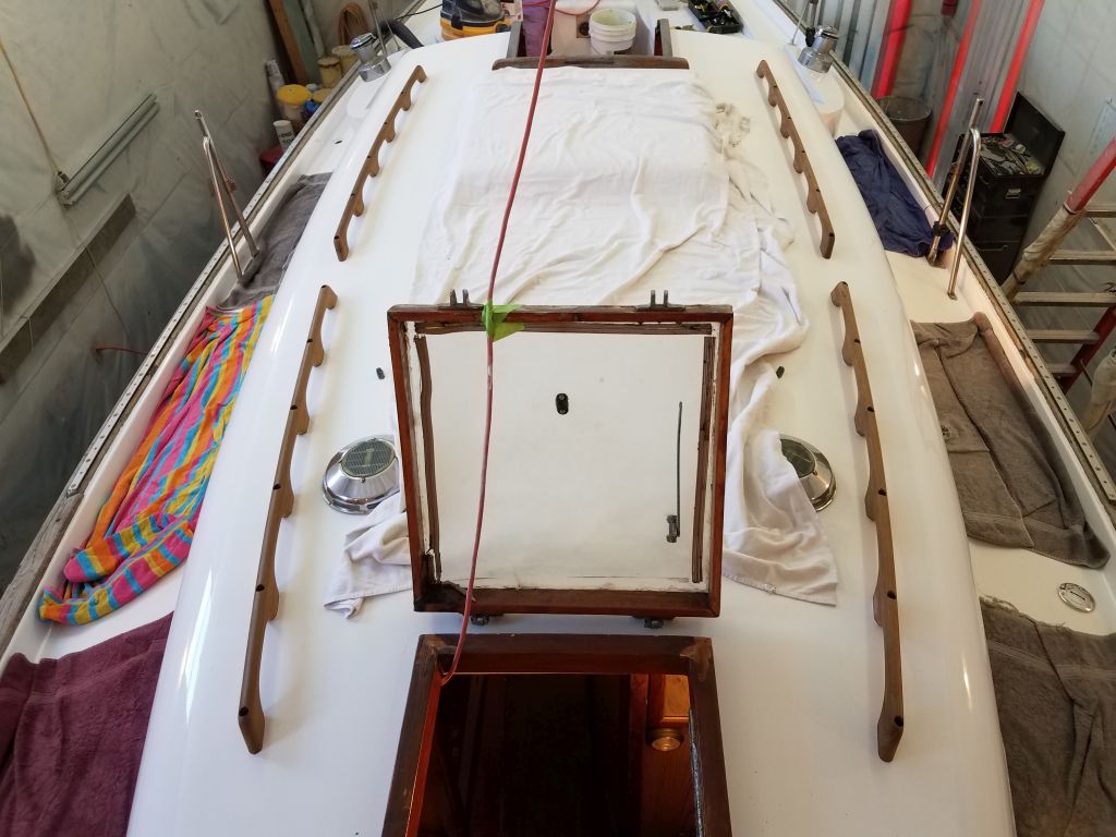
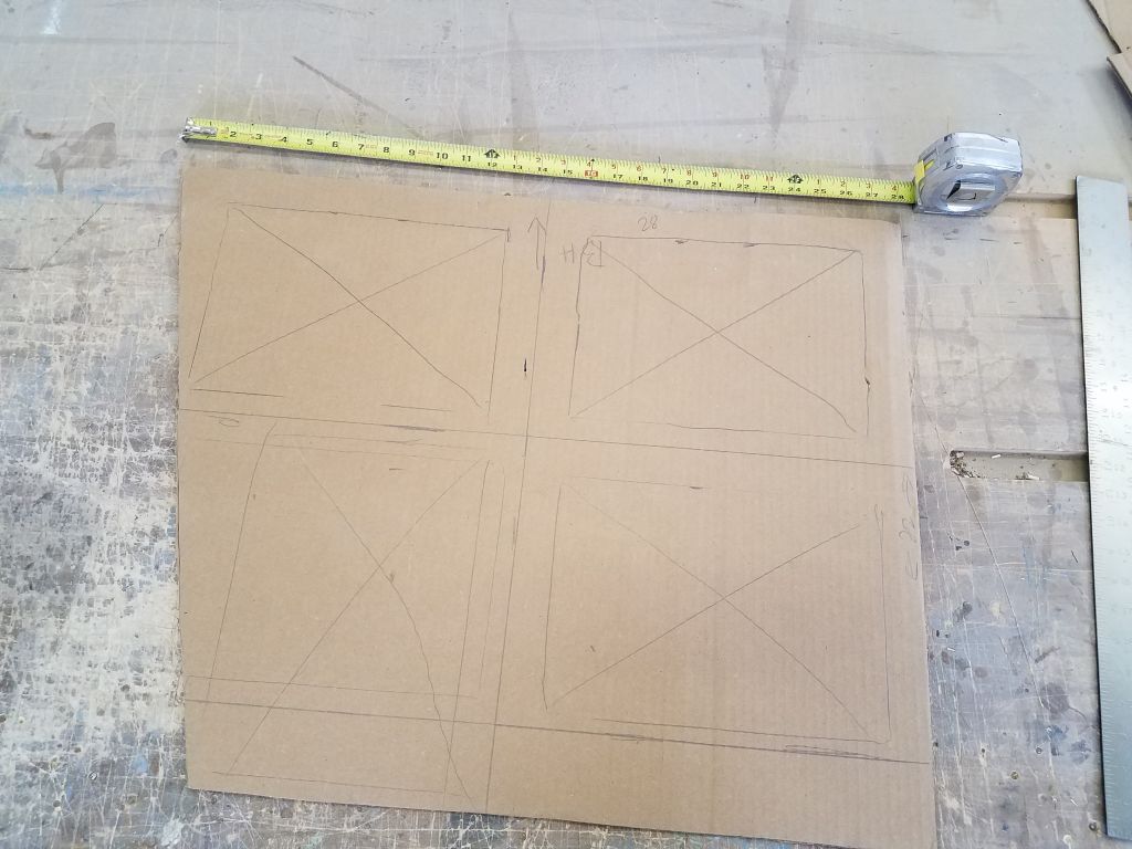
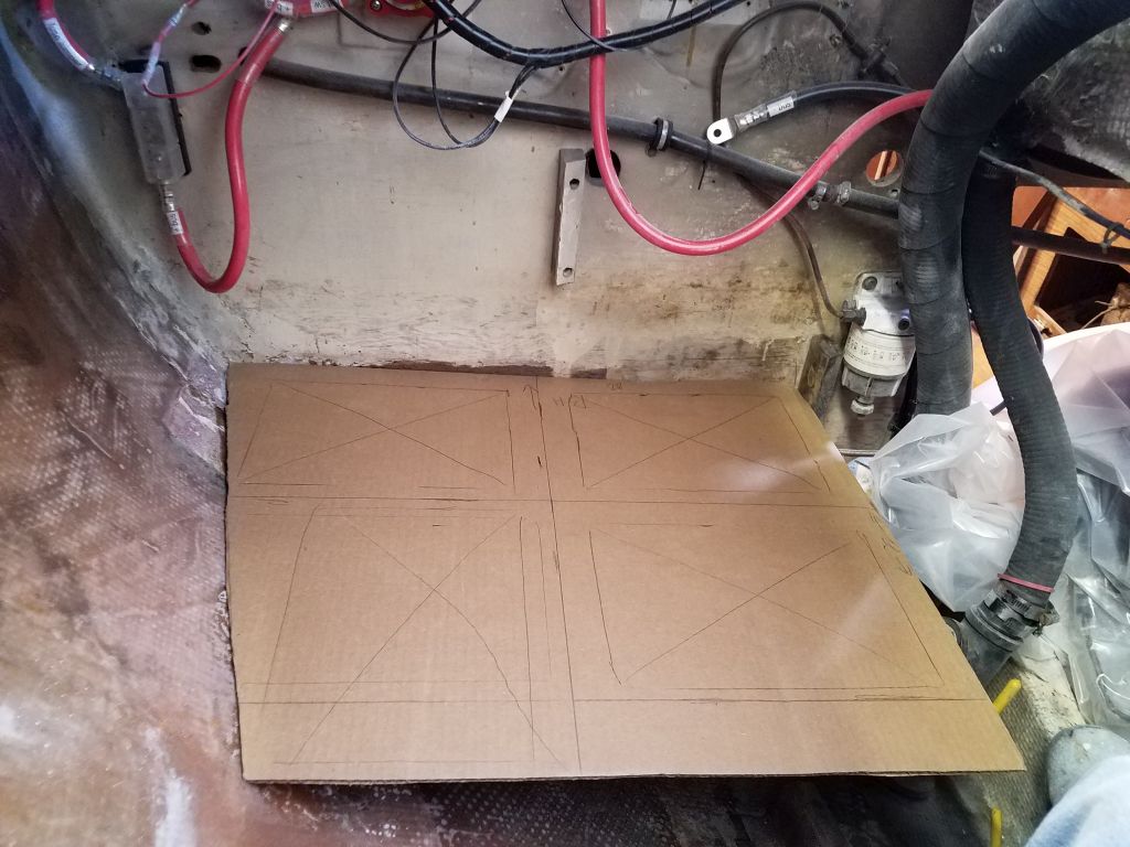
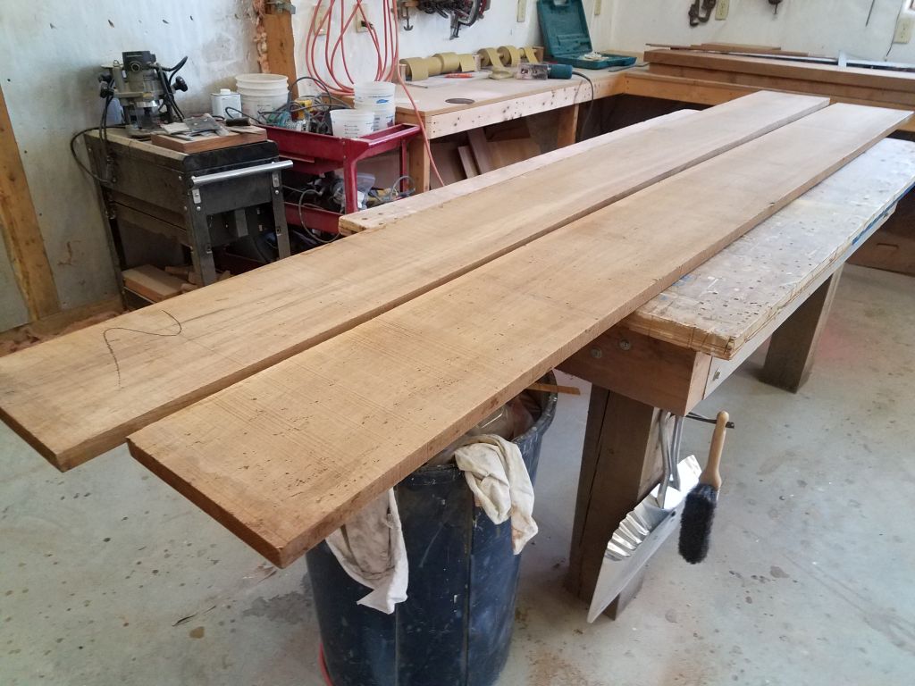
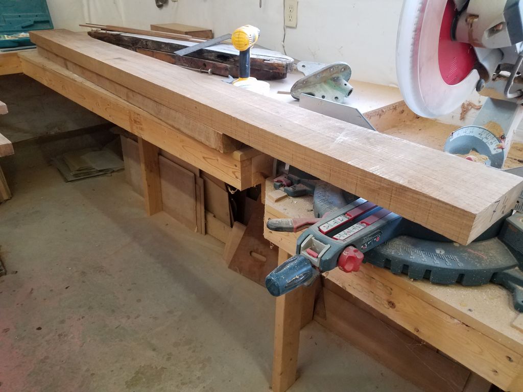
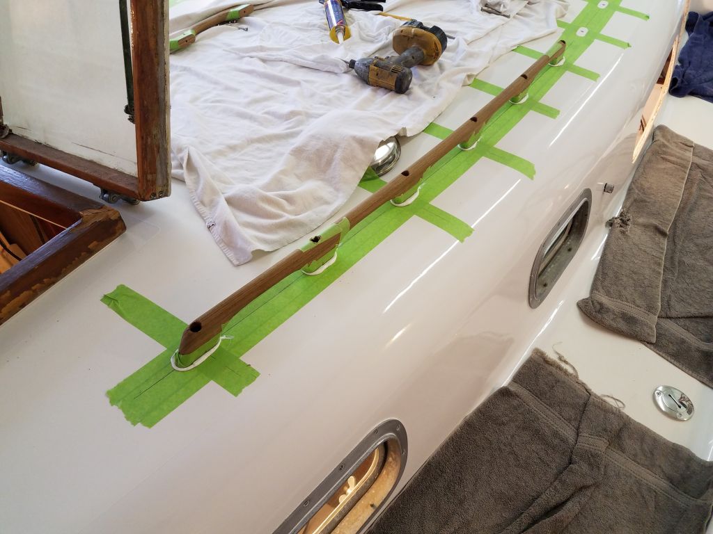
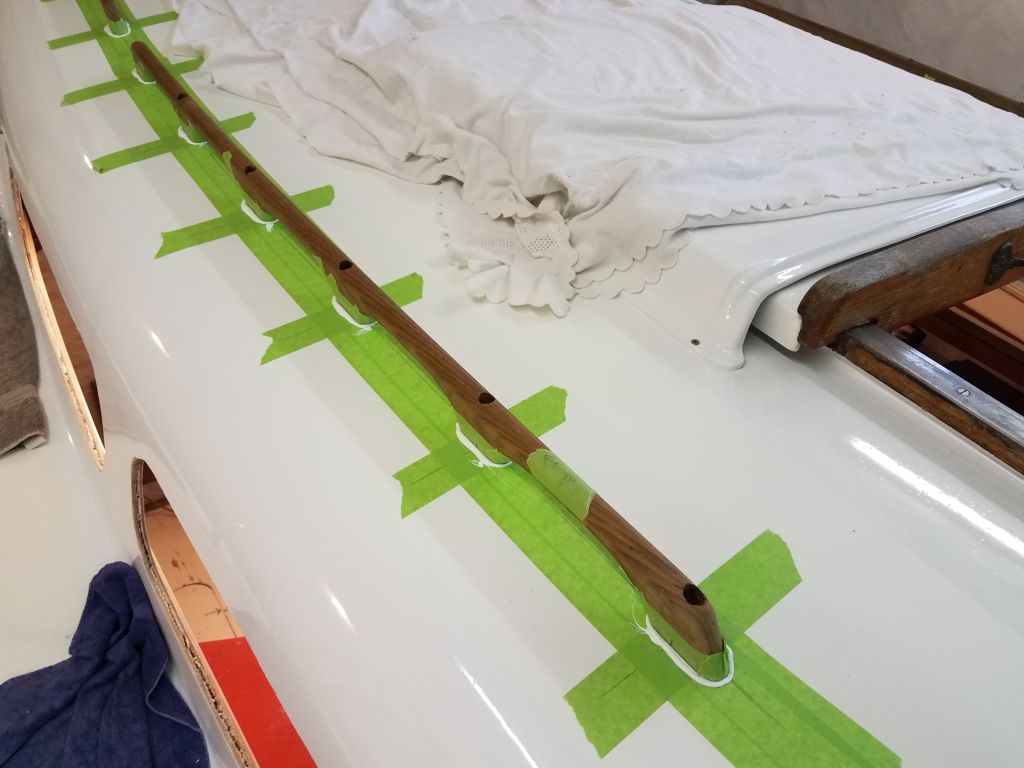
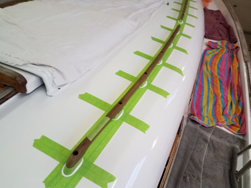
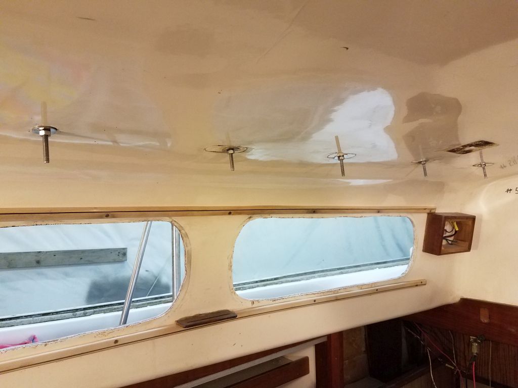
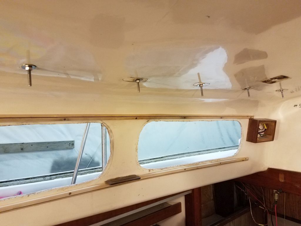
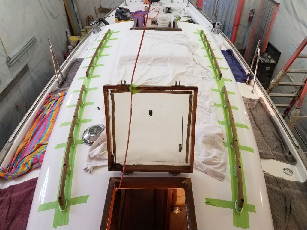
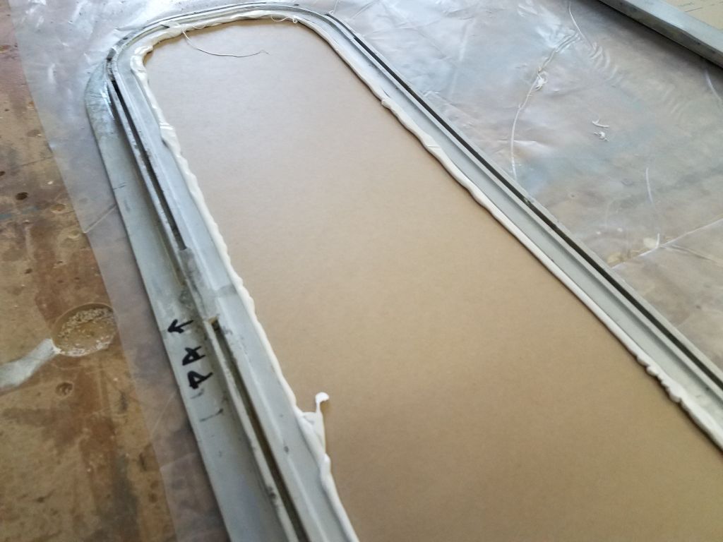
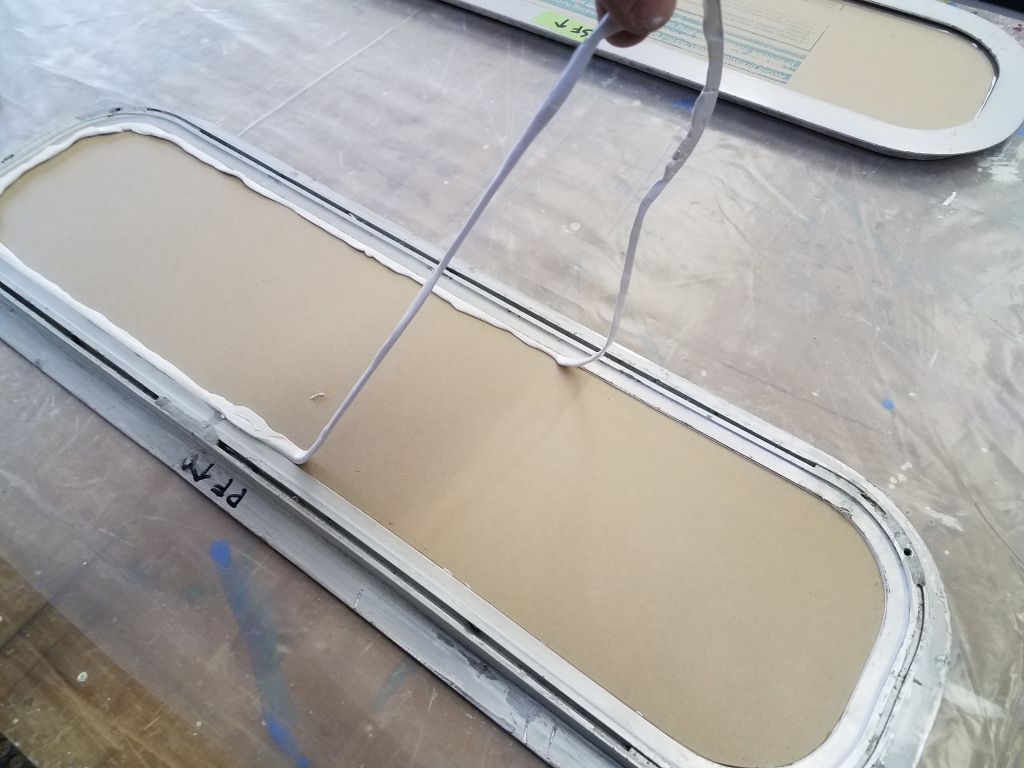
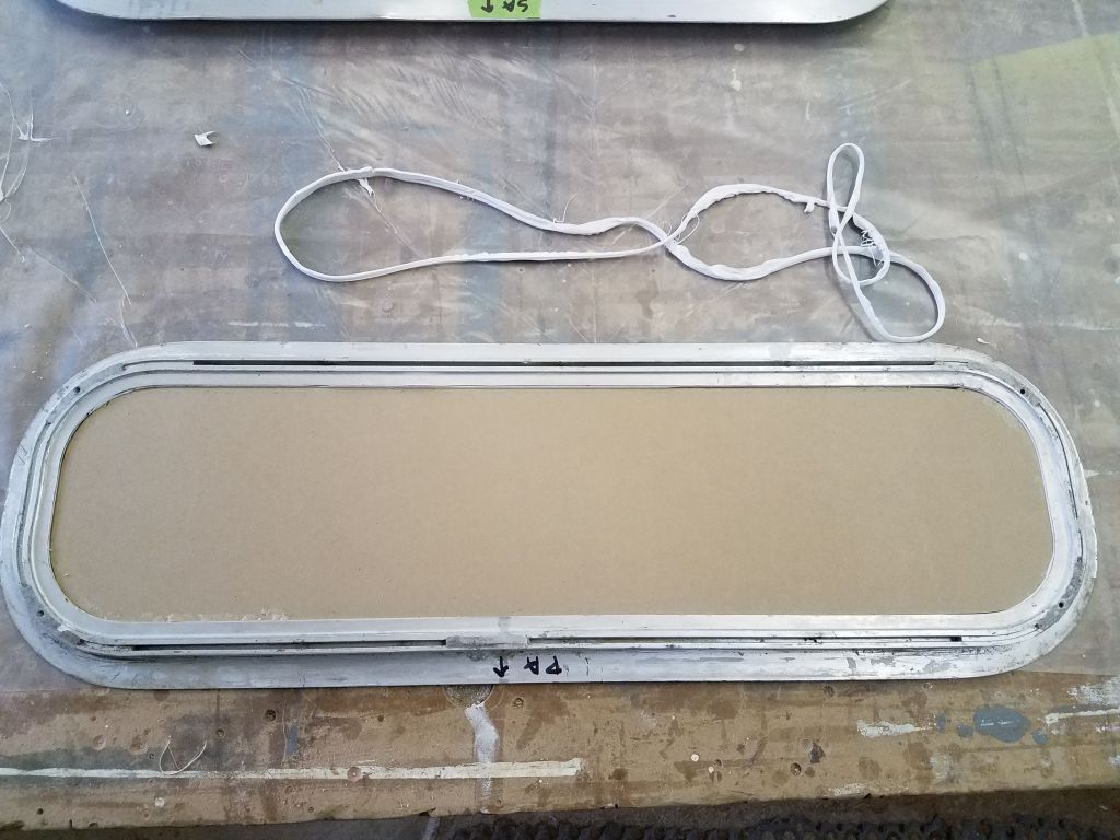
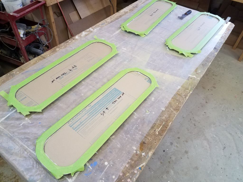
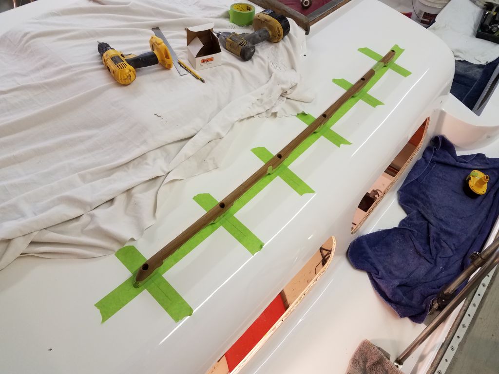
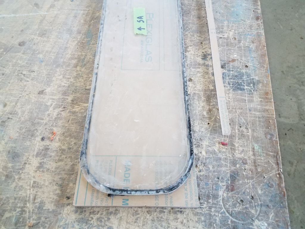
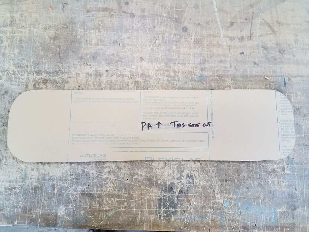
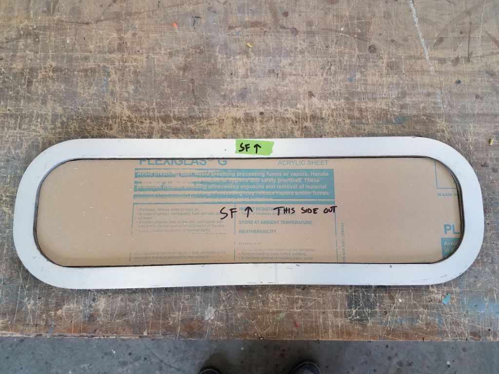
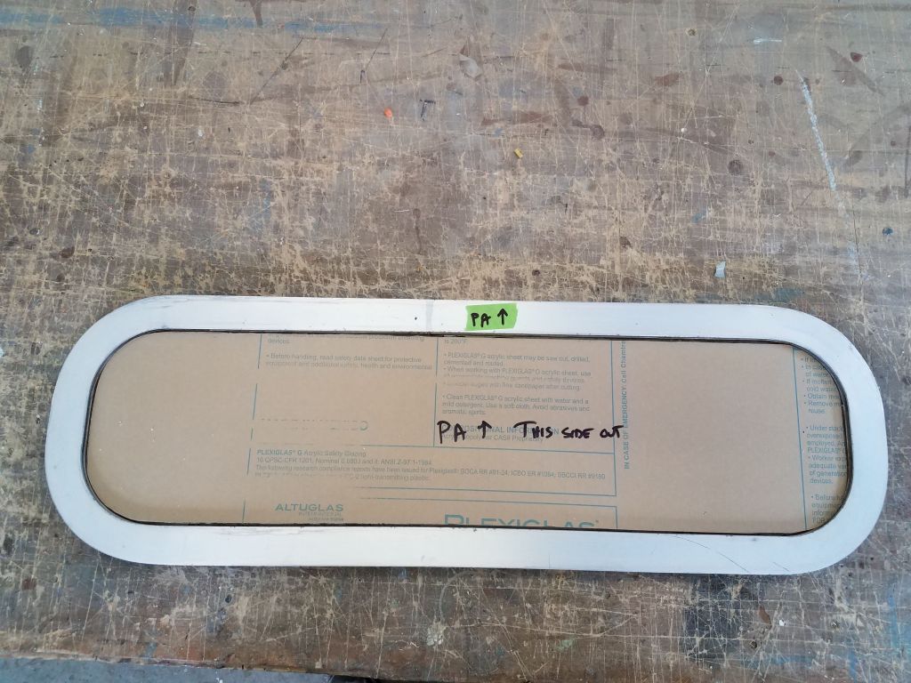
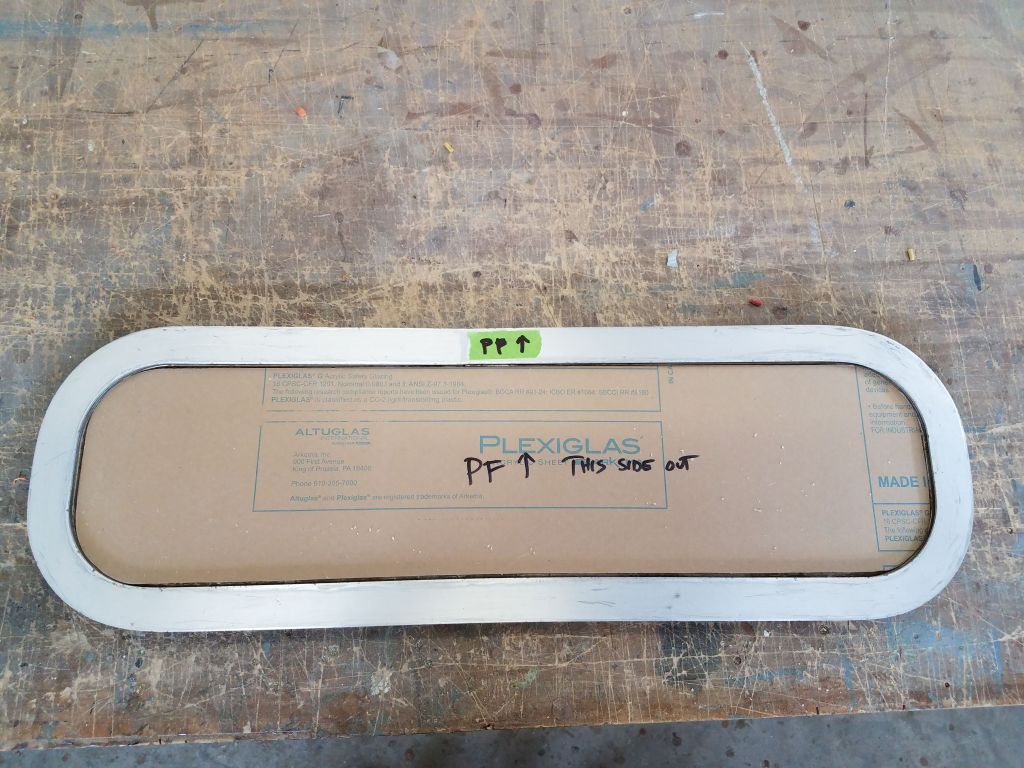
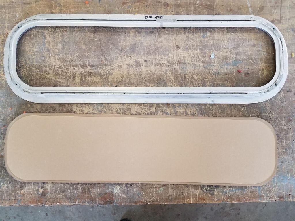
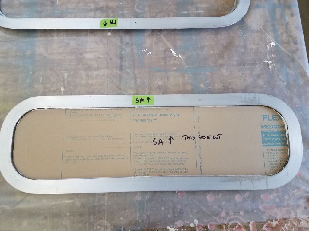
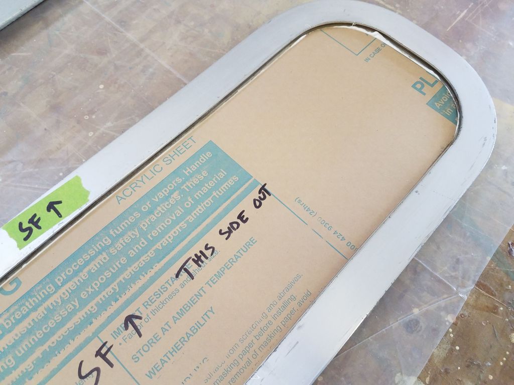
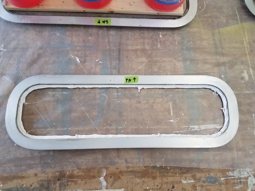
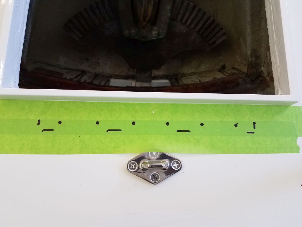
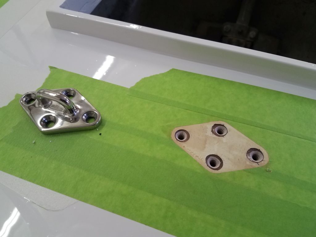
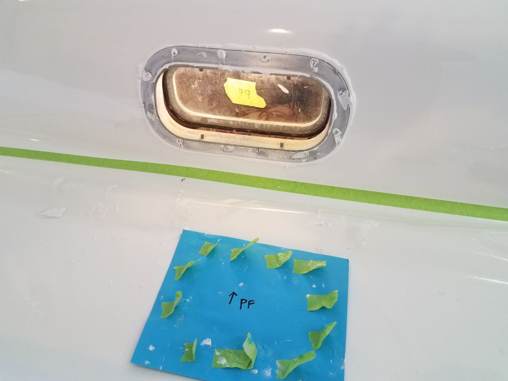
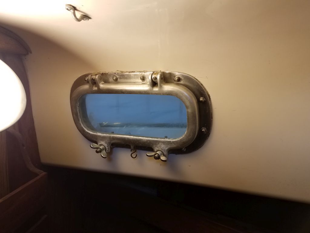
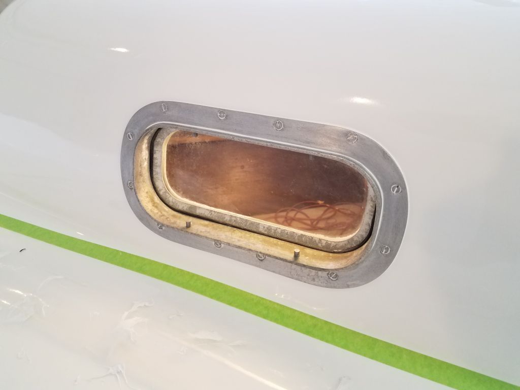
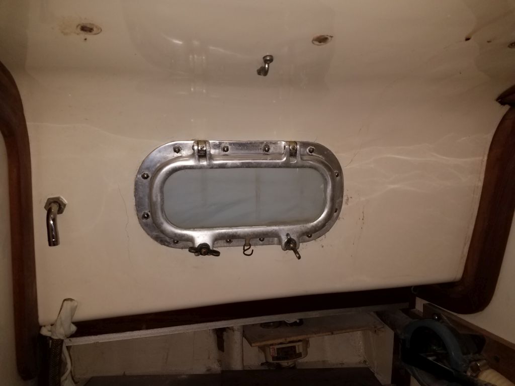
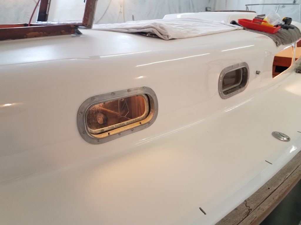
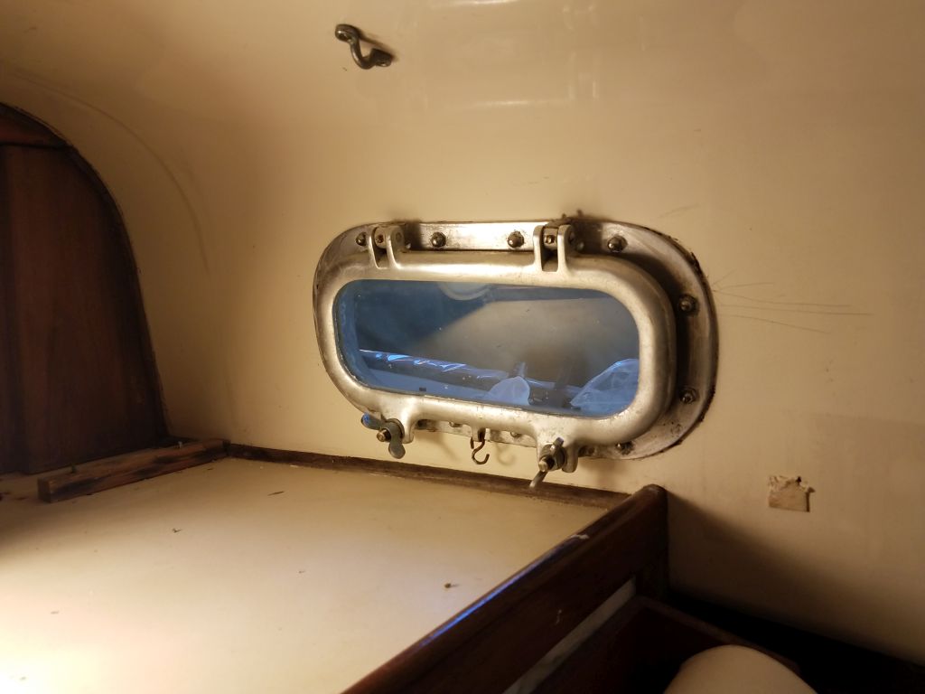
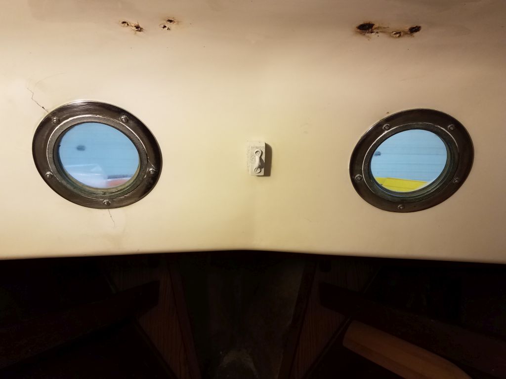
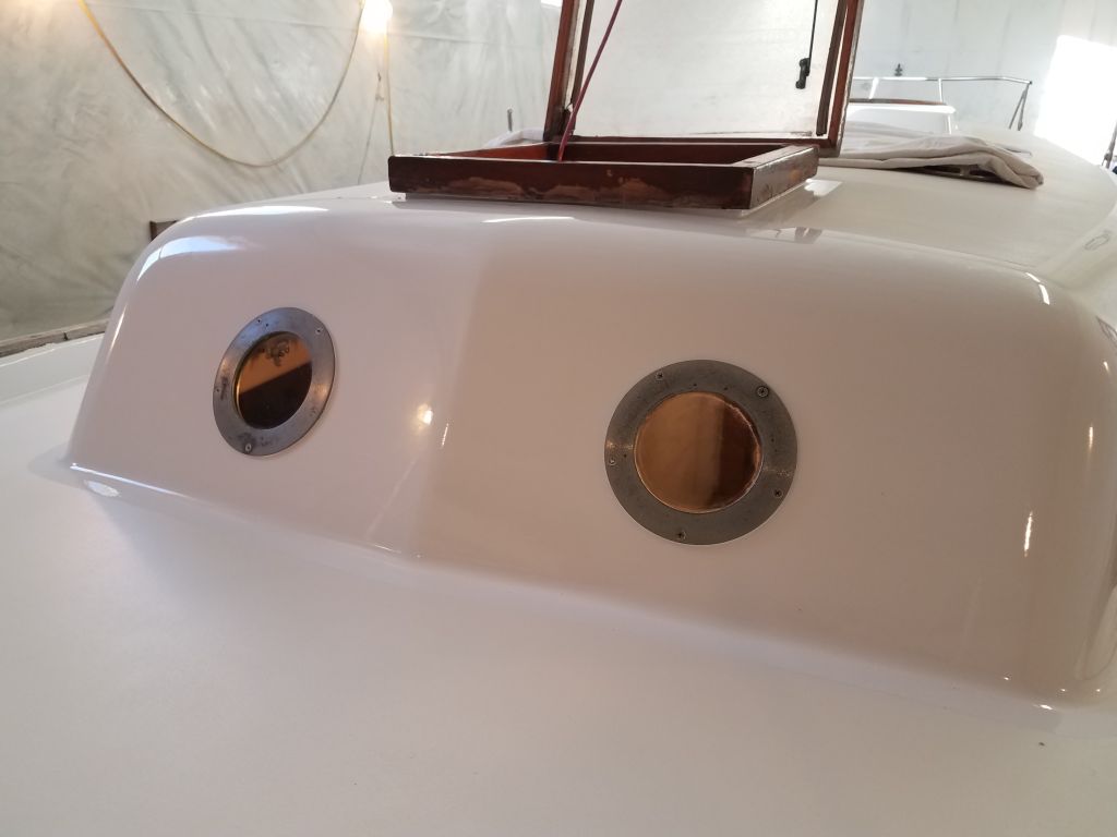
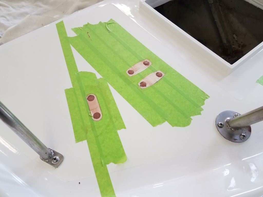
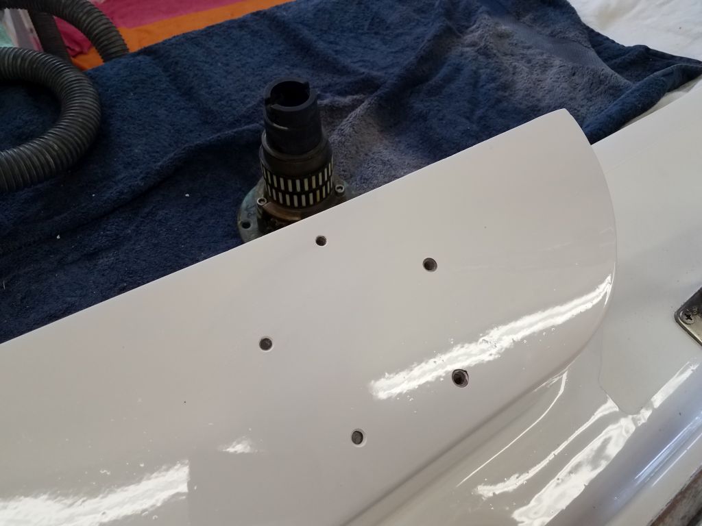
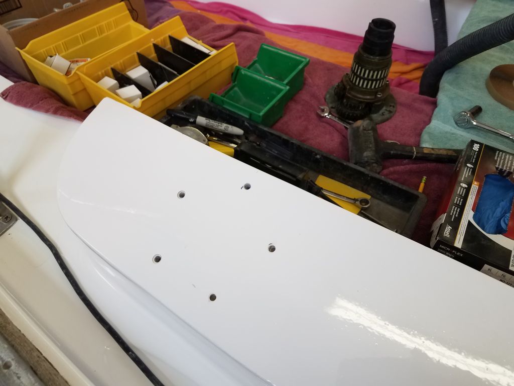
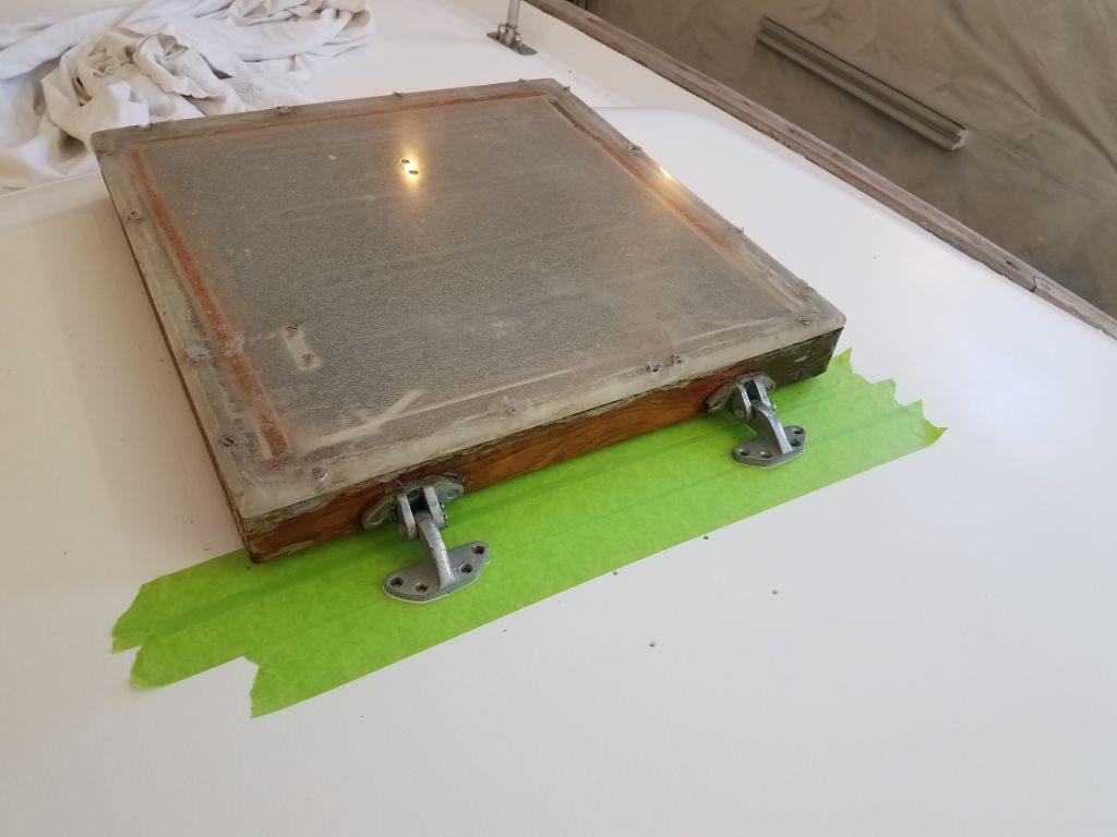
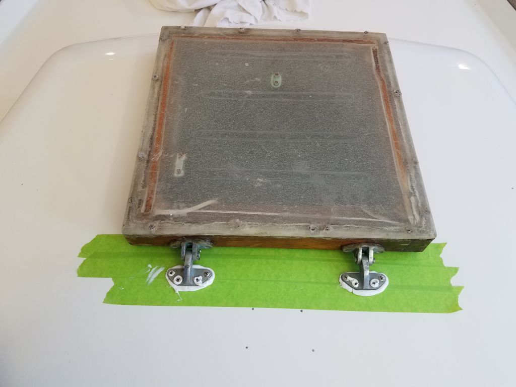
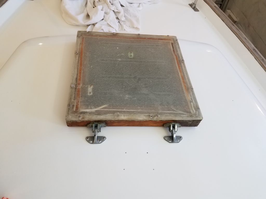
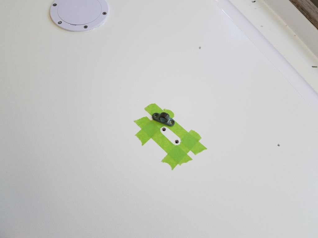
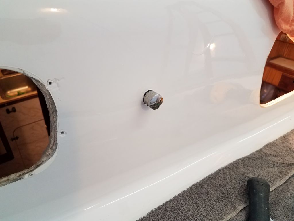
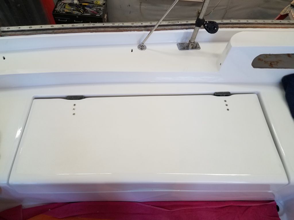
Now I turned to the deadlight frames and lenses.  I’d ordered new 3/8″ clear acrylic for the replacement lenses (the originals were 3/16″, and had the plastic shop cut the rectangular blanks a bit oversize so I could do the final cutting in the shop.  After confirming the overall width of the original lenses at 6-1/2″, I trimmed the new blanks to the correct width on the table saw, then used each of the old lenses as a template to cut the new pieces to fit the frames.

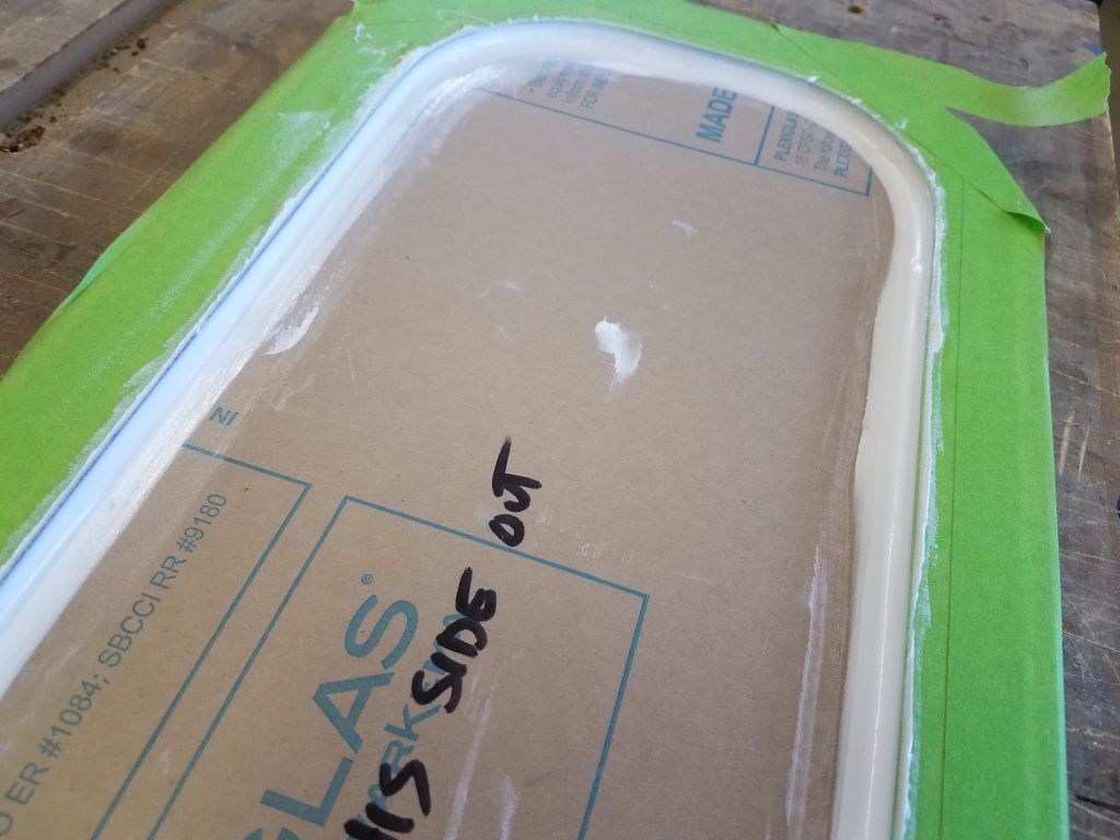
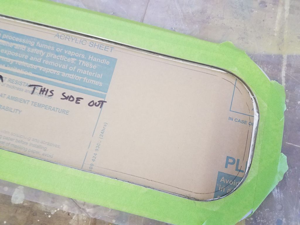
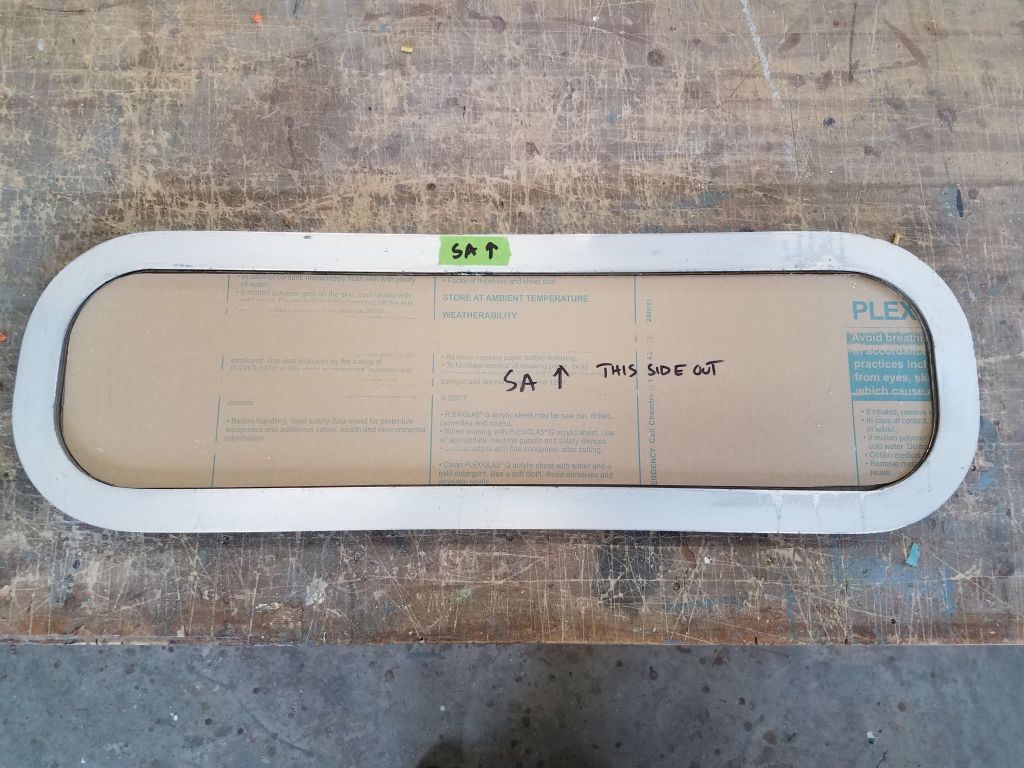
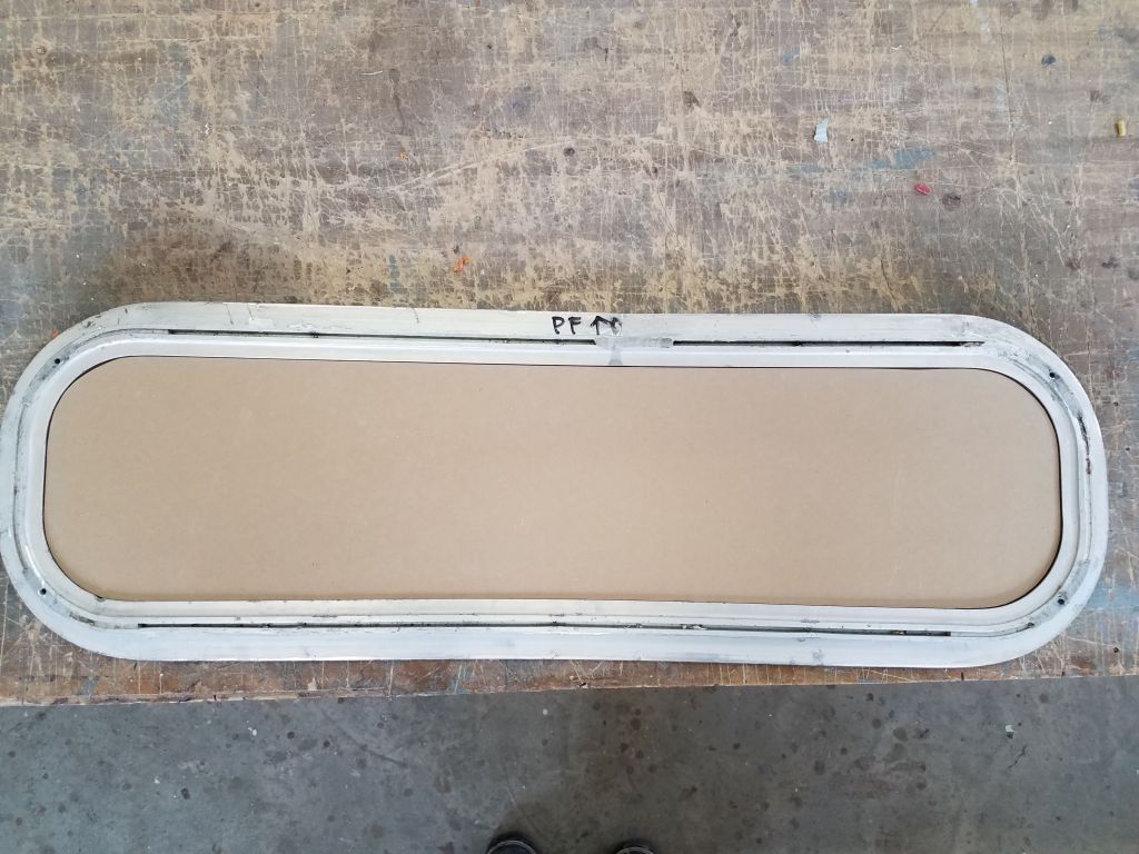
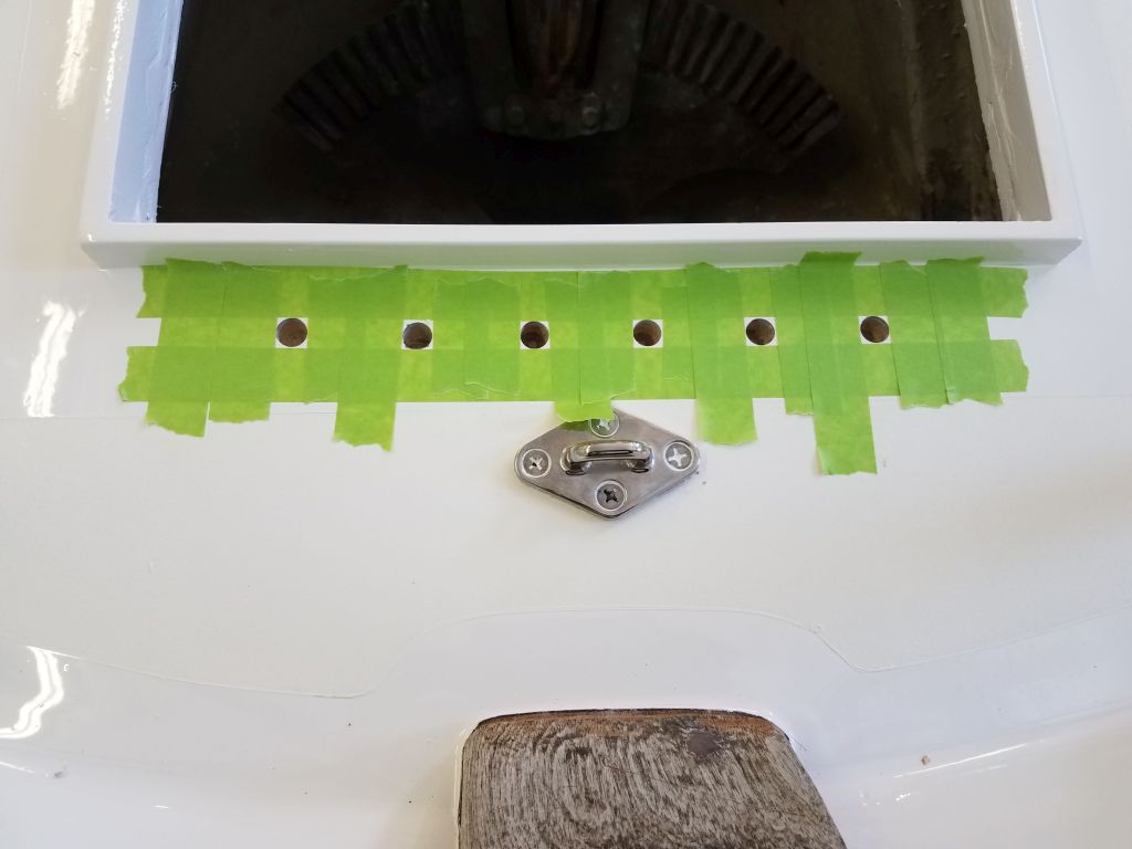
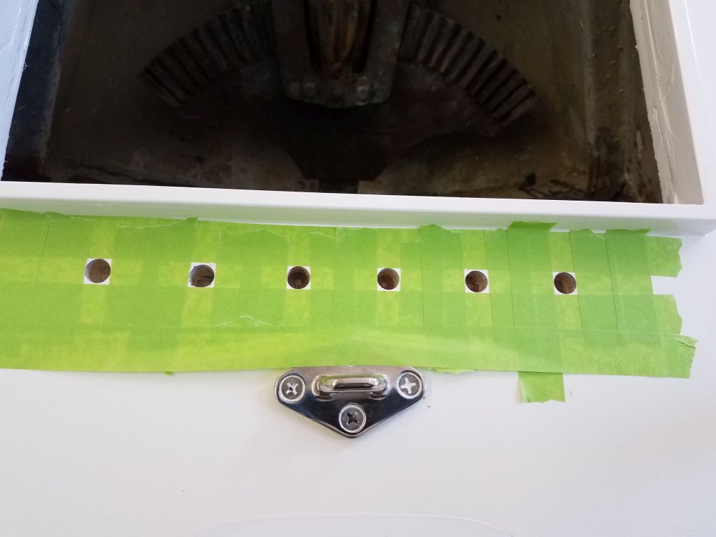
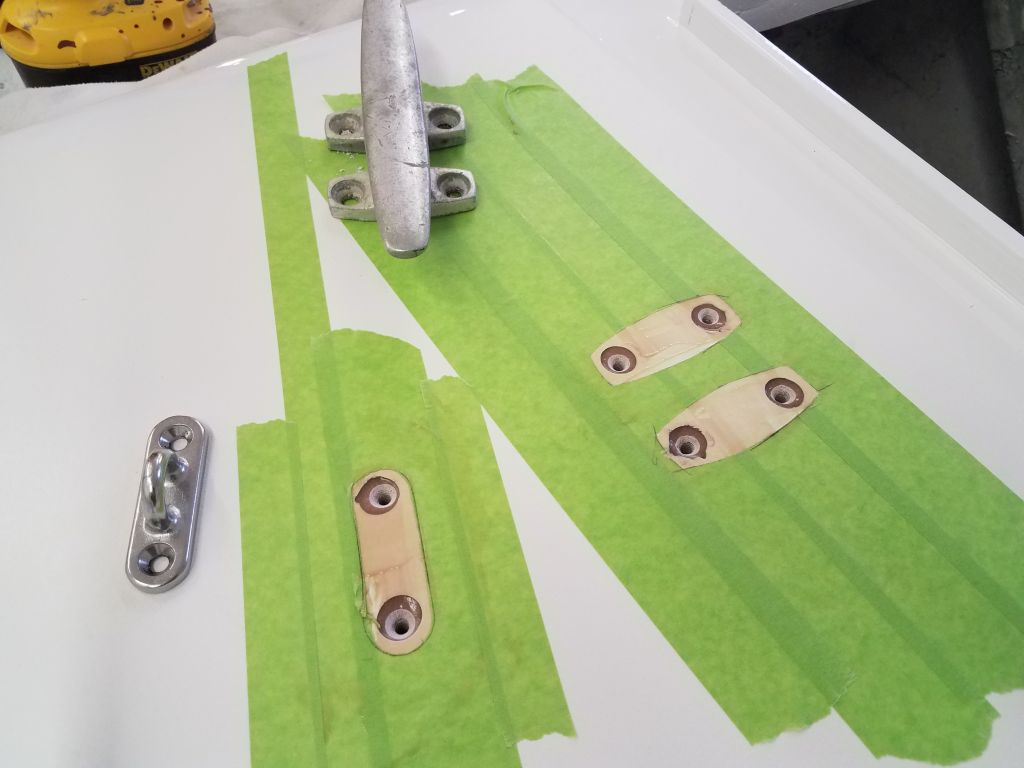
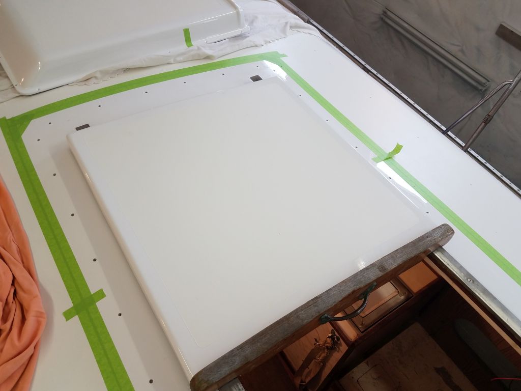
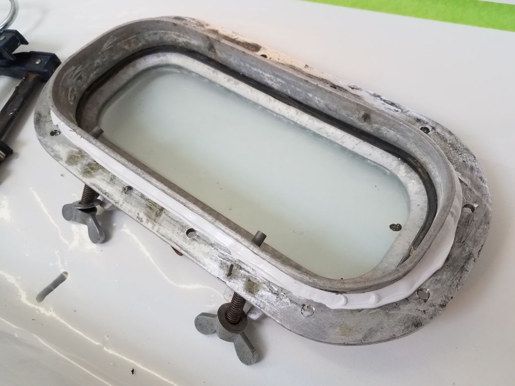
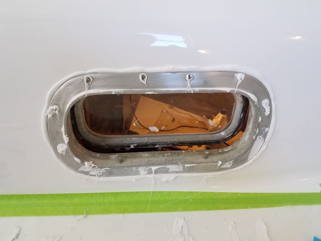
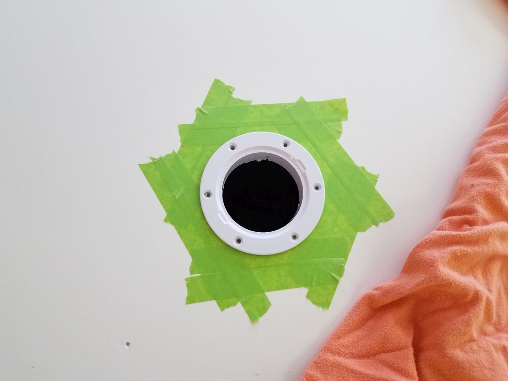
After cleaning the raw frames one final time, I prepared for final installation of the lenses.  For each lens, I trimmed the protective paper on the back (inside) side where the frame overlapped, exposing the plastic in the bonding area but leaving the paper in place elsewhere.

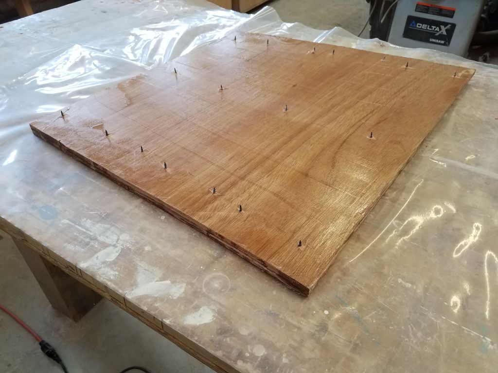
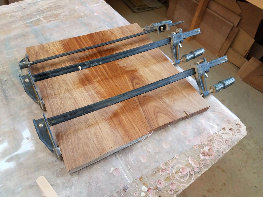
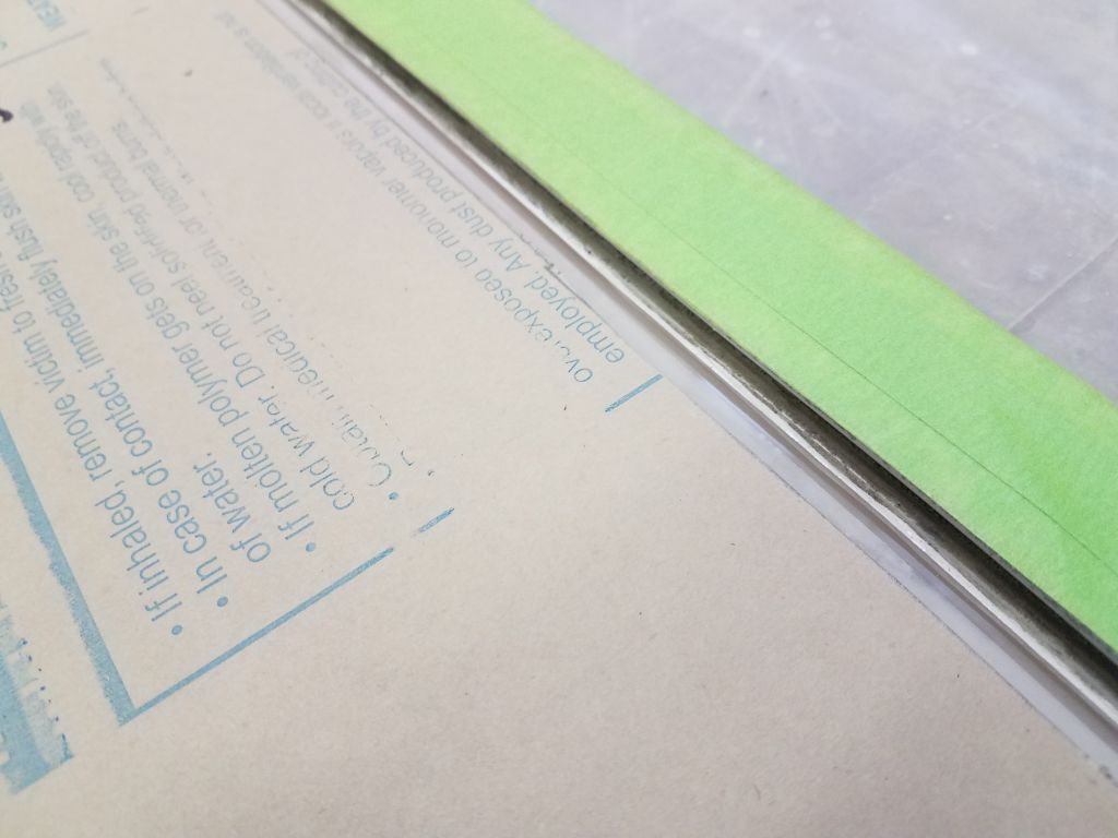
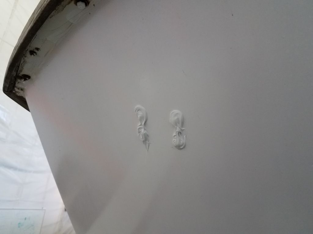
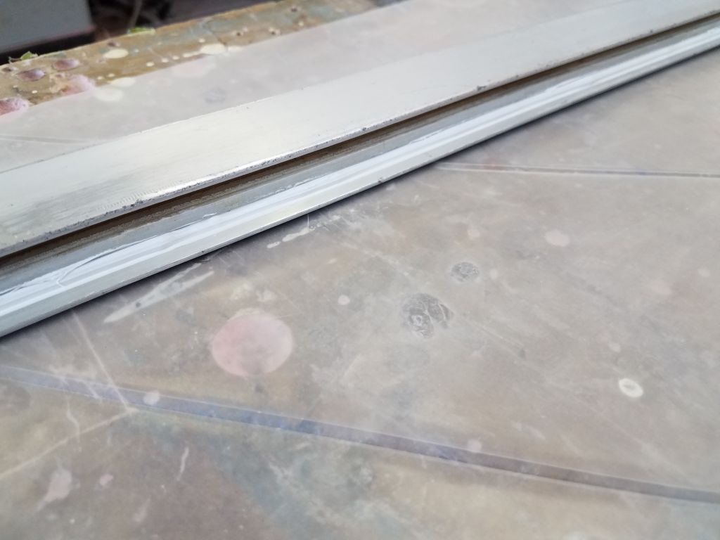
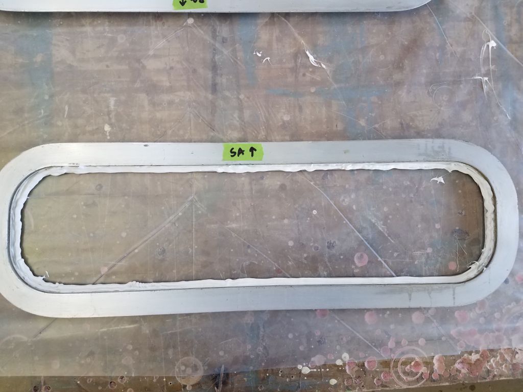
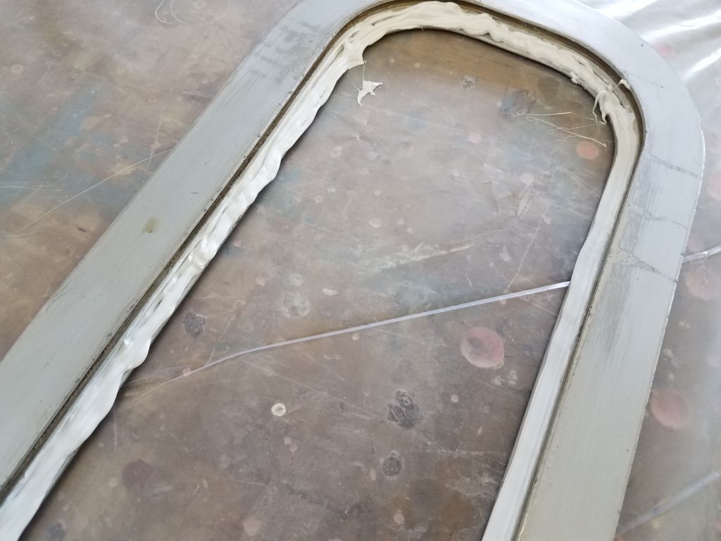
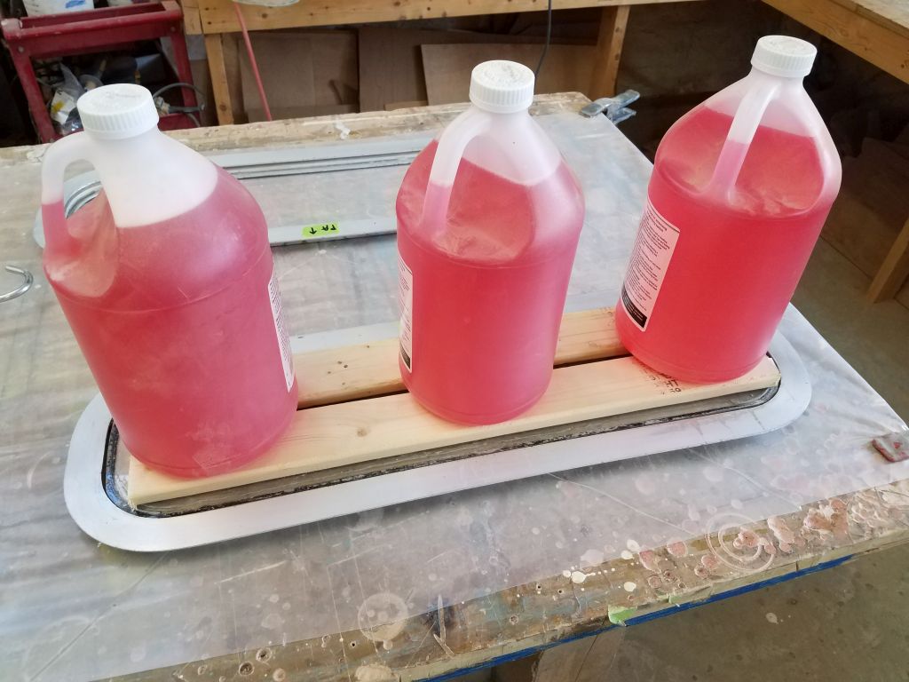
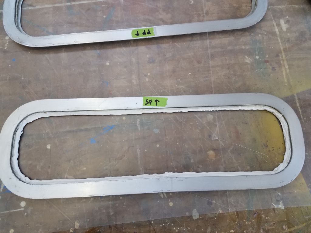
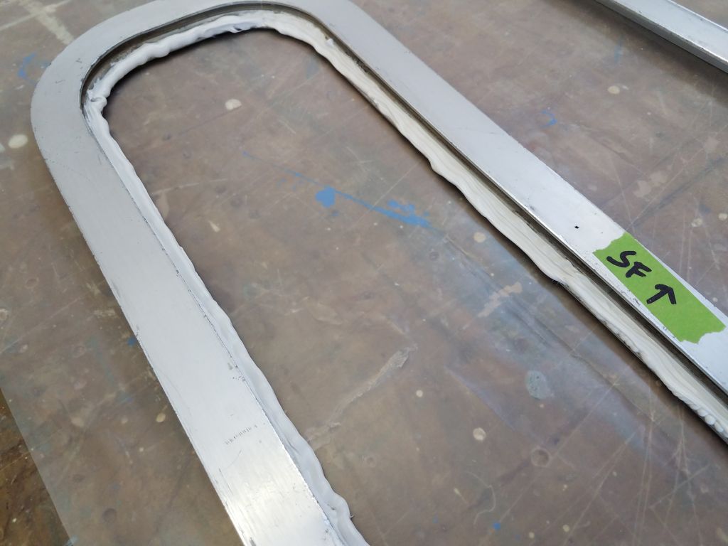
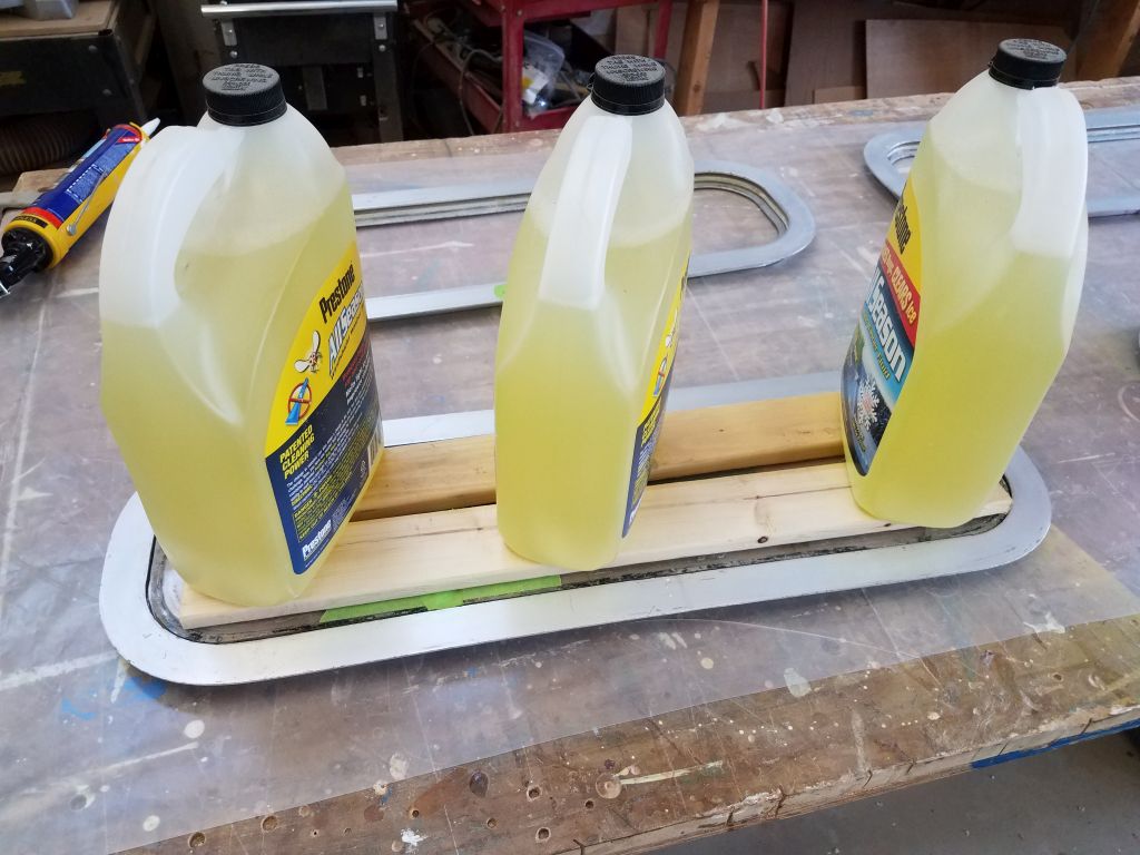
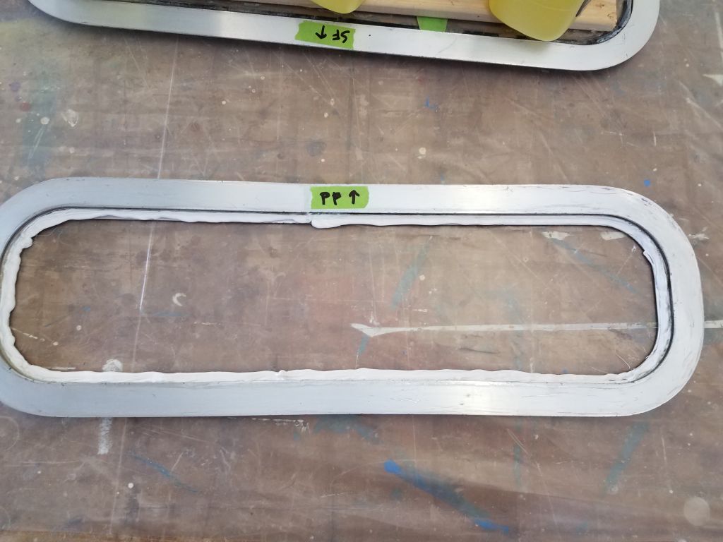
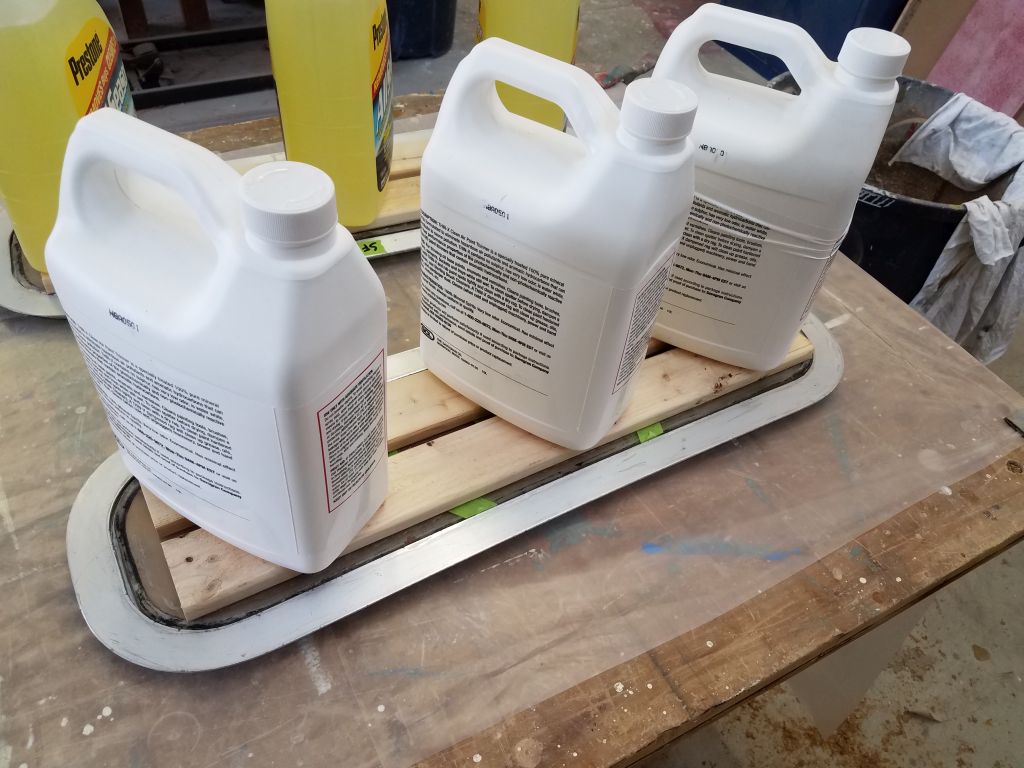
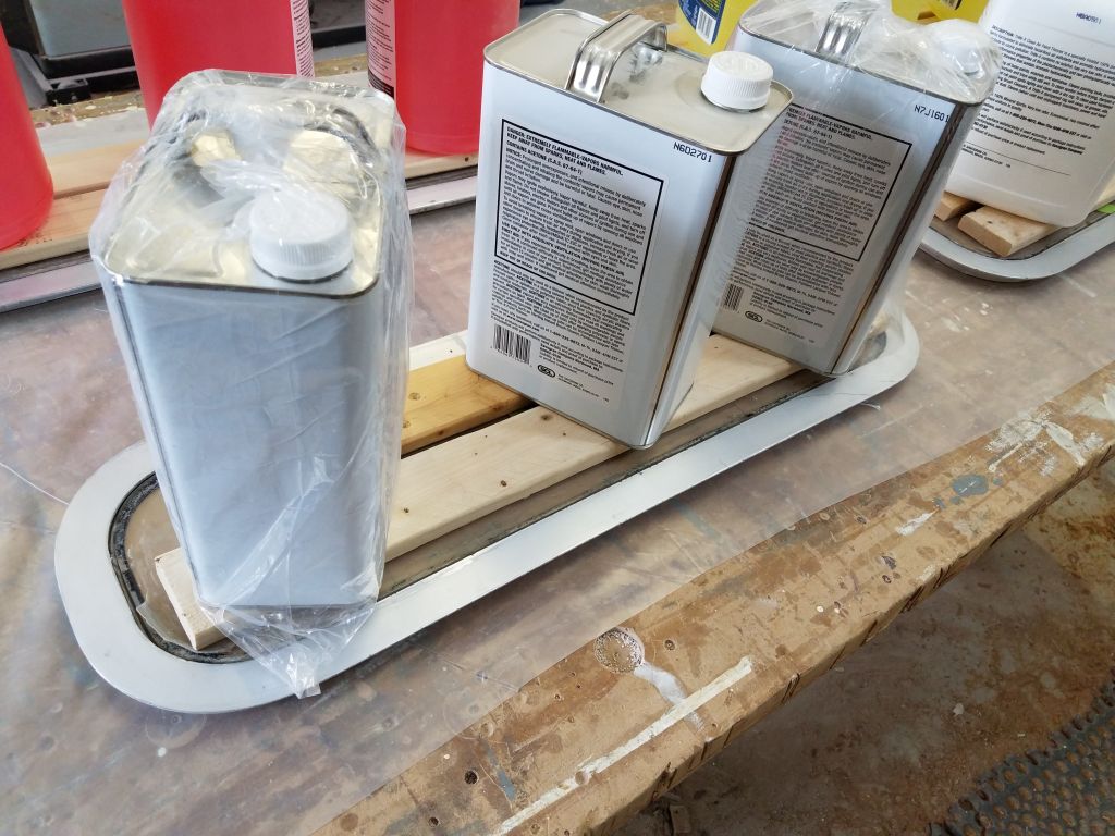
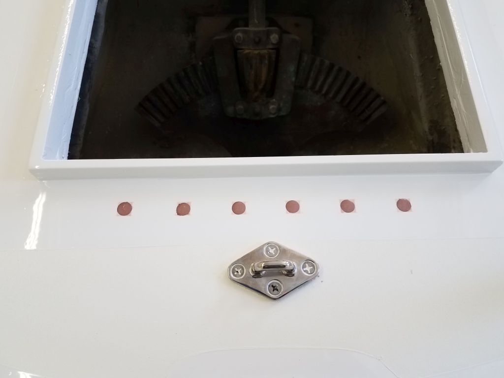
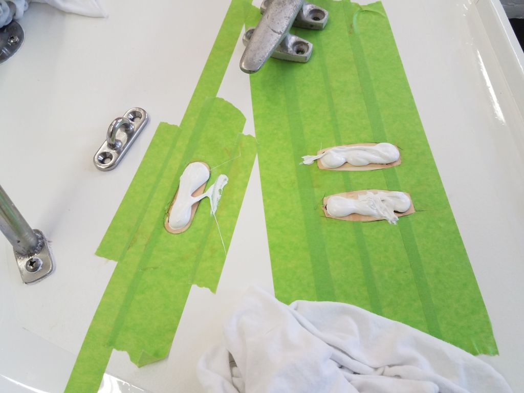
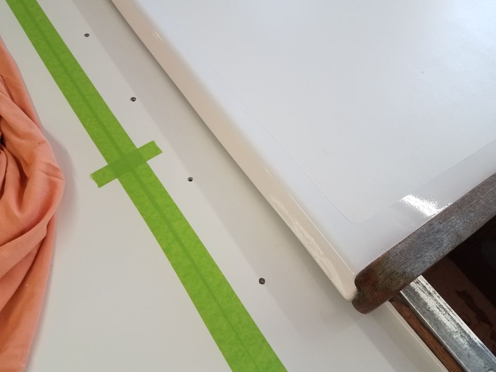
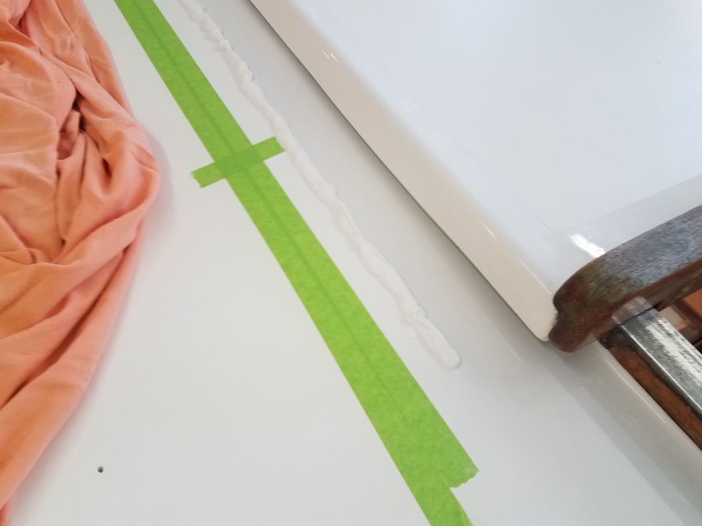
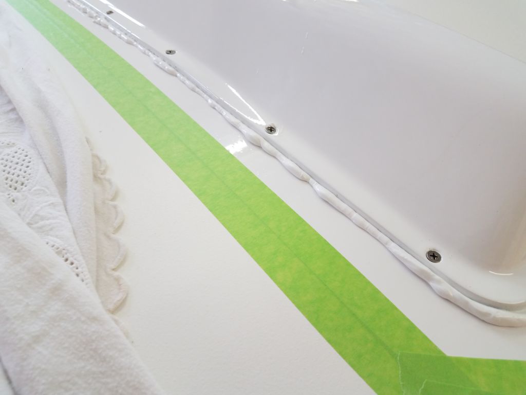
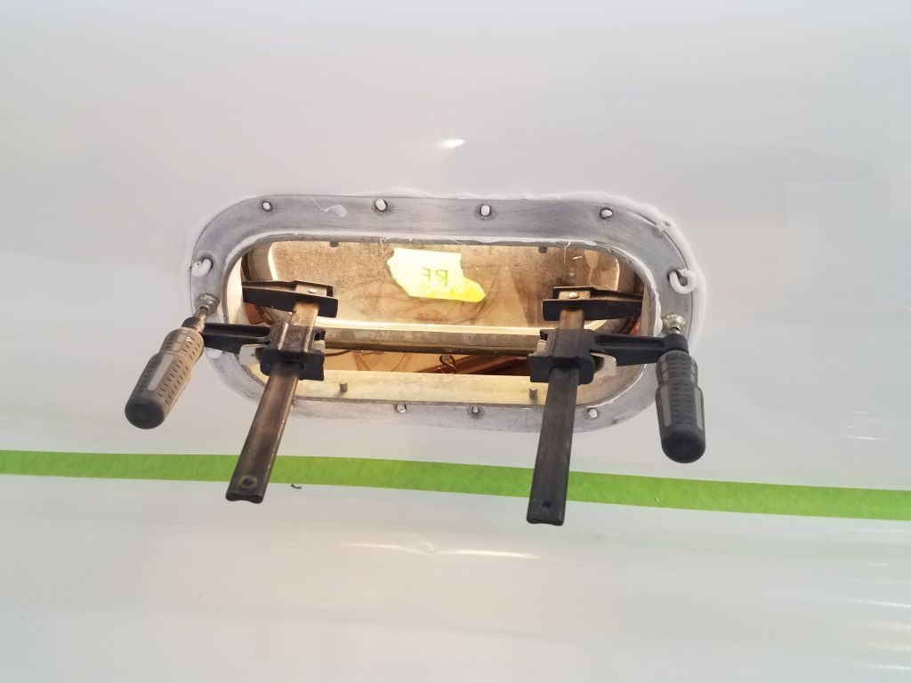
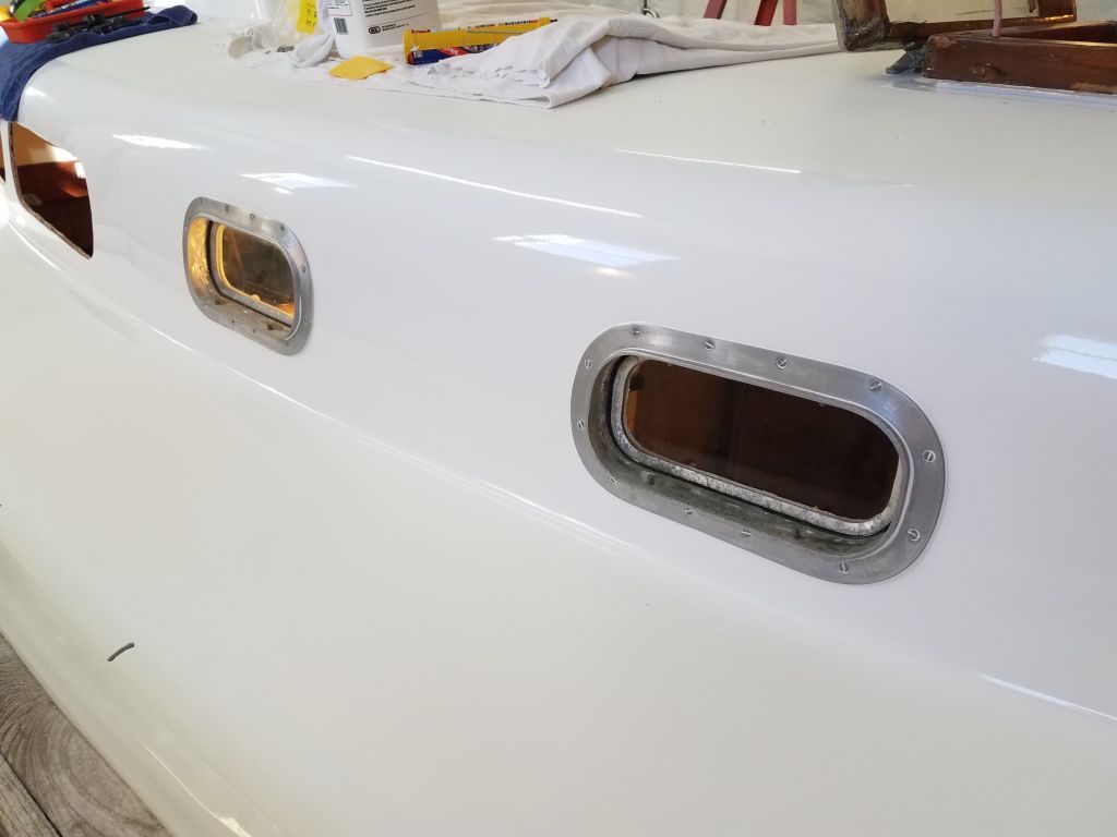
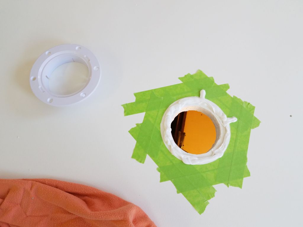
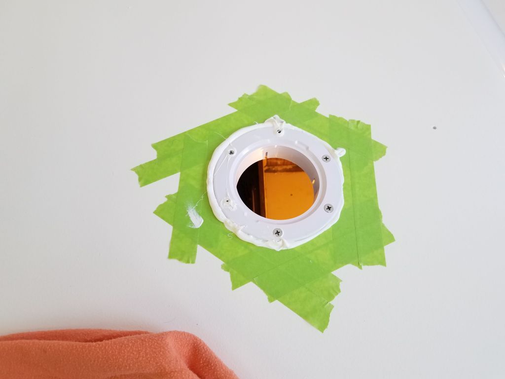
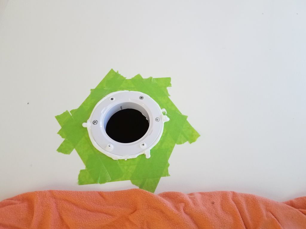
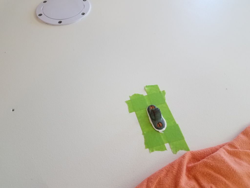
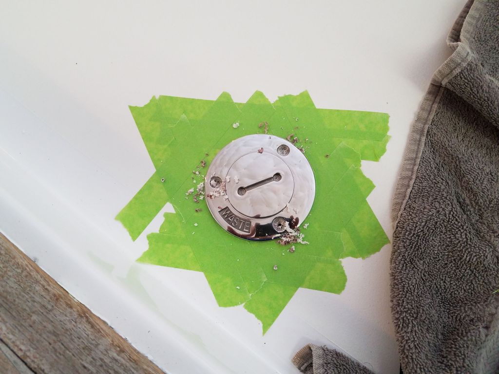
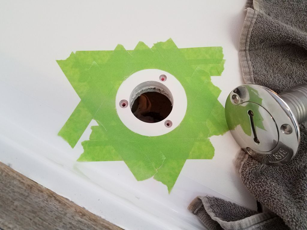
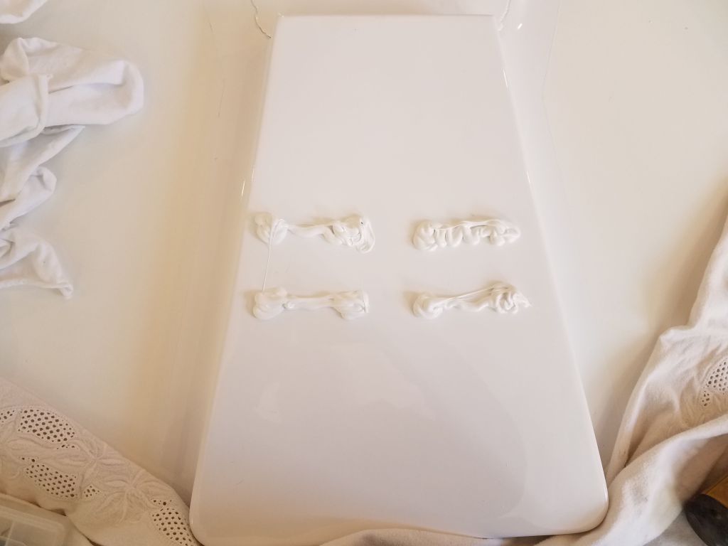
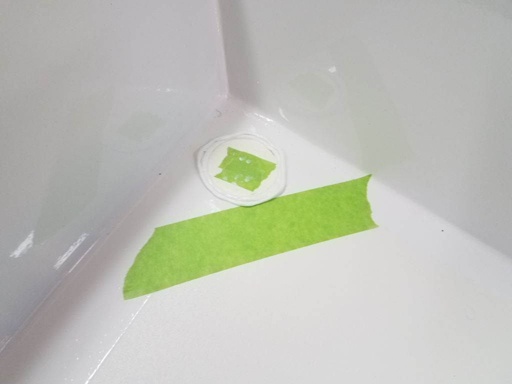
In these frames, the lenses relied on a bond between the lens and the frame only.  The original setup had rubber gaskets pressed into grooves inside the frame, but I planned to use modern flexible adhesives for the job.  For each installation, I first applied the sealant–a polyurethane–into the innermost groove of the frame, filling it with sealant.  Then, I applied sealant over the bonding flange, and pressed the new lens firmly into place.  To ensure the lens didn’t move during curing, I added some weight over the lens to hold it in place securely.  I repeated this process for each of the four lenses.  Later on, I’d finish the job by applying more sealant on the outside, filling the second groove and creating an external cosmetic-only bead for improved appearance.

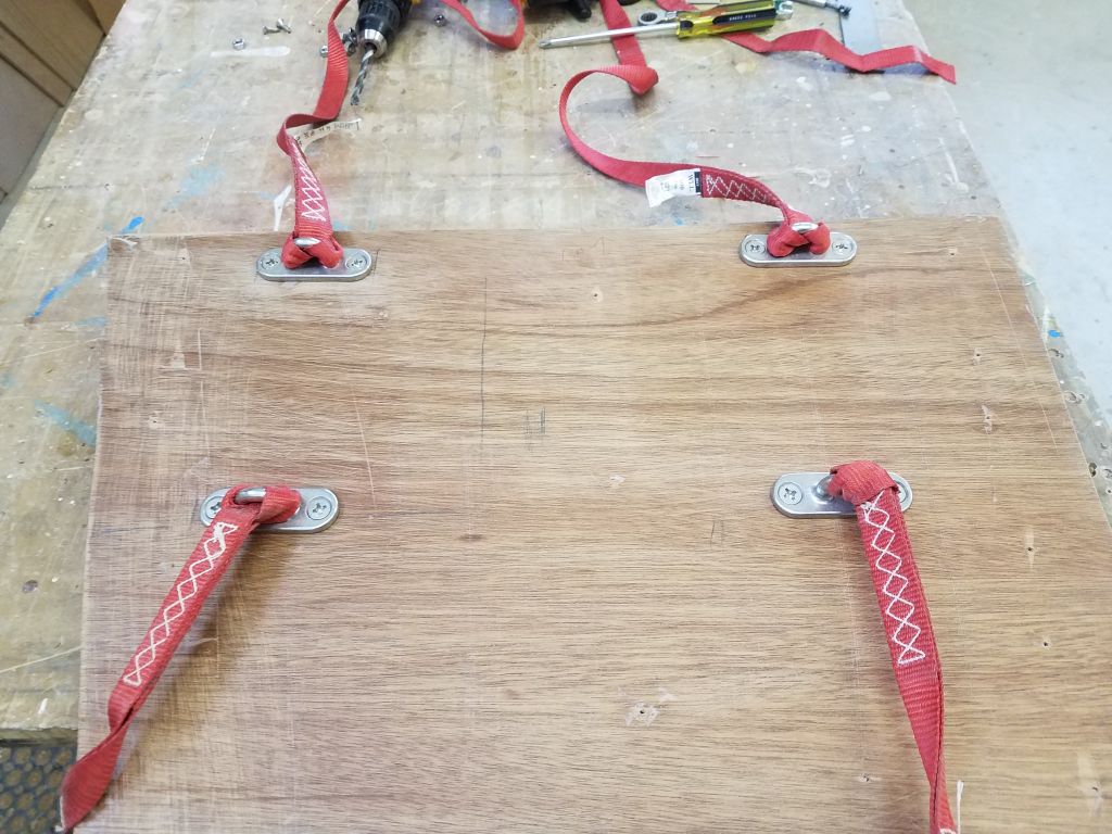
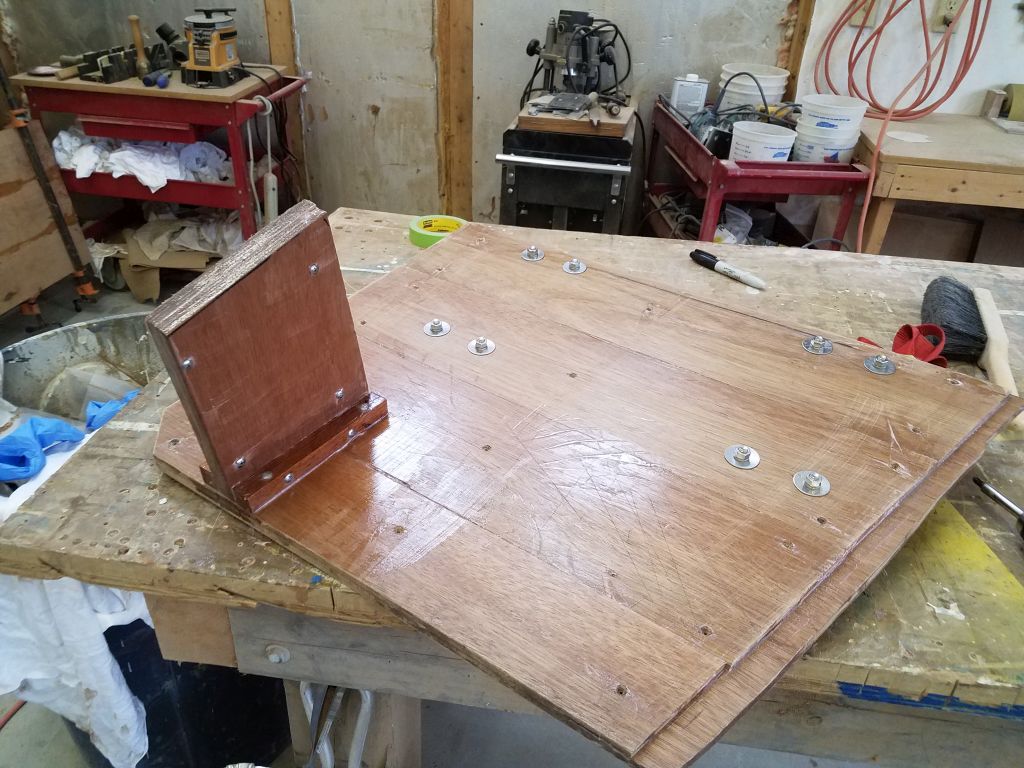
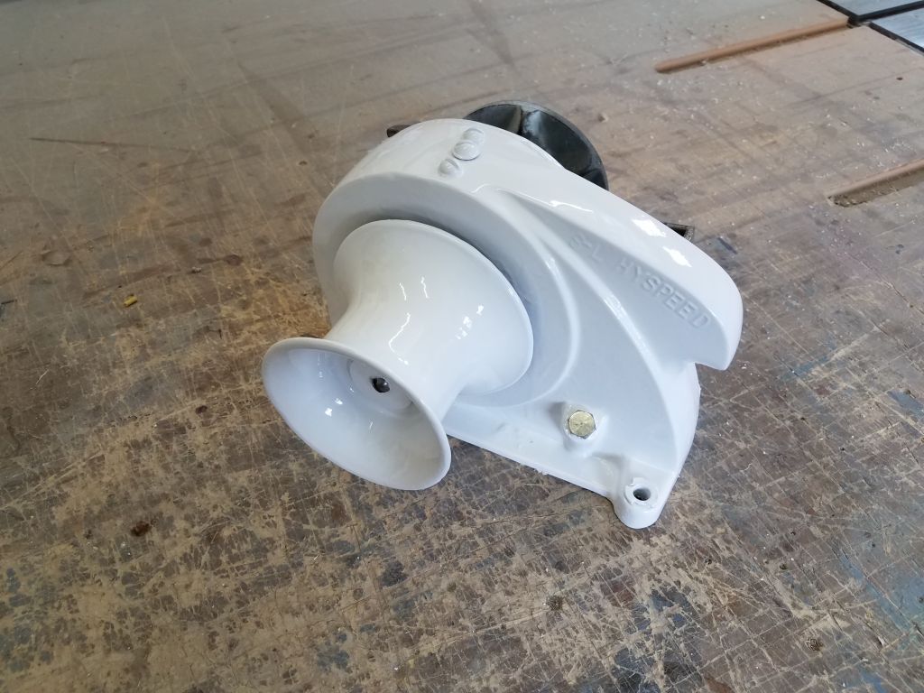
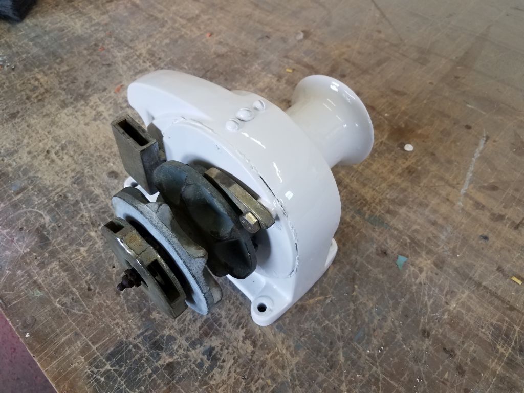
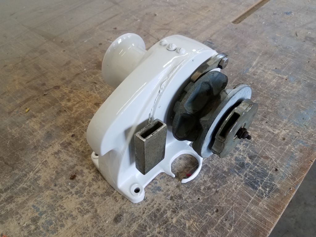
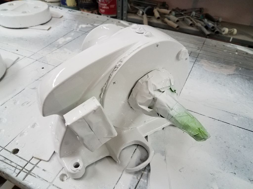
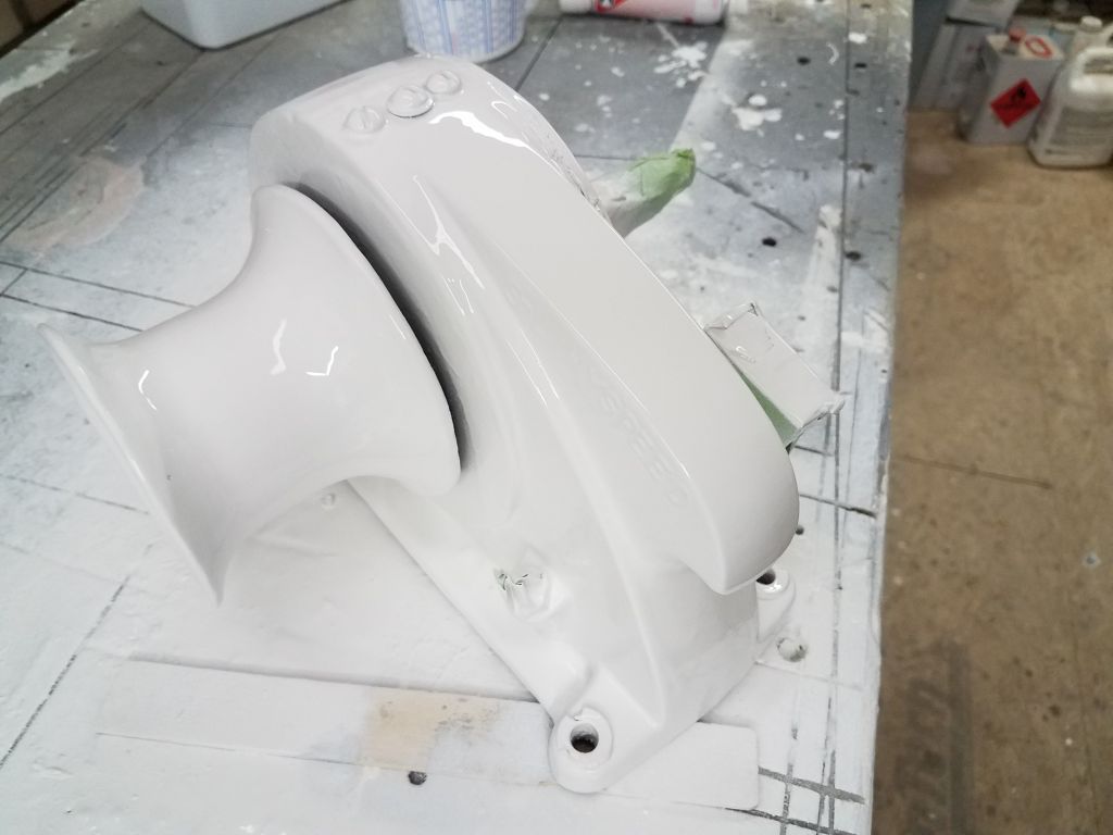
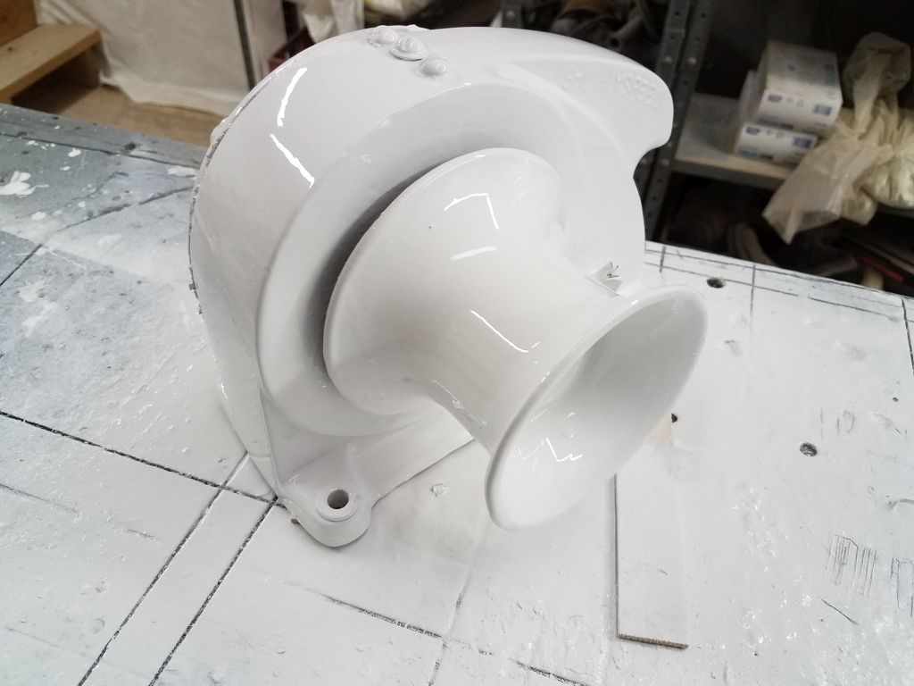
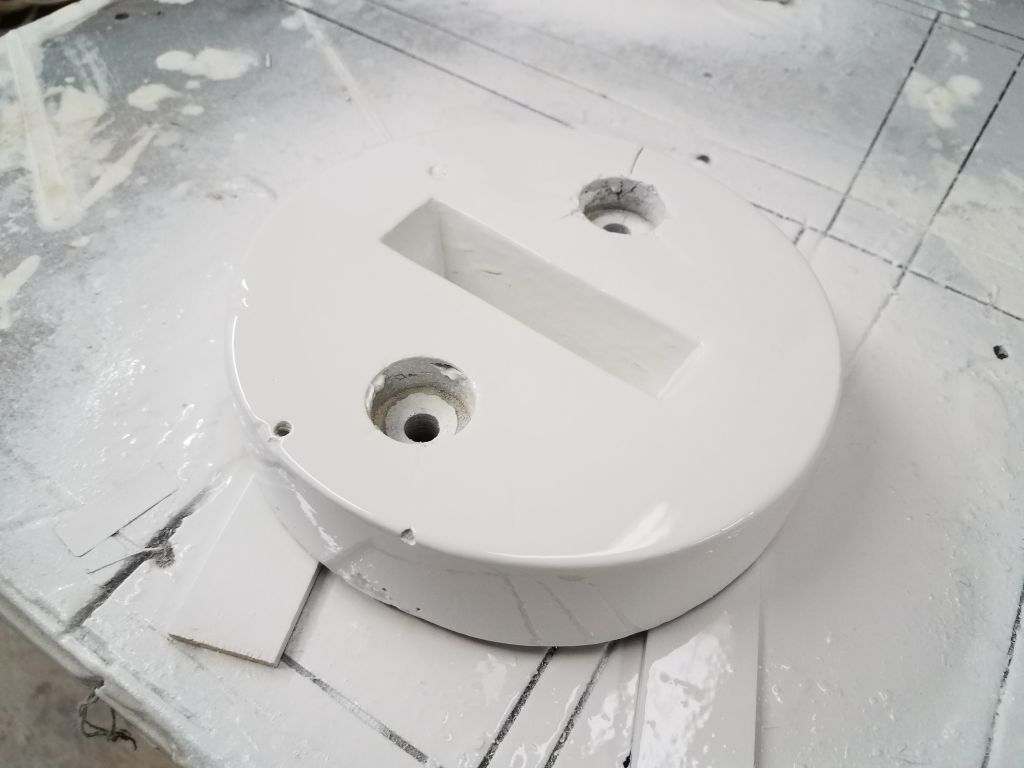
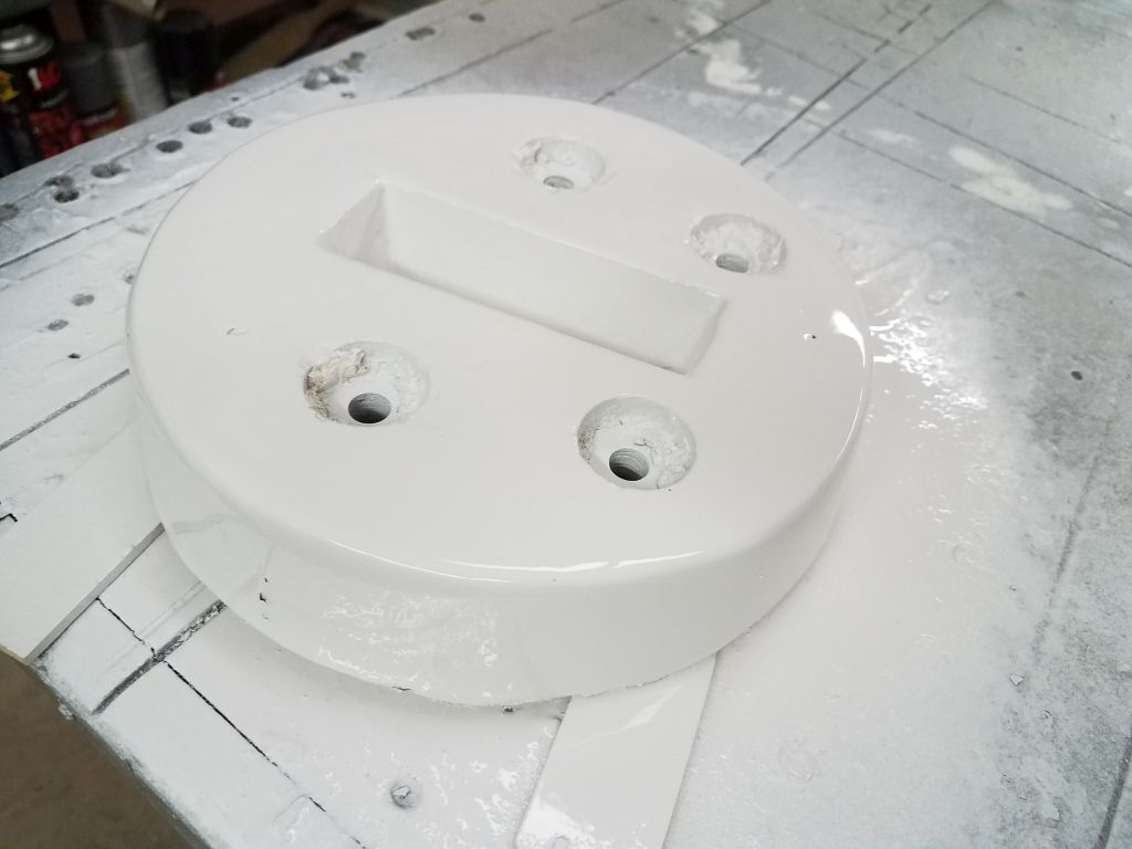
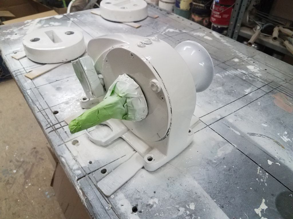
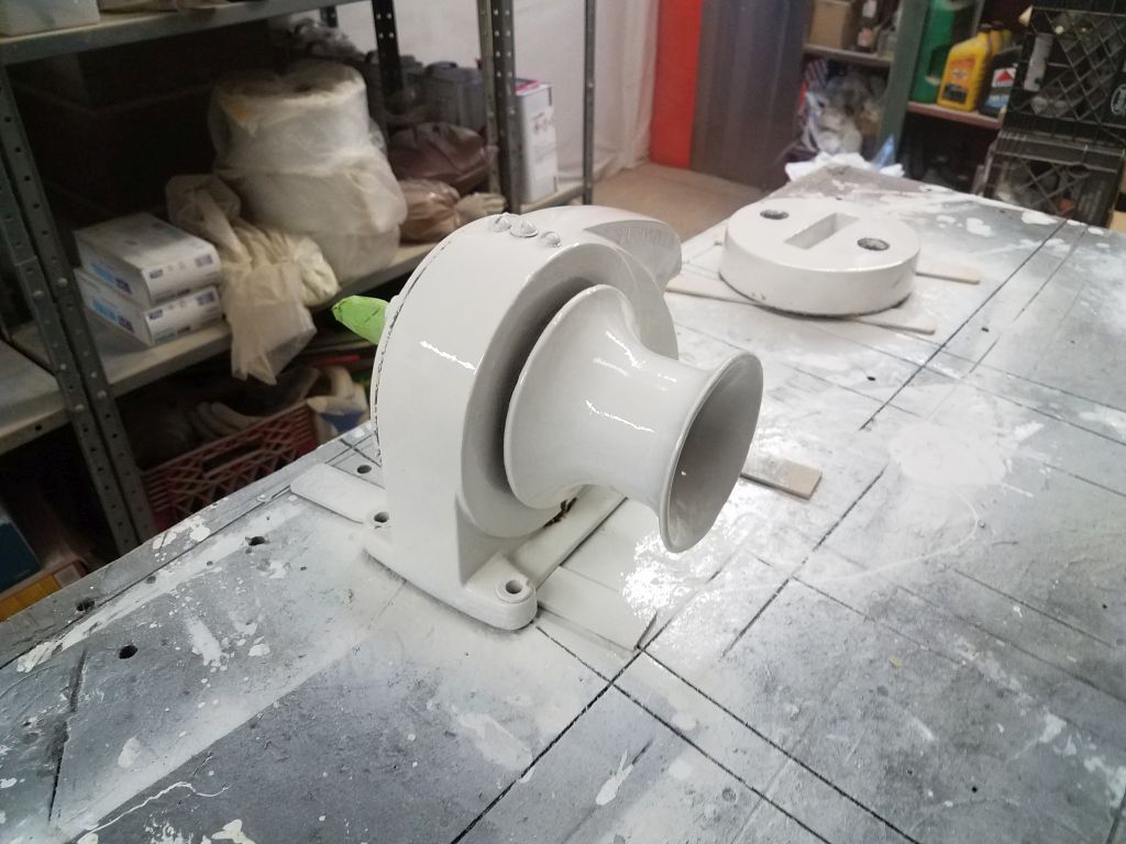
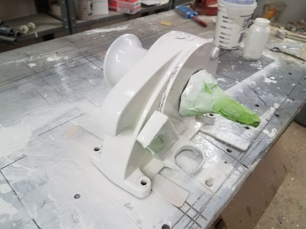
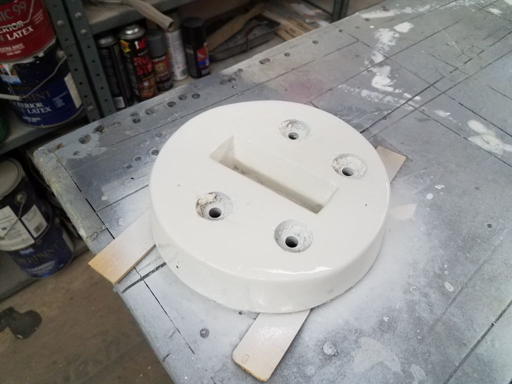
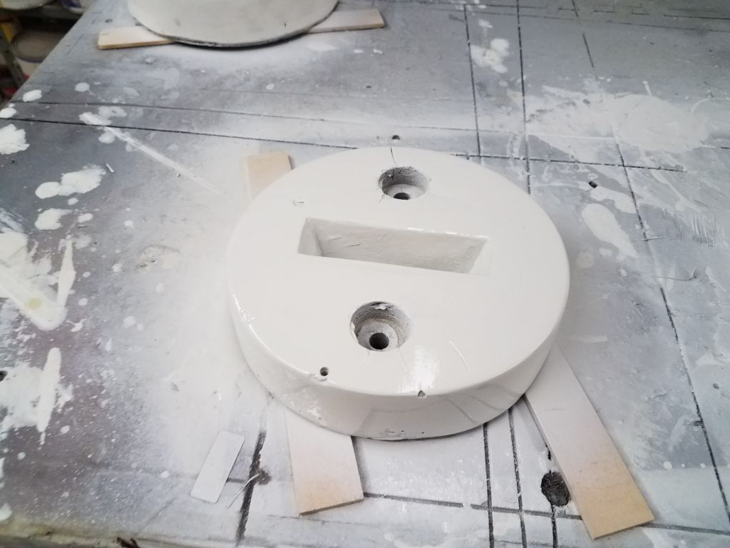
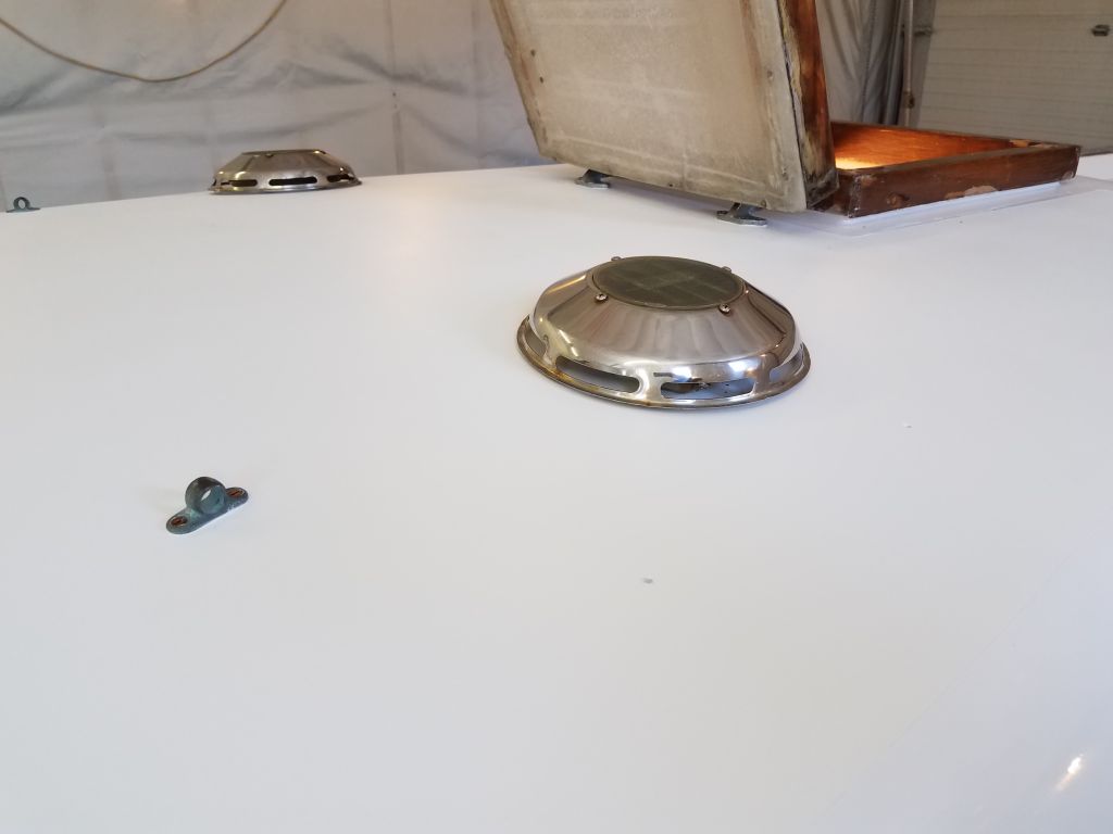
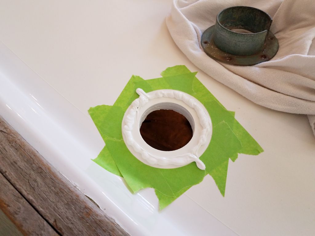
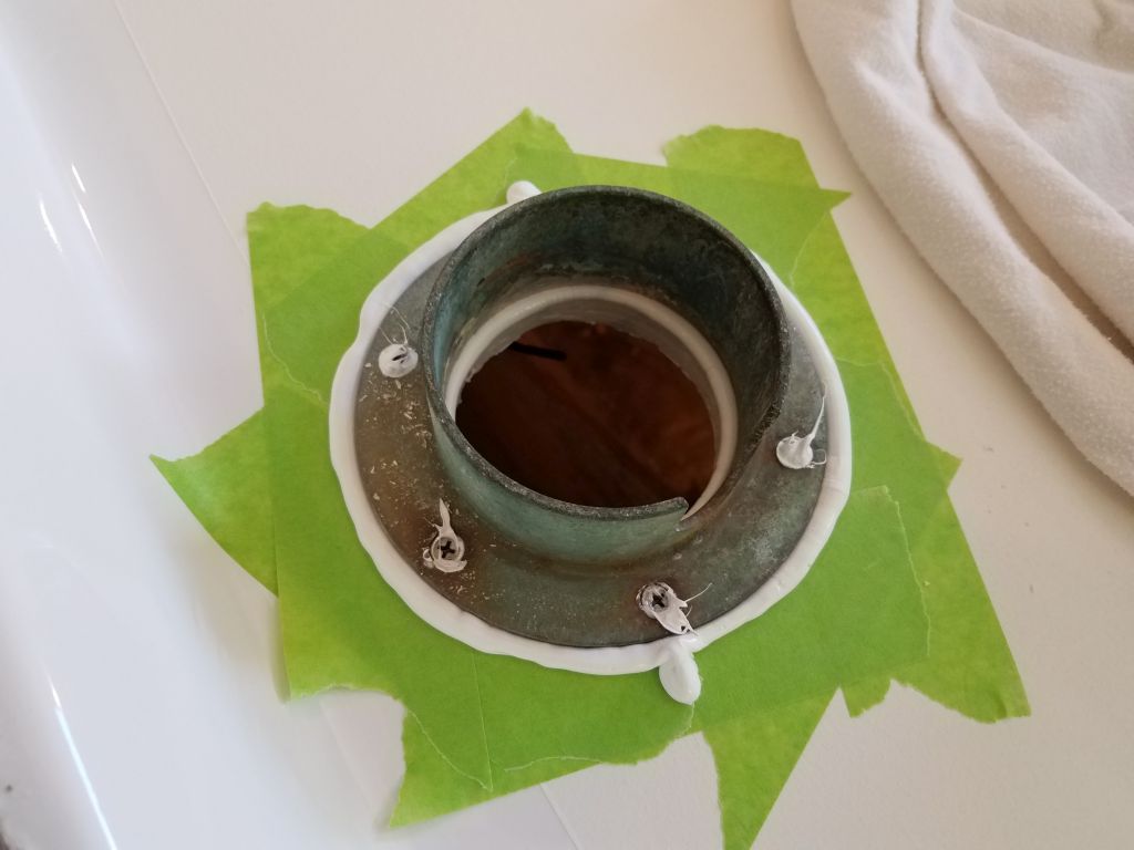
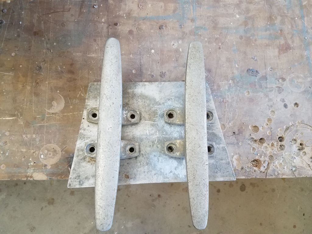
Throughout the day, I applied three coats of gloss white LPU to the anchor windlass and two mast step assemblies, using a little disposable spray gun.

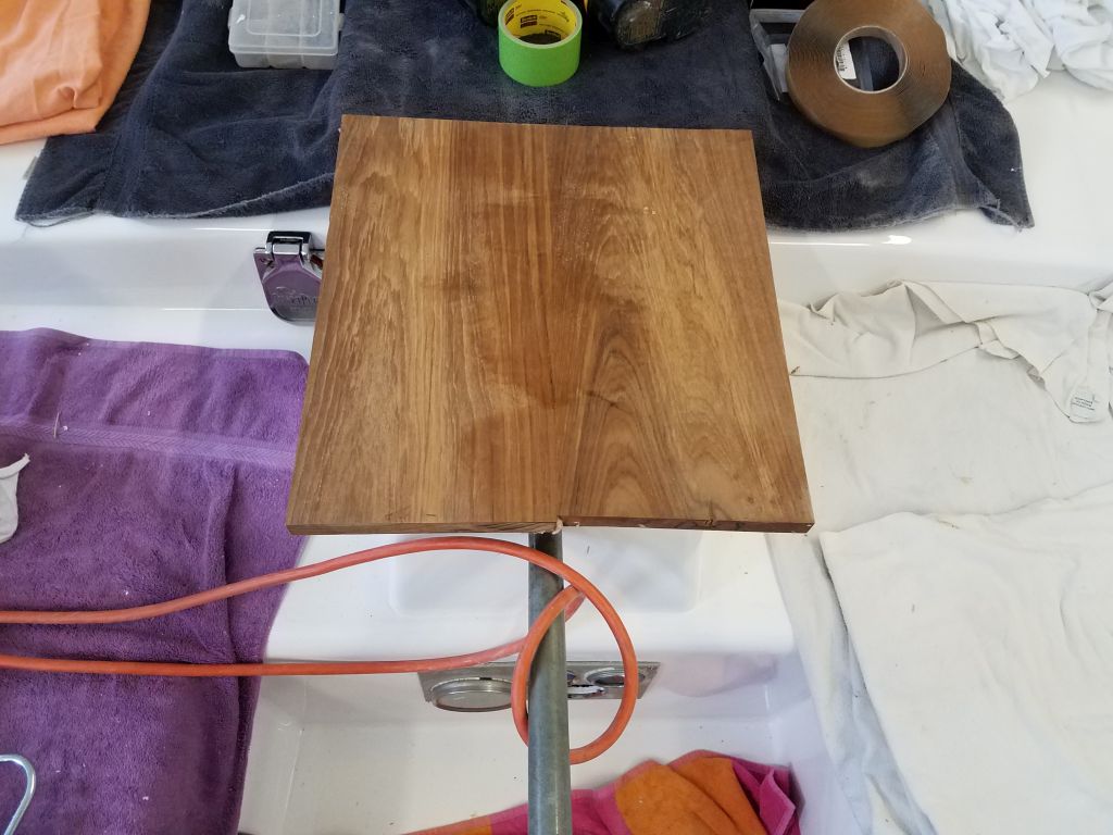
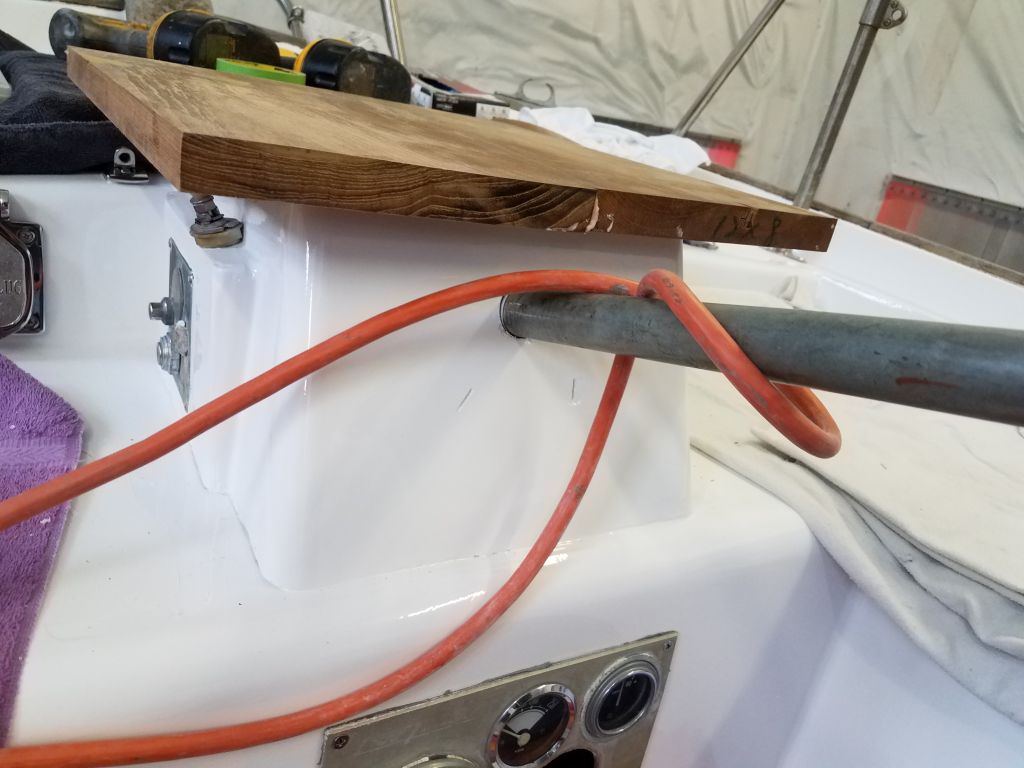
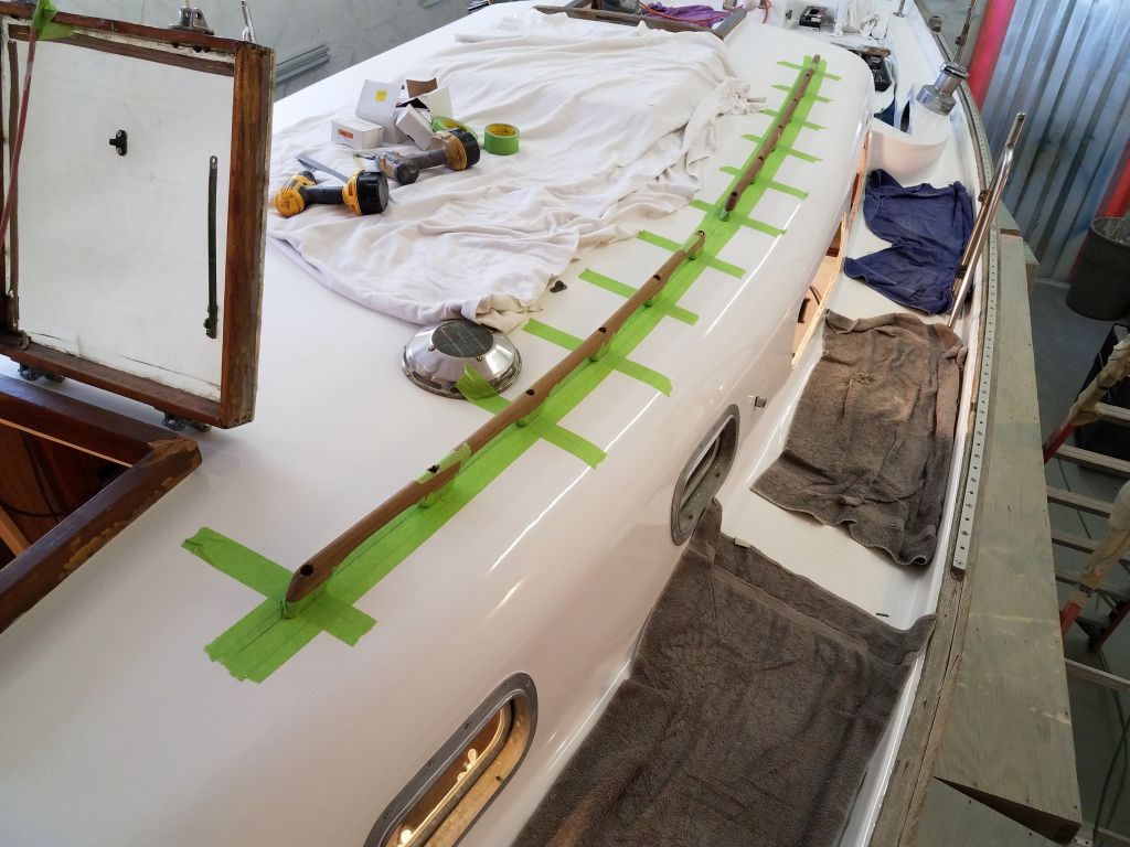
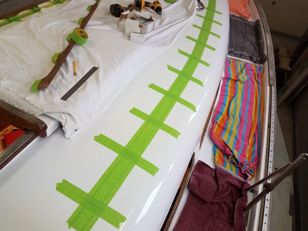
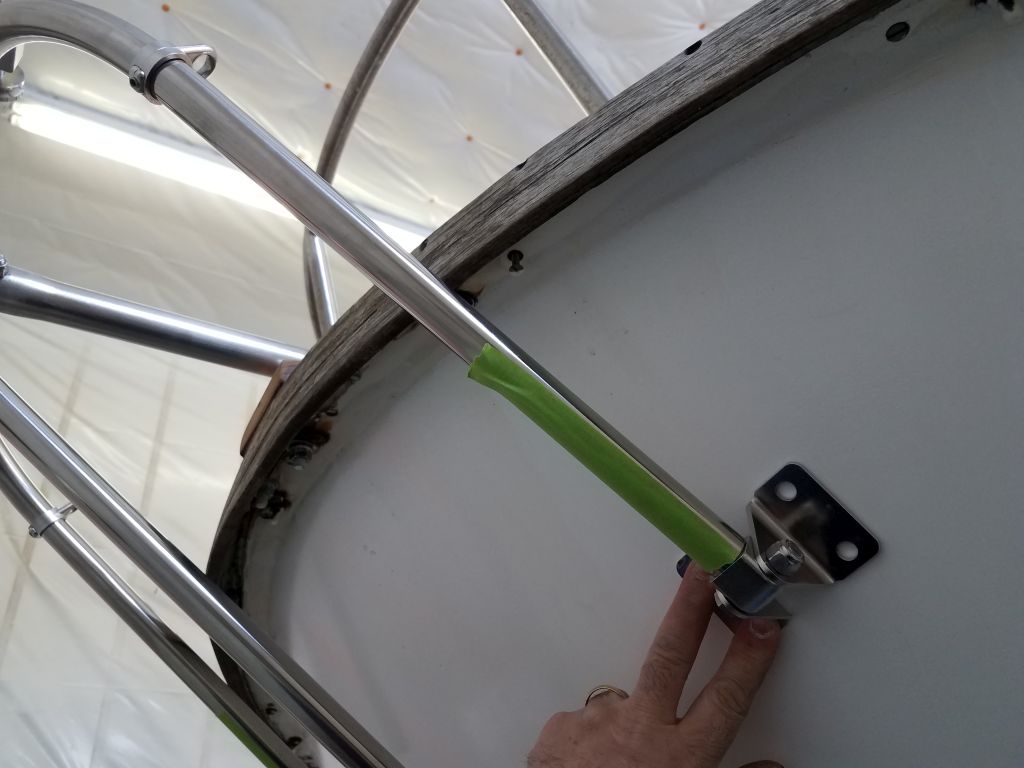
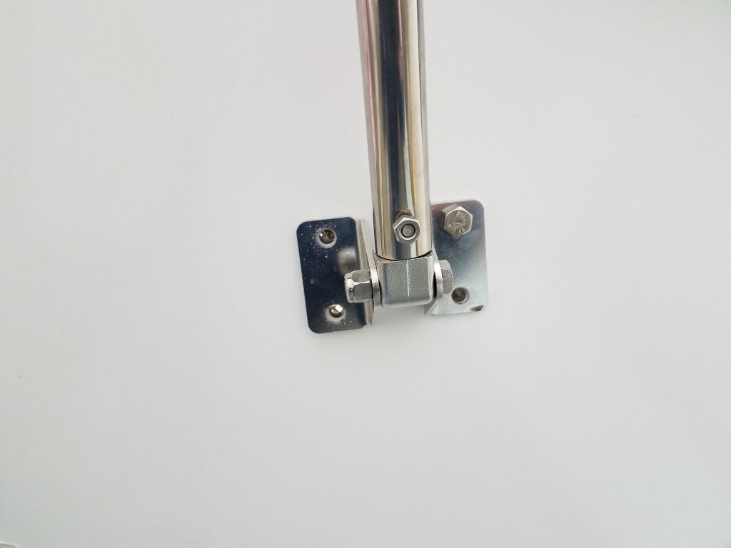
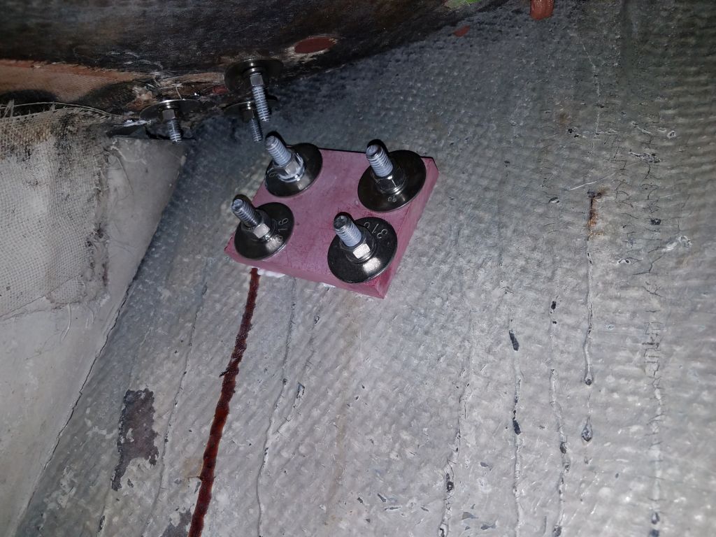
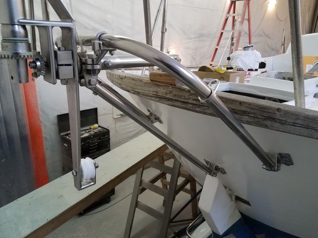
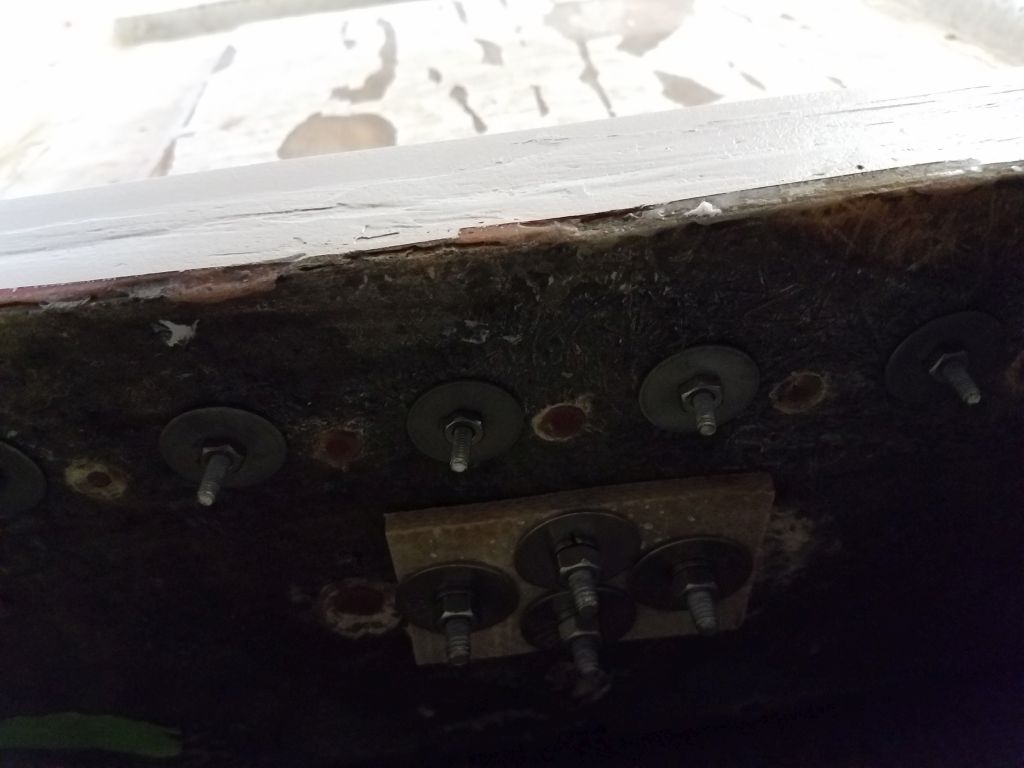
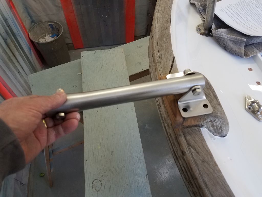
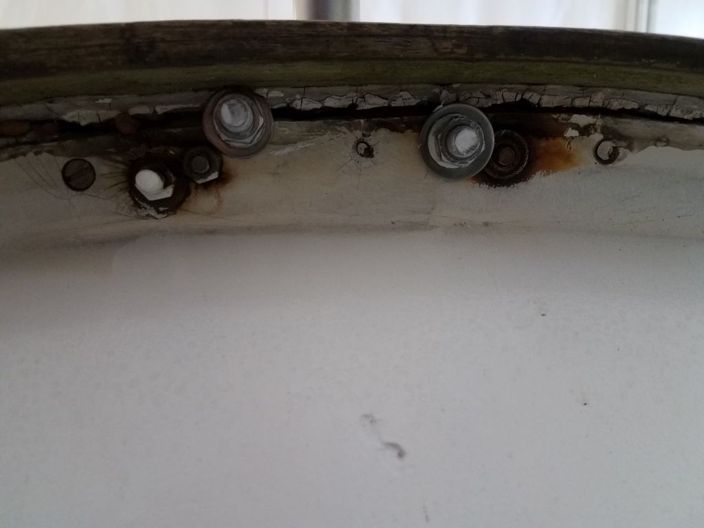
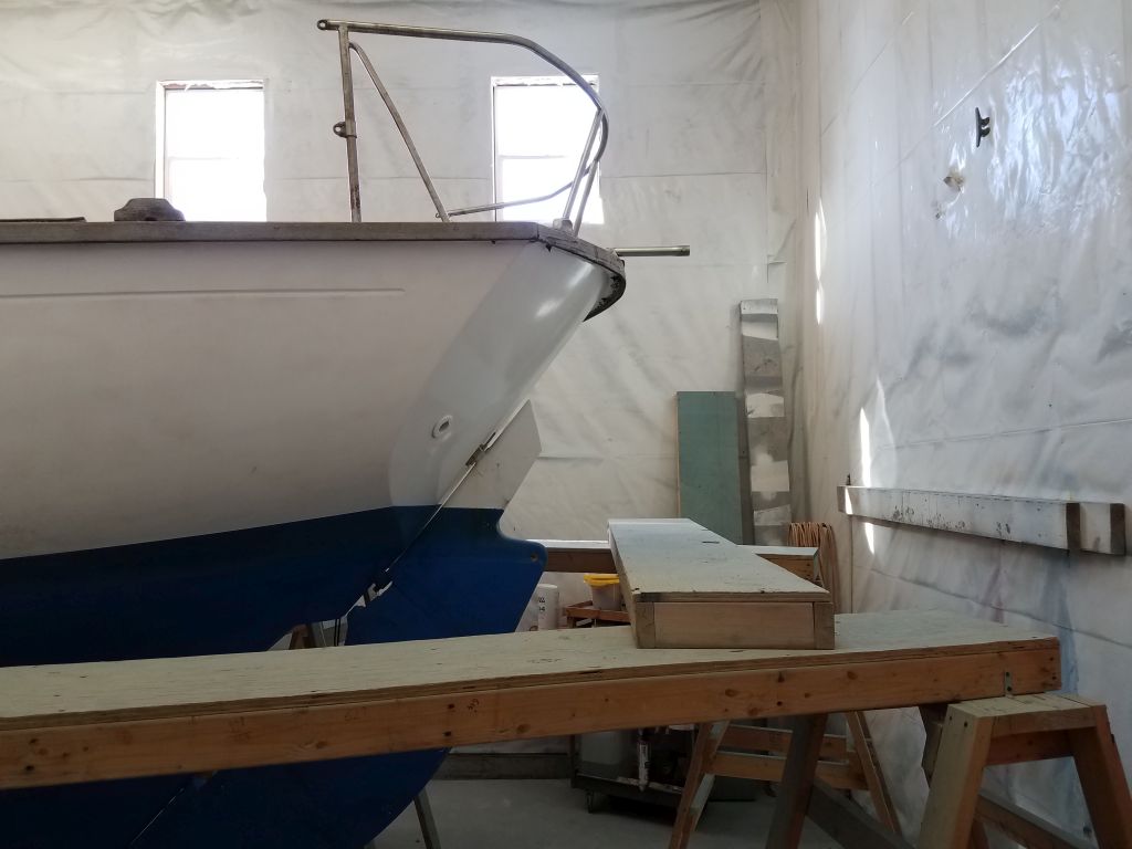
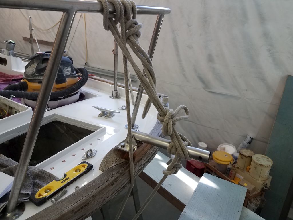
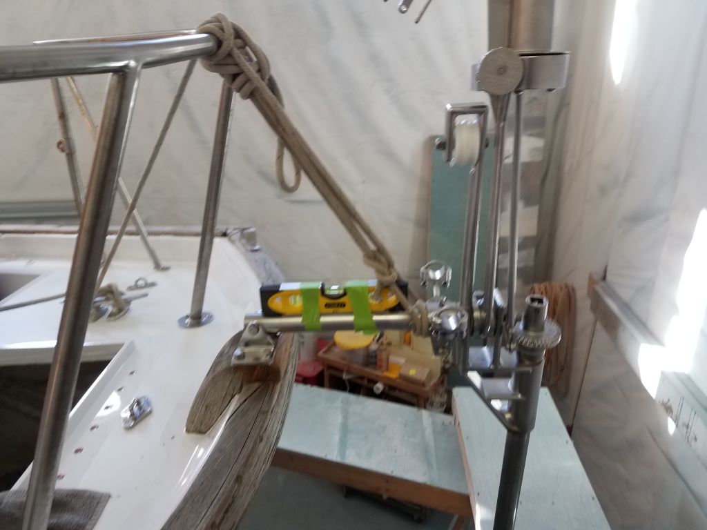
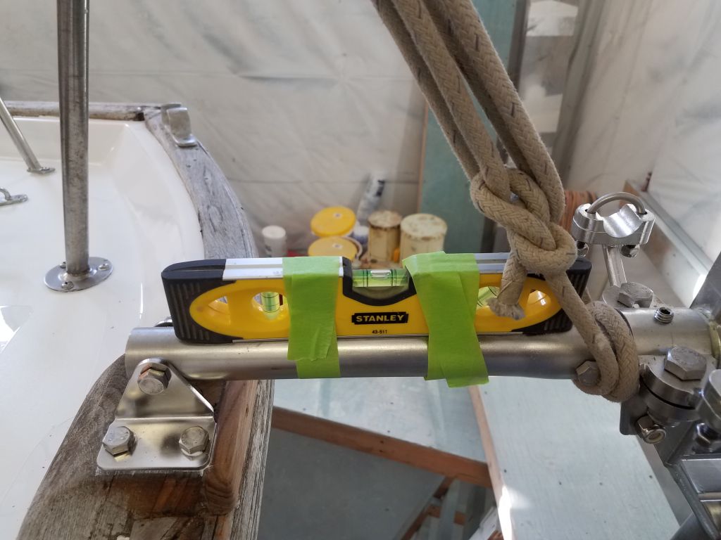
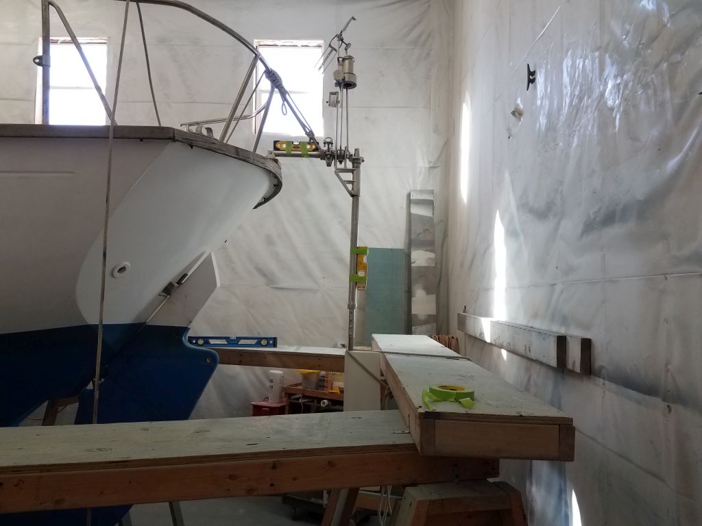
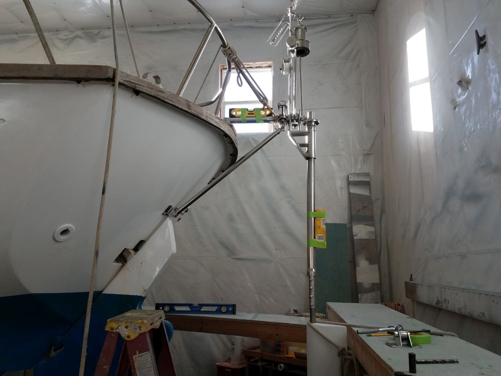
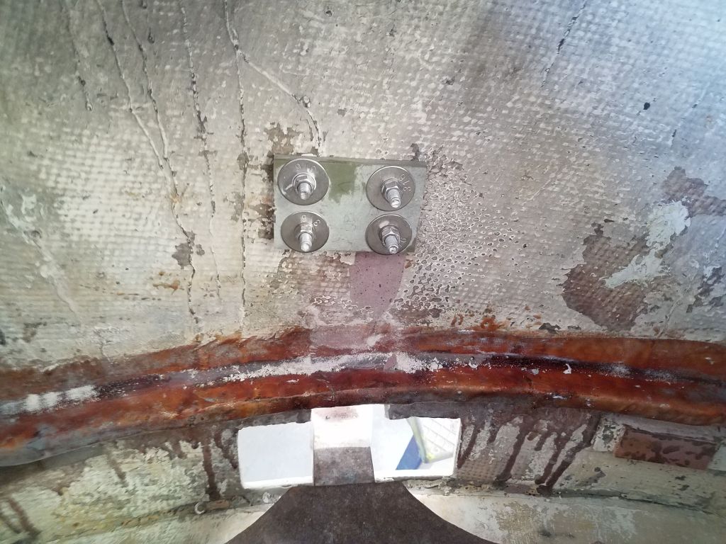
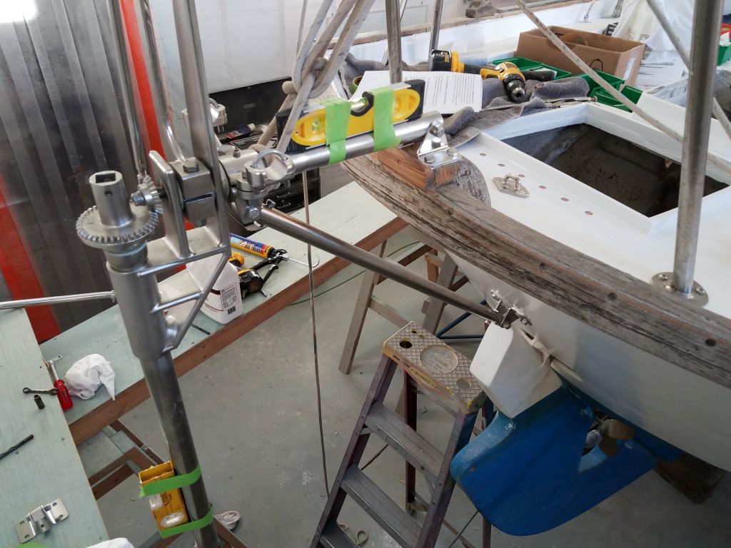
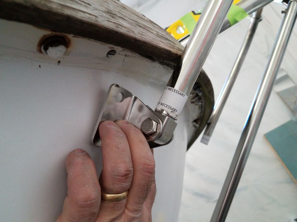
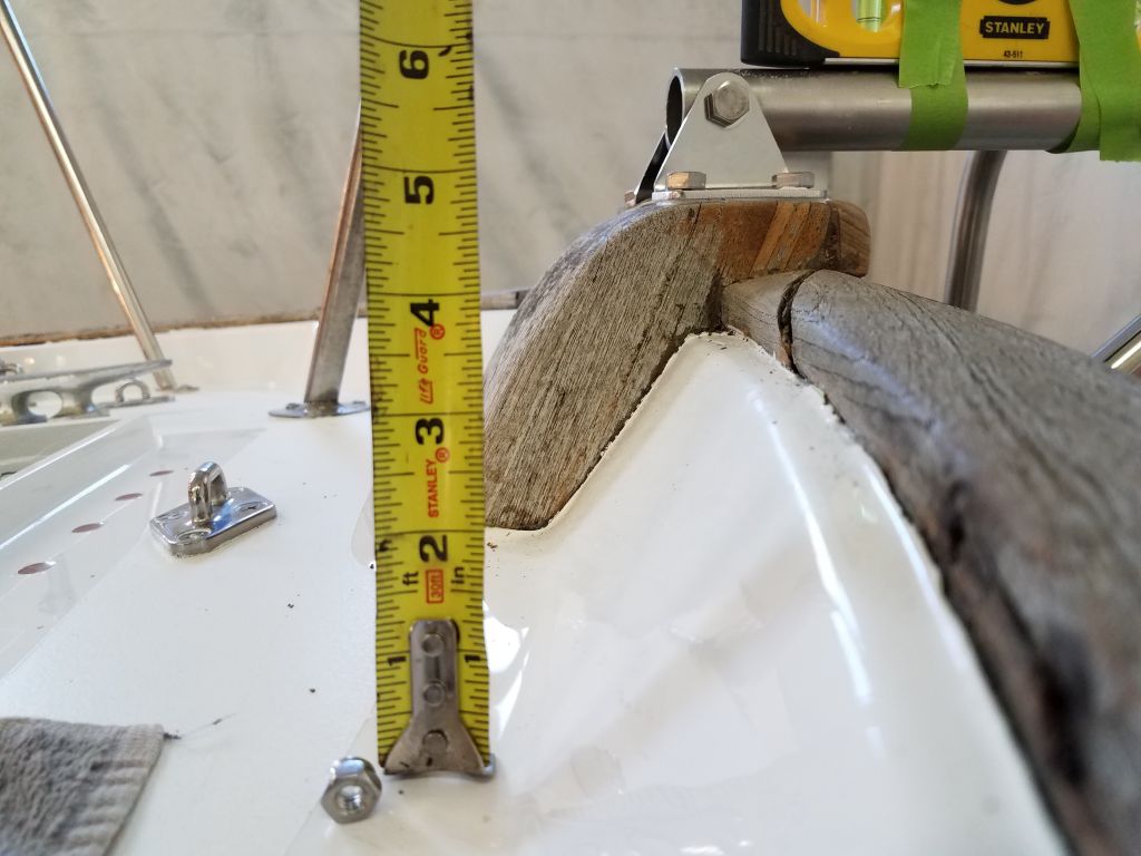
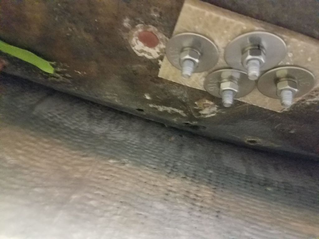
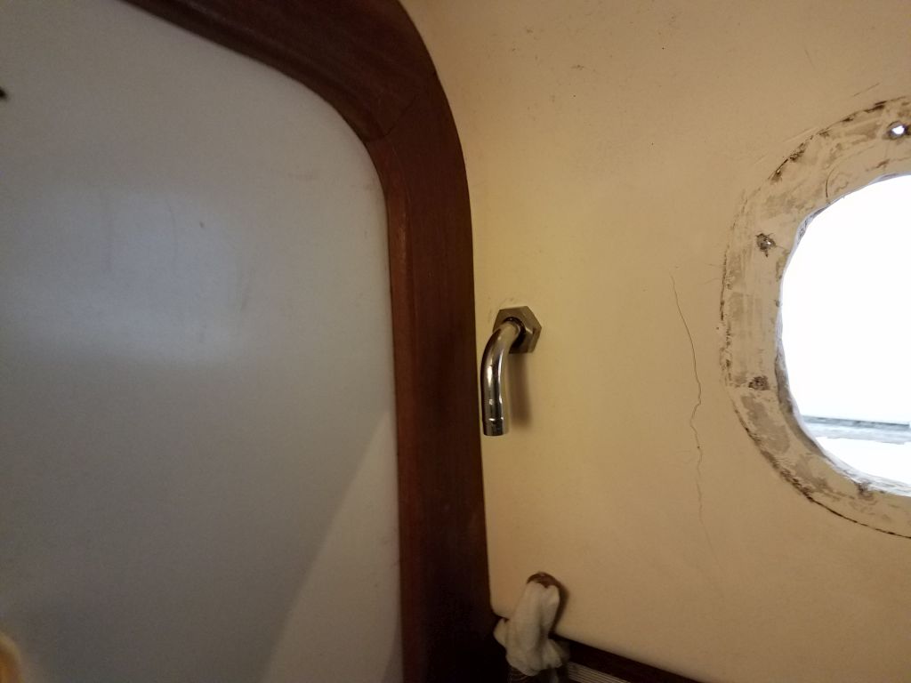
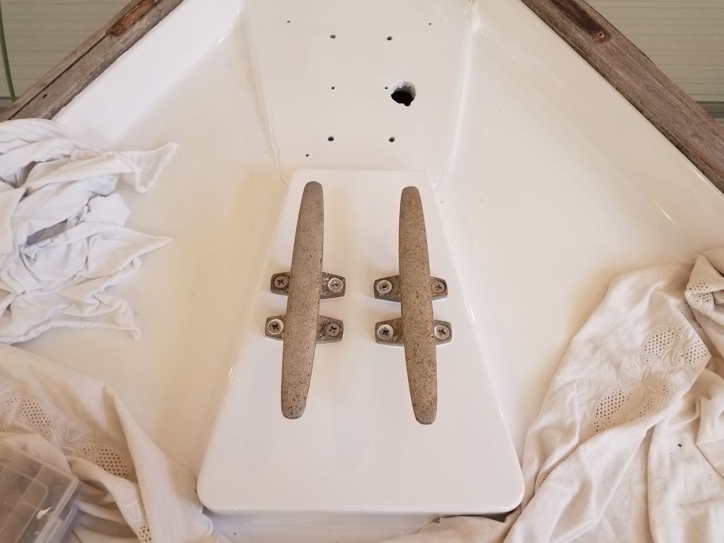
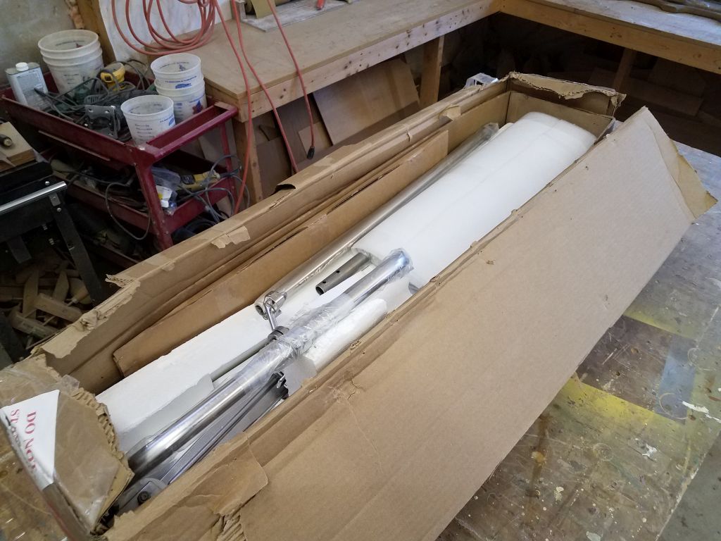
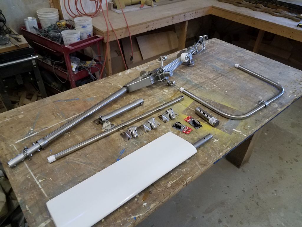
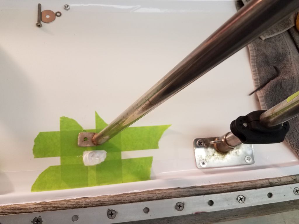
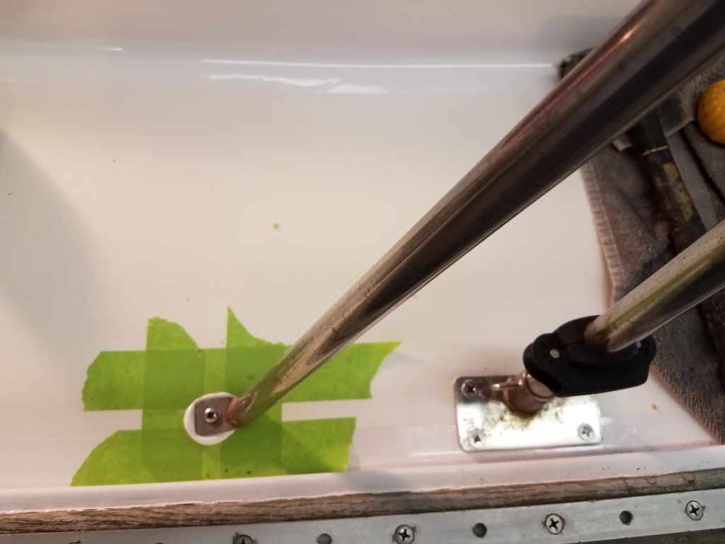
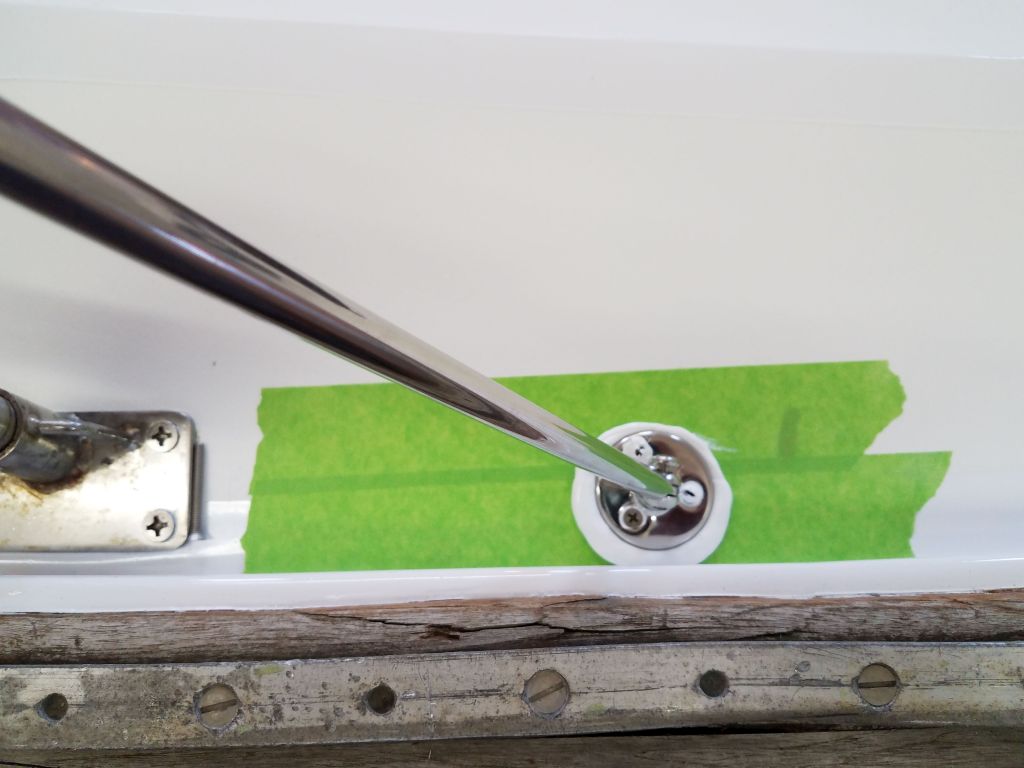
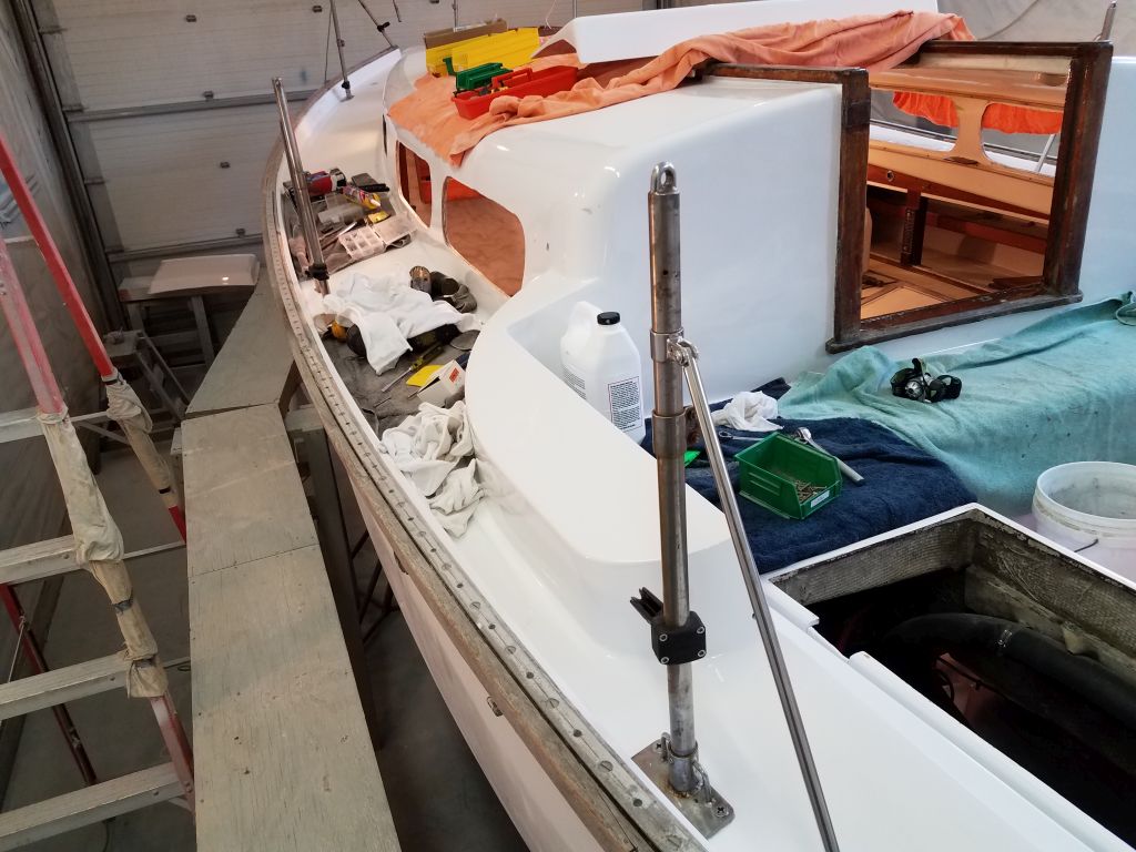
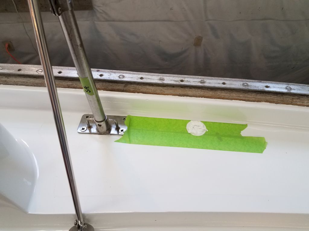
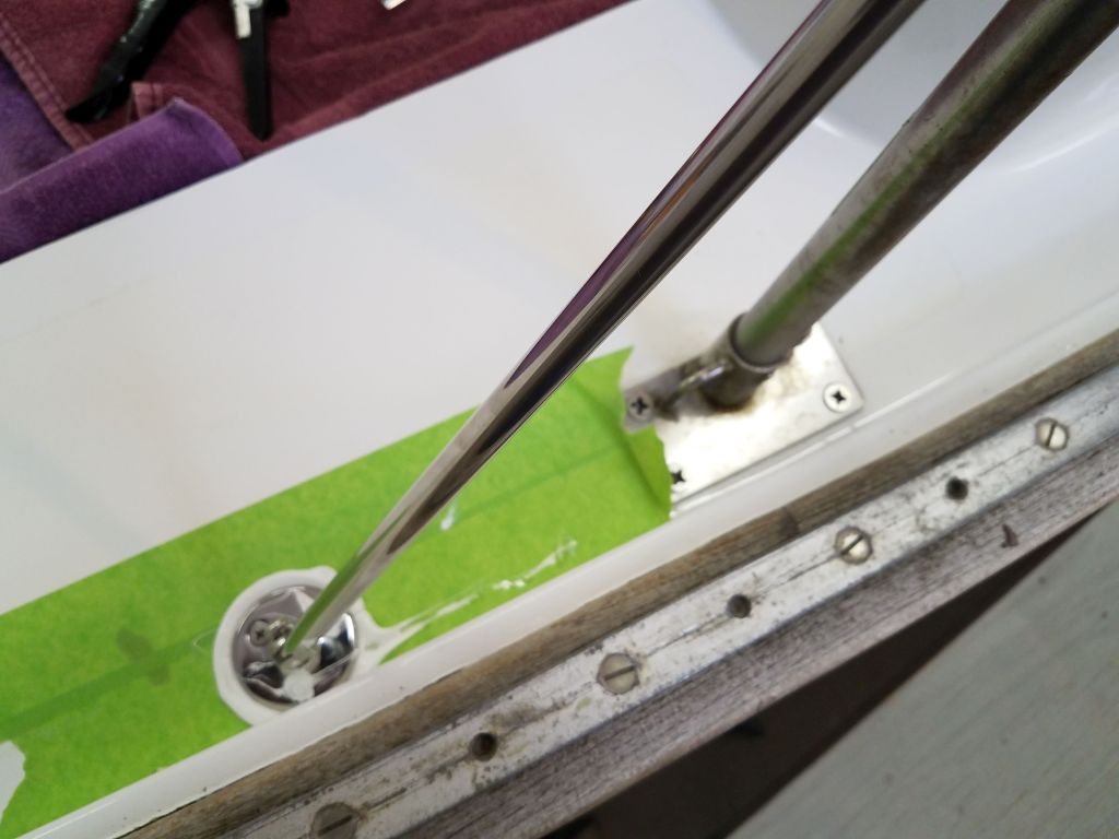
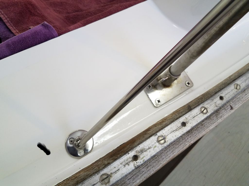
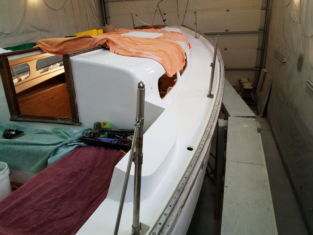
I spent the afternoon working on the Norvane windvane installation.  The first step in the installation was to install a horizontal pipe and support bracket, which the instructions called the “belled pipe” on account of its flared (belled) end configuration.  Reviewing the instructions, along with the anecdotal photo of a sistership’s installation and making some confirming measurements, I installed the bracket for the belled pipe right on top of the wooden block located at the taffrail centerline.  This allowed for two through bolts, which passed through the block, taffrail, and outward hull/deck flange, with two 2″ lag screws for the inner pair of holes, since there was no means of throughbolting here.    Any forces on this particular support pipe would  be sheer in any event, and this pipe mainly spaced the vane out correctly beyond the transom.  The real support for sailing forces came from other means that I’d soon get to.

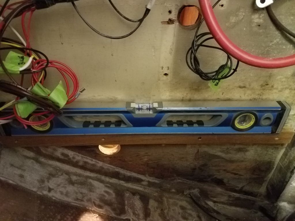
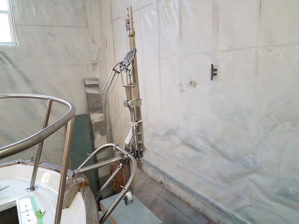
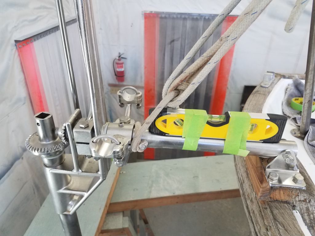
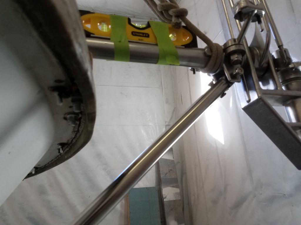
Following the installation guidelines, I set up the new pipe with a level and by eye as needed, then secured it to the stern pulpit with line to help hold it in its required horizontal attitude for the next steps.

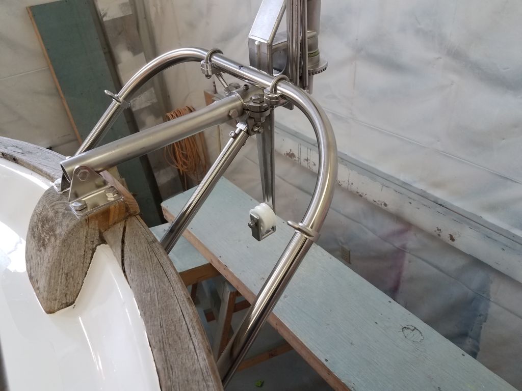
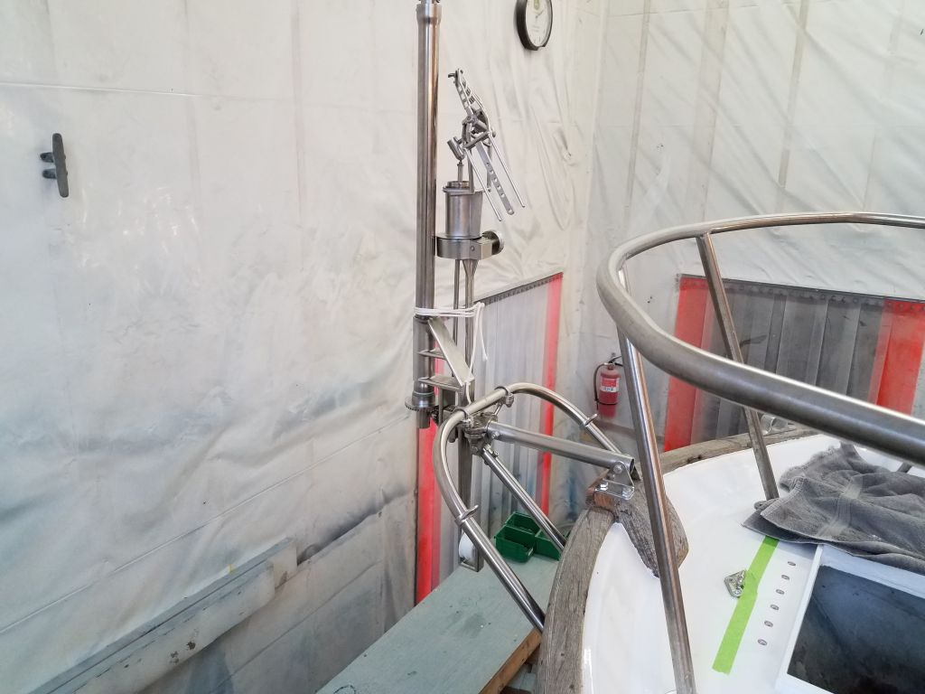
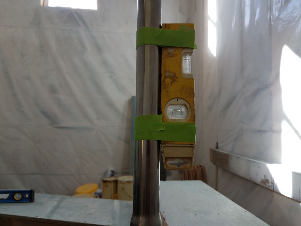
With the belled pipe secured for now, I installed the main body of the windvane, which featured an insert that slipped right into the belled socket at the end of the pipe, with a through bolt to secure it.  This held the vane securely, and now I fine-tuned the supporting lines to ensure the whole thing was plumb and level as required.  I also used this opportunity to confirm yet again that the vane was mounted at the correct height for this boat, and that the servo rudder was positioned as required in the instructions–that is, with 1-3″ of the rudder above the waterline.

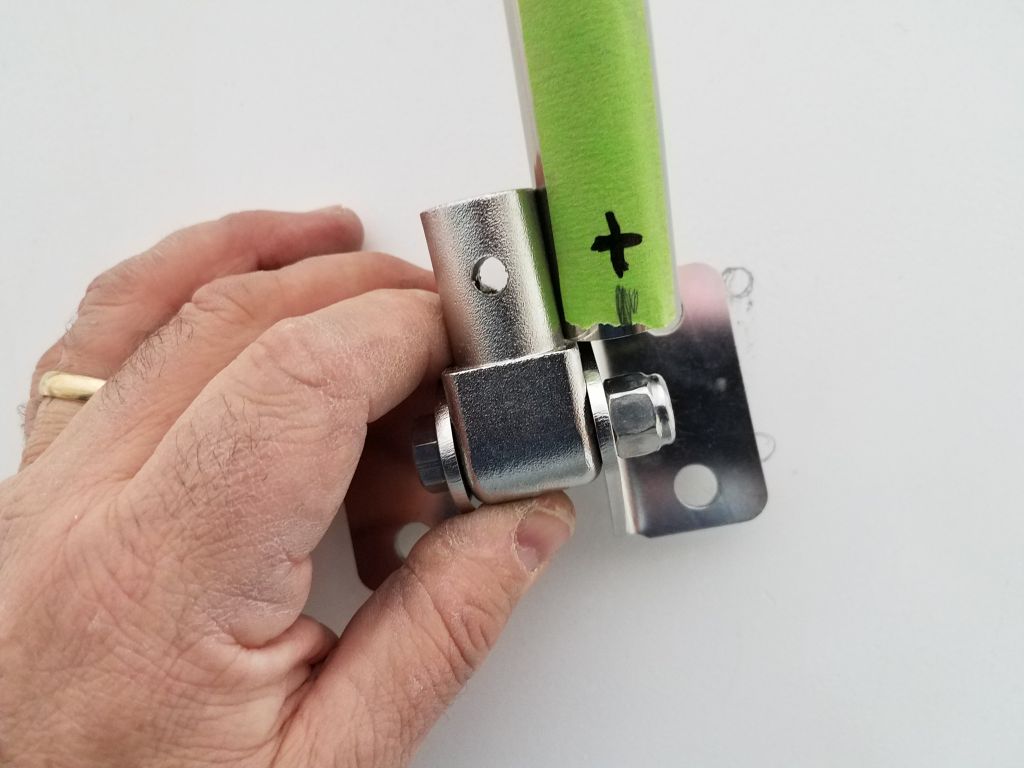
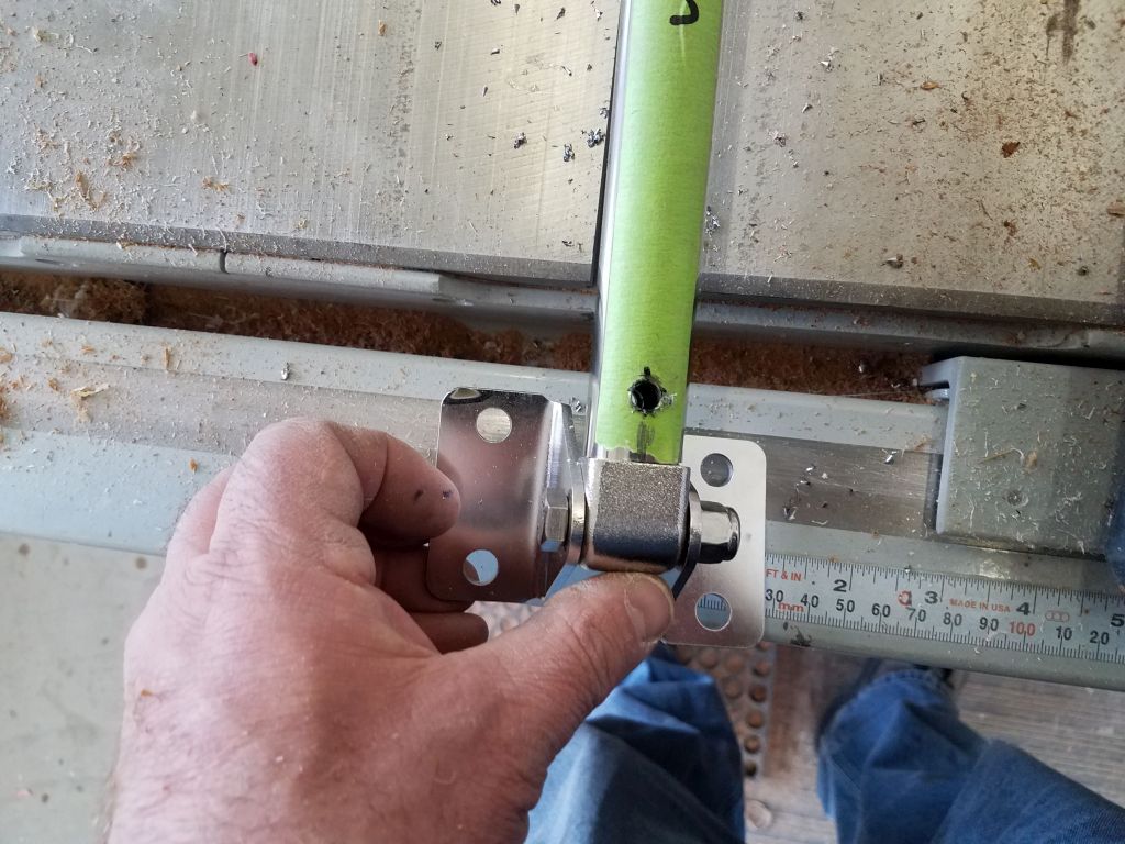
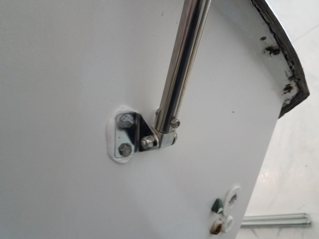
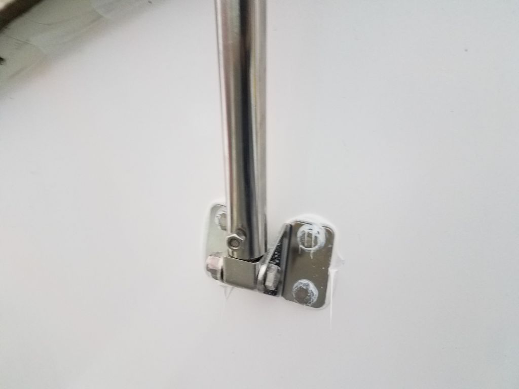
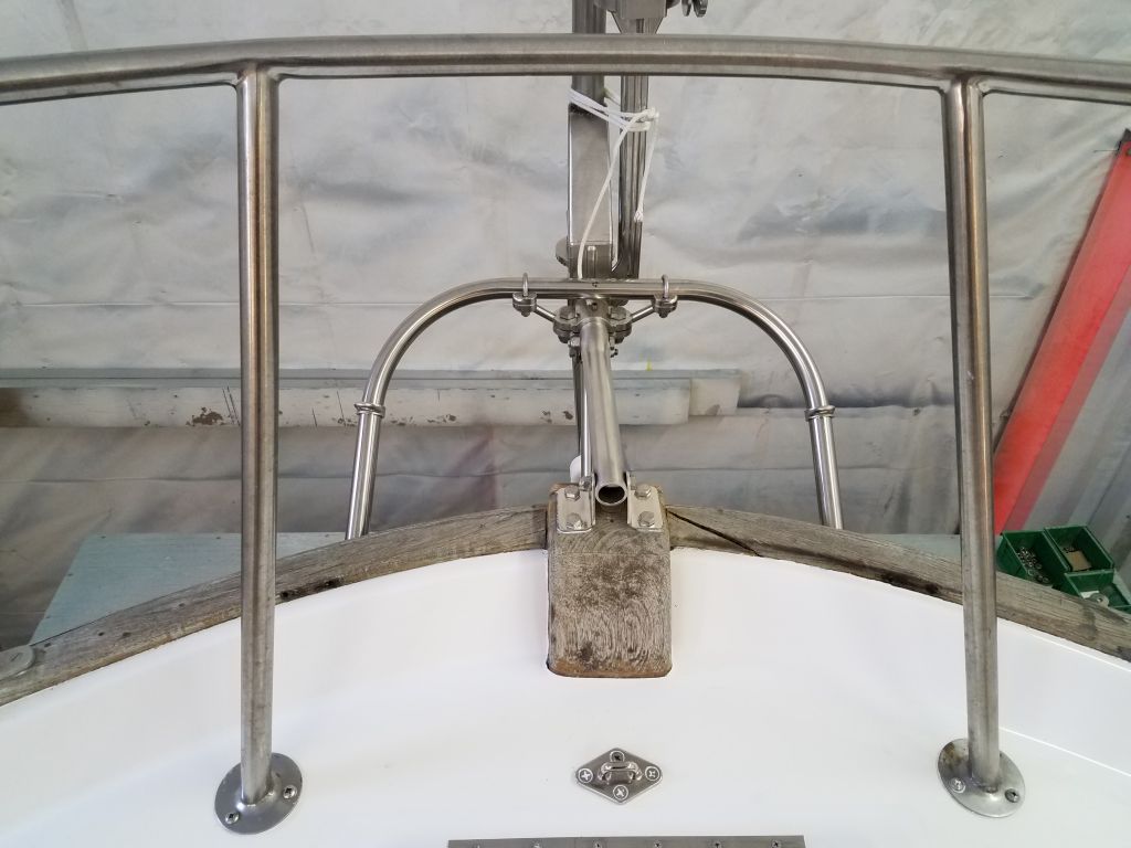
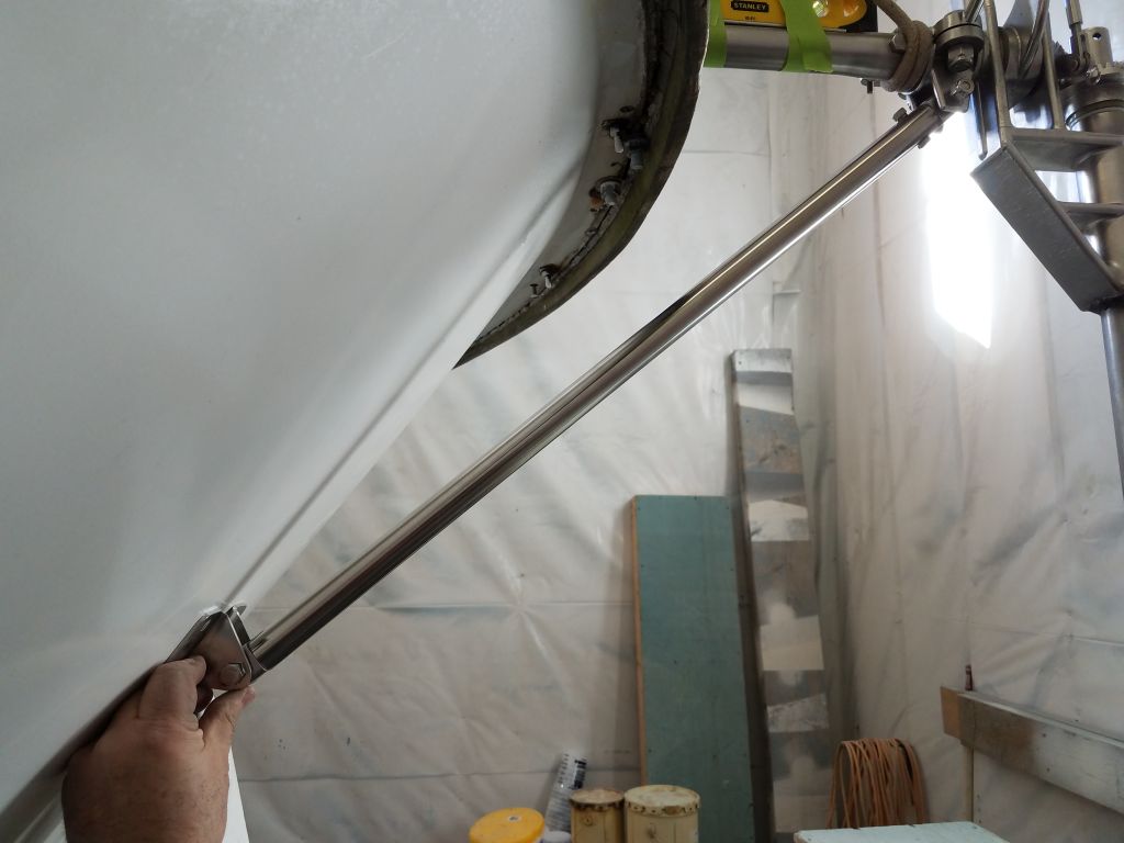
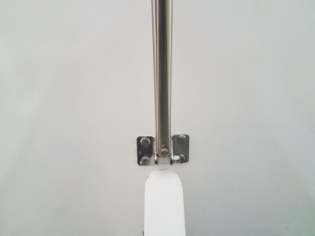
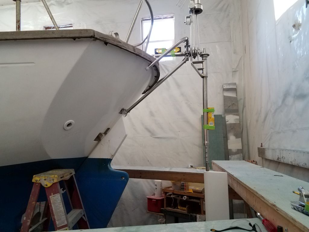
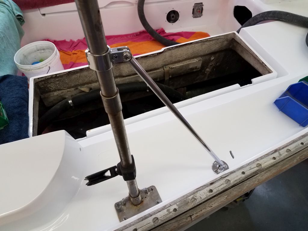
With the vane secure, plumb, and level, next I installed the main diagonal vertical support, which led from the vane body down to the transom on centerline.  The length of pipe included was just a bit too long for me to install the bracket above the rudder where it entered the transom, so I made a mark and cut off the pipe accordingly.  Then, satisfied with the length and bracket position, I drilled through the support pipe for the bolt that would secure it to the insert end that fit into the bracket.

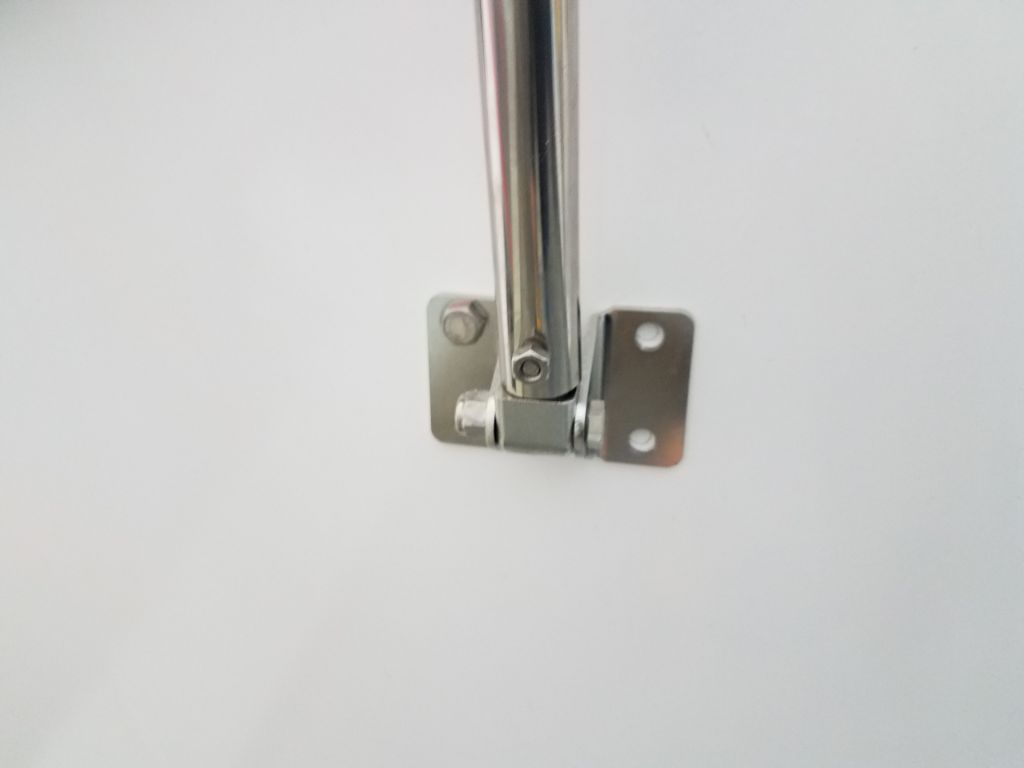
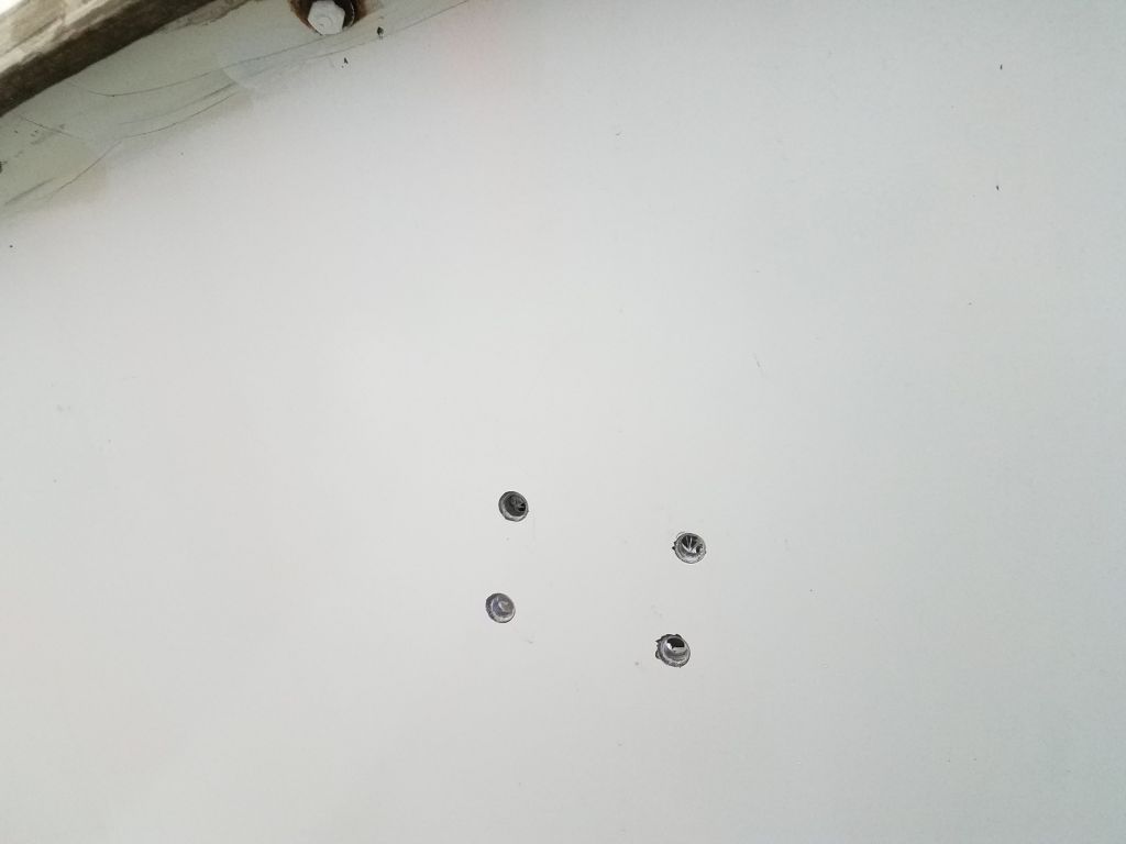
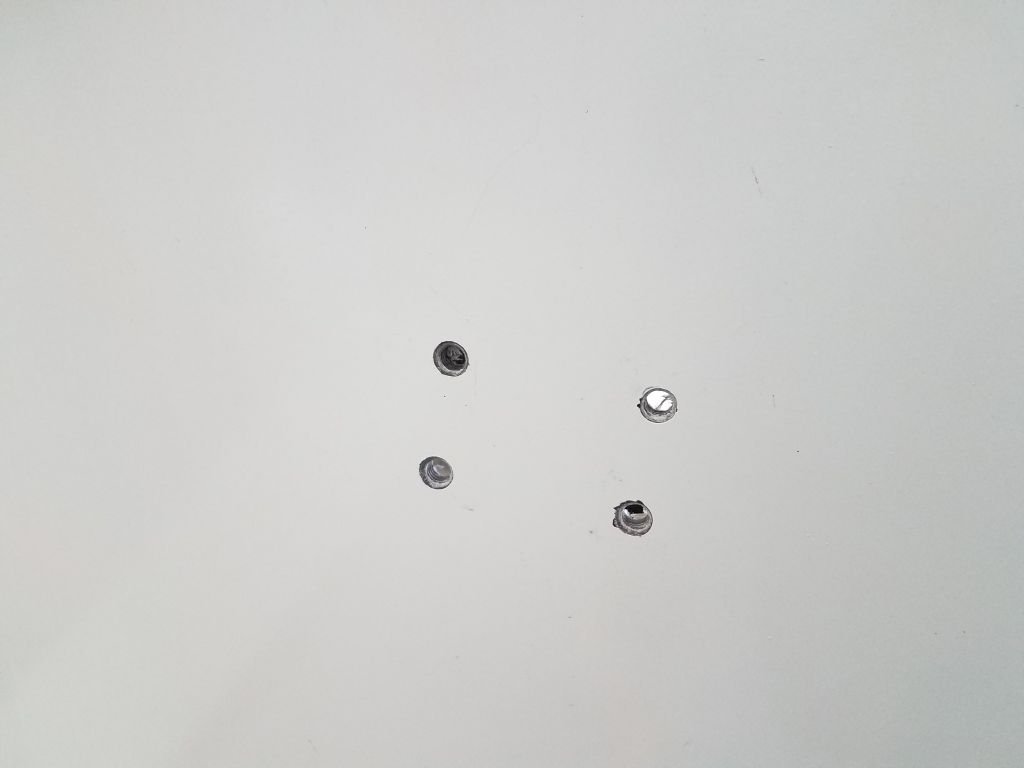
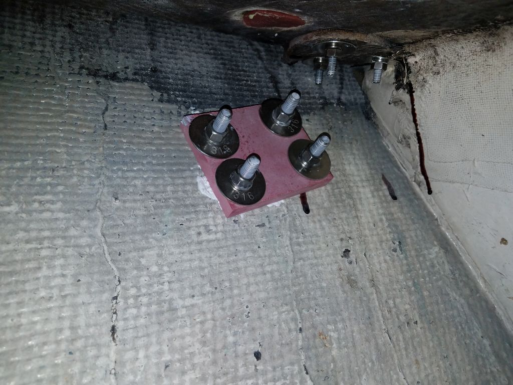
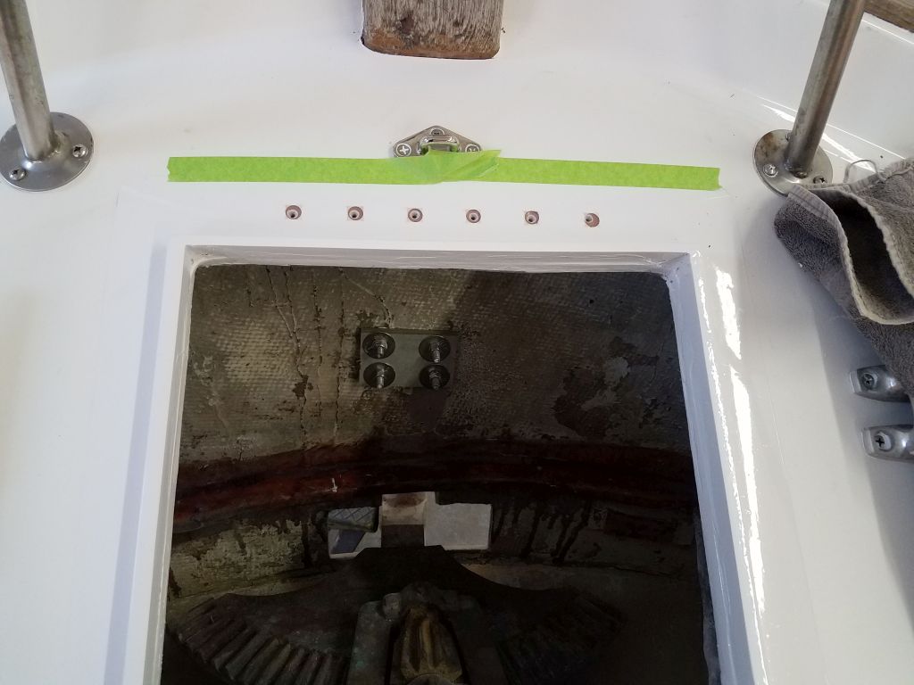
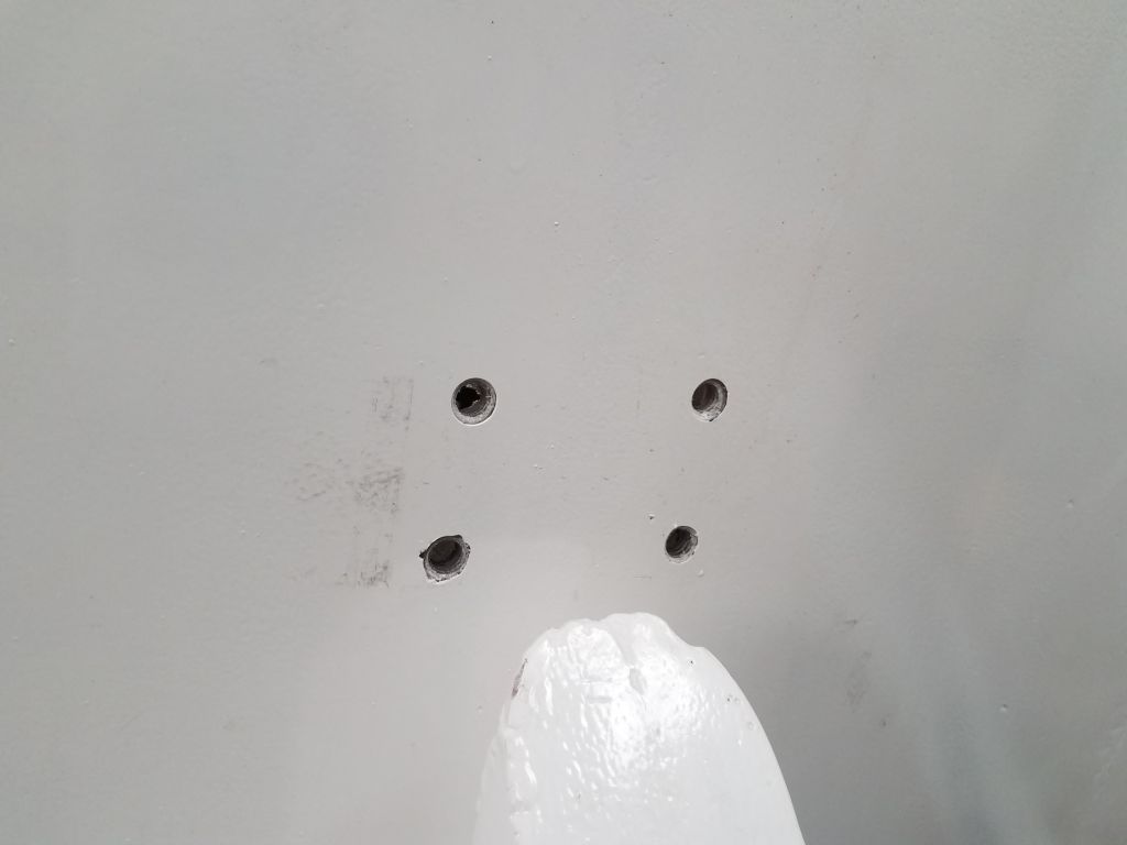
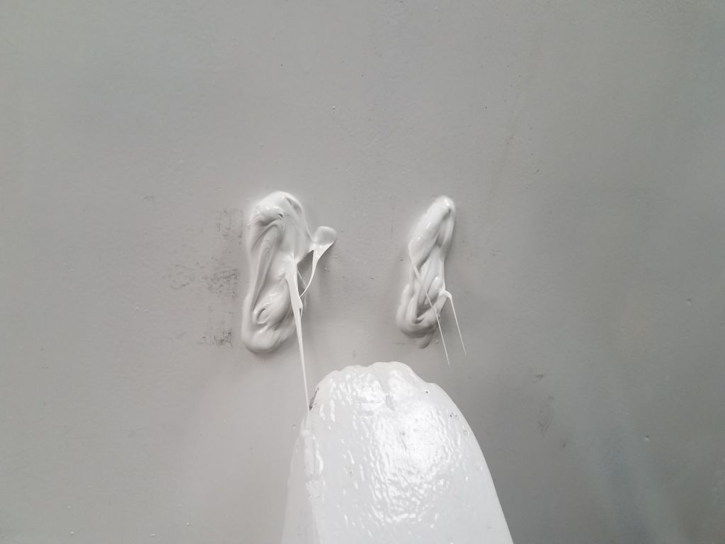
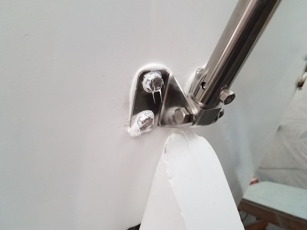
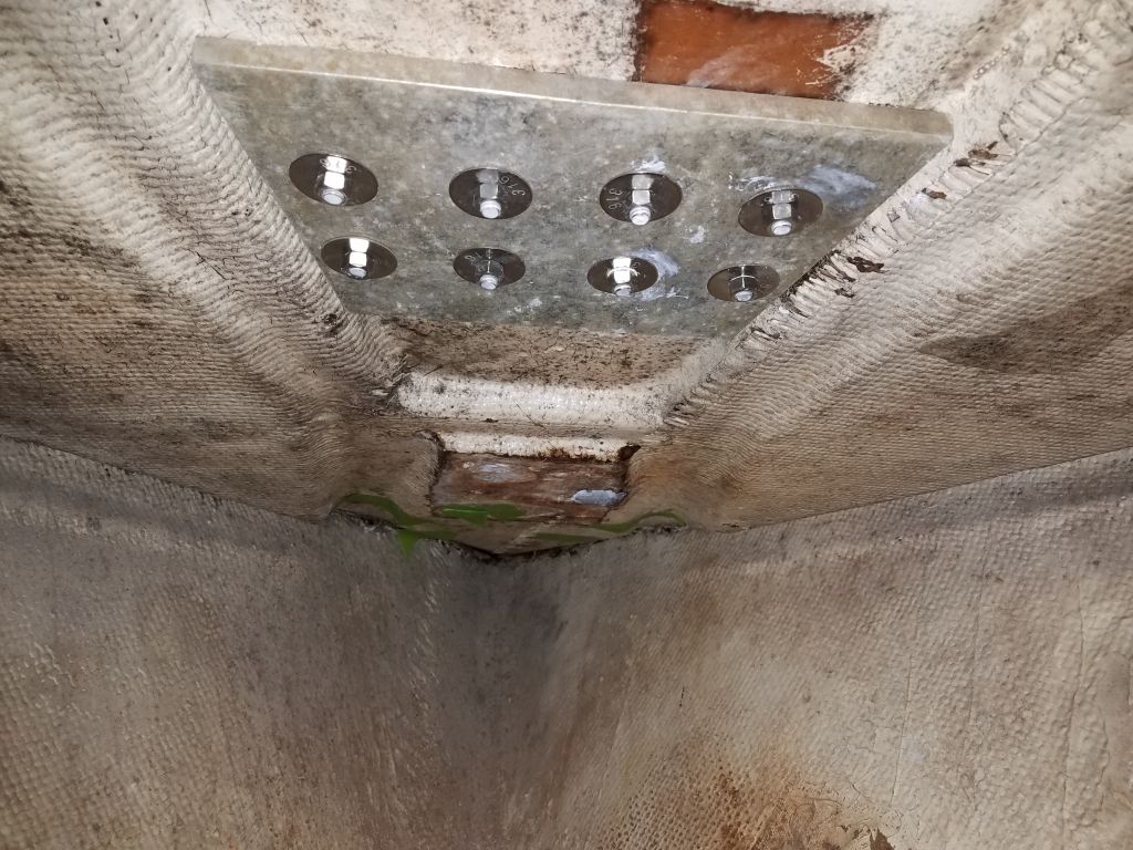
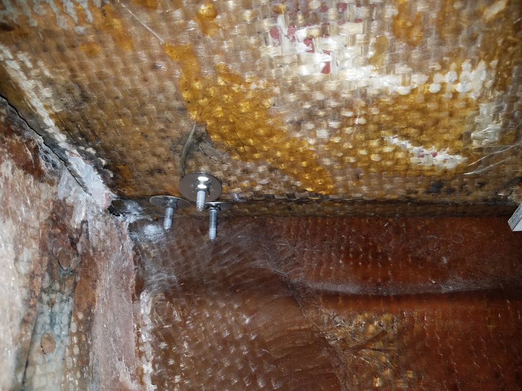
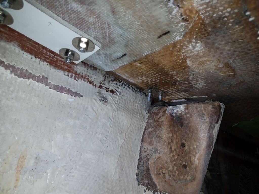
I marked, drilled, and tapped the holes through the transom for the 3/8″ bolts required, and secured the bracket with sealant and a good fiberglass backing plate inside.  Then, after checking the level/plumb once more, I tightened the bolts that secured the brace to the transom bracket and vane, firming up the whole installation and locking it in place.

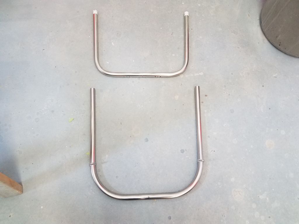
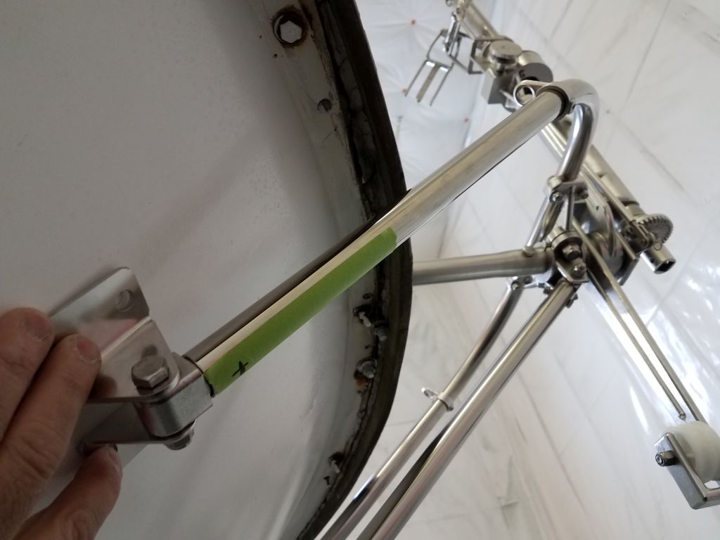
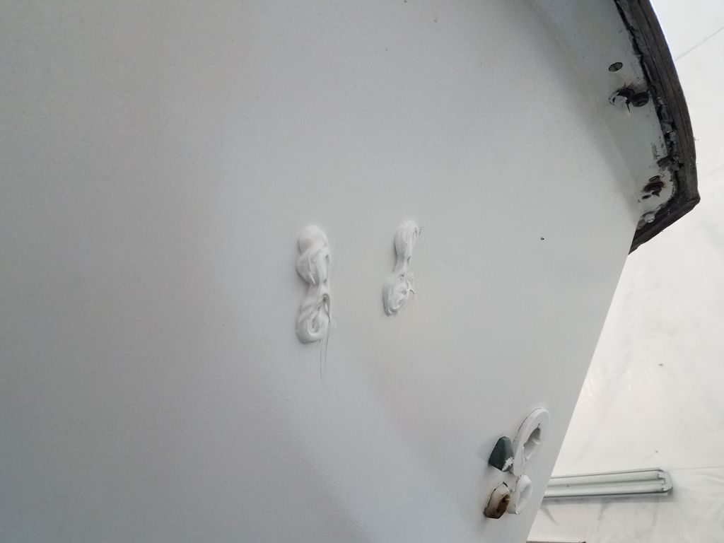
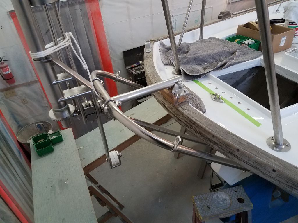
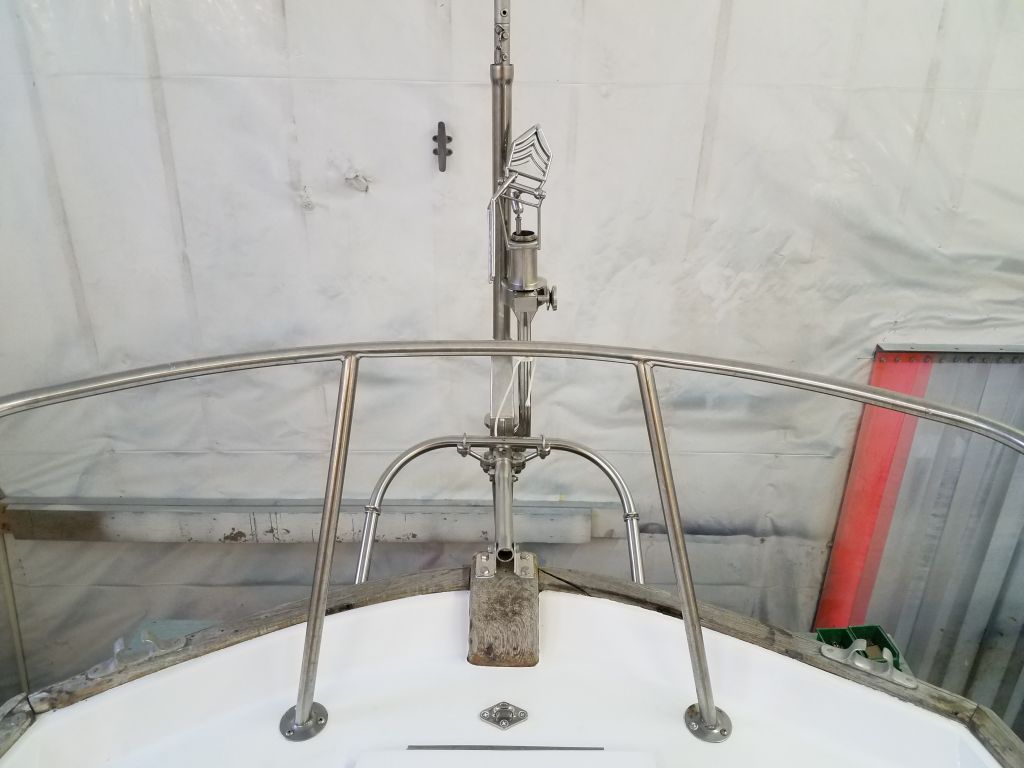
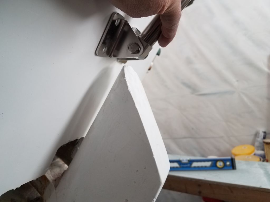
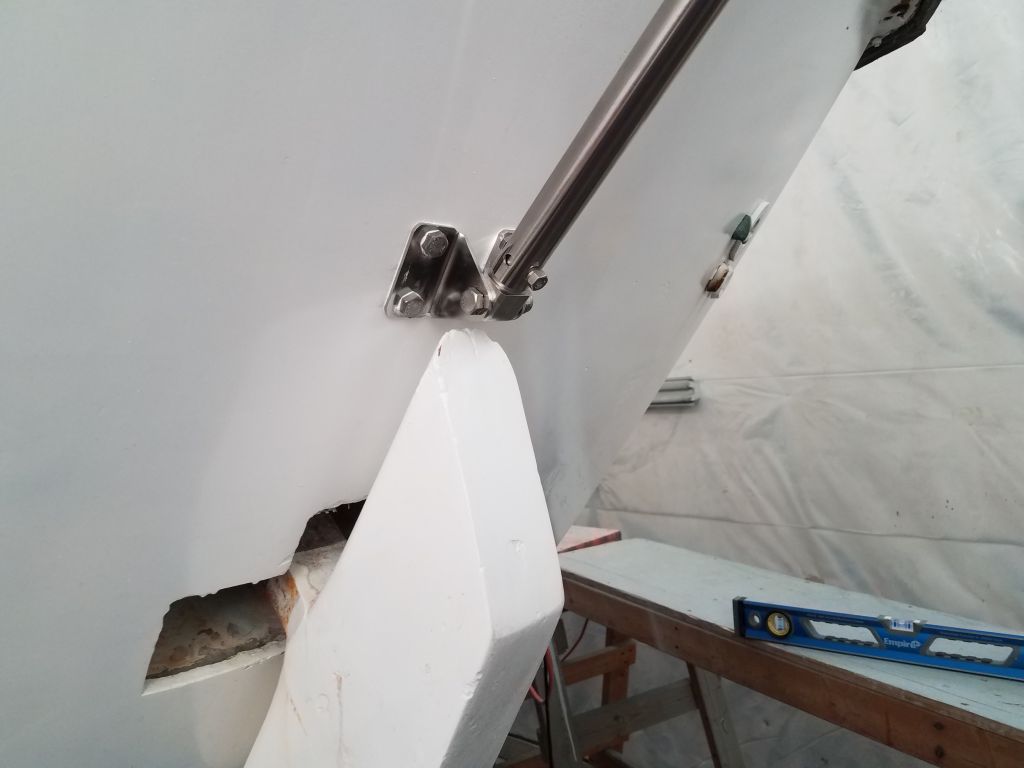
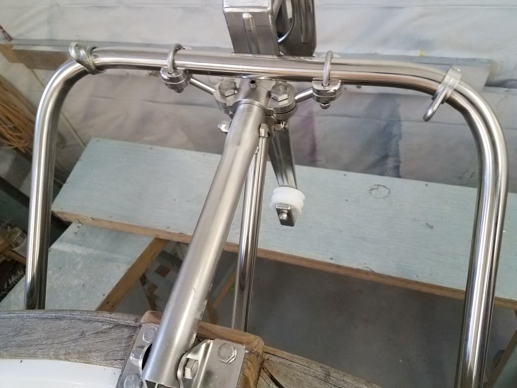
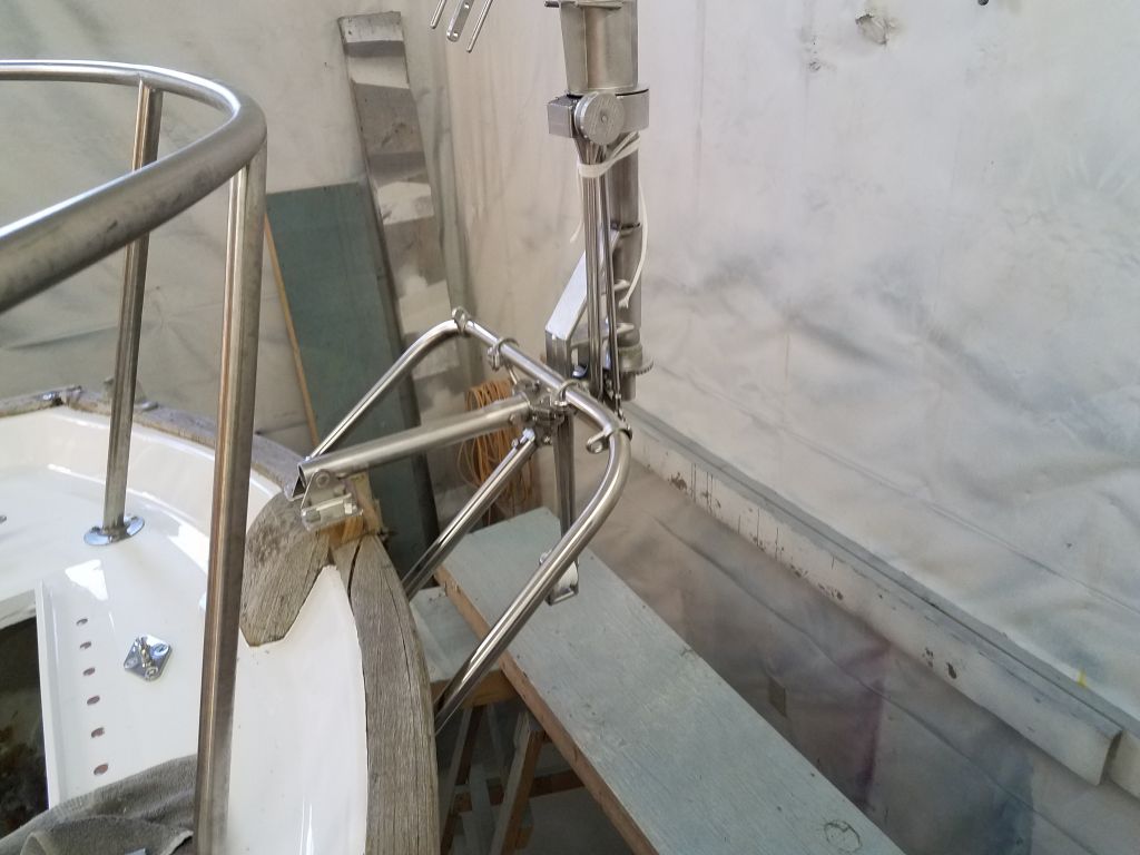
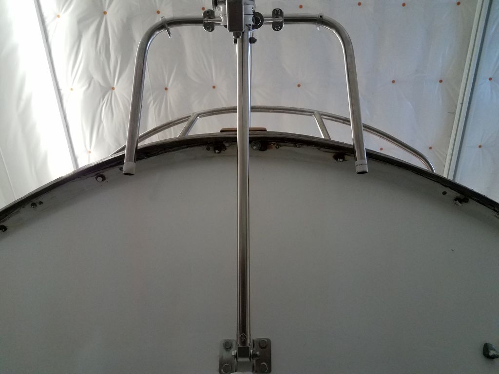
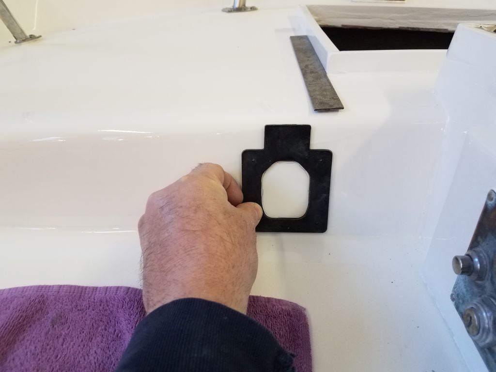
The last part of the supporting structure for this windvane was a U-shaped stainless tube that fit through brackets on the top of the vane and extended towards the hull, where they’d ultimately be secured with additional brackets.  Here, however, I ran into a problem:  the legs of this brace were too short to properly secure to the hull.  At issue here was the fact that the top of the transom from the outside was actually several inches higher than the deck, thanks to the tall molded bulwarks surrounding this deck.  I could make the brace and bracket work (i.e. touch the hull) if I held the bracket right up beneath the overhanging toerail, but this would place the bracket above deck level, not where it should be secured.  Even in this too-high position, the bracket didn’t really touch the hull, as the pipe contacted the edge of the toerail above; even if I thought mounting here was an option, I’d need blocks to build up beneath the brackets.

For the brace and brackets to be positioned properly–that is, with the brackets mounted on the hull somewhere below deck level and where I could access the bolts from inside the hull–I calculated that the legs of the stainless brace needed to be about 5″ longer.   This would place the support brackets in a good position, and better triangulate the forces acting on the windvane in any event.  I couldn’t hold the pieces in this mocked-up configuration and take a picture at the same time, so I haven’t shown where the brackets would end up once I dealt with the extended U-brace.

The brace itself was a simple-enough thing and I hoped to get a new one fabricated locally and quickly.  But for now, this disappointment ended work on the vane installation, for which I’d otherwise been on track this day.

Total time billed on this job today:  7.75 hours

0600 Weather Observation:  26°, mostly clear.  Forecast for the day:  Mainly sunny, around 40°

Jasmine 50

< Back to Jasmine

Tuesday

I was out of the shop much of the morning on other business, but before lunch I installed the two “new” self-tailing winches on the winch islands.  These winches were older Barient model 24-45.

Later, I worked on a few straggling hardware tasks, including installing the two locker latches on the cockpit lockers.

At the poop deck, I marked the hole locations for the deck side of the steering room hatch hinge and prepared the holes for fasteners in the usual way, removing the core material and filling the voids with thickened epoxy.

The windlass I removed earlier, an old but reliable aluminum Simson-Lawrence Hyspeed manual model, still worked well according to the owner, but the finish on the case was worn and in poor condition.  The owner requested that I refinish it to the extent realistically possible.  I’d been walking by the windlass for weeks, ignoring it and hoping it would magically take care of itself, but alas.

It was a happenstance that I ended up working on the windlass on this day.  I’d been looking for something else, unrelated, in the shop and stumbled upon a nearly identical windlass in my parts inventory.  This windlass had some issues–part of the capstan was broken off, and the operation was stiff at best–but might still be valuable as a source of parts, beginning with the gypsy, which was a smaller size than the one off Jasmine, which was sized for 3/8″ BBB chain–a massive size when contemplating an all-chain rode, as was the owner.  The other gypsy hopefully was sized for 5/16″ chain, which would be a good choice going forward.  I used the attic windlass as a test bed, since it didn’t matter so much if I harmed anything, and soon found it was straightforward to remove the gypsy.  One thing led to another, and before I knew it I was well into the windlass painting preparations.

I had no need, desire, nor inclination to disassemble the “real” windlass nor to rebuild anything that didn’t require it, and not wanting to adversely affect the winch’s currently excellent operation, I chose to leave things pretty much as is during my preparations.  However,armed with new confidence after working on the “attic” windlass, I removed the chain gypsy to improve access.  I removed all the paint from the casing by hand, exposing the bare aluminum; it didn’t really take much to remove the old, failed coating.

With adequate preparations, I applied epoxy primer to the windlass with a small disposable sprayer.

While I had the primer going, I also sprayed the two original mast steps, which I’d prepared earlier with light sanding as needed; the original finish was gelcoat over the molded fiberglass steps.

Total time billed on this job today:  5.25 hours

0600 Weather Observation:  8°, clear.  Forecast for the day:  Sunny, 20s

Jasmine 49

< Back to Jasmine

Monday

I prepared the bolt holes for the five pieces of poop deck hardware by drilling and tapping for 1/4″ machine screws, after which I installed the hardware with new fasteners and backing plates.

On the coachroof, I dry-fit the sea hood so I could predrill and bevel the fastener holes before installation; I’d pre-marked these hole locations earlier, and the decks were already prepared for the new fasteners.

After cleanup, I applied a heavy bead of sealant to the deck, covering all the fastener holes, and installed the seahood with new fasteners.

Next, I turned to the opening ports.  I prepared the work area by spreading some plastic sheeting over the deck for protection, and laying out all the tools and pieces I’d need.

For each of the four units, I followed the same basic installation, starting with a dry fit and reaming out the bolt holes in the cabin side as needed.  To install the port, I applied a bead of sealant at the juncture between the spigot and the port body flange–but not on the flange itself.  Then, still working from outside,  pulled the port into position, holding it in place while I applied additional sealant inside and around the spigot and hole and over the cabin trunk in way of the bolt holes and trim ring mounting area, ensuring ample coverage everywhere.

Finally, I installed the trim ring from outside, clamping it and the port body in place temporarily while I installed the bolts.  I could reach through the open port and install the nuts for 8 of the 12 fasteners from outside, but I had to install the four along the top edge from inside.  I reused the original machine screws and nuts, replacing them each in the same position from which I’d removed them some weeks earlier.

I repeated this process with each of the remaining three units.

I finished up the day’s work with the two round deadlights in the forward cabin.  I found I could stand through the forward hatch and do both sides of the task as necessary, and with only a minor issue on the first unit aligning the trim ring from within, I soon completed both installations without additional trouble.

Total time billed on this job today:  7.5 hours

0600 Weather Observation:    32°, partly cloudy.  Forecast for the day:  Sunny, highs in the upper 30s

Jasmine 48

< Back to Jasmine

Friday

To replace the old 110V shore power plug, which hole I’d sealed over during the deck work, I ordered a new, modern plug and prepared now to install it.  The original receptacle had been located perilously close to the steering room bulkhead hidden behind the cockpit, and this was one reason I’d chosen to fill the old hole.  Back then, I’d noted some reference points so I could determine the new location after the paint was complete, and with this in mind I used the rubber gasket from the new receptacle to lay out the location for the 2-1/2″ hole required.  I wanted the new hole to be outside a line even with the steering room hatch trim, so I used a steel ruler to extend this and position the hole accordingly.

With the hole cut, I installed the new receptacle with its included gasket and machine screws.  There’d be no wiring to the plug for now, but the owner wanted it in place for future use.

By now, I’d familiarized myself enough with the Norvane windvane mounting system to understand that none of its mounting components would impede the hardware placement on the poop deck.    I’d avoided pre-preparing any of the deck locations or fastener holes for the stern hardware because at the time, I didn’t want to commit to any locations that could adversely affect the windvane.

The owner even sent me a photo of a similar installation on a sistership, which was greatly helpful in visualizing the entire arrangement, and this, along with my increasing knowledge of how the setup worked, allowed me finally to proceed with the hardware on the poop deck.

I laid out the stern mooring cleat positions, along with two new padeyes for the mizzen mast running backstays, plus a new padeye on centerline aft of the hatch for the mizzen sheet.  The setup when the boat arrived had included a ridiculous tiny traveler for the mizzen sheet, which seemed not only poorly executed but also entirely unnecessary, so the owner agreed that a simple attachment point would make more sense.

In my habitual way, I cut away the masking tape around each piece of hardware, then marked and drilled out the top skin and core material in way of each fastener location.  Then, I filled all the holes with a thickened epoxy mixture.

In the meantime, I worked to locate and prepare the holes for the cockpit sheet winches.  These winches were new to the boat:  they were some older model self-tailers (Barient 24) that I had on hand from another boat, and that fit the owner’s desires for winch upgrades.  The winch replacement would also, thankfully, avoid the irritations and bolt layout I’d dealt with during removal of the original winches some weeks before.

I didn’t have the correct fasteners on hand to complete the winch installation, but got all the holes prepared and ordered the correct fasteners for next time.  I also figured out any other gaps in my fastener inventory and ordered what I’d need to complete the Norvane installation, as well as the final hardware elsewhere on the boat.

Finally, I installed a length of piano hinge on the aft side of the steering room hatch.  I wouldn’t do the final hatch installation till I’d completed all the work on the aft deck, since access within was much easier without the hatch.

Total time billed on this job today:  6 hours

0600 Weather Observation:  -8°, clear.  Forecast for the day:  Sunny, mid-20s.

Jasmine 47

< Back to Jasmine

Thursday

After cleaning up from the latest snowfall, I got back to work with the hardware on the coachroof, starting with the plastic deck plates for the solar vents.  I’d already pre-filled and marked the fastener locations for these fittings, so installation was straightforward.

Next, I installed the forward hatch with its two after hinges.  There was no access to this area from beneath–it was in way of the mast beam and bulkhead–so I installed the hinges with screws alone.  This section of the deck was solid fiberglass now that I’d rebuilt the mast step area earlier.

I waited on the mast step for now, as I’d need to build it up taller than original.  One of the upcoming projects for the riggers was to shorten the mast by a couple inches to remove some corrosion at the base, and accordingly we planned to raise the step to make up the difference.  Meanwhile, I installed two little bronze eyelets that had come off the deck near the vent fittings; I’d prepared these holes during an earlier stage of deck preparation as well.

Other than the sea hood, this completed the hardware installation for the coachroof, so now I moved down to the port sidedeck and worked on the new waste fill deckplate and reinstalled the waste tank vent fitting in the cabin side.  The deck was solid fiberglass around the waste fitting, so all I had to do was drill, tap, and install.

On the foredeck, I installed the round anchor line hawse in its original position to port,  where I’d also filled the surrounding area with solid fiberglass and epoxy to prepare for a simple installation now.

To wrap up work on the foredeck, I reinstalled the two mooring cleats.  I reused the original aluminum backing plate belowdecks.  I also installed the bow chocks which were mounted on the raised overhanging bulwark/toerail and hadn’t really needed to be removed for the deck work, but at dismantling time I’d just been going through my habitual motions and only afterwards realized my mistake.

Back in the cockpit, I installed the hinges for the starboard cockpit locker.

To round out the day, I decided to unpack and inventory the Norvane windvane assembly and begin to acquaint myself with the installation, as I planned to move forward with this soon and wanted to see how this particular vane would hang from the boat.  Plus, I needed to determine what sorts of fasteners and drill bits I’d need for the installation.  I inventoried the included parts, noted any fasteners I’d need to order, and acquainted myself with the installation directions.

Total time billed on this job today:  6.75 hours

0600 Weather Observation:  12°, clear, 8″  snow and sleet overnight.  Forecast for the day:  Sunny, 25°

Jasmine 46

< Back to Jasmine

Wednesday

Over a disjointed morning rife with various competing distractions, I managed to finish up the stanchion installations, starting with the port amidships stanchion, completing the installation I’d begun earlier now that the epoxy-filled hole for the gate brace had cured.

Later, after stepping out for a bit to attend to other business, I completed the installation of both gate braces at the aftermost stanchions.  The bolt locations for the brace bases fell outside of the cored area on each side of the deck, so all I had to do was mark, drill, tap, and install the bases accordingly.  First the port side…

…then the starboard.

In the afternoon, I decided to tackle the “easy” installation jobs in the cockpit, starting with the old engine instrument panel.  I applied butyl tape sealant to the back of the panel and installed it in its original opening.

Next, I reassembled the gearshift lever and bilge pump bellows that I’d removed before painting.

Then, I installed the circular access port in the cockpit sole.

I reinstalled the starboard cockpit locker lid hinges, using more of the butyl tape to seal these fasteners.

Finally, I installed the new cockpit seat drain fittings, heavily applying sealant around the flanges and necks of each fitting and tightening the nuts from belowdecks.

Total time billed on this job today:  4.75 hours

0600 Weather Observation:  8°, clear.  Forecast for the day:  Snow by noon, heavy snow in the afternoon, about 10″ expected

Older posts Newer posts