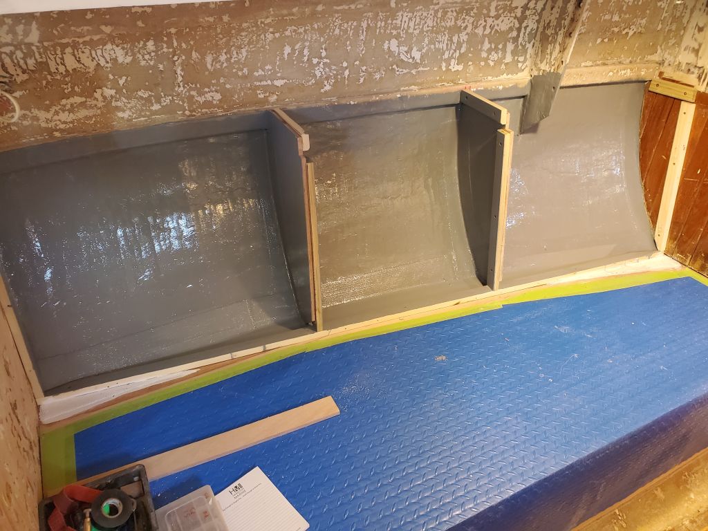
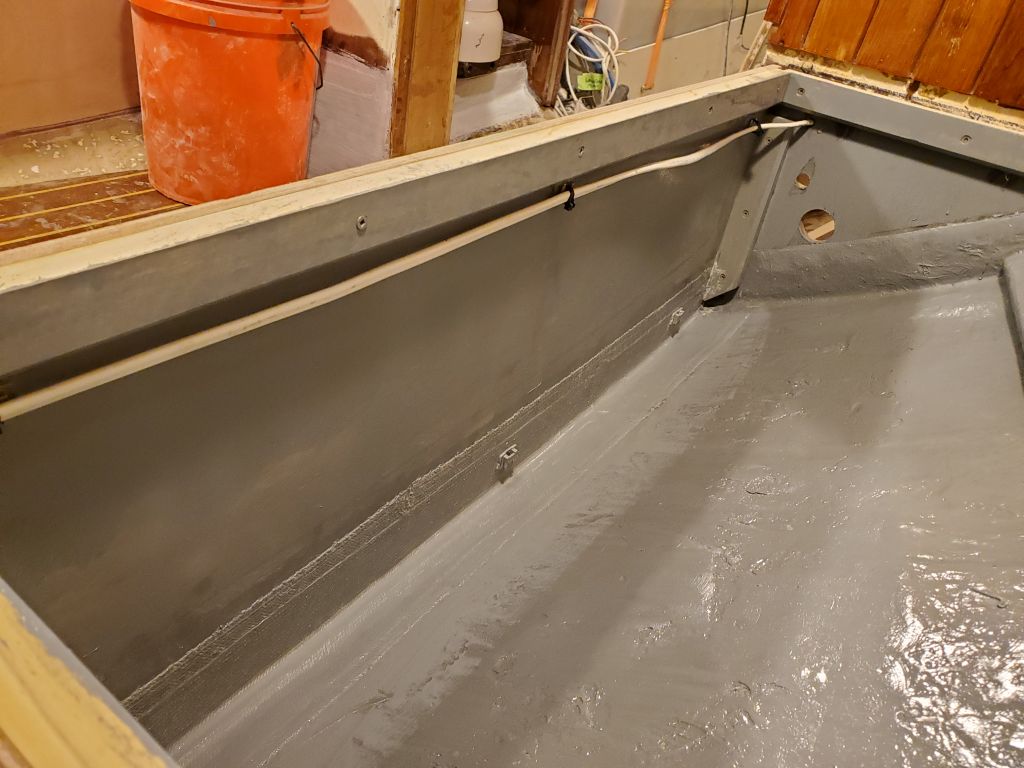
In a short work session, I painted the lockers behind the settee backrests to prepare for the final installation (and additional construction) next time.
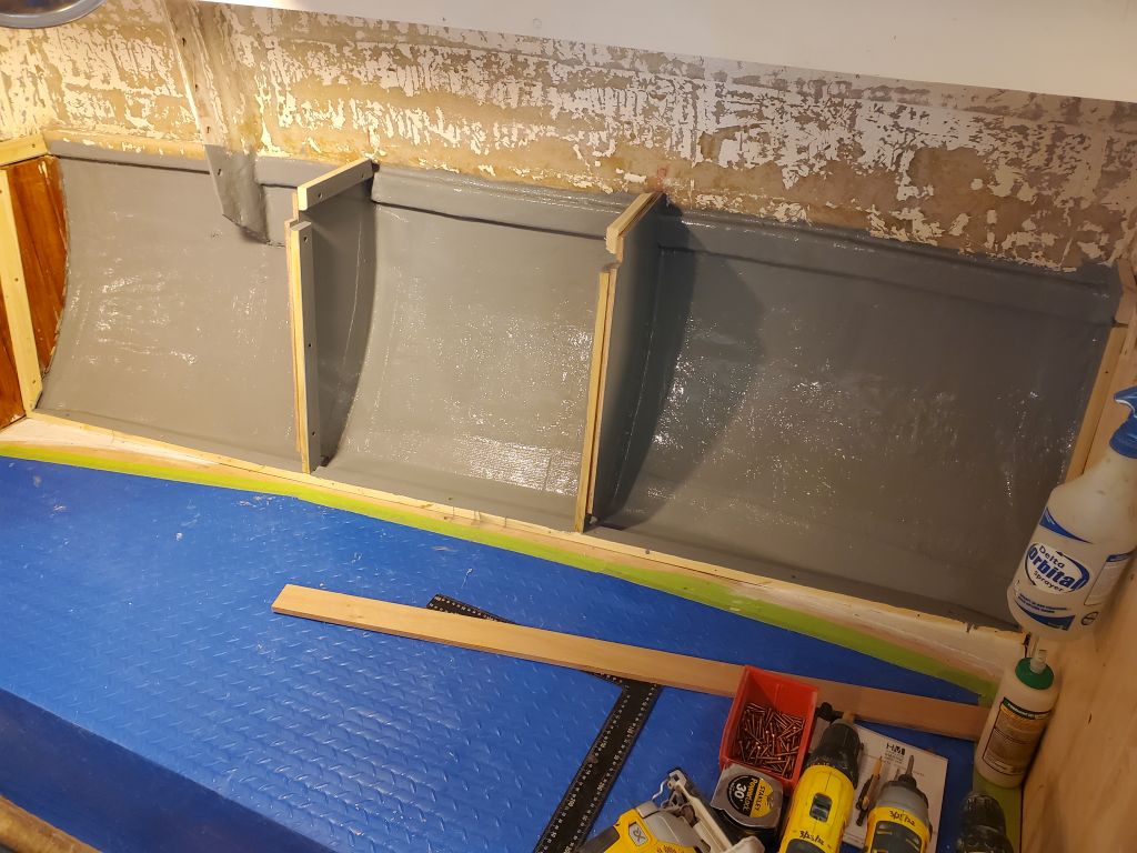


In a short work session, I painted the lockers behind the settee backrests to prepare for the final installation (and additional construction) next time.
I’d hoped to make my first task painting the lockers behind the settees, the last task remaining before I could think about permanently installing the backrests and continuing the construction. However, the primer I’d applied late in the day last time was still a bit tacky and was not yet ready for overcoating. So I left it to cure the rest of the day and planned instead to come in over the weekend to do the painting, since I had to be out of the shop Friday.
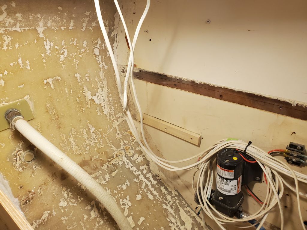
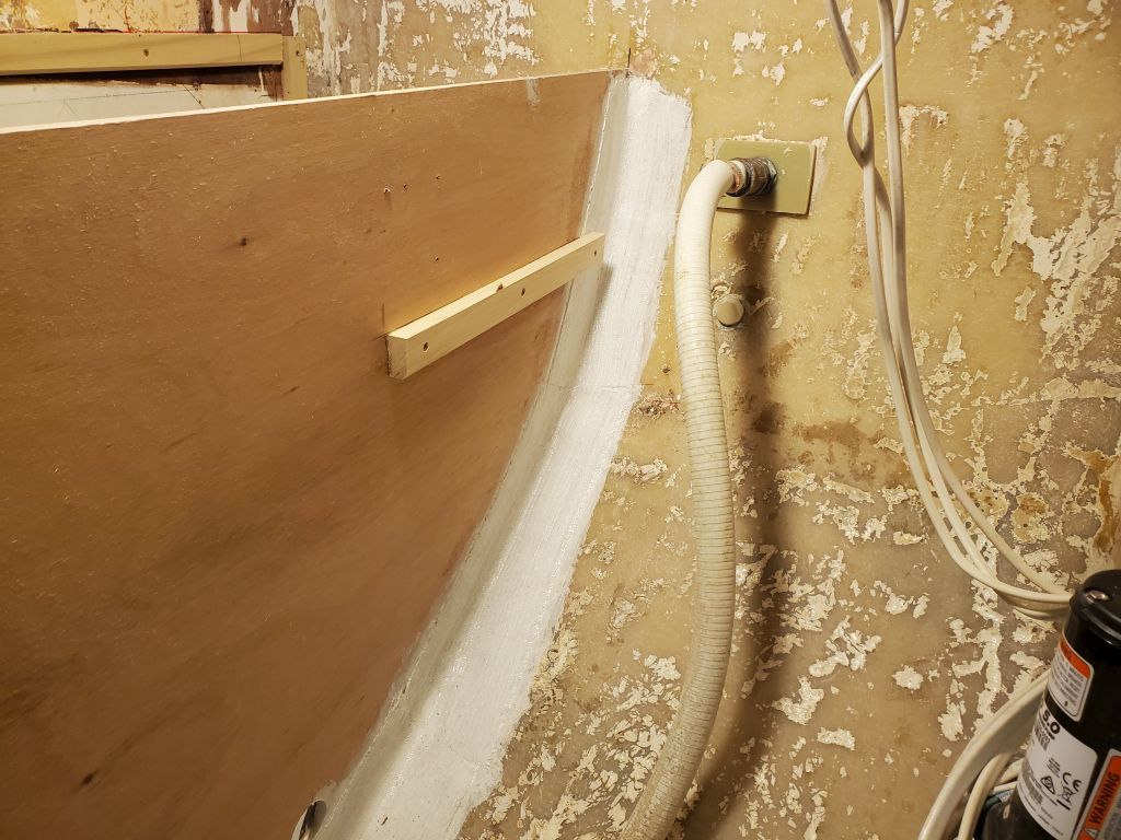
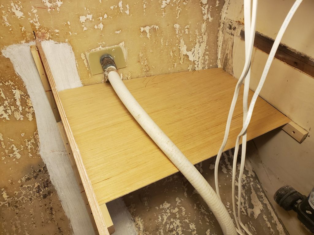
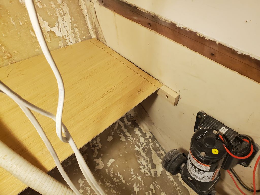
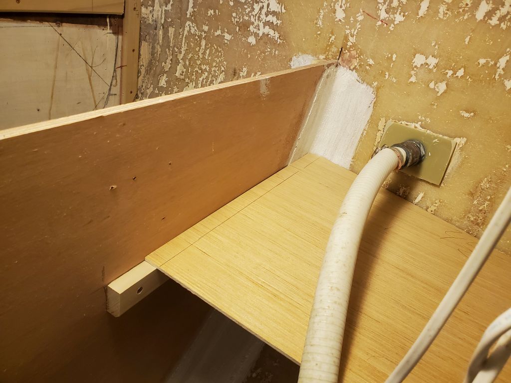
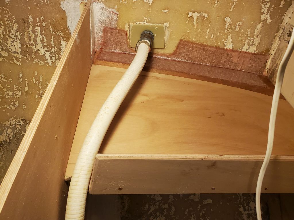
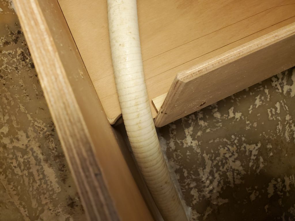
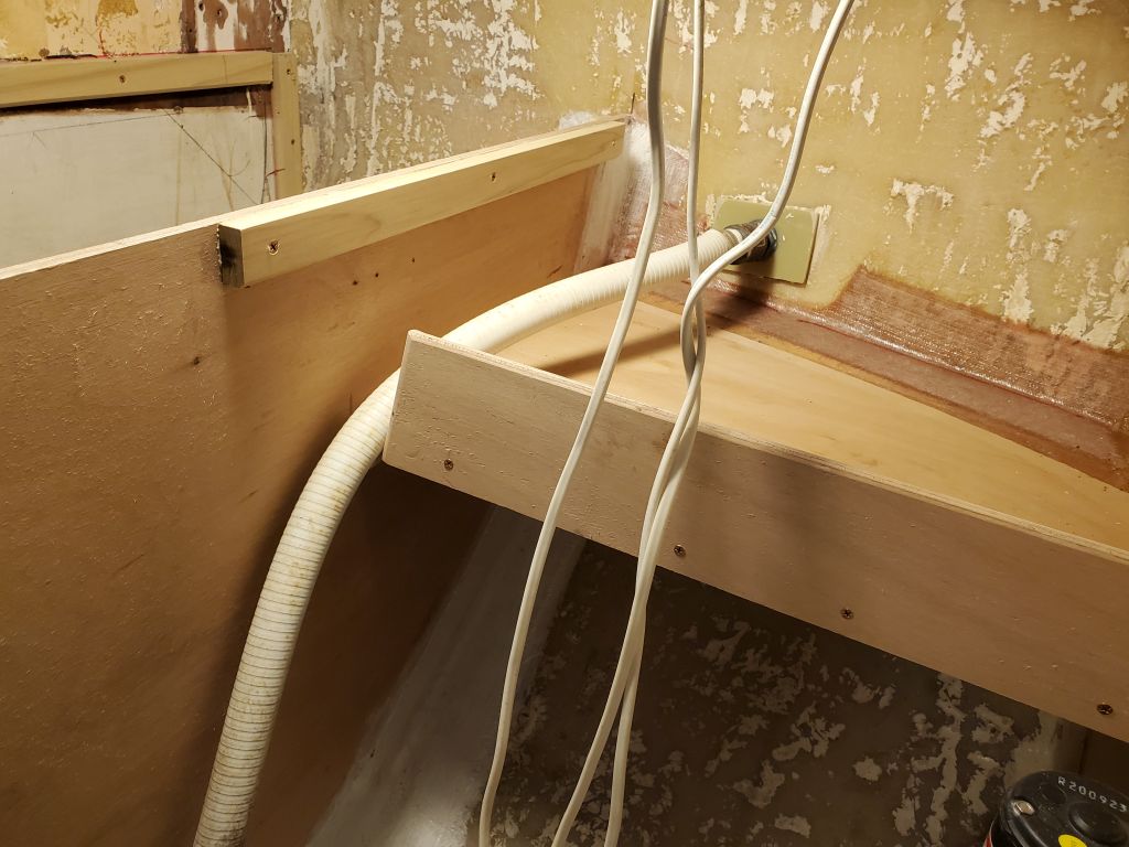
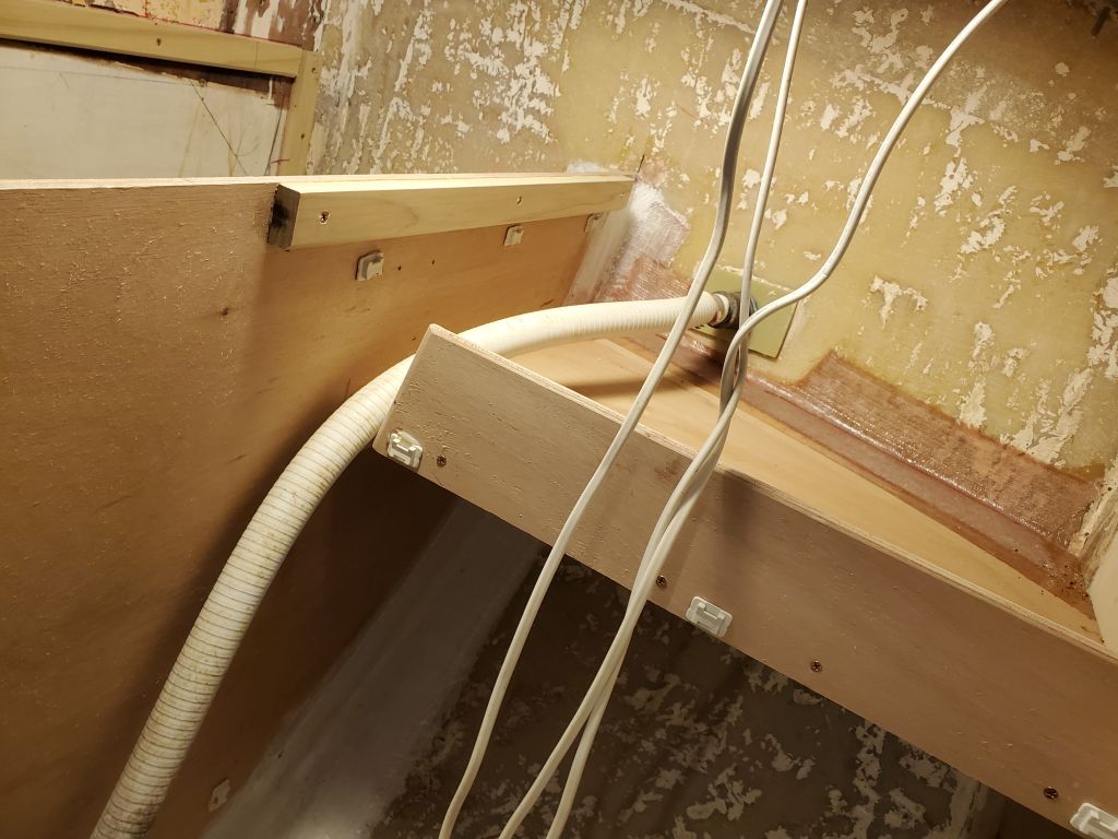
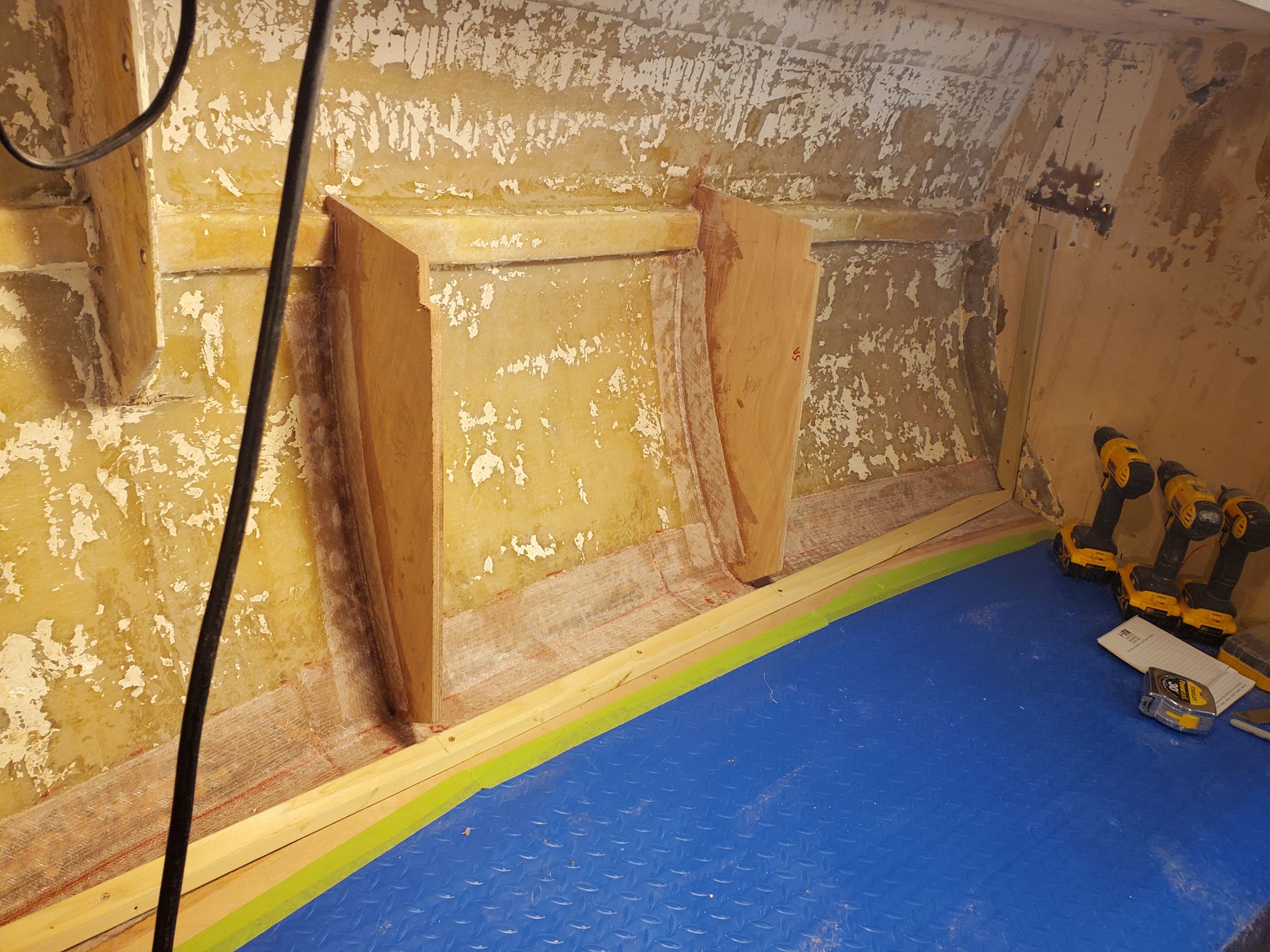
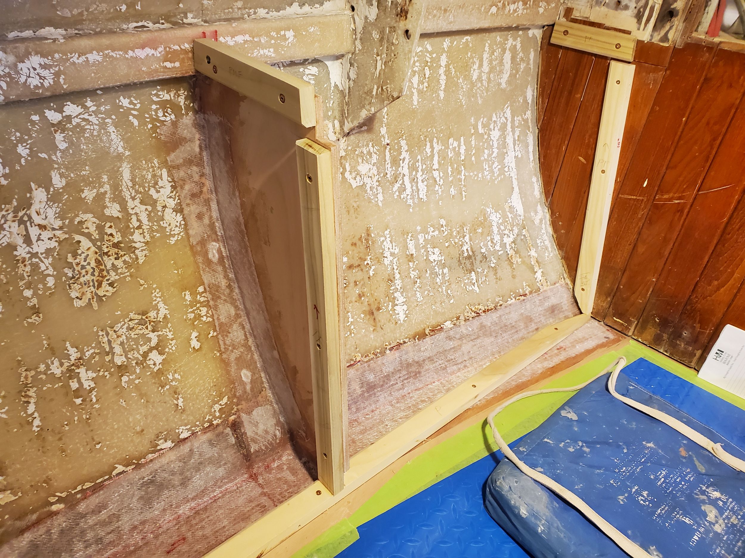
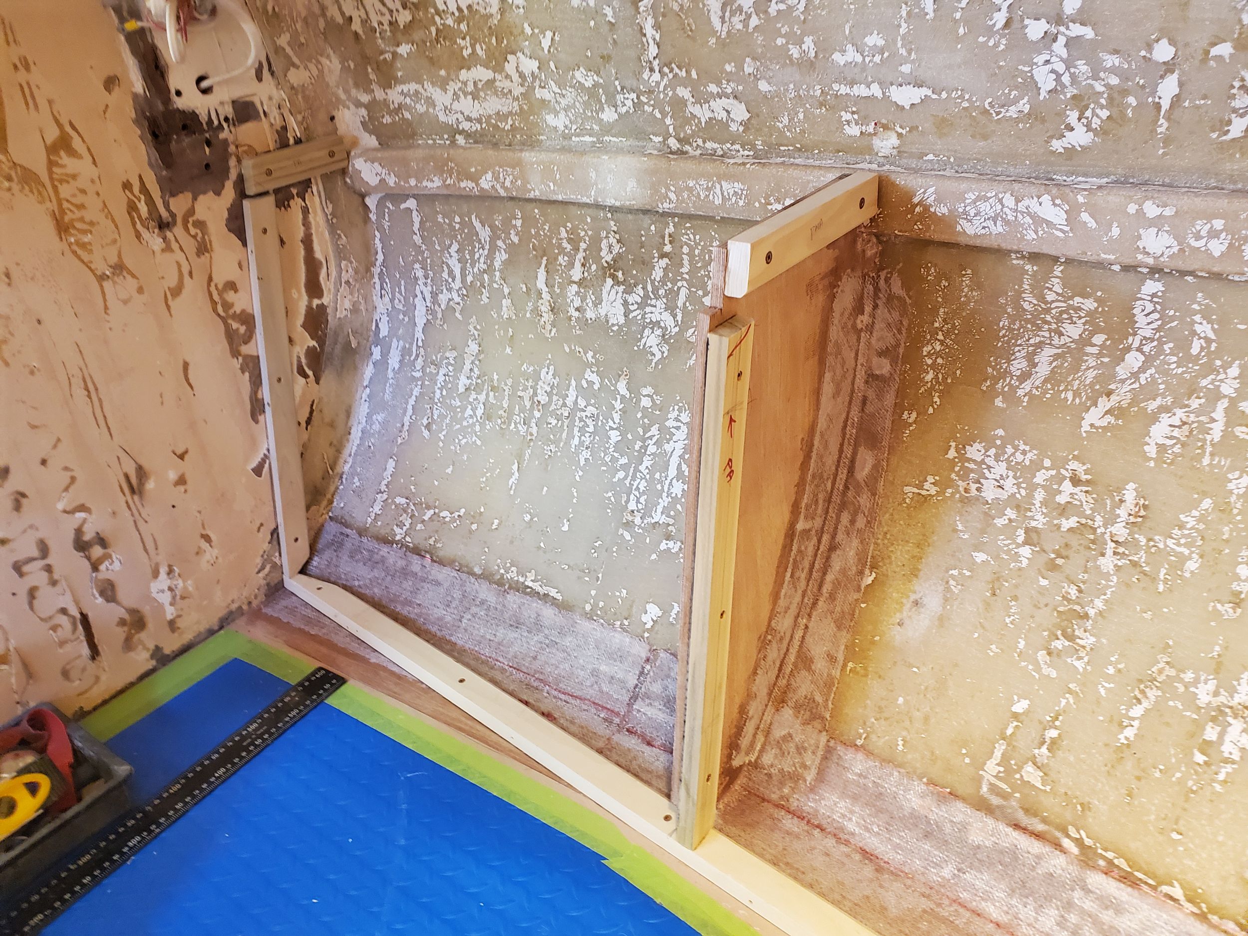
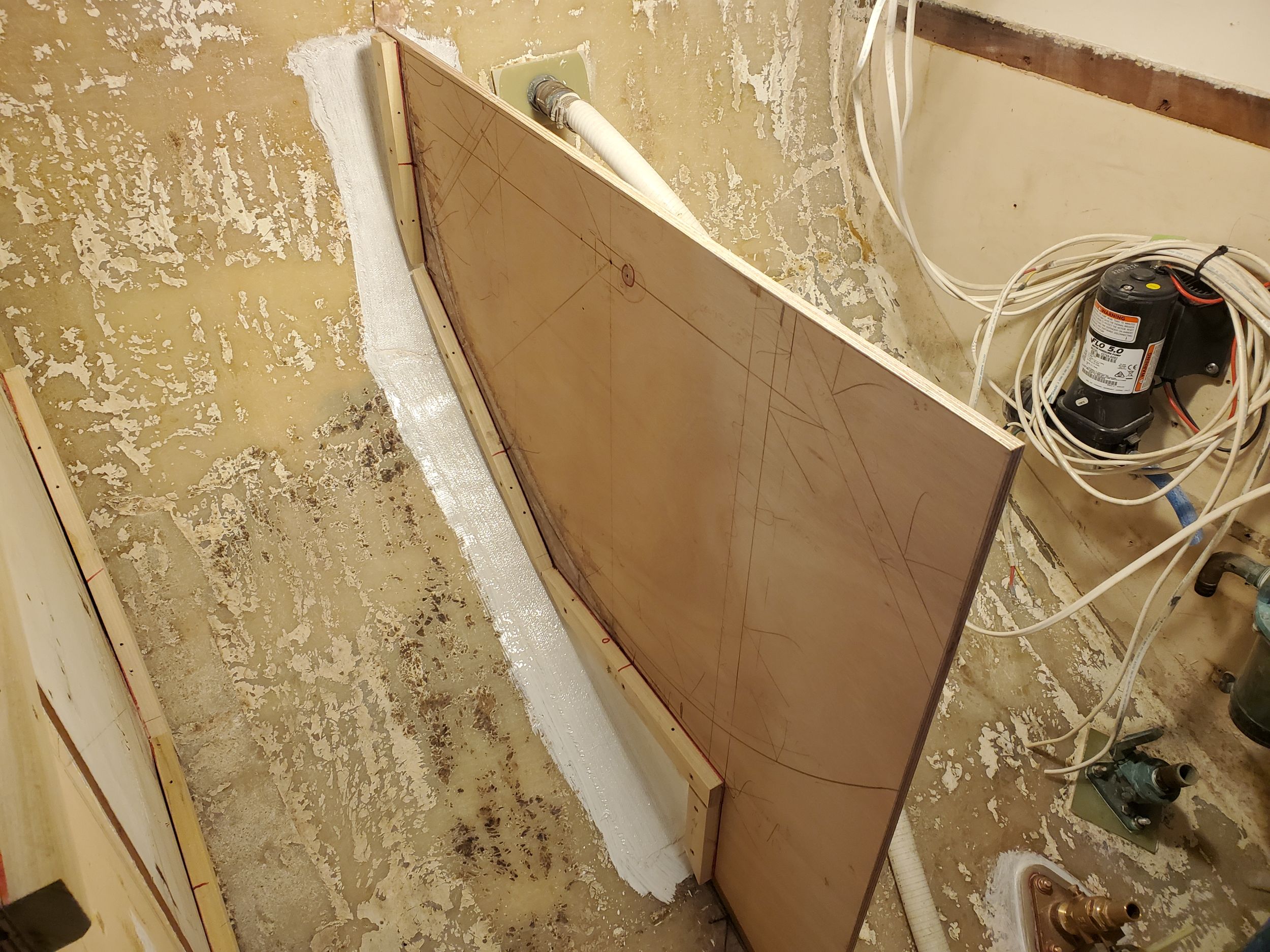
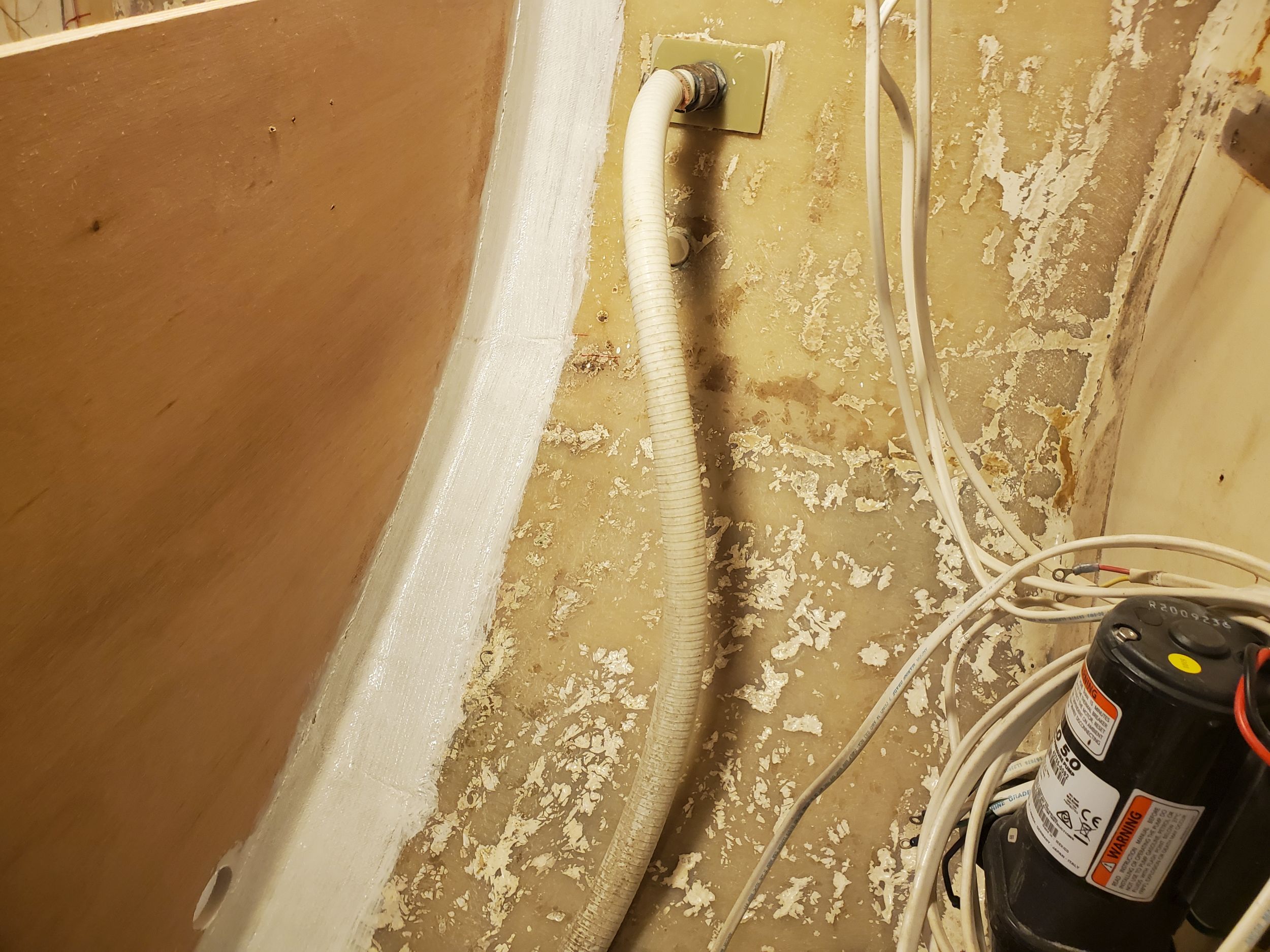
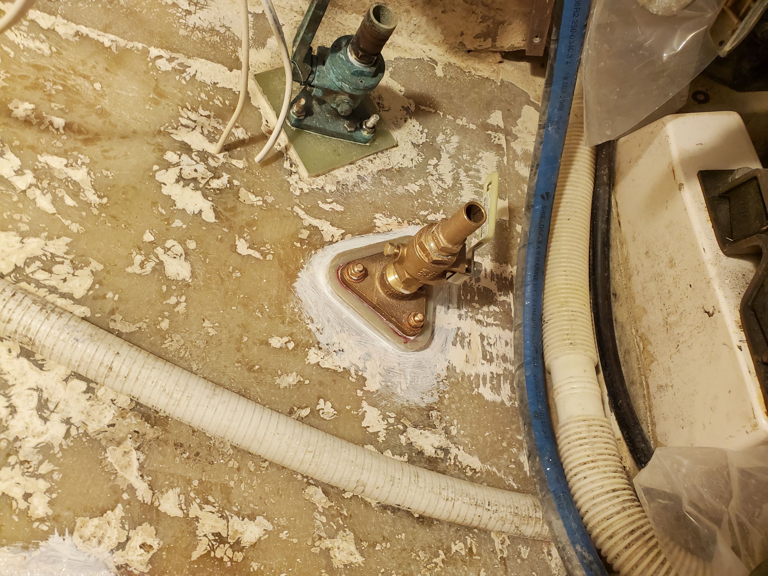
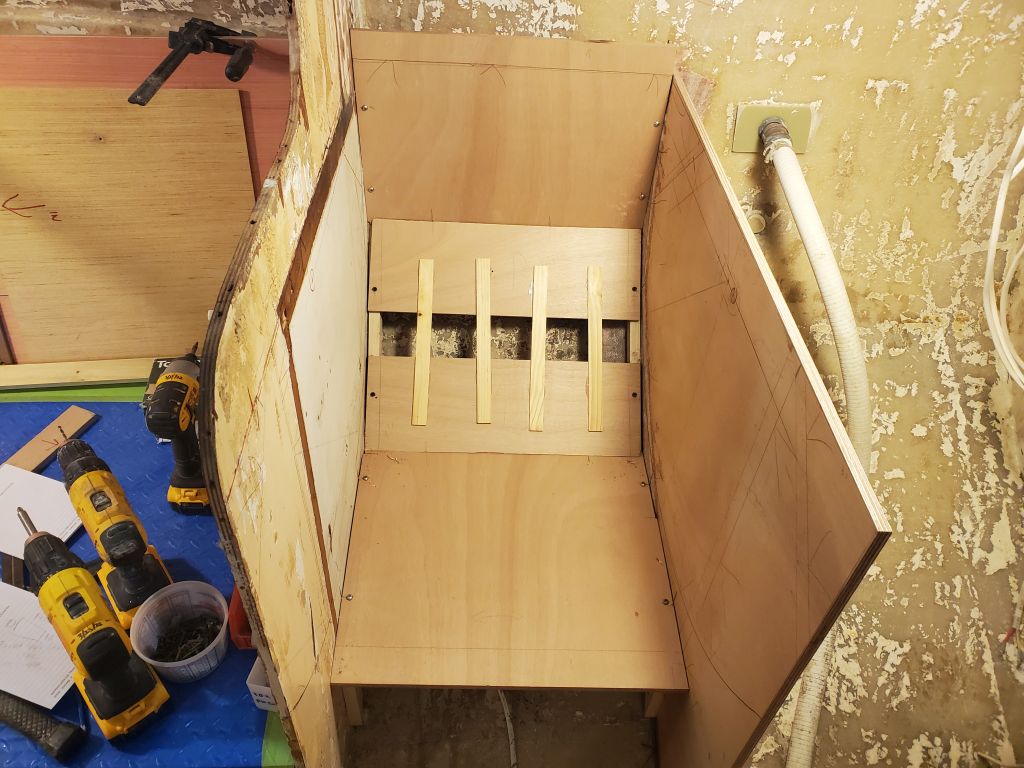
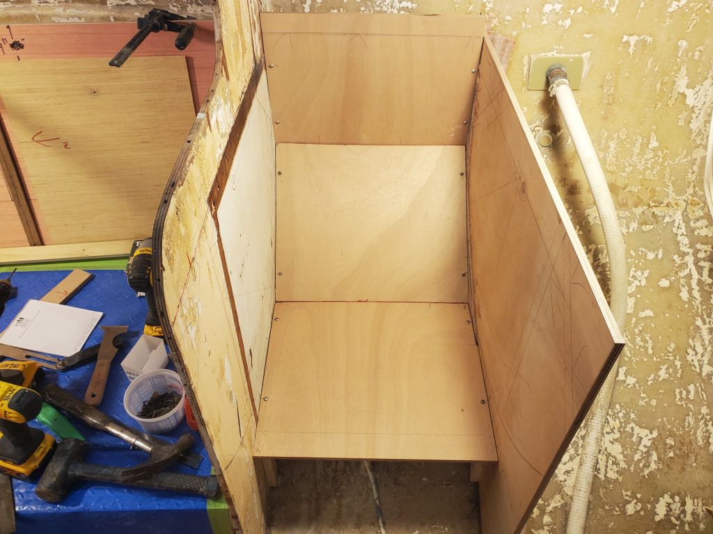
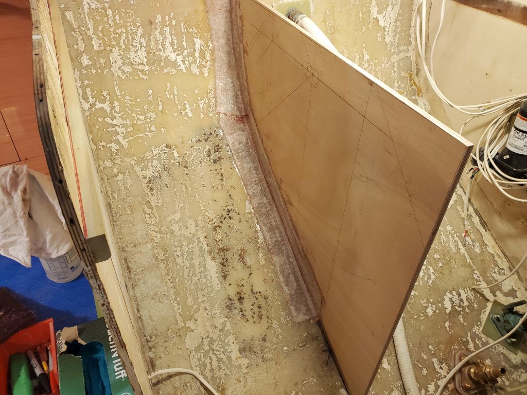
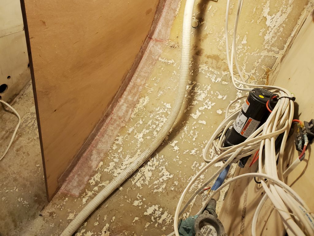
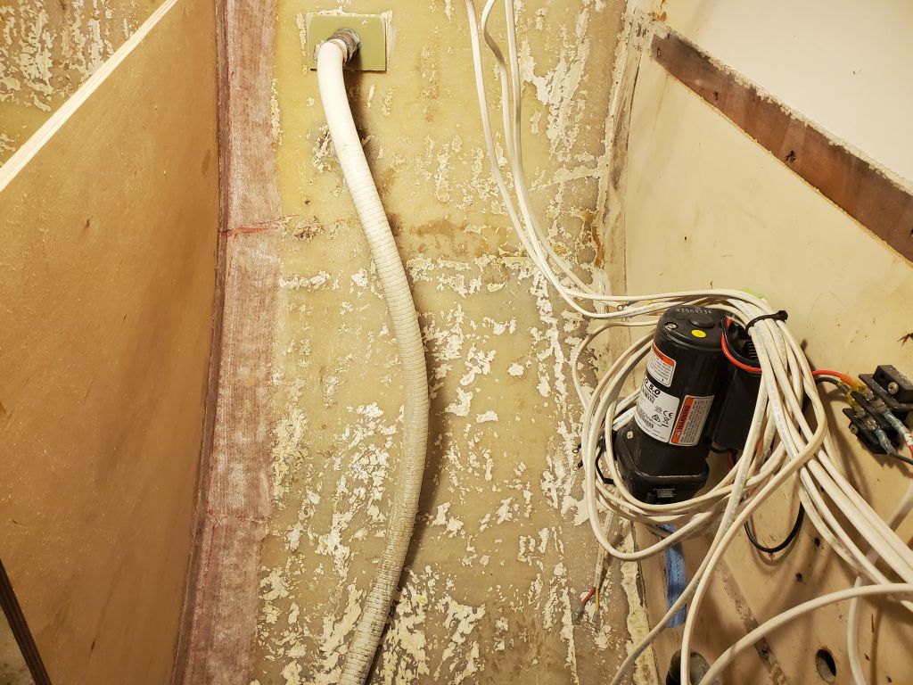
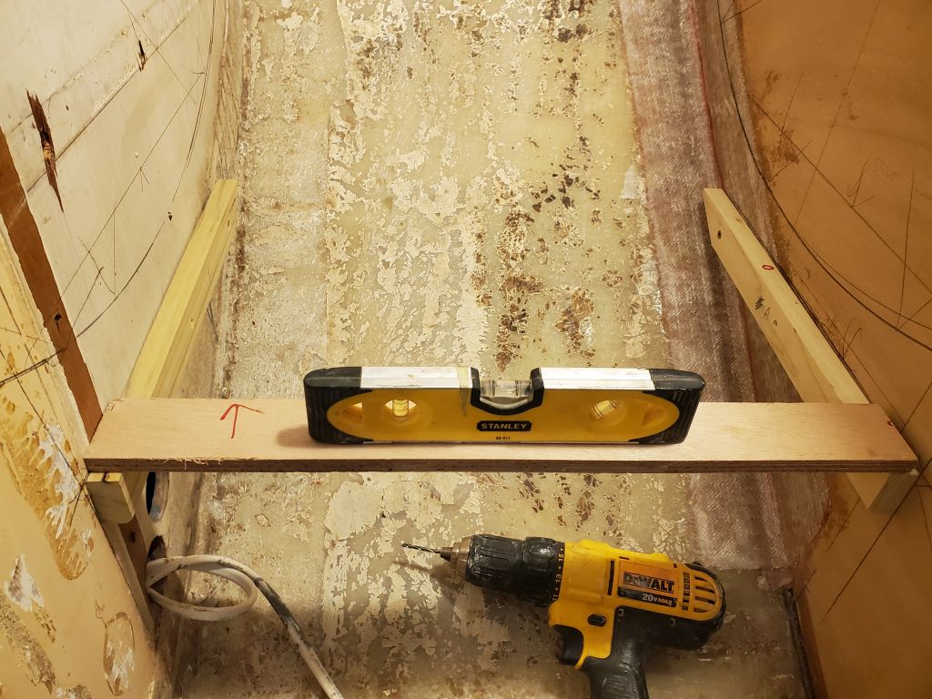
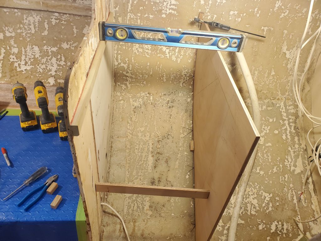
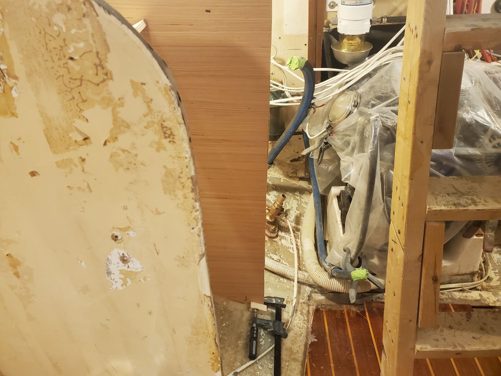
In the galley, I wanted to provide a shelf beneath the countertop to provide some storage that would be accessible through a hatch in the back corner of the countertop to help make use of this otherwise-inaccessible and wasted space. The shelf had to clear a discharge hose and skin fitting, and couldn’t be too far down lest it be too deep for the access provided.
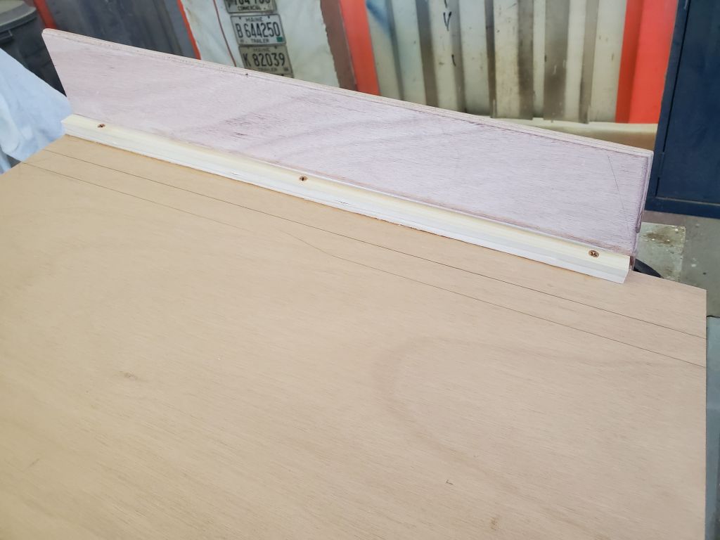
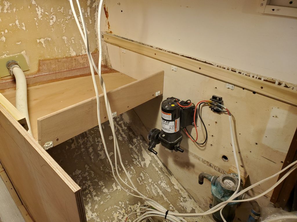
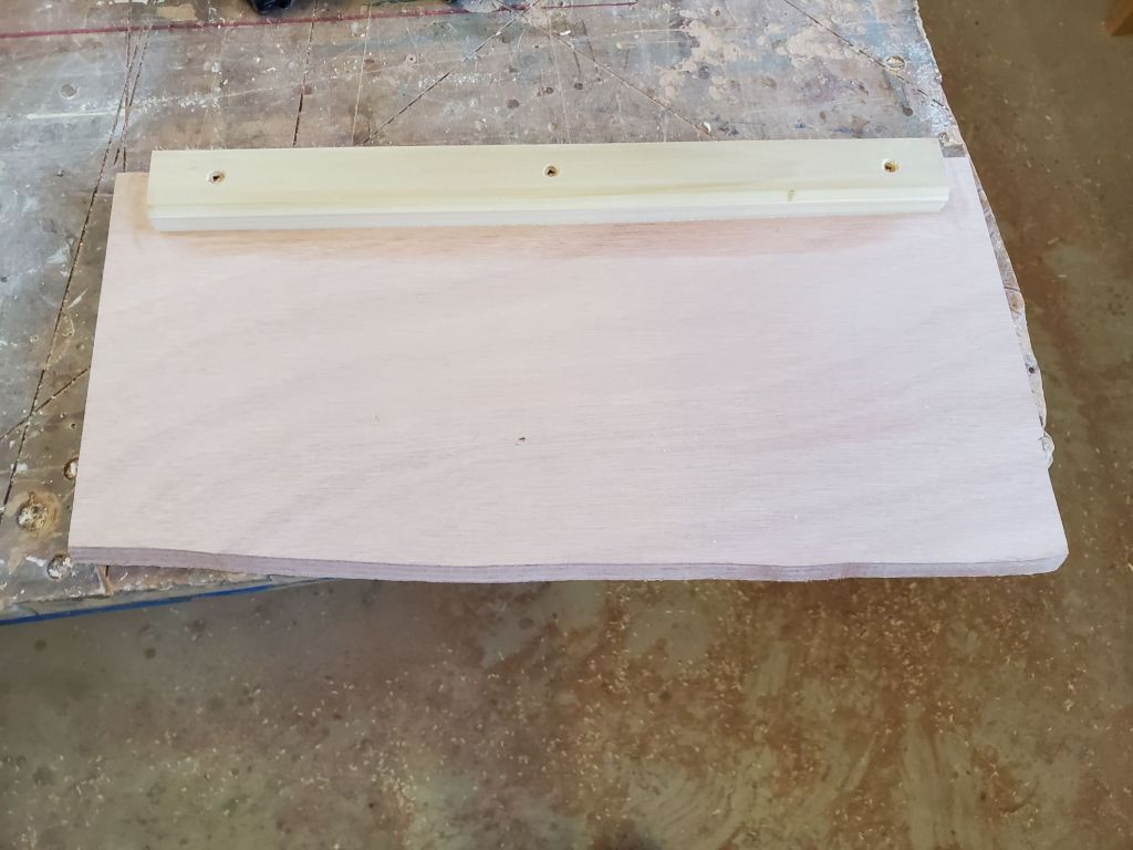
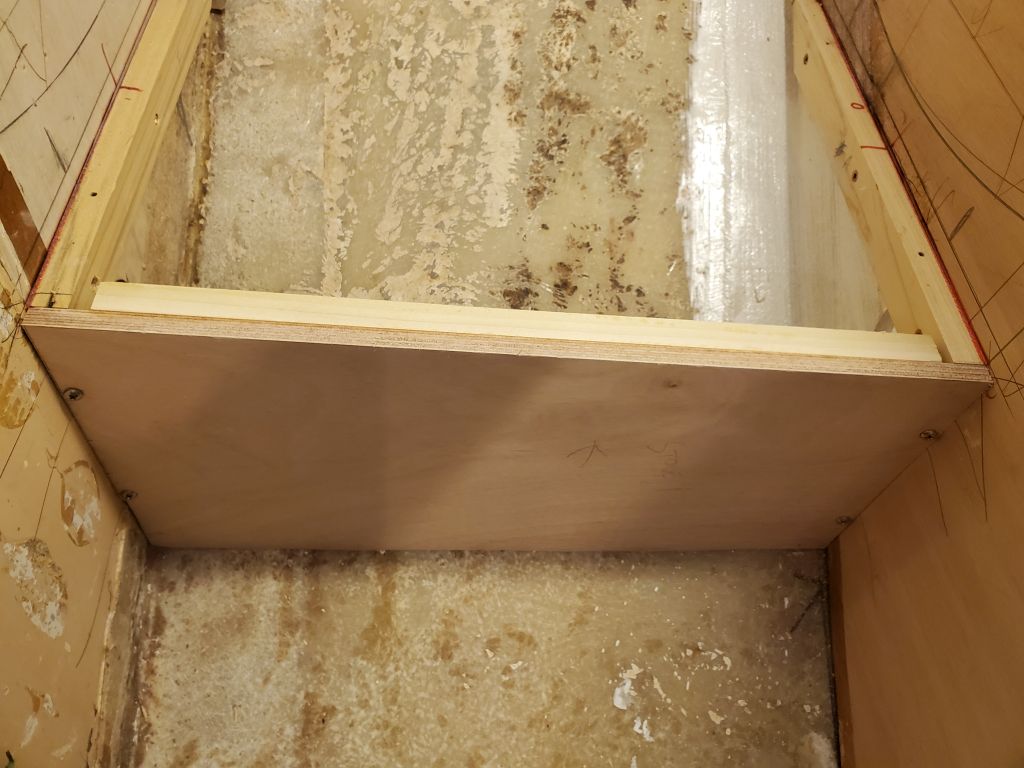
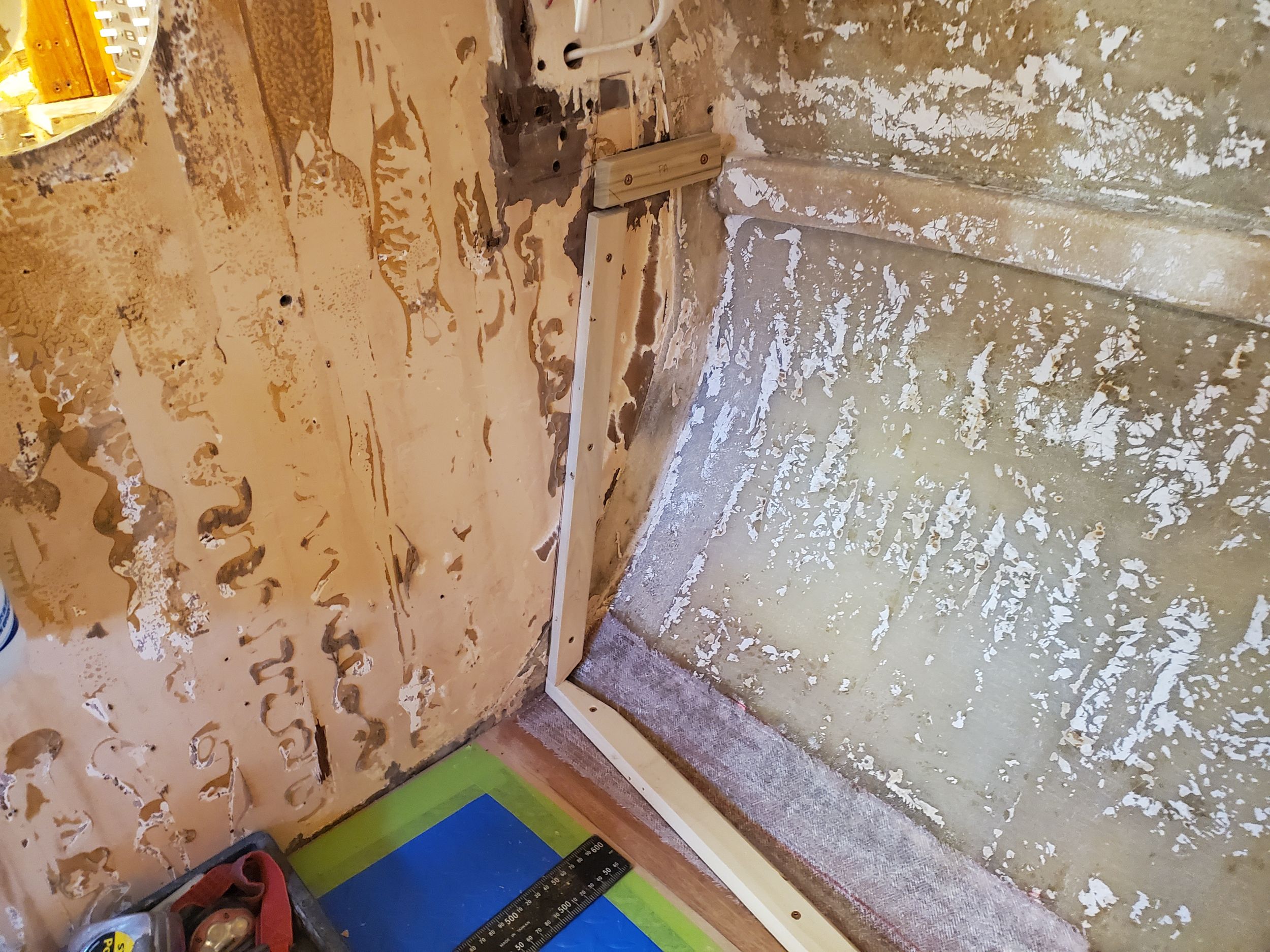
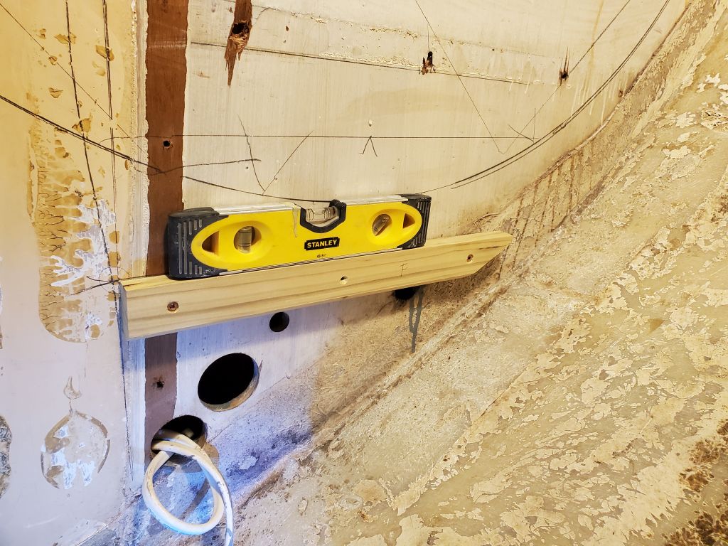
I started with some support cleats on both bulkheads, an appropriate distance down. Next, with a rough plywood template, I patterned the shelf, and cut the final shelf from 12mm marine plywood. I added a fairly tall plywood fillet at the inboard edge, to hold whatever shelf contents there would be, and left space for the hose to run on its course. Finally, I installed the shelf with glue and screws on the support cleats, and a strip of tabbing to secure it to the hull in the usual way.
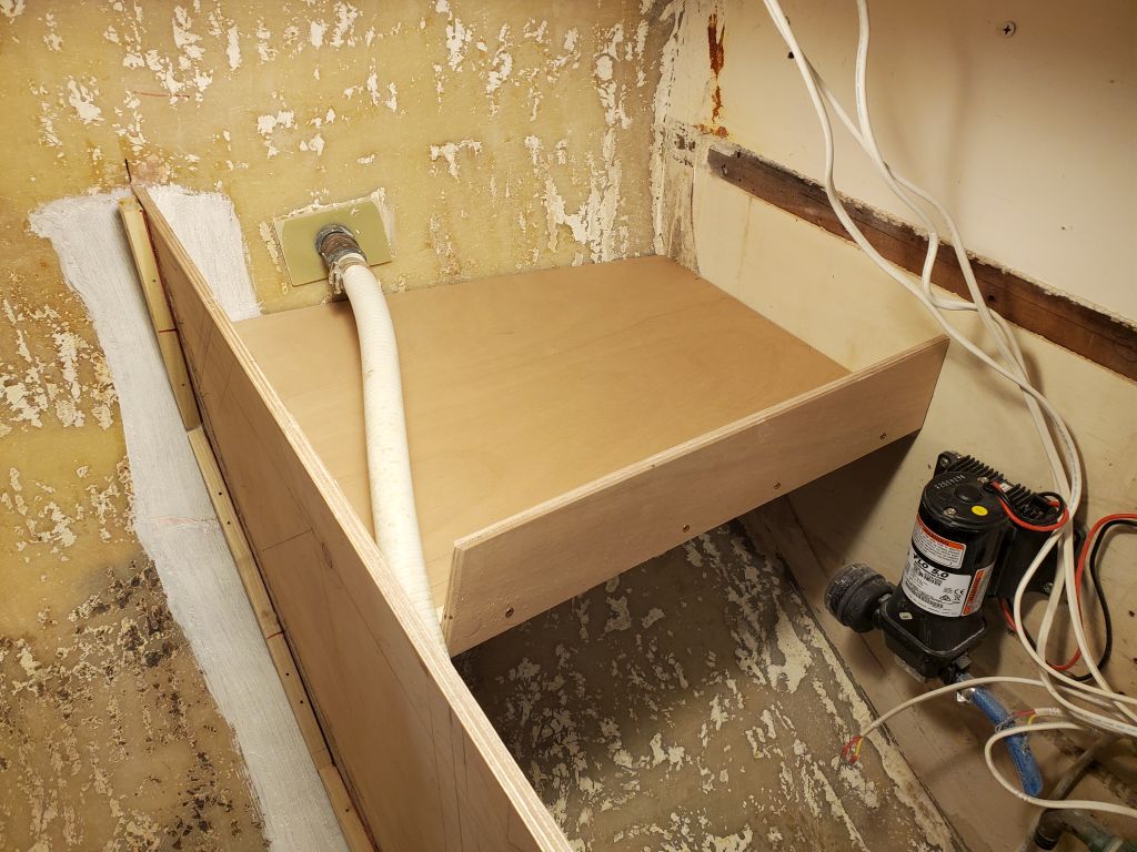
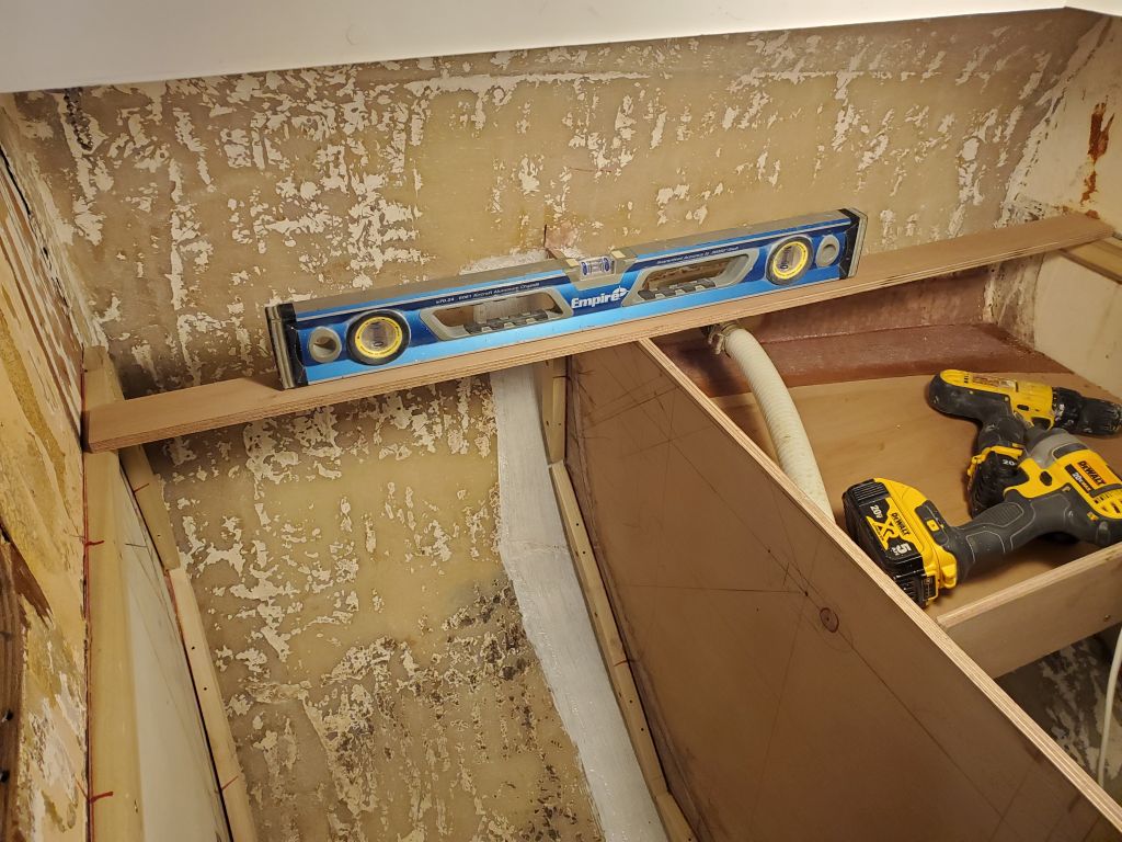
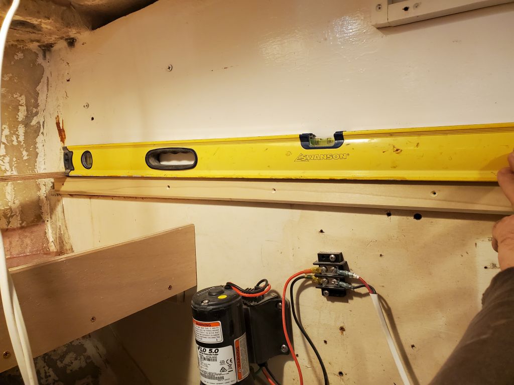
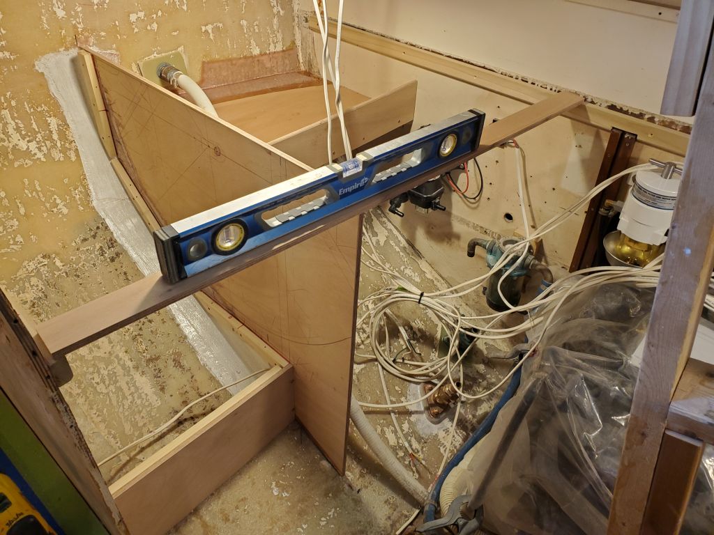
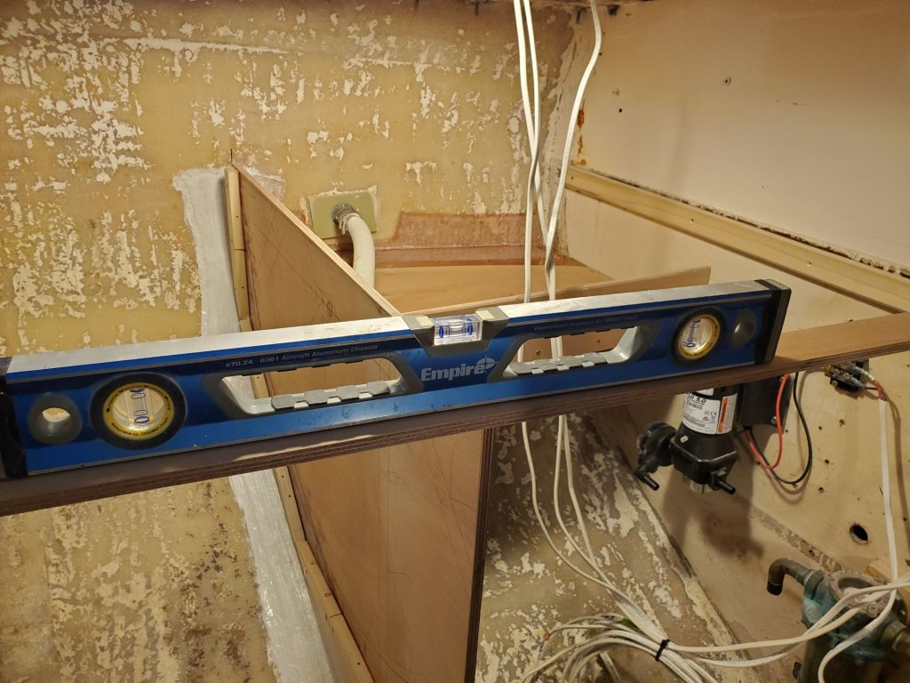
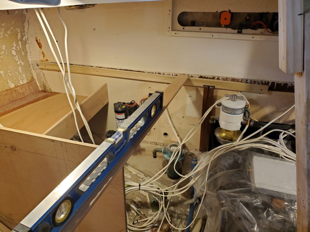
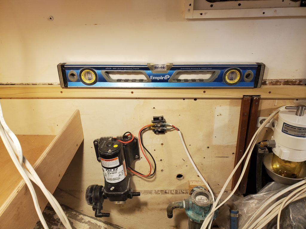
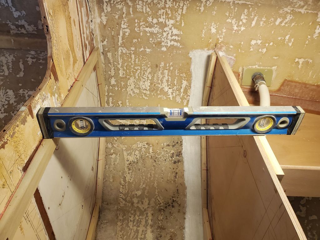
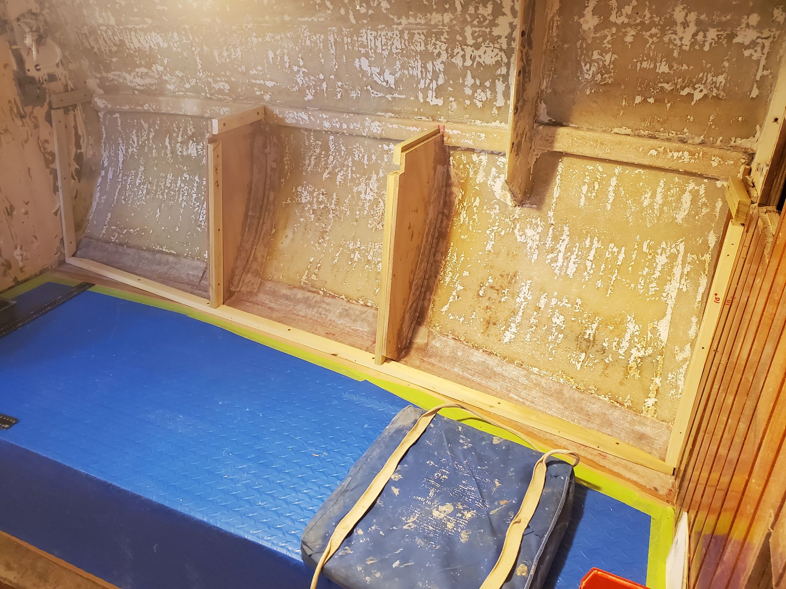
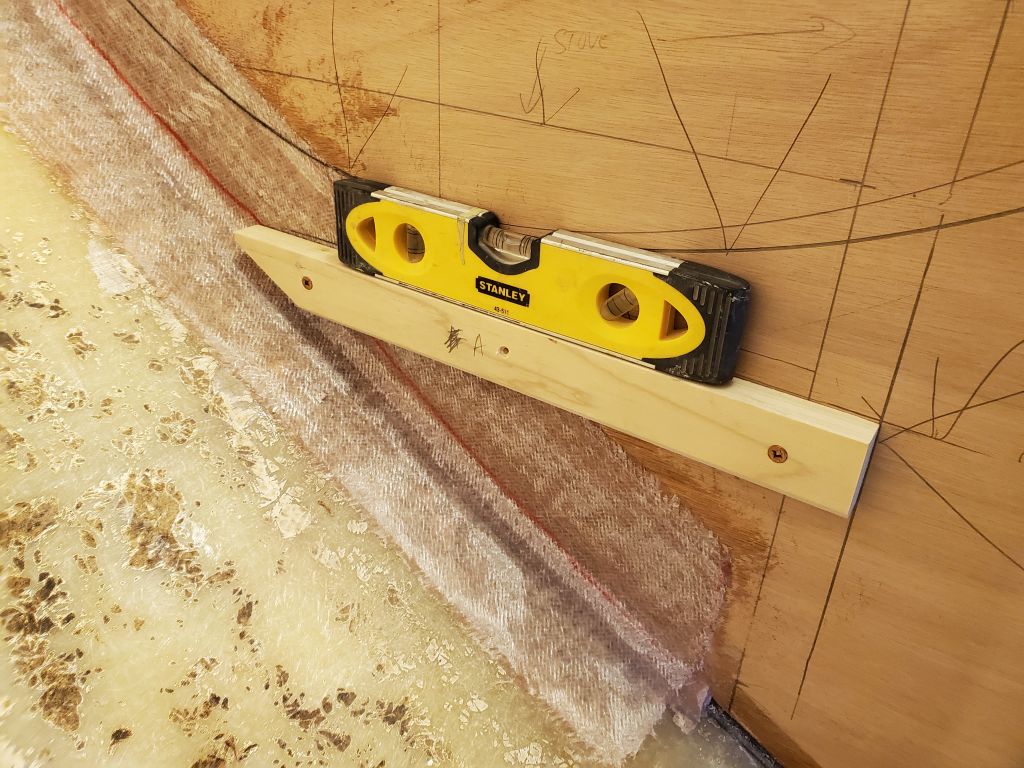
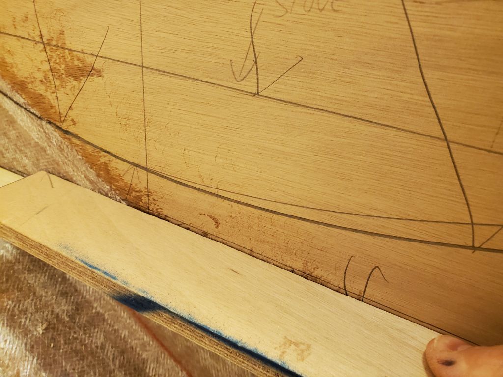
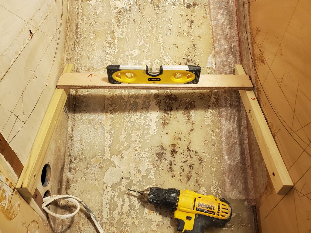
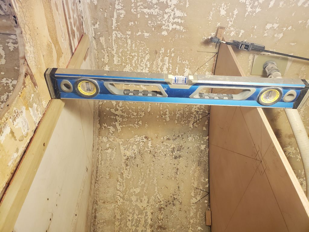
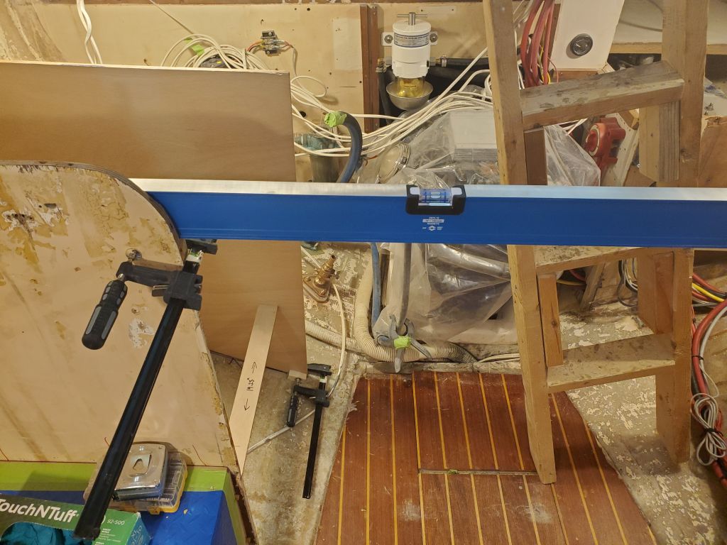
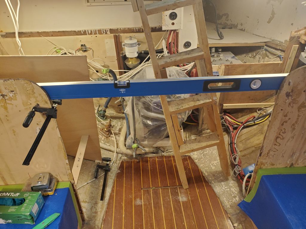
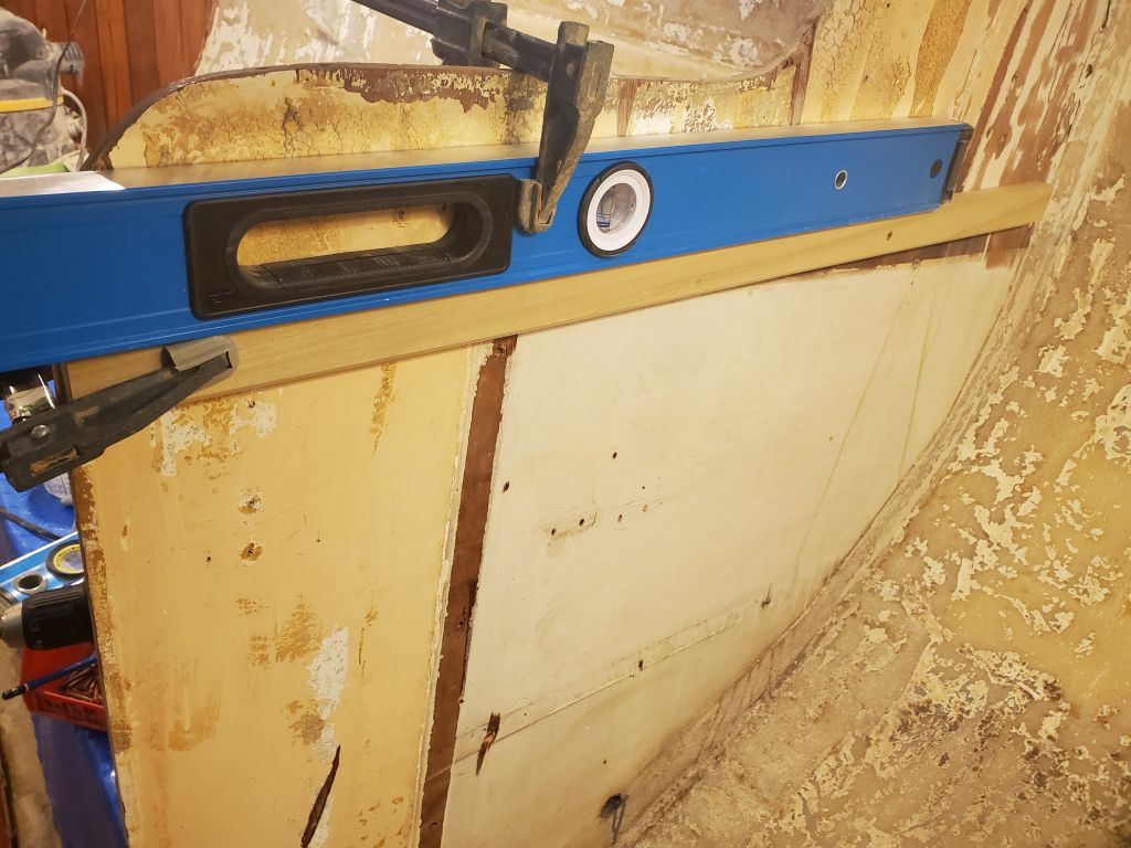
I continued with some additional cleats to support the countertop, including one along the aft bulkhead, and one on the new stove bulkhead, which I kept short at this point since there’d be a support beam running across the boat that I needed to tie in with and secure to the aft side of the bulkhead. I leveled the countertop line across the stove and reference cleat from the forward bulkhead, and checked its position with a long level run across to the port side of the galley, where the countertop height had originally been set earlier in the project.
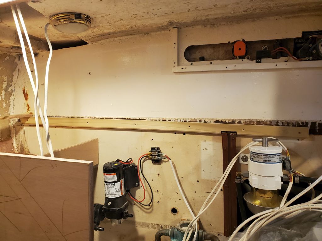
Next, while the access was good and I was thinking about it, I installed some wire mounts in the space to help me start cleaning up the existing wiring that I’d removed from its original mountings in the old galley.
I’d considered adding an access hatch to the short bulkhead at the inboard edge of the stove compartment, but the opening would have been so small as to be nearly worthless, so instead I decided to make the whole panel removable for access behind if necessary, much like its counterparts on the port side. I installed a support cleat along the top edge of the panel to help support the stove platform above, and secured the panel with screws. I’d remove this later for finishing when the time came.
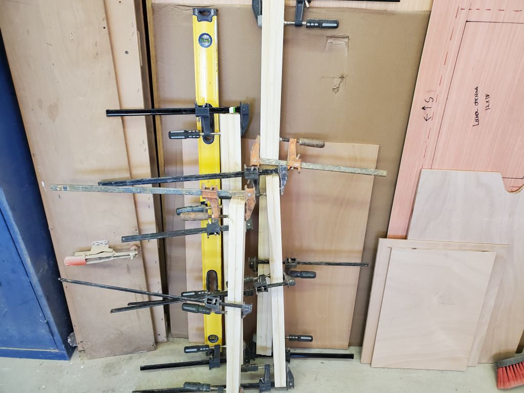
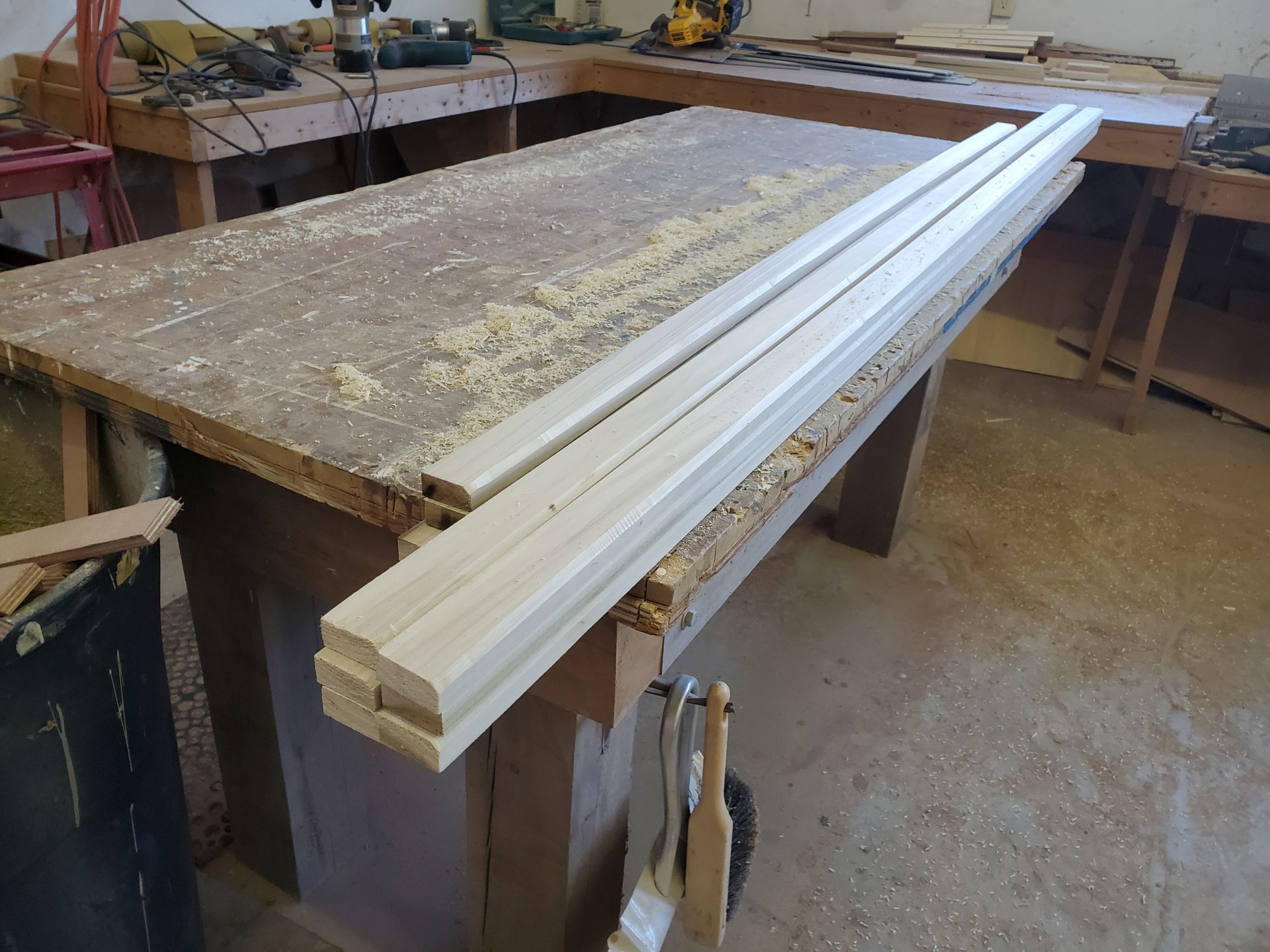
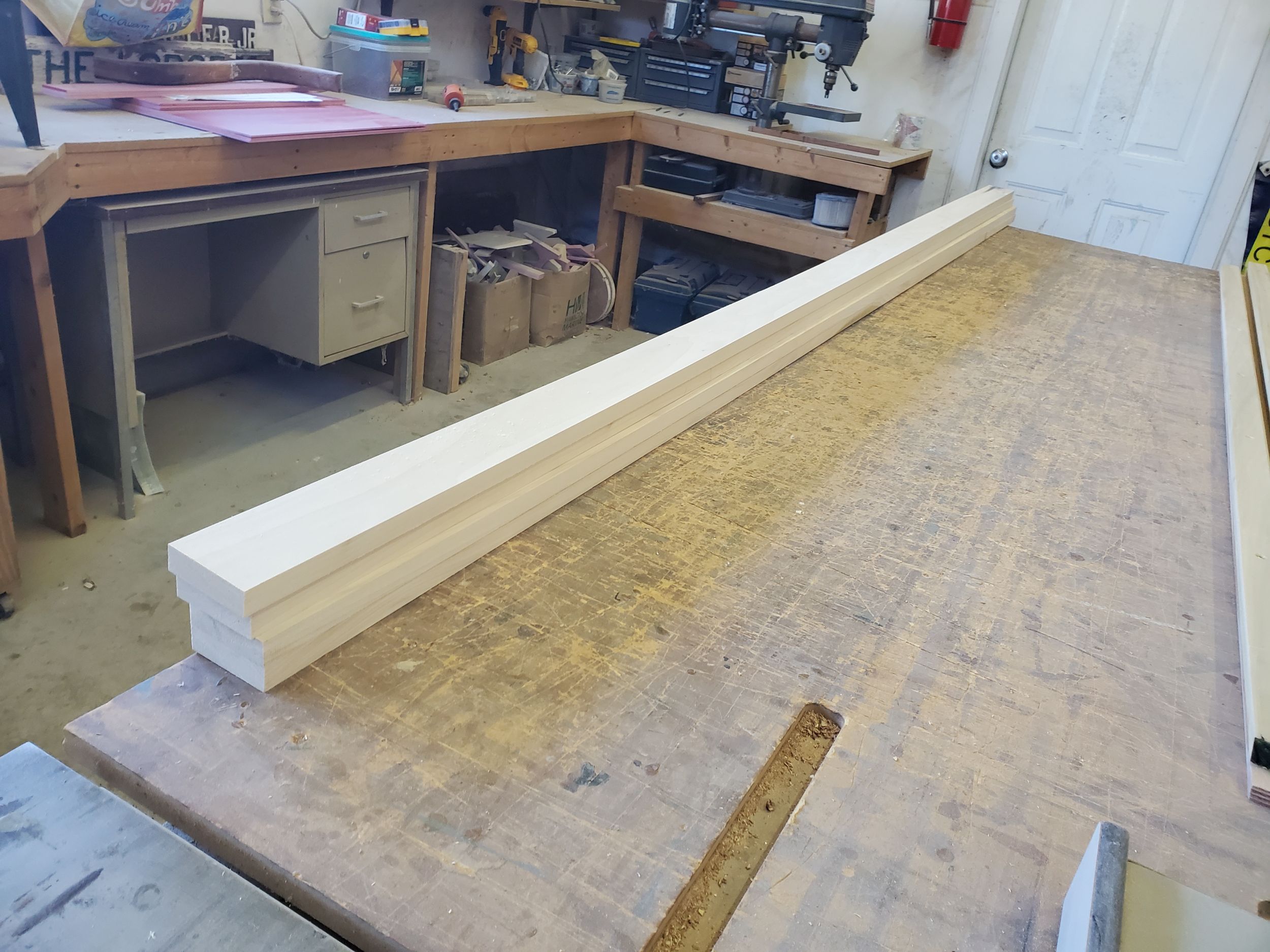
The final odd in a day of odds and ends was to glue-laminate several support beams for the galley structure, including a horizontal beam, vertical support, and a couple interim countertop support pieces. I glued these from the poplar that I’d cut earlier, using waterproof wood glue and clamping securely till cured.
My first task, as is the usual way of things, was to lightly sand the new tabbing securing the settee backrest divider bulkheads.
I installed some pre-cut cleat stock to the upper back edges of the two plywood settee backrests with glue and screws, and set these aside to give the glue a chance to set up.
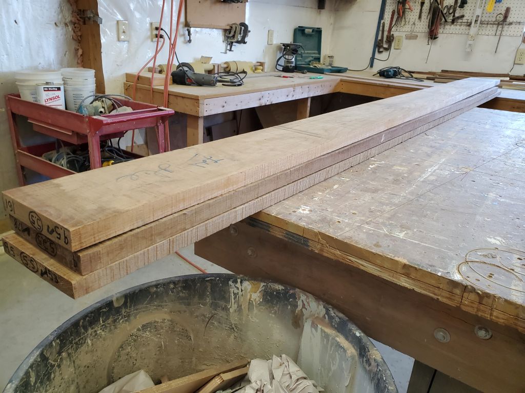
I’d used up all my cleat stock, so I took a few minutes to mill a new supply, as well as milling some wider pieces that I planned to use for support beams in the galley.
Now I brought the two backrests up into the boat for a dry fit. The pieces fit well, with just a bit of minor, final reshaping on the starboard side. I secured the backrests with several screws to hold them tightly to the support cleats for the next process, which was to fit and determine the positions of several additional support cleats: one on each divider bulkhead; plus four per side along the top edges of the dividers and fore and aft bulkheads to support the horizontal shelf above. I measured and cut these cleats to the sizes required, then, for the divider cleats, held them in place so they were tight to the backrest and marked the bulkheads accordingly. For the short horizontal shelf-support cleats, I used a level and the cleats themselves to mark lines on the bulkheads for their final positions.
I removed the backrests for clear access, then installed all the support cleats–six per side–with glue and screws, aligning them to the marks.


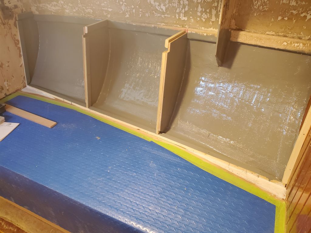
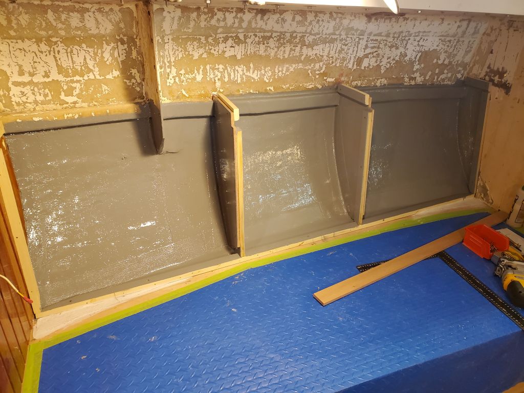
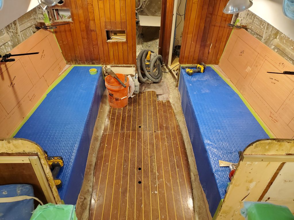
With that, I cleaned up the area and applied epoxy-based 2-part primer over the tabbing inside the settee lockers, and also around the galley stove surround, my extra step to hedge against curing issues with the locker paint.
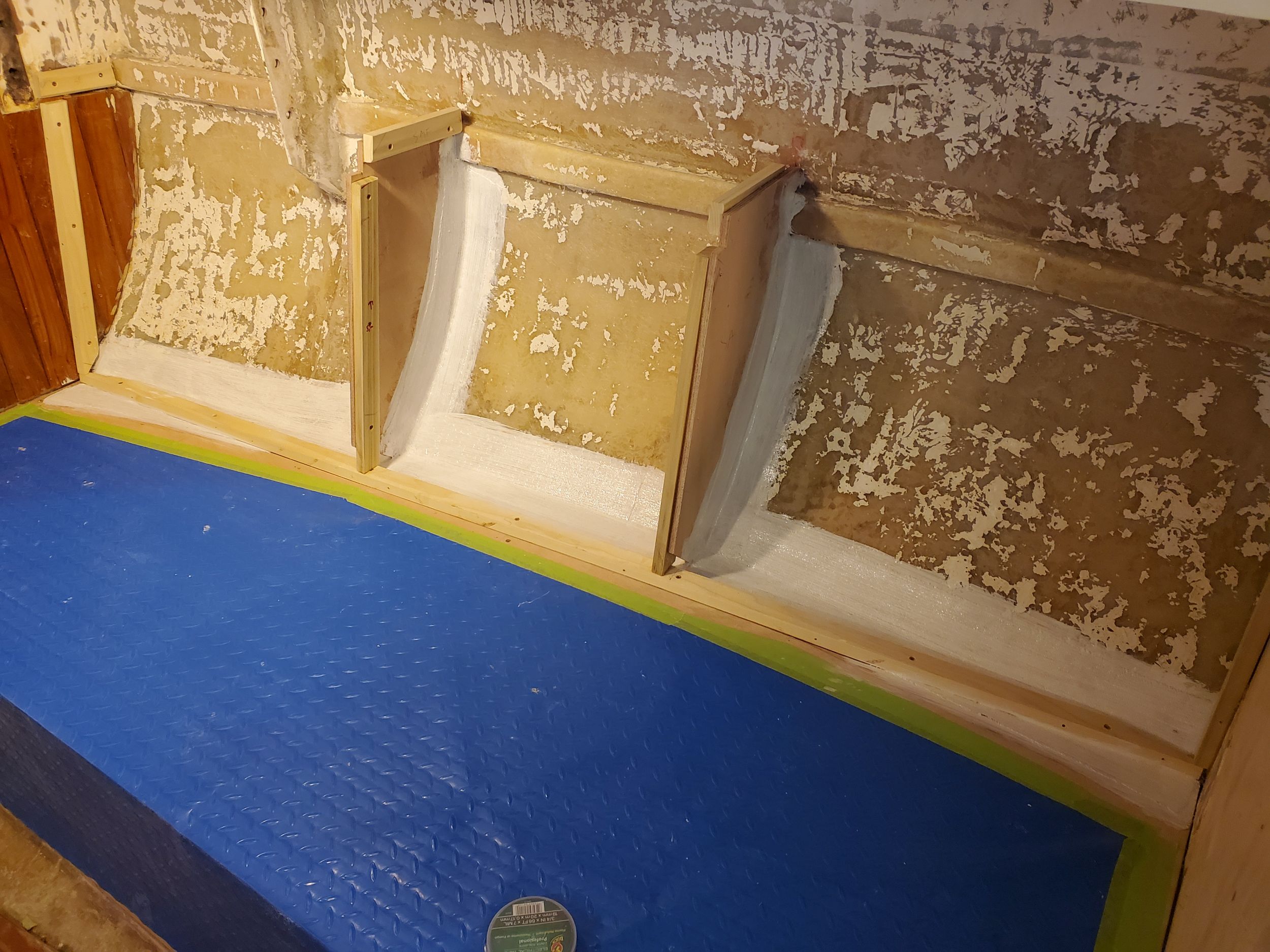
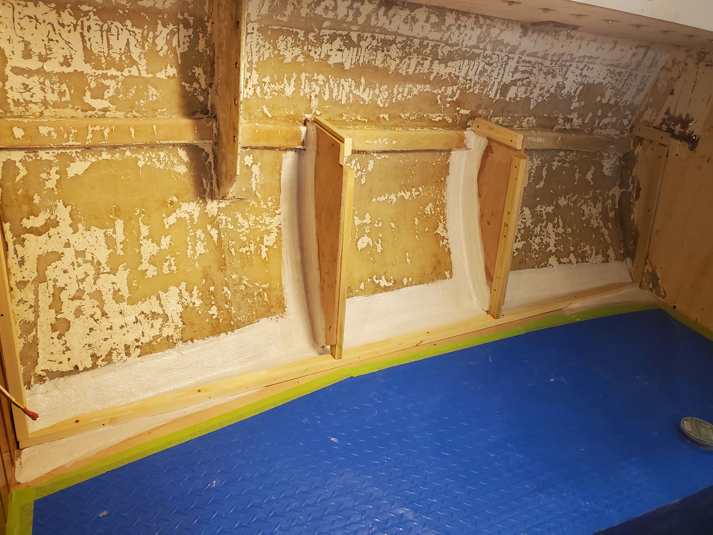
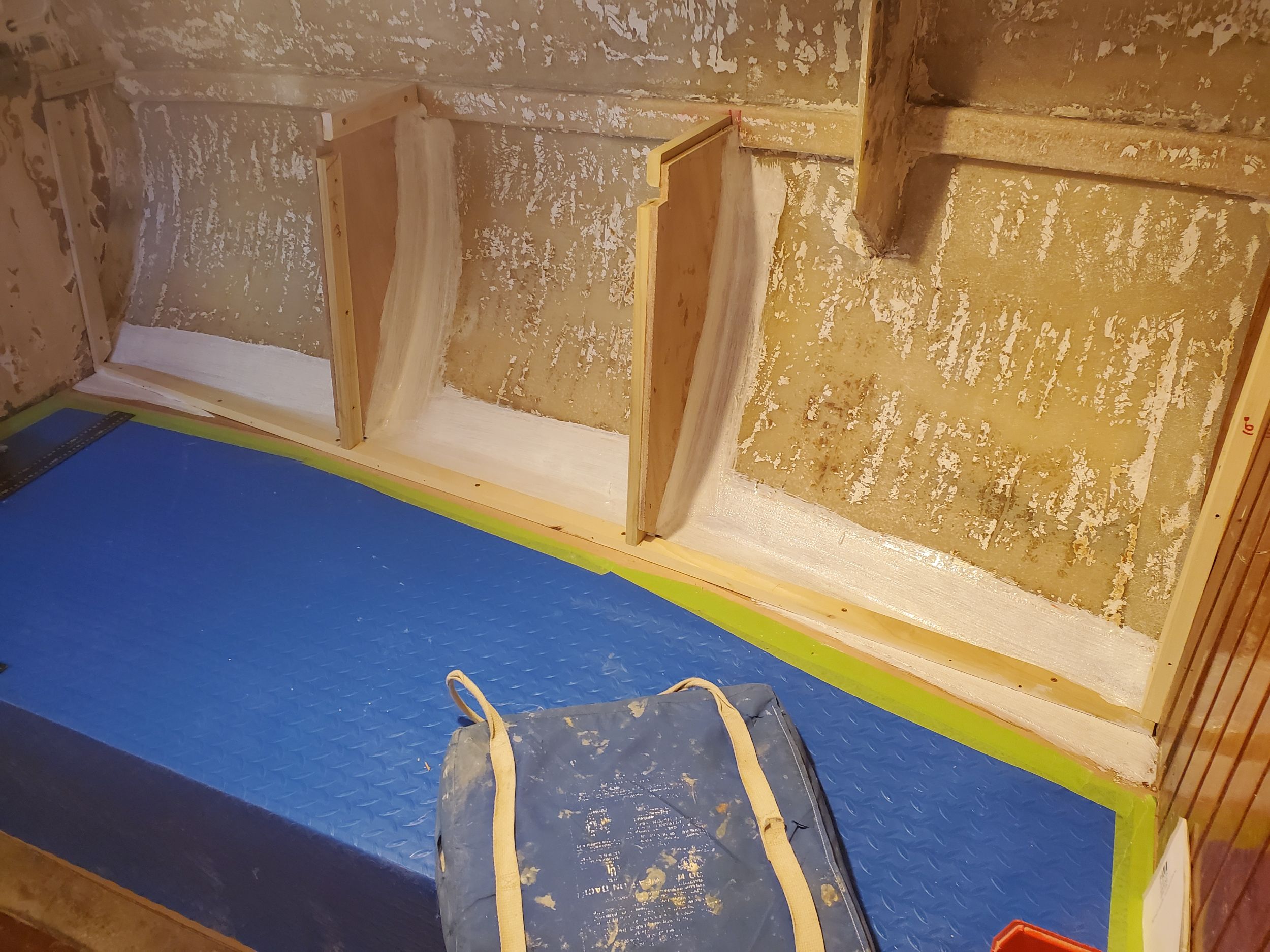
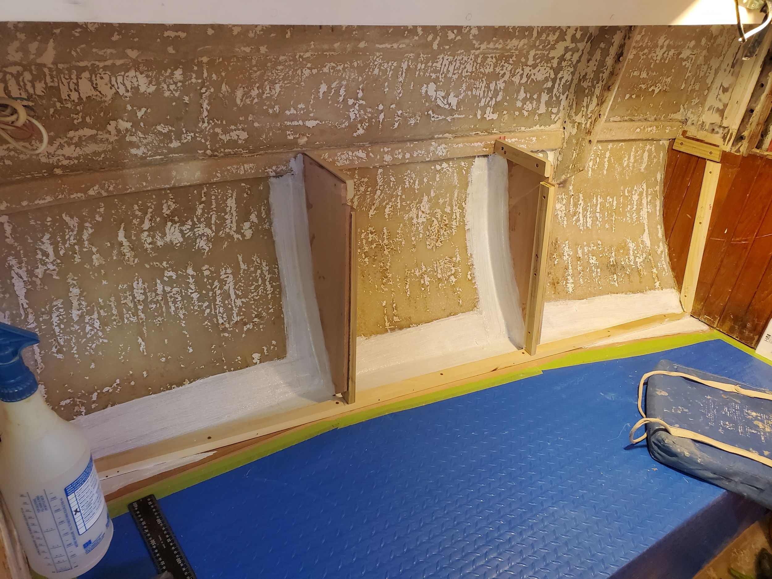
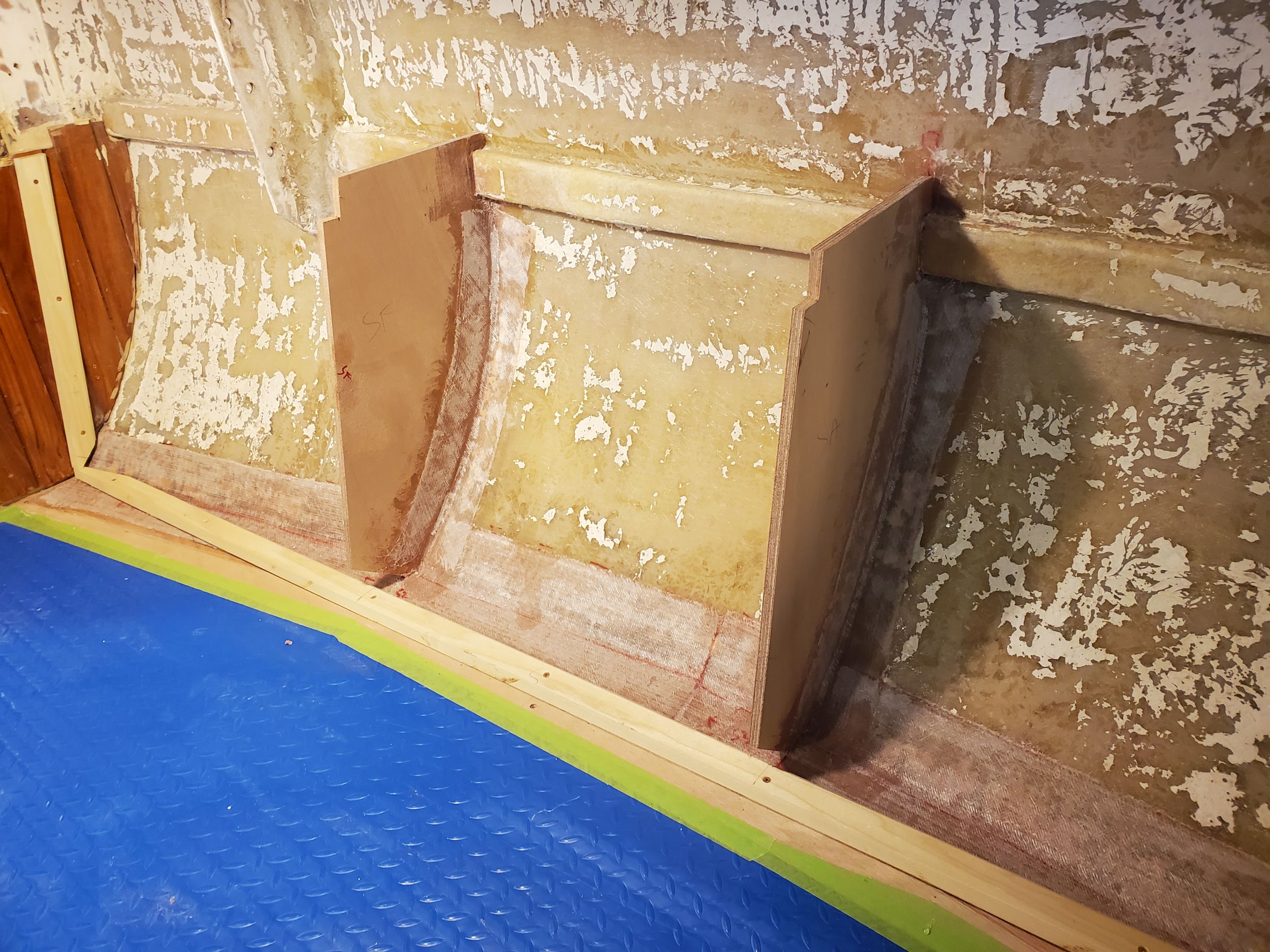
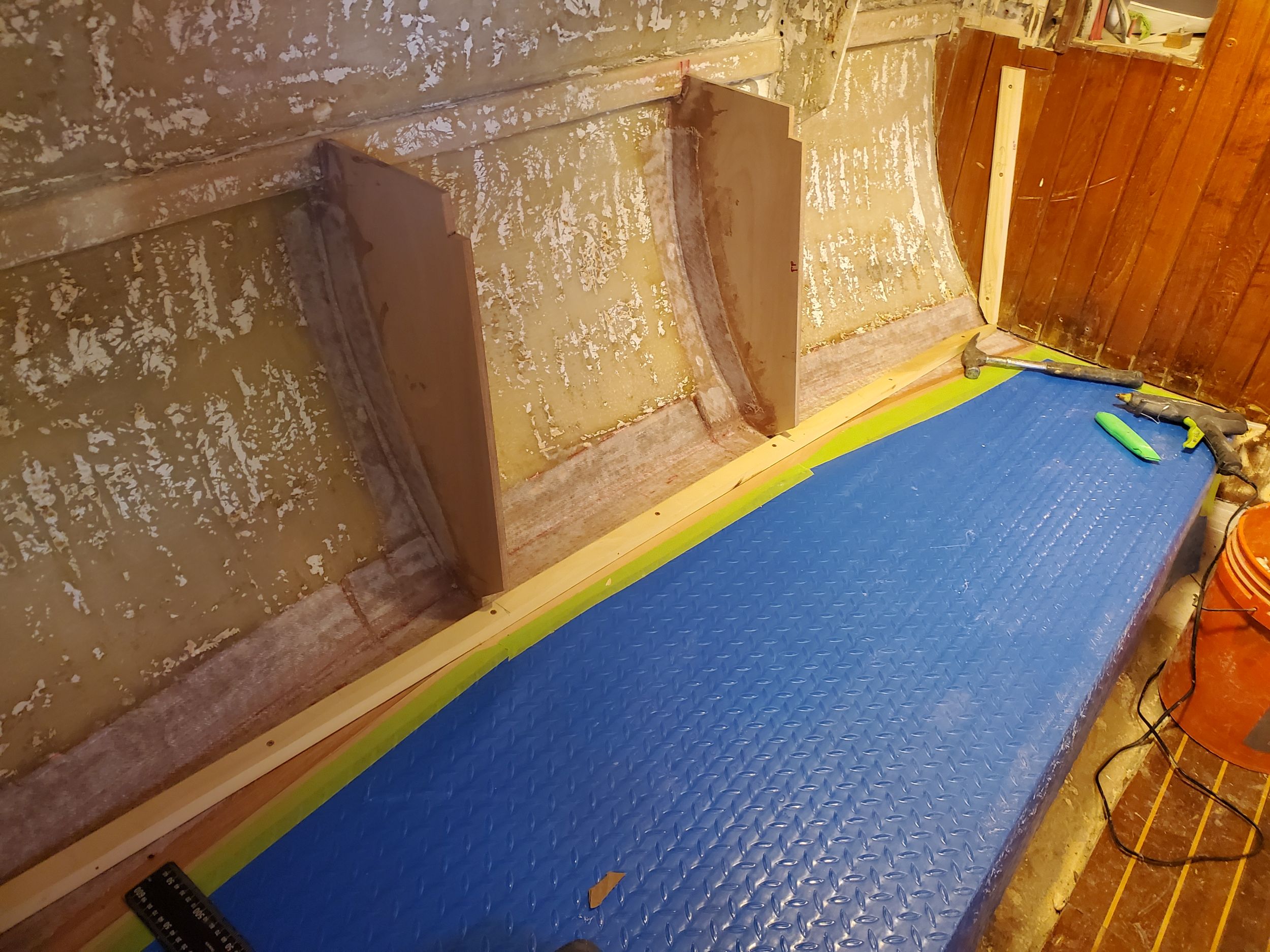
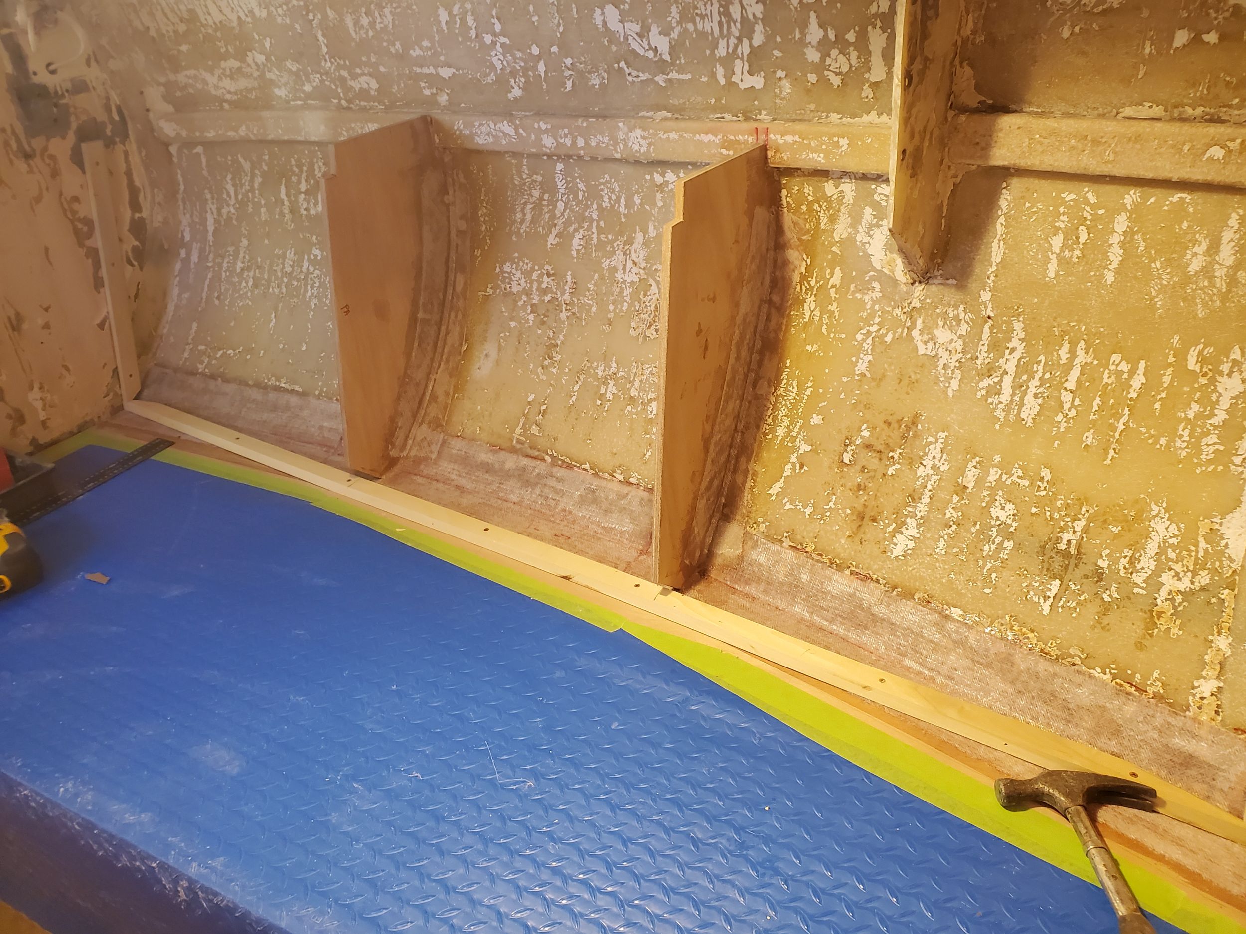
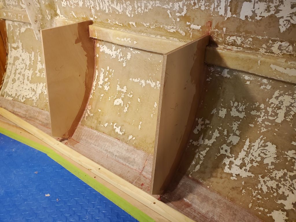
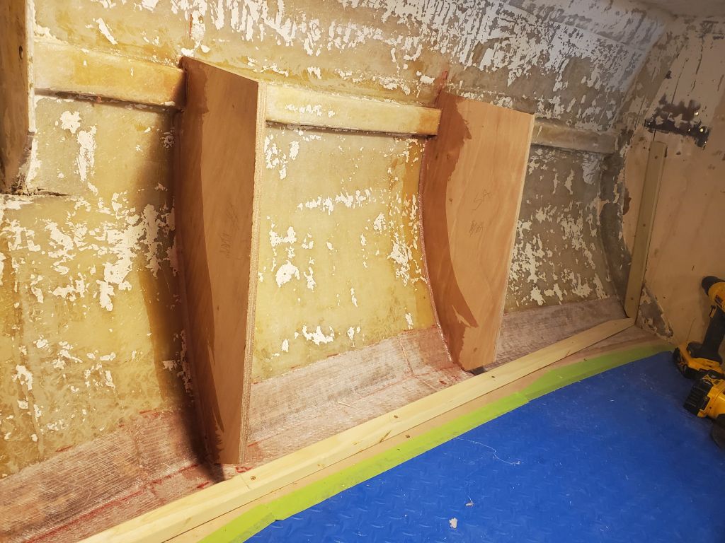
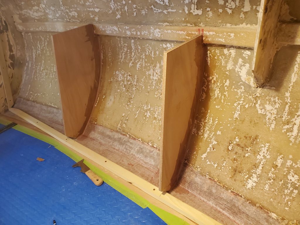
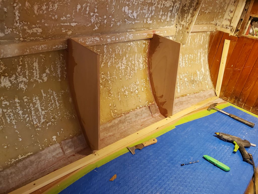
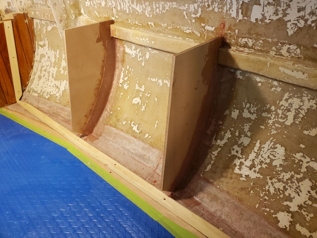
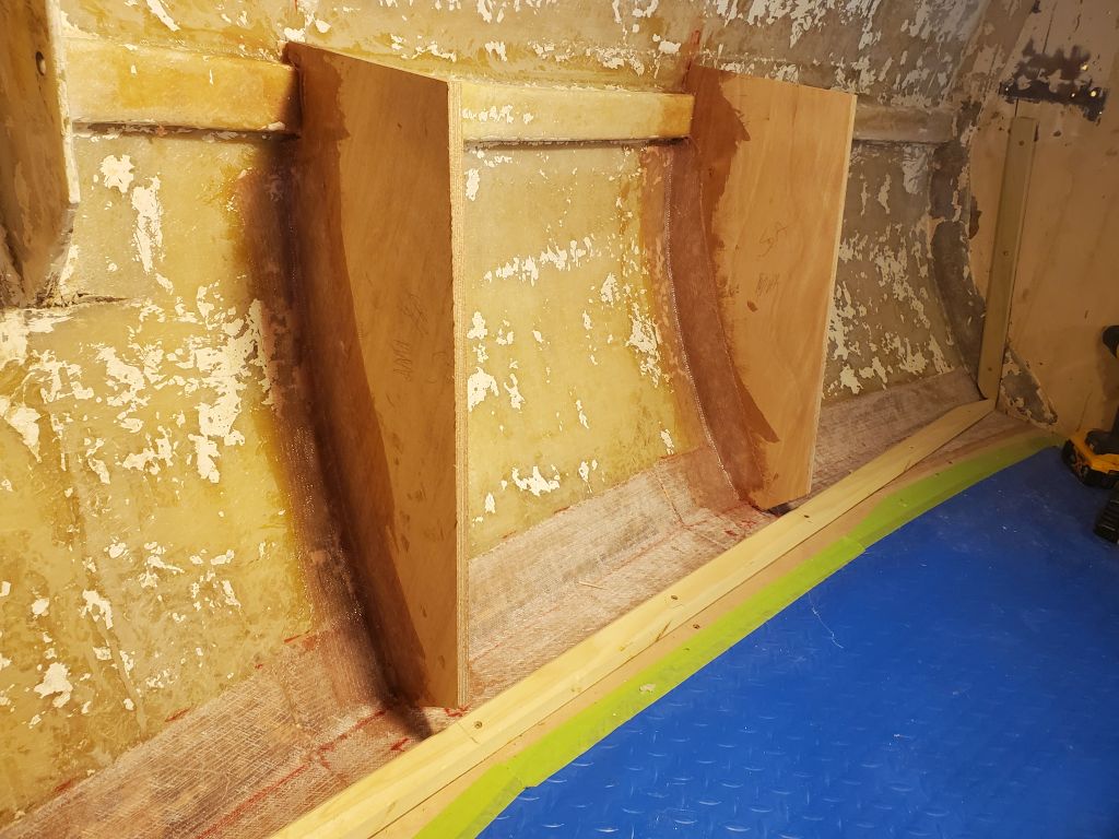
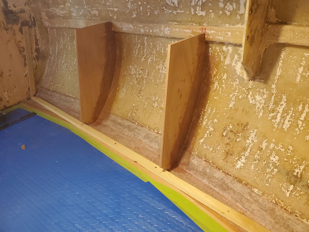
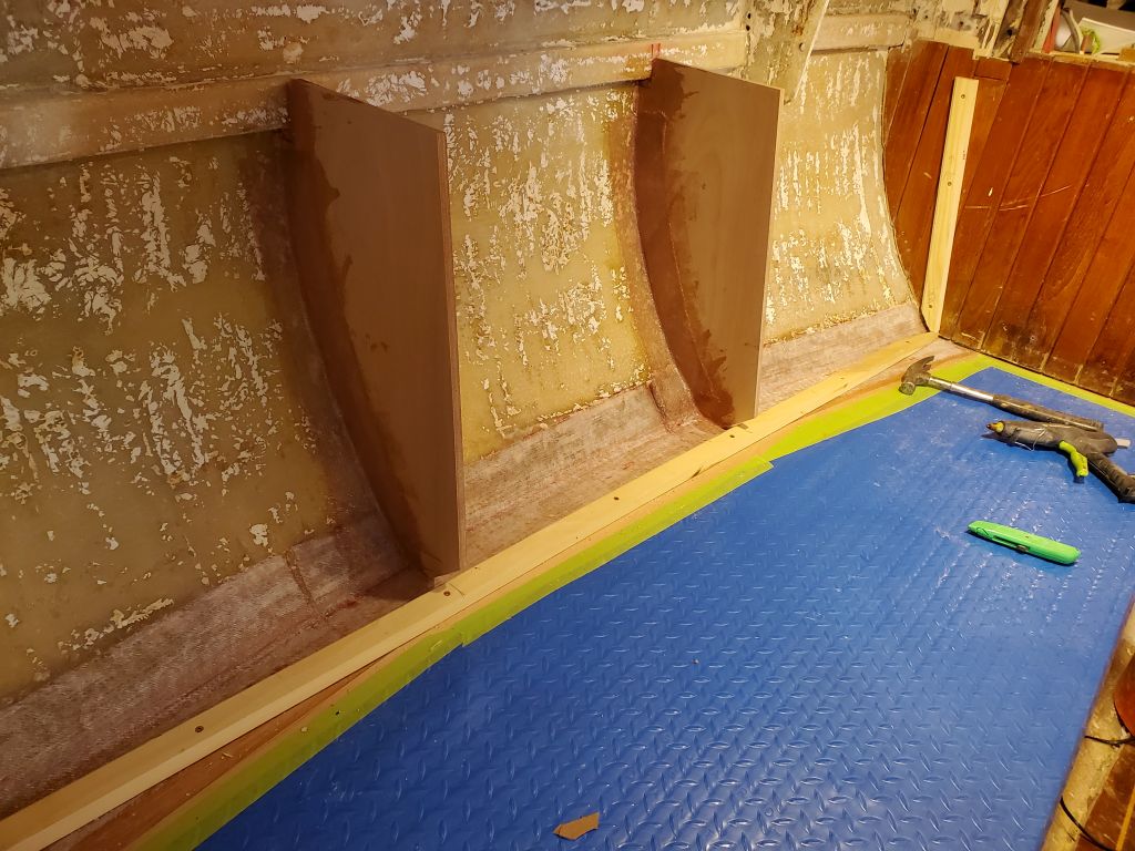
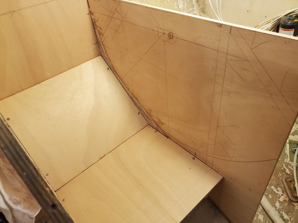
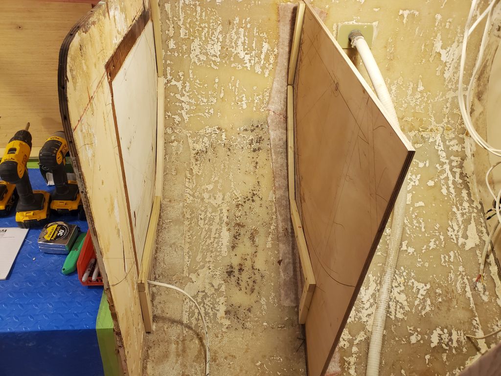
With the plywood blanks I’d pre-cut to the rough shape of the hull, I worked to finalize the four dividers/supports for the settee backrest and lockers. For each location, I scribed and trimmed the blanks to fit, then held them temporarily with hot glue blocks so I could use a simple jig to mark the 10° angle to match the backrest, and also mark the height of the backrest so I could strike a level line for trimming. Down on the bench, I trimmed each divider to its final size, keeping the cut lines just inside of the marks so I could make up the final difference later with a support cleat; I didn’t want the plywood to be over-sized at all.
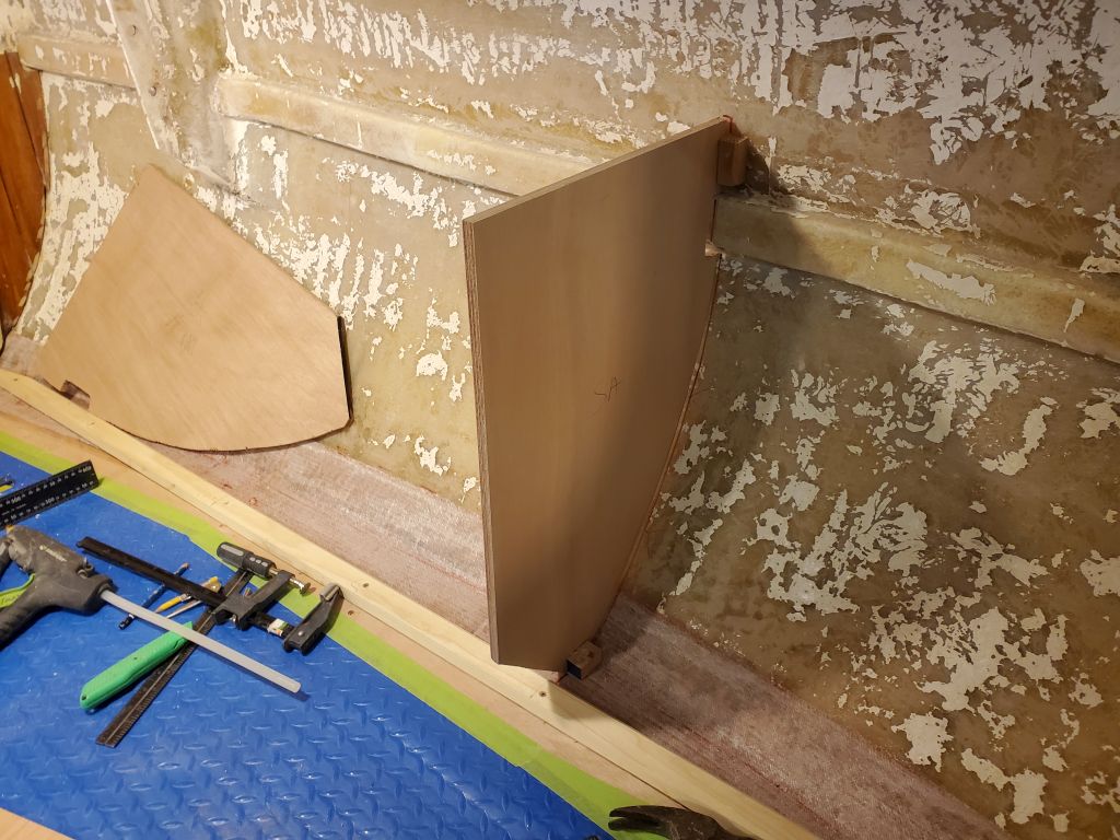
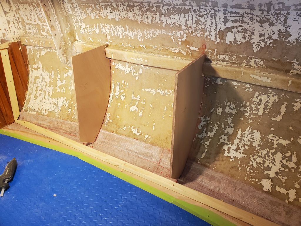
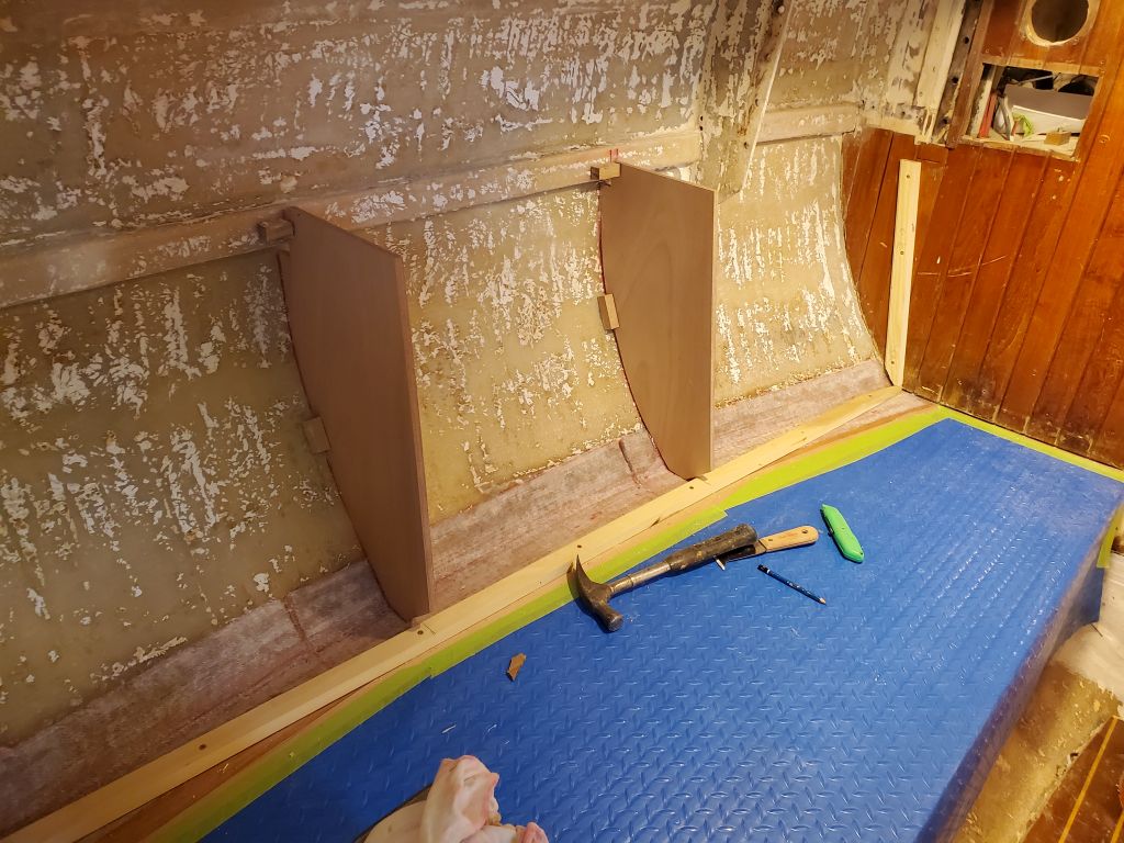
I held the now-trimmed dividers in place with some dabs of hot glue, then applied small epoxy fillets and, finally, strips of 4″ tabbing on each side to secure the bulkheads in place.
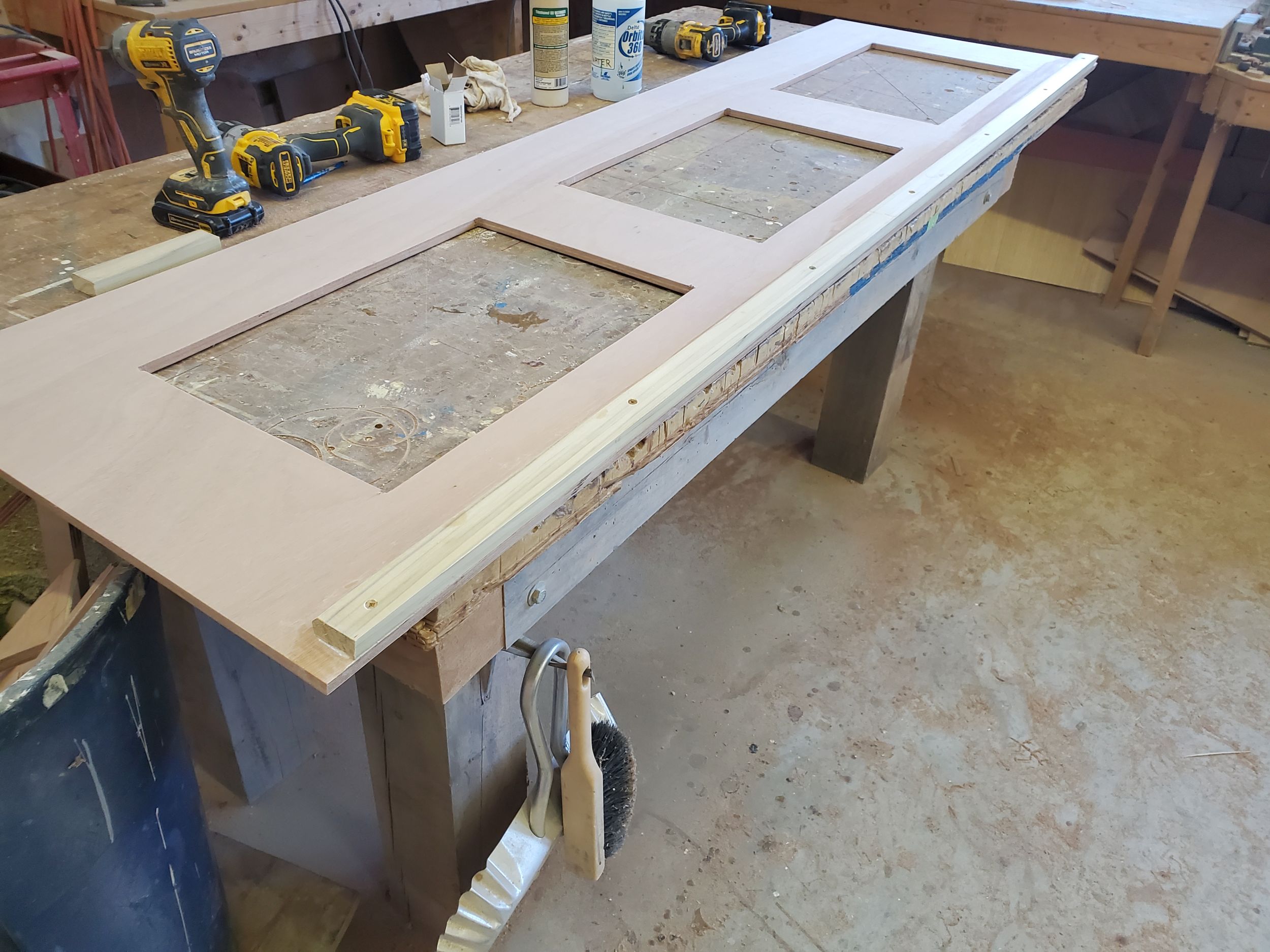
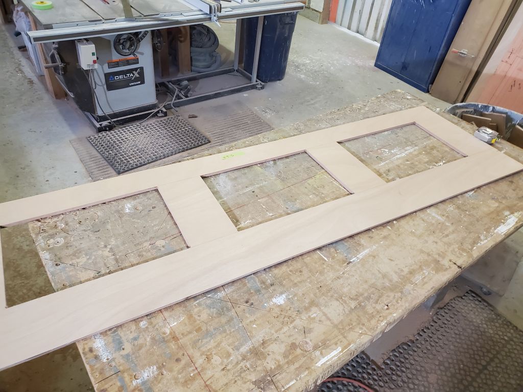
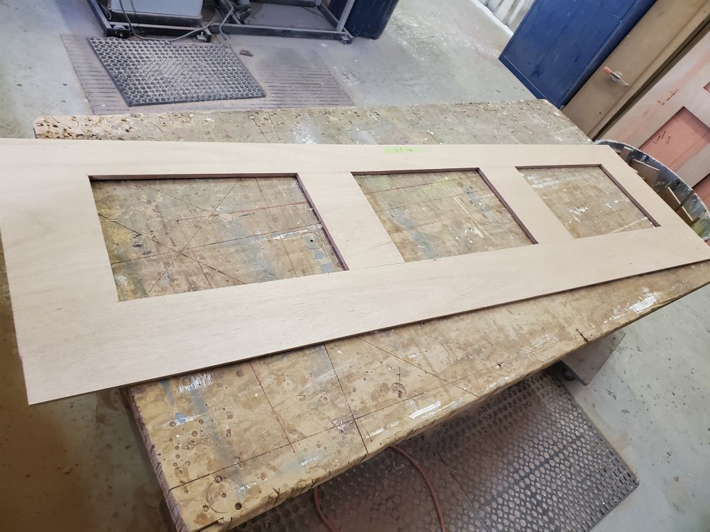
During the afternoon, I worked on the final settee backrests, cutting them to match the templates from 12mm okoume plywood. These would be ready for installation as soon as all the preparatory steps for the insides of the lockers were complete.
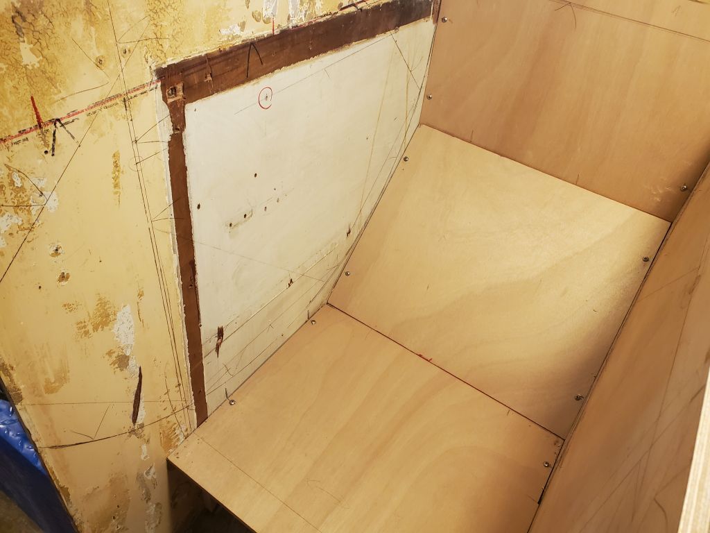
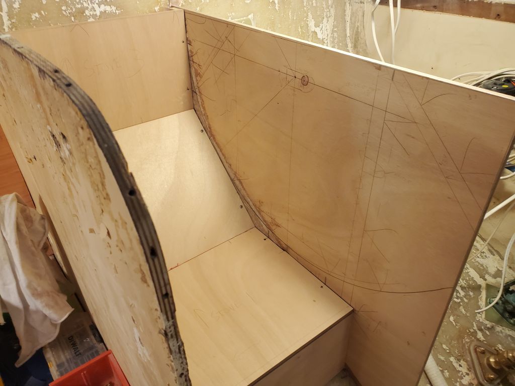
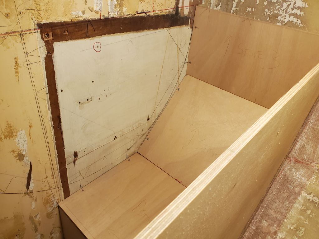
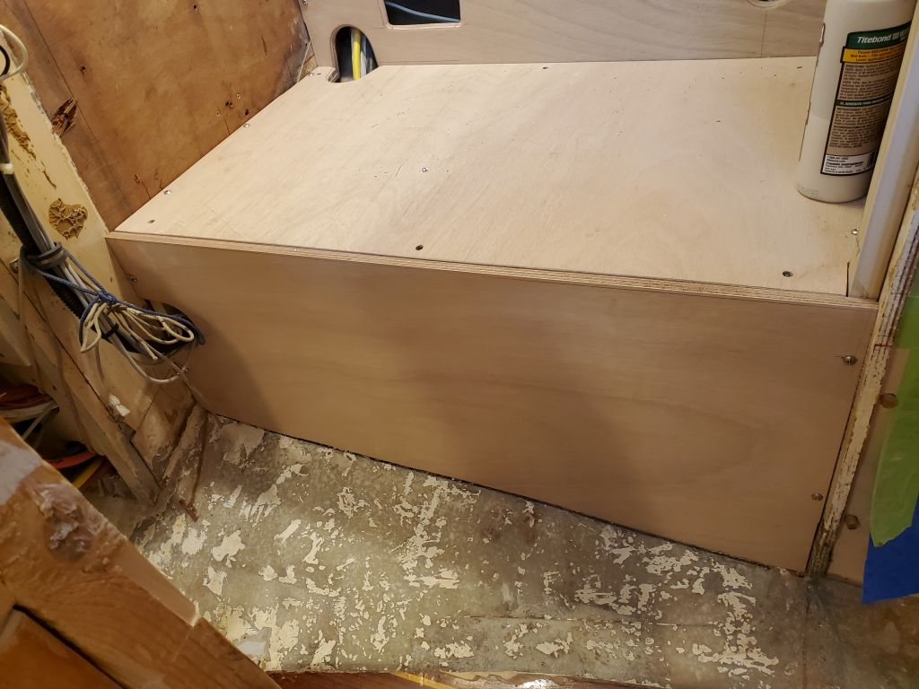
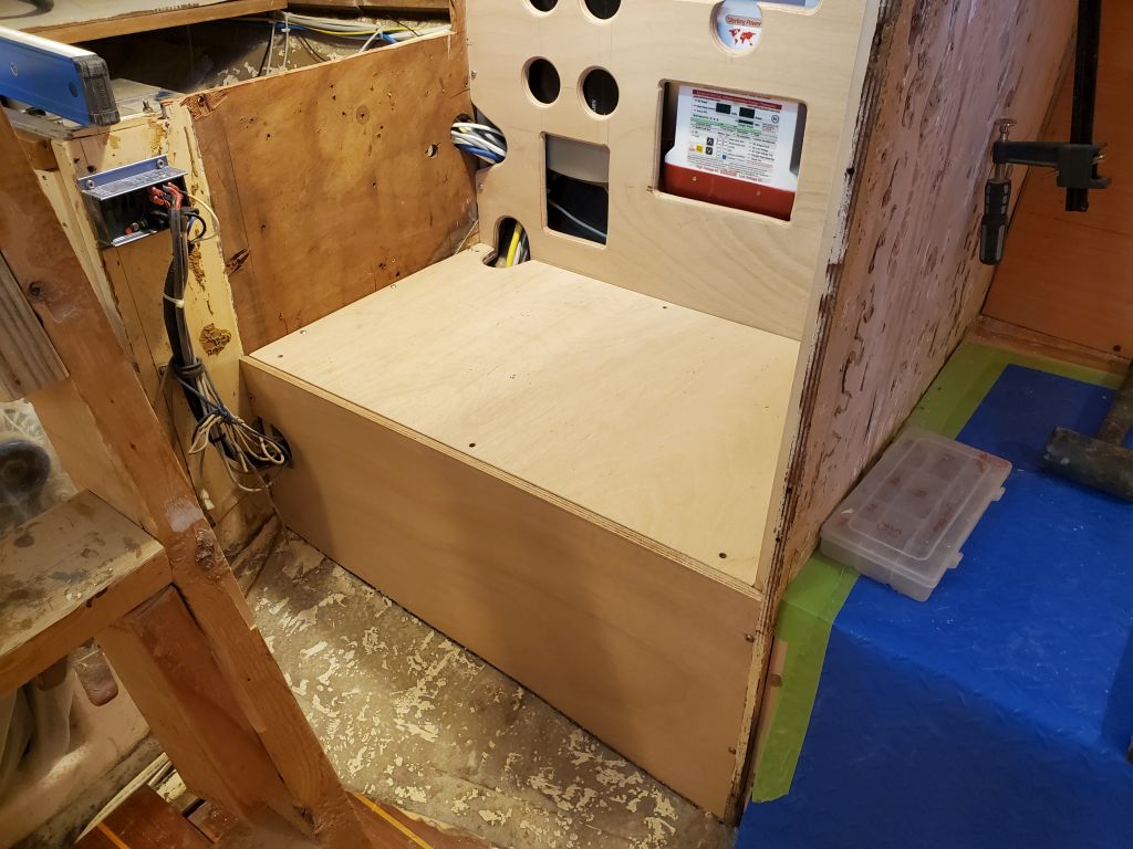
The next step for the stove compartment was to cut and fit the three panels to make up its interior. I began with the base (floor) and the vertical back panel, using basic thin plywood templates to determine the size and shape, then transferring these to the 12mm okoume for the final panels. I left the ends run wild for later trimming flush with the tops of the bulkheads (back panel), and the short vertical front panel (floor) later. I secured the plywood panels with four screws each, which is how they’d ultimately be installed when all was said and done.
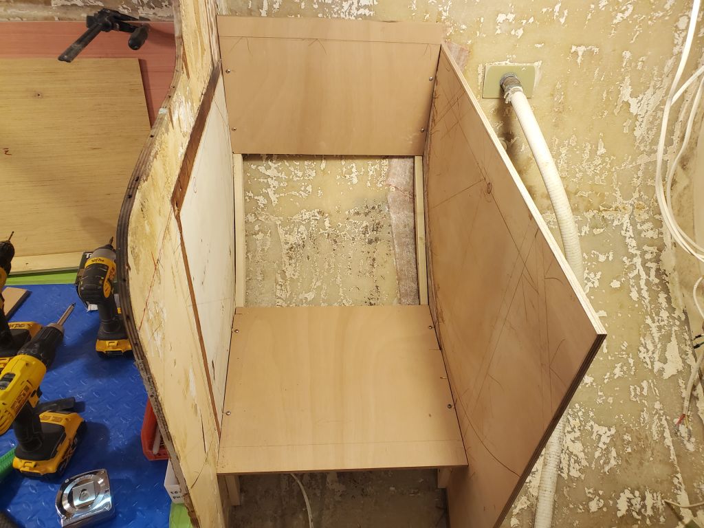
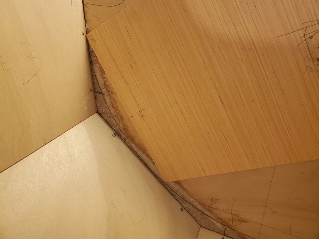
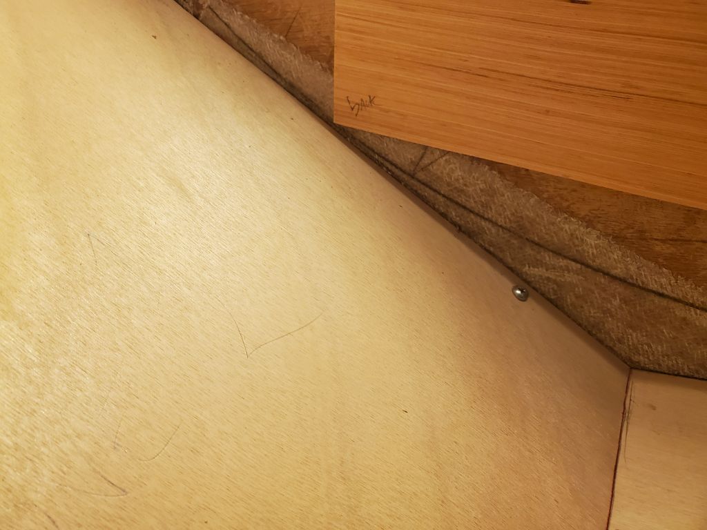
For the angled center panel, I cut two 6″ wide pieces from scrap 12mm okoume, each piece slightly narrower than the actual width of the space, then beveled one edge to the angle required to mate with the other panels; the mating angle was greater than 45°, so first I cut the panels on the table saw at the maximum angle, then increased the bevel on the bench with a sander. I secured each panel tightly with temporary screws, ensuring the beveled ends mated properly with the adjacent horizontal and vertical panels, then secured them together with several hot-glued sticks to hold the orientation and give me the finished length. I marked the edges in the usual way–a 1″ metal ruler to provide the offset from the bulkhead sides–then cut the final panel from plywood, securing it in place along with the others.
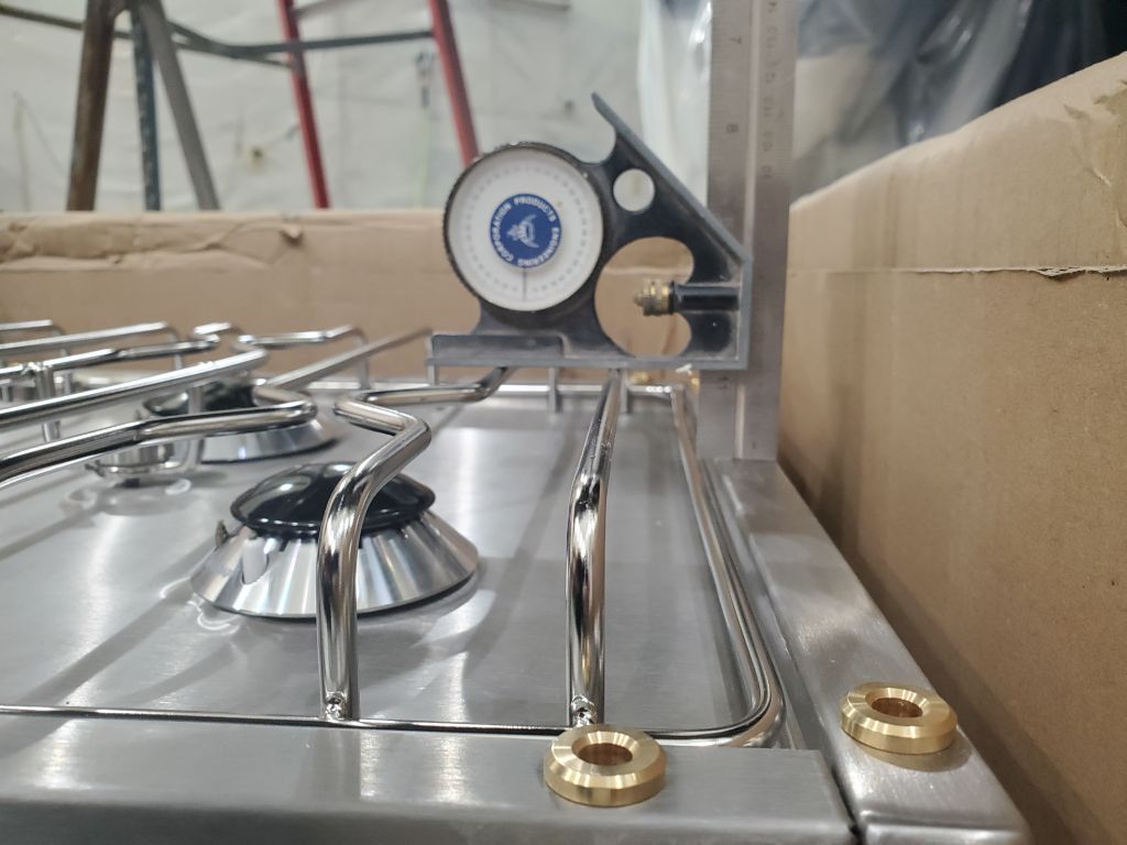
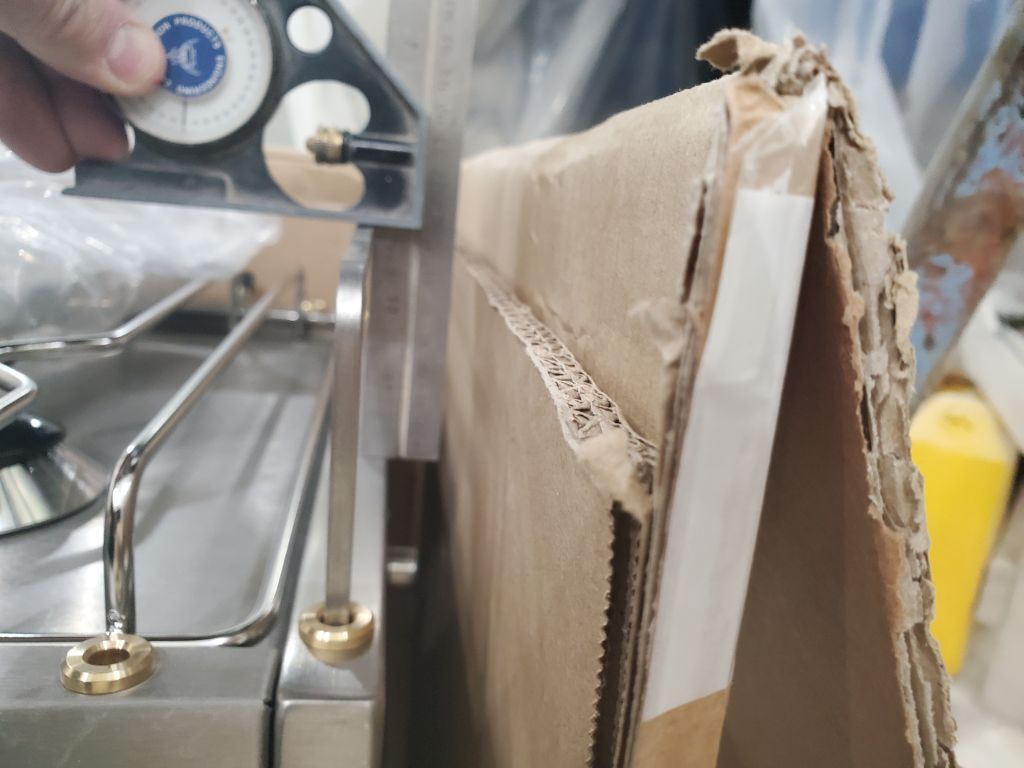
With my stove template secured to each side in turn, I checked the swing clearance, which was fine on both sides.
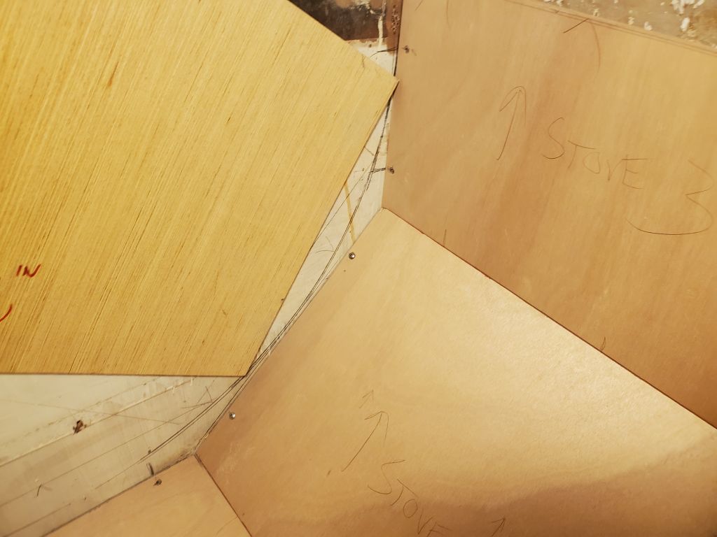
To finish up the surround for now, I templated and cut the short vertical panel on the inboard side of the enclosure, then cut the base panel flush with the edge of the new panel, and marked and cut the back panel so it was flush and level with the bulkhead. The sides of the enclosure, plus the three panels I’d just cut, would be faced with stainless steel for heat resistance and to complement the stove itself (24 gauge stainless with a #4 brushed finish), so I removed the panels and measured them (along with the bulkheads on either side) so I could order the sheet metal to complete the enclosure. Then, I removed each of the support cleats in turn and permanently installed them with glue and additional screws as needed.
With the stove at a natural stopping point, I turned back to the settees, first scribing the plywood templates at the ends so I could make the final panels to fit. Then, I removed the templates and permanently installed the six support cleats (three per side) with glue and additional screws, cutting the angled backrest cleats to their final lengths in the process.
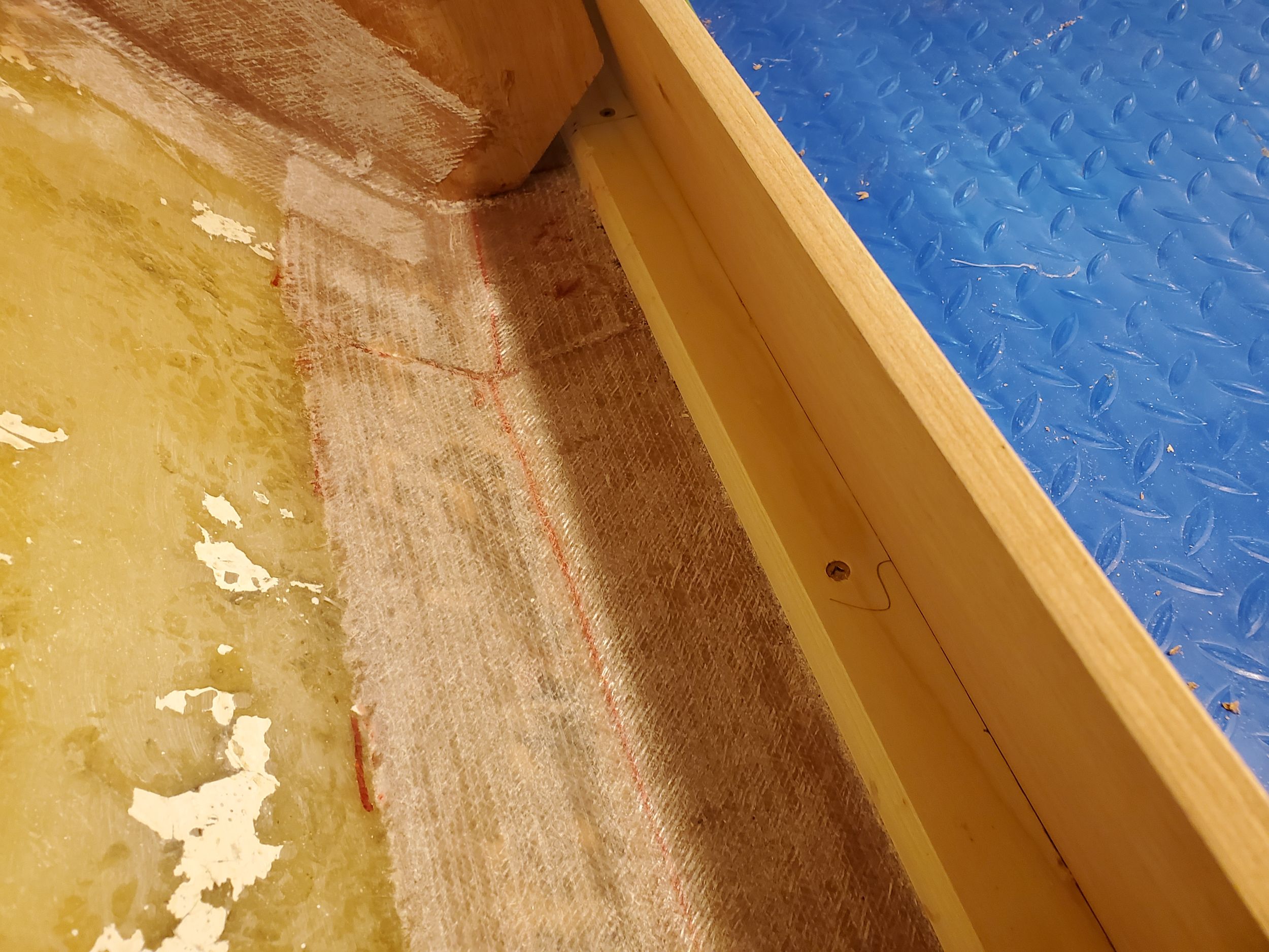
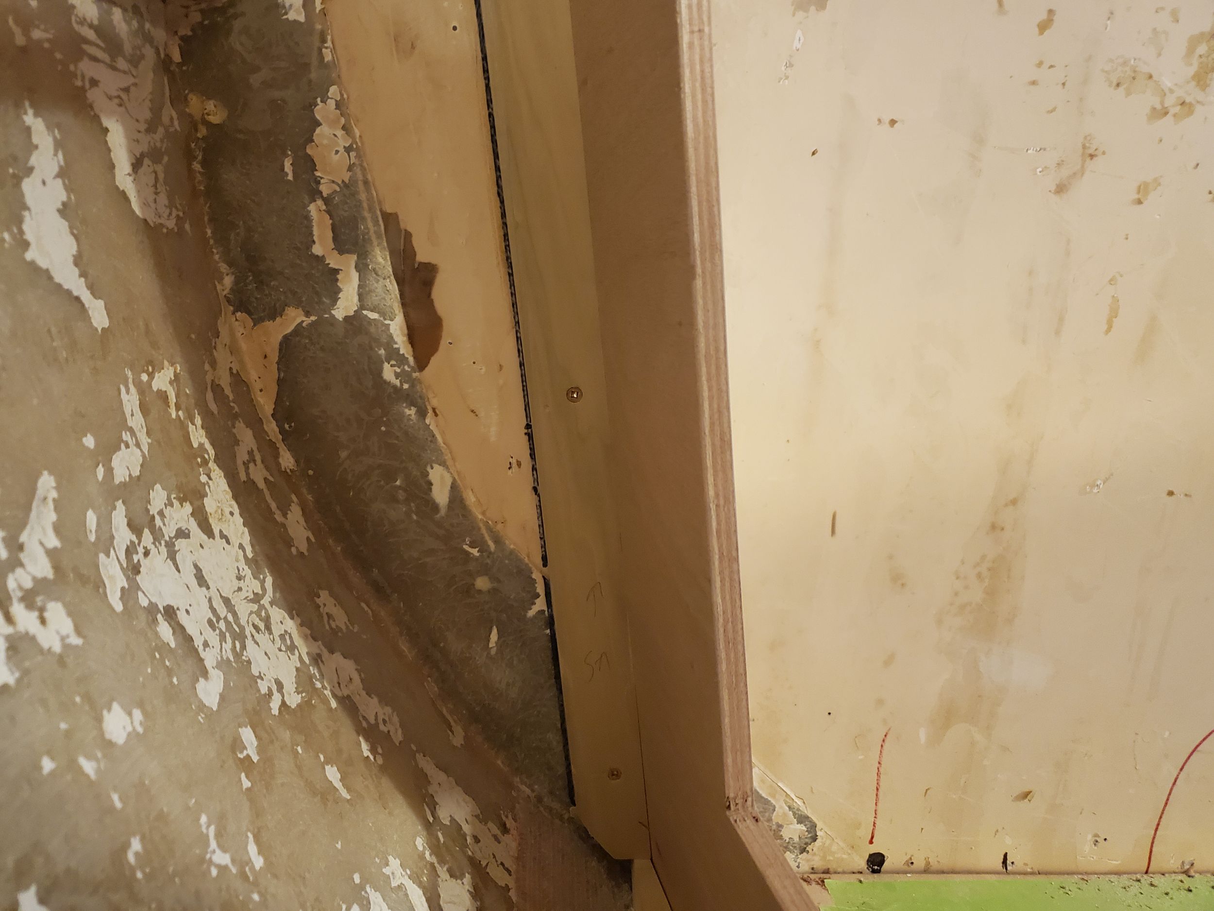
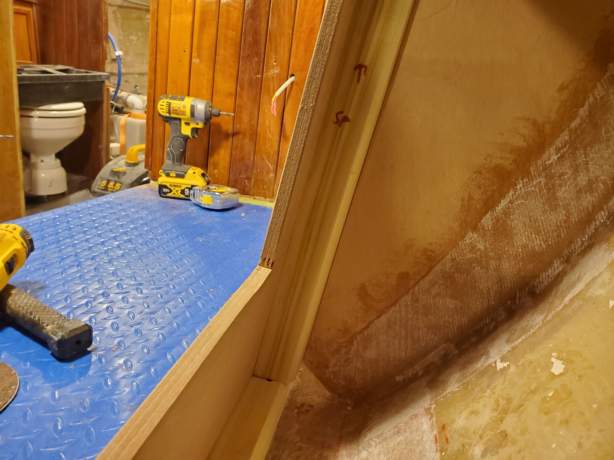
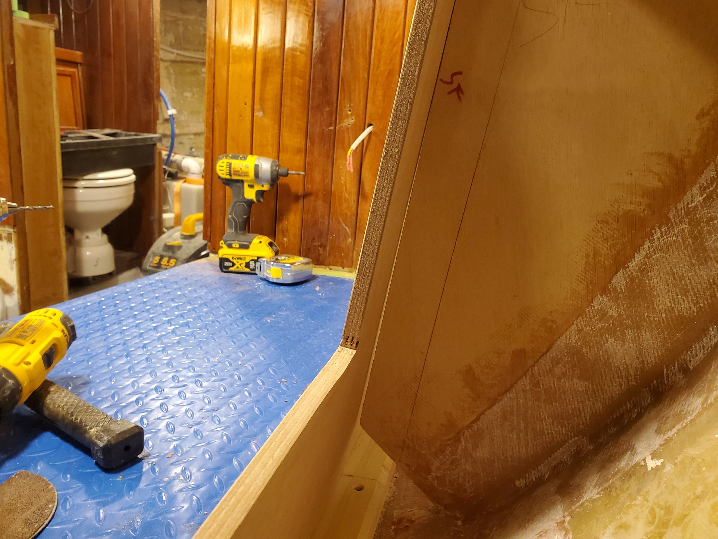
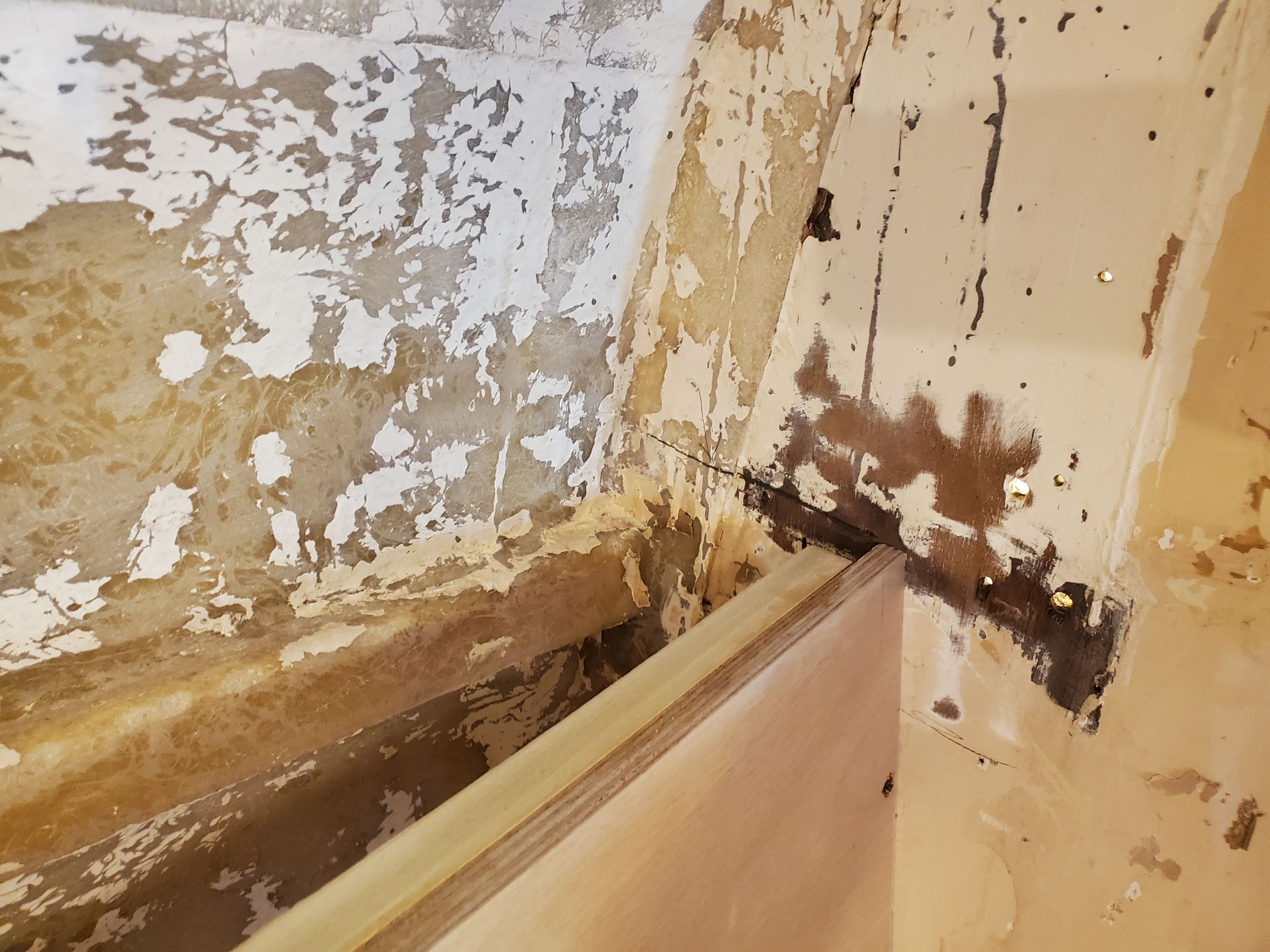
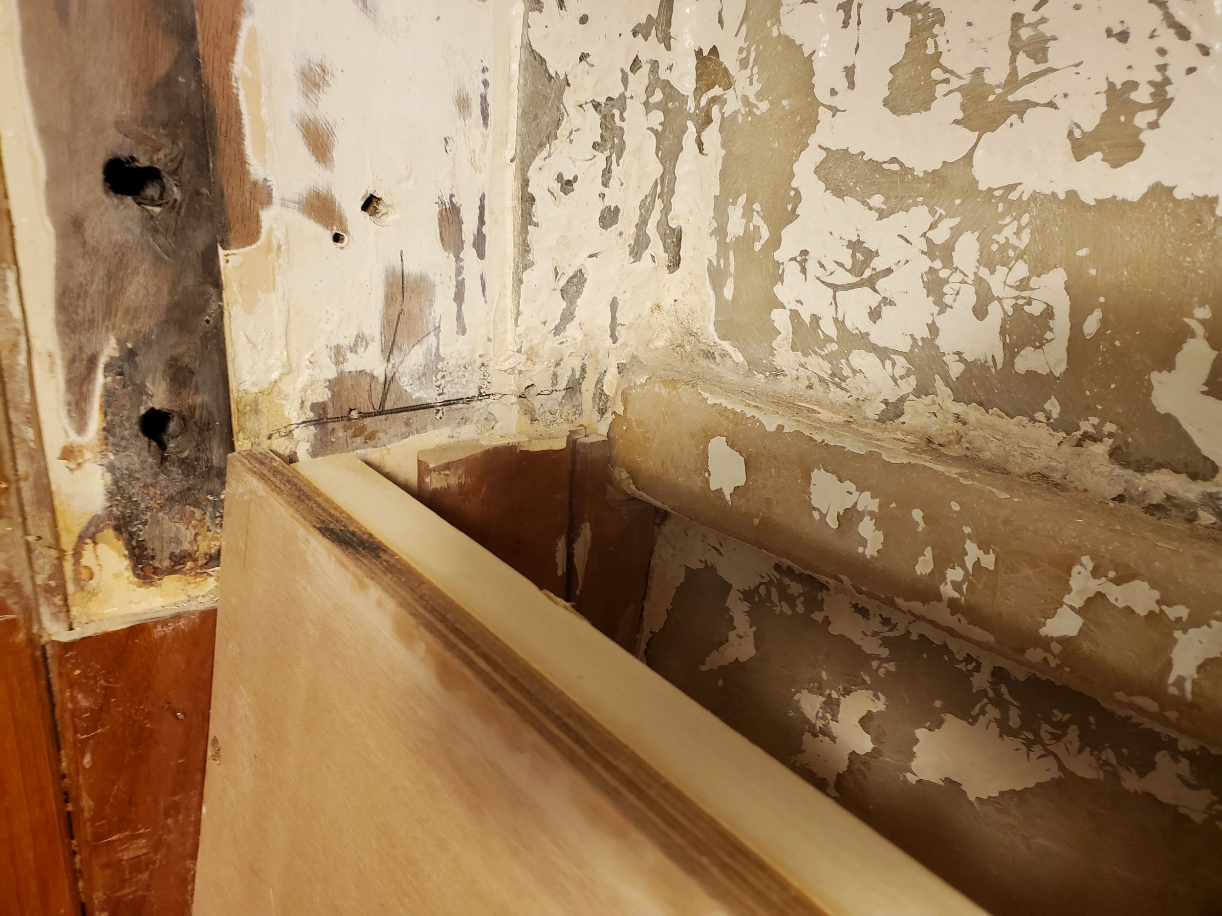
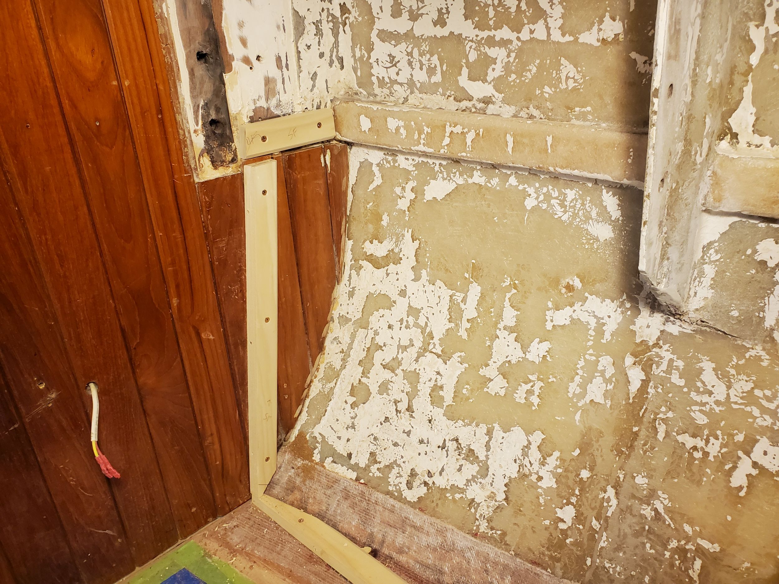
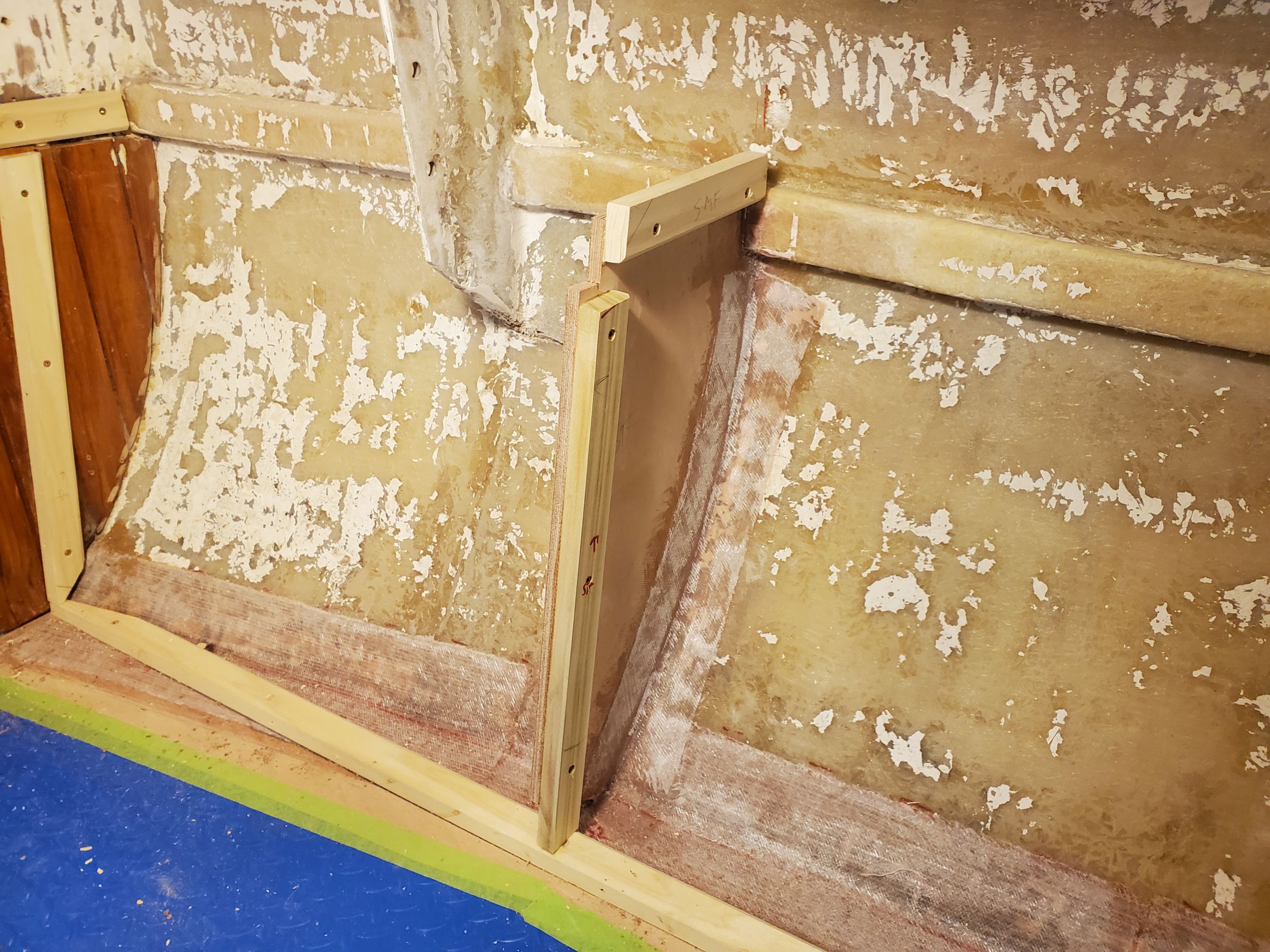
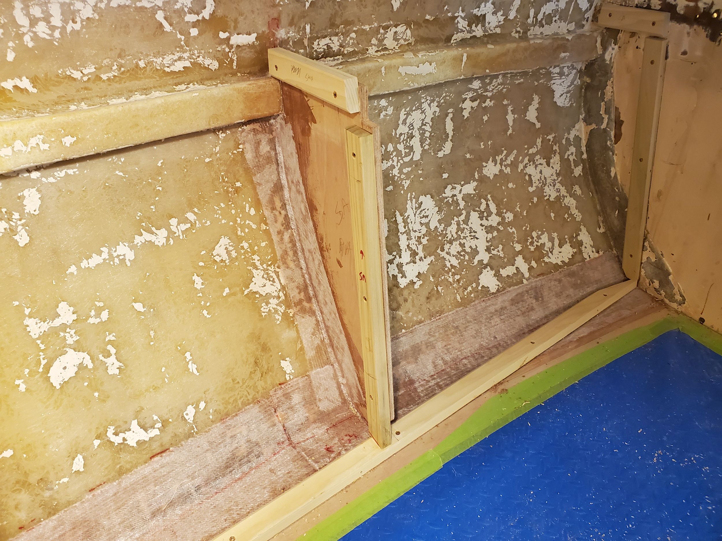
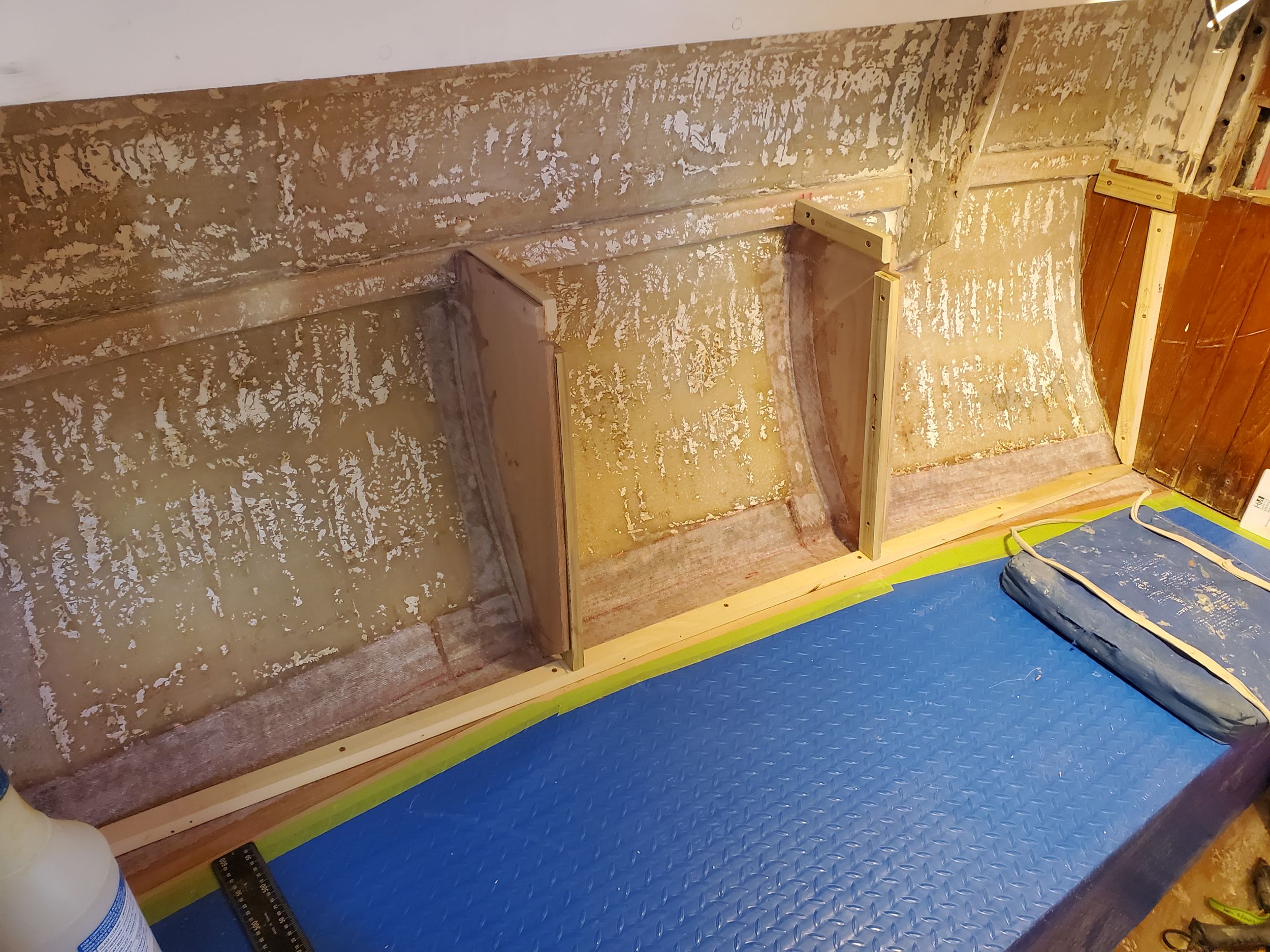
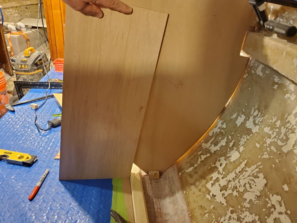
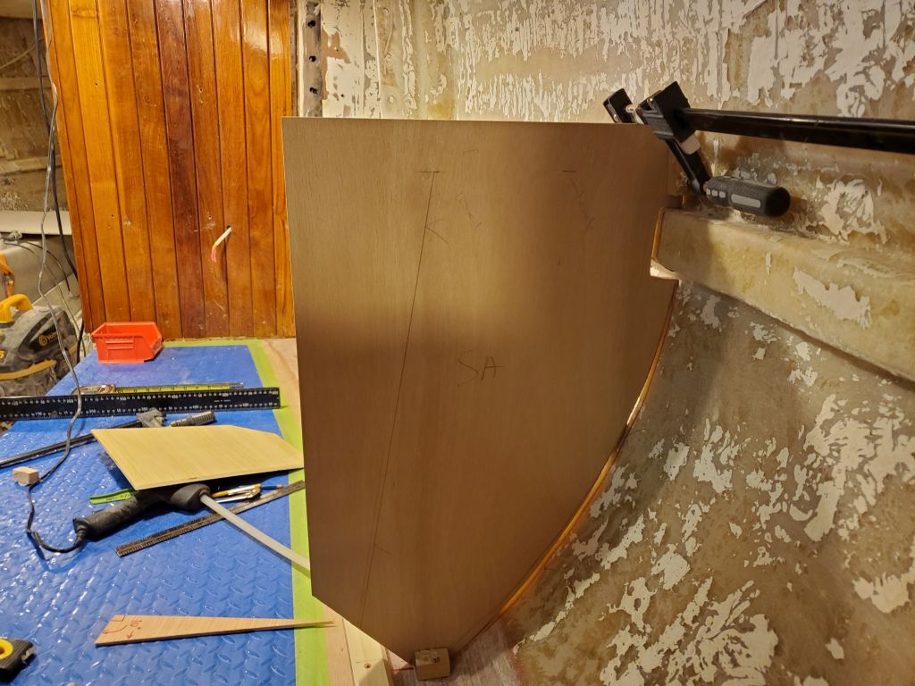
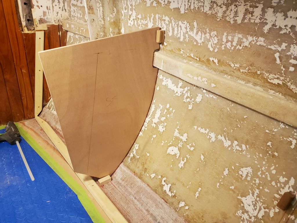
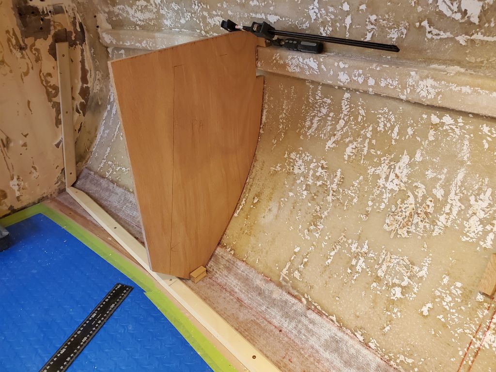
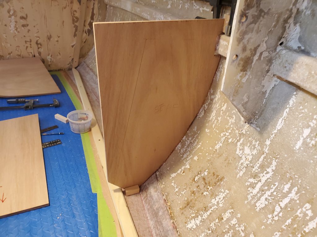
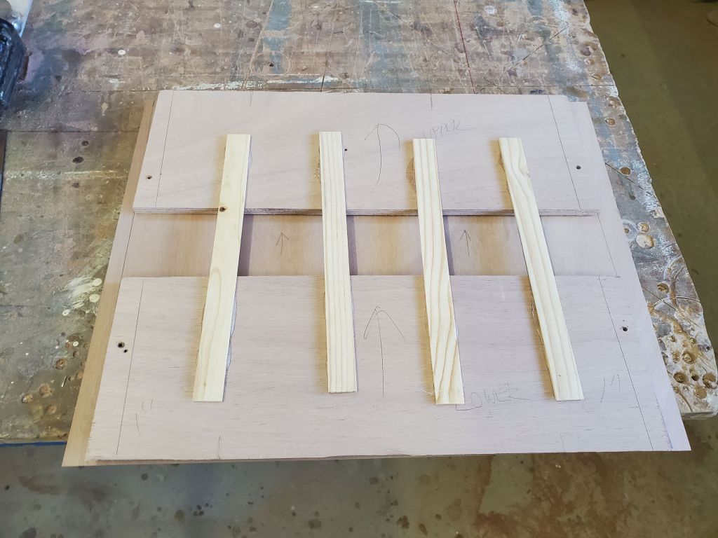
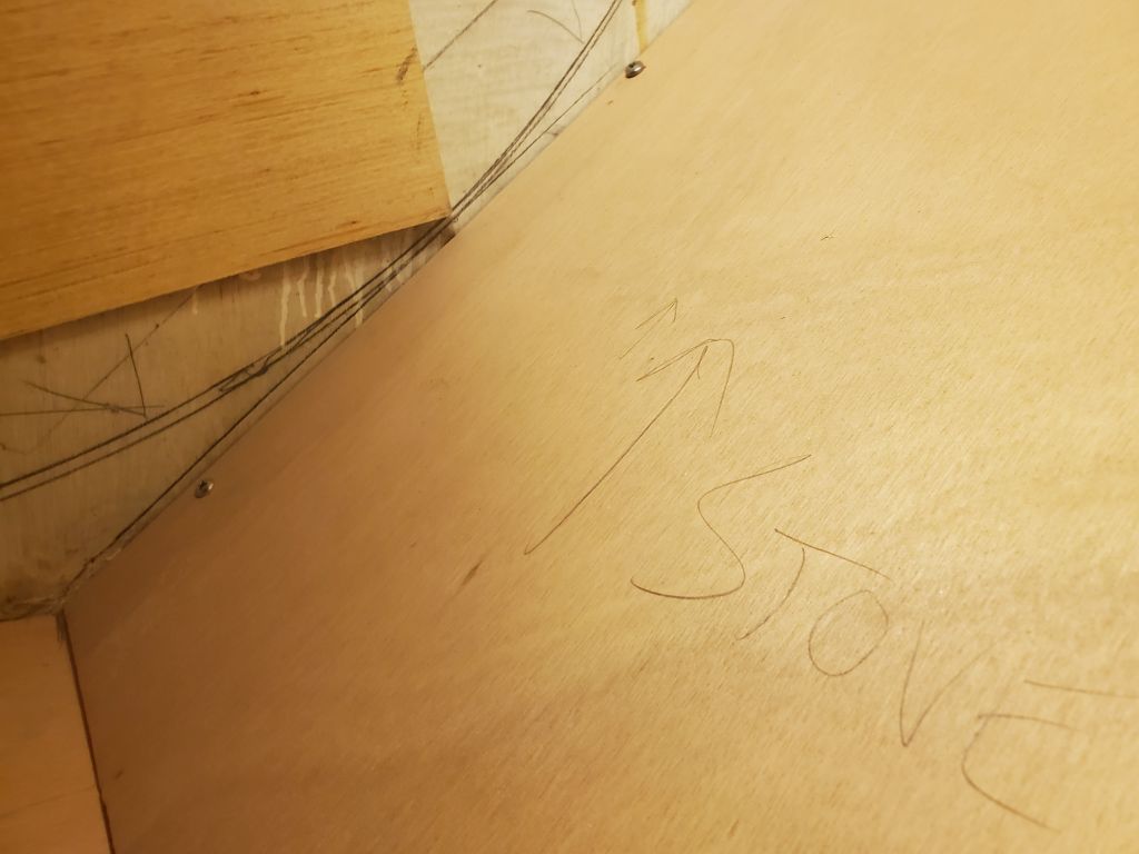
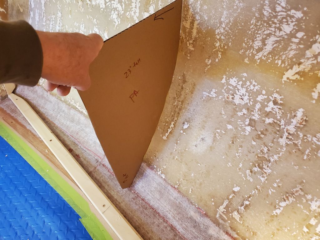
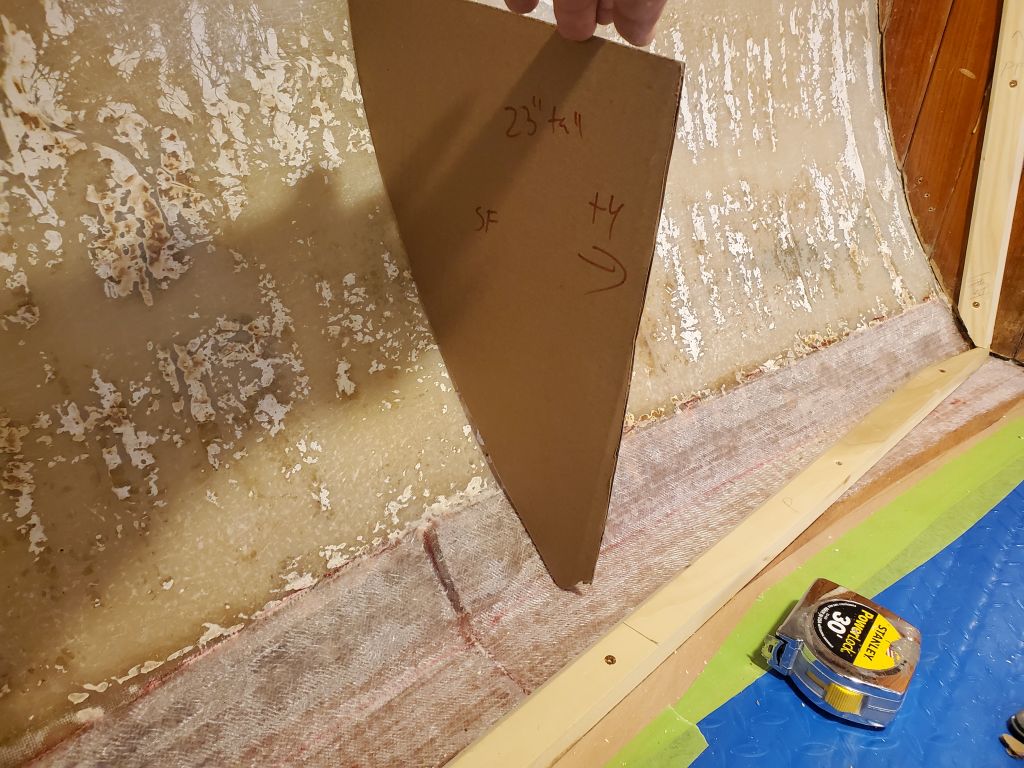
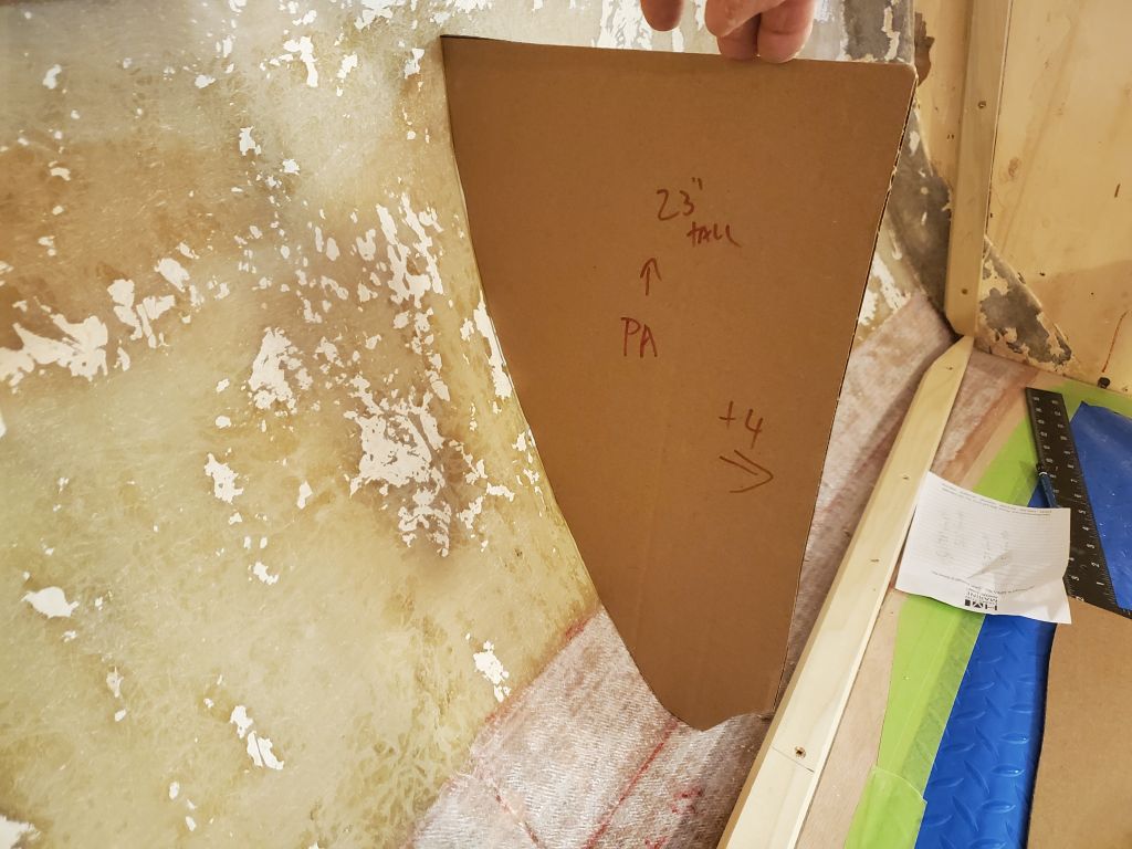
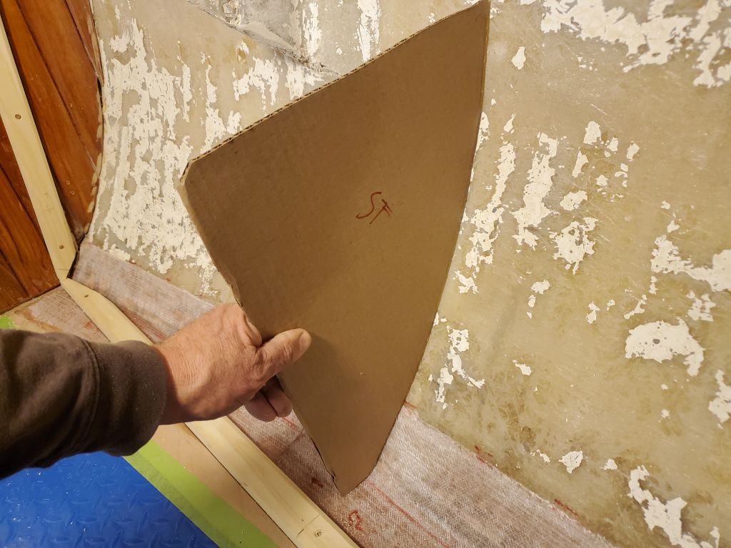
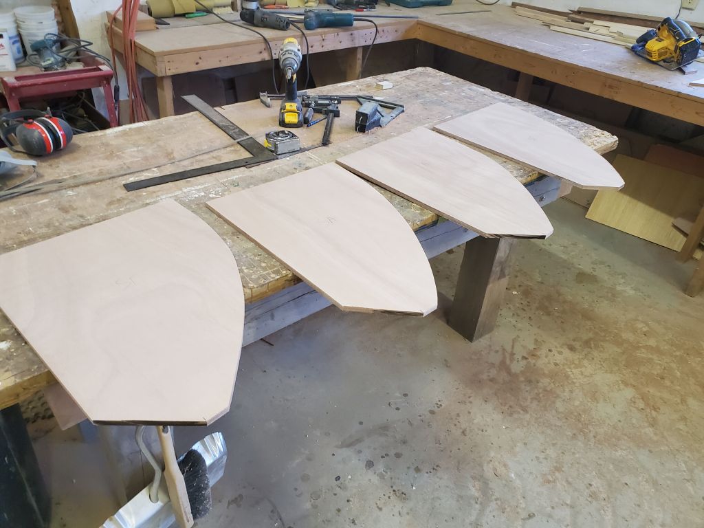
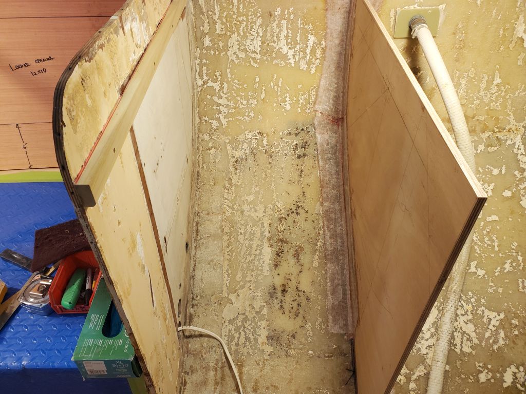
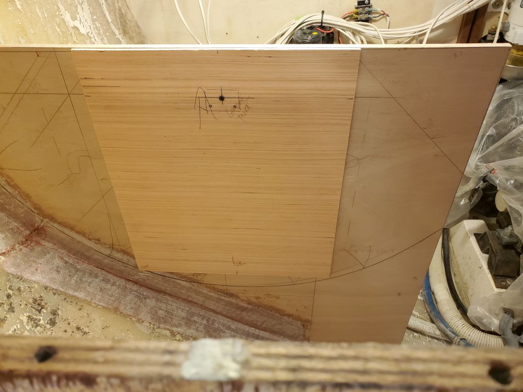
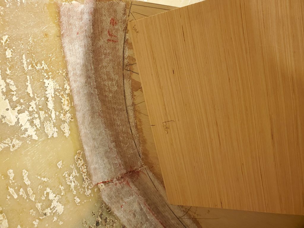
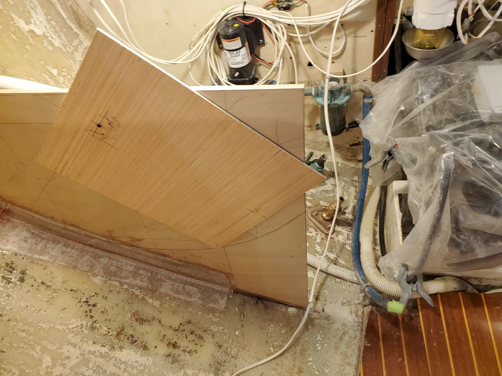
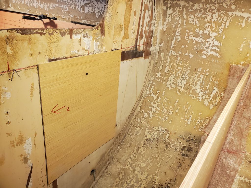
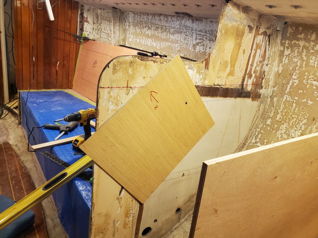
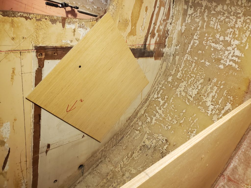
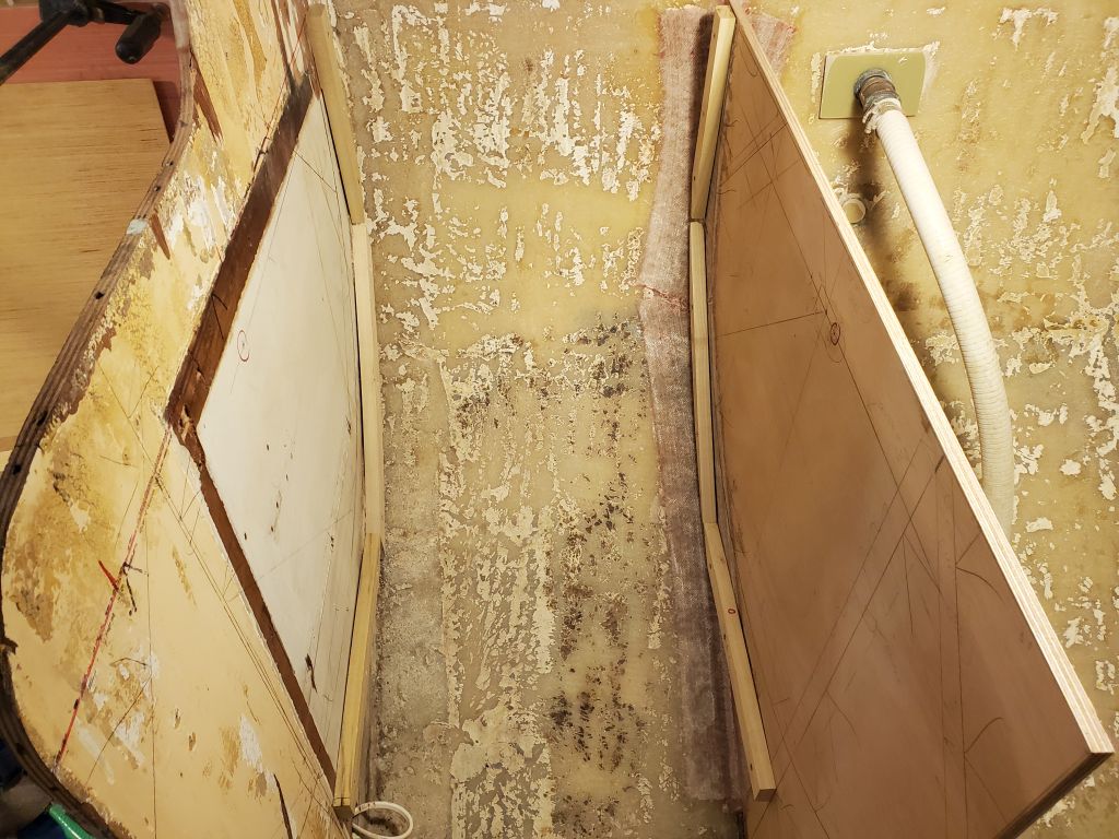
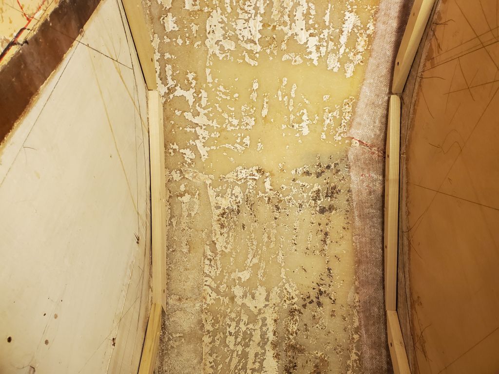
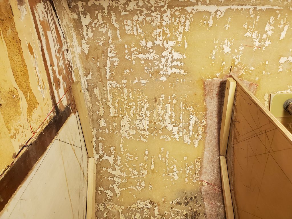
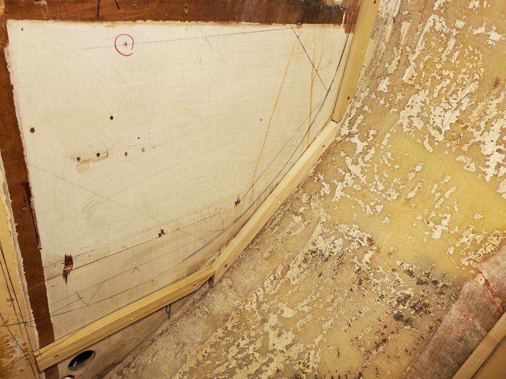
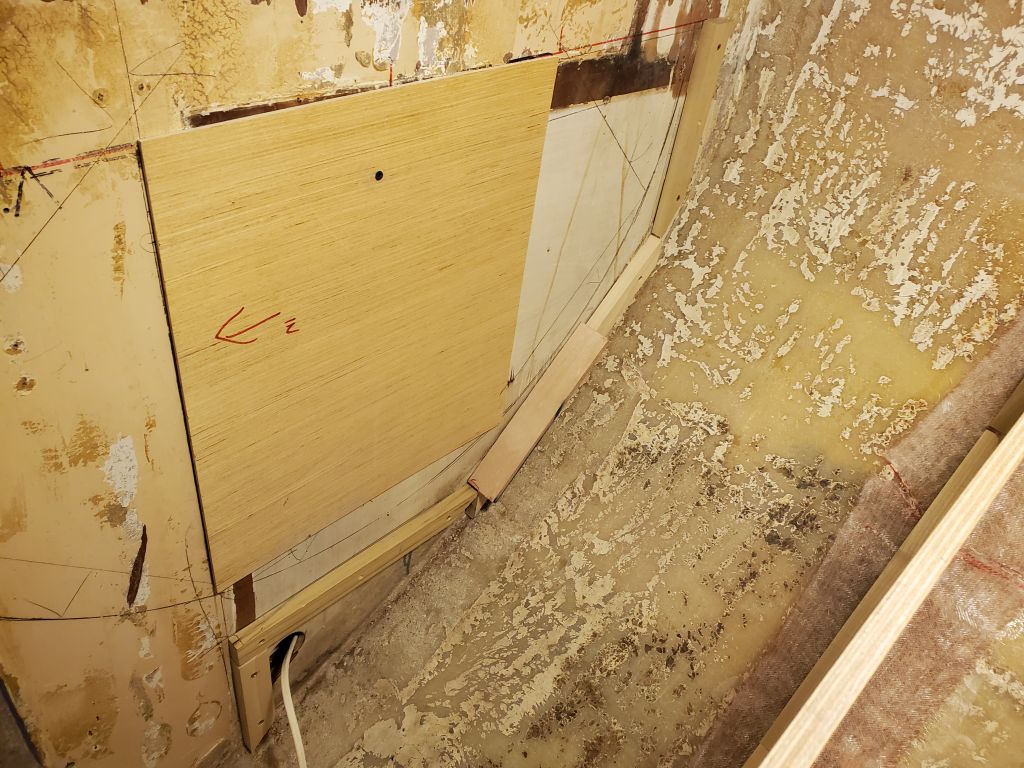
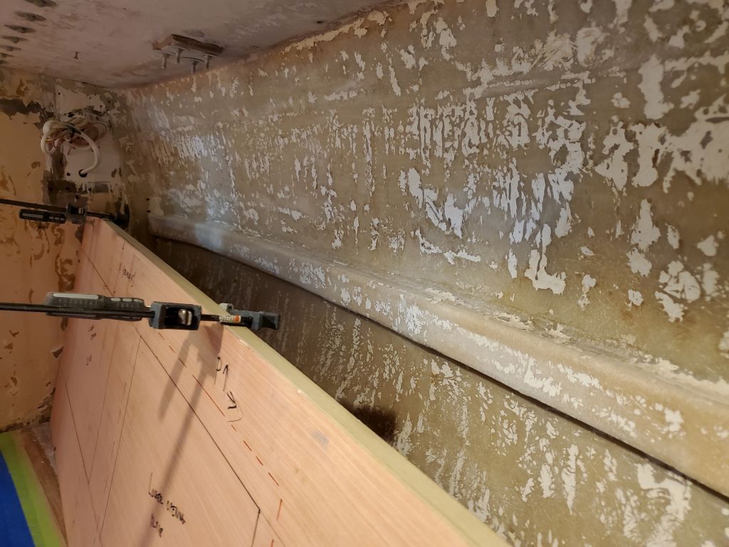
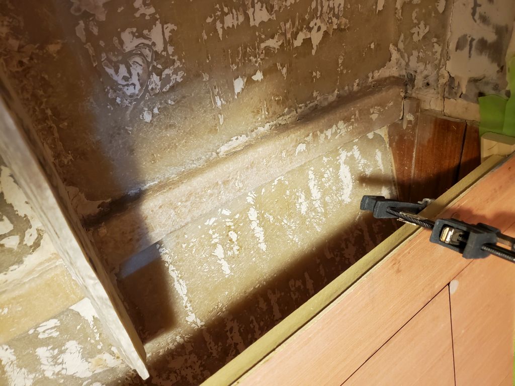
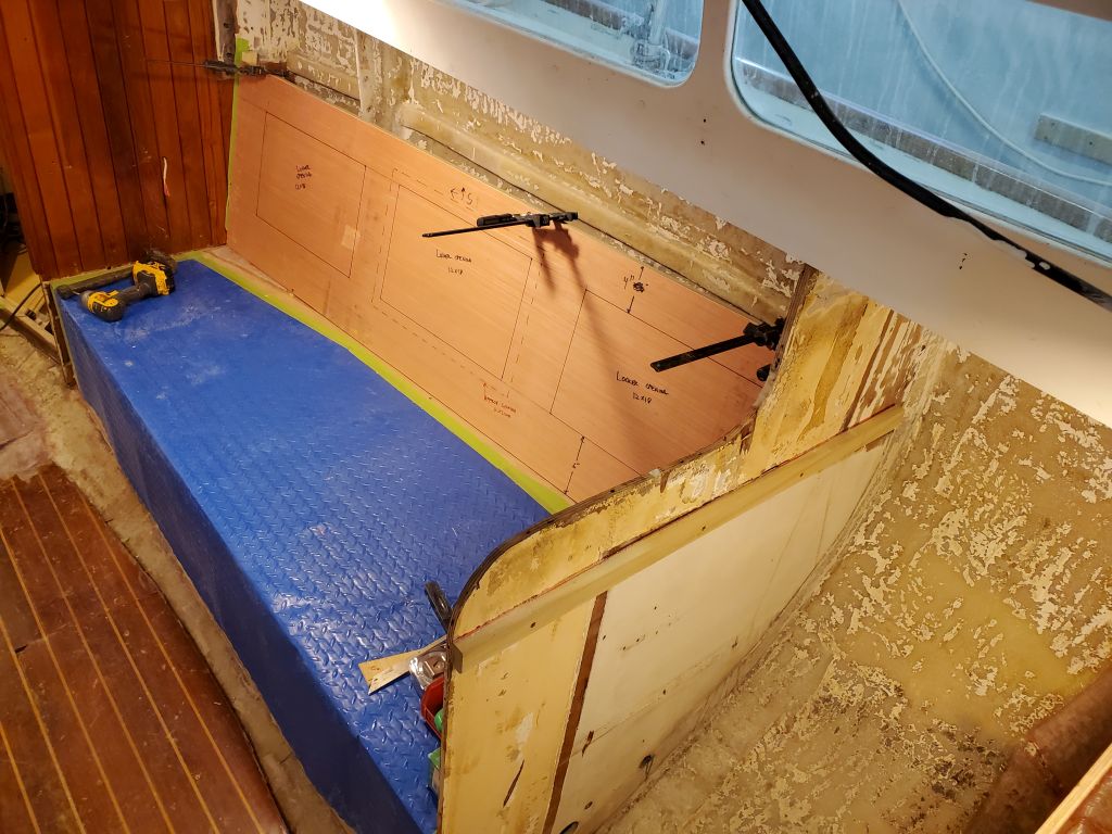
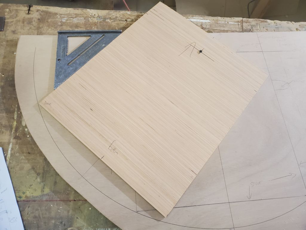
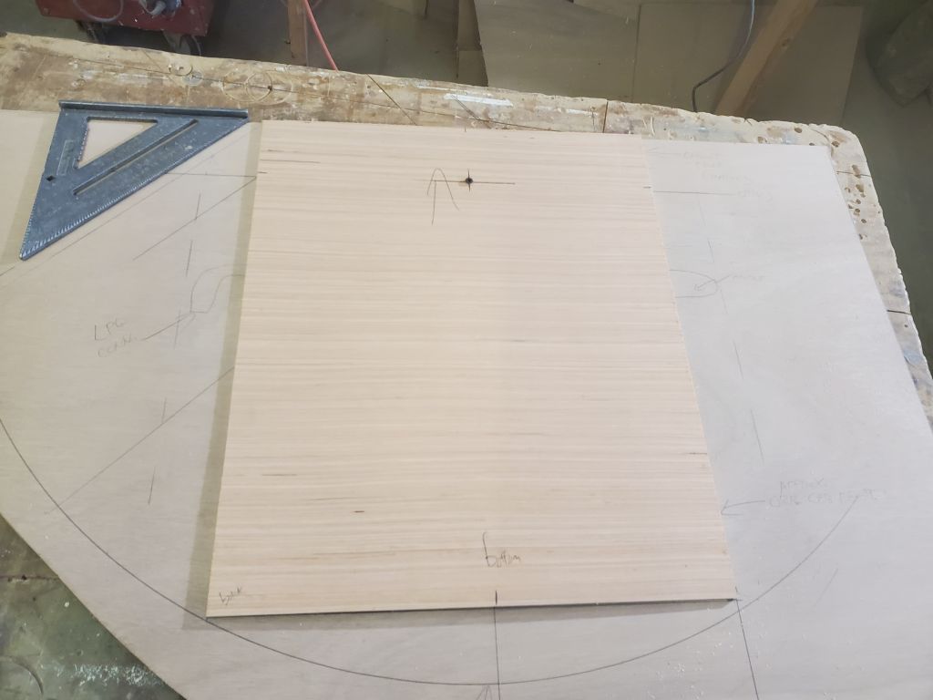
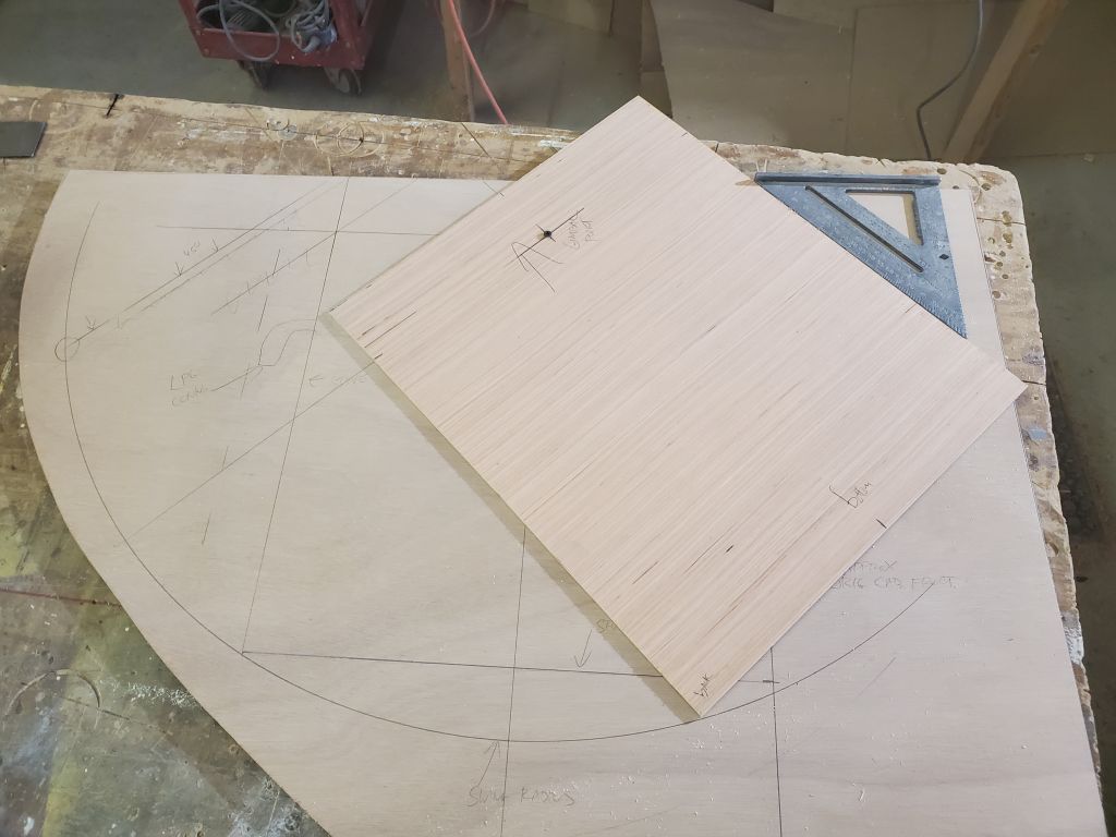
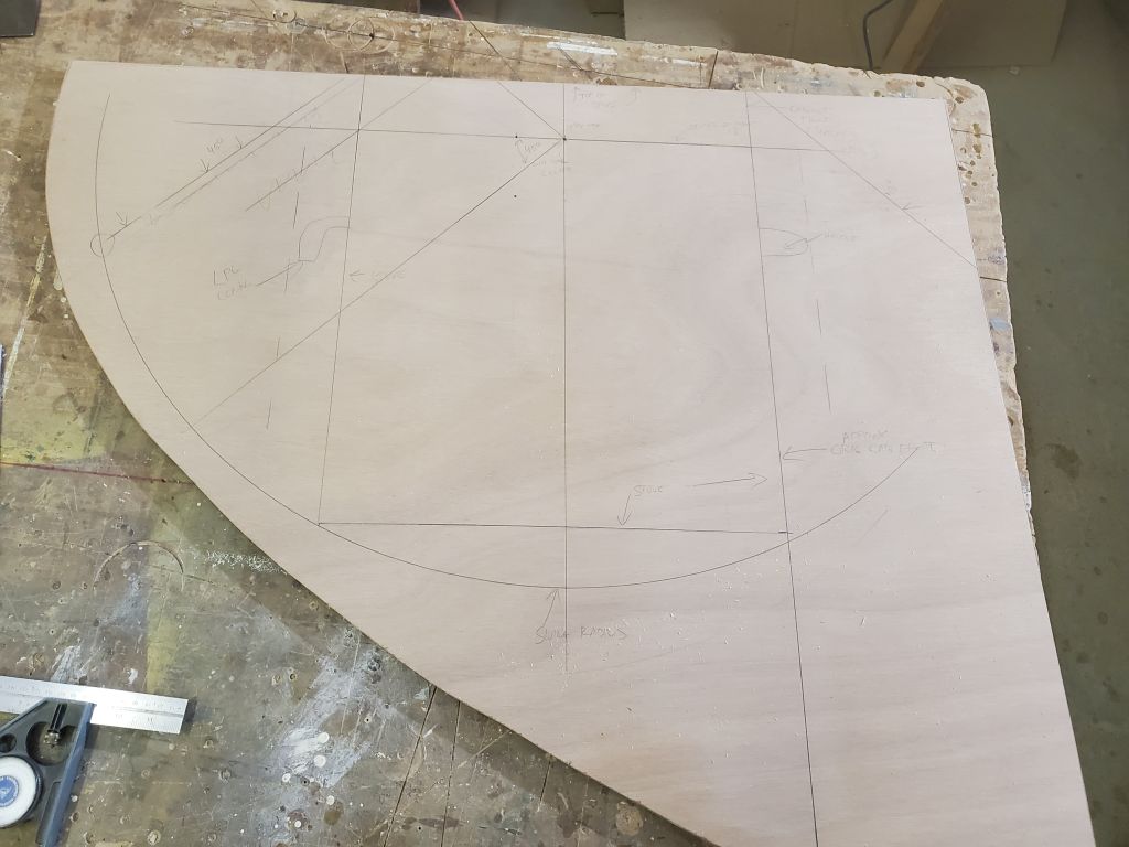
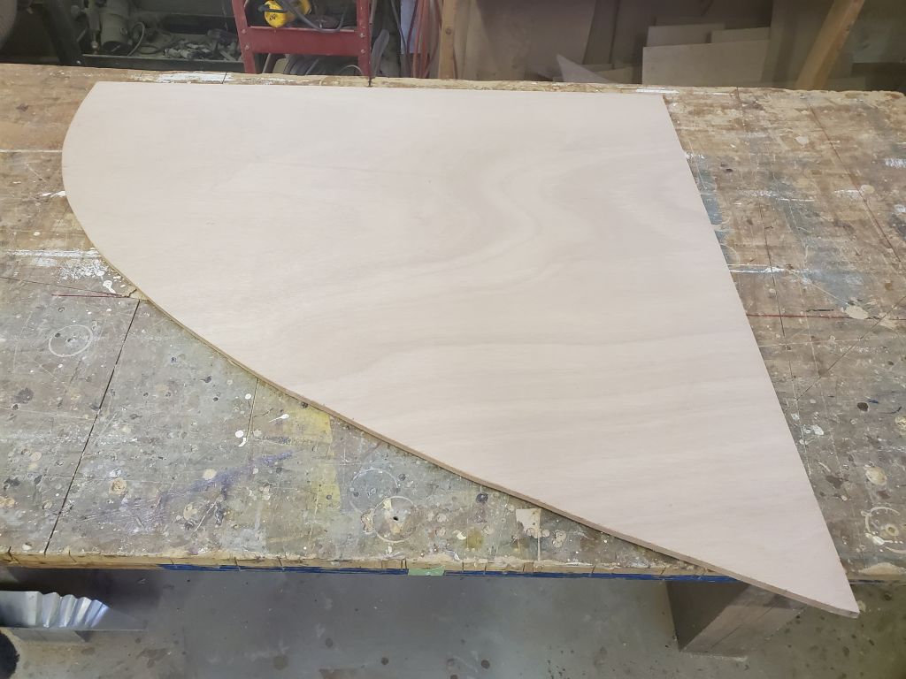
To support the settee backrest and divide the storage lockers accordingly, I planned two small bulkhead dividers on each side. Working from the templates and the layout for the locker openings I’d designed, I determined the positions of the bulkheads, and up in the boat I made some basic plywood templates to get me started on the hull shape for the final bulkheads. At some point I got lost in my labeling of these templates and marked several in the same way–these things happen–so ignore the markings on the four templates. Each template photo does show a different location, but the markings caused consternation when I was back in the woodshop trying to cut the oversized plywood blanks and every template seemed to say “SF” or “PA”. We all get our lefts and rights and ports and starboards messed up sometimes. Eventually I got it worked out and created four bulkhead blanks, each cut roughly to the hull shape at this point and oversized to allow final fitting and cutting to the necessary shape next time. The angled cuts at the bottom would allow the panels to clear the lower support cleat for the backrest.
I continued work on the stove cabinet, starting with a quick sanding of the new tabbing.
Afterwards, I spent most of the rest of the day laying out and installing the support cleats for the stove enclosure. It didn’t seem possible that eight little cleats could take so long, but so it was. The main complicating factor was transferring exact positions across the narrow space to ensure all layouts were identical; this was a bit of a challenge (and time-consuming) because the forward, original, bulkhead was not square nor perfectly plumb, and I had to build a custom square of sorts to fit in the space and allow me to transfer the positions across as needed, since my existing commercial tools were too wide or too narrow for the job in this 19″ wide space.
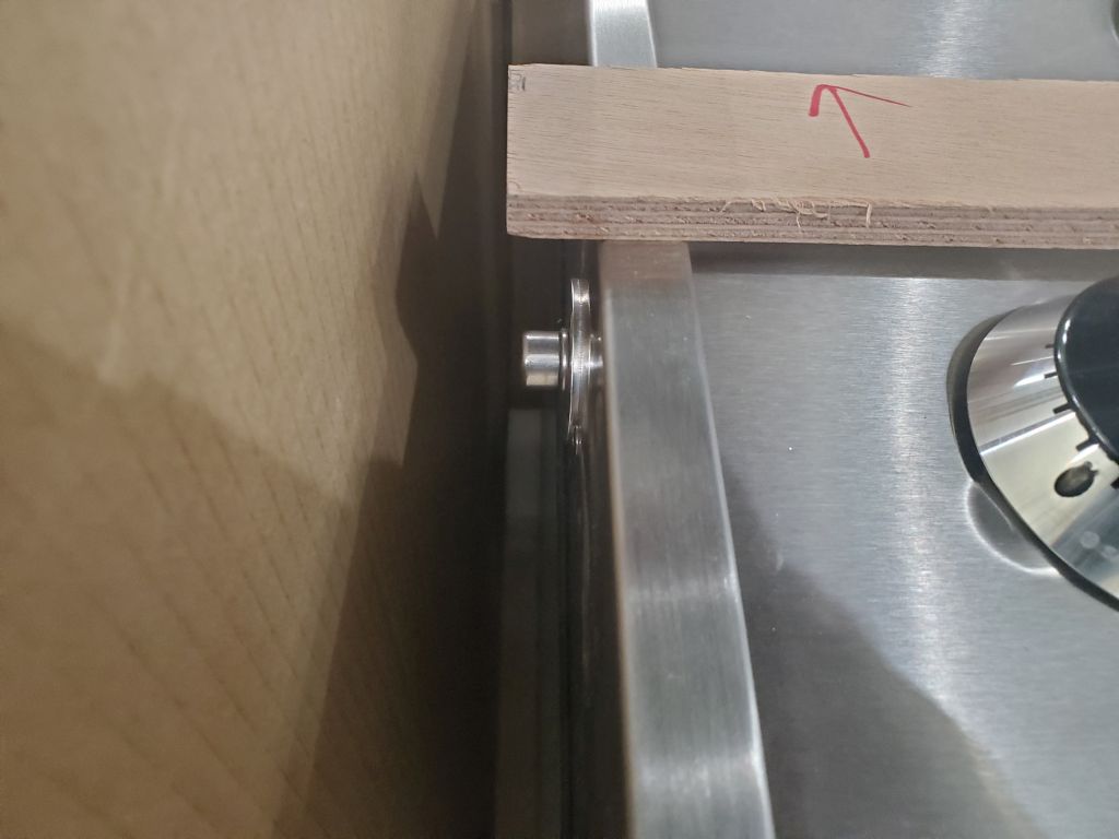
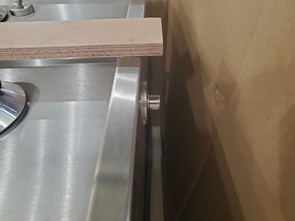
I started by repositioning the stove gimbal center a bit further inboard, after much consideration of the space and the various factors at hand. The most salient limiting factors were, in order of importance from my perspective:
I ended up moving the stove position 1″ inboard from my original layout. This would give a bit more clearance for the enclosure, make the stove a bit more convenient to use, while not interfering more than necessary with the potential access to the under-sink area. All things in small, curvaceous boats require compromise. Once I’d located the aft gimbal point, on the new bulkhead, I transferred its position across to the forward bulkhead, double-and triple-checking the measurements in all dimensions. Then, I used my pre-measured radius stick to draw the stove swing radius on both sides, and checked the overall stove fit with the stove template to ensure its proper swing and also mark the after limit of the enclosure (based on a 45 degree outboard swing angle).
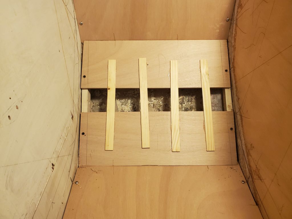
For the floor of the enclosure, I roughed out a layout mark providing for 1″ clearance between the top of the eventual plywood and the gimbal arc, then measured and installed identical cleats on both sides of the enclosure, ensuring they were aligned and level. For now, I dry-fit the cleats with just a couple screws, awaiting completion of the entire enclosure first before I committed to any positions with glue and additional screws.
For the vertical back side of the enclosure, I marked the location providing 1″ clearance from the point at which the stove was swung 45 degrees outboard, and installed identical cleats on each side, again laboring to keep the cleats in the same position, square and aligned with each other and properly plumb. Apparently I took only one photo of this part of the process.
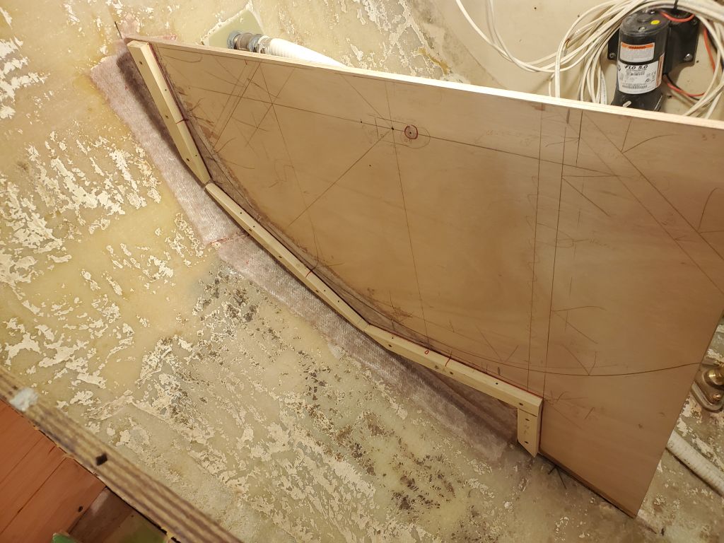
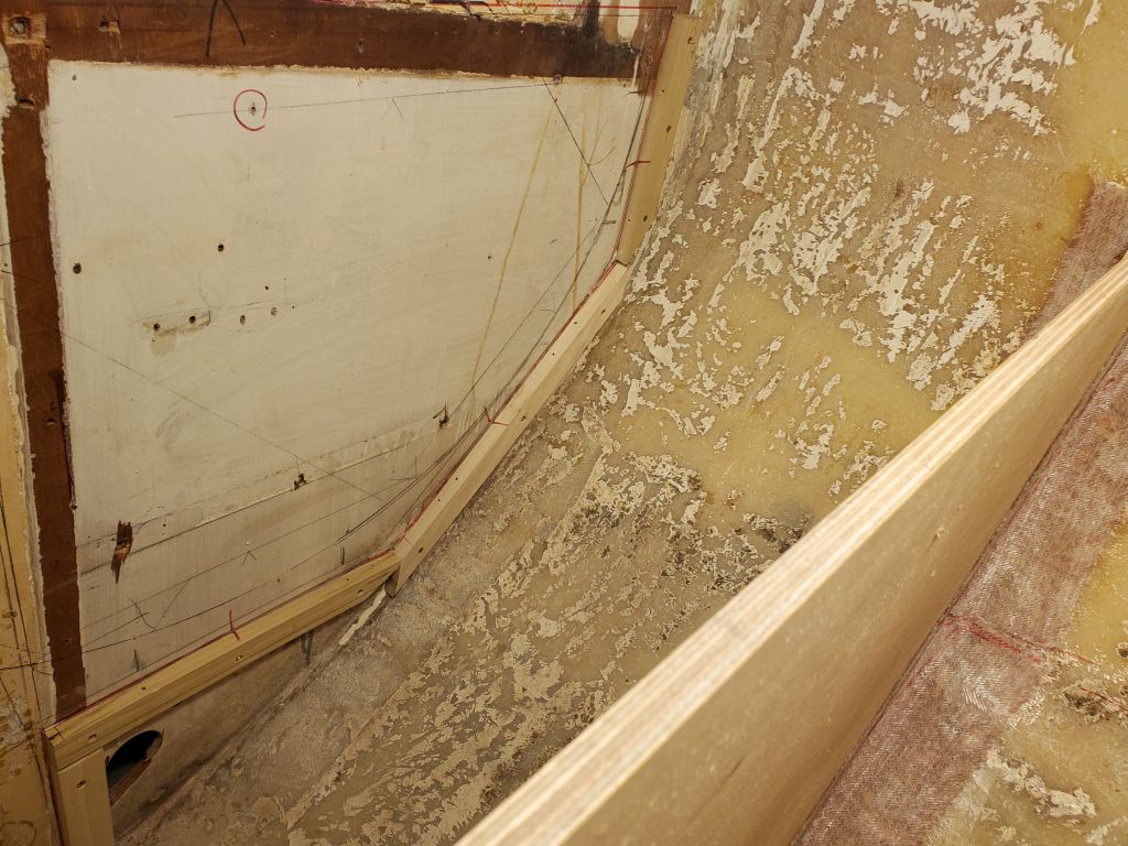
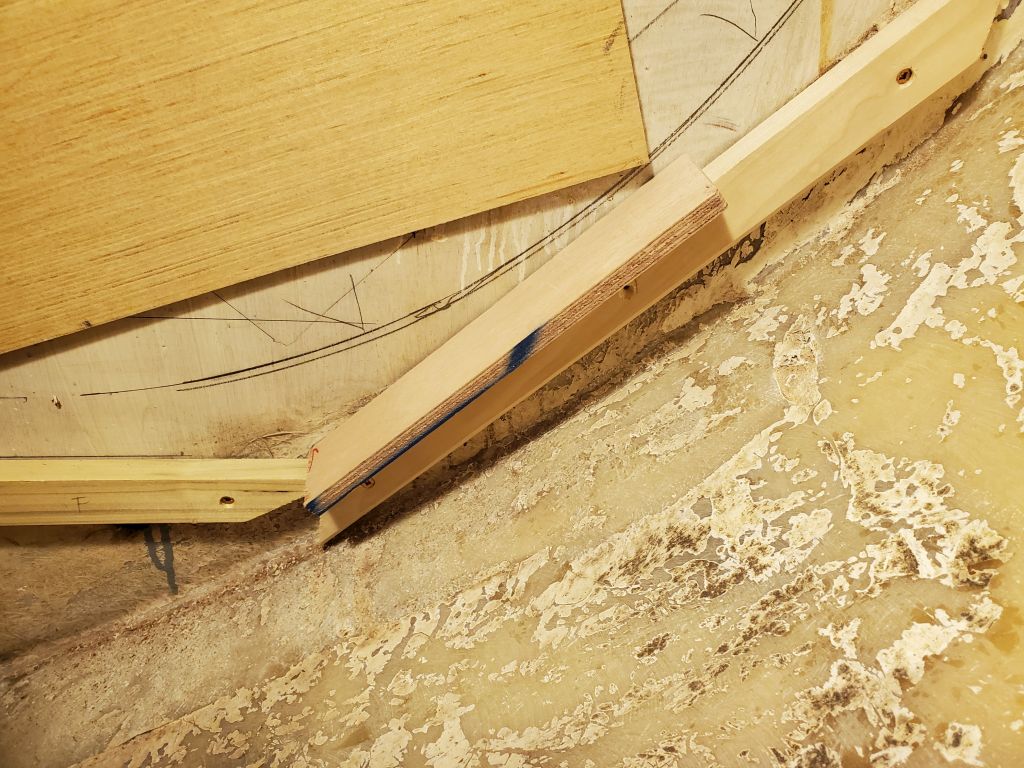
I had little spare room for the angled cleat to span between the floor and back of the compartment, at least on the aft side, so I made a hot glue template of the required angle and length of the cleat, positioning it so as to provide more than ample clearance for the 12mm plywood panel and some leeway, as this was the closest point of approach for the swing radius and the hull. These cleats were the most time-consuming as they had to fit just so, and the after cleat required various modifications on the fly to allow it to fit in the space and along the lavish fillets someone had installed beneath the bulkhead tabbing.
I finished off the basic cleat layout with two short vertical cleats to support the eventual panel beneath the enclosure, forming the front of the cabinet.
I reinstalled the stove template and checked it physically against the new cleats, using a scrap of 12mm plywood to ensure clearance as needed.
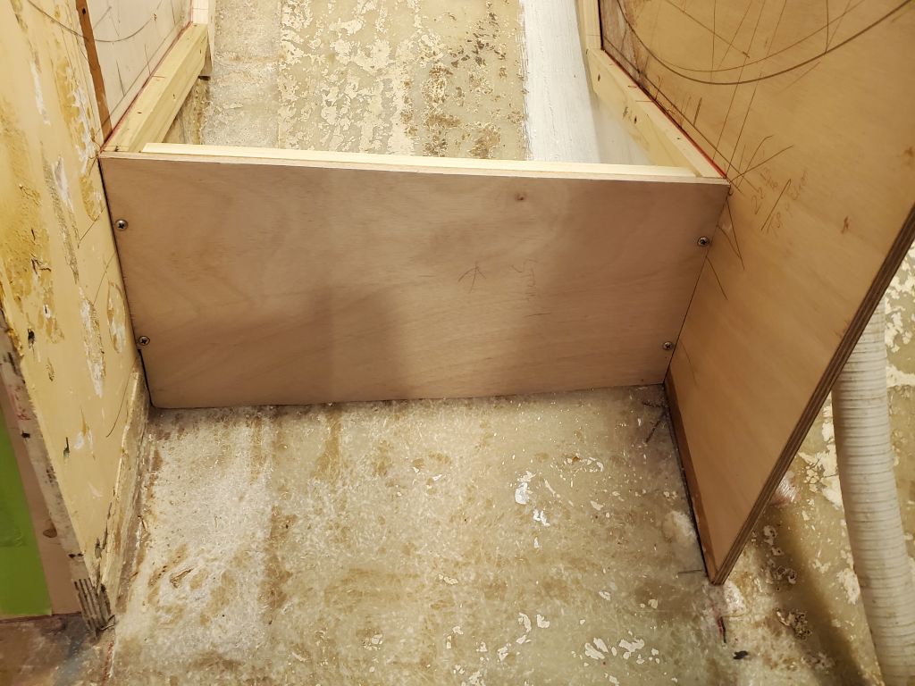
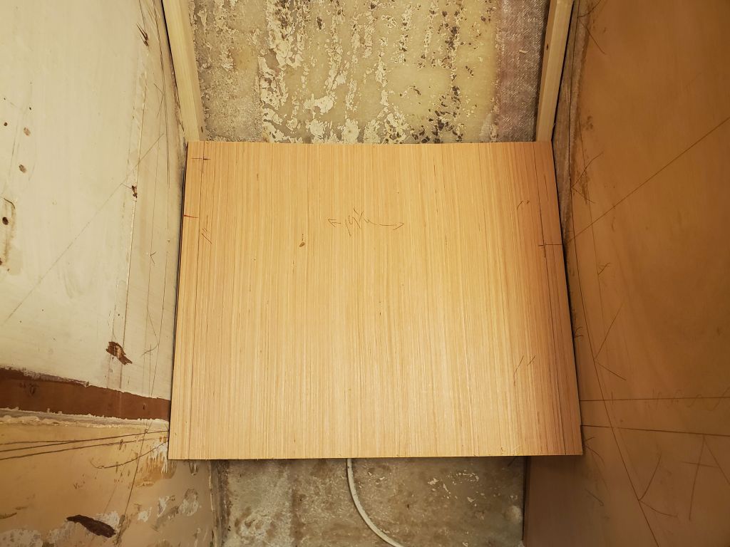
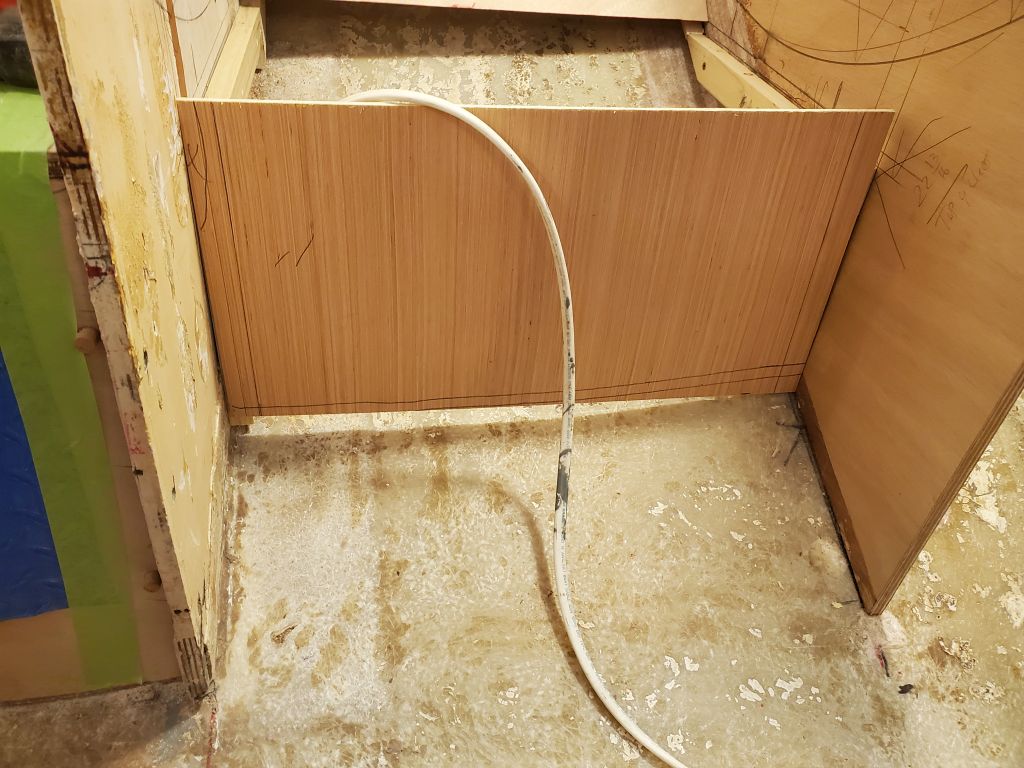
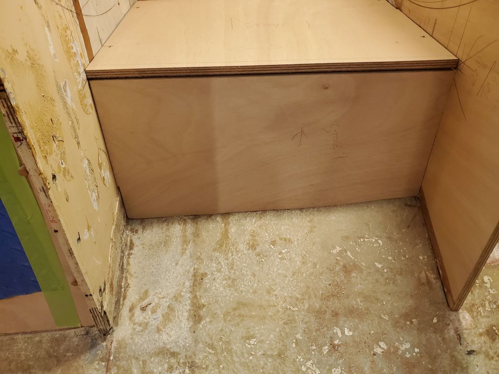
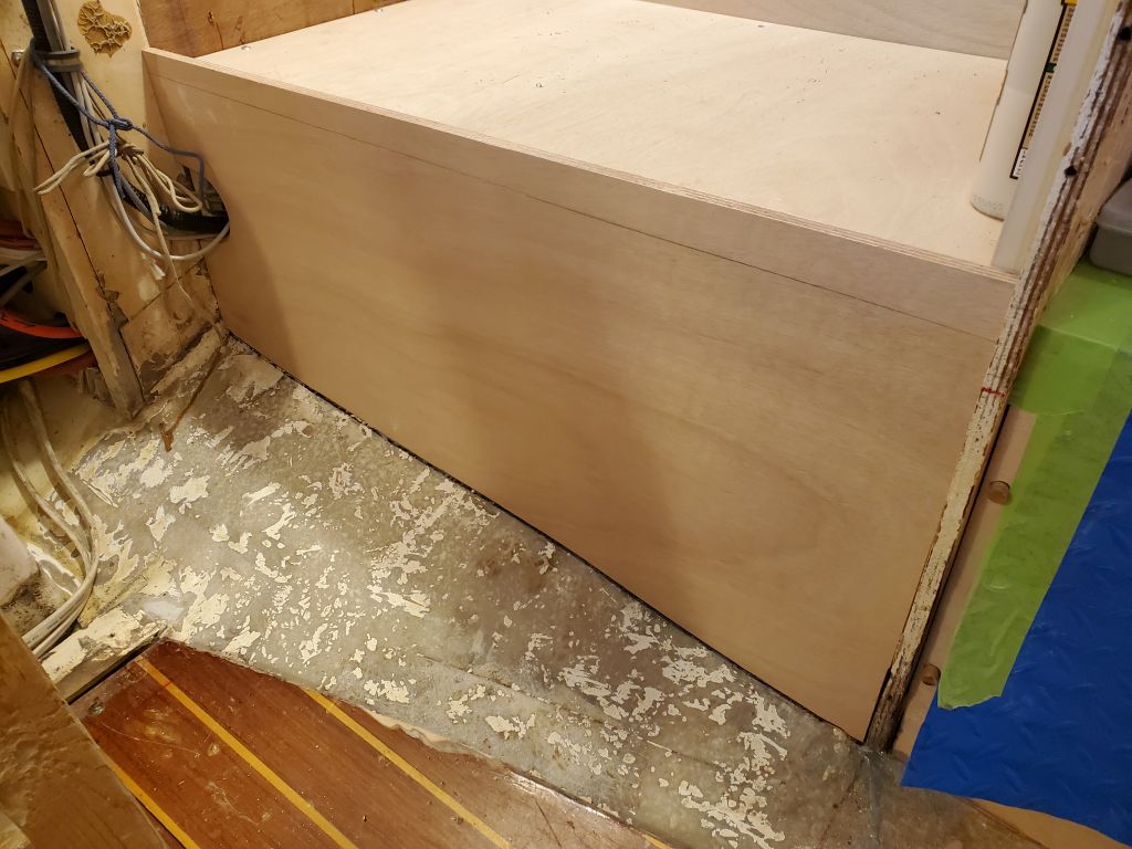
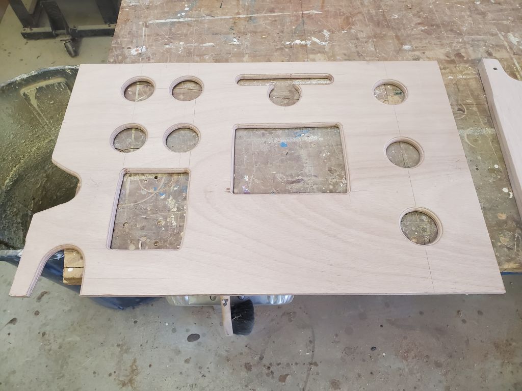
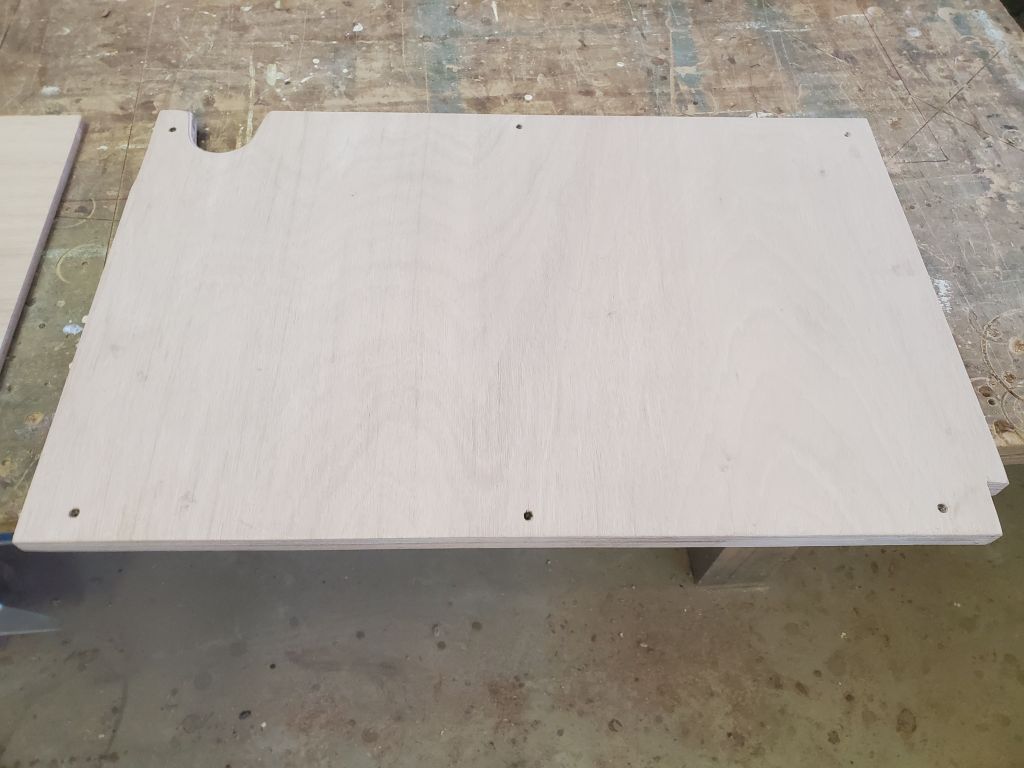
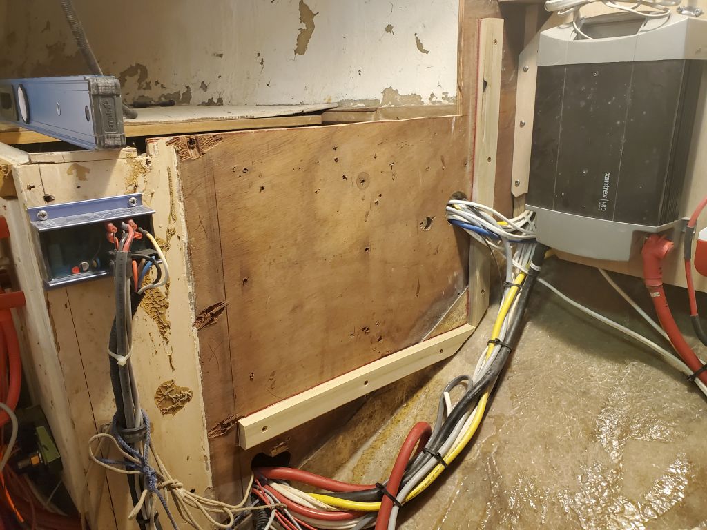
In other works, and because I’d need it soon for other aspects of the galley construction, I prepared and installed (temporary) a front cover panel for the refrigerator cabinet on the port side. For this, I followed the usual steps of a rough cheap plywood template scribed and marked to fit, which I then used to cut the final panel from 12mm plywood slightly over-height for final marking against the floor of the space. I planned this panel to be removable in the final analysis, so installed it with surface screws. This panel would provide some support to the cabinetry extending across the engine room and center of the boat, details of which would be making themselves more clear as the adjacent elements came together.
I spent the first part of the morning continuing work on the new stove bulkhead in the galley: remove the glue blocks, lightly sand, fillet the spaces where the glue blocks had been, and install 6″ tabbing in epoxy resin on both sides of the bulkhead.

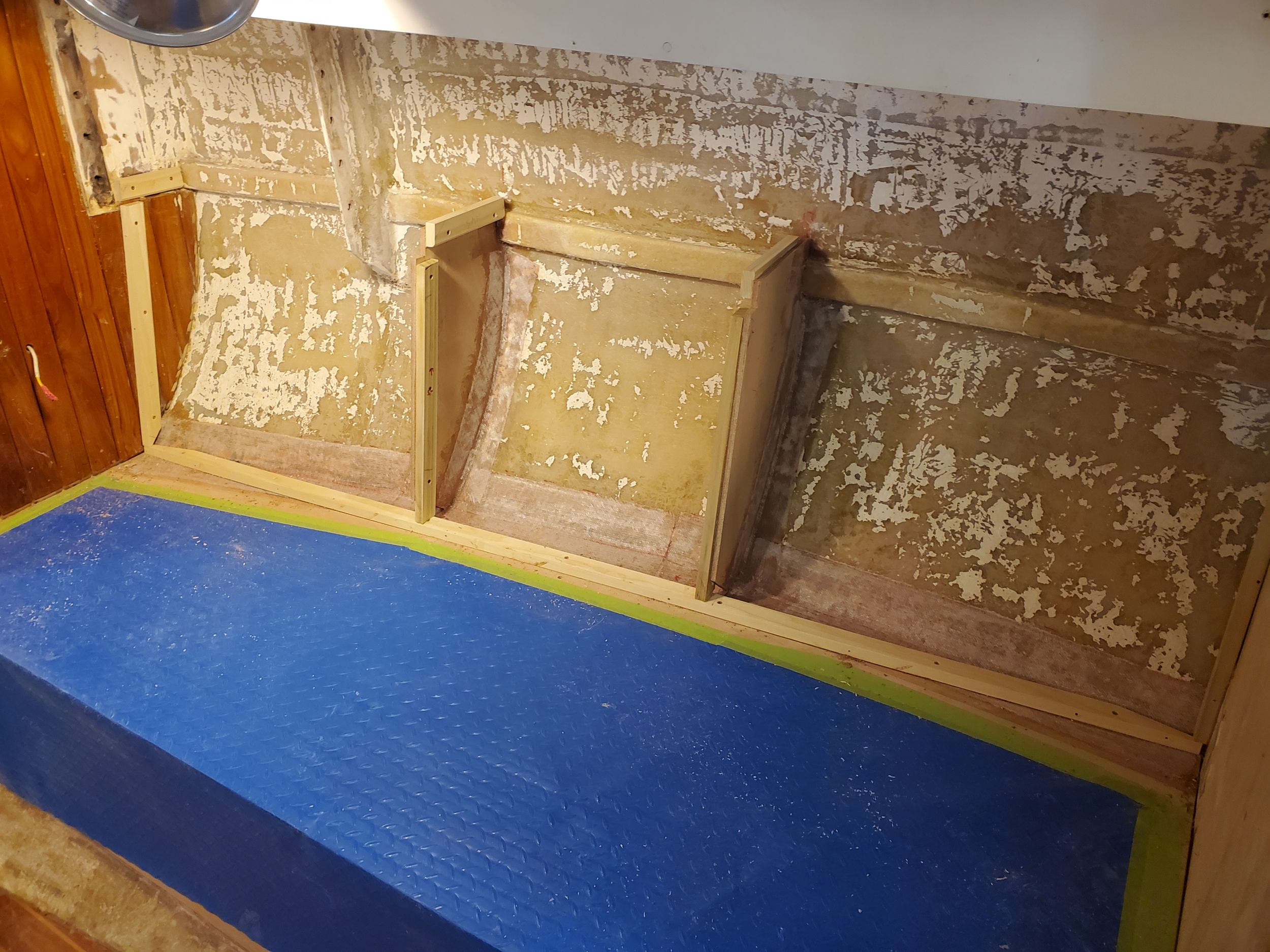
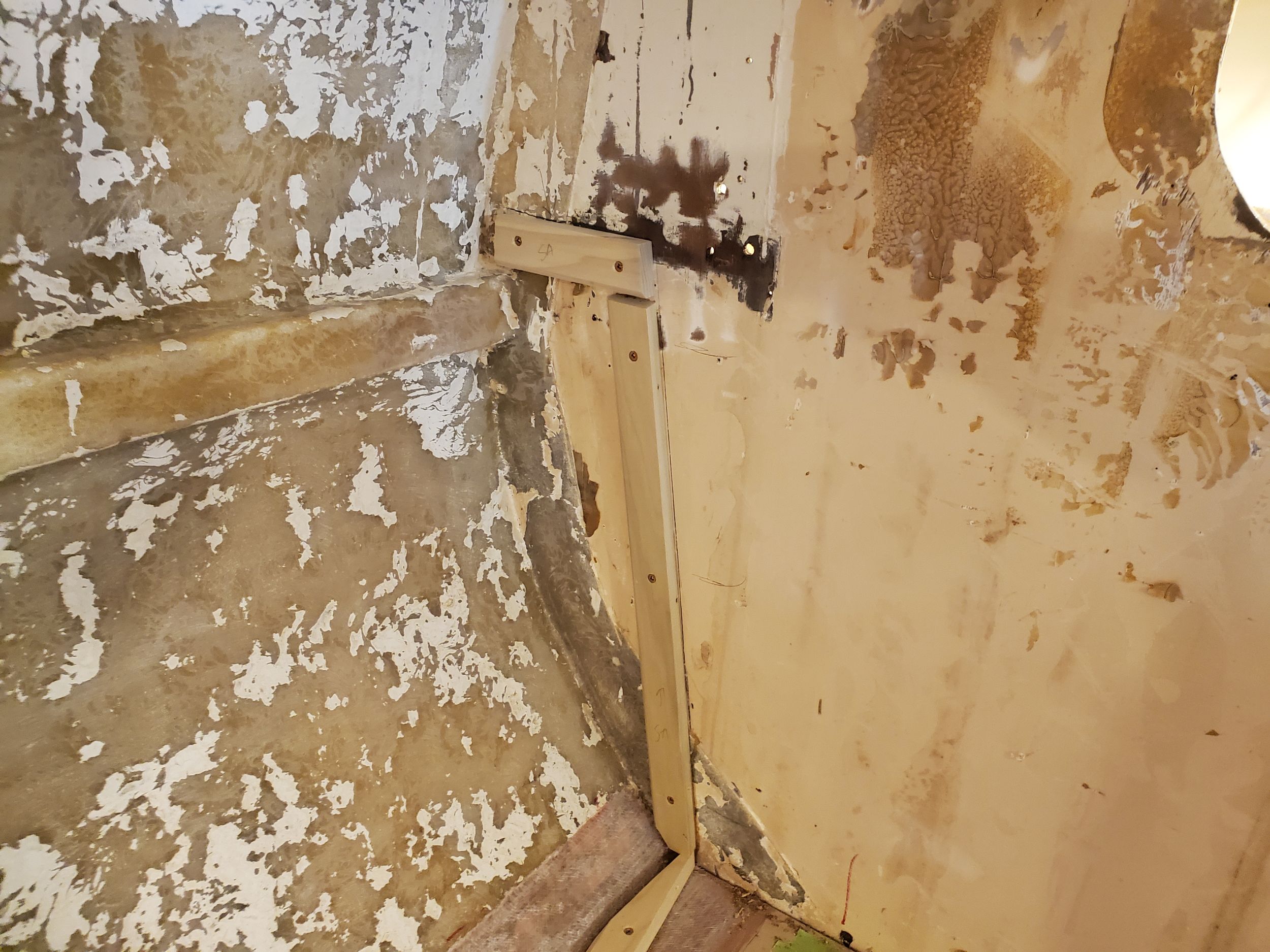
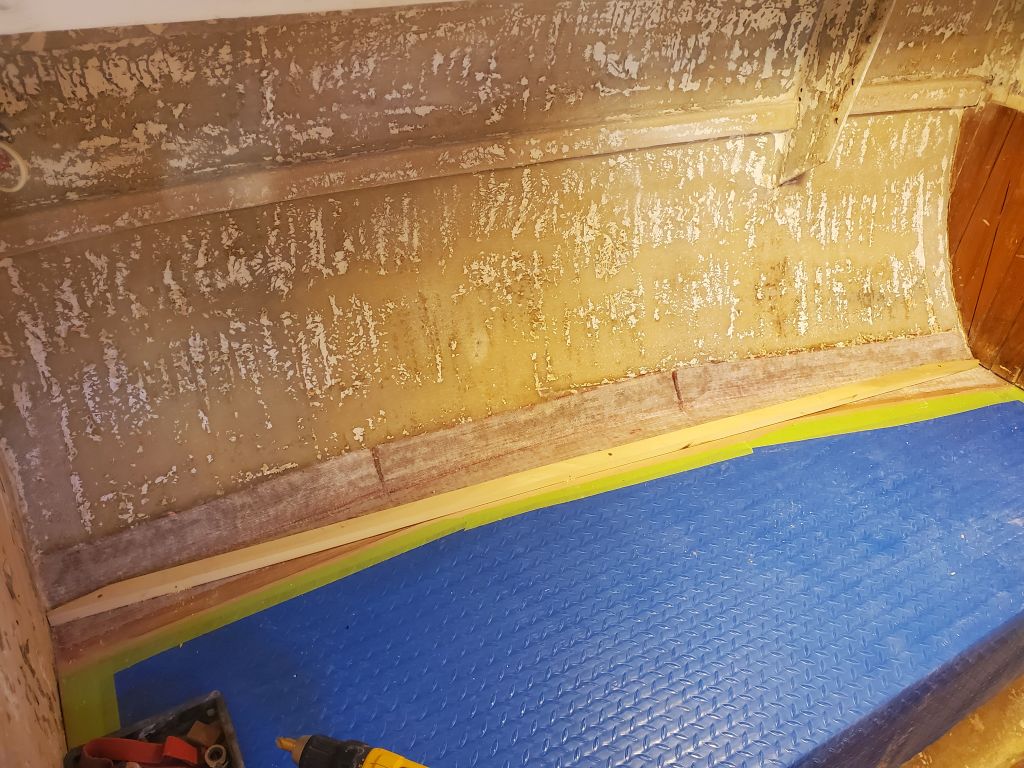
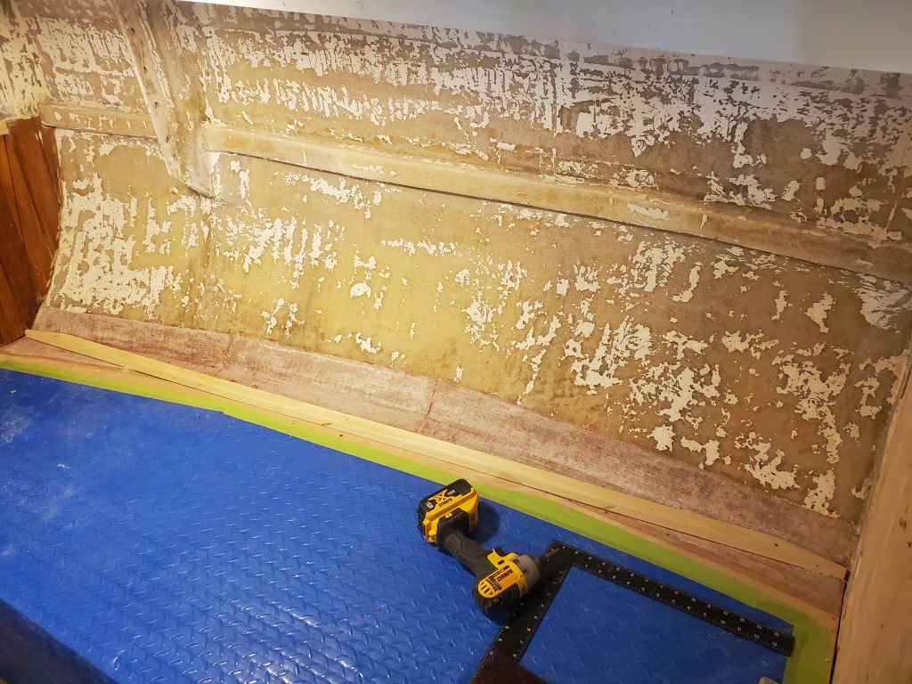
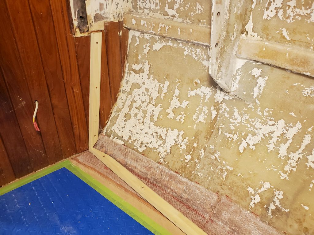
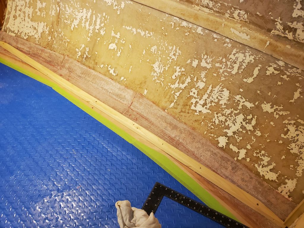
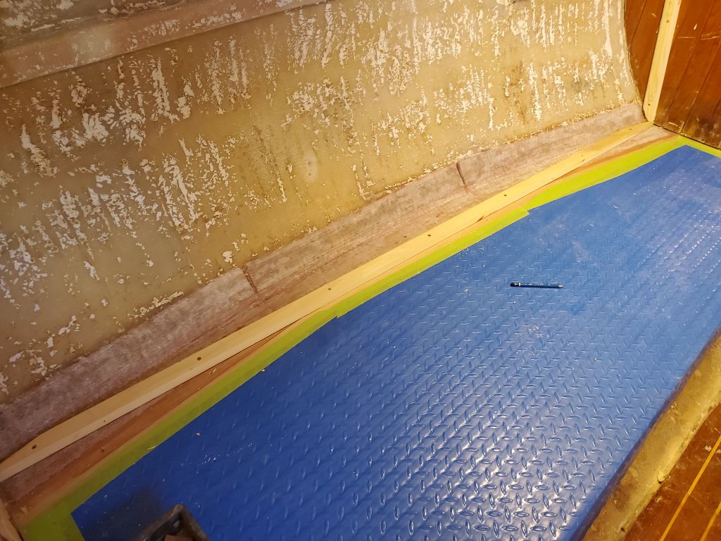
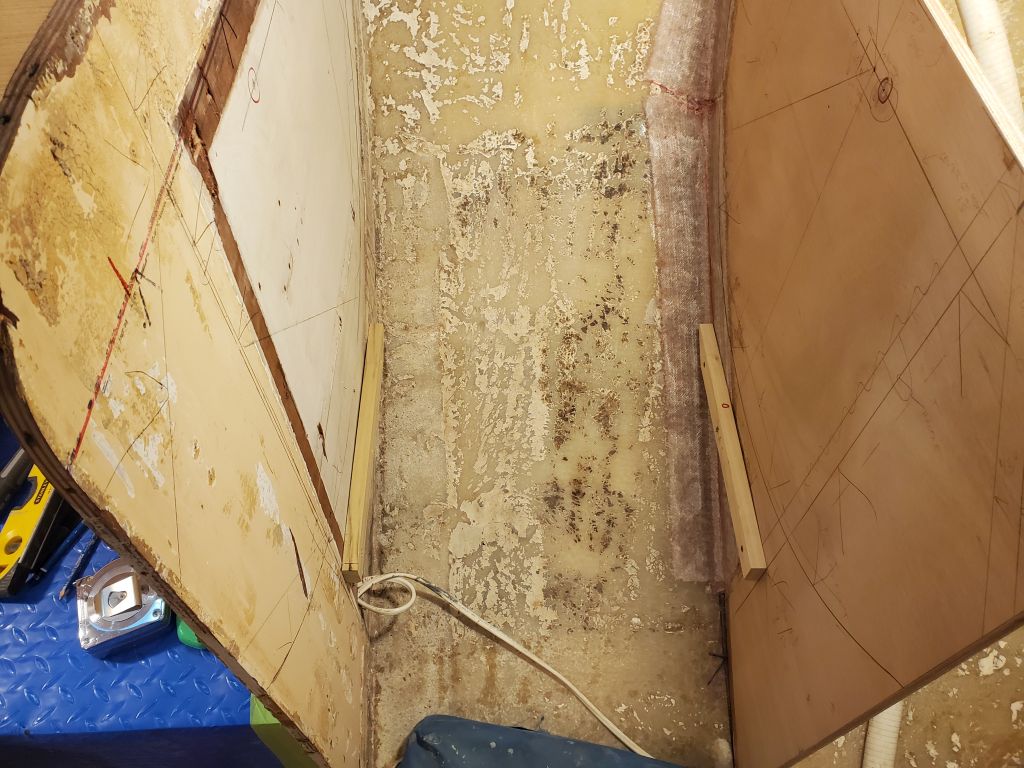
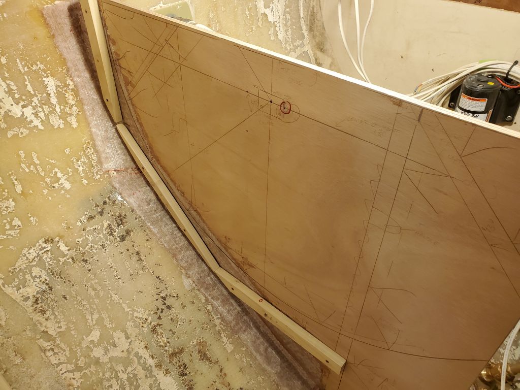
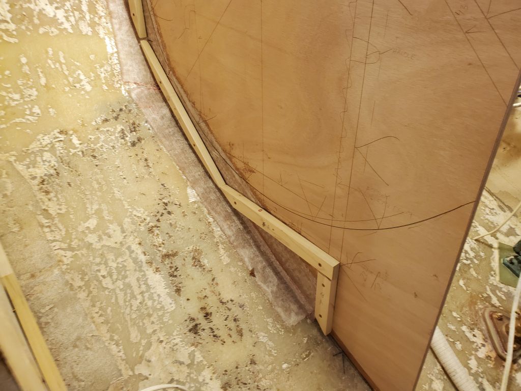
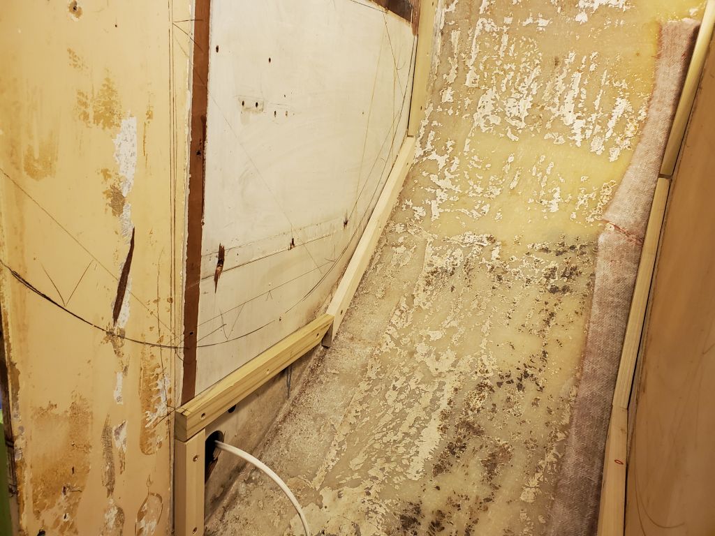
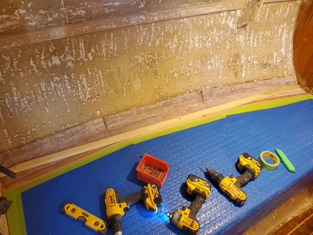
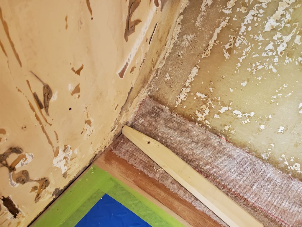
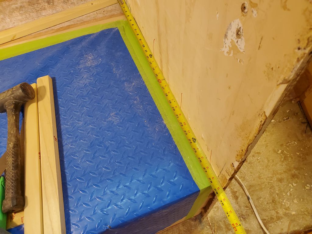
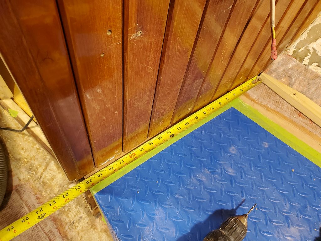
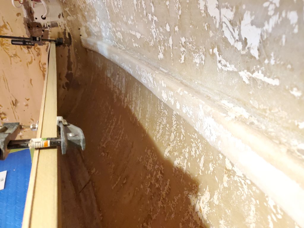
Next, I turned back to the settees, ready to build upwards. The owner requested that the berths be as wide as possible at both ends, which would dictate the position of the backrest/locker face, so to begin I cut support cleats to run as close as practicable to the fore-and-aft intersections of the berth with the hull. I began on the port side, with a hardwood cleat cut and slightly shaped at the ends to fit into the tapered corners, and secured it temporarily with three screws for now. Factoring in the thickness of the eventual backrest panel, this left a berth width of approximately 18″ at the forward end, and 27″ at the aft end.
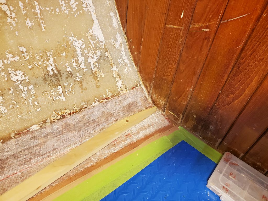
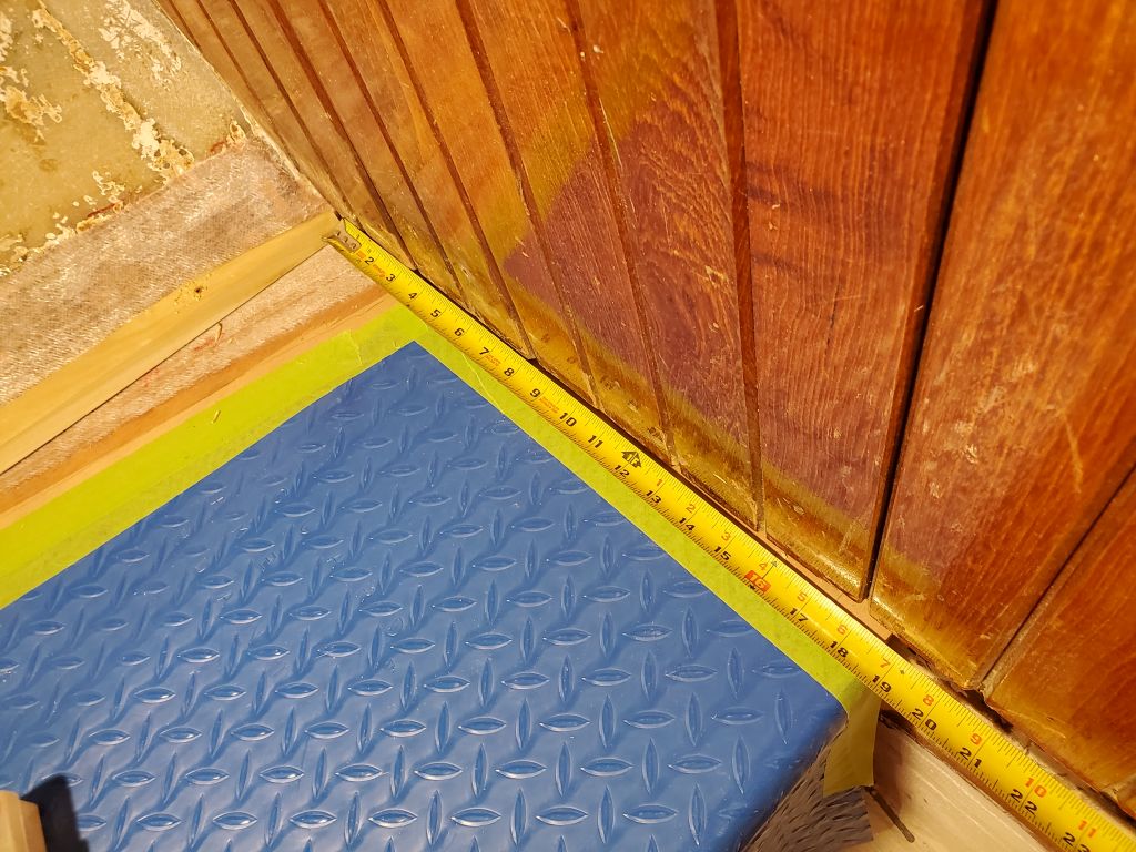
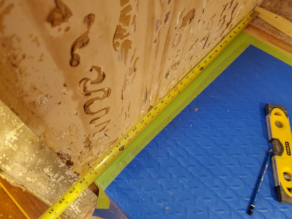
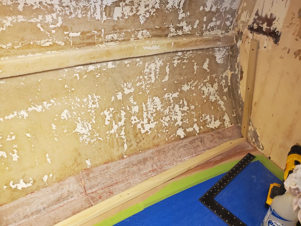
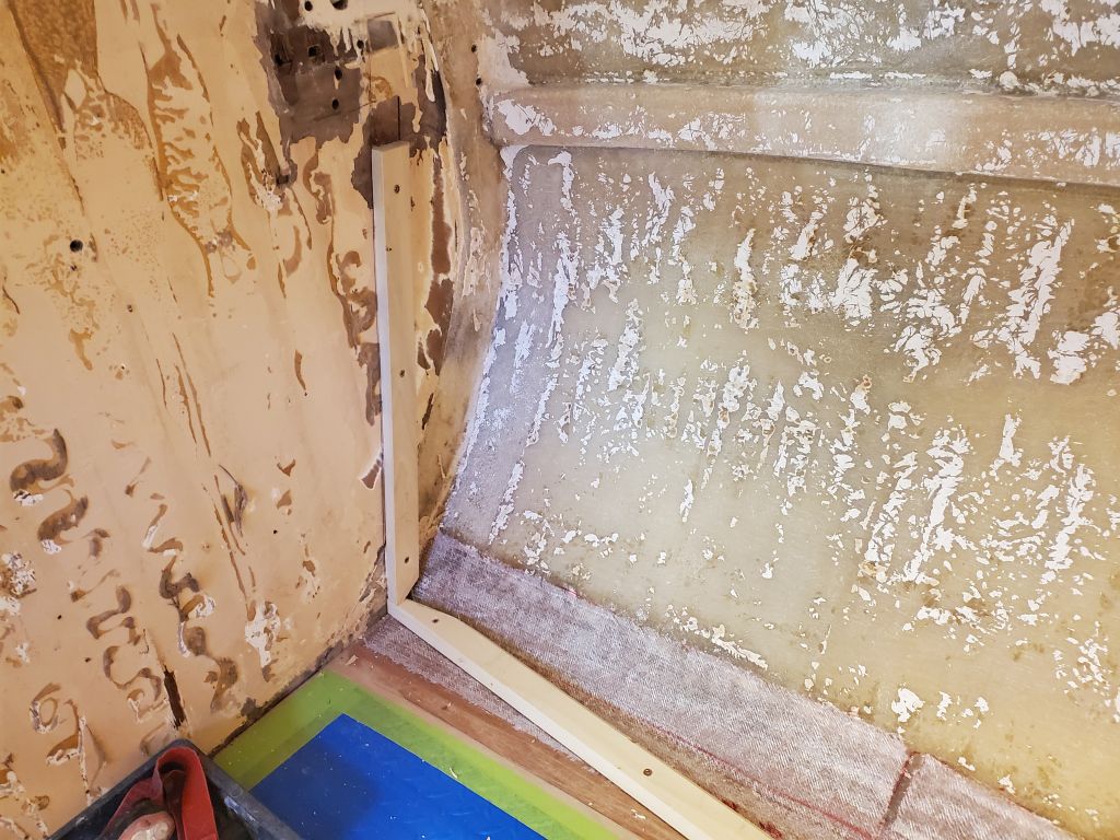
I repeated the process on the starboard side, where the berth was just a touch wider: these berth widths had originally been dictated by the position and widths of the two after bulkheads, as well as the opening into the head and forward cabin. Here, the forward end was approximately 19.5″ wide, and the after end 28″.
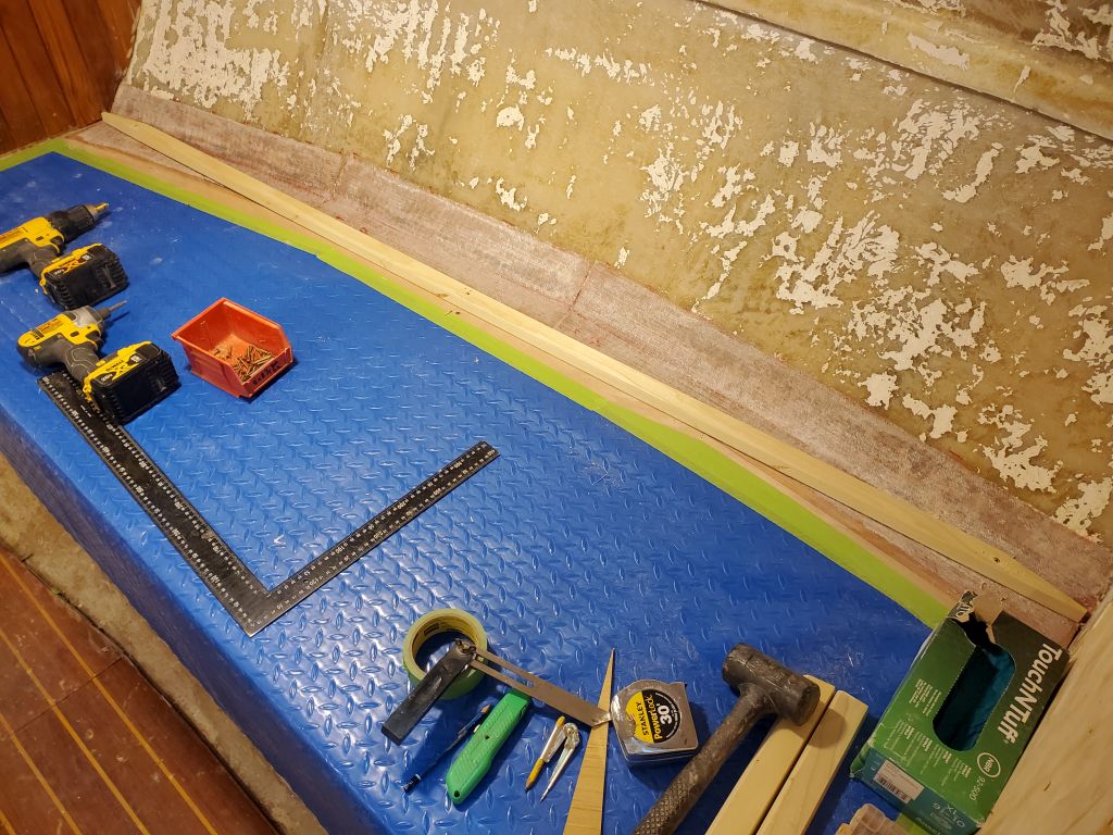
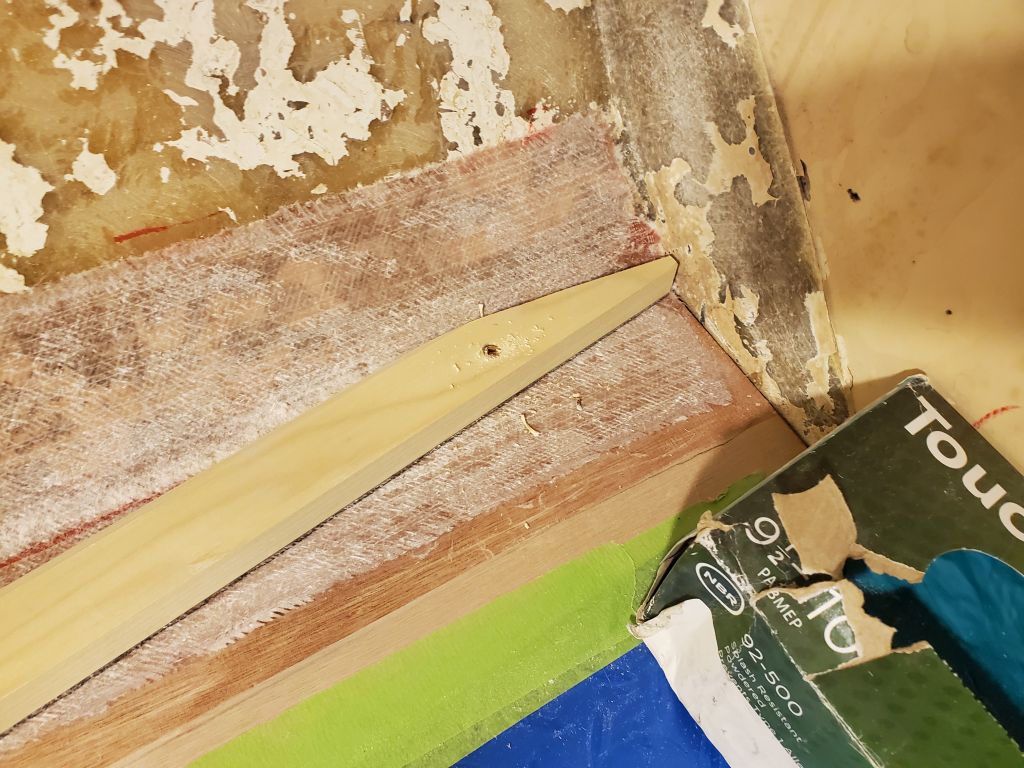
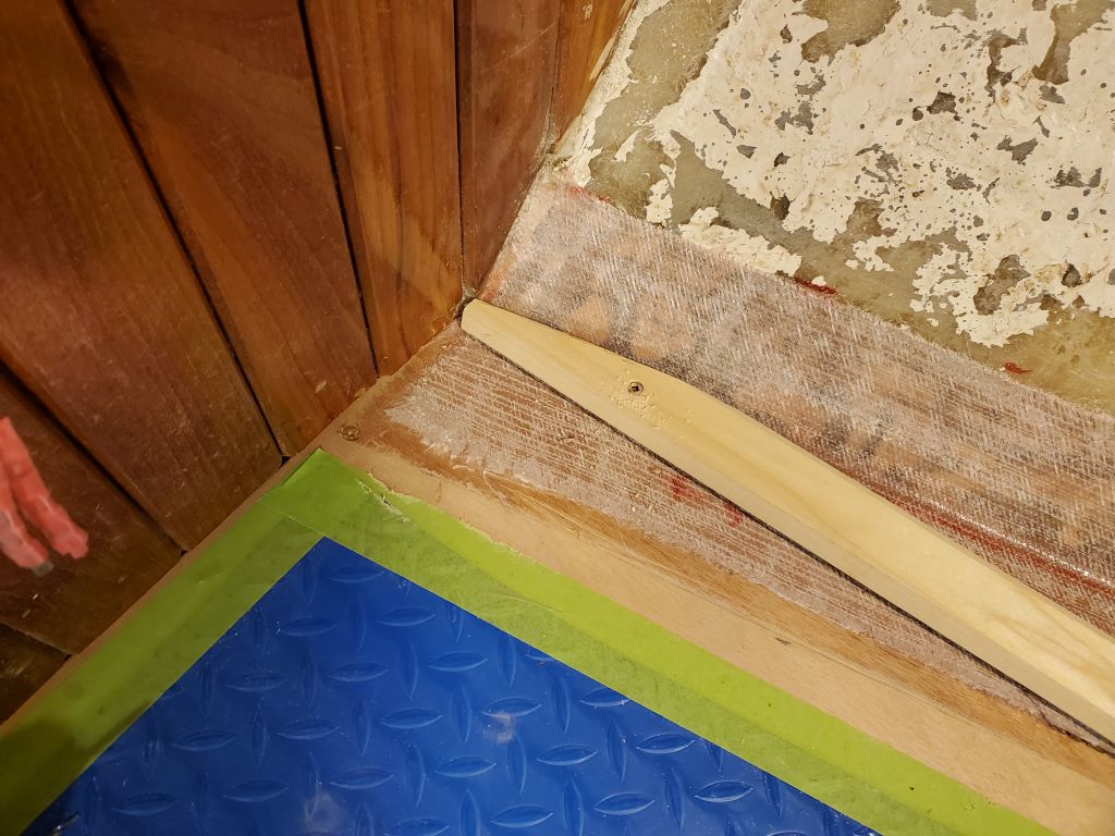
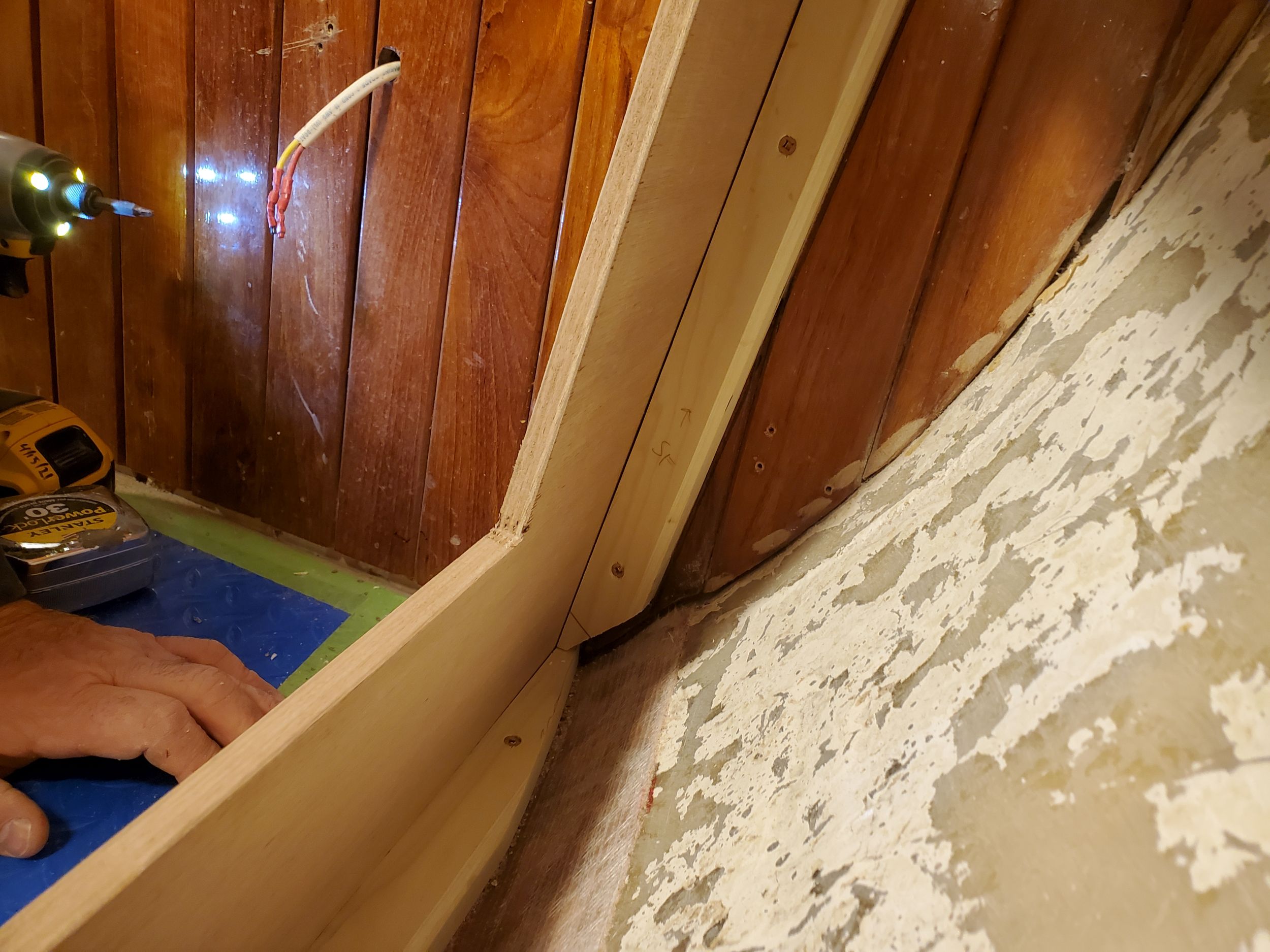
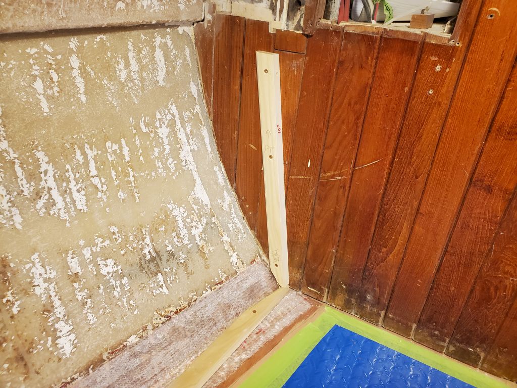
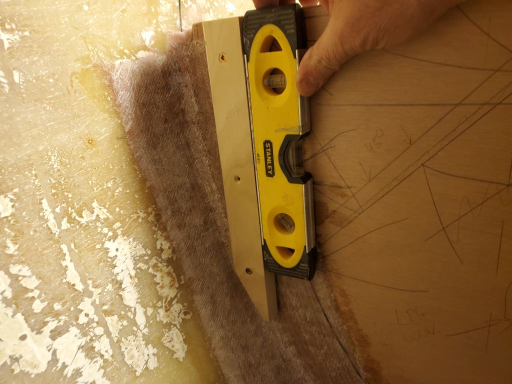
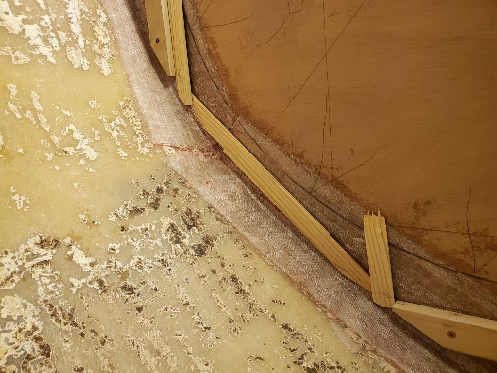
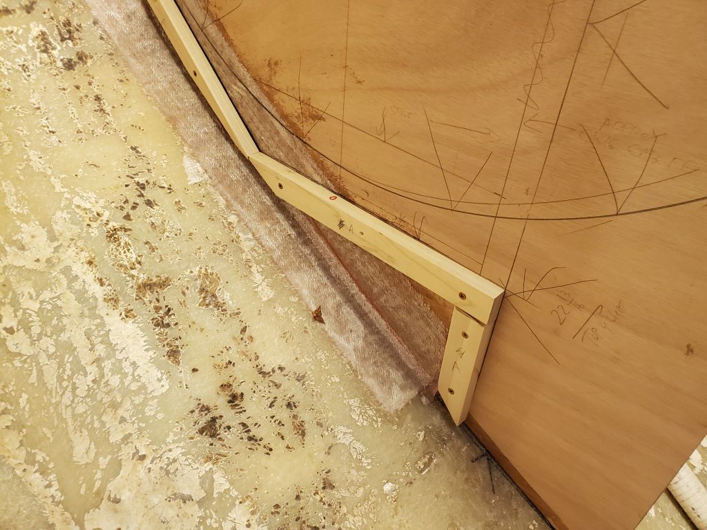
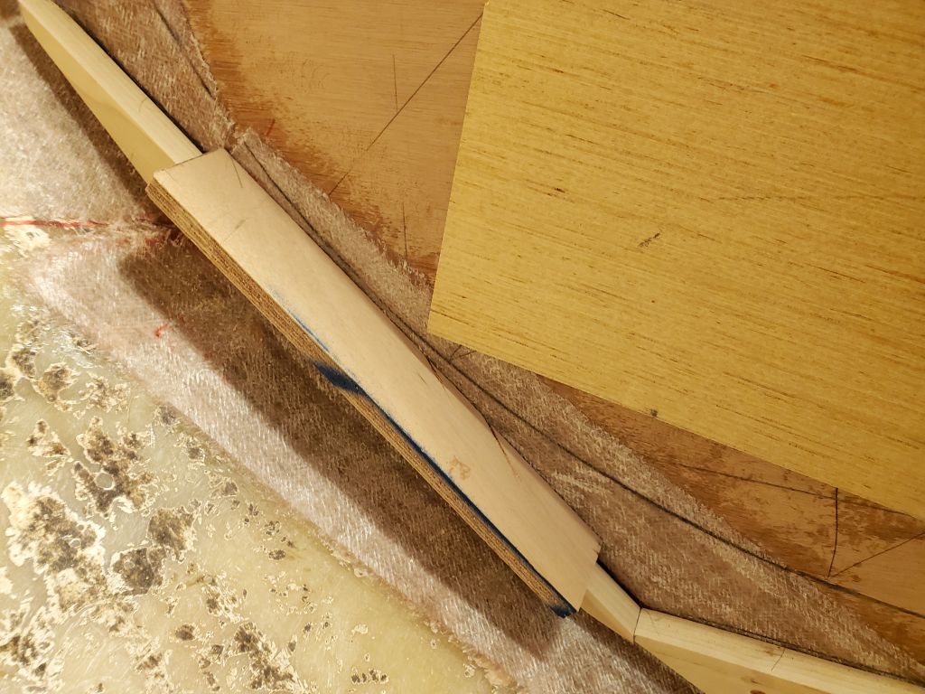
10 degrees works well for a backrest angle, so with this in mind I’d pre-cut the bottom cleat to this angle along its outer edge. From here, I struck layout lines up the bulkheads on each end, following the angle measurement, and temporarily installed vertical support cleats for the backrests. I left these cleats over-long for now pending final decisions on the backrest design. Because the bulkhead angled from forward to aft, these cleats also required a slight angle (10° worked well) on their edges to accommodate the panel.

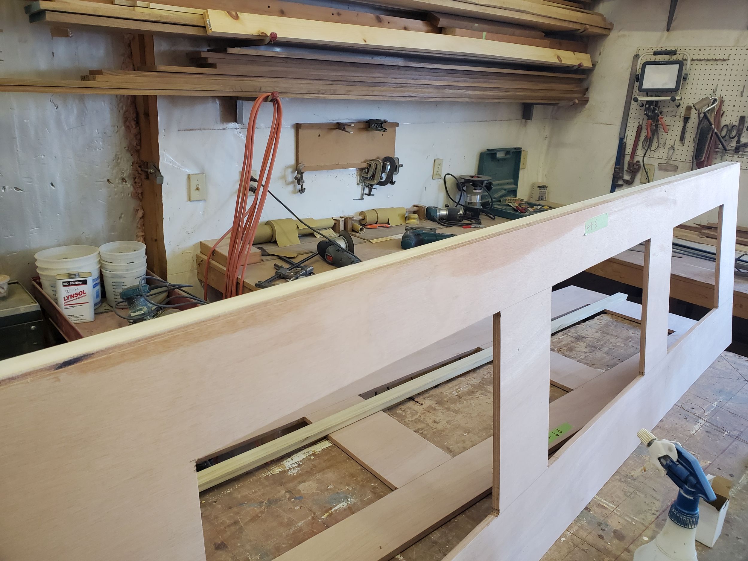
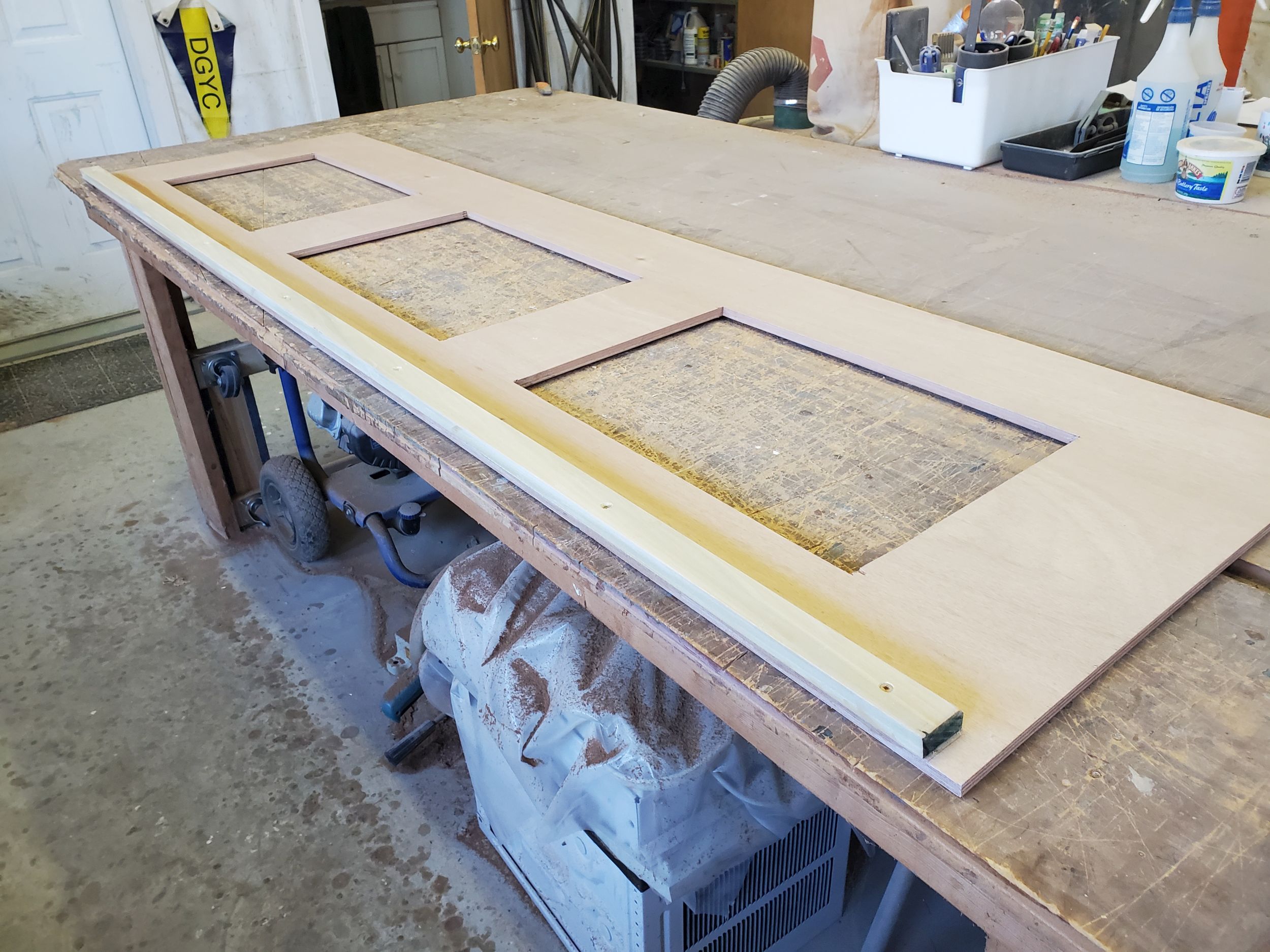
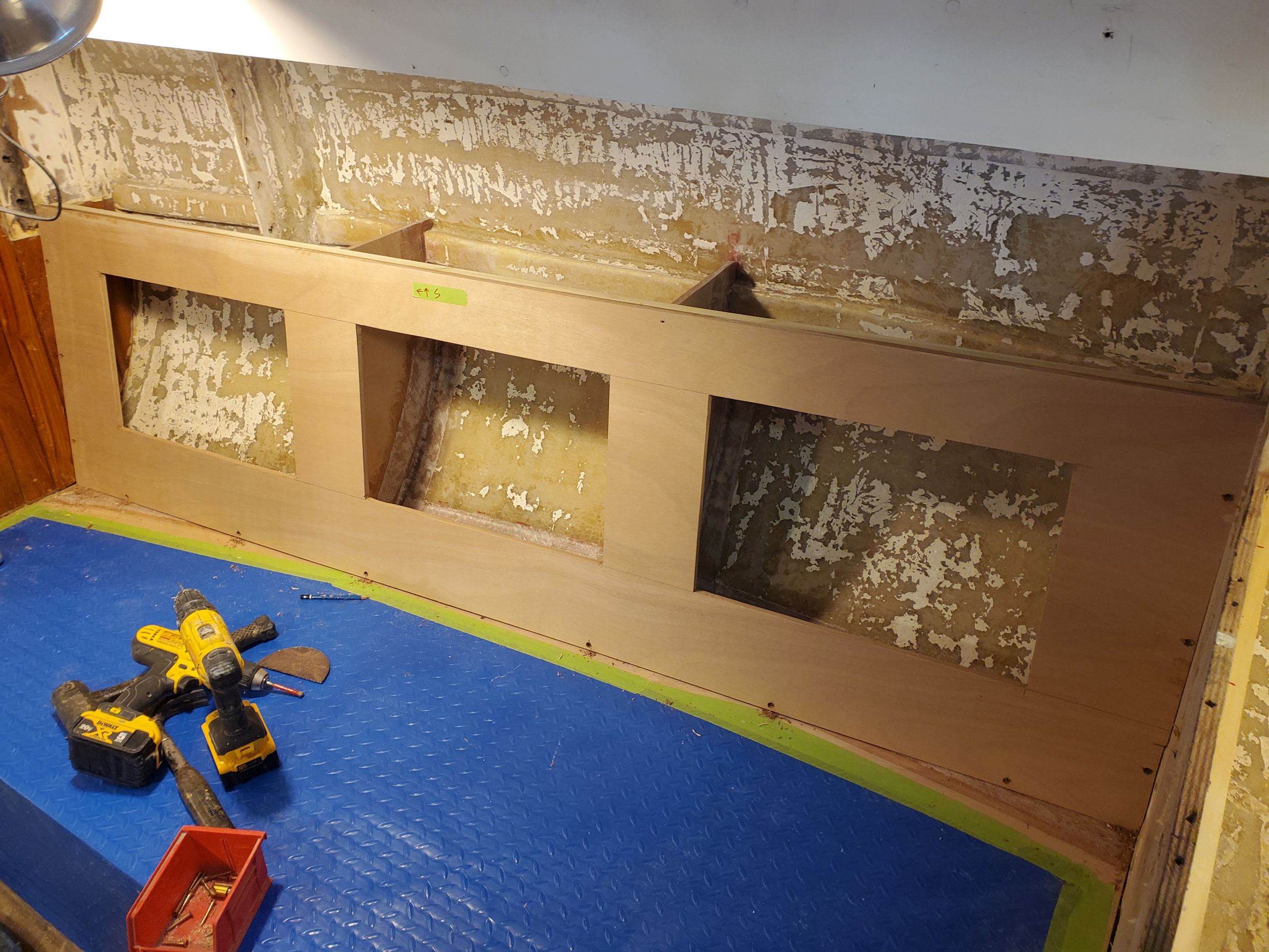
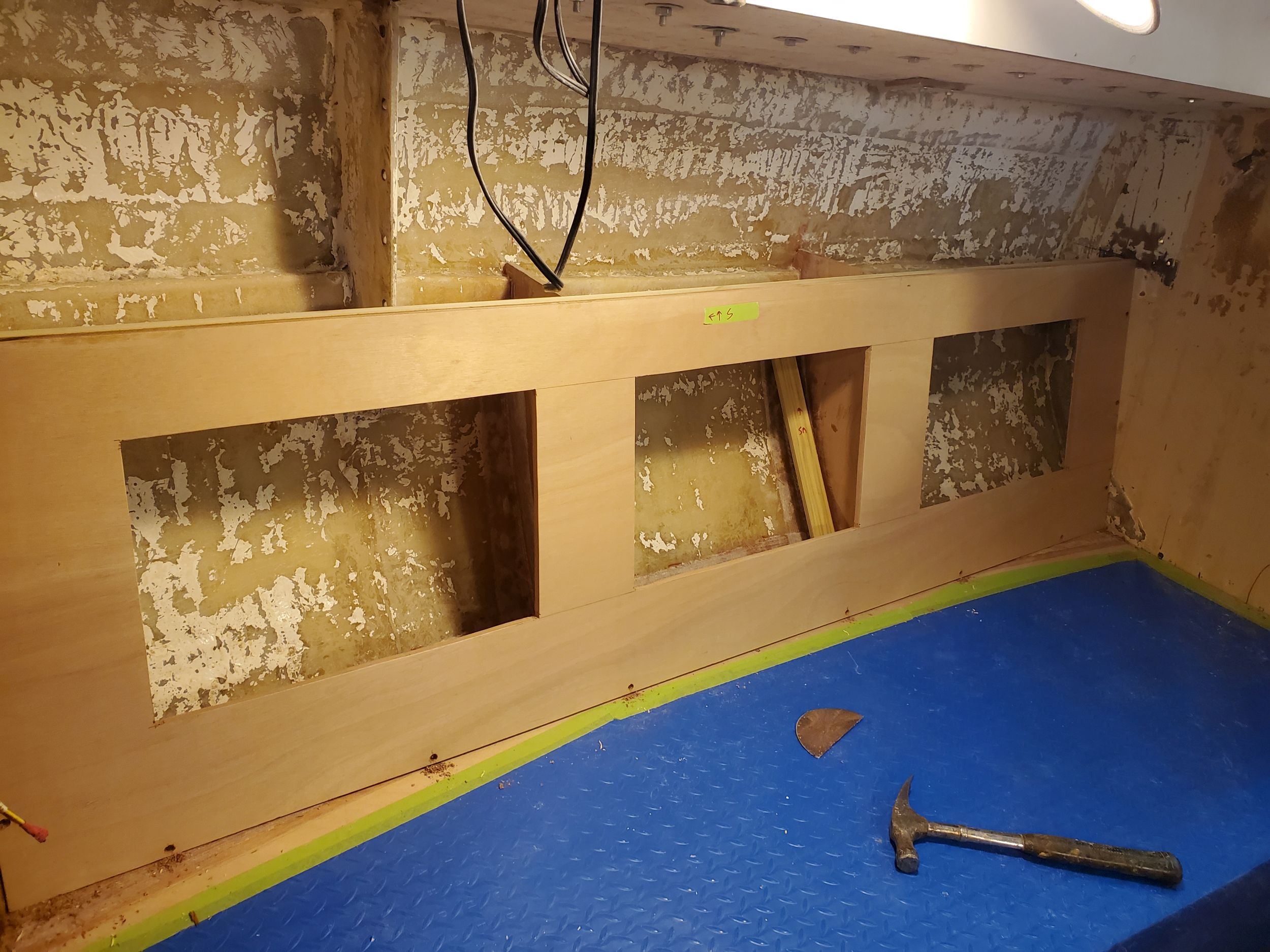
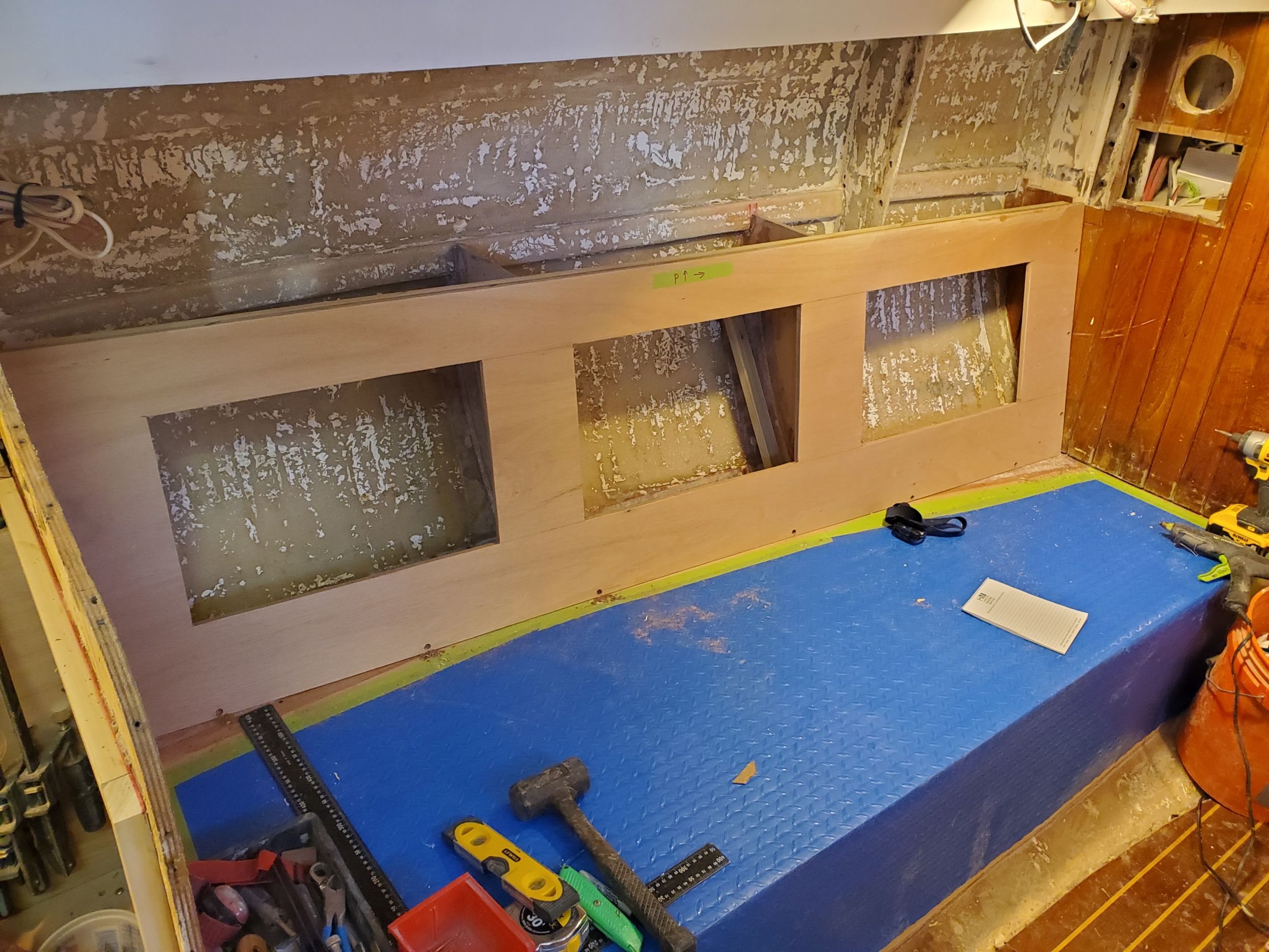
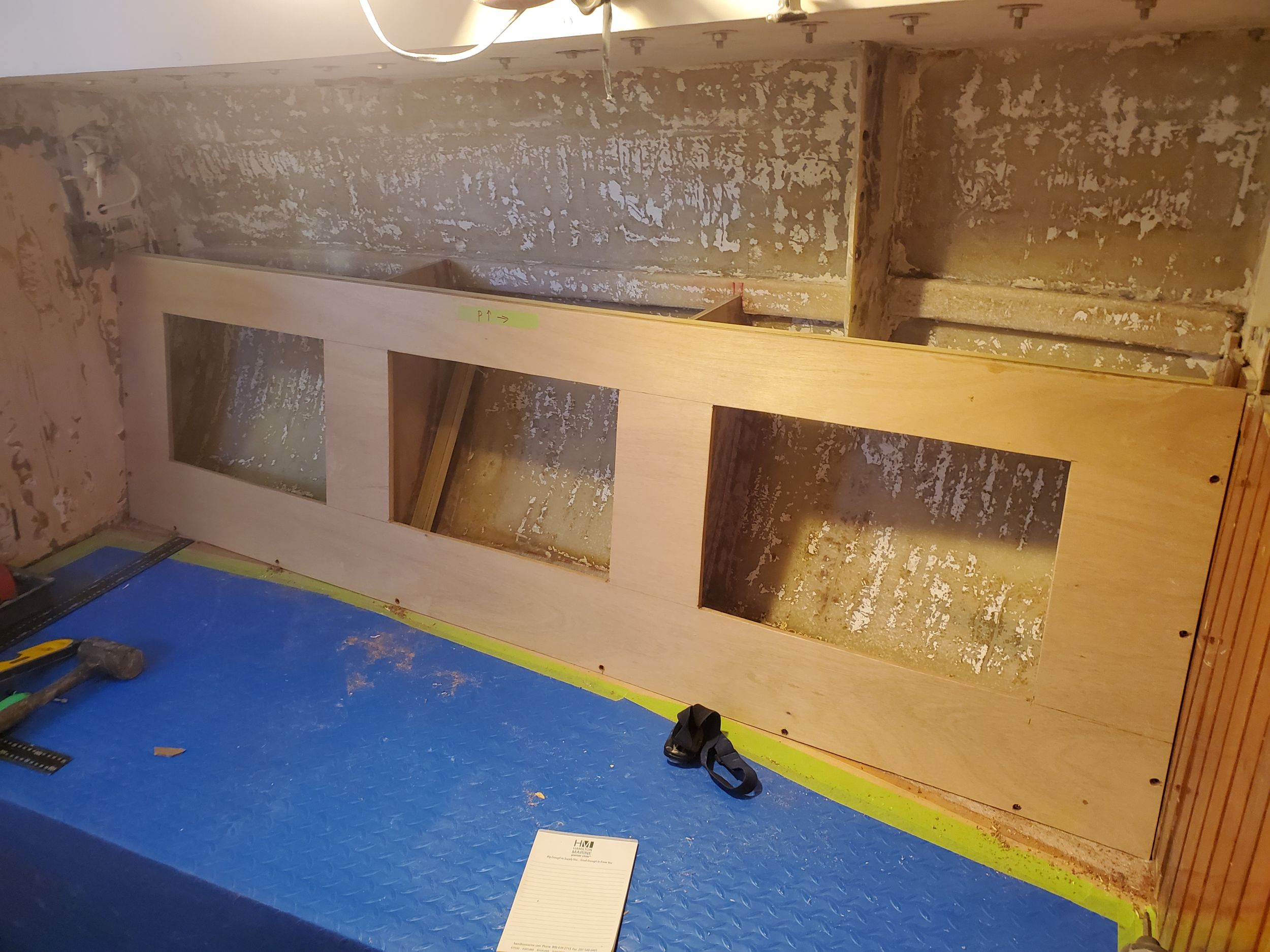
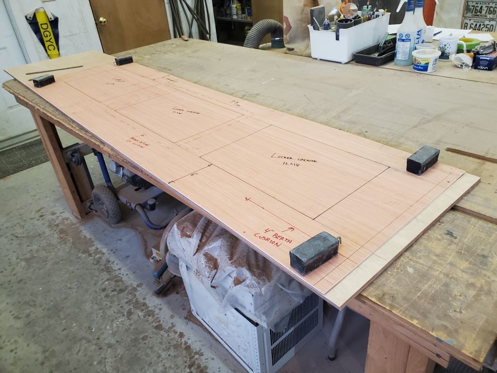
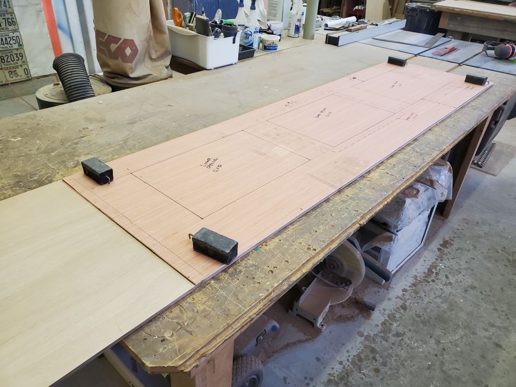
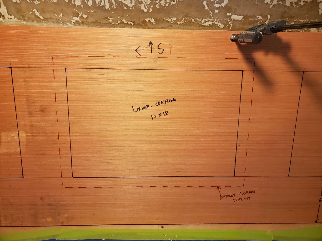
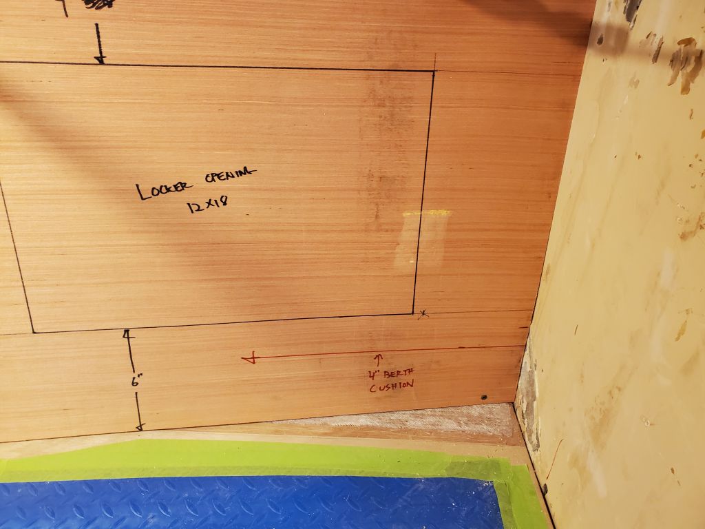
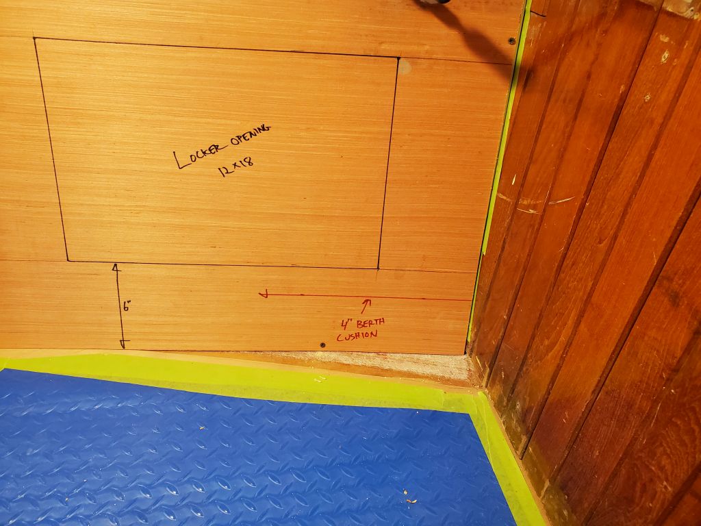
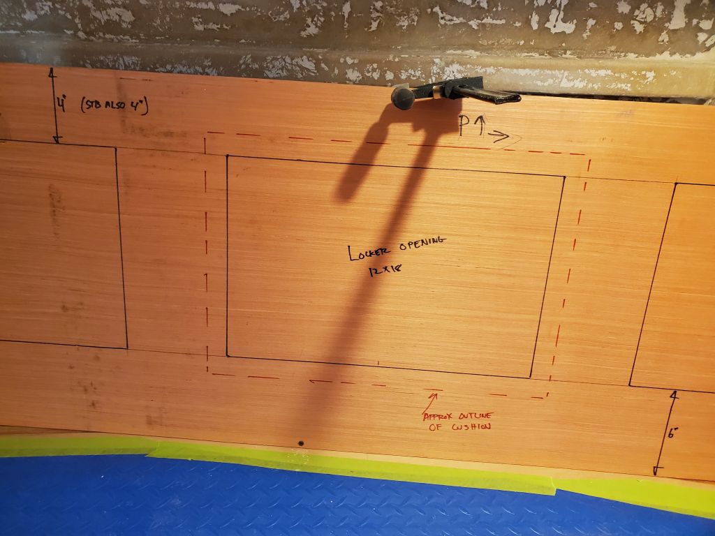
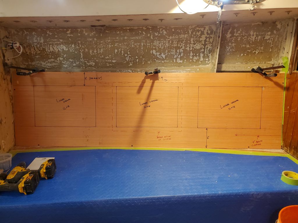
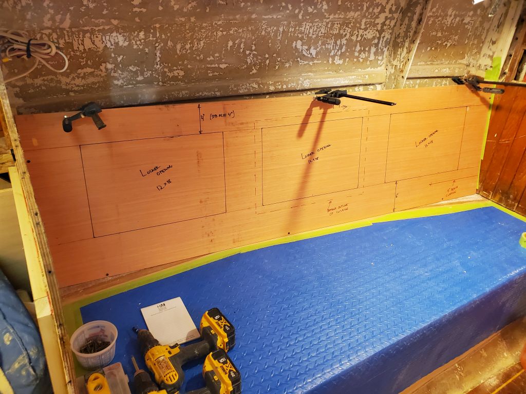
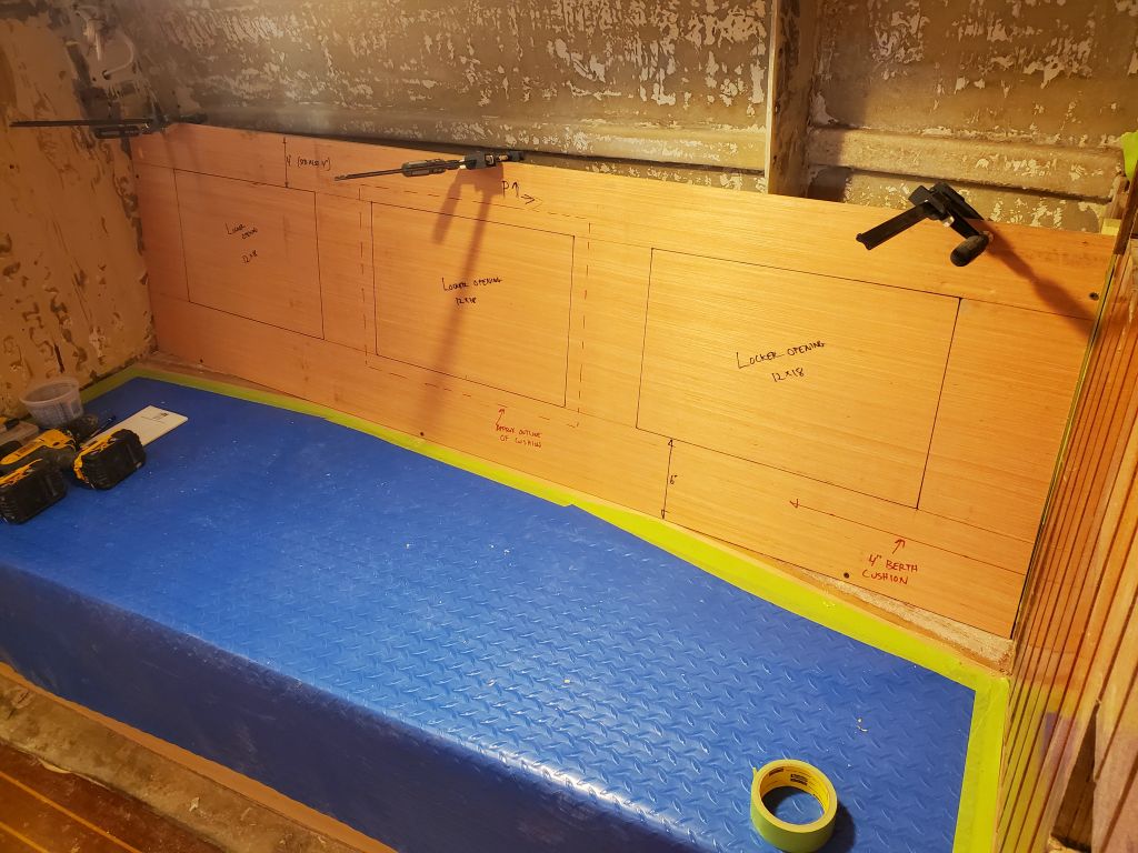
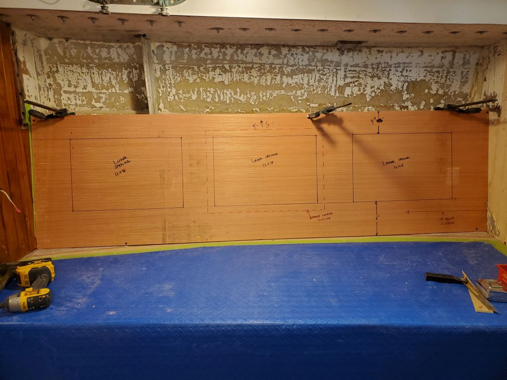
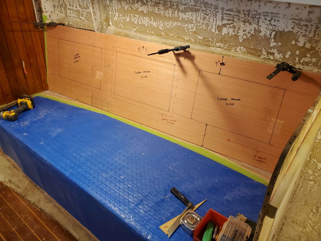
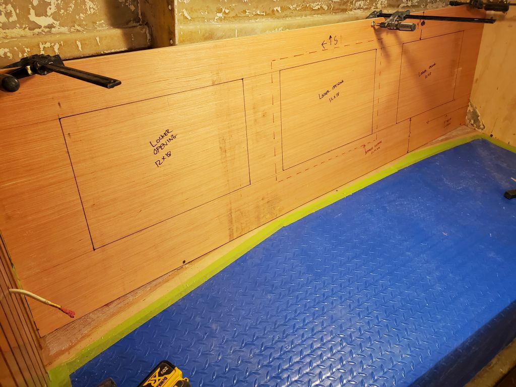
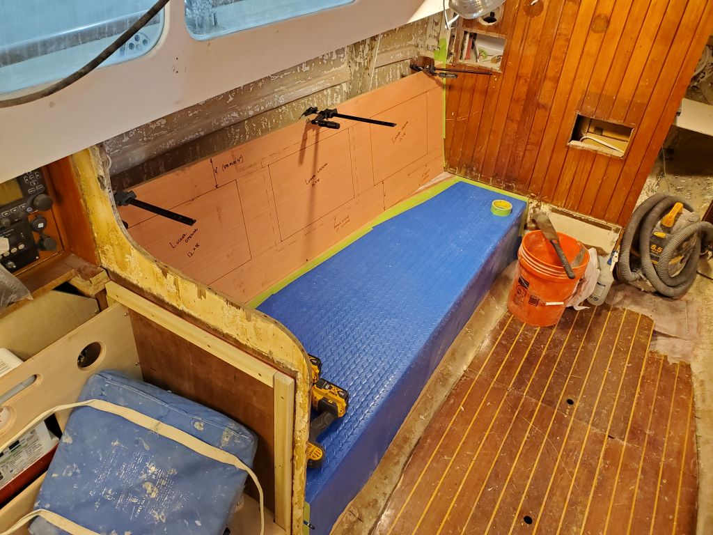
Based on various factors, including desired backrest/locker height, cushion thickness, distance to the deck above, and aesthetic considerations, I settled on 22″ for the height of the backrest panel, and prepared 3/16″ plywood blanks as templates and mockups for both sides of the boat. I drew in proposed locker openings: three openings on each side, each opening 12″ high and 18″ wide. These dimensions were predicated not only on the available space (i.e. these dimensions worked out symmetrically and in an aesthetically-pleasing way), but also considered possible storage of some of the plastic storage containers that the owner had originally stowed behind the original backrests, so regardless of the potential space behind the backrest itself, I wanted the locker openings at least to accommodate these items if possible. In the final construction, I’d install two dividers/supports behind the panel to support the backrest and the cabinetry above, and divide the space into the three lockers designated by the proposed openings.
Other assumed/predicted dimensions that I took into account were a 4″ thick berth cushion (leaving 18″ of backrest above), and 2″ thick backrest cushions built into the locker lids. I marked a rough outline of the backrest cushion on the center opening on each side (1″ overlap of the opening). The height of the locker opening above the berth top also would allow the locker lids to open flat when all the cushions were installed (the bottom edge of the lid was 2″ above the top of the berth cushion). I left 4″ above the locker openings to allow for the backrest cushion overlap, plus a fiddle/trim at the top edge where the backrest would transition to the upper cabinets, plus an appropriate amount of open space.
Port side:
Starboard side:
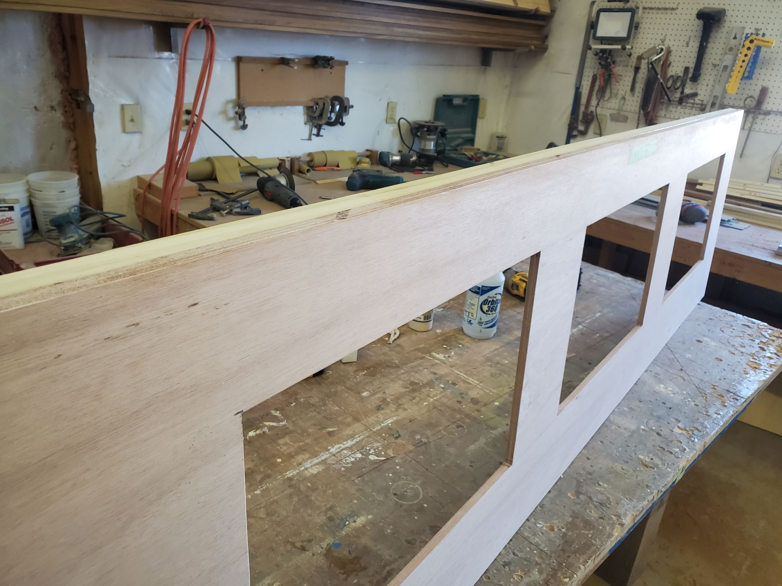
The 22″ height of the backrests left a minimum of 12″ above for the upper cabinets, which I’d mock up once the details of the lower section were finalized. The upper cabinets would likely be a combination of enclosed storage lockers with at least some open shelving for books or other stowage, probably in the center of one or both sides.
Even in temporary/template mode, the new backrests started to bring together the future appearance of the interior in (I thought) a good way.
To begin, I quickly and lightly sanded the fresh fiberglass tabbing on the settees, readying the area for whatever came next.
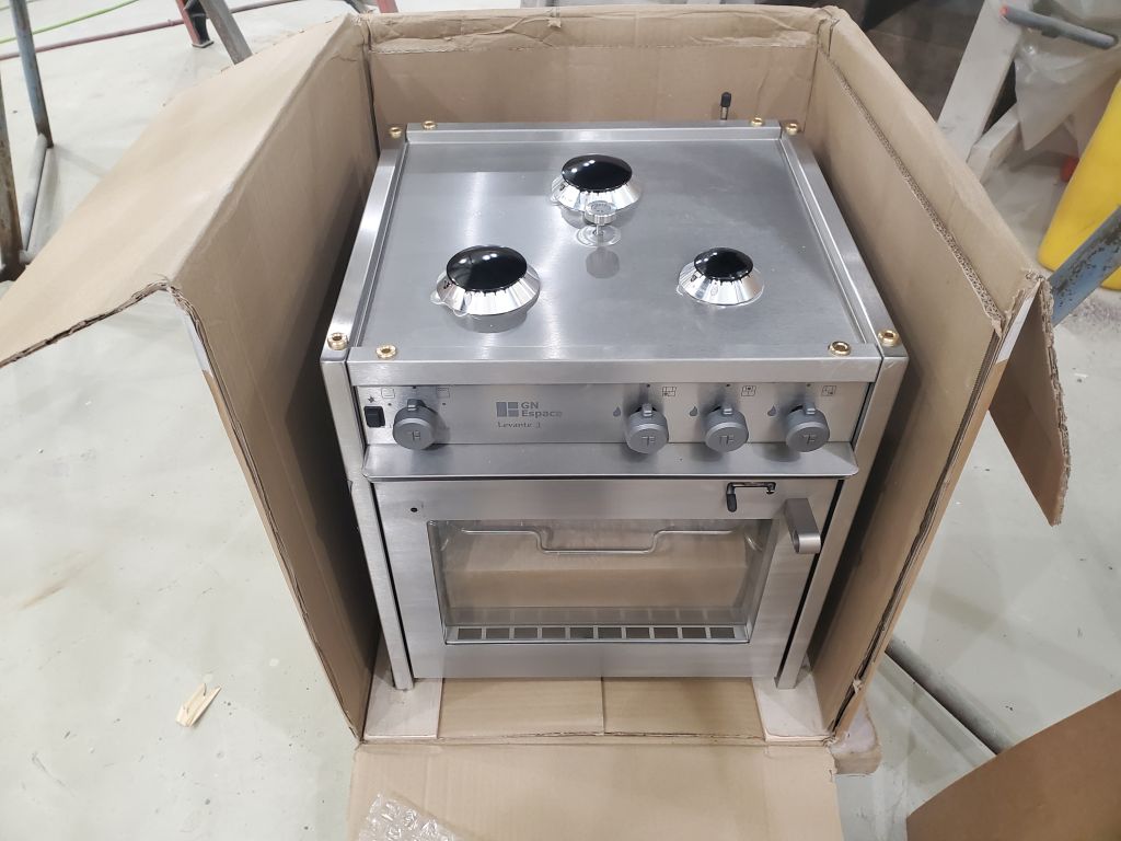
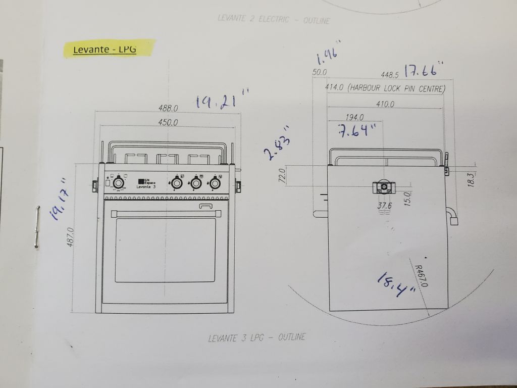
With the actual stove, I confirmed various measurements from the drawing and to ensure my layout so far would fit the actual stove. I also measured the additional height of the stove grill, which fitted over the burners, and the removable pot clamp holders that fit in all four sides of the stove. These added 1-3/16″ and 2-15/16″ respectively to the height of the stove itself. Consulting with the owner, and looking at various images of these stoves installed in other boats, we decided that the stove should be mounted with the top of the box itself flush with the countertop. This gave me information that I’d need to work out some initial layout.
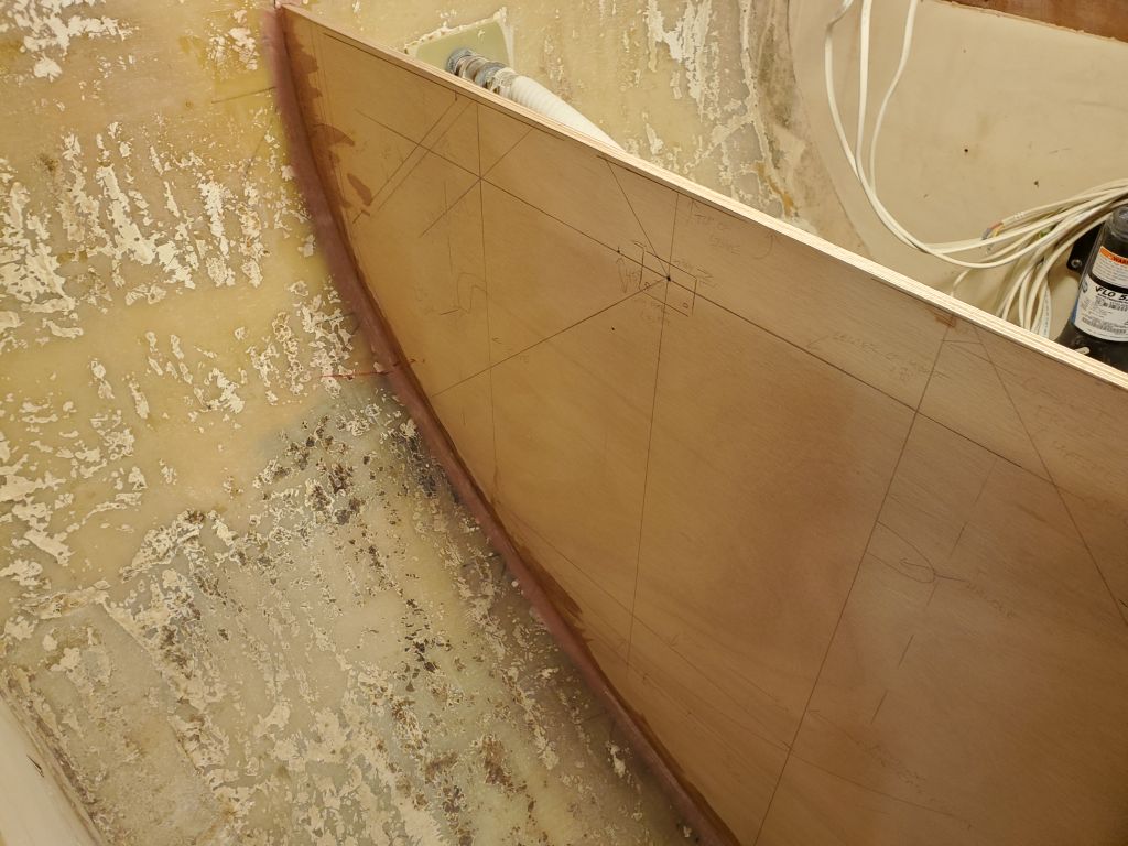
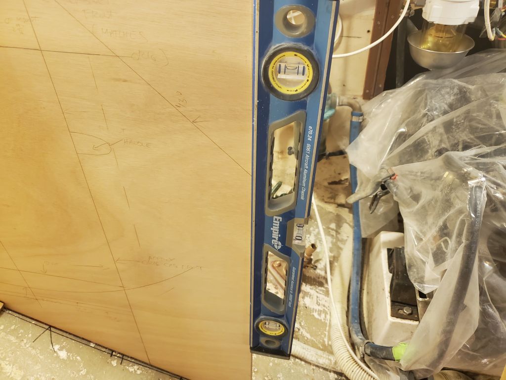
I trimmed the bulkhead blank to the level and plumb lines I’d marked when it was in the boat–the outermost of the two plumb lines, which was in line with the edge of the forward bulkhead. I could trim this further back later, though since the face of the cabinets was likely to continue in this same plane all the way across the engine room and to the port side, ultimately the location of this seam wasn’t that important, unless I incorporated it into a fully-removable panel. These unknowns would make themselves clear enough in the near future.
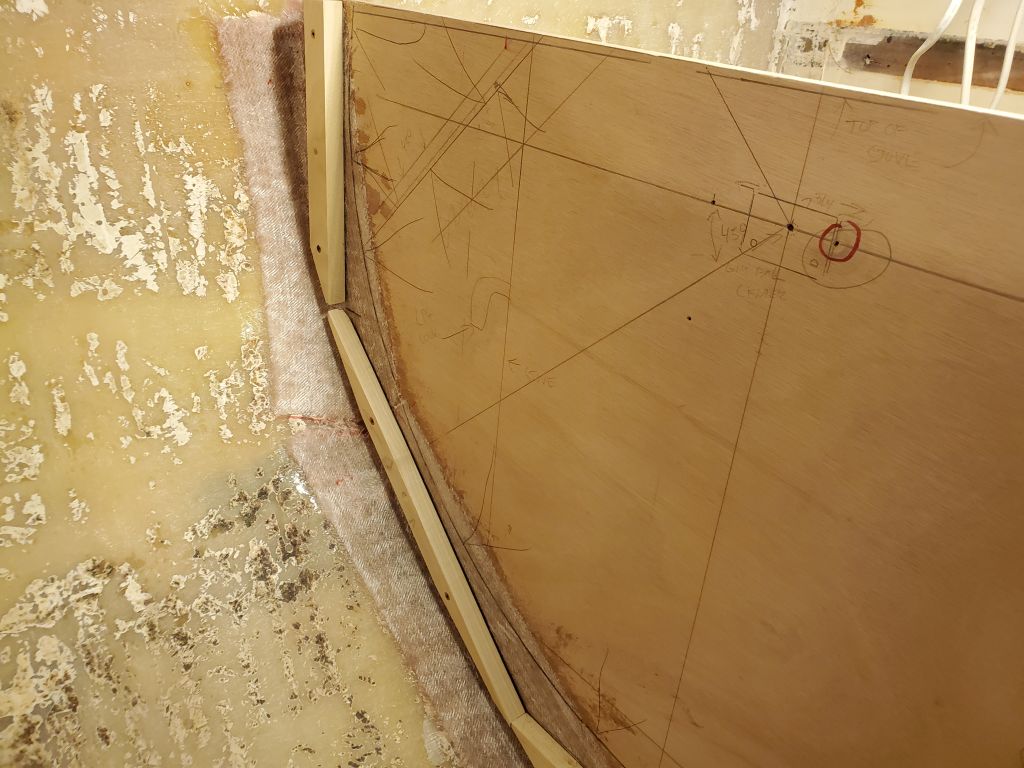
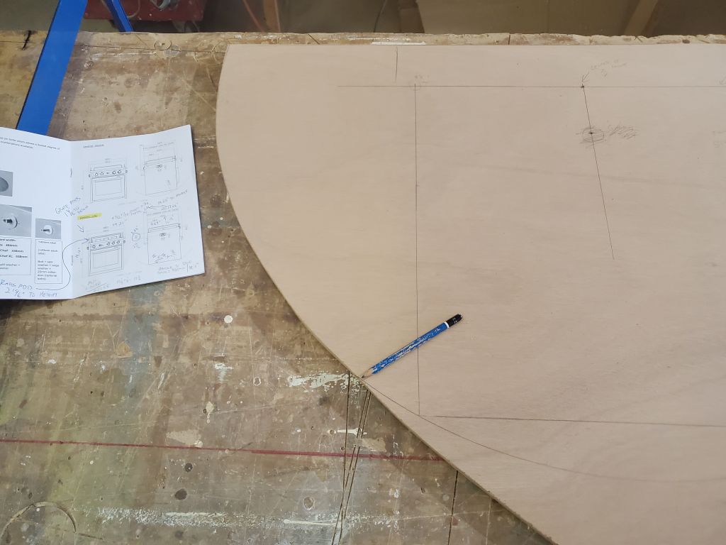
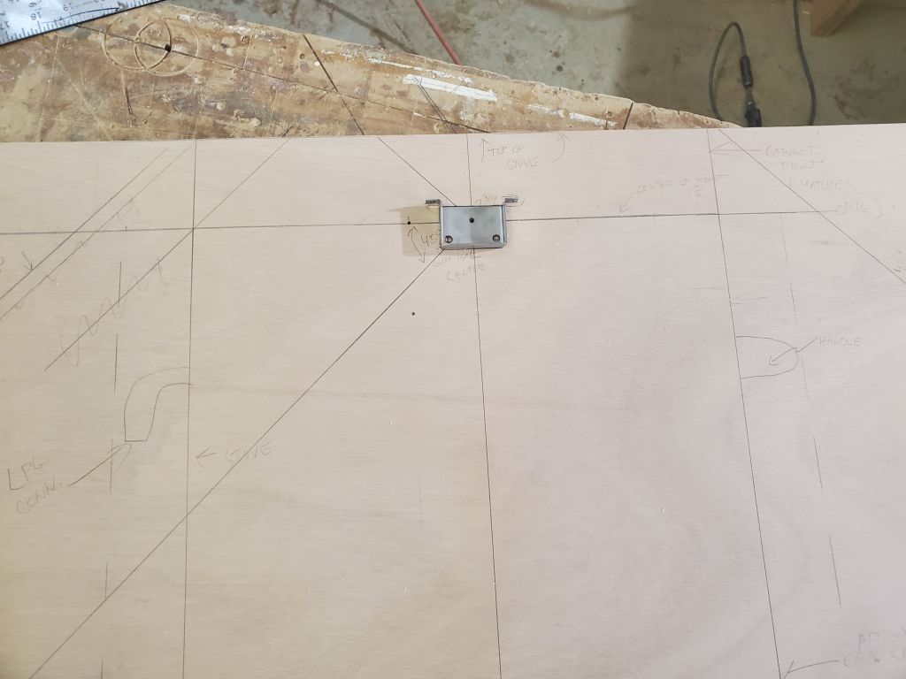
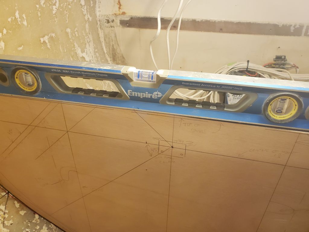
From here, following the information in the stove measurements, I worked out an initial layout, keeping the entire stove–including the oven door handle (2″ proud of the stove front) behind the second vertical line demarking the original cabinet front. One has to start somewhere. I measured and laid out the gimbal center, along with the dimensions of the stove itself, and used a shop-made “compass” to strike the swing radius (just over 18″) on the panel. In this location, I quickly found that the radius ran out before the outboard edge of the bulkhead, meaning the stove would hit the hull long before it reached an adequate swing. The pencil in the final photo points to the spot where the radius ran out.
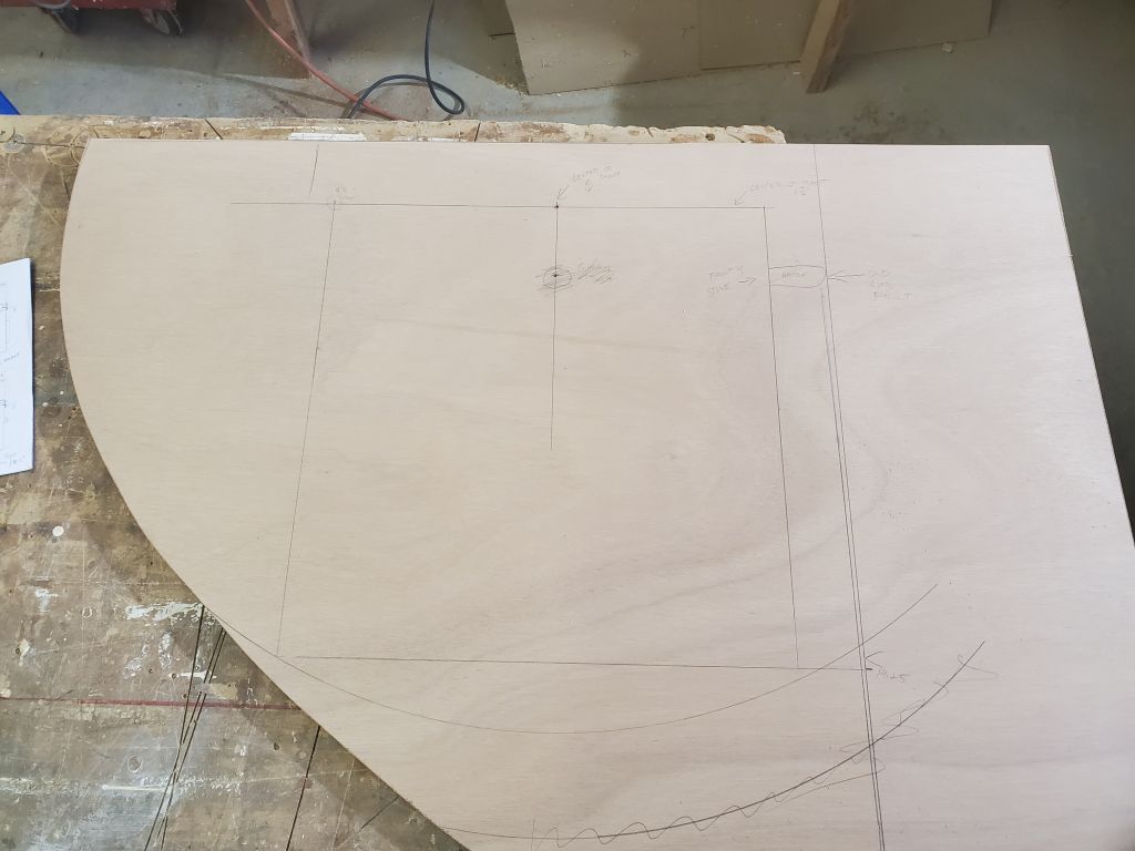
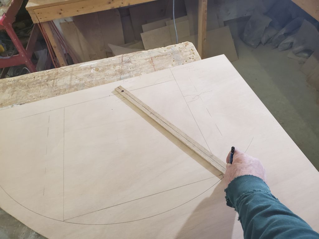
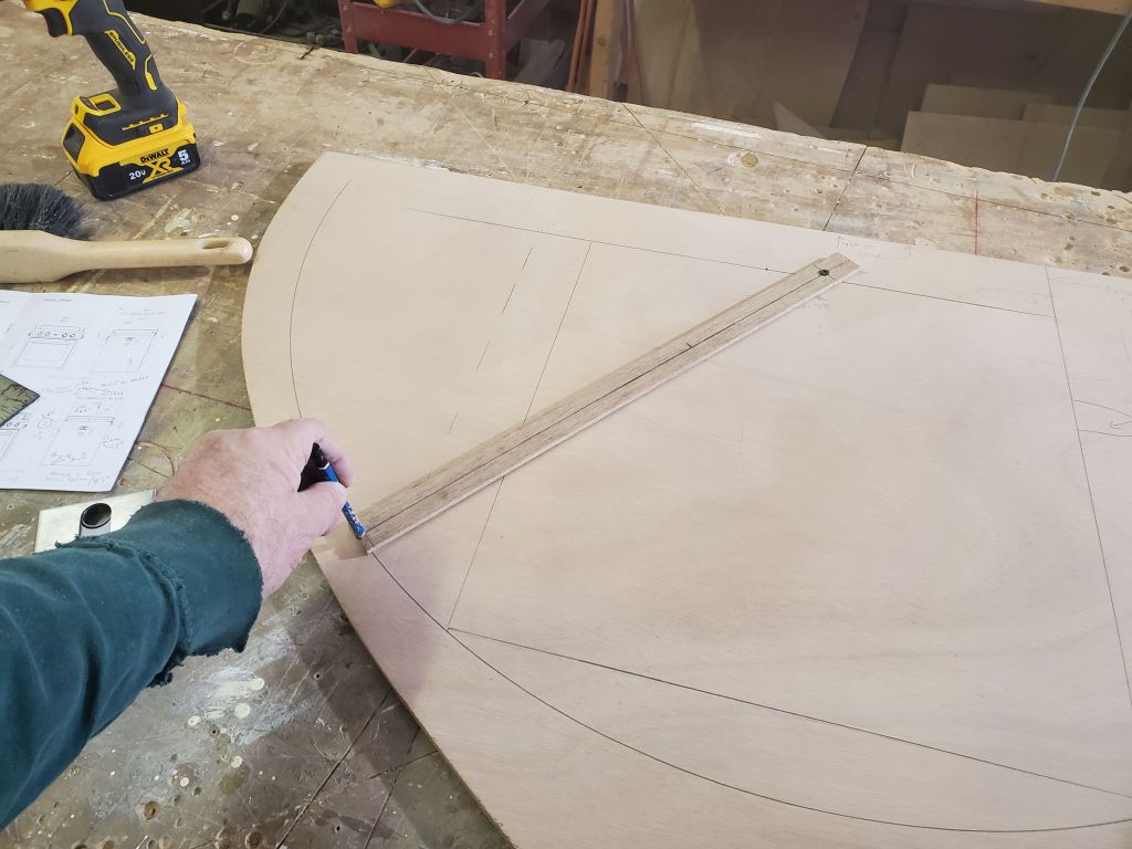
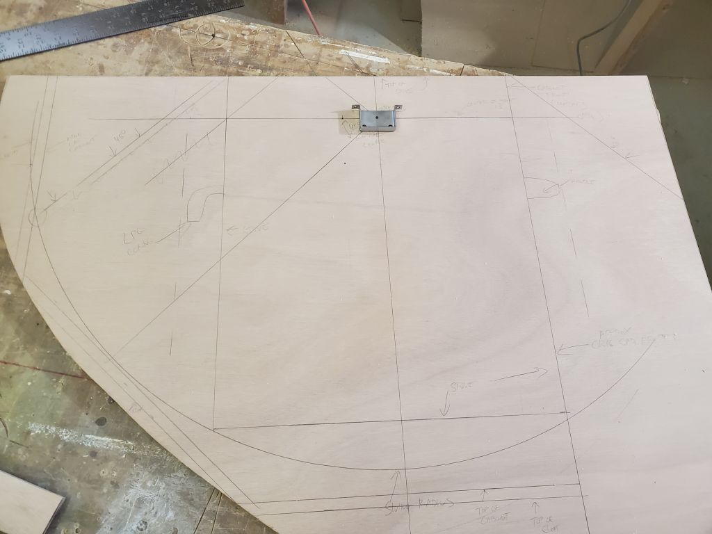
This posed little problem. I sanded off the layout marks I’d made so far and started anew, this time with the front of the stove (not including the handle) moved out to the initial vertical layout line. I wanted to keep the stove as far outboard as possible to allow plenty of room to work between the companionway ladder and the stove, and to allow swing room inboard when underway. In this new location, 2″ further inboard, the stove fit pretty well. The swing radius cleared the hull at the outboard edge of the bulkhead, with just enough room to build some supporting cleats and panels to close off the space. To figure these locations, I made a simple template of the stove that I “gimbaled” at the pivot point, and swung it to 45° in each direction, which seemed a reasonable maximum gimbal to provide for, and used this mark to locate the outboard vertical bulkhead of the space. When the stove was swung to the max in the inboard direction, the base of the unit stayed nearly within the limits of the space defined by the forward bulkhead face, which would keep the stove clear of the companionway and even allow some access to the galley countertop beyond. This layout confirmed that the stove would fit and swing properly in the given space (the forward end of the space, in the boat, was a bit deeper so no issues there), and while I might slightly manipulate the final location once the new bulkhead was in place and it was time to finish off the opening, I knew that it would fit as hoped and intended, and this basic layout was easier on the bench.
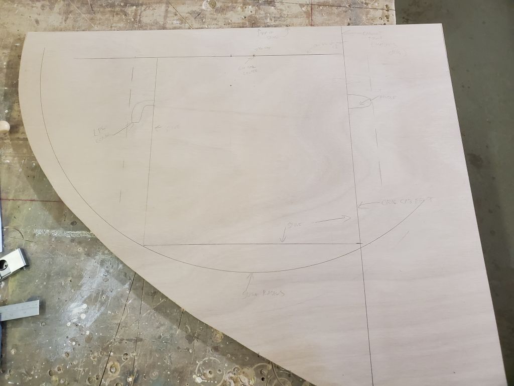
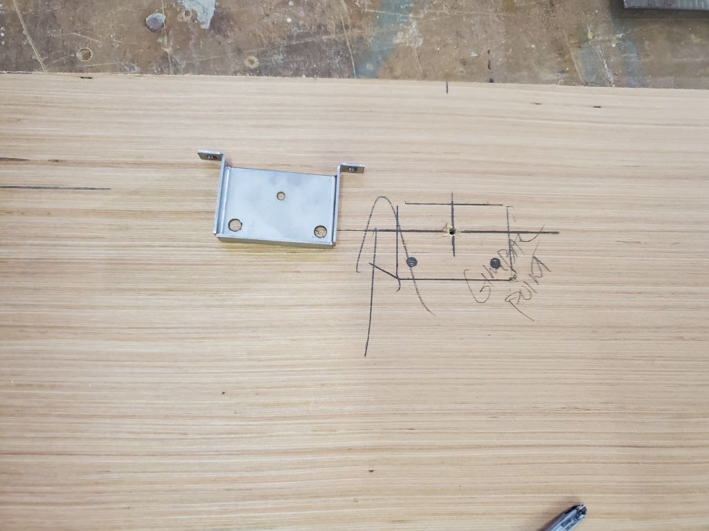
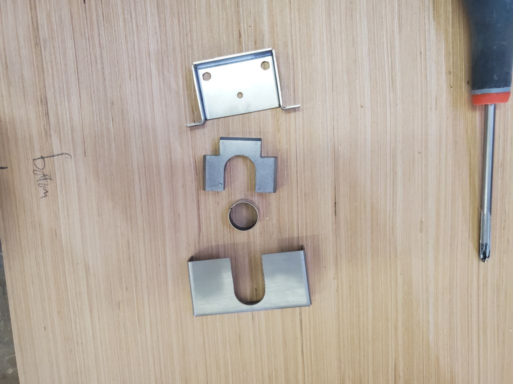
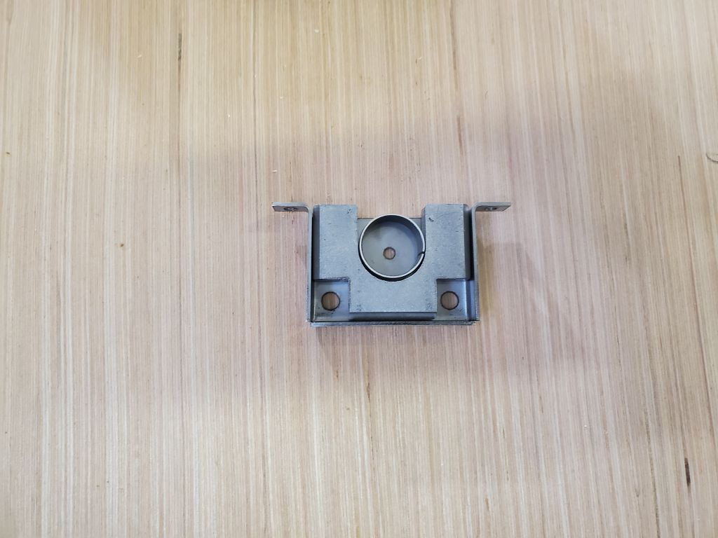
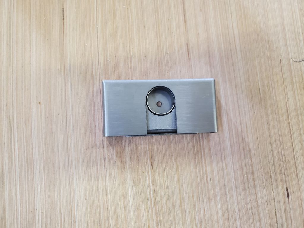
The stove template would come in handy later for locating and mounting the actual gimbal hardware, so I made some layout marks on the template, as well as on the new bulkhead, using the actual hardware.
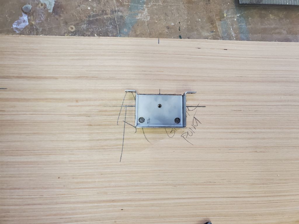
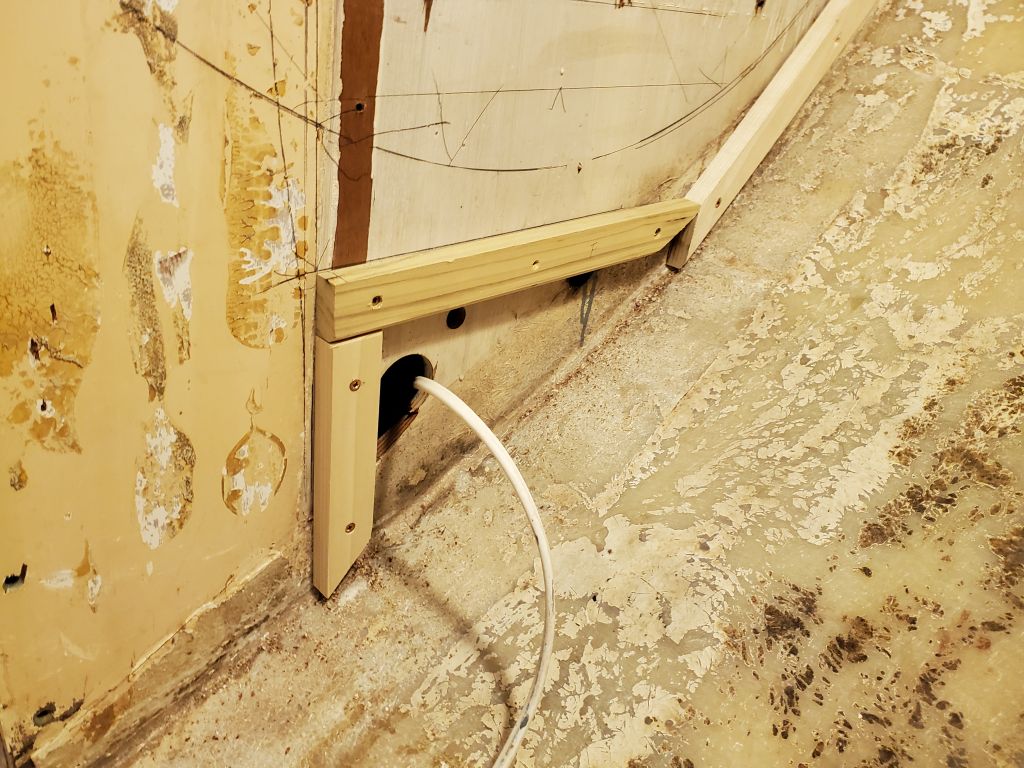
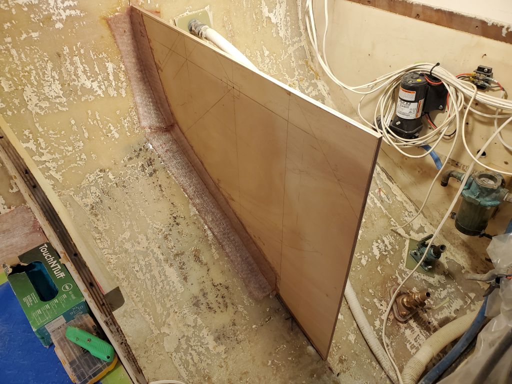
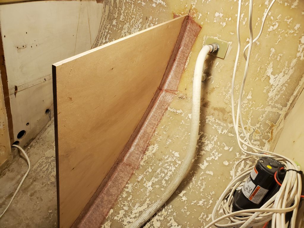
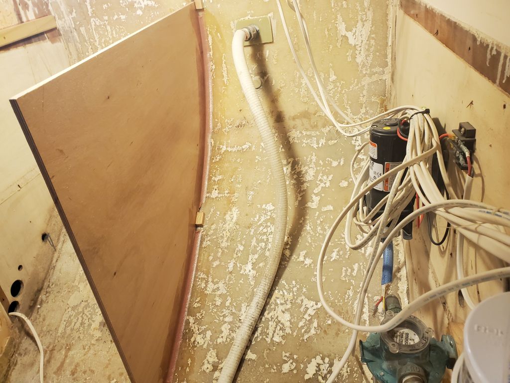
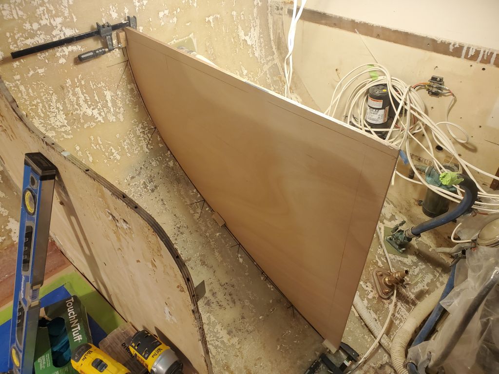
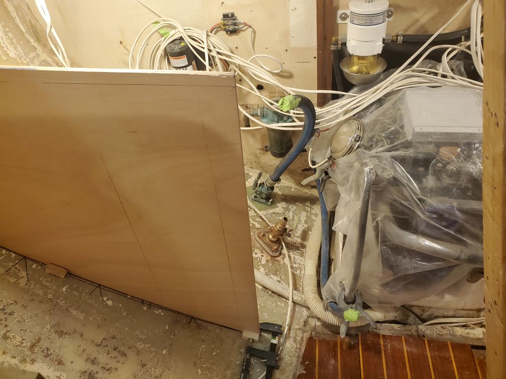
Now I brought the bulkhead into the boat and set it up in its final position, secured with hot glue blocks as needed, and level and plumb as required. Once the position was finalized and repeatable thanks to the glue blocks, I epoxy-coated the edge grain of the plywood and installed it with epoxy fillets on both sides, leaving space around the glue blocks for now. I stopped the fillet short on the forward side as the remaining section of the bulkhead would be exposed, and I didn’t plan to tab that portion (the back side, however, would be fully tabbed).
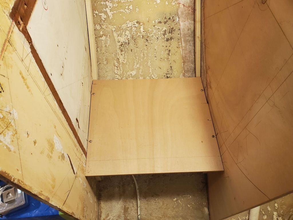
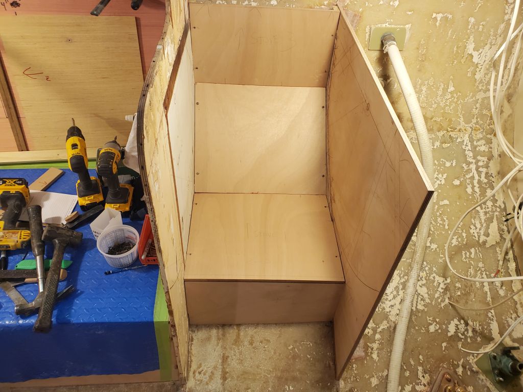
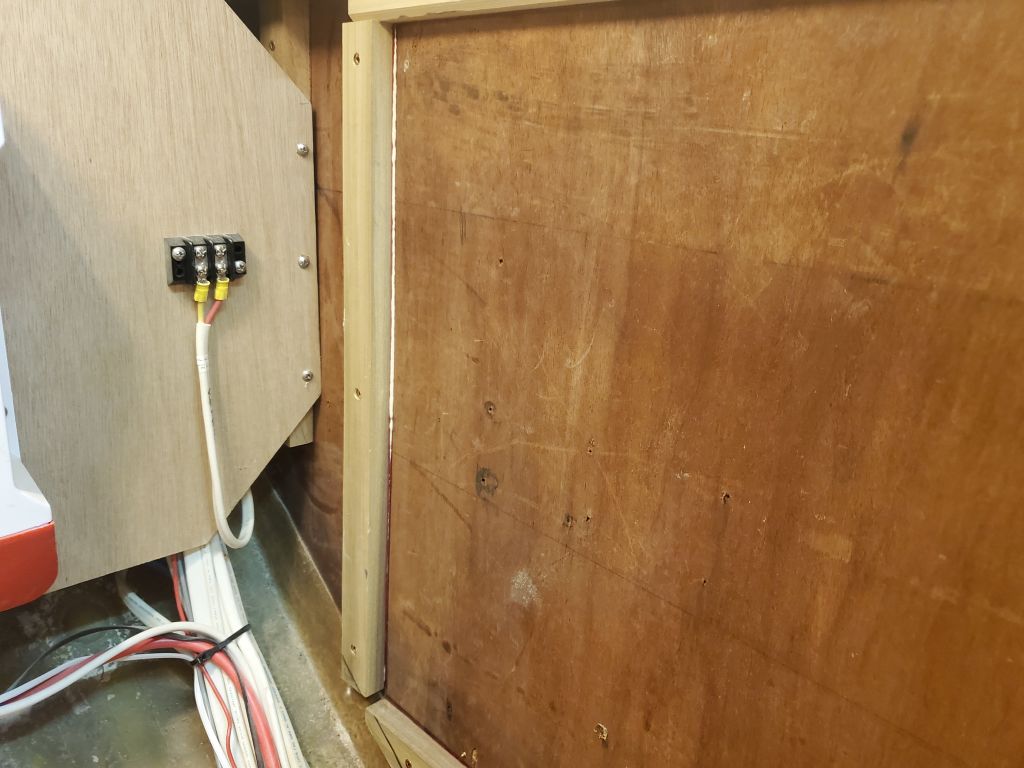
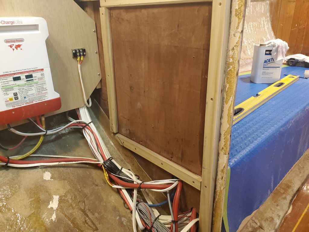
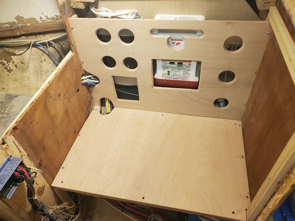
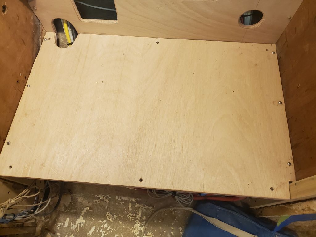
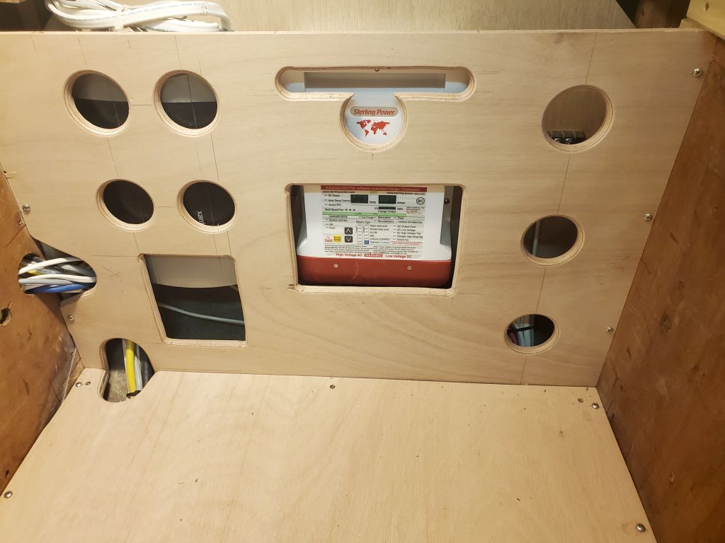
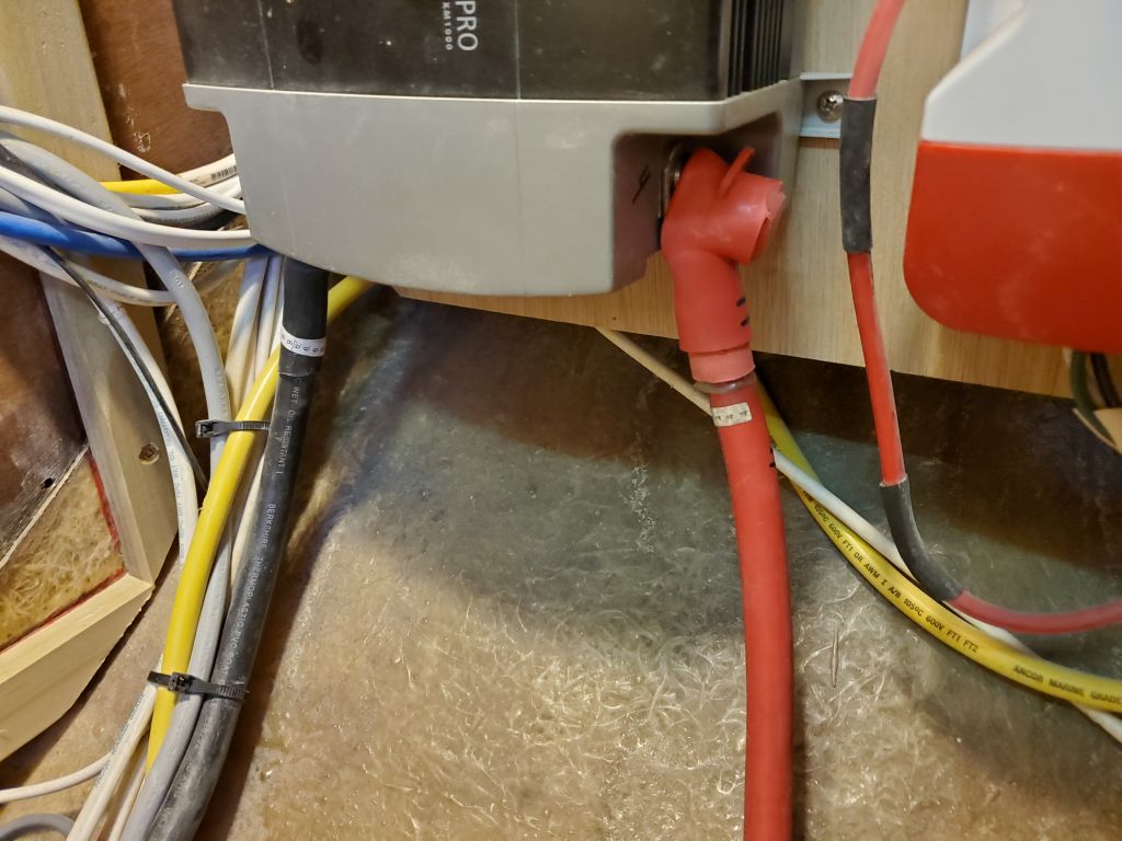
With a bit of time left in the day, I cleaned up the two panels from the refer space on the port side, adding an additional ventilation slot to accommodate a duct on the battery charger behind, then permanently installed all the support cleats in that space with glue; I’d set them up dry till I was happy with the overall configuration. I added a short vertical cleat on the aft side to support a new vertical panel that would close off the bottom of the space and also provide some support for the transverse galley bulkhead extending across to the stove. Then, I temporarily installed the floor and back panels with exposed screws, as both these panels would remain removable in the final construction to allow access behind. Sometime later, I’d remove and paint these panels, but for now I wanted them in place so I could continue the galley construction.
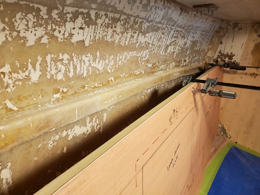
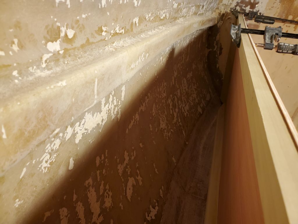
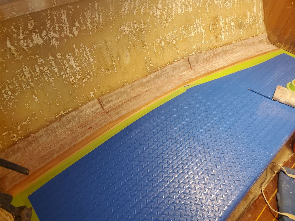
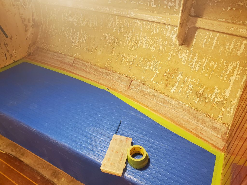
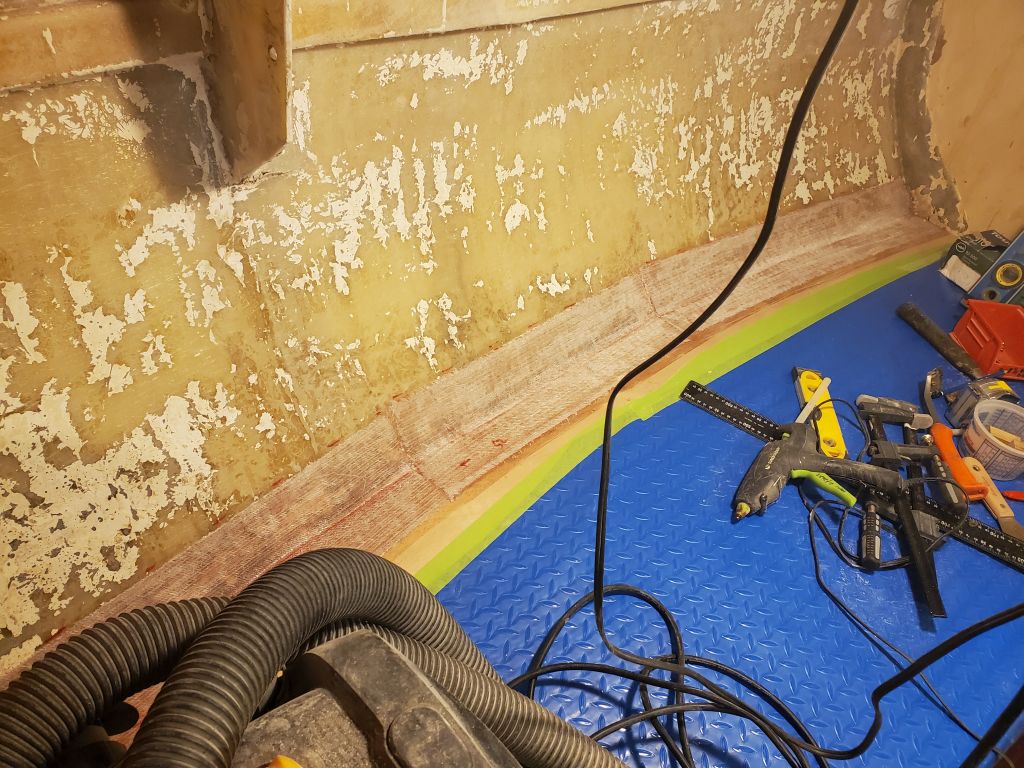
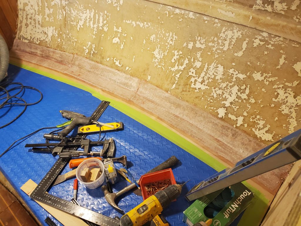
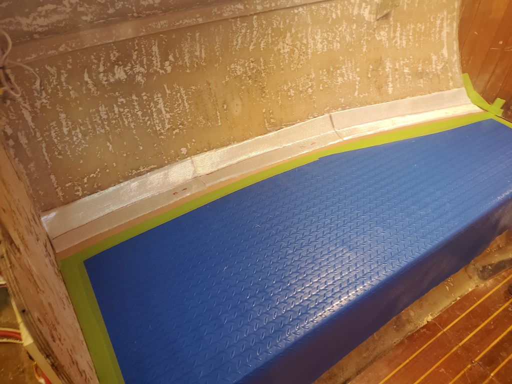
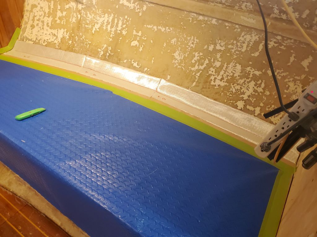
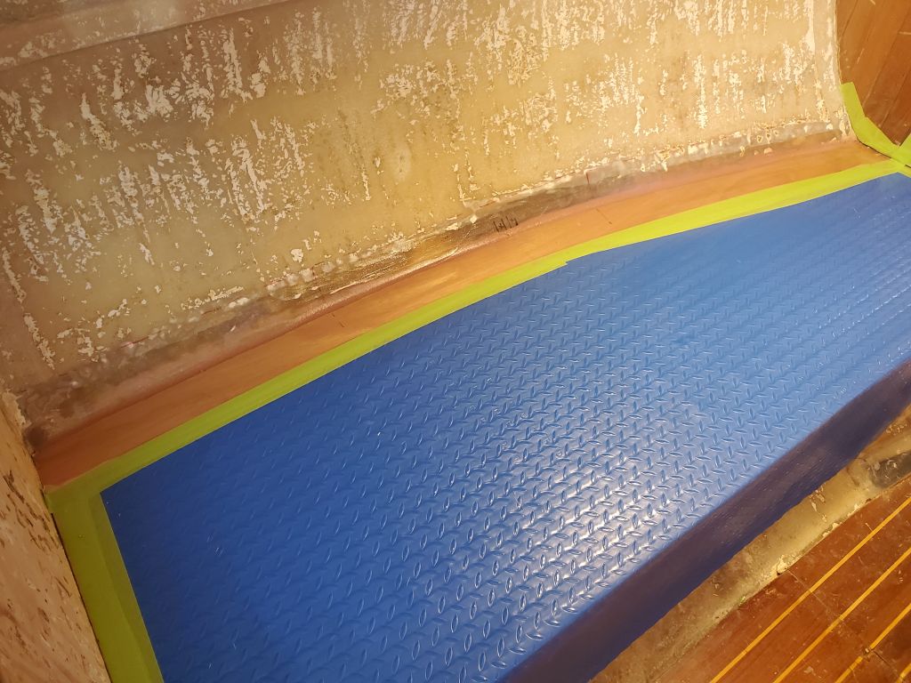
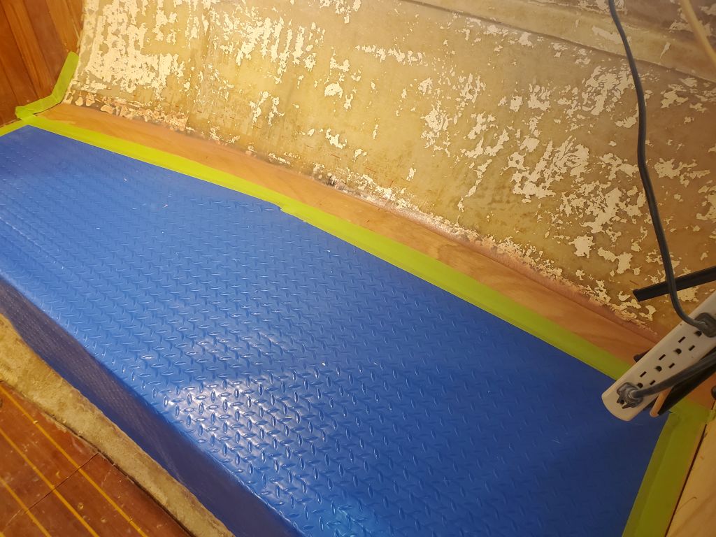
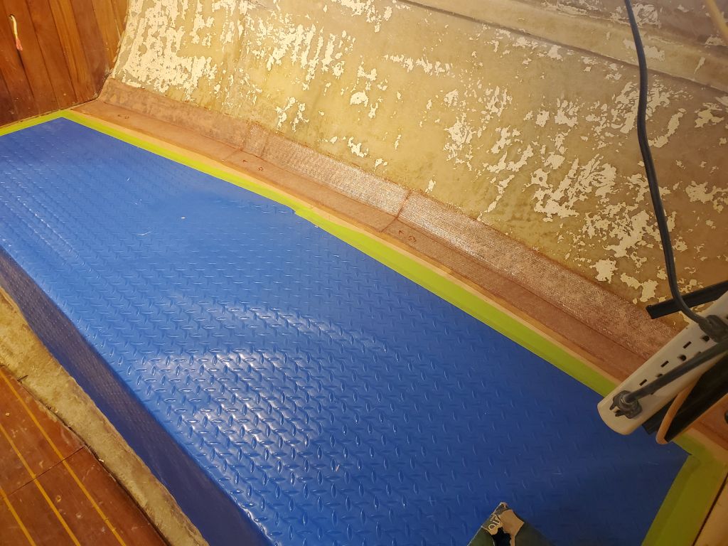
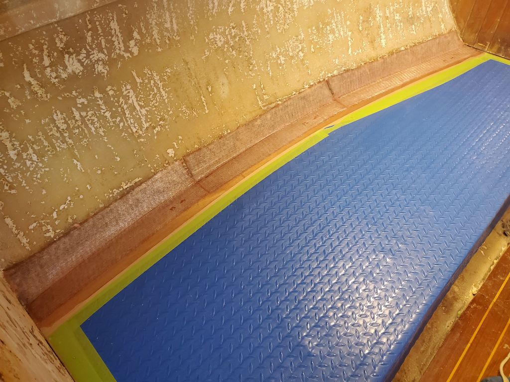
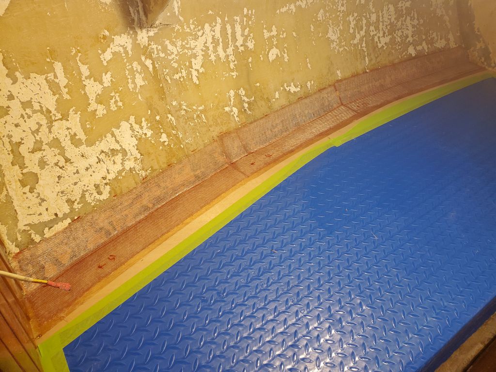
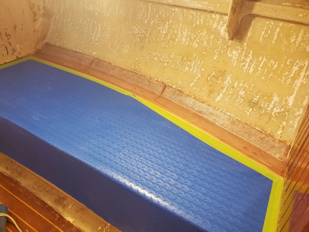
I masked off and covered the settee tops to protect them during the various upcoming constructions, as well as (immediately) during the fiberglassing of the seam at the hull, which was my first task. I cut 6″ tabbing to fit, then applied a thickened epoxy fillet to the seam before wetting out and installing the tabbing on both sides.
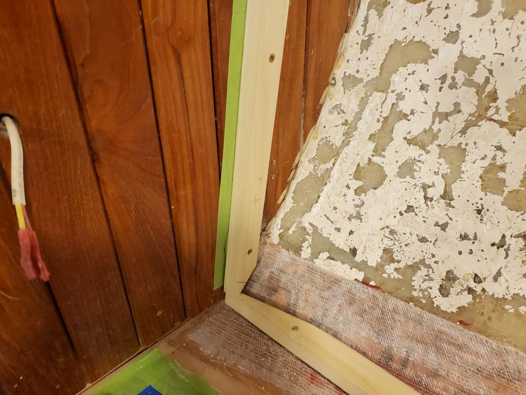
I planned to continue work on the settees–backrests and upper cabinets–soon, but for now, while the epoxy cured, I turned to the galley and the new bulkhead required to support the new gimballed stove. The owner selected this specific stove because it was narrower than most, and would fit better in the existing galley space without compromising the settee length. It also seemed like quite a nice, well-thought-out, stove and oven unit.
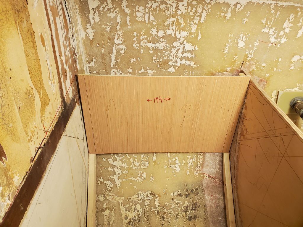
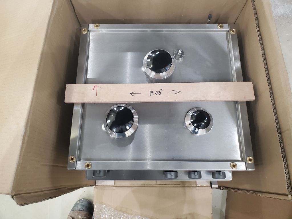
The width clearance required for the installation was 19.2″ minimum according to the stove diagram. I added a bit of clearance to allow for metal sheathing inside the opening, and, with a square, roughed out a mark on the hull where the bulkhead needed to go.
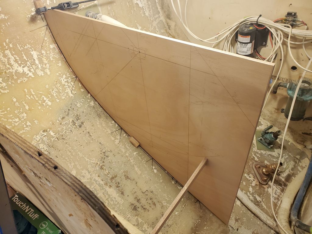
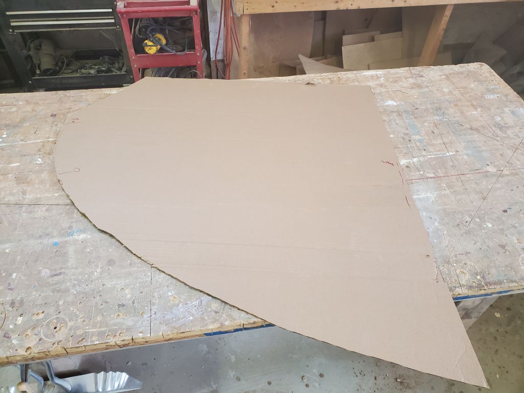
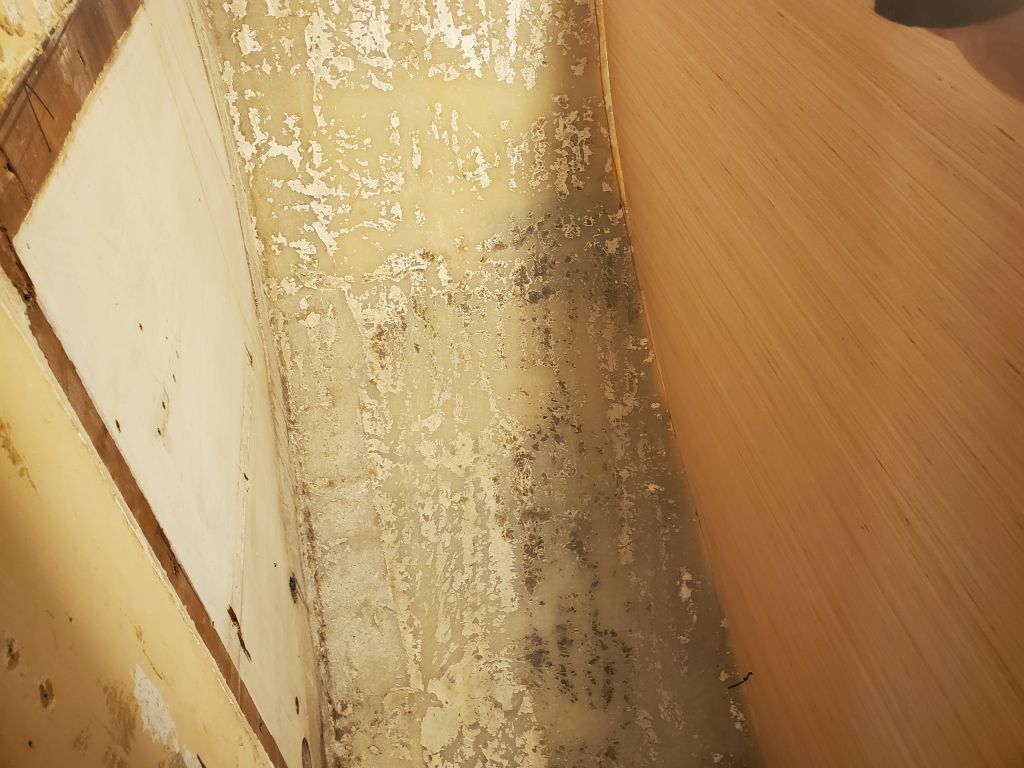
I started with a piece of cardboard cut to somewhat oversized dimensions and cut by eye to an approximate curve, then fitted it and scribed the cardboard to match the shape of the hull.
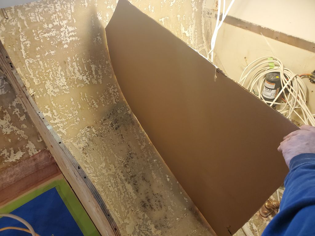
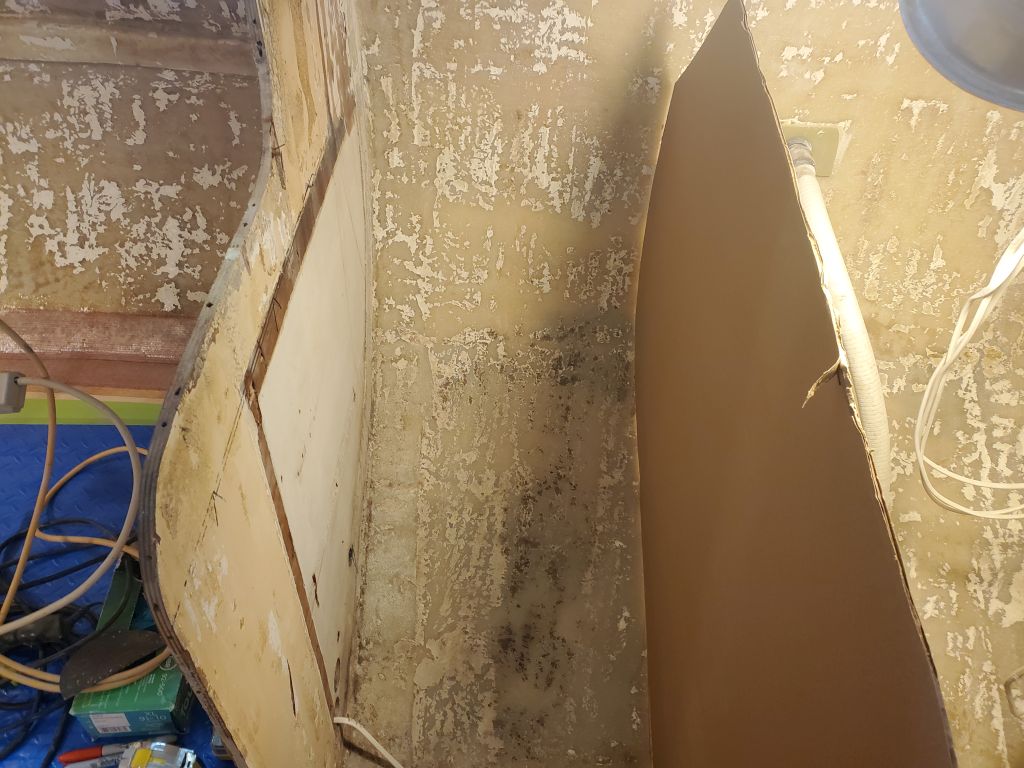
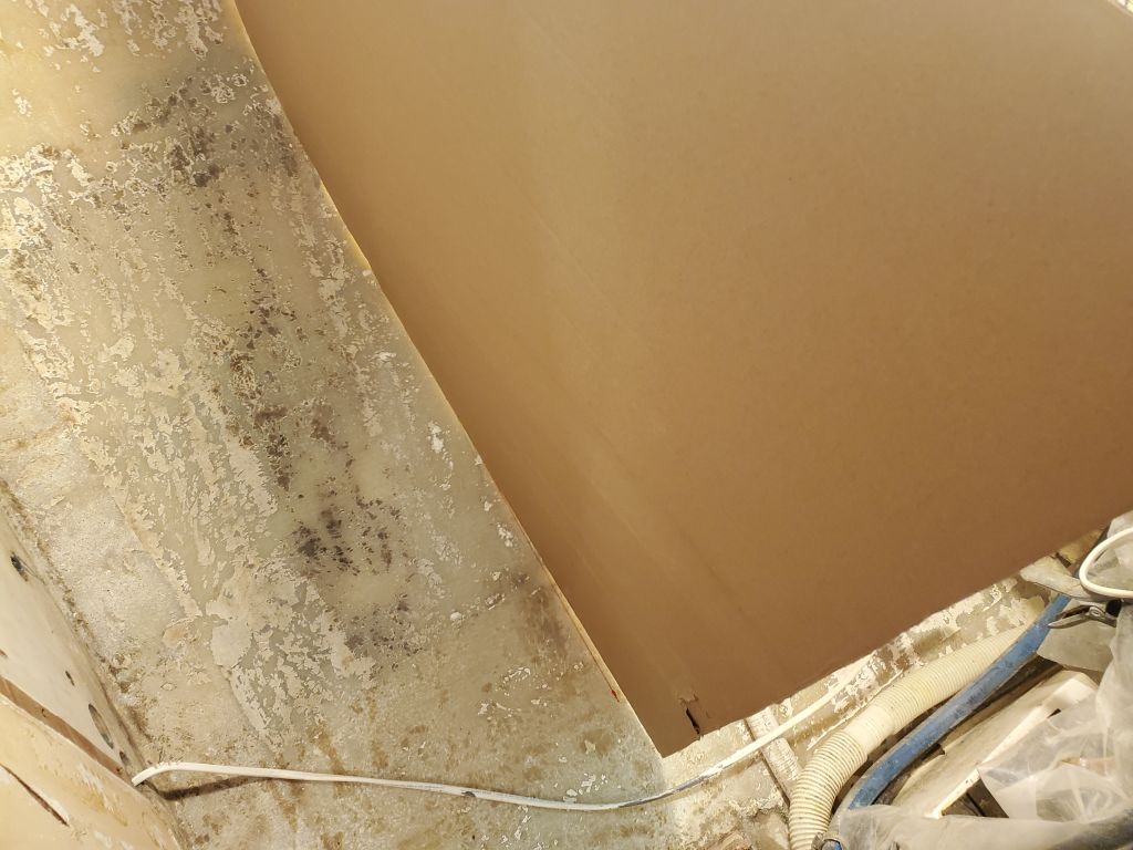
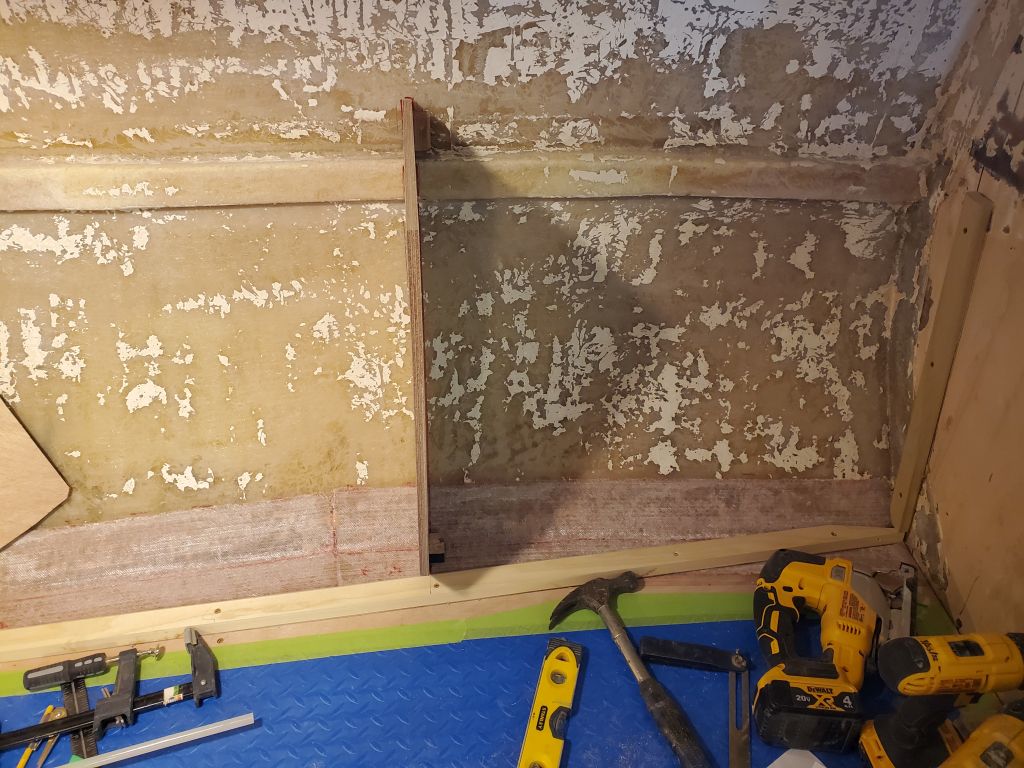
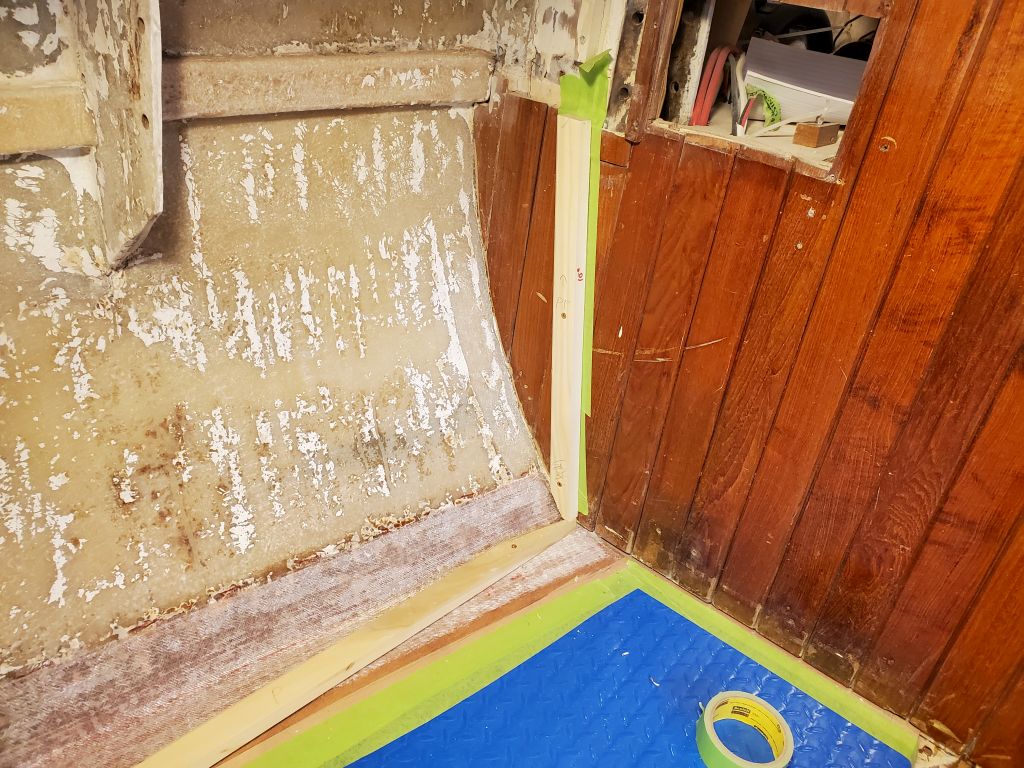
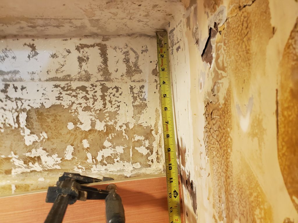
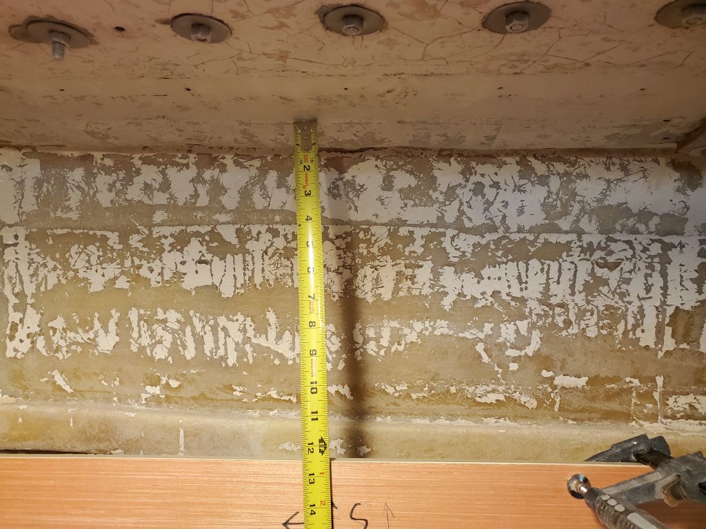
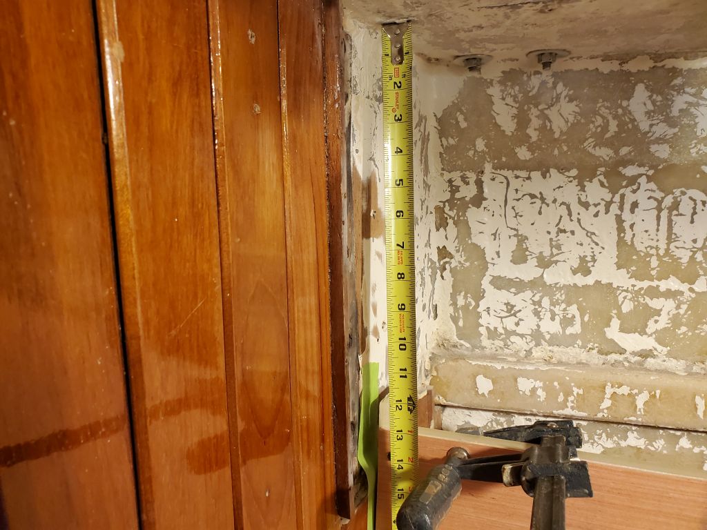
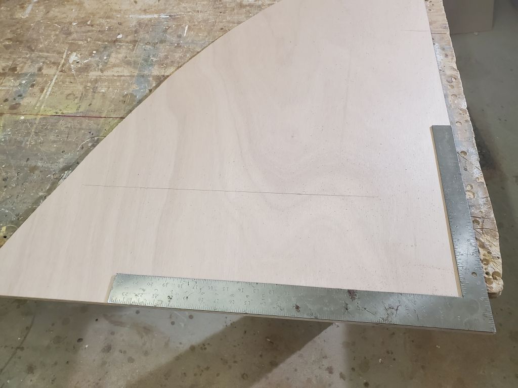
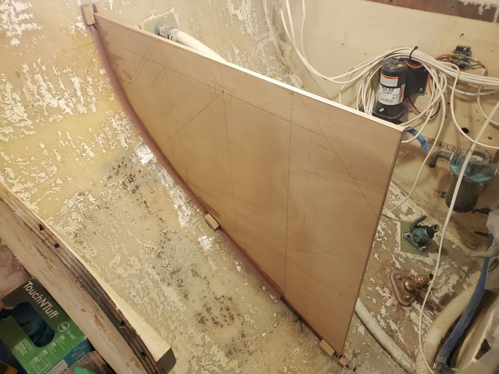
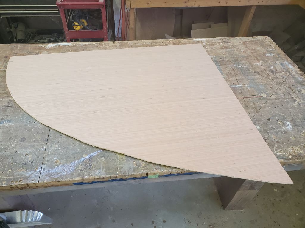
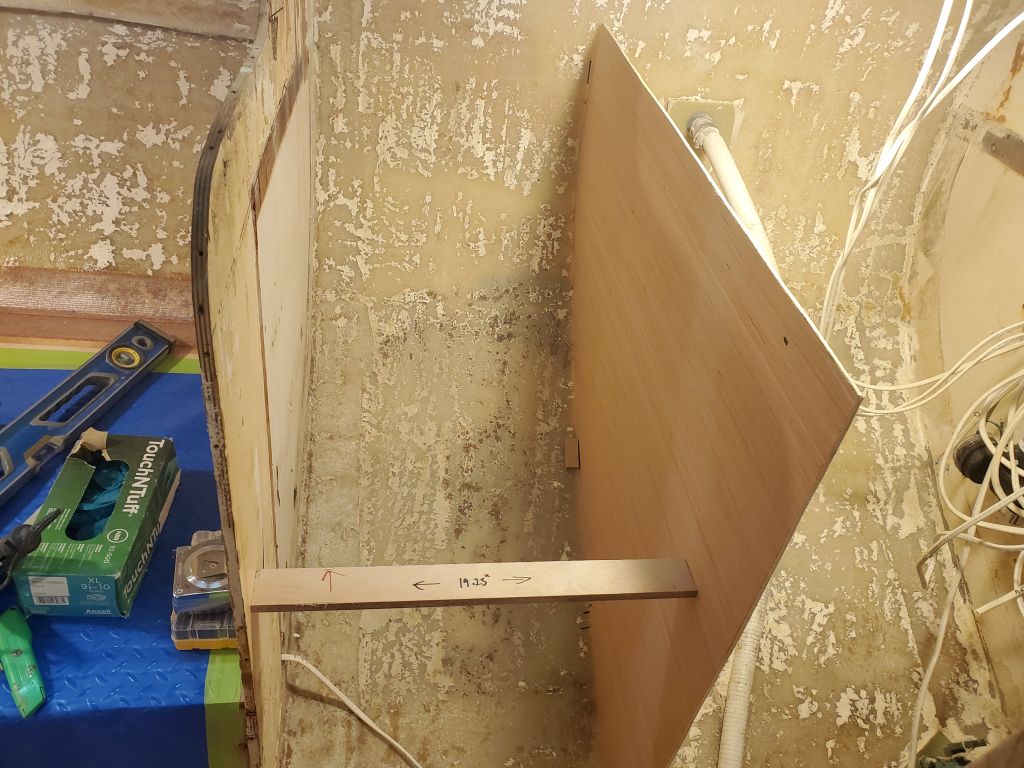
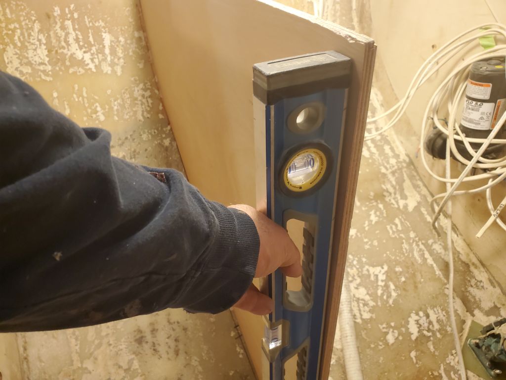
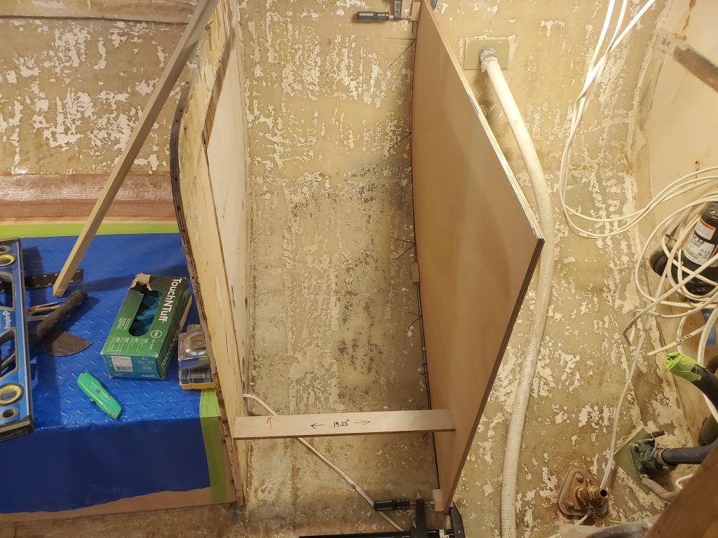
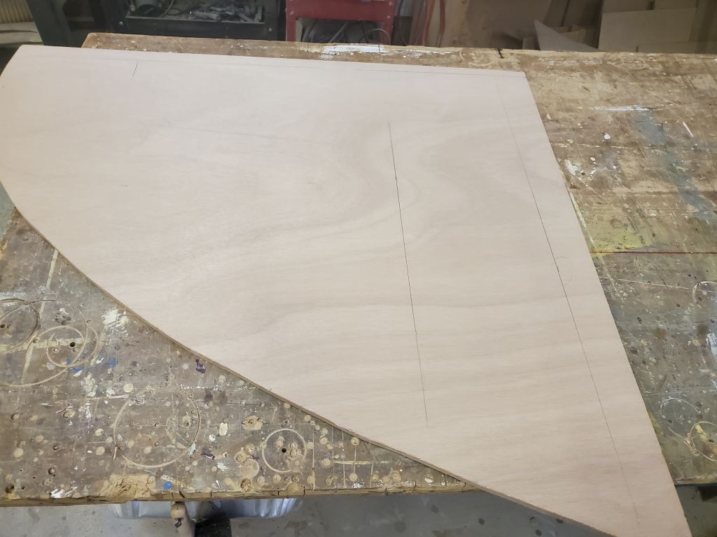
Satisfied with the rough pattern, I transferred the shape to a piece of 3/16″ pattern plywood and cut it out. Then, over a couple fittings, I scribed and cut this template to fit the hull in the required location. I left the template over-height and over-long so I could eventually mark the bulkhead for its final height and transverse width in place, level, and plumb. I held the template in place with some hot glue blocks and clamps, and cut a measuring stick to 19.25″ to ensure that the bare minimum space for the stove was provided in all areas. The forward (original) bulkhead in the galley was slightly out of plumb and out of square, so the width of the space increased as one measured closer to the hull, which provided a bit of additional room in the final analysis.
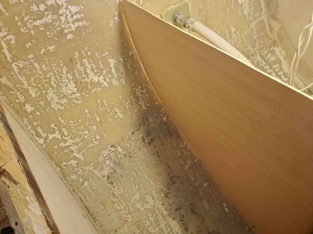
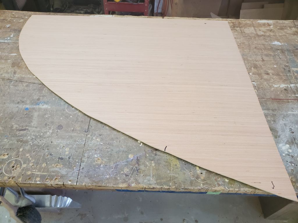
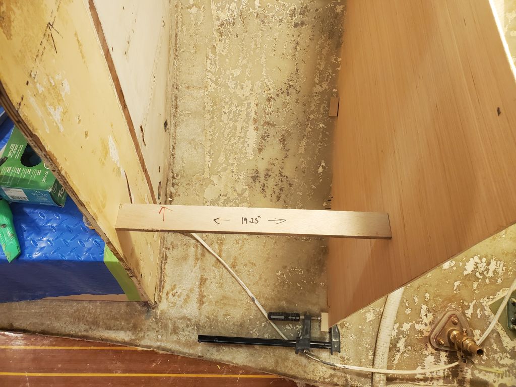
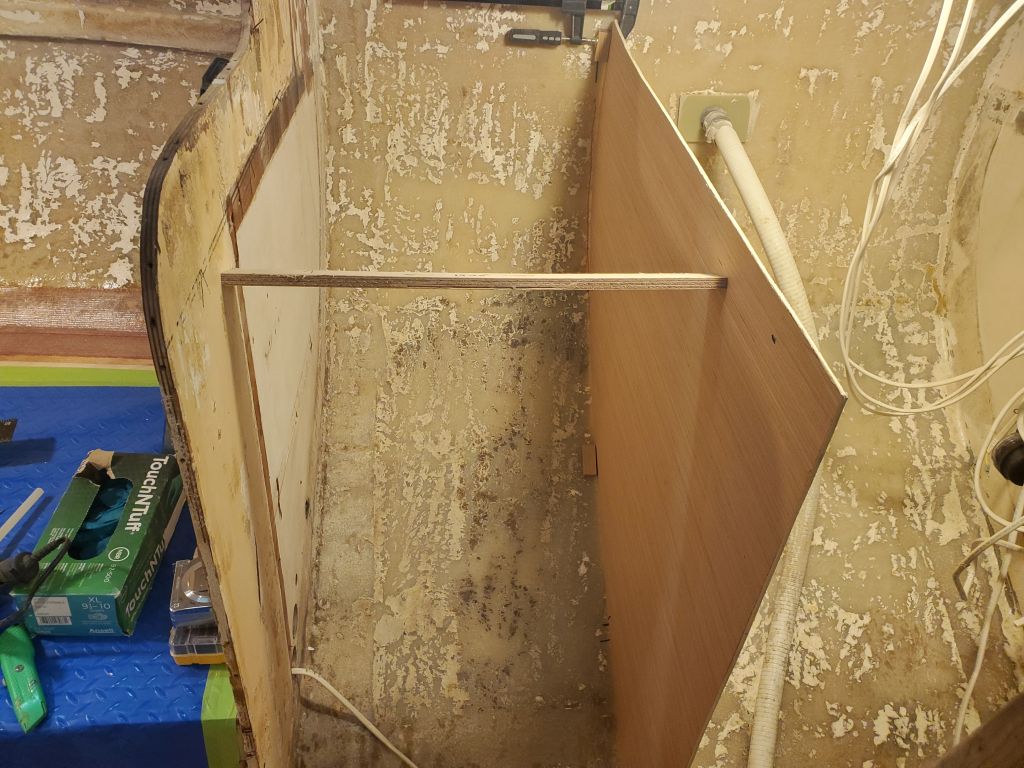
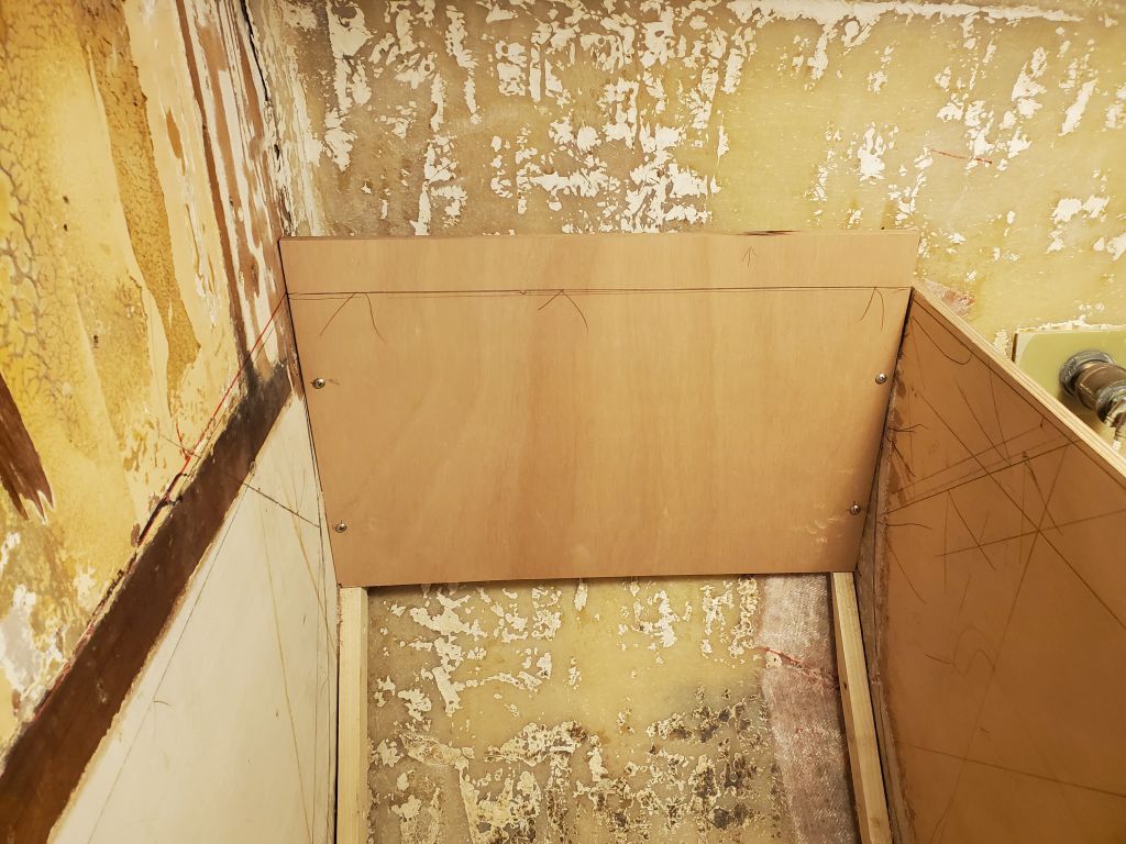
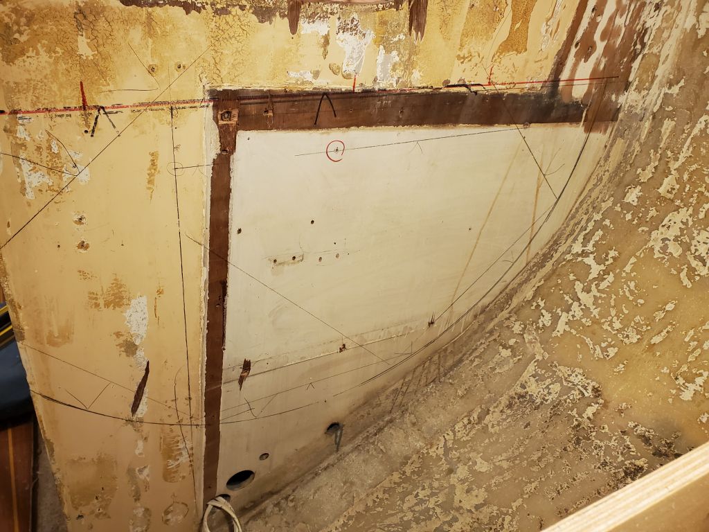
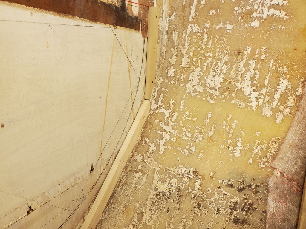
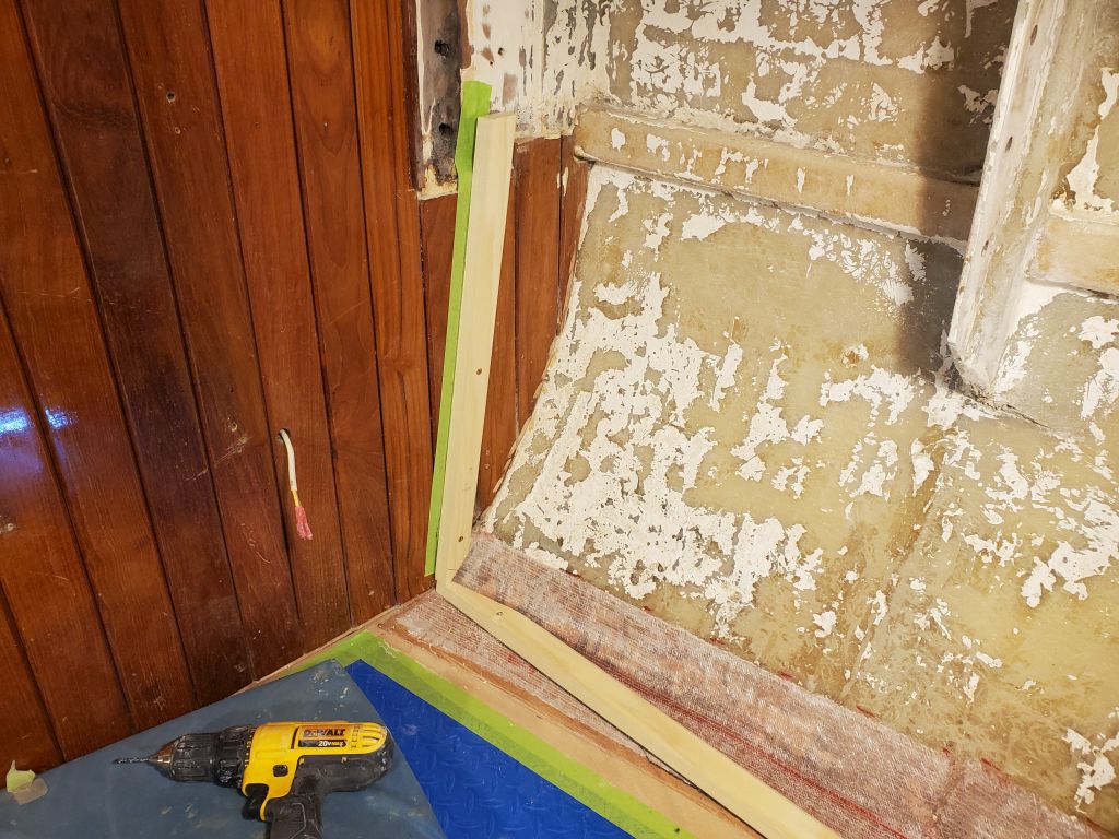
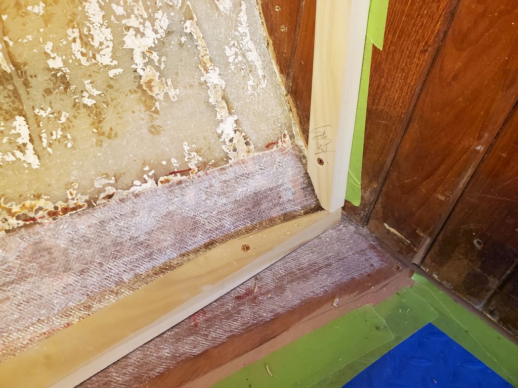
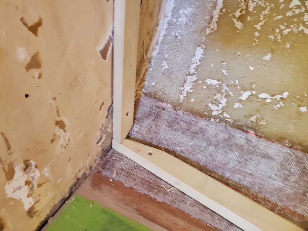
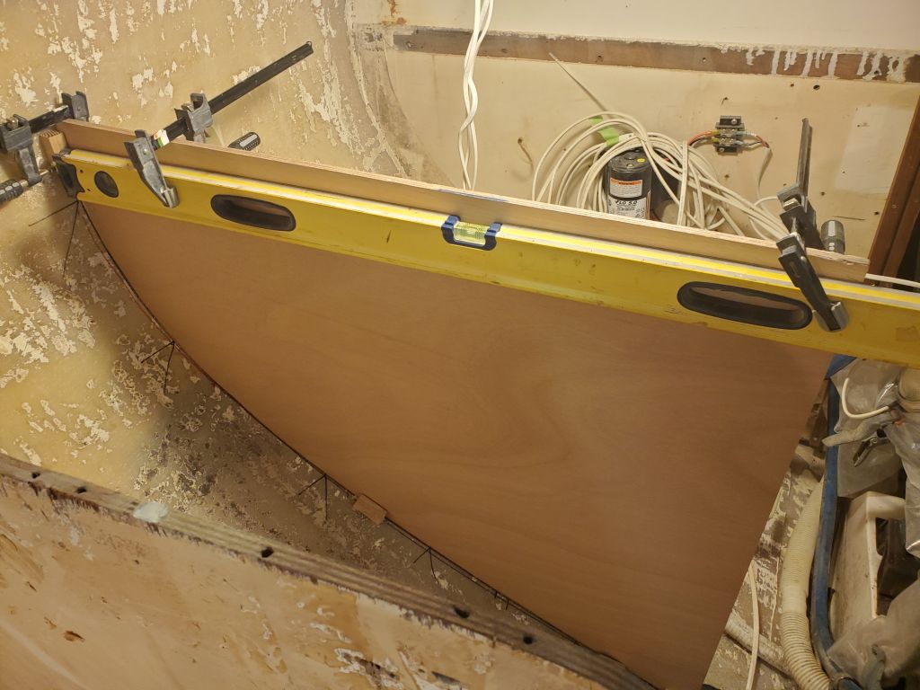
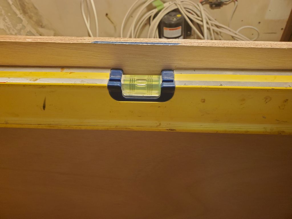
Next, I transferred the pattern to a piece of 12mm okoume and cut it to fit before setting it up plumb in the boat, clamped to the glue blocks to hold it. To help with layout and measuring, I leveled across the boat from the port bulkhead, where there was already a countertop cleat installed, and installed a temporary cleat on the stove side; this cleat was only to give me a solid reference point from which to mark the proper height and level on the new stove bulkhead, as well as set the course for the remainder of the galley construction. From this reference, I could get a tick mark and then arrange a level on the new bulkhead to mark its final height.
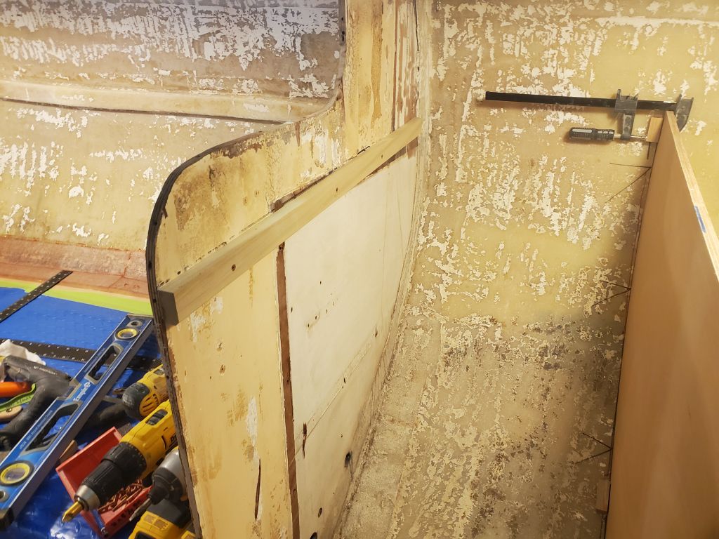
The plane of the new bulkhead would likely extend across the center of the boat to form the engine room and remainder of the galley before intersecting with the port side, but as of yet I’d not worked out the final details of where one panel would end and the next begin. There were various considerations, including how and where I planned to make access into the area beneath the galley and the engine room (though I planned substantial and easy access for both to the extent possible within the confines of the space).
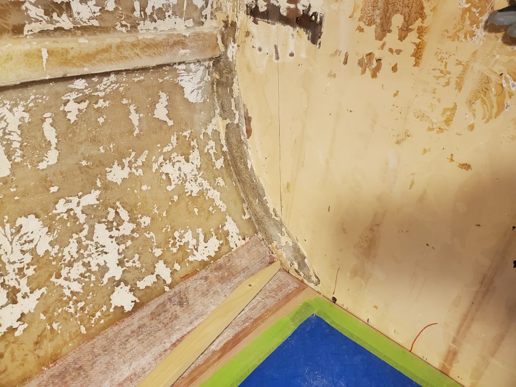
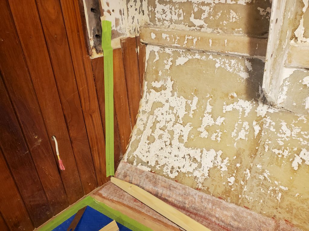
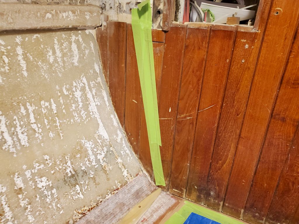
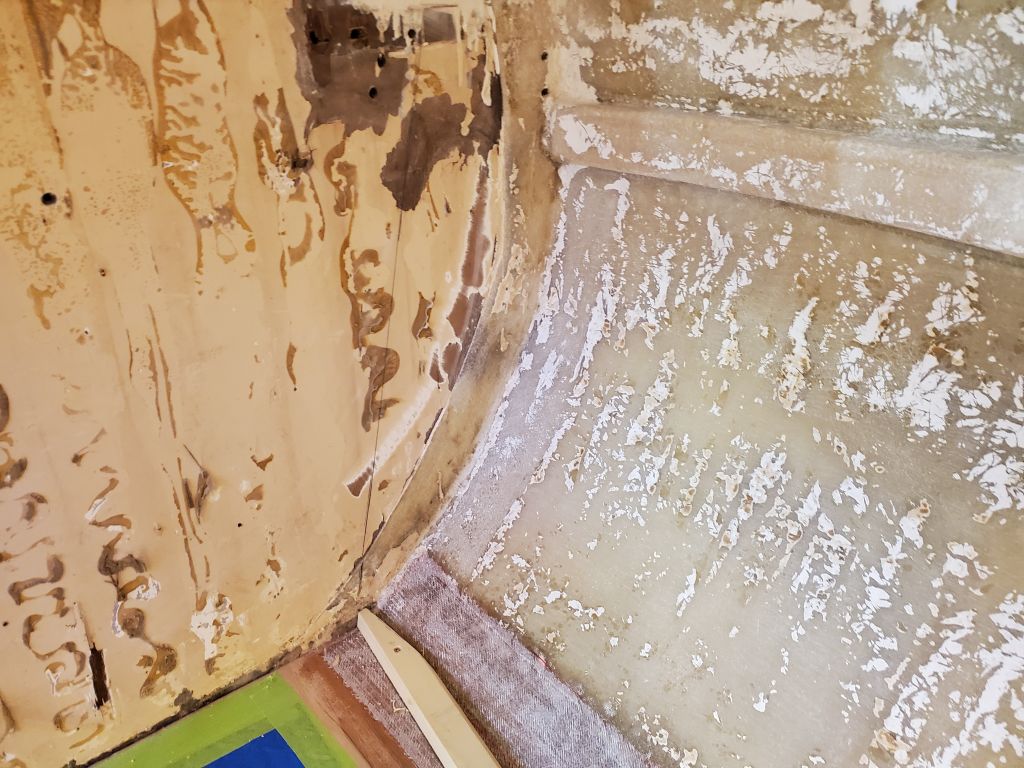
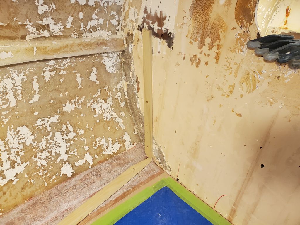
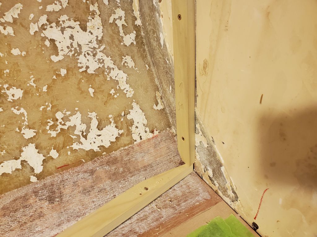
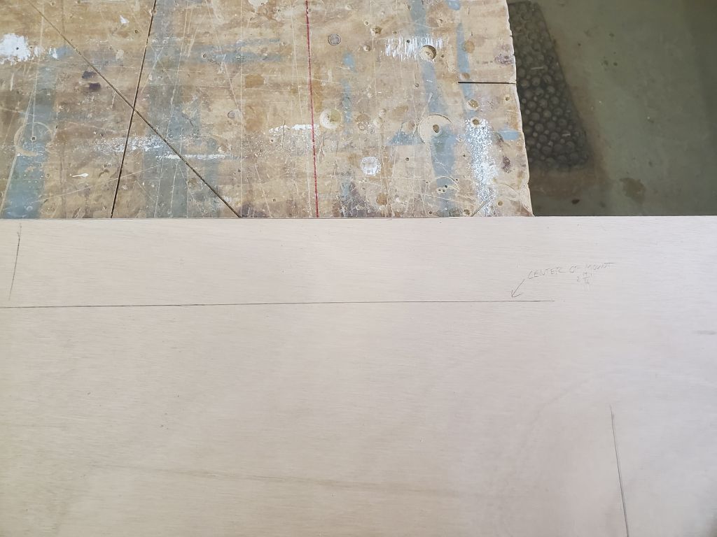
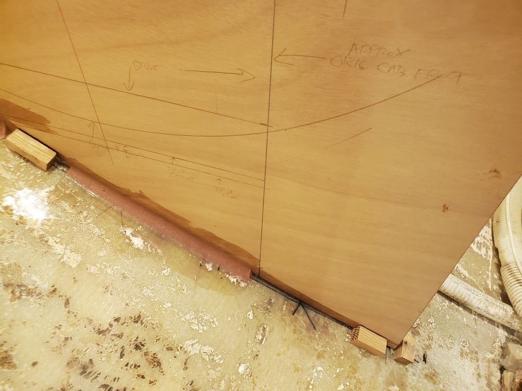
For now, I made a few marks on the new bulkhead:
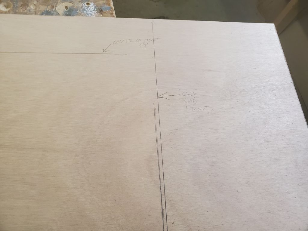
First, a plumb line even with the edge of the starboard forward galley bulkhead (furthest on the right in the photos below).
Then, a second plumb line, further outboard, to represent the location of the original longitudinal cabinet front, according to the ghost of the old cabinetry supports still visible on the aft side of the bulkhead (next line to the left in the photos below).
Finally, I made a mark closer to the hull, just at the top edge of the panel, to show the furthest-outboard point with enough height clearance for the stove, not necessarily accounting for the gimbal action; because the height of the stove itself was just under its width, I simply used my 19.25″ marking stick to provide an easy reference for this, though it was only a maximum-reference and wasn’t necessarily indicative of the back side of the eventual space (small mark closer to the outboard (left) edge of the panel in the photos below).
Next time, I’d work through some of the remaining questions, starting with the actual location of the stove mounts to ensure that the stove fit properly in the space and could gimbal as designed.
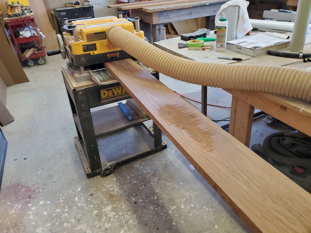
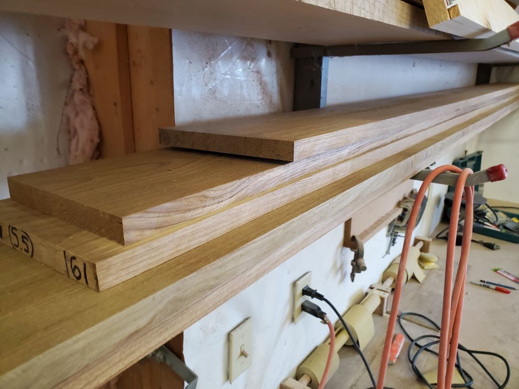
After installing new planer blades, I finished up the planing with three additional planks.
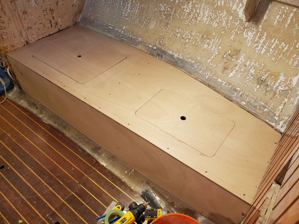
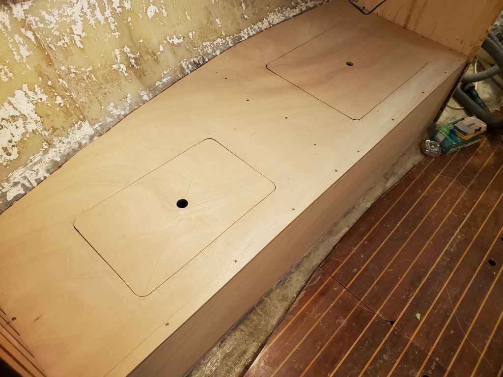
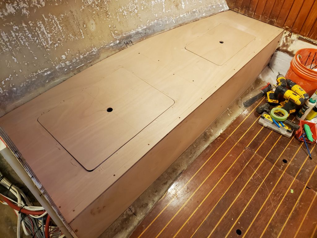
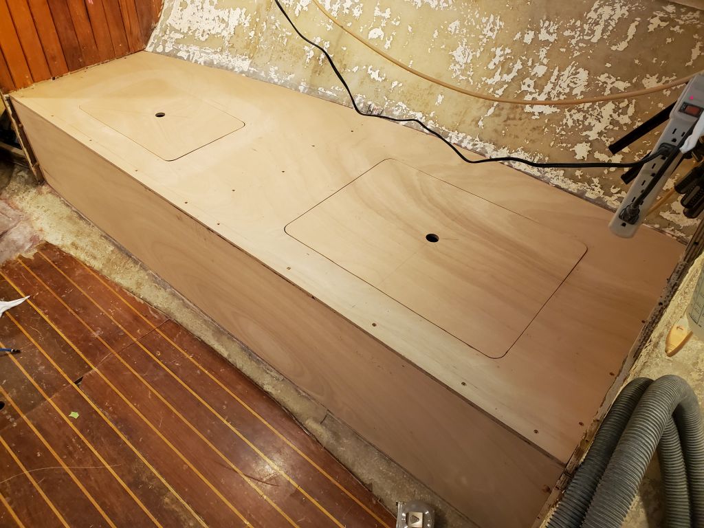
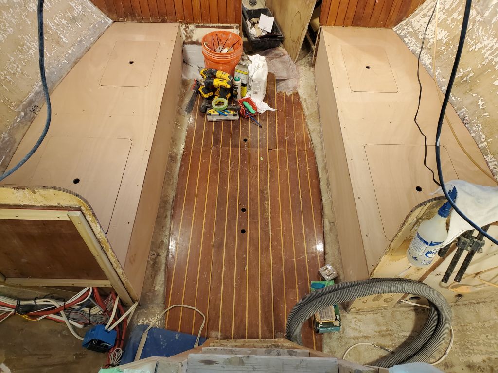
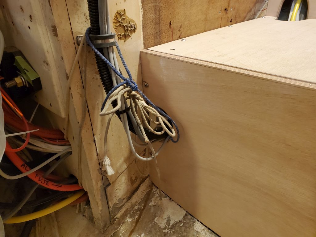
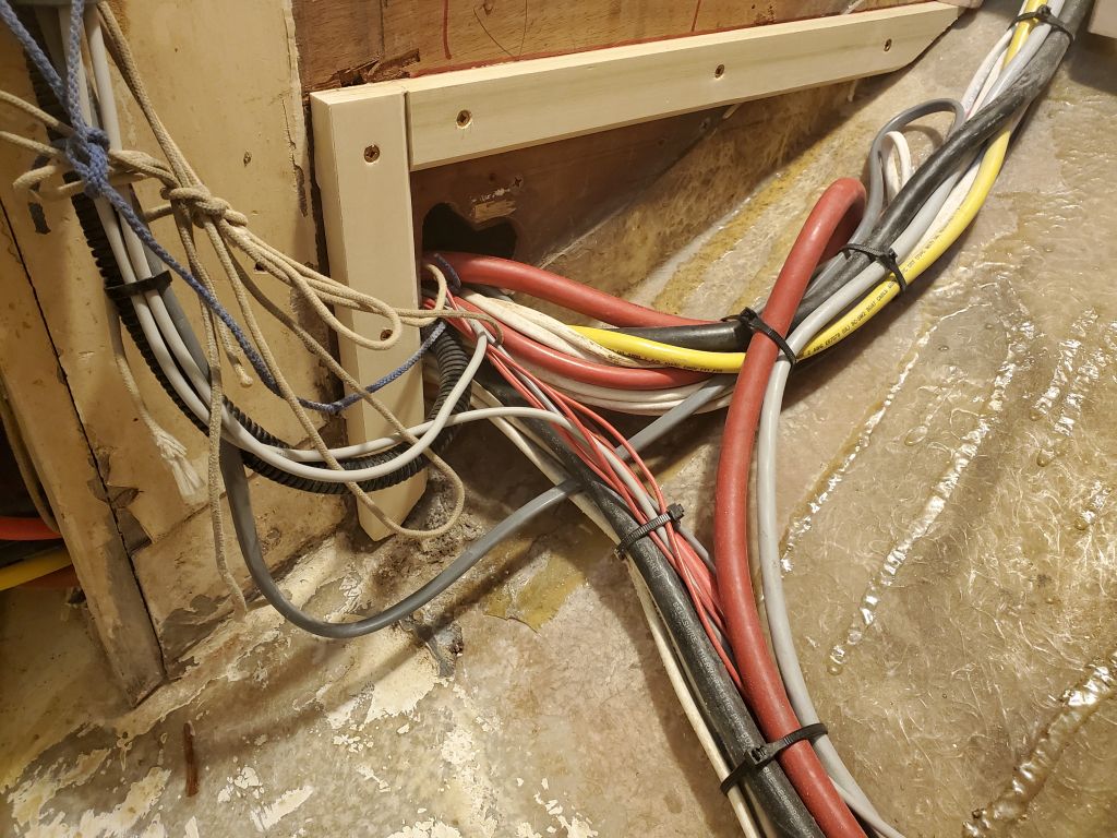
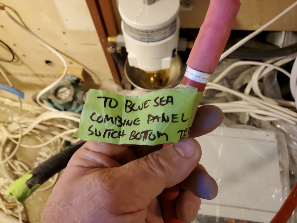
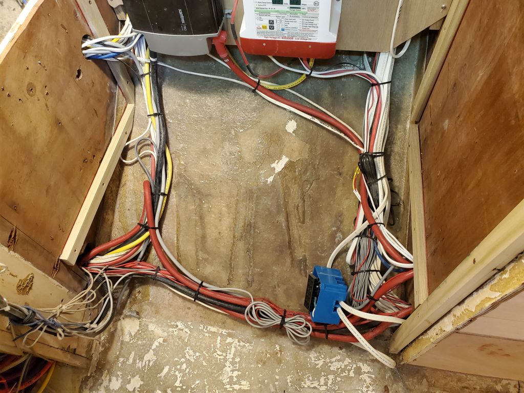
In the settee lockers, I cleaned up the wire bundles and secured the wires along their final routes on each side.
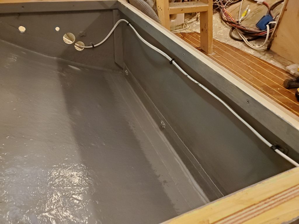
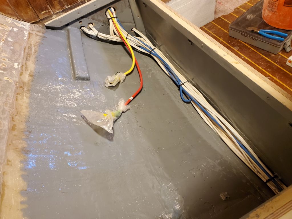
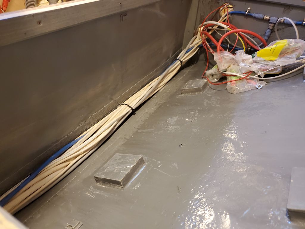
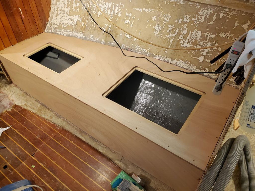
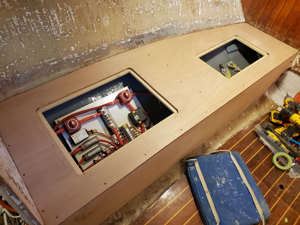
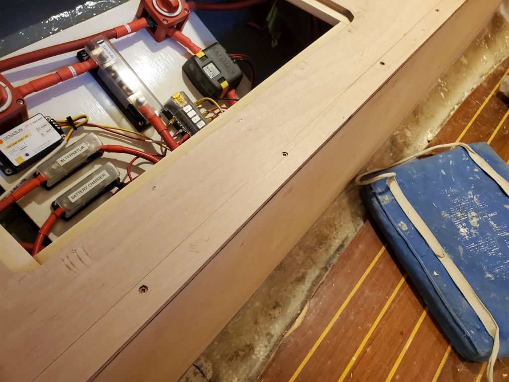
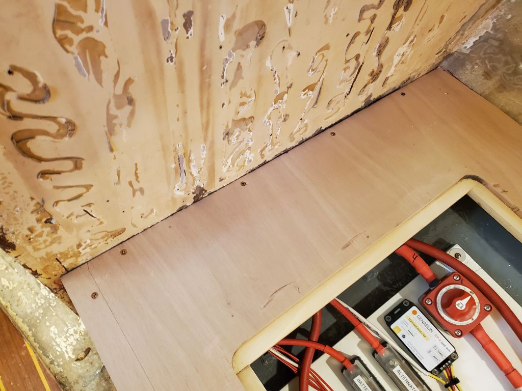
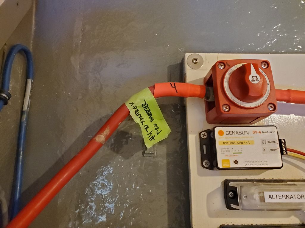
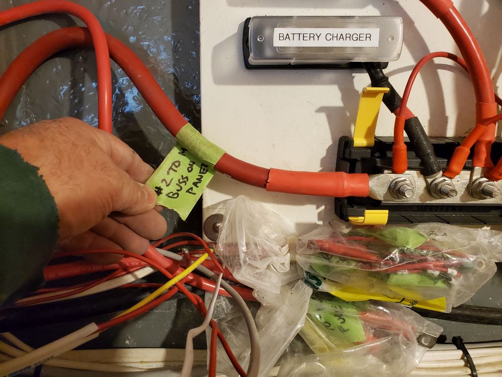
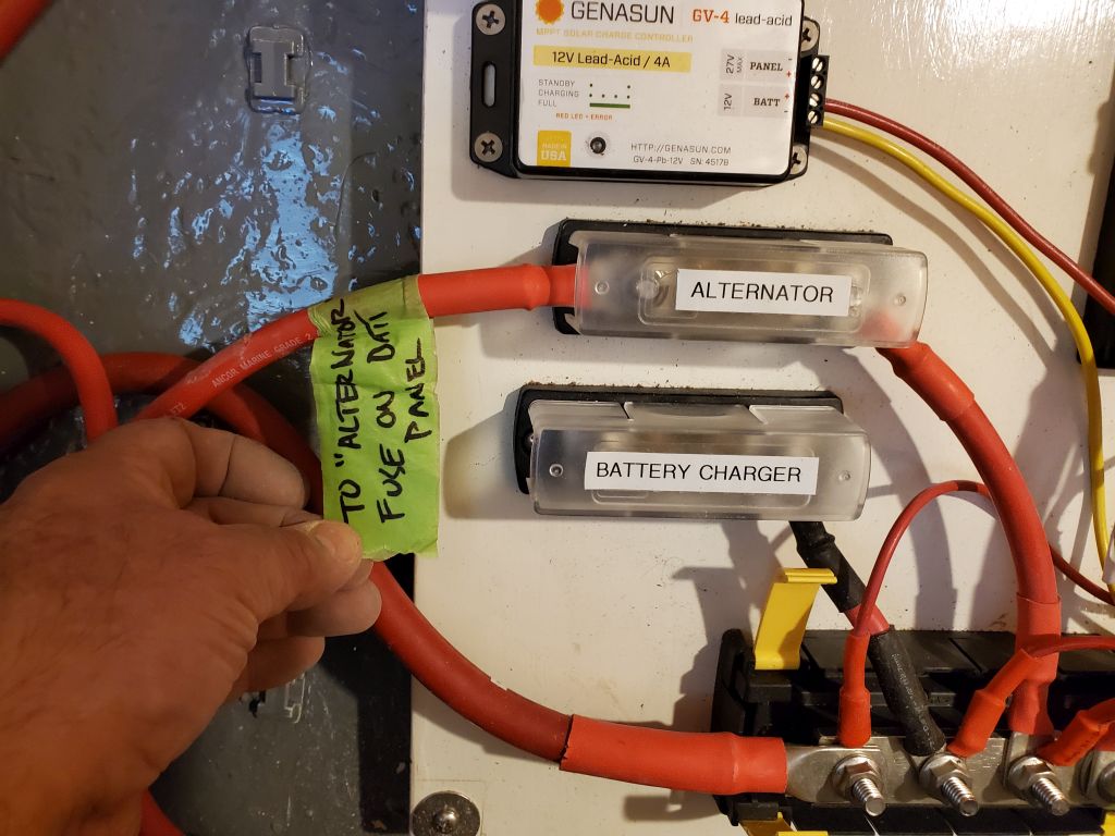
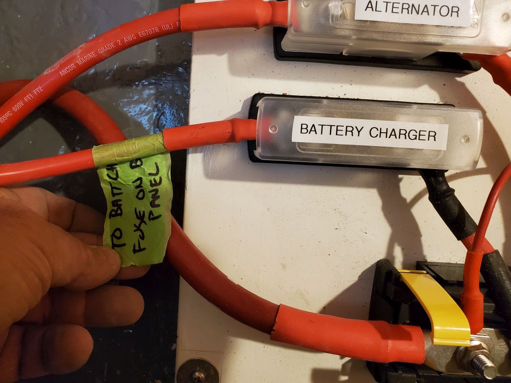
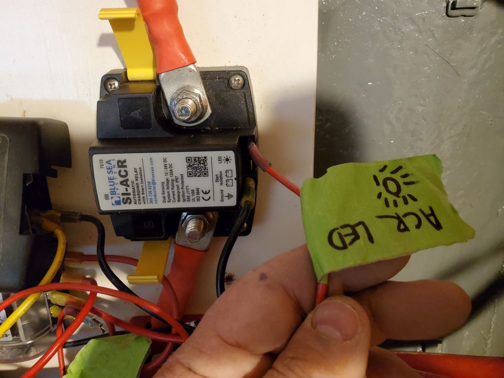
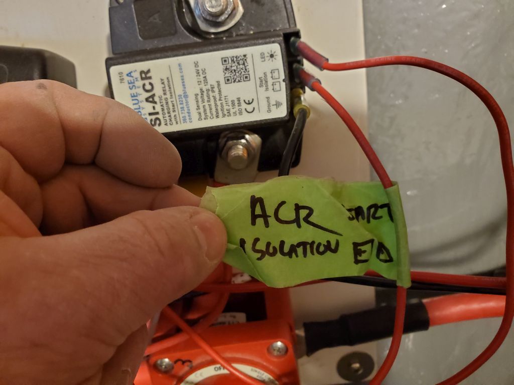
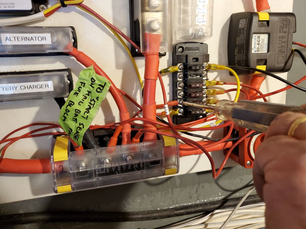
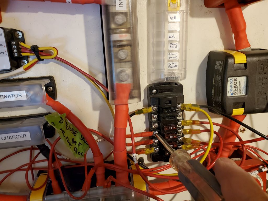
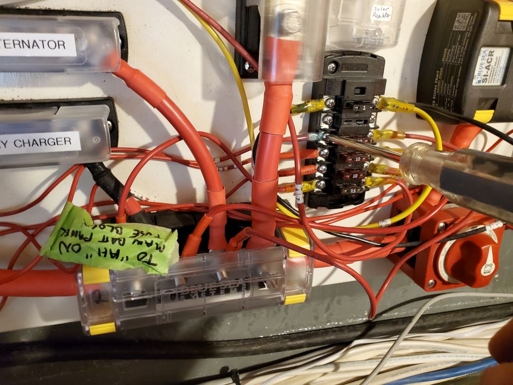
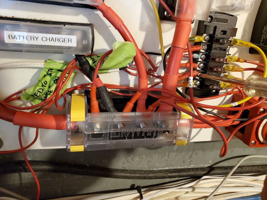
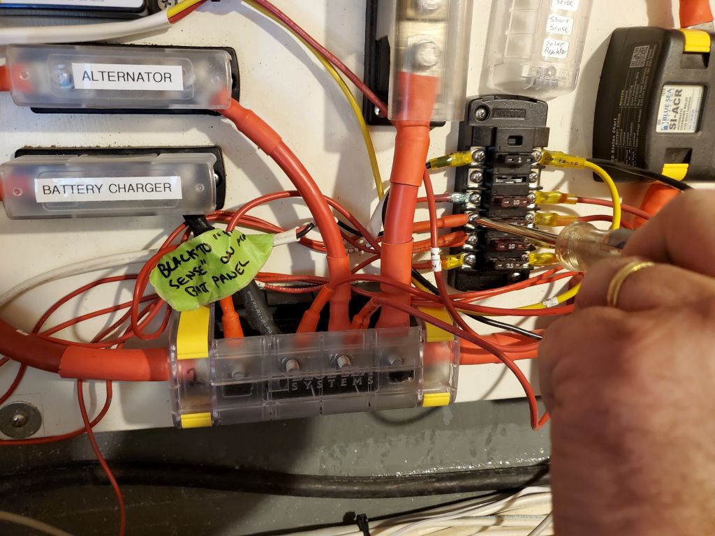
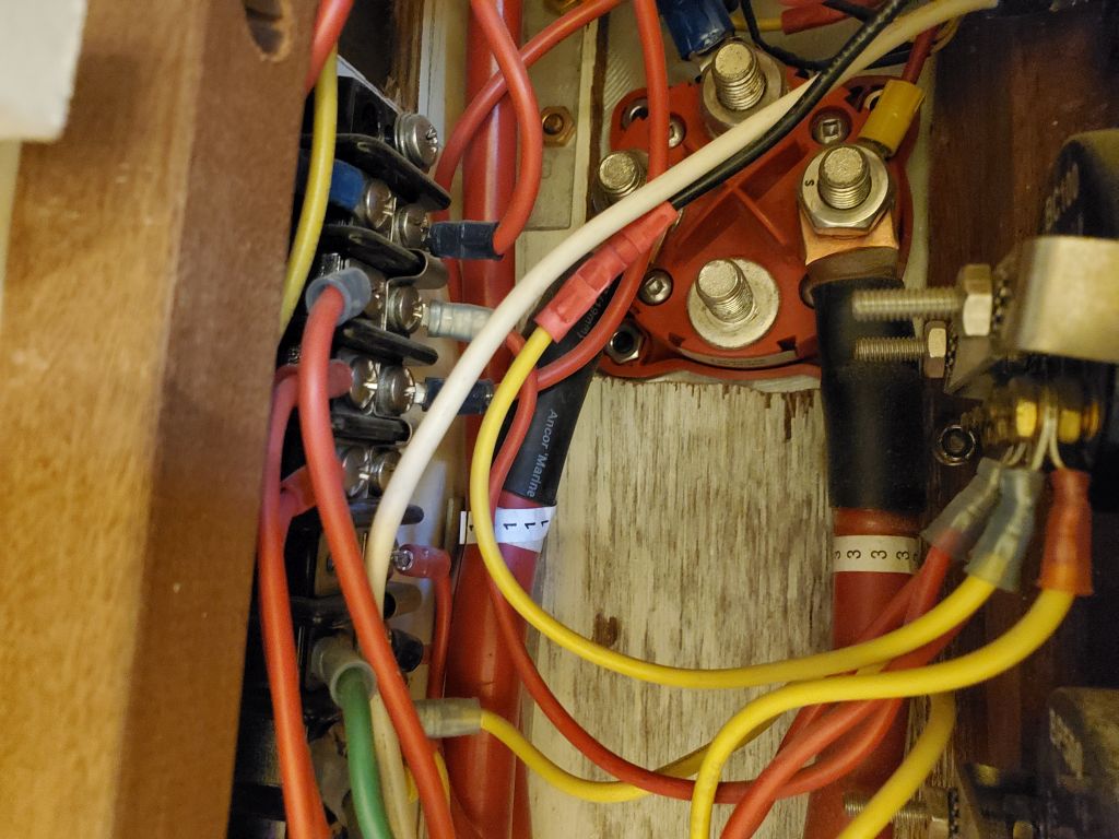
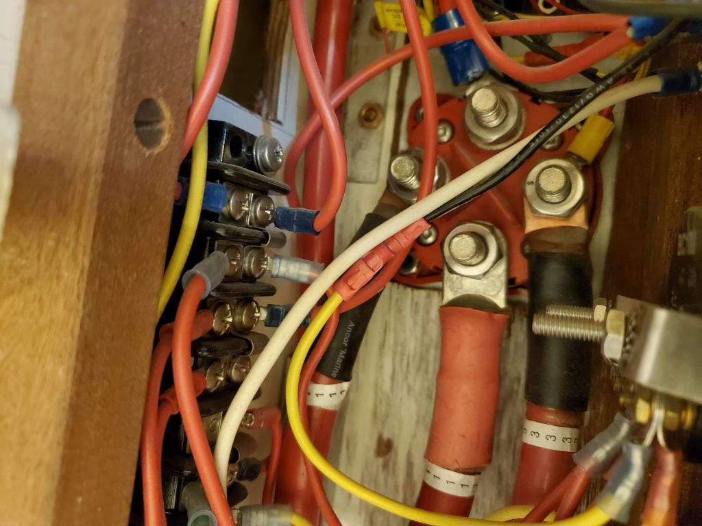
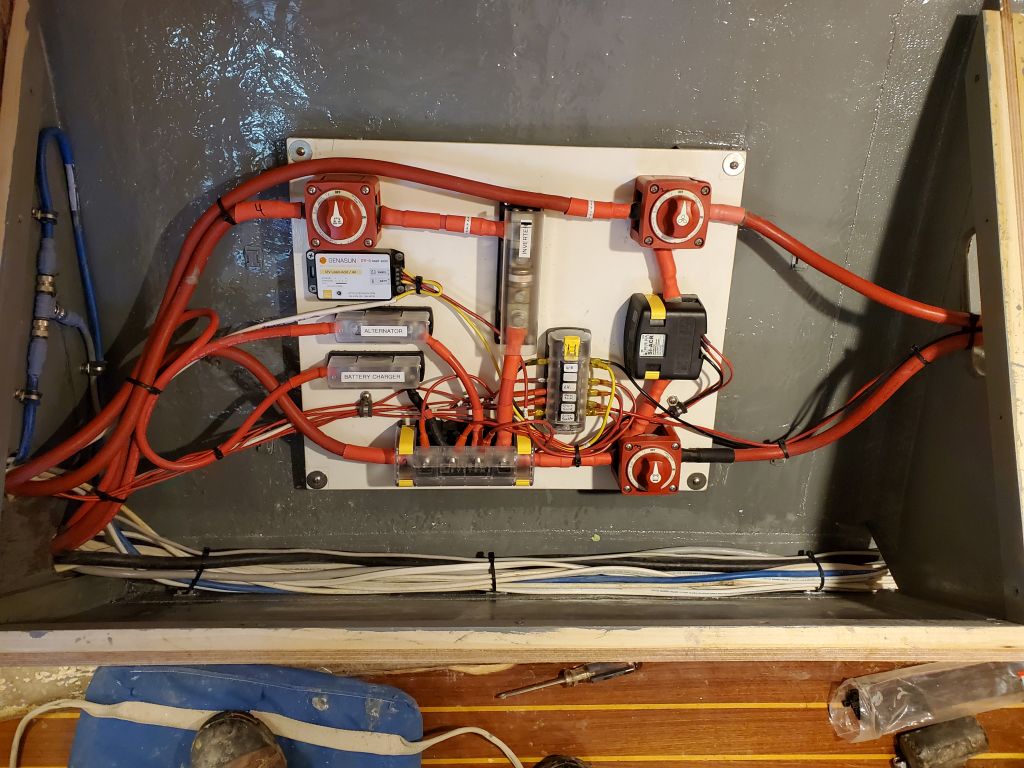
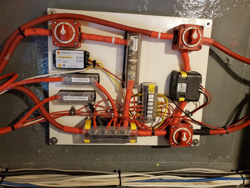
Next, I reinstalled the battery switch panel in the port after settee locker, then spent some time reconnecting all the wires that I’d removed and labeled earlier in the process. Several wires run into the forward compartment would ultimately be connected to the battery banks, once I’d built the new battery locker at the forward corner of the settee. I straightened the wire runs as much as possible and secured the various wire bundles around the panel, and in the space beneath the refer compartment in the galley.
With the wiring connections complete, it was time to finally install the settee berth tops. I installed these with glue and screws. It was too late in the day to finish the installation along the hull on each side, but next time I’d install tabbing to secure the plywood along the outboard edges.