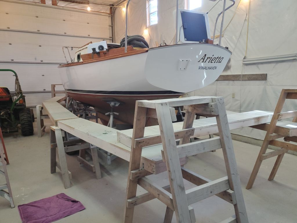
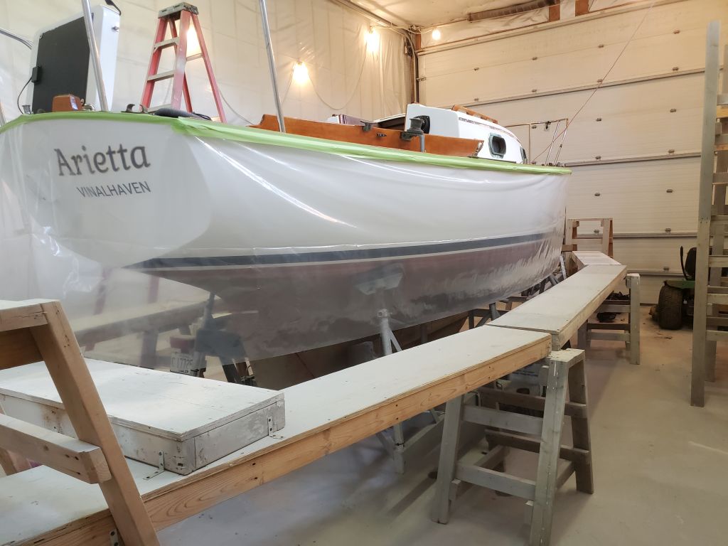
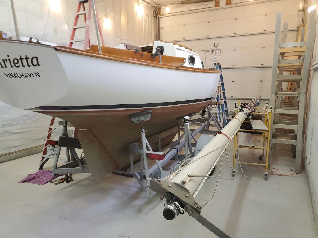
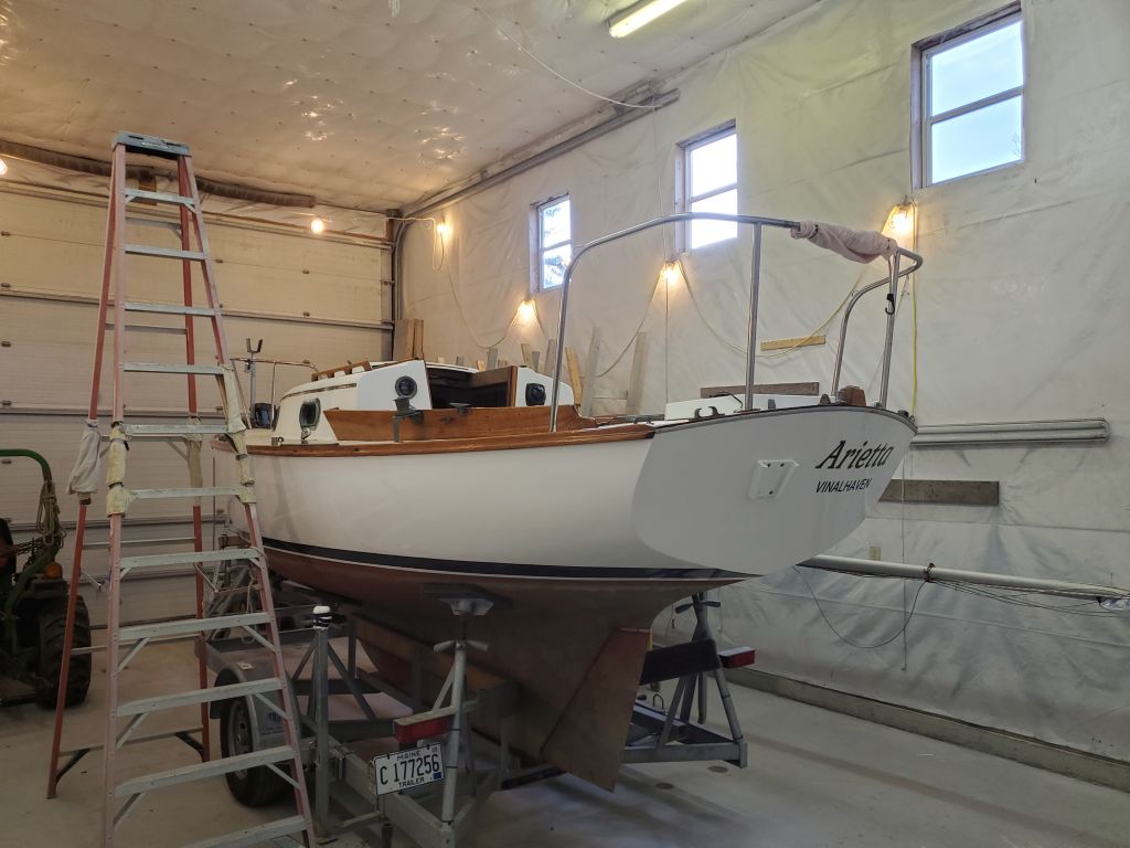
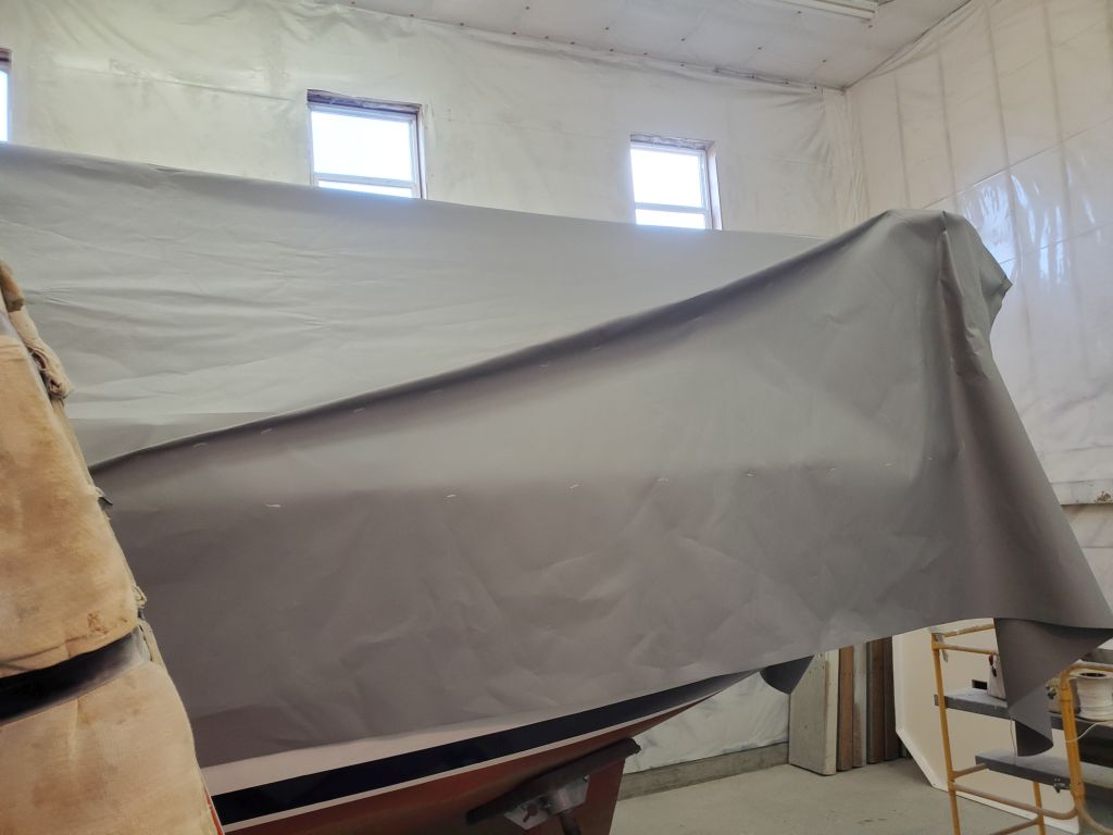
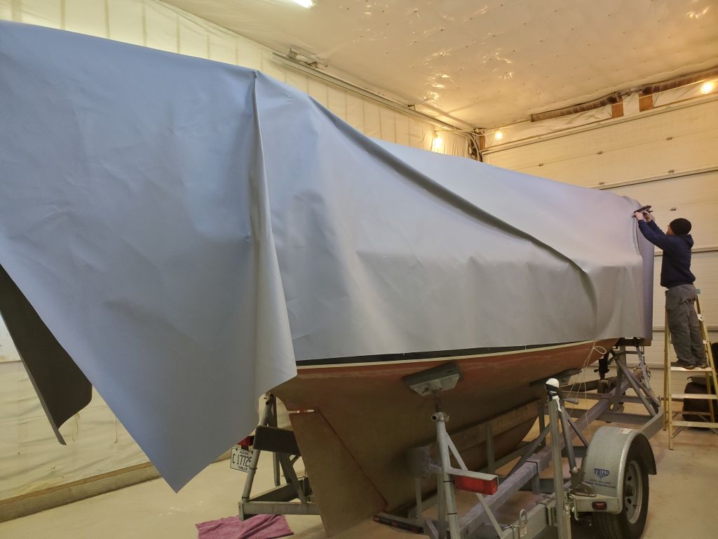
(page 4 of 4)

Arietta Phase 2-9

Thursday

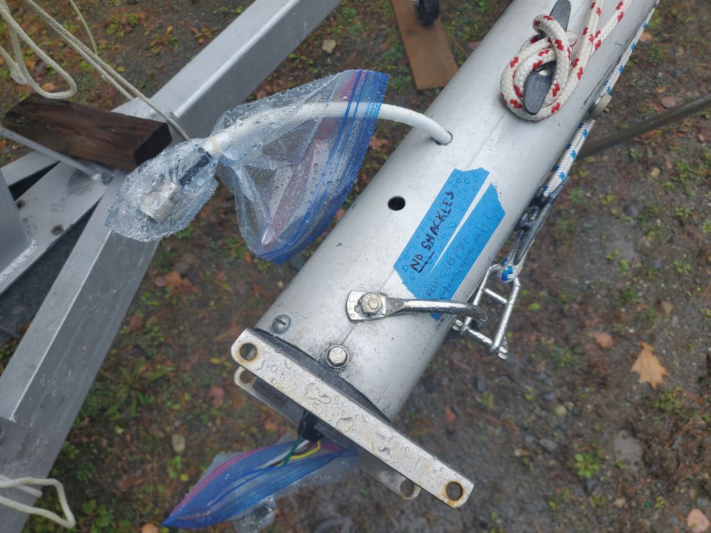
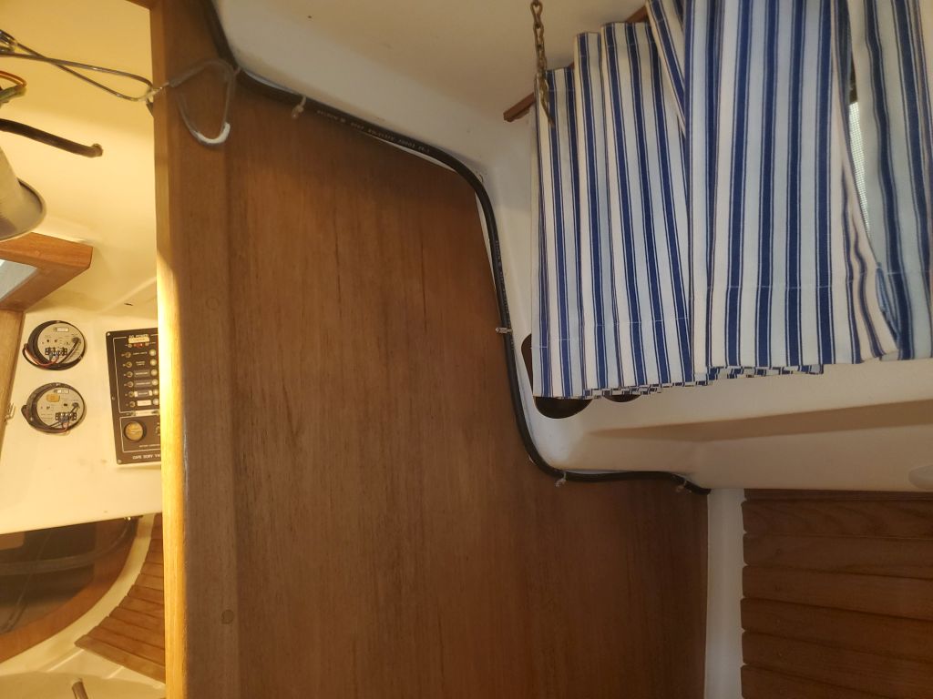
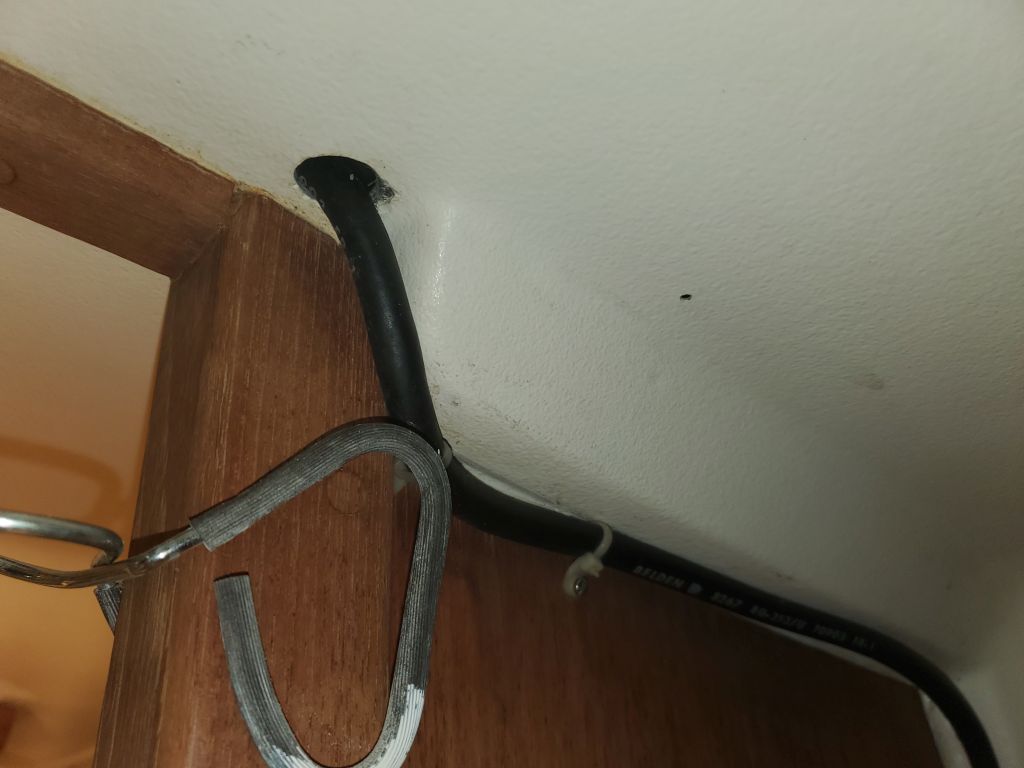
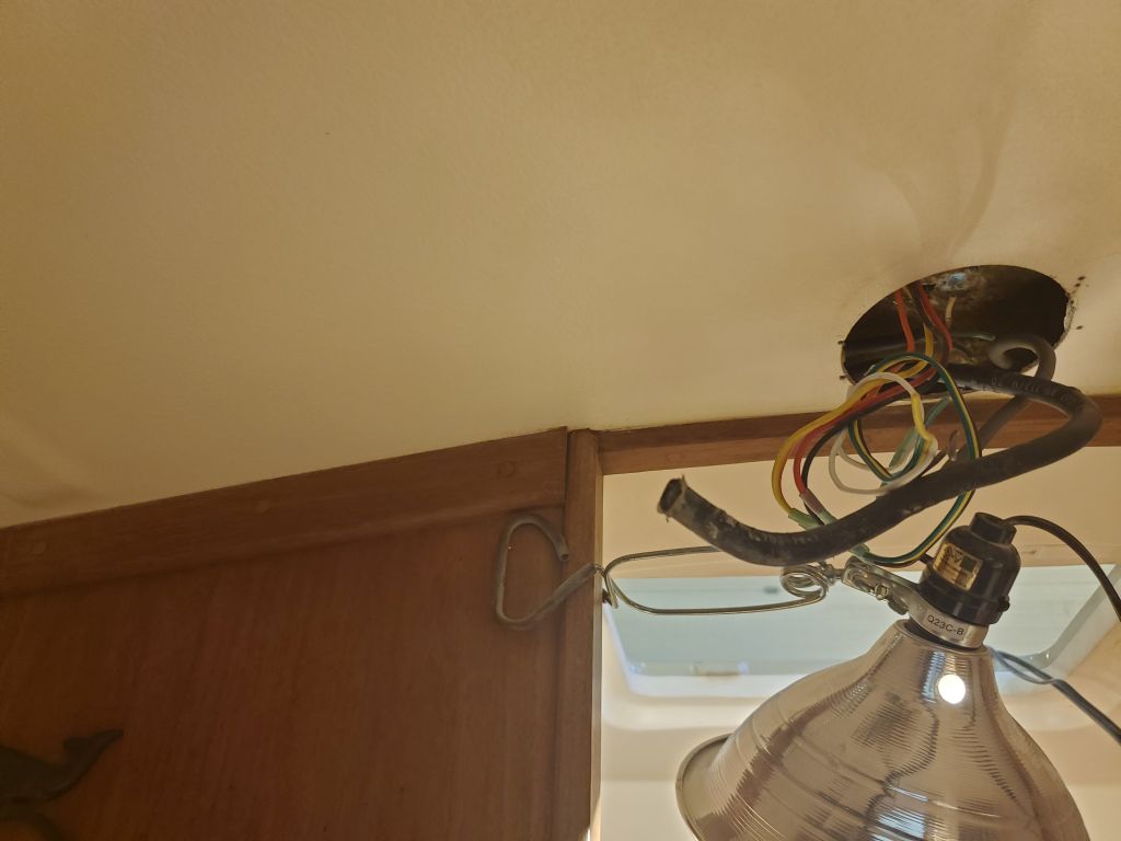
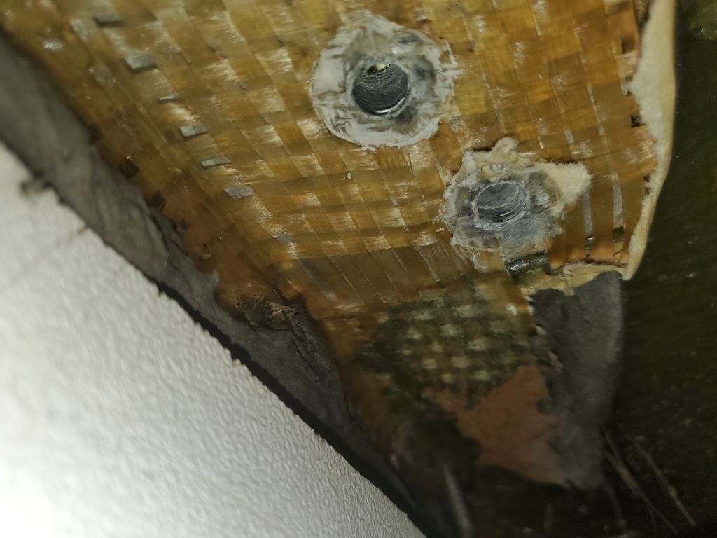
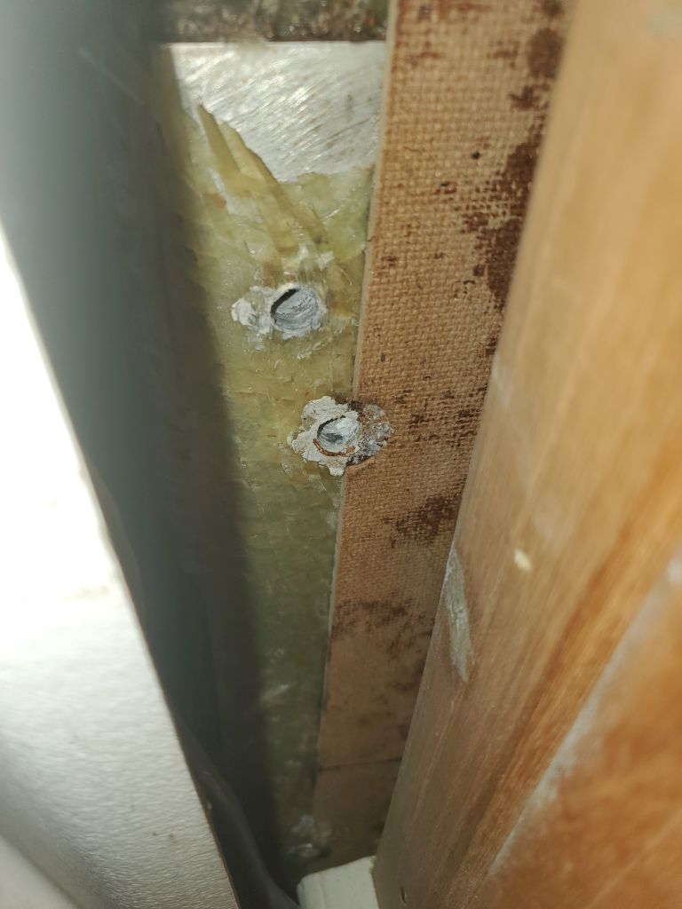
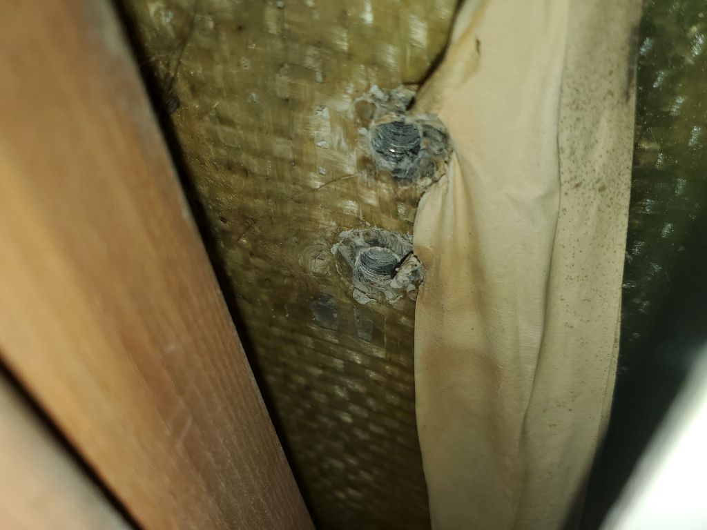
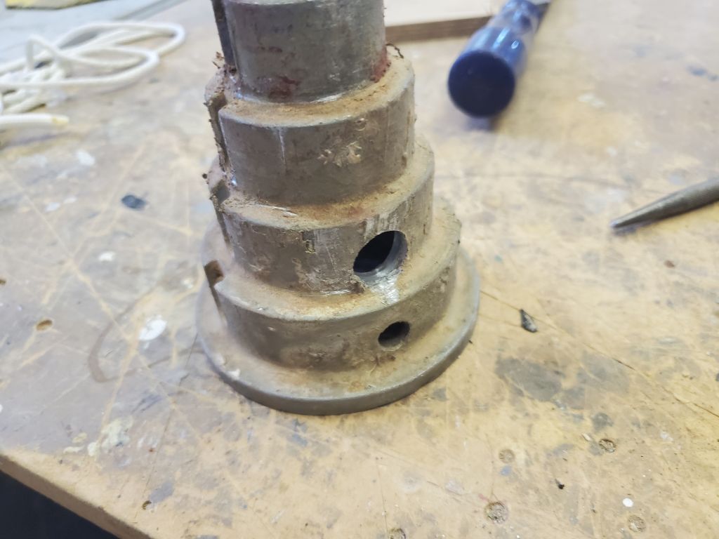
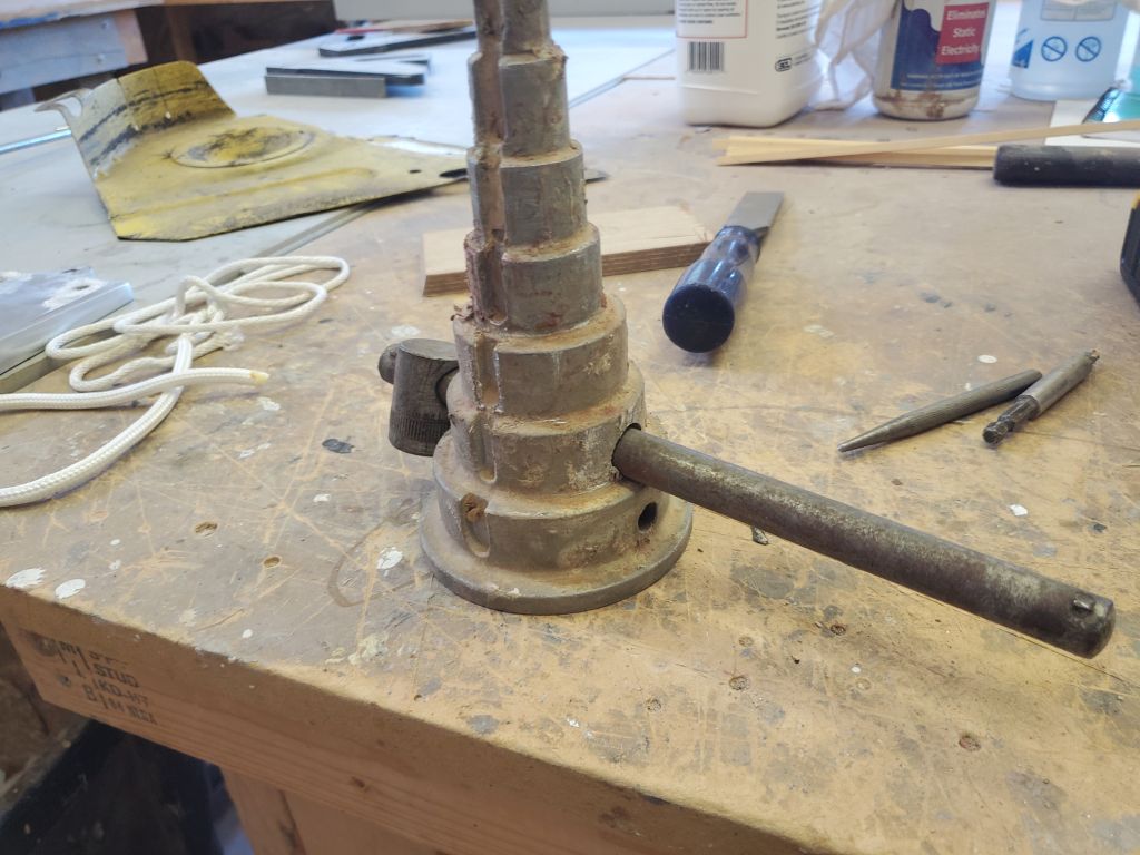
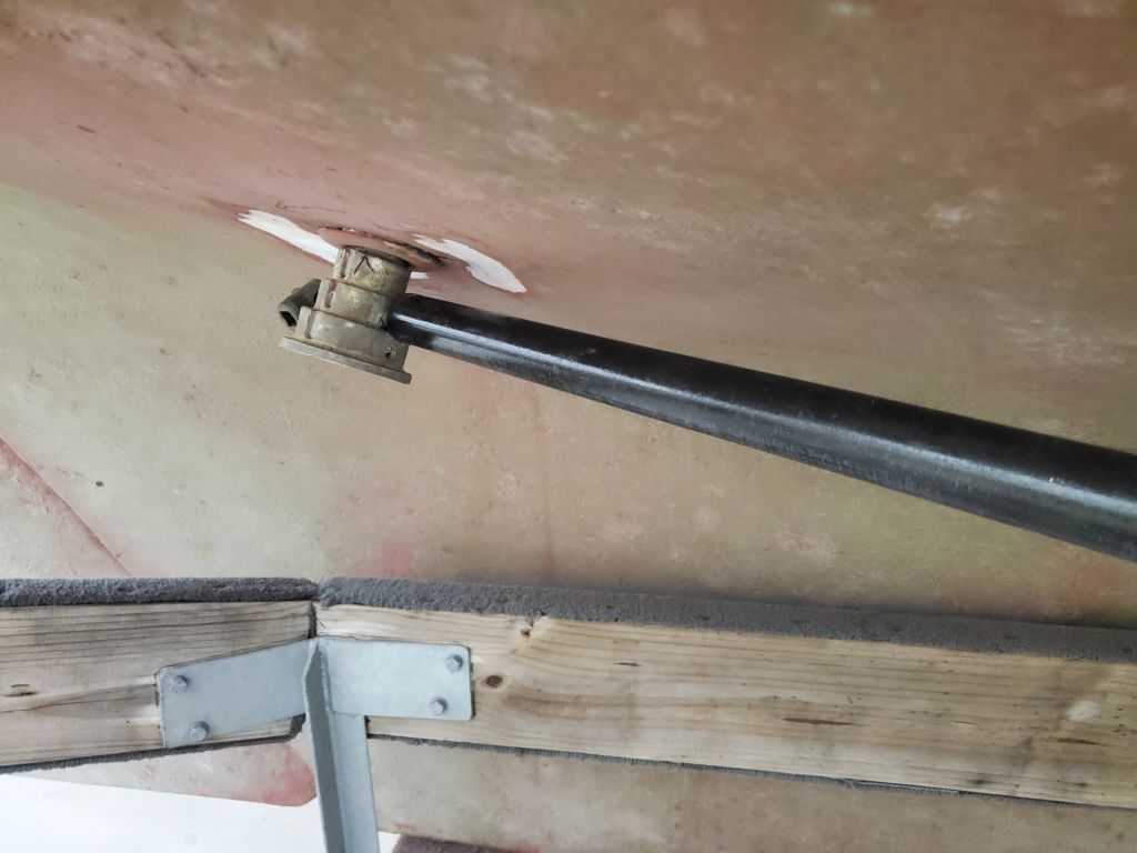
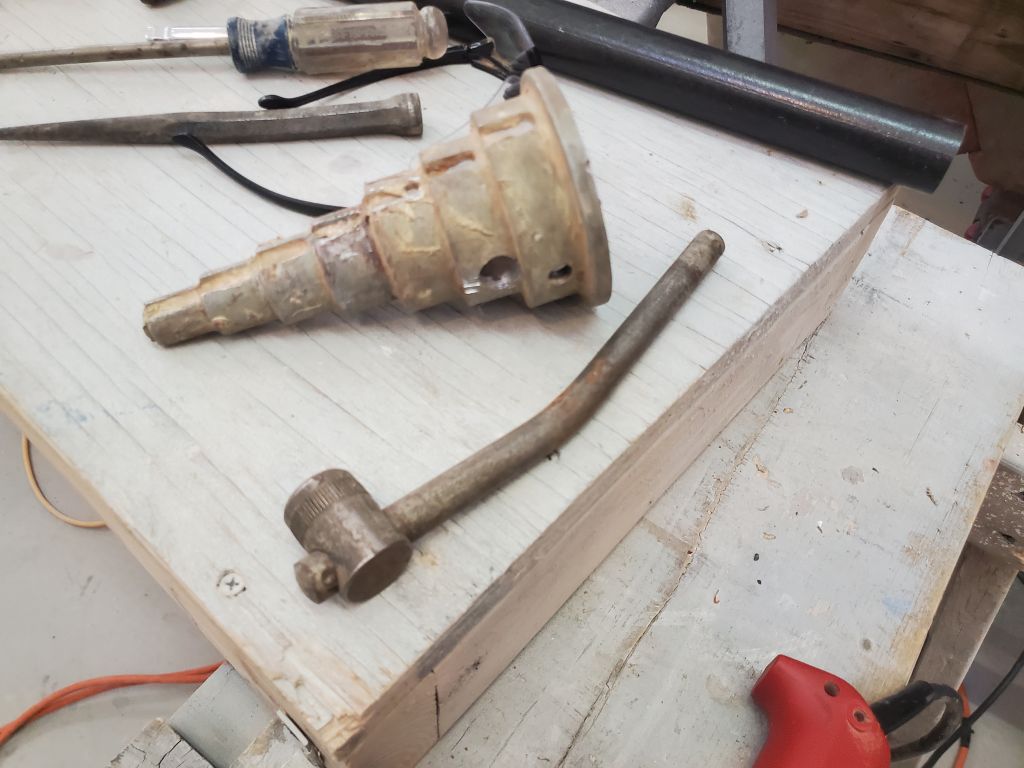
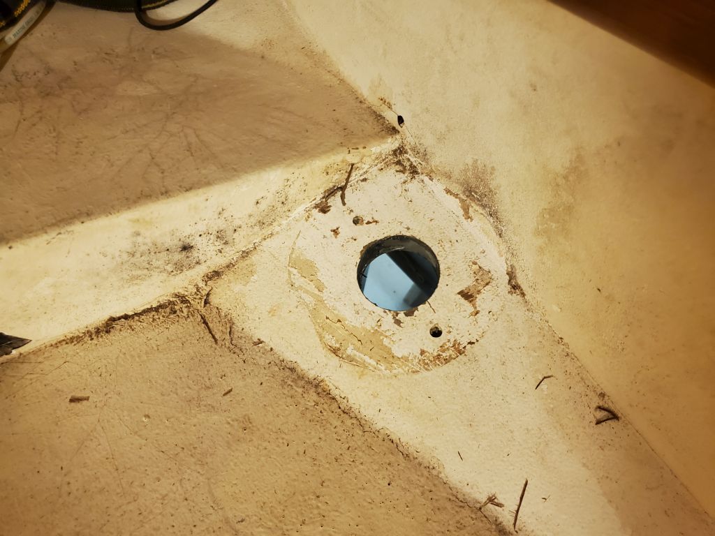
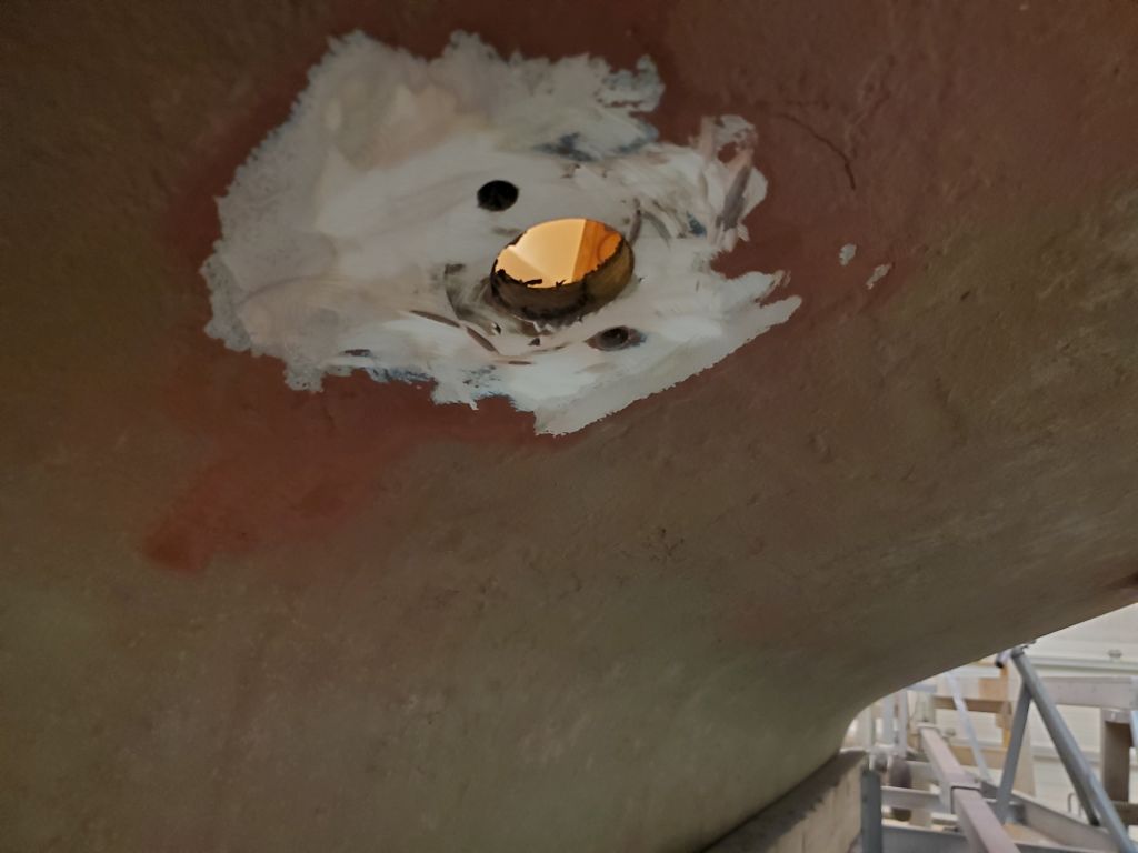
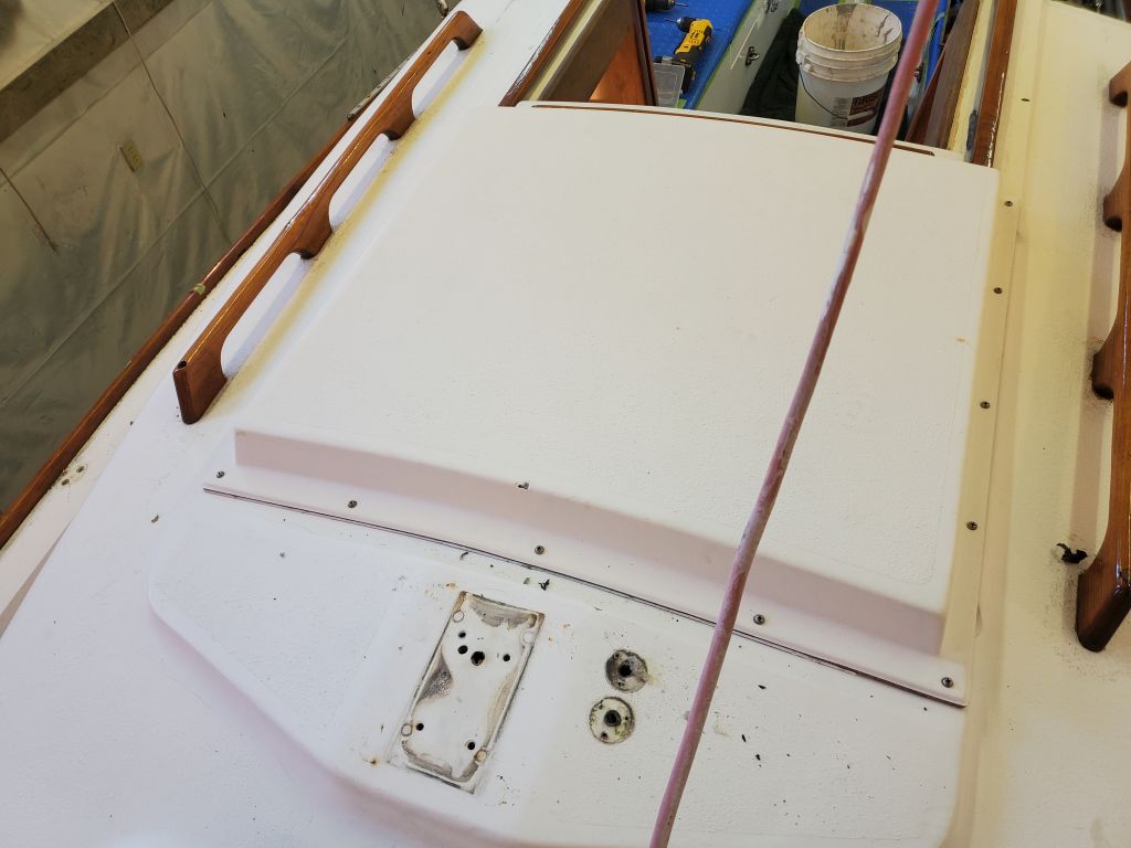
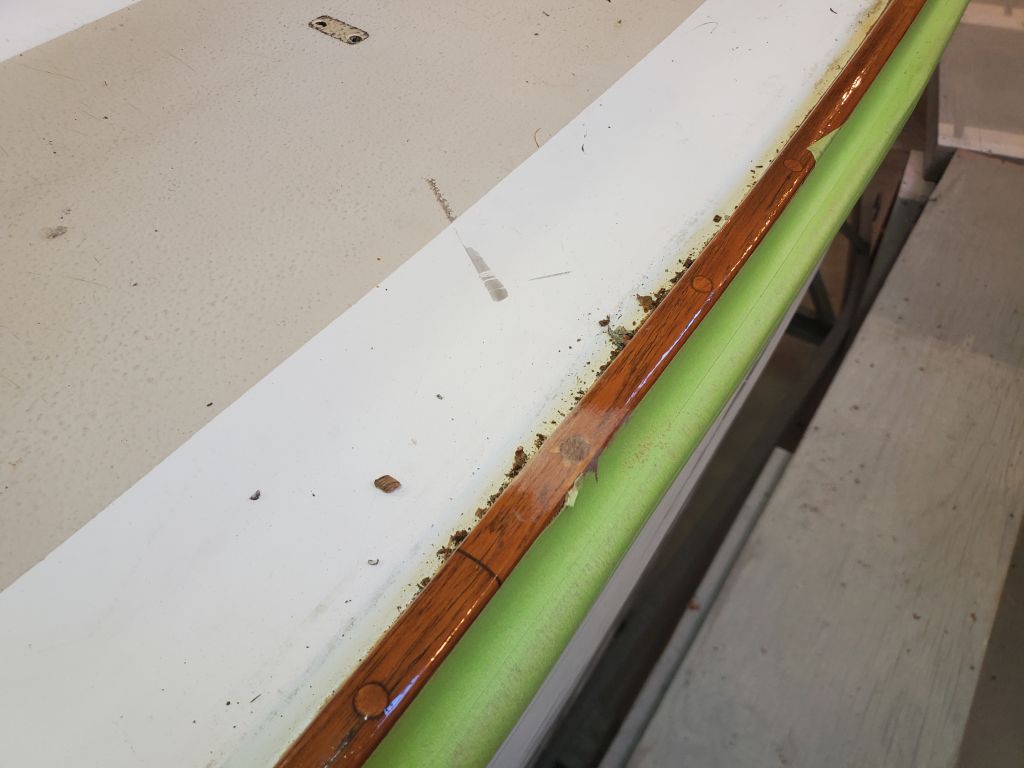
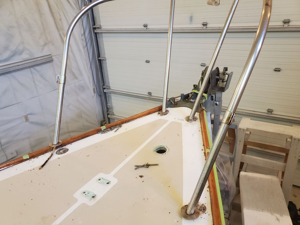
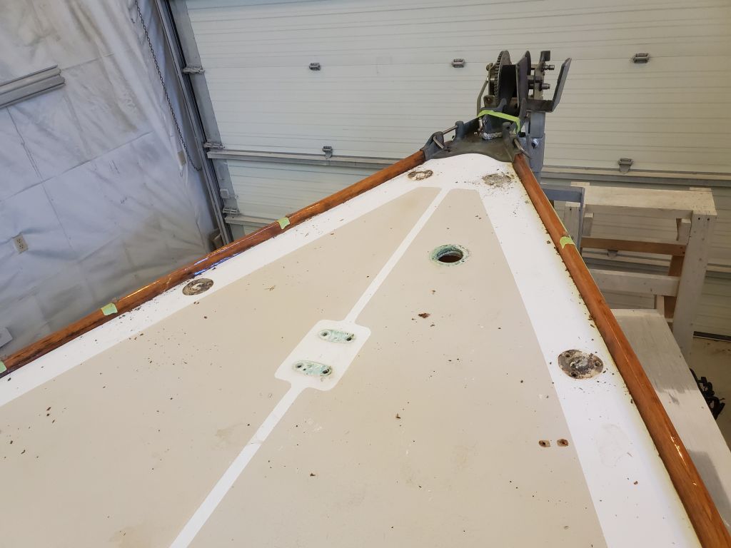
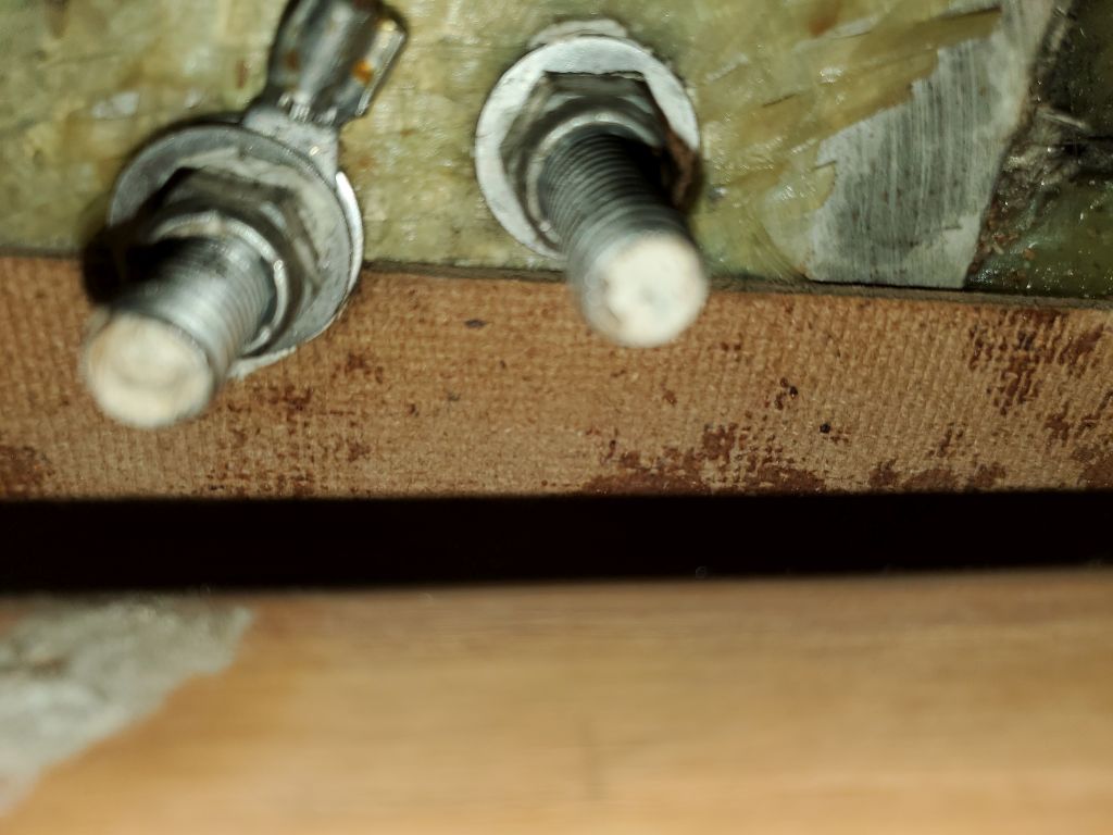
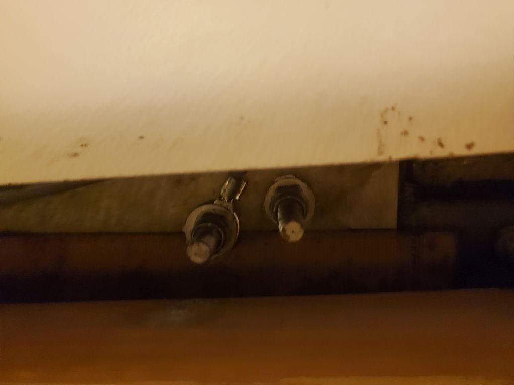
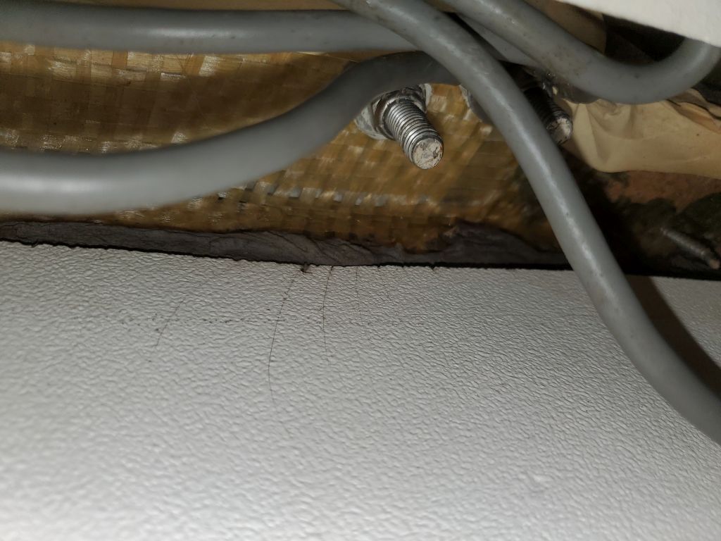
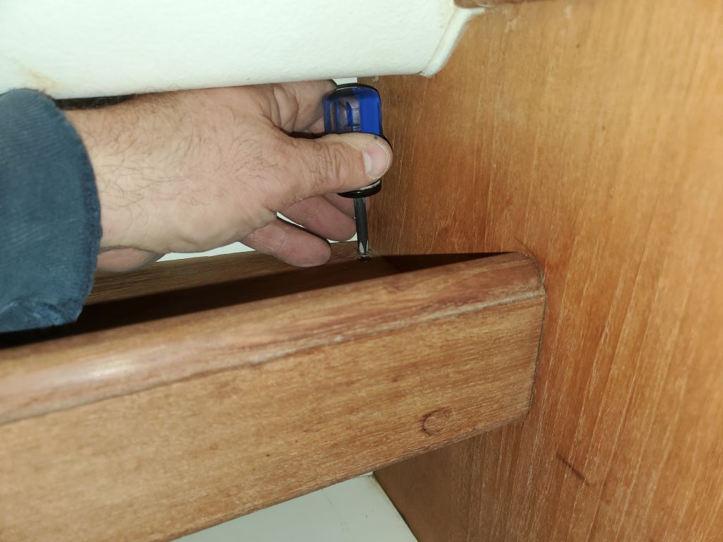
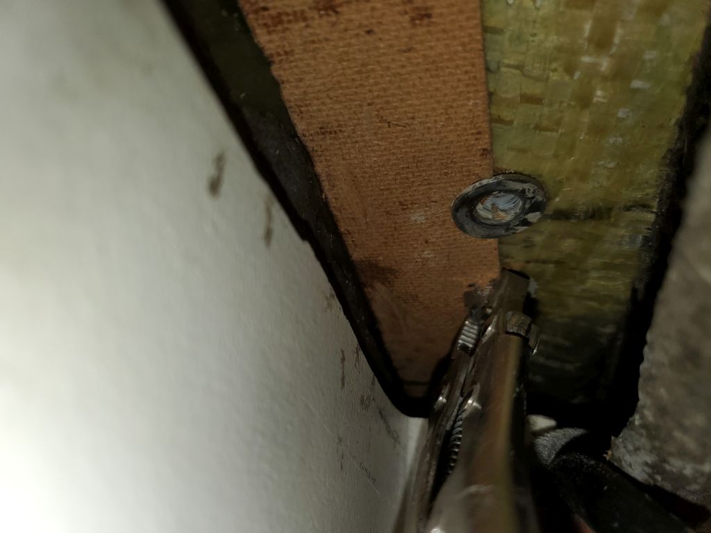
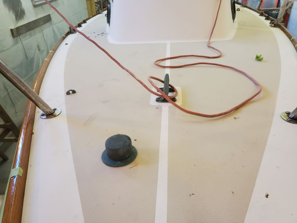
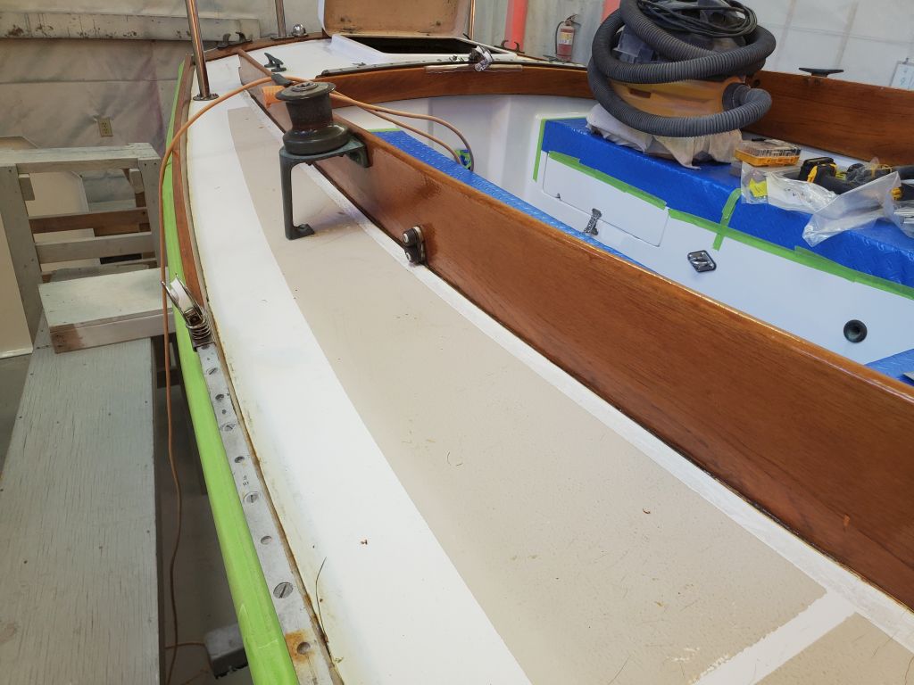
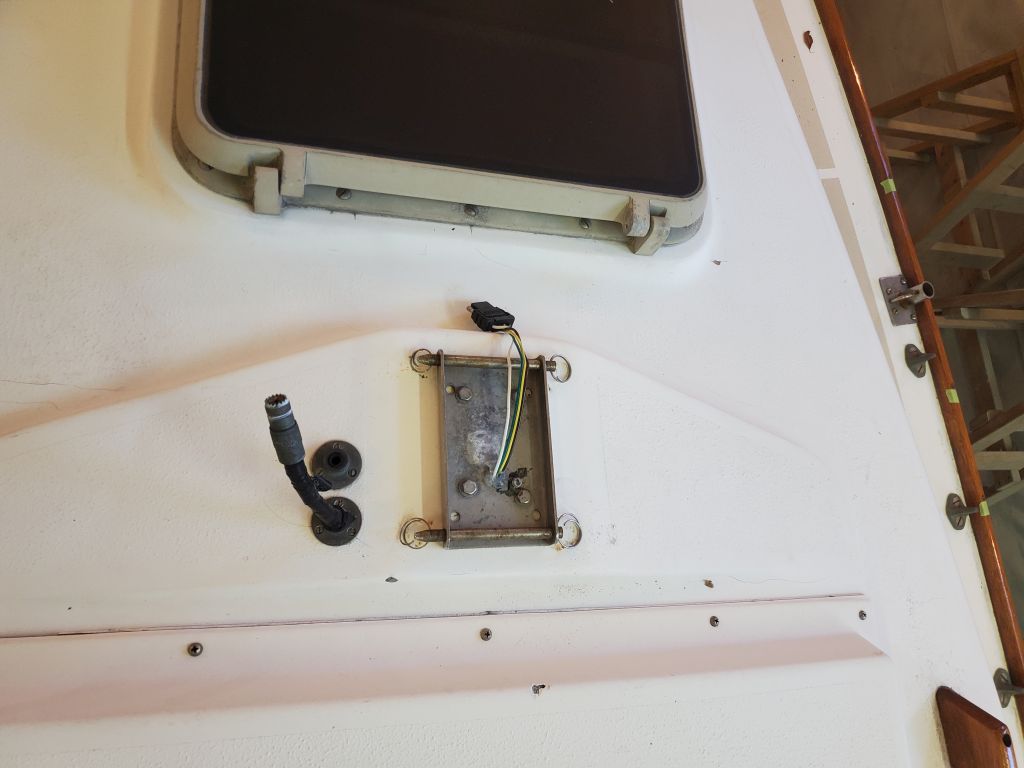
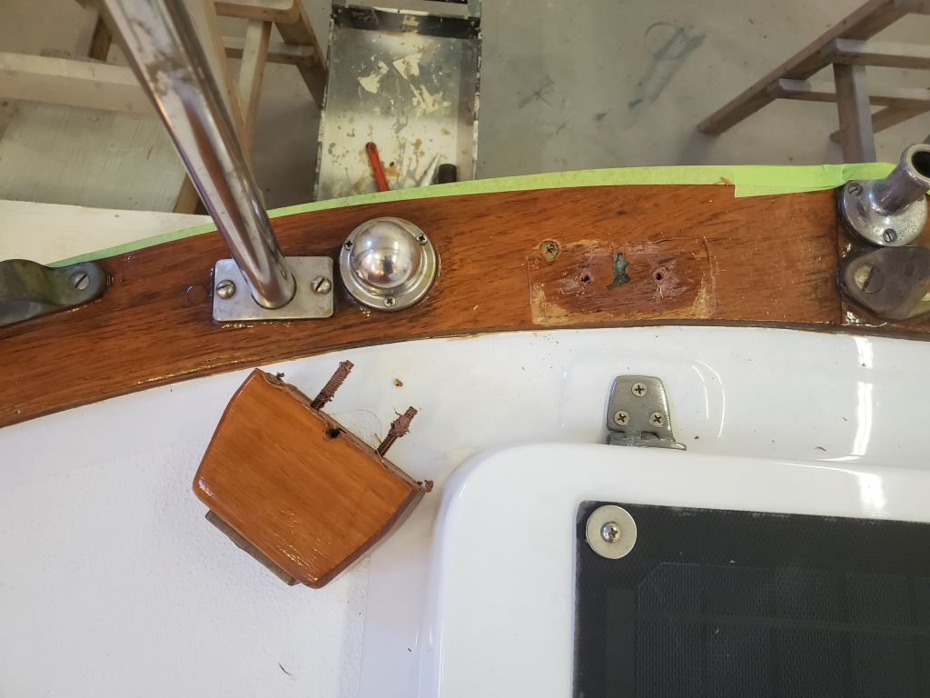
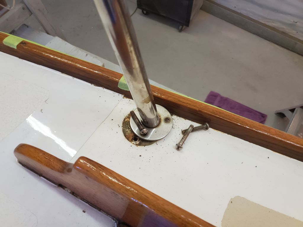
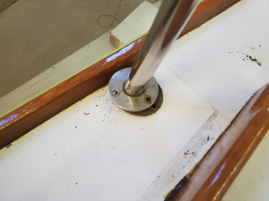
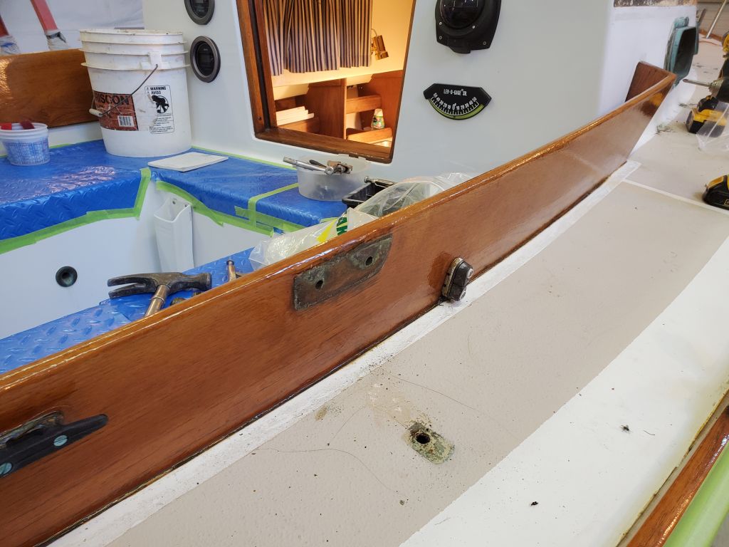
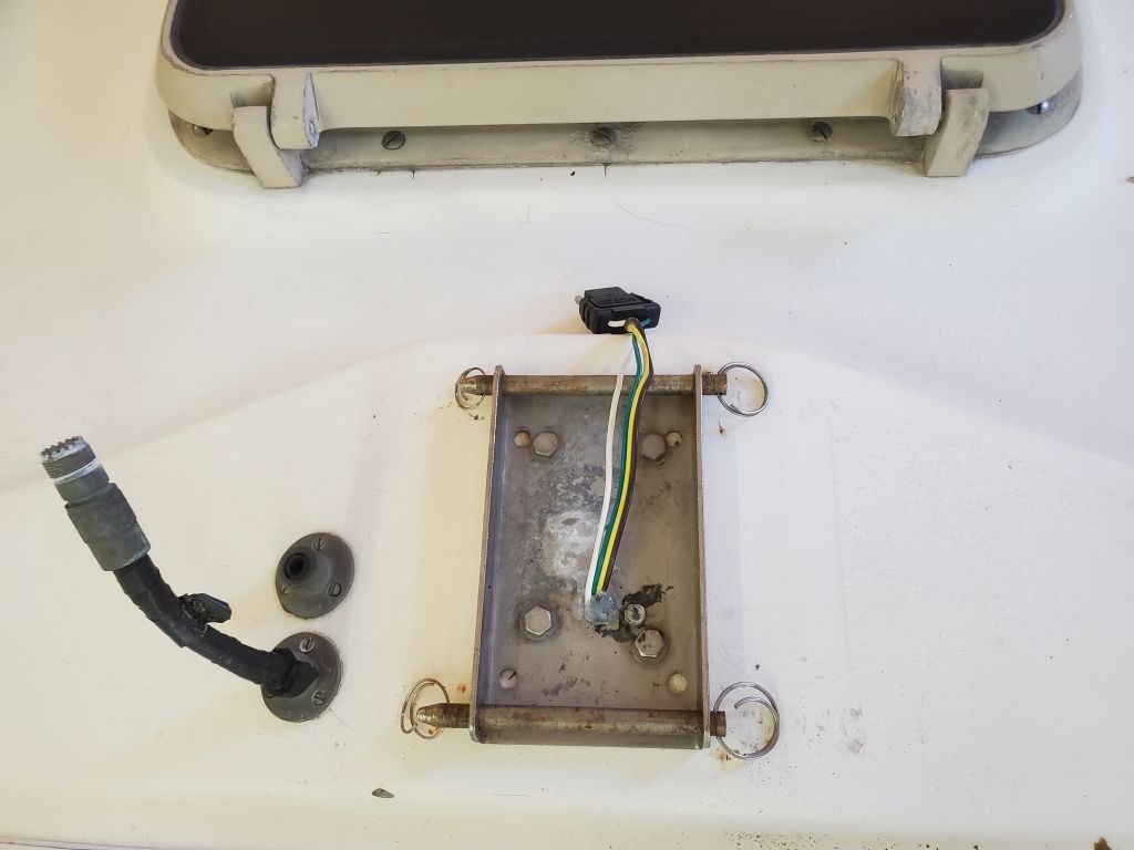
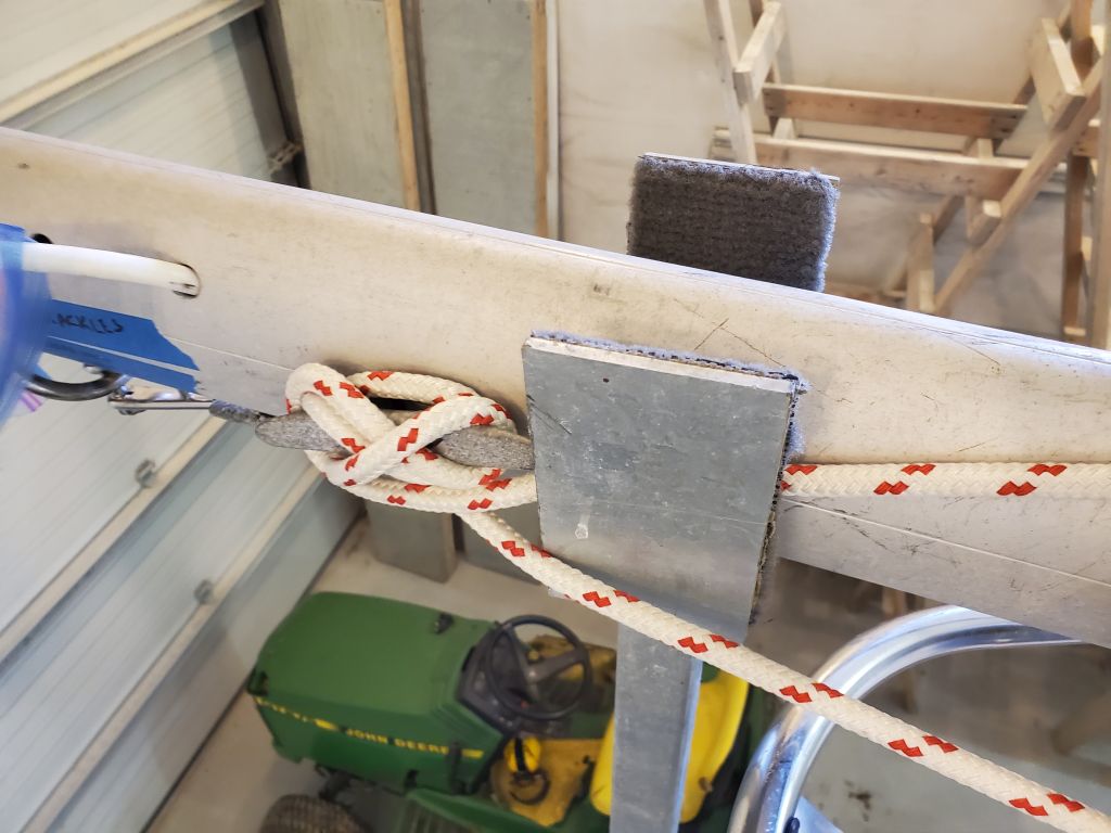
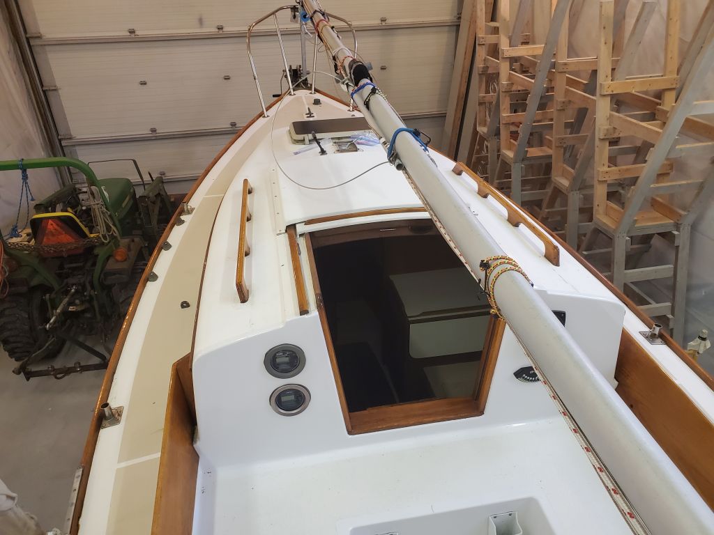
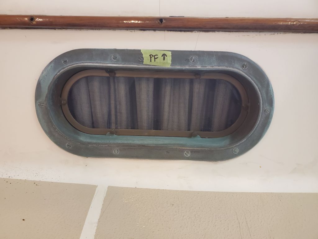
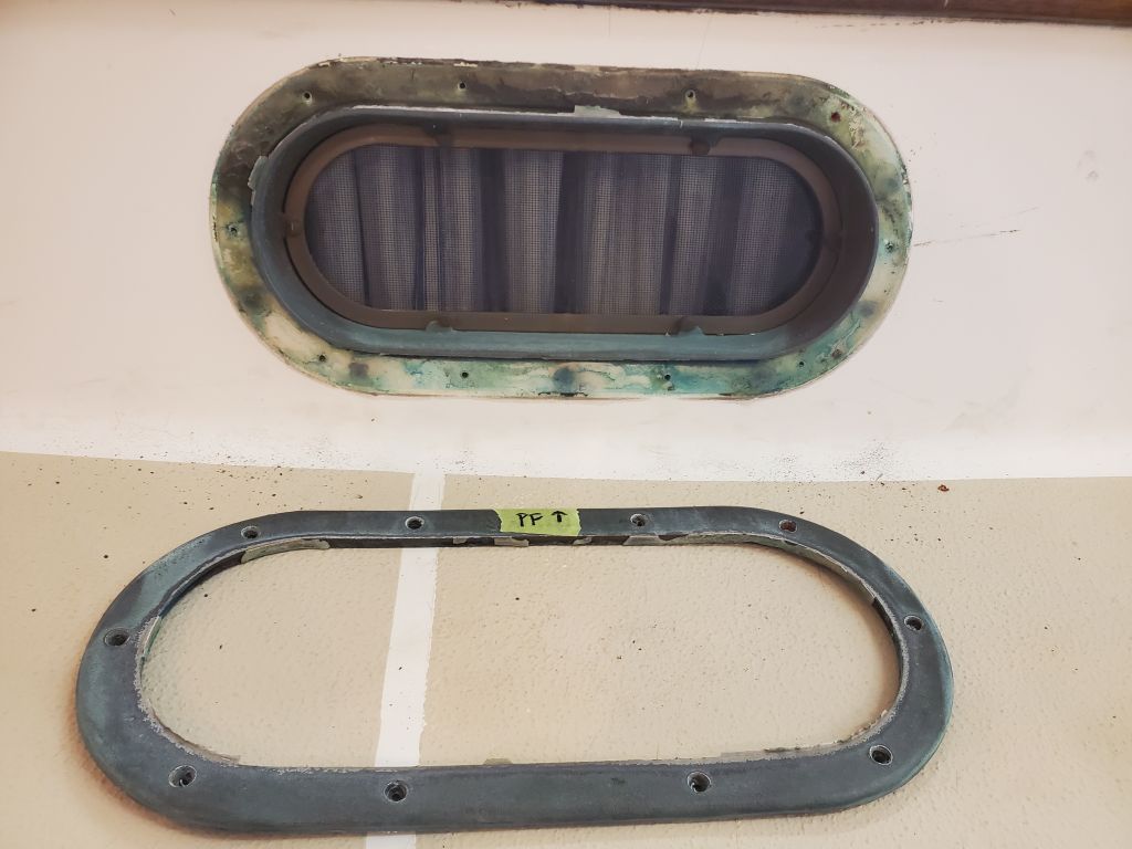
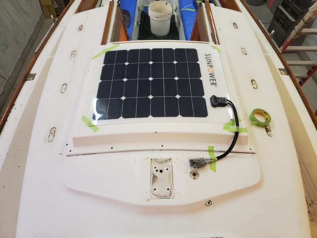
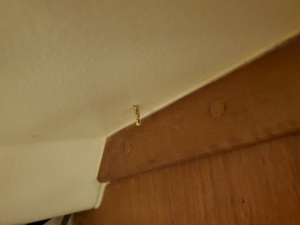
Among the options under consideration for leading some of the mast and other wiring through the deck was an elongated version of the round deck seals I’d used in the past.  I ordered one to get a sense of its size and possible suitability.  It was a bit smaller than I expected, which was probably a good thing since too much bulk might have been an issue, but otherwise appeared to offer the right amount of space through the rubber gasket for the leads we anticipated:  A pair of wires for a new solar panel, and the mast wiring harness.  The owner requested a through-deck connector for the VHF antenna leading to the mast, which I didn’t have on hand but would factor into the equation at some point.

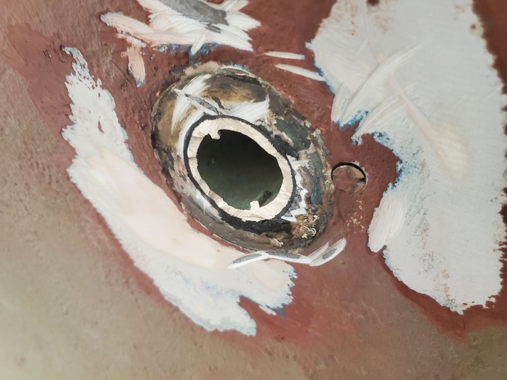
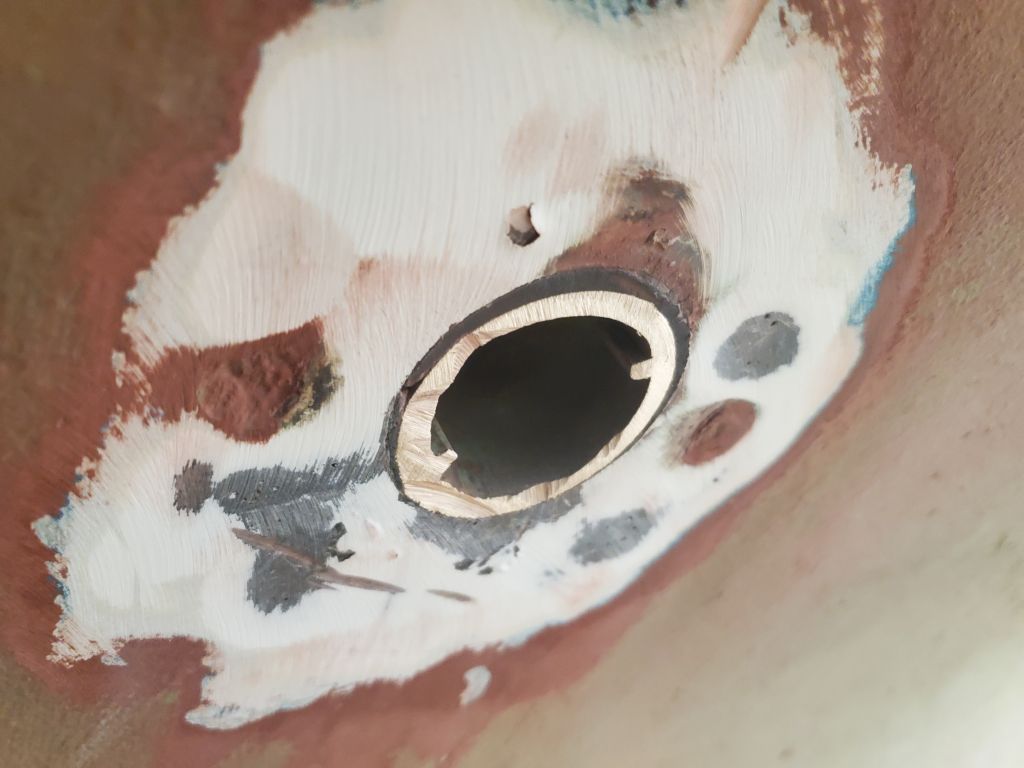
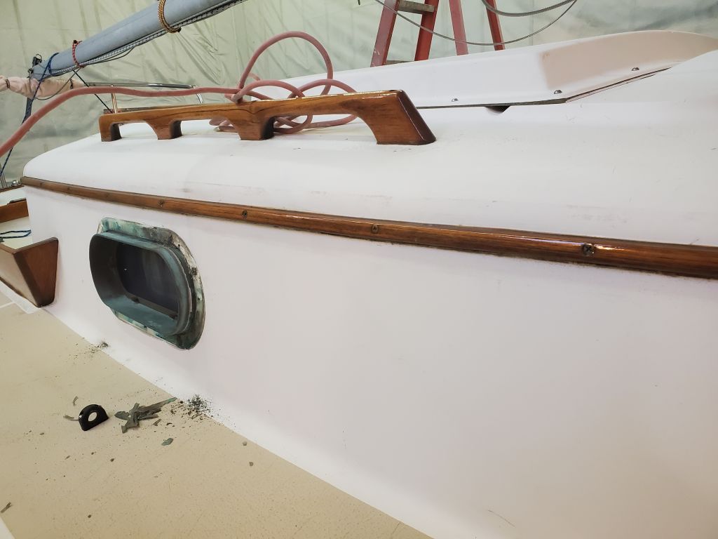
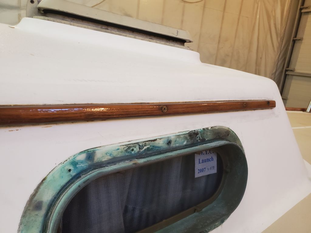
The position of the gland as I mocked it up was fairly well preordained by various construction factors, including the change in elevation of the mast step molding (the mast step was on a flat section, but the deck angled off to each side right where I placed the gland), and, in the fore and aft orientation, by the location of a pair of built-in mast step stiffeners below deck.

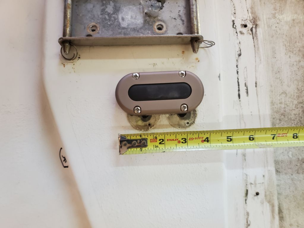
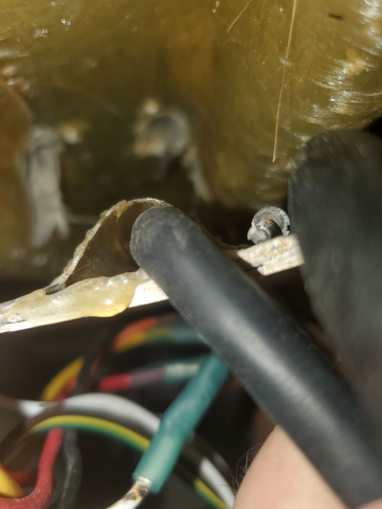
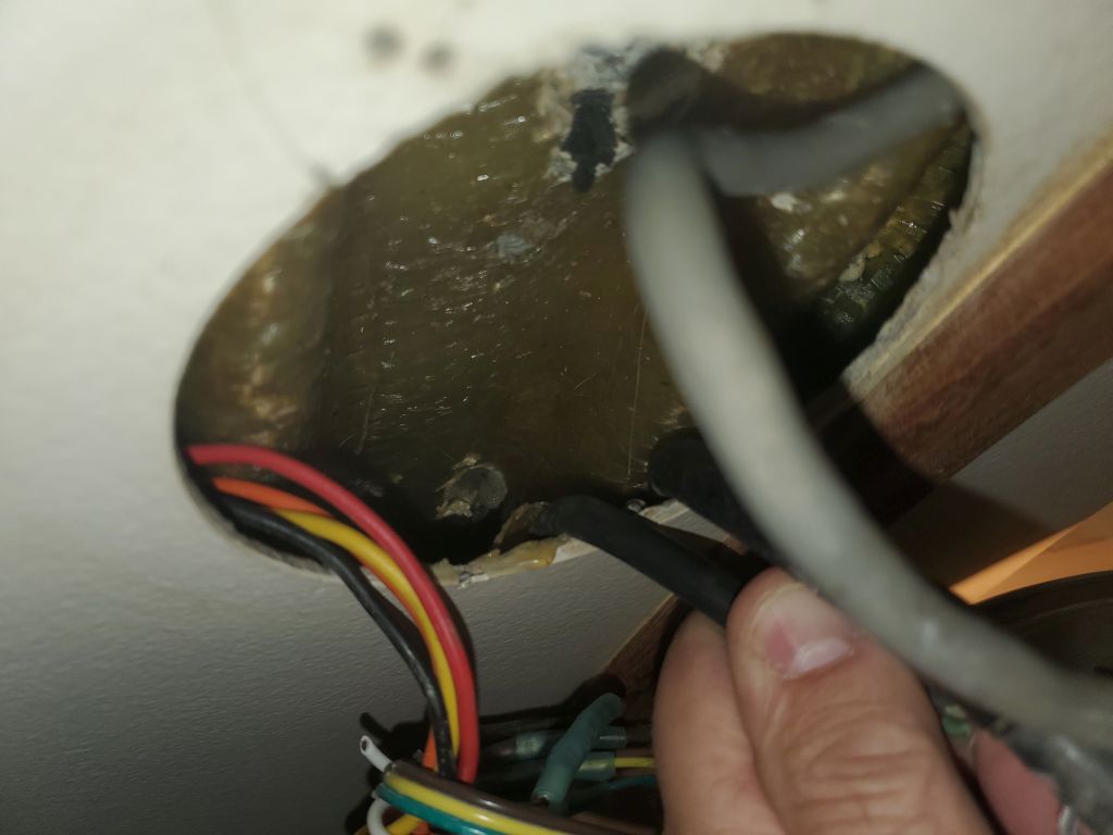
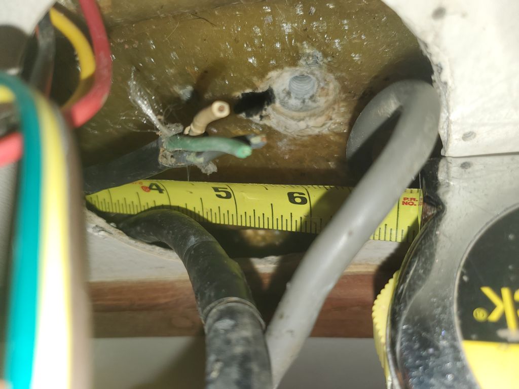
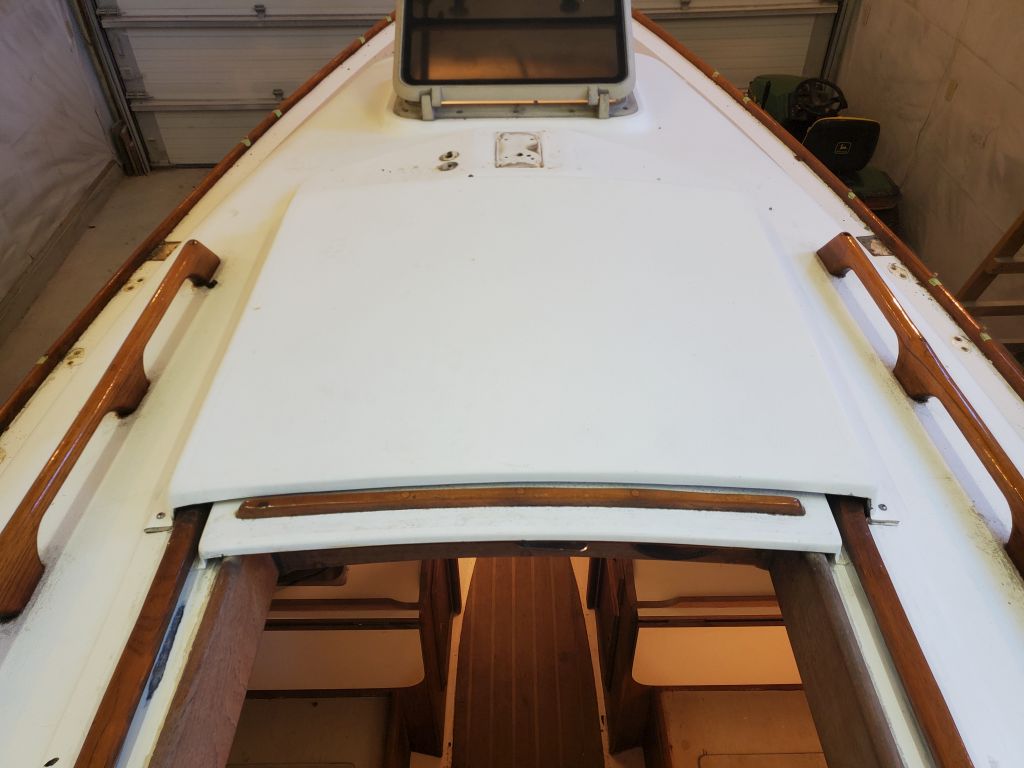
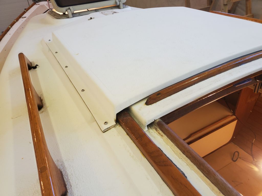
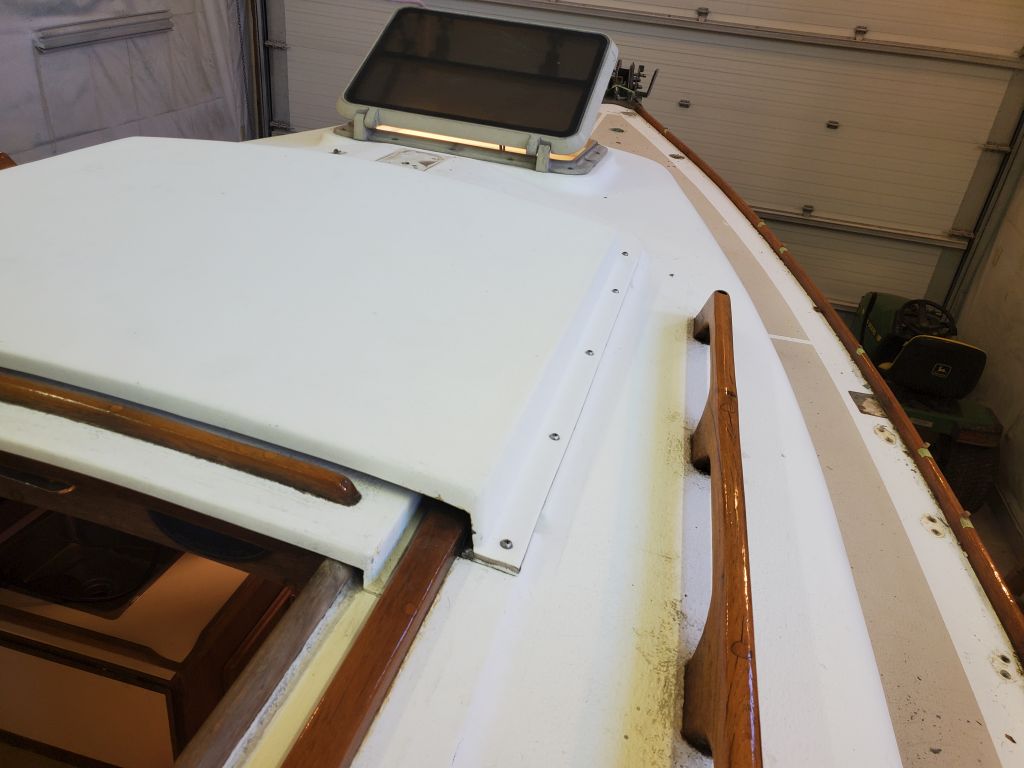
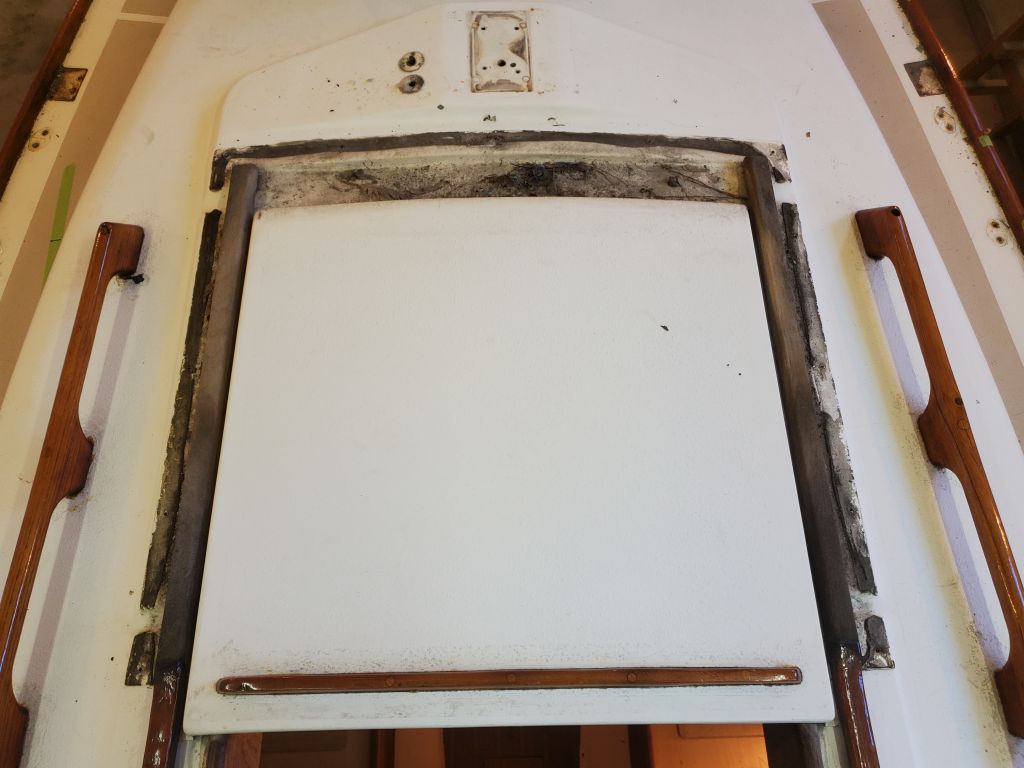
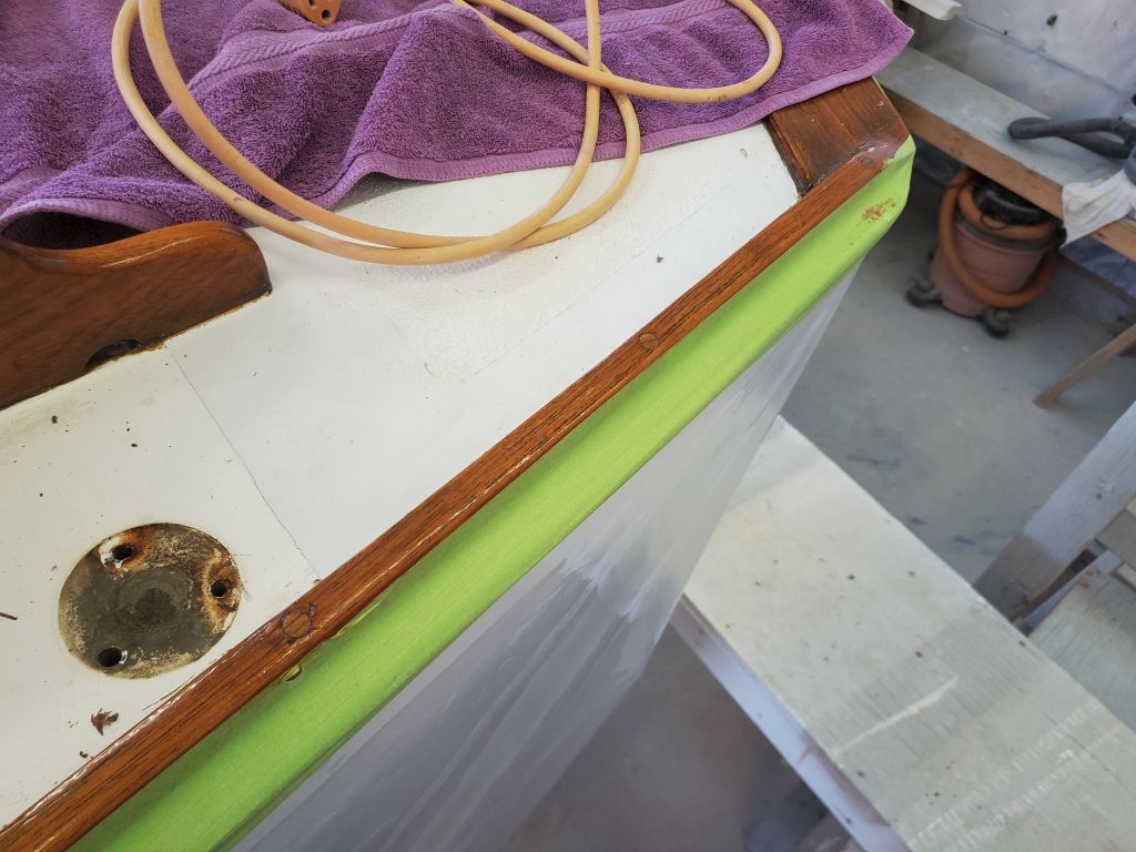
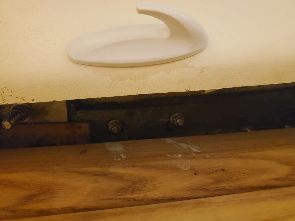
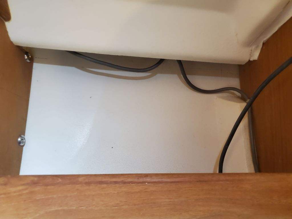
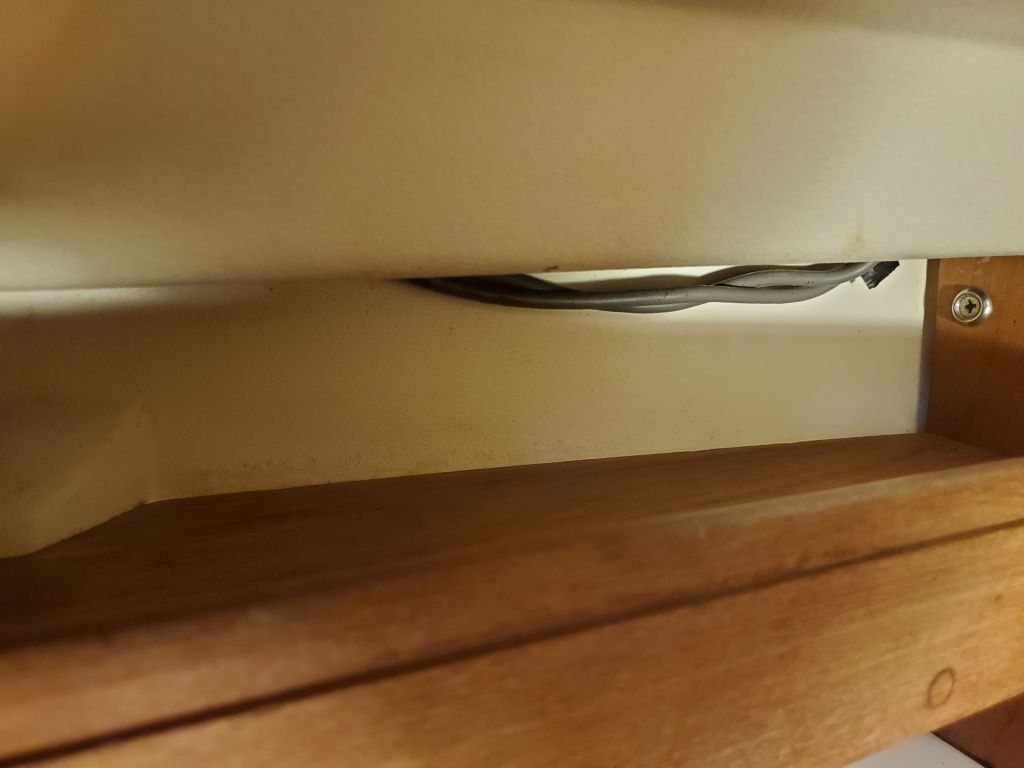
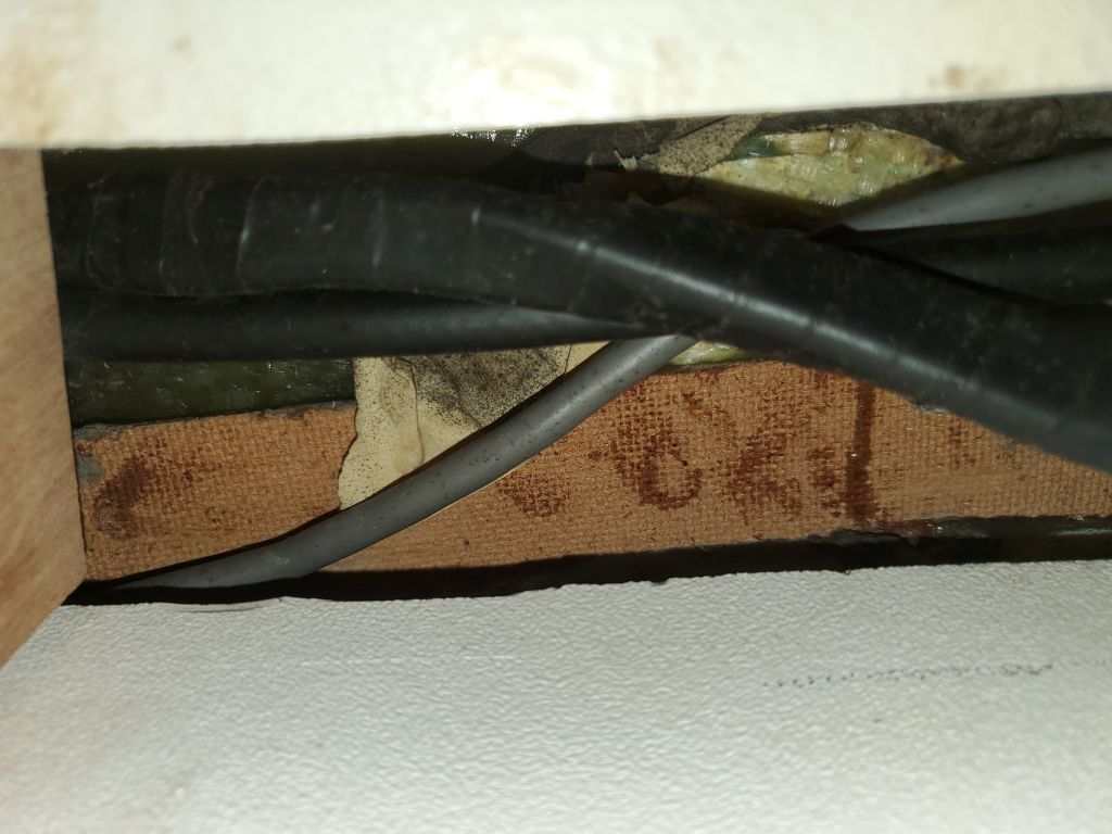
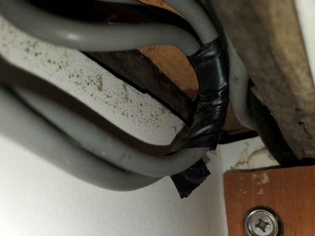
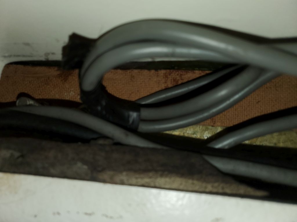
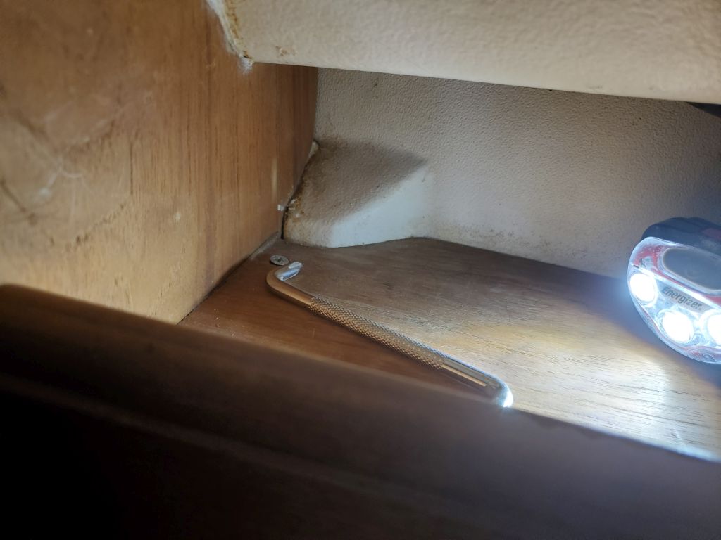
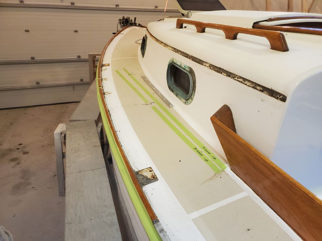
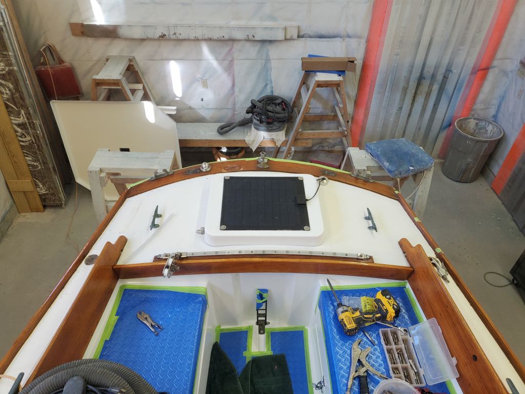
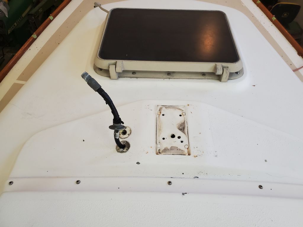
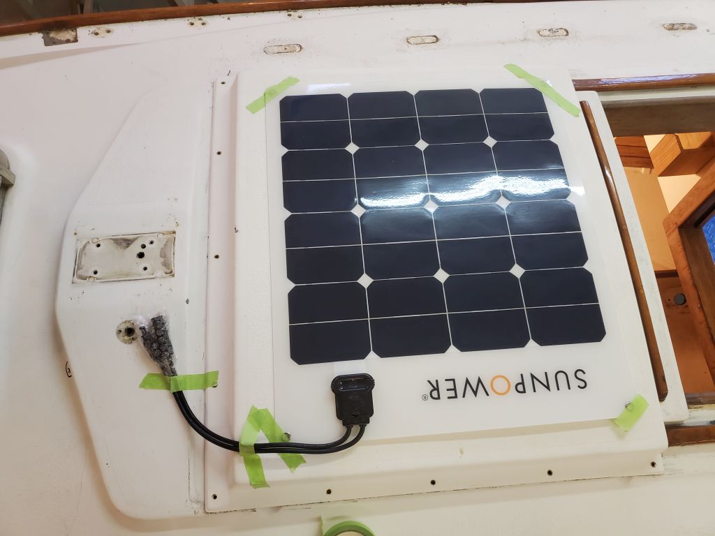
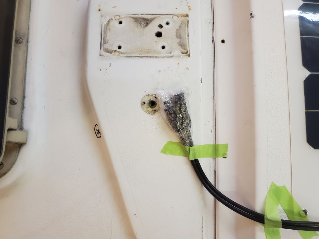
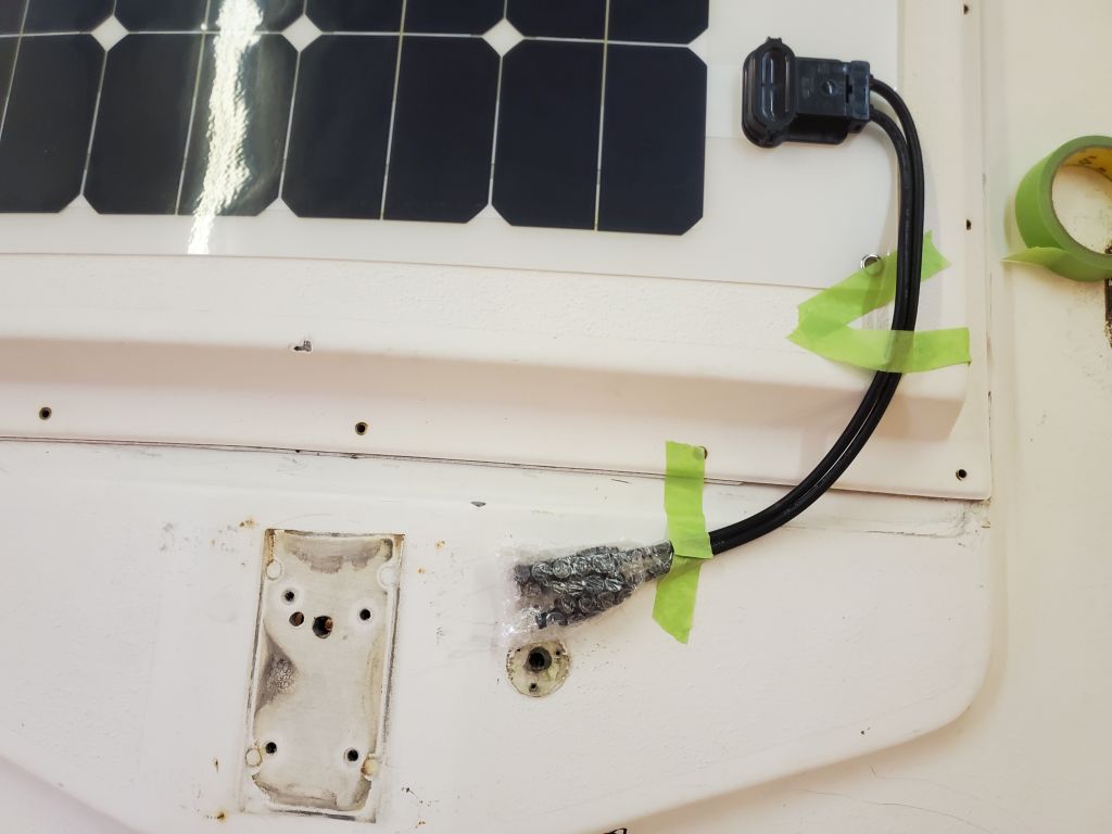
The solar panel the owner selected for mounting on the sea hood above the companionway featured a built-in wire harness with a pair of short leads, which would ultimately be connected to coordinating leads led through the deck from below.  This whole arrangement seemed to work well naturally with the ordained position of the deck seal, whether we ultimately went with the one shown above, or some other type.  I held the solar panel position just a bit aft on the sea hood since the owner reported that during the mast lowering process (with the hinged mast step), the mast could contact the leading edge of the sea hood, so keeping the panel aft a bit would help protect it from damage.  The wire leads off to the port side would be out of the way and could be routed and secured roughly as shown.

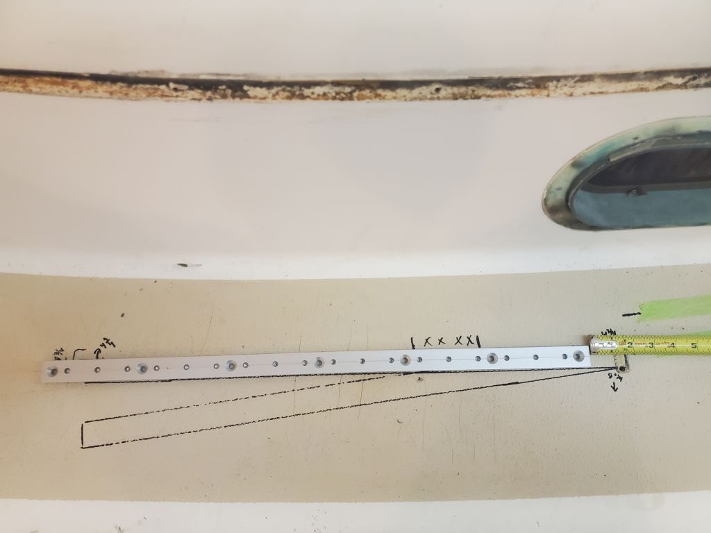
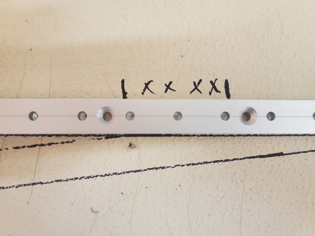
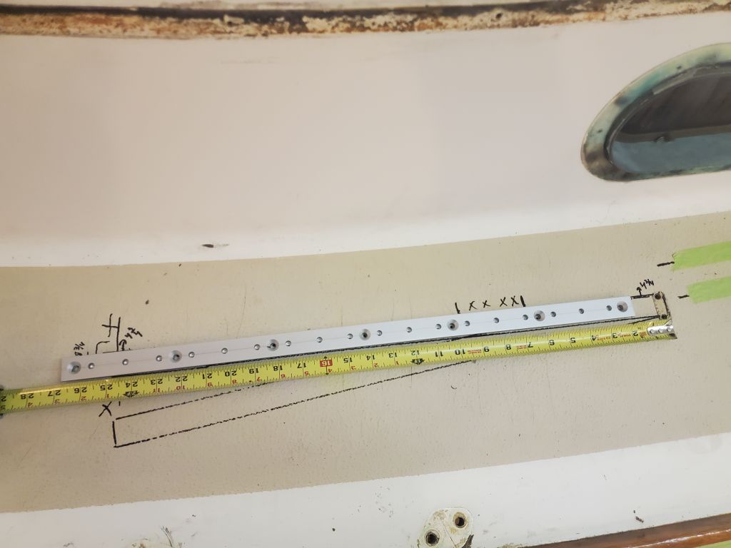
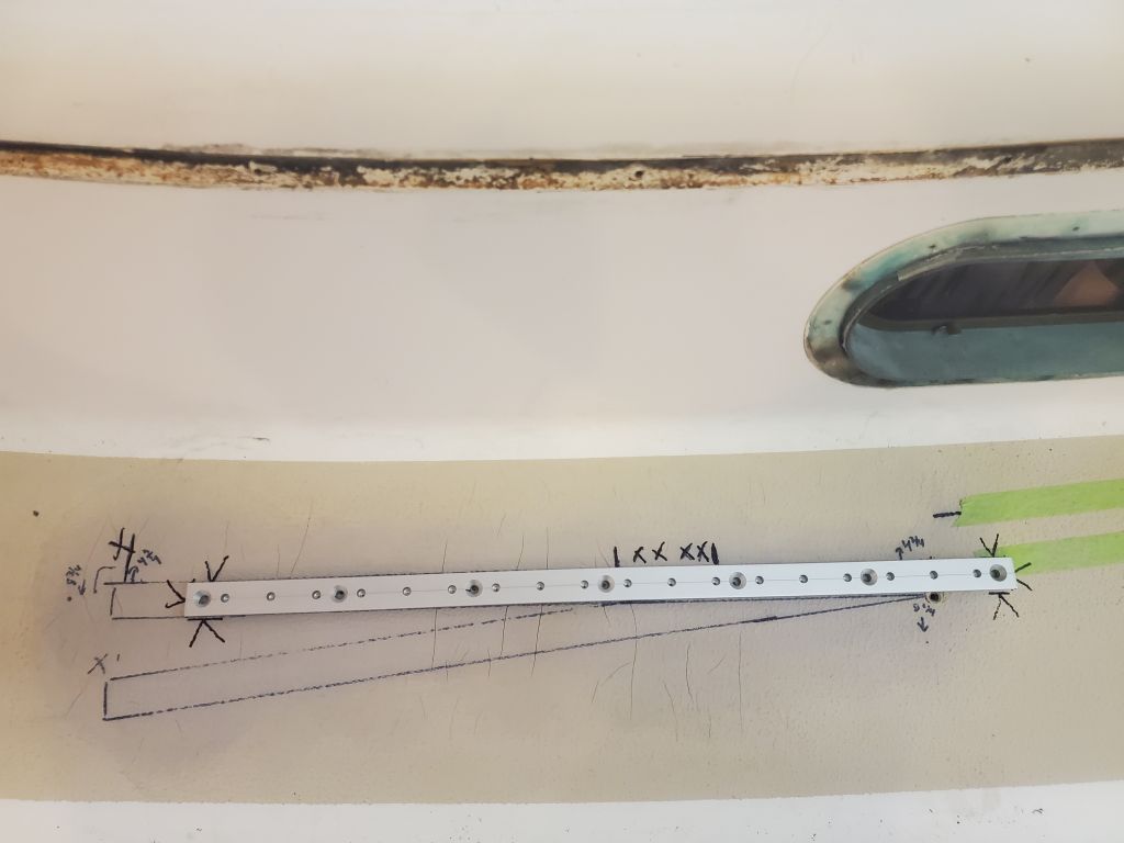
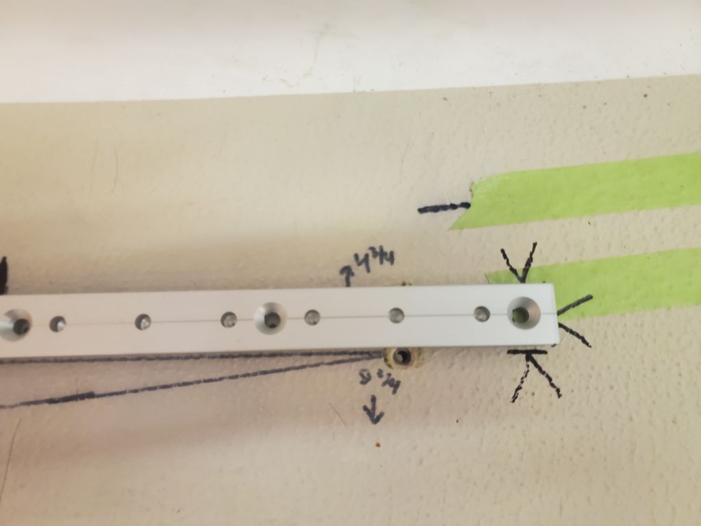
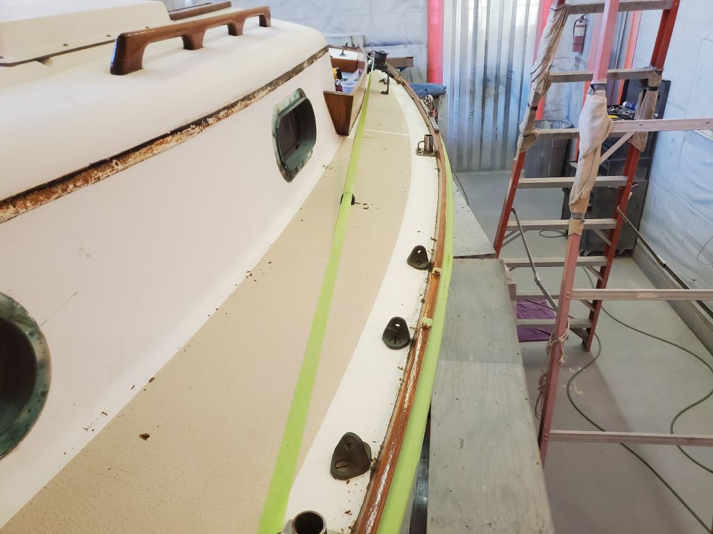
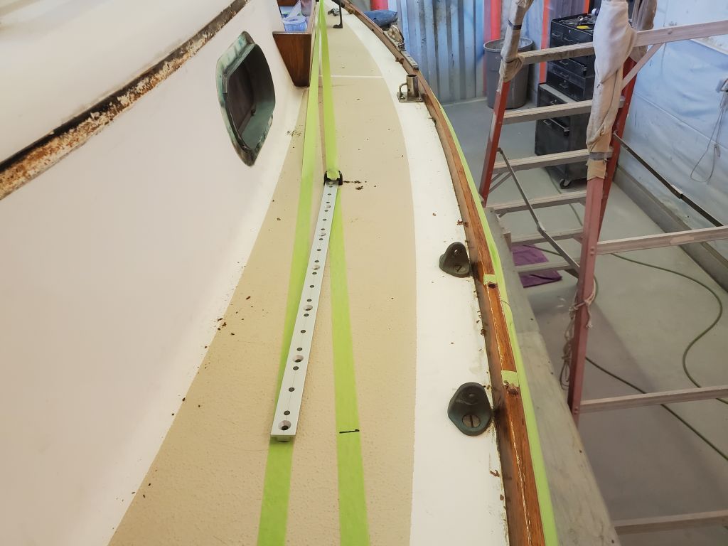
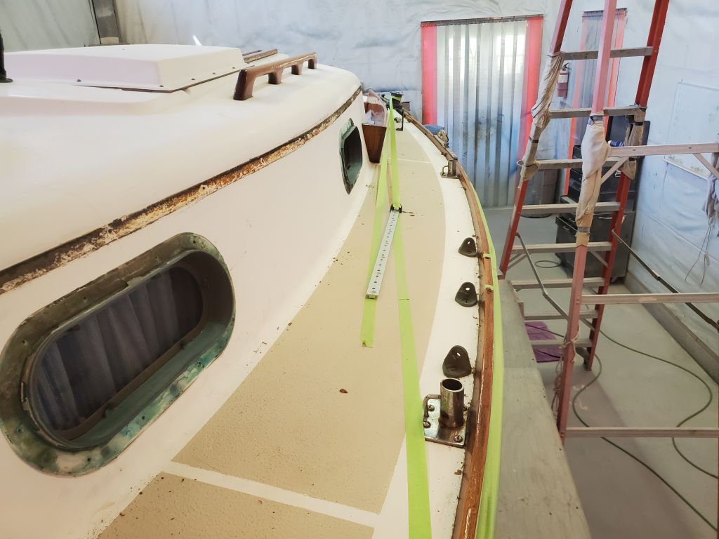
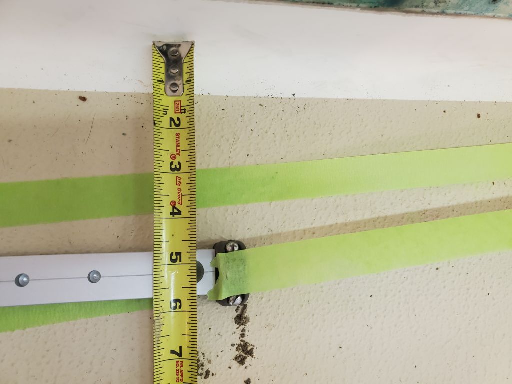
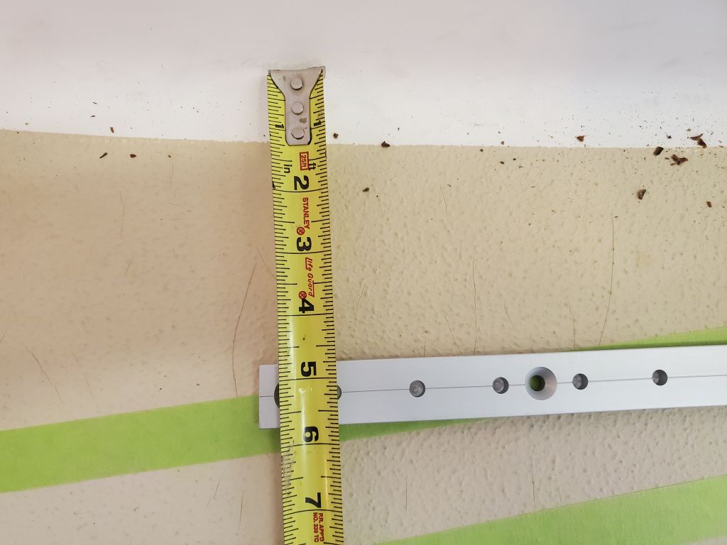
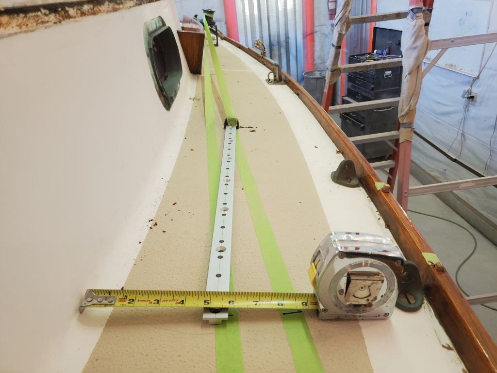
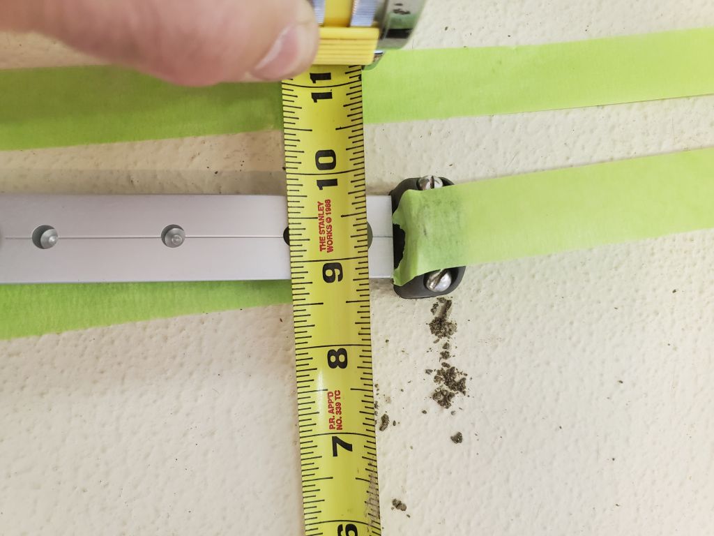
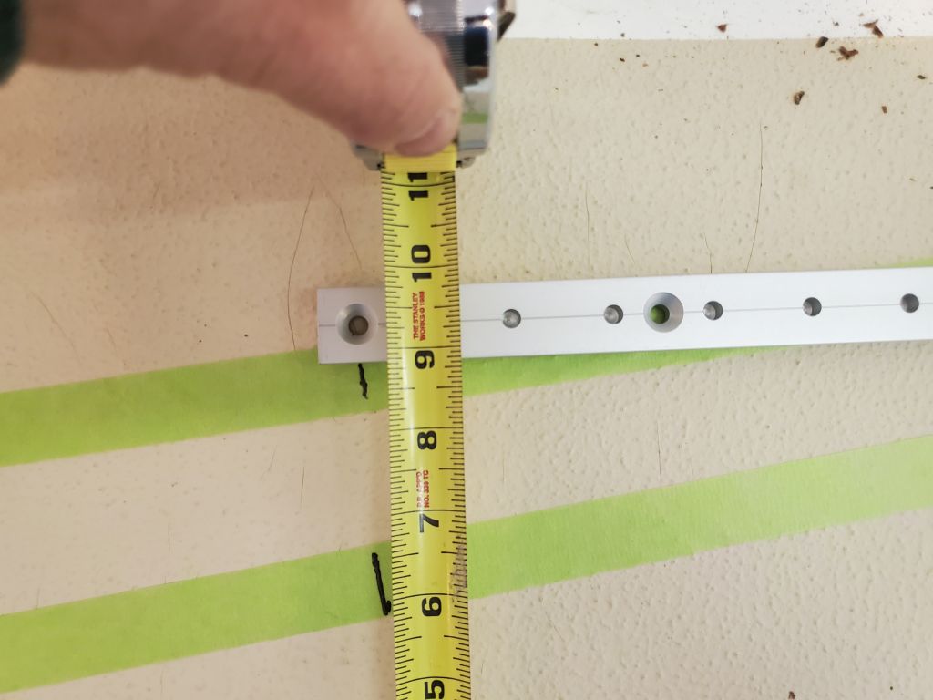
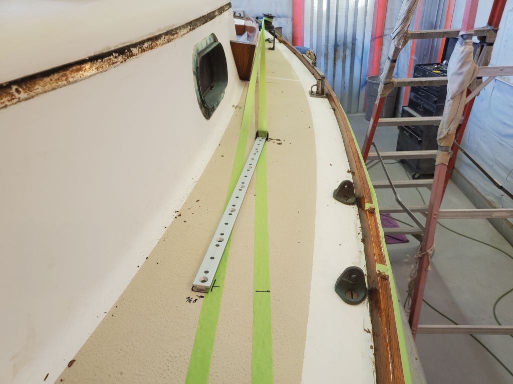
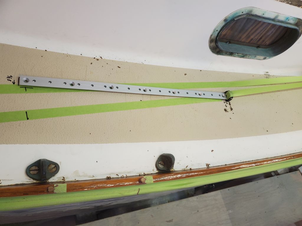
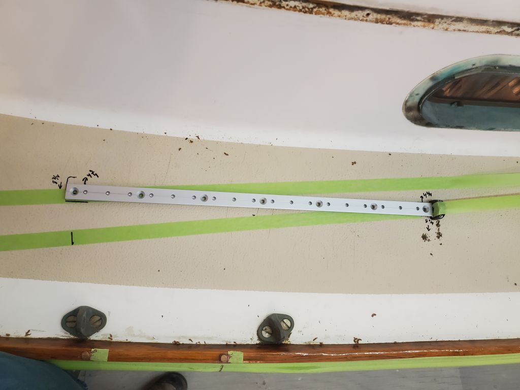
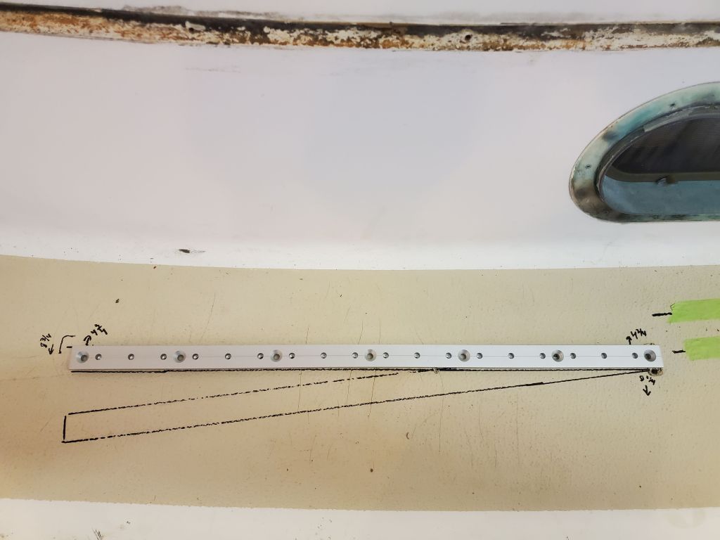
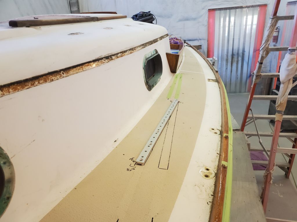
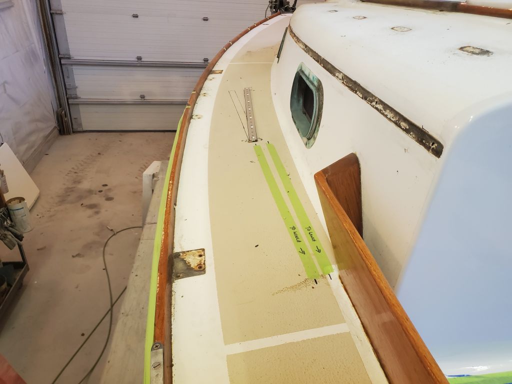
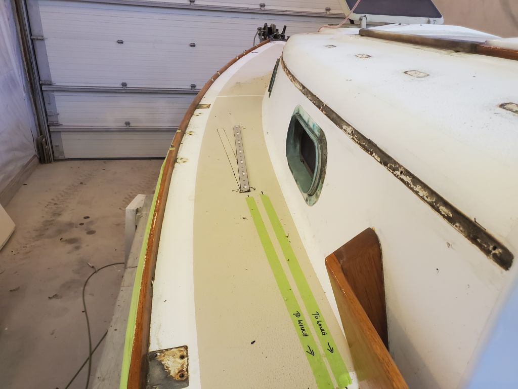
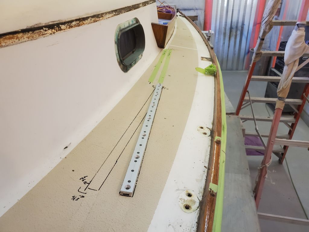
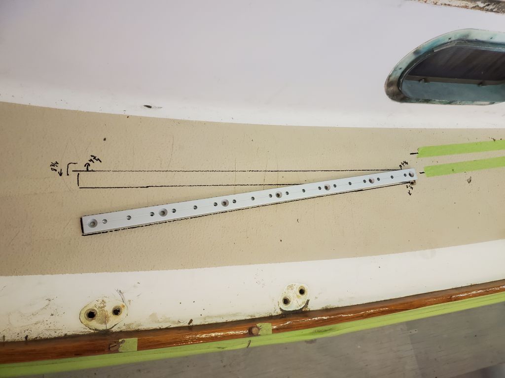
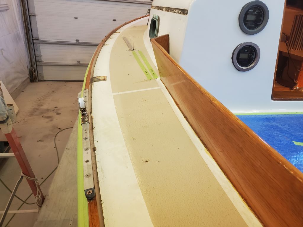
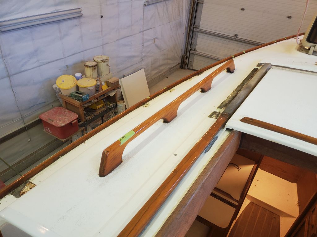
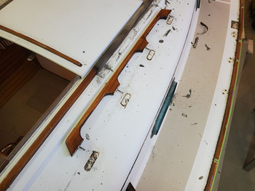
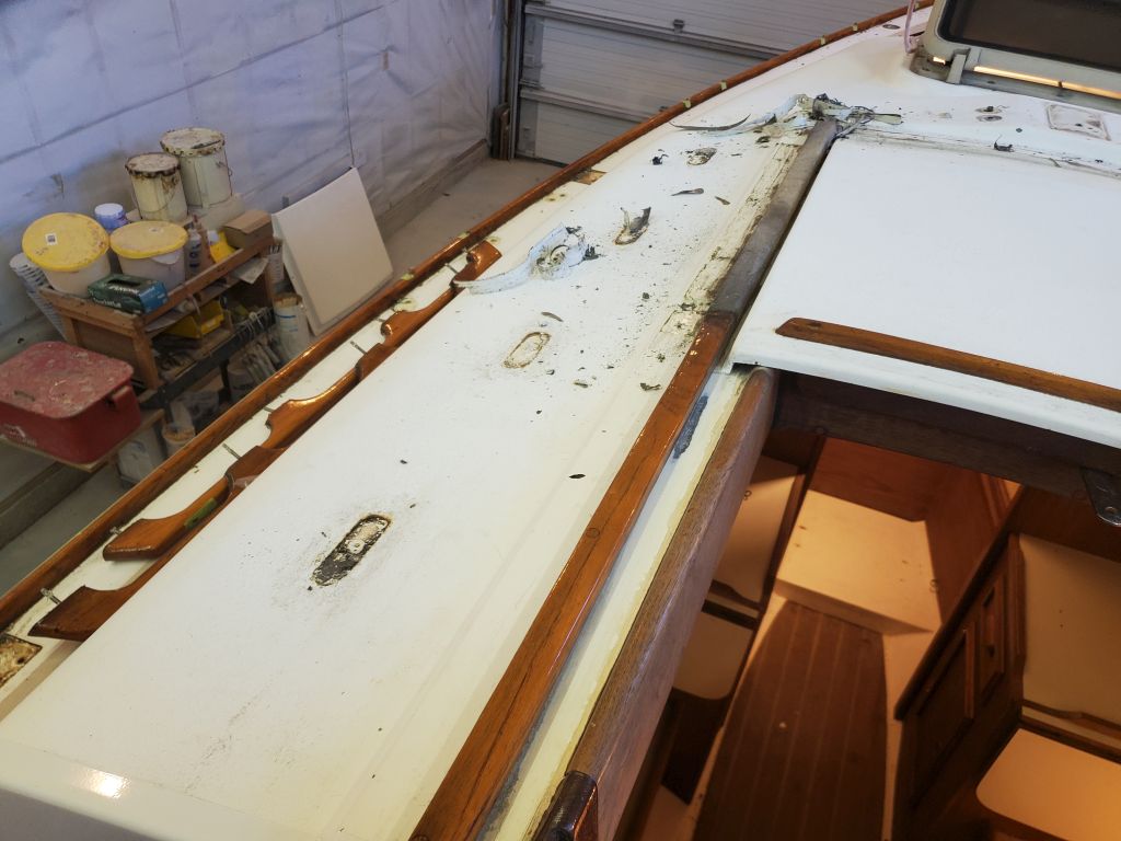
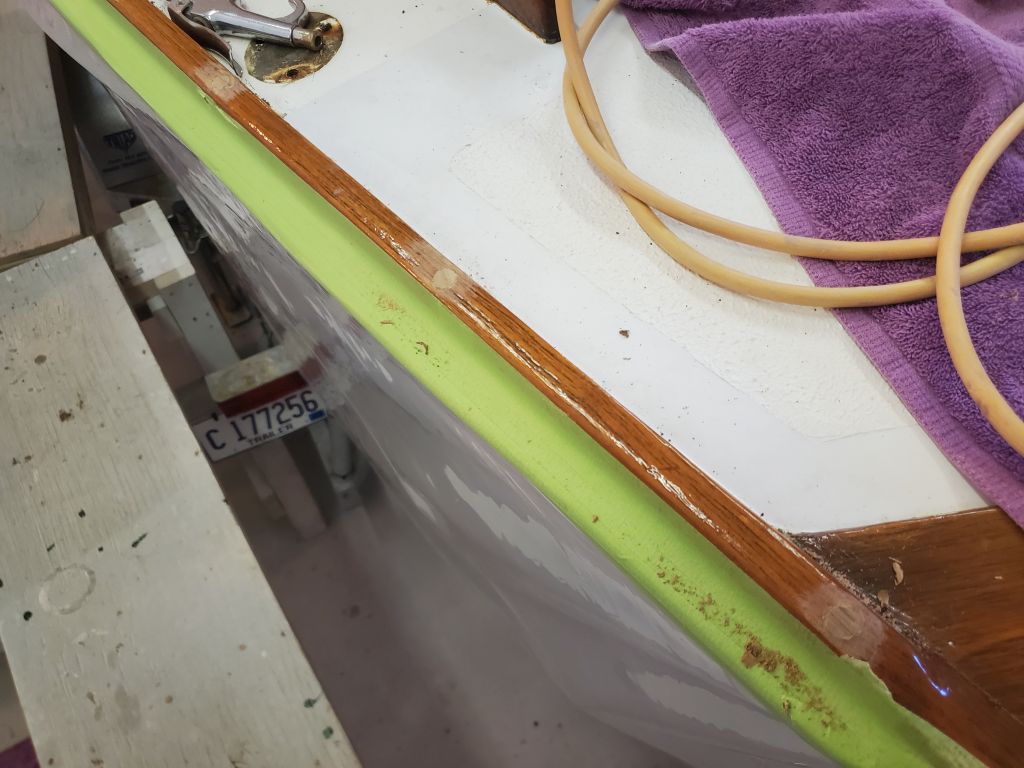
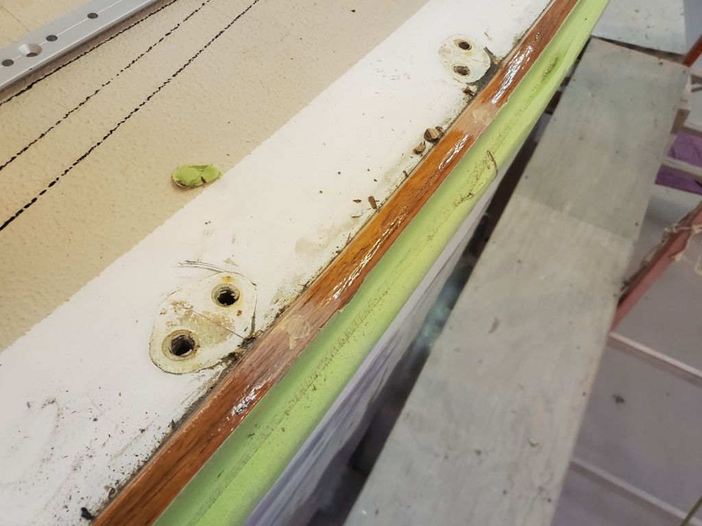
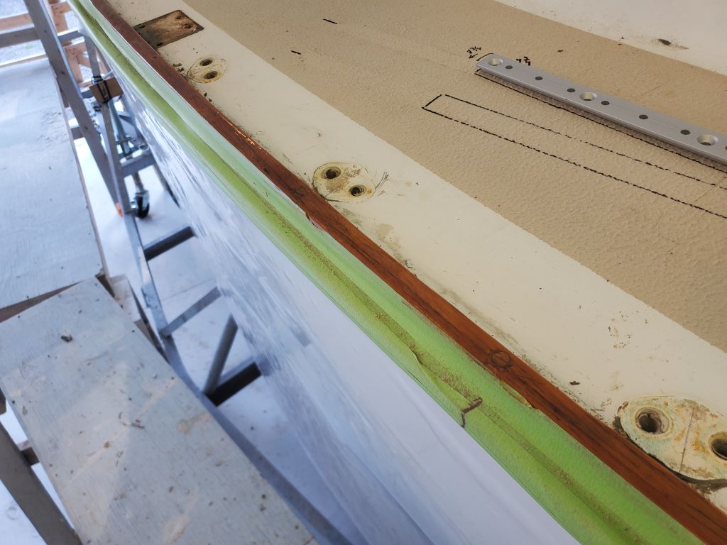
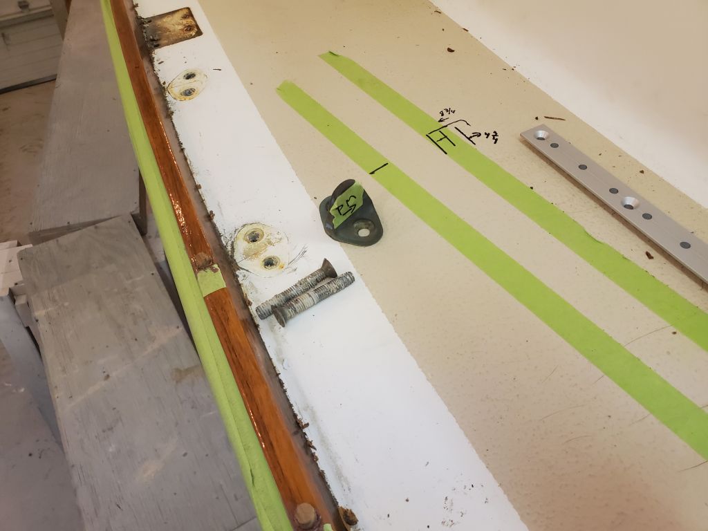
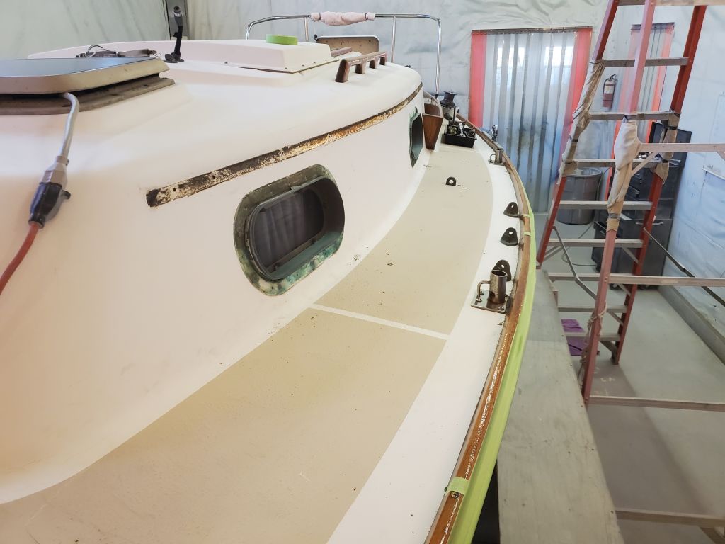
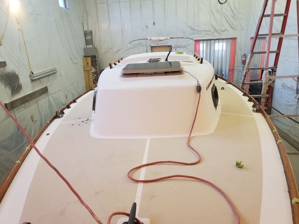
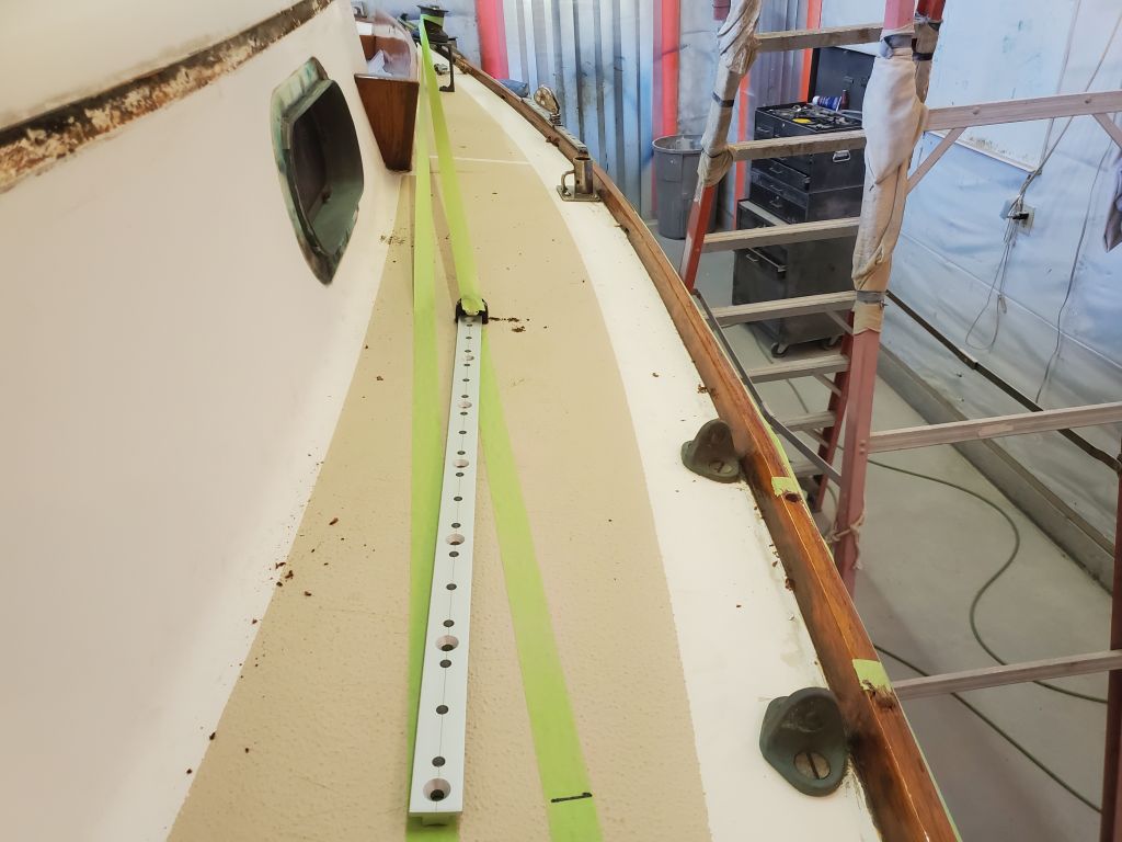
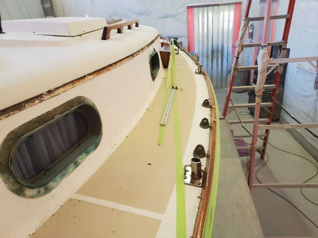
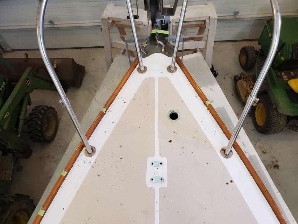
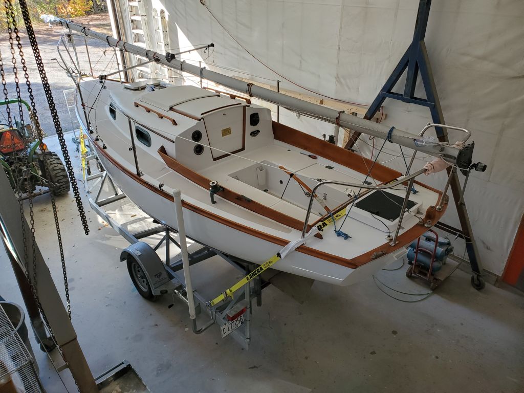
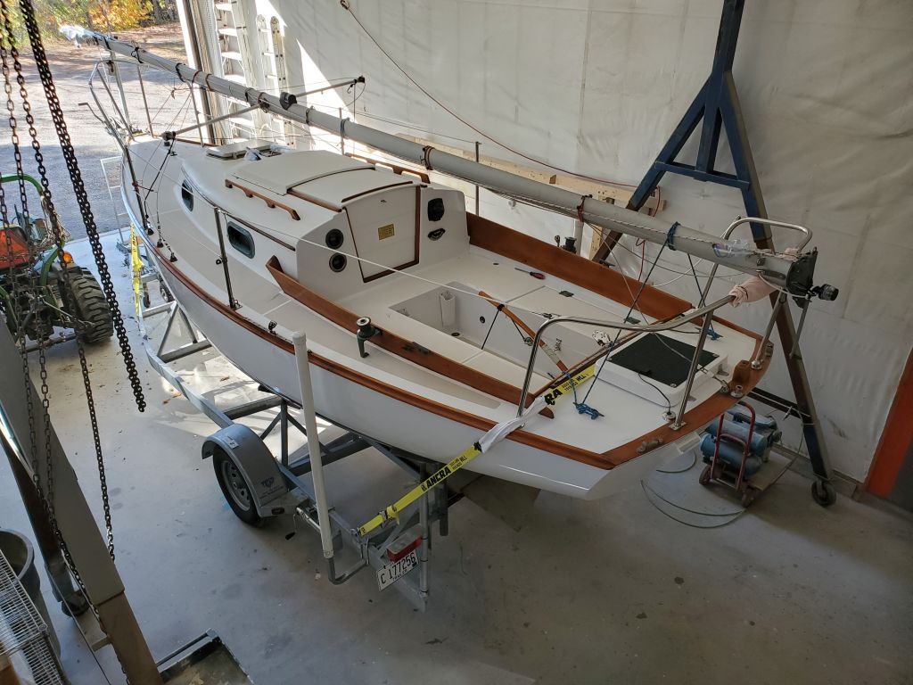
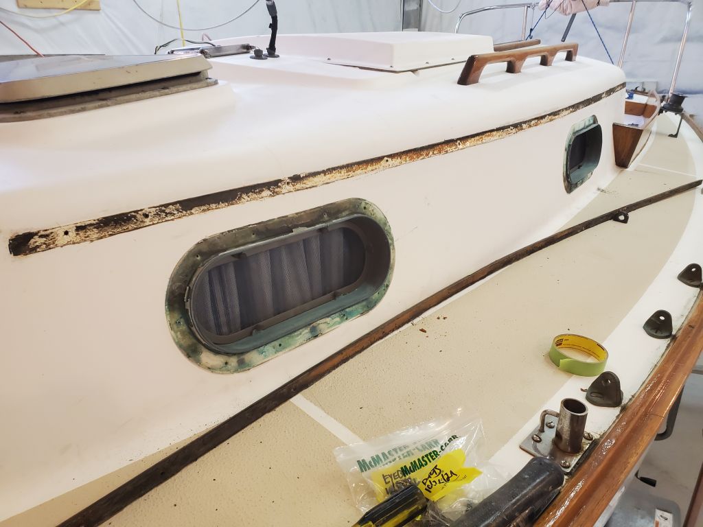
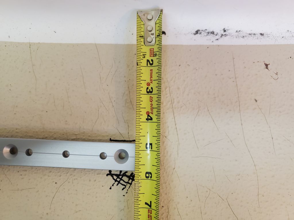
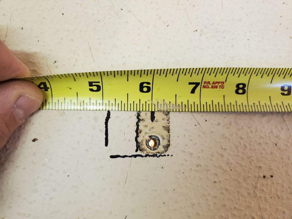
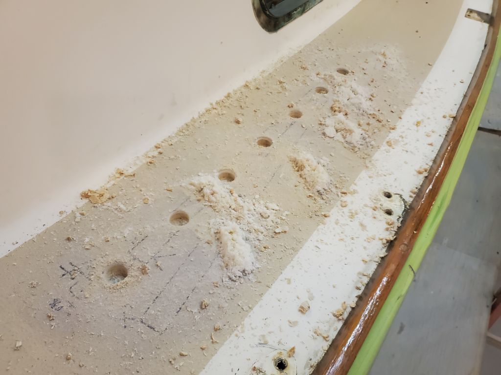
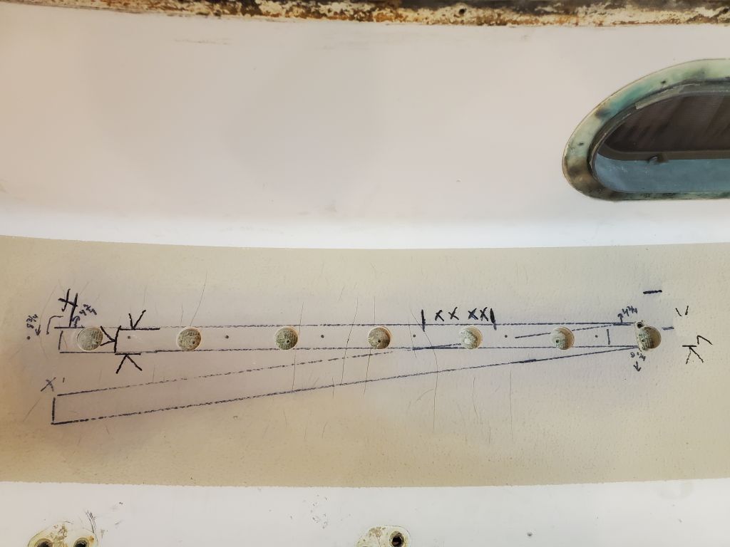
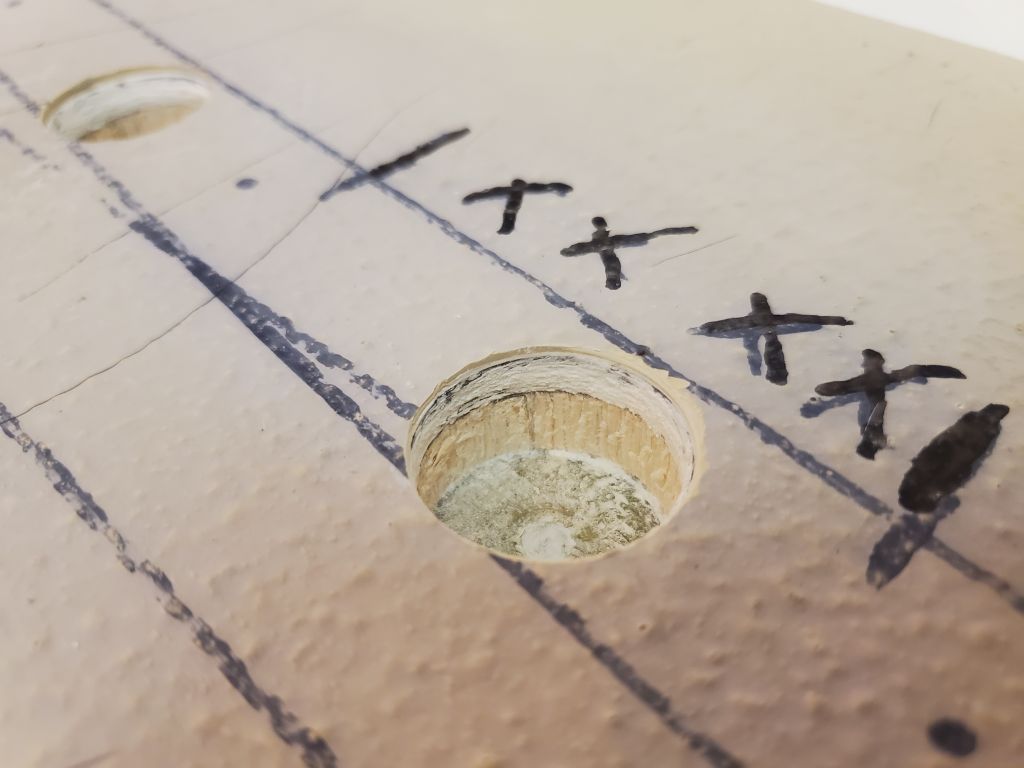
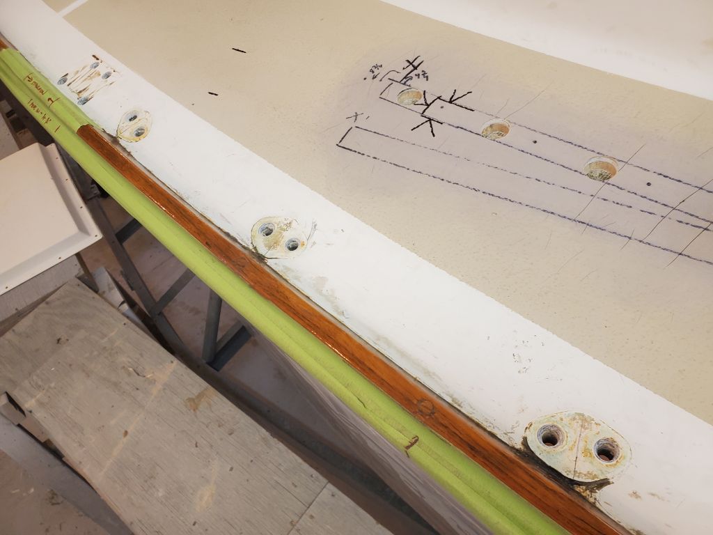
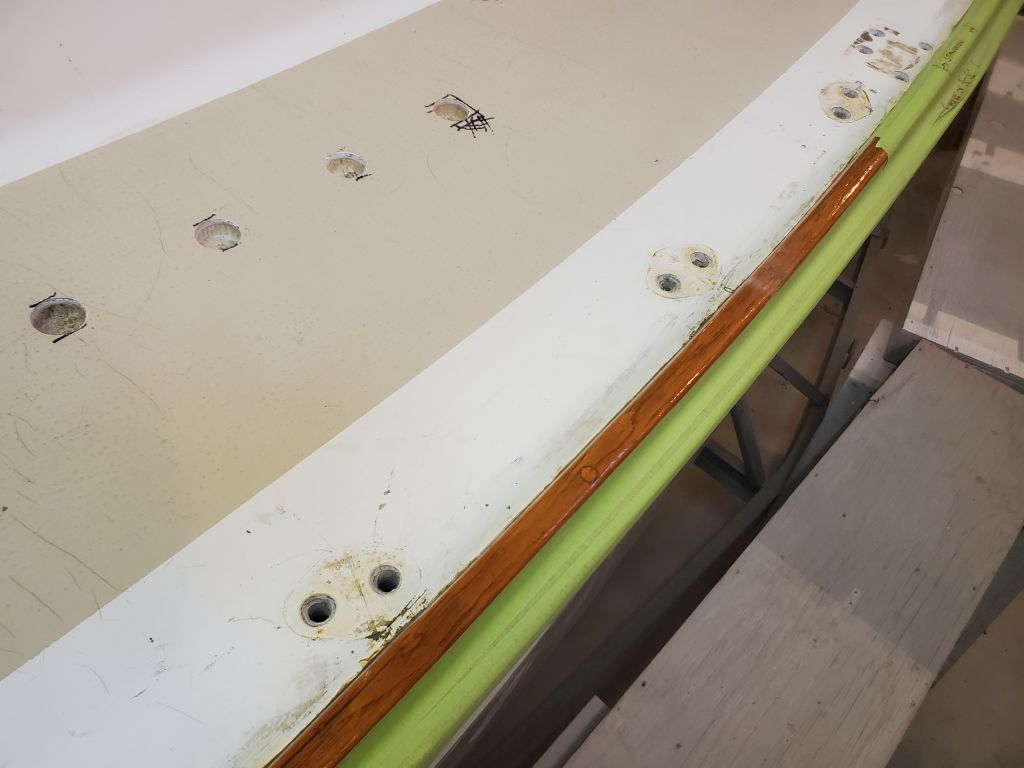
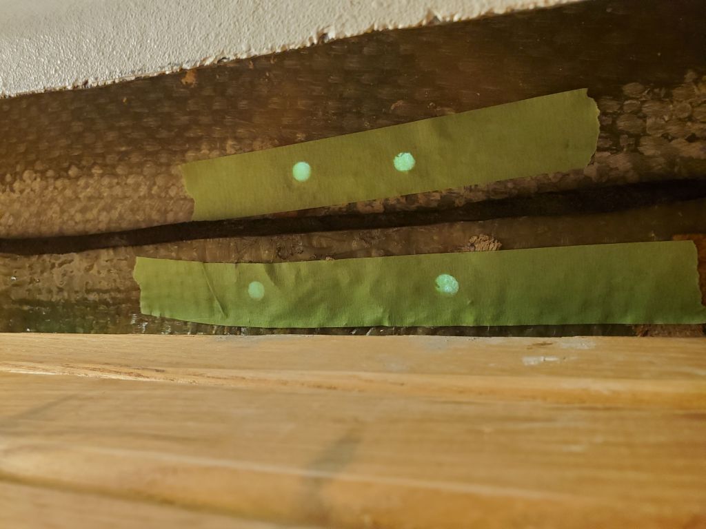
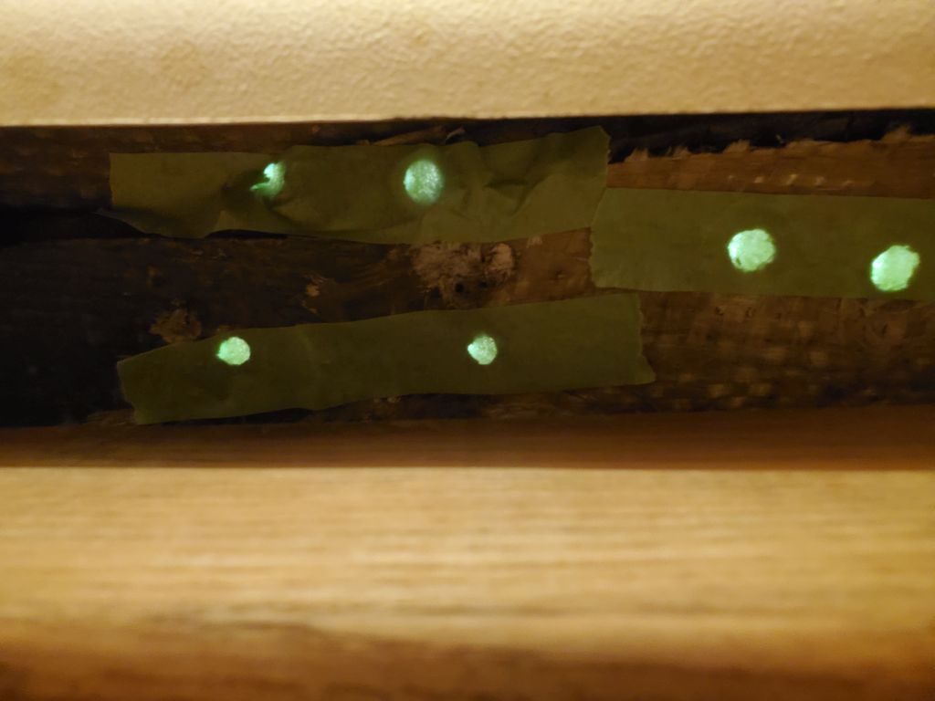
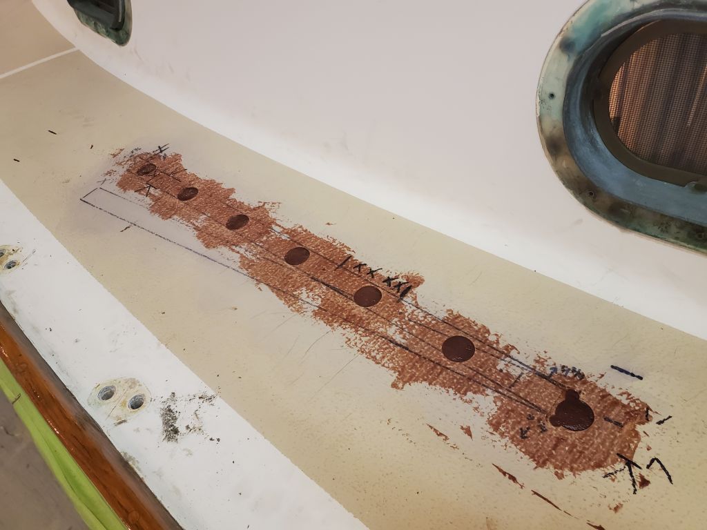
Moving on, I worked through various chores around the deck related to the deck surface prep and sanding coming up in the immediate future, beginning with the final layout of the new jib tracks.  Starting to port, where I’d been mocking this up for a while, I double-checked the measurements above and below decks, satisfying myself that there were no obstructions other than the known one at the galley bulkhead (and the third forward bolt in the track), then drilled pilot holes at each fastener location, starting with a self-centering bit to mark the holes accurately, then switching to a regular bit and passing all the way through the deck with smallish pilot holes.  I started with the forwardmost hole to confirm that I’d held the whole track assembly far enough aft to miss the main bulkhead.

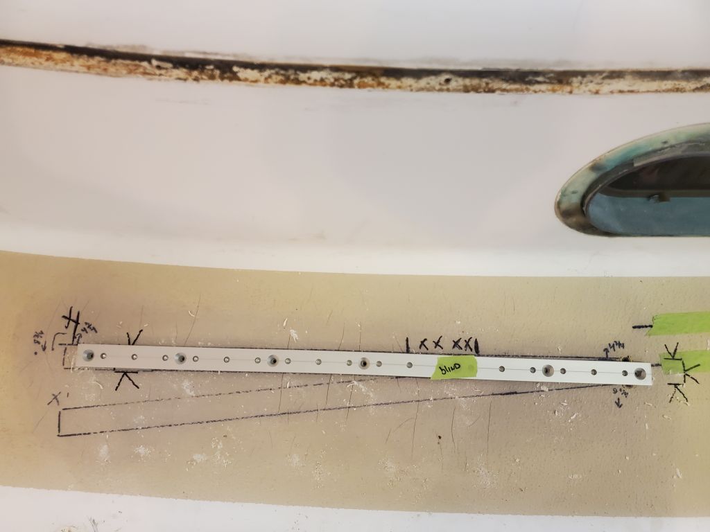
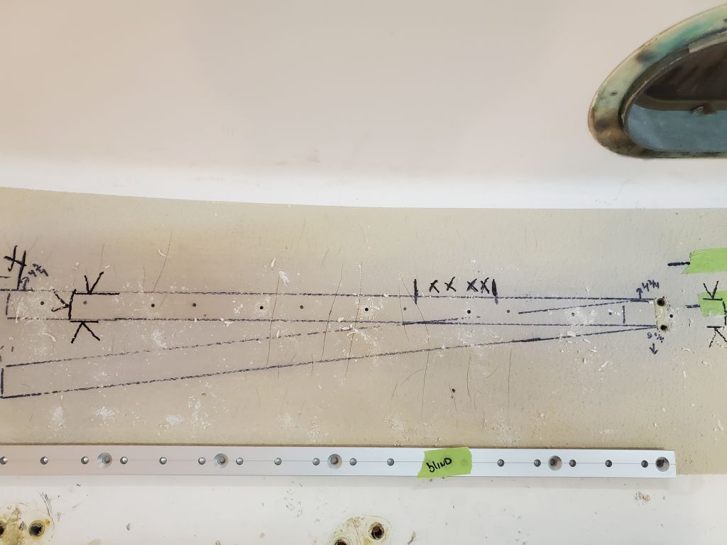
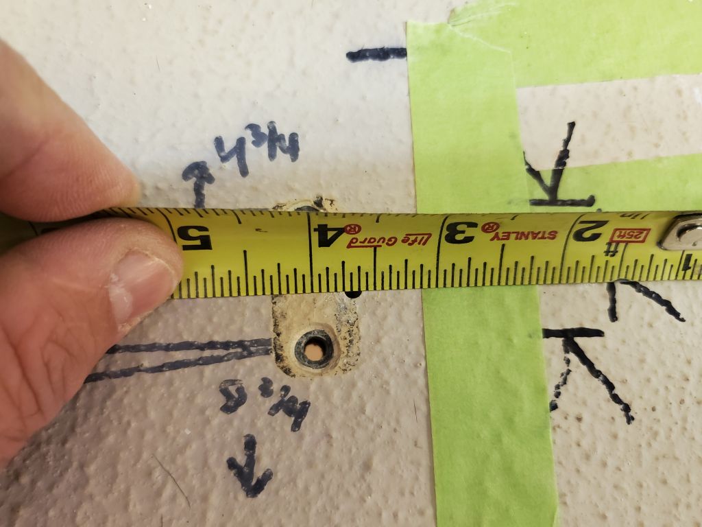
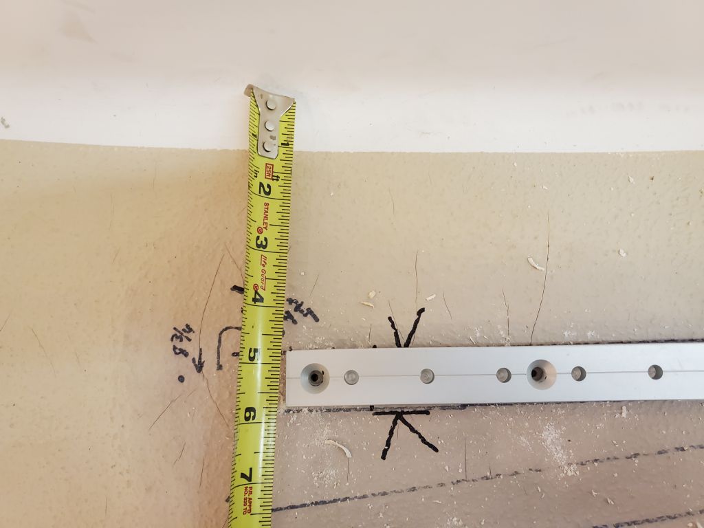
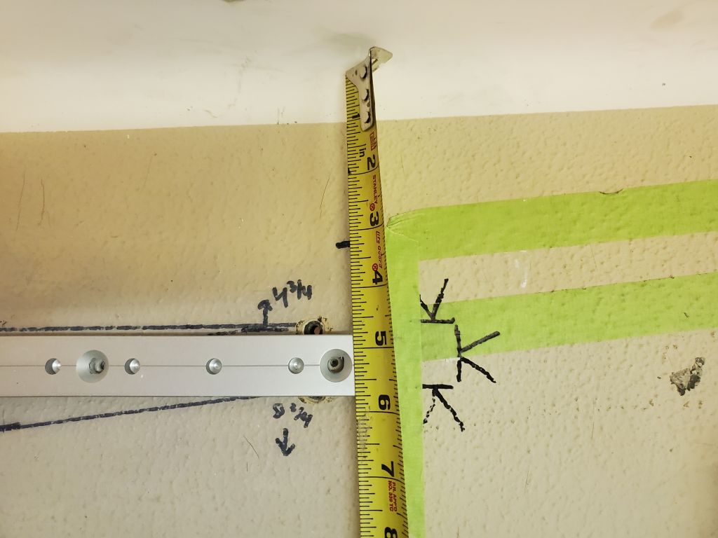
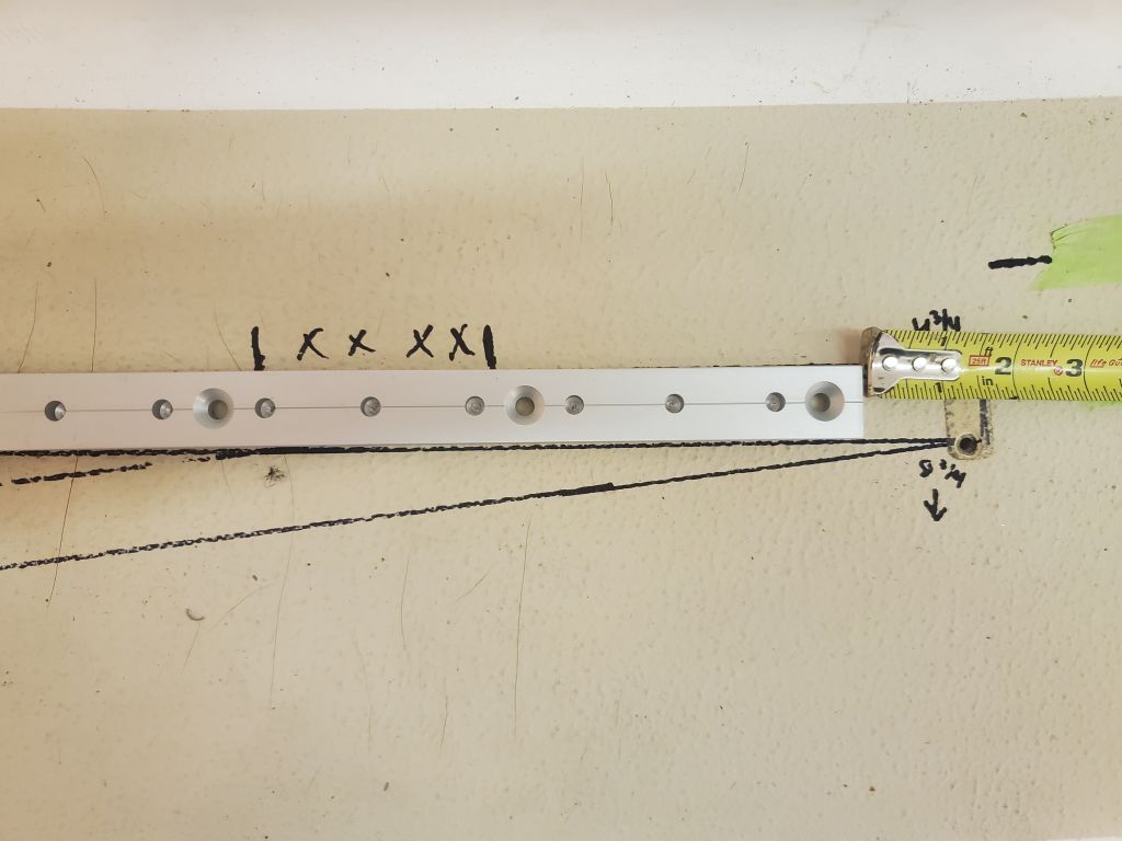
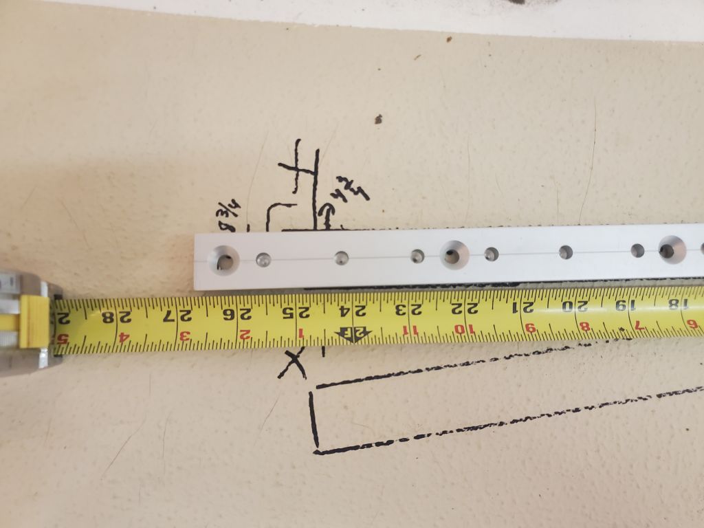
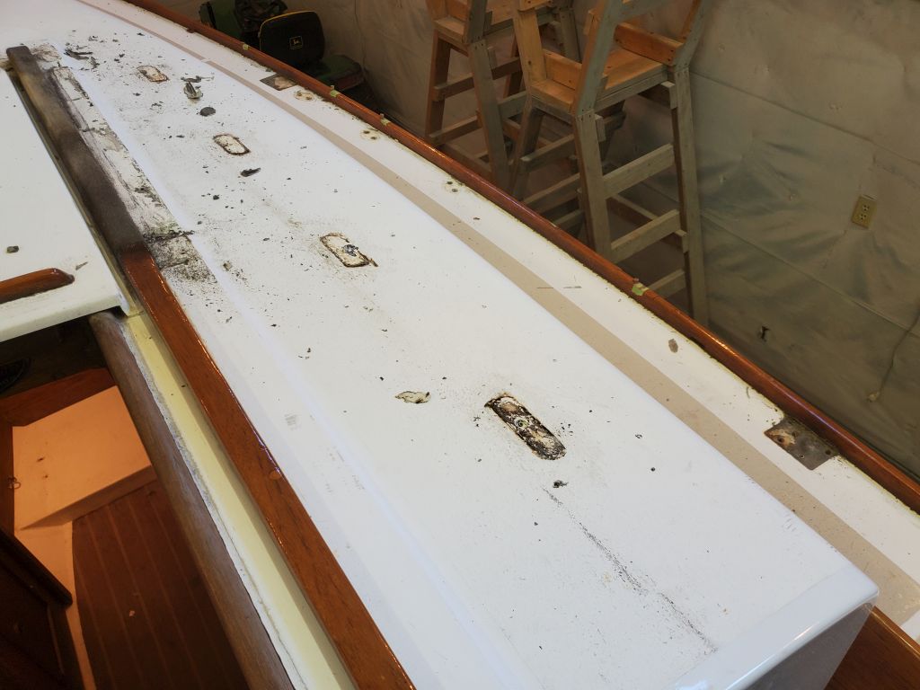
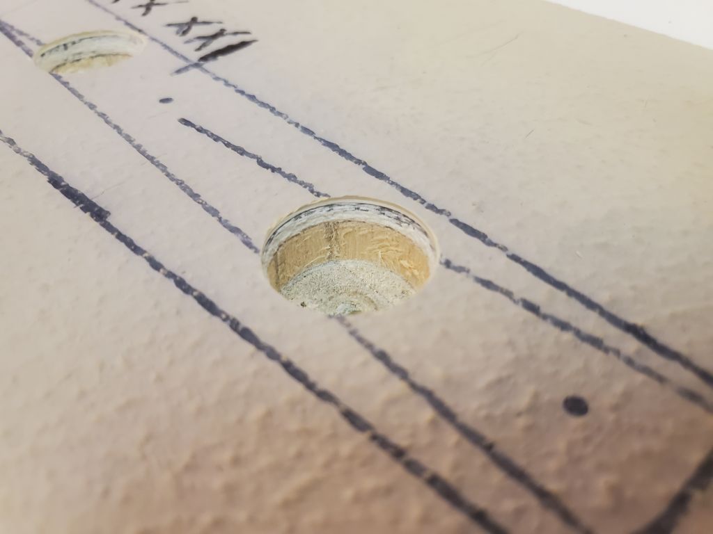
Moving to the starboard side, I repeated the process, first laying the track out according to the measurements I’d taken from the port side, then confirming the position above and below, and finally marking and drilling the pilot holes at the fastener locations.

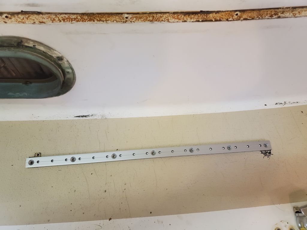
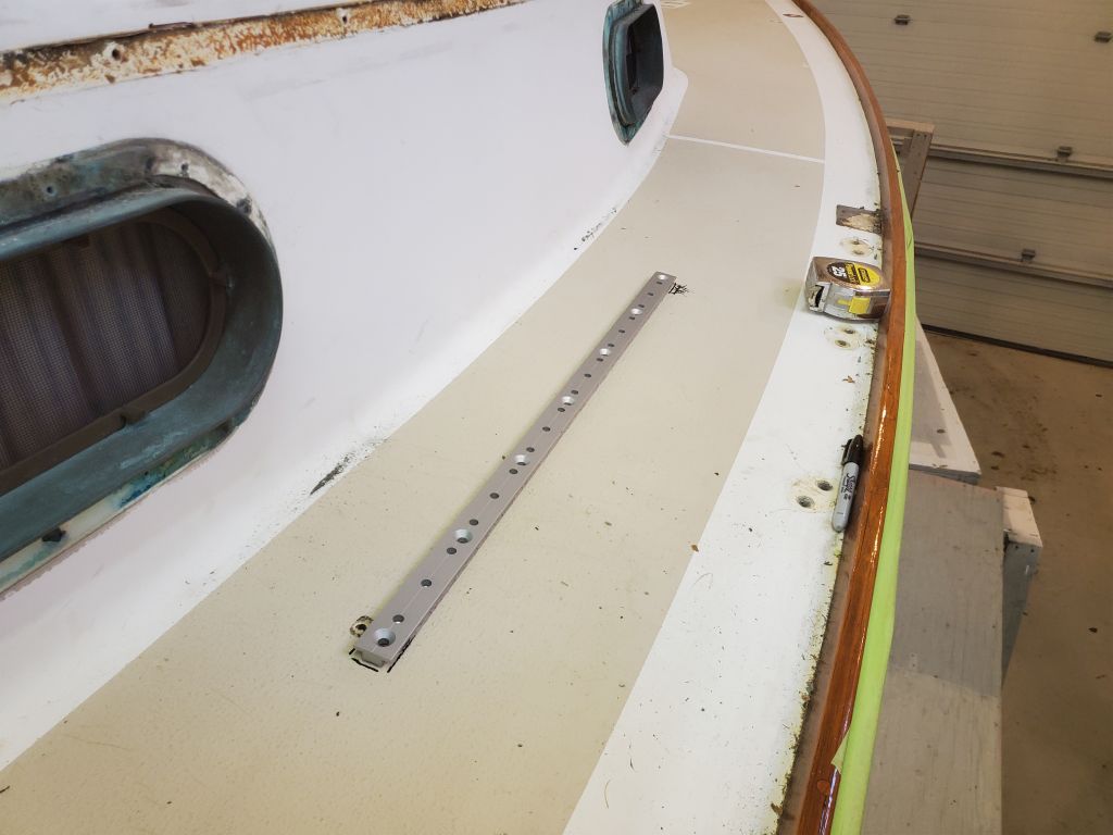
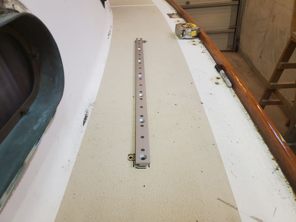
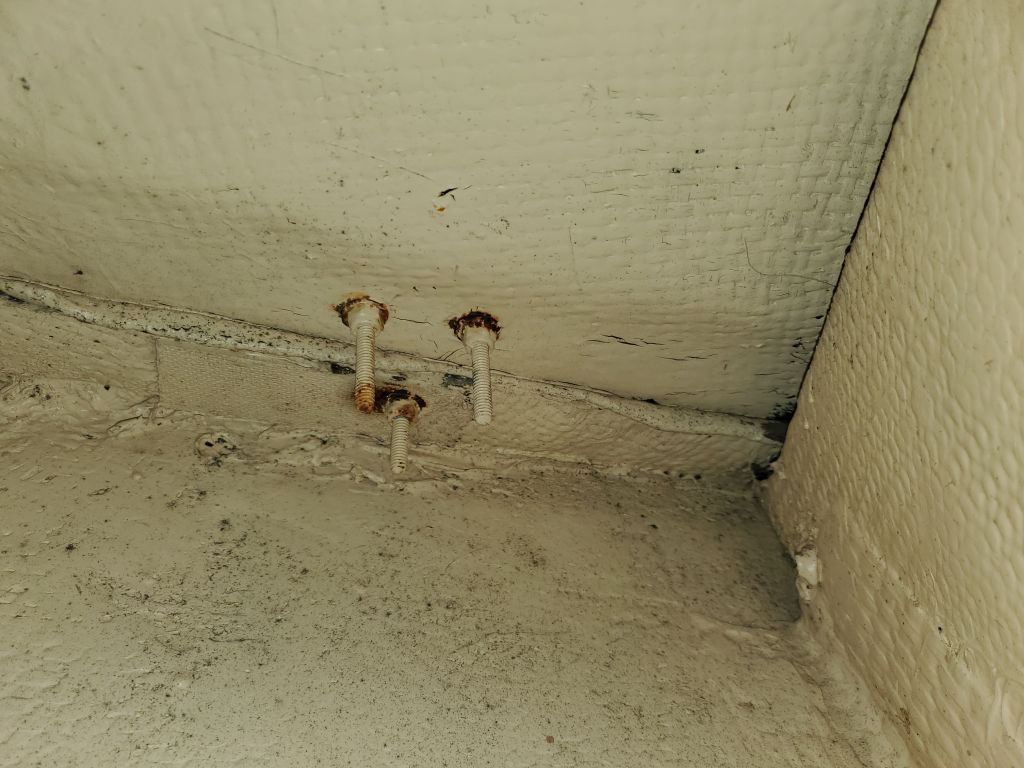
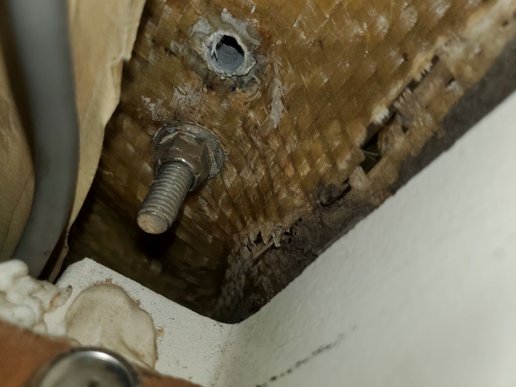
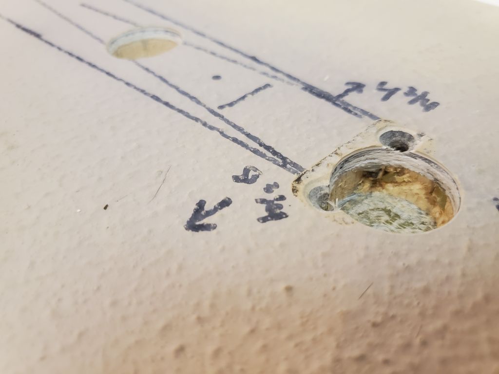
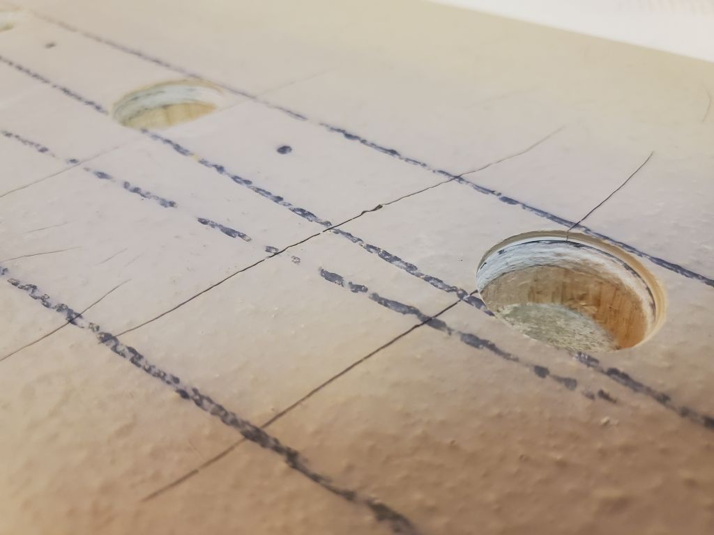
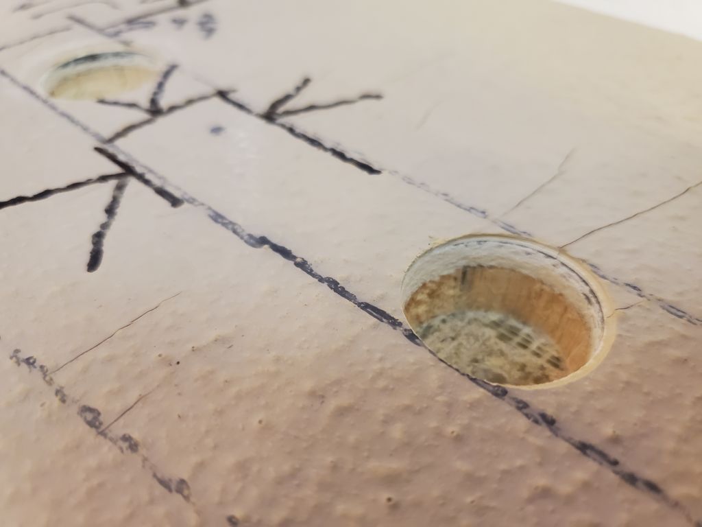
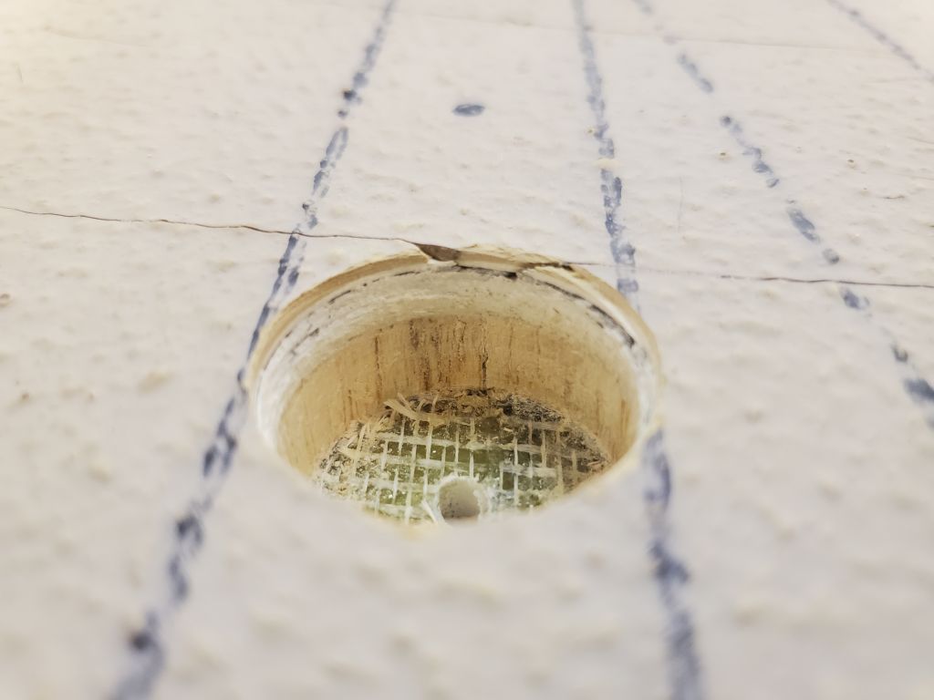
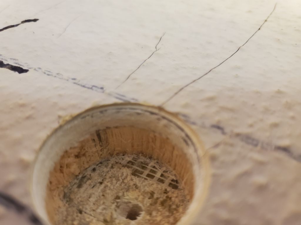
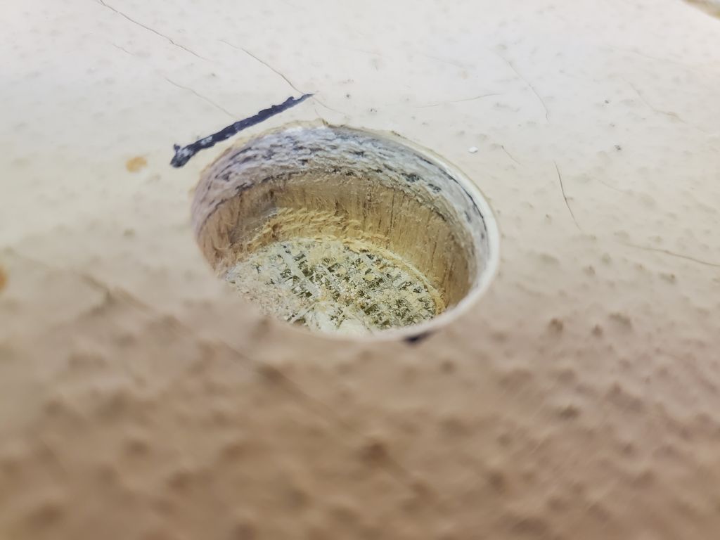
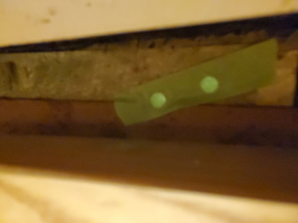
I used a 1″ Forstner bit to ream out the deck core at each fastener location.  This also gave good insight into the deck condition, which was excellent at all such locations, with the core dry and clean and fully bonded all around.
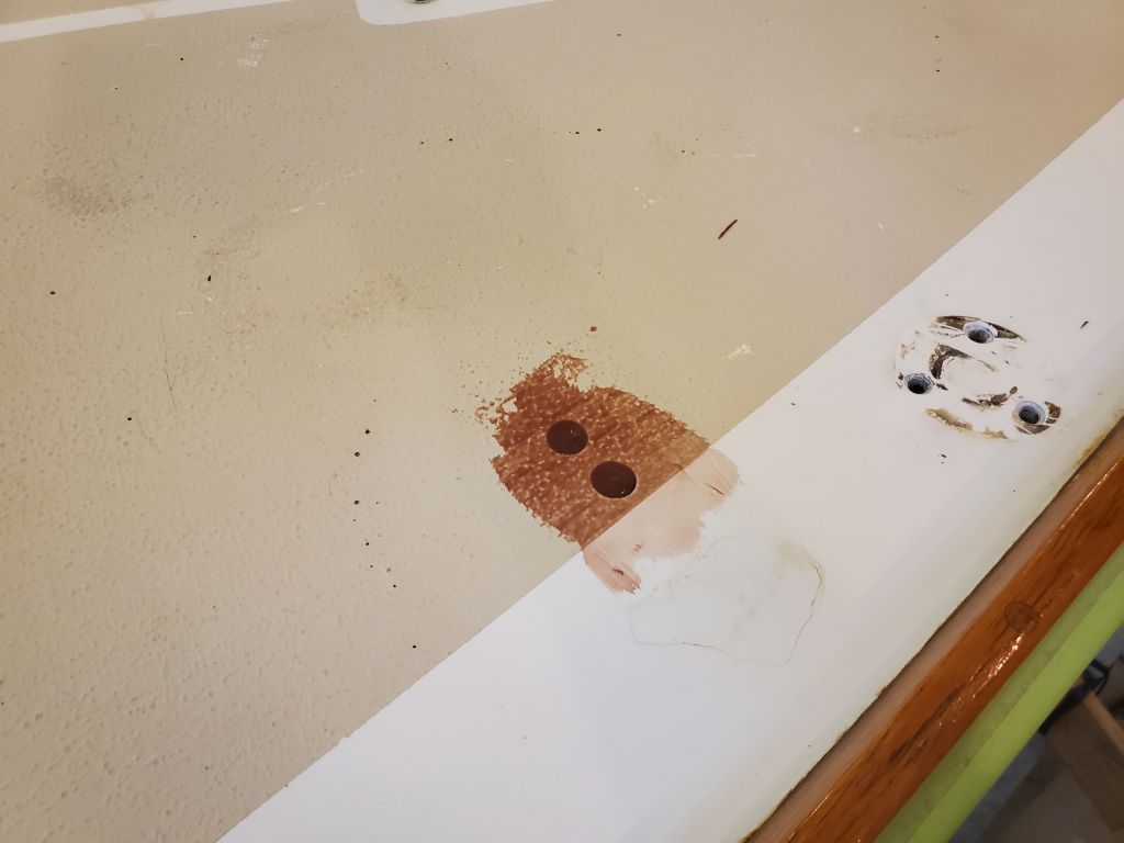
Port side:

Starboard side:

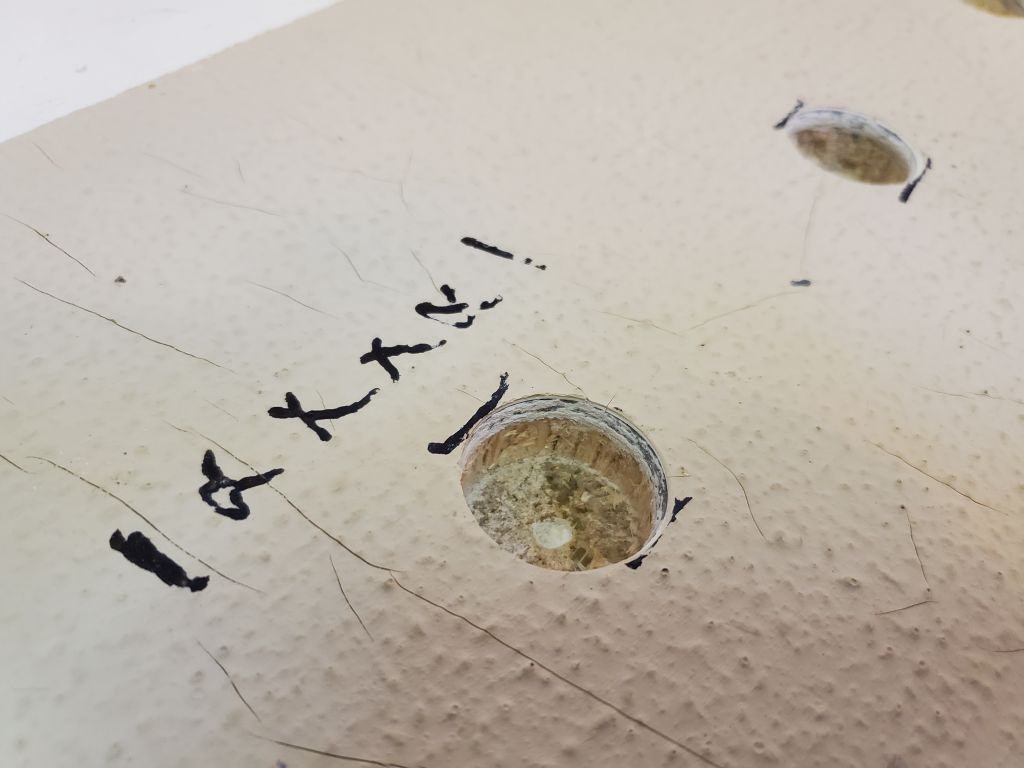
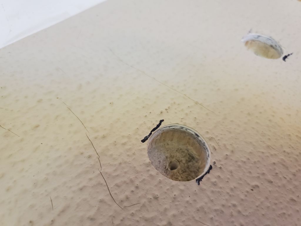
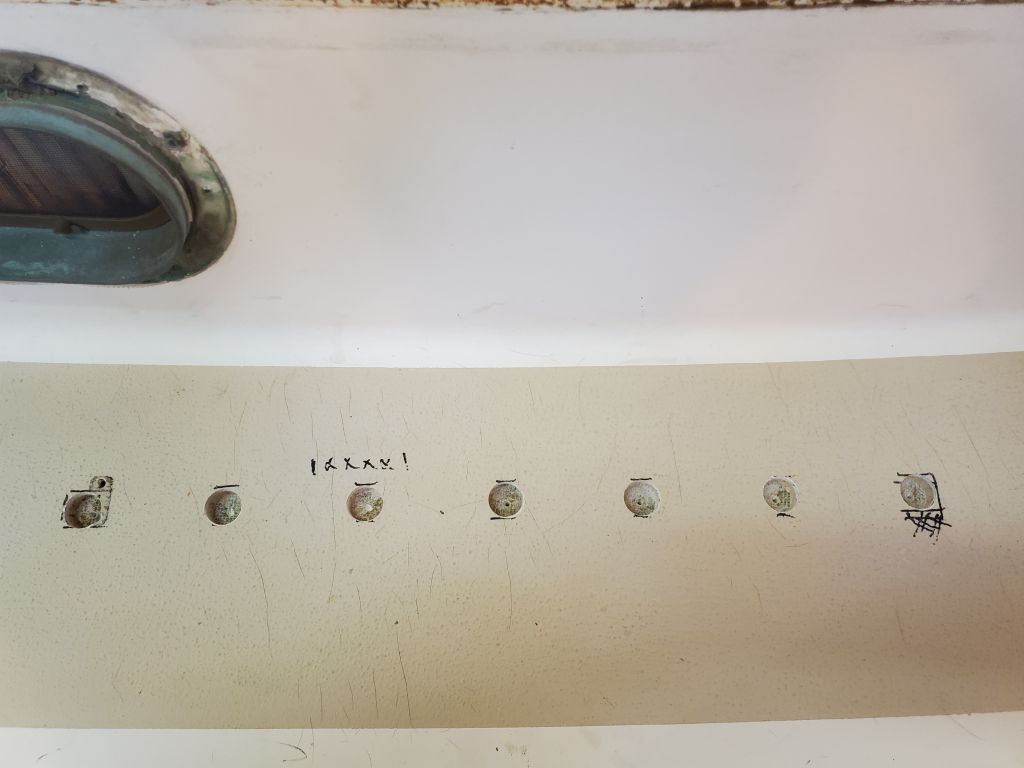
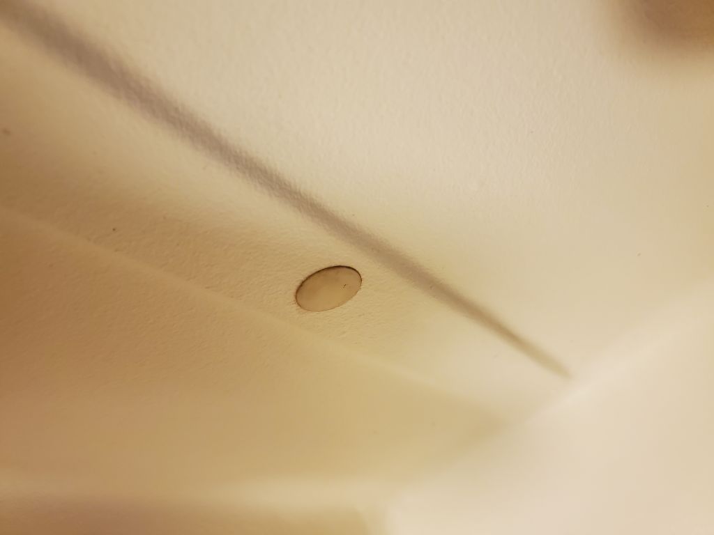
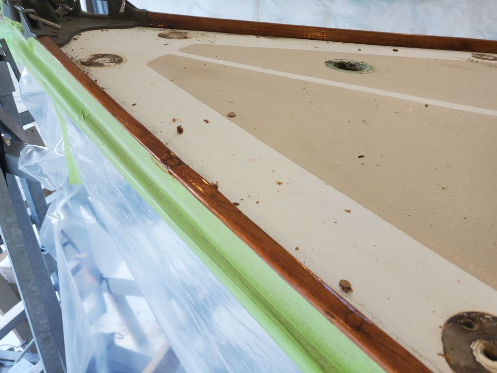
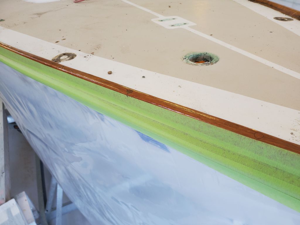
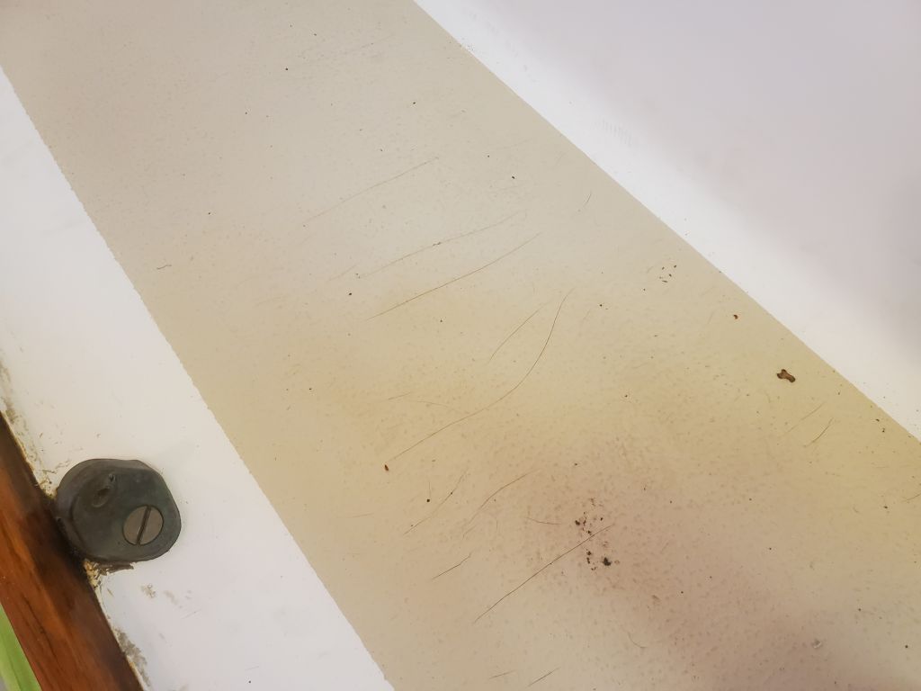
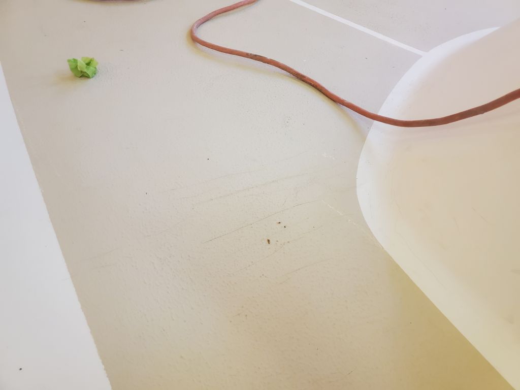
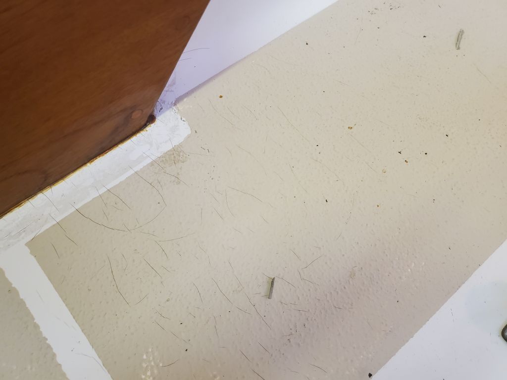
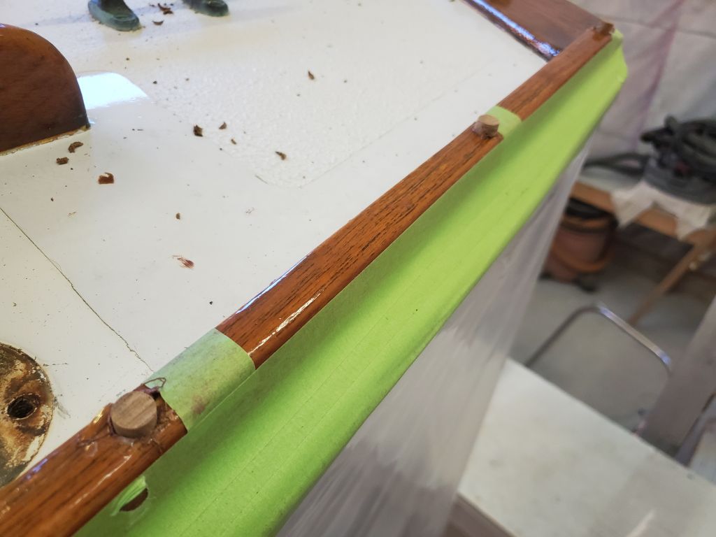
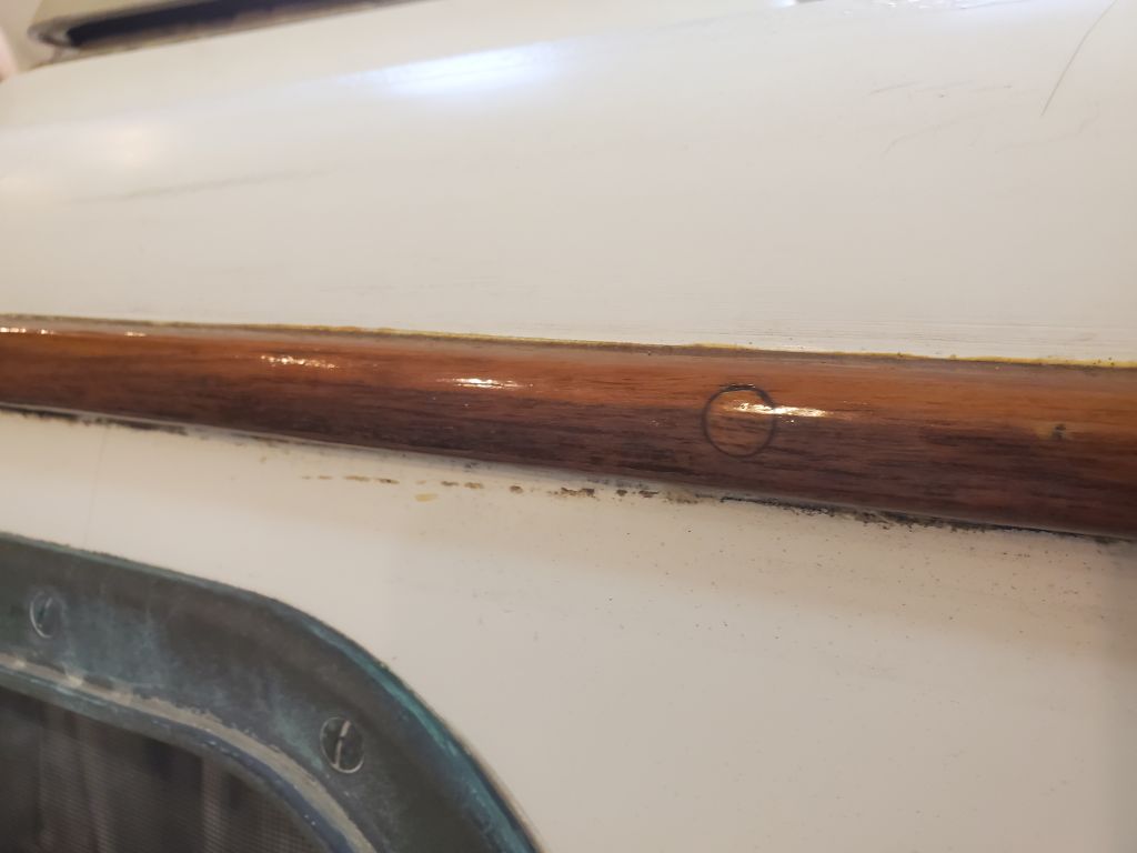
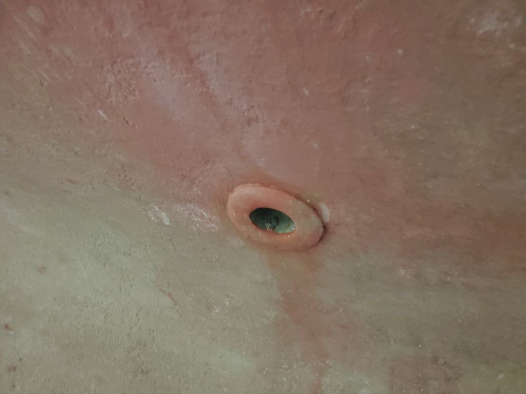
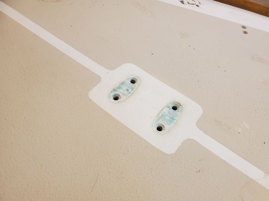
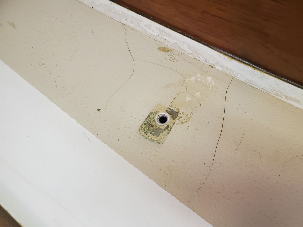
Several of the minor deck cracks running hither and yon around the decks passed through some of these new holes, giving sound insight into the nature of the cracks without conjecture.  The cracks passed only through the heavy layers of gelcoat, ending at the top of the laminate below.  Gelcoat is simply pigmented, unreinforced resin, and as such, if applied too heavily, tends to crack over time and with normal sailing stresses.  During the upcoming surface prep, I’d work to grind out and stabilize these cosmetic nuisances, but in this instance they were not indicative of any underlying issues and are quite simply the nature of things.

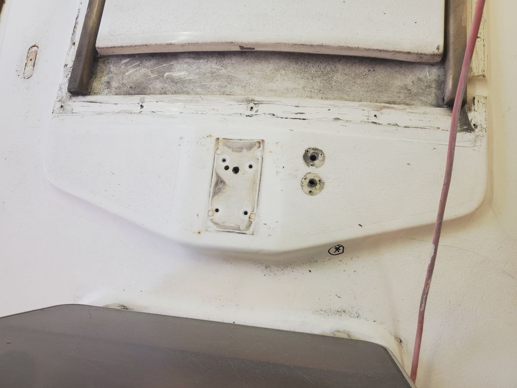
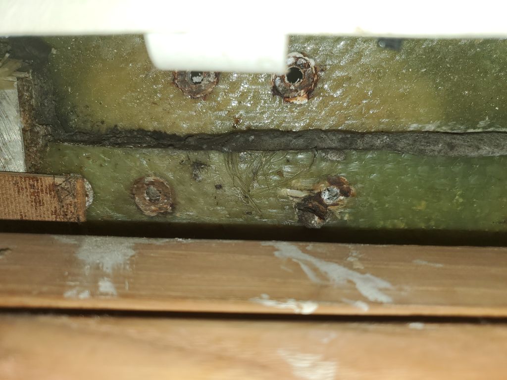
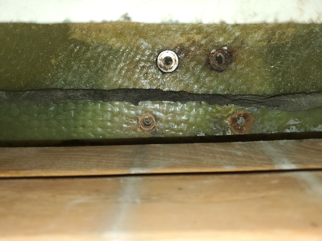
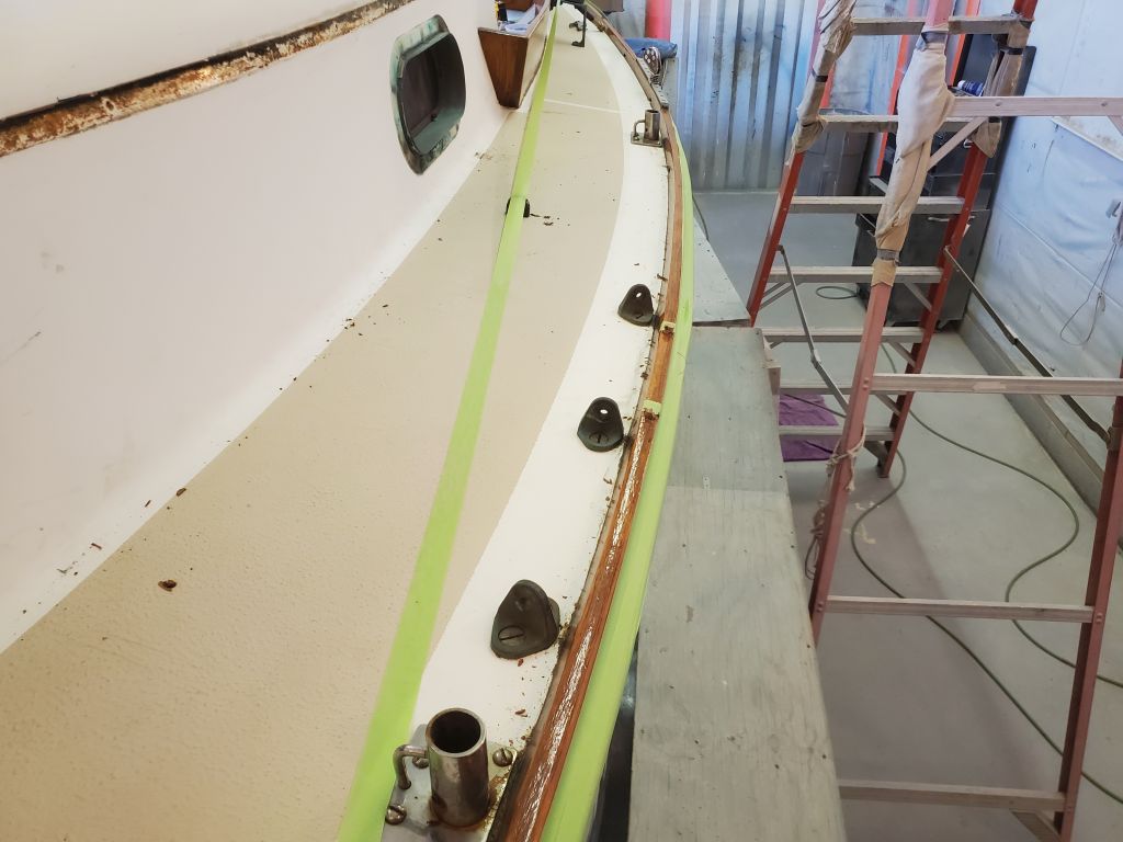
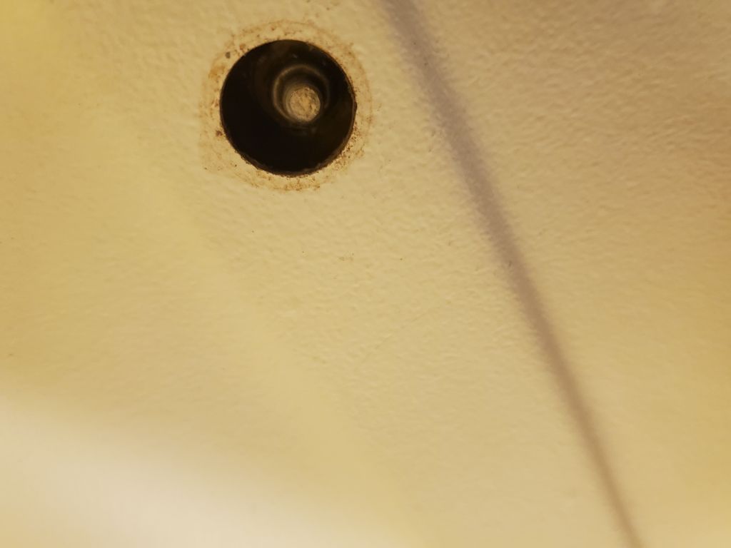
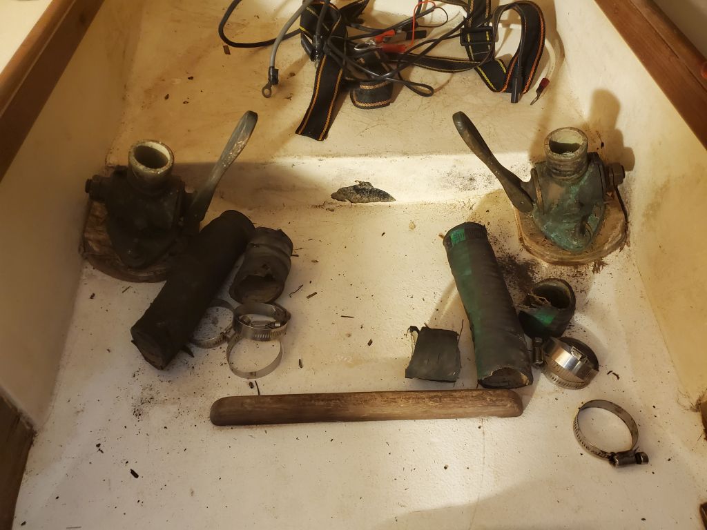
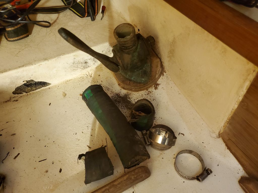
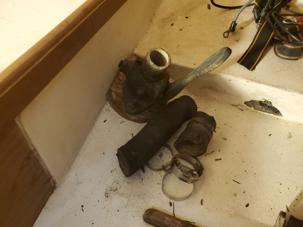
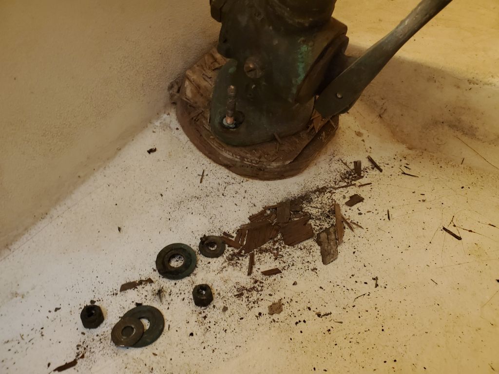
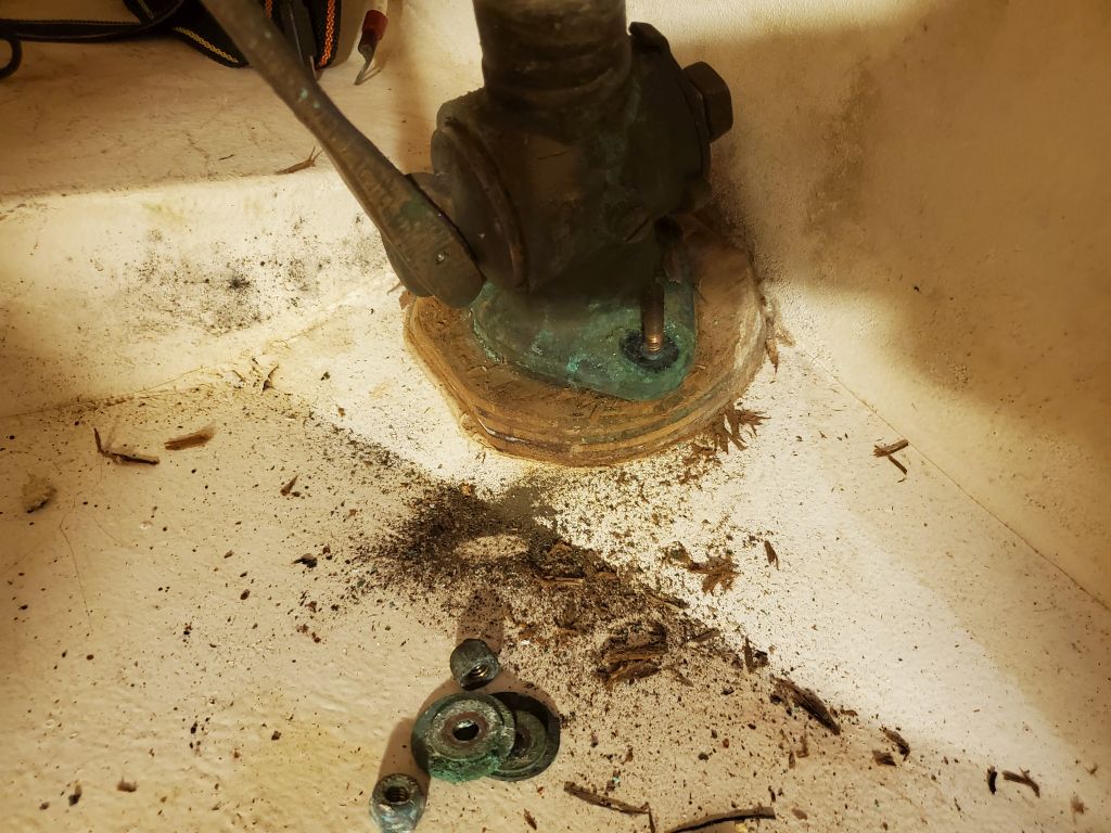
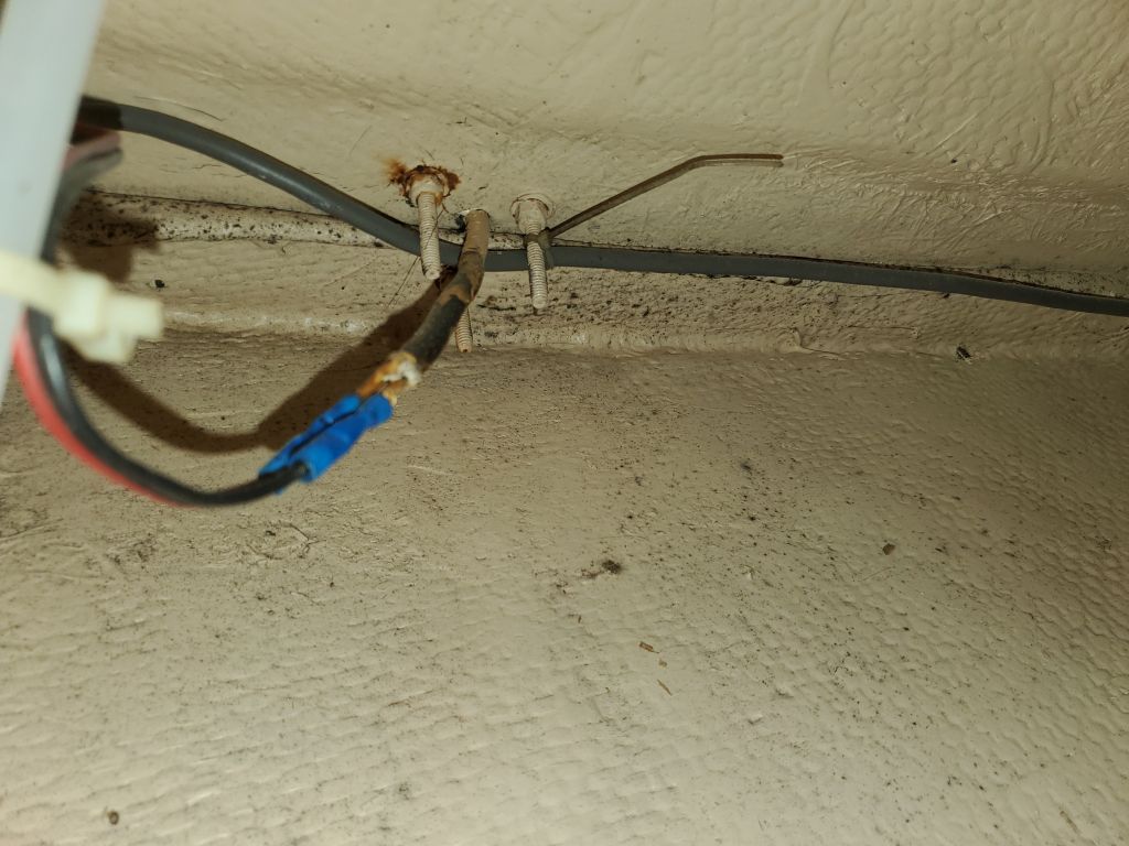
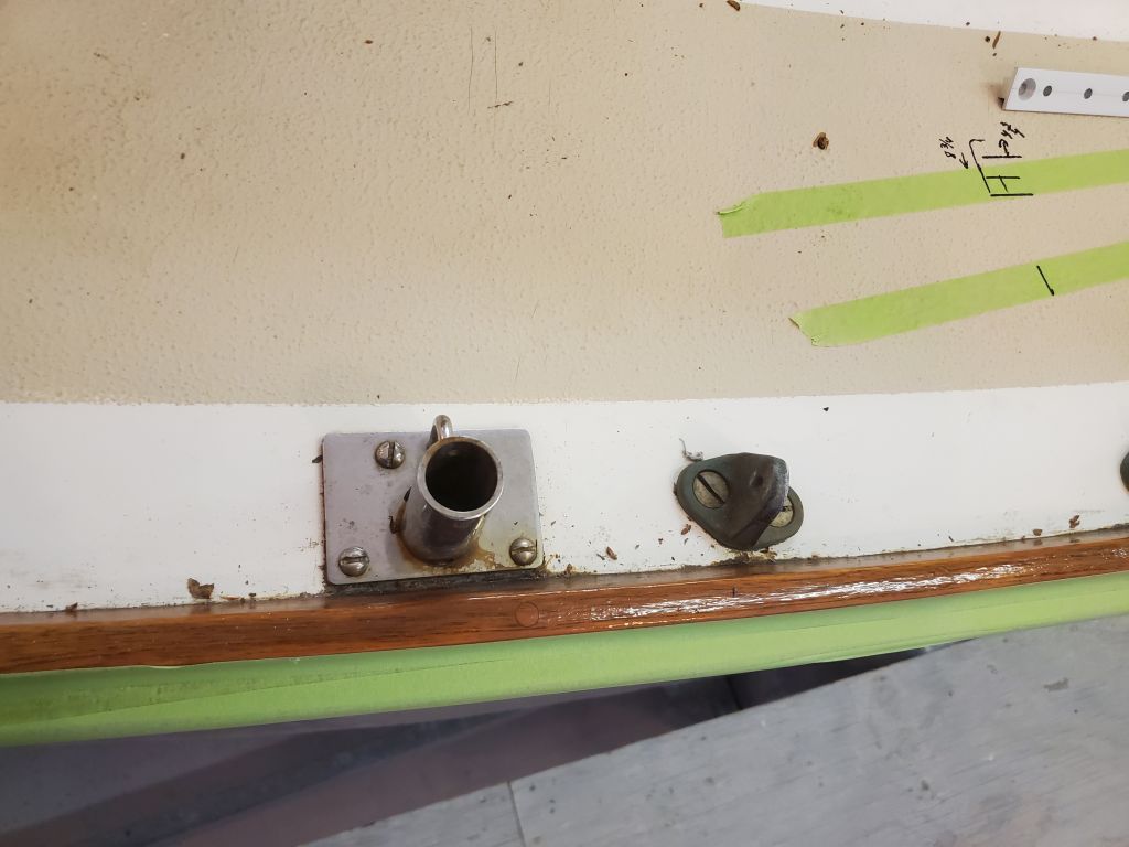
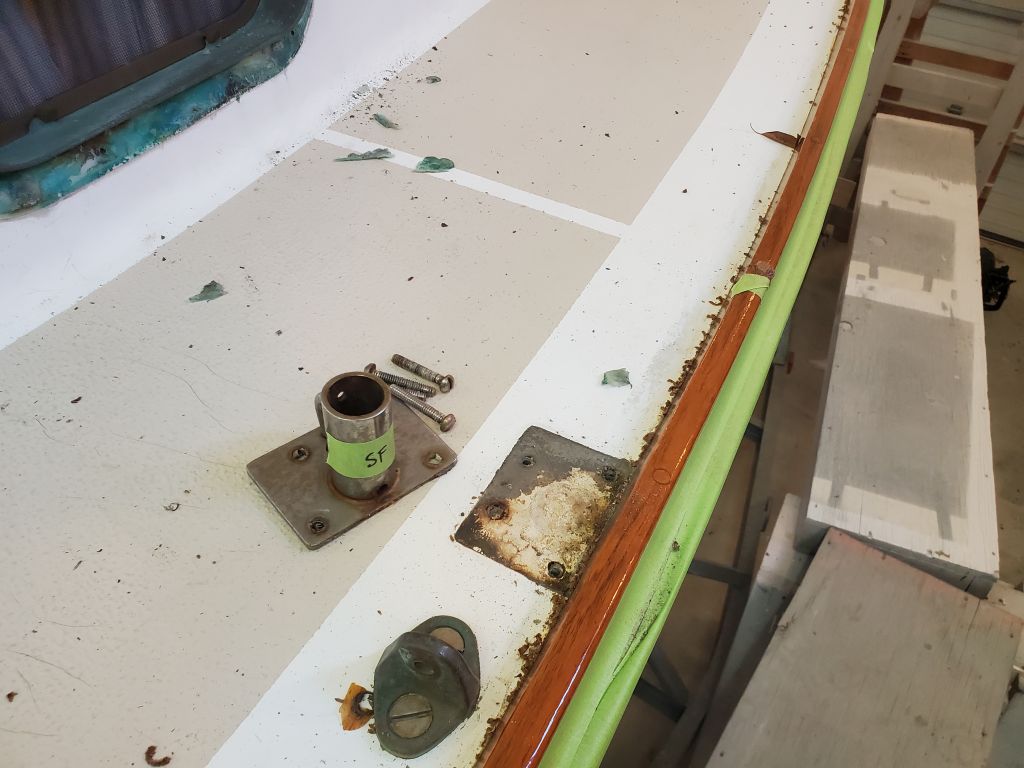
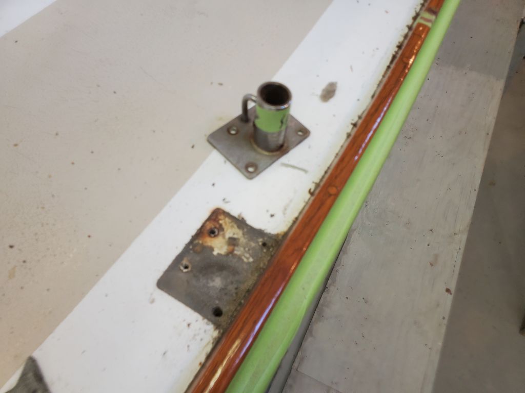
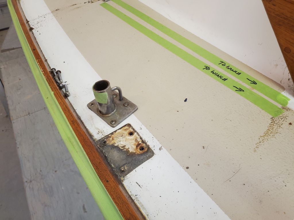
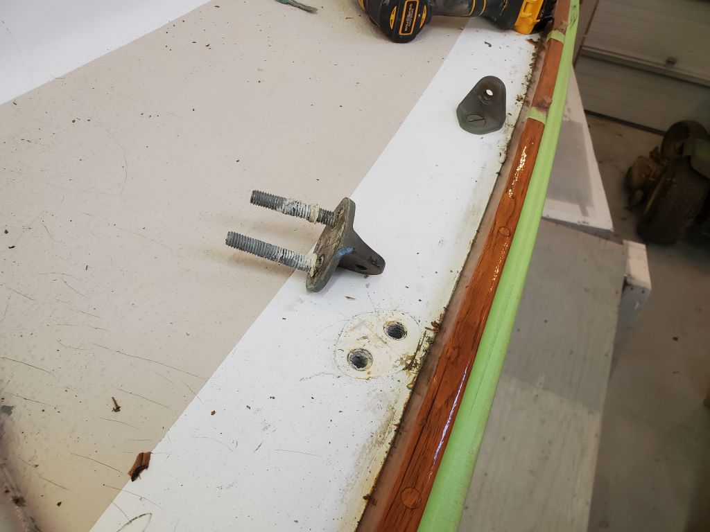
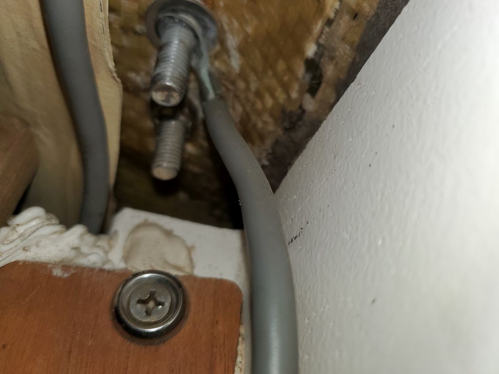
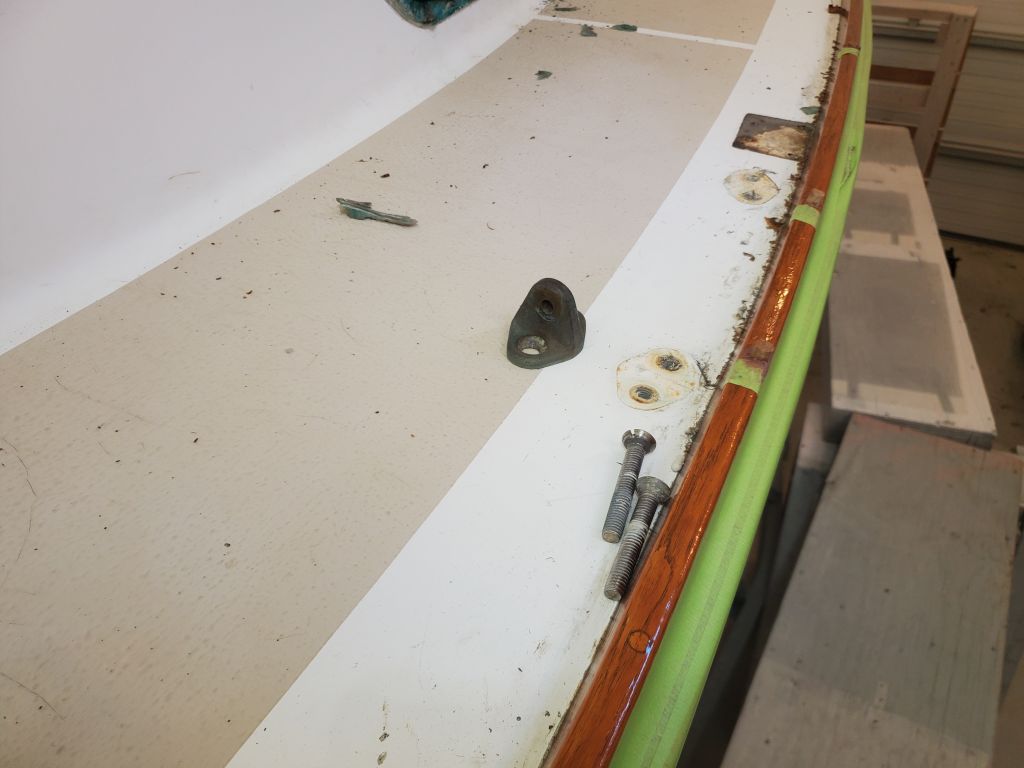
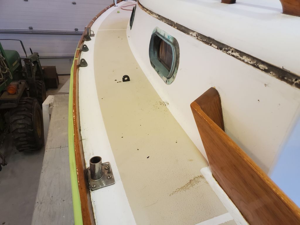
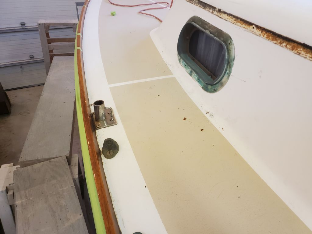
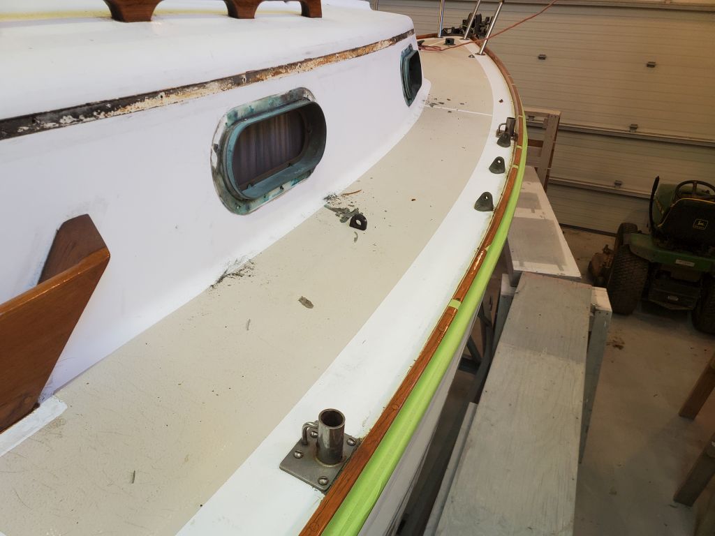
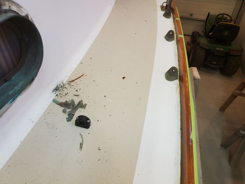
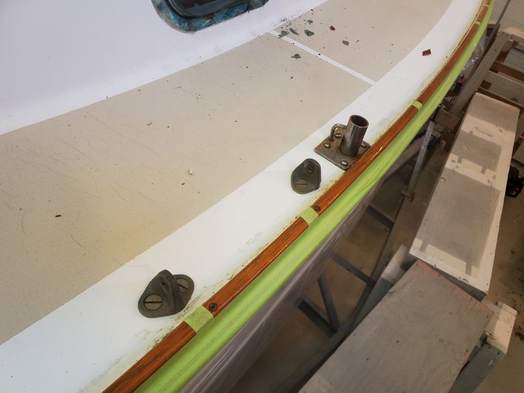
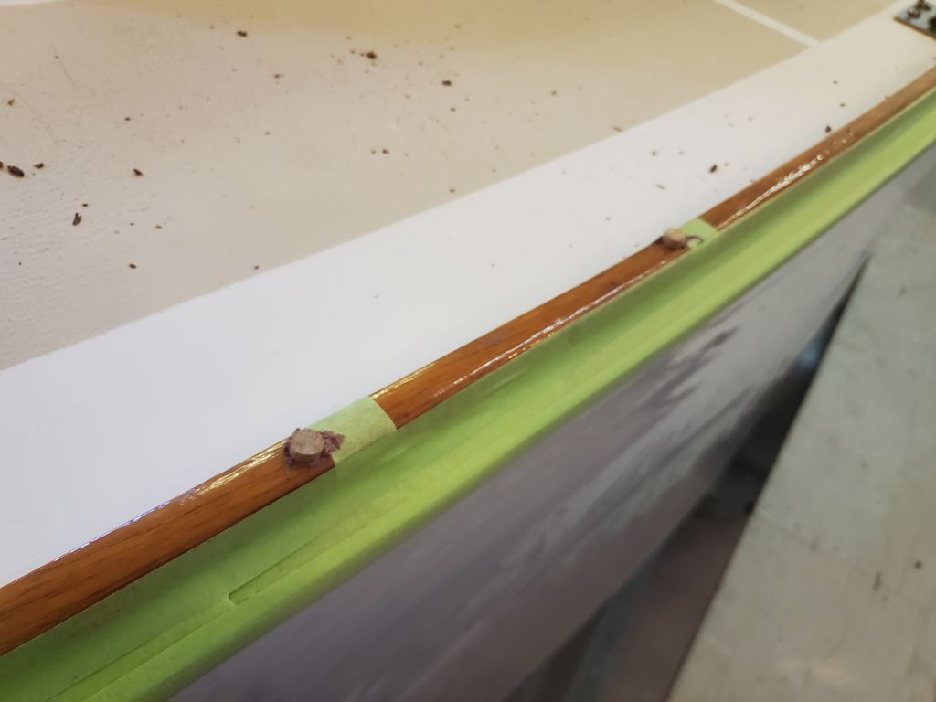
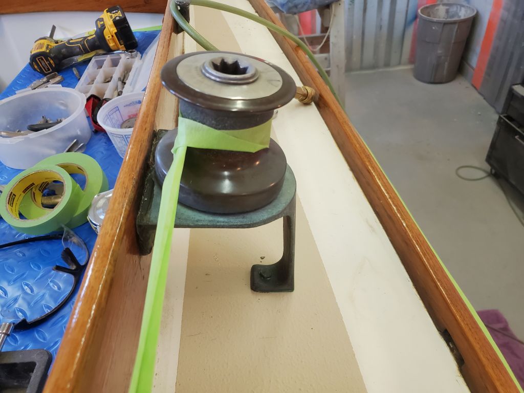
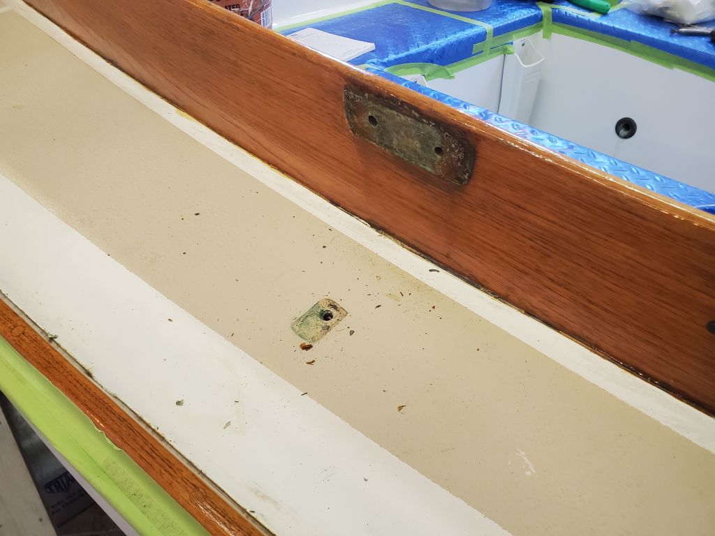
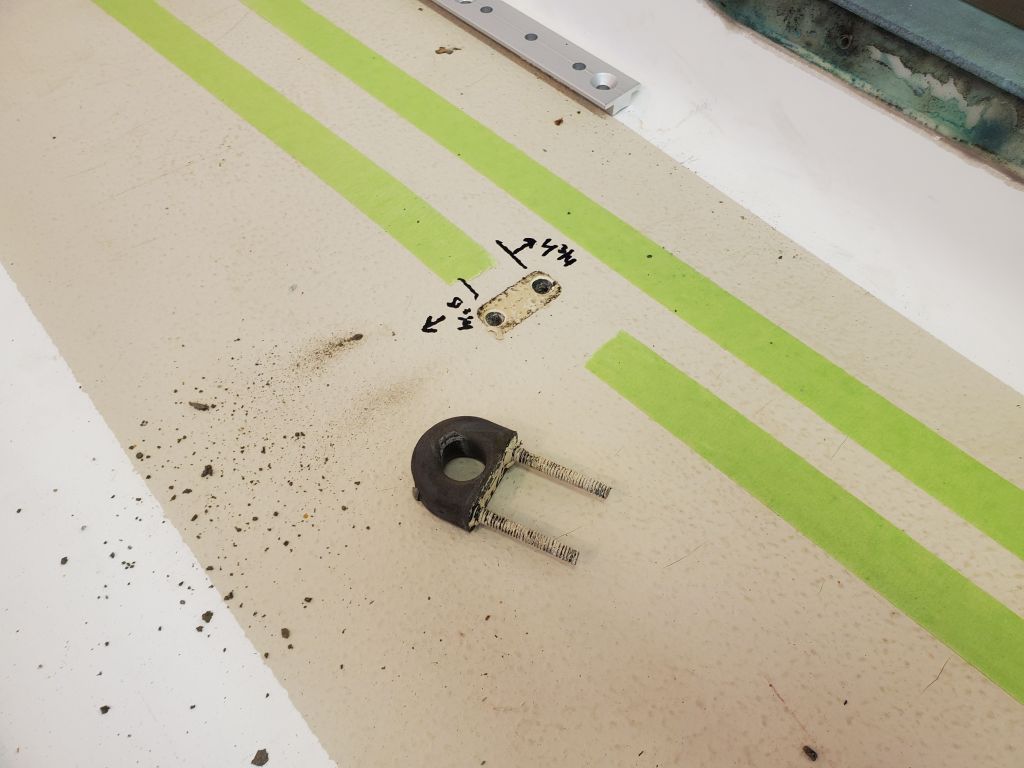
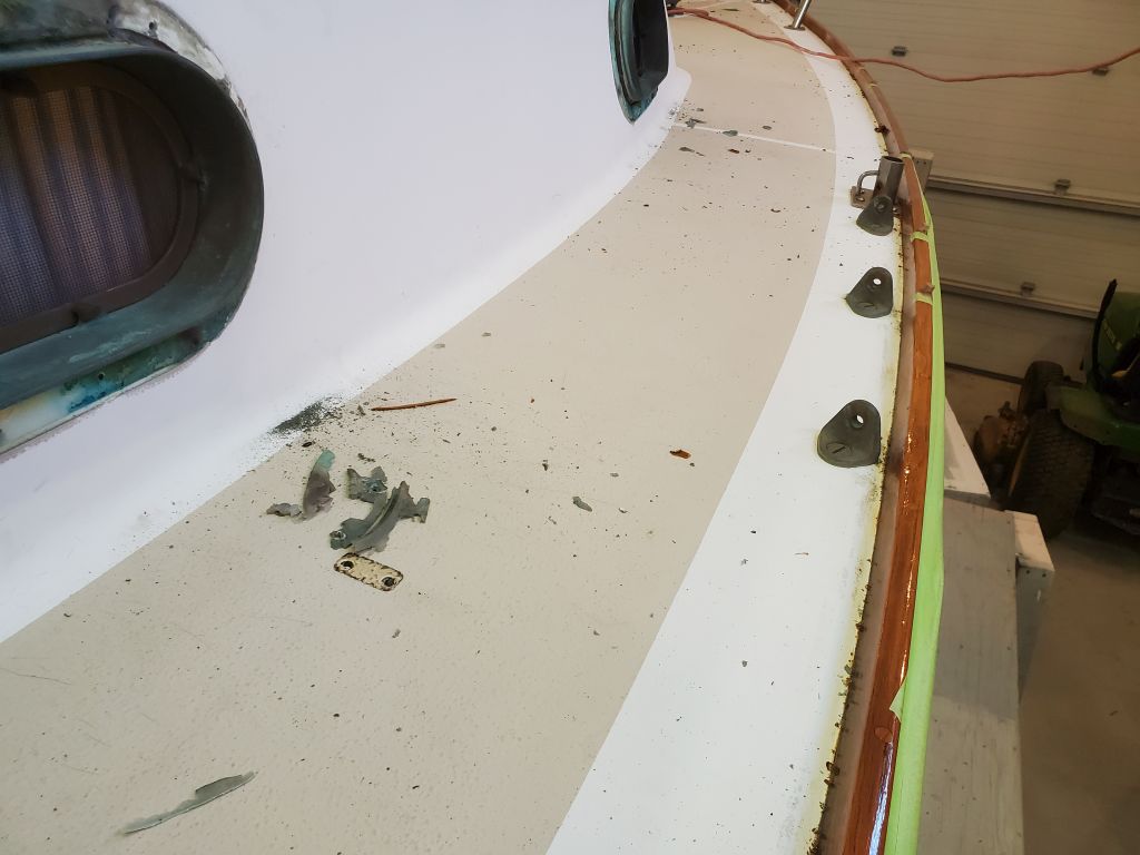
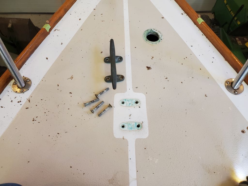
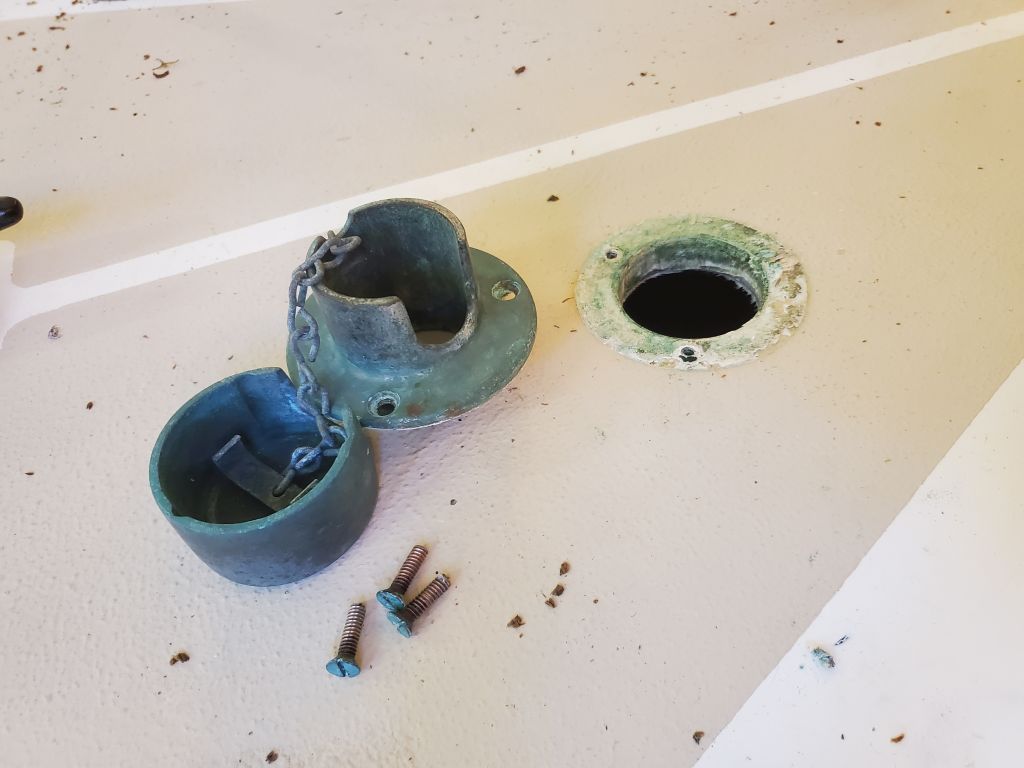
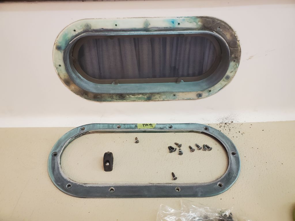
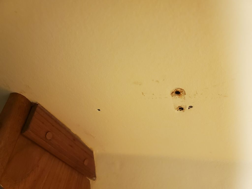
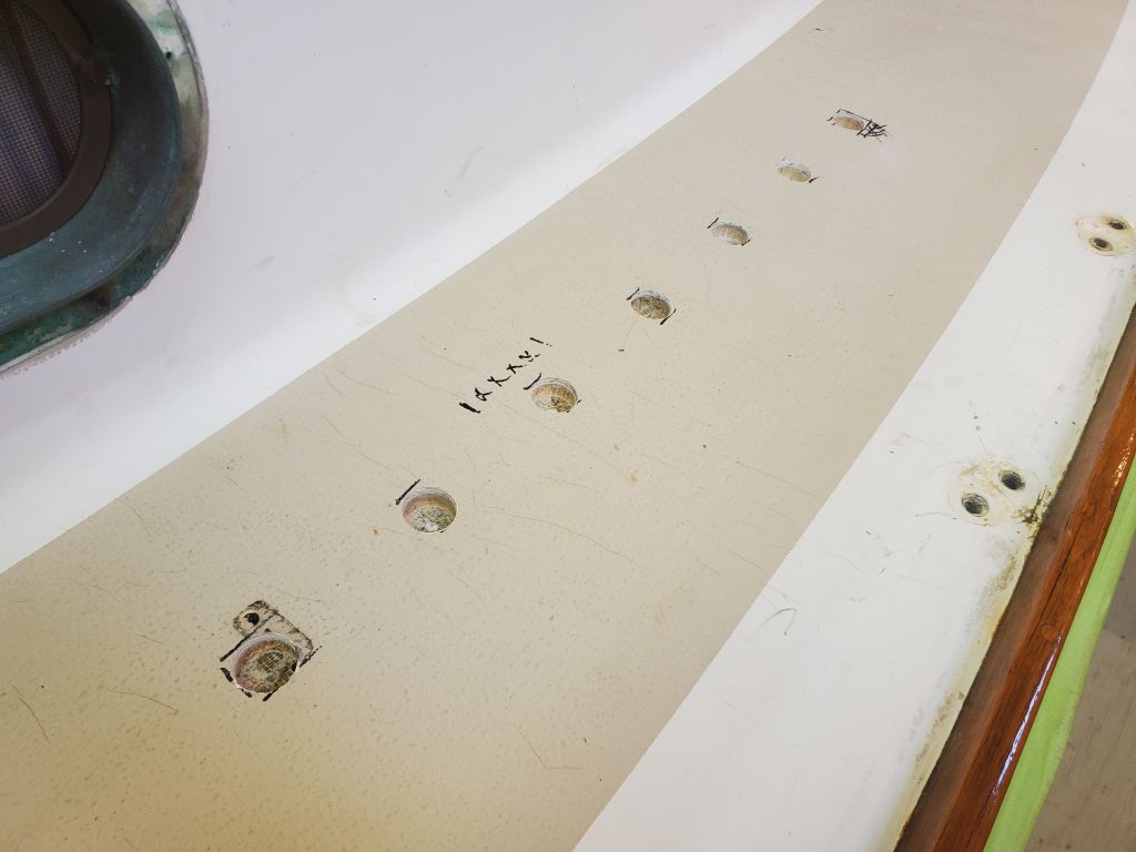
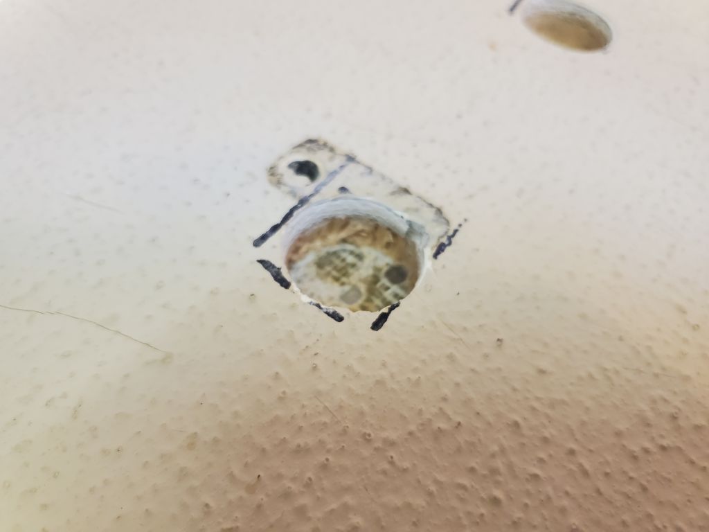
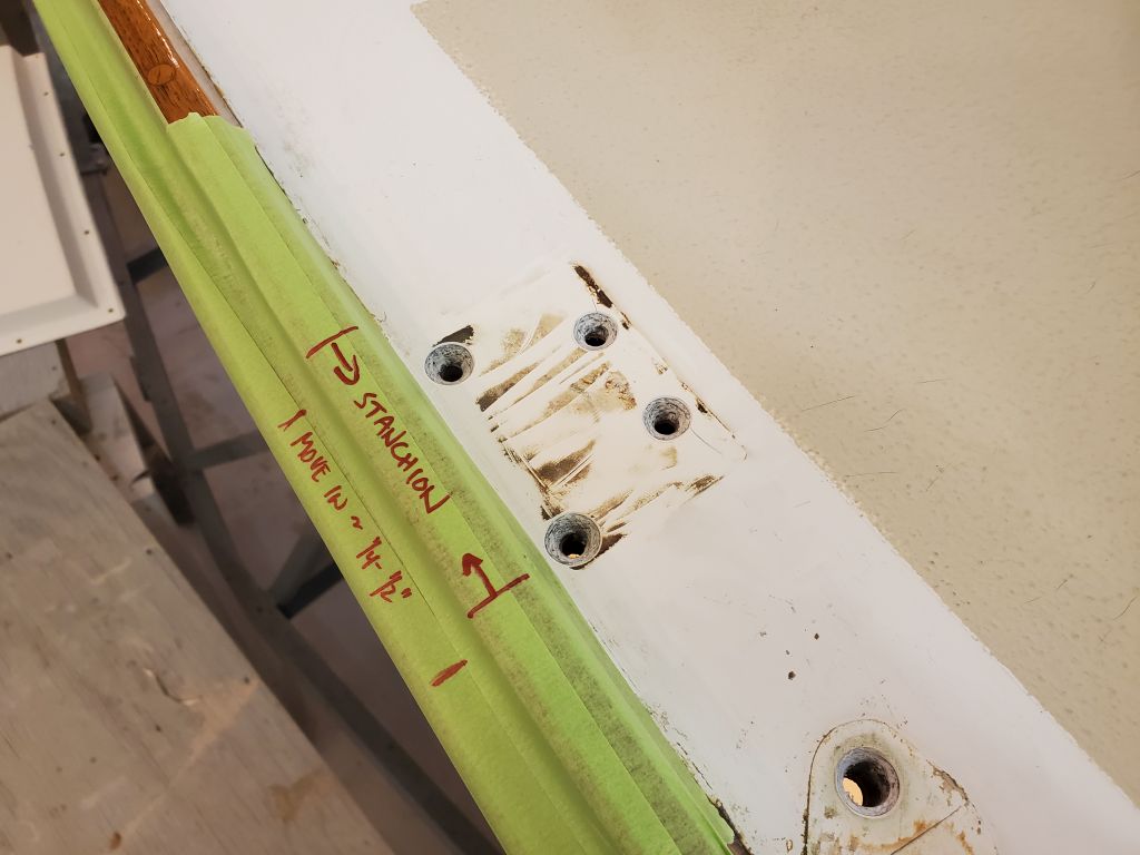
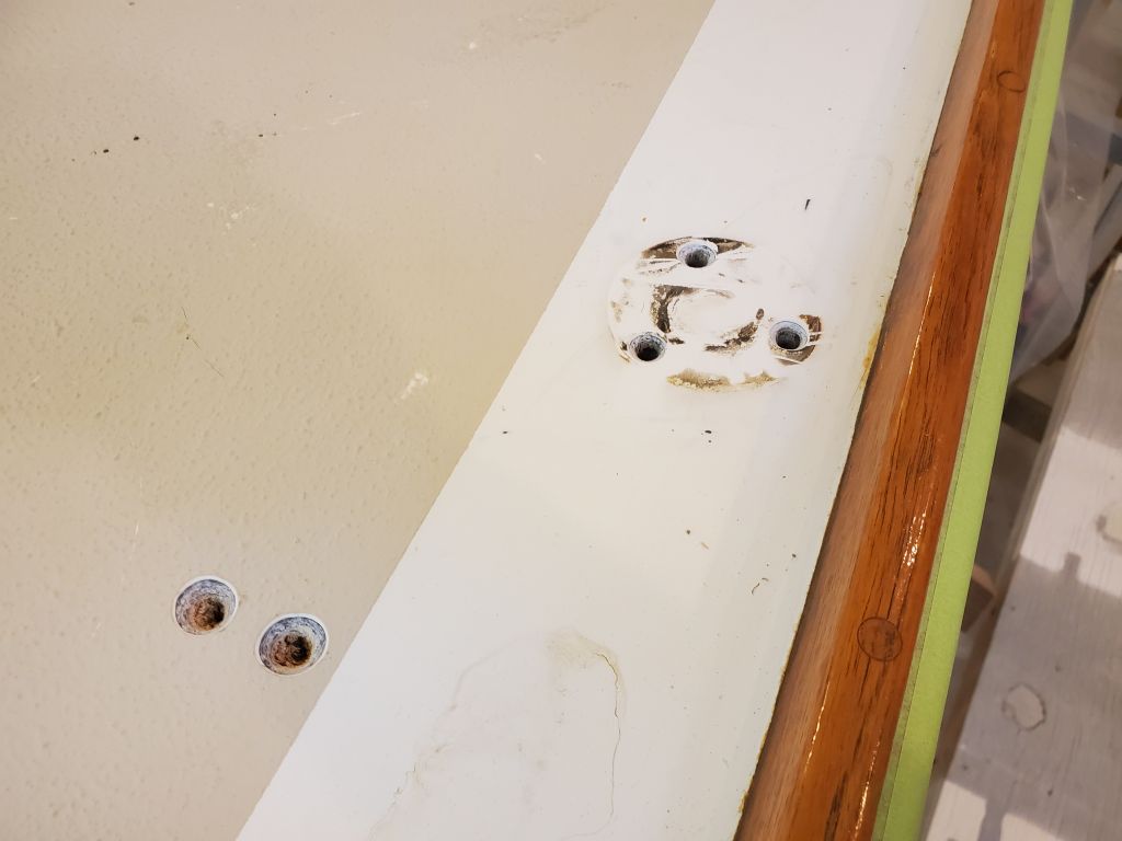
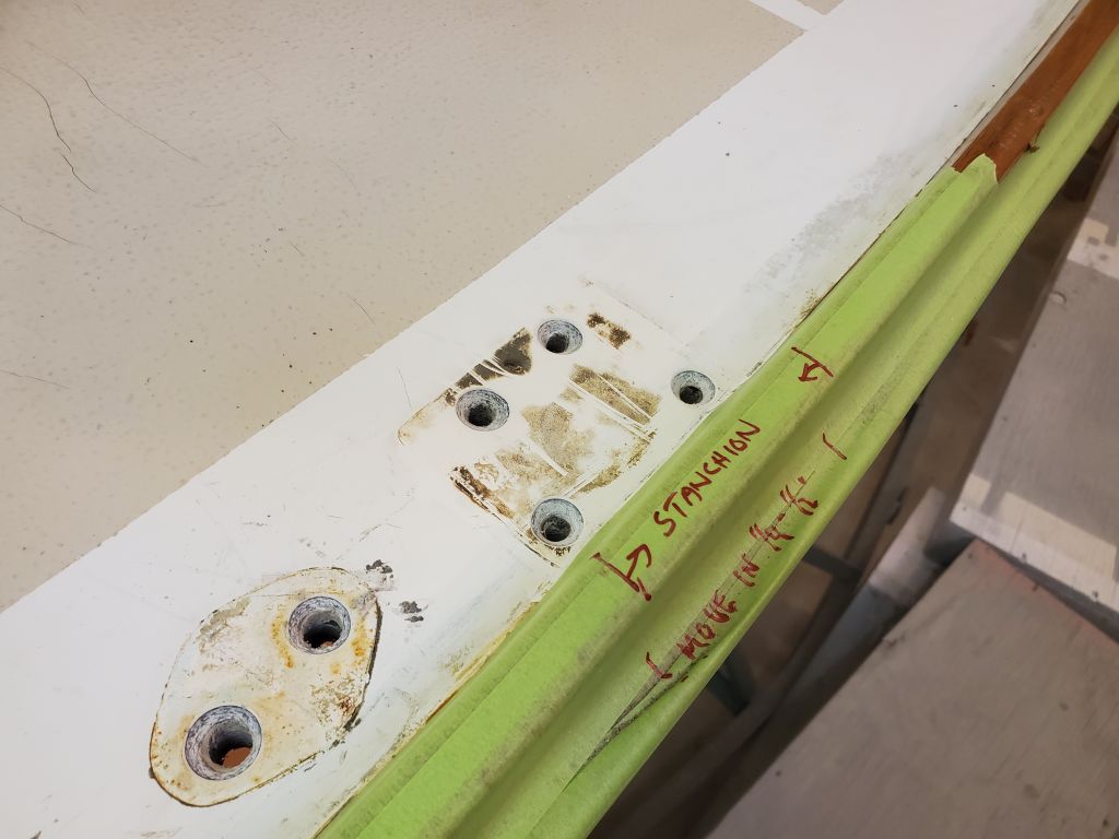
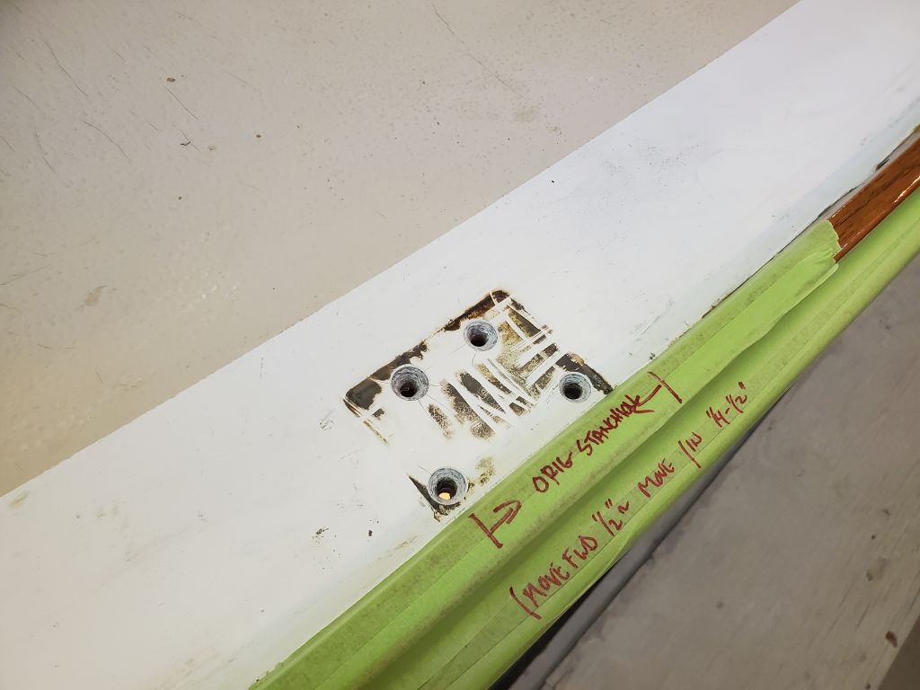
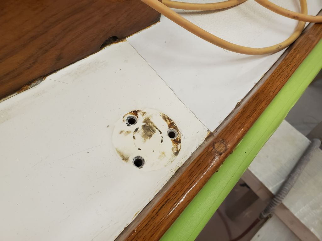
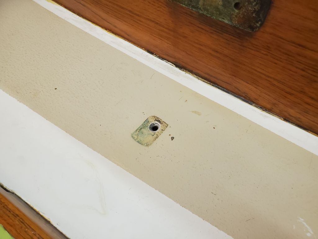
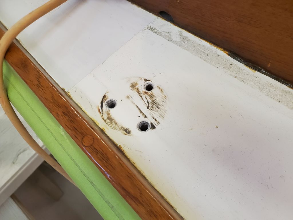
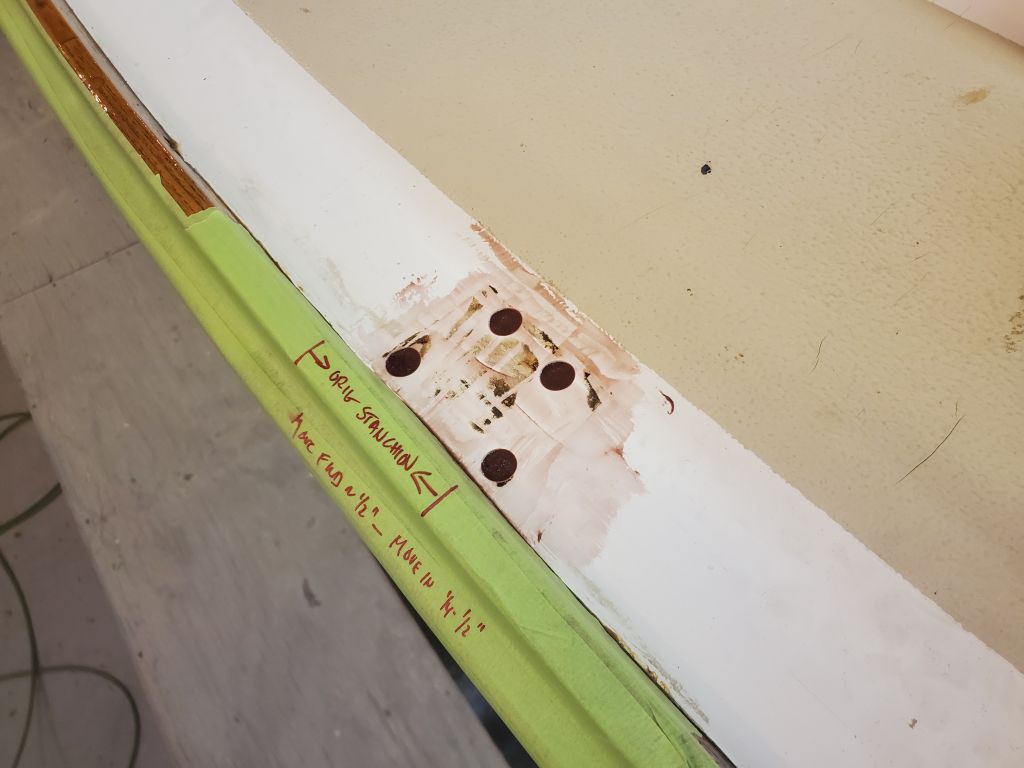
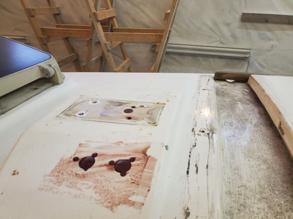
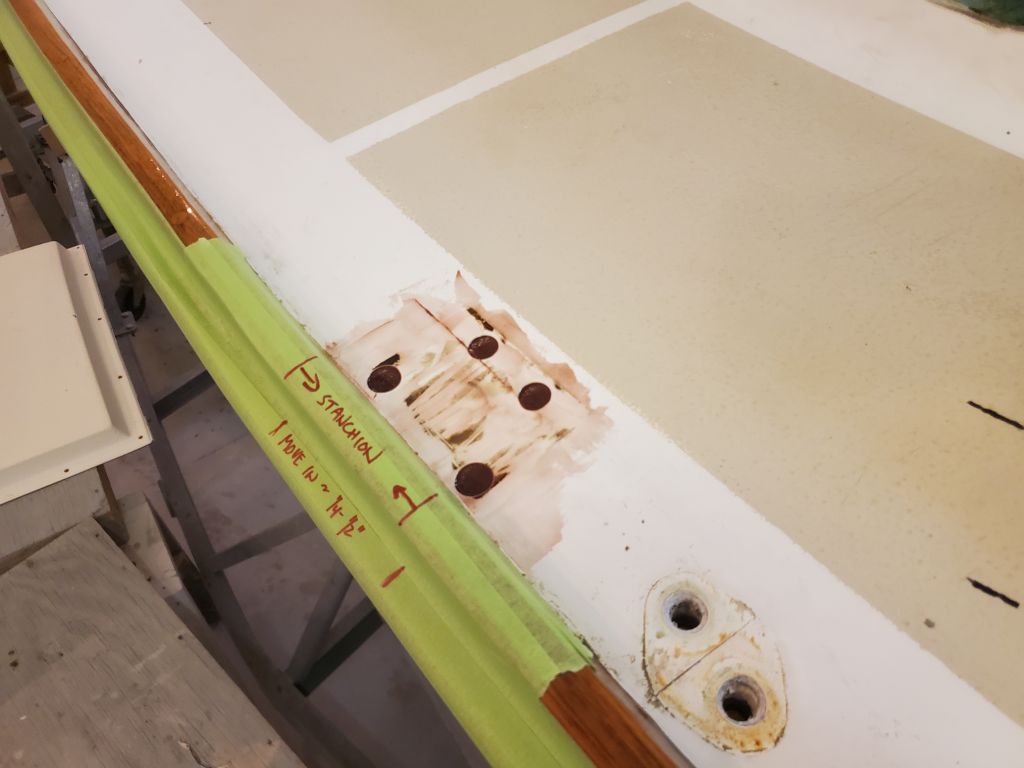
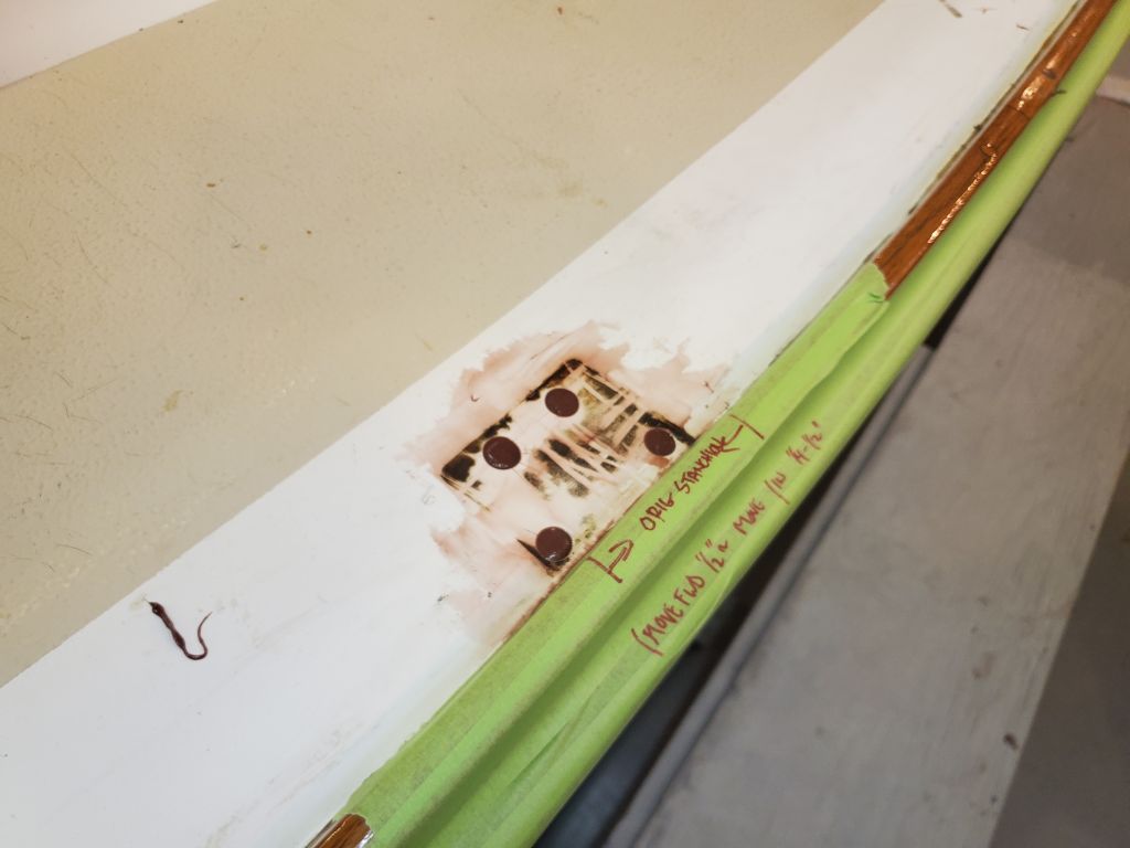
Continuing with some of the hole preparations, I scraped away most of the old sealant and other residue and marked the existing locations of the four stanchion bases, for ongoing reference and to help with repositioning a little later.

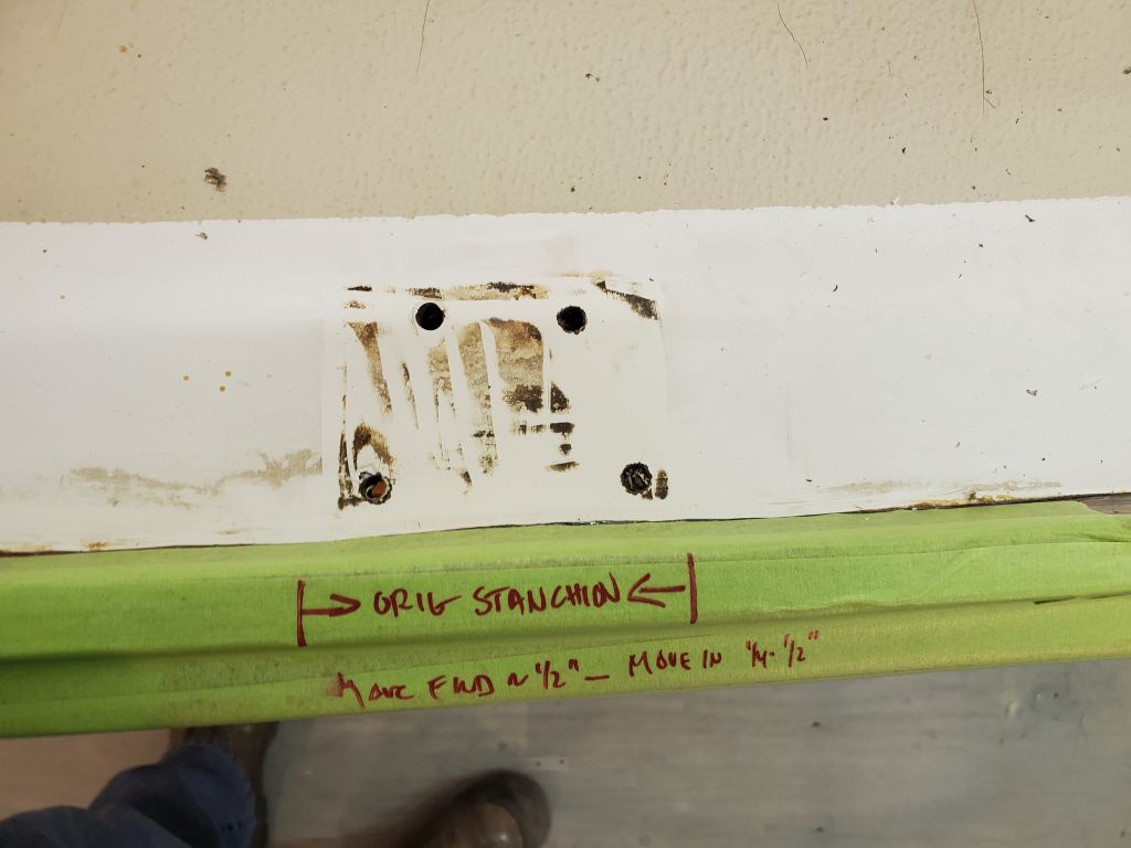
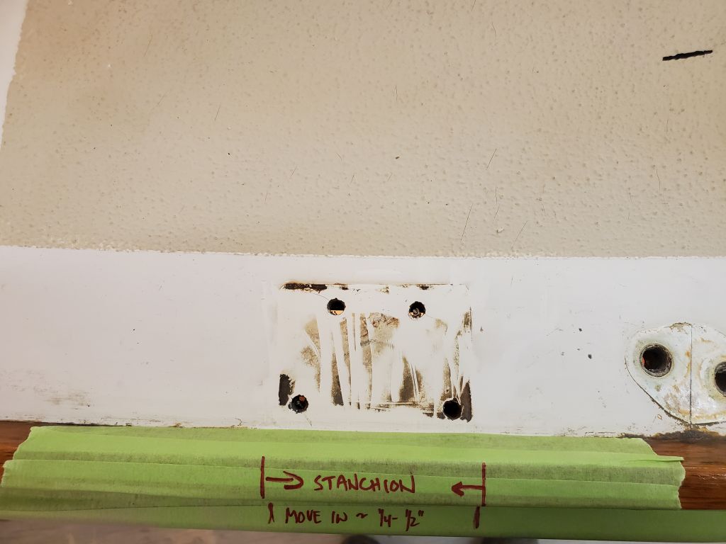
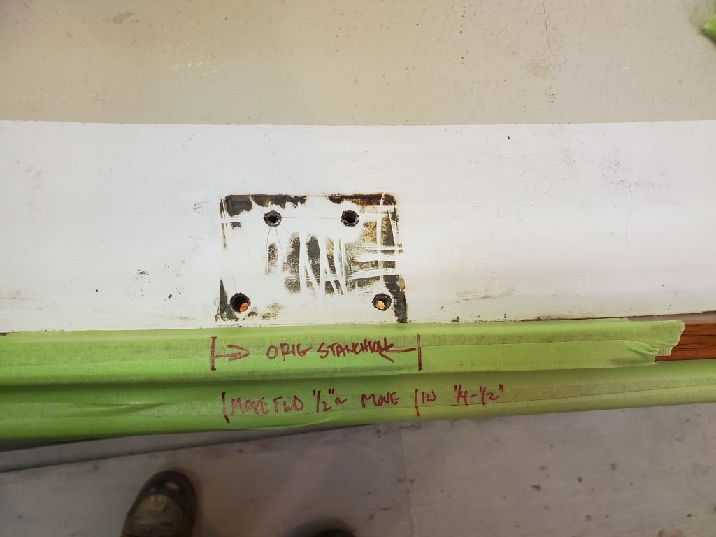
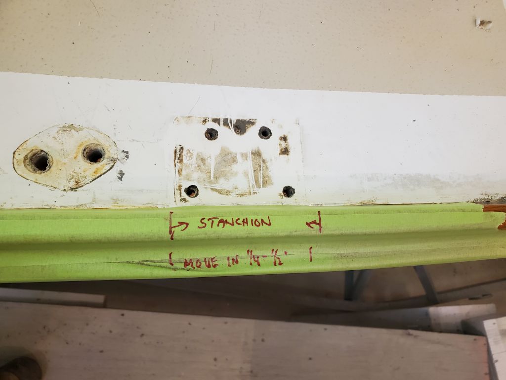
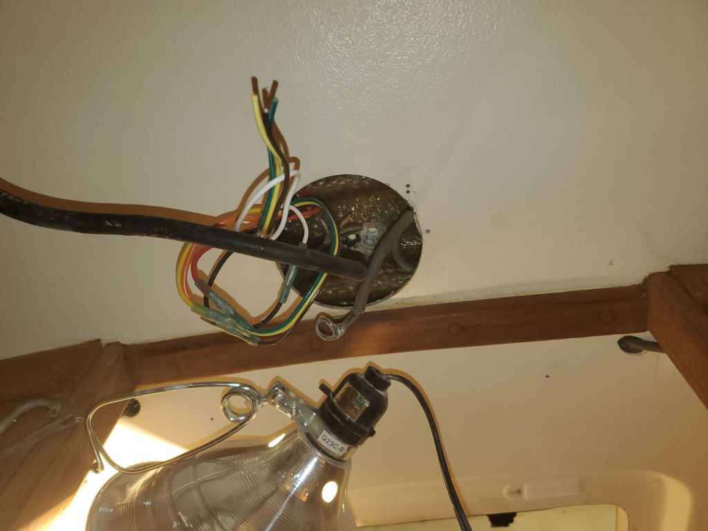
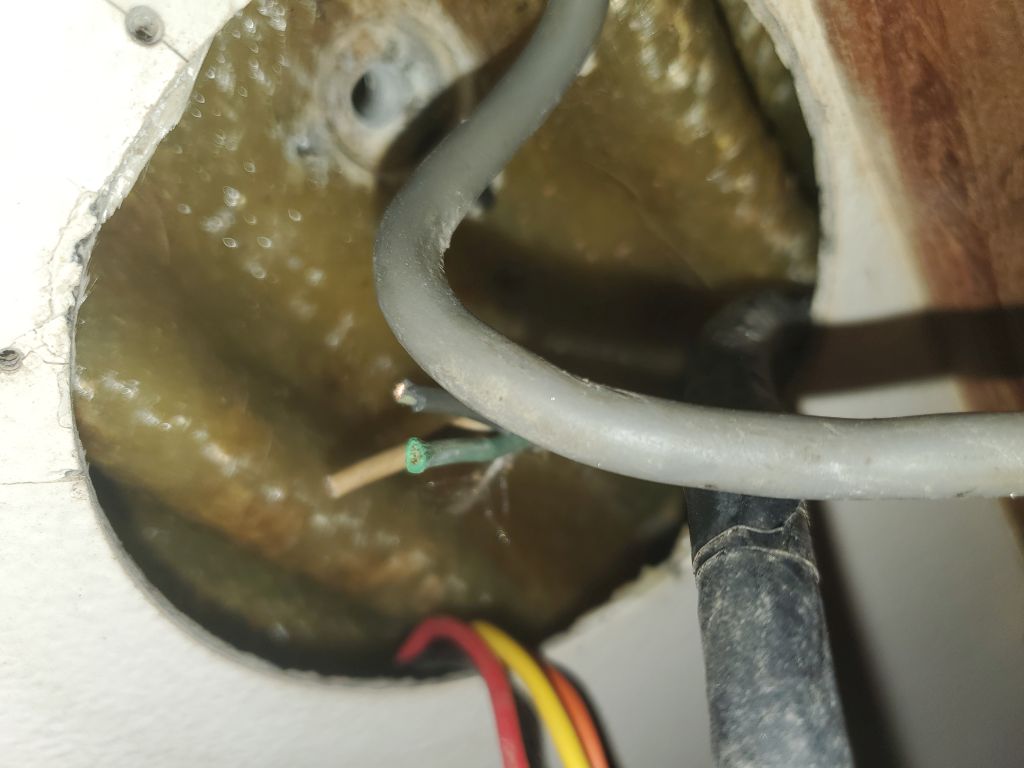
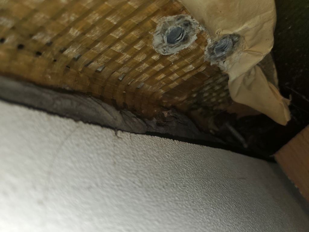
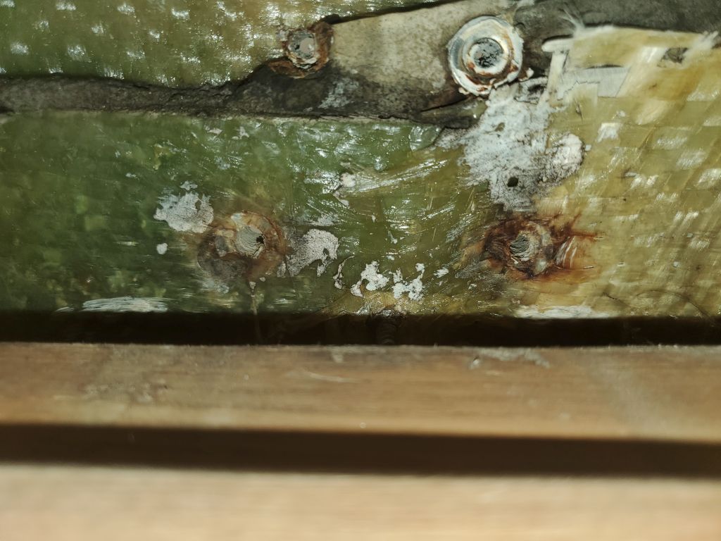
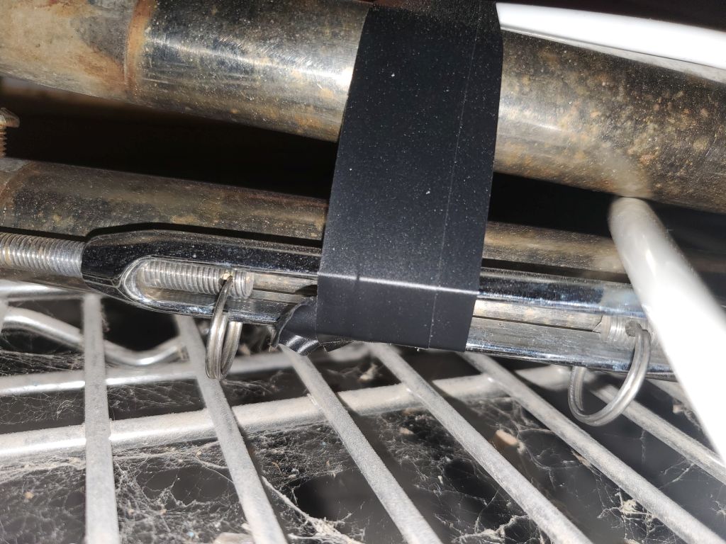
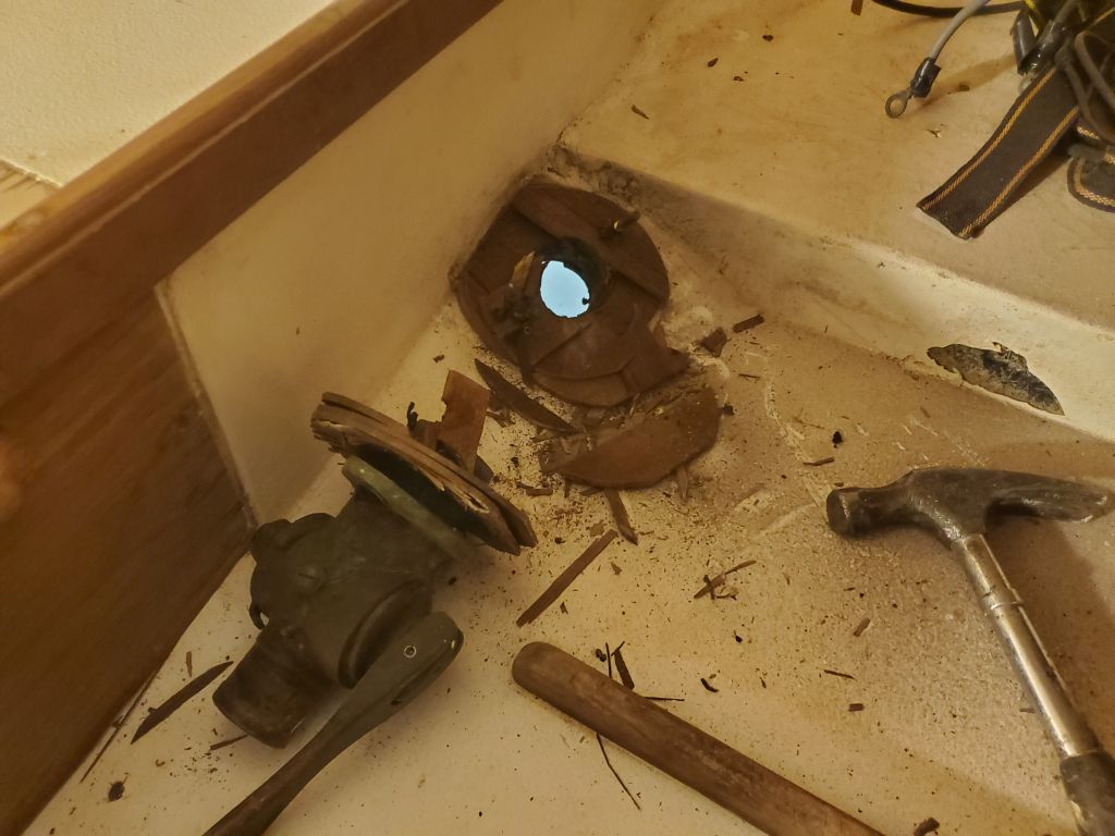
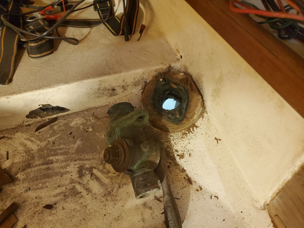
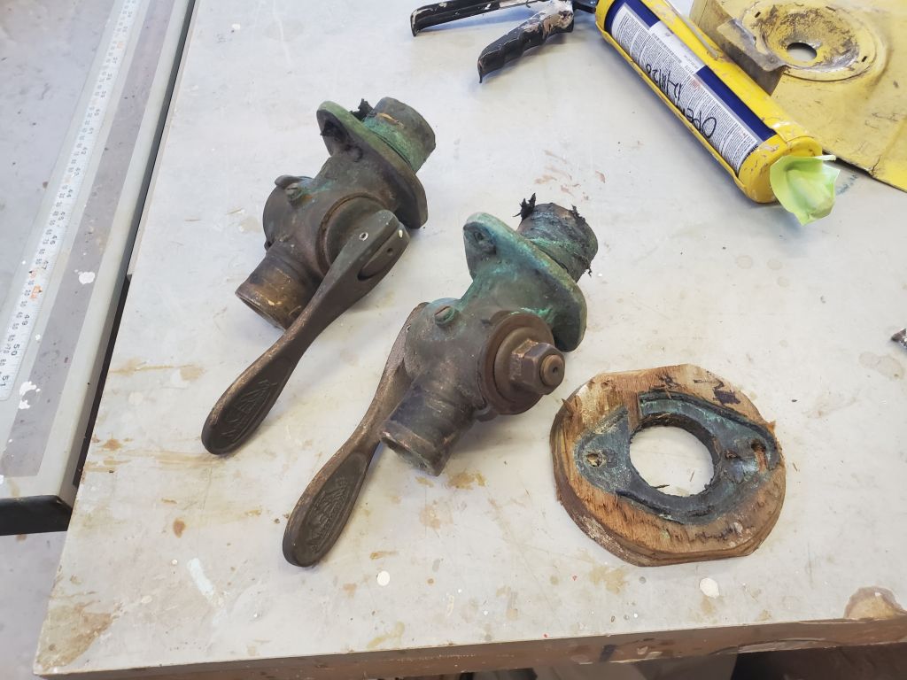
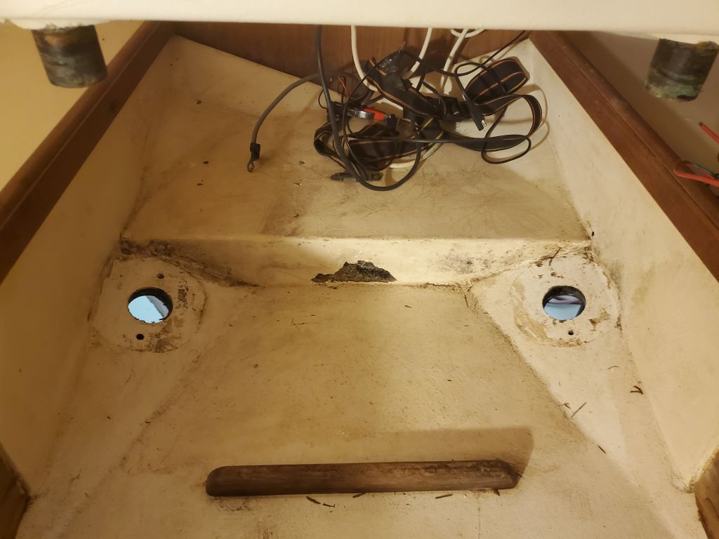
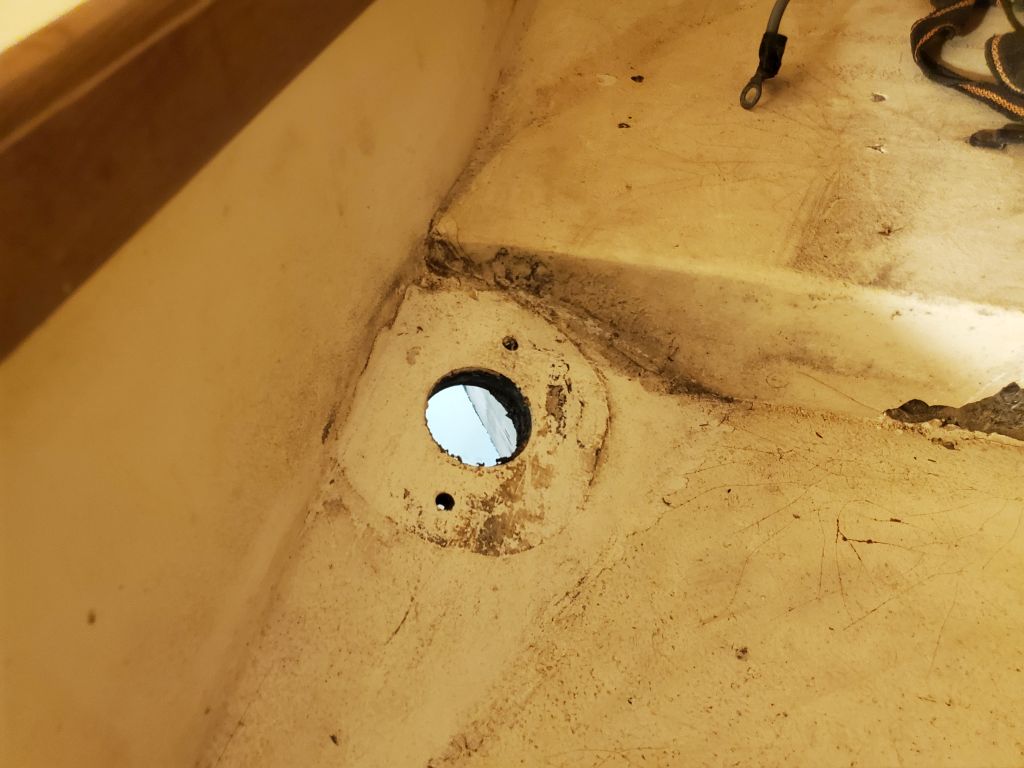
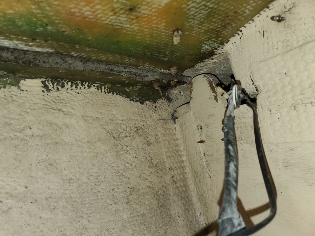
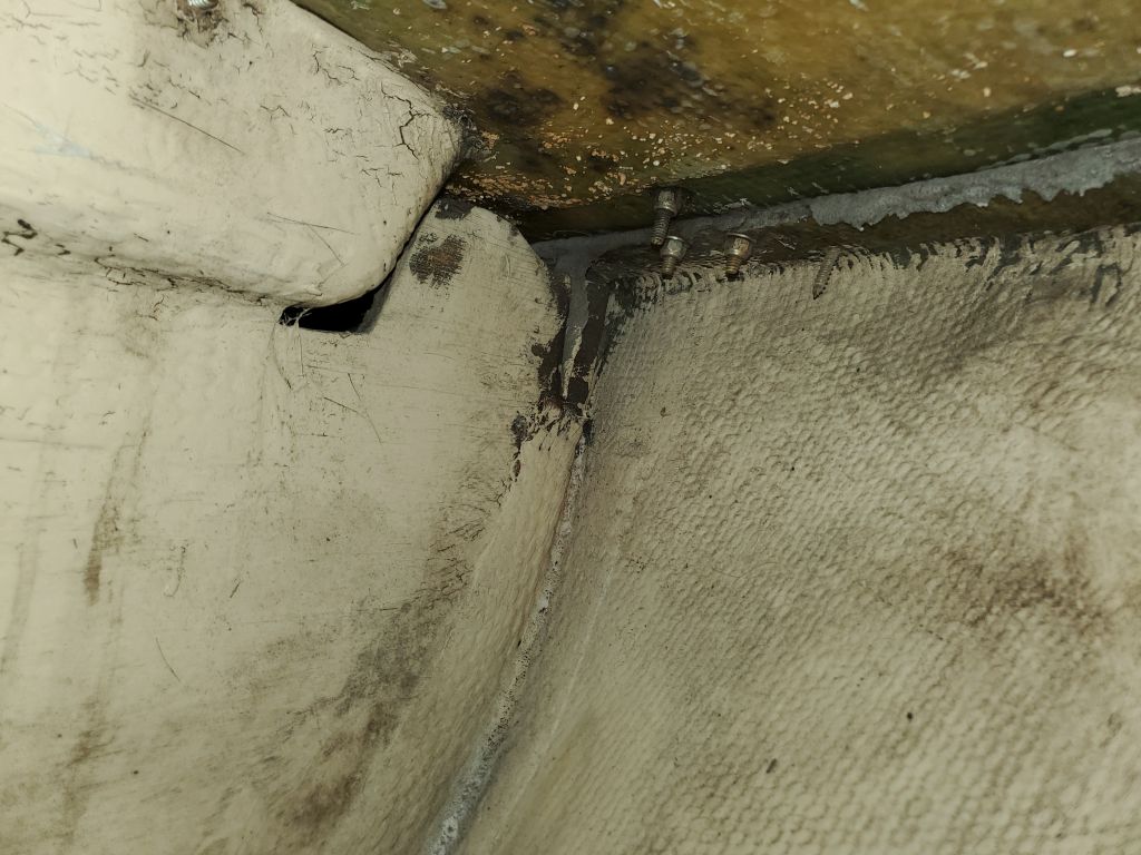
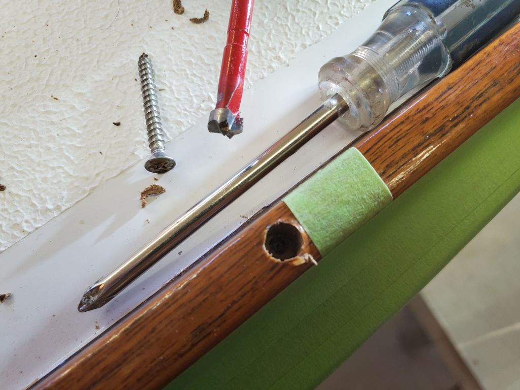
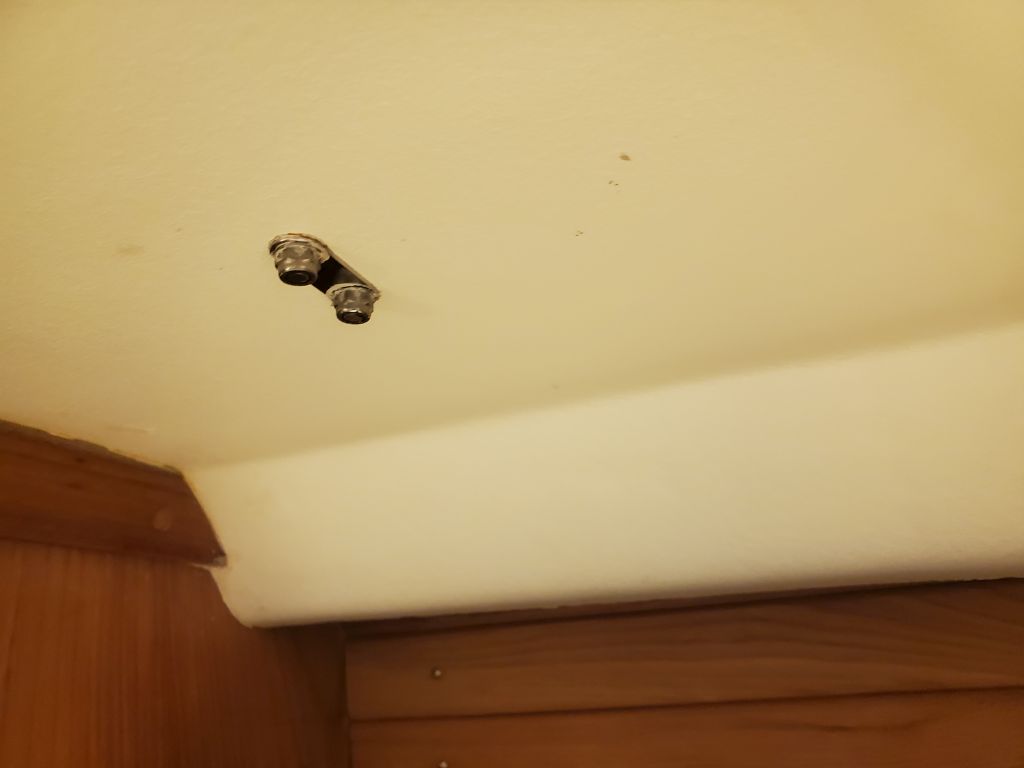
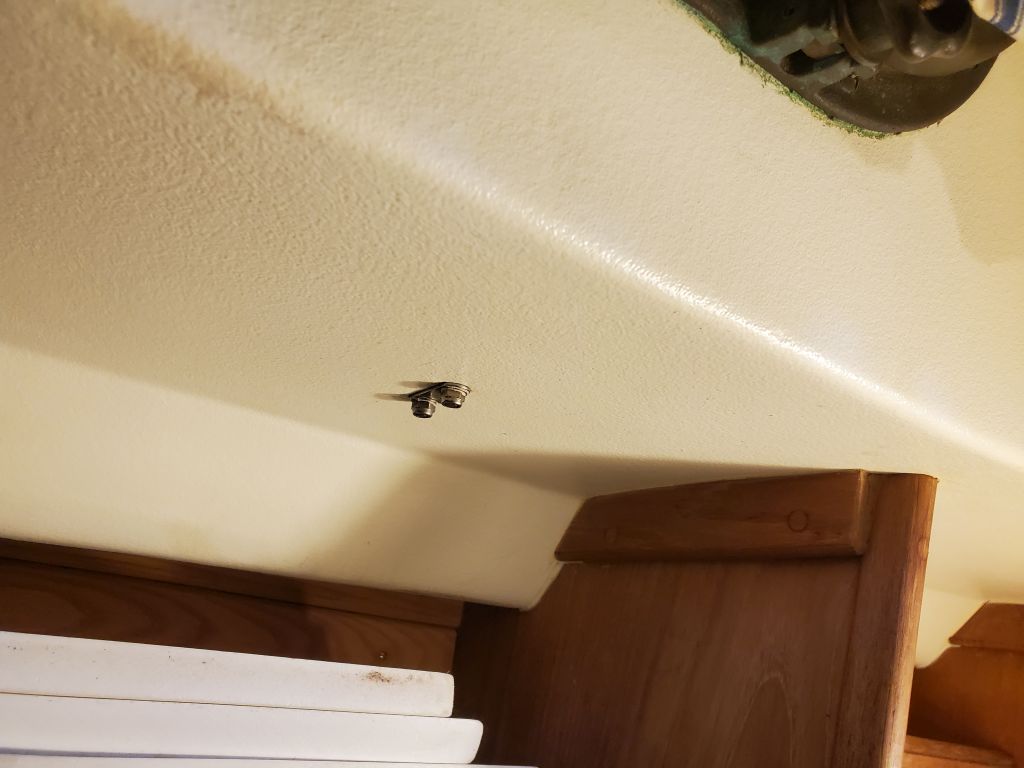
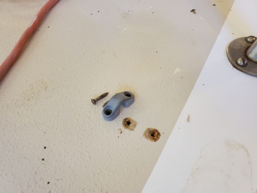
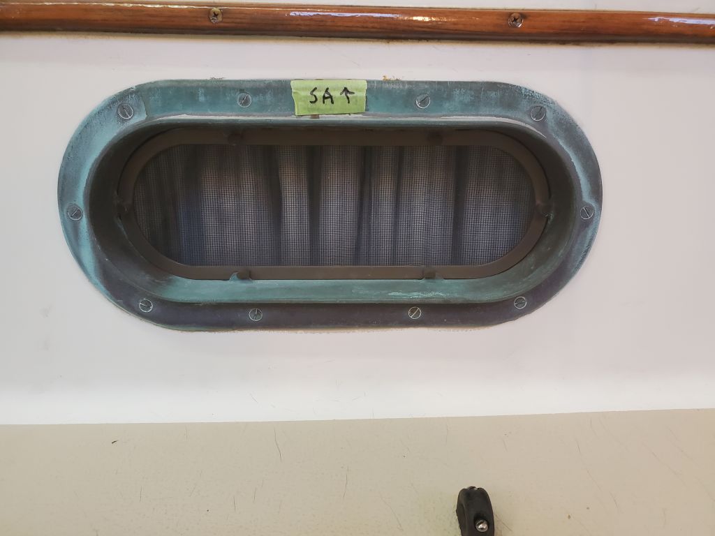
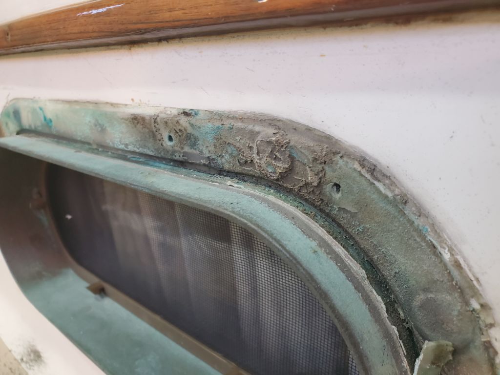
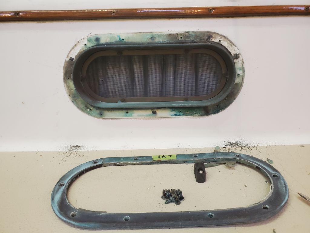
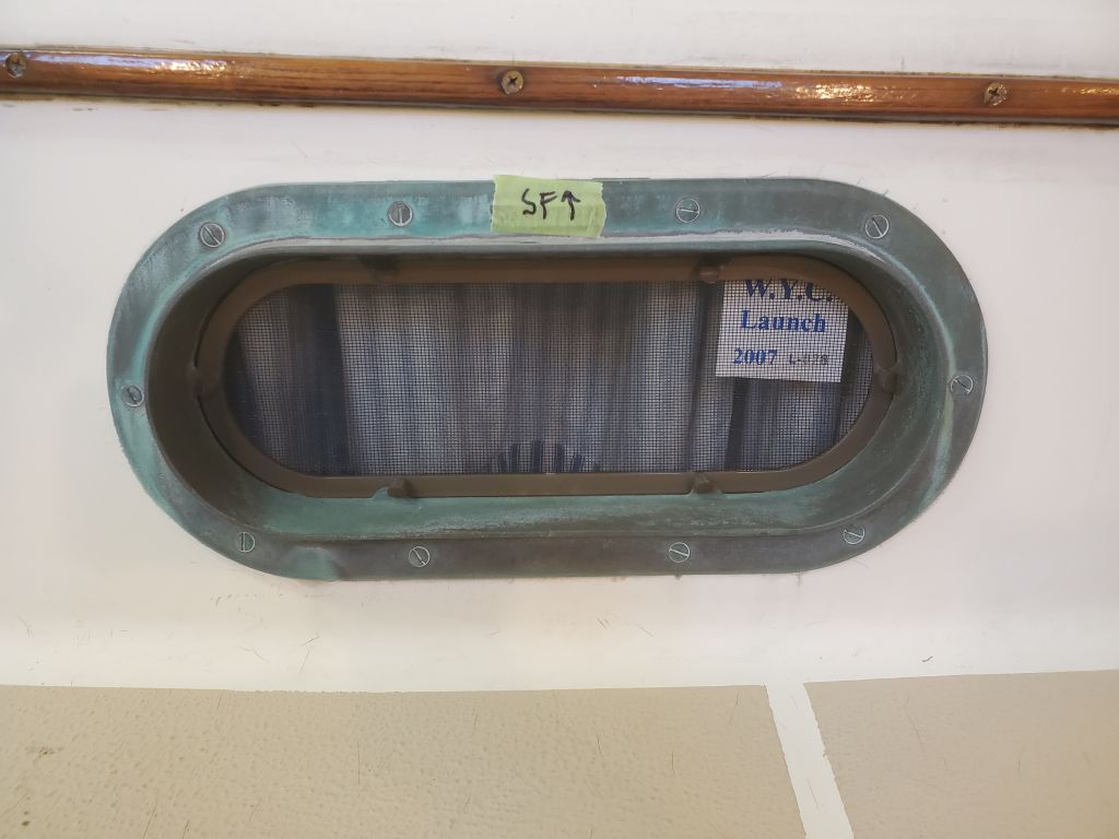
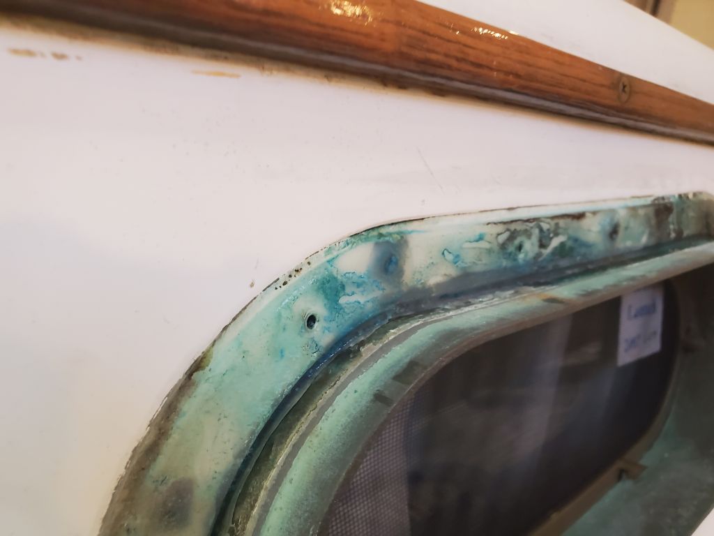
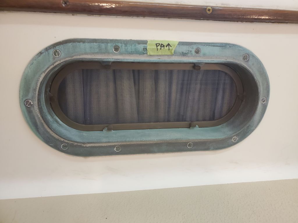
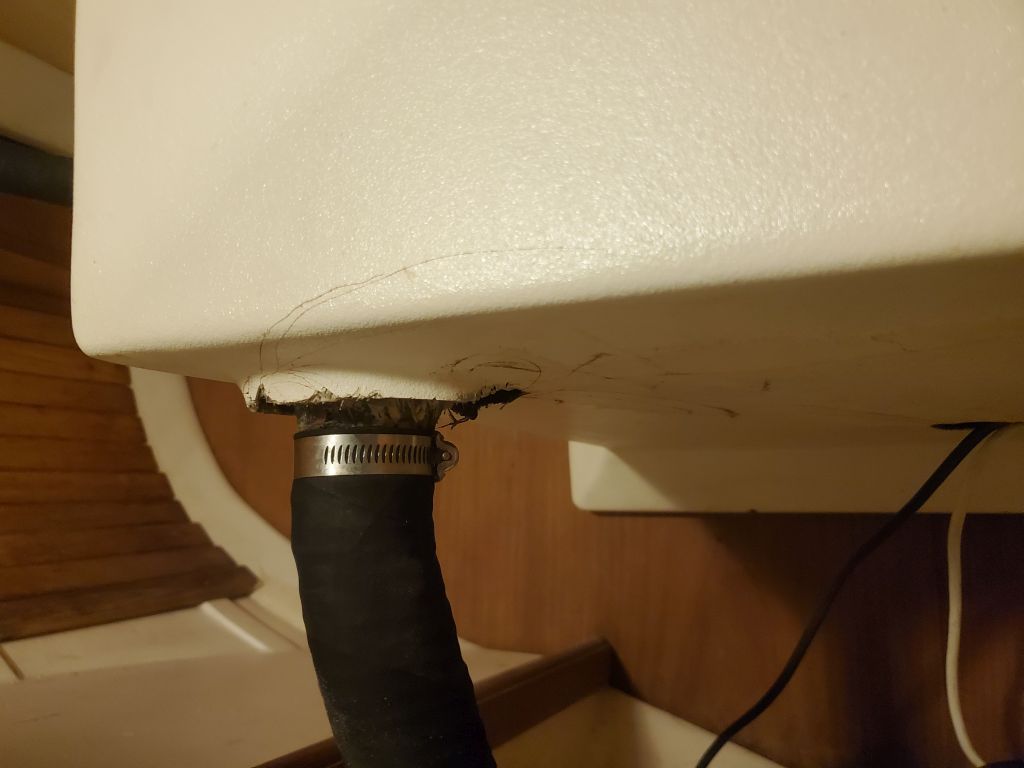
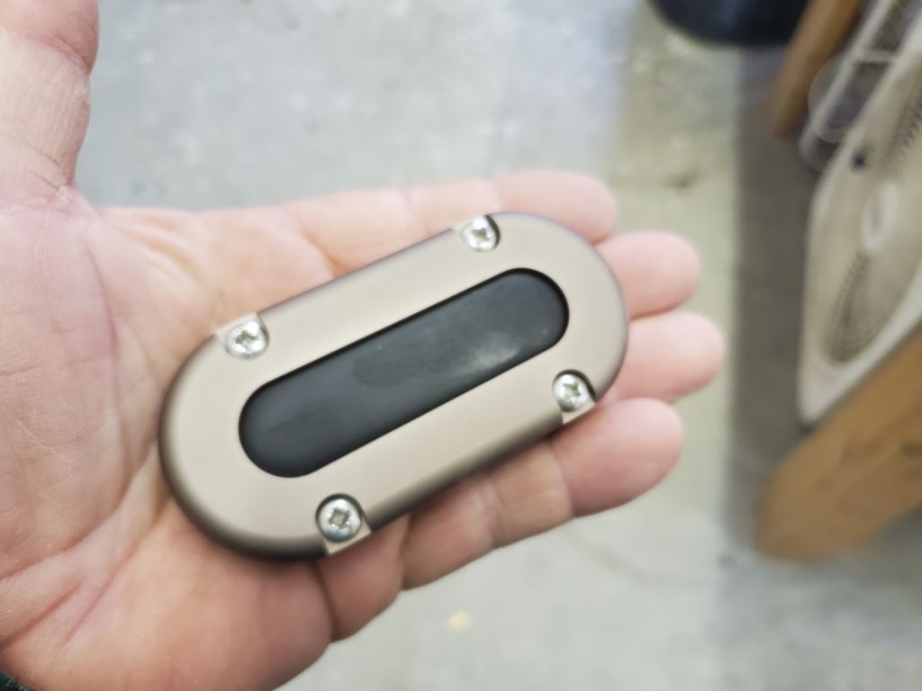
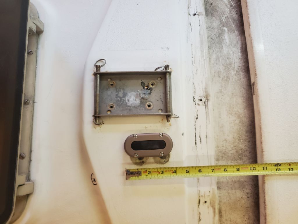
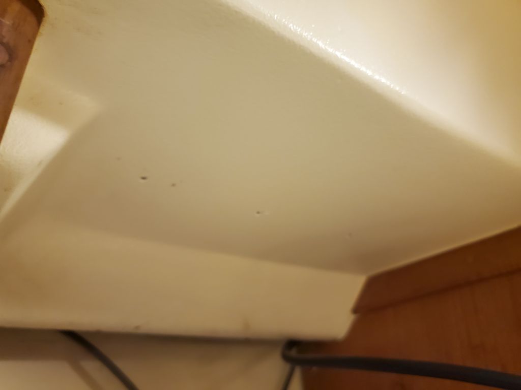
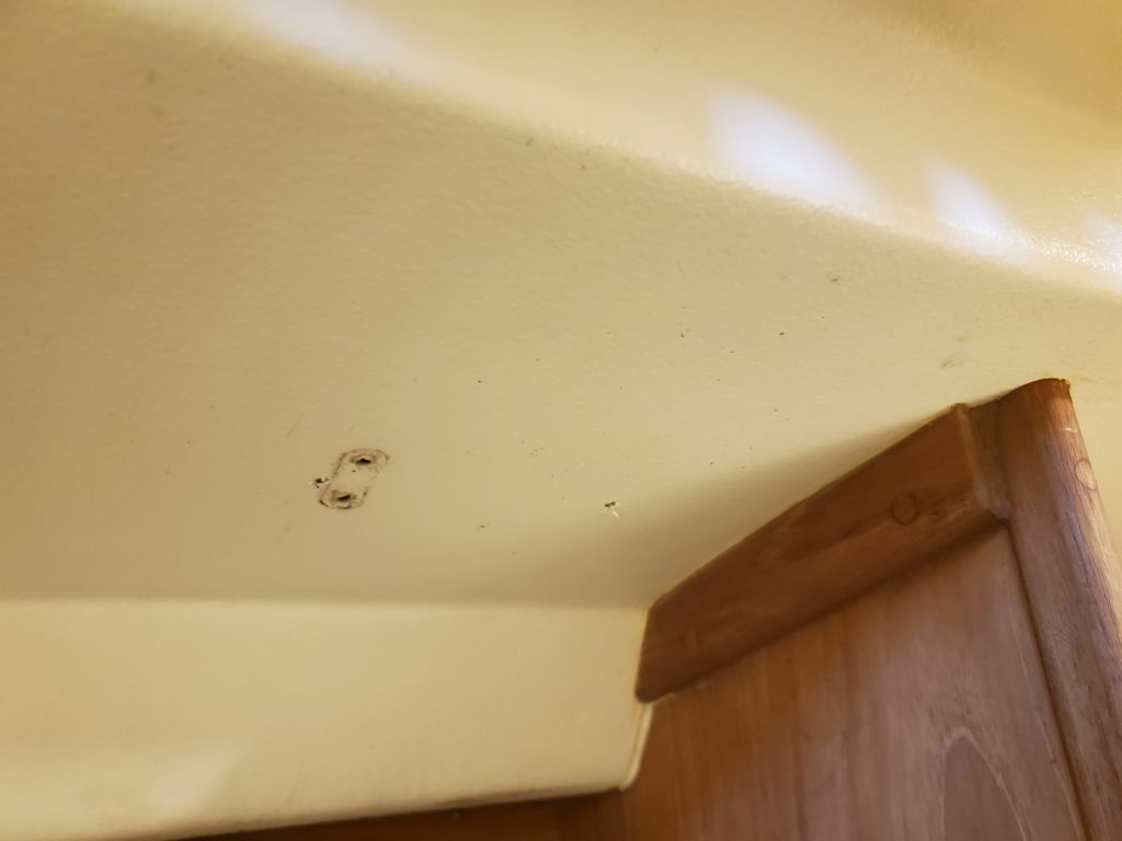
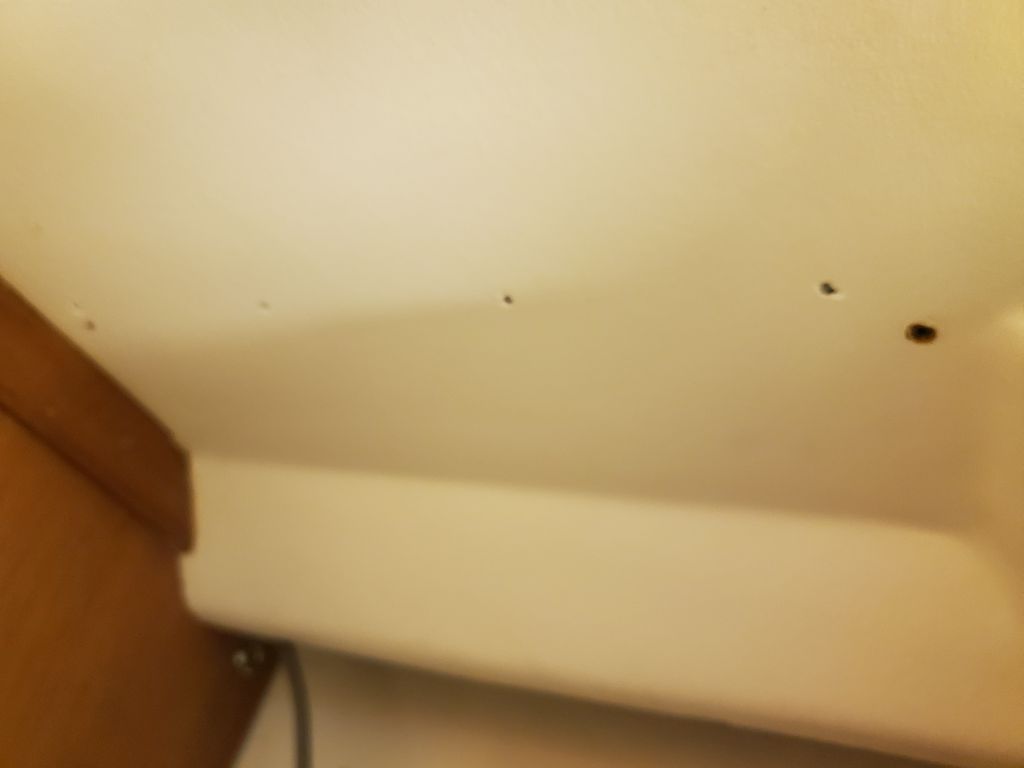
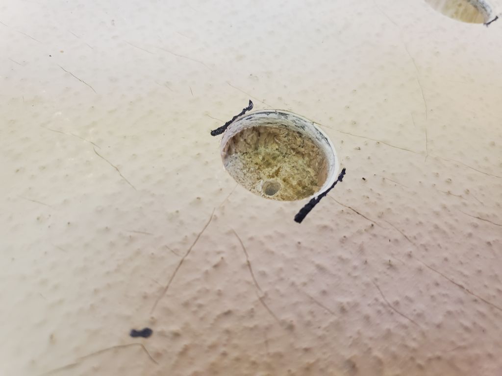
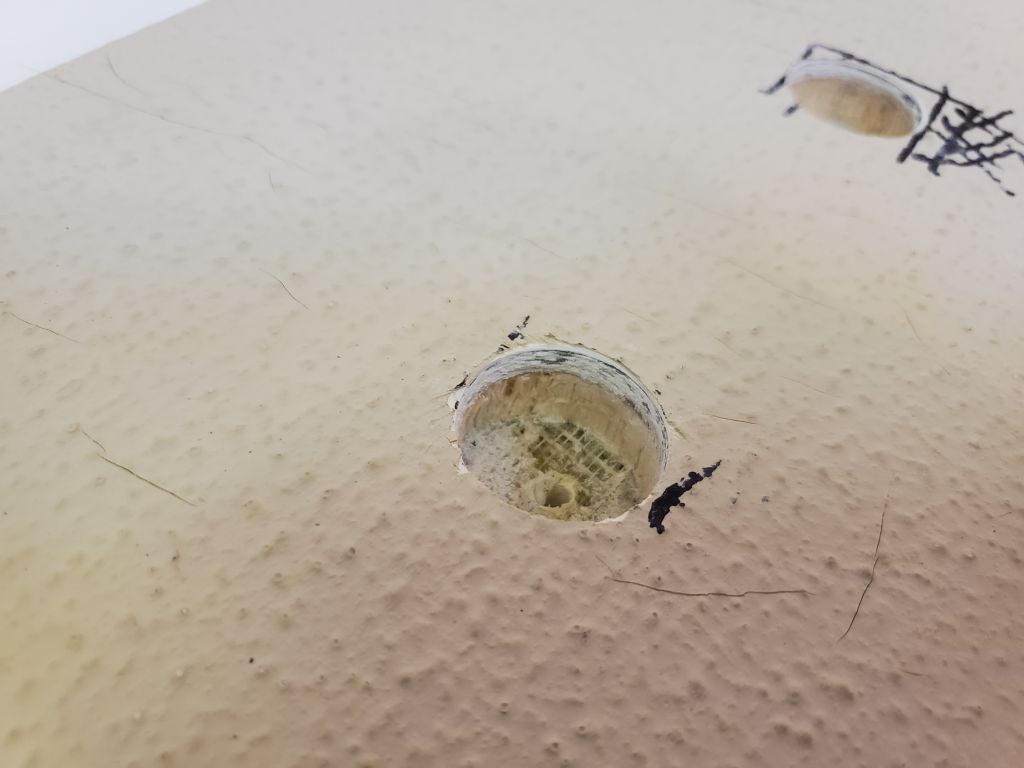
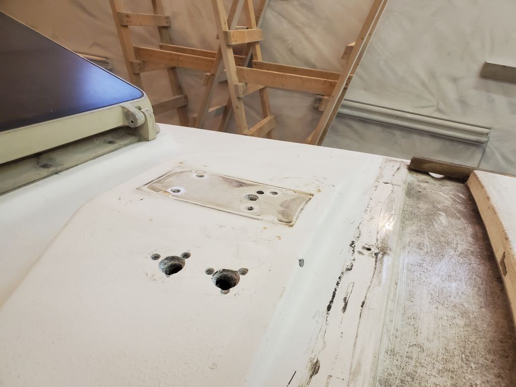
Next, I reamed out these fastener holes to enlarge them and provide a decent bonding area for filling and patching, since all four stanchion bases would be relocated slightly inboard, and the after two slightly forward as well, during this refit.  Similarly, I reamed out any other fastener holes that would be abandoned or relocated, including the old mast wiring holes and those left from a small fairlead on the foredeck that the owner reported was no longer used.  The stanchion bases and mast wiring holes were all in solid fiberglass portions of the deck; the core beneath the two small fairlead holes in the cored foredeck was observed to be in good condition without need for further attention.

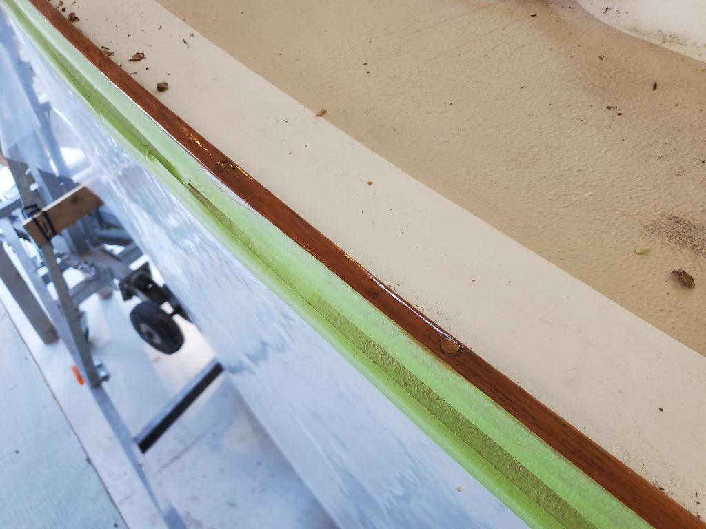
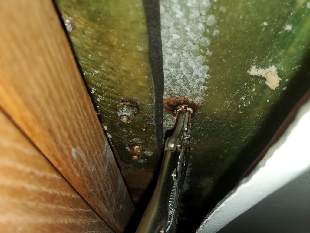
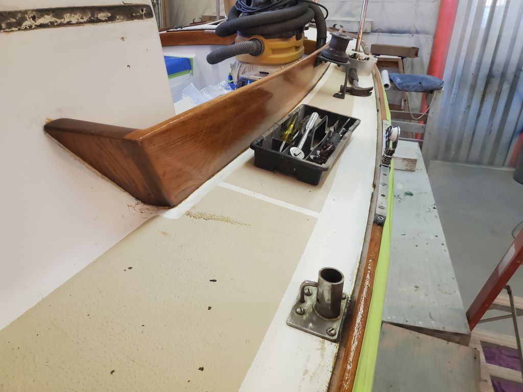
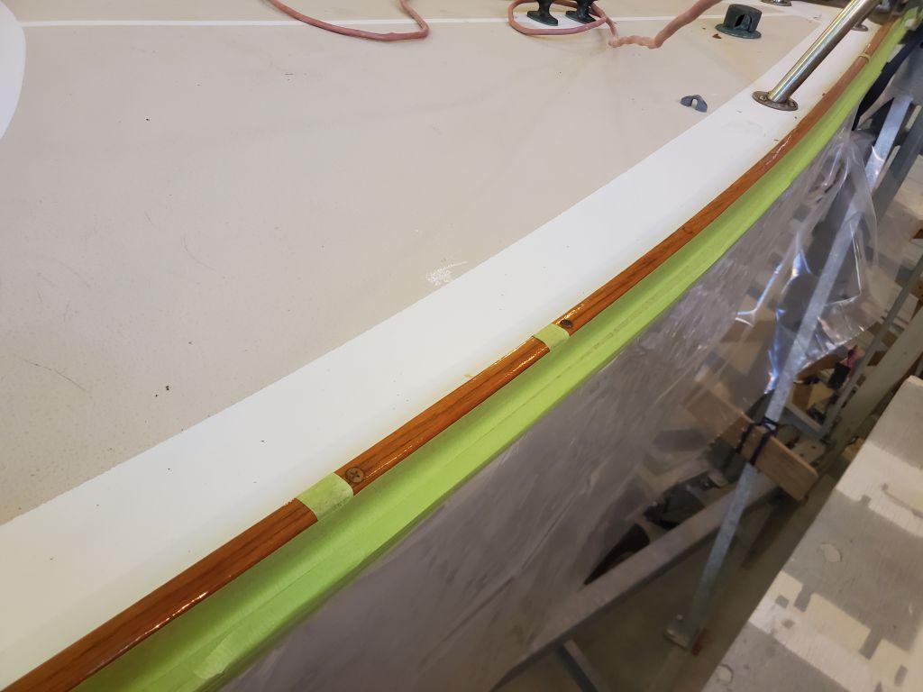
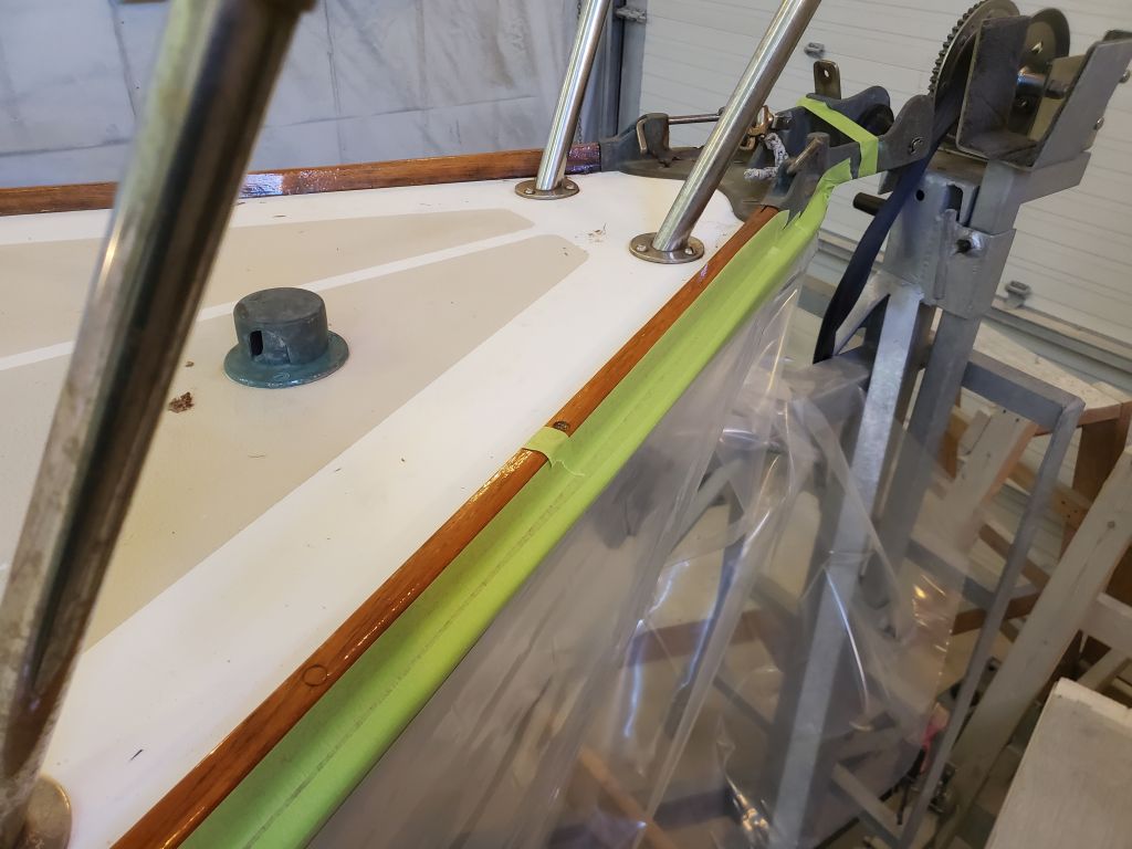
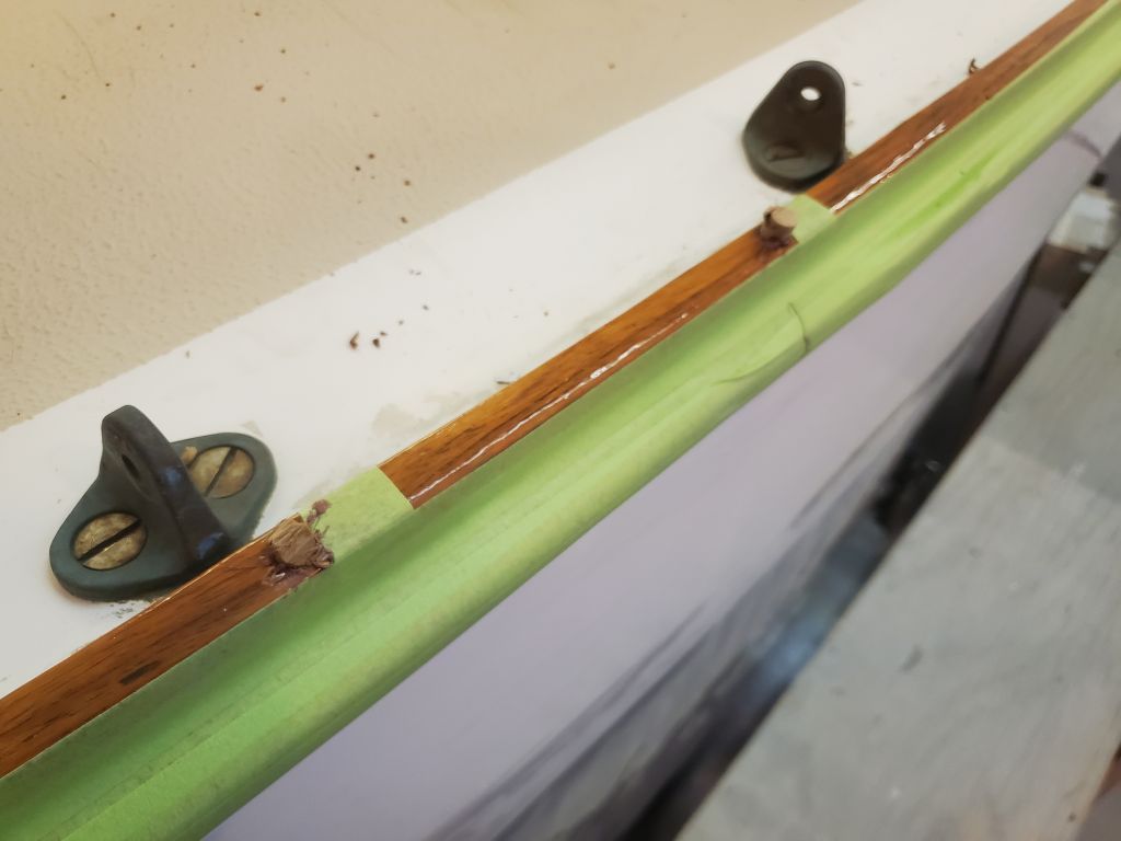
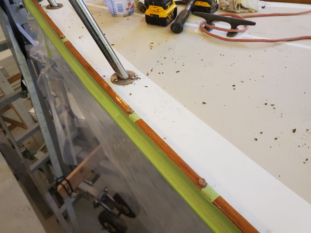
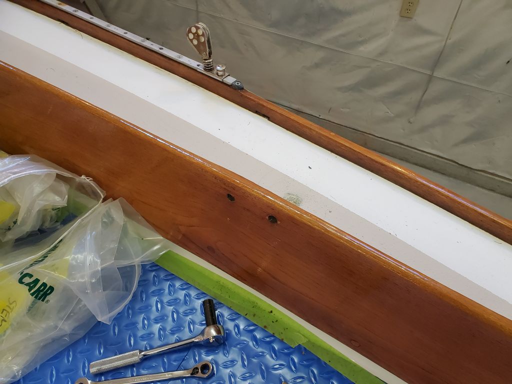
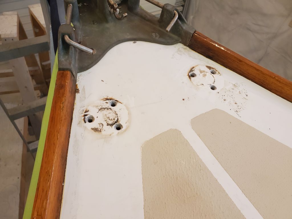
Similarly, I cleaned out the remaining fastener holes about the deck, including the pulpit bases, chainplates, winch bases, and cleat locations, just to remove old sealant for the work ahead; I planned to reuse these holes, so they would not be filled.

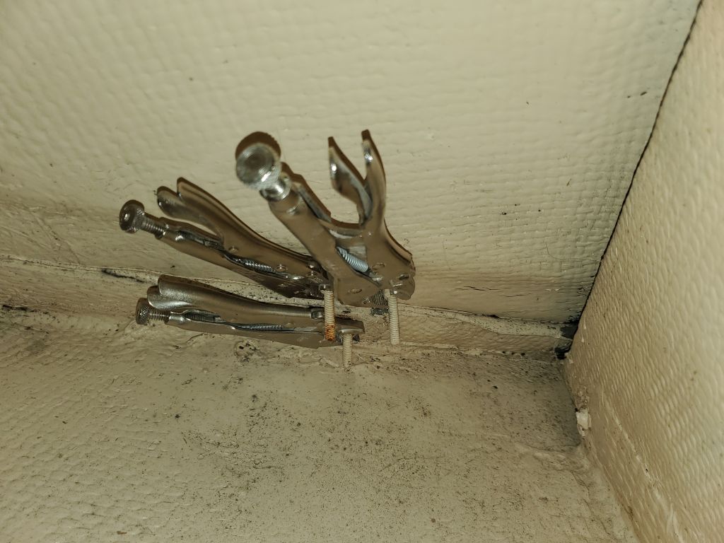
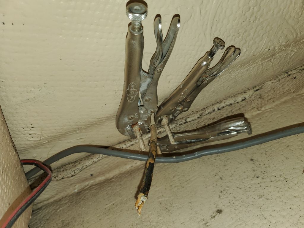
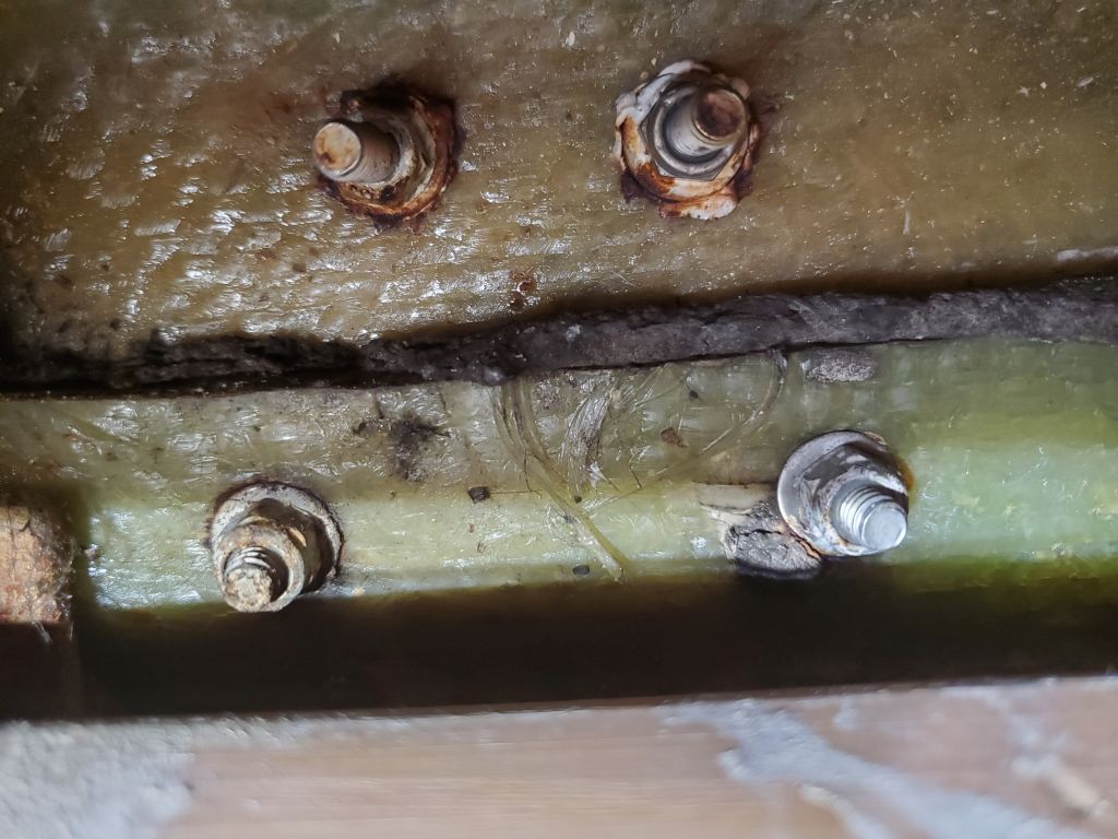
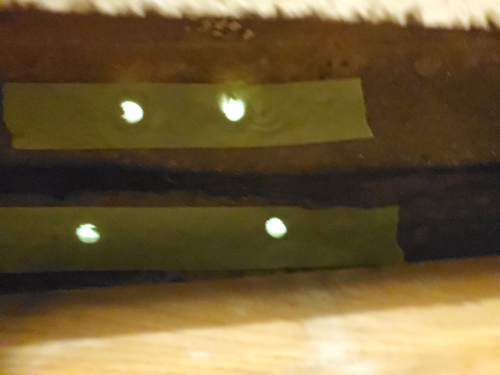
I masked over most of these holes from belowdecks to keep  epoxy fill (where applicable) from ending up where it shouldn’t.

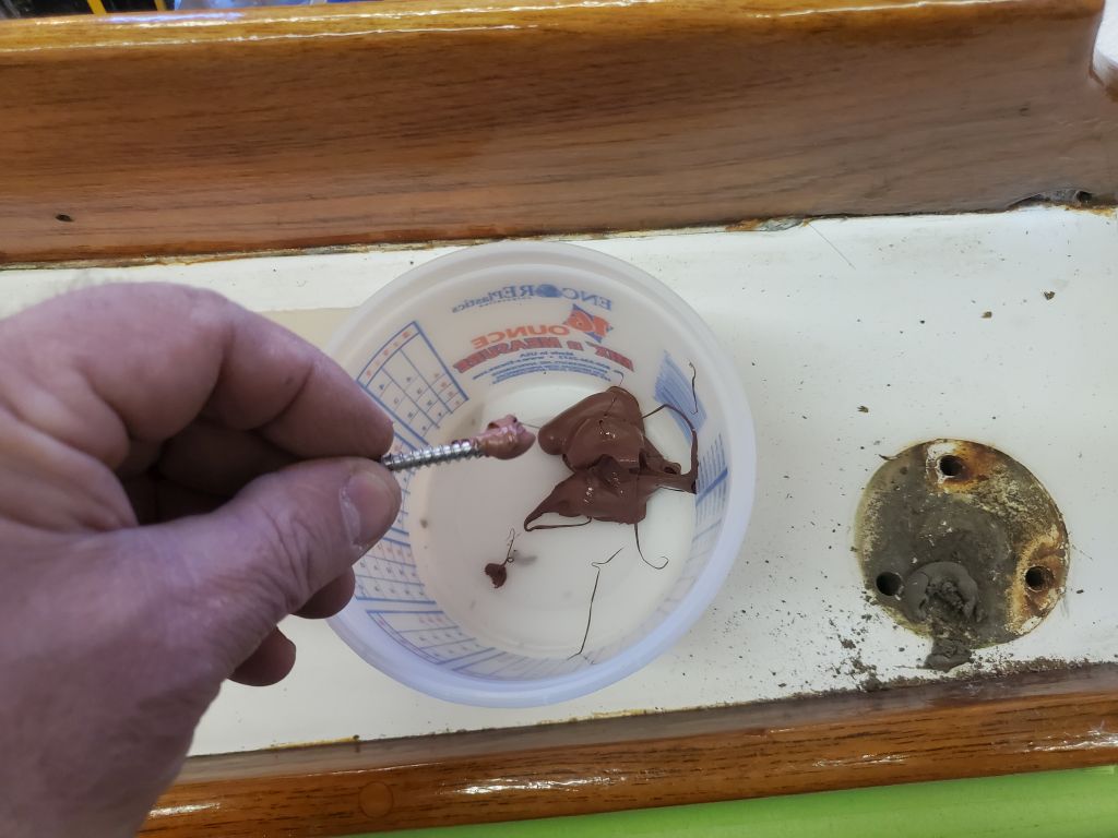
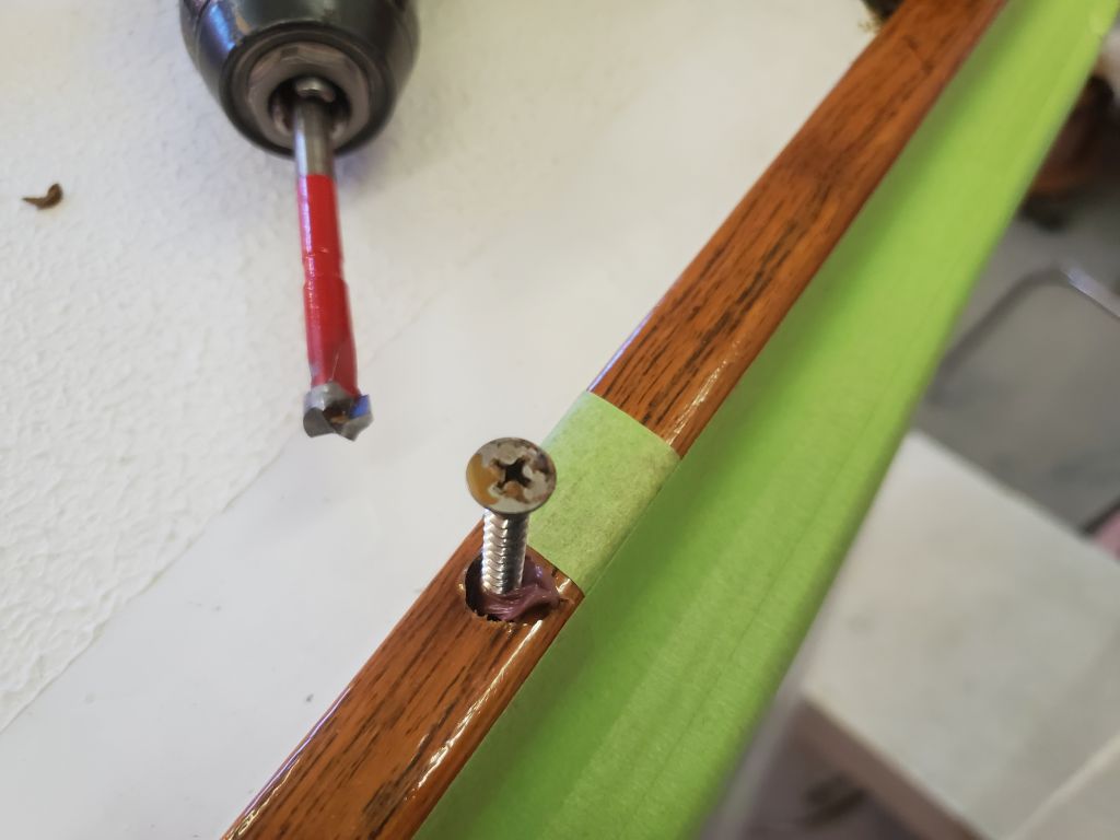
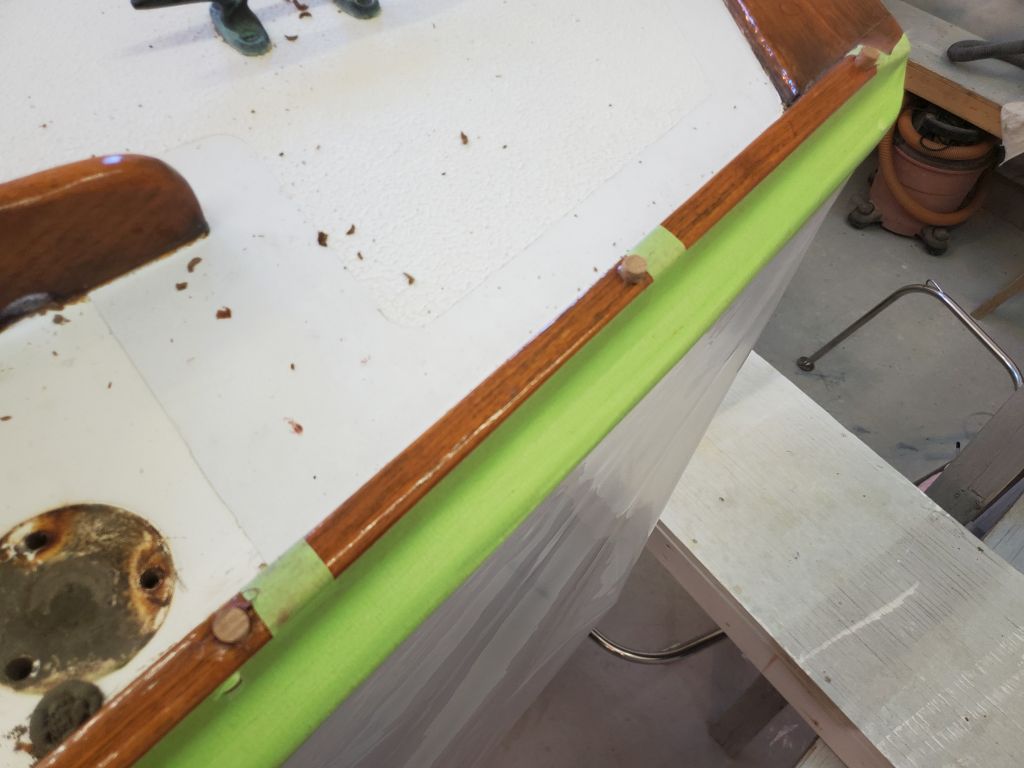
After final preparations and pre-treating all the holes and exposed core with unthickened epoxy, I filled the prepared holes with an epoxy mixture made with high-density filler, giving me a head start on the deck repairs and patching before I dug into the sanding and surface prep next time.  My epoxy is red in color because the hardener reacts with the weld material of the splice in the storage container of the gear pump I use, and the coloring is exacerbated when the hardener has sat for some period time without use.  It has no effect on performance, and I actually like this trait since it makes it easy to know the two parts are well-mixed.

Total time billed on this job today:  4 hours

0600 Weather Observation:  44°, cloudy.  Forecast for the day:  Rain, 58°

Arietta Phase 2-8

Wednesday

I spent the first part of the day largely on semi-extended planning and related discussions with the owner, starting with details about how best to reroute (or not) the mast wiring through the deck.  I sent off various detailed photos showing the exact situation between the deck and cabin liner, where the old wires had run, and we batted around various ideas for an improved setup when the time came.  I won’t go into great detail again here, as the owner and I covered all this in detail during the day, but these photos show the existing mast wiring access hole (too small) and existing wiring located within the narrow channel beneath the deck formed by two glassed-in transverse “beams” that reinforce the deck beneath the mast step.

Regarding the new jib track location, we decided on the inboard, parallel-with-the-cabin-trunk location, as anticipated.  Before finalizing the position and preparing mounting holes, I made some measurements belowdecks to see how the tracks related to any obstructions like bulkheads.  Naturally there were a couple impediments to the placement of the track exactly where we wanted:  the small bulkhead at the aft end of the galley, and the main bulkhead forward.  By transferring measurements taken below to the sidedecks, I determined that the fastener hole spacing on the track required me to move the track somewhat in order for the fasteners to miss these bulkheads.   Moving the track aft about an inch and a half cleared the galley bulkhead and kept the forward end well clear of the main bulkhead, but extended the track further aft than the owner wanted, since adjustment room forward of the old fairlead was much more important since he’d identified through use that the sail required a more forward lead position.  Moving the track forward about 2″ also cleared the galley bulkhead, but then the forward end interfered with the main bulkhead.  Clearing that particular bulkhead would have required a substantial move further forward, if this even worked–but that was a non-starter anyway.

After discussing a few options, we decided to effectively move the track aft about 1/2″ from its “ideal” position (i.e. the aft end of the track aligned with the original fairlead position), which ensured that all the fasteners but one would clear the bulkheads below in a pleasing and effective way; one fastener in the center part of the track would land over the galley bulkhead, and for this I planned to use a shorter machine screw tapped into the deck structure, counting on all the other fasteners in the short track to take the load of the sheet.  After all, the working jib had been sheeted to a plastic bullseye secured with two #10 bolts for 40 years, so this seemed a reasonable compromise.

I’d confirm the measurements on the starboard side before fully committing, but it was good to have this placement figured out.  These photos simply show some of the initial layout, with the obstructions marked with x-marks.  All this black marker would be soon sanded off as I began the surface prep for the deck refinishing.

I also investigated for the owner the condition of the chainplate backing plates, which fortunately on this boat appeared to be stainless steel bar (CDs are notorious for using mild steel backing plates for the chainplates).  What I could see of the metal was in good condition, through the various bolt holes (with camera only–no direct visual access) and at one place at the port forward end.

Similarly, I took a closer look at the stanchion base locations, as the owner wanted to move them all inboard just a bit to allow more clearance with the toerails and free passage of water, debris, etc.  This would be possible, though the inward movement would be slightly limited by the desire/need to keep the outer pair of fastener holes in the inward molded deck flange.  We also discussed moving forward slightly the after pair of bases, to help tighten a maxed-out thread on the opening gates on each side.  This also seemed possible, as the lifeline turnbuckles at the forward end had enough remaining adjustment room to take up a small (perhaps 1/2″) move forward.

I really wanted the scupper seacocks and through hulls out of the boat before I started work on the decks, as this was hanging over my head and to date I’d had only frustration in my removal attempts.  Hoping to save and reuse all the hardware, I’d been taking it slow and (for me) patiently.  Now, armed with a length of pipe that I picked up for leverage, I made a minor modification to my old step tool that did fit the tabs inside these through hulls, but which so far I’d not been able to use effectively as there was not enough moment arm.  Normally, a screwdriver inserted through the holes in the bottom of the tool was more than sufficient for new fittings’ installation, but it wasn’t enough to break free these old threads and whatever sealant.  To help with this, I drilled a new, larger hole above to accept a 1/2″ diameter socket extension-type thing that I had on hand, and which looked strong enough to do the job.  It also happened to fit inside the 3′ pipe I’d picked up.

With the rig set up in one of the fittings, I applied some heat to hopefully loosen things up.  At first, this seemed to work, as I saw the mushroom head move when I applied pressure.  But then it stopped, and further pressure only bent the 1/2″ rod I’d put through the tool.  Inside the boat, I discovered that my turning had bent the fixing bolts securing the seacock flange, and that the whole seacock had turned in the process.  Not helpful.  And this now seemed increasingly stupid, and the time spent was starting to seem inefficient.

I figured if I could get the valves out of the boat, I’d be able to remove the threaded through hulls more easily, and given the modest cost of new mushroom fittings versus the cost of labor, I made the decision to stop wasting my time and quickly ground off the mushroom heads so I could pull out the valves (and remaining stems) from the inside.  Easy peasy.  Afterwards, I removed the remains of the plywood backing blocks, the replacement of which was the point of this exercise.  The original plywood was essentially sound, though did easily fall apart into its various laminations with little effort.  Now I could focus on making the new backing plates and removing the old through hull stems from the valves, and things would be ready for new installation soon.

Total time billed on this job today:  5.25 hours

0600 Weather Observation:  44°, light rain.  Forecast for the day:  Showers, then clearing late, 54°

Arietta Phase 2-7

Tuesday

Before getting too far along with the deck cosmetic work, I wanted to finalize and mark the locations of the new 24″ long working jib lead tracks on the sidedecks.  Before removing the winches last time, I’d made some marks  approximating the existing line leads (from the old bullseye fairleads) to the winch for use in determining the correct position and orientation of the new tracks, mainly to ensure a fair lead aft past the coaming and to the winch drum on the port side, where clearances were closest.

With the existing lead line struck, and representing the outermost position of the eventual track, I struck a second line further inboard, determining the line closest to the coaming as possible for reference and to help determine the theoretical innermost line the track could take (keeping, as a constant, the existing fairlead location as the aft end point of the new track).  These two lines gave me a wedge-shaped area through which I could arc the forward end of the track, any point through which could conceivably be the final position.

Aesthetically, it would be nice if the tracks lined up with something nearby, though the ultimate lead was more important than pure aesthetics.  Not really knowing for sure how the tracks should be aligned going forward, I started for now with the aft end (constant) at the existing fairlead, which meant the edge of the track was 4-3/4″ from the cabin trunk, and replicated this measurement at the forward end.  This kept the forward end of the track just on the green tape mark representing the possible fair lead aft to the winch, so this positioning would work, and also look smart.

Next, I measured from the toerail to the outboard edge of the track at the fairlead (8-3/4″), and replicated the measurement at the forward end.  This actually pushed the forward end of the track closer to the cabin trunk, calling into question the fair lead-i-ness from the first couple hole positions to the winch.  Also, this looked odd, but again, it helped establish the ultimate parameters in play.

Of course the track could also just follow the original line extended forward from the winch and bullseye, skewing the track at an oddball angle across the deck, but possibly keeping it in the right place according to the line required by the jib sheet leading from the clew.

Later, I marked the deck along the two main proposed track locations, starting with parallel to the cabin at 4.75″ (as determined by the position of the original fairlead):

And following the original lead line as established by a straight line incorporating the inner edge of the winch drum, and the original fairlead (and continued forward):

Theoretically, the track could be positioned anywhere between these two outlying positions.

Next, I continued with hardware removal, starting with the sea hood, which was easy to remove by unscrewing the dozen or so screws along the outer flange.  I’d hoped to remove the companionway slider too, but it was pinned in place by the trim surrounding the inner companionway, which I did not want to remove; in any case, I could repaint the hatch with it in place.

Next, I removed the handrails.  Inside the boat, I removed the plastic hole covers in the liner, which hid the nuts and washers from beneath.  These covers were old and brittle, and mostly broke during removal.  Once the way was clear, I used a 7/16″ nut driver to remove the nuts; fortunately, the bolts didn’t spin, since their heads were hidden beneath bungs in the rails (all except the forwardmost one on the starboard side), and I hoped to remove–and later reinstall–these rails without disturbing the bungs.  All eight nuts came off without issue, and with a bit of careful prying I removed both handrails.

That seemed to be it for hardware in the way of the deck work ahead.

After finishing up some work with another project at the shop, I turned to the scuppers, continuing my work to eventually remove the through hulls and replace the backing pads as the owner requested, and removed the old hoses; these were in fairly poor condition and required replacement regardless of the state of the seacocks.

I’d not yet hit upon the right tool combination to unscrew the mushroom fittings from outside the boat, and I thought I’d try unbolting the valves and unthreading from above.  The four fixing nuts (two per side) came off without issue, but I wasn’t able to remove the bolts–I’d hoped to hammer them out, breaking whatever putty was covering their heads on the outside, but this didn’t work.  I could see no sign of the heads from outside, so I removed some bottom paint from around the through hull, hoping to find them.  Eventually I did–the one I’d tried to bang out from within.  It was partially hidden beneath the flange of the mushroom head, which meant that hook or by crook, the through hulls would have to come out first before I could remove the valves.  I’d revisit this job sometime later when I’d worked out a way to spin out the fittings; the new step wrench I purchased didn’t engage the ears inside these particular through hulls, so wouldn’t be helpful in their removal.  My older, original step wrench had a better hope of working, but first I needed a way to increase leverage.  More on this to come.

Meanwhile, I finished up work on the toerails by paring away the excess bungs I’d installed the other day, then applying a coat of finish over the new wood to blend it with the existing coatings.

Total time billed on this job today:  4.5 hours

0600 Weather Observation:  30°, mainly clear.  Forecast for the day:  Sunny, 62°

Arietta Phase 2-6

Monday

Back on hardware duty, I started at the stem with the bow pulpit, which was secured with 12 long bolts through the foredeck.  Access was moderate, if uncomfortable, and it took several trips back and forth between setting up locking pliers from beneath, removing screws from above, resetting the pliers when they fell off before the nut was spun off, and resetting for the next set of bases, but eventually the pulpit was free.

I had to leave the shop for an appointment for several hours, but upon my return in the afternoon I continued work on the hardware, working my way down the sidedecks to remove the stanchion bases (two per side) and chainplates (three per side).  Things didn’t start out too badly in the forward cabin, where the forward set of stanchion bases and chainplates were located.  Access to the bolts was through a narrow, but accessible, opening at the side of the molded interior liner.  There wasn’t really room to work a wrench in there with any sort of efficiency, so again I fell back on my locking plier helpers, eventually removing both port and starboard bases, and port and starboard forward chainplates without too much trouble.

Continuing aft, the situation deteriorated.  There wasn’t good access to the after stanchion bases since there were long shelves installed fairly close beneath the locations, which prohibited visual access and greatly limited tool access, so eventually I decided to remove these shelves, as much to assist with the eventual reinstallation of the hardware as anything.  With the shelves out of the way, I had sufficient access to remove the after set of stanchion bases from both sides.  Note that the stanchion and pulpit removals were all complicated by the choice of round-headed, slotted fasteners that seem to be the most difficult to deal with in a removal situation, but at least the stanchion bolts weren’t an inch or more longer than necessary like the pulpit bolts had been.

I had wavered on whether or not to remove the chainplates from the getgo, or just work around them, as part of me was loathe to disturb them.  But I was lulled into a false sense of security with the forward pair, which weren’t too hard to remove even though the fixing bolts were substantially longer than necessary, meaning unwinding the bolts was near eternal.  But I did end up regretting my decision to remove them as soon as I moved on to the remaining two pair:  Access was difficult, with no direct visual access from beneath in the tight spaces, and, on the port side, another shelf that blocked all practical access to the nuts.  There were various heavy wires in the way as well:  Bonding wires connecting all the rigging attachment points (and forming the worst of the bulk that made the access more challenging), plus a wire bundle down the port side.  All these factors conspired to make the final removal of the hardware much more time-consuming than I had hoped.

On the starboard side, access was fair enough that I could remove the aft chainplate without too much trouble, but the forward chainplate was located directly in line with the bulkhead, and access to the forward bolt was too tight to allow a socket or wrench, as there was only a small space above the bulkhead, and with the bulkhead right in line with the bolt, there was insufficient room for any sort of convenient tool.  I finally prevailed after I removed entirely the after bolt (each chainplate was fixed with two 3/8″ flathead bolts), which then gave me just enough room to clamp onto the nut a small set of locking pliers, after which I could remove the bolt from above.  As simple as this all sounds when reduced to these few sentences, it must be said that this took a very long time and I wondered if I’d even be able to remove this particular bolt and chainplate.  I prevailed, but it was close.  The woven roving with the cracked/broken fibers seen in these photos serves only to secure the metal backing plate beneath the deck, though which the chainplates are bolted and by which are reinforced, and as such doesn’t appear to pose any problems, though, as I discovered it while reviewing these photos, I planned to have a more detailed look presently.

Moving over to the port side, my first task was to remove the little shelf that was in the way, which was secured with four screws through the top side.  The inner pair of screws I could reach with my right angle drill, removing them rather easily, but the outer pair had so little clearance that I was reduced to using a stubby screwdriver on one, which was bad enough, and then, for the aft screw, one of those ridiculous right-angle hand screwdriver things that every tool kit has, but one fervently hopes never need use.  It worked, a sixteenth of a full rotation at a time, and finally the shelf was out and I could attack the chainplate bolts.  Once I managed to get the mess of wires out of the way enough, I was fortunate that these four bolts came out more easily than their counterparts to starboard, aided by the fact that the sealant bedding these chainplates was strong enough to allow me to unwind the nylock nuts from beneath with a ratchet, without need to hold the bolt from spinning.  In fact, on these two final chainplates, the bond of the sealant was strong enough that my impact gun, for a while, couldn’t even turn the bolts from above once the nuts were removed, breaking two hefty slotted bits before I found one that didn’t shatter before it had managed to loosen the sealant’s bond on the remaining fasteners.

Despite the fact that it was a short day, it hardly seemed a day’s work, removing these few bits of hardware, but there you are.  I daresay I thought this was perhaps the worst of it, though.  Next time, I hoped to finish the required removals with the handrails, sea hood, and companionway hatch, which would then leave things pretty much ready for the real work to begin.

Total time billed on this job today:  4.25 hours

0600 Weather Observation:  30°, mainly clear.  Forecast for the day:  Sunny, 62°

Arietta Phase 2-5

Friday

Now that the staging and other setup was complete, I could get into the early stages of the project for real.  I began by documenting the existing condition of the decks and hardware, for my own reference later, and for posterity otherwise.  The decks were original, with the usual minor and expected cracking here and there at the corners and in the main parts of the deck.  I didn’t anticipate the need for any real repairs, though there’d be a fair bit of crack mitigation.

I wasn’t ready to crawl up in the nether regions of the bow just yet–where I normally tend to start my hardware removal–so this time I began at the stern.  The owner mentioned that the oarlock, as installed last year, didn’t allow him to properly use a sculling oar since the angle was too acute given the orientation of the mounting block and the oarlock installed.  He requested that I reinstall the block, and the oarlock itself, at an angle approximating that of the transom, to better give him the sculling orientation he needed.  So to begin, I removed the oarlock and its mounting block, setting it aside for later attention.

Next, I removed the stern pulpit, as the forward two bases were located in the part of the sidedeck I’d not worked on last time (the poop deck and environs had been part of last year’s work that included the cockpit and hull).

I hadn’t planned on getting into this just yet, but sometimes the stream of consciousness method takes hold.  My attention was drawn to a couple screws in the toerail adjacent to the stern pulpit:  Another of the small projects the owner had requested, if possible, was to deal with the various (17, as it happened) screws in the toerail that had, over the years, lost their bungs.  Since the wood was in good shape all around and given its age, repairing these screws and bungs seemed a good option versus replacing all the exterior wood.  Earlier in the project, I’d gone around the boat and marked with tape all the screws requiring attention.  I’d planned to get around to these later, but since I was in the area and staring at three such screws at the aft end of the port toerail, I thought I’d go about seeing what the prospects were.

The exposed screw heads were covered with a lot of the toerail finish, but were easy enough to engage with a screwdriver–just a hand driver, as I didn’t want to strip any screw heads–and remove.  I started with a single screw as a trial, but once it was out (and with ease), it just seemed to make sense to bang out this little project now.  So, one screw at a  time (to avoid disturbing at all the bedding of the rail with the deck), I removed the screws, cleaning out the remnants of the bunghole as needed and carefully extracting the screw.  Then, I used a 3/8″ Forstner bit to drill a deeper hole for the screw and a new bung, and reinstalled the screw after dipping it heavily in some brown sealant.  I finished each hole with a new teak bung, counting on the excess sealant I made sure was in each hole to secure the bungs.

And in such fashion I worked my way up the port rail, then down the starboard side, repairing all 17 locations.  Later, once the sealant had cured sufficiently, I’d return and pare off the bungs, and dab on and build up some finish so that annual toerail maintenance in the spring would finalize and cover all the new bungs.  Each screw typically only took about two minutes start to finish, though a few required more effort to clean out the heads, and more finesse to remove without damaging the surrounding finish or wood.

With this small job checked off, and now back on hardware detail, I continued working forward, turning next to the cockpit winch bases.  Before removing the winches, however, I used some tape to strike a line between the port winch (at the inboard side of the drum where a line would lead) and the old bullseye fairlead in the sidedeck, which up till now had served as the lead for the working jib.  The owner wanted to install short tracks in its stead, but we also had to ensure that the line leads from the various positions of the track would line up with the winch without chafing on the coaming along the way.  The tape approximated the path the line would lead between the existing bullseye (which would demark the aft end of the new tracks) and the winch, so I’d have this for reference later.  I also struck a second line of tape, this one led as far inboard as it could go while maintaining a fair lead aft, past the coaming, and to the winch drum.

Between these two marks, somewhere, was the sweet spot for the new tracks’ position, which detail I could finalize a little later; I mocked up a couple things and took some measurements that I’ll get into more in the immediate future.  For now, I had enough information on the decks to proceed with the winch removal.  (I didn’t need to repeat this process to starboard, since on that side, with the line leading to the outboard edge of the winch drum, there was sufficient clearance regardless, so I could simply replicate the final track position as determined to port).

The winch bases had a single bolt passing through the sidedeck, which was accessible from beneath at the aft ends of the quarterberths, and removal proved to be no problem.  Two additional screws secured the bases to the coamings, and after removing these both winches were out of the way.

Continuing forward with all the “easy” hardware, I removed, in turn, the bullseye fairleads, anchor hawsepipe, a little fairlead up near the bow pulpit, the bow cleat, and, finally, the mast step and wiring bases nearby, bringing me to the end of the day.

Total time billed on this job today:   4.75 hours

0600 Weather Observation:  Clear, 25°.  Forecast for the day:  Sunny, 48°

Arietta Phase 2-4

Thursday

The first step in any project is some basic setup and prep, and here I started with the cockpit, which I’d repaired and painted a year ago and wouldn’t be getting any attention now.  However, to protect it during the adjacent deck work, and the ins and outs through the companionway while I removed hardware and performed other tasks, I covered the sole and seating surfaces with protective plastic designed for the purpose.

Most of the work would be at deck height, and now I set up staging around the boat to improve access.  I had to work out some optimum spacing and use of my various horses and planks, slightly complicated by the bulk of the trailer, and ultimately found I needed to remove the loading guide supports at the aft end, as they protruded too far and prevented the staging planks from being where they needed to be–and these steel bars would also be a constant headache for snagging cords and hoses.  I made reference marks to register the guides’ positions, then removed them for now.

Afterwards, I could finish setting up the staging planks around the boat, getting everything just right for safety and to ensure the right distance from the boat in all areas for access and to avoid being too close.  I secured all the planks with little L-brackets and screws to prevent shifting.

Finally, to protect the hull during the work above, I hung plastic sheeting that I taped to the toerails all the way around.

Total time billed on this job today:  3.25 hours

0600 Weather Observation:  Clear, 26°.  Forecast for the day:  Sunny, 47°

Arietta Phase 2-3

Wednesday

With some time at the end of the day, my impatience got the better of me and I decided to remove the mast; I’d planned to wait till the bay next door was free in a few more days, at which time I could easily use the crane there to remove the spar, but after inspecting the situation and test-lifting the mast I decided it was light enough to remove safely by hand, which I did using a pair of ladders, eventually lowering the mast easily onto my rolling staging so I could move it outside and out of the way for the duration of the project.

Total time billed on this job today:   0.75 hours

0600 Weather Observation:  Clear, 30°.  Forecast for the day:  Mainly sunny, 5o°

Arietta Phase 2-2

Wednesday

Having sewed together a blank of cover material roughly 30′ x 13′, Jason returned to perform the initial templating for the new winter cover.  This process looks awkward, but works out in the end with a cover that fits the boat tightly and accurately.

We began by repositioning the mast a bit further aft, which gave better extension beyond the transom to improve the cover’s coverage and create better lines for the aft termination.  This mast position would be crucial in the future, as the fitment of the cover would require the same mast position each time.  Fortunately, this was straightforward:  The mast was positioned so the halyard cleats at the base were tightly against the forward mast support on the trailer.

Now, with the blank centered and draped over the boat, Jason used a few temporary grommets and lines to pull the centerline tight, and also secure the blank amidships at the widest point of the boat.  From there, he let the blank tell him what it wanted (the Tarp Whisperer), and in this case the cover did fairly settle right into its desired contours, at least once the magic happened back at Jason’s shop.  With temporary darts stapled in place (and duly marked), and key points marked on the blank itself (e.g. the edge of the rubrail, stem and stern, etc.), the process in situ went swimmingly and rather quickly.  The stapled darts would ultimately become tight seams, and the ends would eventually become trimmed and neat terminations with simple lacing.

We won’t likely see the finished result till the end of the project in some weeks’ time.  With this step out of the way, now I could think about removing the mast and getting to work for real.

Total time billed on this job today:  1 hour

0600 Weather Observation: 43°, clear, windy.  Forecast for the day:  Partly sunny, 53°

Arietta Phase 2-1

Tuesday

Arietta was back for another round of work, this time focused mainly on completing the remainder of the deck refinishing, after completing the cockpit and hull phase last year.  After clearing space in the shop following summer break, I moved her indoors and prepared to get to work.

The first order of business this season was to get the preliminary work done on a new winter cover, which Jason, my canvas subcontractor, would be taking care of.  The new cover would use the mast as a ridgepole, and until the initial fitting was done, the mast had to stay in place on deck.  After an initial consultation and some basic measuring, Jason had the information he needed to build a rough blank for the cover, and now I’d wait till that was complete and patterned before I could get into the bulk of the deck work.

In the meantime, however, I planned to pick away at the work list and get done whatever I could in advance, so I started by removing the lifelines and stanchions, which needed to be out of the way for the cover in any case.  I also removed and secured some rigging that had arrived still attached to the chainplates, preparing not only for the new cover work, but, afterwards, for the removal of the mast during the bulk of the project.

Next on my list of early projects was to remove the bronze port trim rings in advance of the deck preparations and painting.  These were secured with bronze screws from outside, and removal was straightforward.  The trim rings had been bedded in abundant silicone, which I’d later have to remove.  The trim rings were in good condition and would require minimal cleaning, since the bulk of the old sealant had remained on the gelcoat.

Next, I removed the teak eyebrow trim from both sides of the cabin.  All the screw heads were exposed (but buried beneath a substantial coating of finish) except for one I found on the port side that still had the last vestiges of a bung, suggesting that at one time all the screw holes had been bunged.  This trim was easy to remove, and other than the inevitable damage to the gummy coating as the screws came out, remained intact.  However, I planned to mill new trim here, since it would be quicker and easier than attempting to save and restore the old trim; this would also allow bunging the screw holes during installation.

With a bit of time later in the day, I began to assess another one of the projects on the list:  Replace the backing pads beneath the scupper seacocks.  The original pads of plywood, while still generally sound, were beginning to deteriorate after years of moisture and condensation.

This would require removal of the hoses, valves, and through hulls.  I hoped to be able to unthread the through hull mushrooms from the valves from outside, after which I could unbolt the valves and replace the pads as needed.  However, the through hull installation wrench I had, and which works well for new installations, wasn’t suitable for removing these fittings, as I found I couldn’t apply enough leverage to break free the threads.  After a fruitless attempt, I ordered what I hoped would be a better tool for the job, one to which I could apply a wrench, and set this project aside for the time being till the new tool arrived.

Total time billed on this job today:  2.75 hours

0600 Weather Observation:  Cloudy with showers, 43°.  Forecast for the day:  Rain, 50°

Newer posts