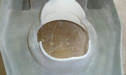
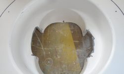
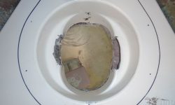
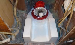
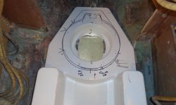
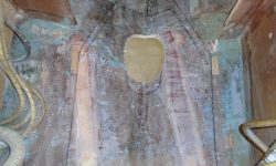
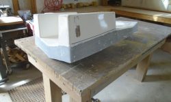
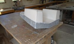
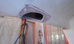
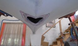
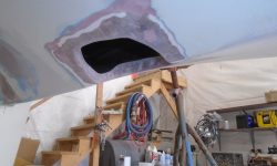
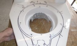
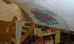
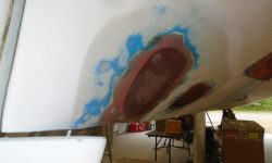
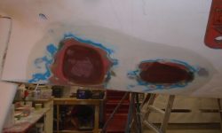
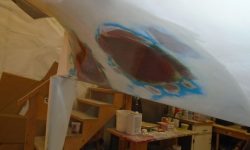
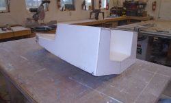
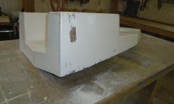
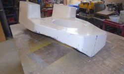
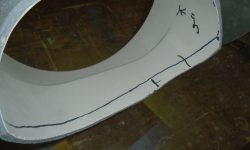
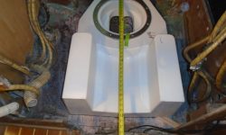
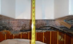
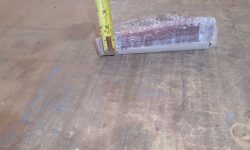
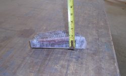
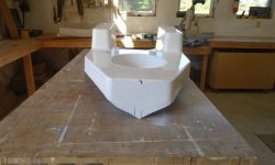
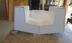
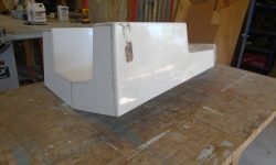
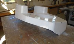
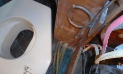
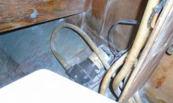
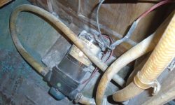
(page 7 of 8)

Acadia 14

< Back to Acadia

Monday

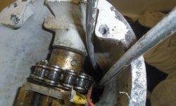
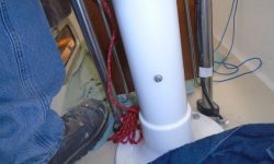
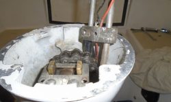
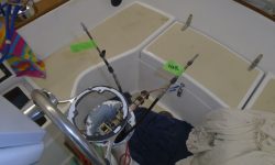
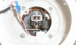
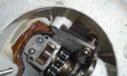
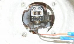
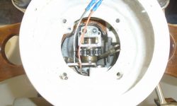
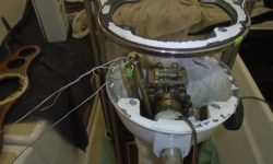
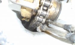
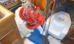
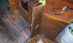
After spending the morning on another project and other commitments, I turned back to the pedestal control cables’ removal.   Hanging down into the lazarette from above, I was able to loosen the nuts securing the tensioning eyes on the steering quadrant, which slackened the steering cables enough to allow me to (still with difficulty) move the chain in the pedestal and, finally, pull out the engine cable clamp through the tight opening.  Before pulling the cables, I secured messenger lines to their lower ends so I could feed the new cables in later.

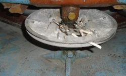
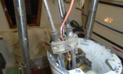
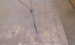
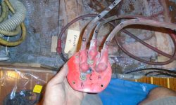
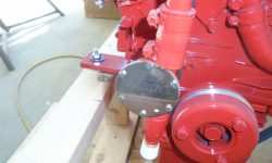
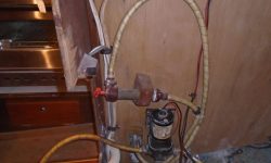
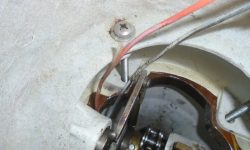
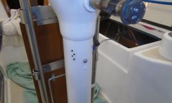
Pleased with this success, I proceeded to pull the cables through–it was far more difficult to pull then than I’d expected, with a lot of friction–, and then both cables just hung up and wouldn’t move at all, causing momentary vexation, but the reason eventually became apparent:  there was a secret second control cable clamp located near the bottom of the pedestal.  This prevented me from pulling out the cables, and was not something I’d found any mention of in any of the Edson documentation covering control cable replacement.  There was another nut securing this second clamp, and though the nut was reluctant to release from the aluminum pedestal, eventually I removed it, releasing the second clamp, at which  time I could completely remove the two control cables.

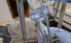
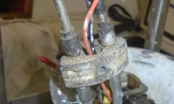
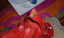
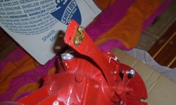
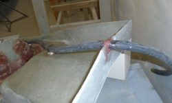
The original cable clamps were aluminum, with stainless screws holding them together, and inevitably after 37 years, the screws were well corroded into place in the aluminum housings, and removal of the old clamps in a usable way seemed unlikely, though I’d soak them in penetrating solvent in an attempt to allow removal.  I ordered a replacement clamp to have on hand either way–I saw no need for the second, lower, cable clamp, which seemed like it’d be virtually impossible to secure with the pedestal in place anyway.

clamp2-101016

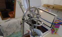
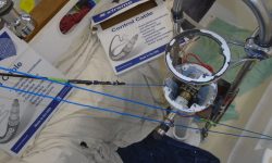
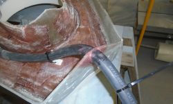
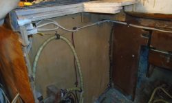
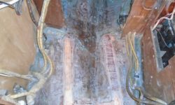
Meanwhile, I could at least start the new installation by feeding the pair of new cables I’d ordered earlier into the pedestal from above.  With the messengers well-taped to the ends of each cable, one at a time I fed them down and, finally, out the lower end of the pedestal into the space beneath the cockpit, ensuring that each cable led directly from the base to the top without being twisted or otherwise interfering with the steering chain and cables, nor the compass wiring.  I’d never have gotten the cables threaded down and through the bottom holes of the pedestal without the messenger lines.  I could finish up the upper end of the cables, including the clamping, later on, when my new clamp arrived, but my immediate goal had been to continue to finish up those projects that were more easily done before the engine installation continued, while I’d as much space inside the boat as possible.

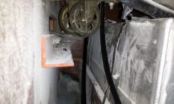
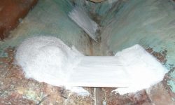
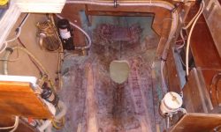
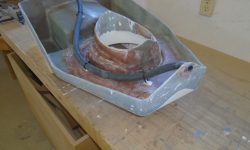
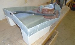
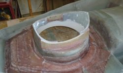
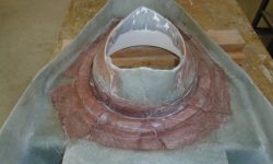
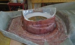
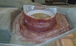
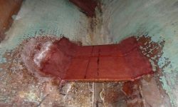
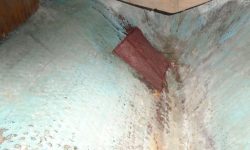
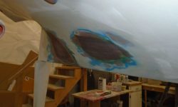
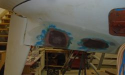
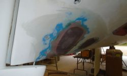
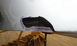
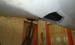
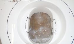
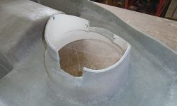
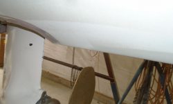
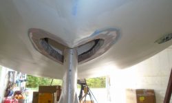
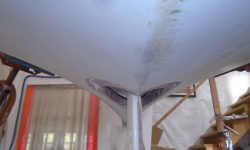
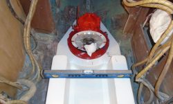
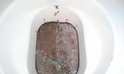
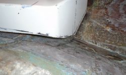
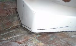
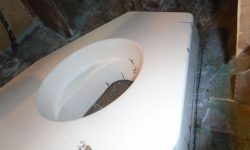
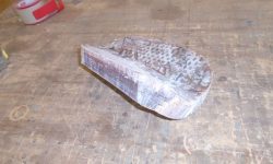
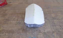
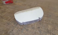
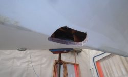
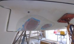
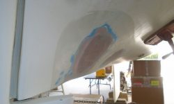
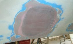
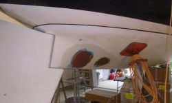
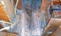
With what I hoped was the worst part of this nasty chore over with, I took a moment to apply a quick coat of 2-part epoxy primer to the new fiberglass in the aft end of the engine space–the strut and stern tube patches, and the waterlift platform–to prepare these newly-epoxied areas for engine room paint.  I wanted to finish out the space beneath the fuel tank before the engine foundation was in place, as access was much better now, and one-part paints tend not to cure properly over new-ish epoxy without the tie coat between.  I happened to have leftovers from a batch of the primer that I’d used on another project earlier in the day, so it was the perfect opportunity.

primer1-101016

Total time billed on this job today:  2.5 hours

0600 Weather Observation:
45°, clear.  Forecast for the day:  sunny and windy, high 57°

Acadia 13

< Back to Acadia

Friday

Continuing with the engine room preparatory work, I focused again–and first–on the fresh water plumbing, picking up where I left off.  I added a new length of hose leading from one side of the tee fitting downstream of the new accumulator tank to eventually service the cold supply for a water heater.  I led this, and the other pair of hoses, around the back end of the engine room and down to the port side, where the hoses fed into the cabinetry near the forward end of the engine room.  I secured the hoses with rubber-lined clamps as needed to keep them safe and out of the way.

Near the pump, I found room for another tee fitting that was part of the original configuration, where the two tank supply lines conjoined, and, as required, I shortened  and reconfigured these hoses to lead into the water pump suction side.  I extended a hose leading from the port tank, exiting the cabinetry on that side of the engine room, but for now I left this length of hose unconnected pending the installation of the engine foundation, after which I’d know how and where to lead and secure the final length of hose.

When I removed the old engine, I’d removed the original battery switch and its cables, which were in the way at the time.  Now, the potential routing of these cables would have an impact on my chosen fuel filter location, near the head of the engine room to port.  This might require releading or replacing the existing cables, so to start I marked and removed the three cables from the back of the switch, and reinstalled the switch in its original position.   I’d route the cables back to the switch later, but their original routing left something to be desired and for now these cables were secondary to the requirements of the fuel system.

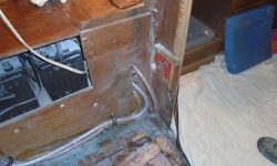
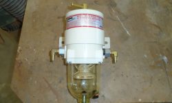
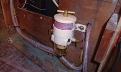
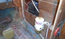
After preparing the new fuel filter–supplied by the owner with his engine purchase–with the appropriate fittings, I installed it on the blank cabinetry at the forward port side of the engine room where it’d be easily serviceable under any conditions.  I left room above the filter to allow removal of the cartridge even when the overhead cabinetry and drawers were in place.  Clearance between the filter and the engine would be tight-ish, but the footprint of the engine foundation was outside that of the filter, and according to the engine drawing the engine should remain inside the edge of the foundation here.  Later, I’d connect the filter, using new hoses, with the existing length of copper tubing that remained at the aft side of the engine room.  First, though, I required an adapter fitting to convert from the flared nut end of the tubing to a hose barb.

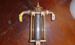
The final pre-installation in the space was the raw water filter, which I mounted on the starboard side directly above the raw water intake seacock.  I’d connect its hose runs later.

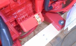
Engine control cables require fussy little clamps at the engine and transmission to hold the cable in place, and before installation I always liked to replace the irritating shallow-slotted screws  and tiny metric nuts with 5/32 Allen-head bolts and #10 nuts for ease of installation in dark and tight confines typical of most engine rooms.  One likes to remove unnecessary frustrations wherever possible.

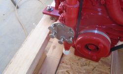
Similarly, I always replace the tiny original screws holding on the raw water impeller cover plate, choosing instead large knurled fasteners for ease of use.  When the pump impeller fails underway, the last thing one needs is a slotted screwdriver and minuscule screws standing between quick replacement of the impeller.  Easy fasteners promote sound maintenance practices too, for annual inspection and replacement of the impeller.

The epoxy securing the limber hose I installed through the base of the engine foundation was cured, and I cut off the excess hose length as needed.

Total time billed on this job today:  3.25 hours

0600 Weather Observation:
42°, clear.  Forecast for the day:  Sunny, near 80

Acadia 12

< Back to Acadia

Thursday

One final step I wanted to complete before the engine foundation was ready for installation was to deal with drainage through the space.  There  would be no clear passage (that I could determine)  directly beneath the foundation base from  end to end, because the recess and opening for the Saildrive leg more or less obstructed the way, but I thought it was prudent to add a limber hose beneath the foundation so there was at least some means of drainage from the aft part of the boat.  The solution would be necessarily imperfect, but worthwhile nonetheless.

To this end, I installed a drain hose on the bottom of the foundation, exiting at the centerline at both ends.  I secured the hose out of the way around the Saildrive opening as required for clearance; this forced an uphill angle in the hose run at the aft end, but there was no helping it given the contours of the foundation and how it related with the hull.  To secure the hose at the ends, I bedded it in some thickened epoxy adhesive.  Later, I’d cut the hose ends flush with the foundation.

Later, I continued work in the engine room with the potable water system.  As needed, I shortened the existing wiring harness and reconnected the wires to the water pump, then installed a new accumulator tank on the aft bulkhead of the space, connecting it to the pump’s outlet with a new length of hose.  From here, I began to reroute the existing water hoses around the aft end of the engine room, where I felt they’d be most out of the way.  I planned to continue this run across the top of the after bulkhead, then down the port side to where the hoses re-entered the cabinetry.  As needed, I’d replace fittings, clamps, and extend or shorten the hoses accordingly.

With only a short time window this day since I’d been focused on a small–but time-sensitive–side project for a couple days, I made worthwhile progress despite the minimal change in the noticeable appearance of the system, but now the route forward was more clear, and I looked forward to wrapping up these ancillary installations as soon as possible so I could move on with the engine installation itself.

Total time billed on this job today:  1.75 hours

0600 Weather Observation:
39°, clear.  Forecast for the day:  sunny, high in the 70s

Acadia 11

< Back to Acadia

Wednesday

After spending the morning working on an unrelated project, I turned back to the foundation, and sanded as needed the fiberglass tabbing I’d installed around the saildrive leg opening.  With prep work now complete on the foundation, I test-fit it once more to ensure that my new fiberglass work didn’t impede the opening and space required to rotate the drive during final installation.  I didn’t expect it to, but didn’t want to find out later.  Fortunately, the opening looked good, and since it clearly allowed rotation room within, I didn’t bother to test-fit the drive leg again, though I’d been prepared to if needed.

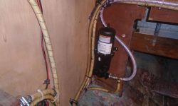
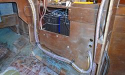
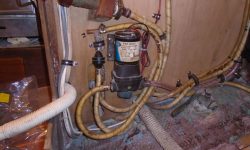
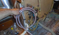
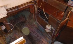
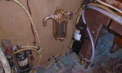
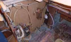
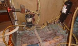
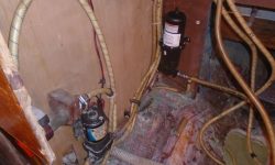
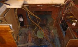
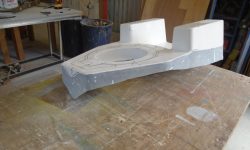
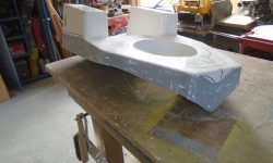
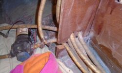
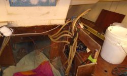
Before I could permanently install the foundation–and then the engine–there was some ancillary work to complete in the engine room, beginning with the fresh water system and its myriad hoses.  I’d earlier moved the pump and some of the hose runs to give me more room to work and to fit in the new foundation, and the owner wanted to move the pump forward, to the starboard bulkhead, so with an eye towards getting the engine room squared away, I began to sort out and label the hoses so I knew what went where, which would help in reconfiguring the system.  Things looked like a mess, but the photos below actually show progress.

With some of the hoses and nearby wiring beginning to sort themselves out, I started some reinstallations on the bulkhead, including the little icebox drain pump, and, below it, the electric fresh water pump in the new mounting location I’d chosen.  Later, I’d reroute and shorten the related hoses, and also add an accumulator tank to the system, but had to get the pump in place first.  Meanwhile, I routed and secured some of the wiring that ran through the engine room, which I”d been holding out of the way during the foundation work, but now it was time to lay things out so I could install the immediately-related auxiliary equipment required for the engine installation (i.e. fuel filter, raw water system).  I’d have to leave the wide space above the pump open so the in-counter trash can had room; it fit in that countertop opening directly overhead.

Total time billed on this job today:  3.25 hours

0600 Weather Observation:
39°. clear.  Forecast for the day:  sunny, high 60s

Acadia 10

< Back to Acadia

Friday

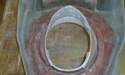
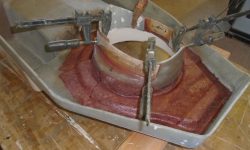
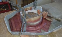
The fiberglass work from last time had cured overnight, so I removed the clamps from the foundation, then lightly sanded the new glasswork to remove rough edges, and trimmed the excess material inside the opening, bringing the top (really the bottom) edge down in line with the actual shape of the cutout.

Up in the boat, I washed and lightly sanded the new exhaust platform, and the little patch over the strut bolt holes.

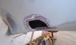
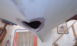
I had a short day planned, as I couldn’t face the pedestal cables again so soon, and I had an unrelated job to begin at the shop, but first I wanted to keep the foundation work going, so I reinforced the side opening repairs with some tabbing set in epoxy resin, which tied the new pieces in with the surrounding areas from the back, or hidden, side, and also ensured the seam would be watertight from this side.  Later, there’d be more glasswork on the inside of the opening, once the foundation was permanently installed.

Total time billed on this job today:  1 hour

0600 Weather Observation:
39°, clear.  Forecast for the day:  increasing clouds, 50s

Acadia 9

< Back to Acadia

Thursday

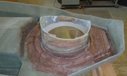
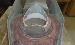
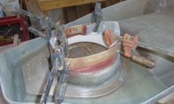
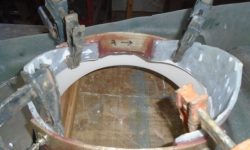
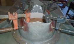
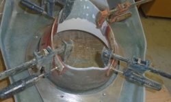
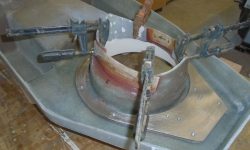
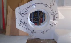
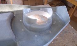
Now that the backing ring was secured, I could remove all the mounting studs that had aligned it while the epoxy cured.  Then, I focused on creating new sides for the Saildrive leg opening, where I’d cut out the material earlier to allow the leg to spin as required.  The new sides would make it easier later to glass in the opening from outside, but needed to follow the curvature of the cutout so as not to impede the rotation of the drive leg during final installation a little later.

I happened to have on hand  some leftover strips of epoxy laminate that I’d made for some previous project, and they were just right for the job:  the right width, and the right thickness to be flexible enough to bend to the curve, yet stiff enough to hold that curve appropriately and maintain the width of the opening required for the drive leg rotation.

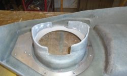
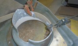
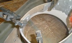
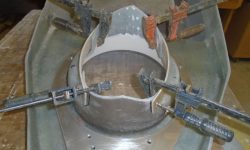
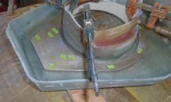
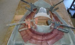
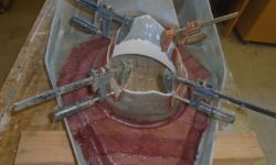
I secured the new pieces with thickened epoxy adhesive, clamping them securely and near the ends of the s trips to spring the curved center portion well outward, following the curve of the top cut in the foundation.  Later, once the glue was cured, I’d trim the excess material as required, since the strips were constant width and the opening featured an angle or curve.  I filled the small gap between the bottom of the new sides and the existing foundation with an epoxy fillet, and  planned to glass from the inside (i.e. the bottom, exposed side) now, as well as from the outside (inside the hull opening) later, once everything was in place.

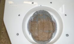
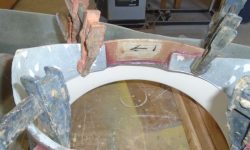
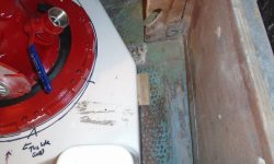
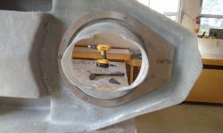
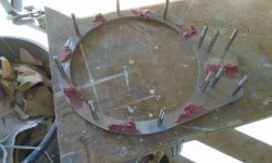
I scuffed up the top of the aluminum backing ring, and placed small bits of tape over all the threaded holes for protection.   Then, I fiberglassed it in place with various pieces of tabbing and epoxy resin.  I didn’t get fancy in the preparations (i.e. angled fillets and smooth edges around the ring) because I saw no call for it, as this tabbing really only secured the ring against movement during installation of the leg. and provided no structural requirements beyond that.  Frankly, the epoxy adhesive bonding the ring would have been sufficient as is, but it was a simple additional step to complete.  The tabbing encapsulated the ring and secured it to the foundation on both sides; the masking tape prevented the resin from fouling the bolt holes and, in this installation, had no bearing on the function of the tabbing as required.

Leaving the new glasswork to cure, I prepared to focus on myriad ancillary tasks that lay ahead before I would actually install the engine foundation and engine.  These tasks included directly related systems such as the fuel and exhaust system, but also indirectly involved existing systems like the fresh water and electrical systems, namely how these systems ran through and were installed in the engine room.  With a wide-open space, now was the time to square away these details.  To that end, and planning ahead, I began to prepare an order for various materials that I’d require to complete these installations and changes, and assessing on-hand inventory as needed.

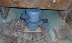
One of the immediately related installations was a new waterlift muffler for the exhaust system, as the original was in poor condition and I’d discarded it.  The owner had purchased a new muffler along with the engine, and with this on hand I determined its future location just aft of the engine room,  The muffler allowed rotation of the inlet and out let ports, as well as the top and bottom of the unit, which made it easy to configure for the specifics of this installation–a handy feature, since (as usual) space was at a premium behind the engine.  Specifically, headroom was tight in the chosen location beneath the fuel tank, which was where the muffler needed to go in order to remain aft and clear of the new engine foundation.

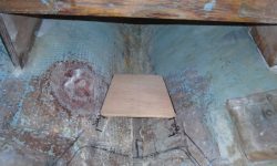
Satisfied that the chosen location would work, I built a little plywood platform to support the muffler and fit into the shape of the hull.  Then, I epoxy-coated the plywood on all sides, and secured it to the hull with some thickened epoxy on the bearing surfaces and fiberglass tabbing over the top and onto the hull.  At the same time, I completed the interior patch of the old propeller strut location, which area I first sanded clean, then filled the bolt holes as needed with thickened epoxy, and finally installed as layer of fiberglass over the top.

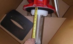
Looking to round out my current order of necessary supplies, I turned to the engine control cables, leading through the pedestal.  The old cables were probably original, and one of them was split and damaged, and required replacement.

To access the tops of the cables so I could remove them, I removed the binnacle compass, exposing the controls and cable connections.  Removing the clevis pins proved to be no problem, but of course there was more to this seemingly simple task than I’d first thought.  Though it seemed obvious in hindsight, based on the way these sorts of cables work, initially I’d not considered the fact that the cables would be secured somehow within the pedestal.  But of course they were, with what turned out to be a devious little clamping system, and this prevented the cables from moving.  As pedestal-mounted control cable replacement or removal had never been something required in my past, I had to consult the online documentation available to determine how to proceed from here.

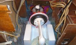
I found that there was an internal clamp below the wheel shaft, with a screw securing it from outside.  This screw was hidden behind the autopilot mount, so it took me a while to find it.  Releasing the screw-and the clamp was no particular problem.  But I knew I was in trouble when I read in Edson’s own instructions that there was “limited room” inside the pedestal to allow the clamp to move.  Following the prescribed procedure, which called for pushing the cables–and clamp–down from the top till I could get the throttle cable over to the left (port) side of the pedestal along with the gear cable, I soon found that the cable clamp would not pass by the steering chain, and even getting the cables to one side had required removal of the entire pedestal top to improve access.  The instructions suggested the clamp would fit, and allowed further suggestions how to eke it by, but after fighting the arrangement for some minutes, it eventually became clear even to this stubborn and highly annoyed individual that it simply wasn’t going to be removable until I slackened the steering cables and moved the chain off the sprocket.

Lucky you, friendly reader, I will spare here the details of my private thoughts on this frustratingly thoughtless design–as well as some of the specifics of what I went through to even get as far as I did–but I’d sure enjoy the chance to have a little chat sometime with some of the folks who design things that are so eminently unserviceable out in the field.  Suffice it to say that spending two hours completely disassembling the pedestal ultimately only to fail to remove–never mind replace– these cables, and necessitating further disassembly of the steering system to effect what seemingly should be (to me) a simple maintenance procedure does not suggest good design.  (I didn’t even want to think about the prospects of re securing this cable clamp inside the pedestal later…yet of course I must consider it.)  I’d revisit the cable replacement on another day.  All I’d really wanted from this exercise was to confirm the lengths of the cables so I could order replacements, and in the end I simply estimated.

Total time billed on this job today:  6.5 hours

0600 Weather Observation:
45°, mainly clear.  Forecast for the day:  sunny, 60s.

Acadia 8

< Back to Acadia

Wednesday

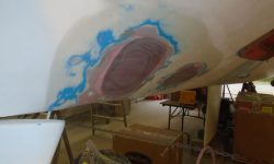
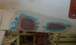
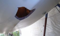
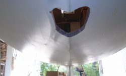
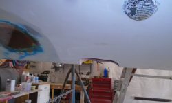
I finished up the exterior hull patches with a final washing and light sanding, smoothing the epoxy coating.  Sometime later, I’d paint the area to match.

Up in the boat, I disconnected the transmission and drive leg from the hoist, as the only way I’d be able to handle it appropriately was by hand.  It weighed about 75 lb.  In order to install the leg, it was necessary to angle it through the hole, allowing the long shaft to pass through first, then tipping the transmission into place.    There was insufficient room to maneuver the unit the “right” way, which would require tipping the whole bulky unit well aft:  there simply was neither enough headroom nor manhandling room to allow this process.  Instead. I reversed it and tipped the leg through the hole backwards, hoping then to twist the whole thing around into the correct orientation.

The width of the opening in the hull was narrower than the longitudinal width of the drive leg, so turning the unit was not possible.  The clearance was close, but didn’t allow the twist as required.

While I had the leg in place, even though it was pointing the wrong way, I did a preliminary check of the prop clearance, one of the reasons for the dry-fit.  With a straightedge, I extended the line of the hull onto the leg from both sides, and was pleased to find there would be ample propeller tip clearance.  The small black mark on the trailing edge of the leg (facing the camera) indicated the top of the propeller, so I had nearly 2″ of clearance.

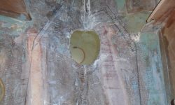
Now I made some marks on the outside of the hull to suggest where I needed to widen the opening and allow the leg to twist.  Initially, it appeared that only a small amount of material, and some general cleanup of the still rough-cut opening, would be required.  I removed the leg and opened the hole more with a grinder.
leg10-92816

I went through a few iterations of this, cautious in my approach since I didn’t want to open the hole any more than necessary.  Maneuvering the transmission and leg in and out of position was a chore I didn’t care for much, and the process grew frustrating.  Eventually, it became obvious that the molded foundation housing was  also prohibiting the twisting of the leg as I wanted, since the thickness of the laminate was too heavy to allow any bending that might let the leg move through.  I loathed to change anything with the foundation without exploring every potential option first, so I put in a call to the Beta Marine distributor to see if there was a way to remove the prop shaft, which was, frankly, the only thing preventing the leg from fitting in smoothly and vertically.  Having that out of the way would, in theory, obviate the requirement to tip the whole unit nearly 90° in order to angle through the hole.

Ultimately, the short answer was no:  while technically the shaft could be removed, I was advised not to try, which was fine because I didn’t really want to get into that mess in the first place.  I did learn that the whole leg could be removed–it was bolted to the bottom of the transmission housing–and I received a link to a video showing this process, but the problem with that was that the leg would need to be reinstalled from beneath the boat, through the hole in the bottom–a most unsavory prospect that I had no intention of trying.  I considered it for only a few moments before quickly abandoning that particular notion.

So the long and the short of this exercise was that I’d need to modify the hole inside the foundation itself, a prospect well within my skill set and ability and of which I was unafraid, but which I’d tried to avoid only as long as there wasn’t a more basic, “magic” solution to the issue.  Discussing the problem with Stan at Beta made me feel as if I had the appropriate permission to proceed as I’d initially, yet warily, expected, and, knowing that there really was no alternative that I was missing or ignoring, I was ready to get it done, finally.  This whole thing had turned into much more than I’d anticipated, had been tiring and frustrating, and, with the way forward now clear, it was time to rock on.

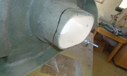
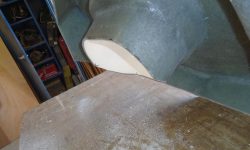
So with the leg in place–again–and angled against the boat and  foundation as far as I could turn it, I made some reference marks on the inside of the foundation, demarking the area I’d need to cut out in order to let the leg twist.  With the foundation down on the bench, I removed the marked areas with a cutoff wheel, leaving openings that would allow the leg to twist through, but would require additional patching later.

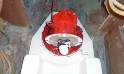
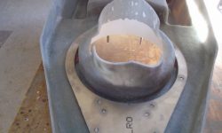
Now, with the foundation back in the boat, I dropped in the leg once more, and threw a small celebration when I could easily turn the unit into the correct position.  I made sure the foundation was in the right position and level, and that the transmission housing was aligned where it needed to be before heading below the boat to check the leg position against the boat’s centerline and to ensure it was properly in line.  Note that the leg is angling forward just a bit because the rubber bellows allowed the transmission flange to sag without the support of the engine ahead.  This would end up vertical once the engine was installed and engaged with the transmission shaft.  There was room inside the hull opening to allow me to glass the foundation to the boat after the leg was installed in this way.

This photo shows the leg propped vertically with some wood scraps.
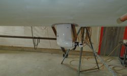
leg26-92816

To check again the propeller clearance, there was no better way than to actually hold the propeller in place and see how it looked.  Good.

Next, I fine-tuned the position of the leg and transmission till everything was just where I wanted it, and test’fit the exterior rubber boot so I could mark its position on the hull for later prep work.  Inside the boat, I hot-glued some little alignment blocks around the foundation to register its position and allow me to put it back in exactly the same place.  Then, I made some various reference marks and marks through the transmission bolting flange onto the top of the foundation so I could drill the holes required for the mounting studs and bolting ring before removing–for the last time, I hoped–the transmission and leg, which I stored in its original cardboard cradle on the cabin sole.  I removed the foundation down to the bench for further attention.

To prepare the foundation for installation, I marked up about 3″ on all sides (or equal to the height of the oil drip pan section and the flat after section), then ground away the gelcoat all around, exposing raw laminate for the best bonding, including inside the leg opening.  Meanwhile, I also prepared the hull opening by cleaning up the inside cuts and removing bottom paint from around the hole to allow the rubber boot installation later.  Because I planned to glass from inside the opening and foundation out onto the hull a bit, I ground a tapered opening around the perimeter of the hull hole as well.  Then, hoping the heavy grinding was done with, and to allow me to work on some other related aspects of the project happily and healthily, I spent a bit of time thoroughly cleaning up the boat and shop from the day’s efforts so far.

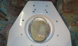
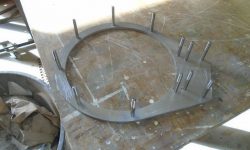
The instructions called for the transmission to be mounted with studs threaded into a supplied aluminum backing plate, which was to be fixed beneath the foundation.  This alignment was critical, so I used my reference marks from the transmission flange itself  to lay out and drill the holes required from the top of the foundation.  I had to enlarge some of the holes till I could eventually install the backing ring–with all studs pre-installed–from beneath.  I wanted to be sure the studs fit properly through the holes, as I’d need to install them from above after the transmission was in place, since with my specific installation I’d need to twist the leg around and required an unencumbered surface for this.  I felt that if I could easily slide all ten or dozen or whatever studs through the holes all at once in this way, I was as close as possible to the result I needed.  Later, I noted that at least a couple of the studs I’d prepared for would not be used in the final installation.

Now I needed to permanently attach the mounting plate to the underside of the foundation.  I’d use the studs to hold the ring in place during installation, but because in my installation the studs needed to be removable, I didn’t want to risk their becoming glued into place.  So I planned to tack the ring in place with epoxy adhesive first, and finish up the glasswork later.  So I lightly sanded the bonding surface of the foundation, and scuffed up the aluminum in way of the spots I planned to tack, then applied some very thick epoxy adhesive, keeping it well away from the threaded holes and studs, and pressed the whole assembly tightly into position, leaving it to cure.

I rounded out the day’s work with some housekeeping chores on the boat, mainly removing an old wiring harness that had once led to the key switch and related items in the lazarette.

Total time billed on this job today:  7.25 hours

0600 Weather Observation:
52°, clouds.  Forecast for the day:  clouds, low 60s

Acadia 7

< Back to Acadia

Tuesday

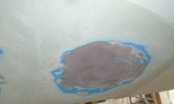
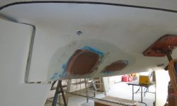
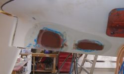
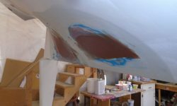
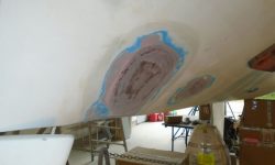
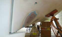
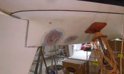
The hull patches at the strut and stern tube location were in good shape, and required only a light sanding at this point.    I filled some small pinholes in the cured compound with a quick-drying acrylic putty, then, after a final hand-sanding, applied a coat of unthickened epoxy resin over both patches to seal the fairing compounds.

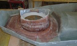
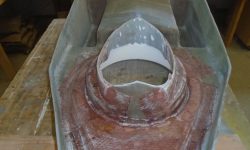
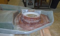
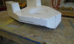
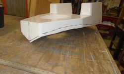
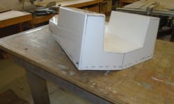
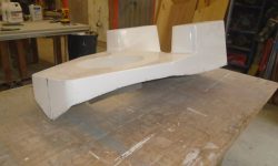
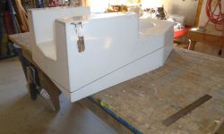
To bring down the engine foundation and increase the depth of the drive leg–and clearance for the propeller–I used a 1″ block and marker to scribe all the way around the base in its existing position.

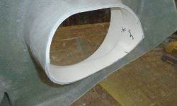
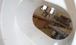
With the foundation down on the bench, I cut to the new lines with a saw and angle grinder equipped with a cutoff wheel, which worked well to cut the lines inside the leg opening.

Now the foundation fit more closely to the hull all around, and the new cut had also lowered the base accordingly.  This effectively increased the distance between the inside of the hull and the top of the propeller blades to about 2-1/2″, which, allowing for a 1″ thick hull, gave 1-1/2″ tip clearance, a good amount.  Nonetheless, I planned to later dry-fit the leg to ensure that the clearance in the real world was where it should be.

Meanwhile, the owner paid a visit, and while we were looking over the engine foundation the issue of the foundation’s proximity to the forward end of engine room arose.  He wanted to be sure the engine didn’t protrude further than the leading edge of the foundation, and while my memory of the engine drawing and engine size suggested that it did not, frankly I’d not considered that it would, given the massive size of the molded foundation base, the logical thought that no way the engine would extend beyond the front in a practical world, and the diminutive size of the engine itself.   However, it was an excellent point, and I’d not specifically checked this during the layout.

beta-25-902-he-sea-prop-60-100-08623

As it happened, the engine did appear, from the rough measurements we took during the discussion, to protrude beyond the foundation.  What an annoyance:  as if the foundation itself wasn’t large and bulky enough for this installation, now the engine needed even more room on the forward side.  I didn’t have a measured drawing of the Beta 25 and drive leg on hand, as there wasn’t this specific configuration shown in the supplied manual, but later I downloaded the fully-dimensioned drawing and found, to my minor private vindication, that at initial glance it did not appear that the engine extended a significant amount forward of the foundation–but closer examination revealed that portions of the engine, mainly the fuel filter and raw water pump, did indeed hang out, likely necessitating more room than I’d originally expected.

In the event, this was a fortuitous awakening, and, humbled, we decided to move the foundation back by a couple inches.  Happily, this was not only possible, but didn’t require a lot of modification.  With the base moved back to a point designed to provide ample room ahead, and leveled as I’d done throughout the process, I rescribed the base as needed and trimmed it to the new lines, before repositioning it in the boat a final time so I could check all the measurements.  From the center of the drive leg hole in the foundation (i.e. the center of the drive leg as shown on the drawing), I required 26″ of clearance to the forward end of the engine room, and now in the new position there was plenty of clearance.

As a further reality check, I temporarily placed as a template the aluminum backing ring that would eventually secure the transmission in place, and measured from its back edge–which was standing in for the back edge of the transmission per the drawing–to the front of the engine space.  This measurement was required to be at least 36″, and again there was ample clearance.

Checking the foundation’s position again in all possible ways, I remarked the hole required through the bottom of the boat and then, with little further ado, cut out the opening, keeping the saw a bit inside the line to allow for later trimming and fine-tuning.  The hull in this area was quite thick, partly because this section also included all the old, heavy tabbing that had encapsulated and secured the original engine mounts, plus centerline reinforcement.  I’d clean up the opening a bit later on in the process.

For now, my next move, I hoped, was to dry-fit the drive leg and ensure it extended deeply enough, and also to ensure its proper position before I glassed in the aluminum backing plate, which would register the entire engine position forevermore.  So with the foundation back in place over the new hole in the hull, I used the trim ring again to make some reference marks that I hoped would help me position the leg from above.  The leg was awkward and heavy enough that I chose to lift it into the boat with the overhead crane, though I could shuffle it around by hand as needed.

The minimal installation instructions for the sea prop cheerily showed cartoonish versions of the drive leg being tilted into position, and I soon found that even with my pessimistic expectations, inserting the leg through the hole was going to be a chore.  The prop shaft extended too far to allow the leg to drop straight through the hole in any position–which is how I’d initially tried, and how I’d set up the chains and crane for lifting–so the whole transmission and leg would need to be angled through at quite a steep angle, which might work well in a new boat production shop when they install these things in an empty hull before the decks are in place, but in the real world such easy overhead clearance did not exist.  So with the day evaporating, so too did my hopes of quickly placing the leg in position for my dry-fit check, so I left it–well-supported and -cushioned–for a new day.

leg10-92716

Total time billed on this job  today:  7.75 hours

0600 Weather Observation:
55°, light rain.  Forecast for the day:  light rain, brief partial clearing later, high in the upper 60s
Acadia 6

< Back to Acadia

Monday

With a late start to the day after a morning meeting,  a light sanding of the hull patches, which I’d begun fairing in last time, prepared them for a second round of epoxy fairing filler, mainly to fill small voids in the initial coat.
Back in the engine room, I returned to the bulkhead modification required on the port side, where the fresh water pump hoses led.  To release the hoses from their slotted passage through the bulkhead, I cut an opening from the side, allowing me to slide the hoses and pump out of the way without disconnecting anything.  While this system might end up being reconfigured later, for now the prudent action was to leave it as is pending further decisions.
With the hoses and pump now clear of the bulkhead, I marked a cut line, just over 3″ in from the existing edge (this matched the distance from centerline of the vertical edge of the companion starboard bulkhead), and cut away the excess bulkhead to improve clearance for the new engine foundation.  I’d clean up the remnants of tabbing a little later.

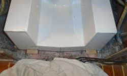
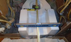
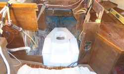
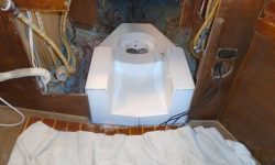
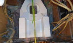
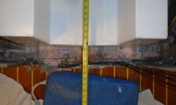
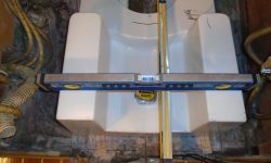
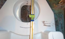
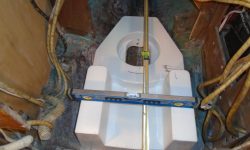
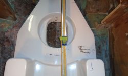
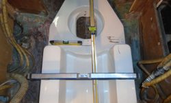
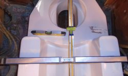
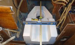
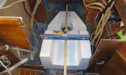
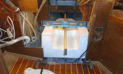
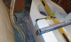
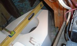
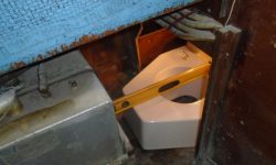
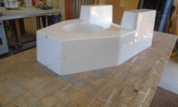
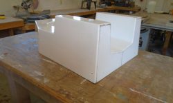
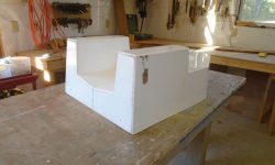
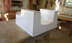
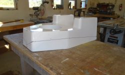
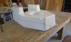
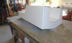
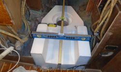
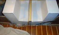
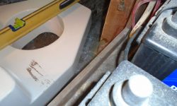
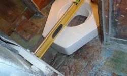
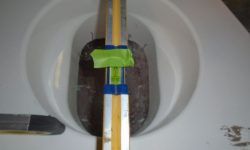
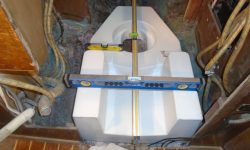
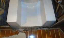
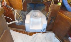
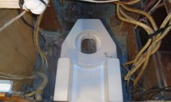
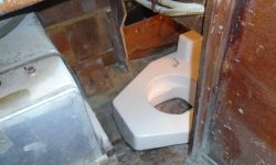
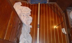
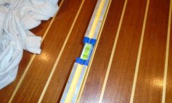
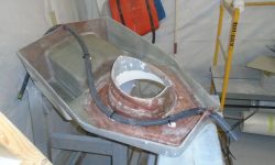
With ample room now in the engine compartment, I set up the molded engine foundation and leveled it from side to side and longitudinally (according to the cabin sole, which position I marked on the level with some tape for easy replication).  After some minor fine-tuning of the fore-and-aft position of the foundation and centering it on the boat, I determined that the highest point was about 5″ above the hull, so to trim the foundation I marked 5″ from the hull at various points around the foundation’s perimeter.  Space was too tight or awkward in most areas to effectively use a scribe, but the 5″ markings would give me enough information for the initial cut.

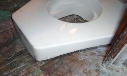
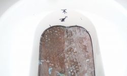
I removed the foundation down to the workbench and connected the various marks with a straightedge and marker, forming a cut line.  At the oval molding for the drive leg, where I’d made my reference marks on the inside (white side). I transferred the marks to the outer (laminate) side since there was no way to get a saw inside the opening, and roughed in the contour of the cut line.

With a jigsaw and carbide blade, I cut to the lines all around.

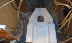
With the foundation back in the boat, I set it up again in the engine room, aligning it as before with several levels.  This highlighted a few areas requiring some additional trimming, as I couldn’t get the aft end of the foundation down far enough.  The contact points seemed to be at the aft corners of the leg molding, as well as a spot on the after starboard side of the foundation.  A couple rounds of trimming, and I could get the foundation positioned properly according to the levels.  I made some marks on the hull to allow me to easily reposition the foundation, as there’d be a few more rounds of in-and-out ahead.

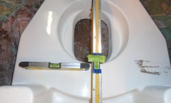
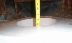
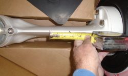
This trimming was enough to allow the foundation to fit more or less closely with the contours of the hull, but a critical measurement remained:  final depth of the drive leg for proper propeller clearance beneath the hull.  The propeller was 14″ diameter, and I wanted to end up with around 1-1/2″ clearance between the blade tip and hull as a minimum.  So after consulting the drive leg itself for a visual reference and for a good measuring point (which turned out to be the base of the transmission mounting flange, which equated to the top of the foundation), I measured down to the hull at a couple points to determine the highest point of the foundation as currently positioned, which was around 7-5/8″.

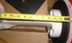
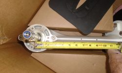
I measured from the mounting flange down this amount on the drive leg, and made a small reference mark.  Then, from the center of the prop shaft, I measured up 7″, the radius of the propeller, and made a second mark.   This gave me just about 2″ of clearance, not accounting yet for the hull thickness, which I did not yet know, but for now I allowed about an inch for hull thickness at the centerline, giving me perhaps an inch of blade clearance as currently configured, and guessing at the thickness of the hull.

There was room to easily bring down the foundation by at least an inch, which would improve blade clearance accordingly, and this would also allow me to fine-tune and (hopefully) properly scribe the foundation to the hull, so that would be my next task, but for now I’d reached the end of the day.

Total time billed on this job today:  4.5 hours

0600 Weather Observation:
32°, clear.  Forecast for the day:  sunny, around 60.

Acadia 5

< Back to Acadia

Friday

The new fiberglass had cured overnight, so I began with the usual wash and sand, bringing the new patches flush as needed and approximating the contours of the adjacent hull.  Inside the hull, where I’d patched over the old stern tube, I just lightly scuffed the new fiberglass to remove any sharp edges.

The new laminate was close enough to the final shape required , so to begin to finish off the exterior patches, I applied a coat of epoxy fairing compound over both areas, using a wide  trowel to shape the compound into the curves of the boat.

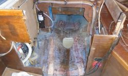
In the engine room, a few loose ends remained.  I needed to clear the space as completely as possible, and the old bilge pump hoses–which were old and in poor condition anyway–were in the way, so I made cuts and removed the hoses into the lazarette for the moment pending further work towards their replacement.   I also removed a bonding wire that ran through the engine room; this wire led to the backstay chainplate, and though I didn’t fit in the small lazarette opening, I could reach the bolt to undo it and remove the wire.  Then, I pulled it through and secured it out of the way with a couple other bonding wires I’d removed from the original engine installation.  This left the way clear in the engine room for better access to the aftermost portions, and to allow me to begin the process of fitting the molded fiberglass base that the Saildrive mount required.

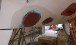
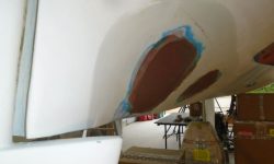
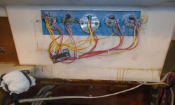
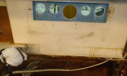
Meanwhile, I removed an old gauge cluster from above the engine room and at the forward end of the cockpit.  The project scope called for me to patch these holes and repaint that portion of the cockpit well to match.

The boat was nearly level as placed, but there was room for improvement side-to side, so I adjusted the stands slightly to correct the slight list.

The longitudinal attitude of the boat was slightly off-level, at least according to the cabin sole, but there was no way to easily adjust this, and I’d simply align the new engine mounting to the same orientation when the time came.

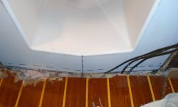
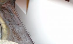
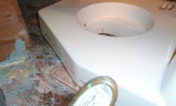
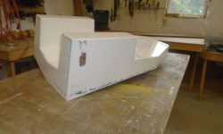
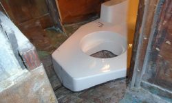
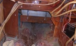
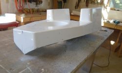
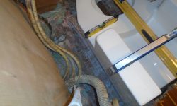
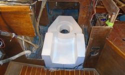
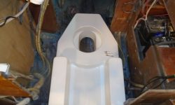
Now I lugged the molded fiberglass base up into the boat and placed it in the engine room for a reality check and to see how much fitting and modification would ultimately be required.  I’d already warily eyed the bulkhead opening at the aft end of the space, thinking it looked too narrow, and while the width was actually OK for all that, the opening was not centered, so the new foundation base ran into interference with the port bulkhead–and with the electric water pressure pump just behind it.  Not only did this prohibit good access to the area, but it also forced the forward end of the foundation off-center by a bit, so clearly modifying the bulkhead and pump installation would be the first priority.  While I had the base in place, I eyeballed the overall position to guess how much material I’d end up removing off the base itself to fit it to the shape of the hull, then removed it for access into the engine room once more.

With the time remaining in the day, I made a cozy nest in the empty engine room and crawled back to remove the water pump from its base, and to remove the clamps securing the multitude of hoses to the bulkhead.  I decided to leave the cutting for a new day, as it was growing late.

Total time billed on this job today:  4.75 hours

0600 Weather Observation:
60°, clouds and a shower.  Forecast for the day:  showers, then clearing and growing cooler.

Older posts Newer posts