Thursday
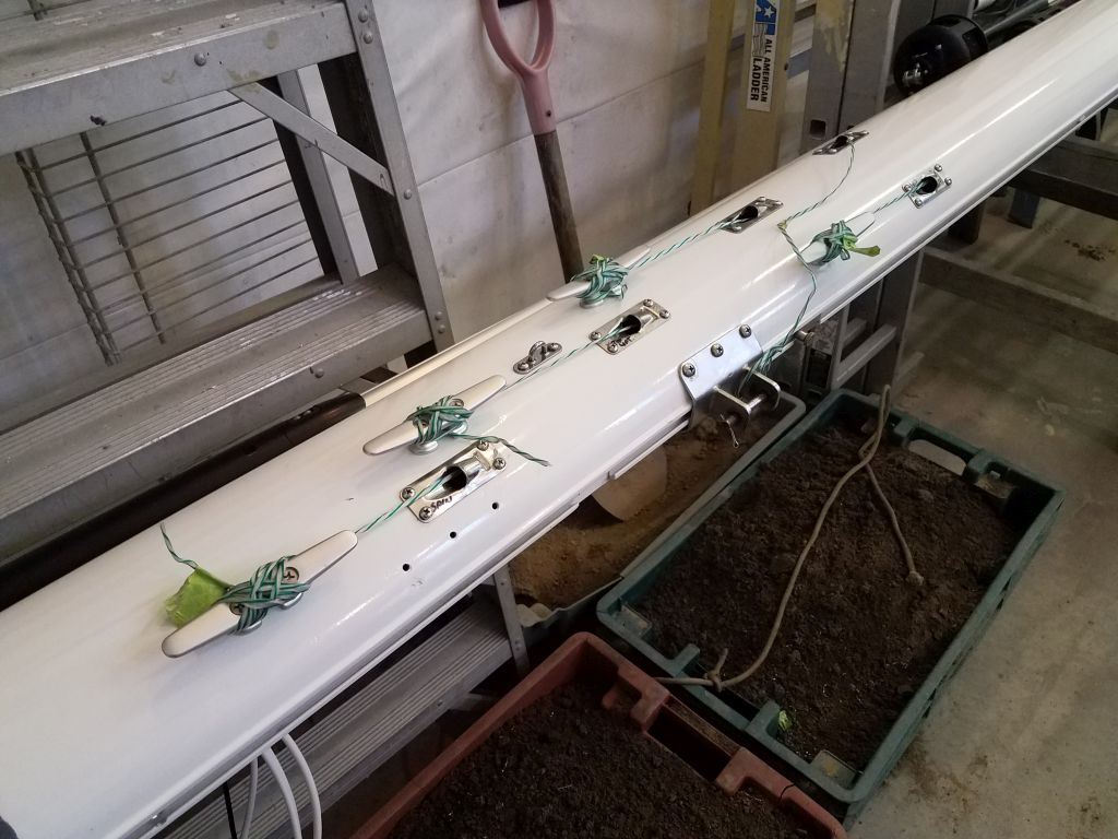
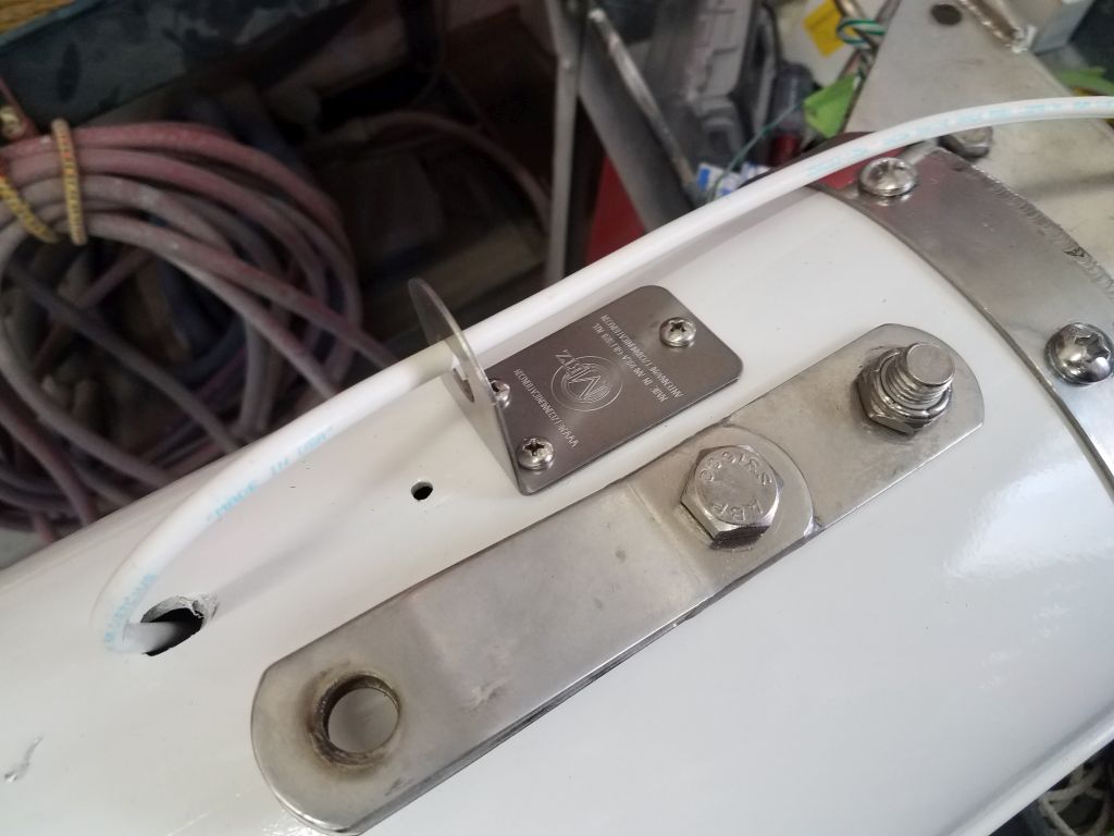
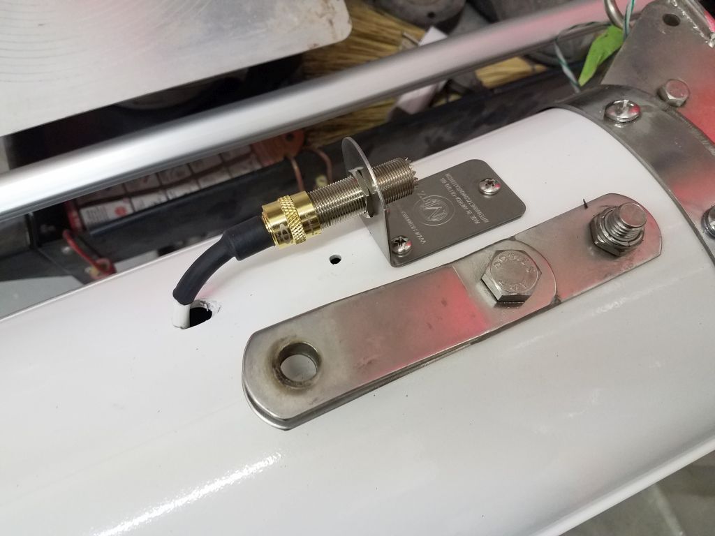
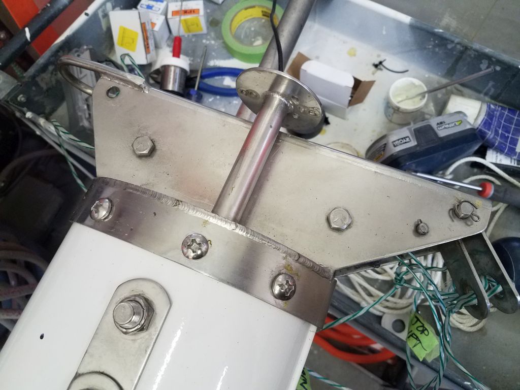
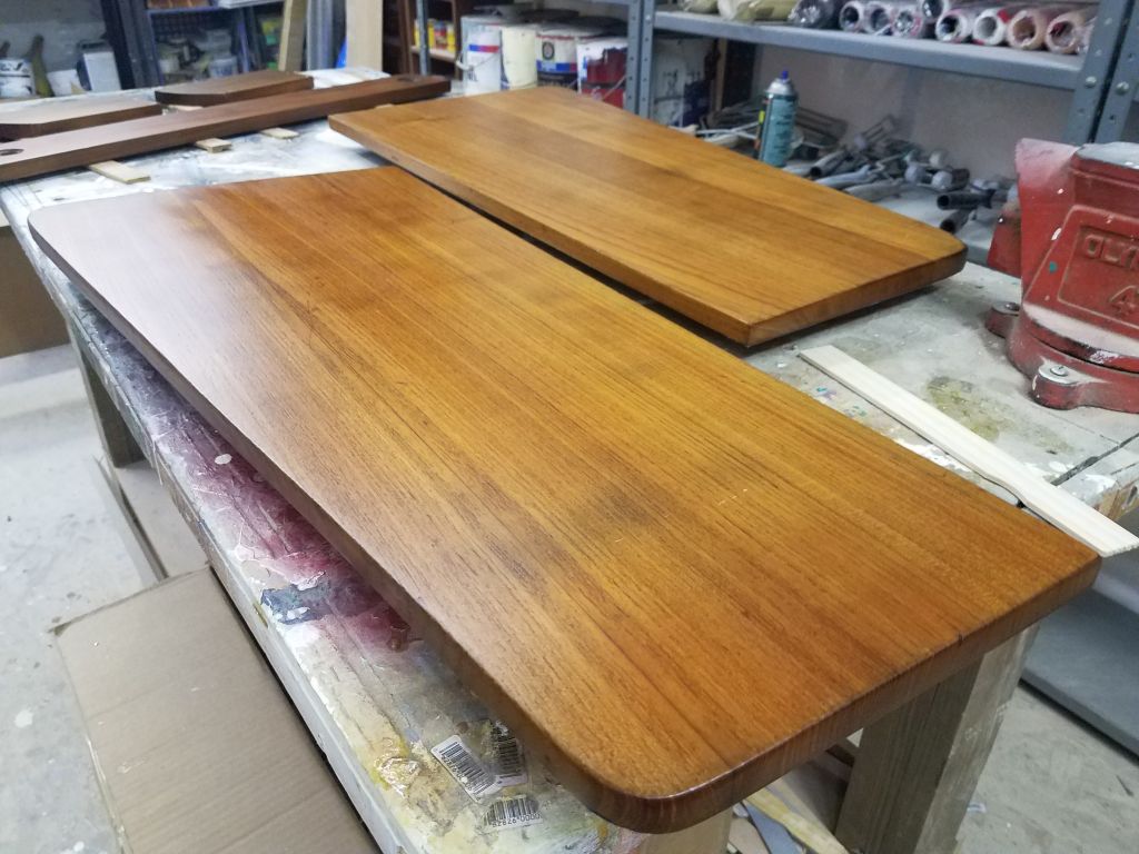
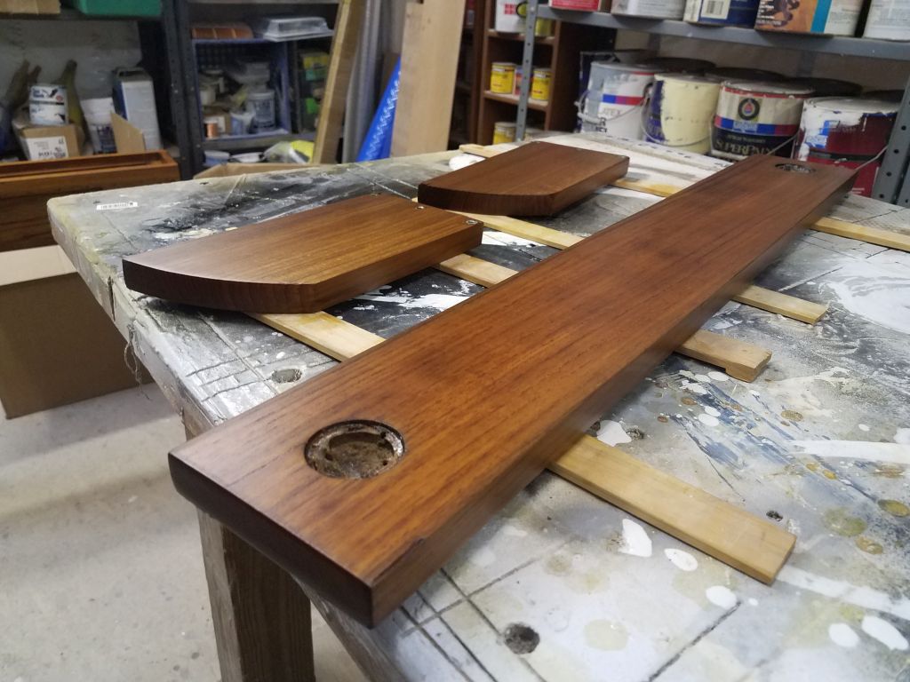
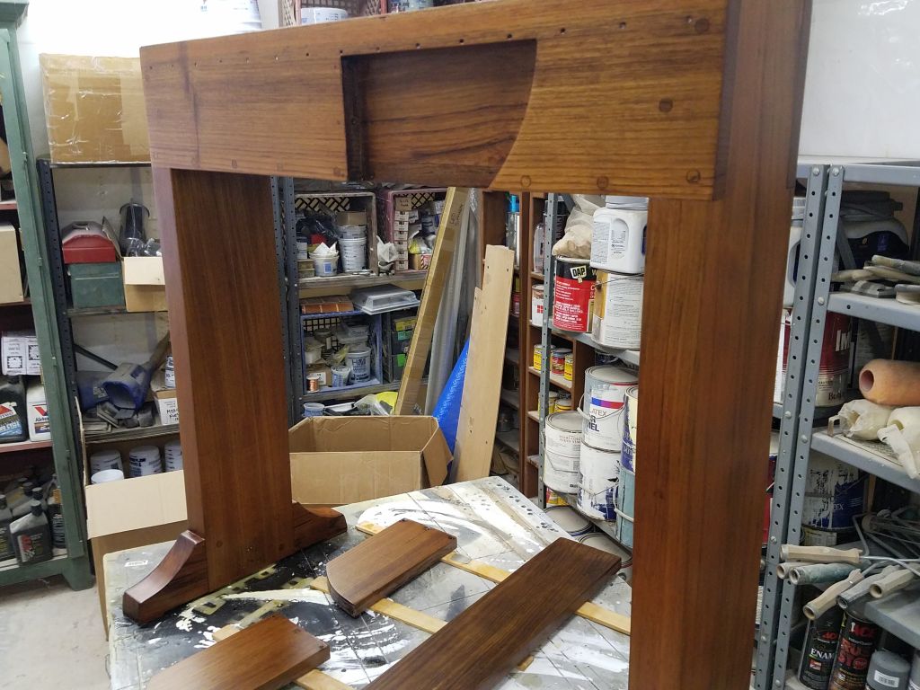
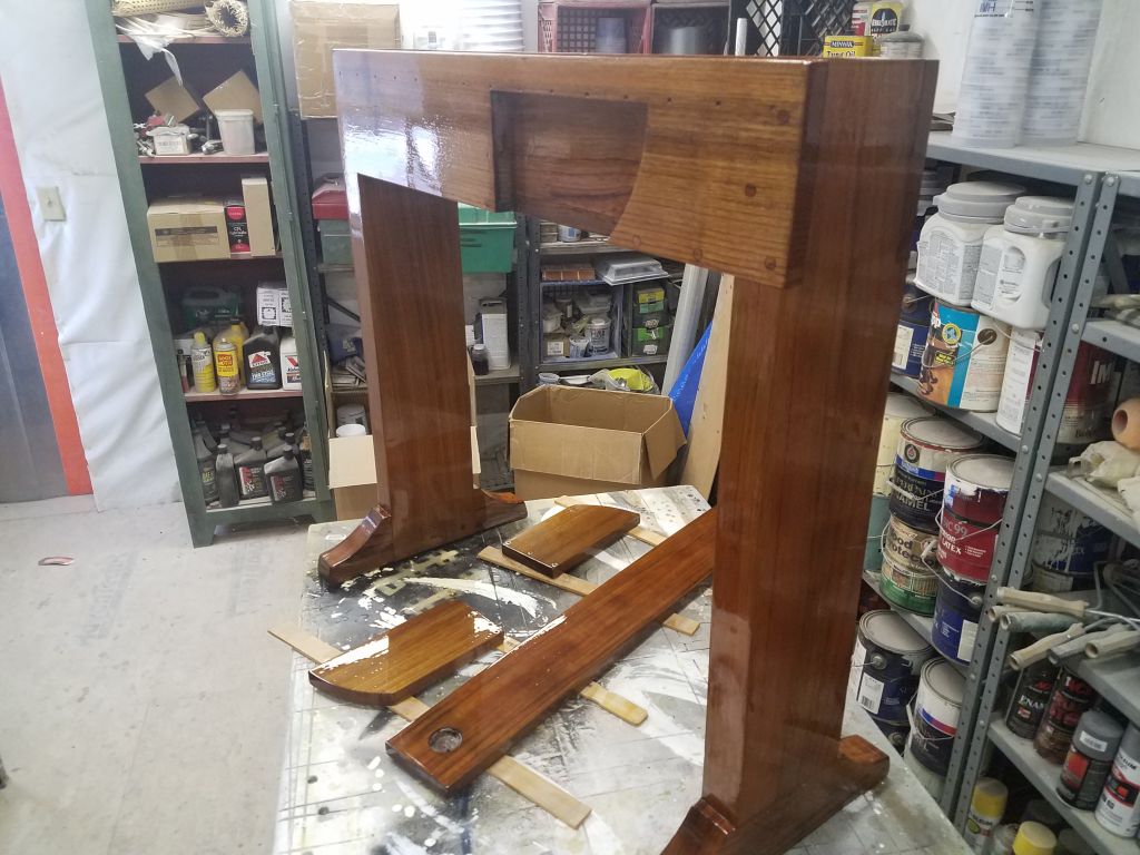
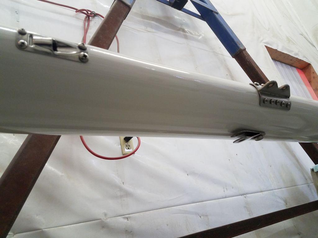
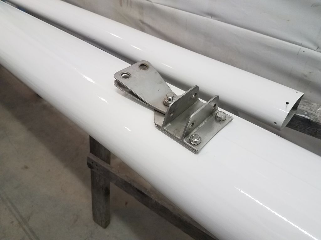
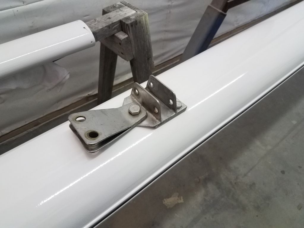
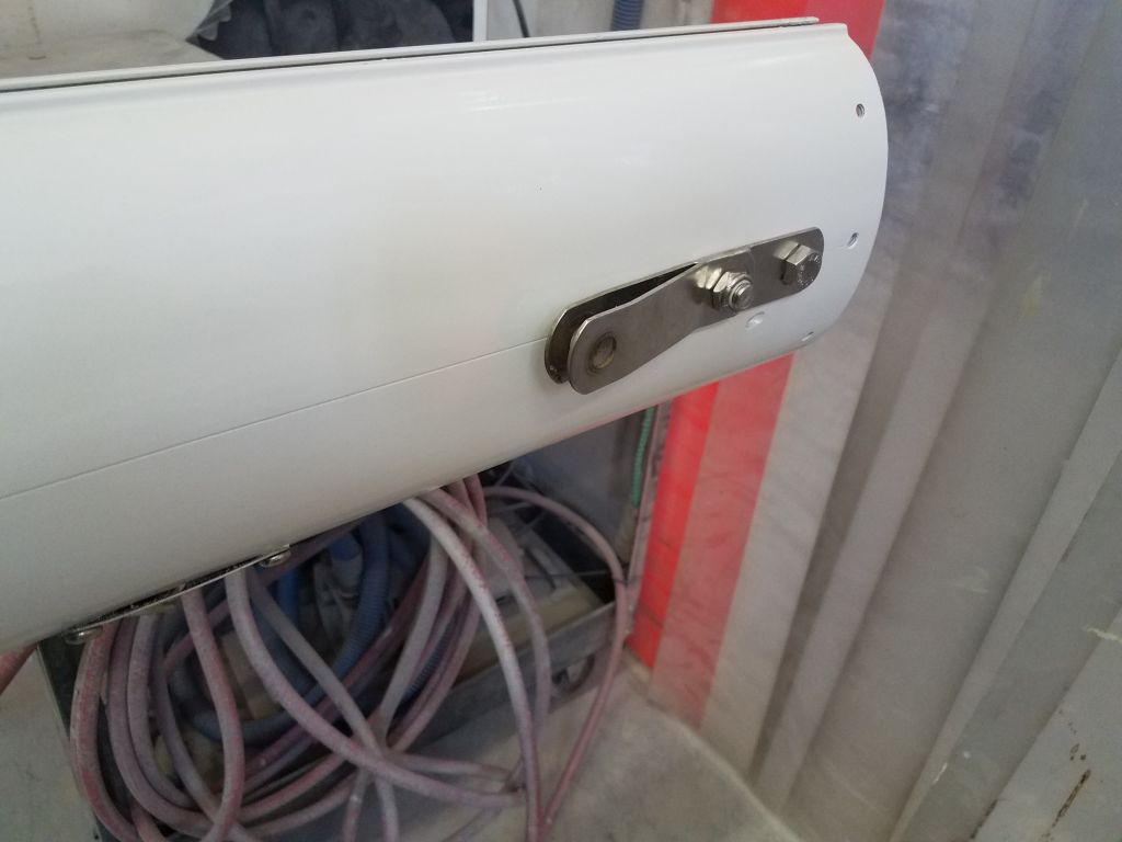
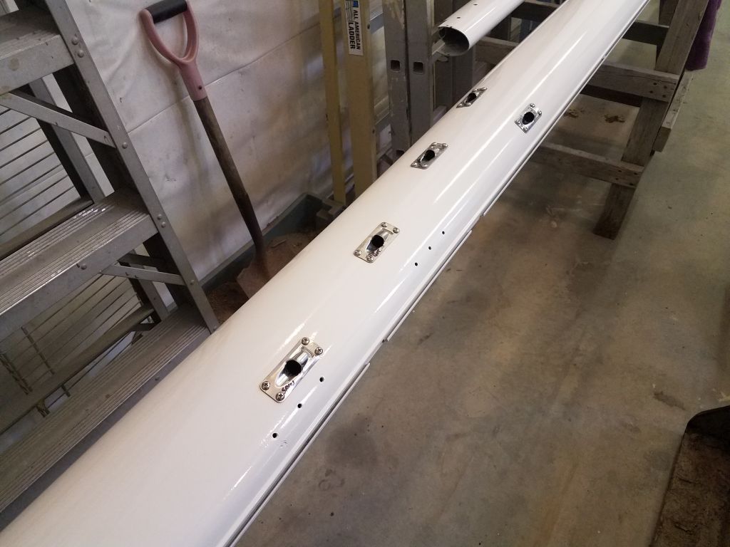
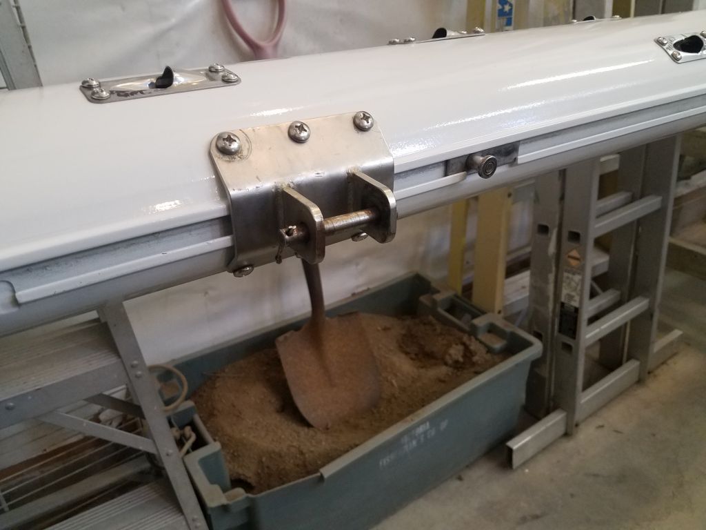
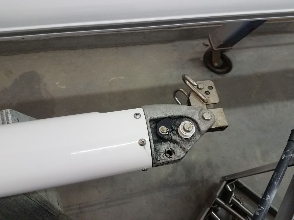
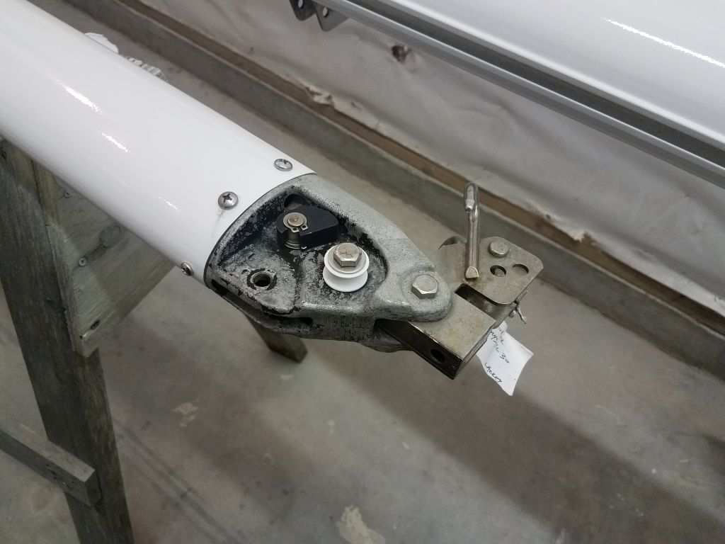
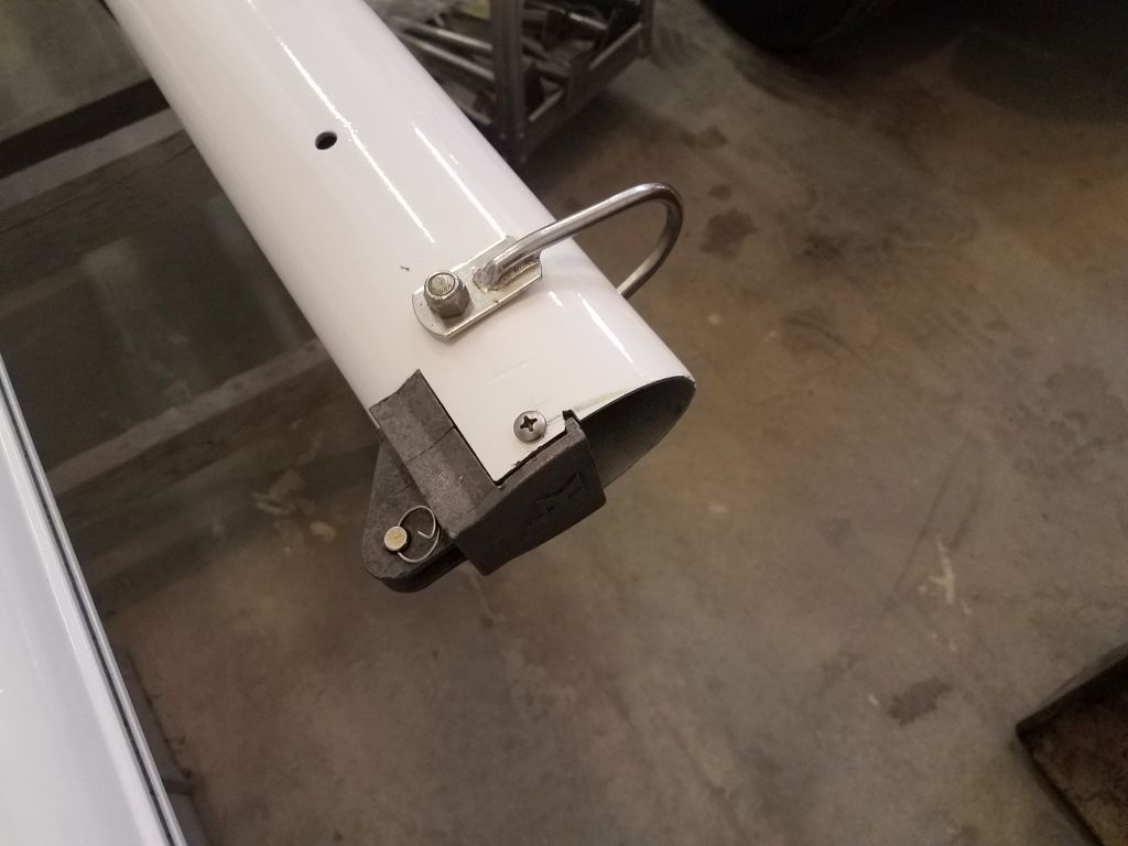
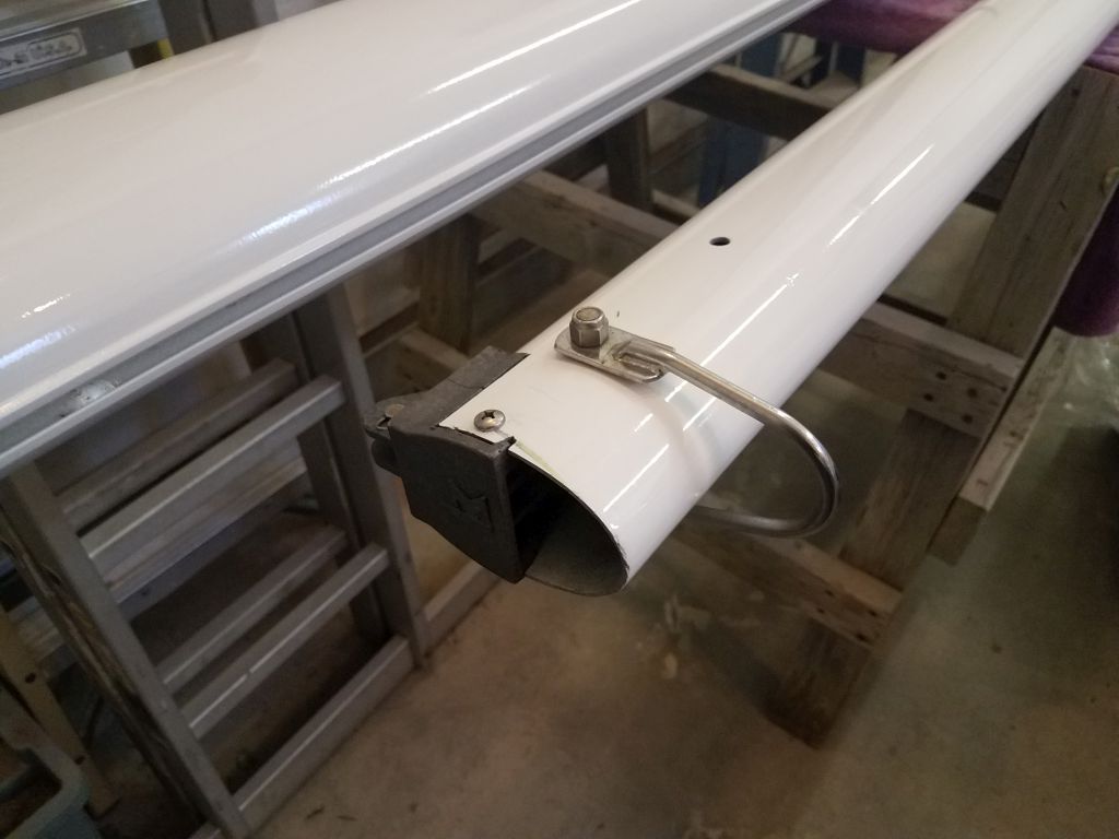
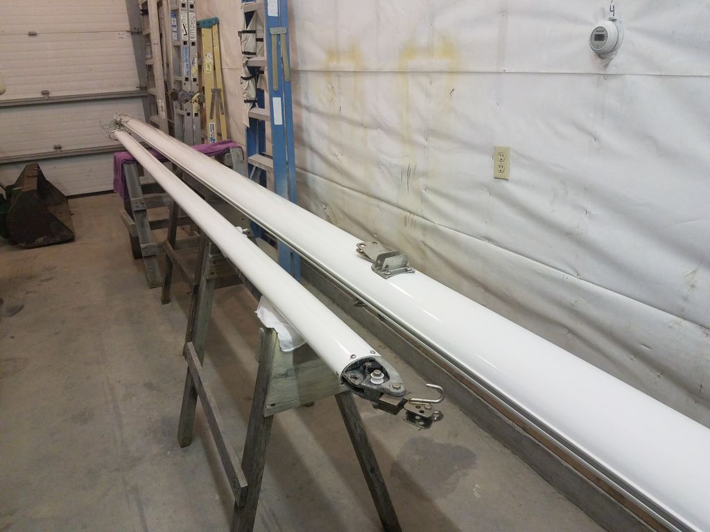
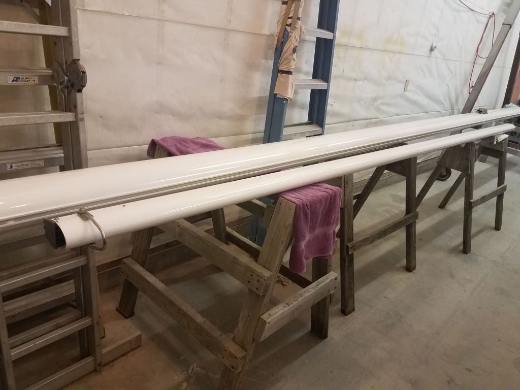
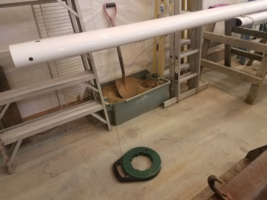
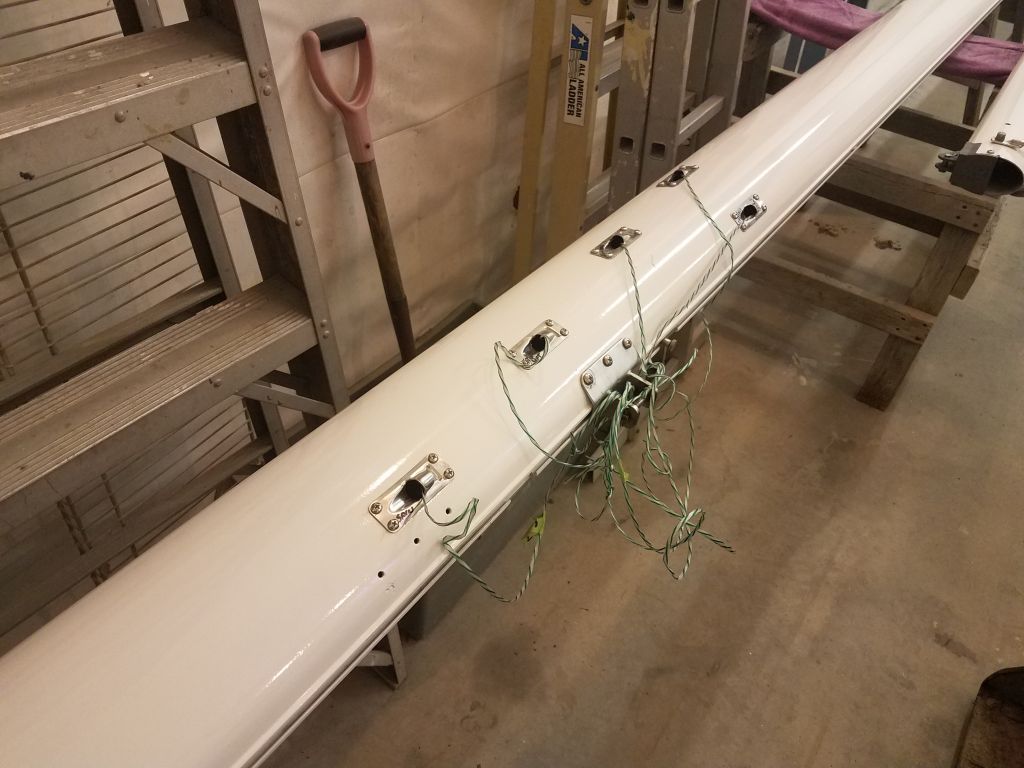
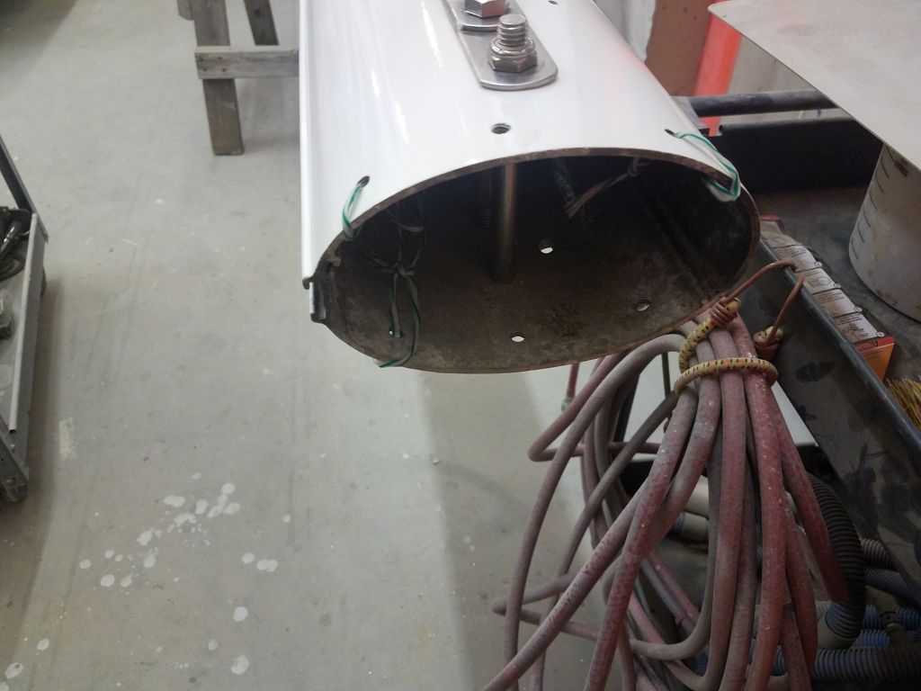
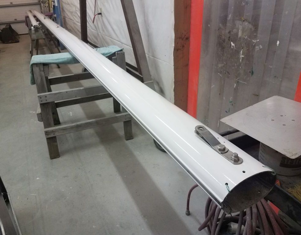
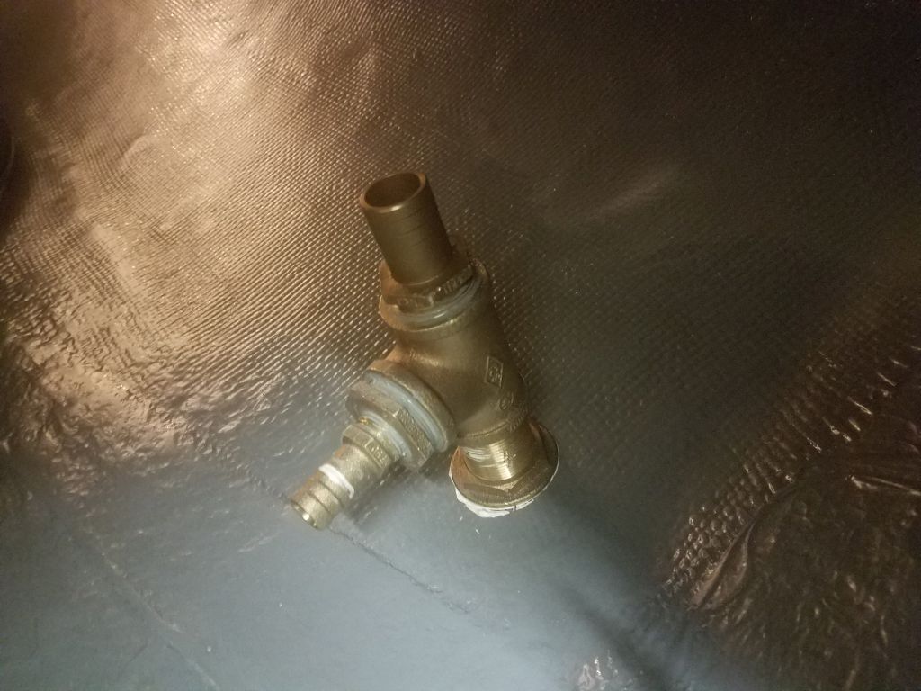
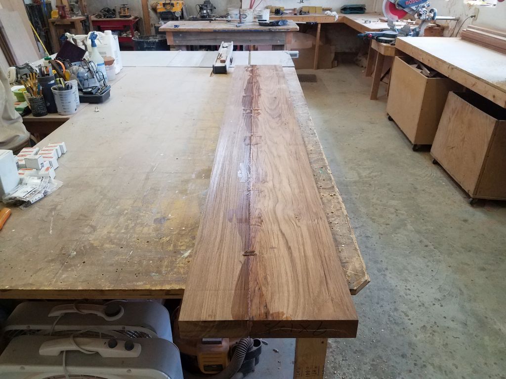
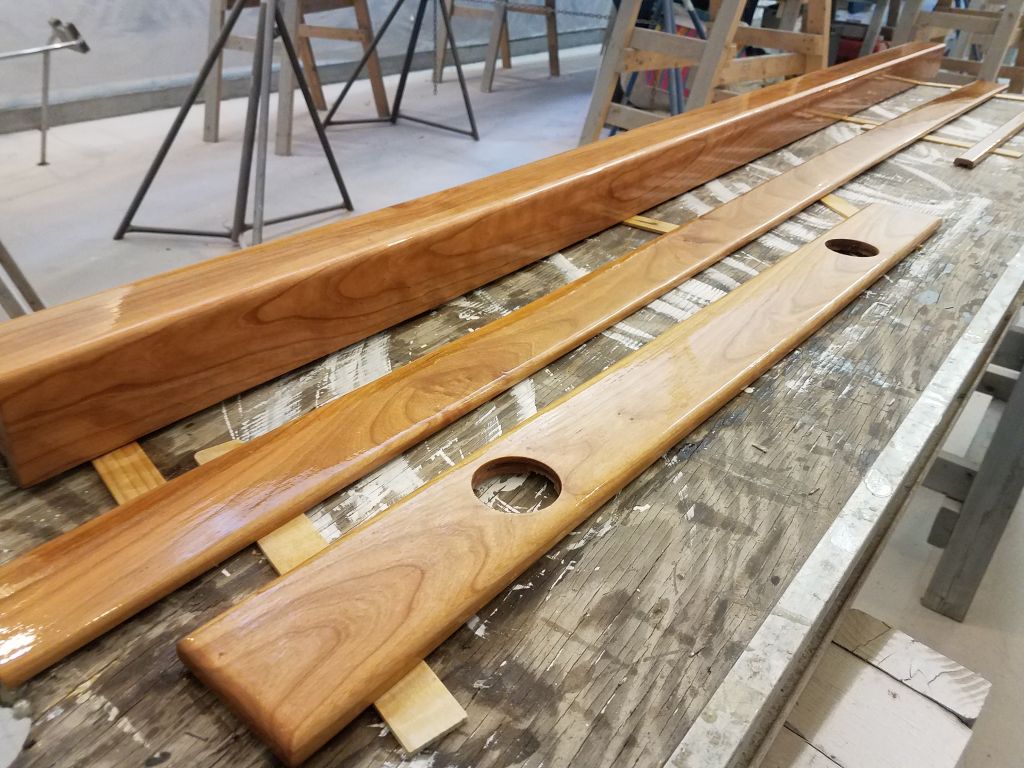
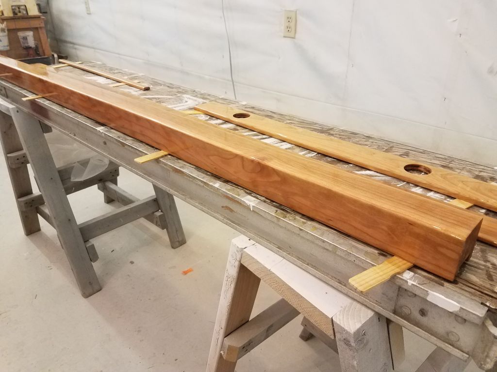
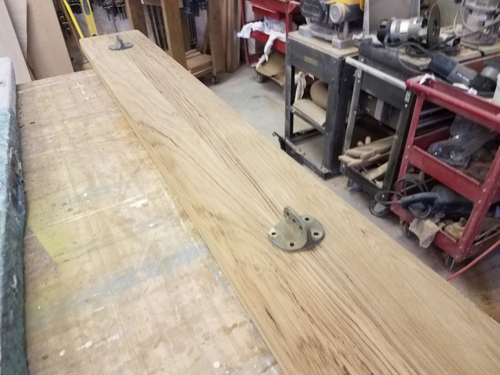
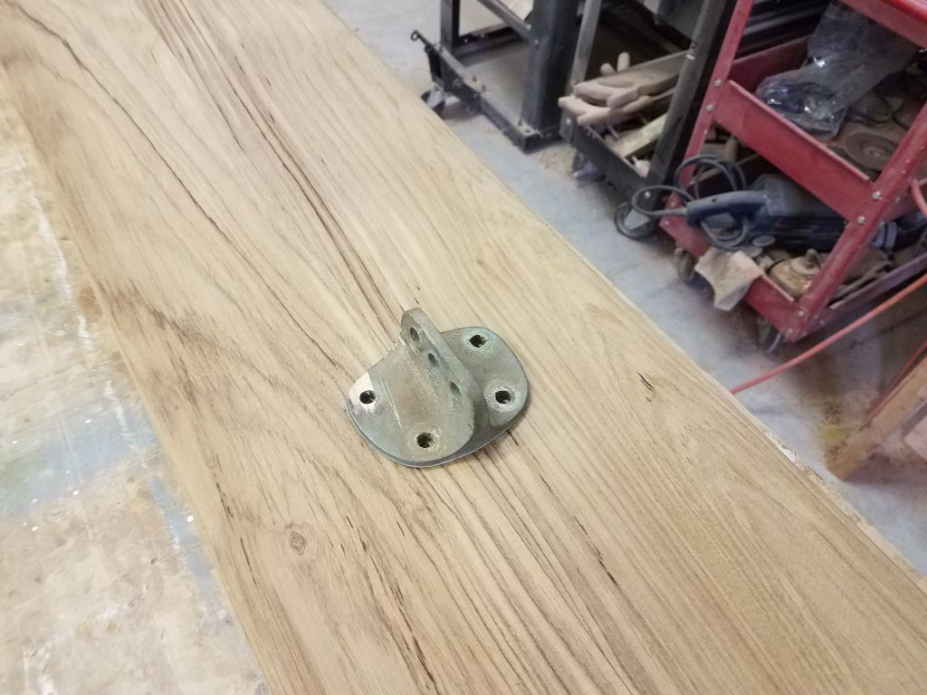
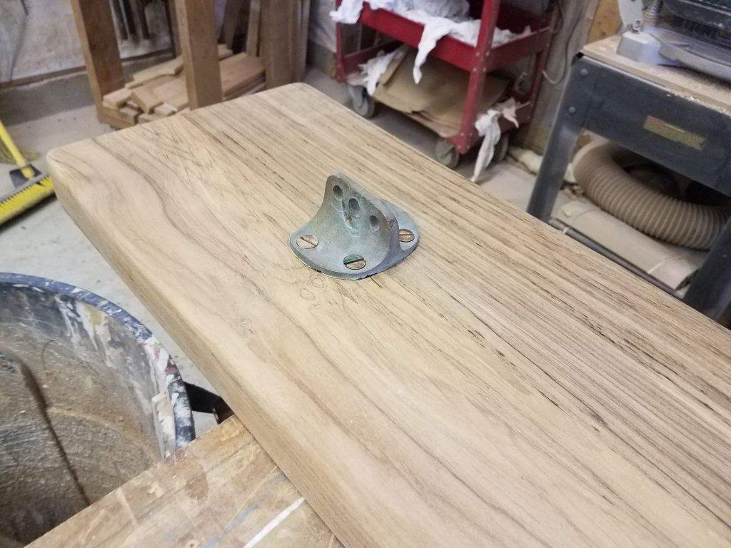
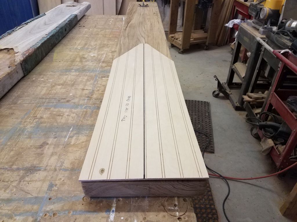
The new bow platform/bowsprit was complete and awaiting installation, and now was the time to begin. Before getting into the physical aspects of the install, I did some prepwork down on the bench, where I transferred the locations of the headstay/bobstay chainplate assembly and the inner forestay chainplate. I thought I might want some way to tie a line to the end of the bowsprit to help hold it during installation (I didn’t yet know how I was going to support it during installation), and it was more straightforward to do now anyway, so I went ahead with the installation of the headstay and bobstay fittings, securing them through the platform with new bronze bolts. The inner forestay hardware would come later.


After double-checking for accuracy and orientation my plywood template I’d made of the area of the platform that fit over the hull, I used the template on deck to mark the ends of the toerails where I needed to cut them. I’d left the toerails a bit long on purpose so I could trim them to fit closely against the bow platform. I cut the rails with a handsaw, then tested the fit of the template once more, aligning it with the marker line I’d drawn on the deck covering during my earlier layout.
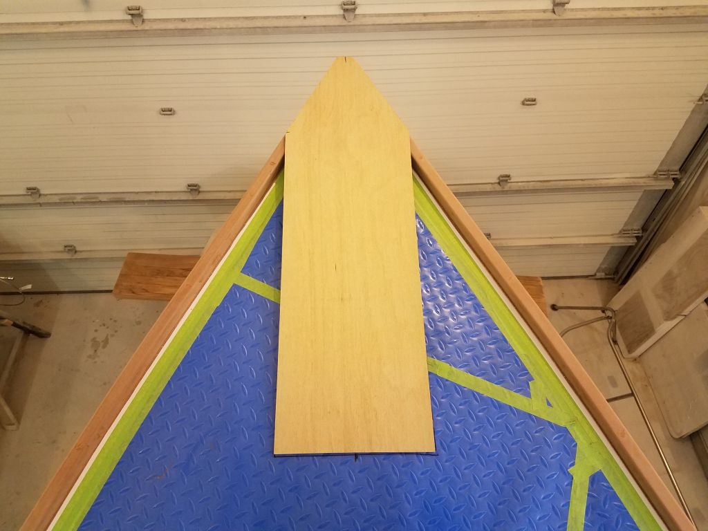
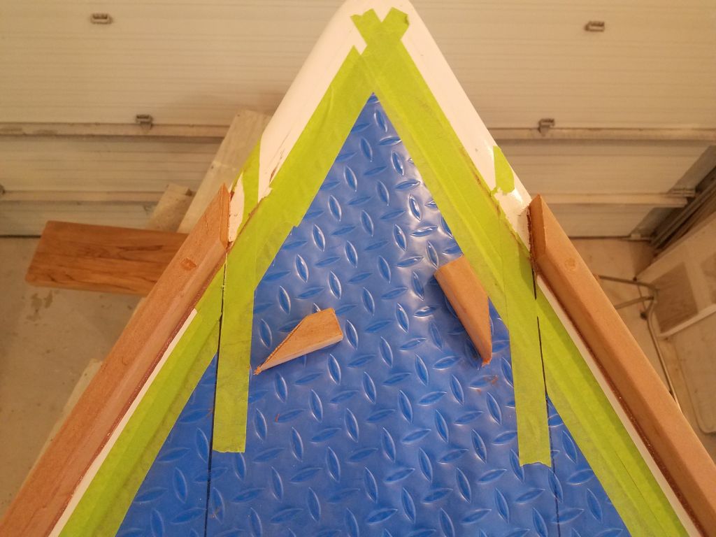
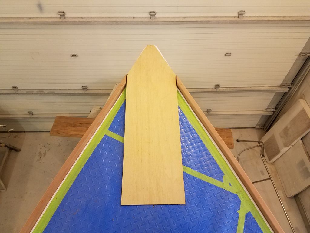
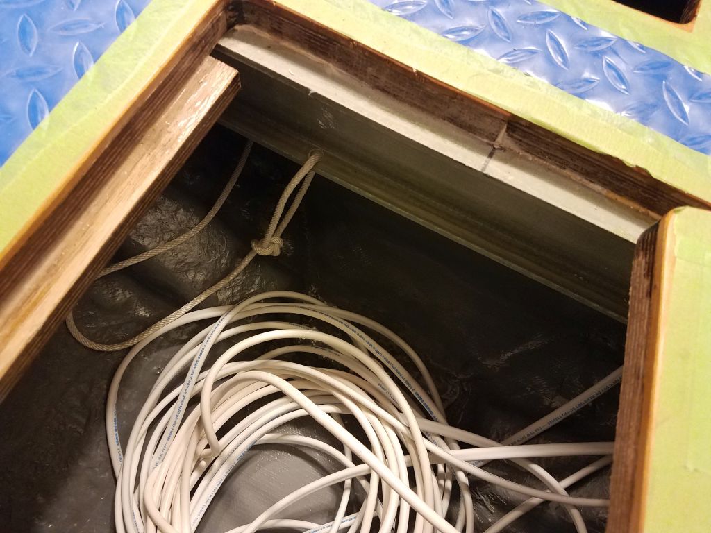
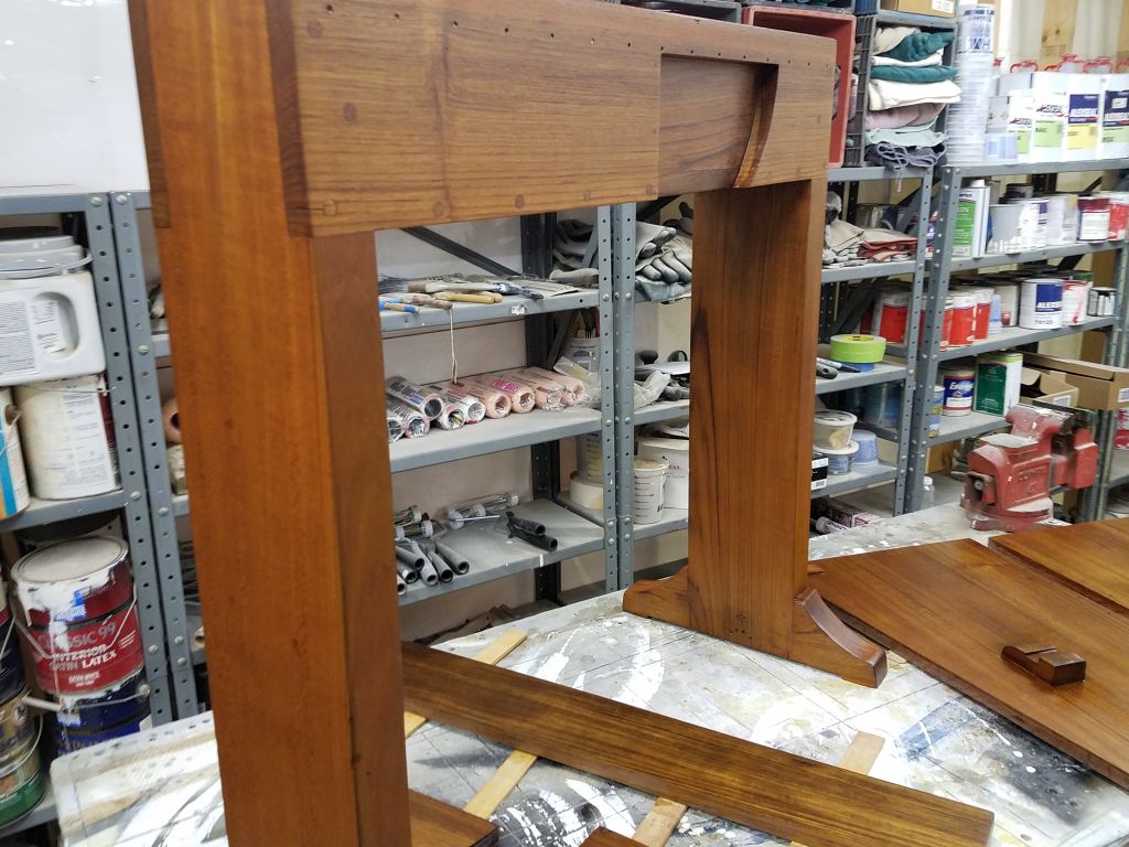
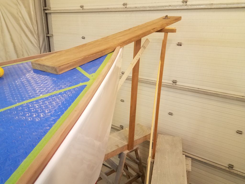
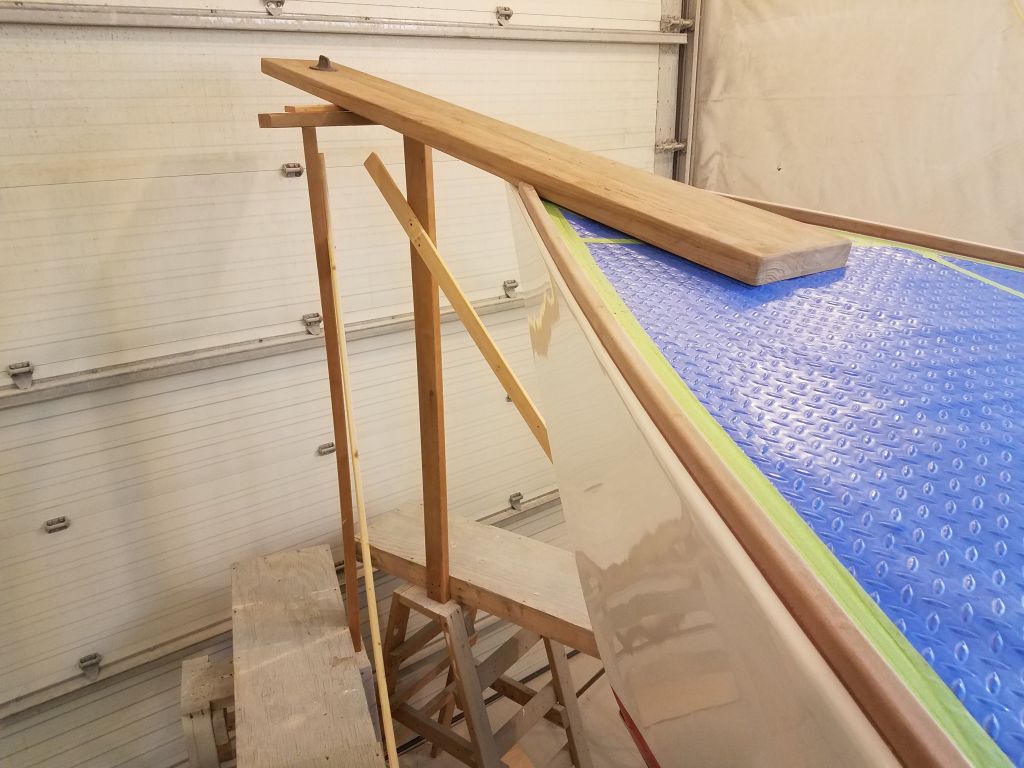
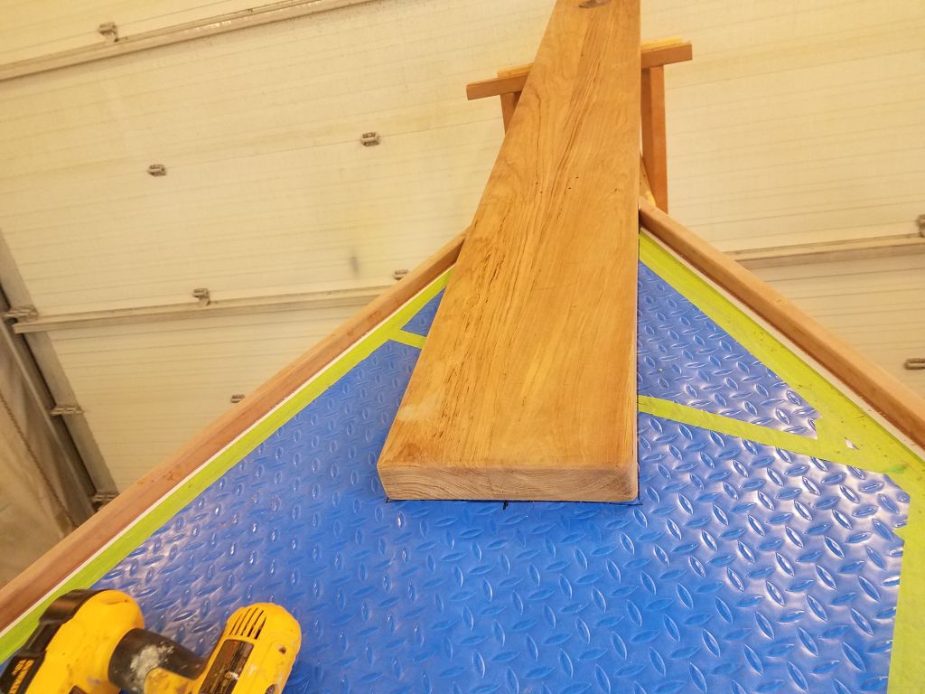
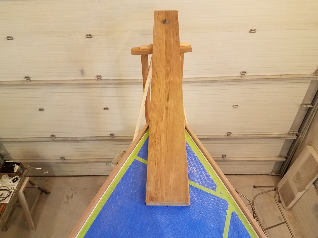
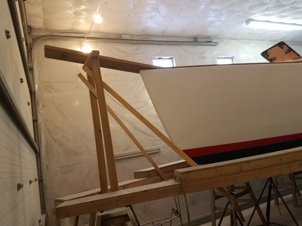
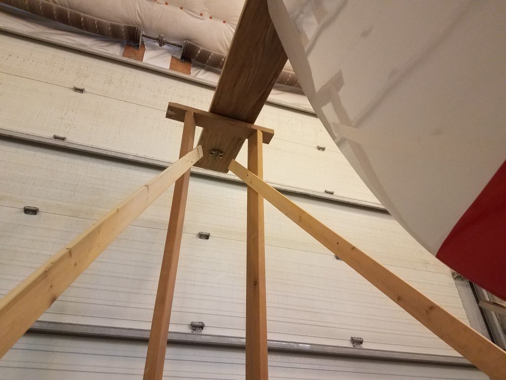
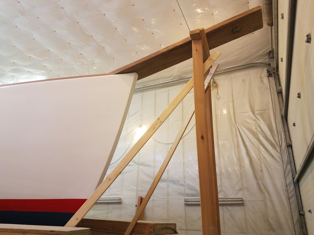
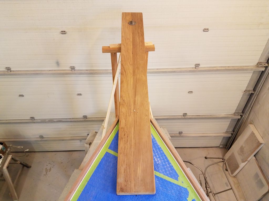
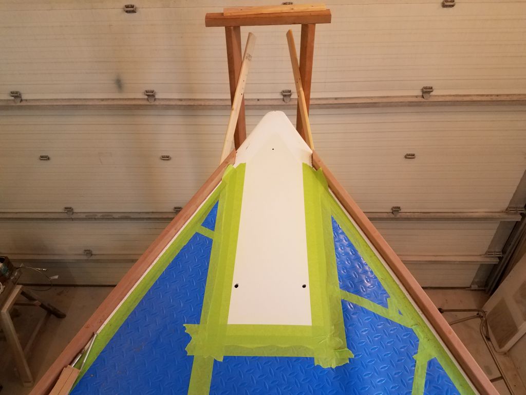
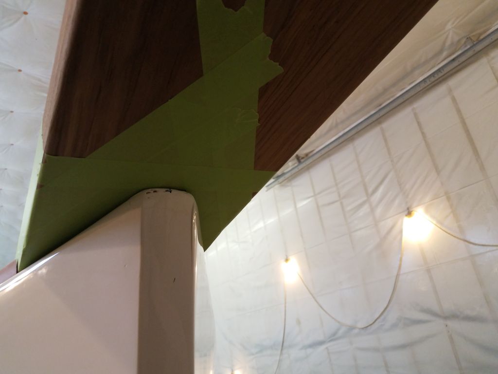
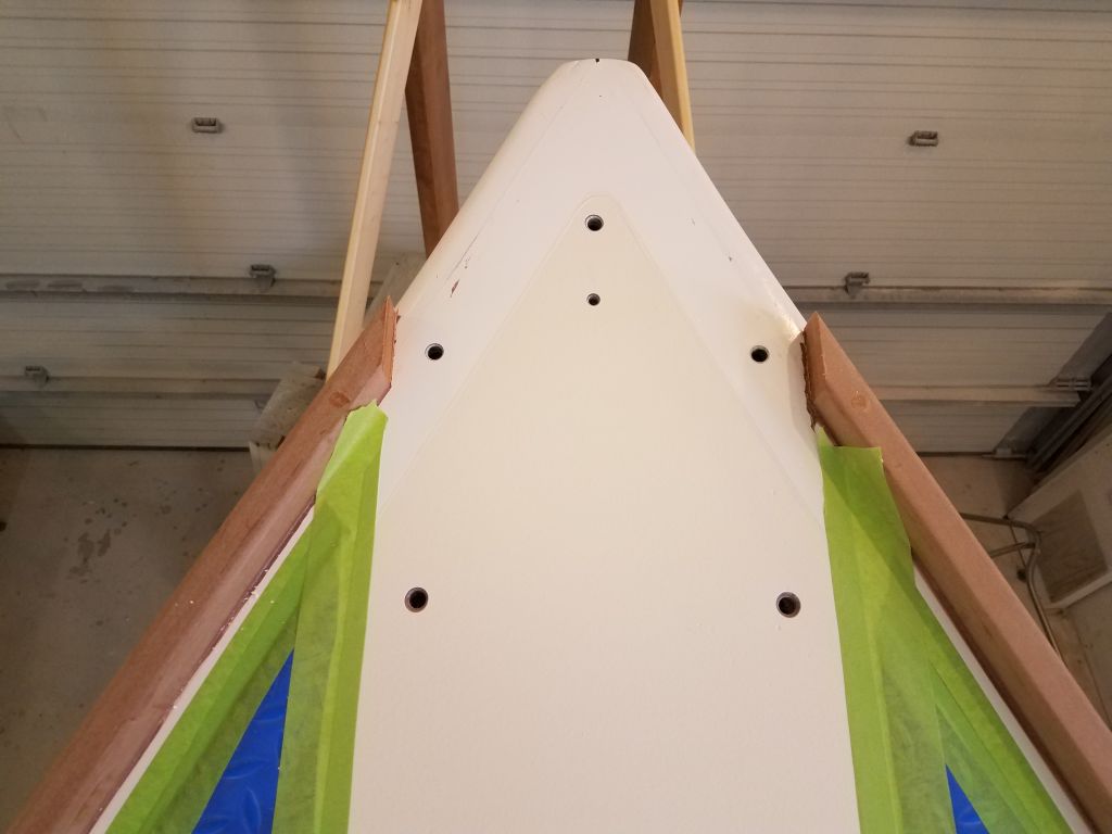
Now I could set the new platform in place on deck. Easing the platform further out through the opening in the bow, till it became unstable, I determined that I needed to build a basic support beneath, as there was no clear means of hanging it with a line, so after some measurements down to the staging–the nearest and most convenient starting point for a support structure–I cut some wood to the proper dimensions and built a simple support at the right height to hold the bowsprit in place while I worked on the deck connection. I’d intentionally kept the height of my new support a bit low, and once I slid the bowsprit out over it, I added a shim beneath to support the platform in its natural position as determined by the shape and angle of the foredeck.


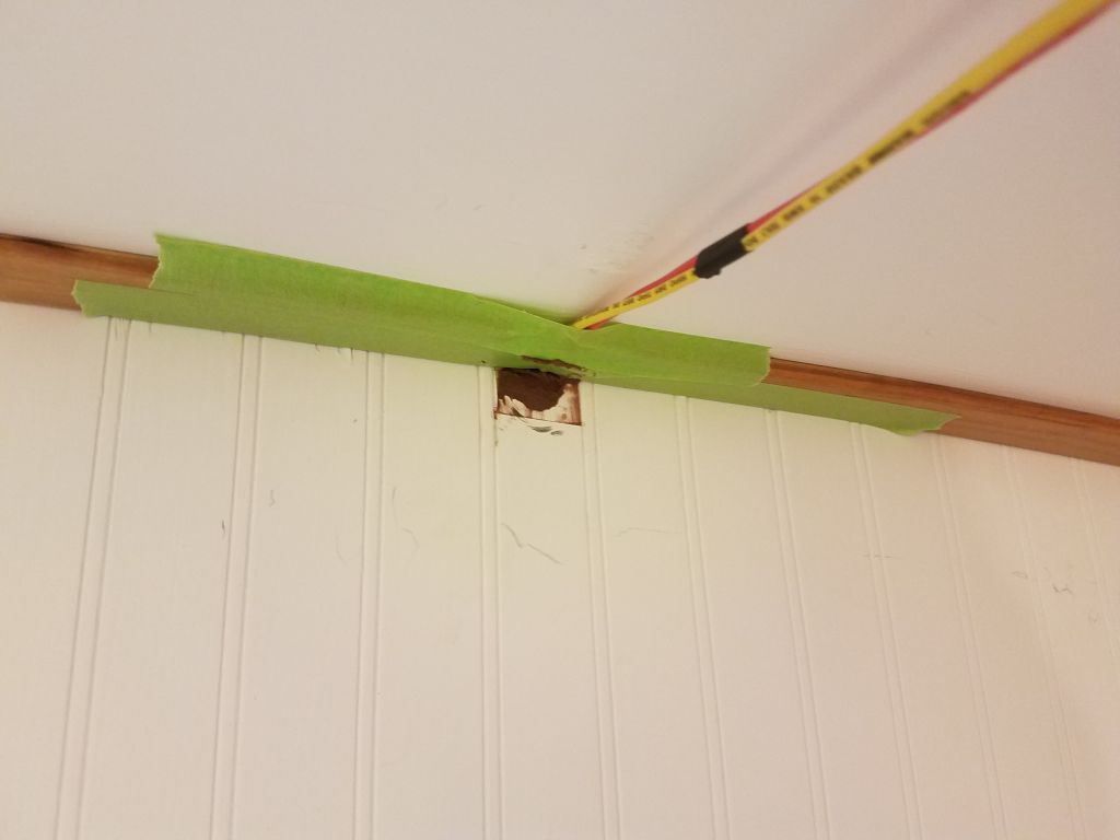
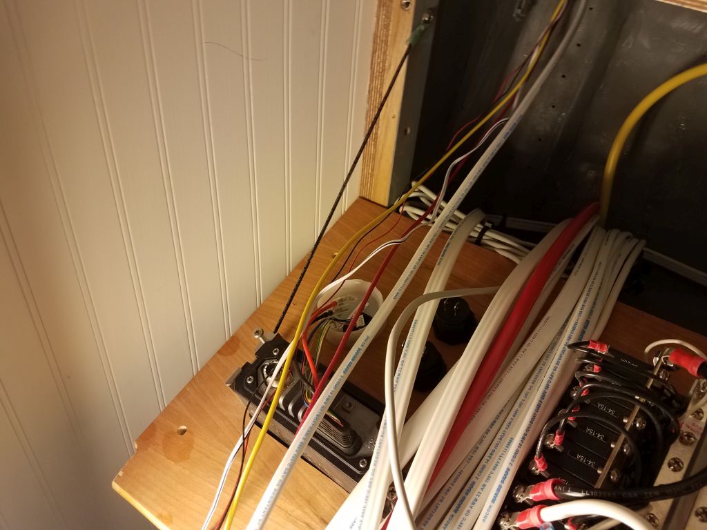
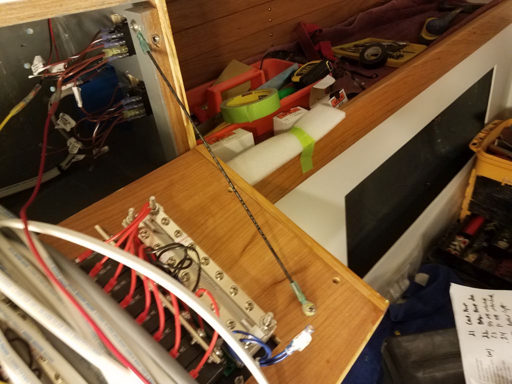
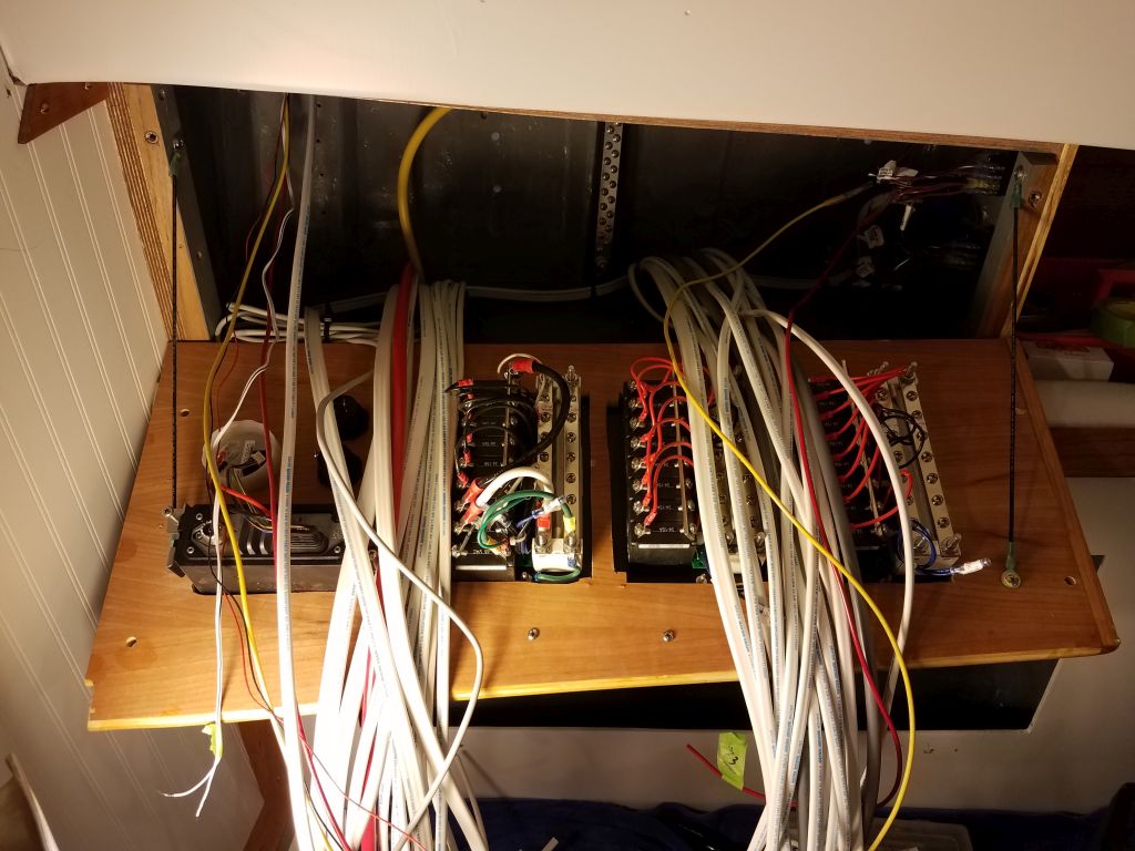
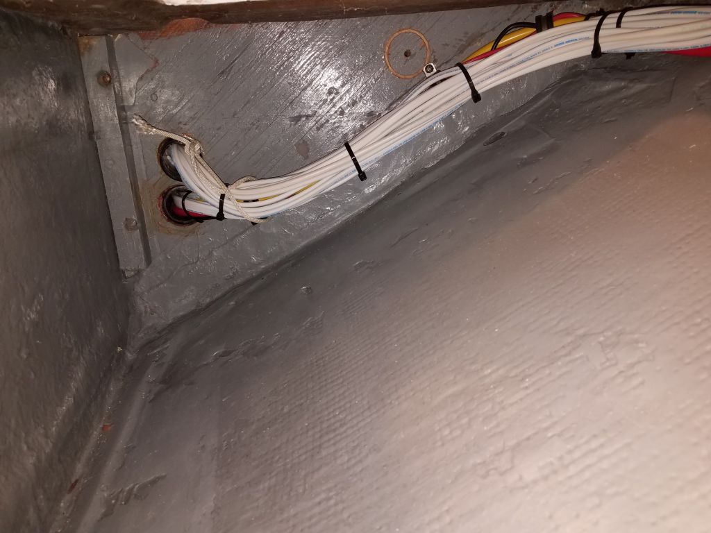
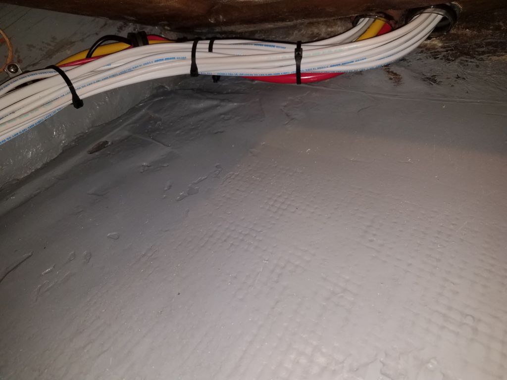
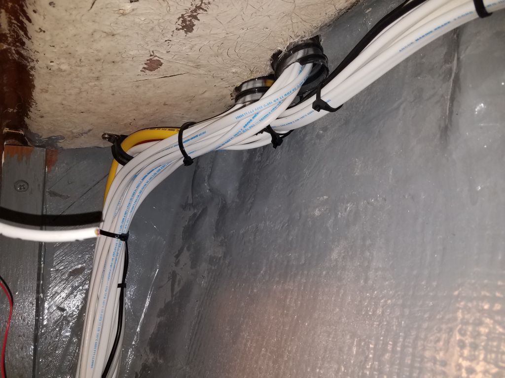
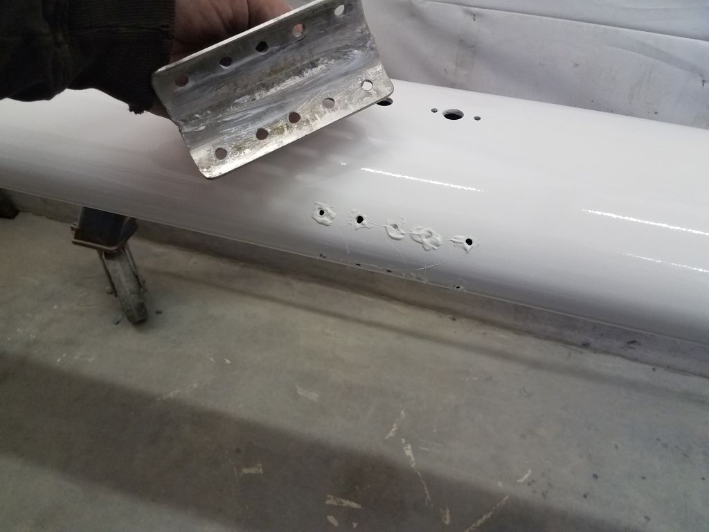
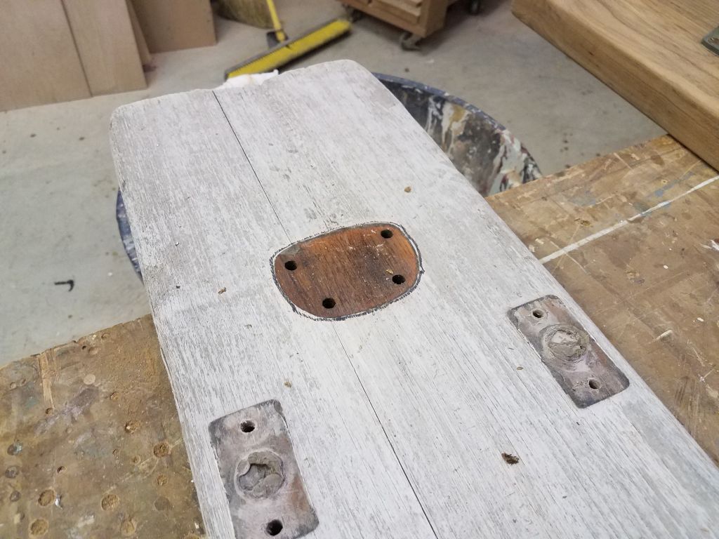
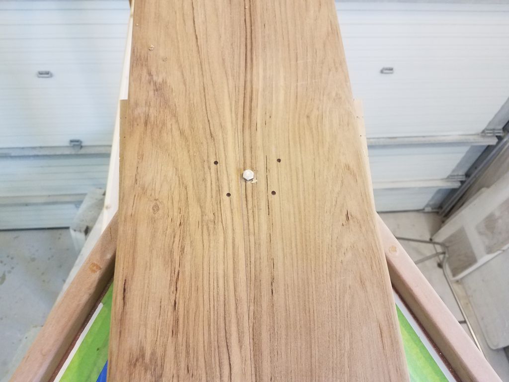
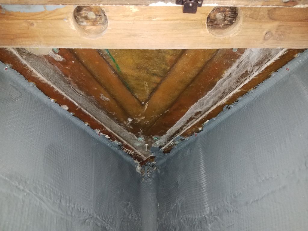
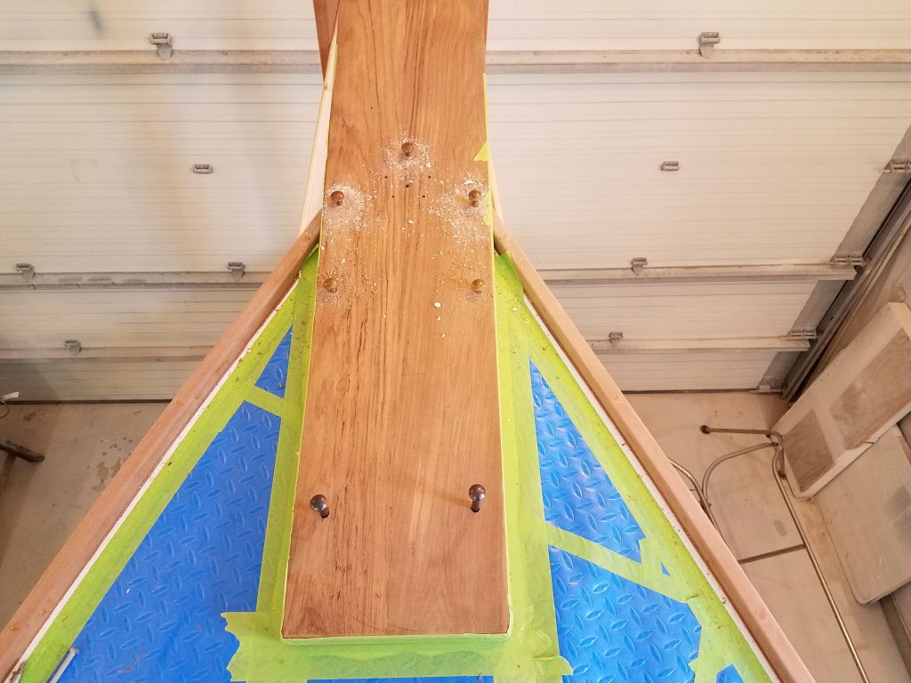
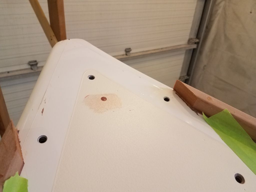
The original bowsprit had been secured by a number of bolts, the after two of which passed through a heavy wooden beam bolted to the forward side of the chainlocker bulkhead. I’d kept this beam in place, and now wanted to re-use the bolt holes to secure the new platform. I’d filled all the holes on deck during that part of the project, but the old holes were still visible from beneath, and after checking to be sure the platform was in the right and final position, I drilled a temporary hole through the platform beneath the spot where the inner forestay hardware would later go (which would hide the temporary hole), and inserted a bolt as a pin to keep the bowsprit from shifting, as movement on the boat and staging tended to wiggle it a bit out of position at this early stage. Then, once I was sure the platform was where it belonged, I drilled up from below, using the existing holes in the main beam as a guide, and through the deck and just a bit into the platform to mark the holes’ locations.
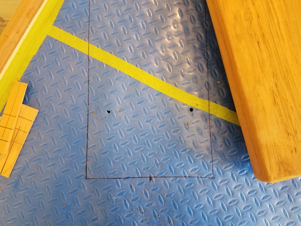
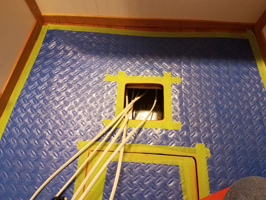
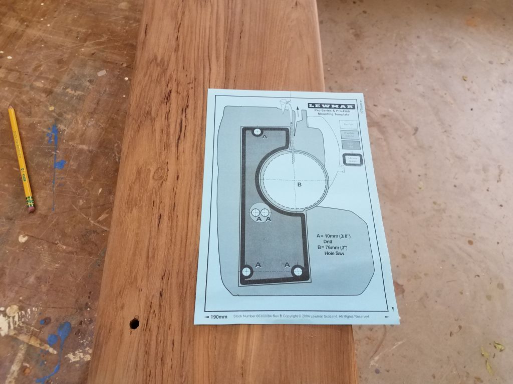
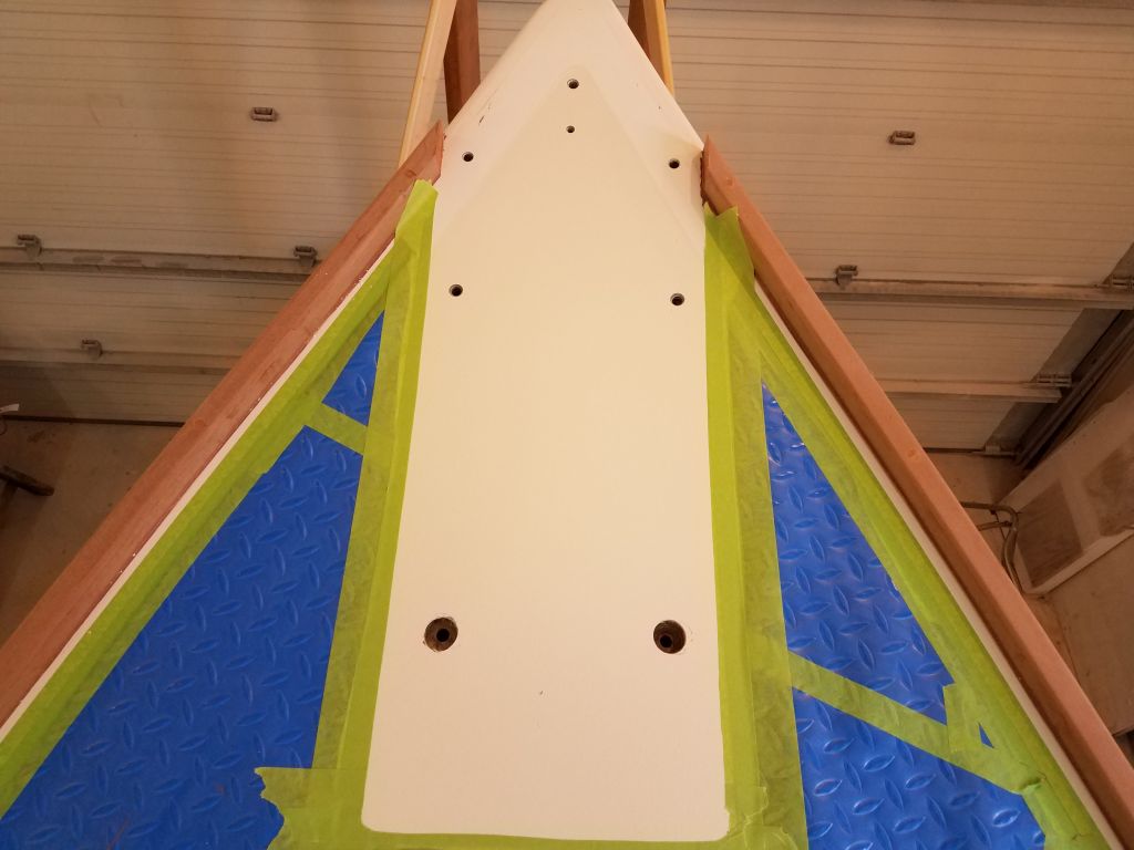
With those critical holes marked, now I could remove the platform again and, down on the bench, finish drilling the holes I’d just started, as well as lay out and drill a series of holes for additional bolts. I used the bolt pattern on the old platform as a rough guide, but made sure to leave space for the anchor windlass, using a template supplied with the windlass that the owner had ordered, so there wouldn’t be some bolt in the way. With the holes all drilled in the platform, and after cutting away the plastic deck covering and adding additional masking tape to the cutout so I could mark the edges of the platform during the next dry-fit, I replaced the platform and, after alignment, drilled for all the boltholes through the deck.

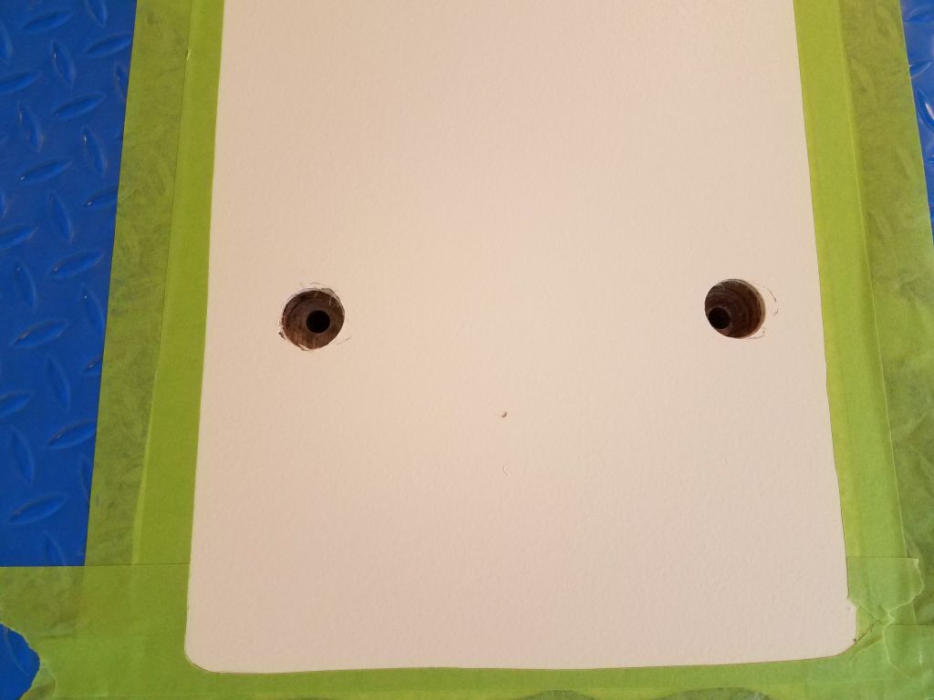
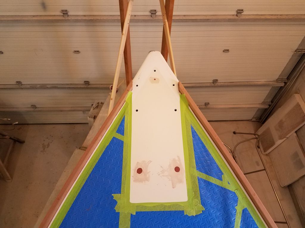
Only the after two bolt locations passed through any deck core; the forward five bolts passed through the solid portion of the deck and/or the original hull flange. So after marking the deck tape where the platform landed, and also the underside of the platform where it met the hull, I again removed the platform, trimmed the tape as needed, and prepared the holes in the deck as needed. This meant boring through the top skin and plywood core for the after two bolts, removing all the core down to the inner skin, and counterboring the remaining bolt holes in the usual way to prepare for eventual sealant. Then, I filled the overbored aft holes with a thickened epoxy mixture, and also patched the single temporary bolt hole beneath the inner forestay. That ended the work for now on the bowsprit.

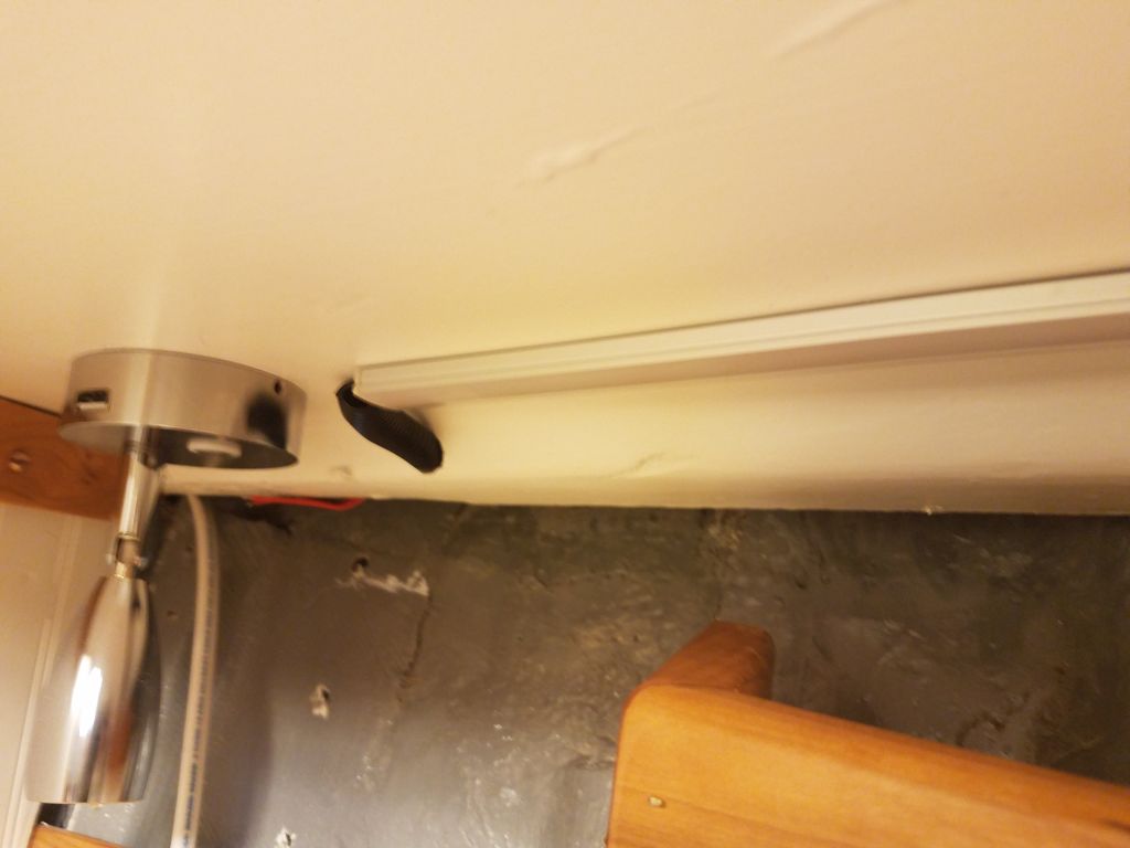
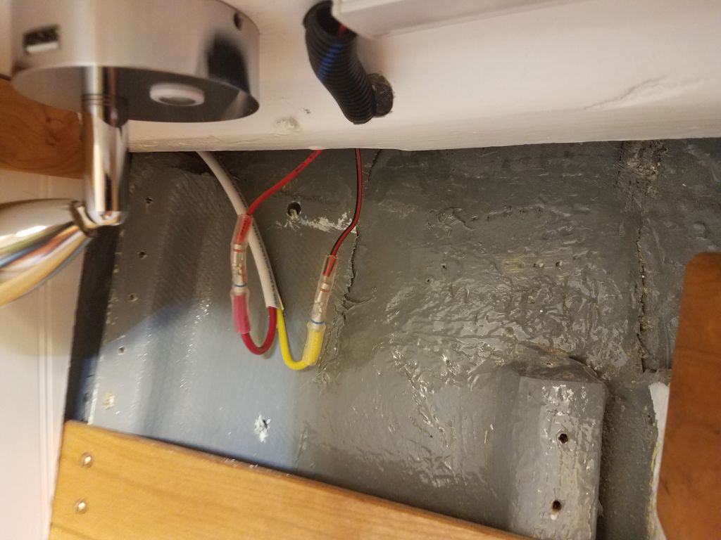
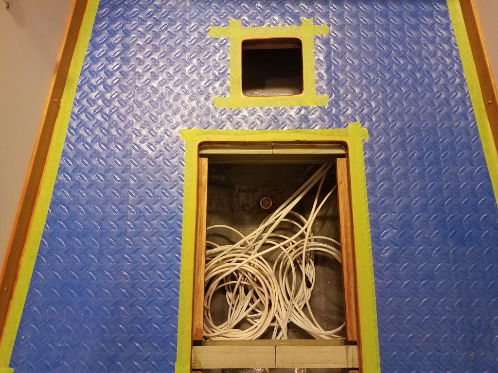
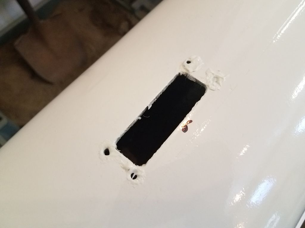
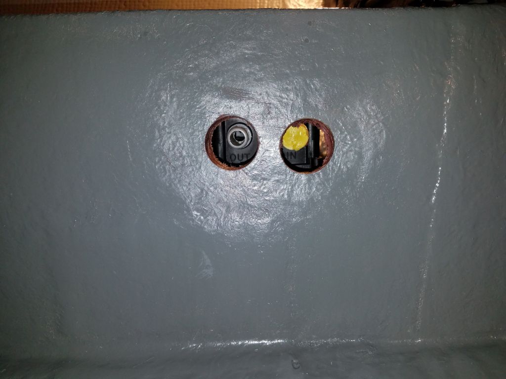
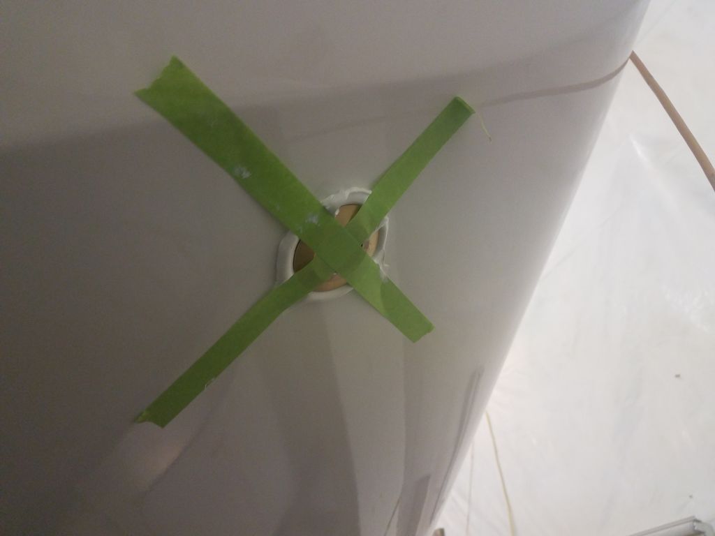
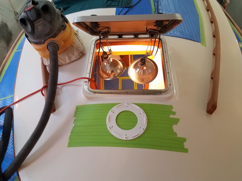
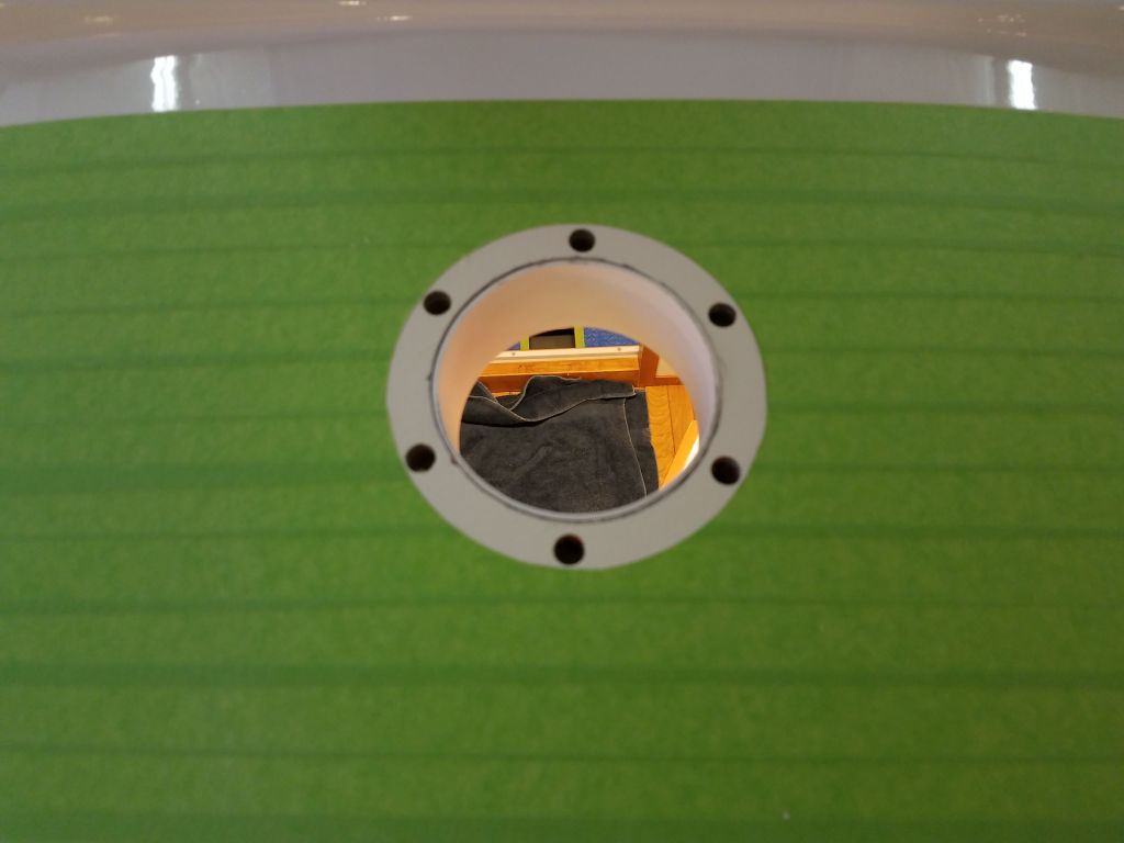
For passive ventilation inside the boat, in addition to the solar vent in the companionway hatch the owner also selected a purportedly waterproof mushroom-type vent that he asked I install in the coachroof just forward of the forward hatch. This vent featured a unique design to prevent or limit the ingress of water, the details of which I haven’t covered here during these early installation steps, but bear with me over the coming days and the various pieces and parts and interesting design features will be revealed.
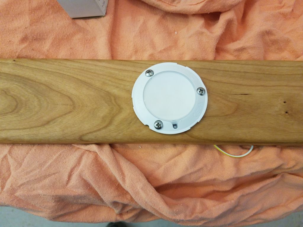
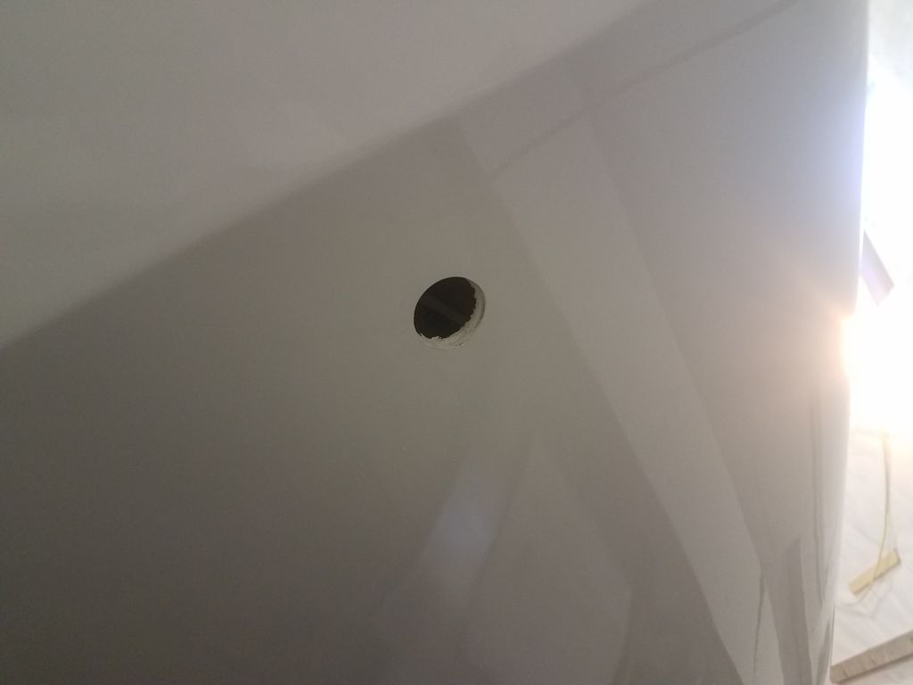
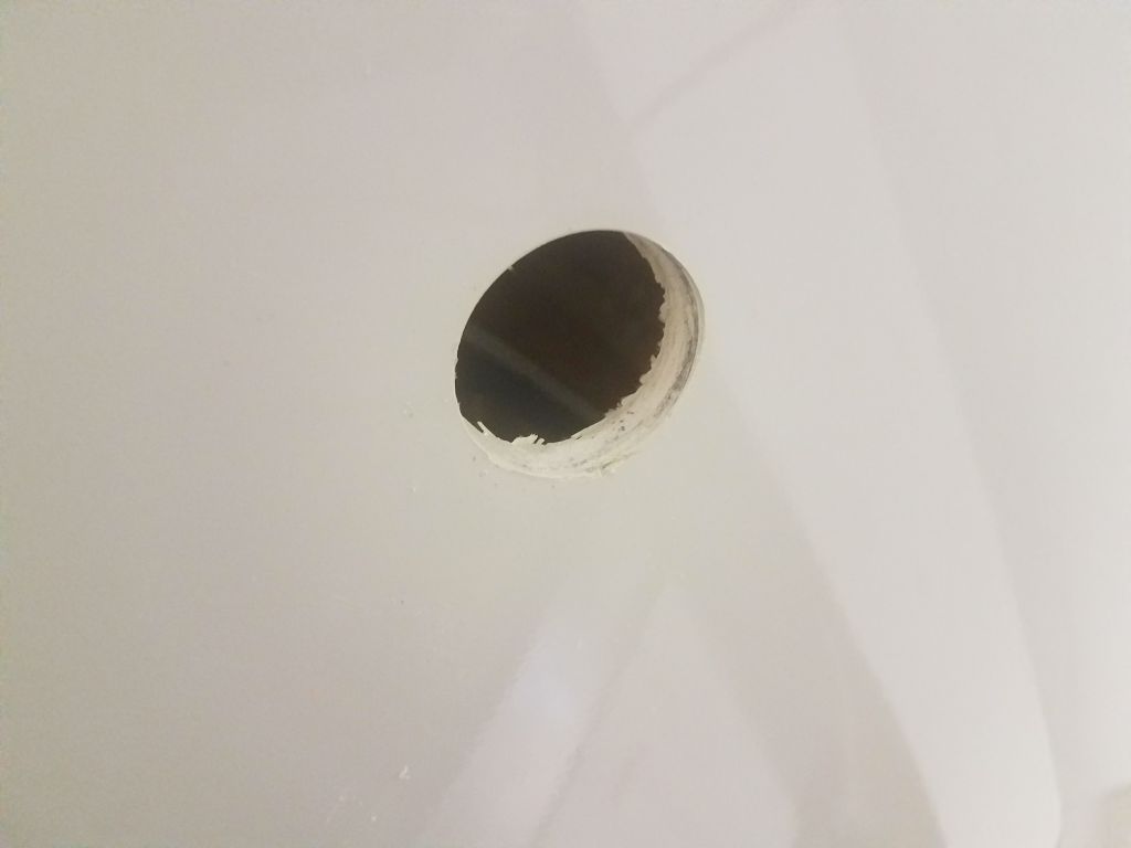
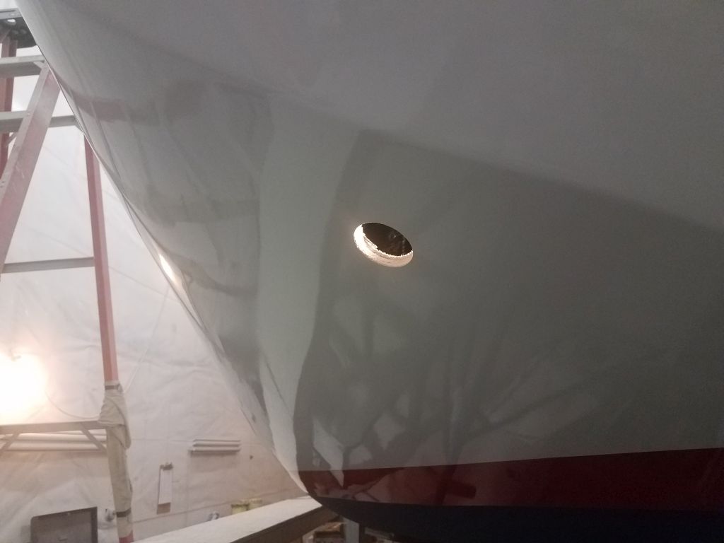
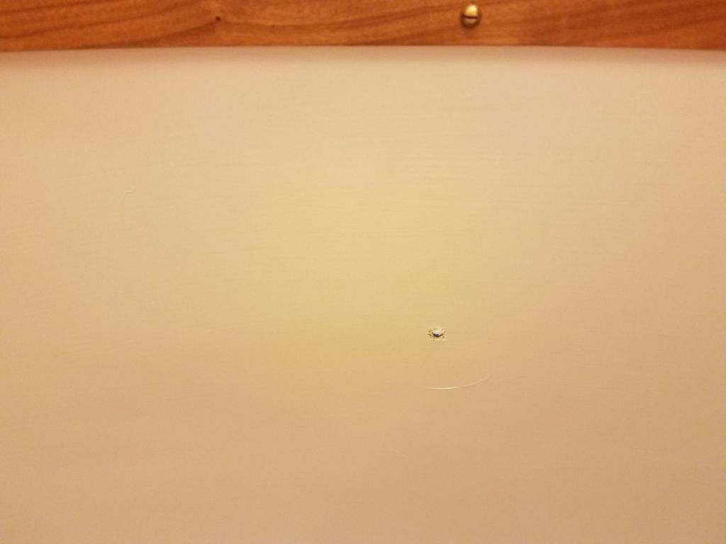
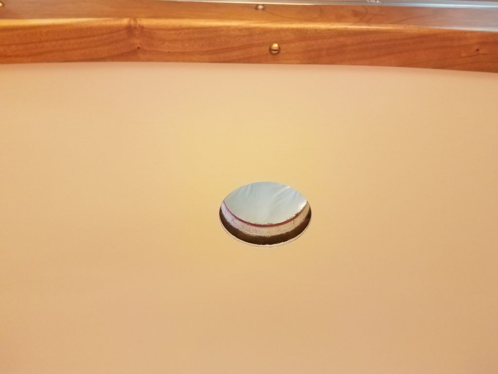
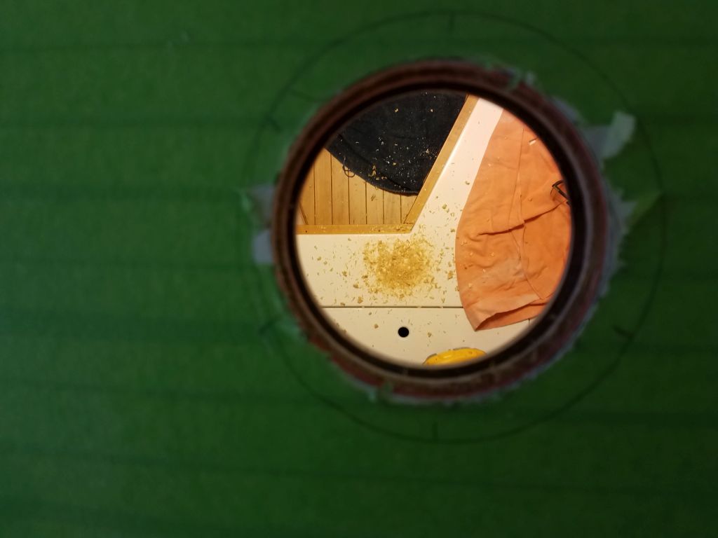
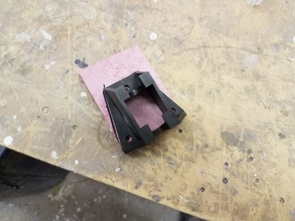
In any event, it was time to drill the large hole required for the vent, and after some layout using the large vent base (one part of about seven that fit together to complete the vent), I marked and drilled a 3-3/4″ hole through the deck, and, after starting the hole from above, through the cabin liner working from inside. The core in the cutout was in good condition, and once the hole was finished I reamed out some of the core within the opening so I could fill it with epoxy a little later.


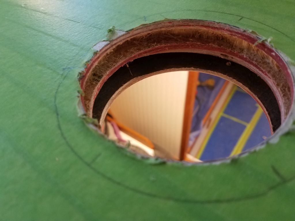
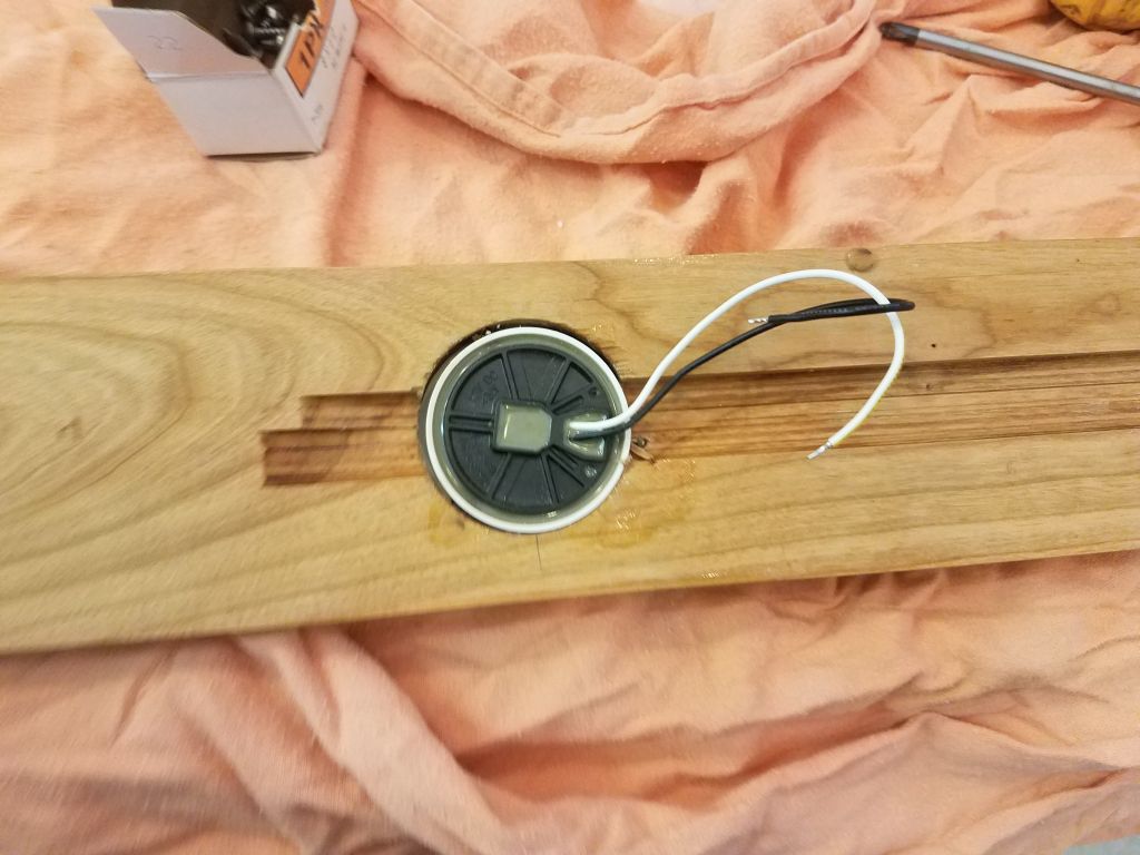
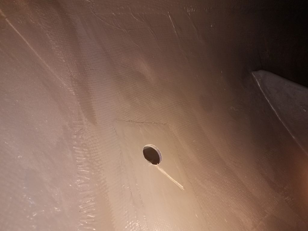
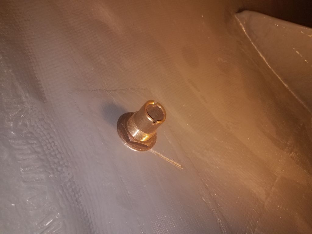
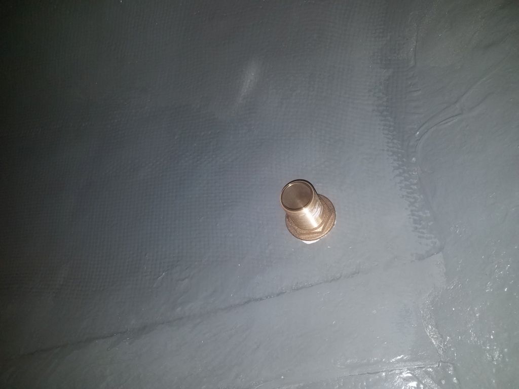
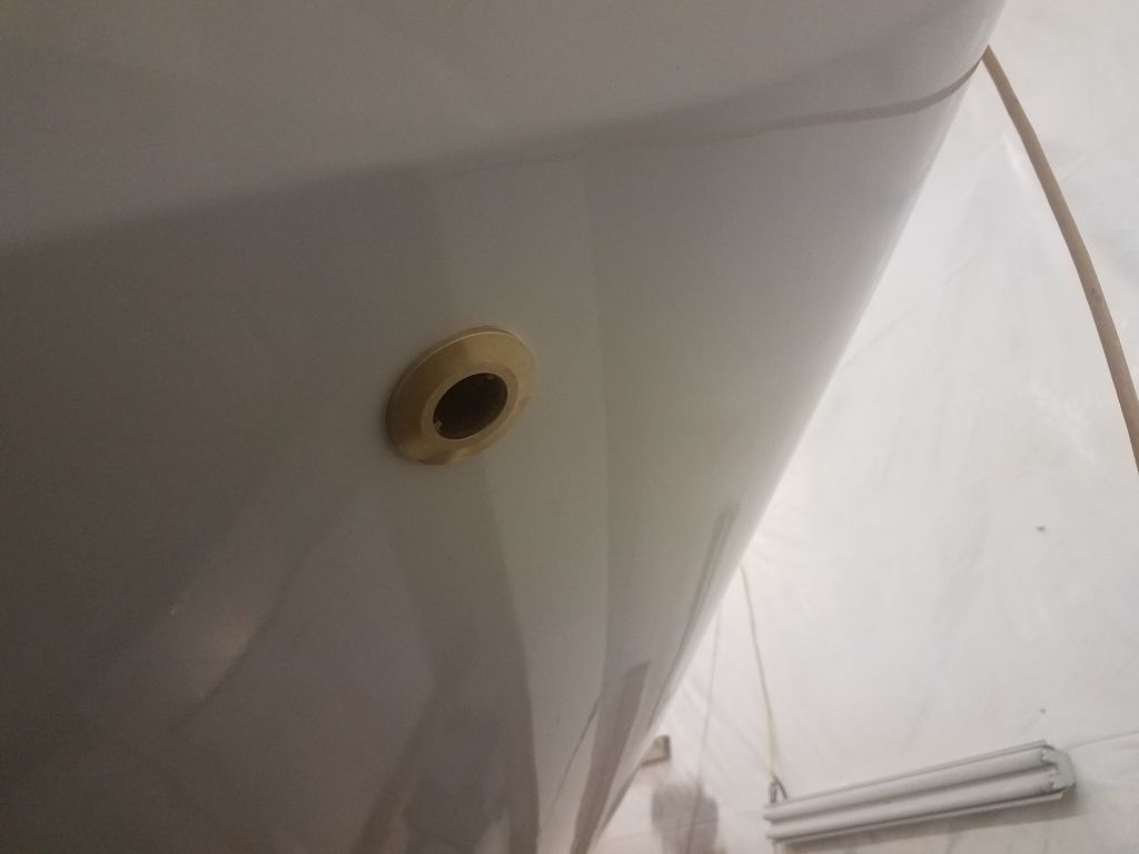
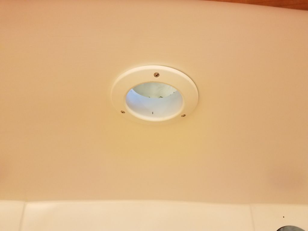
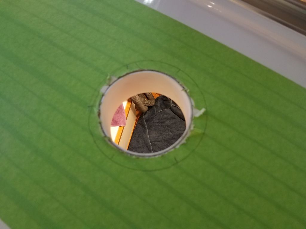
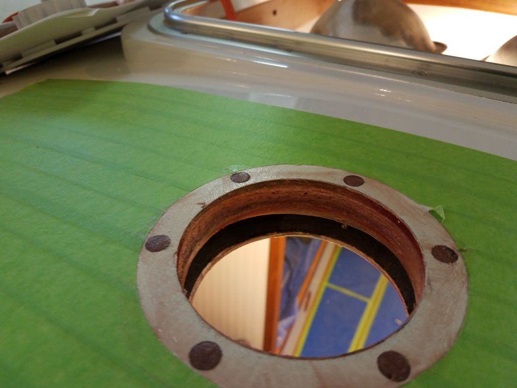
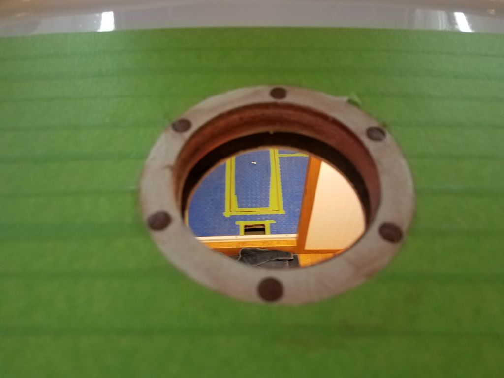
The first piece of the vent was a trim ring/sleeve that fit from beneath, and I had to dry-install this and cut it to length so it was flush with, or even a tiny bit below, the level of the deck. I temporarily installed the trim ring from below with screws, as I needed it in place to align and mark the next part of the vent on deck. I don’t have any pictures of this next piece for now, as I forgot, but I used it to mark the deck for its numerous fasteners, which holes I then opened up with a 3/8″ bit to remove the core from each fastener location.
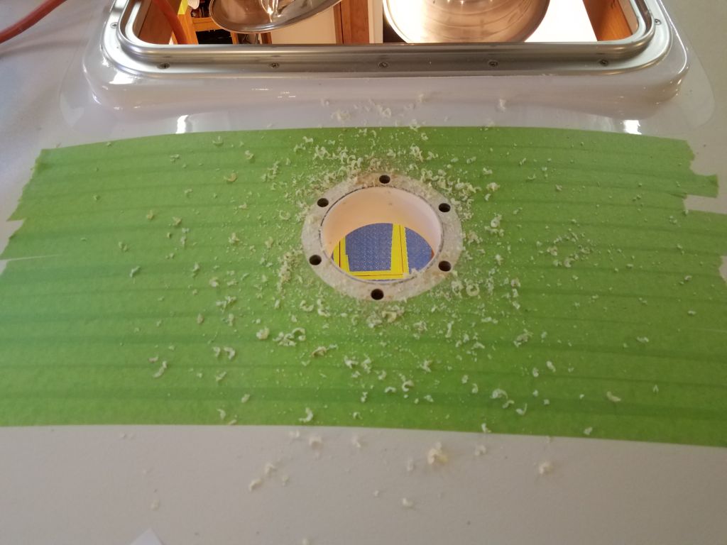
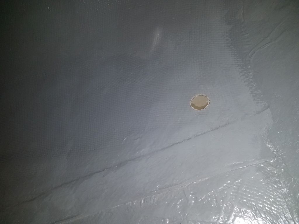
In order to properly proceed with the vent installation, I’d need the first deck piece secured in place so I could align and then mark the deck for additional holes for the next piece of the vent assembly, so I went ahead and filled the initial bolt holes with epoxy, along with the reamed out area inside the vent hole, and could proceed with the next steps once the epoxy cured overnight.
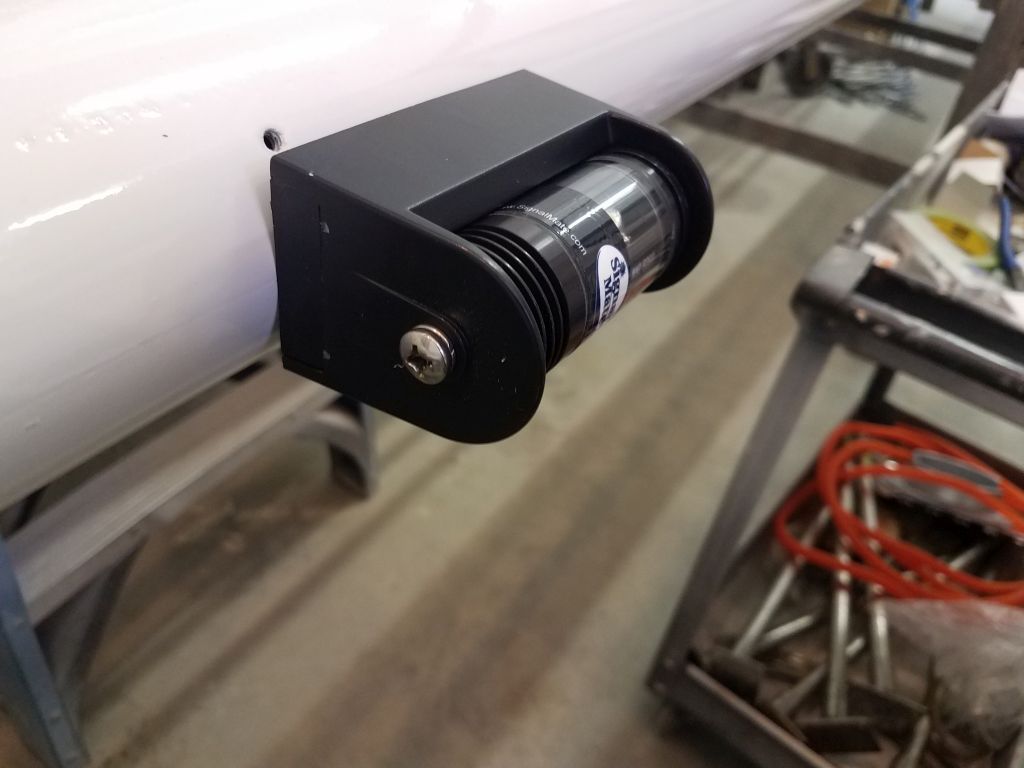
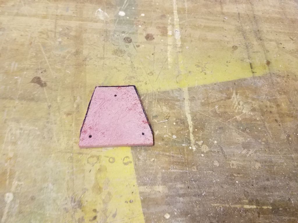
With a little time left in the day, I turned to a couple small jobs, starting with a new fiberglass base to support the bracket for the anemometer masthead unit. Using the plastic bracket as a guide, I cut a piece of prefab 1/4″ fiberglass to size. I’d return to this soon to finish it up.

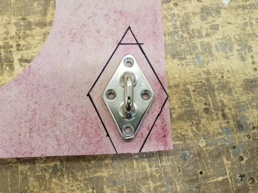
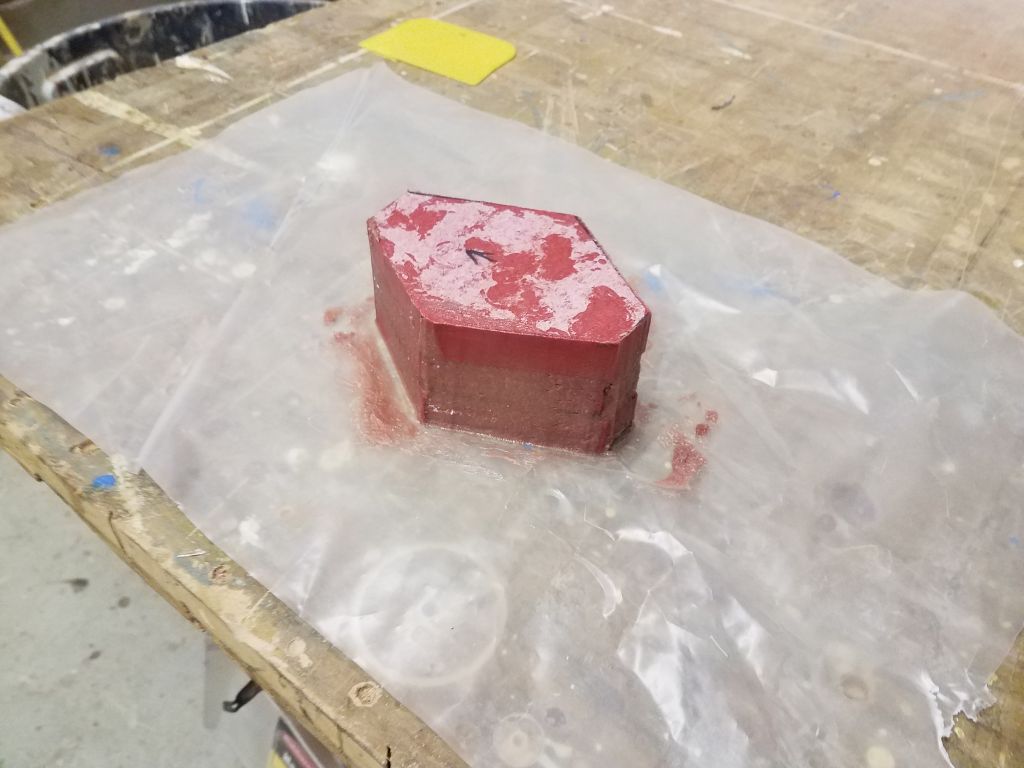
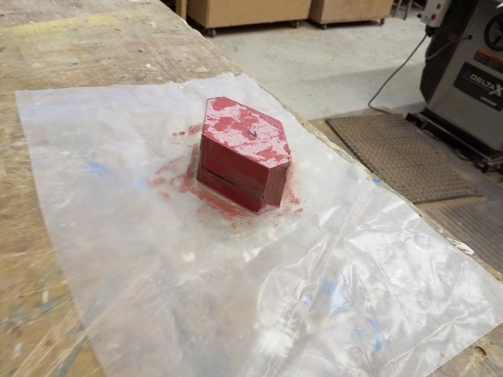
With a rigid boom vang on the way for superior sail twist control, and after various discussions on this subject, the owner elected, with my support, to forgo a traveler for the mainsheet, opting instead for a simple padeye to support the new and excellent tackle, which would mount to the deck aft of the cockpit coaming. Because of the height of the coaming, it seemed important to raise the attachment point a bit to make reaching the mainsheet’s cam cleat easier. For a while leading up to this, I considered installing the padeye to the top of the coaming, but access within was tight, and I wasn’t convinced that the coaming was up to the task without reinforcement; I also was unsure how the plastic wood trim would react to having the padeye mounted atop. So after rejecting this thought some time ago, it meant that the padeye was once again relegated to the poop deck where it belonged. To this end, I cut out three pieces of 3/4″ prefab fiberglass, each slightly larger than the padeye itself, and then glued them together with epoxy, using excess to start smoothing out the edges of the lamination. I left this to cure overnight.
Total time billed on this job today: 7.5 hours
0600 Weather Observation: 31°, light snow. Forecast for the day: Snow, 3-7″ predicted, 32°