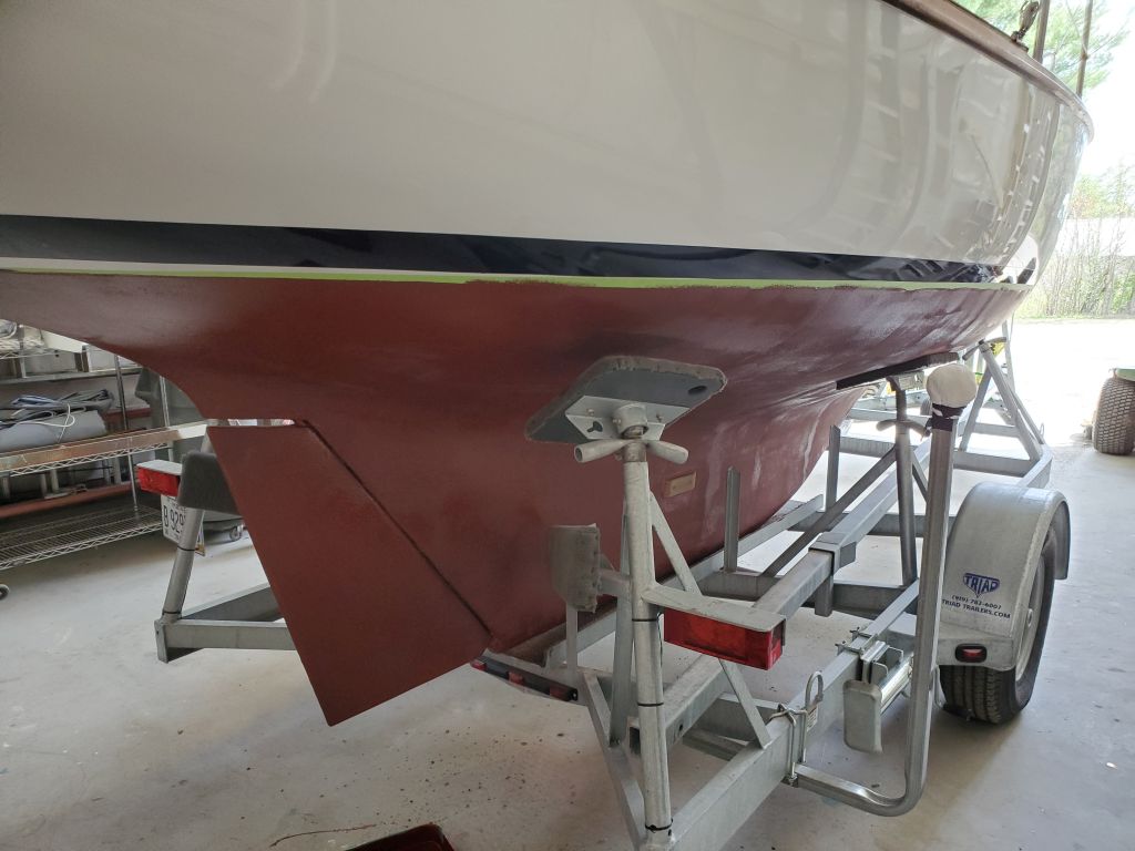
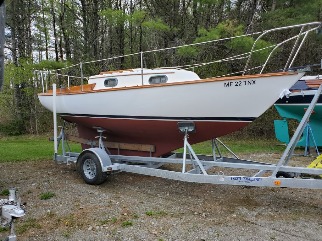
Monday
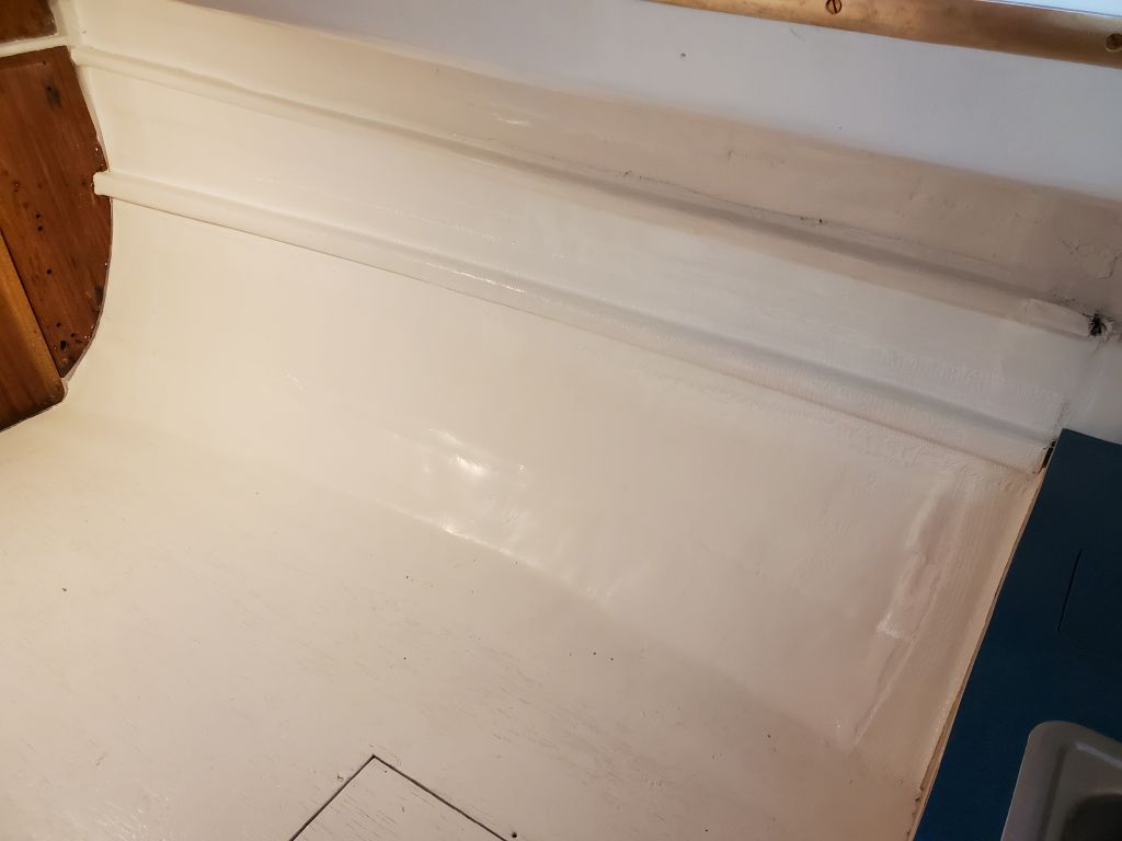
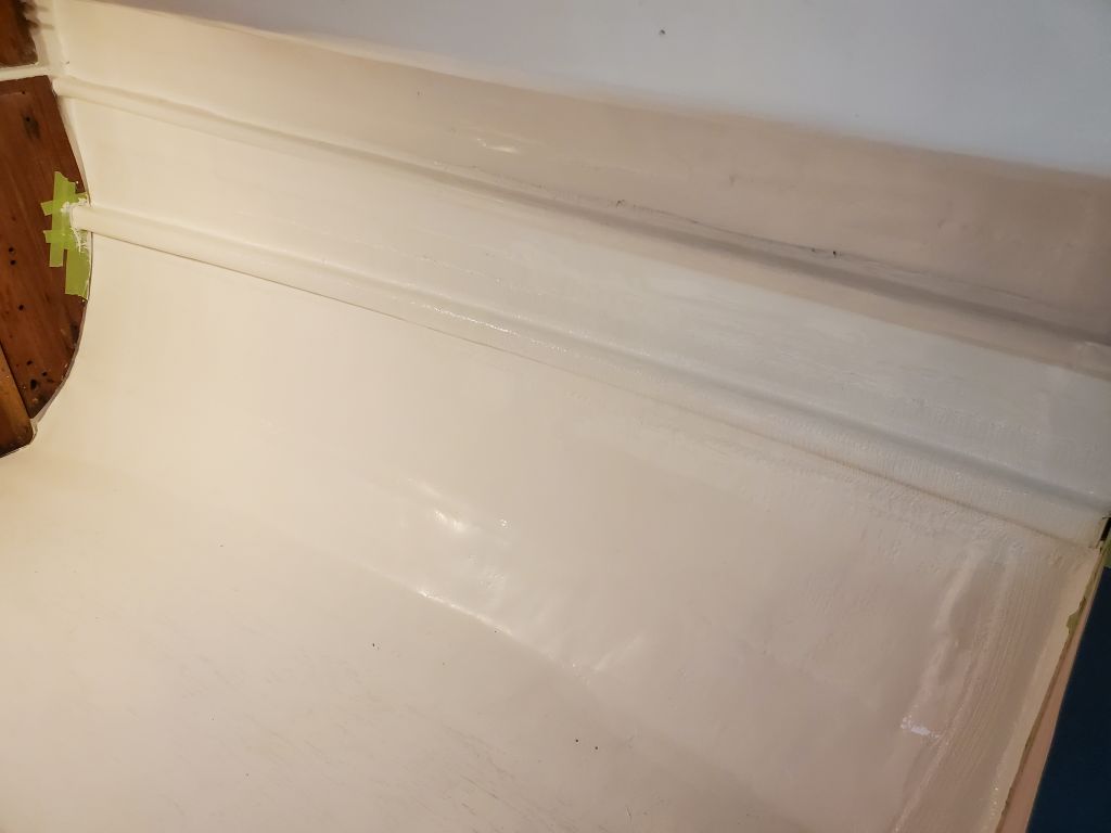
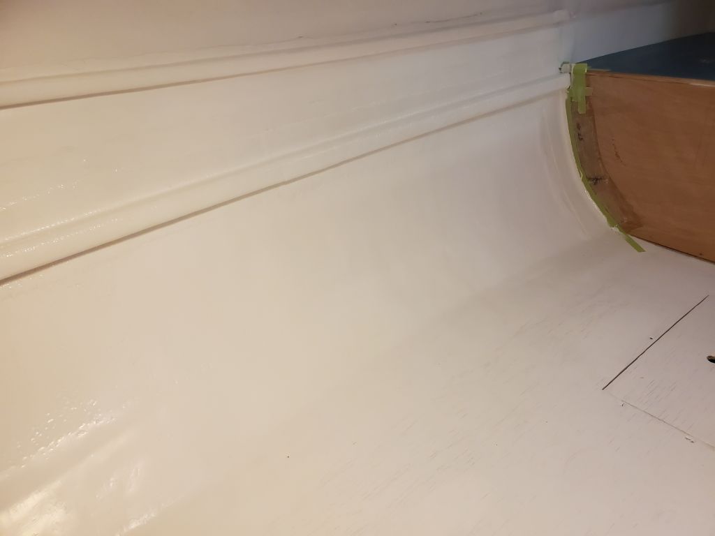
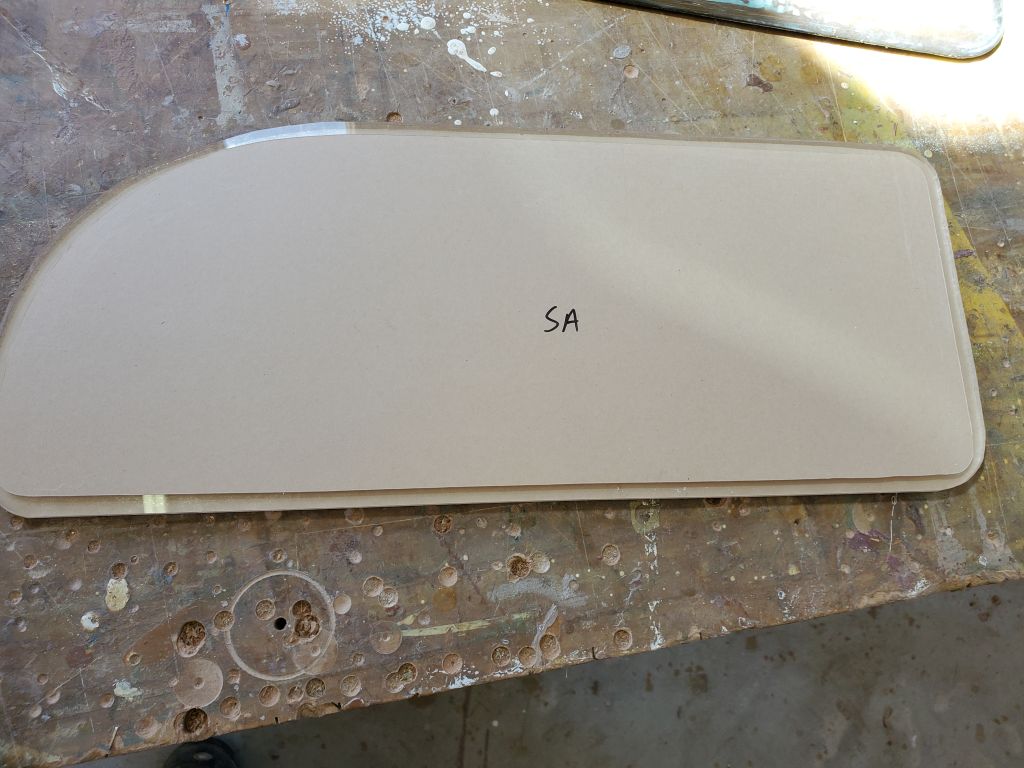
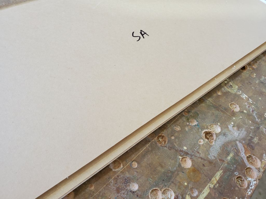
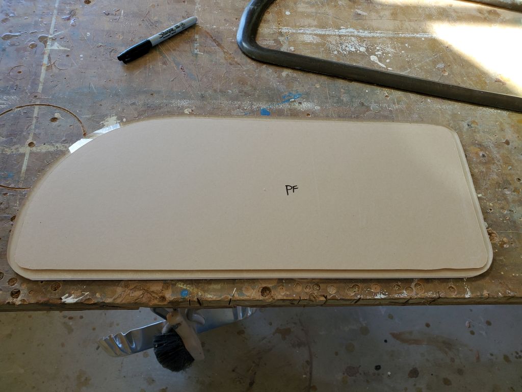
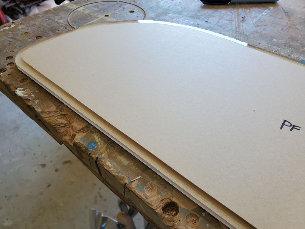
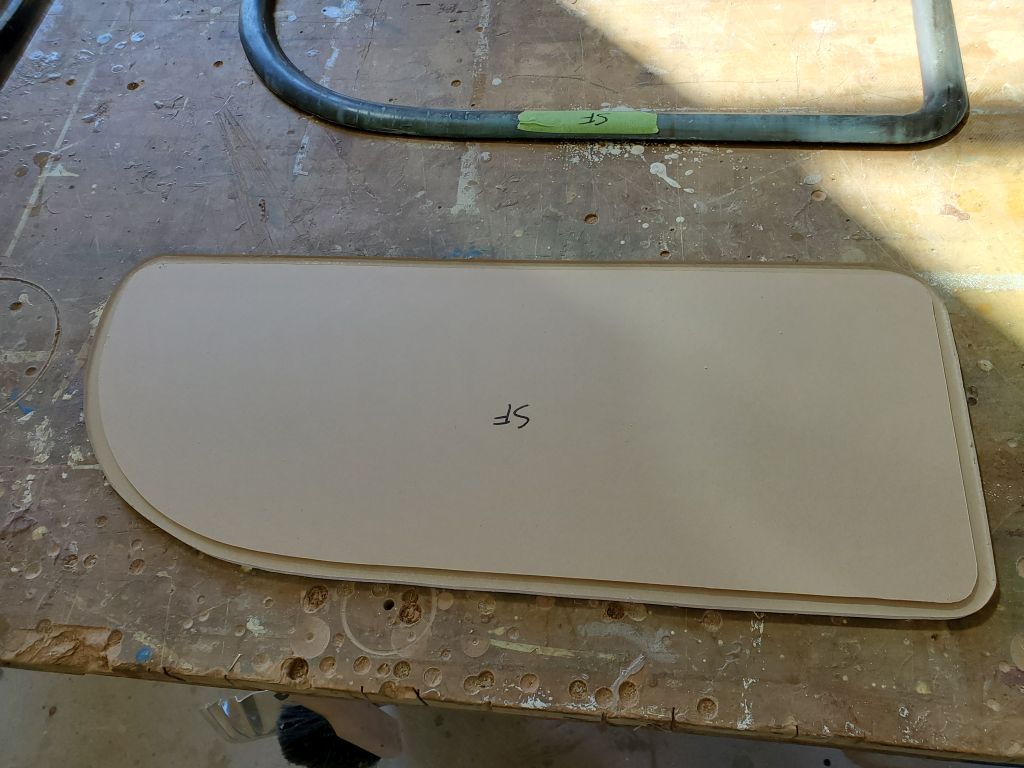
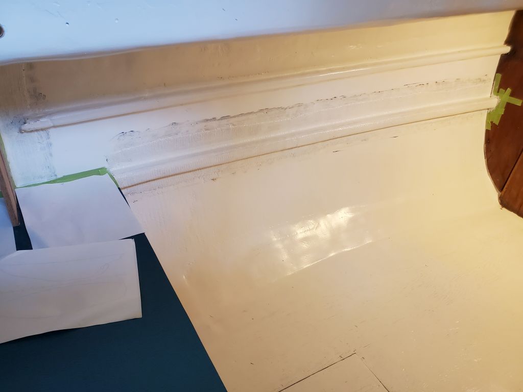
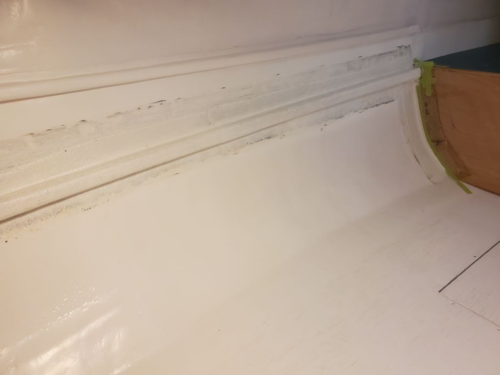
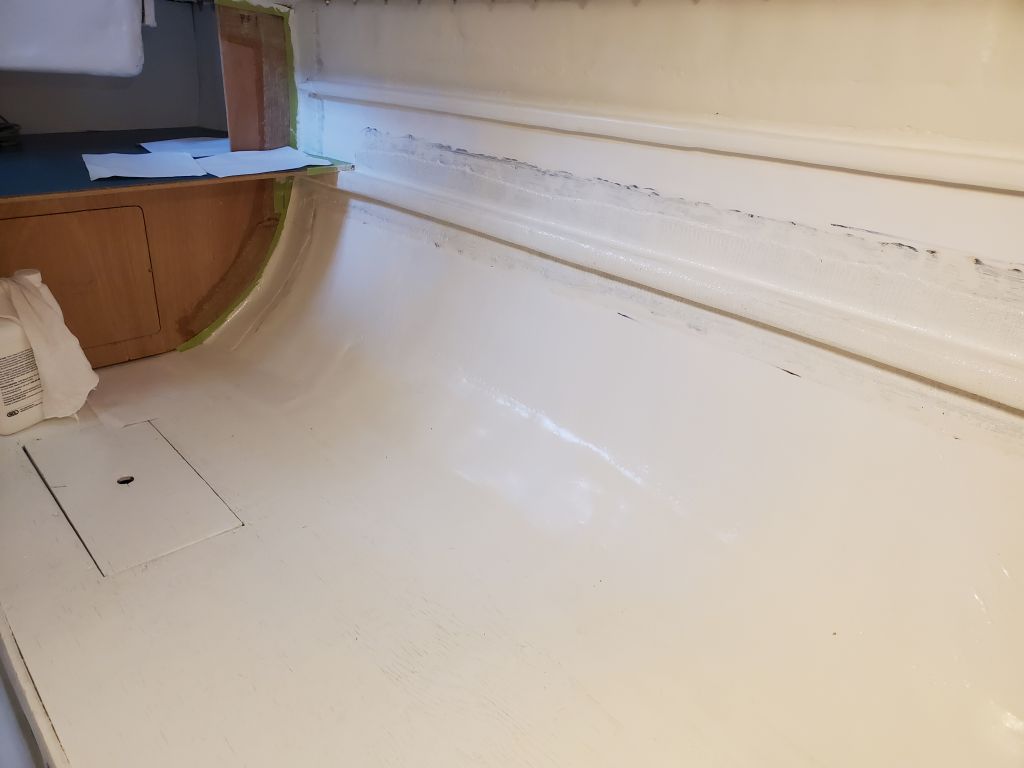
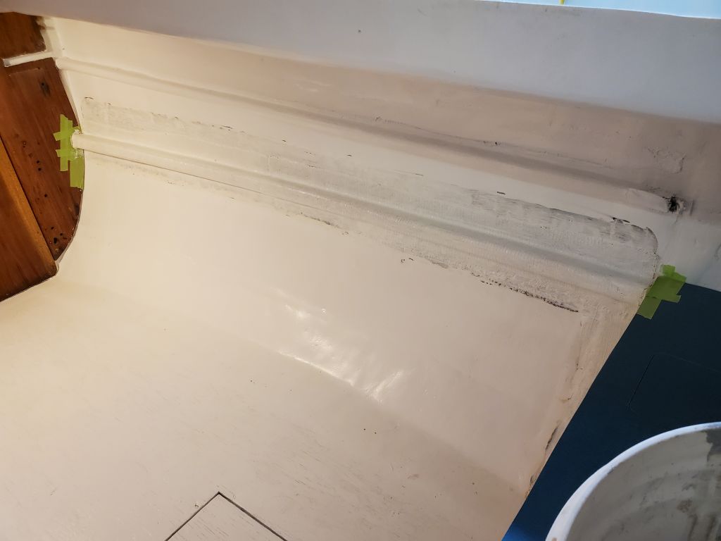
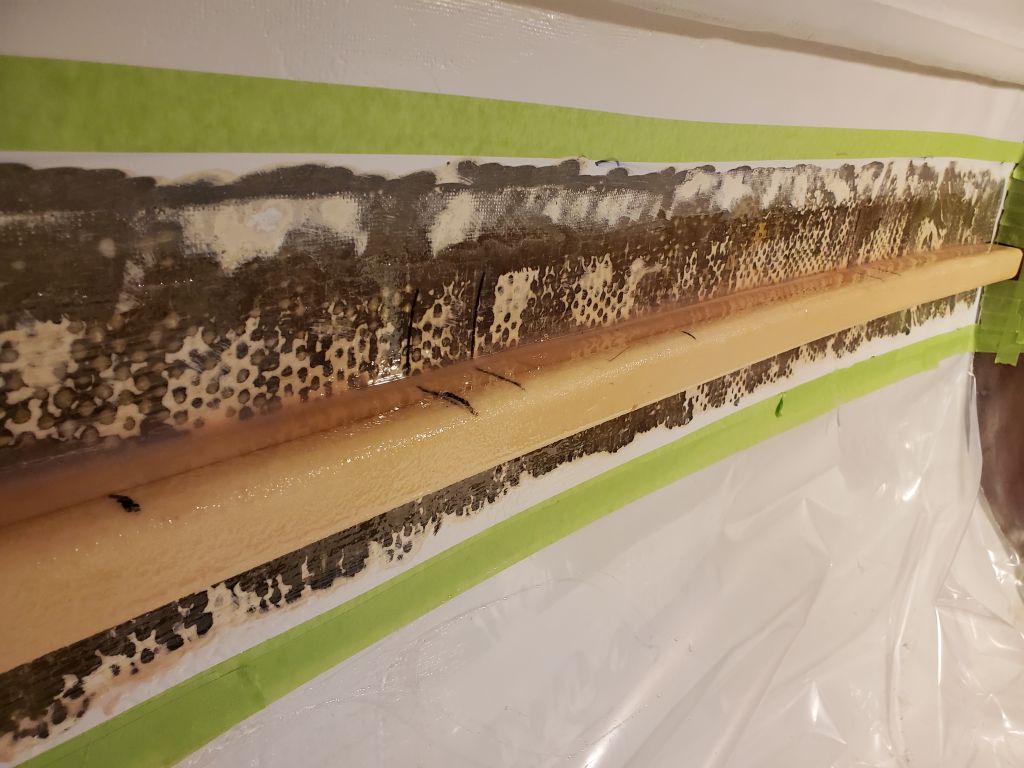
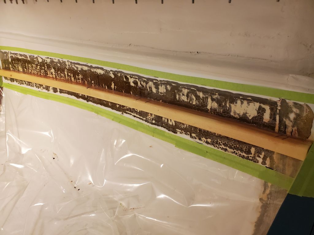
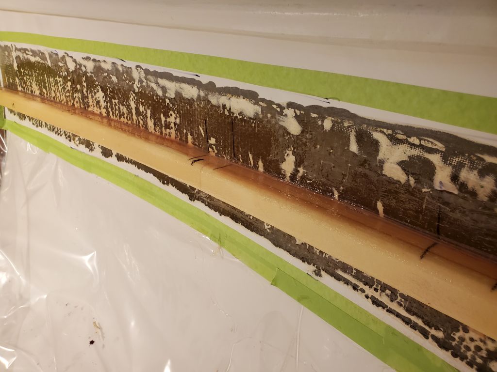
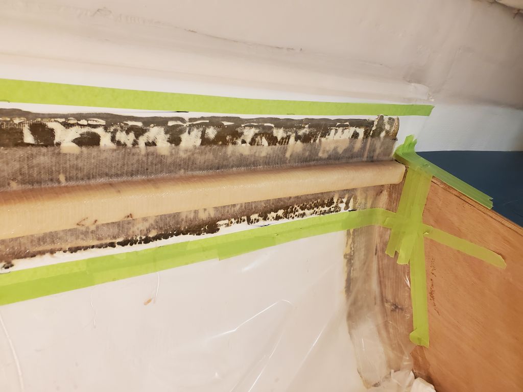
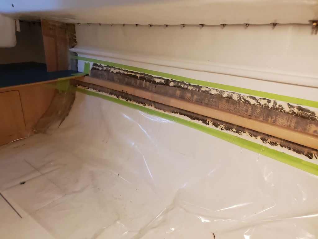
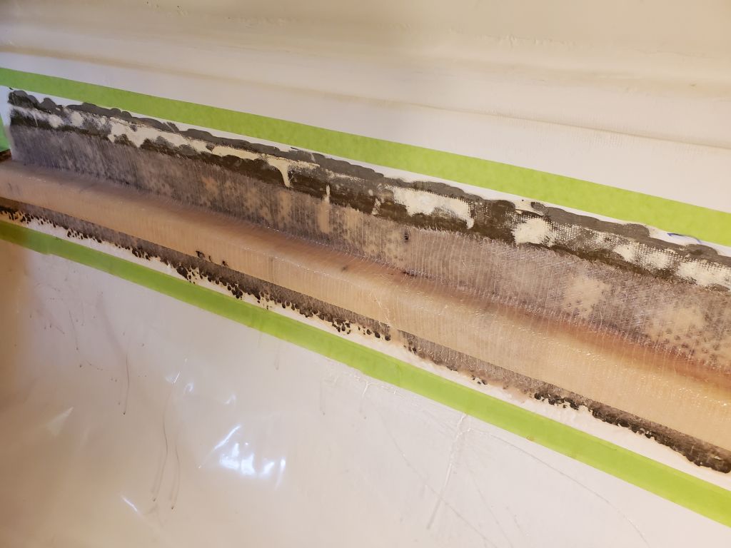
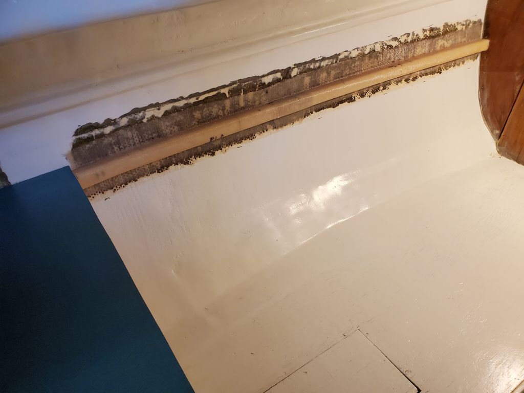
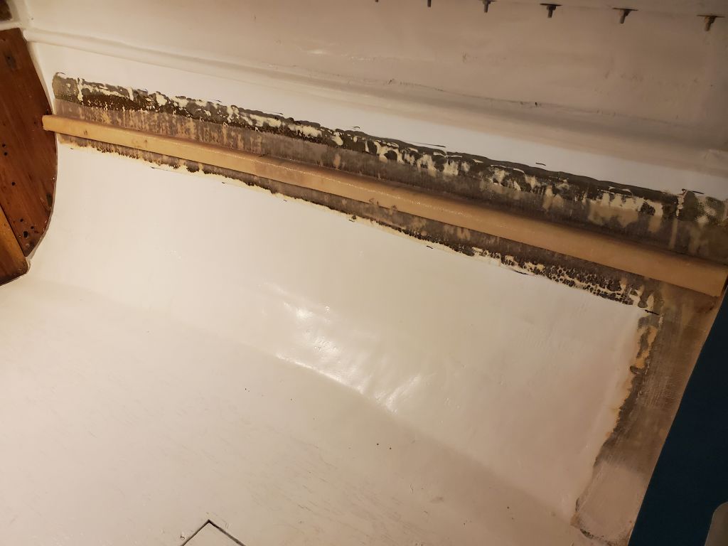
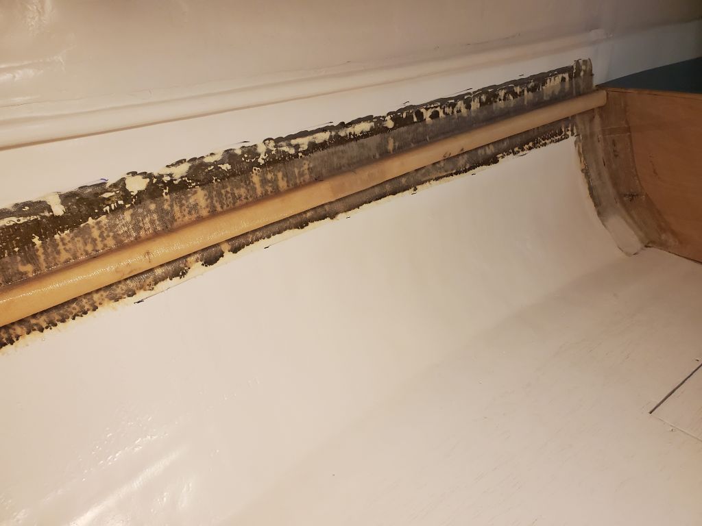
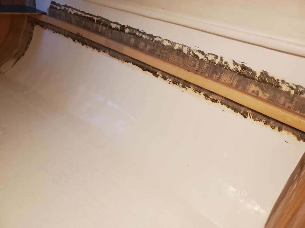
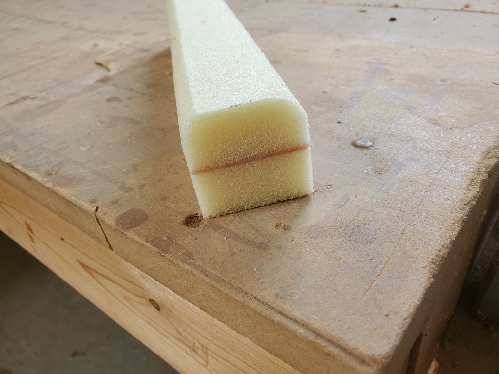
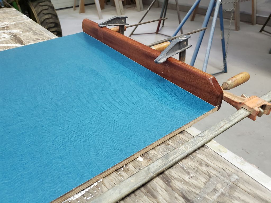
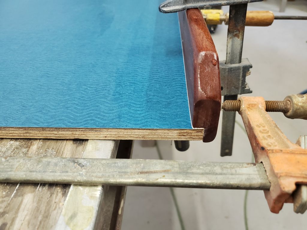
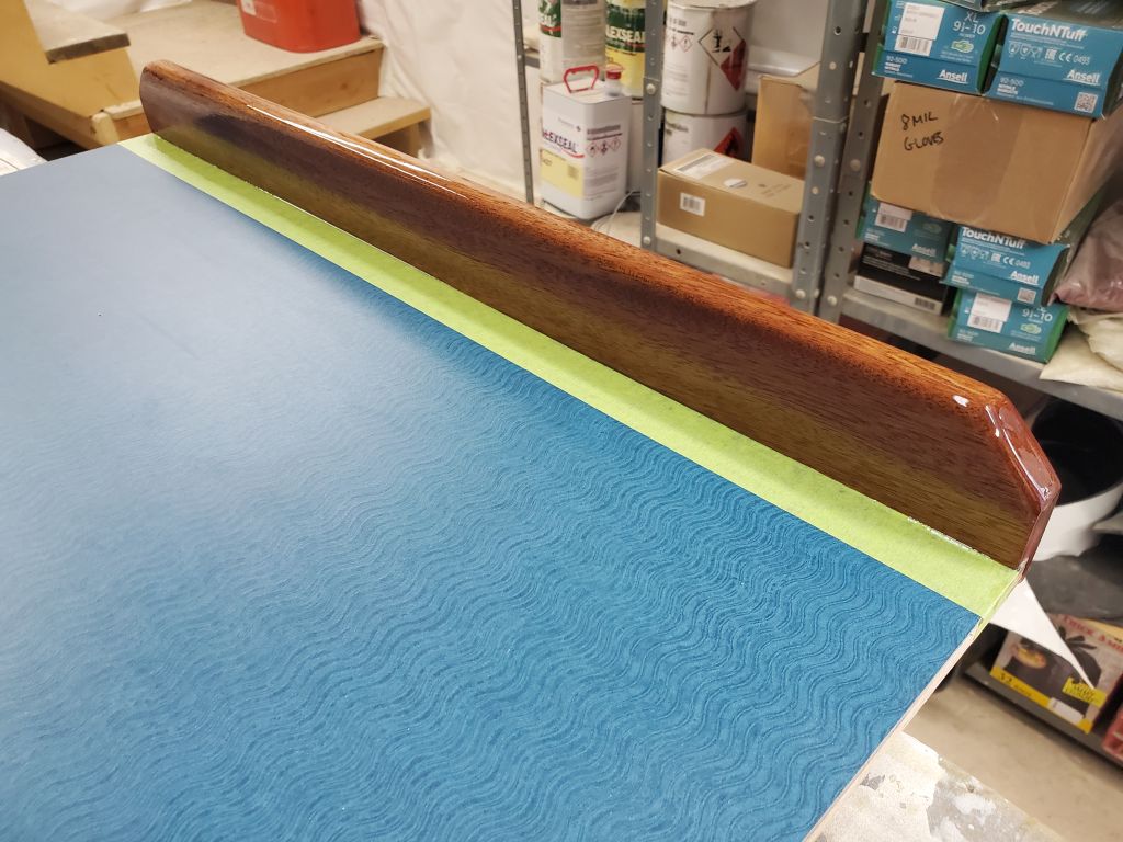
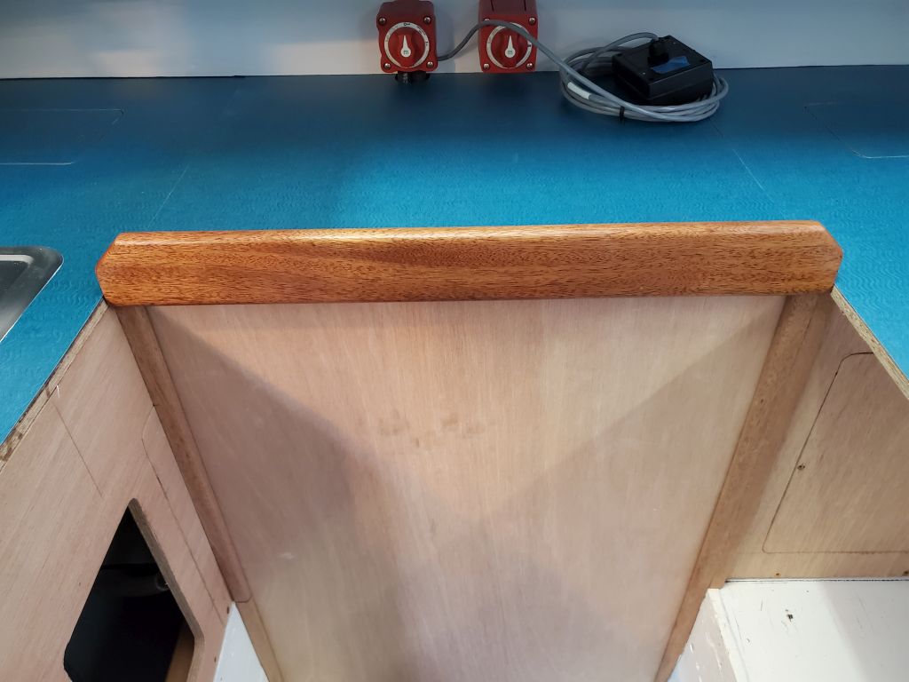
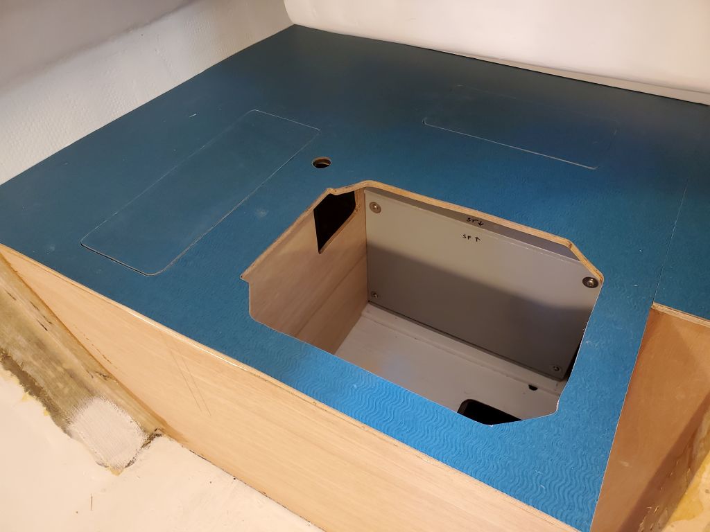
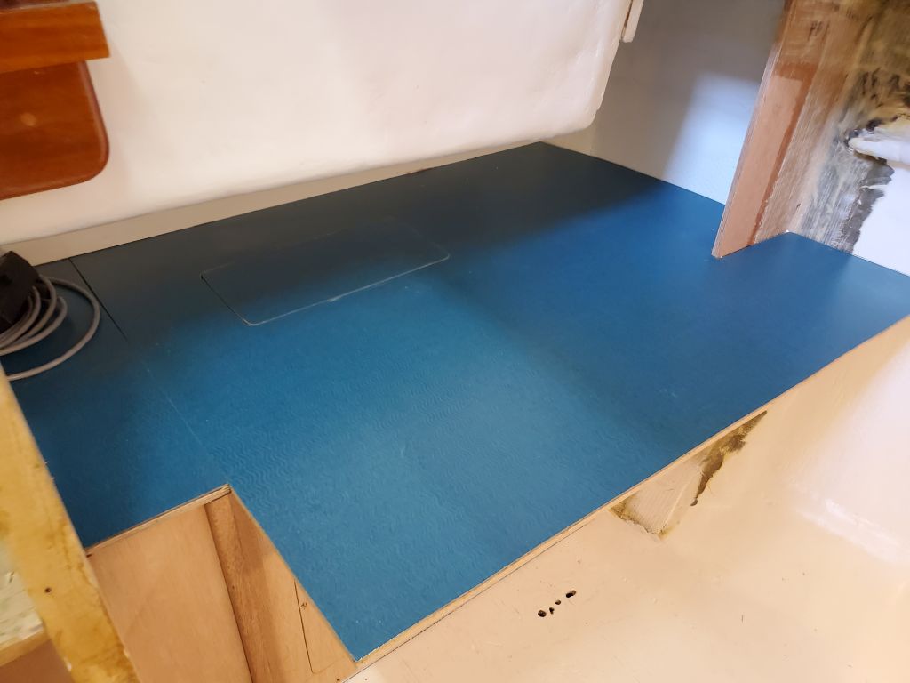
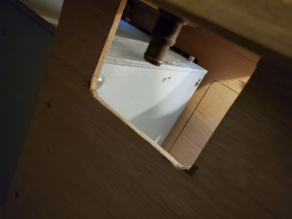
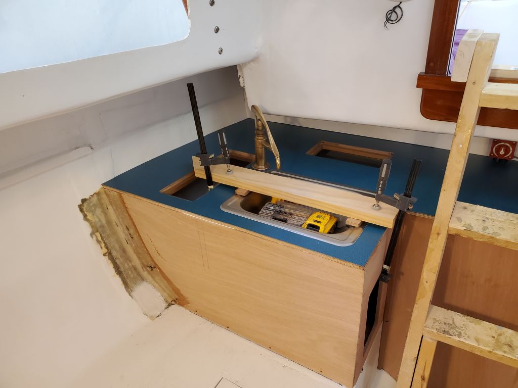
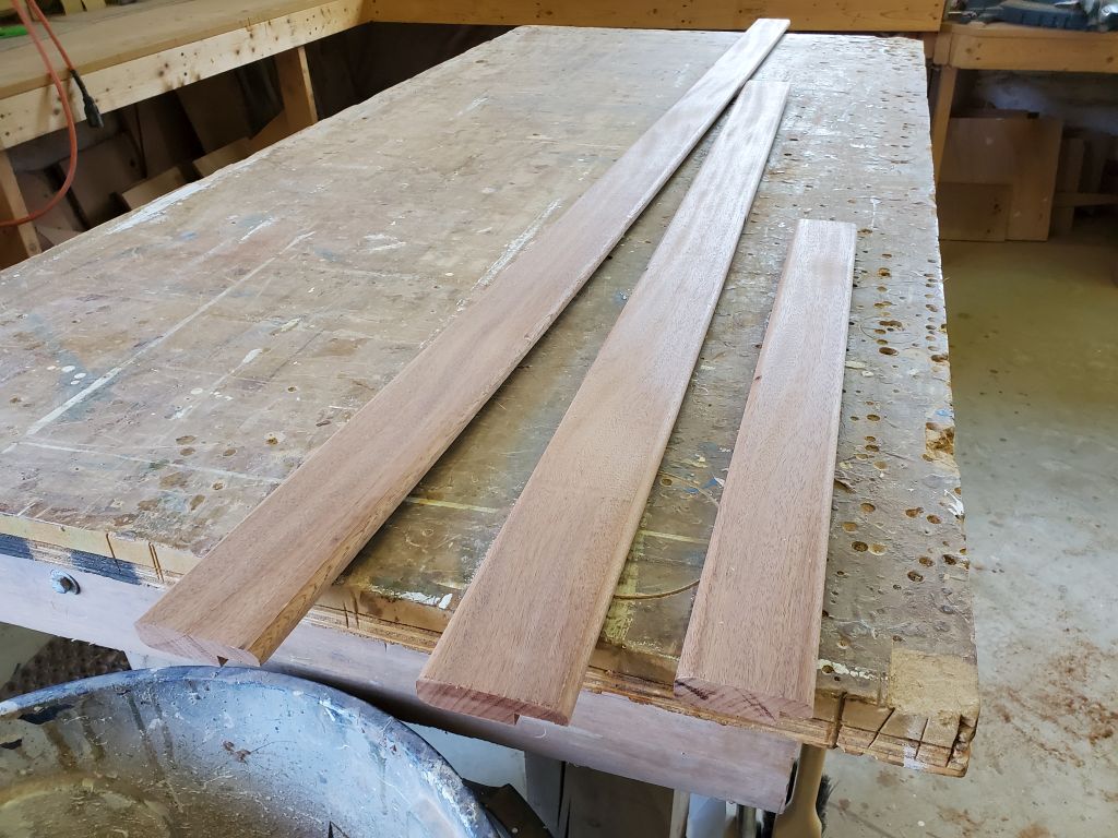
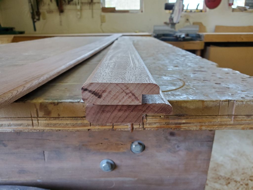
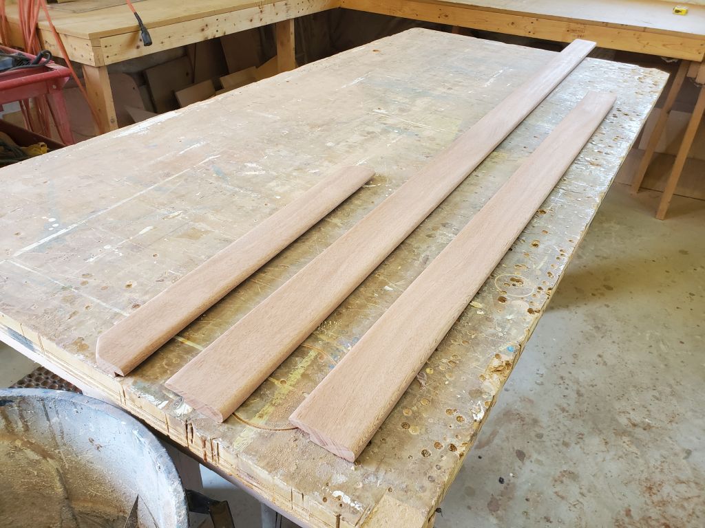
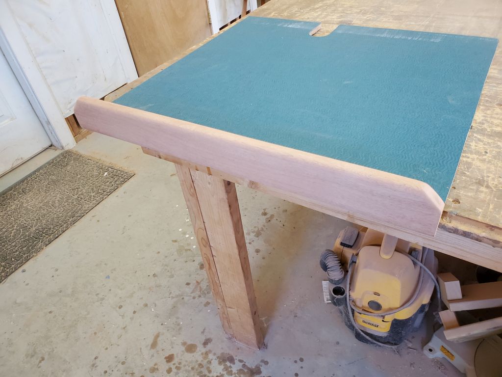
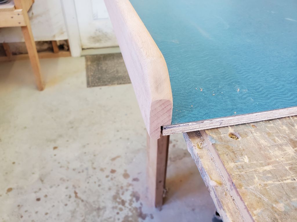
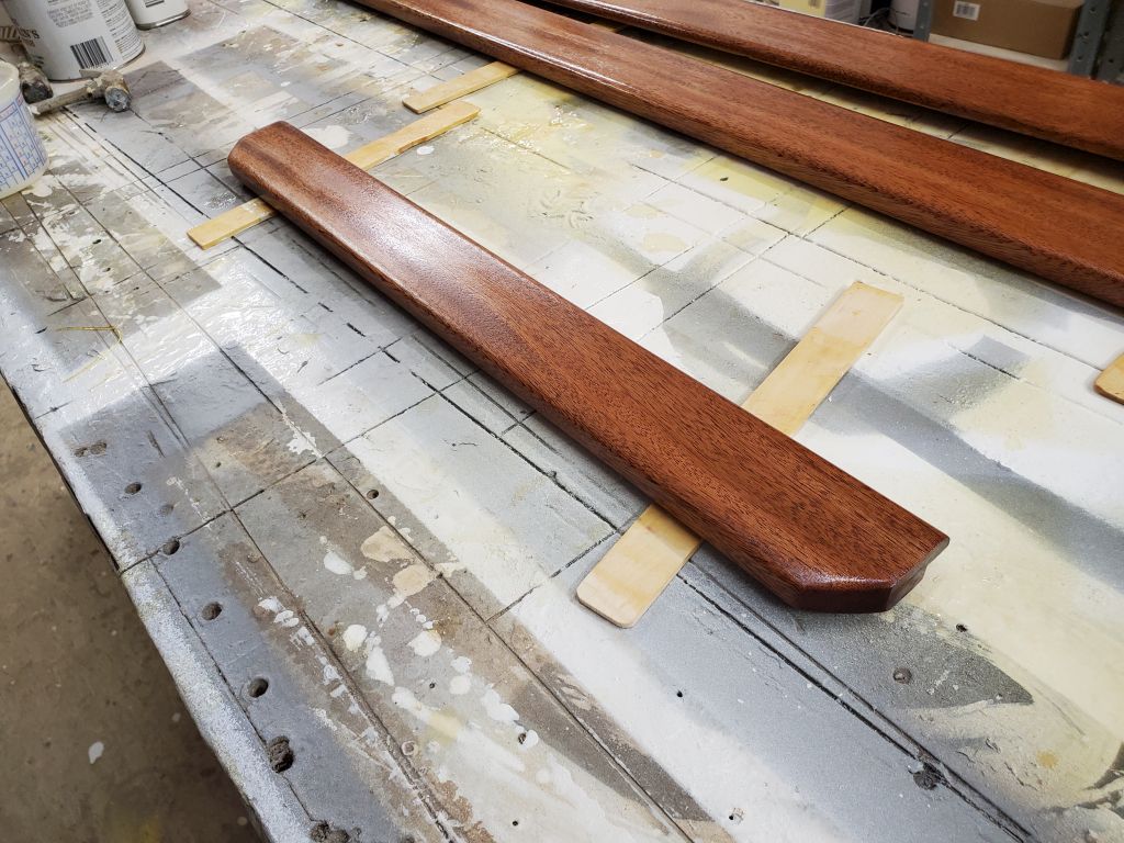
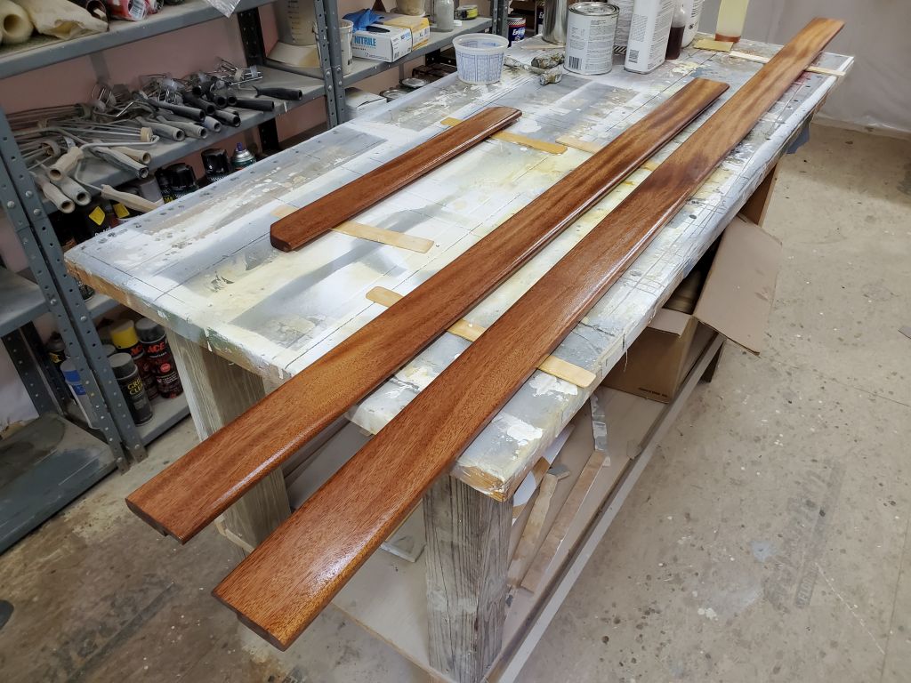
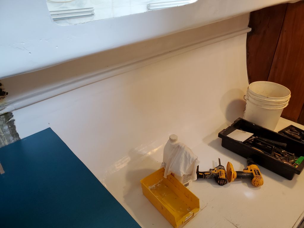
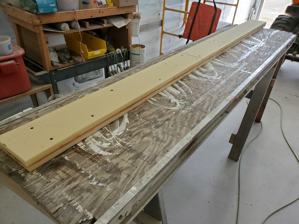
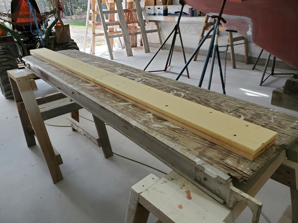
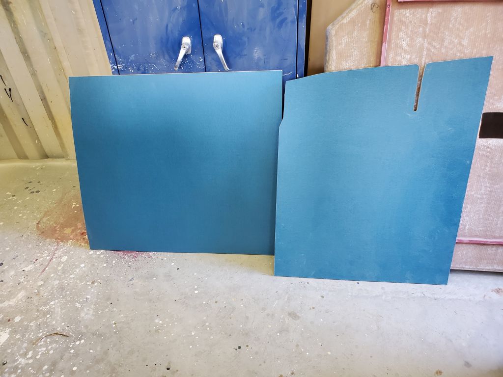
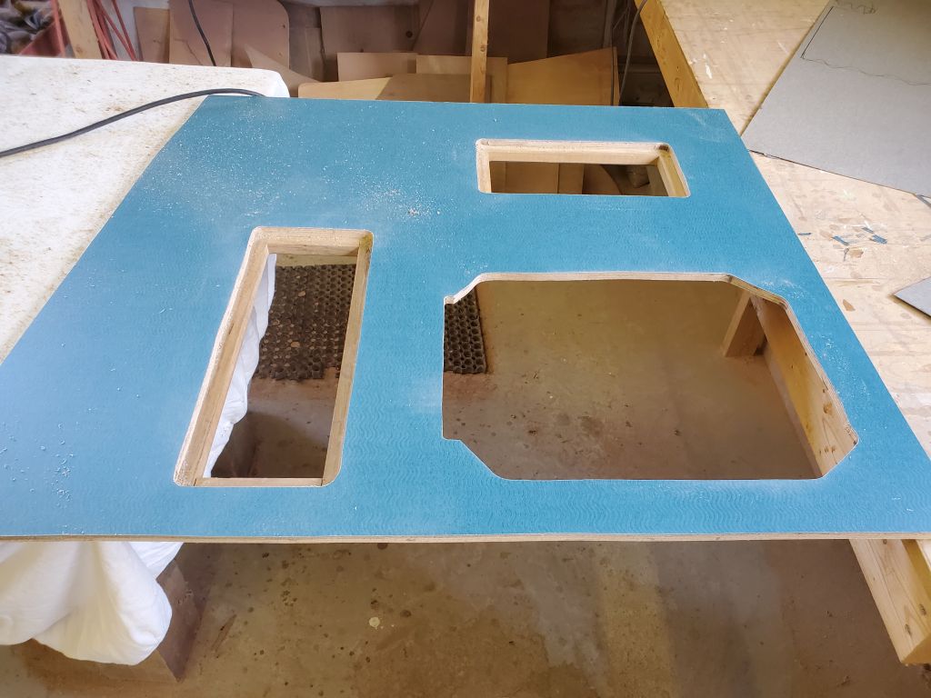
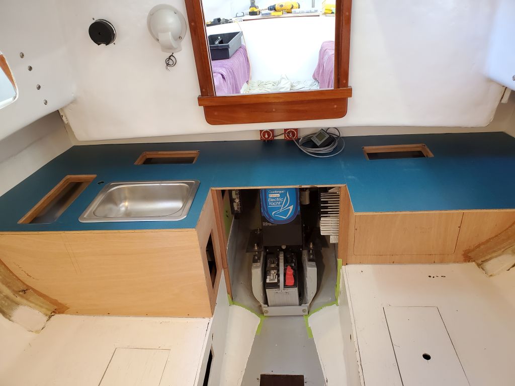
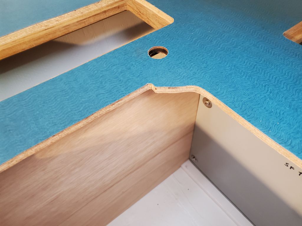
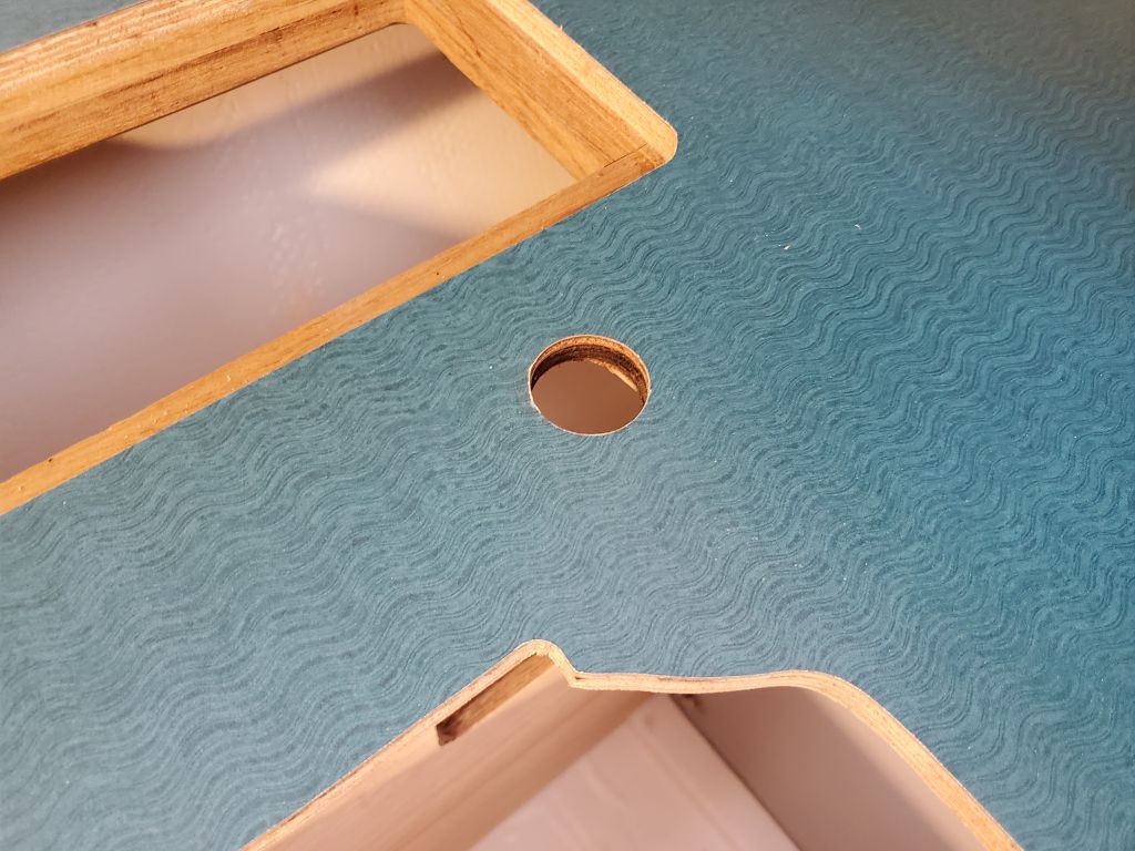
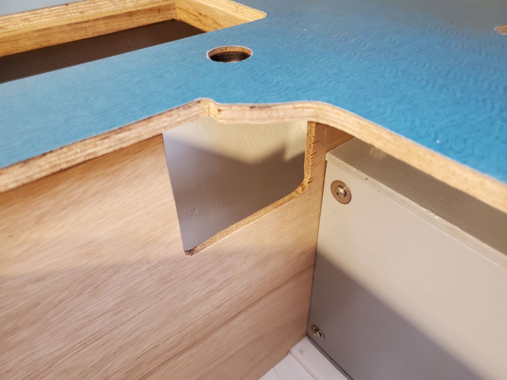
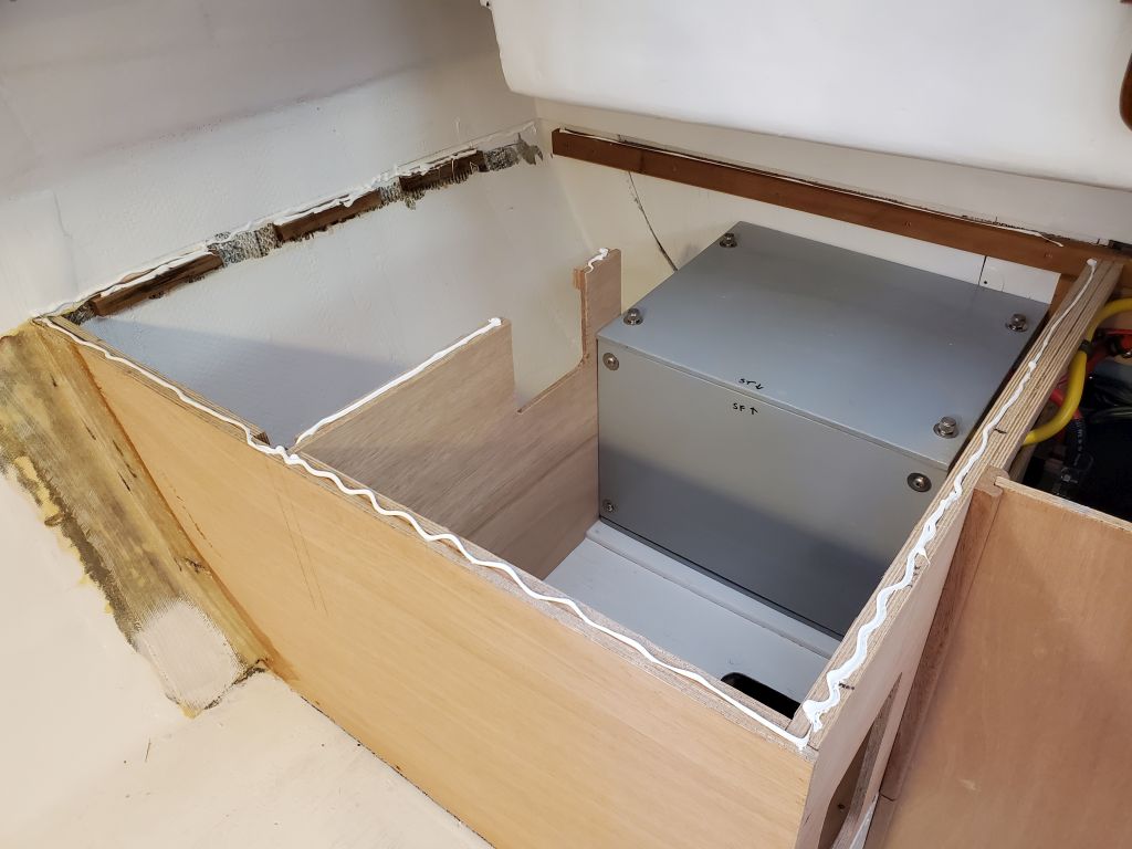
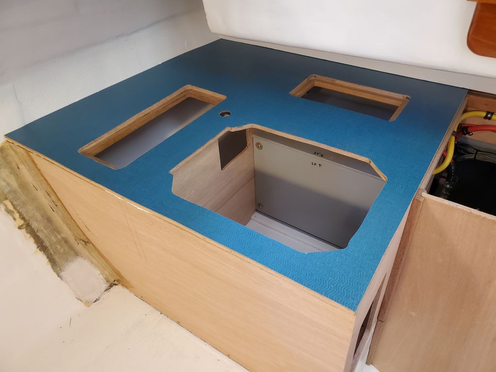
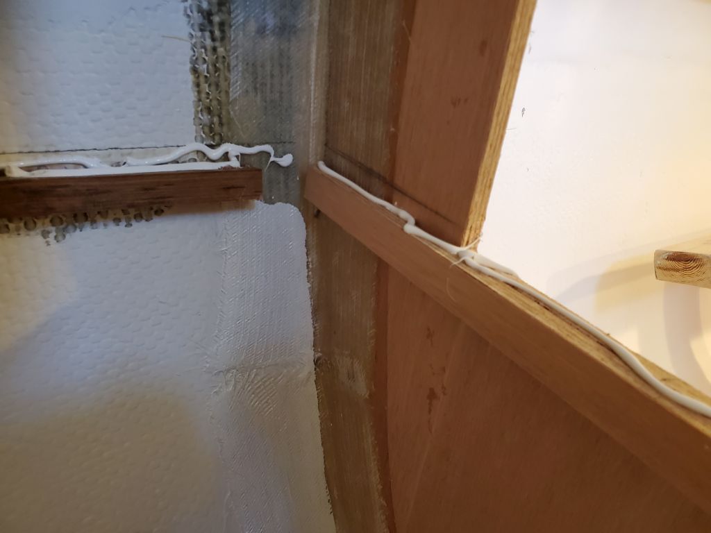
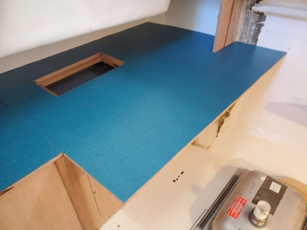
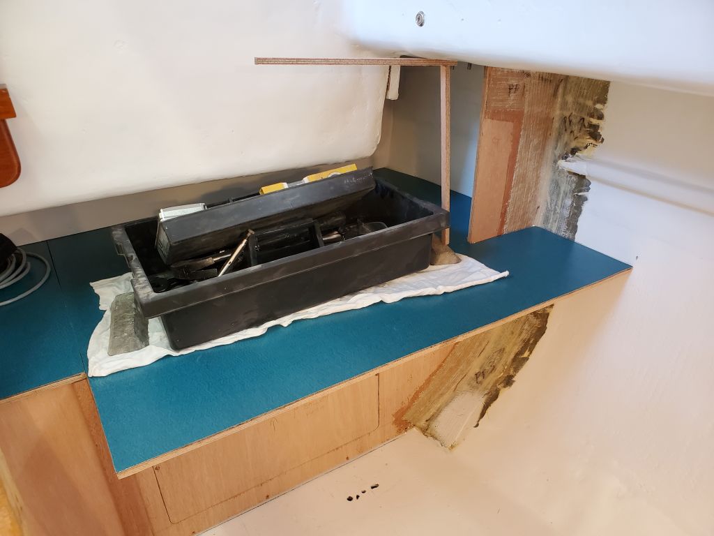
Since last time, in the background, I’d continued work on the trim/fiddle for the engine room countertop. With a coat of varnish on all parts of the trim, I glued it to the leading edge of the countertop, avoiding screws here since there was only the edge of the 1/2″ plywood to accept fasteners.
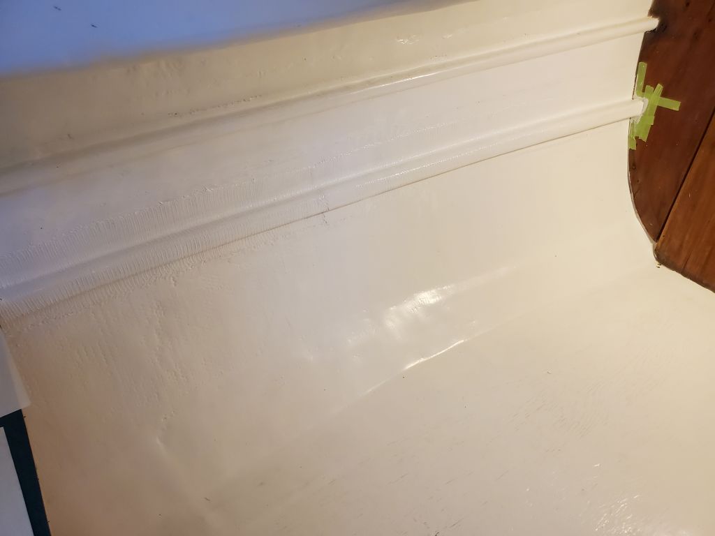
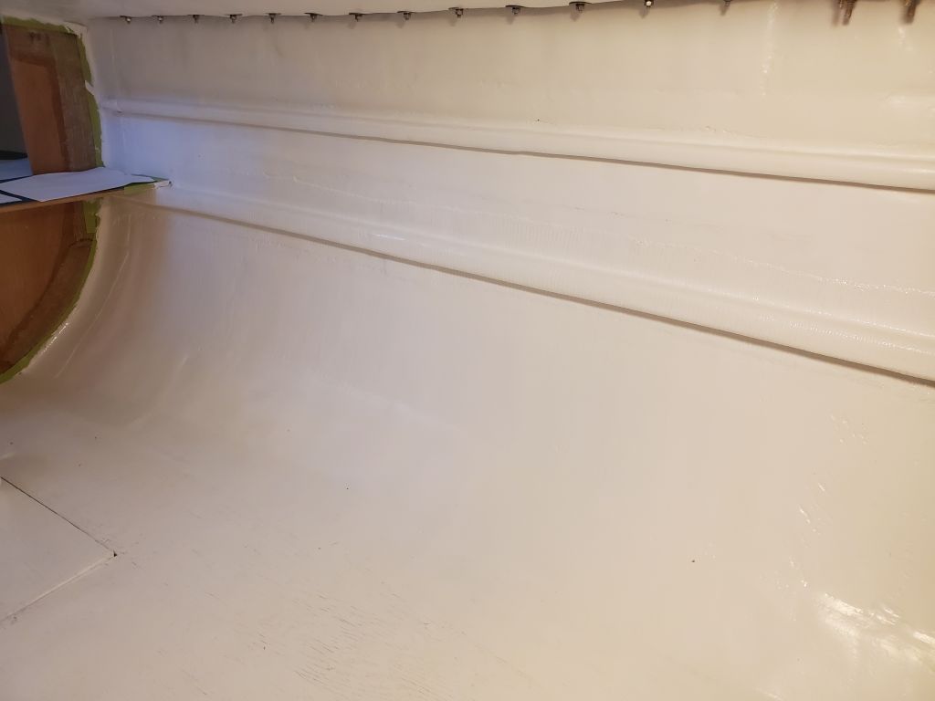
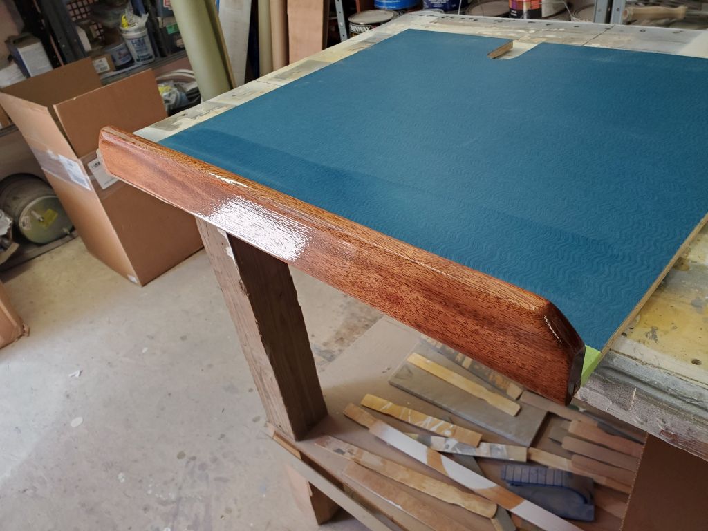
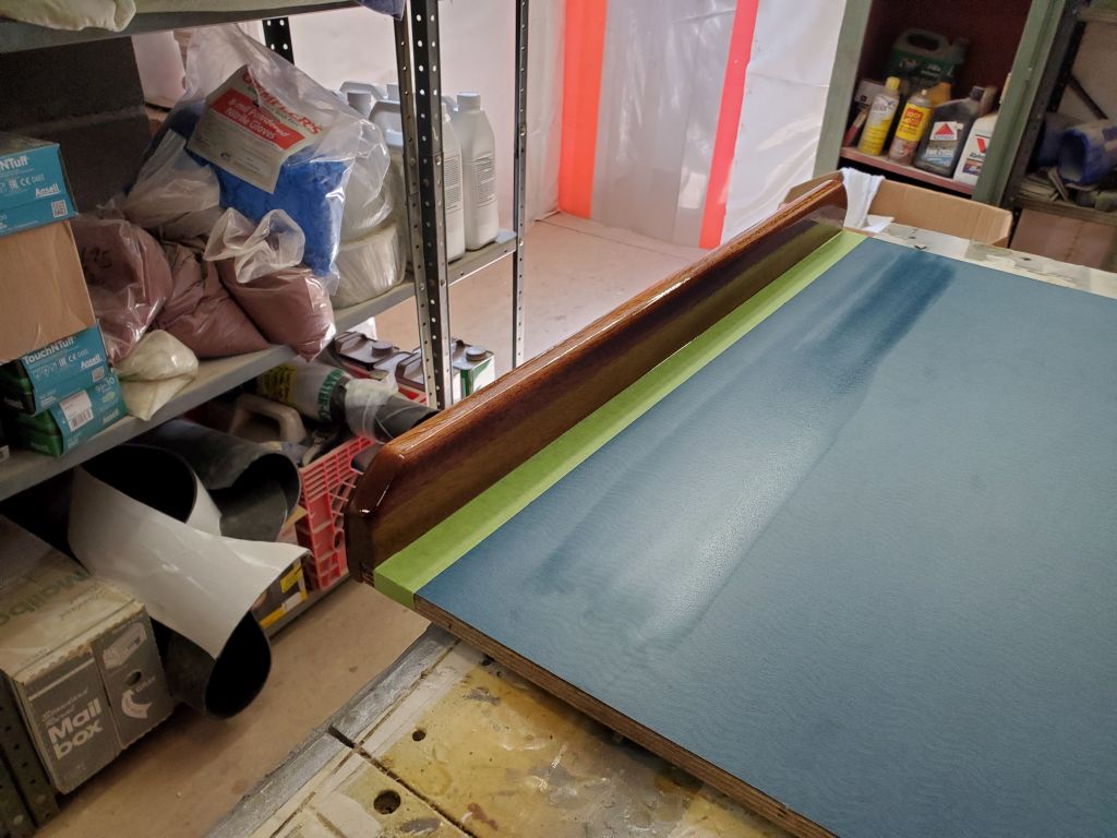
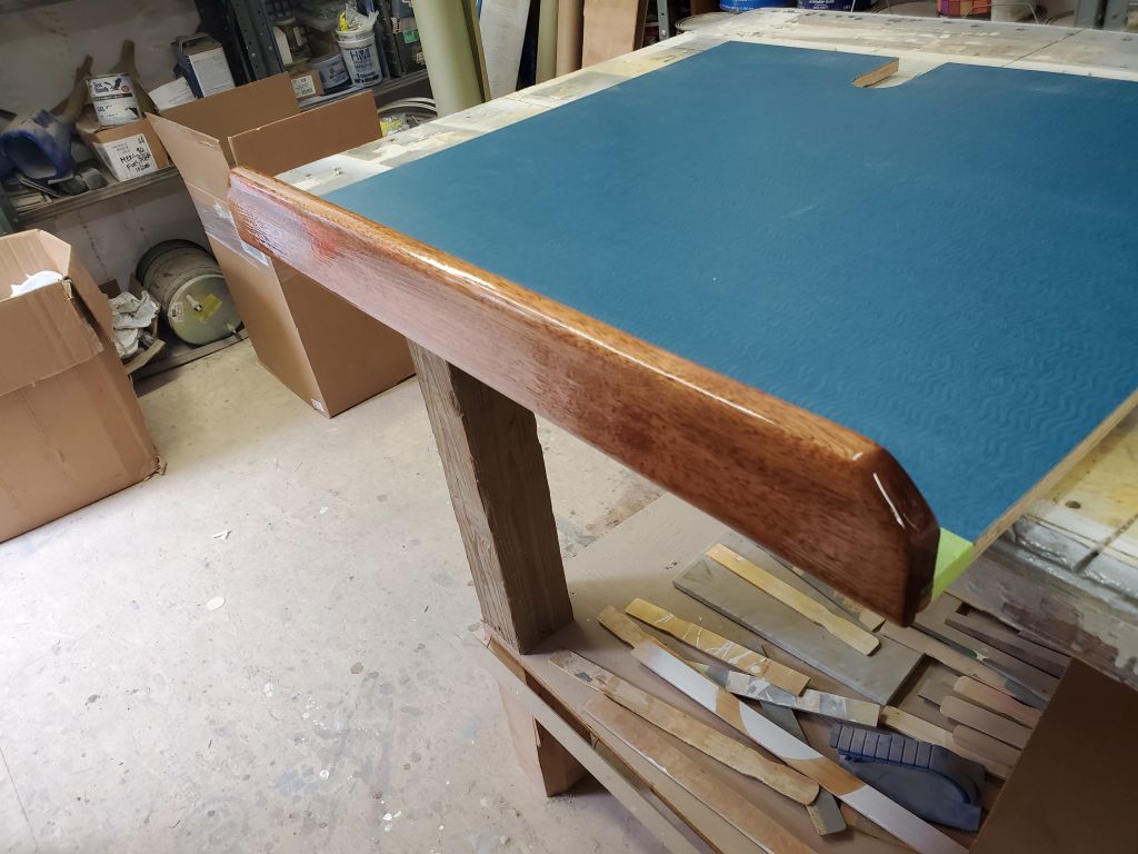
Once the glue had set up, over a few days I applied three additional base coats of gloss varnish, followed by a final coat of satin varnish. In addition to finishing off the forward edge of the countertop (the owner would later install additional pieces to complete the trim from the stock I’d milled), the new fiddle provided a handy handle for pulling out and removing the top of the engine room.
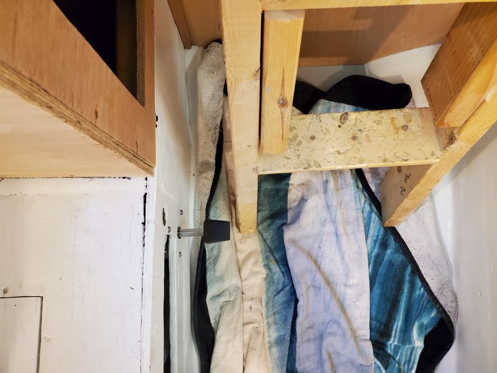
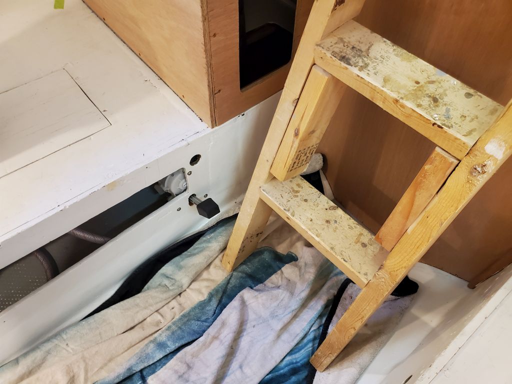
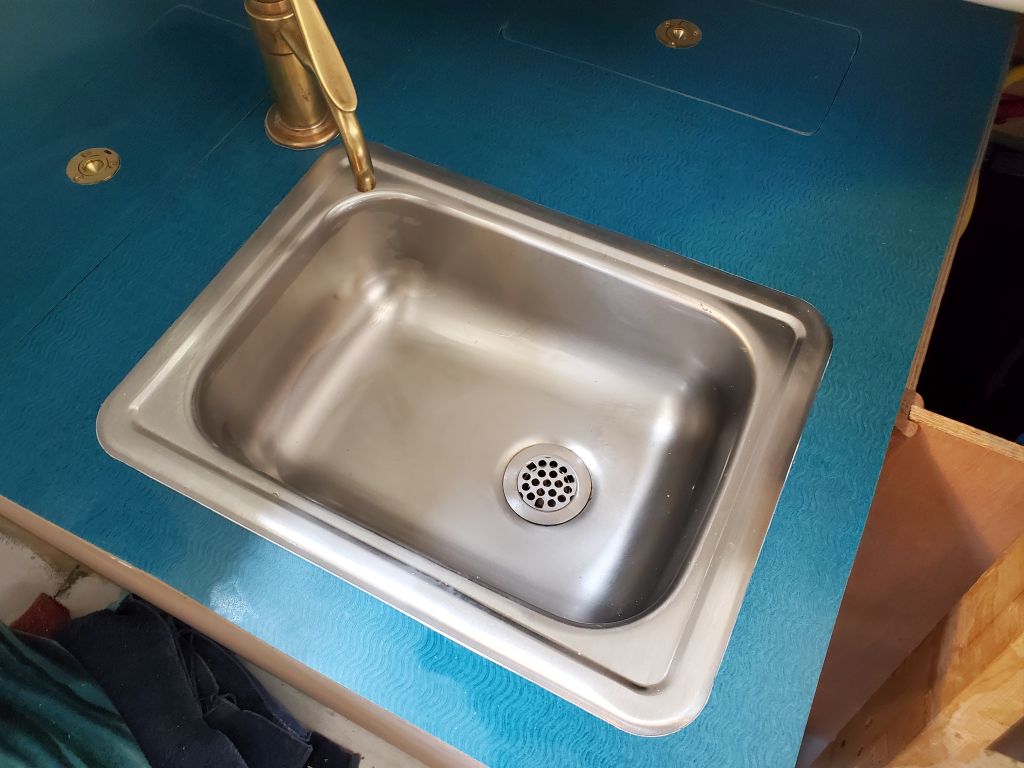
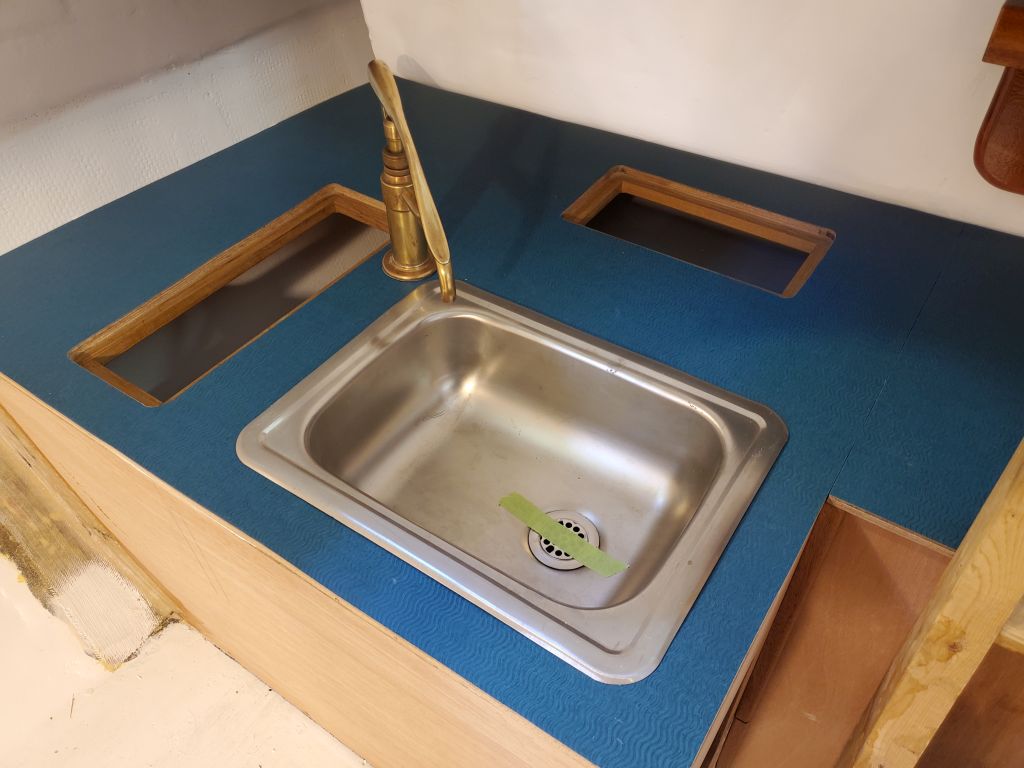
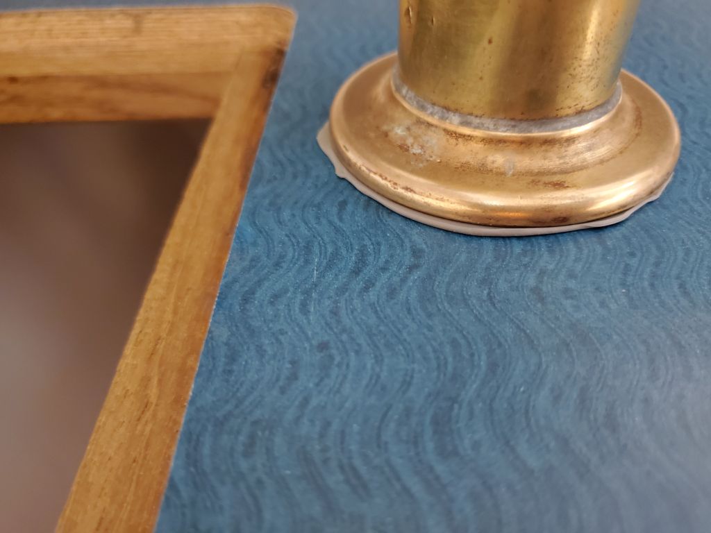
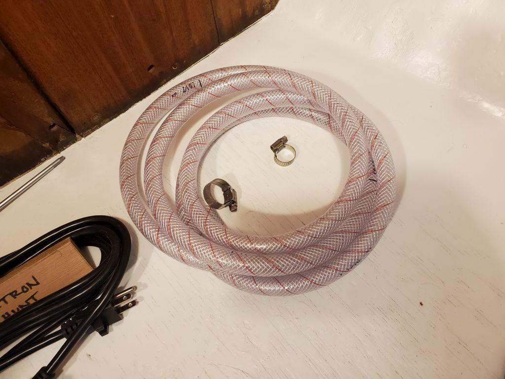
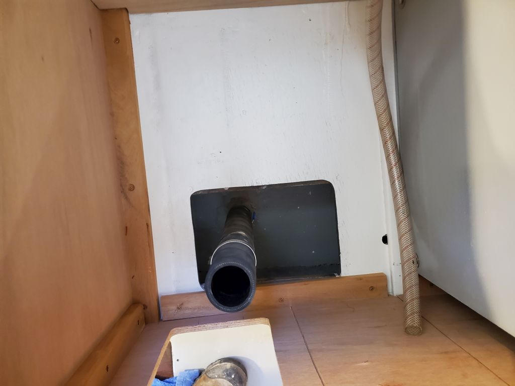
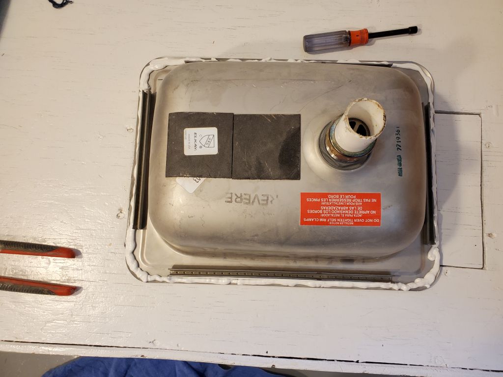
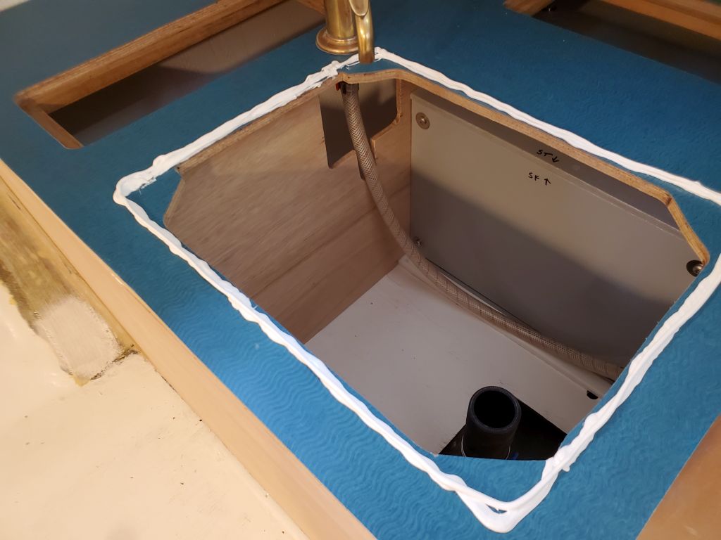
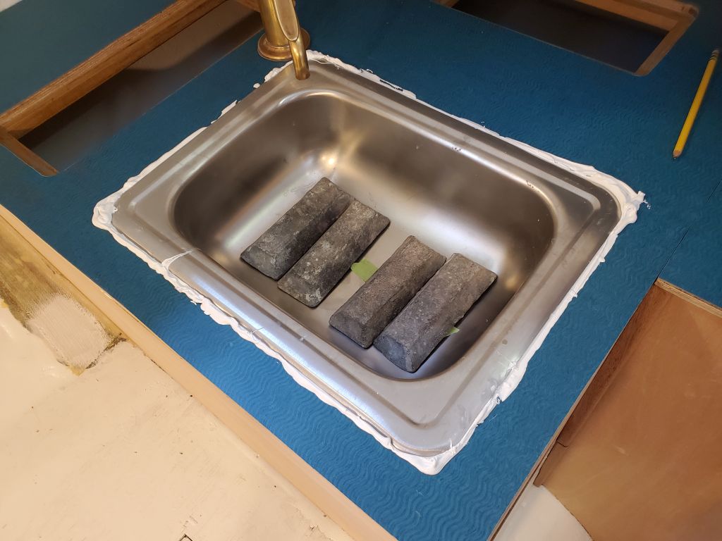
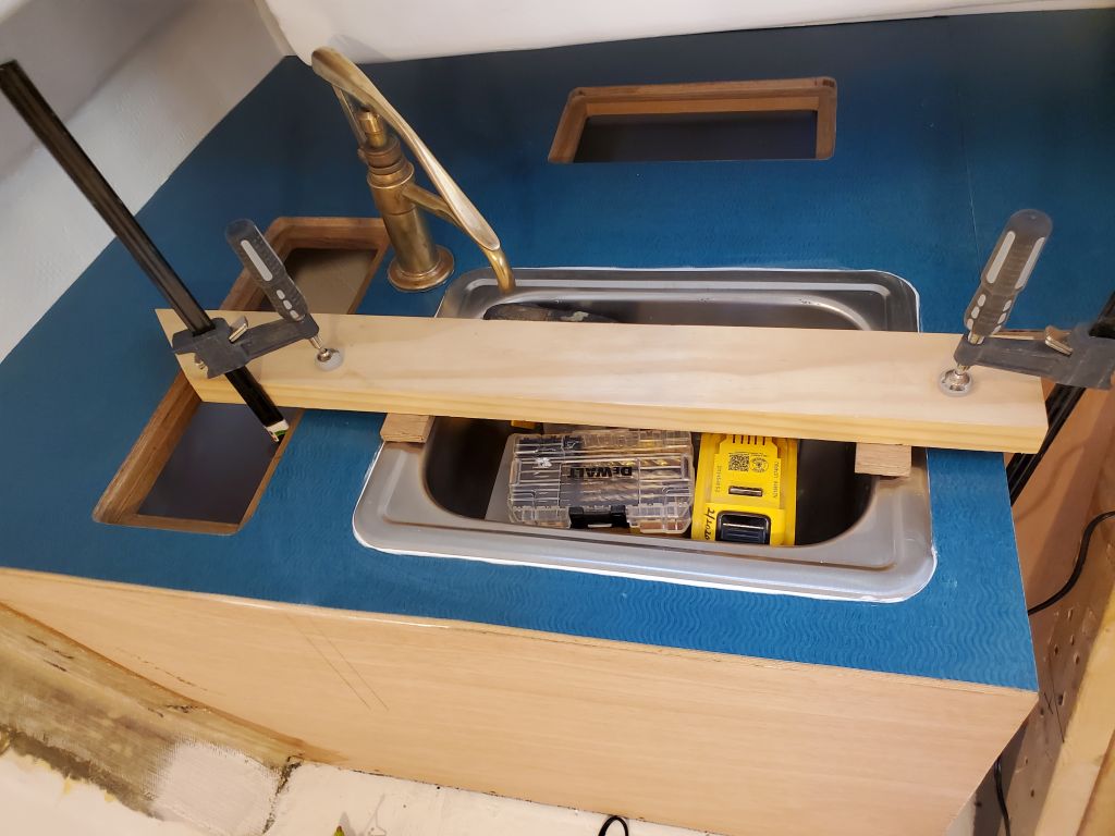
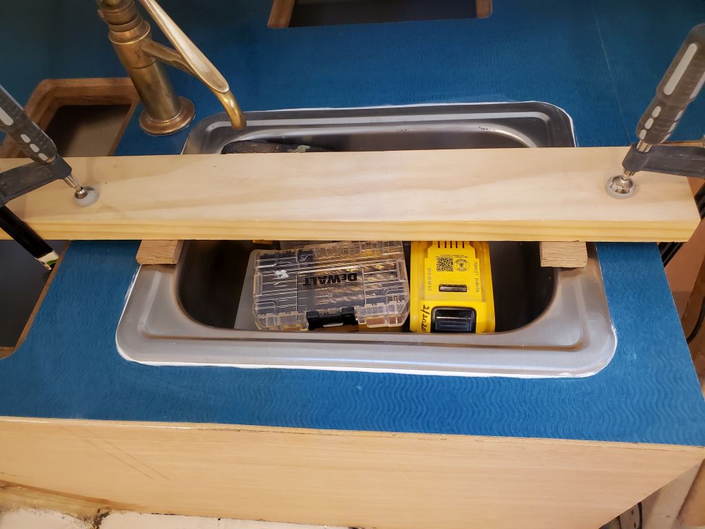
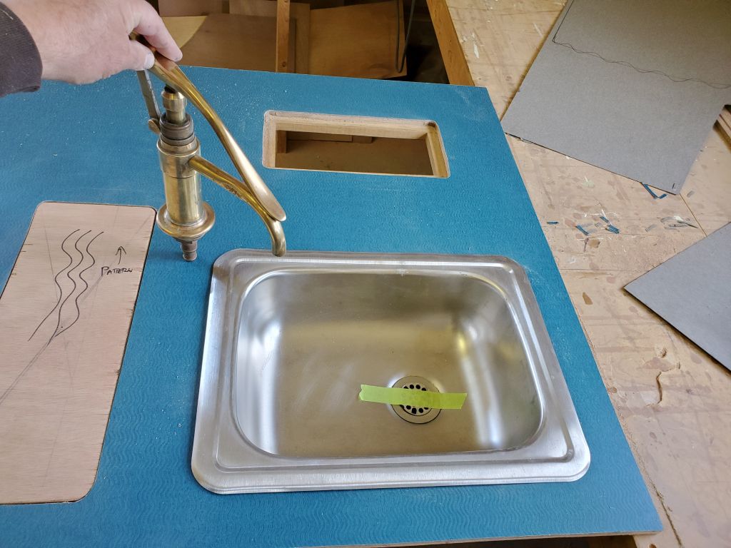
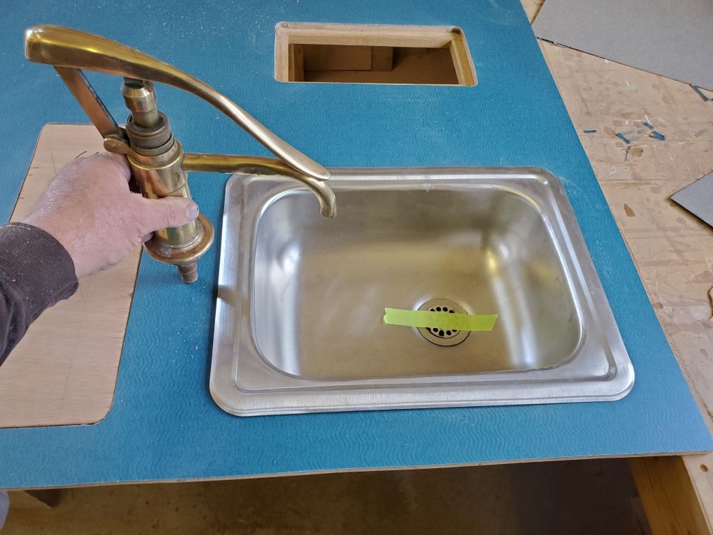
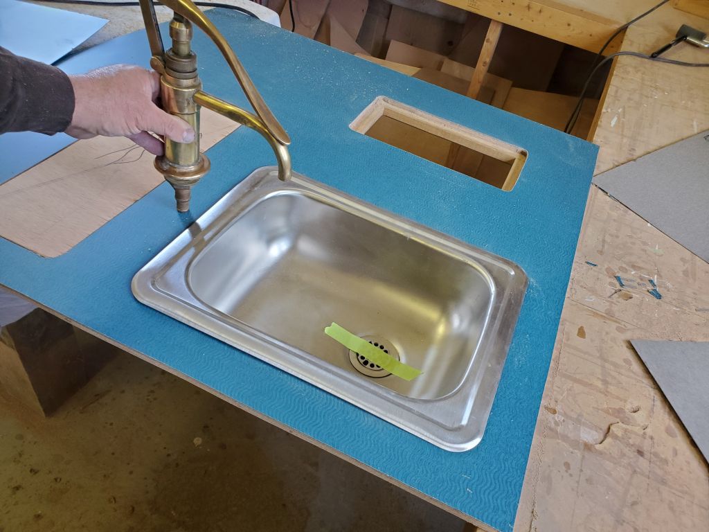
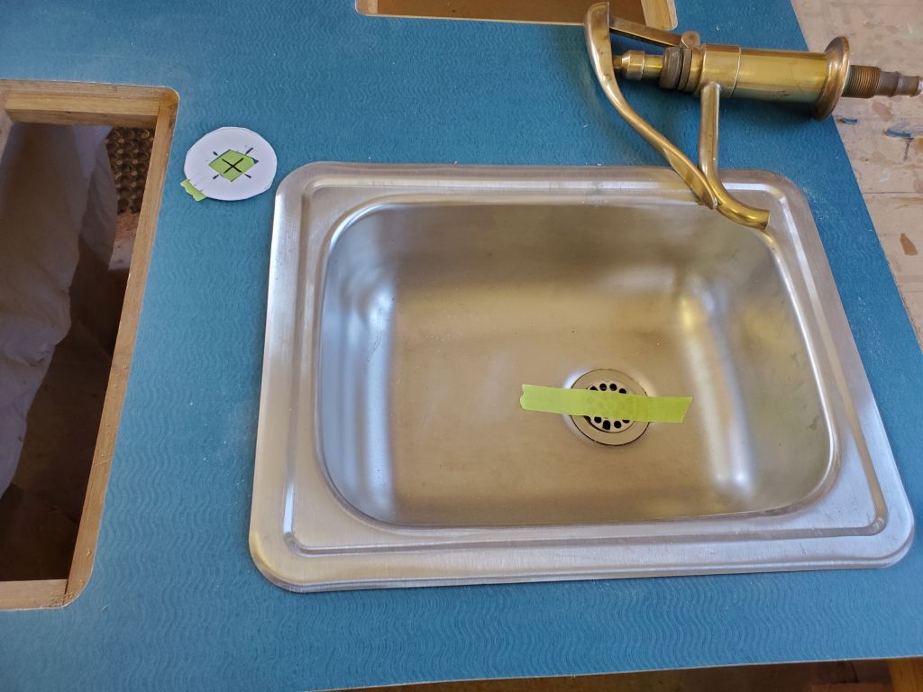
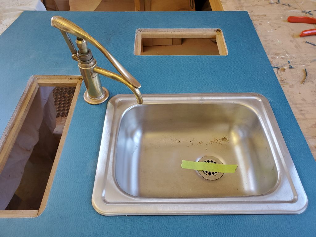
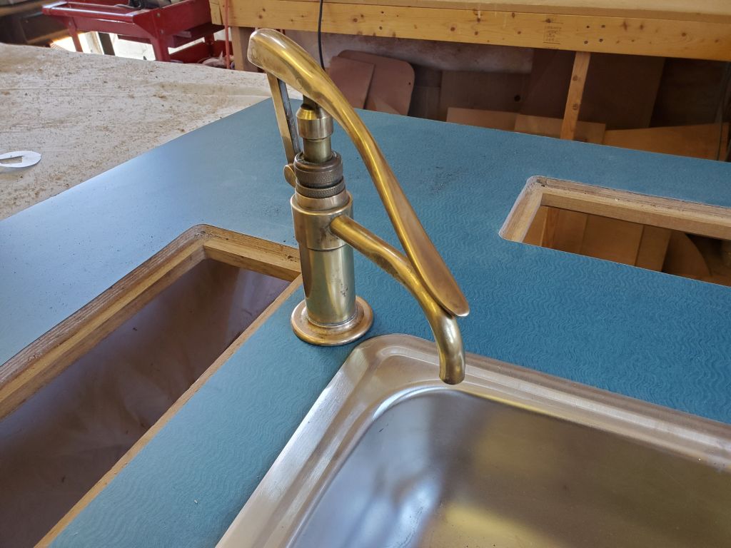
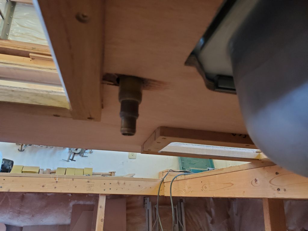
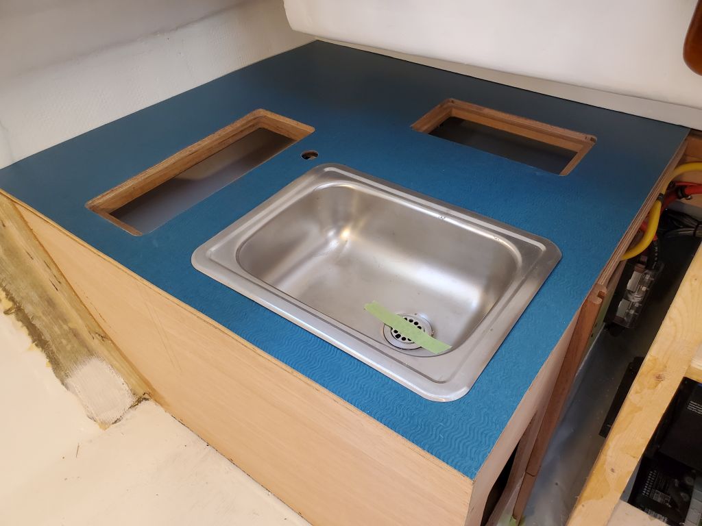
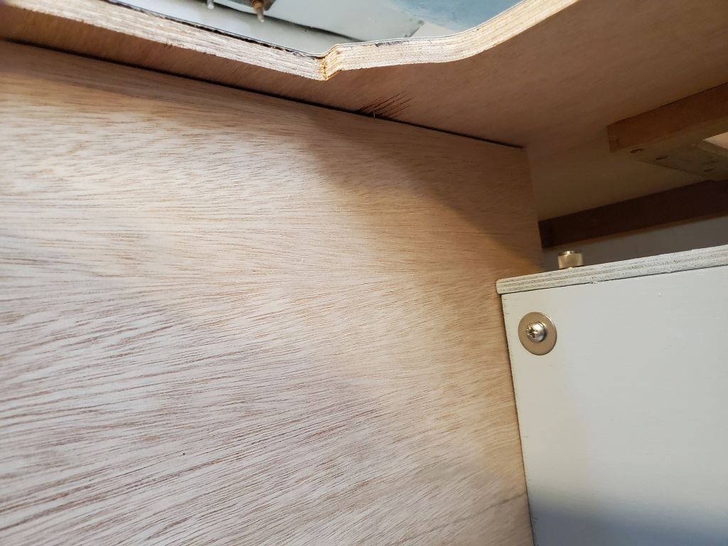
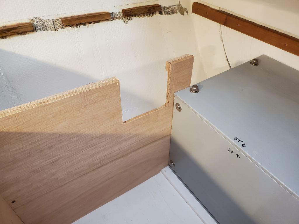
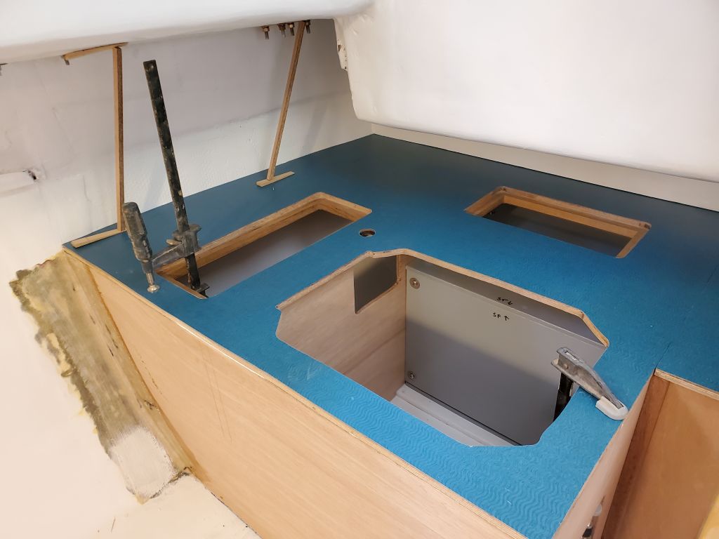
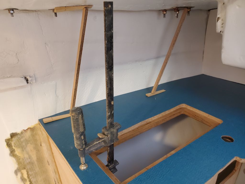
The sink had also had plenty of cure time, so I could remove the clamps and weight to complete the installation.
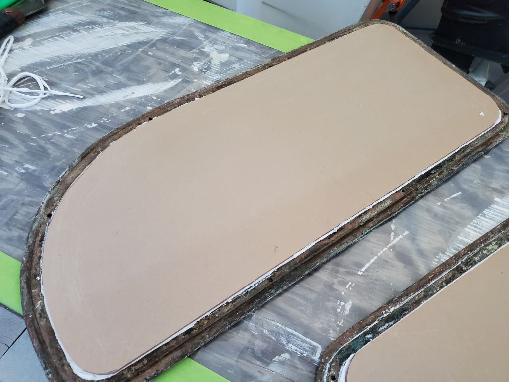
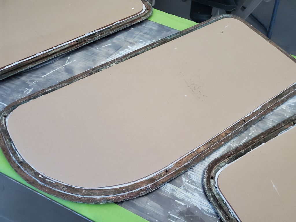
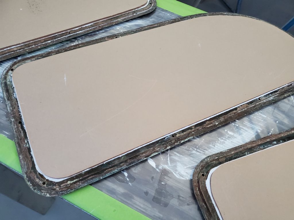
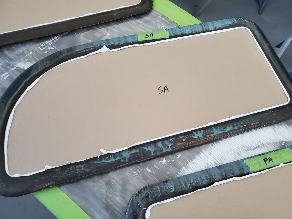
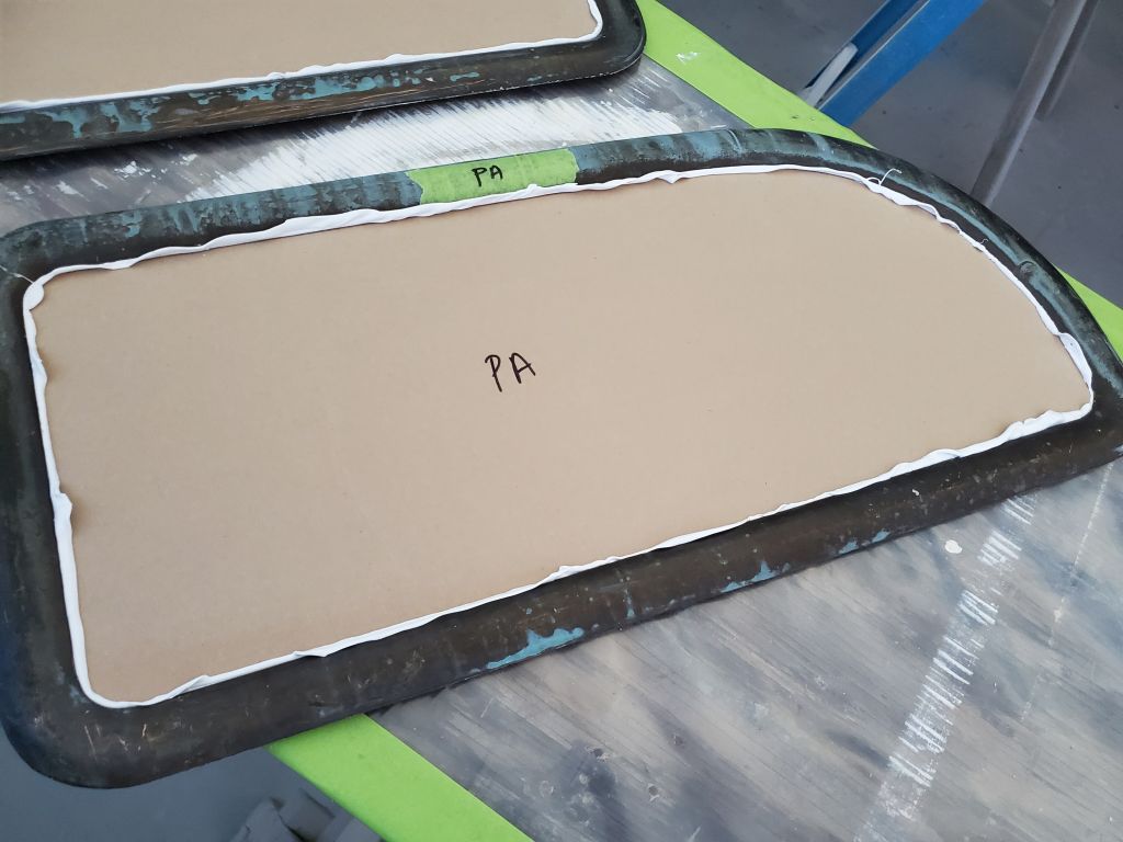
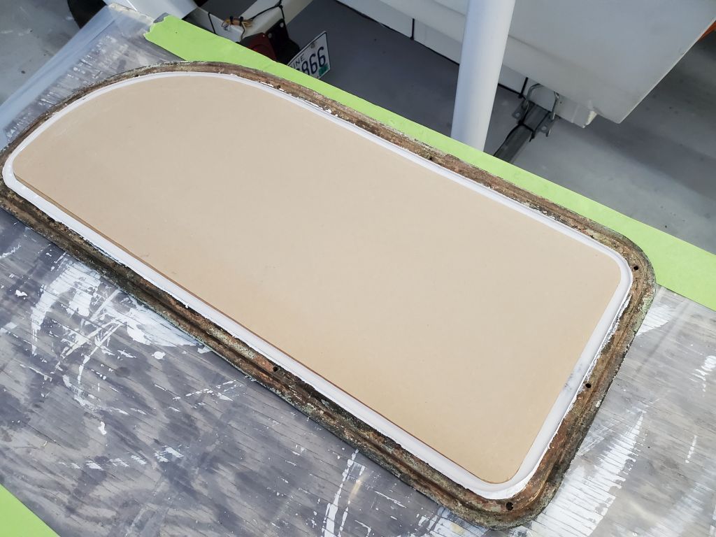
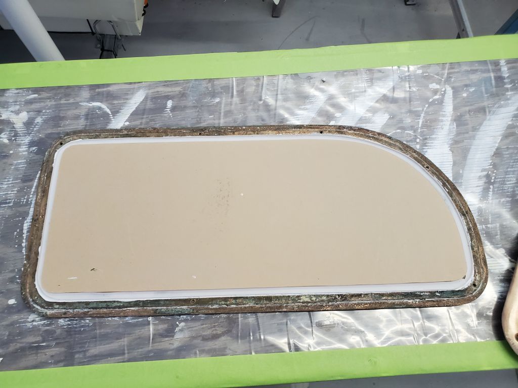
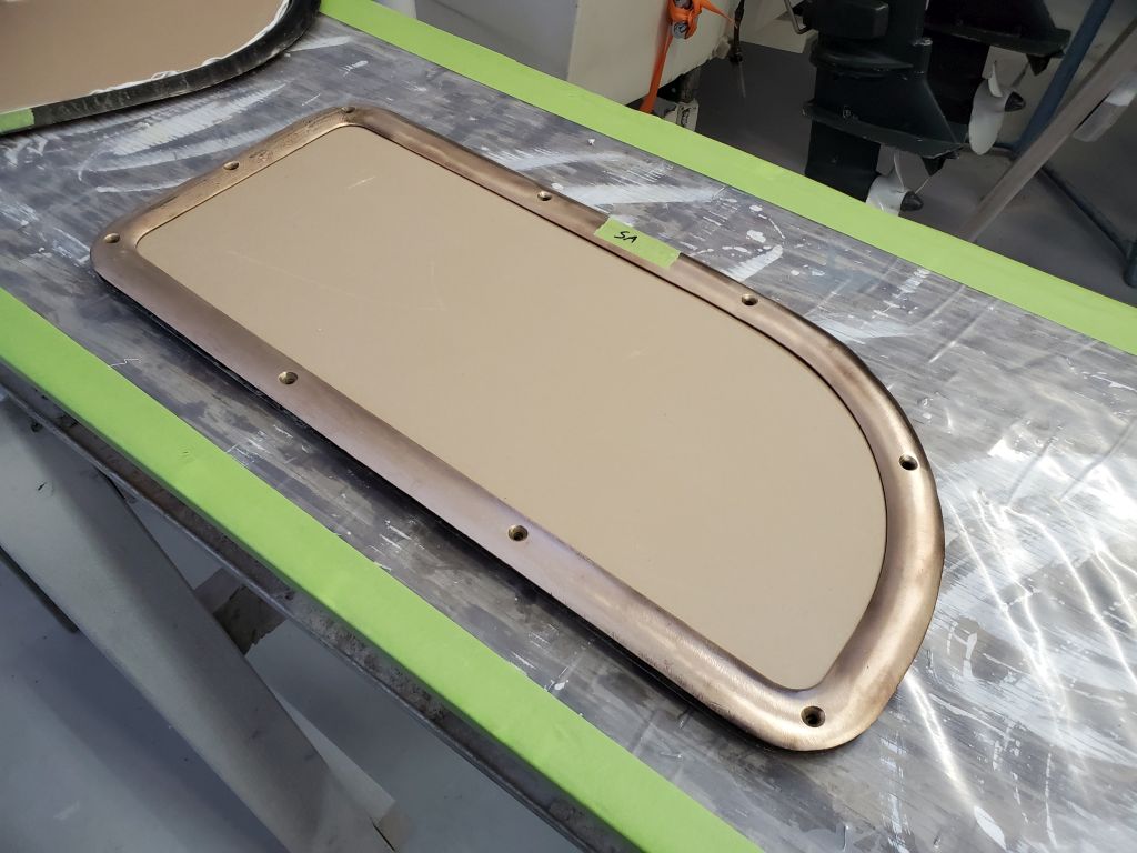
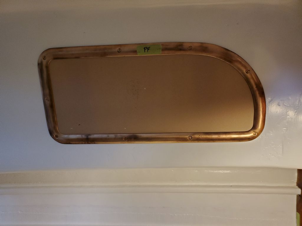
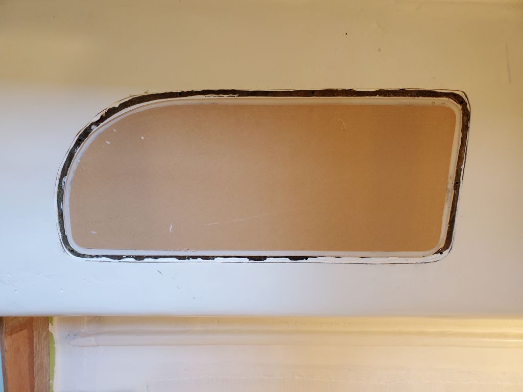
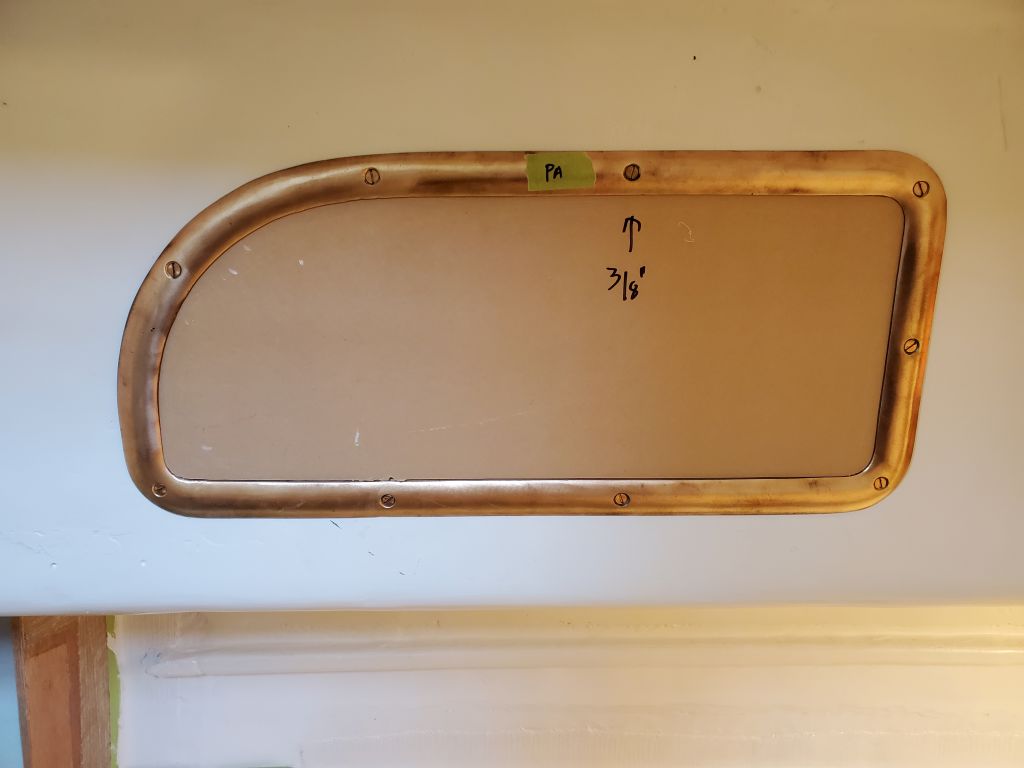
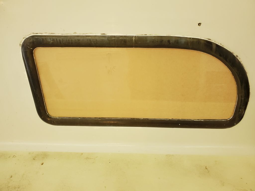
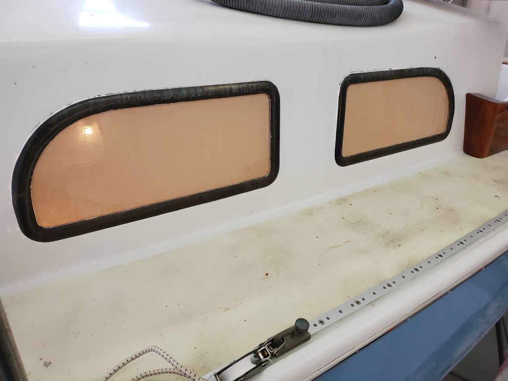
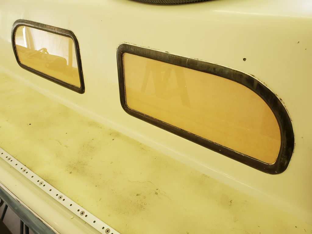
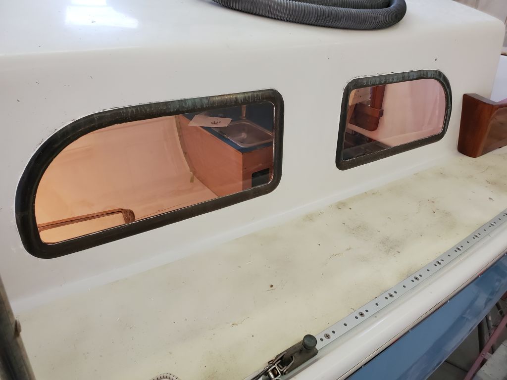
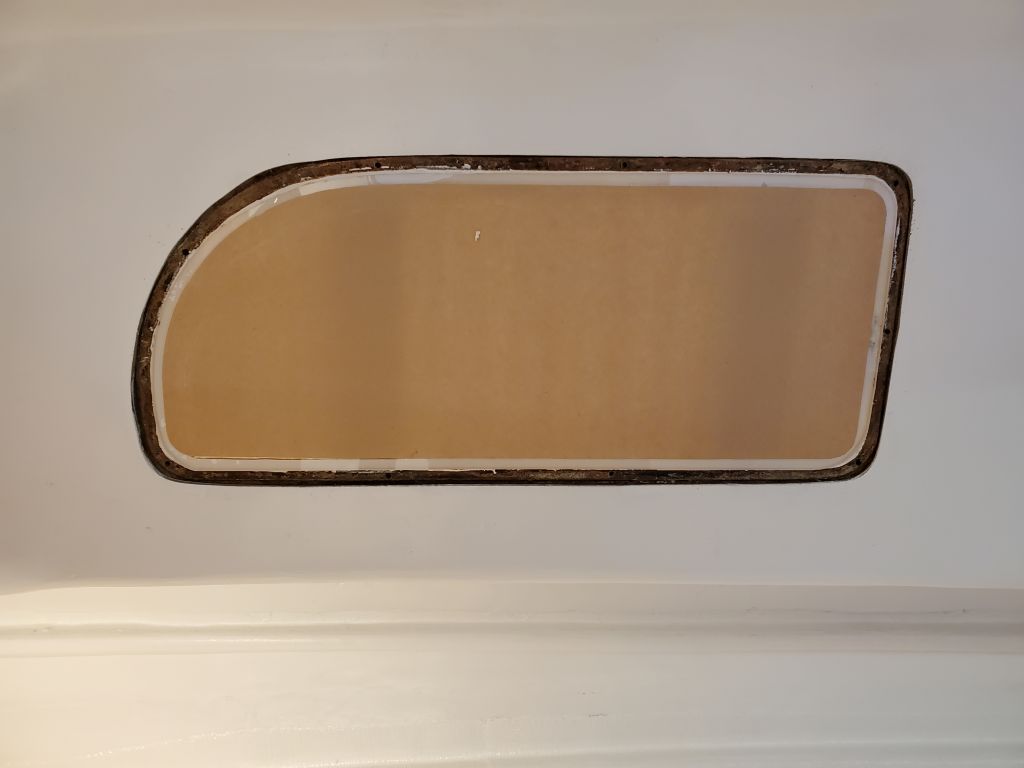
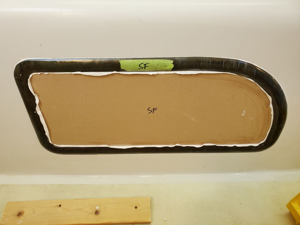
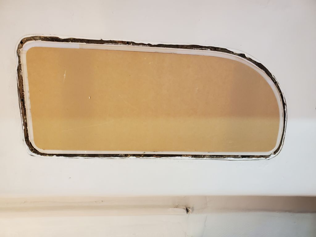
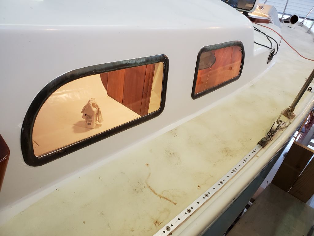
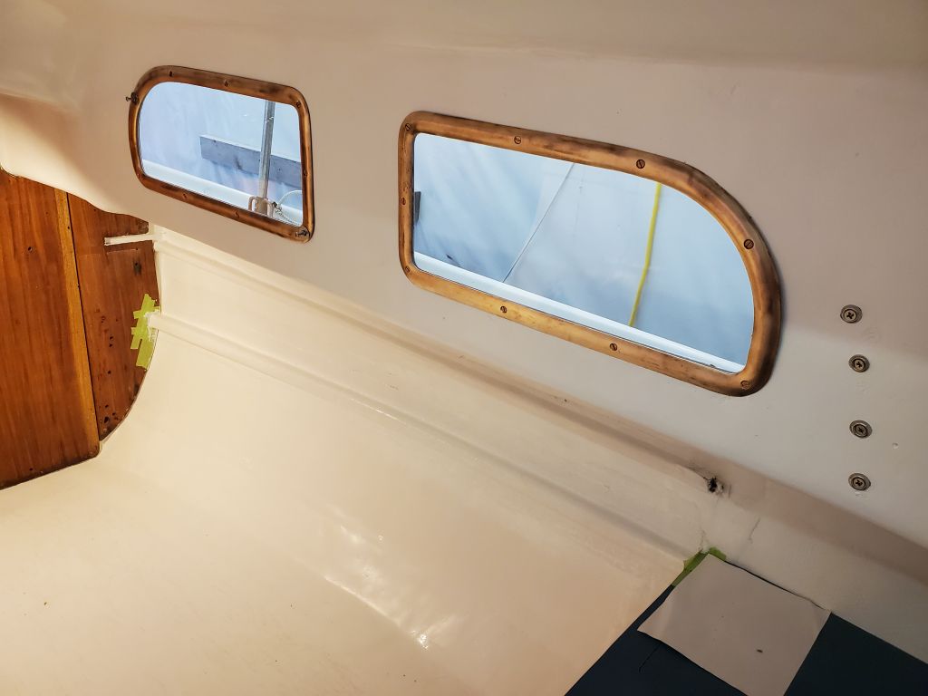
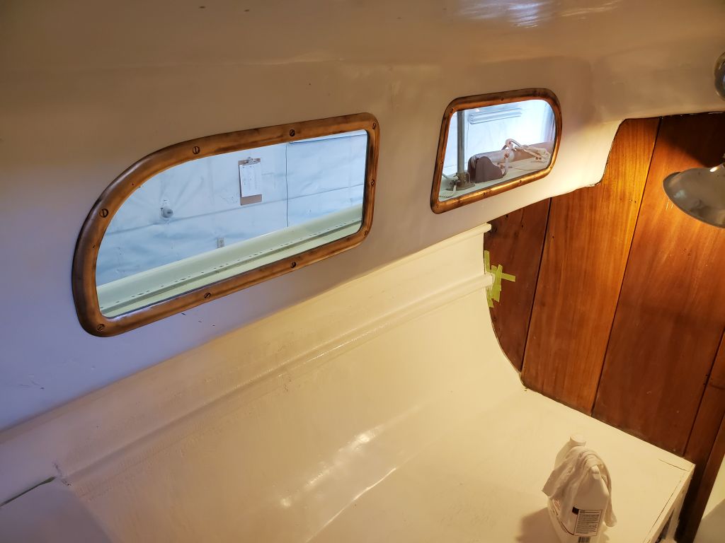
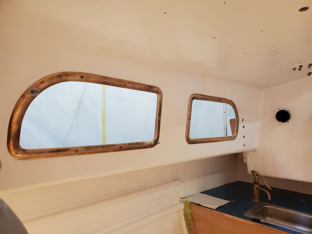
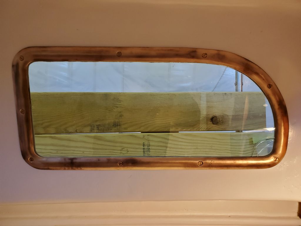
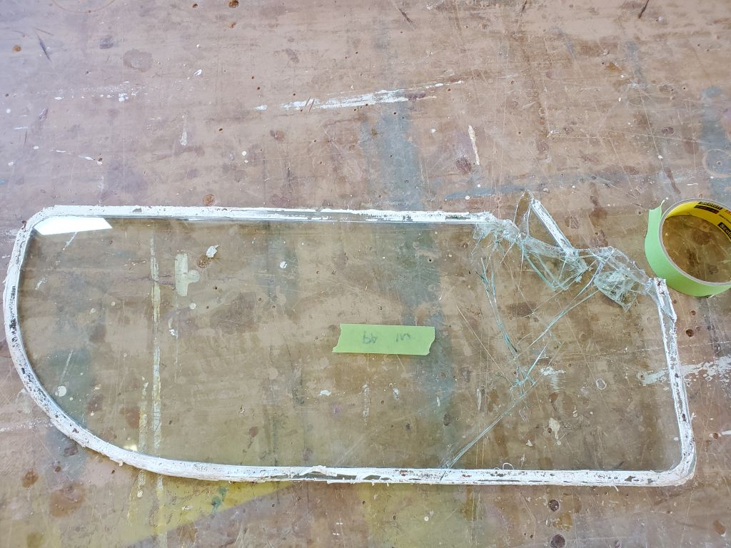
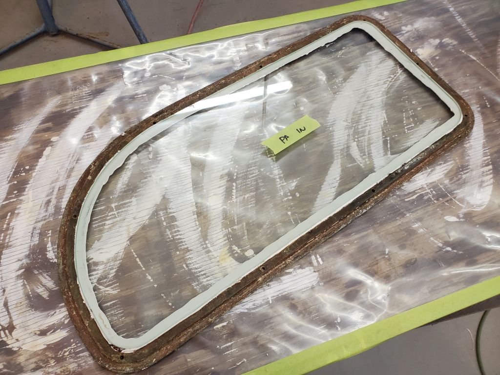
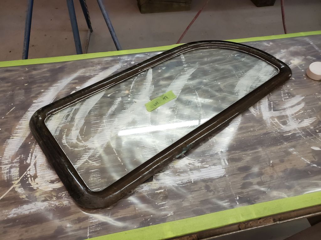
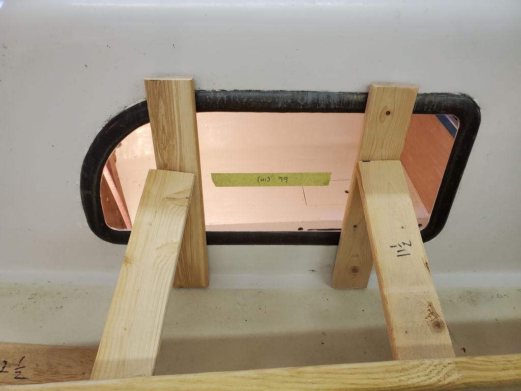
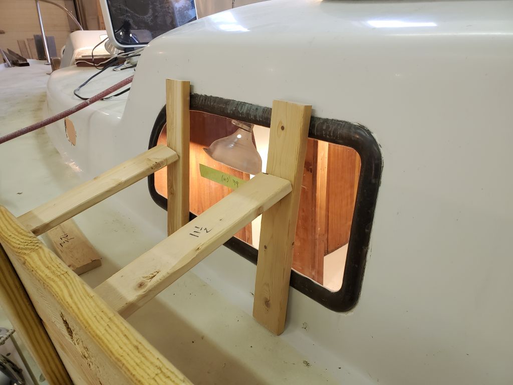
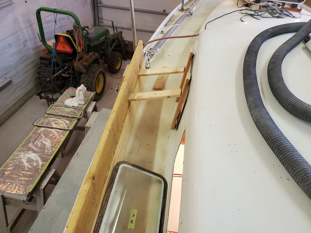
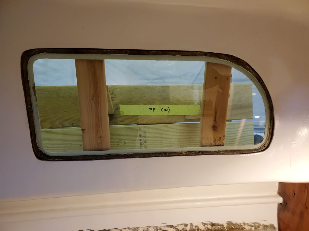
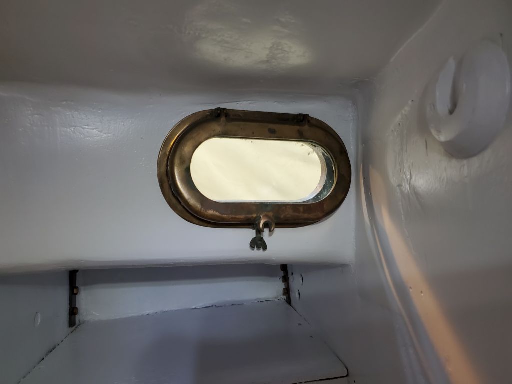
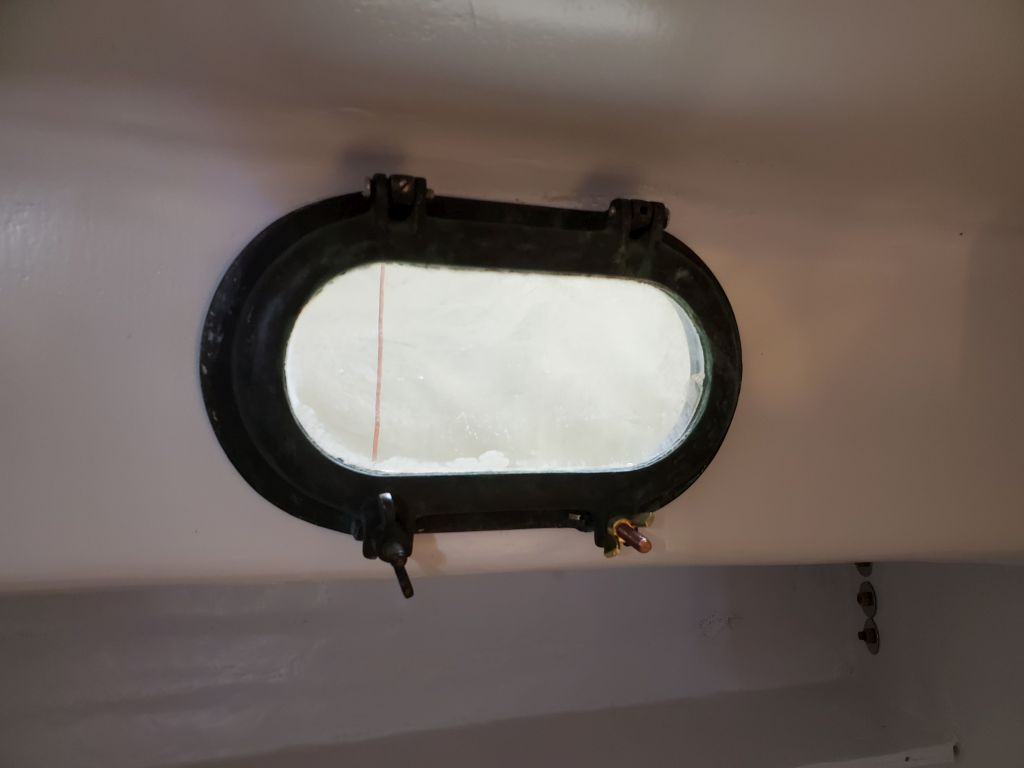
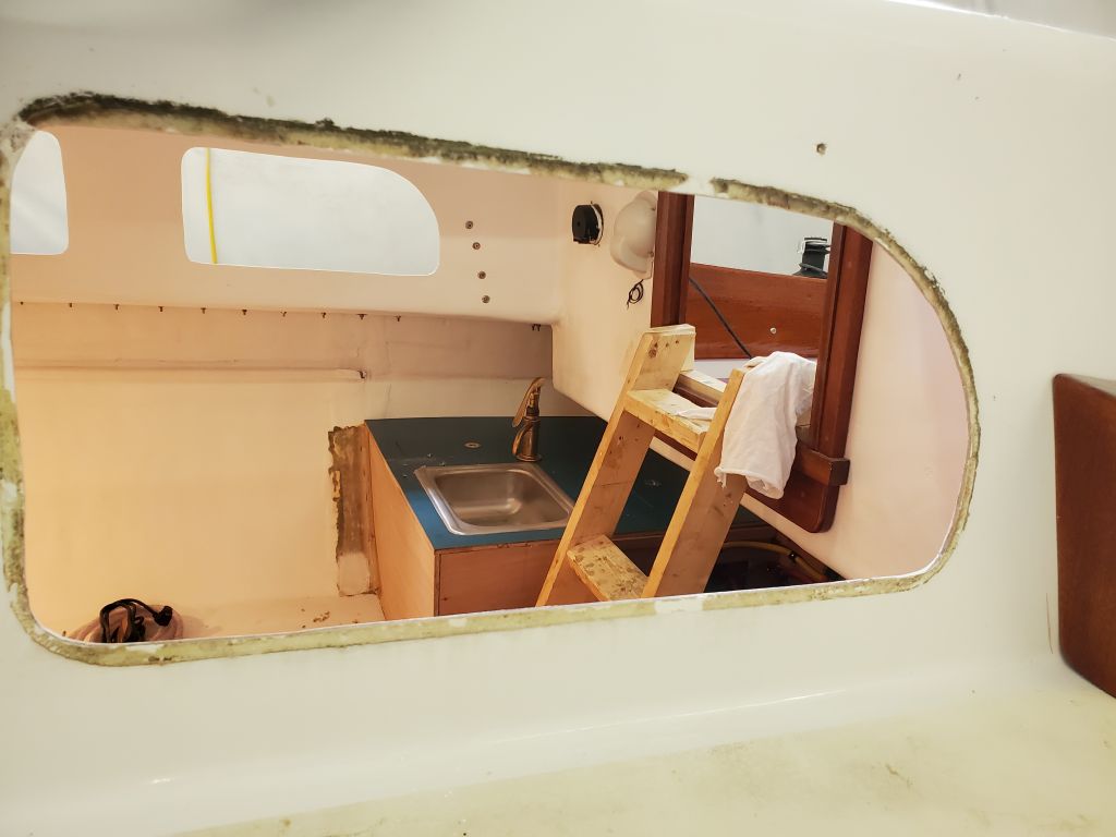
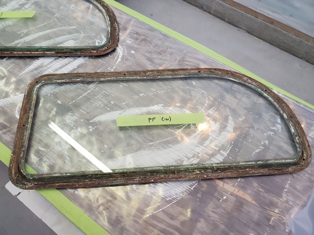
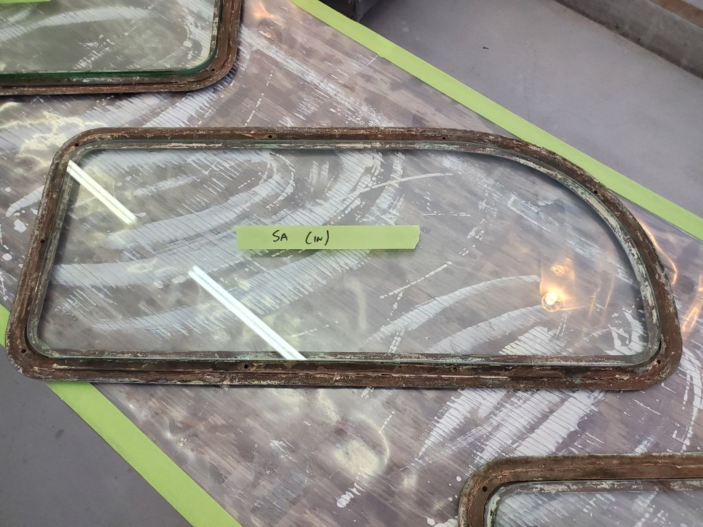
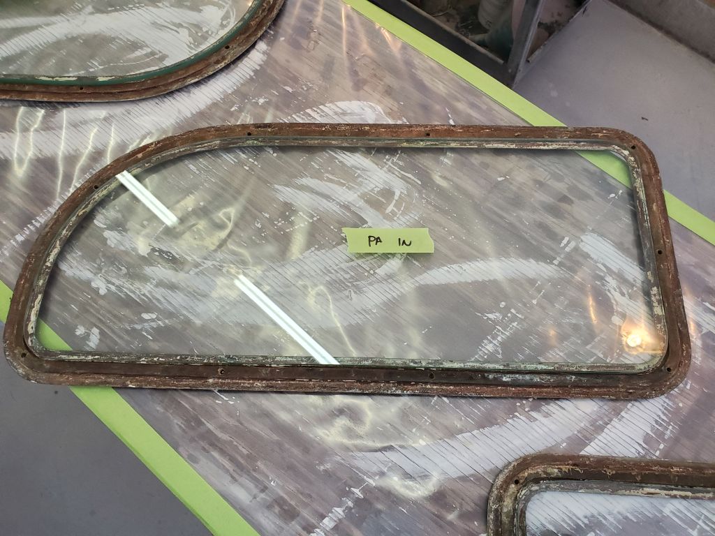
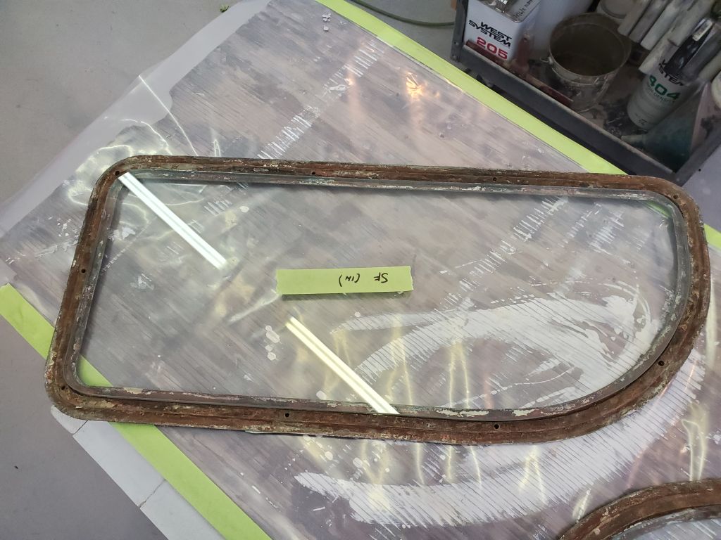
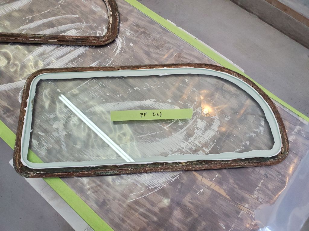
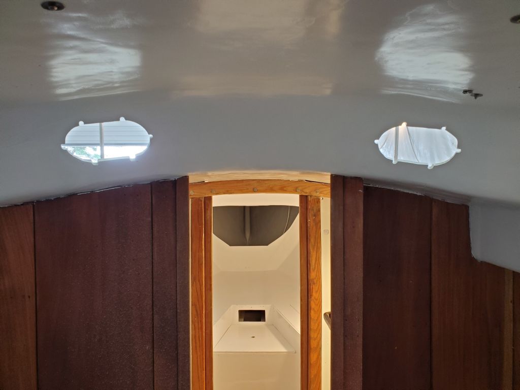
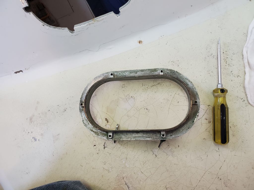
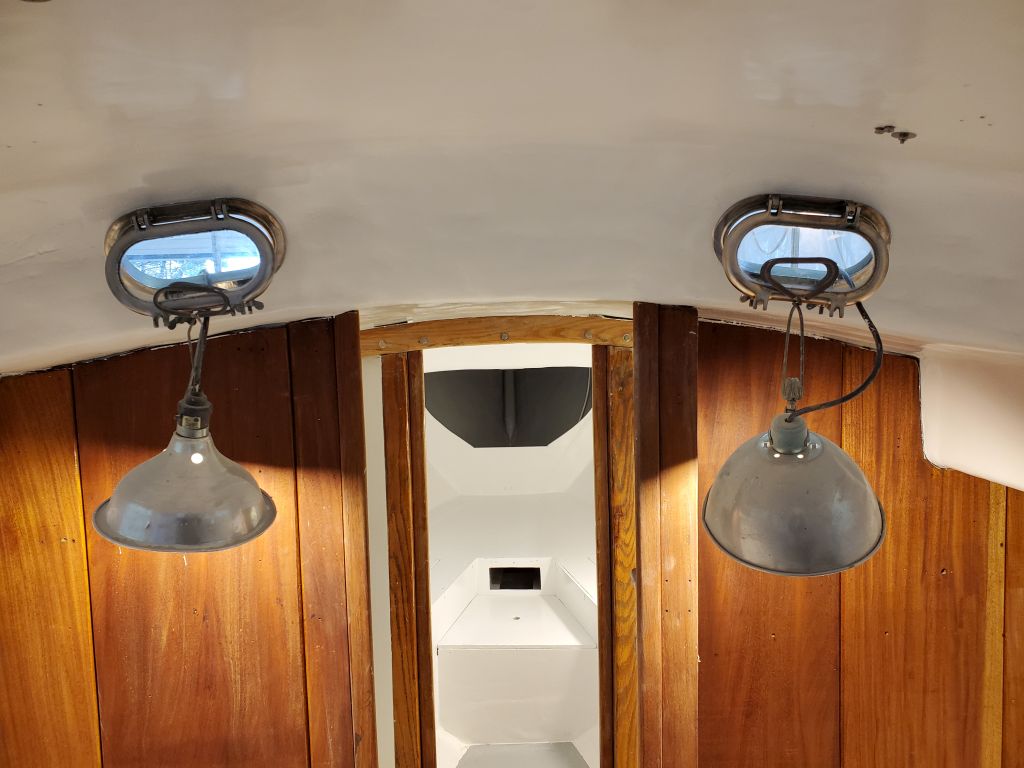
My first and main focus for the week and the balance of my time on this job was to install the ports and deadlights, which the owner had been cleaning up, replacing glass, and repairing. With these freshly delivered to the shop (minus two of the small ports for now that he hadn’t finished yet), I got started with the deadlights, which required some pre-work before actual installation.
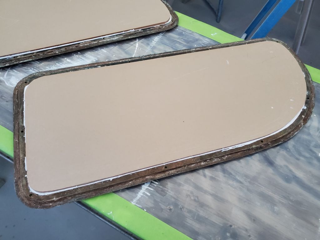
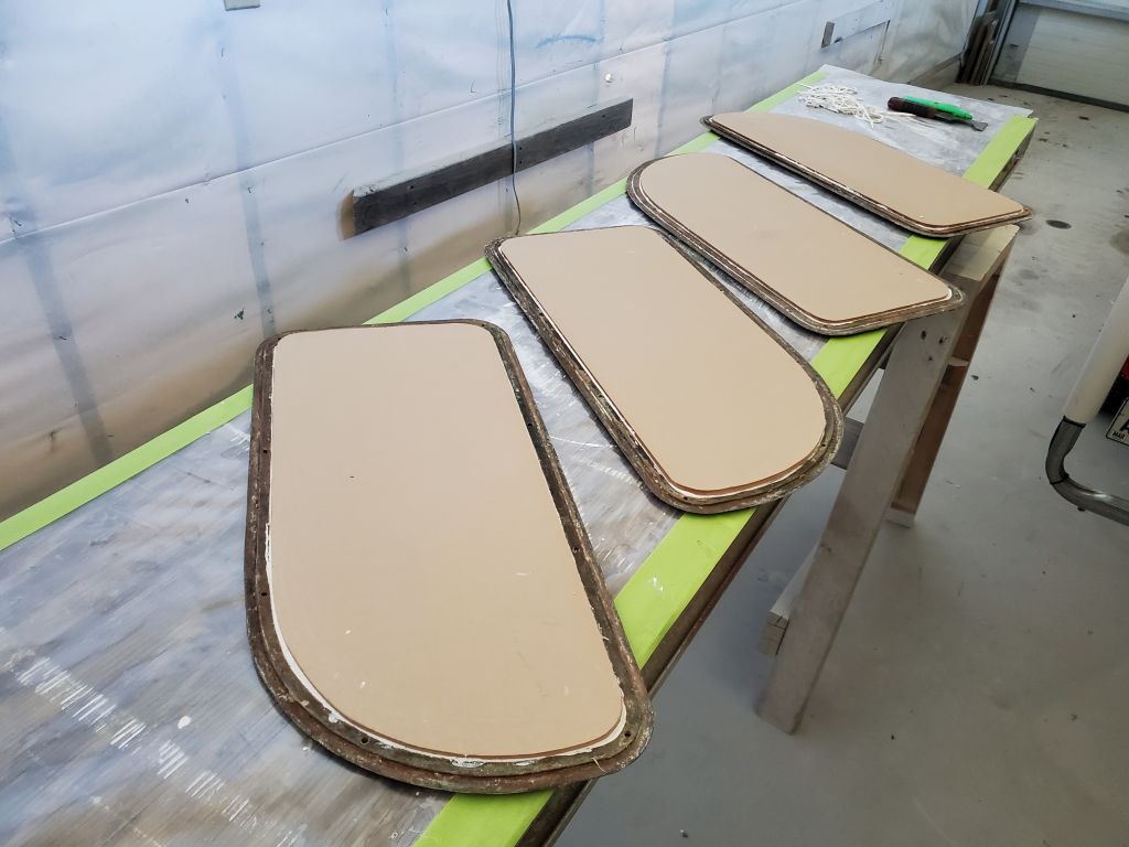
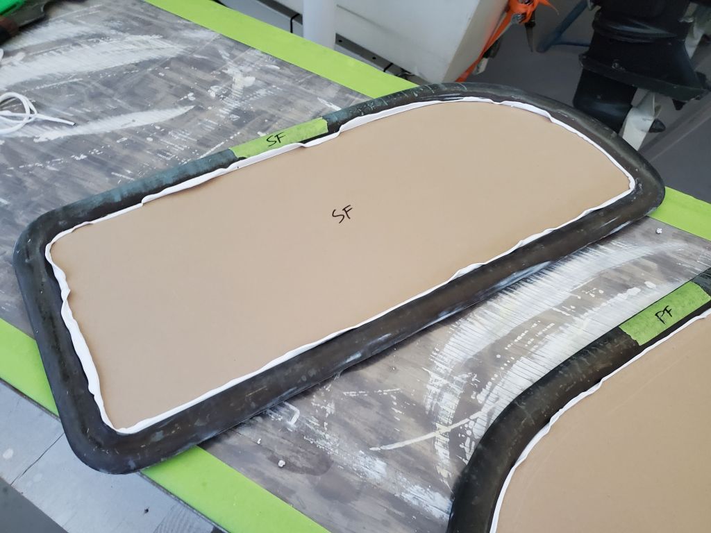
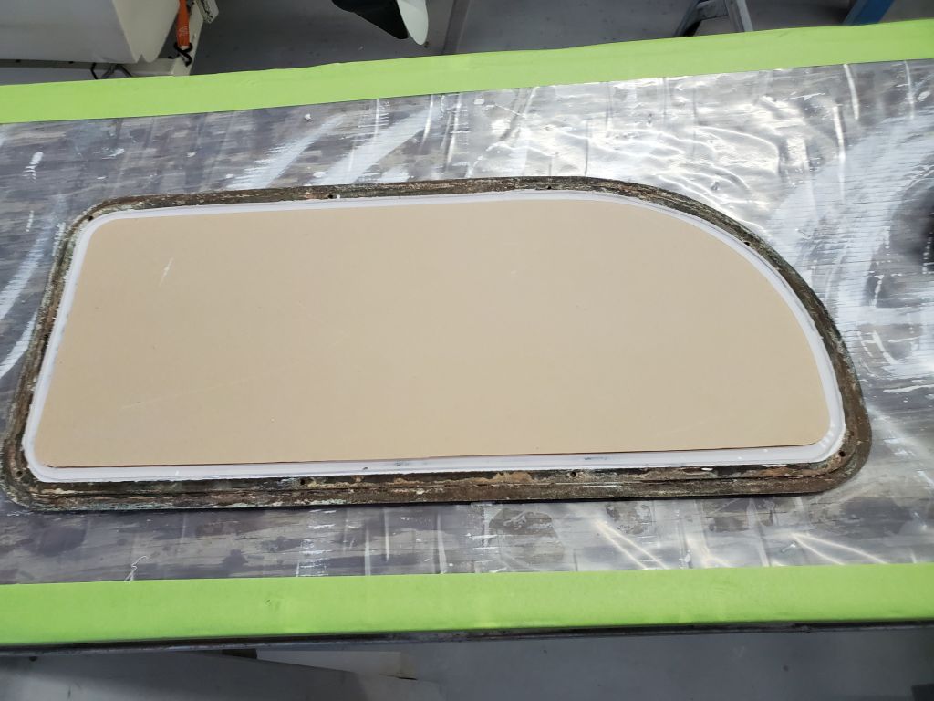
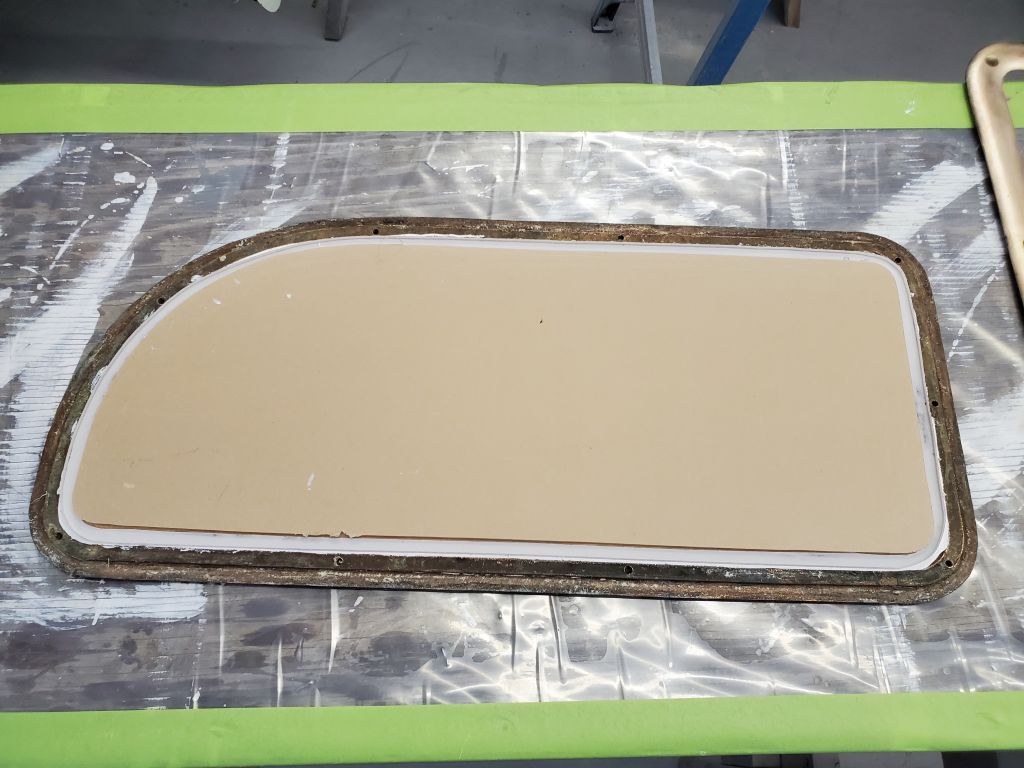
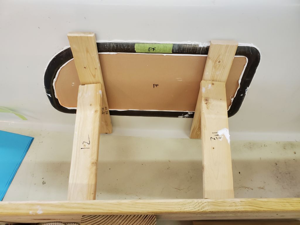
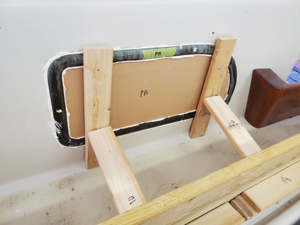
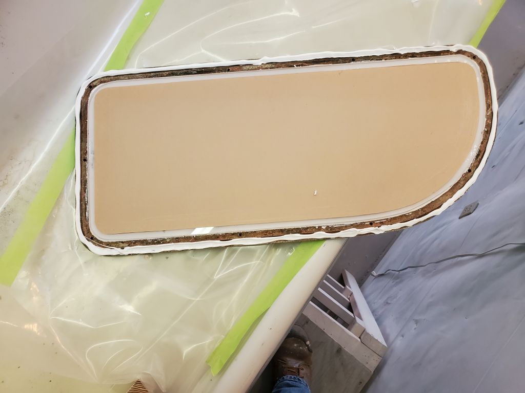
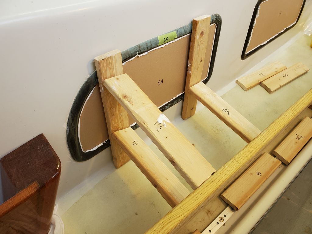
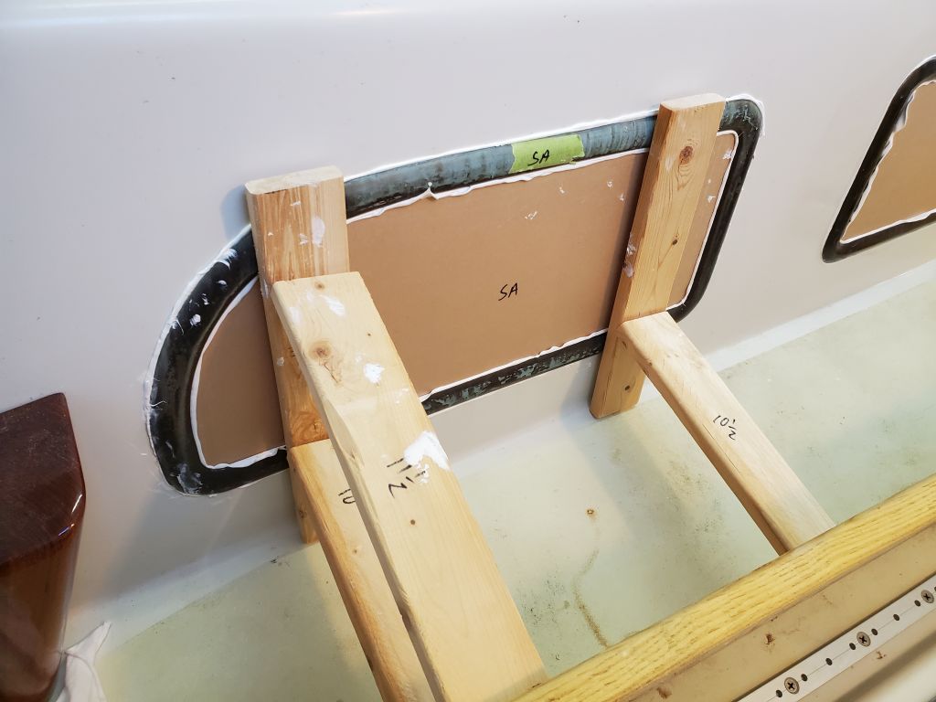
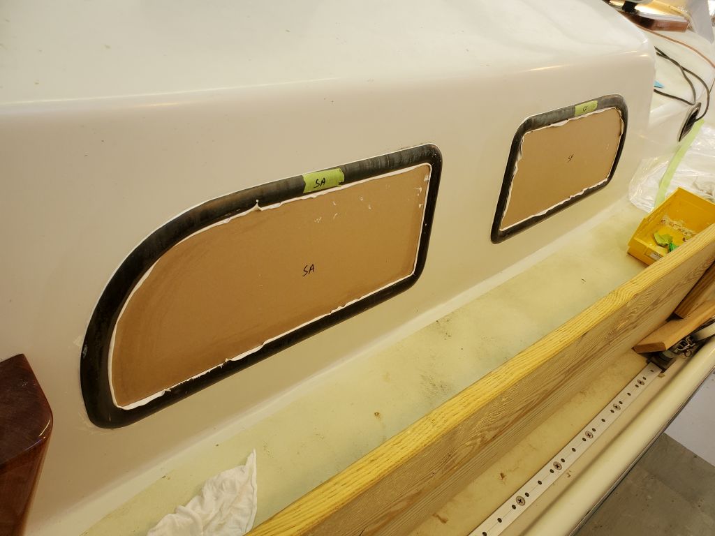
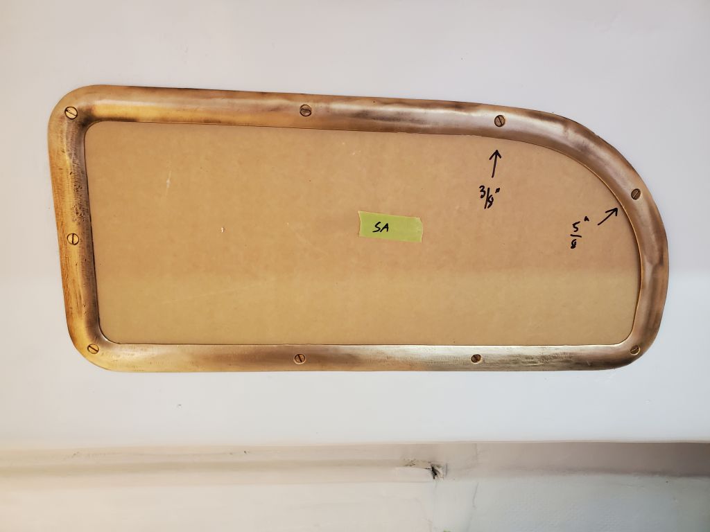
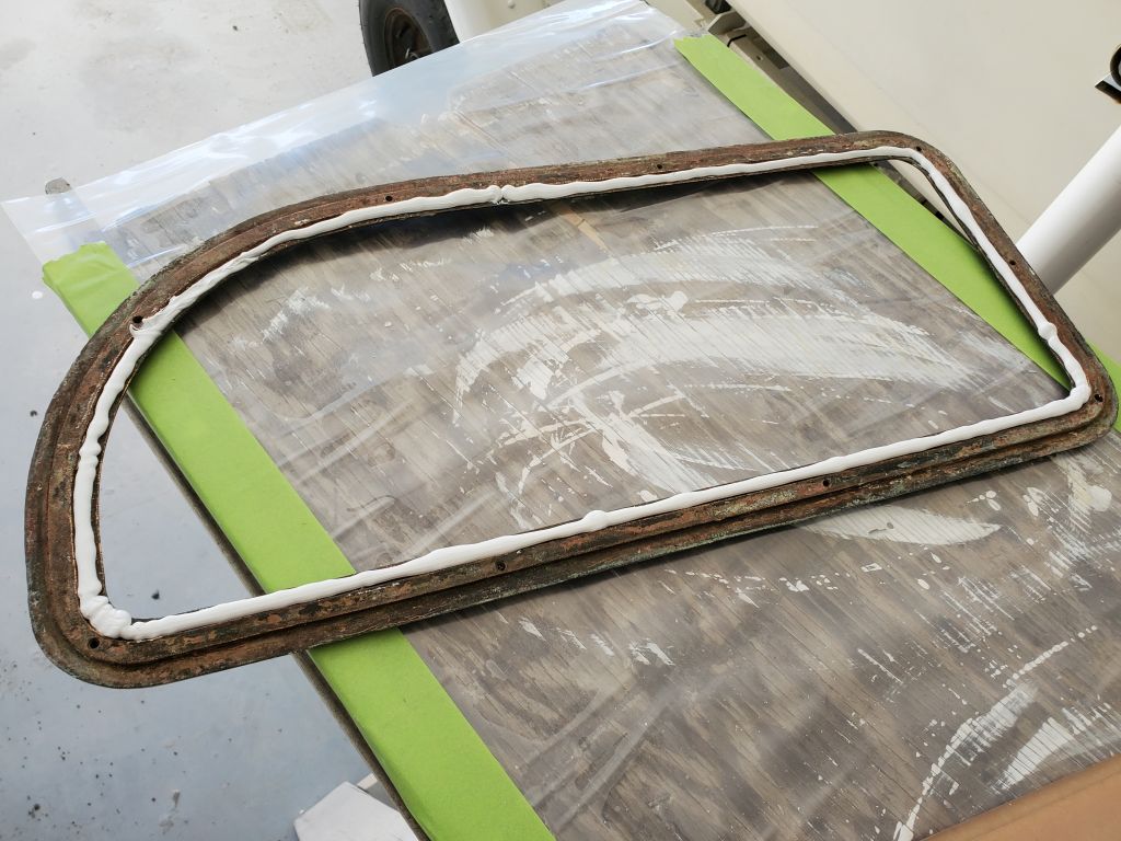
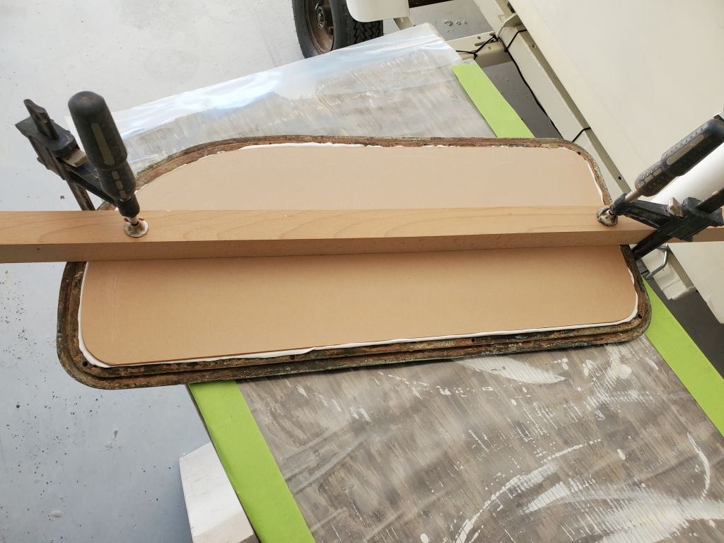
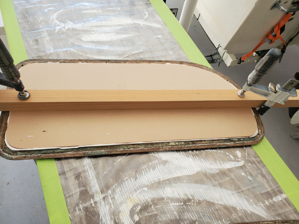
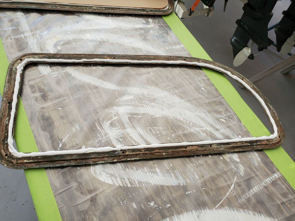
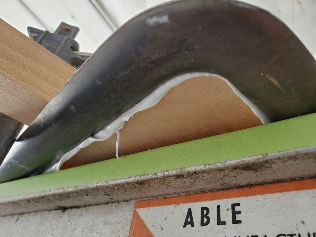
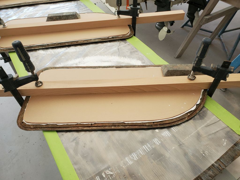
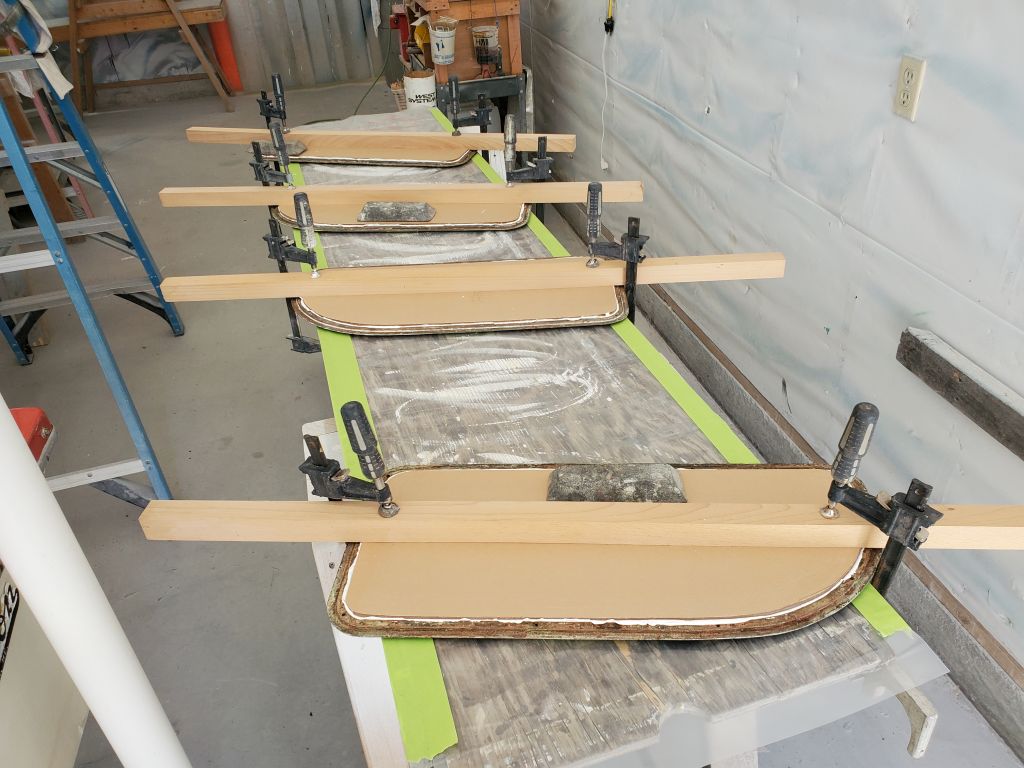
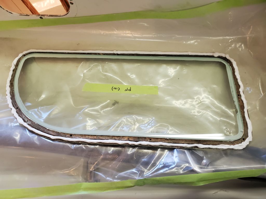
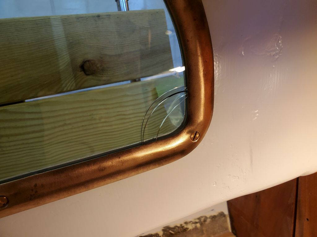
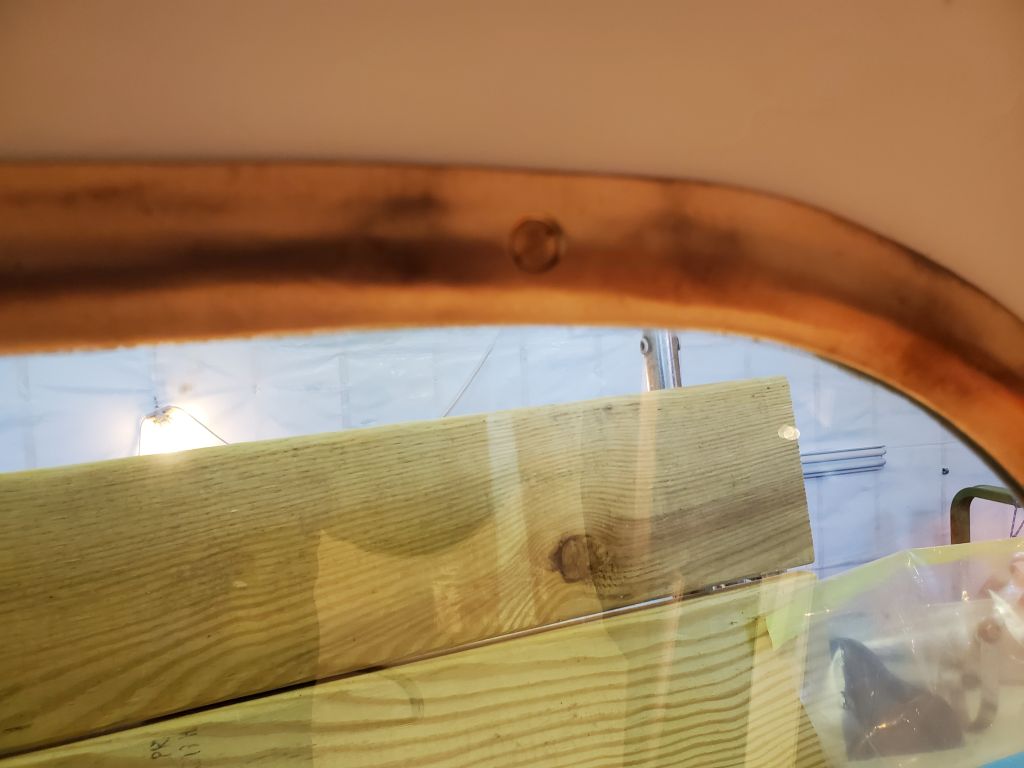
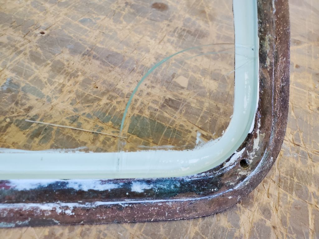
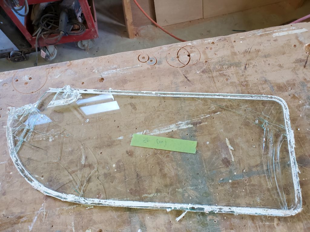
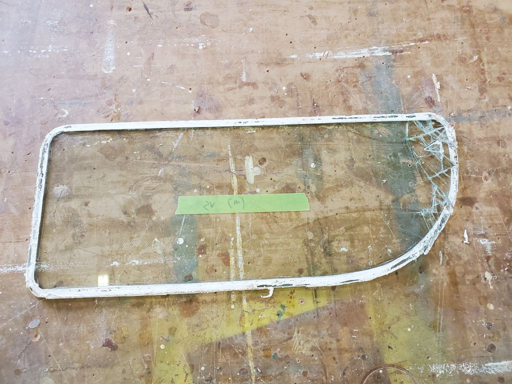
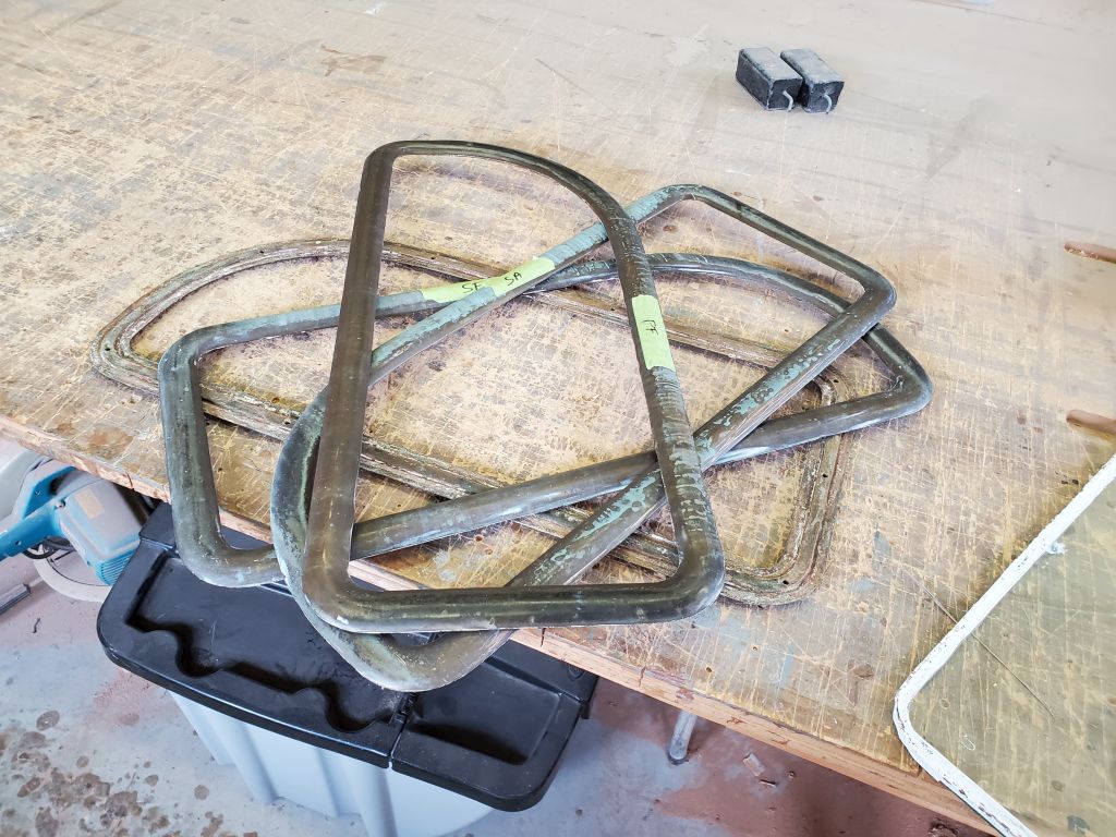
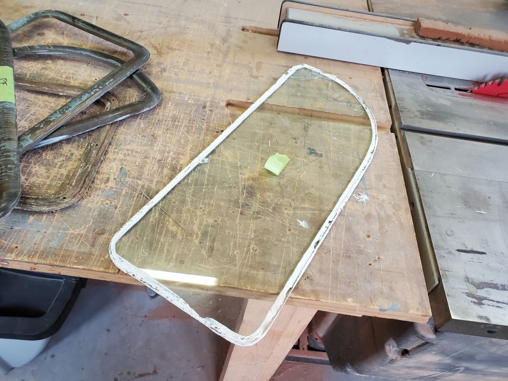
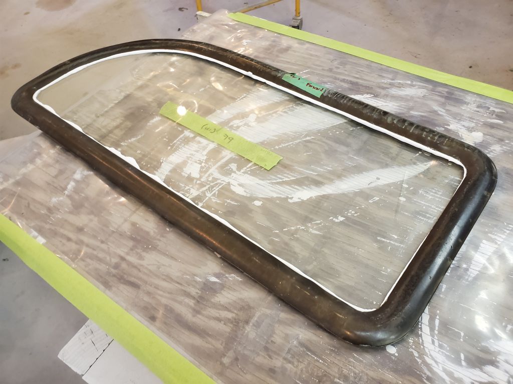
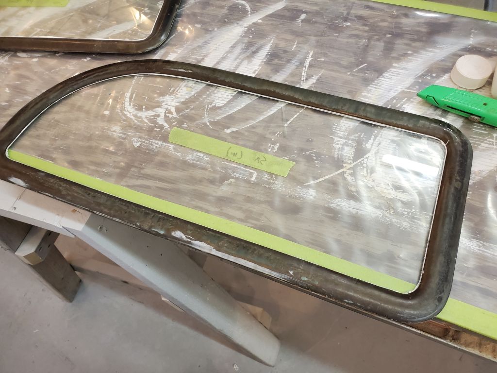
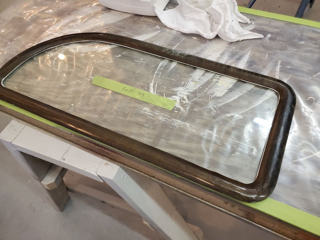
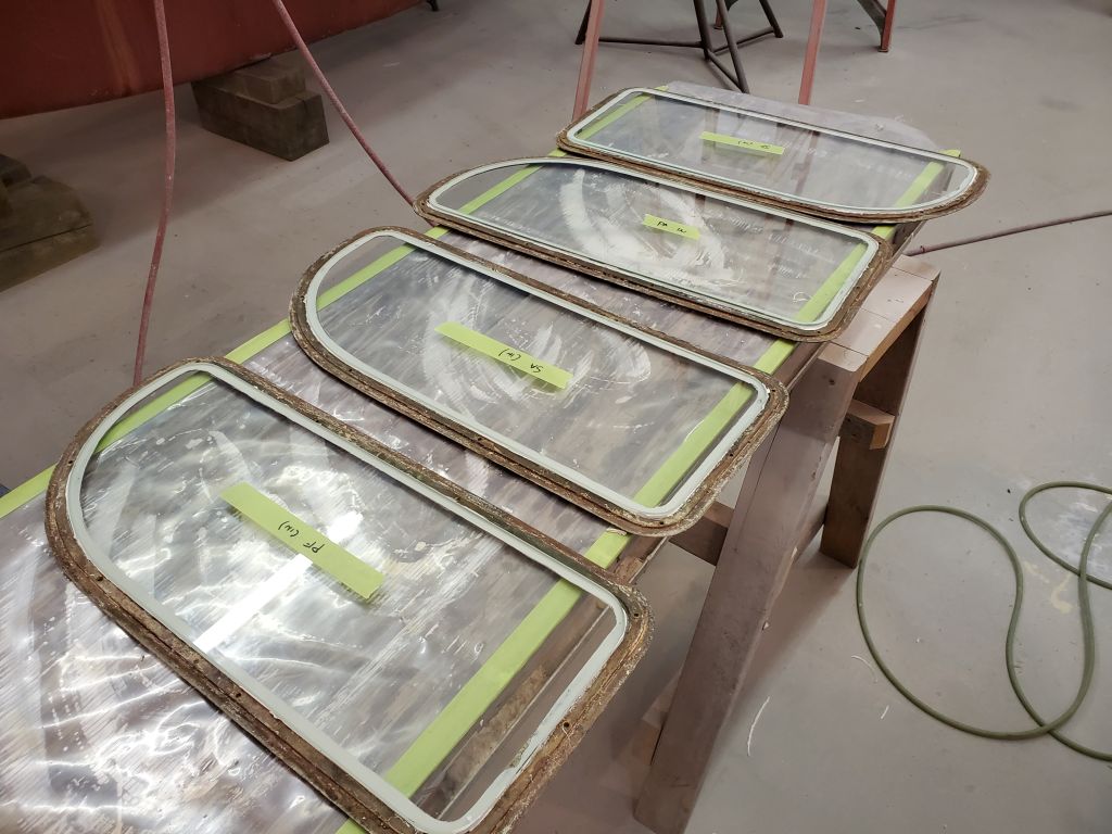
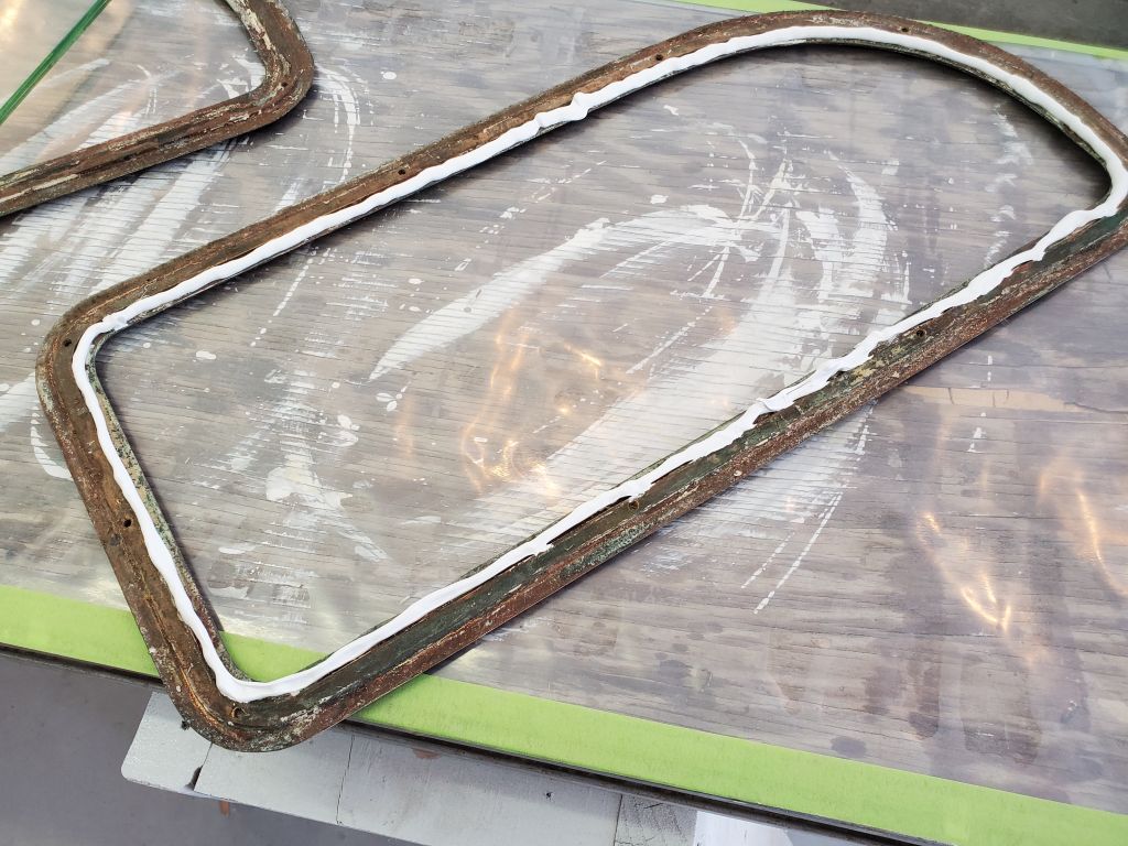
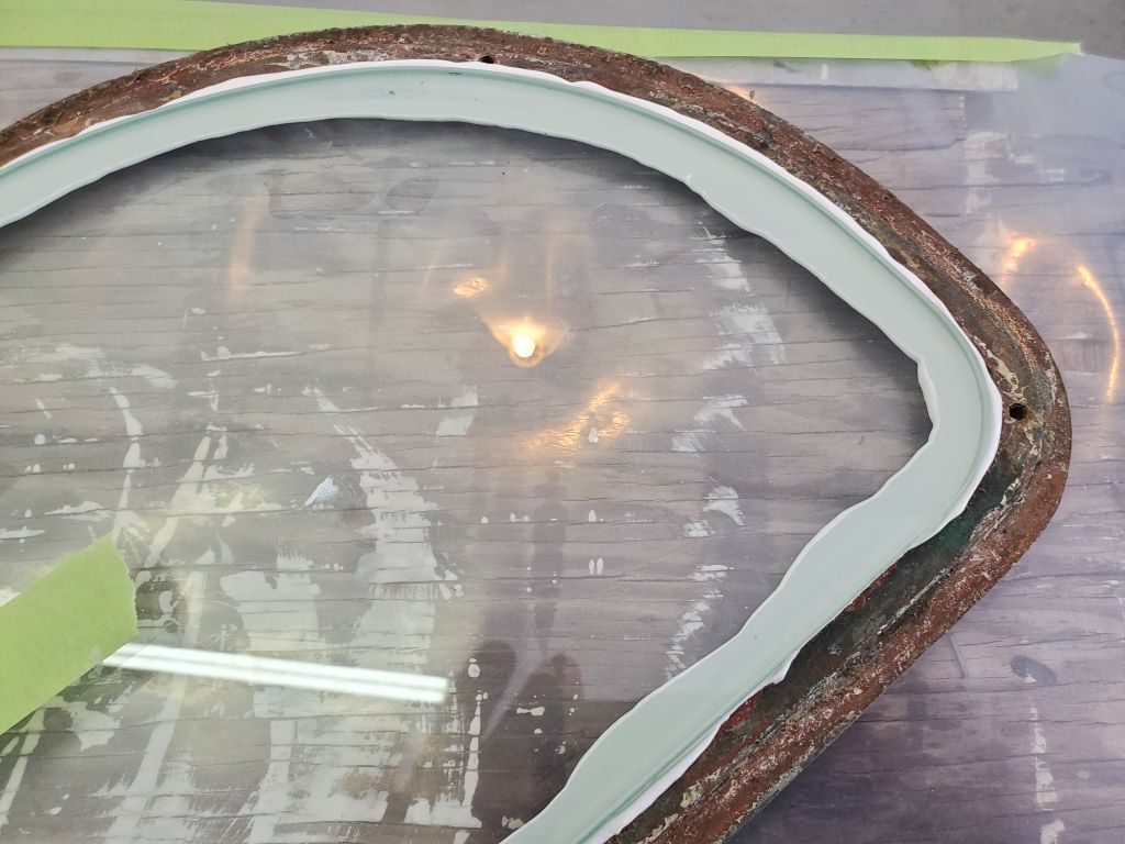
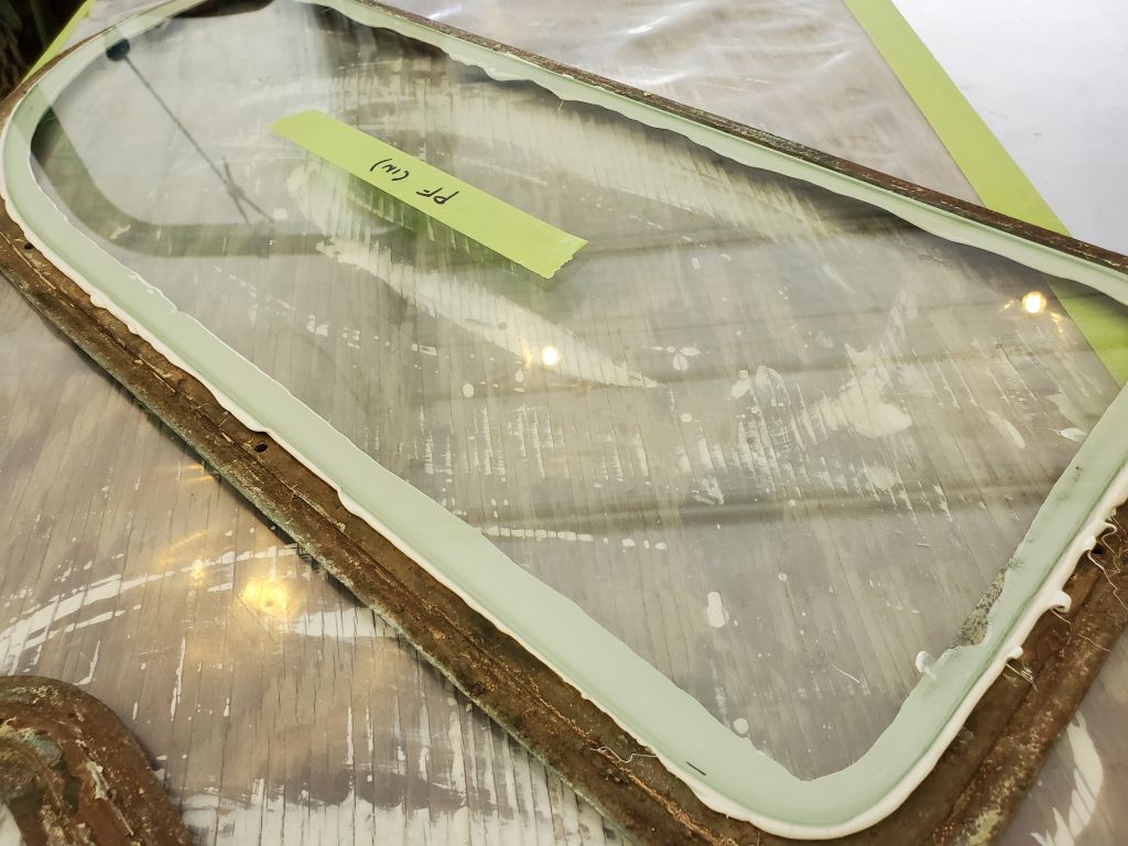
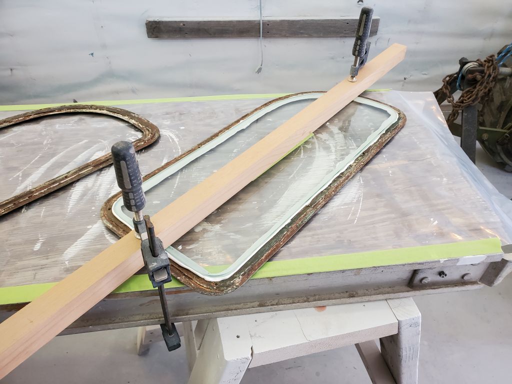
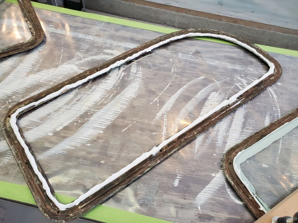
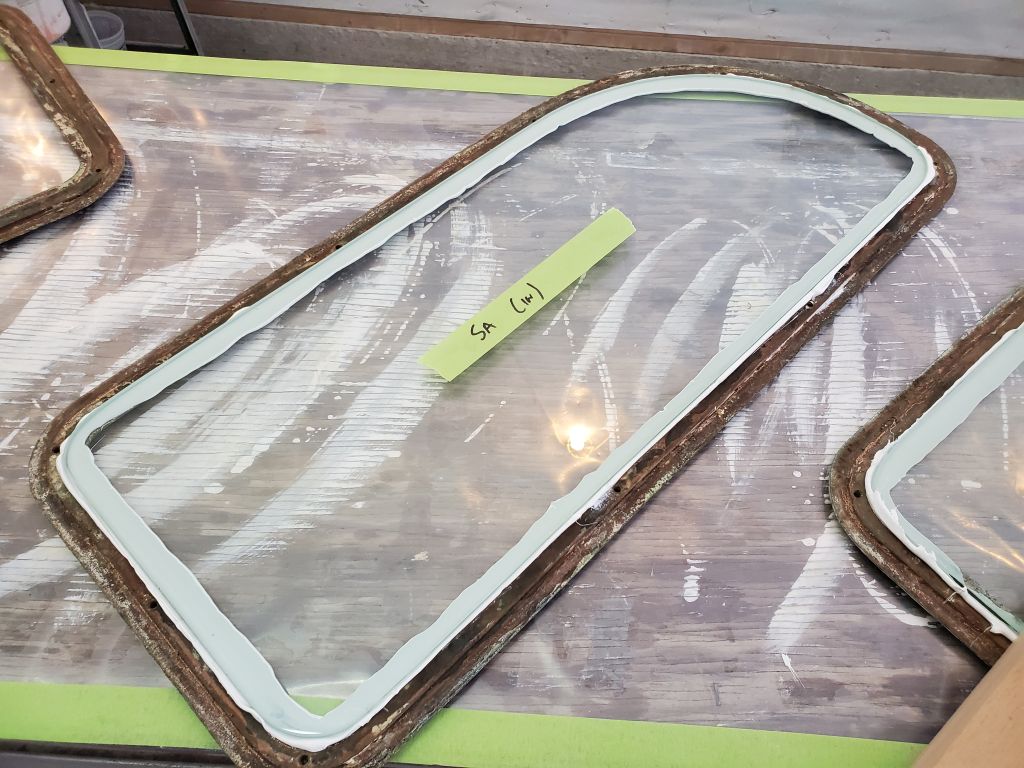
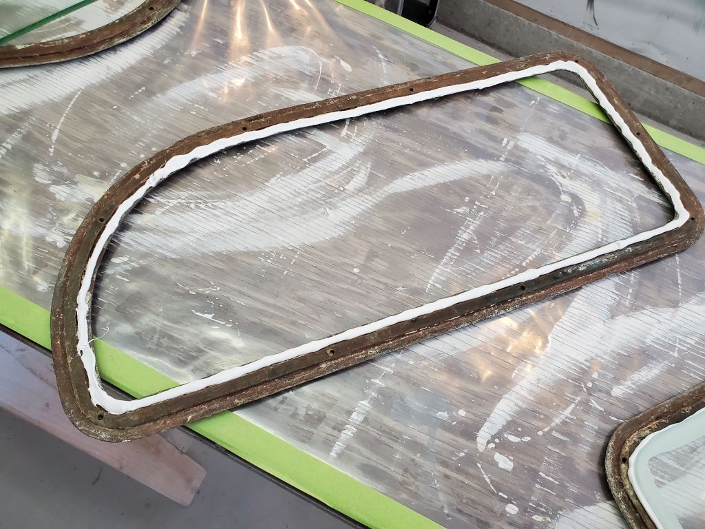
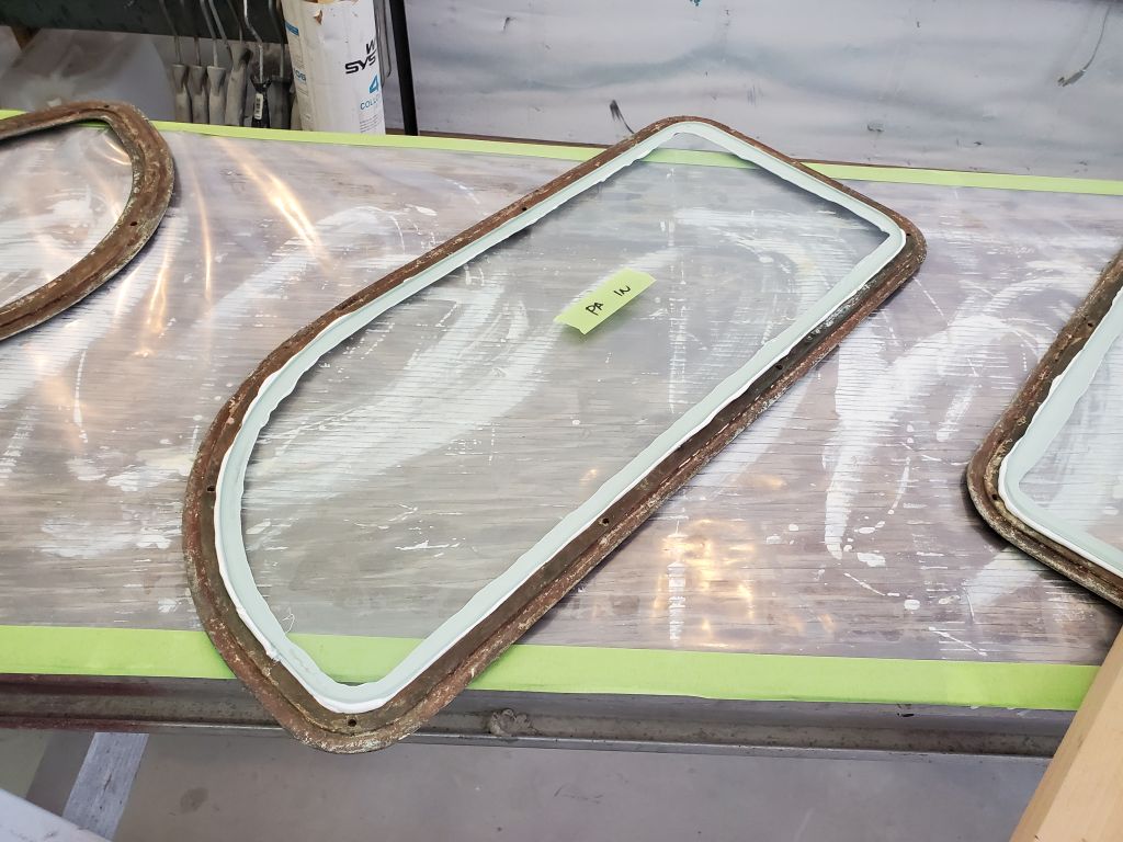
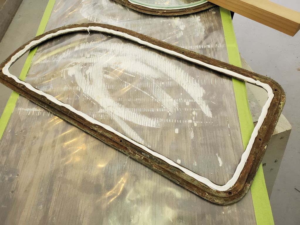
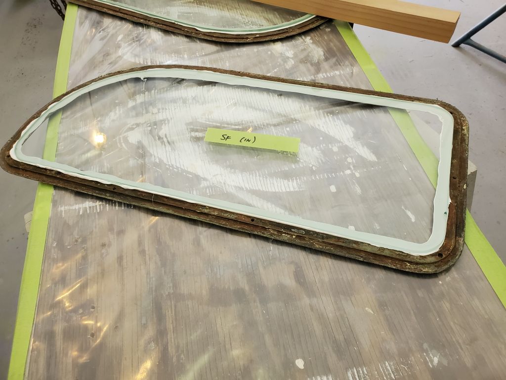
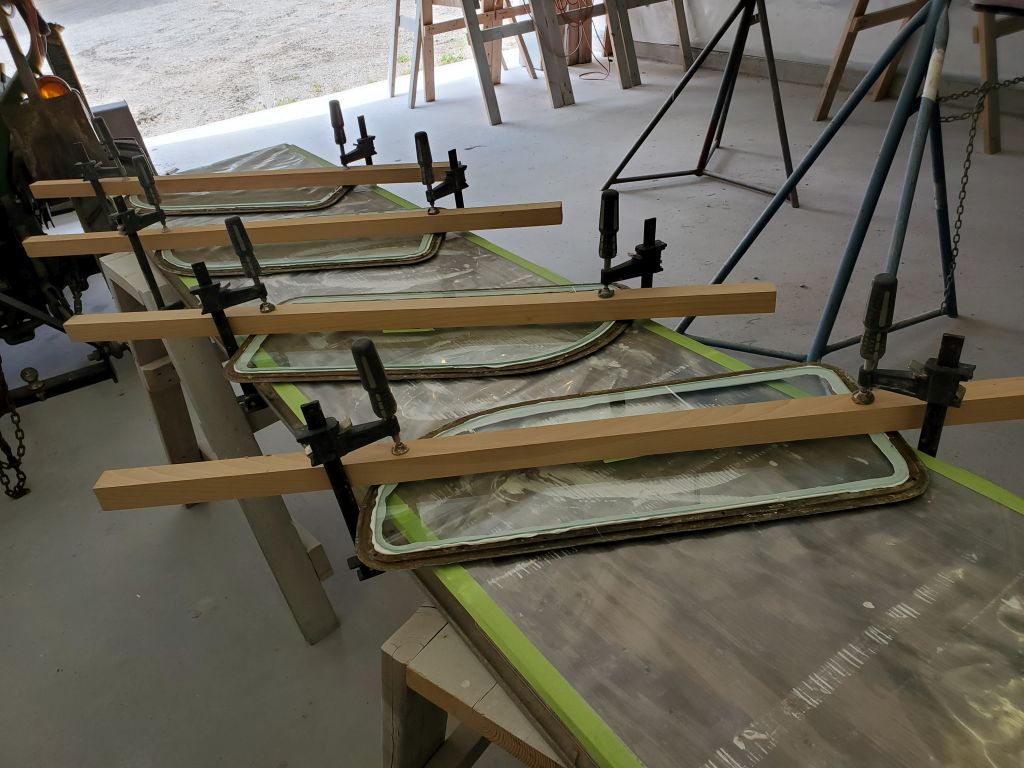
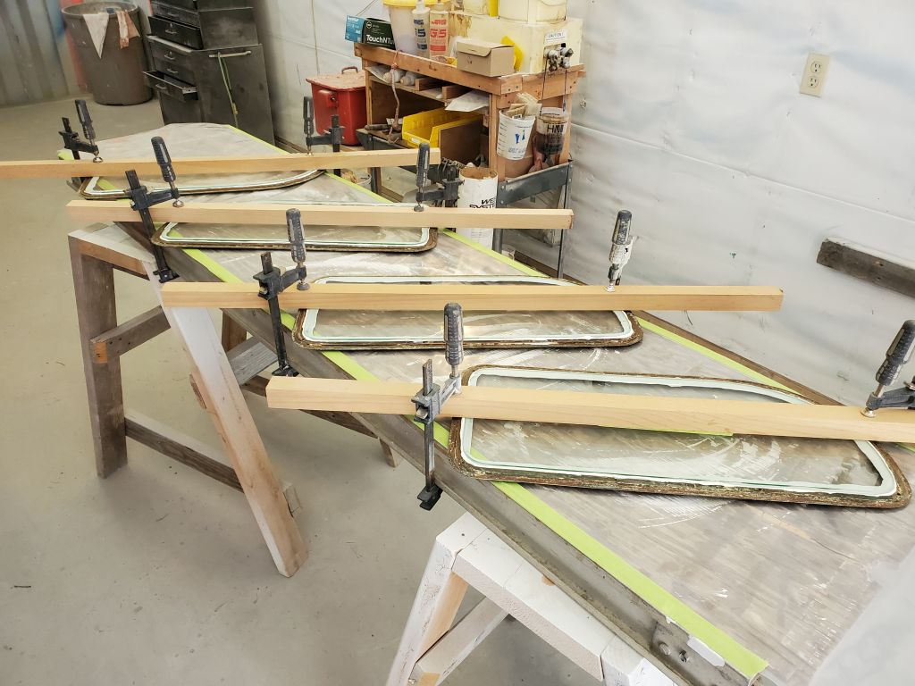
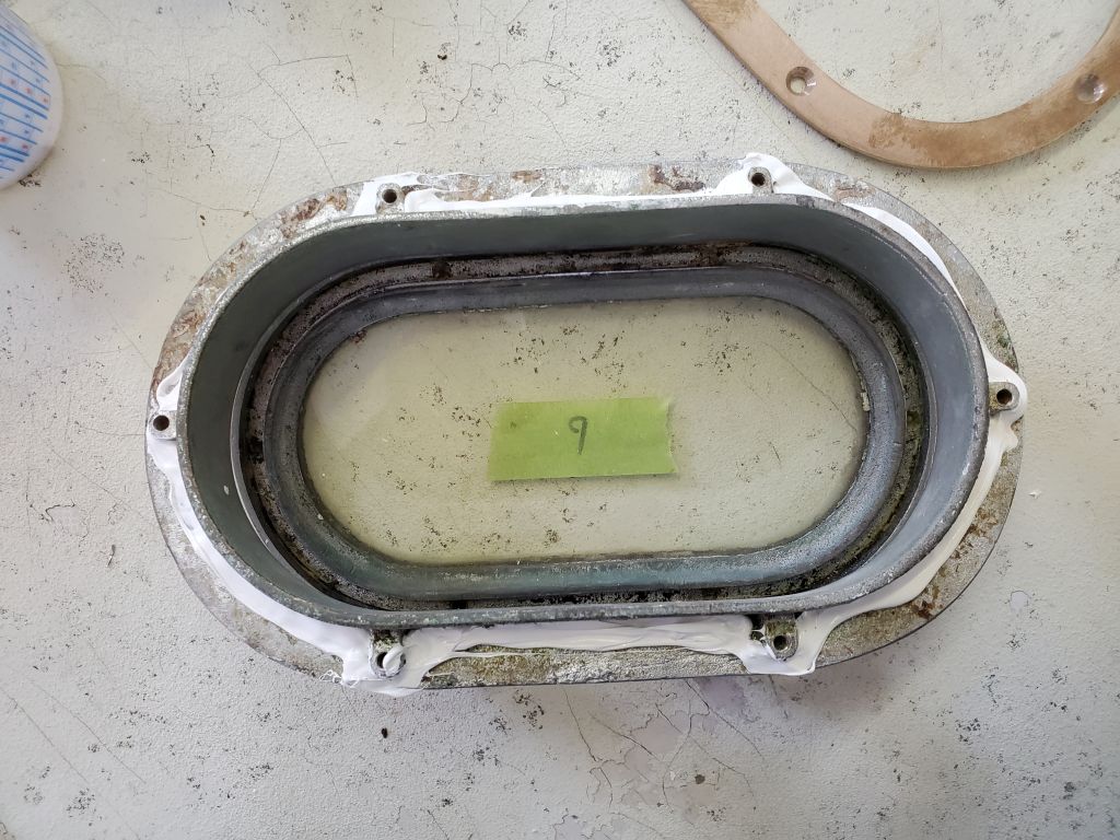
To make installation somewhat easier (read: possible), I liked to pre-install the lenses (new 1/4″ laminated glass in this case) to the outer frames, to hold those pieces together during the installation process. I used a sumptuous bead of Sikaflex to secure the glass to the rabbeted channel in the outer bronze frame, pressing the glass in securely (through the clear glass it was easy to see the sealant spread) and then, more to hold things in place than to provide real pressure, clamped the glass beneath a strip of wood.
I repeated this with all four frames.
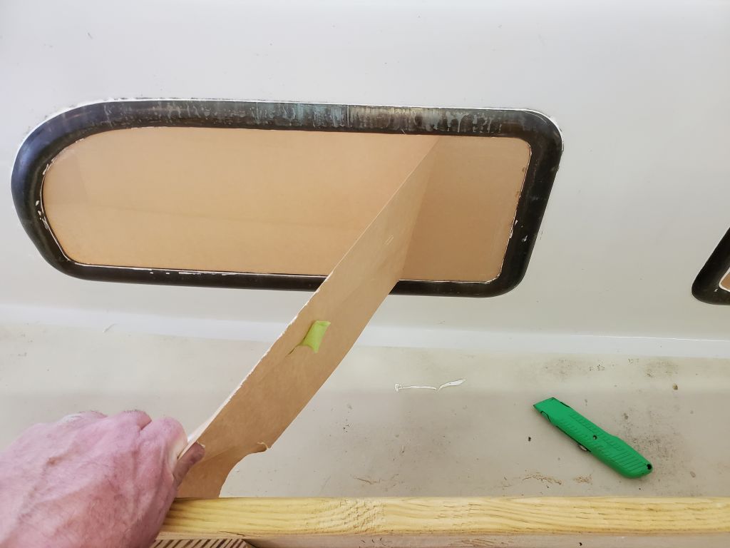
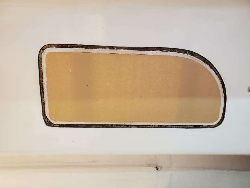
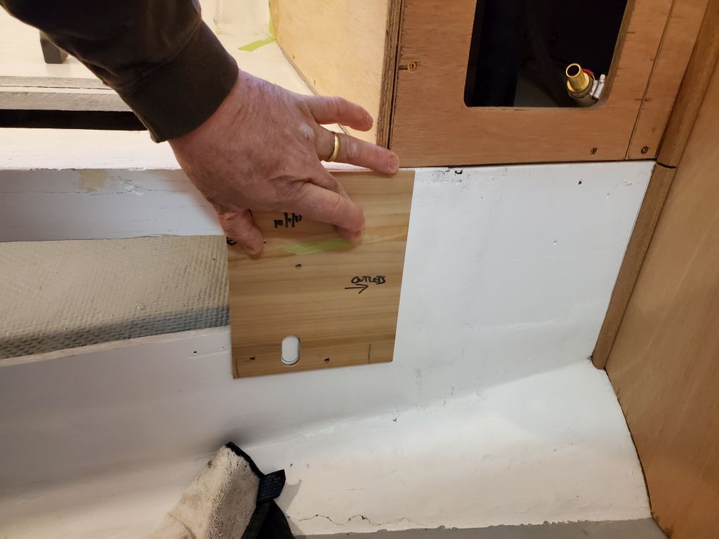
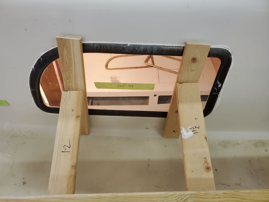
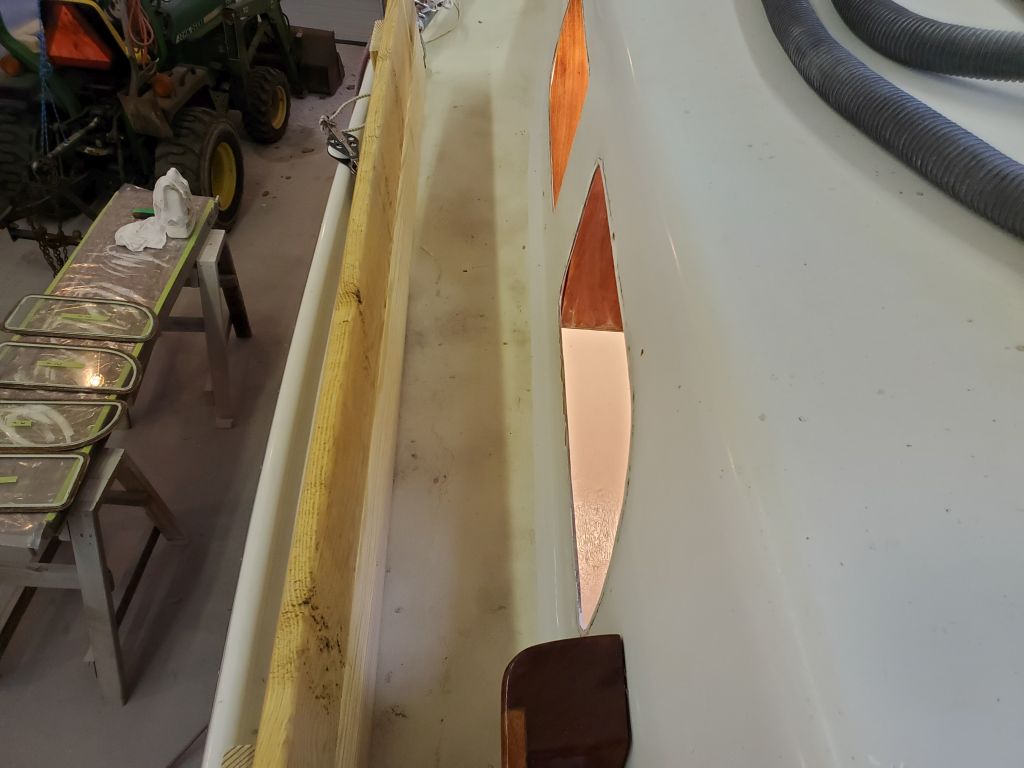
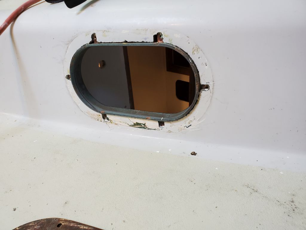
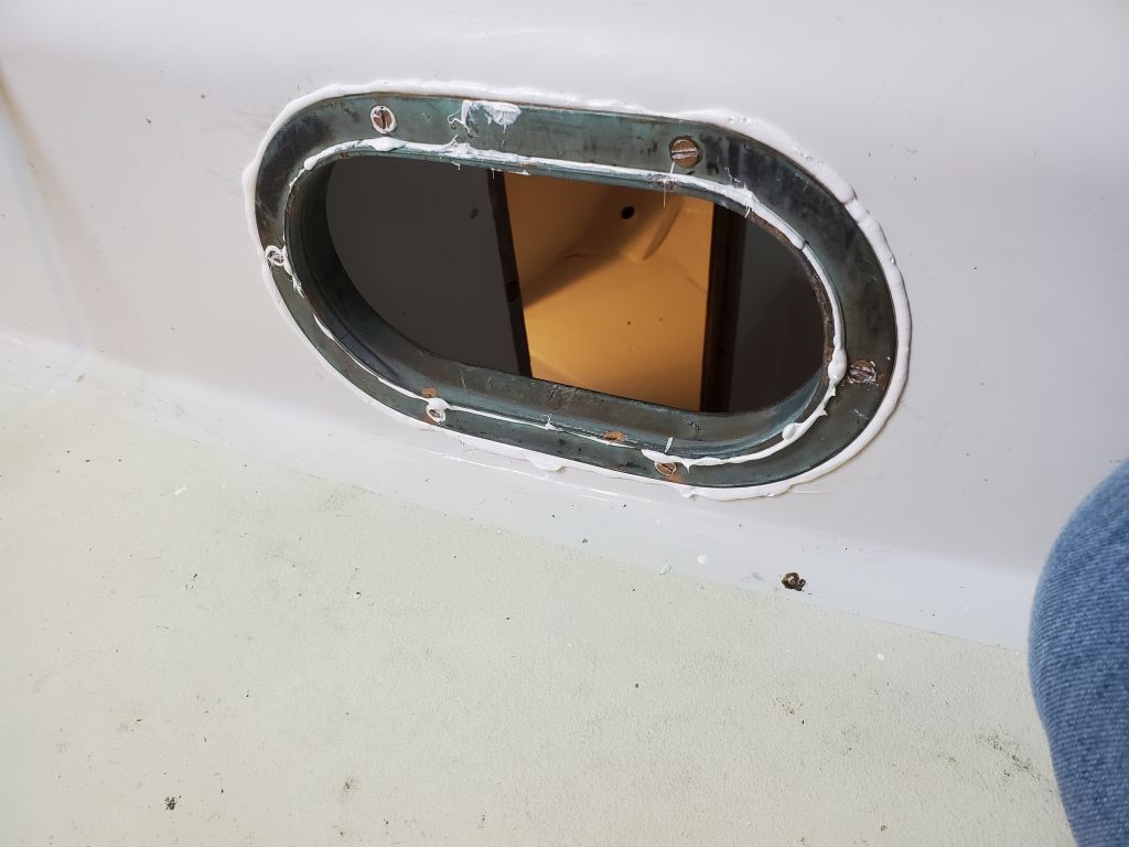
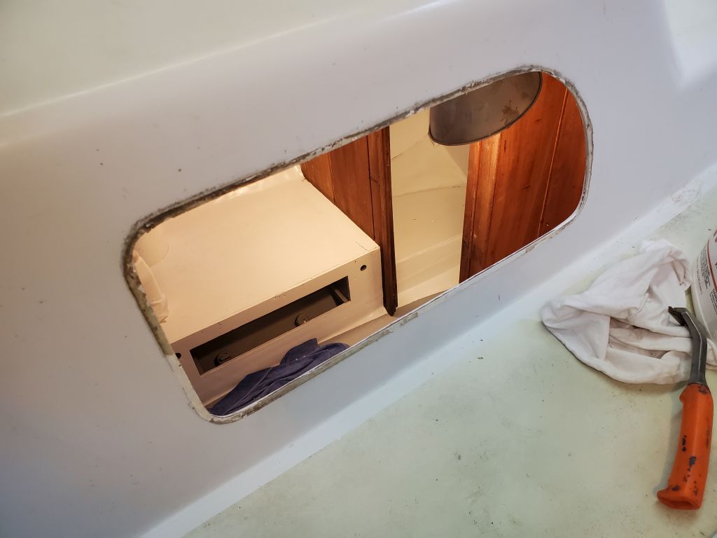
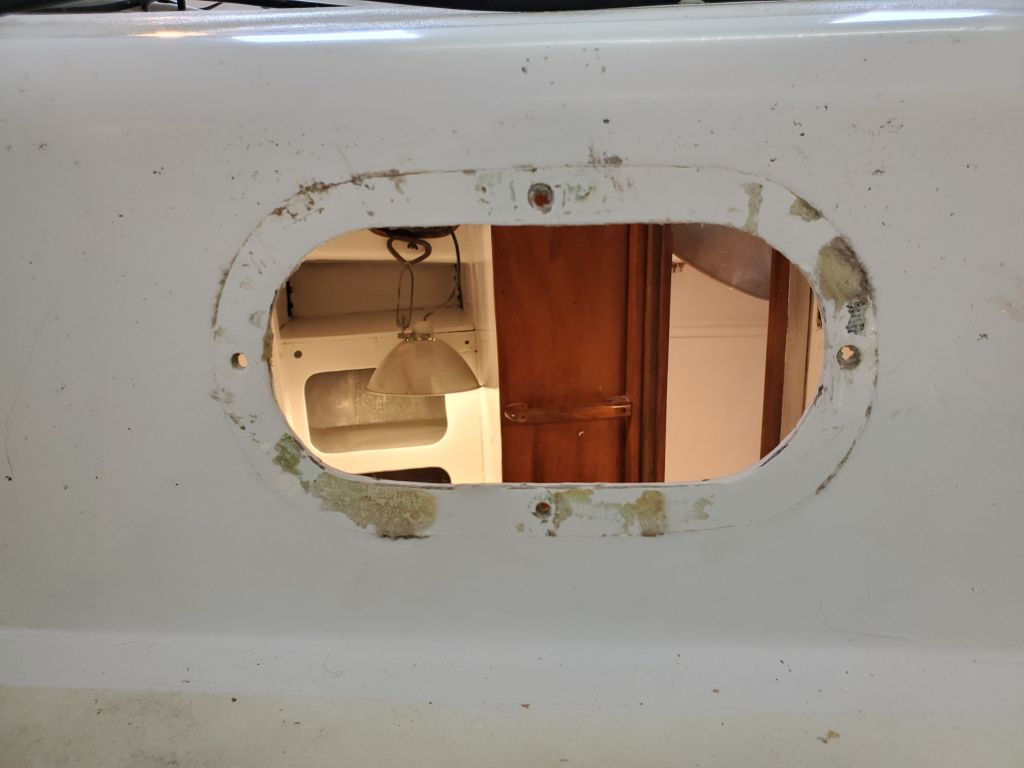
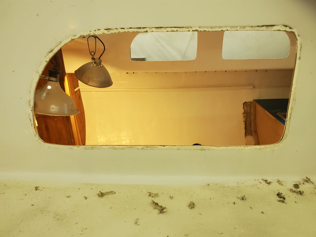
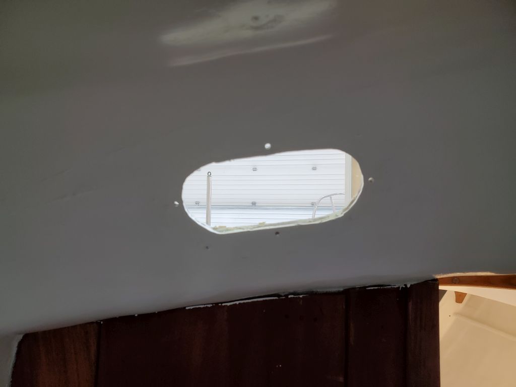
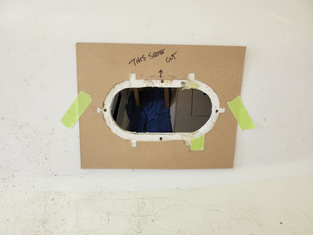
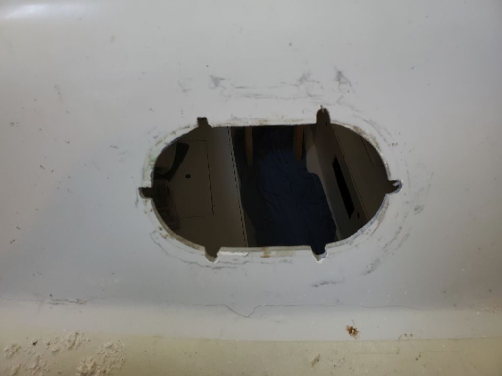
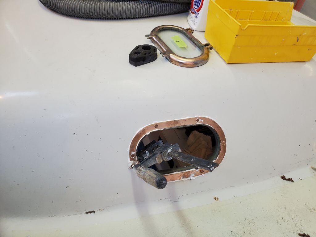
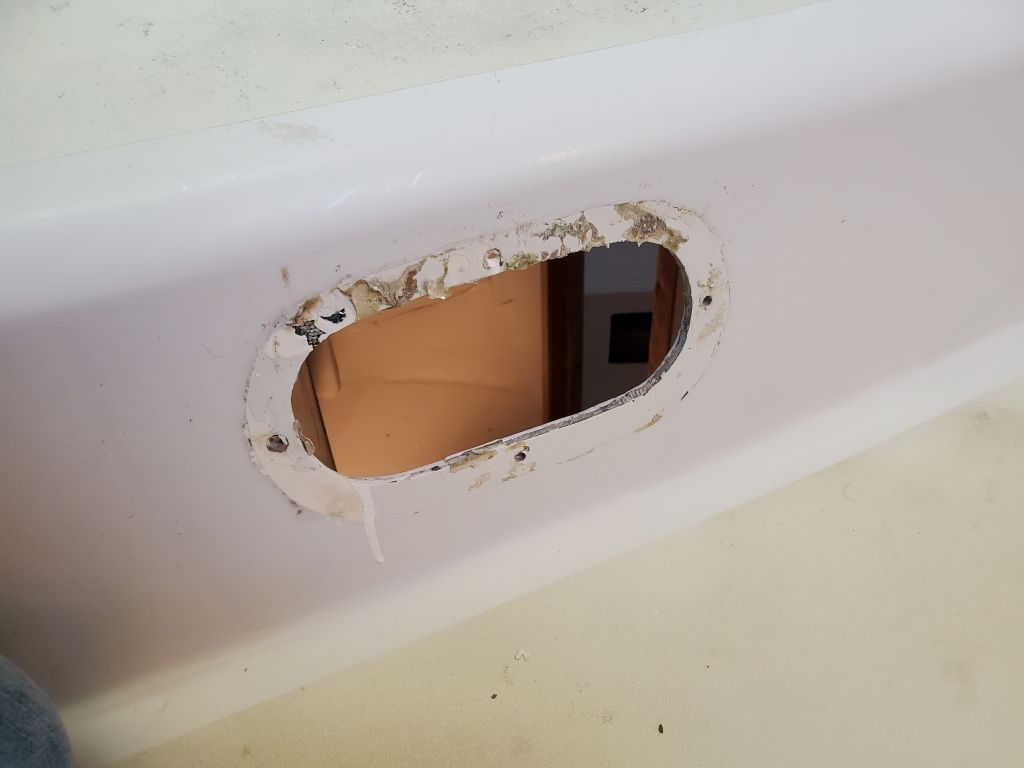
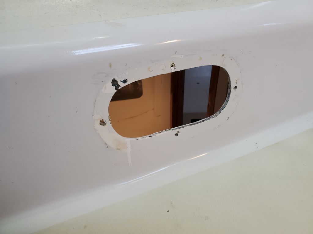
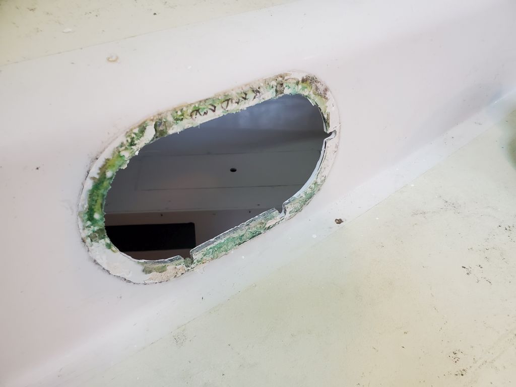
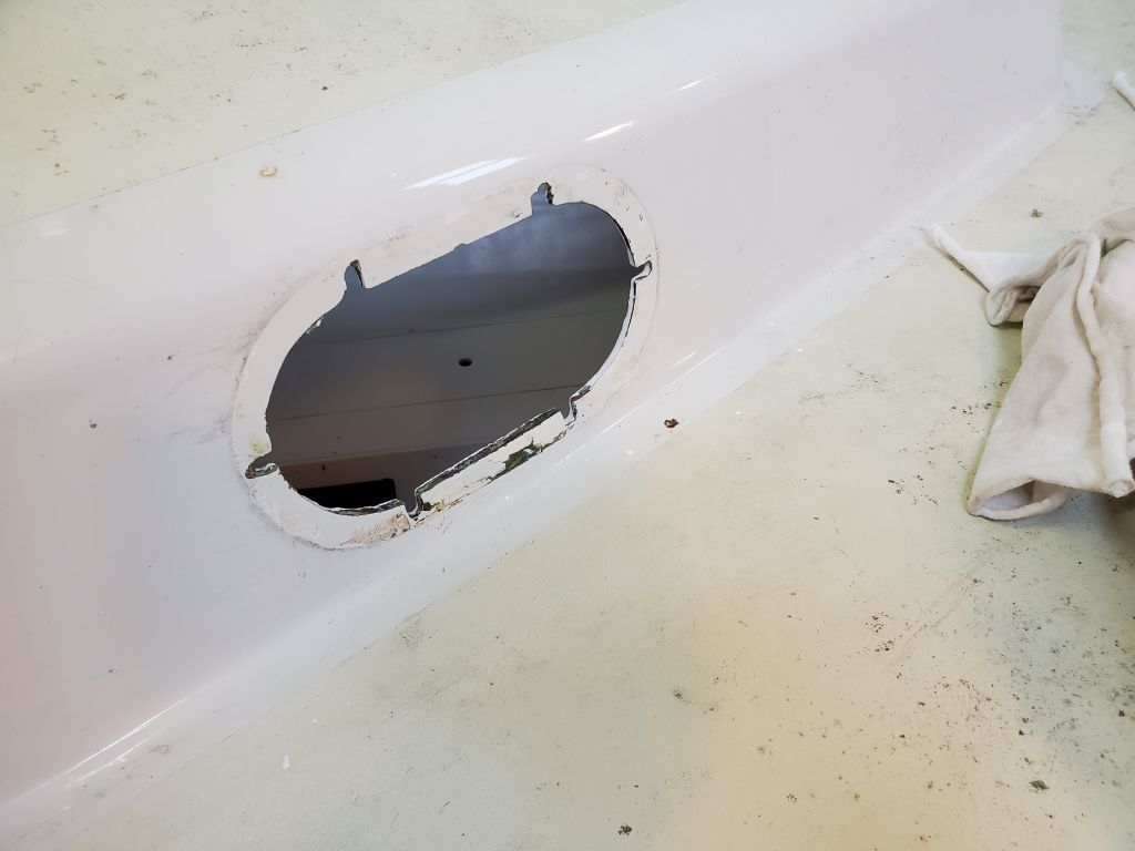
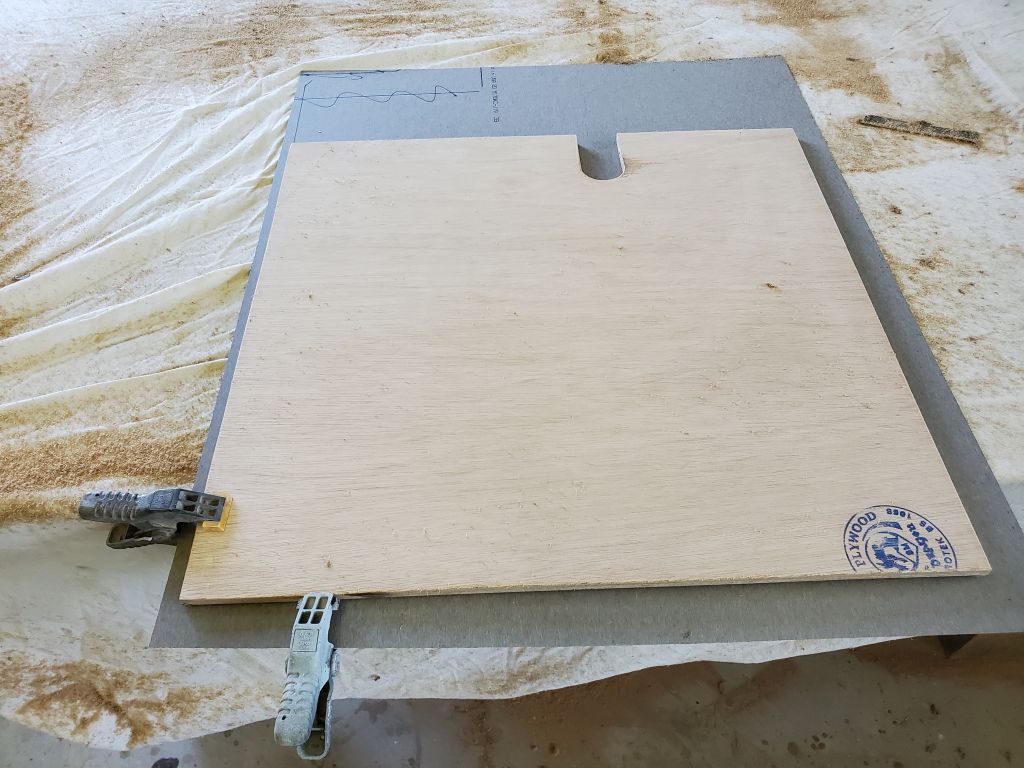
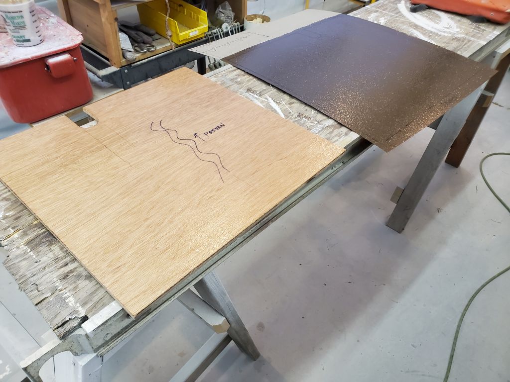
Those would sit in the clamps for a couple days to allow the bedding to fully cure, so now I turned to the small, opening ports. The owner had found two of the later-model Pearson opening ports to replace the older ones in the forward face of the saloon, so the original openings were too small and required modification.
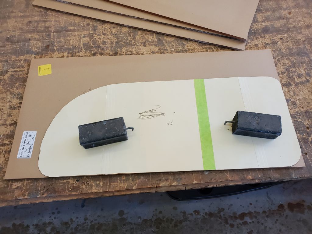
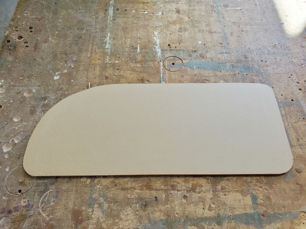
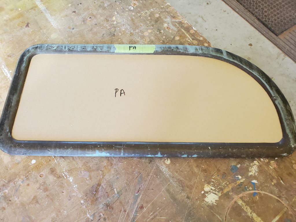
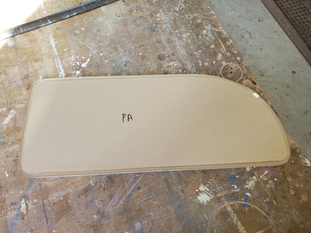
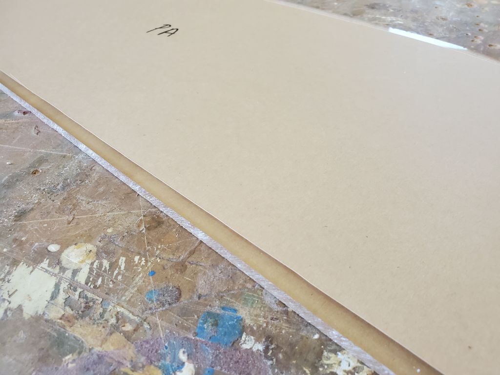
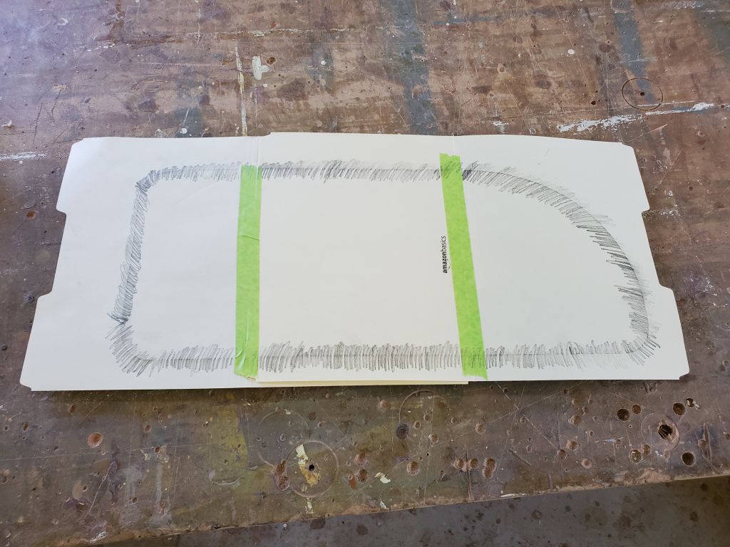
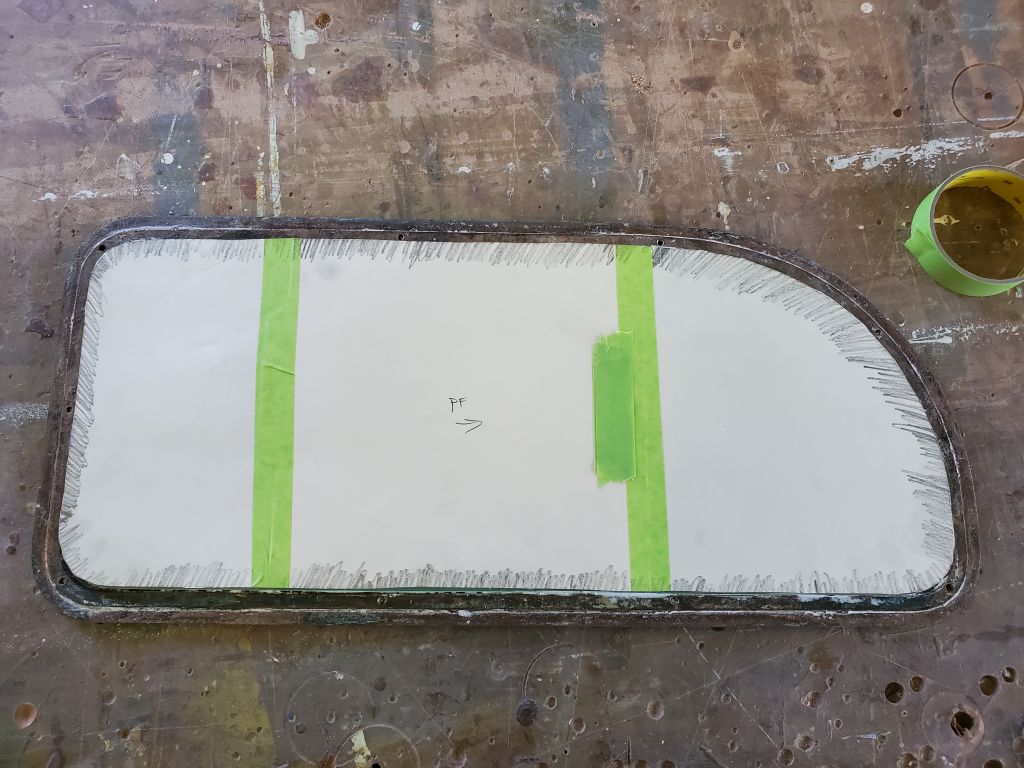
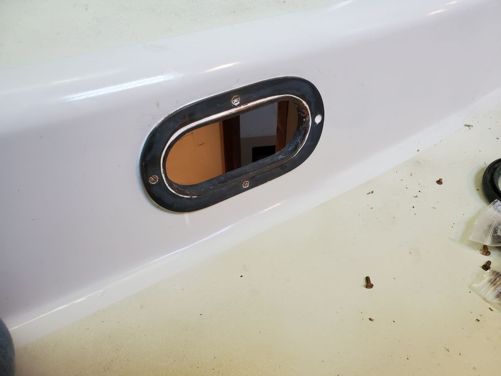
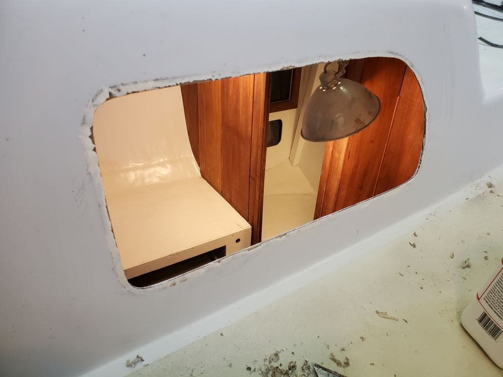
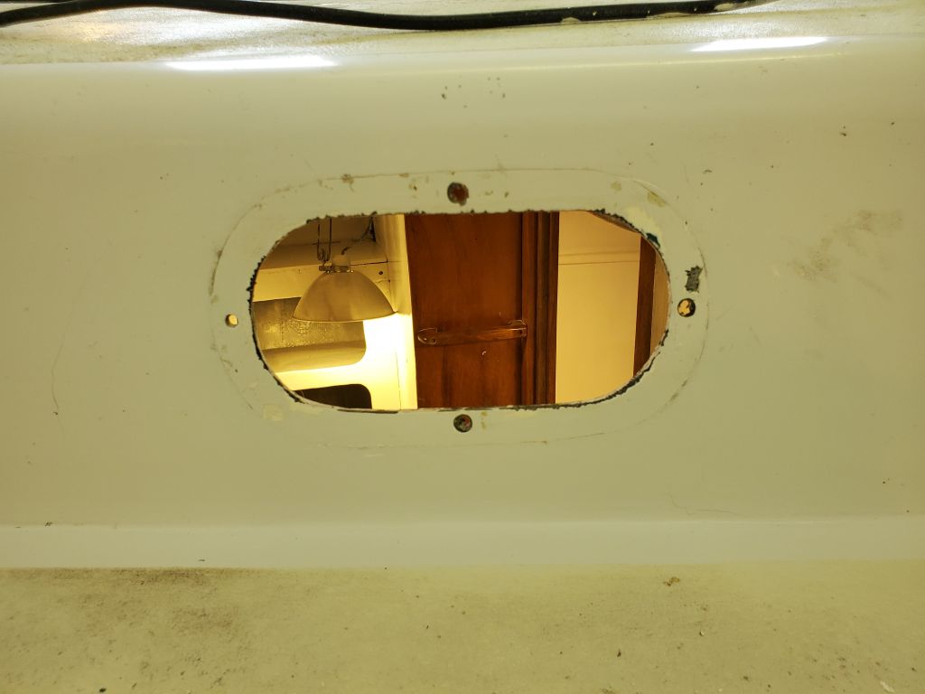
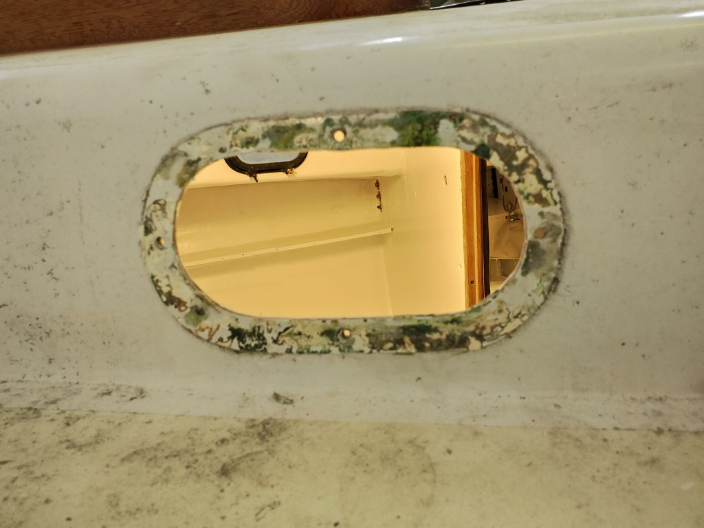
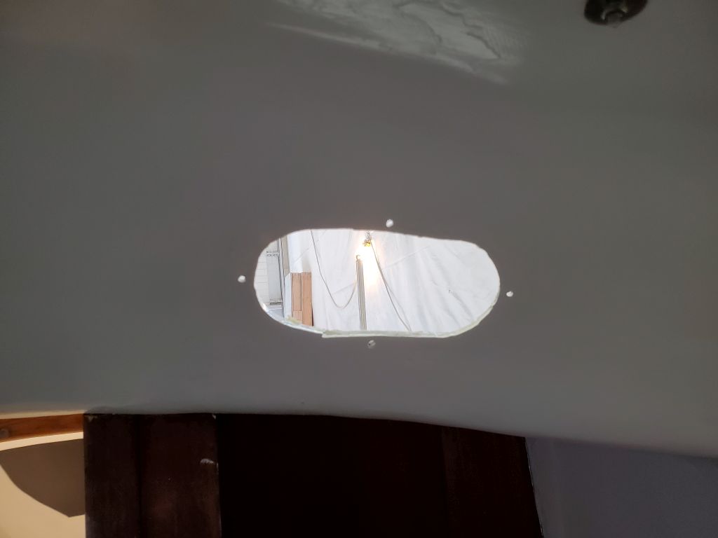
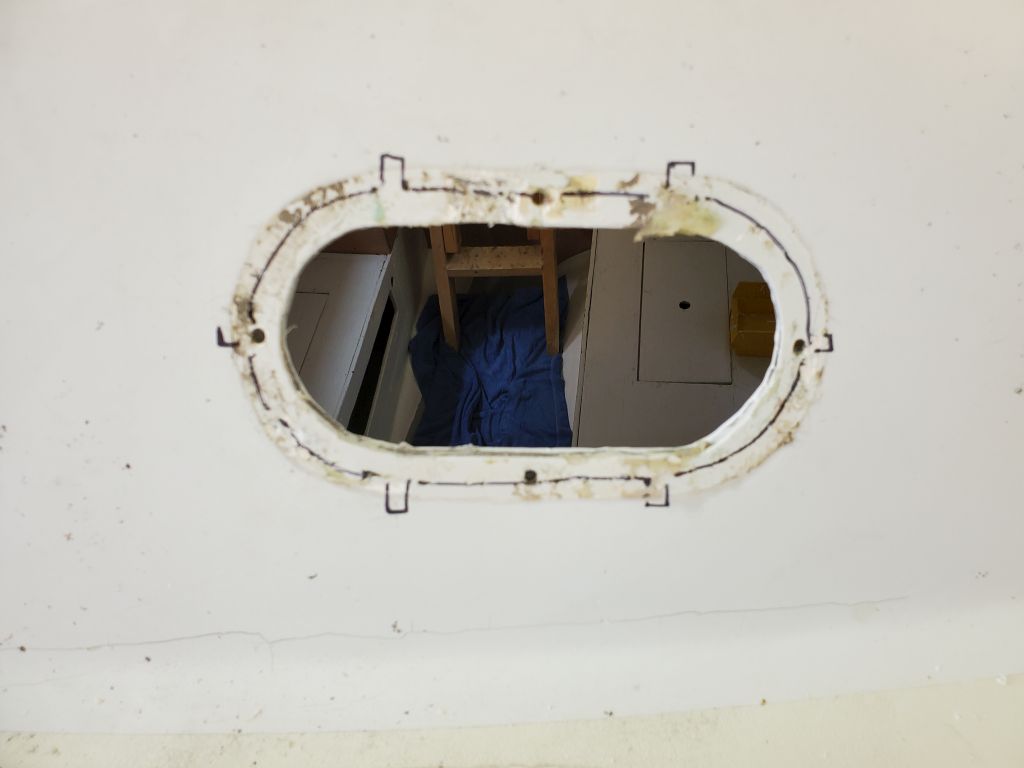
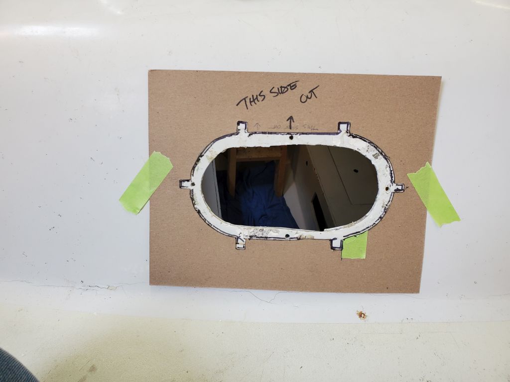
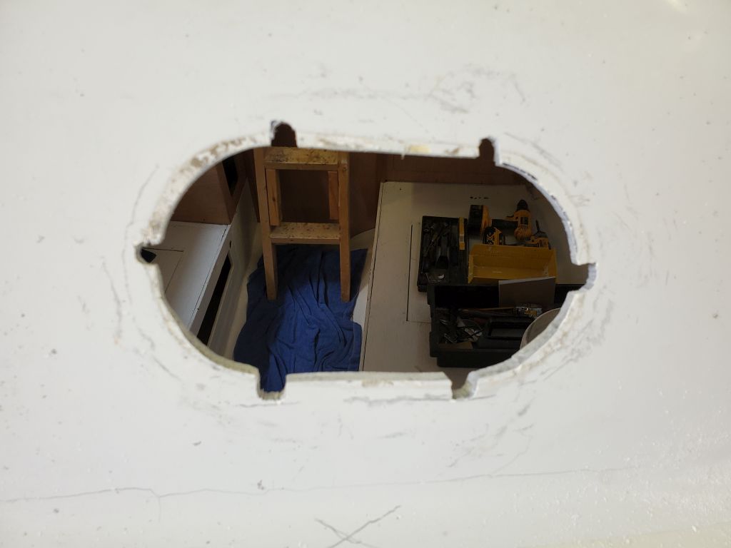
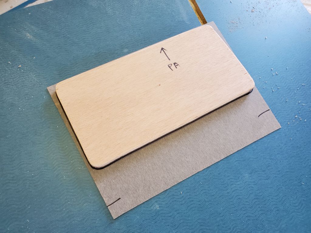
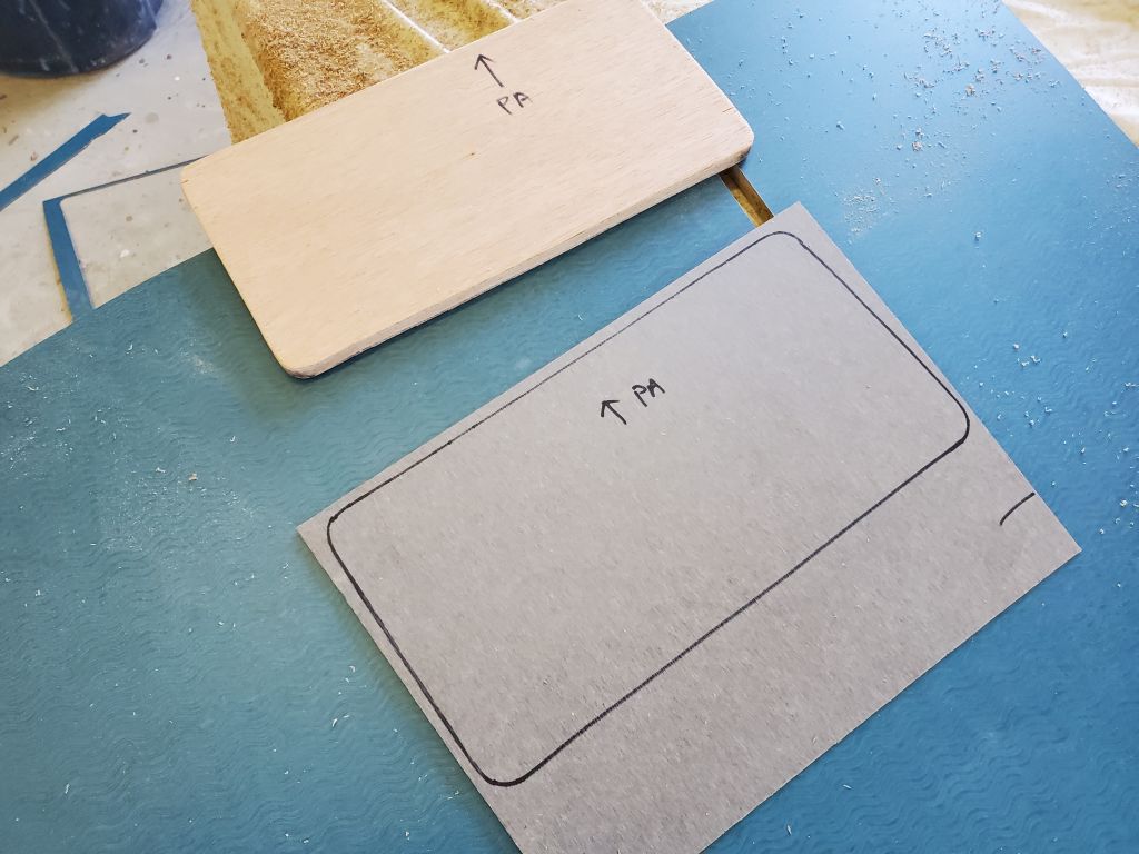
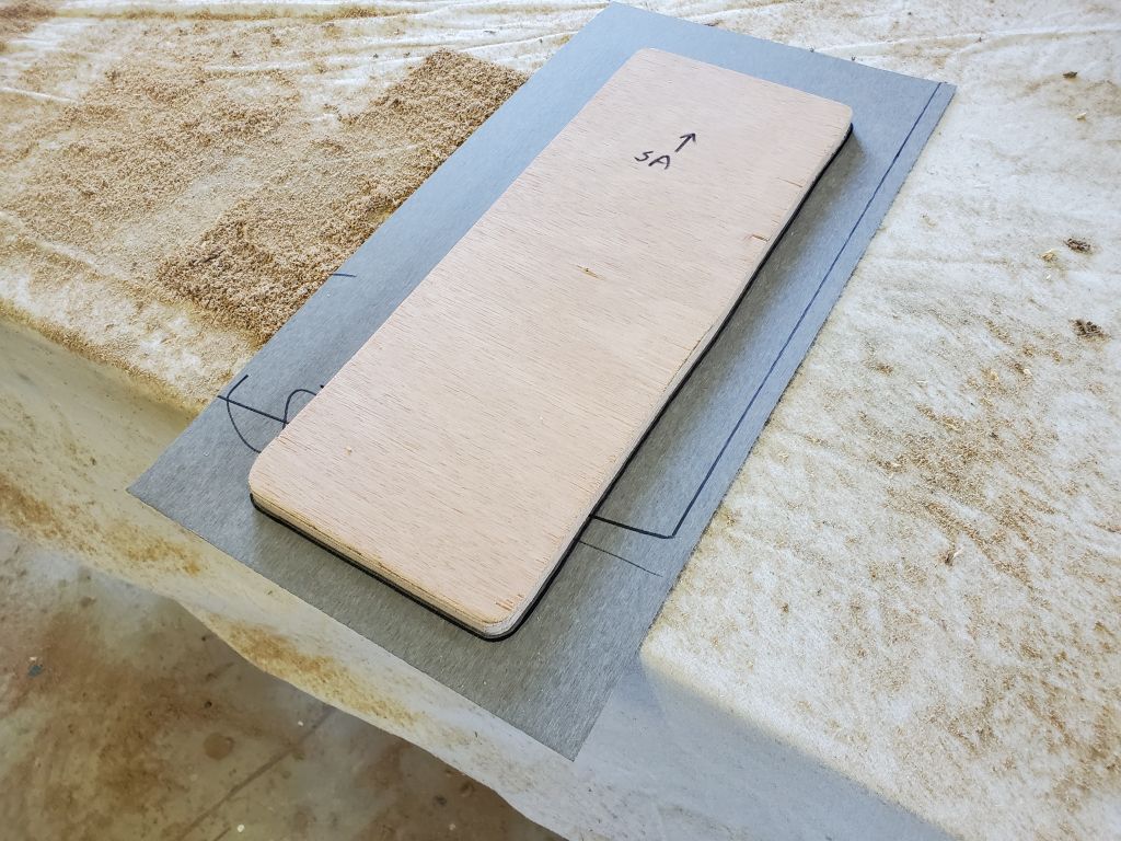
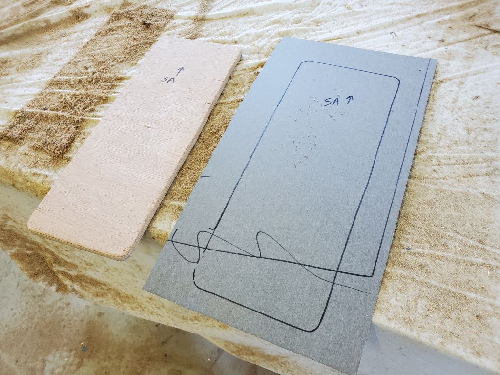
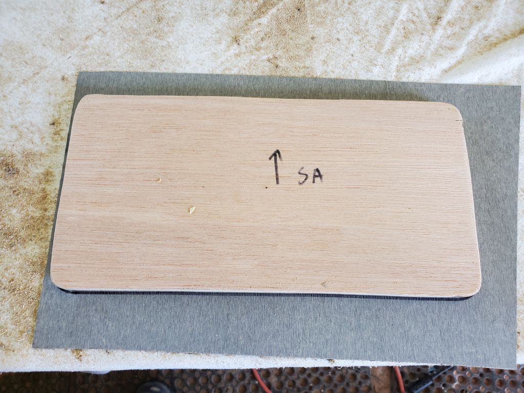
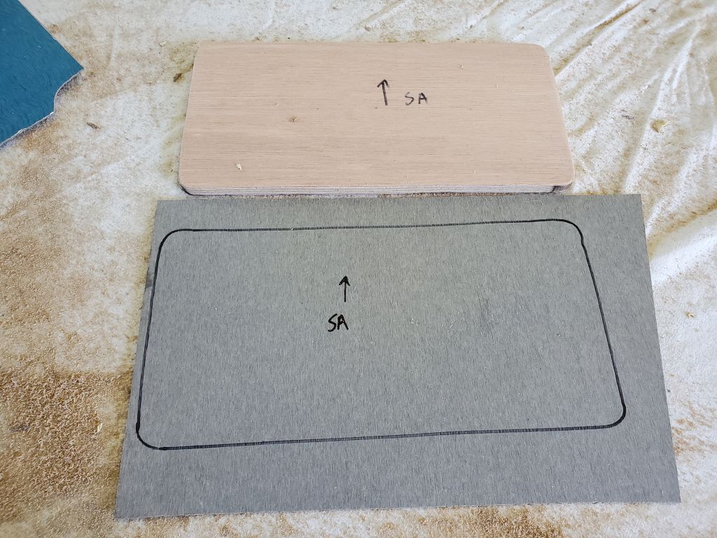
I made a cardboard template of the new ports so I could create accurate cutouts for the spigot and fixing ears cast into the port body. I centered the pattern over the old openings–this looked best and made the most sense here–and cut to the new line so the new ports would fit.
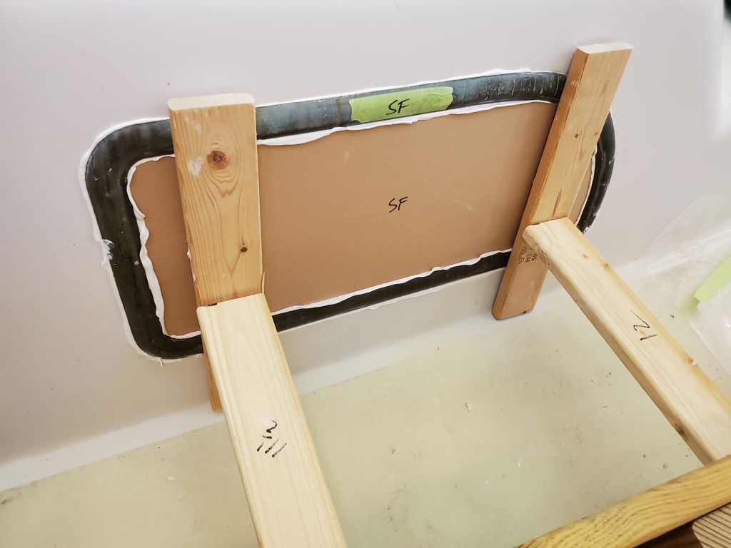
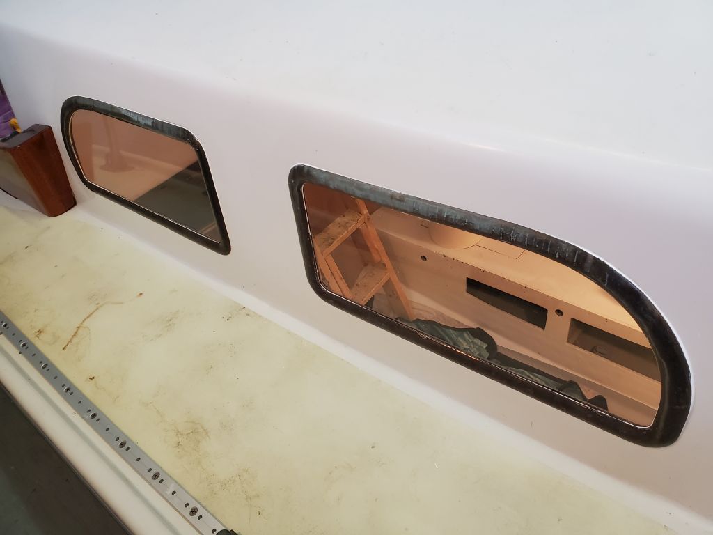
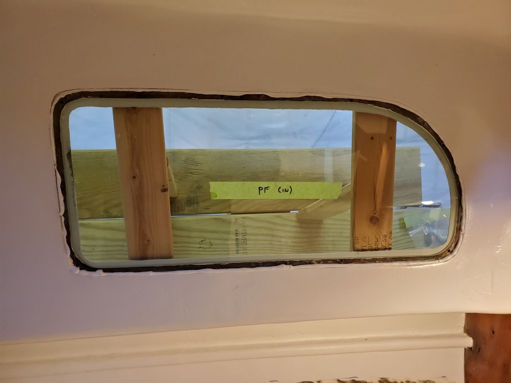
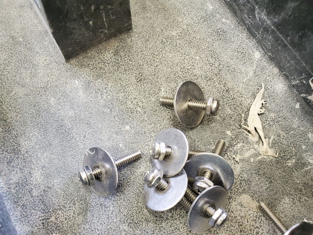
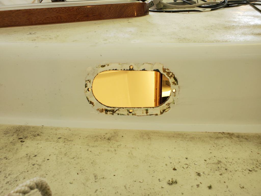
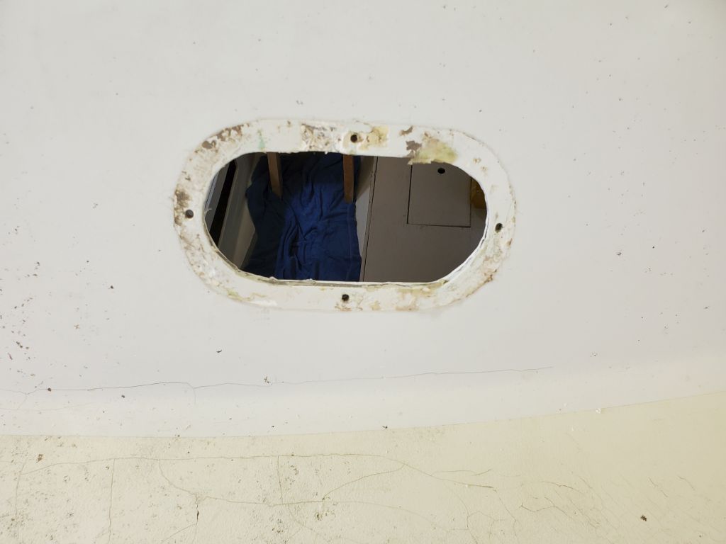
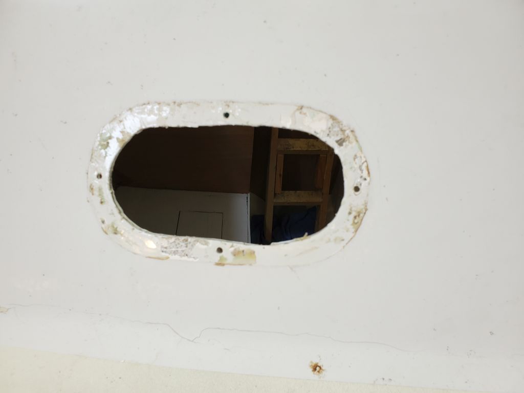
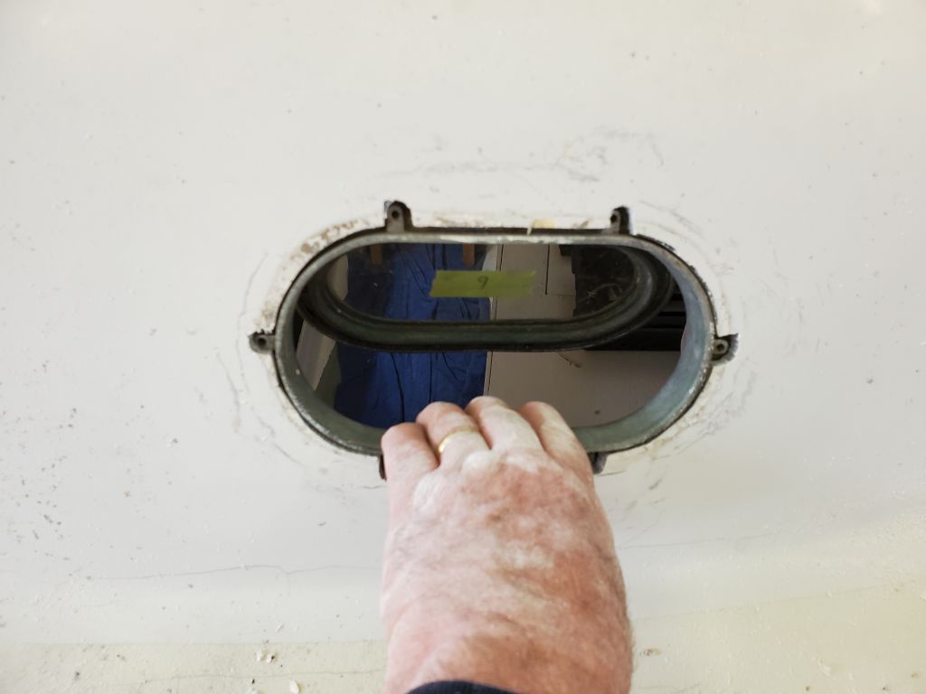
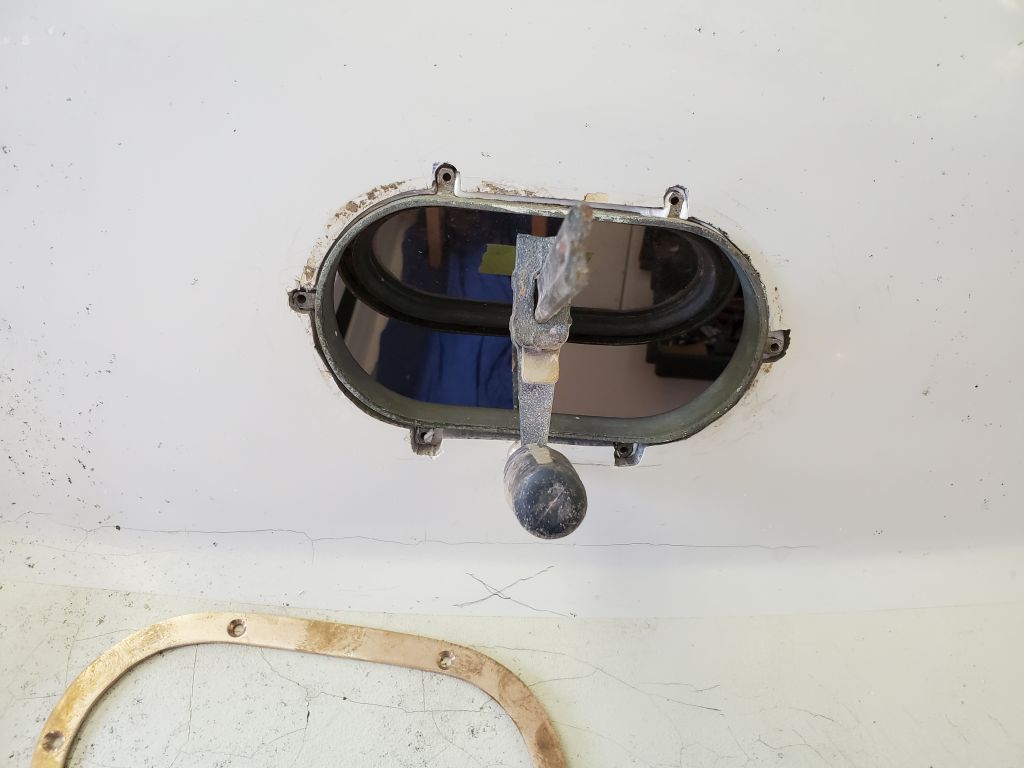
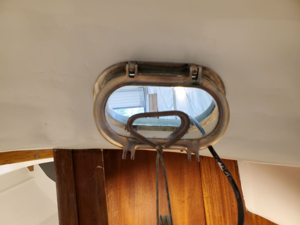
Satisfied with the dry-fit (I had to enlarge the first one I cut–the port side–as the template was a bit tight; I adapted for the starboard side and had a good fit the first time), I finished the installation with sealant and new screws, beginning on the port side. I applied sealant around the inside edge of the spigot, and also around the perimeter of the frame (and out beneath the trim ring) once I had the body positioned in the opening.
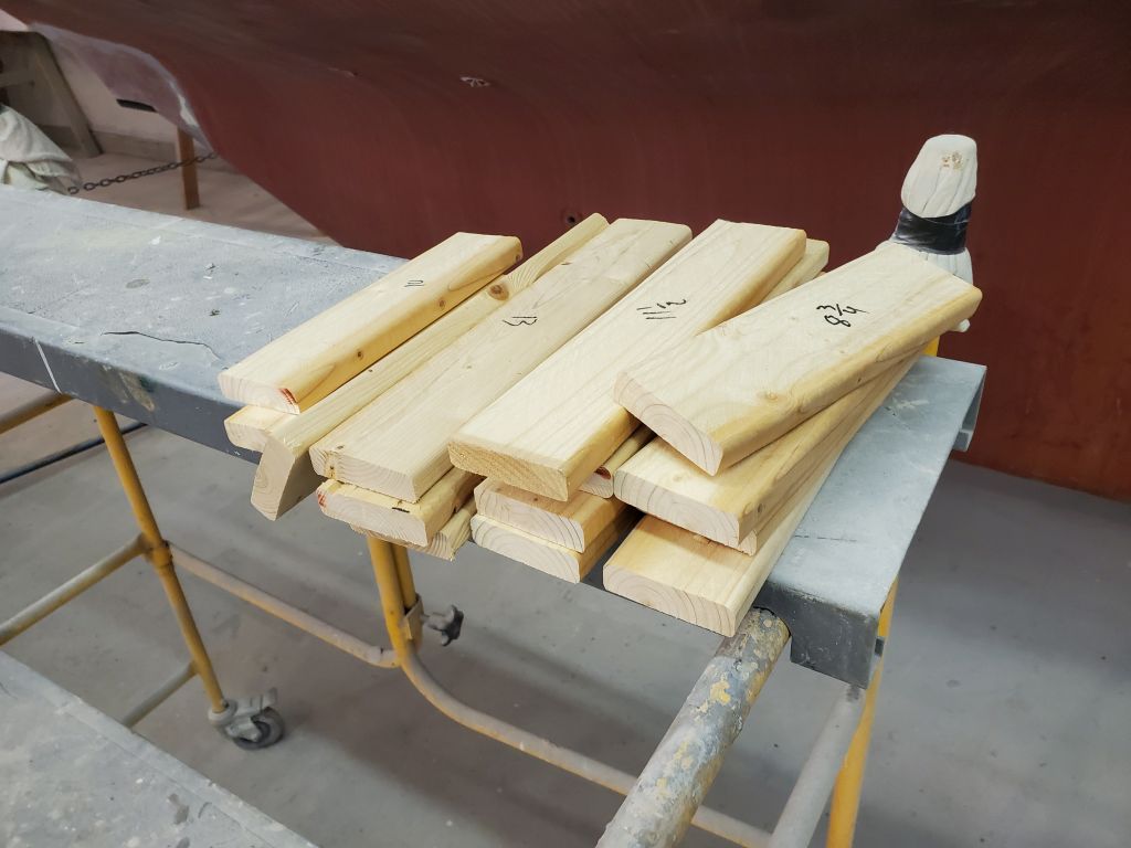
The owner had provided new 8 x 1/2″ bronze screws for the job, but the cabin trunk here in particular was much thicker at the bottom than at the top–as in 3/16″ at the top and over 1/2″ at the bottom, so these screws were too long at the top and too short at the bottom. Fortunately, this wasn’t my first Triton rodeo, and although it had been more than 10 years since I last installed these types of ports, I had on hand a full selection of lengths of #8 bronze machine screws, running the gamut from 1/4″ to 3/4″ (and beyond, though the longer ones weren’t applicable here).
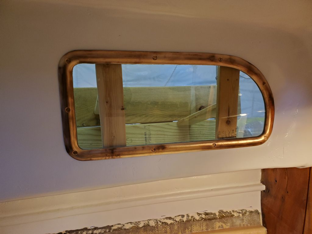
On this port, I elected not to remove the opening portion (secured to the body with two screws), and this greatly complicated the installation, at one point early on nearly causing the whole unit to drop out the back before I had any screws started. I saved it by reaching through the gooey opening, but recovery efforts were long and tiresome, and I was sure to gravely note the lessons learned so I could apply them to the next installation.
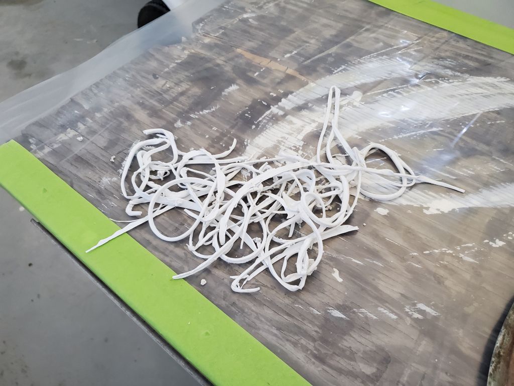
I ended up using a variety of lengths from 3/8″ t0 5/8″ on the port port, using a clamp as needed to help pull the frame tightly to the inside of the cabin so I could get screws started through the trim ring. With the first installation eventually complete, I cleaned up the excess (and overly messy, thanks to my drop-out port) sealant.
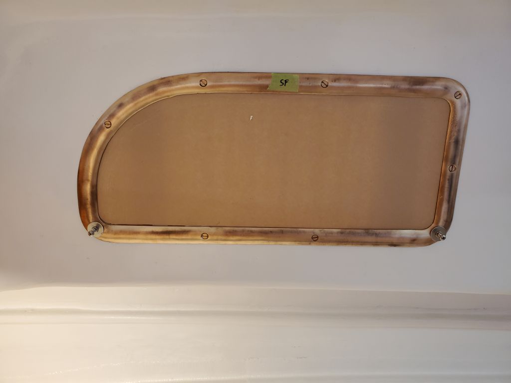
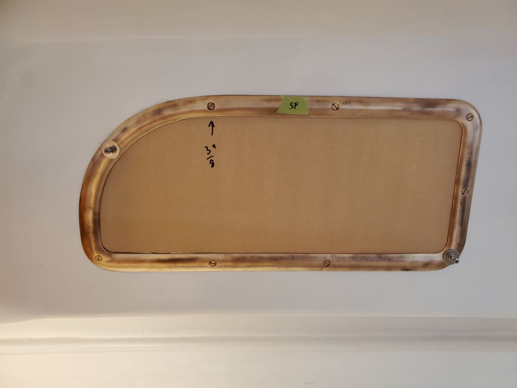
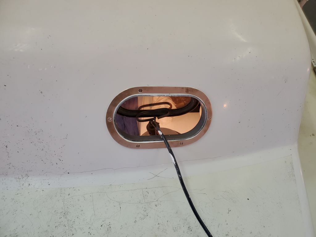
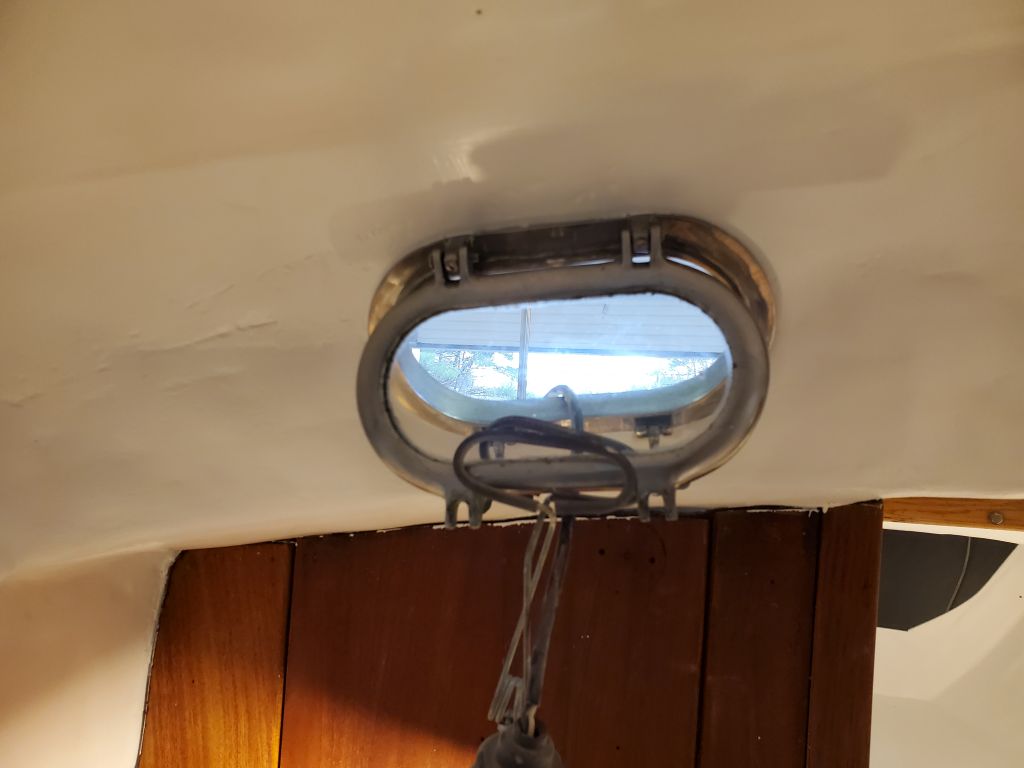
Wiser, I continued with the installation on the starboard side where, thanks to the port side lessons, the installation took a fraction of the time. Here, I removed the opening part of the port, making the body much easier to handle. And I was far better prepared with the screw lengths that I needed and were likely to work (on this side, I needed the tiny 1/4″ length for the top screws).
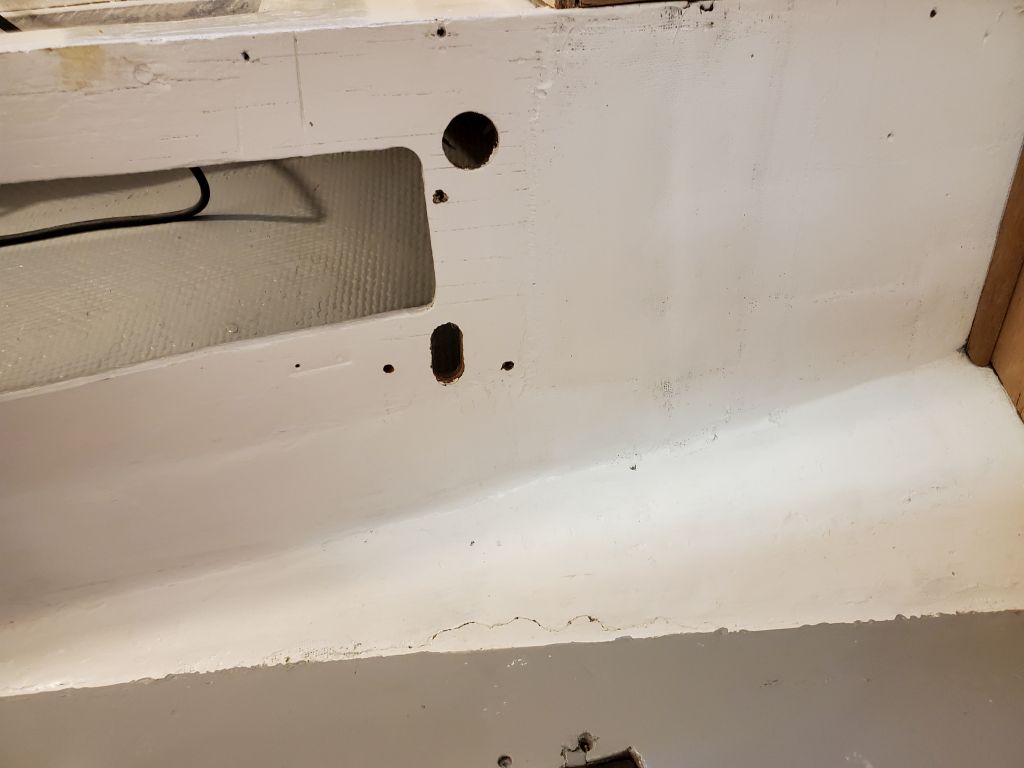
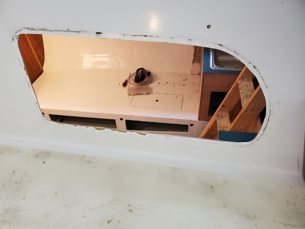
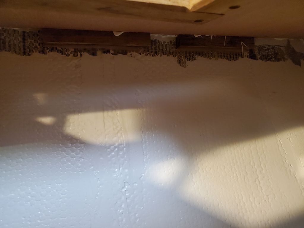
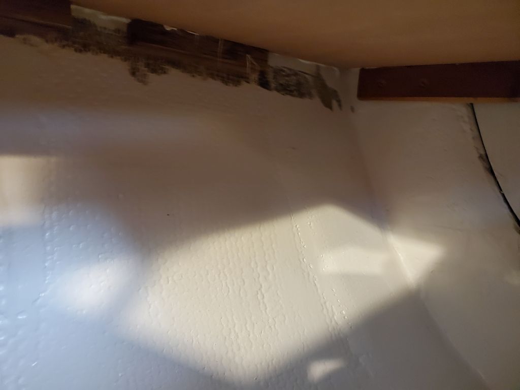
With dwindling time on the day, I finished up with some advance preparations for the installations of the next two (and, for now, final two) opening ports, which would both go on the starboard side forward (head and v-berth). These ports were also mis-matched, with one of the old Pearson style, and one of the newer style like the pair I’d just installed. In any event, now I cleaned up the remnants of the old sealant on the cabin sides and made other preparations to streamline the installation next time.
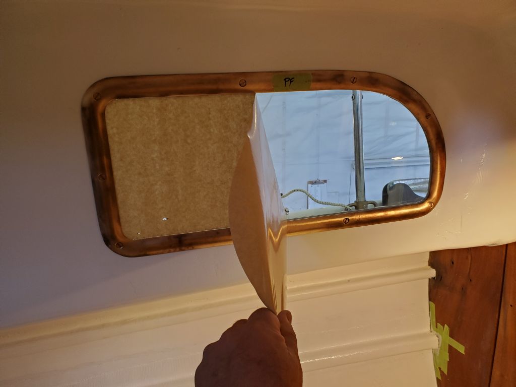
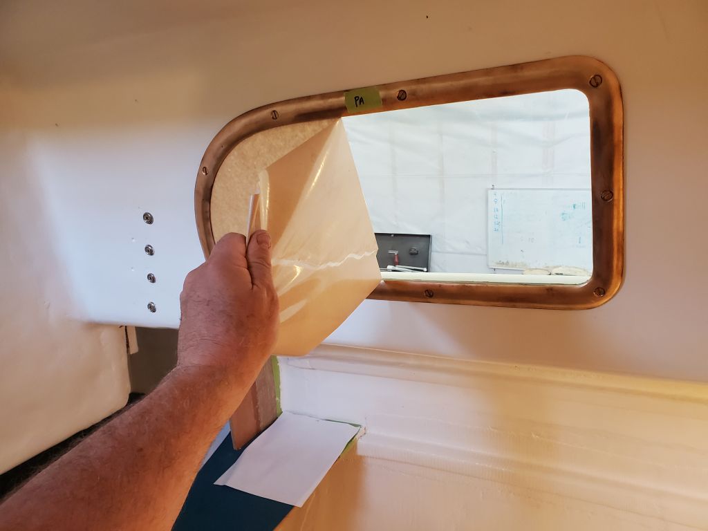
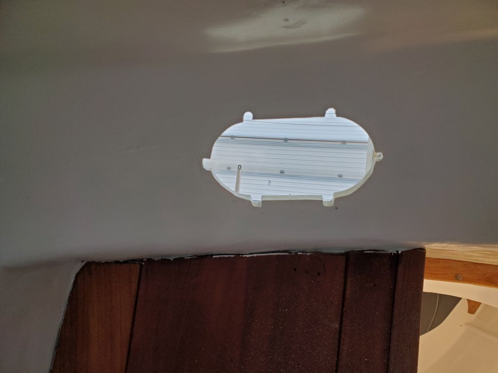
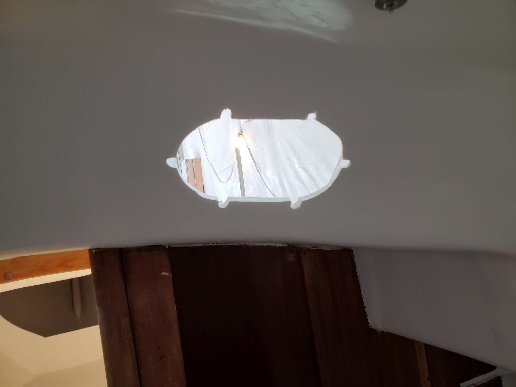
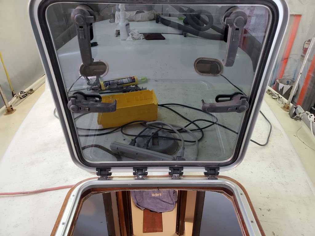
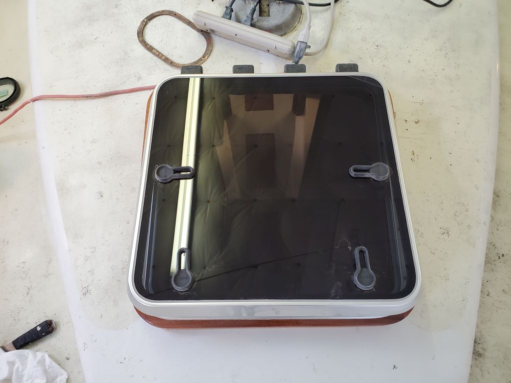
This left me just enough time to remove the protective paper from the forward hatch, since I was there and it was almost time for the boat to depart.
Total time billed on this job today: 5.25 hours
0600 Weather Observation: 45°, mainly cloudy. Forecast for the day: Cloudy, chance of sun, 58°