Wednesday
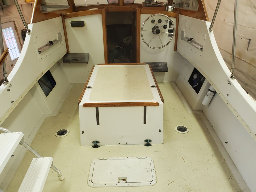
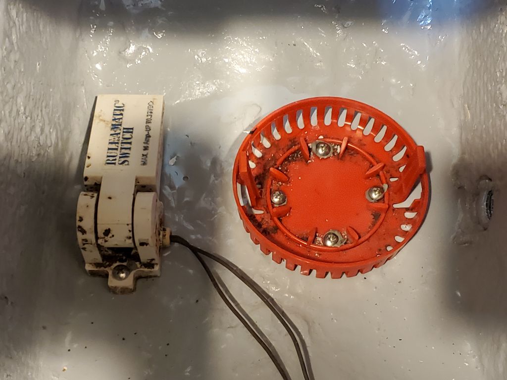
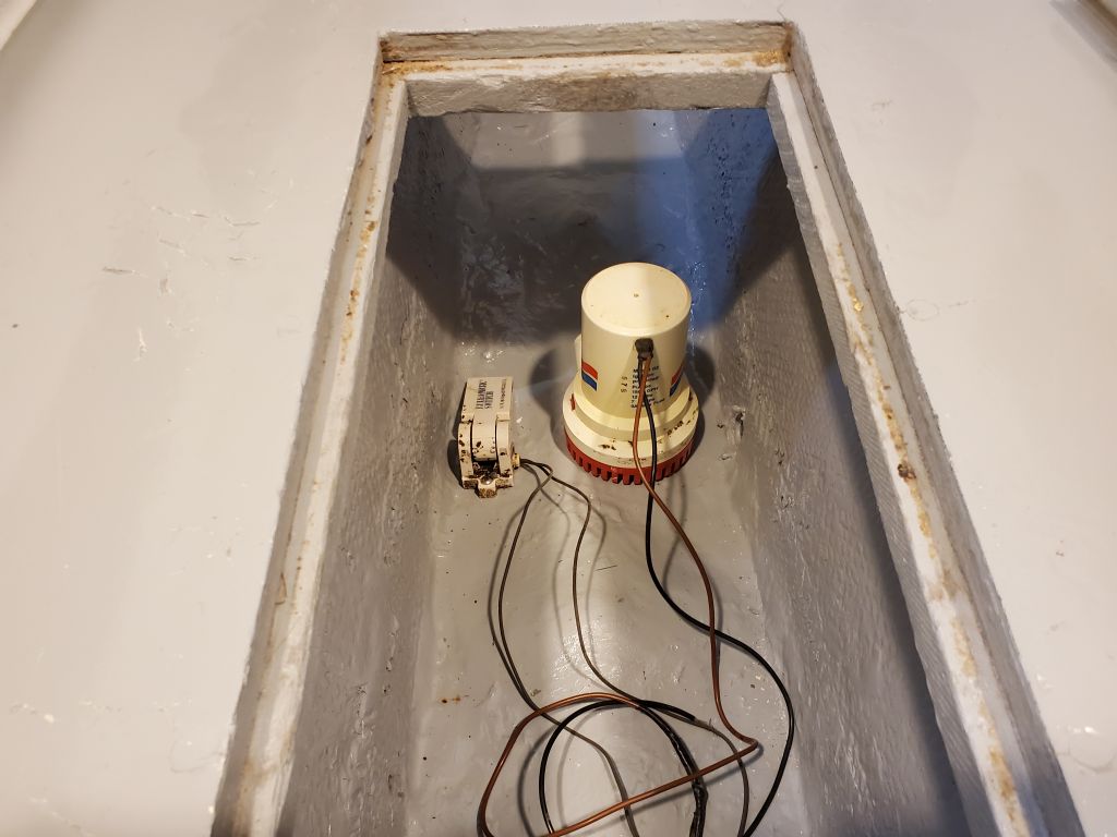
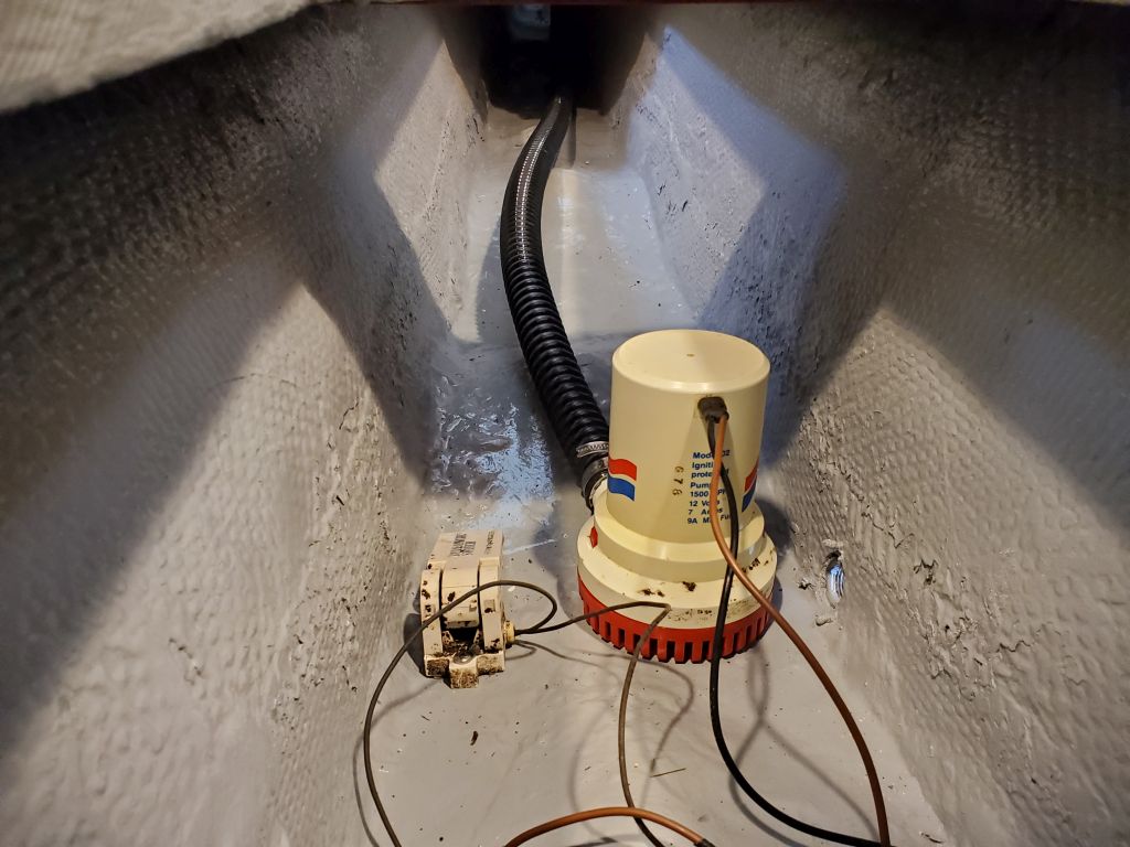
After a day mostly working on other things while I awaited delivery of some materials I needed to finish up a short, add-on work list the owner had requested, I got back to work, starting with reinstalling (physical and plumbing only, no wiring) the existing, operable bilge pump and auto switch. I located the pump in the deepest portion of the bilge, with the auto switch located nearby. With enough solid fiberglass lining the bottom of the bilge, I could use short screws to secure the pump strainer and switch, with sealant at all locations. I arranged the pump so the outlet faced aft, ready for the discharge hose.
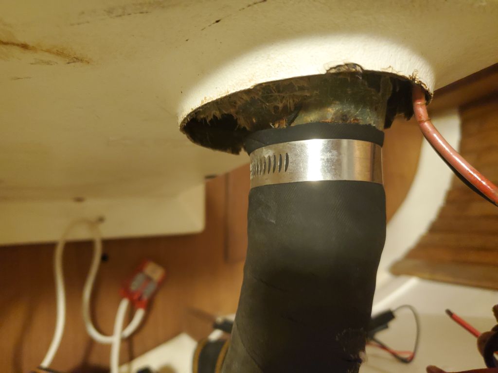
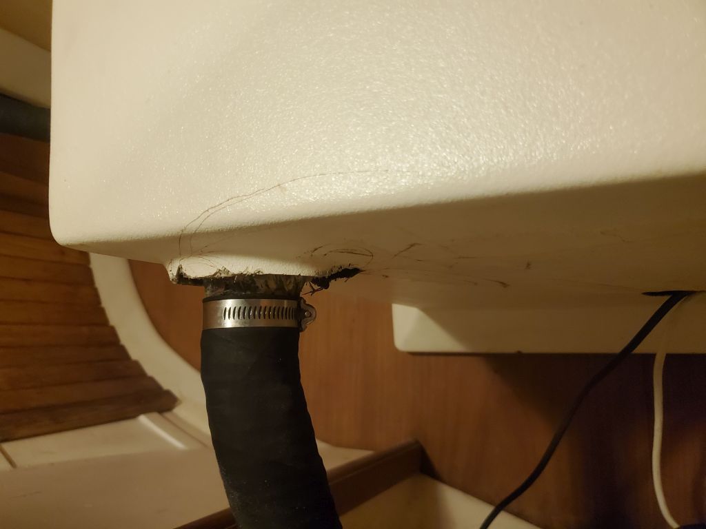
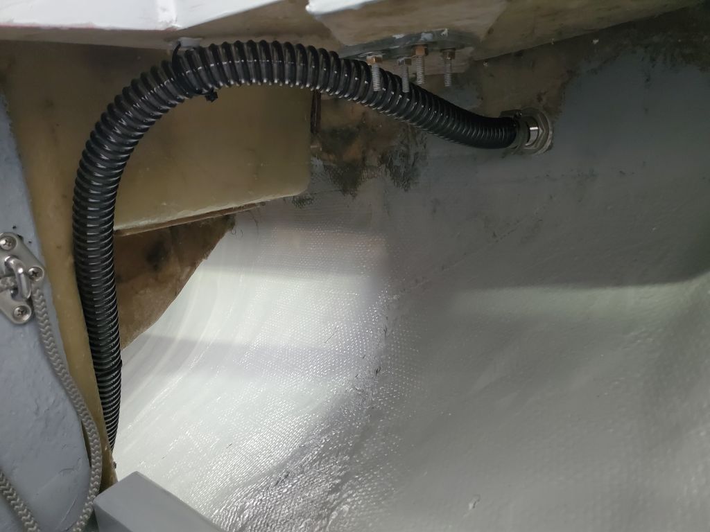
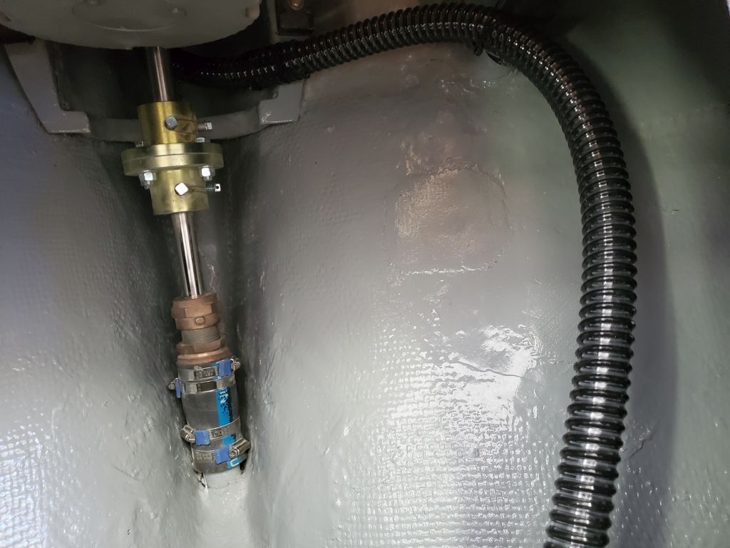
I led a new length of 1-1/8″ bilge pump hose between the hull outlet on the starboard quarter (a fitting dry-installed by the owner and later bedded and permanently installed here) and the pump, leading the hose through the space beneath the cockpit and below the propulsion motor, securing it with wire ties and clamps as needed. Where the hose passed over the engine foundation, I added a piece of offcut hose for chafe protection, securing the hose to keep it well clear of the shaft and couplings.
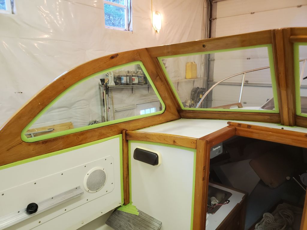
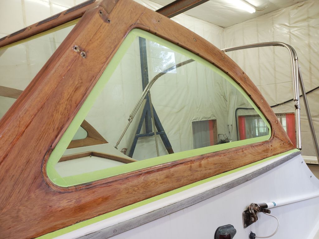
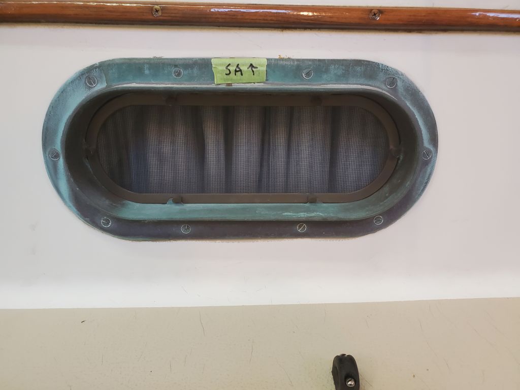
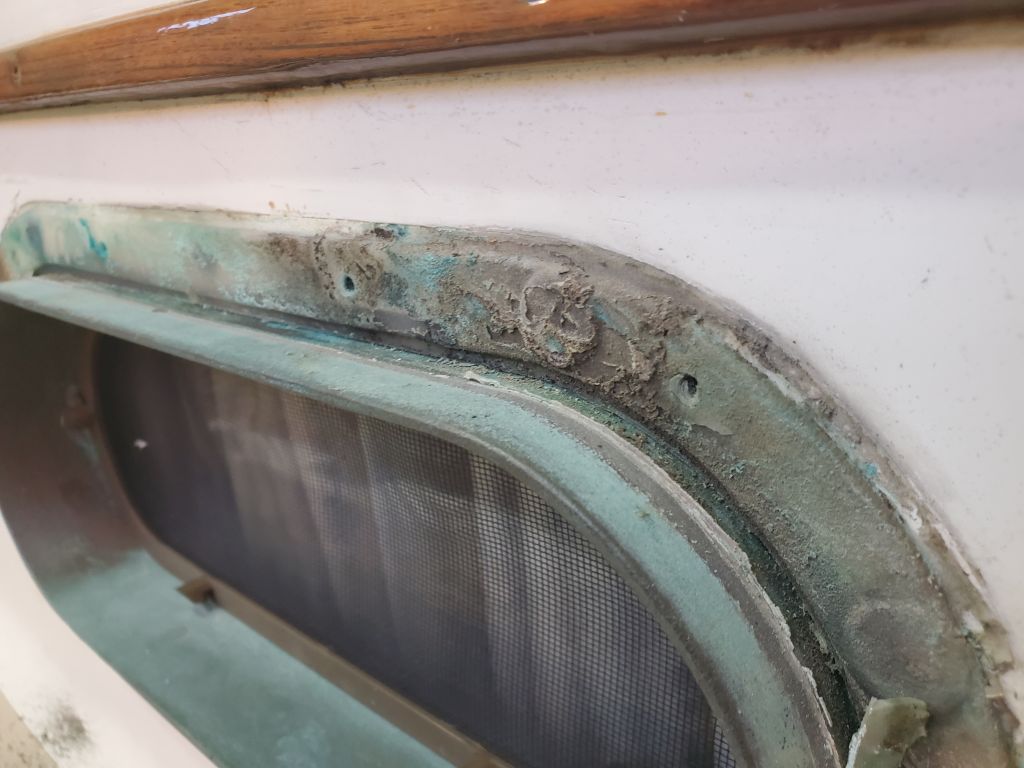
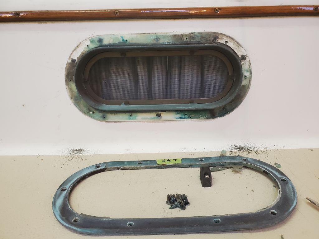
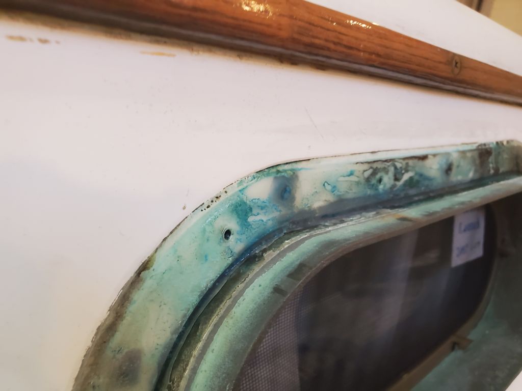
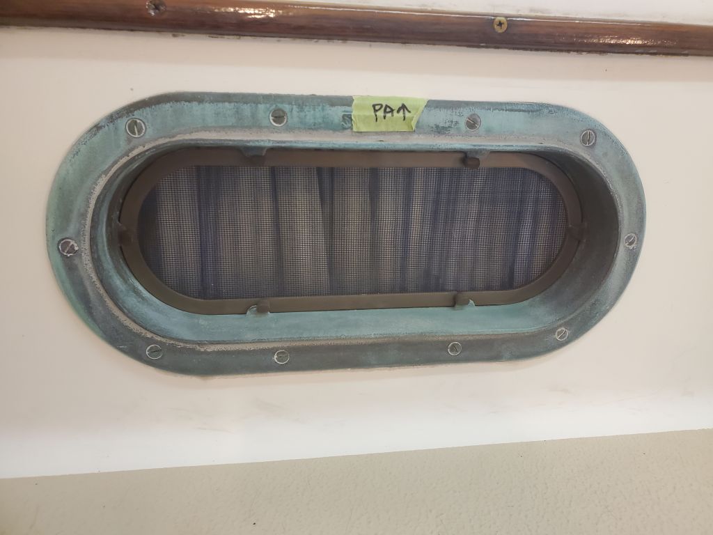
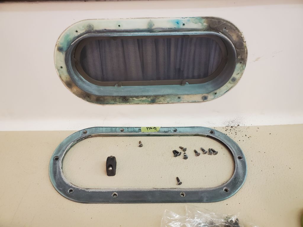
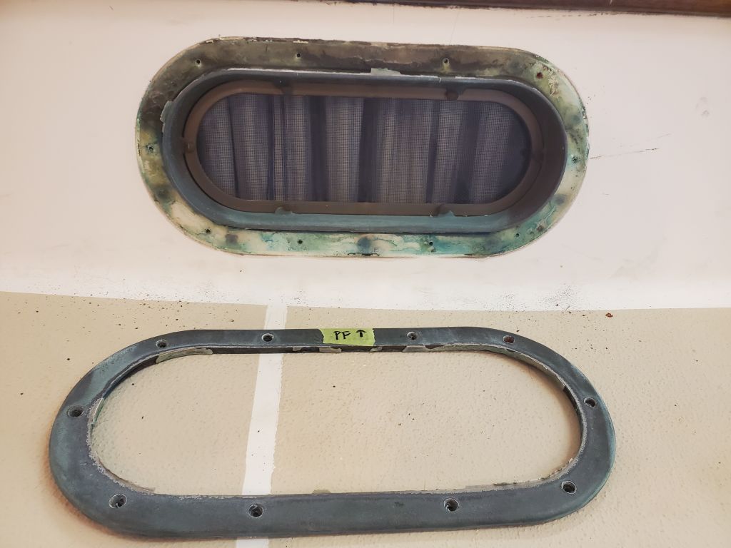
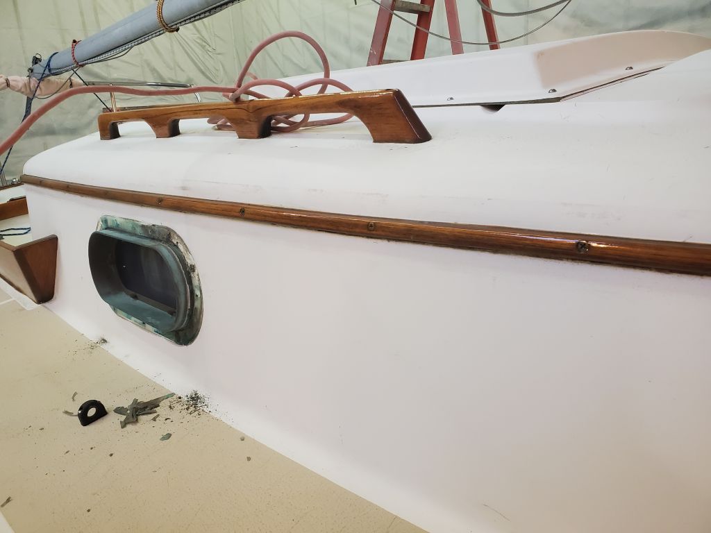
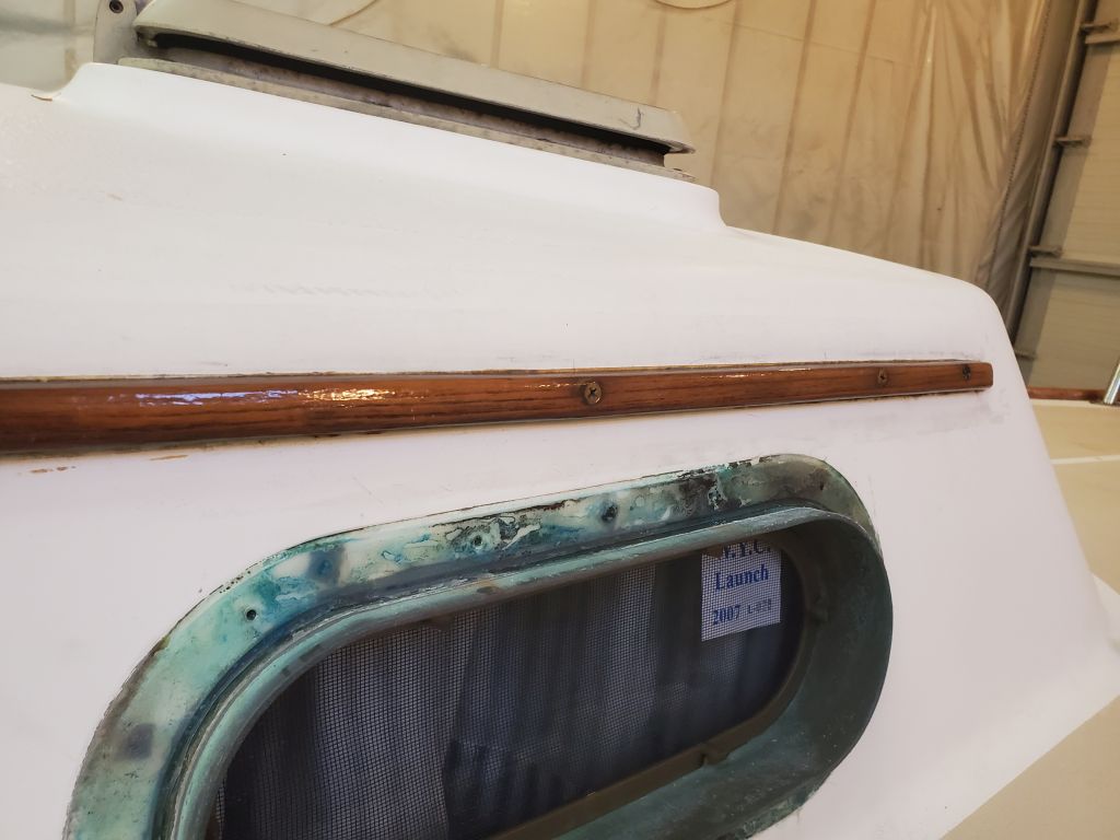
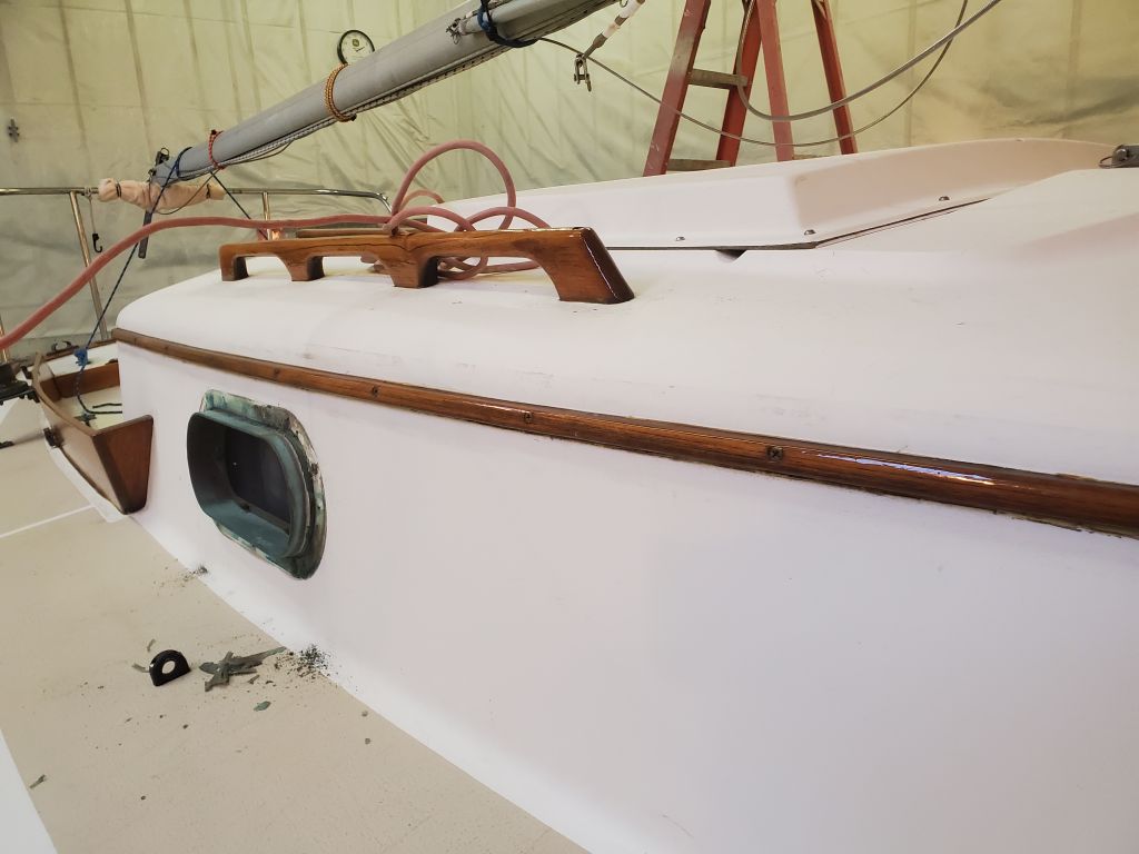
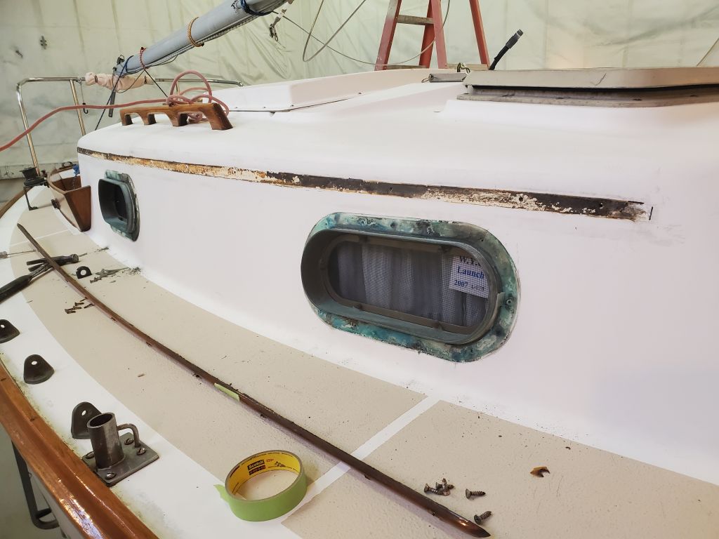
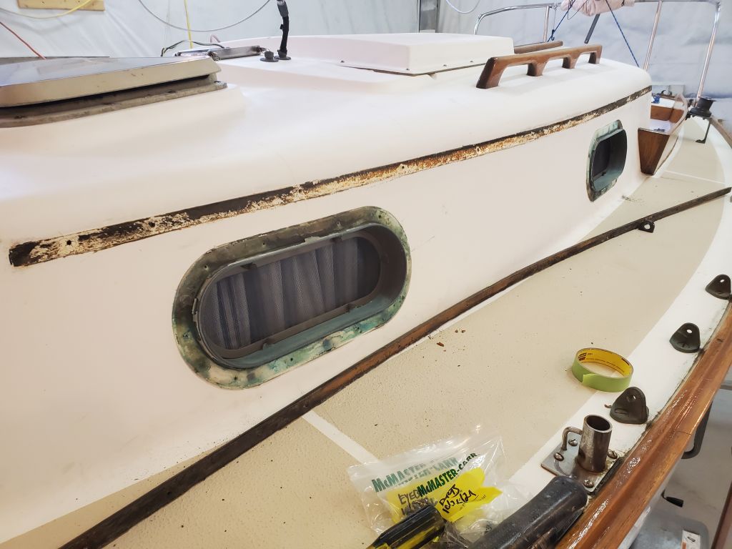
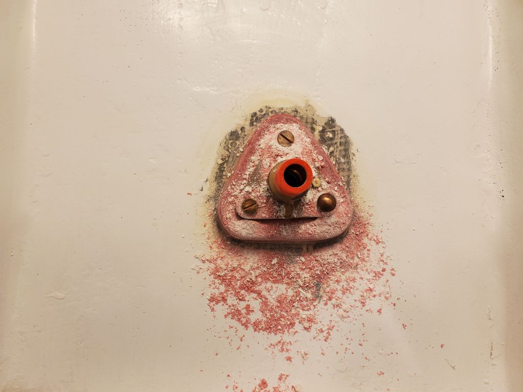
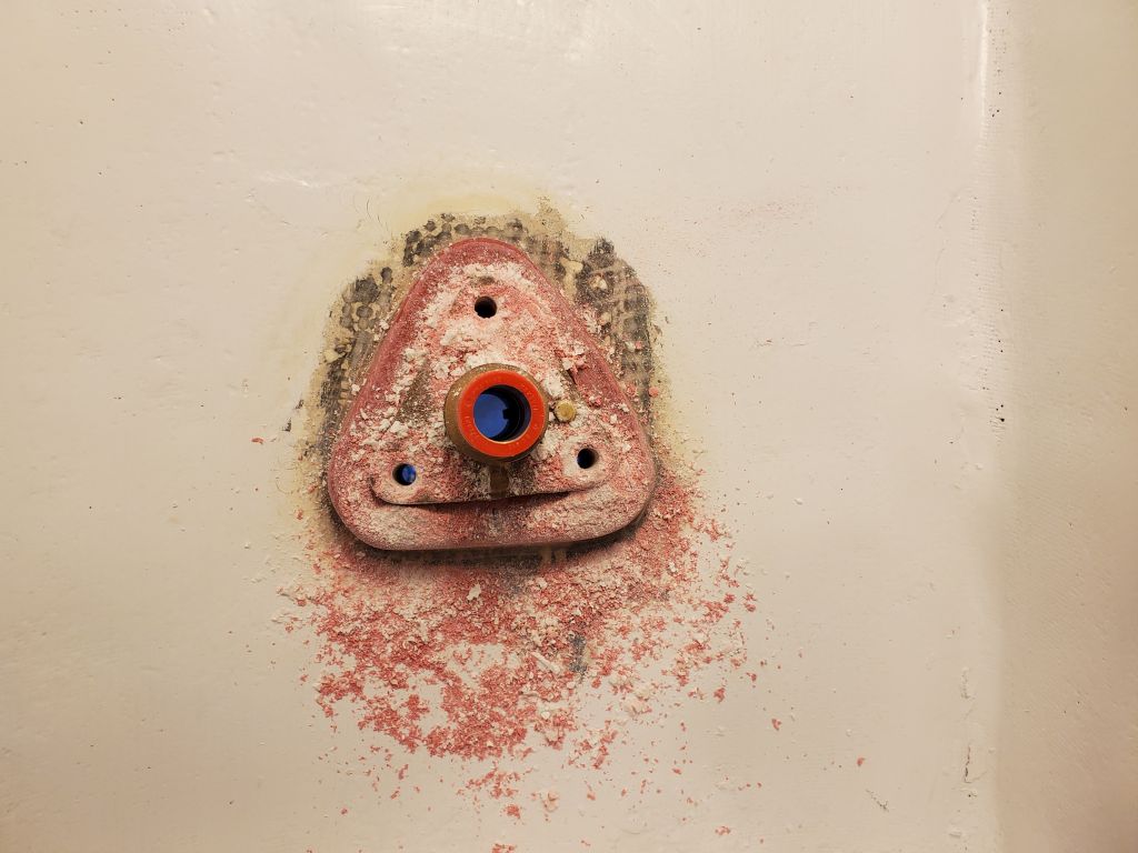
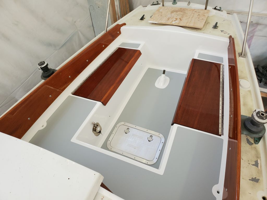
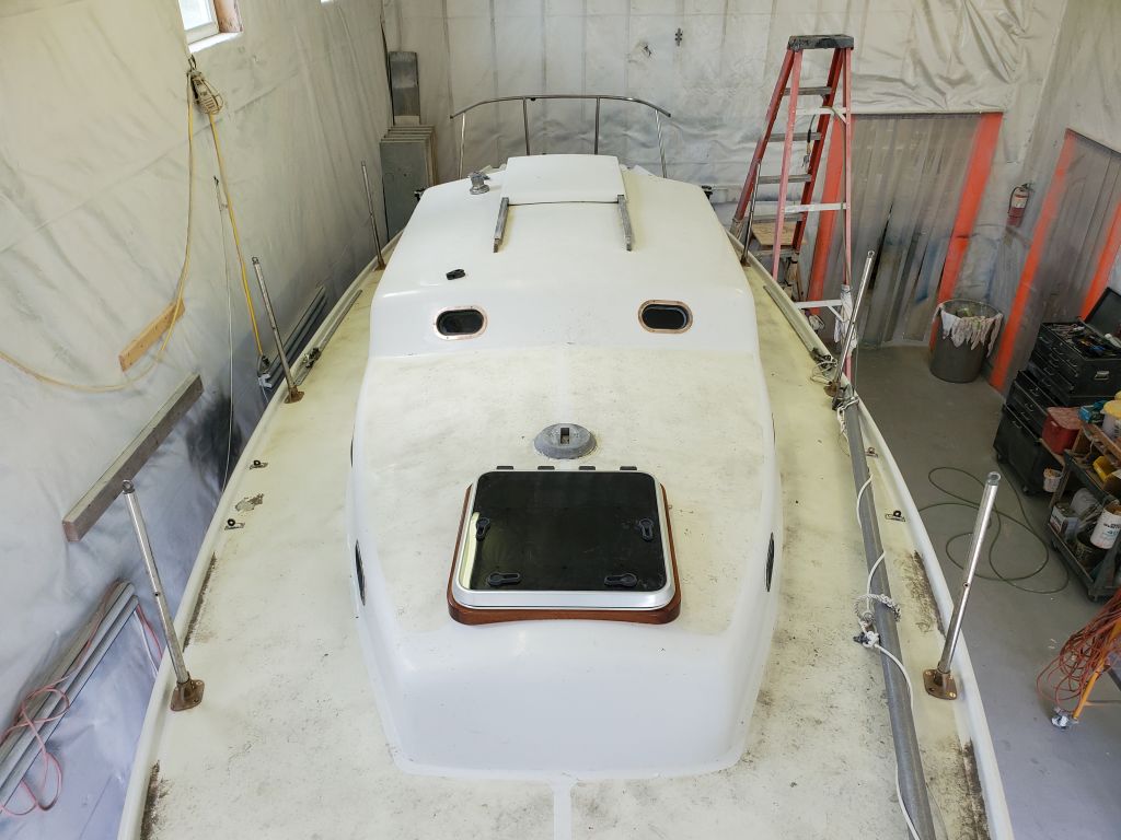
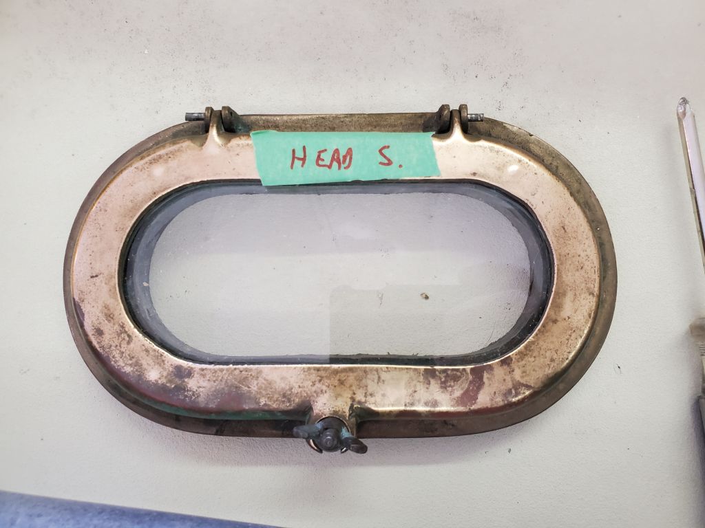
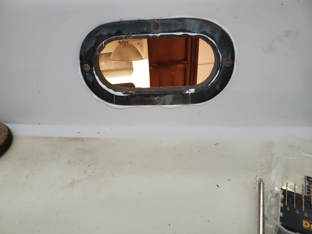
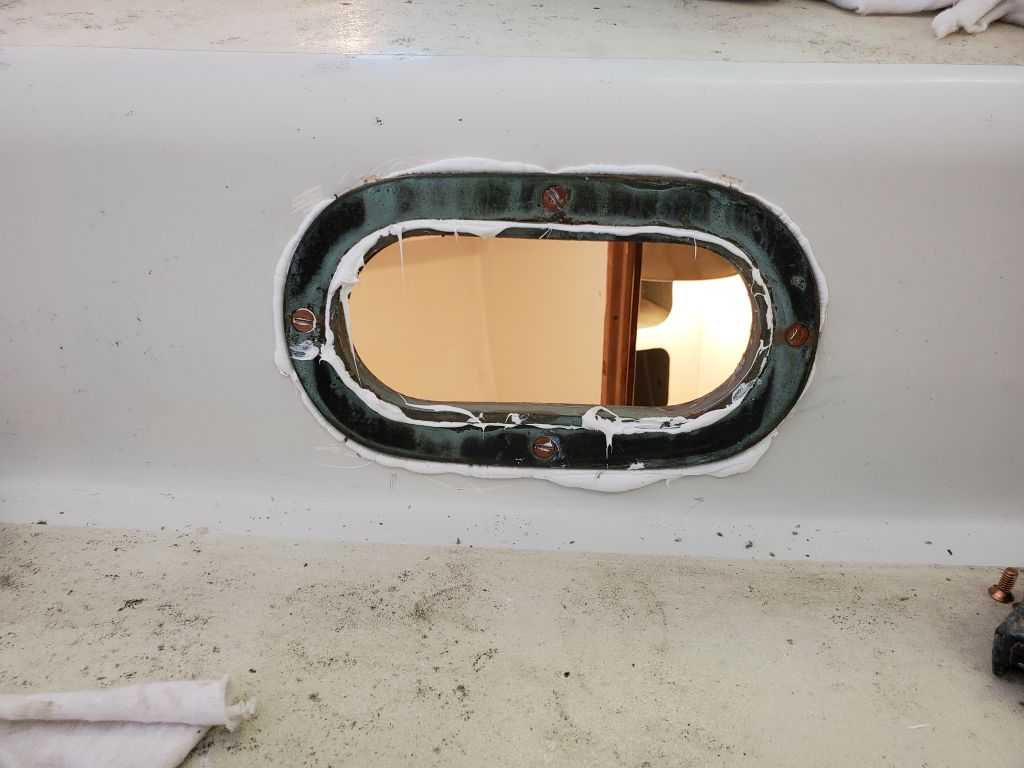
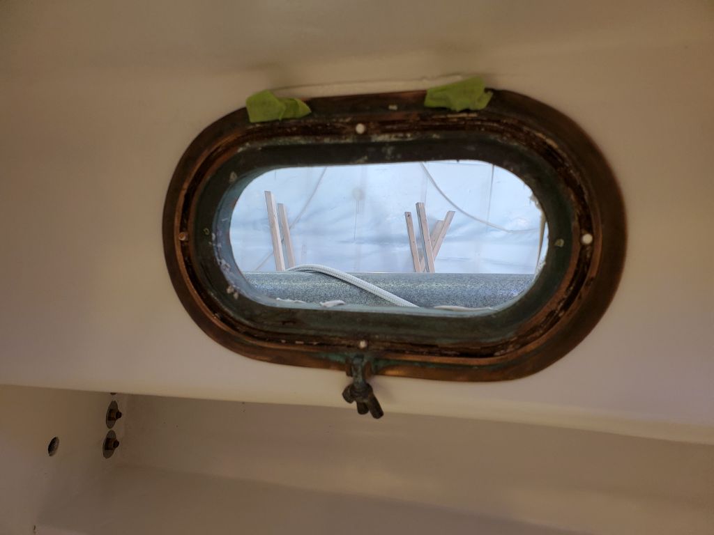
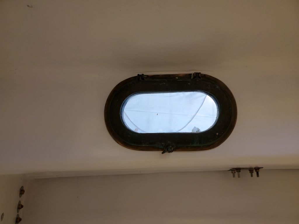
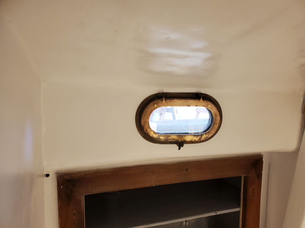
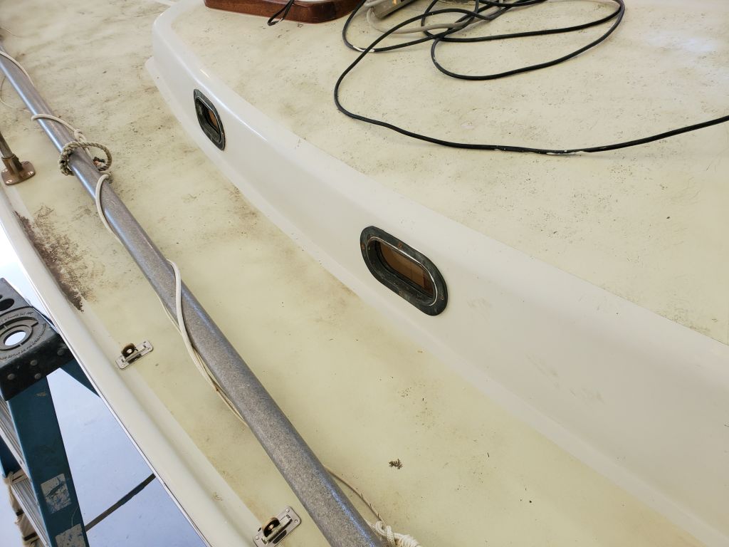
In the past couple weeks, the owner had finished up work on the final two bronze opening ports and shipped them to me, so now I turned to their installation. He’d also found a way to remove the pins securing the opening part of the ports, which meant I could install the port bodies without the hassle of the operating section hanging in the way and adding weight and complexity. This, coupled with the experience from the one I’d installed on the opposite side of the boat, made the process much easier this time. Note that while both of these ports were labeled as “starboard”, they were actually the port ports.
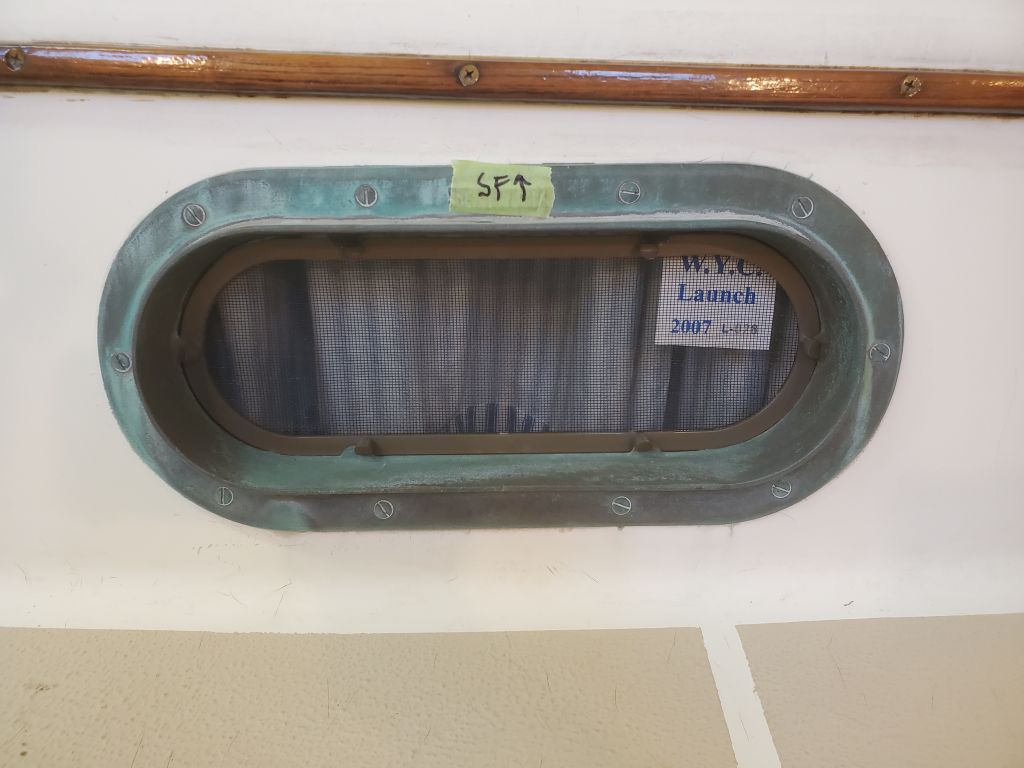
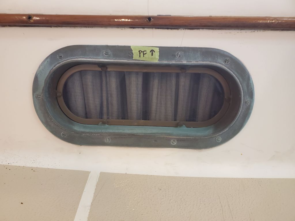
With the removable parts removed, I aligned the body in the opening, ensuring that the screw holes lined up properly through the cabin side, then, after applying sealant around the body and beneath the trim ring, used longer-than-needed screws (3/4″) to secure the pieces together, before then removing and needed the screws one at a time to replace with shorter ones, since the screws passed right through the port and into the still-empty gasket recess. First the one in the head, then the one in the forward cabin. Interestingly, and head-scratchingly, I noticed that the trim ring for the port in the head (like its counterpart to starboard) was thicker at the ends of the port, and thinner in the center–but the ostensibly identical port in the port forward cabin had a trim ring of consistent thickness around the whole thing. This caused confusion when I found that on this installation, the screws at the ends of the trim ring had to be shorter than the ones in the middle, which didn’t make any sense till I figured out that the trim ring was different.
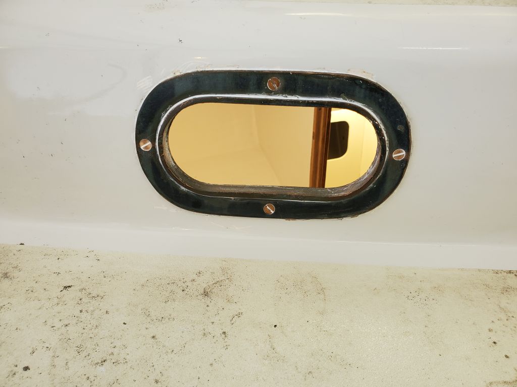
With tbe ports bedded and installed and cleaned up, I temporarily resecured the opening parts, reinstalling the pins only enough to hold the pieces securely for now since the owner wanted to remove them again for installing the gasket material once he had the boat back home again (where it was headed–hopefully briefly–after leaving here before launching for the season in a few weeks).
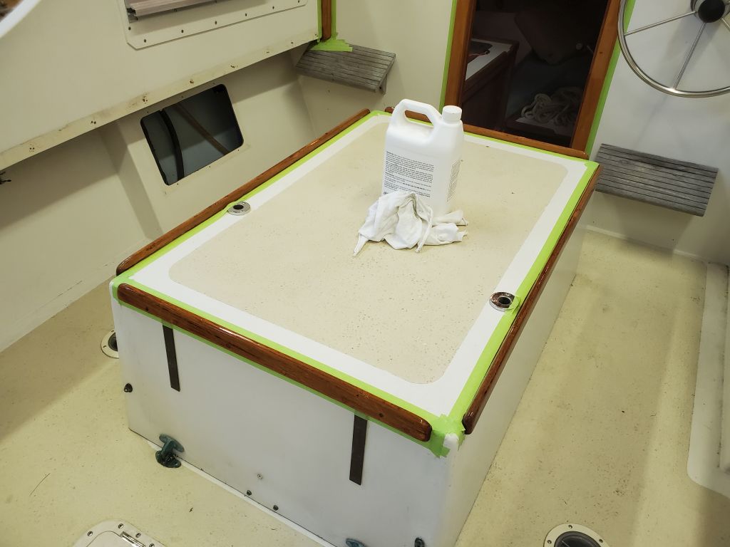
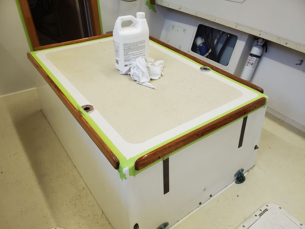
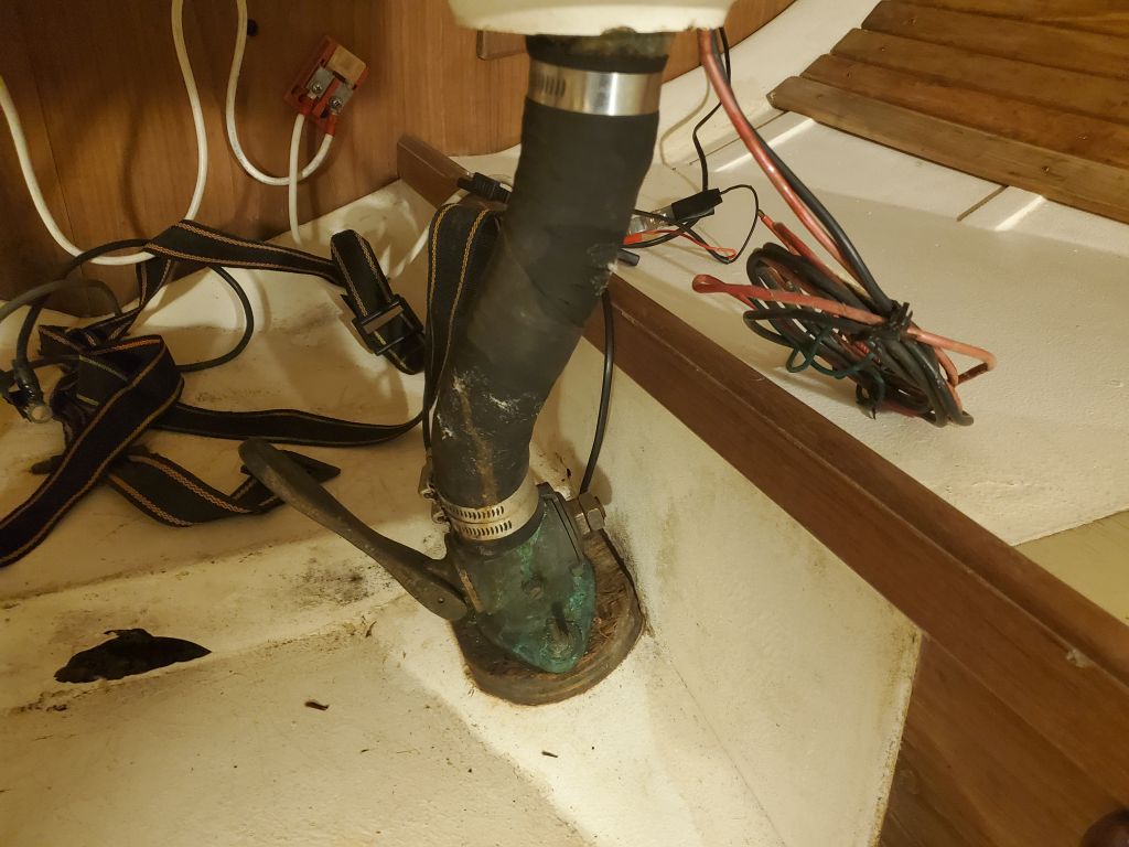
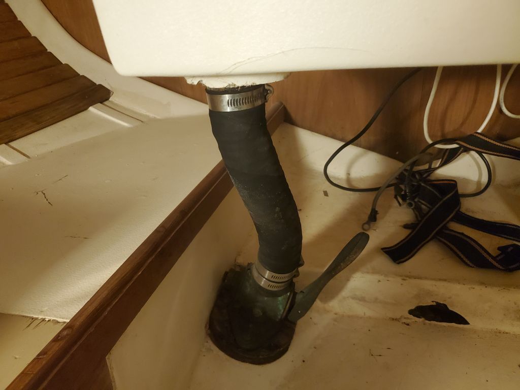
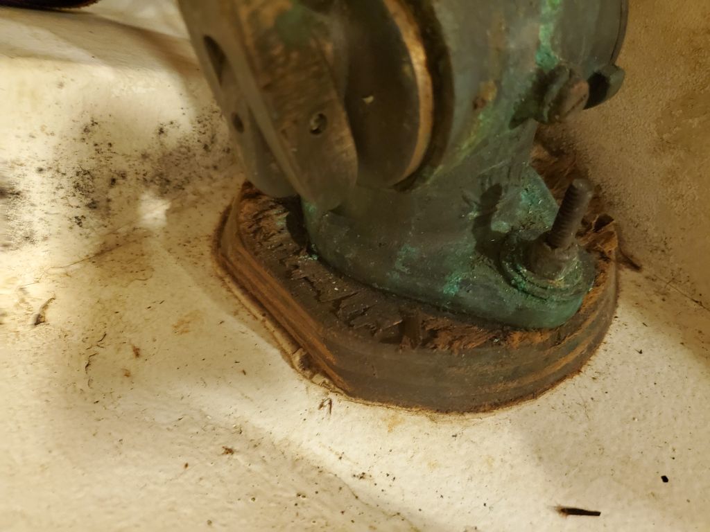
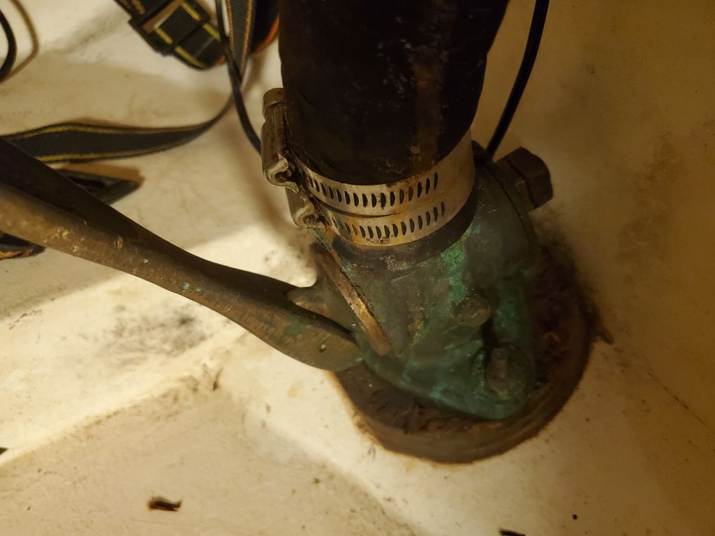
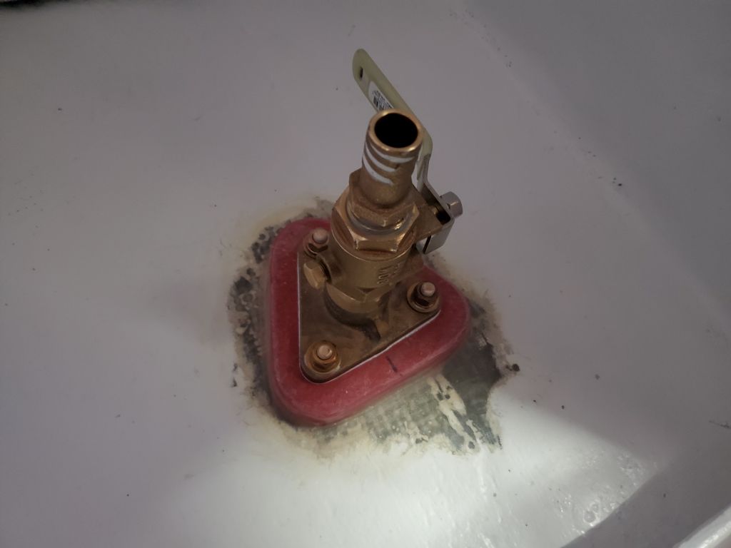
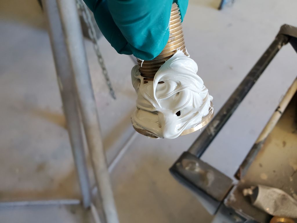
The final task on my slightly-extended work list was to install a through hull on the starboard side of the head, as the owner had become intrigued by the idea of a small vanity and sink there. I’d ordered the bronze fittings required, which all had arrived except for the ball valve required, which caused me to hesitate since I was wary of installing a new fitting sans valve without knowing for sure whether the valve could be obtained in time. Fortunately, the owner lived near a good marine store and was able to find the valve required, so with that question satisfied I proceeded with the through hull installation.
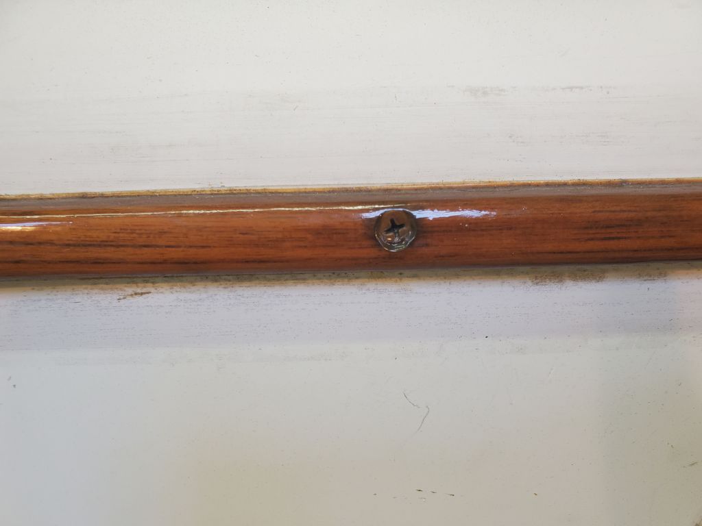
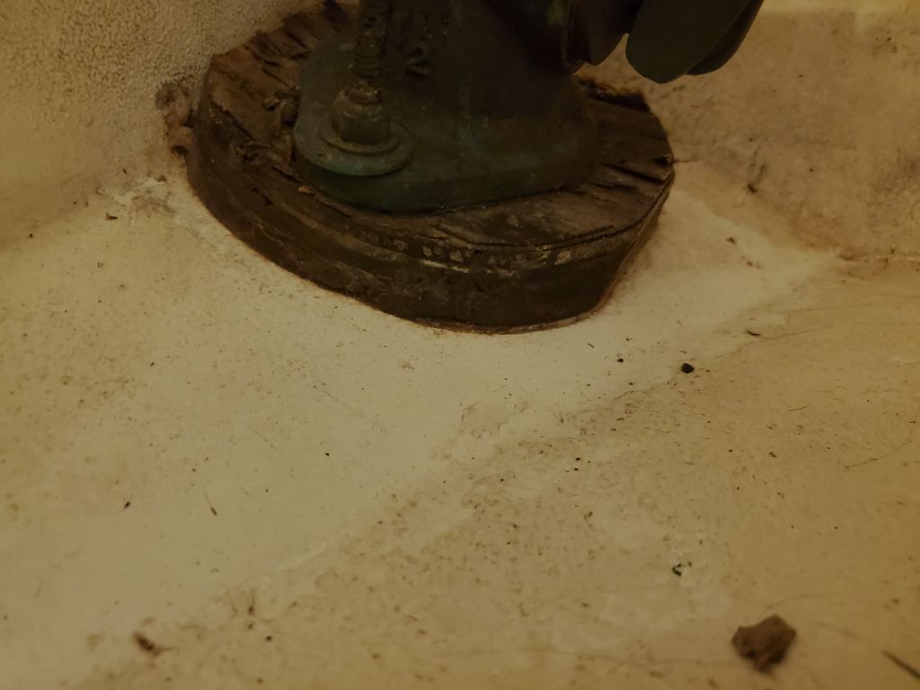
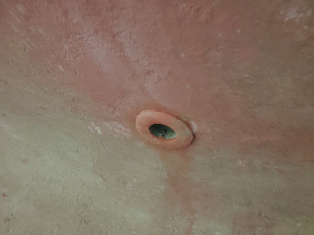
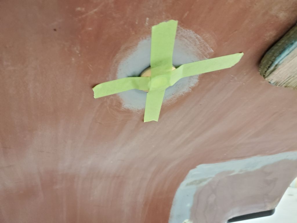
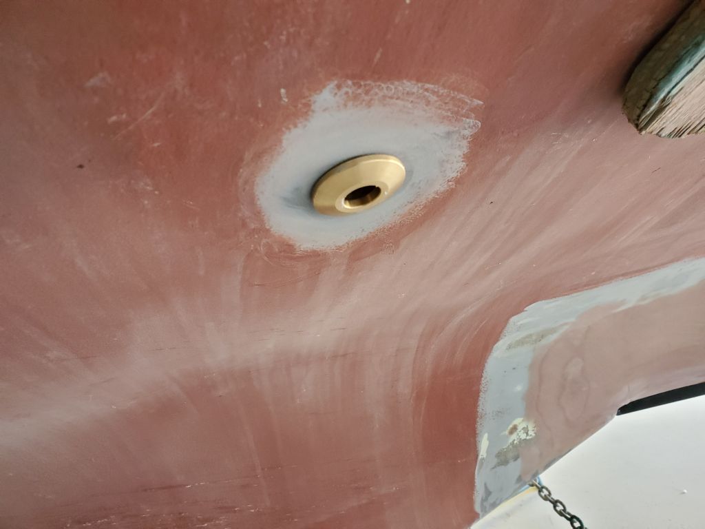
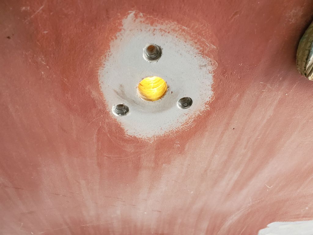
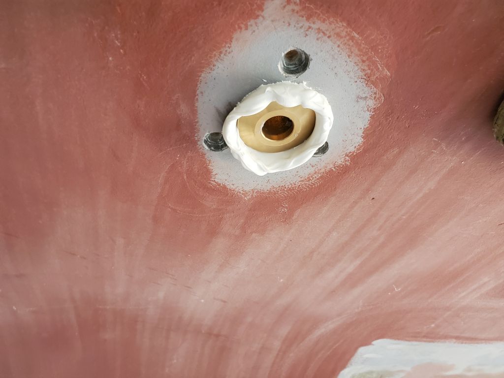
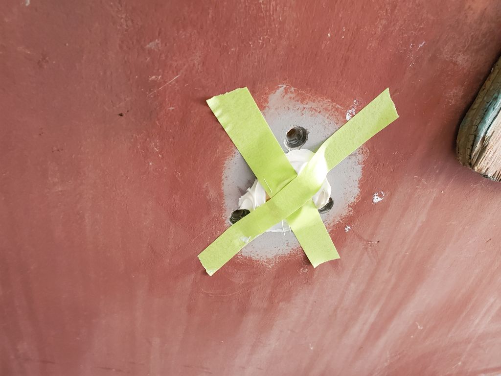
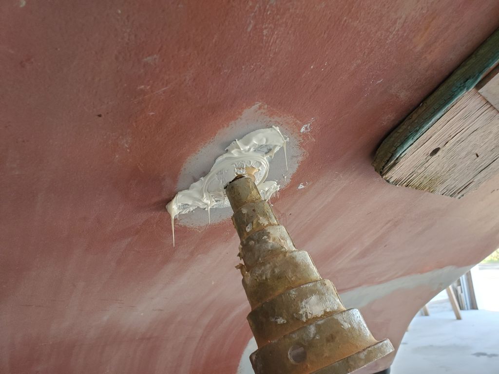
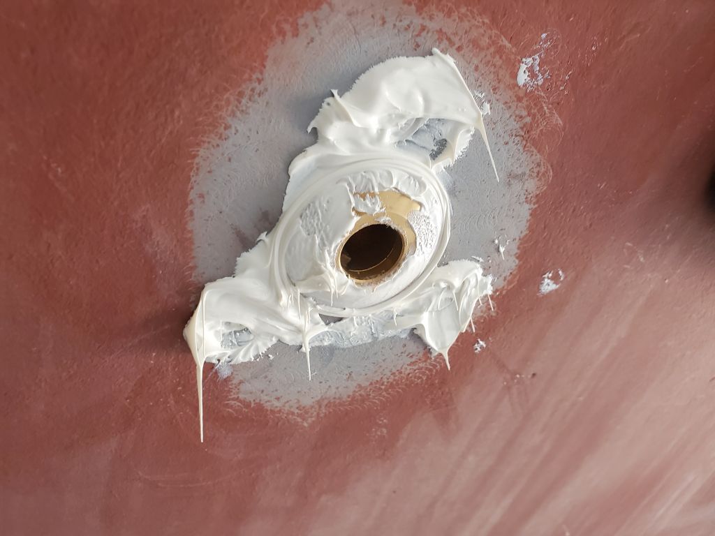
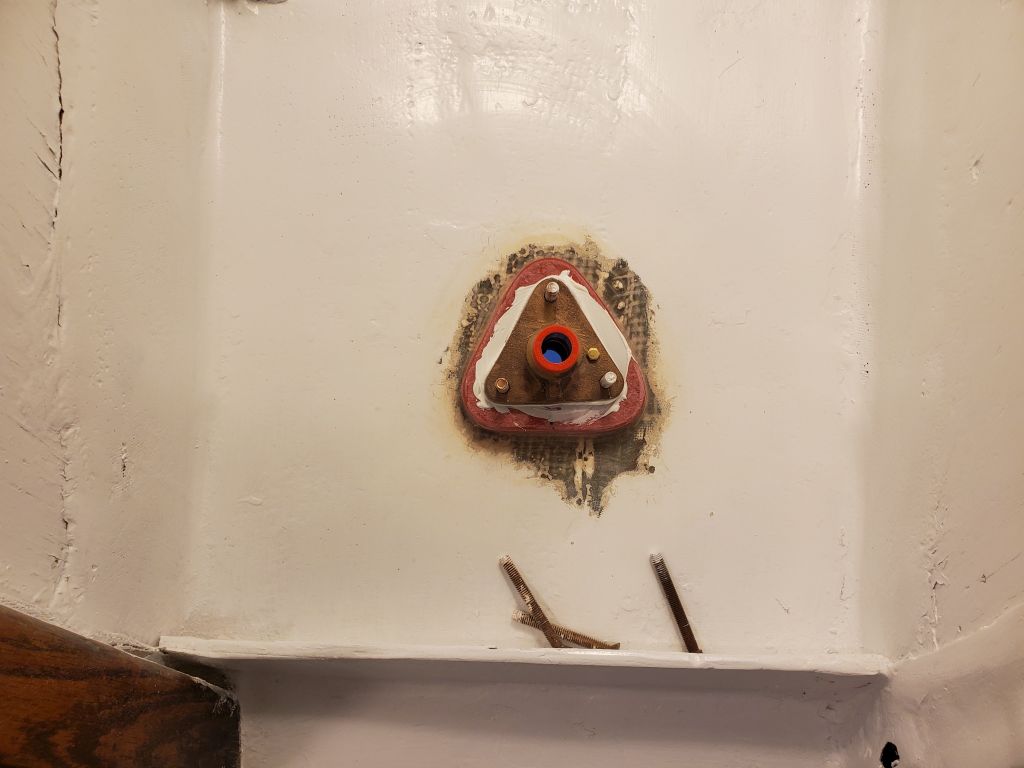
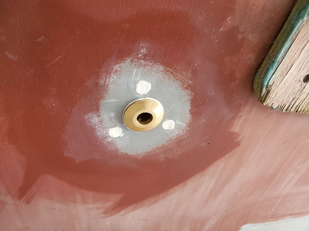
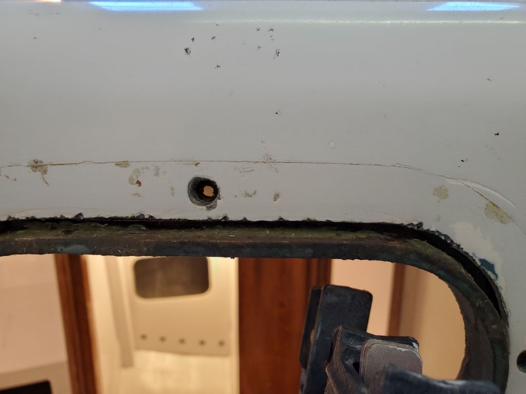
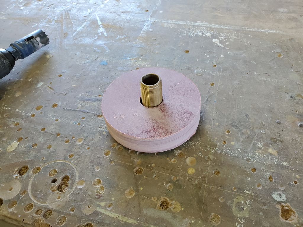
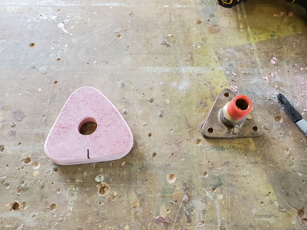
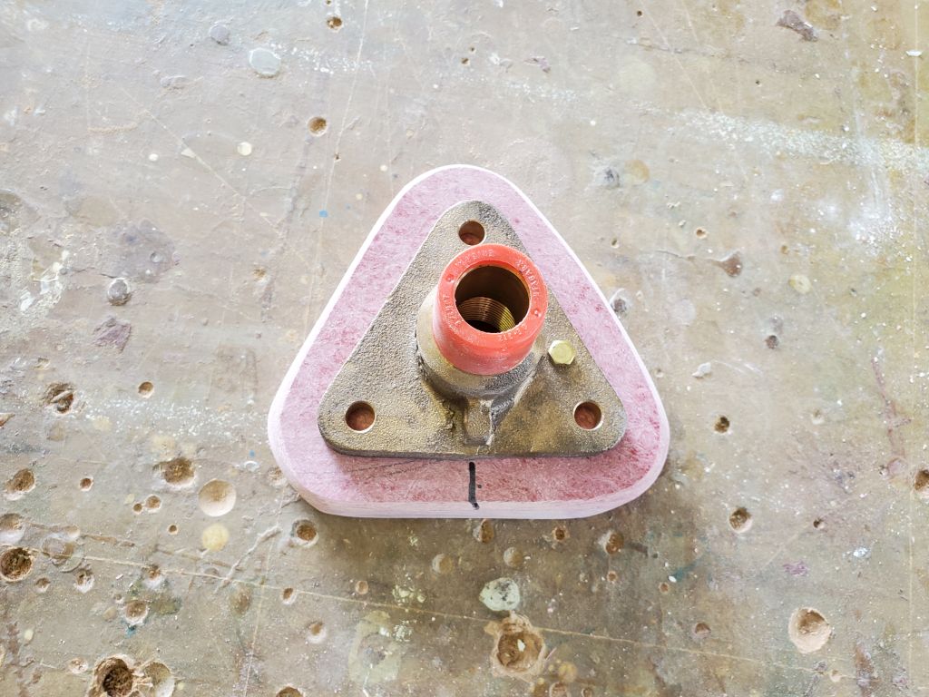
Digging around for a piece of solid fiberglass to use as a backing block, I found what I thought might be a perfect piece already cut (the center cut, or hole saw spoil, of a trim ring I’d built for a heat stove pipe on another project). At 1″ thick, however, I worried it might be too thick for the through hull neck, given the generally-known thickness of a Triton hull, so to check it I drilled a hole through the center, then marked and drilled through the hull in the appropriate position and installed the through hull from inside so I could easily check the threads exposed on the outside. While I could have made this work if I’d had to, there weren’t as many threads exposed as I wanted, and, with ample extra threading room available inside the flange body of the fitting, I decided instead to cut one of my traditional backing blocks from a piece of 3/4″ fiberglass instead.
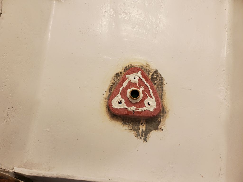
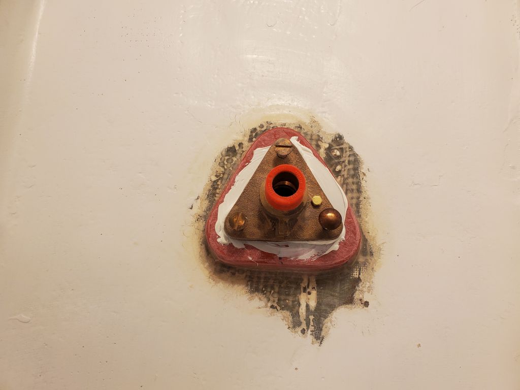
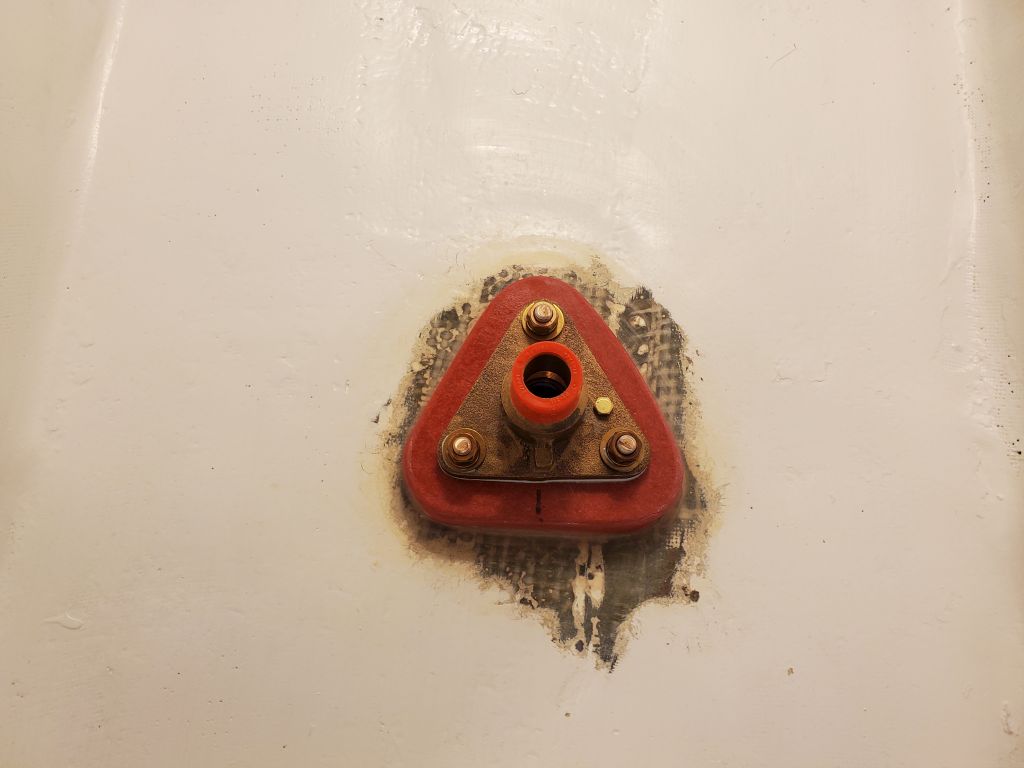
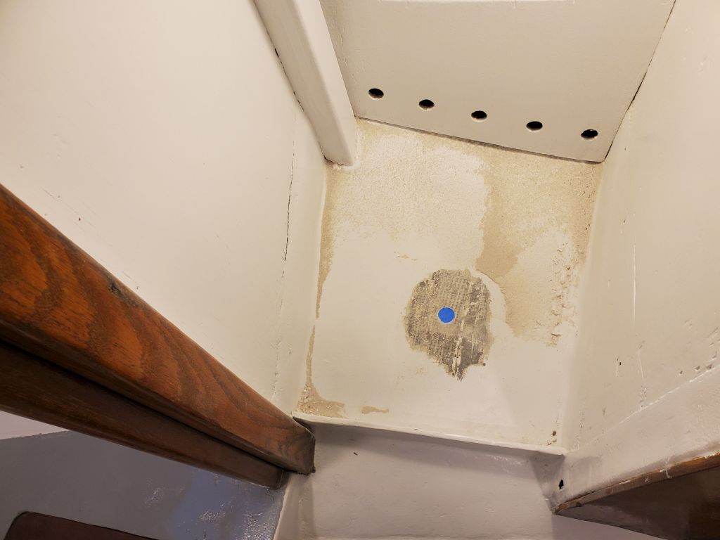
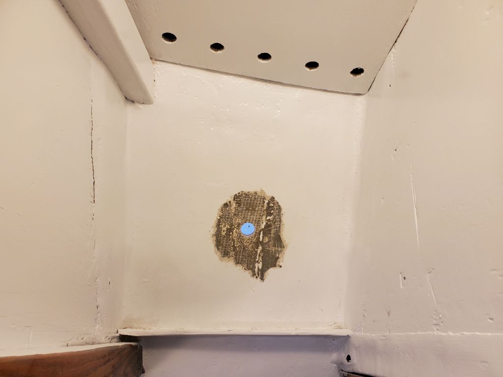
With that decision made, I cut and cleaned up the new backing block, and after roughly marking its position on the inside of the hull, sanded away the paint there to prepare for bonding; I also removed the bottom paint from around the exterior of the fitting, leaving the barrier coat beneath untouched.
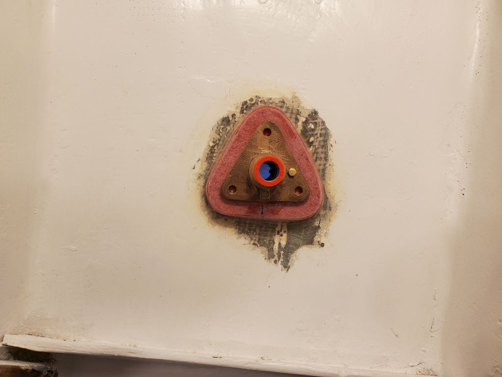
After cleaning up, I installed the backing plate in a bed of thickened epoxy, leaving it to cure overnight before continuing.
Total time billed on this job today: 4 hours
0600 Weather Observation: 42°, mainly cloudy. Forecast for the day: Scattered showers, 60°