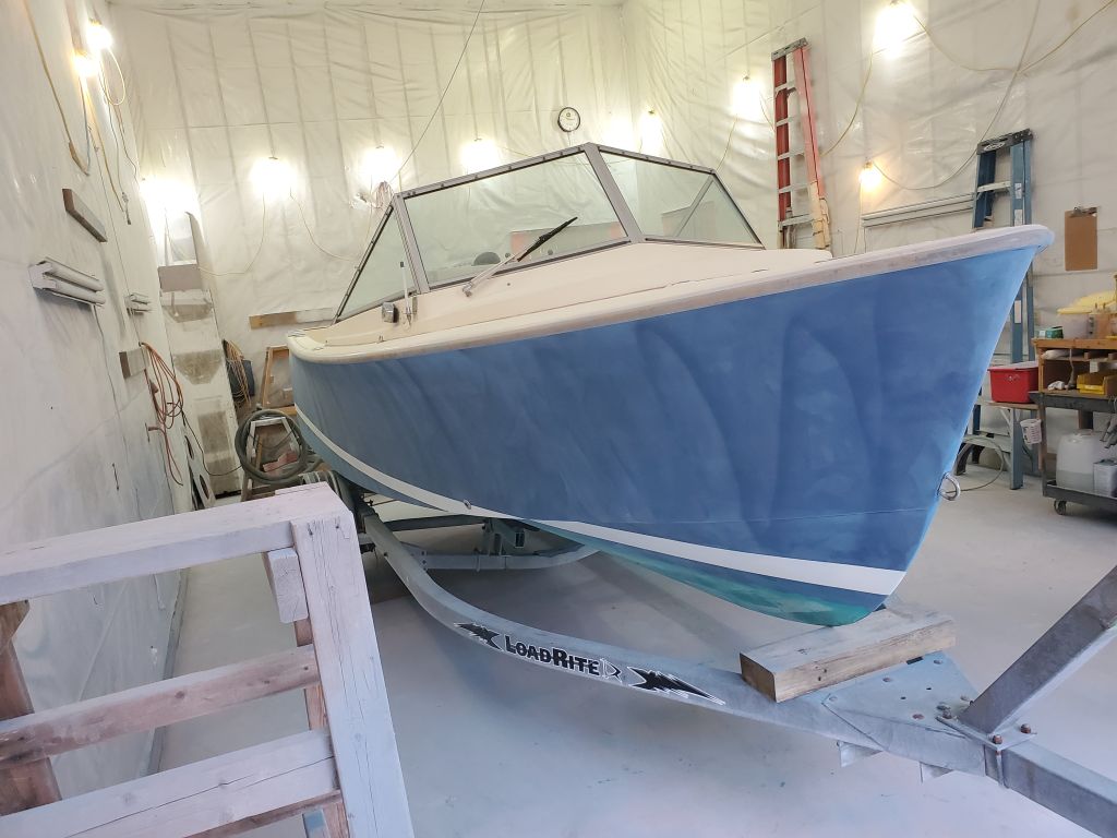
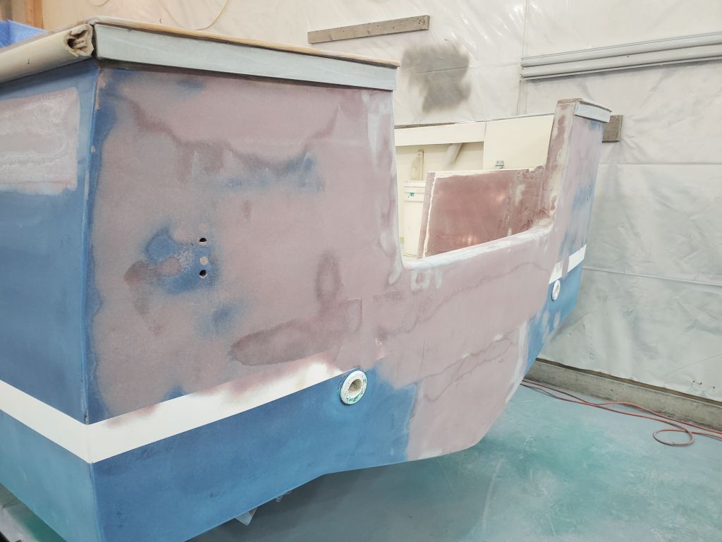
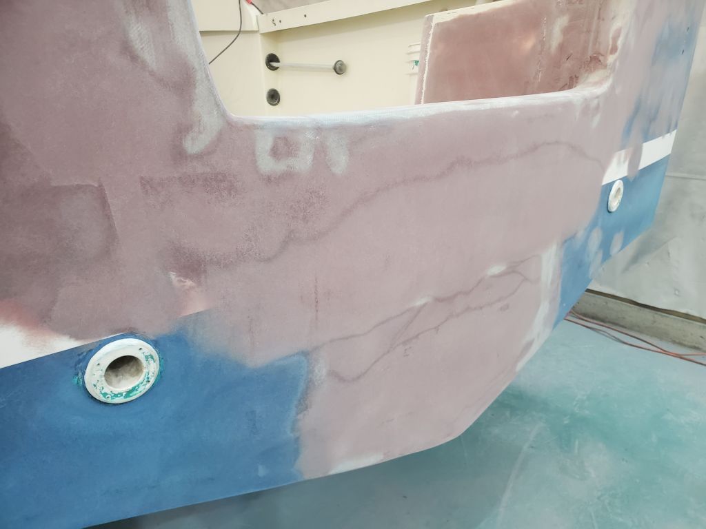
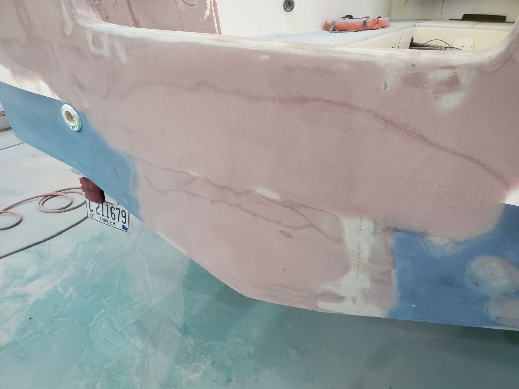
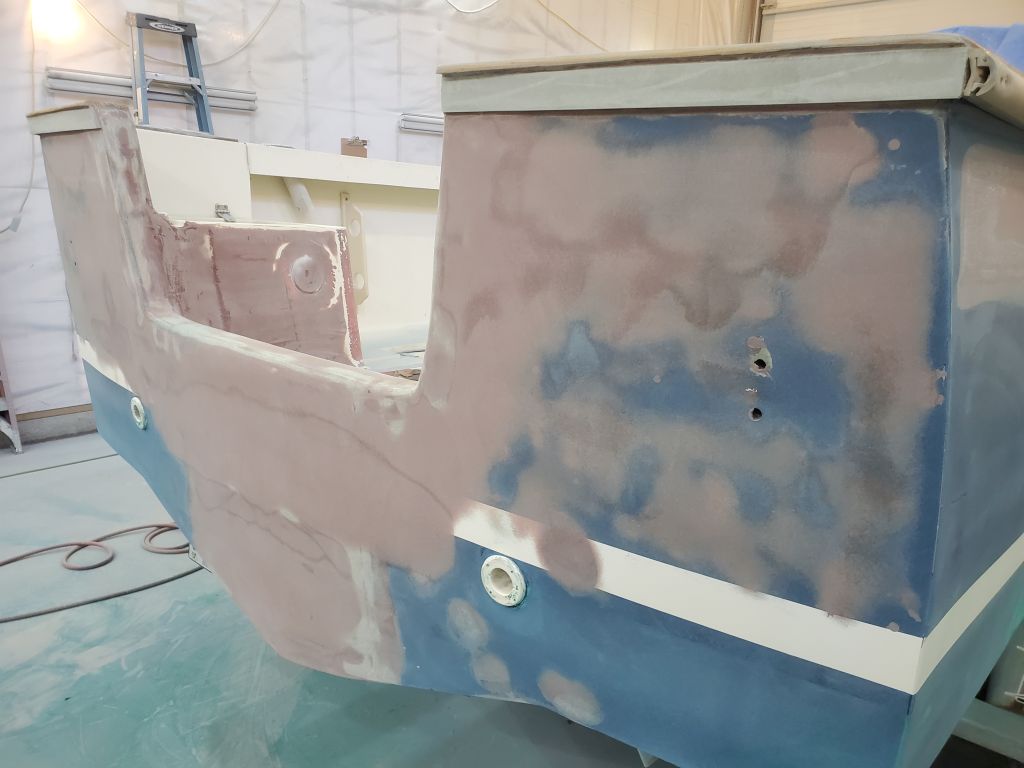
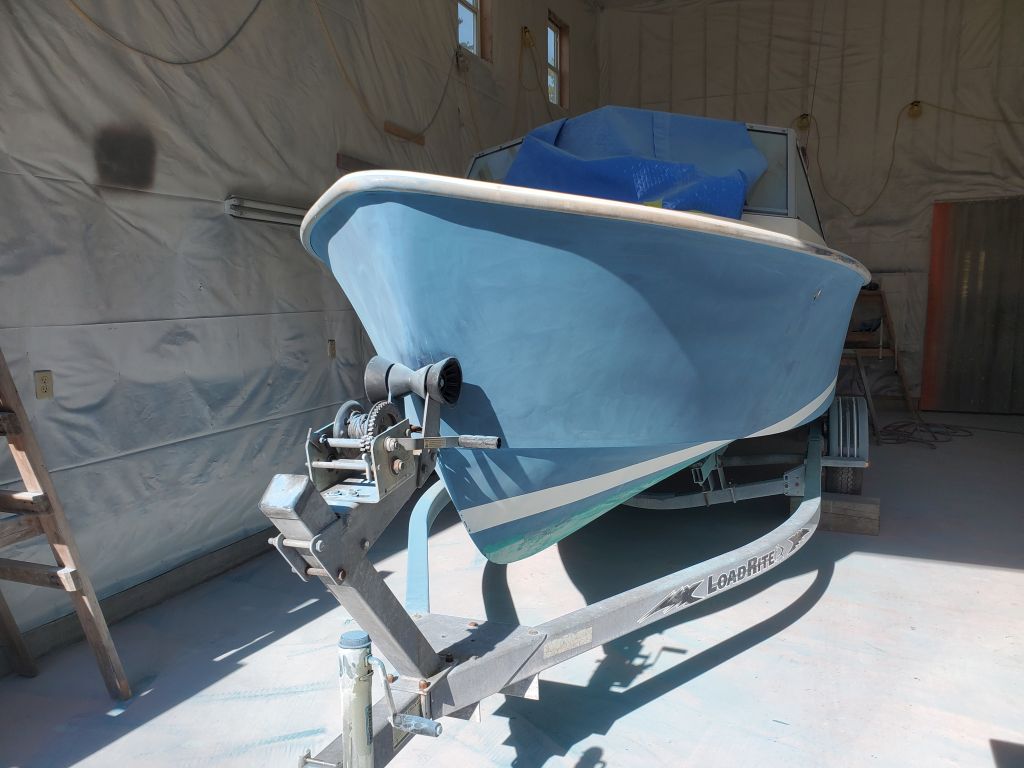
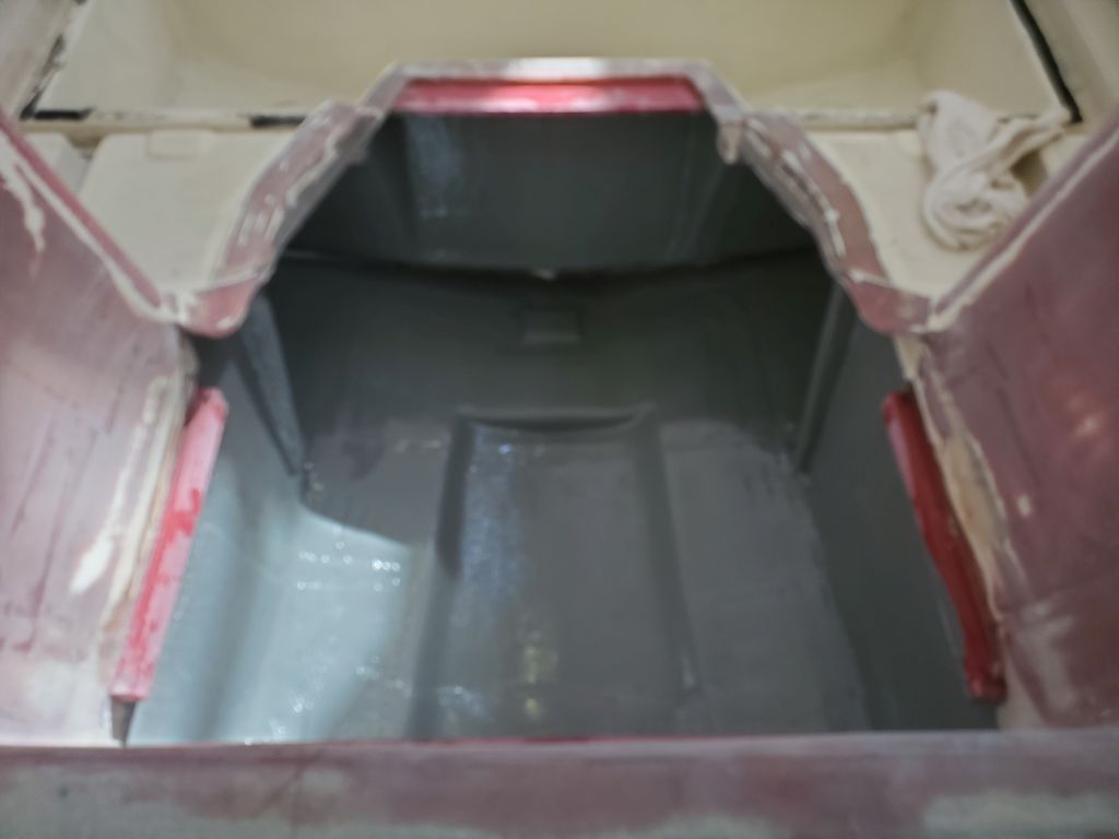
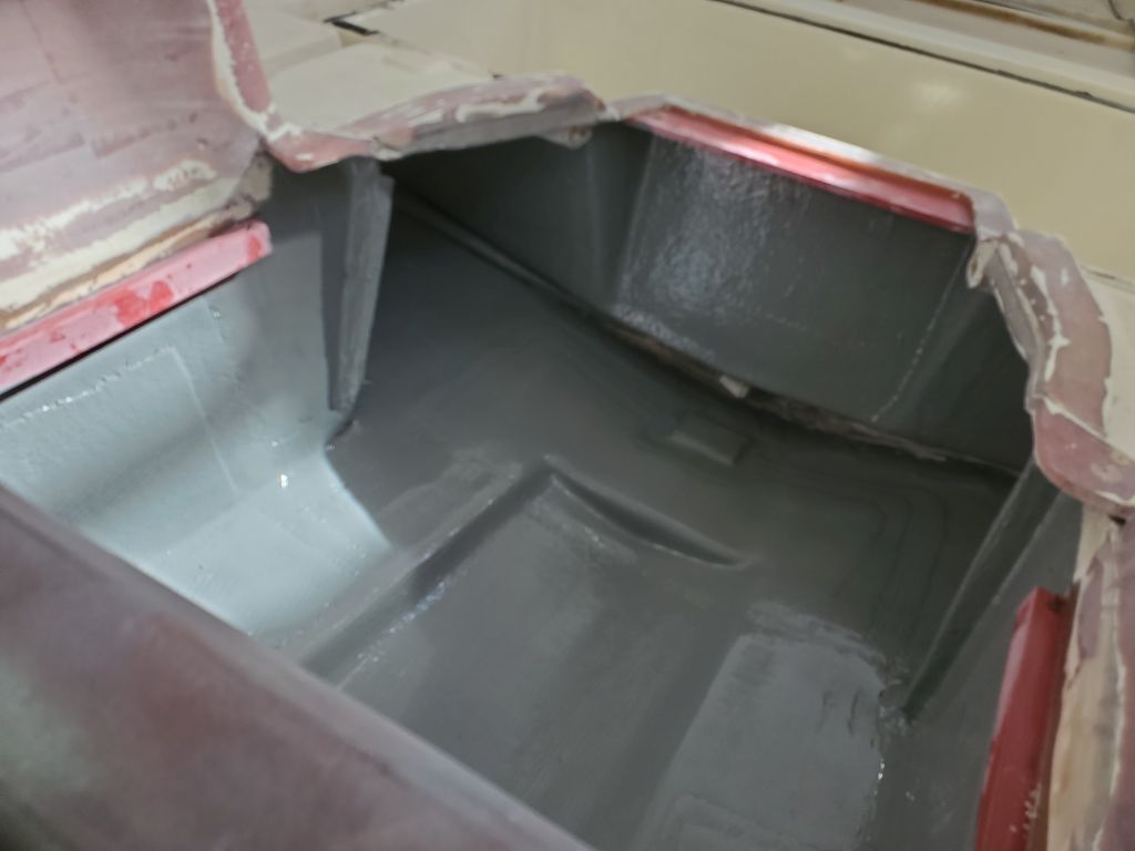
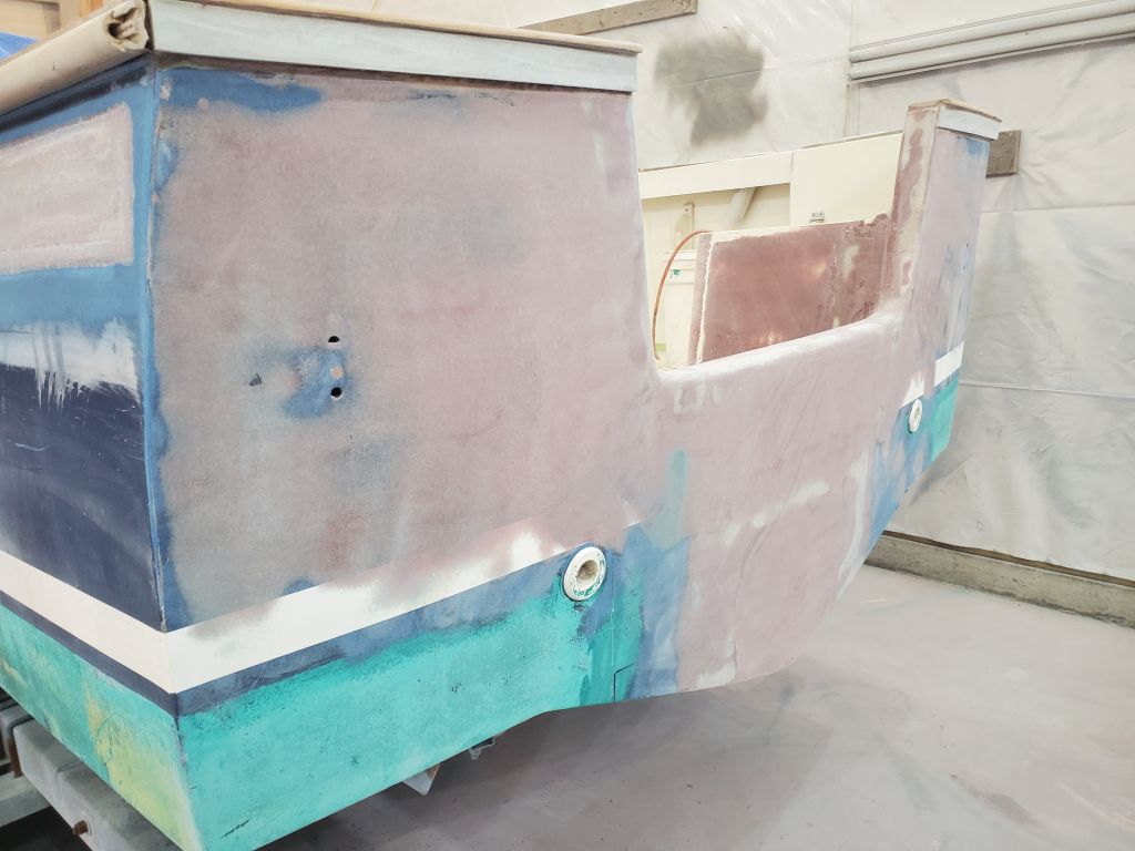
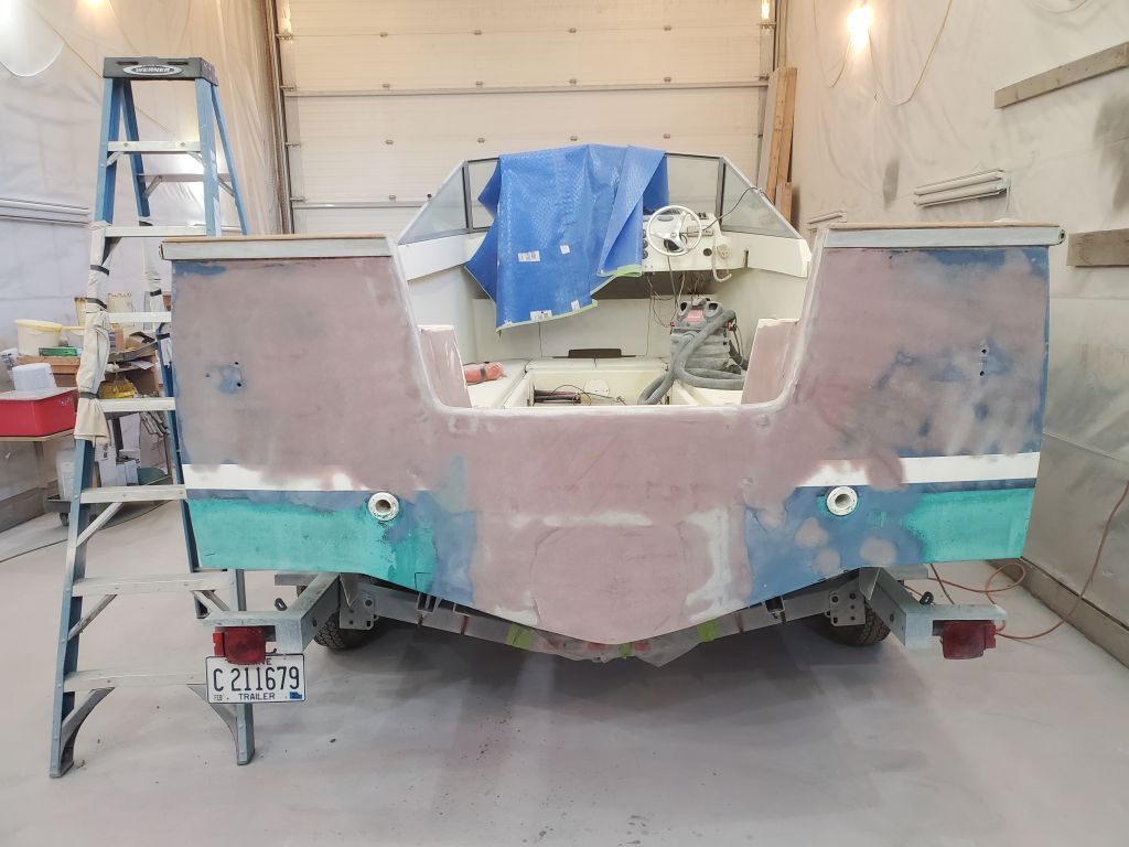
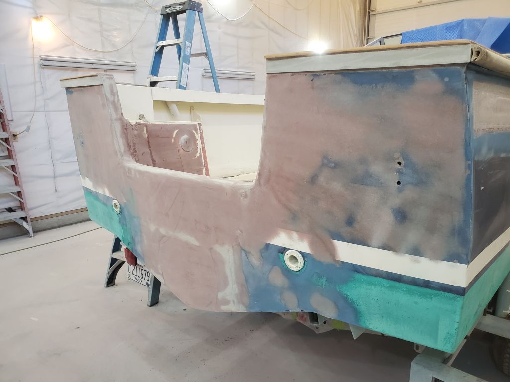
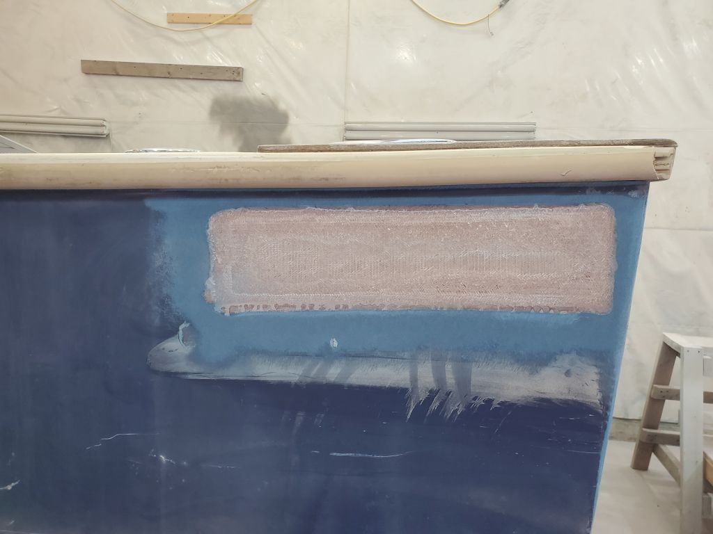
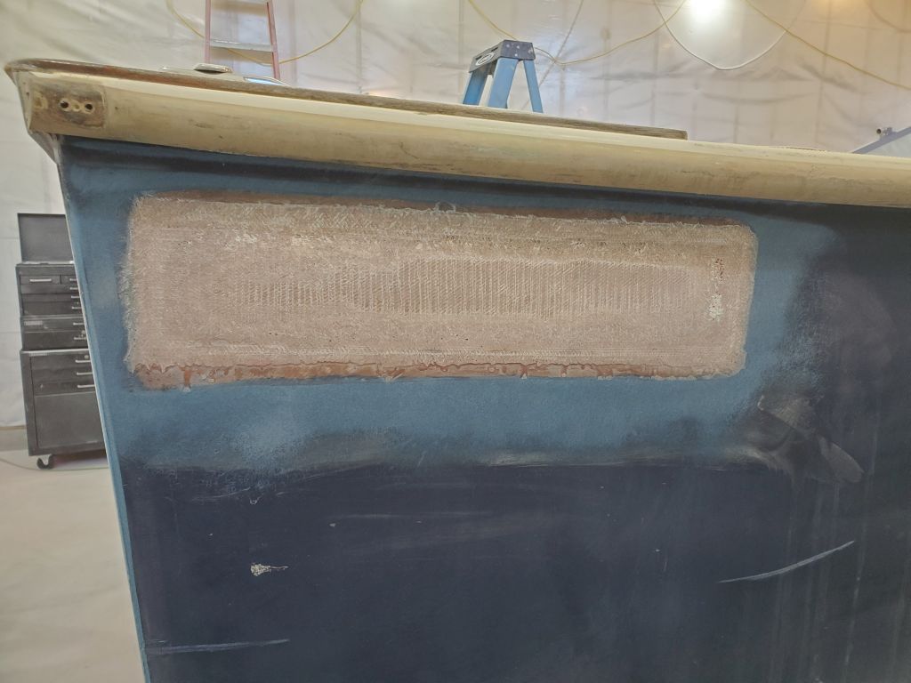
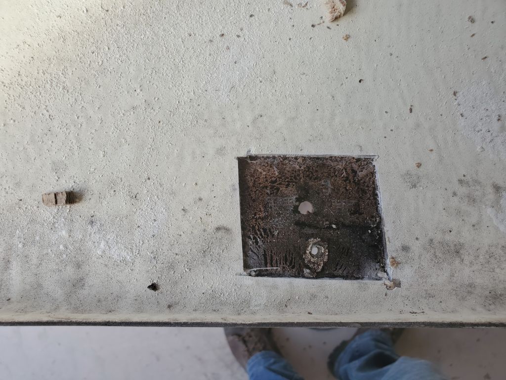
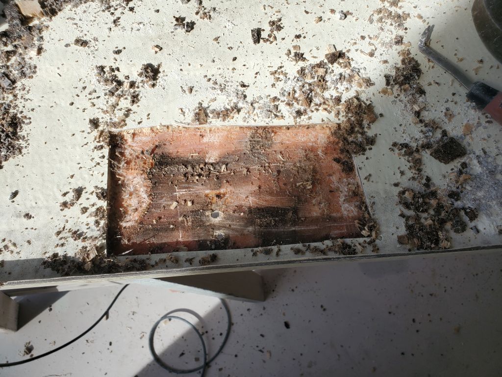
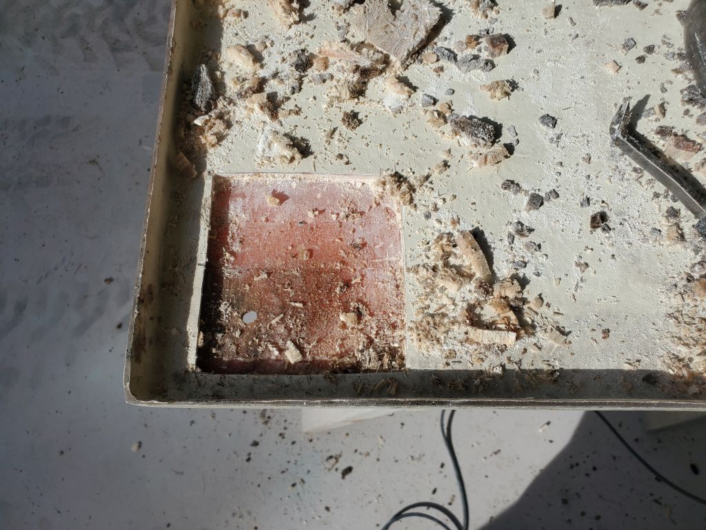
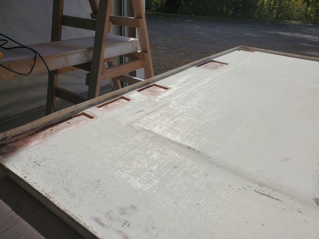
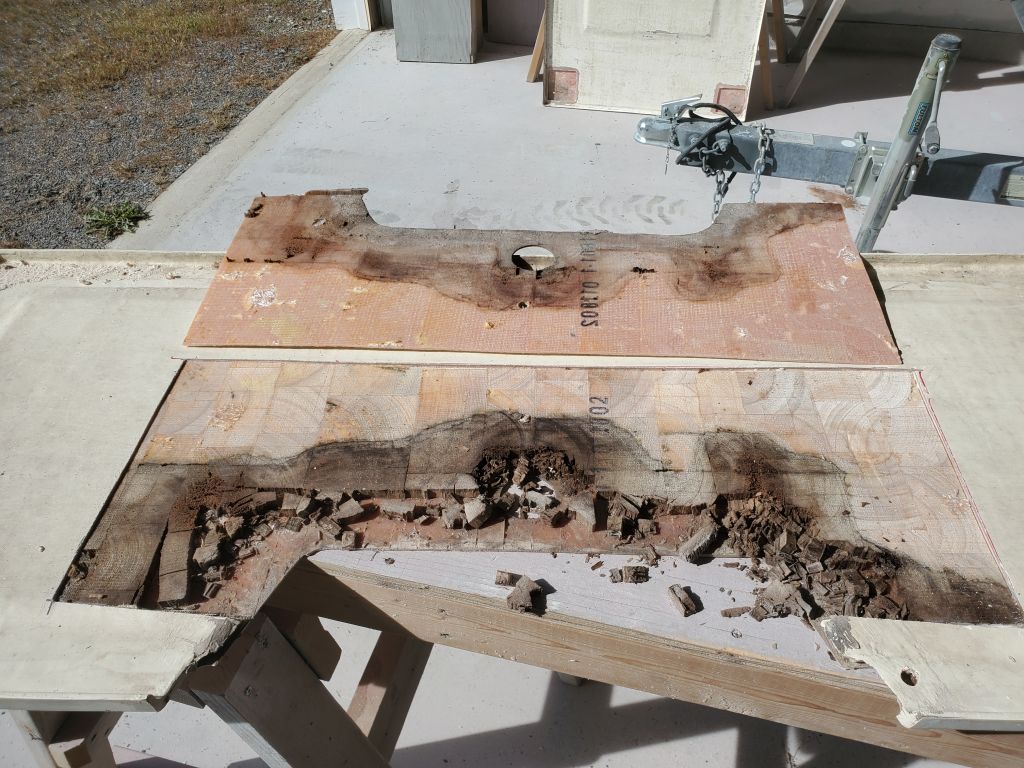
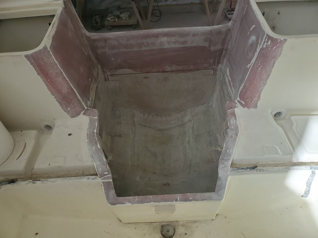
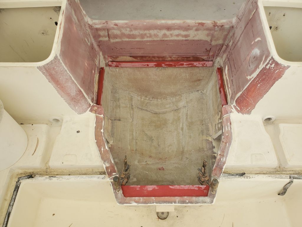
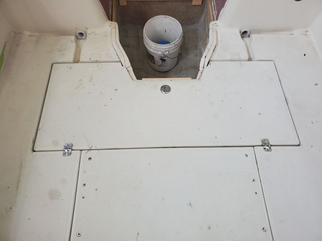
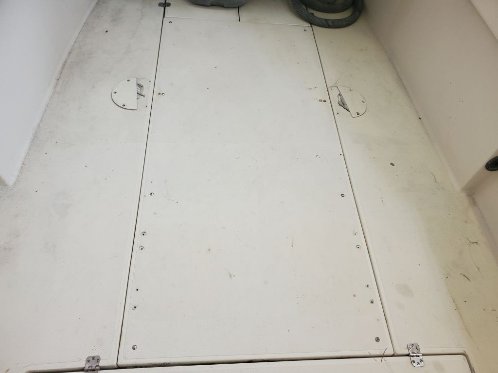
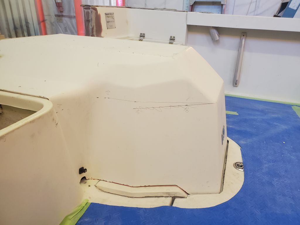
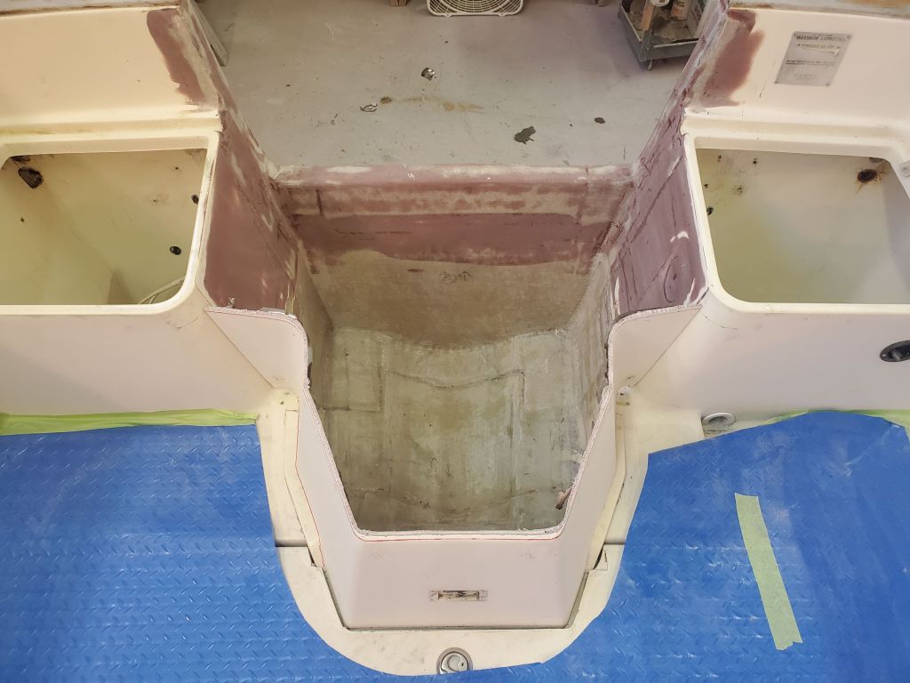
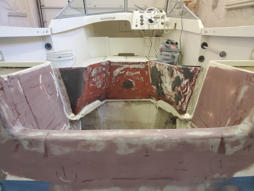
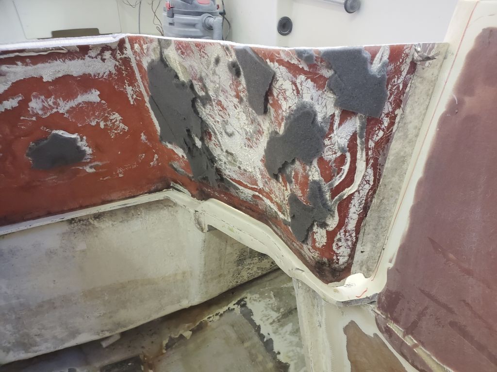
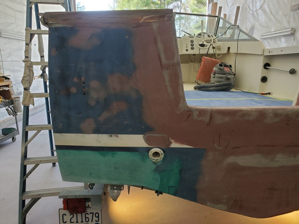
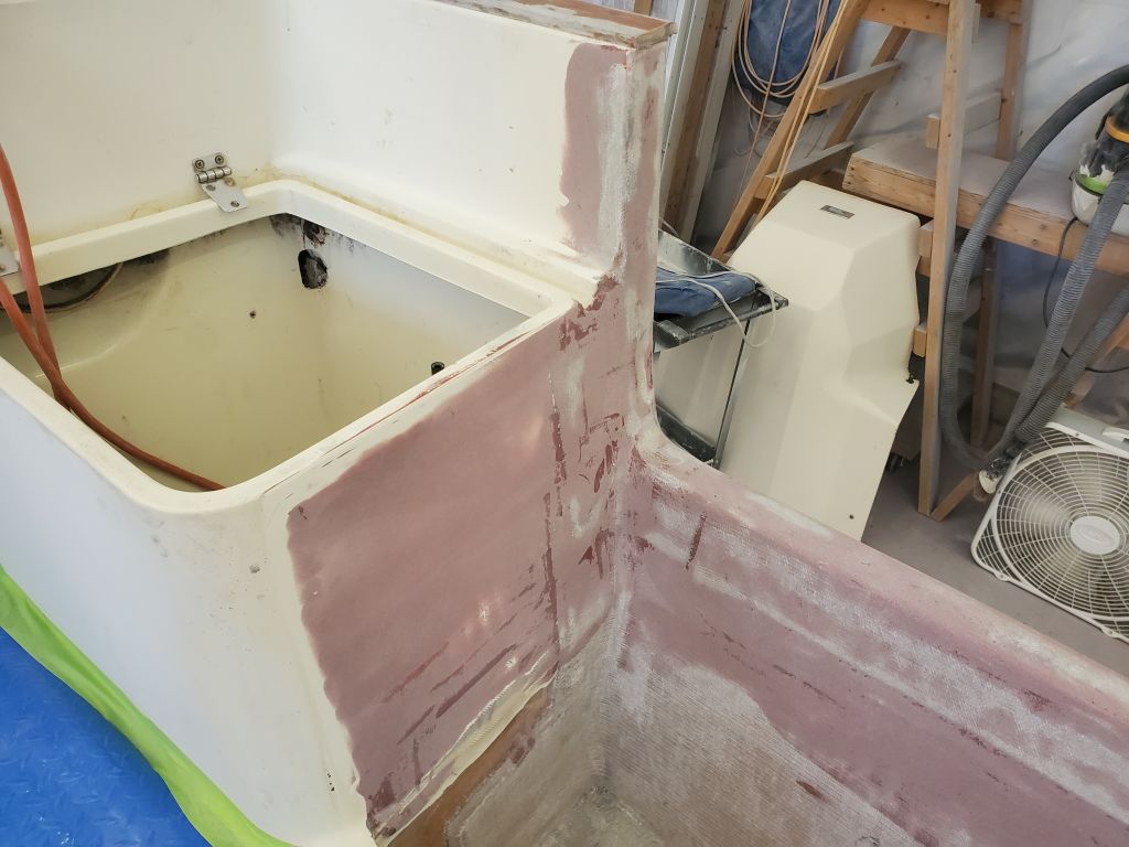
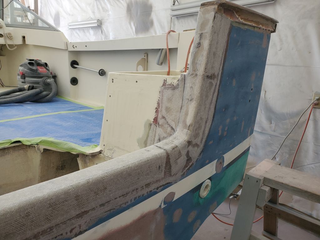
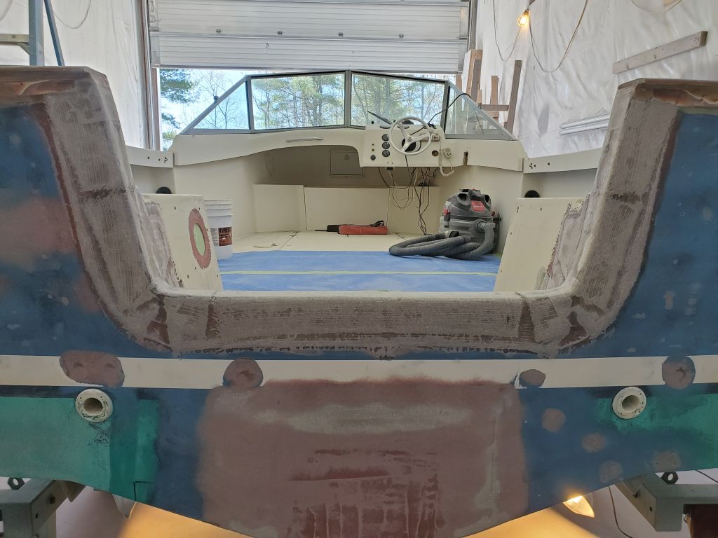
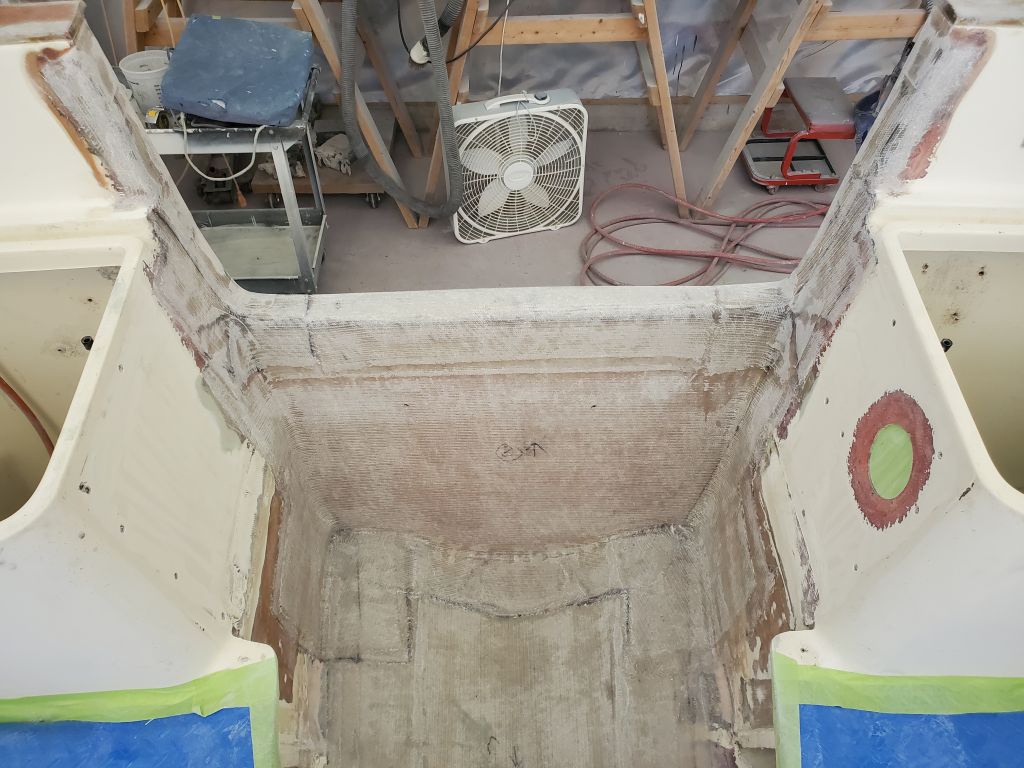
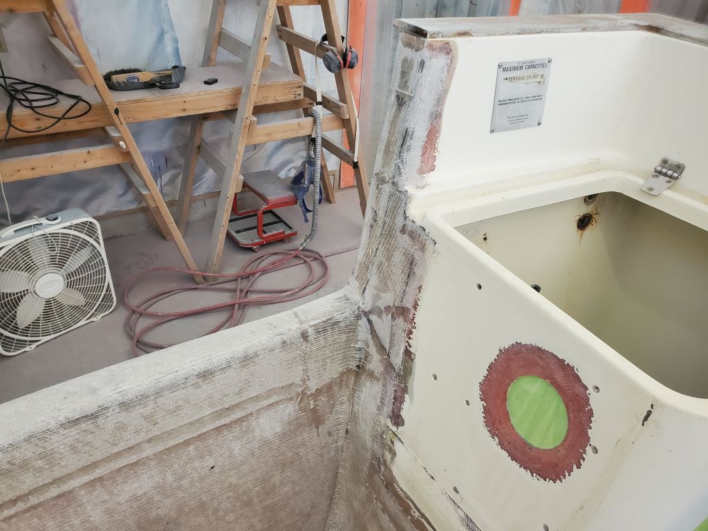
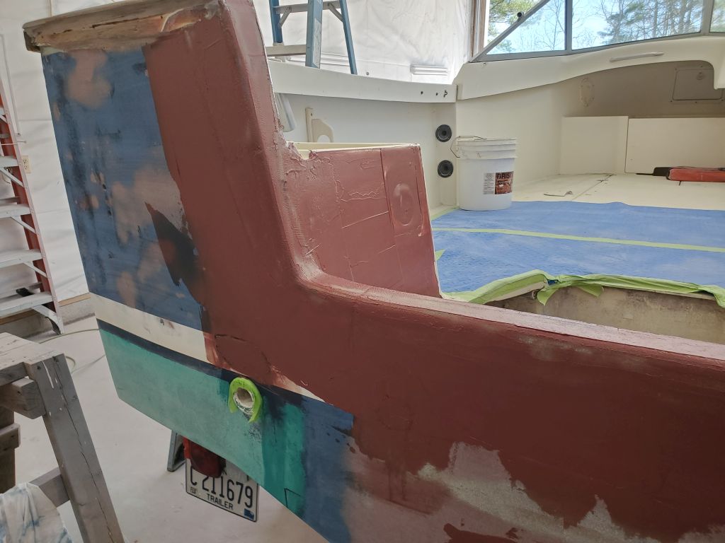
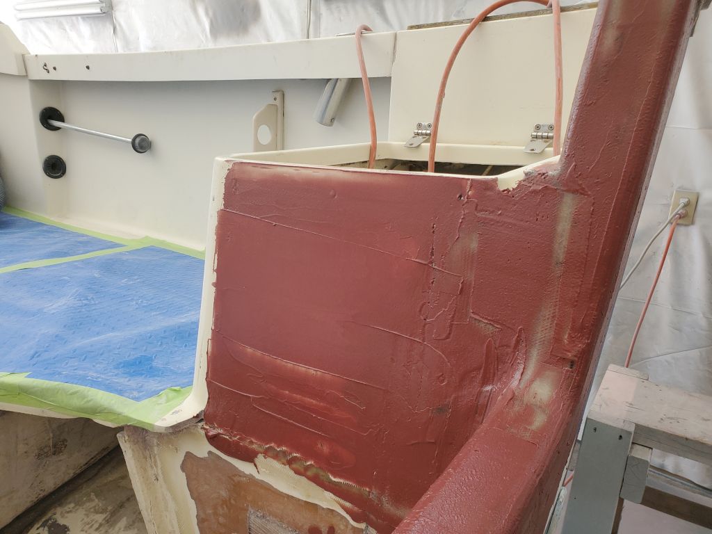
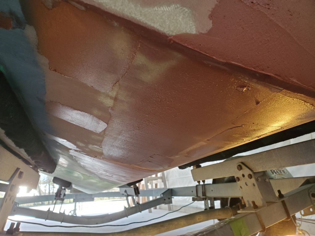
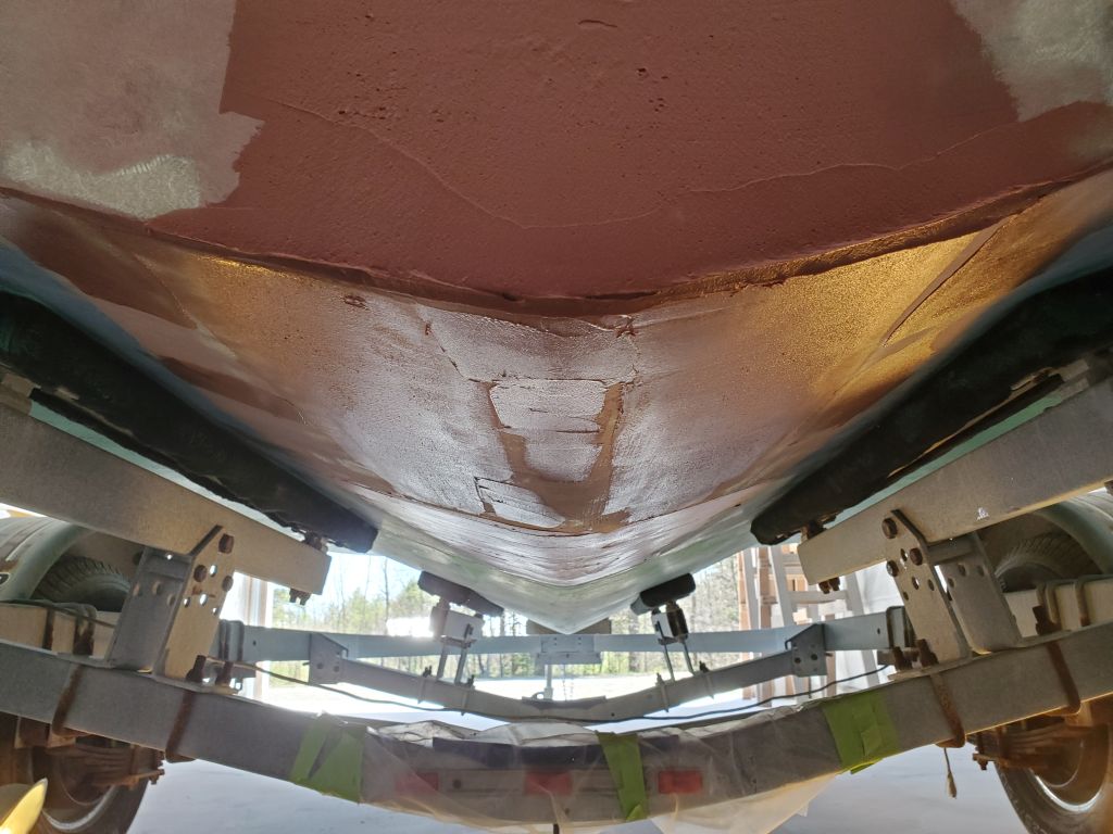
The next stage of the modifications to the transom involved the open deck area, leftover from the original jet drive engine installation. To finish off the structural repairs, I needed to build a new deck to enclose the bilge, and create the usual splash well forward of the outboard cutout.
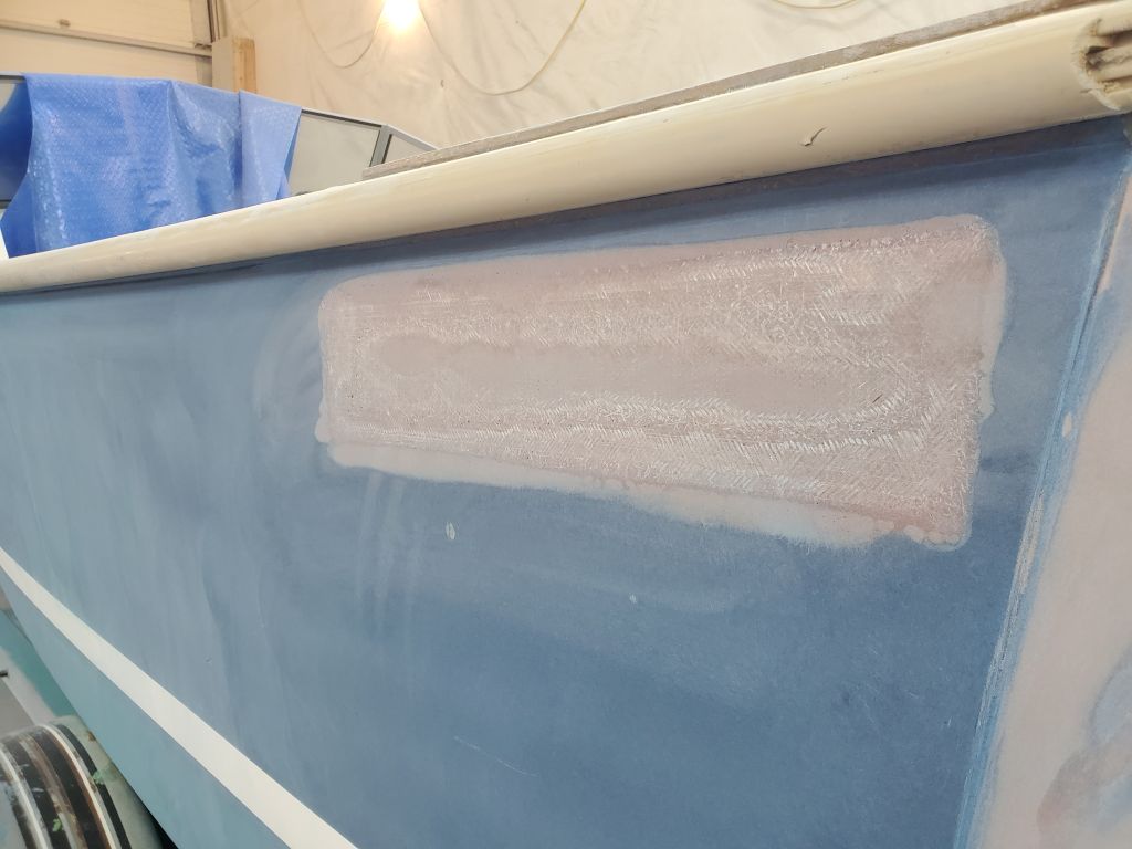
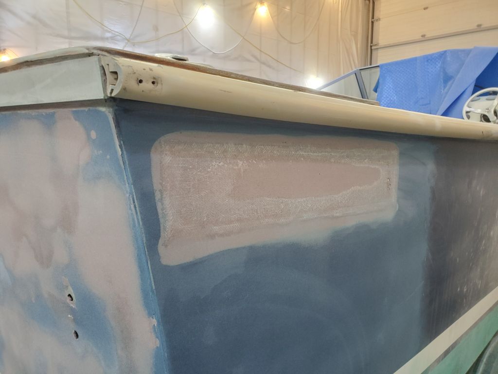
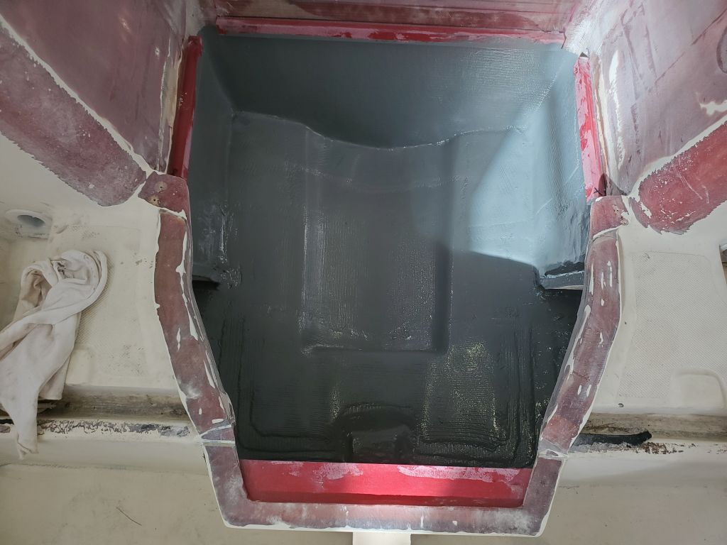
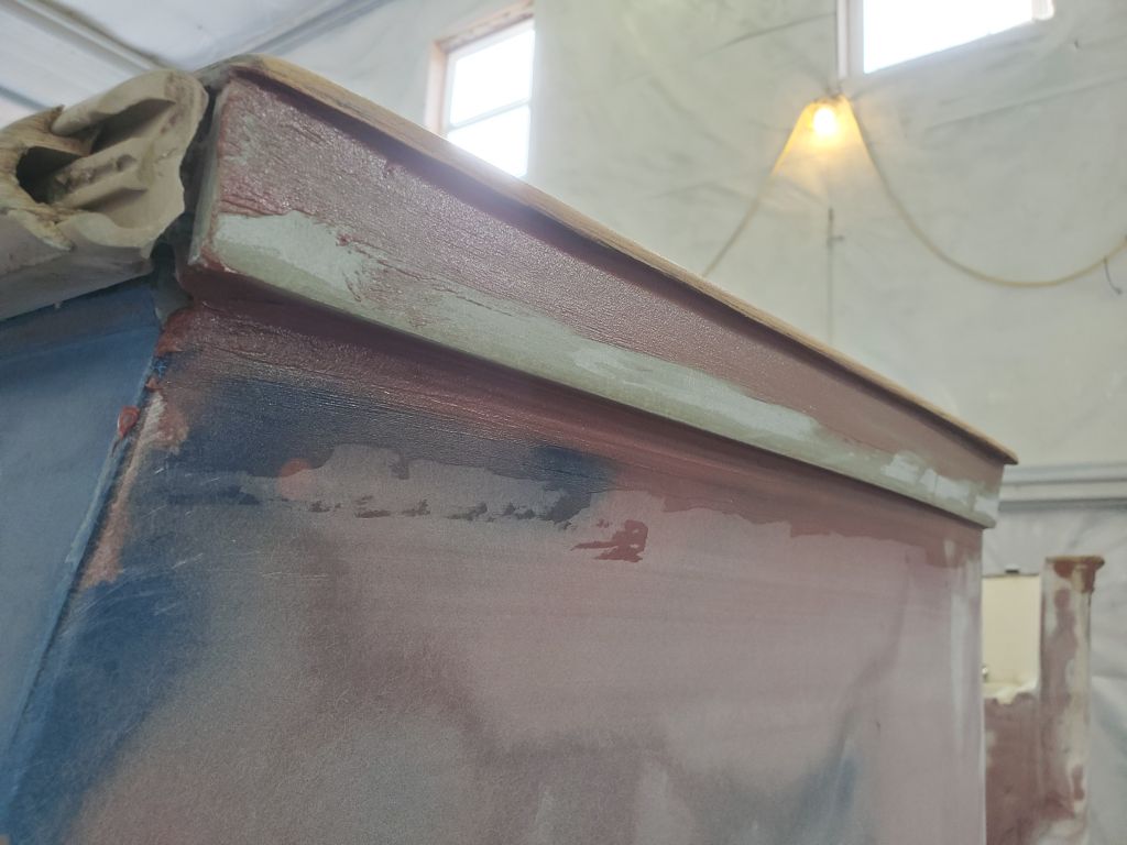
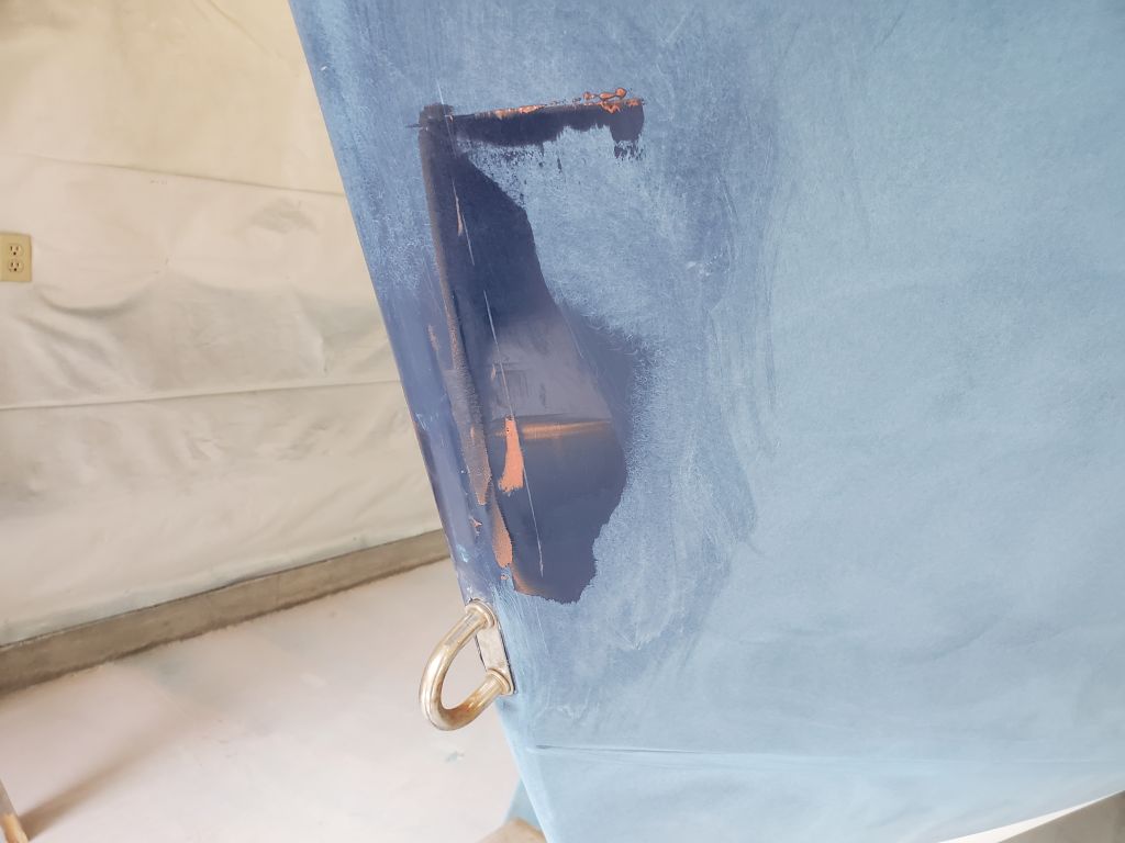
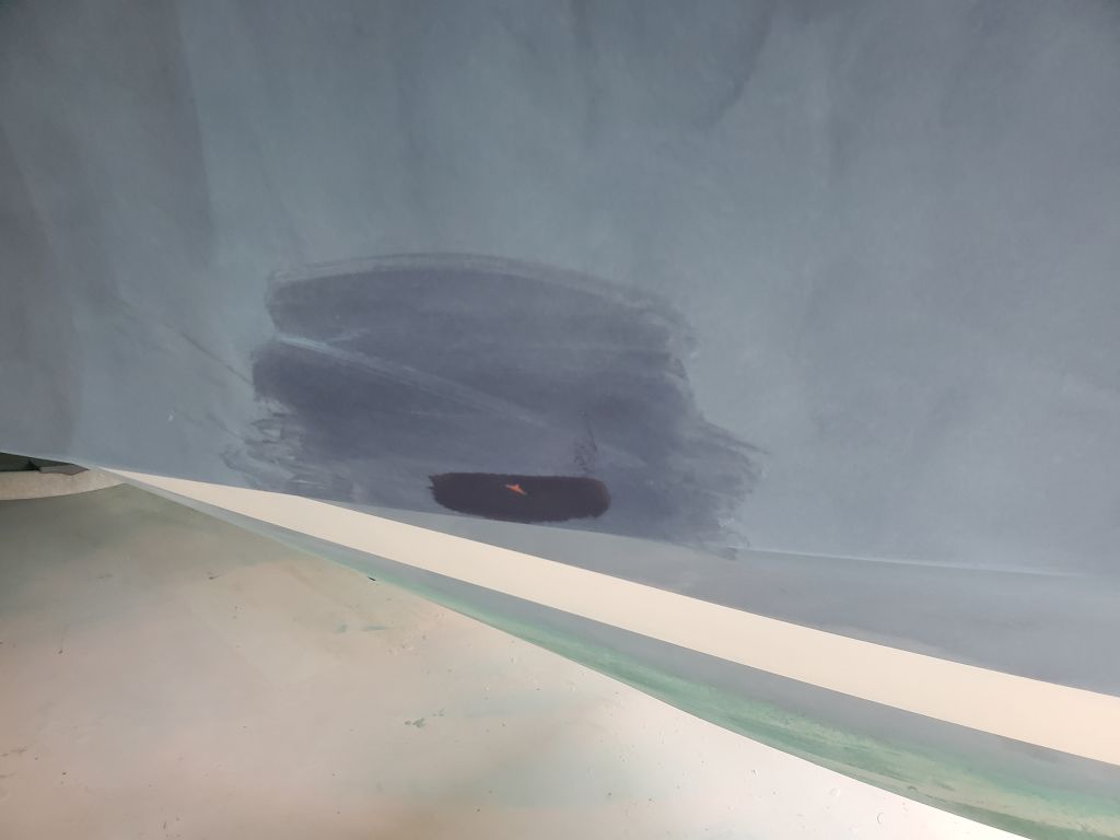
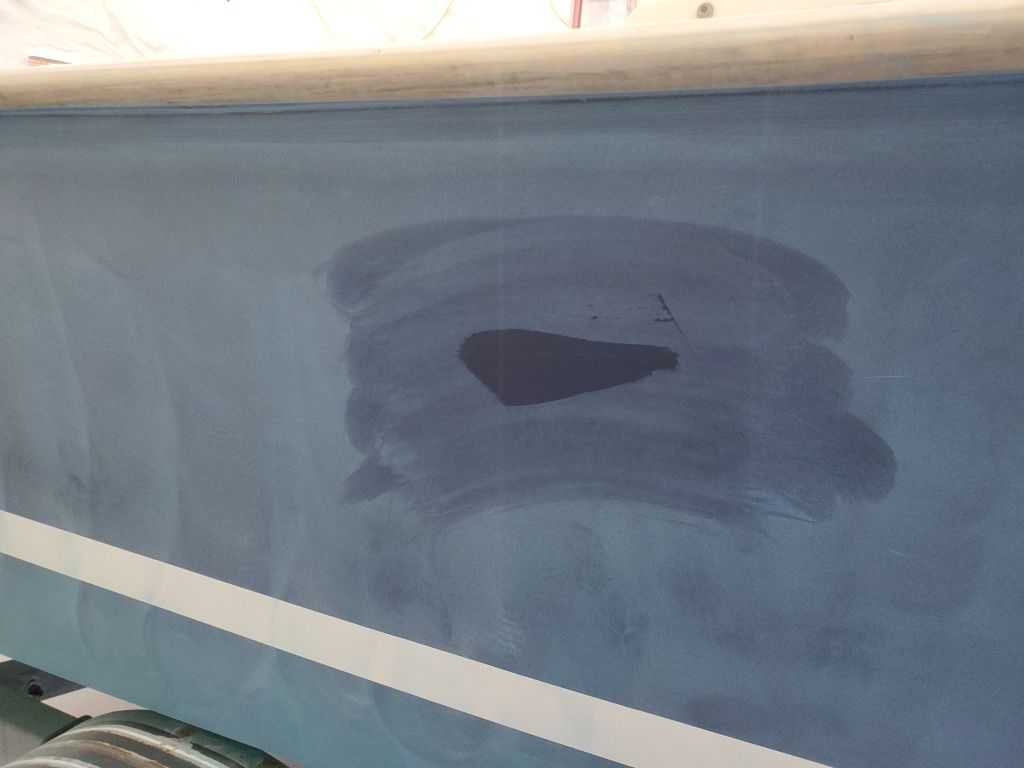
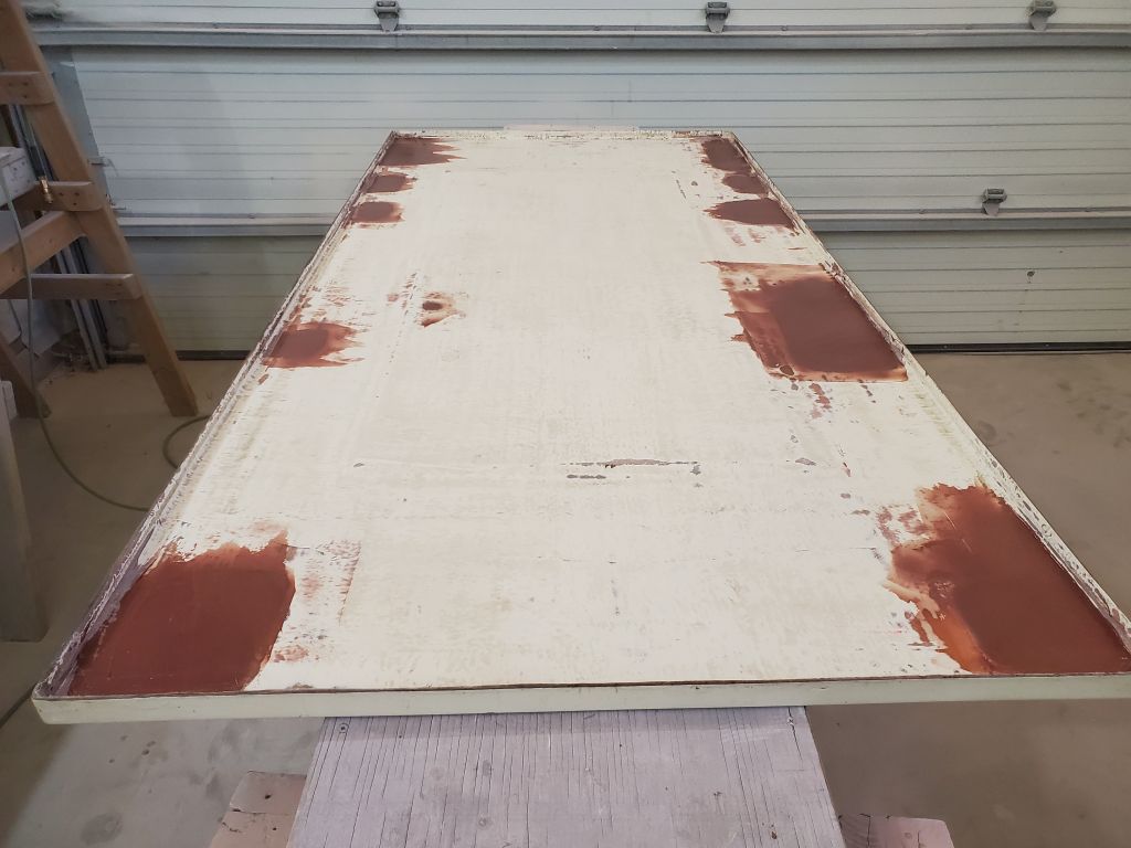
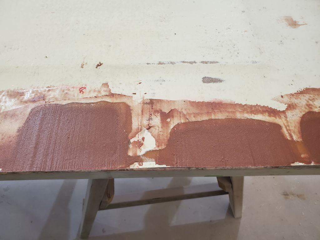
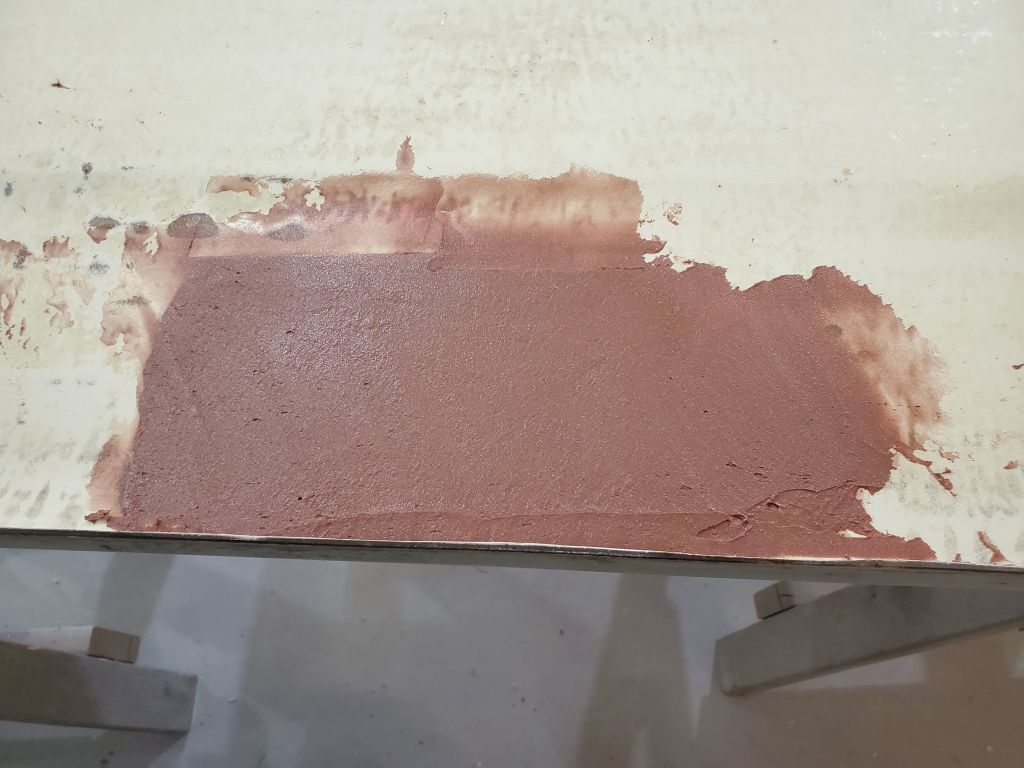
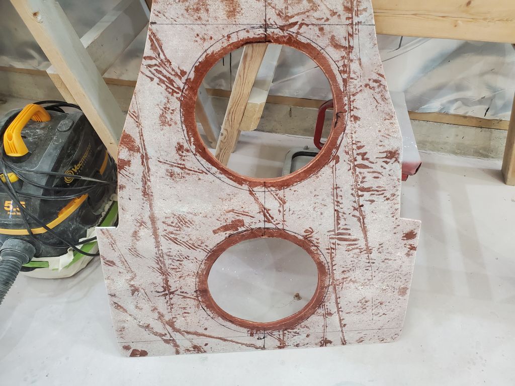
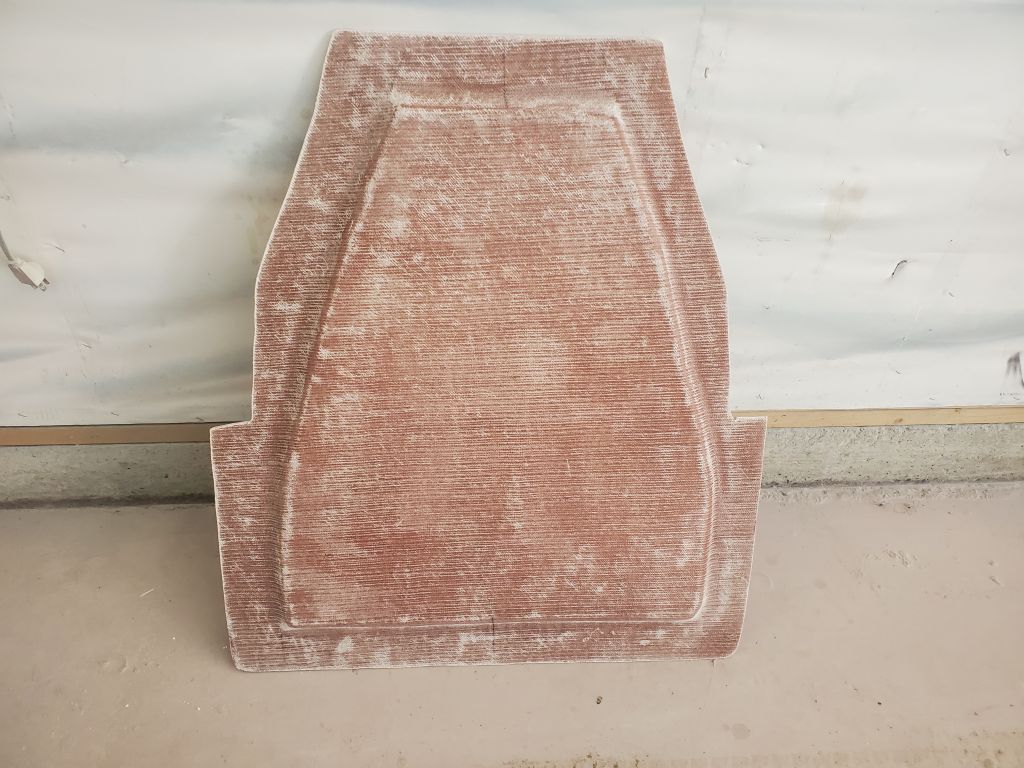
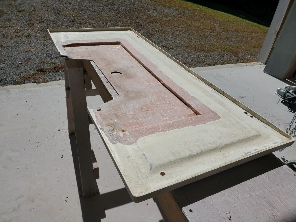
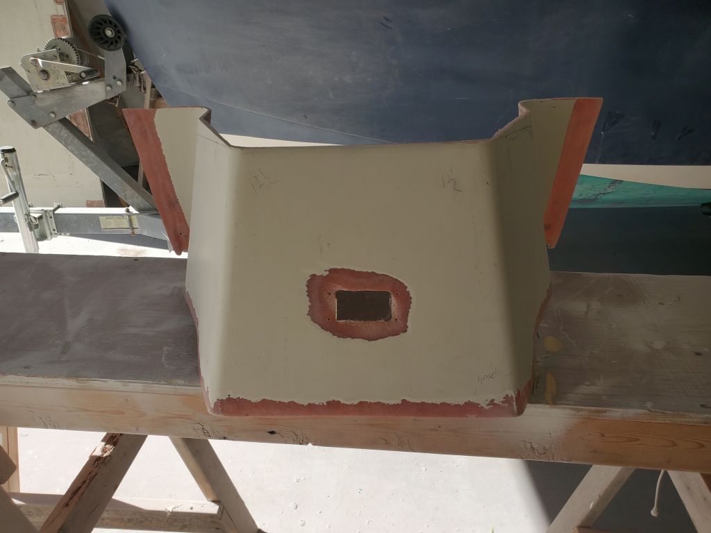
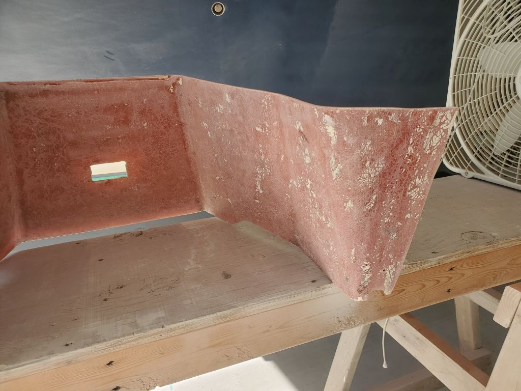
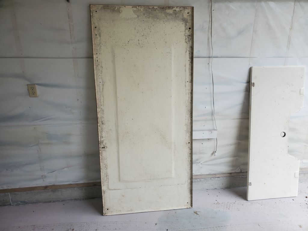
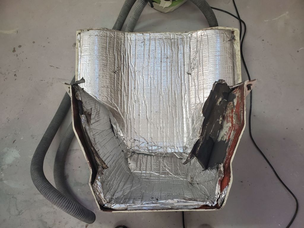
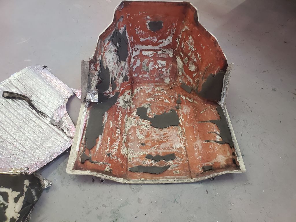
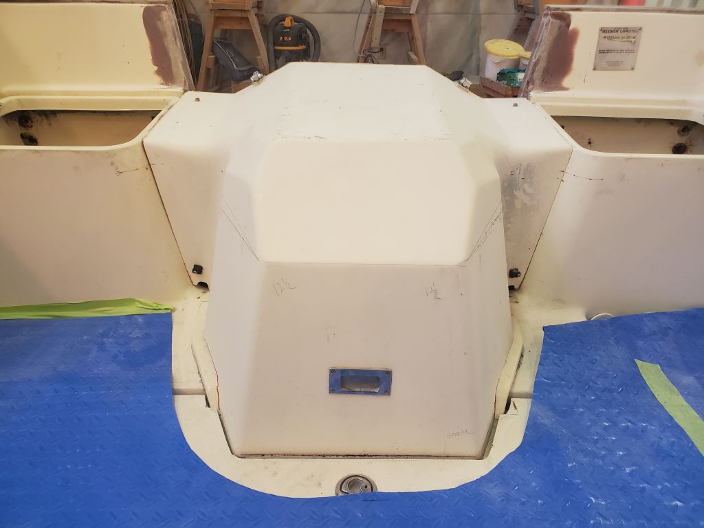
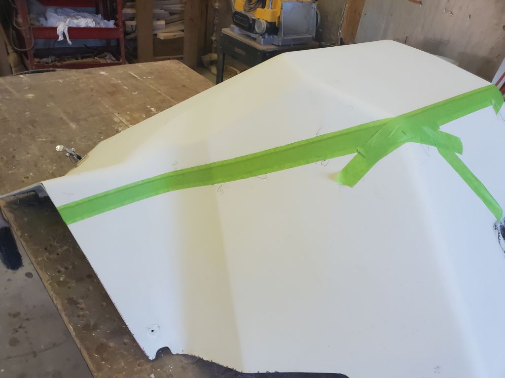
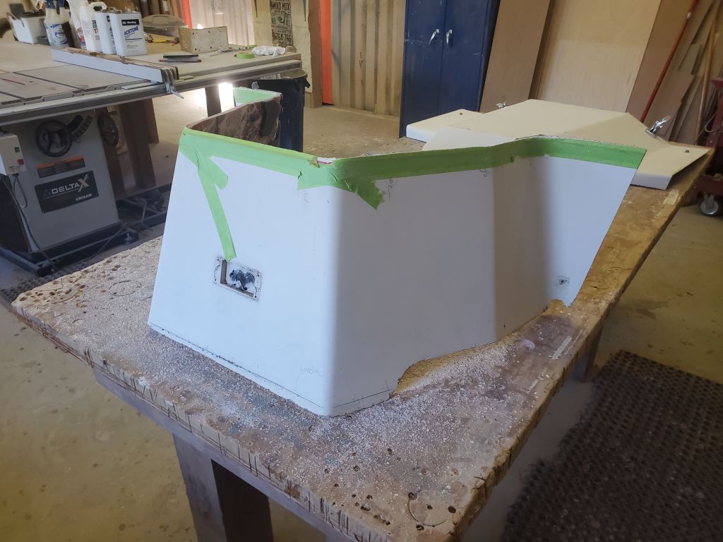
The owner and I previously discussed modifying the original engine box cover to work as the forward end of the splash well, mainly because it was already a reasonable fit, and handled the various different shapes of the cutout with minimal need for additional modification. To begin, I removed the sound insulation from the inside of the cover, to lighten the piece and prepare it for cutting. The insulation was glued in place with an adhesive flexible sealant and came off relatively easily, though there’d be substantial surface prep required on the inside surfaces later.
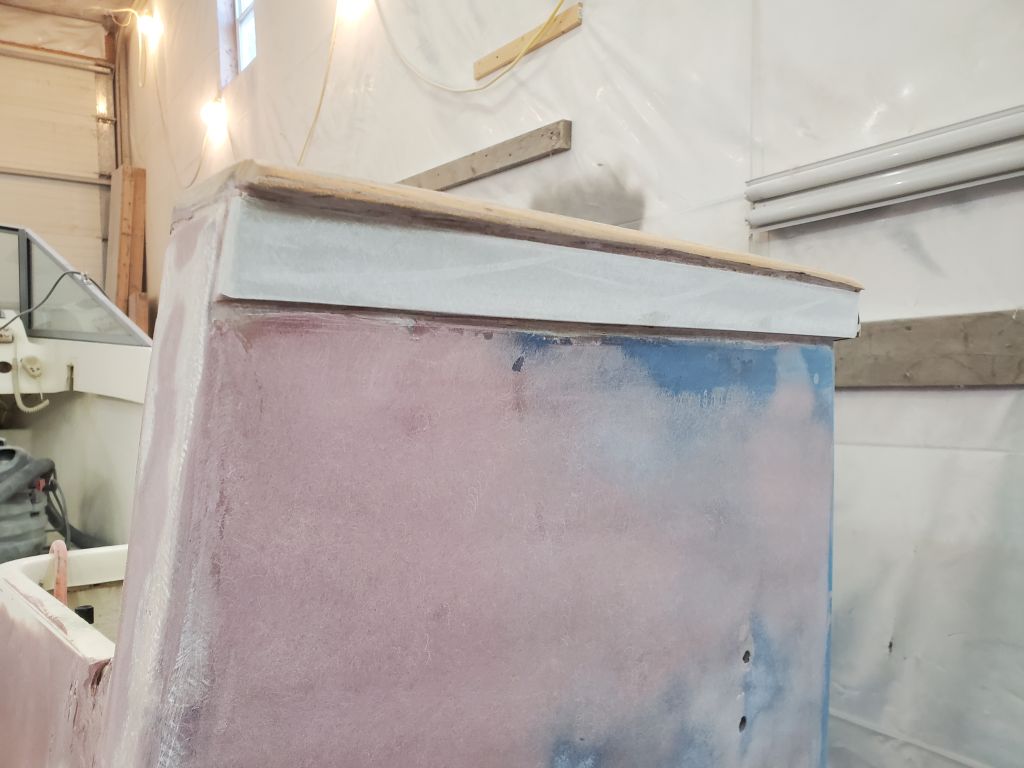
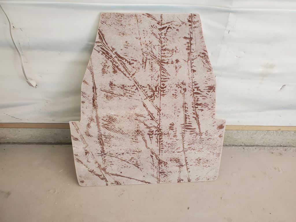
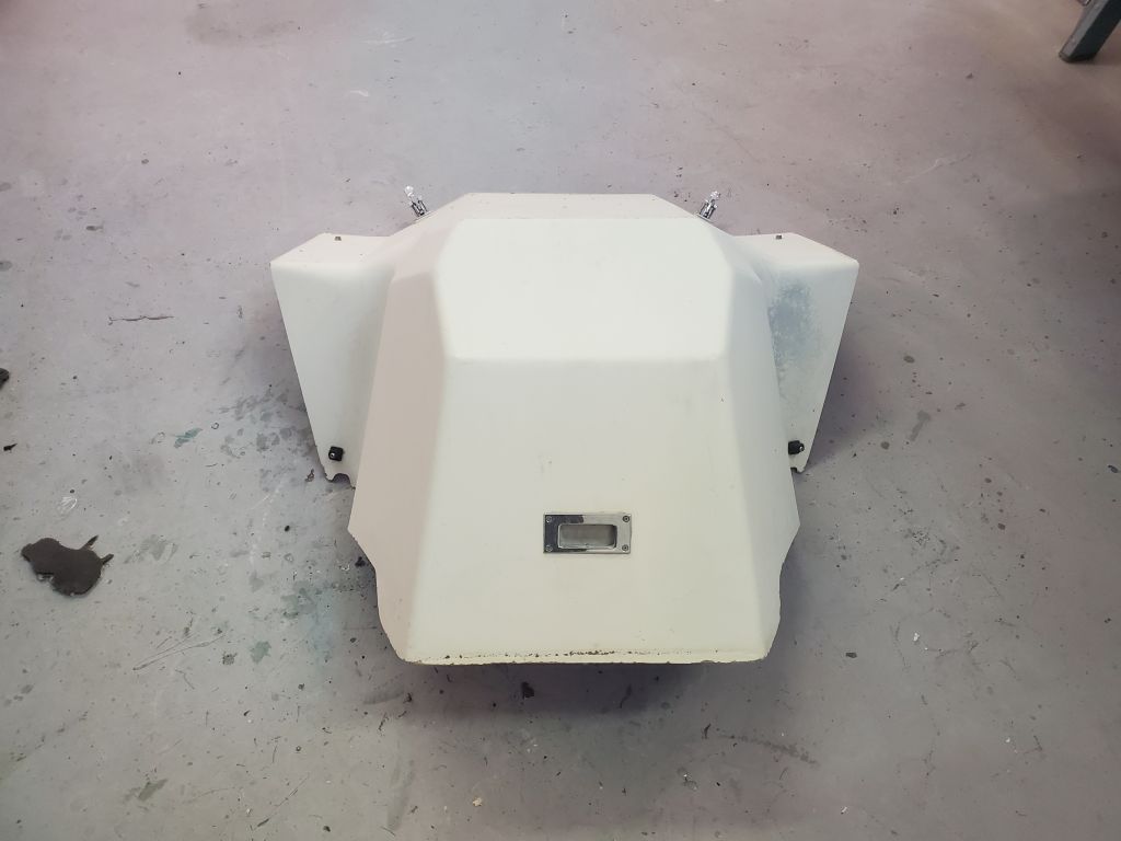
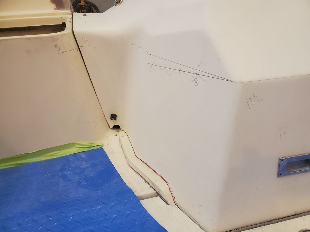
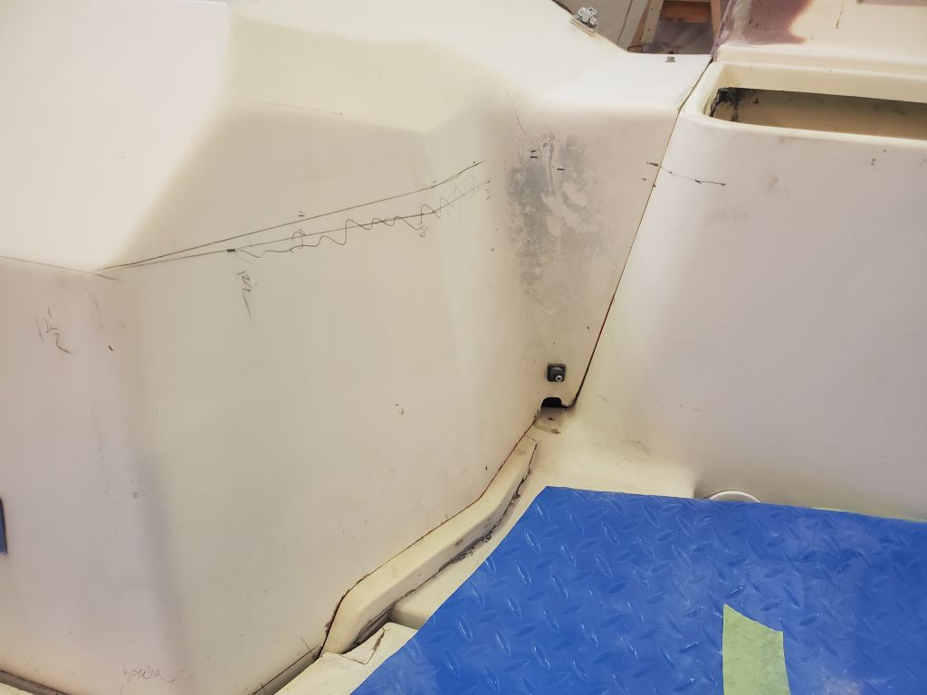
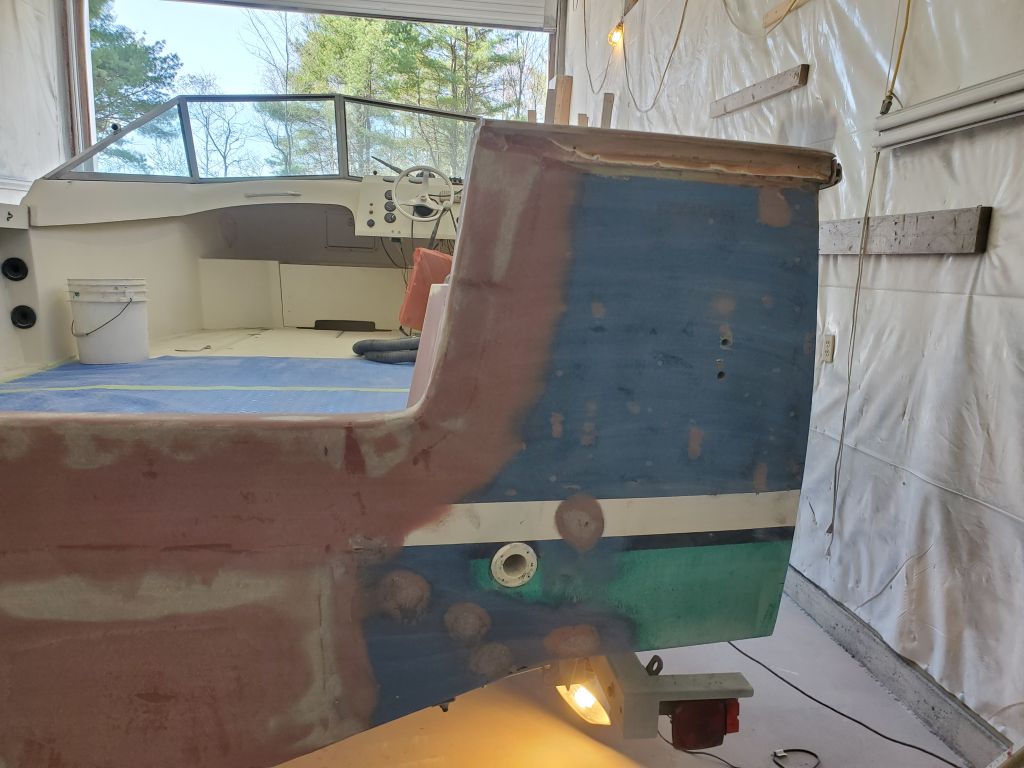
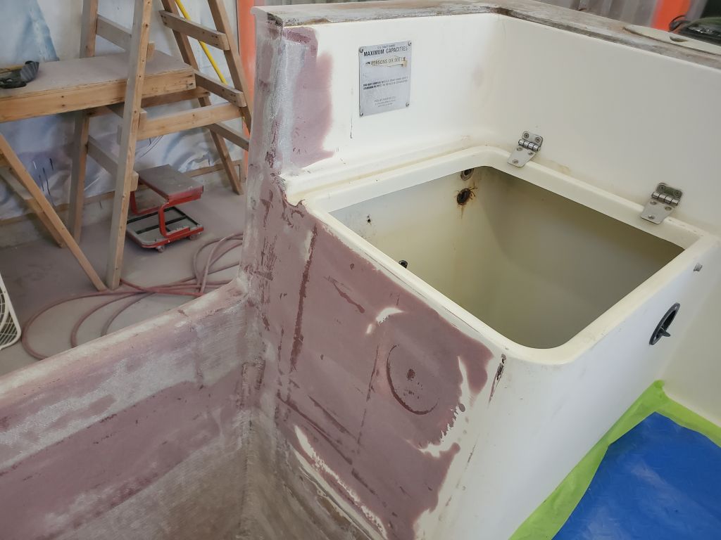
I set the hatch in its proper position in the boat. The angled portion of the forward side seemed the appropriate place to use as a finished height for the modified piece for several reasons, from cosmetic to the fact that, at about 12-1/2″ up from the deck, it just happened to be a good height to begin with. Using various tools I struck this line around the sides of the hatch , eventually intersecting with the molded seats/storage areas on either side. My first line turned out to be in the wrong place, so I struck it out.
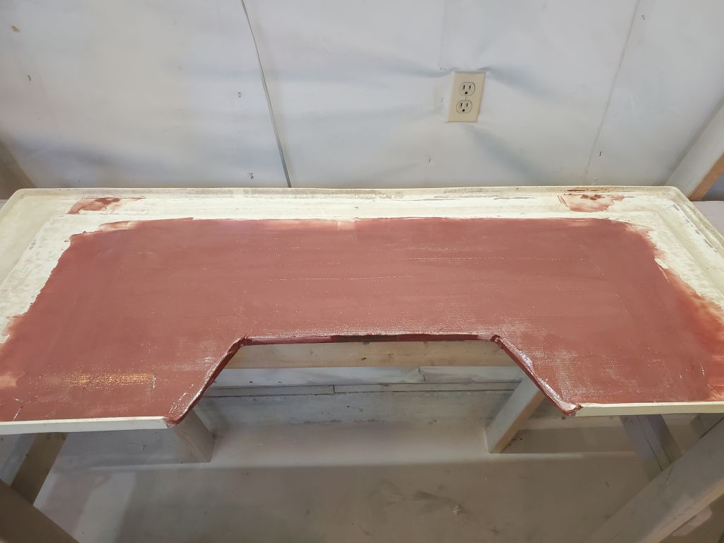
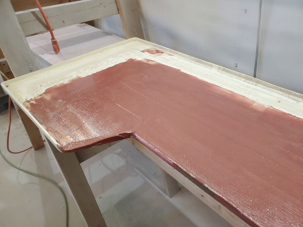
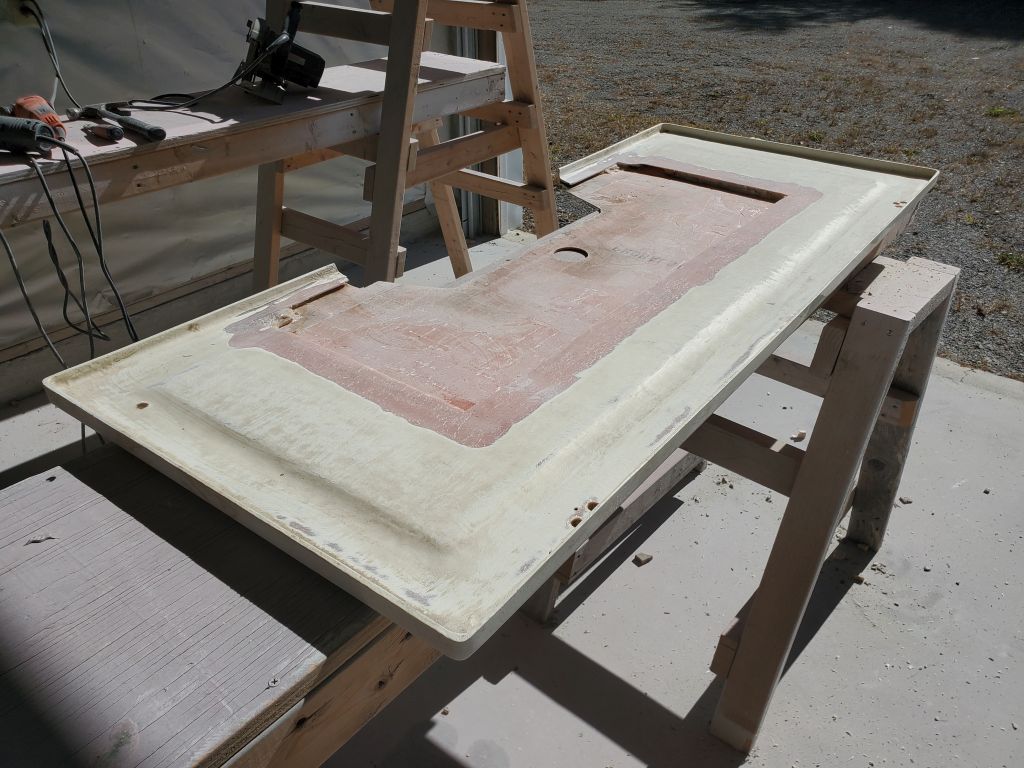
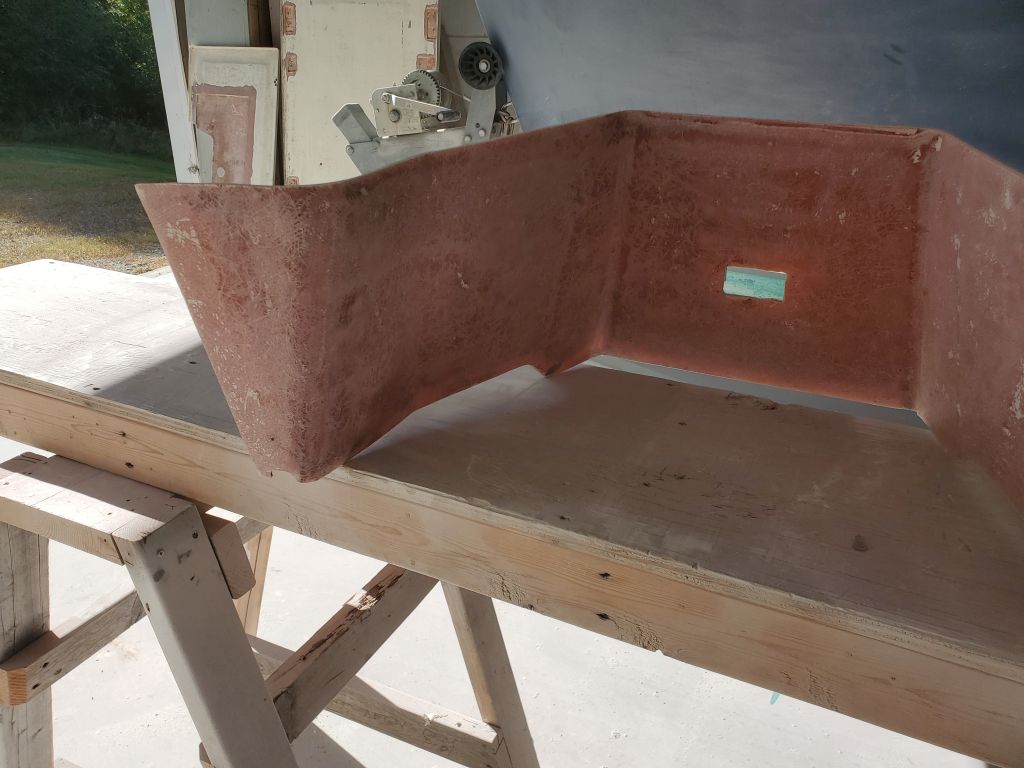
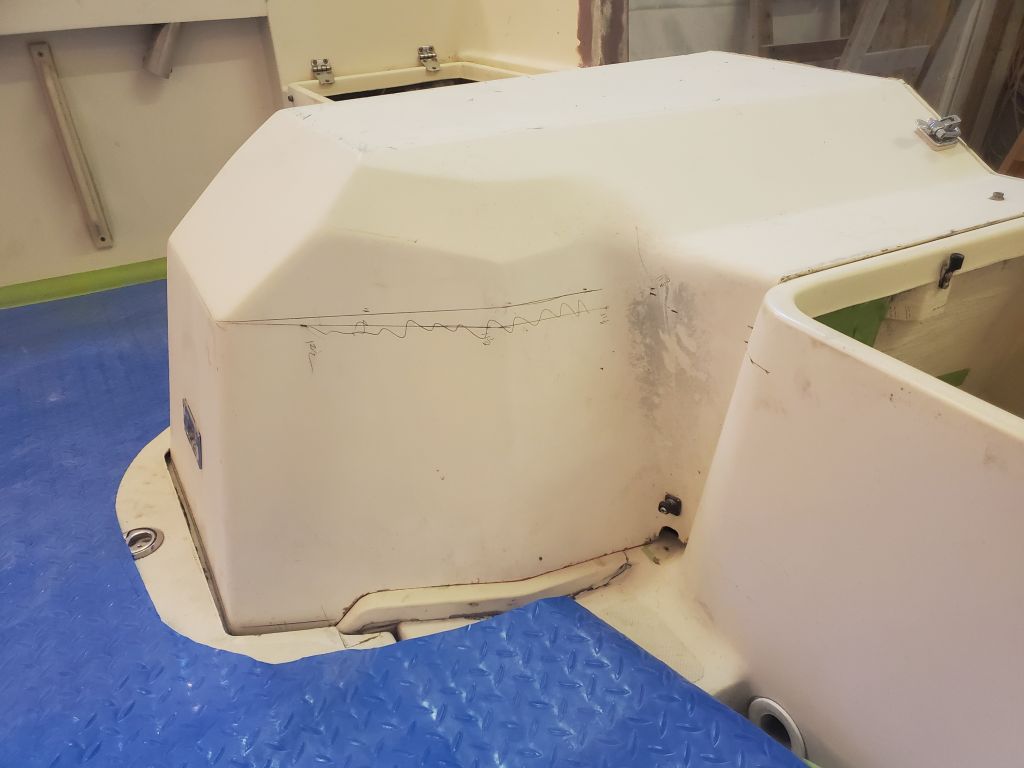
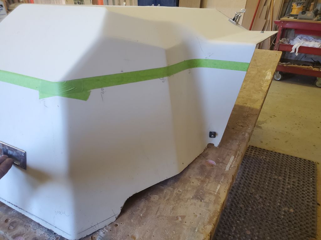
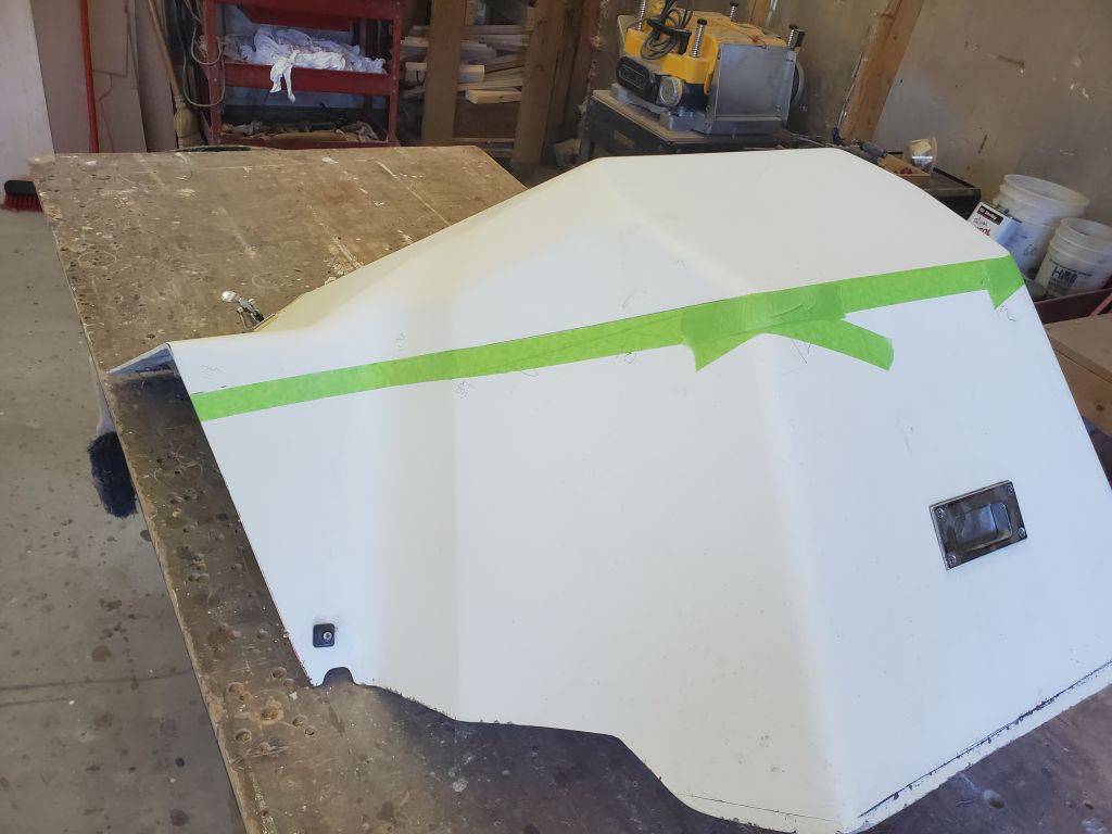
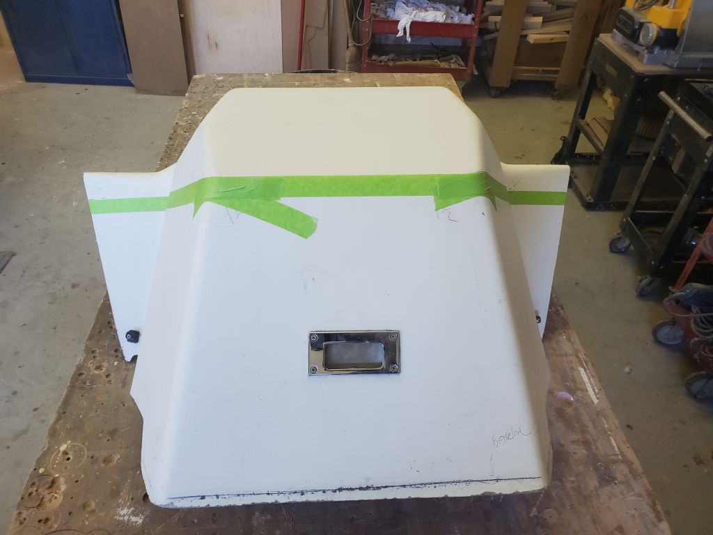
Happy with the initial line, I brought the cover to the bench and used tape to mask off the line for greater visibility. Then, I struck a new line 1/4″ above, using a scrap of plywood as a guide, and masked to the new line; this would be the cut line, a bit above the hoped-for line, to allow me room for adjustments later after the test fit and proof of concept. Happy with the line from a visual perspective, I made the initial cut with a jigsaw, removing the top of the old engine box.
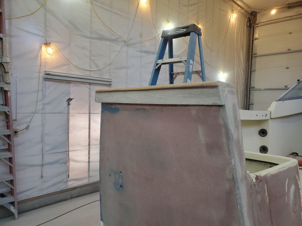
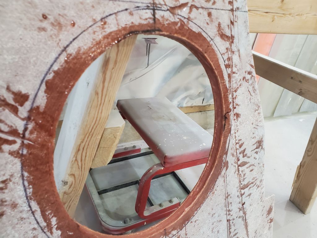
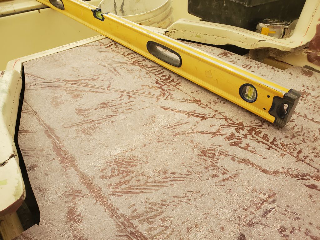
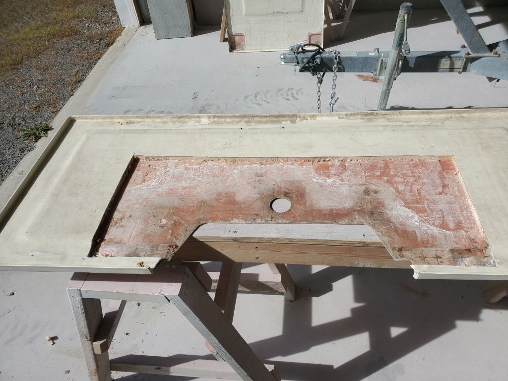
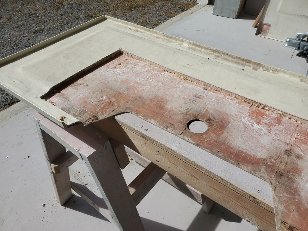
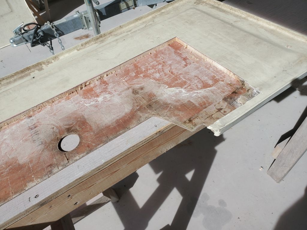
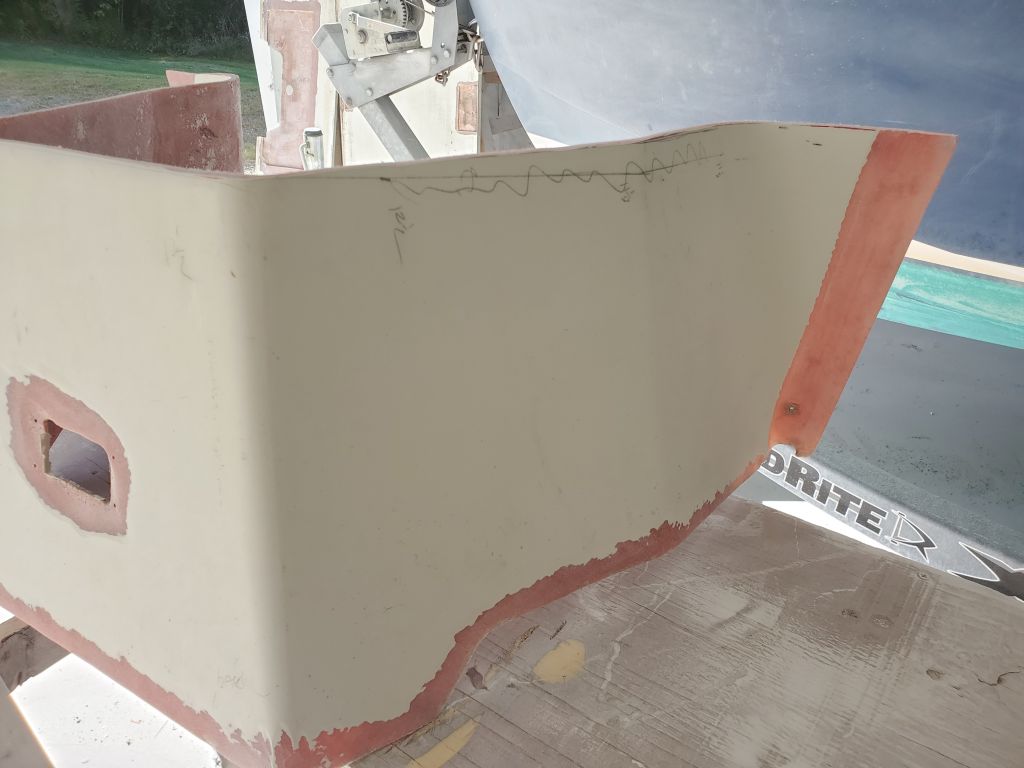
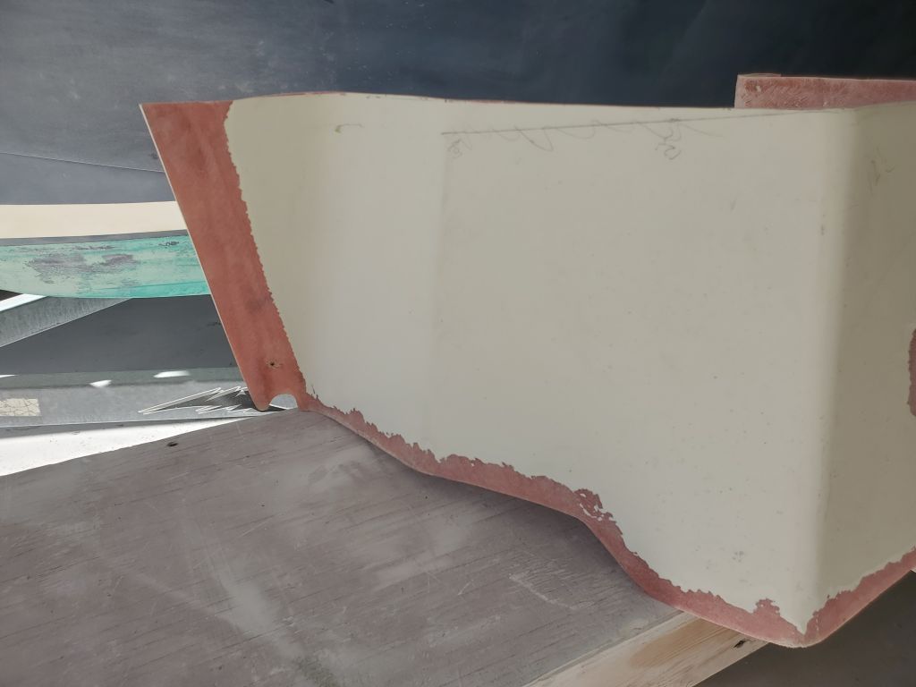
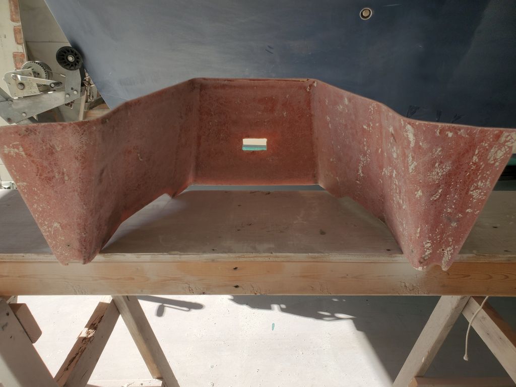
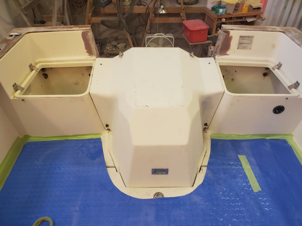
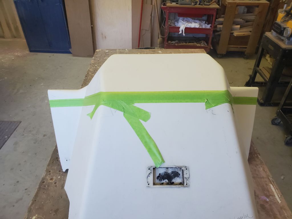
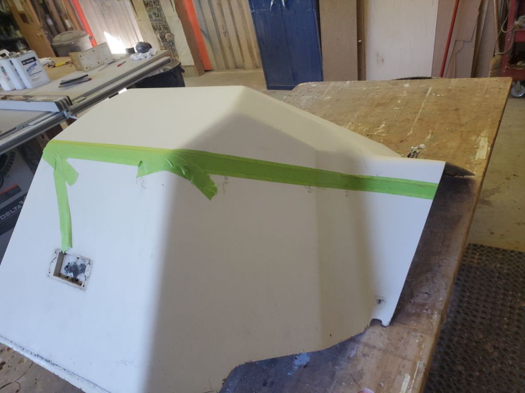
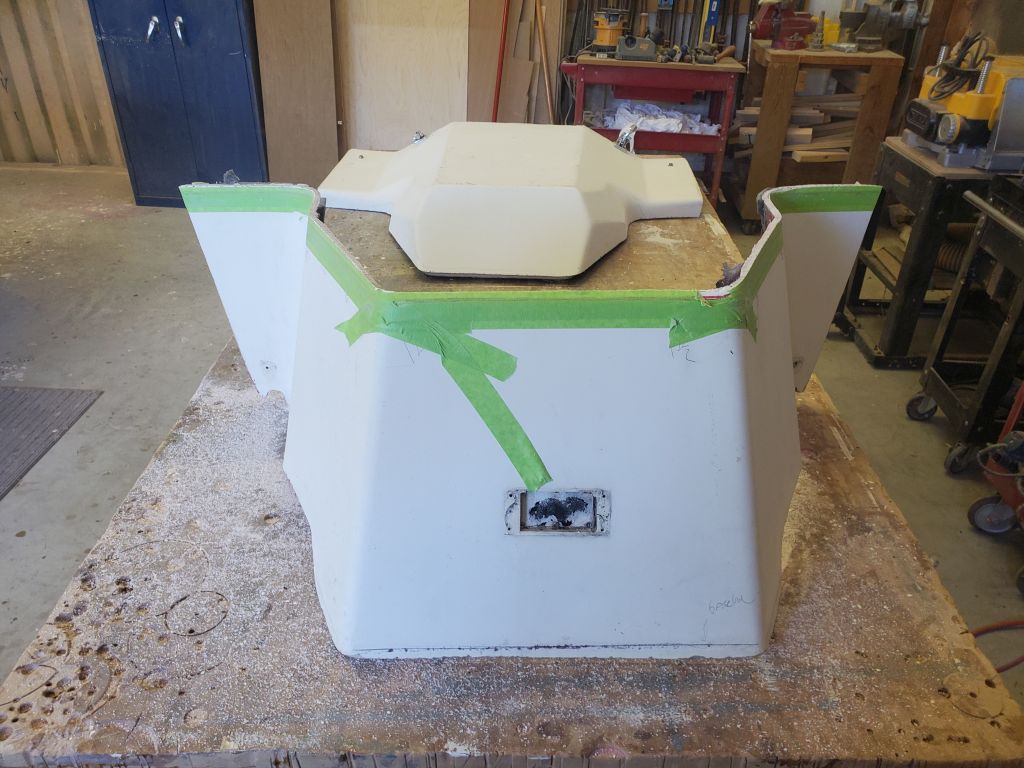
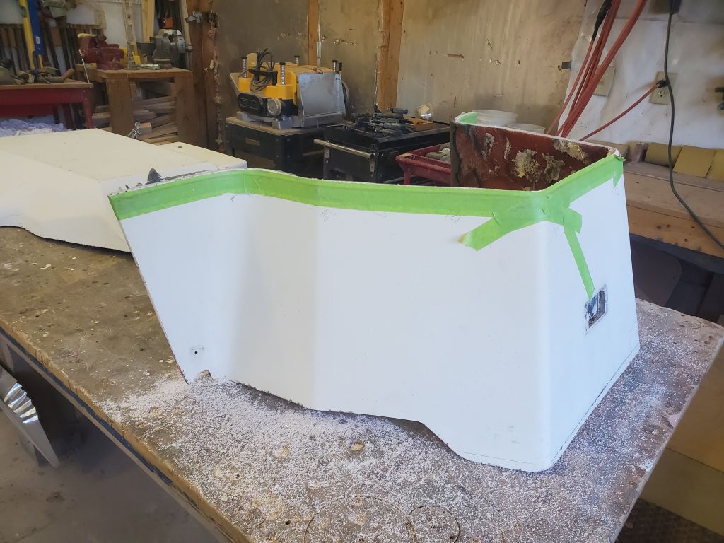
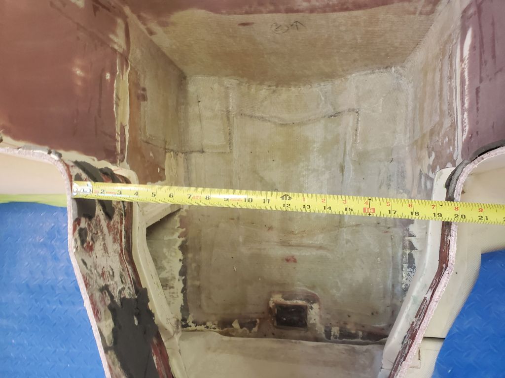
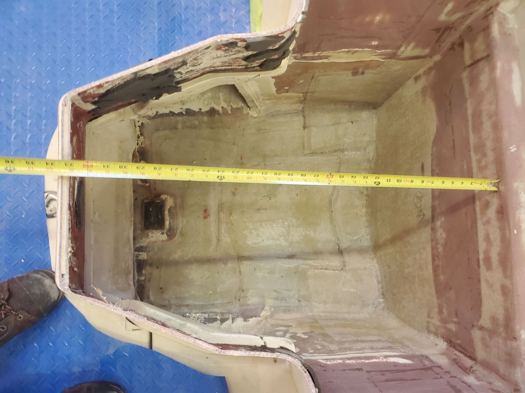
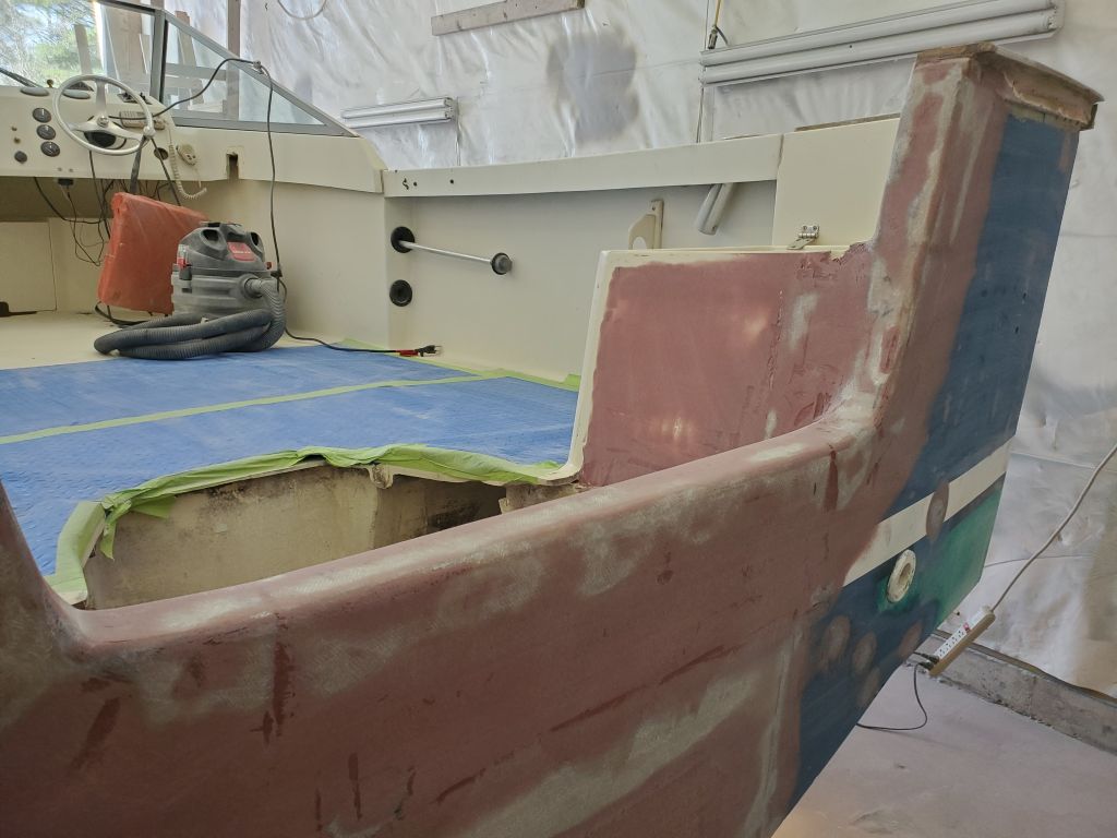
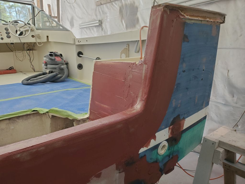
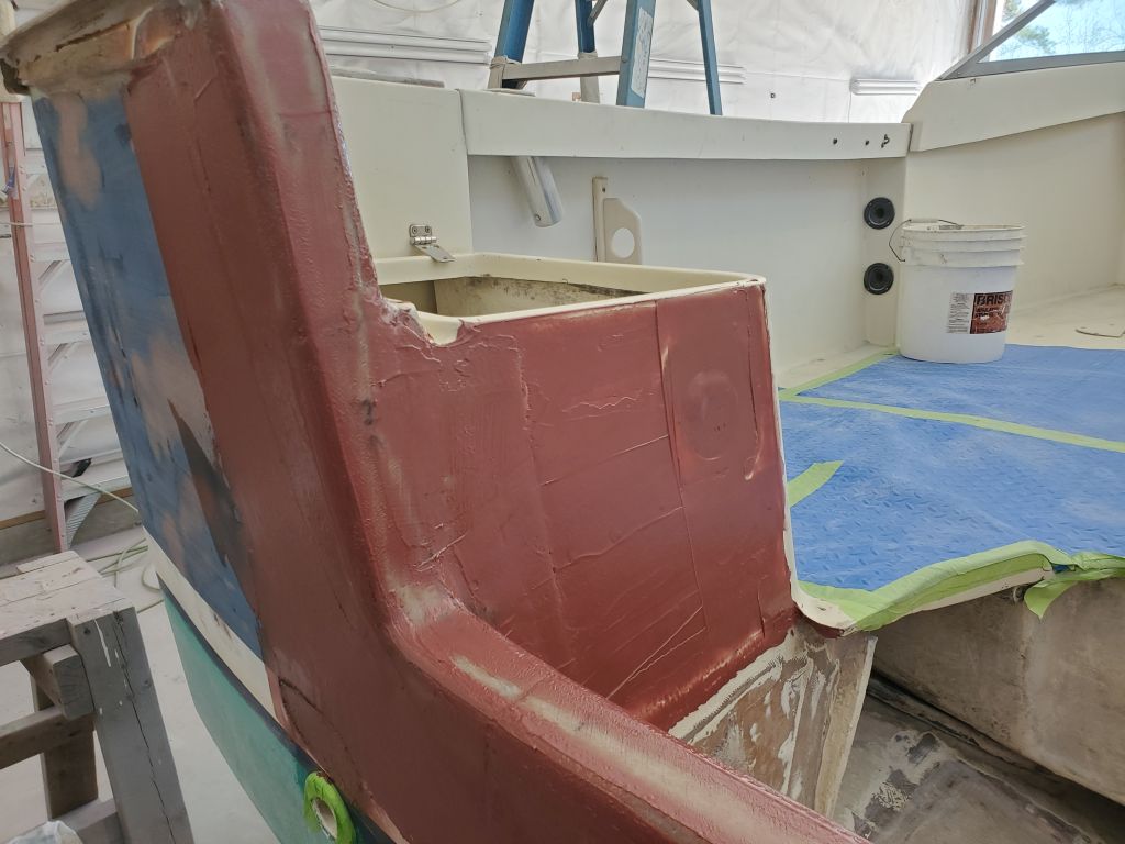
I test-fit the modified bulkhead in the boat and made a couple measurements of the inside width and distance from the transom to confirm the owner’s choice of outboard would fit when tilted up. My eventual plan was to secure this piece in place with epoxy and fiberglass from the inside, incorporating it with the new splashwell deck. For now, the test-fit was complete and I set the assembly aside.
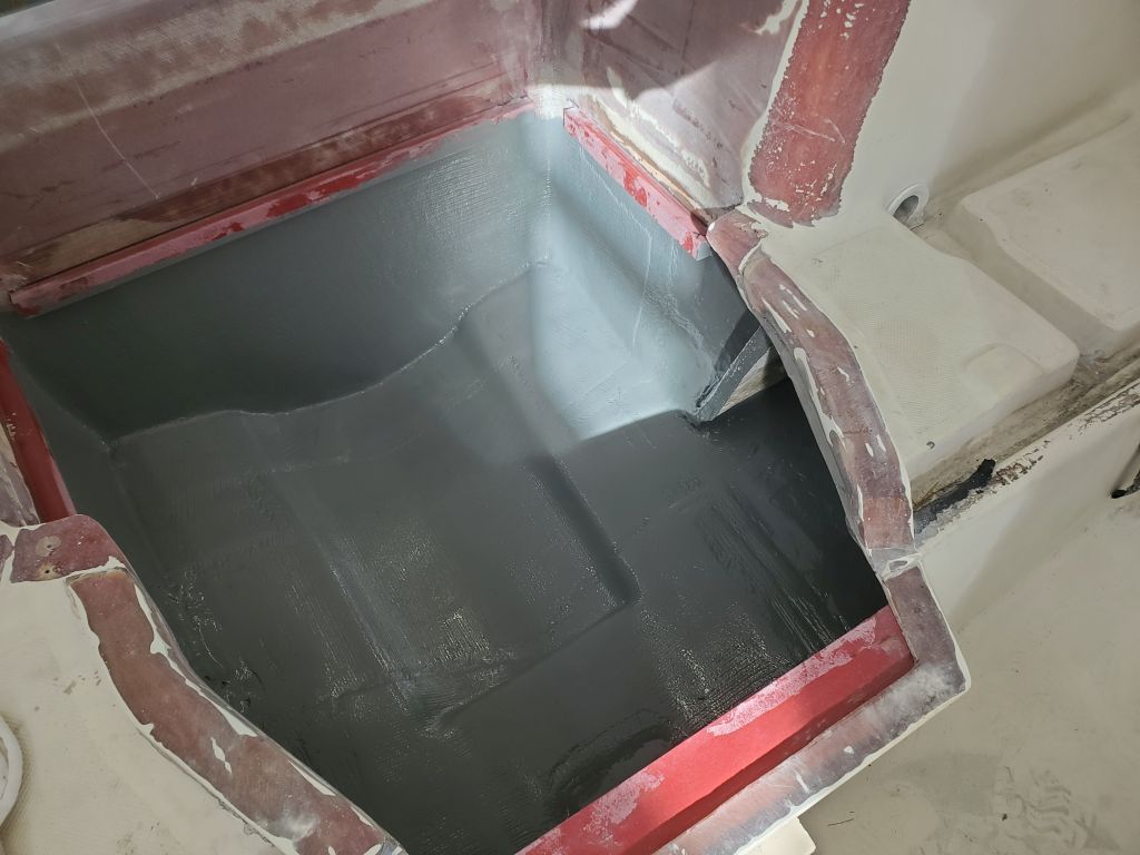
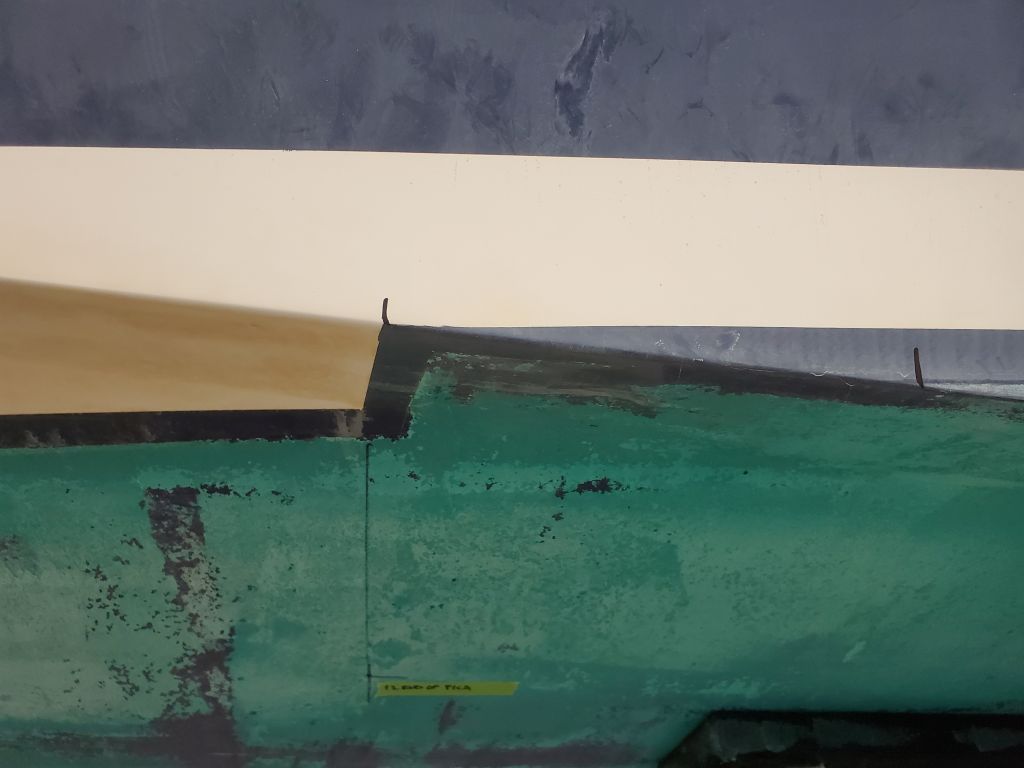
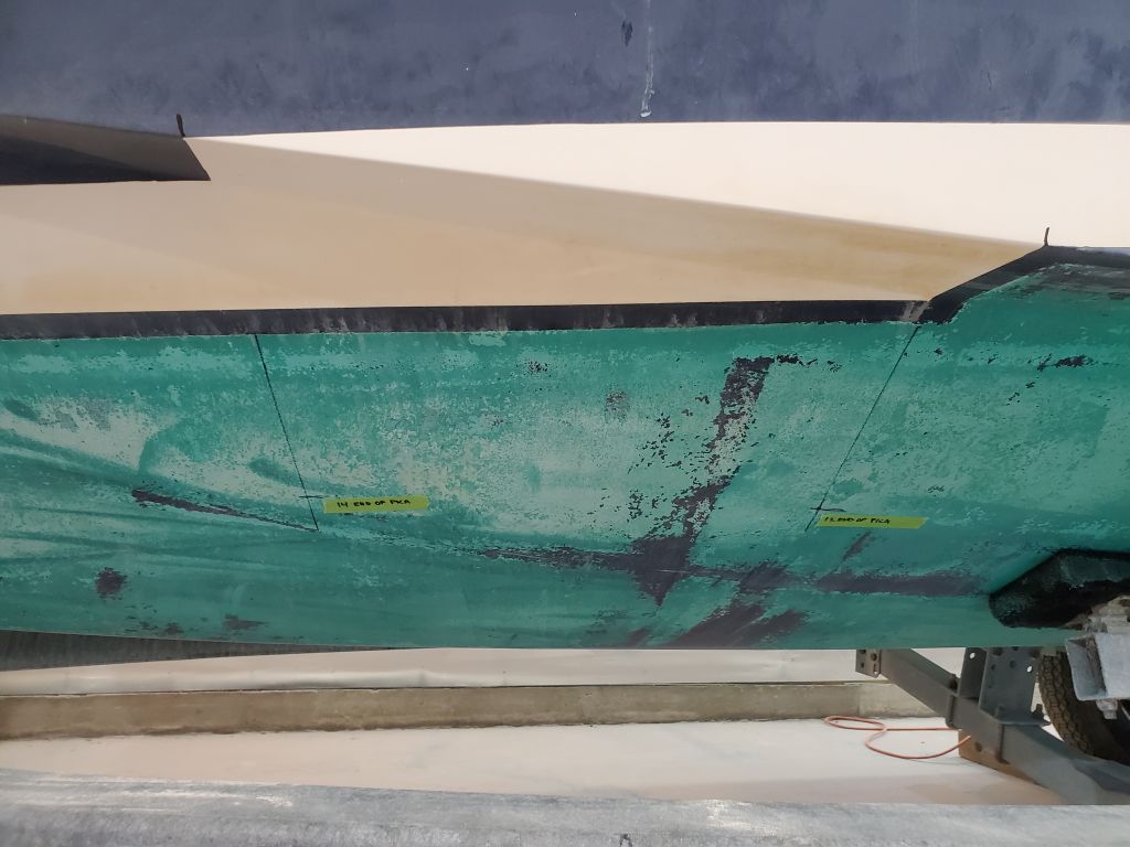
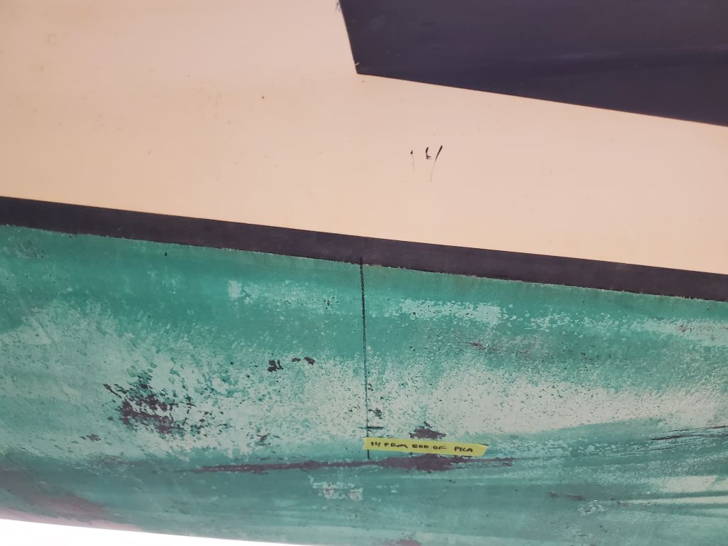
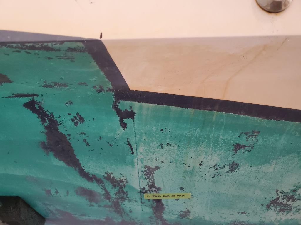
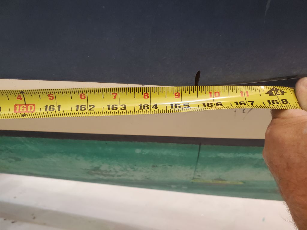
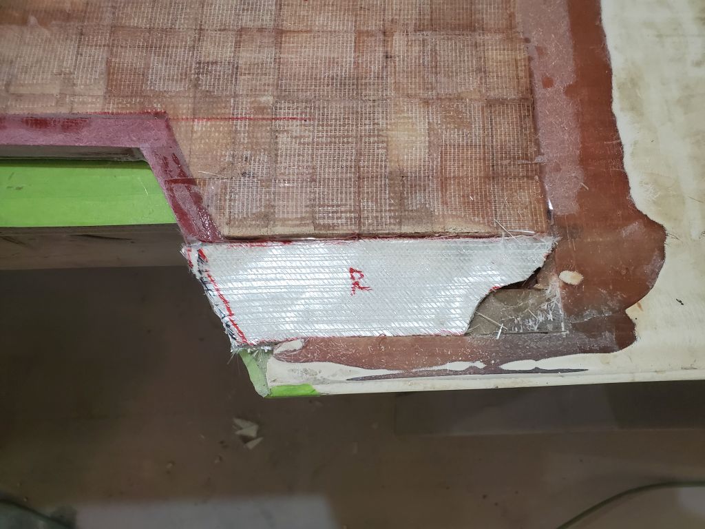
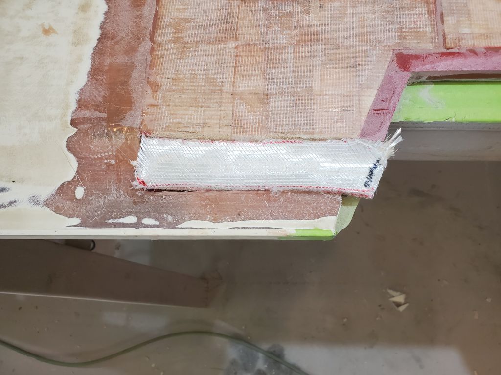
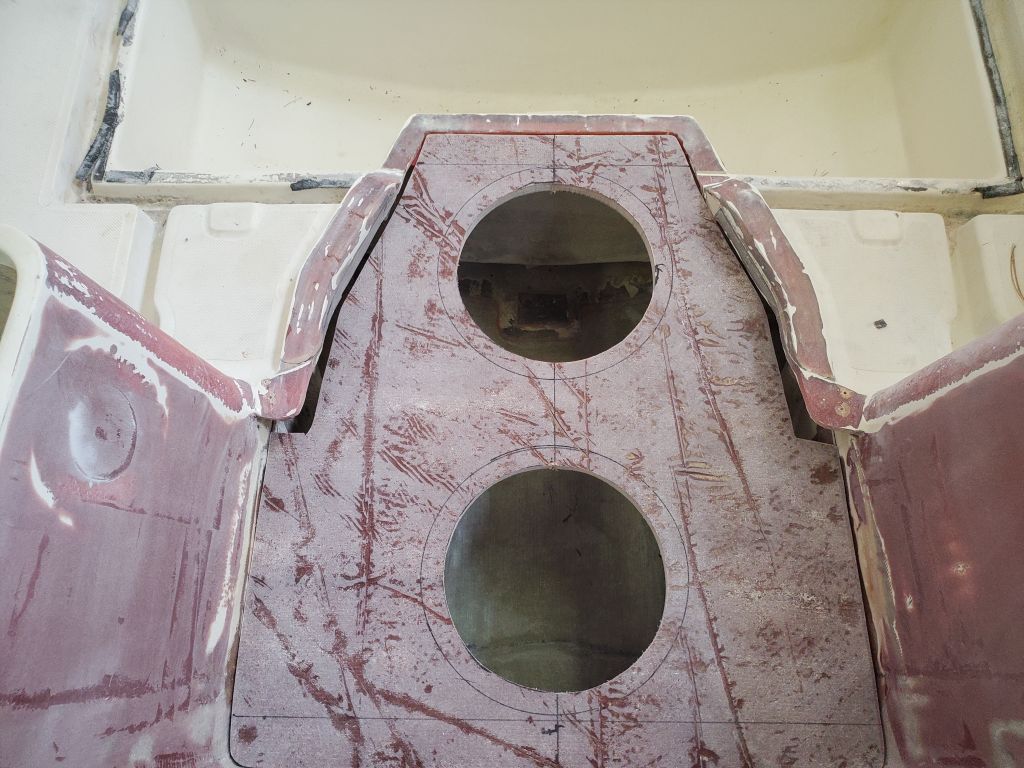
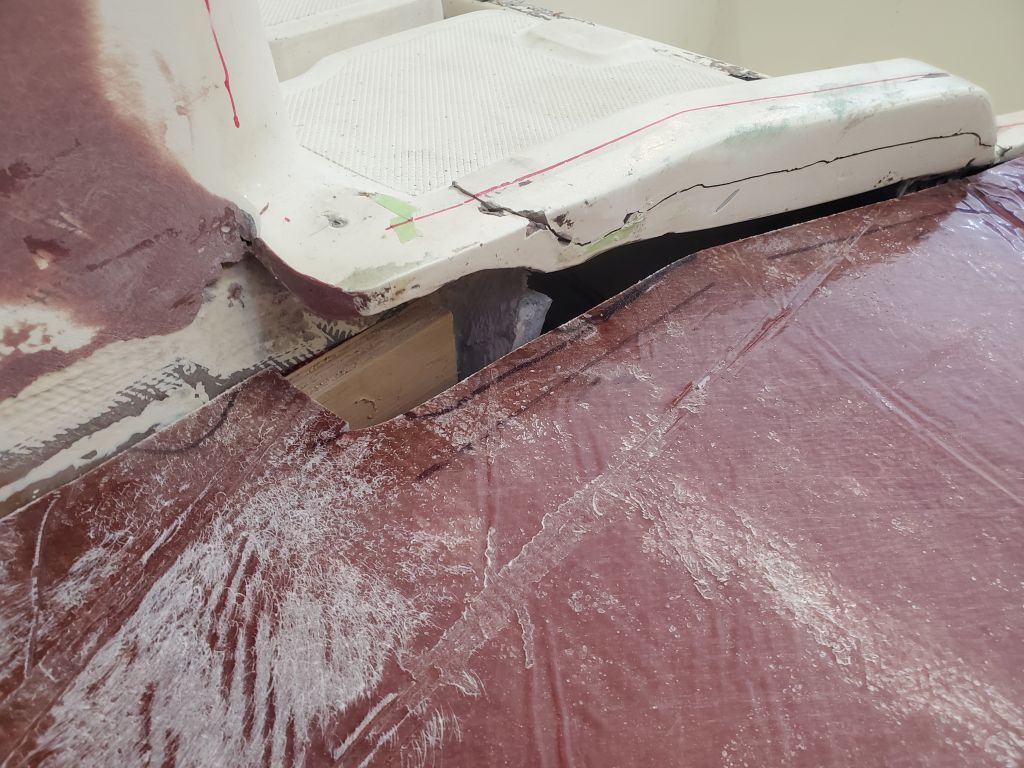
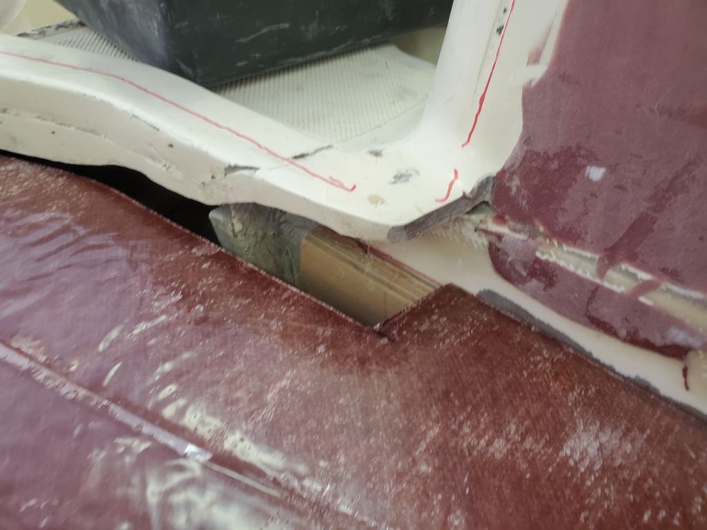
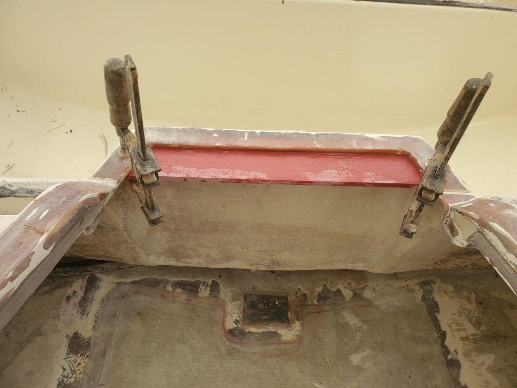
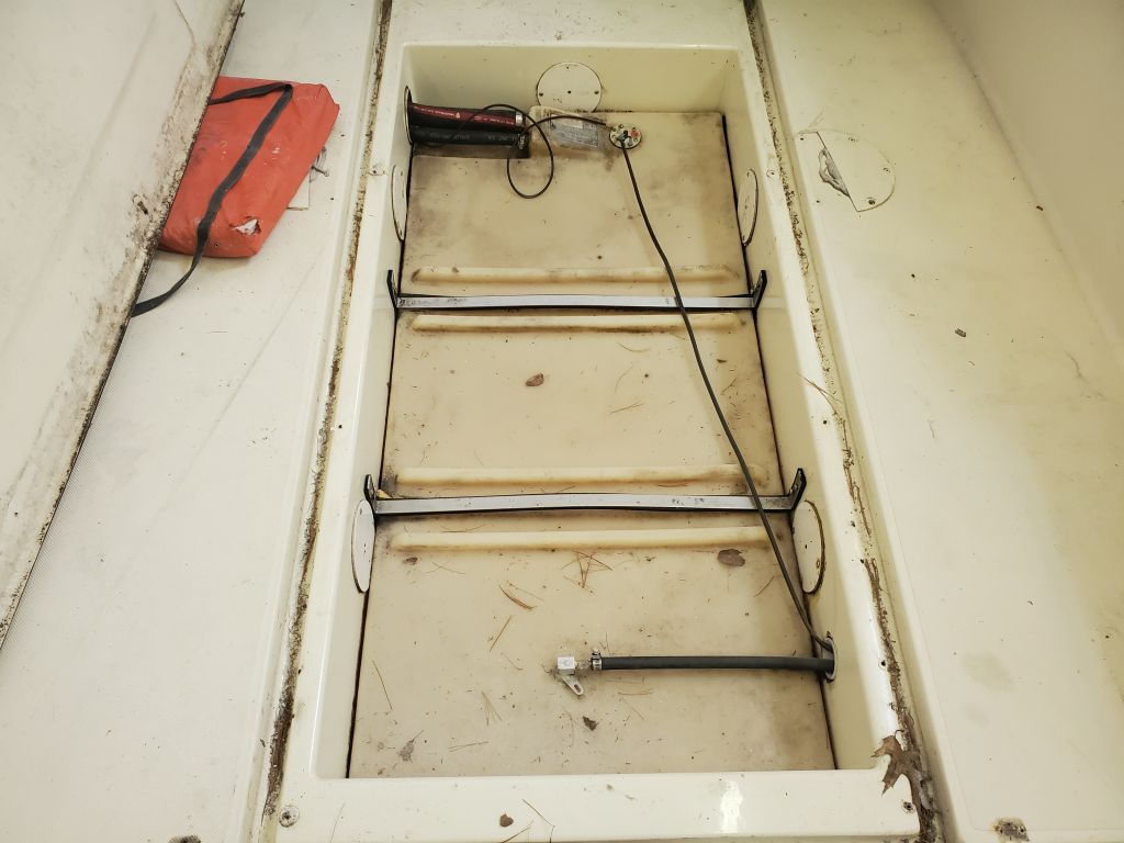
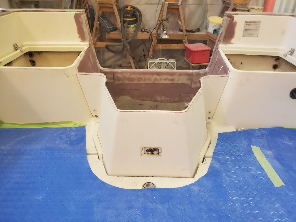
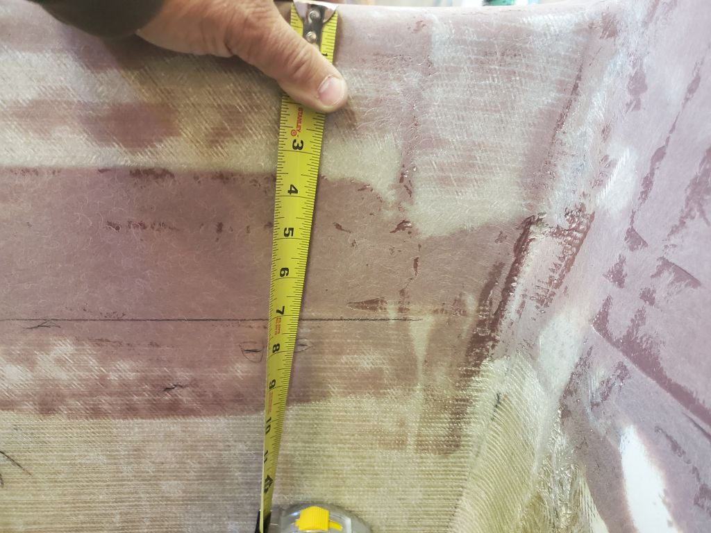
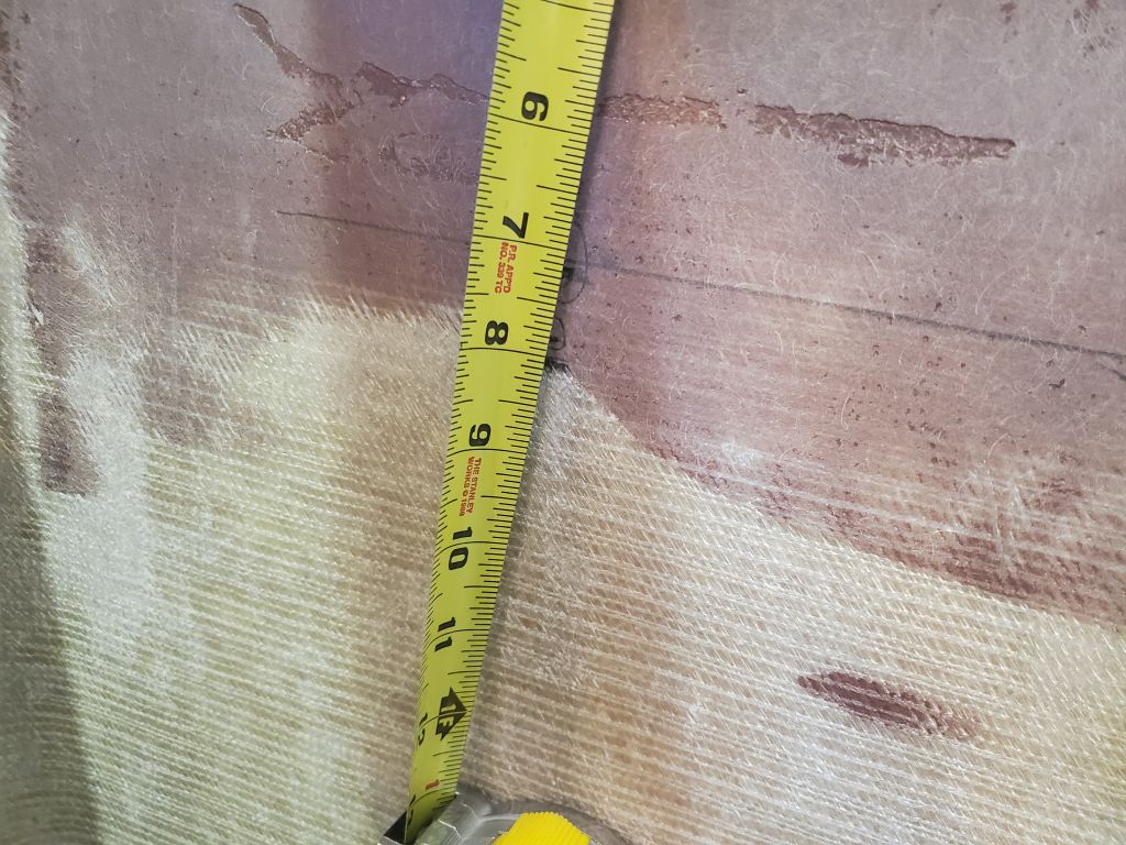
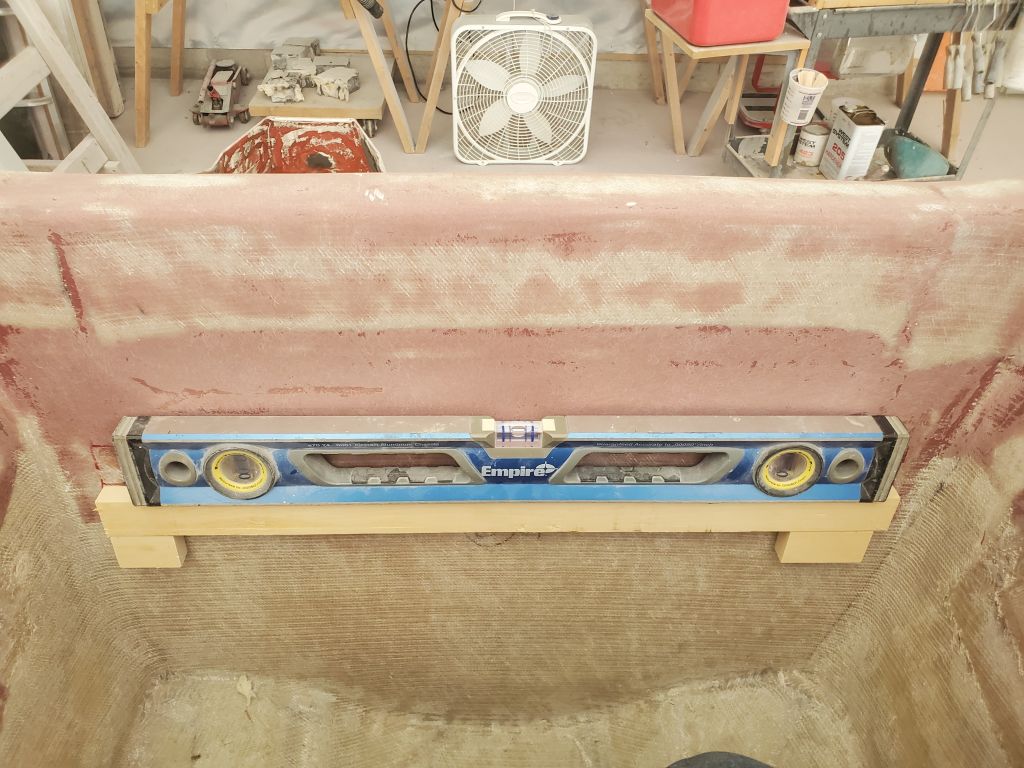
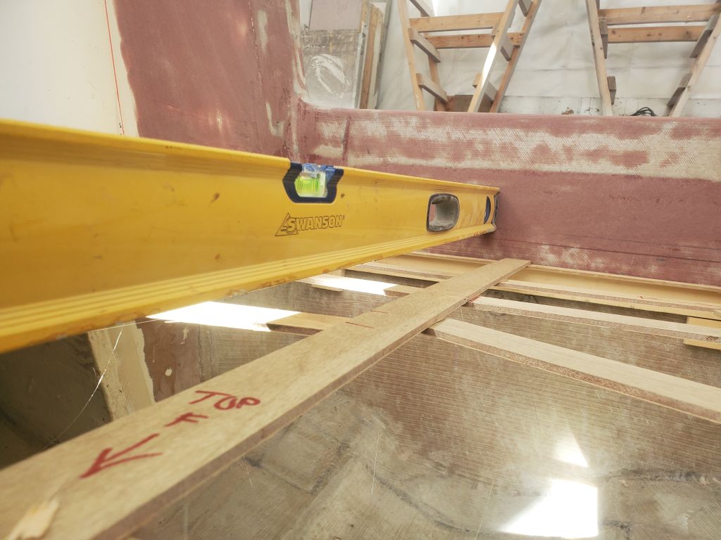
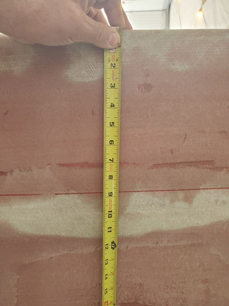
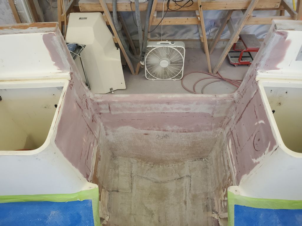
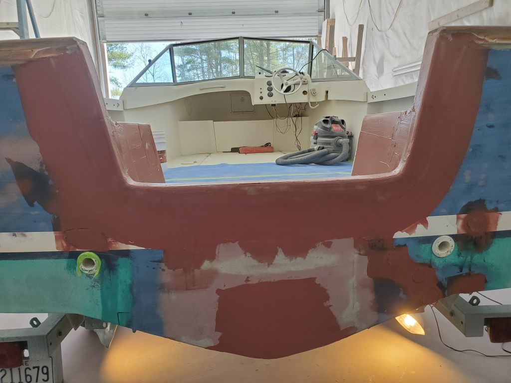
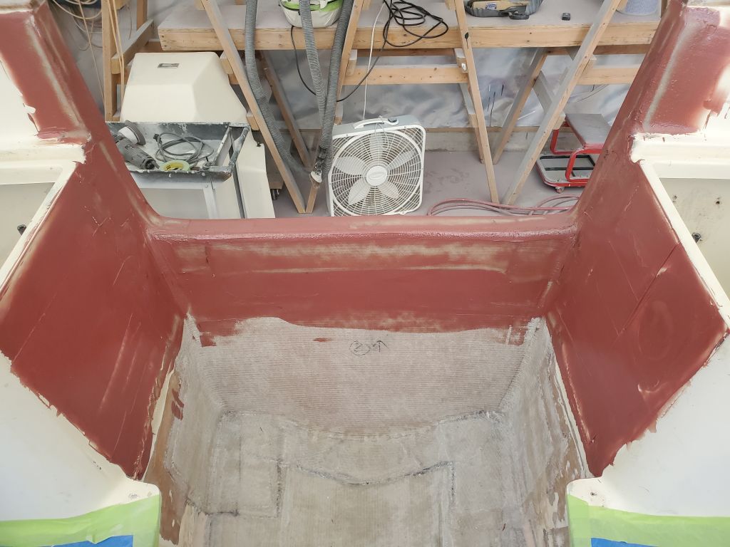
The splashwell deck had one known reference point along the forward edge of the engine room cutout, which was the aft edge of the main deck in way of the livewell locker opening. From here, the deck should pitch aft to drain water naturally out the transom, where eventually I’d install a pair of small scuppers, one per side. To determine the aft end position, I used a stiff straightedge held tightly against the plane of the main deck forward of the cutout, and extended it aft to the transom to make a couple reference marks. From the initial marks, I adjusted them downwards to allow for the depth of the forward edge below the main deck, plus an additional distance for drainage, or roughly an inch total.
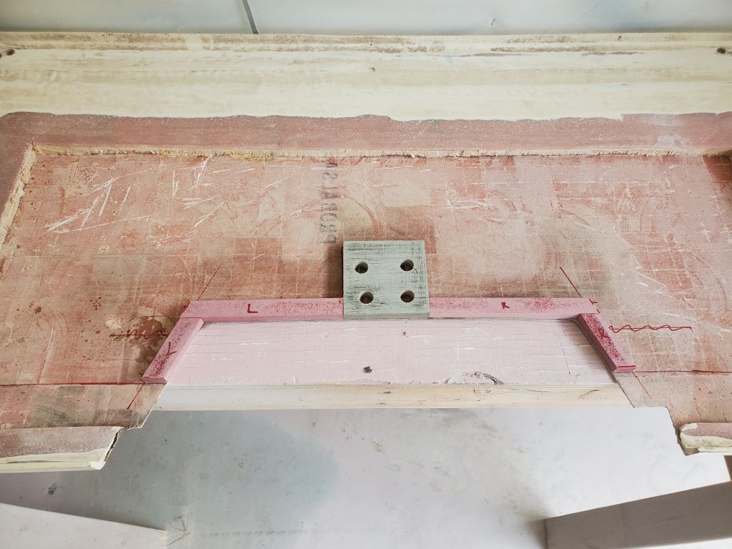
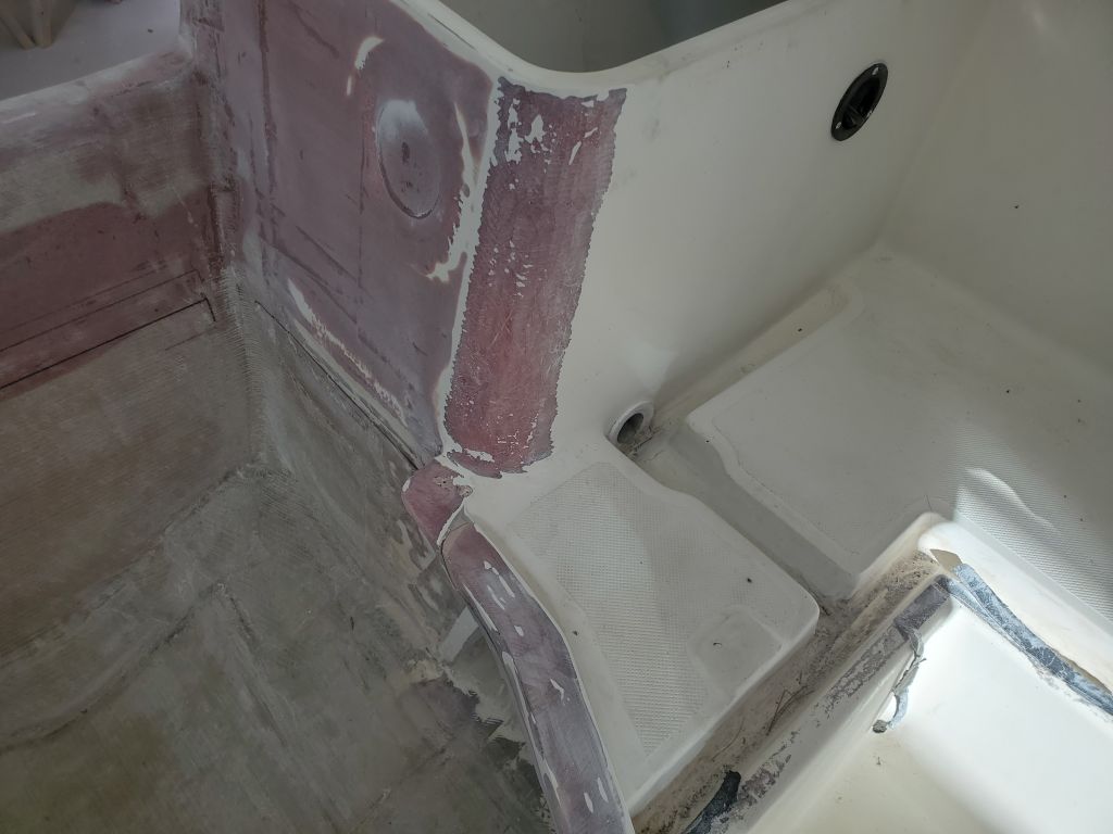
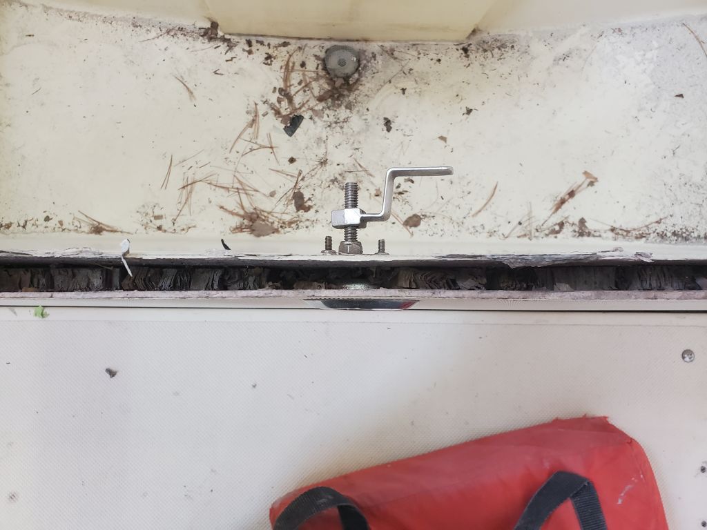
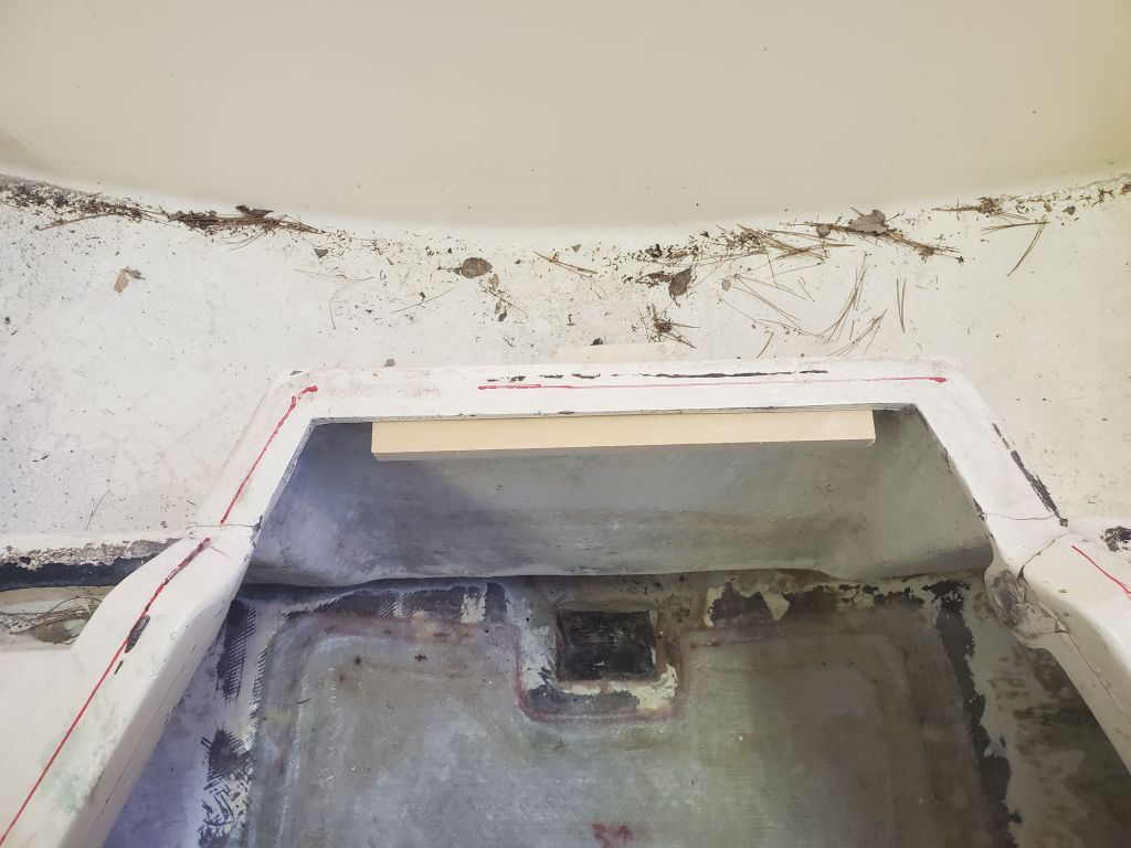
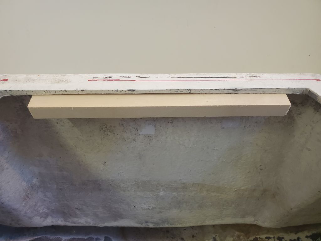
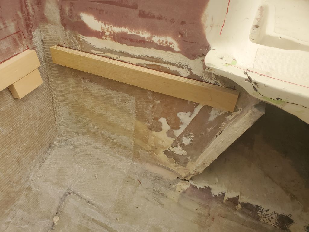
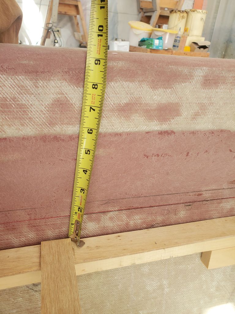
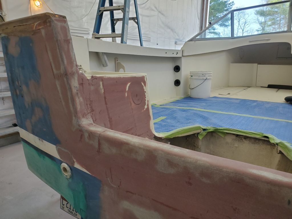
After I’d made these initial marks and begun some additional layout, I realized they weren’t correct, and made some new reference marks, beneath which I temporarily hot-glued a scrapwood cleat at the aft end. At the forward end, I hot-glued another small cleat beneath the exposed deck edge. These formed the two key points to determine the new deck’s plane fore and aft; it should be pitched roughly 3/4″ down towards the transom.
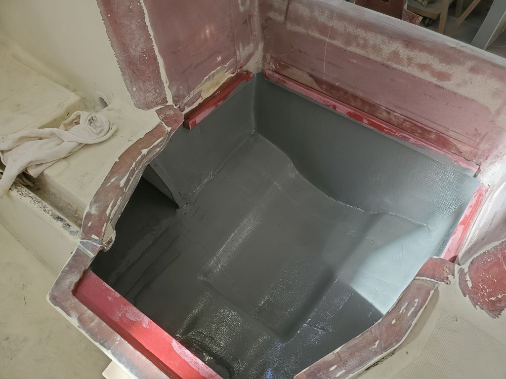
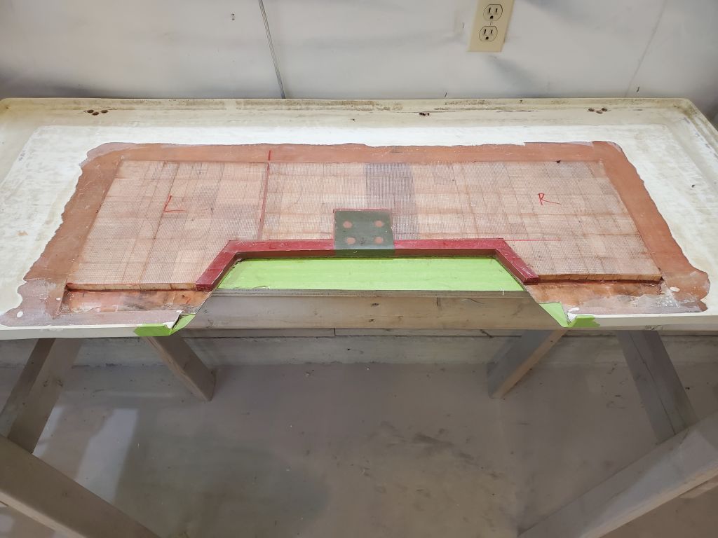
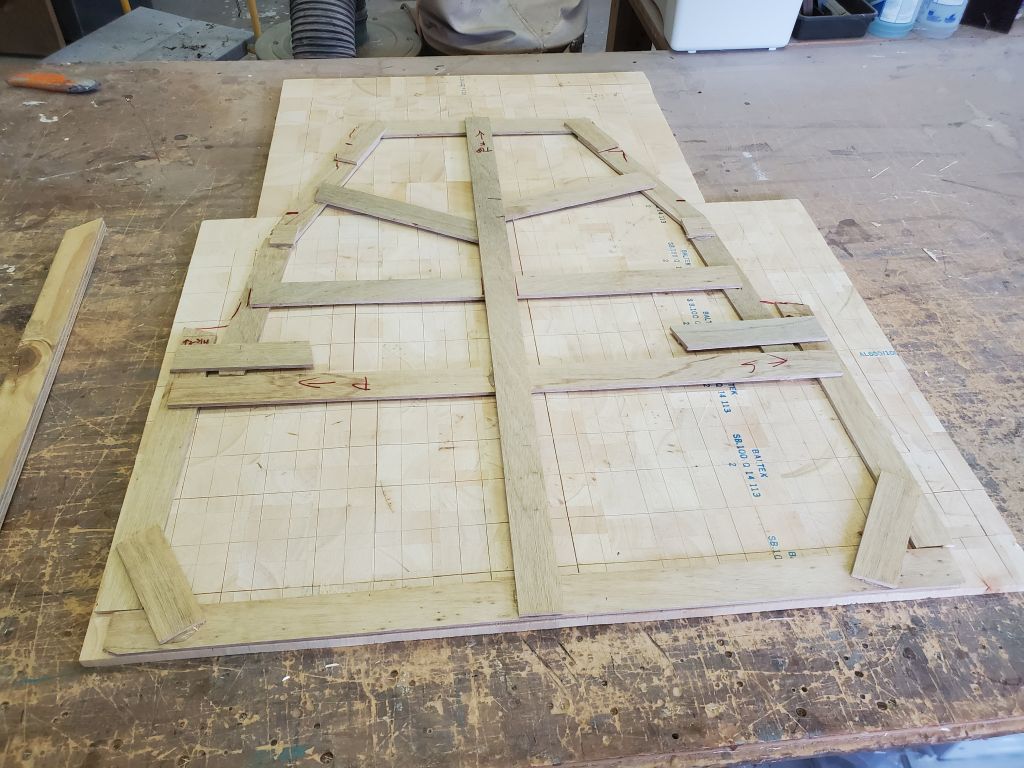
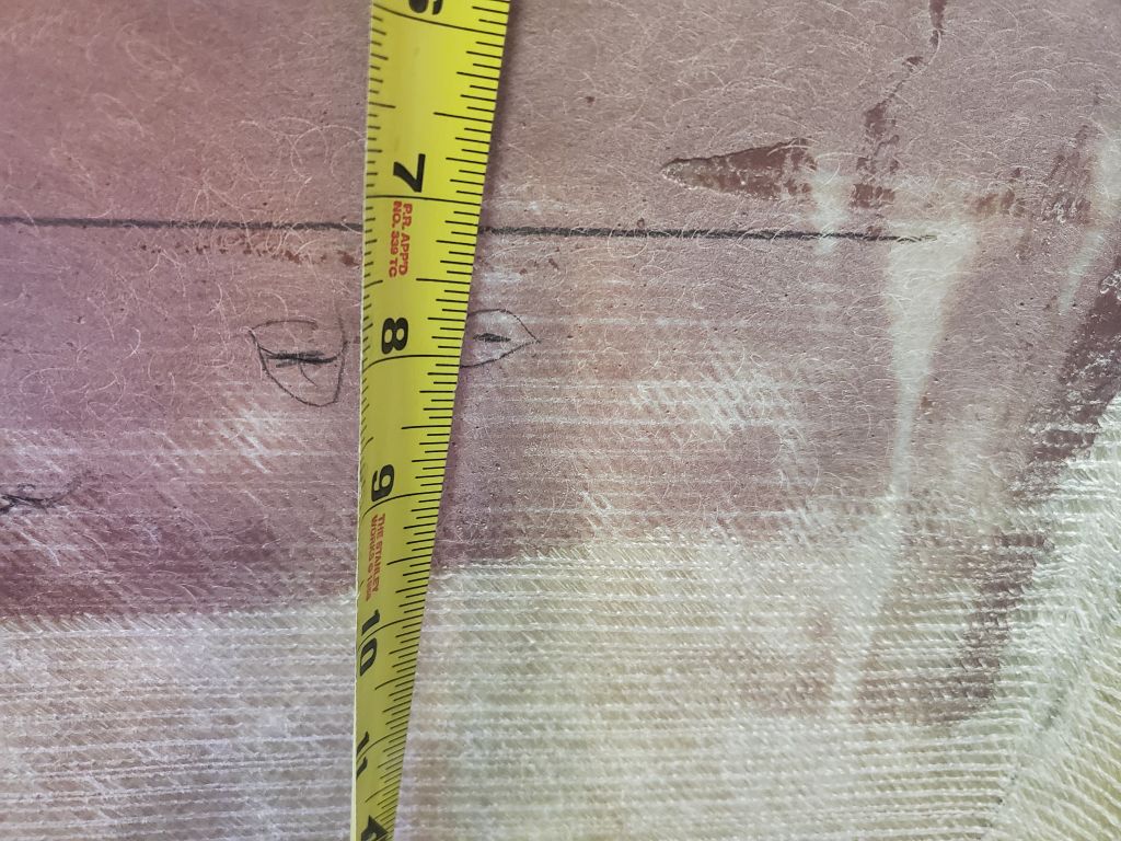
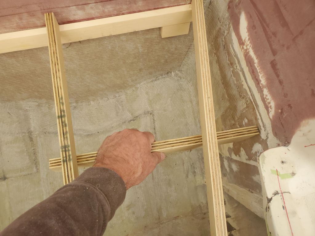
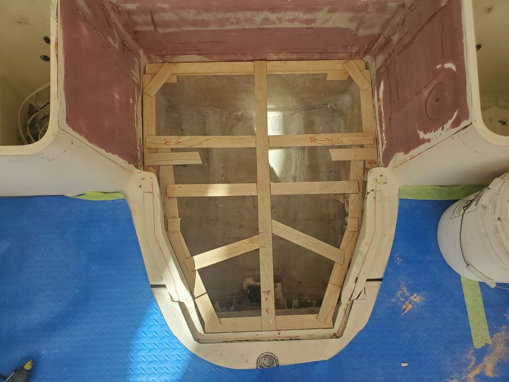
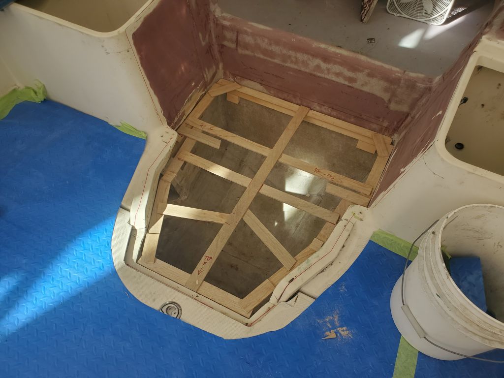
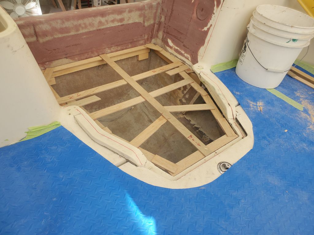
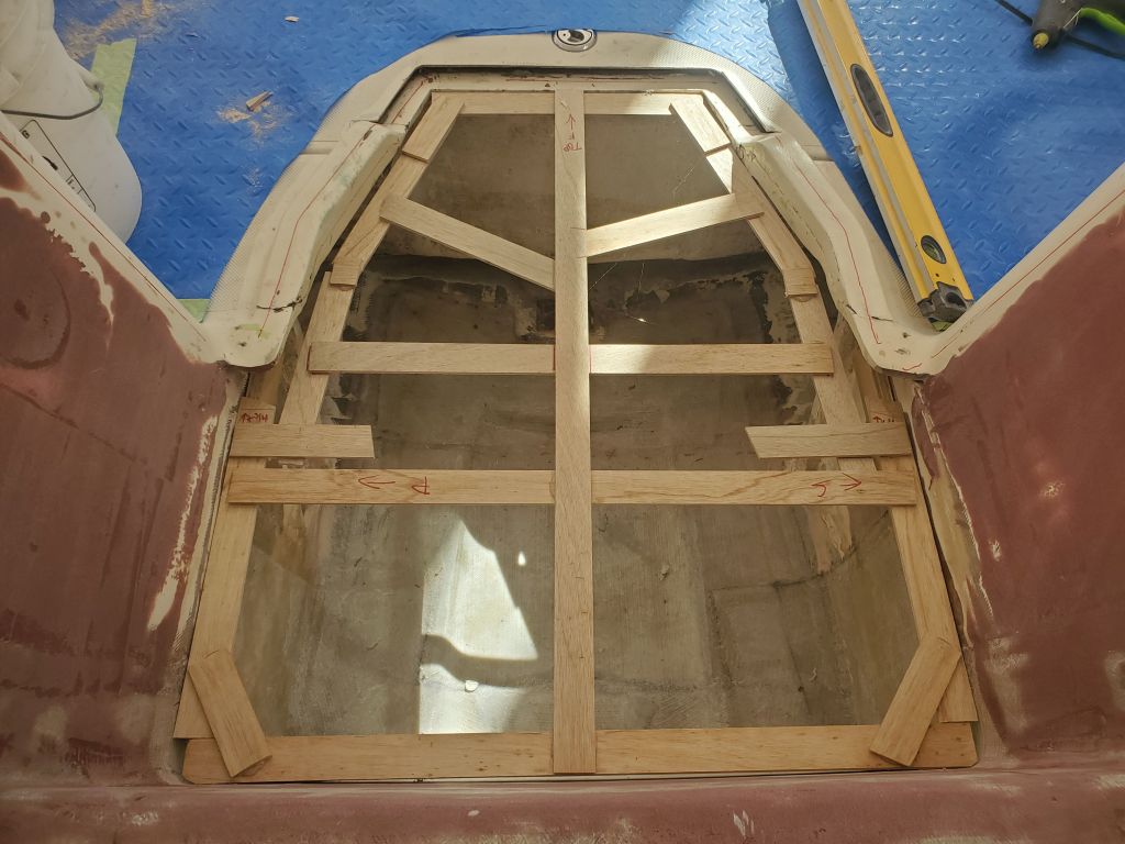
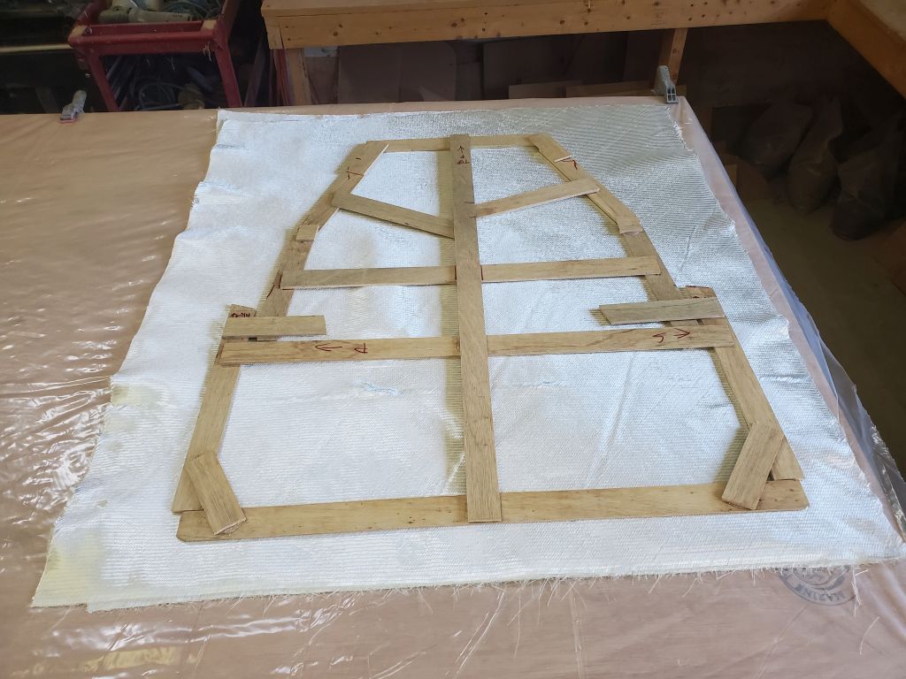
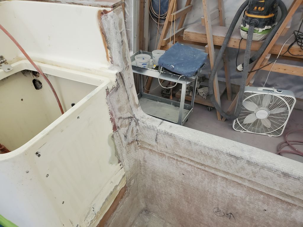
Now I needed to transfer that plane to the sides of the compartment so I could install additional temporary cleats. I installed three longitudinal strips of plywood, on edge for stiffness, to span the space between the forward and after cleats, then used another piece of the plywood held tightly against the bottoms of those cleats to make several reference marks on each side of the compartment, to which I could hot glue additional cleats.
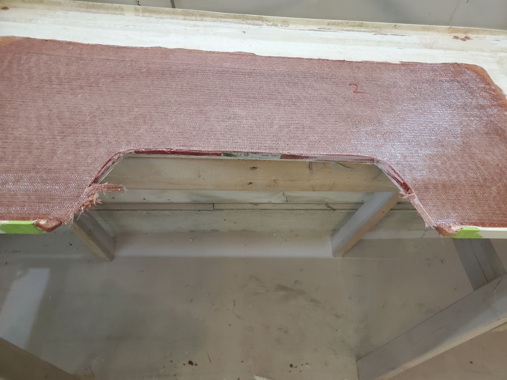
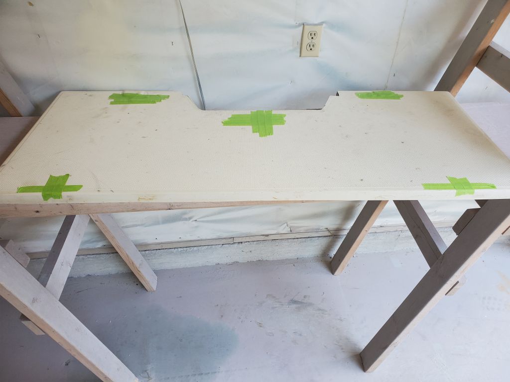
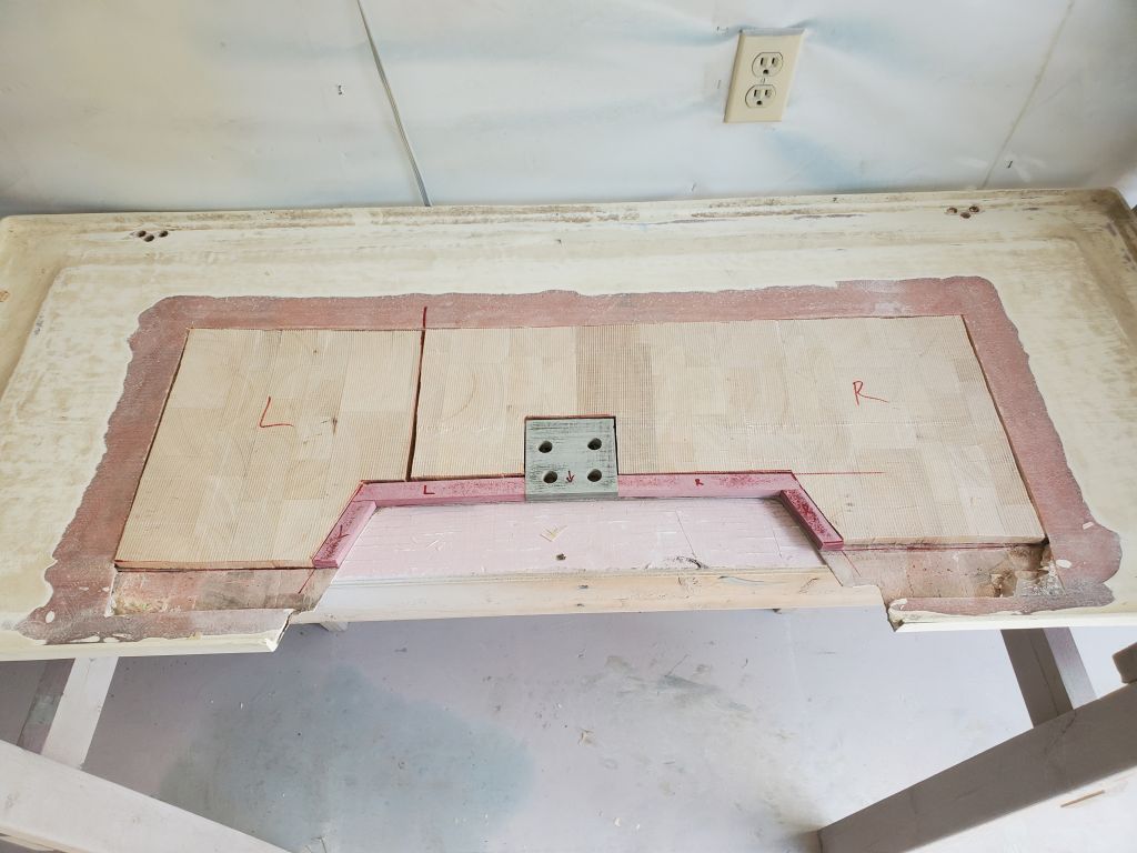
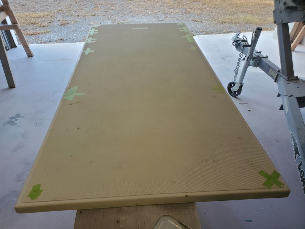
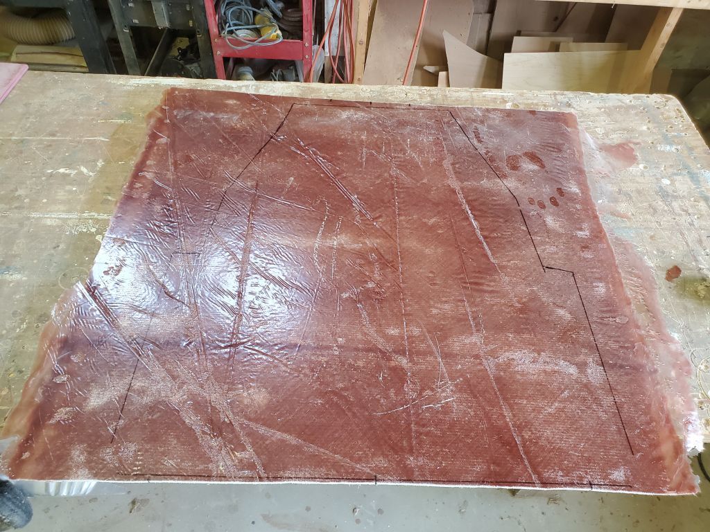
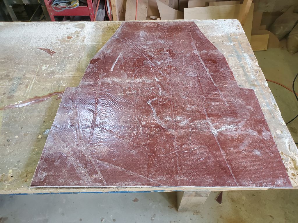
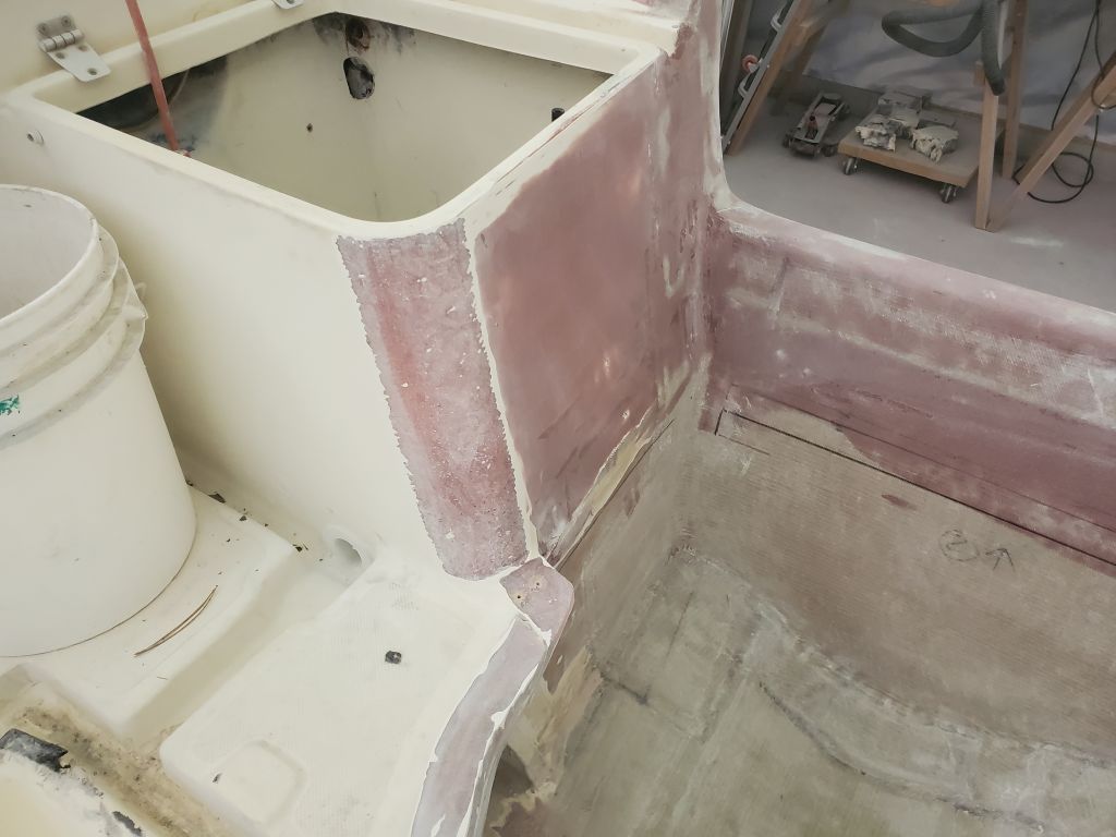
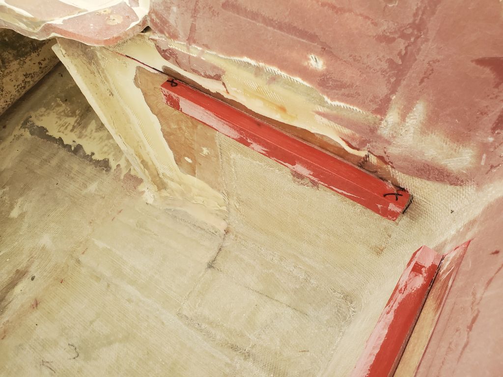
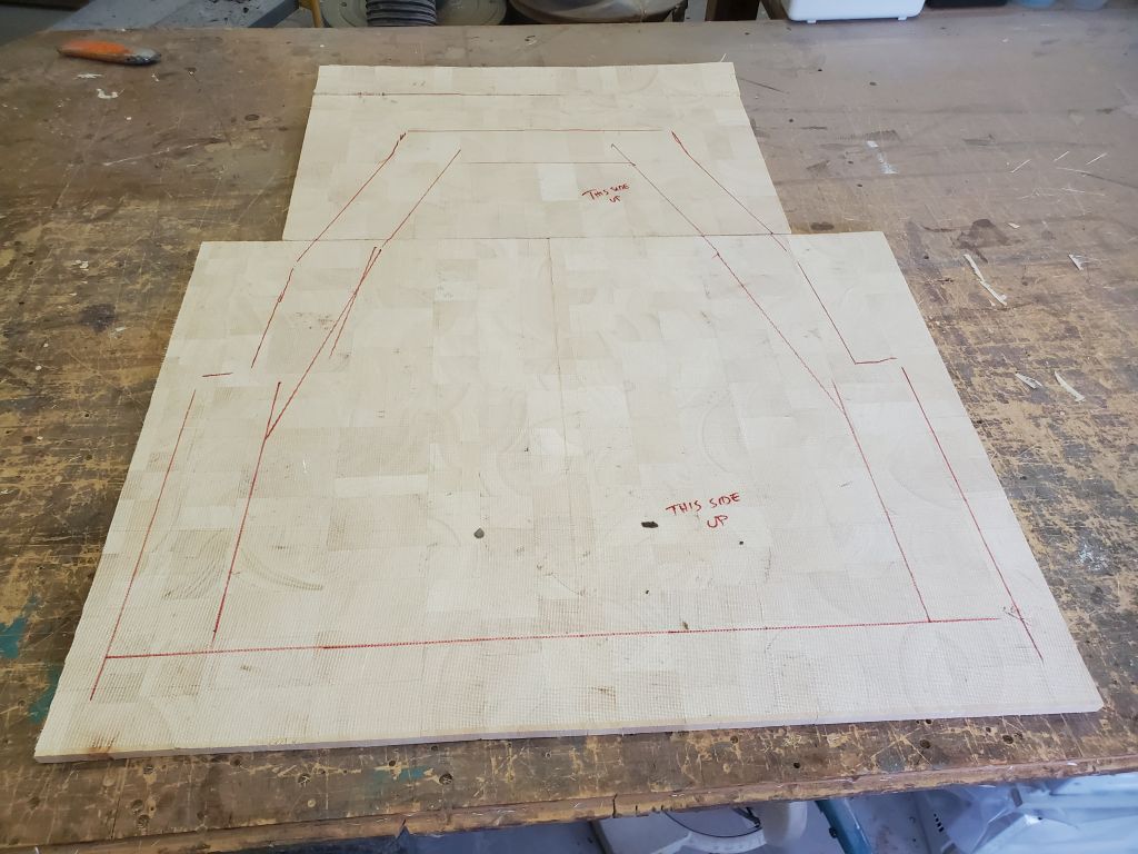
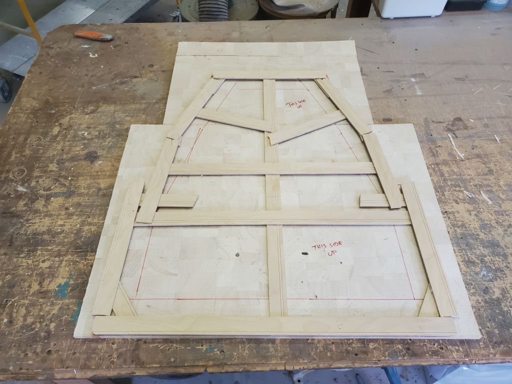
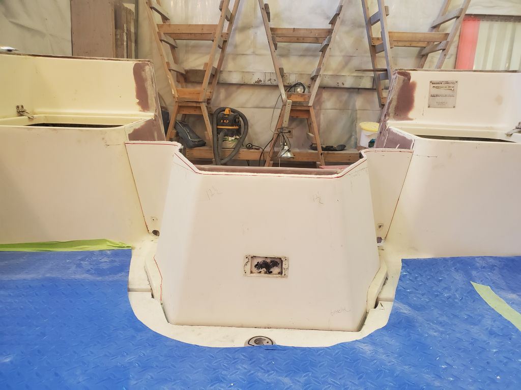
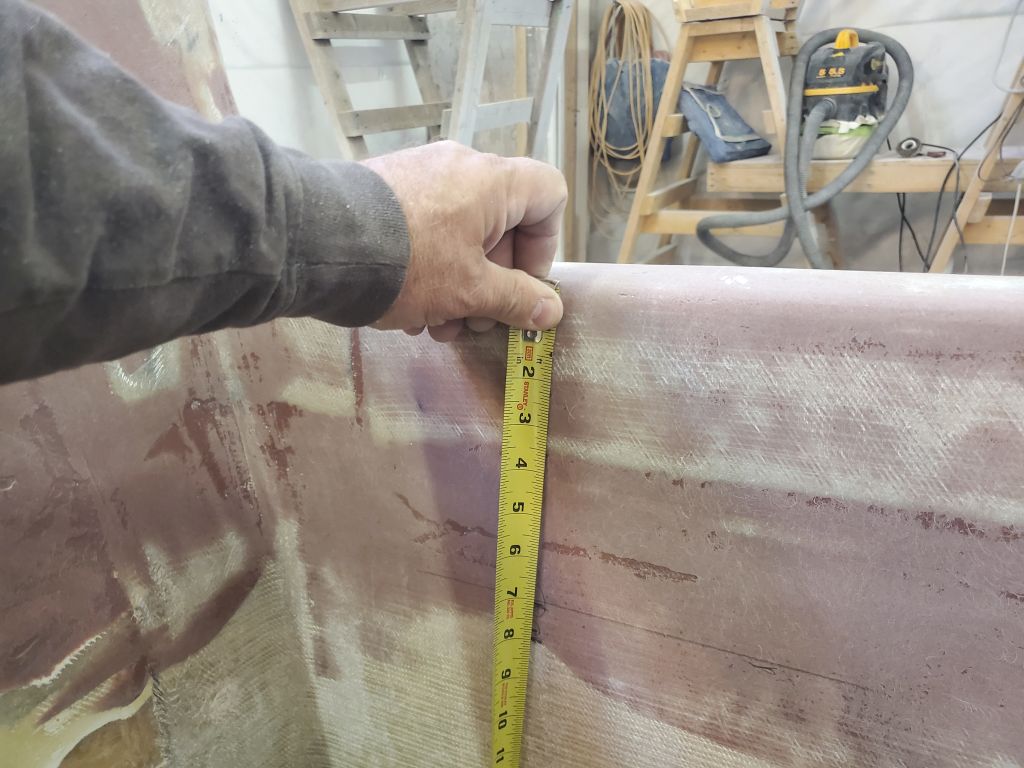
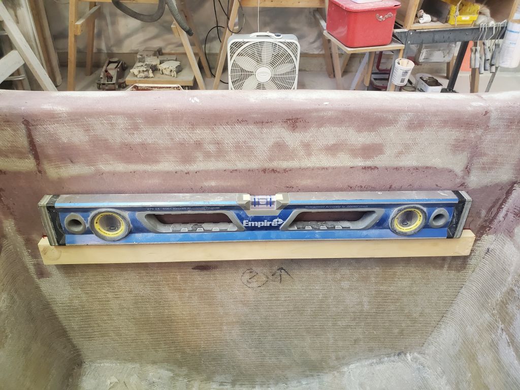
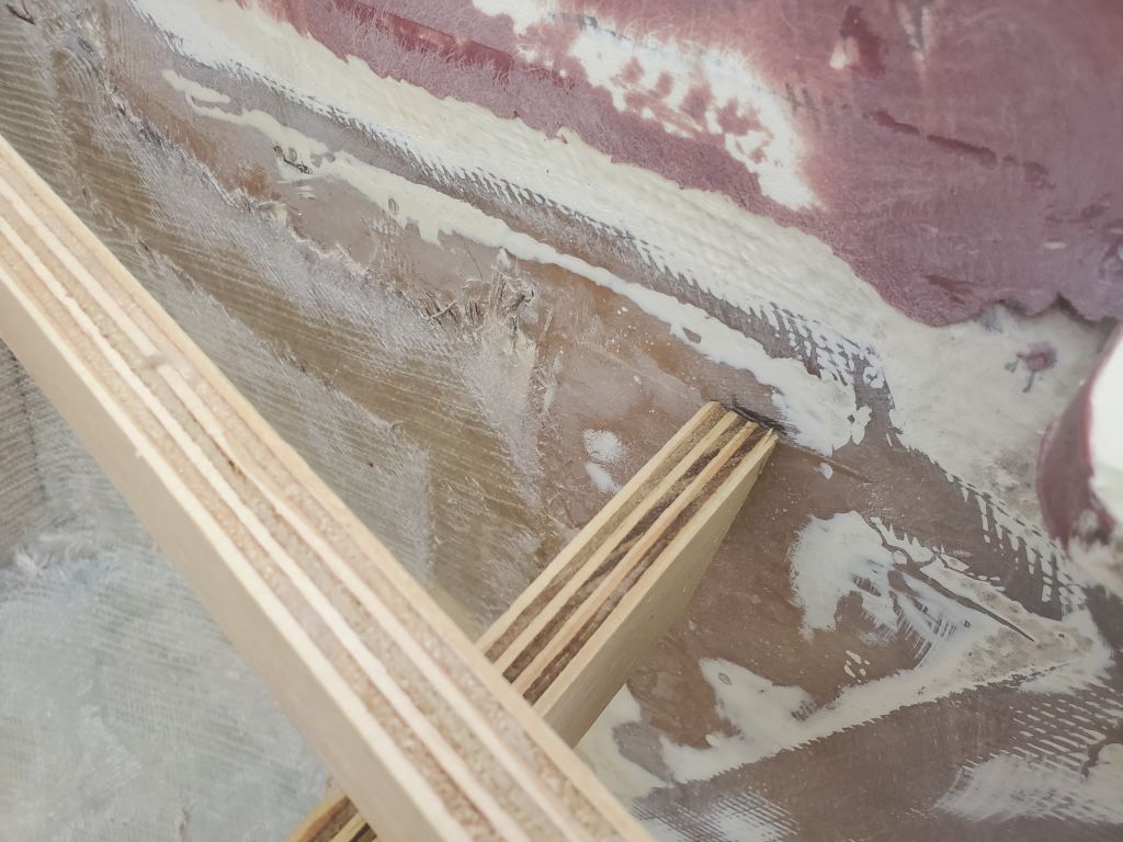
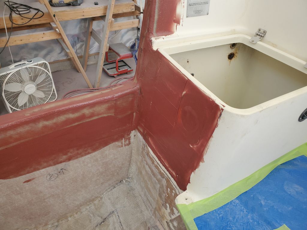
With the new deck plane defined on all four sides, I created a template of thin strips of plywood hot-glued together in the required shape of the perimeter. I’d use this template to cut the custom fiberglass deck to shape once I built it. With the template complete, I checked the position at the aft end with my straightedge once more, with the straightedge held tightly to the plane of the main deck. The aft end was appropriately lower than the forward end when I measured both.
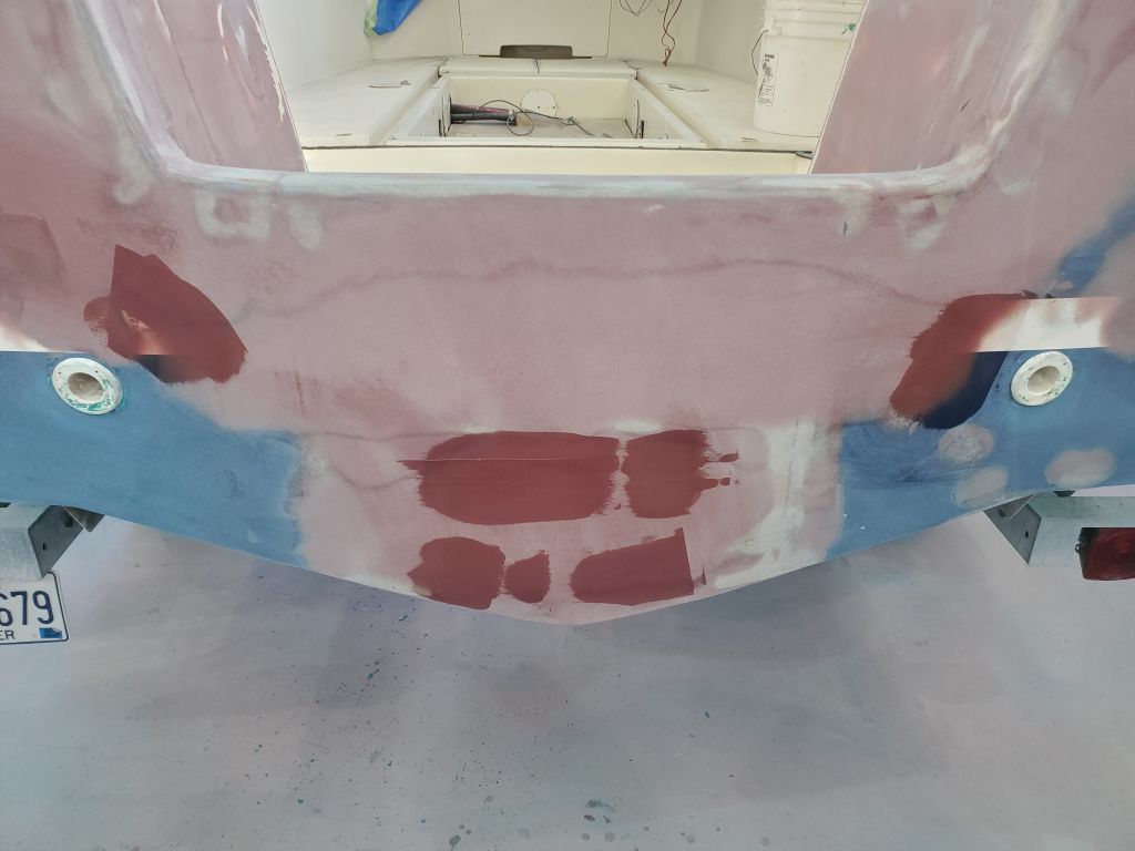
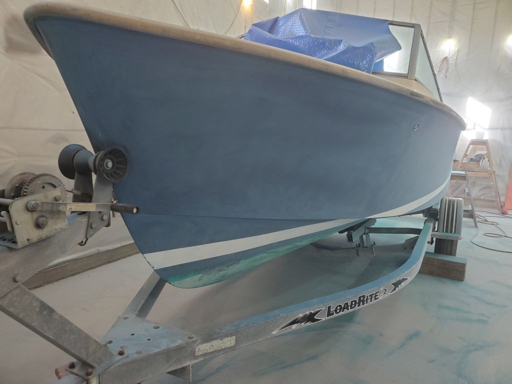
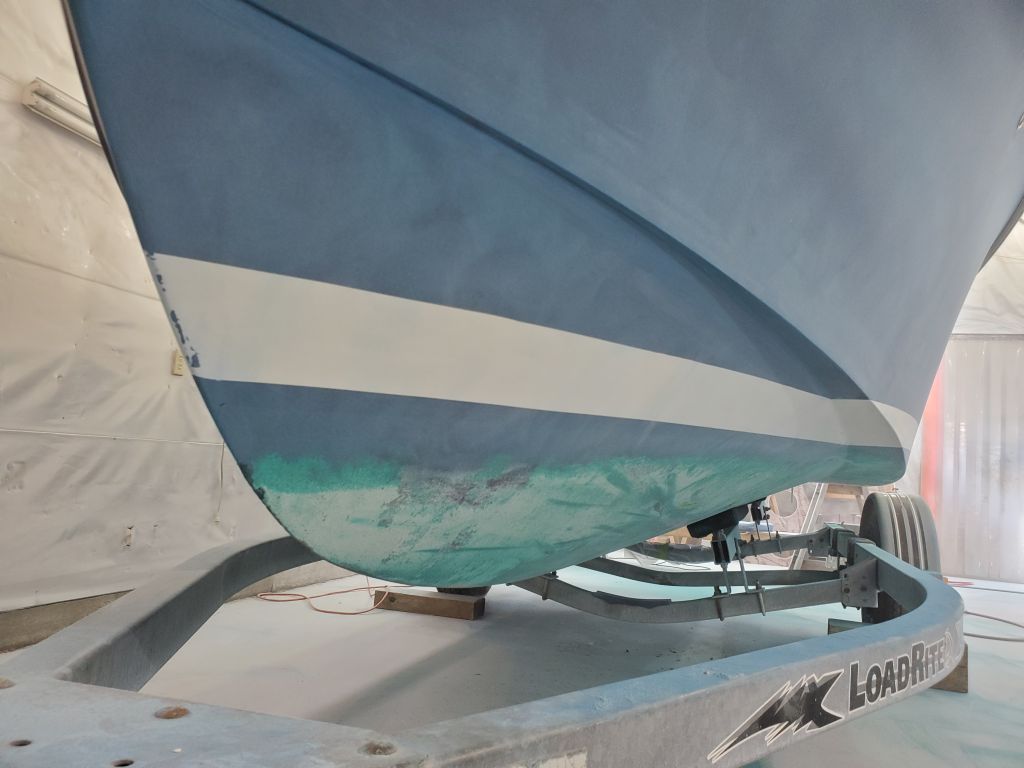
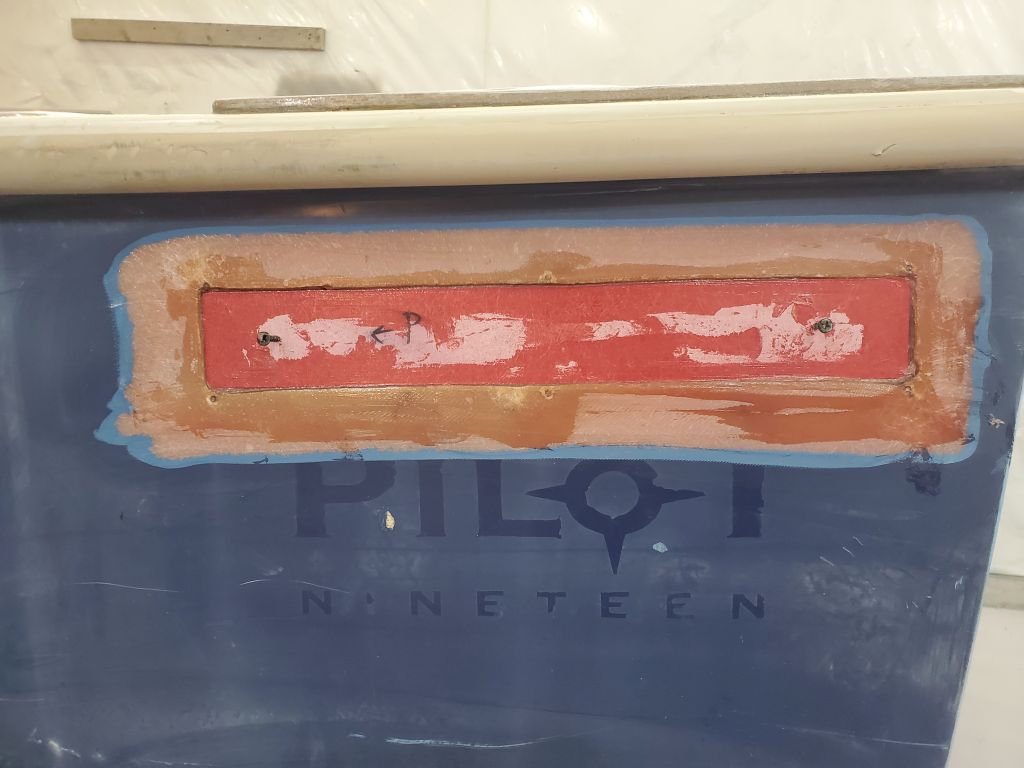
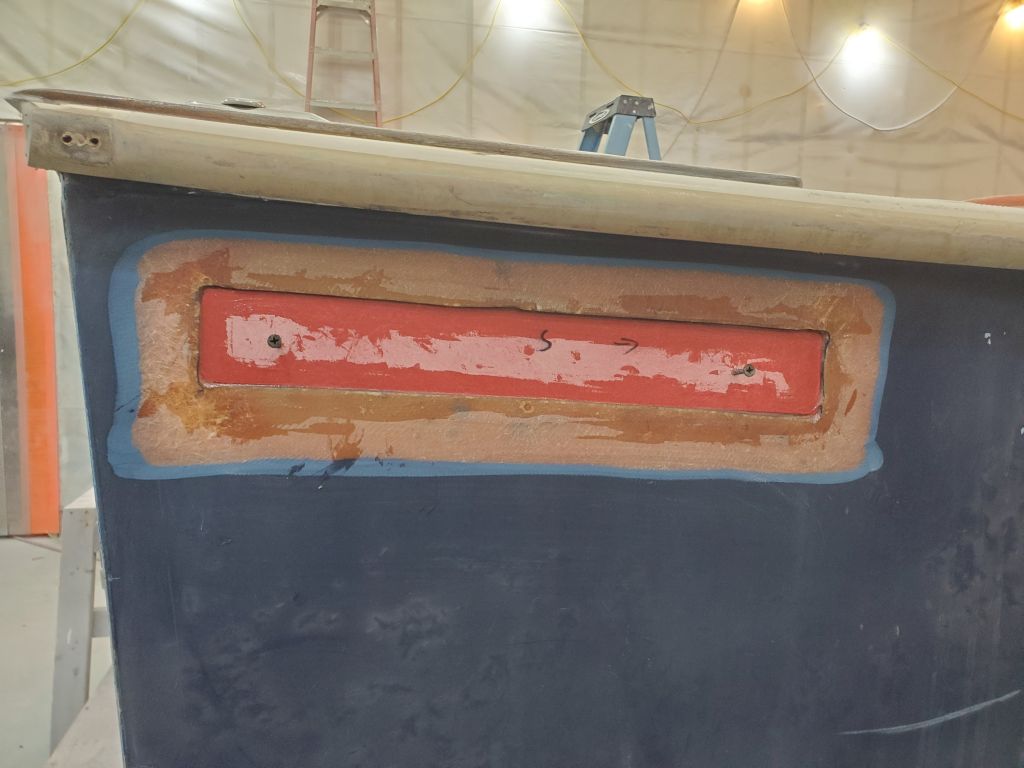
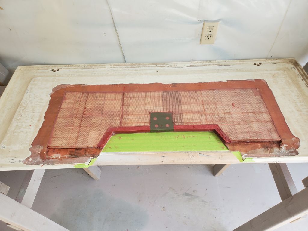
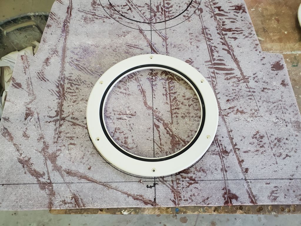
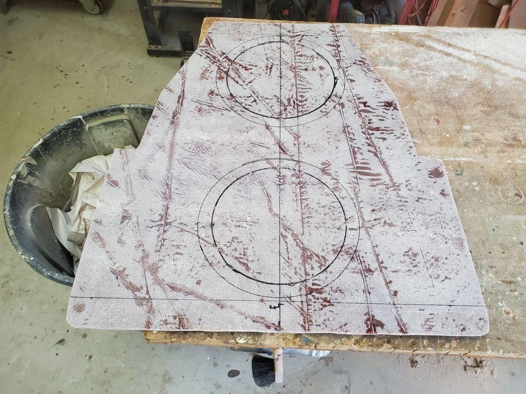
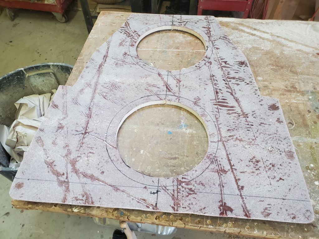
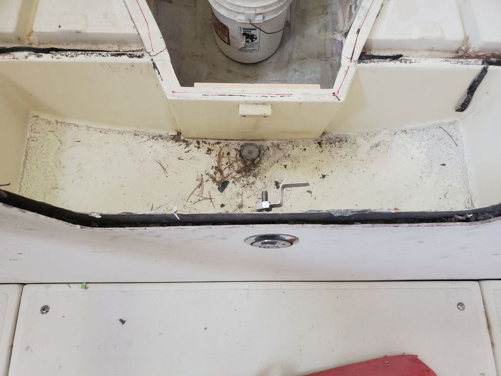
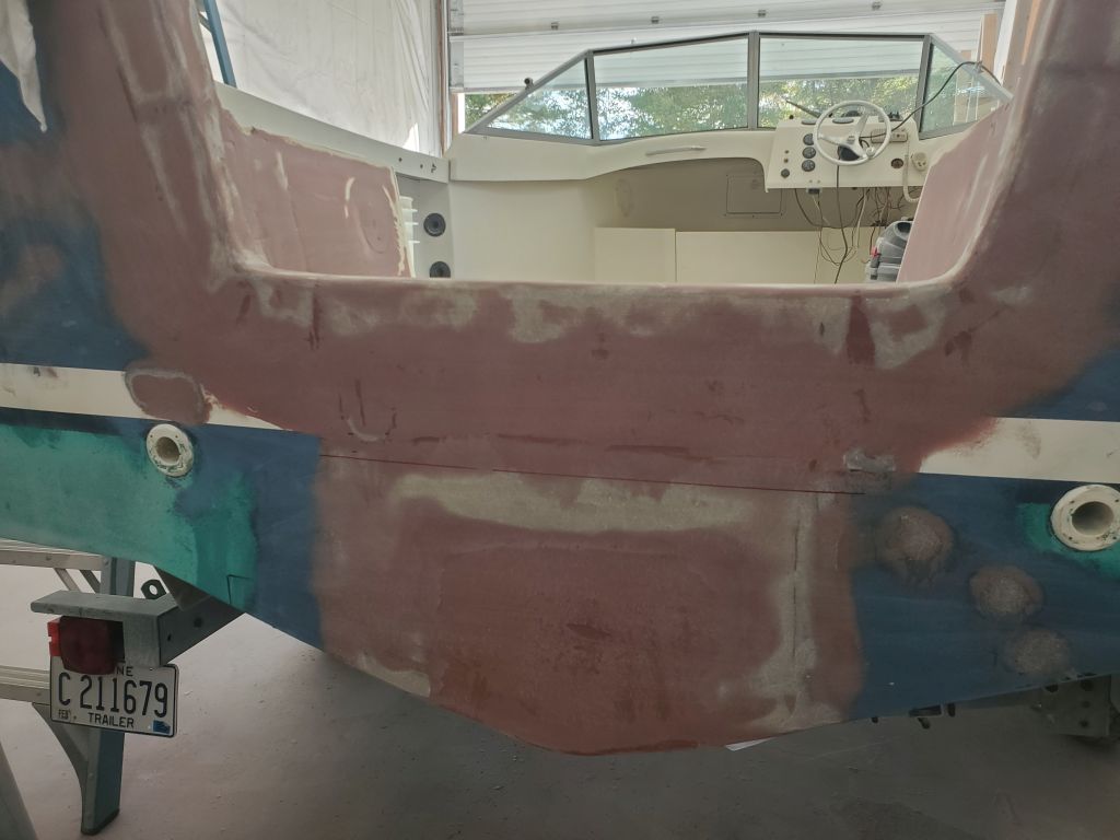
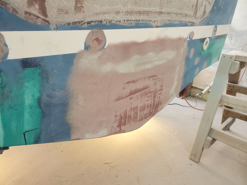
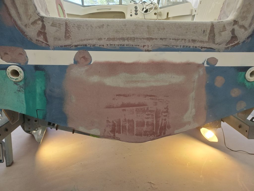
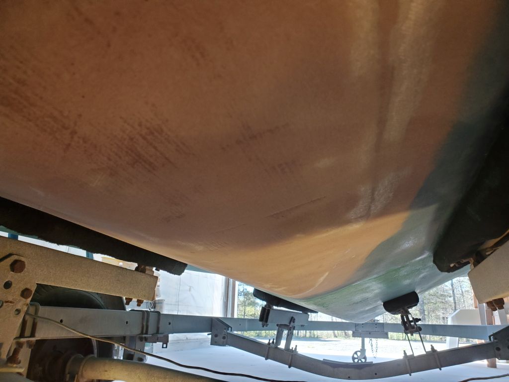
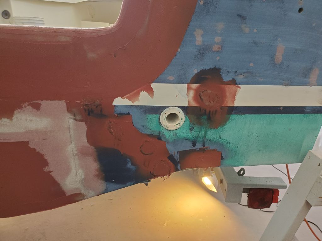
I struck a mark to show the waterline (or at least the top of the antifouling, good enough for this) on the exterior of the transom so I could check that the new deck inside would still be above the waterline for the small drains; they would be roughly 1″ above the waterline as defined by the top of the antifouling (itself a bit above the waterline).
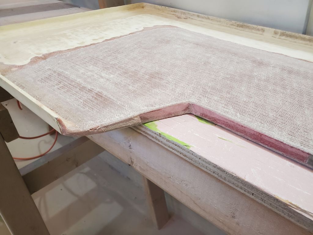
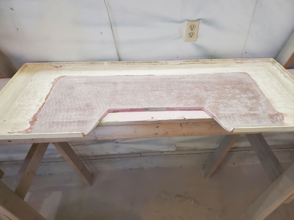
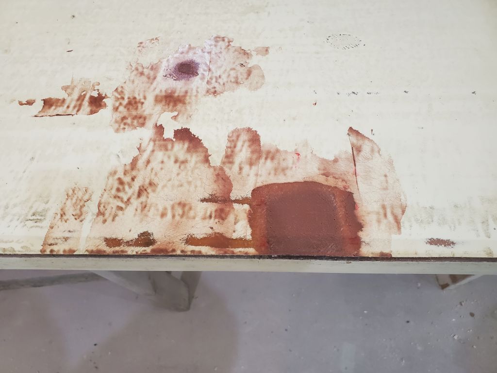
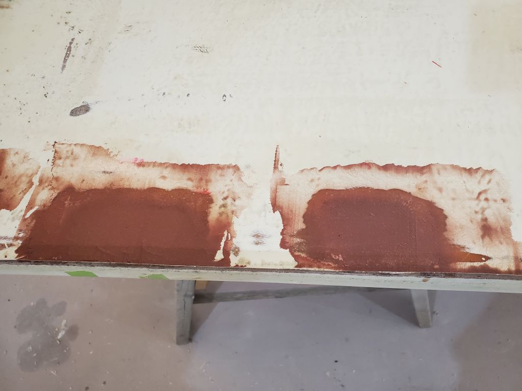
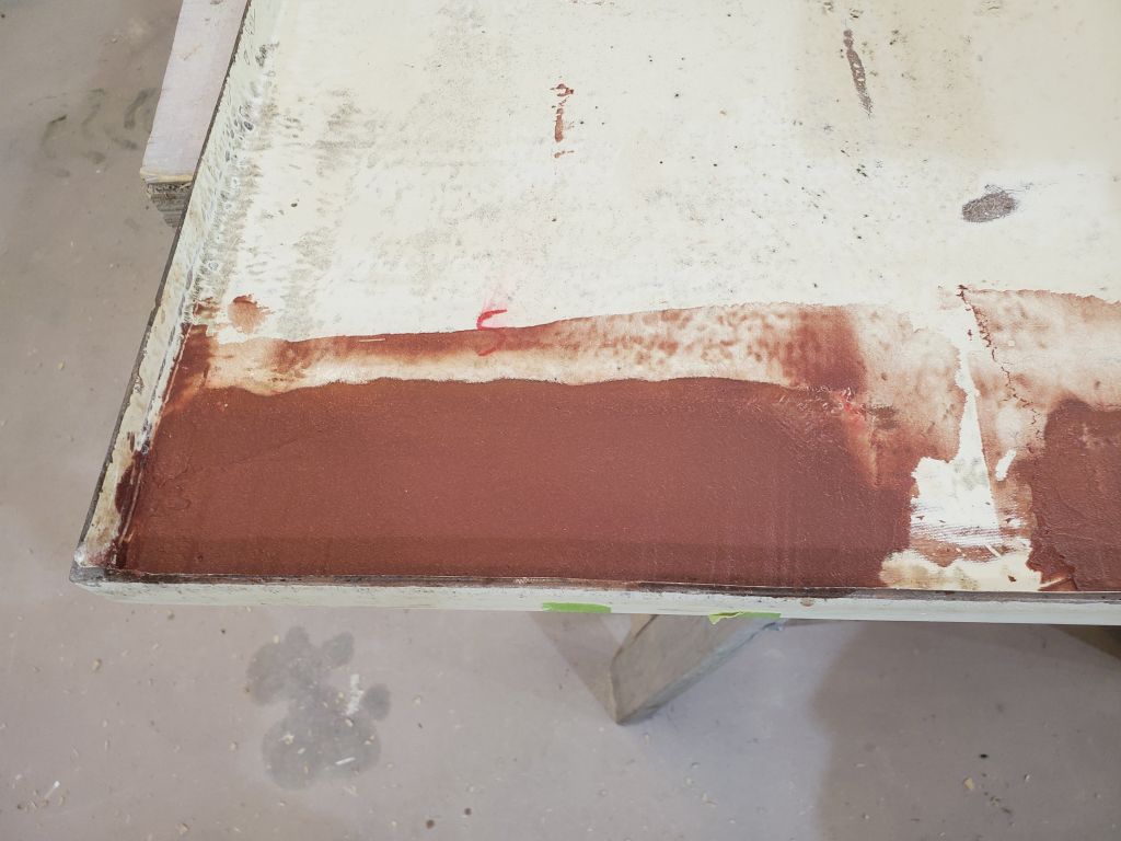
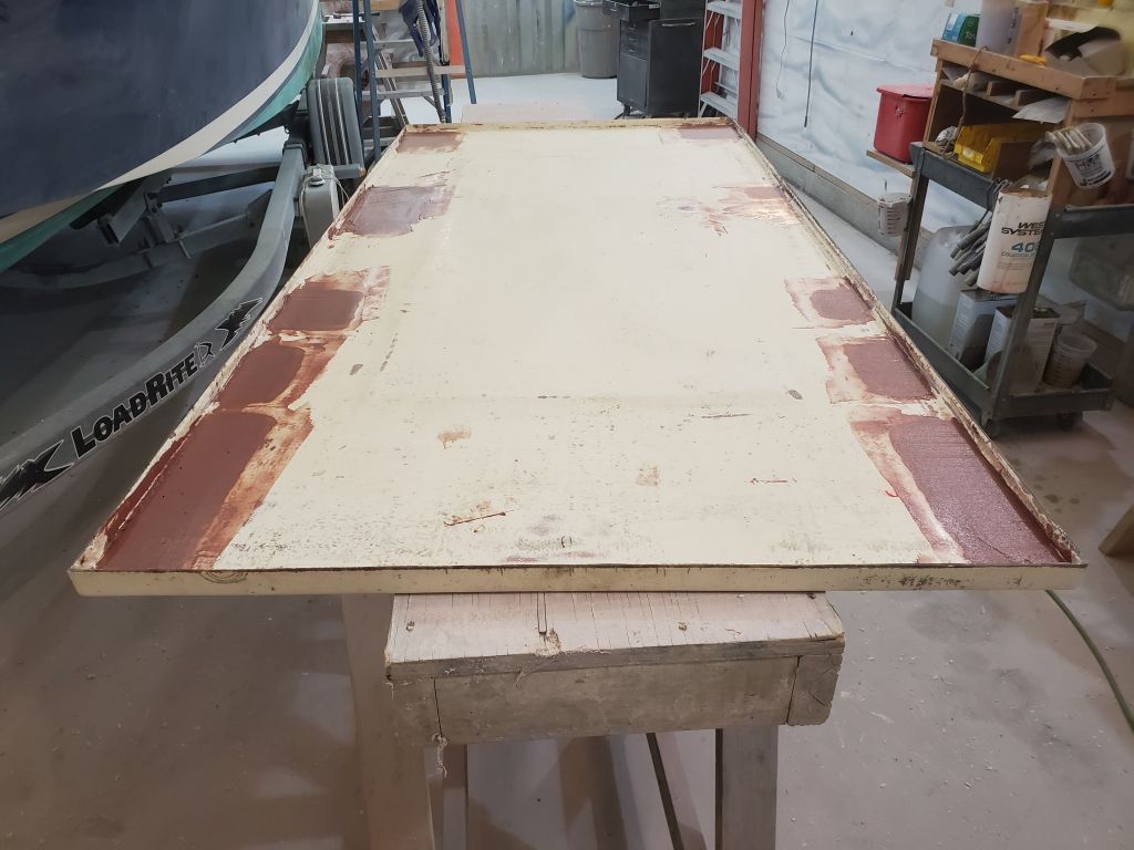
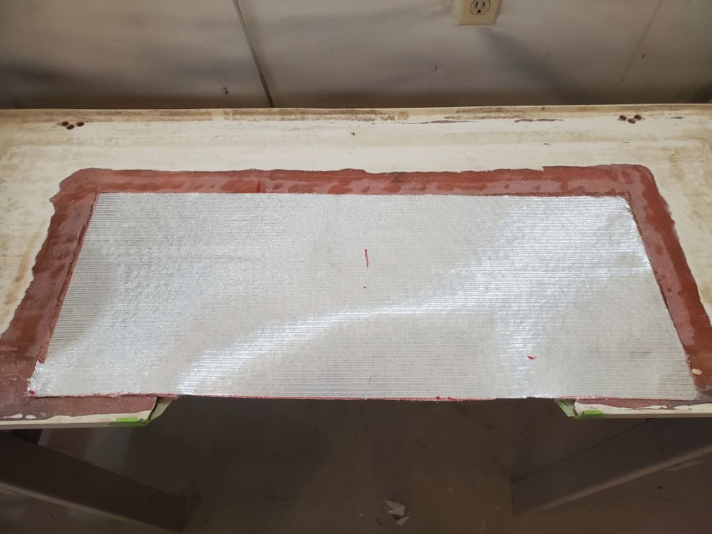
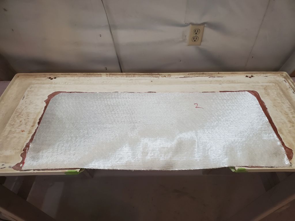
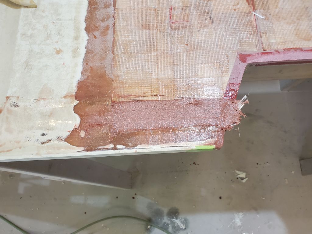
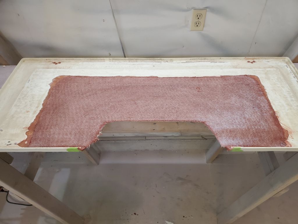
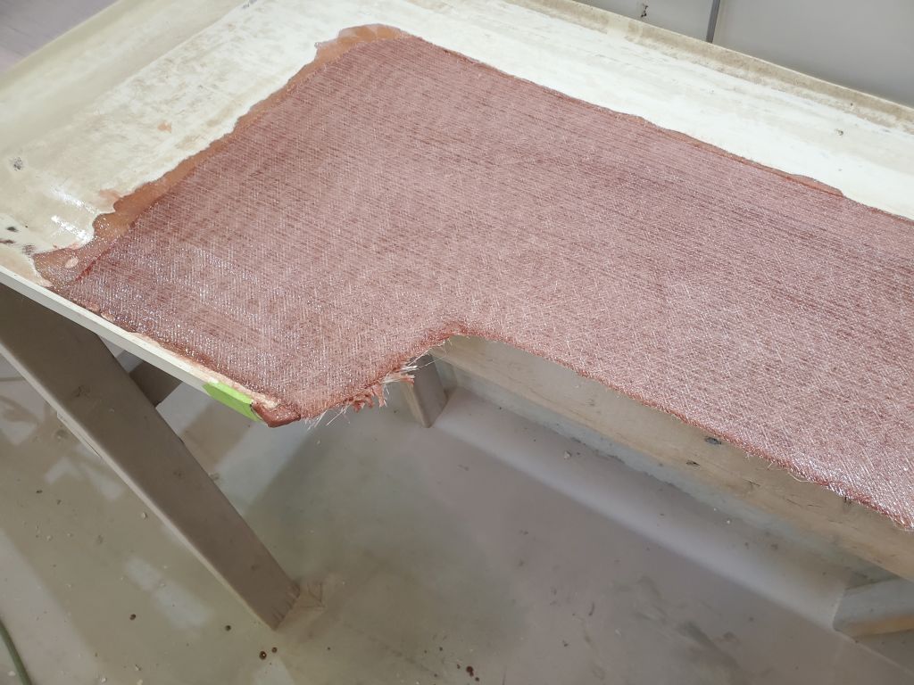
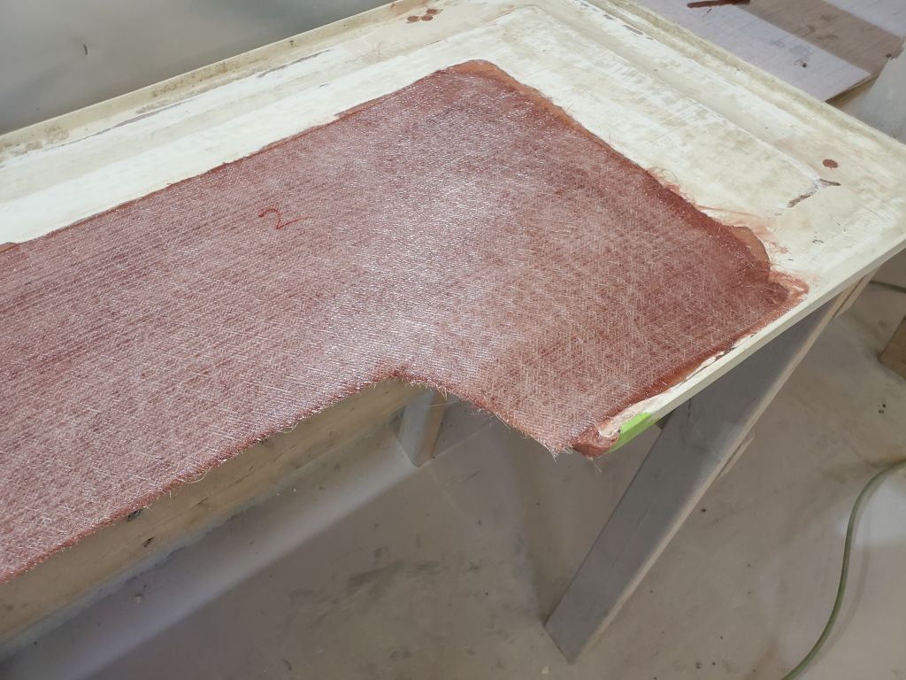
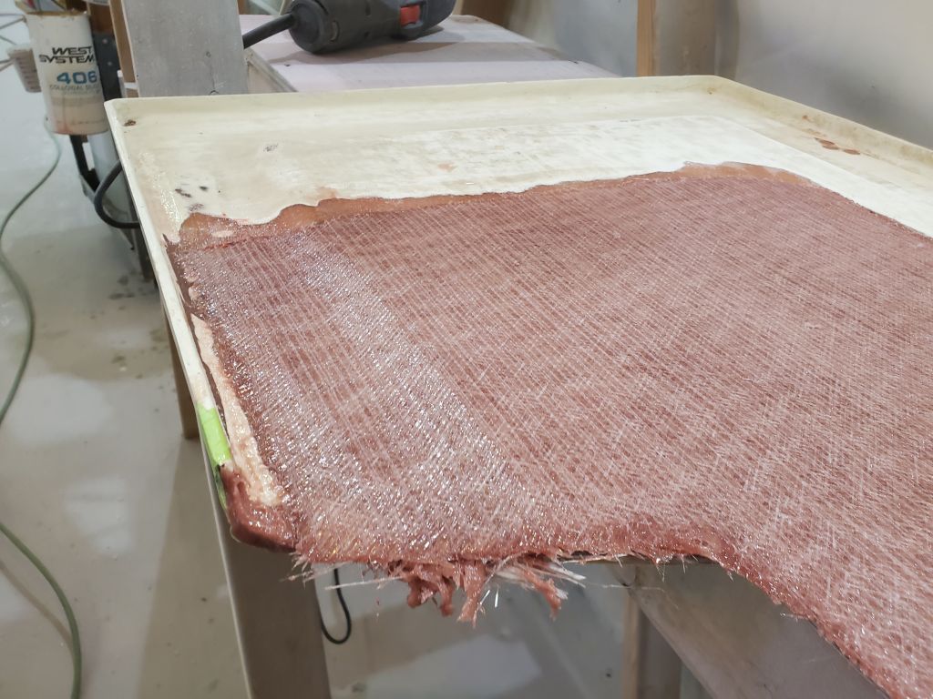
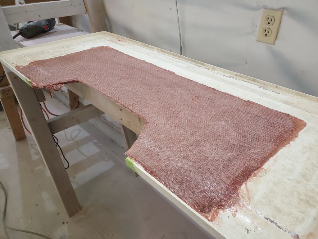
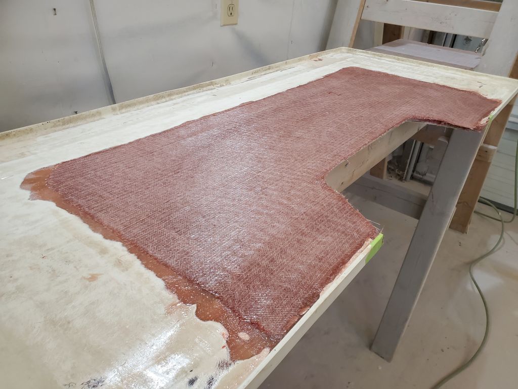
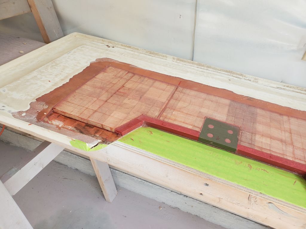
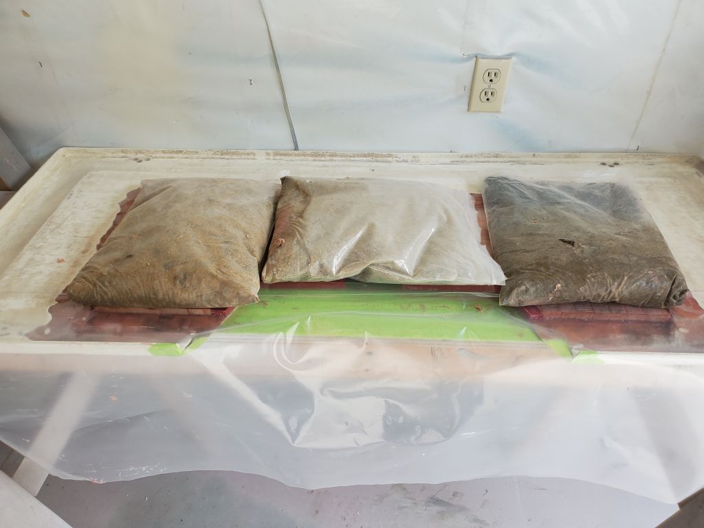
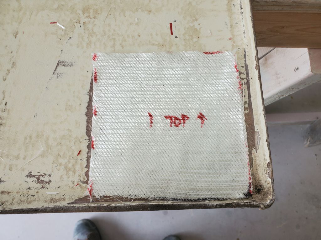
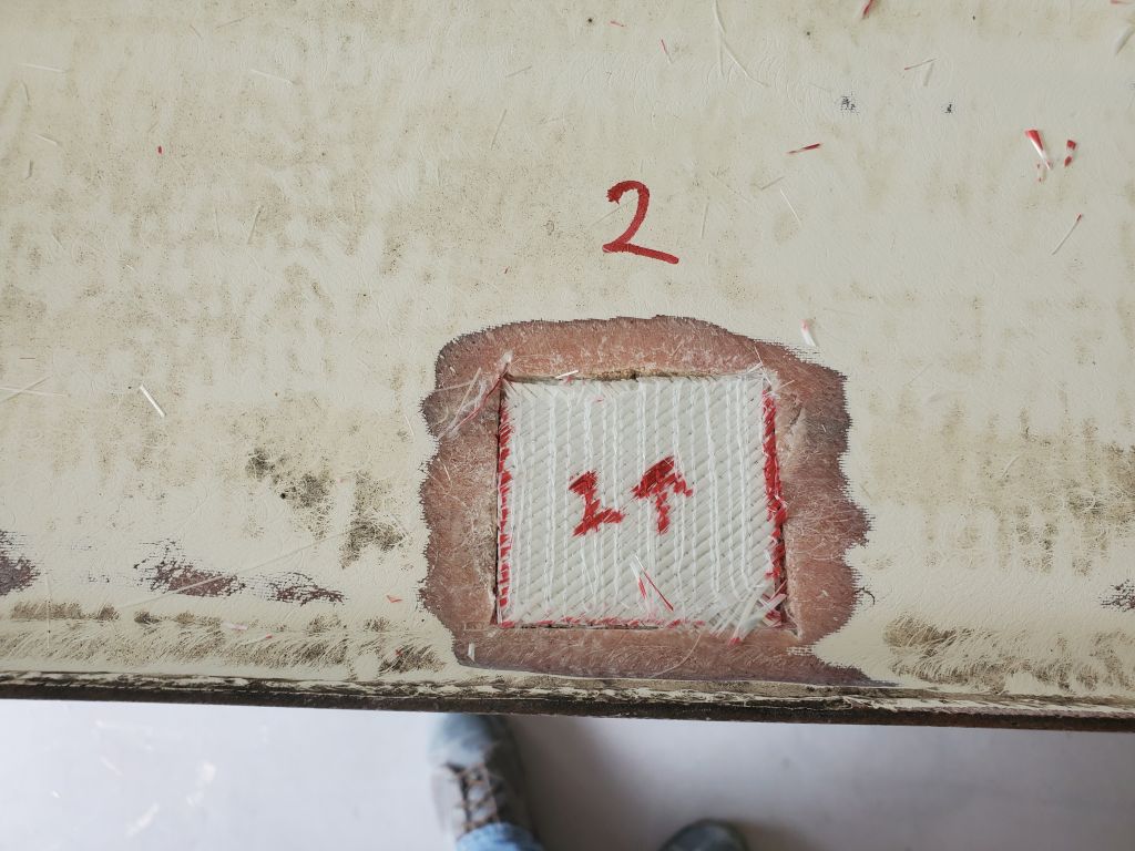
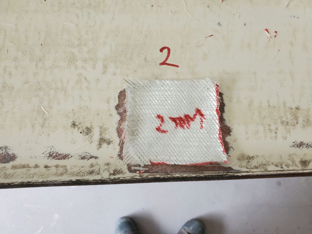
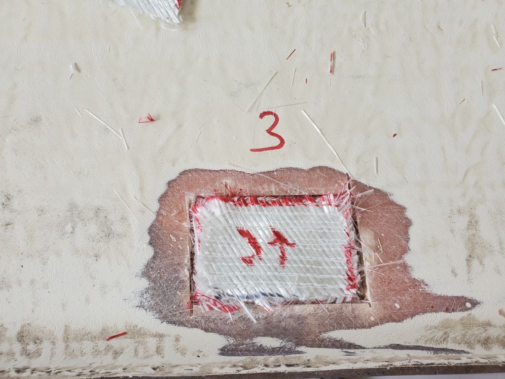
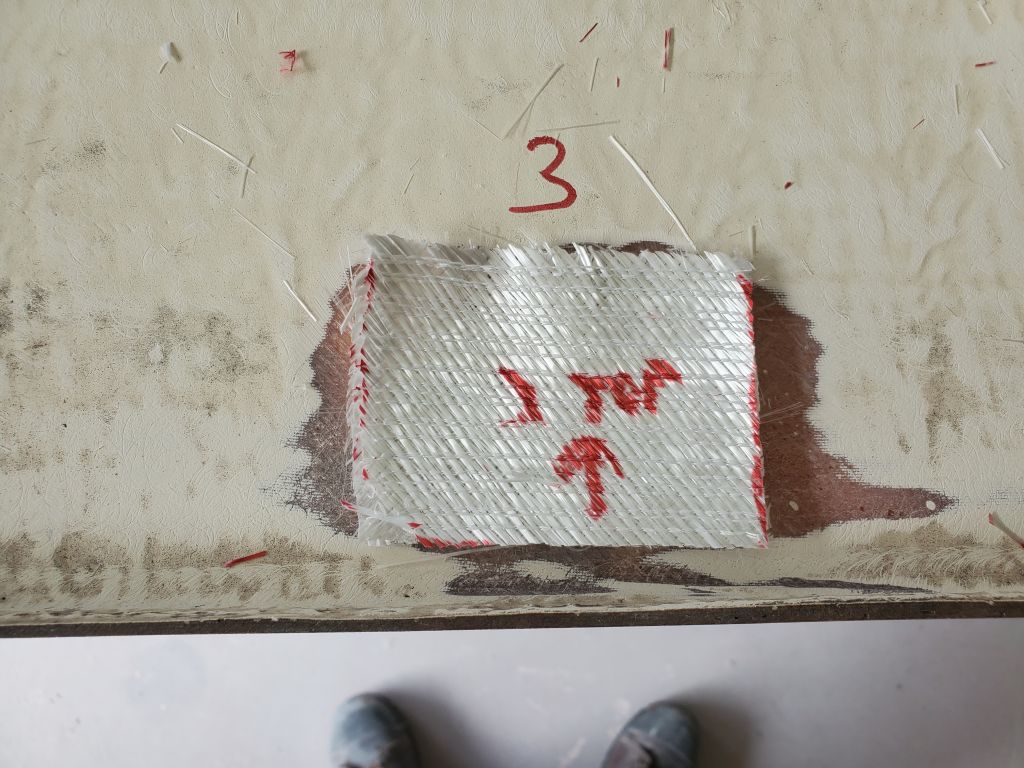
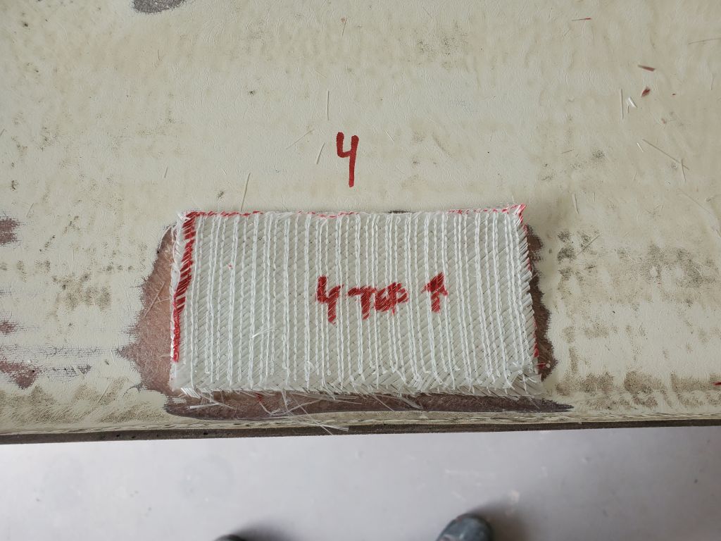
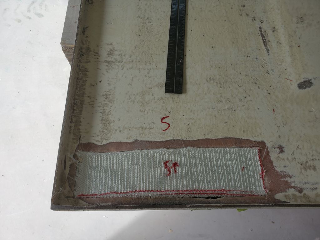
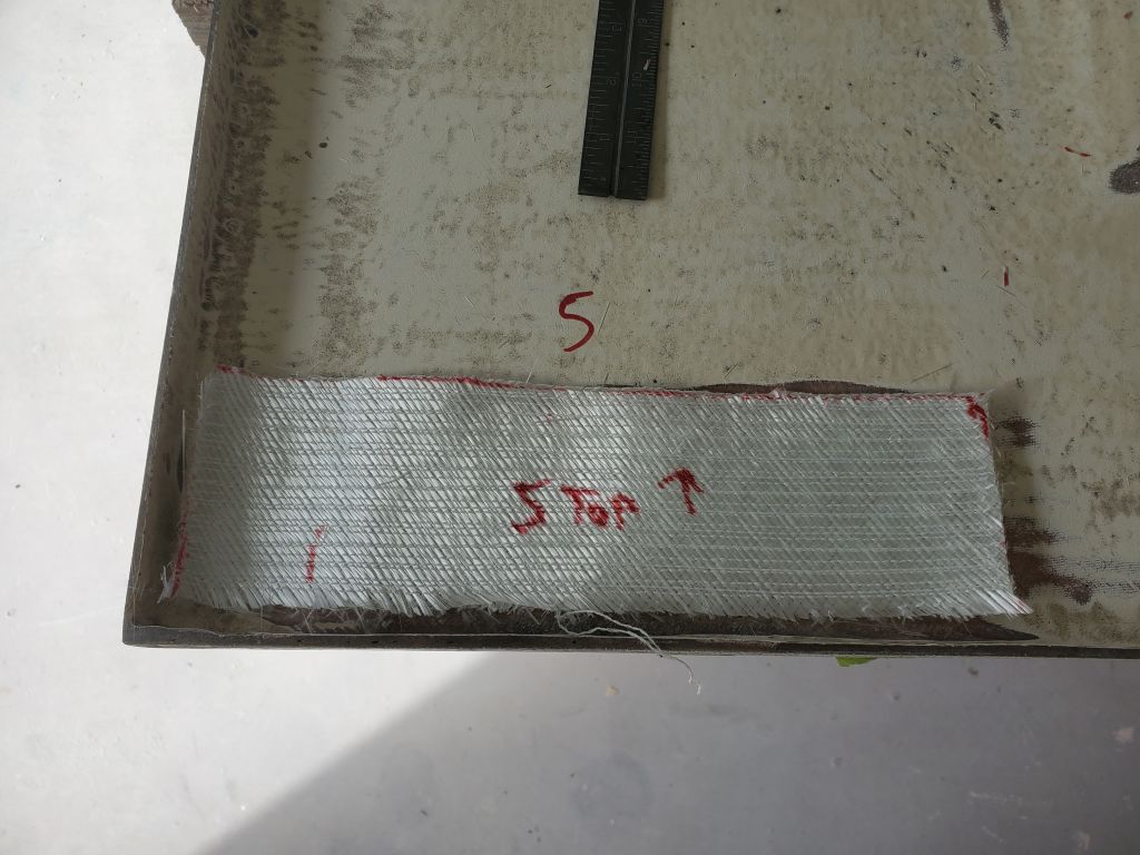
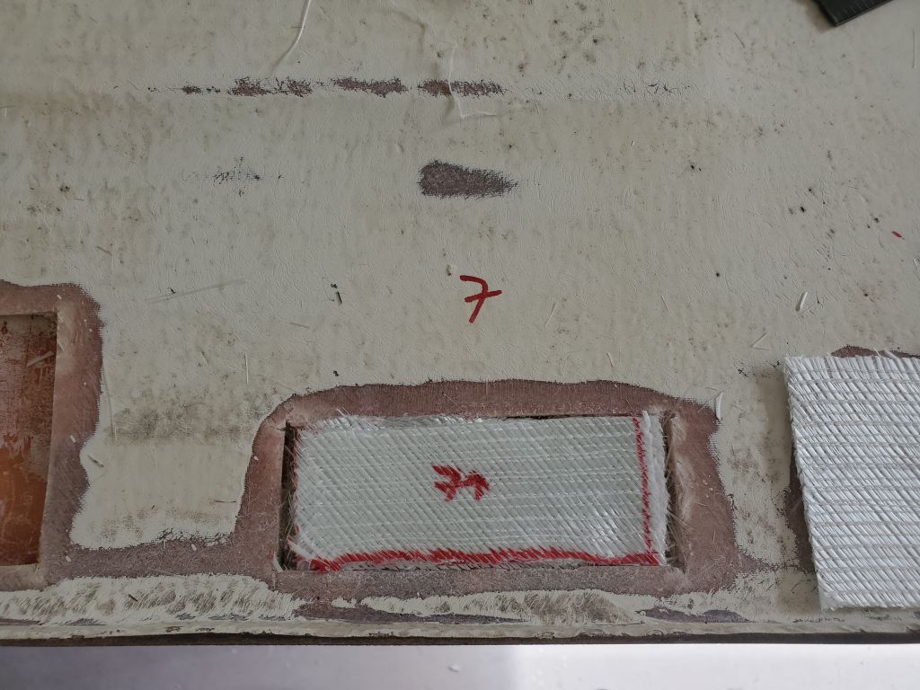
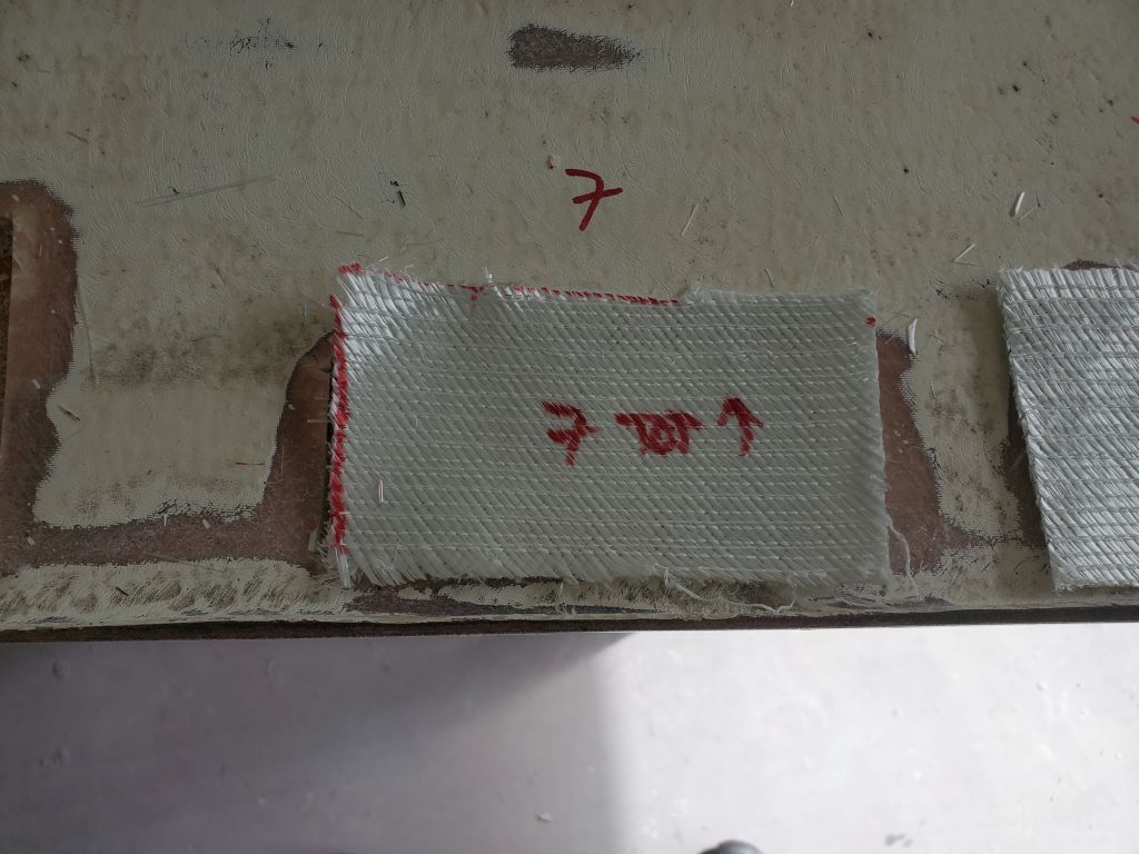
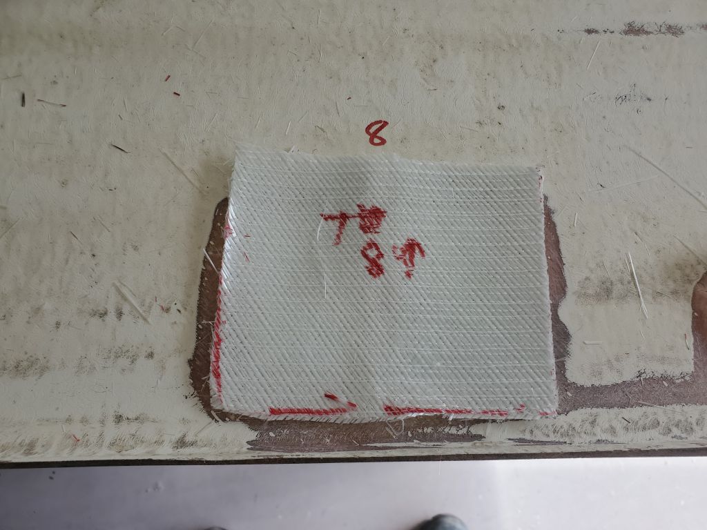
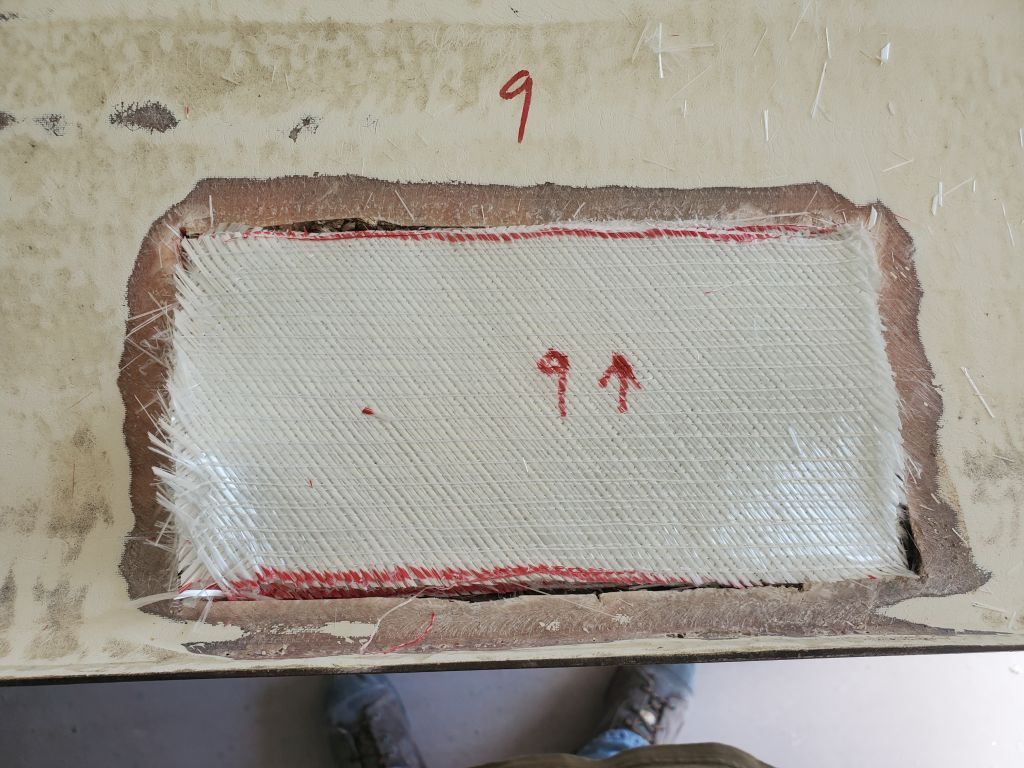
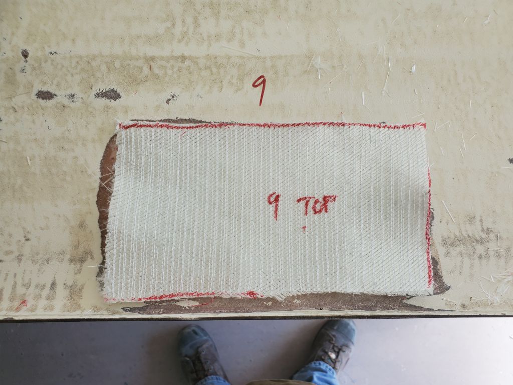
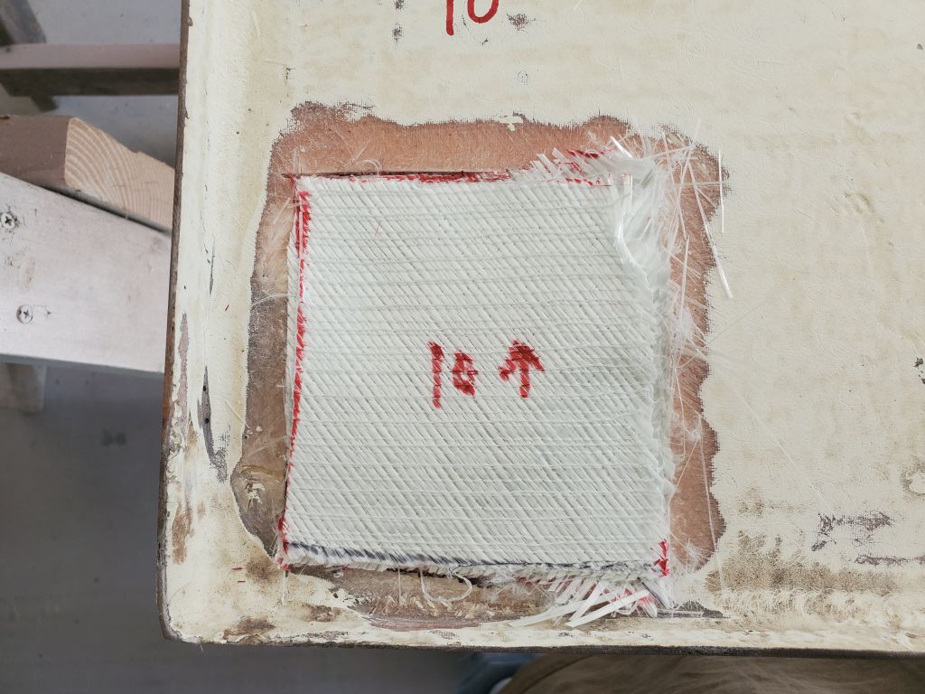
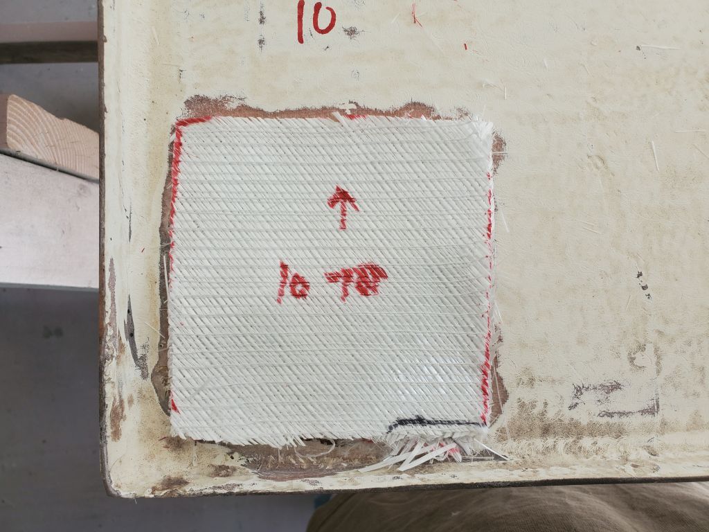
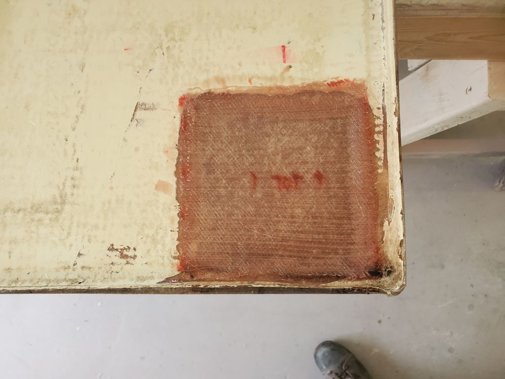
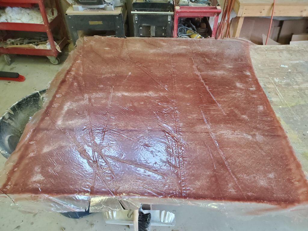
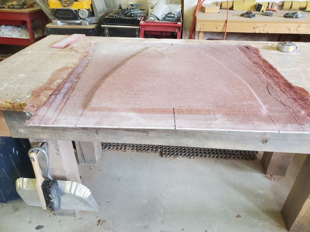
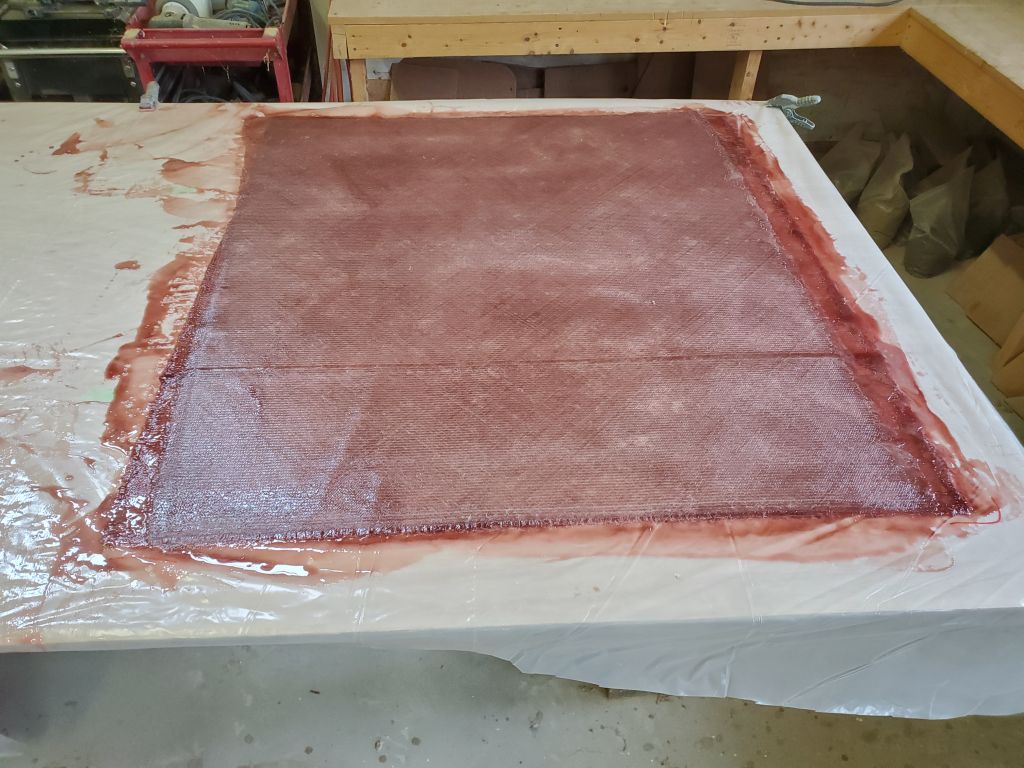
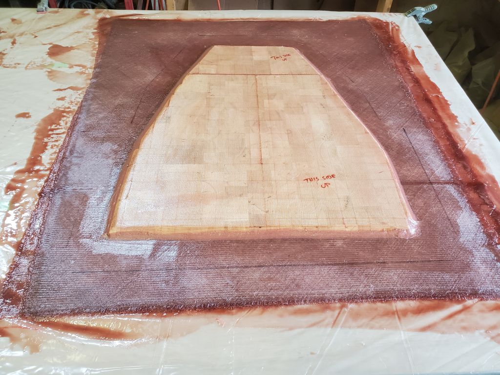
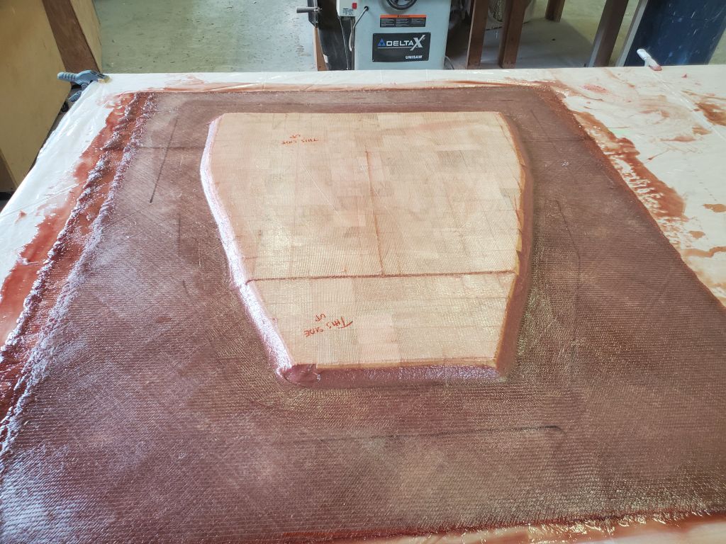
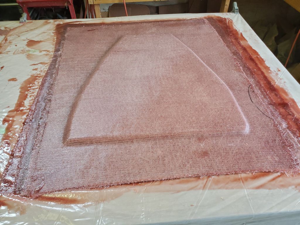
To use up what remained of the day, I cut several pieces of 1708 biax somewhat larger than the template, and prepared a flat molding table to build the new deck. I’d continue this process next time.