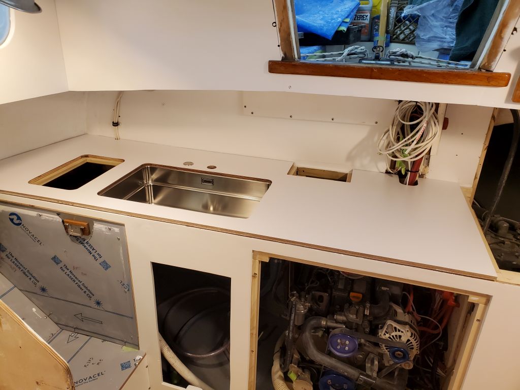
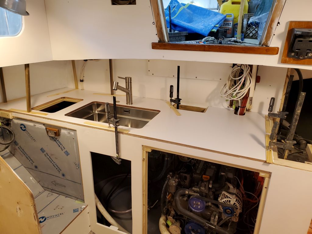
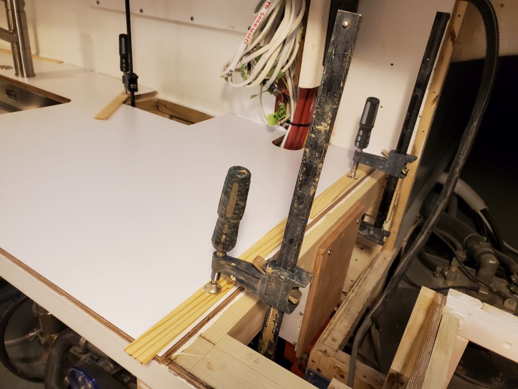
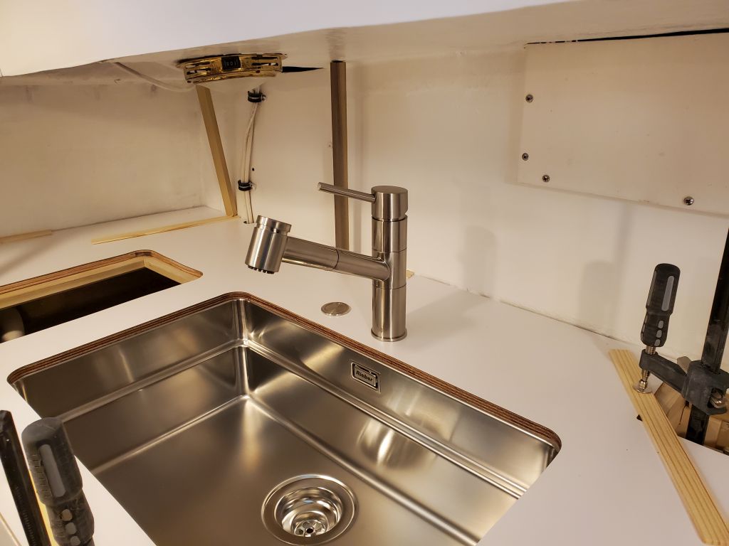
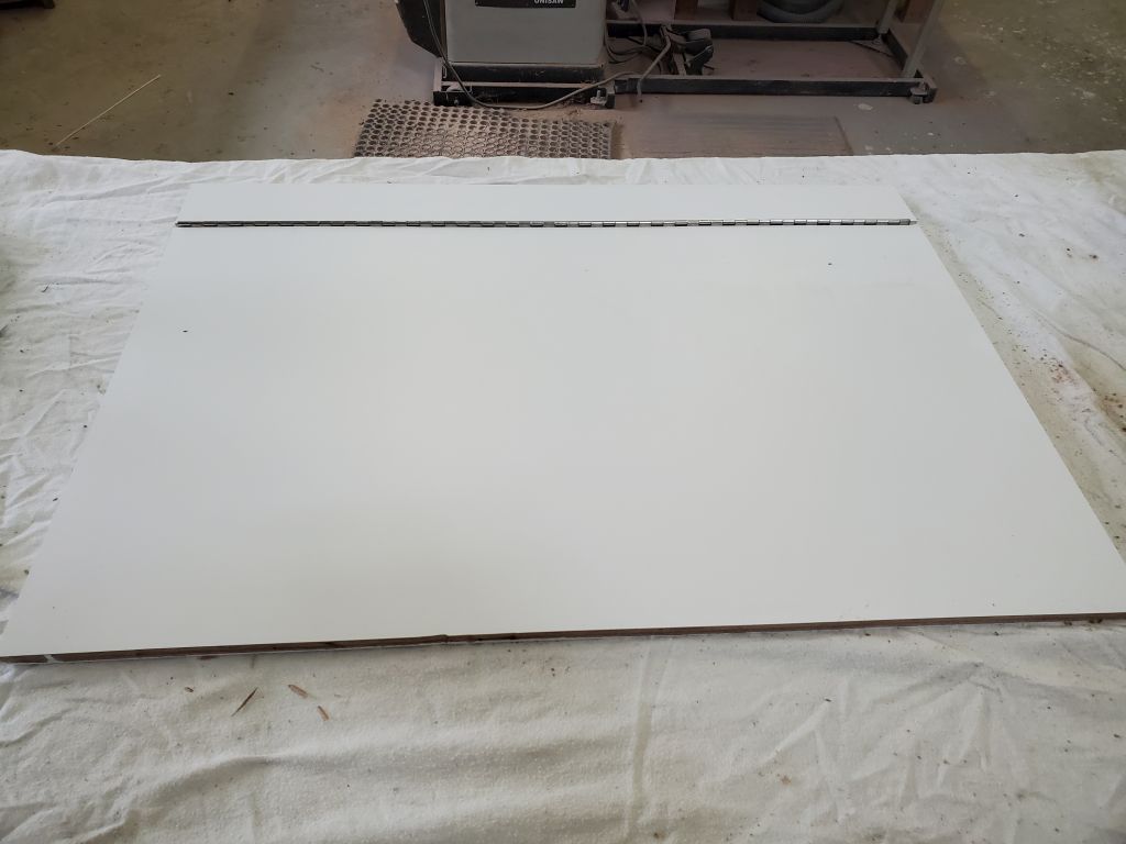
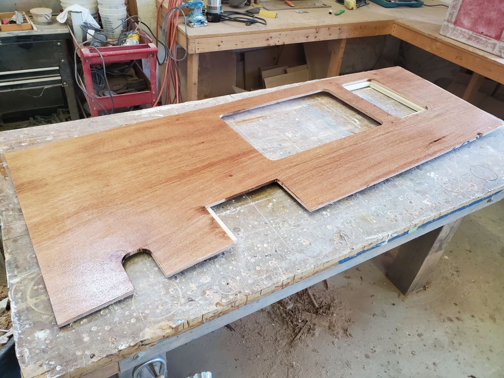
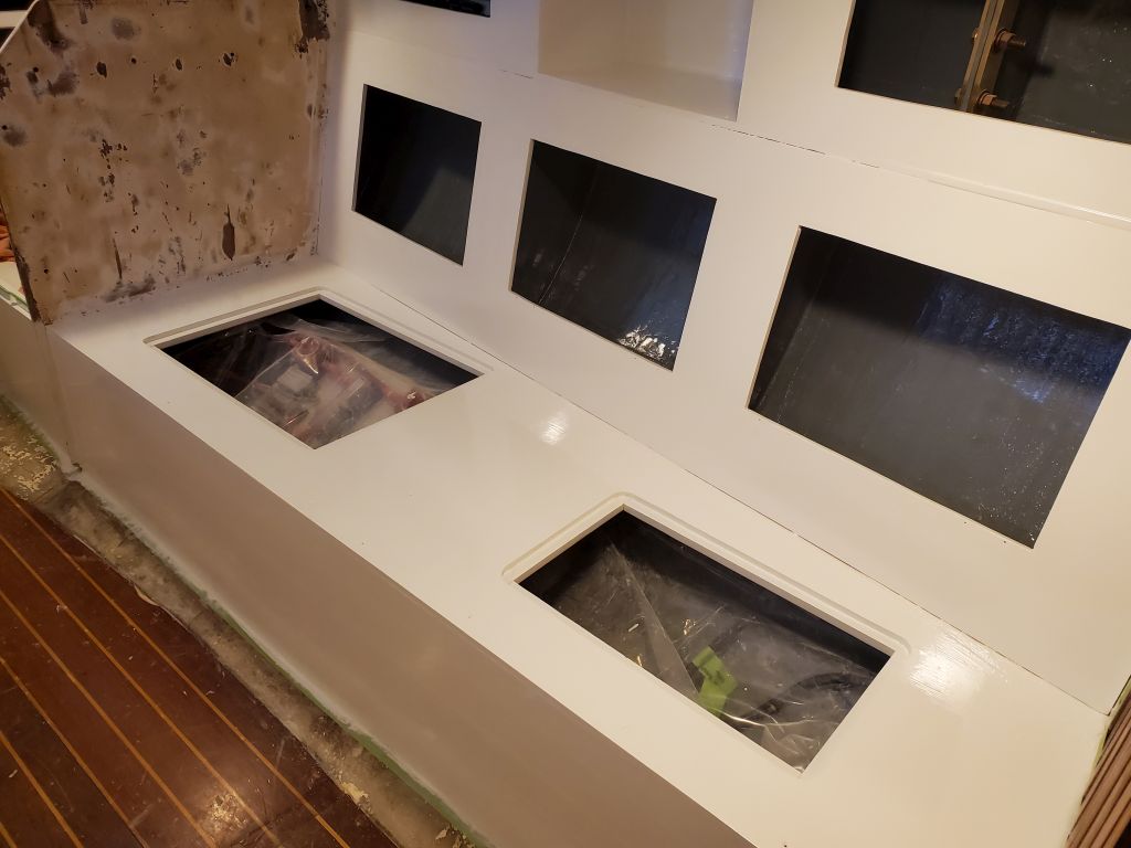
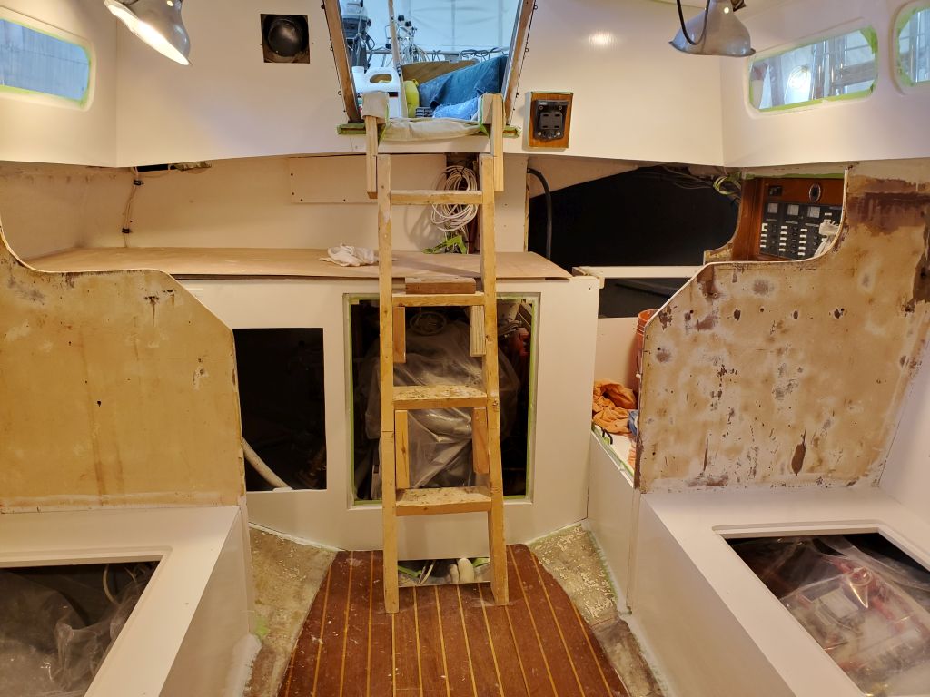
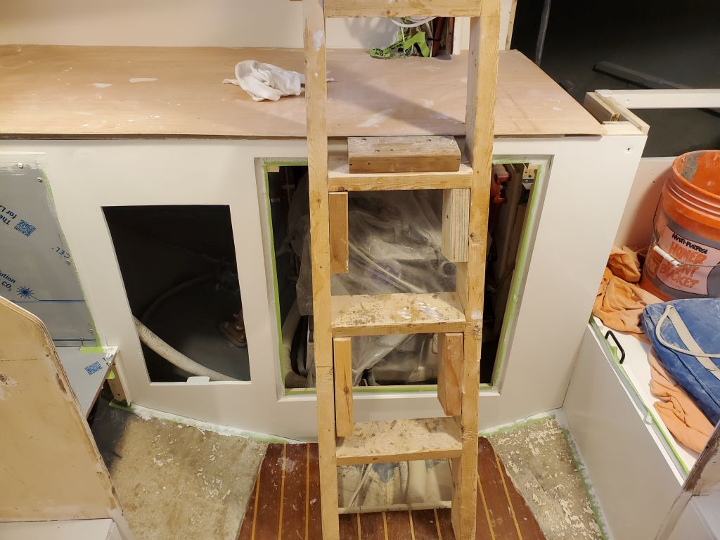
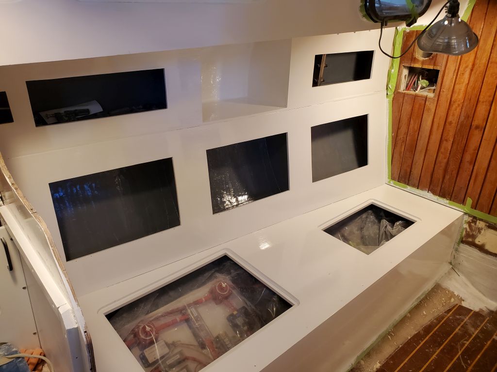
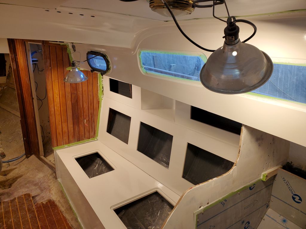
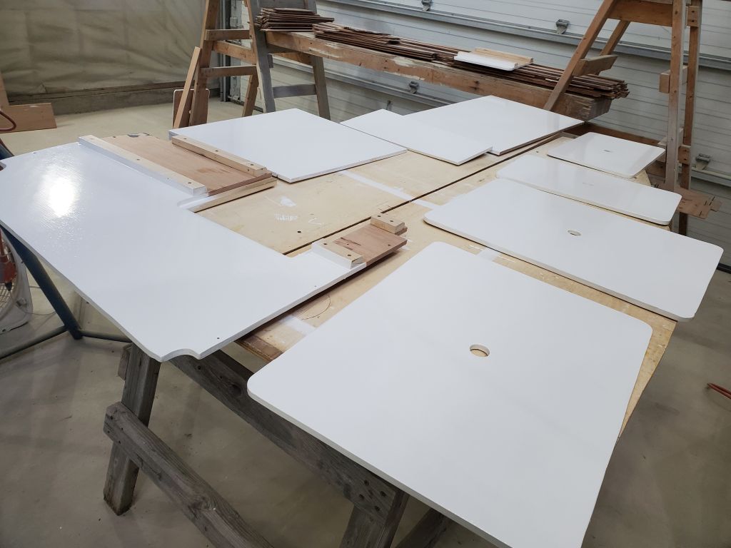
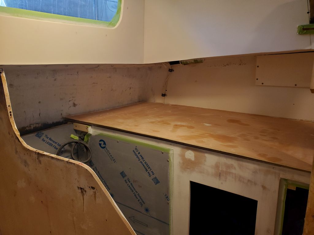
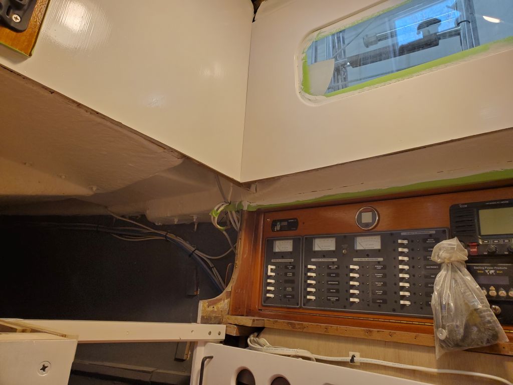
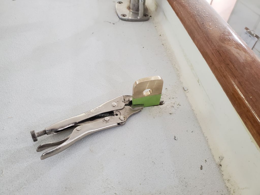
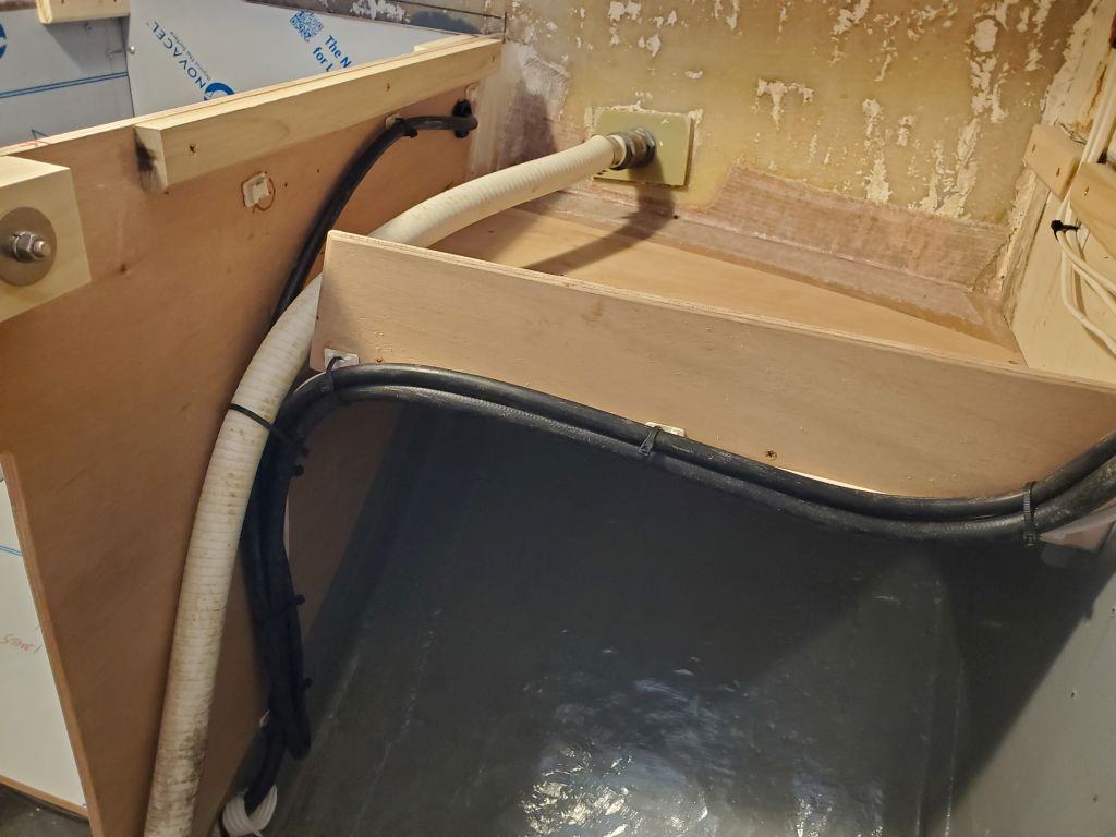
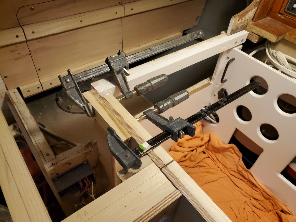
To begin, I unclamped the countertop, which had had ample cure time.
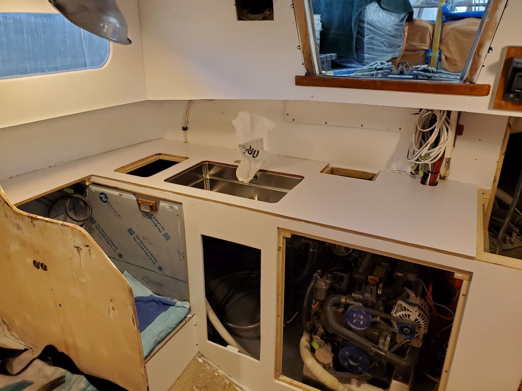
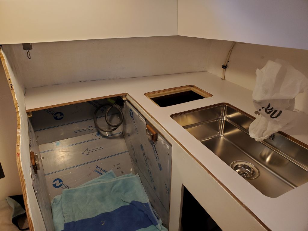
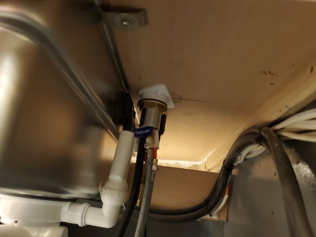
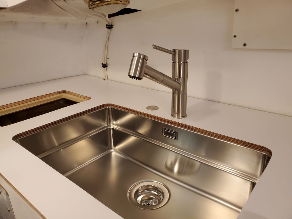
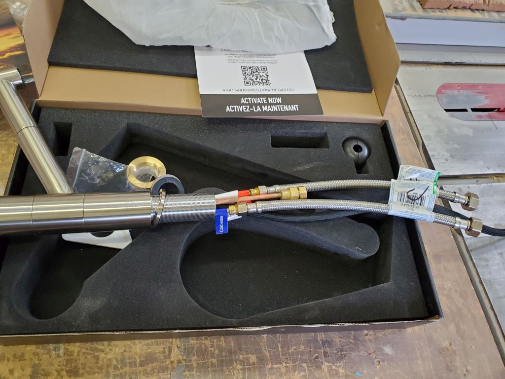
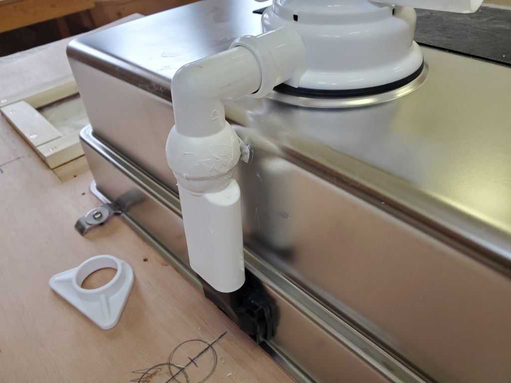
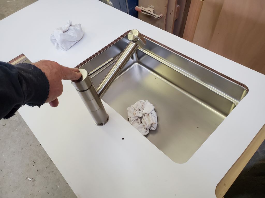
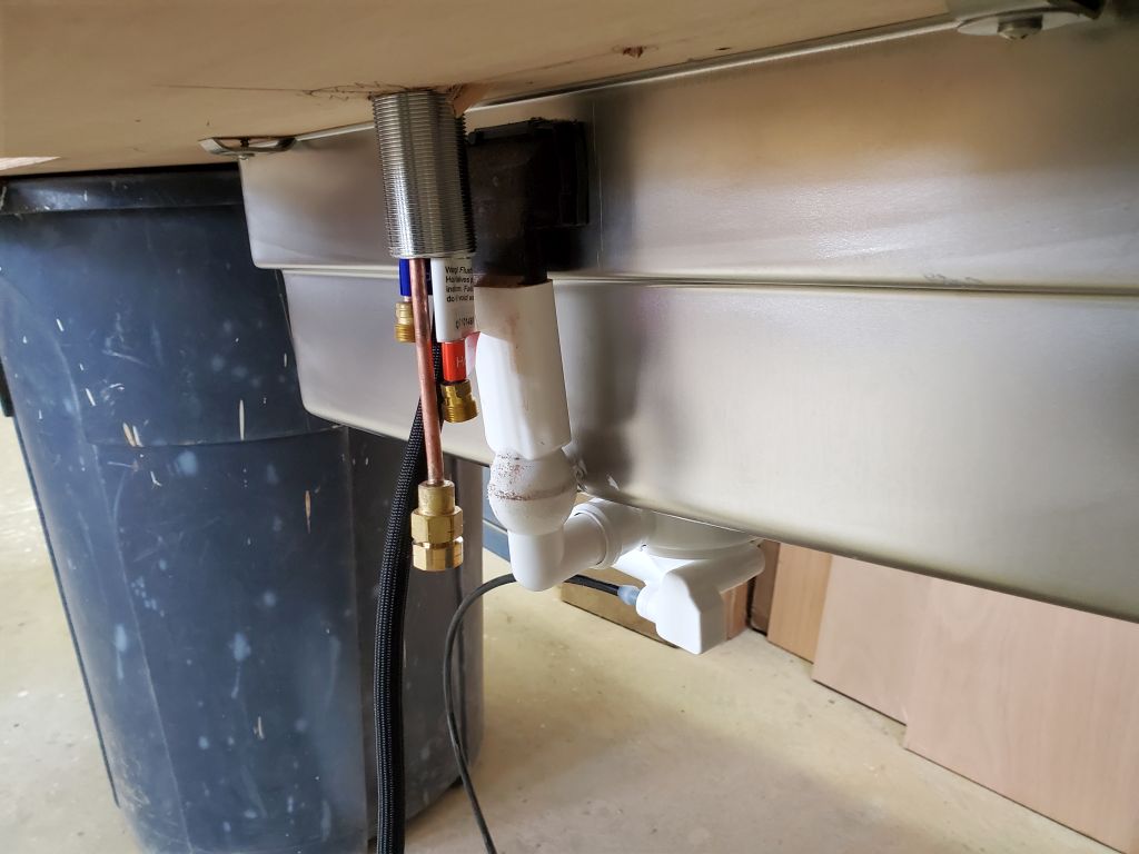
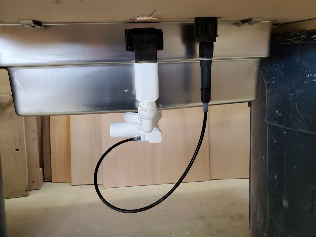
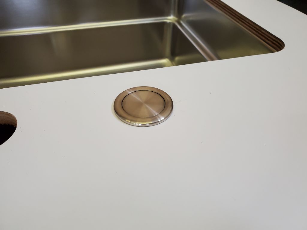
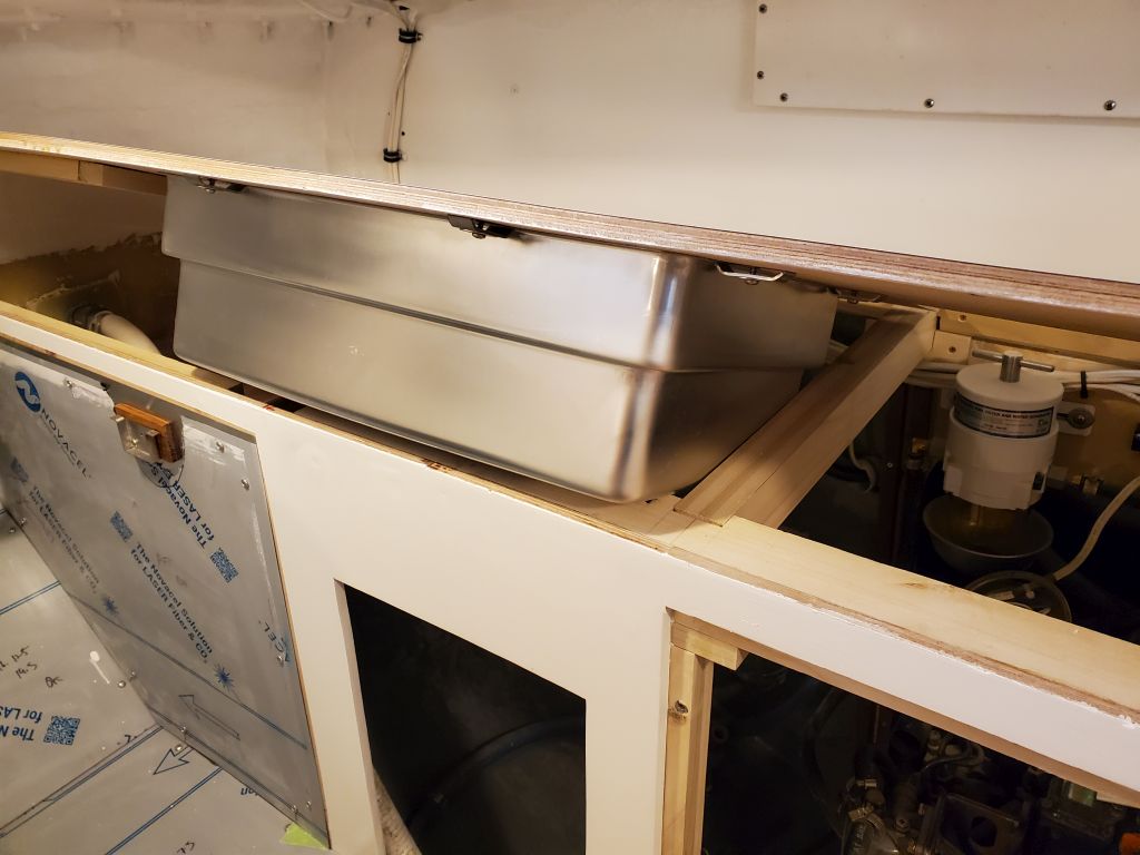
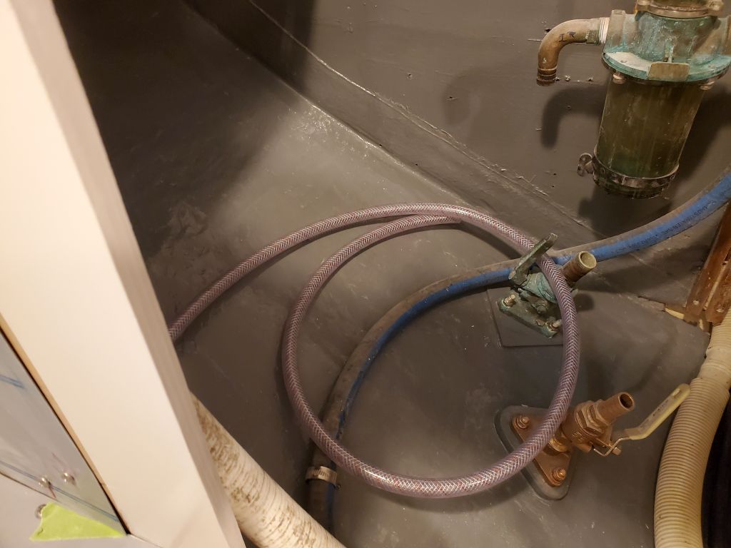
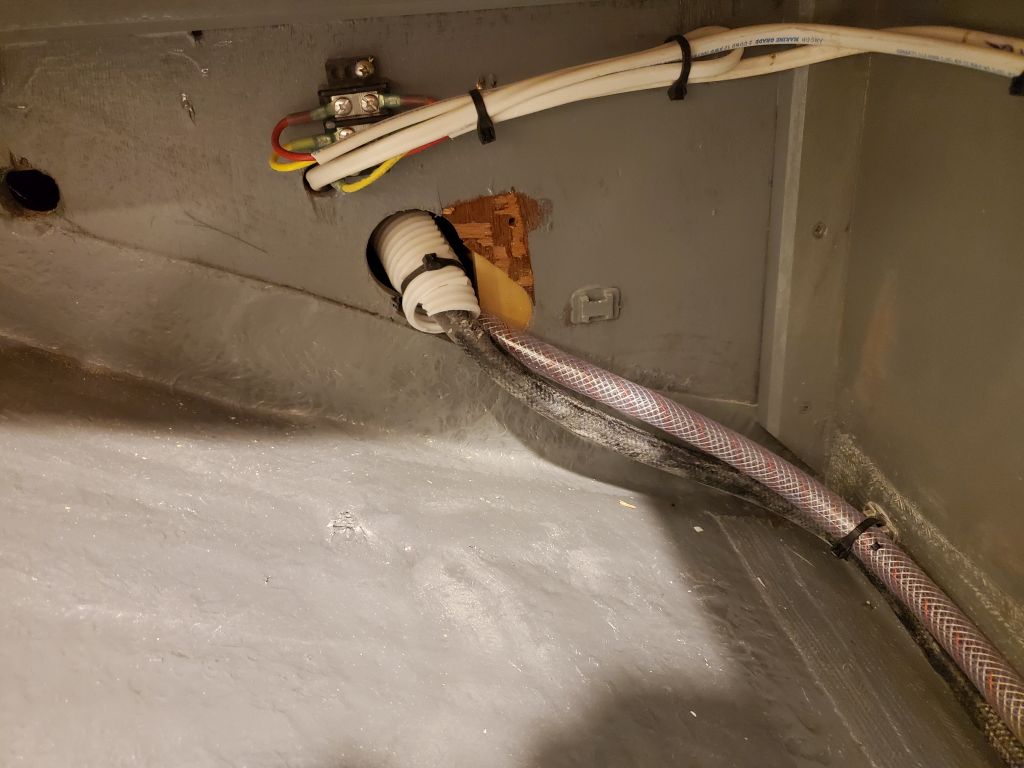
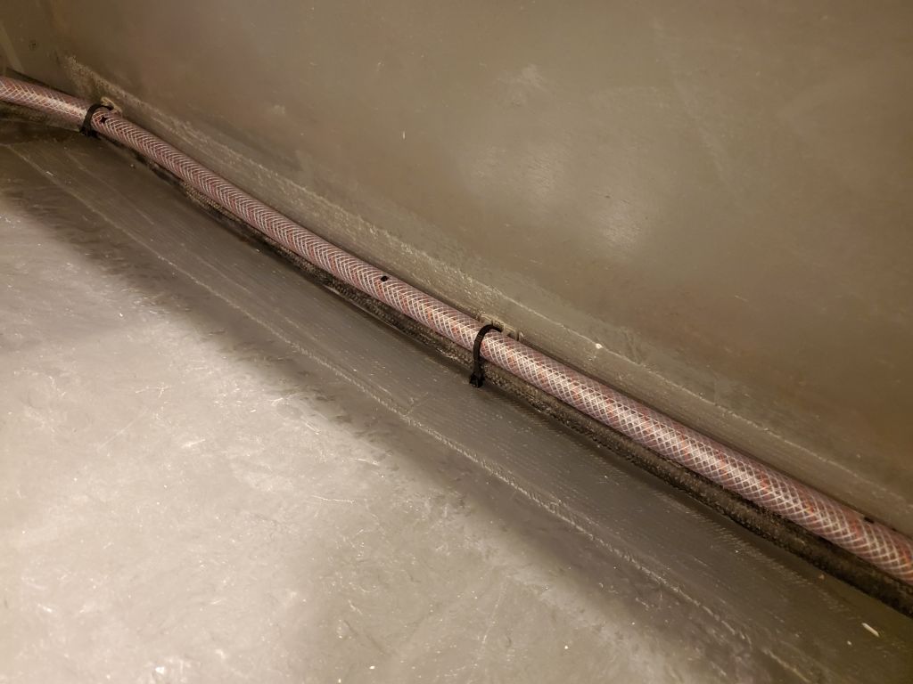
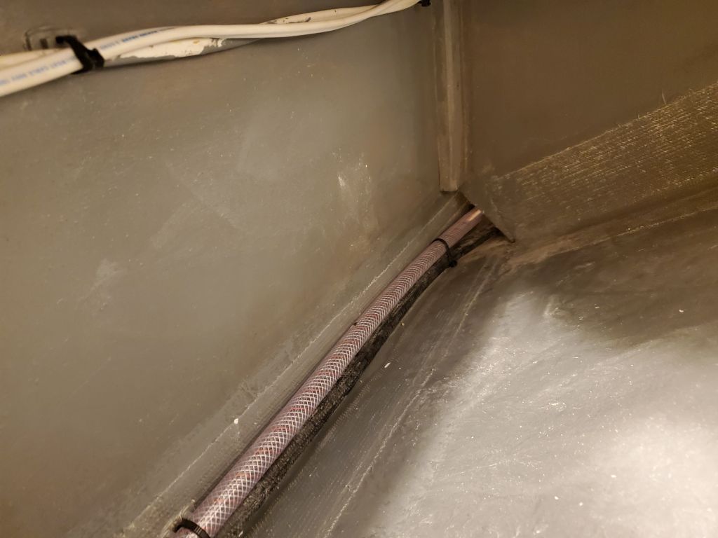
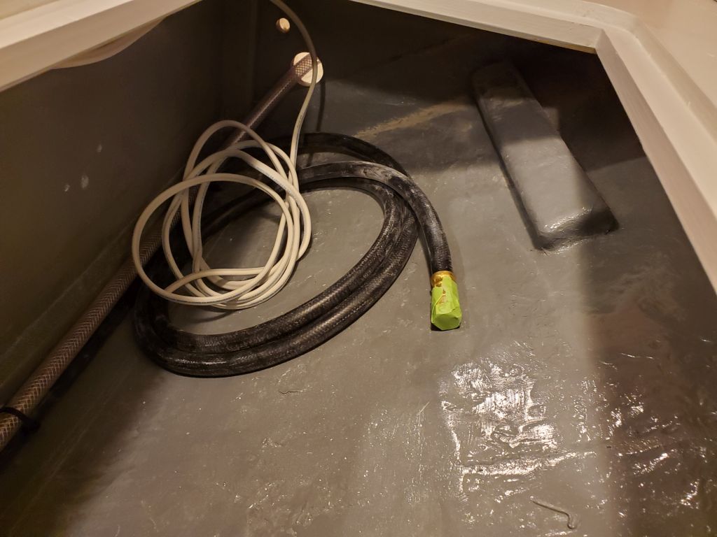
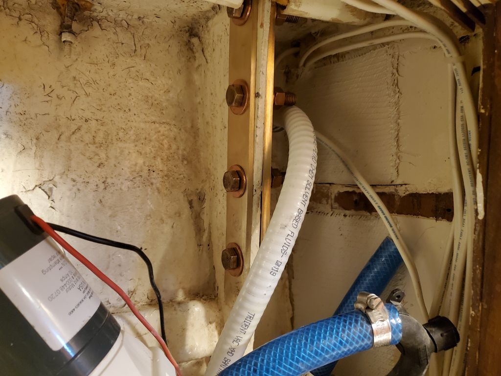
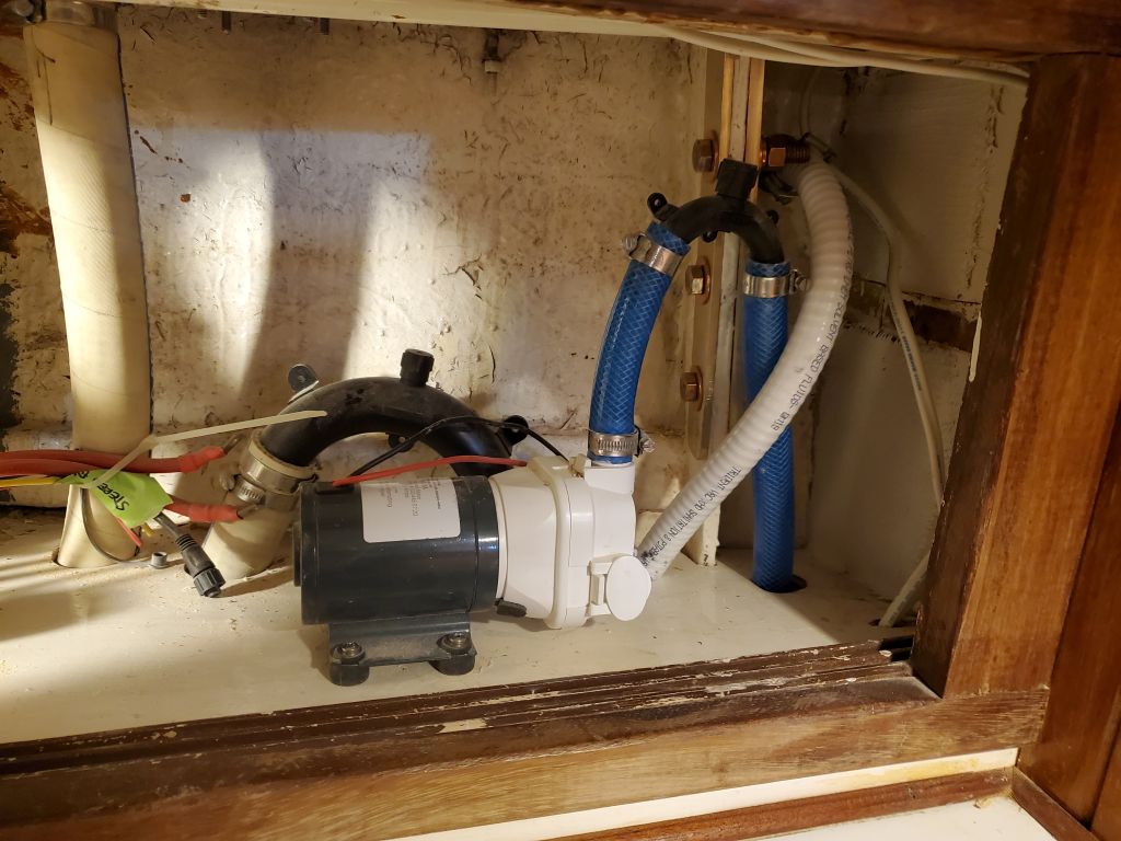
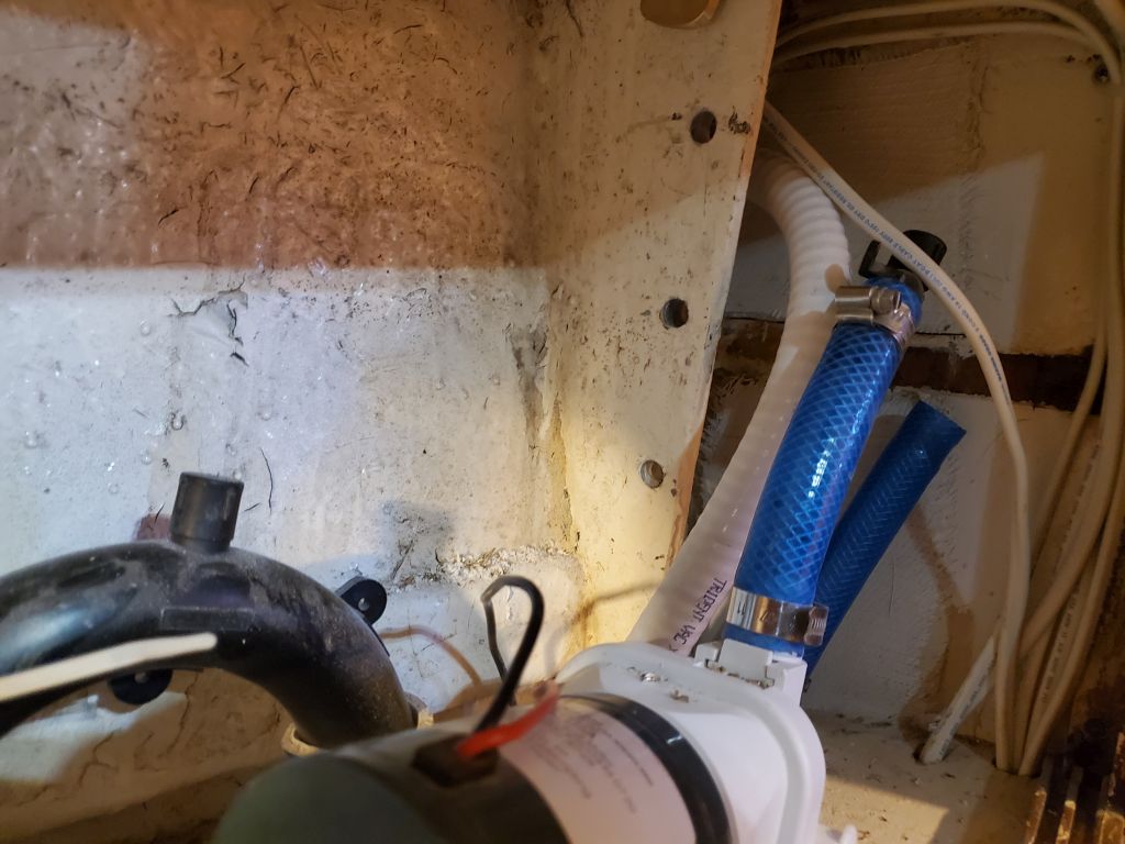
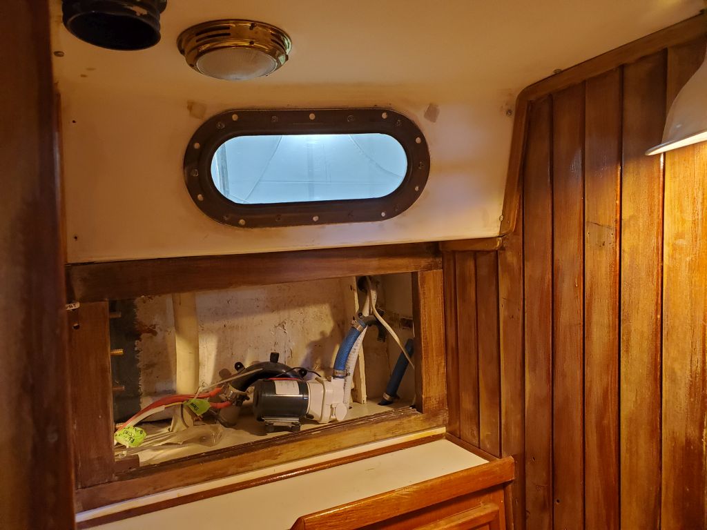
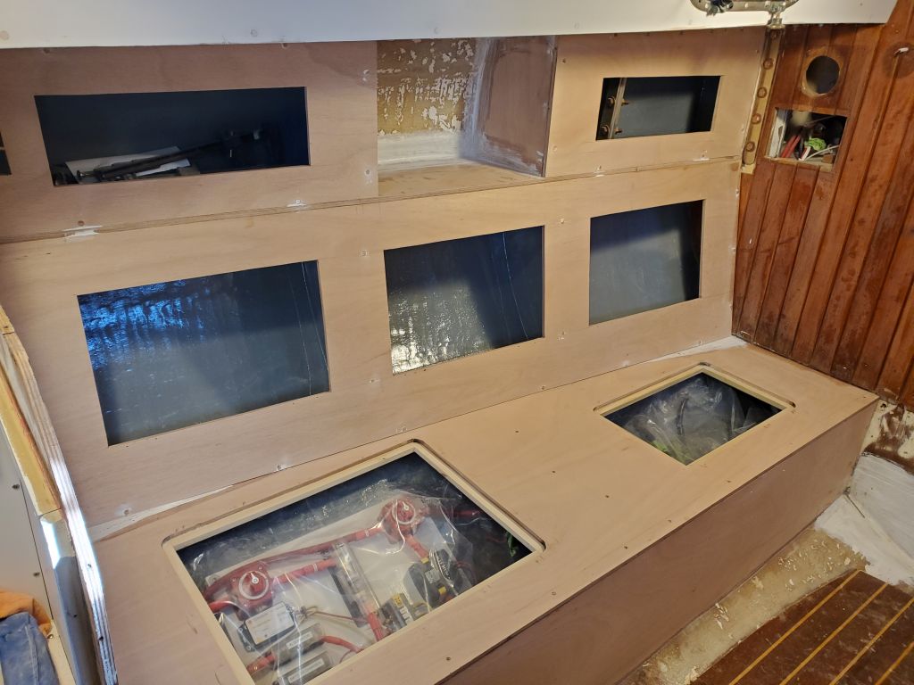
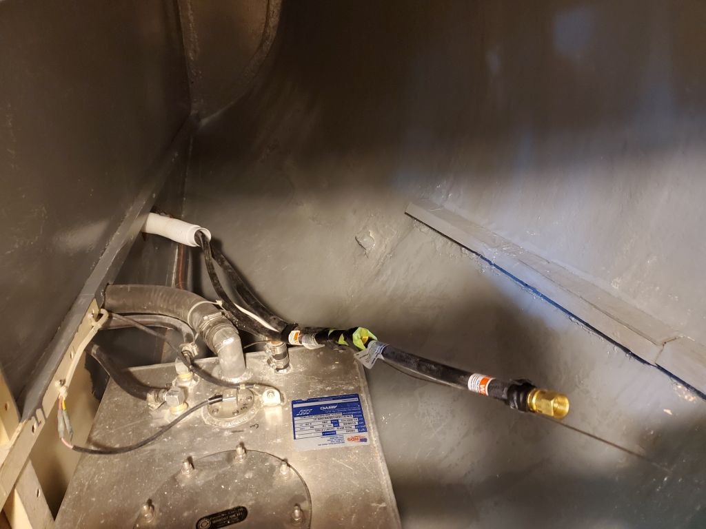
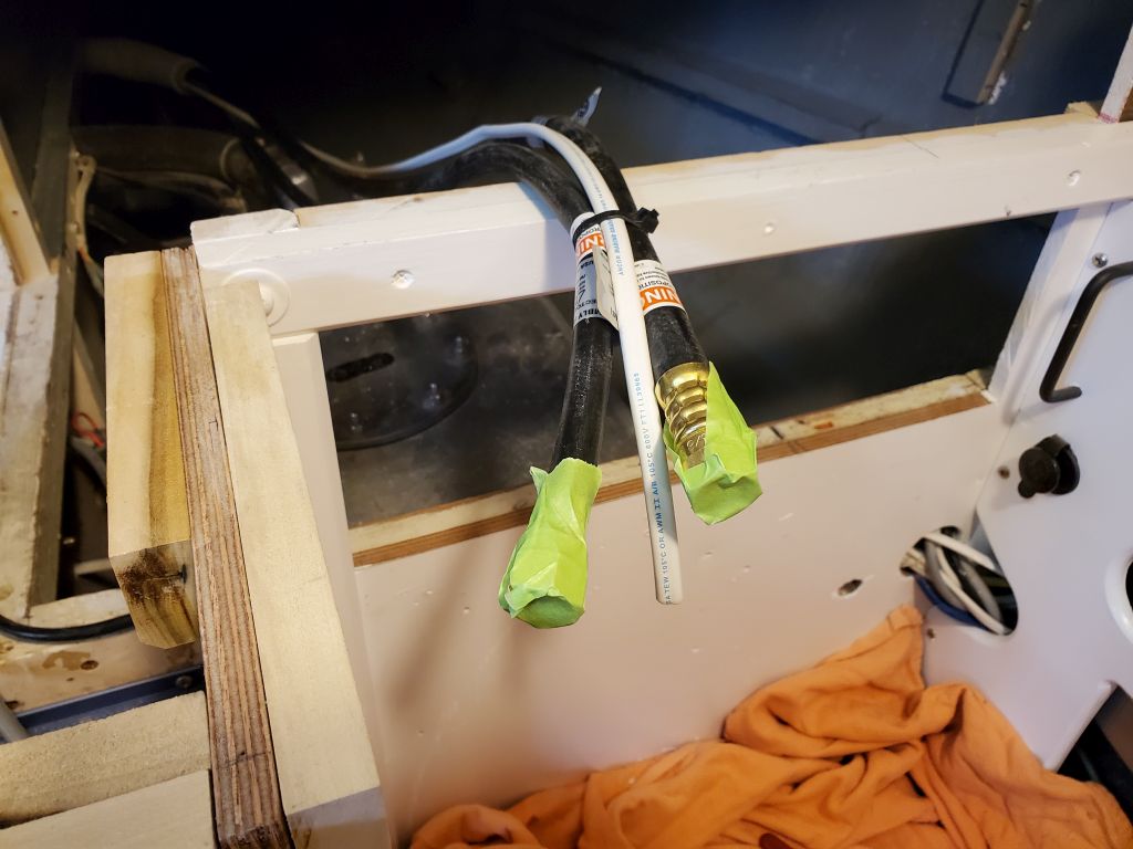
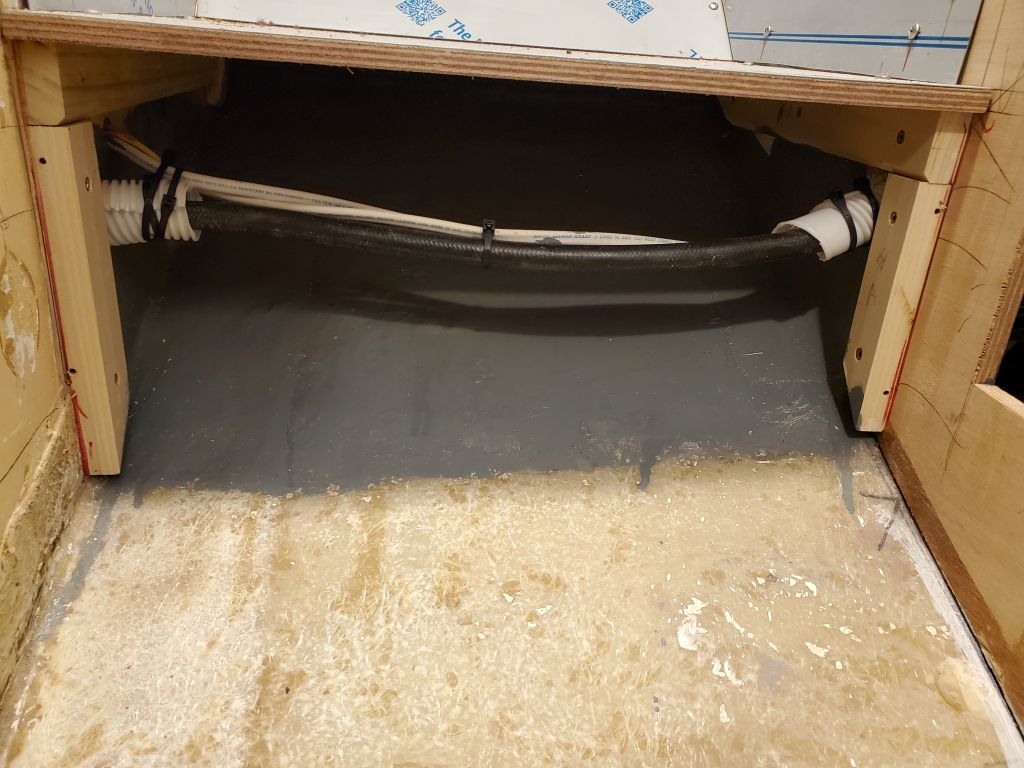
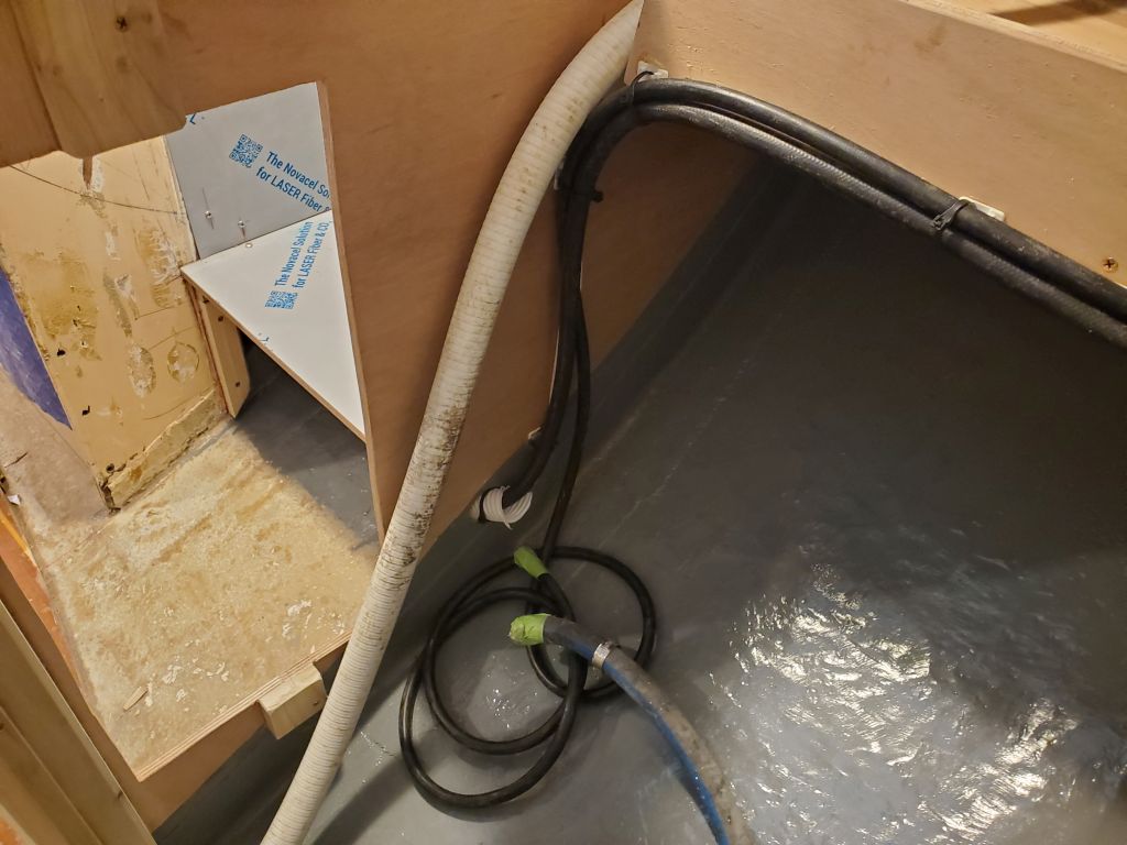
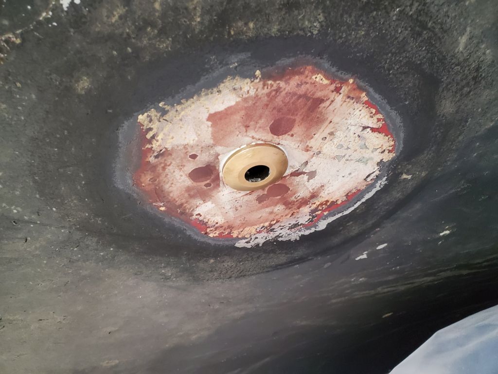
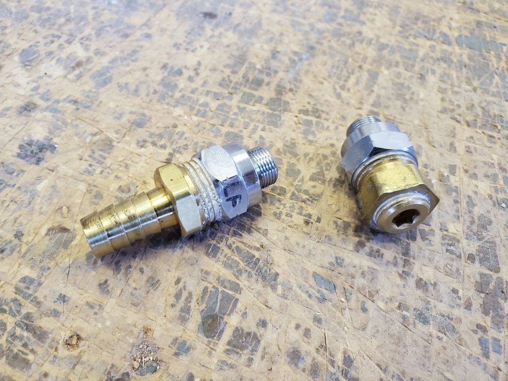
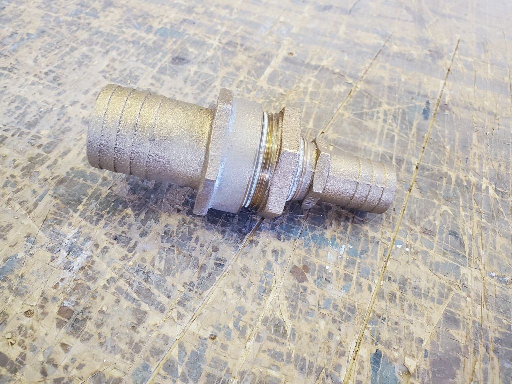
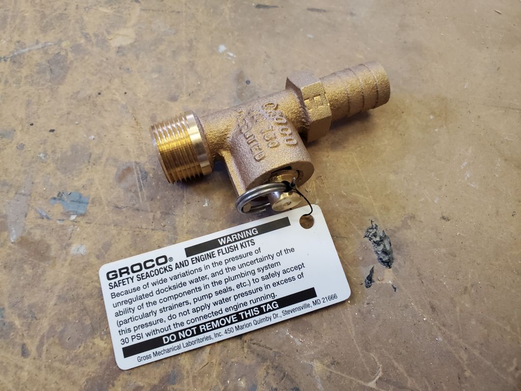
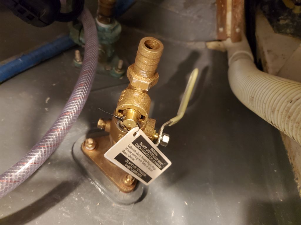
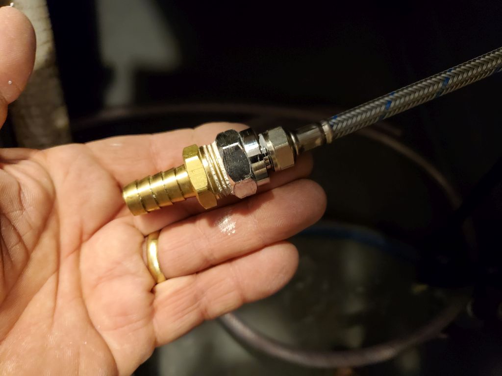
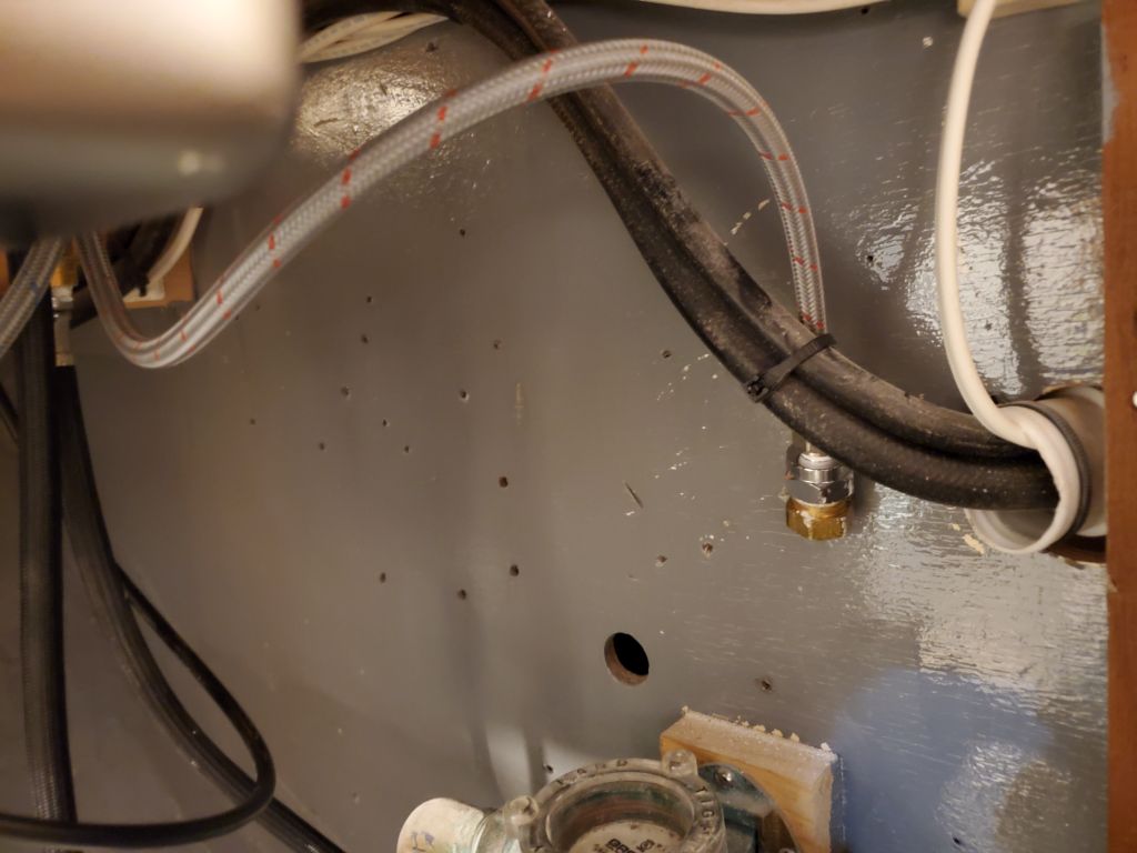
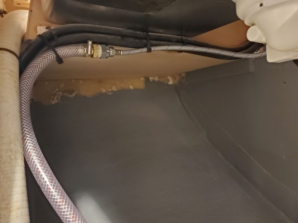
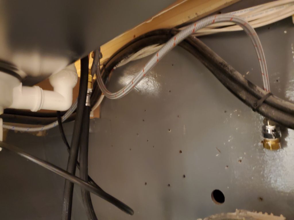
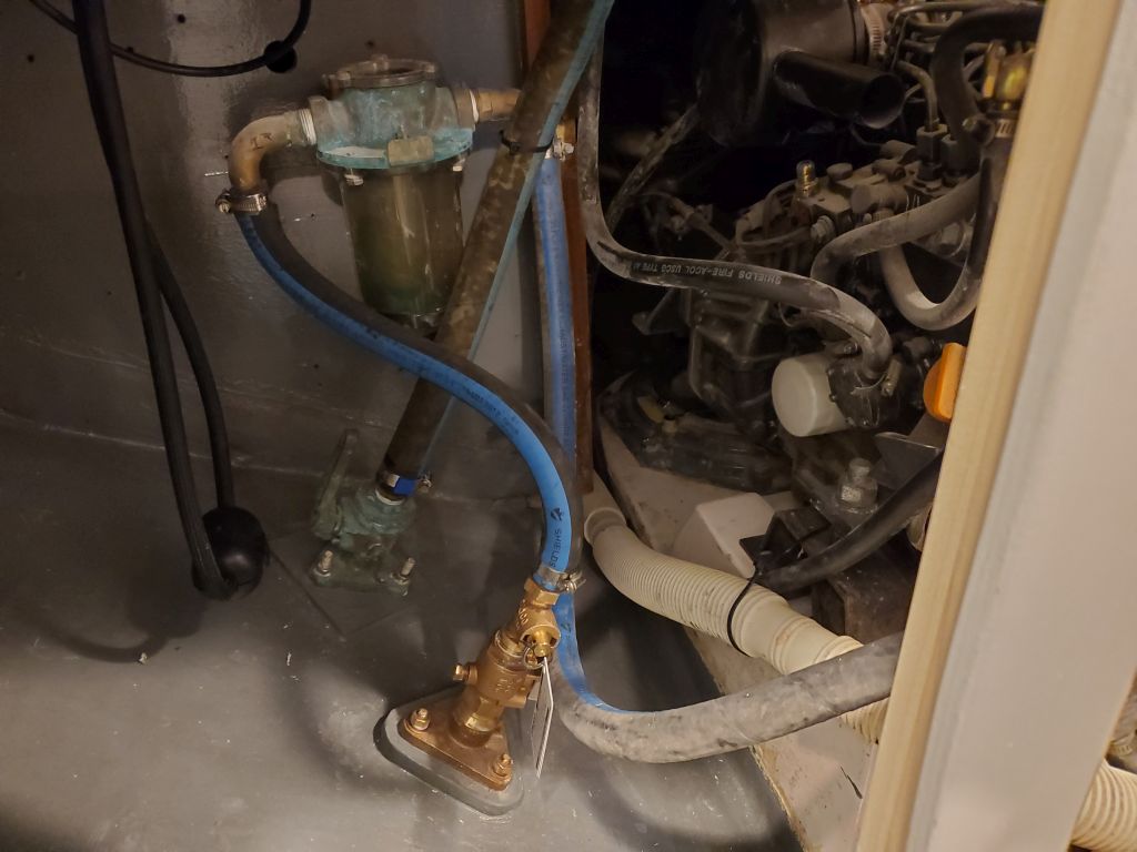
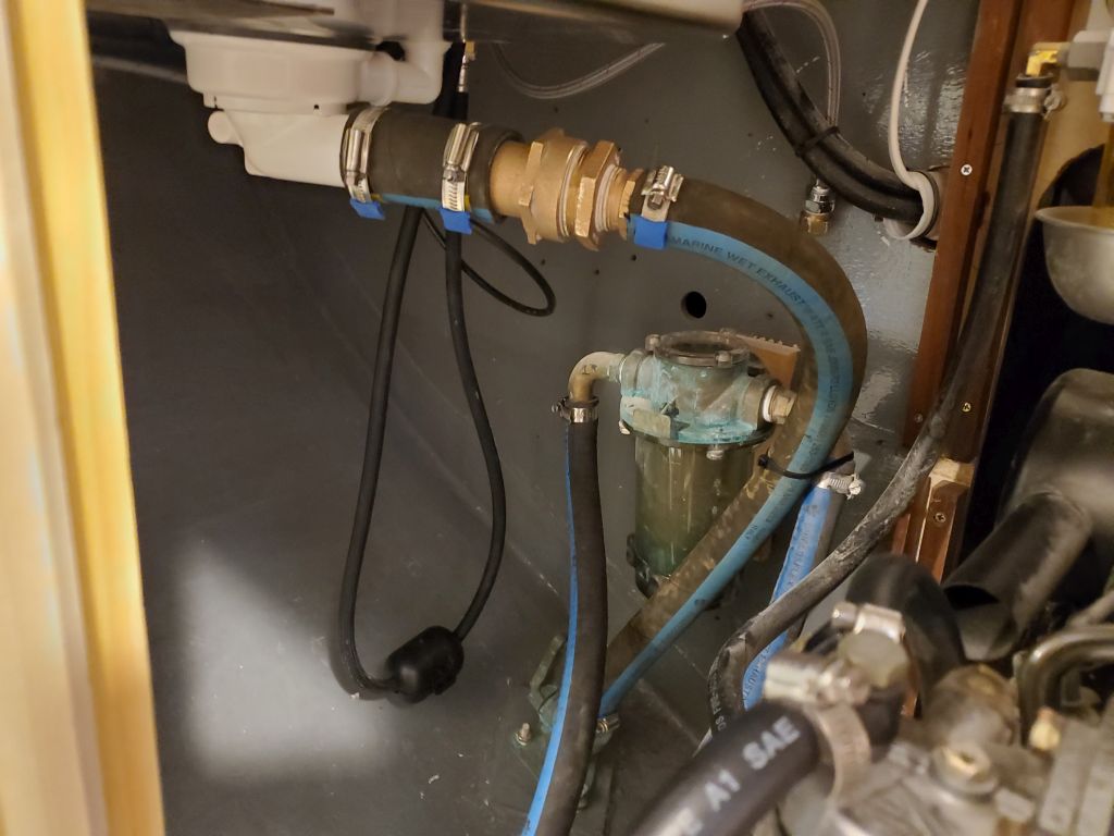
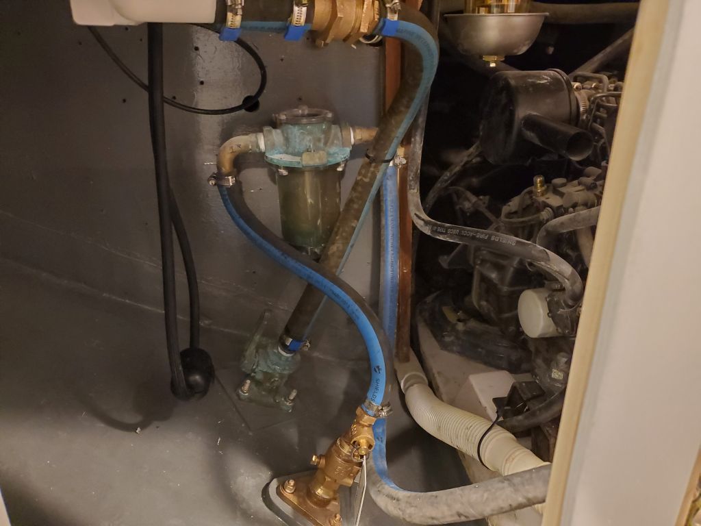
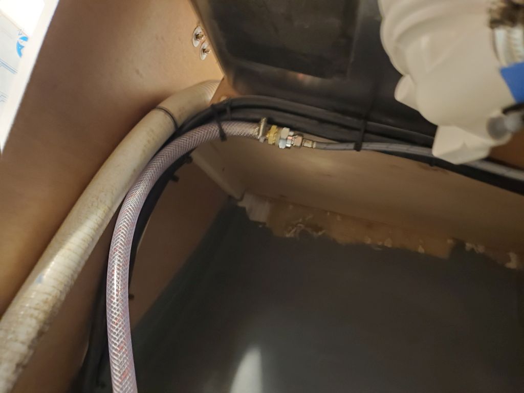
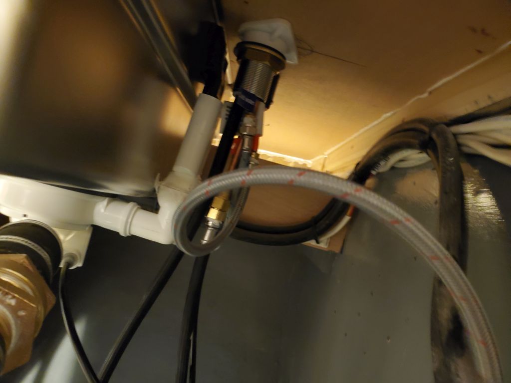
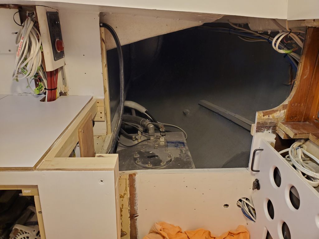
I thought I might as well wrap up the plumbing work with the sink and related area, as I had everything I needed and there was no time like the present. I’d purchased some adapters to connect the compression threads on the existing sink supply hoses to the hose nipple (for supply from the tank) on the cold hose, and a plug on the hot water hose. I also made up a bronze adapter to convert the 1-1/2″ sink drain pipe to the 1″ through hull. I made up these supply and drain connections in the boat as needed, and also installed a winterizing/flushing adapter on the new engine intake seacock that the owner requested, and finished up its hose as well.
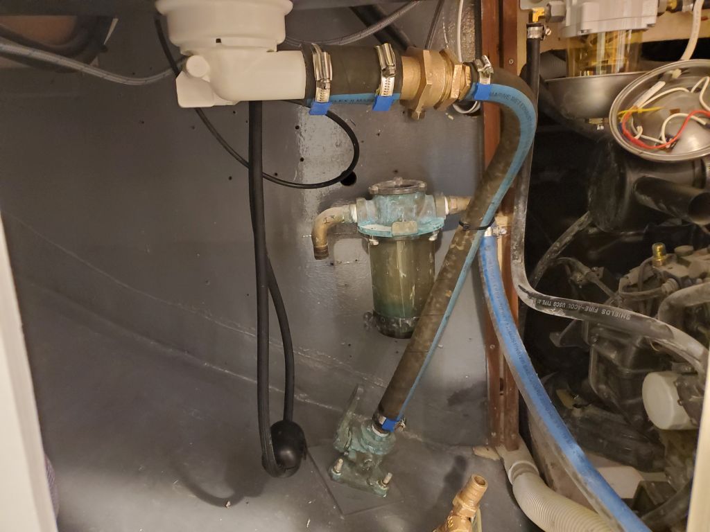
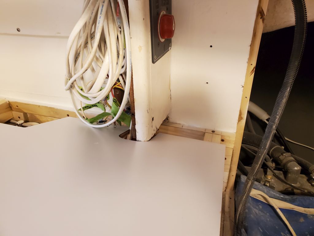
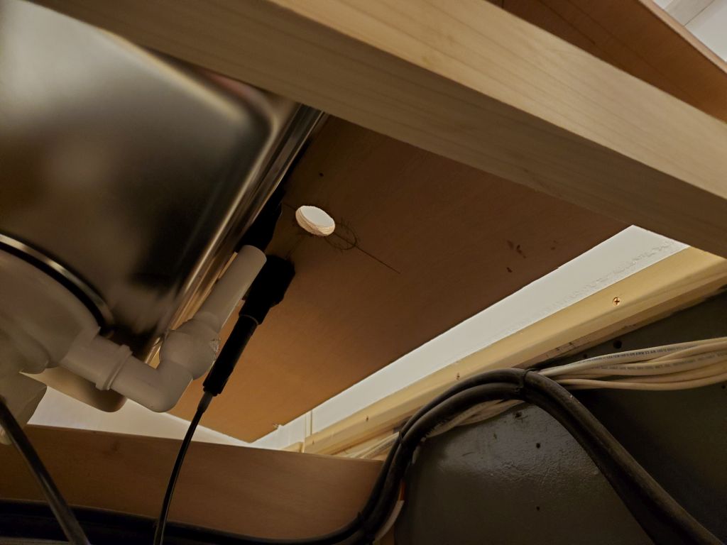
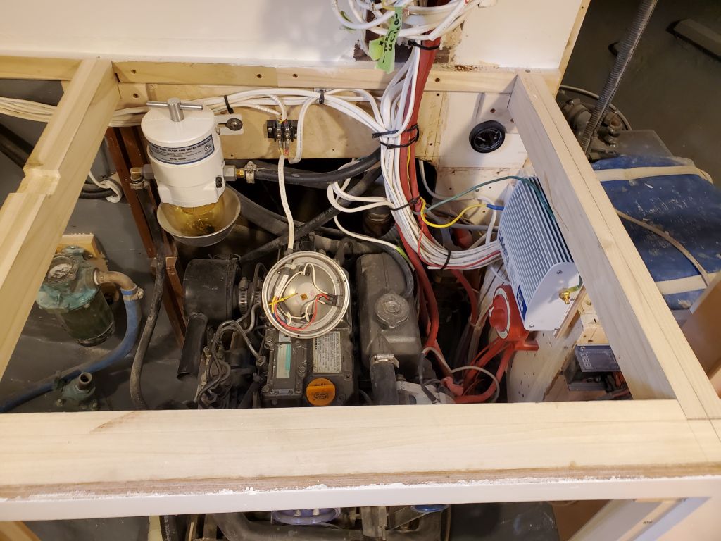
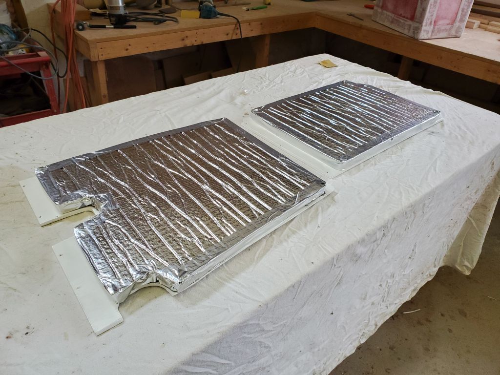
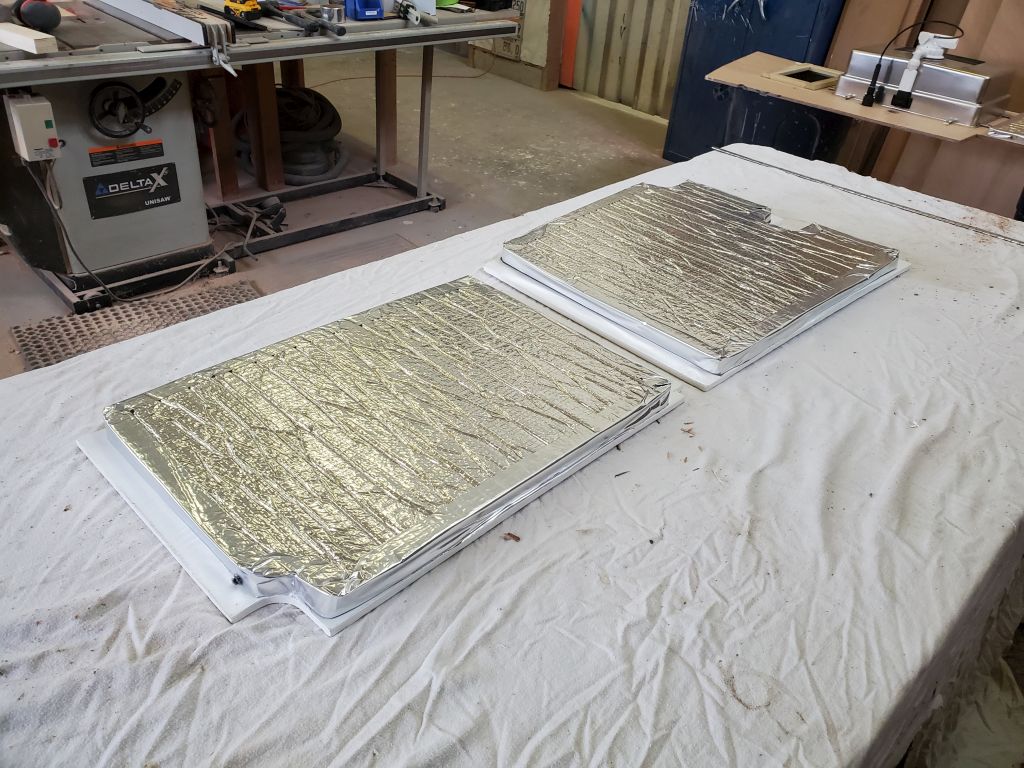
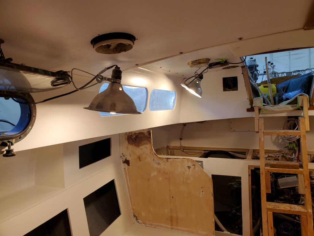
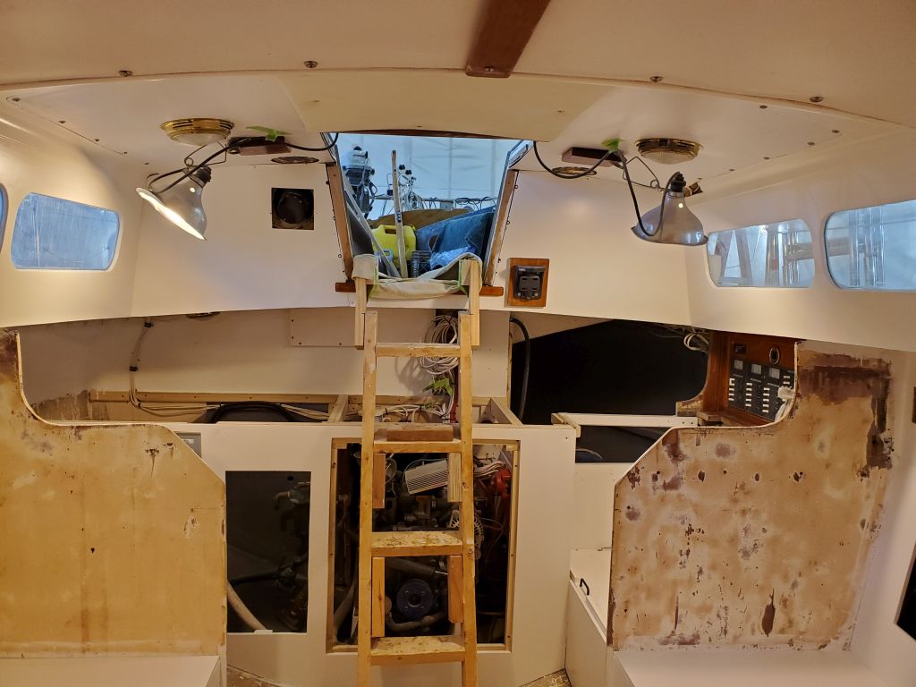
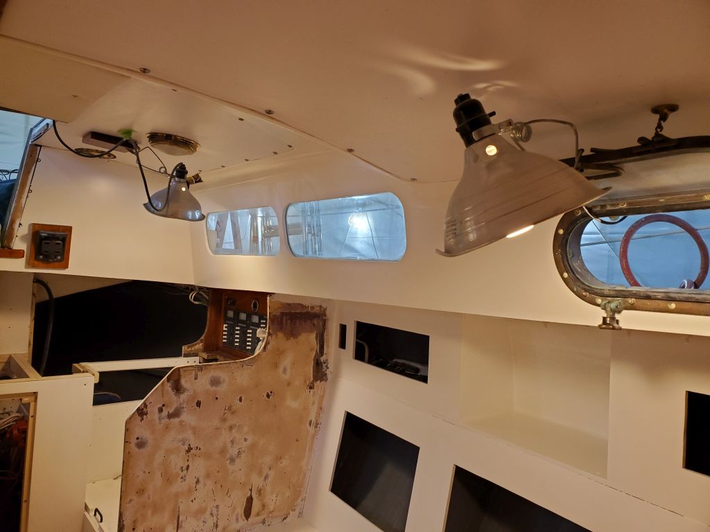
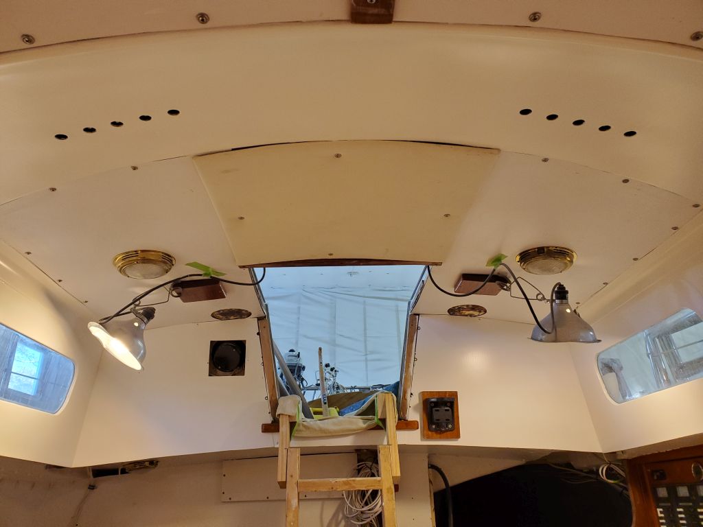
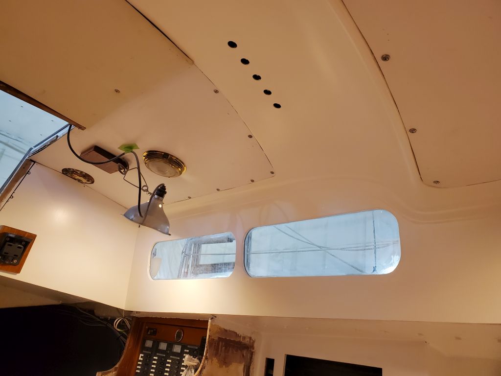
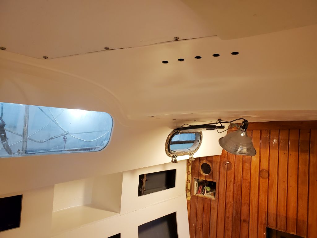
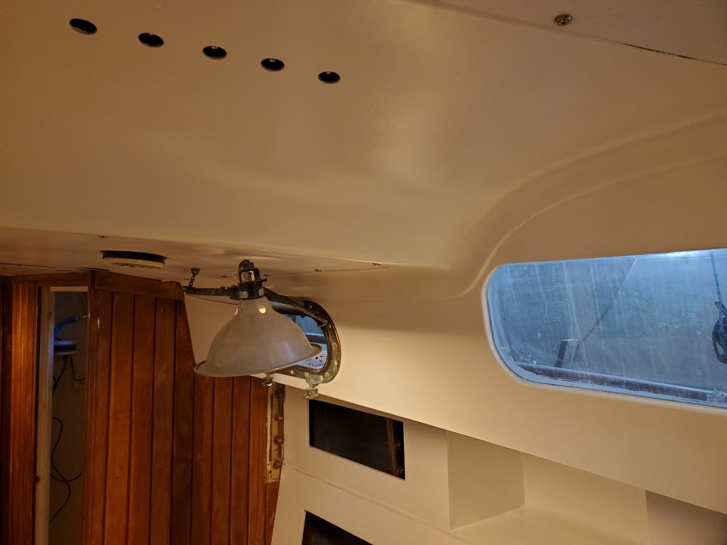
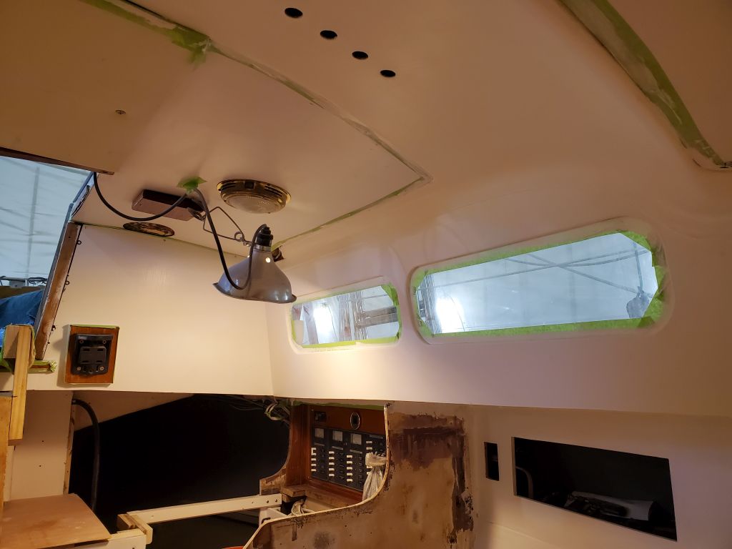
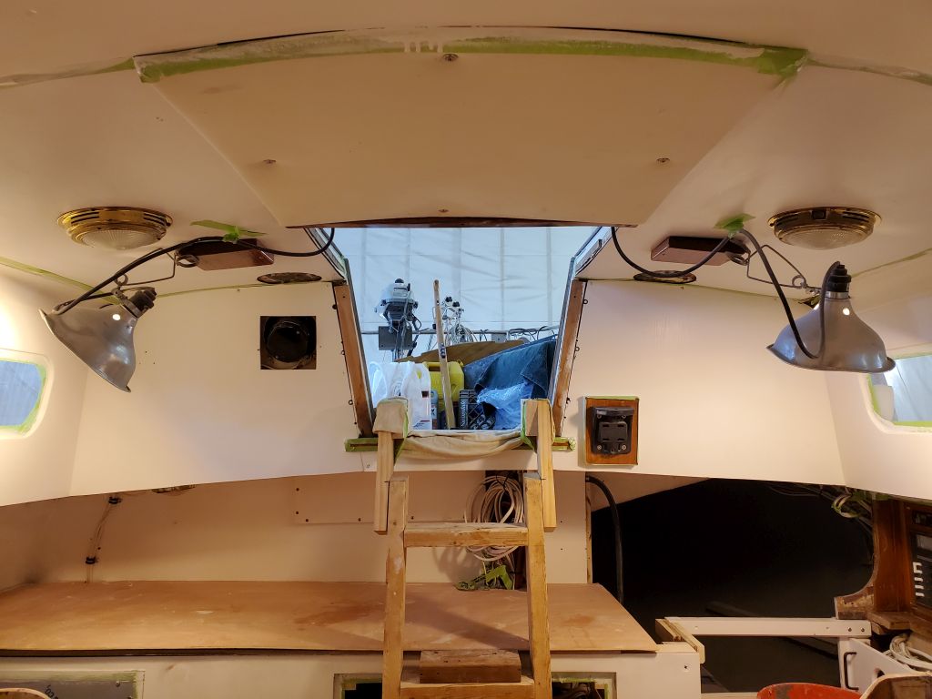
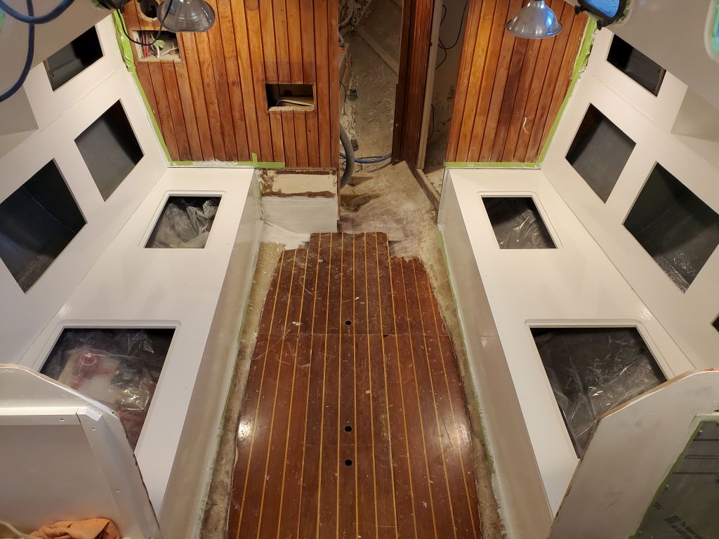
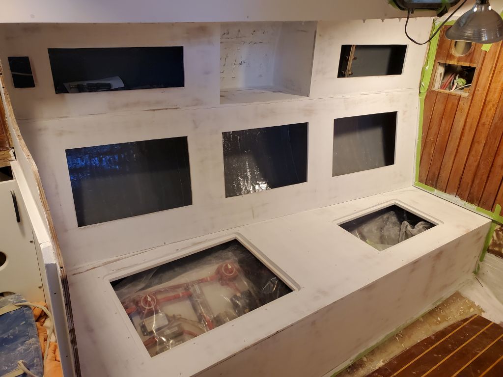
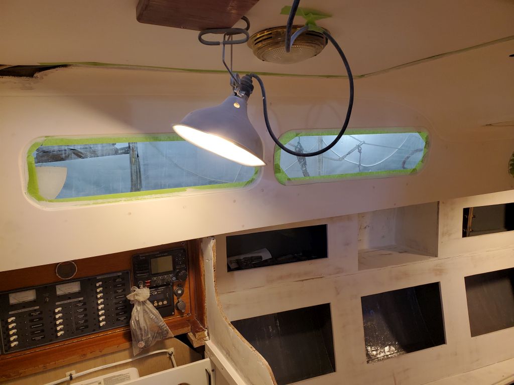
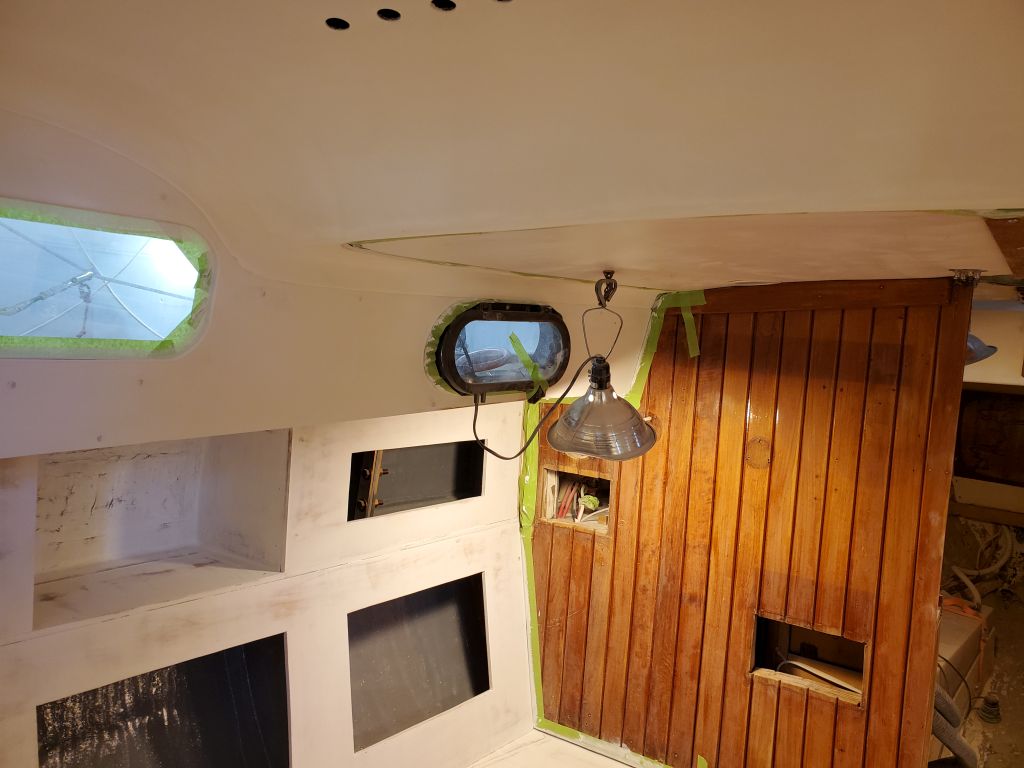
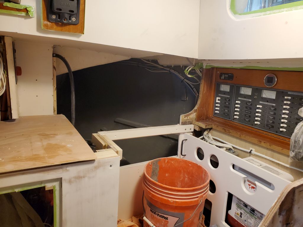
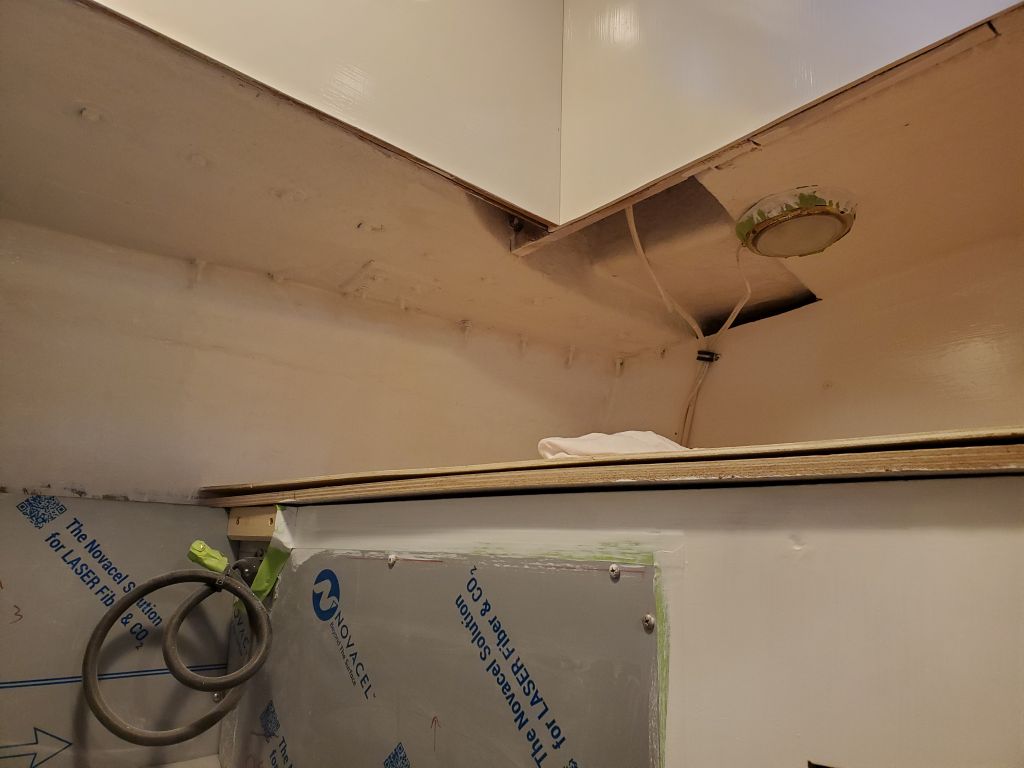
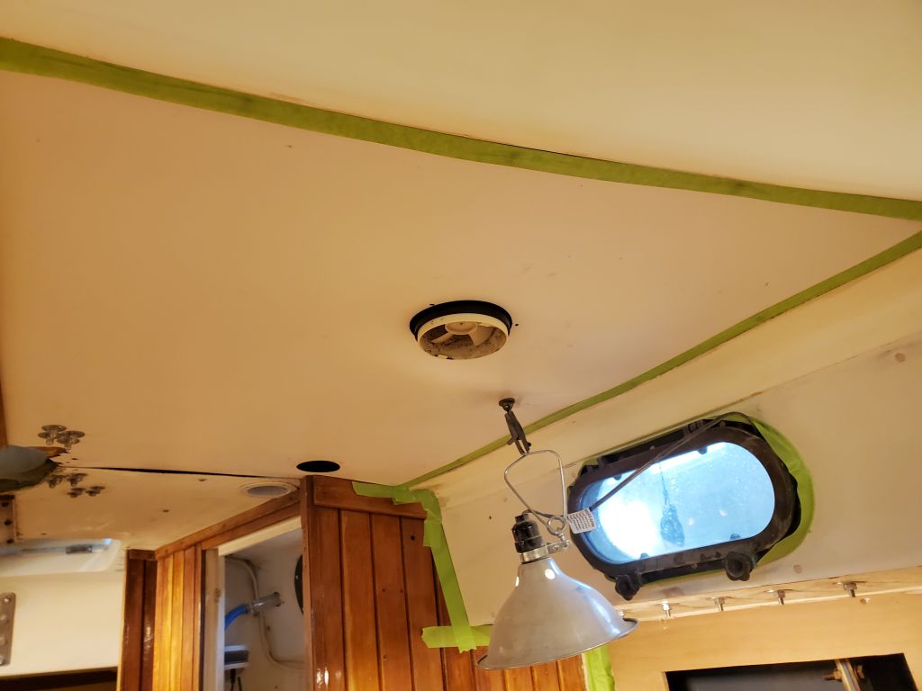
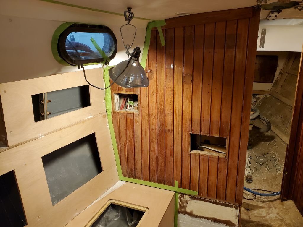
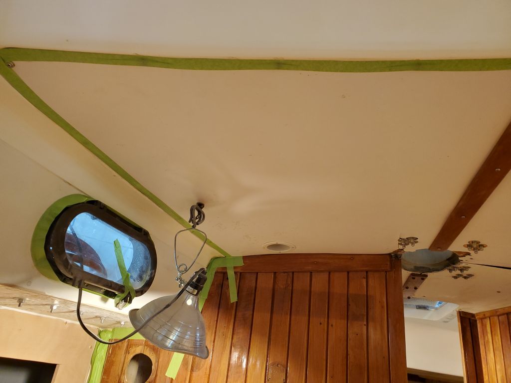
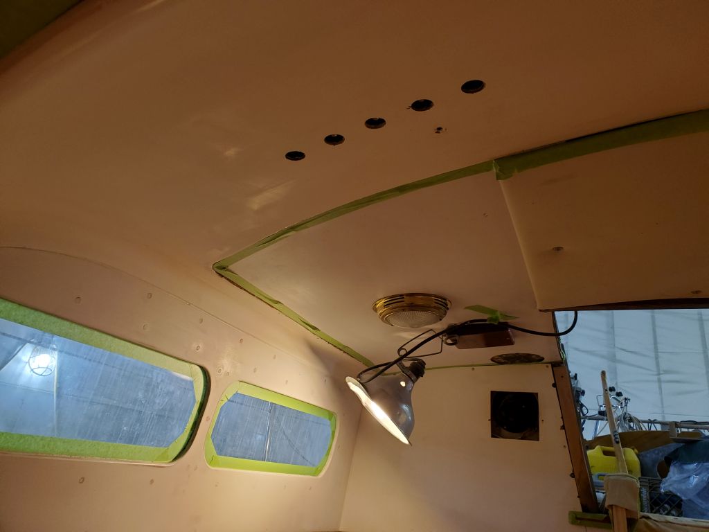
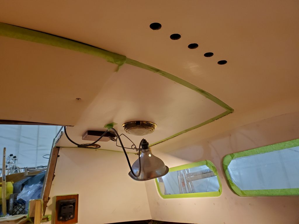
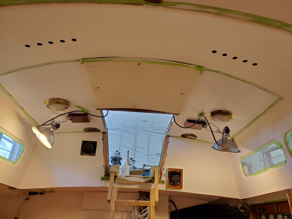
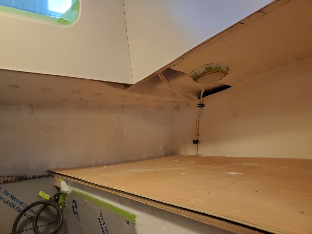
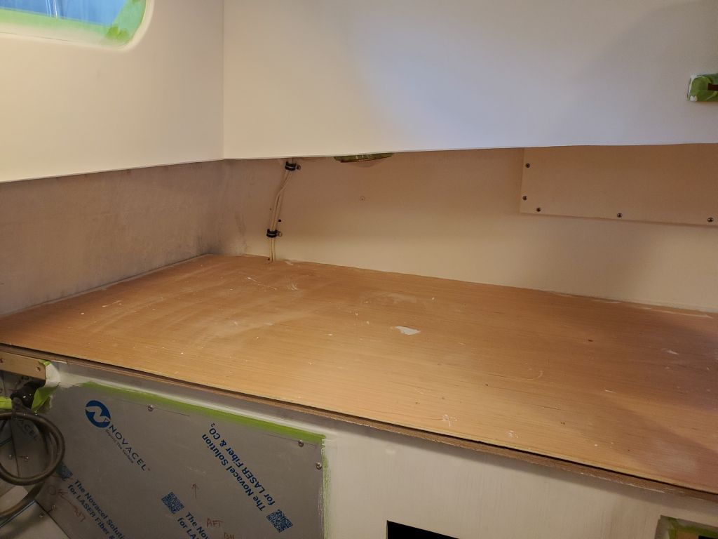
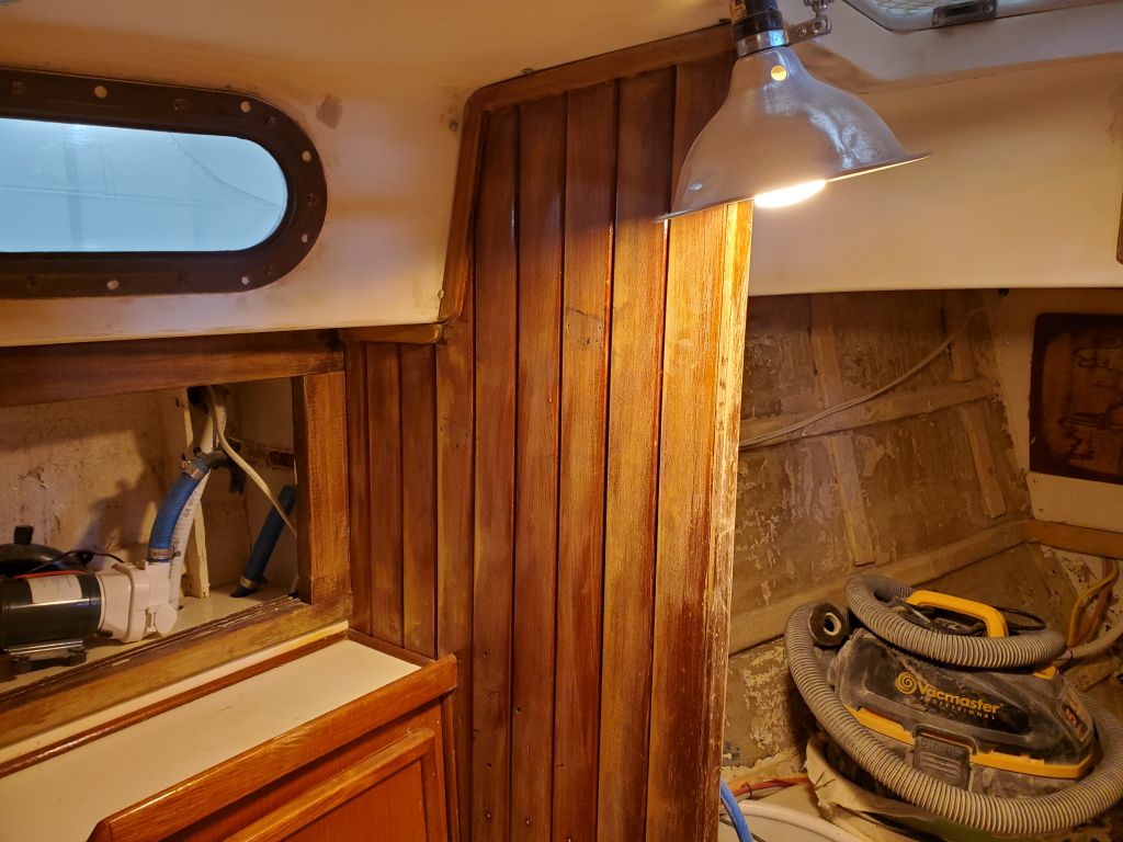
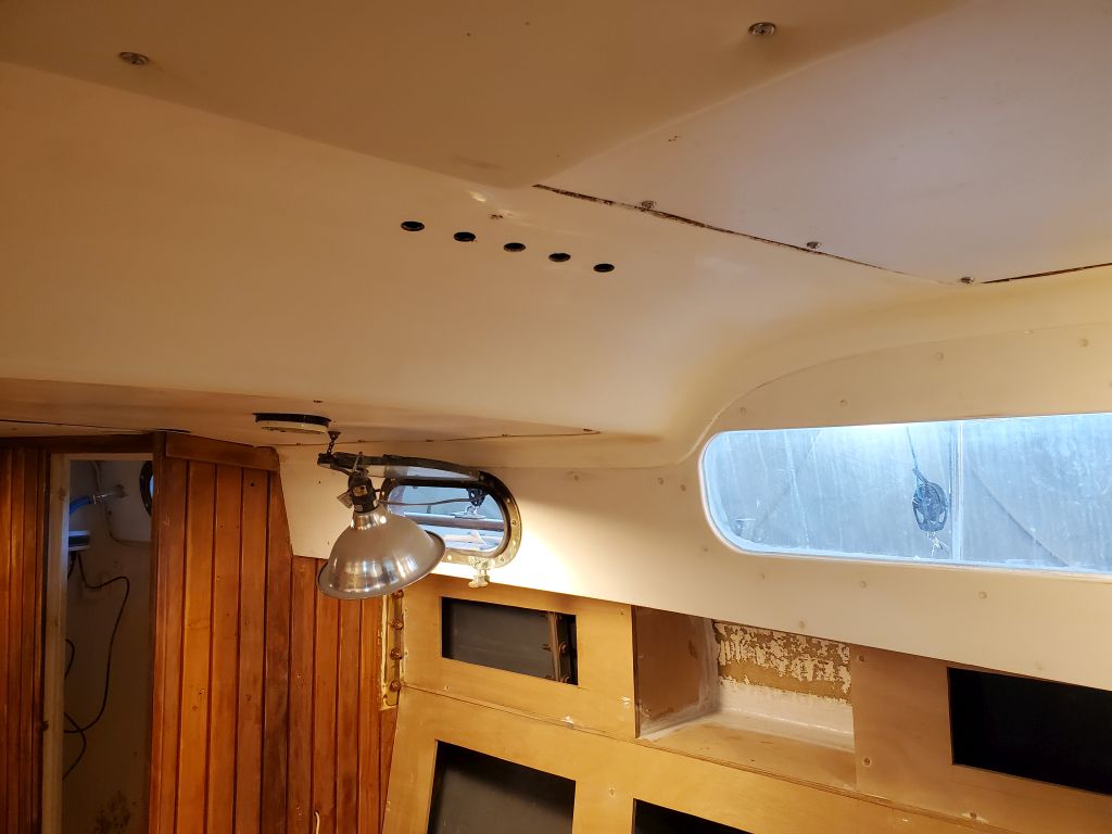
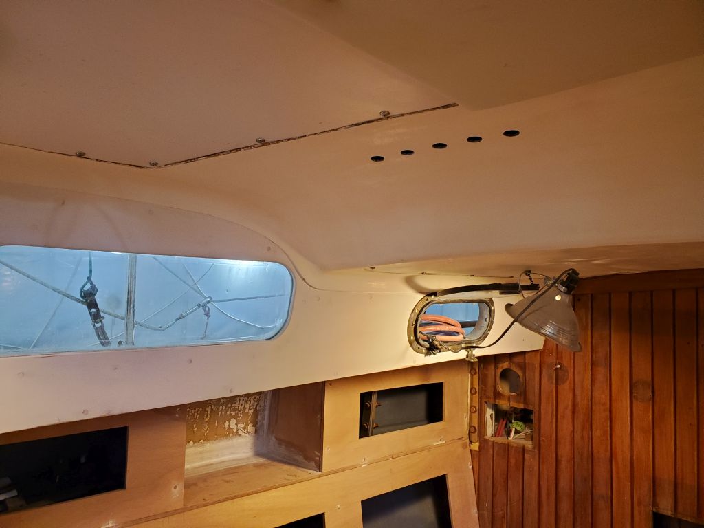
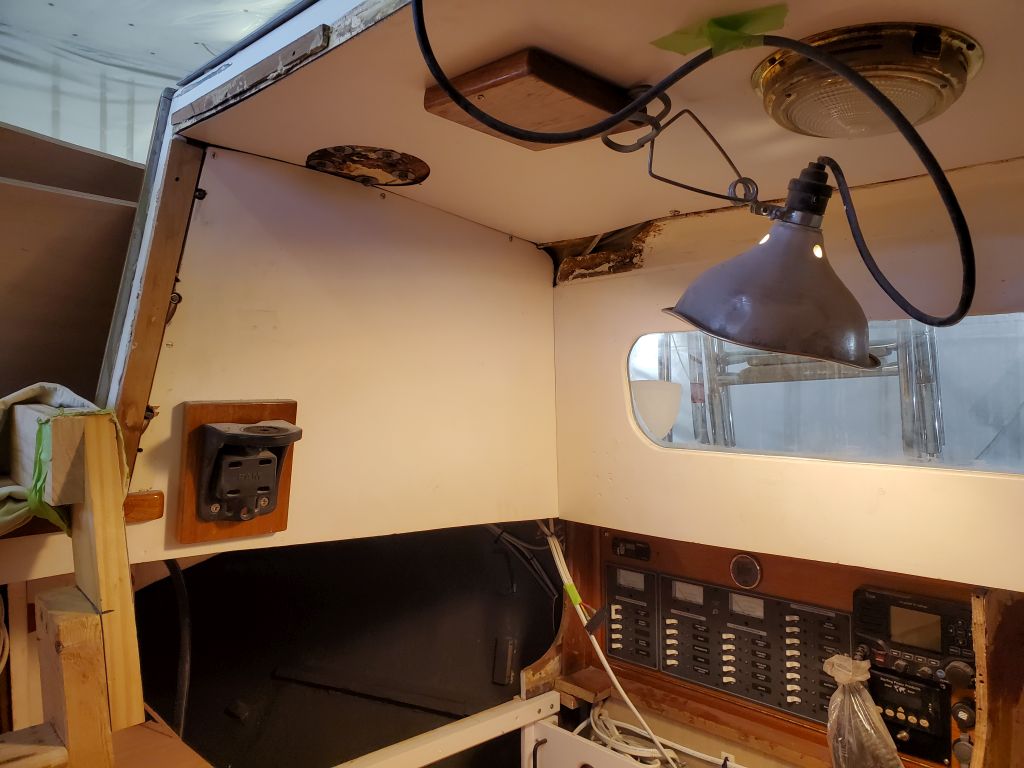
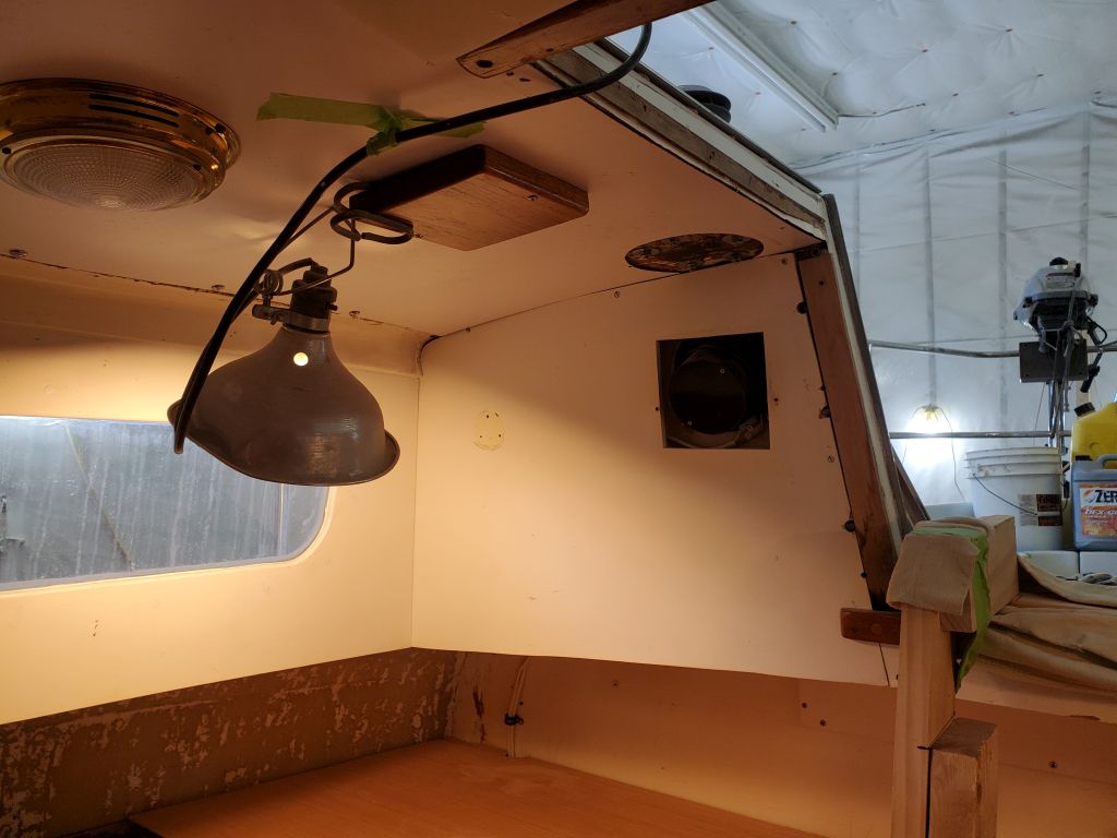
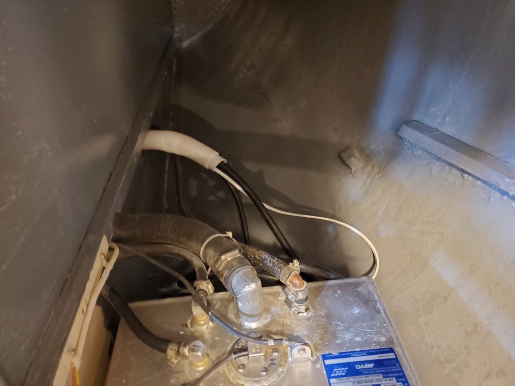
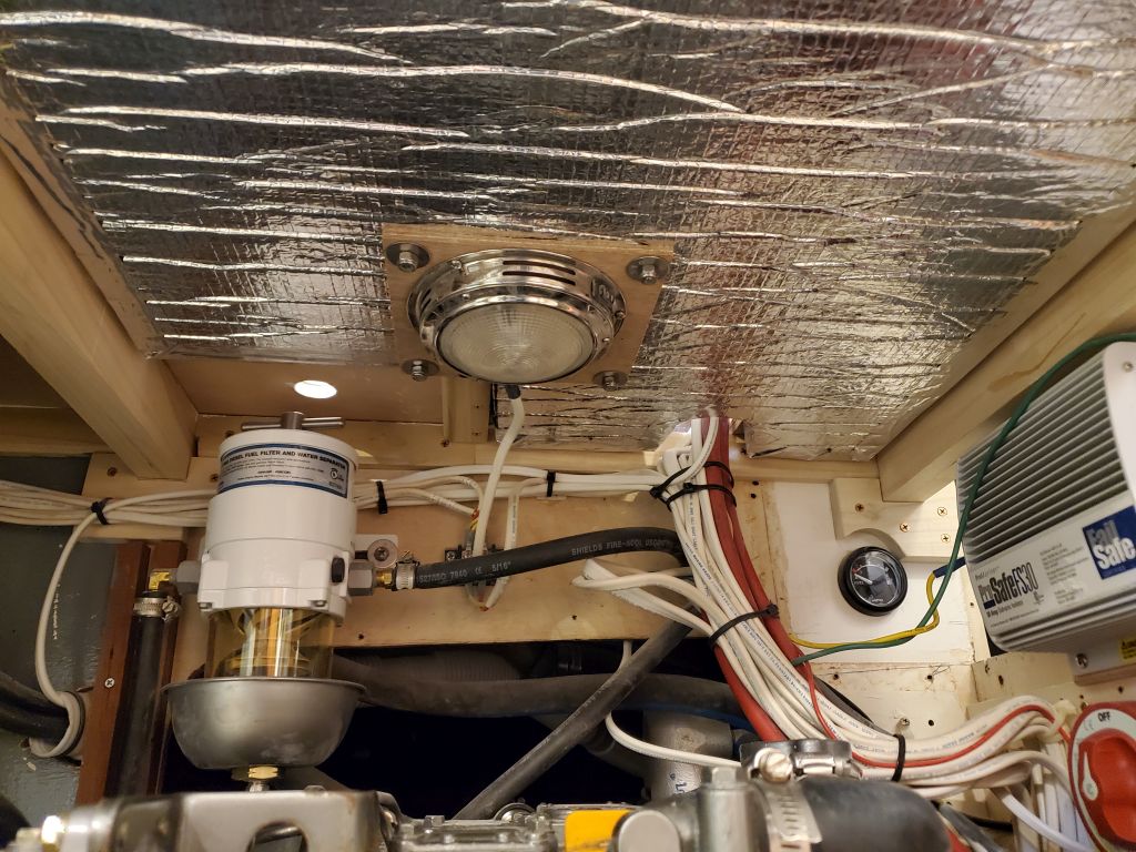
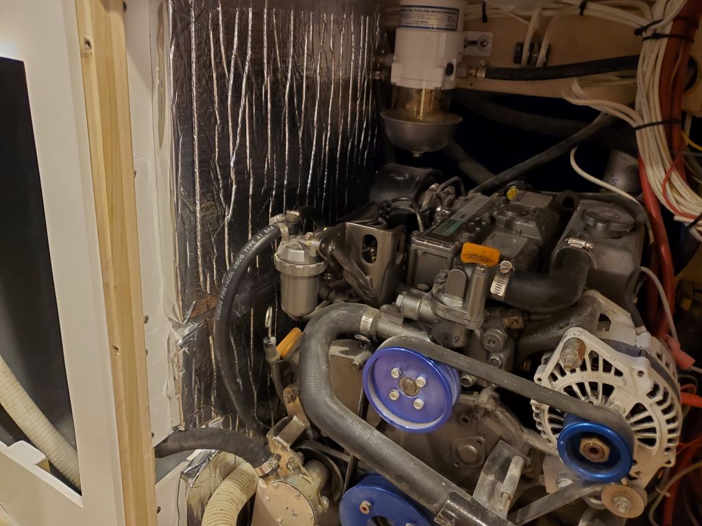
To finish off work in this space, I secured the engine room light to its overhead panel, and test-fit the two removable side panels with their insulation.

Over the weekend, the owner and I discussed the propane locker installation, and by happenstance he received some useful information from the owner of a similar boat. Now, I could start to look at some of the ideas and how they might work on the boat and within the various requirements and confines of the installation.
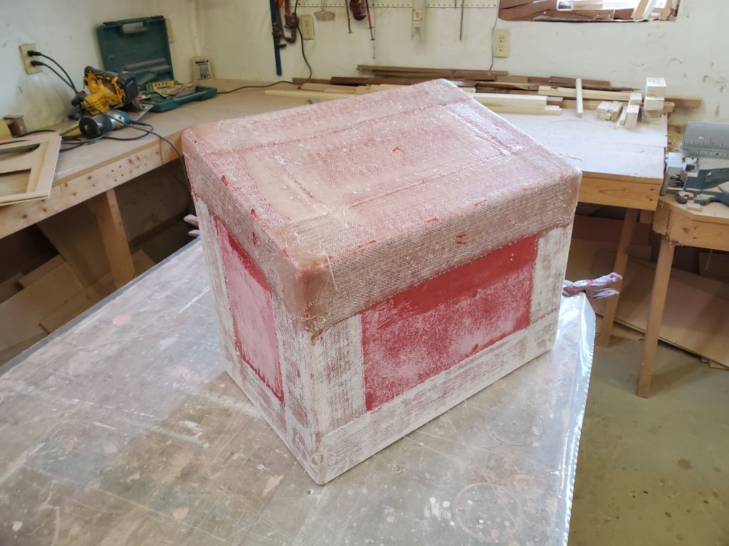
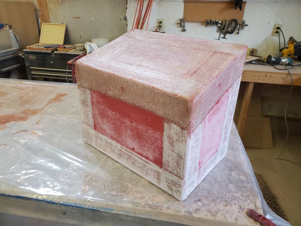
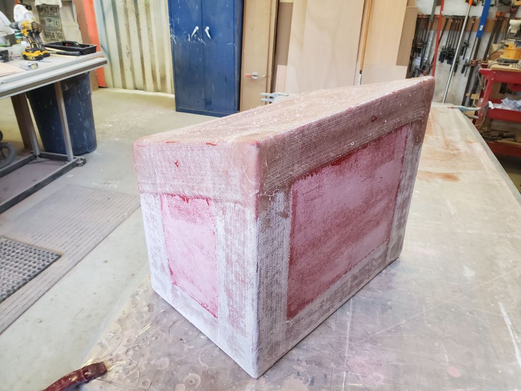
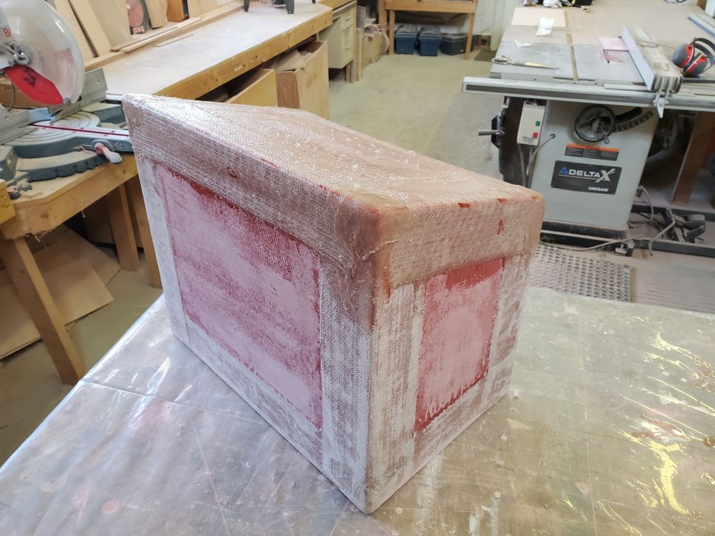
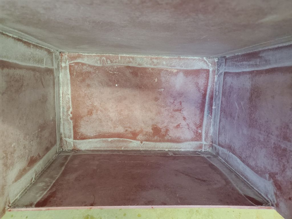
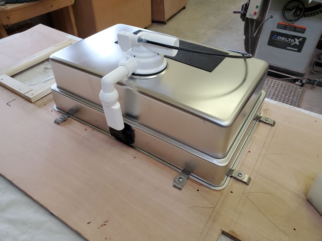
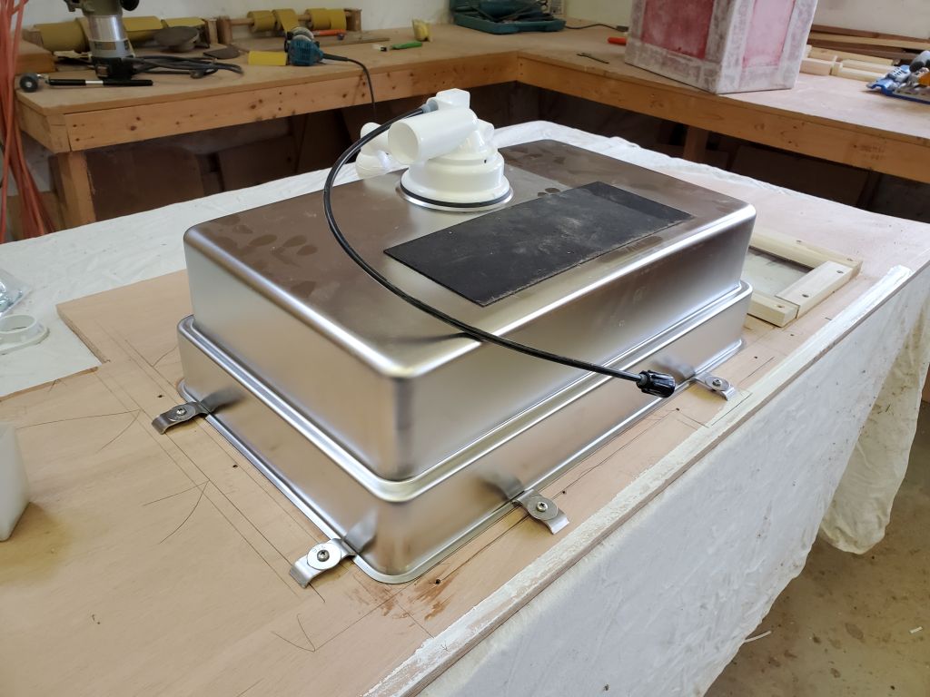
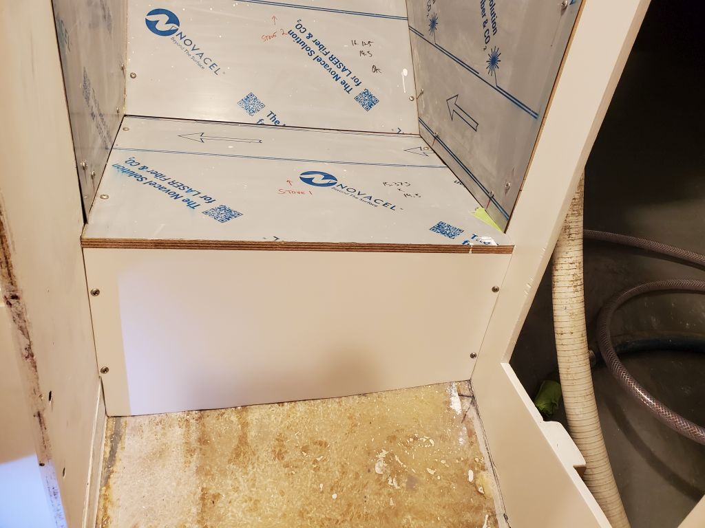
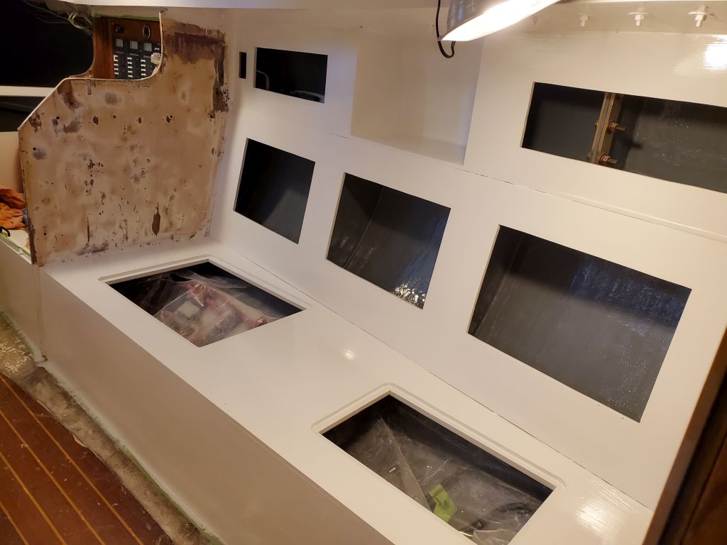
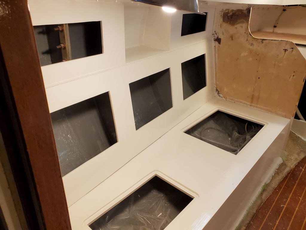
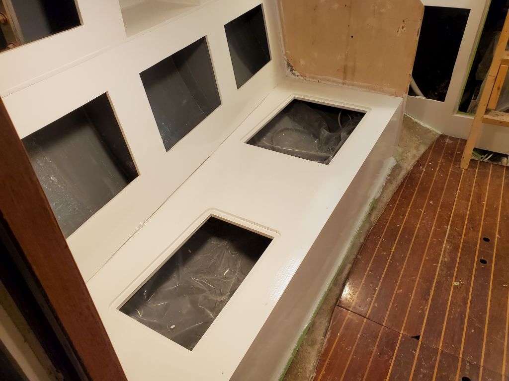
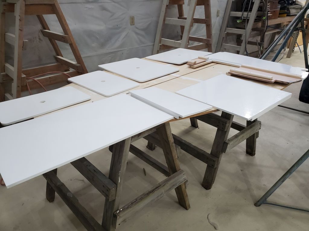
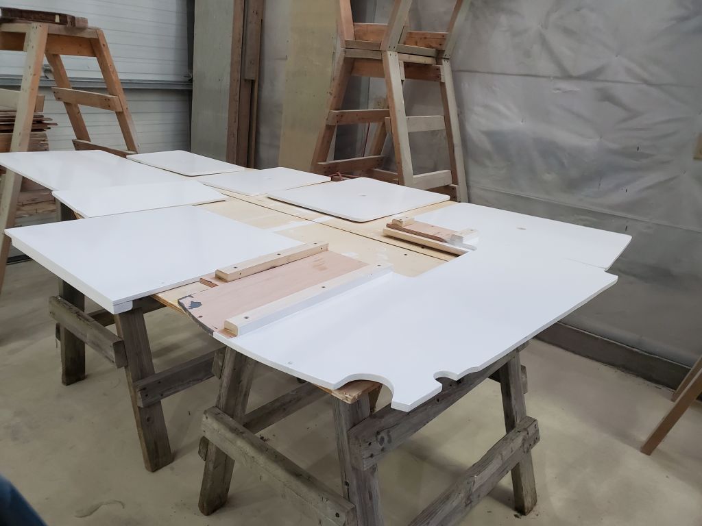
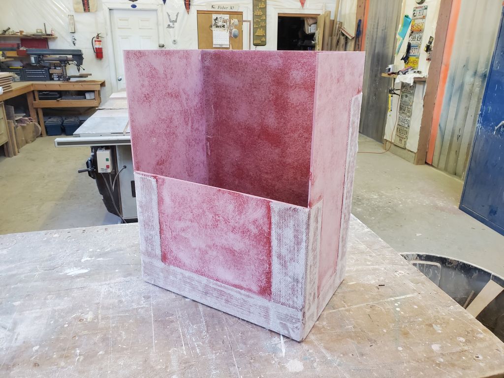
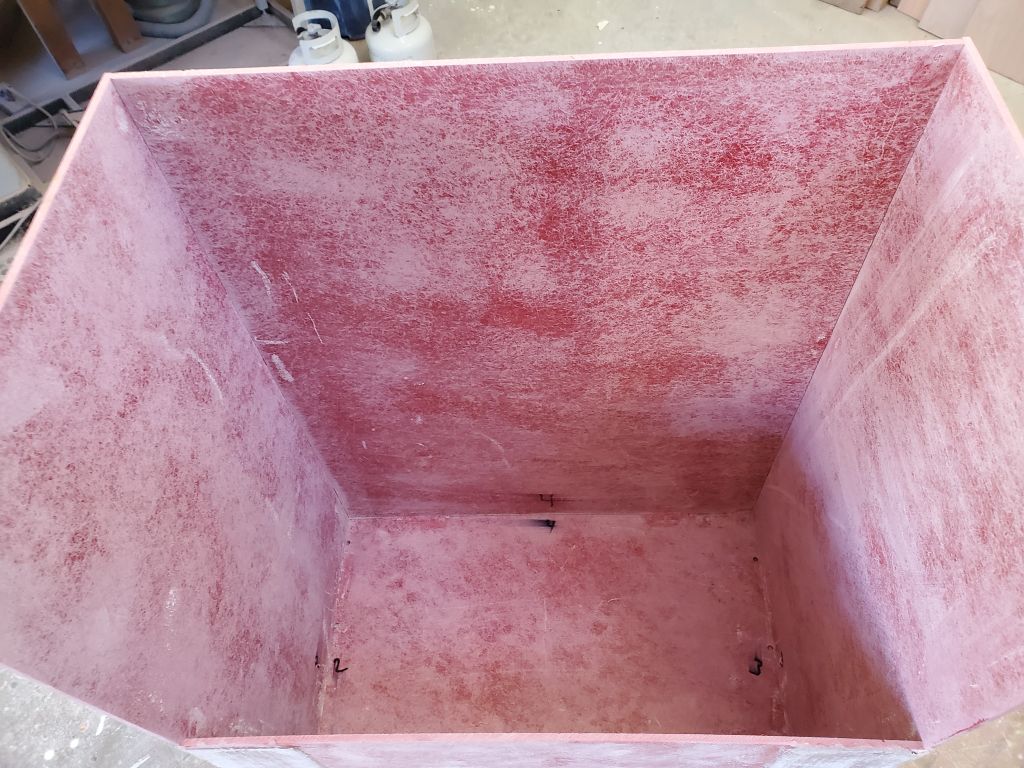
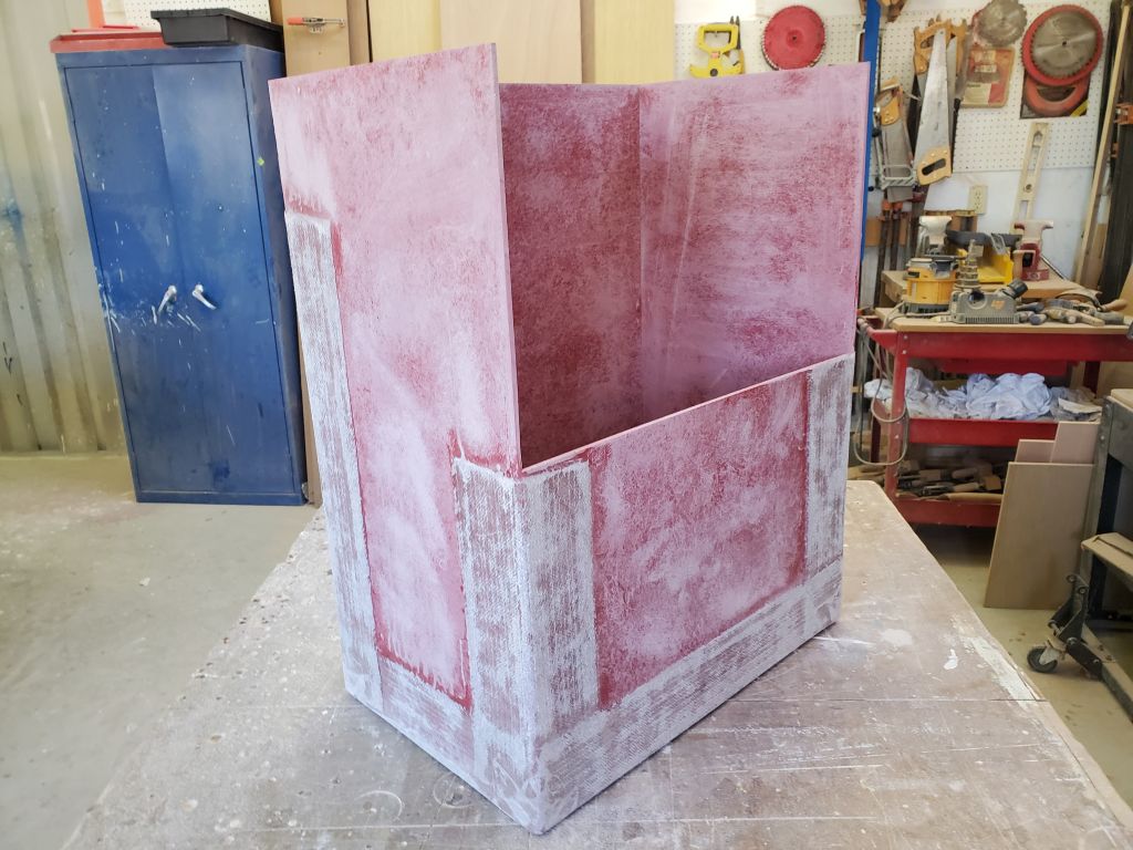
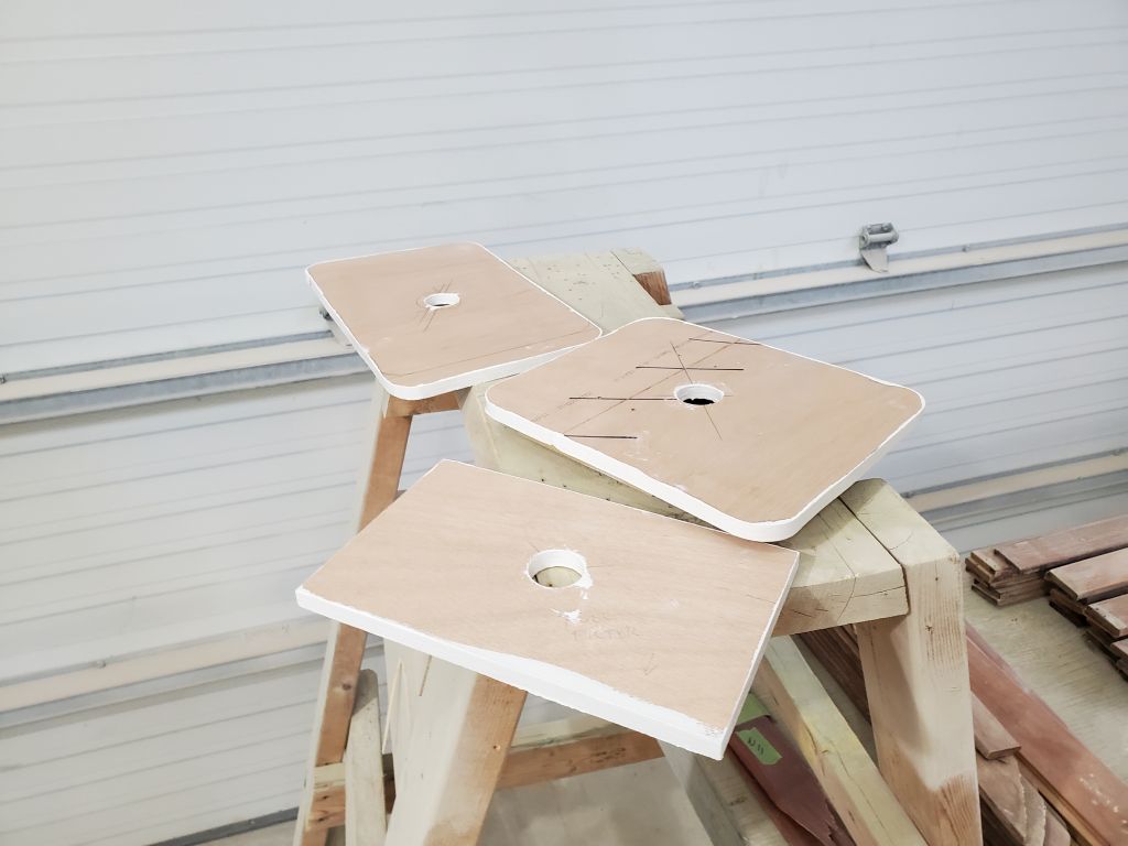
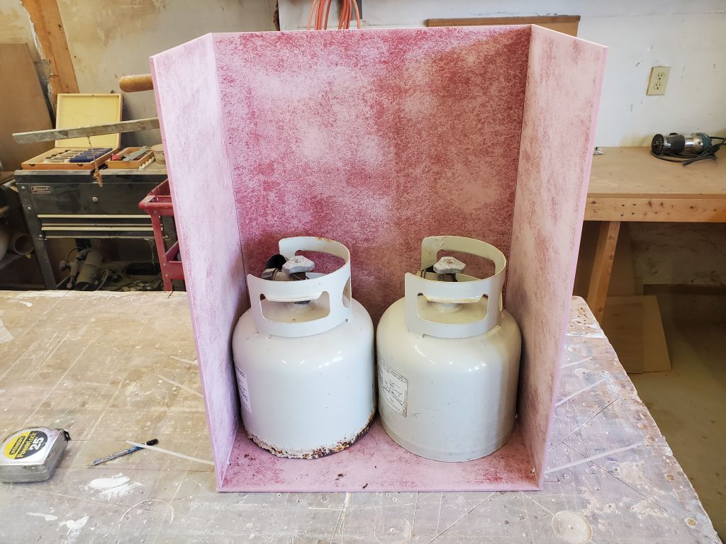
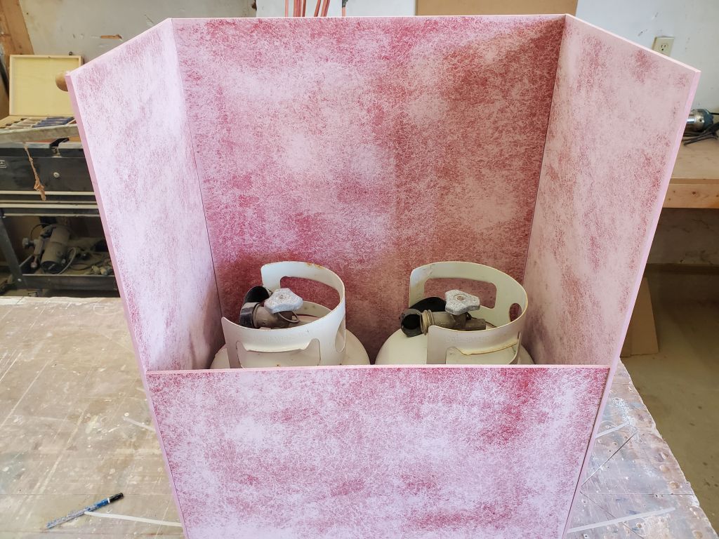
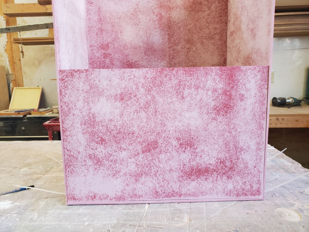
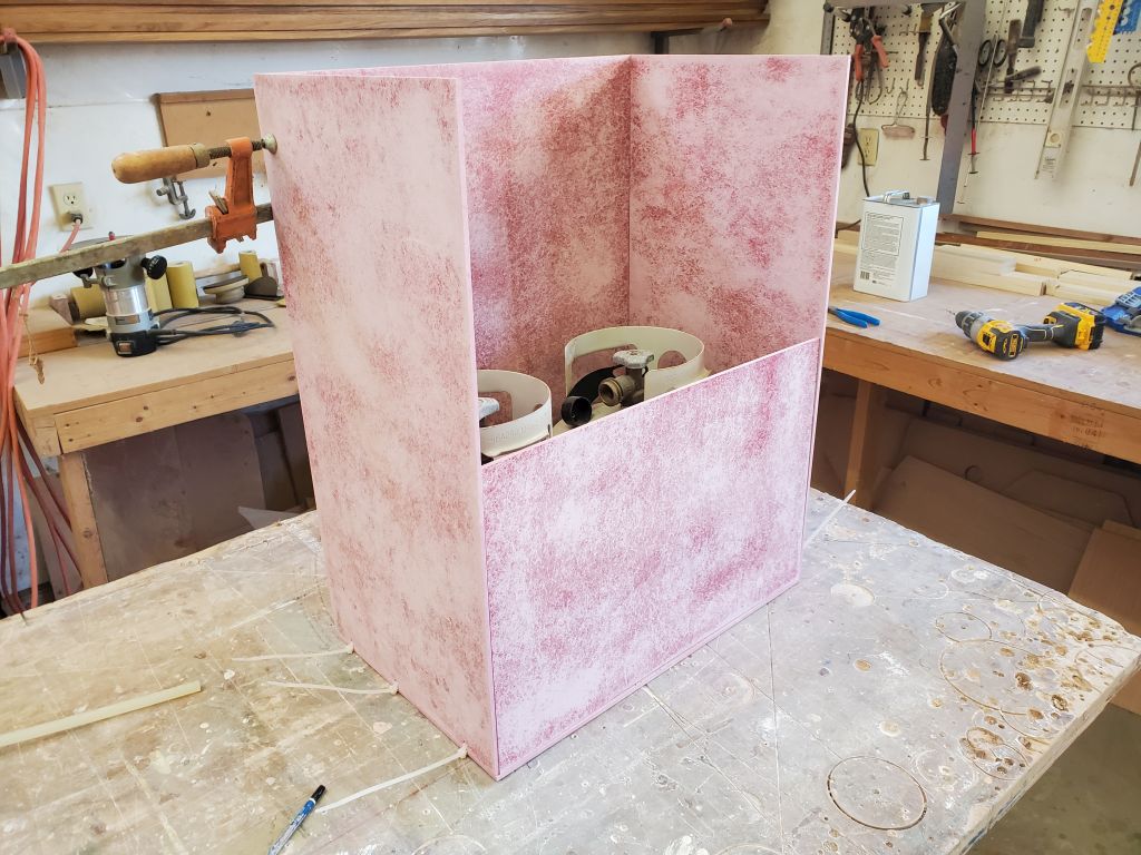
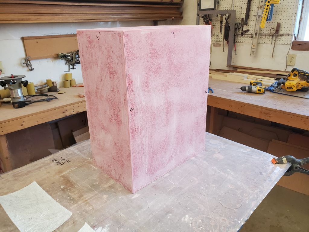
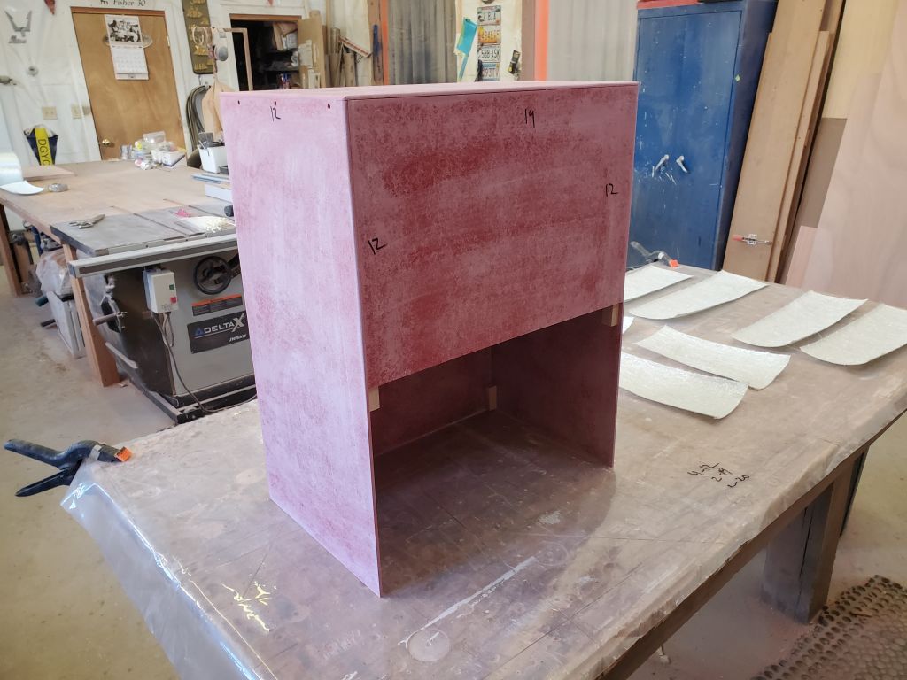
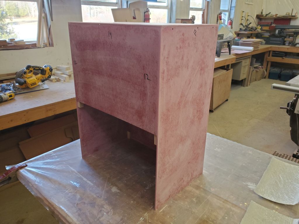
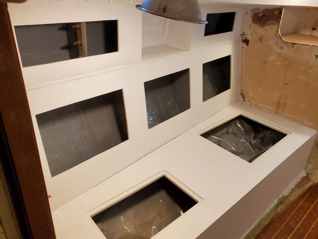
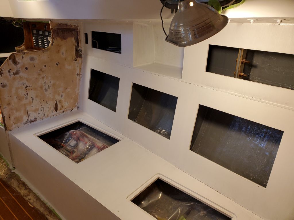
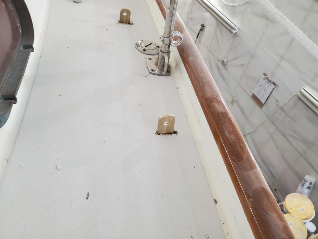
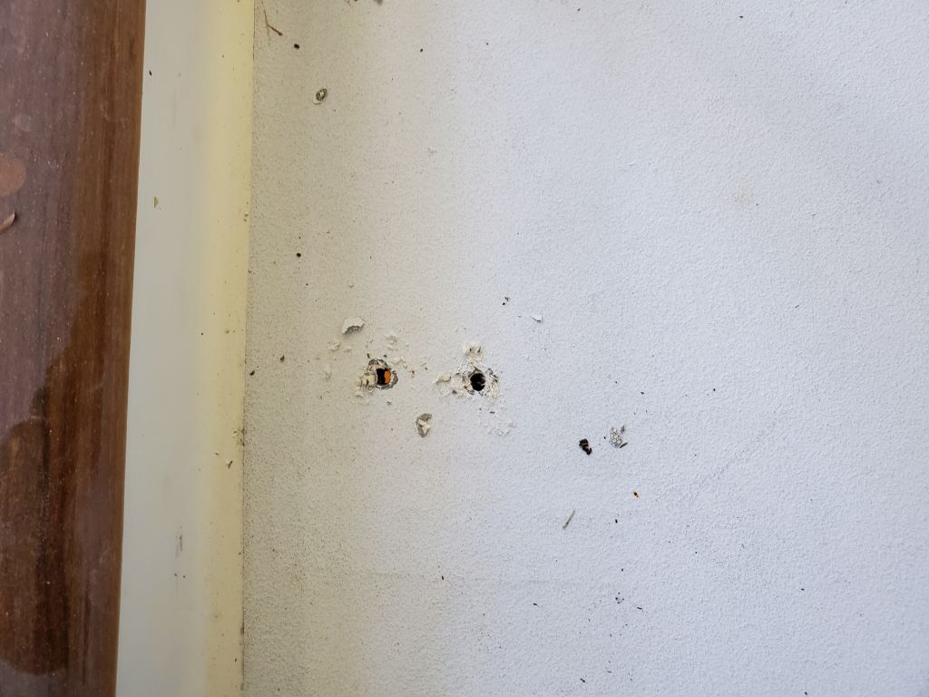
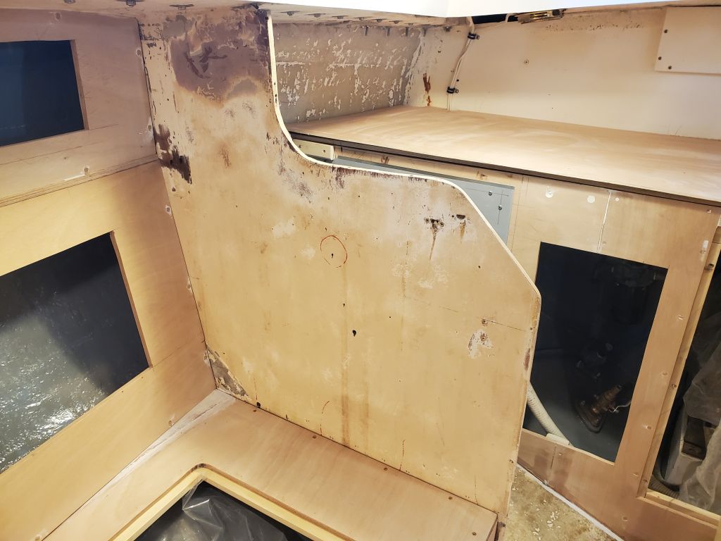
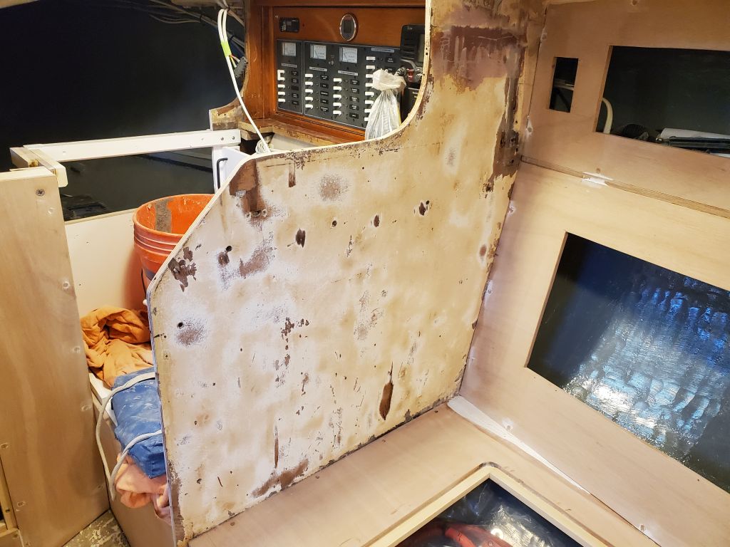
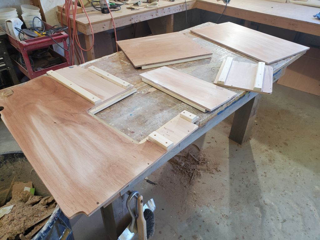
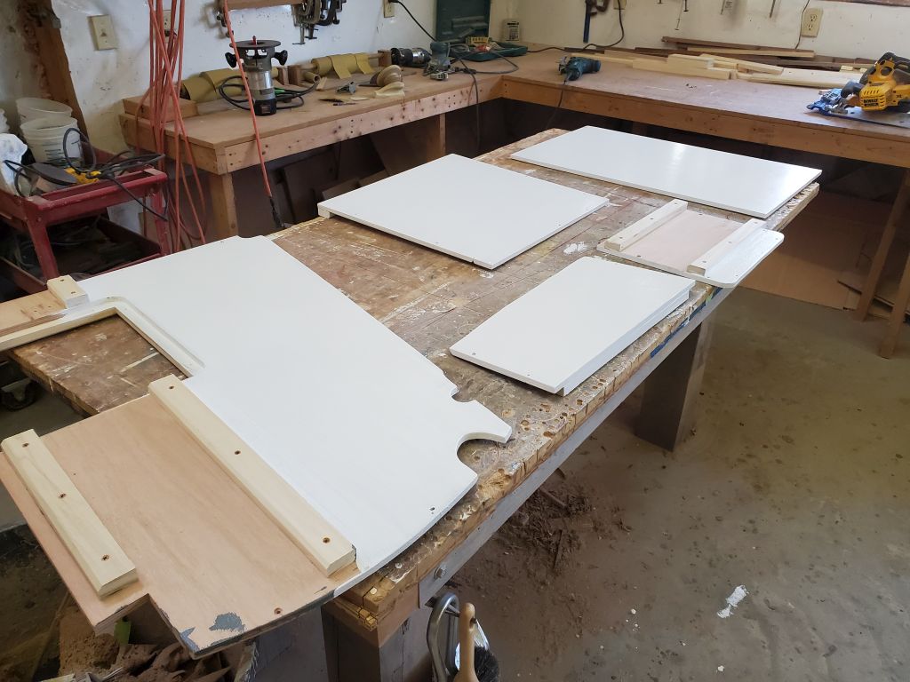
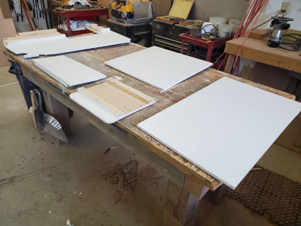
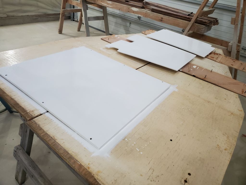
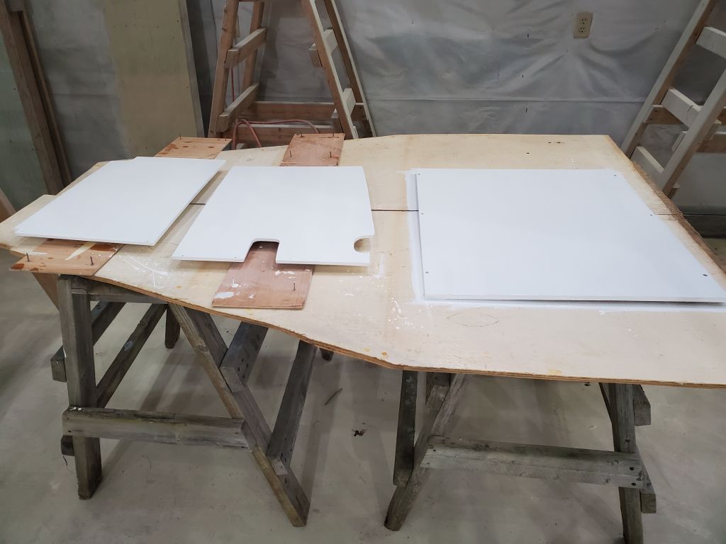
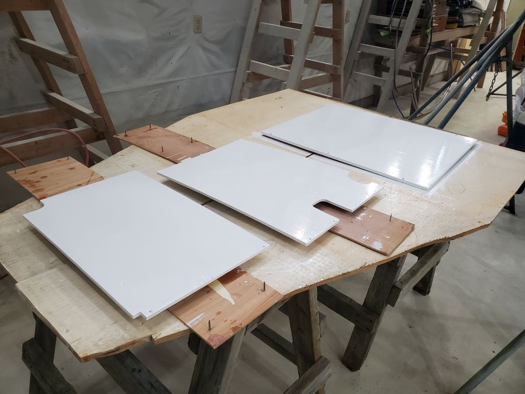
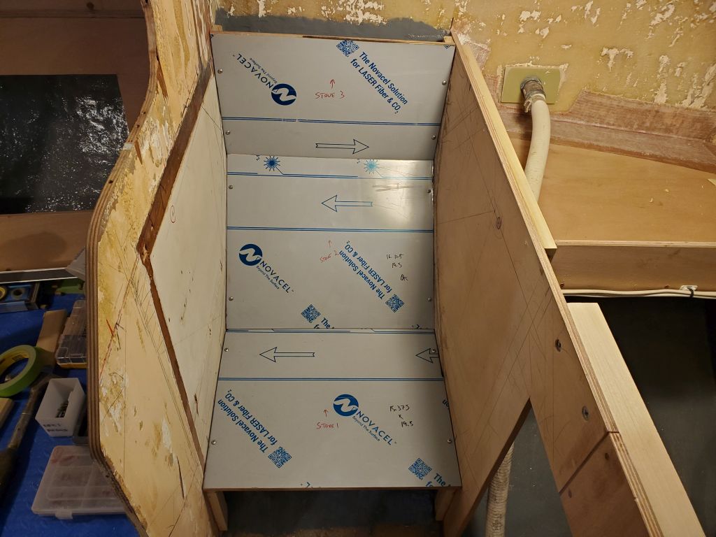
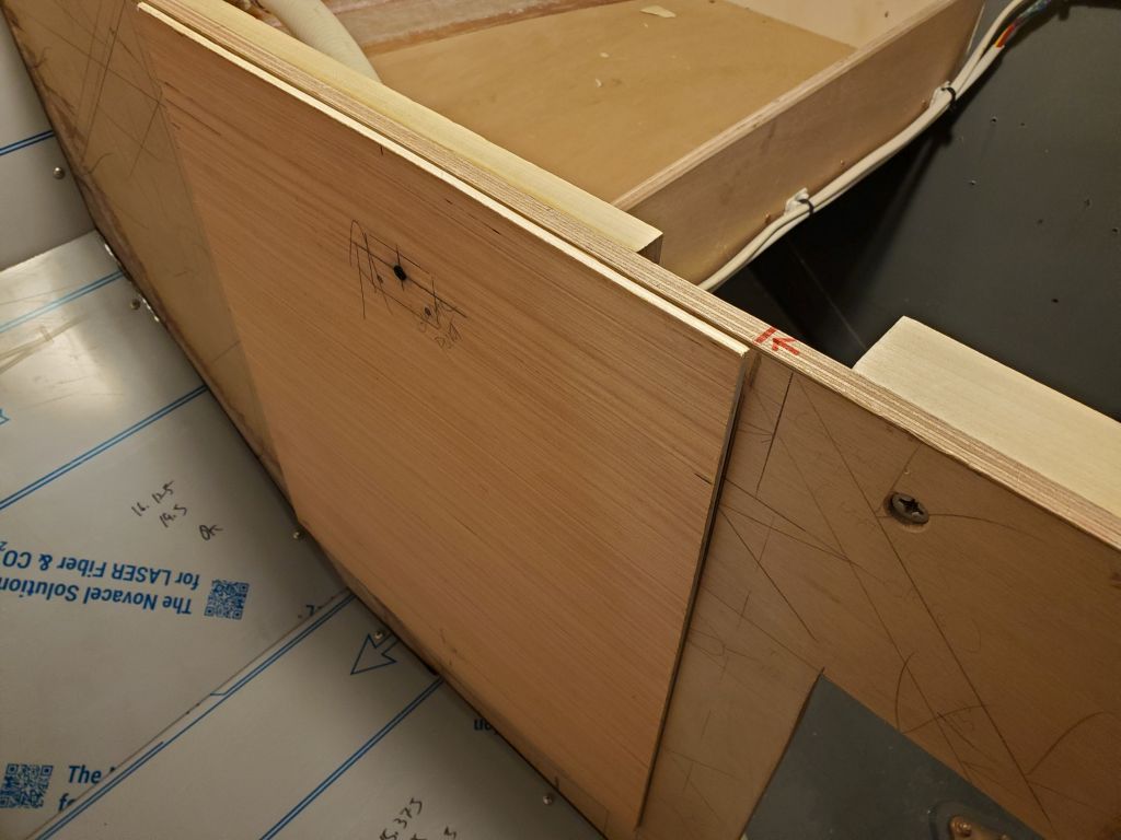
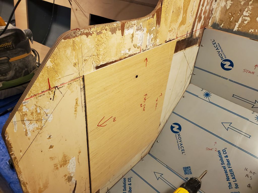
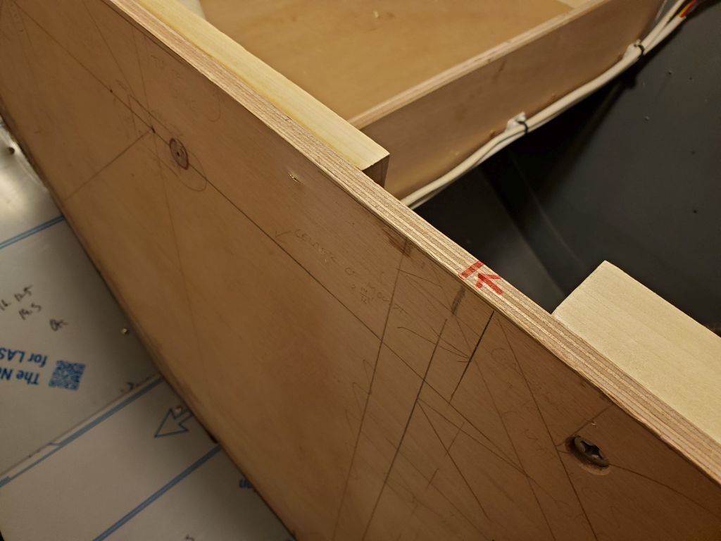
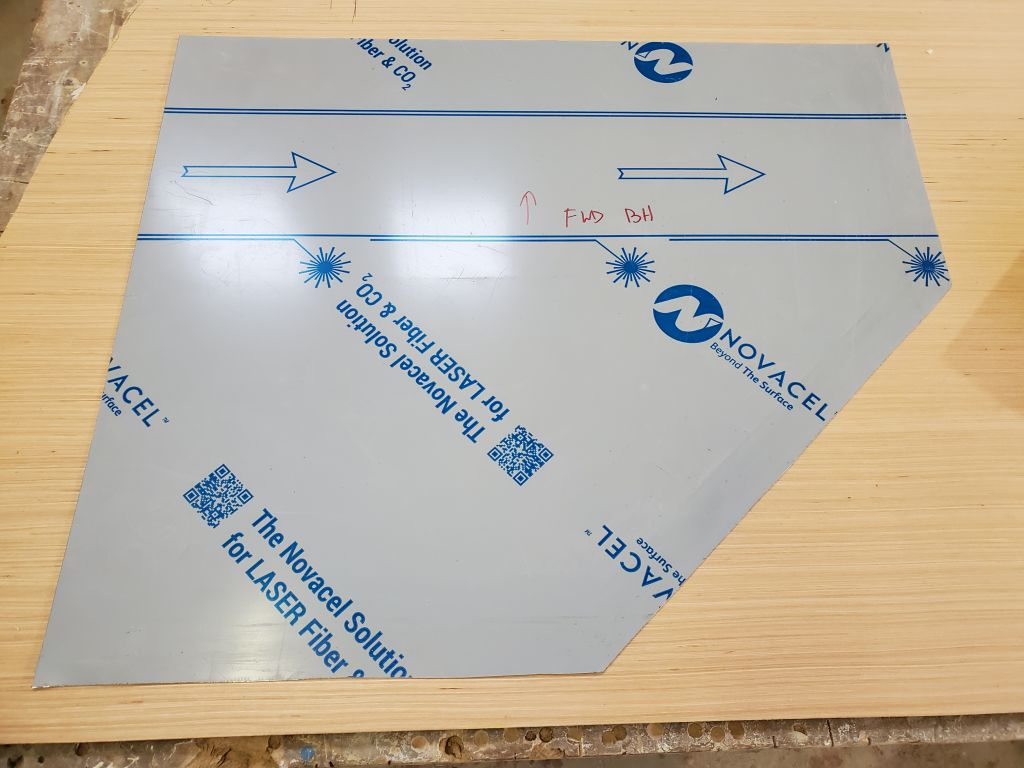
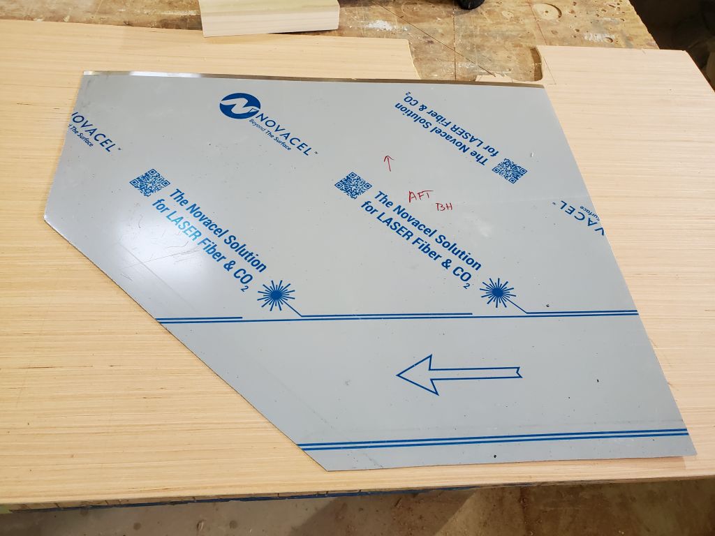
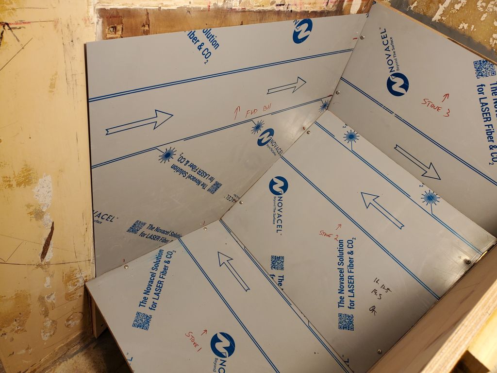
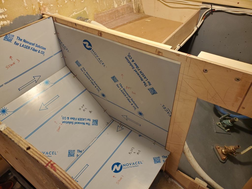
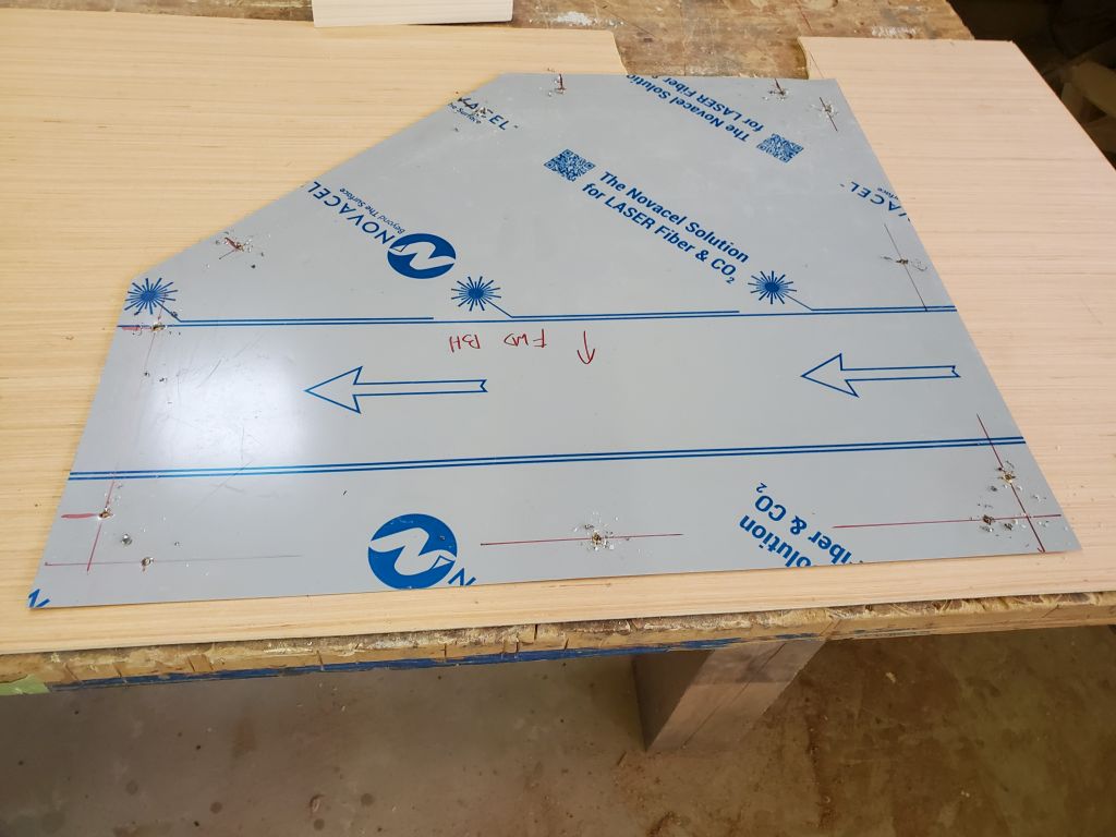
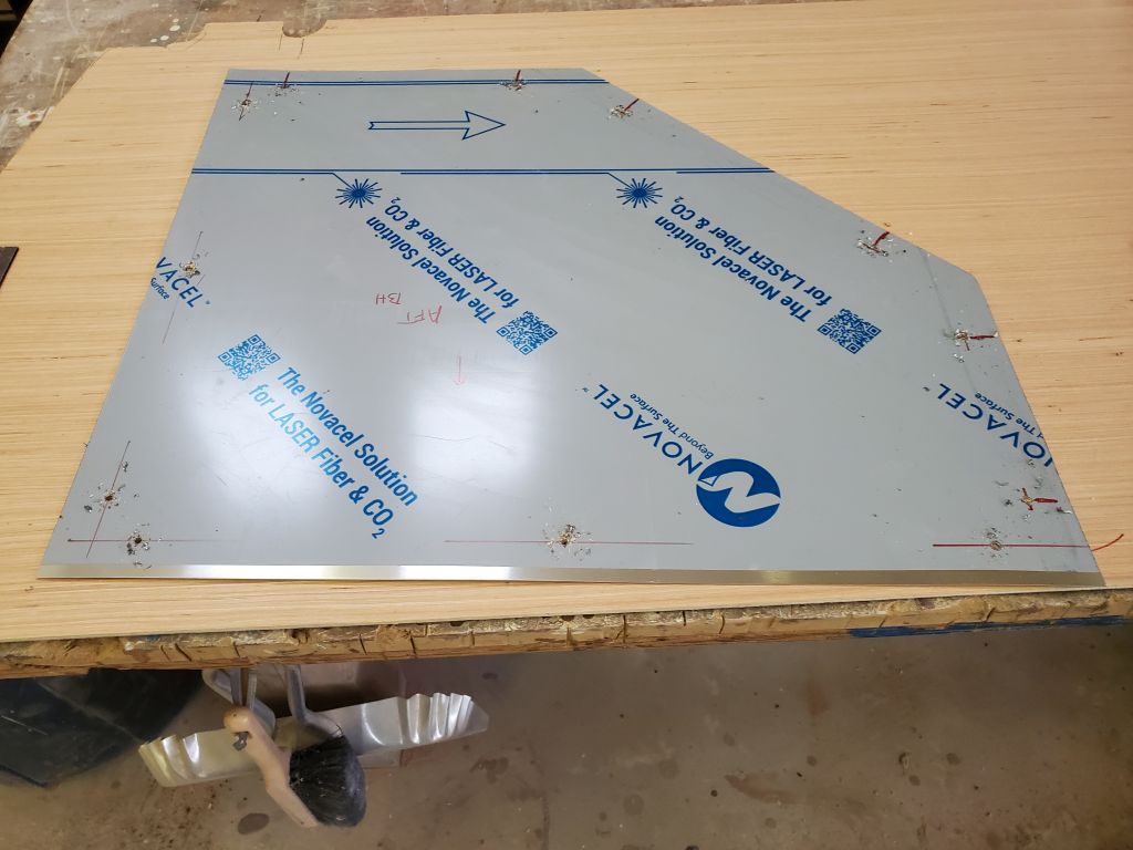
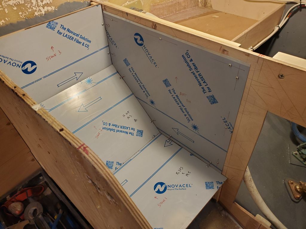
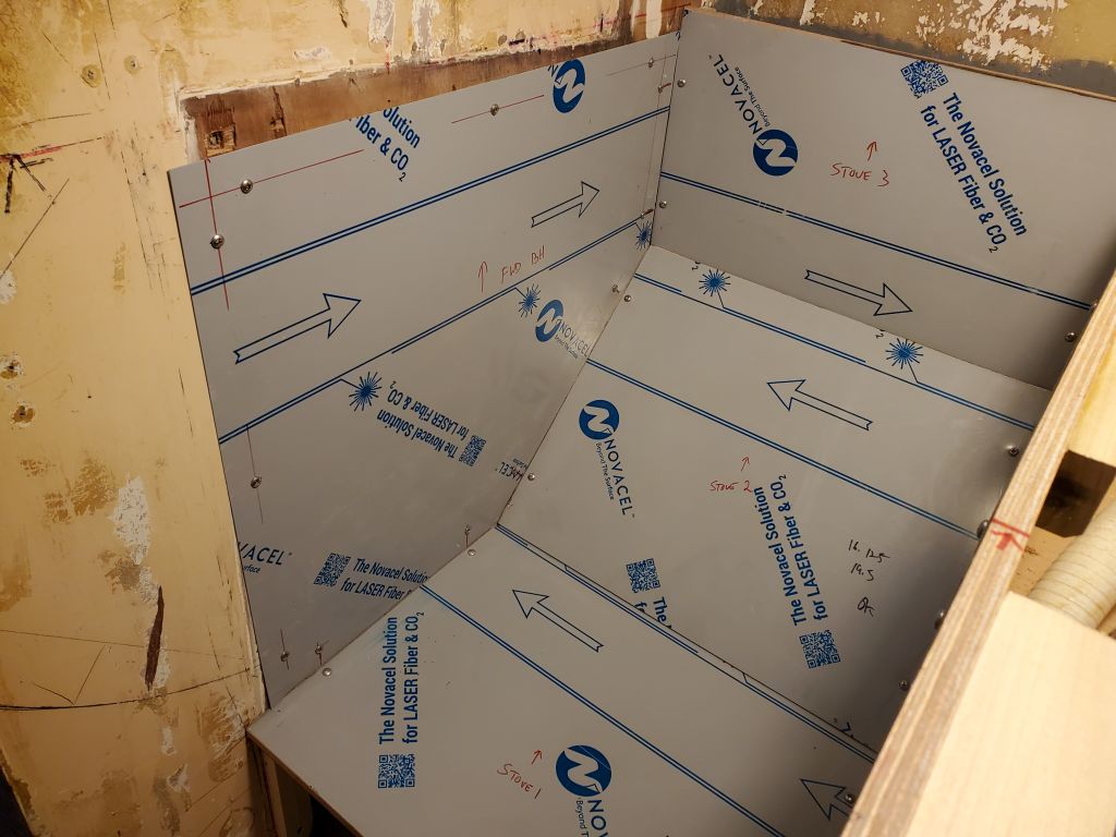
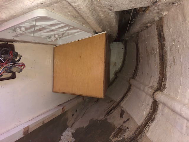
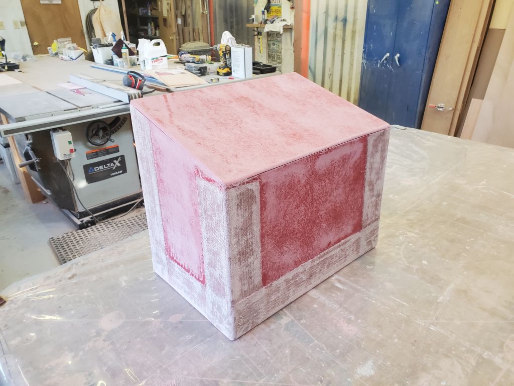
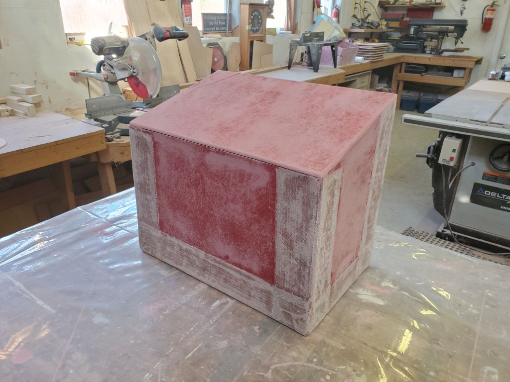
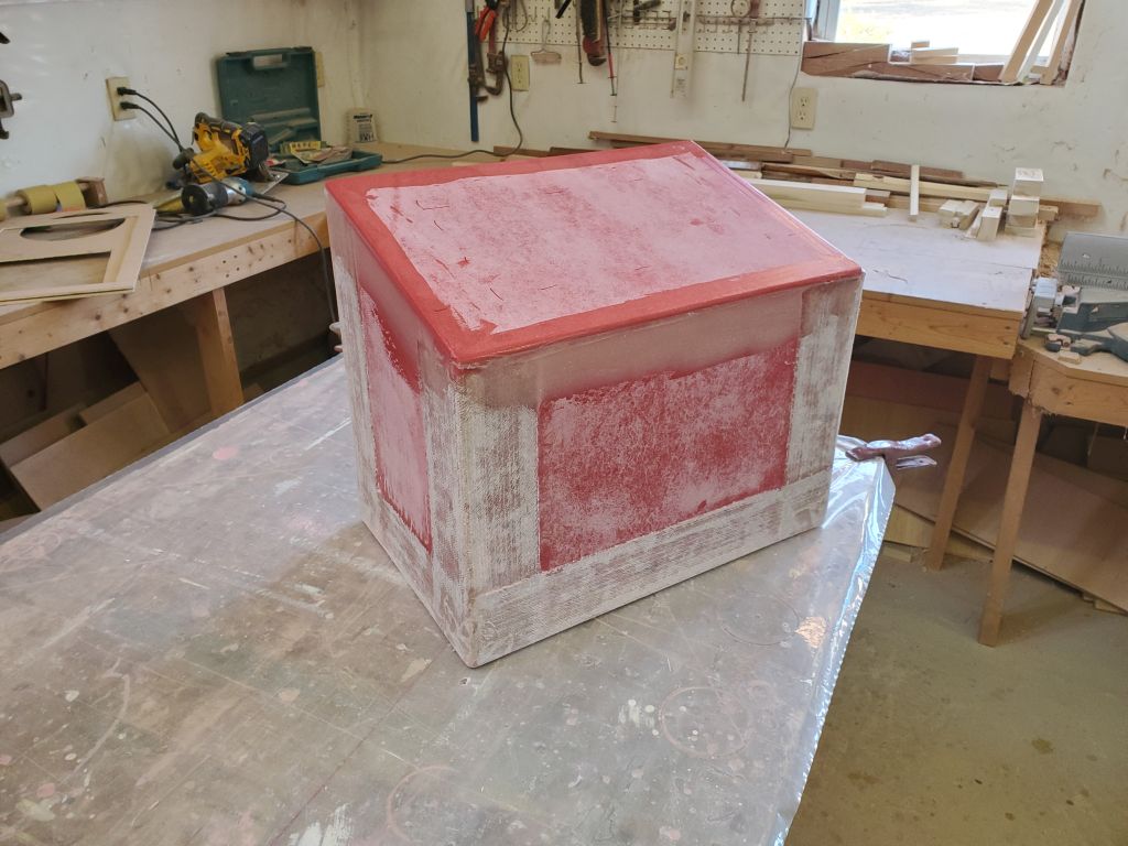
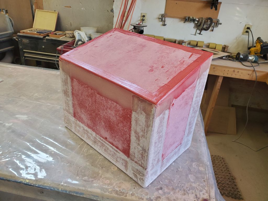
The photos below come from the other boatowner, and were useful in helping me determine a feasible way forward. The main issue complicating the prefabricated box’s installation was the difficult access to the aft end of the quarterberth, and the impossibility of my doing any serious fiberglass work in that environment. That was why I had originally conceived the top-down installation, which had been the working plan for some time but which ran into some issues when the realities of the installation location forced a change of direction in order to maintain the potential for the owner to have access to the forward part of this otherwise-empty locker.
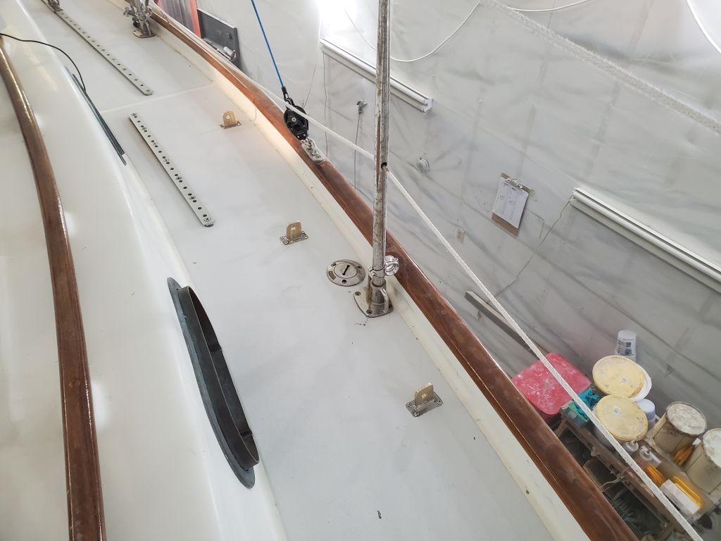
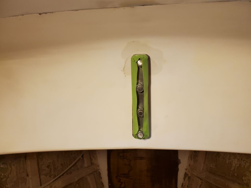
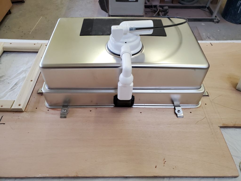
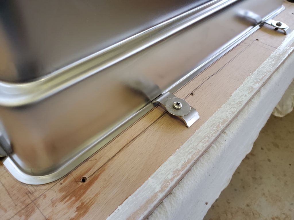
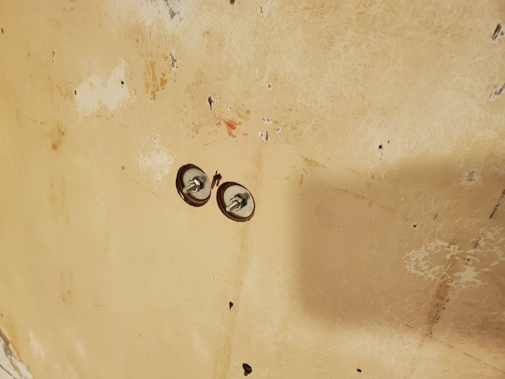
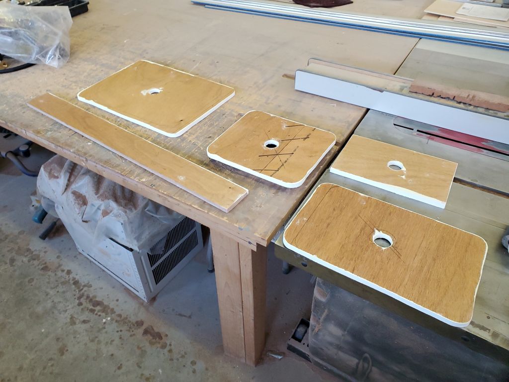
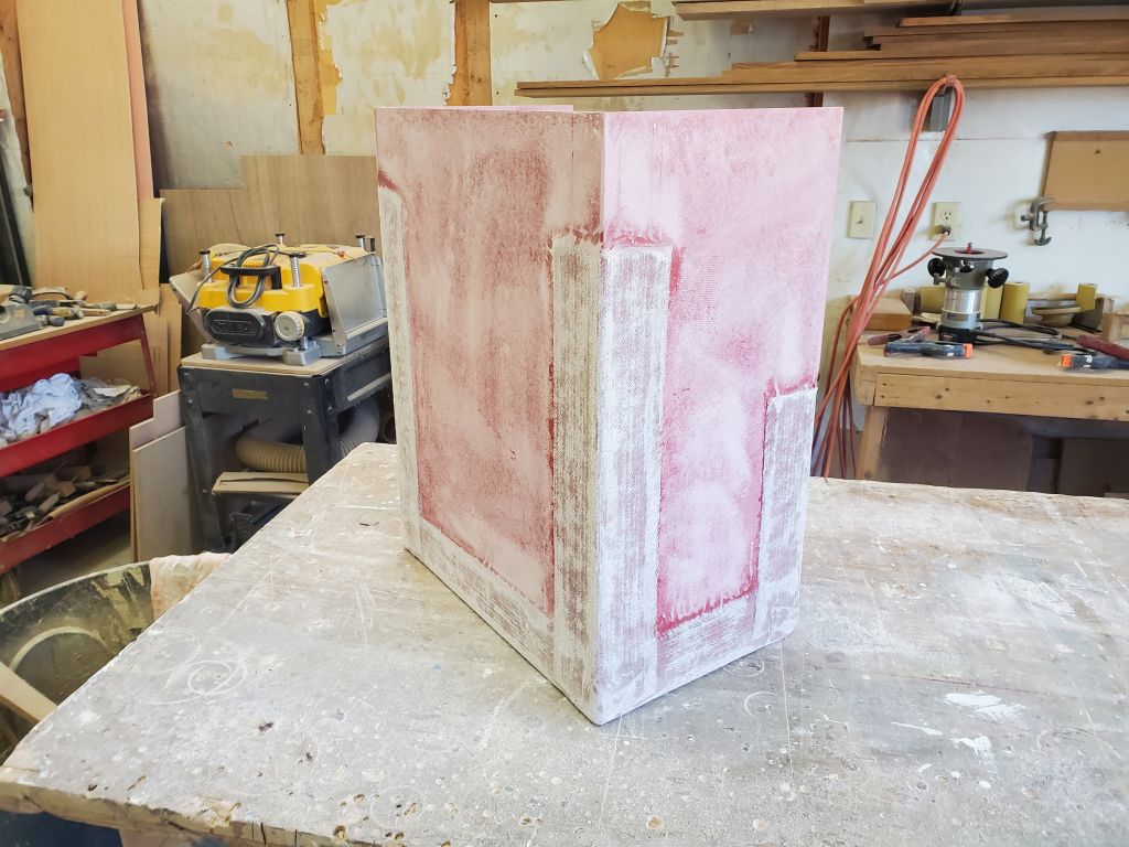
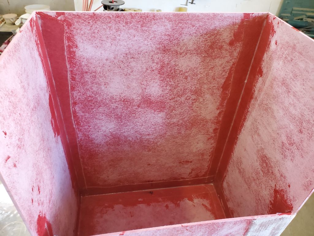
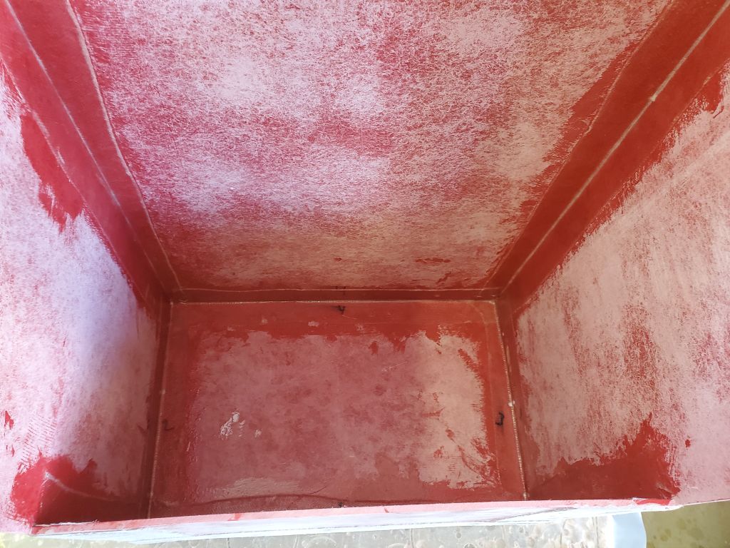
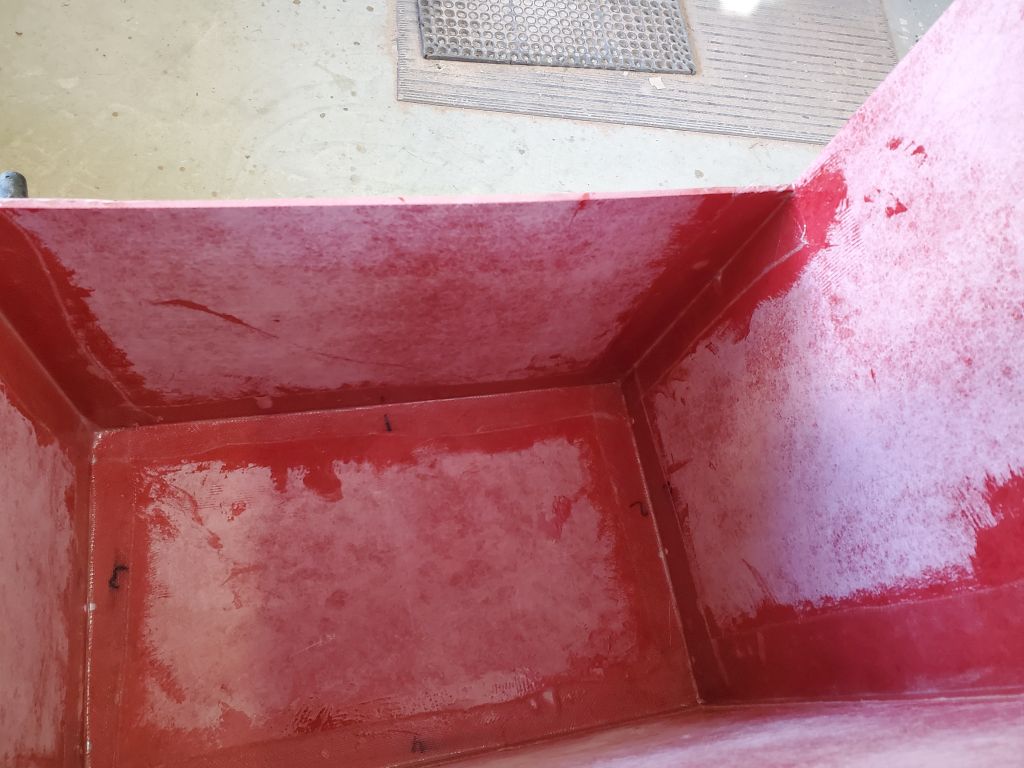
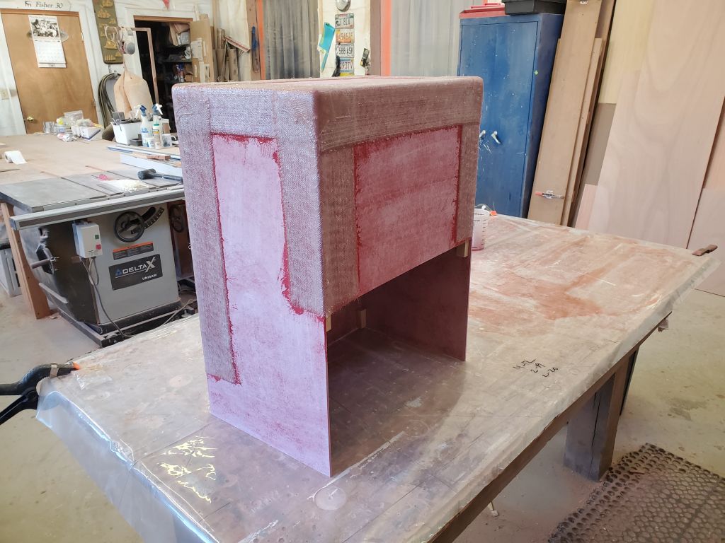
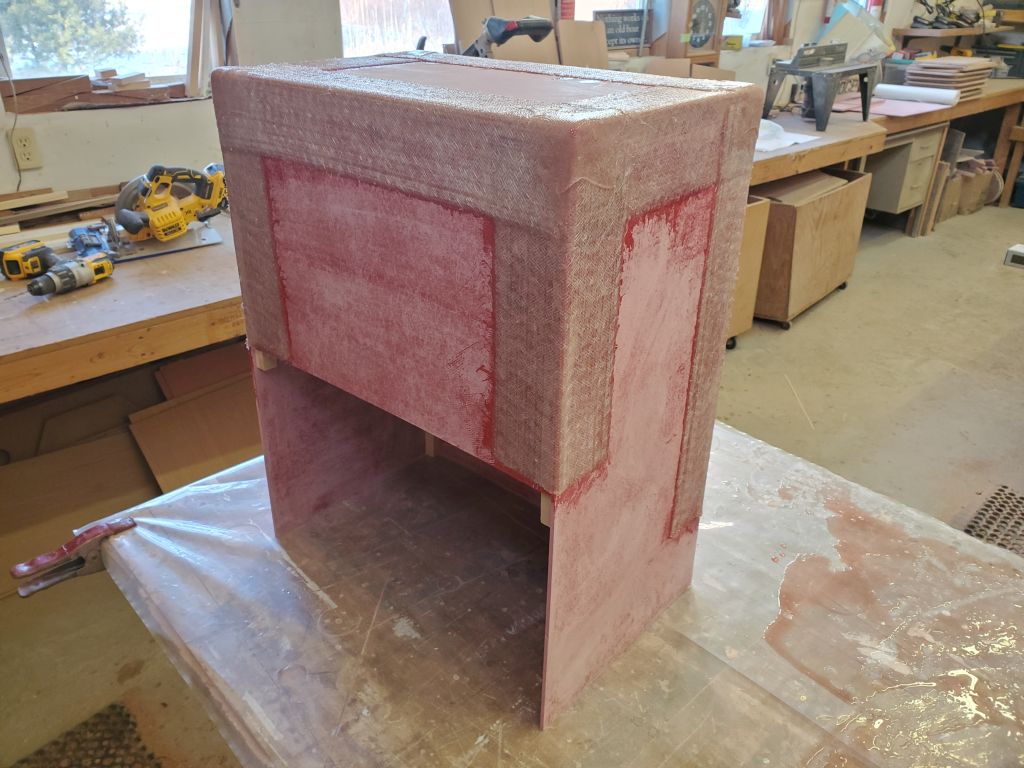
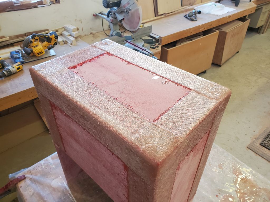
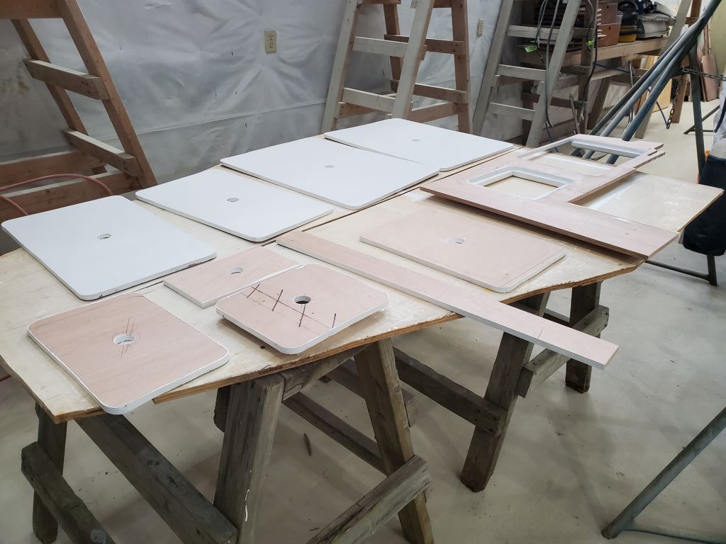
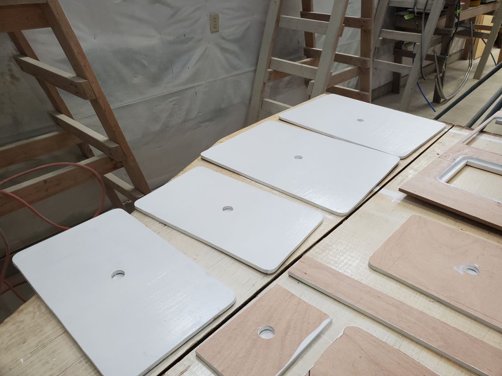
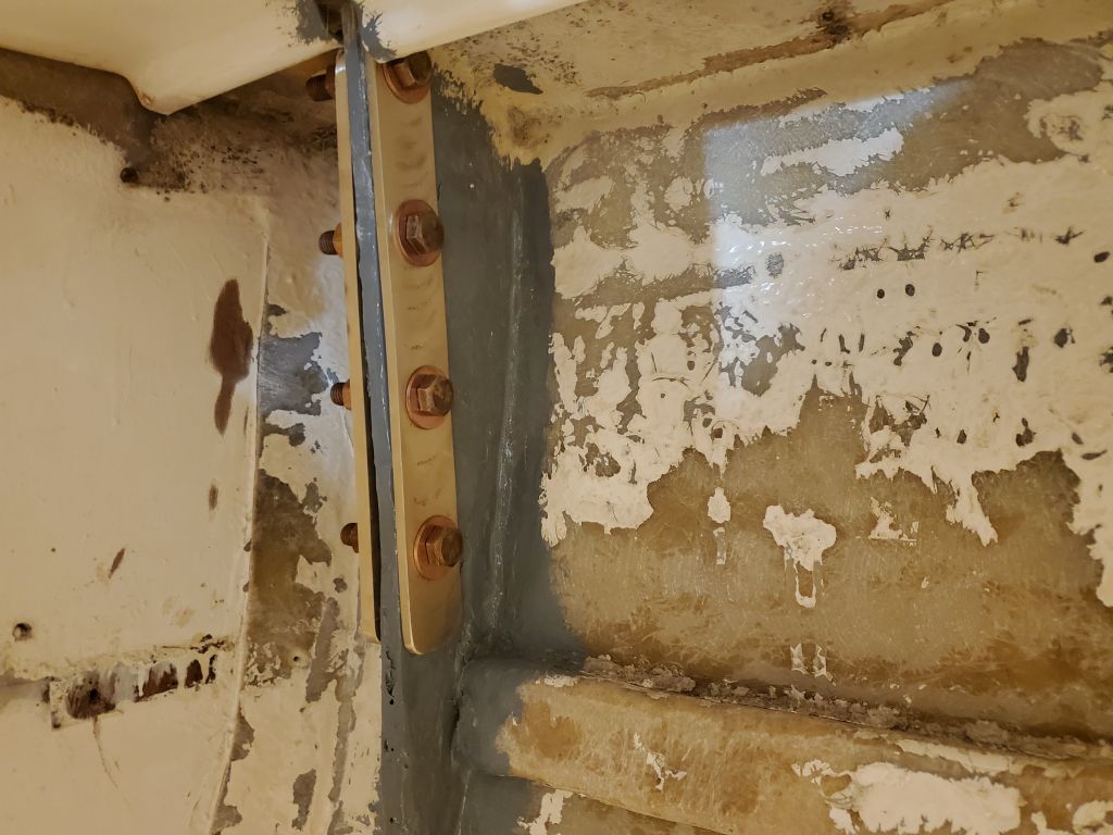
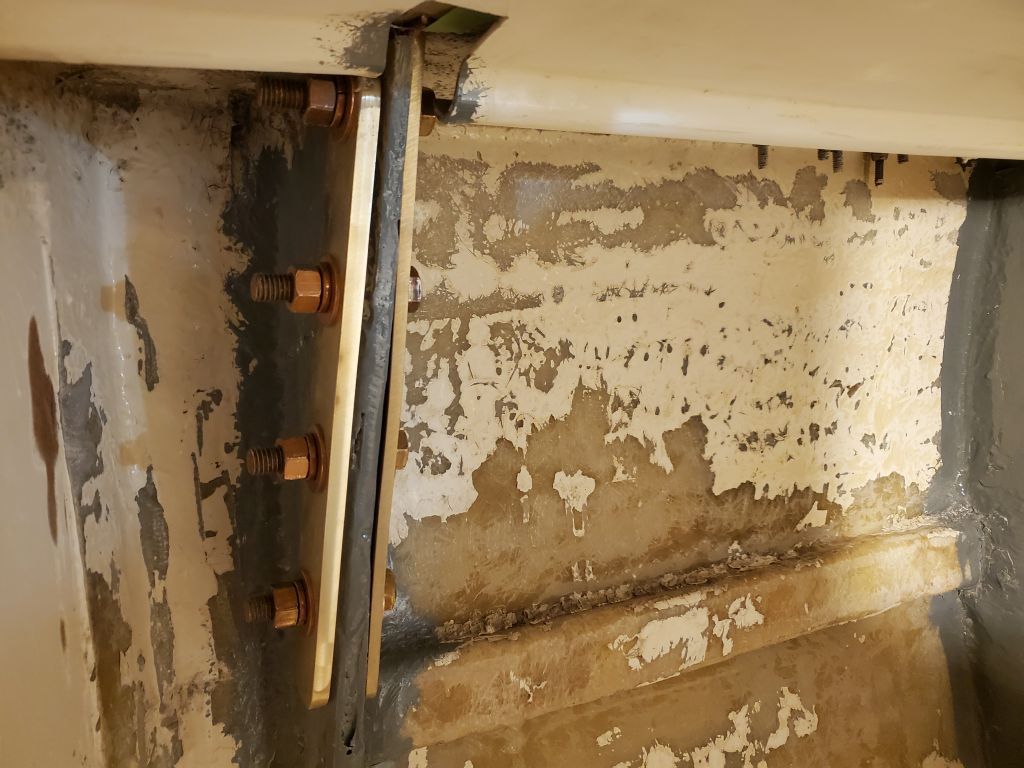
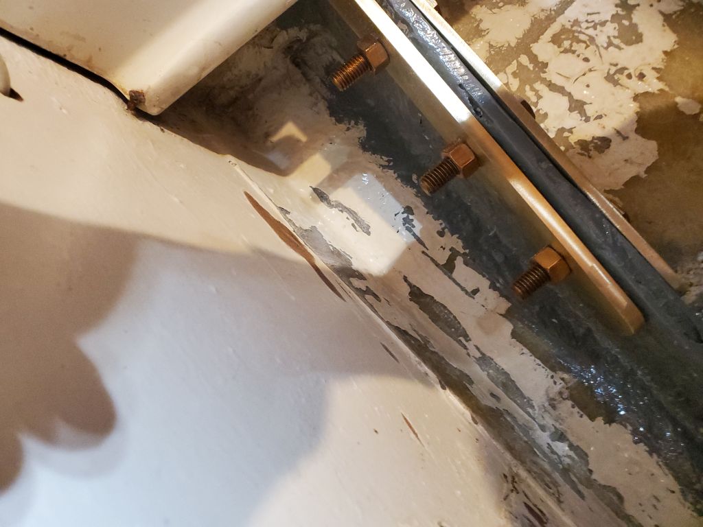
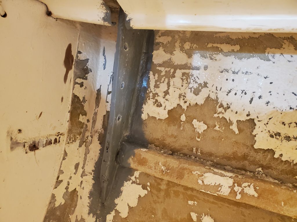
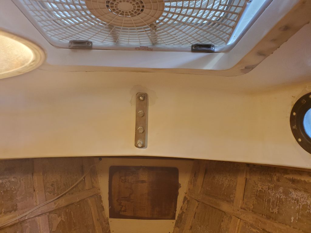
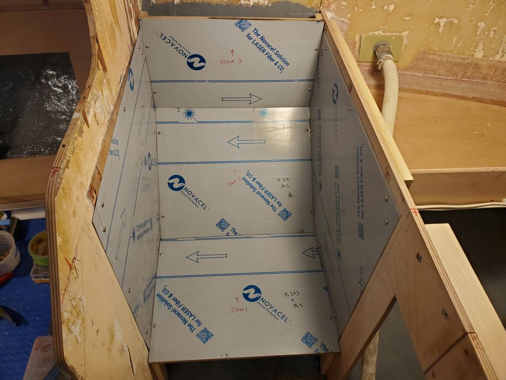
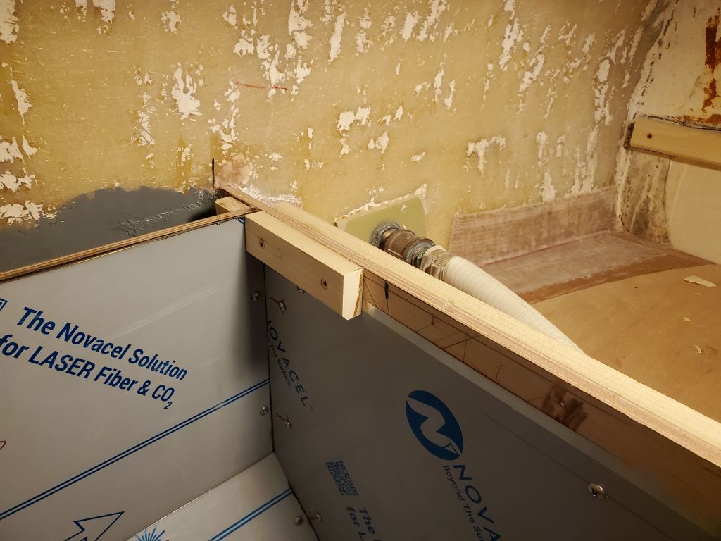
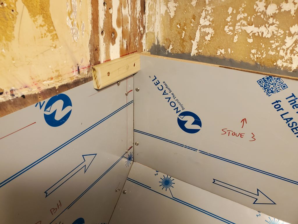
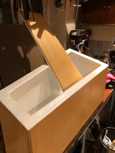
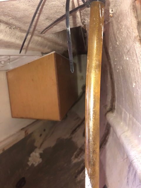
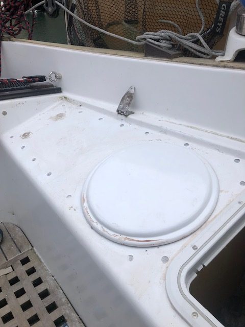
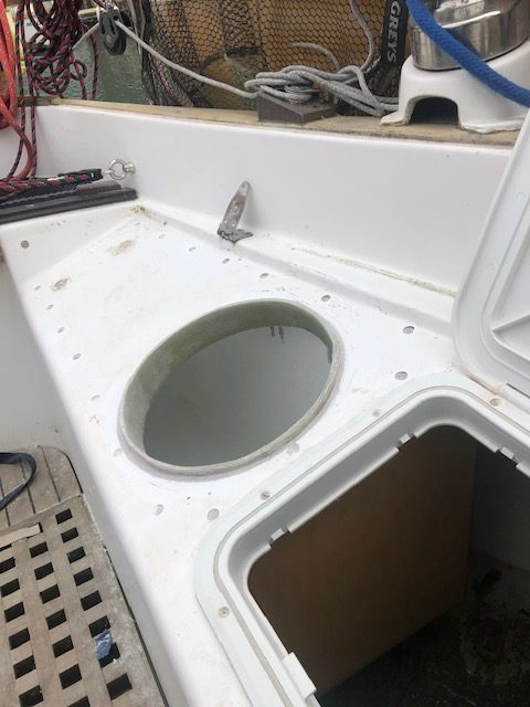
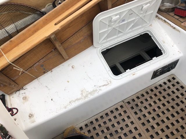
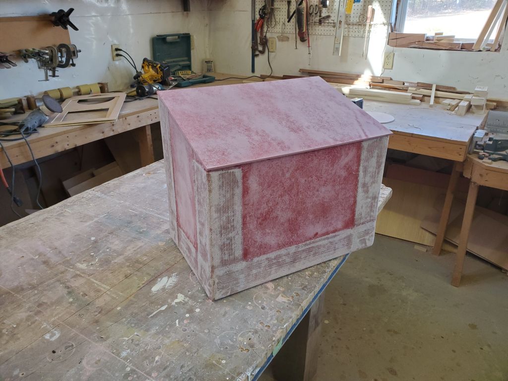
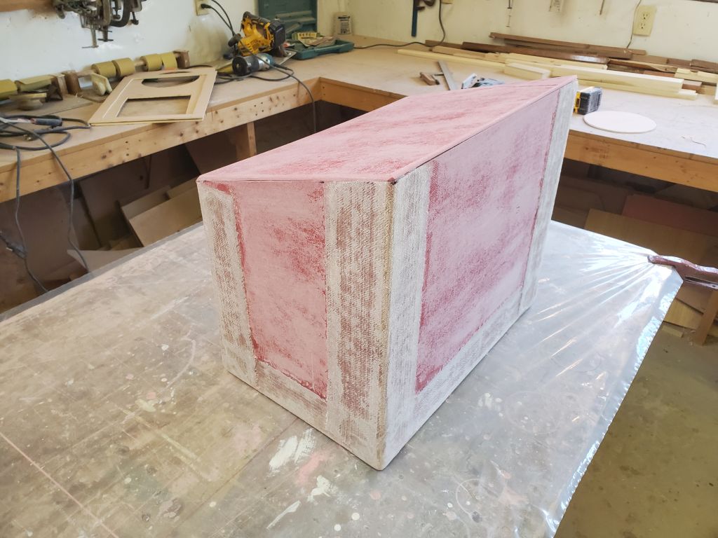
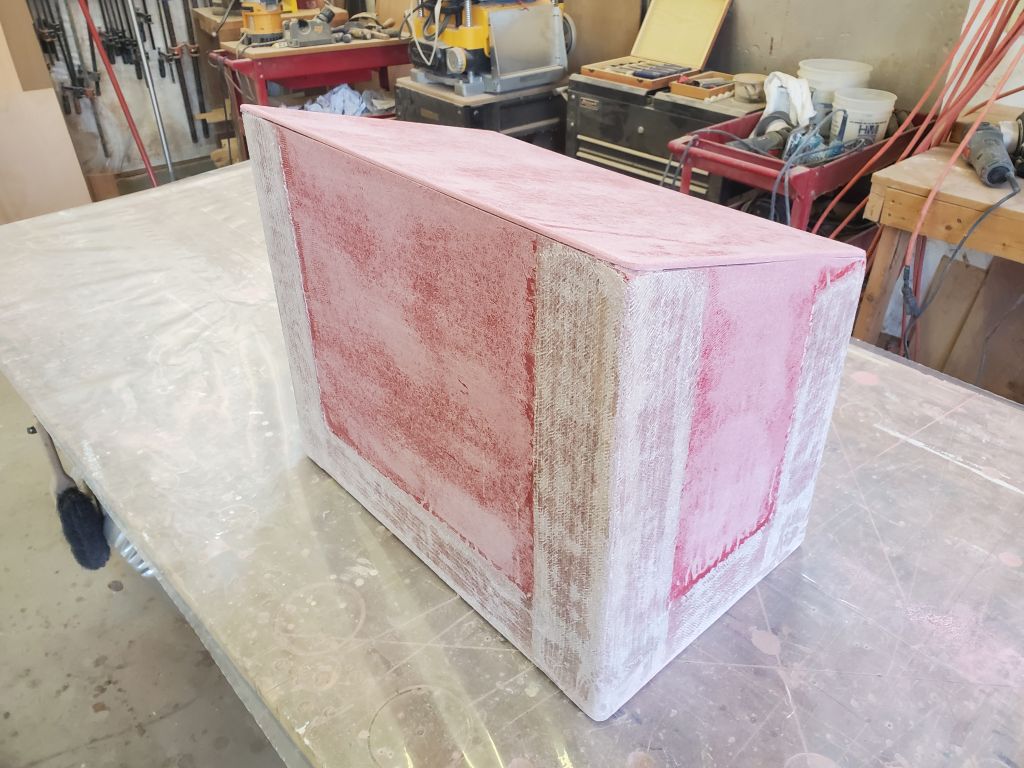
This series of photos shows a box designed for three of the small tanks, which looked identical in size to the two tanks for which I’d built the fiberglass propane box to fit, and the other elements of the installation were similar as well, including the installation of an opening hatch on the forward side. Neither the owner nor I wanted to get into the difficulties, and cosmetic requirements, of a “real” hatch, complete with gutters, etc., though this would be the ideal scenario, probably, were time, budget, and access not factors in the choices made. The box in these photos, made from plywood, featured a full top and then a (in this case) round access hatch to install the tanks within. The locker hung from the bottom of the cockpit seat above, secured with a series of bolts that were visible in the photos.
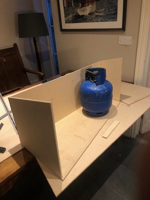
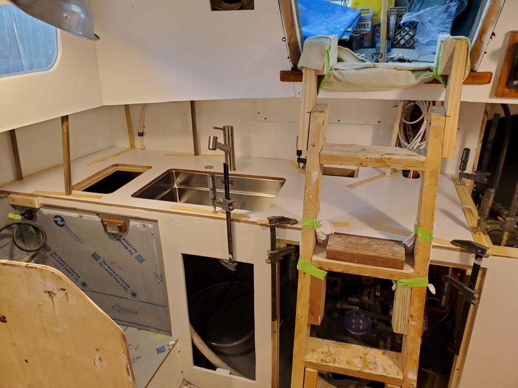
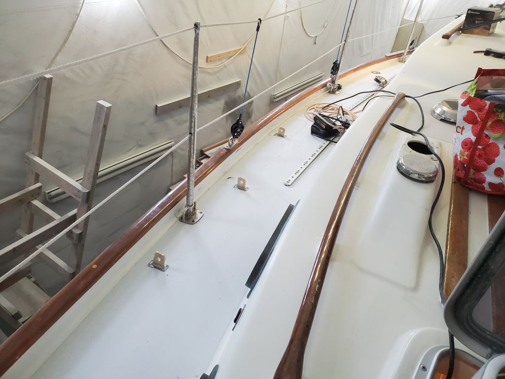
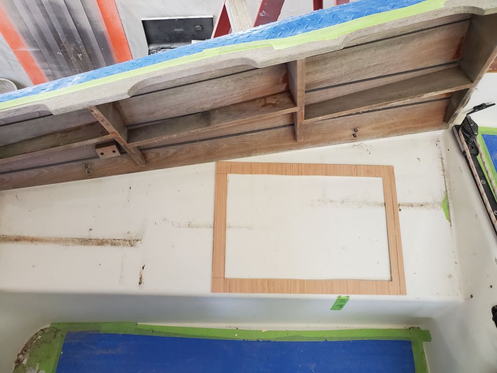
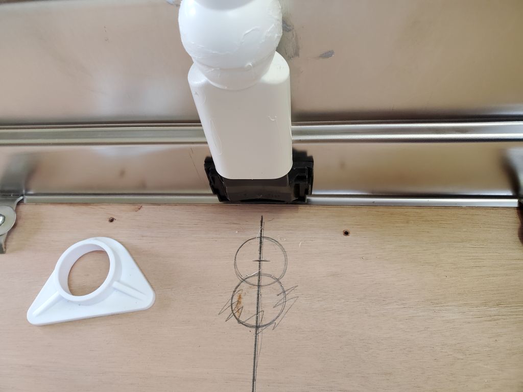
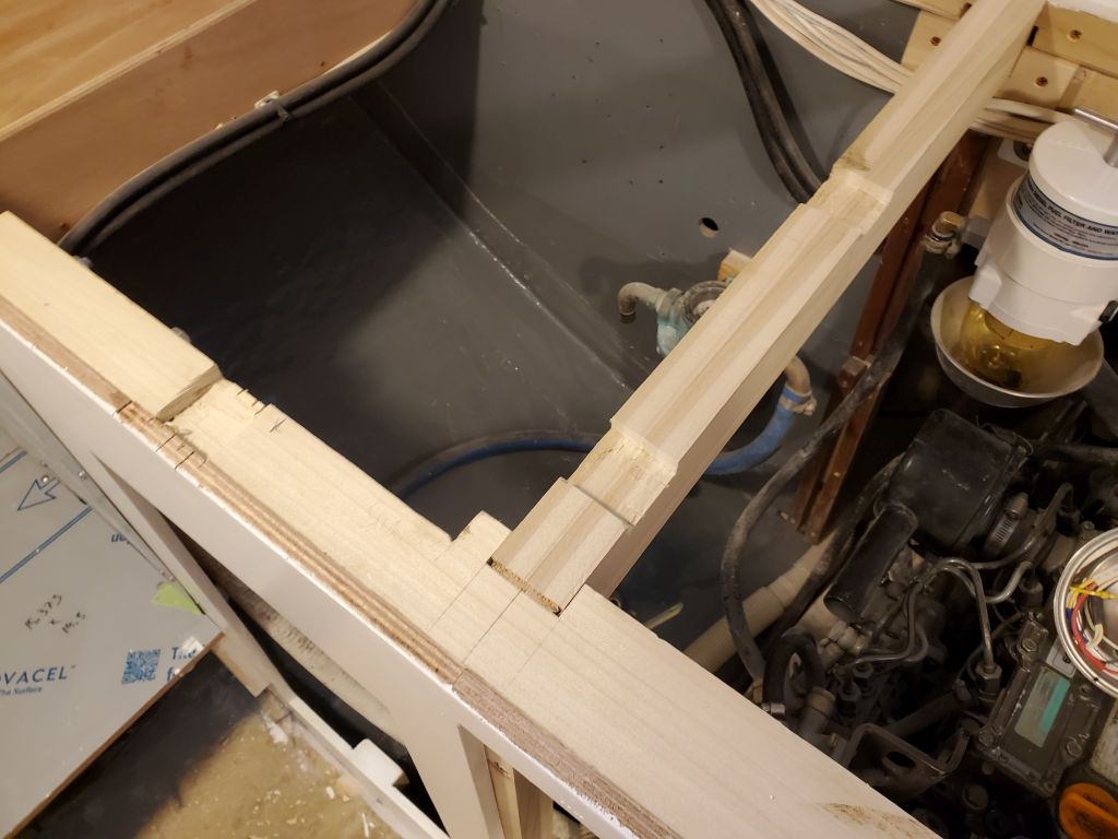
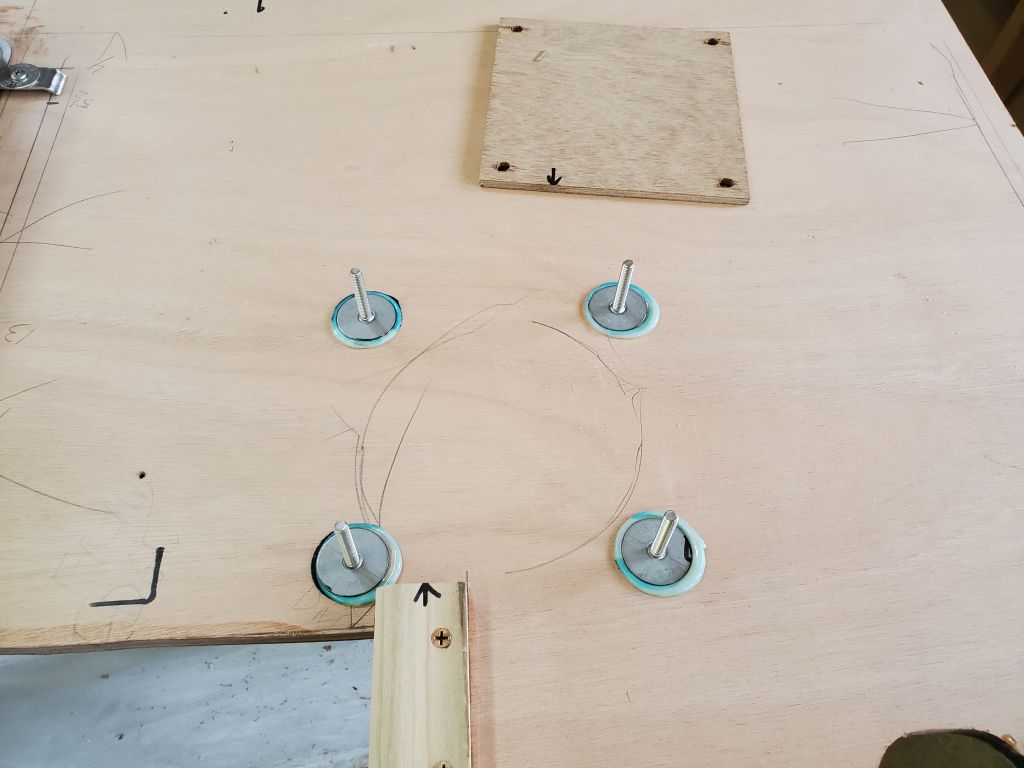
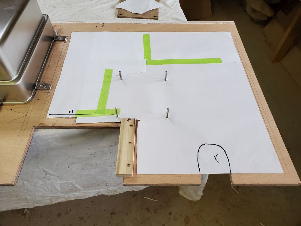
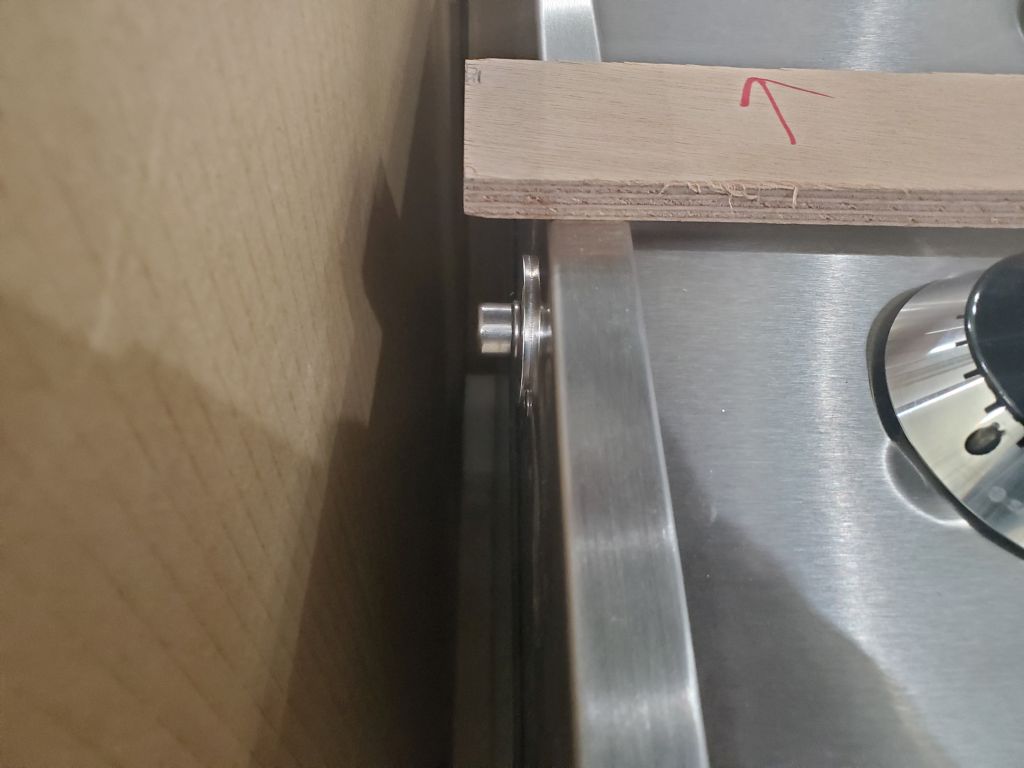
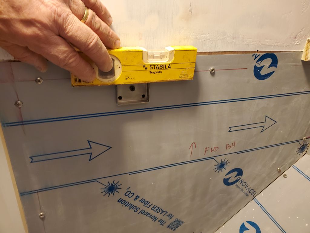
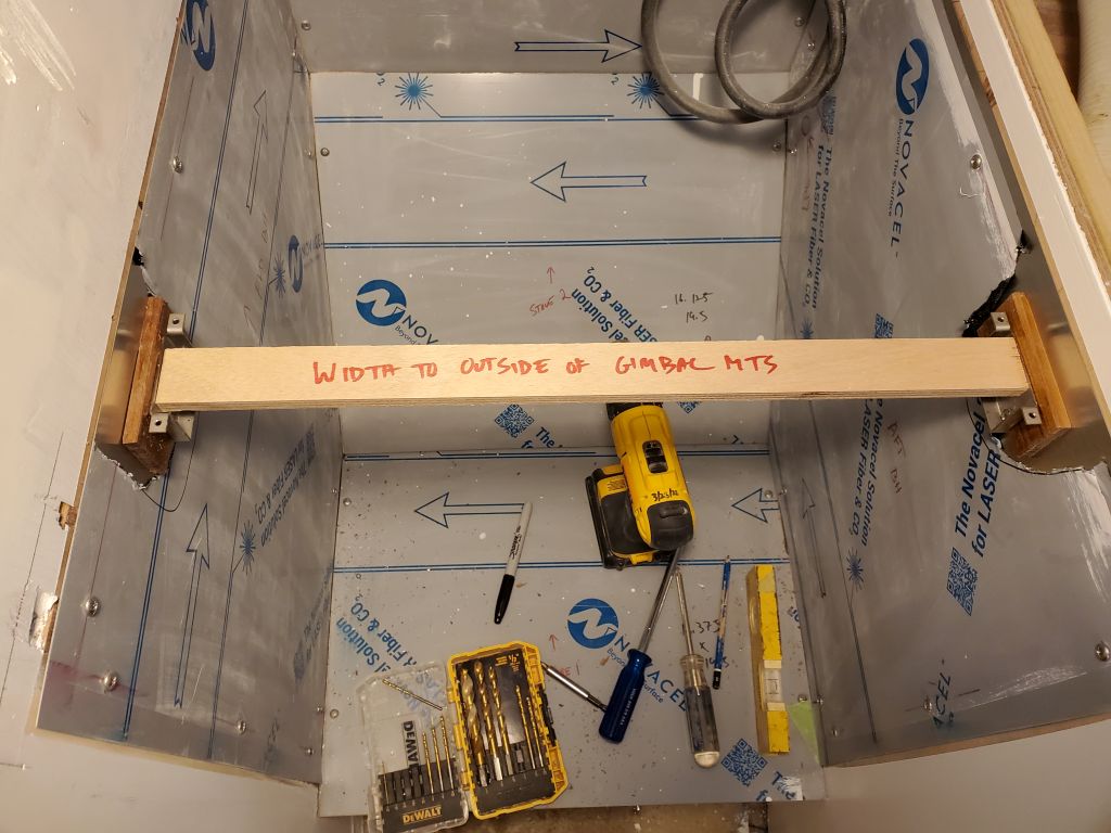
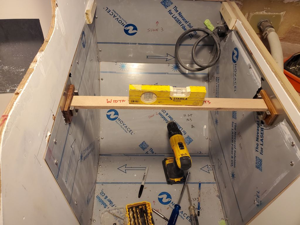
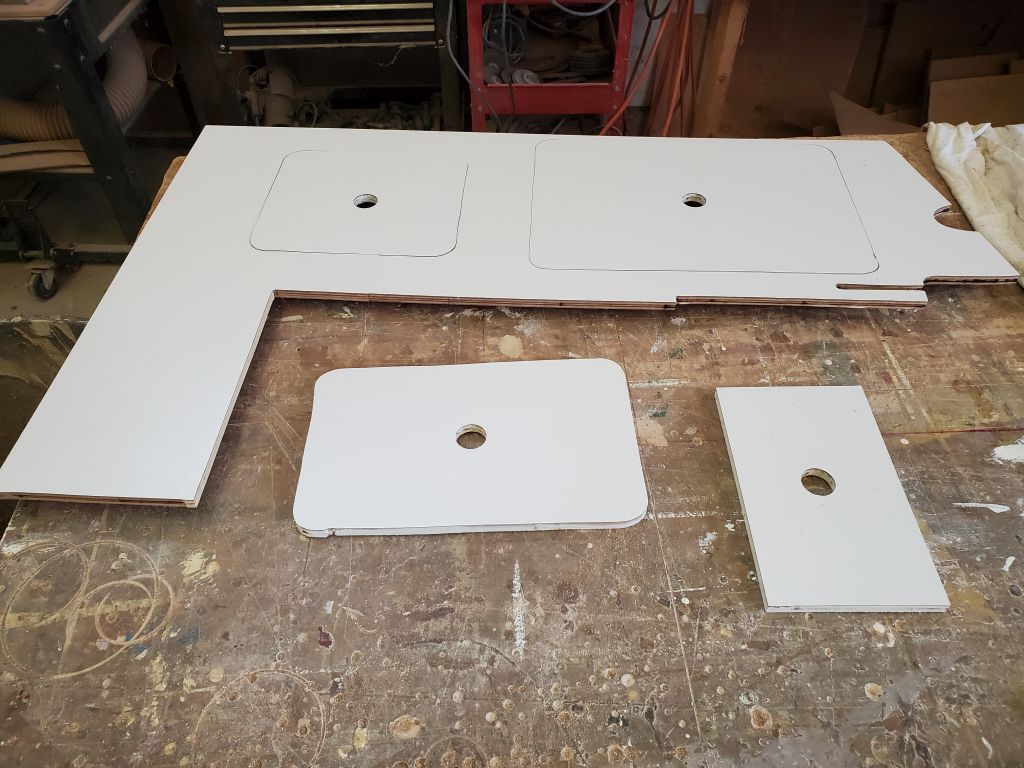
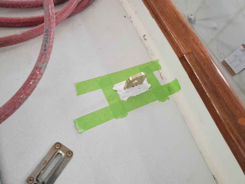
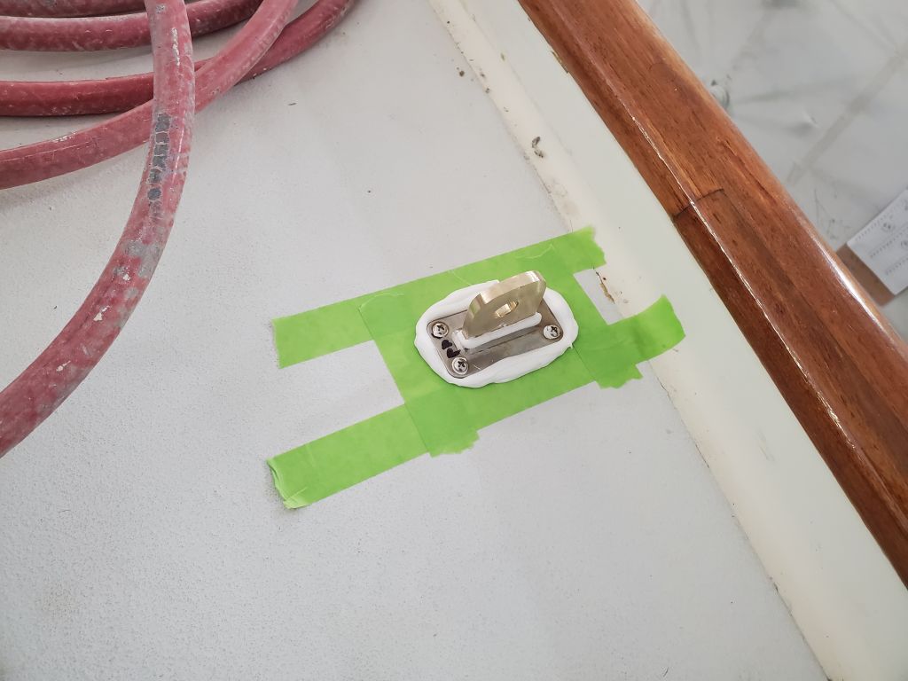
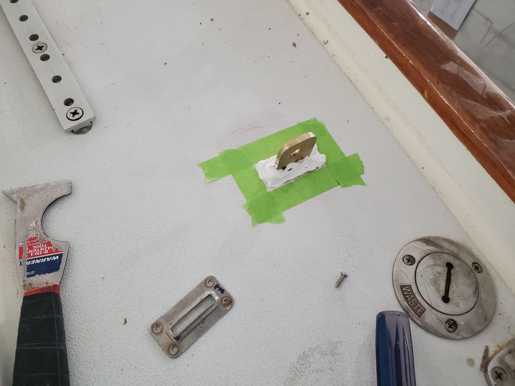
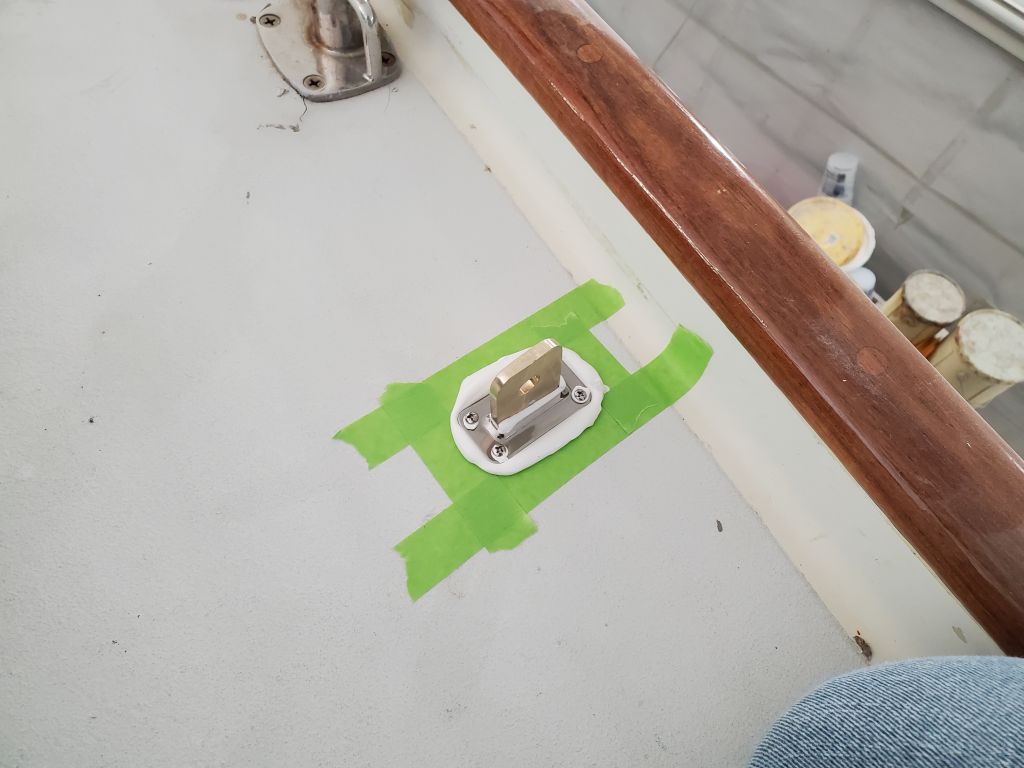
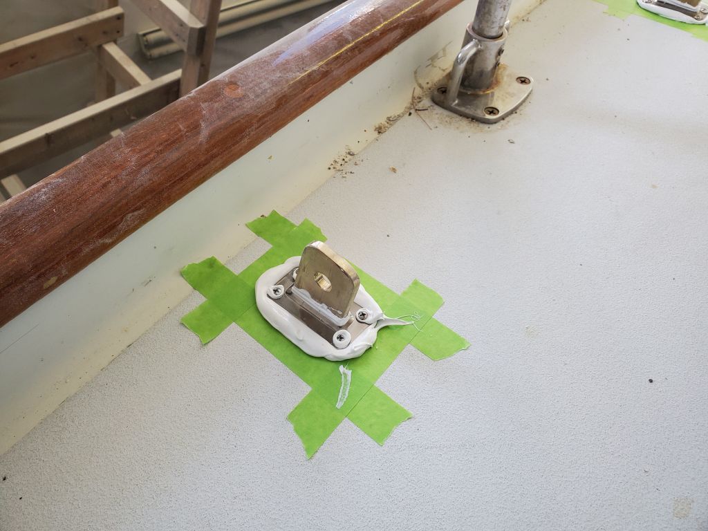
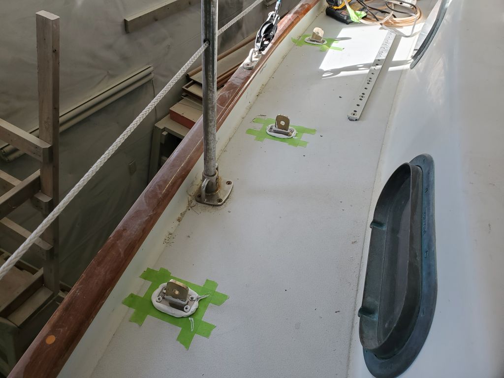
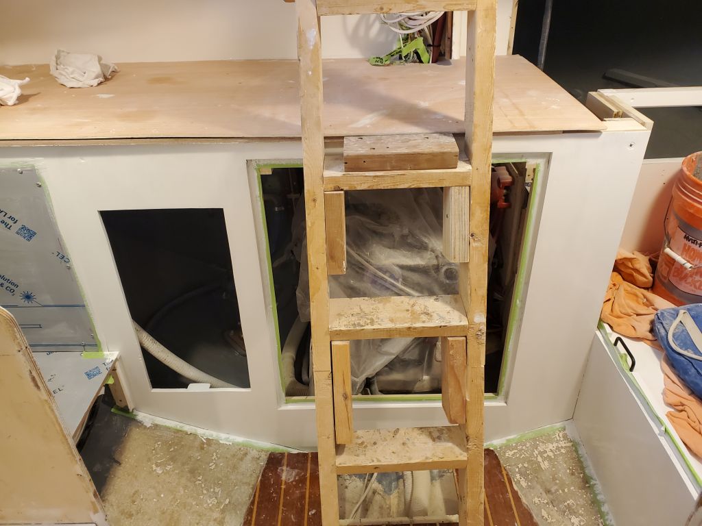
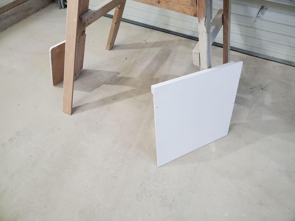
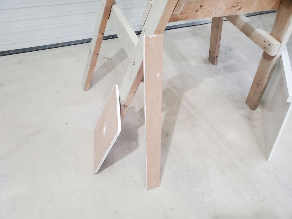
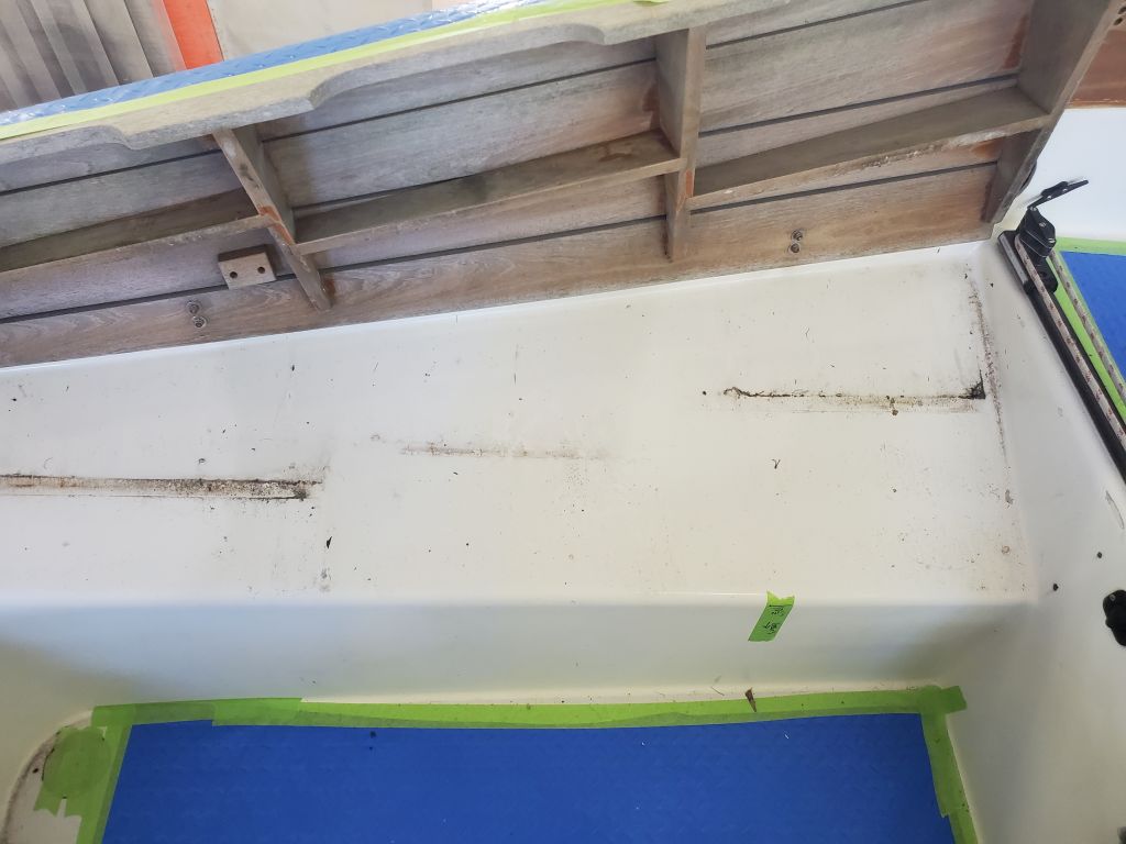
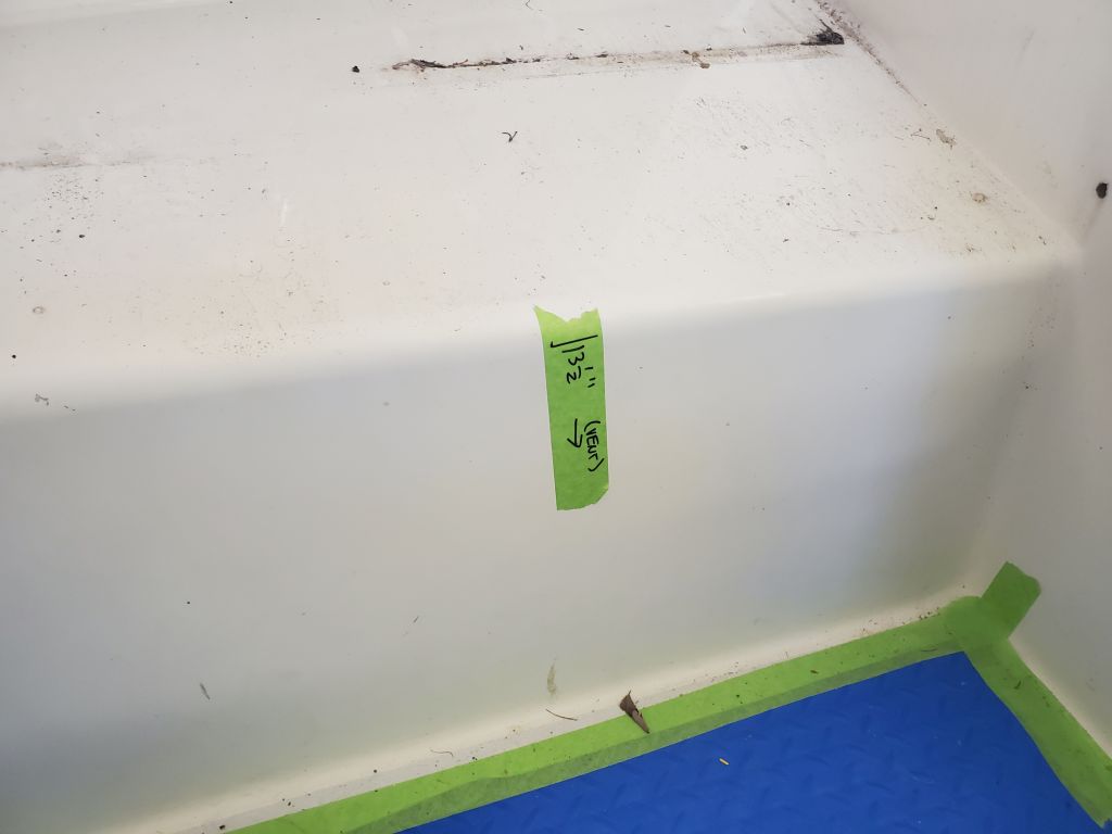
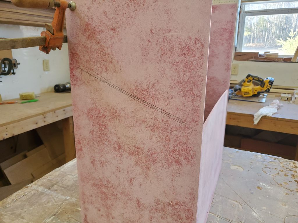
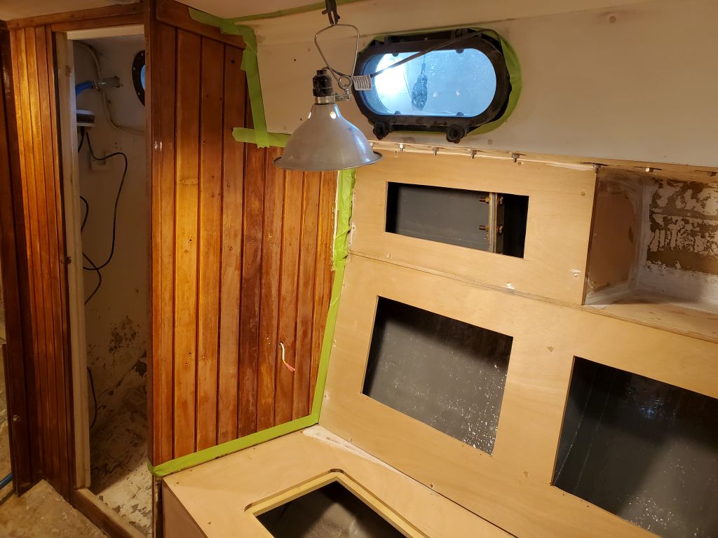
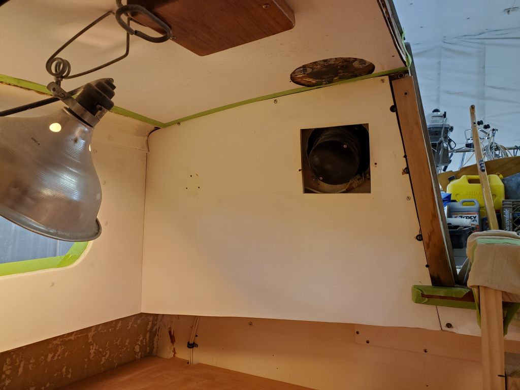
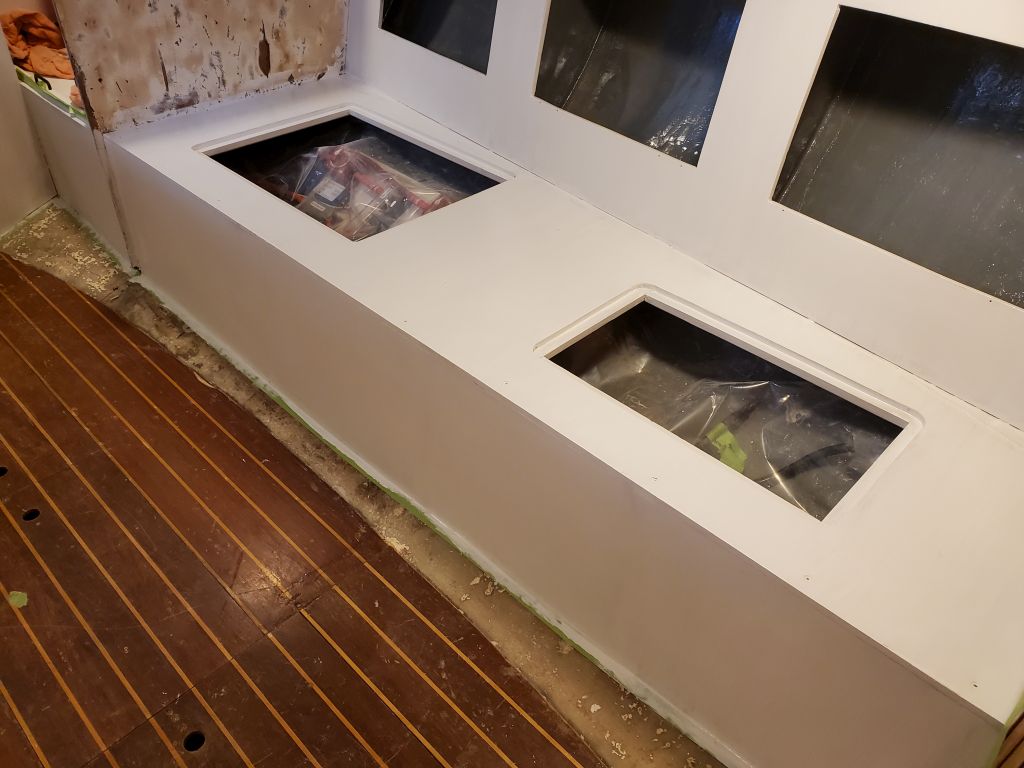
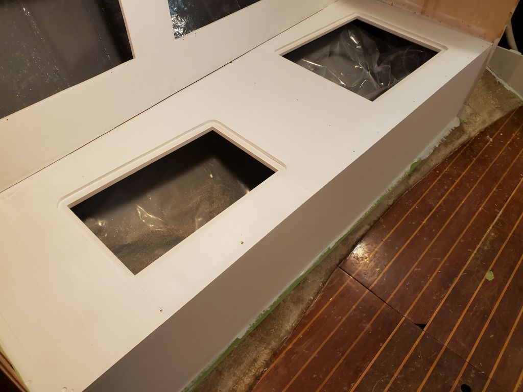
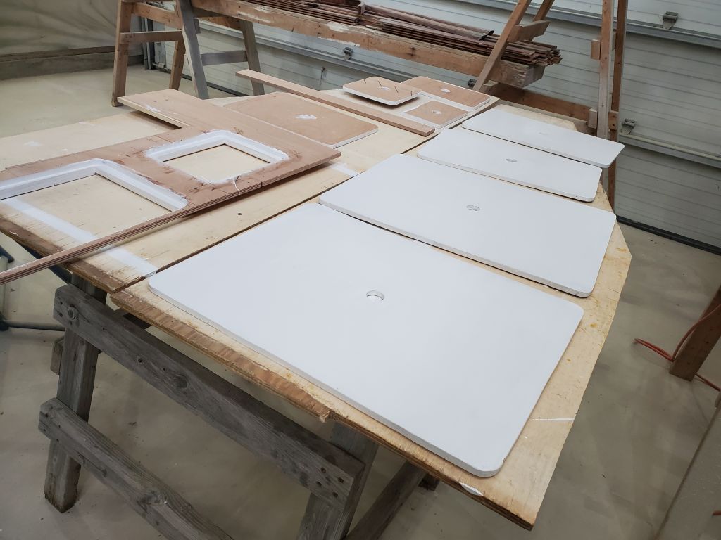
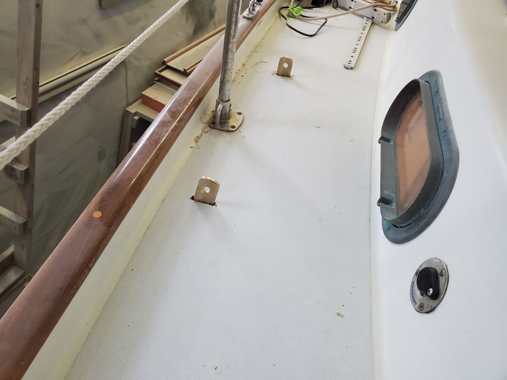
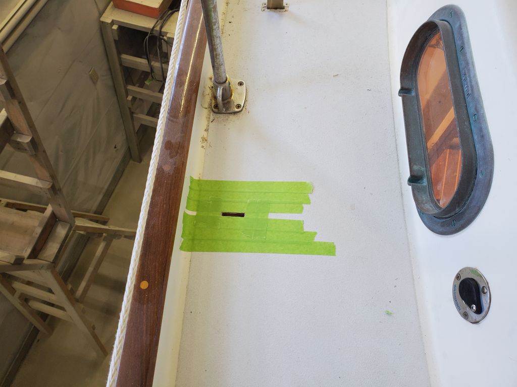
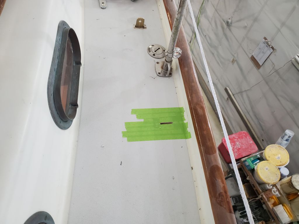
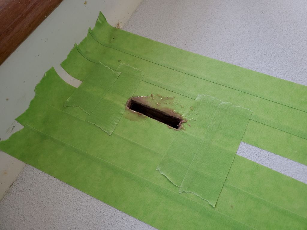
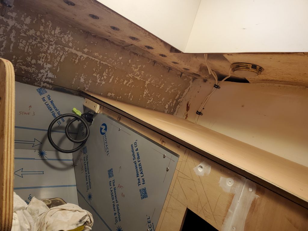
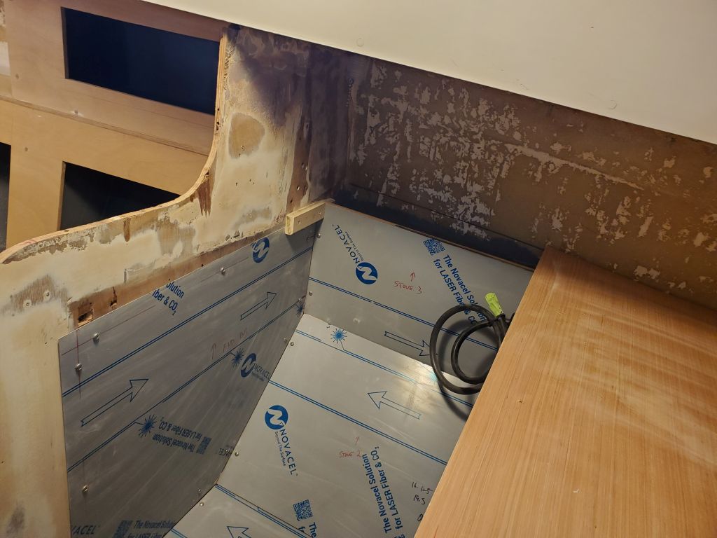
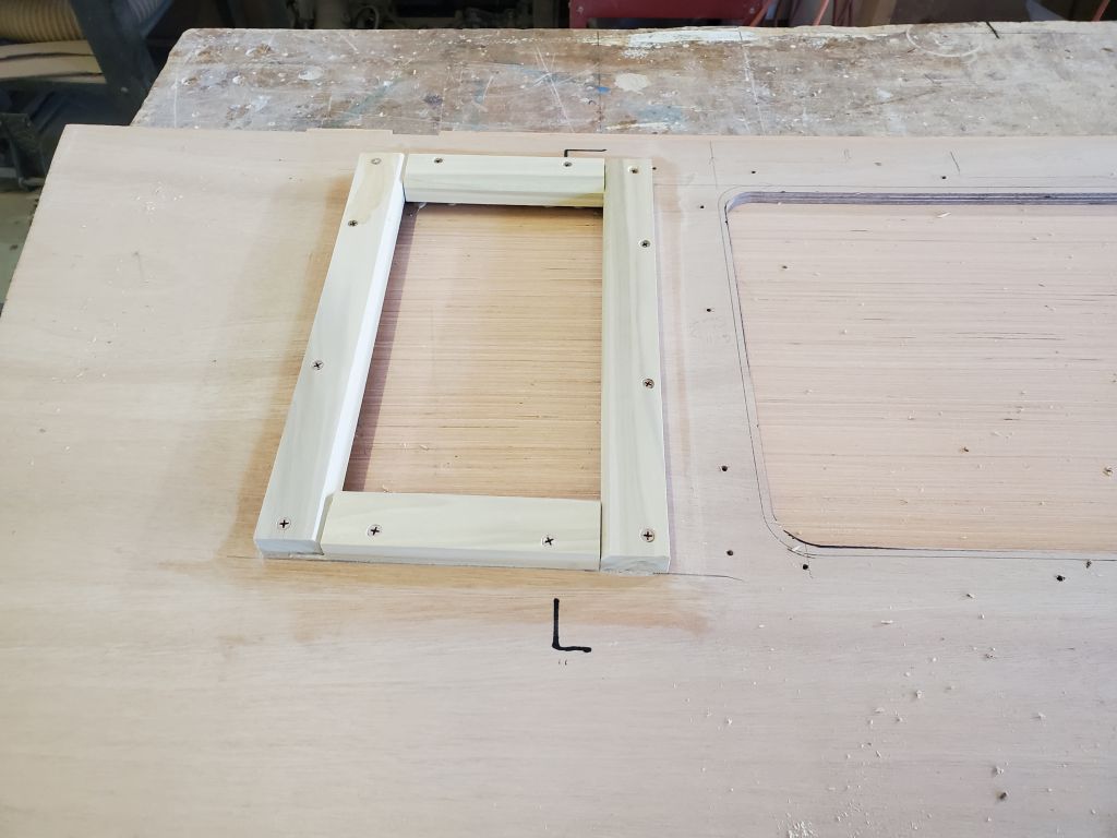
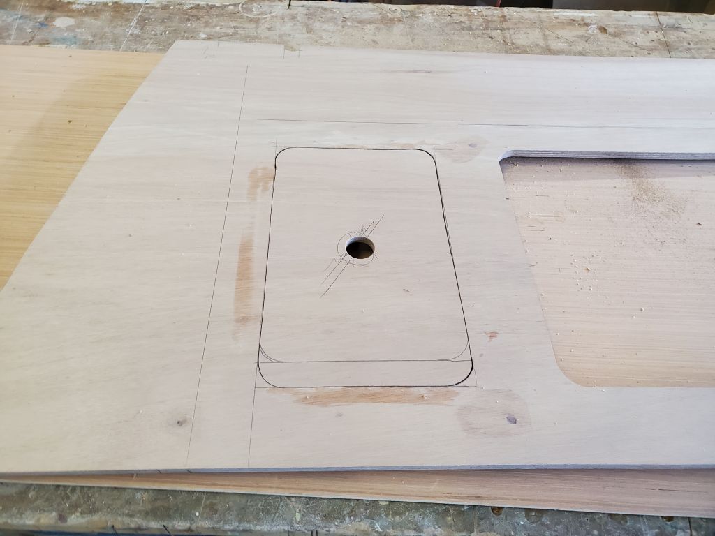
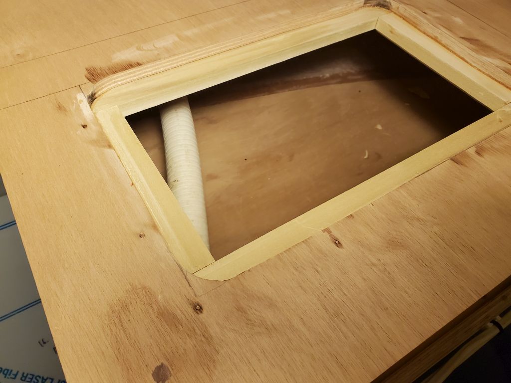
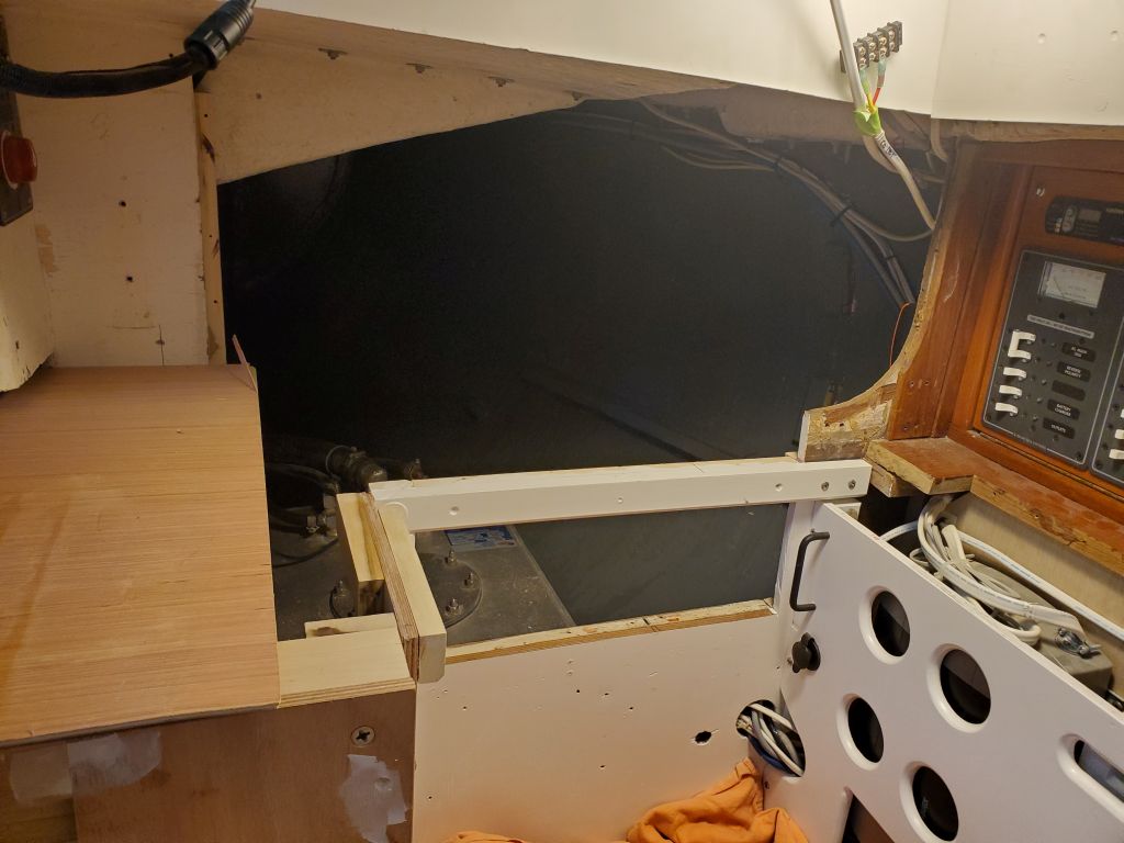
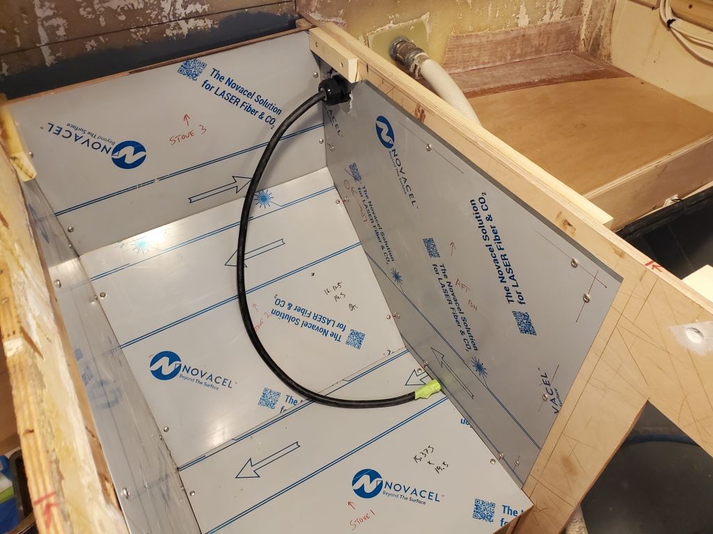
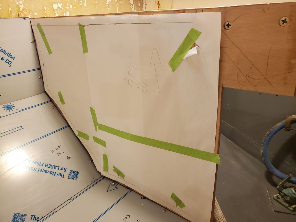
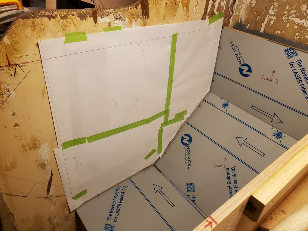
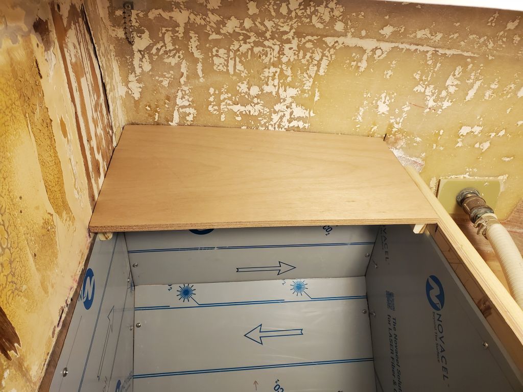
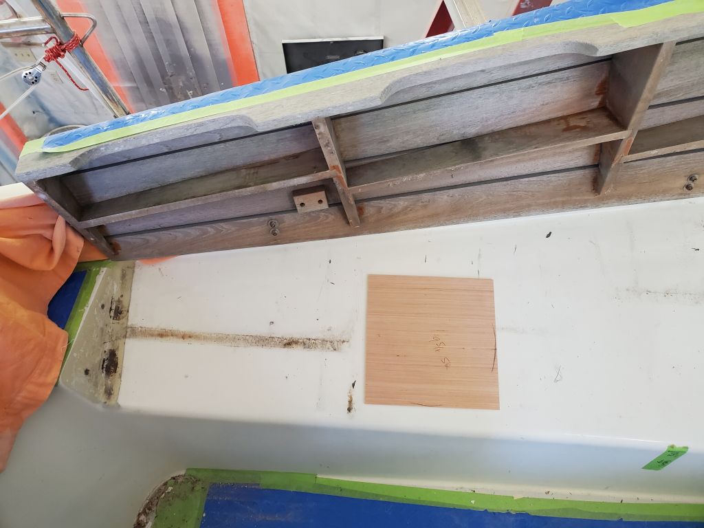
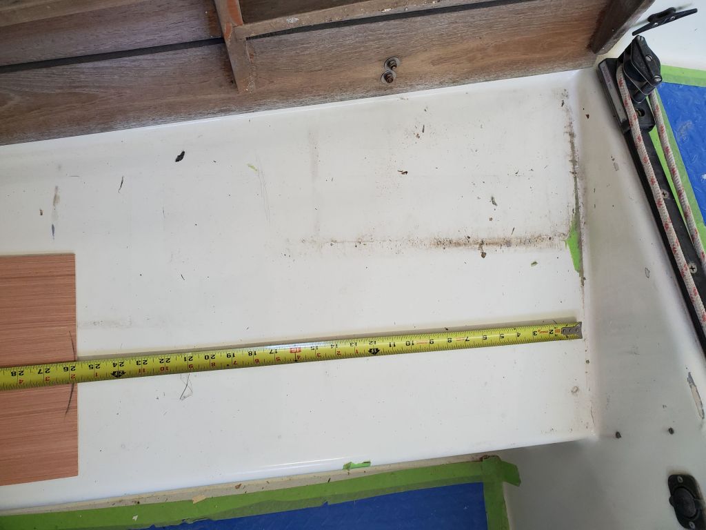
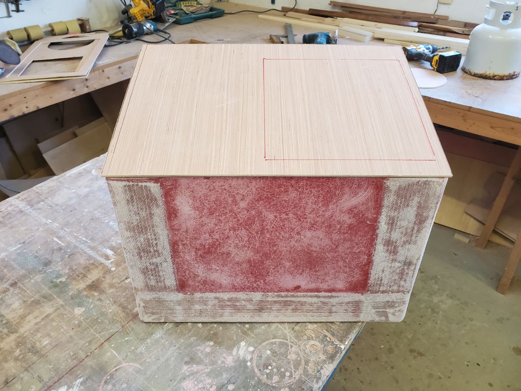
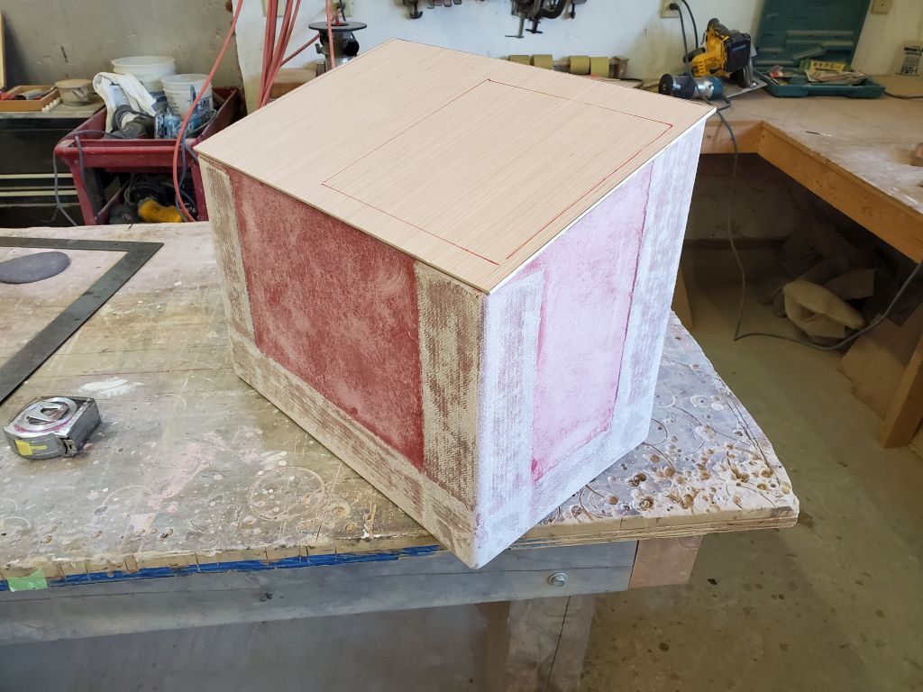
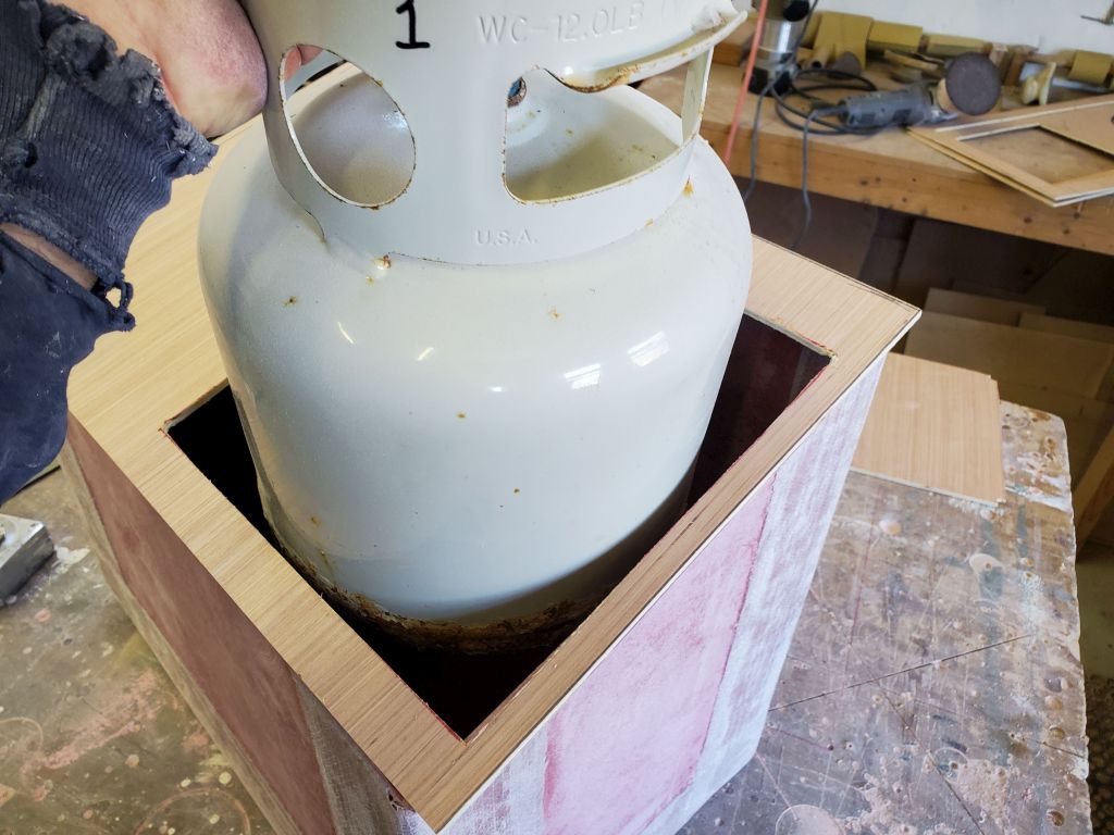
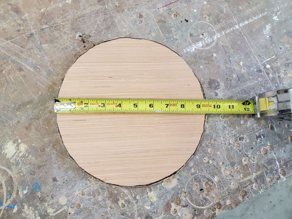
In the shop, I made a rough measurement from the aft end of the cockpit locker (from the cockpit) to show the position of the forward end of the locker if it were pushed as far aft as possible, about 20″ forward of the aft end of the space. That’s the end of the tape measure in the photo. However, I positioned a mockup of a square access hatch forward of that because, looking at the way the wooden locker lid above is built, and which has to close down on top of whatever I built beneath it, it made sense to choose a position for the locker opening where it interfered with as little of the cockpit lid structure as possible. These structural supports on the lid can be seen in the photo, as well as marks on the gelcoat of the structural seat where these members bear. So avoiding the main areas was a goal of the final location in any case. This location still left room for a 24″ long hatch in the space forward, which fit the dimensions of one of the prefab plastic hatches the owner had brought to my attention and was interested in using.
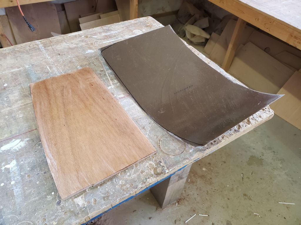
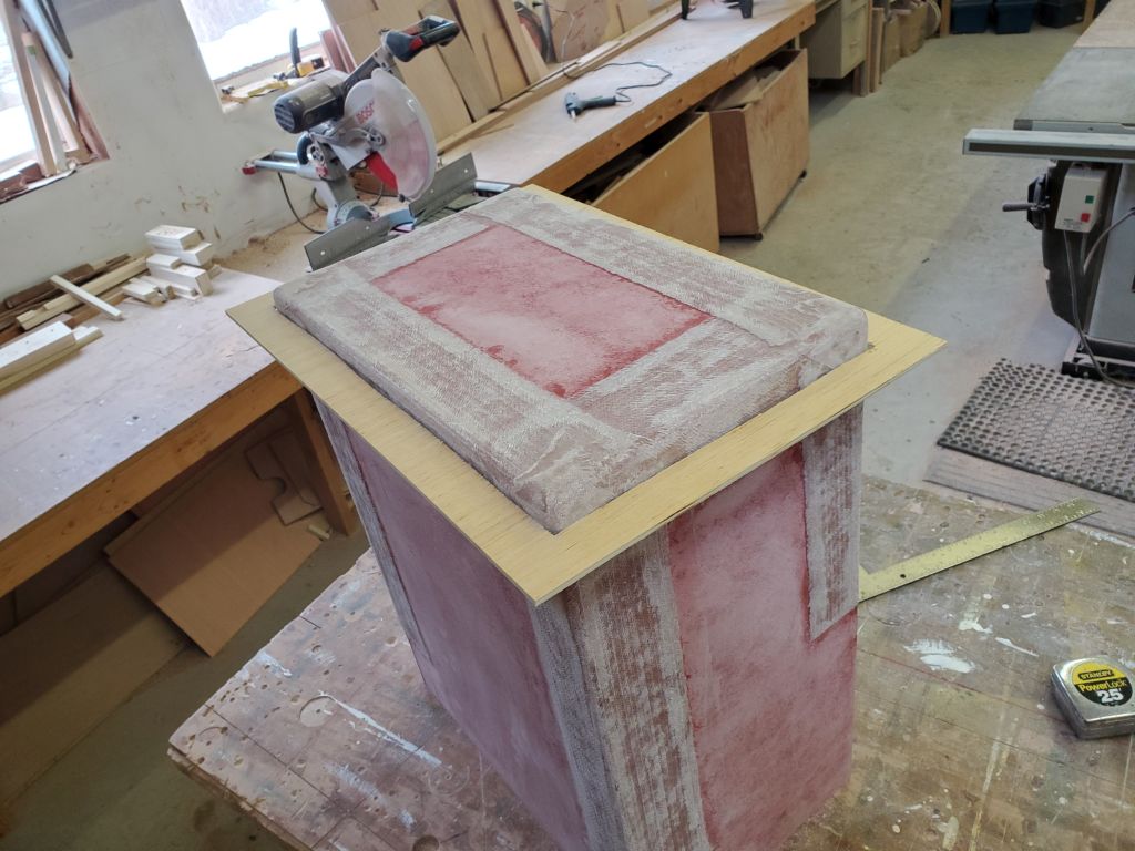
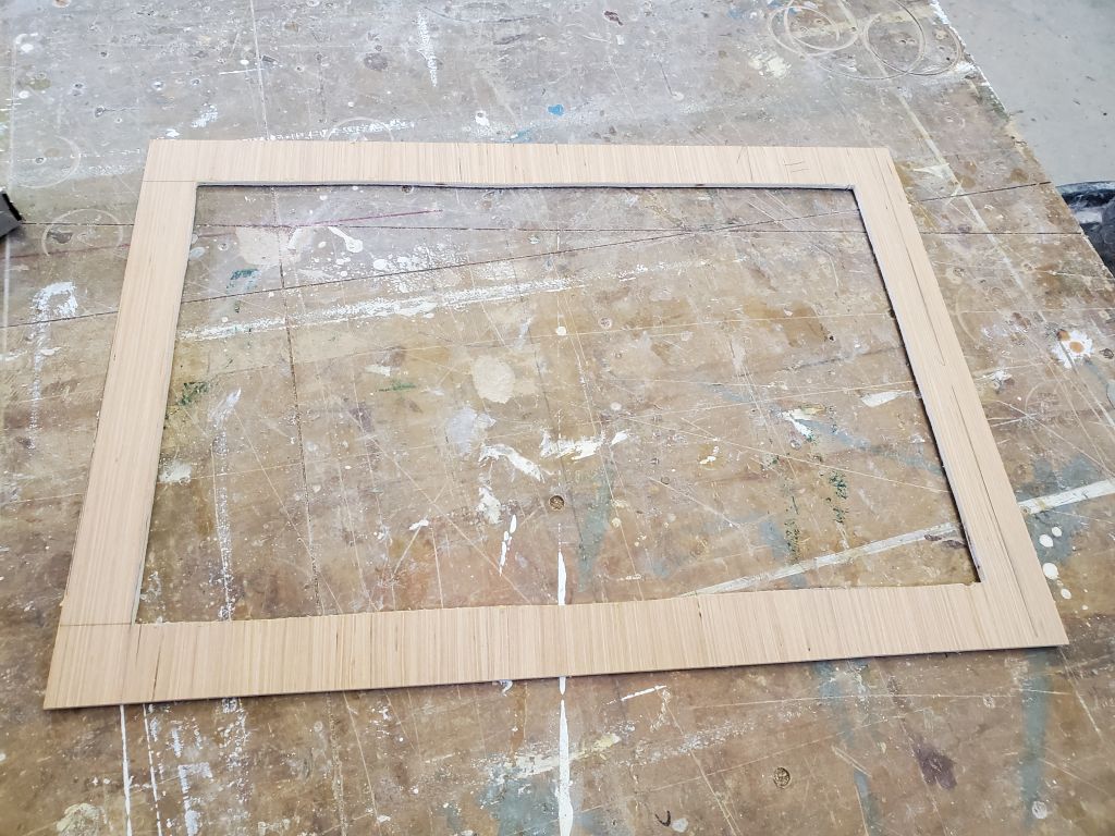
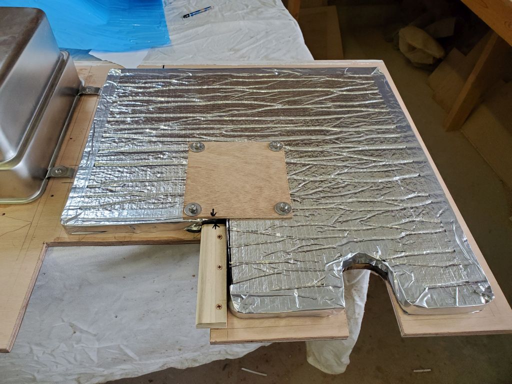
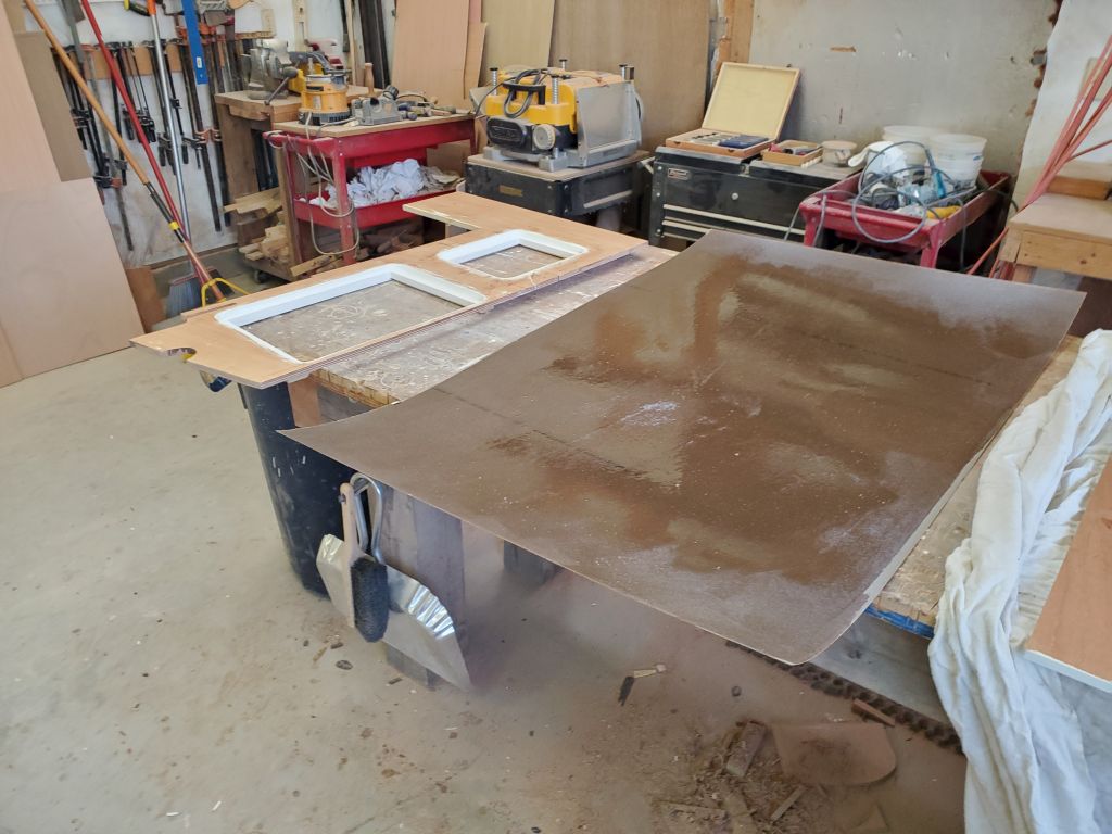
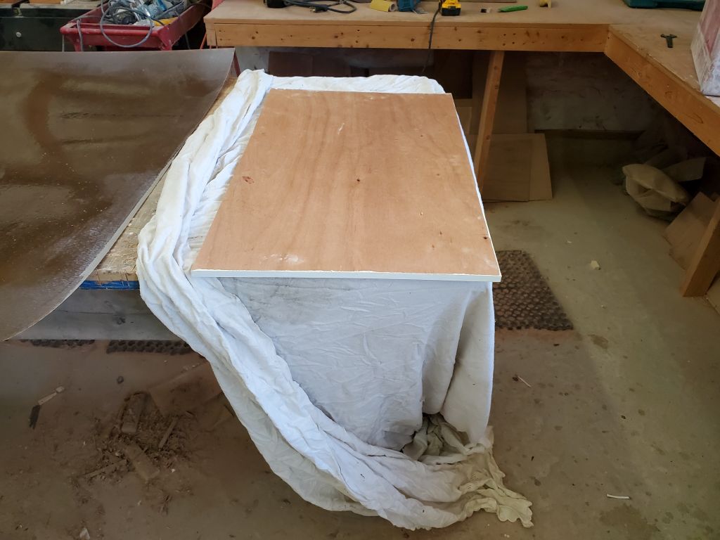
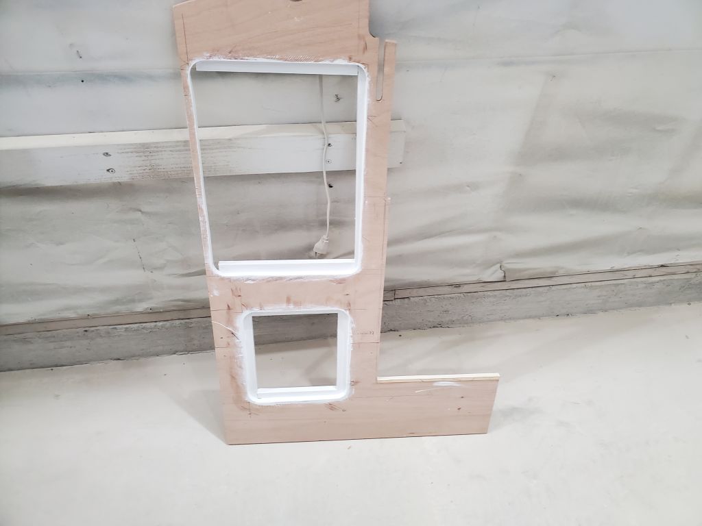
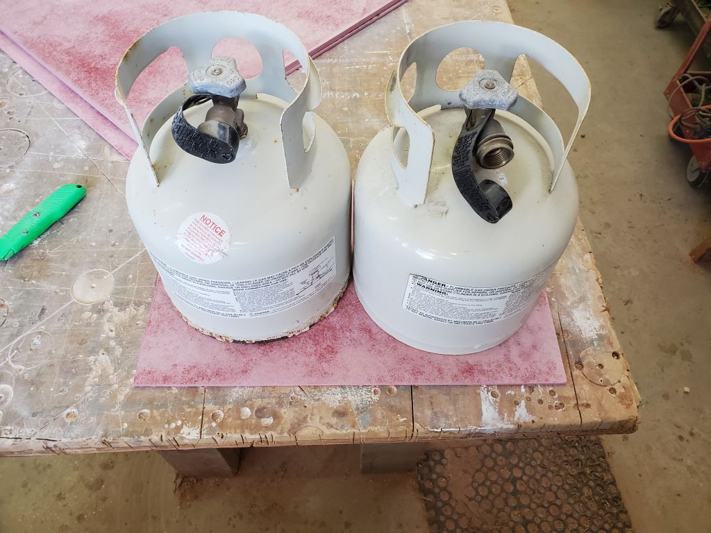
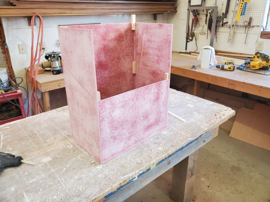
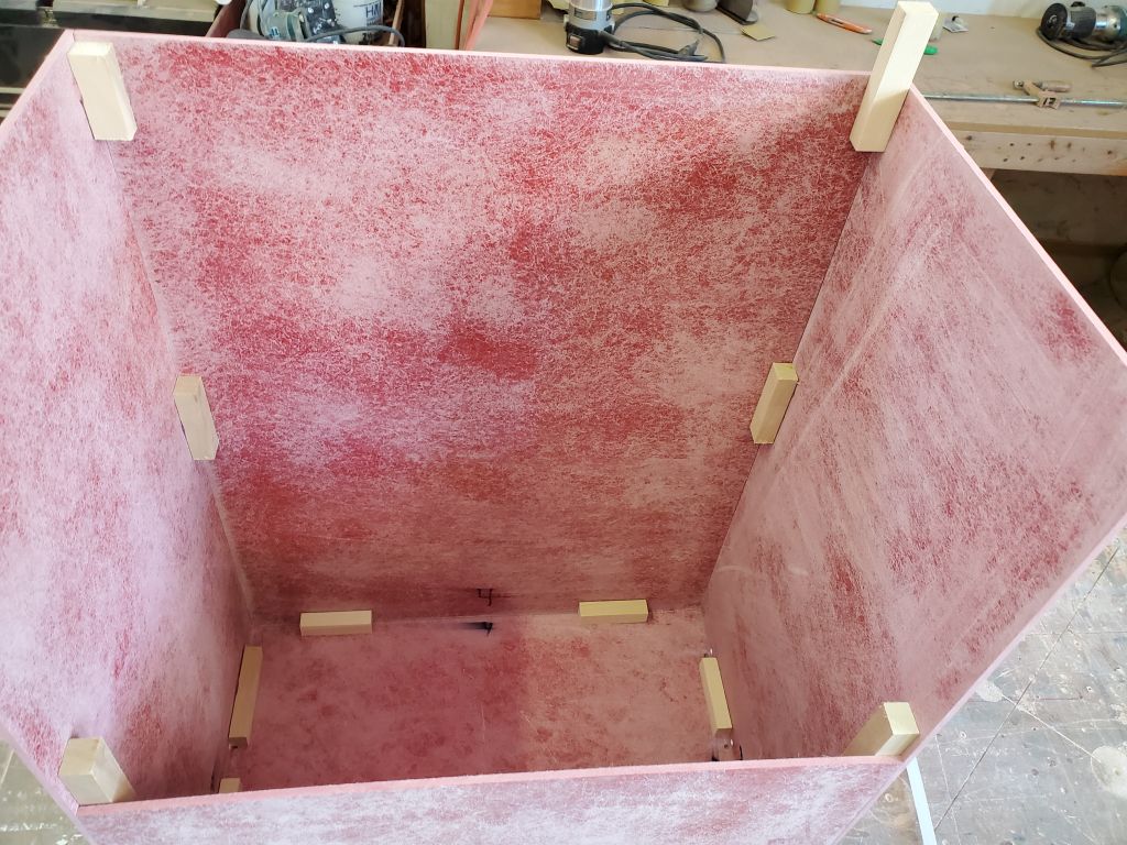
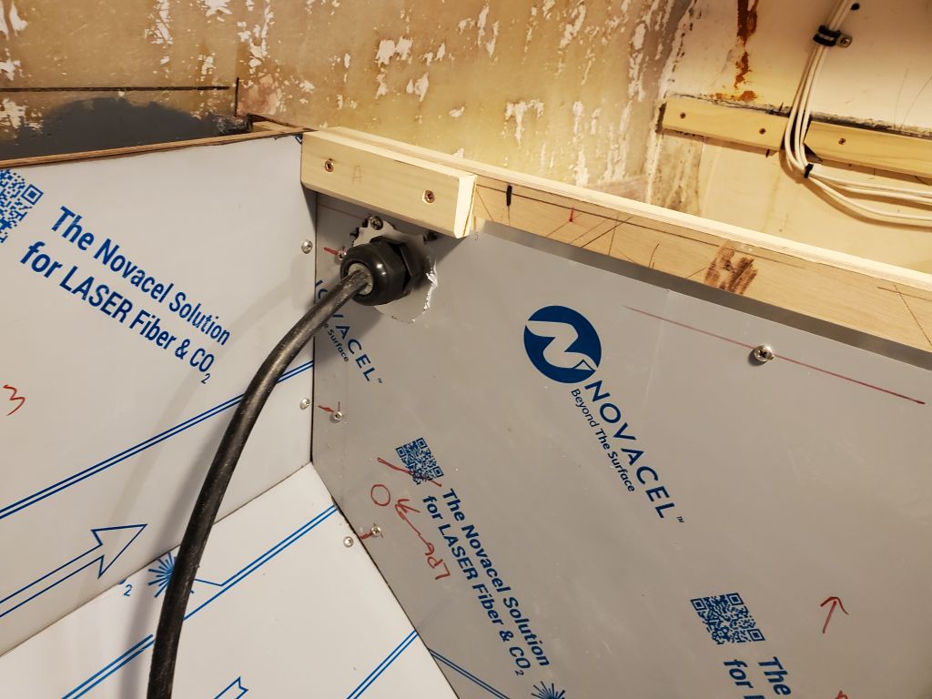
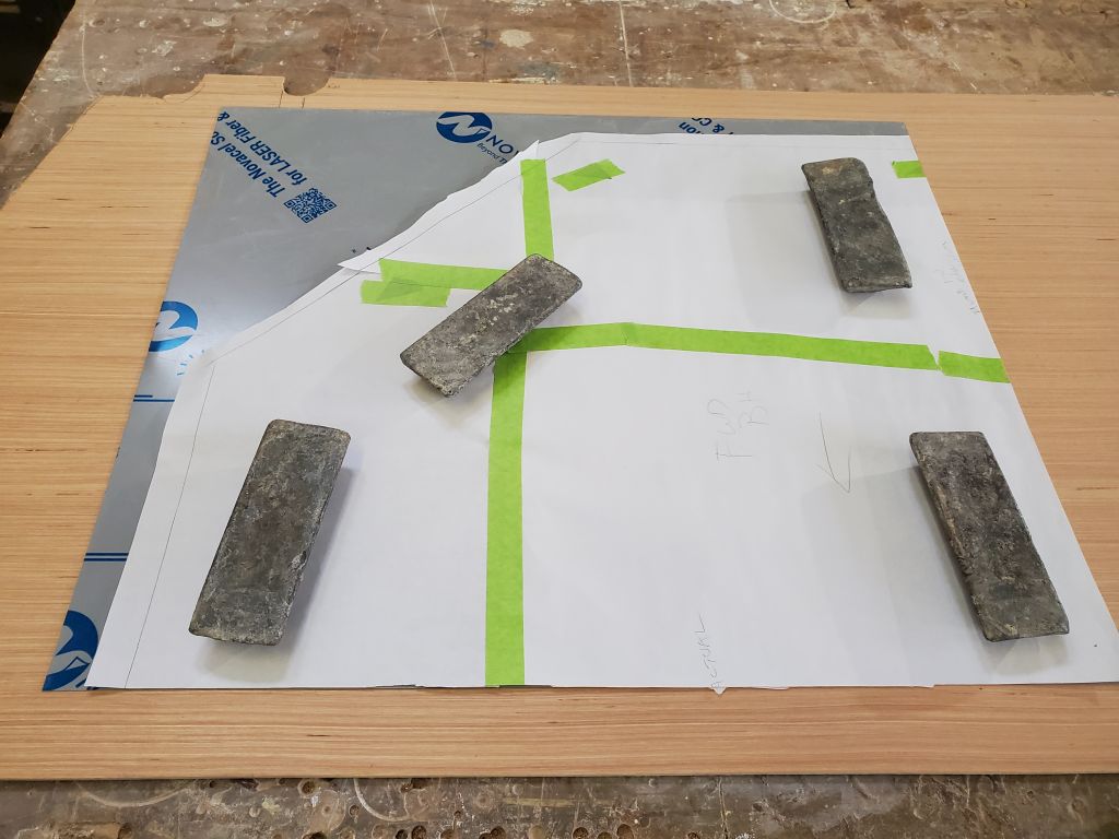
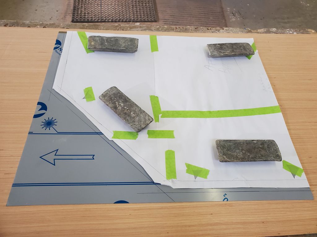
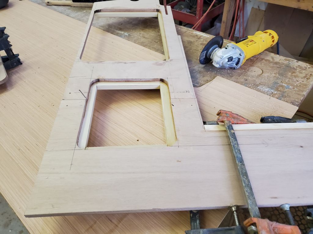
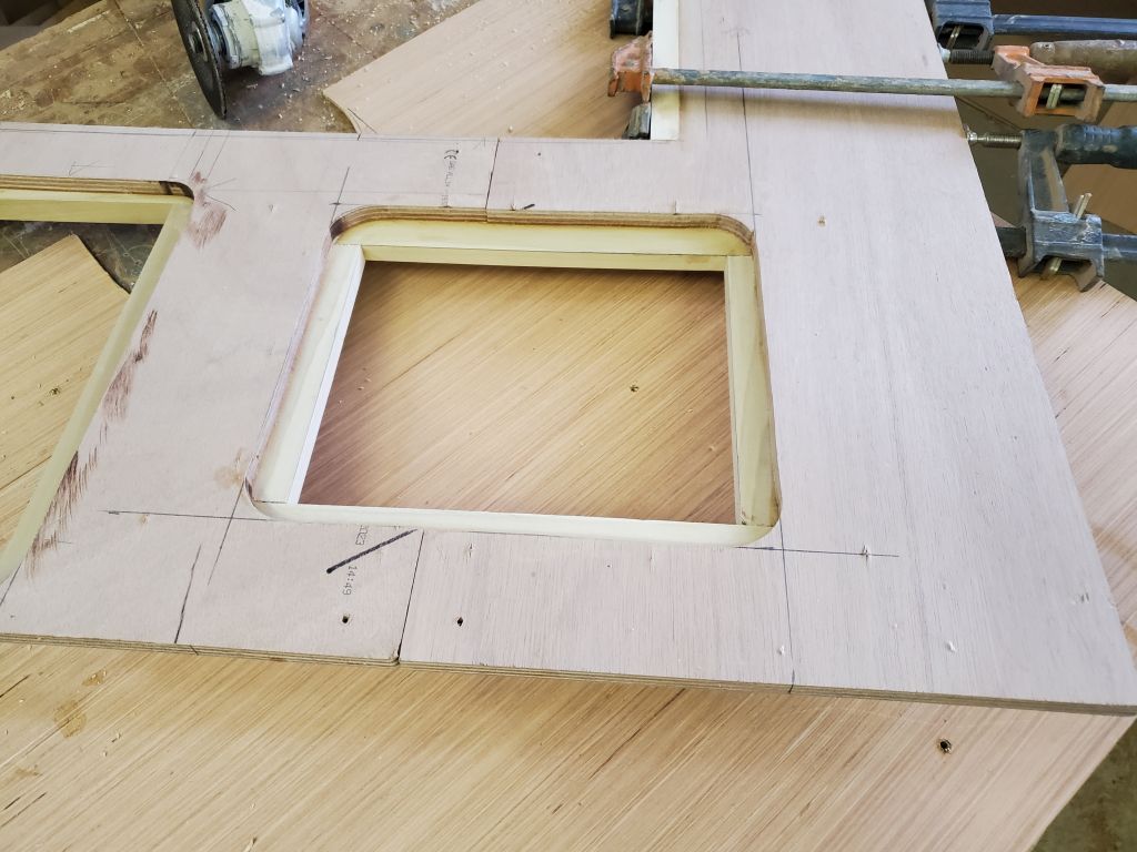
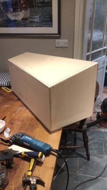
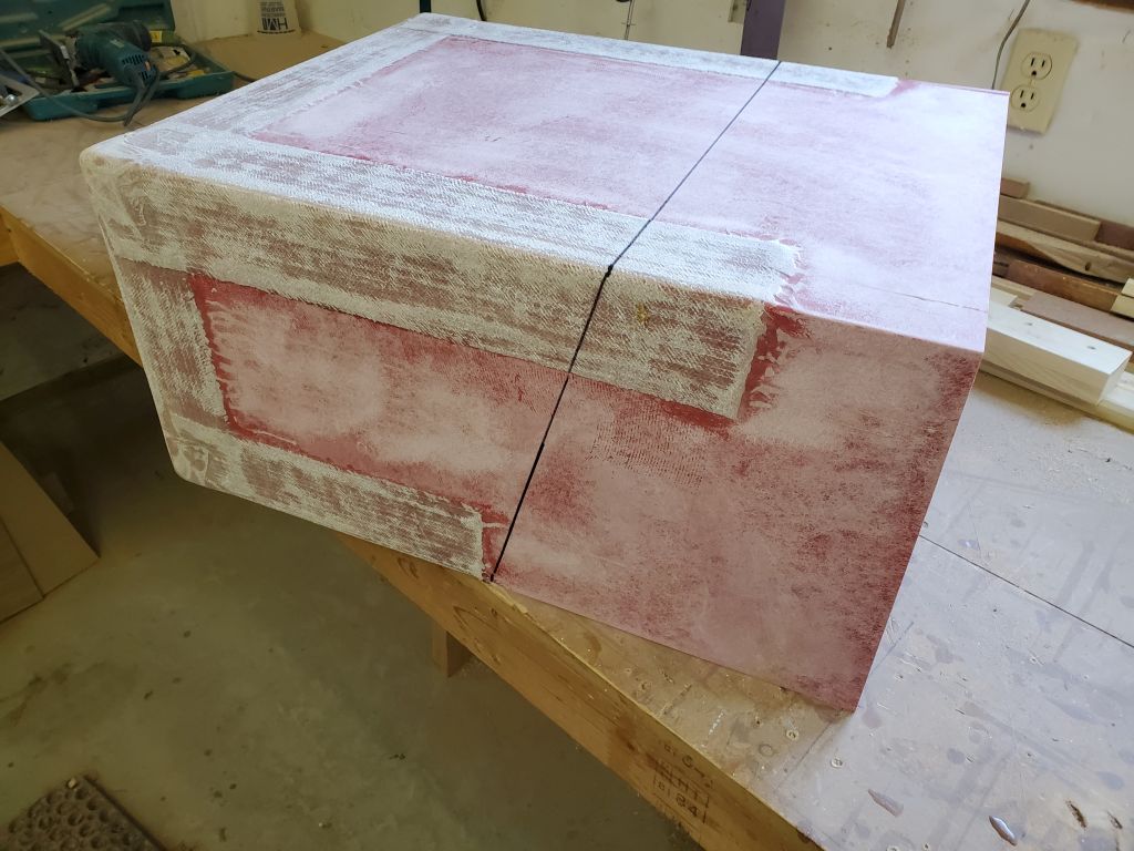
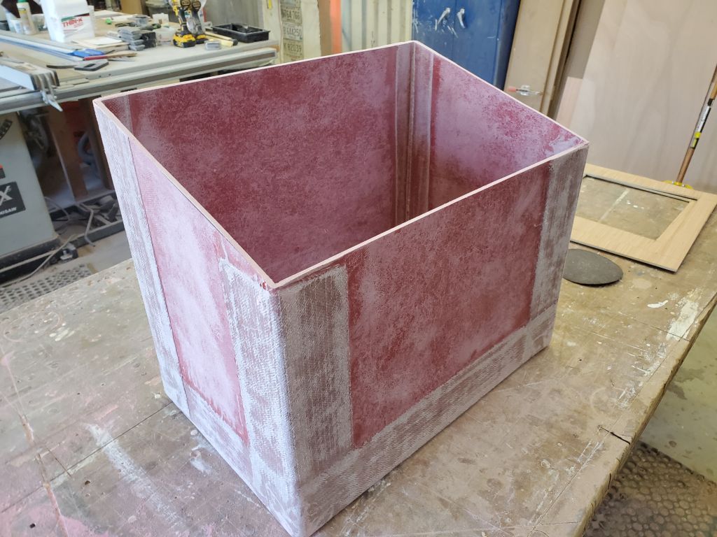
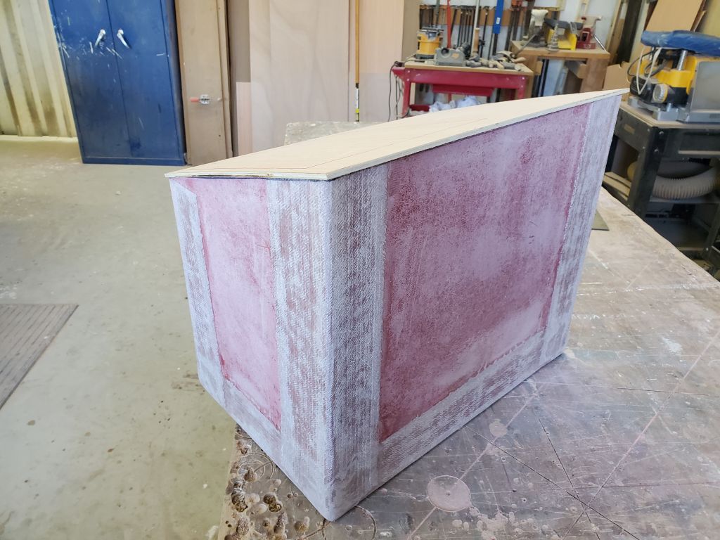
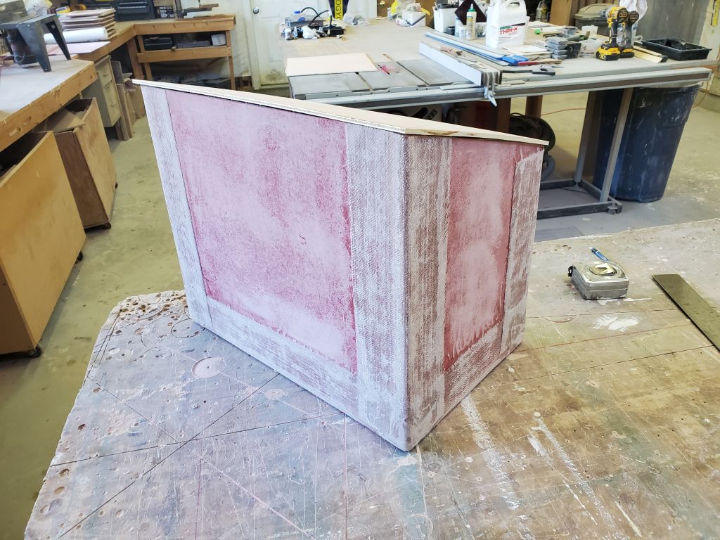
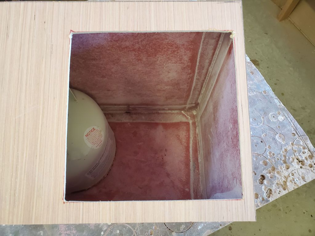
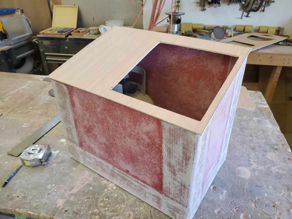
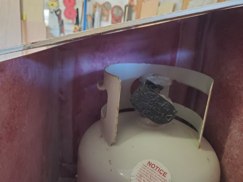
Now, I measured the angle of the seat and cut the LPG box to the correct angle, then made a plywood mockup of the top, which in the final construction would be made of sheet fiberglass like the rest of the box and fully glassed all around. This mockup was slightly oversized for the moment. I cut a rectangular hole to match the plywood template I laid on deck, which was about the practical minimum size of 9-5/8″ square to fit the tanks through and leave a bit of clearance space; the opening could be slightly smaller, but I saw no benefit to that, preferring decent access within. The tanks fit easily, with ample room inside the box and through the opening for manipulating the propane connection and regulator. The tank itself is about 9-3/8″ round, as seen in the round template.
For installation, my plan was to secure the box, with its flat top pressed tightly to the underside of the cockpit, with 5200 between the top of the box and the underside of the cockpit. The owner wanted to avoid bolts visible from the cockpit, so I’d have to come up with a way to hold the box securely while the adhesive cured, but I didn’t conceive of any problem with the adhesion of the polyurethane, particularly with the large bonding surface available. The adhesive would have to be capable of supporting the weight of the box and two, ten-pound tanks, so 35-40 lb. total for the whole arrangement. It would be possible to use bolts to augment the adhesive if needed, but the owner hoped that I could avoid that for appearance purposes.


This installation concept, largely thanks to the owner of a sistership who happened to get in touch with the boatowner at an opportune time, seemed feasible, as simple as possible, and workable with what I’d already accomplished with the box, and would leave enough space for the propane through-fittings for the two supply hoses, as well as the regulator, solenoid, wiring and related that would be inside the box. With the new deck hatch opening just forward, there’d be good access to these hoses for installation and inspection going forward.
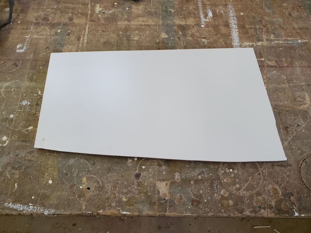
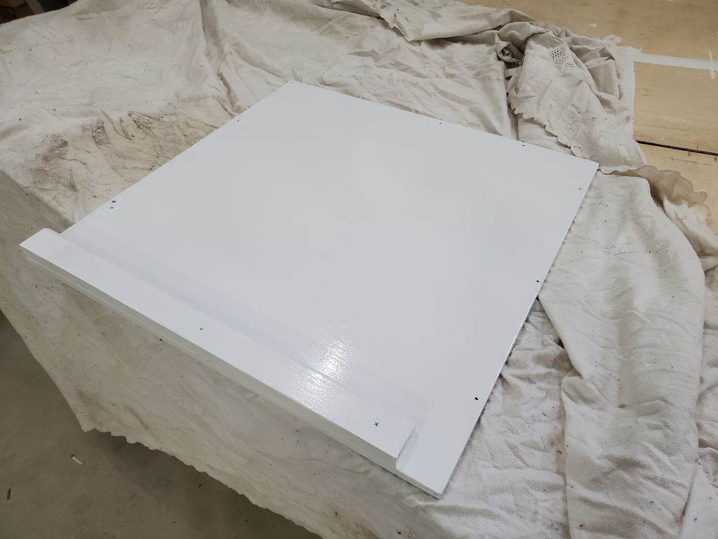
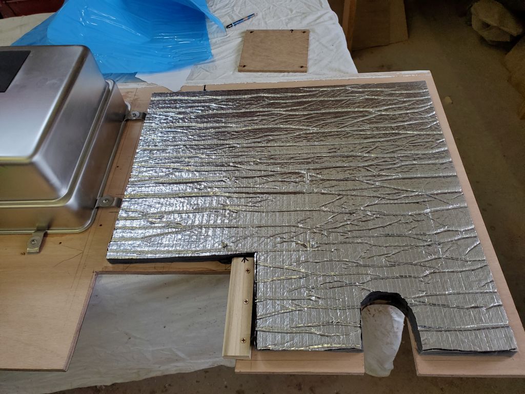
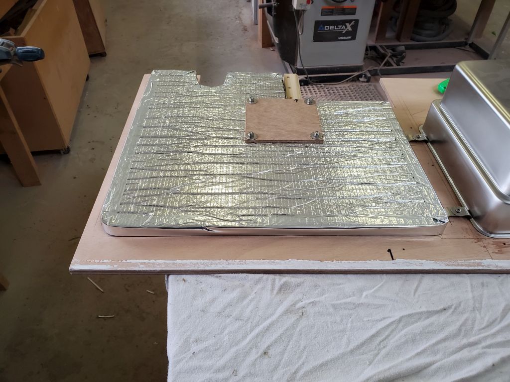
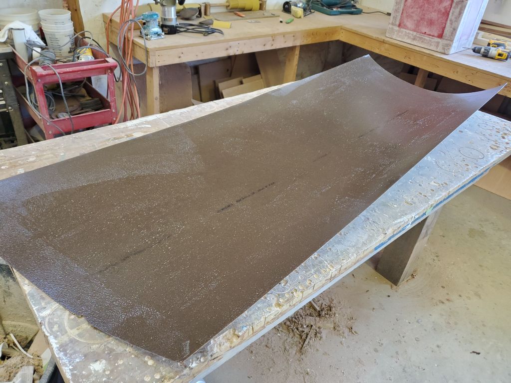
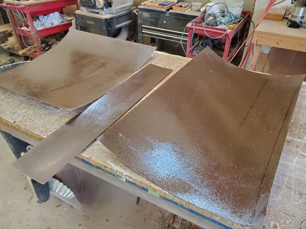
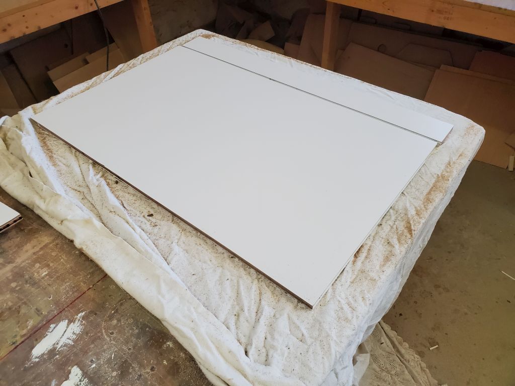
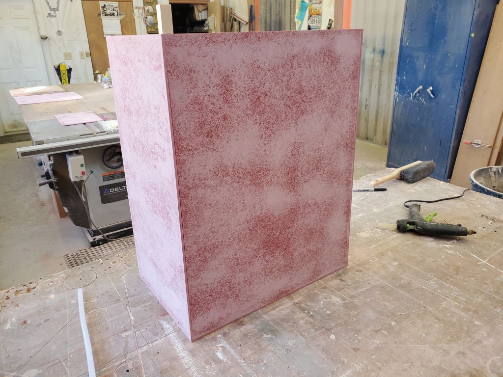
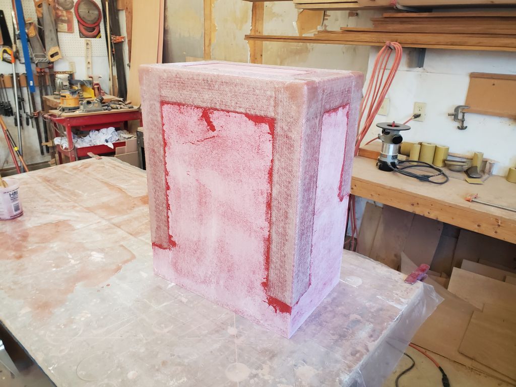
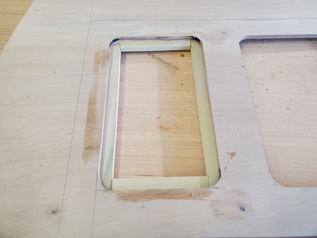
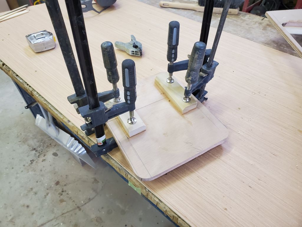
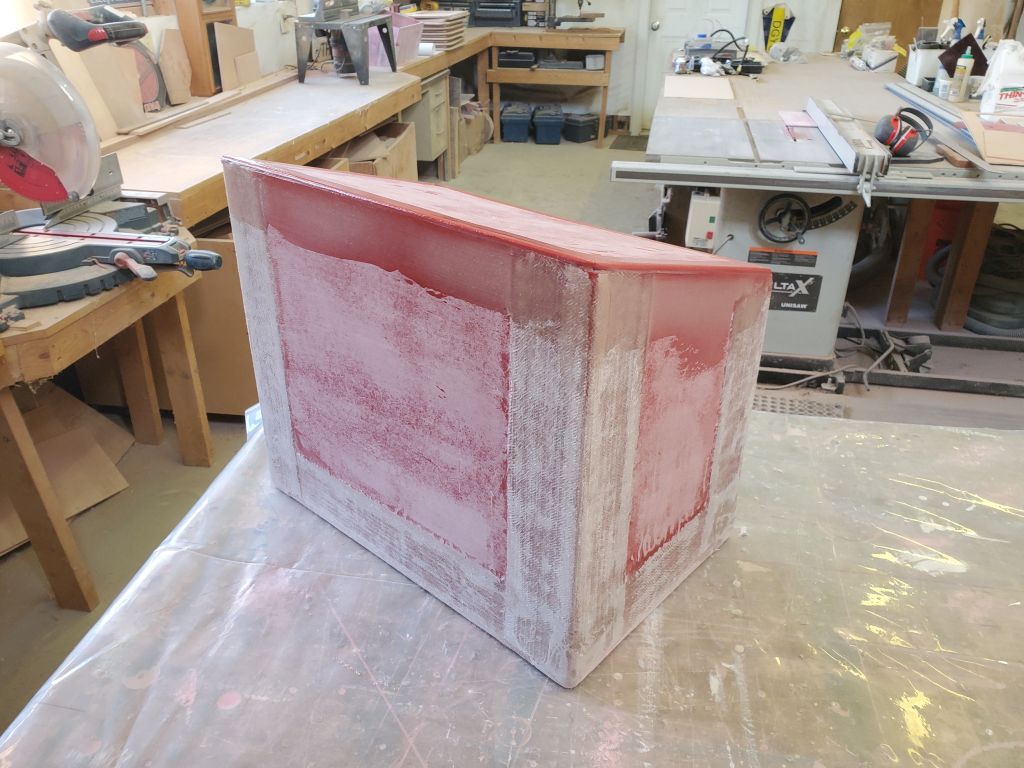
With approval of the concept, I continued work on the box, cutting a piece of fiberglass sheeting to fit (slightly oversized), and trimming it down to its final size. I secured it with some dabs of hot glue so I could ease all the corners to prepare for fiberglass, after which I applied some lightly-thickened epoxy to fill the seam and fair in the existing tabbing for a smoother fit. I left this initial application of epoxy to tack up briefly.
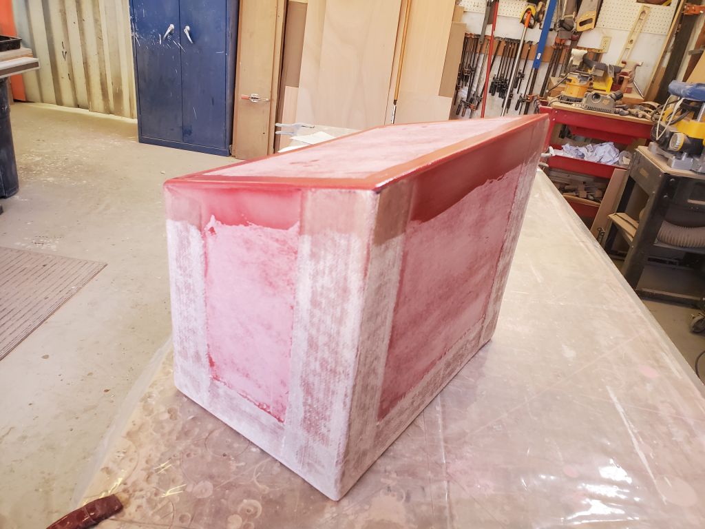
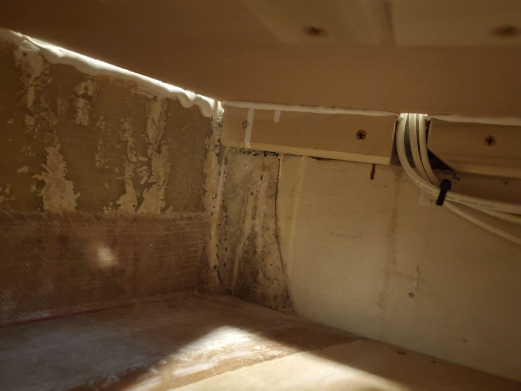
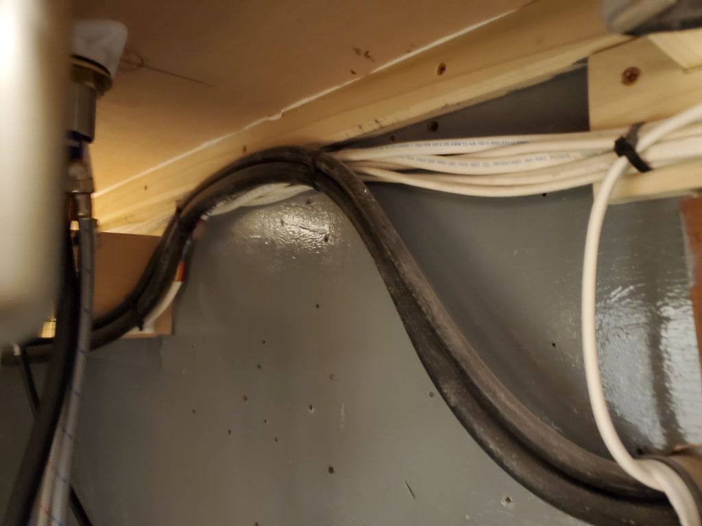
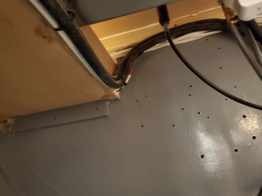
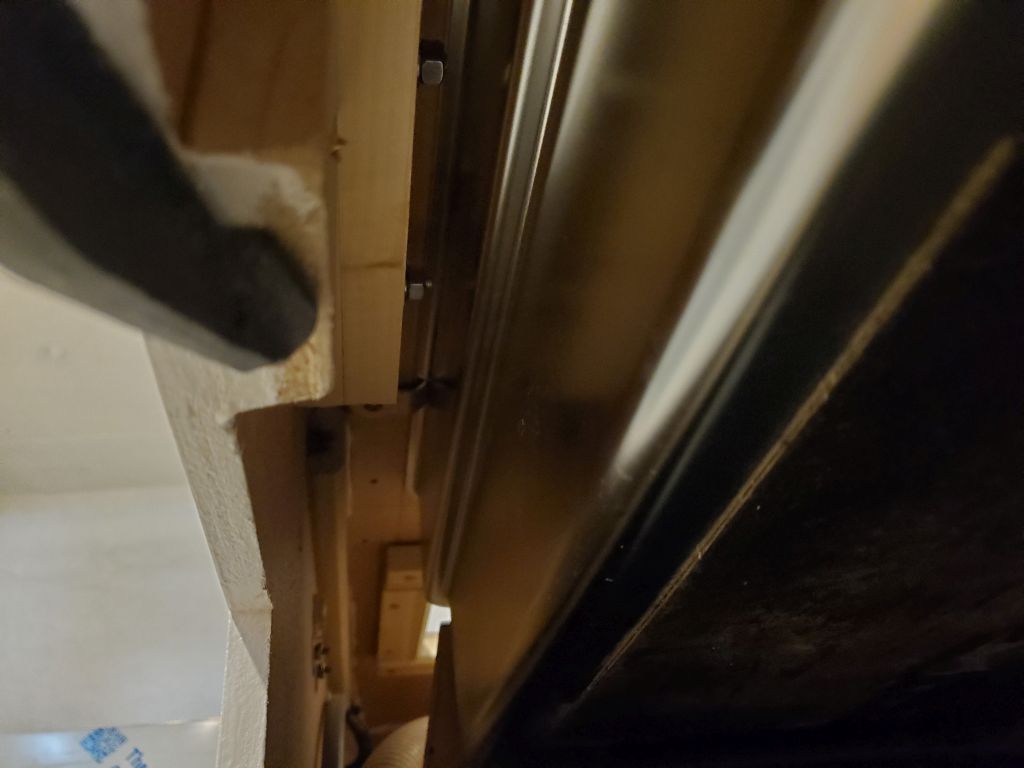
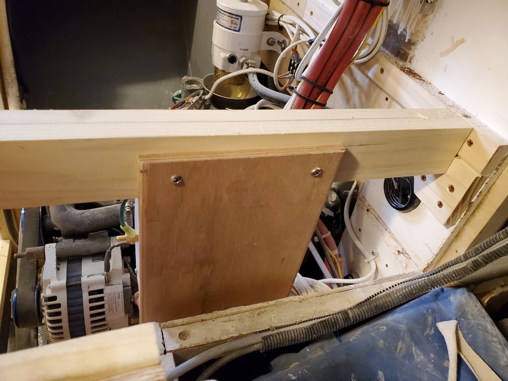
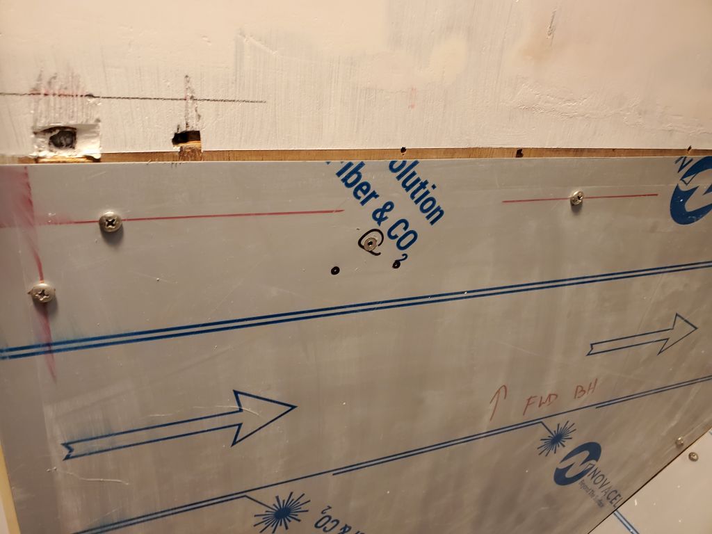
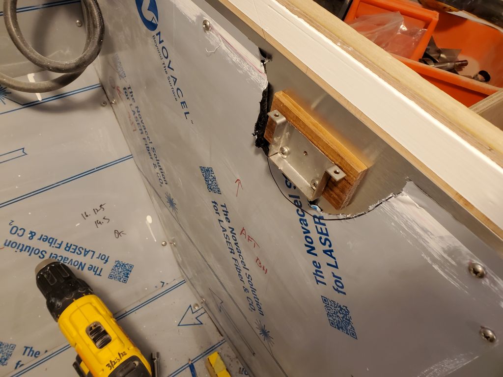
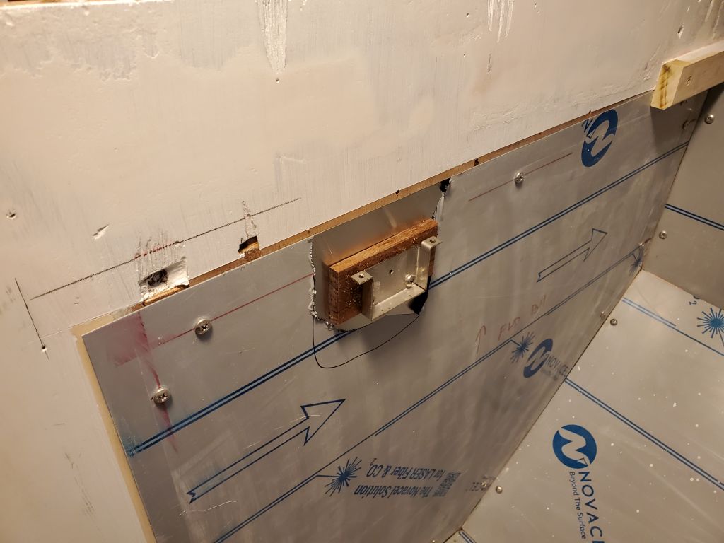
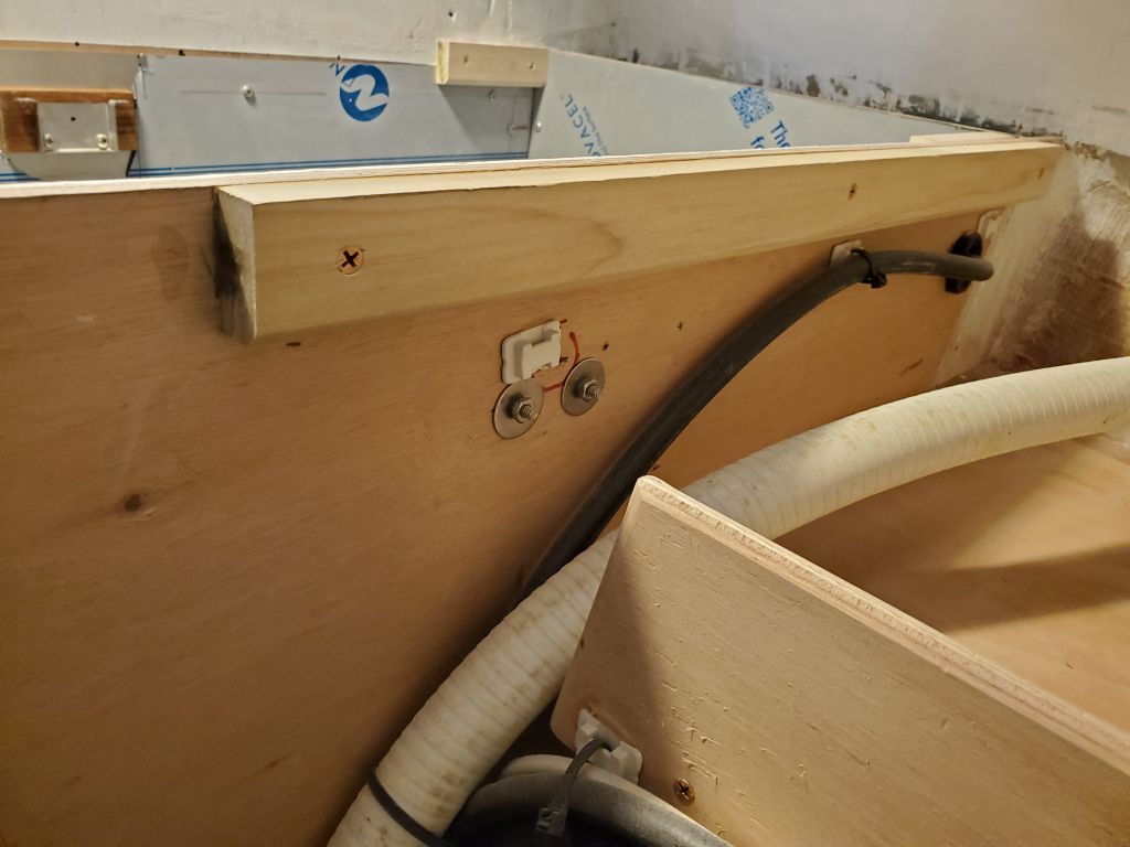
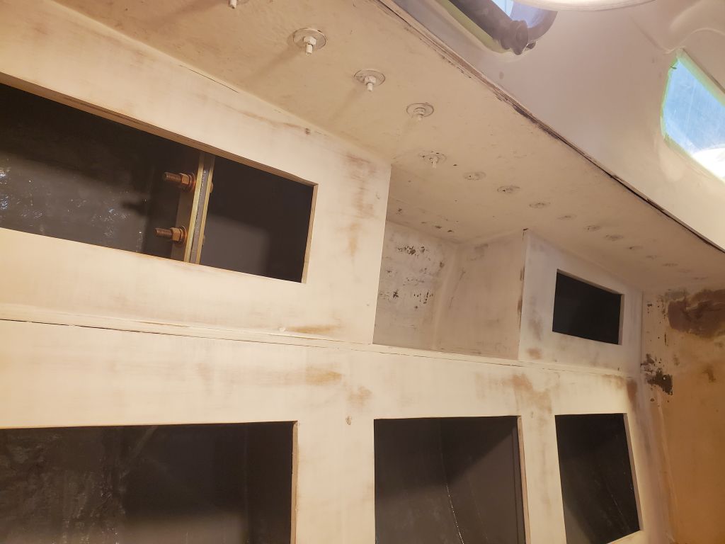
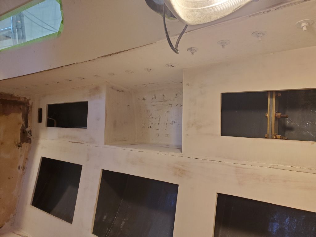
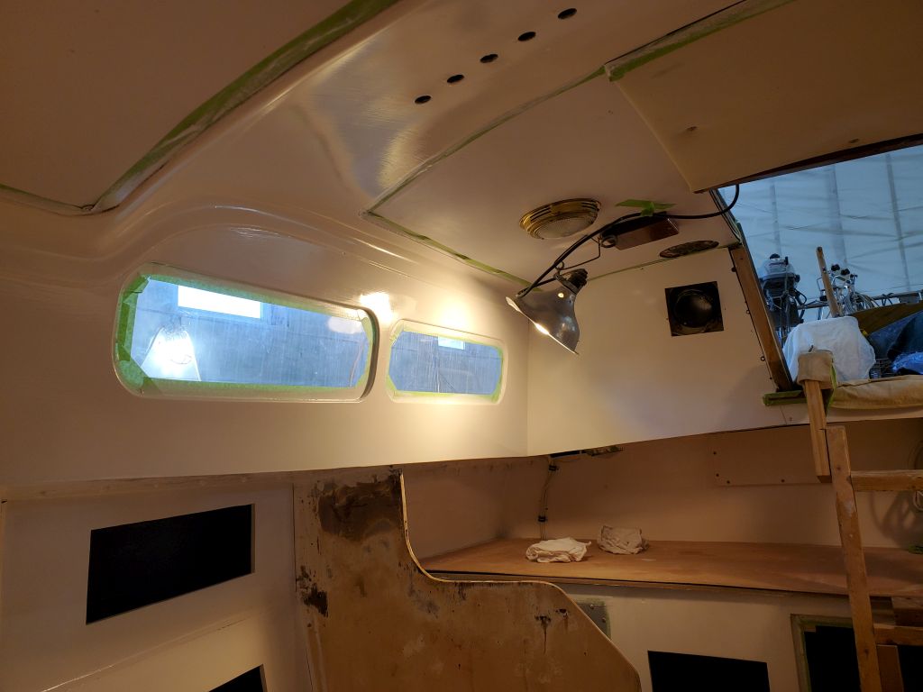
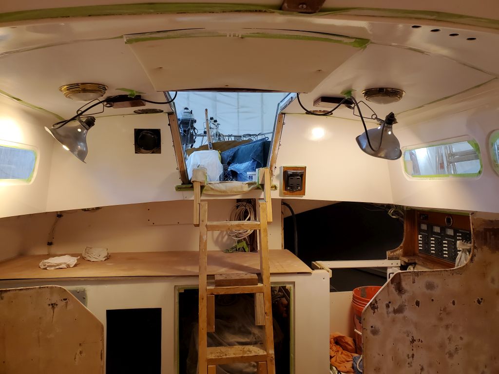
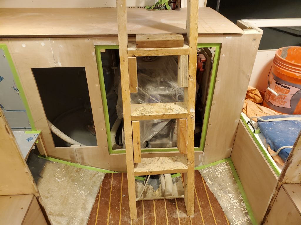
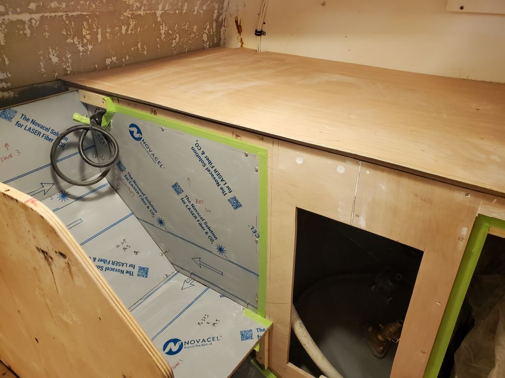
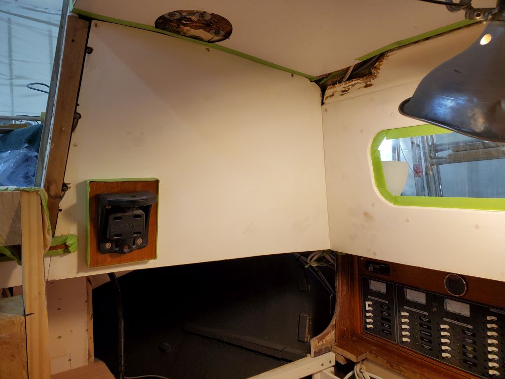
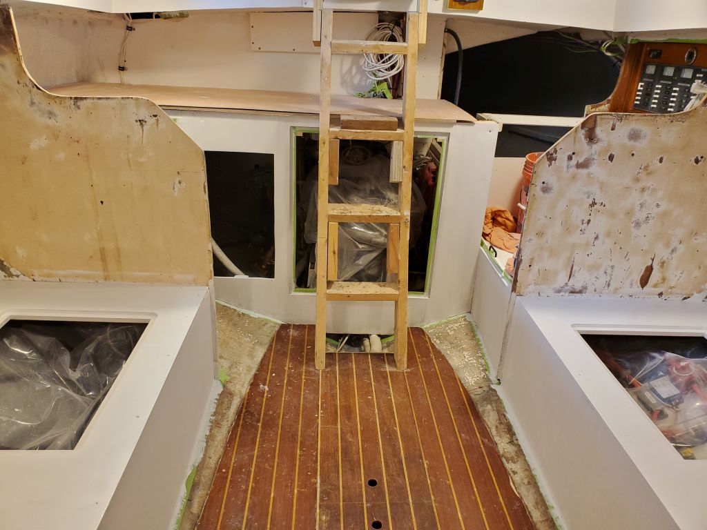
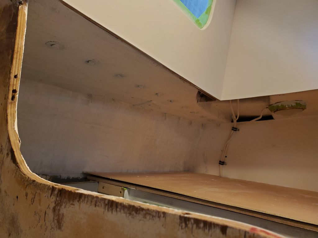
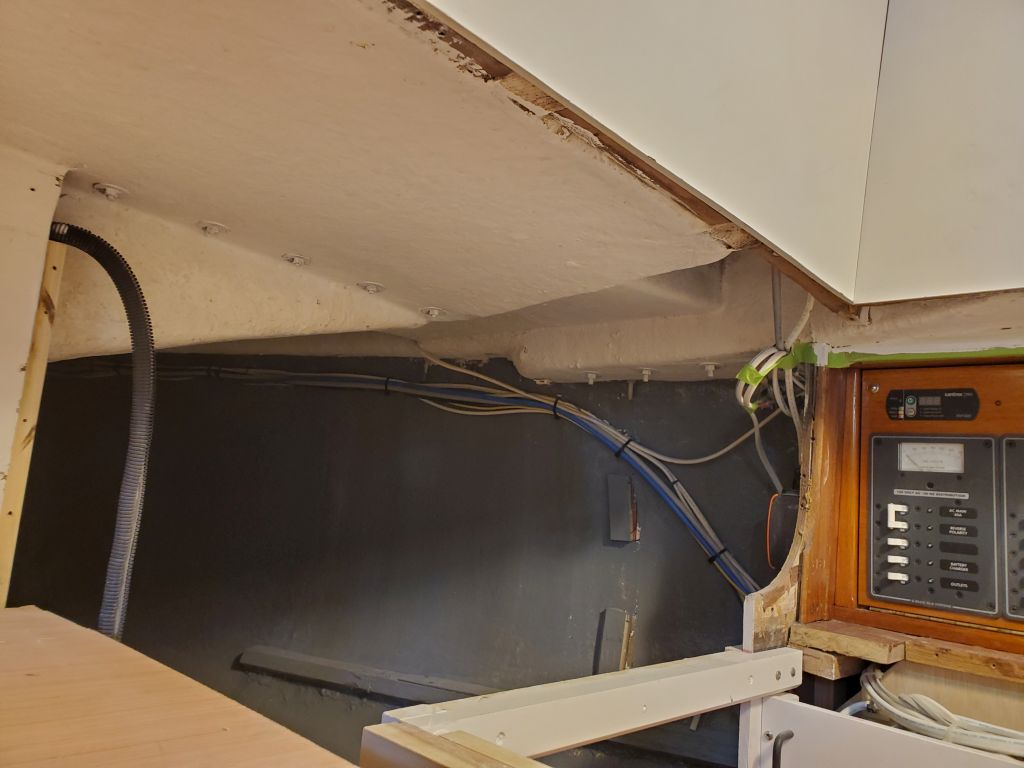
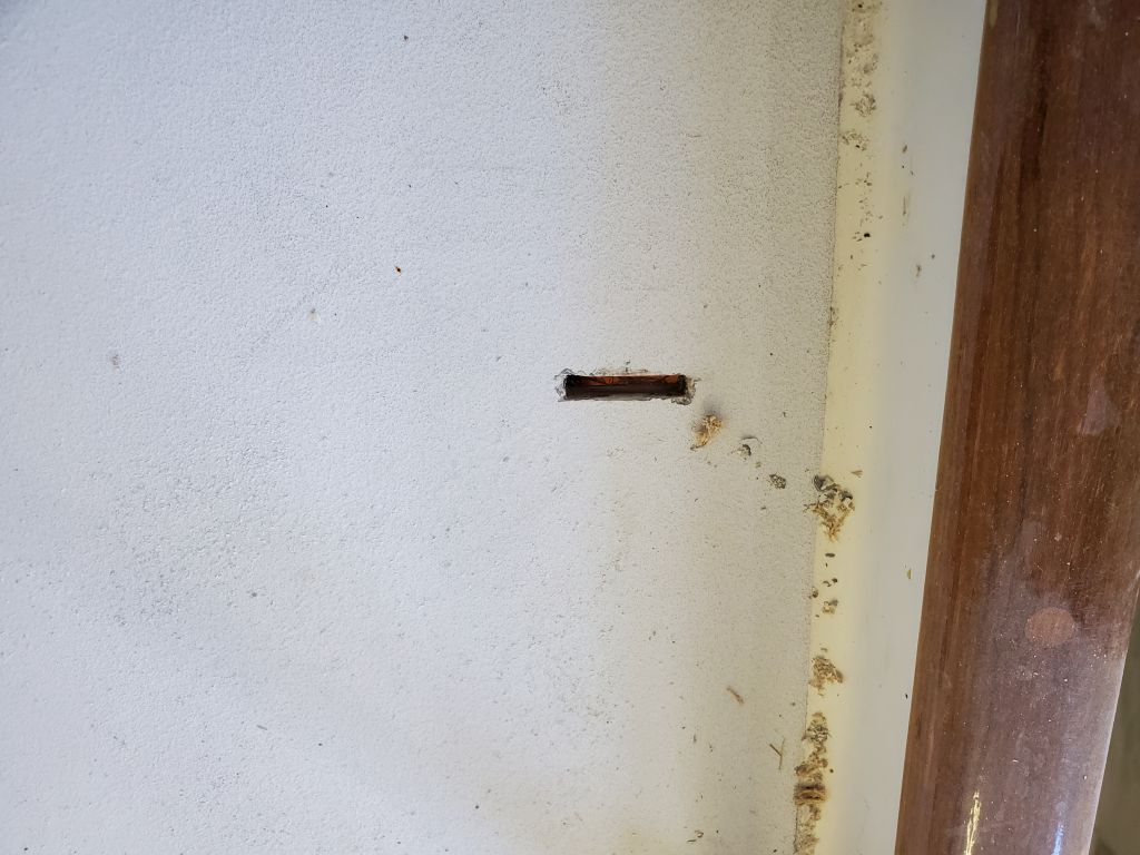
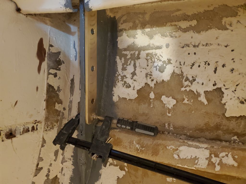
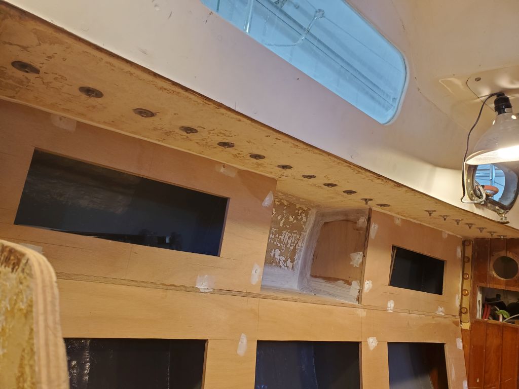
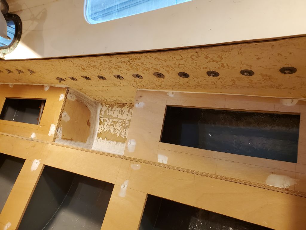
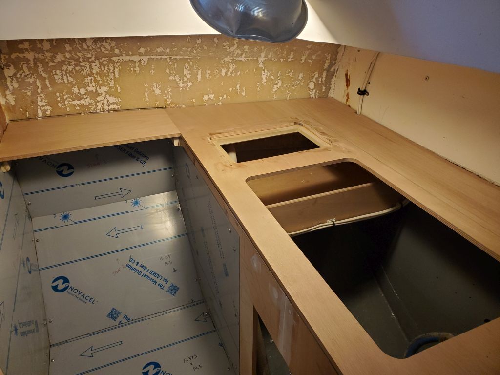
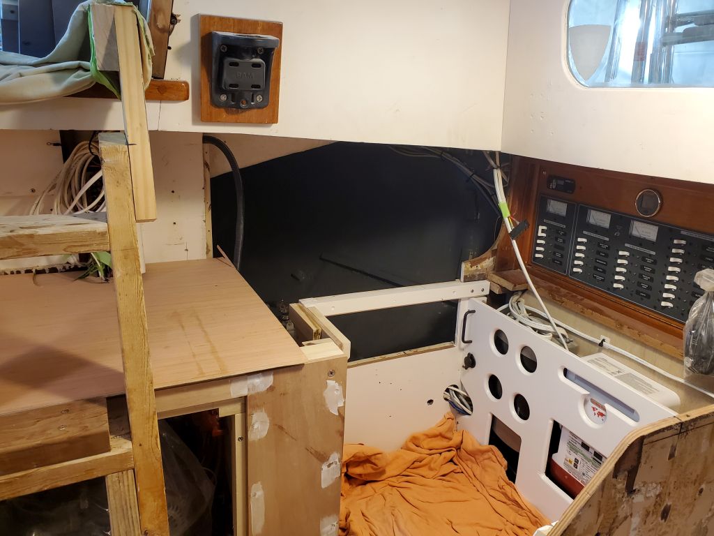
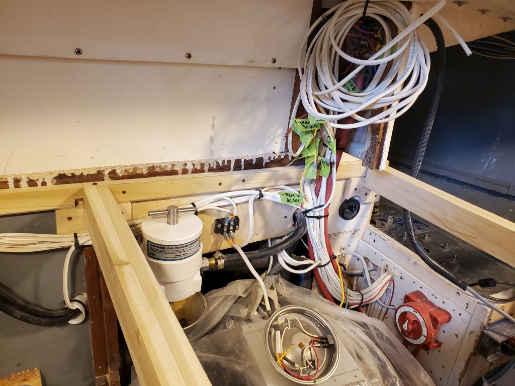
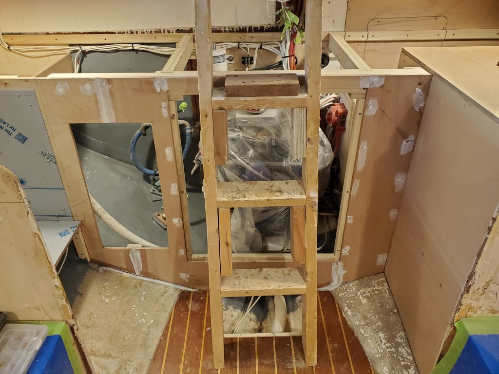
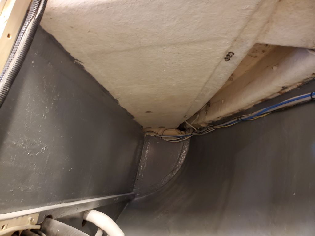
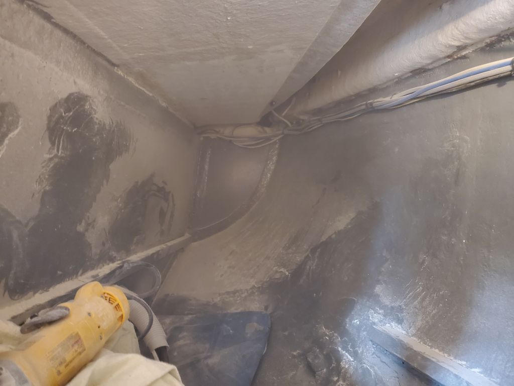
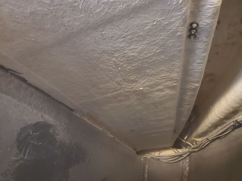
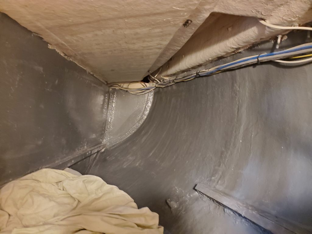
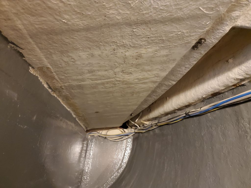
While that was underway, I prepared the underside of the cockpit seat from inside the quarterberth locker. By removing the last of the galley supports, I had reasonable access for the task, which I took care of quickly, heavily sanding the laminate to remove unevenness and any coatings. This area was gelcoated from the factory, so I didn’t have to remove all traces. Later, I went back and cleaned up the sanding debris.
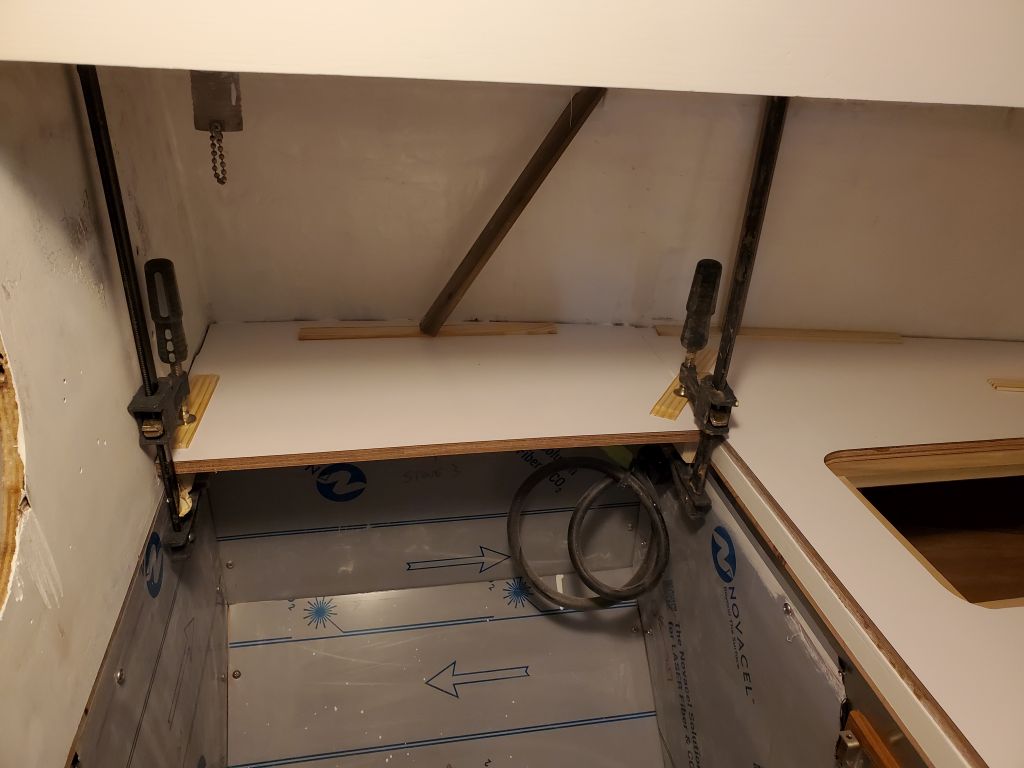
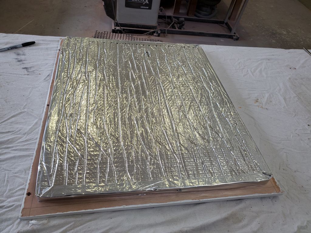
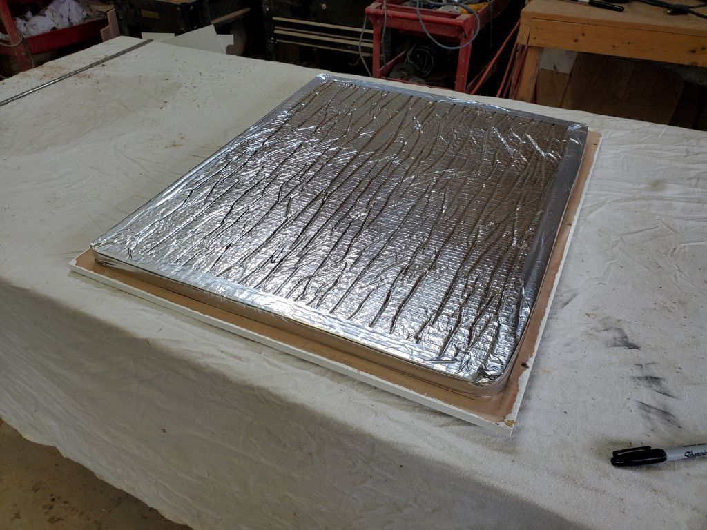
In between, I went back to the shop and installed tabbing over all the seams to secure the new propane box top in place all around, and make it vapor-and water-tight. I installed fiberglass in the center portion of the top as well, so that the finished top would be smooth and even for good bonding when the time came. I’d cut the hatch opening later.