< Back to Nomad
Saturday
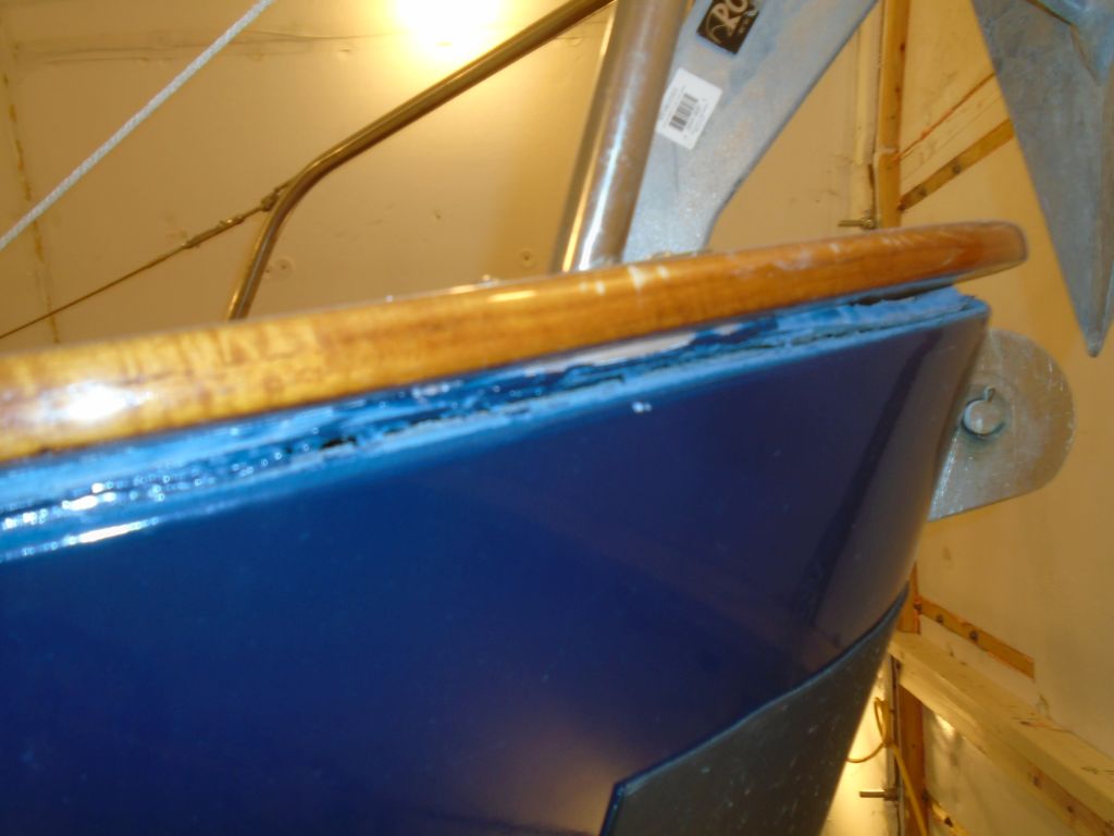
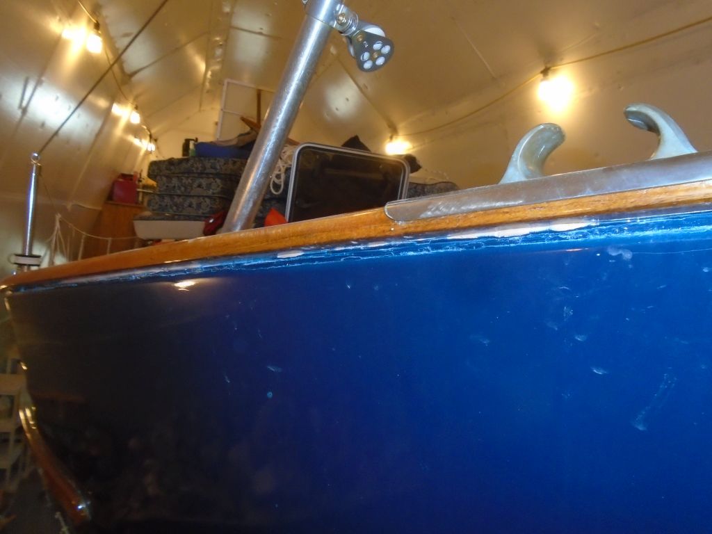
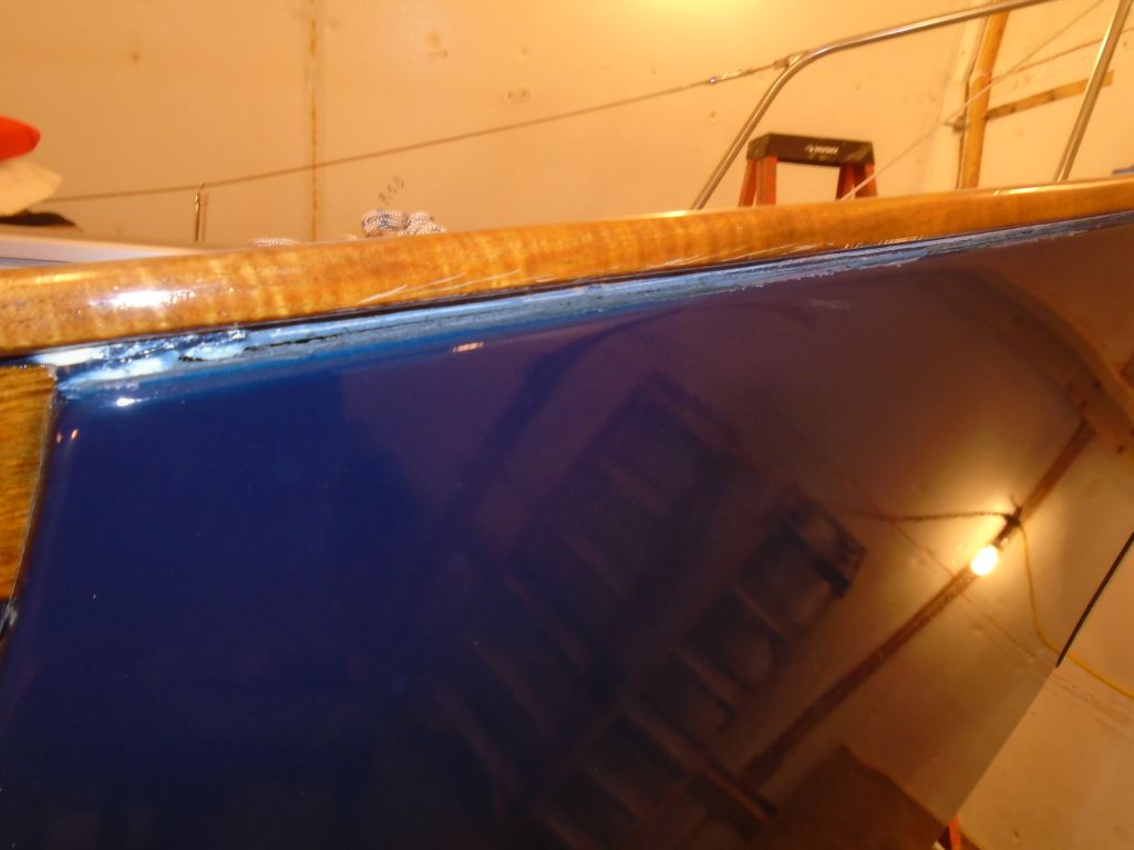
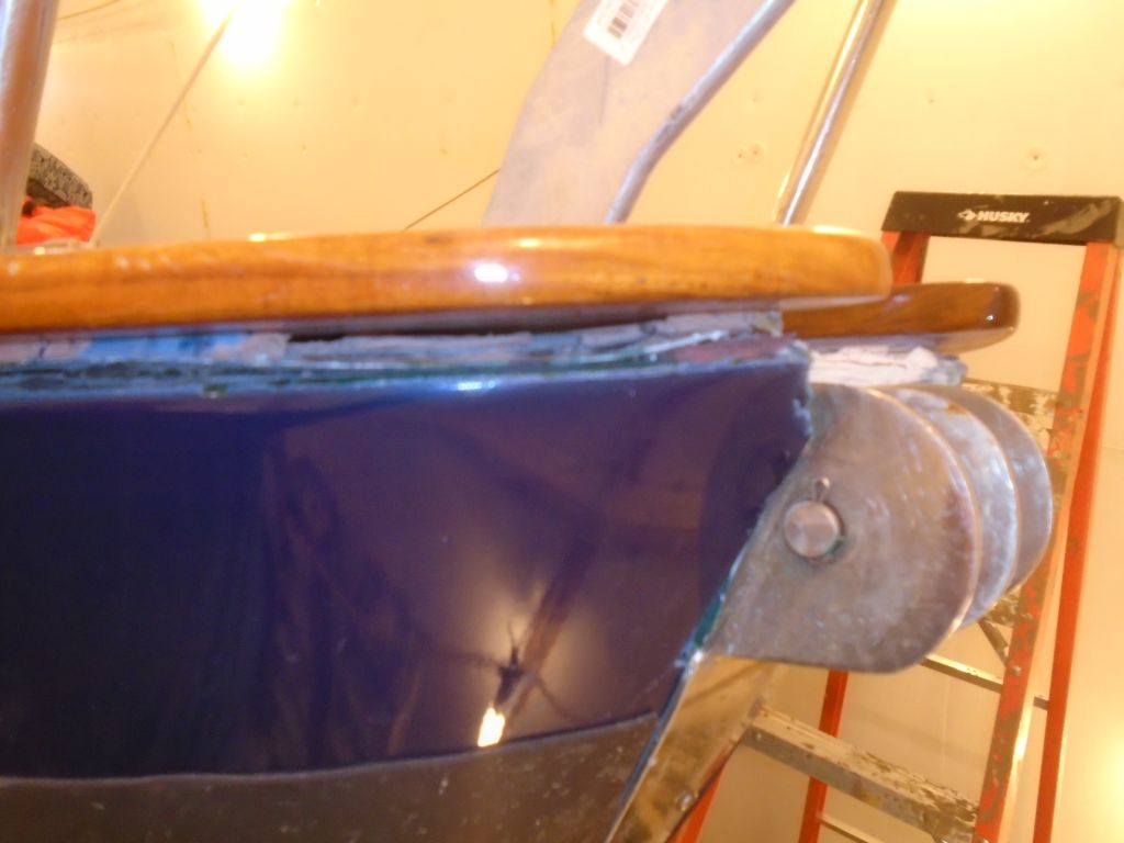
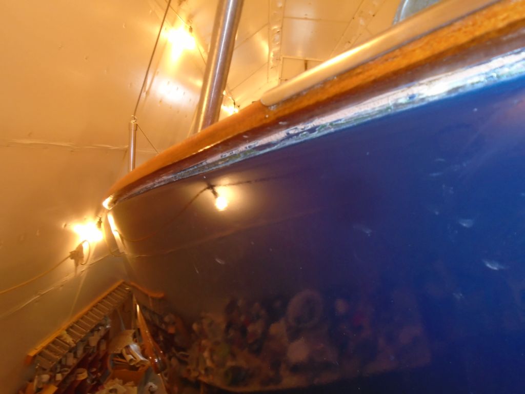
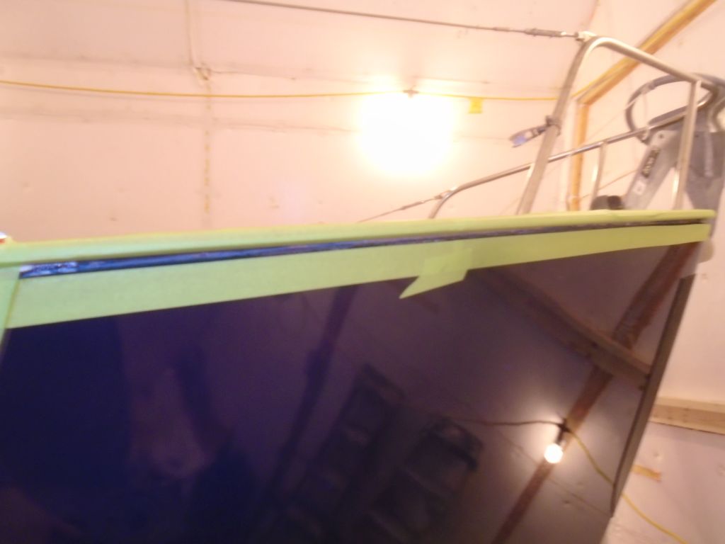
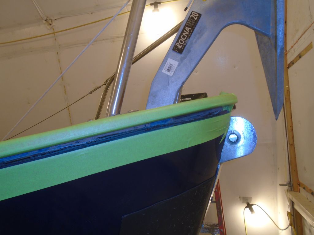
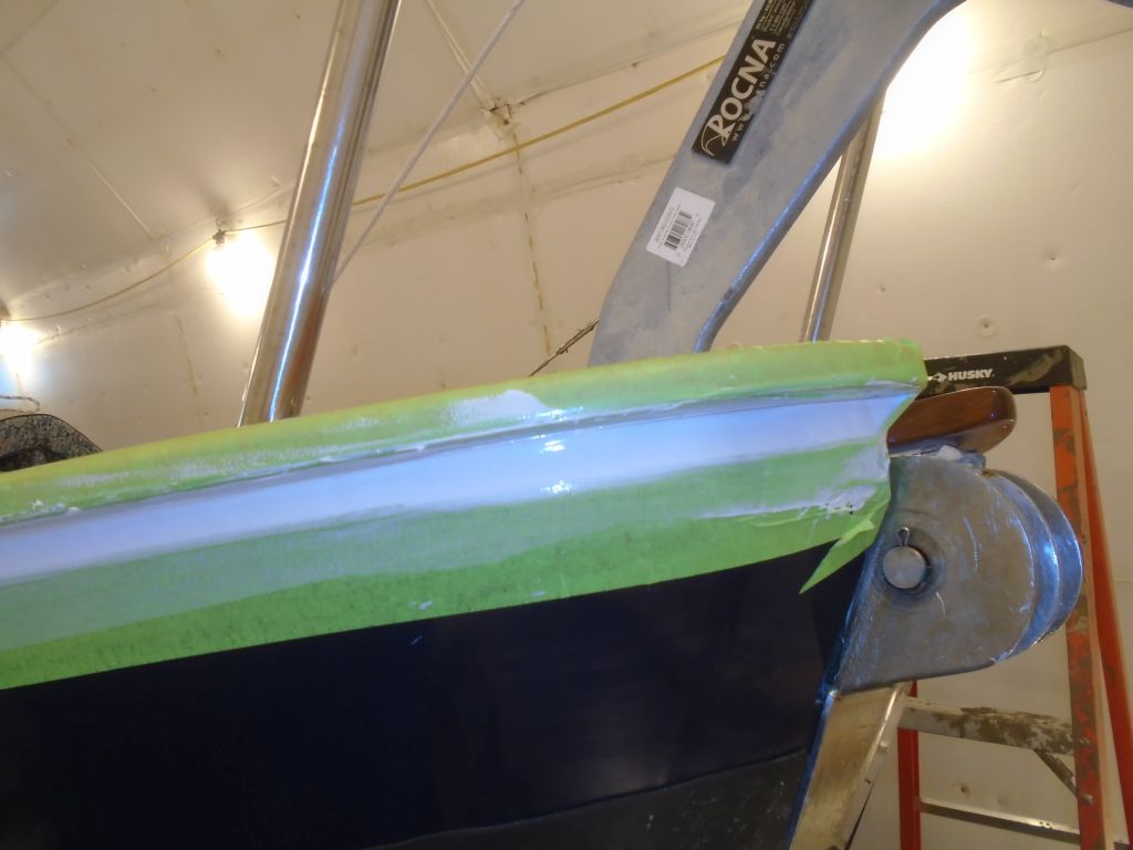
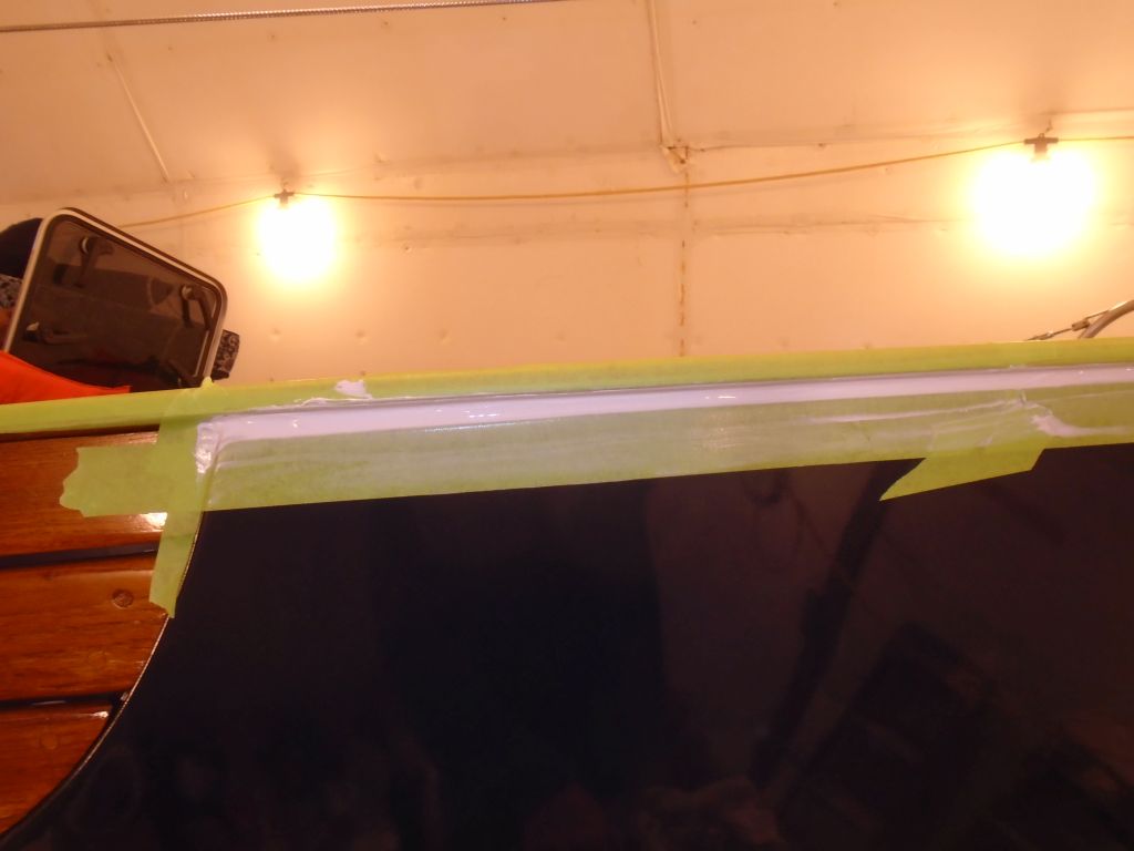
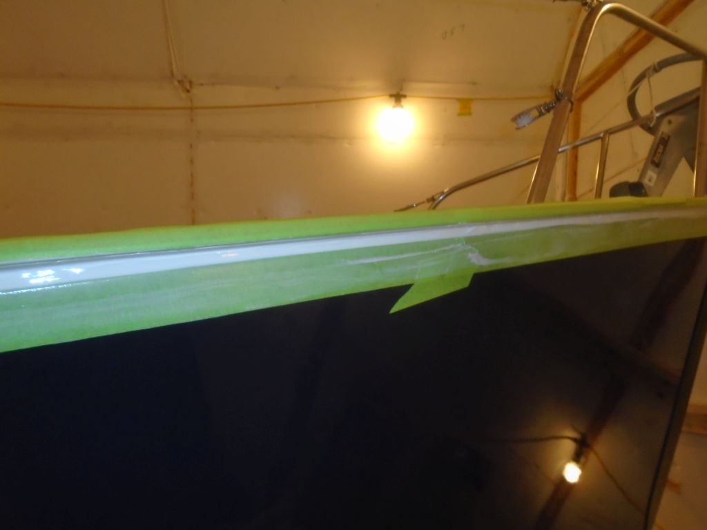
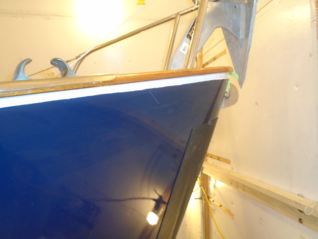
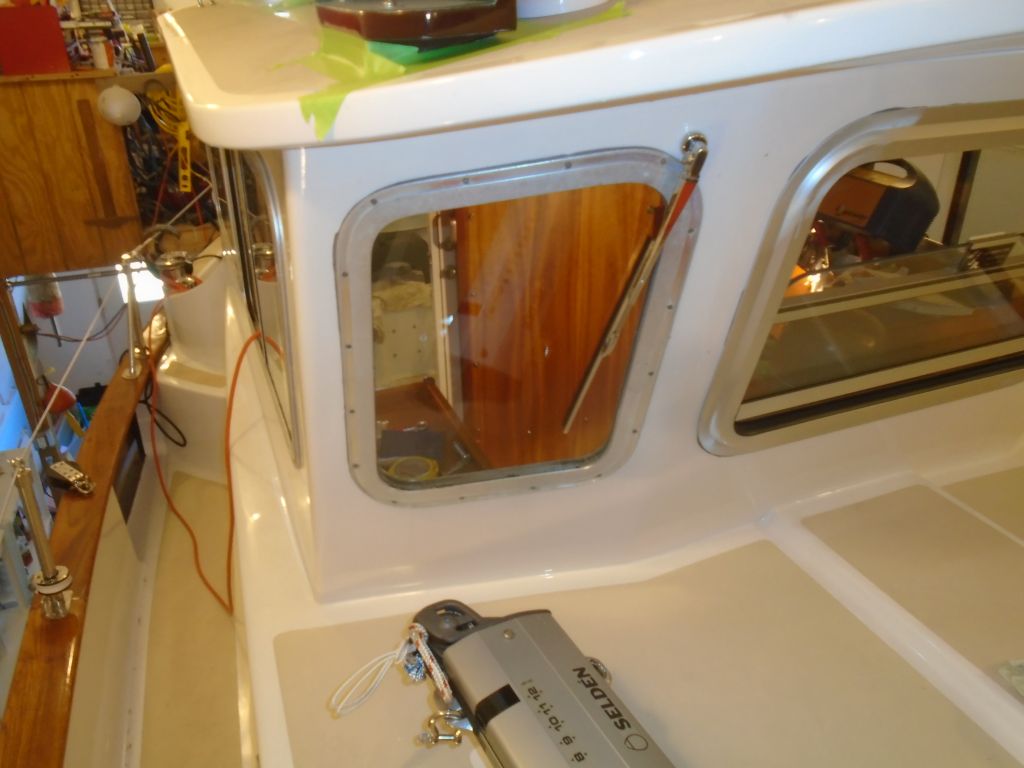
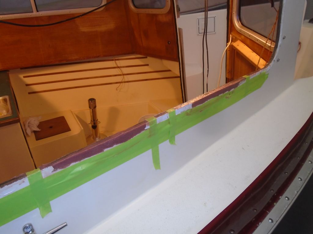
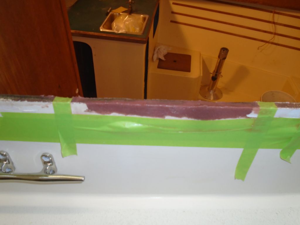
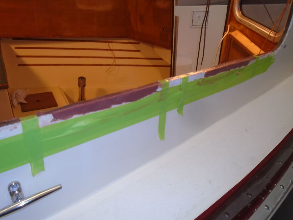
To repair the small sections where removing the starboard pilothouse window had damaged the core and outer skin of the superstructure, I prepared the area by cleaning away any debris or old sealant, then masking off below the damaged area and the outline of the window frame to ensure that the repair stayed within the footprint of the window as much as possible, which would minimize any cosmetic concerns. Then, I installed very thick epoxy putty to rebuild the original shape and replace the foam core that had come out with the window. There was no particular structural aspect nor requirement to this repair, though where the outer skin had separated from the core within I made sure to force some epoxy into the gap with a small brush to help resecure the whole structure together. To hold things while the epoxy cured, I added some high-tech clamps made of masking tape, which basically pressed the outer skin back into place against the core and new epoxy. The epoxy was thick enough to hold its shape, and I formed it into the square-edged shape required for the opening.
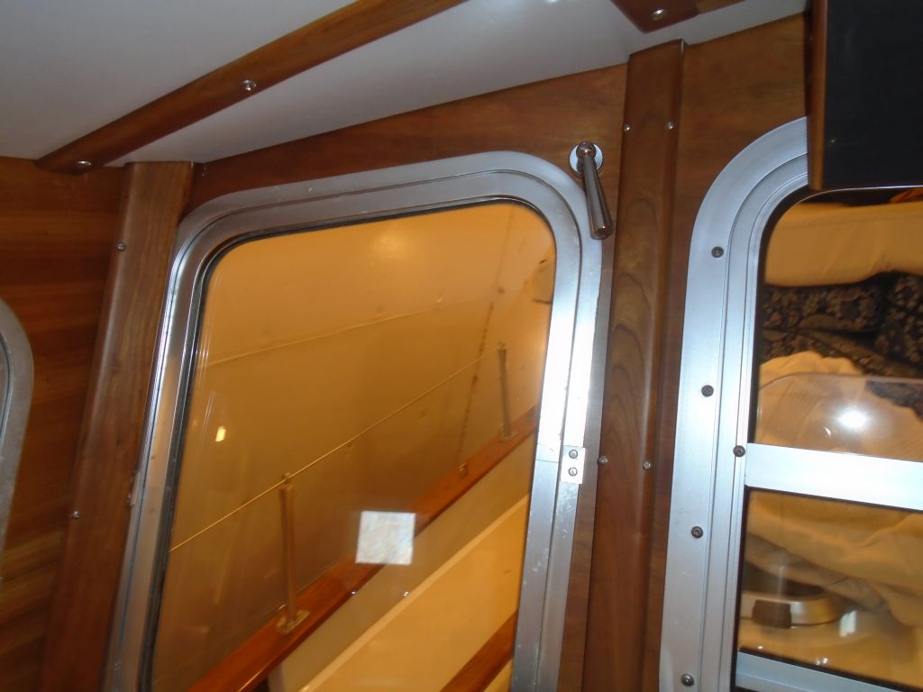
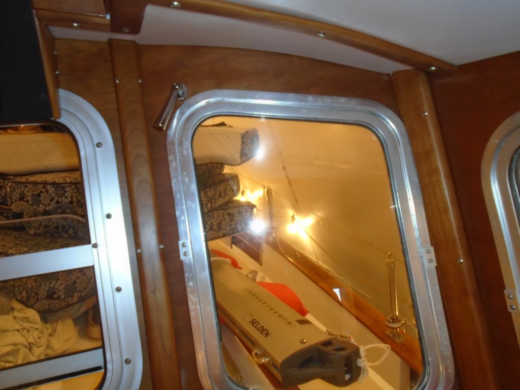
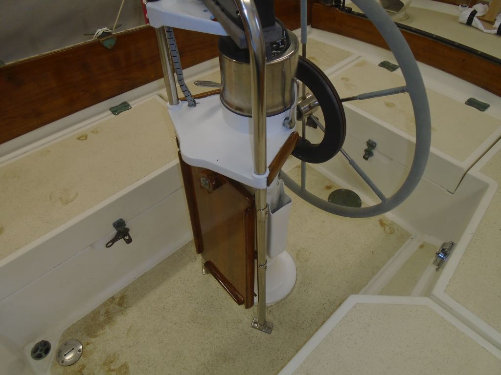
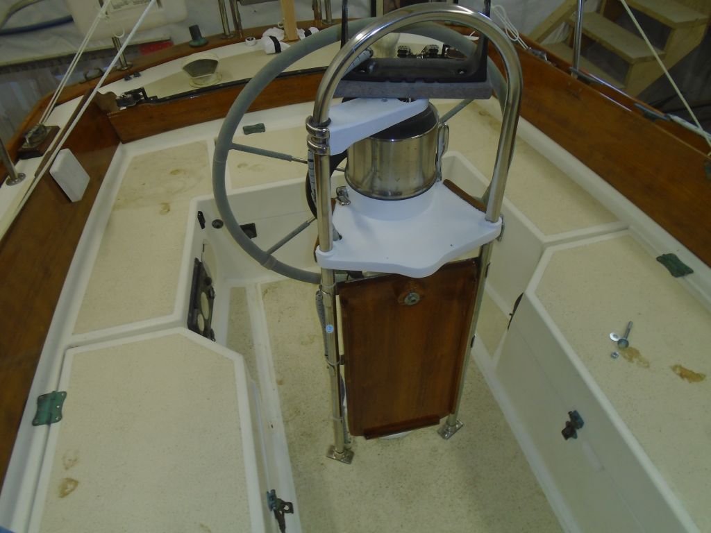
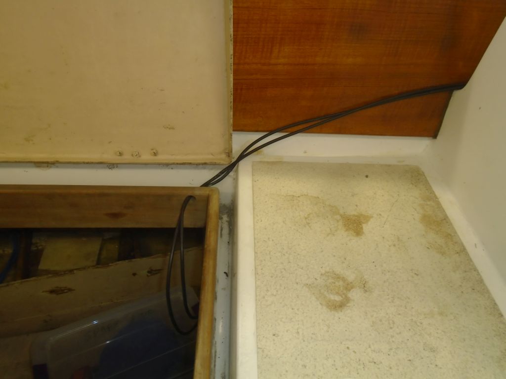
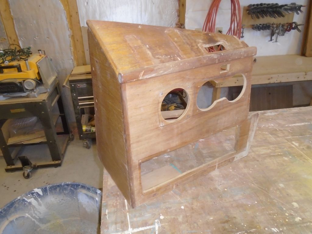
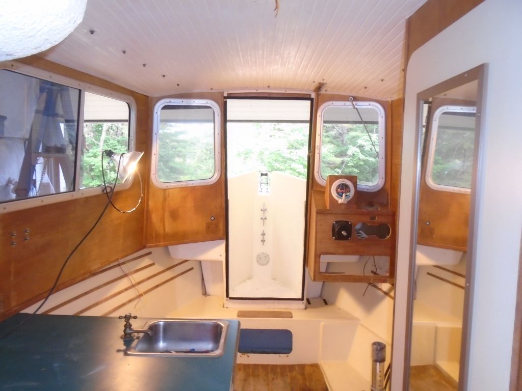
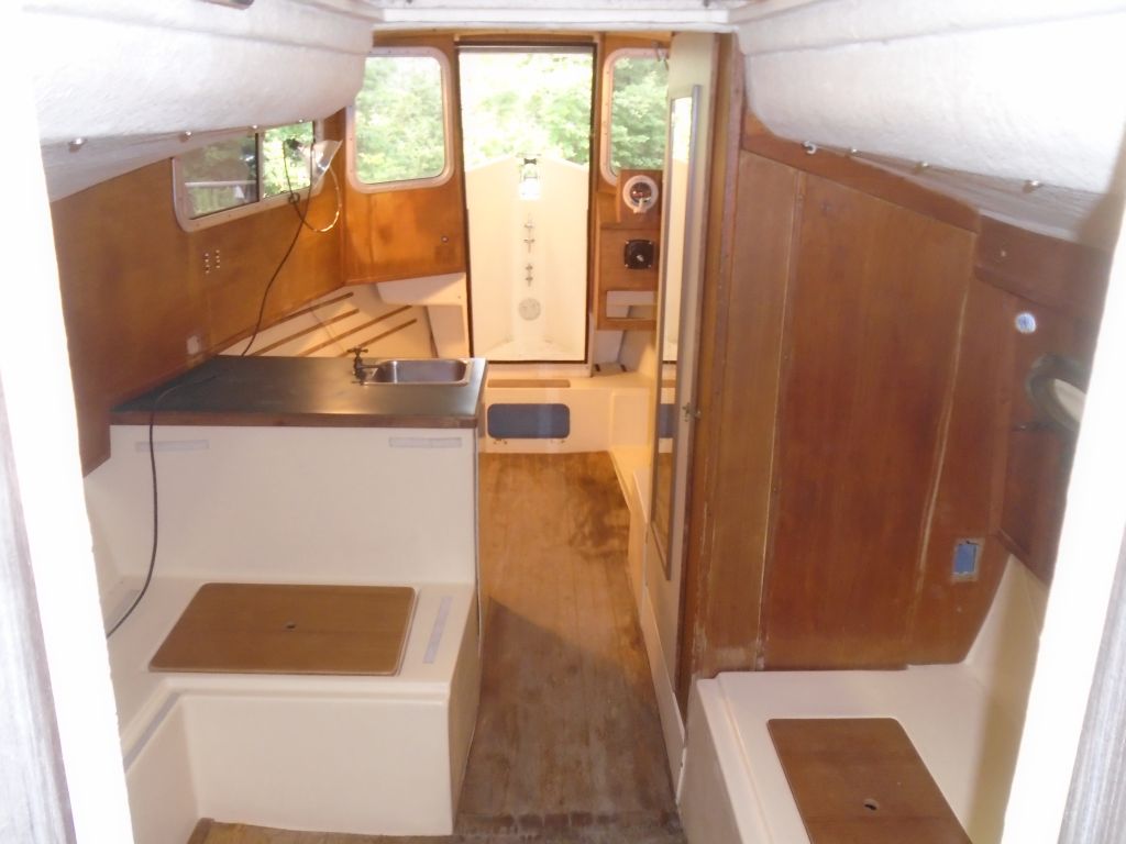
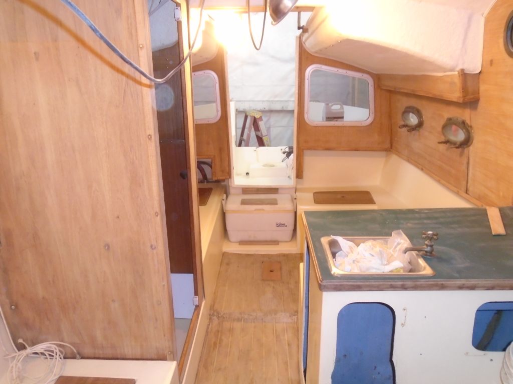
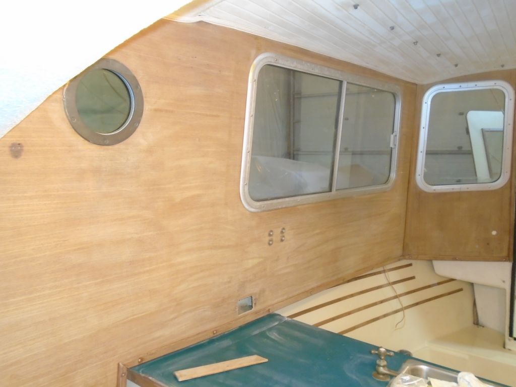
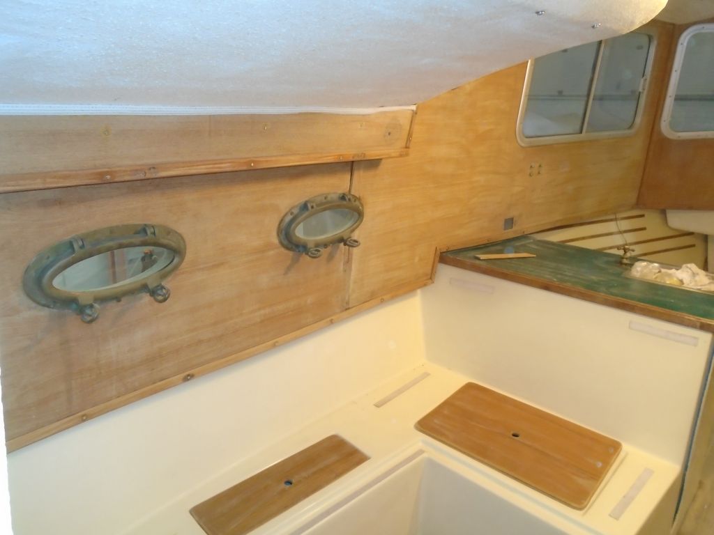
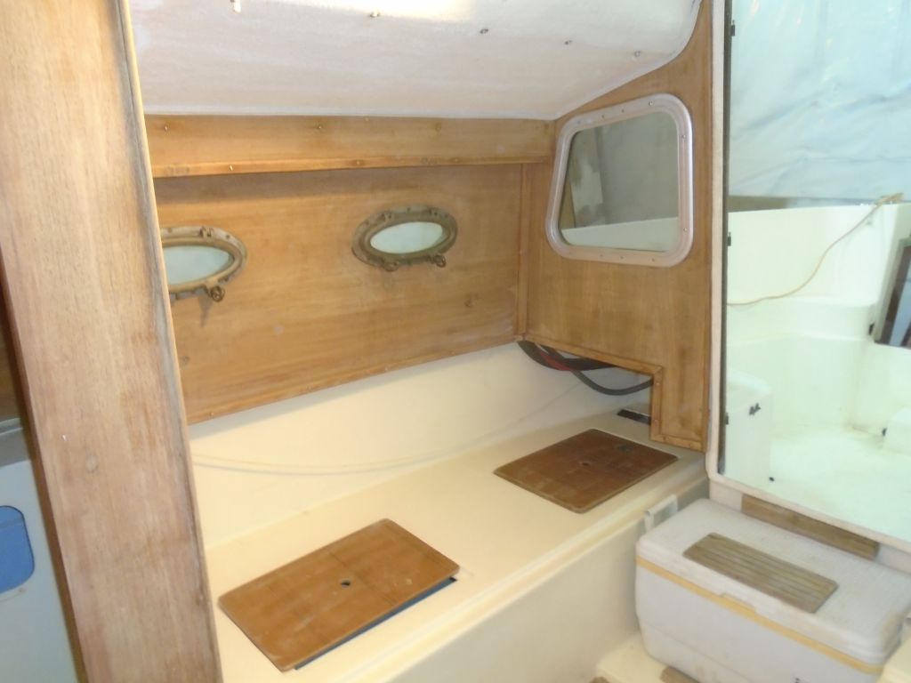
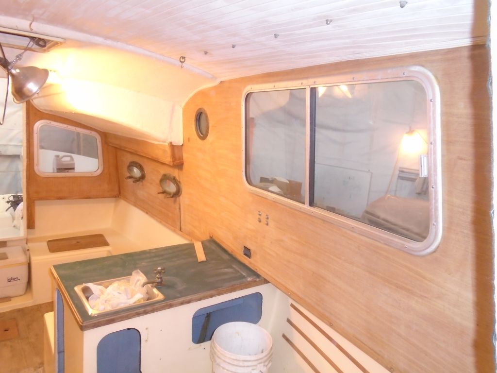
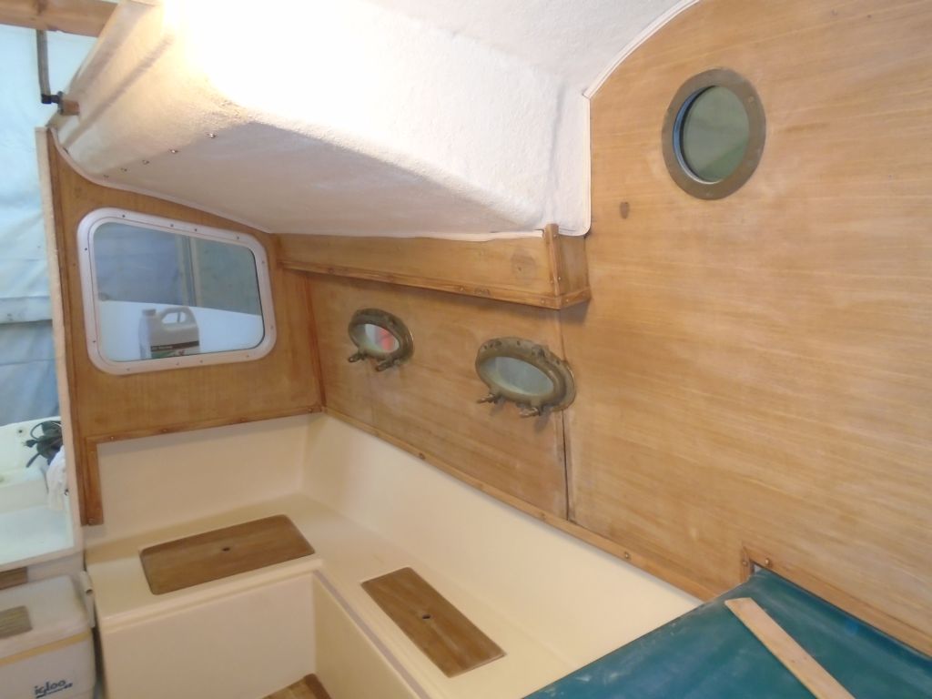
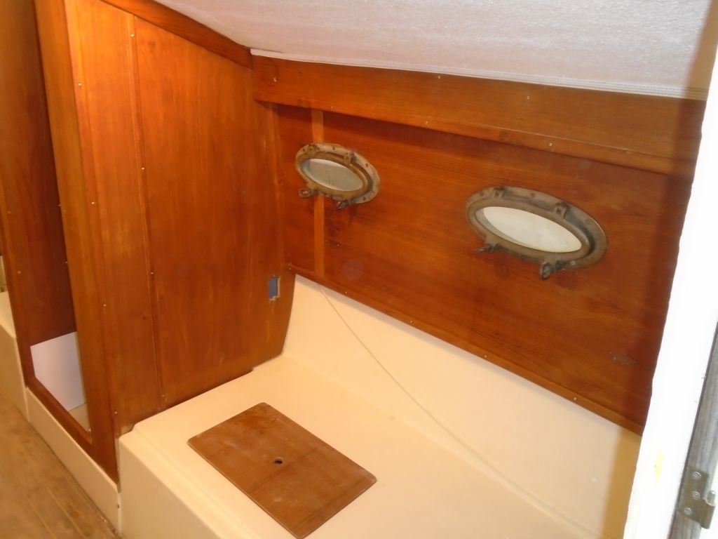
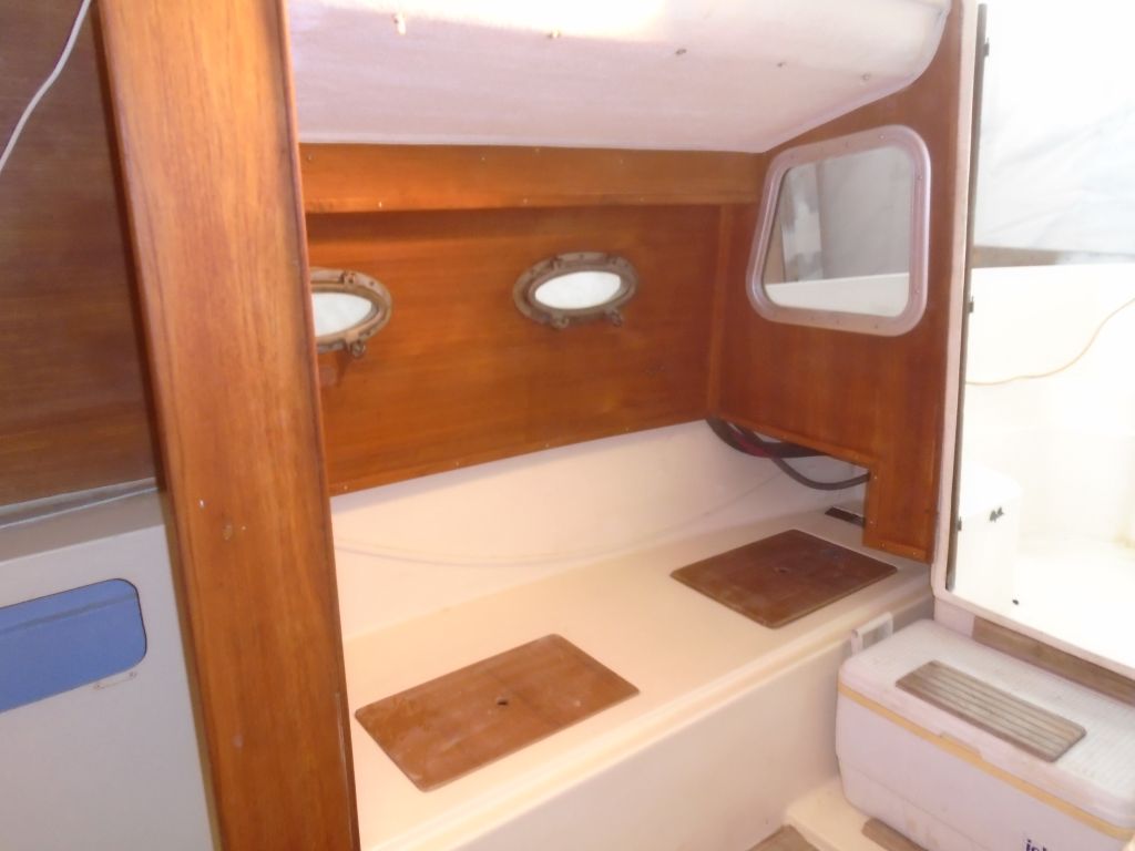
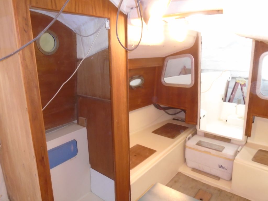
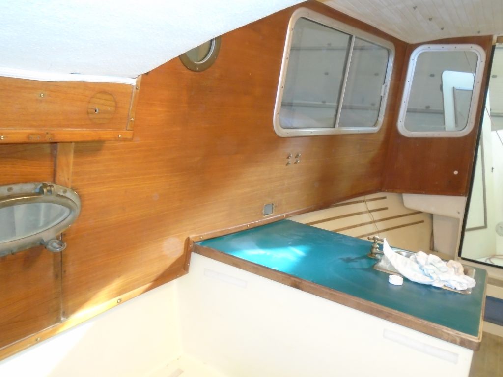
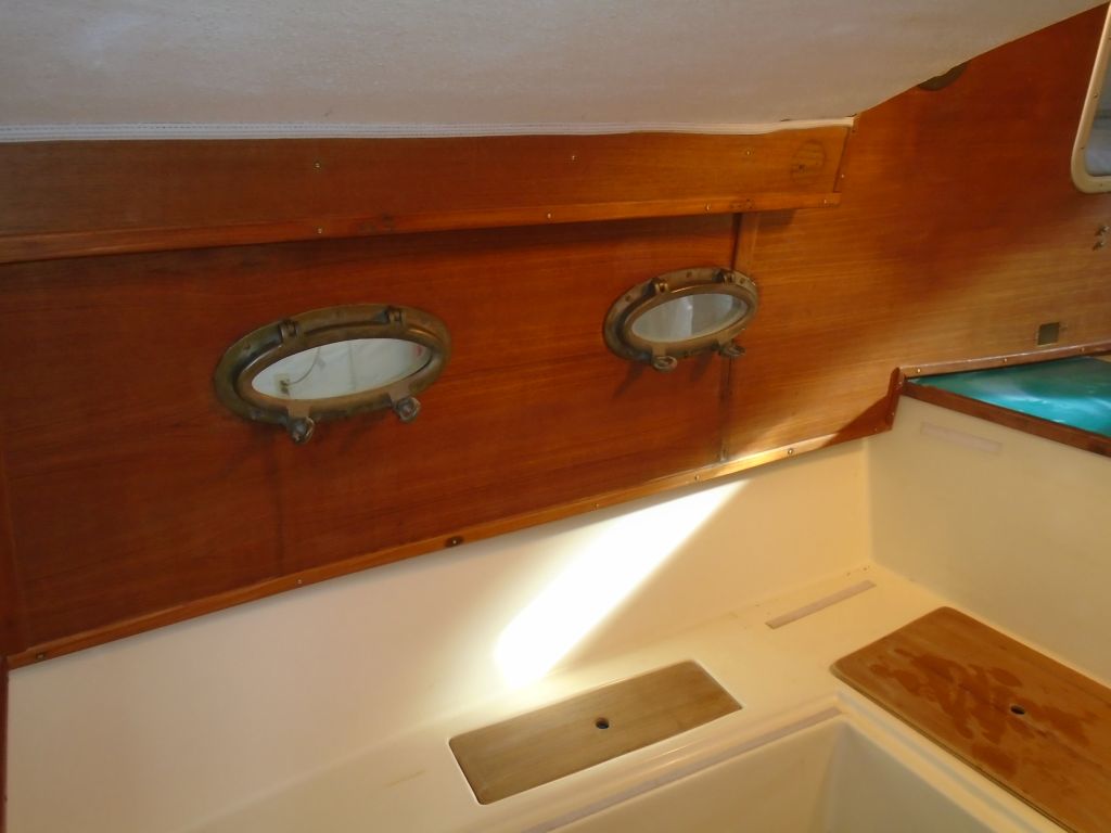
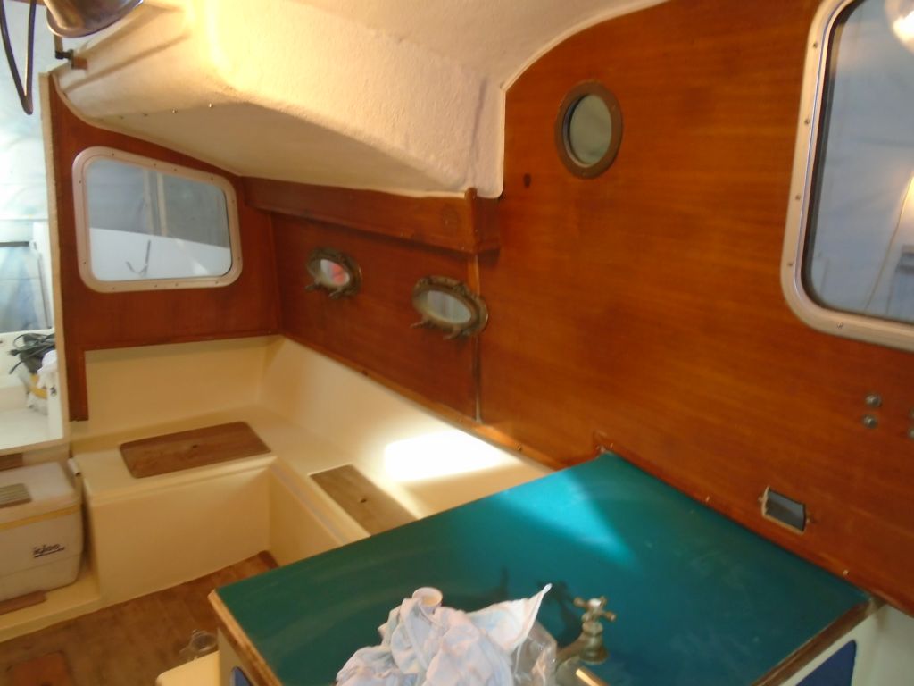
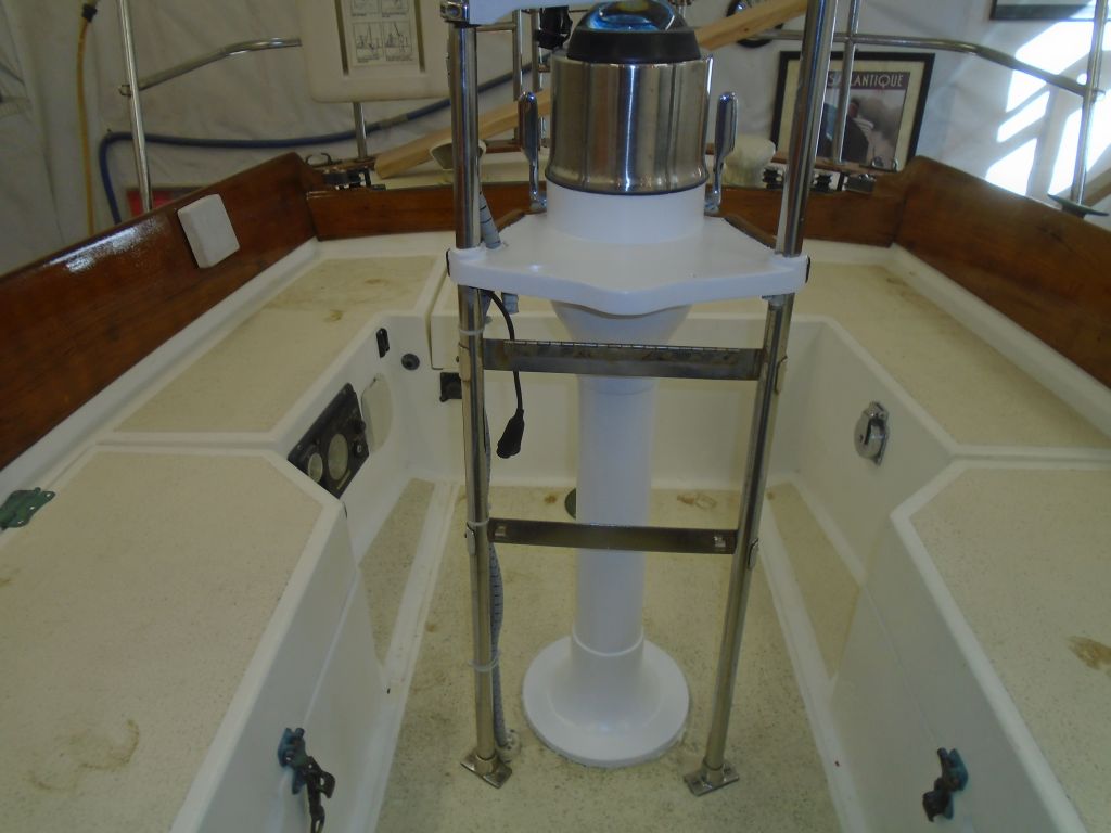
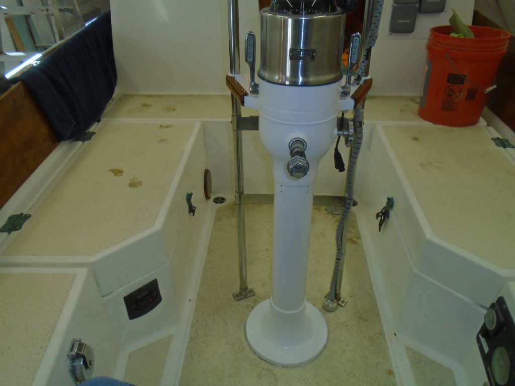
Inside the cabin, I set up tools and breathing equipment, and attacked the interior woodwork and paneling. Restoring the appearance of the interior would go a long way to returning the boat to the cosmetic condition I hoped for. The plywood paneling (1/4″ teak plywood) and various solid teak trim pieces were in sound condition overall (other than the panel that I’d removed earlier), and an earlier test had shown that the surfaces could be brought back successfully. However, the overall nature of the interior construction was pure production line (Larry Pardey might have called it “cheap and cheerful”), and I had to come to terms early on with the wiggly paneling and barely-tacked-in-place trim pieces along the edges and seams, lest I find myself ripping everything out to start fresh. The reality was that the paneling basically looked fine, and would suit my requirements going forward, and while I might have liked (on some level) to start over and do it my way, I’d already done enough of that and at this point in time such a project scope was not of interest nor desire nor need.
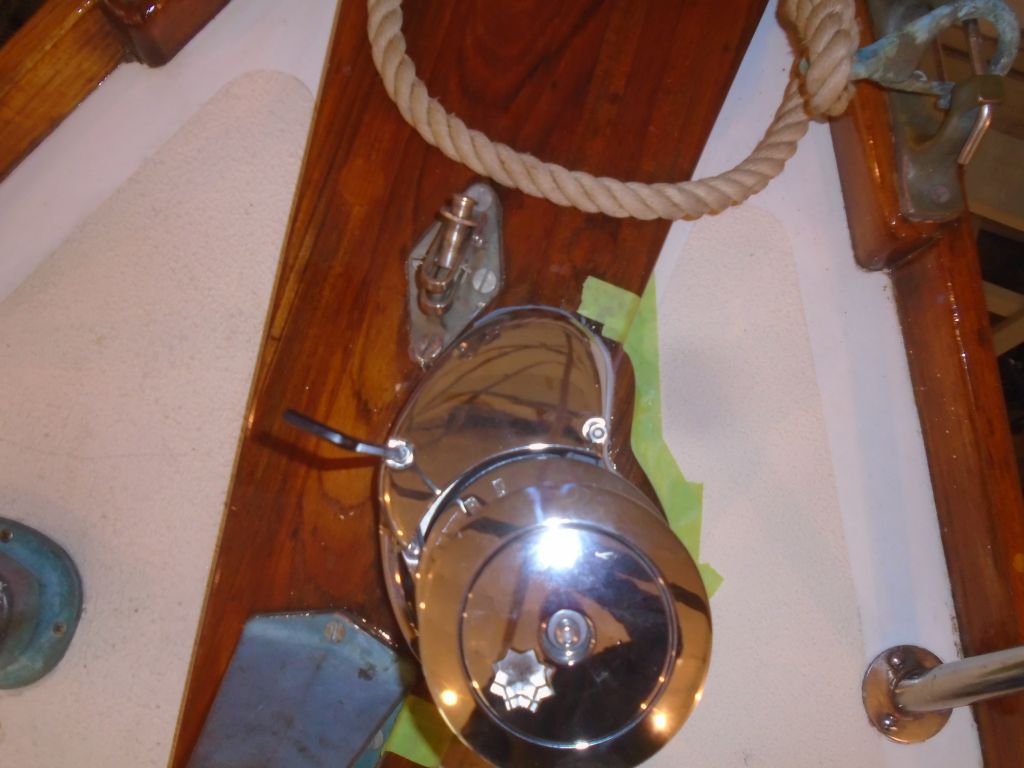
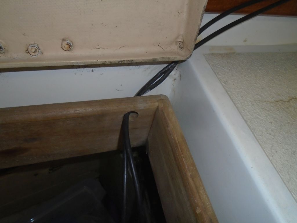
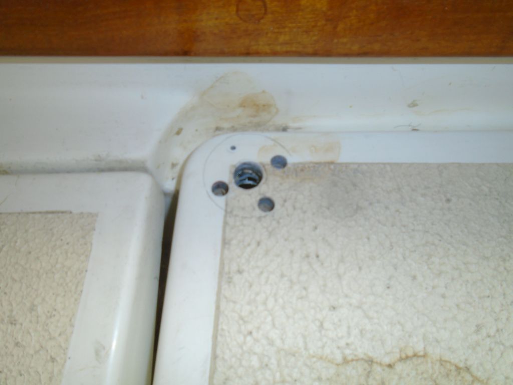
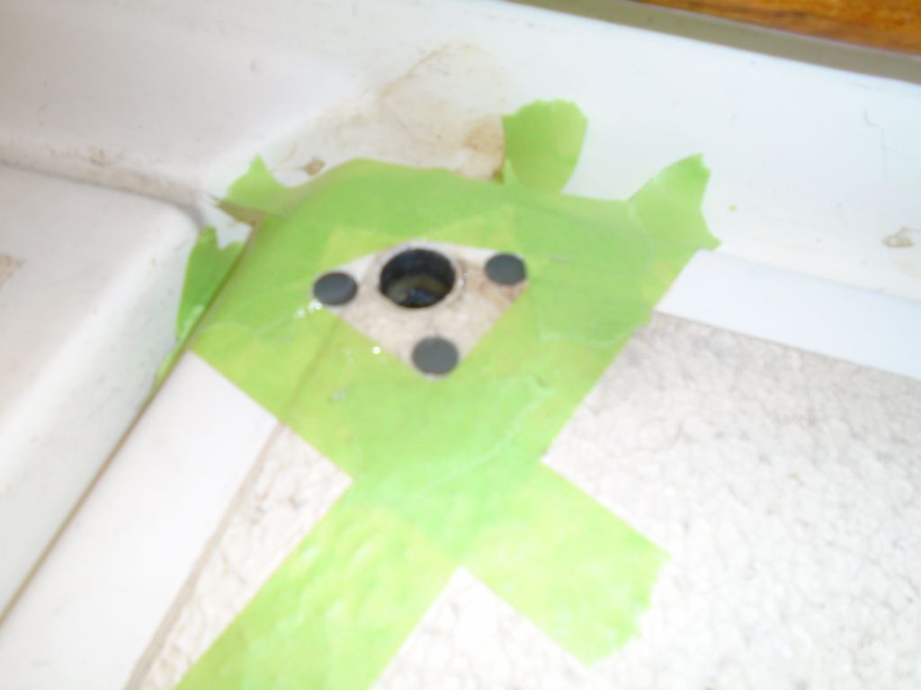
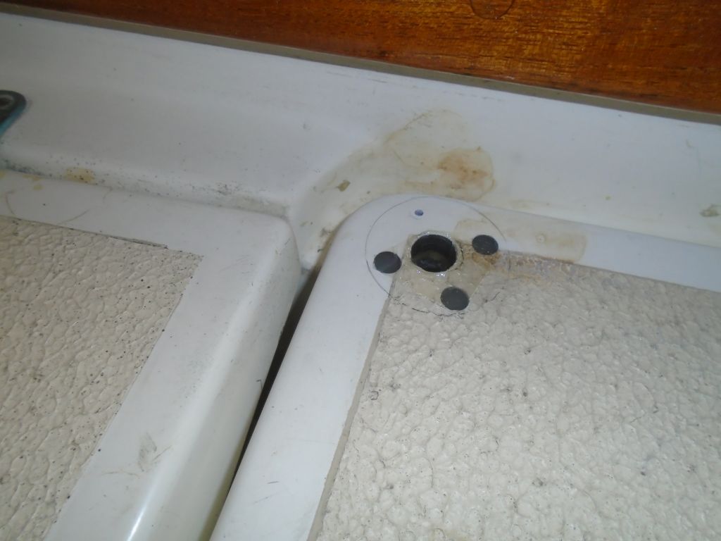
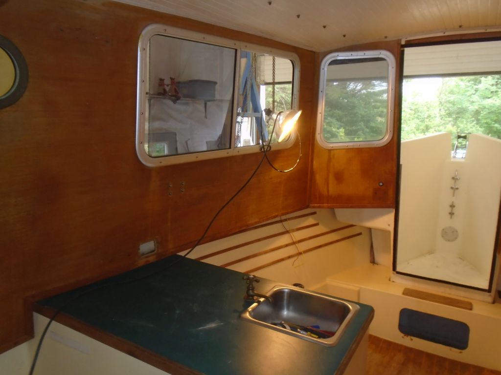
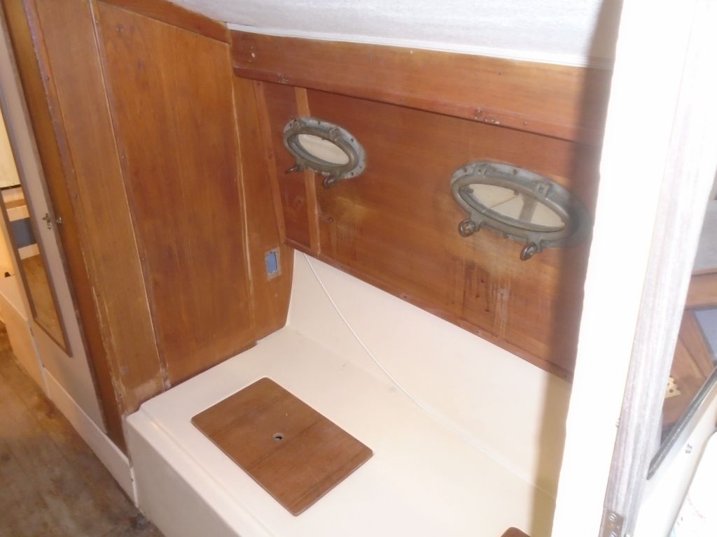
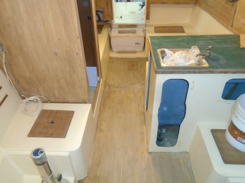
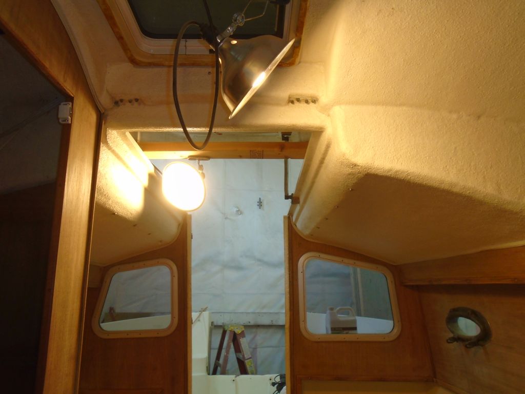
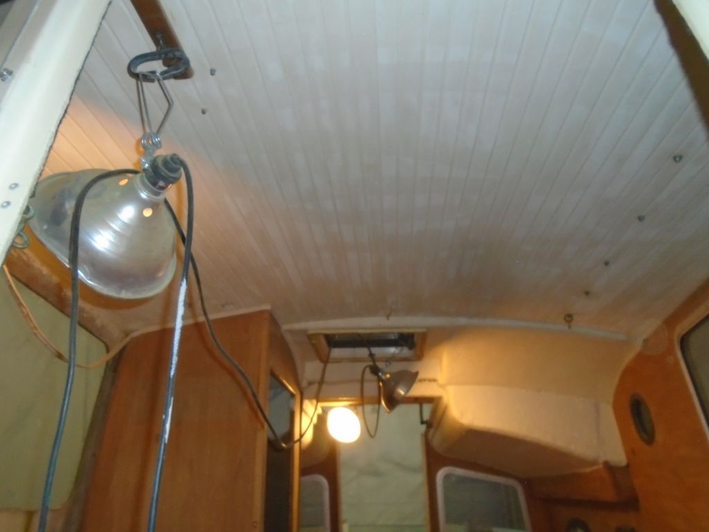
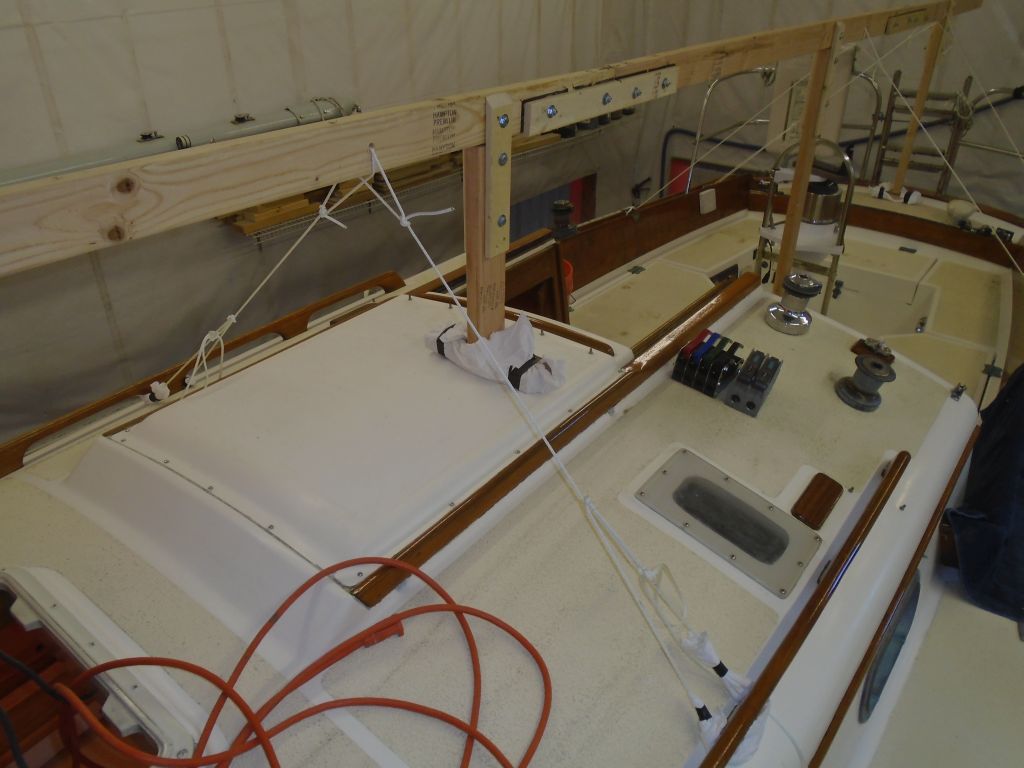
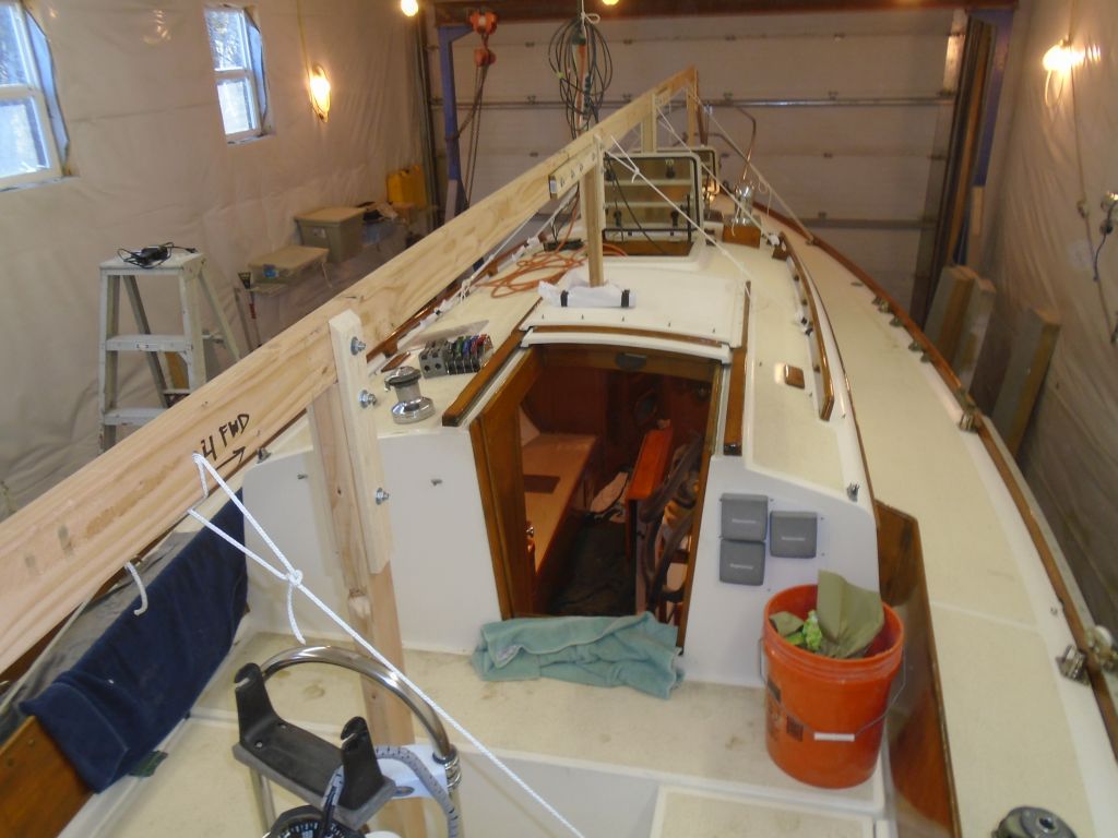
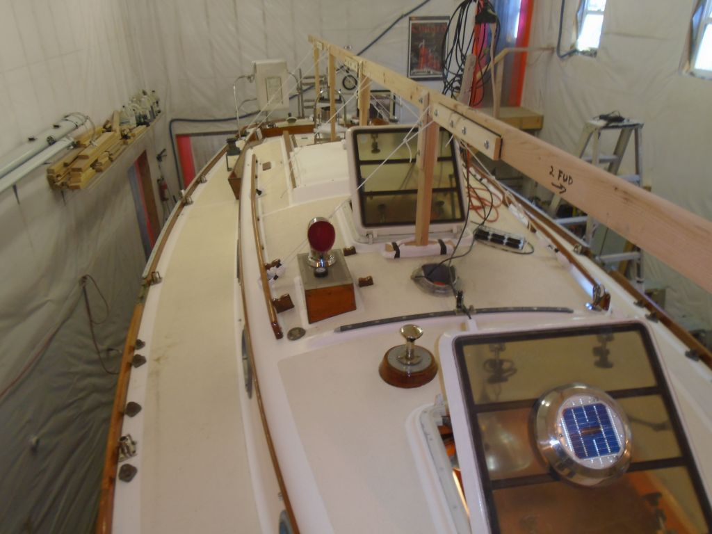
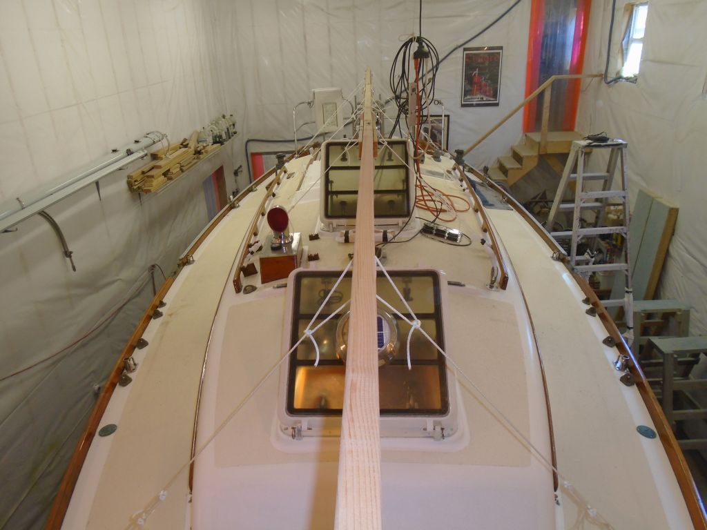
These photos showing the beginning state of the interior date to July 2015.
There was really very little finish on the wood at all, and I found it was pretty quick and easy to sand it away with a palm sander and 120 grit paper. This took care of most of the field areas, and I finished up with hand-sanding as needed for some of the trim, edges, and a couple of narrower panels where the sander wouldn’t fit. Though I’d not been looking forward to this task, and had managed to postpone it for weeks, in the end only getting it done would get it done, and once I knuckled down I was pleased to find that the job went smoothly and quickly–far more quickly than I’d ever imagined. The sanding removed most if not all of the various water streaks and stains, at least to a point appropriate to the overall nature of the construction. In other words, the results weren’t perfect, but then nothing here was remotely perfect to begin with. It all worked in harmony,.
While I was making a mess and in sanding mode, I used a more aggressive tool to sand the old cabin sole, which was in poor condition and not salvageable, though I intended to leave the old plywood in place as a substrate. I gave it a quick sanding to promote a surface that would be ready for whatever came next, and somehow this step made me feel better, as now instead of a neglected, damaged sole I had a surface that looked like it was on the way to something new.
The overhead would also require refreshing. The after parts of the cabin featured a textured surface, while the forward section featured a v-match simulated plank pattern. Both sections were in fine condition overall, except they looked tired and ready for some fresh paint. I ran my sander over both sections, more on the flat surfaces of the forward part, to prepare them for new paint in the near future.
Afterwards, I vacuumed all the surfaces and generally cleaned up, then solvent-washed the woodwork to clean it; this also showed how the newly-sanded surfaces would look once I applied the finish.
There was plenty left to do, but having the interior prep expunged from my list was a great relief.
Total time billed on this job today: 3.75 hours
0600 Weather report:
32°, light rain, coating of snow overnight. Forecast for the day: Rain and showers, then clearing, high in the low 40s