(page 153 of 167)

Salty 12

< Back to Salty

Wednesday

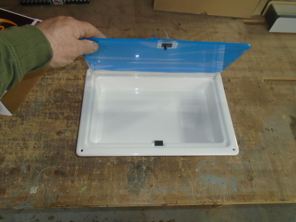
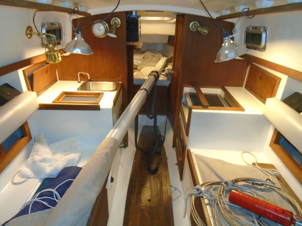
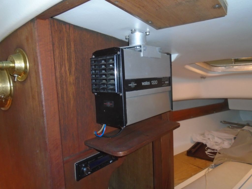
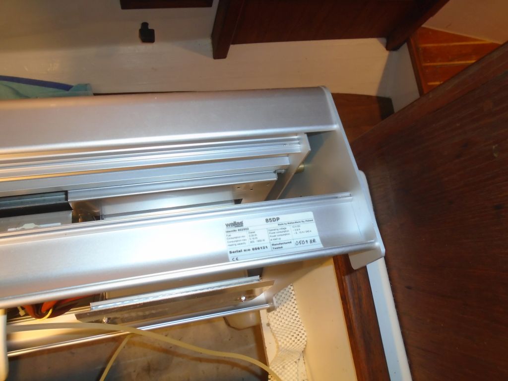
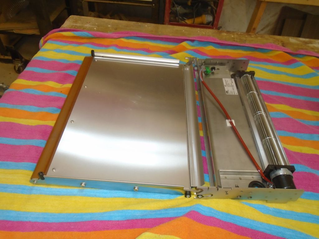
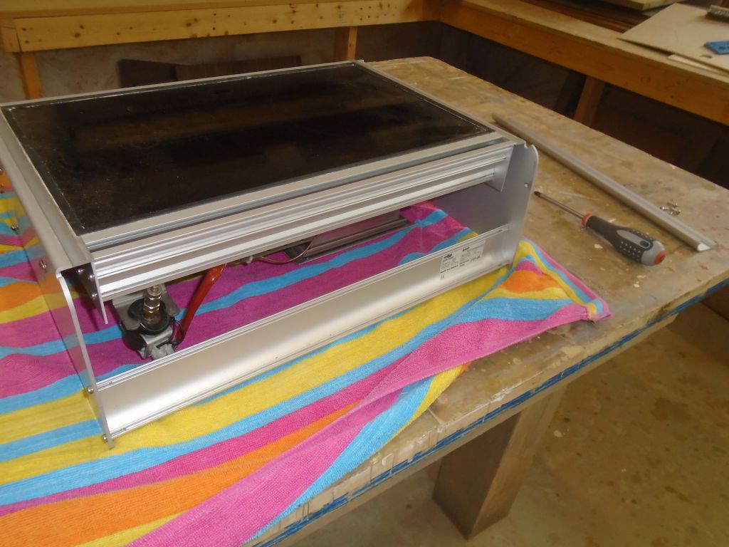
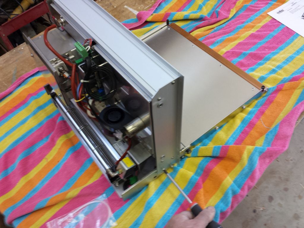
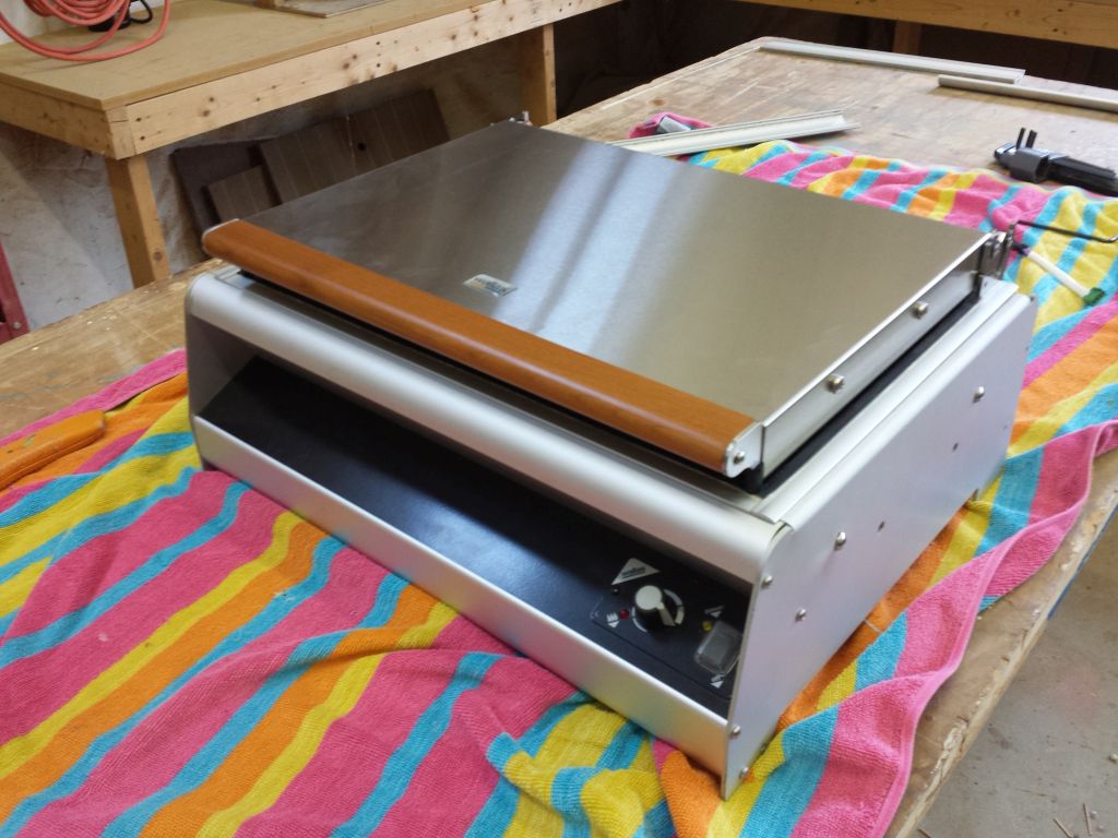
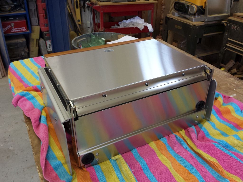
I got started with what could seem like an odd tangent, but earlier, I’d spread various parts for the Wallas cook stove out on my bench, so I could inspect the original stove and a new blower lid that the owner had ordered, and now these parts were still there and in the way.  Rather than pack them up as is, I decided to install the blower lid and have that job completed–it all had to be done at one time or another, after all.  It didn’t look like a major job, but it was something I’d never seen nor done before.

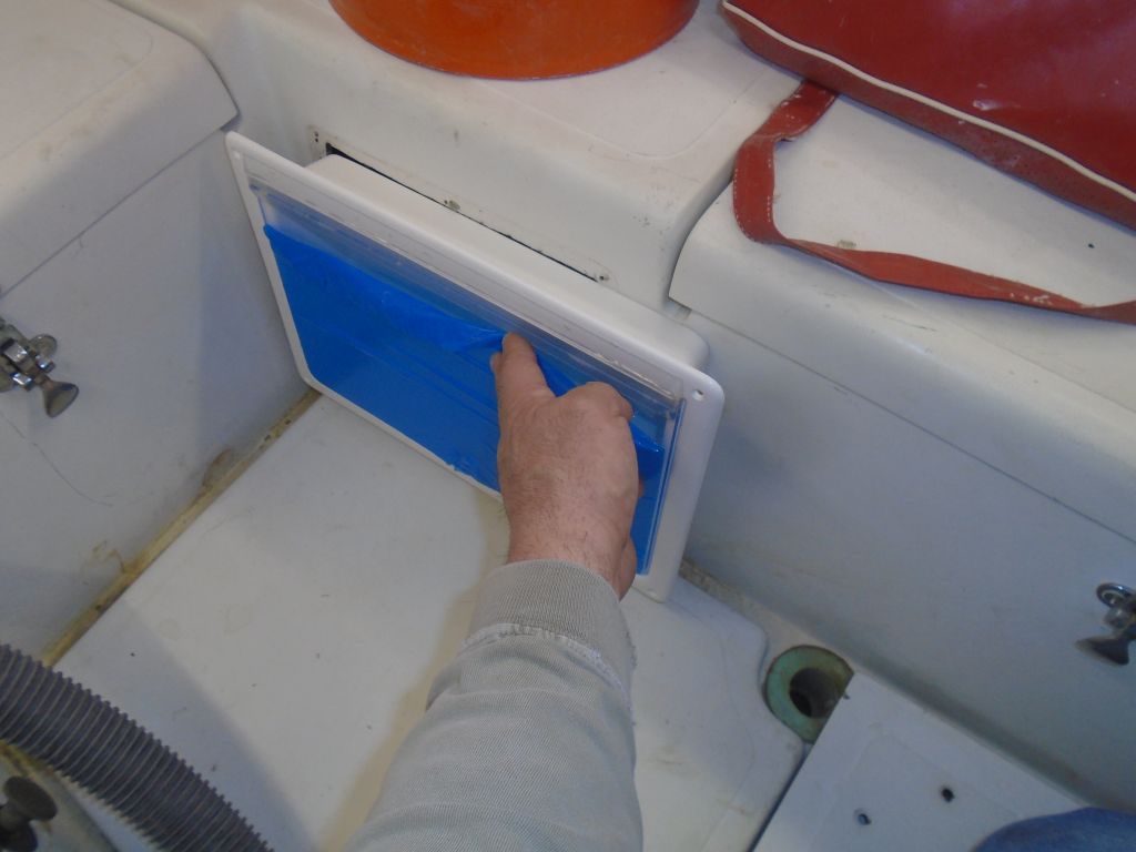
The idea of the blower lid is that when the stove is operated with the lid lowered, it activates a blower that forces air across the stove top (no open flames) and then into the cabin, like a mini forced-air heater.  For such a small boat, this seemed an ideal option for basic cabin heating of the type one would normal experience on those chill days during the sailing season in temperate climates.  When the lid is raised, one operates the stove top normally.

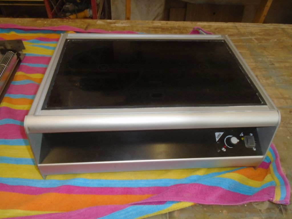
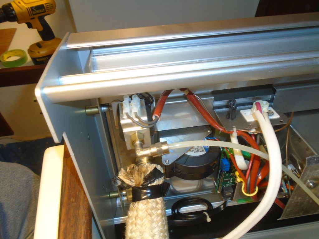
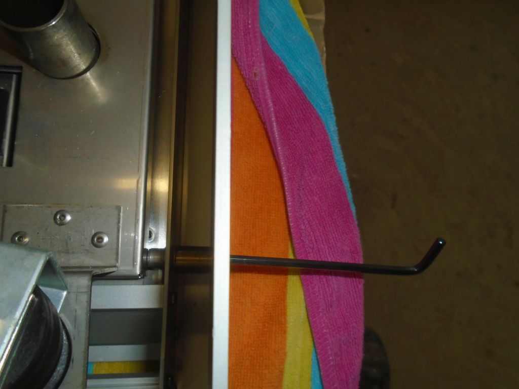
To install the lid on this cooktop, I first had to remove a few parts from the old, and initially this caused a little confusion since the illustrations were just slightly different (or so it seemed) from the stove in front of me.  But shortly I realized that the stove itself was actually installed in a stand-alone base, and that in order to install the blower lid I’d have to temporarily remove the base to return the actual cooktop to its essence.  This was easy enough with four fasteners and little spacers to remove, plus one wire connector to the control knob.

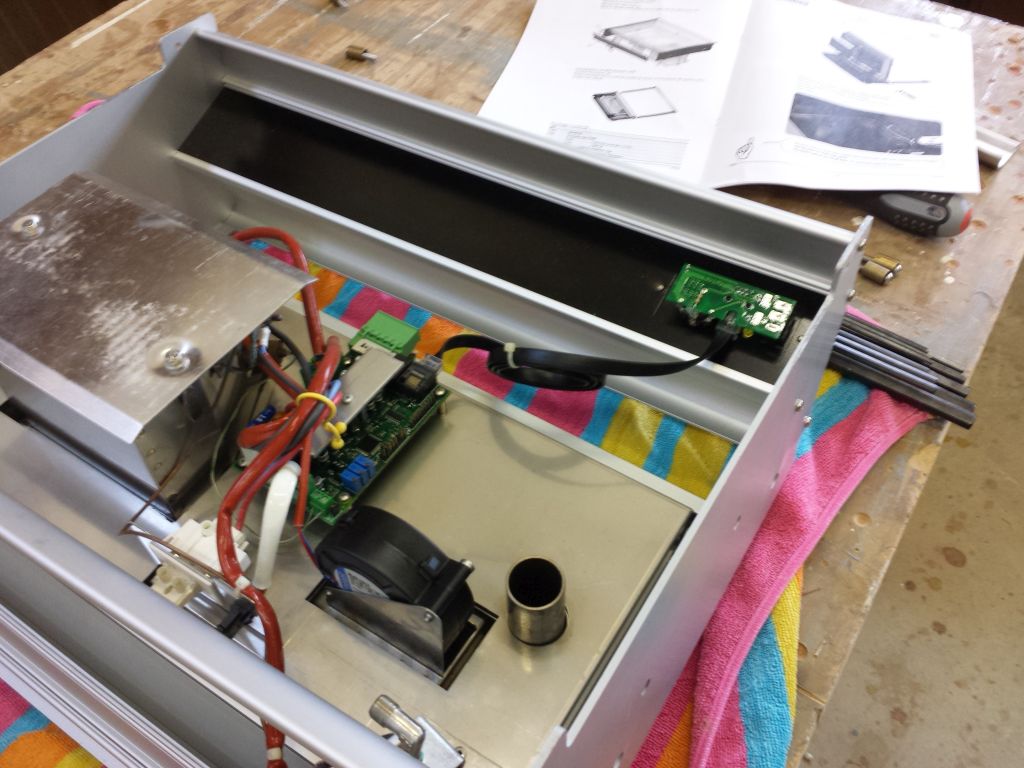
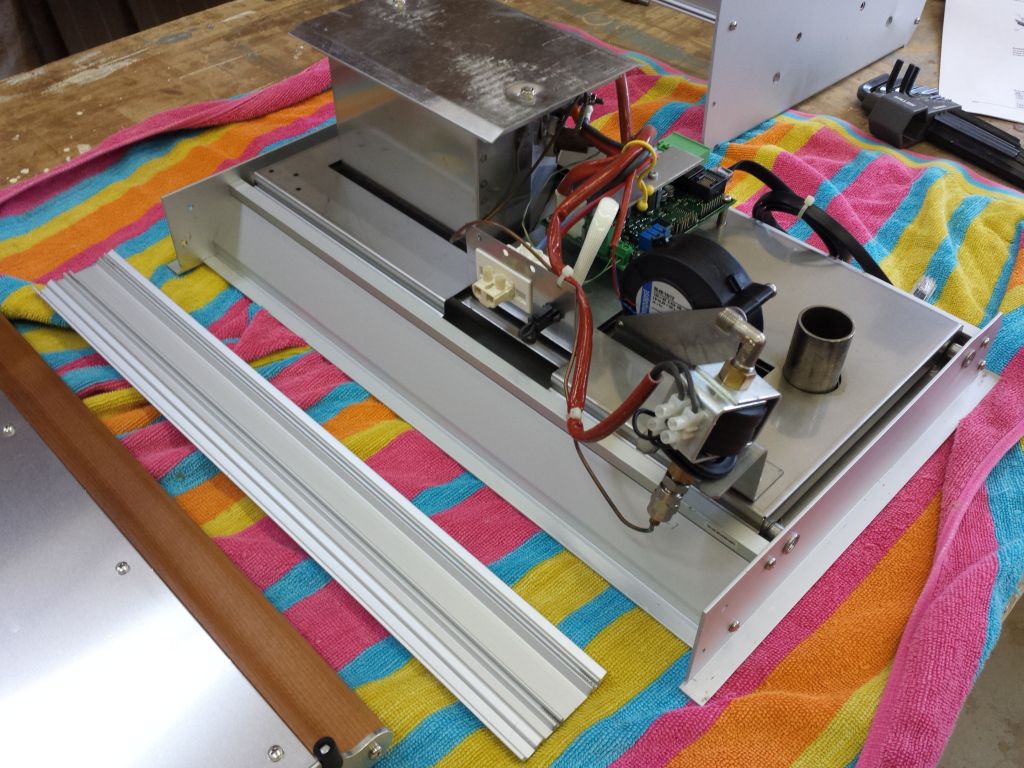
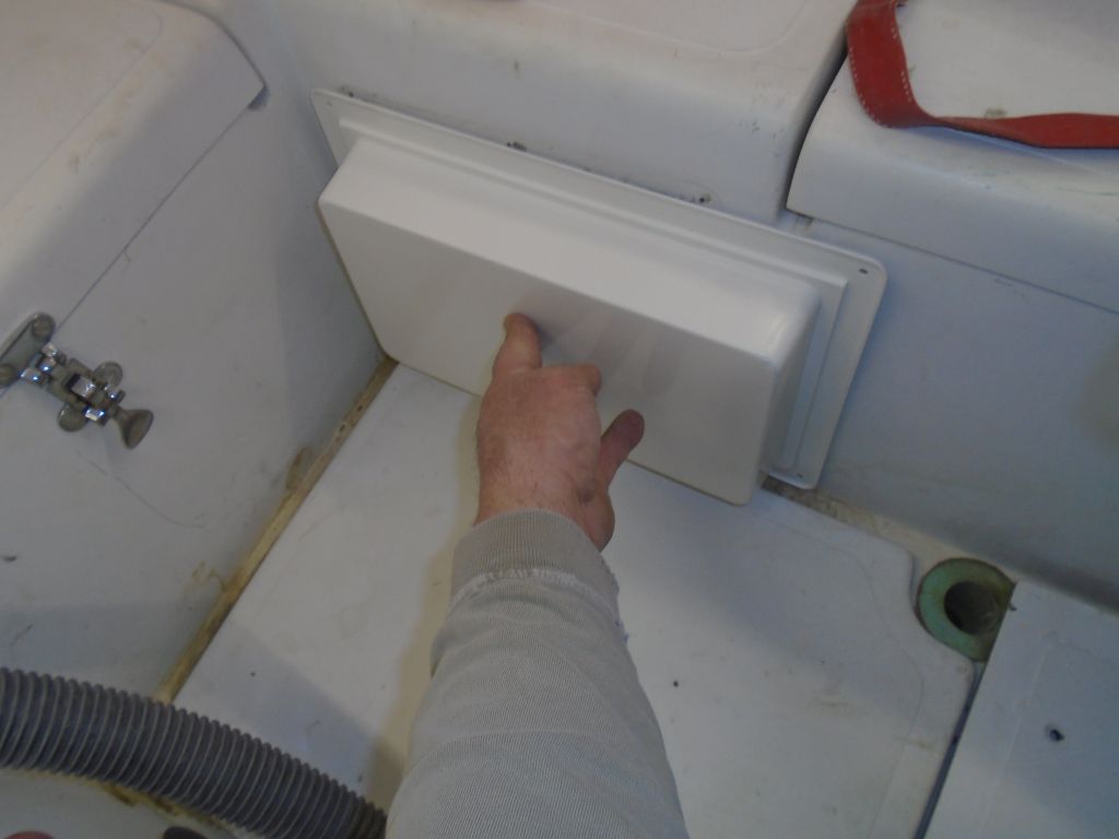
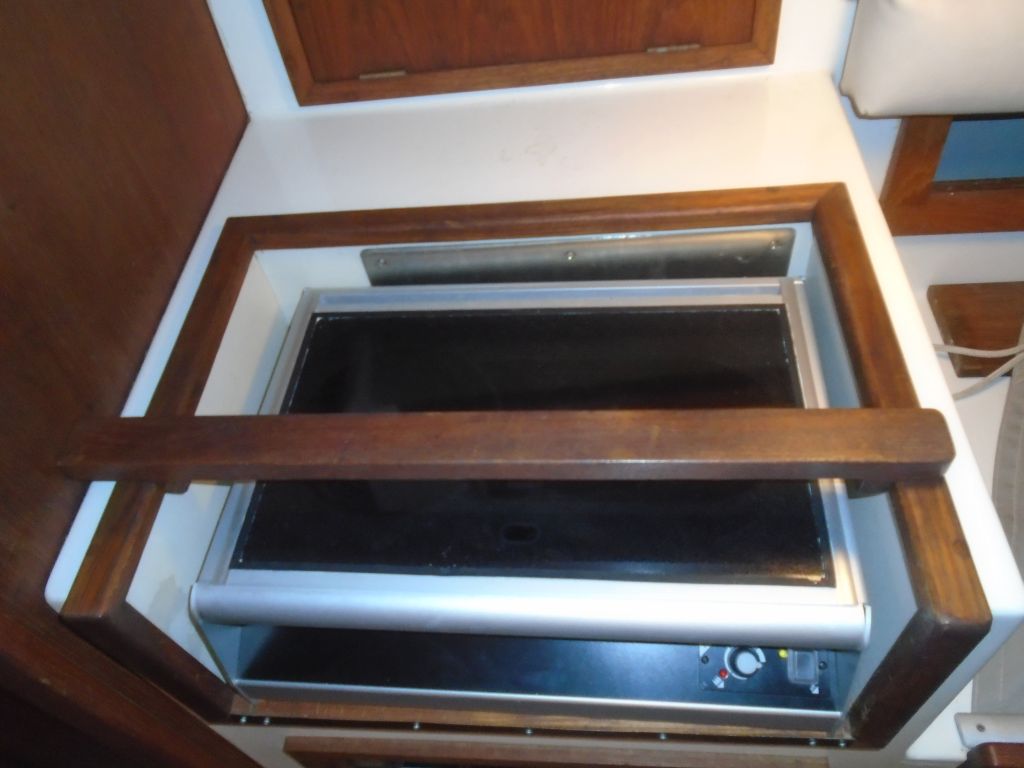
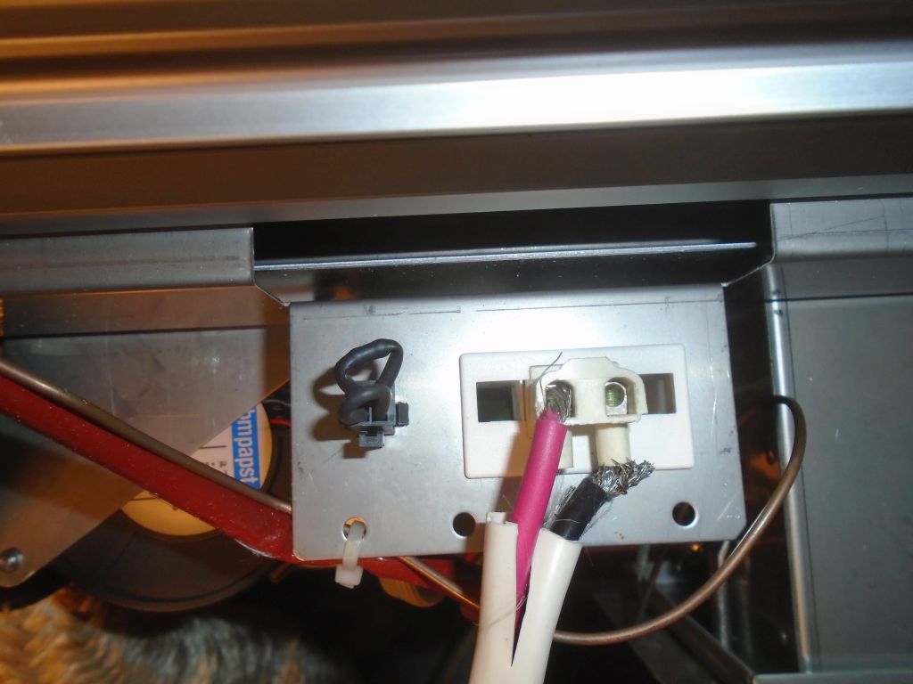
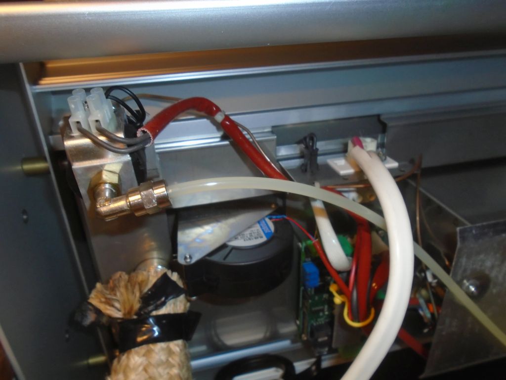
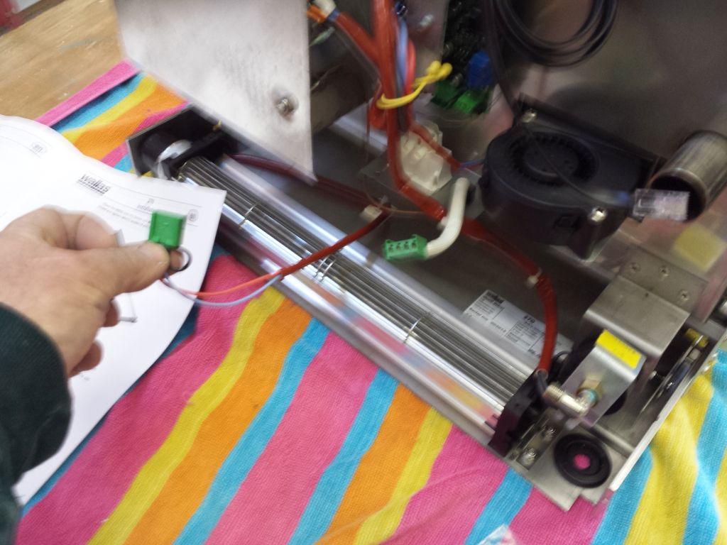
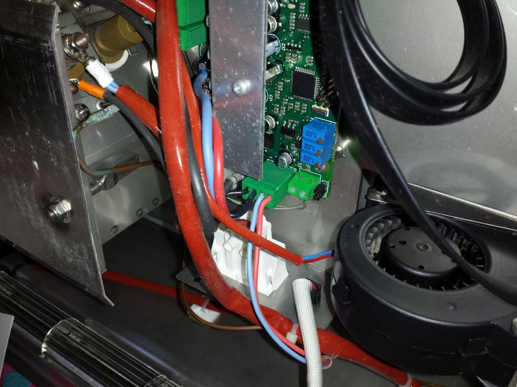
Now, with the cooktop stripped down as required by the instructions (essentially removing a couple aluminum cross bars from the back edge, where the blower would be fitted), I figured out how the blower lid fit into the stove housing, and secured it with the four machine screws provided.  Then I removed an existing wiring harness from the works of the stove, and plugged in its stead the harness from the blower lid, all as directed.

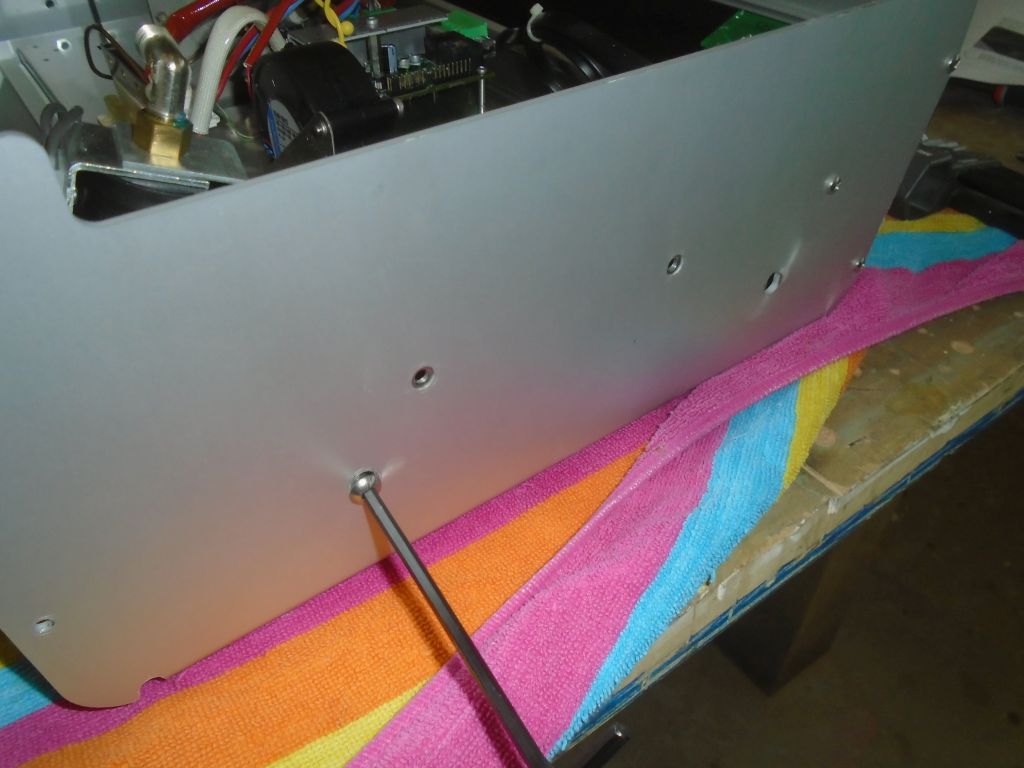
Finally, I reinstalled the external stand-alone base (which required removing one more trim piece, as it happened), and this completed the installation.  The blower lid was frankly a handsome addition to this little stove, and I hoped it operated well and did the job.

Now I could set the stove aside for safekeeping till I wanted to put it back in the boat, and with my bench cleared I could move on with other projects at hand.

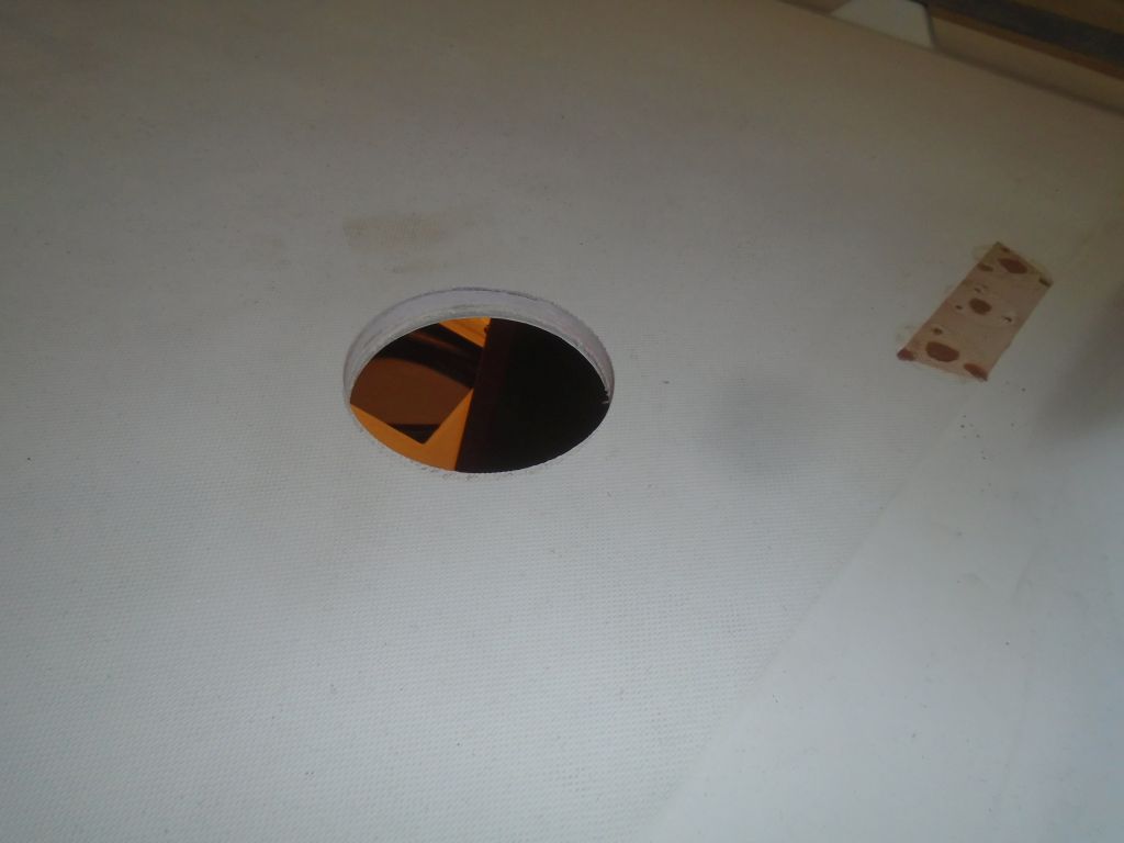
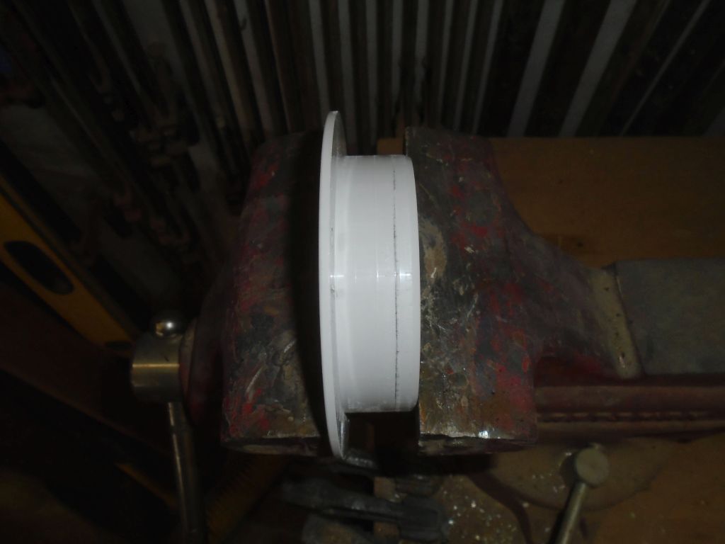
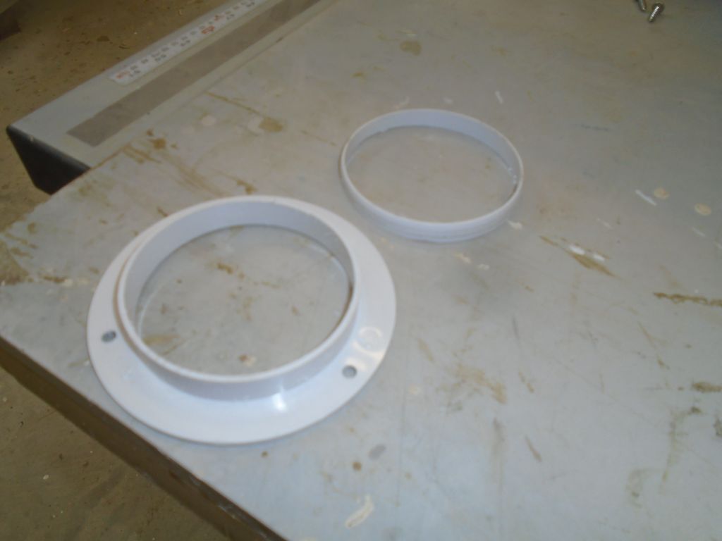
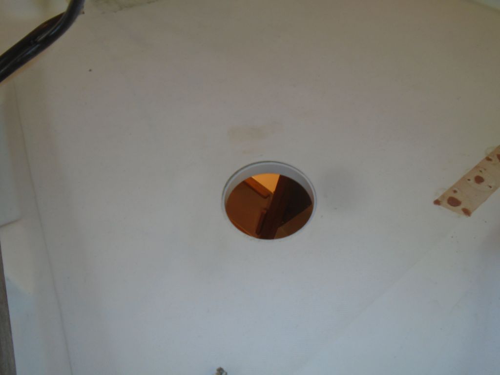
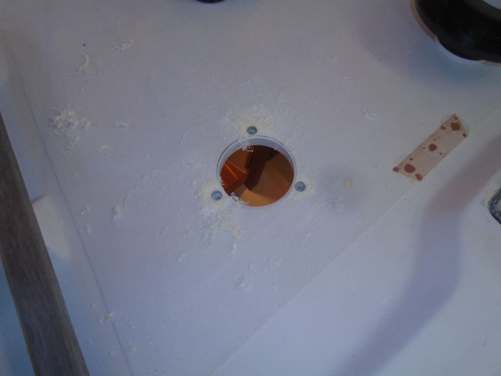
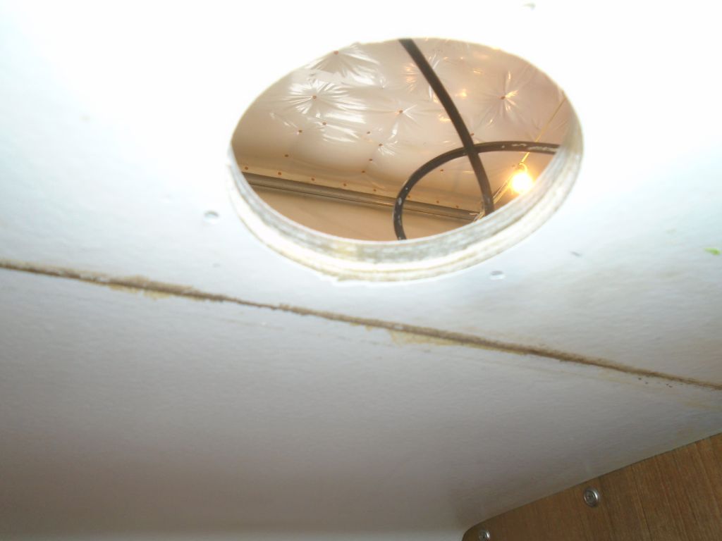
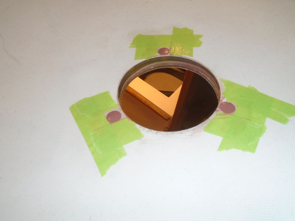
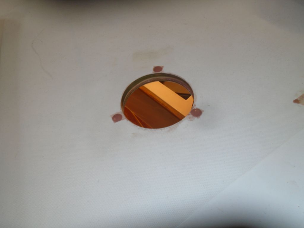
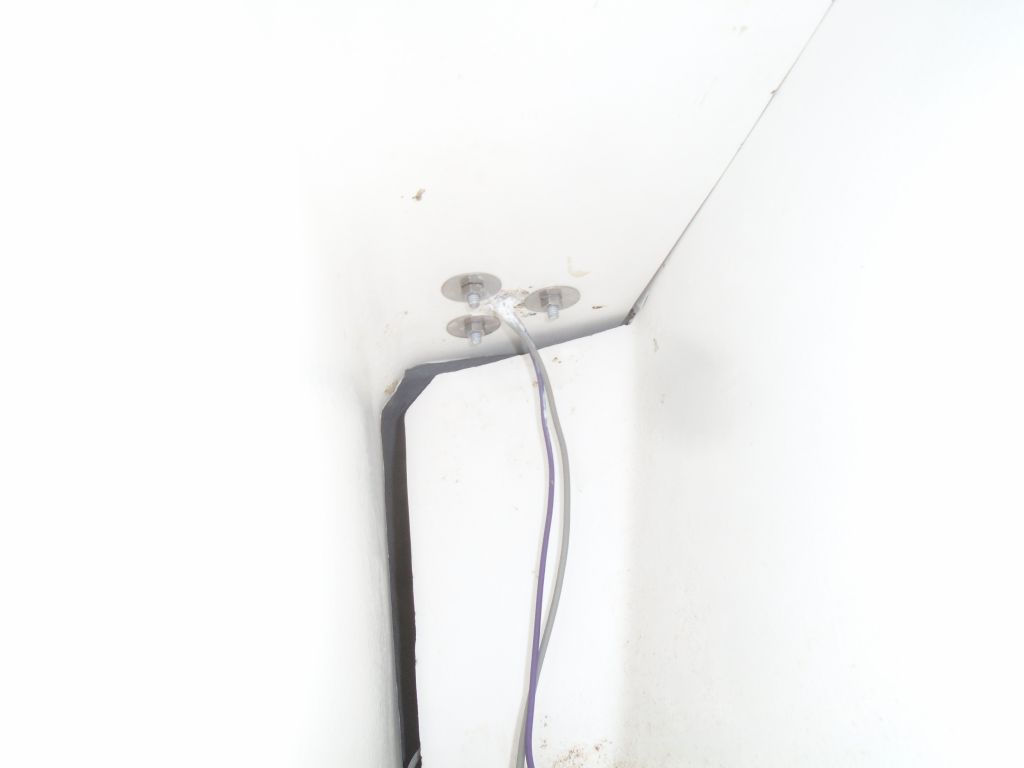
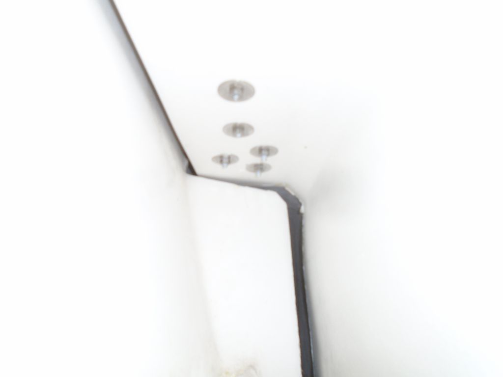
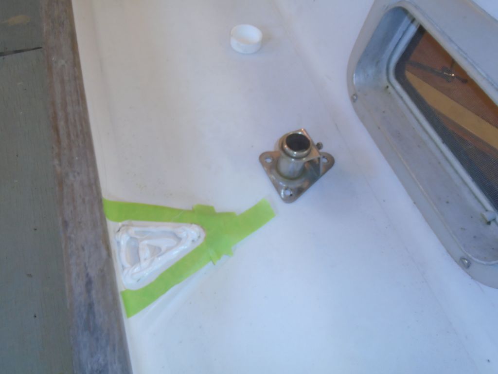
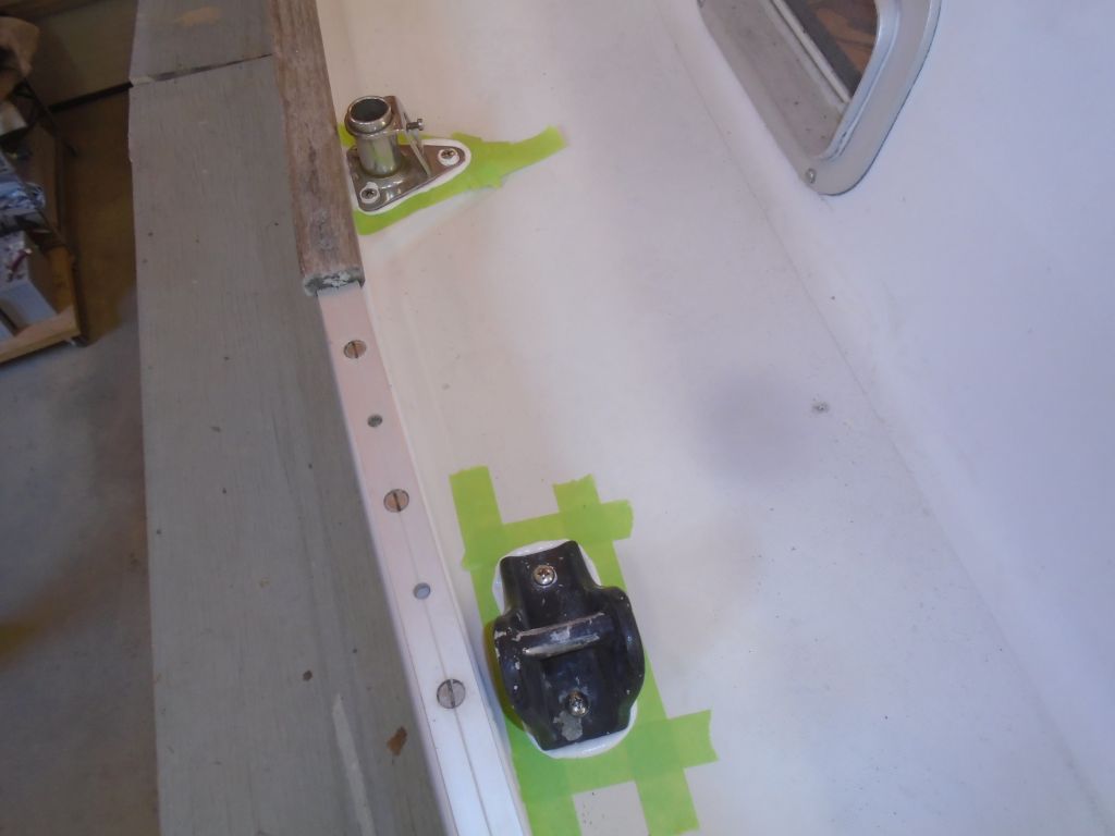
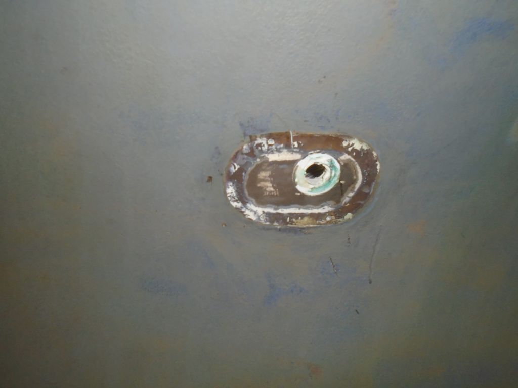
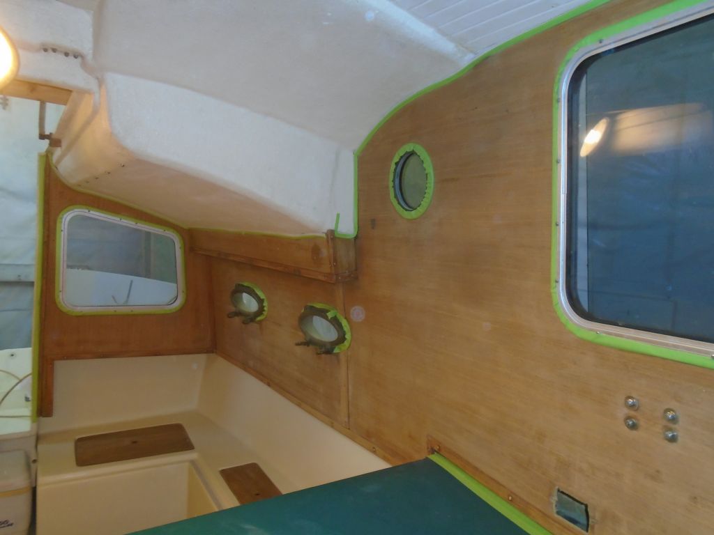
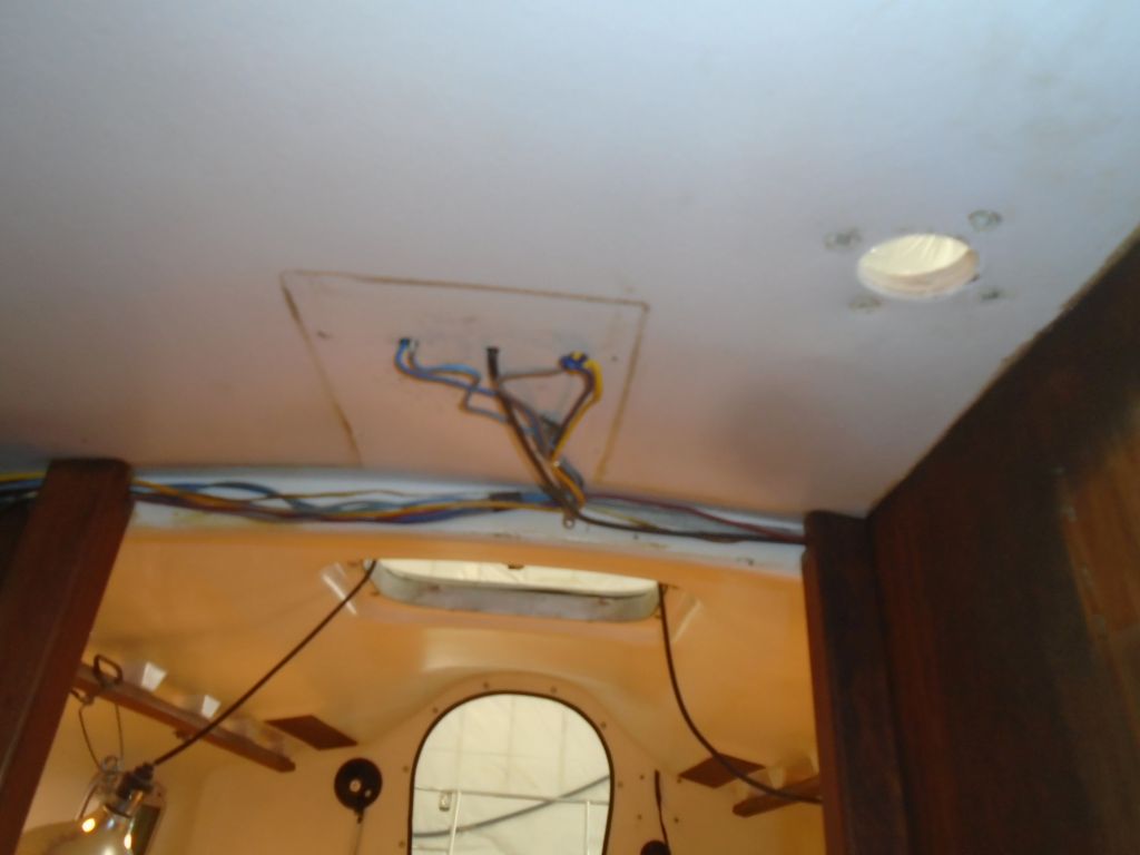
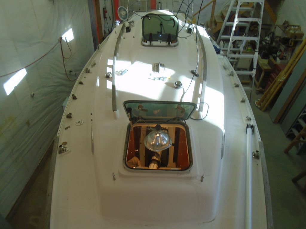
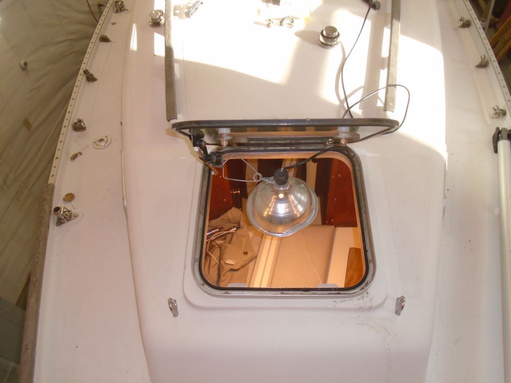
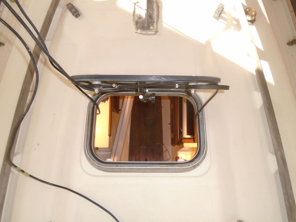
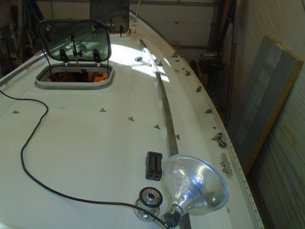
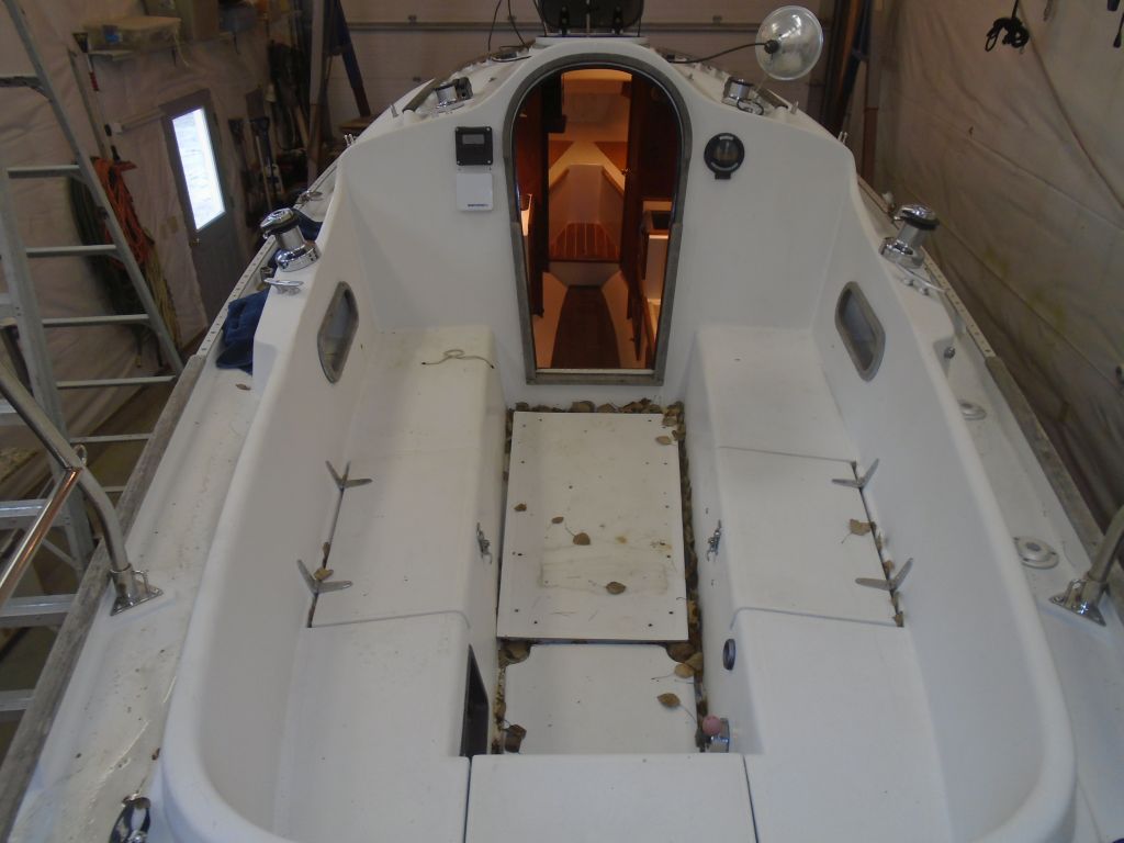
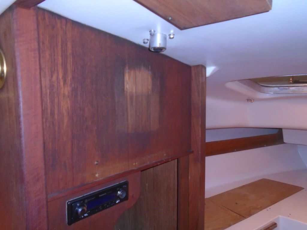
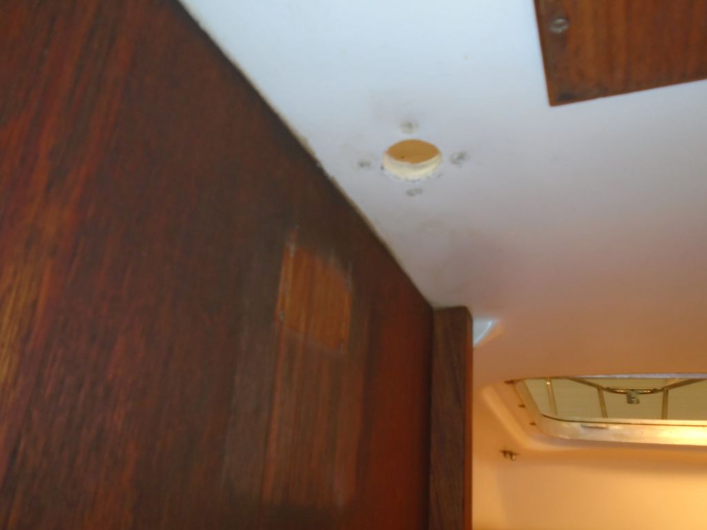
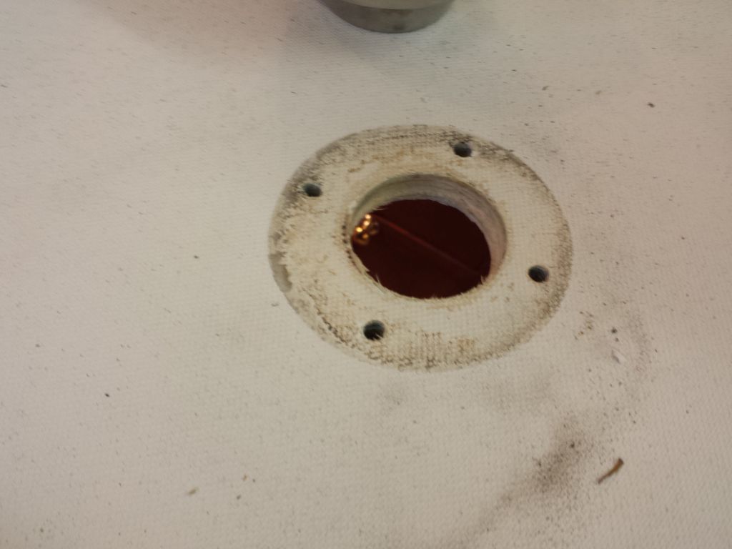
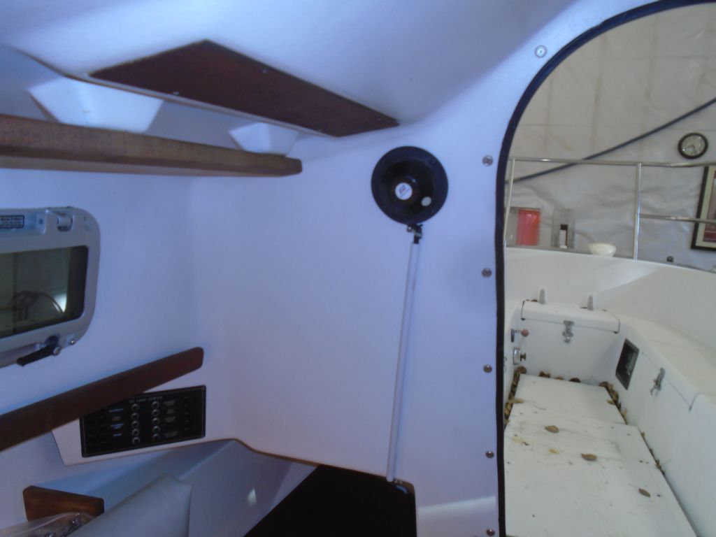
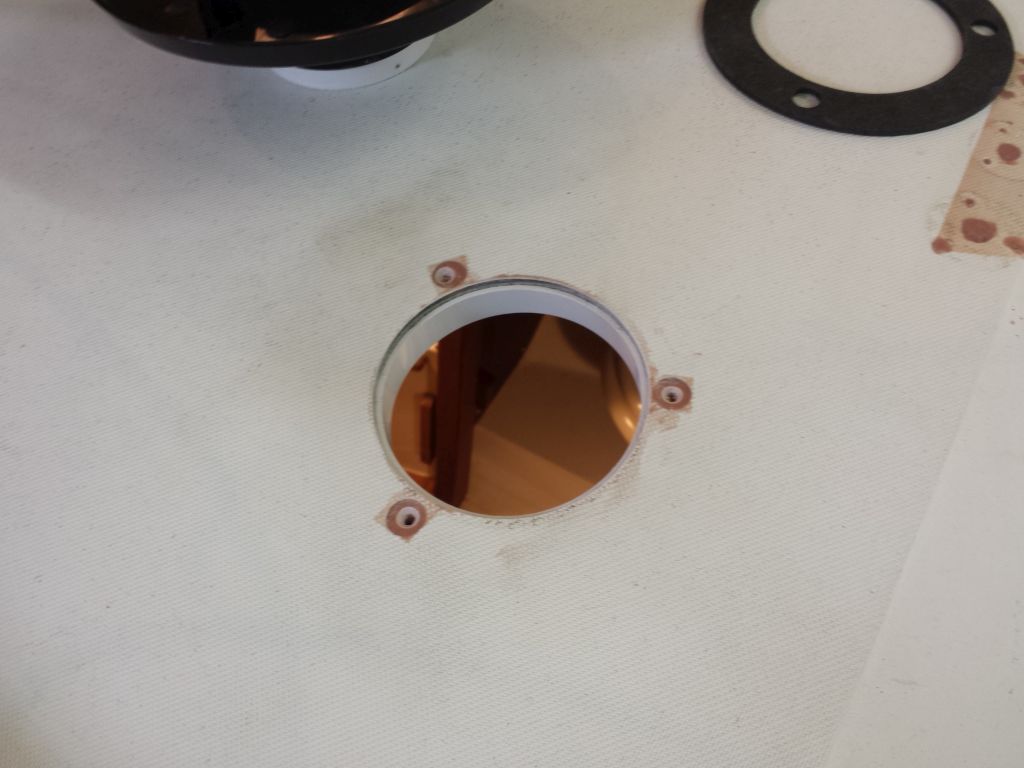
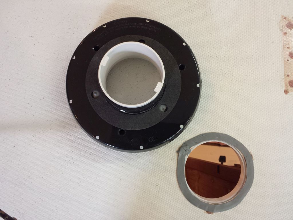
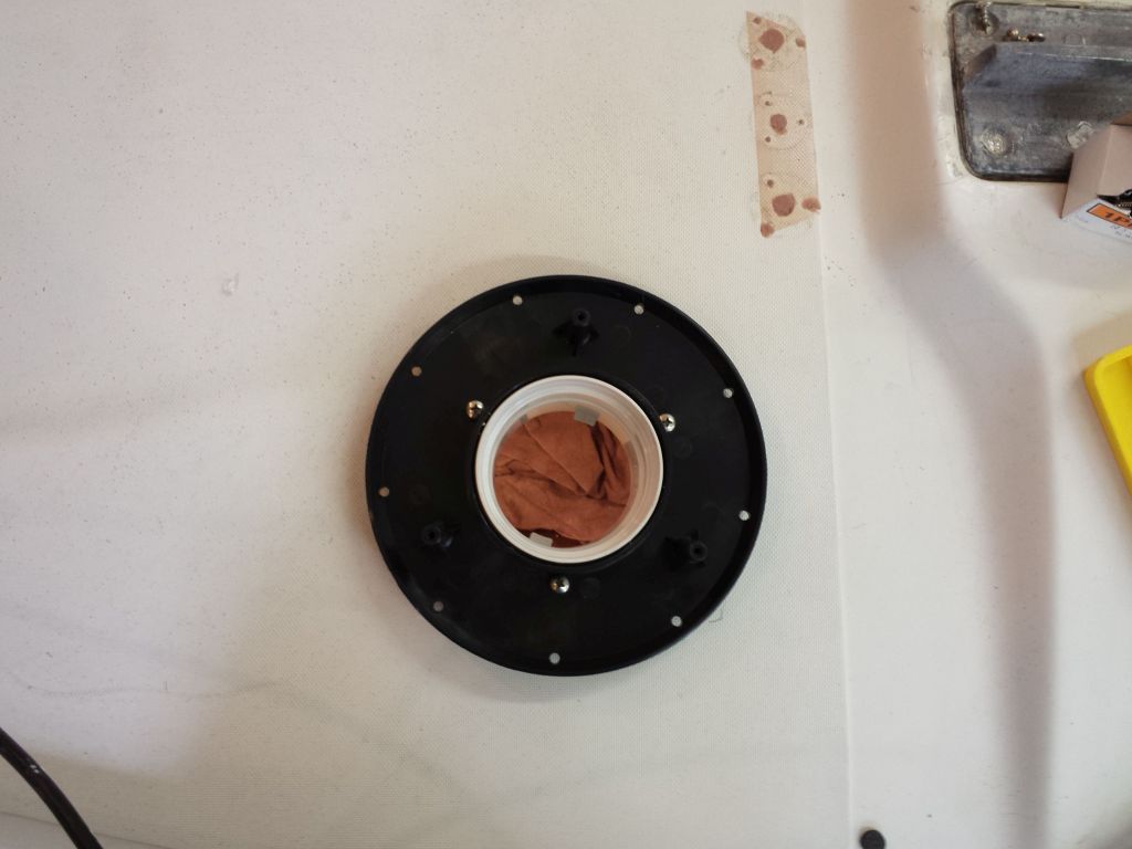
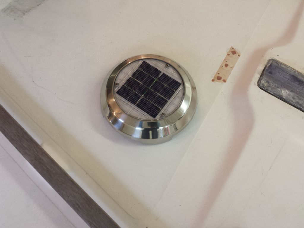
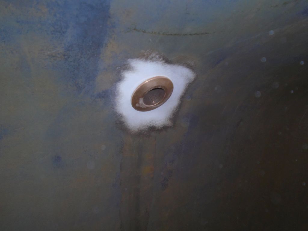
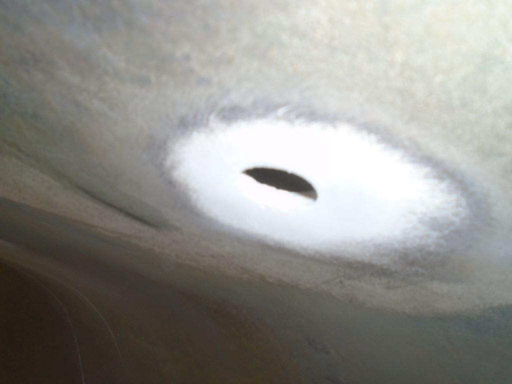
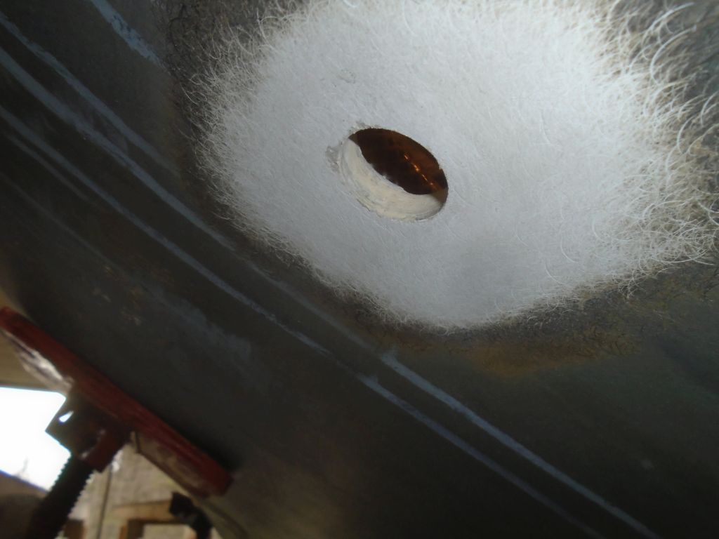
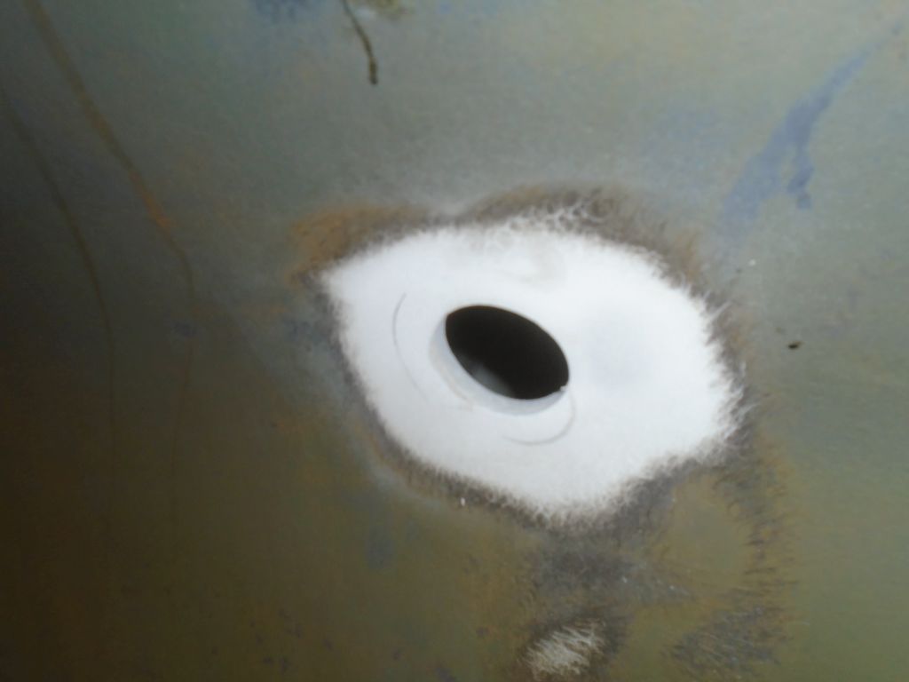
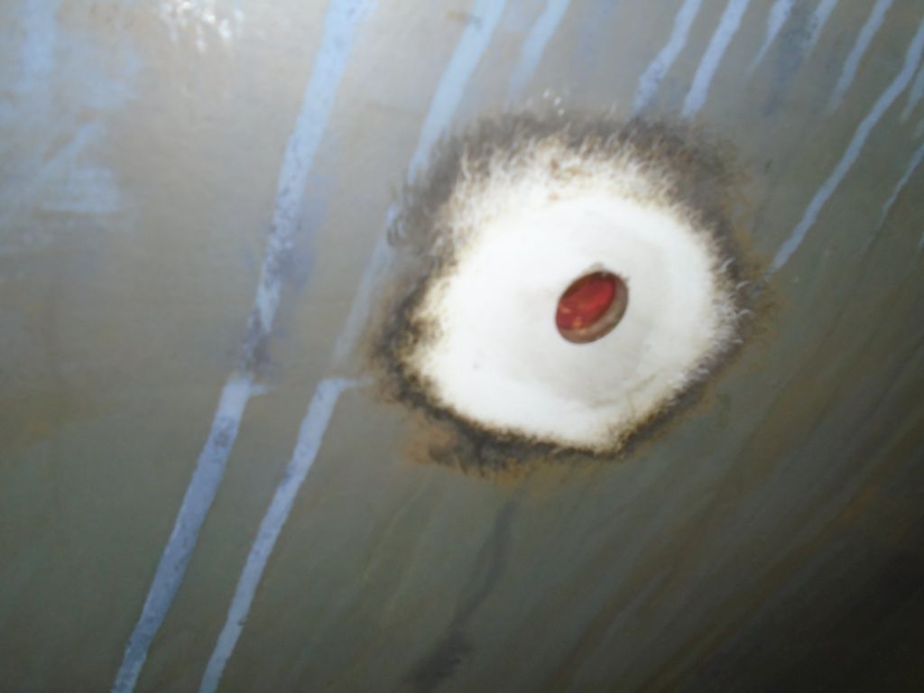
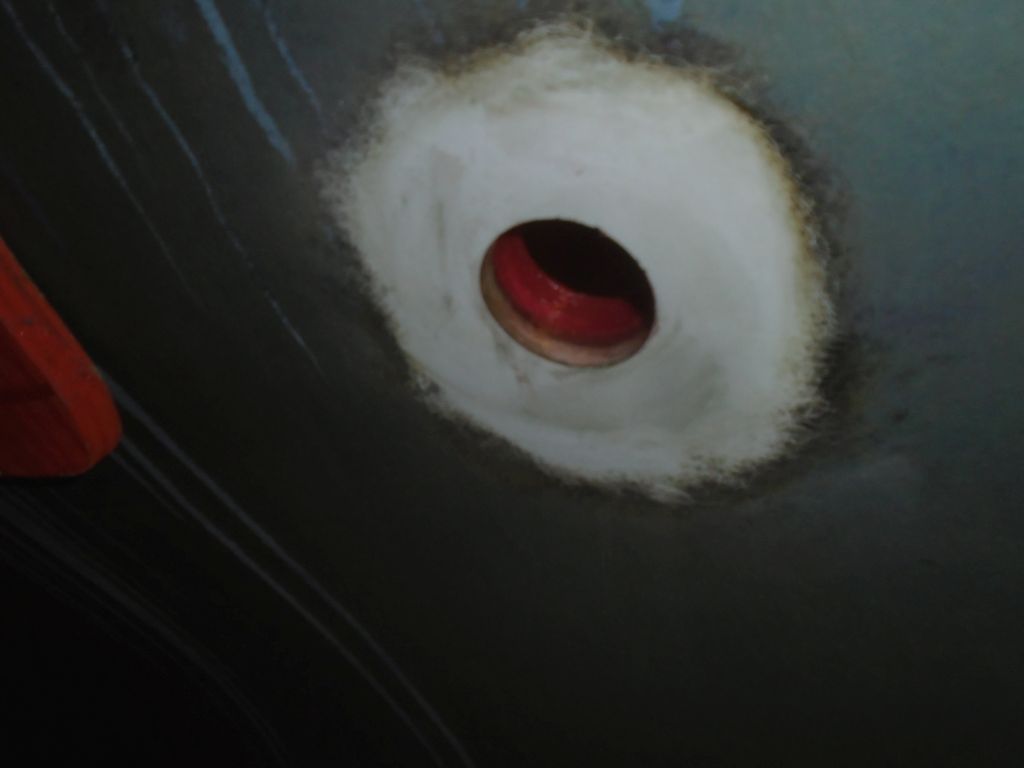
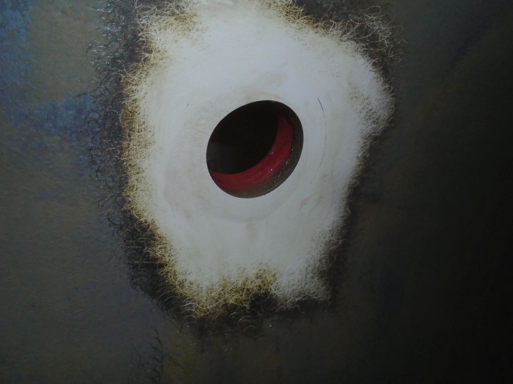
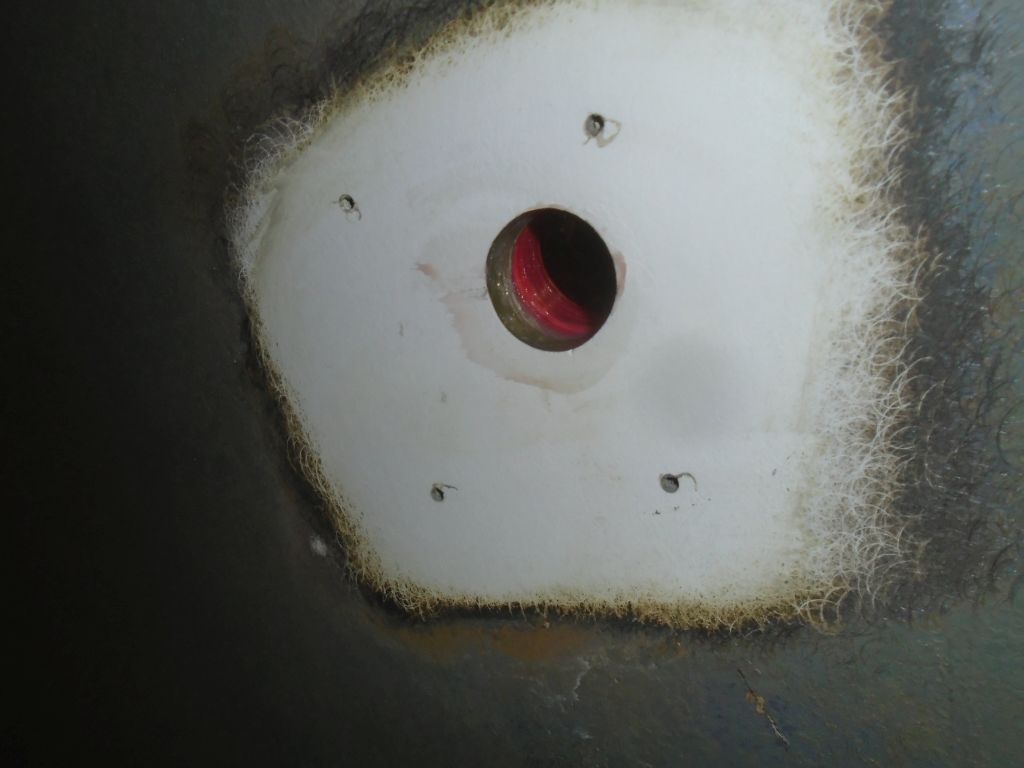
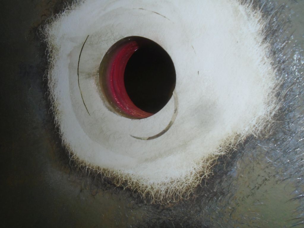
Before starting in a new direction, I finished up the solar vent installation, now that the epoxy filling was cured and ready for the final steps.  From below, I installed the plastic trim ring, then, back on deck I dry-fit the vent housing so I could mark and drill the three fastener holes.  Afterwards, I applied sealant (butyl tape in this case) to the deck around the large hole, and on the housing itself, and pressed into plate the foam gasket provided with the vent before securing the base to the deck.

The vent came with an on/off switch, which was nice, but I tested it for operation before shutting it down once more.  The vent came with (I think) an exhaust fan blade installed, but there was also a second (intake) blade included to reverse the direction of flow if desired.

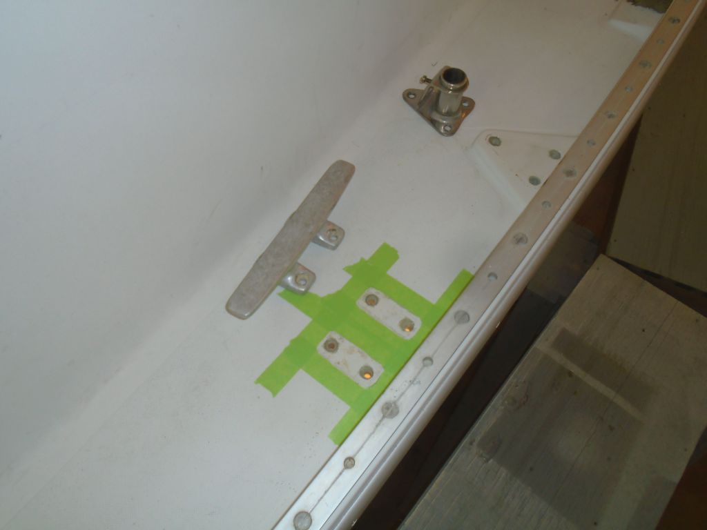
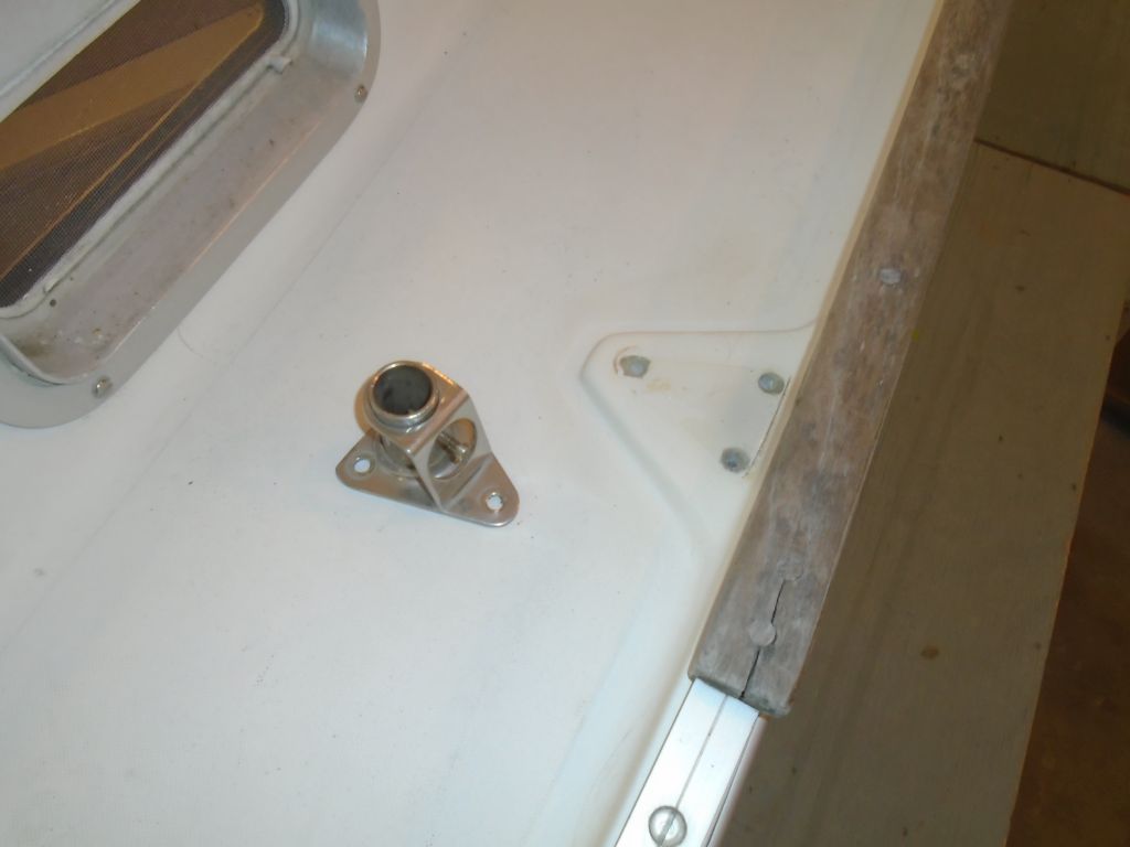
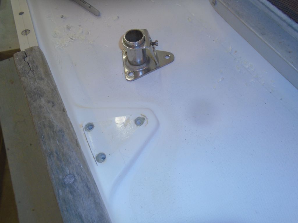
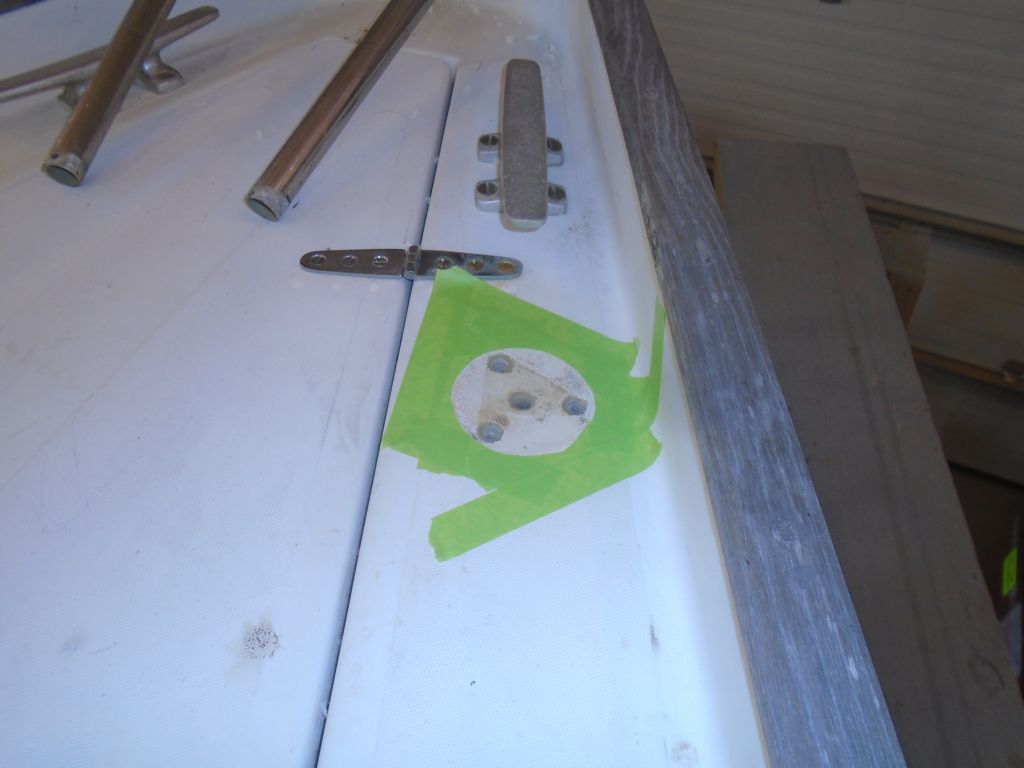
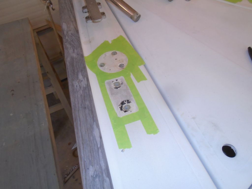
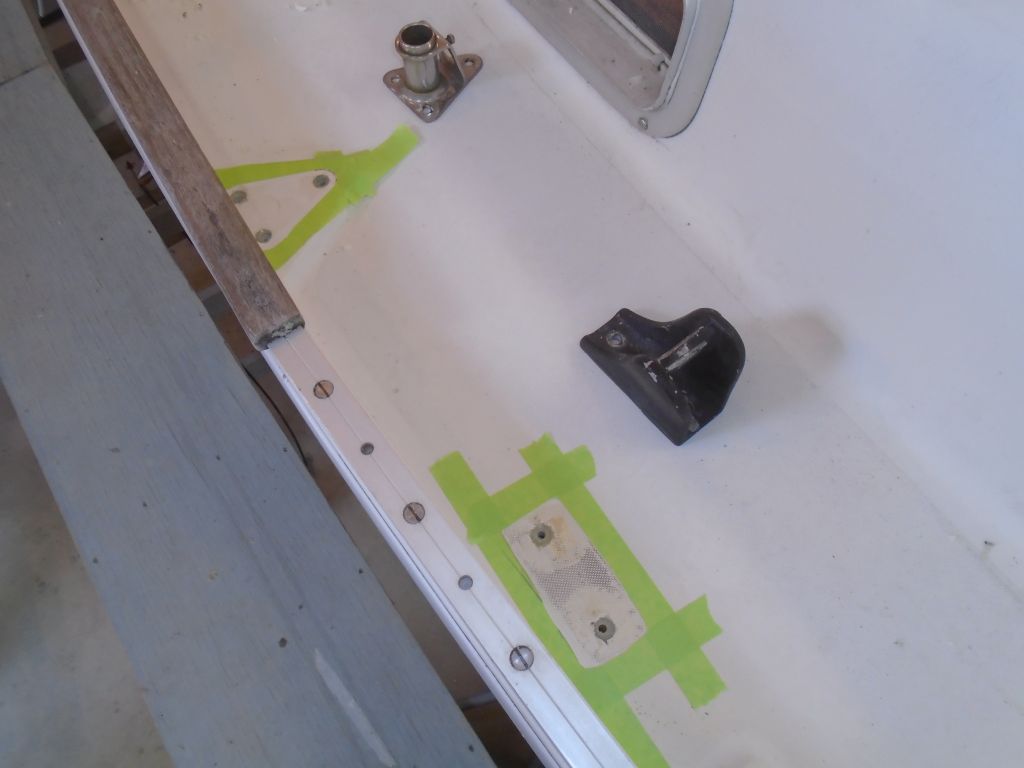
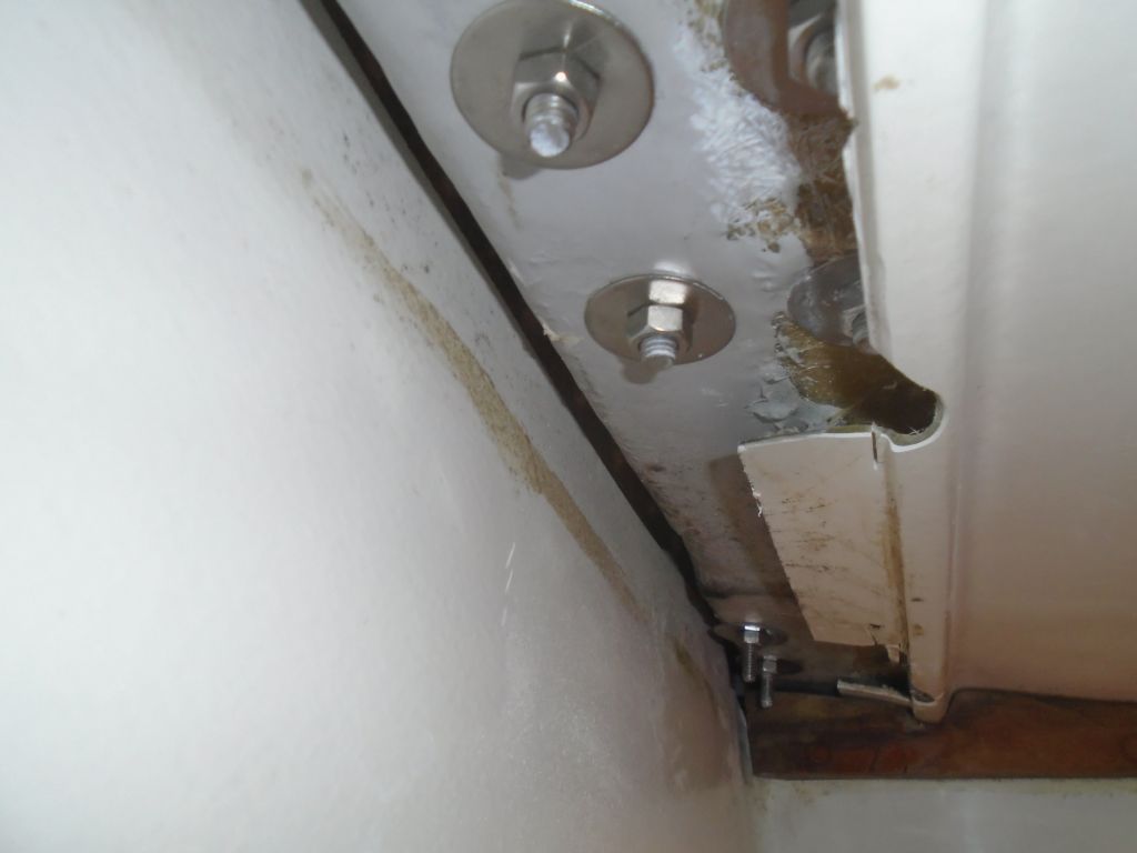
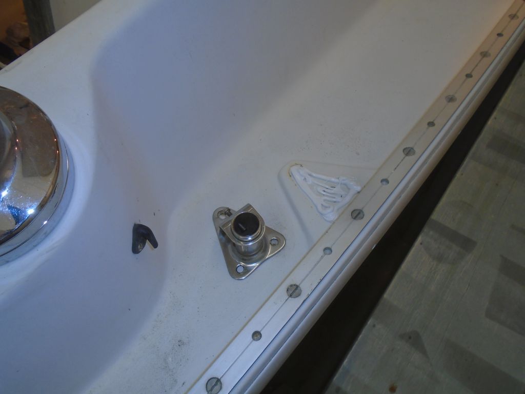
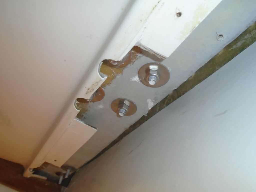
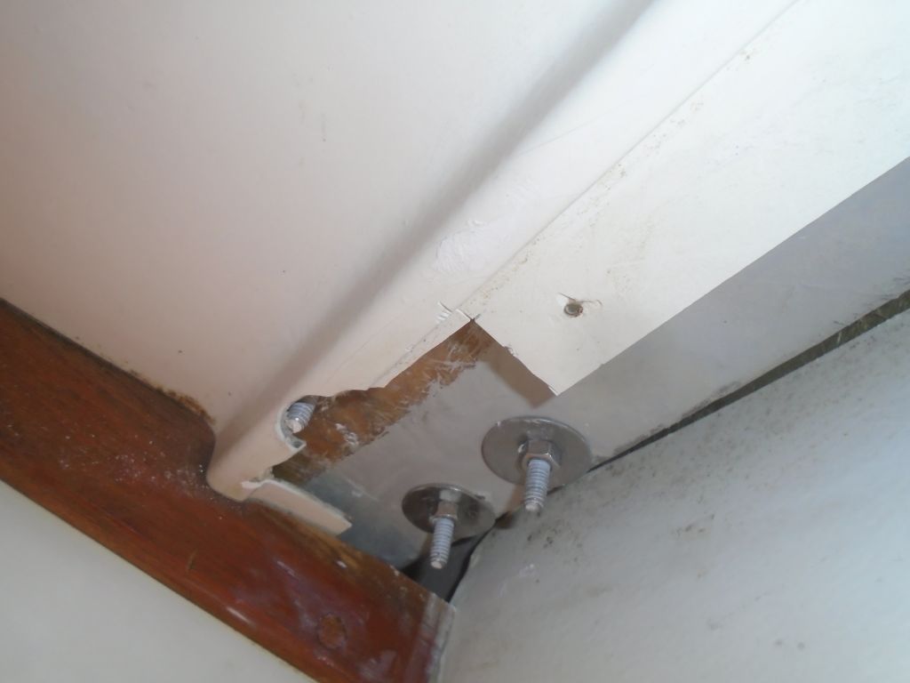
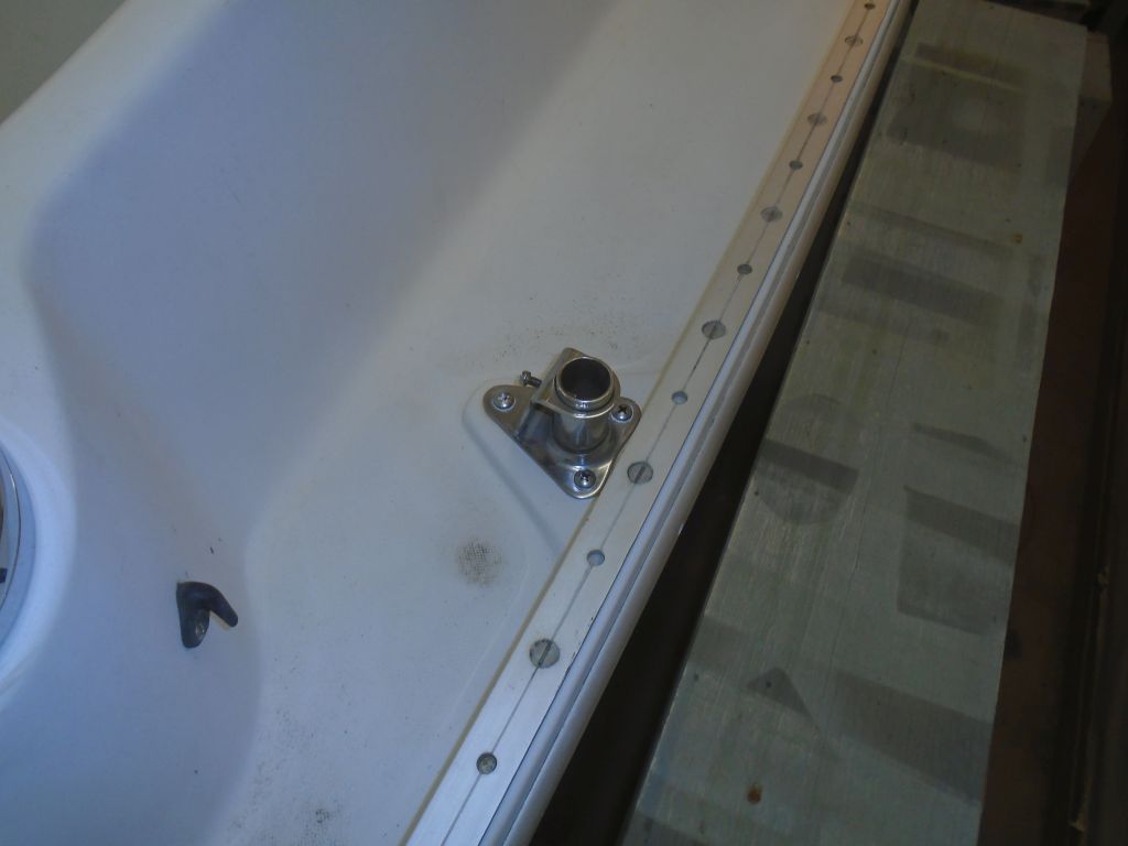
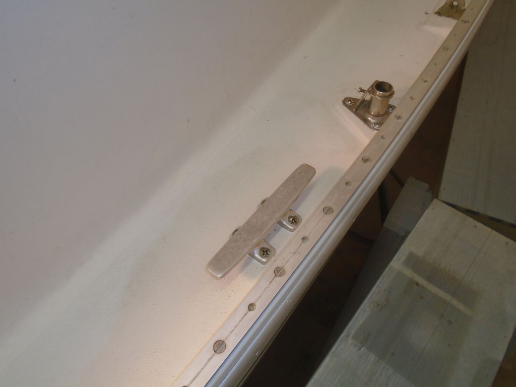
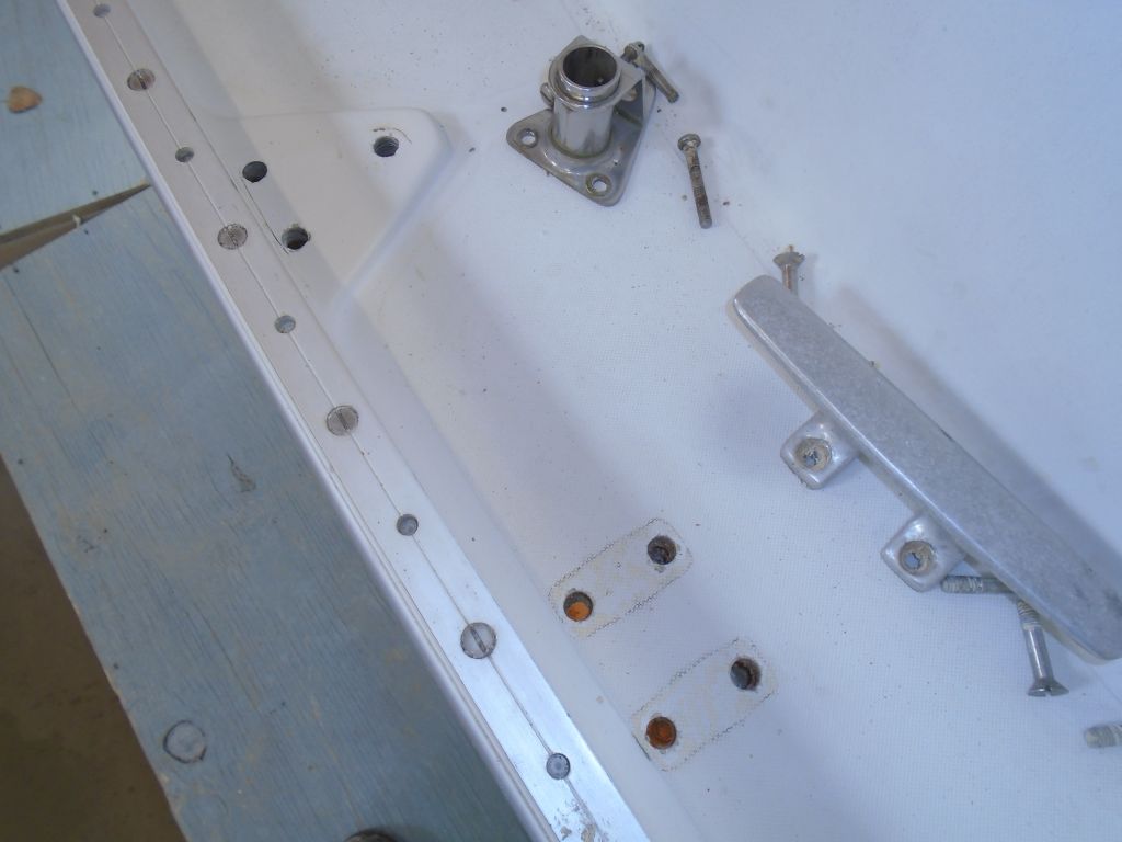
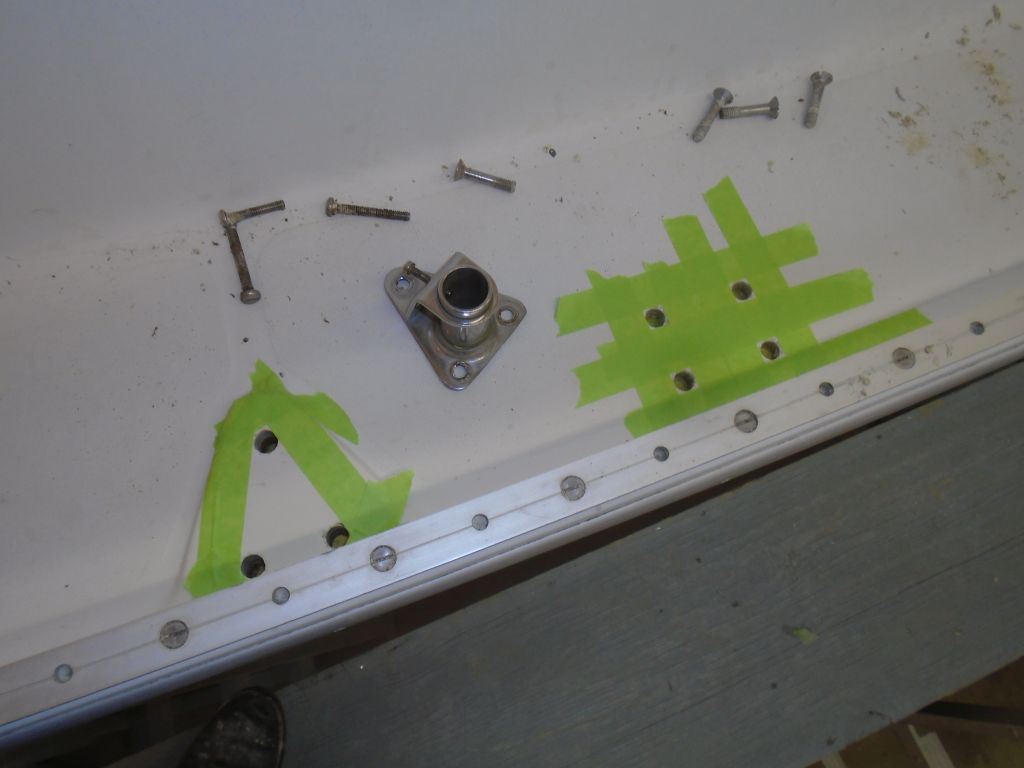
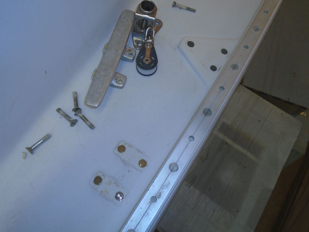
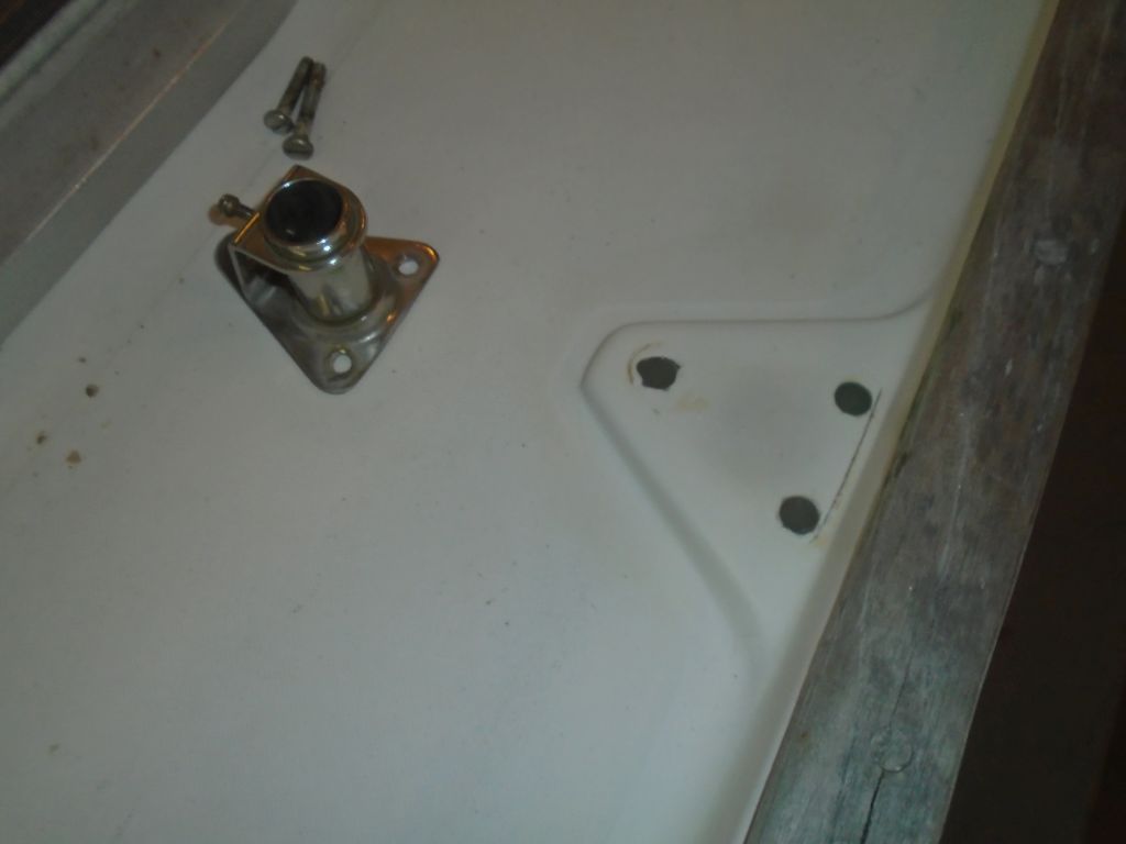
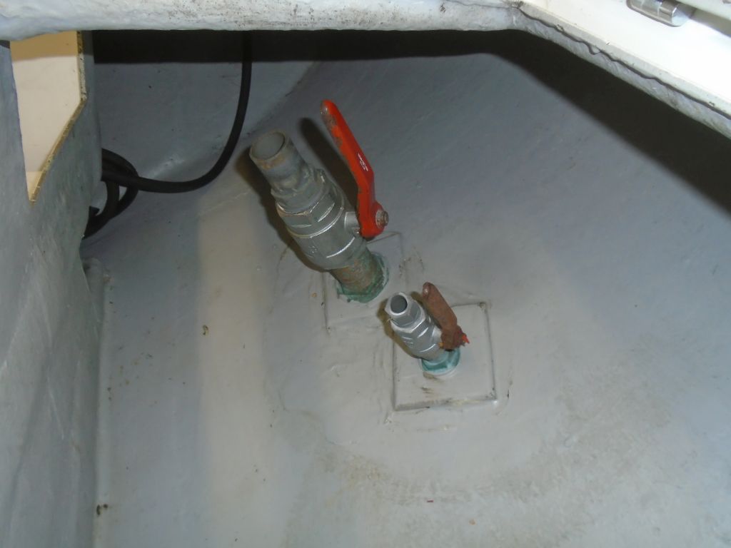
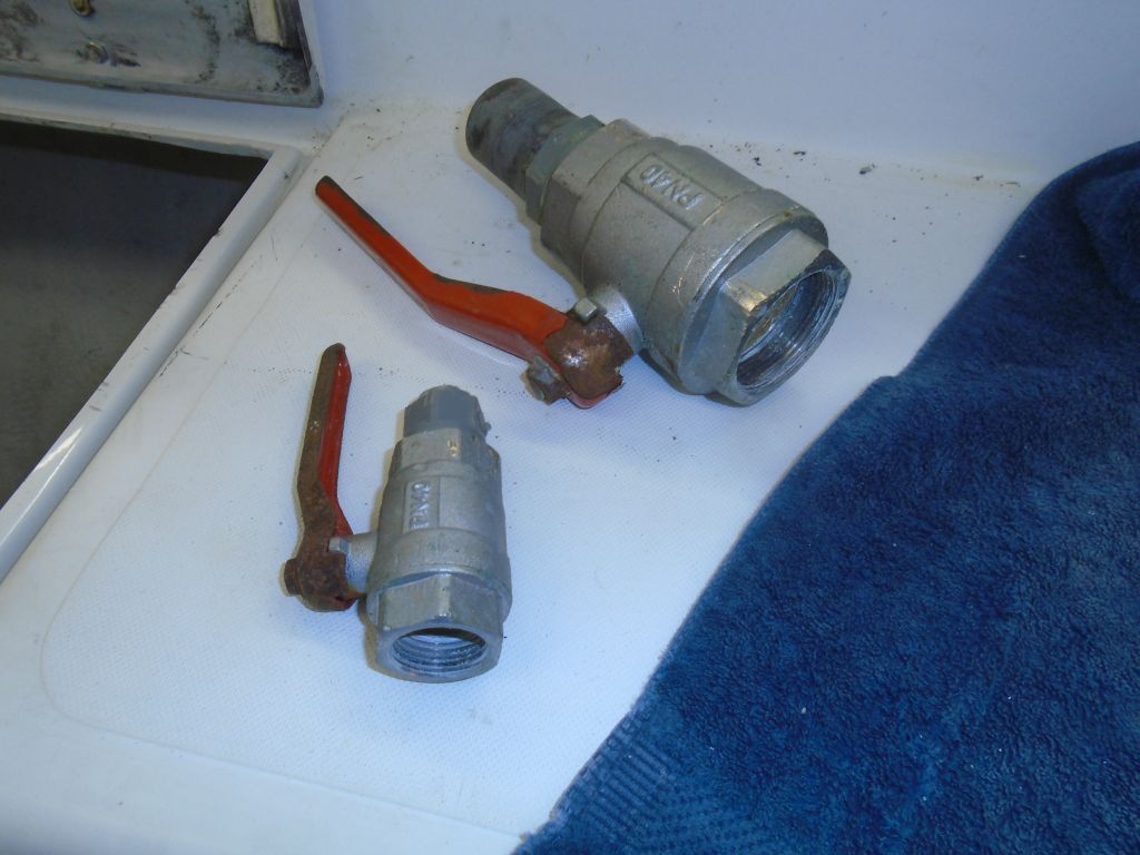
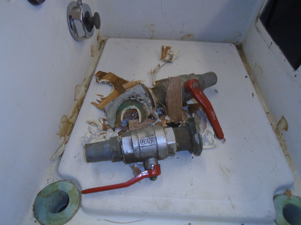
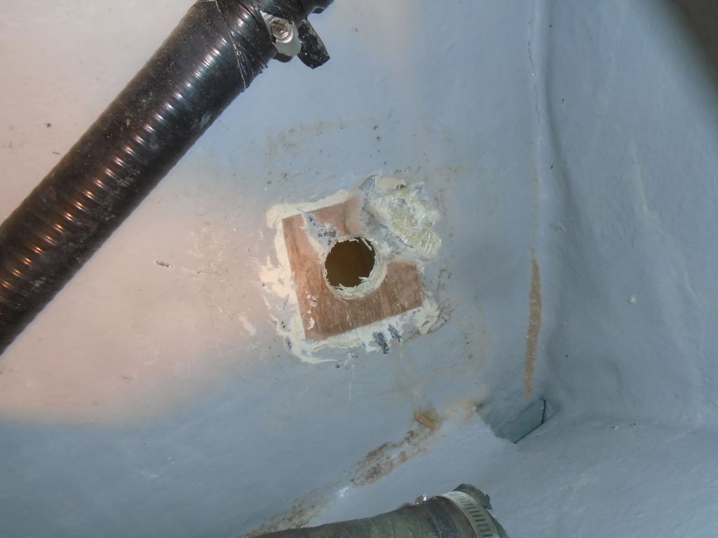
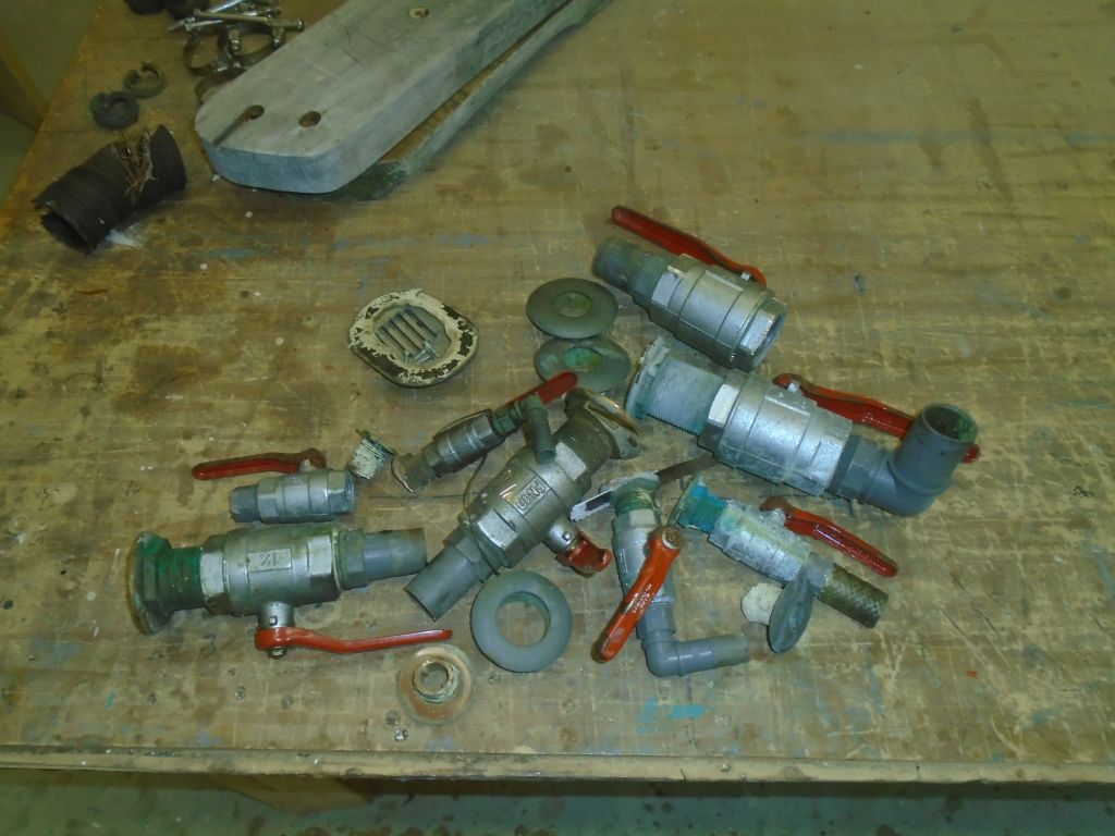
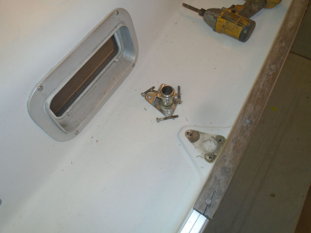
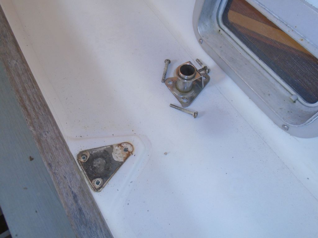
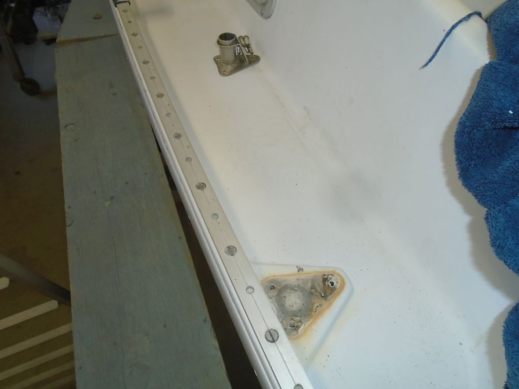
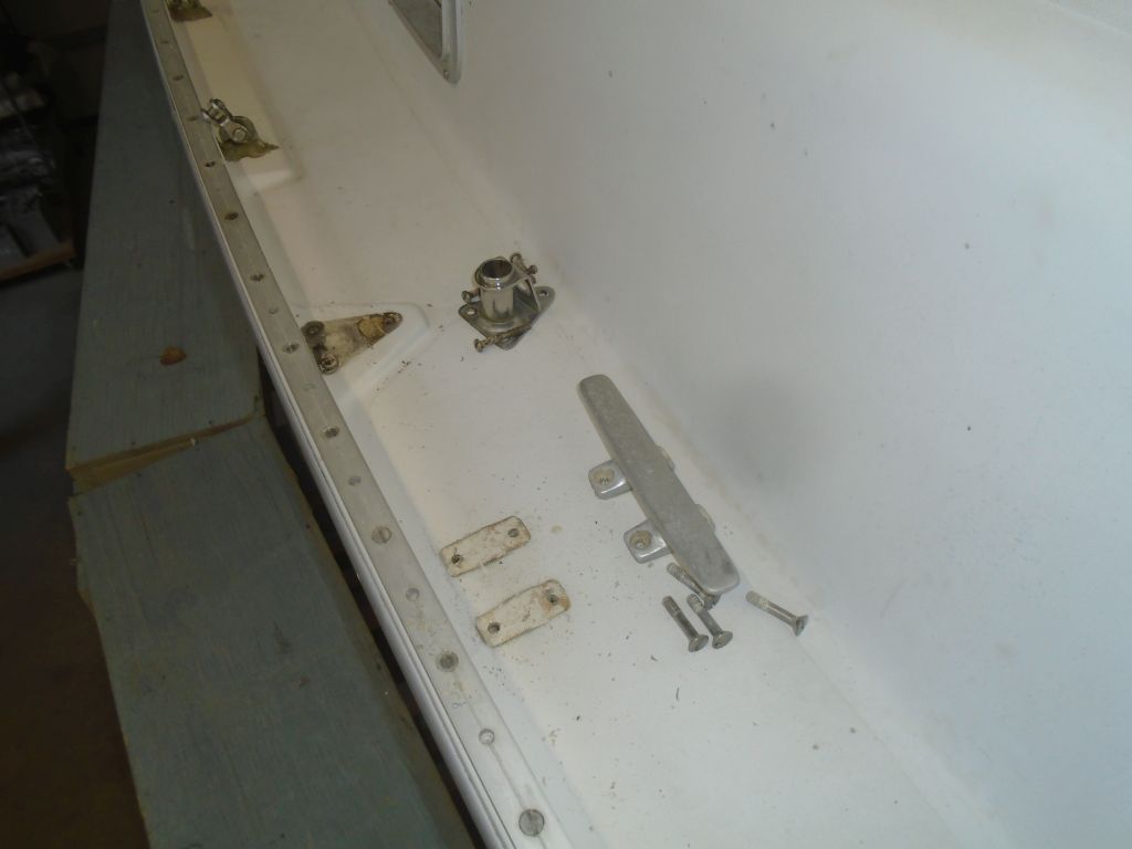
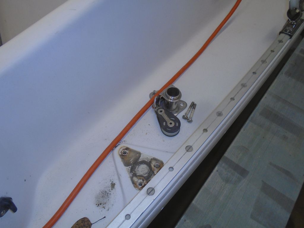
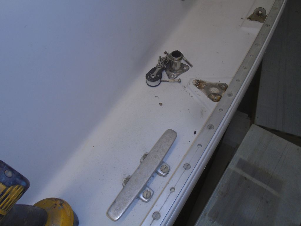
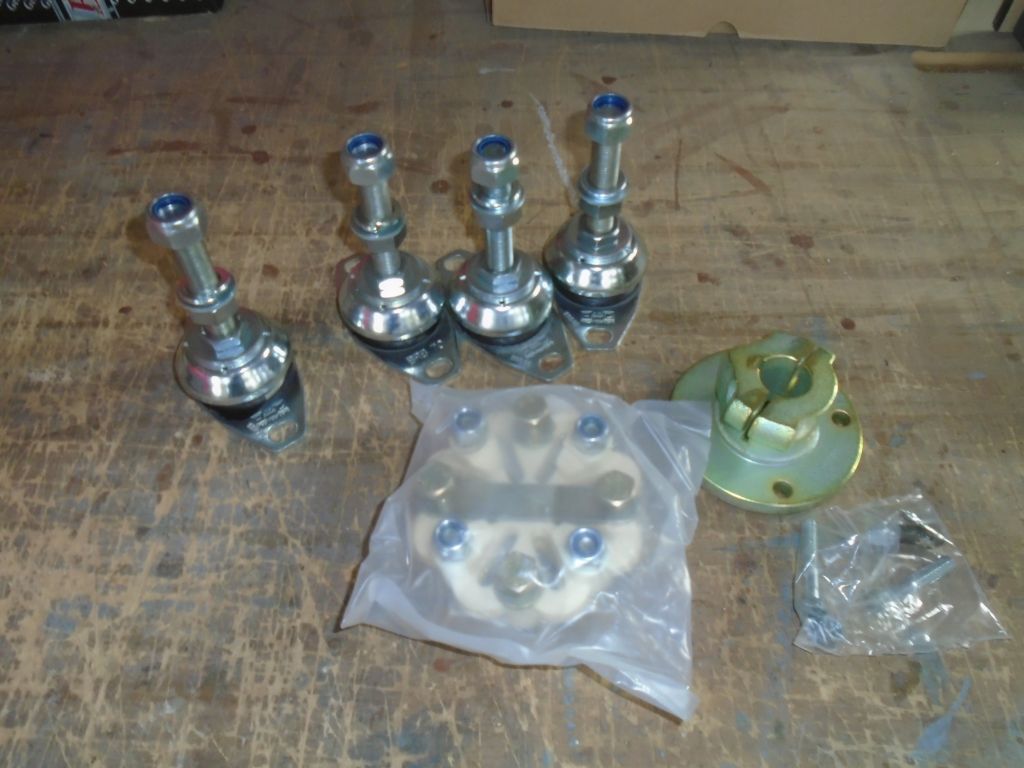
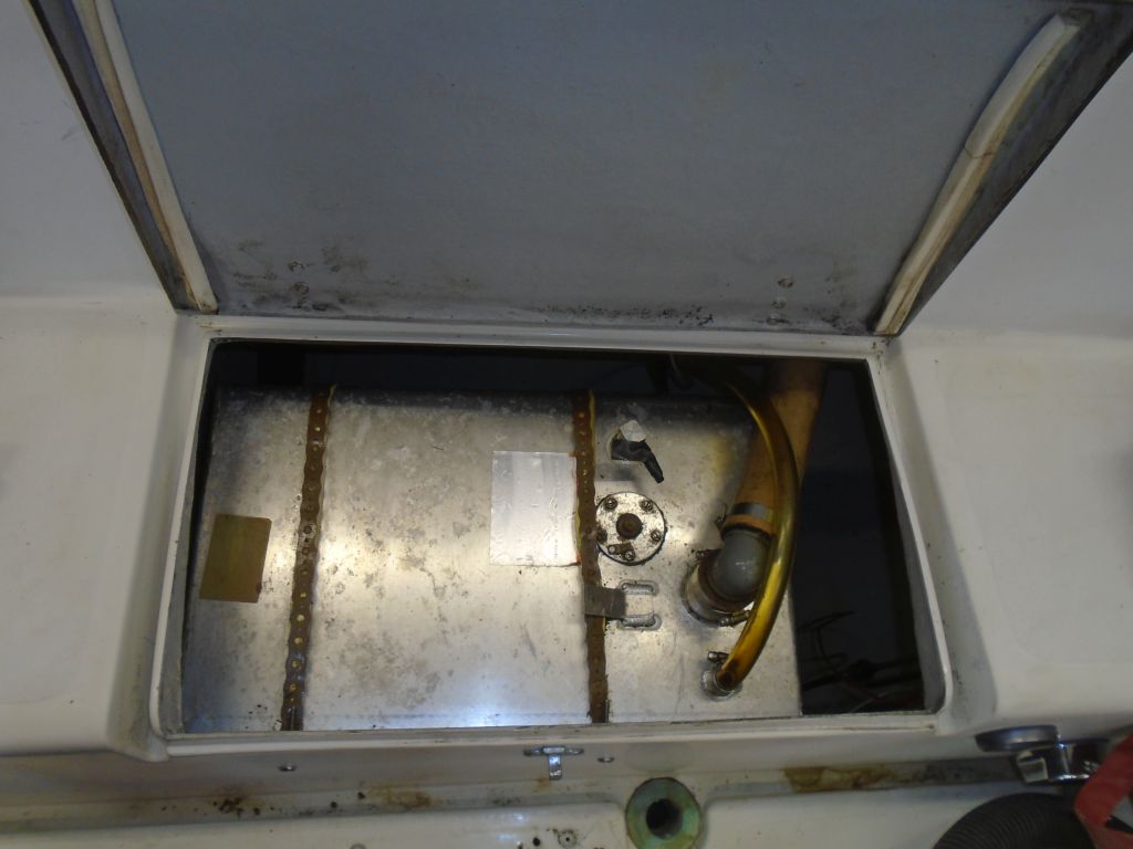
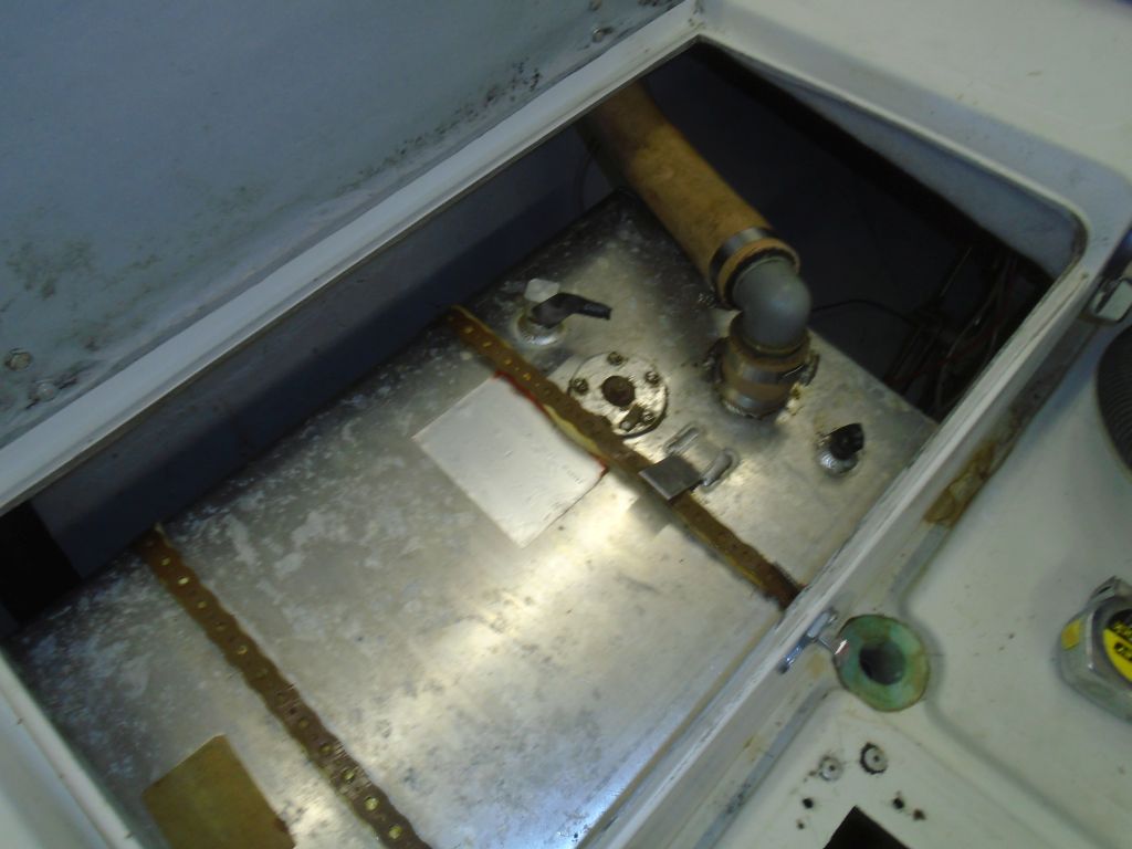
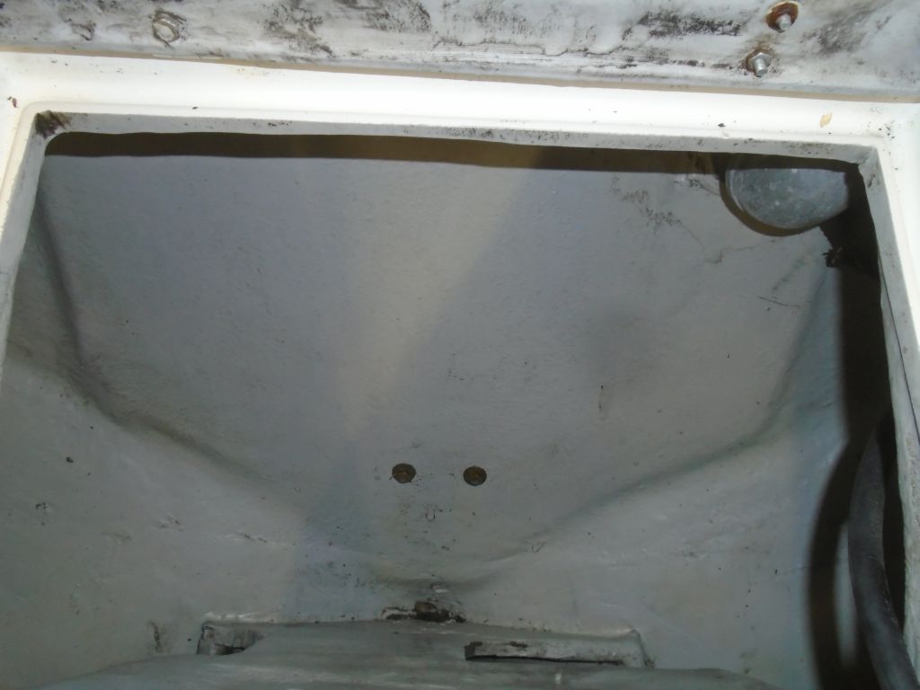
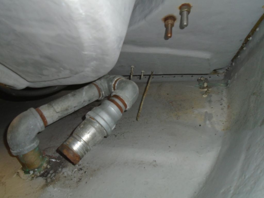
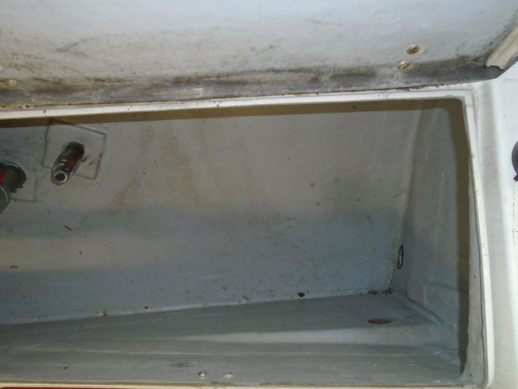
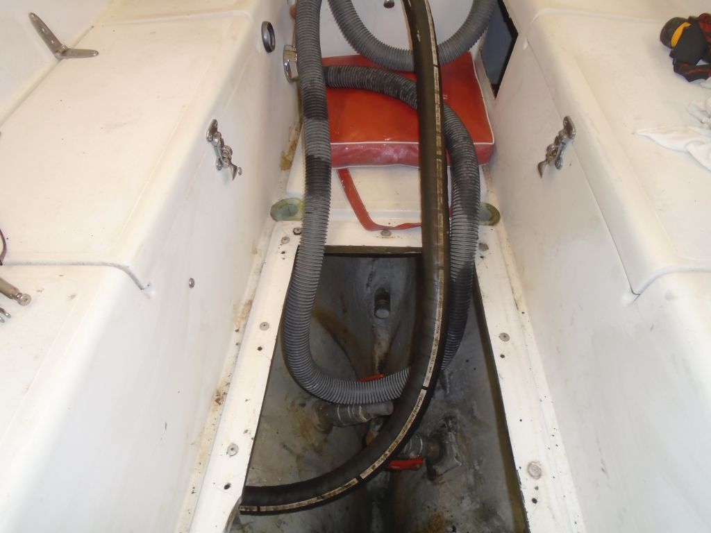
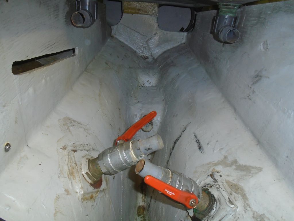
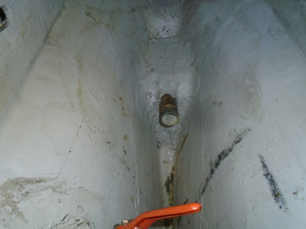
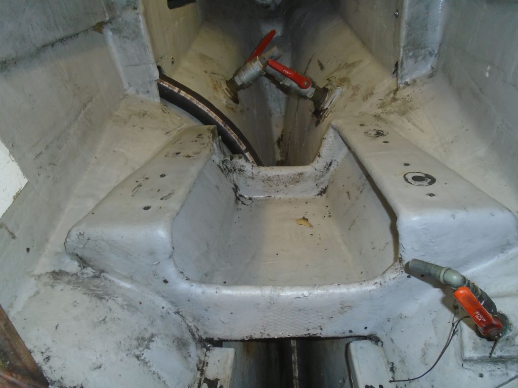
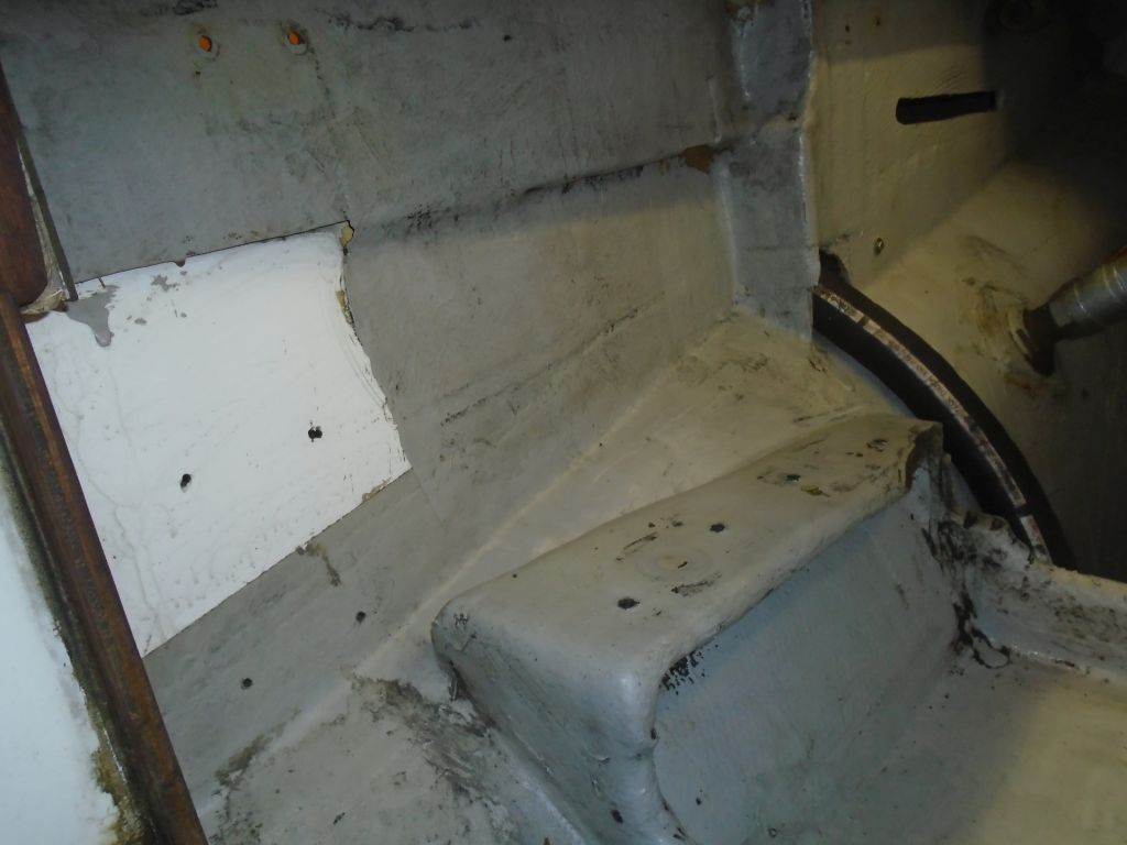
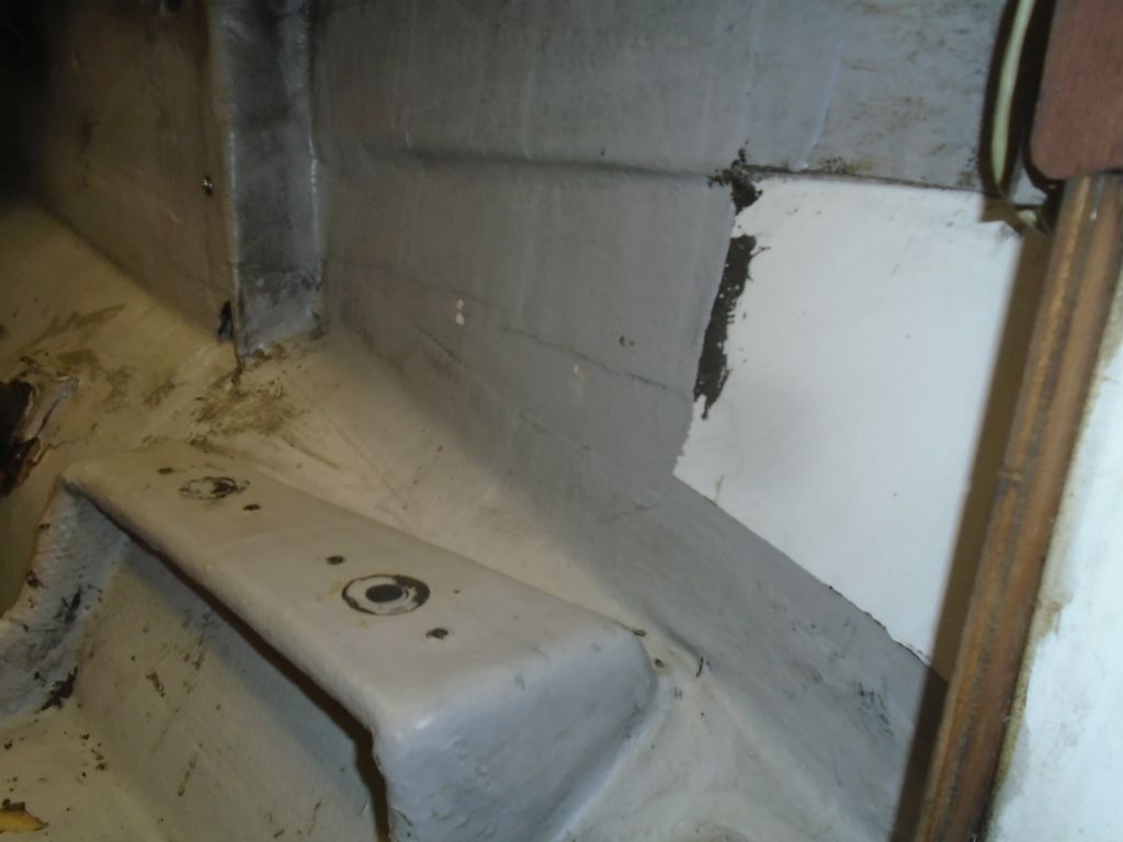
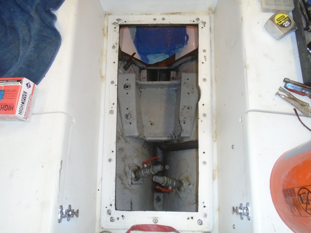
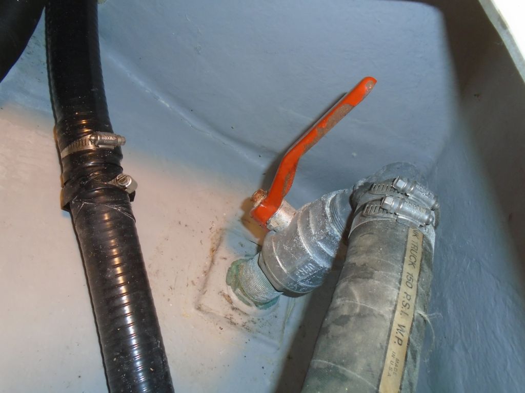
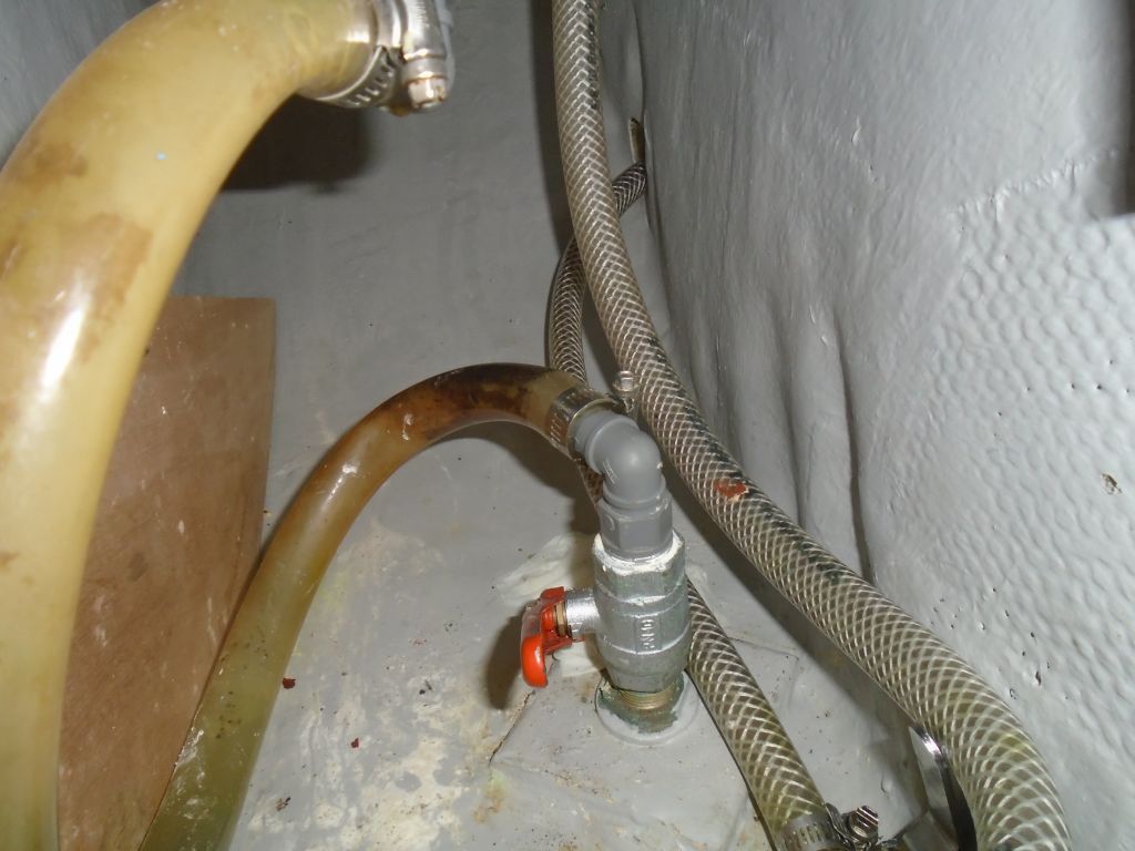
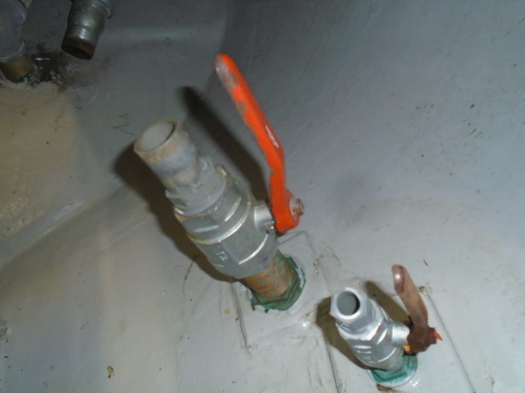
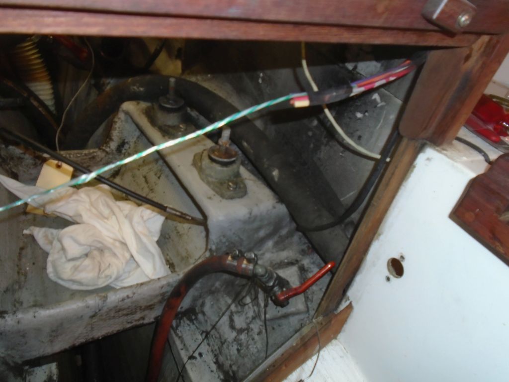
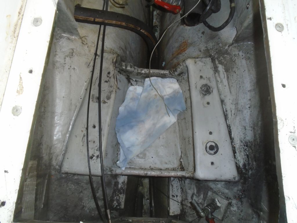
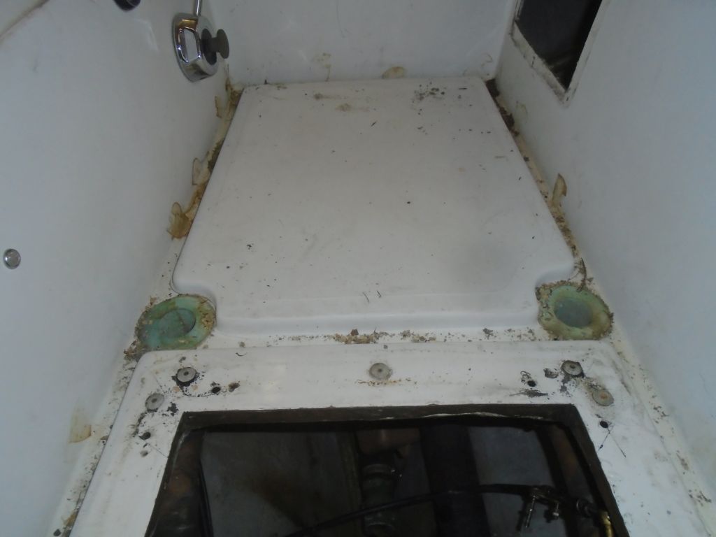
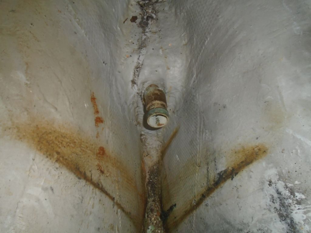
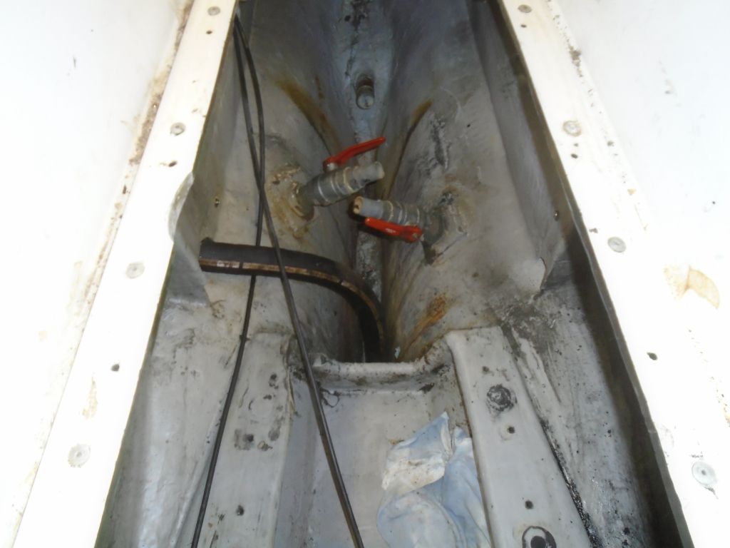
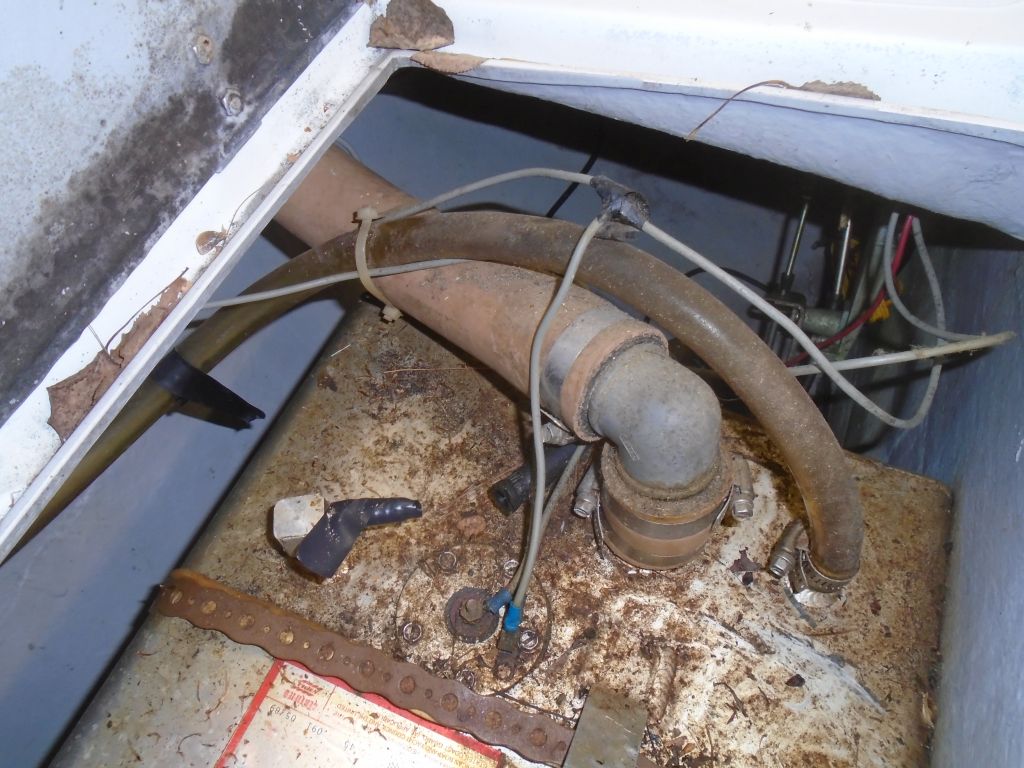
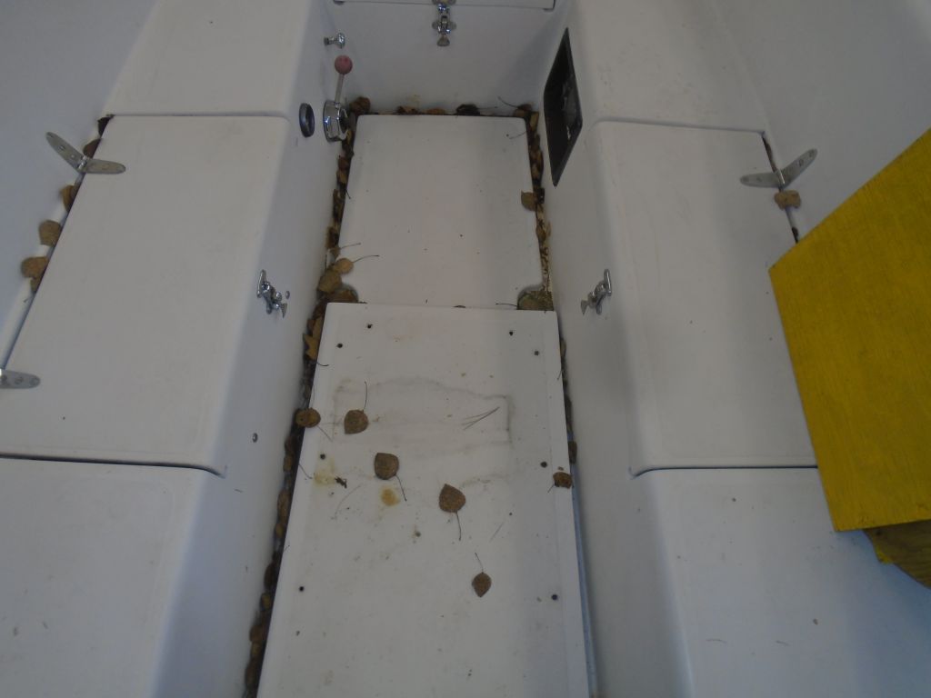
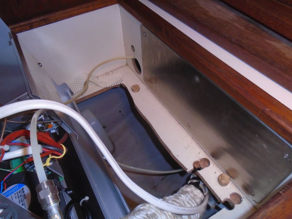
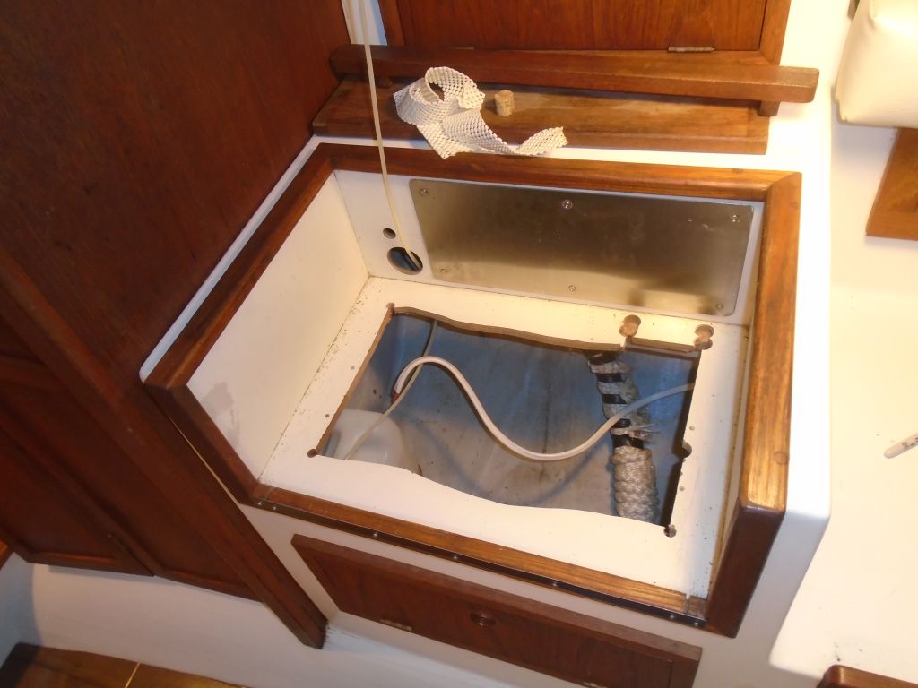
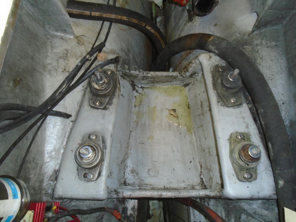
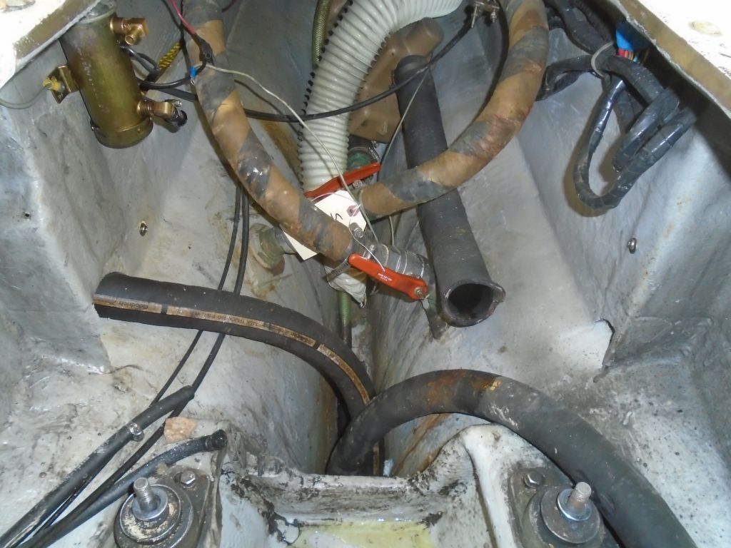
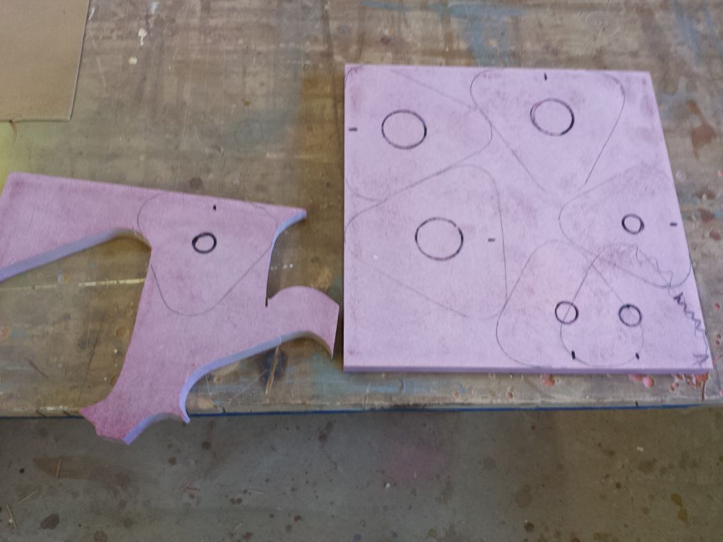
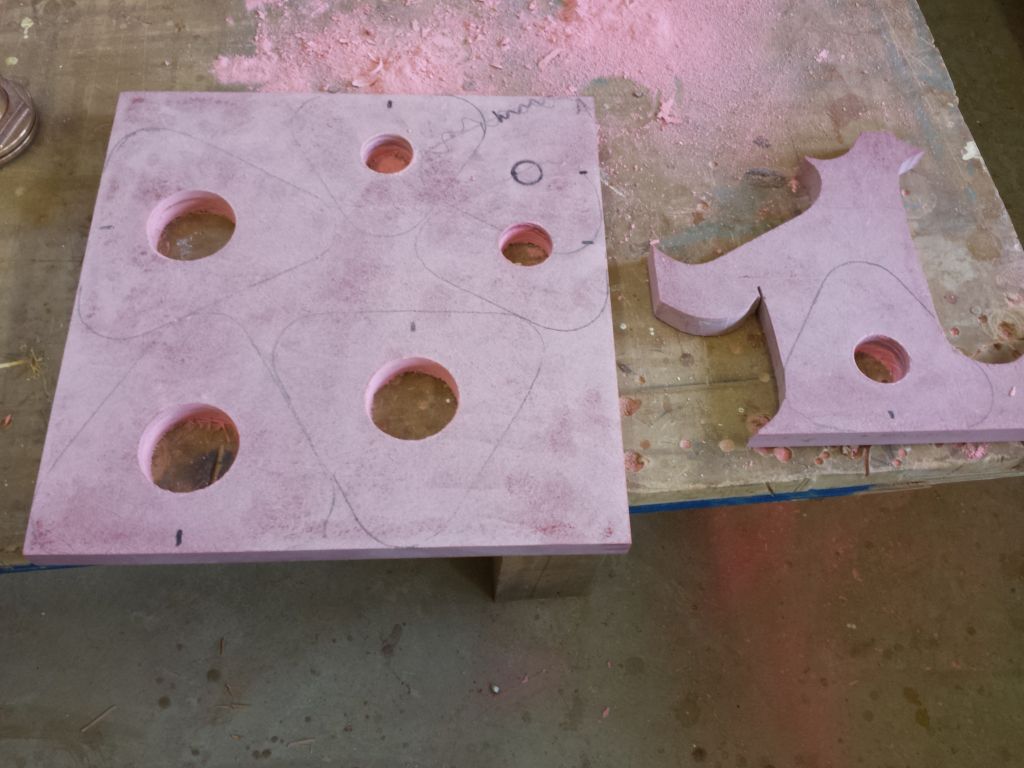
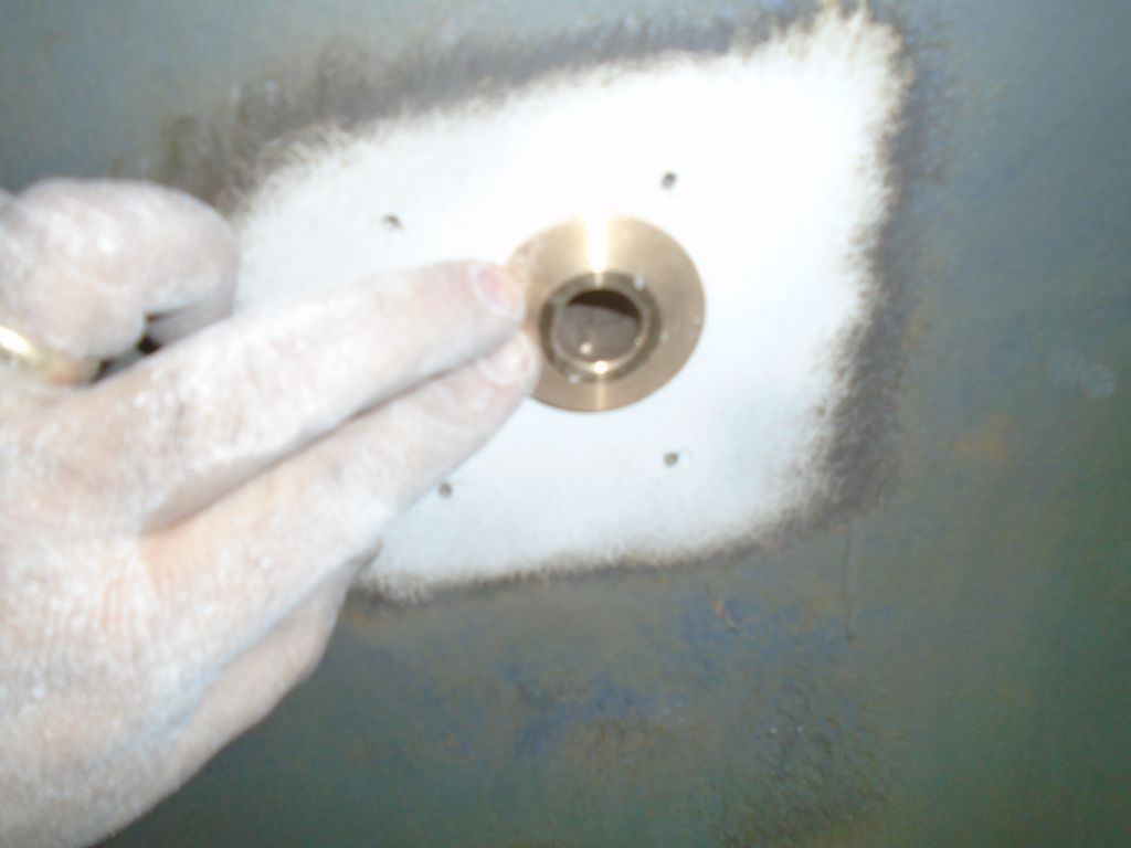
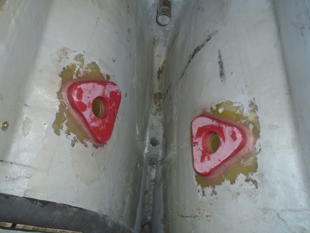
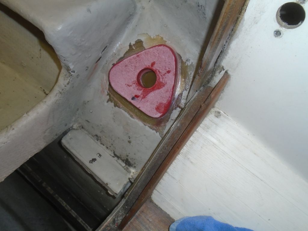
Back at the bench, I got ready to prepare six fiberglass backing blocks for the new seacocks.  On a sheet (plus a little scrap) of 3/4″ thick prefab fiberglass, I laid out blocks for three large (1-1/2″) bases  and three smaller (3/4″) bases, then drilled holes for the through hulls before cutting out the bases and, finally, sanding the edges clean and slightly easing the top edges for looks and tactile feel.

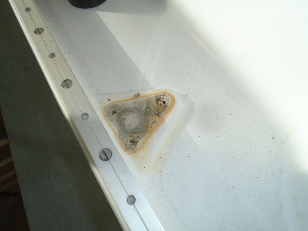
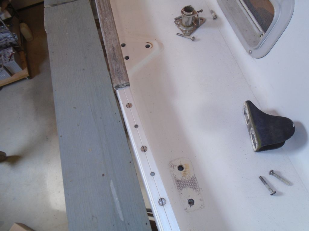
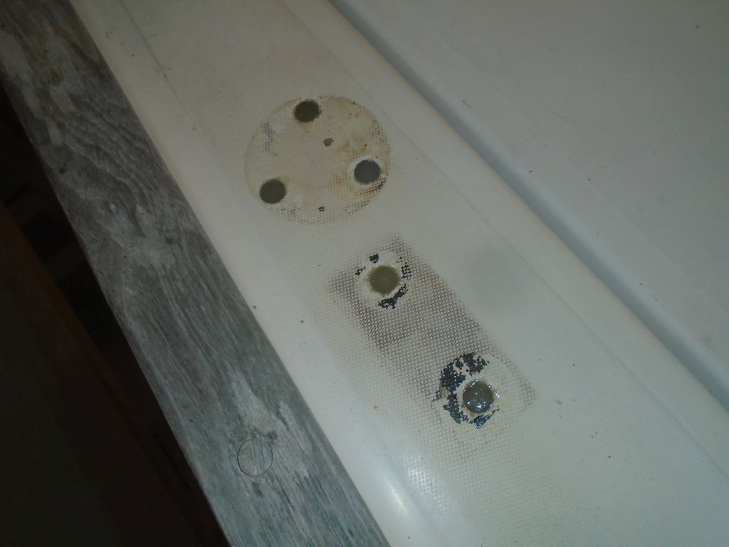
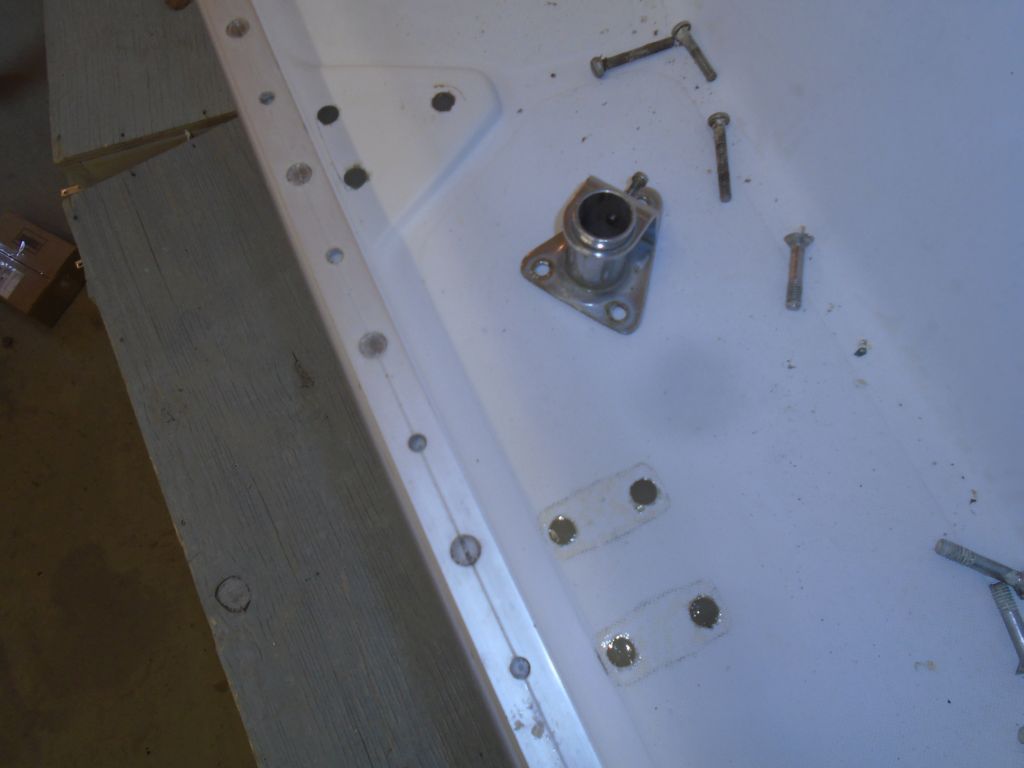
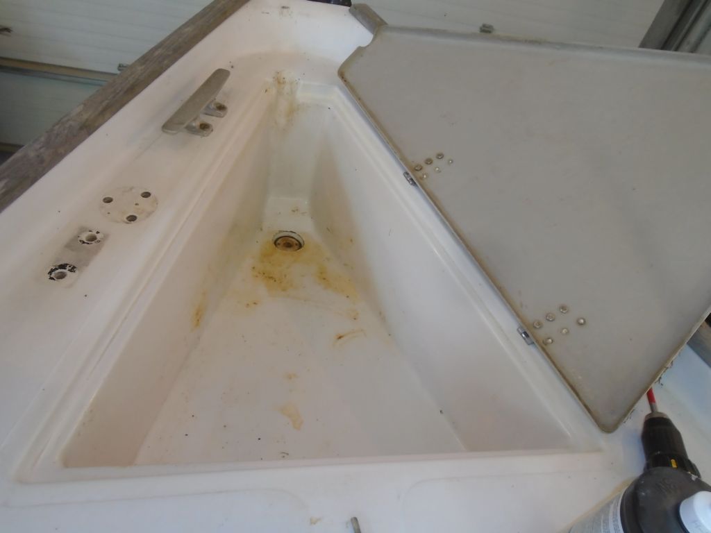
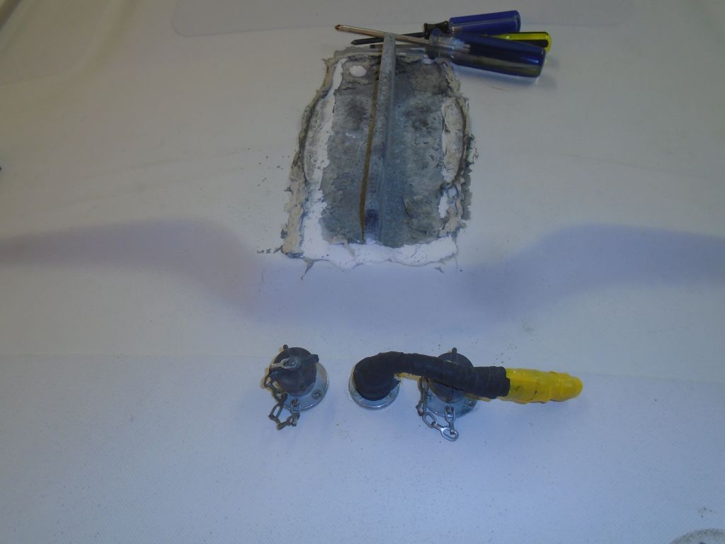
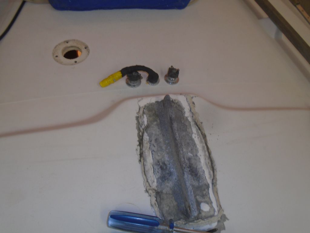
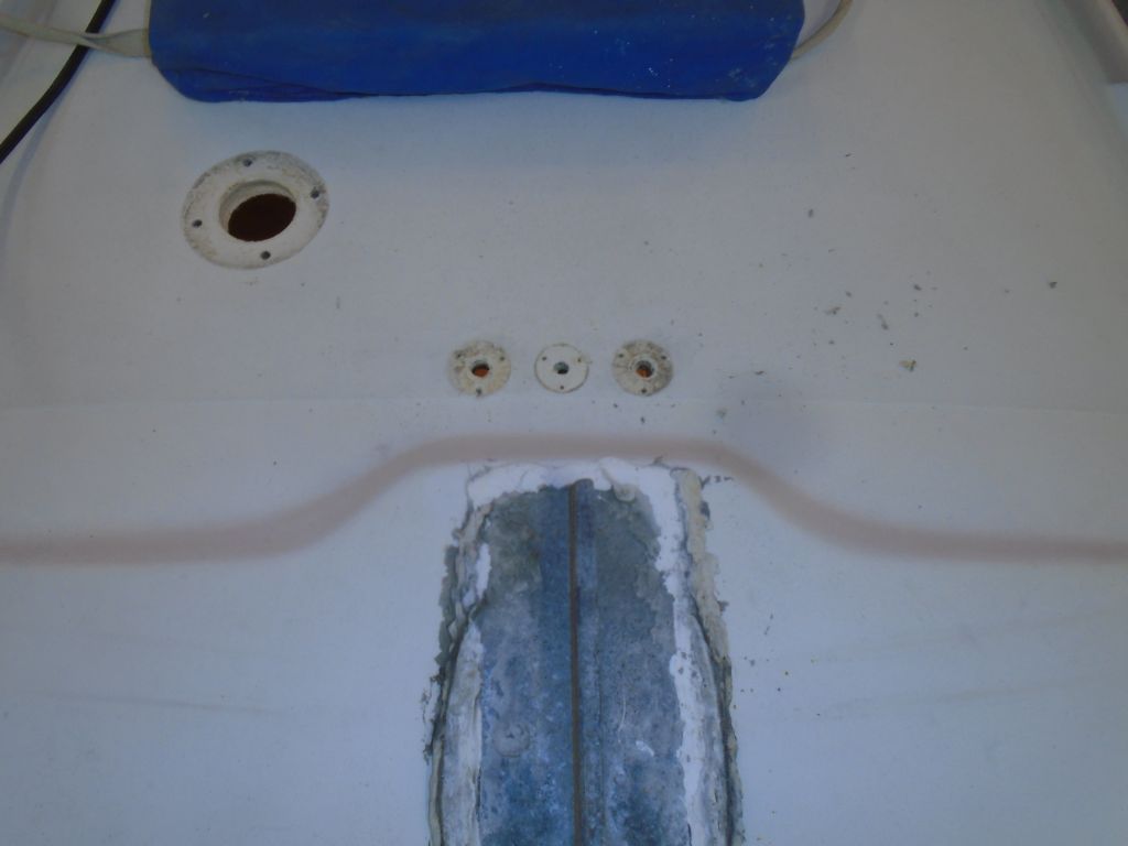
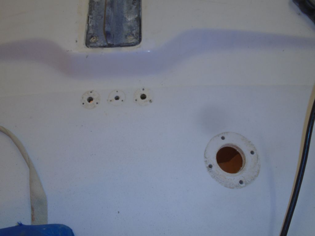
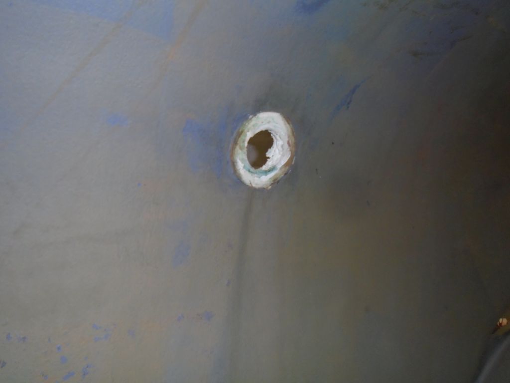
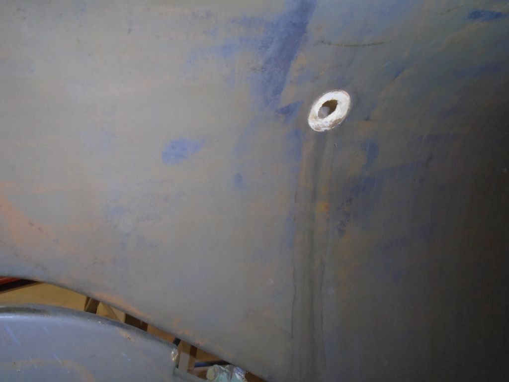
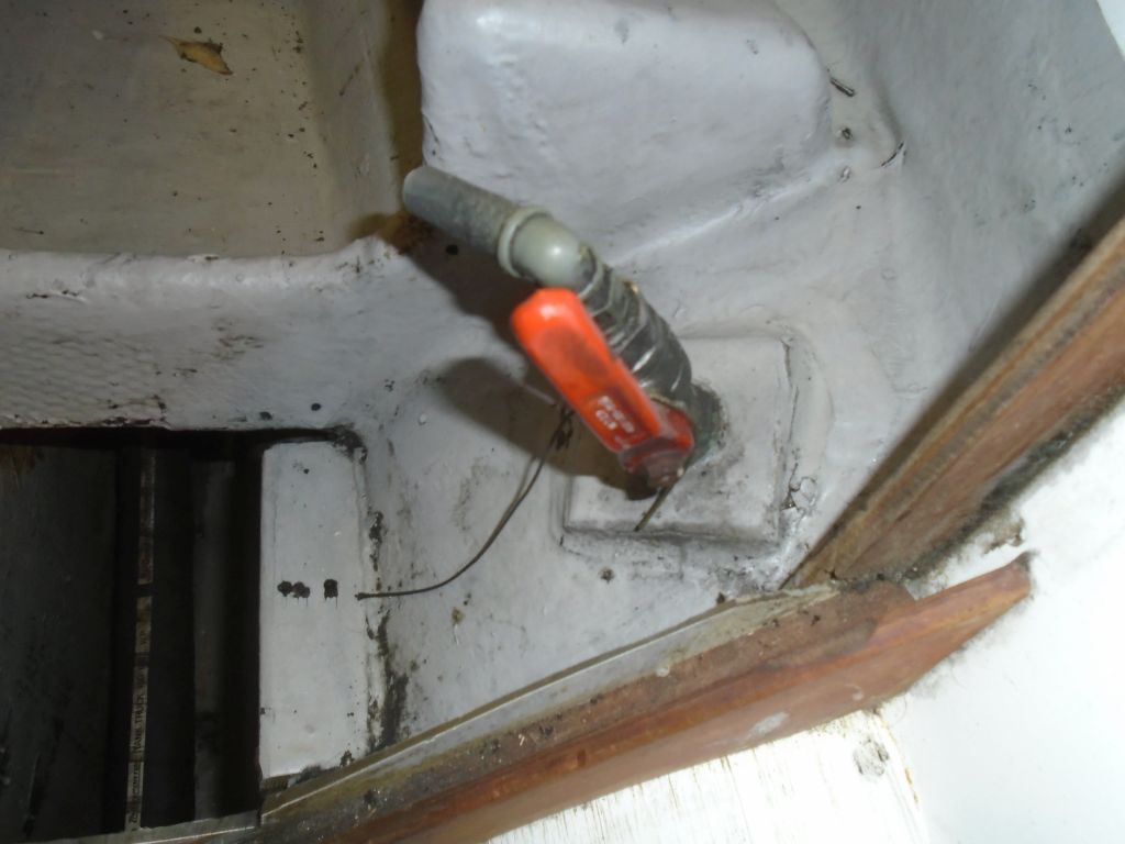
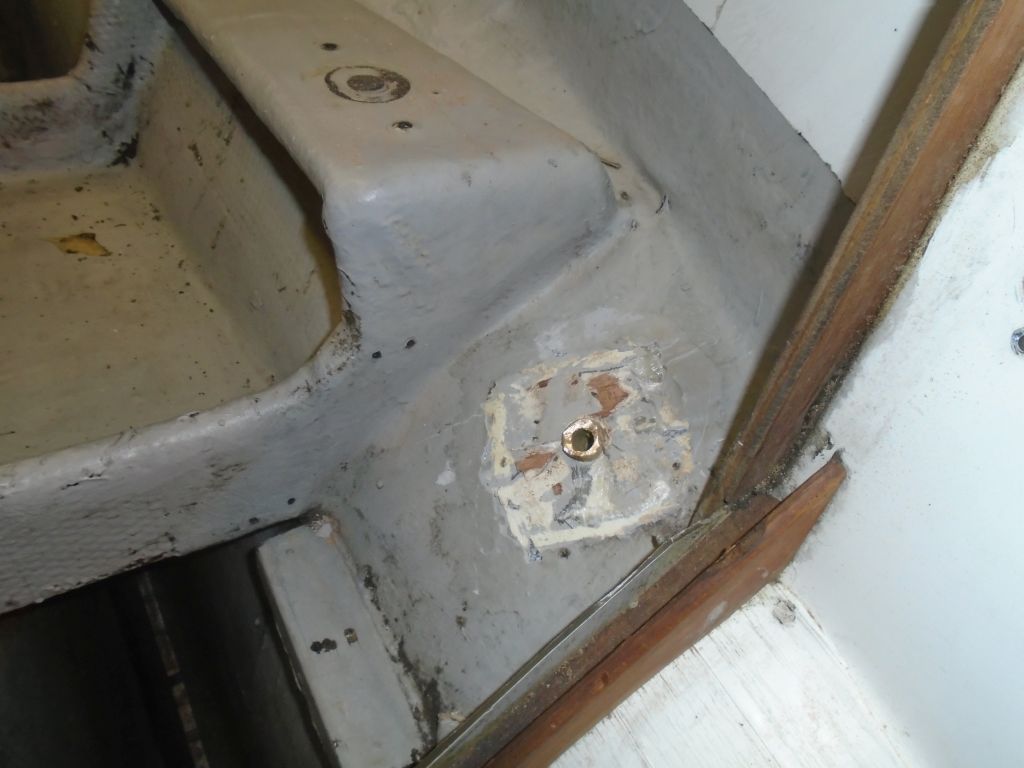
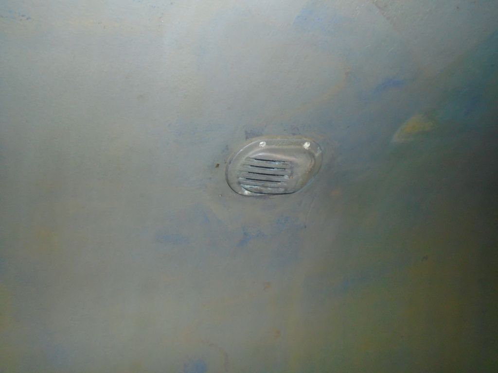
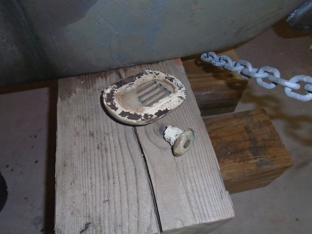
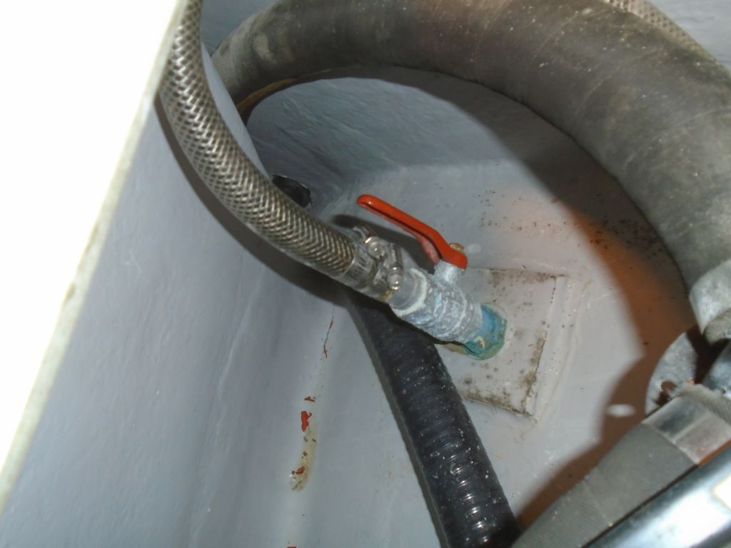
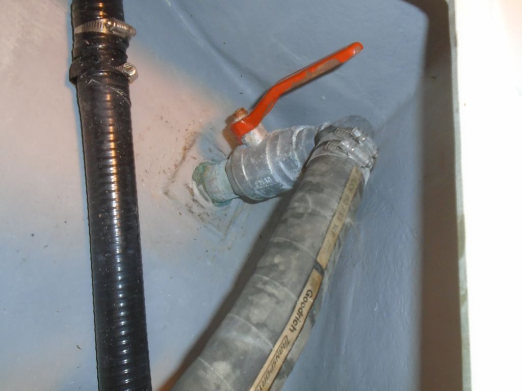
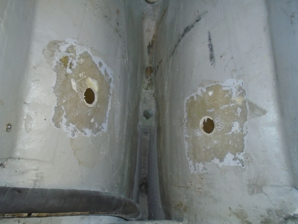
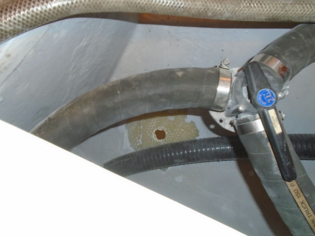
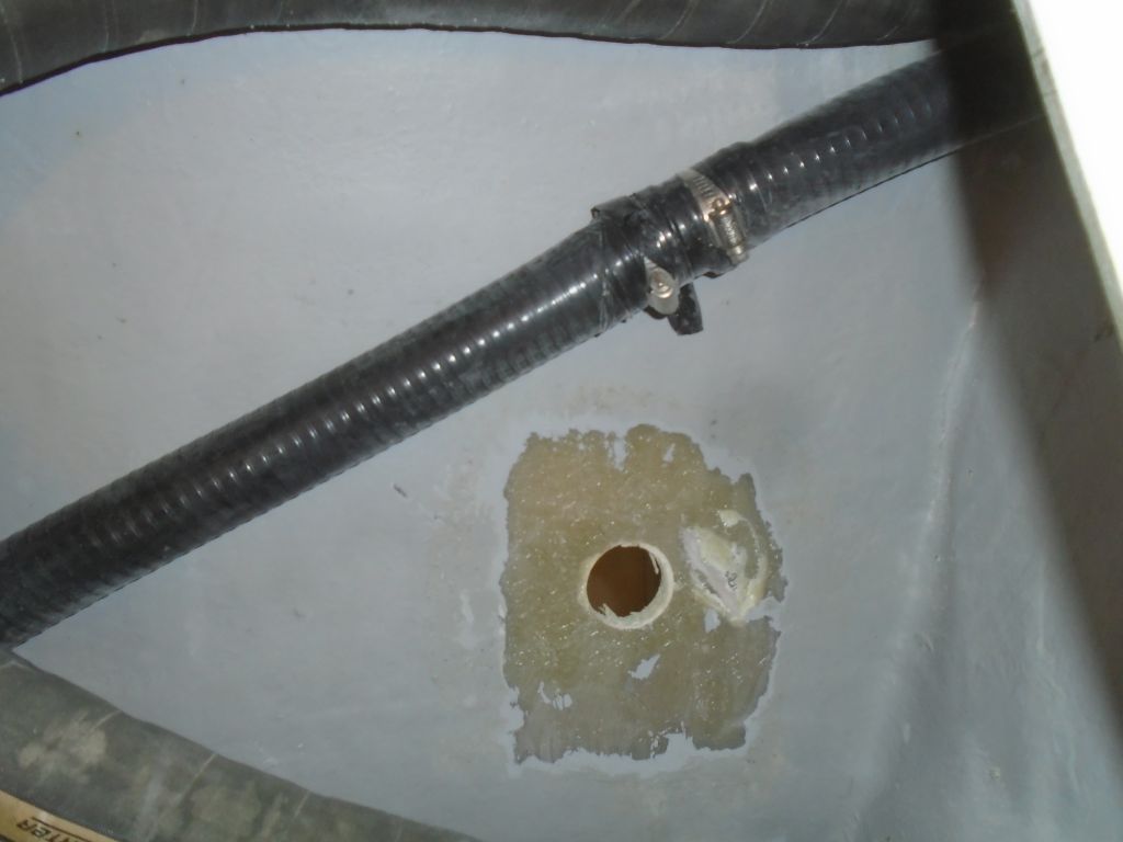
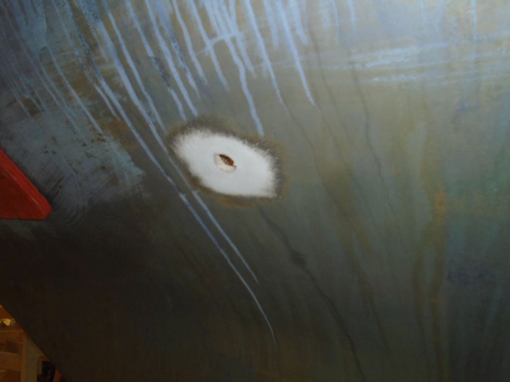
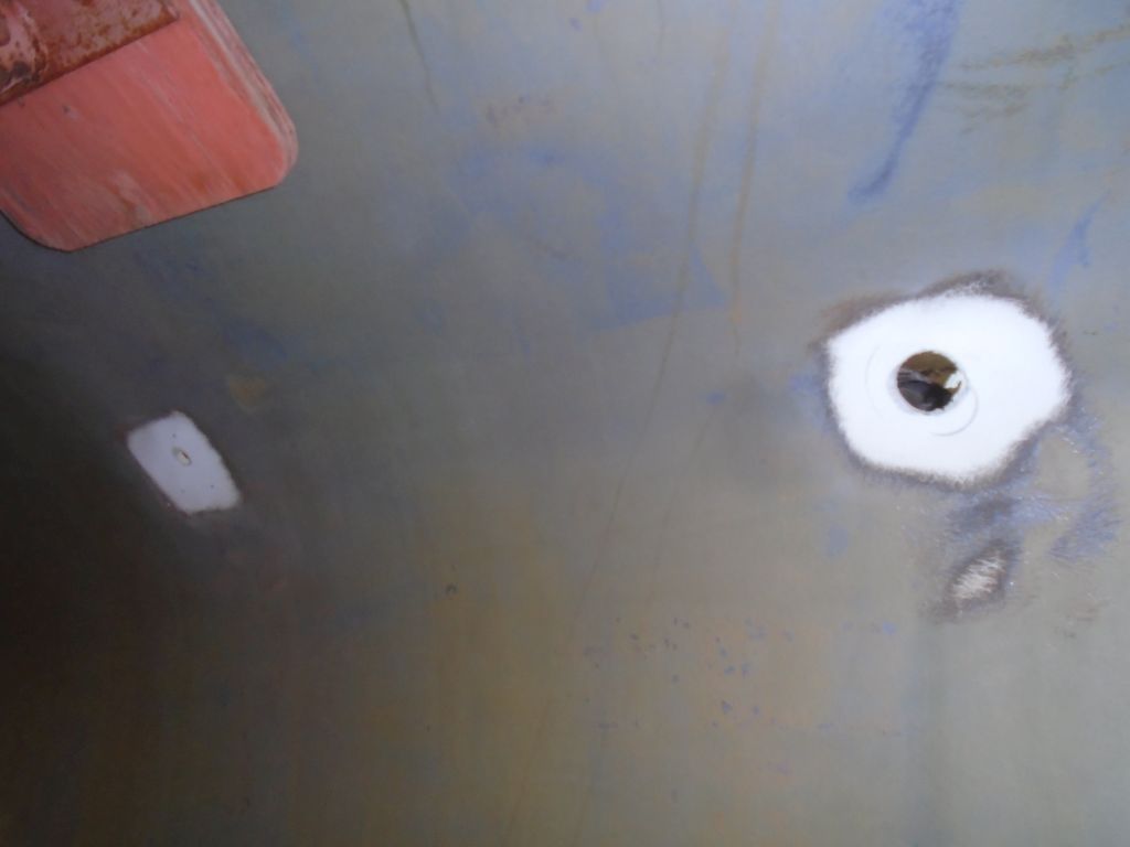
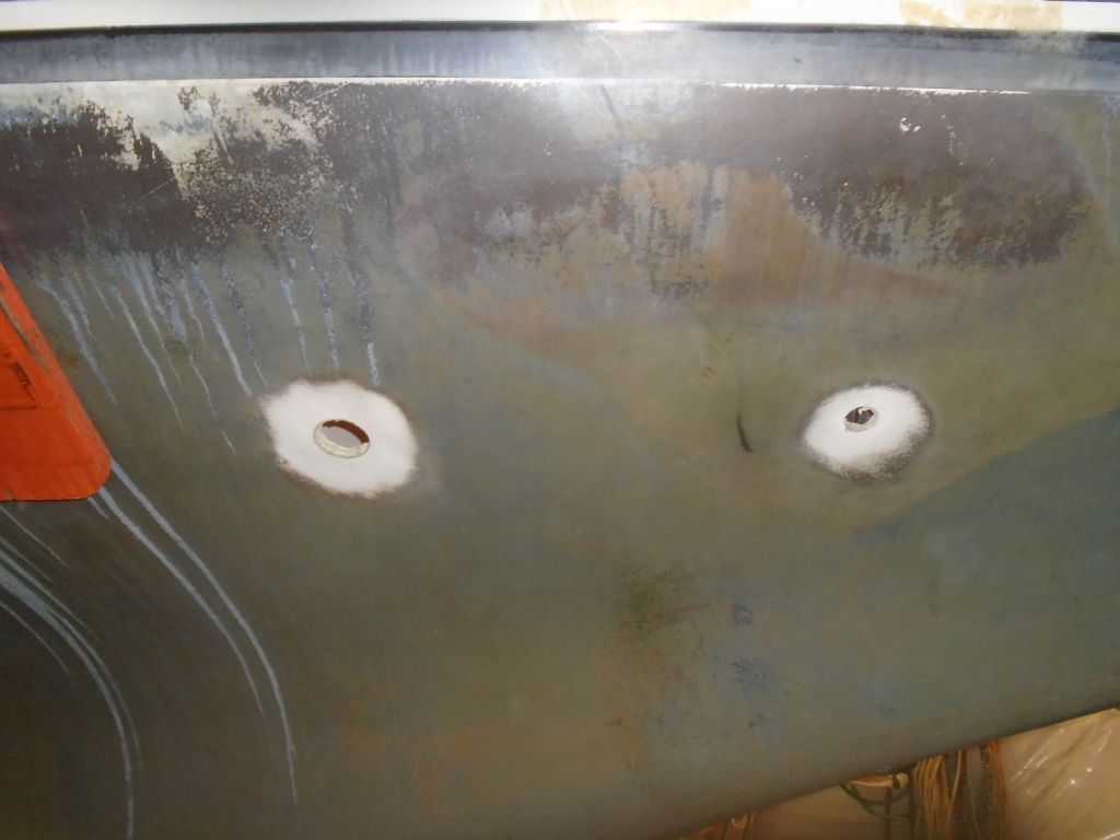
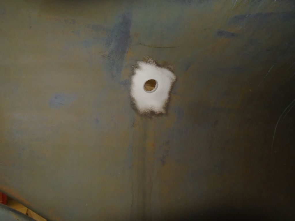
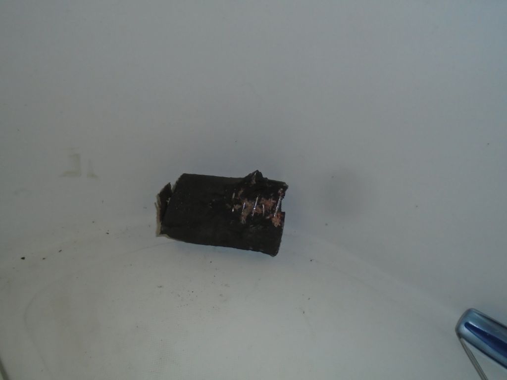
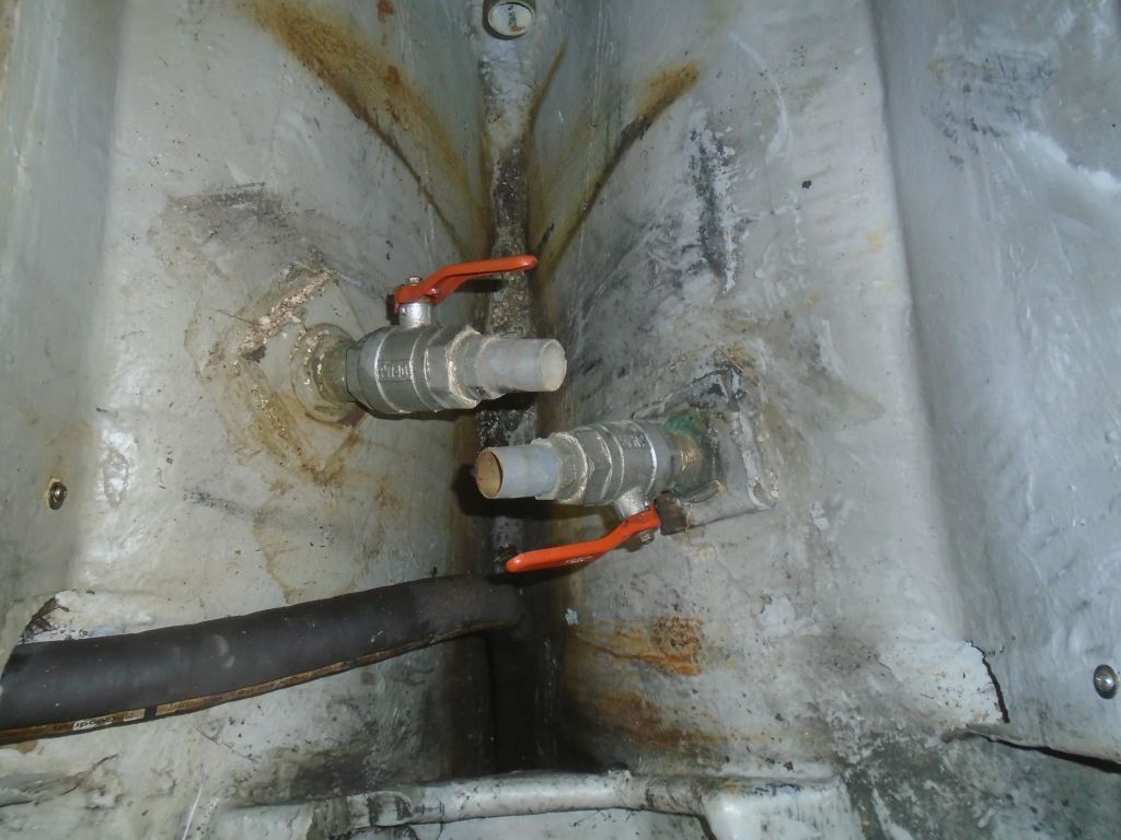
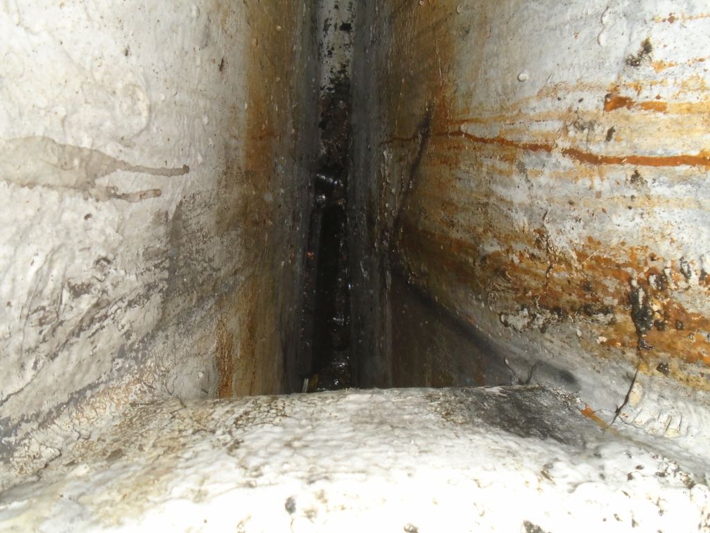
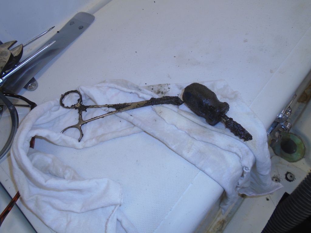
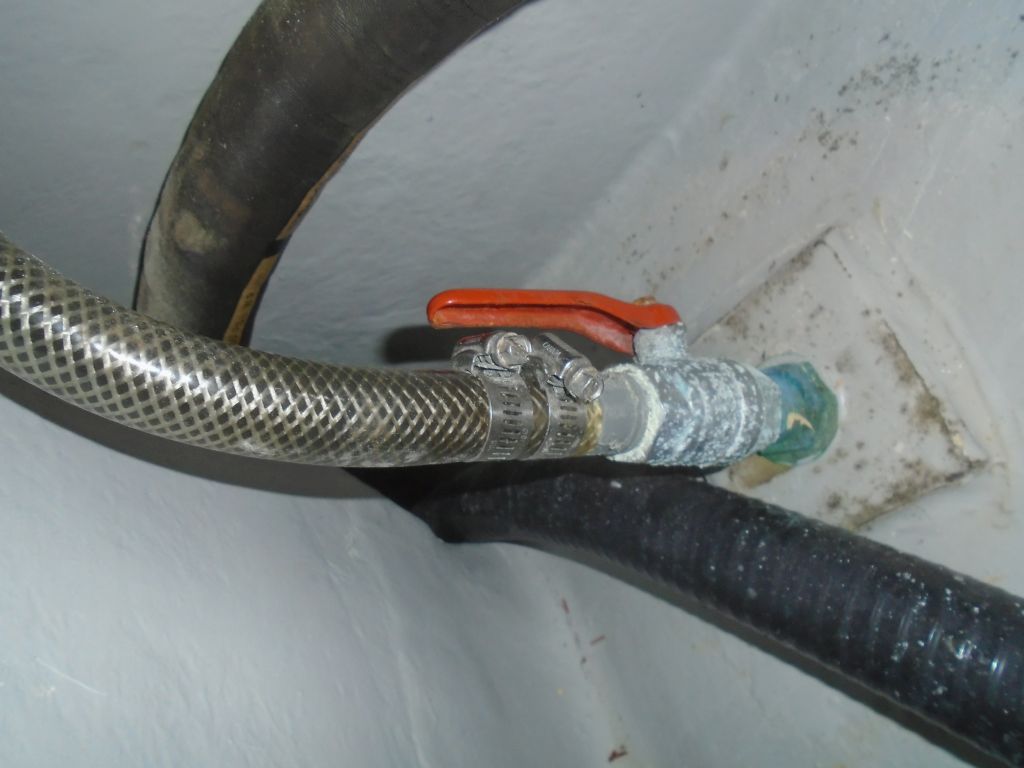
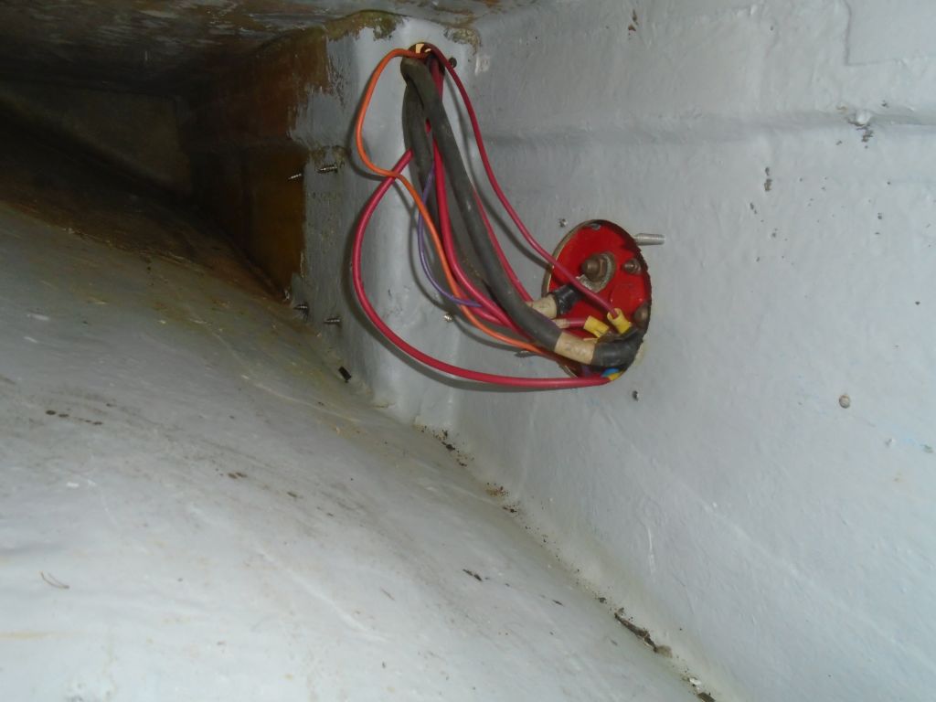
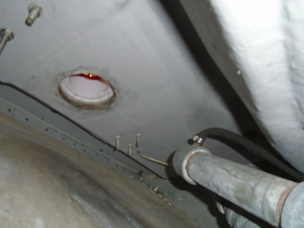
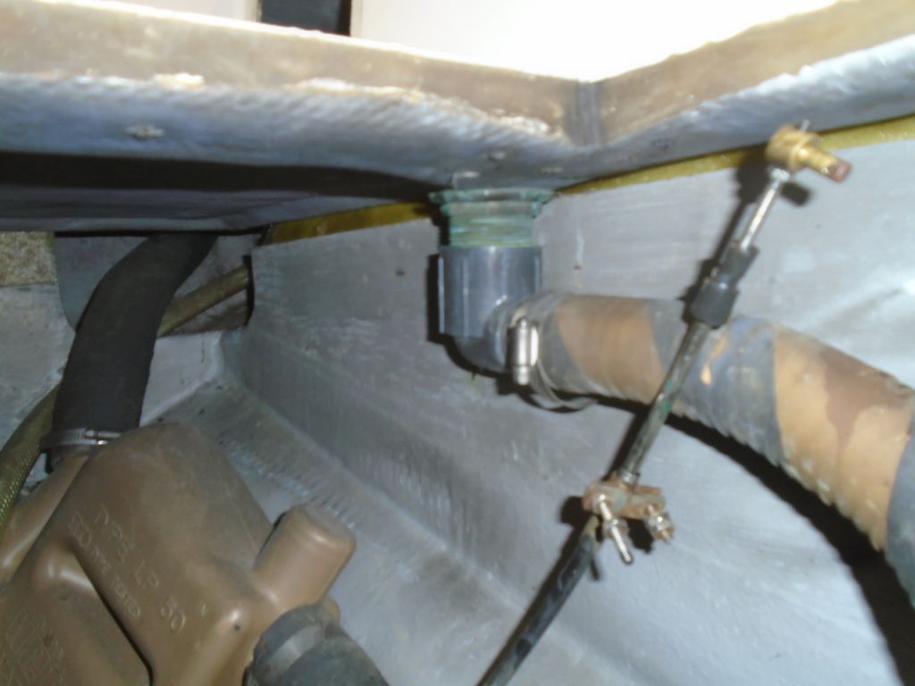
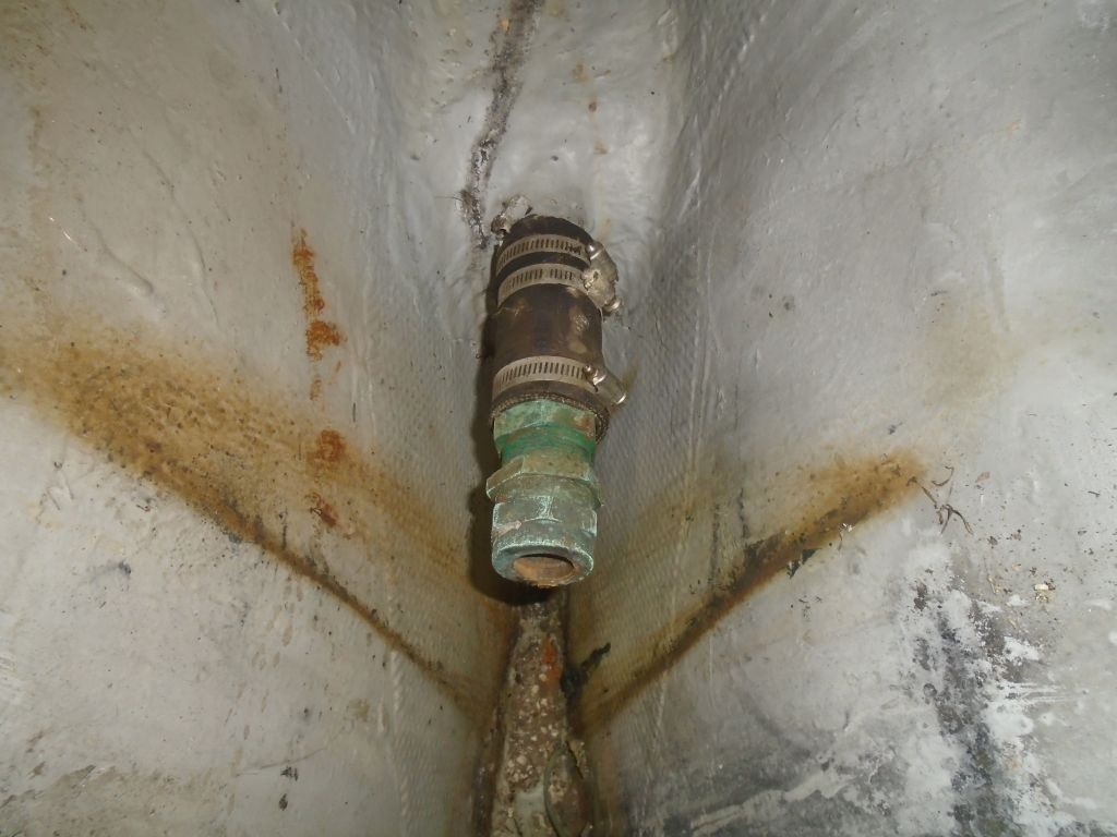
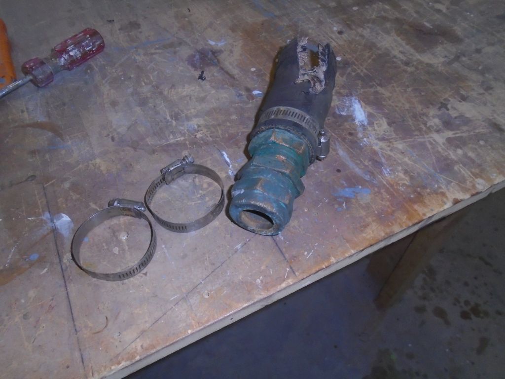
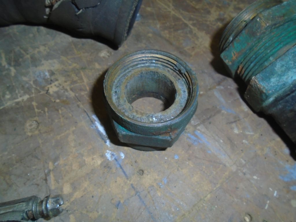
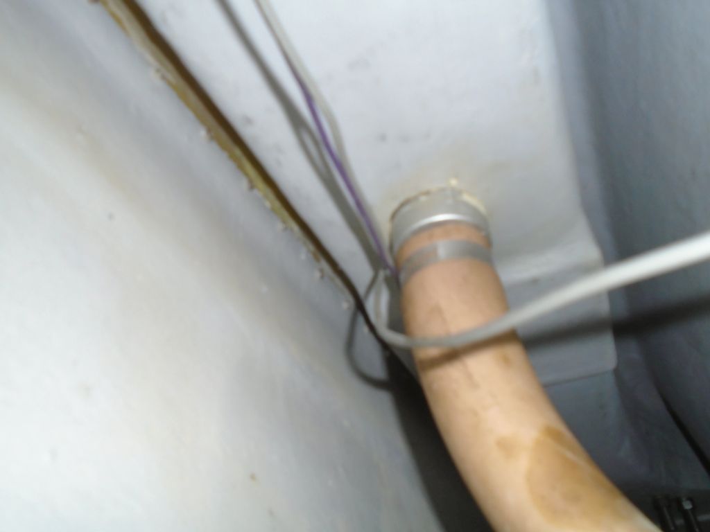
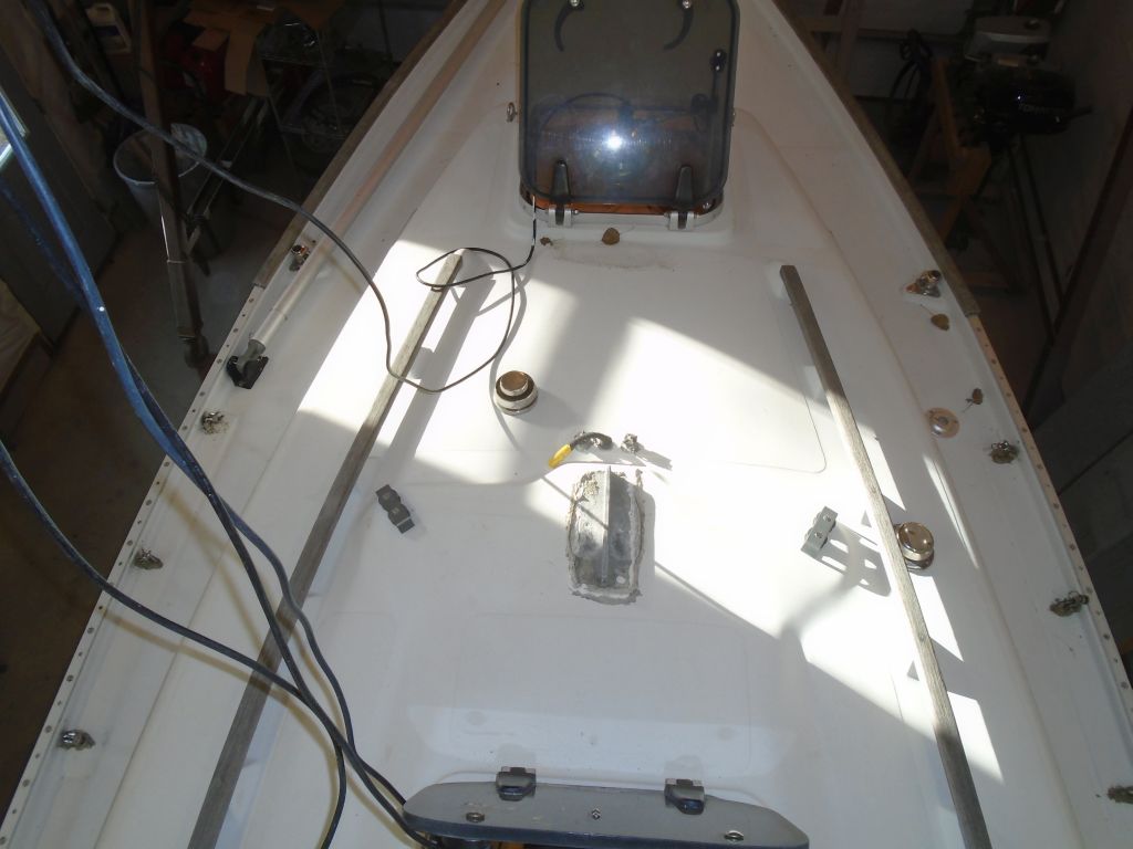
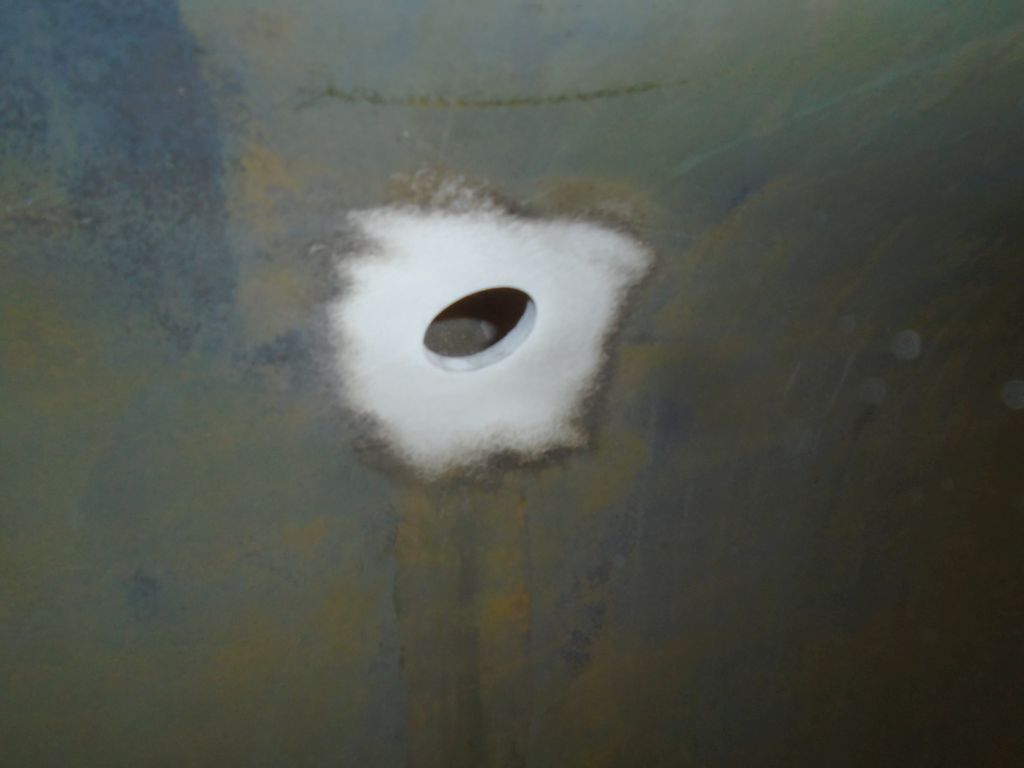
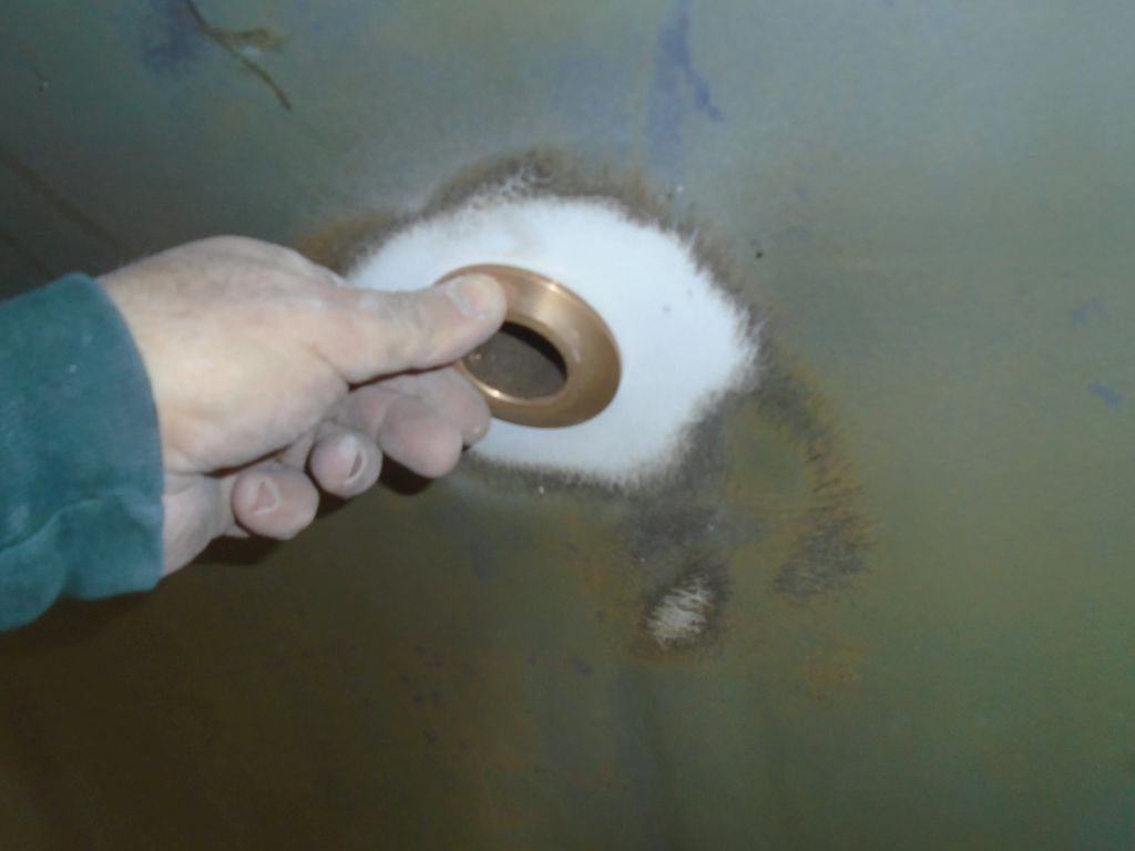
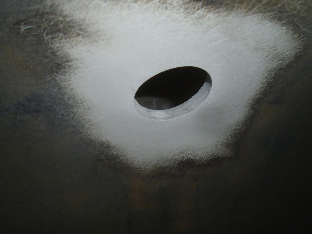
Now I cleaned out any old sealant from within the original hull holes, using a knife and then a drum sander.  I found that the original holes leftover from the larger fittings (scuppers and head discharge) were just slightly smaller than the diameter of the new through hulls, so I used a drum sander to open up the holes enough for the new fittings to slip in properly.  The old engine intake had been something like a 1/2″ fitting, but I found that the hole in the hull was actually larger, and only required a little enlarging to fit the new 3/4″ fitting.

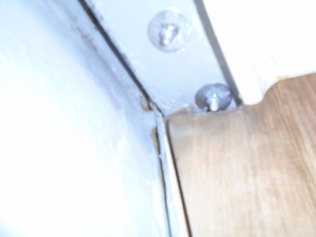
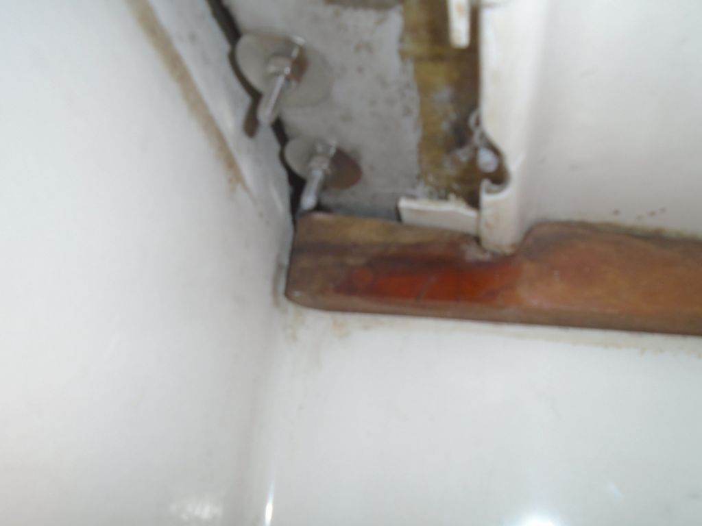
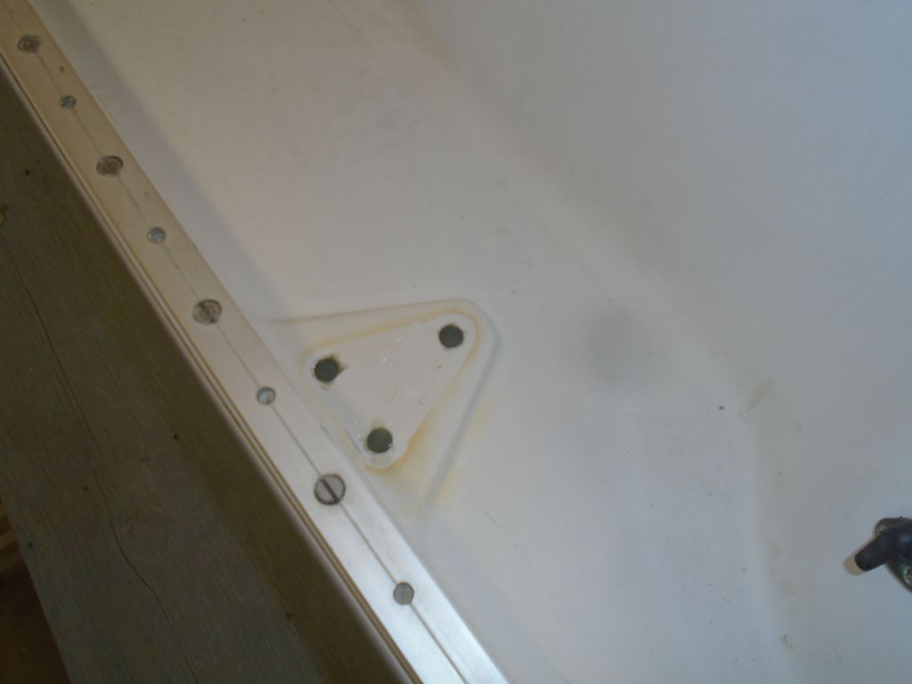
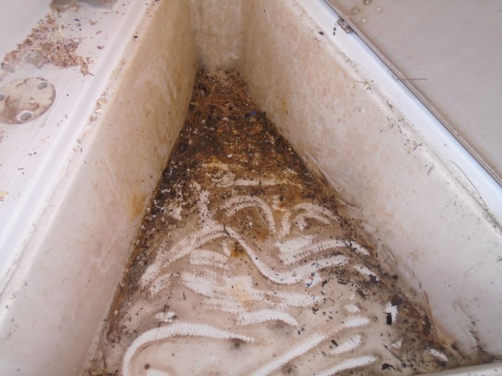
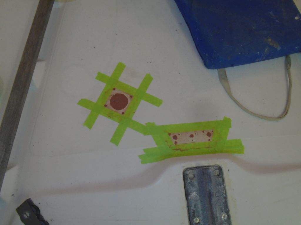
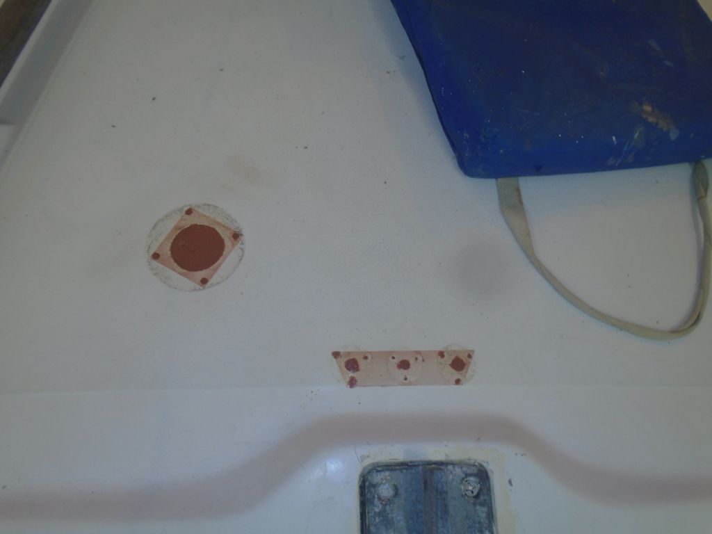
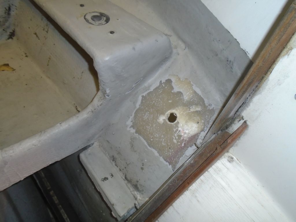
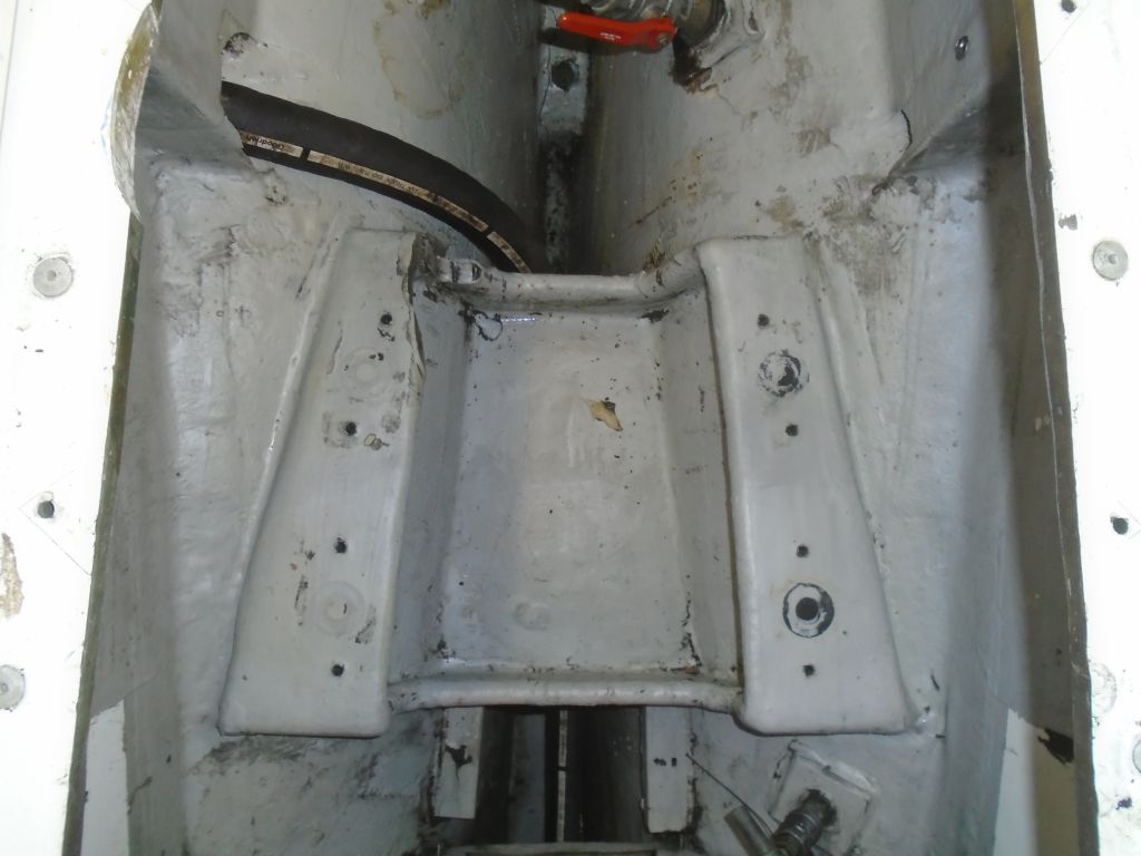
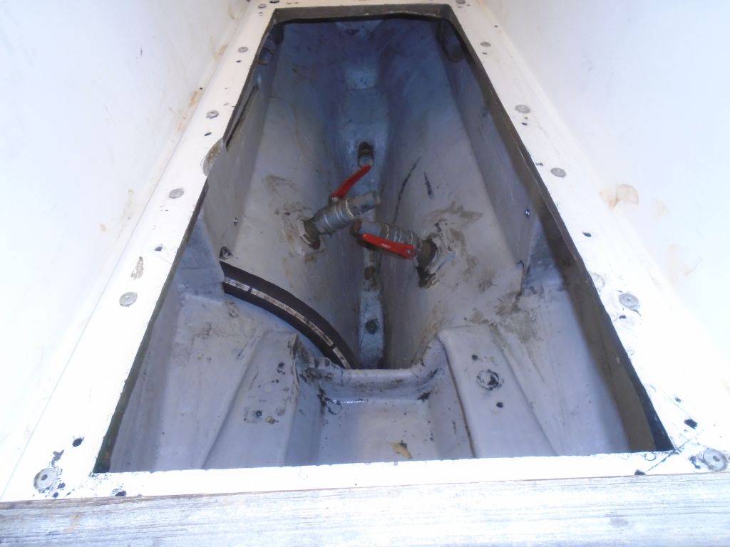
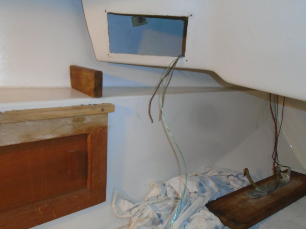
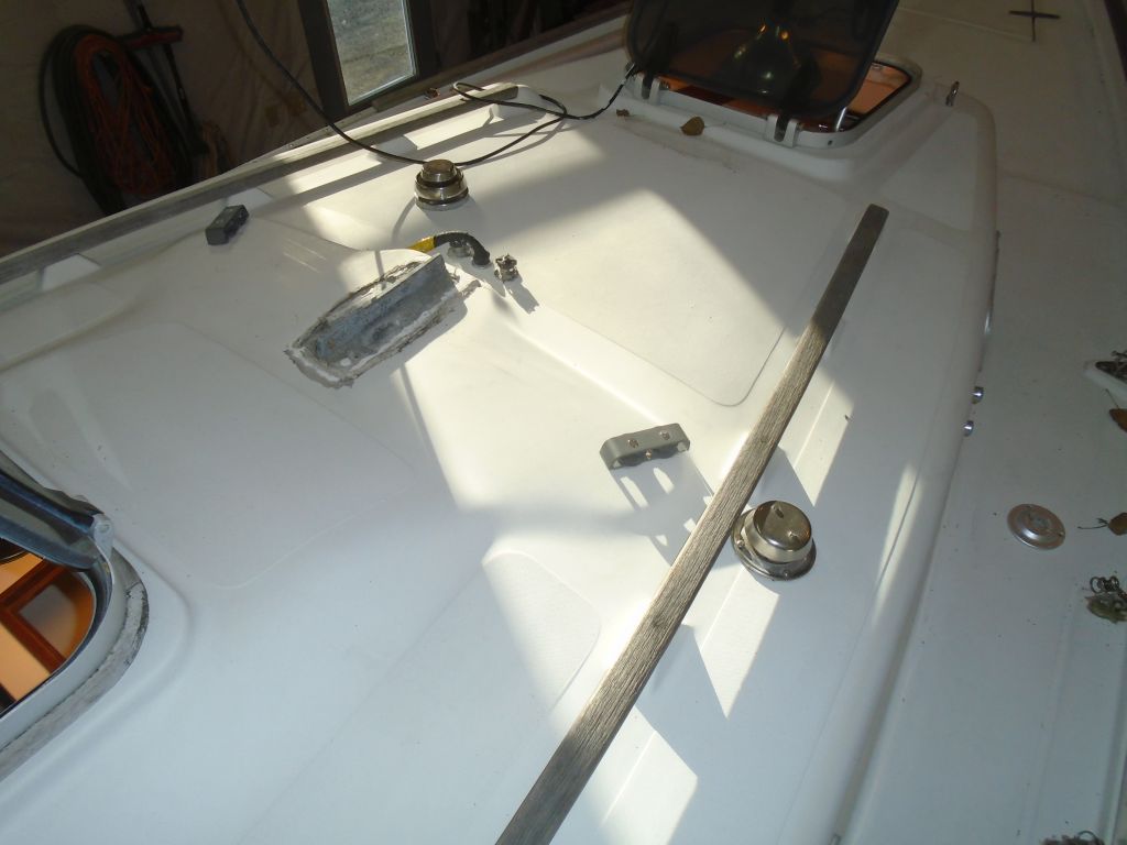
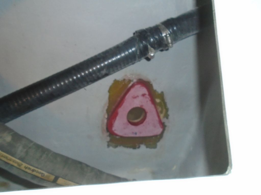
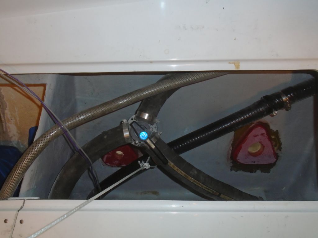
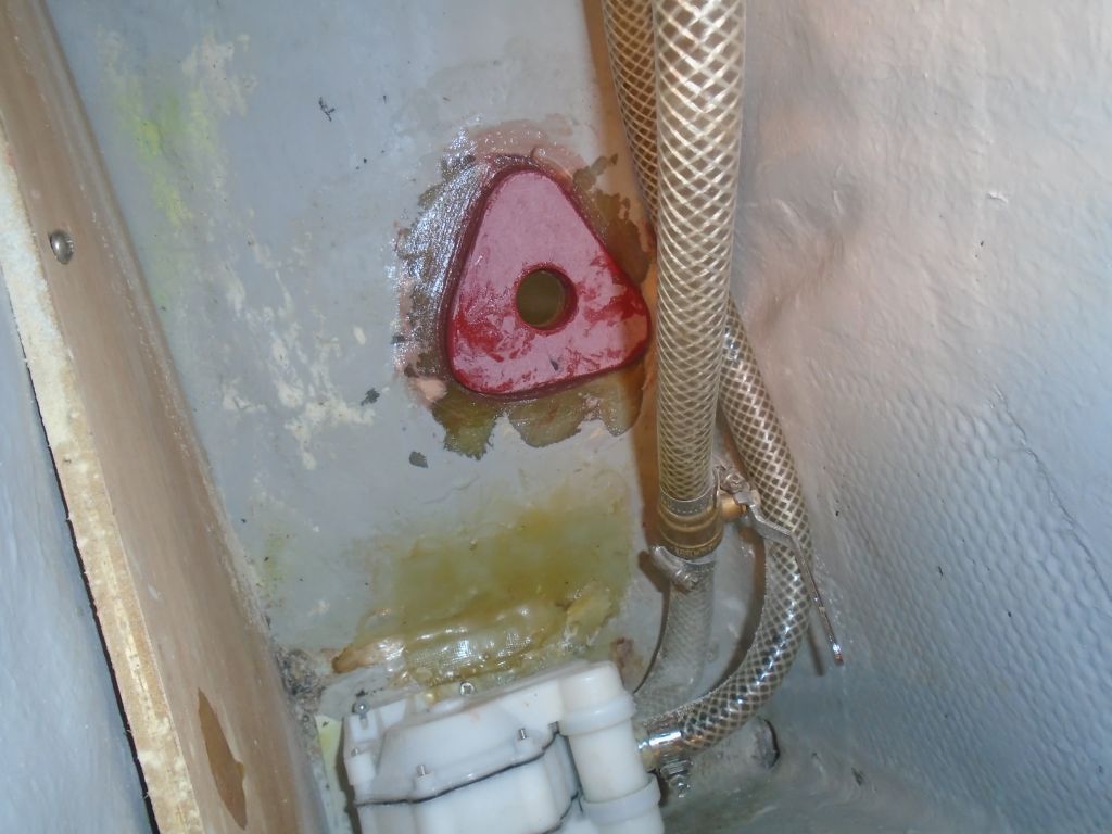
After cleaning inside and out around all the locations with acetone, I installed the new fiberglass backing blocks in beds of very thick epoxy, which held the blocks in place even in the near-vertical orientation back at the cockpit scuppers.  I smoothed the new epoxy to form fillets around the bases, and cleaned out the insides of the holes.  Then, not wanting to unnecessarily shake the boat and possibly make these blocks move before they were cured, I spent the rest of the day, as it were, on a couple smaller tasks that didn’t require me clambering around on board, all punctuated by some unrelated goings-on at the shop that required my at-least sporadic attention.

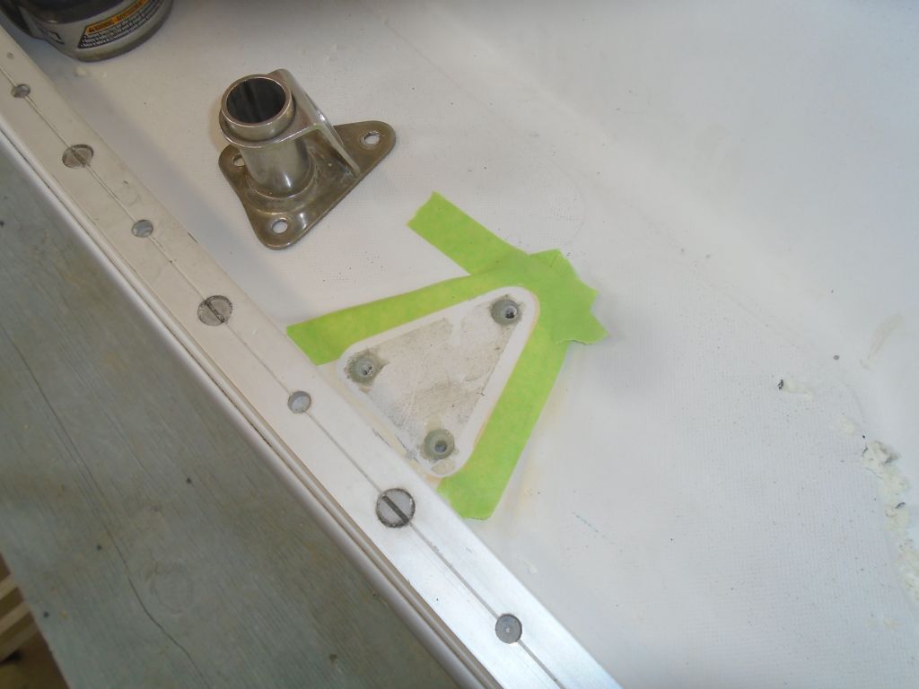
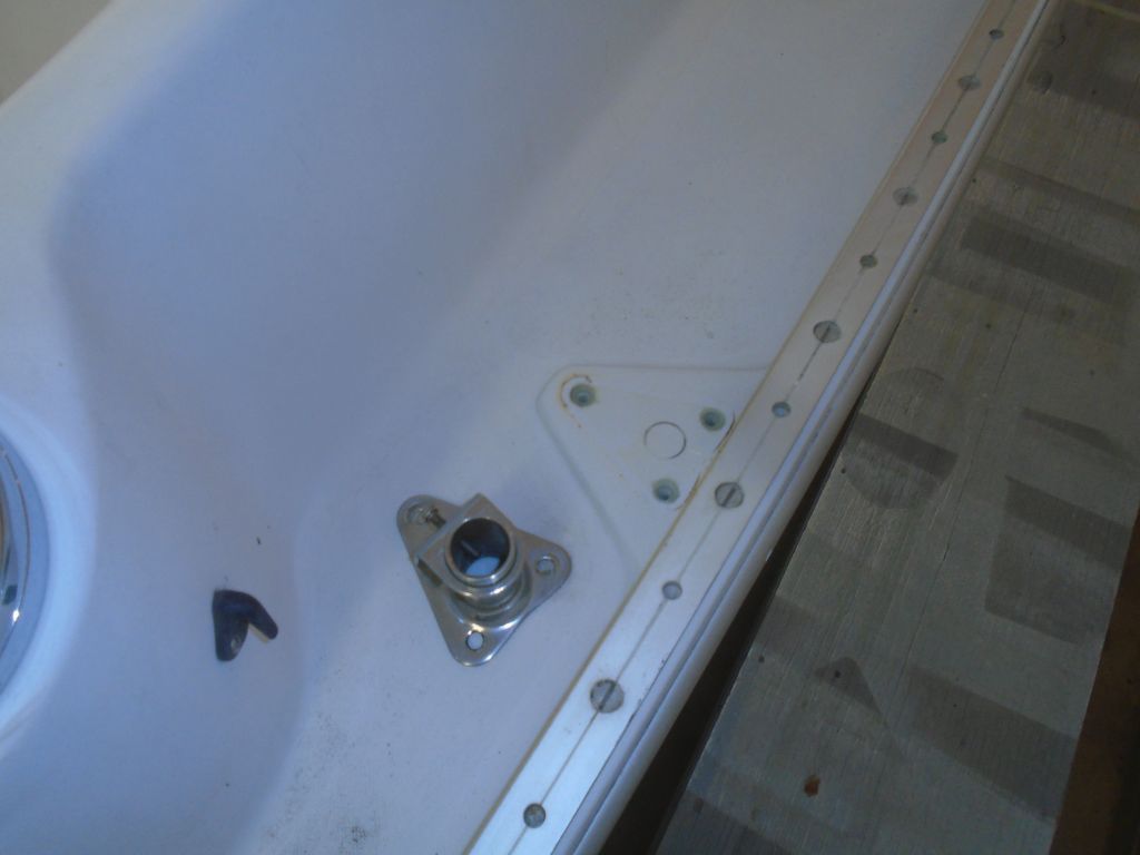
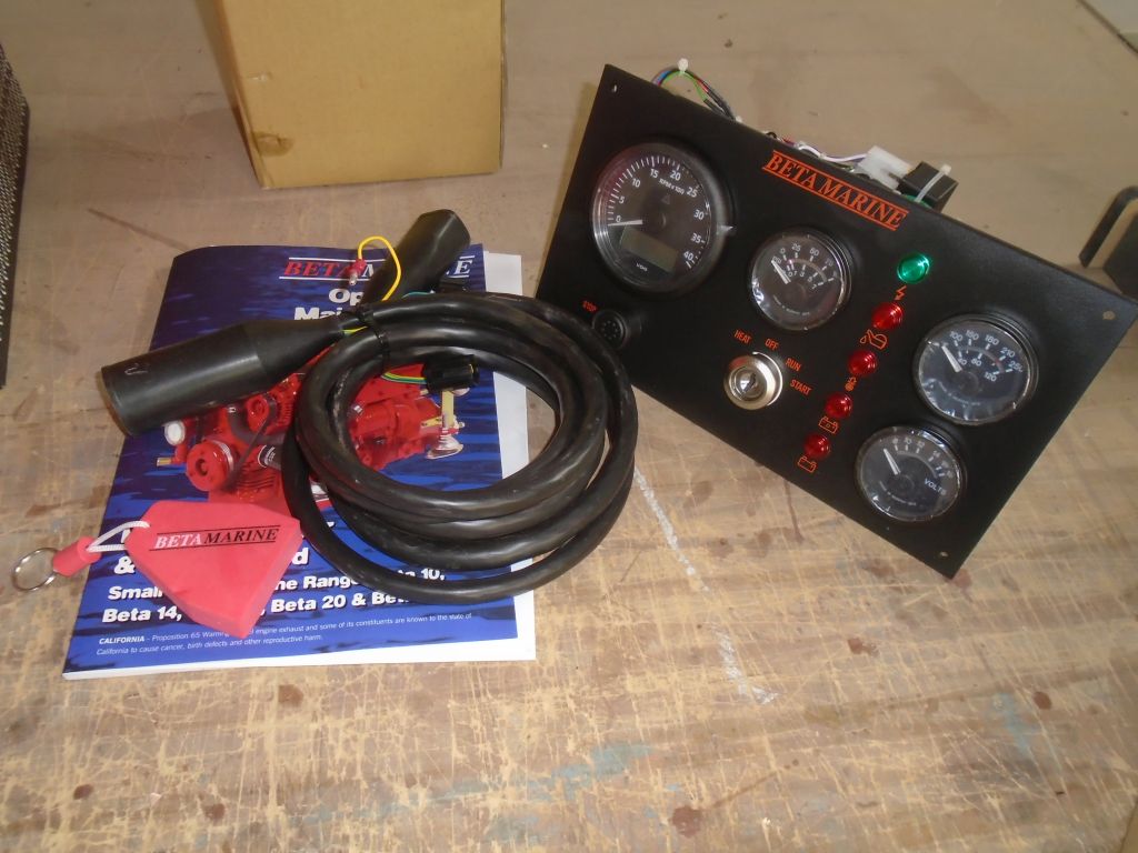
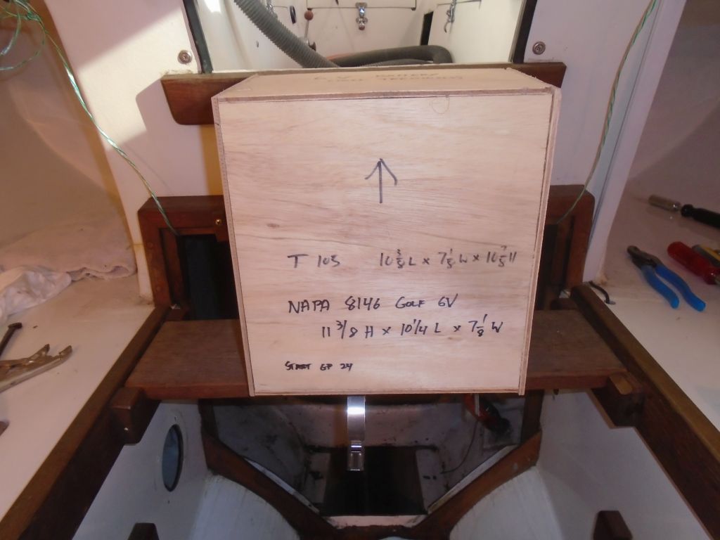
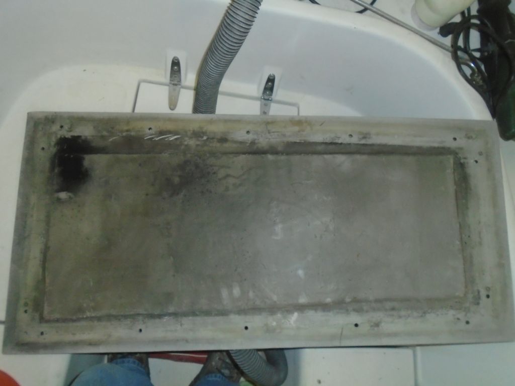
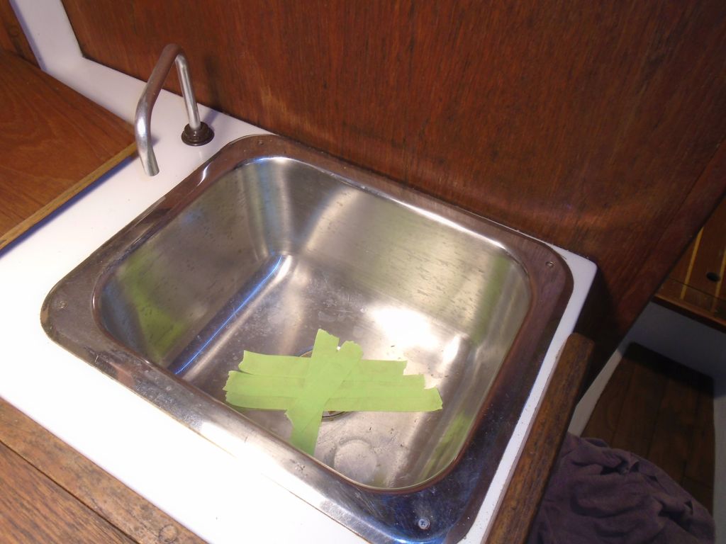
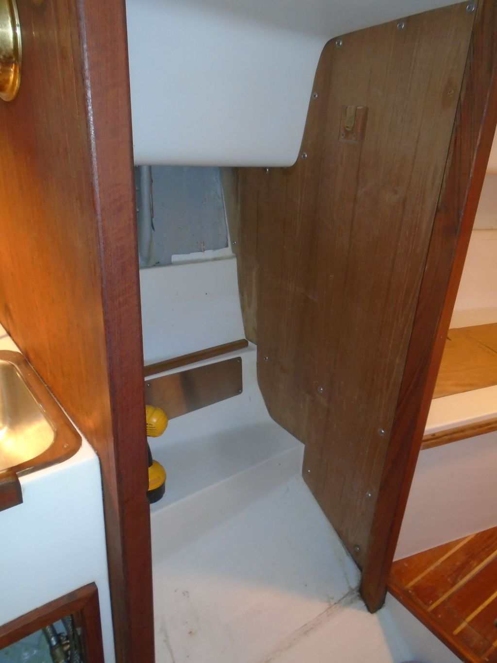
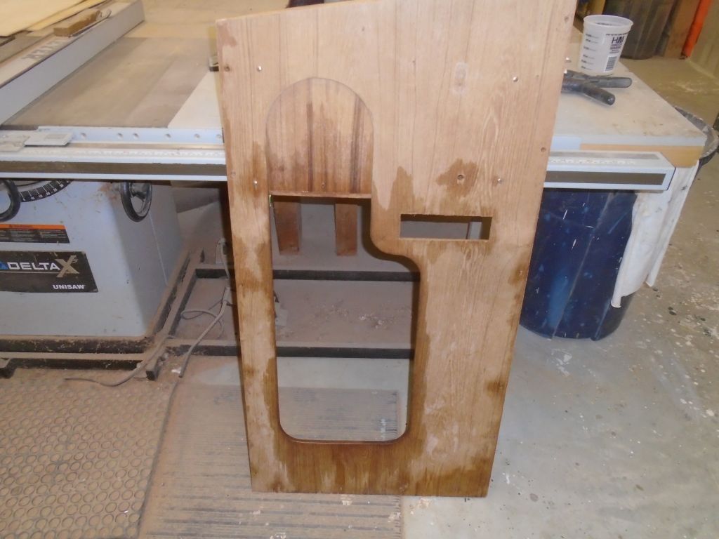
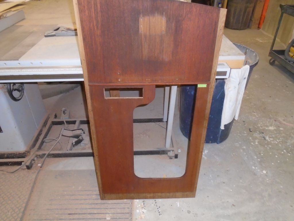
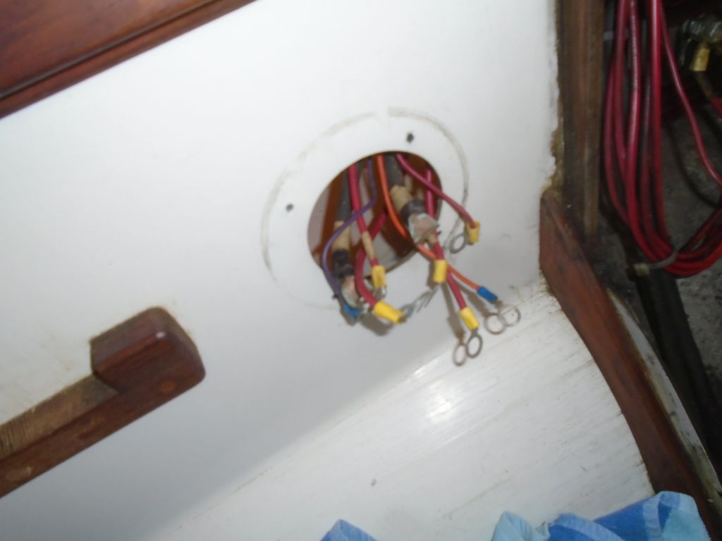
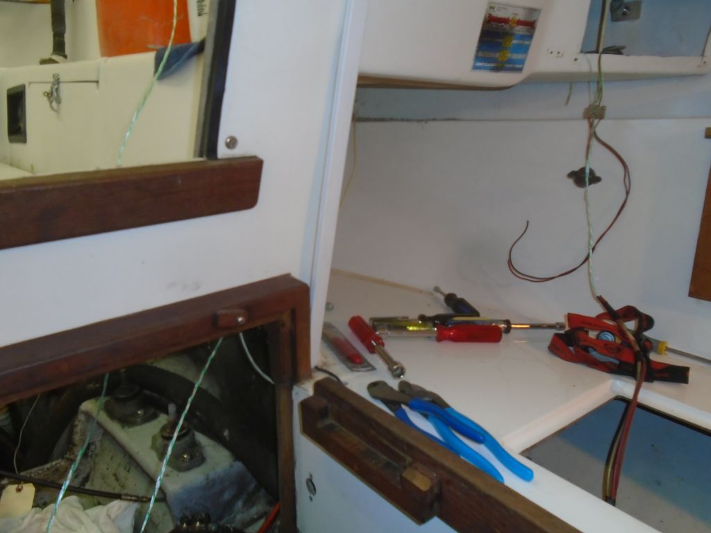
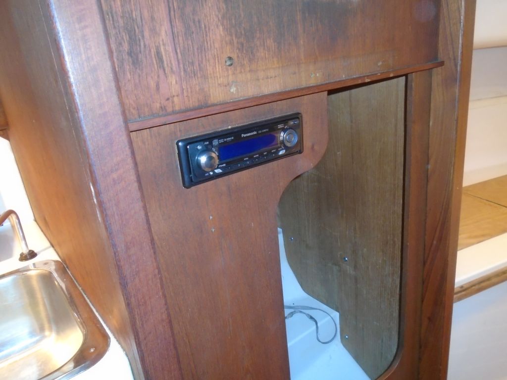
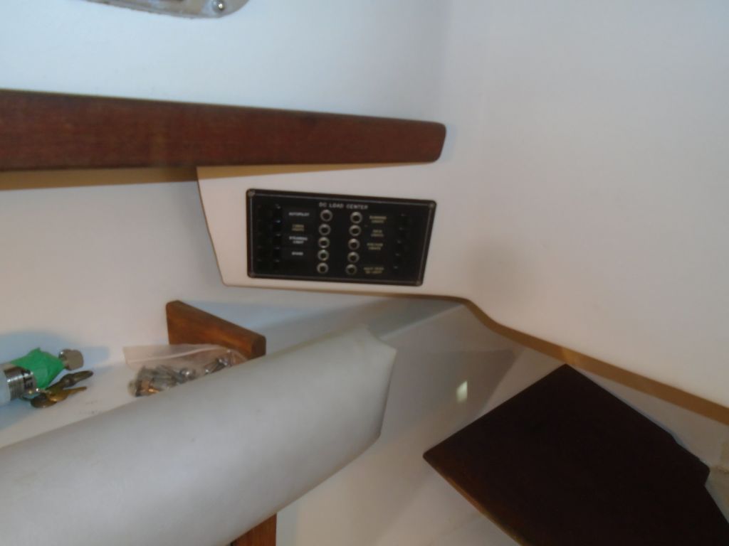
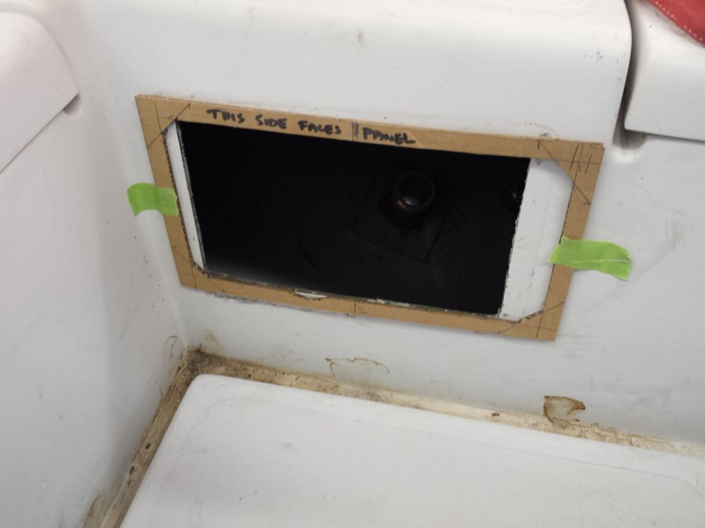
One of these tasks was to check the fit of the actual engine panel.  Years earlier, I’d made a template of these panels, and I taped it in place over the old panel hole to ensure that the new panel would indeed fit.  It did.  Meanwhile I prepared the large panel enclosure for return shipment.

enginepanel1-30916

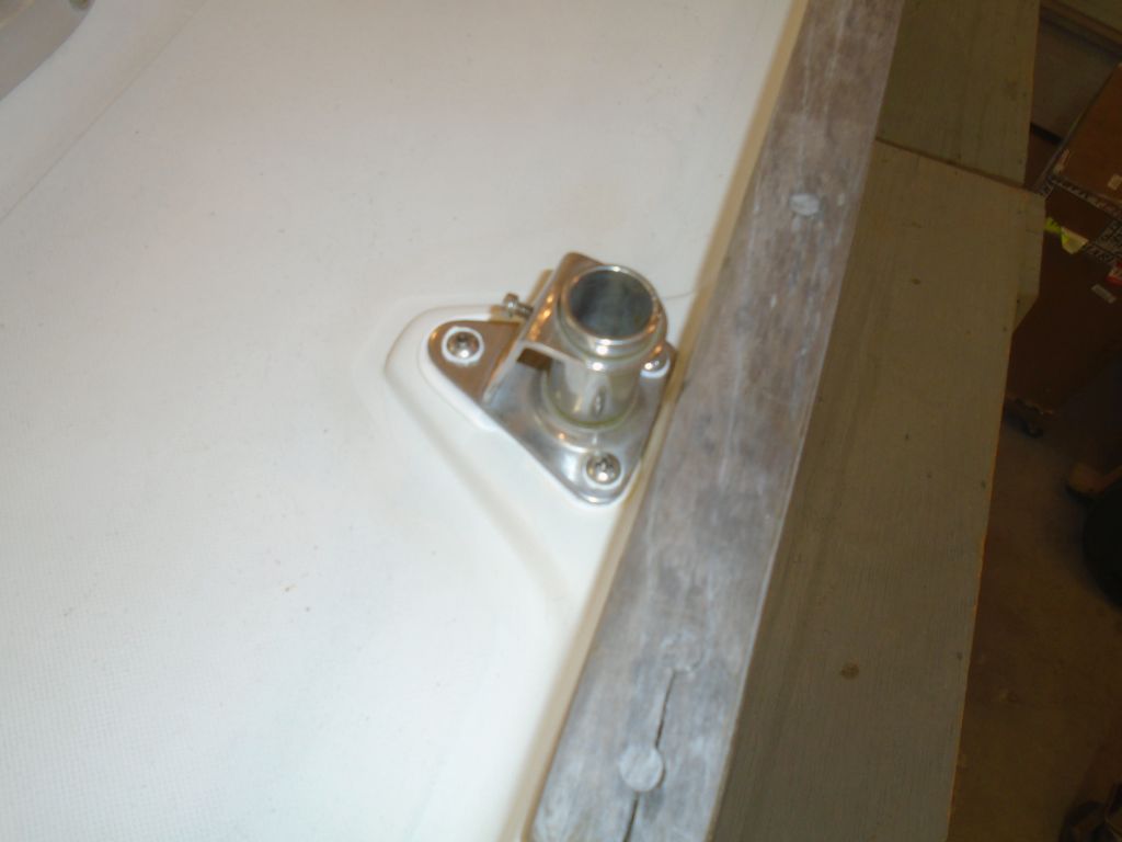
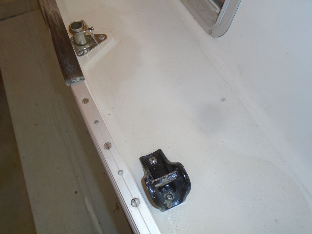
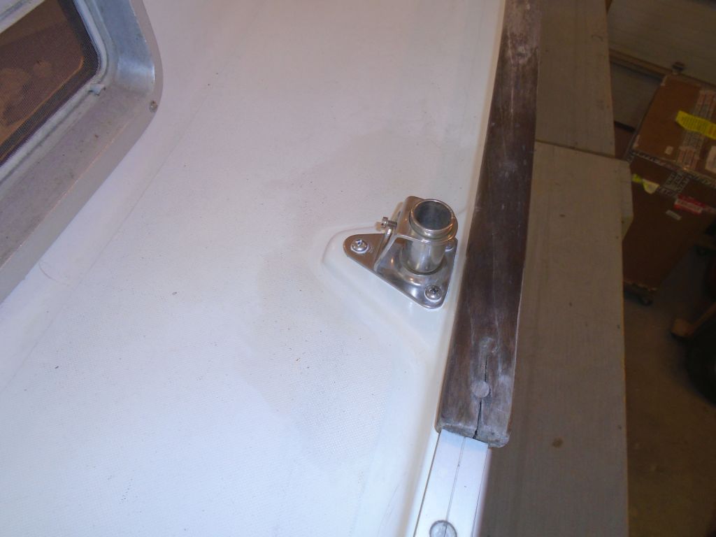
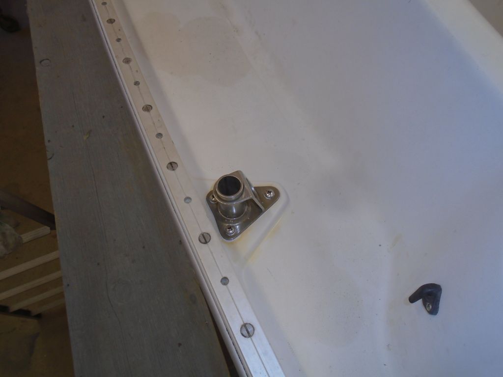
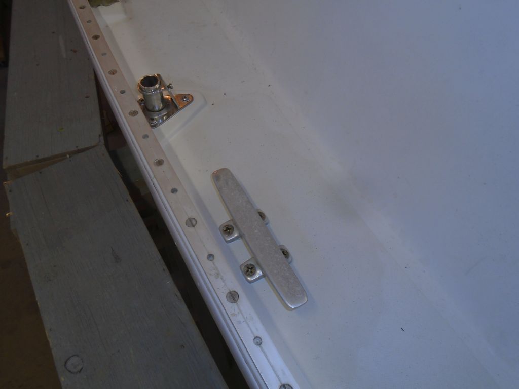
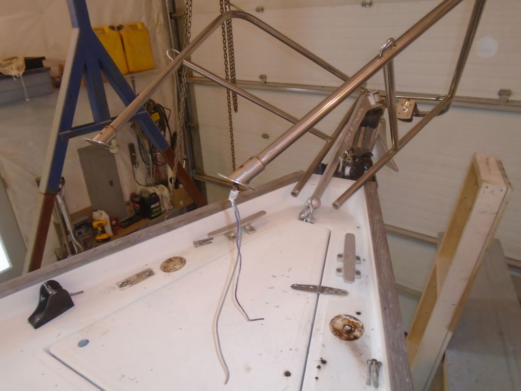
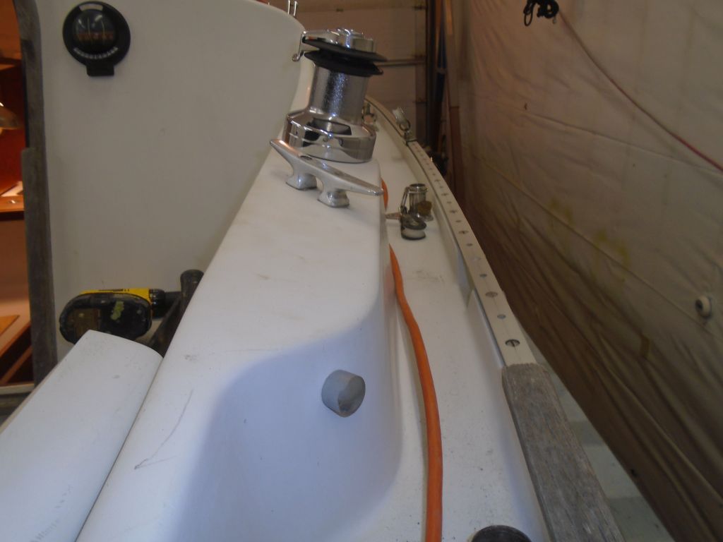
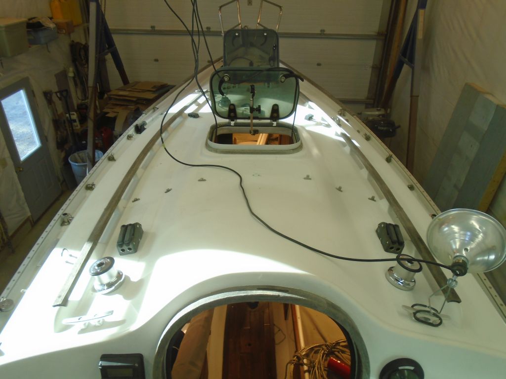
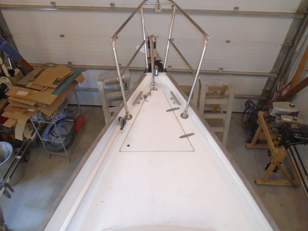
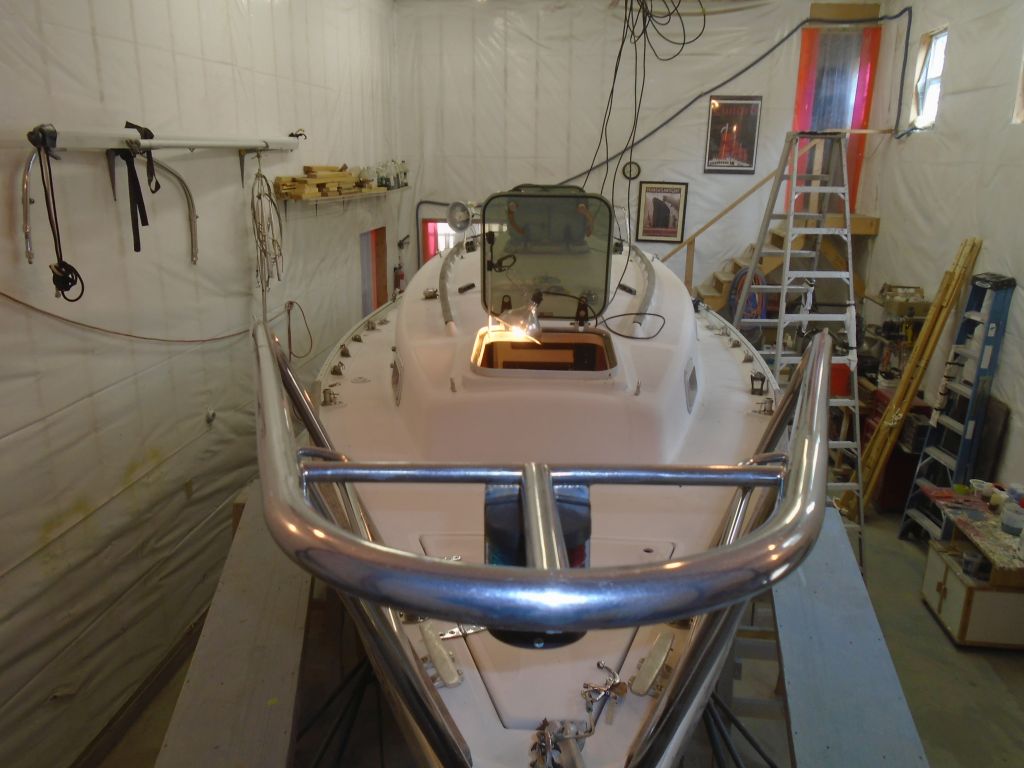
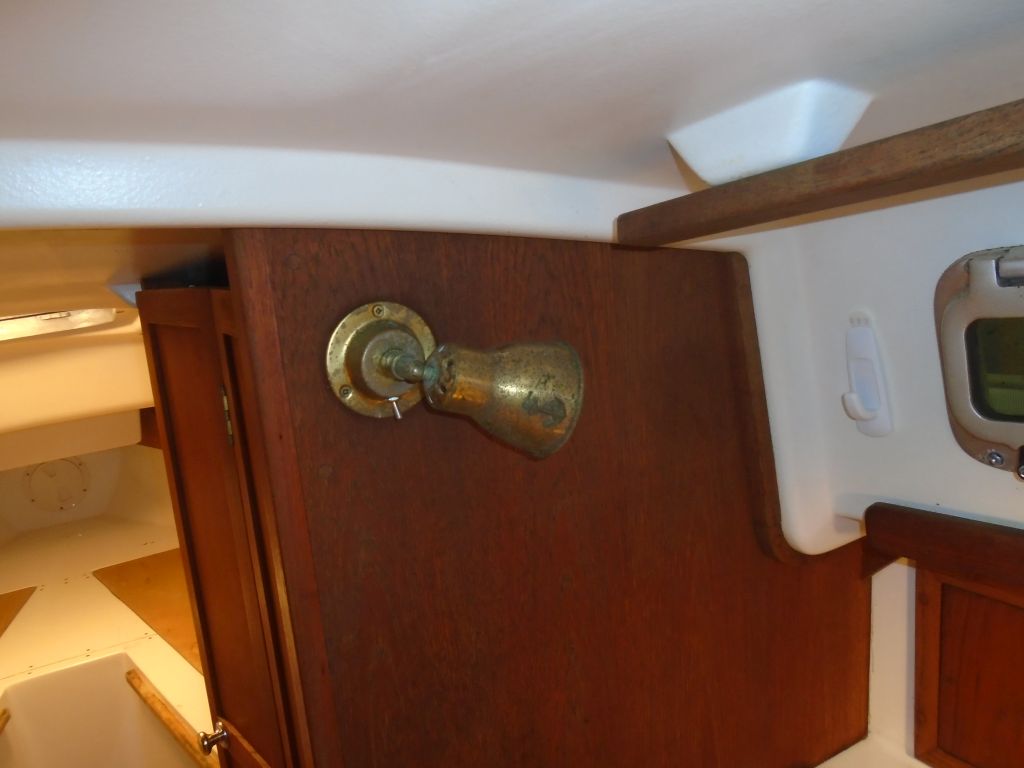
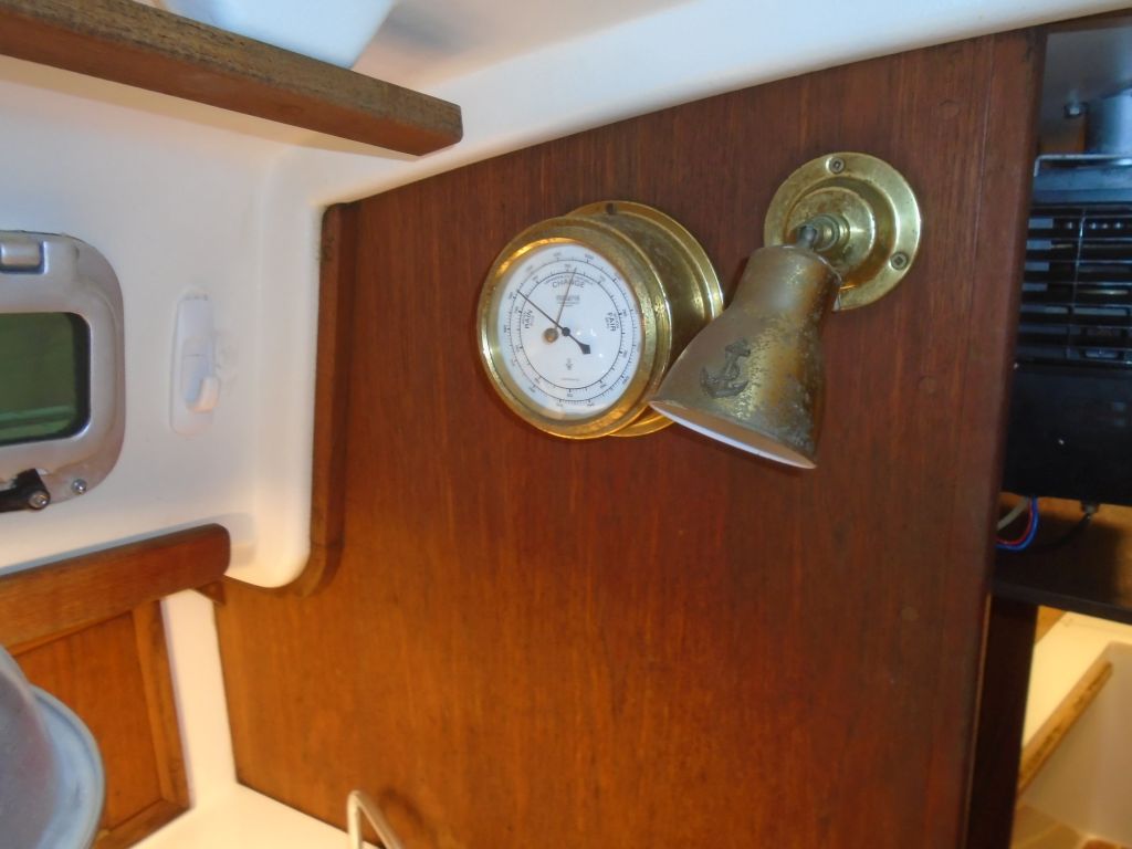
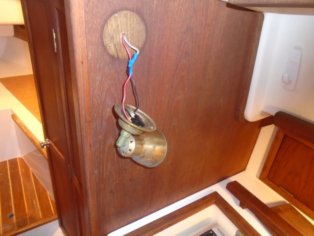
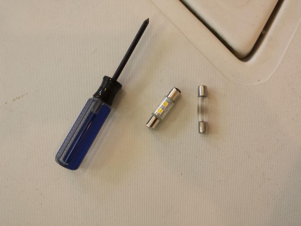
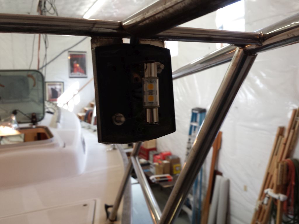
It also seemed a good time to replace the bulb in the bicolor bow light, mounted on the pulpit.  Originally fitted with a standard incandescent festoon bulb, I sourced a replacement LED bulb for the fixture, and installed it now.  The original stern light, also mounted on the pulpit, would be superseded in this case by a stern light mounted on the new Monitor windvane, and I’d remove the old light later.

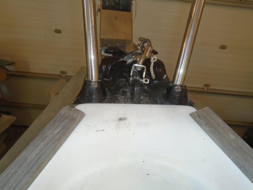
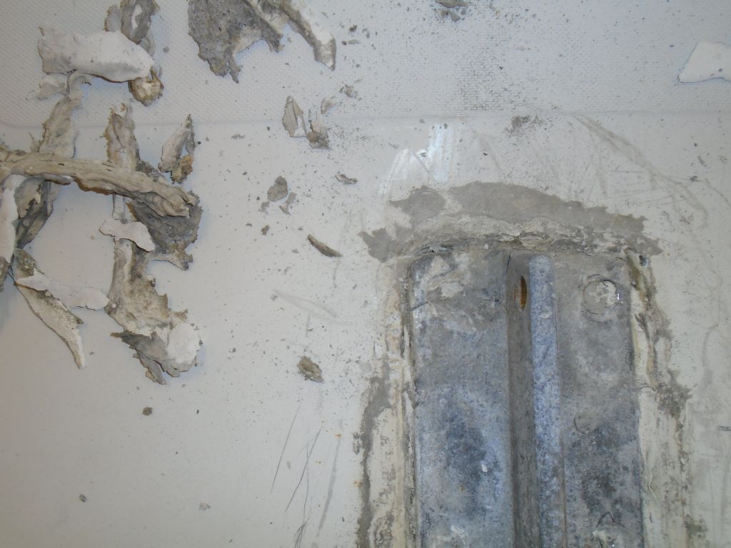
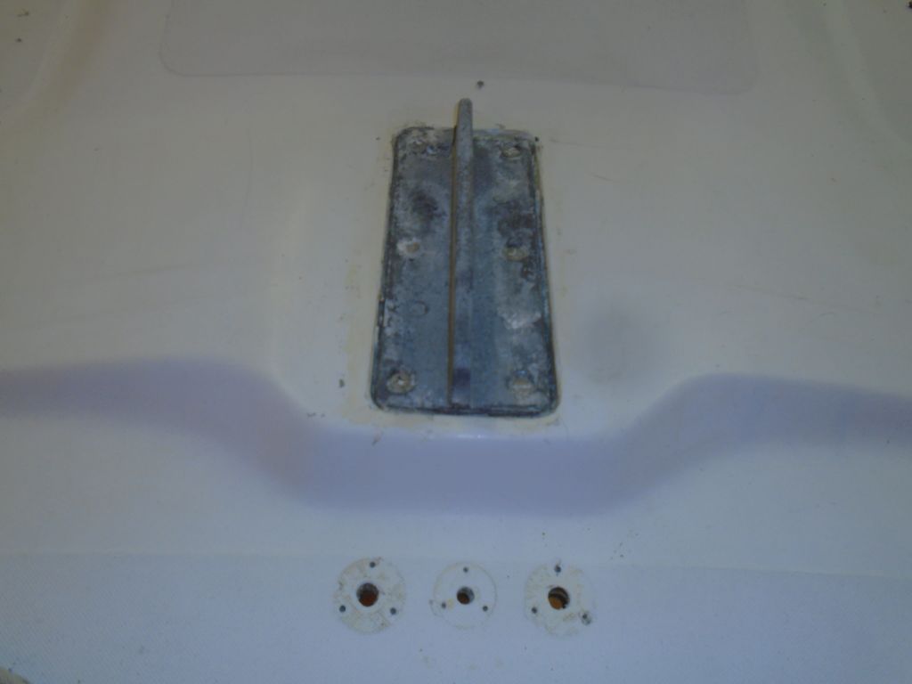
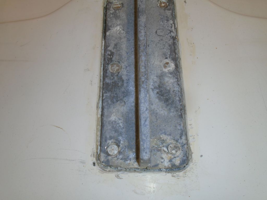
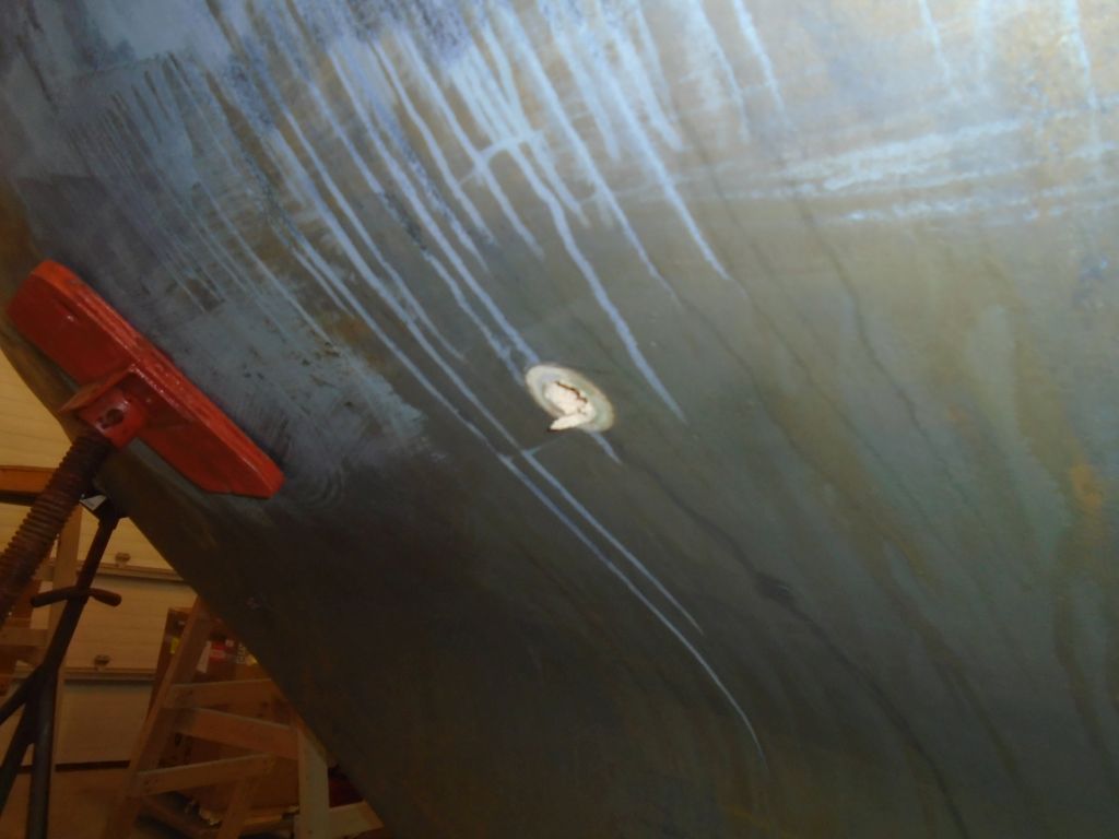
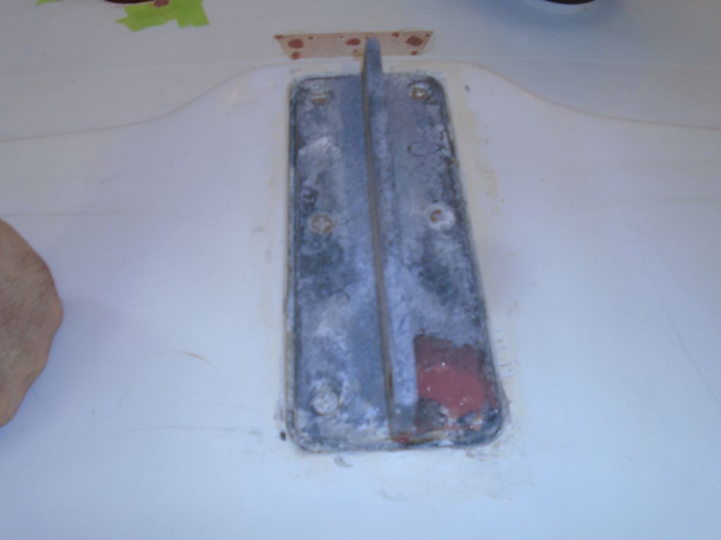
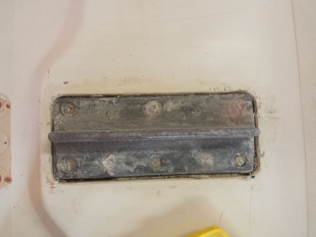
While working on the solar vent installation the past couple days, I took the opportunity to prepare and epoxy-fill the cracked area of the aluminum mast step, which, after curing and sanding, cleaned up the damage and made it look good as new.  Later, after I resealed around the edges, I’d paint the step to protect the epoxy and, come to that, the step itself.

Total time billed on this job today:  5.5 hours

0600 Weather Report:
38°, mostly cloudy.  Forecast for the day:  Partly sunny, high 60°

Salty 11

< Back to Salty

Tuesday

After going through several boxes of newly-arrived parts and supplies, I decided to continue with the solar vent installation, as this would require some additional hole and deck preparations.  The location was preordained, more or less, but to determine exactly where to install the vent over the newly-filled deck hole left over from the old cabin heater, I started in the cabin with the included plastic trim ring so I could locate the vent where it’d be clear of the hanging locker bulkhead, which was nearby to port.  Once I’d determined that, I drilled a pilothole from inside, which allowed me to start the hole saw in the right location from the deck surface.  This fitting required a 3-3/4″ hole.  The deck was in good condition within this opening.  The only core visible was a layer of what appeared to be Coremat or similar laminate bulker, which was low in the opening near the tightly-fitting inner liner.   This  laminate schedule was mirrored elsewhere in the decks where I’d so far drilled holes (such as the midships cleat locations and bow pulpit).

The plastic trim ring that would help dress up the inside of the opening was too tall for the thickness of the deck, so I used a fine saw to cut off the excess, allowing for a flush fit within.  Then, with the trim temporarily installed from within, I could insert the top portion of the vent (with the top removed for access) and mark the fastener holes.  Even though there wasn’t much for core material, and the fasteners might not even penetrate what passed for it. I overbored the fastener location as a matter of course, and filled the voids with thickened epoxy.  I also coated the inside of the large hole with epoxy to seal it.

While working in the cockpit the day before, I’d noticed that the space available where the old engine instrument panel had been was a lot smaller than I remembered, and, having recently unpacked a special molded and covered recess for the new panel (which I’d never used before, as it was a fairly new offering), it occurred to me that there’d not be room for the insert.  While the panel itself was nearly the same size as the old one, the insert was substantially bigger, and a quick test-fit confirmed my fears:  there simply wasn’t enough space in this small cockpit to fit the large enclosure.  It interfered with the locker lid gutters and the cockpit sole.  I’d have to send this back, unfortunately, and install the panel normally.

Now that the hardware holes for the stanchion bases and other sidedeck hardware were epoxy-filled and cured, I decided to move on with the reinstallation and rebedding of the hardware that I’d removed.  So at each location, I prepared the deck by marking, drilling, and tapping the new epoxy for the appropriate size machine screws, and masking around the hardware to protect the deck from sealant (mainly nonskid areas).  Because of the raised, smooth-gelcoated platforms on which the stanchion bases sat, after masking all three on the port side I decided that it really wasn’t required for the second side, so I skipped this step for the stanchion bases on starboard, which saved time and effort.

With all the locations prepared, I started at the bow and installed all the hardware.  The pulpit and forward spinnaker pole chock was easy enough to complete.

Moving on to the forwardmost stanchion bases, things slowed down considerably.  If I thought that removing the old fasteners from those liner-hidden inboard locations of the stanchion bases  the reinstallation proved me wrong:  removal had been a day at the beach.  Trying to thread nuts and washers onto these fasteners–blind and without even room for a pair of fingers–proved to be frustrating and time-consuming, and ultimately the only way it  could happen was for me to open up the edge of the liner in way of the fasteners, just to allow a way to get the nuts started.  I’d determined at the onset that there was no practical means of installing backing plates, nice as that would have been; as it happened, there was barely room for nuts and washers on these inside locations.  I tried everything I could before resorting to using a drum sander to create a rounded notch in the molded liner in order to reach the inner fastener on each stanchion base, but there simply wasn’t enough access to start the nuts and washers till I made some room.

Even the after pole chock was challenging, since the forward bolt was directly above the bulkhead, and I had to leave the bolt partially unthreaded (from above) in order to leave enough room beneath for me to start the washer and nut, after which I could tighten down the bolt the rest of the way.

Moving on from the forward cabin, I thought the worst was past, but the access for threading nuts onto the inner sets of bolts on the stanchion bases and midships cleats was no better here than it had been in the v-berth.  What’s worse is I could almost get the nuts started on the middle stanchion base and nearby cleat, but despite all efforts I just couldn’t succeed despite many frustrating attempts and varied techniques.  So in the end, I was forced to use the drum sander again, just to gain barely enough access to complete the installations.   I’d started with the port side, so with this hard-won knowledge  I got smart on the starboard side and pre-notched the liner where I needed to, which made the final installations late in the afternoon go much more quickly.  I used large washers wherever possible, but had to resort to regular-sized washers for the innermost fastener on the stanchion bases, as there simply wasn’t room for a fender washer.  The final set of stanchion bases, which I could access from inside the electrical panel areas, was almost a treat with luxurious one-hand blind access but no liner in the way.  The angle and closeness of the photos make the notches look huge and much worse than they are; in reality they’re not really visible from normal cabin attitudes, but I’d think about a simple way to cover them nonetheless.

Total time billed on this job today:   8.25 hours

0600 Weather Report:
25°, mostly cloudy.  Forecast for the day:  Mostly sunny, high around 50°

Salty 10

< Back to Salty

Monday

After removing a final piece of hardware (at least for this particular round) from the starboard sidedeck, which had resisted efforts last time (and I’d run out of time before I could finish it), I prepared all the hardware locations  by boring 1/2″ holes at each fastener location (this kept the larger hole within the footprint of the hardware in all instances), which removed the core material (plywood) from about the fasteners for future core isolation.  I also cleaned off old sealant from the deck and hardware bases.  Then, I masked around the holes (and from the underside of the deck) to prepare for epoxy filling.

Next, I filled all the prepared holes with a thickened epoxy mixture, and removed the tape afterwards.

At the bow, I removed the anchor, chain, and rode from  the roller and anchor well, exposing a filthy anchor locker that I cleaned up afterwards.

At the mast step, I removed three old wiring fittings, which we’d not be reusing, and prepared the holes for patching.  For cosmetic reasons on the molded nonskid pattern, I’d be building a simple cover to secure to the deck over the patched holes (the undersides were hidden in a wooden trim box).

I took this opportunity to clean off unsightly gobs of old sealant from around and the top of the mast step plate, which was head-scratchingly secured into a molded recess in the deck that, frankly, seemed only like a trap for water and offered no benefits whatever.  This process exposed a pre-existing crack in the aft starboard corner of the plate, which didn’t appear to cause any structural concerns with the integrity of the step itself, but made me wary of attempting any further removal of the step for rebedding, since there was hardly any way to get under the piece anyway thanks to the recess, and I worried the casting might fall to pieces if I tried.  Sometimes well enough is best left alone.   With a cleaned-out groove about the step I could later refill with new sealant applied in a more uniform manner, and perhaps force some epoxy into the aft corner to shore up the crack.

Next, I masked around the old wiring holes (now prepared for filling), and, nearby, around the hole left over from the old cabin heater vent.  I filled these voids with thickened epoxy–the wiring holes as a permanent closure, and the old vent hole as a temporary means of providing a place for a hole saw to enlarge the opening, since we’d decided to install a solar deck vent in its place, which required a larger opening.

Following my inspection of the through hull fittings earlier, the owner had requested that I change out all the underwater fittings with new bronze through hulls and flanged seacocks to replace the ill-threaded valves directly on the existing through hull necks.  However, since the outlets were above the waterline, we decided to keep the two through hulls that had serviced the bilge pump outlets and simply replace the valves inside with new bronze ones.  So I got started in the cockpit locker, and removed the two valves from those through hulls, pending arrival of the new valves later.  Fortunately the valves unthreaded without any particular issue.

Moving on to the cockpit scupper drains, after a brief attempt to unthread the valves and through-hull nuts from inside, I quickly gave that up as a waste of time and, with a reciprocating saw, simply cut the through hulls off from inside, working the blade through the wooden backing blocks and quickly through the fittings themselves, after which I could remove the remnants of the plywood blocks and push the through hull fitting out from inside.

I continued with the engine raw water intake, located at the forward end of the engine room to port.  This fitting featured an external bronze strainer, which I removed for access to the through hull beneath.

In similar fashion, I removed the galley sink drain, and the heat intake and overboard fittings.

Afterwards, to prepare for new installations I sanded away the paint from the outside of every fitting, and any remnants of old sealant, adhesive, and factory interior gelcoat on the inside of the hull at all locations.  Sometime soon I’d finish the basic prep work by cleaning out any sealant remaining in the old through hull holes themselves, but for now the day was over.

Total time billed on this job today:  8.5 hours

0600 Weather Report:
20°, partly cloudy.  Forecast for the day:  mostly cloudy, chance of snow and rain showers, high around 40°

Nomad 21

< Back to Nomad

Sunday

I masked around various windows, ports, and adjacent surfaces as required to prepare the newly-sanded interior woodwork for varnish.

Afterwards, I applied a thinned-down sealer coat of varnish to all surfaces, the first of several coats to come.  I’d be rebuilding the starboard pilothouse panel soon and would catch that up with the other areas as needed.

Total time billed on this job today:  2.5 hours

0600 Weather Report:
10°, clear.  Forecast for the day:  Sunny, 33°

Salty 9

< Back to Salty

Friday

Next on the agenda was to rebed the deck hardware, which required, of course, removing it all first.   Hardware fastener access across the boat varied from nonexistent to excellent, with a good dose of frustrating production shortsightedness thrown in just for fun and to make sure no one enjoyed the process too much at any given time.

I decided to start with the items along the sidedecks, since the access to these fasteners shared the wiring access panels in the cabin, and the sooner I finished up with the hardware, the sooner I could start work on new wiring runs.  The fasteners for some of the stanchion bases, deck cleats, and spinnaker pole chocks were kind of accessible from these chases, but unfortunately the inner liner and the removable plywood cover panels were ill-conceived and actually still covered most of the nuts for these pieces of hardware, prohibiting access.  In particular, this affected access to four stanchion bases and the breast cleats.

To allow access to the inner sets of fasteners at each location, as well as increase the access to those that were sort of exposed outboard of the liner, I used a small cutting tool to remove some of the liner in way of each piece of hardware, as far inboard as the molded lip that defined the edge of the cover panel.  Unfortunately,  even with this portion cut away, the innermost fasteners were only just barely reachable, and not fully exposed.  While removal was possible now–and indeed I could and did now remove all this hardware–it was still far more difficult than it should have been, and reinstallation later would be similarly complicated by the liner design, which could (should) have been better designed to actually allow access rather than just tease at the idea.

All fruitless whining aside, once I’d opened up the access where I needed it, I started at the bow and worked aft, removing the pulpit, pole chocks, and stanchion bases as far aft as the cockpit.  Since I’d be turning around and reinstalling/rebedding these items as soon as possible, I simply left them on the deck from whence they came.

The new engine had arrived at a nearby trucking terminal, and I headed out to pick it up, unloading it in the shop and inventorying the included accessories, which this time included a plastic water-resistant cover panel for the instrument panel, a spare parts kit, coolant reservoir and vent loop, and all the usual accessories.

Total time billed on this job today:  5.75 hours

0600 Weather Report:
10°, clear.  Forecast for the day:  sunny, high in the 20s

lh6

< Back to Lively Heels

Thursday

The last task remaining on my work list for this off-season was to help the owner install new aftermarket sail  tracks on both masts.  These tracks, by Tides Marine, make sail dousing a cinch thanks to their slippery no-friction construction, which essentially allows sails to simply fall without effort.

The first step before ordering the final product was to perform various measurements of the mast and existing sail tracks.  We’d planned to do this the last time I was working on the boat, but the required measuring tools from the manufacturer hadn’t yet arrived, so we postponed the measuring.  With the little plastic measuring tools now on hand to determine the actual track size, we headed to the yard where the masts were in indoor–but unheated–storage.  Despite one of the warmest winters on record, this day happened to be about one of the coldest of the entire season even with the late calendar date, but so it goes.

We repeated all the steps detailed below for both masts, and I’ve included specific details for each spar that might be useful for posterity.

Starting with the mainmast,  the first step was to use the provided measuring tools to measure two aspects of the size and shape of the internal mast groove.   In this case, we had a flat internal luff groove built into the mast, so we proceeded with the appropriate tools and directions for that type of track.   According to the directions, the idea was to find the side of the measuring tool that fit the internal groove in a specific and well-defined manner, which two measurements would then indicate the size of the new track extrusion.  It was a simple trial and error process till we found the right slot width (size H as shown) and slot lip thickness (size 2 as shown).

Many of the written directions were predicated on the idea that the track would be being measured and installed with the mast standing, which didn’t apply here and frankly made things much simpler from a measurement and installation standpoint, but nonetheless we went through all the motions and noted the measurements required as a matter of course.  These tracks come in a large reel, and get slid up the mast track right off the reel, in theory.  So to accommodate this, the instructions called for a certain minimum length to the mast gate, where sail cars (and in this case the new track) would be installed.  On the mainmast, the existing mast gate was 4″ in length, which was the recommended minimum, but later we’d have to modify the gate since it was open on only one side of the sail slot, and both sides needed to be open to accommodate the new track.  I’d already extended this gate once, on one side, and opening the other side would require careful cutting with a small grinder.  I’d do that later, when installation time came around.

The instructions also suggested that the top of the mast gate be at least 10″ above the gooseneck, and here we had plenty of leeway.

Next, we measured for the exact length of the new track.  With the instructions as a guide, we measured from a point about 1-1/2″ below the masthead sheave (which was high enough to allow the headboard cars to be raised all the way, but not so high where the track might interfere with the shackle or sheave at the top), and down to a point about 1-1/2″ above the gooseneck.  The overall measurement to the gooseneck fitting itself was 310-1/4″, and subtracting an appropriate clearance at the lower end brought us to a final track measurement of 308-1/2″.  One wants the bottom of the track to be as close to the gooseneck as possible, since the lower the track the lower the stack height (which is substantial with the cars used in this system) of the sail, but also high enough to allow insertion of the cars, including the 4″ long batten cars included with the system.

The final measurement requested in the ordering instructions was the internal width of the existing luff groove, a measurement that was easiest to get from a full-width slot further down the mast, which had once been used as the insertion point for the sliding gooseneck on the original boom.  I used calipers and a tape to measure this at between 5/8″ and 11/16″.   To allow enough space for the track to be installed, our thought was that erring towards the lower rather than higher side of this measurement would be prudent, depending on the manufacturer’s own recommendations or requirements.

Moving on to the mizzen mast, we repeated the same processes.  Most elements of the mizzen extrusion were the same as the mainmast, so it was more a matter of confirming this than starting from scratch.

Mizzen mast groove measurements were, as expected, H and 2 respectively.  Similarly, the overall luff groove width was the same at 5/8″ – 11/16″.

The mast gate above the new mizzen gooseneck was shorter than the required 4″ measurement, so modification would be required for that (as well as to open the other side as with the mainmast).  On the mizzen, the owner wanted to lower the boom position and gooseneck from its current location, as this had turned out to be inconveniently high for sail stowage and sailcovering.  In addition, he planned a new mizzen sail to replace the ratty old one, and to accommodate the new boom position, so several of our additional measurements had to account for this repositioning.  We’d deterimed some  months before that the new position of the gooseneck would be nearly 11-1/2″ lower than its existing position, as shown with these pencil marks.


What all this meant at the immediate moment was that the measurement to the position of the mast gate was much larger than it appeared from the existing gooseneck position.  In fact, the top of the existing mast gate was 23-1/2″ above the new top of the gooseneck fitting (once it was moved).

Taking all this into account for the final track measurement, and starting with the tape about 1-1/2″ below the sheave at the masthead, we determined the overall length to to the top of the gooseneck fitting (once repositioned) to be 193″, so the track length would be slightly shorter, or 191-1/2″, ending about 1-1/2″ above the gooseneck.

Allowing for the position of the actual tack connection point on the gooseneck, and leaving room for sail stretch and to ensure that the sail could always be fully raised (i.e. not too long), the dimension for the luff length of the new mizzen would be 190″.  These photos simply show the relationship and measurements of the gooseneck fitting, tack position, and boom position for reference purposes.

Total time billed on this job today:  2 hours

0600 Weather Report:
8°, clear.  Forecast for the day:  sunny, high around 23°

Salty 8

< Back to Salty

Thursday

This ended up being mainly a planning and ordering day, punctuated by my departure for a few hours in the middle of the day to help another boatowner with some rigging-related measuring tasks.

One question we resolved, at least in concept, was battery placement.  The new electrical system would feature an engine start battery along with a house bank of two 6-volt batteries in series, and with limited space available my first task was to find the best (or a possible) location.  The original house batteries had been in a locker beneath the cabin sole, which the owner didn’t care for, and as it happened the space would hardly–if at all–allow the planned batteries to fit.  Some time ago, since I use these batteries often, I’d built a plywood mockup of the batteries, a simple box that included the height of the terminals in its overall size.    Using this as a guide, I found that the “battery” didn’t quite fit beneath the cabin sole, and that the length of the locker was barely able to accommodate the two in line.  I thought there might be enough sloppiness in the size of the rough mockup that an actual battery might just fit, in in any event it was close, and with the desire to use a different space anyway, I continued to search, but felt that there was at least a probable fallback position.

I tried the mockup in one of the settee lockers, but the fit there wasn’t even close.

batterymockup4-30316

Nowhere else fit the bill of the basic requirements (i.e. space available, room for safe and proper terminal coverage, close to the engine room and electrical service to limit cable runs, etc.) except for the port cockpit locker, where there was plenty of room and where I could build a platform or box to accommodate the batteries and which made sense for various other reasons.  The owner seemed to like this location, and I’d move forward with some additional mockups to finalize the idea.

With most of the dismantling and old systems’ removal mostly complete, it was time to turn to preparing for new installations, specifically the electrical system, engine-related systems, and through hulls.  This inevitably led to various questions in terms of logistics, specific requirements from the owner, and more, and with tracking down and eventually ordering the bulk of the materials required for these varied installations, the day disappeared with a murmur and nothing particularly to show for it, at least not till the overloaded boxes started to arrive in a day or so.

Total time billed on this job today:  5.5 hours

0600 Weather Report:
8°, clear.  Forecast for the day:  sunny, high around 23°

Salty 7

< Back to Salty

Wednesday

The teak rudder cheeks, which held the tiller, were well-weathered, but were still sound, with no rot or punkiness detectable.  The tiller was in similar condition, and the owner chose to replace both.  To to begin the day, I removed the rudder cheeks, which were secured to the top of the rudder with four through-bolts hidden behind large bungs.  With a drill, I bored through the bungs, and dug out the remains with an awl and chisel as needed so I could access the bolts and nuts for removal.  With the cheeks removed and down on the bench, I disassembled the two sections from the spacer in the middle, so I could pattern and measure the pieces as needed.

Back in the boat, I spent some time cleaning up and assessing the fuel tank and fuel situation.  Though the tank initially looked nasty, I found that it cleaned up well, and the tank itself was in excellent condition.

fueltank1-30216

The owner was rightfully concerned about running  old or dirty fuel through the new engine, so I removed the fill hose (and the vent, which was in the way and which I found (fortunately) was not clamped to its vent fitting up in the cockpit coaming, so I could easily replace that particular hose.

With the fill hose removed from the tank, I could get a decent look inside.  The fuel looked clear and clean (and nearly full), and I could see the bottom of the tank easily, with what minimal signs of any dirt or debris in the tank.  In short, I thought it looked good.  I did my best to show this in a photo, and though the view isn’t great, it shows the clean, clear fuel and the bottom of the tank as well.

fueltank10-30216


This was all good news, as past experience and the overall measurements of the tank and its permanent fittings meant that tank removal or replacement would be time-consuming and challenging, given the not-quite large-enough locker opening to remove the tank.  So I was happy to recommend leaving things as is, and with a good new fuel filter arrangement planned for the new engine, I saw no cause for concern.

I found I could work around the tank well enough to continue work in the locker, and I removed the control cables from the existing throttle control in the cockpit, as I’d be replacing these for the new engine (but keeping the control).

controls1-30216

I had hand (but not visual) access to the fuel fill hose, as well as the waste pumpout hose.  I wanted to replace the fuel hose (the light-colored one), but the waste hose, which ran through the engine room and forward to a tank beneath the cabin sole, was in good condition throughout (you’ll see why I know this in a moment) and I saw no need to replace it.

Happy with the positive news on the fuel tank situation, and with the control cables and some stray wiring now out of the way, I cleaned up the rest of the starboard locker with some cleaner; the original gelcoat-painted surface cleaned up well.  Continuing aft, I removed–with effort–the little stub of exhaust hose from the gooseneck fitting at the transom (I had to use a saw to cut through the hose and wires), and cleaned up the locker surfaces there as well, and continued with the process into the port cockpit locker.  One can see how misaligned the gooseneck arrangement is, which is why the hose was such a tight fit against the hull at the lower end.  I doubted I’d have any luck (or leverage) to crank that leg another 1/8 turn and straighten it out, but perhaps I’d try later.

The waste pumpout hose was already disconnected from the waste tank, for whatever reason, so I pulled it through and out of the engine room to get it out of the way for now, cleaning it of dirt, oil, and greasy debris as I went.  This allowed for a through inspection as well, which revealed the hose was in good condition.

er2-30216

With the bilge as free and clear as it ever would be, I spent a couple hours cleaning it and the engine room as much as possible, removing various detritus and lost tools from the depths (including my 3/8″ wrench that I dropped down there when I removed the old engine back in September), and using long tools to dry out and clean the surfaces in the bottom, where I couldn’t actually reach.  I continued the process with the rest of the space, removing dirt, belt residue, oily black exhaust staining, and generally making the space habitable.

Now I could work in there without getting myself filthy every time.

The existing through hulls (8 total) were in fair condition with bronze through hull fittings, to which were screwed ball valves of indeterminate type.  All the valves operated when tested, some easily, some less so.  In order as shown, these are the head intake and discharge; the galley sink drain; cockpit scuppers; bilge pumps (these two above the waterline); and engine intake.  I hadn’t yet addressed the waste hoses (they were in decent condition and the waste system was outside of the scope of the project for now), but later I removed the drain hose from the galley sink, as the existing hose was ill-suited to its task.  None of the installations was what I would do, but they were all functional and essentially sound as is.  We’d be deciding soon how to proceed.

To better access the tight space beneath the galley, I removed the sink, which was secured with sealant and four screws from the top.

With the removal of the stereo from the hanging locker panel, the owner requested that I enlarge and make symmetrical the existing opening, which would also remove the old stereo hole.  To make this easier, I removed the whole panel, which was secured with screws from inside.  It’d be simpler to make the changes down on the bench.  This would also improve access to the space for wiring or other needs.

With most dismantling and systems removal now complete, and the spaces mainly cleaned up, it would soon be time to begin new installations and rebuilding.

Total time billed on this job today:  7 hours

0600 Weather Report:
33°, rain, coating of snow and sleet overnight rapidly turning to slush.  Forecast for the day:  rain, high in the 40s, then clearing and temperature dropping through the 20s and teens overnight.

Salty 6

< Back to Salty

Tuesday

To access the wiring for removal, I had to remove several interior panels and cover plates to expose the wiring along the underside of the deck and, in the head, behind vertical interior panels.  These panels were easily removable.  The port wire chase cover in the forward cabin was already missing when I started, but there were no wires in that area anyway.  In the head, I also removed the bifold door to improve access throughout the process, and some additional trim pieces that covered the wiring in the passageway and at the mast step.

In the main cabin, I removed the padded backrests from the tops of the side cabinets, which improved access and would prevent any damage to these pieces during the work.  They were secured with three screws from above and were easy to remove.

With access now available everywhere, I methodically removed all the existing wiring and wire tie mounts, most of which had been installed in pre-fabricated wiring harnesses at the factor and before the hull and deck had been mated.  One wire tie mount in the forward cabin was attached to the now-inaccessible side of the deck molding, without even a fingertip’s room outside of the screw head now that the molding wasn’t conveniently upside down on some shop floor.  That screw was destined to be there in perpetuity.

electrical11-30116

At the after ends of the wiring runs, at the twin panels on each side of the cabin, I removed the old panels and then most of the nearby wiring, leaving a few things in place that would remain intact for now, namely the wiring for the depthsounder and knotmeter on the port side, and compass light to starboard.  Where wires ran from the engine room into each of these panel areas, I led in messenger lines when I pulled out the old wiring, as this would make running something new easier through the tight wire chases located in gaps behind or within the interior liner.  Eventually, I removed most of the wiring, including battery cables and related components, all of which made a fair-sized pile.

At first I’d been unclear whether or not to remove an existing (and fairly modern) stereo, located in the port hanging locker, and speakers, but with clarification from the owner I went ahead and removed these.

I worked my way aft through the engine room, removing the old engine mounts, fuel filter, fuel pump, fuel lines, and wiring harness and panel.  This cleared enough space for me to continue with the exhaust system, which I removed mostly intact.  The connection at the transom was through a stick-built galvanized pipe riser/gooseneck, and access was tight, particularly since the hose was pressed tightly against the hull as the gooseneck provided virtually no clearance.  With old, heat-welded, wire-reinforced hose, I had to cut the hose with difficulty below the gooseneck, leaving a bit of the hose still stuck in place for now  (I’d have to remove that later, but broader strokes for now).  While I was in there, I removed the old and cracked scupper hoses and anything else I could.

This mostly cleaned out the engine room, exposing the stuffing box, which I removed next.  The hose must have rotated at some point, because the three clamps had ended up in about the most challenging orientation for removal (and even casual factory installation wouldn’t have done this for any reason).  Once I had the clamps loose, which wasn’t too difficult despite the awkward orientation (fortunately), I found that the hose was impossible to twist off the stern tube, and I had to saw through it with a sharp knife, exposing the wire reinforcements that I could then cut one at a time to finally allow me to remove the hose.  The bronze packing box was in good condition, and even the old rings of packing were generally sound within, though it would be replaced with new packing regardless.

Meanwhile, I removed the suction and discharge hoses for a manual bilge pump, as well as an abandoned discharge from a nonexistent electric pump (the switch had been in place, but no signs of the pump or wiring in the bilge).  These photos obviously show the plumbing before removal.

The fuel tank, located in the starboard cockpit locker, prohibited access to a waste pumpout hose, as well as its own fill and vent hose, which were located in the deck above and were impossible to see or easily reach (other than by remotely-held camera).  The condition of the fuel in the tank was of concern given the installation of a new engine, and I’d be assessing options and alternatives for what to do with the tank and fuel in the days to come.  Recalling the challenges in removal from a project years back on another Contessa 26, I was not enthused at the prospect of removing this tank either, but more on this later.  For now, all I did was document the beginning condition of things, and I’d soon be delving into this in more detail.

Total time billed on this job today:  7.5 hours

0600 Weather Report:
20°, clear, breezy.  Forecast for the day:  Sunny, 33°

Salty 5

< Back to Salty

Monday

During the weekend, I moved the most recently-completed project out of the shop to make way for Salty.  I left the winter cover in place till she was indoors, but later I removed and stored the cover, and removed the wooden frame to prepare for the project ahead.

I began by leveling the boat from side to side.

The hull was in good condition overall, and at this time no significant cosmetic work was planned.  The surface appeared to be factory gelcoat, but it was in good condition and appeared to have been generally well-maintained.

The decks, also in original gelcoat and molded nonskid, were in good condition, with the usual collection of dirt and oxidation.  Again, no major cosmetic work was planned at this time.

The interior was also in  overall good condition, and once more cosmetic concerns were not part of the project at this time.  Instead, most of the work would focus on the boat’s systems and equipment sides, which, as we will see, required more attention.  After documenting the starting condition of the boat, I removed excess gear from the cabin and elsewhere to prepare for the work ahead.

Next, I set up staging around the boat at deck height.  Because the boat was narrow, with tight sidedecks, I could reach most parts of the deck from the comfort of the staging, and work would be easier there for whatever deck-related work was required.

The boat’s previous owner had installed a Wallas 1500 cabin heater in an awkward location in the narrow passageway, right below deck level, a necessary compromise for this sort of unit in a small boat like this.  However, the new owner planned to revamp the interior heating situation with a special add-on blower lid for the cookstove (more on this later), so the old heater was now obsolete, and I made it my first priority to remove it and clear the way.

Removal was fairly straightforward.  The heater was plumbed to a portable fuel jug inside the locker, and it was easy to remove the fuel lines and electrical service.  Then, the heating unit itself came off its mounting bracket with ease, and the bracket itself was simply screwed to the bulkhead.  With the heater out of the way, I could remove the Charlie Noble fitting from the deck; this was secured with four bolts.  Fortunately, the nuts came off without spinning the bolts, as I couldn’t easily figure out how to remove the top of the vent fitting to access the screw heads on deck, even though I researched the part briefly first.  As it happened it was a non-issue, and soon all that was left was a neat hole in the deck, which I’d patch in due course.

The galley was equipped with a Wallas 85DP cooktop, also fueled with a small fuel jug beneath.  The stove itself was not permanently installed, and with the anticipated modification to install a Wallas blower lid–which, when lowered, allowed the cooktop to act as a hot-air cabin heater–I decided to remove the stove to make the modification easier.  The blower lid was a neat idea since it made efficient use of limited space in the cabin, and would surely provide ample heating power for such a small boat.  I’d work on that installation presently.

One of the main tasks on the work list for this project was to revamp the entire electrical system, with new wiring and various fixtures, along with new LED interior lighting.  To that end, I began disassembly, removing the interior lamps and unscrewing the electrical panels to get a look at the existing wiring situation and plan for the work ahead.  Removal of the remaining wiring and such would continue in the days ahead.

The other major project that formed the core of the job was installing a new diesel and revamping all related systems, as well as other plumbing systems on board.  In the time since I removed the old diesel several months earlier, the owner had decided to replace it with a new engine rather than continue to pursue rebuilding options, and this work would consume most of the time and resources allotted to this project.  So in the near future, I’d remove extraneous and outdated equipment from the engine room, and soon the boat would be down to a clean slate for the new installations to come.

Total time billed on this job today:  8.75 hours

0600 Weather Report:
20°, mostly clear.  Forecast for the day:  sunny, then chance of showers later, high in the 50s.

Older posts Newer posts