

February 11, 2016
lh4
Thursday
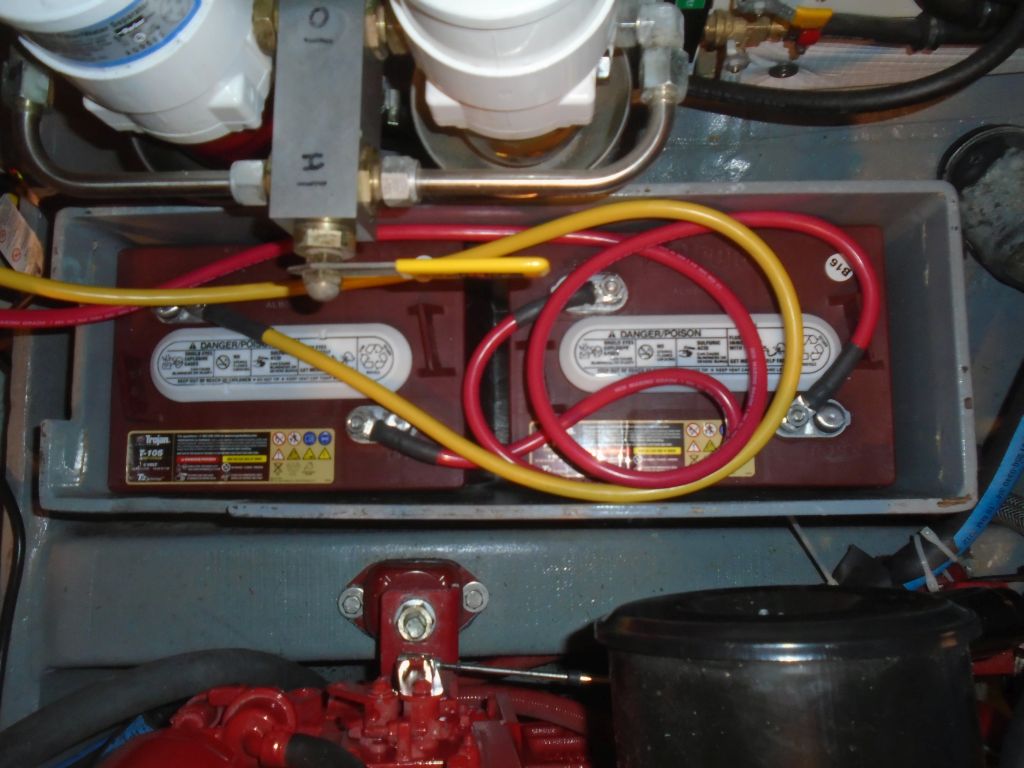
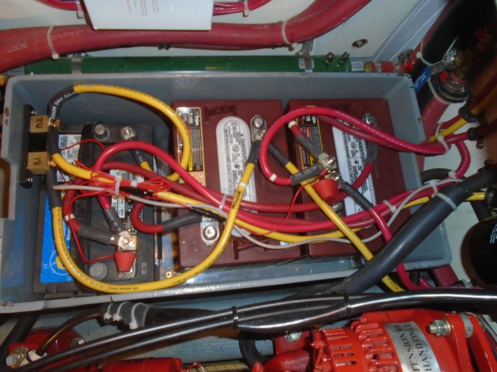
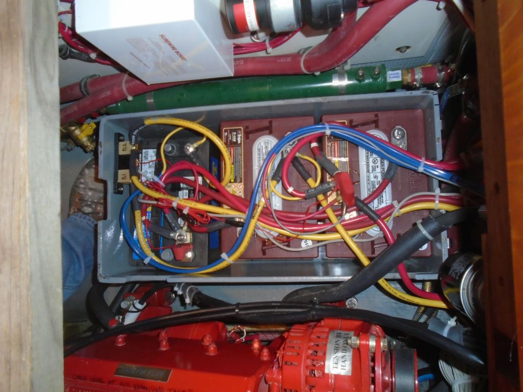
Returning for a day with hopes (and expectations) of finishing up the list of wiring chores, I got started with installing four new 6-volt batteries for the house bank. The original 6-volt batteries that I installed in early 2014 when I still was working on the boat myself had been damaged by sitting in a discharged state for a year, an embarrassing mistake that I’d discovered when selling the boat to this owner. The original set had performed badly during the boat’s first season, and in addition to replacing the non-functional batteries, the owner elected at this time to add the second set that had been part of the electrical plan from the beginning, doubling the capacity of the house bank to over 400 Ah.
During an earlier work day, I’d prepared the new wiring for the second set of batteries, so installation now was straightforward in the starboard battery box, with the other set back in the port box, along with the starting battery, where the bulk of the wiring was.
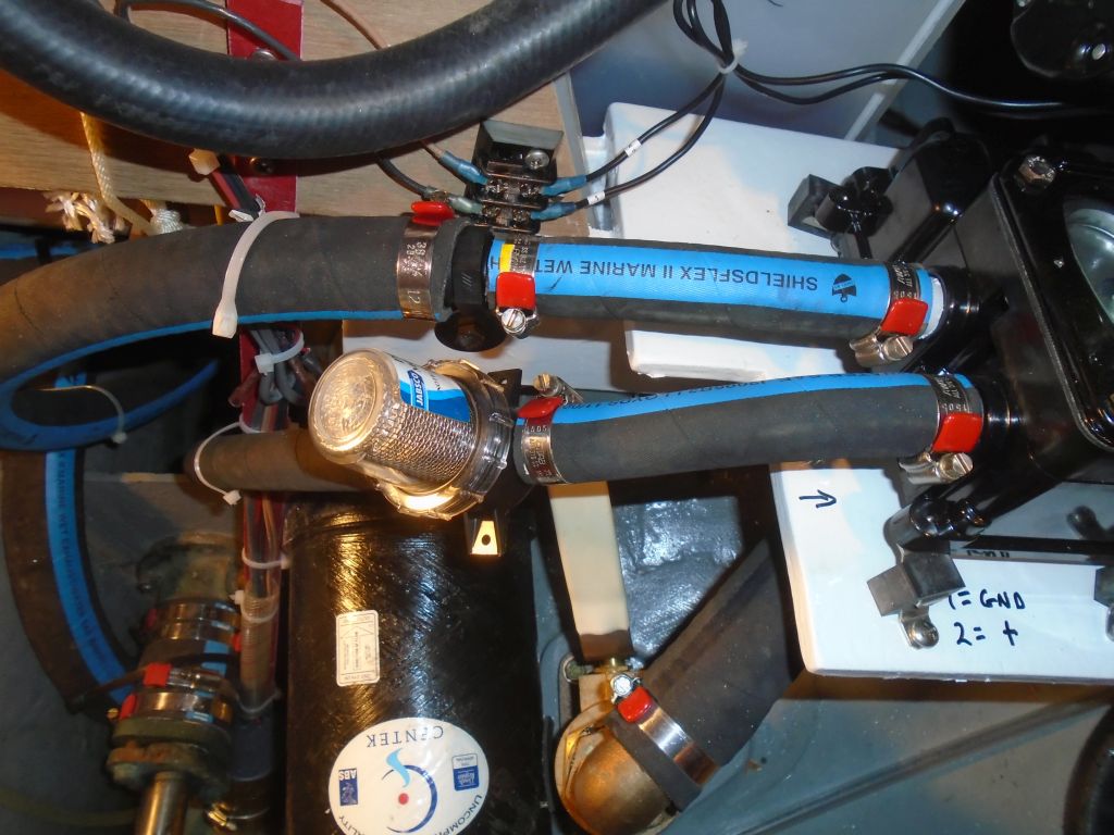
Another small job pending from my earlier work session was to adapt the 3/4″ discharge from the new bilge pump to the existing 1-1/8″ hose already in place. This required a simple adapter fitting, which I’d purchased earlier and now installed.
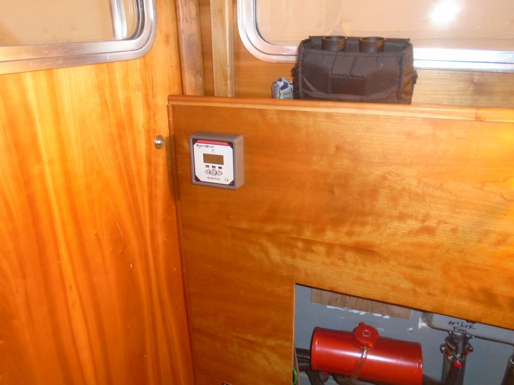
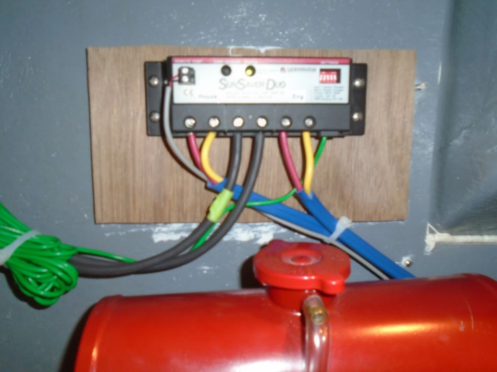
With the solar panel and its basic wiring in place from before, I worked now to complete the installation of the solar controller, wiring, and a remote readout panel. In my absence, the owner had attached a wooden block in a locker outboard of the engine room where I was to install the controller–convenient to the panel wiring and engine room, but out of the way and out of sight. I attached the controller and remote readout in the owner’s selected position, then led in two pairs of 10AWG cable for the runs from the controller to the battery banks–one pair each for house and start banks, along with a smaller wire for a temperature sensor required for the controller. The task was straightforward in concept, but with largely full existing wiring conduits and convoluted route between this location and the engine room, the physical chore took a bit of time, though it all went well and according to plan.

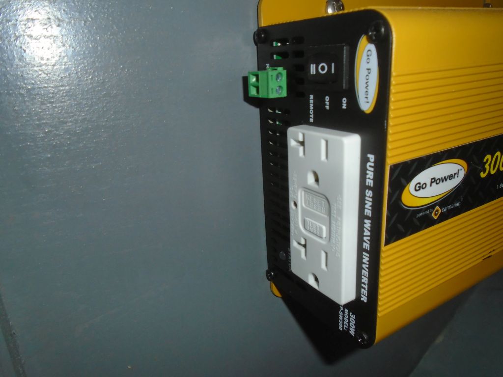
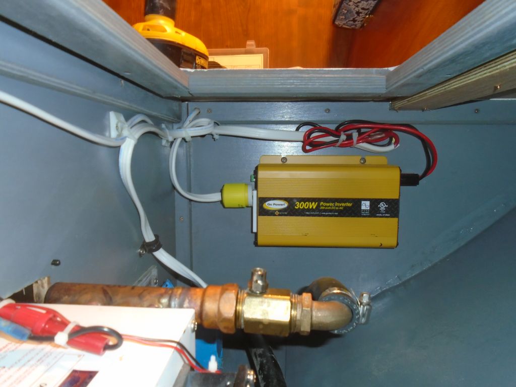
Next, I turned to the final wiring task on my list, which was to install a 300W inverter in the cabin to service a single AC outlet in the dinette area. The owner had supplied the inverter, and earlier we’d discussed the location and wiring plan, so now it was a matter of getting down to business.
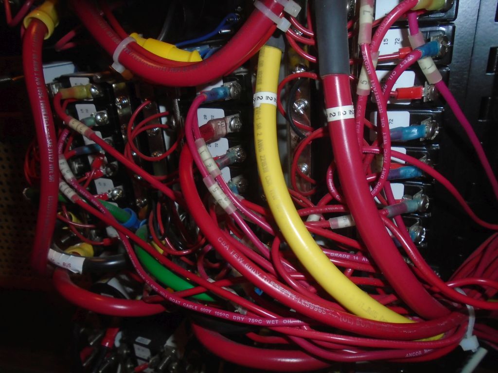
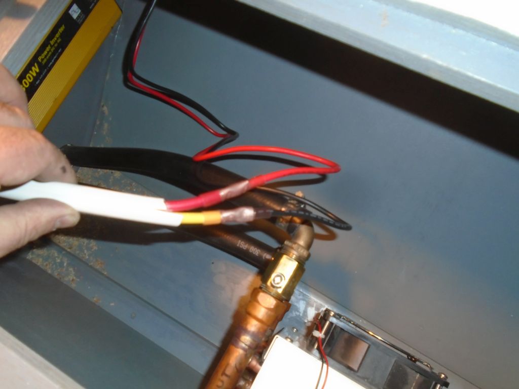
Between then and now, I’d made a couple preparations back at the shop, setting up a plastic outlet box with a glued-on fiberglass flange to allow me to secure it in the cabinet properly, and preparing a short length of 12/3 cable with a standard 3-prong plug on one end to connect the outlet on the inverter itself (which would be inside a cabinet and out of convenient reach) to a remote outlet located in the cabinet front. Now, I began by running an 8/2 sheathed conductor from the locker beneath the dinette and into the engine room and electrical panel. Fortunately, I found that an existing wire conduit was in place that I could actually get to and use, because despite the short distance the numerous other installations within and without the engine room made access quite complicated. As it was, the chore was pleasingly straightforward, and I connected the cable ends to a circuit breaker in the panel that was already set up for this addition (second down in the middle row), then connected the other end of the conduit (after leading it alongside an existing wire run through the adjacent cabinet) to the supplied wire ends that plugged into the inverter itself. I secured the inverter to the aft bulkhead in the center locker beneath the dinette, which already contained one of the heating fans for the heating system and which the owner pledged to keep free from detritus to allow the inverter the cooling space required.


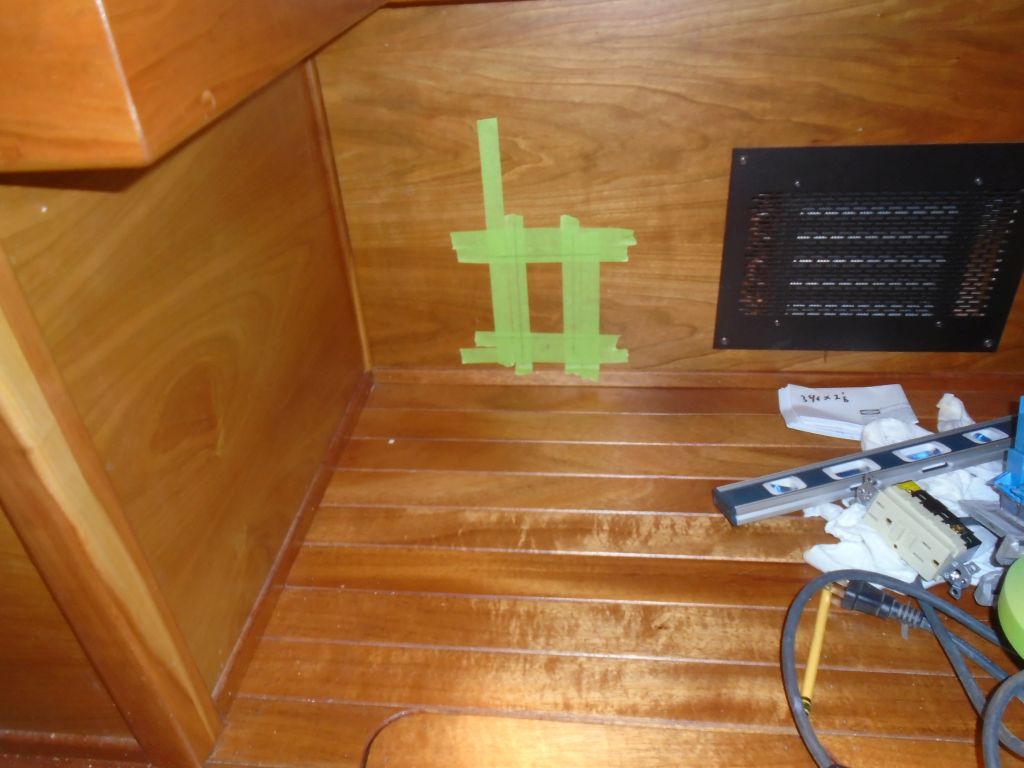
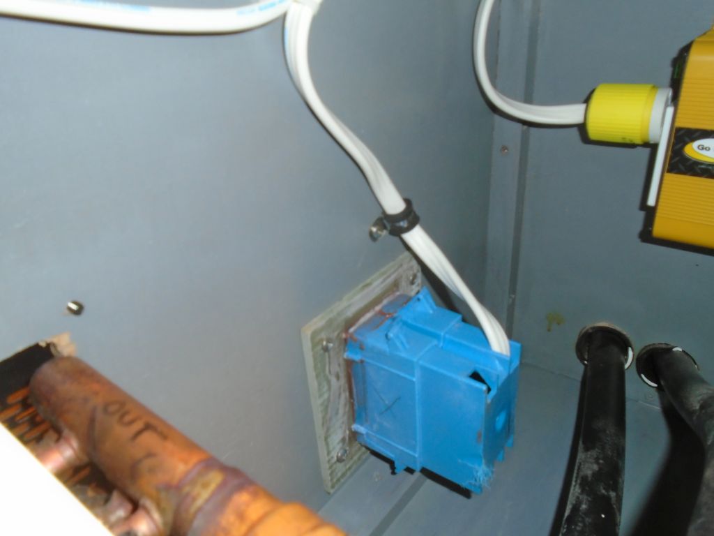
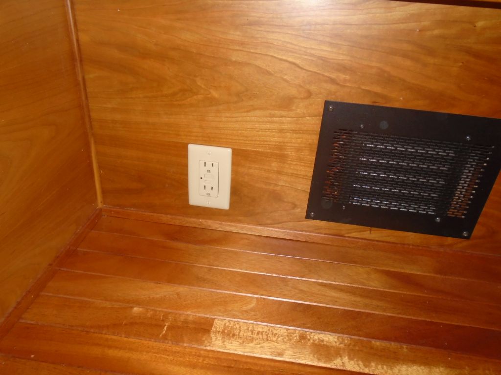
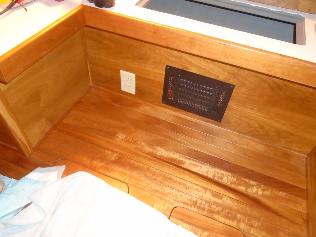
I laid out for the receptacle in the front bulkhead of the locker, keeping the cover plate even with the bottom of the adjacent heating grille, and choosing this location both for its proximity to the inverter behind, clearance space behind the bulkhead, and because I needed a certain amount of access space for my saw in order to cut the opening. I secured my plastic outlet box to the back side of the bulkhead with screws through the FRP flange that I’d attached, then ran my pre-made cable from the inverter plug into the box, where I wired it to a typical GFCI outlet. The system tested operational.
Total time billed on this job today: 6.5 hours
0600 Weather report:
18°, partly clear. Forecast for the day: sun, clouds, show shower in the afternoon, high near 30 but dropping in the afternoon