Phase 3: Finish
Work
|
Shop Home
Page
Shop
Planning
Phase 1: Site Prep and Foundation
Phase 2: Framing
Phase 3: Finish Work
Phase 4: Shop Setup |
| Heating
Plant Early
in the process, I chose radiant floor heating as the
best option for the shop. I did not arrive at this
conclusion without significant consideration, however,
but in the end, it seemed the best option by far:
quiet, no air movement, heat near the floor where it is
needed most, and supposedly efficient thanks to the
thermal mass formed by the 6" concrete slab.
Of
course the radiant system cost more (about 13% more than
the runner up, ceiling confectors), but I felt it would
be worthwhile in the long run to avoid the air movement
that would be caused by the confectors. |
 I
had to make the decision early, since the tubing for the
heating loops needed to be in place before the slab was
poured. In my absence, the heating contractor
installed the tubing for four separate zones (one in
each bay and the office), and the snaking tubing was
secured in time for the concrete pour shortly
thereafter. With that, no further action on the
heating was required for some time, while construction
of the building pressed on. I
had to make the decision early, since the tubing for the
heating loops needed to be in place before the slab was
poured. In my absence, the heating contractor
installed the tubing for four separate zones (one in
each bay and the office), and the snaking tubing was
secured in time for the concrete pour shortly
thereafter. With that, no further action on the
heating was required for some time, while construction
of the building pressed on. |
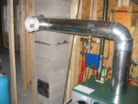
 By
January, with the building fully enclosed, it was time
to get the heating plant installed and up and running,
even before the insulation was underway. Over a
period encompassing four days, the contractor and his
helpers installed the boiler, oil tank, and the myriad
plumbing pieces required for the complicated system.
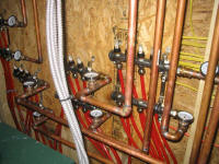
Each of the four zoned required a circulating pump and a
pair of tubing manifolds--outflow and inflow, along with
temperature gauges and individual tubing flow controls
that would allow the heat distribution to be fine-tuned
ad infinitum. In the end, it made for a rather
impressive setup. By
January, with the building fully enclosed, it was time
to get the heating plant installed and up and running,
even before the insulation was underway. Over a
period encompassing four days, the contractor and his
helpers installed the boiler, oil tank, and the myriad
plumbing pieces required for the complicated system.
Each of the four zoned required a circulating pump and a
pair of tubing manifolds--outflow and inflow, along with
temperature gauges and individual tubing flow controls
that would allow the heat distribution to be fine-tuned
ad infinitum. In the end, it made for a rather
impressive setup. |
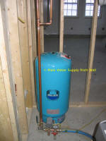
At the end of installation, it took a fair bit of
tweaking and air bleeding to get the system working
properly. With the well tank and piping connected
inside the utility room for now, a ready supply of water
was available with which to fill the floor tubing.
I left late in the day when the system was up and
running, but it wasn't until the next day that I
could begin to feel the effects of the heat.
Feeling a warm concrete floor seemed unnatural, as one
tends to get used to the floors being cold and clammy,
but it didn't take long before I was forever spoiled:
warm feet make all the difference. Even after only
a week or so of the heating plant in operation, I could
tell that it had been the correct choice, and I looked
forward to spending many warm winters inside the shop. |
|




 |
Plumbing
Plumbing needs were
simple: a single half-bath with toilet and sink,
and one exterior sillcock. With the bath located
adjacent to the utility room and water inlet, the piping
runs could be relatively short and simple.
 Earlier
in the building process, before the slab was poured, we
installed the drain piping in the ground for the toilet
and sink, and stubbed the pipes well above the finished
floor level. Later on, with the bulk of the
building complete but before insulation was installed, I
used schedule 40 PVC drain pipe to run a vent line from
the sink drain stubout in the floor, up through the
walls and ceiling, and out through the roof. At
the same time, I also plumbed sideways from the floor
stub out, through the back wall of the bathroom and then
out into the room for the sink drain. Earlier
in the building process, before the slab was poured, we
installed the drain piping in the ground for the toilet
and sink, and stubbed the pipes well above the finished
floor level. Later on, with the bulk of the
building complete but before insulation was installed, I
used schedule 40 PVC drain pipe to run a vent line from
the sink drain stubout in the floor, up through the
walls and ceiling, and out through the roof. At
the same time, I also plumbed sideways from the floor
stub out, through the back wall of the bathroom and then
out into the room for the sink drain.
|
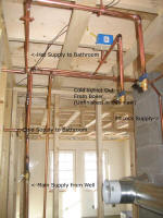
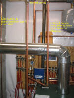
 During
the heating plant installation, the contractor installed
a copper line from the well water inlet straight
upwards, near the back wall of the bathroom, and placed
a ball valve shutoff at the top. This made it easy
for me to tap into the potable water system, and I began
my piping installation right off the top of this shutoff
valve. Since the line in place was made using 3/4"
pipe, my first step was to reduce this down to the 1/2"
size commonly used for interior plumbing. Then, I
installed a couple tees to allow water to run to both
the sillcock, cold water side of the sink, and a third
run over to the tankless hot water coil in the boiler.
I sweated all the joints with a torch (using the
hotter-burning MAPP gas rather than propane) and
lead-free solder. During
the heating plant installation, the contractor installed
a copper line from the well water inlet straight
upwards, near the back wall of the bathroom, and placed
a ball valve shutoff at the top. This made it easy
for me to tap into the potable water system, and I began
my piping installation right off the top of this shutoff
valve. Since the line in place was made using 3/4"
pipe, my first step was to reduce this down to the 1/2"
size commonly used for interior plumbing. Then, I
installed a couple tees to allow water to run to both
the sillcock, cold water side of the sink, and a third
run over to the tankless hot water coil in the boiler.
I sweated all the joints with a torch (using the
hotter-burning MAPP gas rather than propane) and
lead-free solder. |
| At logical
points in each piping run, I installed ball valves to
allow for easy shutoff and maintenance as required,
particularly on either side of any installation,
including at the stubouts for the cold and hot water
supplies to the sink, in the run to the sillcock, and at
both the inlet and outlet of the tankless hot water
coil. The extra shutoffs were probably
unnecessary, but should the supply to any portion of the
system need to be shut down in the future, only that
particular system need be disabled. Convenience of
future maintenance is always a consideration. My
heating contractor, Jim, put me onto this; he installed
all the components in the heating system in this manner,
and I thought it was a good idea, so I emulated it in my
own work. |
I chose a frost-free sillcock, in which the actual
plunger mechanism that closes off the flow is located
well within the heated building, rather than outside;
with a slight downhill pitch to the installation, this,
in theory, means that the faucet can be left energized
all winter long without problem. |
I'll save you the minute details of the job, and instead
rely upon the pictures of the finished installation to
describe the final setup. Try to contain your
excitement.I'm
not an expert at sweating copper pipe joints, so my
joints aren't always the prettiest. But out of the
many joints I soldered in the system, I had only one
small pinhole leak (easily rectified), so my soldering
is effective. |
|


|
|


|
|


|
| |
Click here to continue... |
|
This page was originally
posted on January 23, 2006. |
|