|
|
~MENU~ |
| Home |
| The Concept |
| The Boat |
| Bringing Her Home |
|
Weekly Progress Log |
|
Daysailor Projects |
| The Boat Barn |
| Resources |
| Other Sites |
| Email Tim |
|
|
| From a Bare Hull: Initial Deck Frame Layout |
Without a detailed set of construction designs and drawings, each step in the construction process required a substantial amount of visual layout and what amounted to full-scale lofting of the basic shapes of the deck crown and cabin trunk. One of the reasons I chose to make the midships bulkhead so oversize was because it would make an excellent platform on which to produce full-scale lofted drawings of the deck, where I could properly visualize the shapes before committing to anything permanent. Deck Beam
Design/Deck Crown |
Next, I consulted several sources to determine the appropriate way to lay out a proper deck crown. There are a few schools of thought here, each with their own proponents and naysayers. The first school says that the crown can simply be a true arc of a circle, with points running through the two edges and the maximum height at the centerline. The general consensus seemed to be that this method was amateur in nature and produced unpleasing crowns from a visual and practical nature, and is not highly regarded. I never seriously considered it.
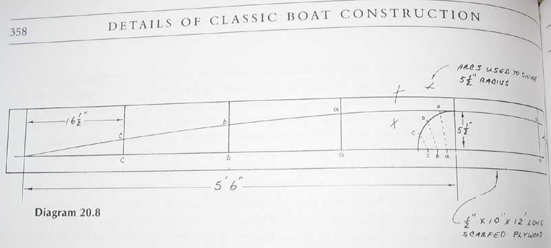
The final school argues that the traditional method, in which all deck beams share a single shape and mold, produces a deck that, when viewed from the theoretical side, may appear inappropriately shaped as the beams progress from stem to stern. For certain applications, such as a truly flush-decked boat, there is logic to this argument. This method opines that each beam should be uniquely shaped according to its position, to avoid the appearance of a hogged deck amidships that might result when using beams built off a single mold. A recent article in Wooden Boat magazine covers this method in some details; I shan't repeat it here. I rejected this particular method because there was so little actual deck in my design, with most of the boat taken up by the large cockpit with narrower sidedecks outboard, and I couldn't see the virtue in following this method for very little actual return in my particular case. That said, the method probably would bear further investigation in certain circumstances. Each case is unique, and therefore must be addressed individually as needed. It took several reads of the section in Pardey's book before I understood the whole process; some of my research even included a trip through my old Geometry textbook to refresh my memory on how to divide an arc. For more, click on the link below. Click here to read a detailed account of the beam crown layout method. |
 With
the shape drawn out full-size on the bulkhead, I found I could easily
visualize what the decks might look like, and decided that I was pleased
with the result. I decided to continue using that shape, so it was
an easy step to transfer the measurements to a length of 2x10 that I had
laying around, from which I cut a test beam and, ultimately, a laminating
mold upon which to glue up the many deck beams needed. More on the
beams' construction is coming up in subsequent pages. Jump
ahead... With
the shape drawn out full-size on the bulkhead, I found I could easily
visualize what the decks might look like, and decided that I was pleased
with the result. I decided to continue using that shape, so it was
an easy step to transfer the measurements to a length of 2x10 that I had
laying around, from which I cut a test beam and, ultimately, a laminating
mold upon which to glue up the many deck beams needed. More on the
beams' construction is coming up in subsequent pages. Jump
ahead... |
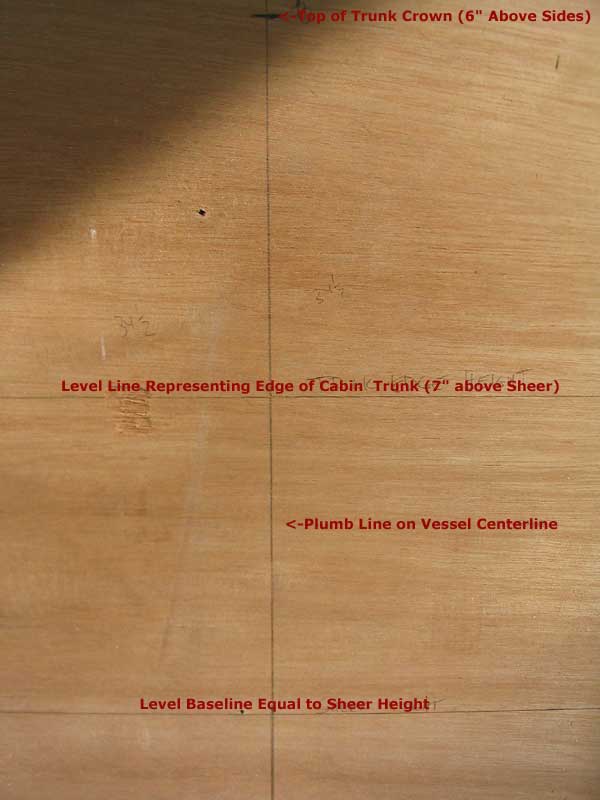
Cabin Trunk Crown The other reason I left the mid bulkhead oversize is that it was destined to become the demarcation point between the cockpit and the cabin trunk. As such, it of course was the perfect place to draw out the designed shape full-size, which was necessary not only to reinforce the accuracy and visual effectiveness of the drawing, but also to provide a cutline so that I could remove the unnecessary portions of the bulkhead and cut it down to the proper shape. Click here to refresh your memory on the design concept.
Click here to read a detailed account of the beam crown layout method. |
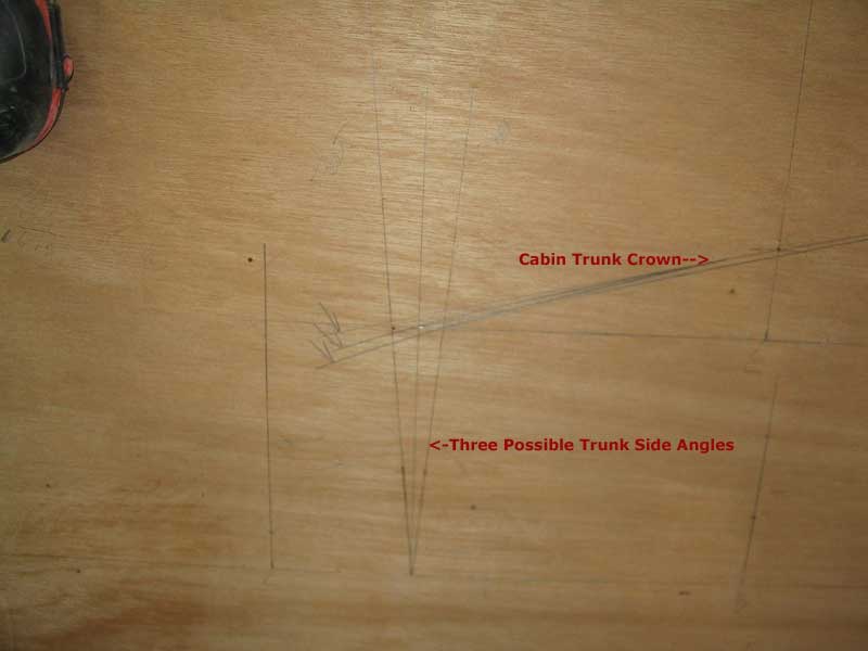
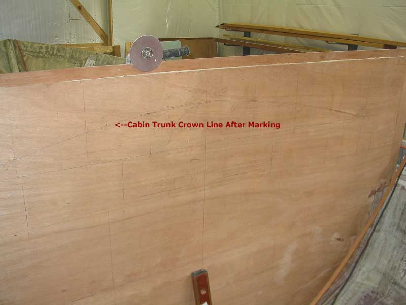 Getting
the shape of the after end of the eventual cabin trunk correct was
critical before making any cuts in the bulkhead. Because the entire
deck design is wrapped up in the overall shape of the cockpit--and, by
nature, the cabin trunk, since the trunk is essentially intended to be a
seamless continuation of the cockpit coamings as they sweep around the
forward part of the boat--many of the following steps would hinge directly
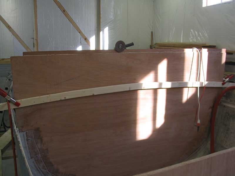
on the bulkhead shape, so it needed to be right. With the basic
shape drawn on the bulkhead, I left it alone for several days, taking time
now and again to glance at it, absorb the shape, and see what I
thought. I saw no need to rush the cutting, but it was clear that
I'd need to make the cuts sooner rather than later. Getting
the shape of the after end of the eventual cabin trunk correct was
critical before making any cuts in the bulkhead. Because the entire
deck design is wrapped up in the overall shape of the cockpit--and, by
nature, the cabin trunk, since the trunk is essentially intended to be a
seamless continuation of the cockpit coamings as they sweep around the
forward part of the boat--many of the following steps would hinge directly
on the bulkhead shape, so it needed to be right. With the basic
shape drawn on the bulkhead, I left it alone for several days, taking time
now and again to glance at it, absorb the shape, and see what I
thought. I saw no need to rush the cutting, but it was clear that
I'd need to make the cuts sooner rather than later. |