|
|
~MENU~ |
| Home |
| The Concept |
| The Boat |
| Bringing Her Home |
|
Weekly Progress Log |
|
Daysailor Projects |
| The Boat Barn |
| Resources |
| Other Sites |
| Email Tim |
|
|
| From a Bare Hull: Deck Layout & Deck Beam Construction |
Waterline and Cockpit Sole Height While the shape and depth of the cockpit wasn't necessarily critical at this particular juncture, it will become so later in the process, particularly as relating to the engine placement and location of the waterline. I wanted to keep the sole as low as possible without interfering with the minimum space required beneath for an engine, and without ending up too close to the waterline.
|
 During
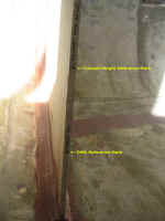
demolition, I had intentionally left a small bit of the old cockpit sole
around the rudder tube, so now I could use that as a reference point from
which to figure the new cockpit sole height. With a level, I transferred
that location tot he aftermost bulkhead (shown in the photo, left); by
measuring from the waterline mark up to the sole mark, I could then
transfer that new line to the mid bulkhead, once again giving me two solid
reference points for future work. I drew out a rough cockpit well
shape on the mid bulkhead for my own reference in future planning, and
also transferred the height of the sole to my construction drawing. During
demolition, I had intentionally left a small bit of the old cockpit sole
around the rudder tube, so now I could use that as a reference point from
which to figure the new cockpit sole height. With a level, I transferred
that location tot he aftermost bulkhead (shown in the photo, left); by
measuring from the waterline mark up to the sole mark, I could then
transfer that new line to the mid bulkhead, once again giving me two solid
reference points for future work. I drew out a rough cockpit well
shape on the mid bulkhead for my own reference in future planning, and
also transferred the height of the sole to my construction drawing.
While I may not have done anything specific with these reference marks at this stage, they will become important later, so I thought it made sense to get them figured out earlier rather than later. |
Deck Beam Laminating Mold and Construction Once I had the proper shape for the main deck beams determined, creating a test beam and laminating mold was straightforward. Using the measurements from the layout step, I recreated the crown shape on a 10' length of 2x10 that I had around, and cut out a mock beam with my jigsaw. This left a sturdy base section that I could use to form my laminating mold. Click here to revisit the beam layout process.
|
 I
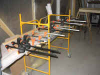
glued up the deck beams one at a time from three pieces of mahogany, each
one 3/4" thick and just over 2" wide. This allowed for
finished beams of 2" in width (after smoothing) and 2-1/4" in
depth, which seemed more than sufficient to me after I consulted a number
of different sources on the subject. I varied the lengths according
to the beams needed on the boat, choosing the appropriate section of the
beam mold on which to clamp each section. To glue the laminations
together, I chose resorcinol glue, a very strong, highly waterproof glue
that is easy to mix and use. For each beam, I clamped the glued
pieces in place and left overnight, or for the appropriate curing time as
necessary. I found that springback was virtually negligible. I
could only glue up one beam a day, so I tried to ensure that I got ahead
of myself so that I'd never have to wait endlessly for deck beams.
So I continued gluing up a beam a day, and in the meantime I got to work
on the sheer clamp. I
glued up the deck beams one at a time from three pieces of mahogany, each
one 3/4" thick and just over 2" wide. This allowed for
finished beams of 2" in width (after smoothing) and 2-1/4" in
depth, which seemed more than sufficient to me after I consulted a number
of different sources on the subject. I varied the lengths according
to the beams needed on the boat, choosing the appropriate section of the
beam mold on which to clamp each section. To glue the laminations
together, I chose resorcinol glue, a very strong, highly waterproof glue
that is easy to mix and use. For each beam, I clamped the glued
pieces in place and left overnight, or for the appropriate curing time as
necessary. I found that springback was virtually negligible. I
could only glue up one beam a day, so I tried to ensure that I got ahead
of myself so that I'd never have to wait endlessly for deck beams.
So I continued gluing up a beam a day, and in the meantime I got to work
on the sheer clamp. |

