
|
|
~MENU~ |
| Home |
| The Concept |
| The Boat |
| Bringing Her Home |
|
Weekly Progress Log |
|
Daysailor Projects |
| The Boat Barn |
| Resources |
| Other Sites |
| Email Tim |
|
|
| Sidebar: Details on the Deck Beam Layouts |
To lay out the shape of the curved deck beams and cabin trunk overhead beams, I used a traditional layout process described in several published sources on the subject, including Details of Classic Boat Construction, by Larry Pardey. Using this source as a basis, I worked out the curves using my own particular dimensions. I followed the same process to create both the deck beam curve and the cabin trunk curve, though the measurements in each case differed. The steps and photographs below refer to my layout for the cabin trunk beams. |
|
|
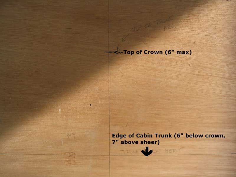
Step 1 |
|
| Step 2 Next, I set my compass to 6"--the height of the maximum crown--and scribed an arc the left of the centerline, running between the centerline and the baseline. The centerpoint of the arc is the intersection between plumb centerline and level baseline. |
 |
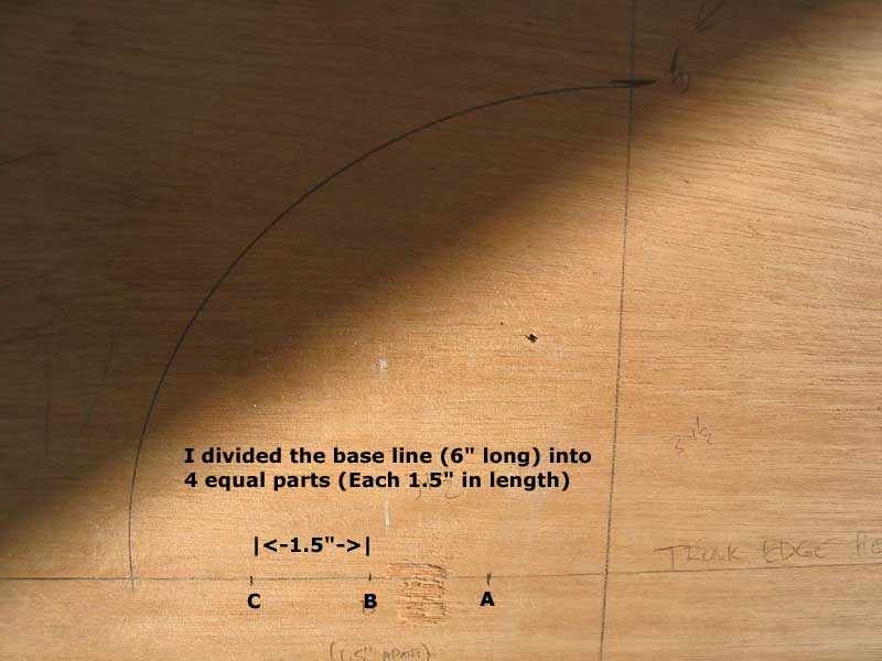
| Step 3 I divided the base line into four equal parts between the intersection of the arc and the centerline. In this case, each mark was 1.5" apart (6"÷4). |
 |
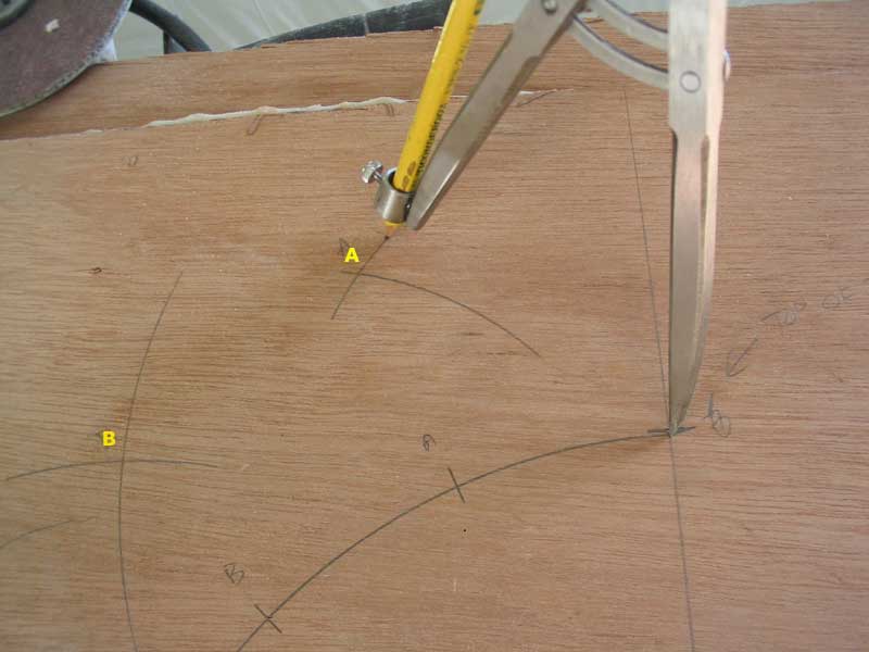
| Step 4 Next, I divided the arc into four equal parts. To do this, I had to dig through some old texts to refresh my memory on how to proceed. To evenly divide any arc, set the dividers to any random setting larger than half the radius (anything over 3" in this case), and, with the point on first one and then the other of the intersection points (12:00 or 9:00 in this case), swing an arc first one way then the other, creating a specific point in space. When a line is drawn through this point (B in the photo) and the centerline of the arc (the intersection of plumb centerline and level baseline), the intersection with the arc represents the halfway point of its length. |
 |
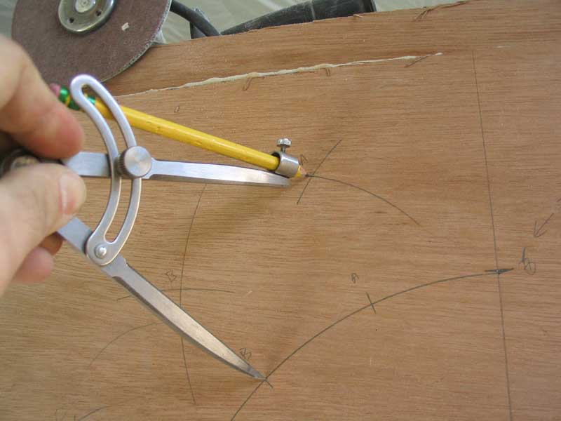
| Step 5 After dividing the arc in half, each half can be divided in half again by following the same process, only moving the dividers as necessary whichever points are being used as the basis of the division. This photo shows me swinging the second arc that forms point A in the photo above. I have the dividers set on the centerline of the original and (point B) to create the second half of the point. |
 |
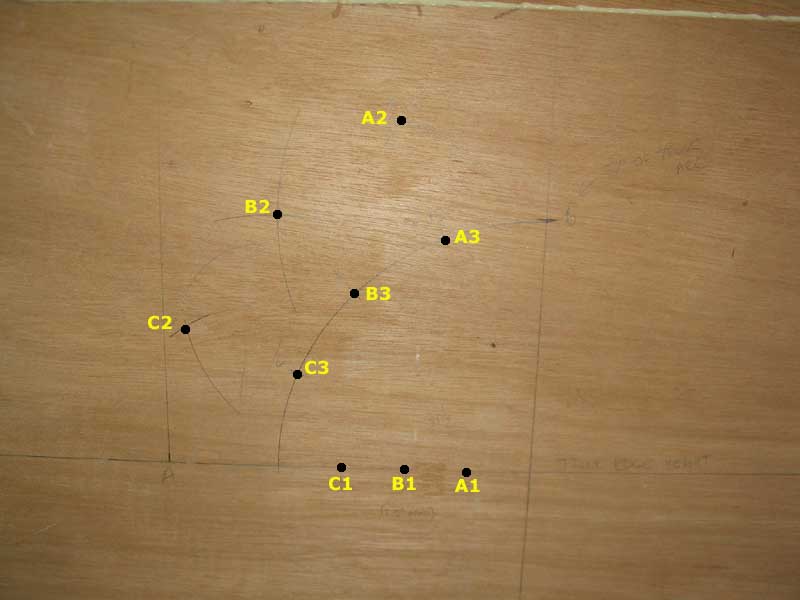
| Step 6 When the points (A2, B2, C2) are marked with the compass, connecting them with the baseline points (A1, B1, C1) creates the evenly divided marks where they intersect the original arc (A3, B3, C3). Don't try to connect the points in this photo, because there's a distortion resulting from the angle of the camera in relation to the plane of the board. But they line up in real life! |
 |
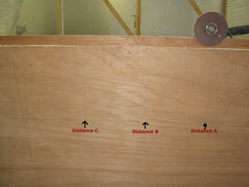
| Step 7 The three points on the divided arc--A3, B3, C3--represent the heights of the arc at three evenly-spaced points along the baseline. To locate these heights, I first measured the baseline (from the edge of the cabin trunk to the centerline) and divided it into four equal parts, and marked these accordingly on the baseline as shown. I drew perpendicular lines upward at each point. |
 |
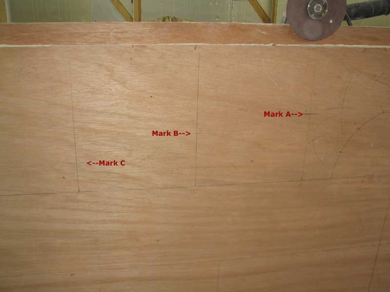
| Step 8 Next, I transferred the heights represented by the points A3, B3, and C3 in step 6 over to their respective lines. You could measure the height and transfer it or, as I did, simply use a level to transfer the marks across. |
 |
| Step 9 With 9 total measured points (four on each side plus the centerline), there was enough information to strike an arc through all the points. I drove a small nail into each mark and bent a springy batten across the nails, holding it tightly in place with tape, and traced the line with a pencil. The arc in this photo looks overly curvy on the centerline because, as I found out later, I had placed the batten on the centerline above the mark, while the line was below the marks at all other locations. I later made a minor adjustment to the arc, which flattened the topmost portion accordingly, but it doesn't show in this photo. |
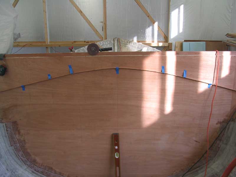 |
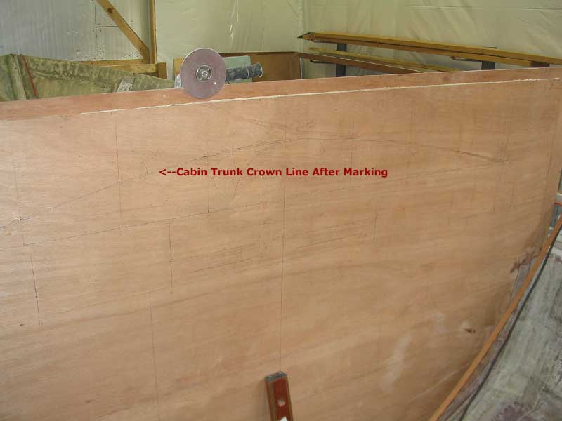
| Completed It may be hard to get a sense of the character of the arc from the photos, but it looks smooth and good, excepting the minor adjustment needed from step 9. |
 |