
|
|
~MENU~ |
| Home |
| The Concept |
| The Boat |
| Bringing Her Home |
|
Weekly Progress Log |
|
Daysailor Projects |
| The Boat Barn |
| Resources |
| Other Sites |
| Email Tim |
|
|
| Boat Barn: Electrical (Page 2) | ||
The electrical system will feature numerous wall outlets and ceiling lights for proper illumination. |
Framing | |
| Raising the Walls | ||
| Roof and Trim | ||
| Electrical Rough In Details Panel |
||
| Insulation/Windows/Doors | ||
| Barn
Home Page
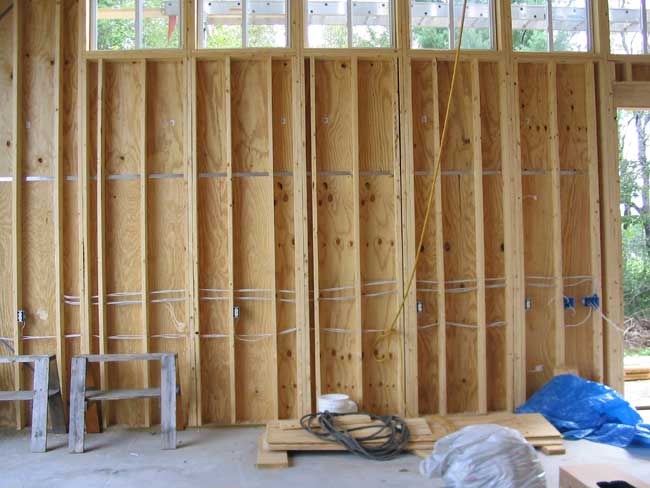
Electrical Installation Detail The electrical plan turned out to be a bit more involved and complicated to install than I anticipated, but after a number of full days of hard (yet enjoyable) work, the installation was complete. The system consists of a series of outlets spaced every six feet or so along the walls, at 42" above the floor for convenient access. Because of the number of outlets, I chose to wire them in four distinct circuits, with about 5 outlets on each circuit. Each wire (14/2 Romex) runs directly to the front corner of the structure, where the master service panel was installed. In addition to the basic wall outlets, I installed a dedicated outlet for the kerosene heater that I plan to install, as well as a dedicated 20-amp line (run to a junction box for the moment) to which my table saw will be attached. I also dropped a double-gang box of 20-amp receptacles directly beneath the panel location. For
shop lighting, I chose some midrange fluorescent shop lights, lit with
two 4' bulbs each. Unsure of how many lights I would ultimately
need, I planned for up to 25 (5 rows of 5 lights each), evenly spaced
across the ceiling. The lights I chose use standard grounded
plugs, so I simply installed 25 outlets in the ceiling, one at each
location. Each bank of five outlets is designed to be switched
from either side of the room, necessitating 3-way switches at each
location. |
|
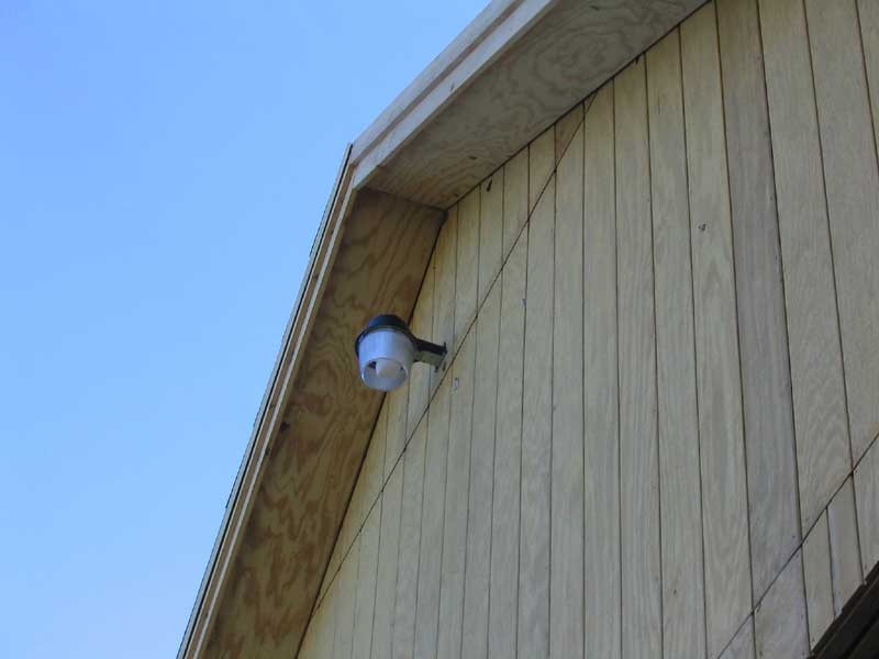 |
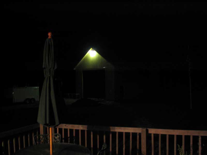
I also ran wires for, and installed, exterior lights at the northern man door, and at the southern sliding door. Both lights are switched from the north man door for convenience. For security lighting, I installed a mercury vapor gable light on the east (front) gable.
|
All 15 amp circuits are wired with standard 14/2 Romex; the 3-way switches require an additional run of 14/3 Romex for each switch. 20 amp circuits (table saw and outlets) are wired with 12/2 Romex. All cables are run through the studs as necessary, and are stapled 12" apart on all other members as needed. Planning ahead, I installed a series of three ceiling boxes, wired with 12/2 Romex, for ceiling fans, spaced more or less evenly along the centerline of the ceiling. I don't plan to install these right away--I'll see how things go, heatwise, this winter and install them as needed. But the time to wire was now. Below
is a series of detail photos showing much of the wiring and features. |
|
| I installed
all of the plastic boxes first, before beginning any wiring. When
running the wires, I simply left a large loop of cable at each outlet
box for eventual connection to the receptacles. Leaving abundant
cable is important to ensure ease of wiring later.
|
|
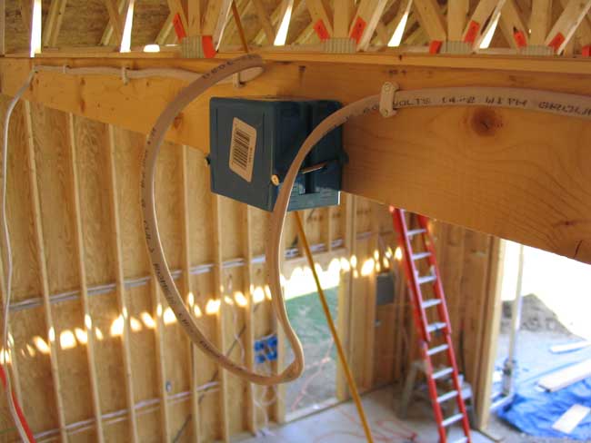
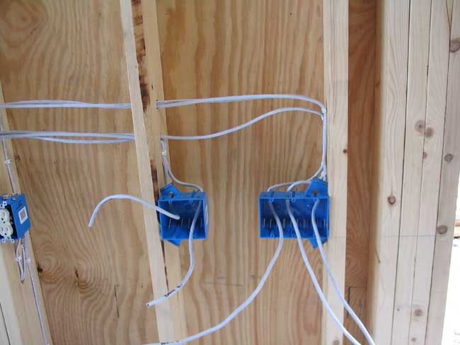
| Because of the
panel location in the front corner of the barn (to the right in the
photo), all wires eventually had to cross over the door opening to reach
the panel. Even with up to four cables running through a single
hole, four sets of holes were required.
|
|
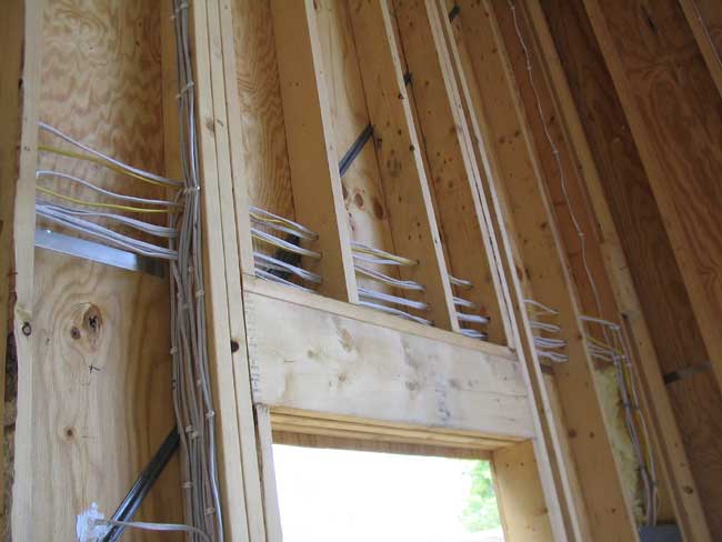
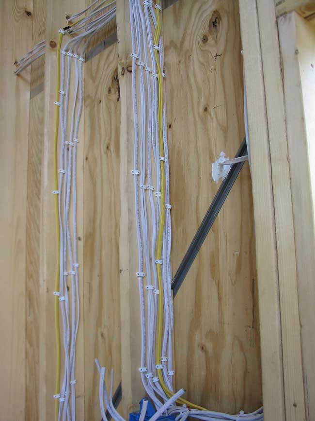
| This shows the
wiring running through the south wall. The wires shown include the
power cable for the string of receptacles and an outside lighting
fixture, plus five cables required for the 3-way switches installed near
the door.
|
|
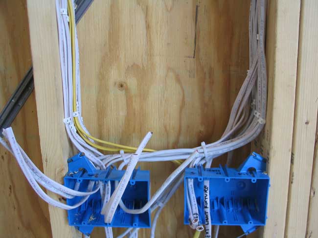
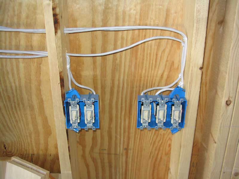
| These are the
future locations for five 3-way switches at the south sliding
door. Because the main power feed enters the boxes on the other
side of the room (see below), the only cables required here are the
3-conductor cables connecting the switches, one for each switch.
|
|
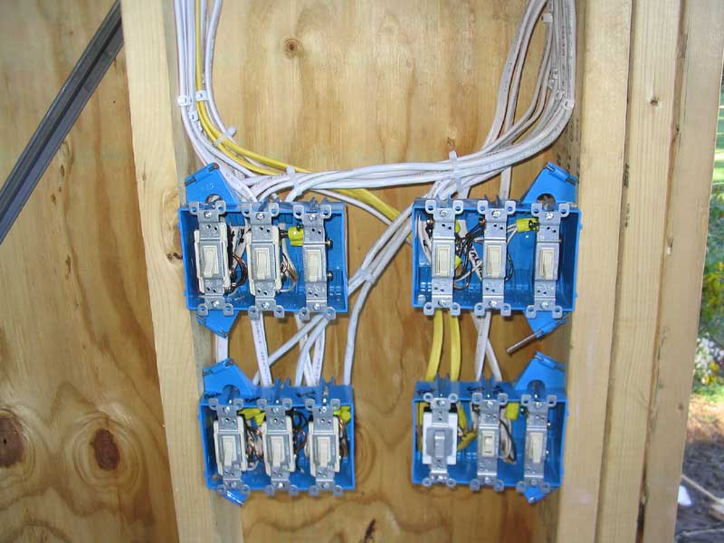
| These are two
of the four 3-gang switch boxes installed at the north door.
Because of an on-the-fly change in my overall wiring plan (I decided to
wire all three ceiling fan boxes together on one circuit, when I had
planned three) there are actually 2 or 3 unused spaces in the
boxes. There are two more boxes located below, just out of the
picture. These switch boxes control the five banks of overhead
lights, two exterior lights, ceiling fans, and the gable light.
|
|
| This shows the
myriad wires running down to the switches in the above picture.
Each switch requires a minimum of two cables--one for power in, one out
to the fixture. The three-way switches require a third cable (3
conductor) to connect to the other switch in the series.
|
|
| Here are all
the switches installed and wired up. The two boxes to the left
contain the three-way switches (with one blank). The lower right
box contains one 20-amp switch for the ceiling fans (of course I
couldn't find an ivory one to match).
|
|
| This is the
second set of 3-way switches, located across the room.
|
|
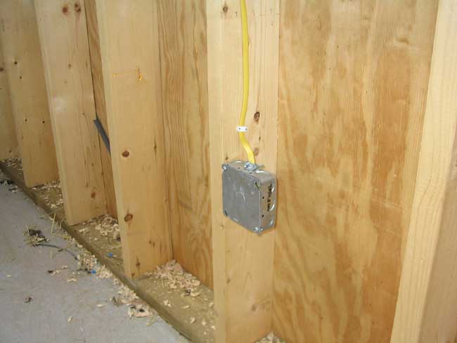
| I installed
this junction box near where I think the table saw will be
installed. Because the saw will be somewhere in the middle of the
floor, I'll simply connect some conduit and a receptacle to the junction
box later in the process.
|
|
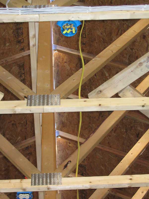
| This shows one
of the ceiling fan boxes, with the yellow 12-ga cable running
perpendicular to the trusses to the next box.
|
|
|
Click here see a series of photos showing the wiring of the service panel. With that, the electrical rough in was complete. All circuits tested operational as expected. |
|