(page 4 of 13)

Calliope Girl 97

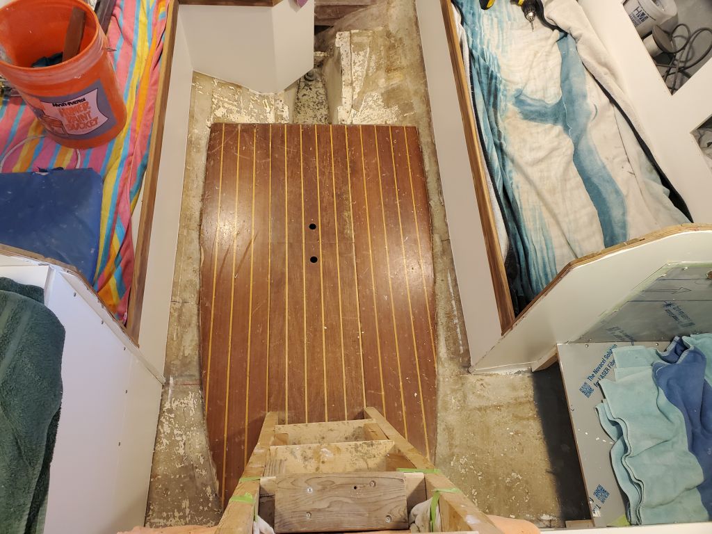
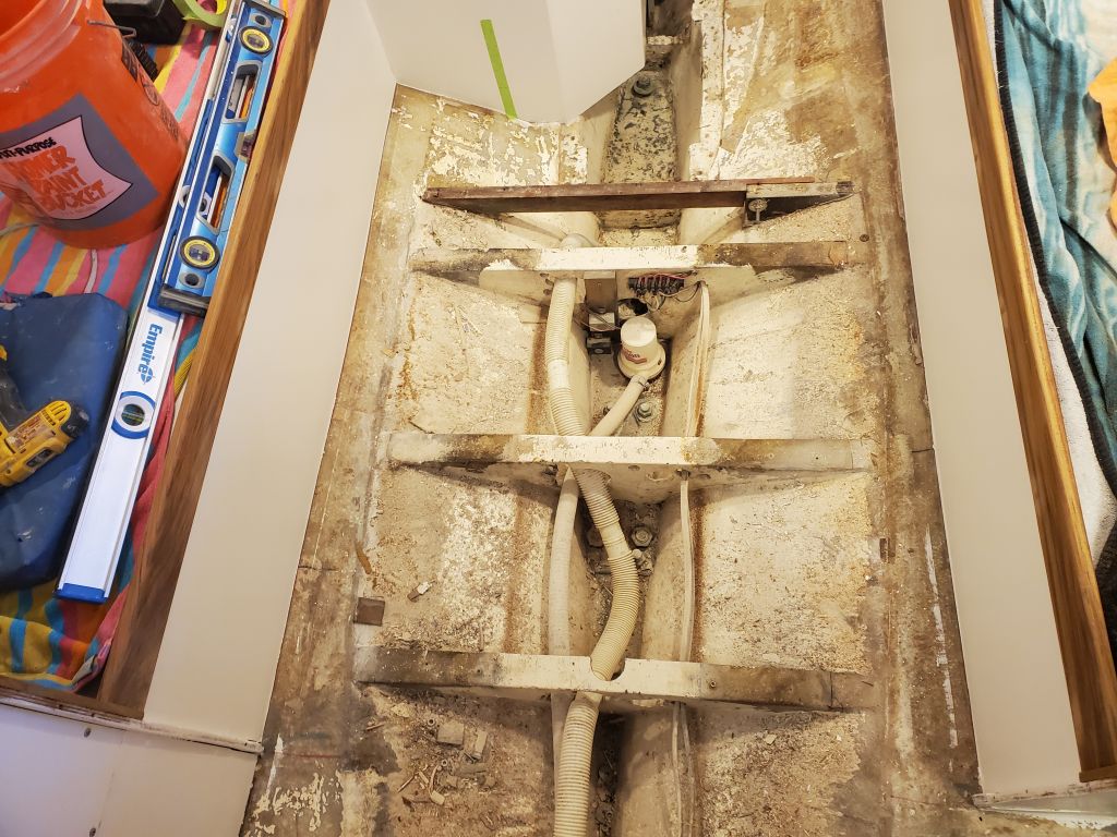
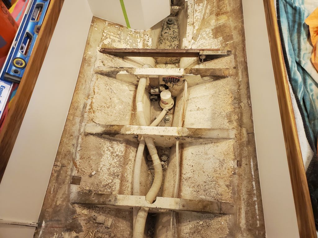
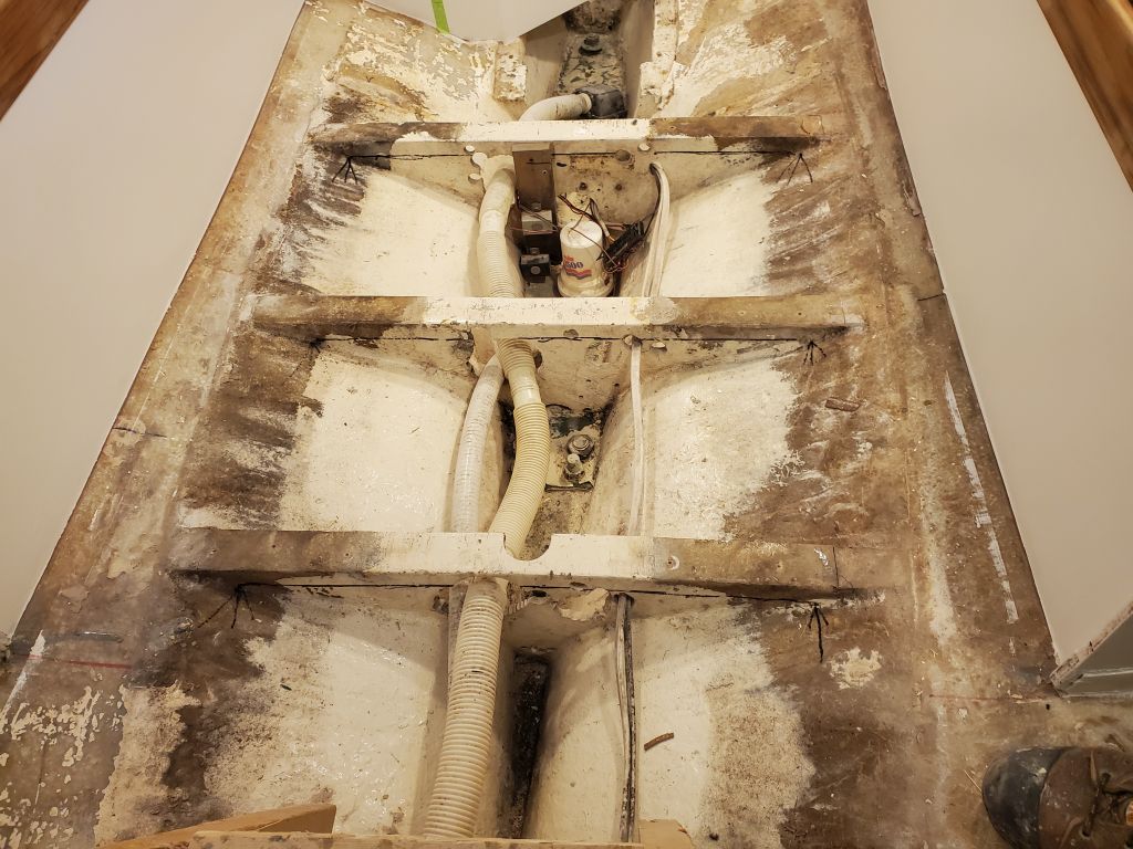
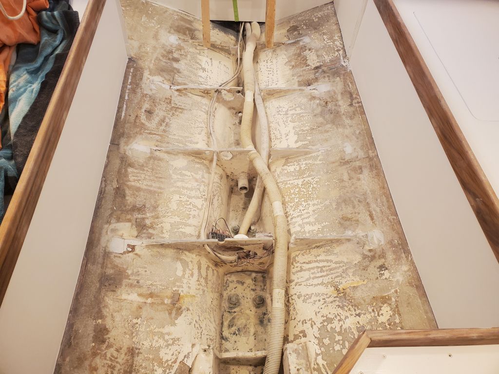
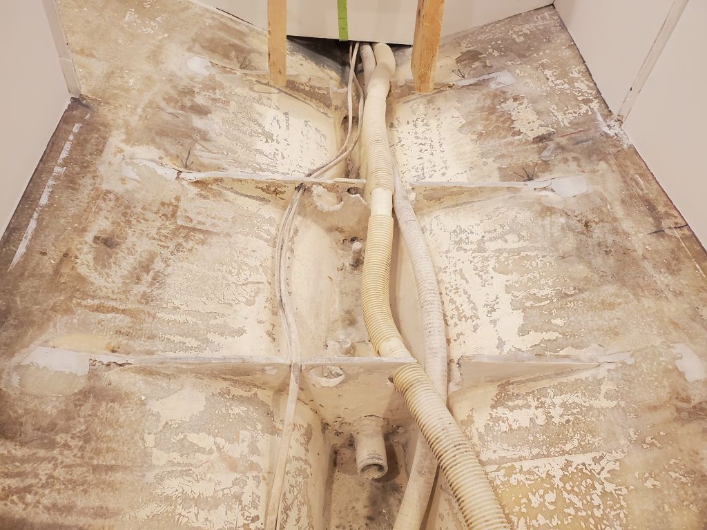
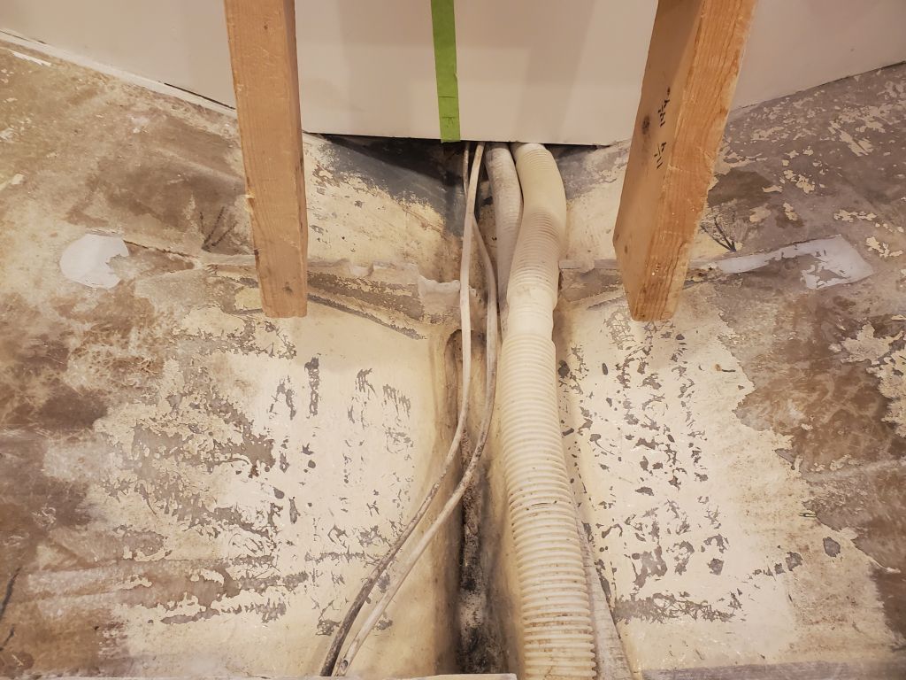
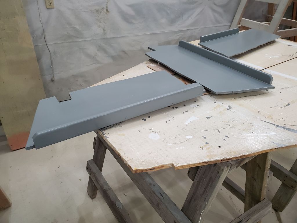
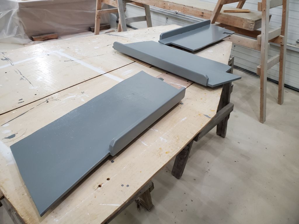
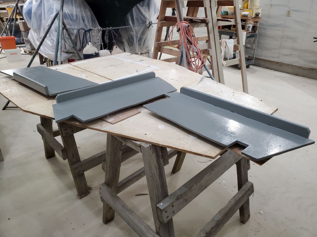
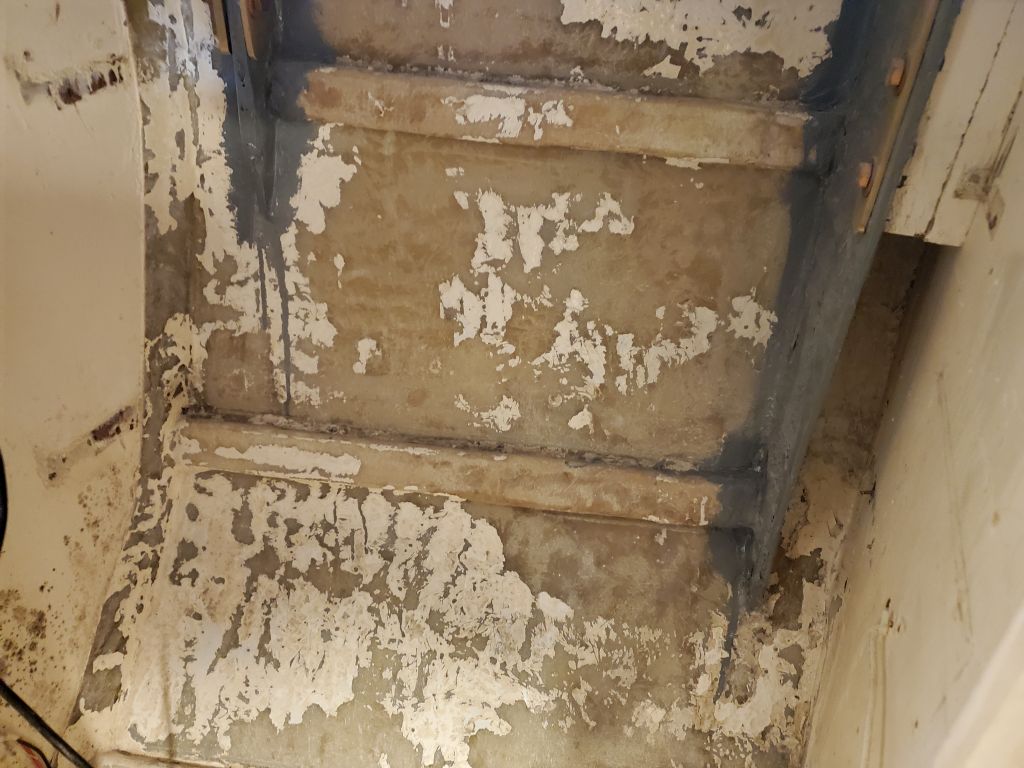
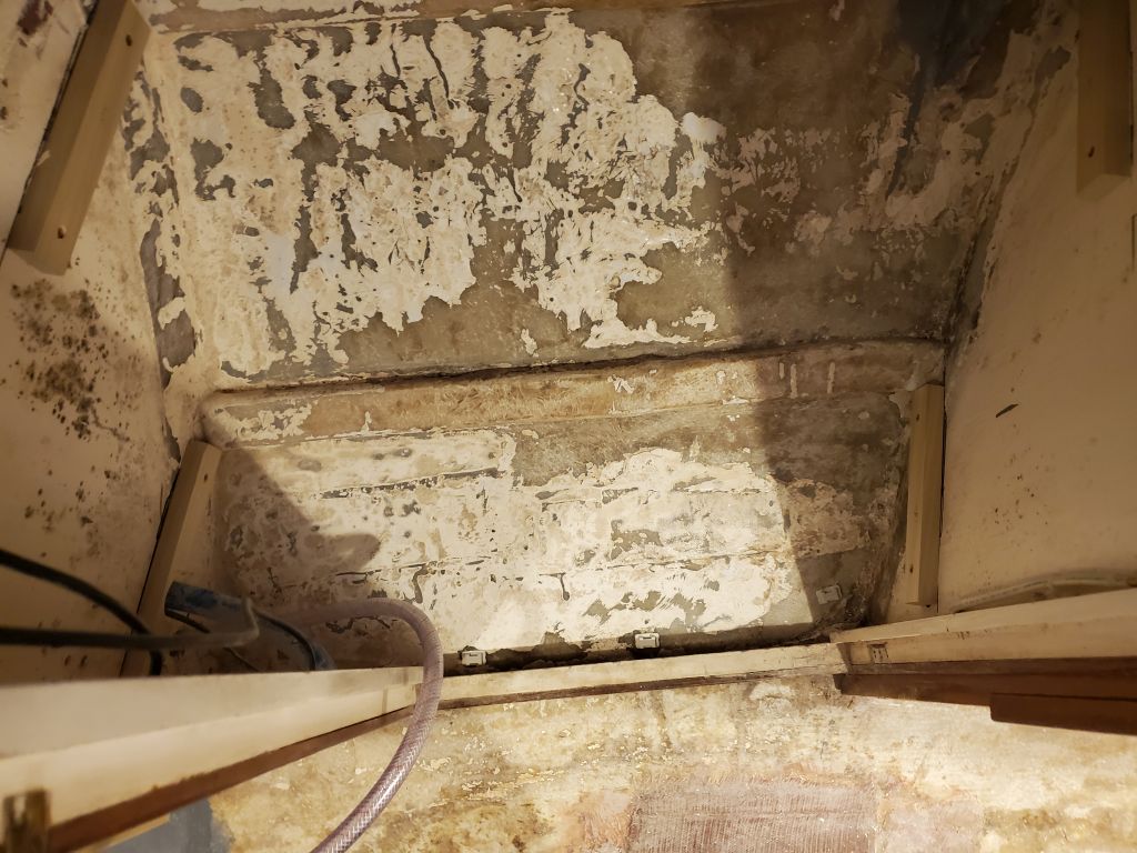
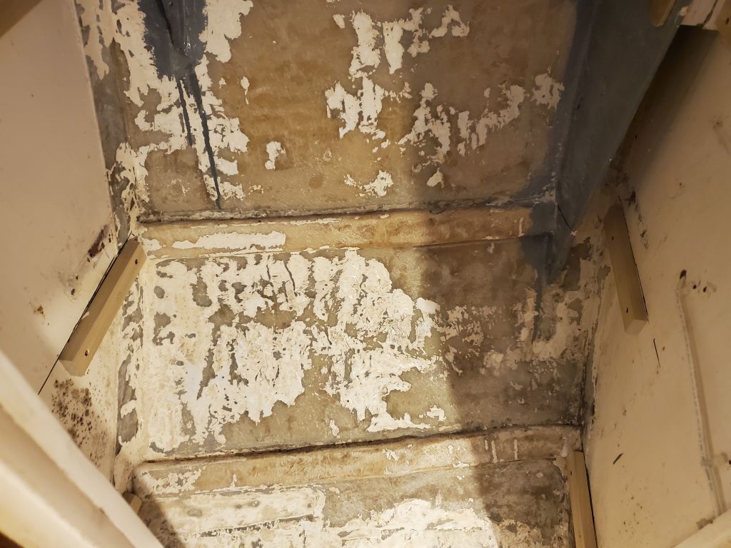
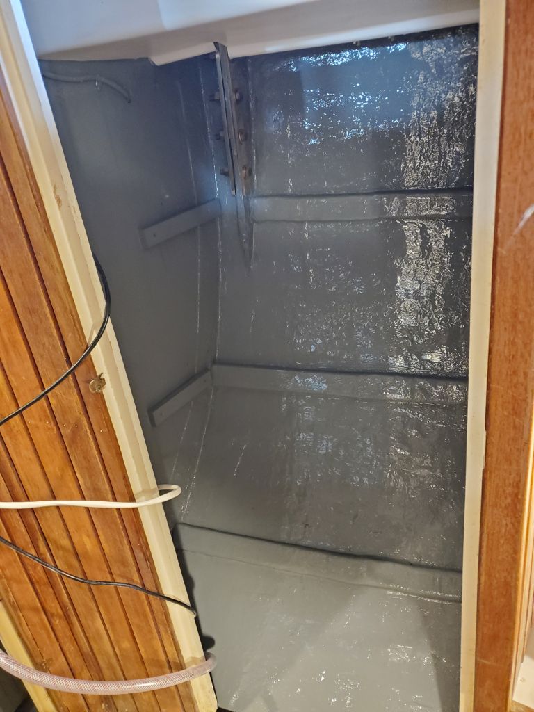
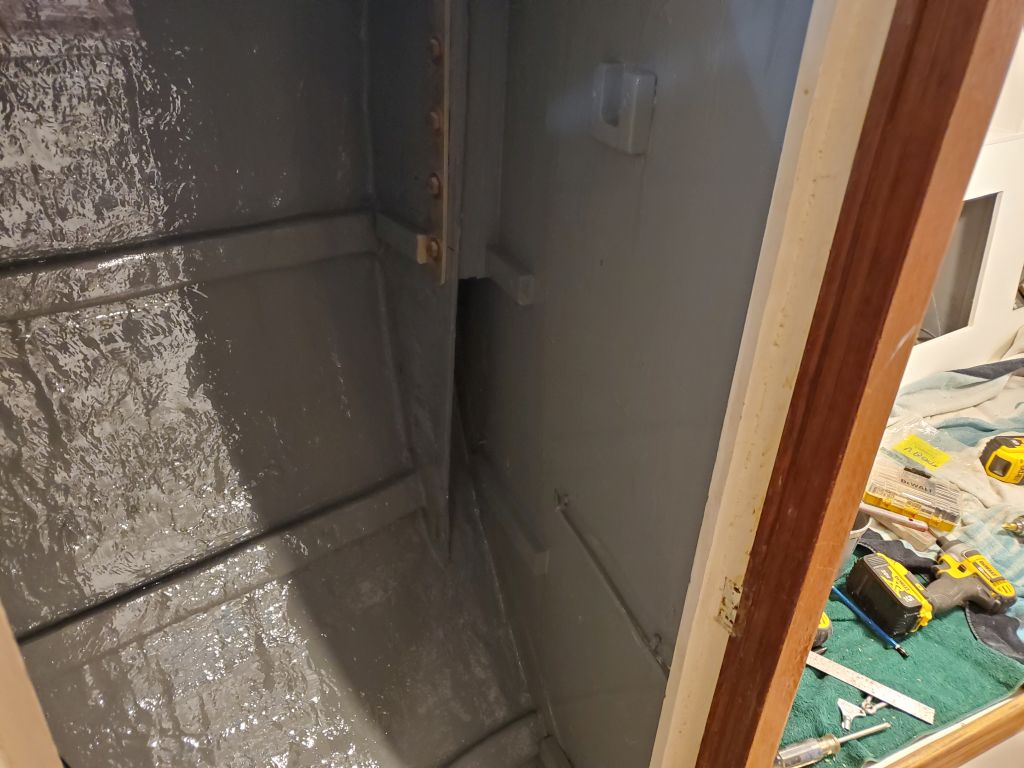
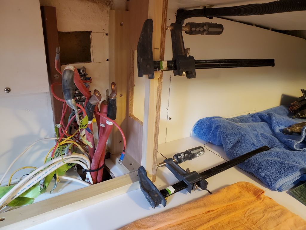
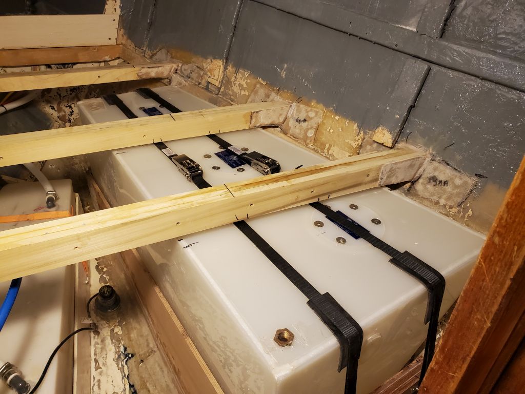
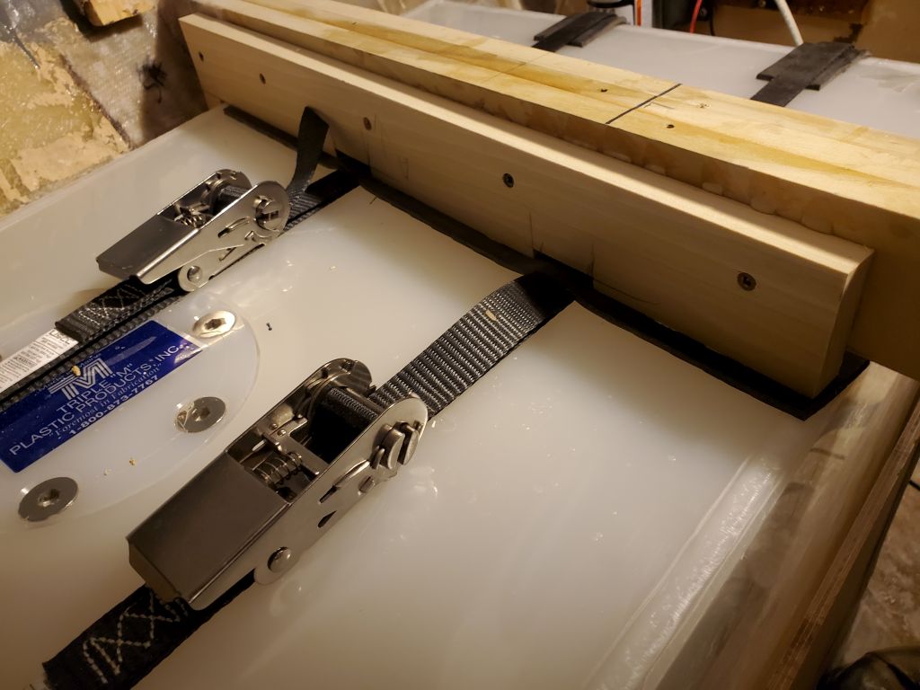
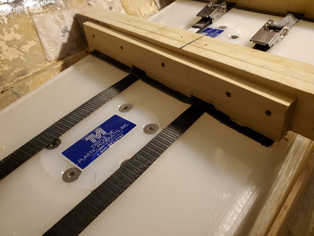
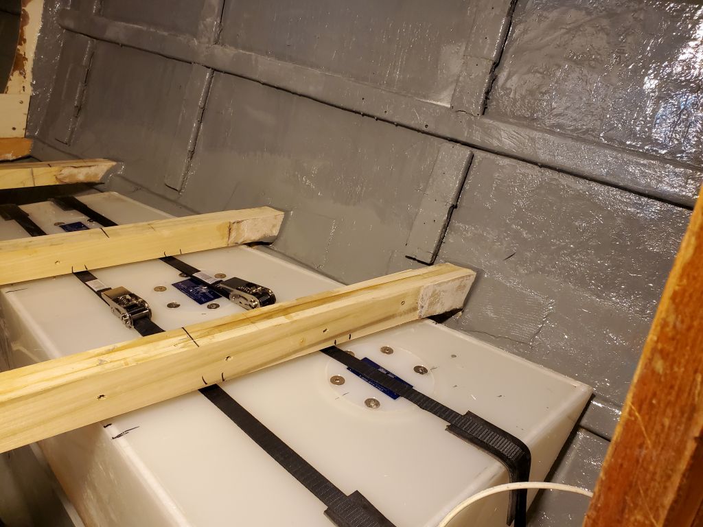
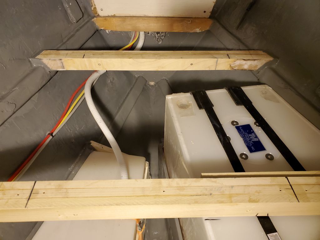
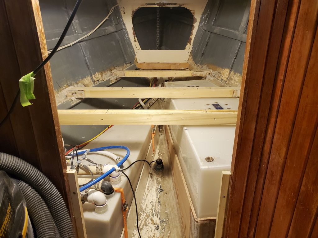
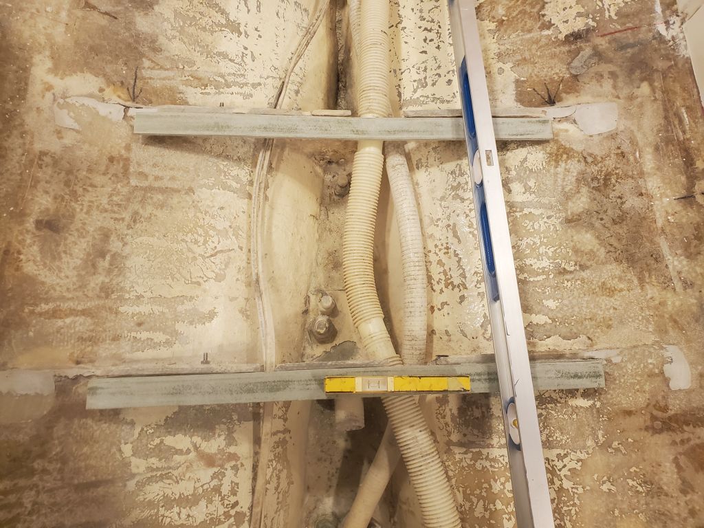
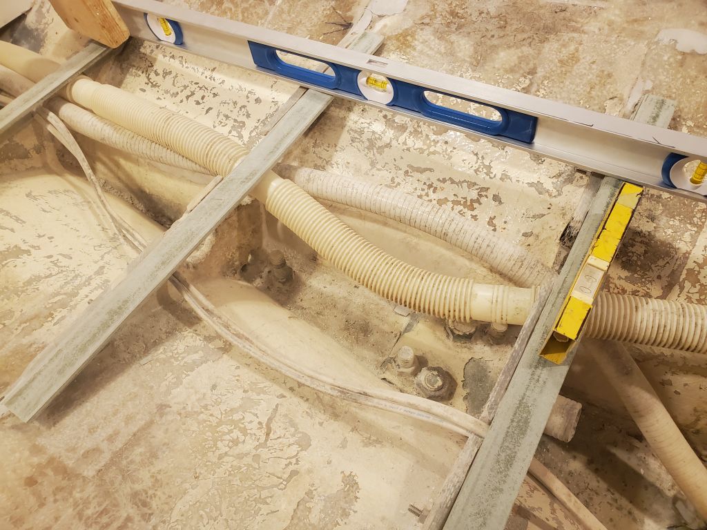
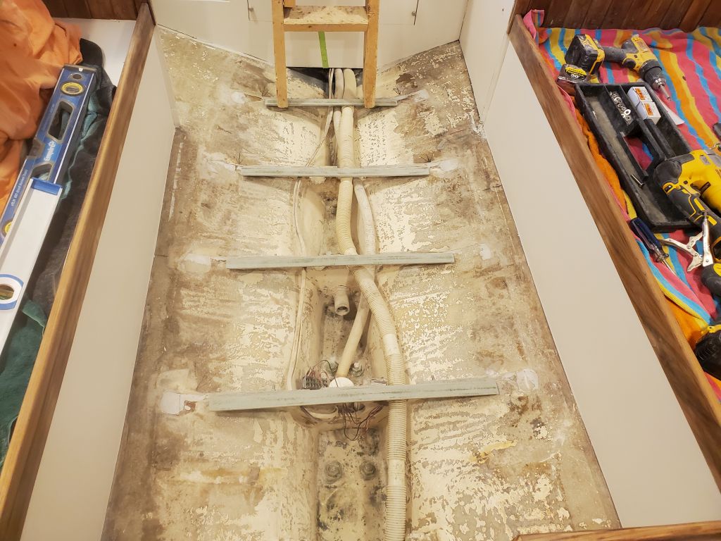
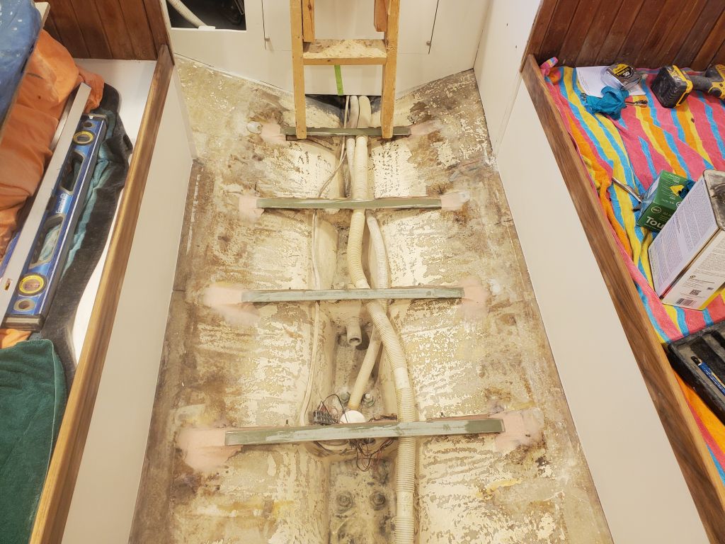
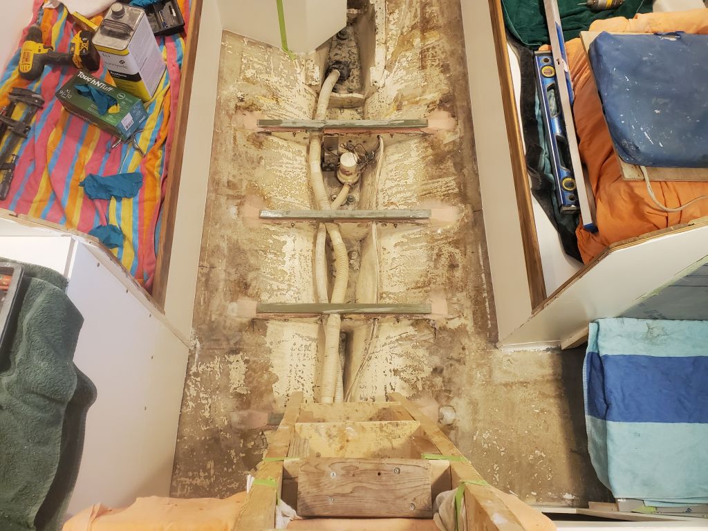
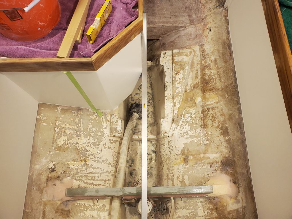
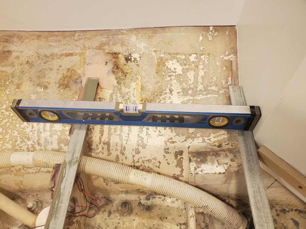
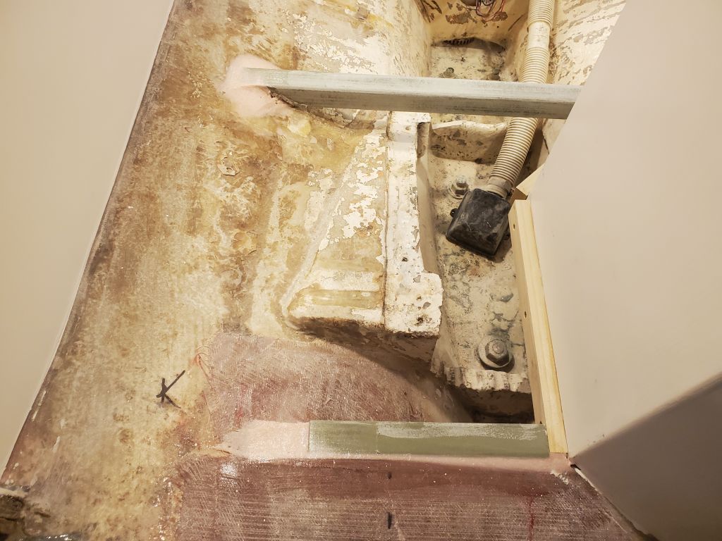
For the cabin sole support beams, I used 1-1/2″ fiberglass angle, which I cut as needed to fit the measurements I took off the top edges of the existing floors where I’d cut them.  Inside the boat, I determined that the aftermost floor, located just ahead of the engine room, was the highest point when determining longitudinal level, to which the boat had been positioned early in the project.  So I started here to position and install the new supports.  With the first beam positioned correctly, I held it in place with two bolts for now, and moved on to the next three in turn, leveling off the previous beams in each case and temporarily securing to the existing floors with two bolts.

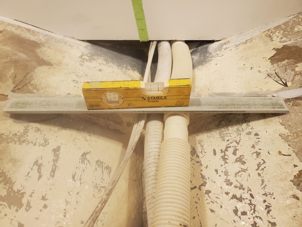
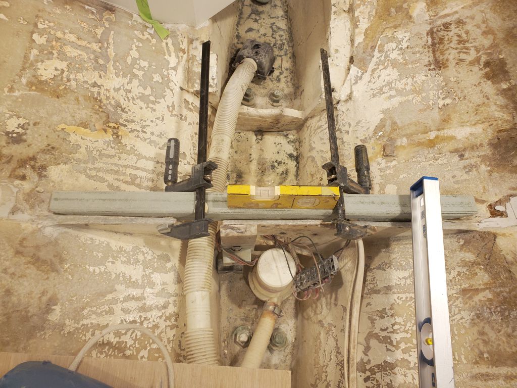
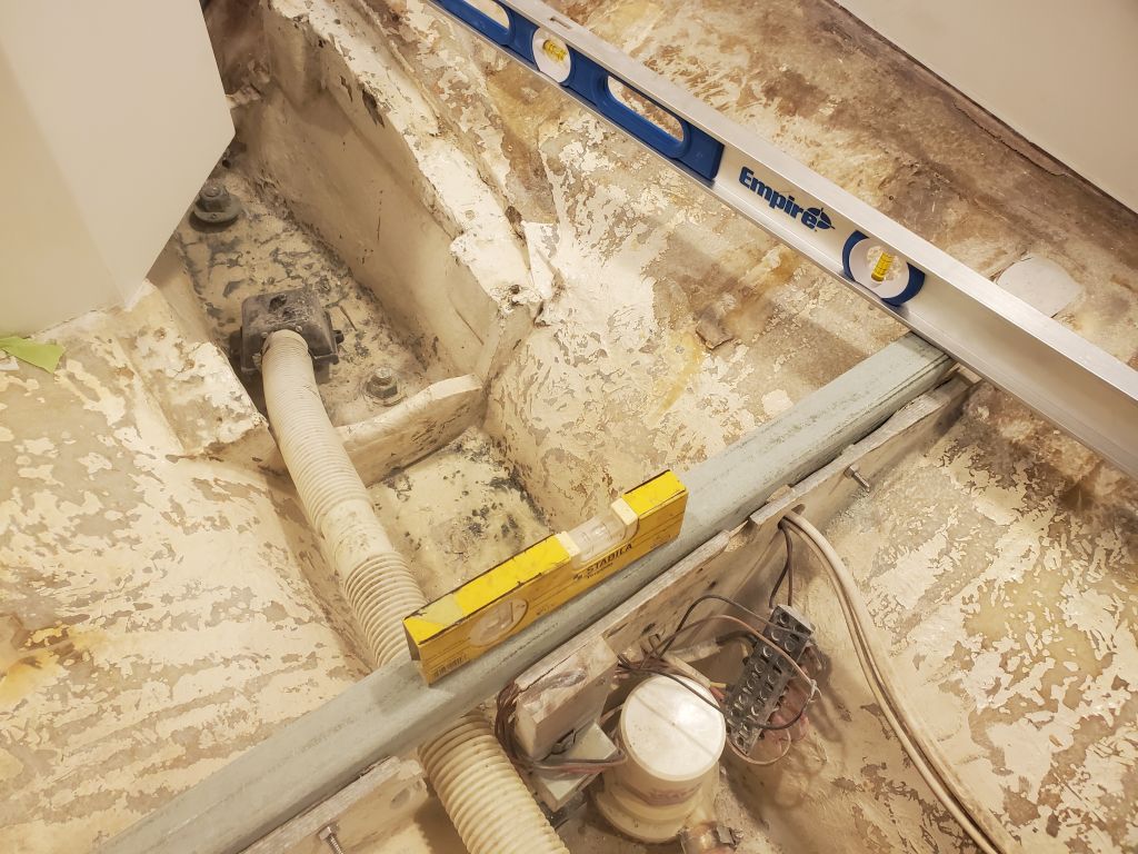
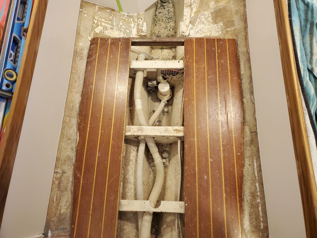
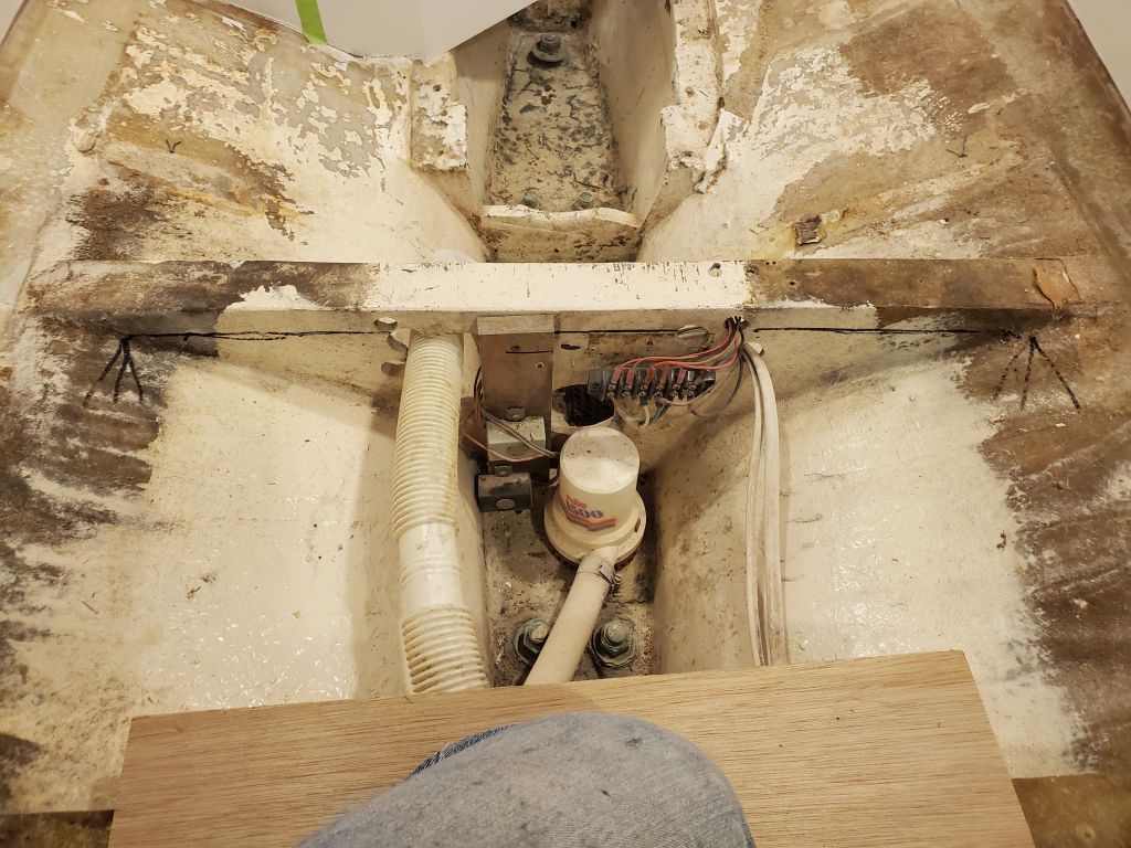
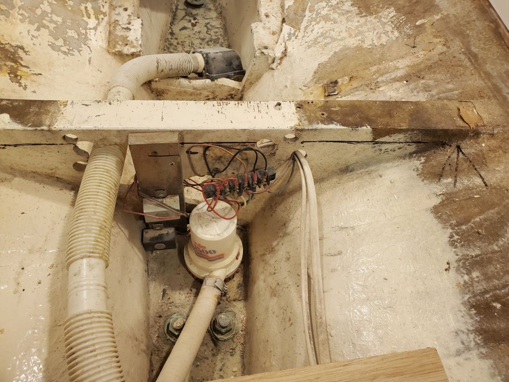
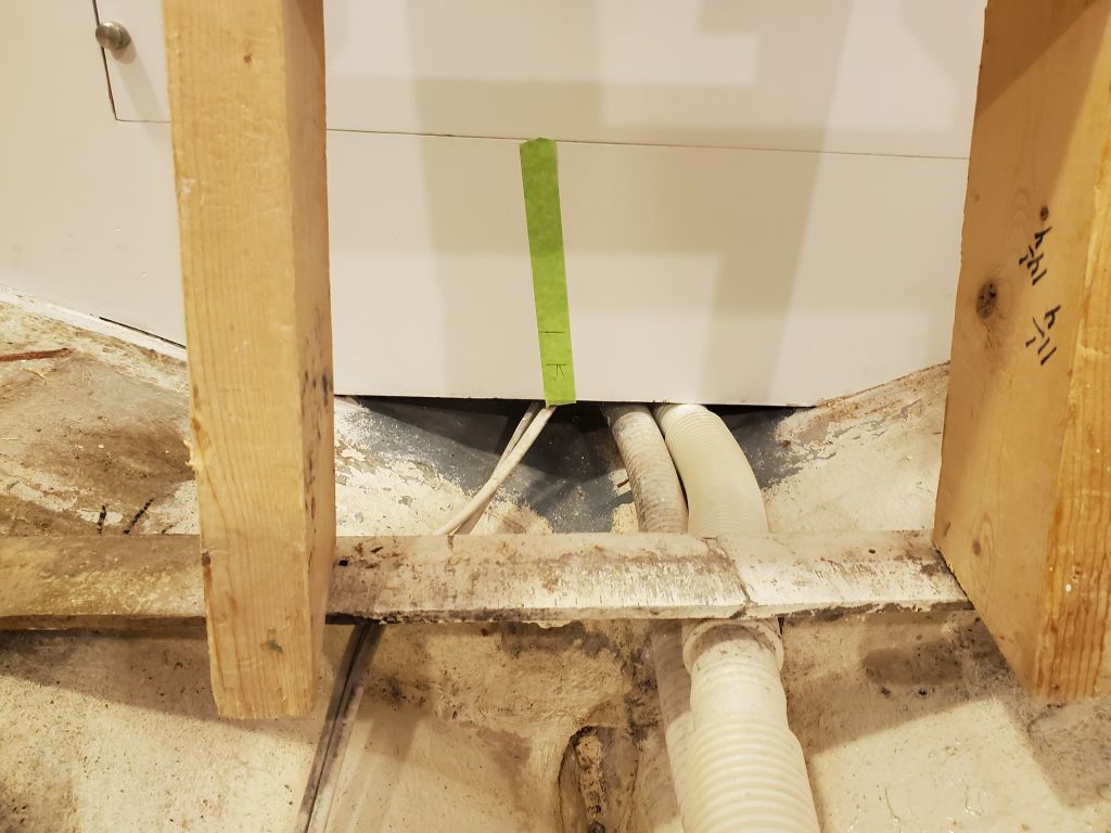
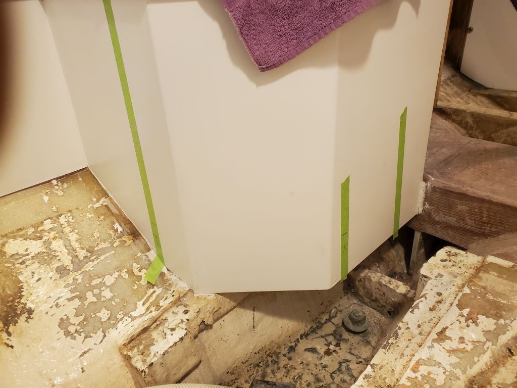
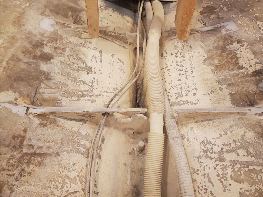
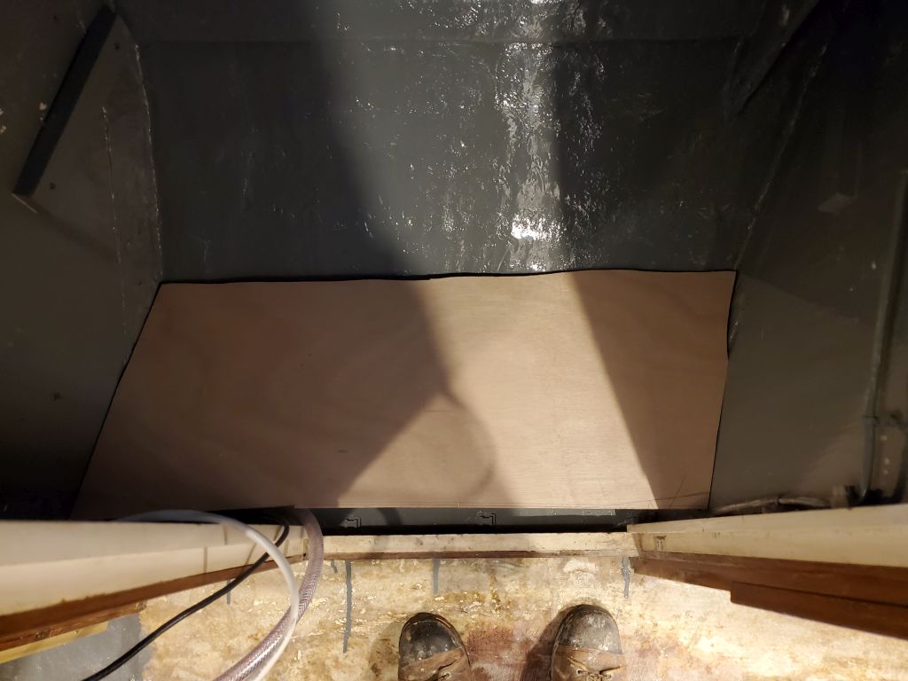
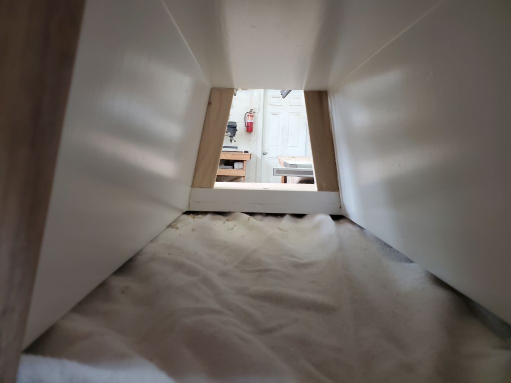
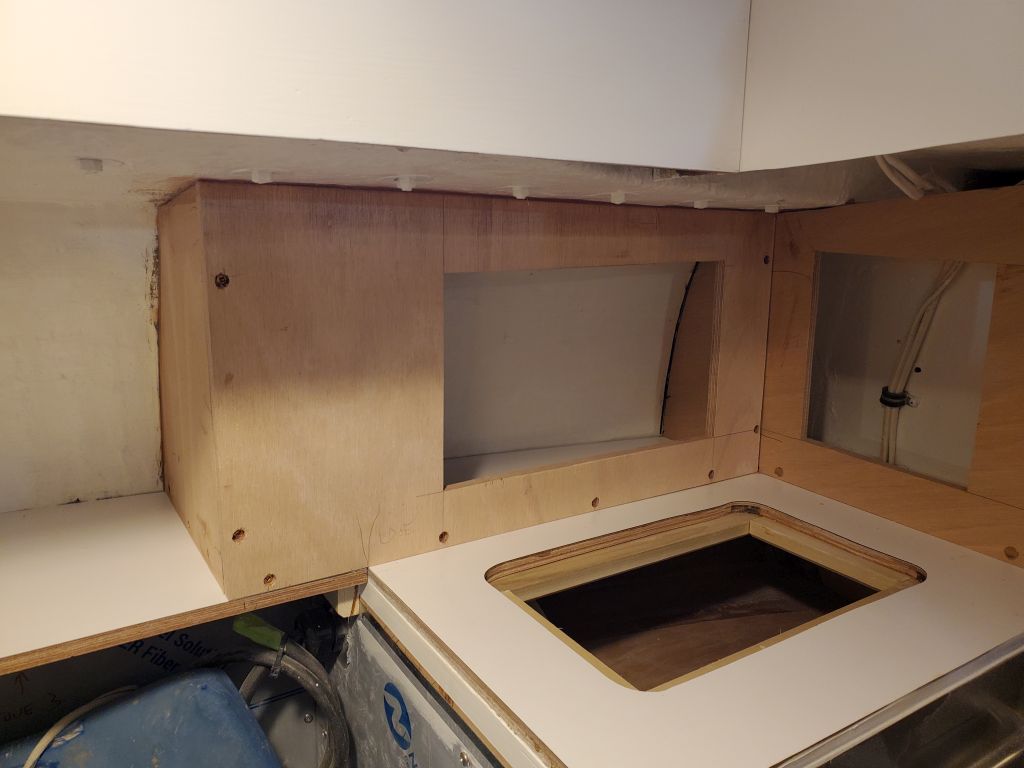
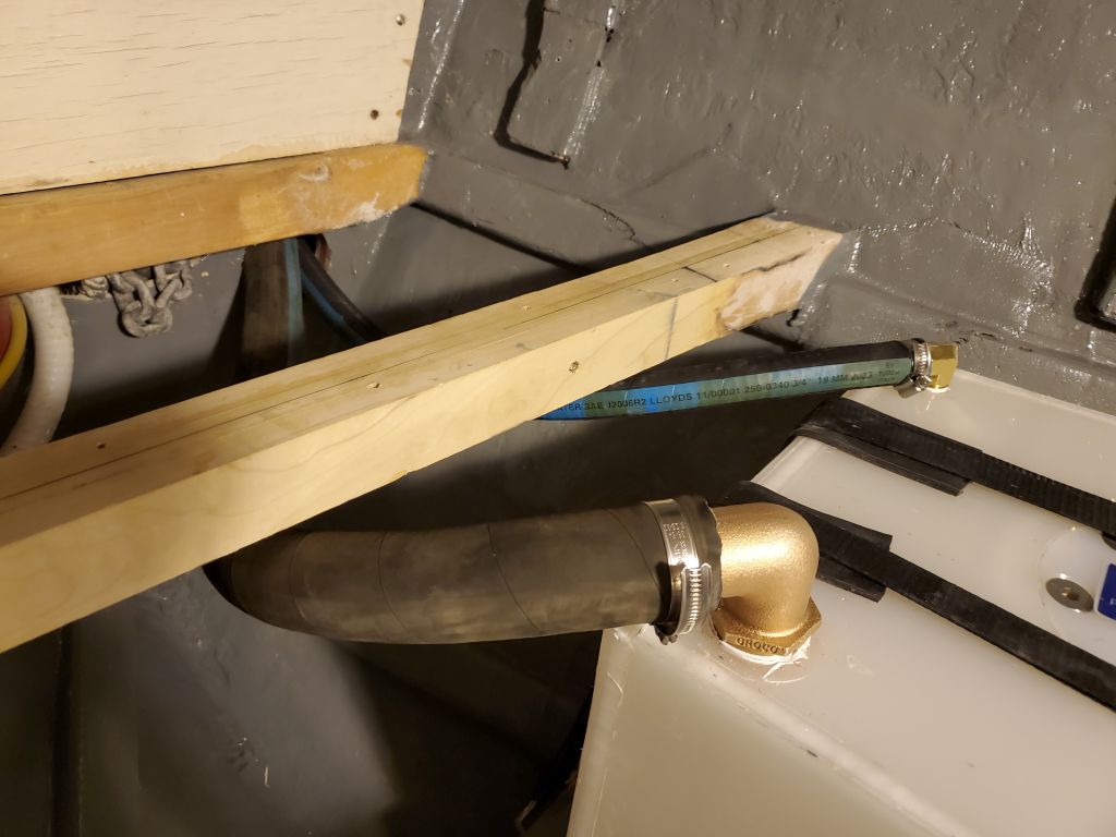
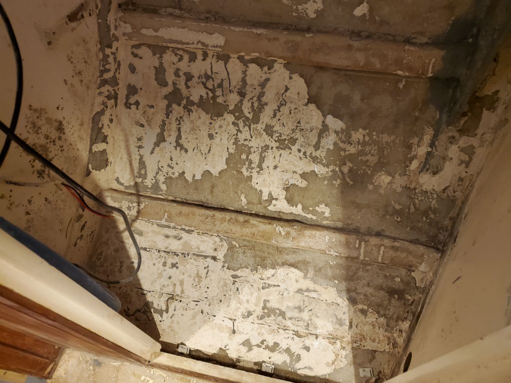
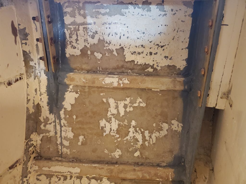
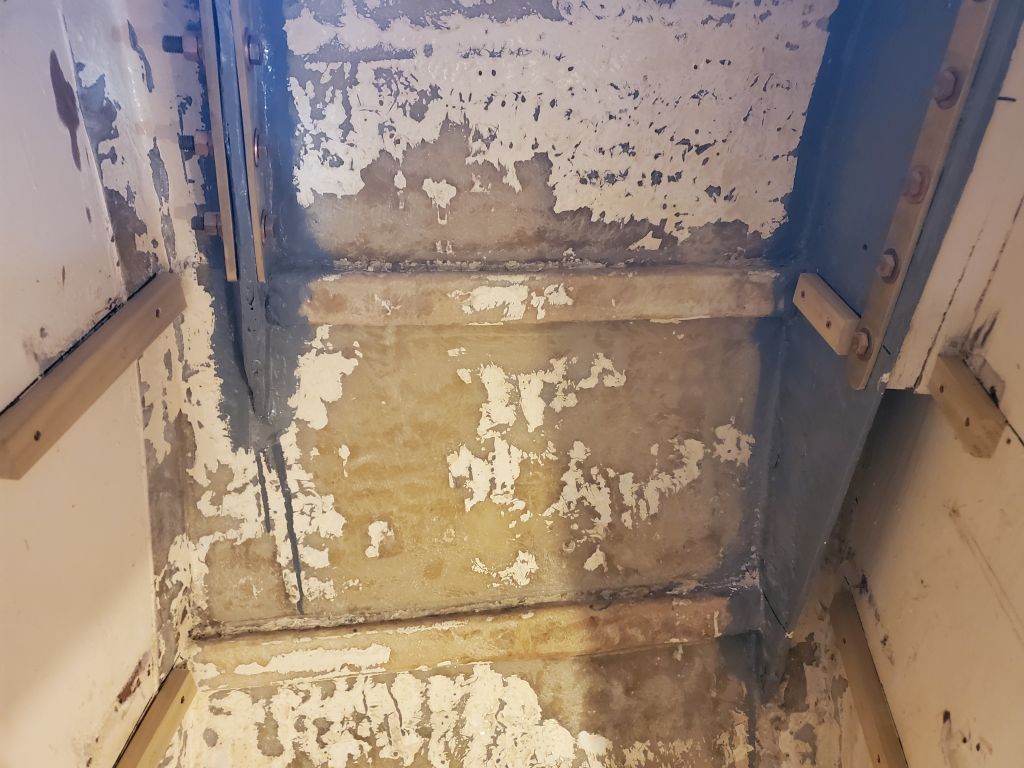
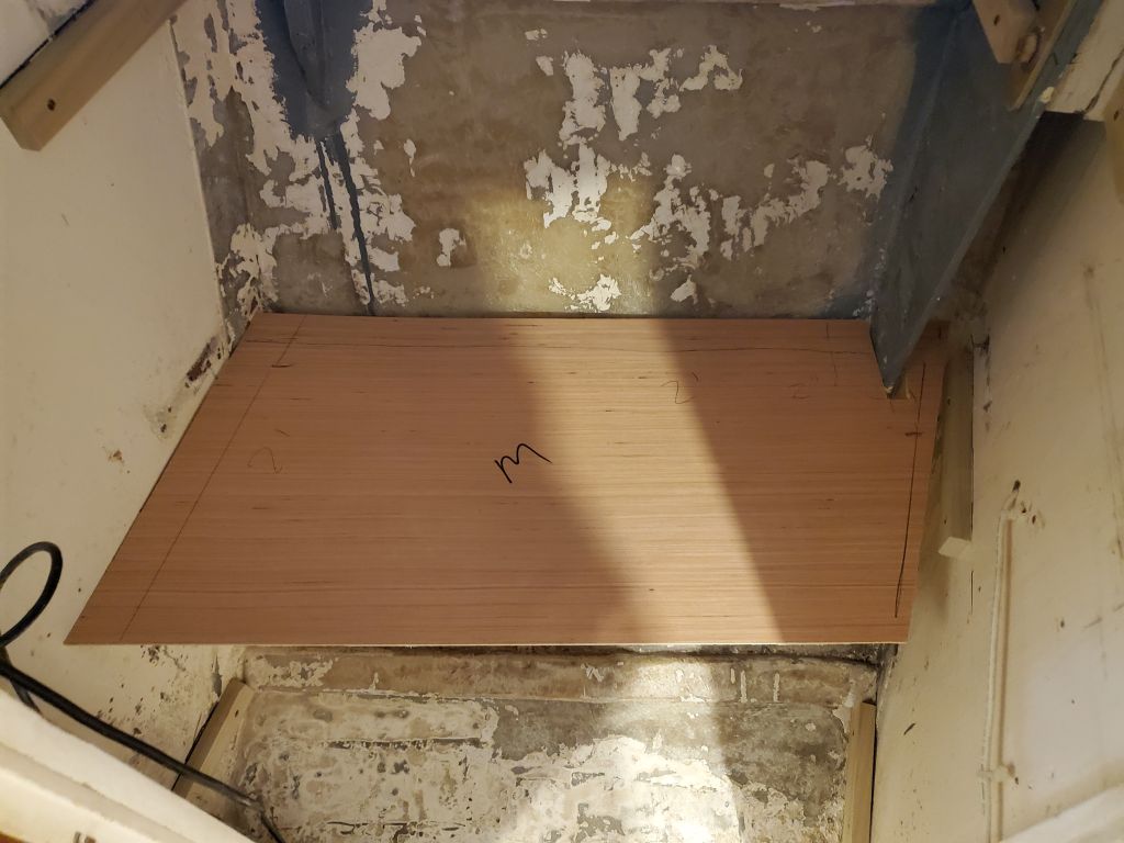
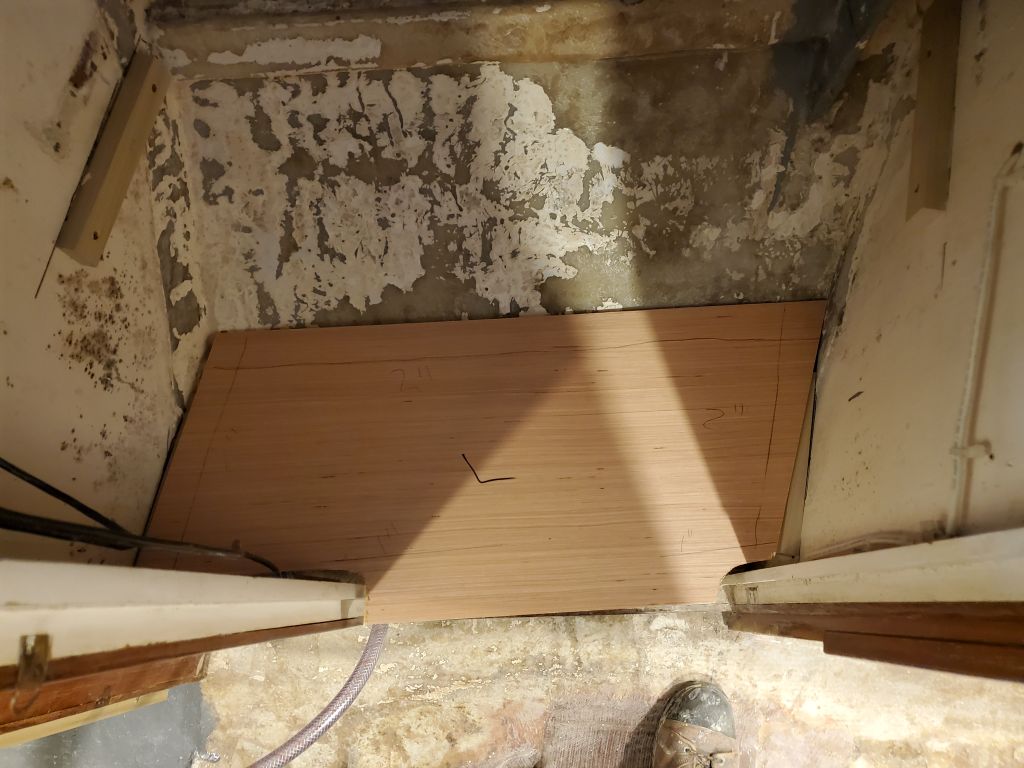
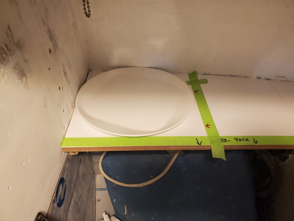
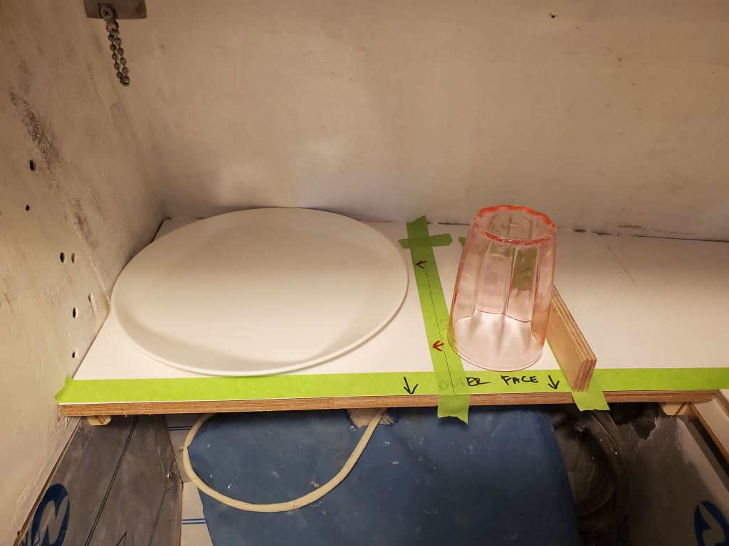
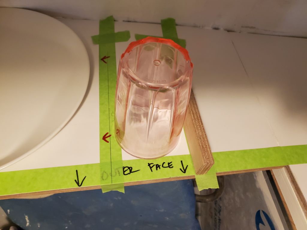
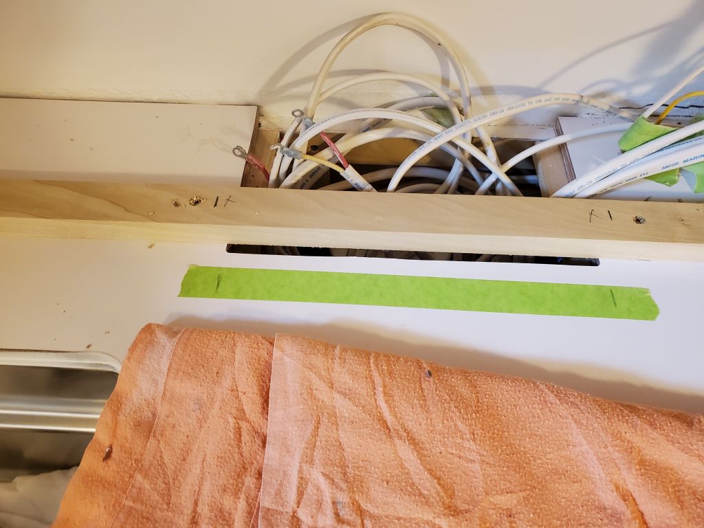
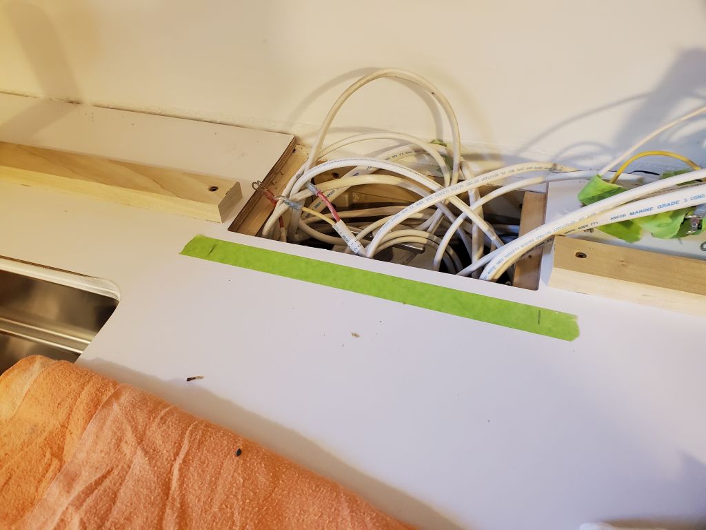
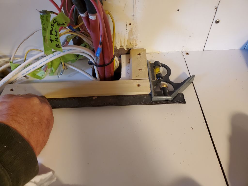
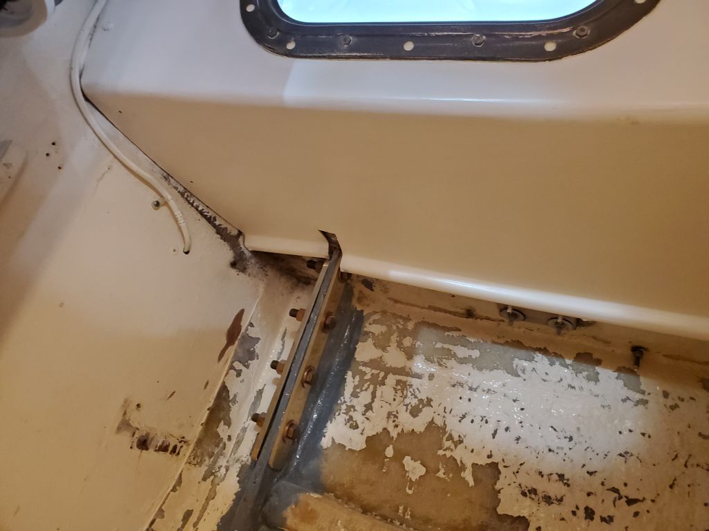
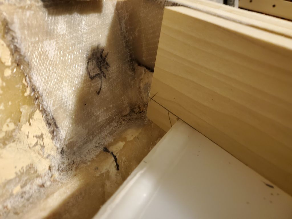
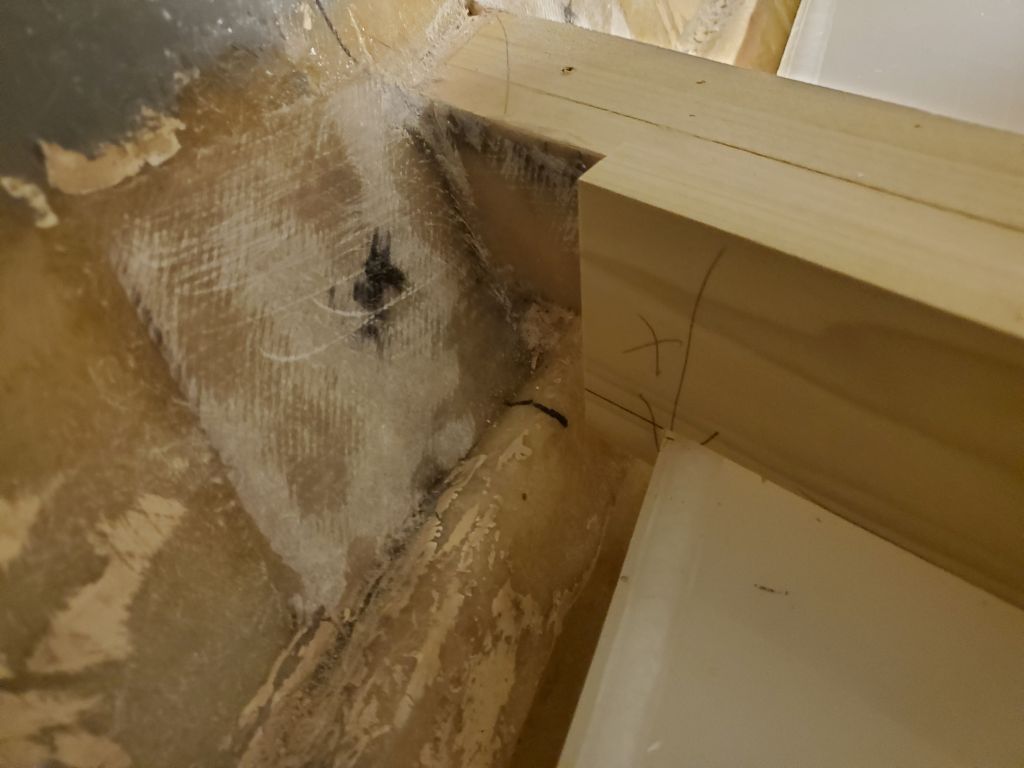
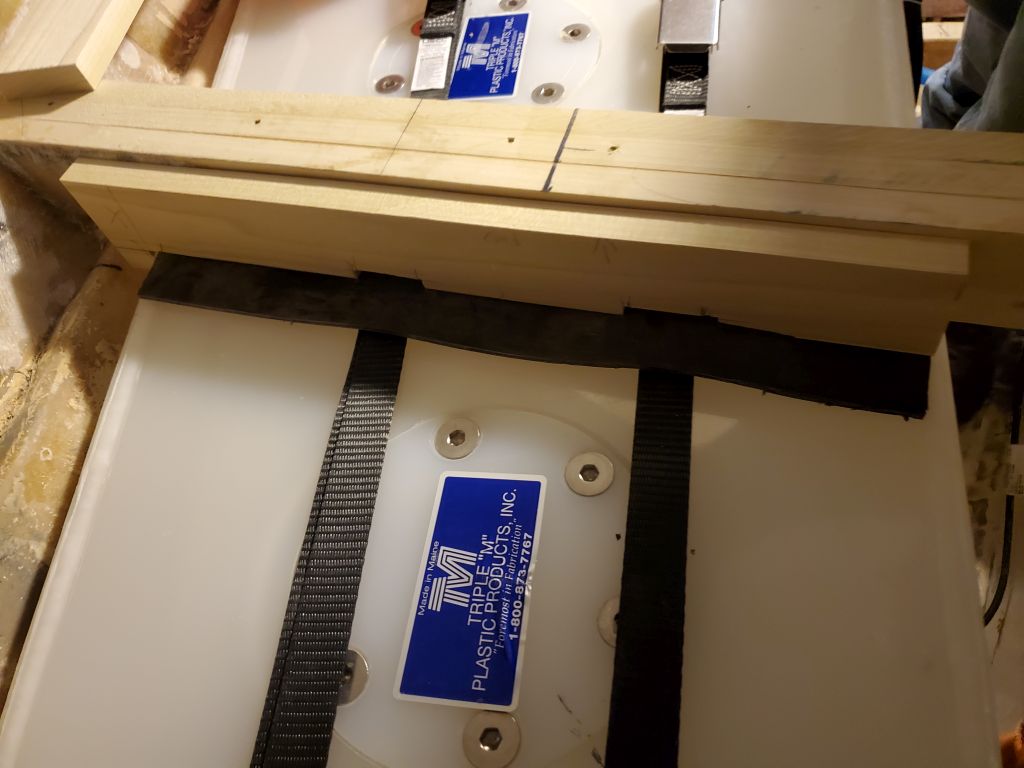
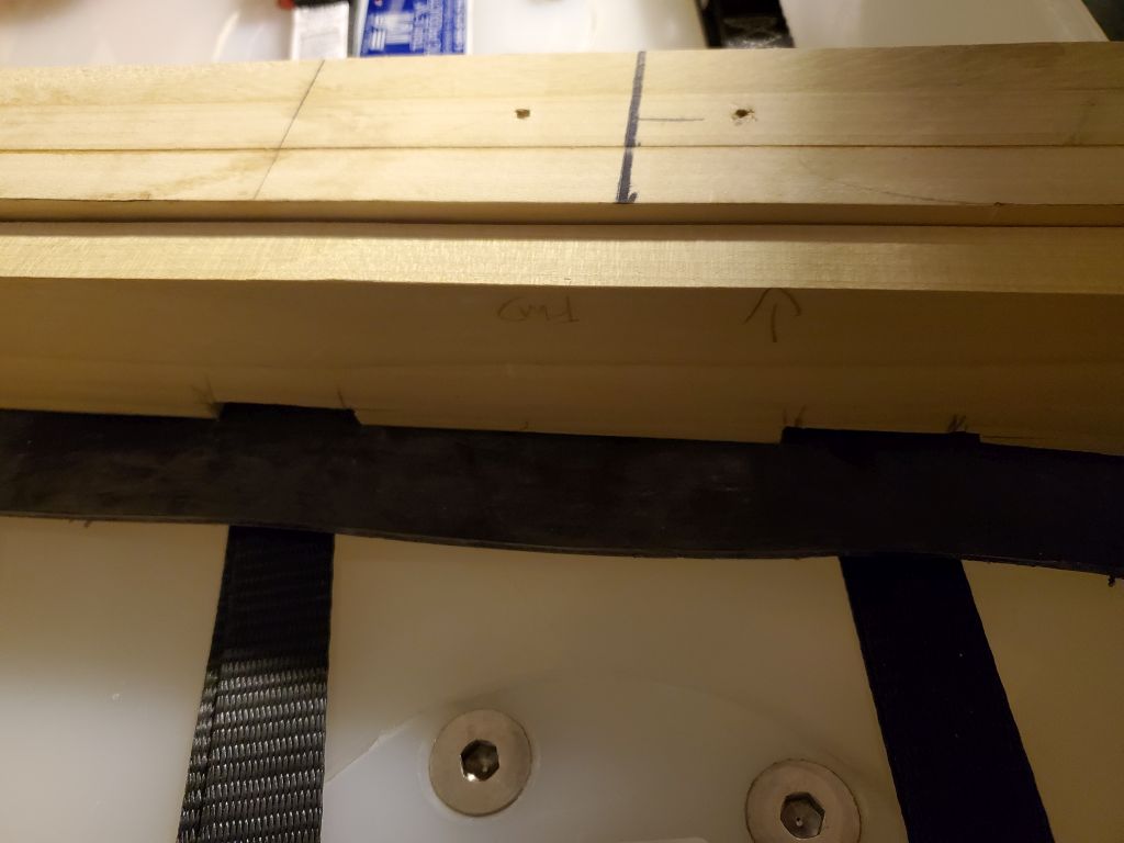
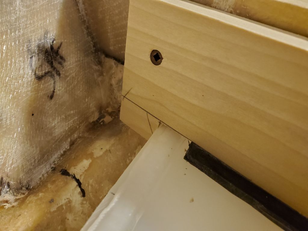
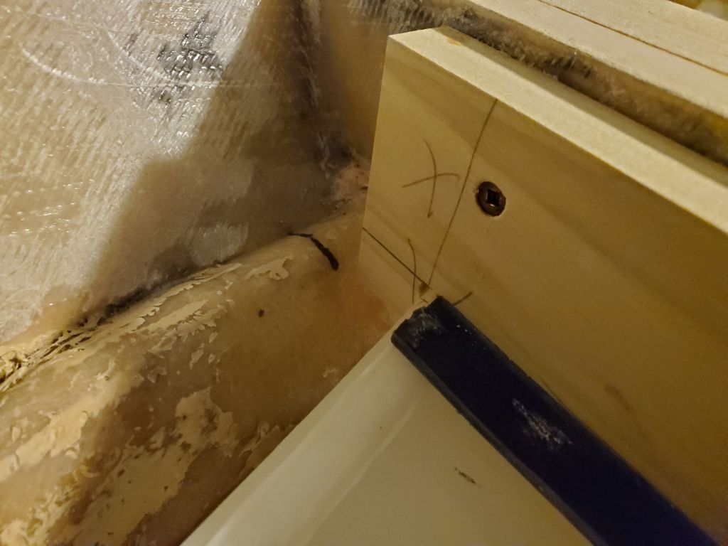
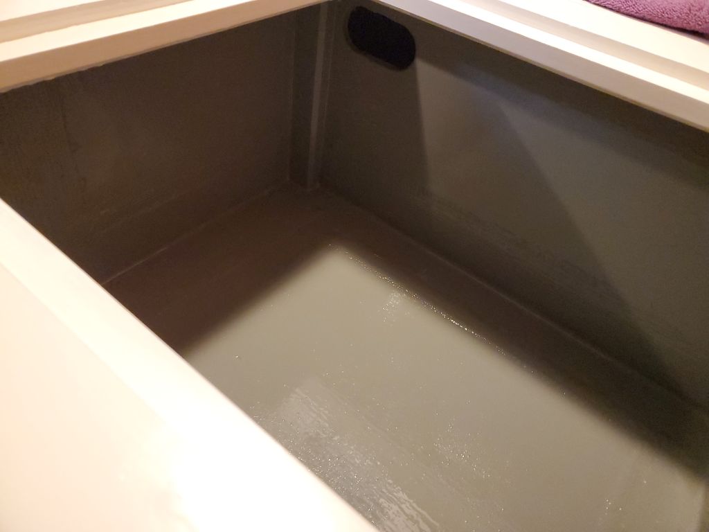
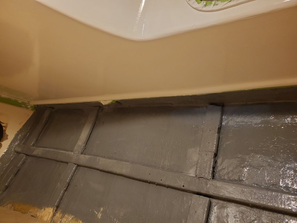
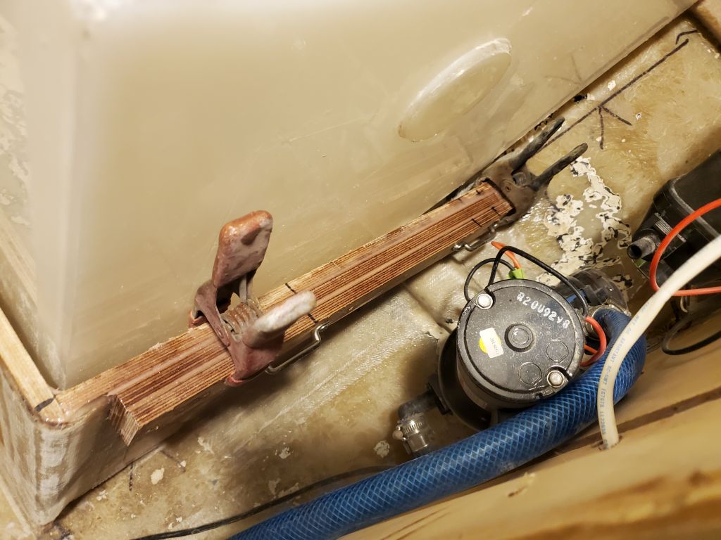
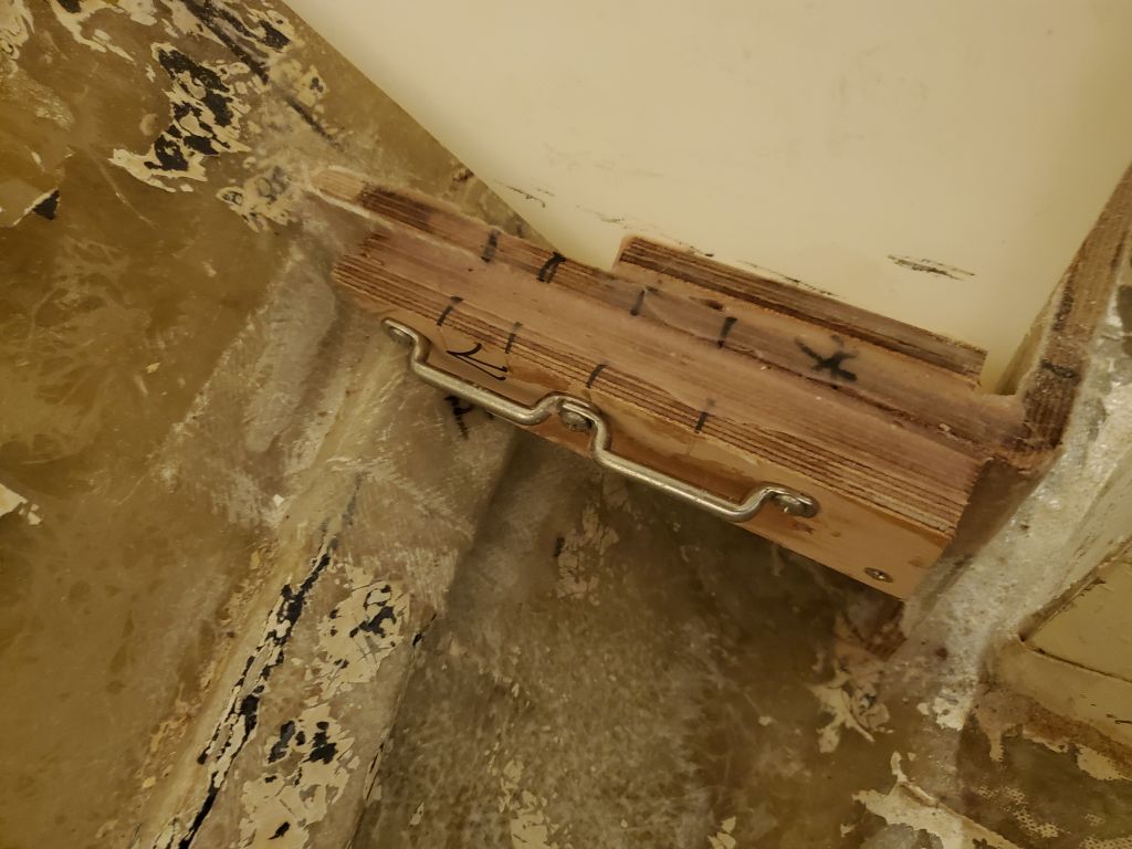
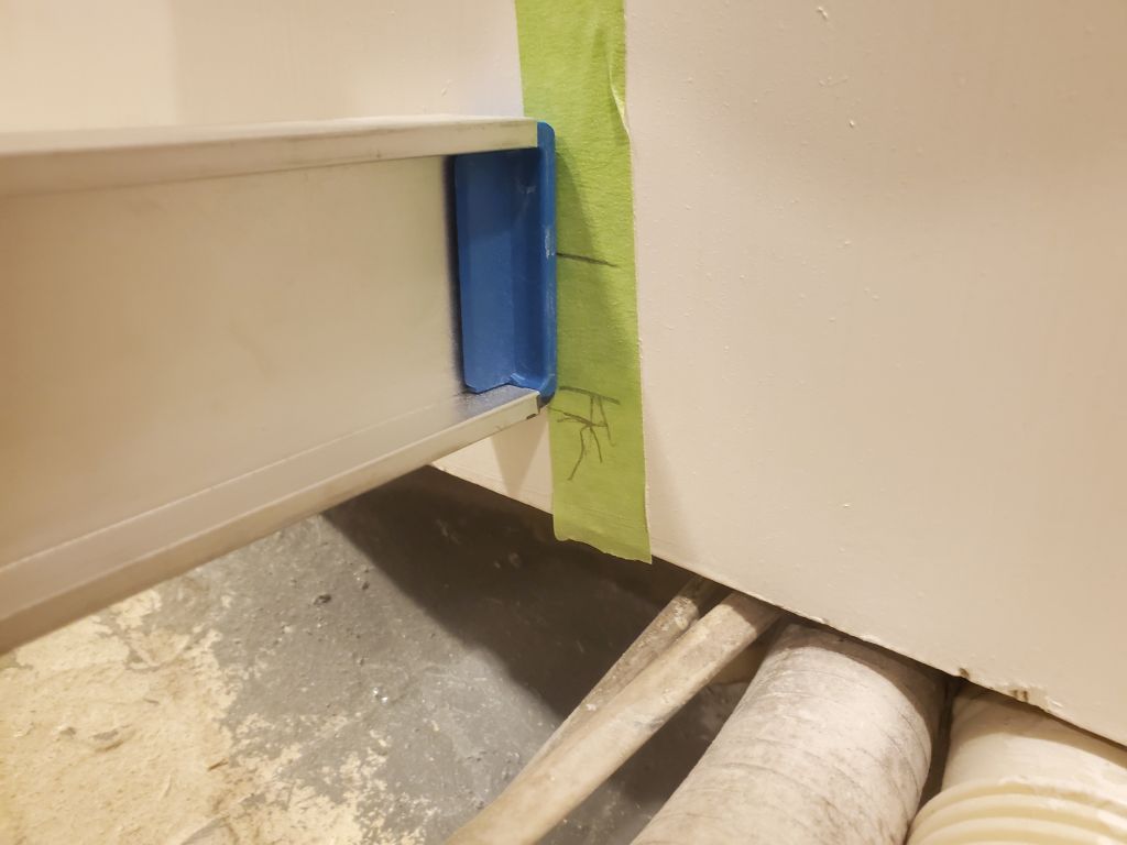
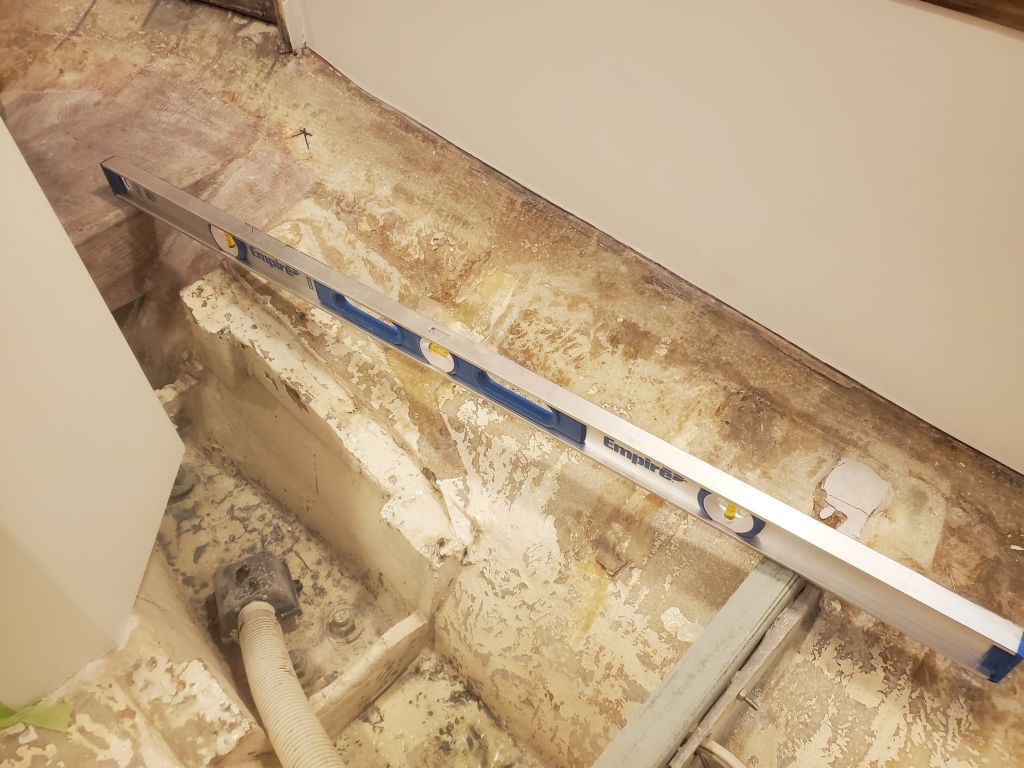
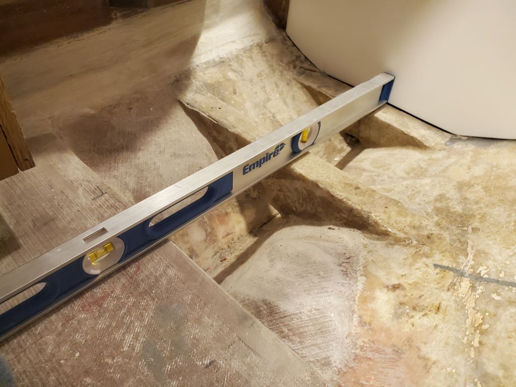
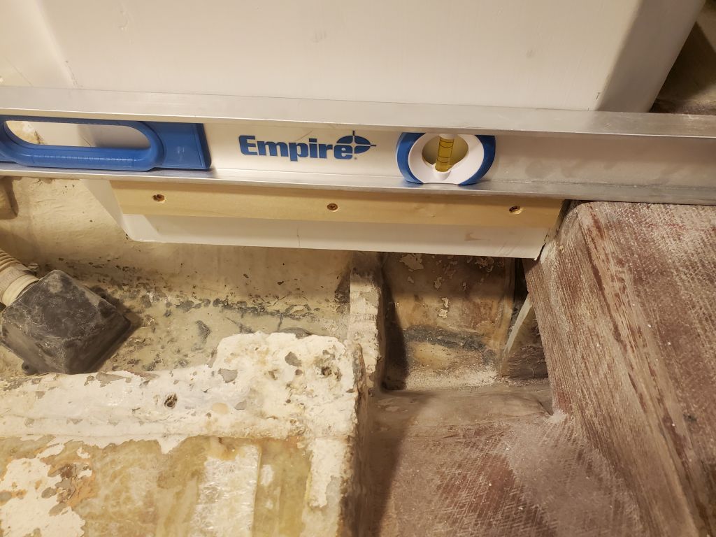
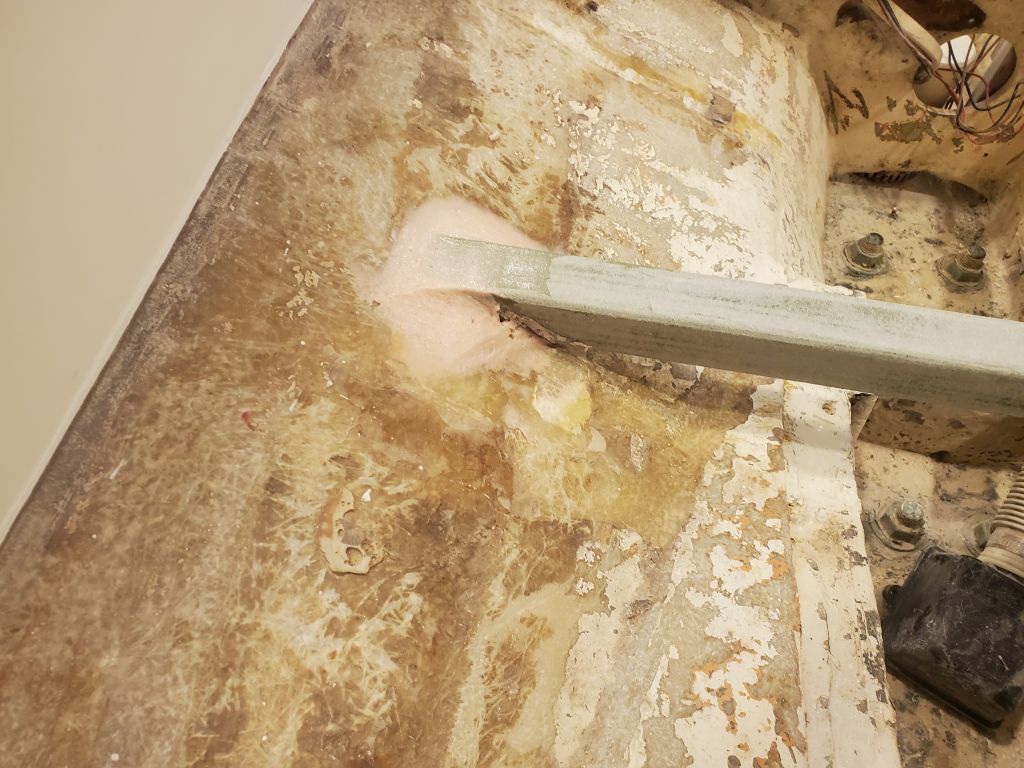
At the aft end, the new height was more than an inch lower than original.    In this photo, where the level is resting on the tops of two or three of the cross beams,  the top mark is the height of the original floors (the supports beneath the cabin sole itself); the second mark is 1″ below that, and the third mark is where the height actually ended up.

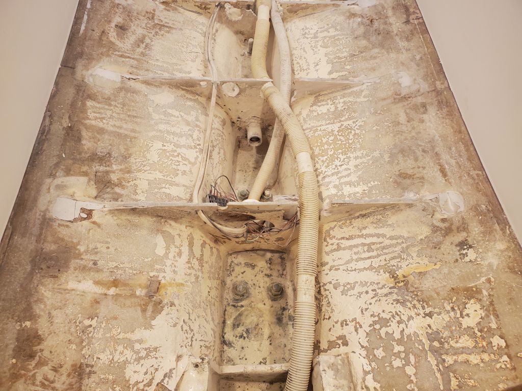
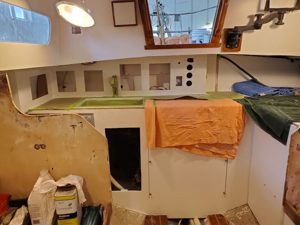
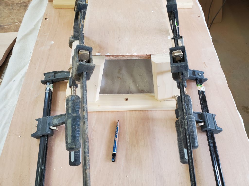
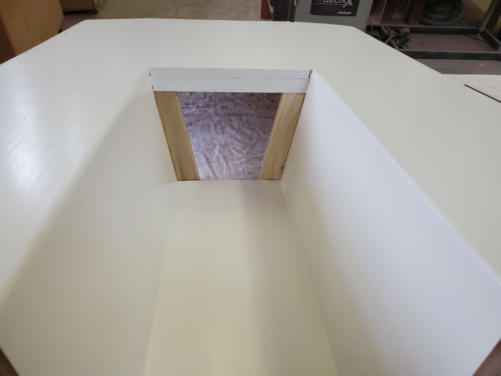
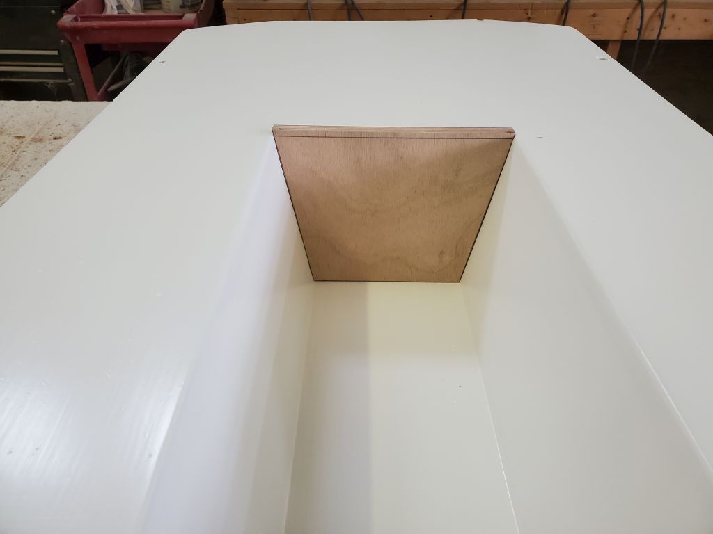
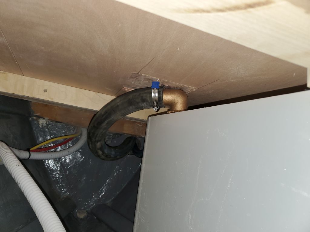
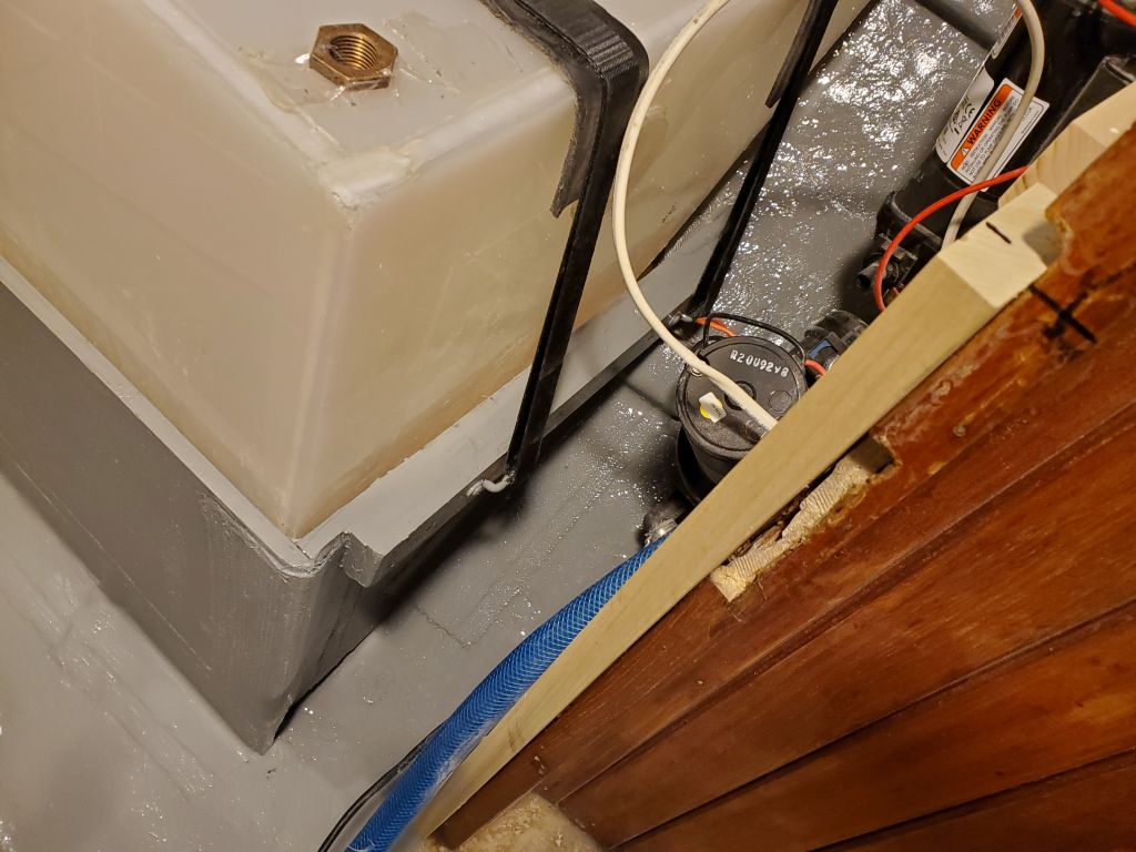
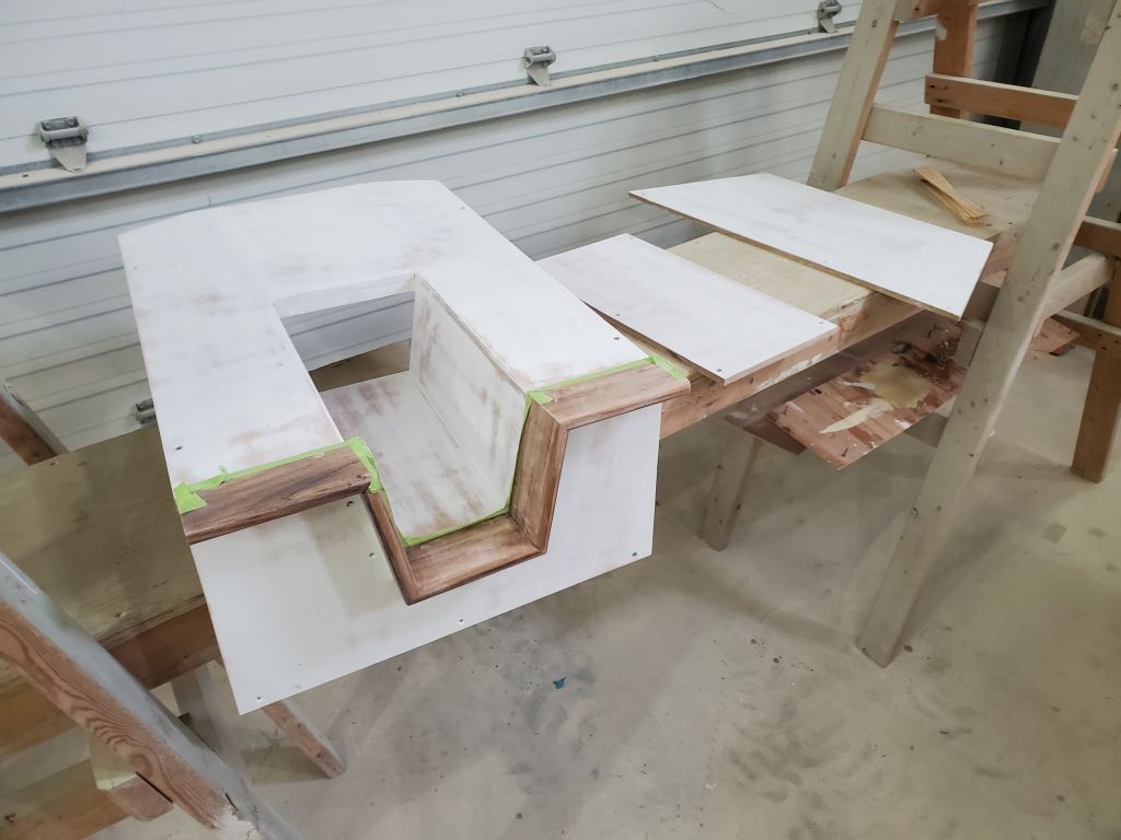
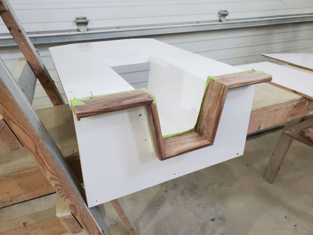
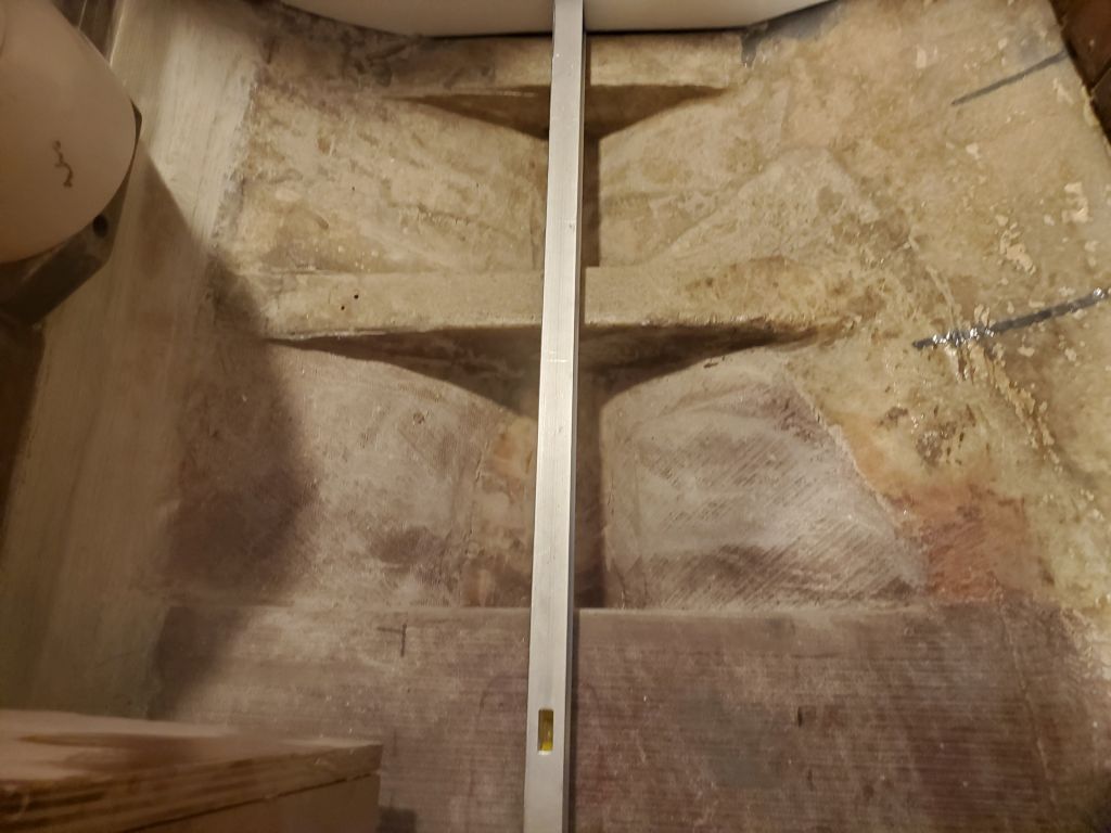
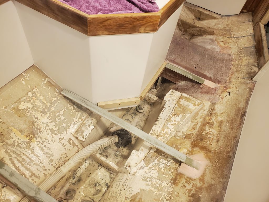
Interestingly, the new height of the cross beams ended up perfectly level with the top of the new mast step structure, a happenstance–but useful and good–occurrence.

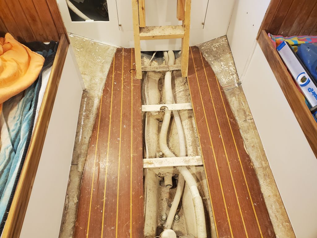
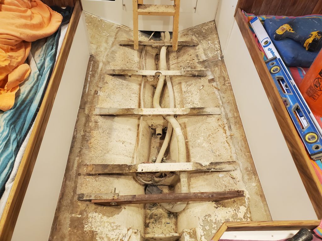
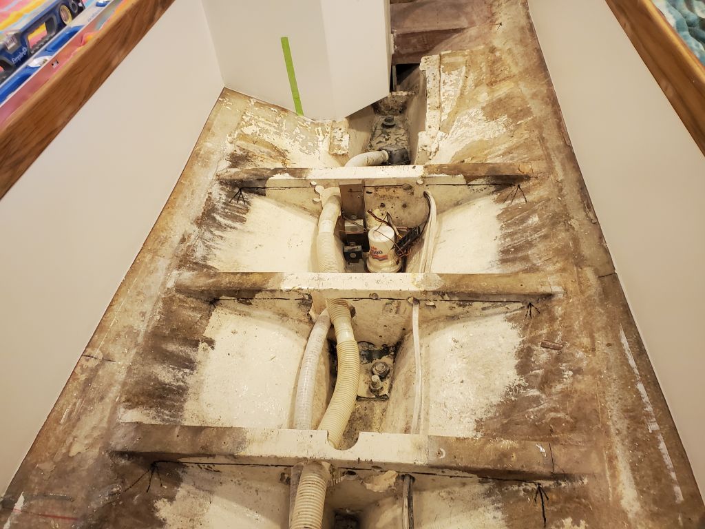
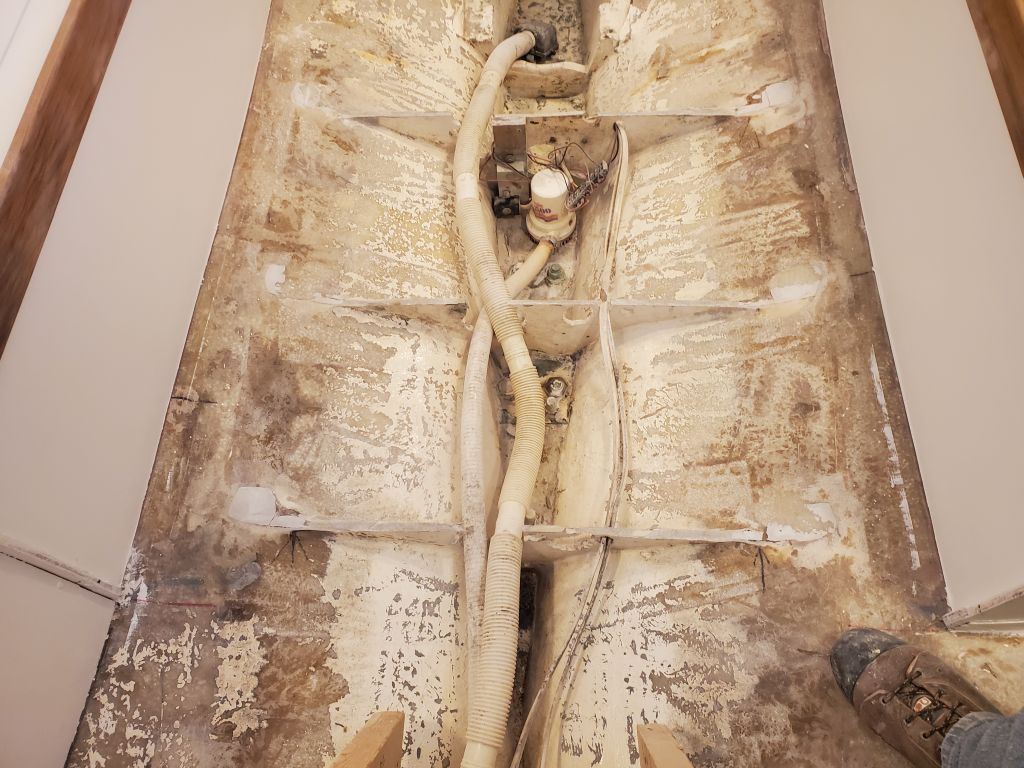
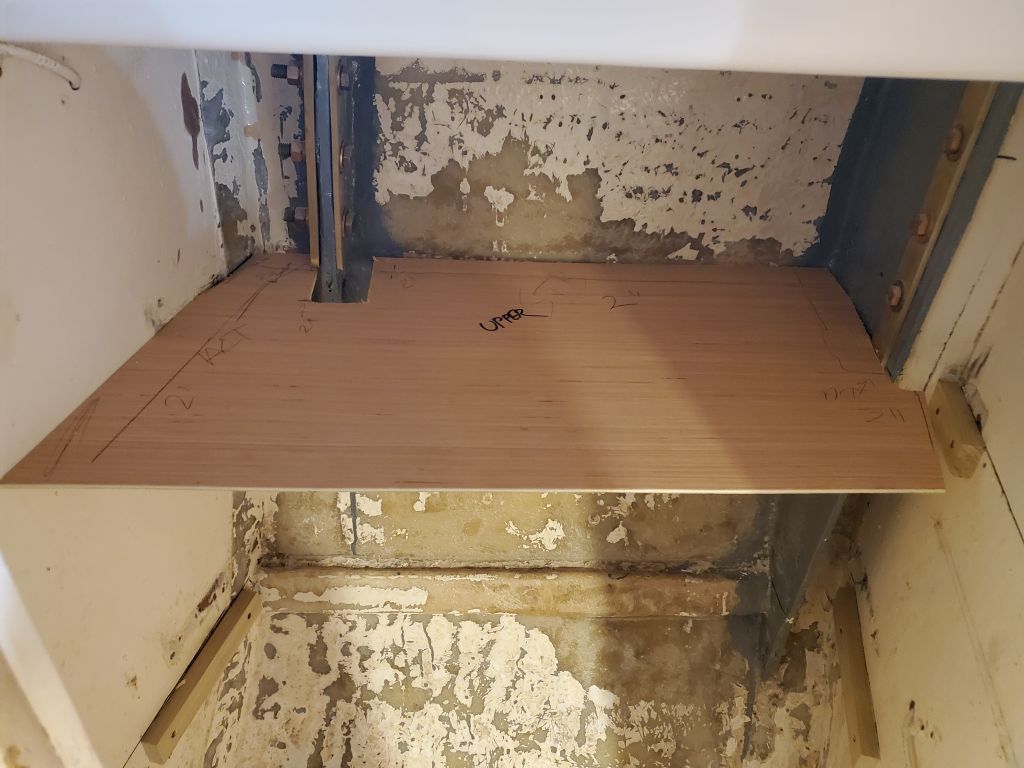
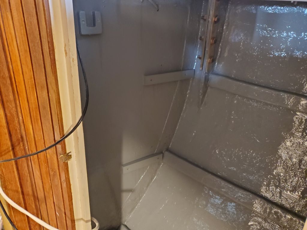
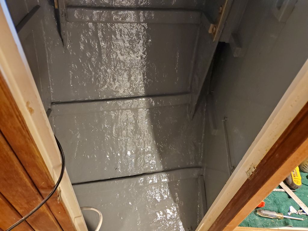
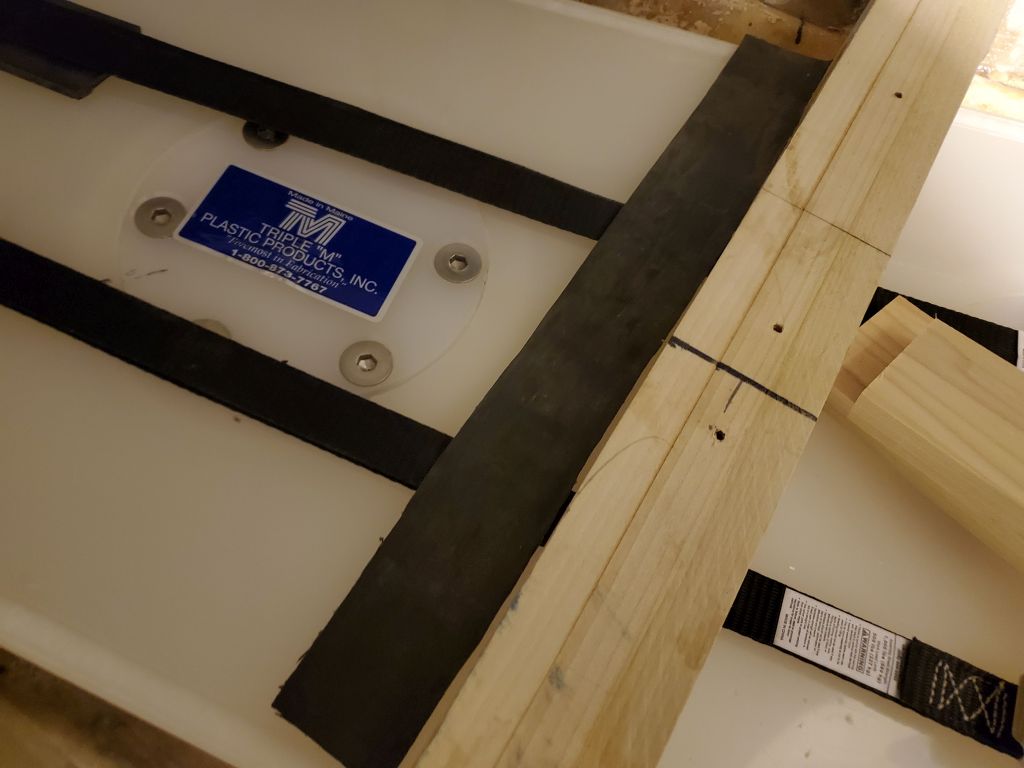
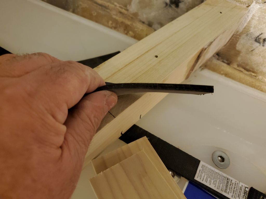
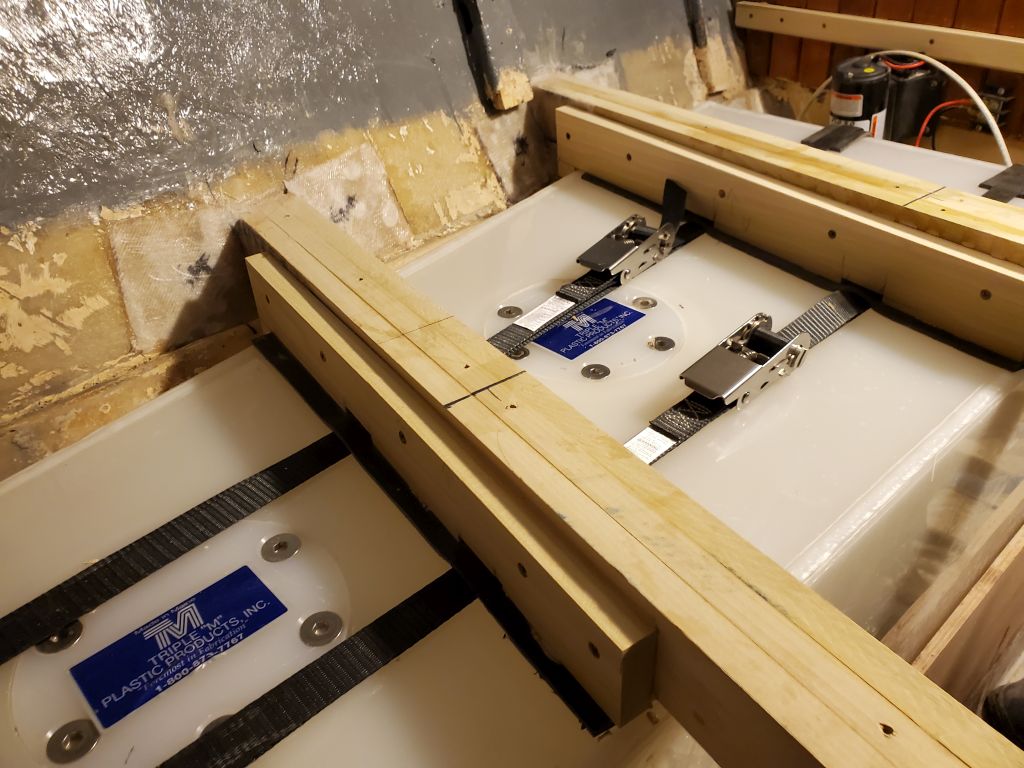
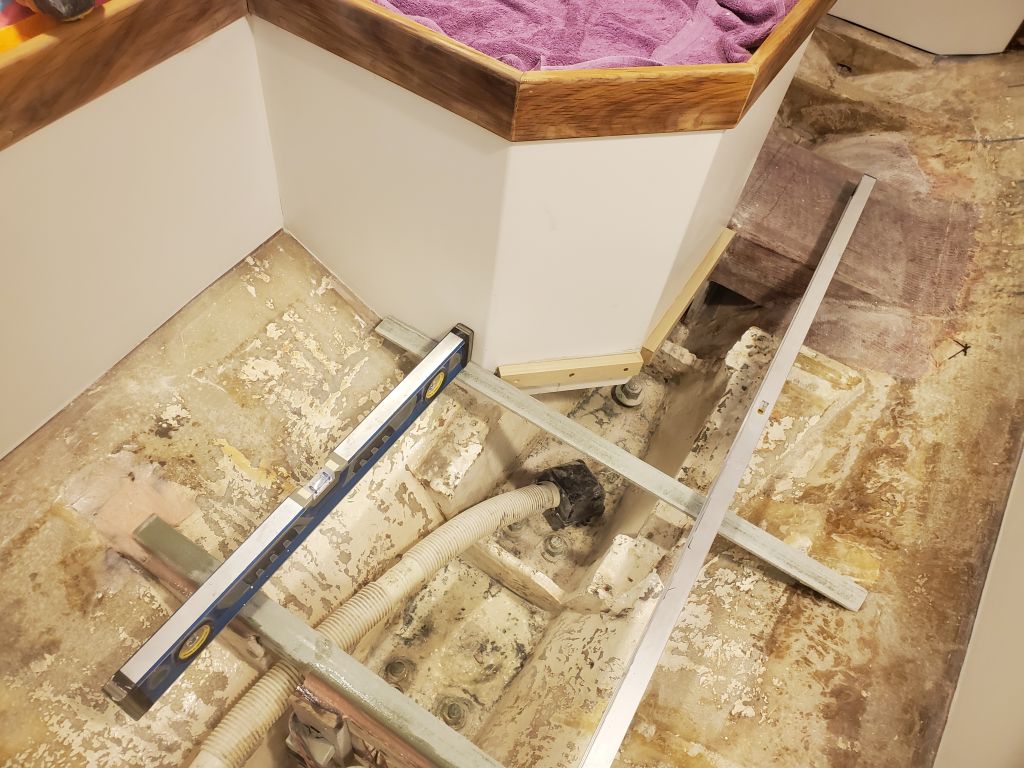
Now I removed the four cross members and, after final preparations, installed them permanently with epoxy adhesive and two bolts each, ensuring they remained level at each location and in both directions.  At the ends, I added thickened epoxy to create the basis for eventually tabbing the ends to the hull in a separate operation to happen later.

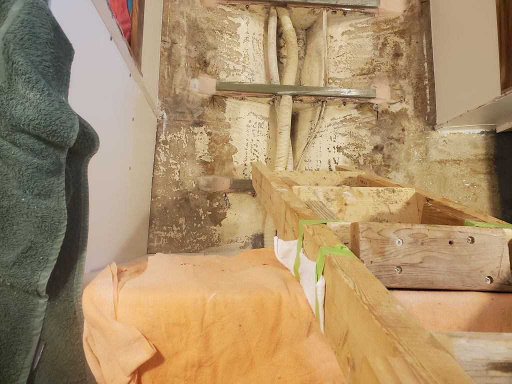
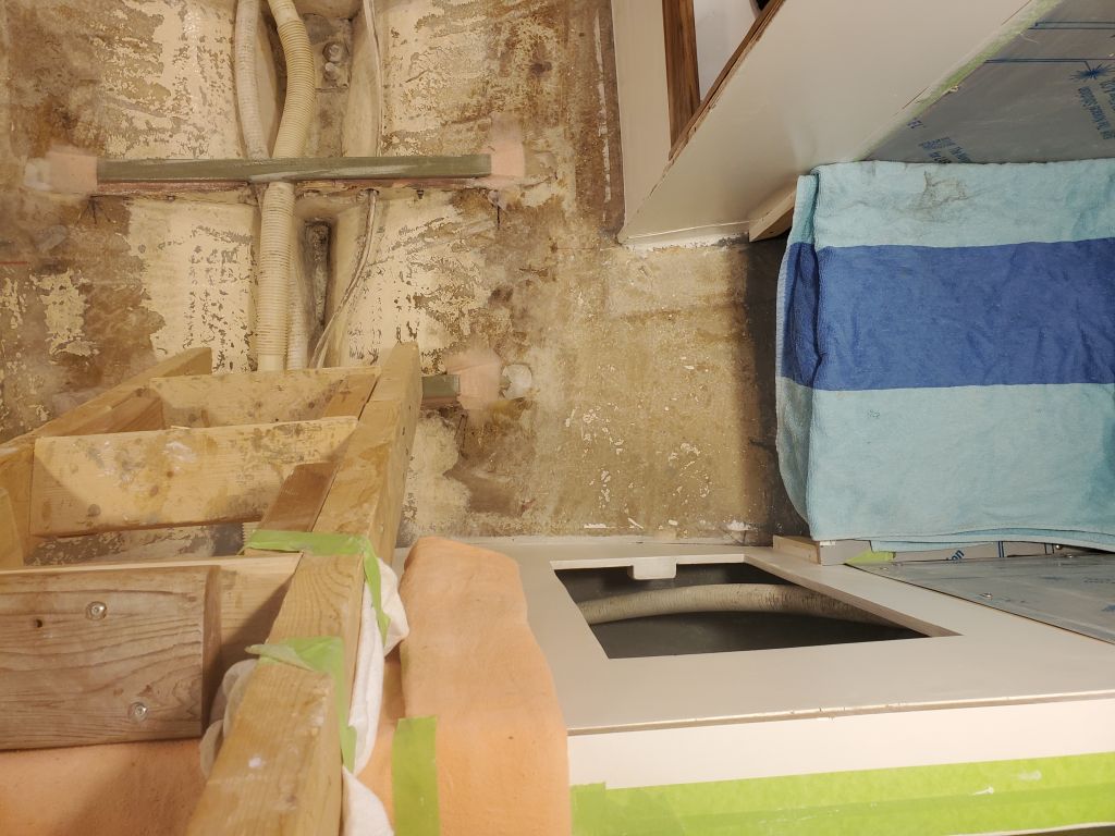
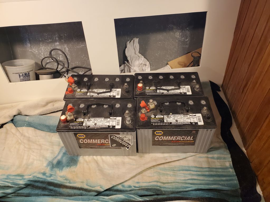
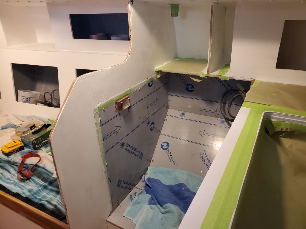
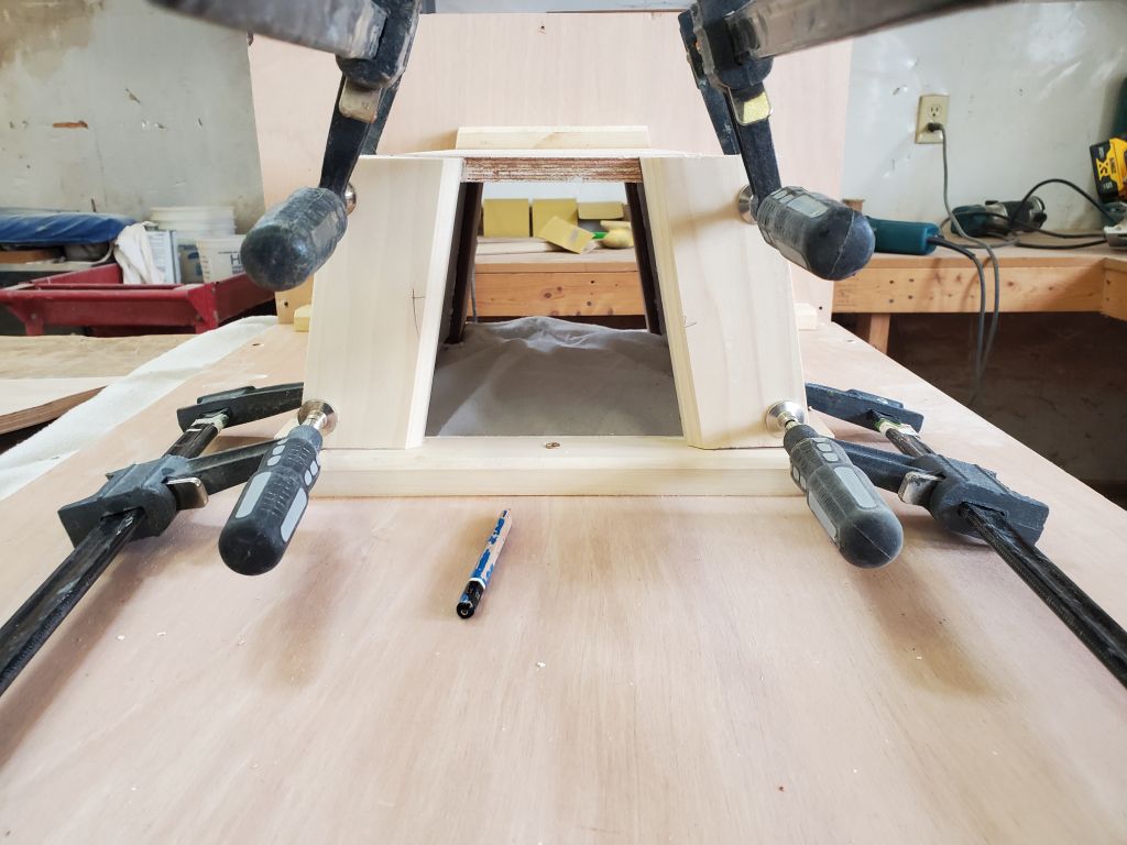
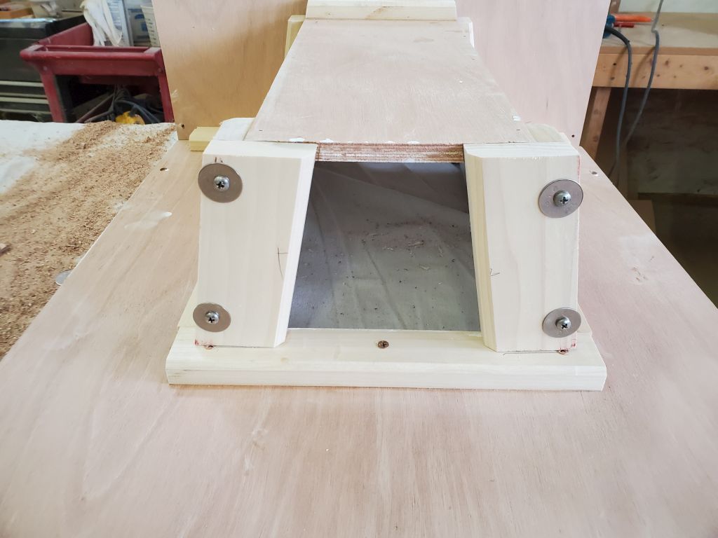
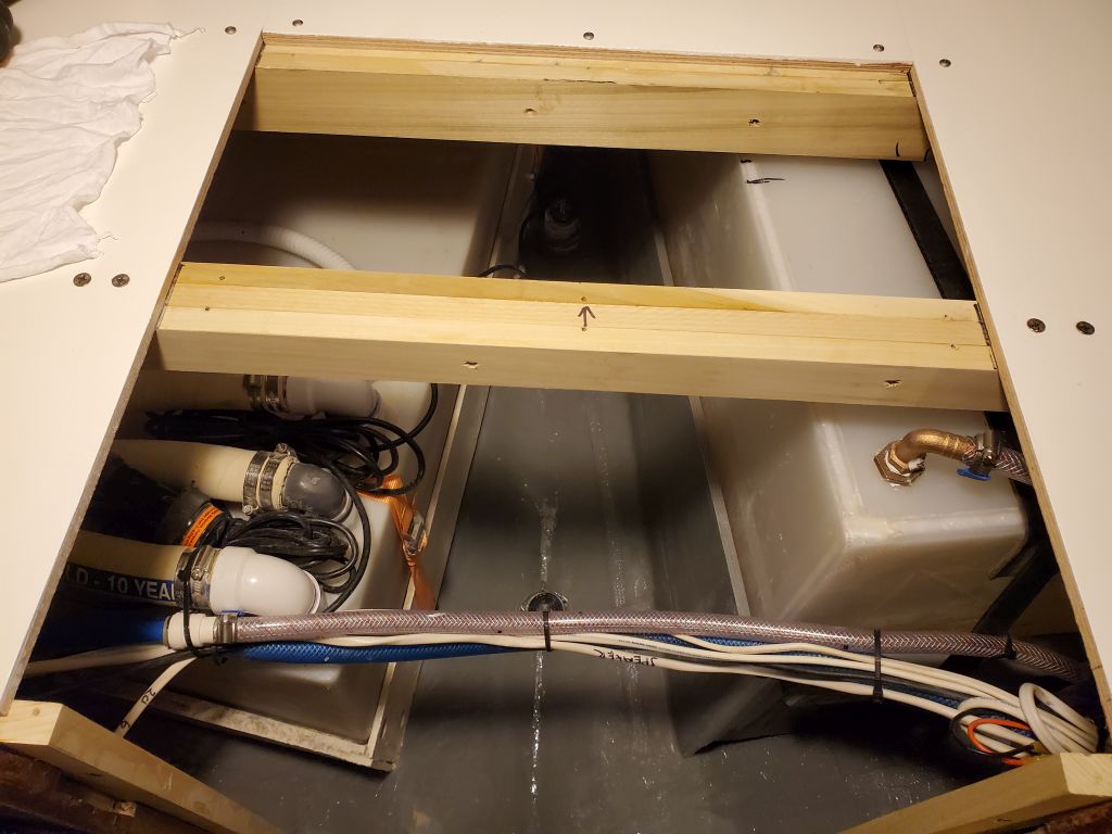
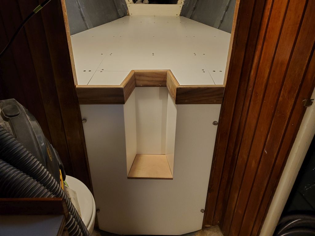
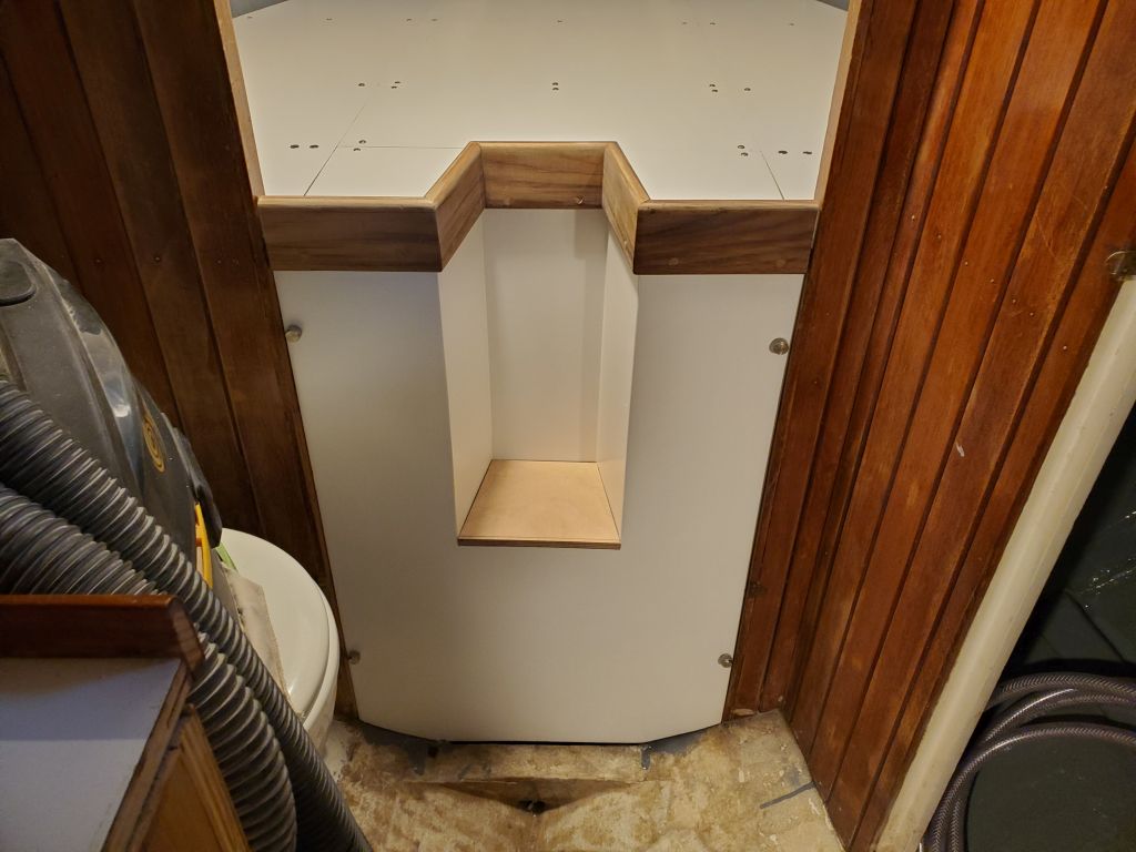
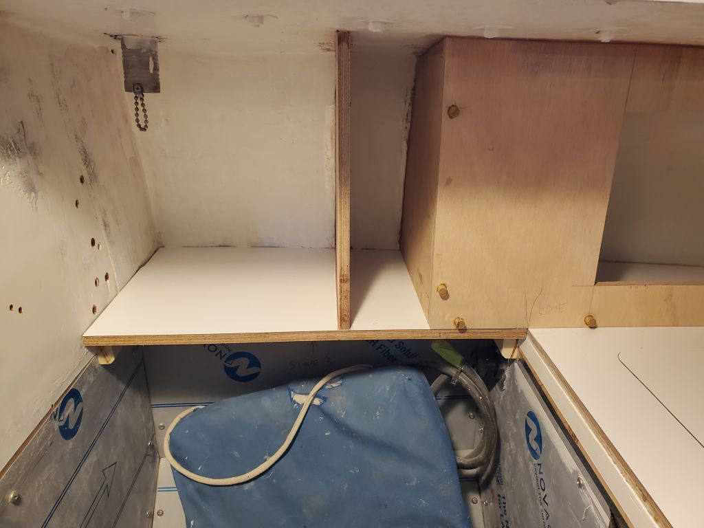
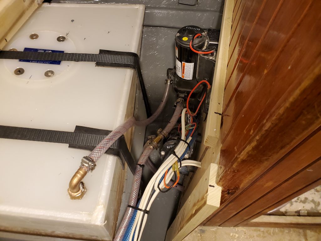
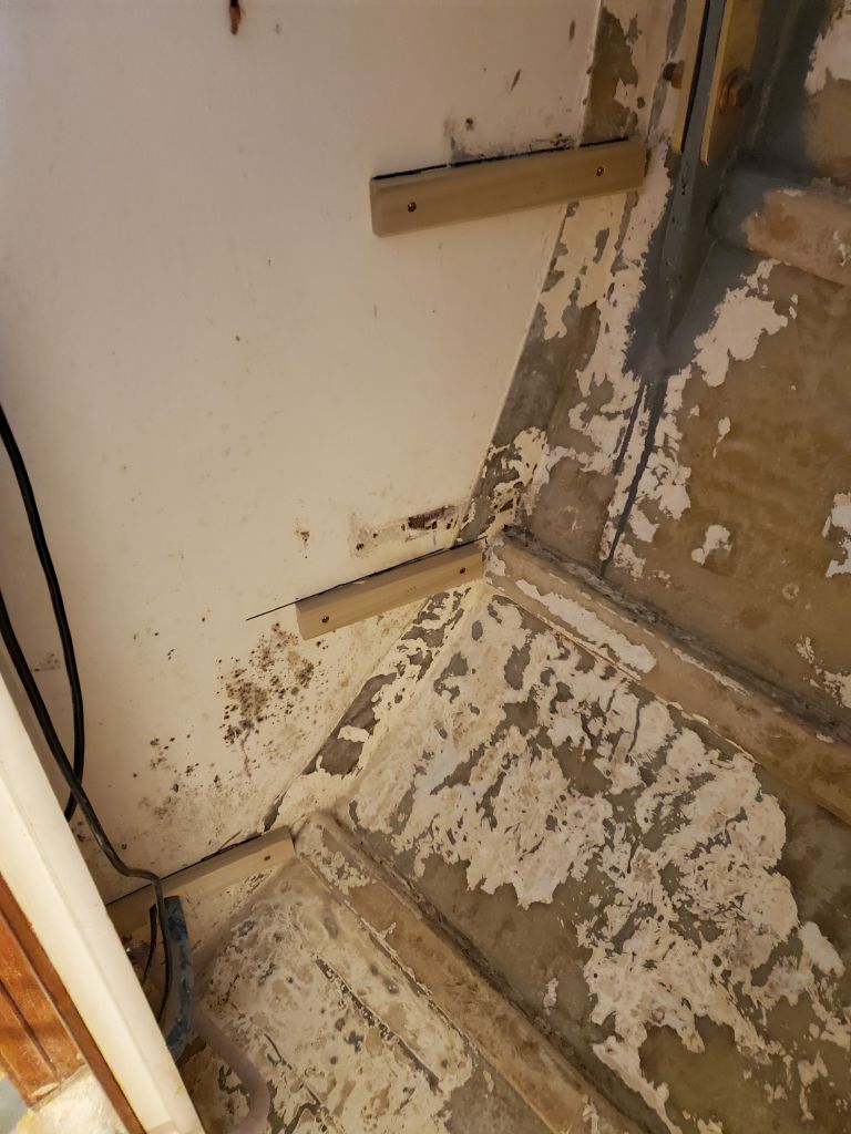
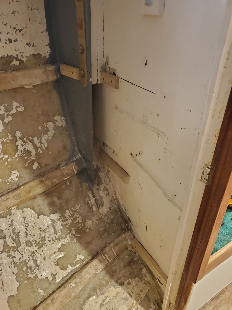
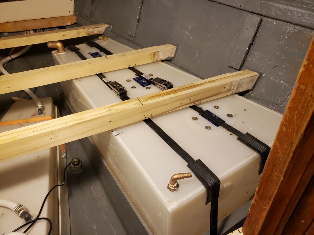
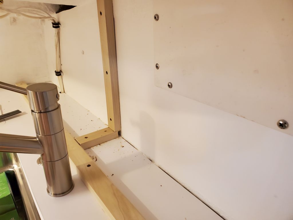
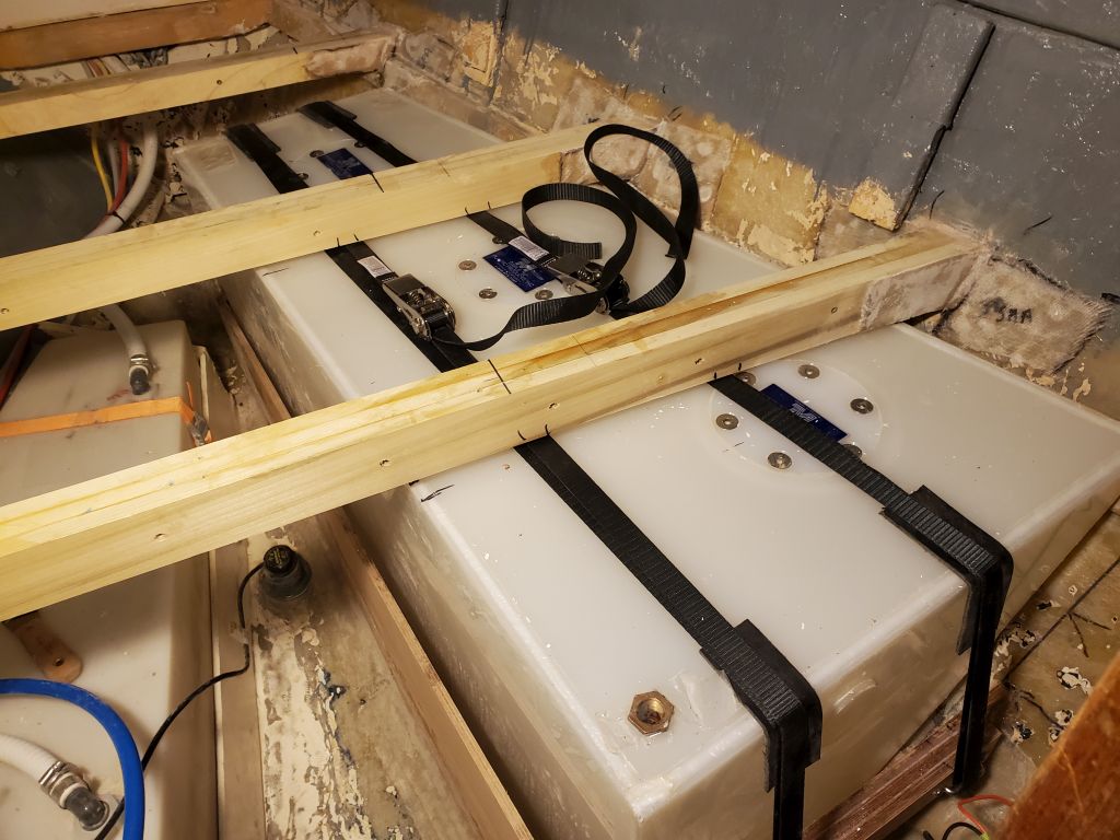
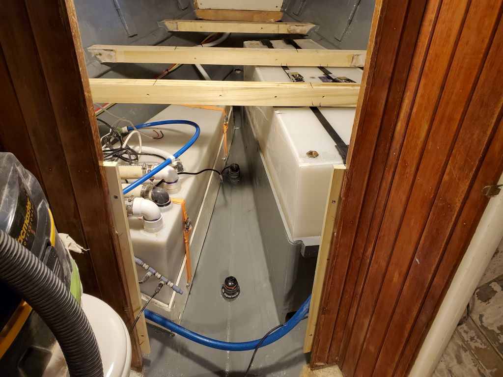
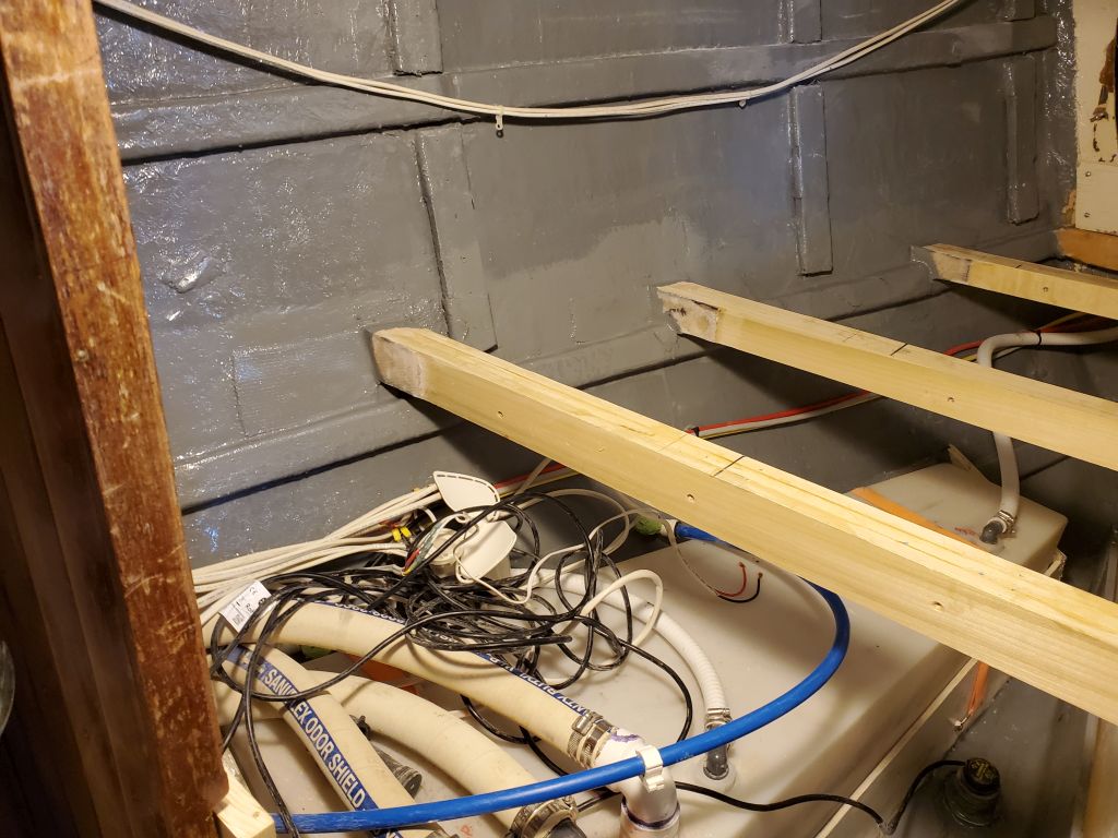
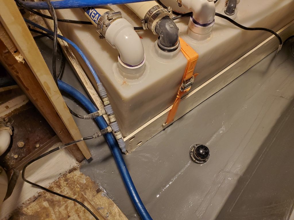
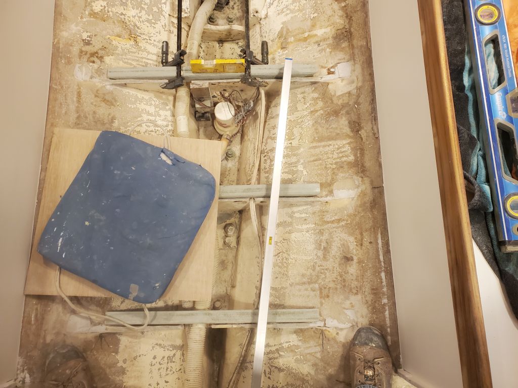
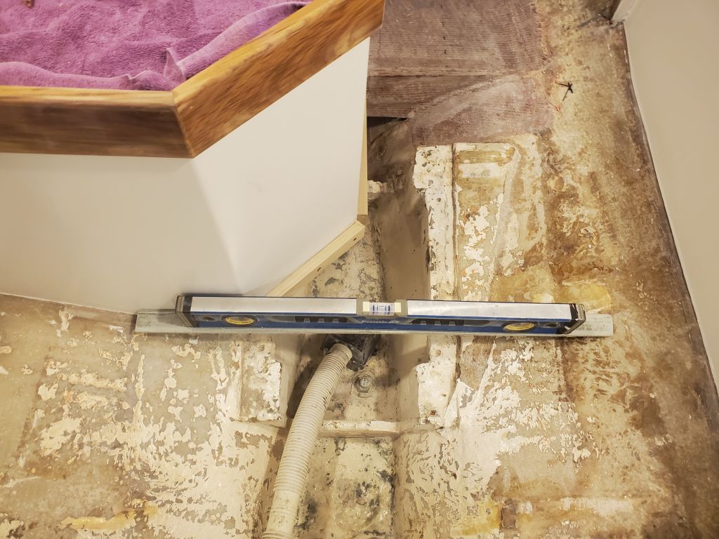
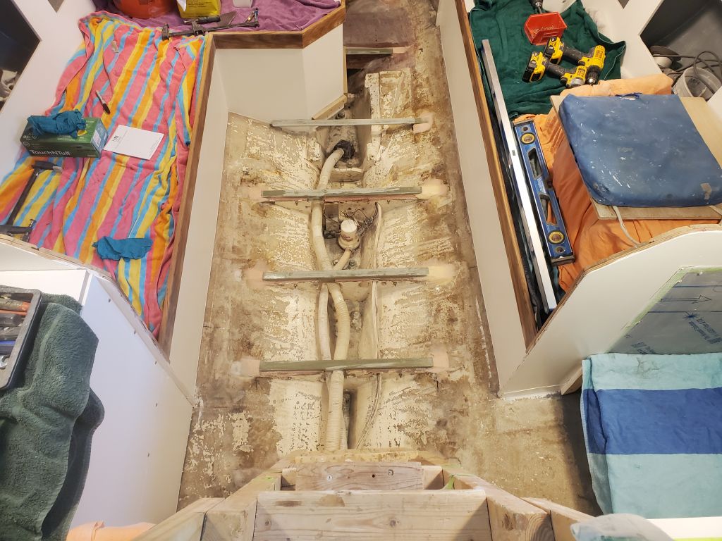
With the main four cross members in place, I continued (pirouetting around the tacky epoxy as needed) with the supports required at the forward end and around the battery compartment. This was made easier thanks to the mast step being level with the new structure, and also thus with the small forward section of sole in the head compartment.  I installed two wooden support cleats on the inboard edges of the battery box, and an additional fiberglass angle cross piece between the aft side of the battery box, where I secured it with screws, and the hull on the opposite side, where I epoxied the angle in place.  And finally, I added a short piece of angle on the aft side of the mast step structure, since I measured eight feet from the engine room bulkhead to the aft corner of the step, so to support a full-length sole panel on this side I needed an extra lip off the aft end of the mast step.

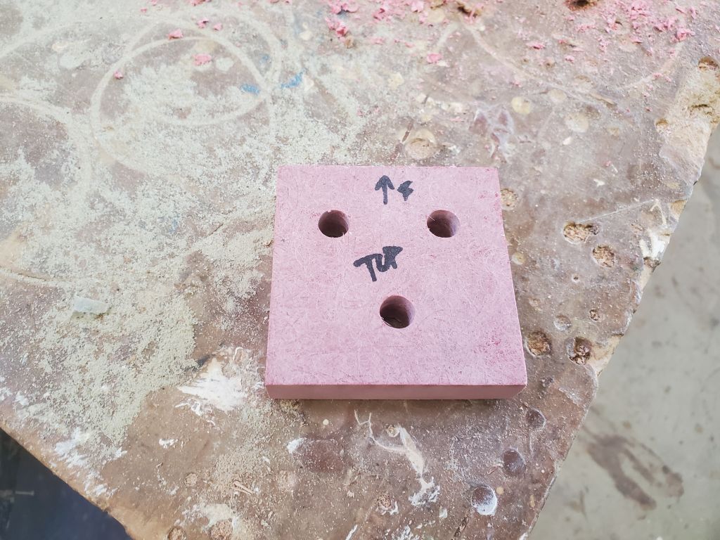
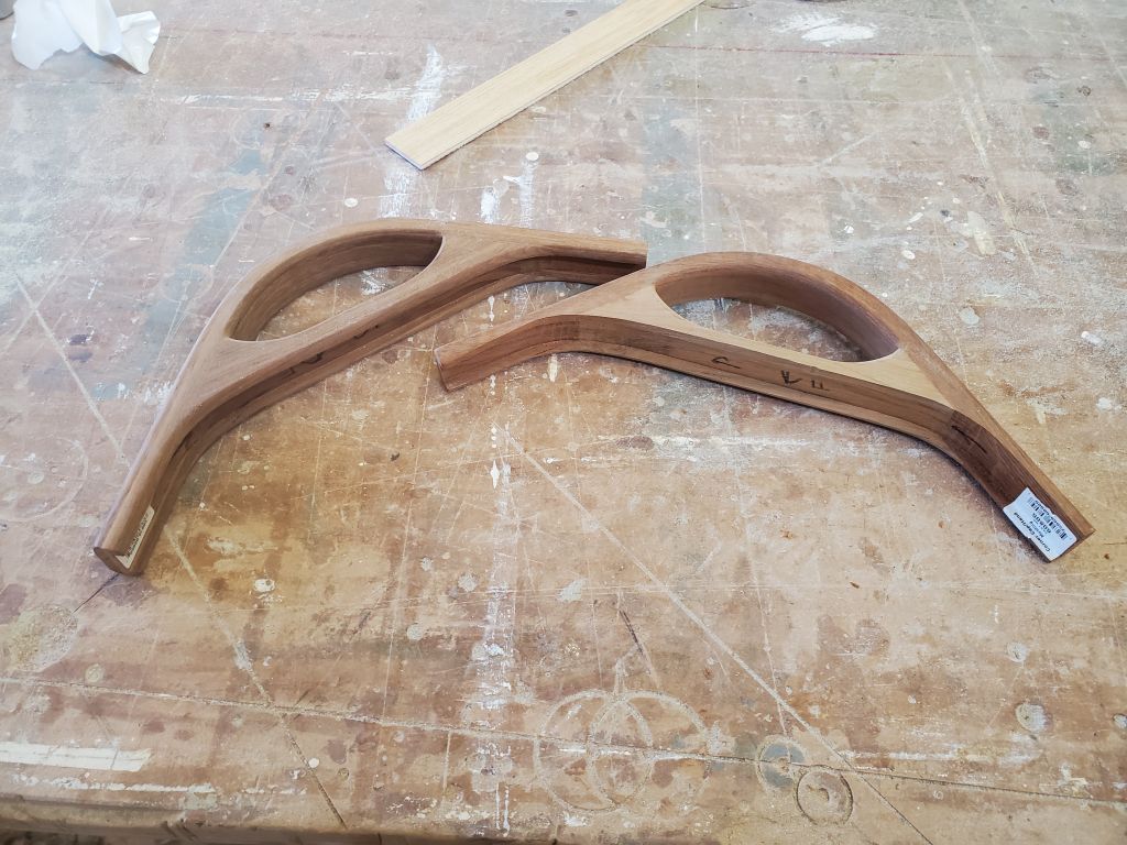
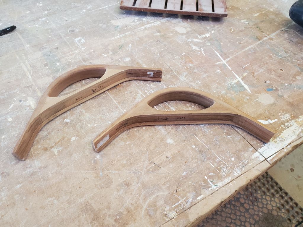
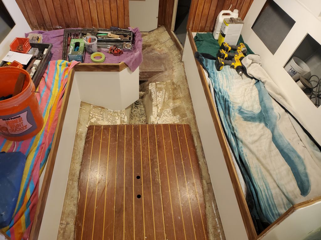
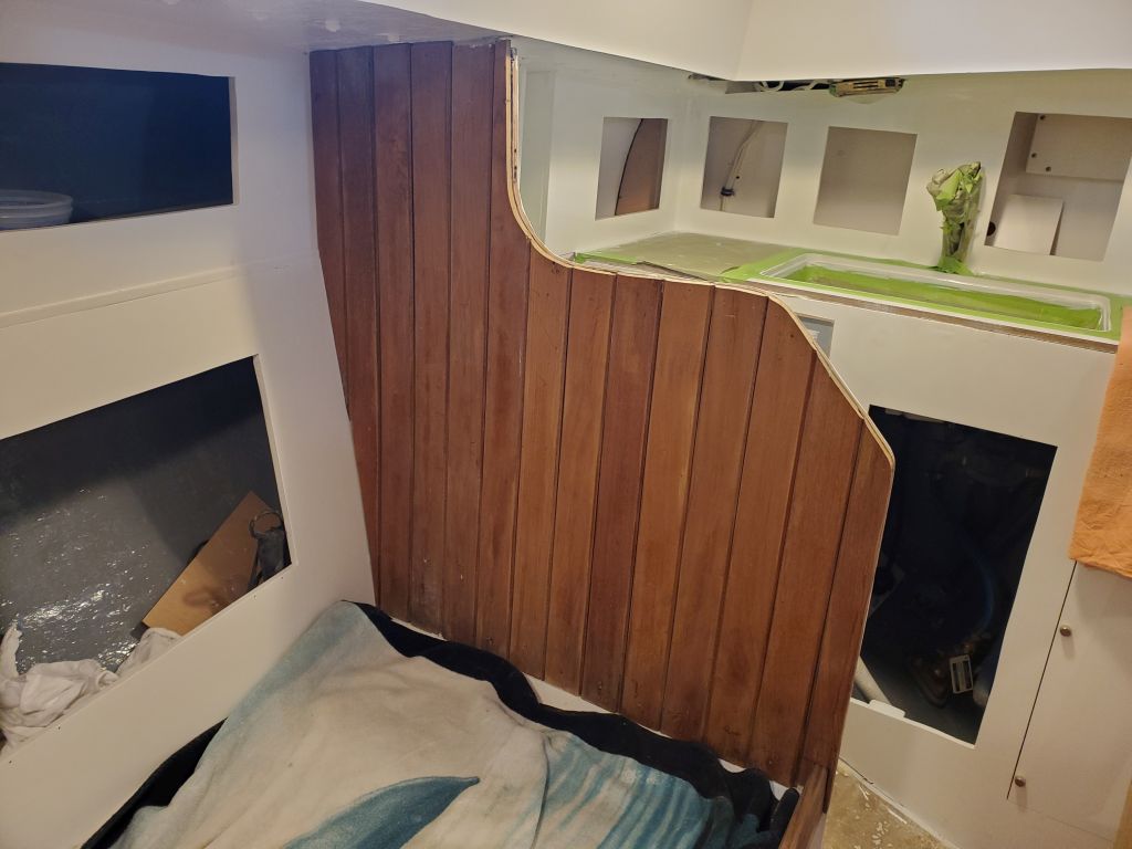
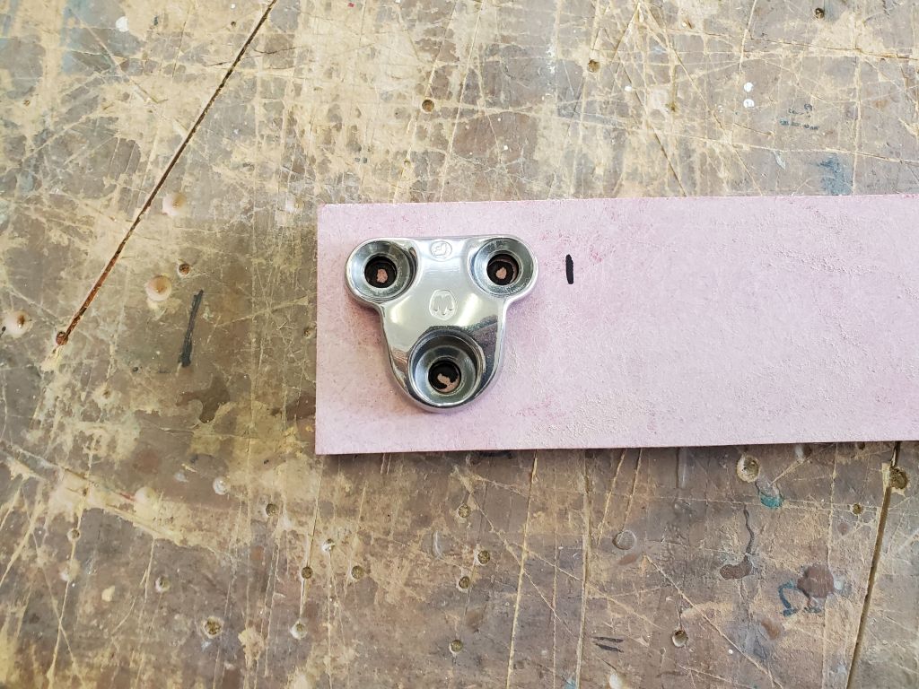
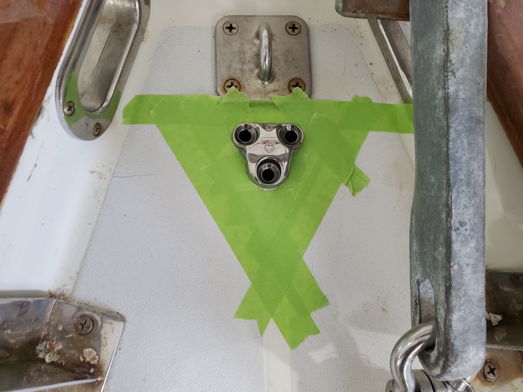
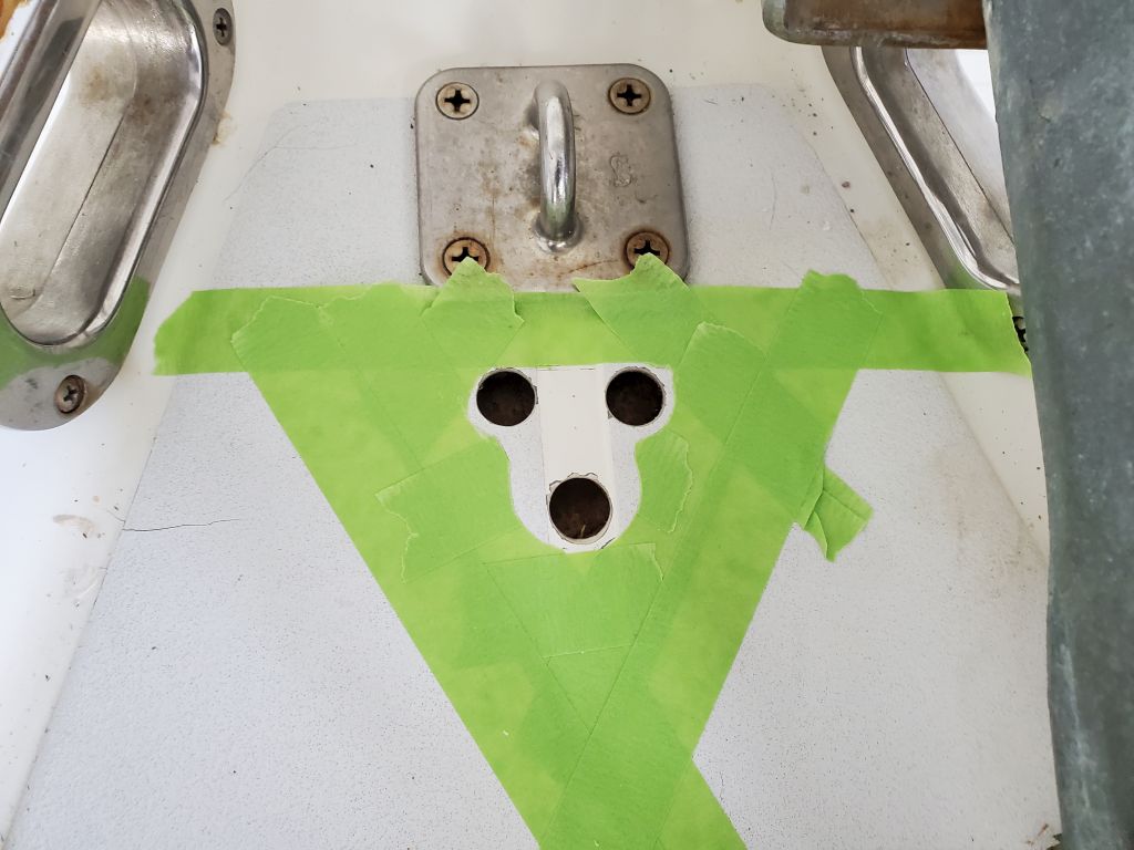
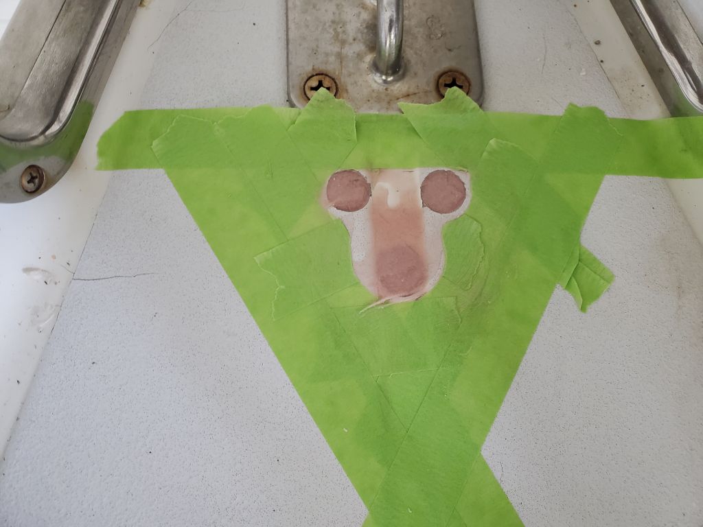
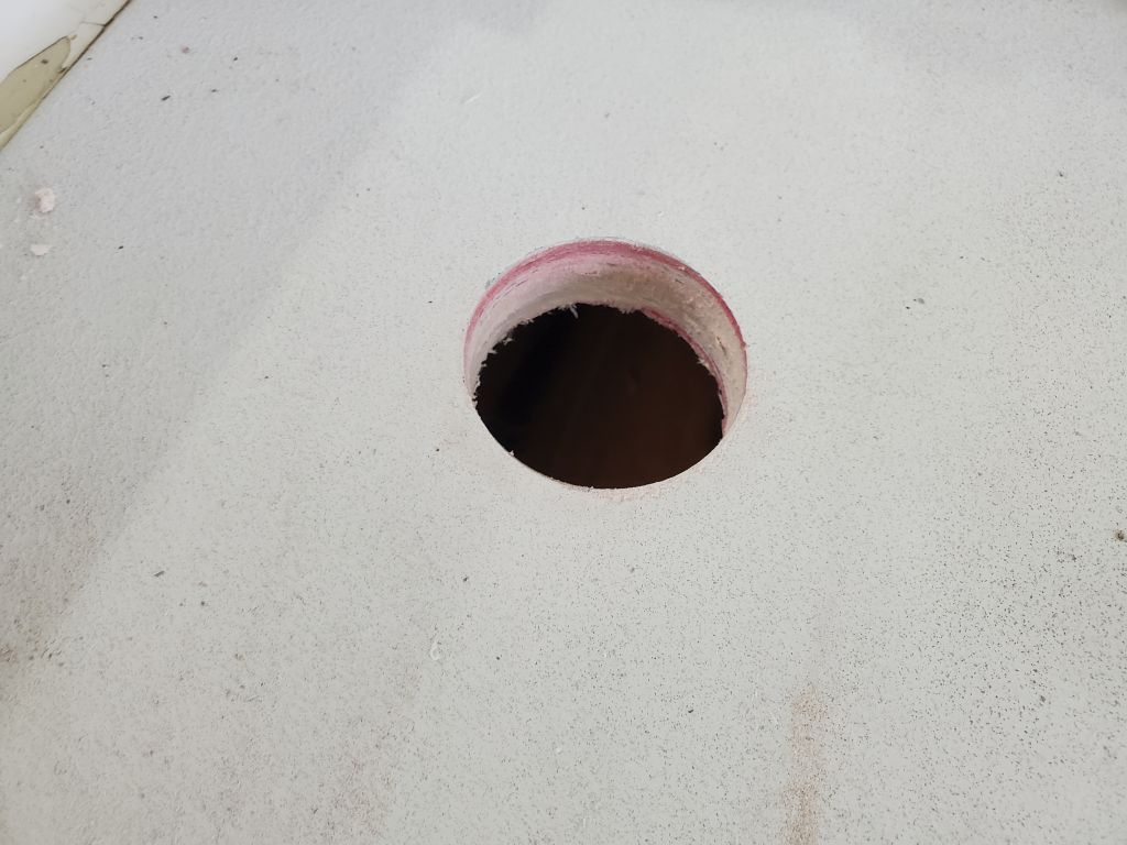
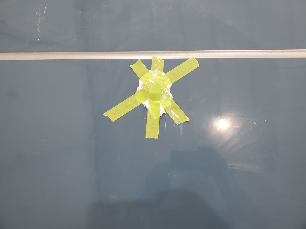
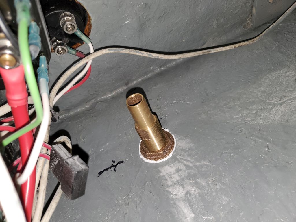
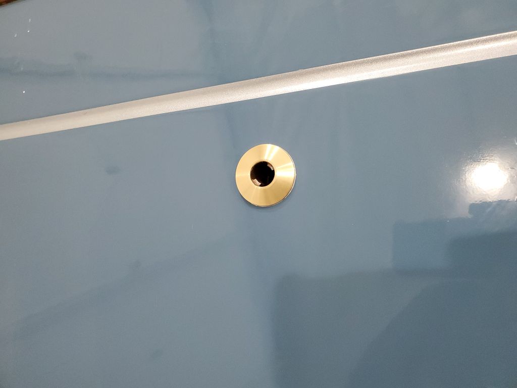
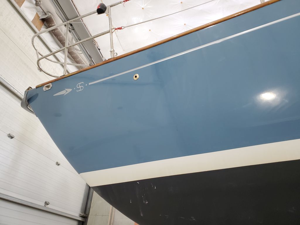
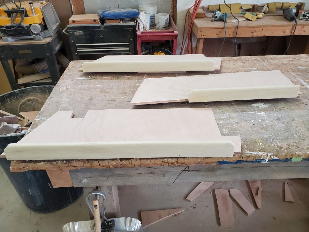
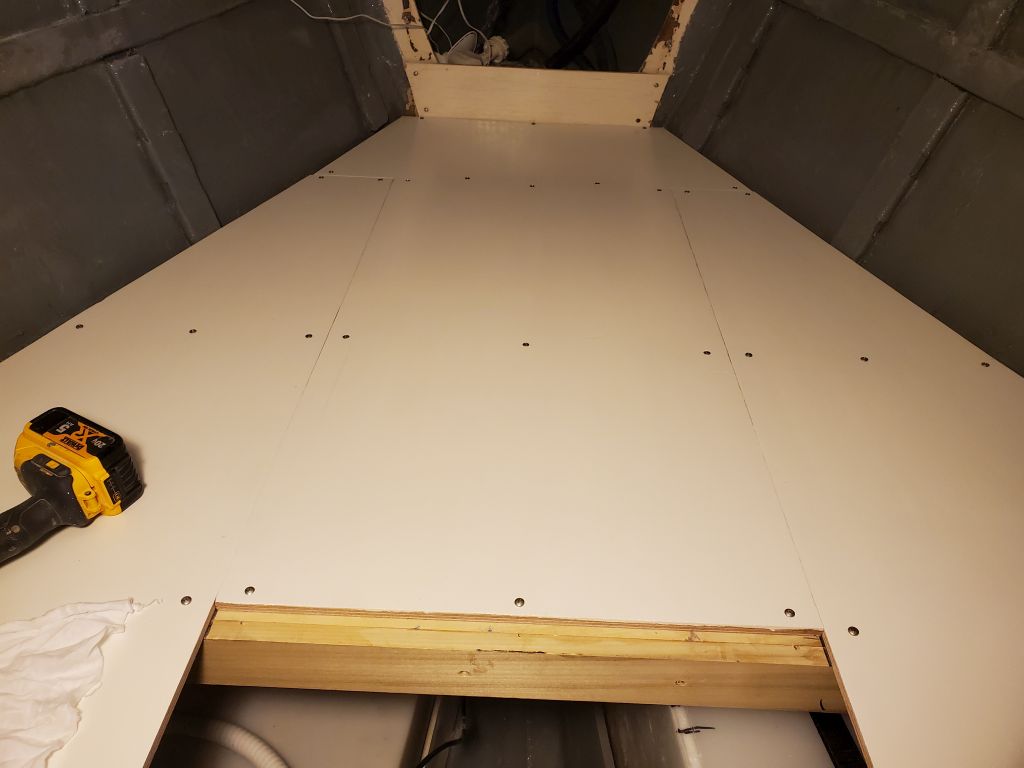
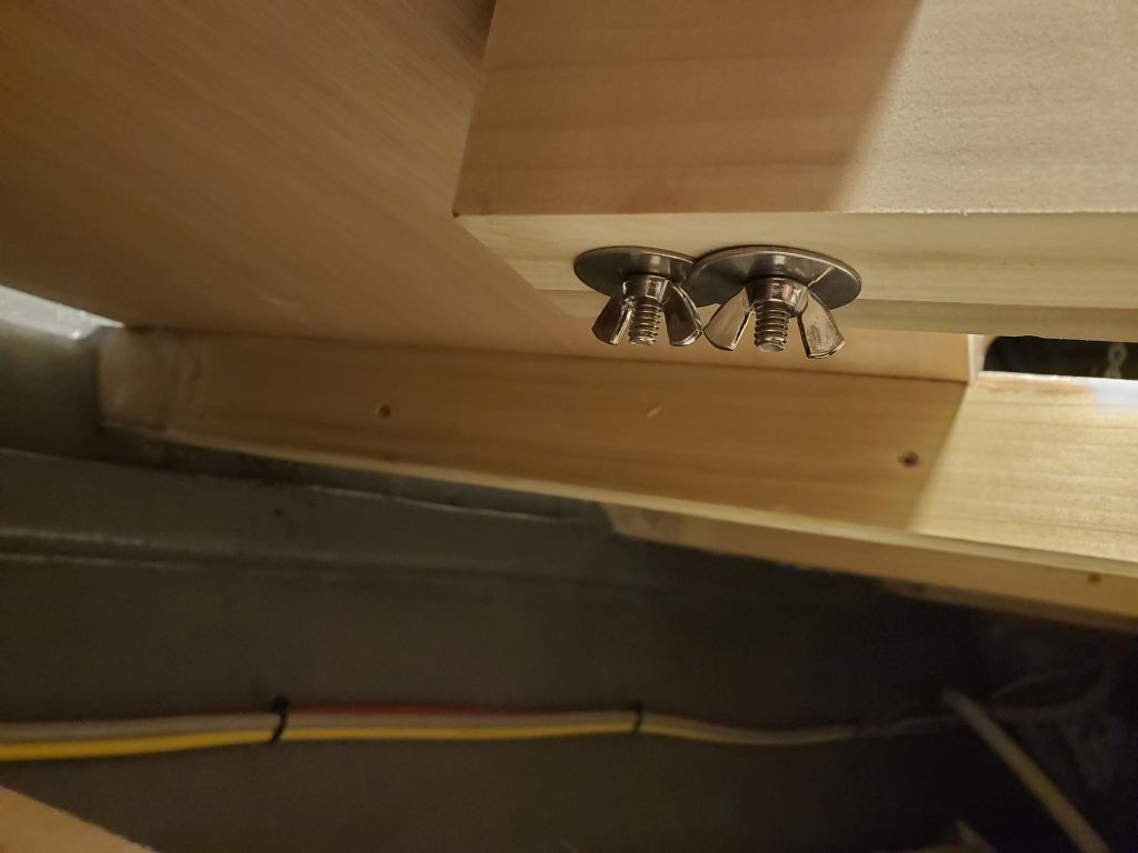
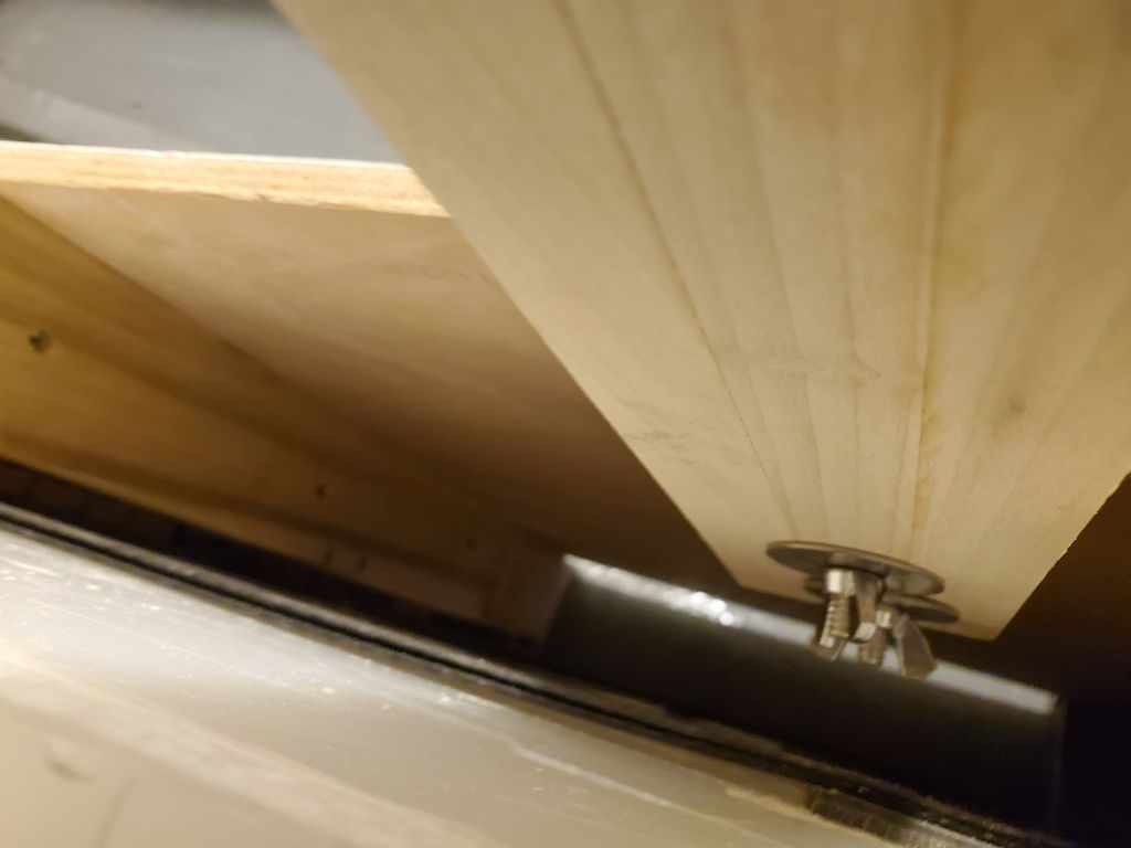
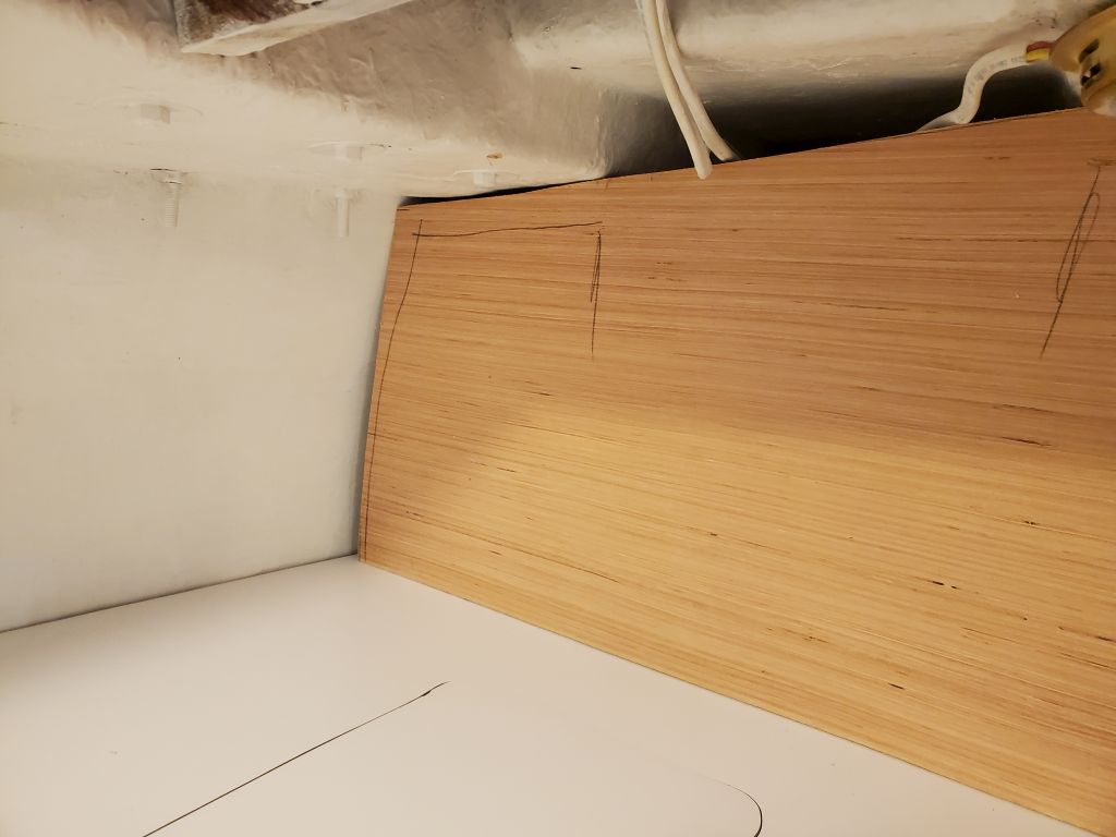
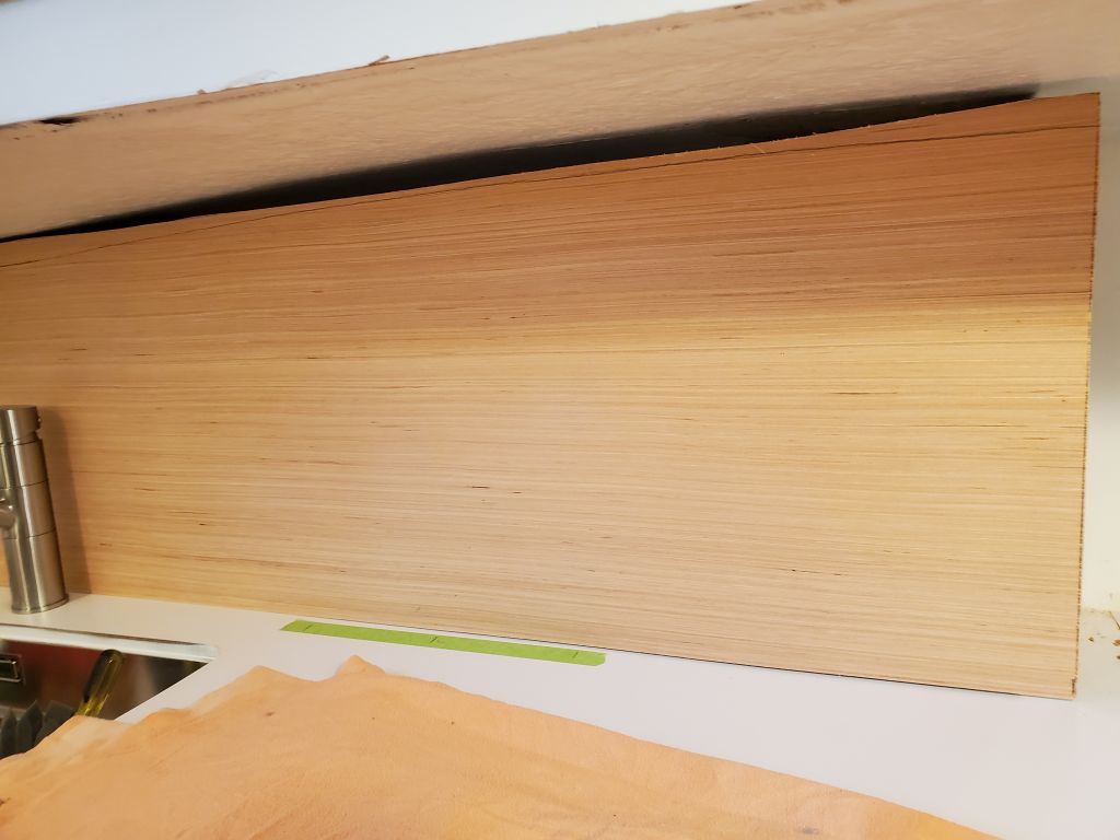
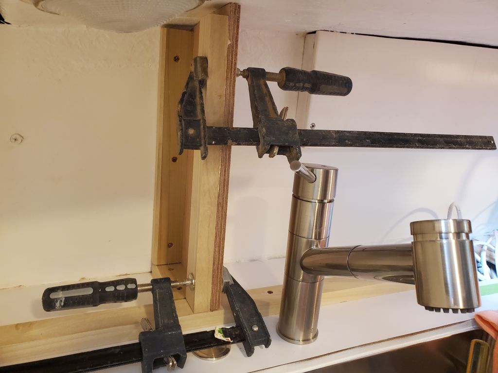
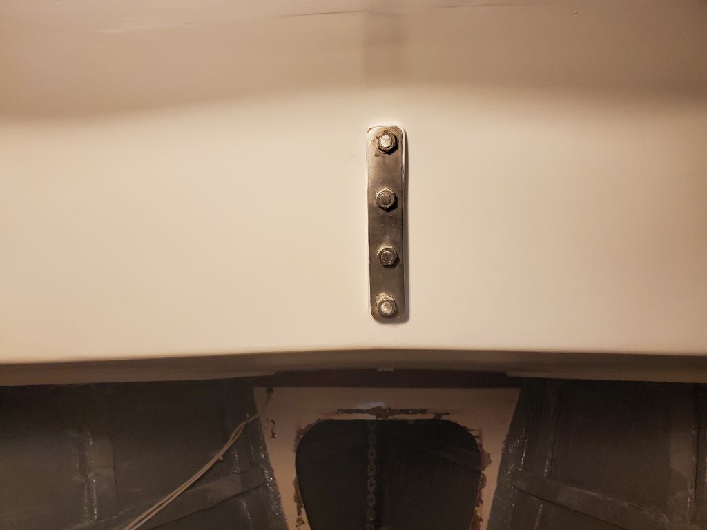
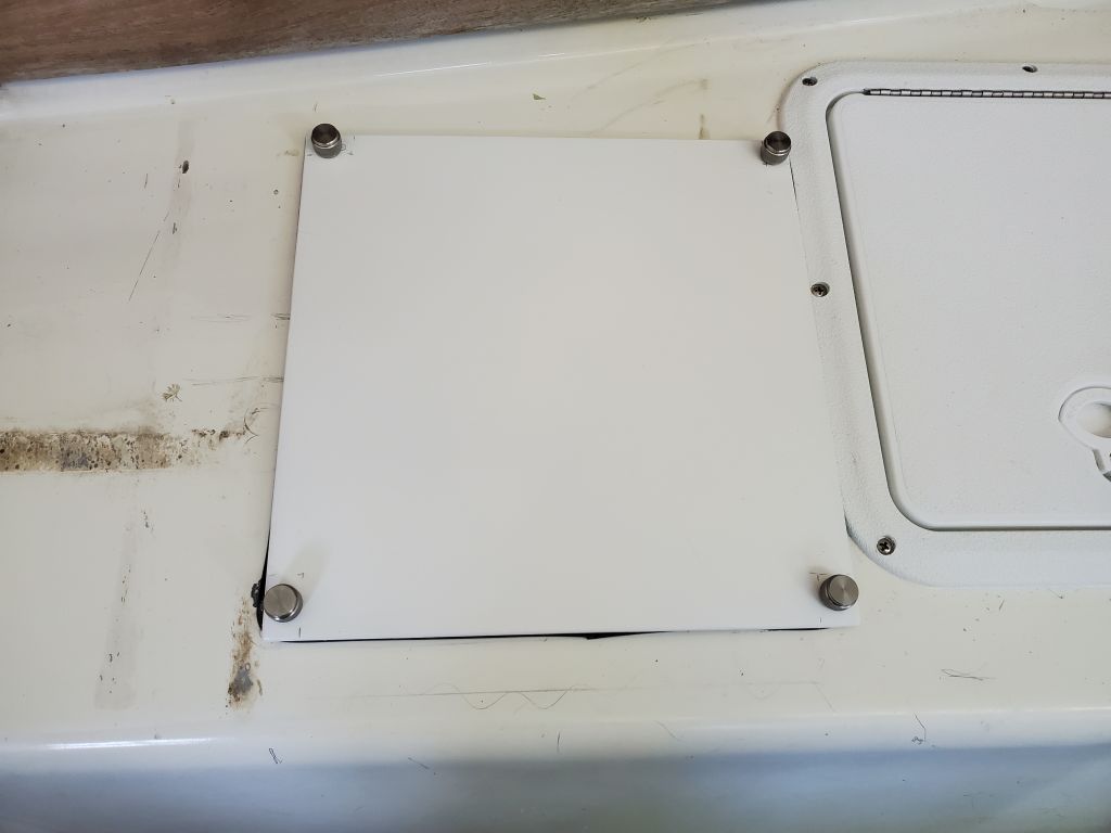
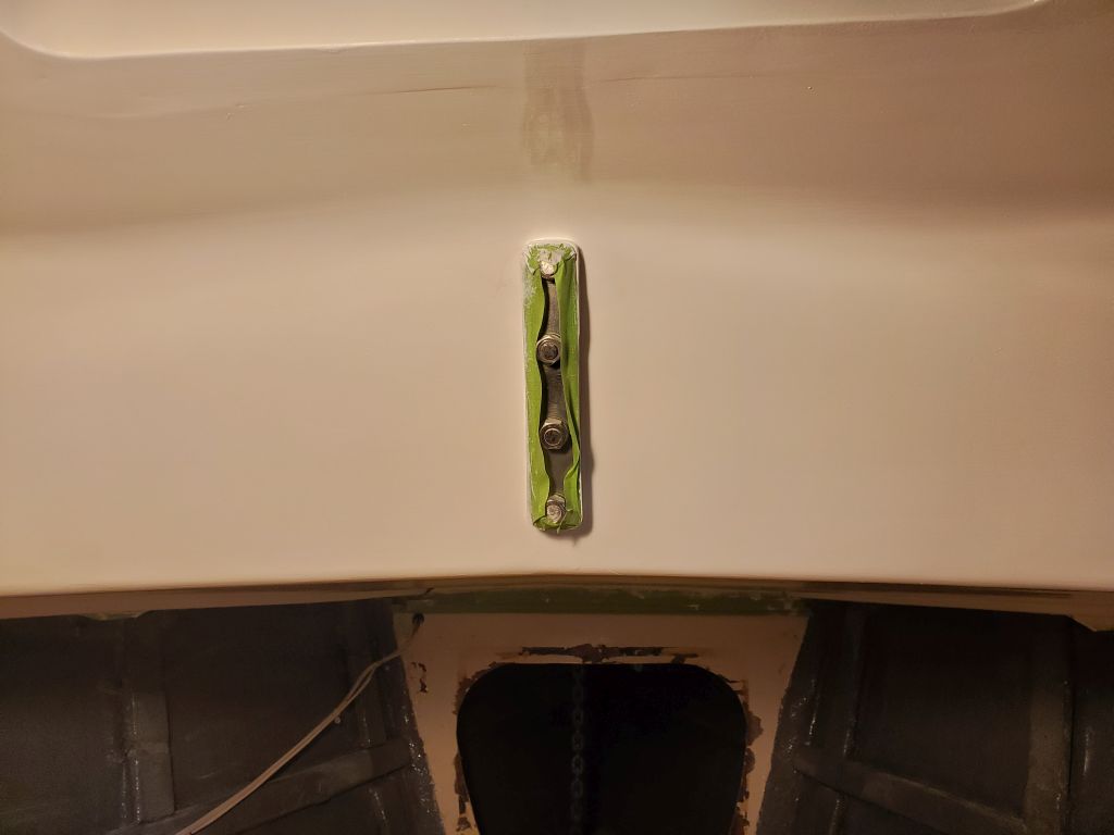
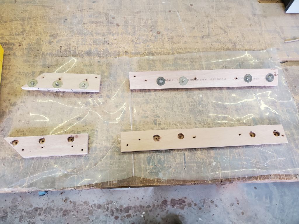
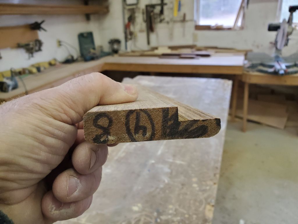
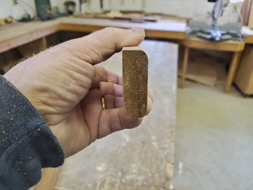
That was about all I could do for the cabin sole for now, but all the main pieces were in place and would cure overnight to allow me to continue next time.  To round out the day, I tackled a couple minor tasks, including preparing a backing plate for the new padeye on the foredeck, and trimming one edge of the prefab teak handles for the galley bulkheads so that they would work in the specific situation to overlap the forward side of the bulkhead, but remain flush on the aft side.  This was necessary since the existing bulkheads, with their staving on the forward sides, were thicker than the milled recesses in the teak, and also to allow the refer lid to open smoothly past any upper bulkhead trim.


Calliope Girl 96

Next on the agenda was the cabin sole replacement.  For various reasons, I’d somehow put this off throughout the project, though in many ways it would have been better to do it early on.  In any event, the time was nigh, and I was ready to focus on the cabin sole.  The owner had asked me to try and lower the sole by an inch or so, which would require some reconfiguration of the structural supports (floors), which brought with it various complications.

Before removing the sole, I took a moment to get the four batteries back into the boat while I had a platform.  I’d stored these in the cockpit throughout the project, and would soon be reinstalling them in the new locker, so I wanted them ready to go.

During the project and  as needed, I’d pared away portions of the old sole to give me access as needed for some of the other interior work, like the new mast step and the battery compartment, so there wasn’t much left.  The entire center portion was removable in two panels.

I pulled up the remaining sections with minimal help from a prybar, exposing the entire area for the first time.  There was a lot of dust and debris from the other construction, so the first thing I did was clean all this up.

To gain the extra headroom, I had to cut back the existing floors.  I’d been thinking this process through for months, and had come up with a plan of attack to strongly and efficiently achieve the requirements.  To start, I marked a line 1″ down from the top edge of each floor, and also used a level to make some reference marks on the battery compartment and engine room bulkhead for future use, both at the existing height and then 1″ down.  I had to reroute some wiring leading to the bilge terminal block, and temporarily unfastened the block to keep it clear of the work to come.

Now I used an angle grinder and cutoff wheel to cut to these lines, removing the top sections of all four floor installations and grinding off the tabbing and adhesive filler at the ends as needed.  This was as fun as it sounds and made quite a mess, but it was the worst part of the job and was now over.

My rebuild plan was to install new fiberglass angle to be bolted and epoxied to the forward face of each floor, and glassed to the hull on each side, all level in both directions.  But this work would come next time, as I wanted to spend what was left of my available time  this day (as I was leaving early so I could watch the total eclipse) preparing the galley cabinets for their final coat of white paint, which I did once I’d cleaned up thoroughly from the cabin sole removal.

We had perfect weather for the eclipse, with 60-degree temperatures and completely clear skies.  Where we are, we had 98% totality (according to some tool I found online), which was close enough for us.  I tried taking pictures through my dark glasses, but only this one at about halfway to totality came out well enough to use.  At maximum coverage, the outside temperature dropped at least 10 degrees, and the light was very dim and with a harsh, white quality to it, much like the unfiltered sunlight one sees in the pictures of people on the moon.  We were lucky to have a great view and near totality right from home.

Calliope Girl 95

Over the weekend, I finished up reinstalling the starboard staving forward of the galley.

I also lightly sanded the primer on the upper galley cabinets and other areas, then applied the first of presumably two coats of semi-gloss white enamel, advancing things so I could finish up with the last coat during the first of the week.

Calliope Girl 94

I spent the first part of the day working on the galley, with a final sanding of the new cabinets and related masking work before applying a coat of primer to all areas, including the back side of the forward stove bulkhead, which had required some minor fill and repair work.

Now that I could more easily access the chain locker, with the v-berth platform back in place, I checked out the situation with existing hardware and obstructions so I could locate and begin installation of the water tank deck fill and vent, and a new padeye the owner asked me to install near the stem.  I started with layout of the padeye on some 3/4″ fiberglass sheet stock that I planned to use for a hefty backing plate, and ensured that I kept the new padeye far enough from a larger padeye just ahead to provide room for the backing plate.  I overbored the three fastener holes through the top skin and core with a 5/8″ bit, digging out the old core and filling the voids with a thickened epoxy mixture.

I located the tank deck fill fitting on the port foredeck, in a position generally symmetrical with a hawsepipe on the starboard side and where there was good, clear access for running the fill hose, and bored a hole through the deck, along with 1/2″ holes at the fastener locations, then reamed out the core and filled the voids with thickened epoxy after first masking over the large hole from beneath.

The existing tank vents for the holding tank were 3/4″ through hulls, and the owner requested I do something similar with the new water tank vent, so I located the new vent on the port bow, in the same symmetrical position as its counterpart on the starboard side, though slightly more forward to allow adequate clearance with some wiring obstructions inside.  Since the hull was solid, I could drill and complete the fitting’s installation immediately.

I spent the remainder of the day installing the original teak staving on the bulkheads forward of the galley, starting with the port side.  This was a pretty straightforward process, since I’d previously sanded the visible side (to be revarnished once installed) and cleaned up the back sides to remove old adhesive.  With some differences in the berth and bulkhead configuration and height, I had to trim many of the pieces to fit, but the installation proceeded quickly as I secured each piece with glue and brads.  Once I’d completed the port side, I continued with the starboard, making it partway across before the end of the day.


Calliope Girl 93

Just what everyone wants in April, especially after a winter with essentially no snow:  A big spring nor’easter, with lots of heavy, wet, sticky snow, high wind gusts, and almost guaranteed power outages, since now half the state gets knocked out every time there’s a bit of a blow.  I’d hoped to get at least part of a day in (hopefully more), but alas, the power went out at 0600 and I imagined that was that.  Disappointing, even though it was expected

Past history, including two other times this very winter season (one just last week, when fortunately I was away), suggested that I settle in to wait out a likely days-long outage, given our globally-owned power company’s abysmal maintenance and performance record over the past number of years and the exponentially-growing number of outages reported with this storm.  But, great miracle of life, the power came back on after only 4 hours, at 1000, and somehow stayed on, despite a few worrisome flickers throughout the day.

So by 1030 I was at the shop, and chose to work mainly on smaller jobs that I could theoretically continue and/or finish up should the power go out again.  I started back in the hanging locker, test-fitting the three shelves again and making final adjustments and marking them for final depth, which cuts I then made down on the bench.  Then, I milled and installed hardwood fiddles on the shelves, gluing them in place and holding them with brads.  I left the forward portion of the lower shelf un-fiddled since I’d left room there for the passage of various hoses and wiring that had to run up from the lower portion of the locker.

With the hanging locker painted, now I could run in some of the hoses and wires I’d staged earlier, including the power supply to the fresh water pump that I’d relocated to the v-berth.  I led these utilities along the bottom edge of the locker, where I’d previously installed some wire tie mounts before painting.  This wiring connection wrapped up the work required in the v-berth, which meant I could reinstall the platform, which would be my next task.  First, though, I installed the potable water filter in the hanging locker and connected the supply hose leading from the pump to the galley sink.

The removable end panel and step for the v-berth required two additional cleats to finally be ready to accept a step platform.  I installed these cleats with glue and eventually pan head screws and washers for extra fastener strength beneath the step, attached to some sub-cleats I’d installed earlier.  Then, I cut a temporary plywood step to fit and to help with access to the berth during the remainder of construction.  Eventually I planned to build a solid teak step.

While the glue was setting up, I installed the remainder of the berth, now fully painted.  The water tank fill hose required a bit of a relief on the underside of the panel overhead to provide the requisite clearance, which took a few minutes to lay out and cut with a router.  By the time I’d finished up with the other panels, the glue on the new cleats had set enough that I could install the end panel and step as well.

Next, I worked on masking off portions of the new galley upper cabinets, ostensibly for primer and paint just ahead, but more immediately so I could apply a skim coat of quick-dry filler over the bungs and panel seams as needed, just to fill any minor voids in these areas before sanding the panels before paint.  I also masked off the exposed countertop edge around the sink so I could paint that at the same time.  The plate and drinkware storage area at the forward end behind the stove would get finished off mainly with teak trim details, other than a shelf at the appropriate height to allow plates below, and bowls and possibly mugs above.

To finish up the day, I prepped and painted the hanging locker shelves on all sides.

Calliope Girl 92

I continued work on the galley, using a template of the starboard face I’d made previously to cut out the plywood panel for the cabinet face.  After some minor adjustments to the fit, I laid out for a single door opening, ultimately choosing one larger door versus two smaller ones because it seemed the best use of the space.  I installed the panel with screws into the support cleats, and epoxy adhesive at the top edge where it met the overhead.  I bunged the fastener holes thereafter.

After a final check of the spacing for the plate and glassware storage area, I templated and then cut a plywood panel for the divider, and installed it with epoxy adhesive all around so I could avoid bulky support cleats that would impede the space for the specific storage items intended.

Next, I turned back to the water tank, and installed the fill and vent hoses, leading them forward into the chainlocker with some excess length to await final routing and connection to their skin fittings, which I planned to install later once the v-berth platform was in place to ease access to the chainlocker.  At the aft end, I installed the supply lines leading from the tank to the water pressure pump, then on through a tee fitting to the head supply and a line to lead aft to a separate water filter that I’d soon install in the hanging locker.

This meant it was time to address the hanging locker.  I’d removed two flimsy shelves earlier in the project, and now I measured for and installed some hardwood support cleats for new shelving, all of which would use the built-in hull stringers running through the compartment for support at the hull end; these stringers were appropriately placed and generally of level orientation.  I chose to add cleats to the lower support as well, which would form a flat bottom in the compartment, hopefully more convenient for storage and also good for hiding and giving utility space to the hoses and wiring that needed to run through the locker to the forward cabin.

Next, I made some rough plywood templates of each shelf that I could use to build the three shelves required for the space.  I transferred the patterns to 12mm plywood and cut out the shelves for a test-fit, but for some reason I have no photos of that part of the operation.  In any event, they were ready to go, and I’d paint them separately before installation.

Meanwhile, I got on with what I really wanted to accomplish, which was to paint out the remainder of the locker so I could get to work on any final wiring and hose runs that had to run through or otherwise utilize the space.

Calliope Girl 91

With some rough measurements of the space, I cut a thin plywood template of the aft galley cabinet, using a compass to scribe the actual contours on the blank.  While I could fit in a one-piece template of the cheap plywood, it was immediately clear that I’d not be able to build the final face out of a single piece, as  I wouldn’t be able to maneuver the less-flexible piece into the space with its tight clearance at the faucet and the shape of the cambered overhead.

With the template on the bench and atop a piece of plywood for the final cut, I traced the scribe marks and cut out the piece, then cut it in two at a location just inboard of the faucet, which coincided with one edge of a planned locker opening to minimize the length of the actual seam.  I test-fit both pieces and made minor adjustments till they fit correctly, and trimmed the overlong port end flush with the short bulkhead already in place.  I chose also to reinstall the battery panel at the end now, while access to the back side was as good as possible.   Access would still be available when all was said and done, but it would be less convenient, so installing the panel now, though it meant having to mask and paint around it, was the lesser of two non-ideals.

After double checking measurements and laying out locker openings in both halves of the locker face, I cut the two openings in the outboard section and installed it permanently with screws into the cleats and epoxy adhesive where the plywood met the hull and overhead.  Before this, I’d taken the time to sand off the paint in the bonding areas.  During the test fit, I’d found that the faucet’s operation required me to relieve the panel directly behind, since the action of lifting the faucet caused the back side to tilt back, and initially there wasn’t quite enough clearance for full action.  I chose to make a gentle and wide and smooth relief in the panel, which was noticeable now with the various striations, but would blend in once painted.

The layout for the inboard panel was a bit more complicated, as I had to incorporate various control panels and gauges that had come off the original panel, including an AC outlet and a new combined propane control and alarm panel, to which the owner chose to upgrade as it simplified wiring and reduced the panel burden (original system shown in the first photo).  I’d kept the piece of the original cabinet face with the gauge layout, which made it straightforward to replicate the cutouts and spacing and add the additional hole for the fuel gauge.    Then I added two large locker openings, including one directly in line with the fuel filter access hatch in the countertop.

As before, I installed the second part of the panel with screws into the cleats and epoxy adhesive where it met the overhead and the edge of the first panel.  Afterwards, I bunged all the visible fastener holes.

Now I could get to work on the second section of uppers, located along the hull on the starboard side.  I installed support cleats on the countertop and face of the aft cabinet as needed, then templated the two faces needed. I had enough time before the end of the day to cut and install the short forward bulkhead with screws and epoxy adhesive where appropriate.  This bulkhead defined the enclosed cabinet behind; forward of this bulkhead would be the space where I’d build in the dedicated storage for plates and drinkware.  I used the wooden brace to hold the bulkhead properly plumb while the adhesive cured overnight.

Calliope Girl 90

After a week away from the shop, I checked over the various paint I’d applied before departure, and in the v-berth this led me down the path to clean up and resecure the various wiring and plumbing I’d disconnected and been storing in the port aft corner throughout the project.  First, along the port gunwale, I secured the wire runs that led forward to the chainlocker, using the new wire mounts I’d installed earlier.  The wire leading down from the bundle runs to a small fan that would remain outside the ceiling once that was reinstalled.

At the aft end, I reinstalled a couple terminal blocks containing wiring for various components, along with some network wiring for the transducers and related equipment, and reconnected a couple of the wires I’d removed to allow clear passage into the space du ring the project, since these wires had to run across the opening into the berth.  I secured these wires to the water hose leading from the washdown pump.  To eventually reconnect the fresh water line leading to the toilet flush (the blue PEX), I repurposed an adapter fitting so I could connect the hose I was using elsewhere in the project to the water pump, but before I could do that I needed a few additional fittings that I ordered, mainly a tee fitting to split the supply between the toilet and the galley sink faucet.

While I was up there, I also tightened the ratchet straps securing the water tank another click or two now that the epoxy securing the mounts had had ample cure time, then I installed the plumbing fittings on the water tank (fill, vent, and supply) and drilled a hole through the chainlocker bulkhead so I could run the fill and vent lines through.  I had to order some hose for these connections and would continue in due course, looking to tie up all the loose ends and prepare to reinstall the platform permanently as soon as possible.

To further that end, I lightly sanded the various panels from the berth, then applied a second, and presumably final, coat of the white enamel to all areas.

Next, I turned to the upper galley cabinets.  After some discussion of various possibilities, the owner elected to devise plate and drinkware storage in the area behind the stove, which had proved to be a good fit for the dimensions required.  I did some basic layout to determine how much space would be required for a couple built-in storage areas to house these items, which would allow me to continue with the layout and construction of the remaining upper cabinetry as well.

Throughout the project so far, I’d avoided the battery switch panel located above the engine room on a short longitudinal bulkhead, and in fact had always planned to leave it be to avoid unnecessary wiring work.  My initial plan had been to keep this inside the new cabinets, accessed with a new locker door, but the owner told me he liked having this switch (apparently the main switch for the system) easily accessible, so I changed my construction plan now to incorporate the panel into the new end cap of the upper cabinets.  This actually worked well given how the whole galley had come together, since with the removable port section I couldn’t build uppers over that area anyway, so now, despite my efforts to avoid it, I removed the panel temporarily, disconnecting its wiring, so I could built it into the new uppers.

I laid out some marks for a support cleat along the countertop behind the sink, leaving enough room for the thickness of the cabinet face itself but otherwise maximizing the depth of the cabinet, then cut and installed a long cleat across the space, leaving an opening where the fuel filter access panel was located.  I continued with a short cleat to define the port end of the cabinet, located so as to allow reconnection of the battery panel as well as ample clearance for removal of the port countertop pieces, and installed additional support cleats near the faucet to divide the cabinet into a couple sections within.

With the basics in place, I templated the two small vertical bulkheads with cheap plywood, then cut out the actual pieces from 12mm okoume, preparing an opening for the battery panel in the port bulkhead.  I let the vertical faces run a little long so I could mark and then trim them plumb and even with the edge of the countertop support cleat at each location, then installed each bulkhead permanently.

To finish up for the day, I bunged the screw holes on the port bulkhead, and installed support cleats on the vertical edges of both bulkheads to give the cabinet face support and a solid means of fastening.

Calliope Girl 89

My first order of business was to wrap up securing the water tank.  But first, while I was up there, I removed the masking tape from the overhead painting (and in the head), now that that work was complete.

I ran straps (with stainless steel buckles) fore and aft along the tank and to the two pair of eye straps I’d installed last time.  I placed 1/4″ thick Buna-N rubber beneath the straps where they passed over the edges of the tank, and tightened the straps just enough to hold them in position for now.  I didn’t want to over-strain the fresh epoxy adhesive securing the mounts I’d just installed.

With the straps in place, I built a pair of wooden cleats to secure the tank from above, off the v-berth cross beams.  These passed more or less directly over the baffles inside the tank, the strongest parts of the tank.  I notched the outer edge of both cleats so they fit over the outboard edge of the tank to further help lock everything in position, and notched the bottom edges where the straps passed through so the straps would remain adjustable and not overly pinched by the cleats.

Once I had the cleats cut to the final dimensions, I laid more of the Buna-N rubber atop the tank in way of the cleats, then clamped the cleats tightly in place against the top of the tank, and the forward sides of the cross beams.  Before clamping, I applied wood glue to the bearing surface, then finally secured the cleats with screws into the cross braces.  This all made the tank highly secure, and  later I’d crank down on the ratchet straps a bit more for extra security.

Next, I cleaned up the space beneath the berth, secured some of the existing wiring on the port side to the wire mounts I’d installed earlier, then applied more gray Bilgekote to the hull and other surfaces as required to finish off the space.

I also painted the inside of the battery locker.

Next, I finished up the last bit of work to complete the propane locker, now that the simple fiberglass lid was painted and ready.  After some basic layout, I located the four fixing holes and drilled them, then installed self-adhesive gasket material around the outer edge of the lid.  With the lid in place, I drilled and tapped the fiberglass cockpit seat for 1/4-20 machine screw thread, then installed the lid with four thumbscrews, compressing the gasket.

I sanded the primer coat on the v-berth panels with 220, then cleaned and prepped the panels for their first coat of white semi-gloss enamel.


Calliope Girl 88

I lightly sanded the first coat of finish paint in the v-berth and head areas, then, after cleanup, applied the second and final coat.

Working carefully to avoid contact with any fresh paint, I removed the entire v-berth platform, which would allow me access to finish up work securing the water tank and painting the space, and also make it quick and easy to prime and paint the berth platform.  While I had it apart, I took the opportunity to glue in some additional support cleats at the base of the small step area, which would eventually support cleats extending into the opening to hold the actual teak step in place.

While I let the glue set up, I trimmed the refrigerator compartment lid according to the marks I’d made from the template.  Happily, trimming the piece with its laminate in plate went smoothly, and soon I had the properly-fitting piece mounted in place.  Final trim would later cover the exposed inboard edge, which was now a bit short by necessity since the adjacent countertop nearby dictated the overall width of the piece (this is what I’d had to trim).

After some final prep, masking (around the fiddles on the removable step piece), and setup, I applied primer to all the v-berth panels.

To help secure the water tank, I planned to use straps running longitudinally, since transverse straps proved to be challenging to engineer.  I also planned to use solid bracing, well-cushioned against the tank itself, secured to the cross beams above, but that would come next time.  In order to give the strap eyes required somewhere strong to mount, since there wasn’t room nor ability to through-bolt them to the water tank platform, I built two-piece plywood strips, with the strap eyes bolted to the outside piece, then the two sections epoxied together after milling recesses in the inside piece to provide clearance for the nuts (and held together as a unit with screws).  Then, I secured these assemblies to the outside edges of the tank bulkheads with epoxy adhesive, leaving them alone to cure.

I spent the remainder of the afternoon working on milling various pieces of trim, including another length of fiddle trim required for the galley, two sections of trim designed for the mid-point of the settee backs, to cover the seam between upper and lower cabinets and also provide a lower fiddle for the open bookshelves, a piece of small general-purpose rounded flat trim, and several sections of cleat stock I’d need for the galley upper cabinet construction and elsewhere.  I had many other pieces of trim to mill too, but I was still working out the final profiles required, so I took the pieces I had to final pre-installation completion by sanding them all smooth and applying a sealer coat of varnish.

Older posts Newer posts