(page 11 of 13)

Calliope Girl 27

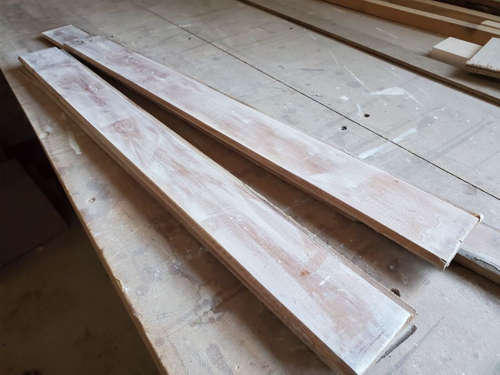
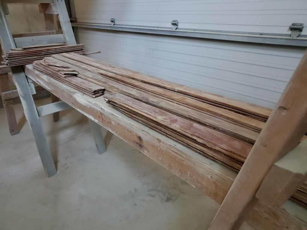
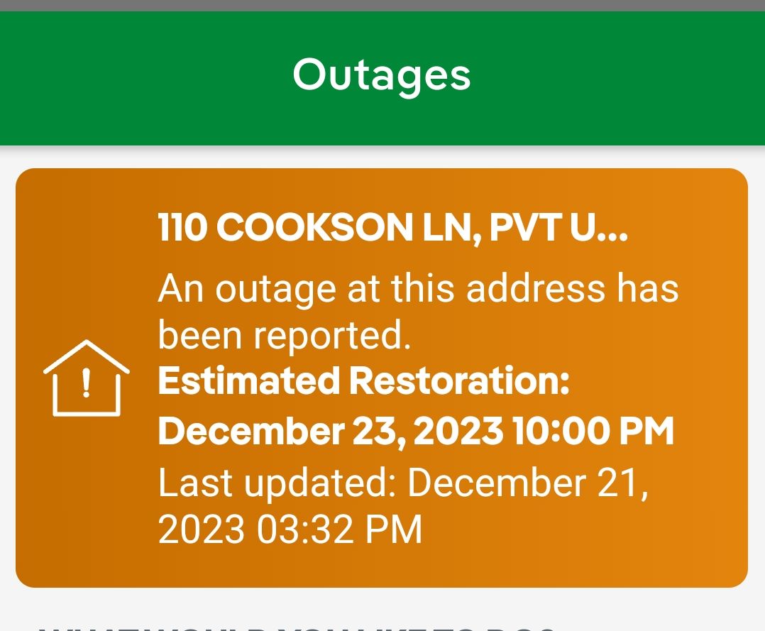
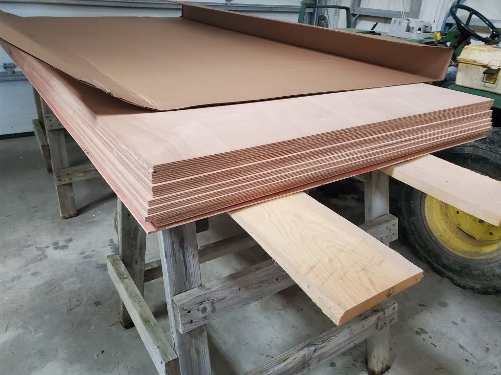
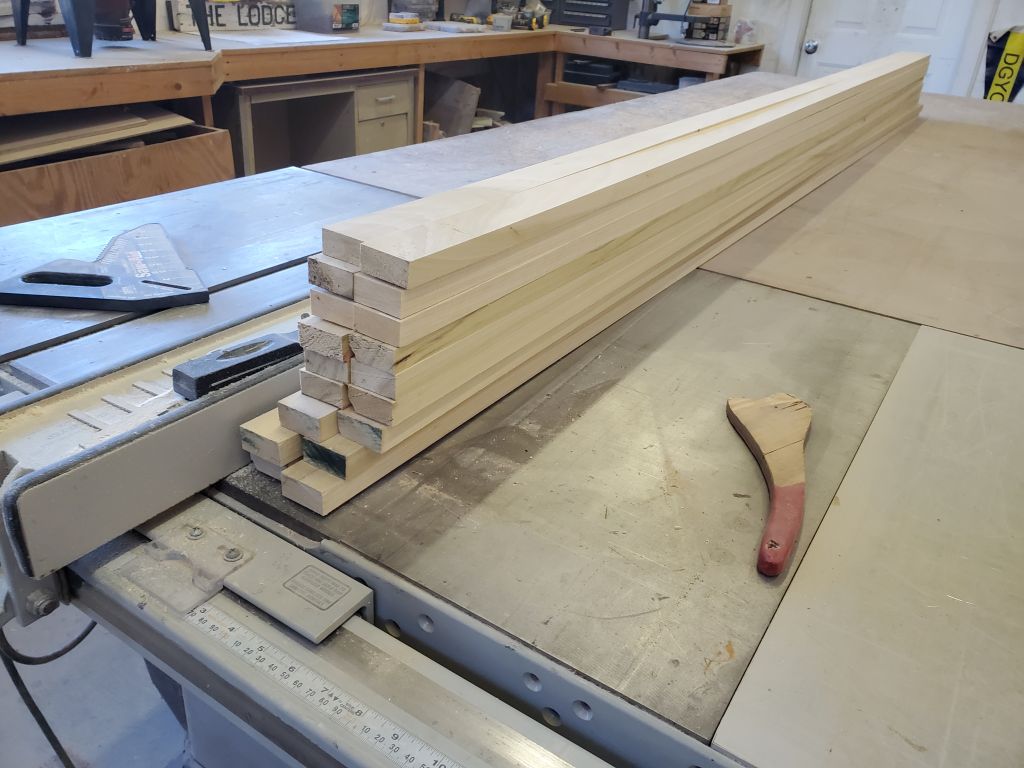
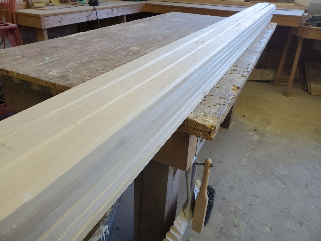
We got power back at the shop last evening around 1745, so I was happy to have a full day ahead.  To get started, I milled some support cleat stock from 4/4 poplar boards.  I like my cleats to be 1-1/2″ wide for ample screw space, split avoidance, and extra bonding area.  The 1-1/2″ width also works well when using the cleats to support a panel cutout.  Once I’d cut a number of cleats to width, I used a router and a chamfer bit to ease one edge on all the cleats, which helps avoid sharp edges in hidden spaces where one might reach into the dark someday.

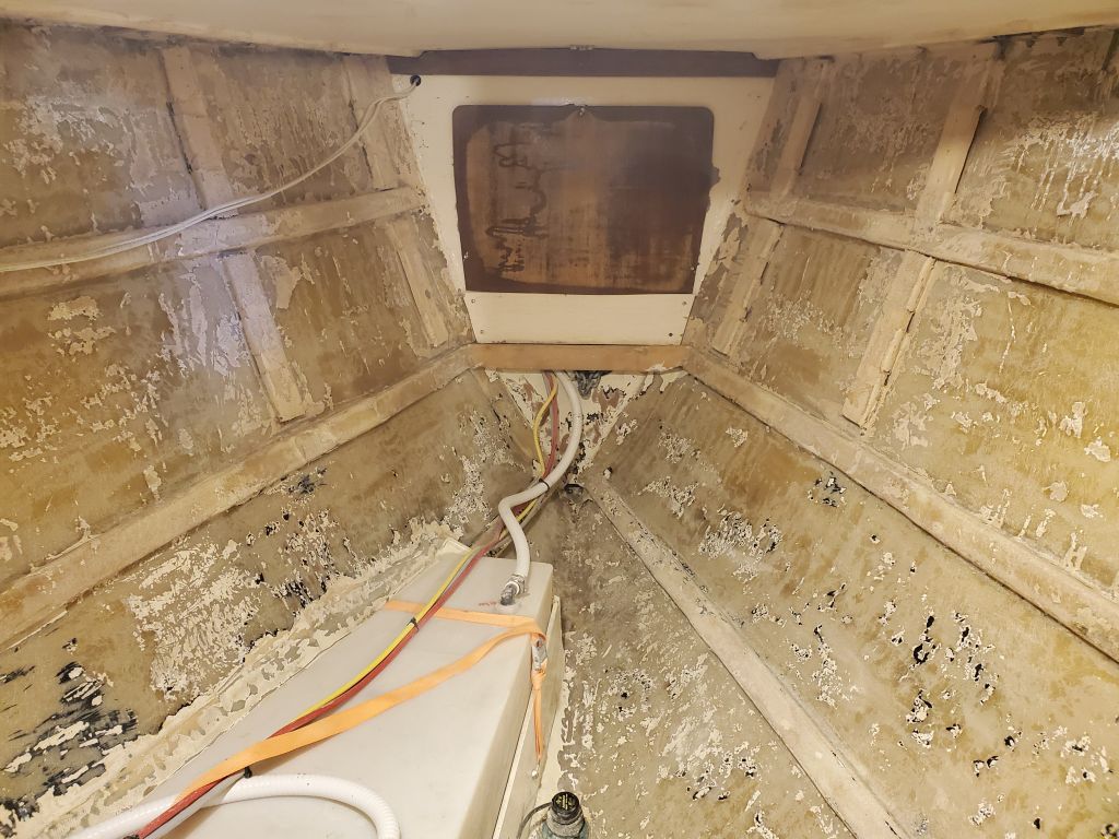
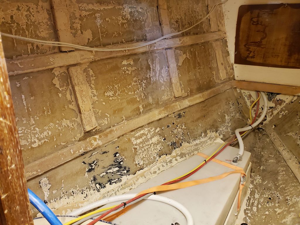
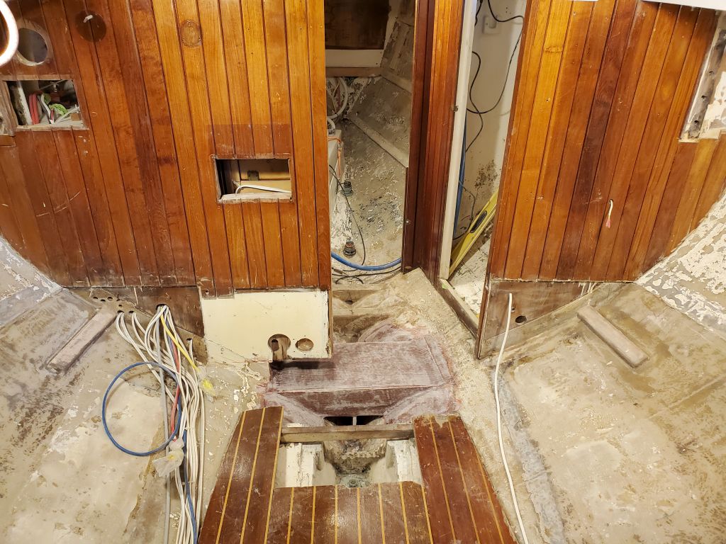
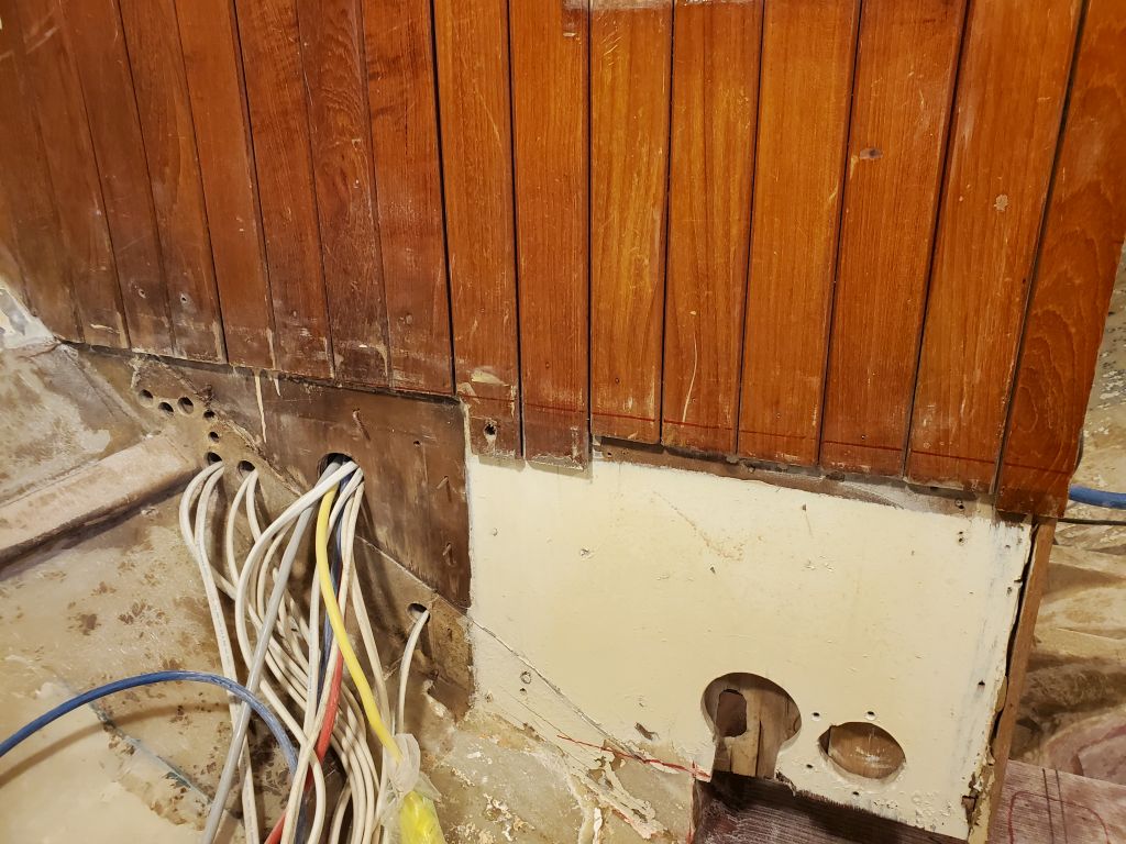
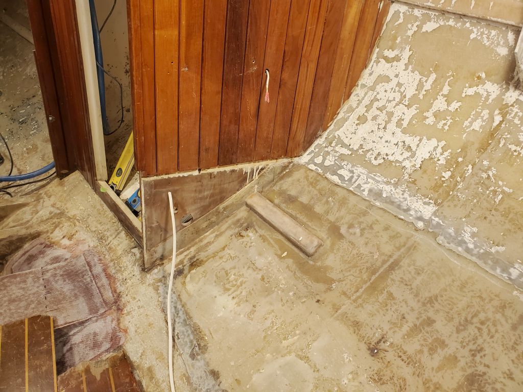
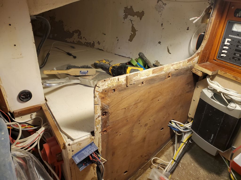
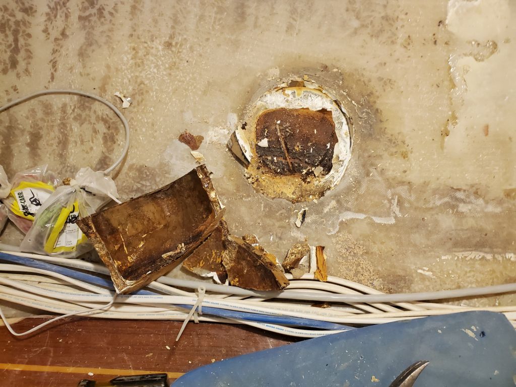
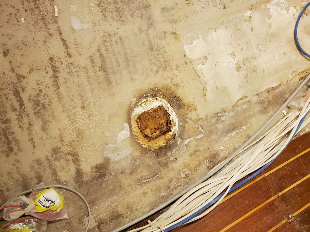
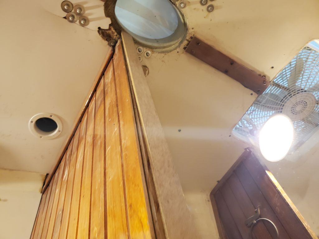
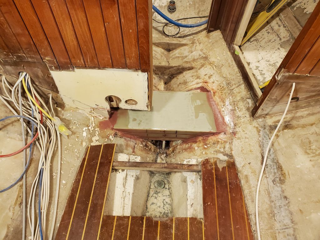
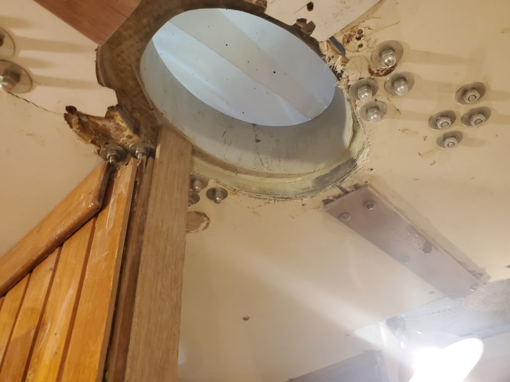
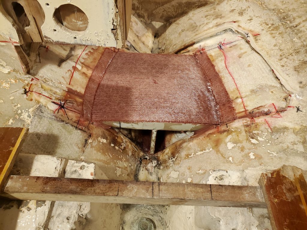
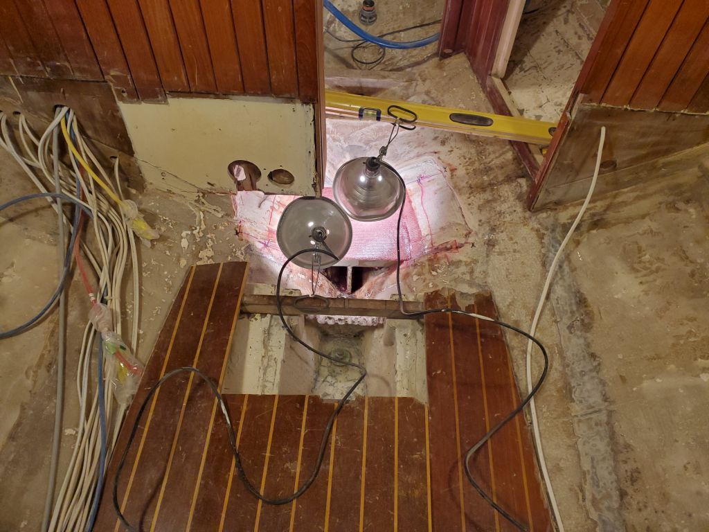
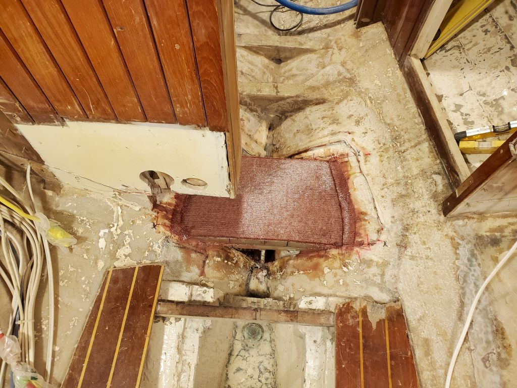
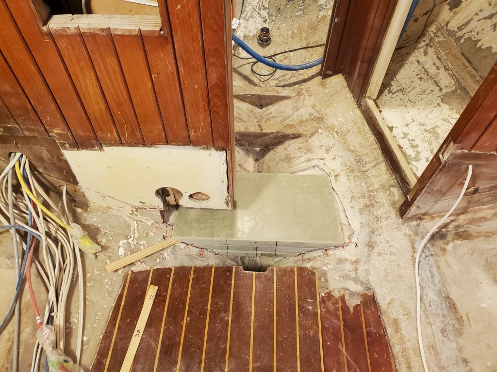
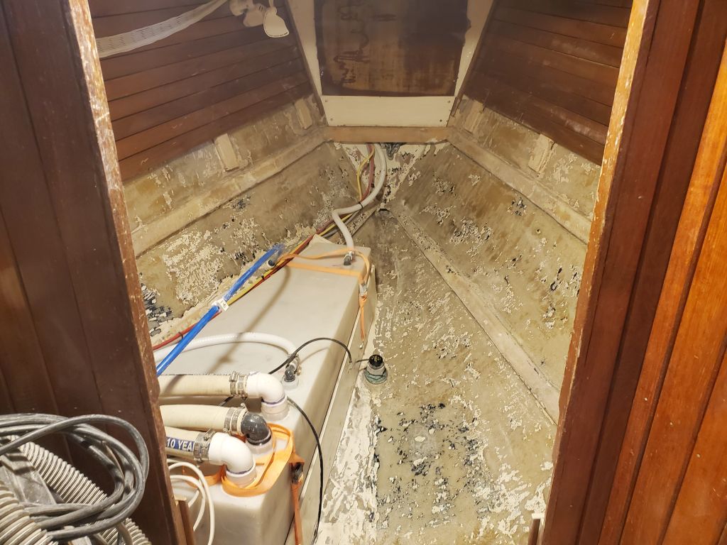
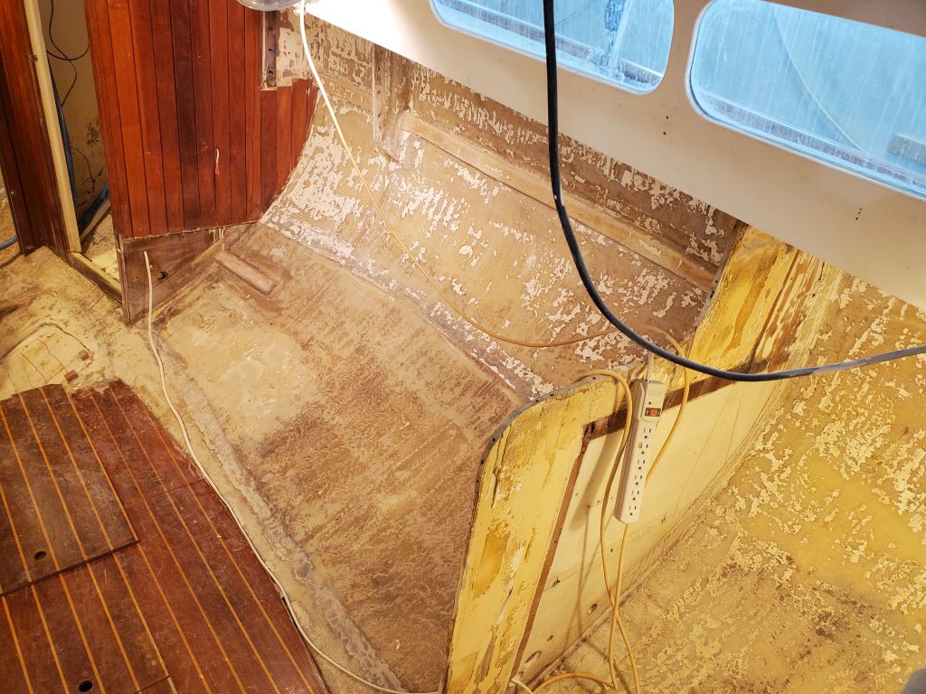
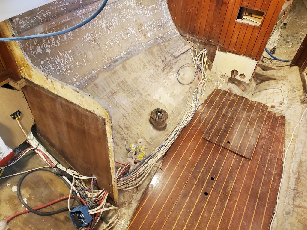
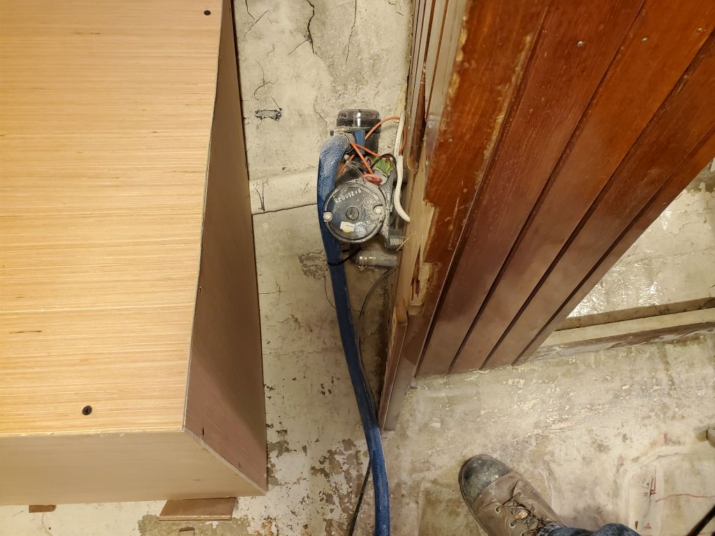
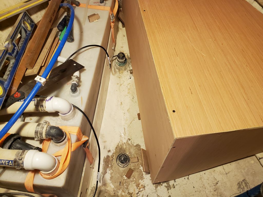
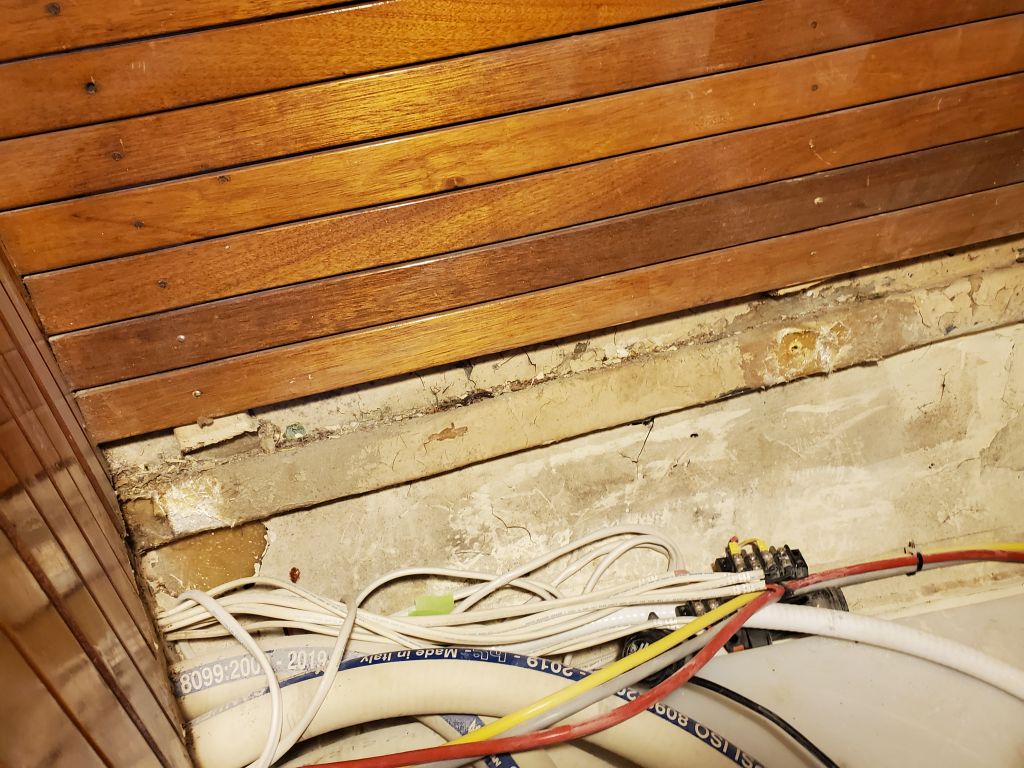
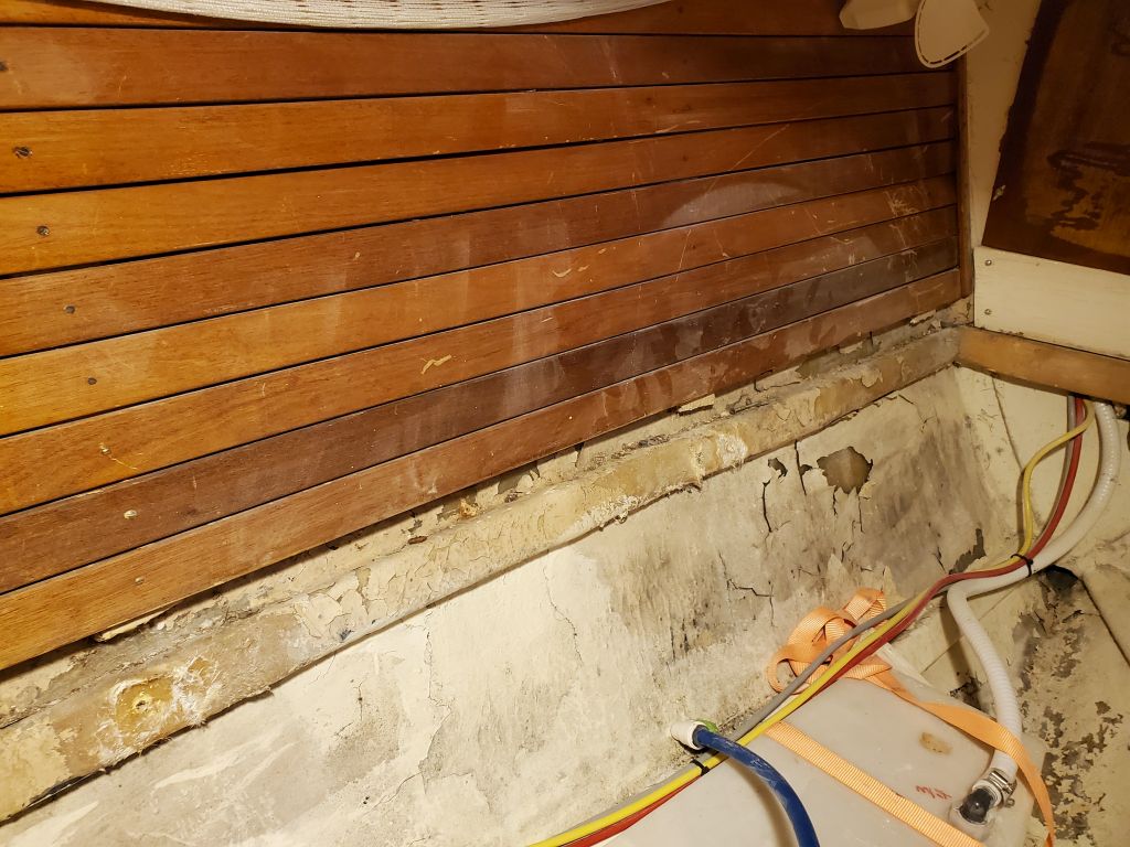
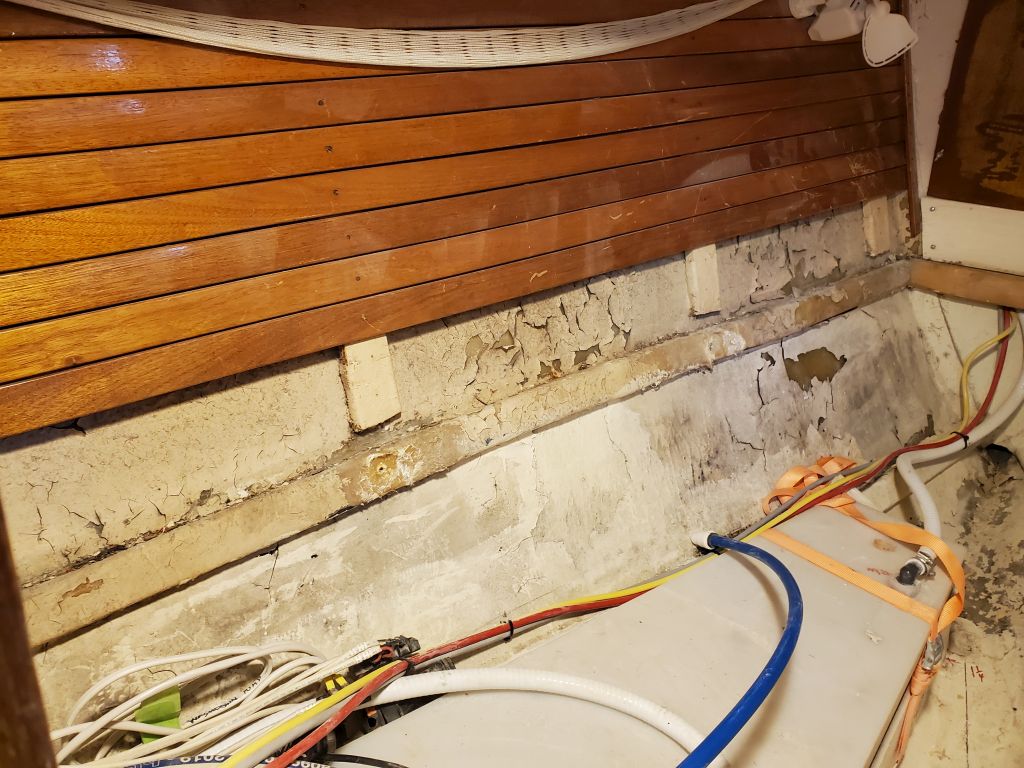
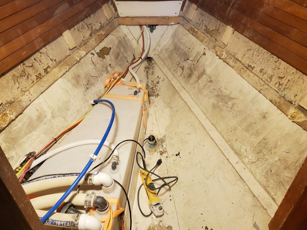
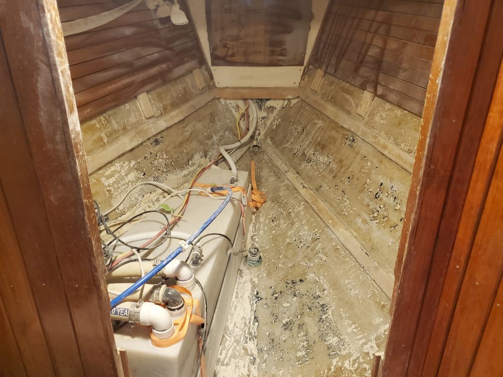
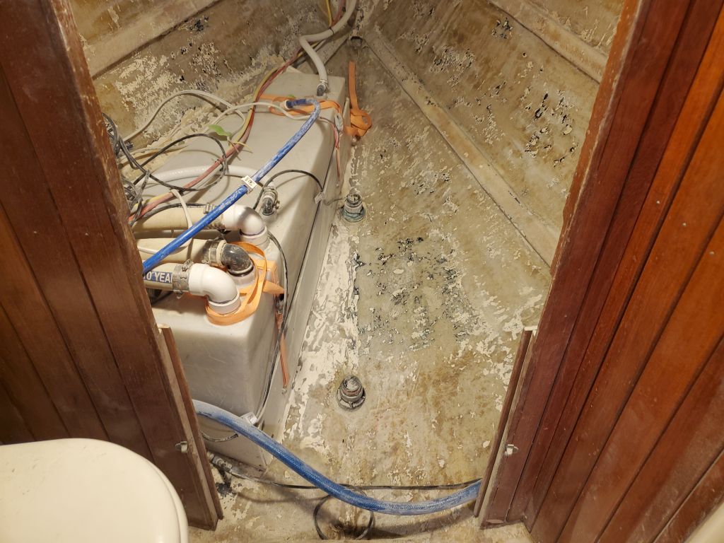
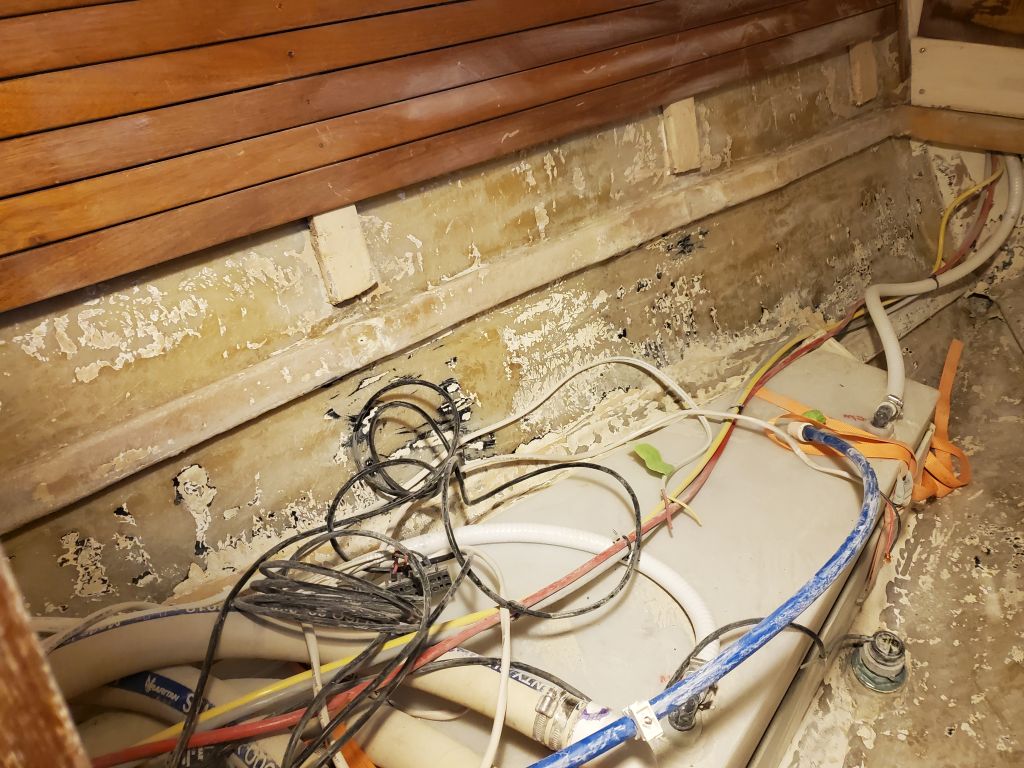
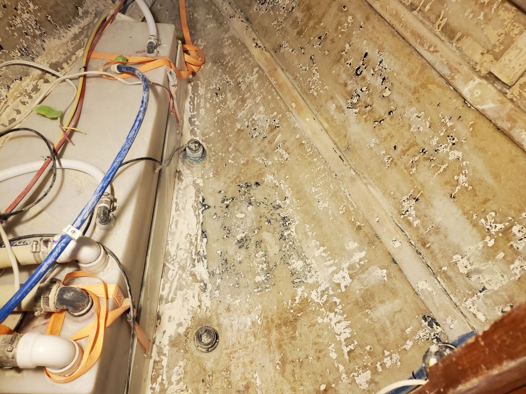
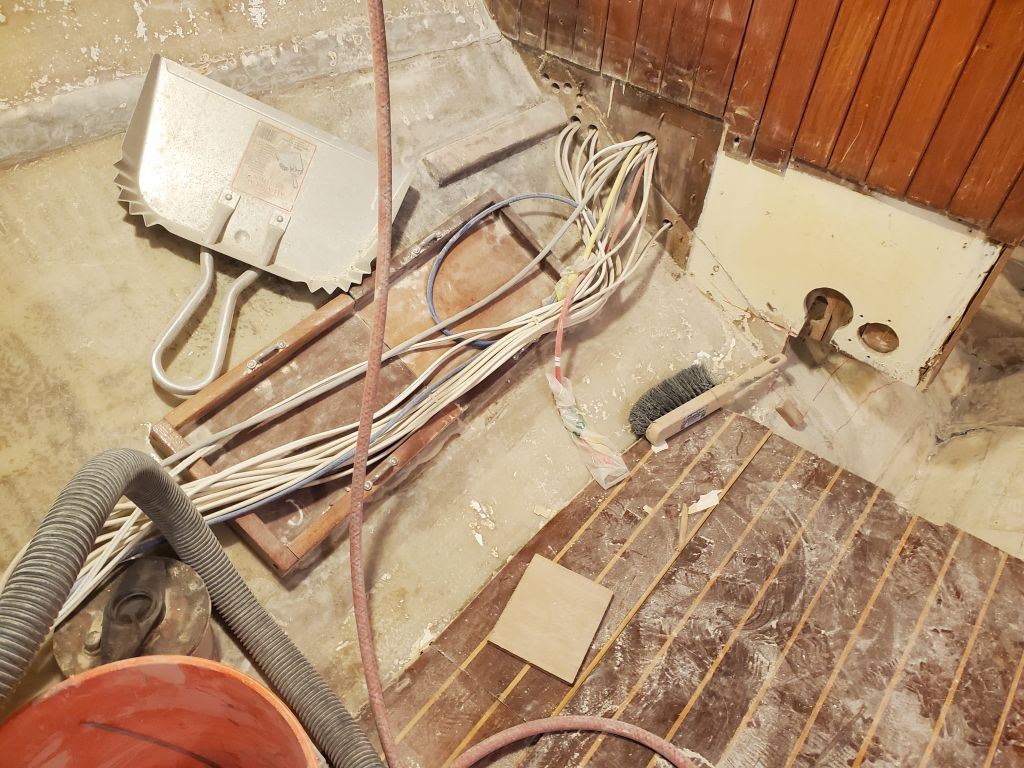
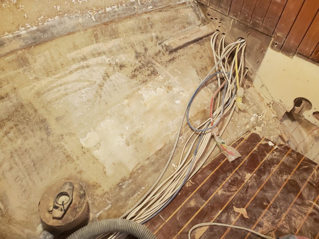
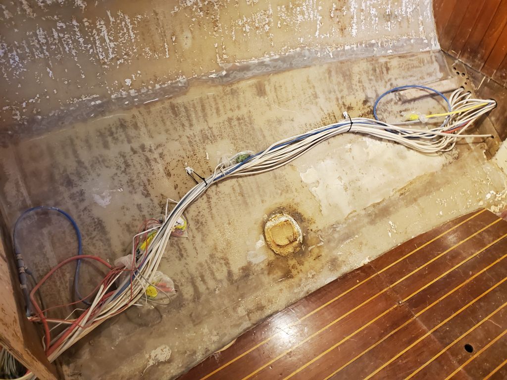
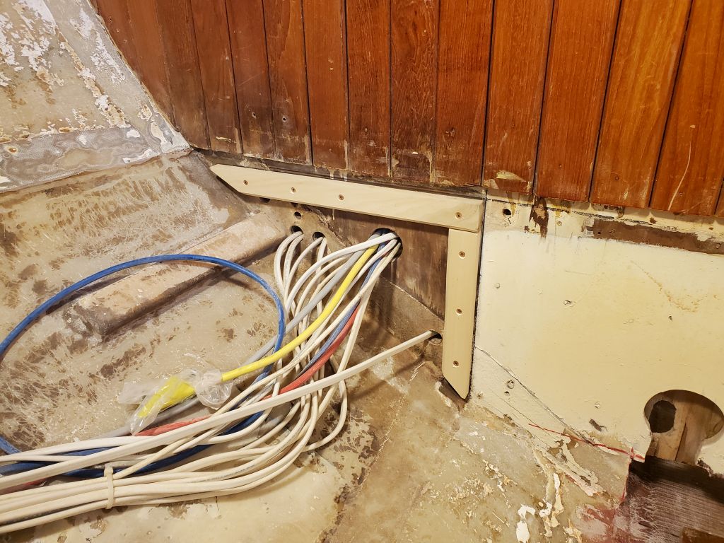
Up in the boat, I installed a few temporary wire mounts so I could temporarily secure the wire bundles on each side out of the way while I worked on the settee cleats and settee fronts.  These wires would eventually be permanently secured down at the inside edge of the settee bases.

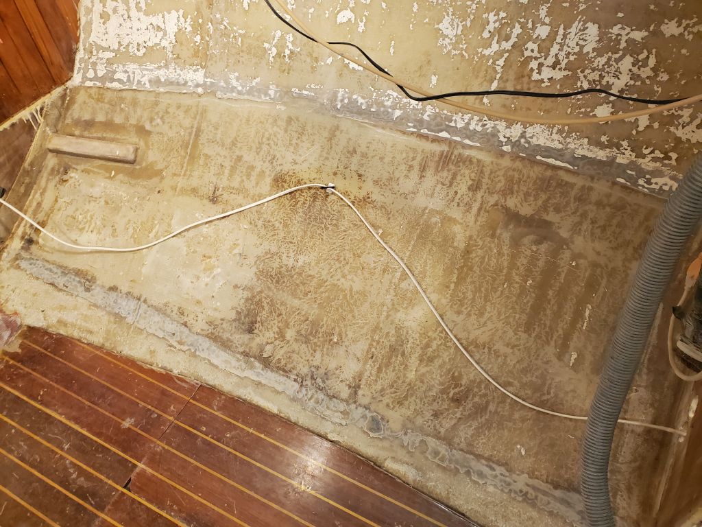
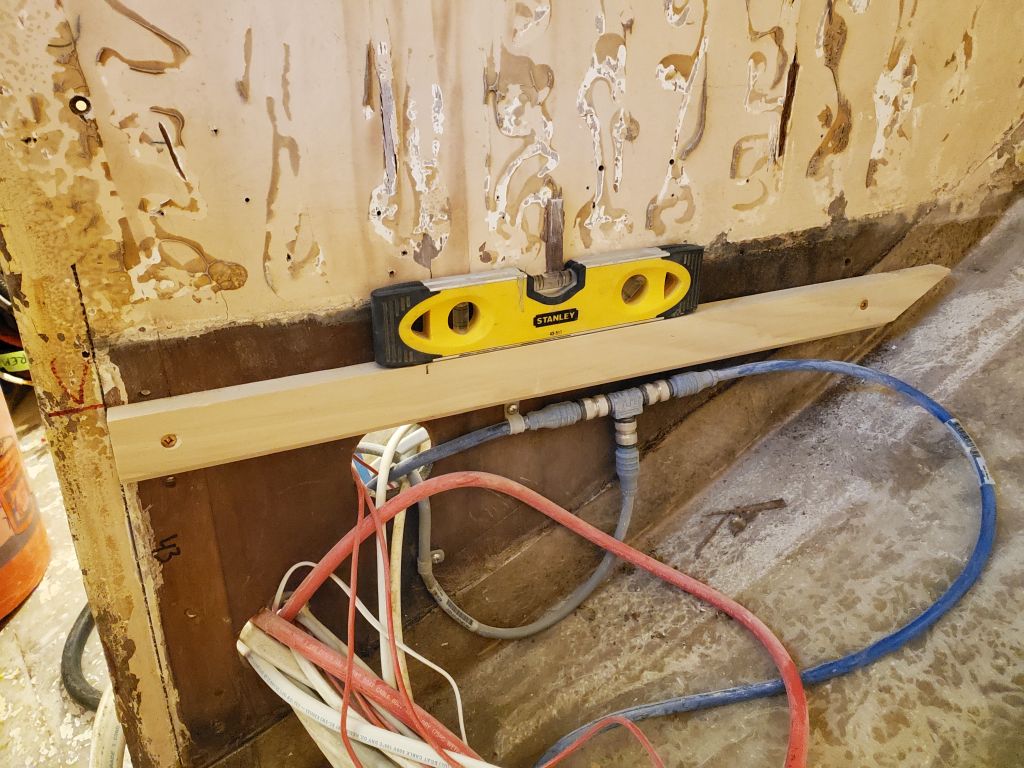
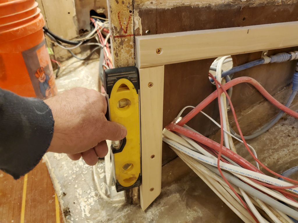
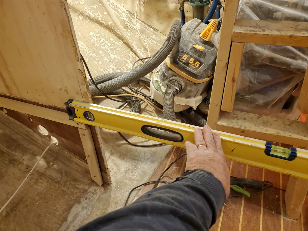
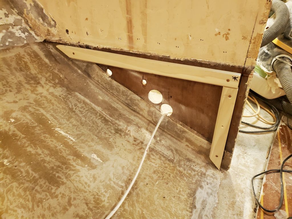
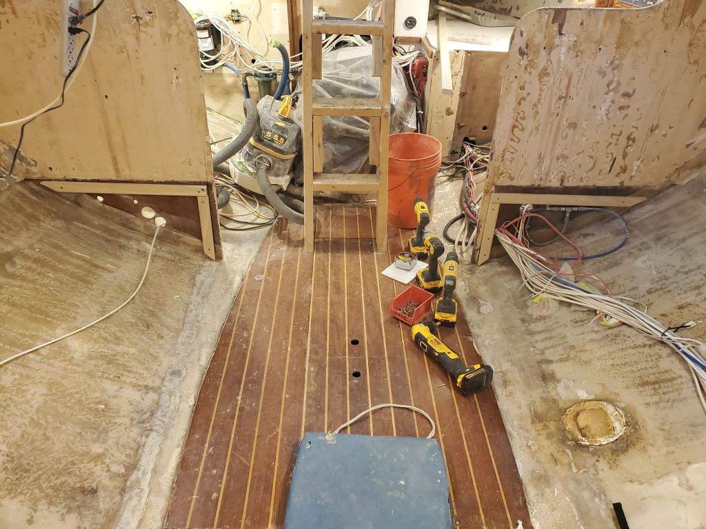
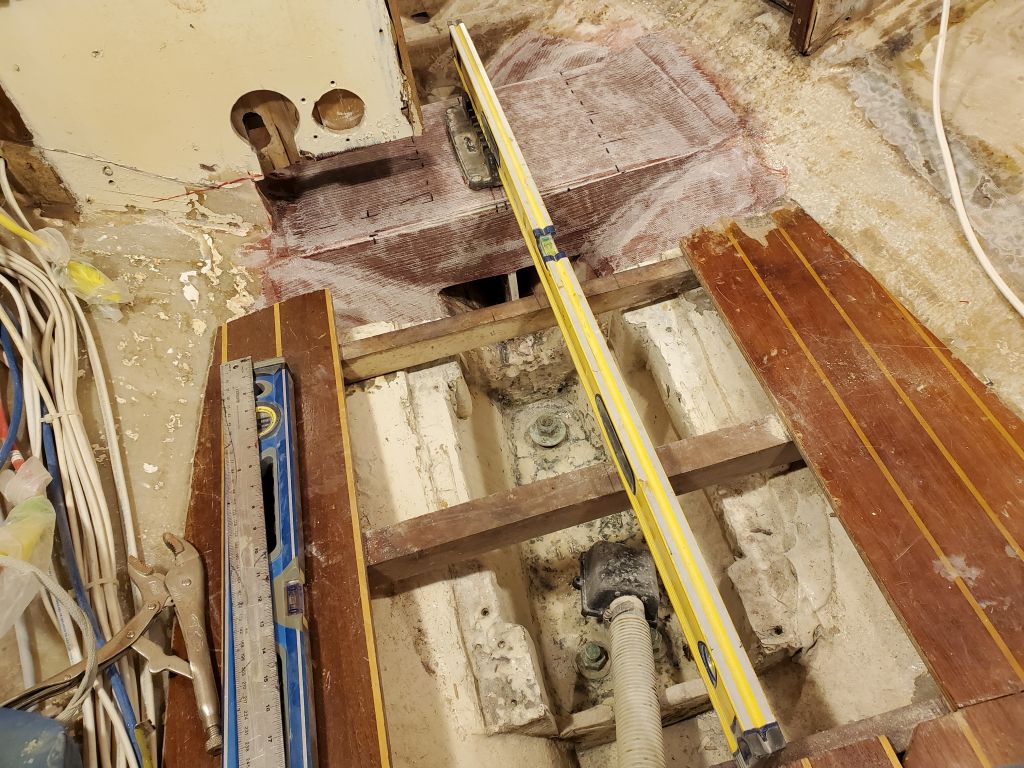
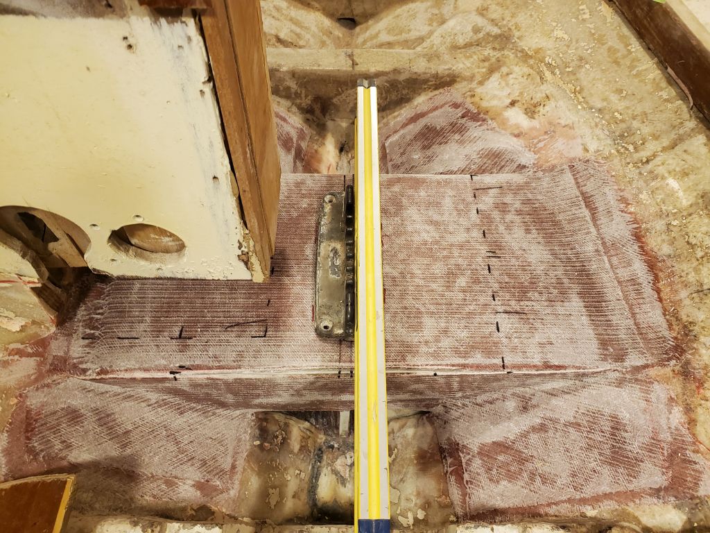
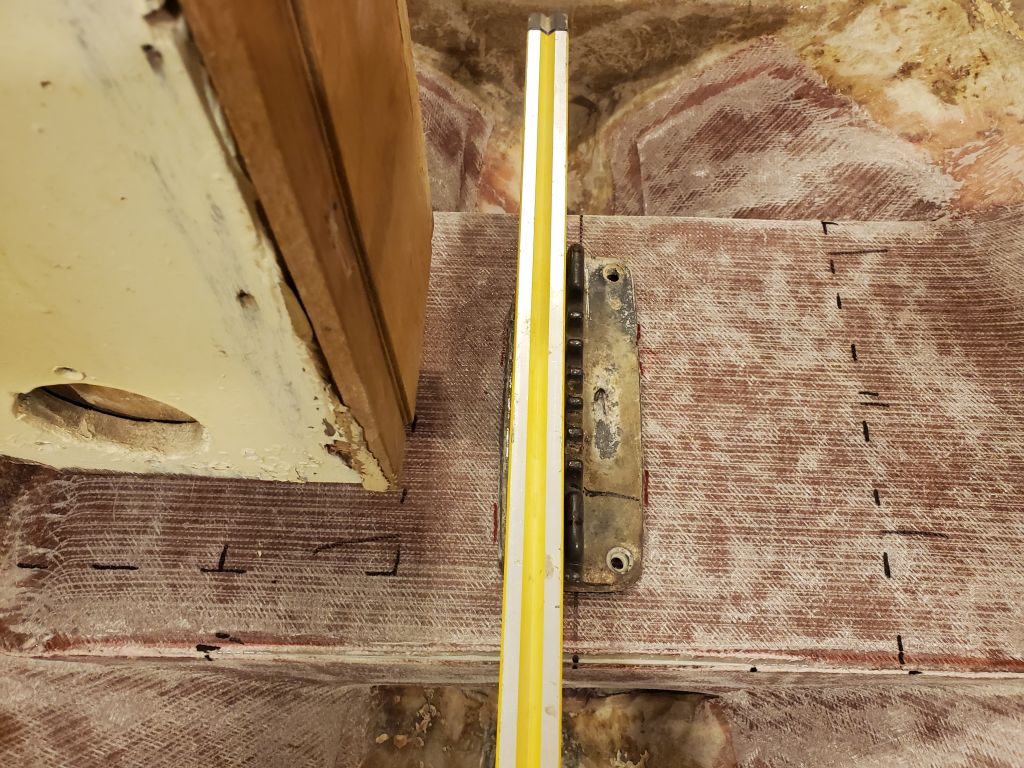
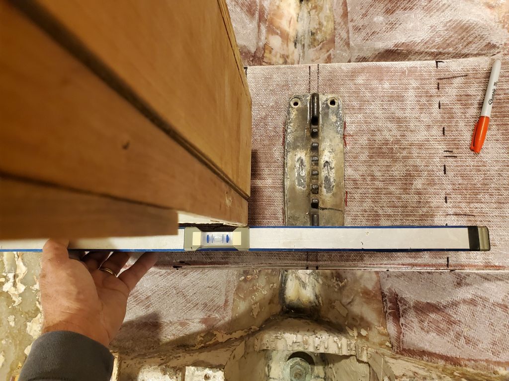
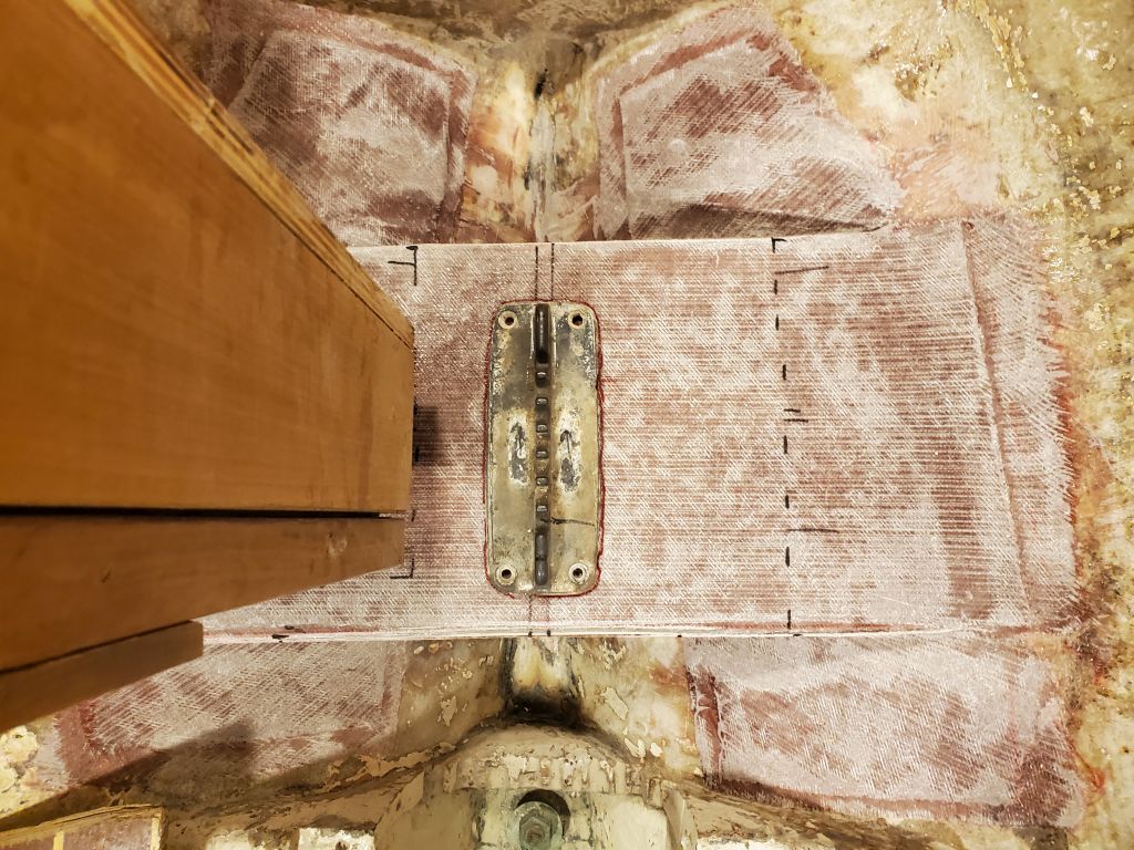
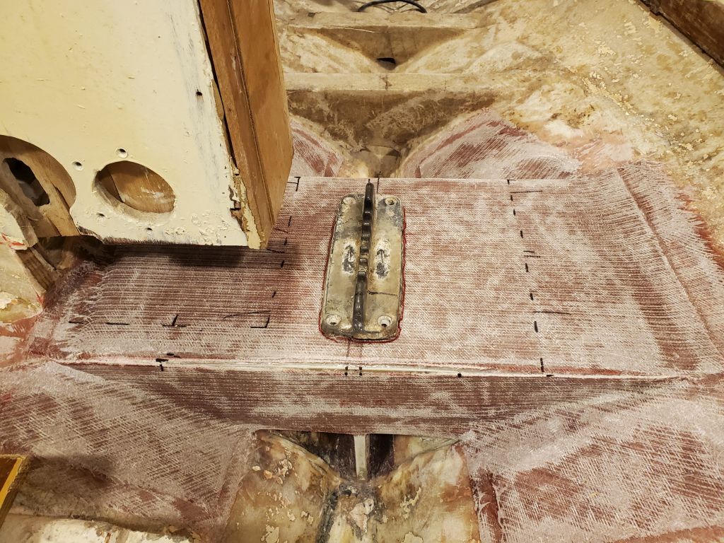
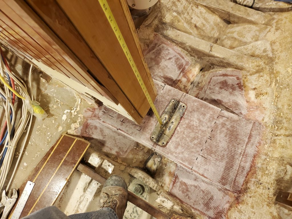
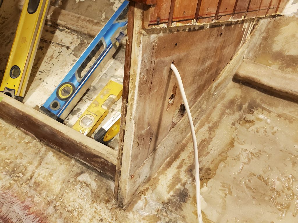
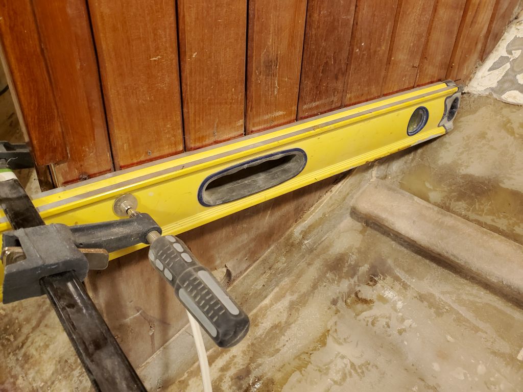
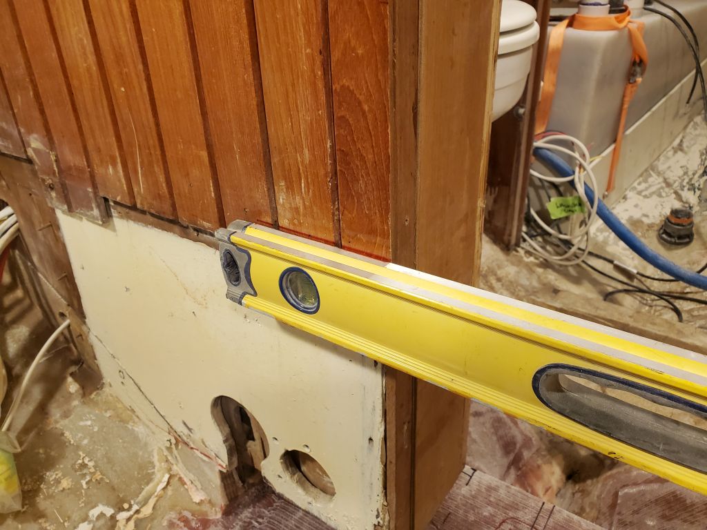
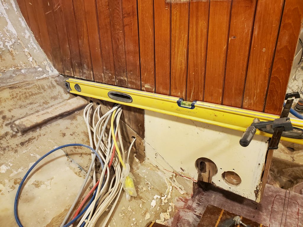
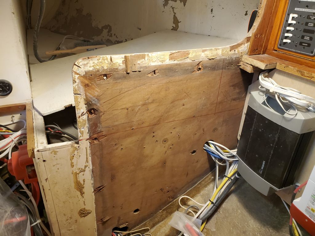
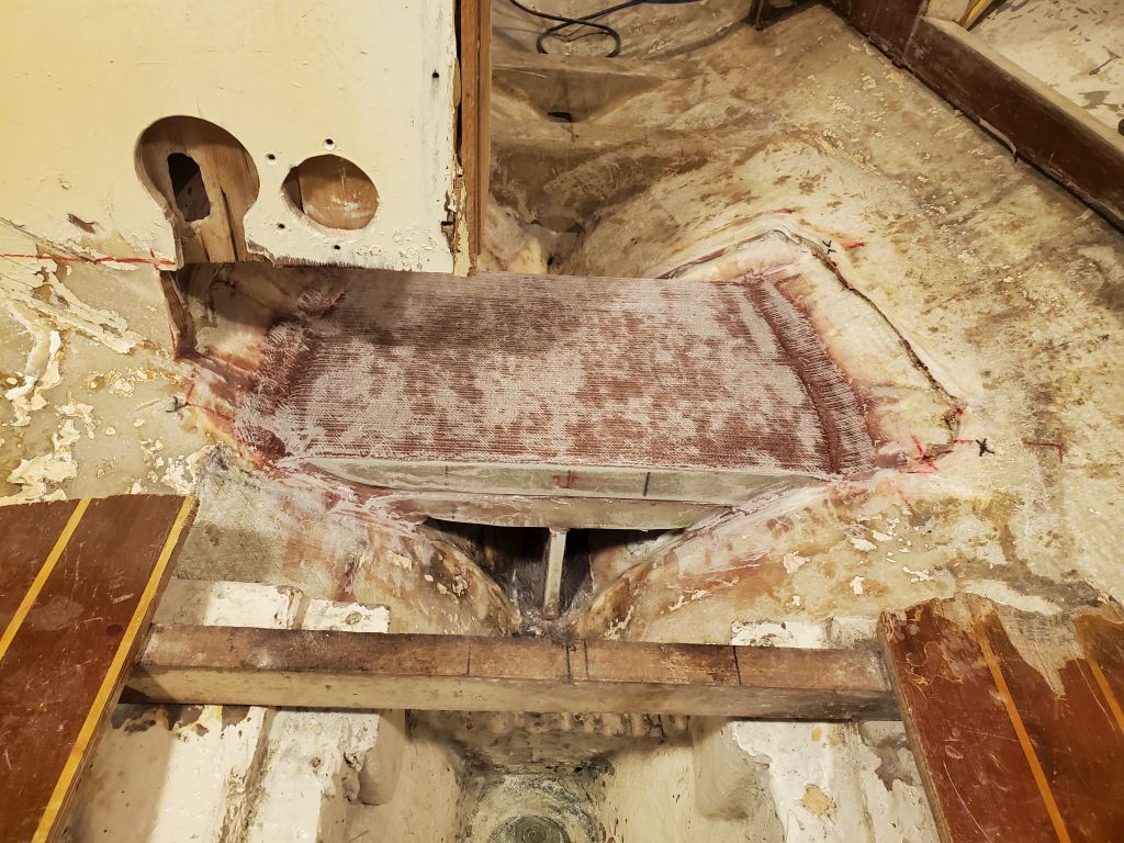
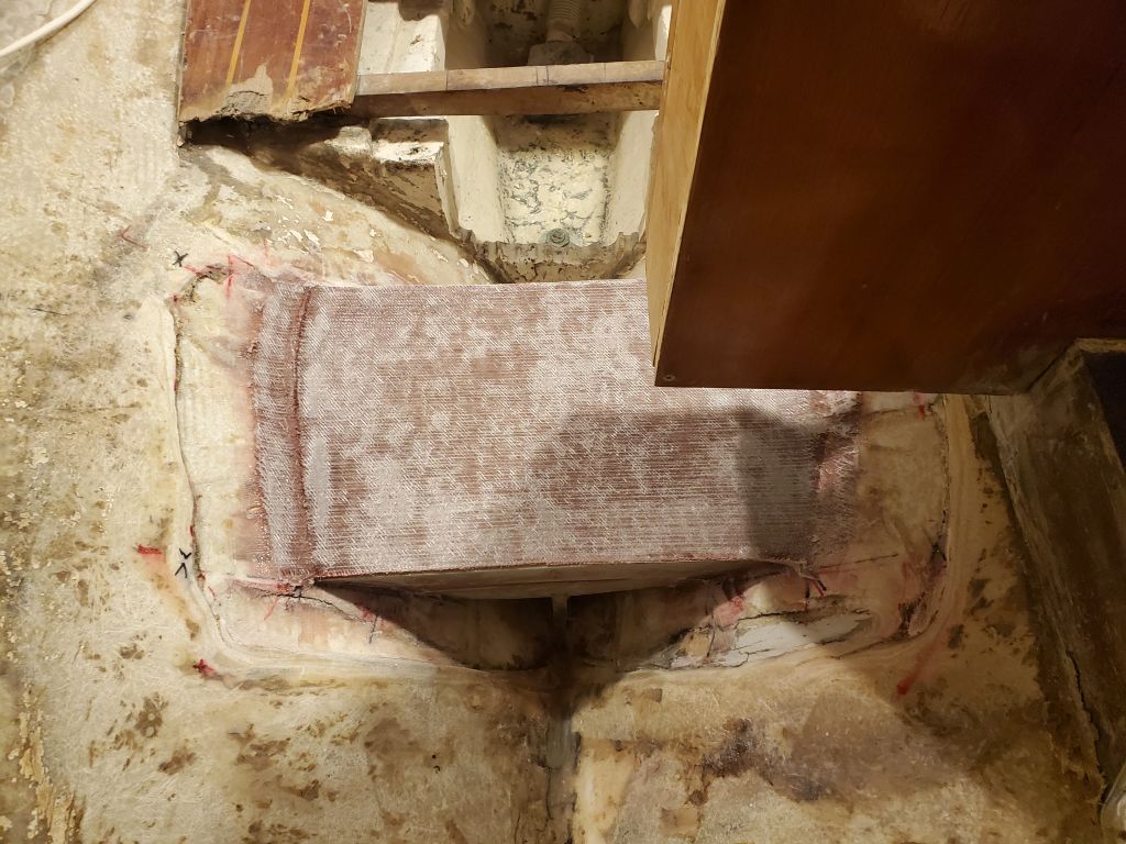
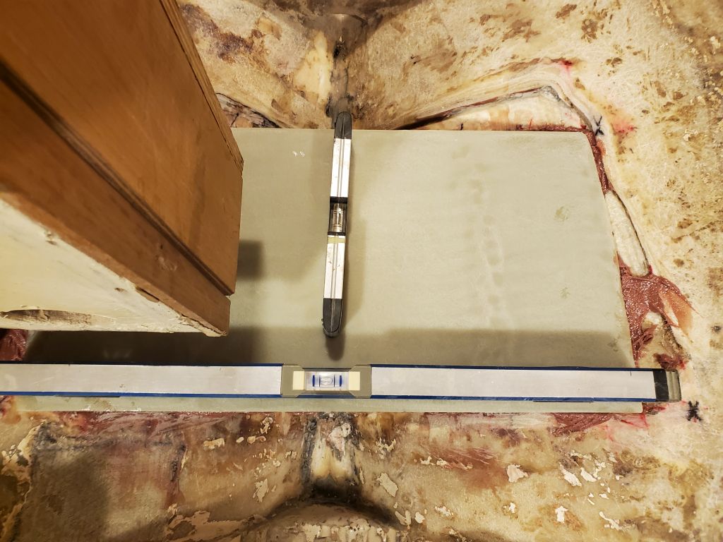
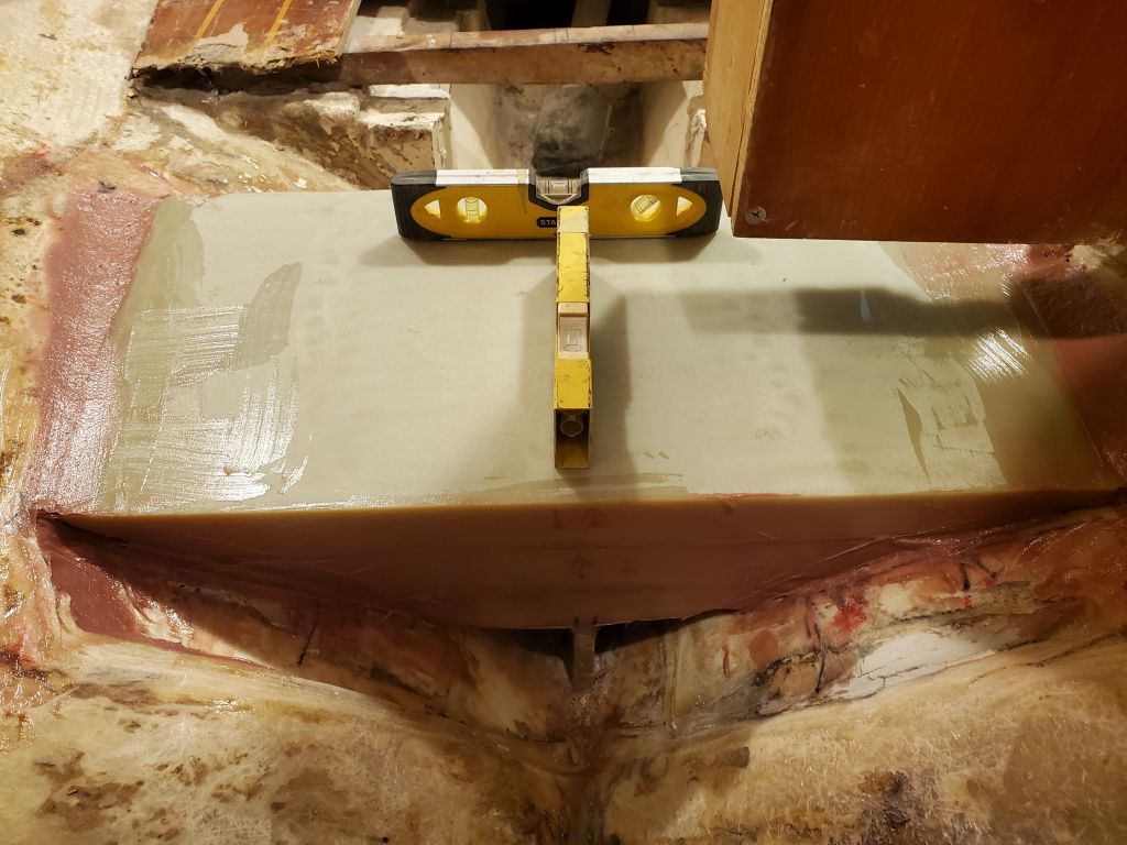
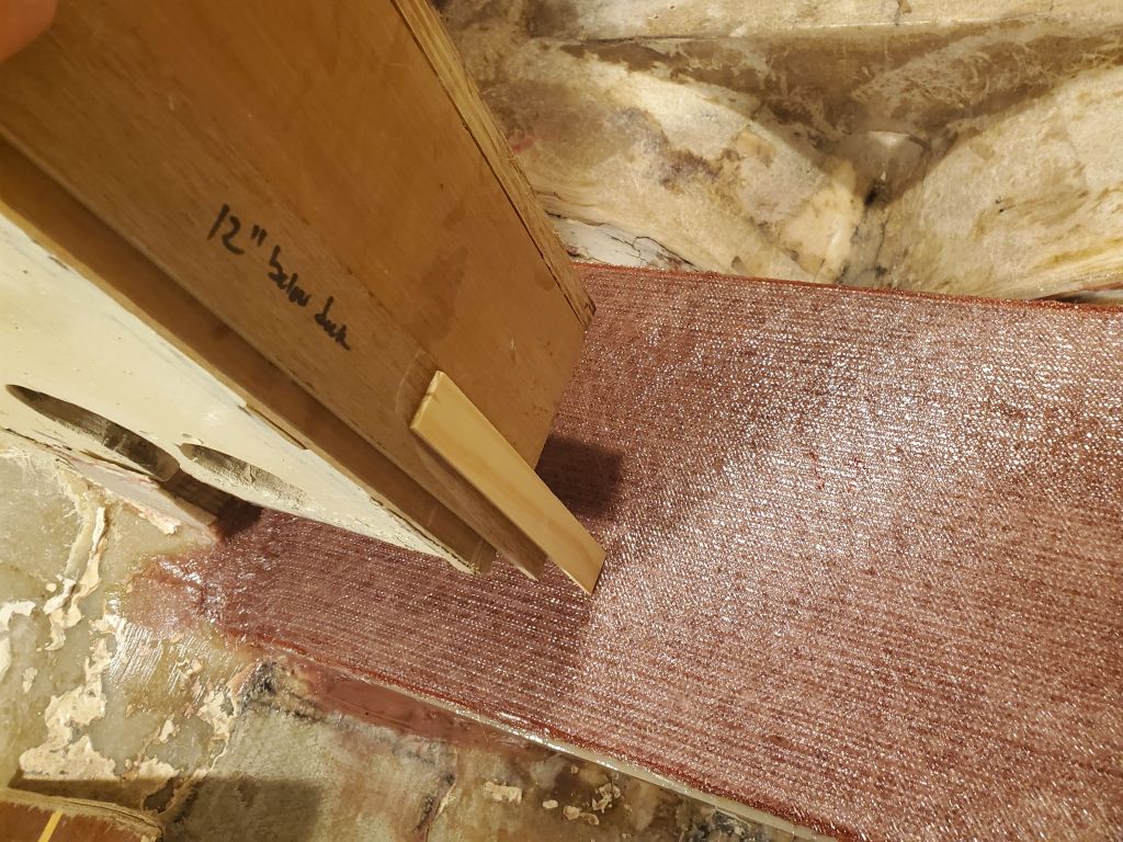
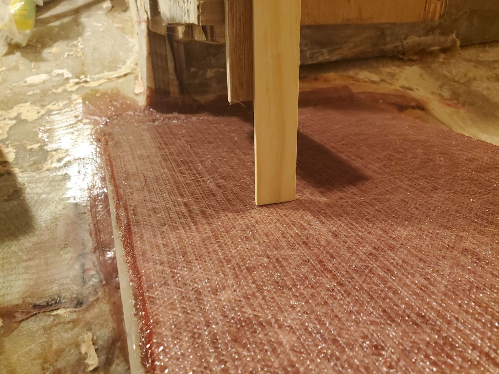
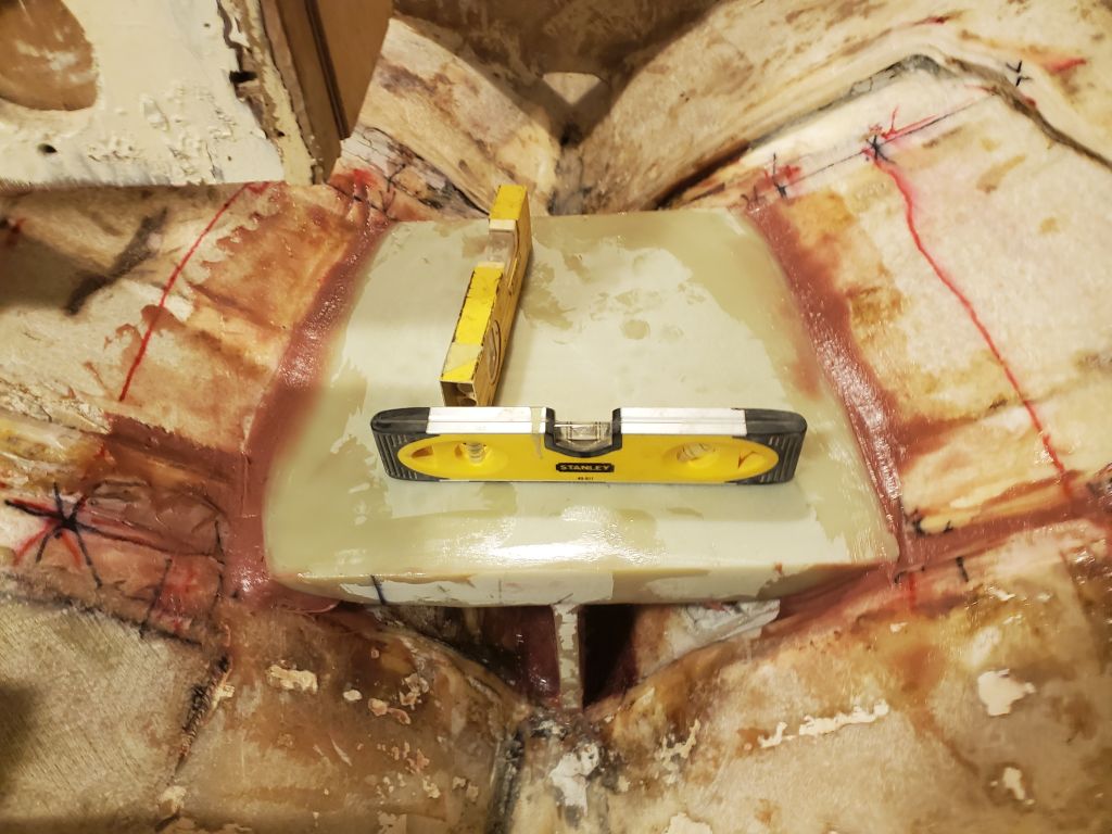
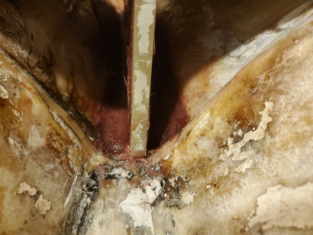
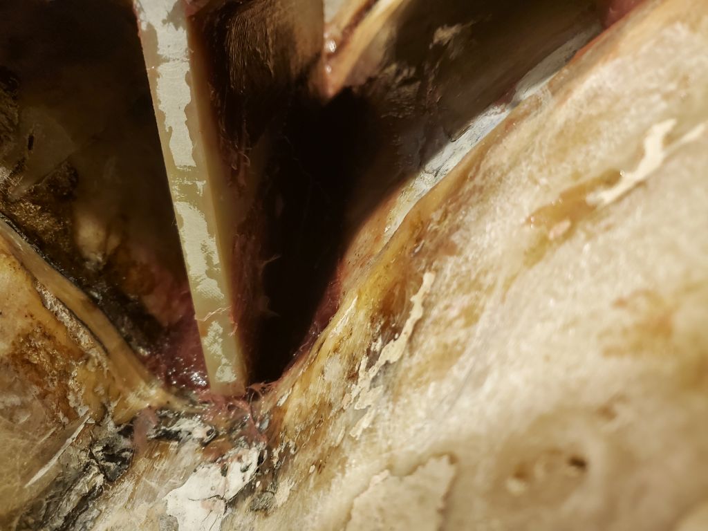
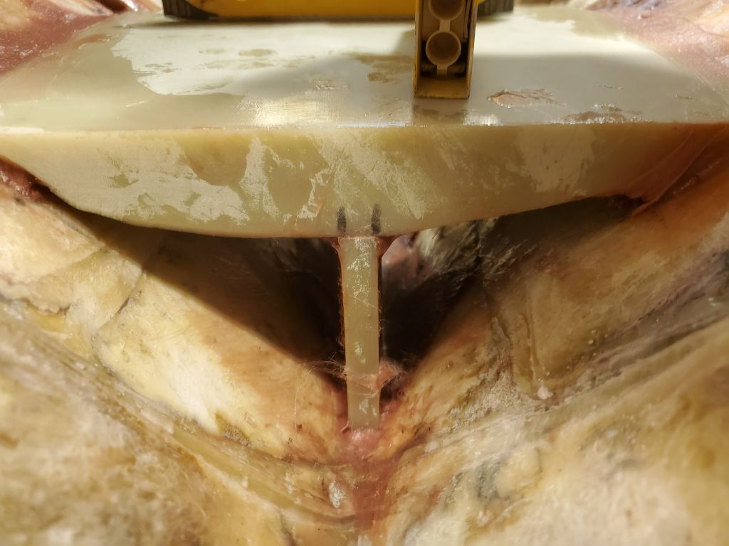
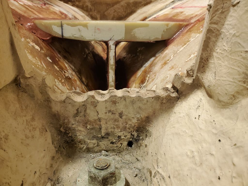
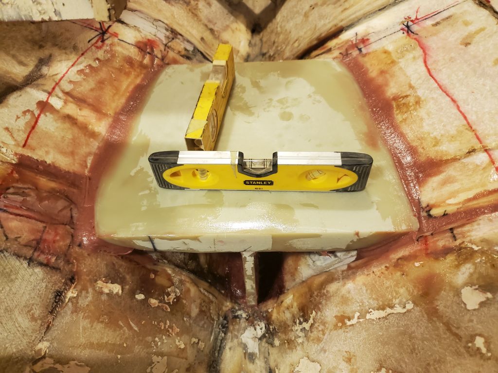
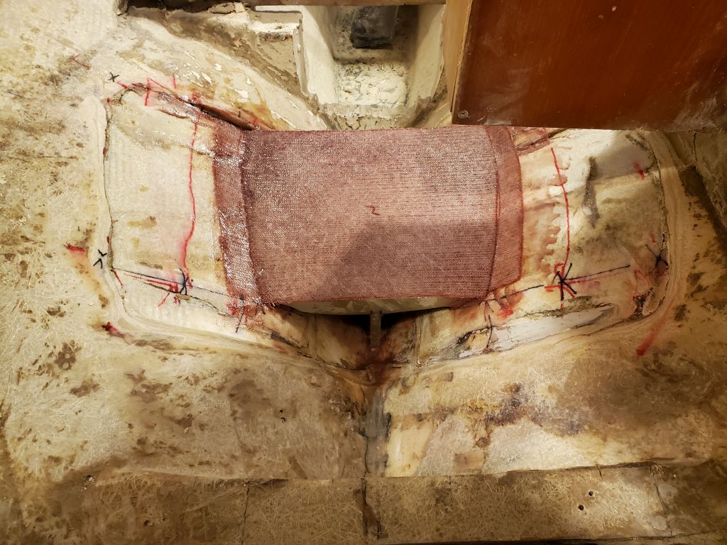
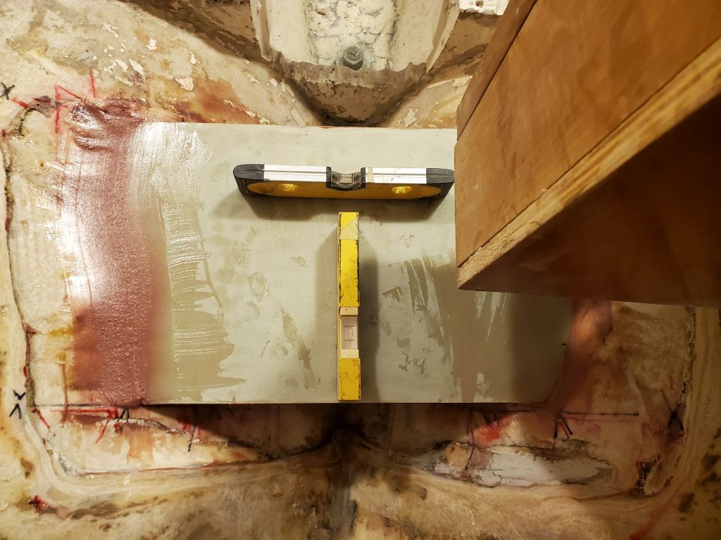
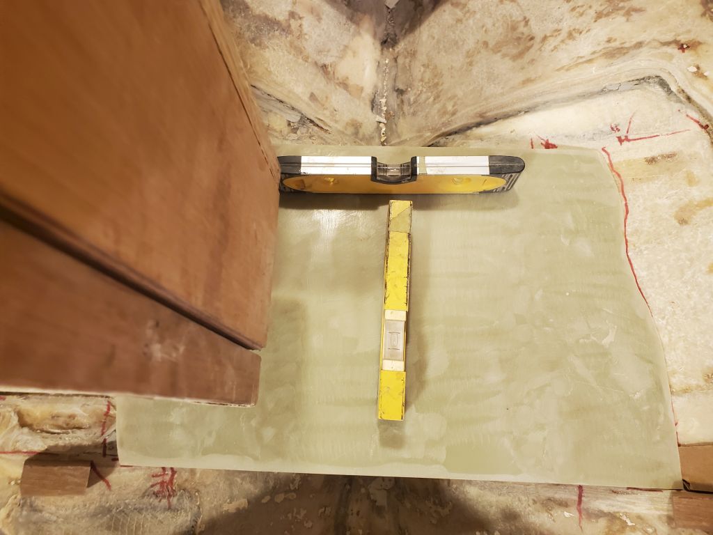
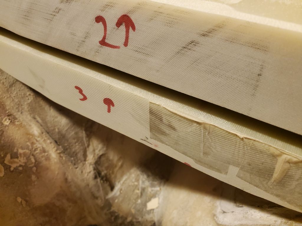
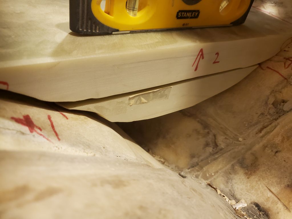
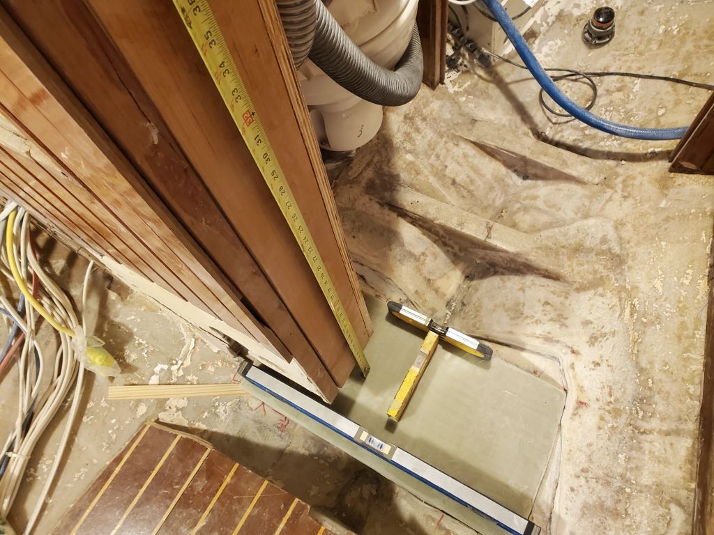
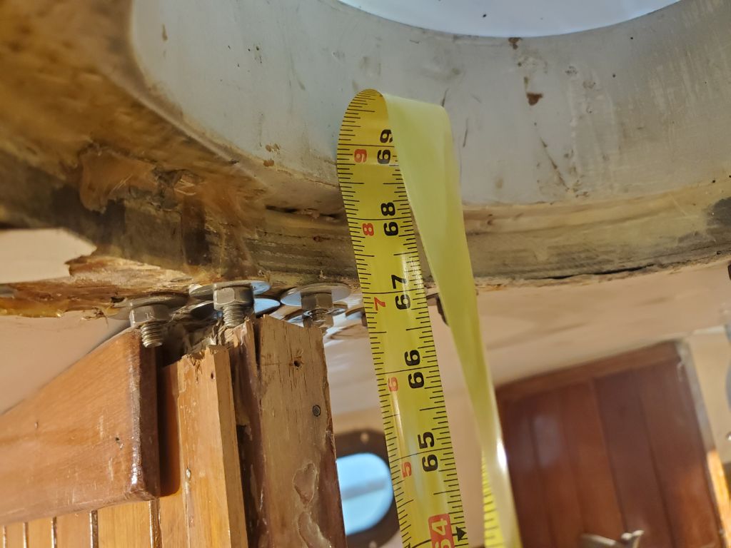
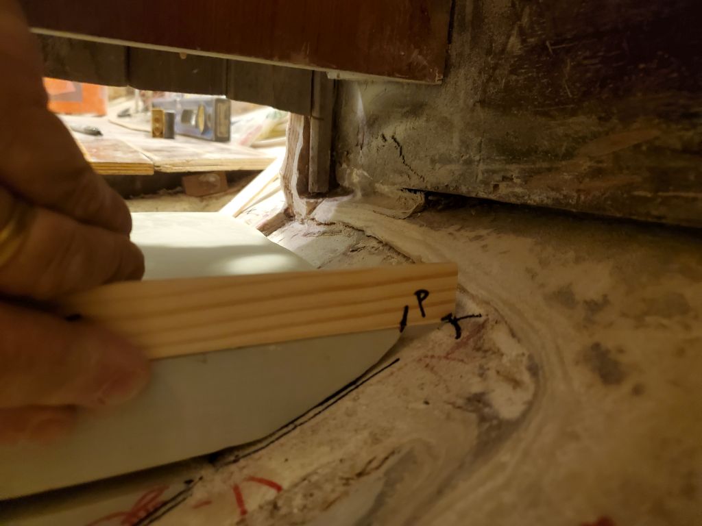
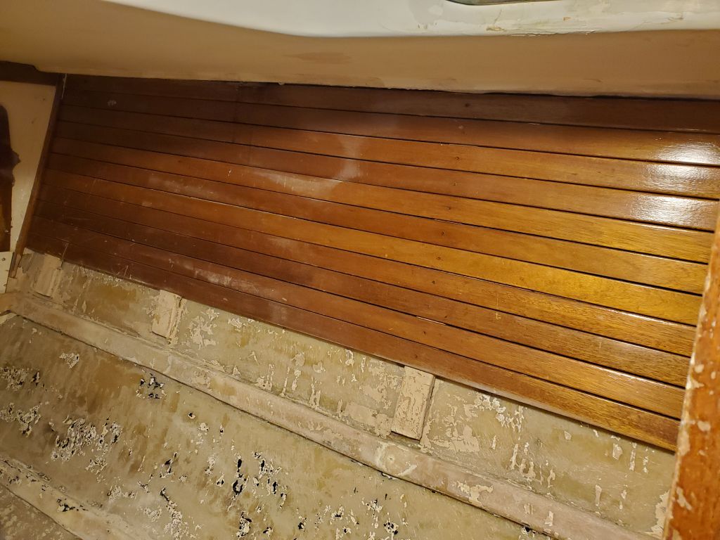
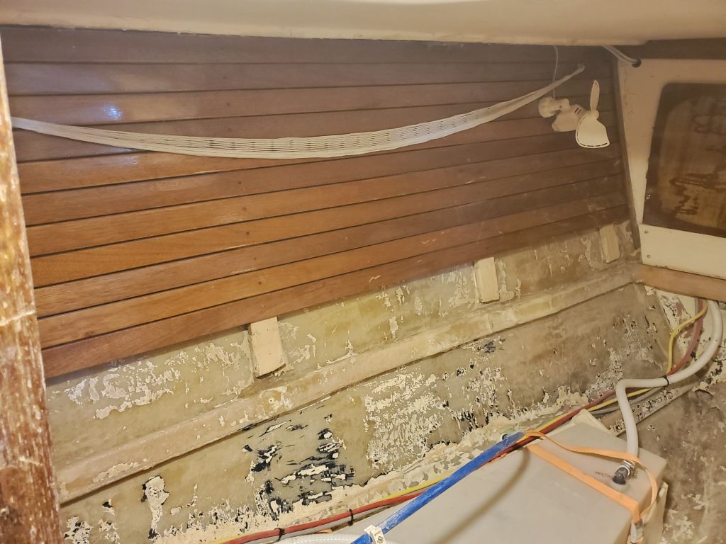
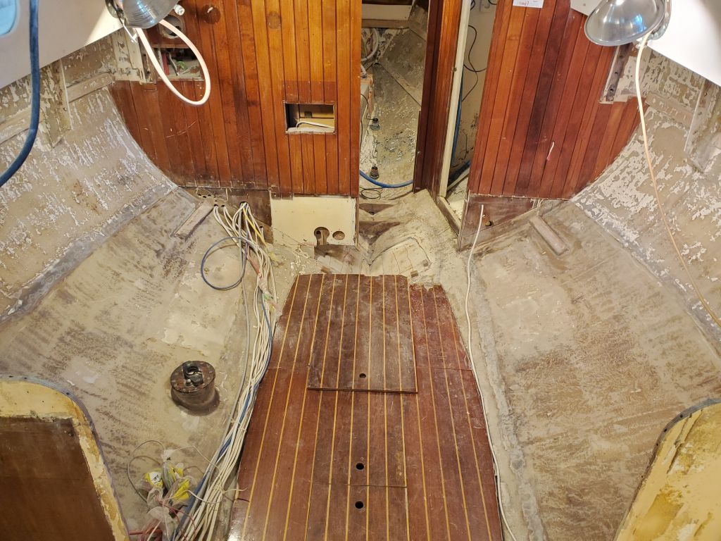
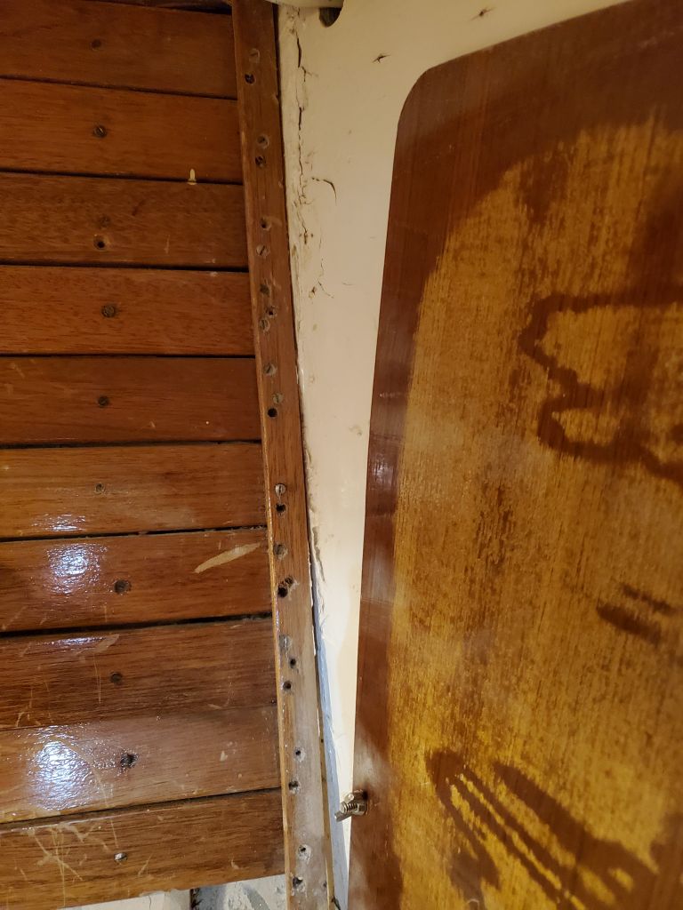
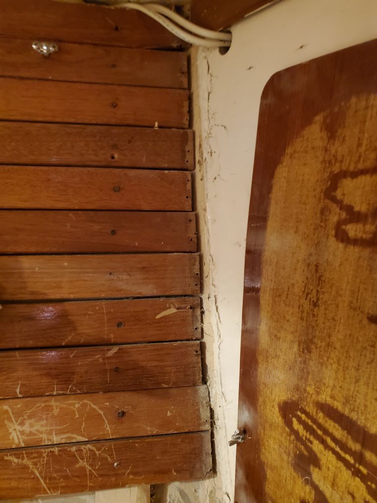
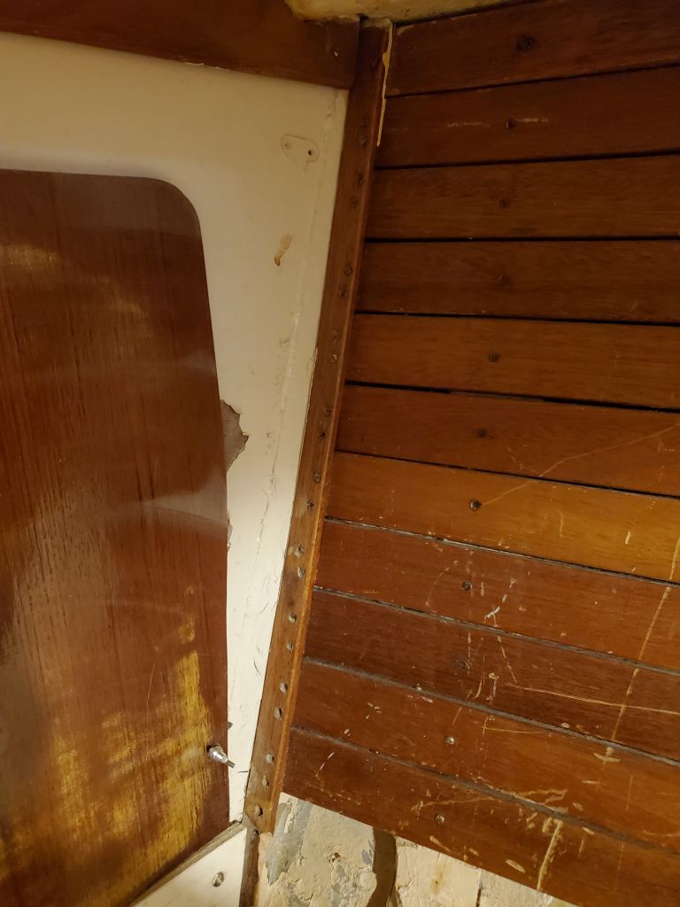
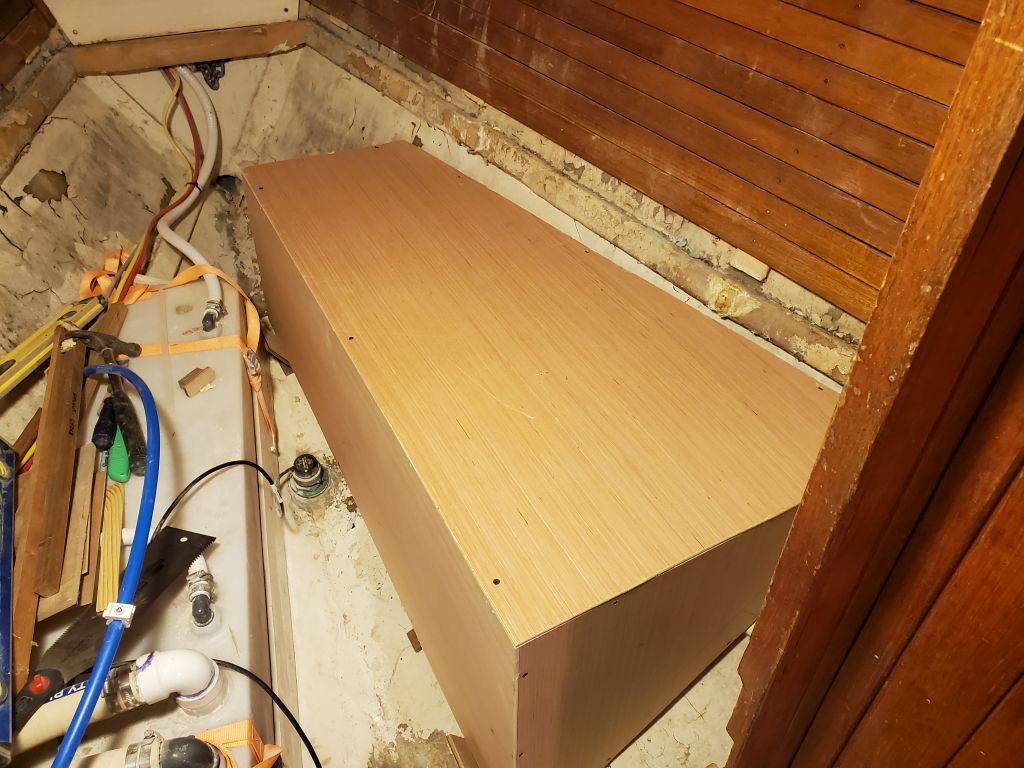
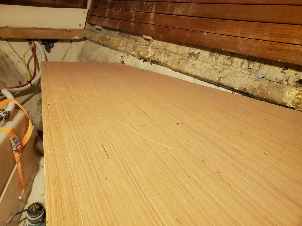
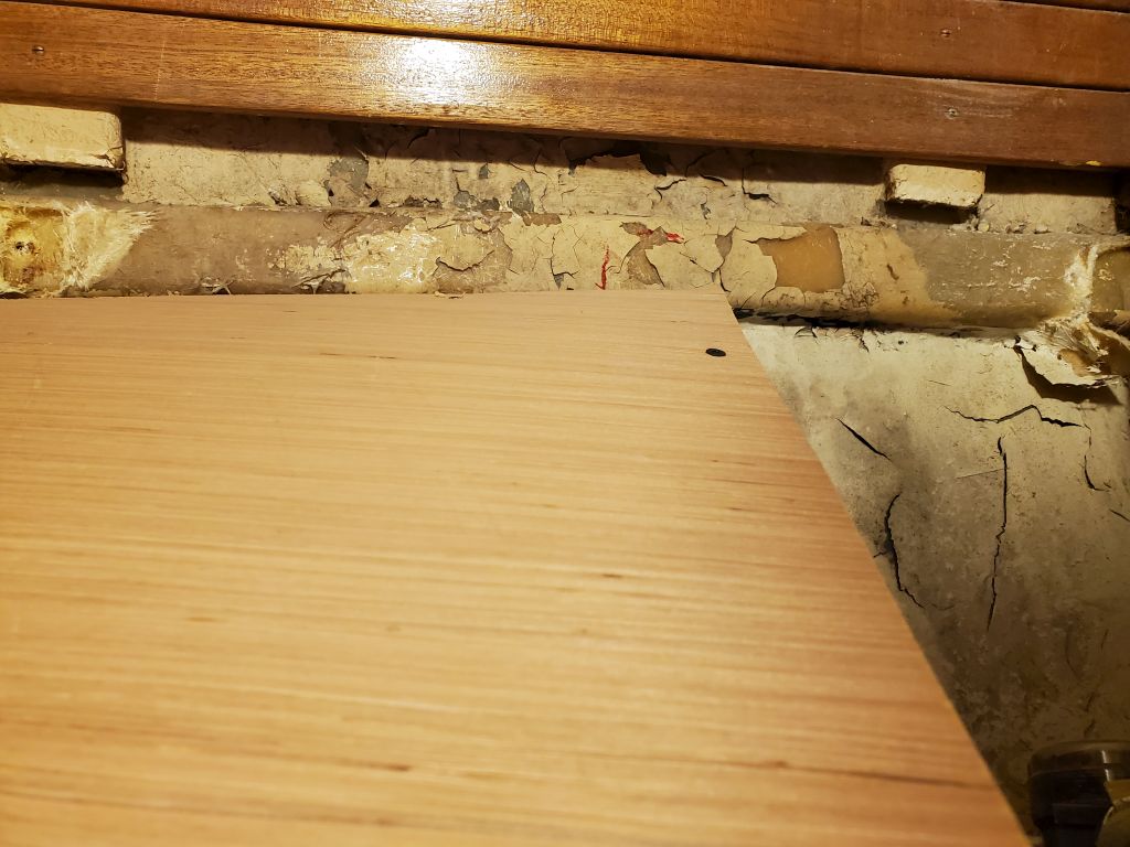
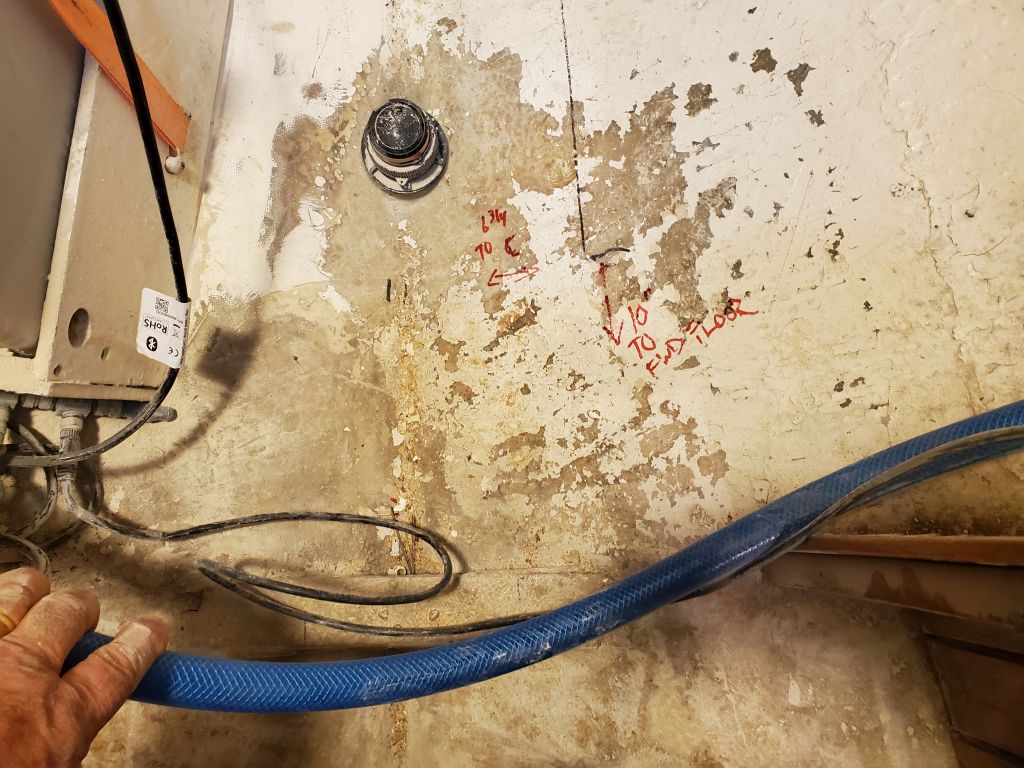
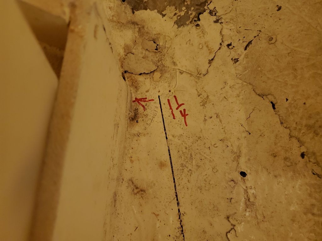
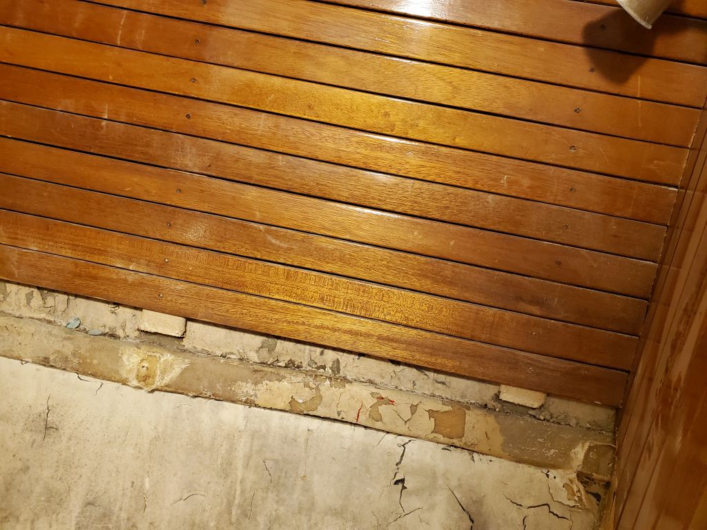
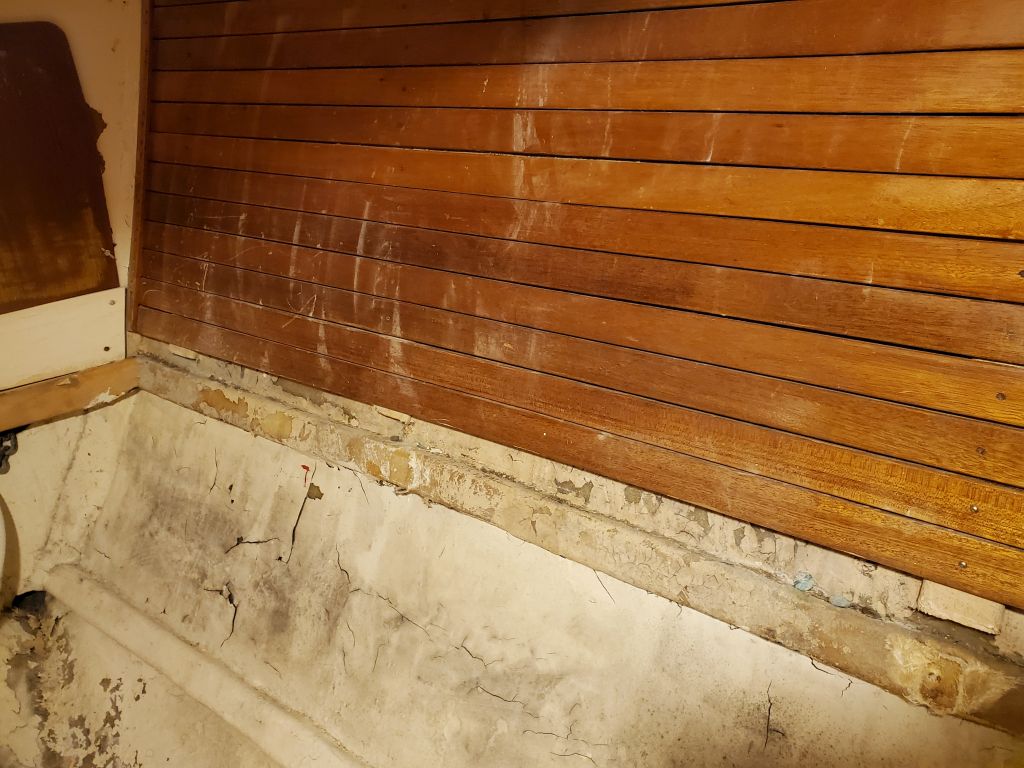
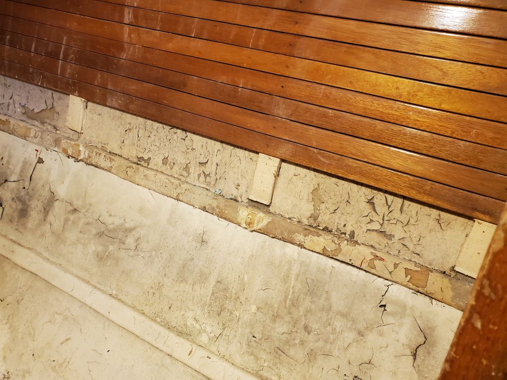
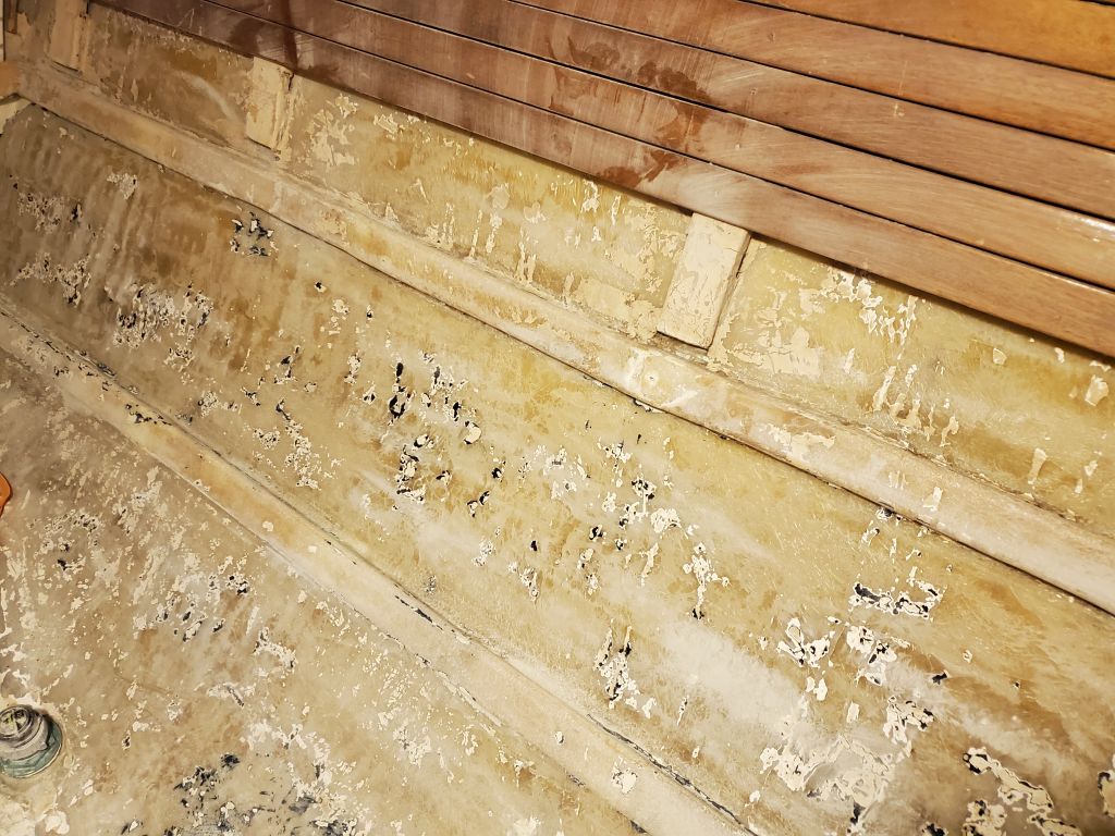
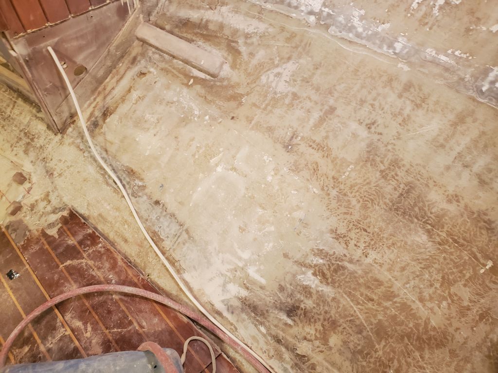
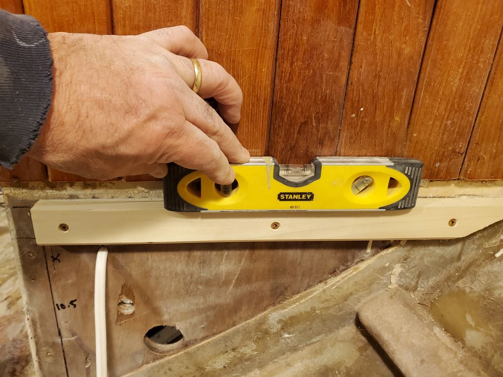
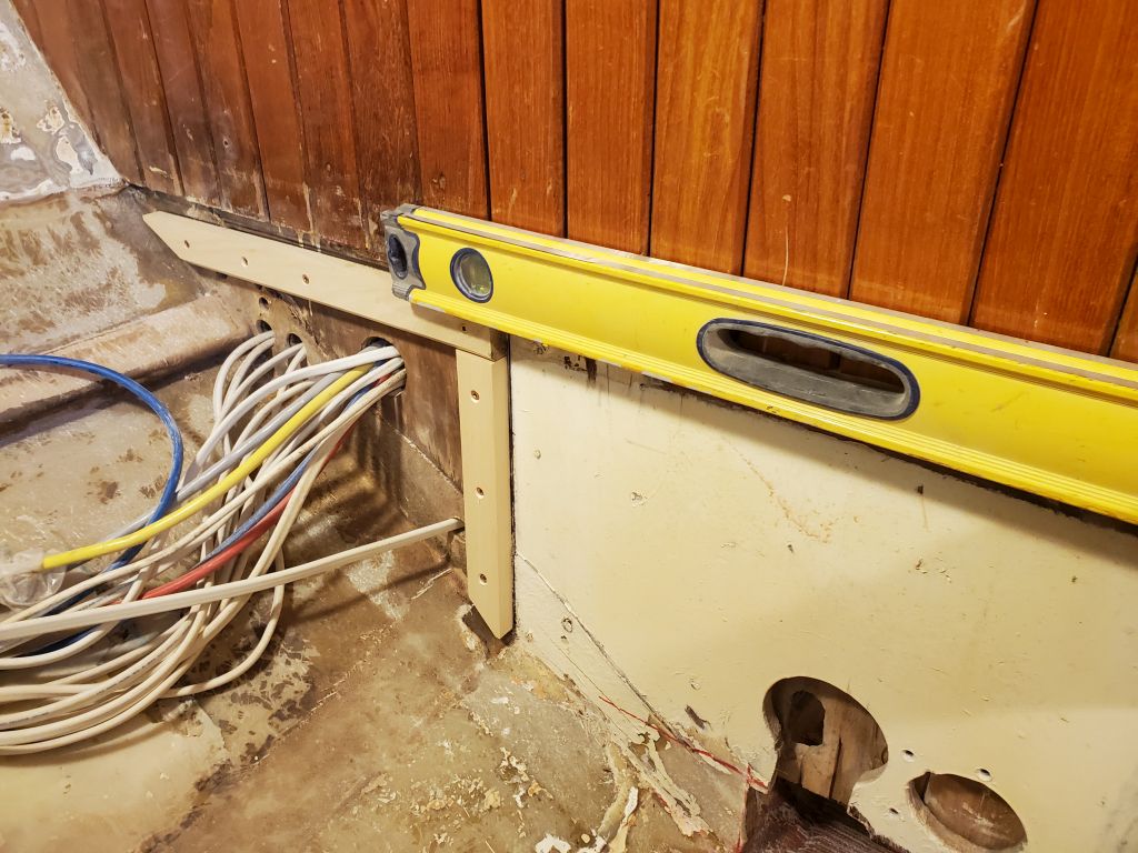
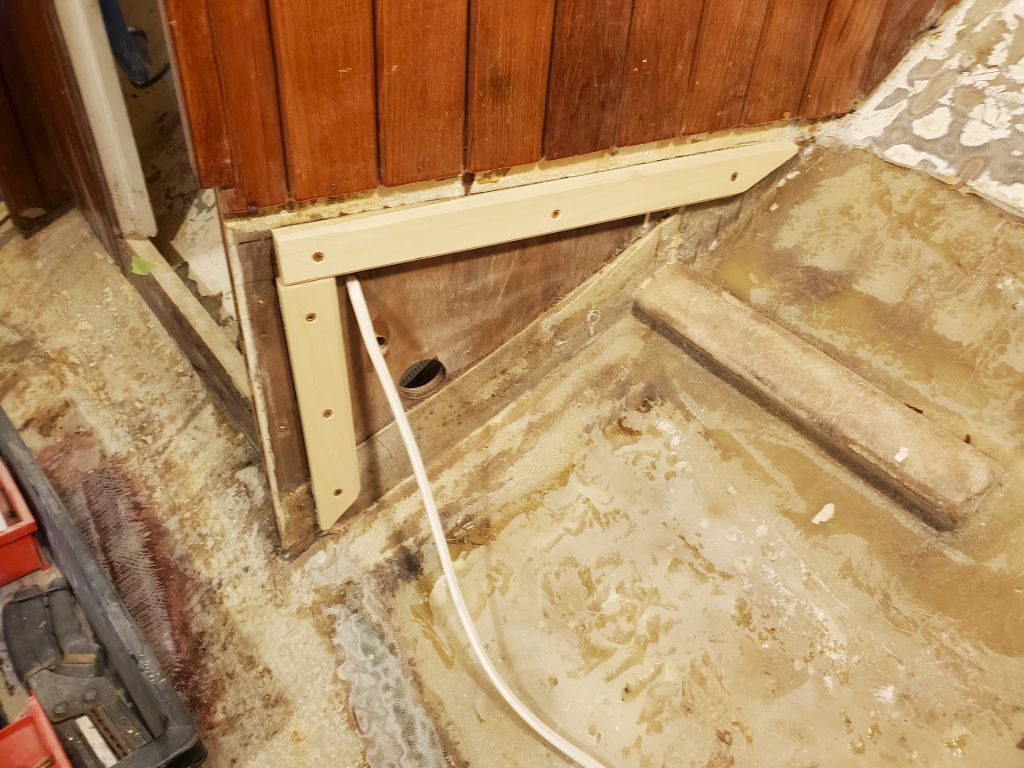
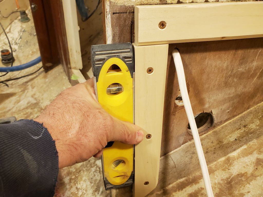
After getting set up with the layout and installation tools I’d need for the process, I started laying out the cleats to support the new settees.  I chose the settees to work on first because I was anxious to have some flat places for tool storage and to work from.  There were no significant changes planned to the basic settee height and position, but I started with fresh layout at the forward bulkhead, ensuring the cleats were level and plumb on both sides and level across the boat between each side as well.  This relatively simple process was complicated a bit by the existing bulkhead staving which, at 3/8″ thick, hung over the cleats and made it more difficult to place the level.  I secured the cleats with glue and bronze screws.  The two sections of the bulkhead were not perfectly aligned from side to side, so these factors later conspired to call some of the cleat placement into question, though ultimately the original layout turned out to be correct.

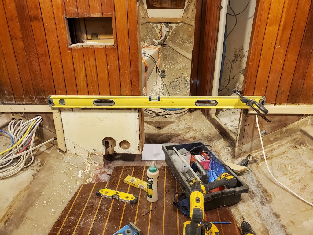
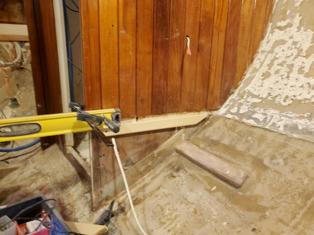
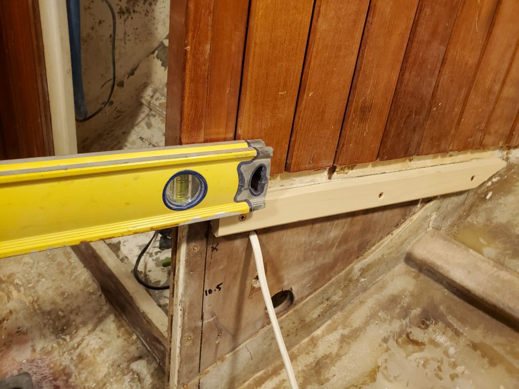
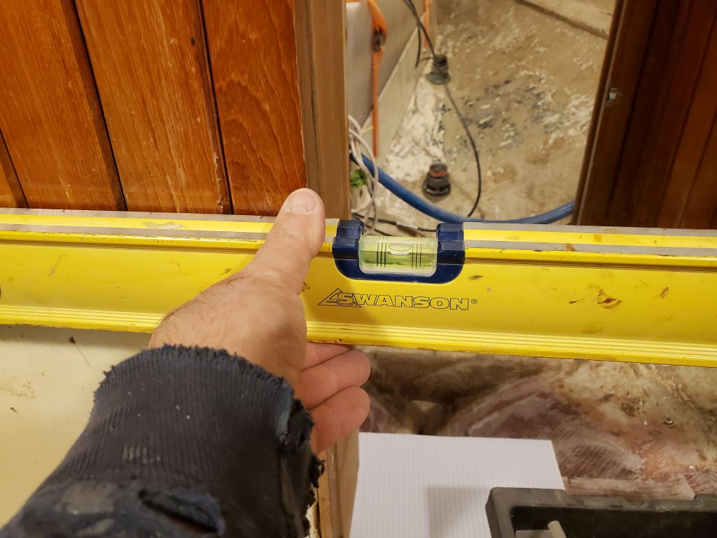
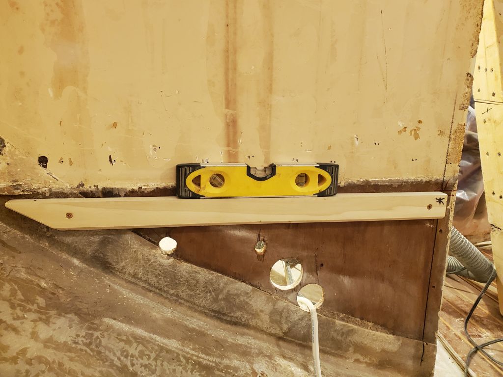
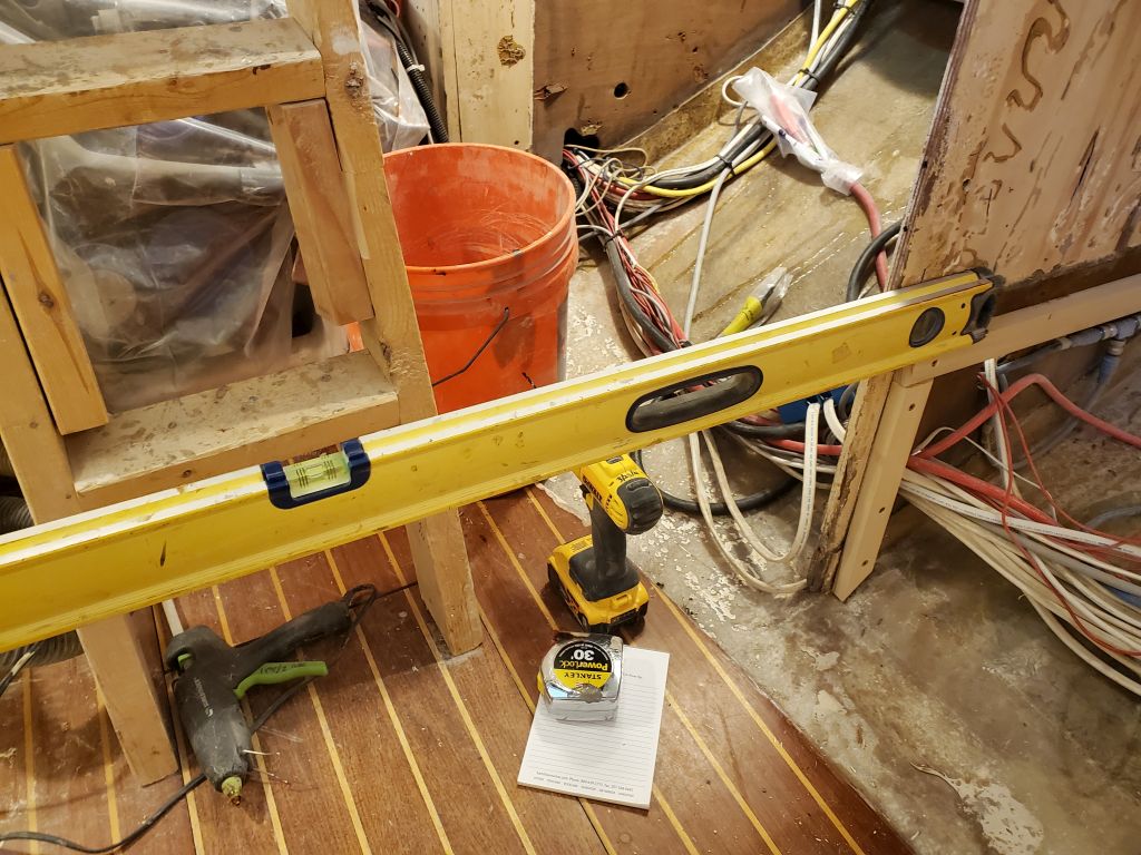
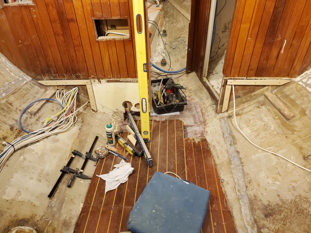
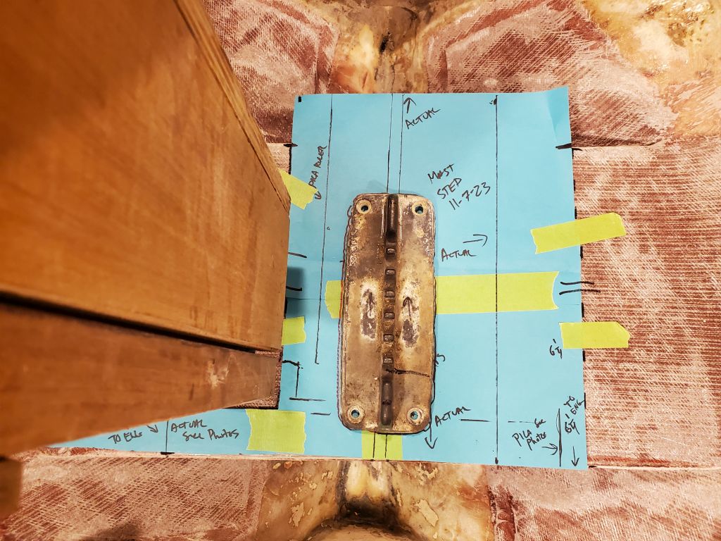
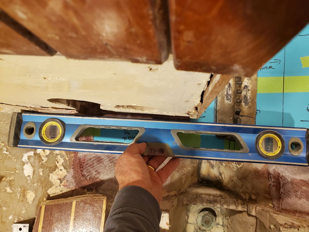
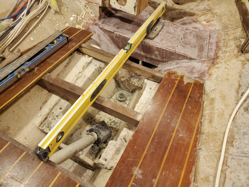
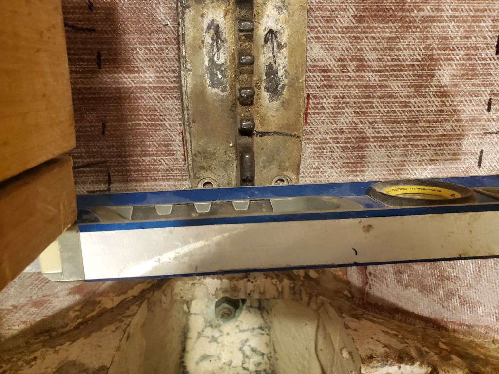
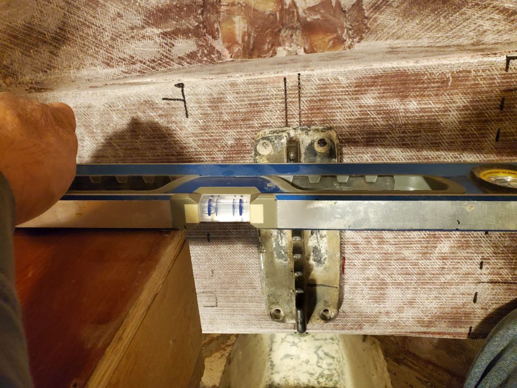
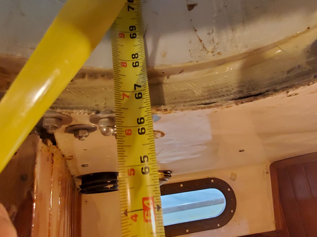
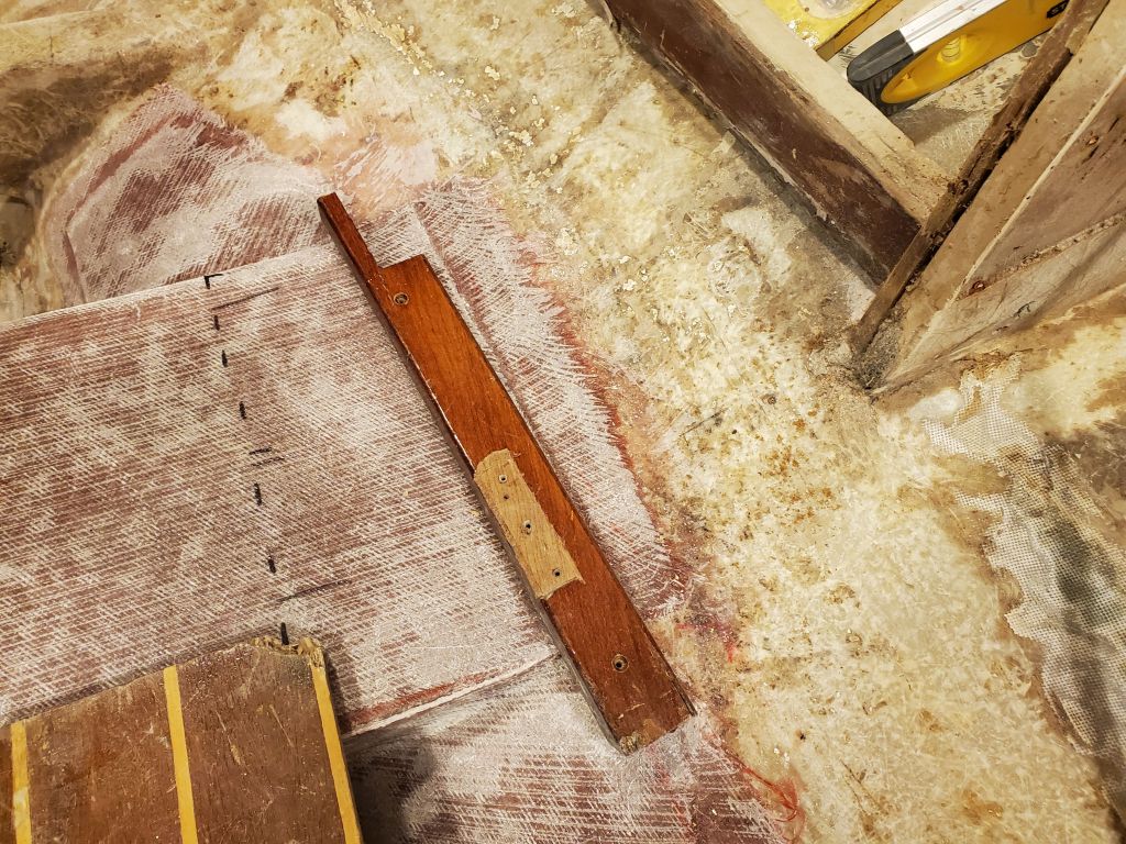
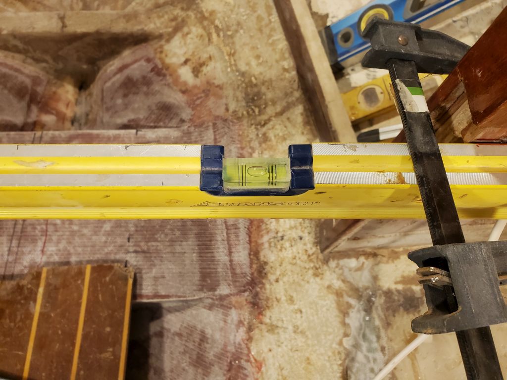
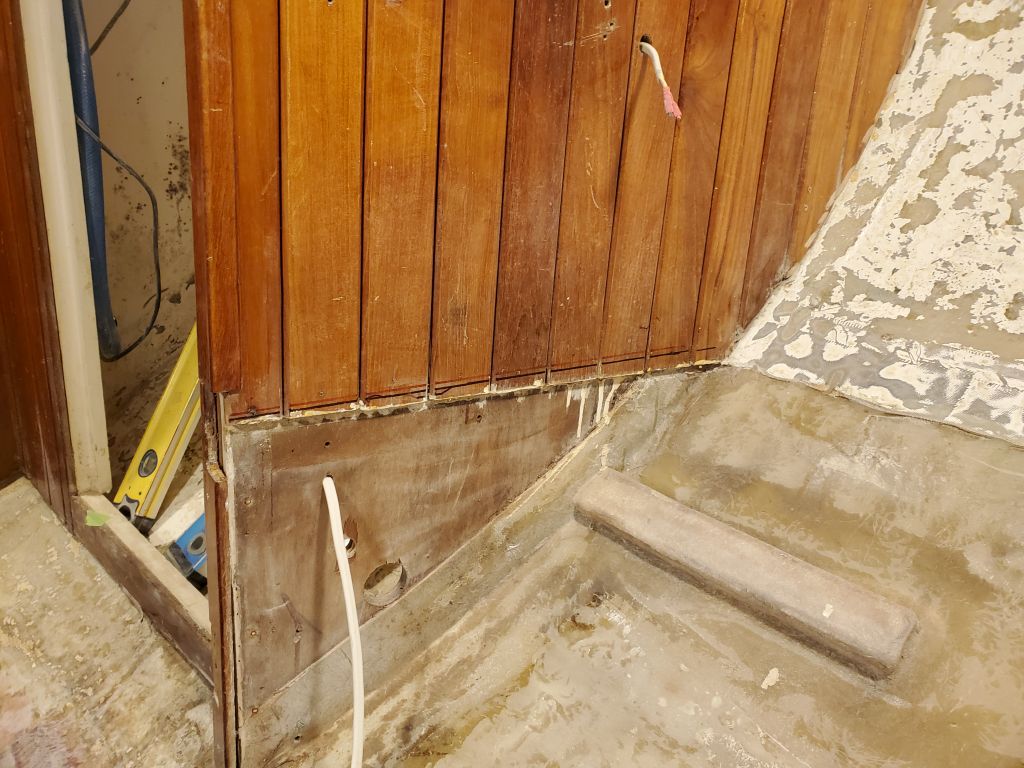
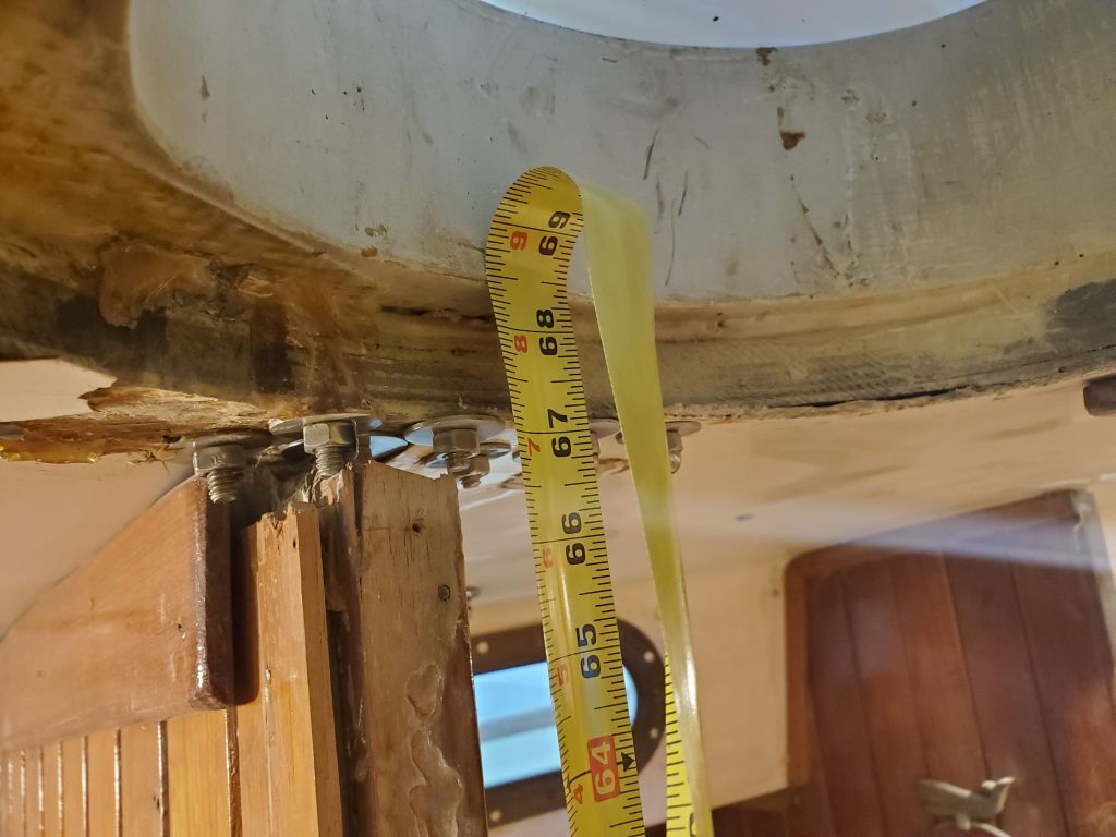
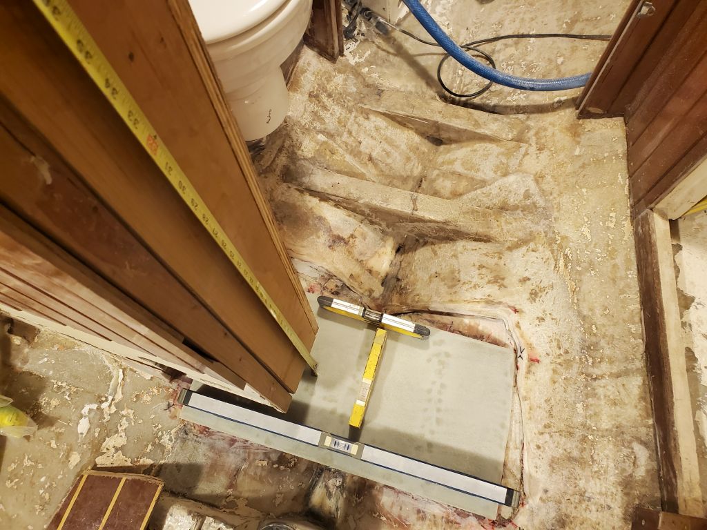
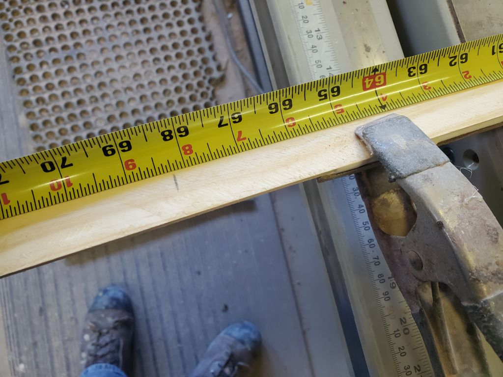
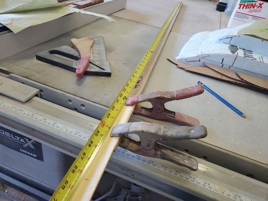
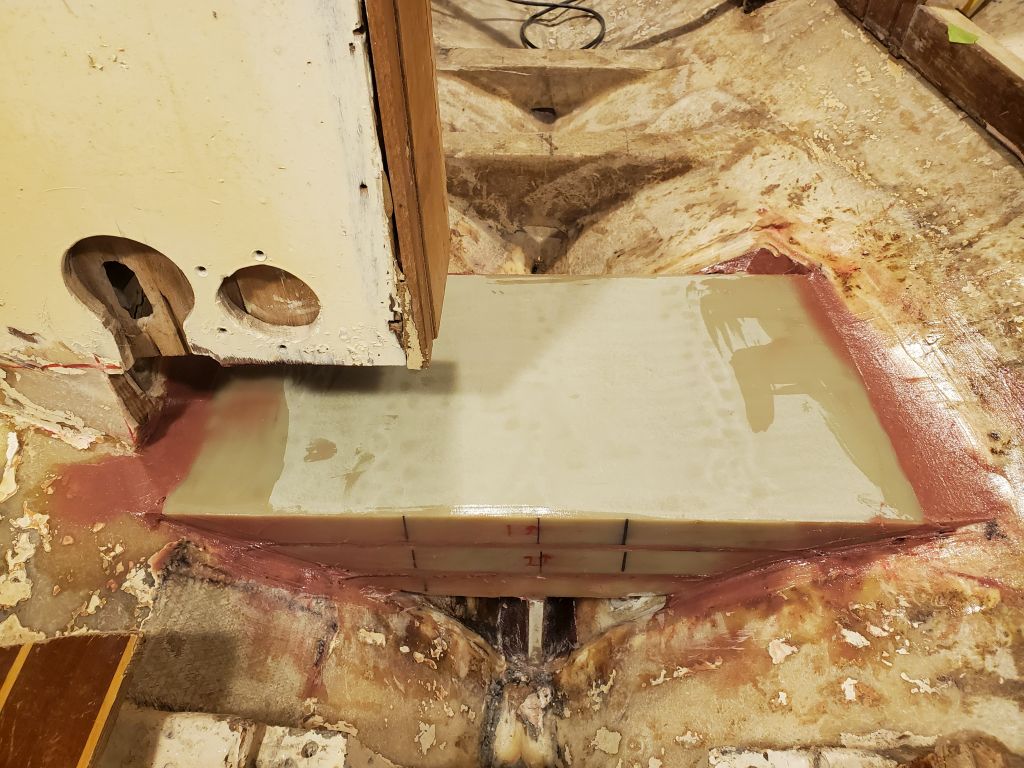
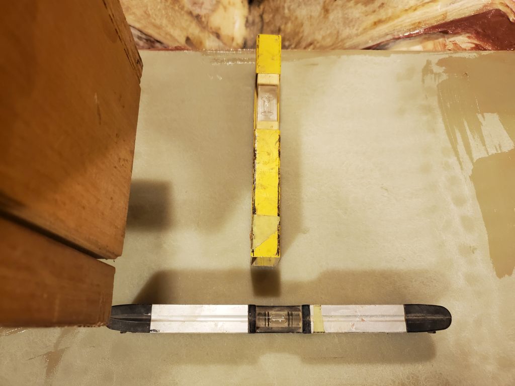
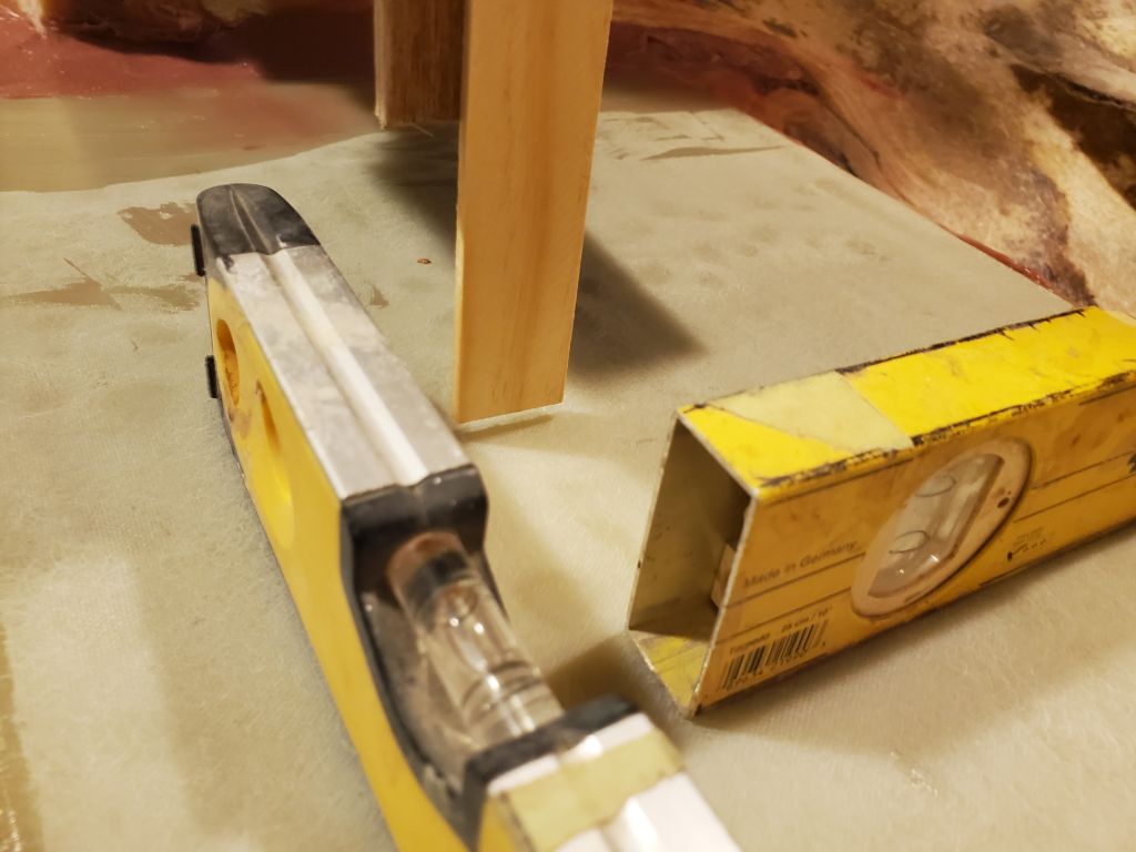
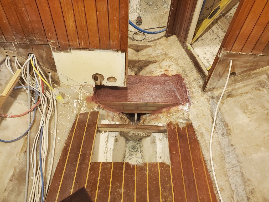
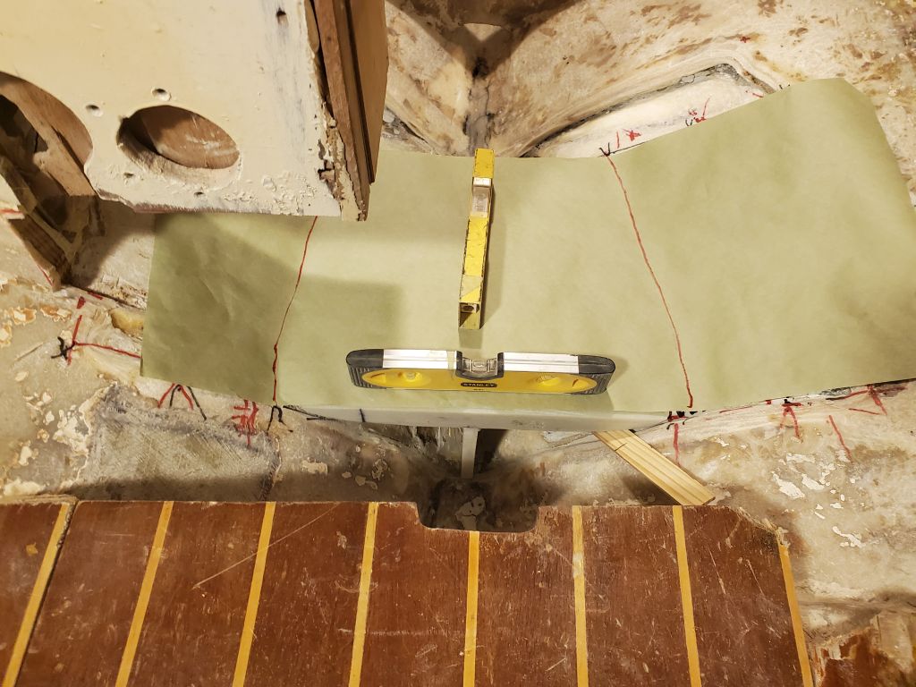
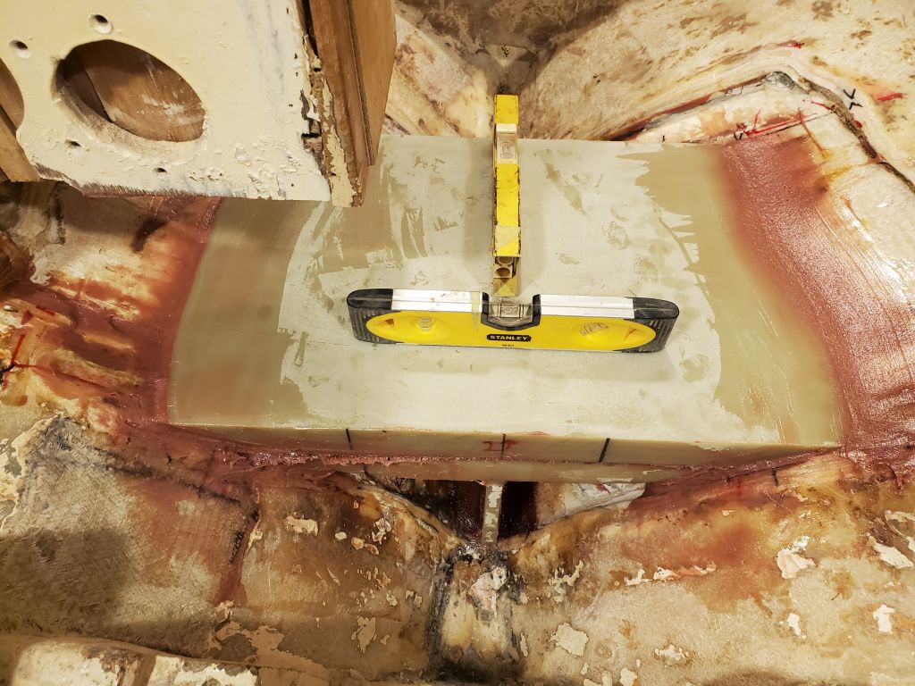
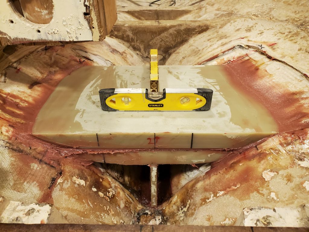
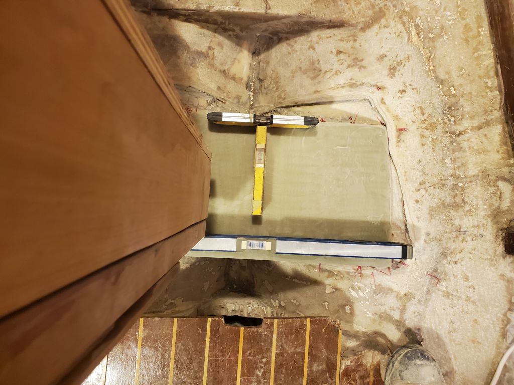
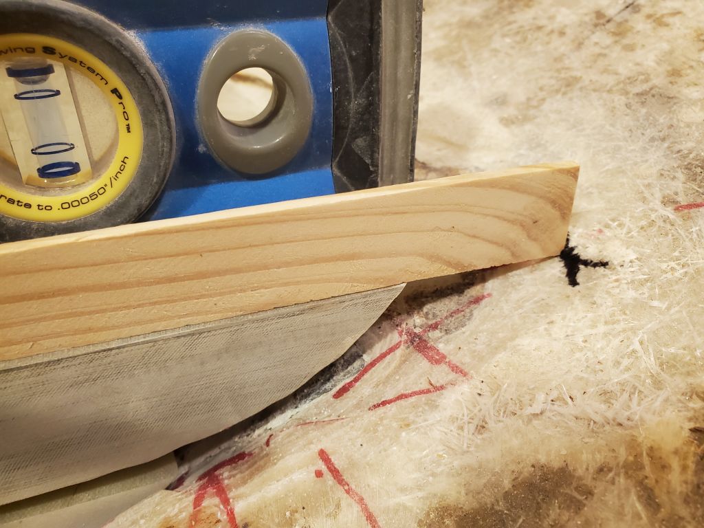
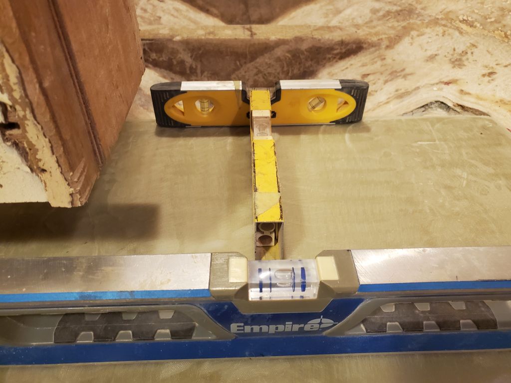
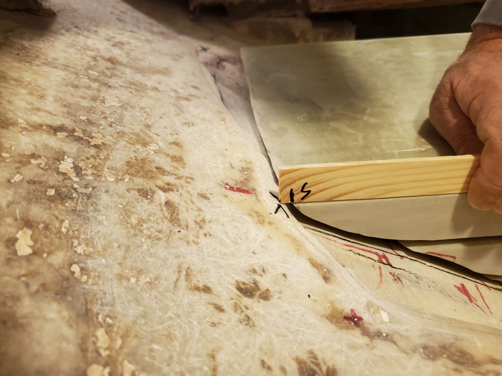
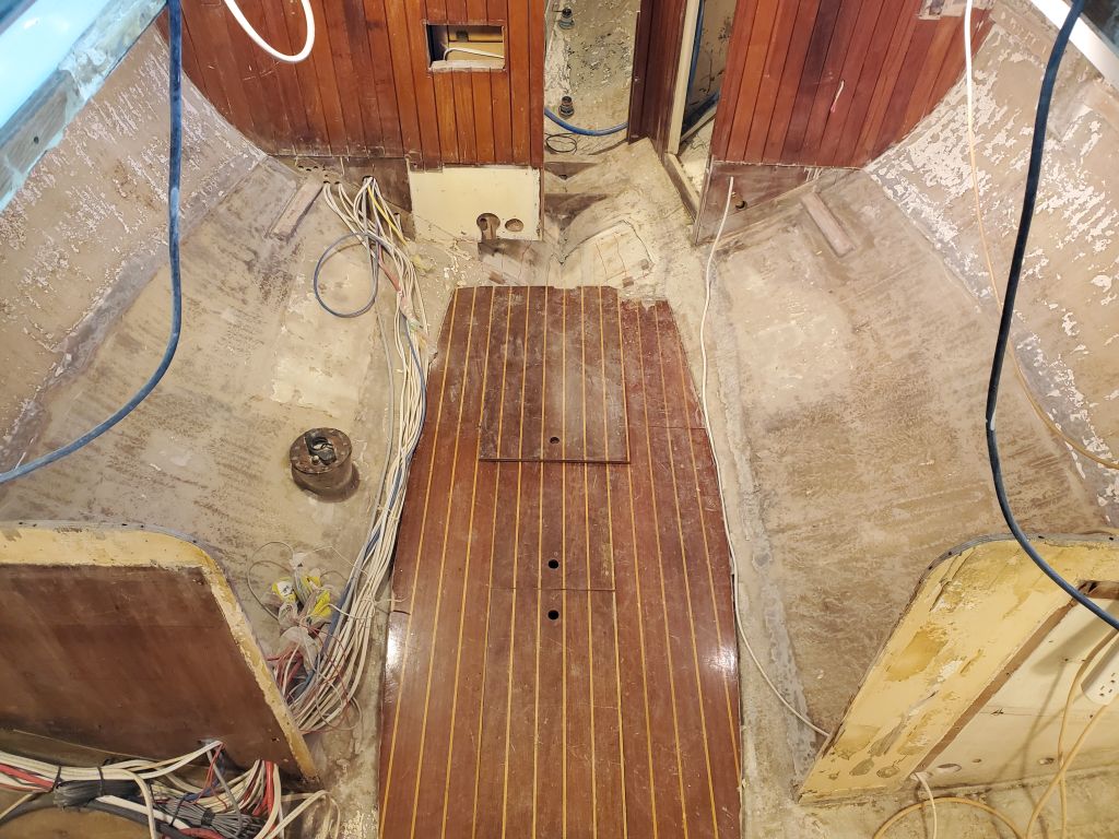
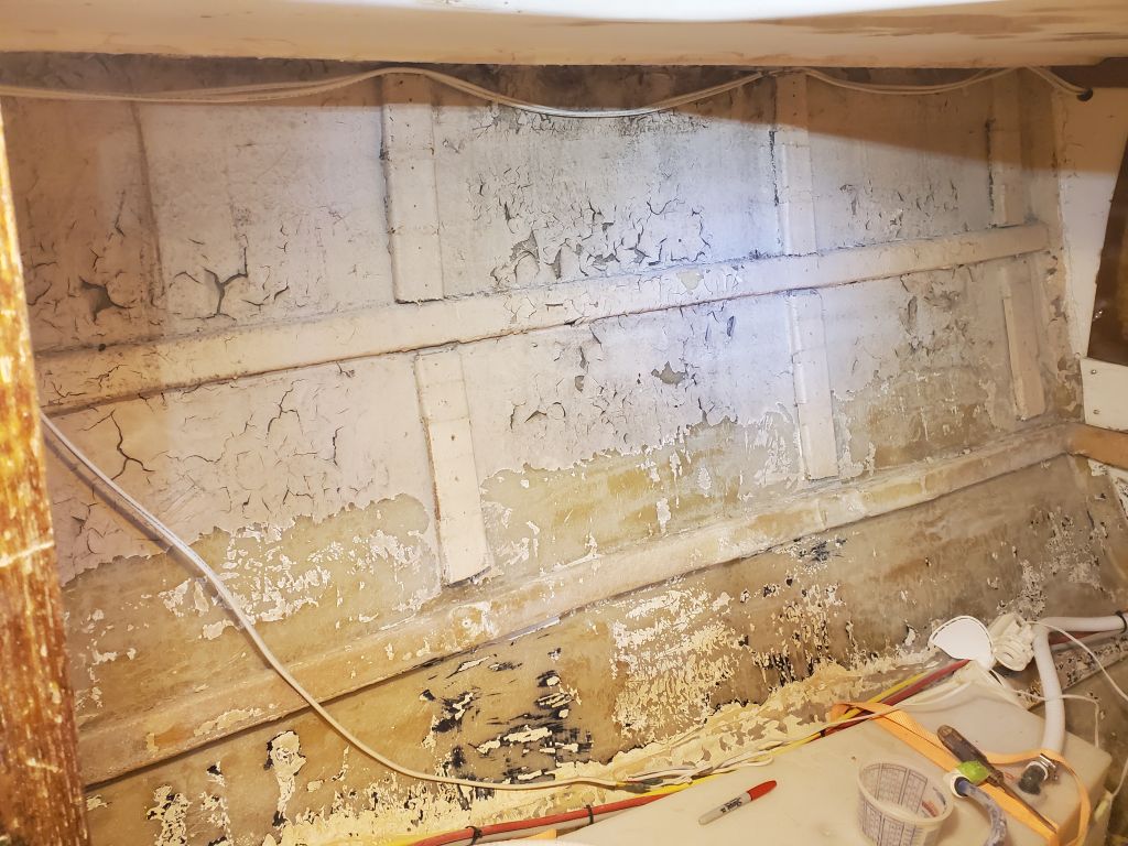
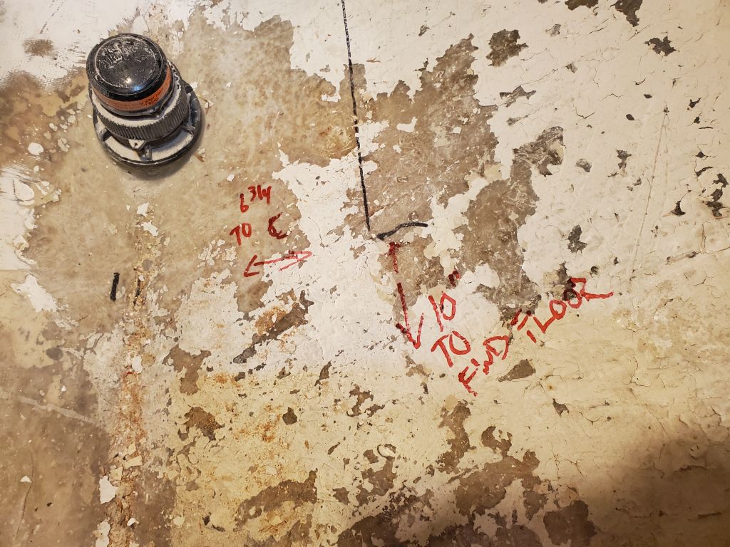
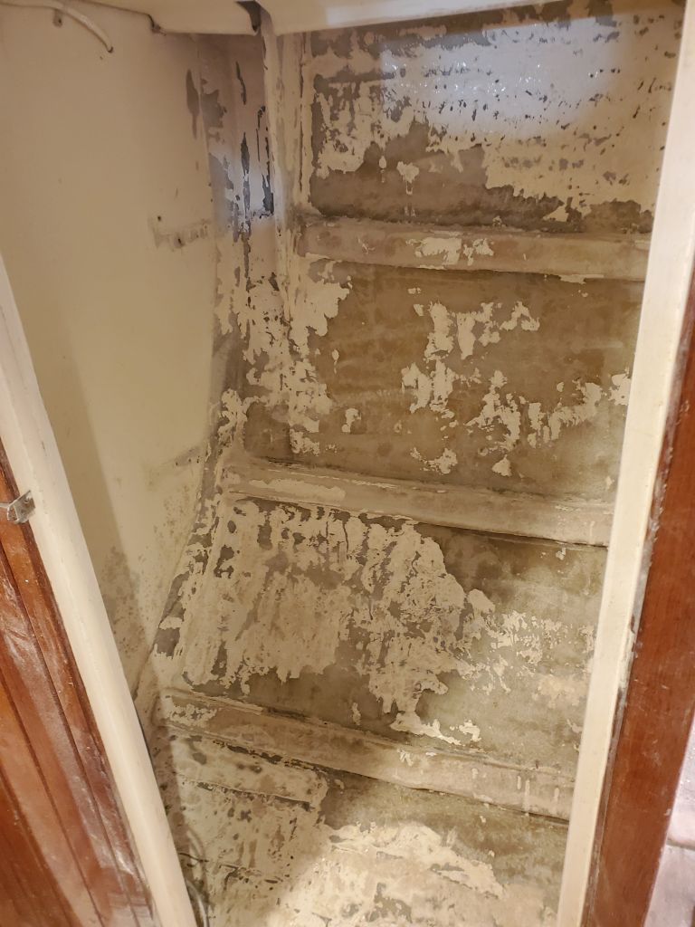
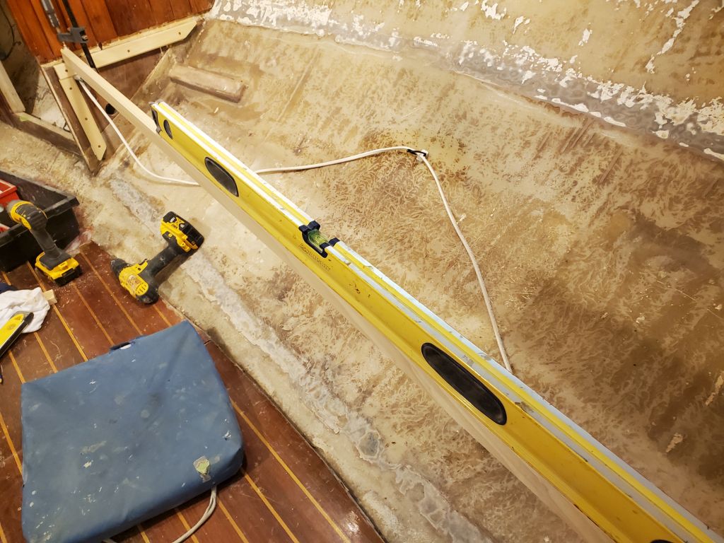
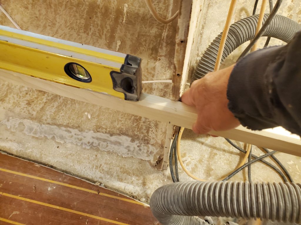
Because the old settees had not necessarily been level to begin with, and because the boat was now leveled according to some new layout marks (originally placed by the owner on the old settees, and from which I’d leveled the boat earlier in the project), and since the settee bases did not land on any flat or level surface, I had to transfer the heights of the forward cleats to the after bulkheads before I could install the cleats there.  Simple enough to do, using a long straightedge with the level atop.

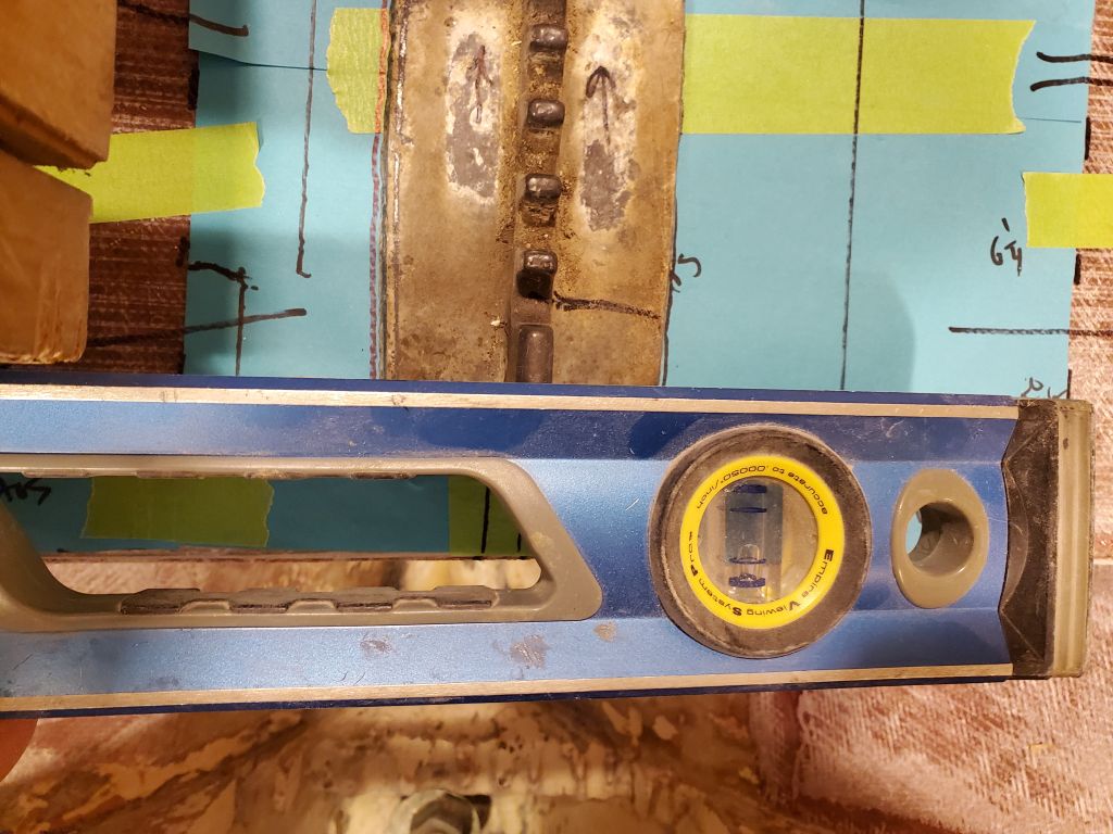
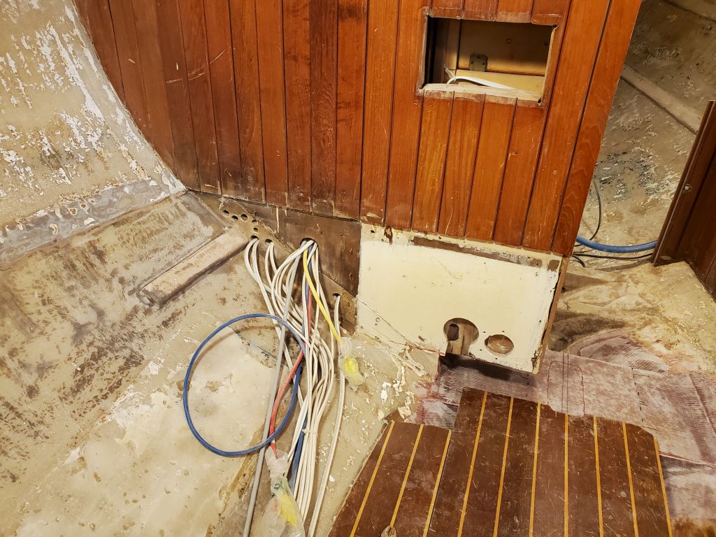
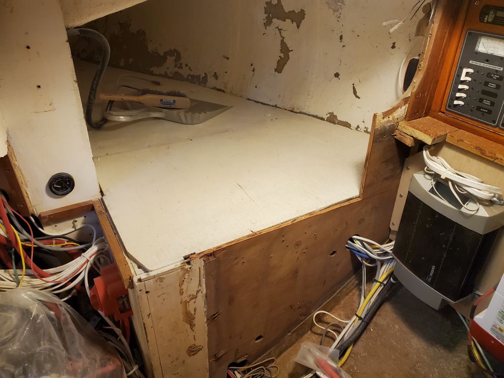
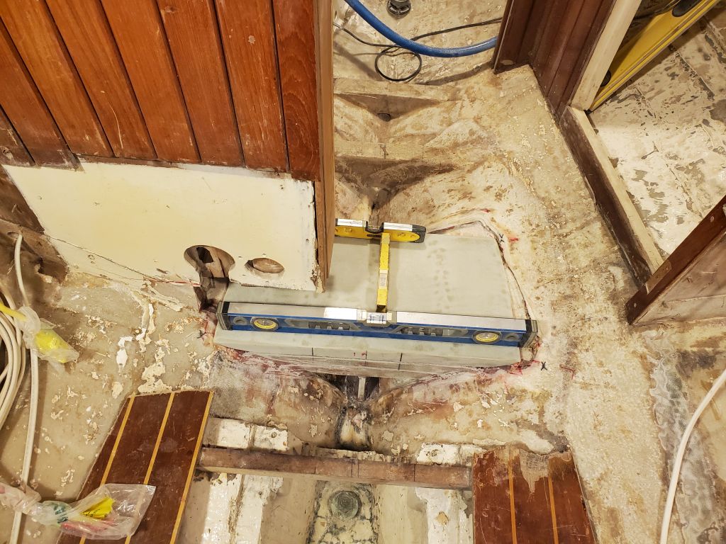
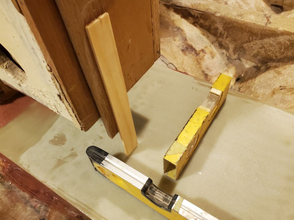
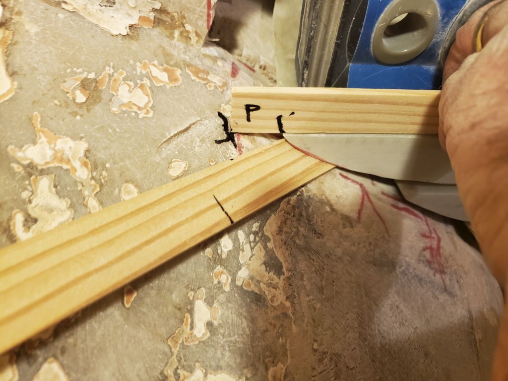
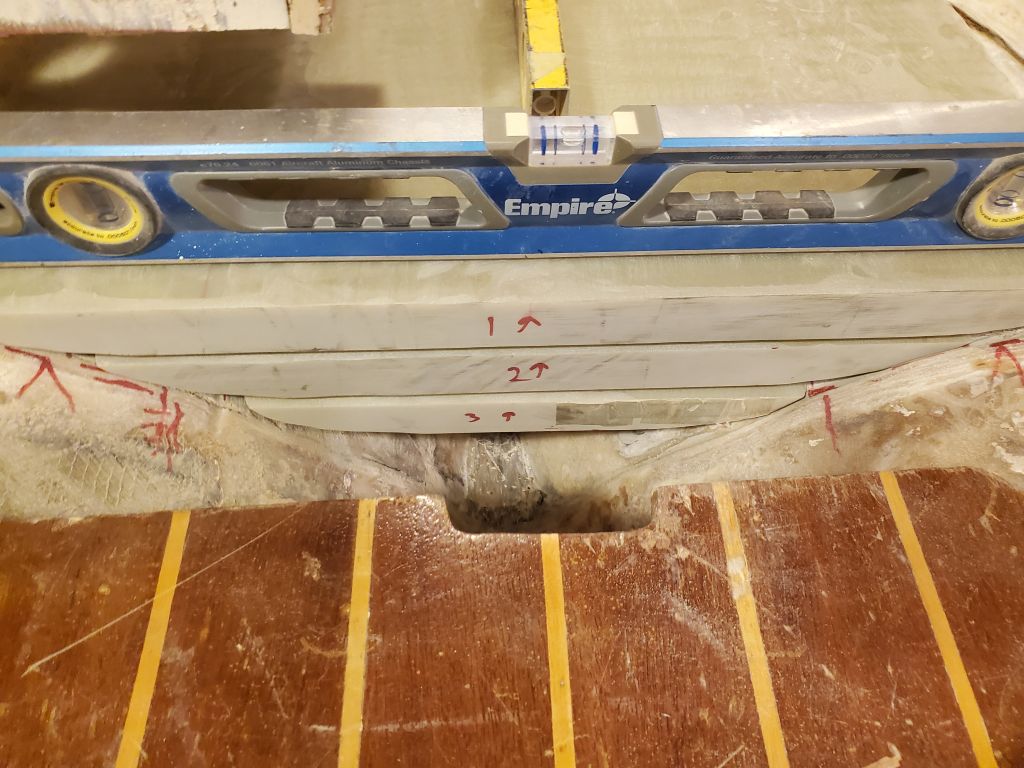
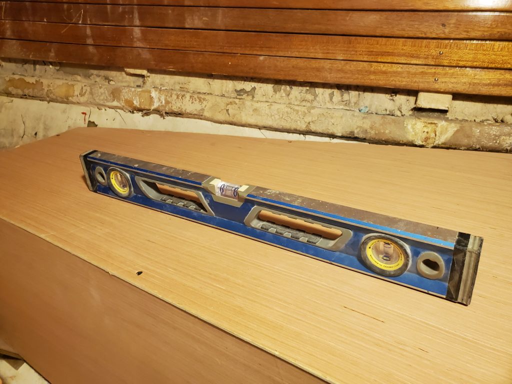
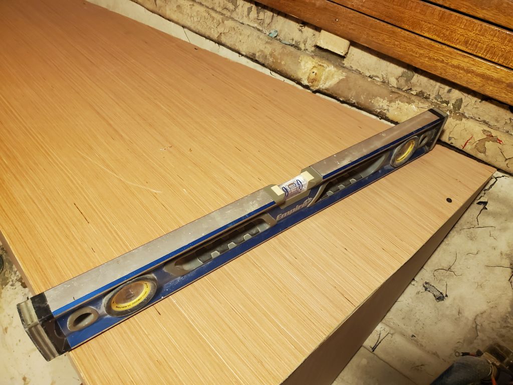
But was it that simple?  I repeated this process on both sides, but the marks I was getting on the after bulkheads didn’t make sense.  This caused quite a period of frustration and double-and-triple checking everything, from the level of the boat overall to the forward cleat placement to the plumb-ness of the various bulkheads.  I’d make new marks after carefully ensuring the level was doing what it should, only to find that leveling across the boat from the after bulkheads didn’t work out with the first marks.  None of this seemed possible.  Was my level out of whack?  Was I out of whack?

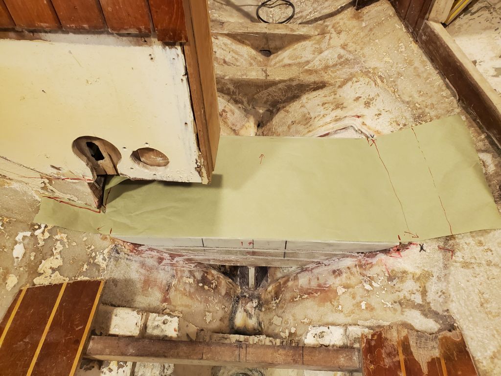
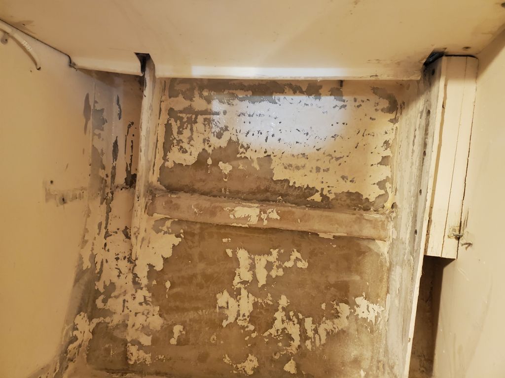
By the end of the afternoon, after basically repeating my layout at the forward end to check the existing horizontal cleats and then starting with a fresh approach, I got some layout marks on the aft bulkheads that made more sense and properly aligned with each other.  The fact that the layout didn’t really match the old installation was of little worry.  However, at this point I decided to only dry-fit the cleats, without glue, so I could double check things next time with fresh eyes, and perhaps a new level (just to be sure).

Calliope Girl 26

As the 4th frustrating day without power got underway, and with the temperature on the cold side, it was time to hook up a temporary generator so I could run the heat in the shop and maintain the temperature at a reasonable level, and more importantly to circulate water through the in-floor piping.  The generator didn’t power the whole shop–just one outlet circuit and one lighting circuit in addition to the oil burner–and the setup wasn’t ever intended as anything other than a fail-safe, but at inception I also never expected that there would be such frequent, long outages as we seem to see now, with at least one (and often two) extended outages statewide per year.

I digress.

In the event, with the generator running the heat for several hours, I also had the opportunity to get at least something done workwise with an extension cord run to one of the powered outlets.  I had no lights in the woodshop, but plenty of natural light through the windows for what I wanted to do.   While I couldn’t do what I’d planned to do this week, which was to get started on the new settees, as I stewed over the unwanted delay, I’d come up with the idea that I could make some progress under the existing circumstances and sand the various ceiling strips (from the v-berth) and bulkhead staving (from the old nav station and galley) to prepare these pieces, which I intended to re-use, for refinishing and eventual reinstallation.  This task was something that had to be done sometime, but was also the sort of job that always seemed less important than many, so this was a good opportunity to knock it off.

The existing gloss varnish on the ceiling strips was in fair condition, but pretty tired overall, with some scuffs and scratches and a general need for refurbishment.  The backs and sides of the rough-cut strips had never been varnished, and didn’t need to be, but after sanding and before installation, I planned to apply a coat or maybe two of gloss varnish as an improved base, and then (at least according to current thoughts) a final coat of rubbed-effect varnish.  Some of the edges had some paint that had dripped down from somewhere.

There were 26 strips, each 3/8″ thick, about 2″ wide, and roughly 6′ long, in total, and I sanded them all with 220 grit and a palm sander (and by hand as needed) to clean up the surface and prepare for more varnish.  I made no attempts to strip or otherwise completely “fix” all the issues, as these strips wouldn’t be worth that sort of labor versus replacement, but that said there was no need to replace them either when a simple refinishing would make a huge difference in their appearance once reinstalled.  As a base, the existing strips were in decent shape, and I cleaned up the edges a bit as I went too.  I set all the freshly-sanded strips aside for later attention.

With more time on hand as the generator continued to run, I continued with the bundles of vertical staving  from the two after bulkheads in the main cabin (3/8″ thick teak boards cut with a v-match shiplap pattern).  I’d been careful removing these from the bulkheads, but inevitably there’d been some damage, mainly to the narrow/thin tongues on one side of the boards, as the staving had been secured with an adhesive of some sort.  There were about 30 of these pieces (mostly about 3′ long, a few longer, a few shorter), and only one had broken completely during removal.  Fortunately, there were a few extras left from the opposite sides of these bulkheads, places where new staving was unlikely to be installed going forward, so I could replace the broken piece as needed.  Sometime later, I’d have to remove the remnants of old adhesive from the back sides.

In the same way, I sanded the existing varnish on these staving pieces with 220 grit paper, including the chamfered (corresponding parts of the v-groove) edges, preparing them for new varnish to suit when the time came.  I added these to the pile of other wood awaiting varnish.

Finally, I sanded some pieces of trim I’d removed from the edges of these bulkheads, including curved pieces to fit.  I wasn’t sure if these would be re-used as is or not, but they were in good shape and I preferred not to re-make the curvy pieces if unnecessary.

With the immediate sanding work complete, I took a moment to think ahead to the new propane locker that I planned to build into the port cockpit seat.  The owner and I had agreed to build this to fit his two existing small steel tanks, which would actually make the new locker fit more easily, avoid the need to purchase an expensive horizontal tank (as originally had been planned), and, with the dual tanks, there’d be plenty of capacity–and the clear indication of usage when one tank ran dry.

With the utility estimating power restoration not until two or three days in the future, I anticipated more “project planning” time ahead, so with that in mind I laid out the two tanks on a sheet of paper to get the basic size requirements so I could figure out how to build the box and what materials I’d need.  I planned to build the box from 1/4″ sheets of fiberglass, in a design that would fit down into the locker from above with a flange to secure it on top–making it easier to install and ultimately removable for access as needed.  The basic measurements I got from this exercise would allow me to order the raw materials soon and get started on the construction whenever possible.

Calliope Girl 25

Following an early meeting, I had just gotten to the shop when the power went out, victim of the day’s strong winds and heavy rain.  Though this had been a threat, I’d not expected it to happen so early, but there was nothing for it but to wait it out.  In the meantime, I continued working on some figuring to determine how much hardwood (teak) to order for the new cabin trim and some other planning for the work ahead.

The damage to the grid from the windstorm appeared severe from reports through the afternoon, so it seemed likely that the power might remain out for several days, which would cause a frustrating and unplanned delay.


Calliope Girl 24

I made a final confirmation of the finished elevation of the new mast step before lightly sanding the new fiberglass to scuff it slightly and remove any hard edges.

There was no better time than now to go ahead and sand the upper portions of the v-berth, where I’d recently removed the ceiling planks to reveal and attend to the failing coatings beneath.

After cleaning up from the day’s sanding, I decided to lay out the mast step base fitting now while my original layout marks were still visible on the nearby structural members and before new work started possibly getting in the way.   Unwrapping the original aluminum fitting from its storage bag, I found that it was in worse condition than I’d remembered, at least after I scraped away the loose material left over from its corrosive environment.  There was also a bit of rocker in the bottom of the piece, i.e. it wouldn’t sit flat and rocked fore and aft.  While it would still be usable as is if needed, I decided to see if there was an easy replacement available and found a part number to work with, but the part seemed obsolete.  I contacted the machine shop that would be doing the new chainplates to see if they could build a replacement (yes), and as of this writing was awaiting a quote.

I started with my paper template of the original step and manipulated it this way and that according to the various measurements and layout marks.  I’d made this template directly off the old aluminum structure and had intended it to document the original, and a few things had changed.  Still, the template got me close to where I needed the step to be, but when I reviewed photos from the removal of the step in the first place, I found I’d actually used different reference points to document the base fitting itself, so I changed tactics and realigned the step according to those criteria.  This included aligning a 4′ straightedge with marks on three of the cross members beneath the cabin sole aft of the step, and also using a straightedge off the main bulkhead and head cabinetry to align the part fore and aft.  With all this, I eventually made some marks on the new structure to reposition the step, but held off permanently marking any fastener hole locations for now.

I checked the measurement between the top of the step base plate and my reference point on the mast collar above, and found it within tolerance of the original measurement, depending on where exactly I held the tape (as the mast base rocked fore and aft and affected the measurement accordingly).  The original measurement was between 67-3/4″ and 67-7/8″; now it was just over 67-3/4″.

With that complete, I moved on to some preparations in the main cabin for the new construction just ahead.  There were several small details to be dealt with before I could begin, including removing a number of old screws that still stuck out from when I’d removed old support cleats.  I removed a bit of the trim from the lower end of the starboard side of the passageway opening, as this trim had been cut to fit around the old berth fiddle, and would likely be in the way of the new work; it would be easier to replace the trim later.

The bottom edges of the staving on the main bulkhead also needed trimming, as some of the pieces on the port side extended down into a space that would, in the new construction, be part of the battery box and berth top.

I also wanted to slightly raise the bottom edge of the staving to give me a touch more room for building new.  In preparing for this cut, I found that the original ends (which had been tight against the berth tops) were far from level, especially to starboard, so I leveled both sides and across the opening as needed and made the cuts required to straighten and clean up the bottom edge of the staving.

I made some layout marks on the after bulkhead at the old nav station, leading to the quarterberth, and cut out the upper portion of the bulkhead for better access in the immediate term, and to accommodate the new galley layout in the longer term.

Finally, I removed an obsolete transducer tank from the hull in way of the port settee.  Unsure what was inside–it should have originally been filled with mineral oil or some such–I removed the top to expose within, and happily found there was nothing inside, saving me the need to pump out whatever might have been there and avoiding a mess.  A little light percussive maintenance persuaded the remnants of the tank to part ways with the hull, leaving only a slight bit of material that I’d remove next time I had a sander going.

Calliope Girl 23

The new fiberglass from last time required a light water wash and sanding to prepare it for the final stage of new work.  Afterwards, I dry-fit the third layer of G-10 to check its fit and check once more the measurement from the mast collar to the top of the step to ensure I had the correct clearance.  With a measurement of 68-1/2″, the top plate was right where I wanted it at this stage, with approximately 1/4″ room to spare to allow for the layers of fiberglass over the top.  I made a quick paper pattern of the area to use for cutting the new fiberglass, along with paper patterns of the forward and after faces.  The top plate fit nicely on top of the layers beneath, with just a small gap appropriate for the epoxy adhesive–no need for additional fiberglass to fill the space.

I help with the final installation stage, I prepared a “story stick” cut to 68-1/4″ long, which was the exact final measurement I wanted from the reference point on the mast collar above to the new mast step top; the stick I used during the early part of the layout had disappeared somewhere along the way.  This stick would make it easier for me to di the final measurement when the fresh glasswork was in place, as I’d not need to rest a tape measure on the wet fiberglass.  I double-checked that this worked as intended, then removed the top plate and cleaned up the whole area to prepare for final installation.

Just before final installation of the last layer of the step, I received delivery of a batch of plywood to be used for the new interior construction.

I installed the final layer of the mast step in a bed of thickened epoxy adhesive and leveled it in both directions before checking the height with my story stick.  Then I used additional epoxy to fill in and smooth over the transitions to the hull on each side, and at the vertical ends of the step to fill and clean up the edges between the three layers and where they met the hull on each side, checking the level and height measurement throughout the process.

I left this to cure for a bit while I prepared three layers of fiberglass to cover the top and secure the platform to the hull on each side; then, right after lunch, I installed the final layers of fiberglass on the top, using my story stick to confirm that they had ended up at the correct final elevation (or just a tiny touch below, as hoped).

With additional thickened epoxy, I applied fillets between the forward and aft edges of the step, and cleaned up and smoothed out various adjacent areas to prepare for the tabbing at the forward and after ends, which I then went down and cut in the shop before wetting out and installing two layers, overlapping onto the hull as far as possible, on each end of the step platform.

There’d be a bit of work to dress up the fully-glassed step in the immediate future, and some layout to prepare for reinstalling the metal step plate later, but the bulk of the work was done.  Below are some photos from earlier in the project, showing the original mast step in a couple different stages.


Calliope Girl 22

After a light sanding of the fillets and a final dry fit, along with a quick paper pattern to help me lay out the full fiberglass layers that would cover the top of this section and further tie it into the hull. the first section of the mast step was ready for installation.  With all surfaces appropriately prepared, I installed two layers of tabbing in epoxy resin between the vertical support and the bottom of the first section (the filleted joint), then installed the piece in the boat with epoxy adhesive on all faying surfaces, and additional tabbing (two layers) between the bottom edge of the vertical support and the hull, tying the whole structure together.  The space beneath was quite tight from the forward end in particular, but with aforethought and some careful work I got the tabbing secured as well as possible.  I couldn’t stop to take any photos of the various installation steps, but the end result had the first layer and its vertical support well-secured with epoxy and tabbing (where appropriate), and level in both directions at the intended height.

While I let the assembly cure for a bit, I prepared three layers of fiberglass to cover the top.  I’d left space for this in the design and orientation of the three layers.  Once the epoxy had set enough to continue, I wet out and installed two of the three layers, tying the top of the first piece into the hull on both sides.  To speed up curing to the green stage, I set up a couple heat lamps while I took lunch break.  This would help me get additional work done in the afternoon.

By my return, and after a visit from the canvas contractor to have a look at the cockpit and some dodger details, the fiberglass had cured enough for me to delicately continue.  First, I set the second layer lightly in place to check its fit and see how the space beneath was looking.  There was still a bit of space, so I went ahead and added the third layer of fiberglass that I’d cut with this in mind.  While that set up slightly, I prepared three new layers of full tabbing to fit the second layer, then installed the second piece in a heavy bed of epoxy adhesive (on the flat and along the hull on each side), pressing it tightly into its proper position and level in both directions.

To wrap up the work for the day, I wet out and installed the three layers of tabbing to cover the top of the second layer and secure it independently to the hull.  I left this to cure overnight, and next time I’d be able to finish up the mast step construction with the final layer and other details.

Calliope Girl 21

I began the week by unpacking and inventorying the new stove and sink, which had recently been delivered from Great Britain, to ensure that the items were in good shape and that everything the owner had ordered was here.  Despite some external box damage, fortunately nothing inside was harmed.

My focus for the day was the new mast step.  With the major unbuilding in the cabin complete, and awaiting new materials for the reconstruction, this was the perfect opportunity to prepare and install the new step assembly.  I’d had the raw materials on hand for a while:  three pieces of 12″ x 24″ x 1-1/2″ G-10 fiberglass, which I now had to shape to match the foam patterns I’d made several weeks before.

To transfer the basic profile from the patterns to the new material, I made cardboard patterns of each end of the three layers, which I could then trace onto the fiberglass sheets, along with a rough tracing of the fore and aft shape of the pattern.  I did the same process for all three pieces of the new step, though I’ve only illustrated the first (smallest) piece below.

With the basic shapes transferred, I started by cutting along the lines with a jigsaw with carbide saw blade set at the maximum angle to remove as much of the material as possible.  I repeated this process with all three layers to rough out the profile.

To complete the shaping, I set up a grinder and fan station near the shop door–I would have done the work outdoors but for the rain–and used a grinder and several coarse flap wheels to shape the three pieces of fiberglass to match the layout lines and the foam patterns as much as possible.

From here, it was a multi-step process involving many trips up and down the ladder into the boat with heavy G-10 panels as I made adjustments to each of the three layers, in turn, so they fit properly in the boat and at the proper heights, as well as level in both directions.  I had some layout marks from the patterning to go by.  The first piece (#3) took the most time to fit, as it ended up a bit high and I had to keep recontouring the fiberglass sheet till I finally got it down to its layout marks, and level.  Once the first section was in, the remaining two went more quickly, though each piece required several trips up and down to grind some more material from the high spots.  The spaces between each layer are intentional and designed to allow room for fiberglass tabbing on each individual layer to add to the overall strength of the assembly.

The most important thing when all was said and done was that the top layer ended up at the proper height to ultimately match exactly the height of the old mast step.  I’d built the patterns so the top layer ended up 68-1/2″ below a known point on the mast collar in the deck above, which allowed 1/4″ of space for fiberglass over the top and to fine-tune the final-final height to 68-1/4″, which was the original measurement.  I strove throughout the patterning process to ensure that if anything, the final platform ended up lower rather than higher.

To help me easily keep the pieces in alignment during installation, and to provide reference points for height and position as I went, I used a straightedge held flat to each corner of each of the three layers to mark points on the hull that I could quickly and easily use during installation and keep the lower layers where they needed to be, rather than risk any possibility of the layers “growing” as I worked up to the critical top.

When these layers were fully installed, they’d surely be strong, but as an added hedge and to help transfer the loads all the way to the bottom of the boat, I patterned, then cut to fit, a piece of 1/2″ G-10 to be installed on centerline beneath the lowest section, extending to the hull beneath.  This left ample limber space on each side.

To prepare for final installation, I had enough time left in the day to epoxy the new support to the underside of the lowest layer.  I’d install tabbing to secure the support to the bottom of the first layer before installation in the boat, then epoxy and tab the lower edge of the support to the hull as well.  My epoxy hardener was dark red after sitting in the pump tank unused for some time; apparently the welded seam on the old style tanks like mine reacts with the hardeners to cause this harmless color change.

Calliope Girl 20

To get the day started, I made up a drawing of the water tank as per the actual mockup, and added in some details regarding fittings locations, inspection ports, and baffles.  Now I could send this off to some vendors for quotes and timeframes.

Next, I vaccummed out the inside of the boat in all areas, ridding everything of the dust that had settled since my last sanding efforts.  There’d be more mess ahead eventually, but at least for now it was workable.

The owner expressed interest in having me remove the rest of the ceiling strips in the forward cabin in order to address the failed coatings in the area and repaint.  Although access to the space was awkward at the moment, given the steep curves, upon assessment I decided that this was as good a time as any to get the job done, as there wasn’t really any other pressing work requiring me just then as I transitioned from the water tank work and surface prep towards some of the new work (and was awaiting materials for the new construction anyway).  The forward ends of the ceilings featured wooden trim with more screw holes than I had ever seen in such small pieces–at least two screws (and/or holes) in each of the planks.  These took a while to remove, as the screws were tiny, with slotted heads, and in fairly poor condition.  I only fussed with the screws because I didn’t want to damage the ceiling strips themselves.

Eventually, I removed the trim, and moved on to the ceiling boards.  These were secured with more of the tiny, slotted screws, and the chore quickly became aggravating, not to mention fruitless, as the screws were mostly bronze and in poor condition, and the slots were filled with varnish and corrosion.  Soon enough, I determined that if I couldn’t remove these strips some other way, I’d be there still…or else would advise leaving the planks in place.  However, I found that with care, and not too much effort, I could pry the boards loose from their supports–there was just one small screw in each of four supporting strips along the length–so this sped up the removal process significantly, though the screws remained in the boards.

At some length, I successfully removed all the ceiling strips from both sides of the forward cabin.  Now I could, when the spirit moved me, clean up and sand the fully-exposed hull.  (I’d also have to do the quarterberth sometime, so I’d make a fun day of it sometime soonish.)

Eyeing the pile of screw-filled boards on the bench, I sighed deeply and, fully knowing there was no better time than right now to remove the screws, set to the task.  I had to use pliers from the back side to spin out the screws enough that I could grab them with the pliers from the visible side to remove them completely, as the tiny screws (#4) were installed through small or nonexistent pilotholes.  However, soon enough the work was done, and future me would greatly appreciate that now-me had done the work, well, now.  Now-me is good that way.

Calliope Girl 19

It was a non-visual day.  I was out of the shop for the morning, but upon my return I started by making some wooden templates of the proposed new chainplates for forward lowers.  After measuring the length of the knee belowdecks at the forward location (12″), I cut strips of 1/4″ plywood (the same thickness as the existing sets of chainplates) to the proper width and length, allowing 12″ below the deck level and the same amount protruding above as on the other two sets.  I used one of the existing chainplates to mark and drill the bolt- and pinholes.  I did this now because I’d been in contact with a machine shop and had arranged a time later on to drop off the old chainplates and patterns for replication.

With the templates complete and all the chainplates ready to go, I killed some time by cleaning up the shop a bit, then took the chainplates to the machine shop for the appointed time to discuss the work with the machinist.

Calliope Girl 18

During the morning, I finished up the water tank mockup with the last two side panels, and the top panel.  I secured the long side panels with glue and screws, but used only screws on the top to make it removable.  Afterwards, using the measurements from the actual “tank”, I recalculated estimated volume, again averaging the volumes predicted by each of the two small ends’ dimensions.  I scoured the internet to determine how to calculate volume of an irregular polygonal prism, and worked from the resultant formulae.  To determine the area of each end panel, required for the volume calculation, I had to split the shape into a triangle and a trapezoid, then find the area of each.  Then I multiplied the resulting base area by the length of the tank (48″) to achieve volume.  This suggested an approximate volume of 54 gallons.  In school they always said they wanted to see the work, so I’ve included it here.

Next, I tested the fit of the mockup in the boat.  It took a minute to figure out the best way to manipulate the tank through the companionway, but it fit, and soon I had it temporary placed in the forward cabin, level in both directions.  Because the aft end of the new berth platform would be raised several inches to make it level (rather than following the not-level lines of the hull stringers, as had the original), there would be ample clearance between the aft end of the tank and the platform above, as well as at the forward end.  This would leave room for plumbing fittings, hoses, braces/supports, and general access.

For future reference, I made some measurements from the inboard edge of the tank to some constant reference points nearby, noting these to use later to easily recreate the position of the tank for permanent installation.

There seemed no better time to prepare the forward cabin, and also the starboard hanging locker, for the work ahead than now.  These areas featured a lot of widely-failing coatings, with large sheets loose from the hull and otherwise flaking away.  To begin, I removed the two lowest sections of the wooden ceiling from the v-berth, to expose more of the hull above the immediate working area, and because the new platform would require additional clearance at the aft end.  Then, I sanded all the surfaces to remove the paint as needed, and to prepare the hull in way of the new water tank’s proposed location.  I did the same in the hanging locker, first removing the two flimsy shelves.

In the main cabin, I pried out the wooden battery trays from each side, then ground the surfaces smooth and clean.  The trays came up without too much difficulty, though quite a bit of wood remained that I had to sand away.

Afterwards, I performed a basic cleanup to remove the worst of the detritus, and hoped that this would be the last of the major surface prep required in the cabin.  With that in mind, I planned a thorough cleanup of the space next time, so that I could begin to move forward with new work.

Older posts Newer posts