Thursday
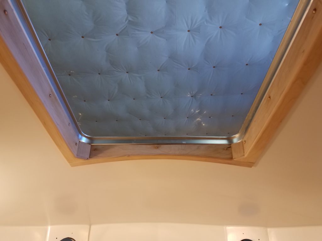
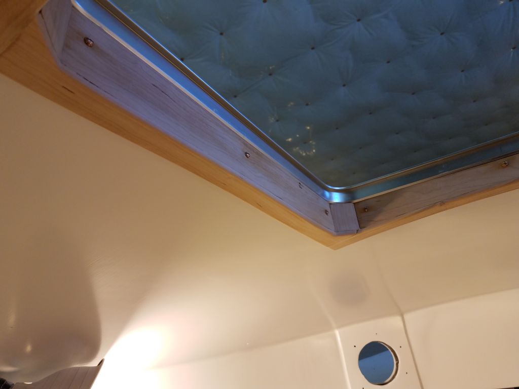
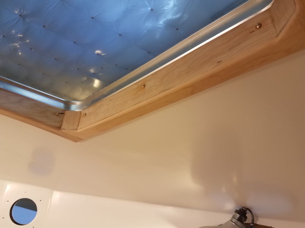
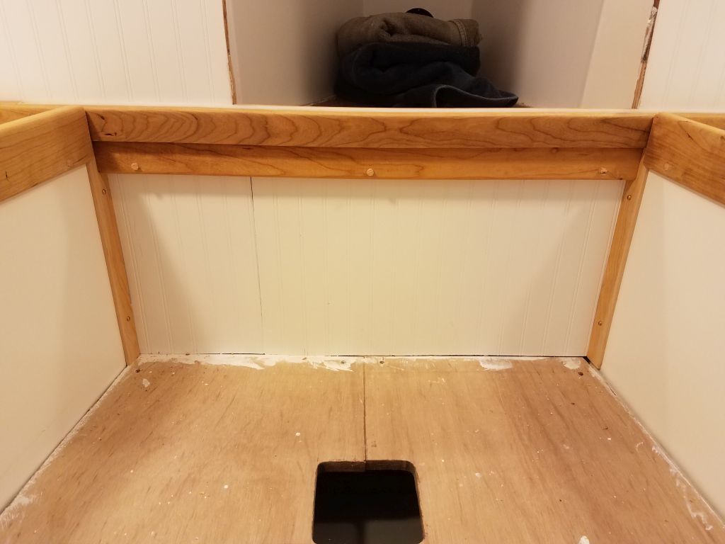
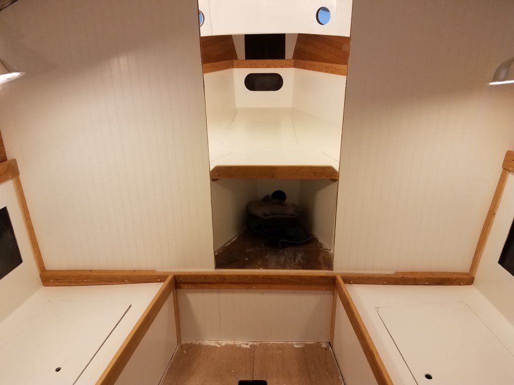
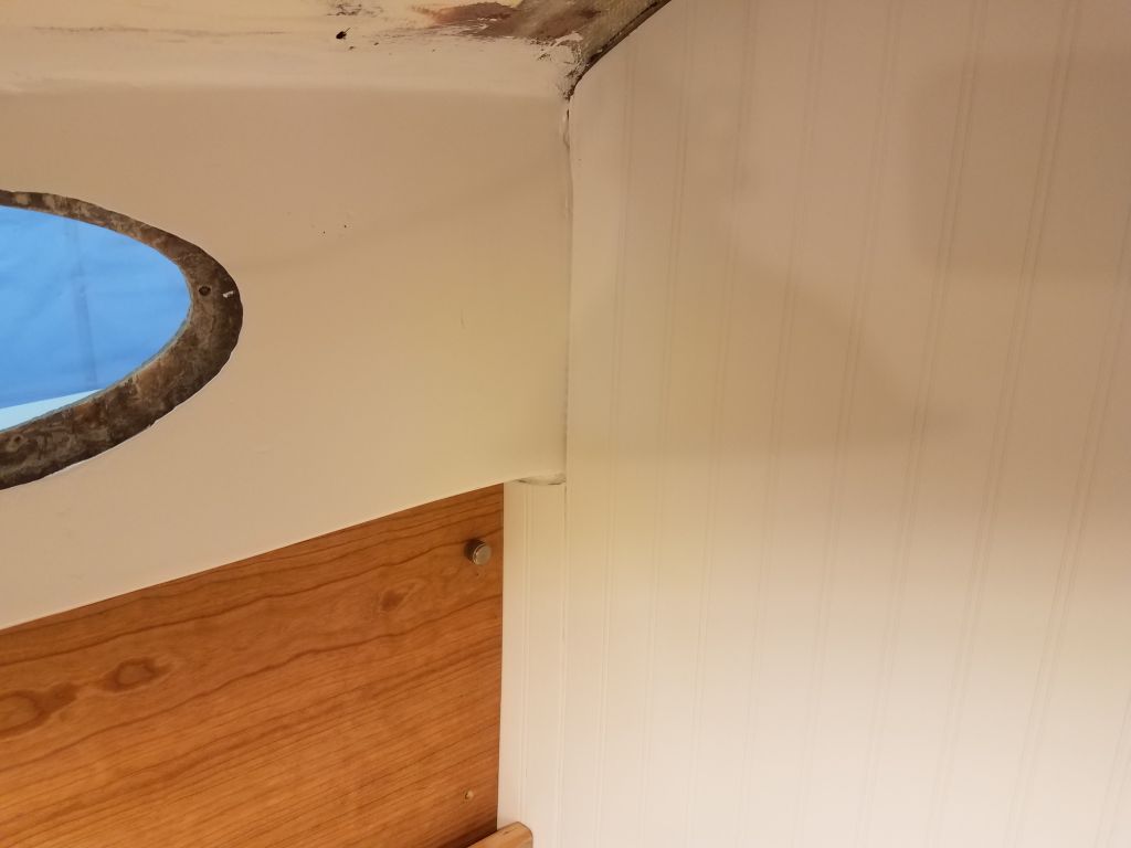
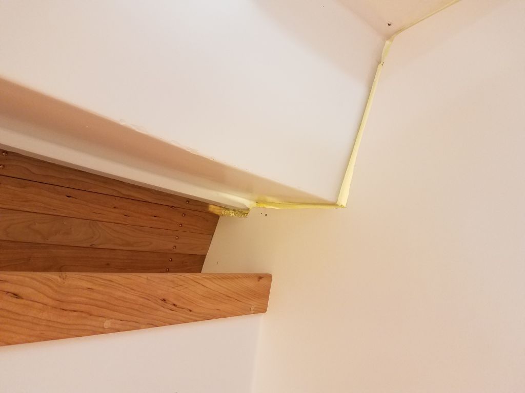
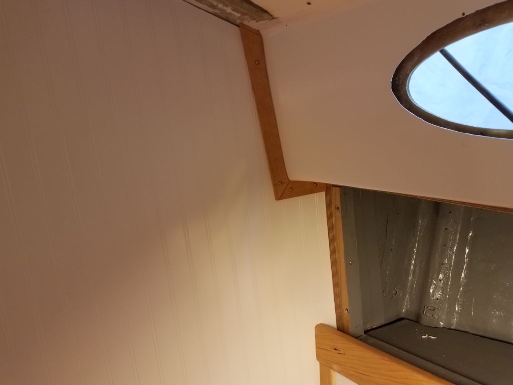
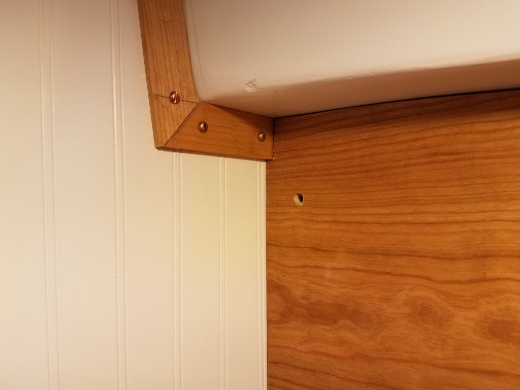
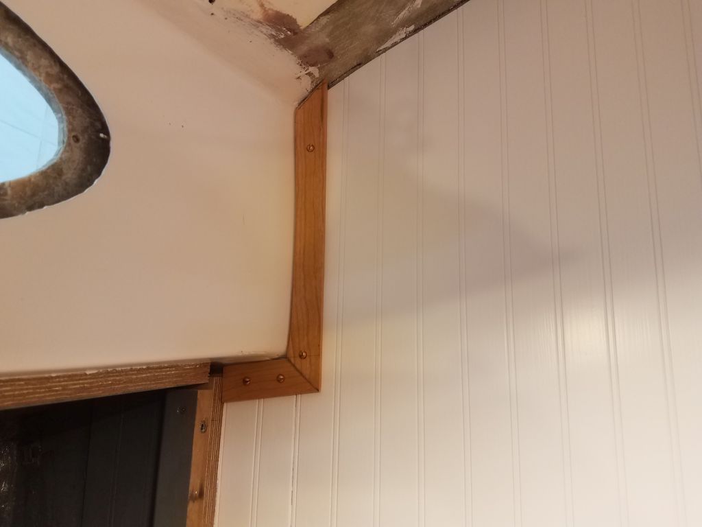
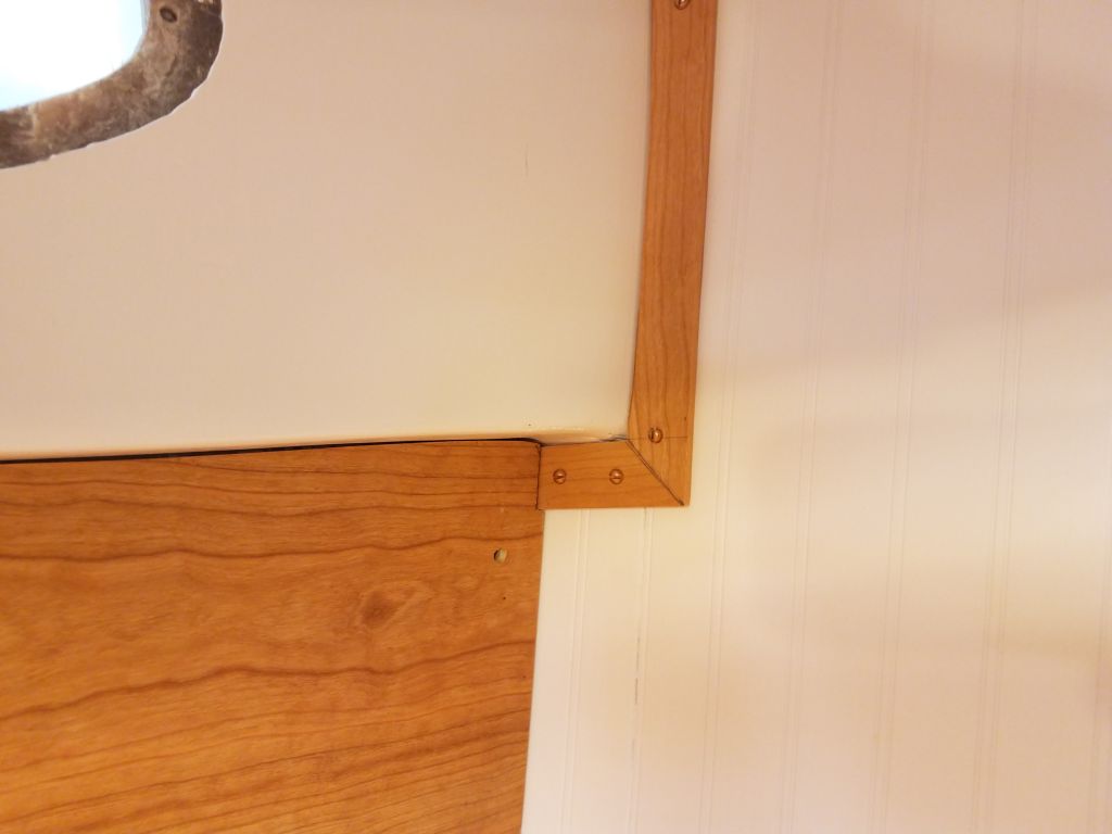
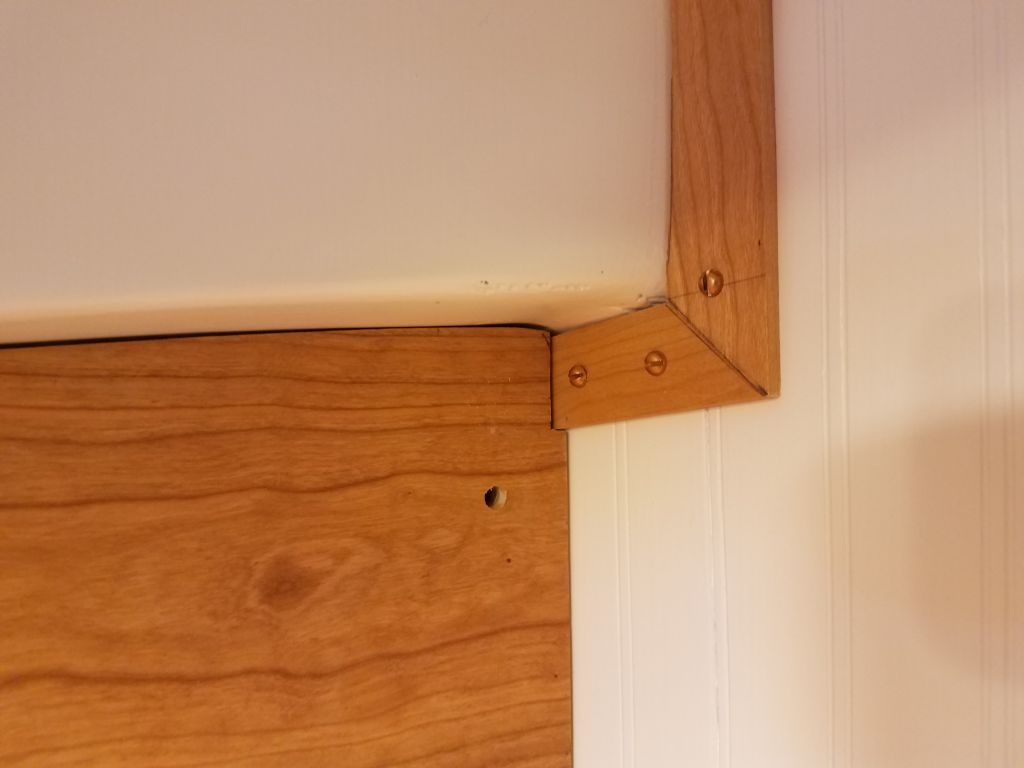
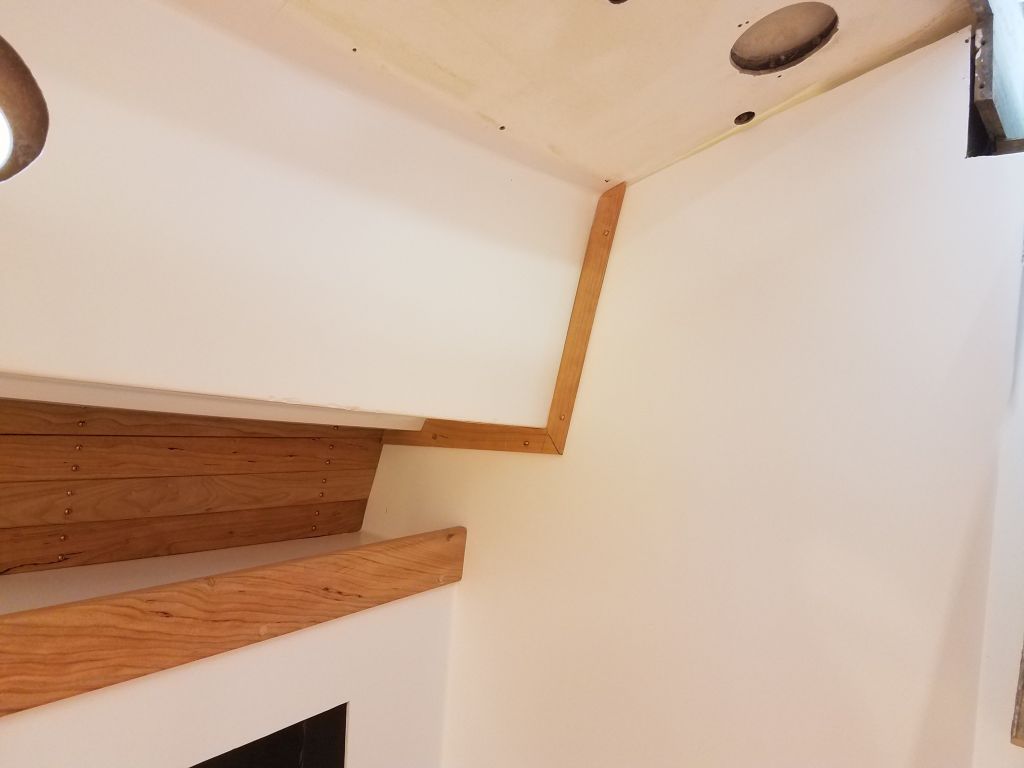
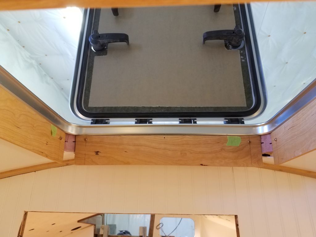
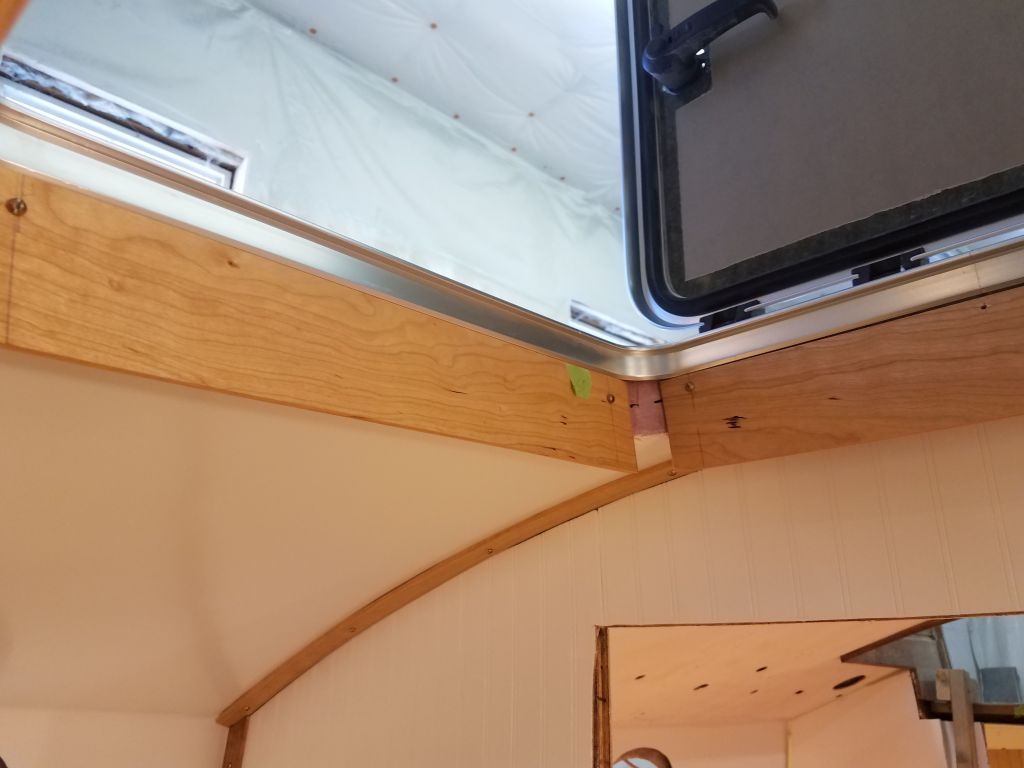
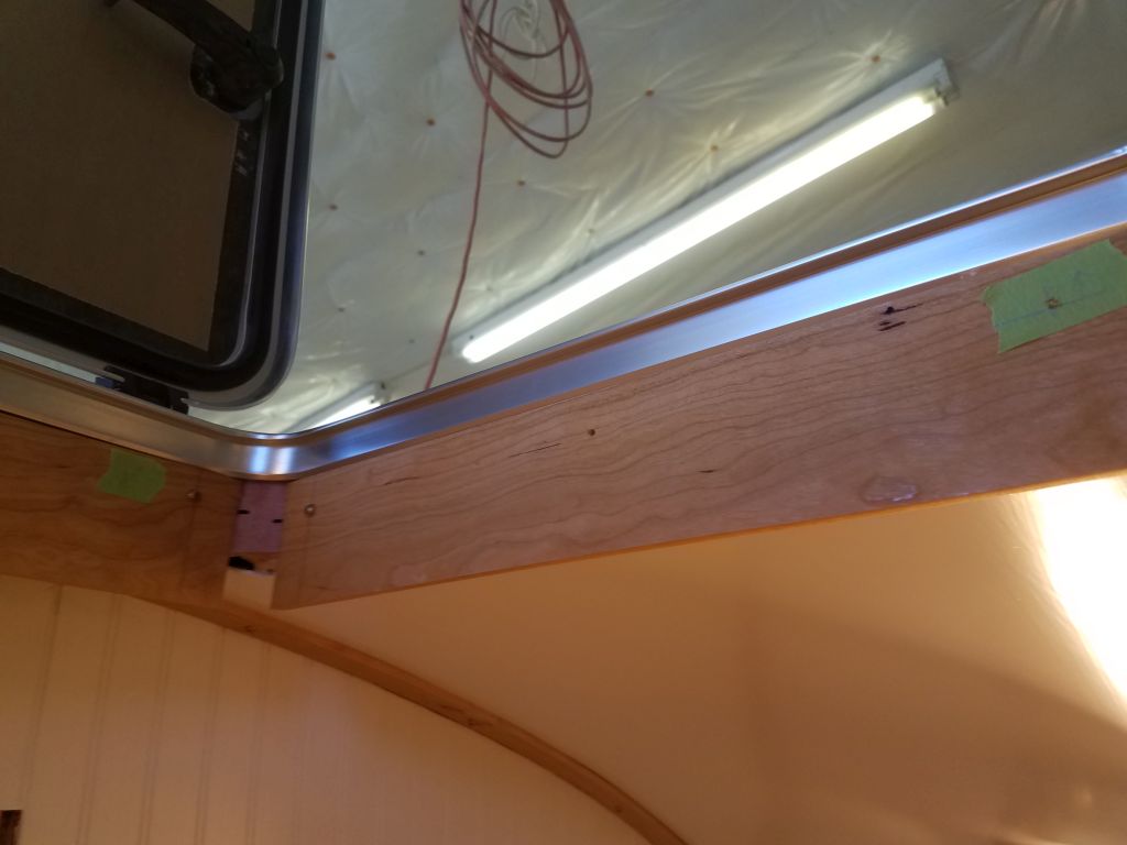
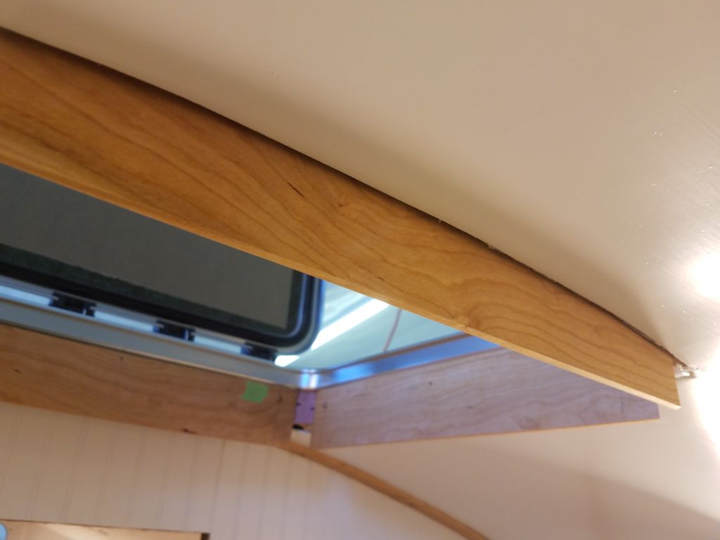
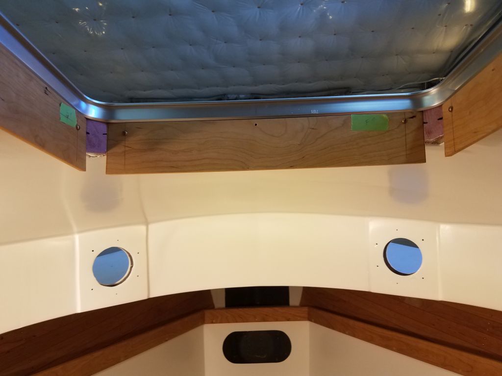
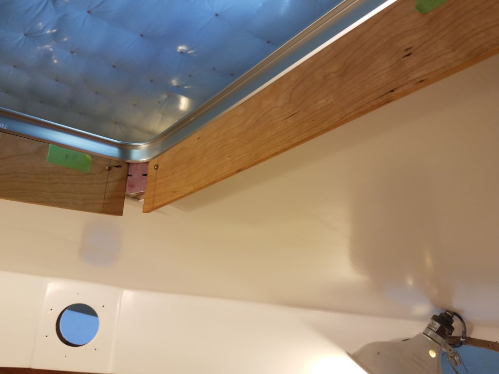
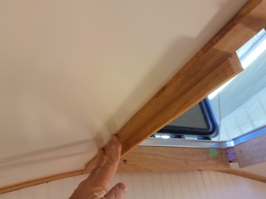
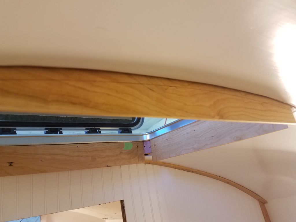
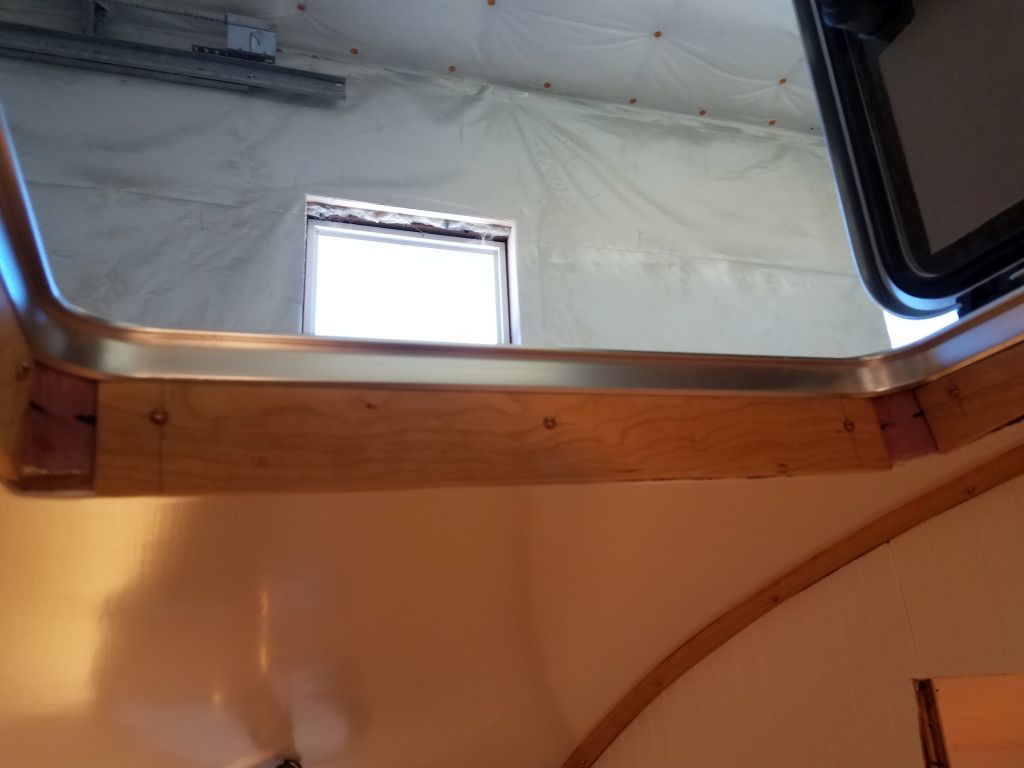
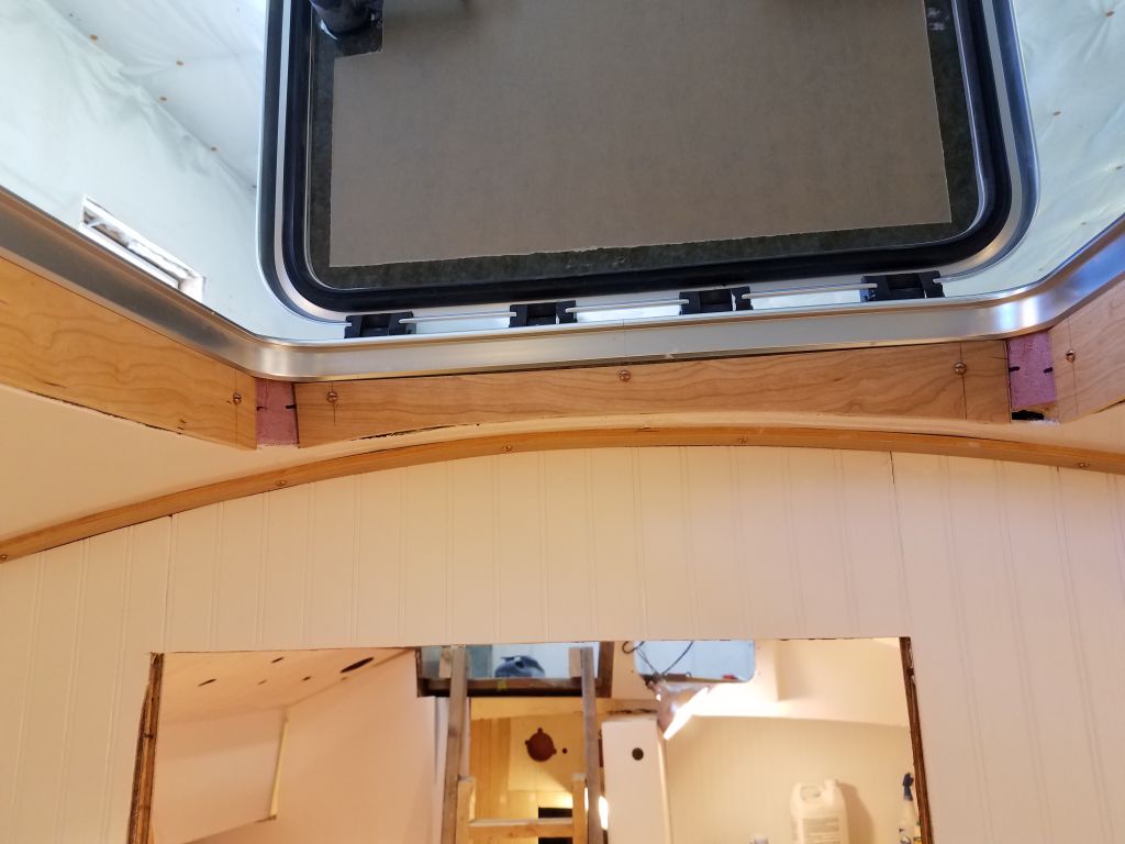
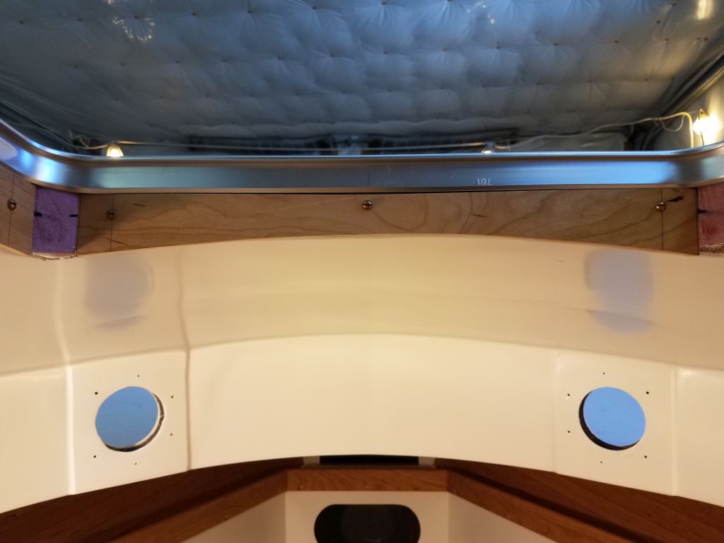
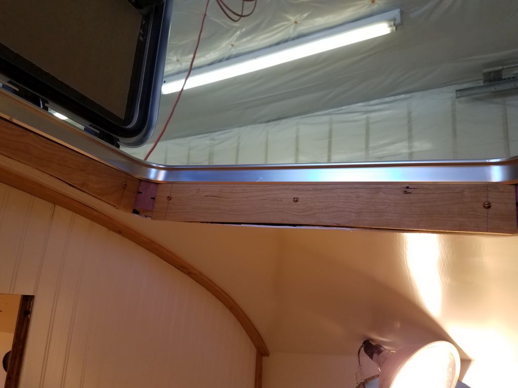
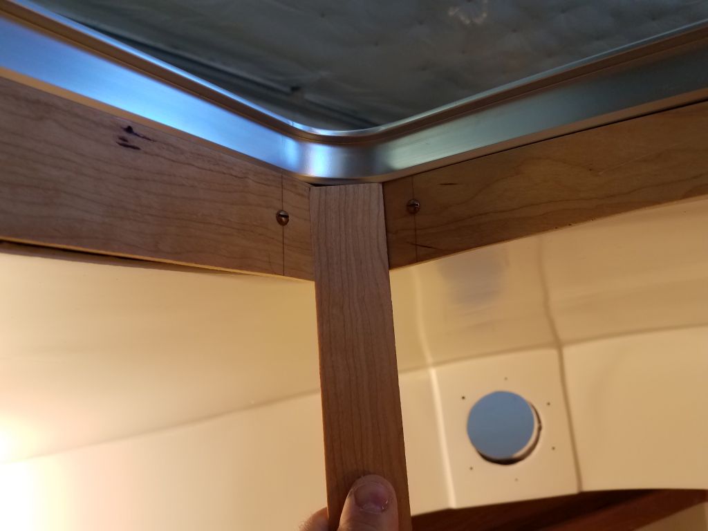
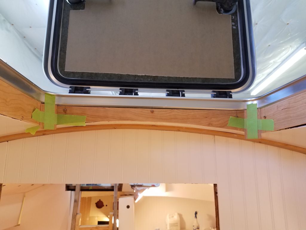
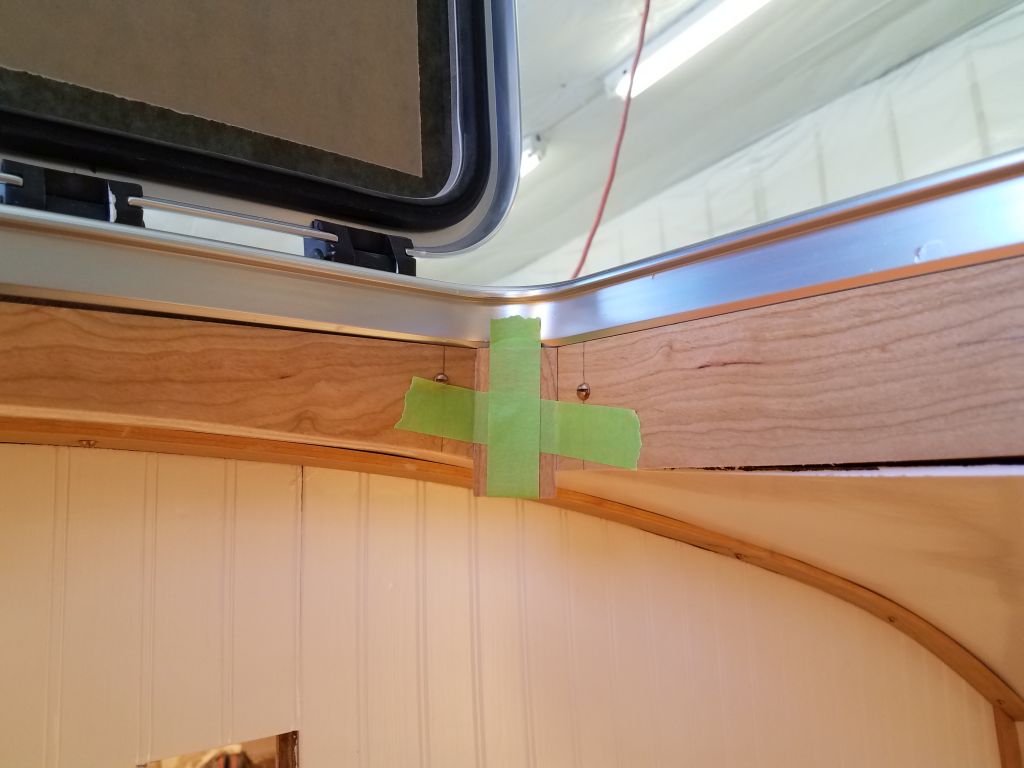
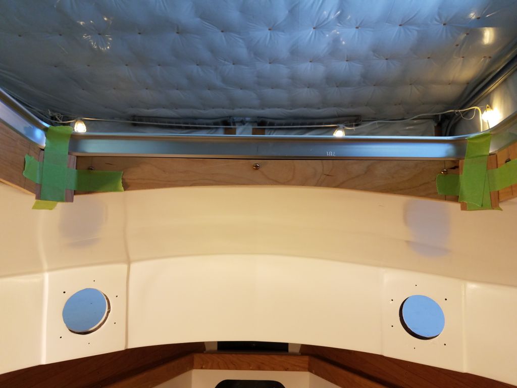
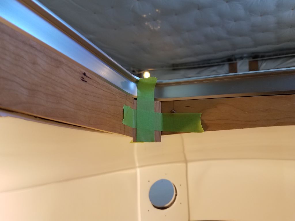
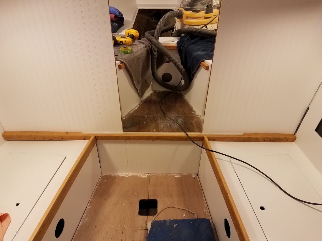
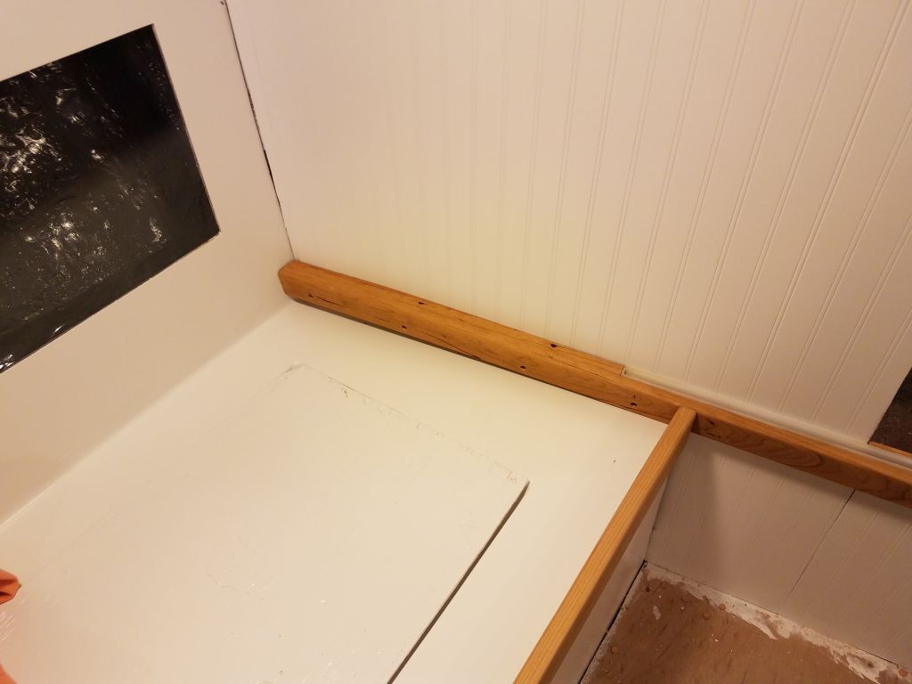
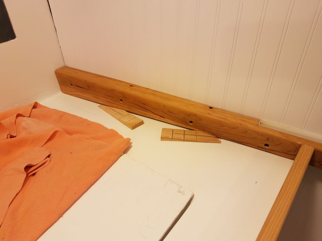
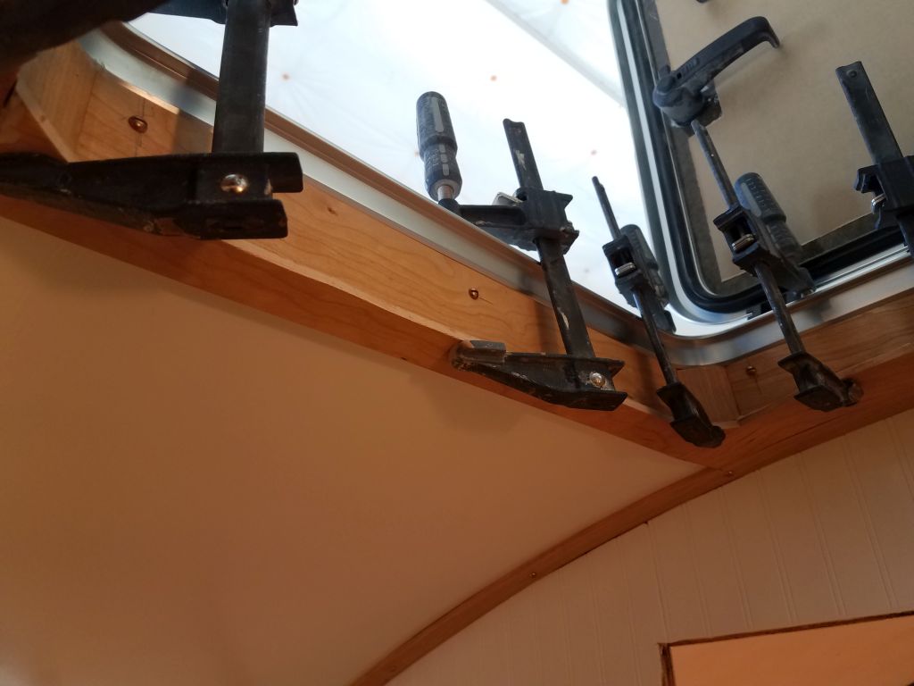
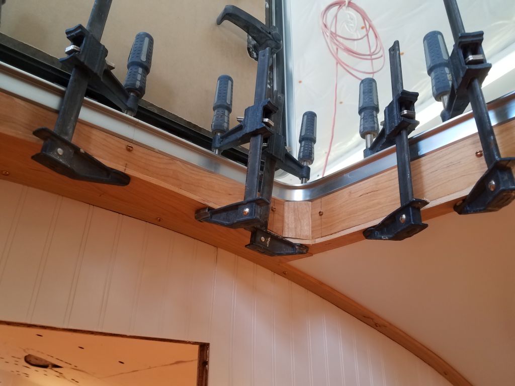
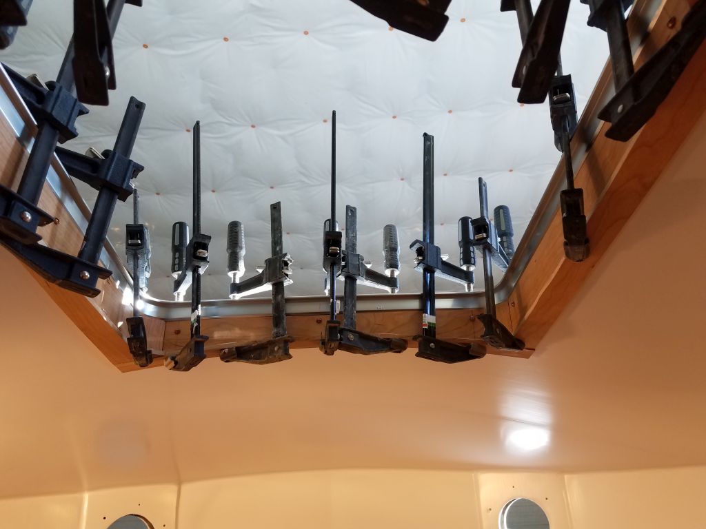
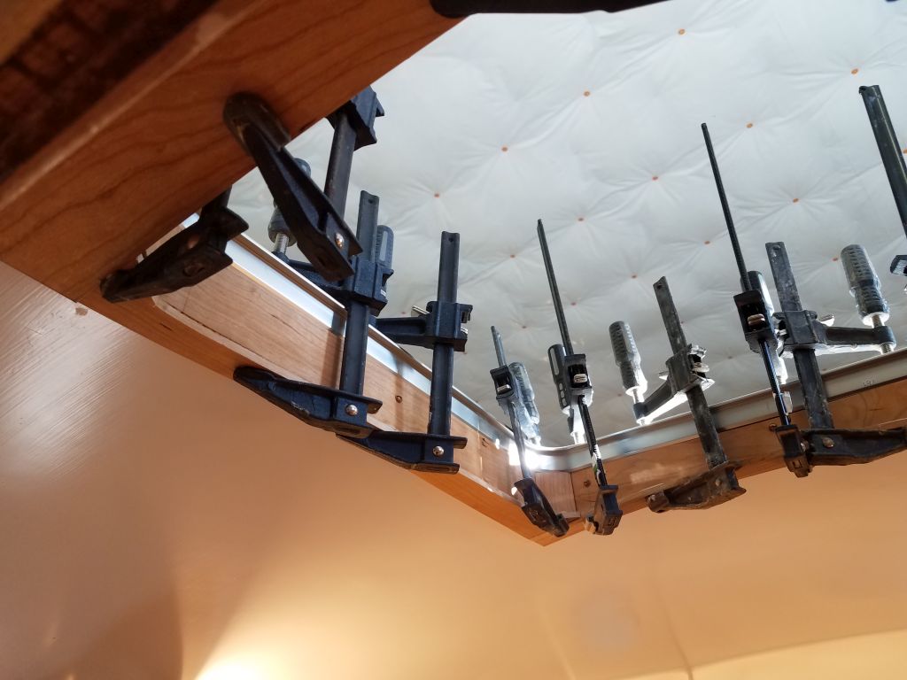
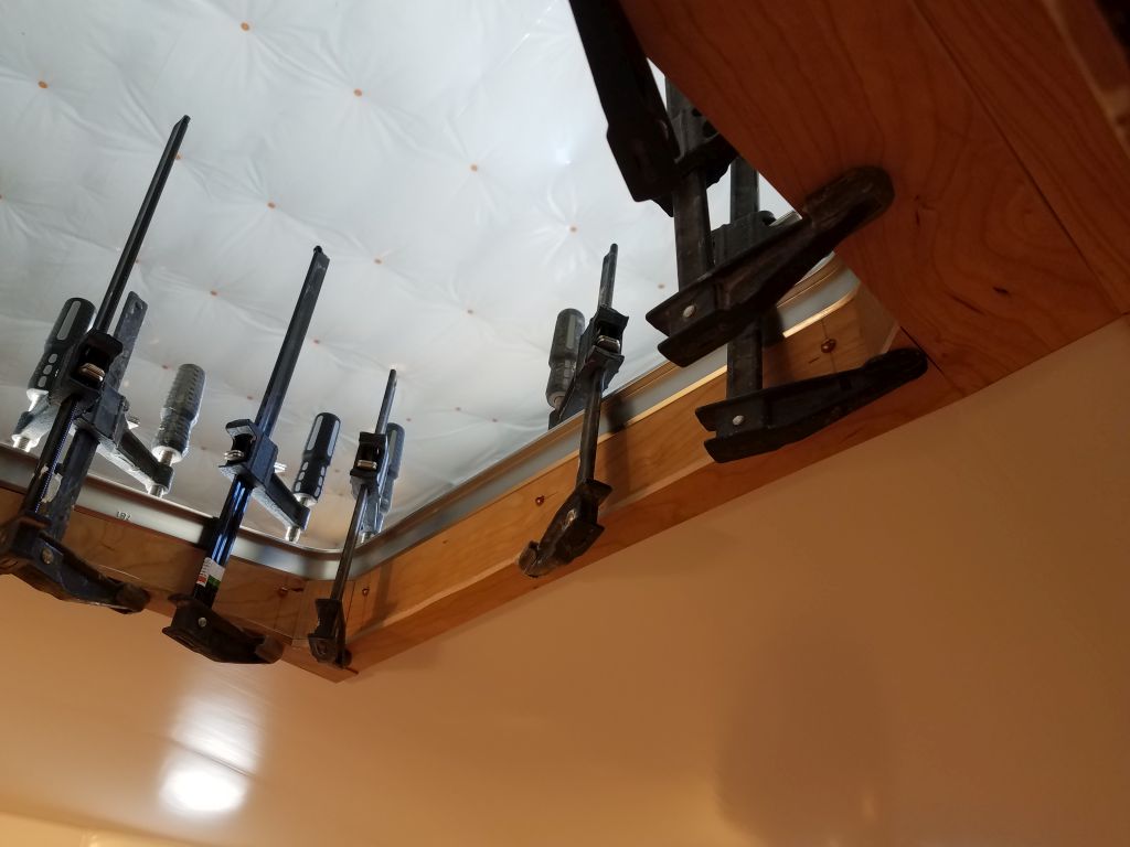
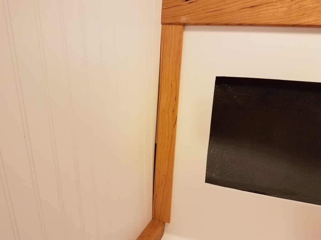
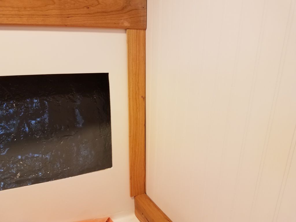
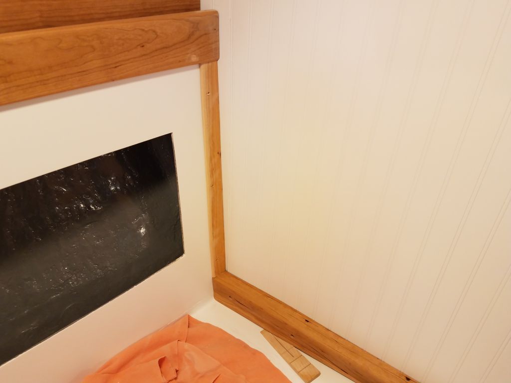
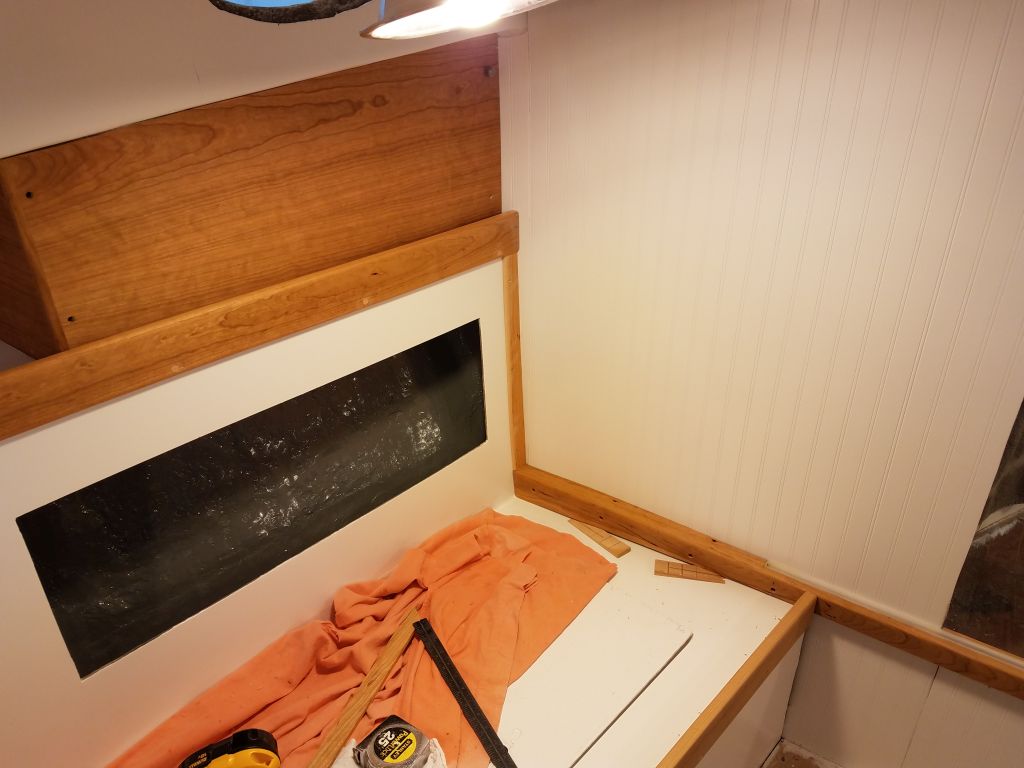
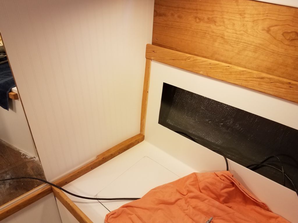
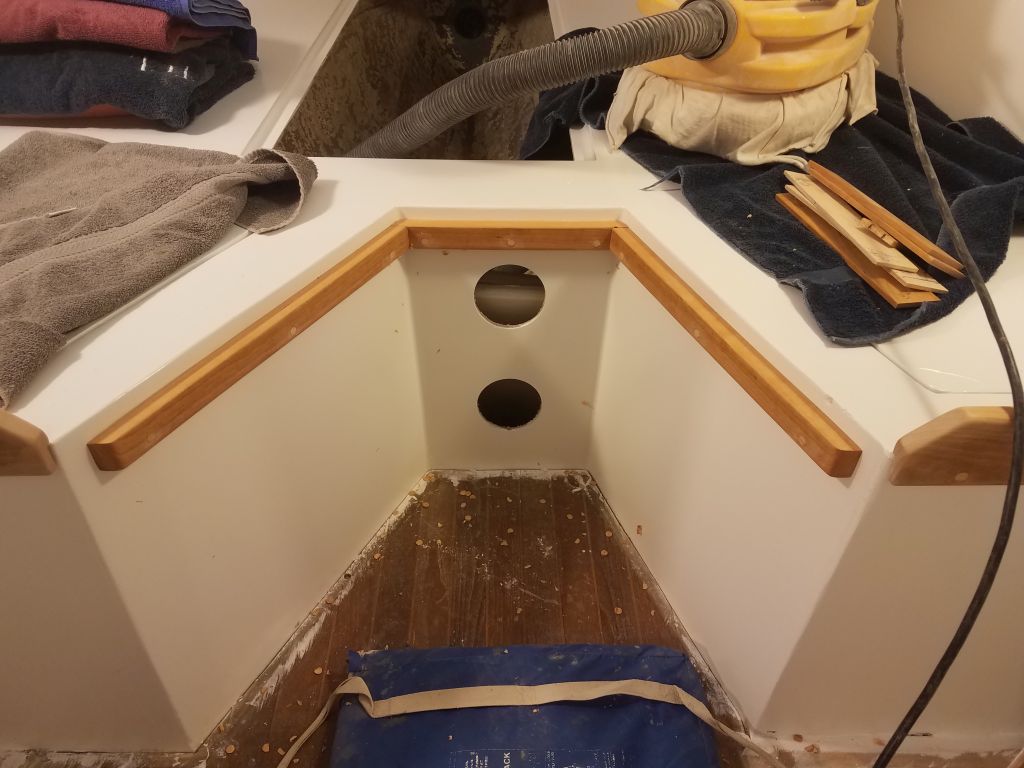
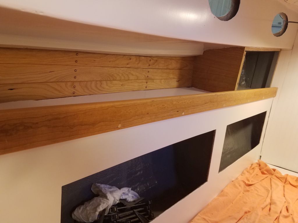
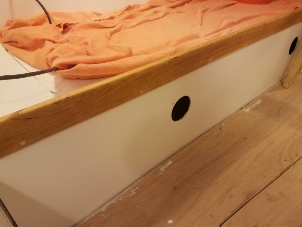
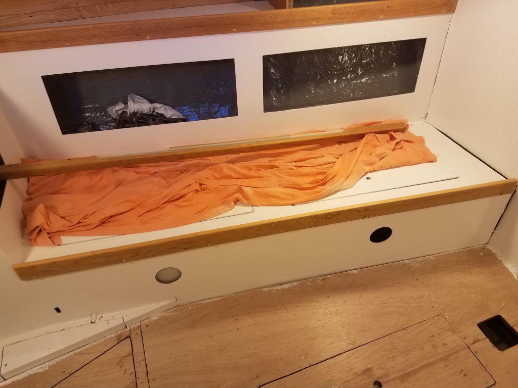
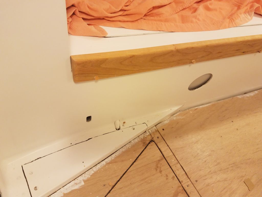
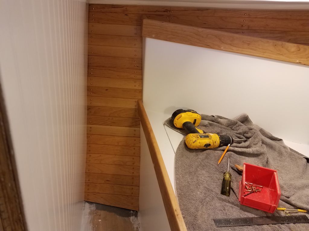
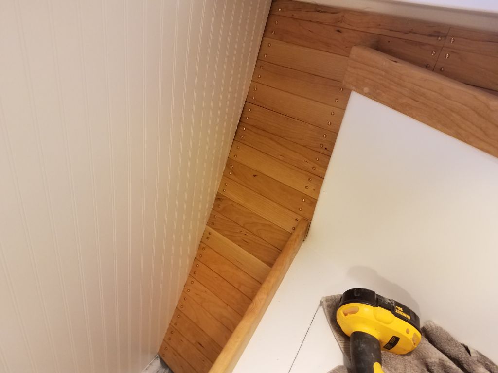
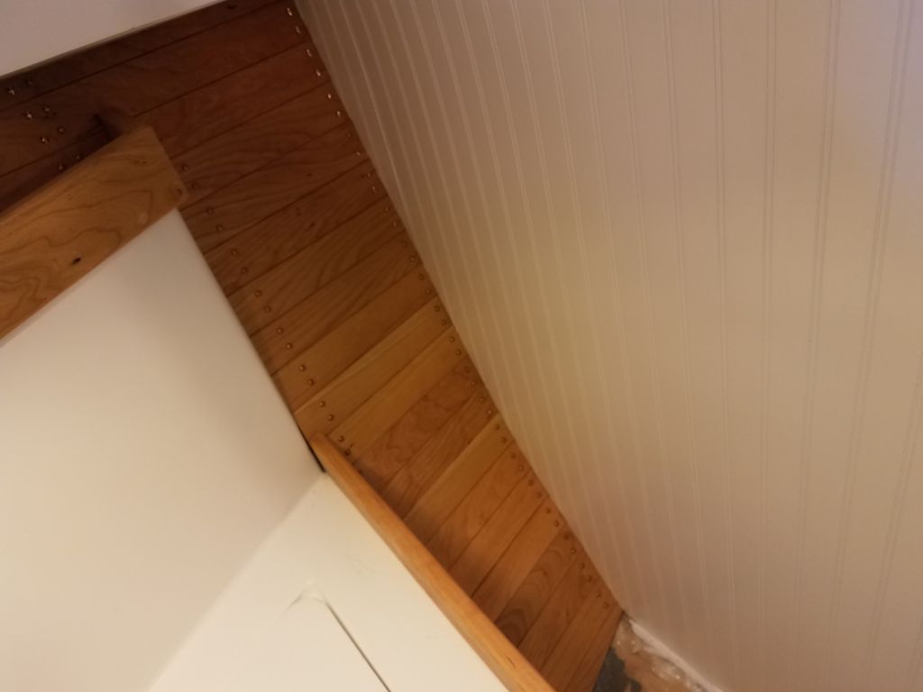
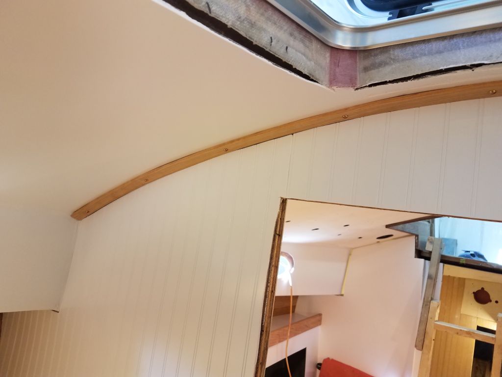
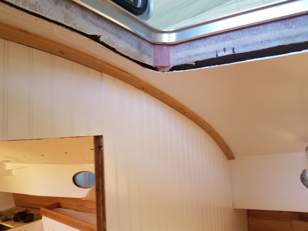
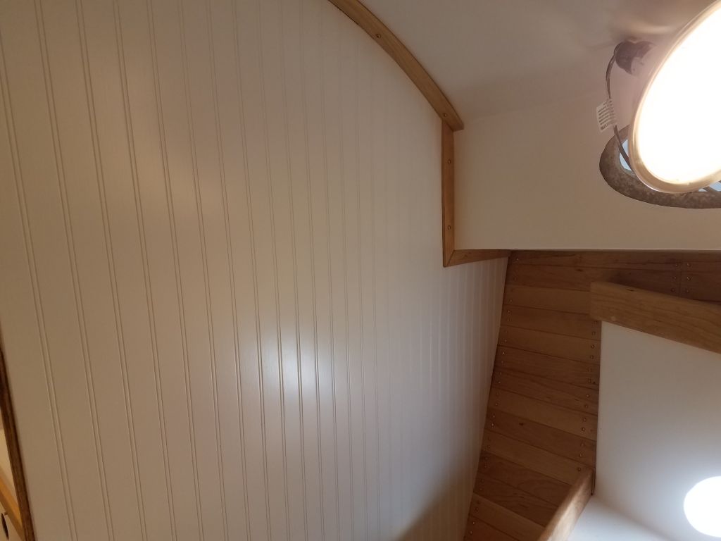
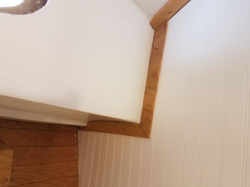
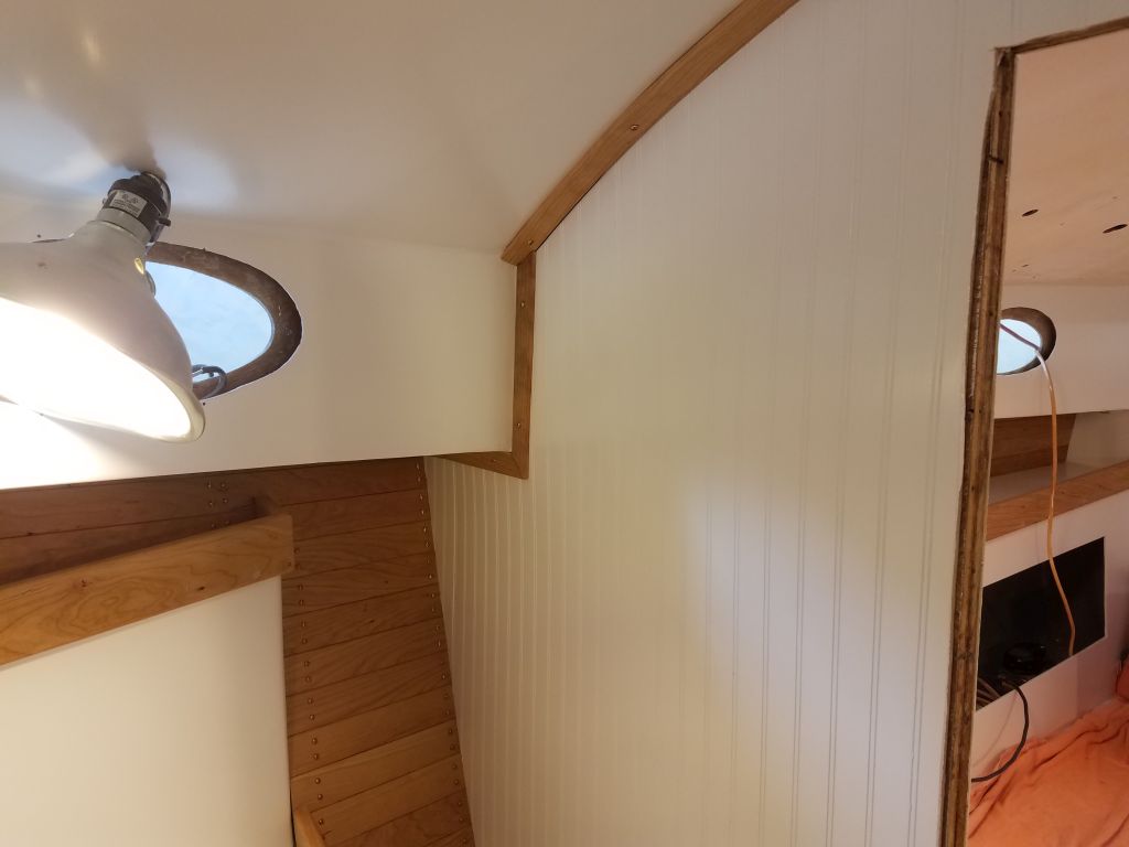
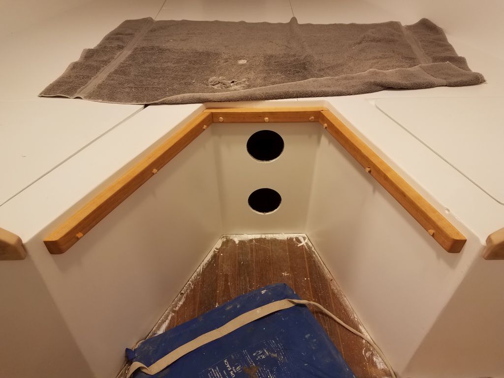
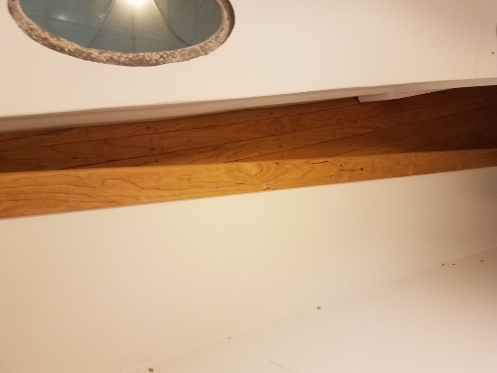
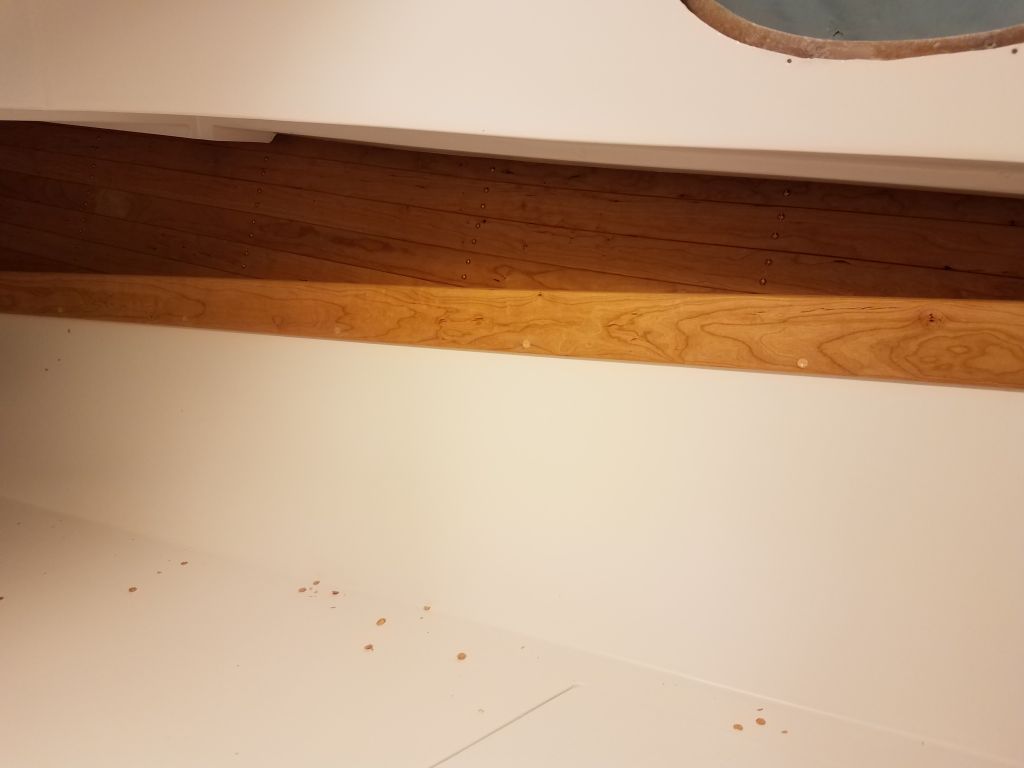
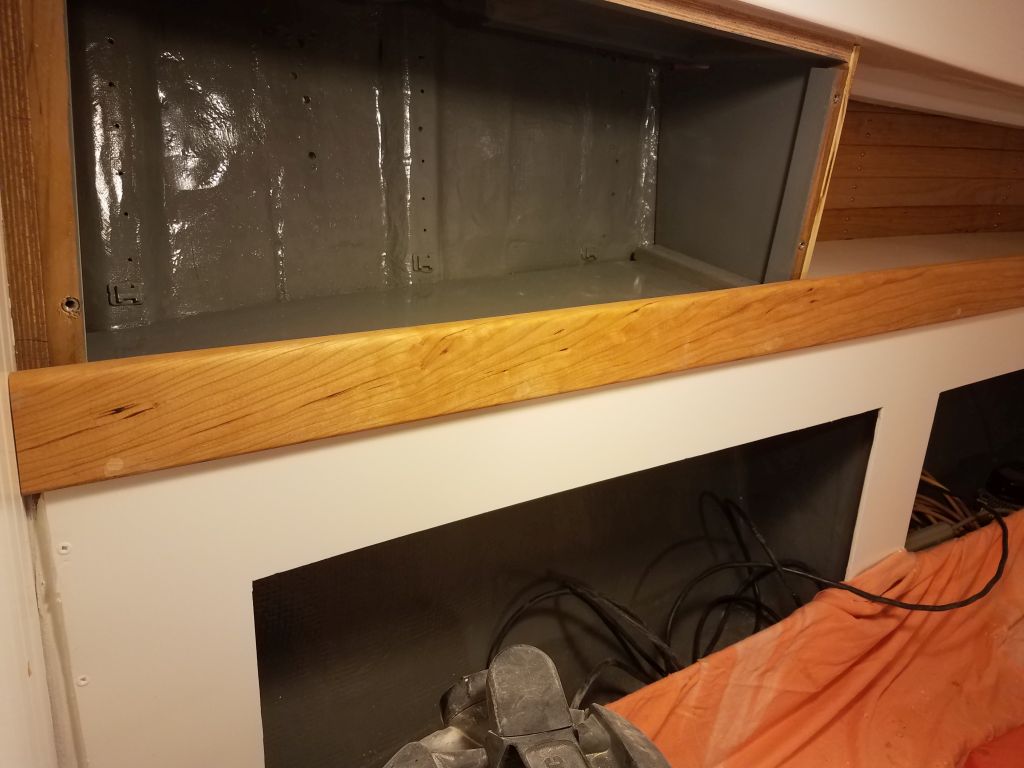
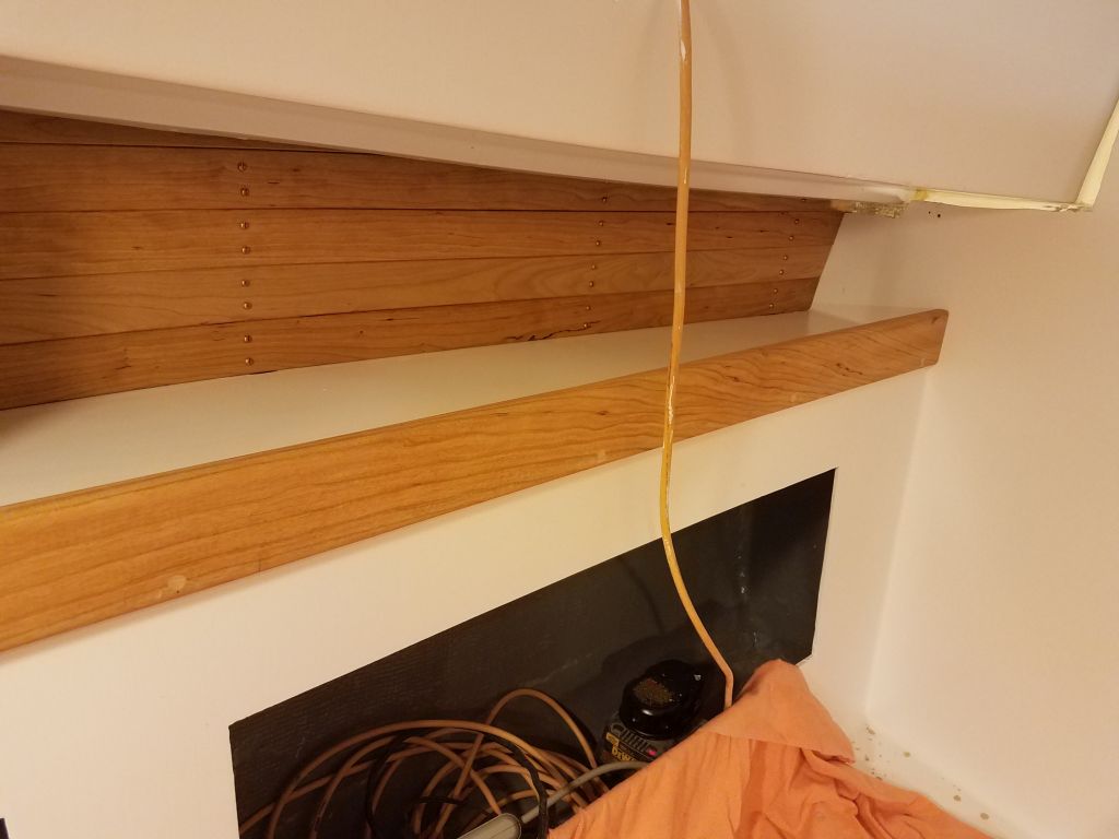
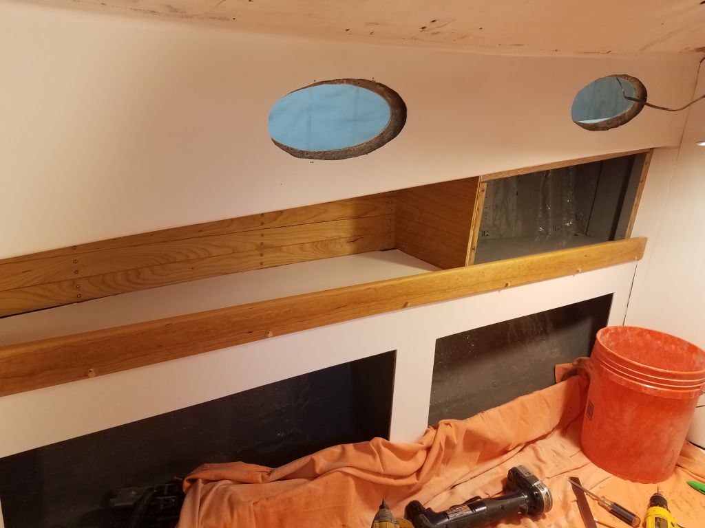
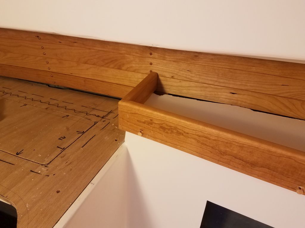
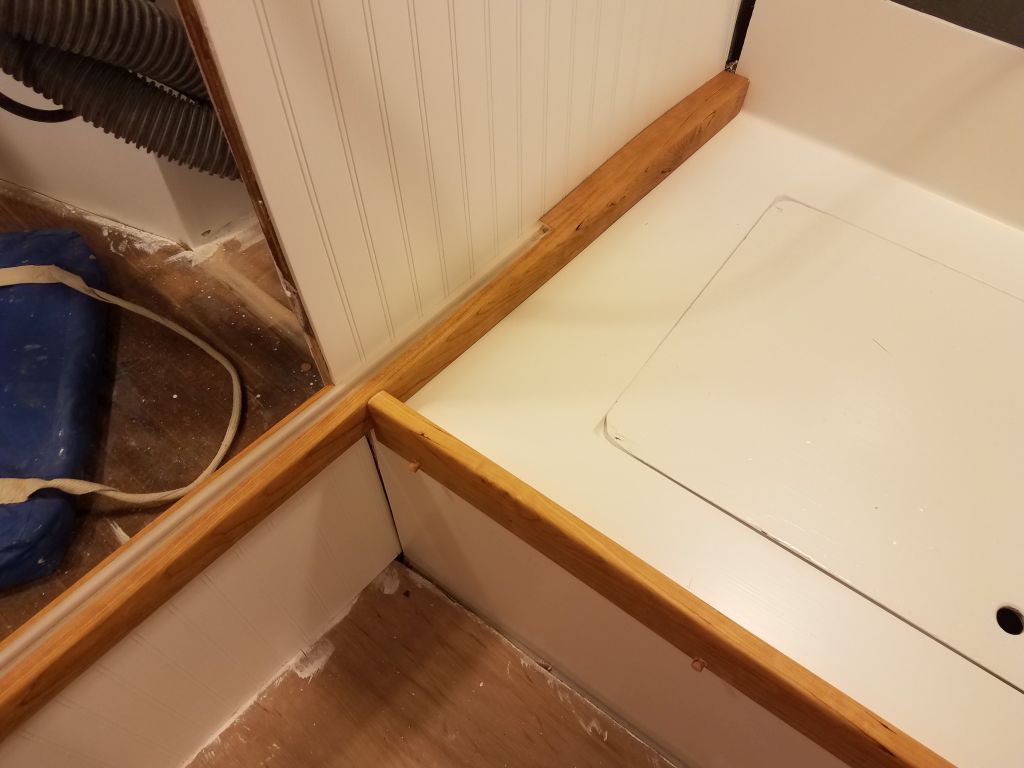
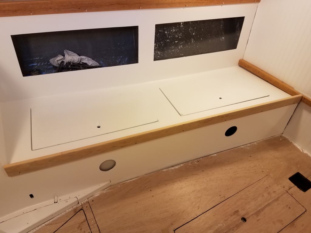
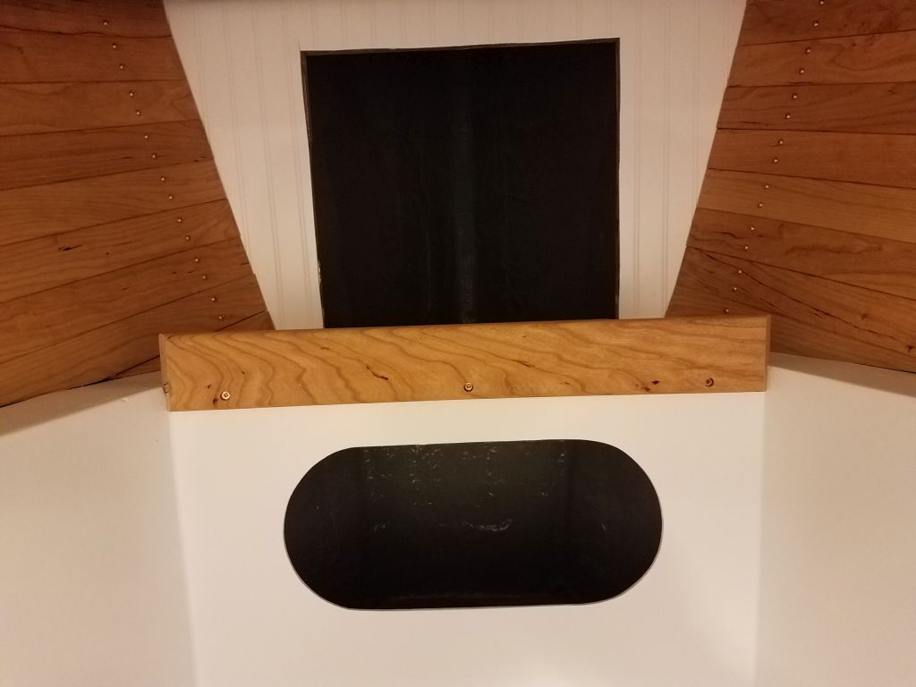
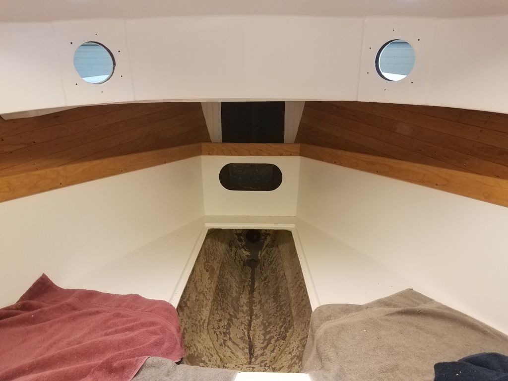
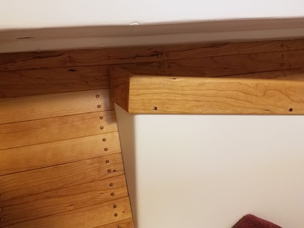
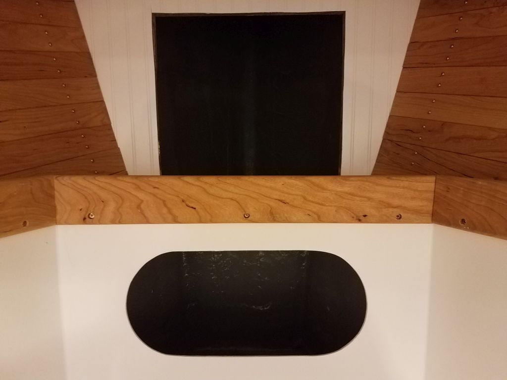
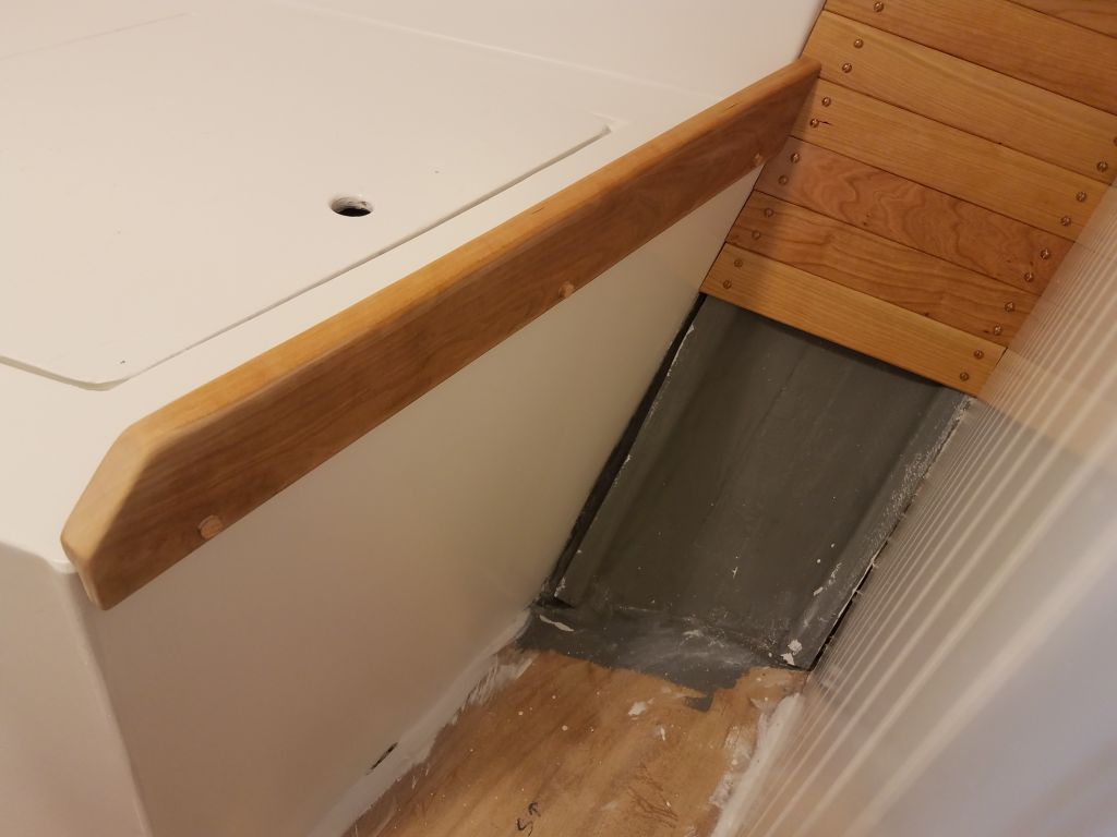
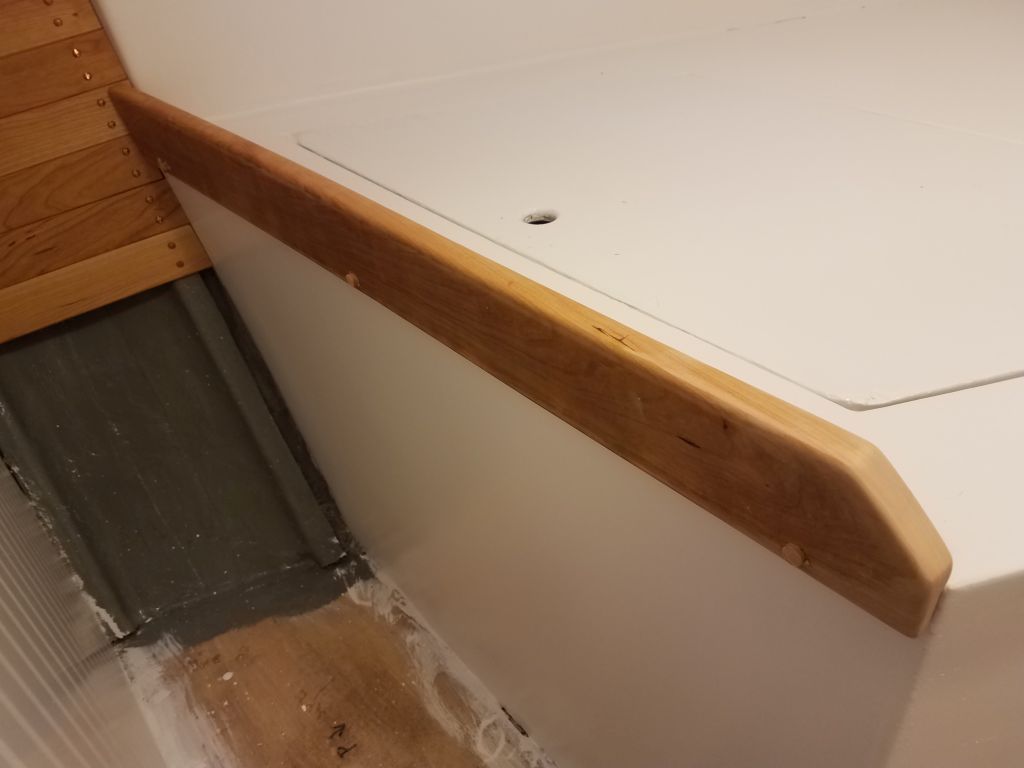
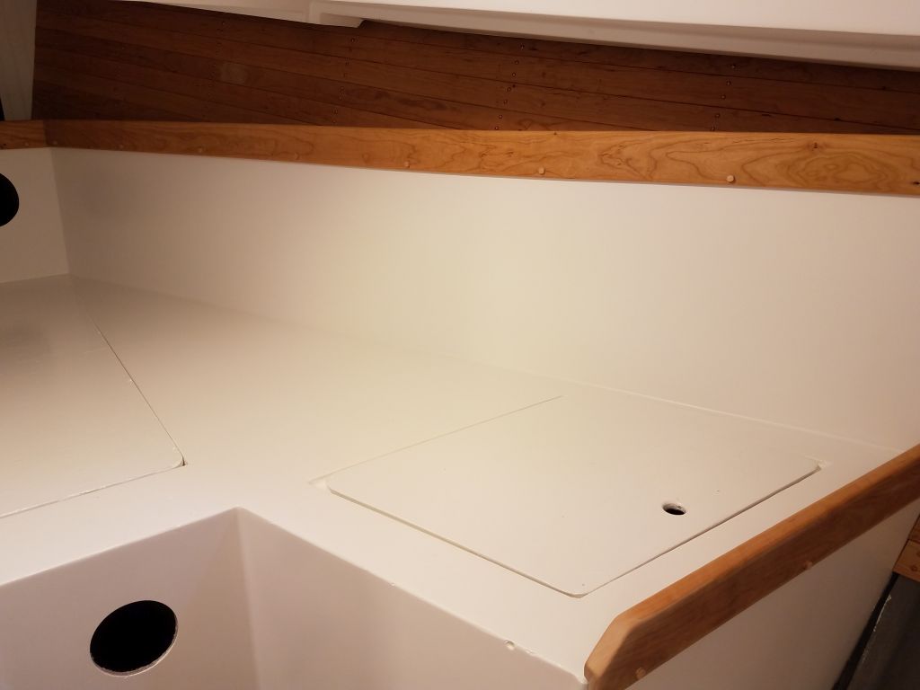
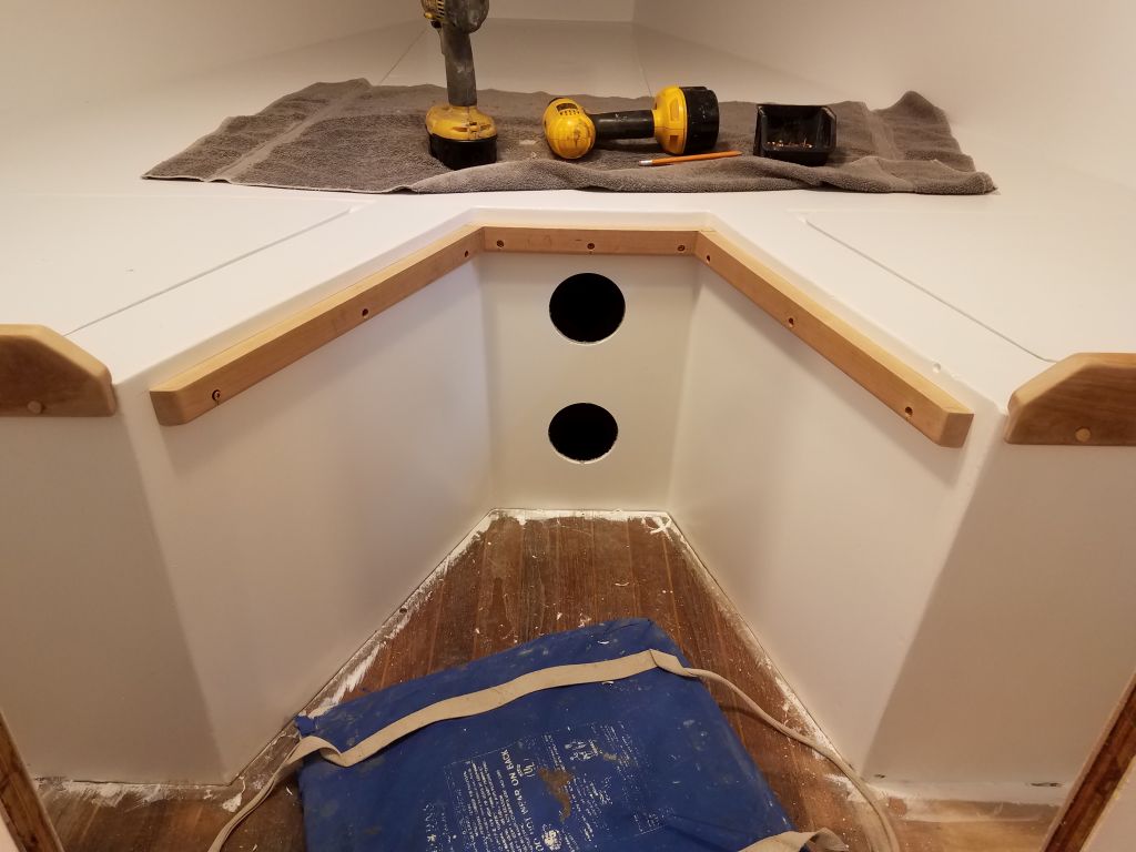
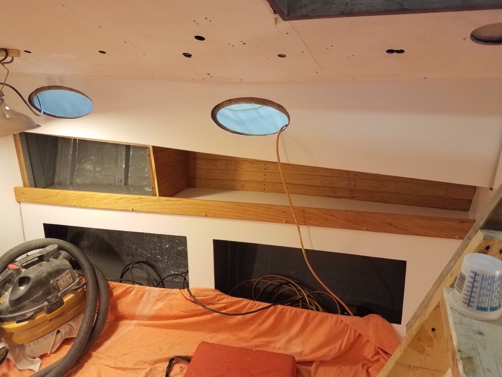
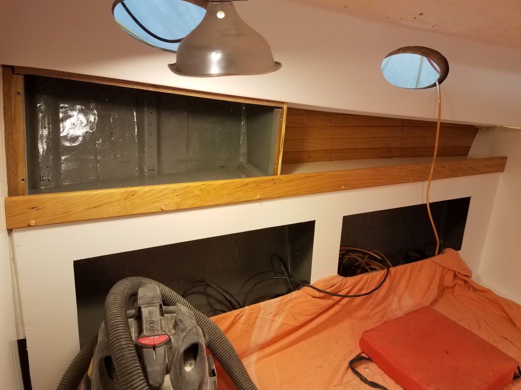
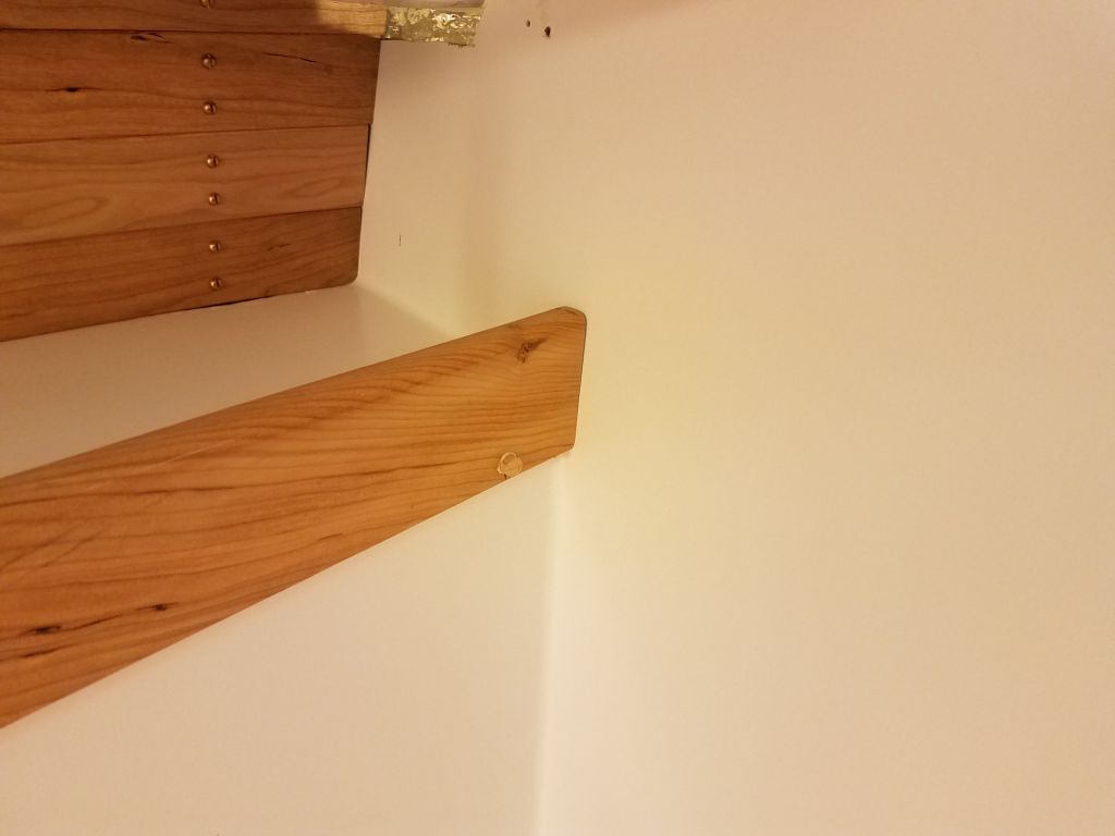
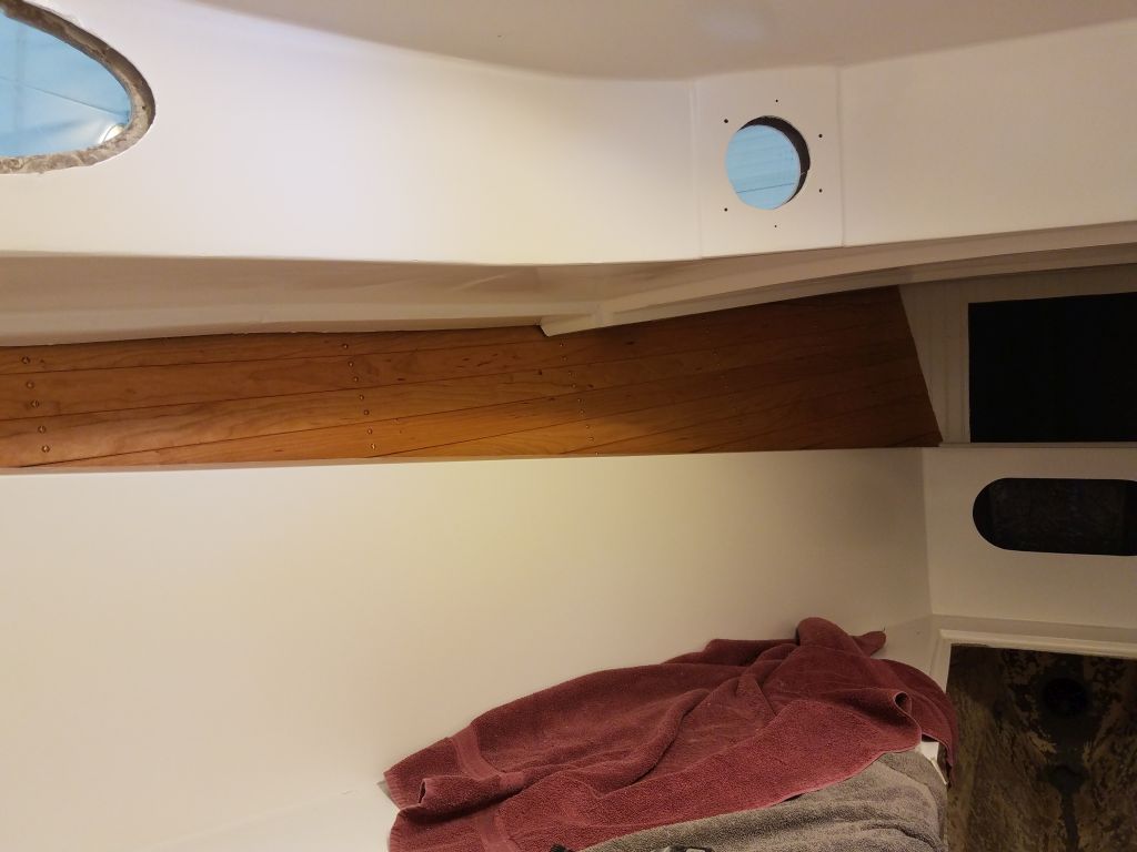
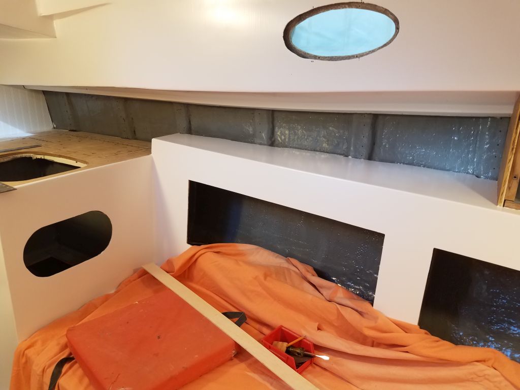
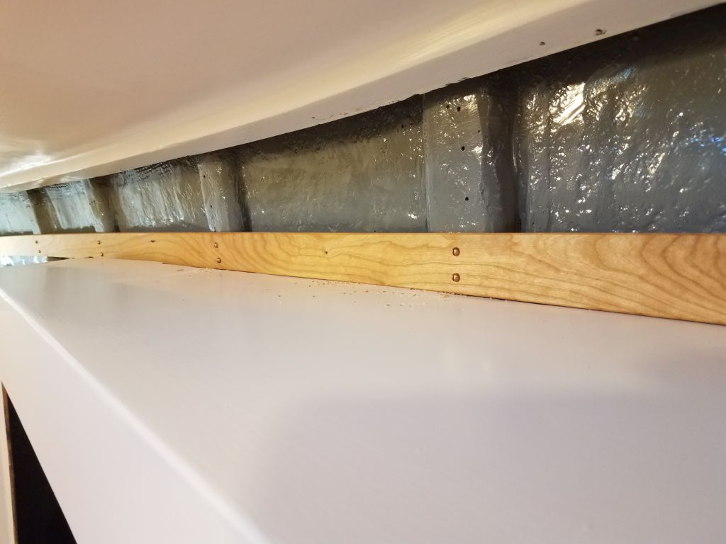
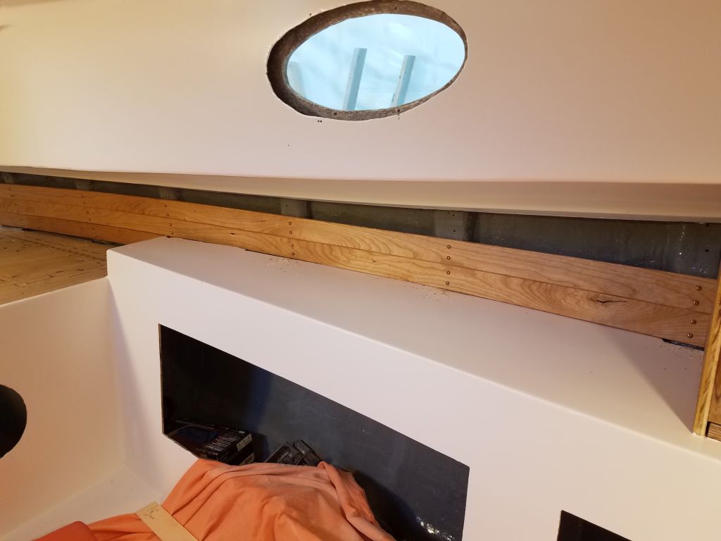
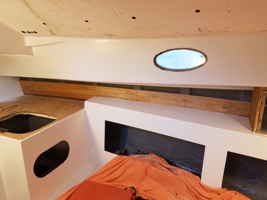
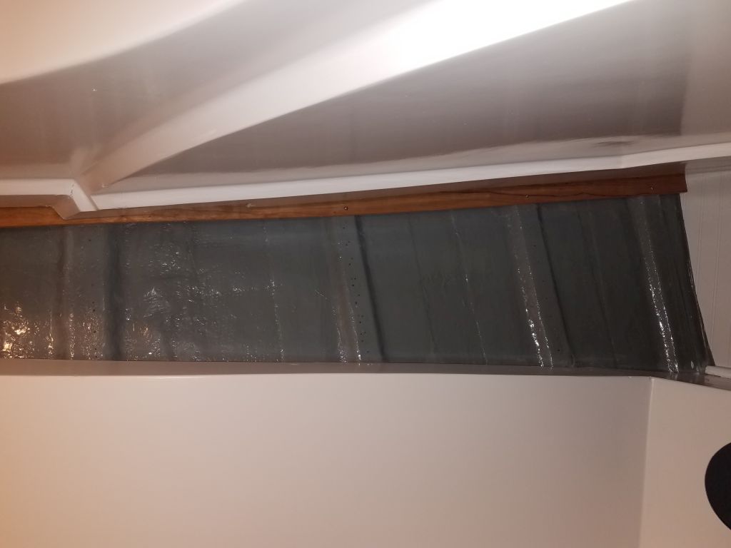
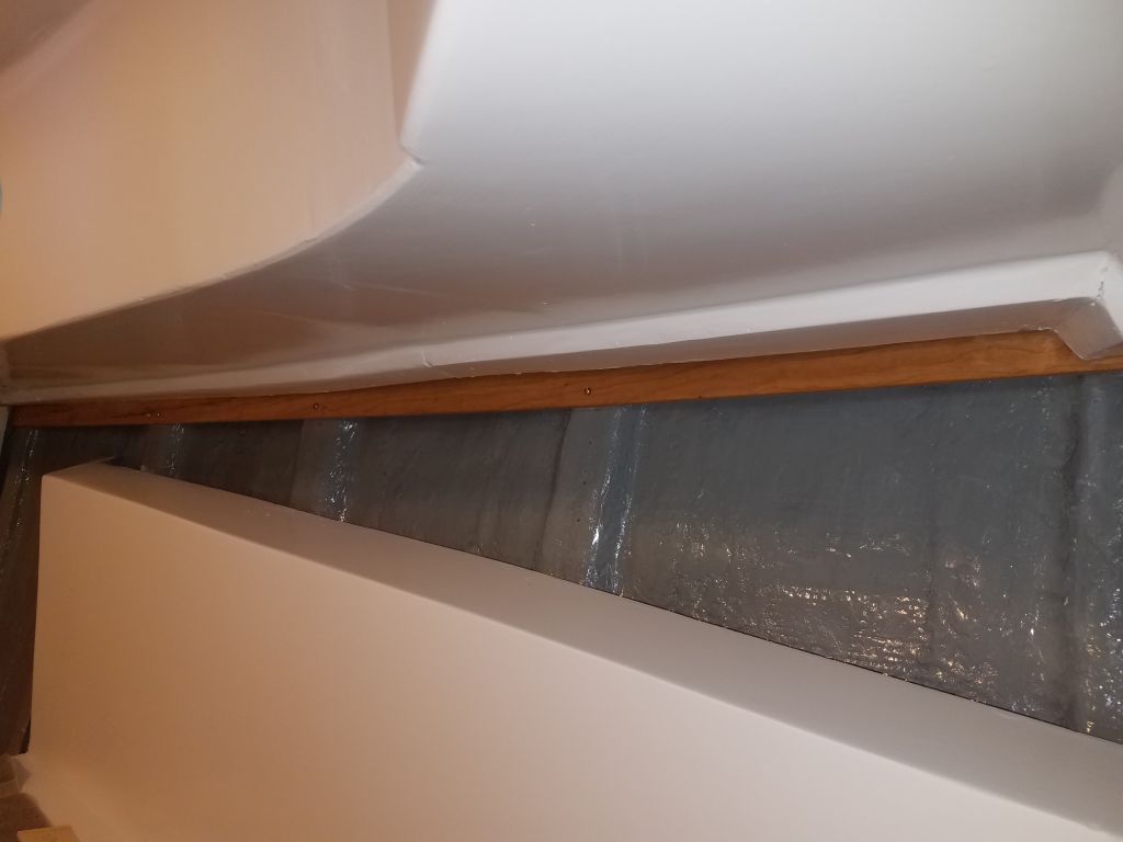
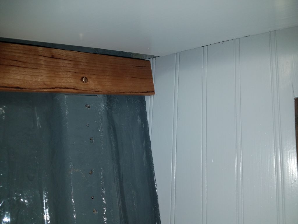
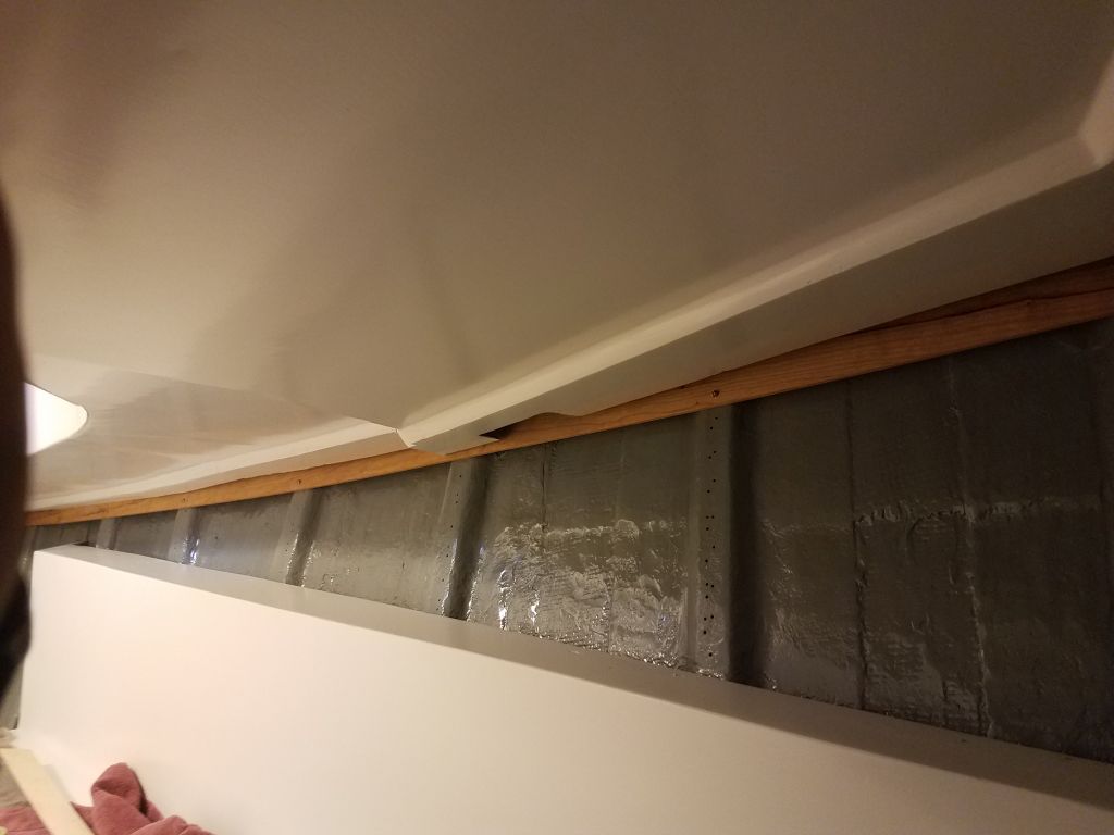
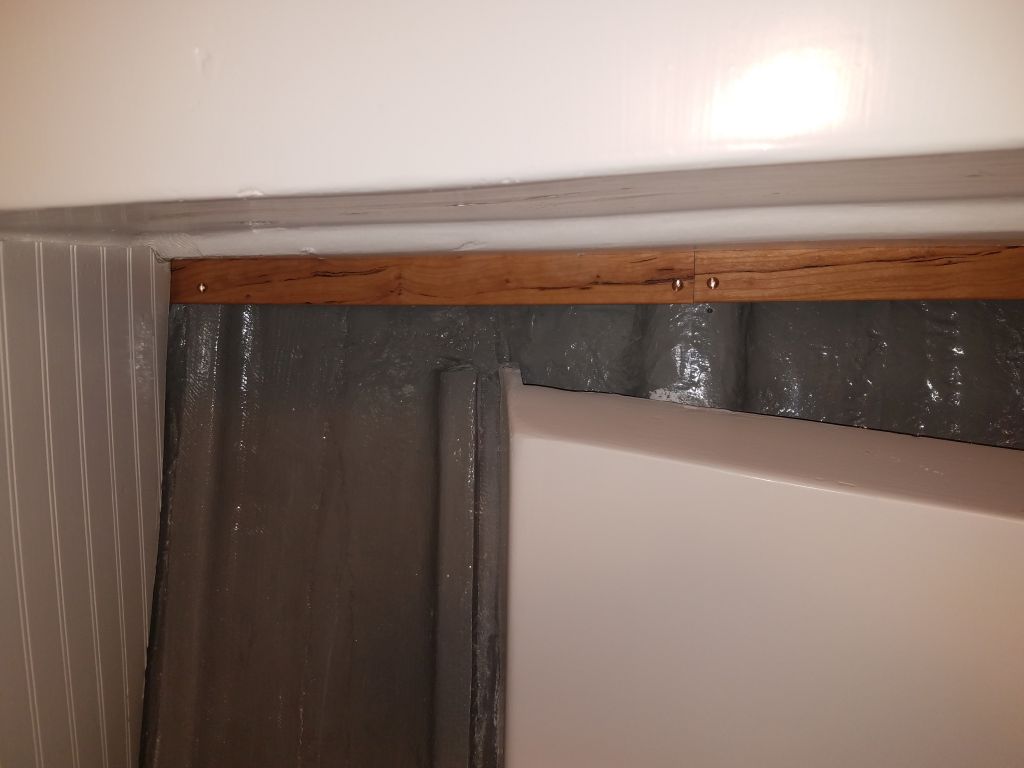
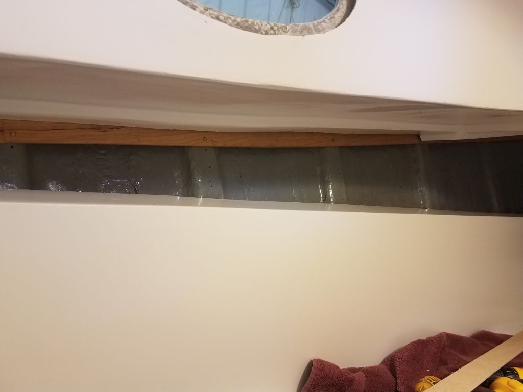
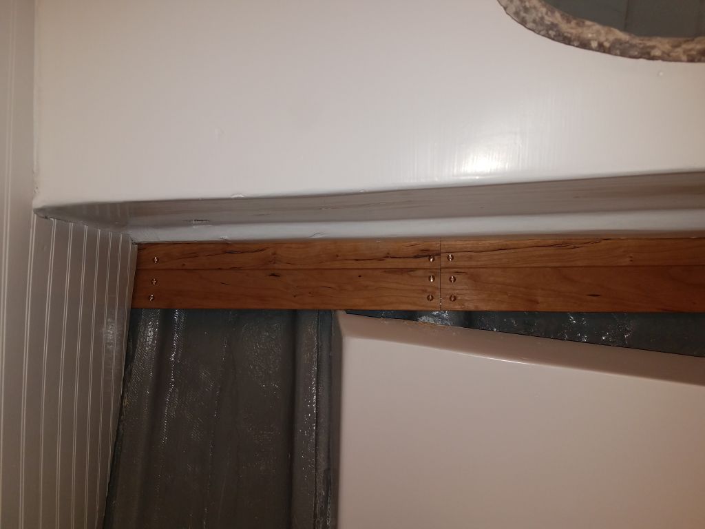
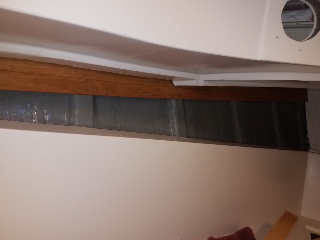
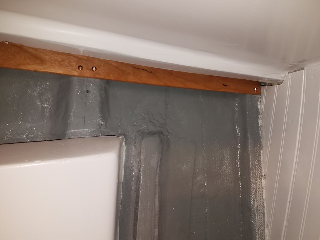
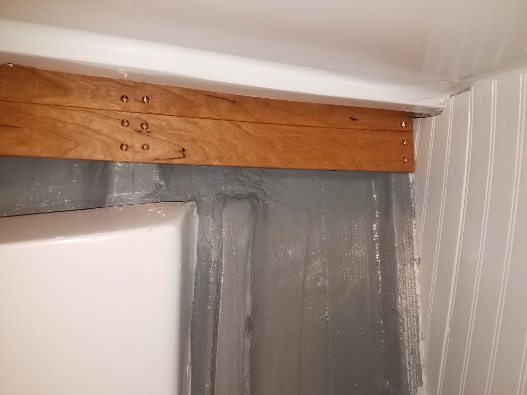
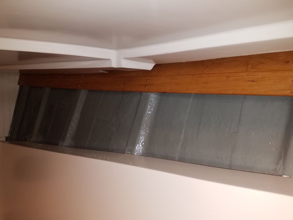
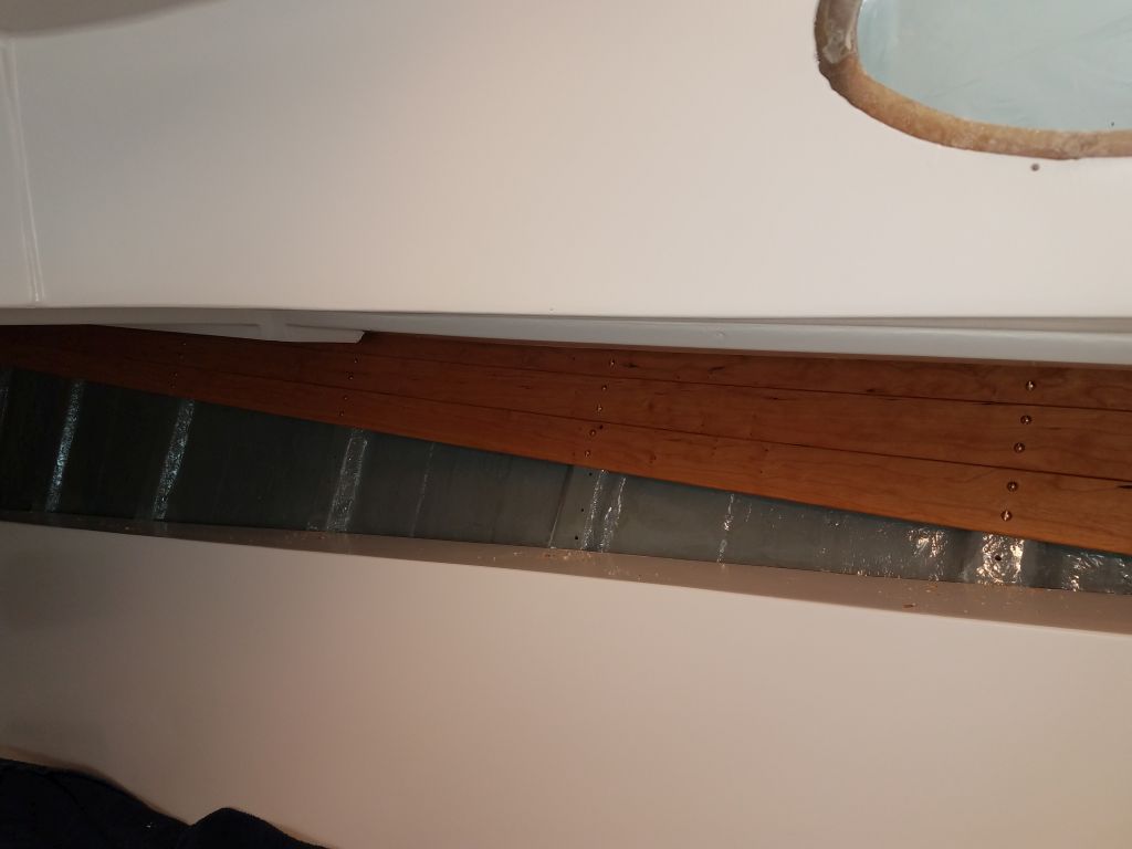
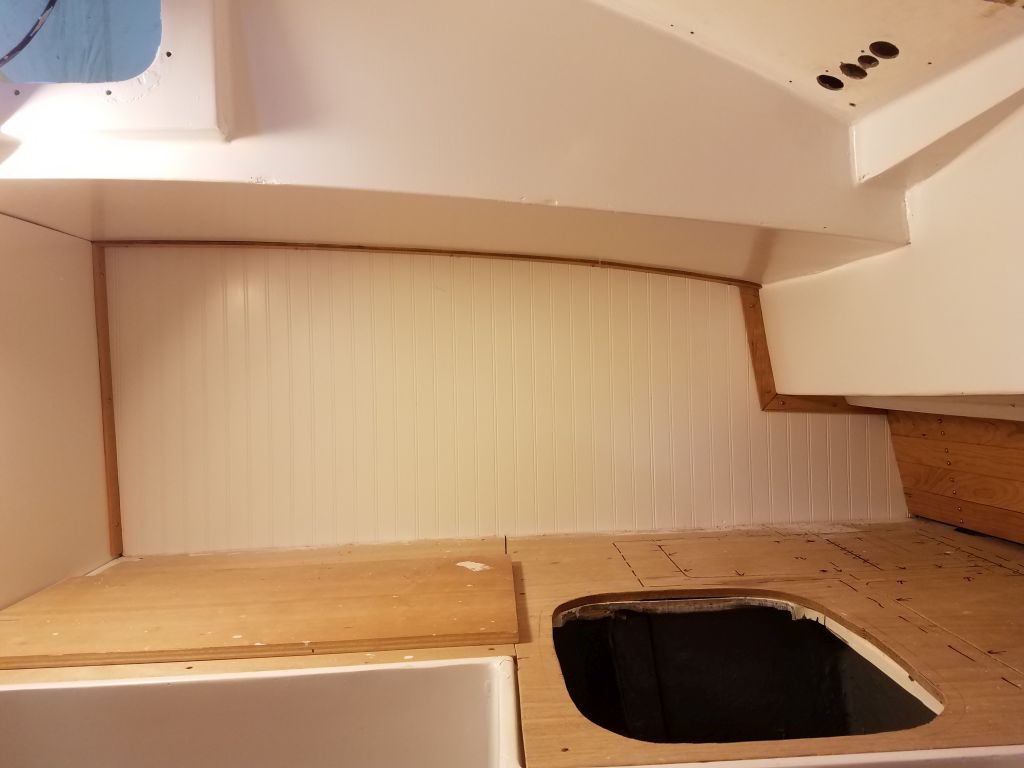
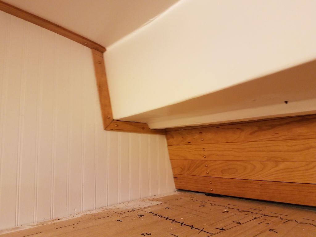
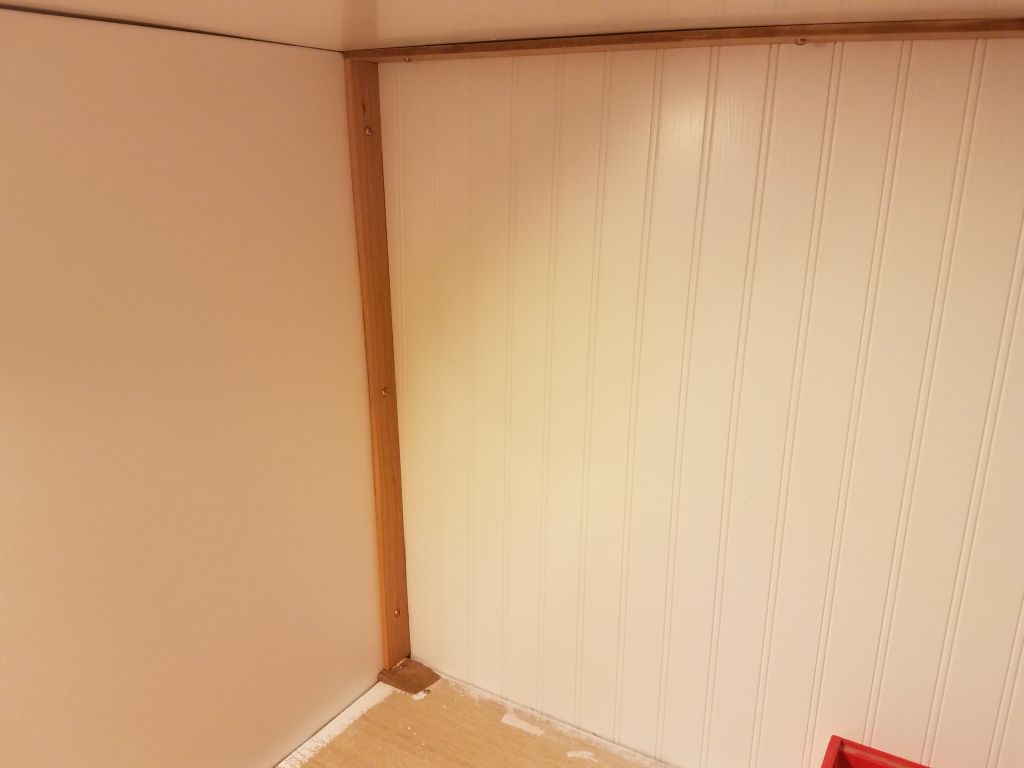
Next, trim-wise, was the galley, which required edge trim along the overhead and liners above and beside the space. As elsewhere, I cut 1-1/4″ wide trim to fit as needed and secured it with screws. At the aft countertop corner, where a piece of vertical trim spanned between the overhead and the countertop, I used a scrap of the countertop material to hold the trim up an appropriate level above the substrate so the countertop would fit beneath.

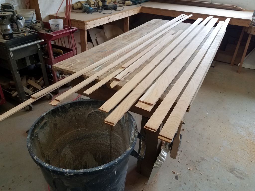
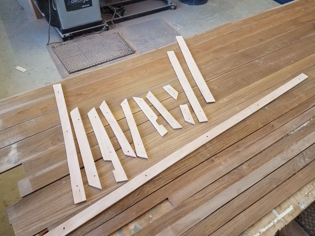
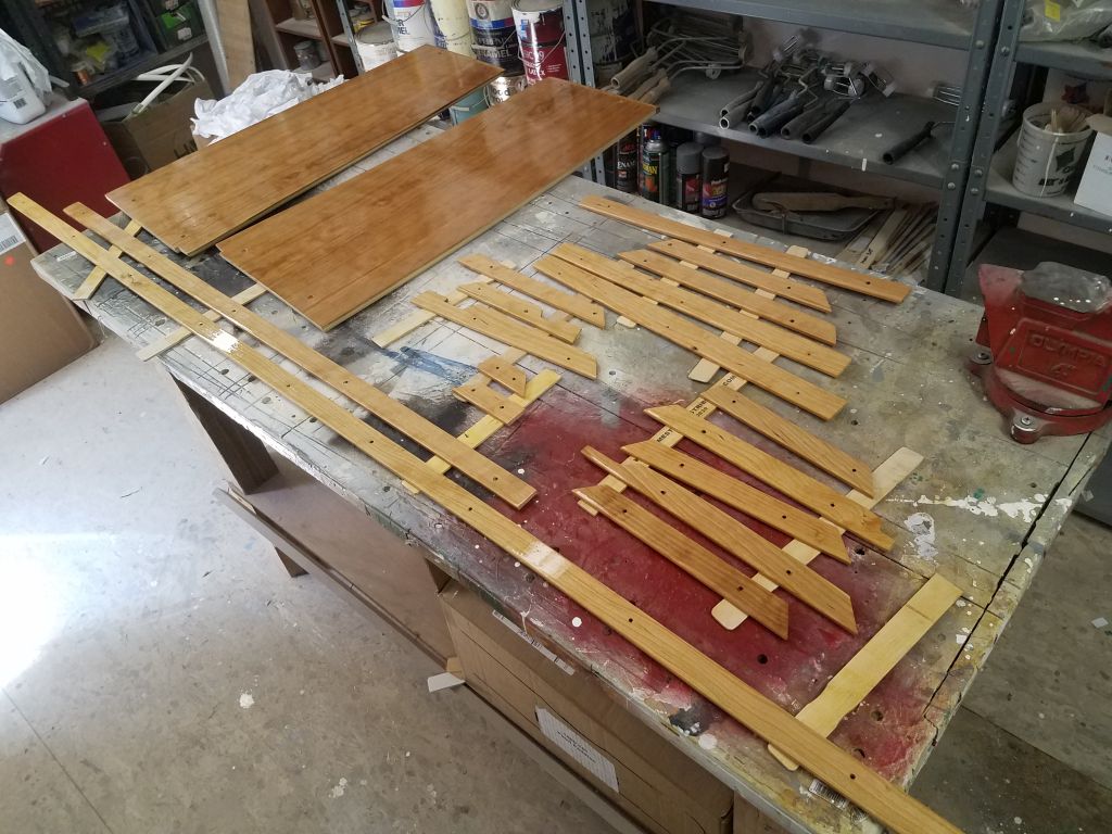
This was the last of the removable trim in the main cabin, so now that I’d just constructed and installed all the trim, I removed it all so I could prepare and varnish all the pieces. Down on the bench, I lightly sanded each piece as needed, removing layout marks and rounding the outer, exposed edge for better appearance. Then, along with the trims from the forward cabin, I applied gloss varnish to all pieces, as well as the plywood electrical locker panels. I’d continue a coat of varnish per day till I had sufficient base coverage, and would finish up with satin varnish.
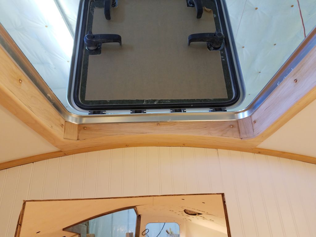
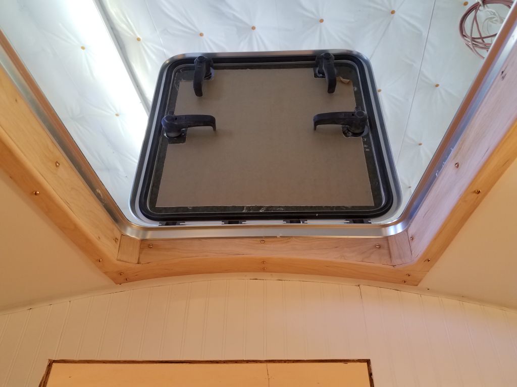
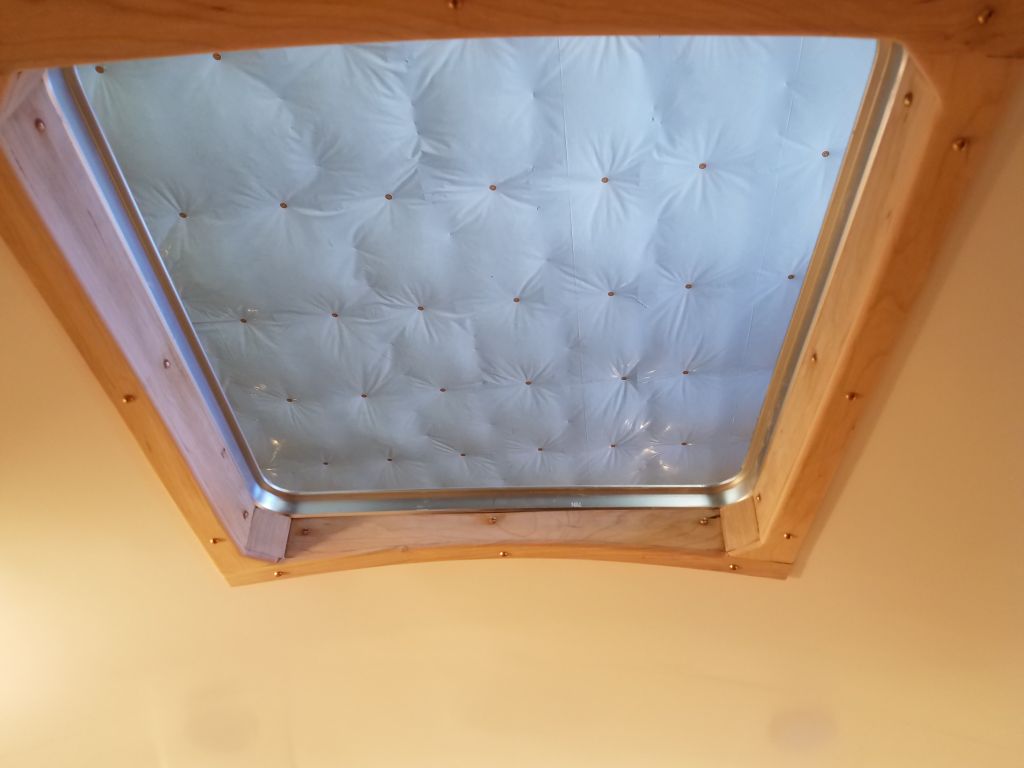
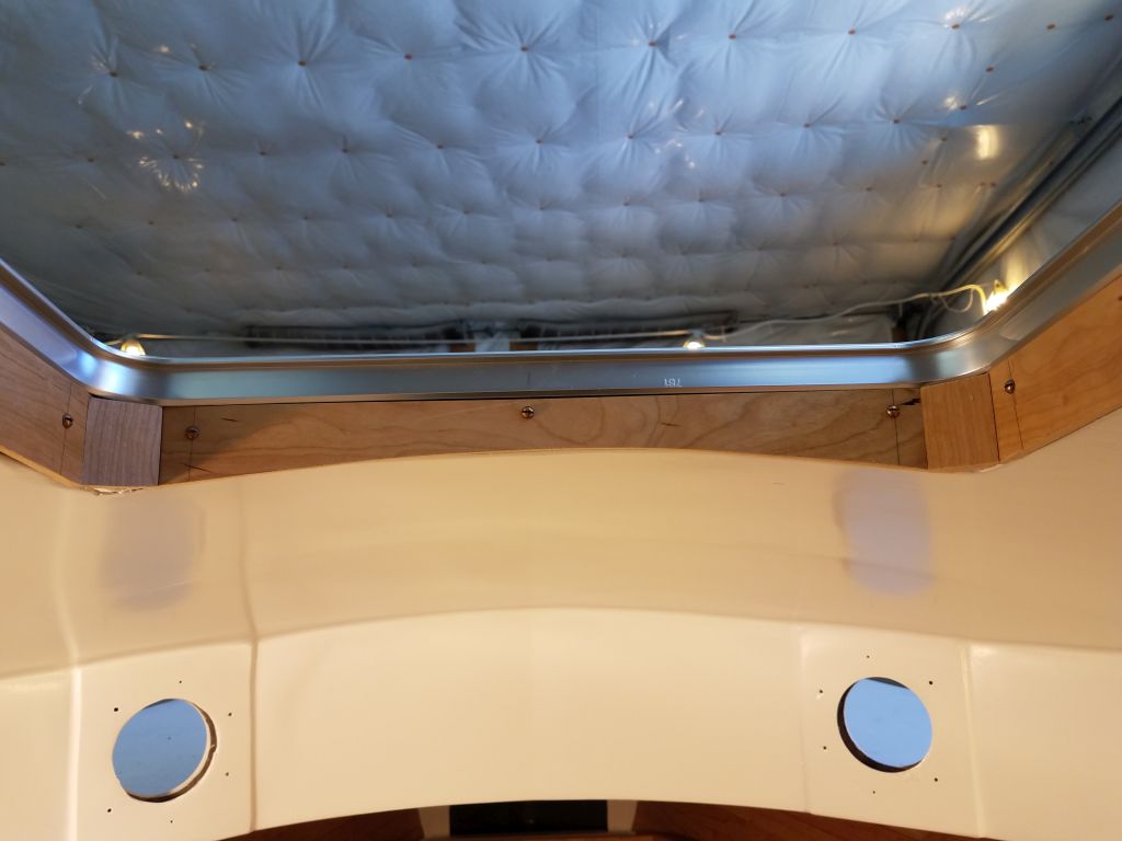
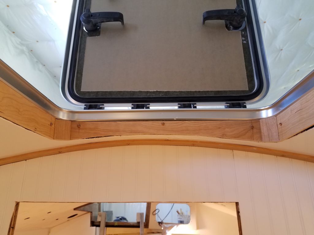
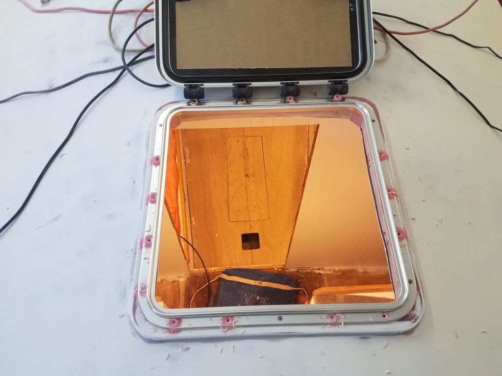
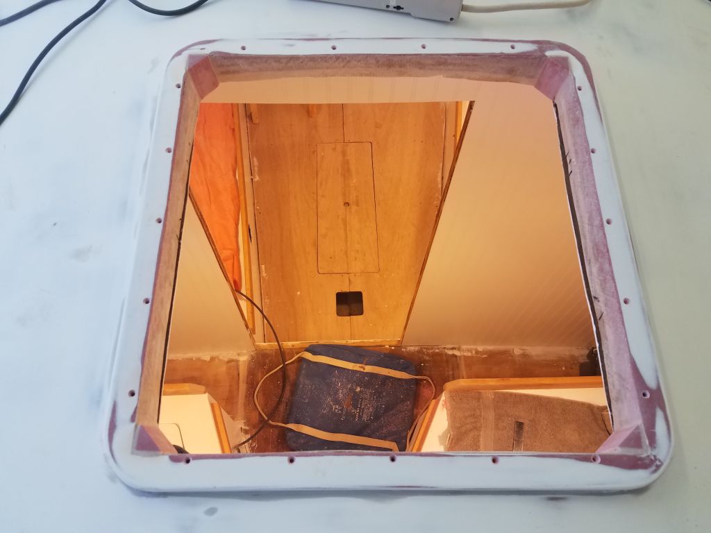
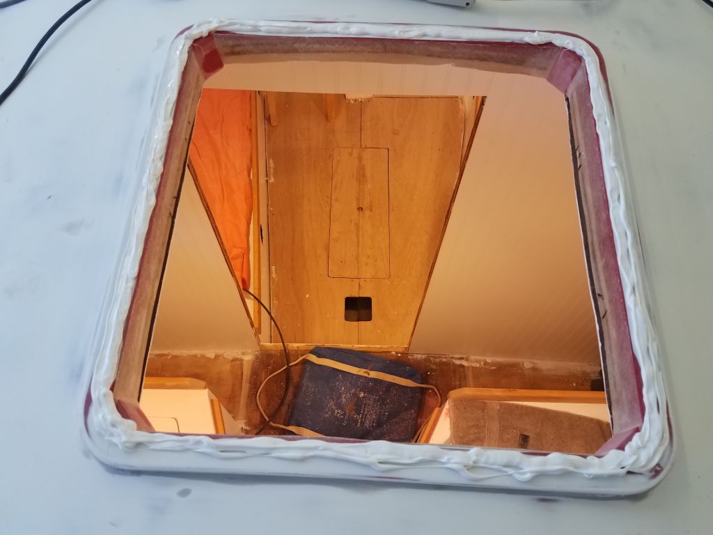
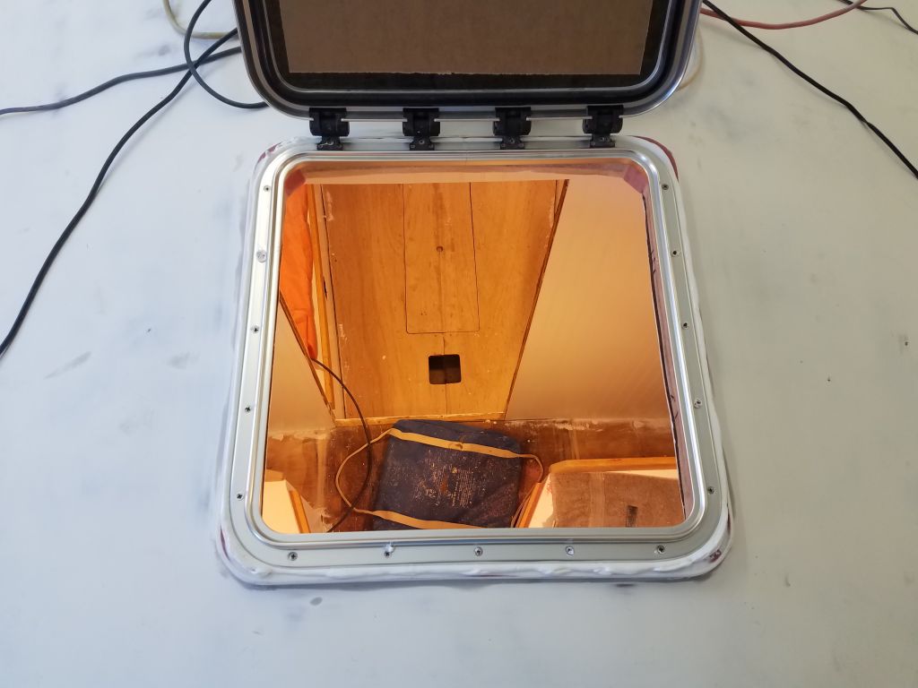
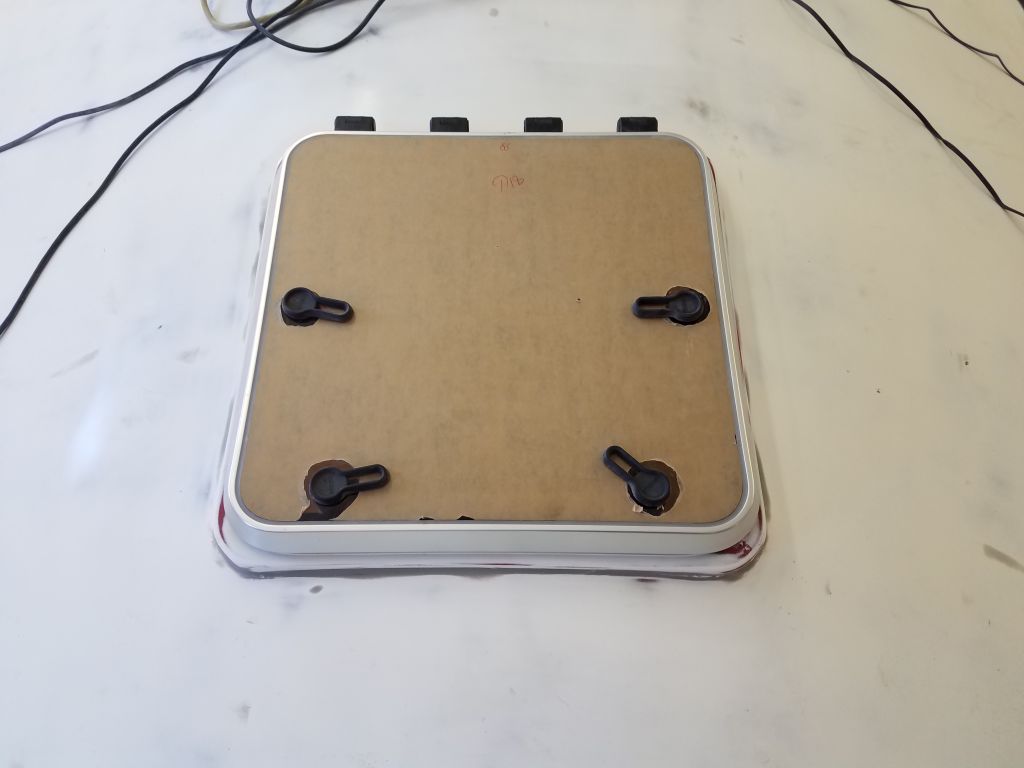
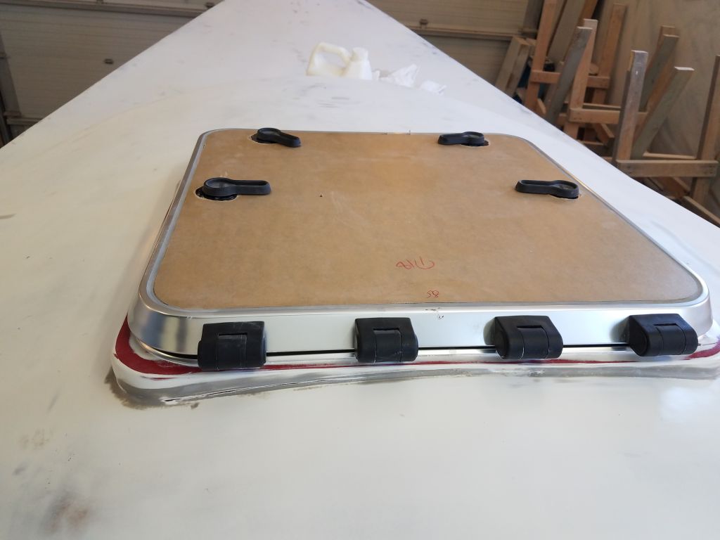
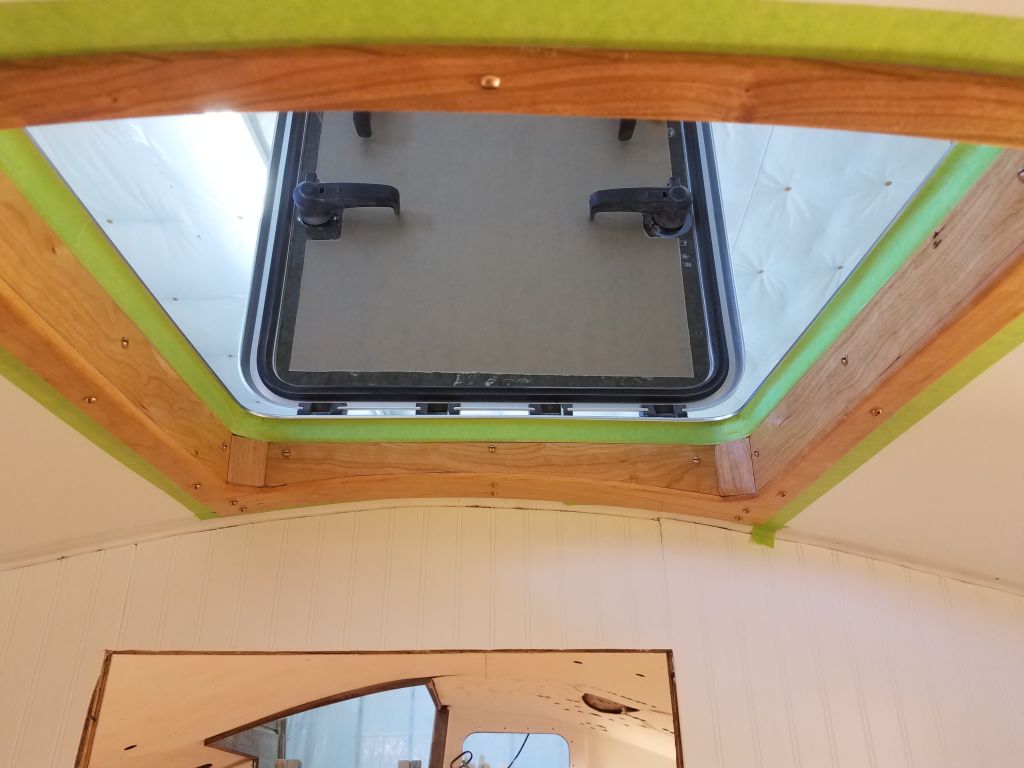
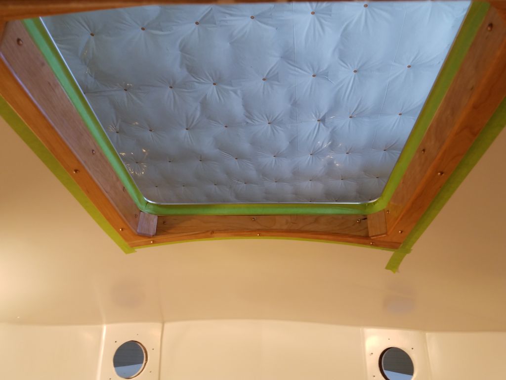
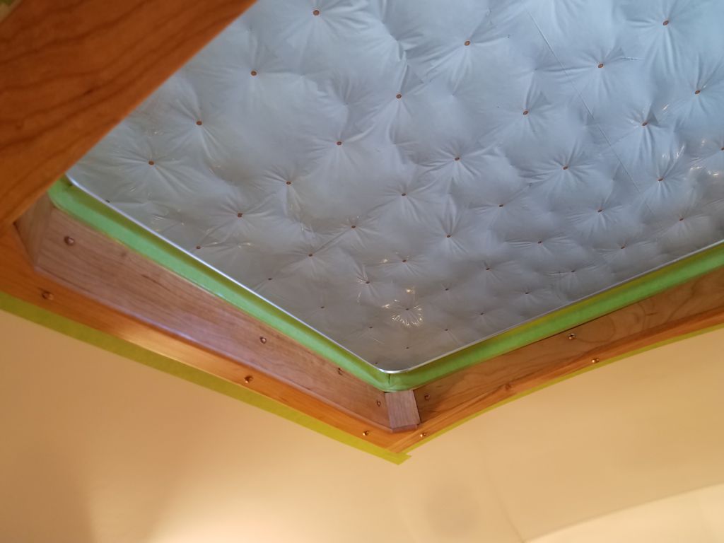
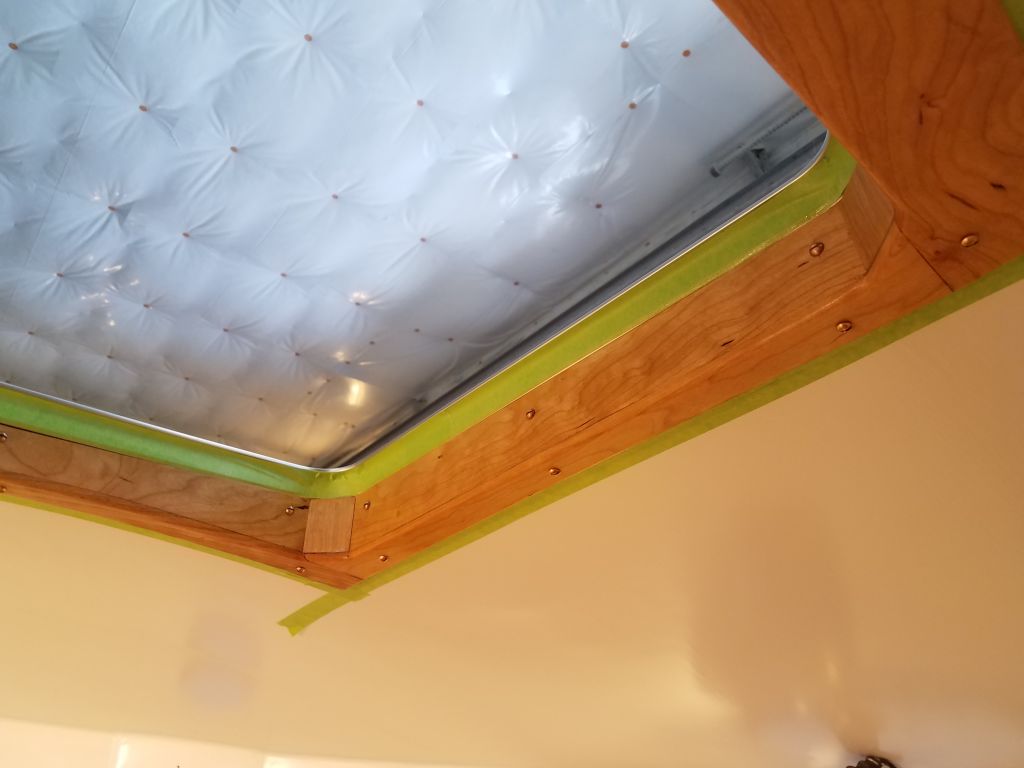
I planned soon to start the varnishing on all the fixed trim in the boat, but I went ahead and masked off and varnished the forward hatch trim now, since this tied in with the bulkhead trim and I wanted the adjacent pieces to be completed all at the same time.
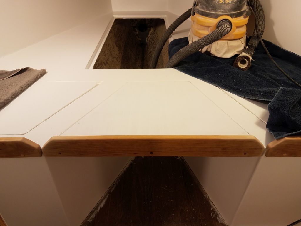
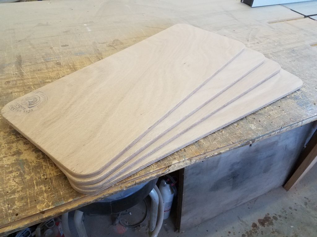
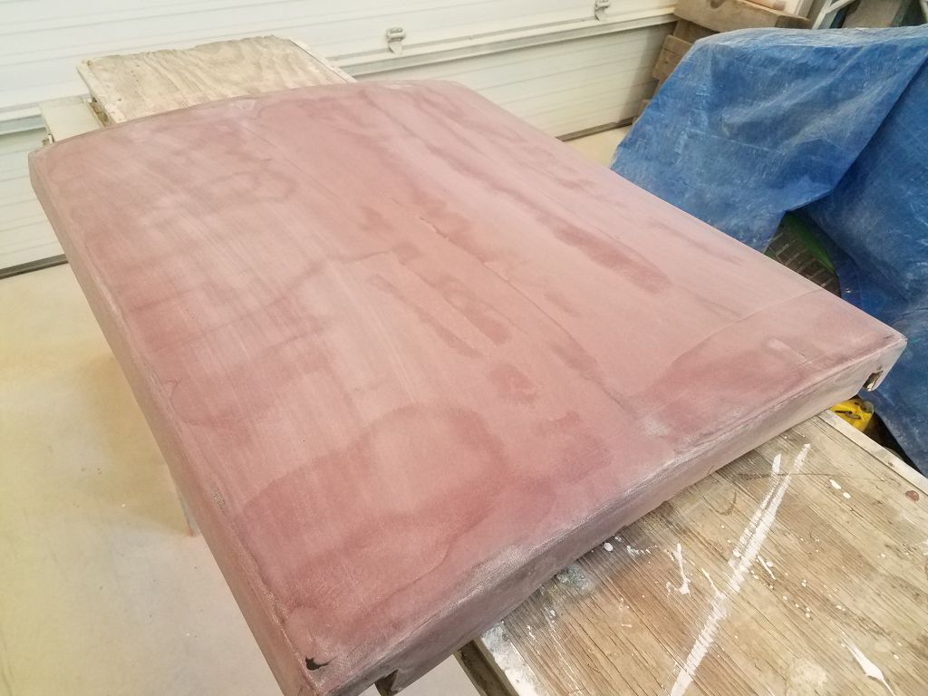
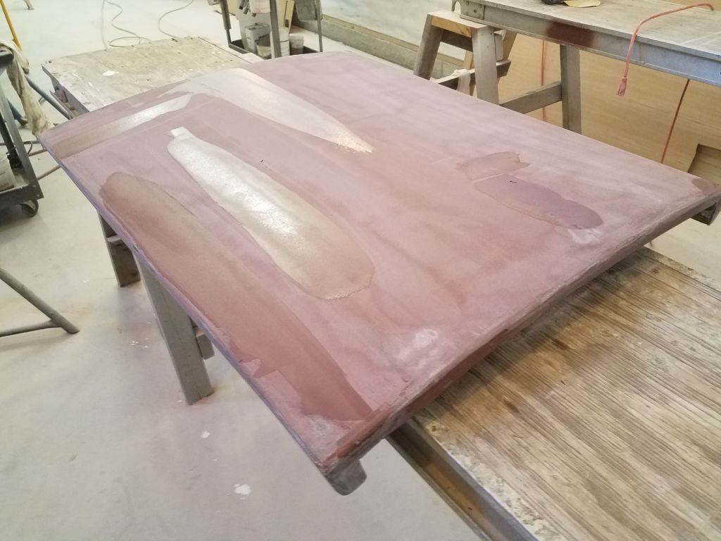
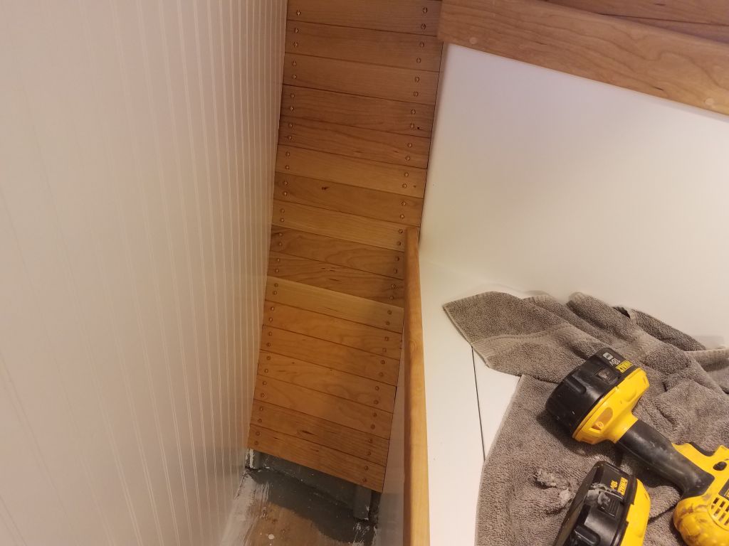
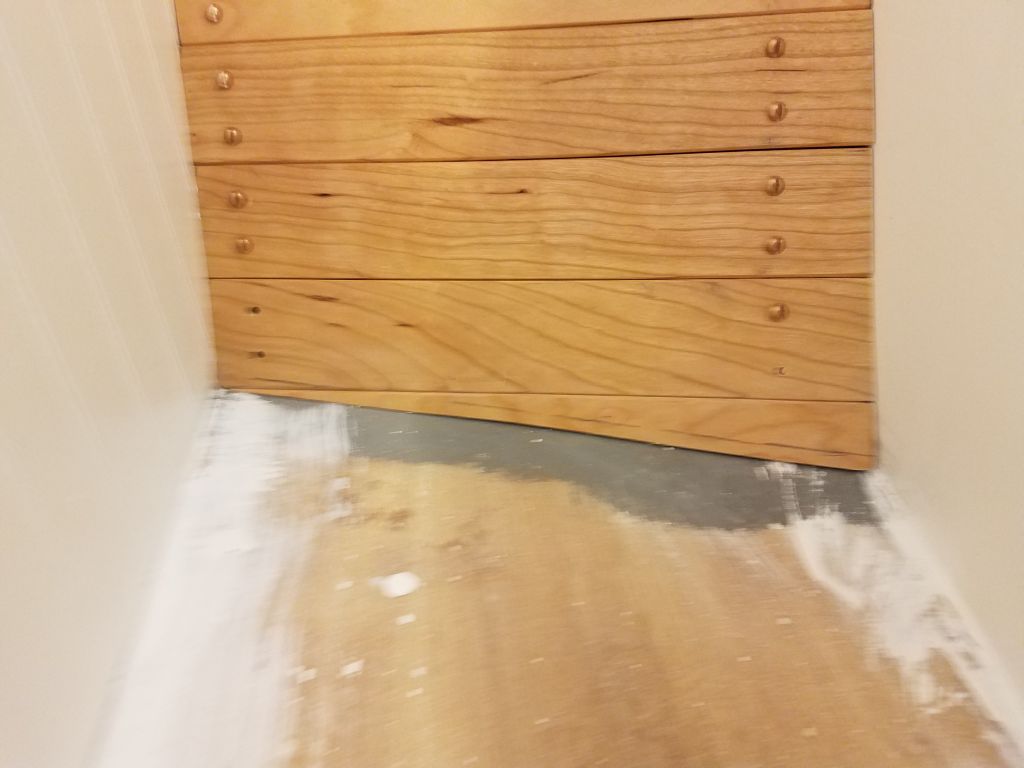
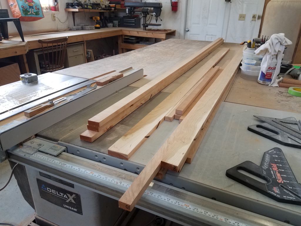
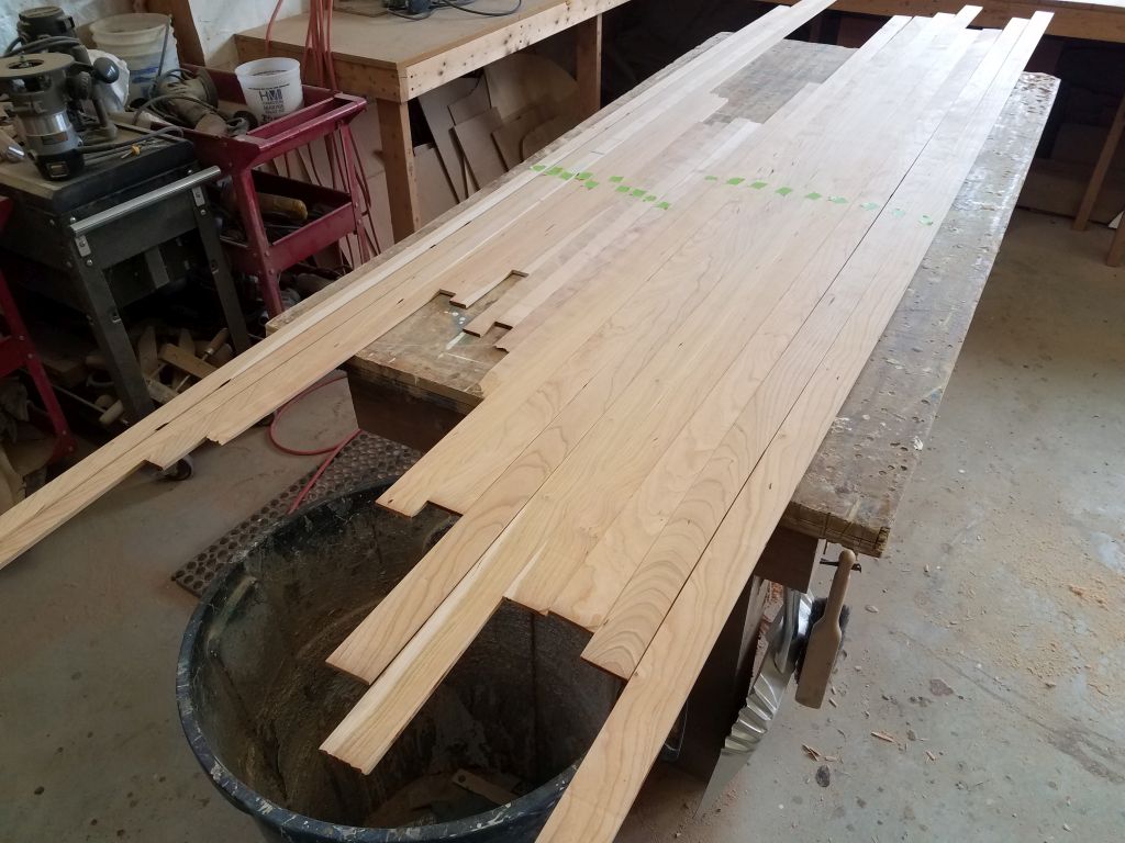
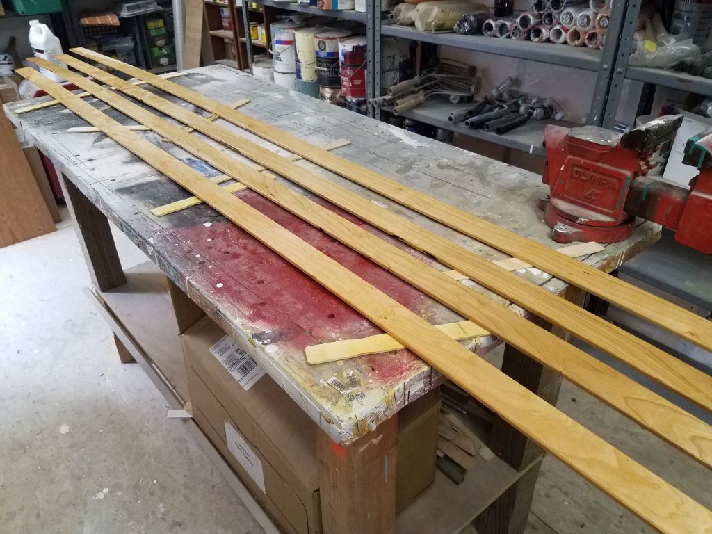
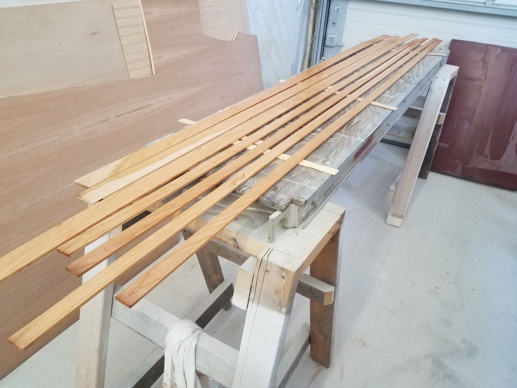
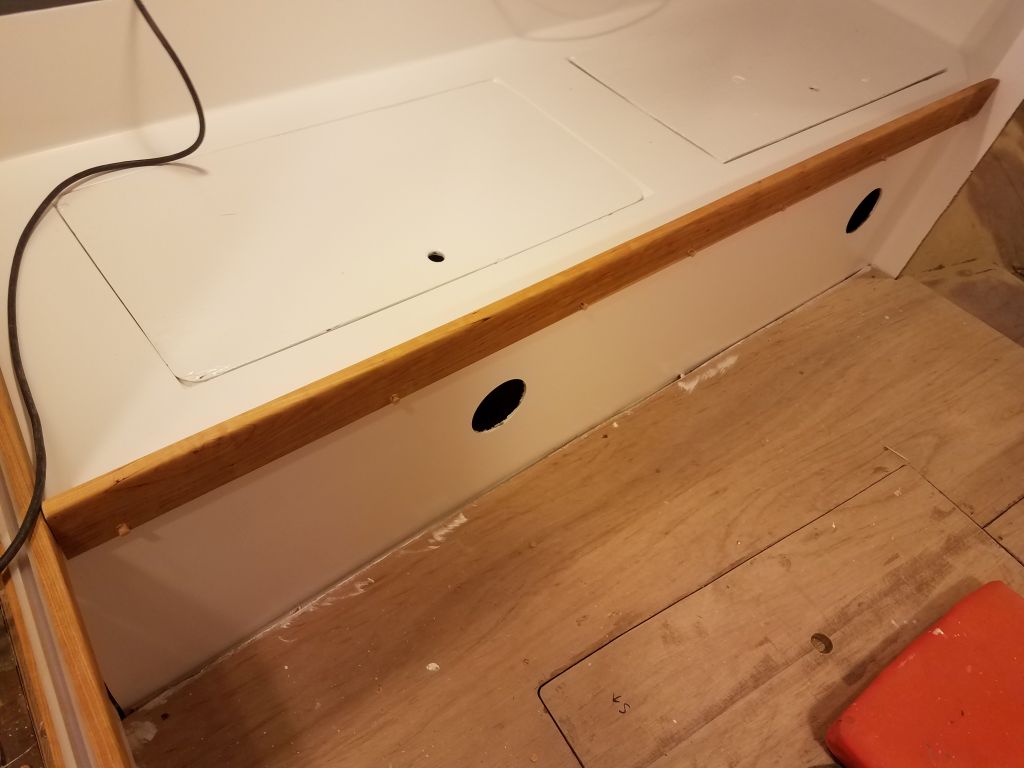
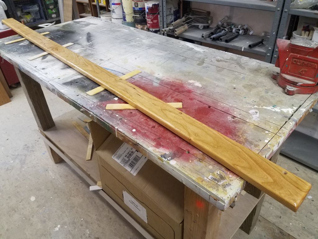
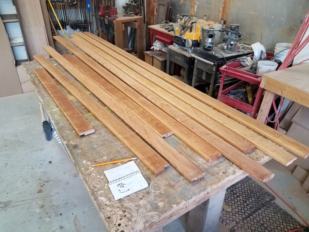
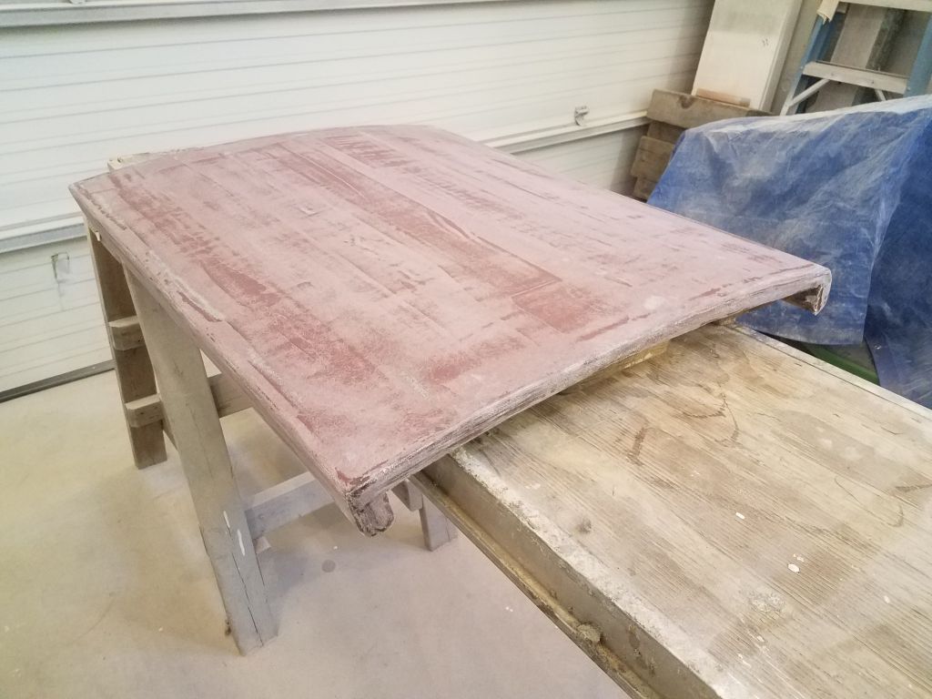
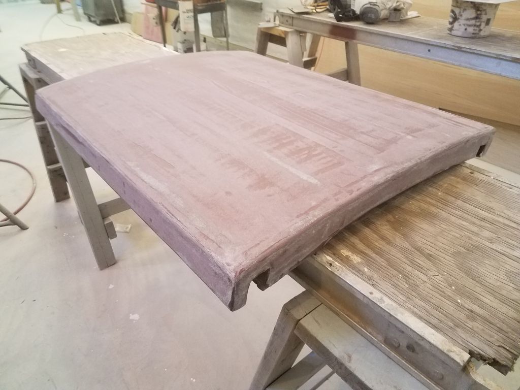
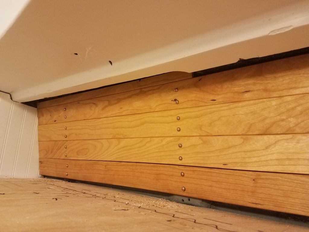
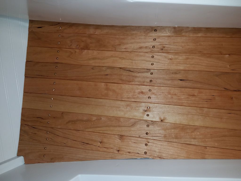
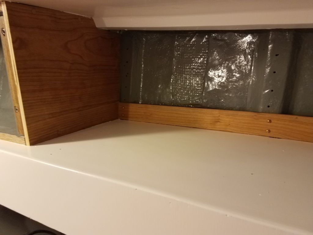
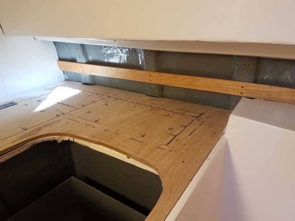
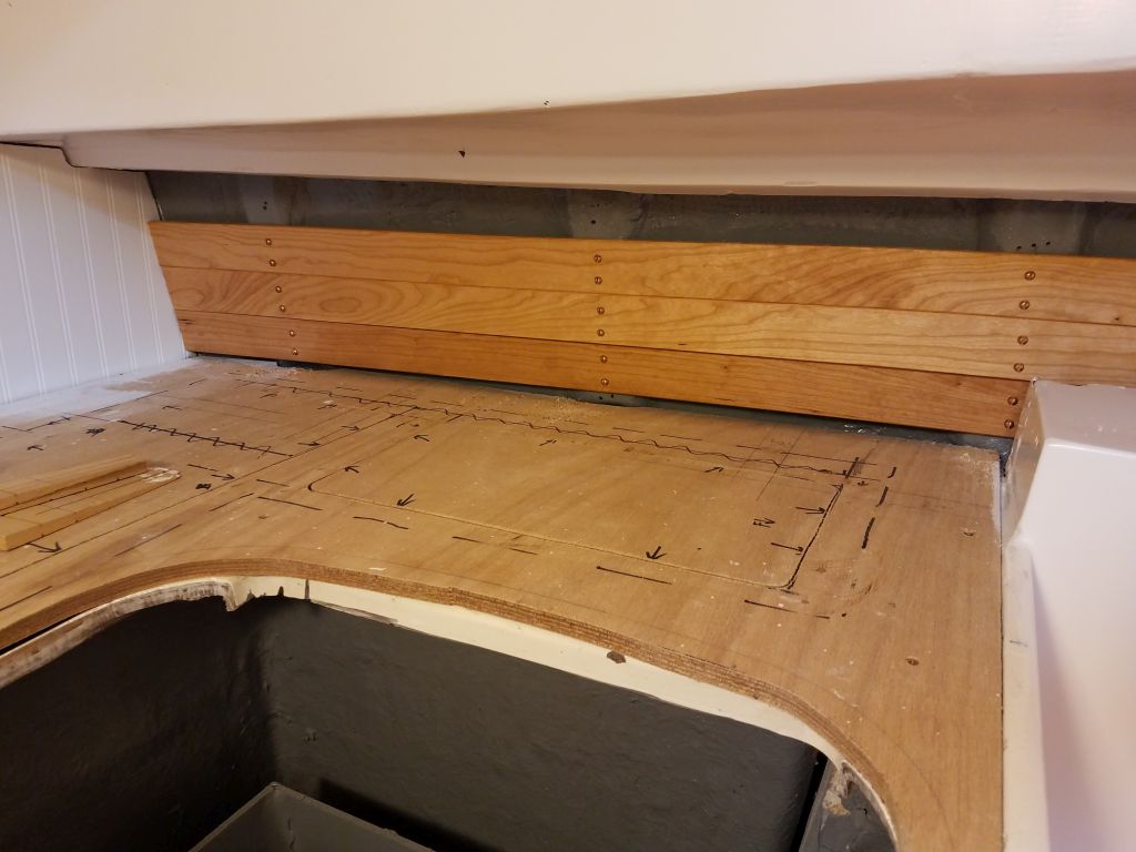
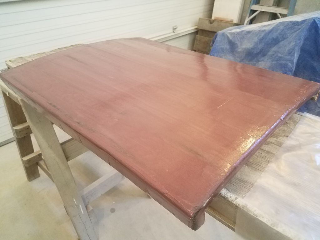
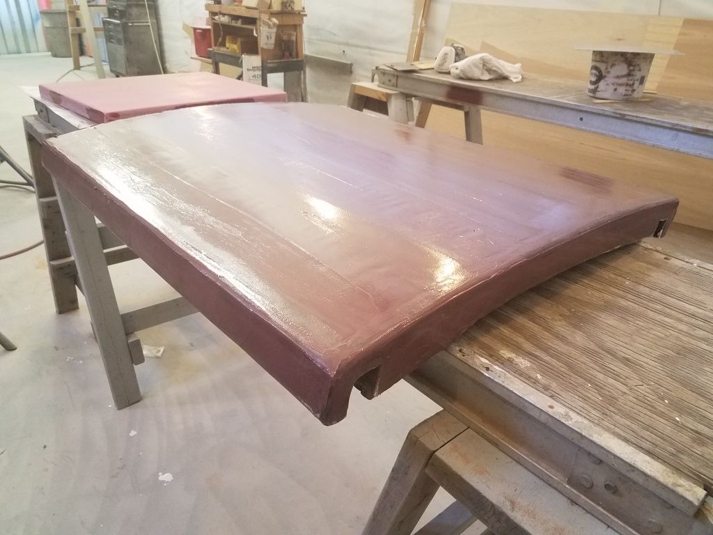
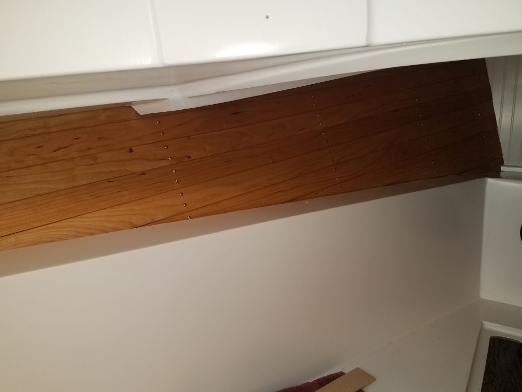
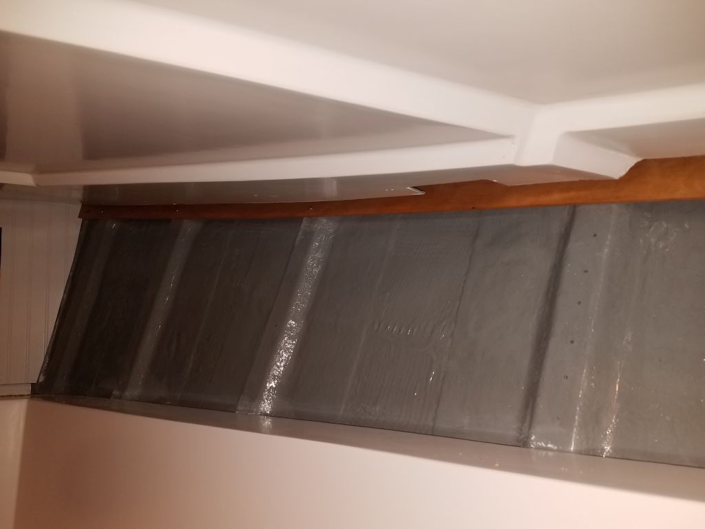
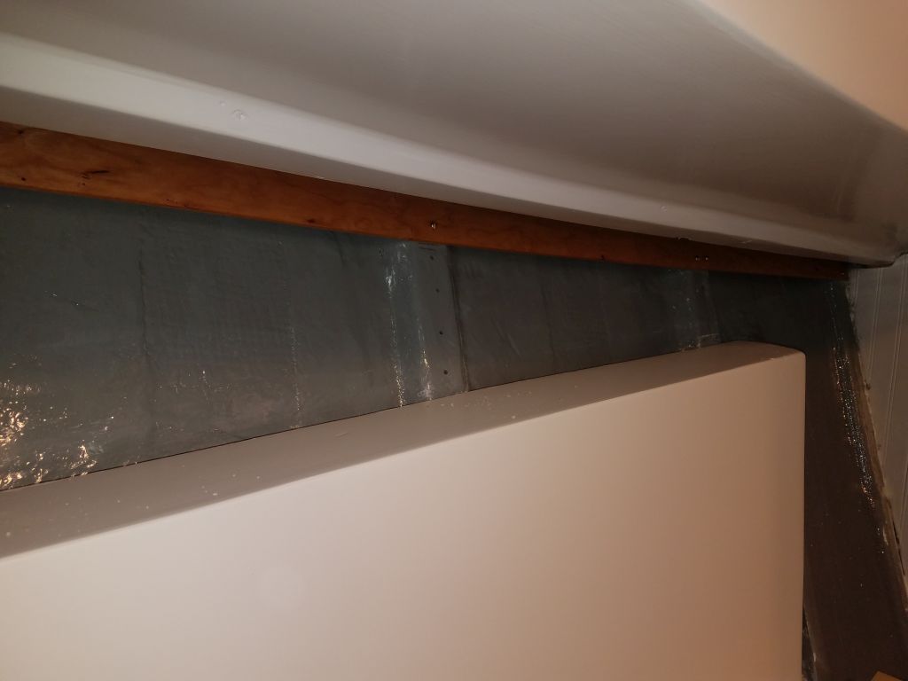
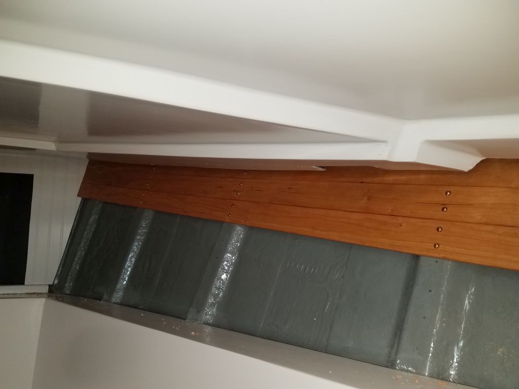
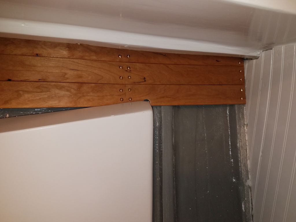
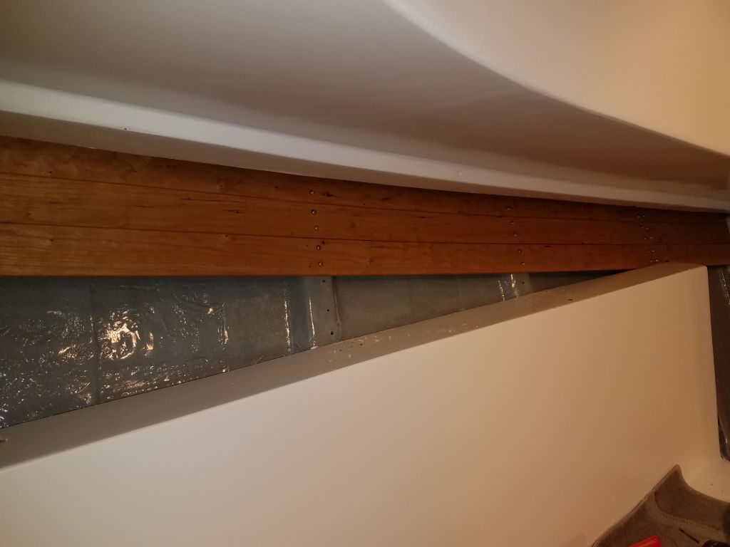
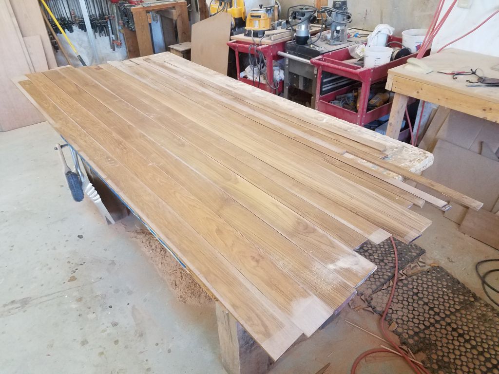
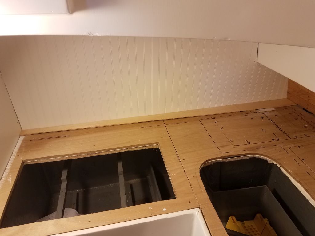
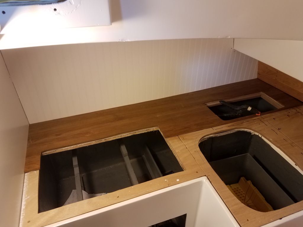
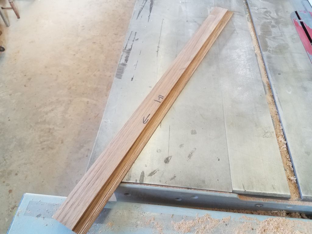
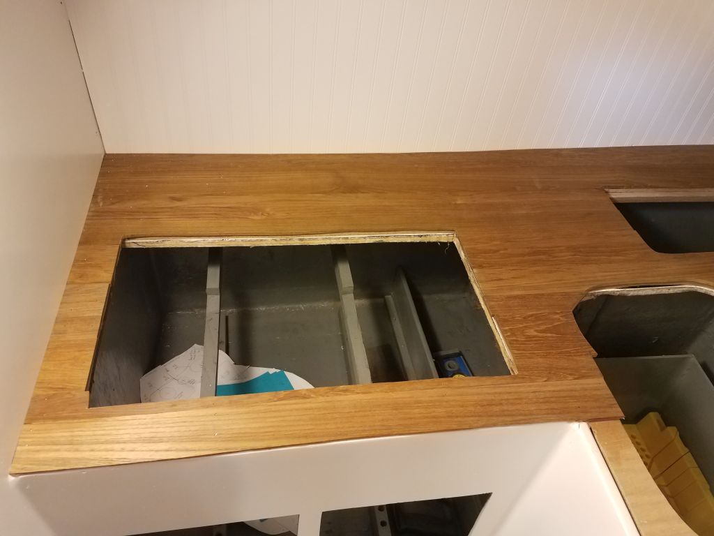
For the galley countertop, the owner requested teak covered with a deep-glossy bar-top epoxy finish, and earlier I’d milled some of the boat’s original interior trim into a series of 1/4″ teak planks for this task. Now it was time to start the installation, and I began by vacuuming and solvent-washing the plywood substrate, and laying out all the teak boards on my bench so I could choose boards easily as I went. The planks were random widths from a little over an inch wide to about 3-1/2″ wide, all based on the sizing of their original source boards.
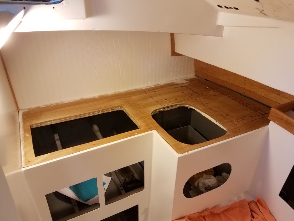
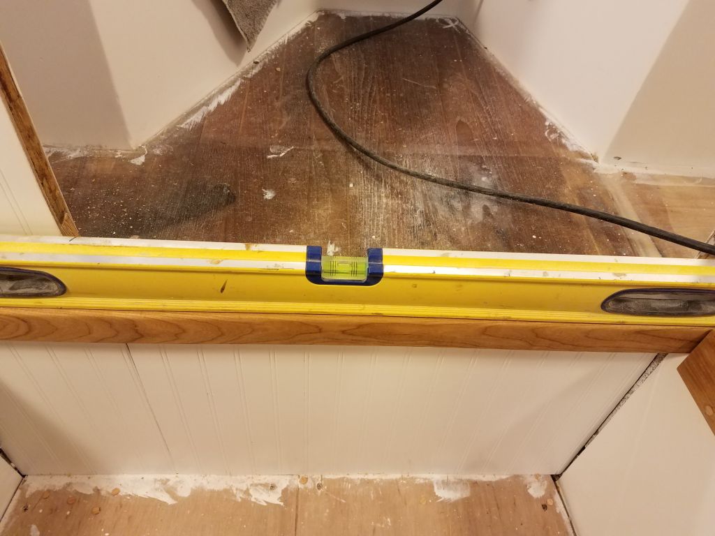
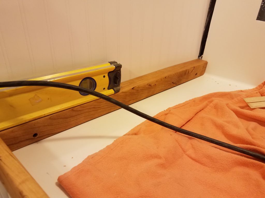
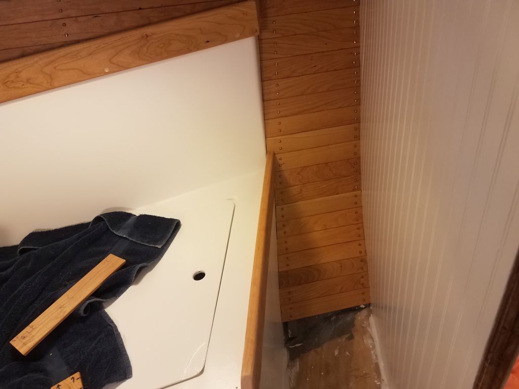
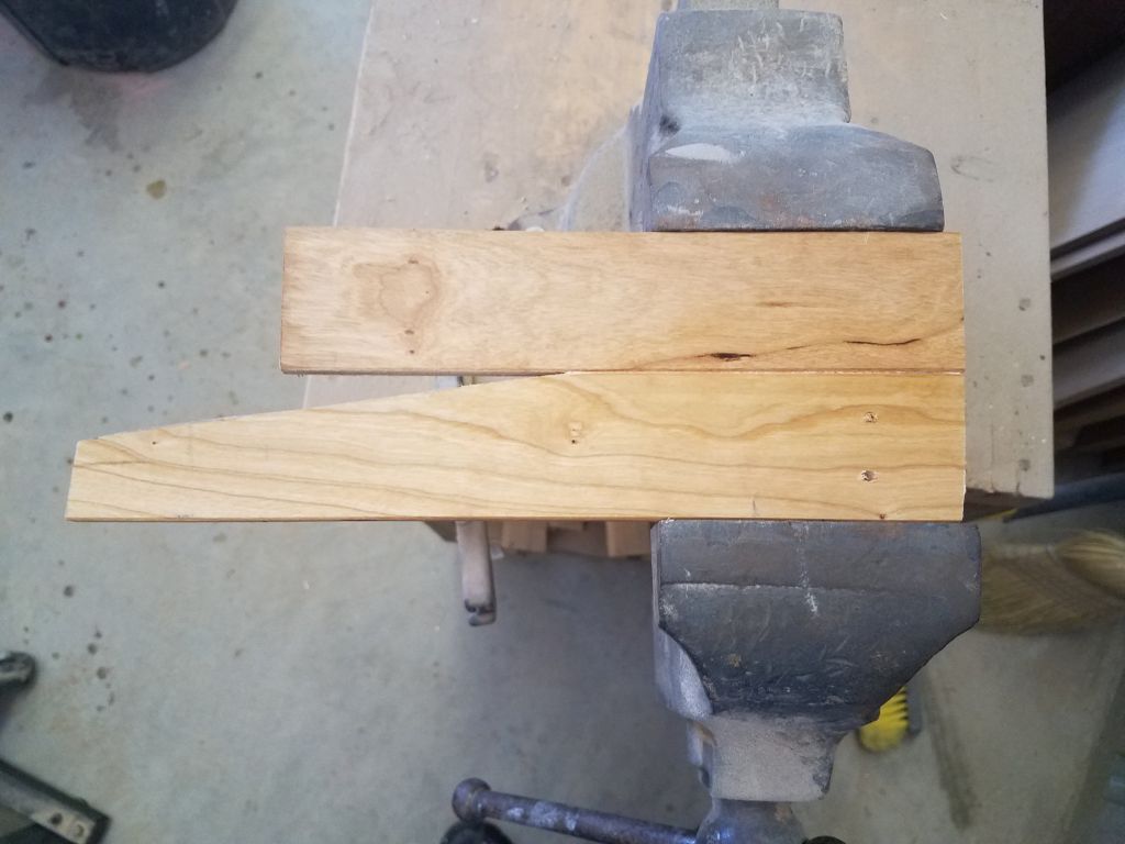
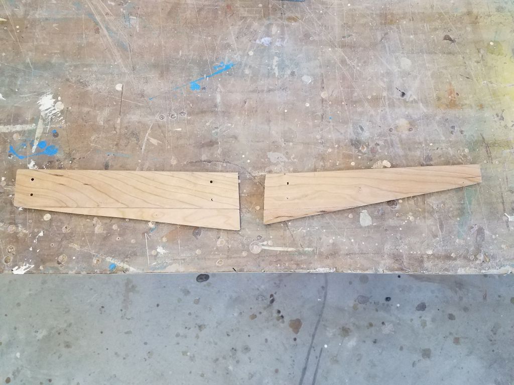
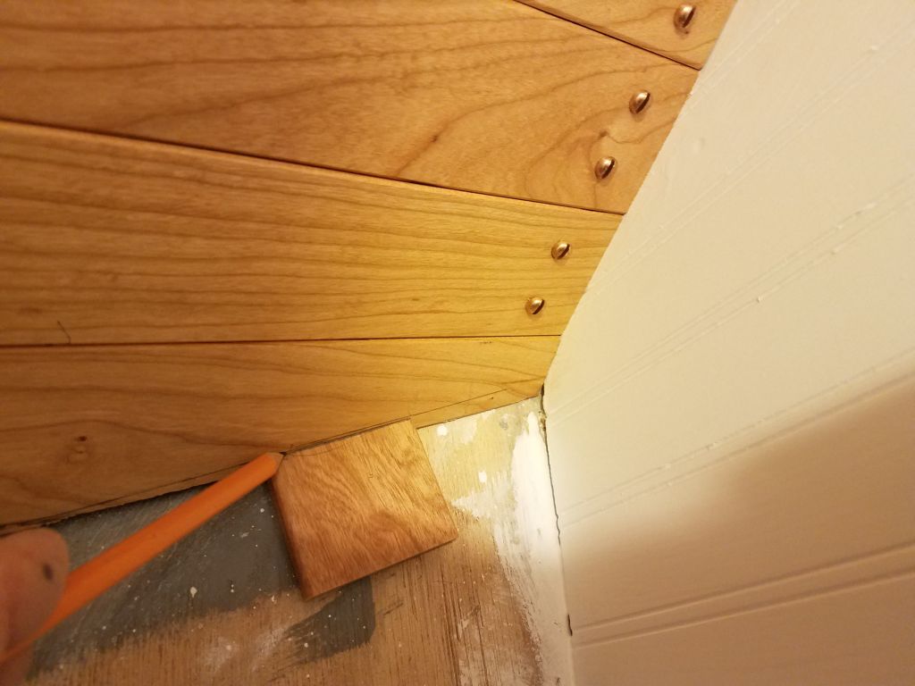
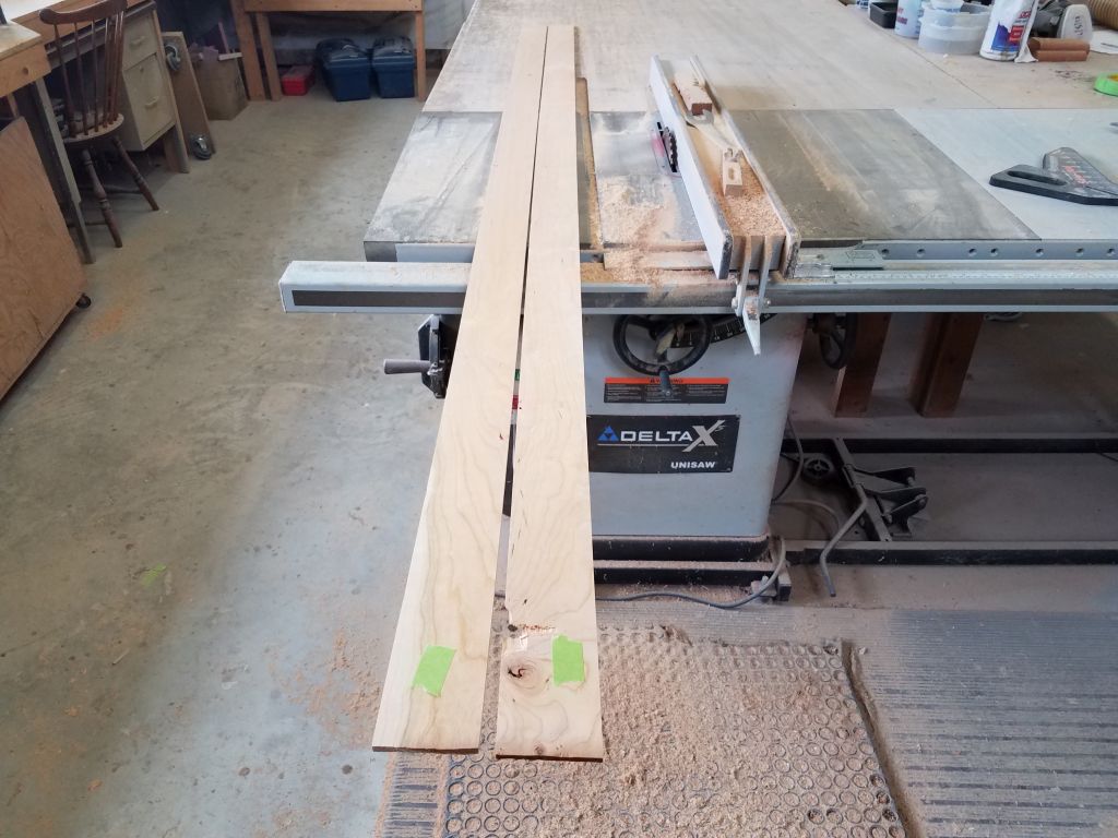
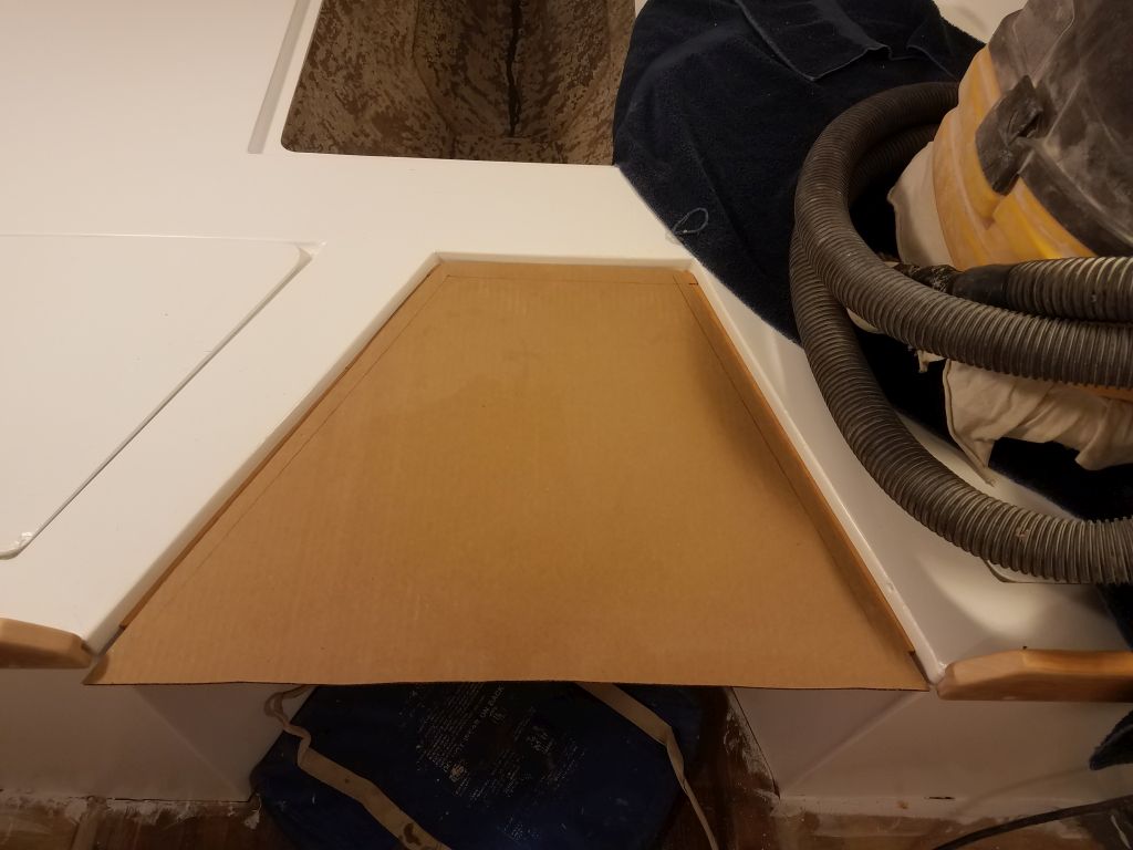
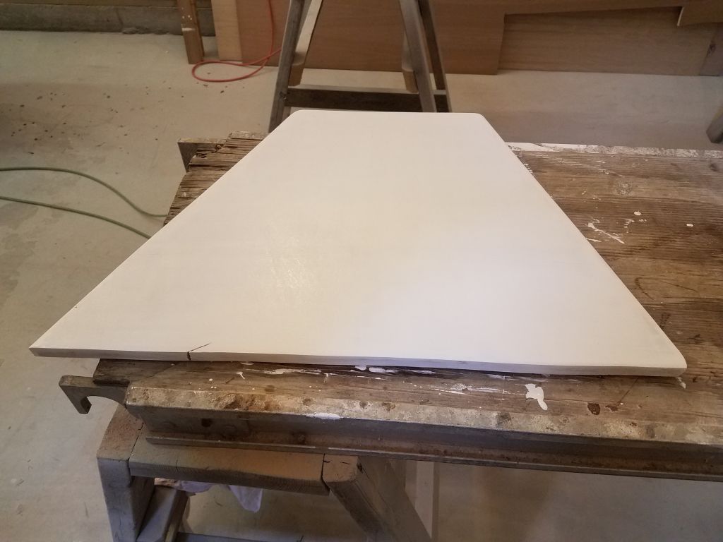
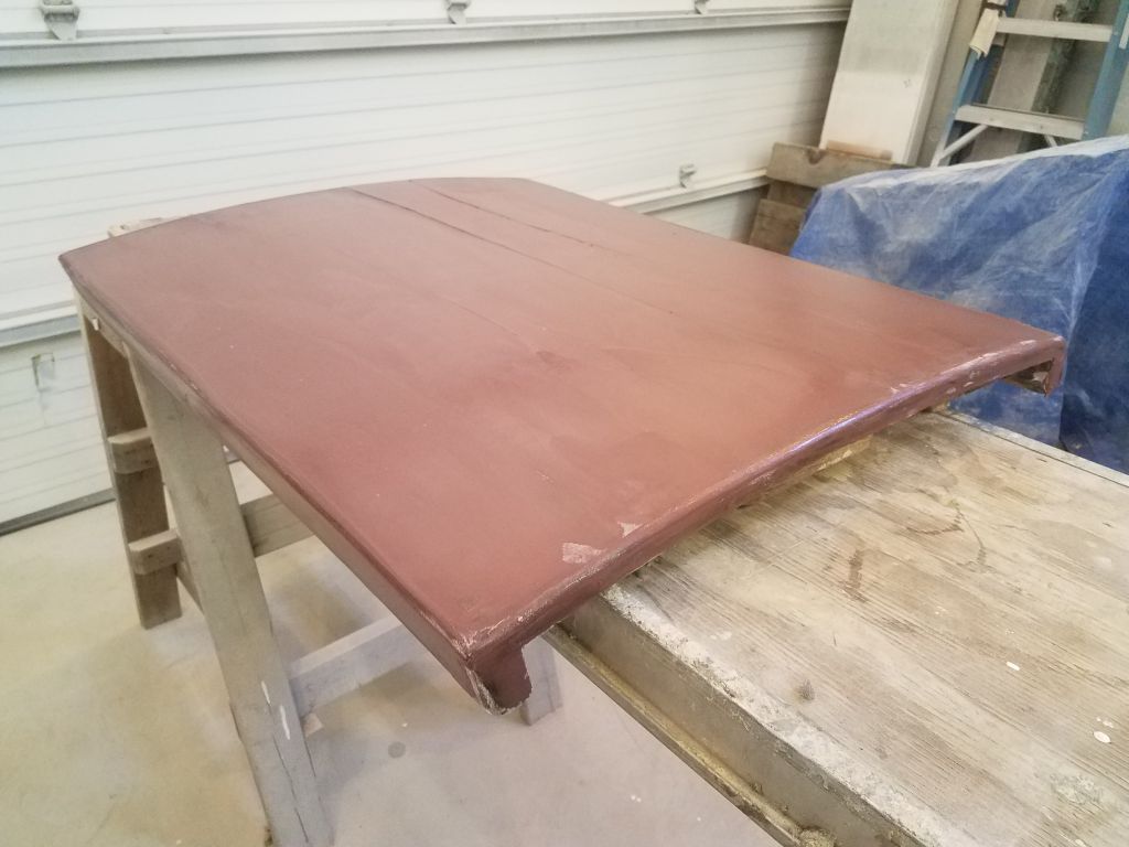
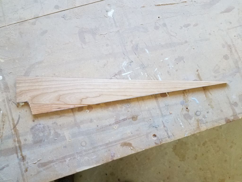
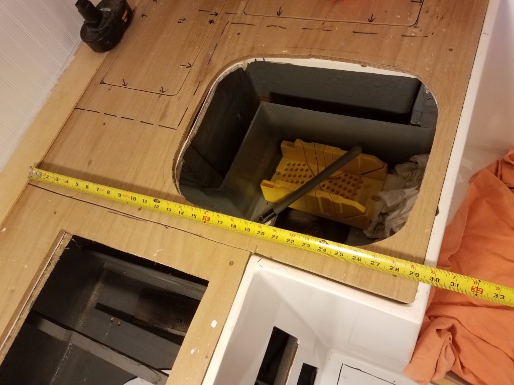
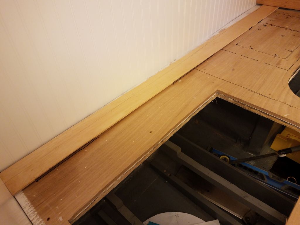
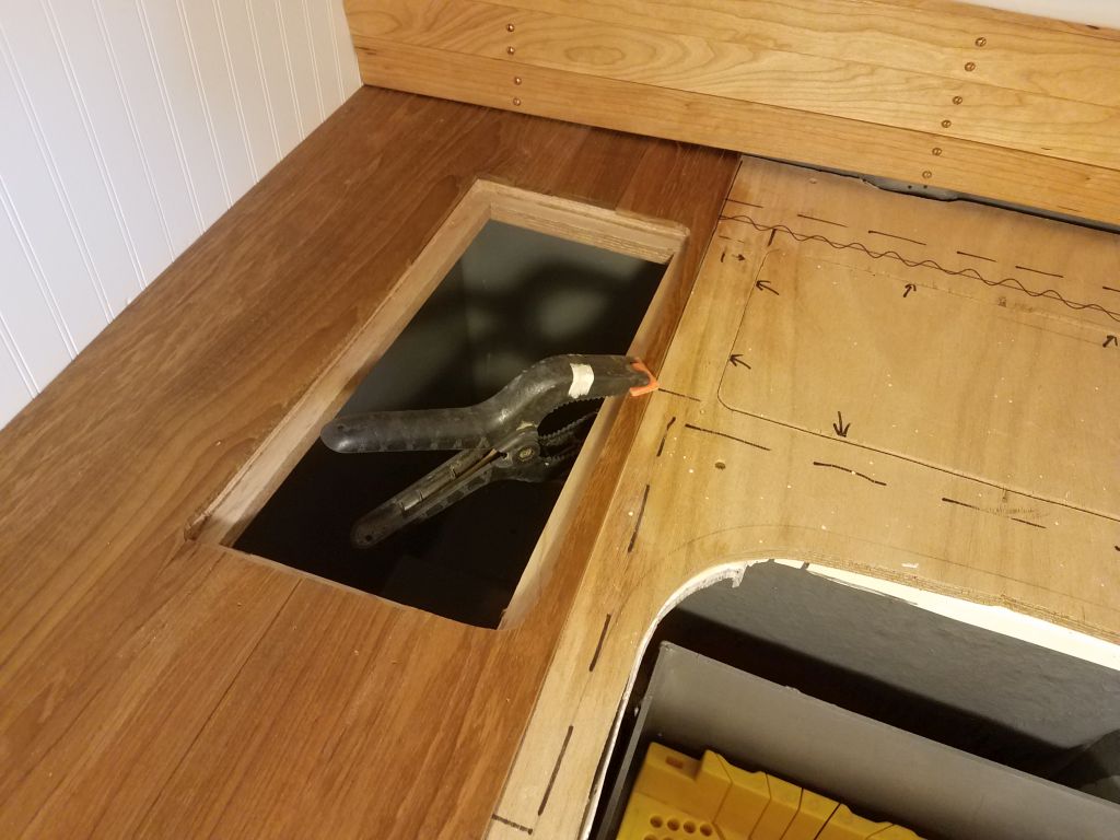
I wanted the planks to end up straight and parallel with the outer edge of the galley once I got there, so to begin I started with a plywood mockup of the 3-1/2″ wide board I planned to use for the first plank against the bulkhead. With this template cut to length and set in place near the aft bulkhead, I measured from the countertop edge in several places and aligned the template accordingly, making marks on the countertop as needed. Though it’s not shown here, I also measured from the shorter leg of the countertop to properly align the first plank–against which all others would register–as close to parallel to both parts of the edge as possible. Then, with the template held firmly in place, I scribed the template to the shape of the bulkhead, which was far from parallel to the forward end of the galley.
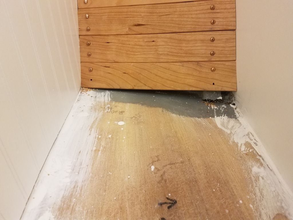
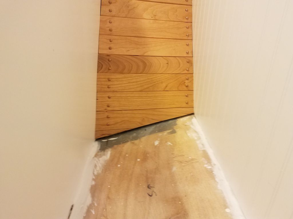
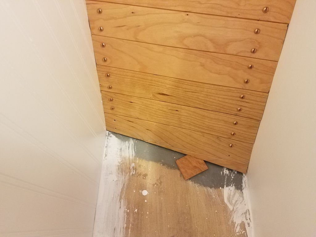
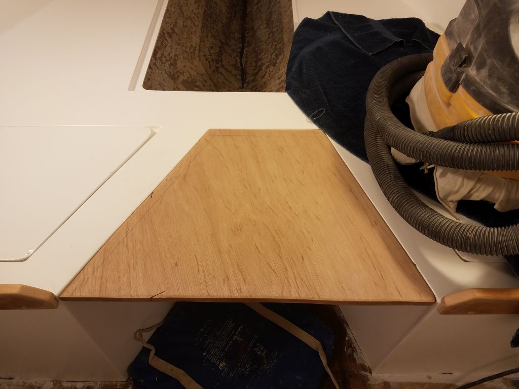
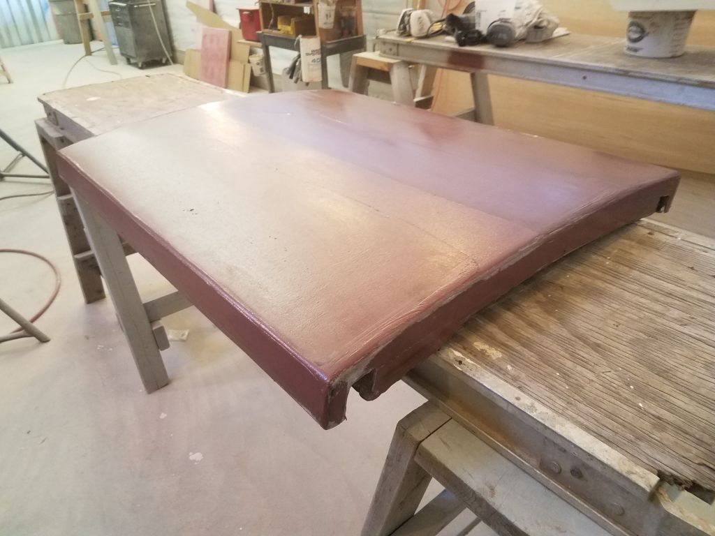
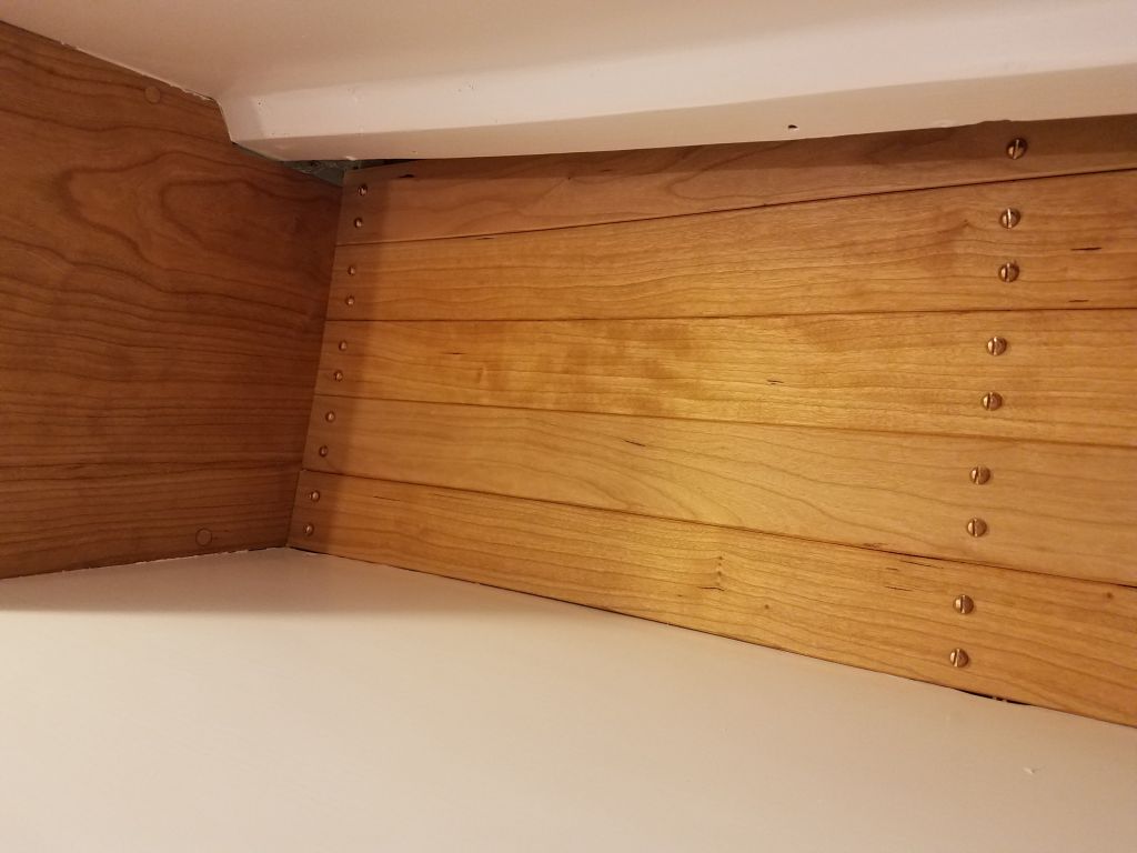
I used the template to mark the teak plank and cut out the shape, then, after a dry fit, secured the plank to the substrate with waterproof glue and brads.


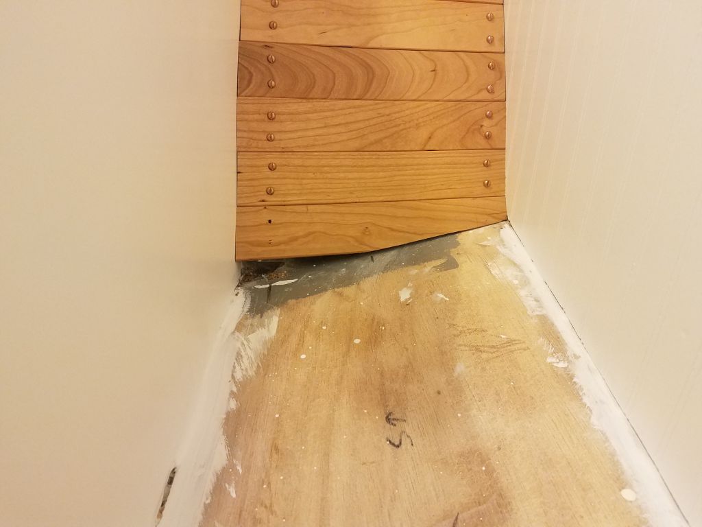
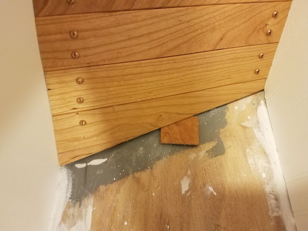
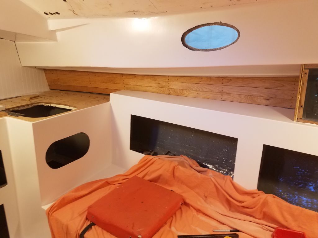
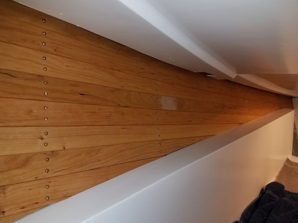
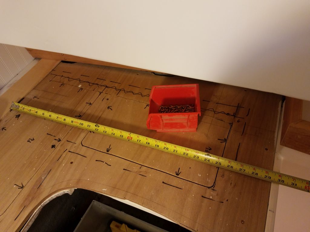
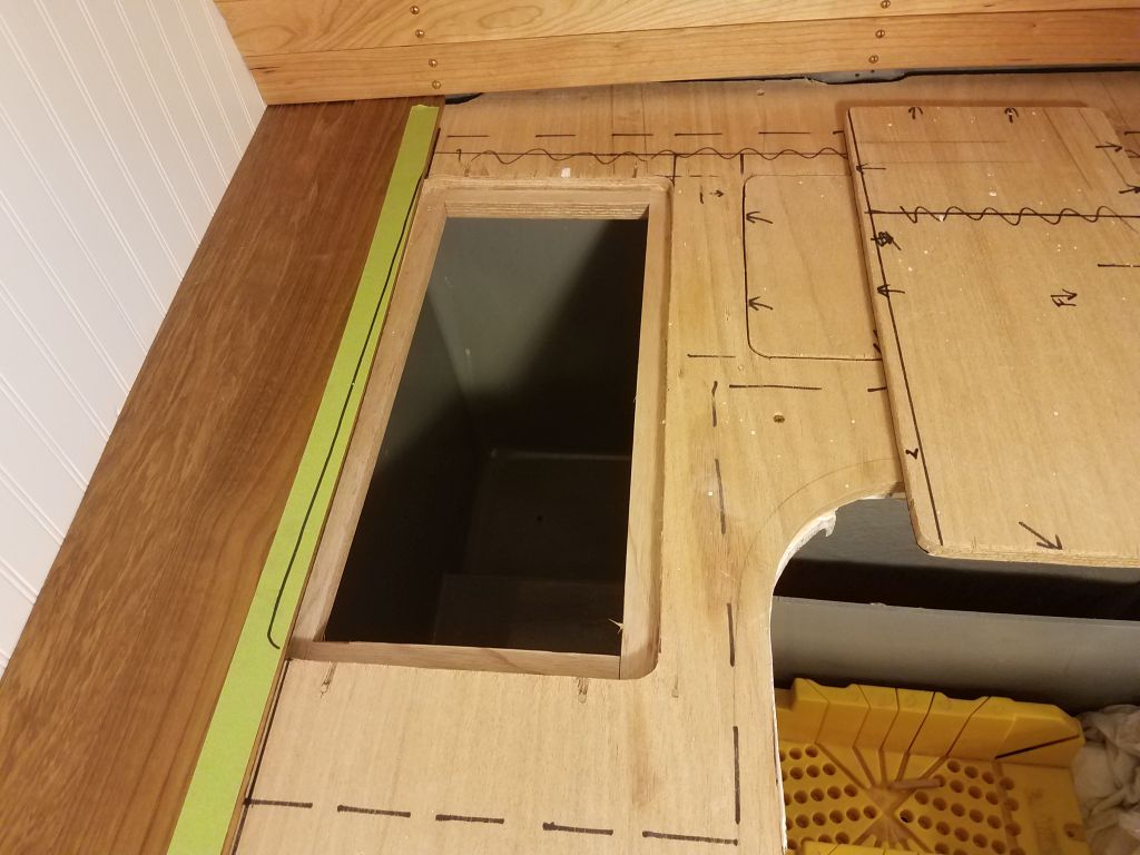
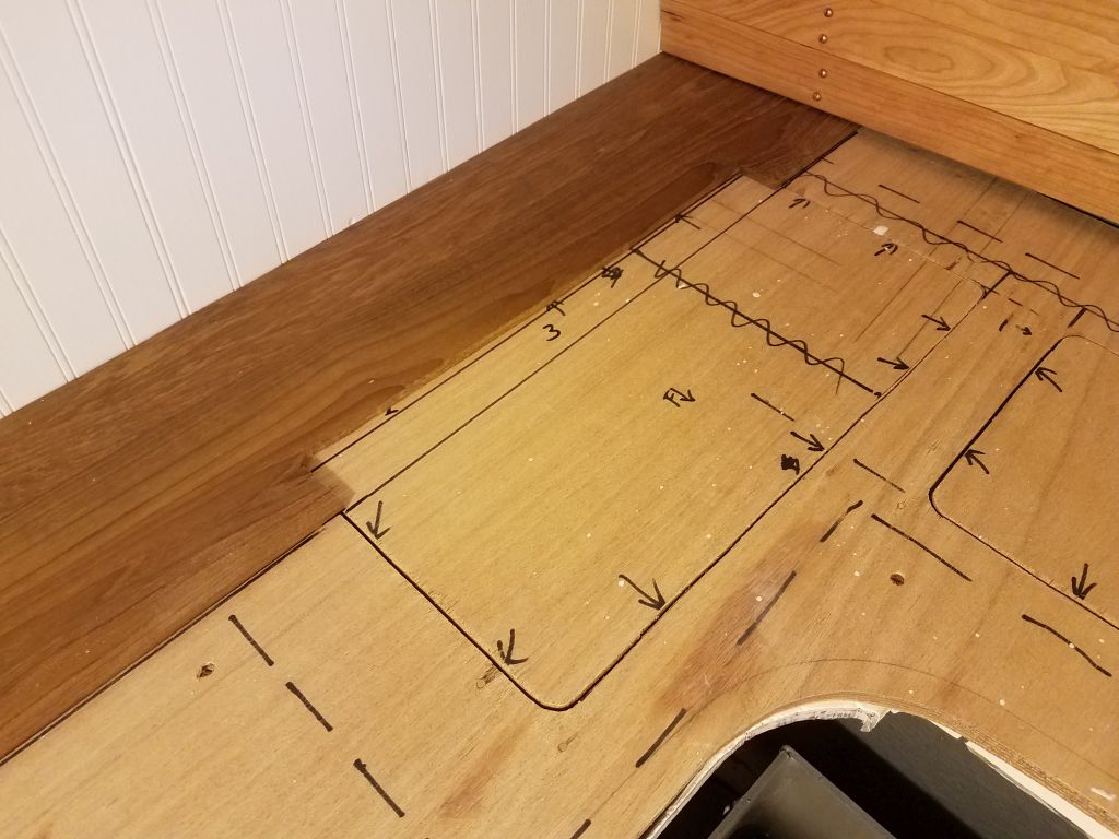
I cut down my template strip to straighten the edge I’d scribed, and now I used it as a marking device to determine the lengths of the remaining planks, most of which from now on would not be continuous full-length with the numerous openings to work around. The second plank slightly overlapped the after storage locker in the countertop, and I made a layout mark to show where to cut the plank to allow some extra into the locker opening for later trimming to the final shape. Then, the third piece of teak–and others following–required cuts for the locker opening, and in these instances I used a single board, cutting each length as required in order so the grain patterns would remain aligned and consistent.
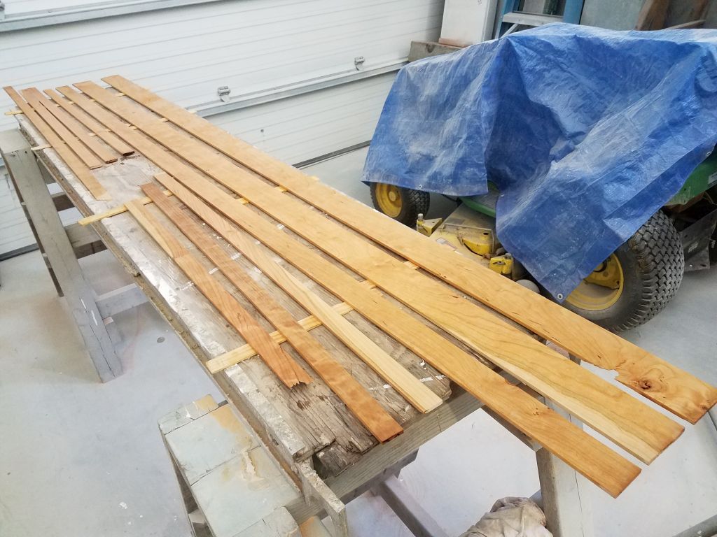
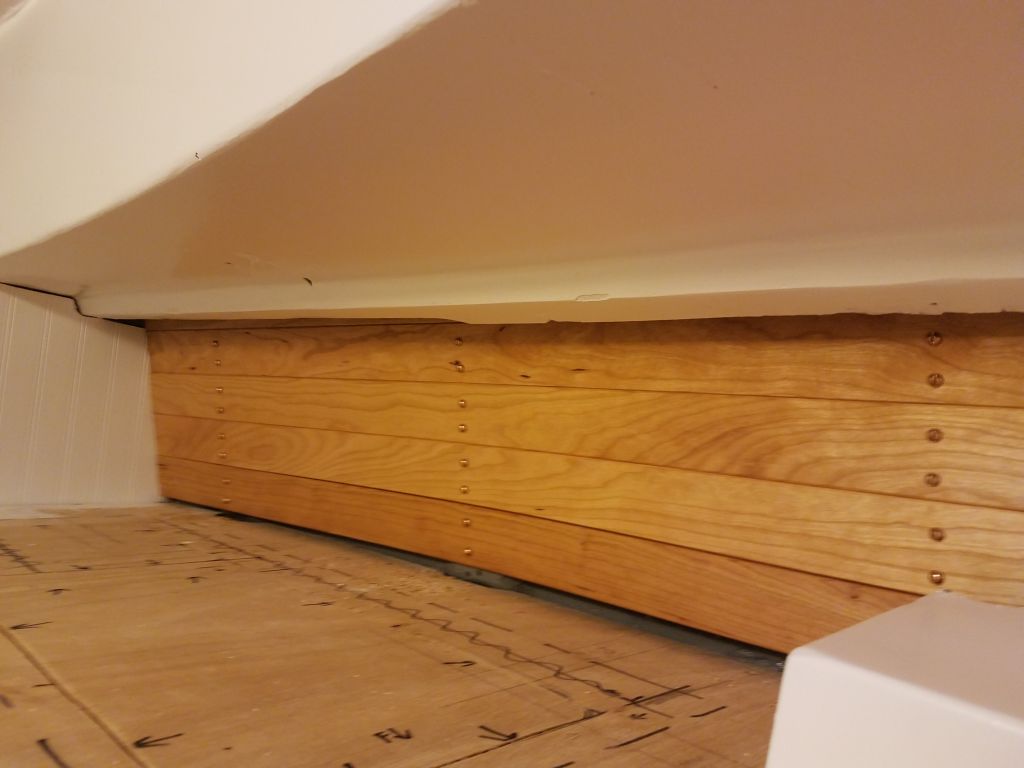
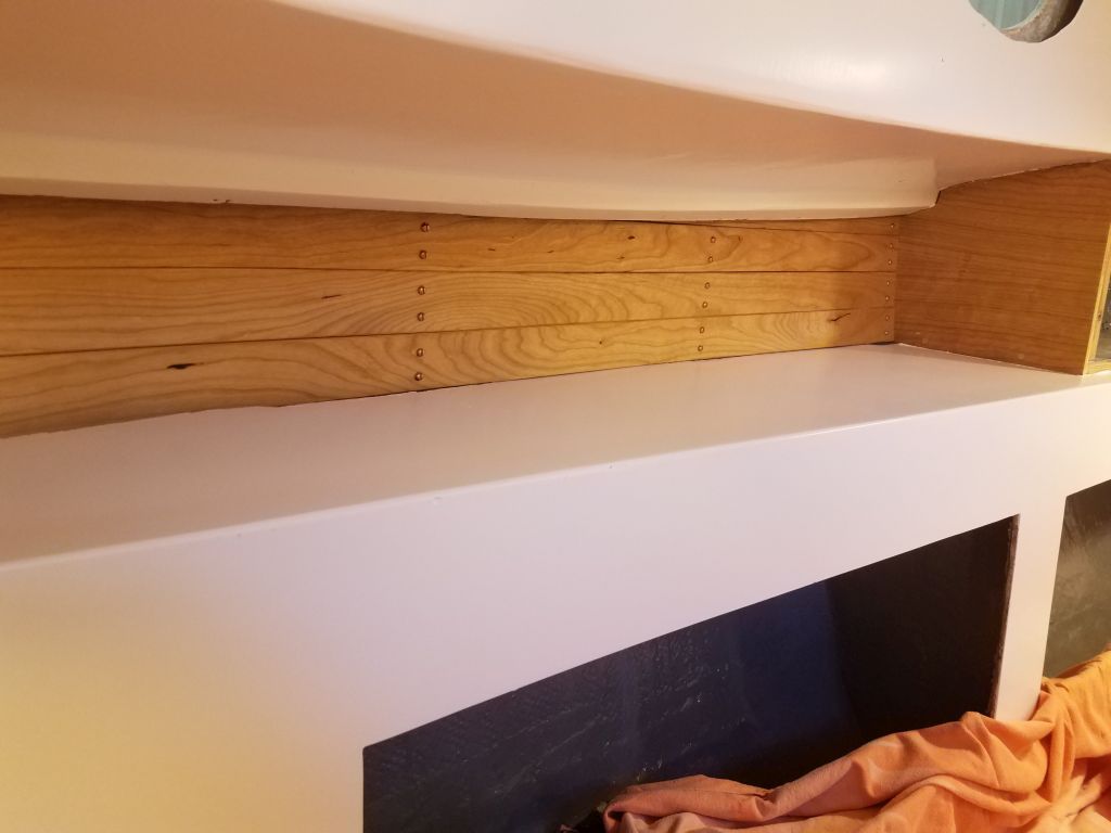
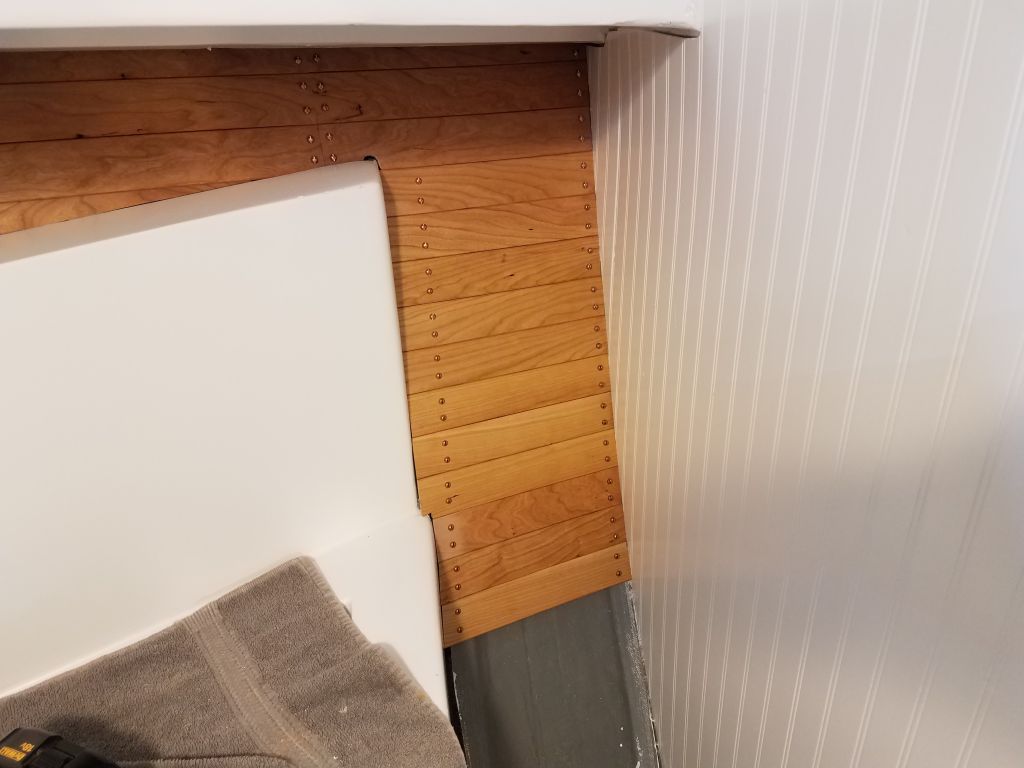
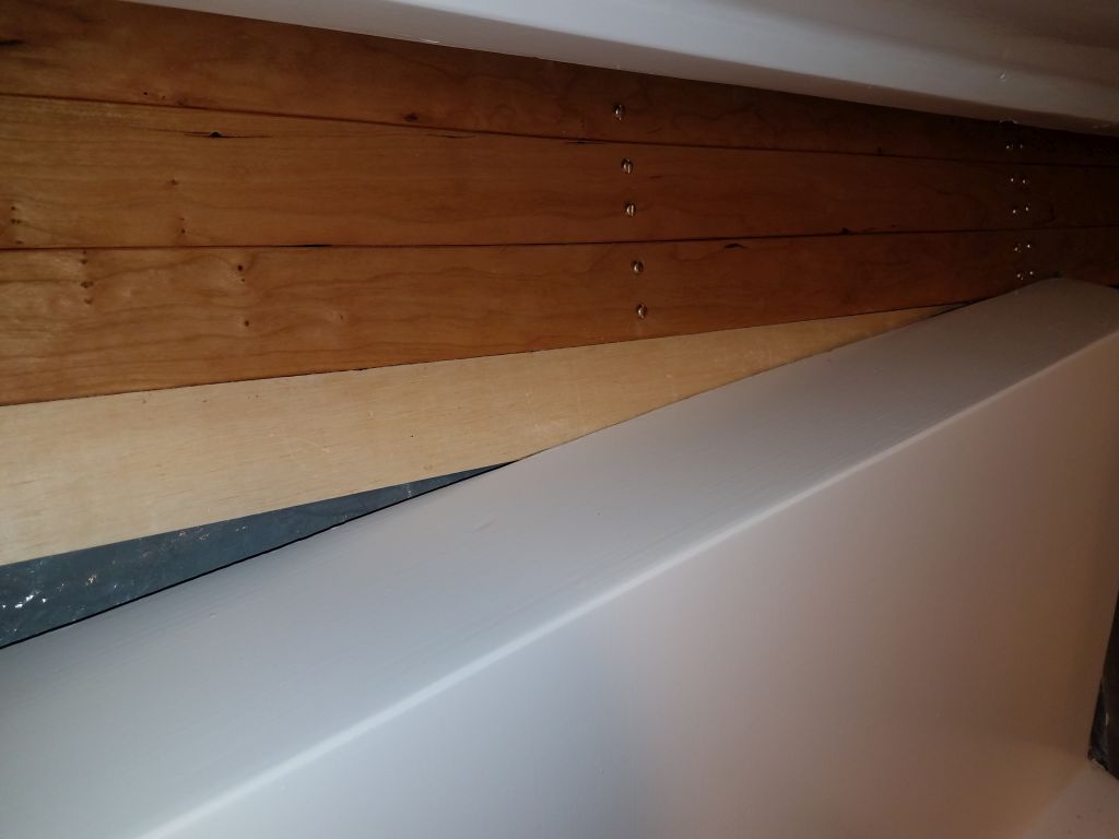
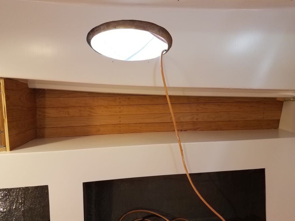
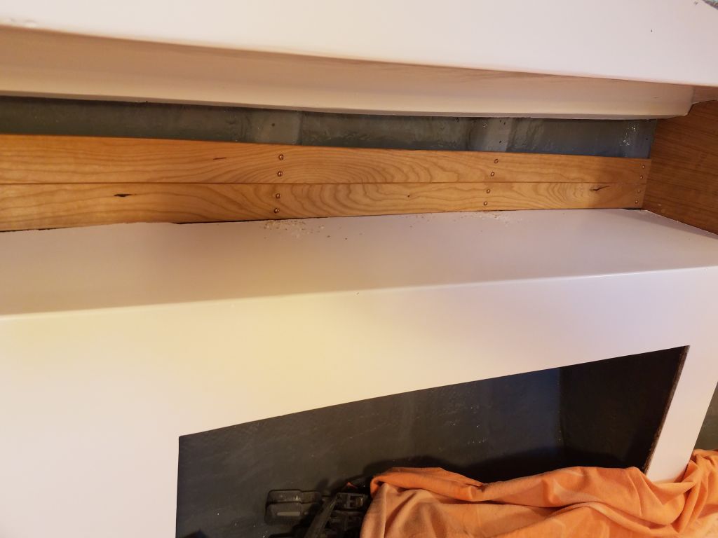
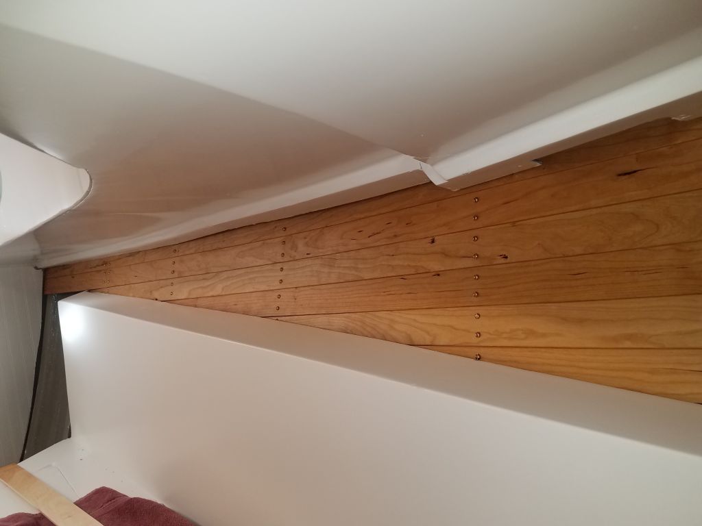
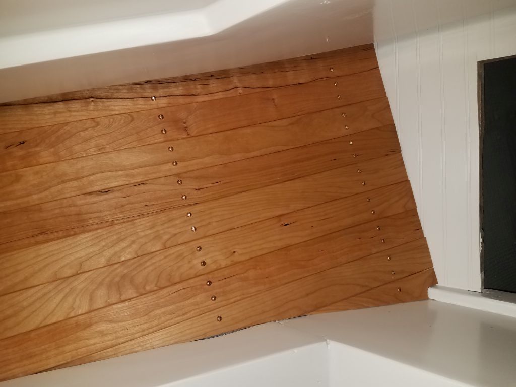
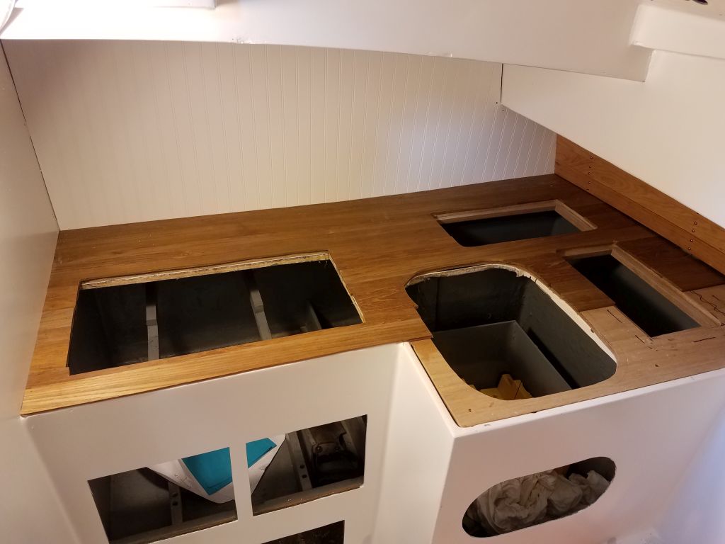
In this way, I worked past the first locker opening, measuring and cutting the planks as needed and choosing the board widths randomly. In each case, I secured the planks with waterproof glue and brads, leaving overhangs at the various openings for later trimming. The outboard ends of the planks slipped beneath the ceiling nicely.
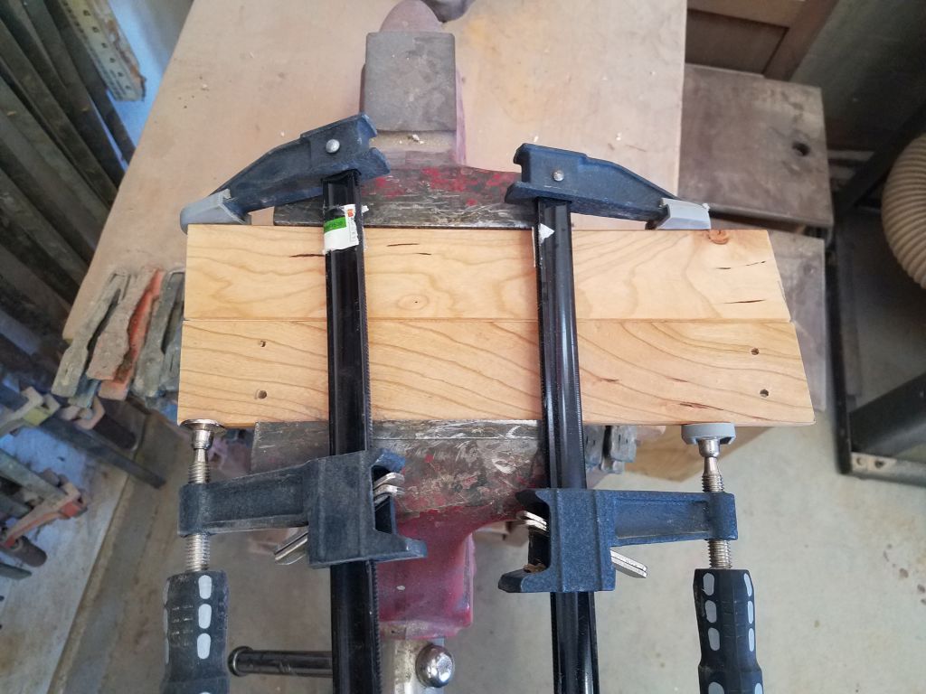
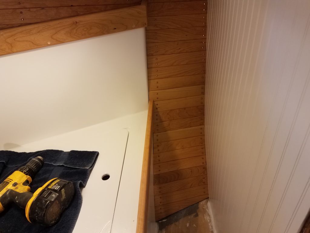
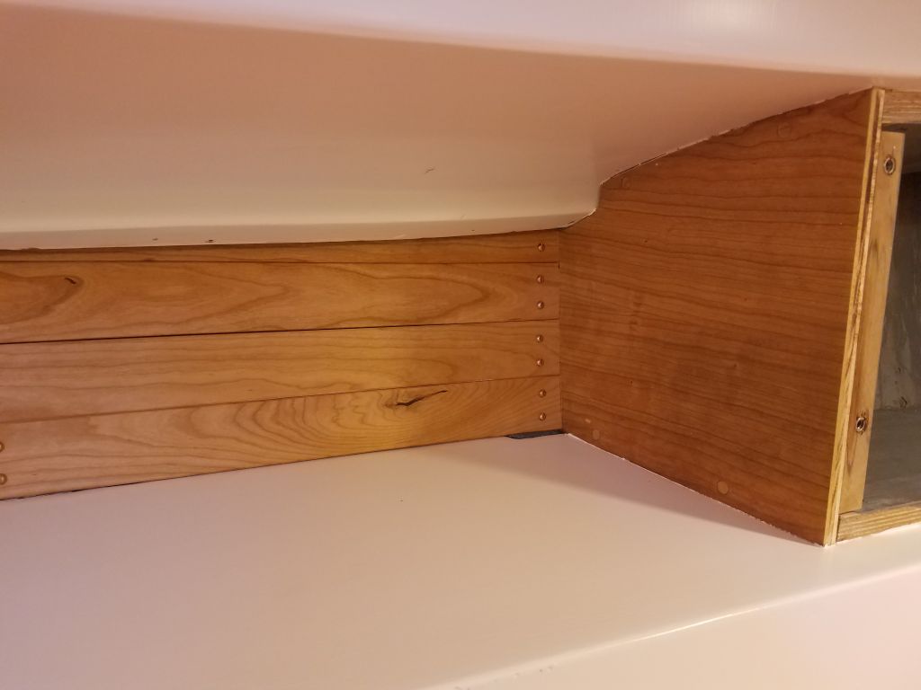
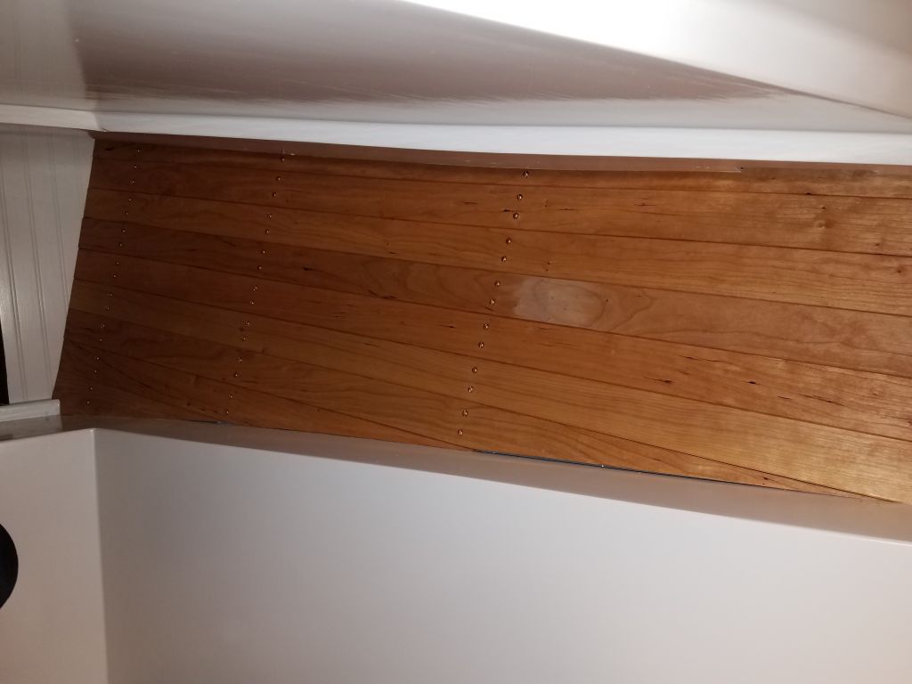
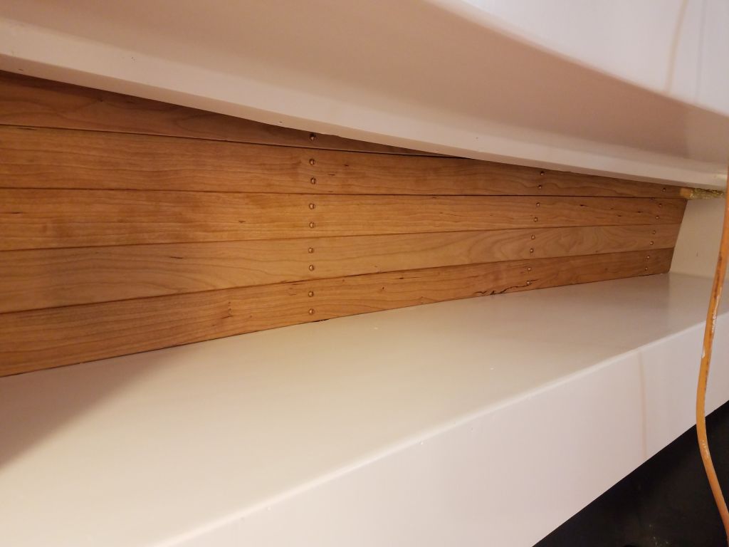
From here, I had three openings to work across for each plank: the stove, sink and the forward storage locker, so the pieces required were short, but I continued using a single board for each strip and setting aside the cut pieces for the locker doors, which I’d set up and glue a little later. By the end of the afternoon, I’d reached the final plank on the short (stove) side of the countertop, which seemed a good place to stop for the day, as it was already late and there wasn’t time to complete the entire countertop.
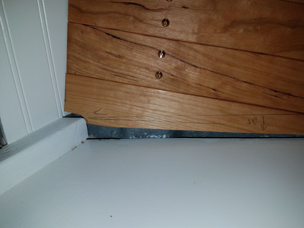
Here, I had to remove some of the bottom of the final plank to clear the molded edge of the original countertop, which was just a bit taller than the 1/2″ substrate I’d installed within, and I wanted the teak to overlap it so the surface would remain a consistent height, and also to allow the fiddles to sit directly on the countertop. I’d cut the relief a little taller than needed, so to secure the plank solidly over the fiberglass lip, I used some thickened epoxy adhesive in that area to fill the gap, and also at the short exposed end of the plank near the sink, where another plank would soon butt up against. The next series of planks would require this relief cut on their inboard short ends to clear the lip on the next section, and I’d finish up next time.

Total time billed on this job today: 8.25 hours
0600 Weather observation: 25°, clear. Forecast for the day: Mostly sunny, 47°