(page 85 of 167)

Scupper 250

Wednesday

Mike from the rigging company was on hand during the morning to finish up the final rigging work:  installing the new lifelines, reefing lines in the boom, and the Tides Marine mainsail track on the mast.  For now, I had Mike leave the port after set of lifelines detached from the pulpit, since this was where I boarded the boat at the moment.

I had another commitment away from the shop during part of the morning, but I spent all of my day working on the engine room batteries, beginning by installing the last ratchet straps and hold-down strap brackets for the remaining three sets of batteries (two each).  As before, I bolted the straps in place through the bulkhead in all cases.  The chore was straightforward, and access to this side of the engine room was better than the far outboard side, but it was still a time-consuming process to get all the straps and brackets in place.

With all the preparatory work done, and the battery box top hold-down straps secured to all three remaining boxes, I managed to get two of the three remaining pairs of batteries in place during the afternoon, starting with the starboard outboard set (on the original starboard shelf in the engine room), then the port set on the centerline platform forward of the engine.  This seemed so simple, but the battery weights, tight quarters, and other logistics meant that each installation required lowering a pair of the batteries from the cockpit to the cabin; setting up and modifying as necessary the 2×4 sliding platforms; placing the batteries in their boxes; sliding the boxes into position (fortunately much easier for these sets than it had been for the first set on the port side earlier); and securing each box with the ratchet strap, hold-down strap, and the battery box top strap.

One pair of batteries remained, and I was excited about completing the installations, but the day was growing short and I thought it’d be better for me to wait to schlep the final pair of batteries from the cockpit into the cabin and then into the engine room, as I was feeling the day’s efforts and needed to save myself, so after modifying the ramp through the head for the final pair of batteries, which would go directly inside the engine room door, I called it quits for now.

Total time billed on this job today:  5.75 hours

0600 Weather Observation:  33°, cloudy. Forecast for the day:  Cloudy, 42°


Scupper 249

Tuesday

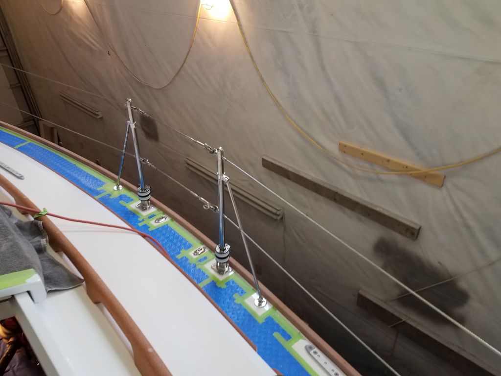
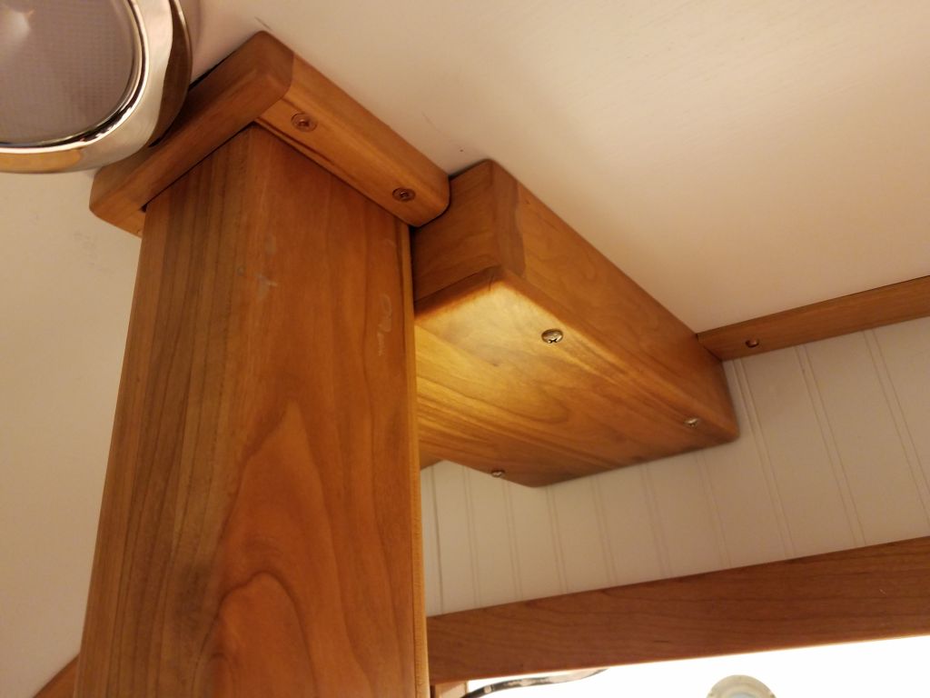
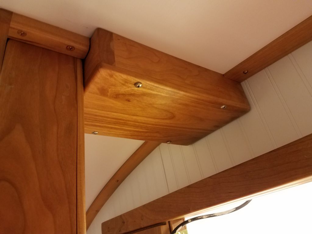
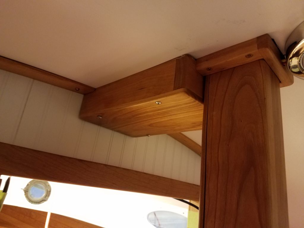
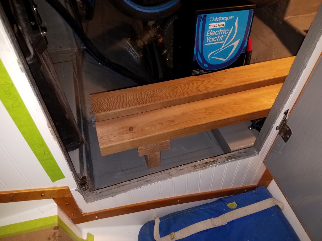
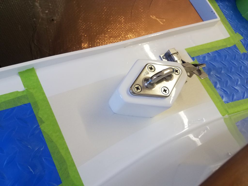
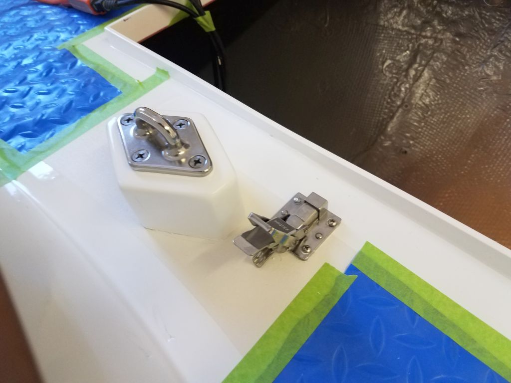
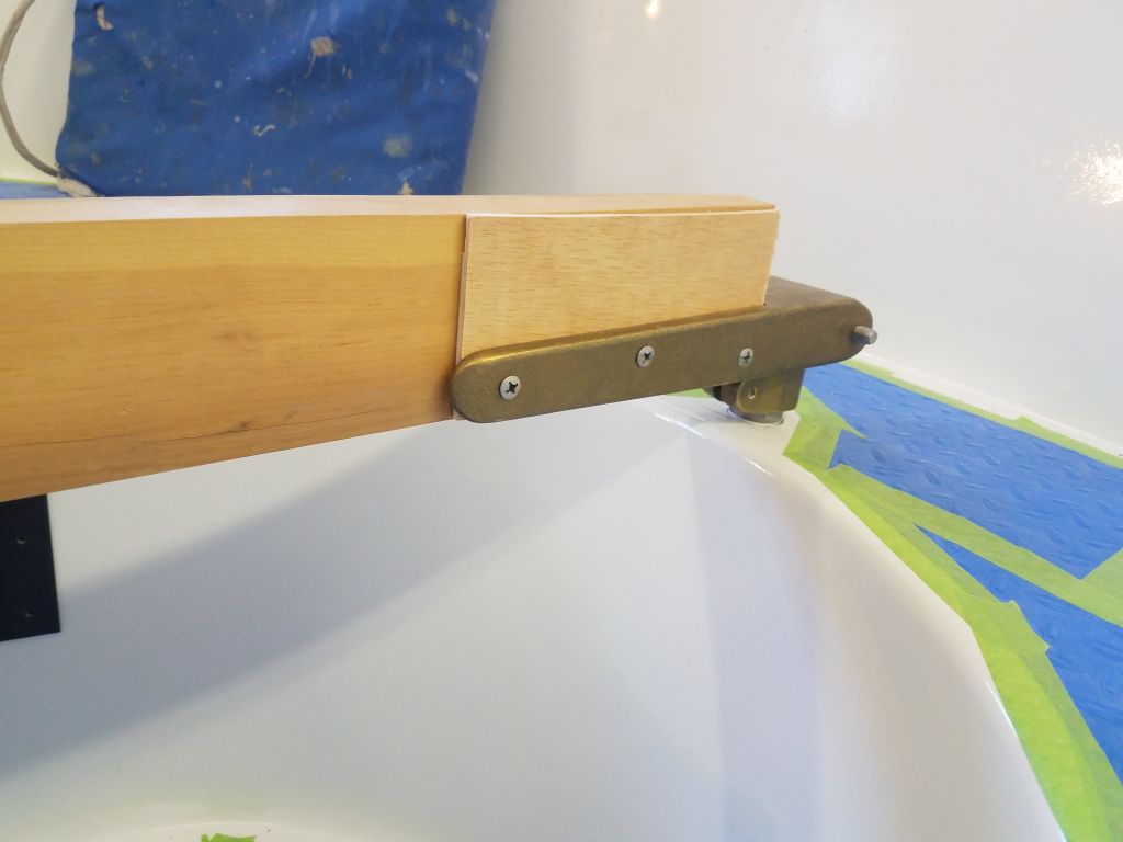
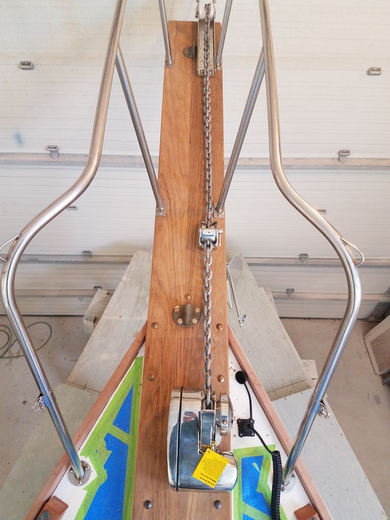
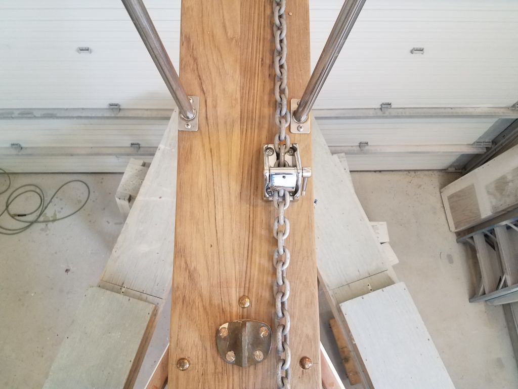
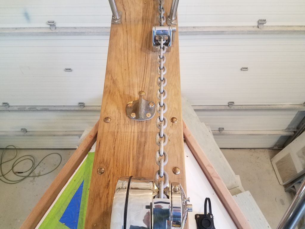
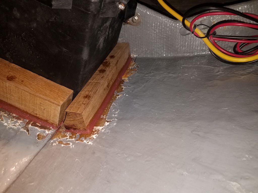
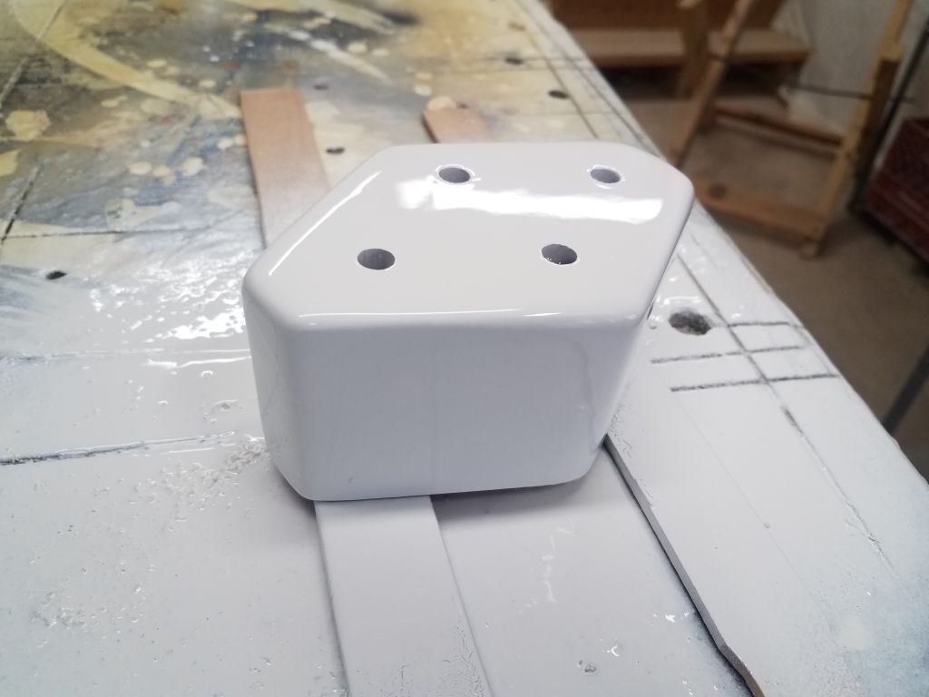
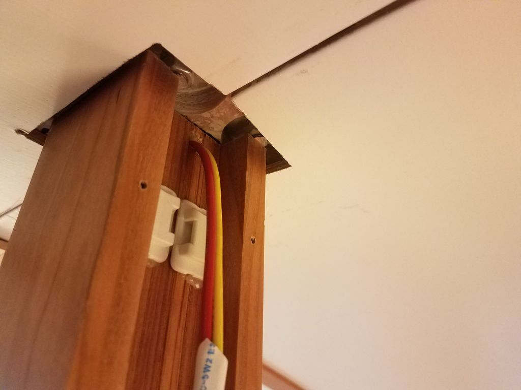
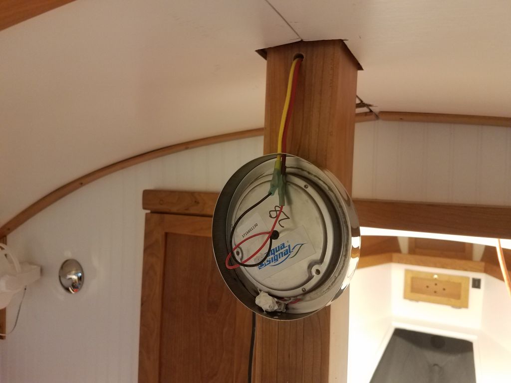
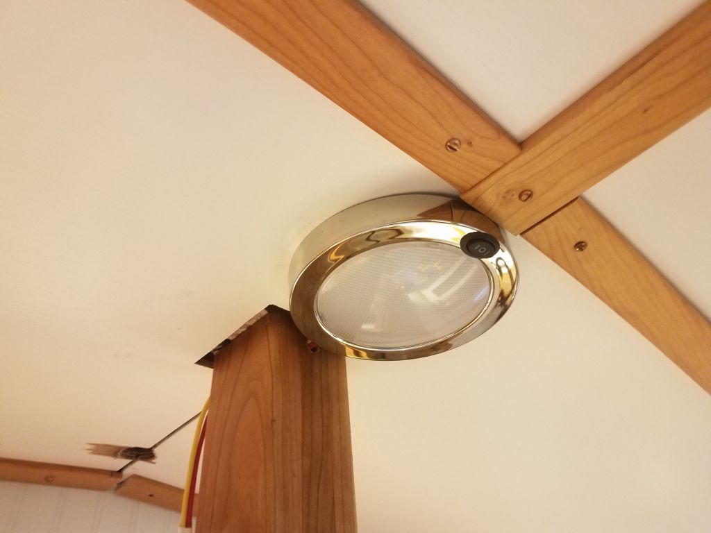
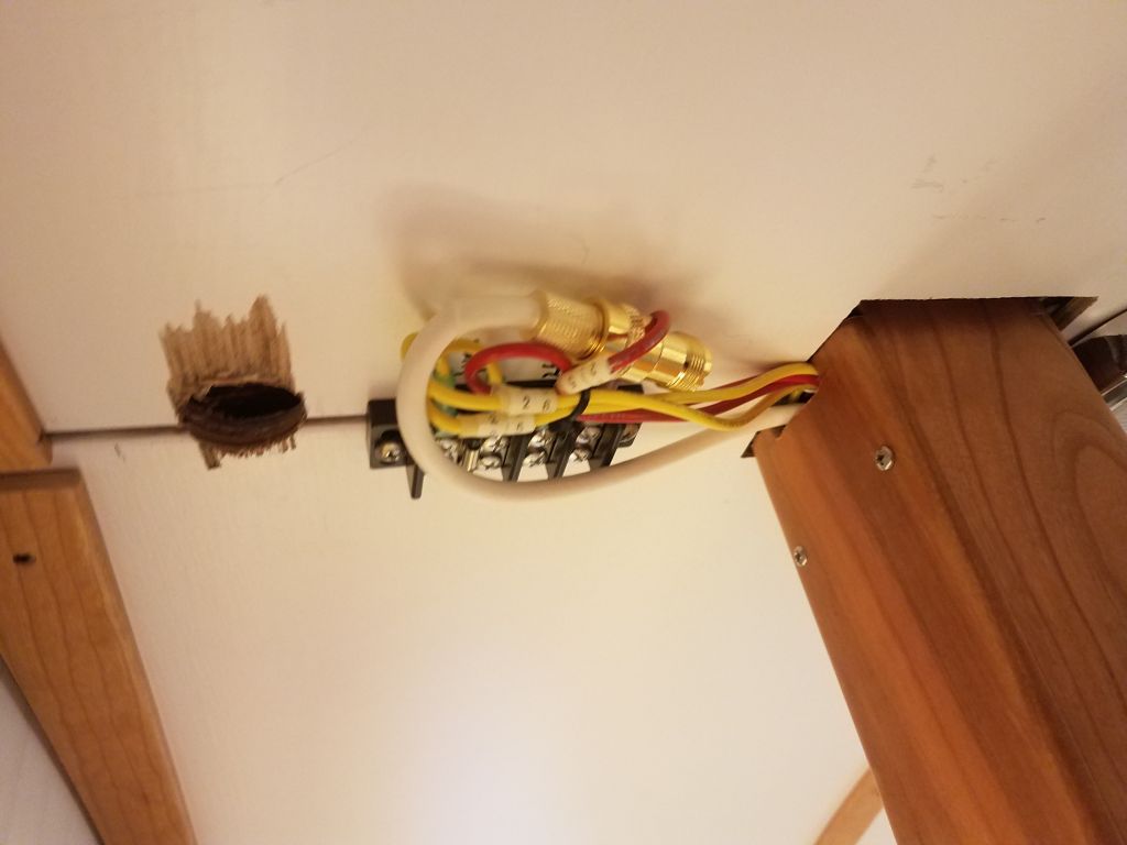
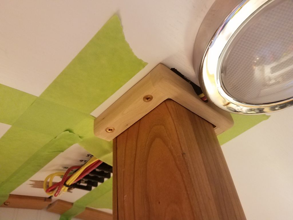
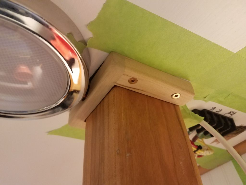
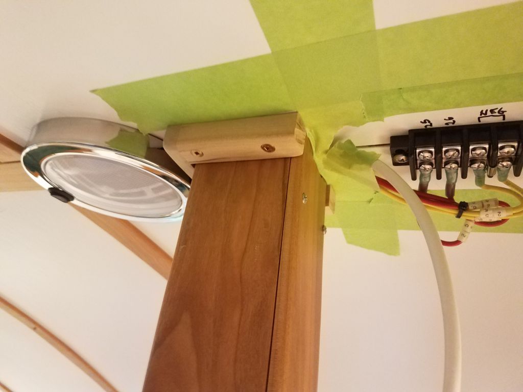
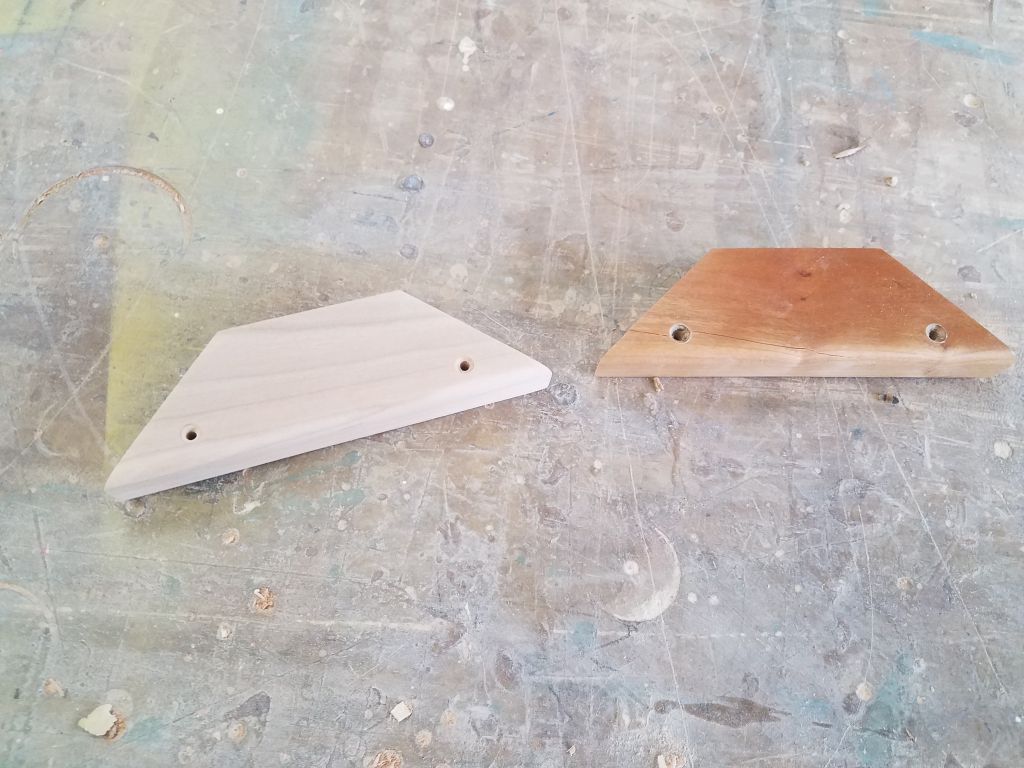
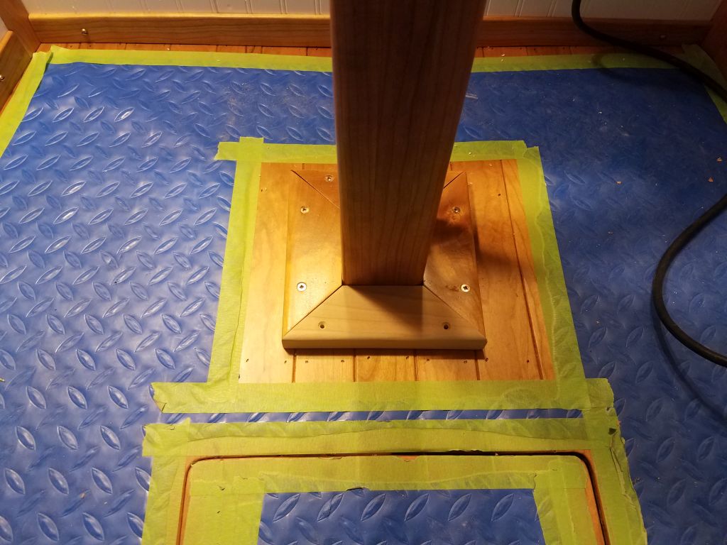
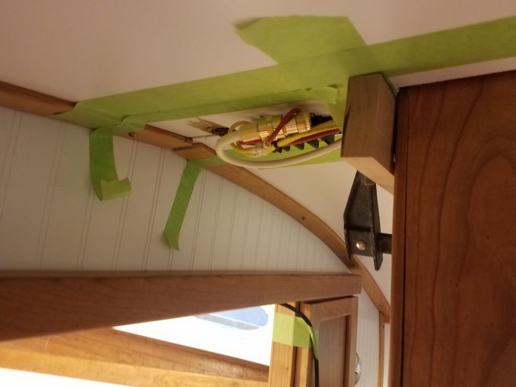
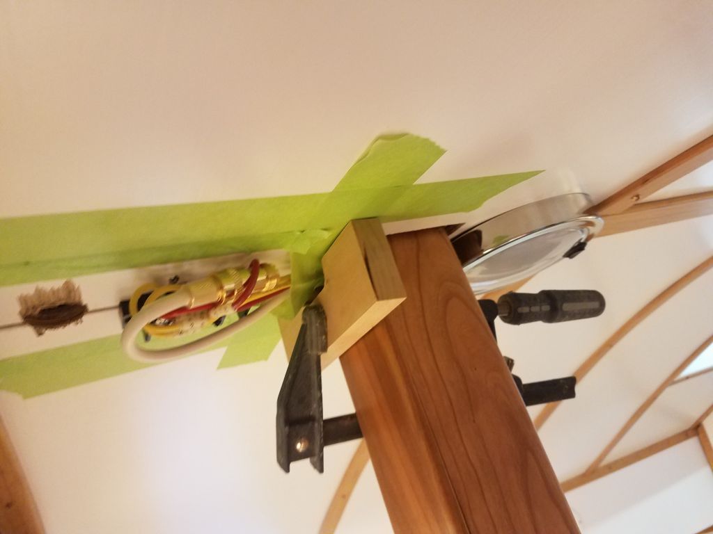
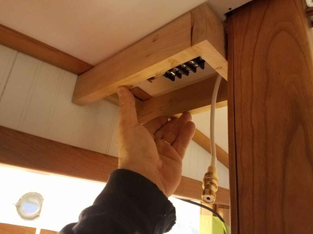
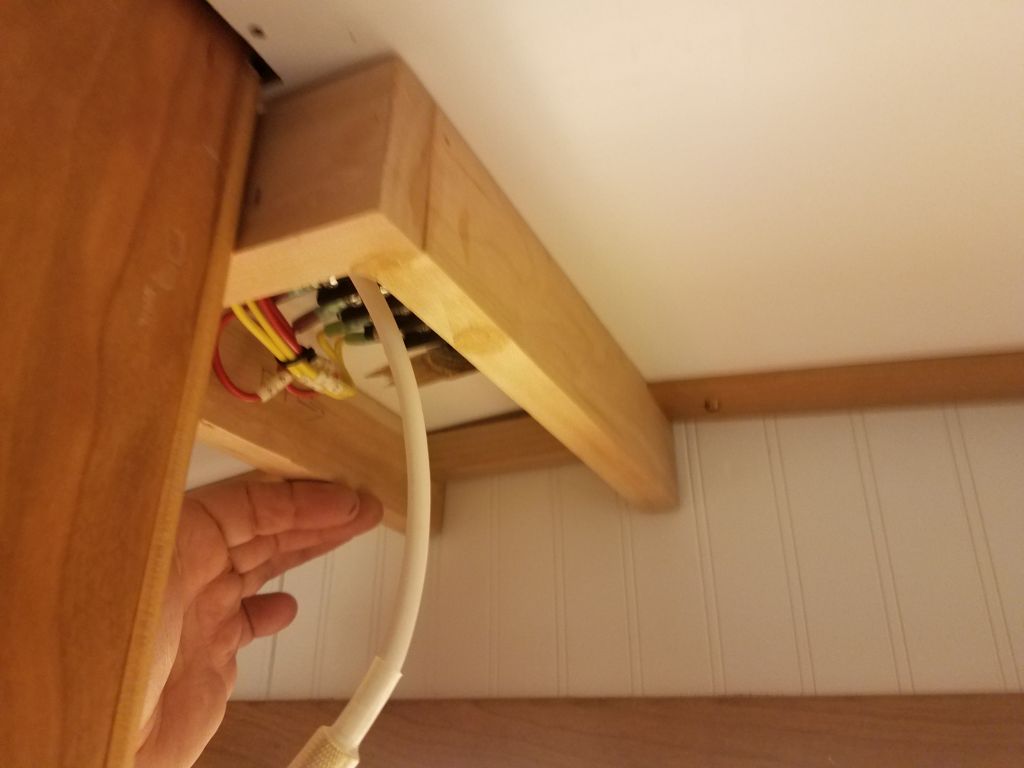
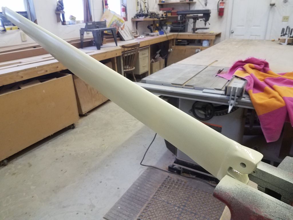
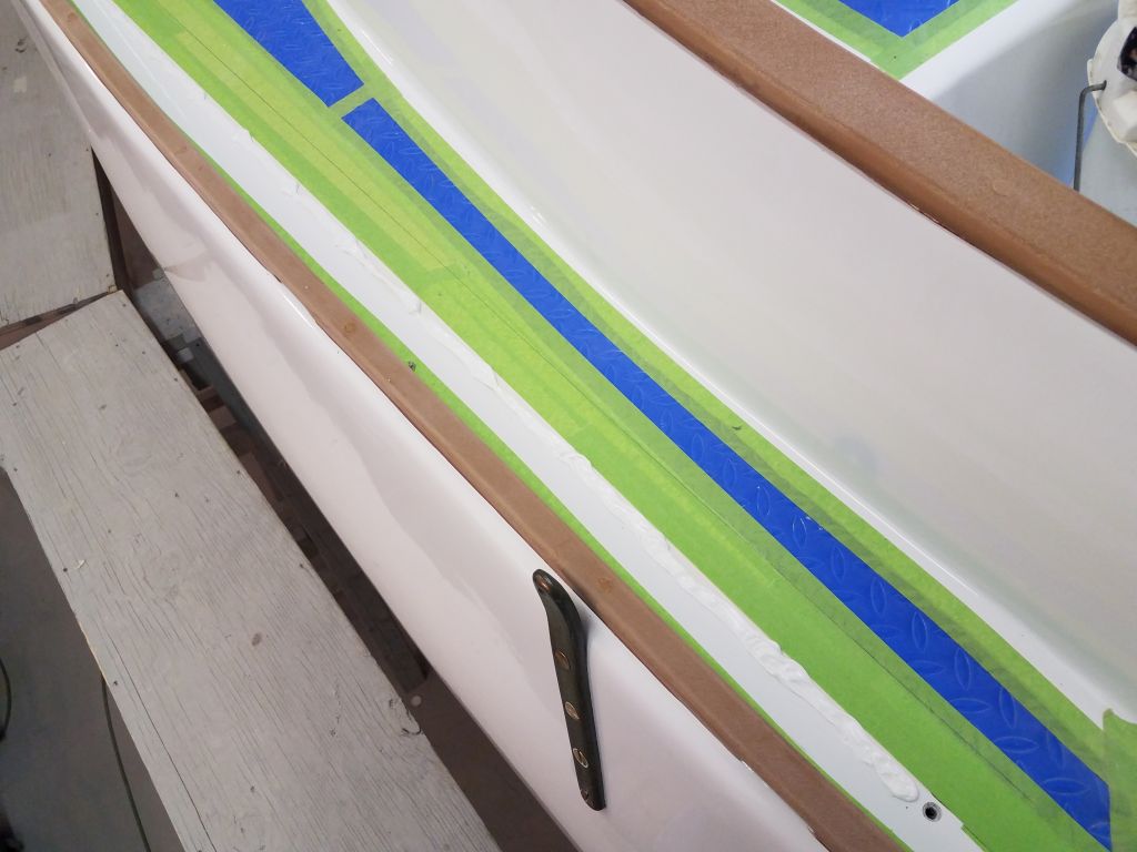
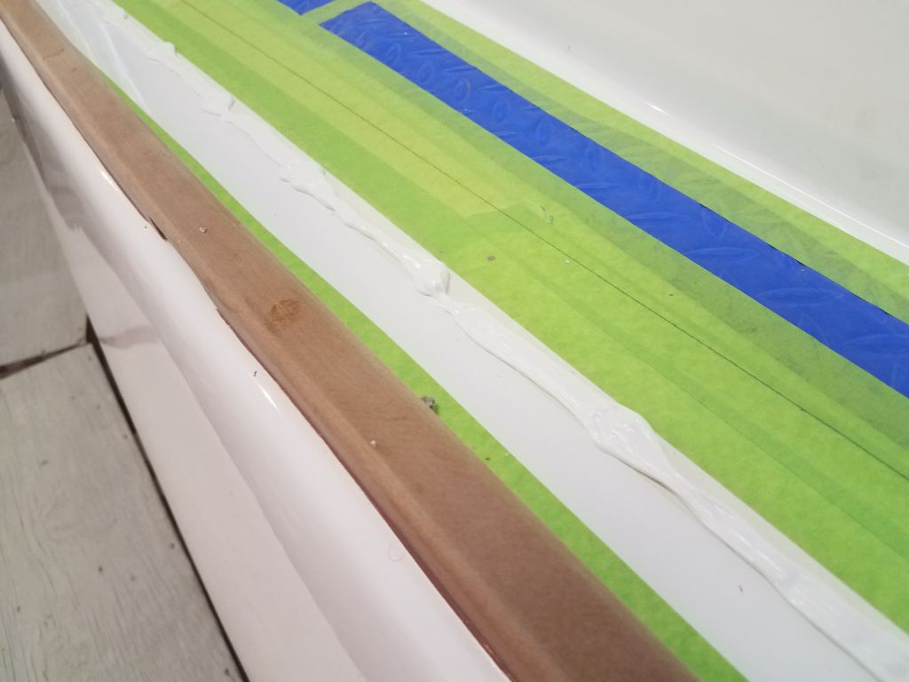
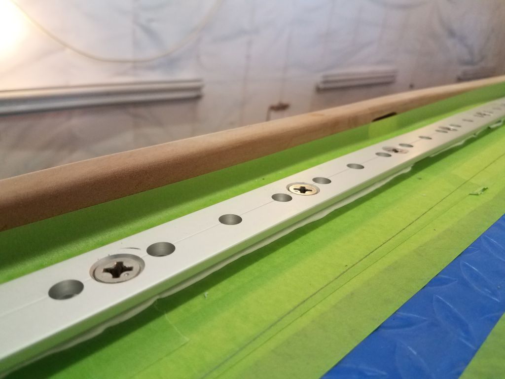
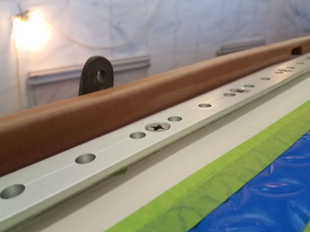
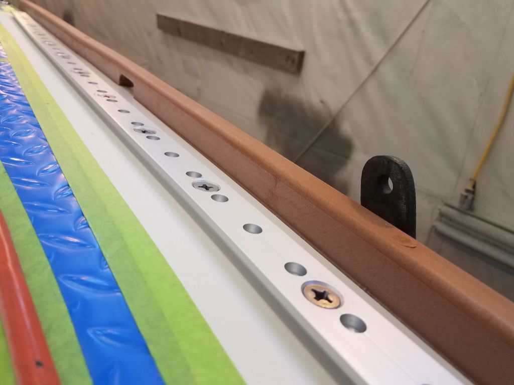
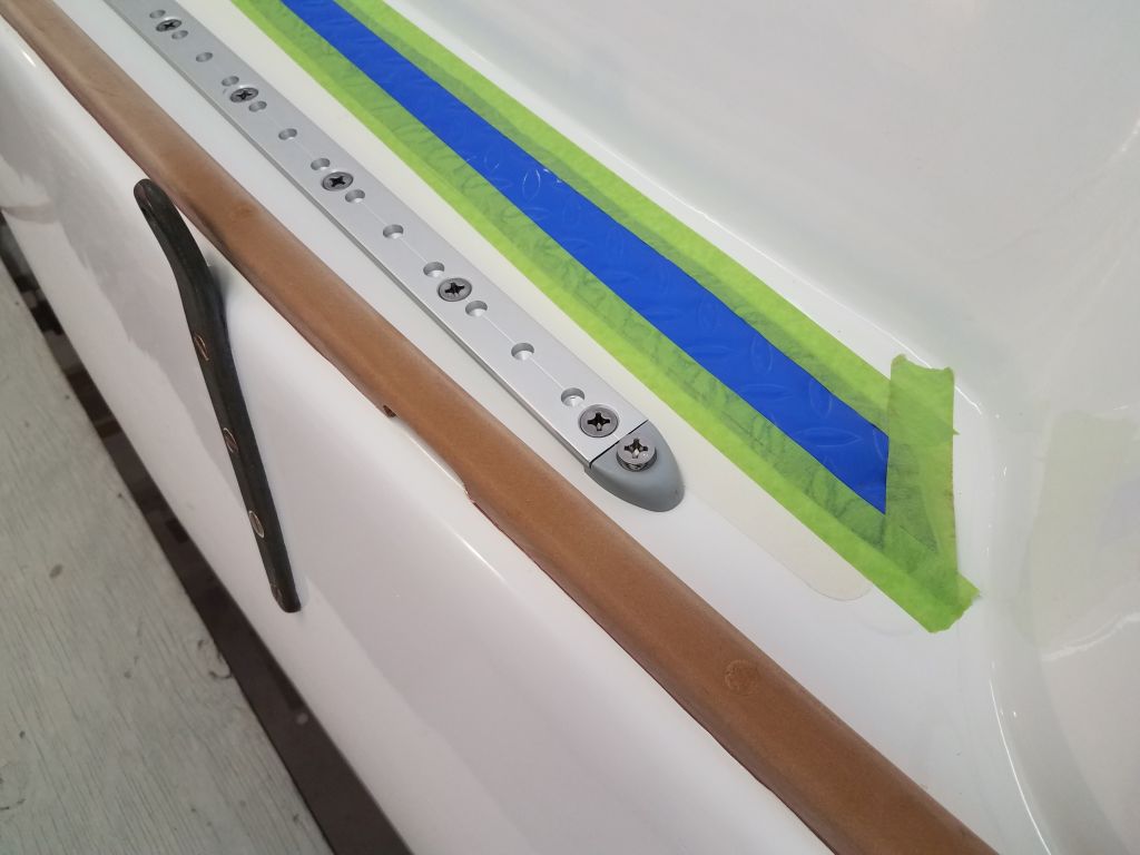
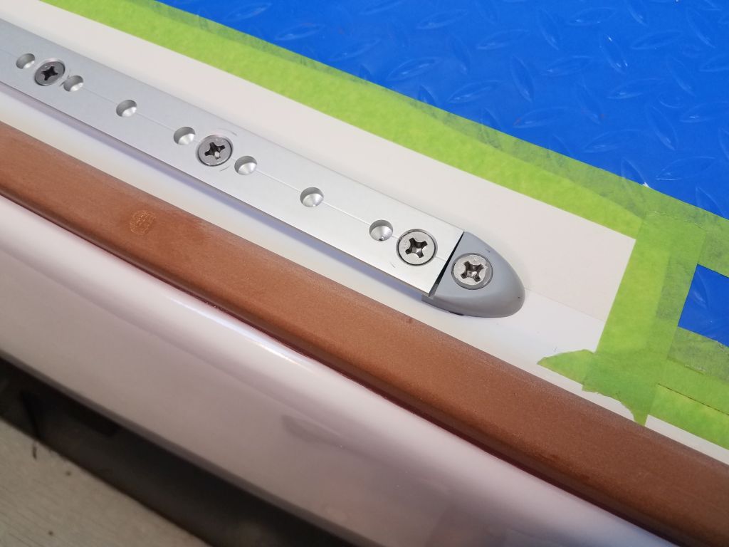
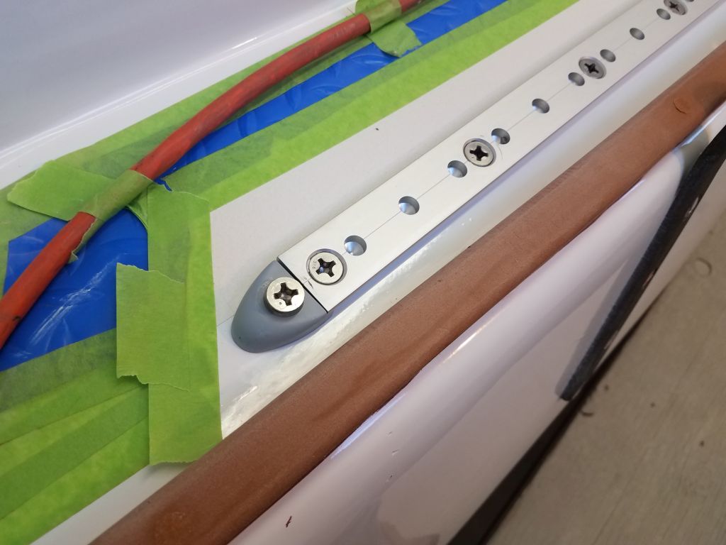
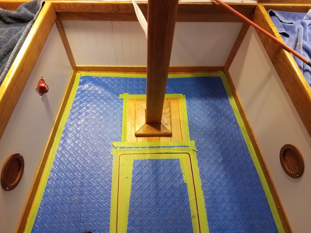
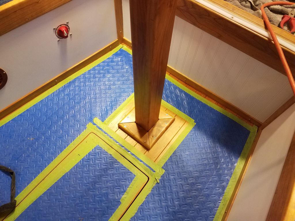
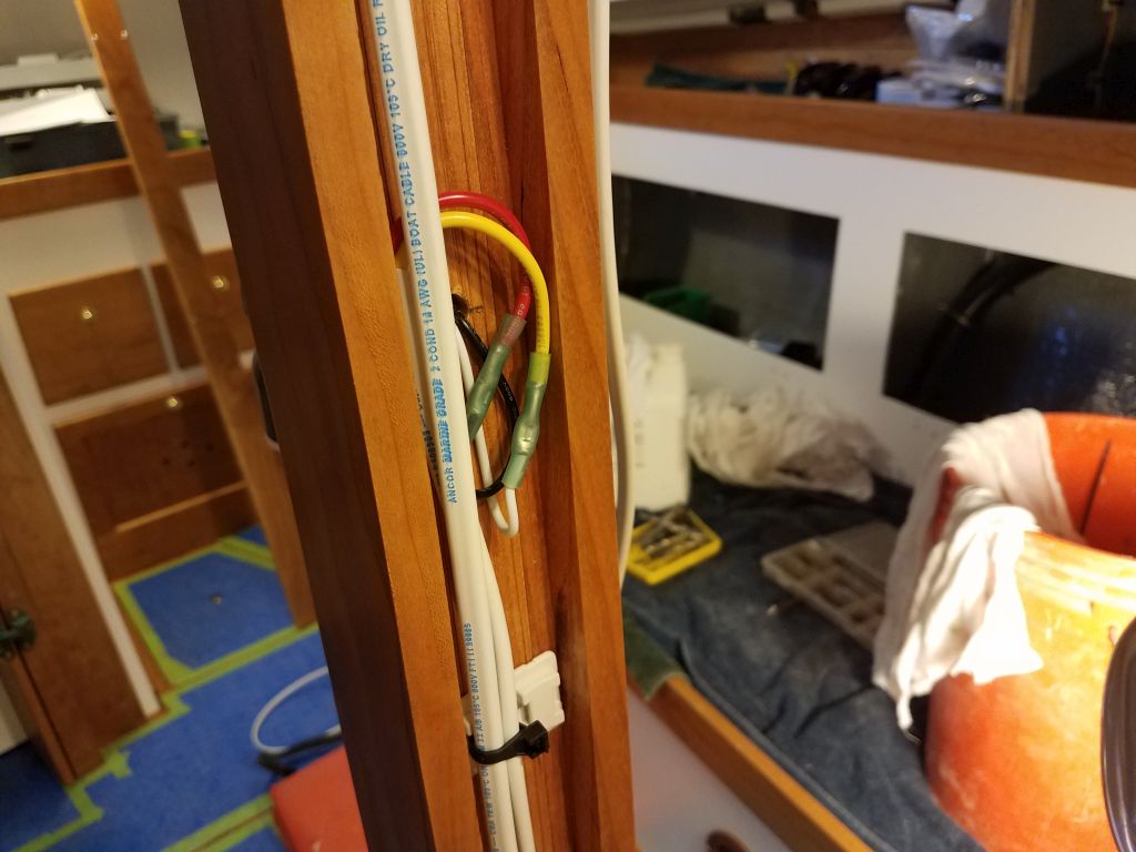
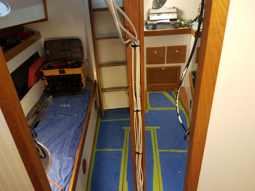
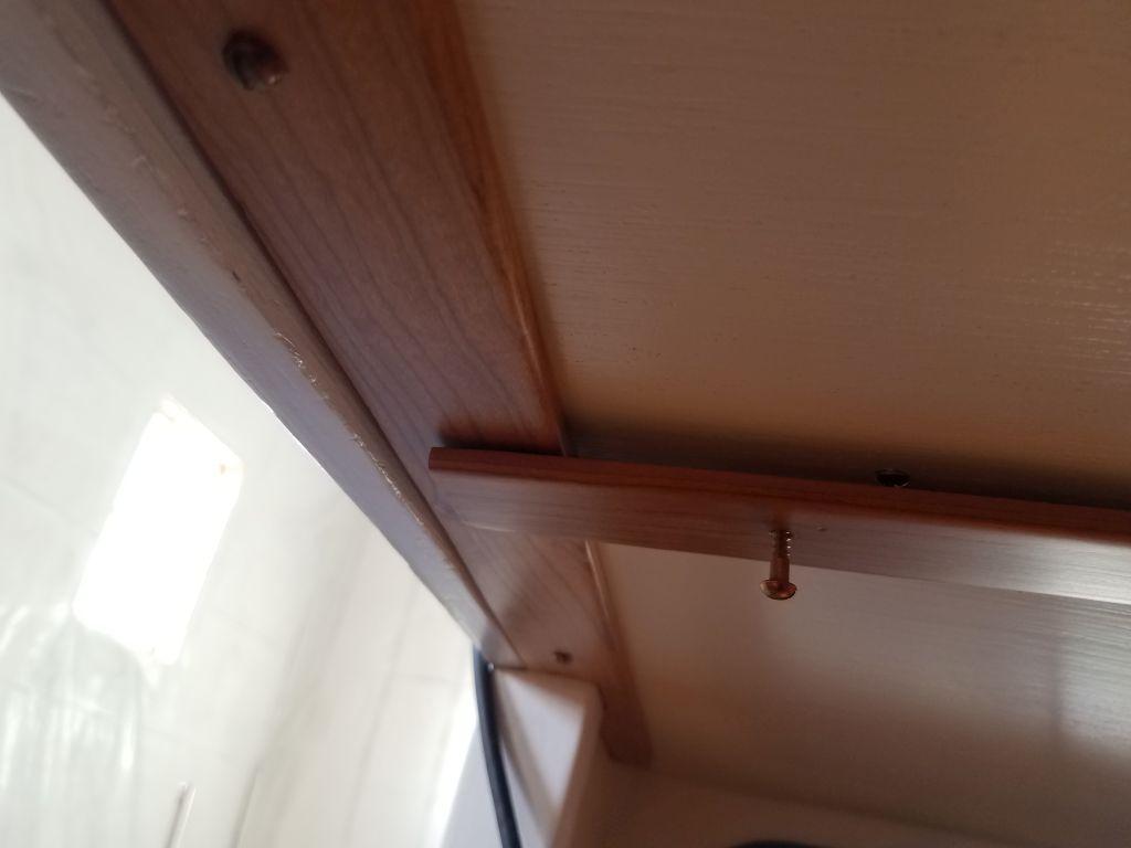
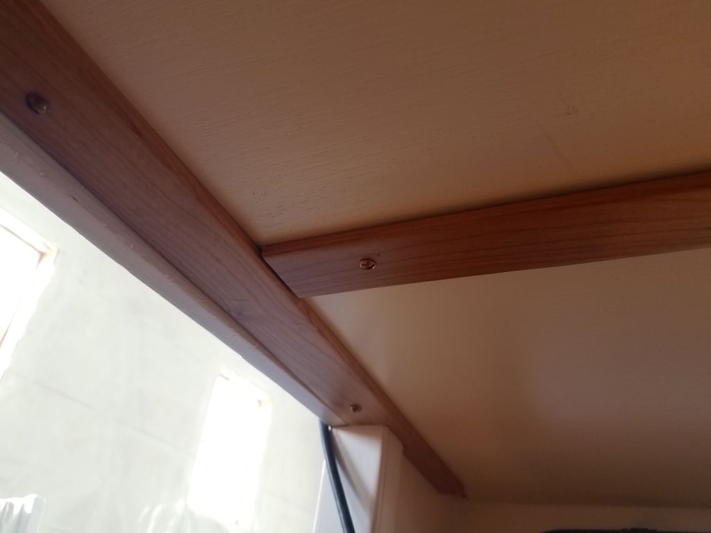
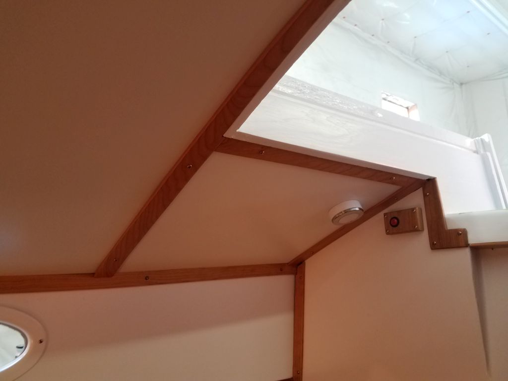
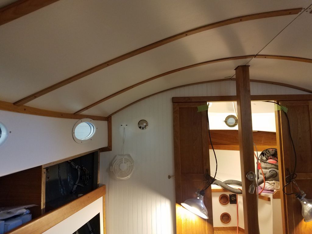
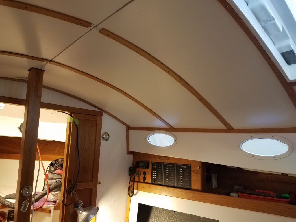
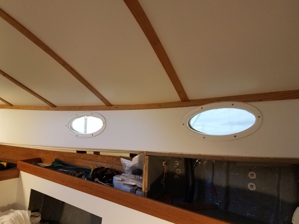
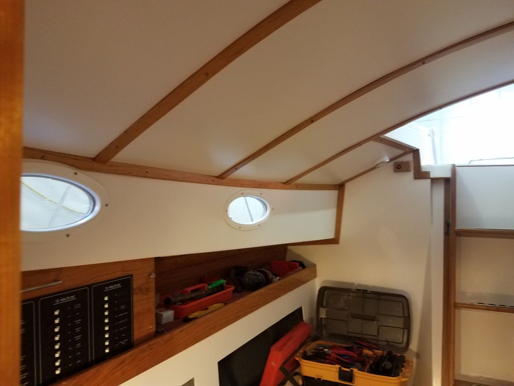
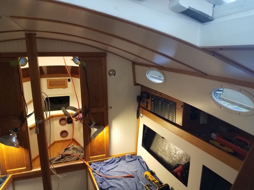
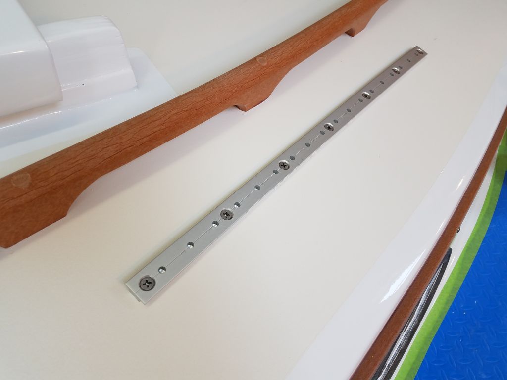
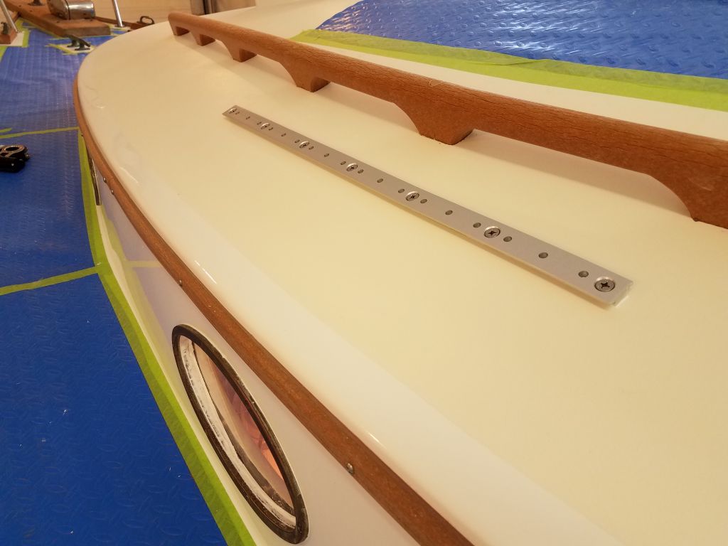
Over the past week or so, I’d finished up the varnish work on the trims for the compression post, including the replacement lower trim, the new upper trim, and the box to cover the mast wiring.  Now, I installed the various trims to complete the work.

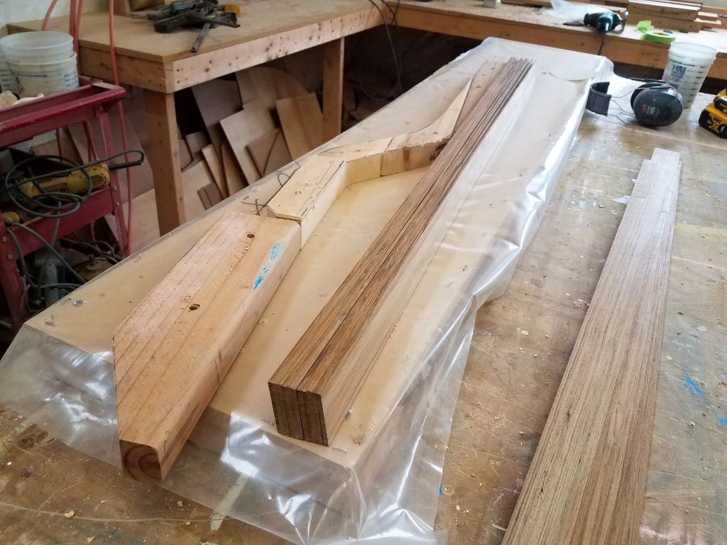
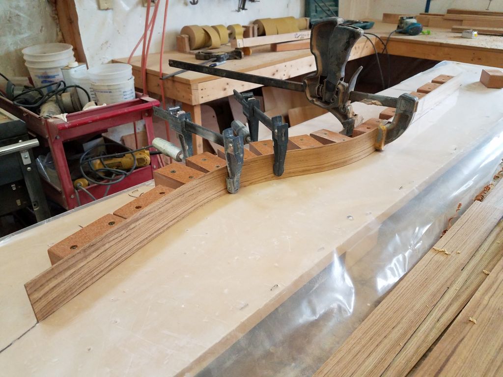
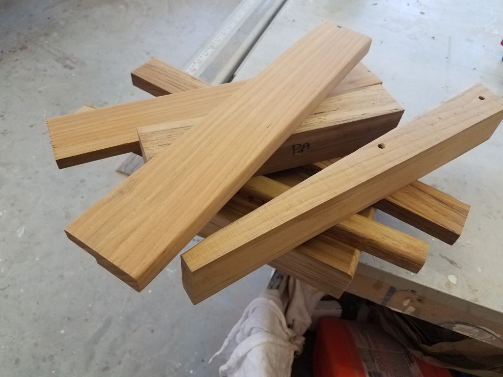
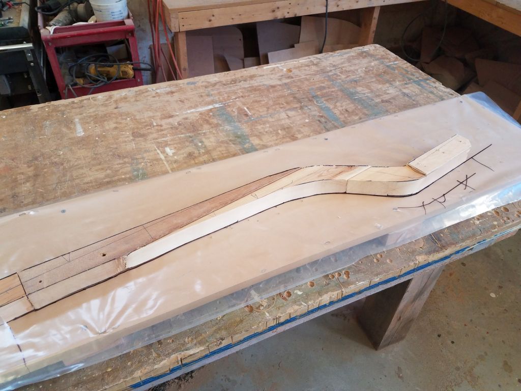
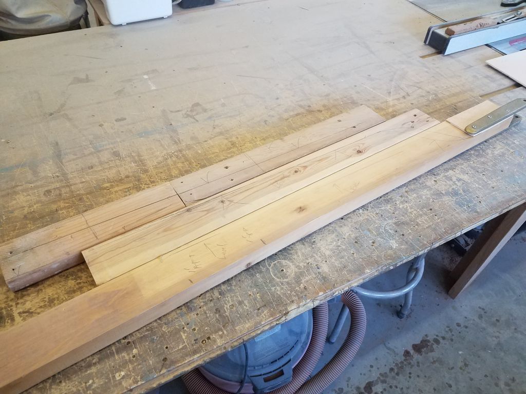
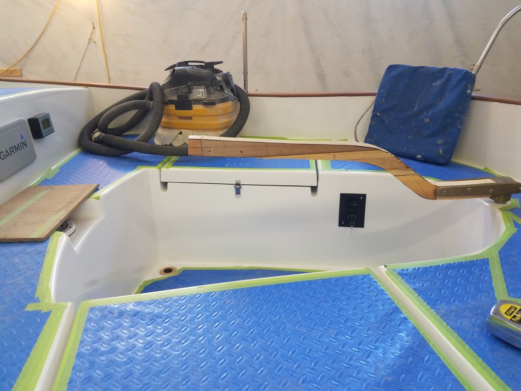
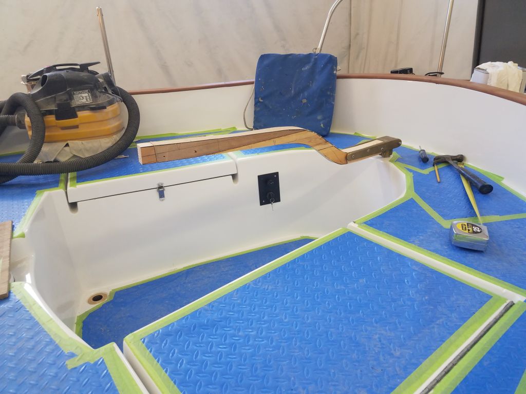
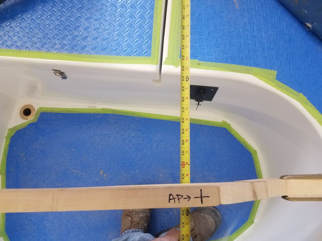
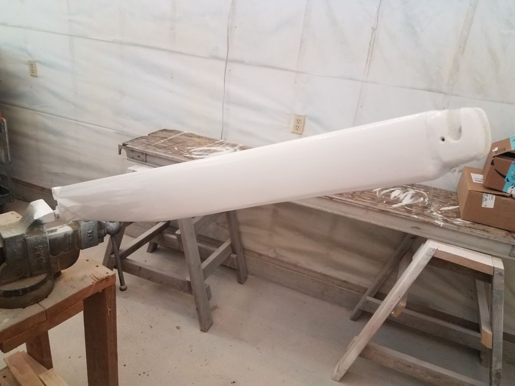
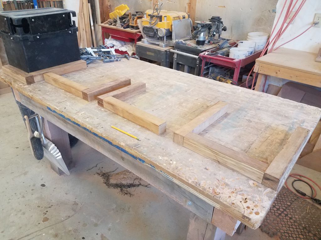
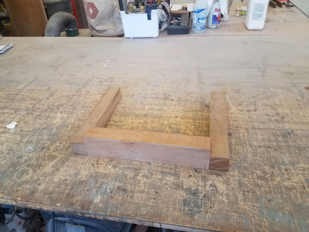
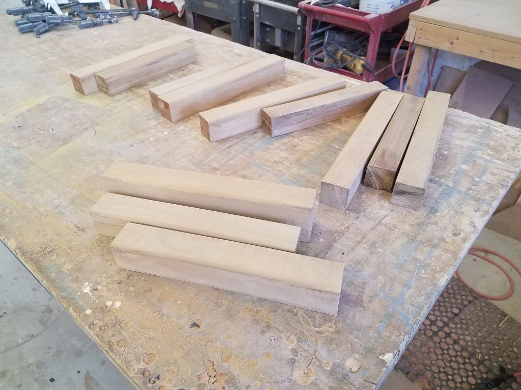
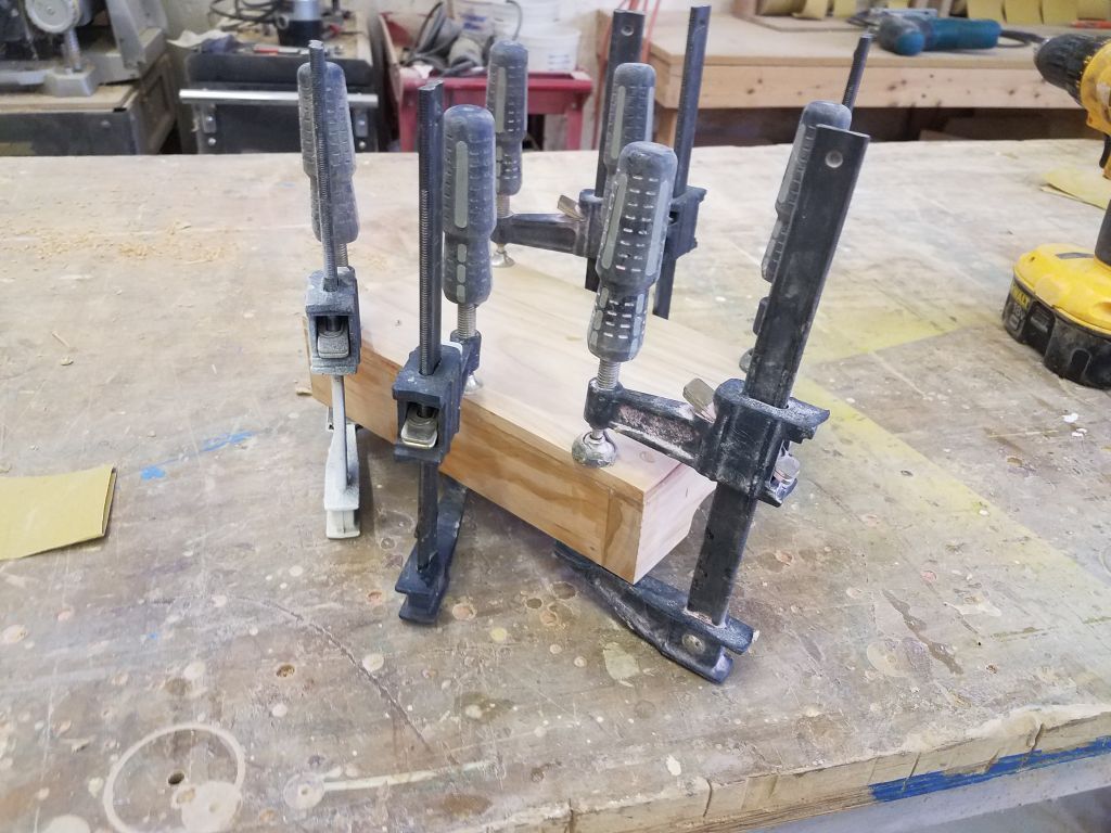
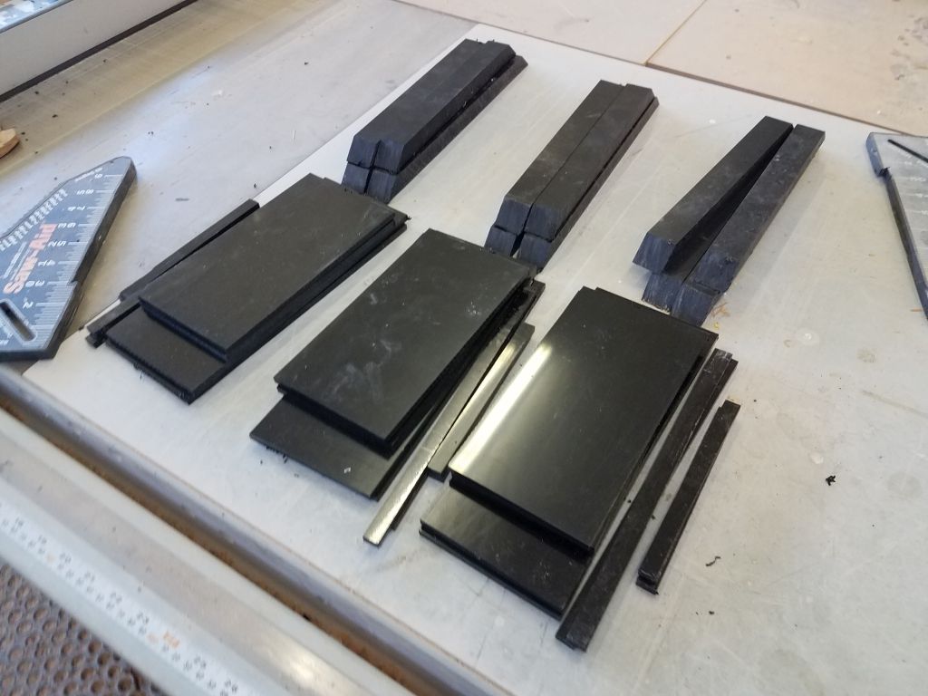
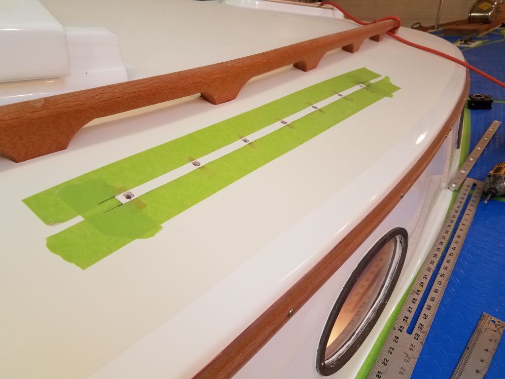
Next, I turned back to the tiller.  In order to get the teak strips to conform to the required shape without breaking, I needed to reduce their thickness, so after milling several extras I planed all the laminations down to about 1/8″ in thickness, a dimension I’d earlier determined would just about meet the curvature.

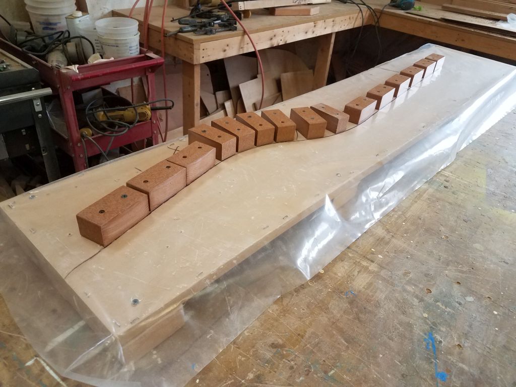
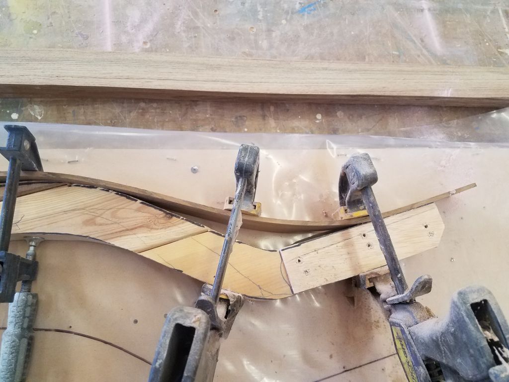
From here, I used a sacrificial lamination clamped against the raw tiller mockup to determine, first, whether the strip would bend to the exact shape (not quite) and, second, to what extent could I bend it.  A comfortable bend turned out to be just slightly less severe than the curve I’d cut into the mockup, but close enough that the basic shape and function of the tiller would remain, so this was a fair (and required) compromise I could work with.  I used the bent lamination to draw a new line on  my plastic laminating board, and this would be the line to which I’d work going forward.

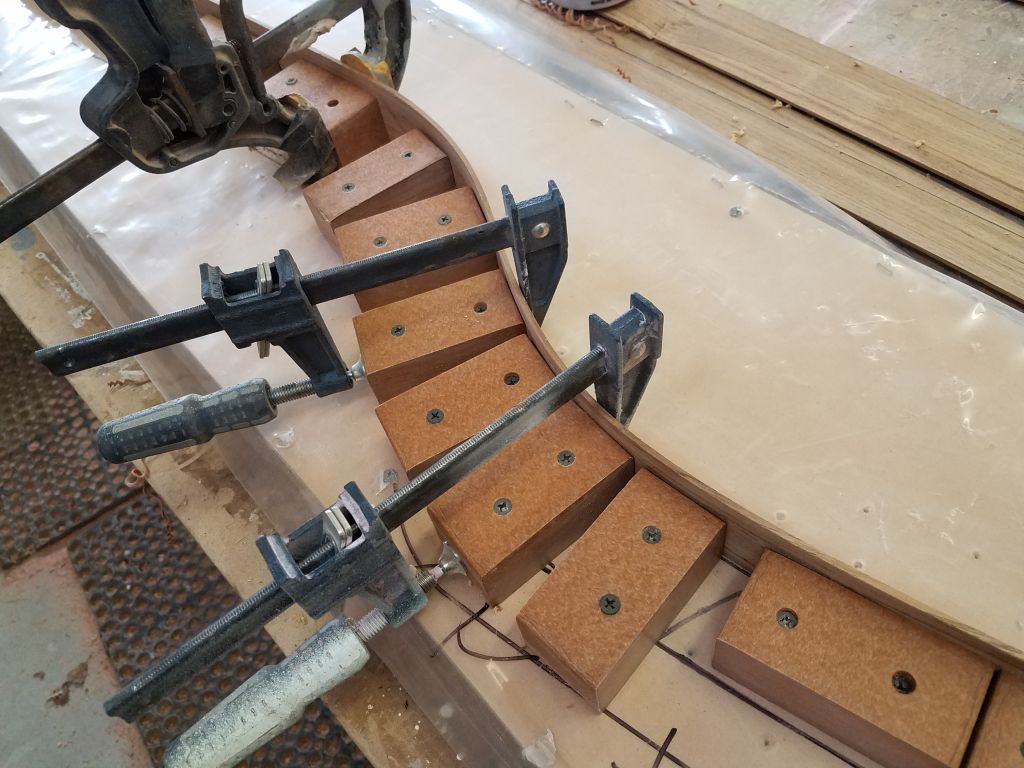
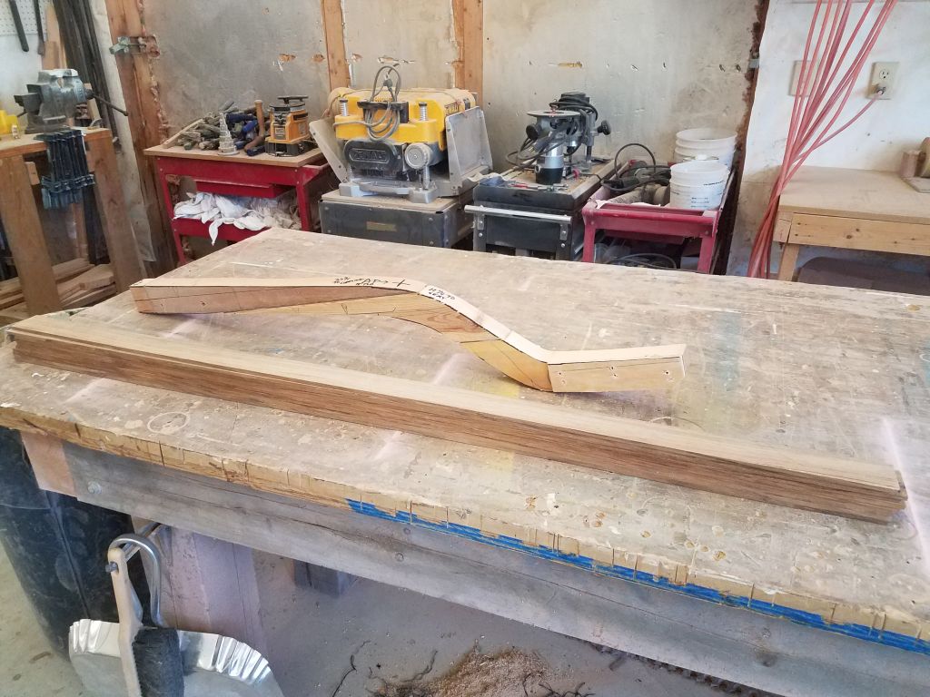
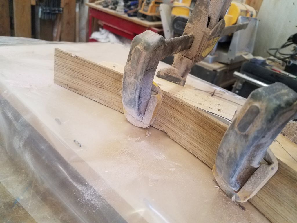
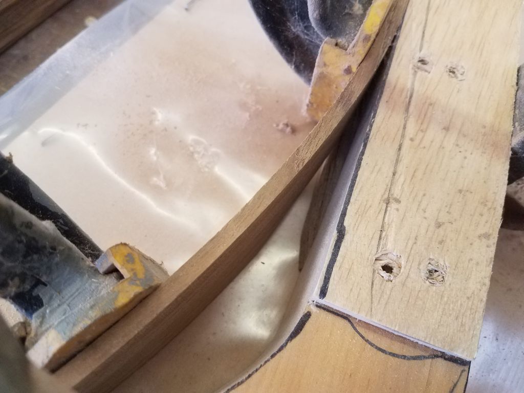
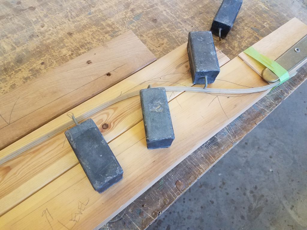
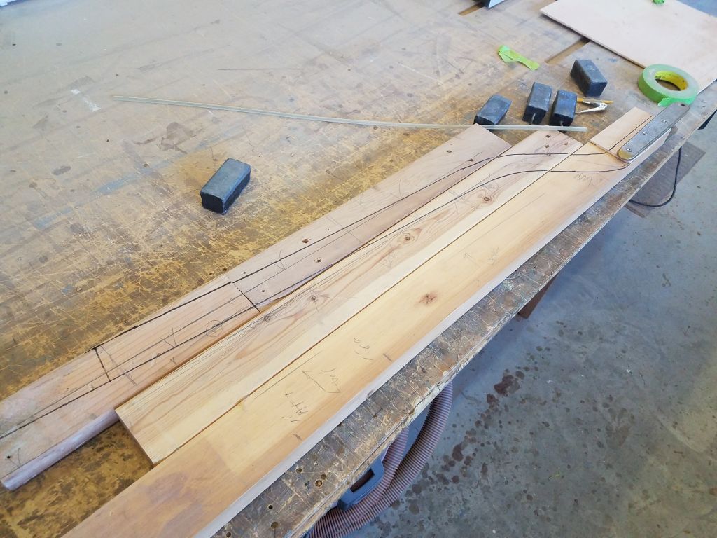
Using that line as a guide, I cut and installed with screws a series of blocks along it, using some scraps of the plastic lumber I’d used for the deck trim since it was nonstick (I hoped).  Then, I test-bend another lamination against these blocks to confirm that I could make the bends required in the final step.

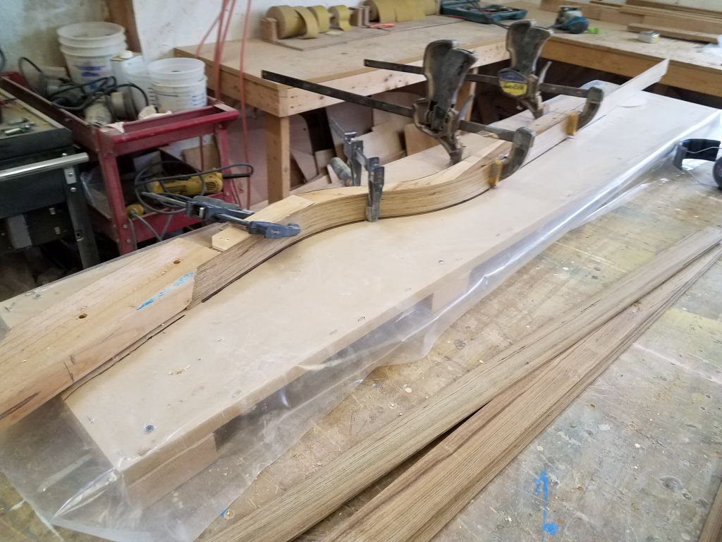
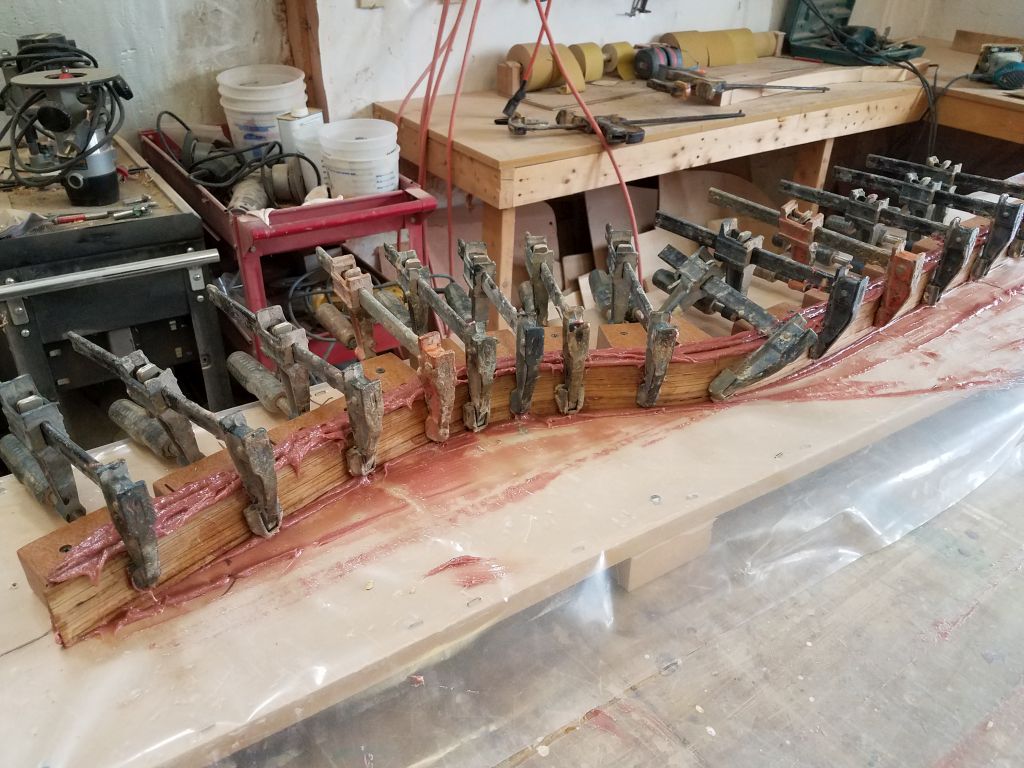
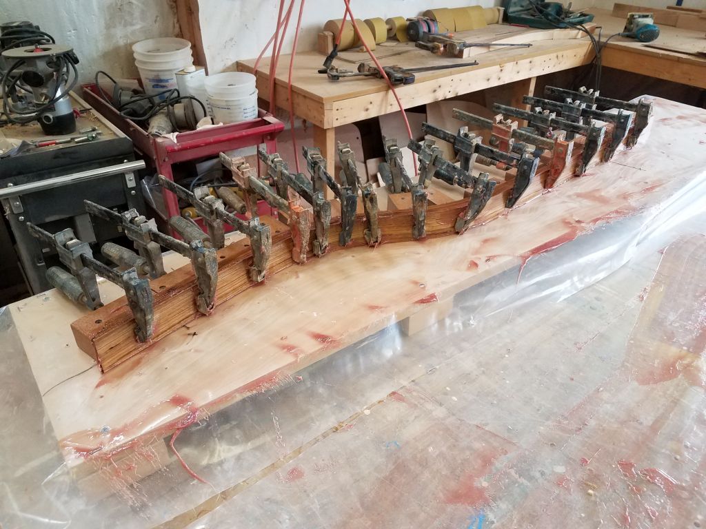
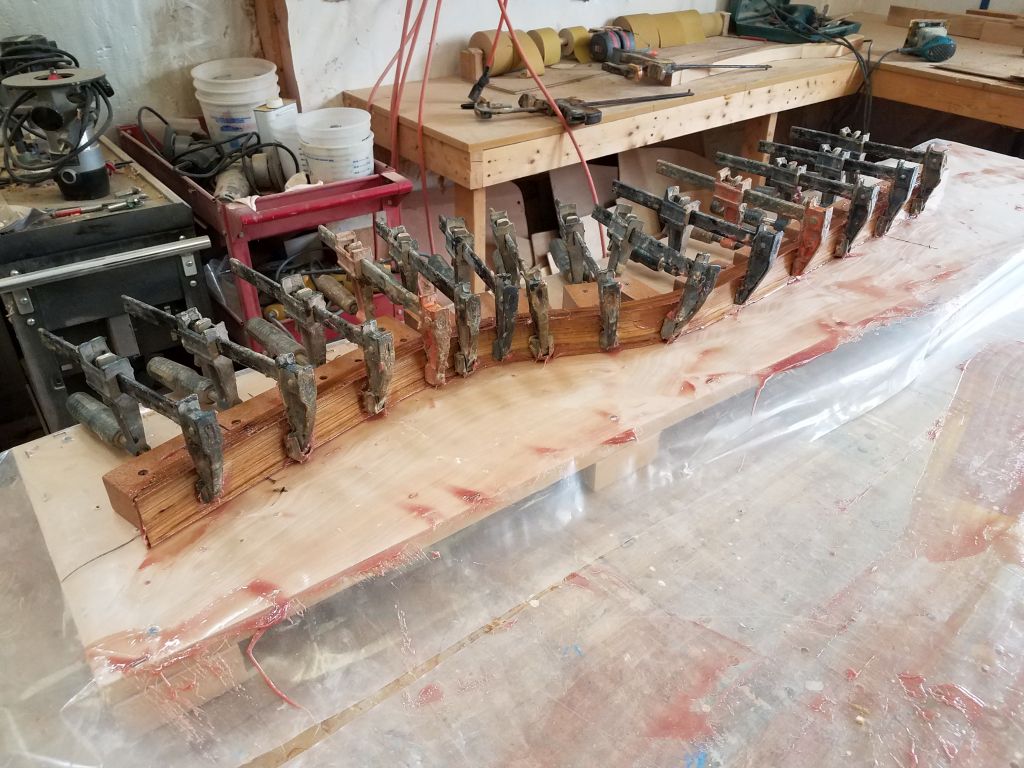
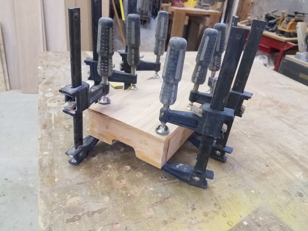
With 10 or 12 laminations required to make up the total bulk of the tiller, I decided to break the lamination into two stages, since that many strips would be hard to handle all at once with a complex curve like this.  After final preparations and acetone-washing all the teak strips, I applied thickened epoxy adhesive to the first set of six laminations, then bent and clamped them to the form, creating lavish squeezeout.  I had no issues bending them into place.  I cleaned up the bulk of the excess, and made sure the top edges of the laminations were flush with one another and pressed tightly against the board beneath before cleaning up any final excess that I could, after which I left the jig alone for the epoxy to cure.  I planned to leave the first round in the clamps for nearly 48 hours before proceeding with the second round of laminating.

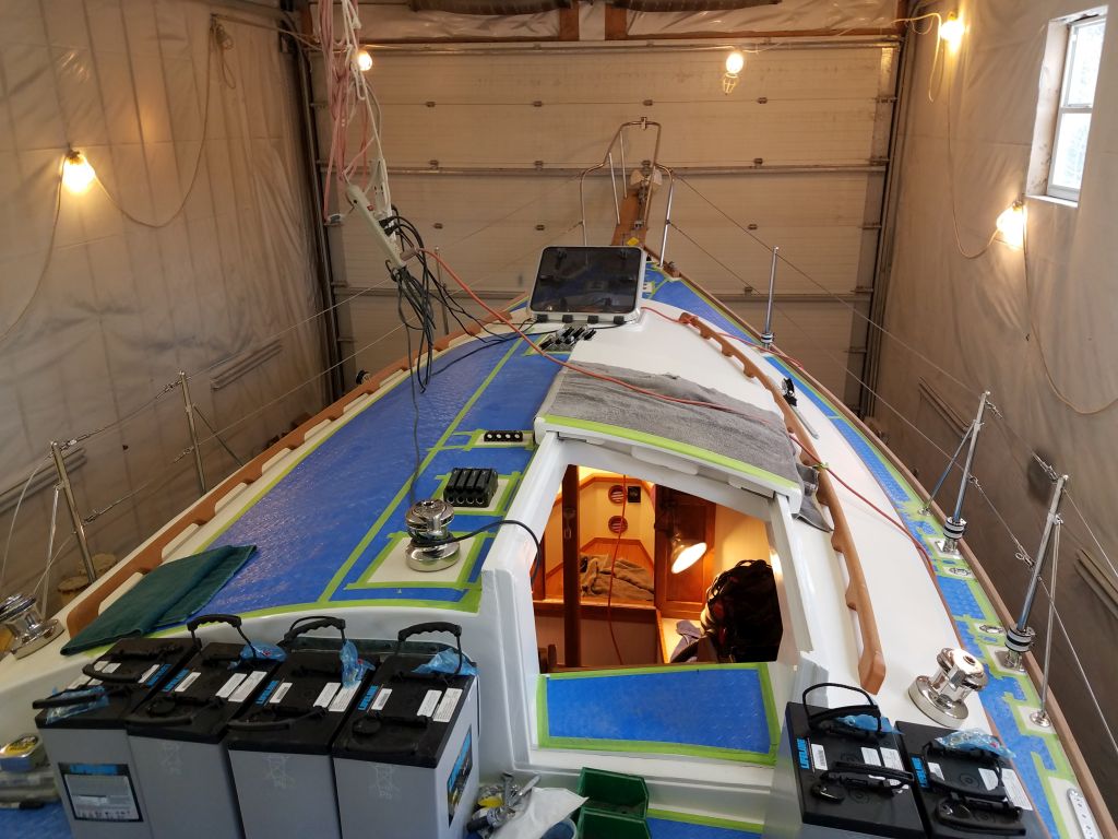
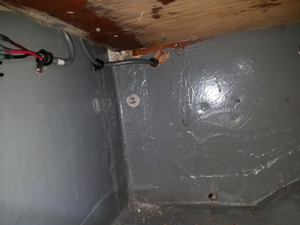
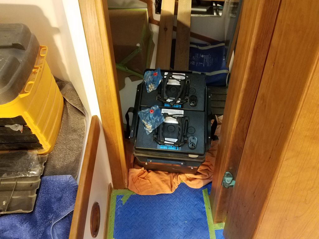
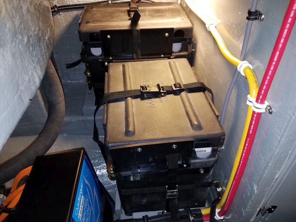
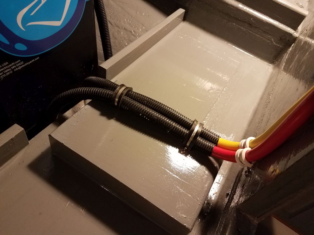
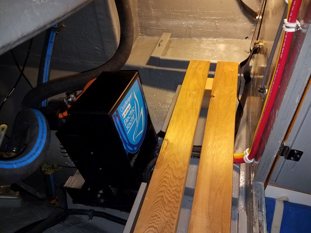
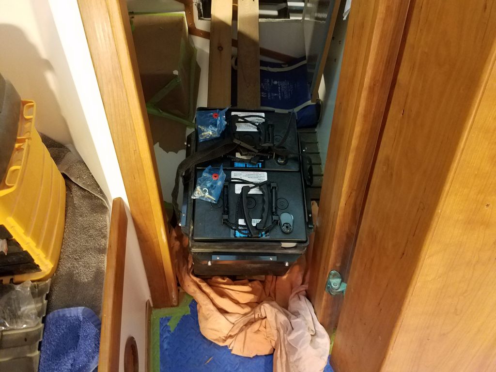
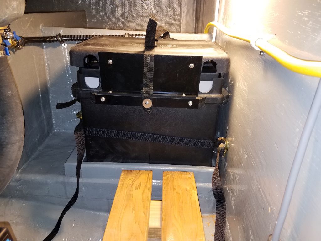
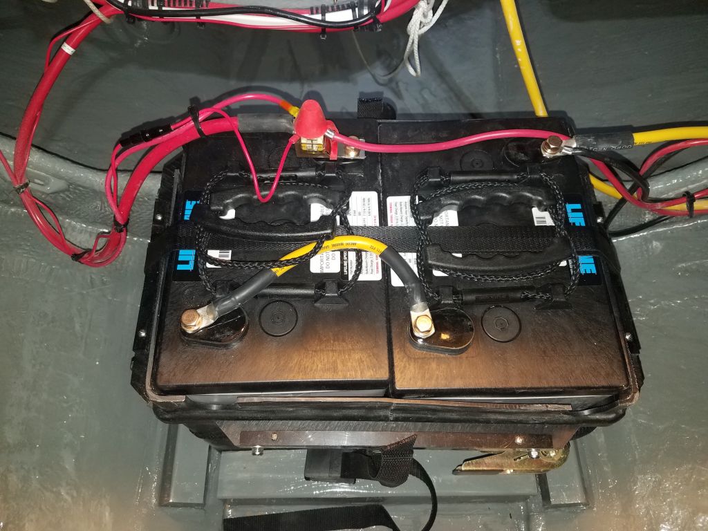
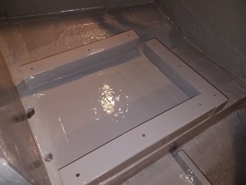
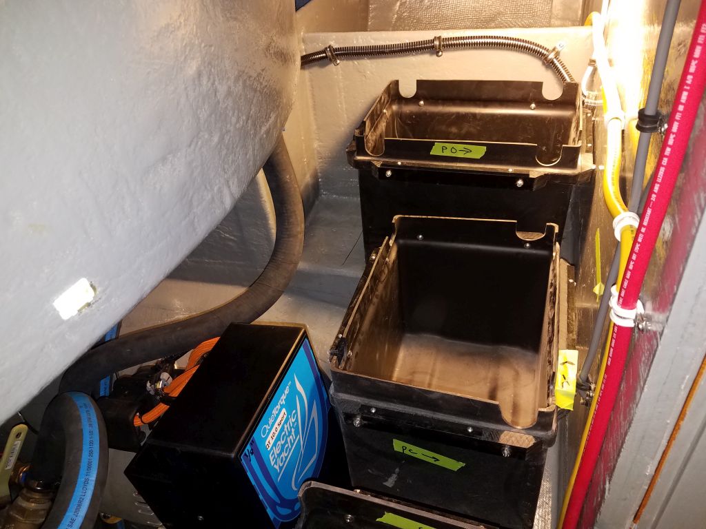
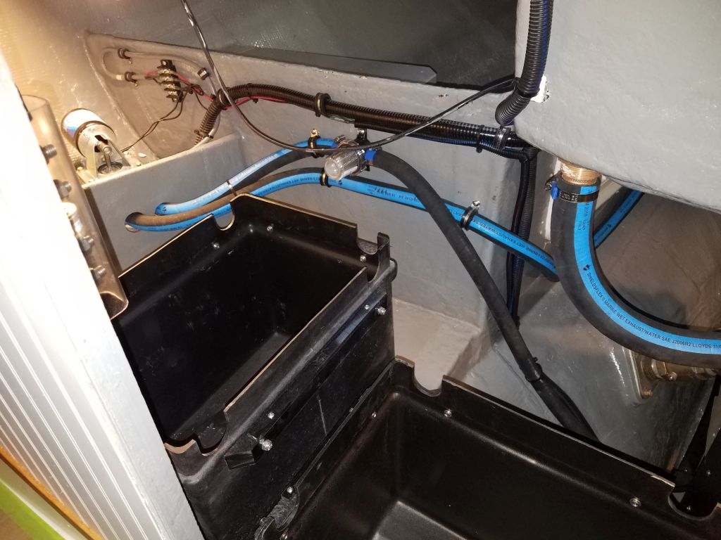
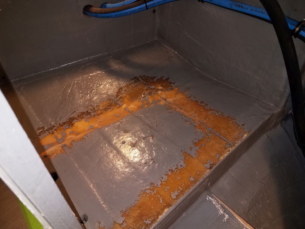
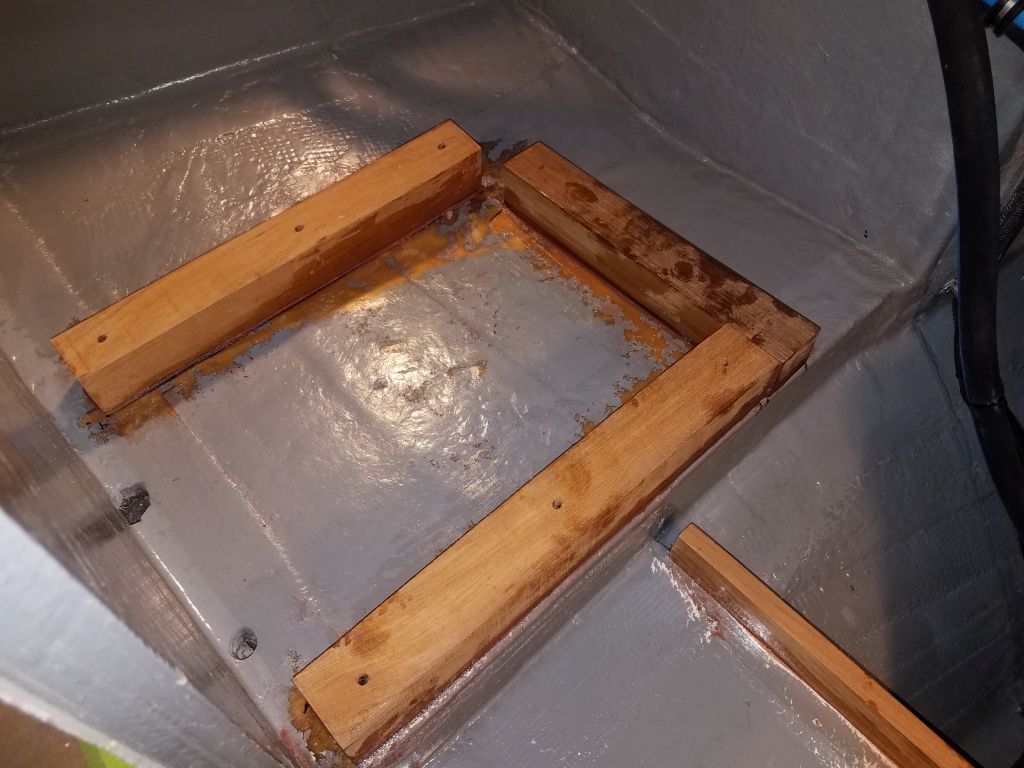
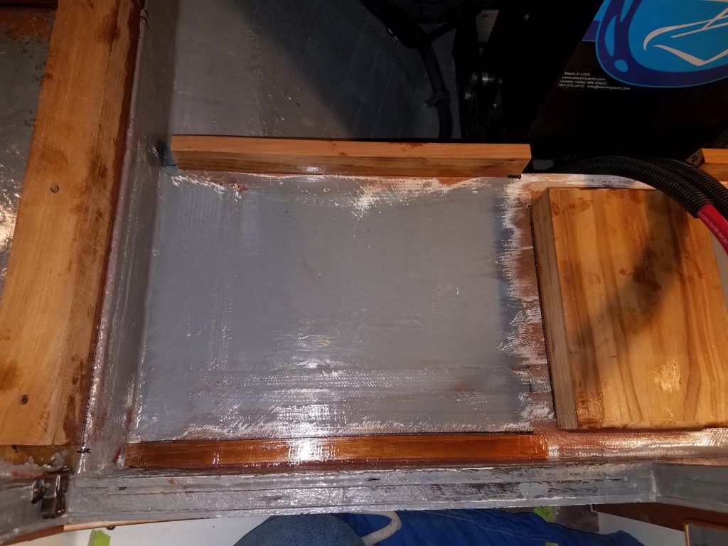
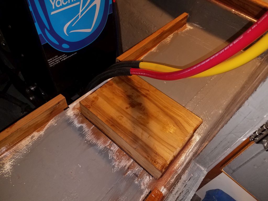
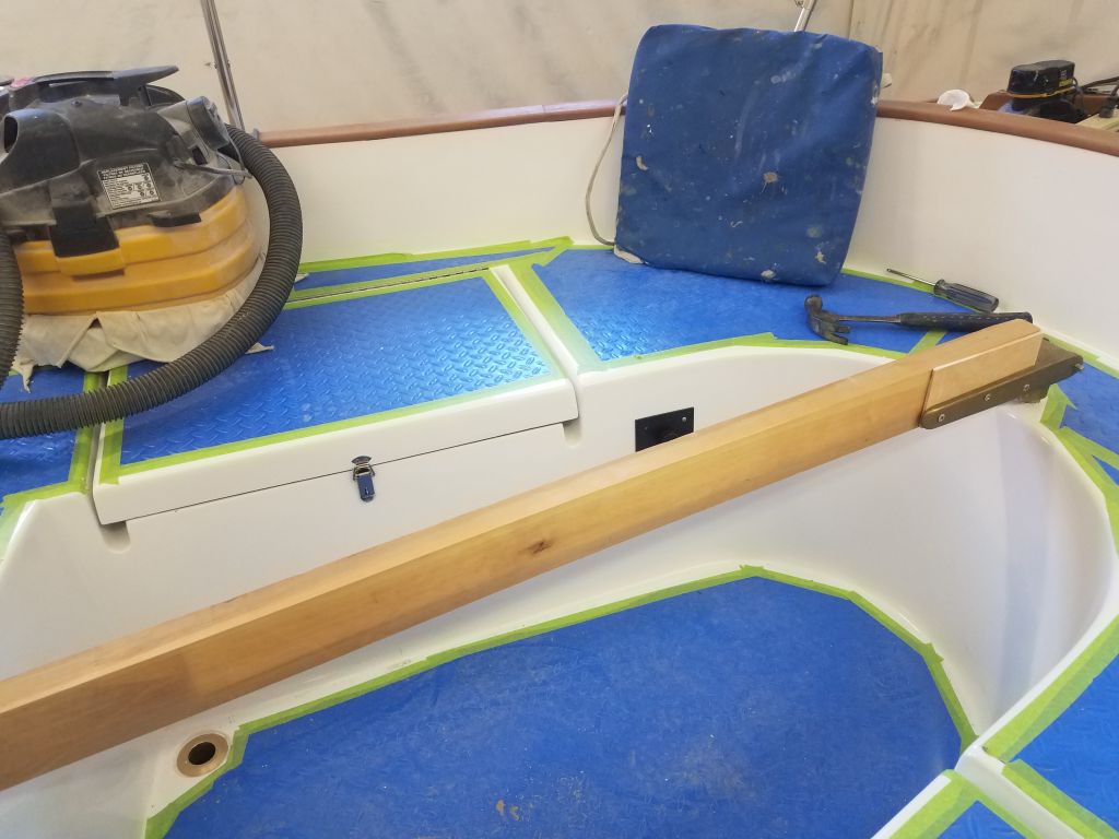
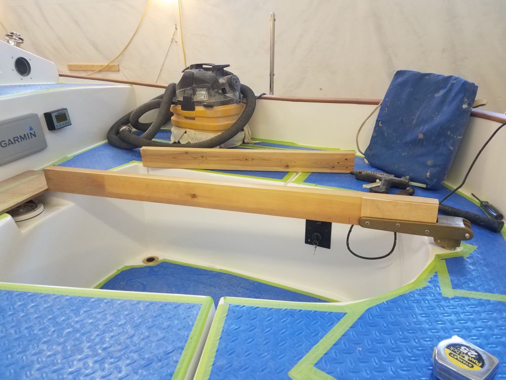
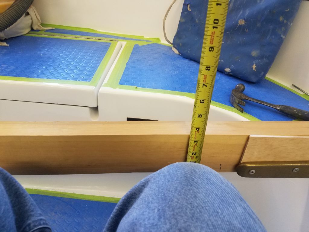
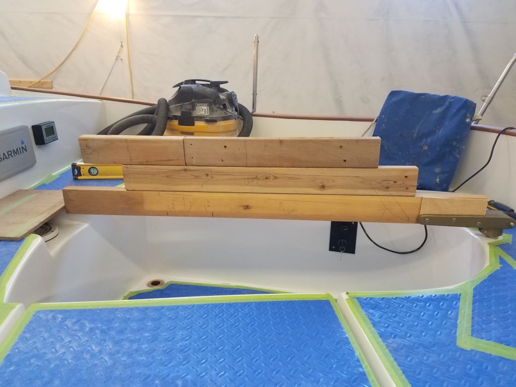
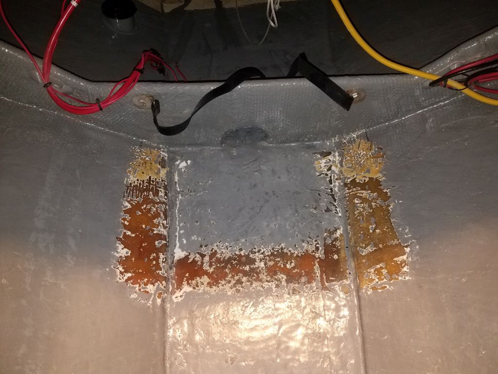
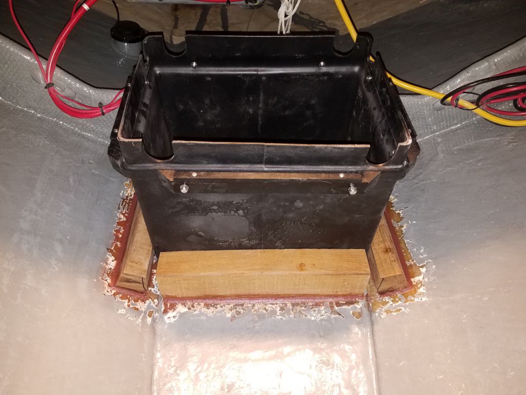
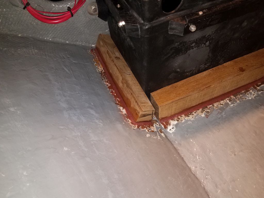
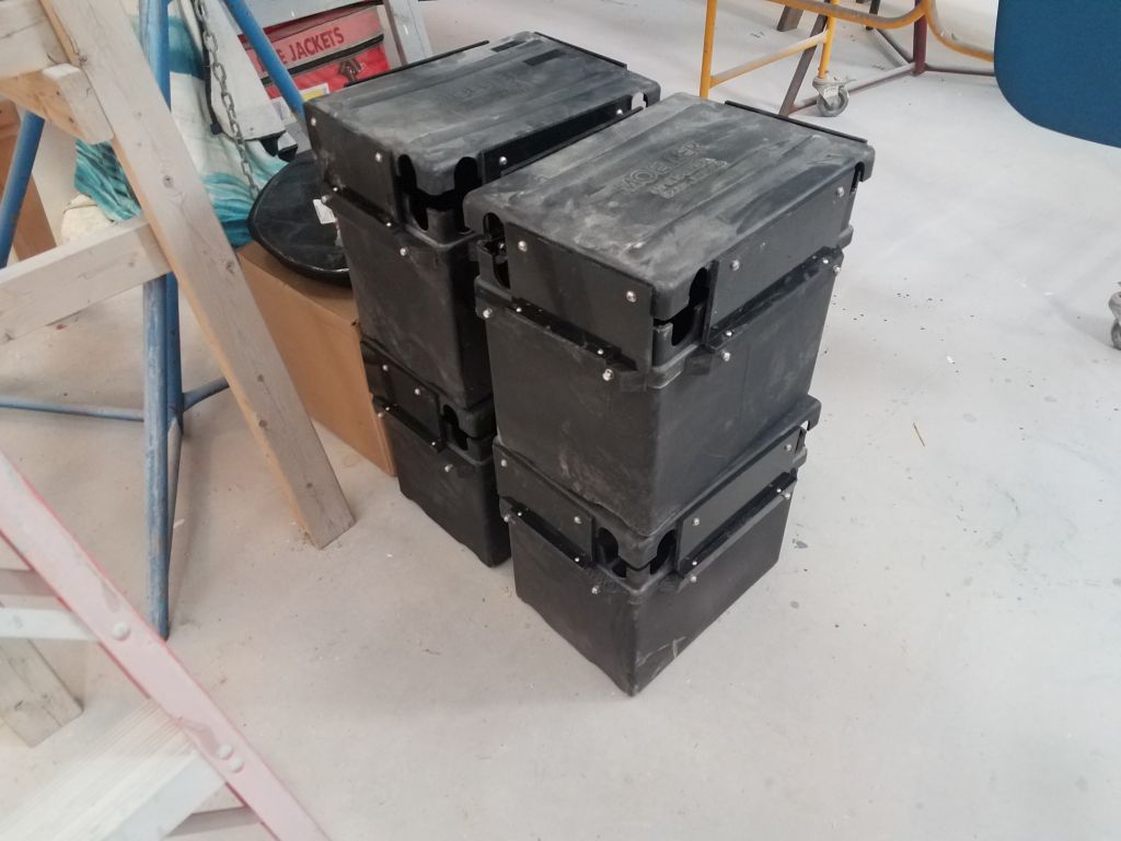
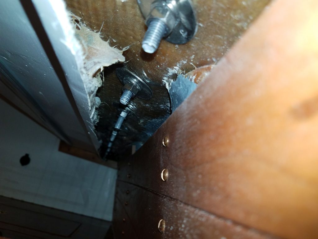
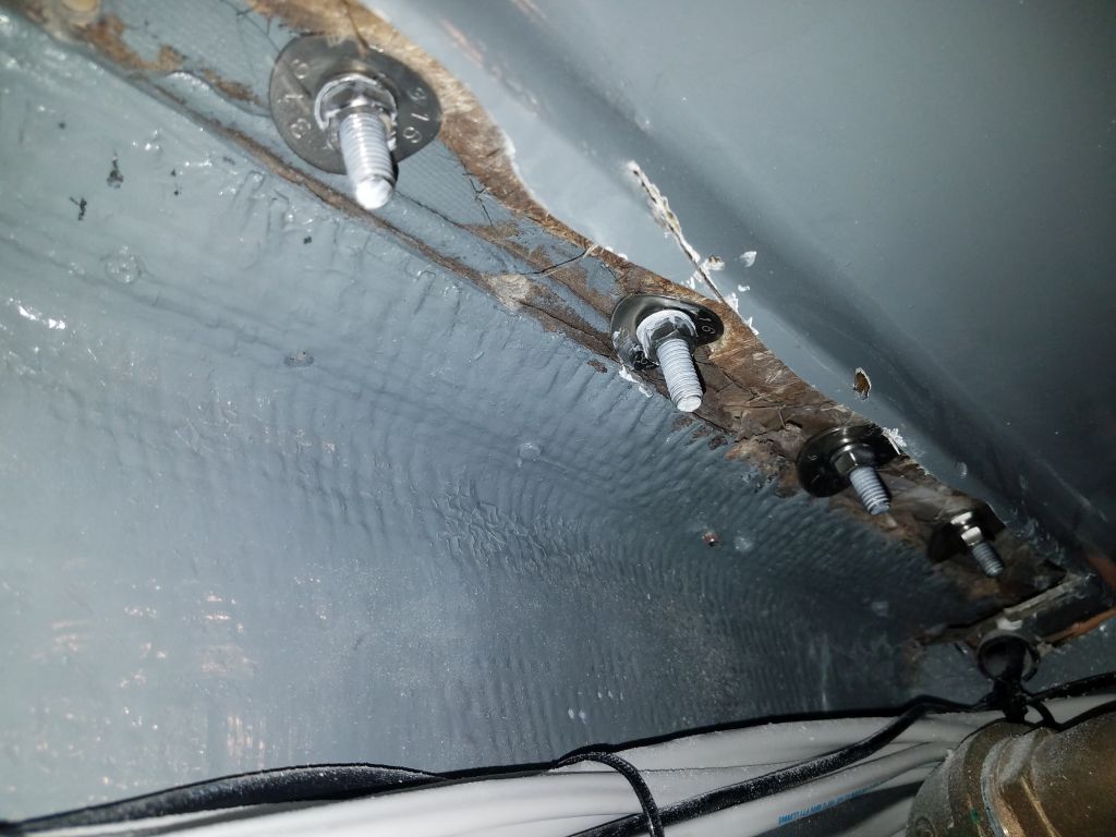
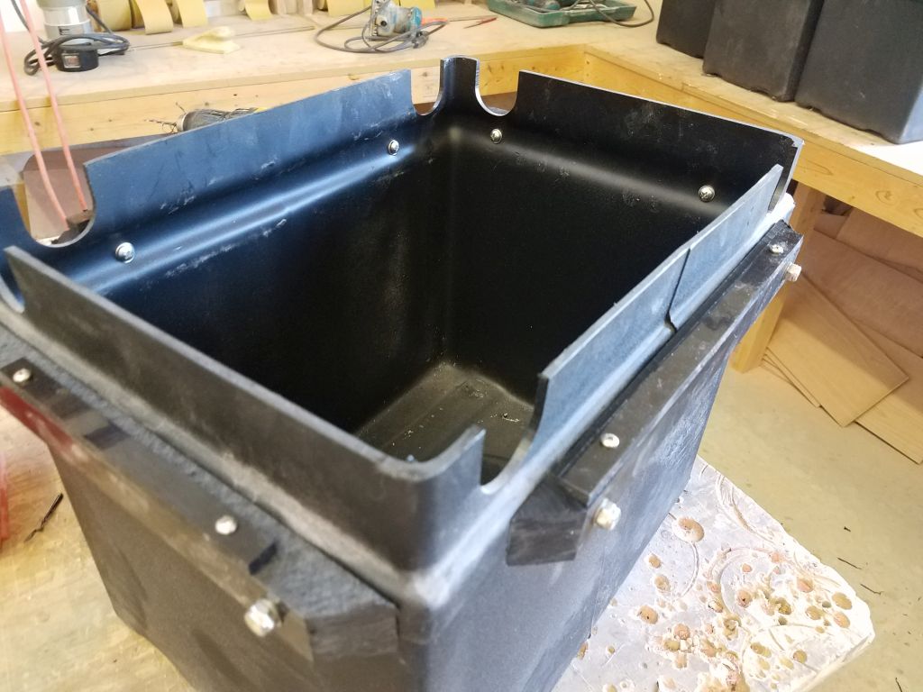
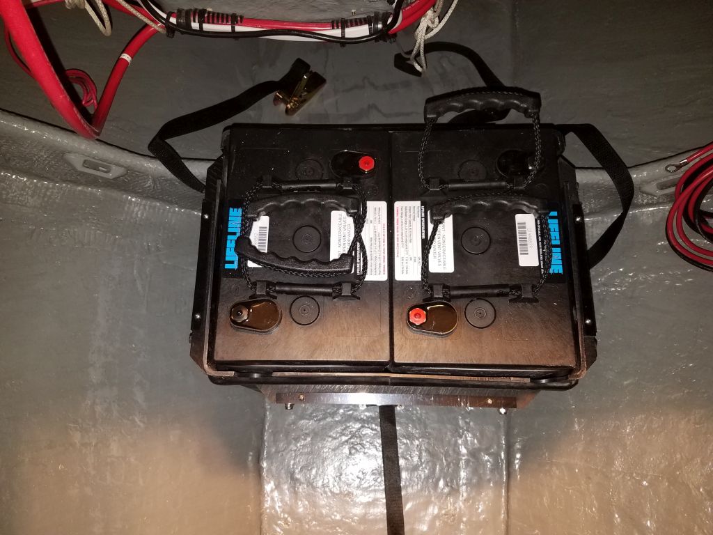
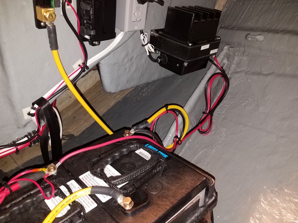
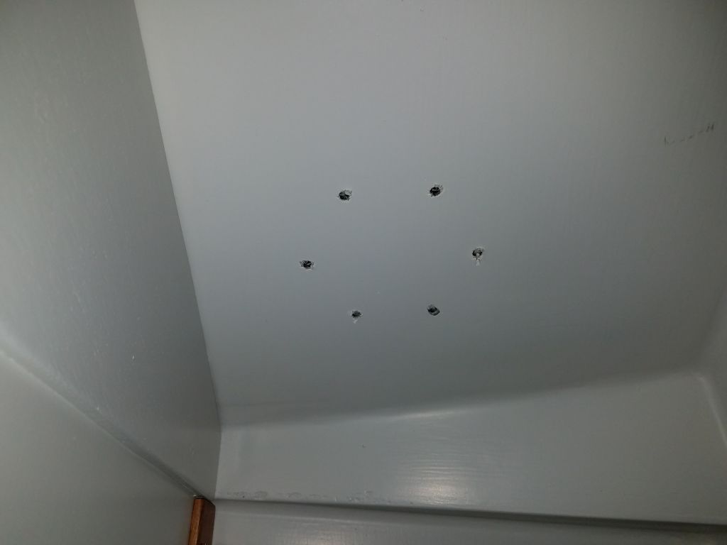
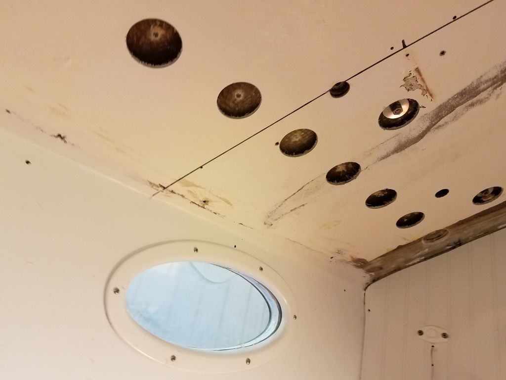
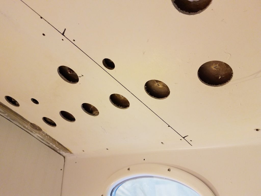
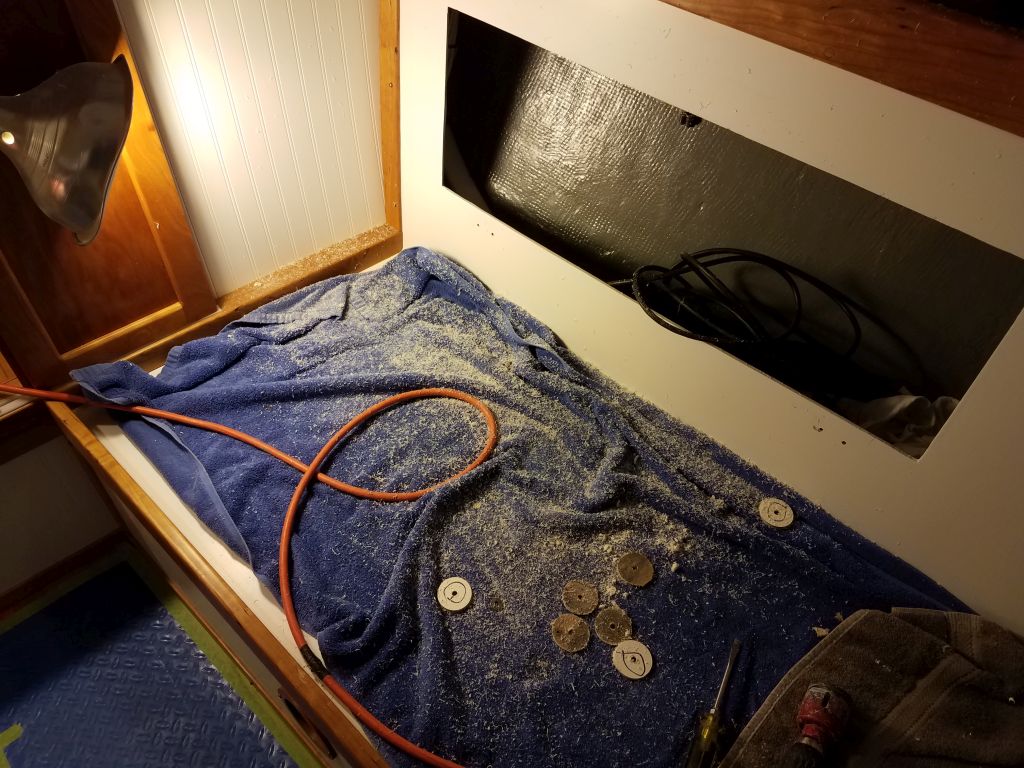
With the engine room and battery areas repainted, it was time to move on with the final steps towards engine battery installation.  To begin, I reinstalled the large cables across the center of the platform; I’d unclamped these earlier to allow room for a large wooden cleat in the center, between the two sets of batteries on the centerline shelf.  I tested battery boxes in all the locations to be sure they fit properly within the new cleats.

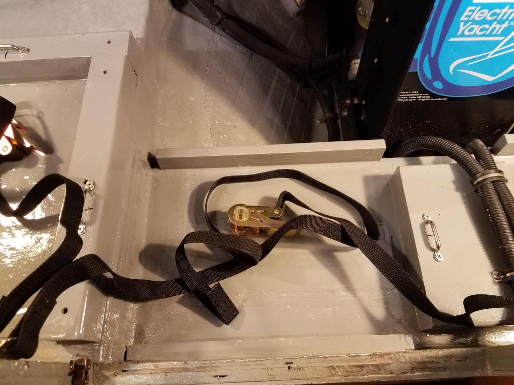
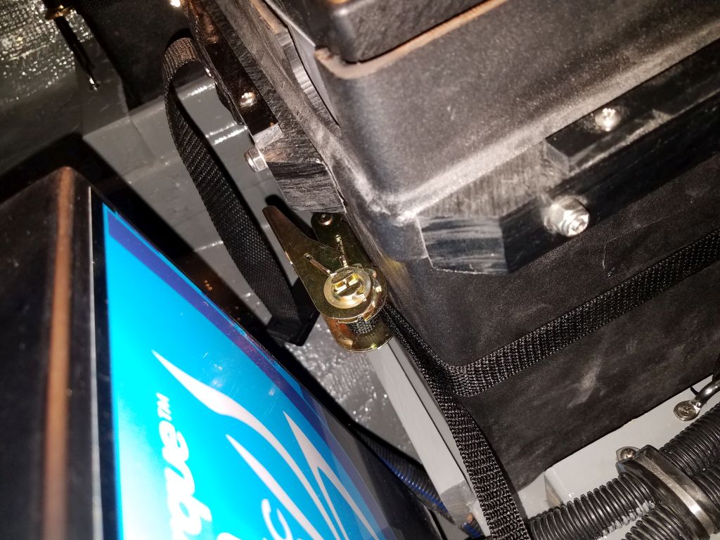
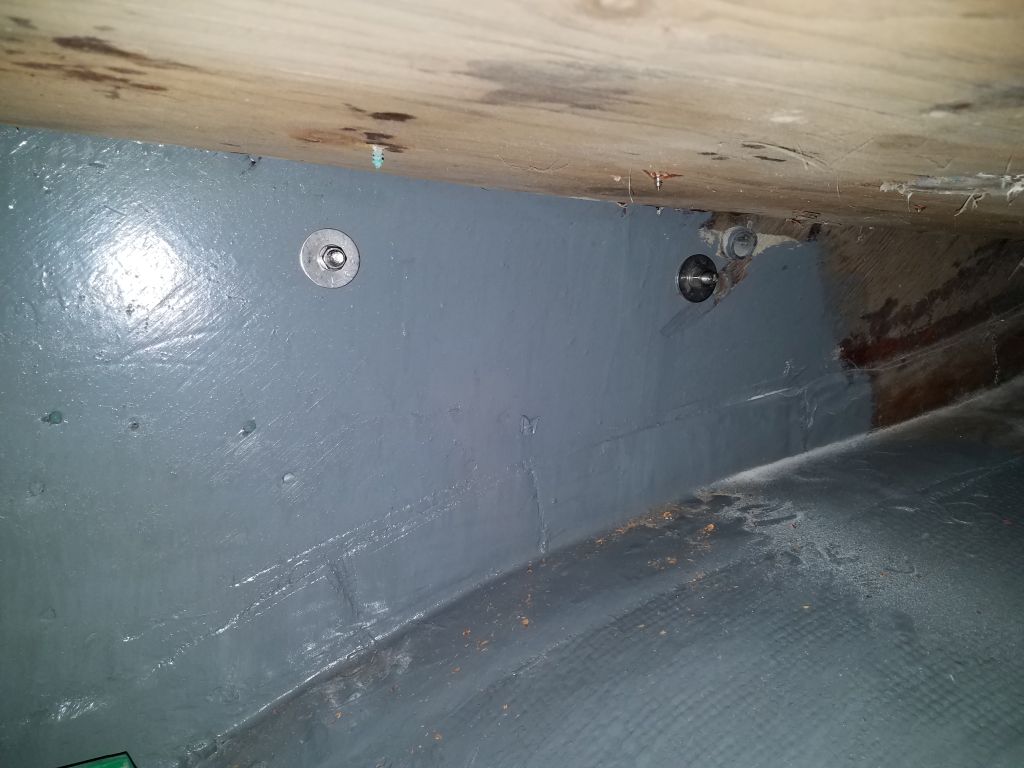
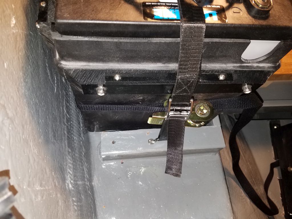
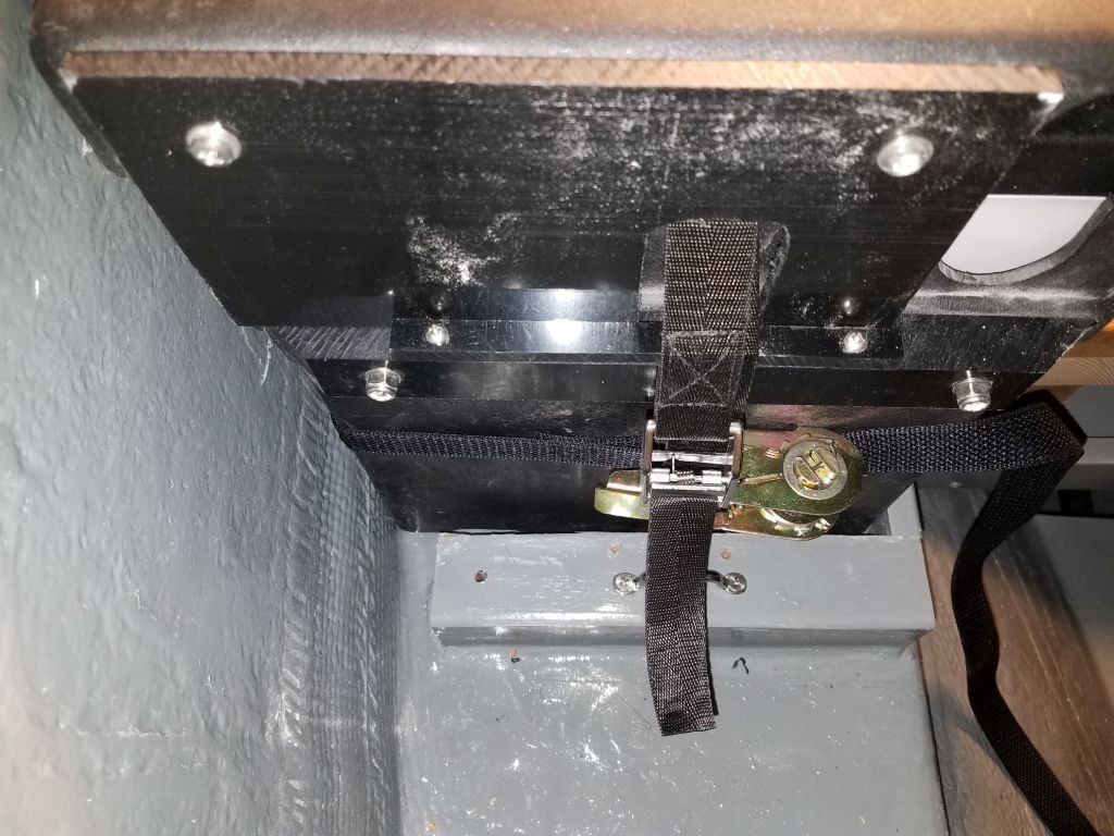
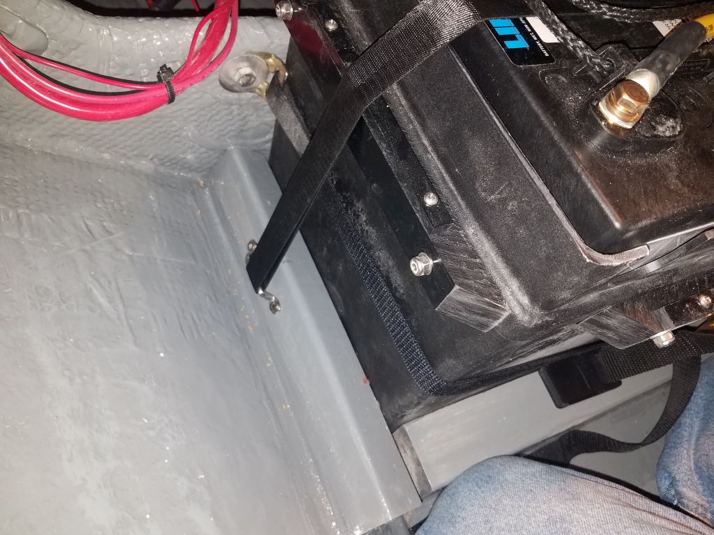
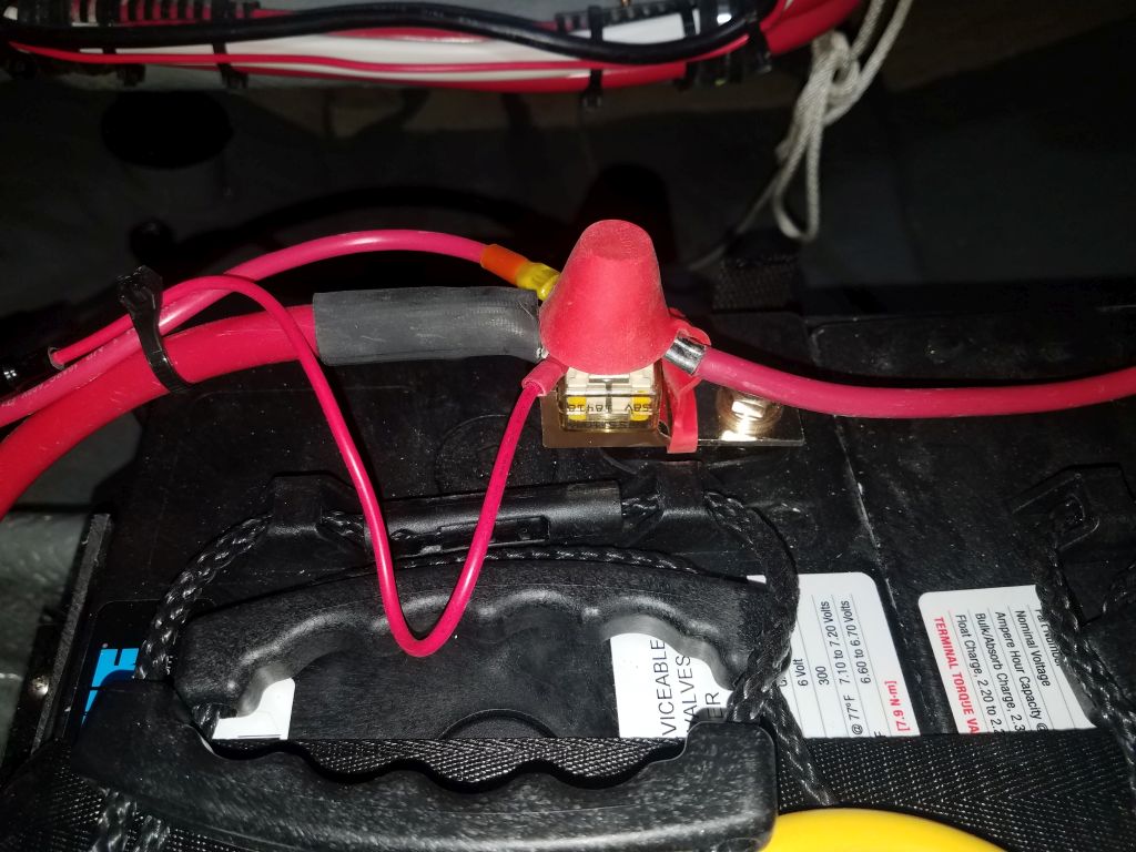
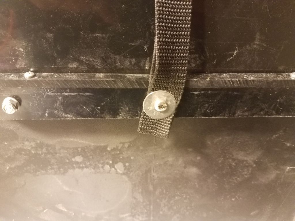
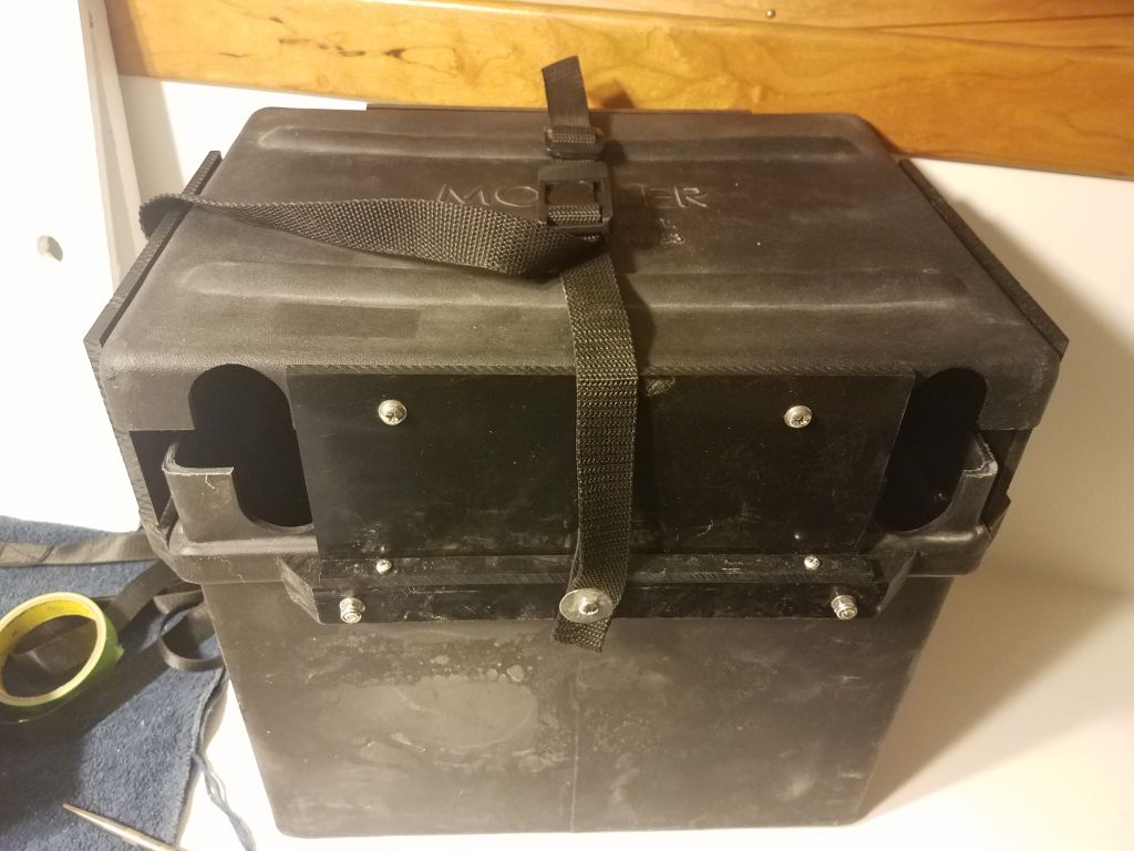
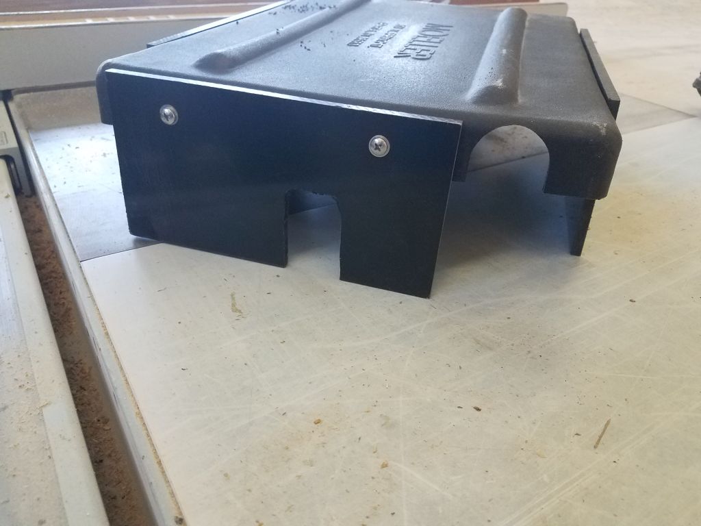
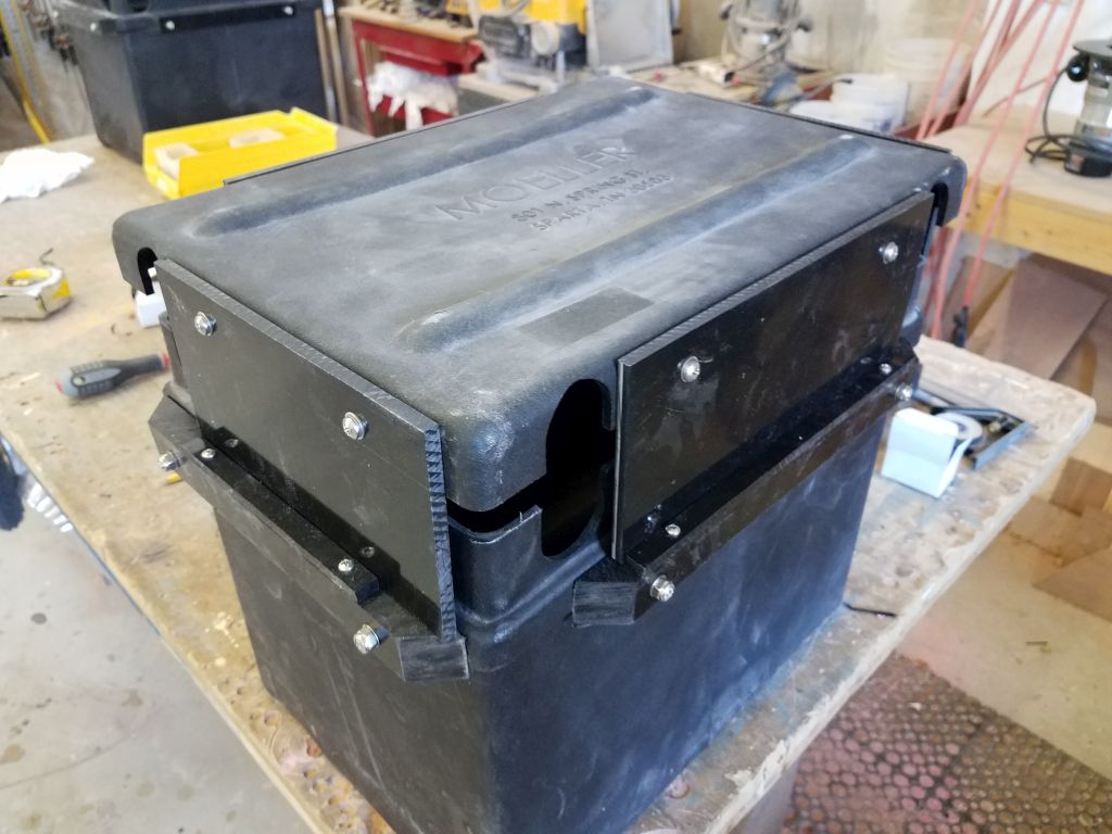
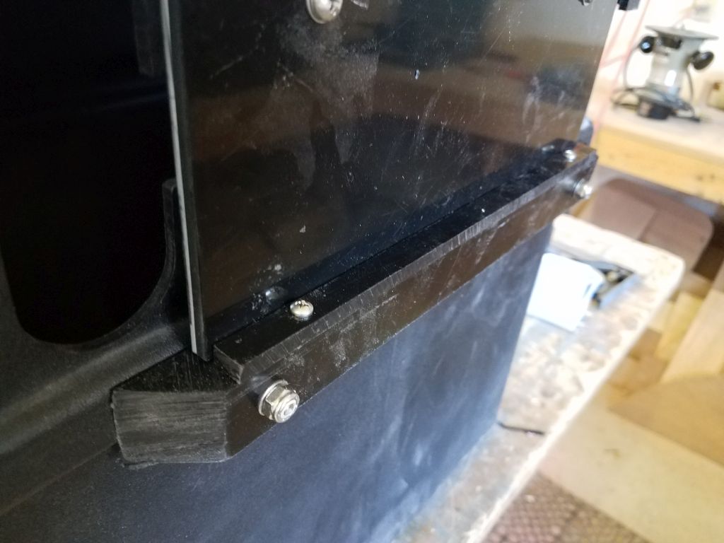
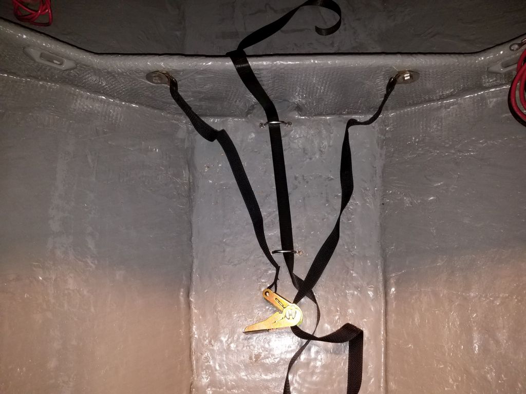
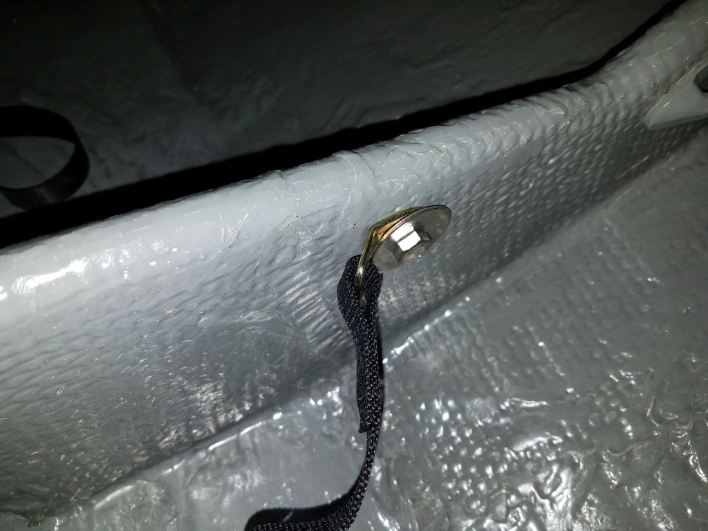
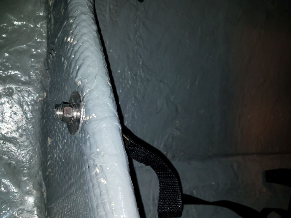
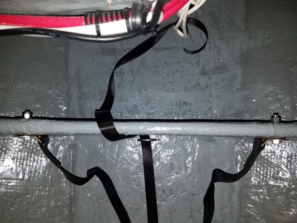
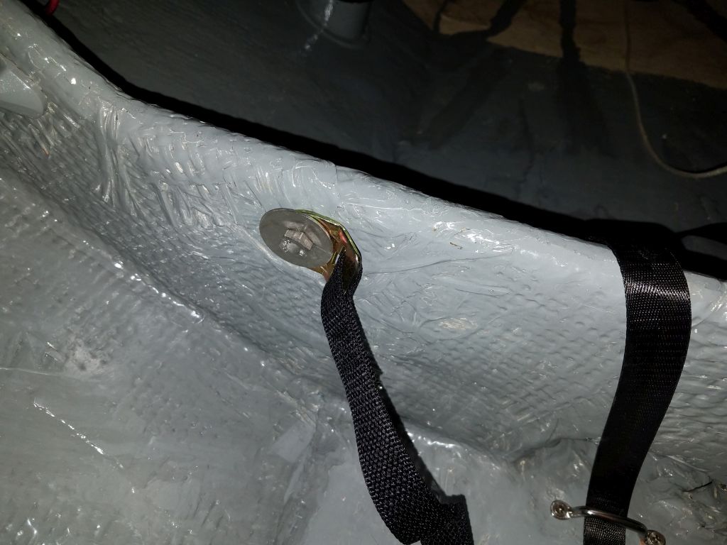
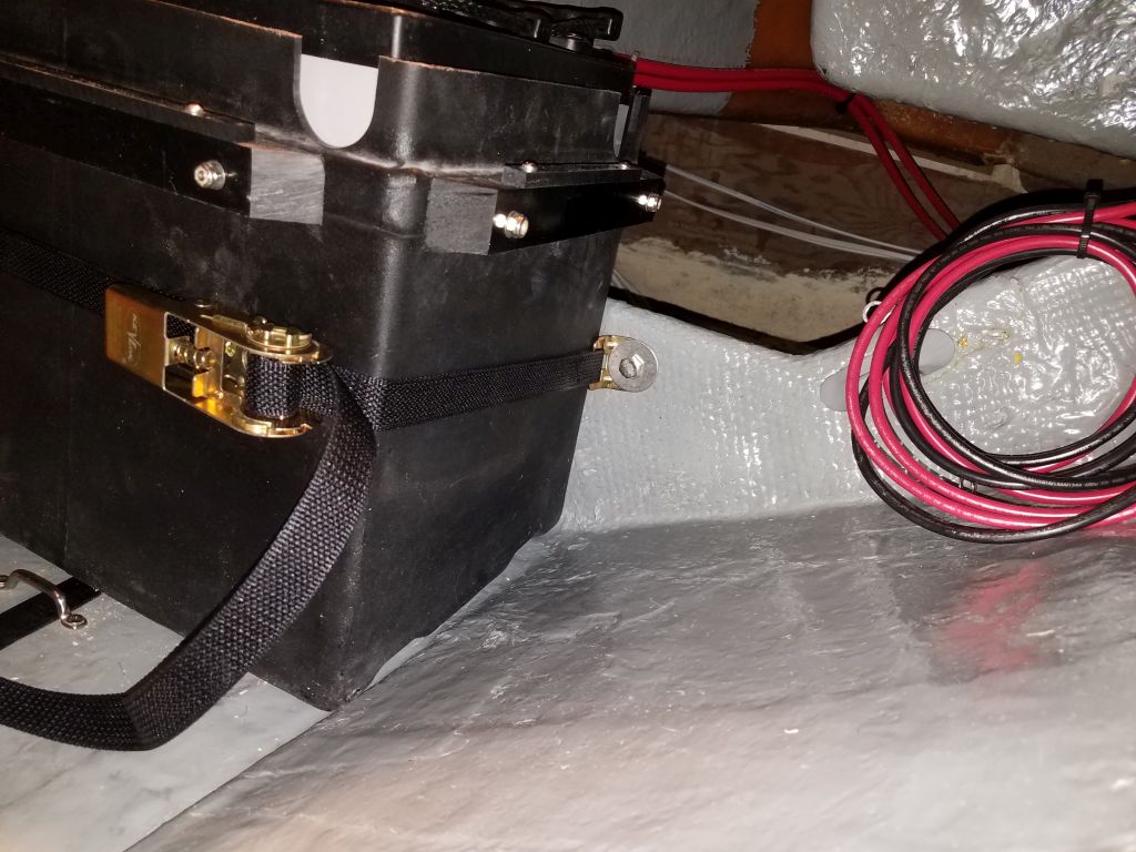
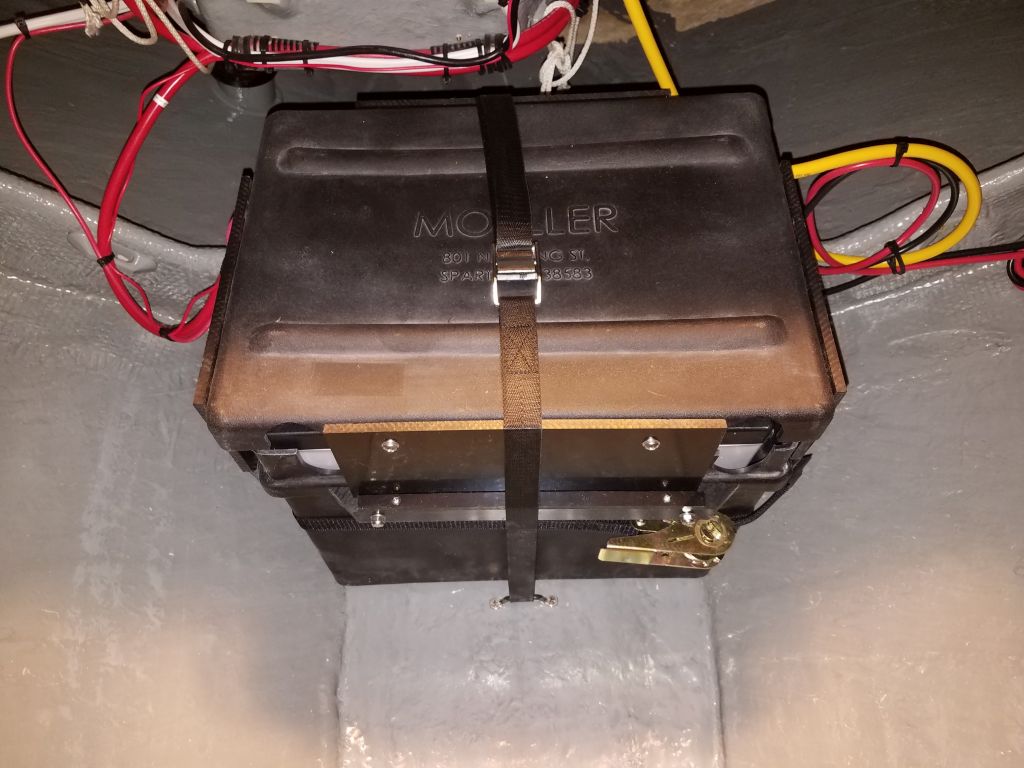
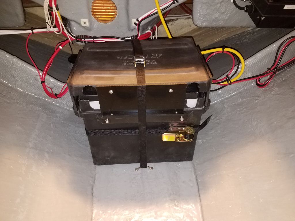
Starting with the port outboard battery location, I used the battery box to mark locations for the ratchet strap and hold-down strap, then installed the ratchet strap with bolts through the bulkhead into the space beneath the galley.  I used tape to hold the bolts on one side so I could get the nuts and washers started on the other.  I installed the brackets for the hold-down strap with screws to the bulkhead on the forward side, and to the after cleat behind.

I had originally thought of pre-installing all the straps first, before getting the batteries in place, but instead I decided to do it more piecemeal, both to spread out the work with the heavy batteries and to get the hardest installation–this port outboard location–completed first.  I’d been thinking through the complications of installing the batteries in this tight space for weeks.  There was no way to put the box in first and then lift in the batteries, as there was no direct overhead access and the batteries were far too heavy to lift from any of the possible contorted positions one might force themselves into, so all along I knew I’d have to pre-install the batteries in their boxes, then get the 200-lb combined units into place from there.  This meant basically sliding them into place.

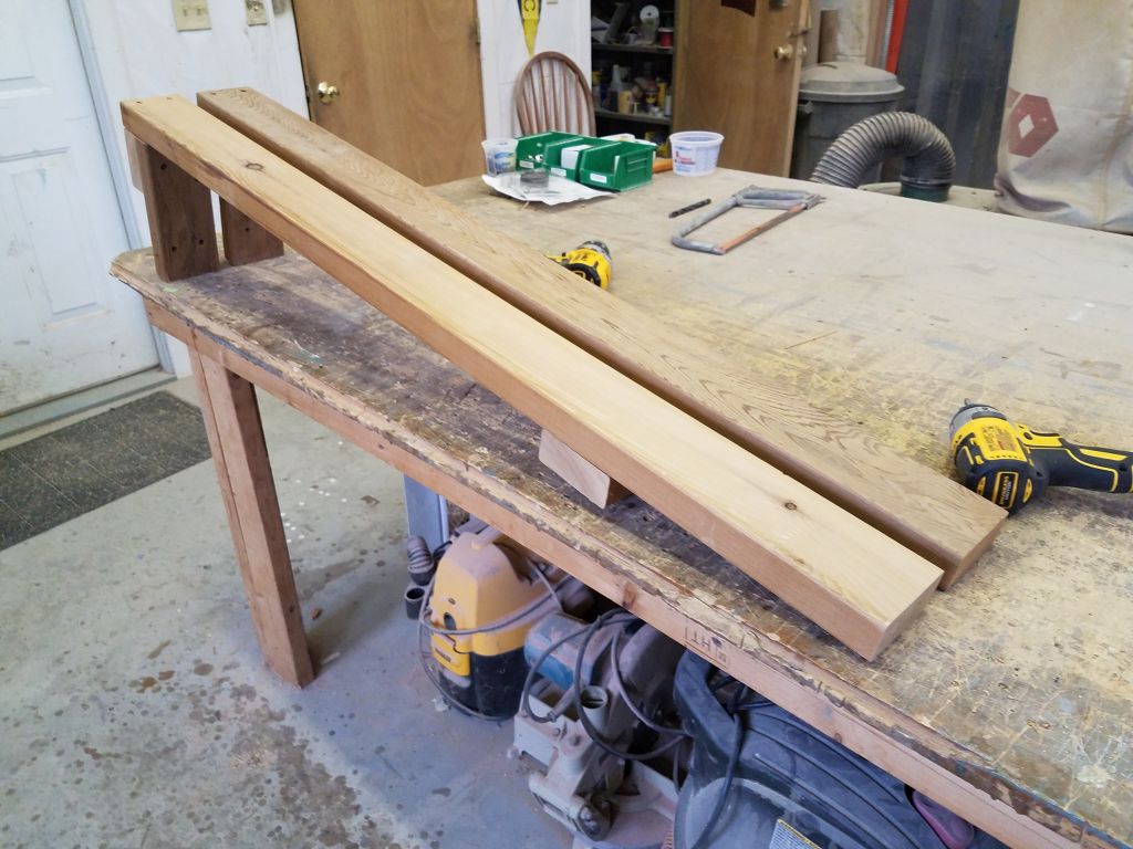
To this end, I built a couple simple platforms from scrap construction lumber:  First, a platform that spanned the center battery shelf from the engine room door to the port side, and built to a height that was just above that of the battery box cleats; second, a similar platform/ramp to run from the head doorway up to the engine room and the other platform.  These platforms would allow me to move the filled battery boxes around and over the various obstructions to their destinations.

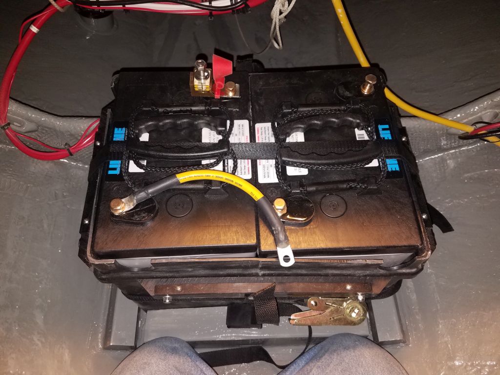
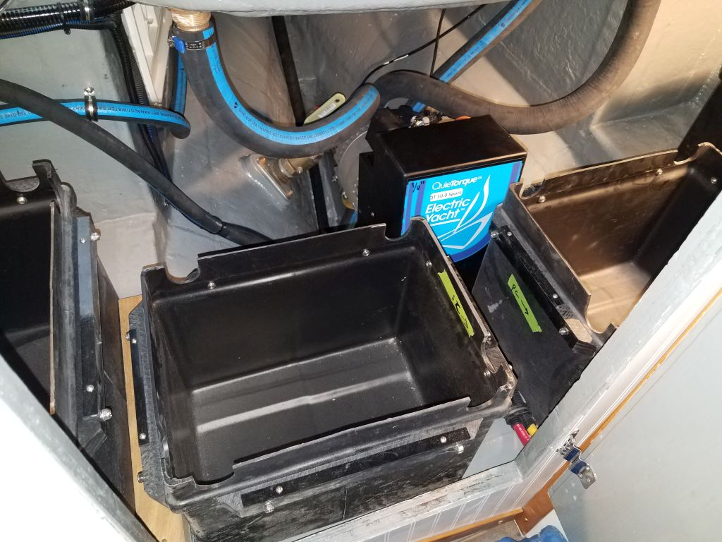
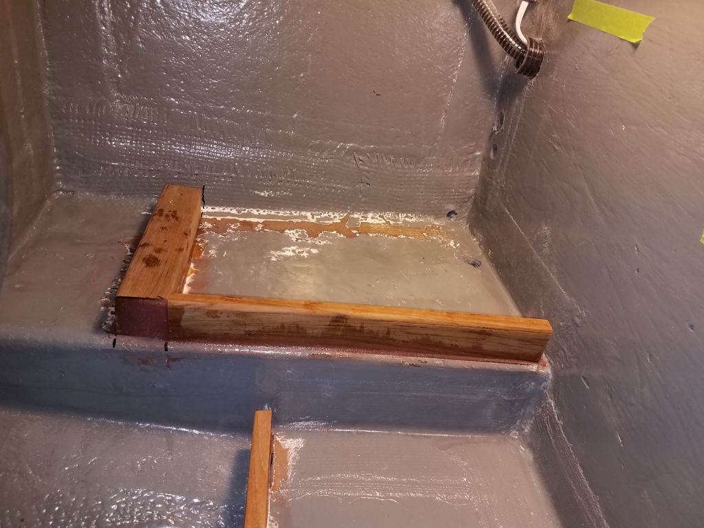
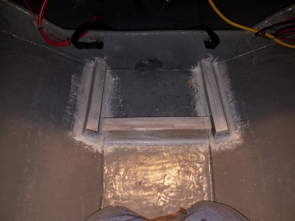
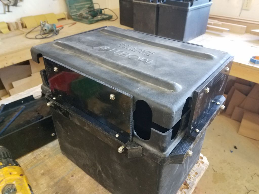
Over the past week, I’d gotten all the remaining eight batteries up to the cockpit, and now I lowered two of them into the cabin, and from there placed them in an awaiting box that I preset on the engine room ramp.  With a slight uphill slope, it wasn’t easy to push the laden box, but it was possible, and soon I had the box in the engine room, where on the flat platform it was quite easy to push the box over to the port outboard side and get it started in the nest between the cleats.

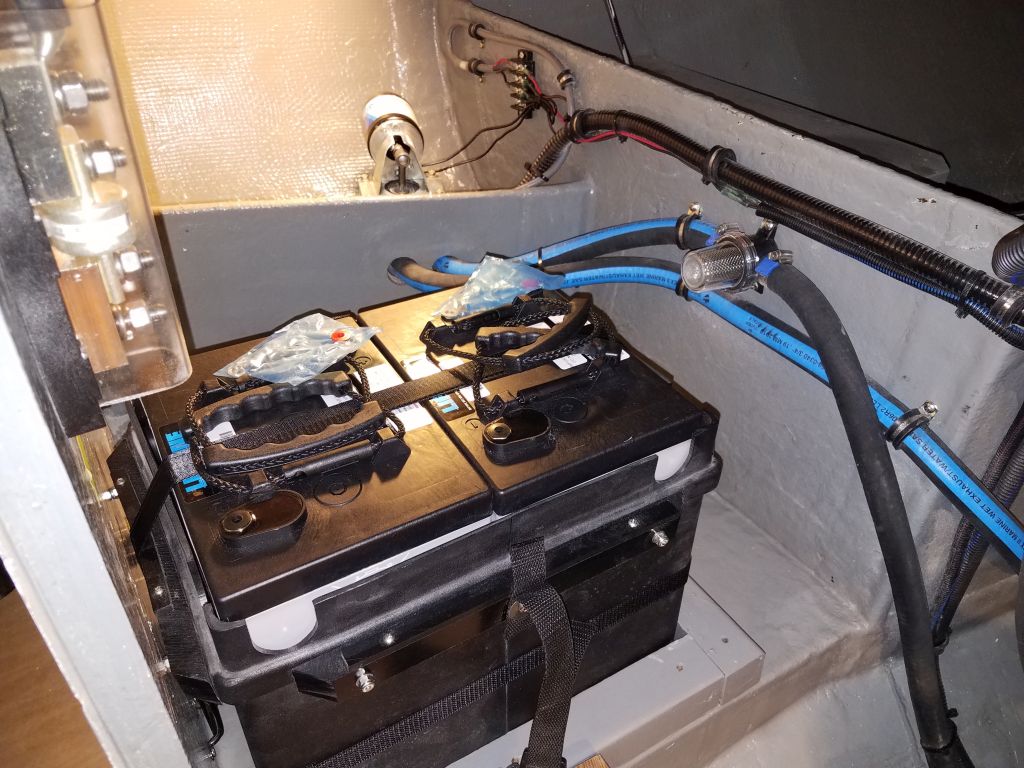
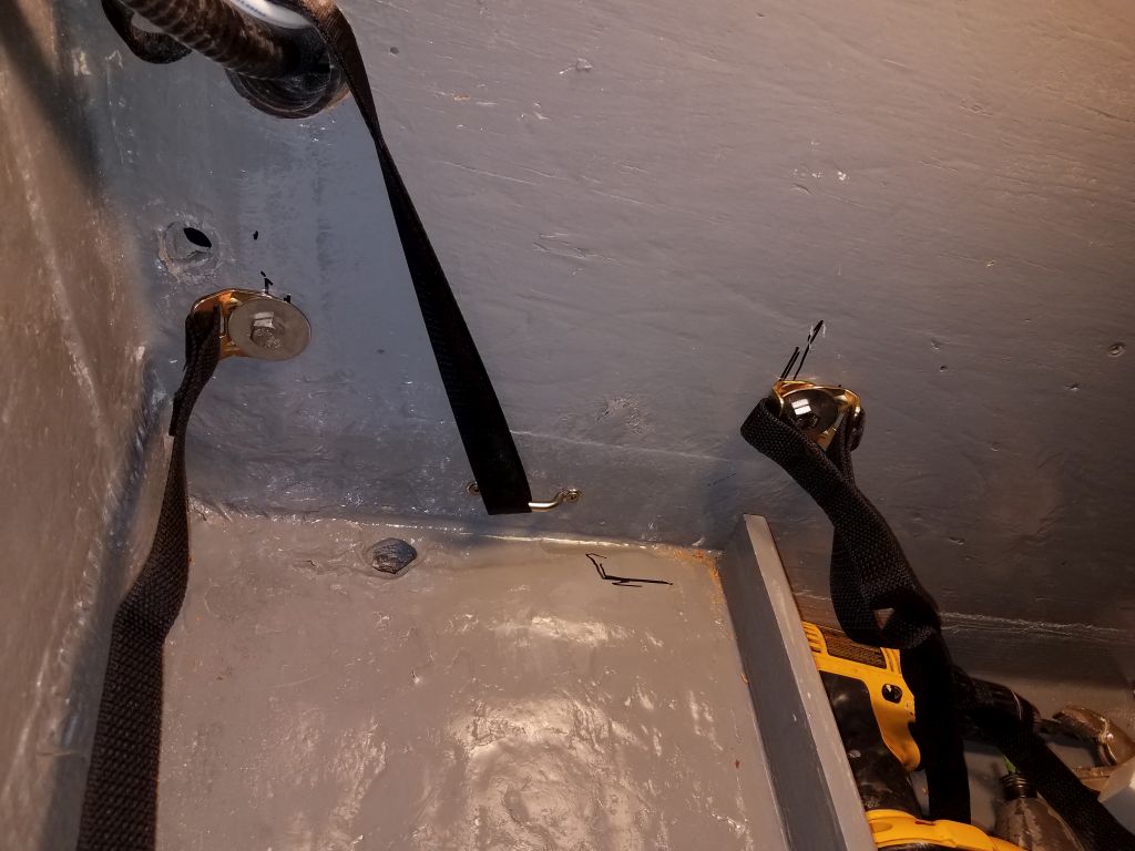
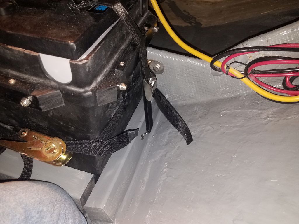
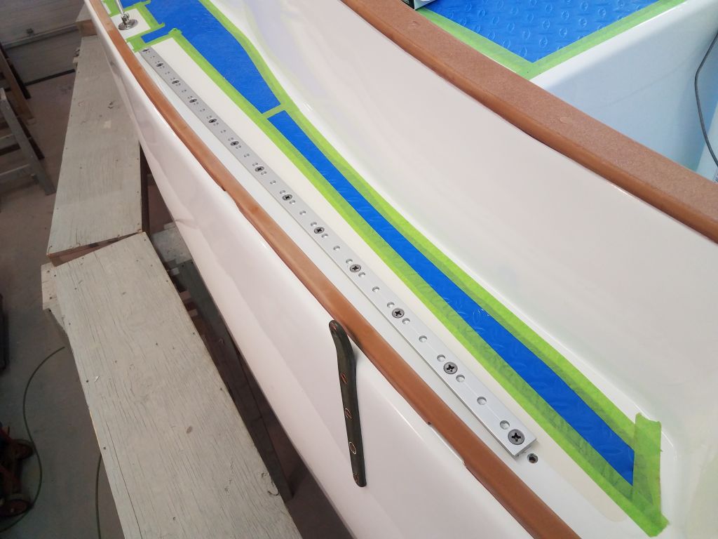
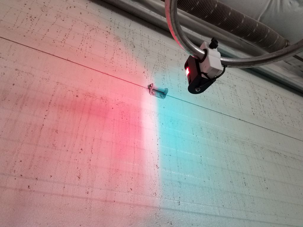
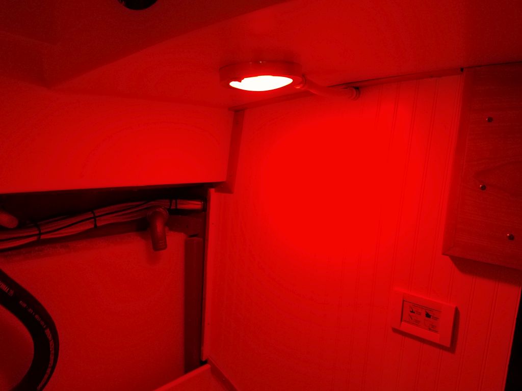
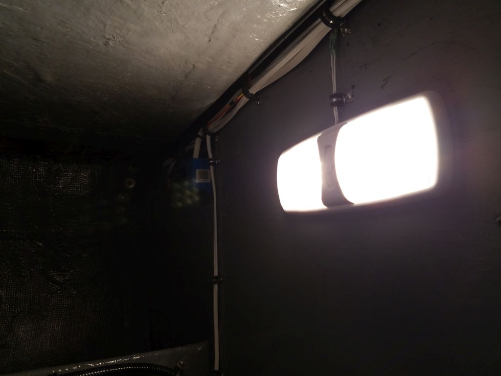
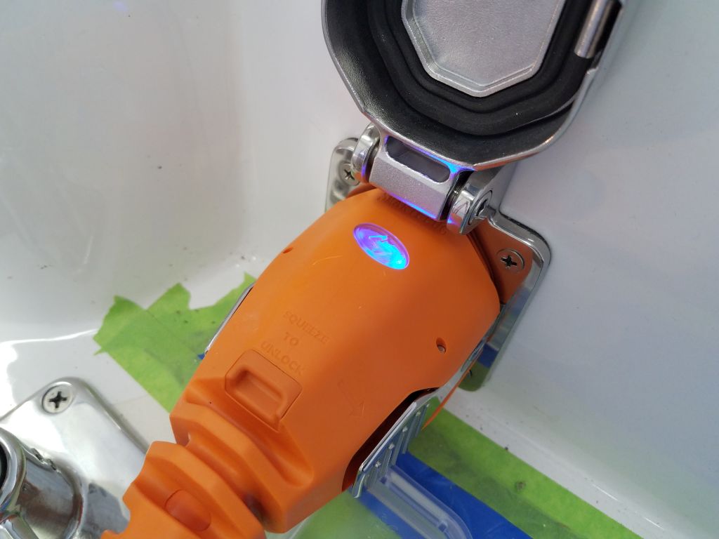
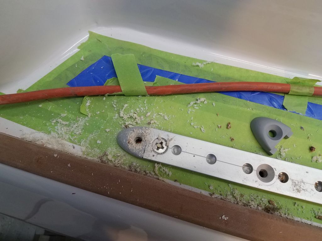
The cleats were tight enough that I had some trouble getting the box to fit inside properly.  The issue was that I needed to lift the far (bulkhead) side a bit to get the aft end in.  Working from the port cockpit locker–the only way I could directly access the space–I tried various things, all of which were complicated by the weight of the batteries and the lack of overhead access, but the box kept hanging up on the bulkhead.  By the same token, I couldn’t edge the box in sideways either (as seen in the photo above).  Access was too tight, and the batteries too heavy, for me to do the relatively simple maneuver required.

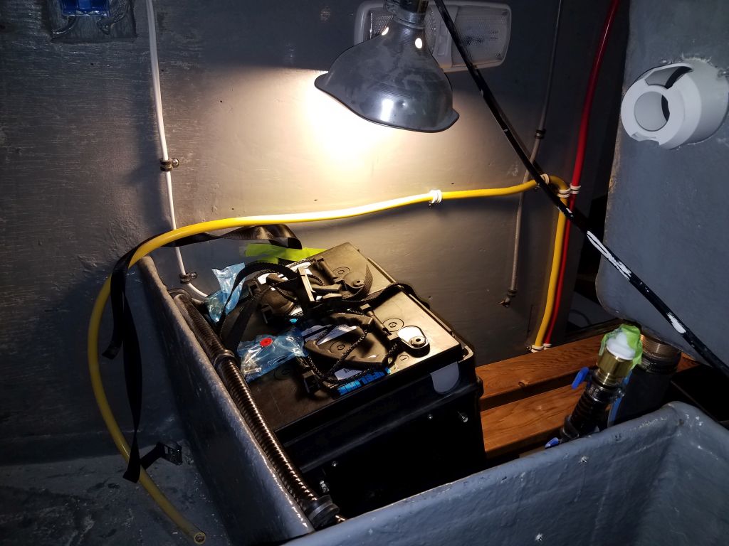
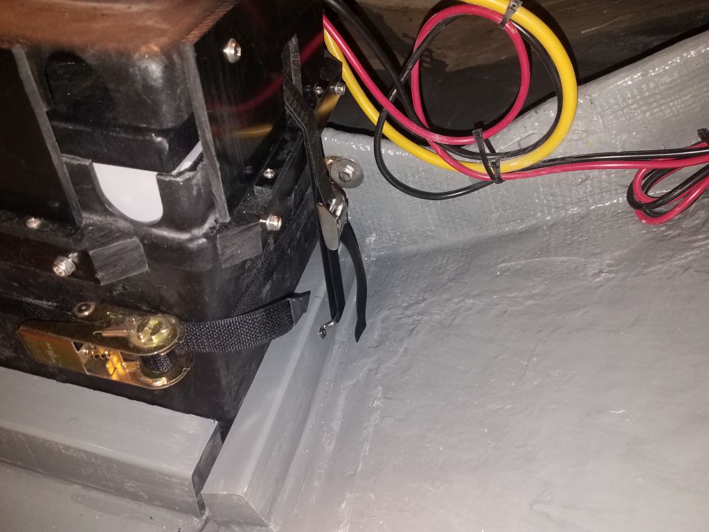
At length, I decided I needed to rig up a little block and tackle on the bulkhead, which would allow me to pull up that side of the box as required for it to fit (note that I knew the box fit, as I’d tried it earlier when it was empty).  After rounding up a padeye, some line, and the block and tackle, I prepared to set things up, starting with a line around the cleat I’d installed on the front of the battery box (to accept the lid).  To my astonishment, as I looped the line beneath the cleat and started to make preparations to tie it off somehow, the box just popped into position.  Done.

This was a great relief, as I’d been fussing with the box for some time, and in the end I was saved the extra work of installing and then dismantling some kind of lifting system.  I expected the remaining three boxes to be much easier to get in place, and I always knew the port outboard location would be toughest simply because of its access issues, so it was a victory after a long afternoon.

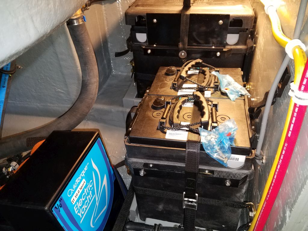
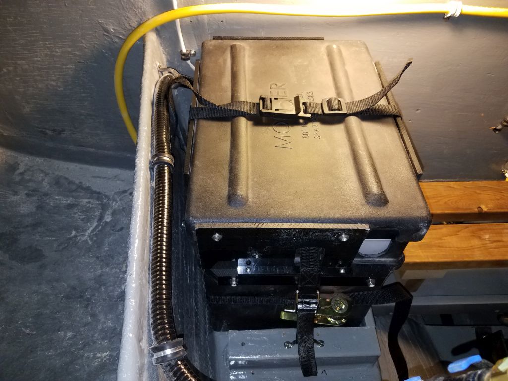
Now I could finish up securing the battery with the ratchet strap and overhead hold-down strap, and then finish up the lid as well, marking and cutting clearance notches for the hold-down strap as needed.  I’d pre-installed the light strap to secure the lid itself before I put the box in place.

Total time billed on this job today:  8.25 hours

0600 Weather Observation:  32°, cloudy. Forecast for the day:  Mostly cloudy, 47°

Scupper 248

Monday

Over the weekend, I applied the final coat of gray paint to the new cleats at the house battery location, and also applied epoxy primer to the fresh cleats in the engine room, so with that done I could move on first thing with getting the house batteries back in place and properly secured.

With the box and pair of batteries back in place and secured by the cleats and the hefty ratchet strap, I began by securing a hold-down strap over the batteries themselves, which would prevent any upward movement.  I reattached the various wires and cables, this time with a terminal-mounted 100-amp fuse on the positive terminal, which I’d had on hand but simply forgotten to put in place when I’d initially installed the batteries earlier.

To secure the battery box top, I used the basic strap that came with the box and attached it to the plastic cleats at the top of the box with a folded double layer of the strap, large washer, and screw.  This strap only needed to hold the top of the box in place.  To accommodate the new strap over the top of the batteries themselves, I had to make notches in the side extensions of the top to allow it to fit over the top of the strap, but this was a straightforward modification.

With springlike and highly unseasonably warm weather outside, I had to take the opportunity to dig out my trailer and a couple of the boats that I planned to soon start working on, as the Scupper project inched ever closer to nominal completion, so this kept me out of the shop and in the glorious warm sun for a couple hours during the middle of the day.  It certainly hadn’t been a hard winter thus far, but nevertheless there was a surprising amount of snow built up despite the frequent temperature fluctuations and no “real” storms to speak of, so with pending boat shifting ahead, it was a relief to get this head start on the process.  I didn’t doubt there was more winter on the way, but spring fever was in the air.

I took advantage of the great weather and opened the shop door so I could raise the anchor the rest of the way onto the roller, leaving about an inch clearance to the door when I closed it, as if I’d planned it.

Meanwhile, I spent some time figuring out the issue with the two bilge pumps, which had not had power when I did my initial electrical tests.  Eventually I found that a ground wire had been erroneously connected to a badly-labeled wire on the panel switches for each pump, when it should have gone directly to the negative distribution buss.  An easy fix, once I figured out the problem, and both pumps tested operational thereafter.

I plugged a USB charger into the panel-mounted USB for a test (this outlet also had a green light to indicate it was turned on), and also tested the USB ports mounted in the light on the compression post and the two lights in the forward cabin–all operational. The two standard cigarette-lighter style outlets (one on the panel, one in the galley) were on the same circuit as the USB port, and thus should work fine, but I still had to round up something I could plug in to test.

To finish up the day, I applied the gray paint to the new cleats and battery locations in the engine room.

Total time billed on this job today:  6.5 hours

0600 Weather Observation:  20°, Fog.  Forecast for the day:  Sunny, 50°

Scupper 247

Friday

Now that the new paint on the mainsheet riser block had had sufficient cure time, I installed it and the mainsheet padeye, securing them to the holes I’d previously prepared on the deck with long bolts, backing plate, and large washers.  I thought this was the final piece of deck hardware to install.

I spent the rest of the morning, and into the afternoon, working on the battery box layout and details in the engine room.  Space was tight, and I had to make various minor accommodations for the boxes and their modified tops to fit properly:  one box on each of the (original) side shelves port and starboard, and two boxes on the new athwartships shelf I’d built for this purpose along the front edge of the engine room.  In my mind, there’d been a lot more room for cleats than it turned out to be in reality, and I had to make some changes to my mental plan, including temporarily removing the large battery cables from the center of the platform to make room for a wide cleat beneath.  In any event, at some length and with everything fitting effectively, I made marks on the platforms where the boxes and support cleats needed to be, then sanded away the paint in areas where I’d be bonding the cleats in place with epoxy, cleaning up afterwards.

Then, I re-milled or milled anew from leftover teak the various cleats required.

After final preparations, I glued and (for the notched cleats fitting over the aft edge of the athwartships platform) screwed the cleats in place, using abundant thickened epoxy adhesive.

Finishing up the battery work for the moment, I applied some two-part epoxy primer to the fresh epoxy on the house battery cleats and environs, which would allow me to apply the final coat of gray paint over the weekend.

Using up the day, I laid out my tiller-laminating board with some fresh plastic atop, and drew on the shape of the tiller mockup.  Then, I milled a stack of teak strips, cutting them to about 3/16″ thick and 2″ wide, which I hoped had a chance of bending to the shape of the tiller blank.  I milled a few extras, and used one to try a dry-bend by clamping it directly against the raw tiller blank.  Unsurprisingly, the strip failed to make the sharp double-bend at the tiller butt–I’d had hope, but no expectations, that it would.   My options might be to use thinner laminations (I had one or two on hand for testing), or to let the bending ability of the strips choose the final shape of that end of the tiller.  But in either case, that’d be something to address next time.

Total time billed on this job today:  7 hours

0600 Weather Observation:  -12°, clear. Forecast for the day:  Sunny, 26°

Scupper 246

Thursday

The new lead cars for the Yankee tracks had arrived, and I took a few moments to install them, and permanently install the after track end stops as well.

One of the small outstanding jobs remaining was to build a tiller, which I’d intentionally put off in favor of working through more of the significant chores, but it was time to start the design process and confirm the shape required for the tiller.

To begin, I screwed a length of scrap 2×4 to the tiller strap (along with a 1/4″ spacer, since the interior of the tiller strap was 1-3/4″ wide), and used this as my initial tiller template.  With the “tiller” installed in the cockpit, this gave me a first sense of how the arrangement would work.  Obviously the 2×4 was far too low in its initial configuration, given the height and 90° angle of the rudderpost where it exited the cockpit, so it was clear I’d have to add a fairly significant bend to raise the tiller up to a working height.  Measuring roughly from my knees in a sitting position, it looked like I’d have to be 6″ higher than the bottom of the initial tiller blank.

I hot-glued one extra layer of 2×4 atop the first, then a second layer when it became obvious I needed the layout space.  This clunky-looking template gave me the room to rough out, by eye, a curve from the tiller strap up to the required clearance height, and then figure the shape of the rest of the tiller from there.  I struck a level line on the template, as I wanted the reference so I could have the tiller shaped with a few degrees’ up angle versus level.

With the basics in place, I removed the template down to the bench, where I used a flexible curve to lay out what seemed like a reasonable (i.e. do-able) curve for the bottom of the tiller, then copied it 2″ higher to approximate the top of the tiller (or a generous maximum dimension in any event).

Next, I cut out the shape, reattached the tiller strap, and tested the fit and function in the cockpit.   The design cleared my knees without raising the tiller at all, though raising it would be easy and natural for additional clearance.  Initially I left the tiller over-long, but once it was in place it looked like stopping it 12″ aft of the forward end of the cockpit struck the right balance between cockpit space, and tiller leverage, so I cut the tiller off at that length, with the results seen in the final two photos of this series..

This tiller design (allowing for minor refinements during the final layout and laminating/shaping process) seemed to check all the boxes for form, function, and space, but before wrapping up the initial work for now, I made some measurements related to a possible tillerpilot, based off the documentation of the tillerpilot in which the owner had expressed interest.  More on this aspect later as circumstances dictate.

Taking advantage of a bit of time left in the morning session, I loaded the anchor rode–a rope-chain hybrid–on board, starting by leading the bitter end of the rode through the windlass and down into the locker, where I led it below the new anchor shelf and secured it to a hole in the bulkhead below.  Then, using the windlass, I loaded all the rode on board and raised the anchor, though with the garage door so close there wasn’t room to get the anchor onto the roller, so I left it hanging for now; it was too cold to open the door just for this purpose, but once it warmed up I could finish loading the anchor (I thought it would clear the door once in place on the roller).

A final installation for the anchor system was a hefty chain stopper, which I located a bit forward of the windlass where it seemed to make sense, yet within easy reach of the foredeck.  I secured this with four bolts through the platform.

After review and a discussion, we decided to add some support cleats around the house battery box in the forward cabin, for additional security underway.  So with hefty teak cleats already cut to size, I did some early layout around the box, marking the boundaries of the cleats, and then, dismantling for now the batteries and the box to get them out of the way, I sanded away the paint from the hull in way of the new cleats to provide for good epoxy bonding.  After final preparations, I secured the wooden cleats around the box with thickened epoxy adhesive, cleaning up the excess and forming fillets on all sides, but leaving the battery box in place while the epoxy cured to hold the cleats and ensure that the box fit properly thereafter.

On the winch islands, I installed a small cleat on each side for spinnaker sheets.

To round out the day, I took care of a couple minor wiring issues, including rewiring the main cabin bulkhead lights to their own circuit breaker, since these lights didn’t have any individual switches on the fixtures themselves, and cleaned up the boat and shop a bit.  My focus in the immediate future would be on the engine battery installations–the last significant job ahead, as well as continuing to expunge the various small tasks still remaining on my ever-shortening punch list.

Total time billed on this job today:  7 hours

0600 Weather Observation:  -2°, clear.  Forecast for the day: Sunny, 20°

Scupper 245

Wednesday

With a commitment away from the shop, I knew it would be a shorter day, and it seemed a good time to finish up the paint work on the spreaders and on the mainsheet riser block.  So one of the first tasks of the day was to get set up and prepare the paint, and then over the course of the day I sprayed three coats of the same gloss white paint I’d used on the spars, hull, and deck.  I segregated the spreaders in the main shop, since I didn’t have any good way to secure them for painting in my small paint room upstairs where I worked on the mainsheet, so I could still do some work in the woodshop, but I mostly stayed out of the boat during the day because of the paint fumes.

In and around the three coats of paint, I finished up the work on the new mast wiring cover box, sanding it smooth and rounding the edges for appearance before applying a sealer coat of varnish, the first of several to build up the required finish.

I finished up the battery box top extensions on the final three boxes, so these were ready for installation as soon as I could make the other final preparations needed in the engine room.  To that end, I milled a series of cleats from teak leftover from the bowsprit project, and I planned to use these cleats to help secure the boxes on the shelves in the engine room, along with straps as I’d used for the forward battery bank.  I also milled cleats for that battery, a bit of additional support to be sure the battery box couldn’t slide.  I planned to epoxy and screw these cleats in place as needed to secure the bottoms of the boxes, and would continue with that work shortly.

Total time billed on this job today:  5.5 hours

0600 Weather Observation:  20°, partly cloudy, 5-6″ of new snow down from yesterday.  Forecast for the day:  Sunny and windy, 35° but getting colder throughout the day

Scupper 244

Tuesday

I spent a good part of the day working on and around the overhead and compression post, a comprehensive set of chores including wiring and wood trim.

First, I laid out the longitudinal centerline trim required along the forward part of the overhead.  I’d pre-milled and finished this piece long ago, but since the compression post wasn’t in place at the time I just made the trim full-length.  Now, I needed to shorten it to fit, and at the same time I had to mark and cut slightly shorter several of the transverse trims where they overlapped the centerline piece.  With all the measurements and cuts made, I could install the trim pieces permanently.  I left space forward of the centerline trim to allow mounting of a light fixture.

I ran the remaining wires the rest of the way up the post, and drilled a hole through the aft side of the post to run wires to the final light fixture aboard:  a bicolor overhead light, which I installed just aft of the post above the table, just forward of the centerline trim on the overhead.  There was just enough space forward of the light fixture for the trim required around the top end of the compression post.

I cut a relief notch on the wire chase cover trim for the post, and led out the mast wiring before installing the trim on the post (oops, not shown).  I made up the mast wiring to a terminal block that I mounted to the overhead forward of the post, just aft of the wiring hole from abovedecks,  which I had just drilled out from above.  The hole saw fell out of the drill right at the end of the cut, causing the tearout to the overhead plywood, but that was OK since this whole area would soon be covered with a cosmetic box to hide all the wiring.

To secure the top of the compression post in place, I made up a simple U-shaped piece of trim that fit around the sides and aft end of the post.  The forward end of the post would be secured by the wiring box, which was next on the agenda.

At the base of the compression post, I made up a new piece of trim to replace the one I’d damaged during installation, and after a test-fit and final milling, I applied varnish to the new trim, along with the U-shaped upper trim.

I made the wiring box with ample room for the existing wiring, plus the wires from the mast when the time came.  Starting with a 6″ x 2″ transverse piece for the aft end of the box, which I clamped to the forward side of the compression post, I measured and cut the two sides to fit between the aft piece and the nearby bulkhead,  With the pieces rough-cut, I glued them into a box shape, and milled some cherry to 1/4″ thickness that I glued into a slim panel for the top (or in this case actually the bottom) of the box, finishing just before lunch.

After the break, the box frame was ready for final fitting, which included marking and cutting to length the two forward pieces of overhead trim to leave room for the wiring box between.  Then, I cut the new top panel to size, and glued it to the box frame.

With all the compression post-related jobs underway or complete, it was a good time to do some final work to the spreaders, which required one more round of sanding to clean and brighten the metal a final time, after which I made final preparations and with a small sprayer applied two coats of the same primer I’d used on the other spars earlier.

Total time billed on this job today:  7 hours

0600 Weather Observation:  10°, high clouds. Forecast for the day:  Light snow in the afternoon, 33°

Scupper 243

Monday

The first order of business for the day was to install the two jib tracks.  I’d previously made all early preparations for the install, so now I just had to apply sealant and bolt down the tracks on both sides.  The only complication, as usual, was access on the port side, where the cabin liner impeded access to the bolts more than I’d hoped, so once again I had to cut away part of the liner at the outboard edge so I could install the nuts and washers, adding one more liner repair to my ongoing list.

Similarly, I had to remove some of the liner in the head, above the holding tank, but here I wouldn’t have to build a cover plate since this whole area would be hidden from view with a panel.

After installing both sides, I cleaned up the excess sealant.

I was waiting for the arrival of the track cars for these tracks, so I left the after pair of end stops loosely installed for now, but I could go ahead and install the forward ends with screws and butyl sealant.

After leaving the shop for a short while on other business, I returned and installed the compression post in the main cabin, securing it at the base with the cherry trim pieces I’d built earlier.  I accidentally split the wood on the after piece when installing a screw, so I’d have to remake that piece, but for now I left it in place.

I led up the various wires from the bilge and into the routed-out wire chase on the forward end of the pole, and as I secured them on the way up, I finished the connections to the little chart light I’d installed on the post before installation.  The remaining wires would go all the way to the top of the post, and I secured  them most of the way, but left them shy of the top set of wire mounts pending final connection details at the top, and installation of the overhead.

With the post in place, now I could finally install the overhead panels and trim, something I’d been looking forward to but hadn’t been able to complete till now because of pending hardware installations above.  I’d built the overhead panels and trim pieces, and painted/varnished them all, many months earlier during the interior phase of the project.

This brought up a minor complication or two, mainly that during the dry-fit of the trim pieces, I’d marked for length a number of the transverse pieces where they met the centerline longitudinals, but apparently I’d forgotten to actually cut them before sanding and varnishing the trims, so in a few places the trim was too long, and I had to test-fit and cut them to the proper length on the fly, such as the area shown below, over the galley.

I installed all the plywood panels with screws, then covered the seams with the varnished cherry trims secured with cosmetic bronze screws.

For now, I installed all the panels and trim except the main longitudinal center piece forward of the companionway, which would require some final fitting around the transverse pieces (which were overlong in a few instances), and also to accommodate the compression post, mast wiring, and an overhead light, none of which were in place during the original construction of the overhead long before.  I’d finish that up next time, but it sure looked nice to have the finished overhead finally in place to cover all the sins of the old liner.

Total time billed on this job today: 6.75 hours

0600 Weather Observation:  10°, clear. Forecast for the day:  Sunny, 33°

Scupper 242

Friday

To begin the day, I installed the little end stops for the staysail tracks.  At each location, I drilled and tapped the hole for a 1/20 x 3/4″ machine screw (not penetrating the inner skin), then installed the ends with the screws and butyl sealant.

Afterwards, I masked the inside edges of the longer Yankee tracks so the decks would be ready for their installation as soon as my new fasteners arrived.  I didn’t mask the outboard edges since these fell over the glossy painted areas of the deck; I mask to protect the nonskid from the sealant and make cleanup easier.

To help hold the modified battery box lids in place, I added some little cleats to prevent the tendency for the tops to spread outward.  At this point, I had two of the five boxes complete, and took a few minutes to mass produce all the extension pieces and cleats required for the remaining three, which I’d assemble later.

Now it was time to install and secure the house battery bank in one of the new boxes.  To secure the batteries, I installed a simple hold-down strap, which would encircle the box and hold the top in place, and a more beefy arrangement using a bolted-on ratchet strap to secure the box against any other movement,  For the house bank, the nearby structural member provided a sturdy attachment point for the strap.

I put the box in place, then installed the first pair of the 300 amp-hour 6-volt AGM batteries, then secured the ratchet strap tightly.  To hold the batteries down, I thought I might add either some firm foam blocking beneath the lid (to make up the small space between the actual tops of the batteries and the lid), or an additional strap directly over the batteries before installing the lid, but I’d assess that and plan ahead before installing the engine battery bank later.

For now, I could move on with the final wiring to hook up the house bank and its charger.  This was relatively straightforward, but I had to cut the pre-installed positive cable to length and terminate it; cut and install the negative cable leading to the inlet side of the shunt (for the battery monitor); install a small positive wire from the shunt to the battery; install the “always hot” lead to the battery; install the positive and negative cables from the charger (pre-installed to the charger and ready for connection); and, finally, install the jumper to connect the two 6-volt batteries in series, creating the desired 12-volt bank.

However many times I do this, I still find it gratifying to have the new system power up and work as intended.

Once I’d confirmed that the basic system was properly connected, I methodically tested all the circuits, lighting, and devices that I could.  As needed, I troubleshot minor problems and corrected them.

VHF:

GPS and compass light:

Running lights:

Courtesy (under-deck) lights:

Main and forward cabin lights, and dual-color head overhead:

Chainlocker and engine room lights:

Companionway and galley switched lighting:

During the initial test, I found that the companionway light didn’t work, so I removed it, tested the wiring (OK), and made up new connections, after which it worked properly.

Part of the continuing series featuring the “The Disembodied Hand”:

Cabin fans and forward vent fan:

(Sorry for the focus problems on the forward vent)

Windlass:

I found that the windlass operated backwards at first, but fixing this was a simple means of swapping two of the terminals on the contactor box.  The switch inside the forward cabin worked also, but there was no way to operate it and “film” at the same time.

I’d need to round up something with a 12-colt cigarette lighter plug and USB to test the 12-volt outlets, but otherwise I was happy with the initial tests.  I also had to troubleshoot the two bilge pumps, which weren’t getting power at the pumps themselves; this pointed to some incorrect wiring behind the switches (which operated and lit up), which was frankly no surprise since I still find automatic pump wiring to be a black art and find it confusing even after however many installations.  I planned to square this away over the next few days.

Moving on, however,  I installed the new AC shore power cord, using an adapter to plug into a normal outlet in the wall, and tested what I could of the AC system.

Starboard outlet:

Galley outlet:

House battery charger:

The engine battery charger would await testing till that battery bank was in place soon.

These tests were all exciting and positive, and I was pleased with the results. There remained ahead a couple lighting installations in the cabin (based off the compression post), so I’d test those as soon as I could.

To wrap up the day, I installed the lazarette hatch latch with bolts and sealant.

Total time billed on this job today: 7 hours

0600 Weather Observation:  5°, clear. Forecast for the day:  Sunny, 16°

Scupper 241

Thursday

I spent the morning working on final preparations for the staysail track and winch installations, starting with final hole preparation in the newly epoxy-filled holes.  With the tracks and winches mocked up as needed, I drilled and tapped the 26 holes required for the tracks, and 12 holes for the pair of winches.  Then, I masked around the T-tracks to prepare for installation.

Inside the cabin, I now had a series of small holes through the old overhead liner (or, in the head for the starboard staysail winch, the finished liner).  At the track locations, I used a large holesaw to remove the liner in way of each fastener, leaving ample room for large washers and nuts that would bear directly on the underside of the deck above.  At the winch locations, I removed squares of the old liner to allow room for a backing plate beneath the winches.  In the head location, I’d have to cover the large hole with a cosmetic cover plate later, but the location above the galley would be covered by the new cosmetic plywood overhead in the near future.

With all the overhead preparations complete, I cleaned up the enormous mess created by the work.

To install the staysail tracks, I applied a good bead of sealant to the deck, then fastened the tracks with 7 stainless steel fasteners each, securing them below with large washers and nuts.  I cut off the excess bolt length, leaving the fasteners recessed below the old overhead.  Back on deck, I cleaned up the excess sealant and removed the tape to complete the installation.

I prepared two fiberglass backing plates for the winches, then installed the winches with sealant and stainless fasteners.

I installed the new lead cars for the staysail, and prepared to mount the removable track ends.  I’d forgotten to prepare the fastener holes for these ends when I did the tracks, so now I marked the fastener locations, then drilled out the core at each location before filling the void with thickened epoxy, leaving it to cure overnight.

Next, I turned to the jib/Yankee tracks.  As with the smaller staysail tracks, and working from my earlier layout, I drilled and tapped the holes at each end of the track, then temporarily secured them with screws so I could drill the remaining holes along the track.  I was pretty sure the tracks on both sides were in a solid fiberglass part of the deck, but I paid attention to the drill spoils to look for signs of core that I’d have to drill and fill.  Fortunately, all fastener locations were in solid fiberglass, so I could go ahead and tap and countersink all screw locations for the 5/16″ fasteners that would secure the tracks.

This time, I marked and drilled the holes for the track ends as well.  I didn’t have enough of the fasteners I needed to do both tracks, so with time running out anyway I’d await final installation till I received the fasteners.

Finally, I drilled and tapped the fastener holes in the poop deck for the lazarette hatch locking hasp, but the fasteners wouldn’t arrive till next time.

Total time billed on this job today:  7 hours

0600 Weather Observation:  29°, light snow.  Forecast for the day:  Snow, 3-6″ forecast, 30°

Older posts Newer posts