Saturday
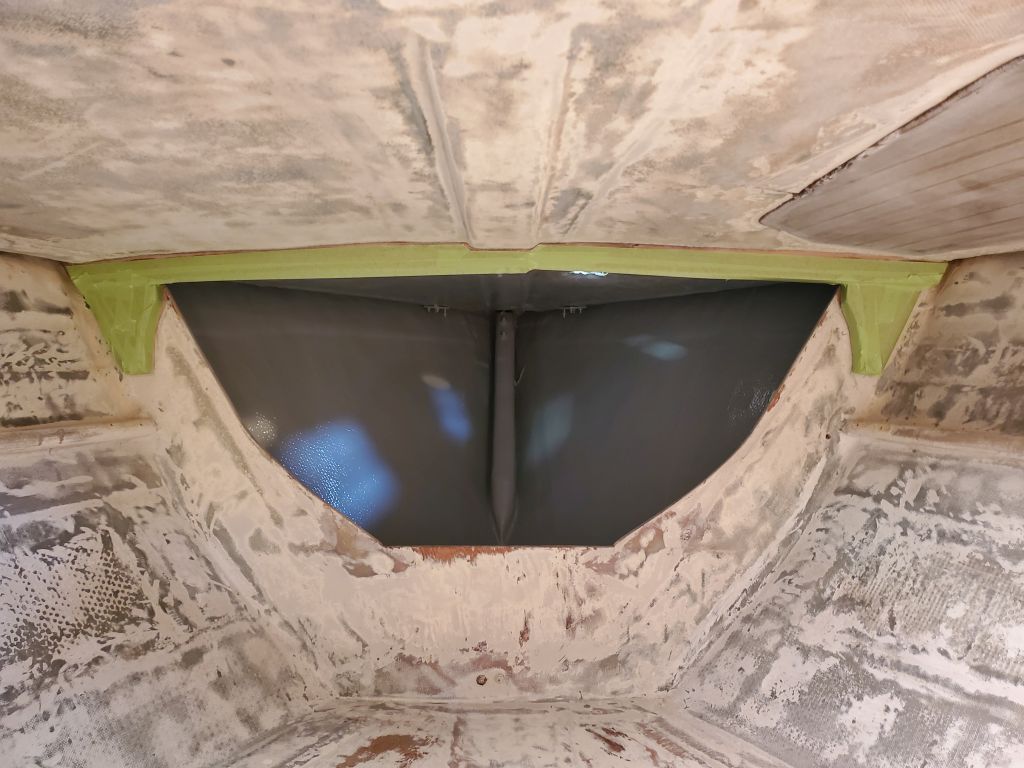
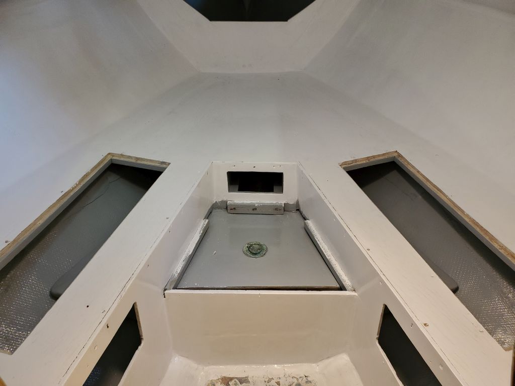
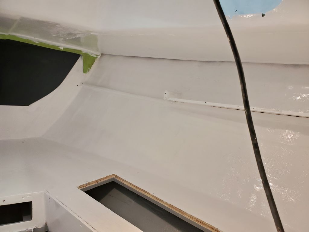
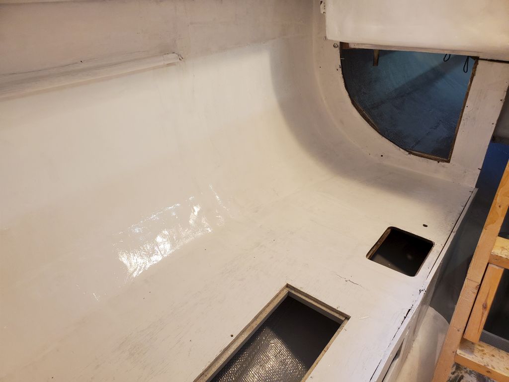
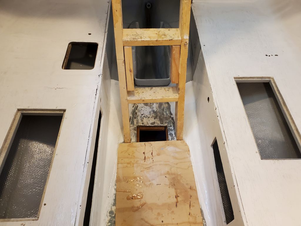
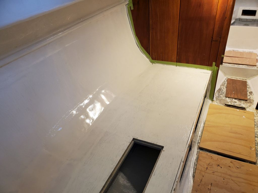
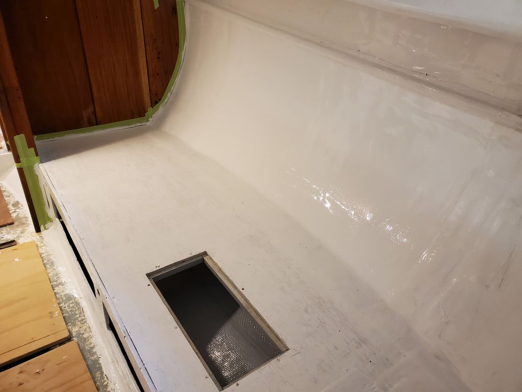
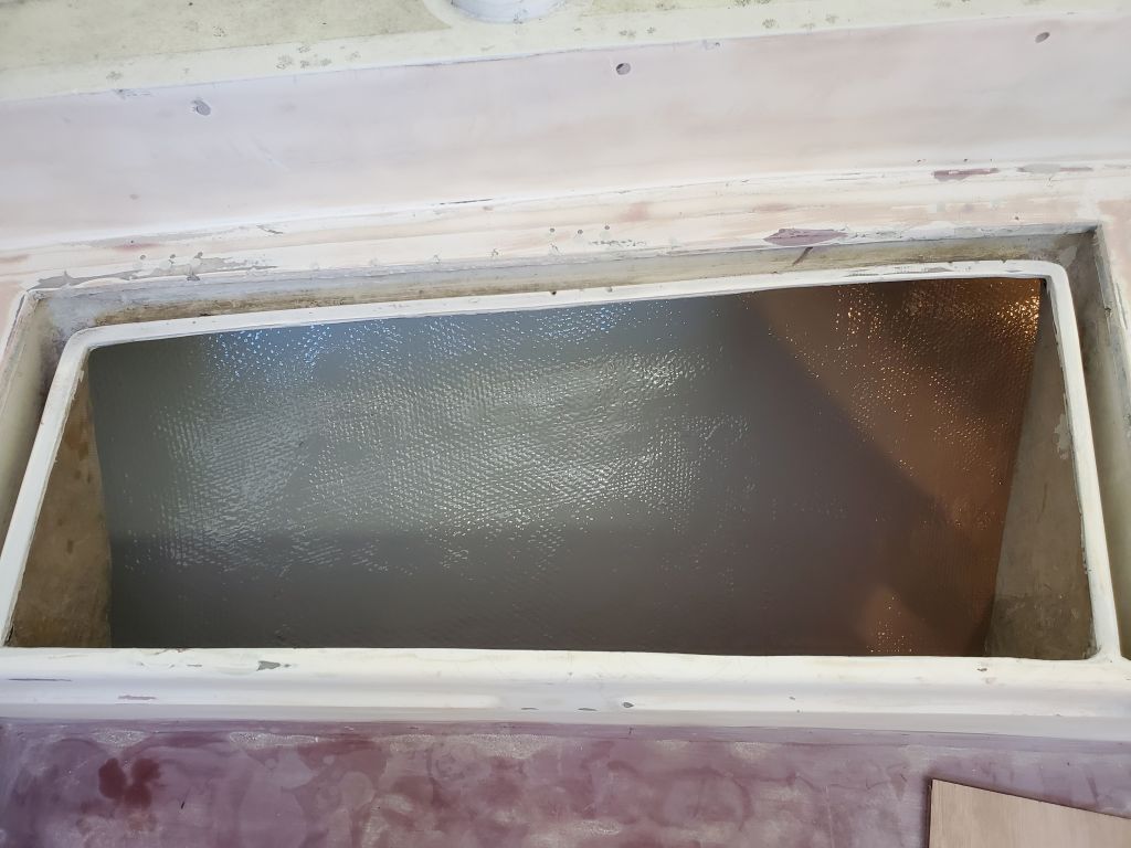
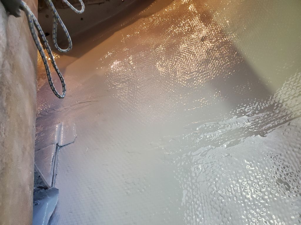
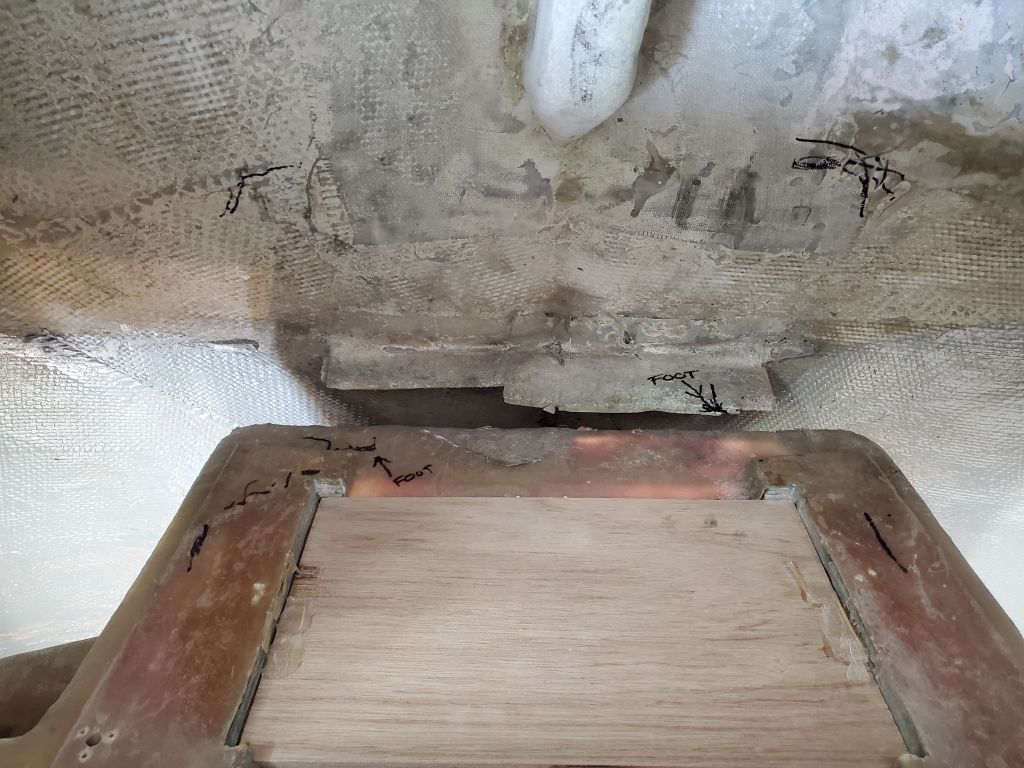
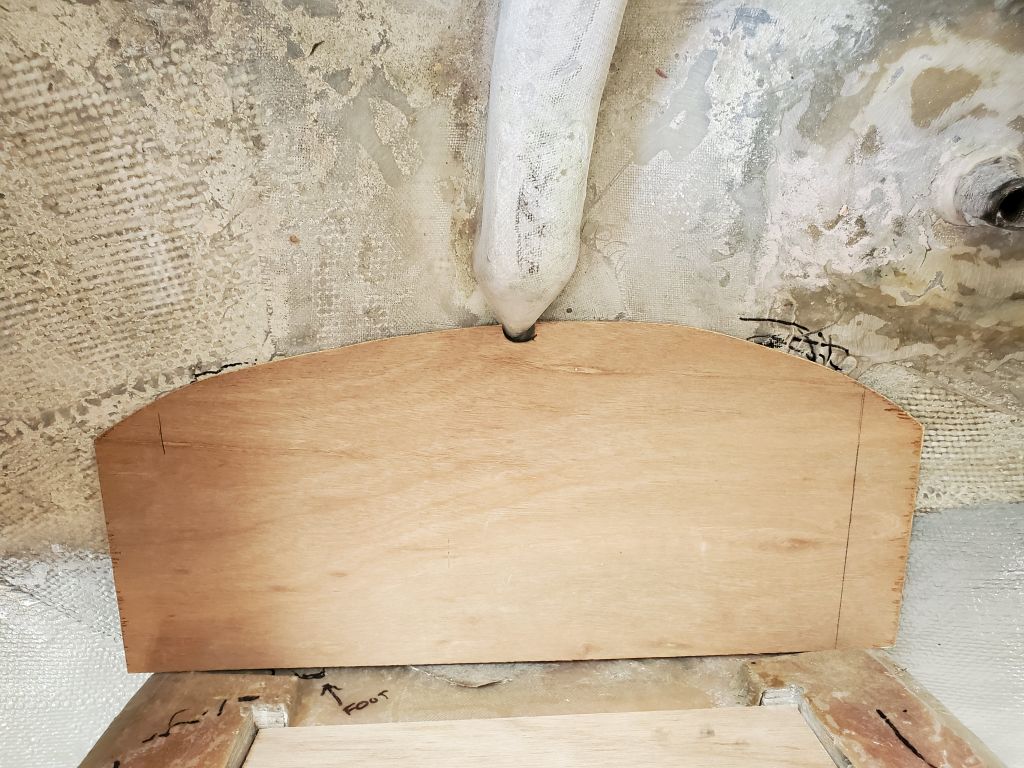
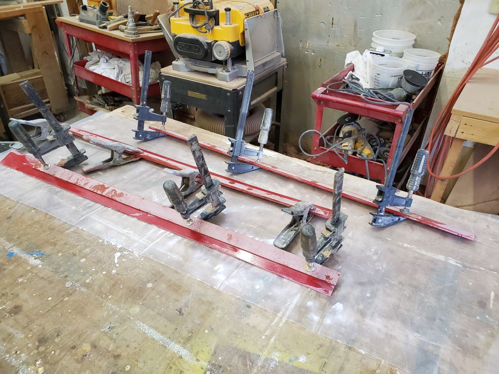
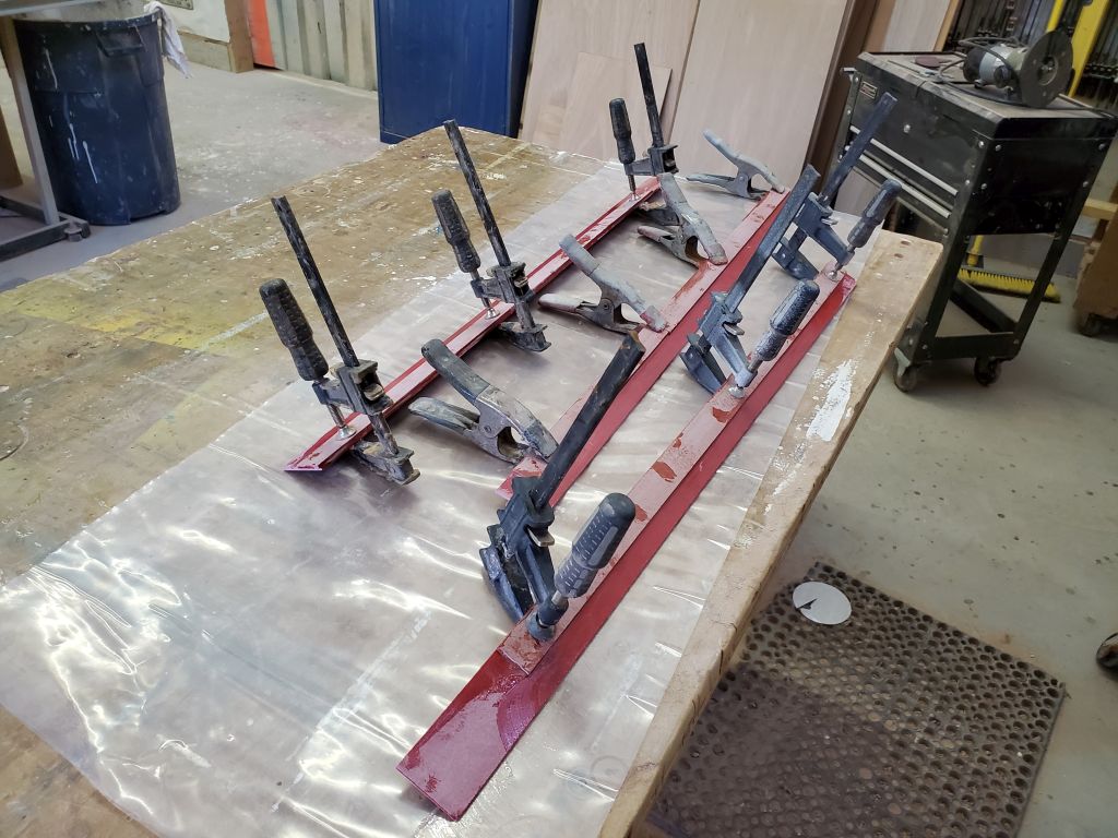
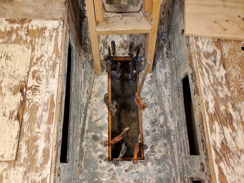
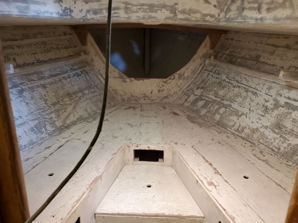
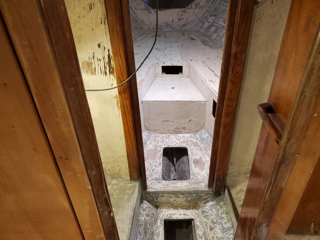
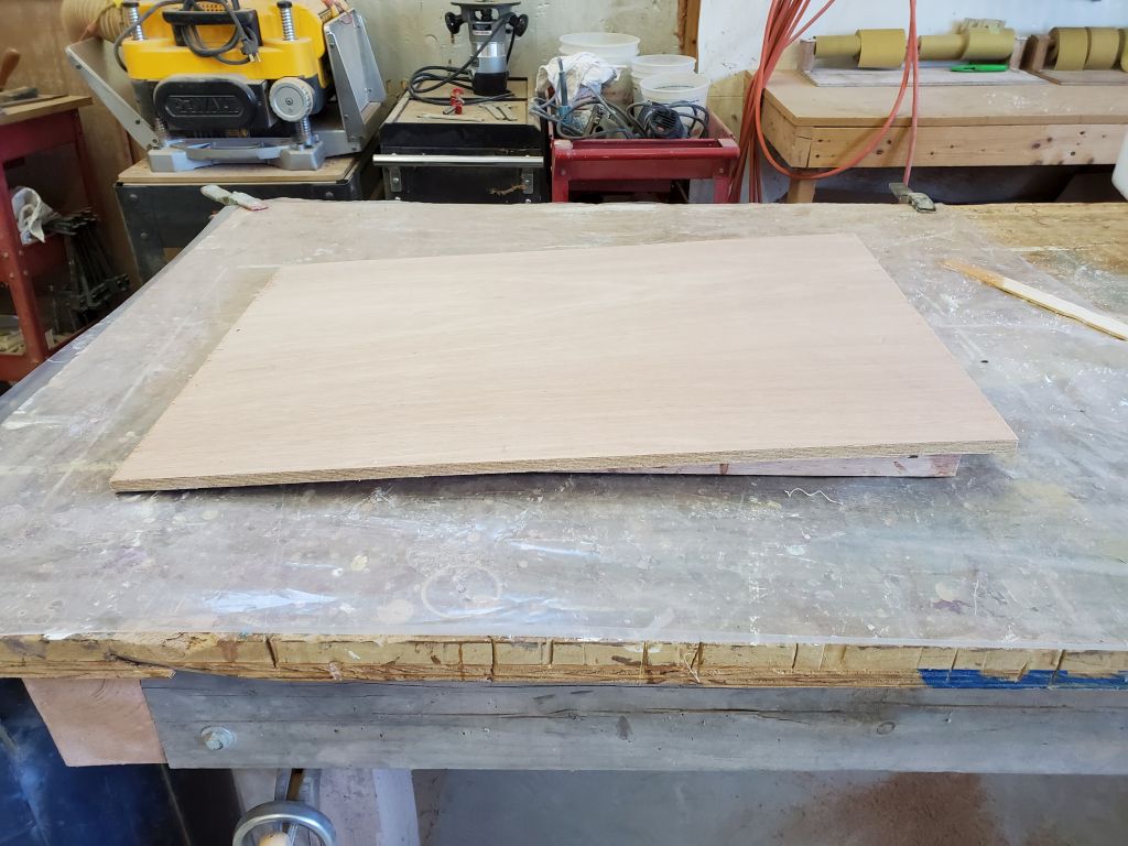
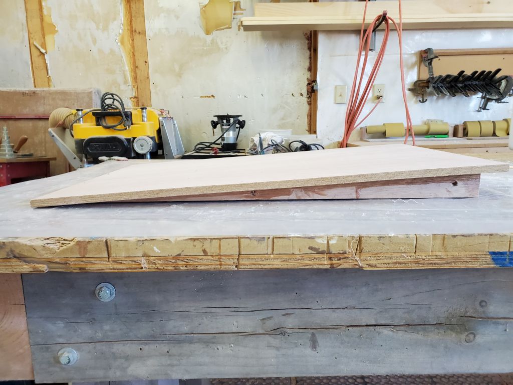
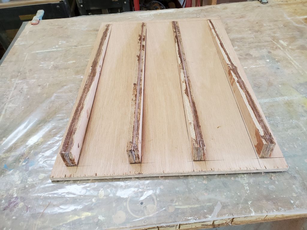
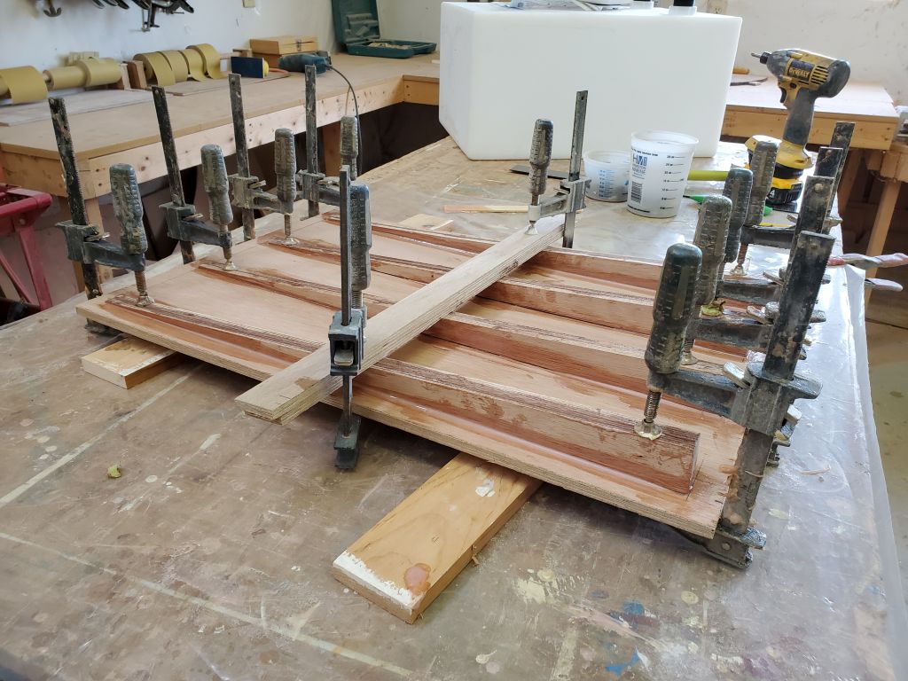
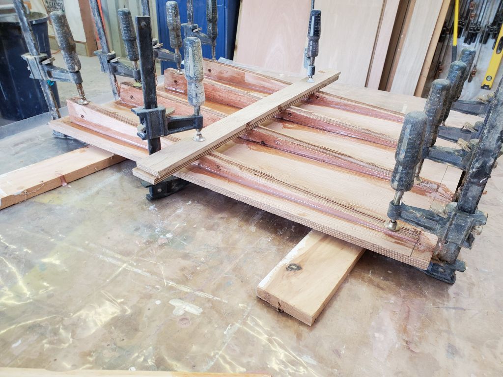
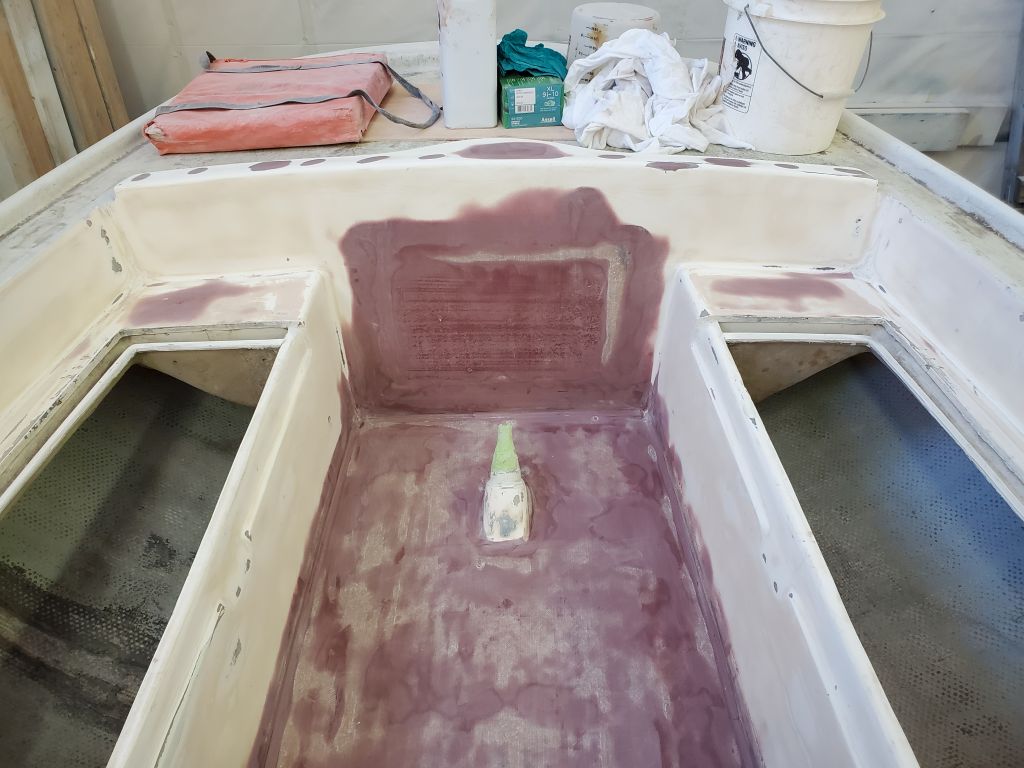
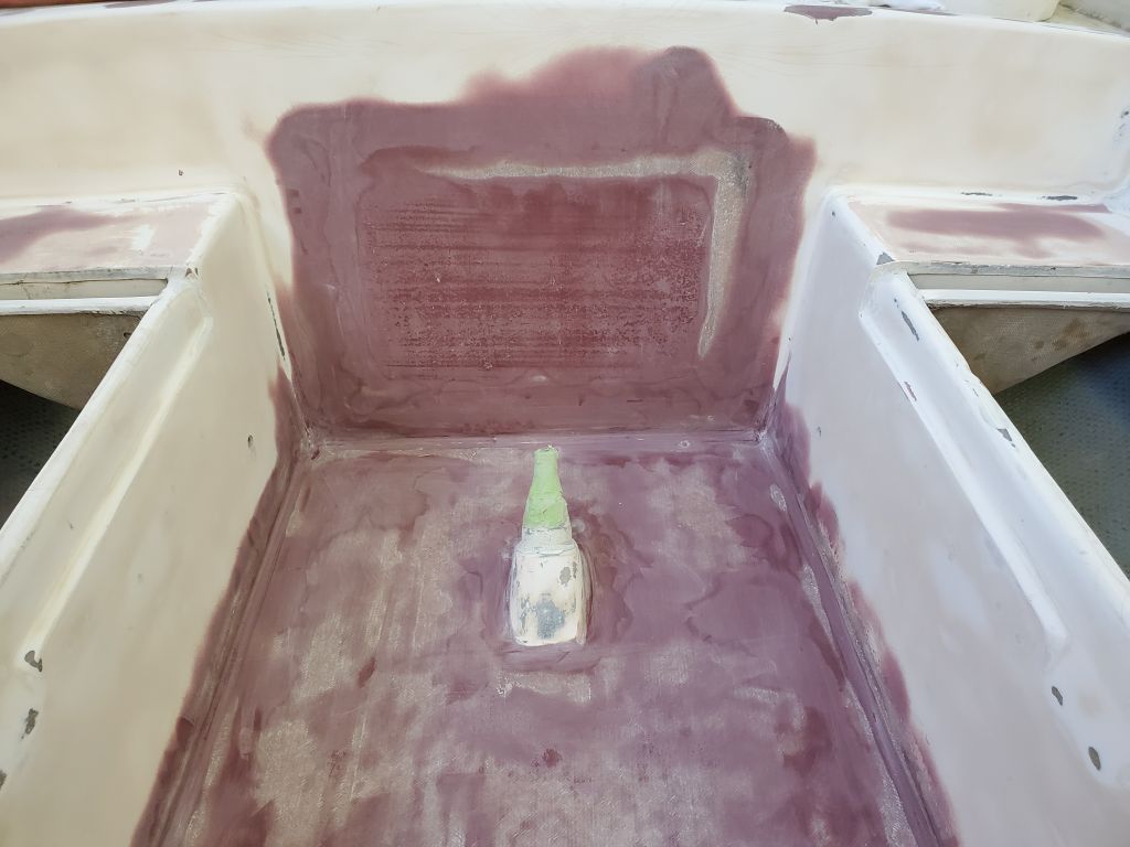
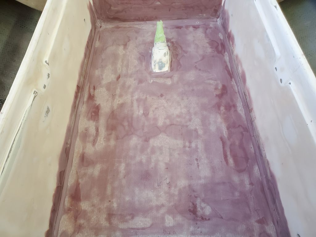
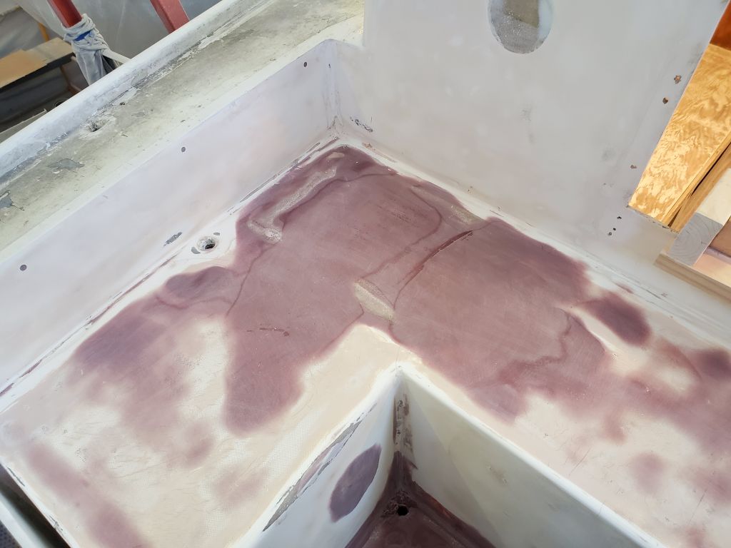
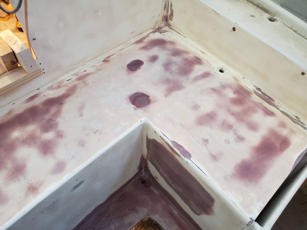
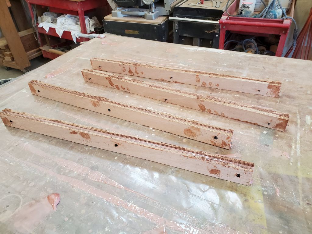
Now that the wedges were securely glued in place beneath the new holding tank platform, I removed the clamps and coated the plywood edges and bottom with epoxy. These areas would never be seen once the platform was in place.
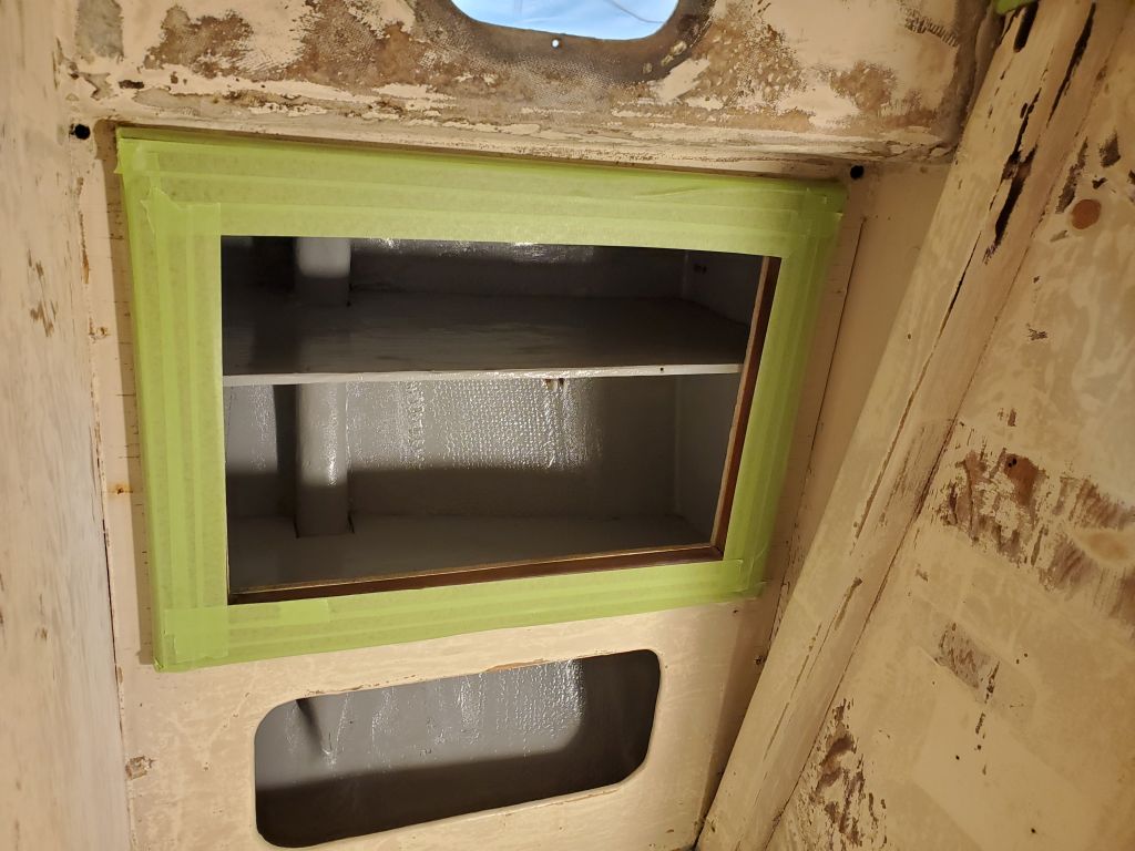
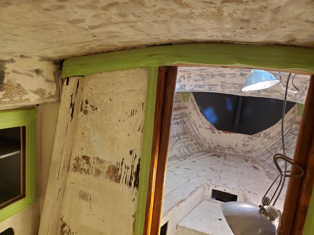
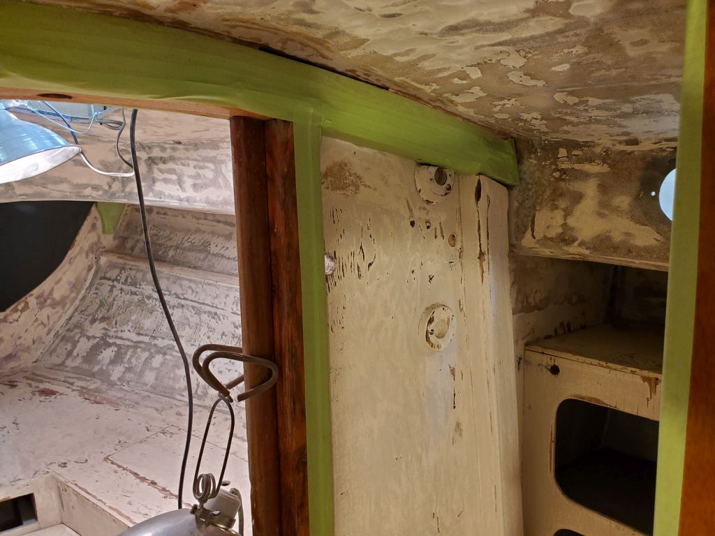
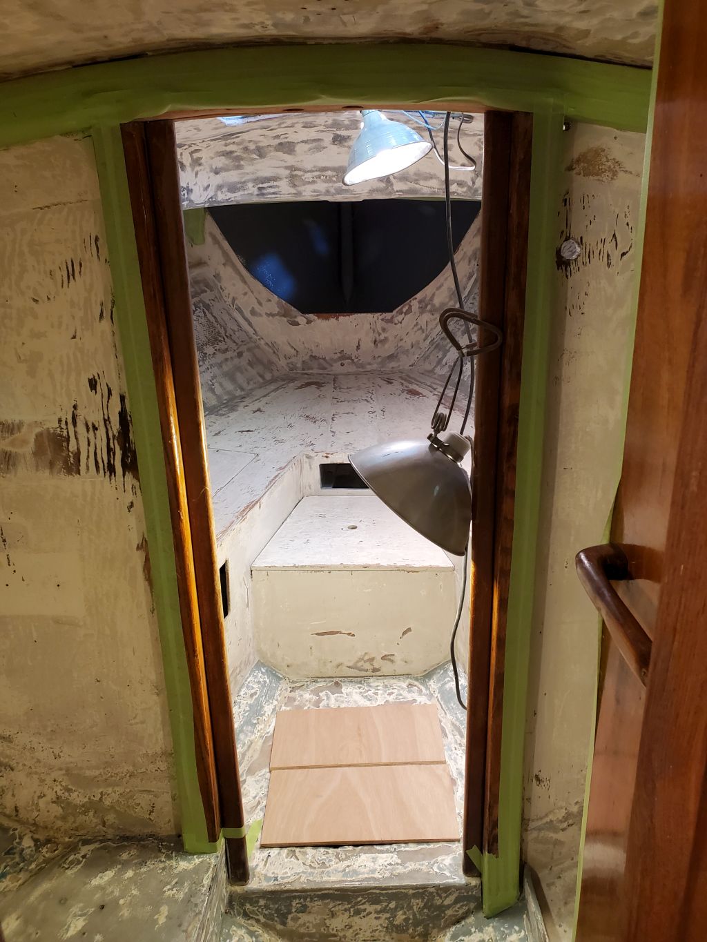
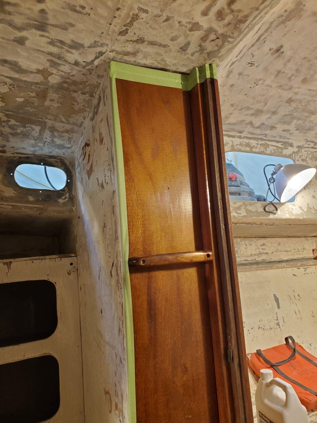
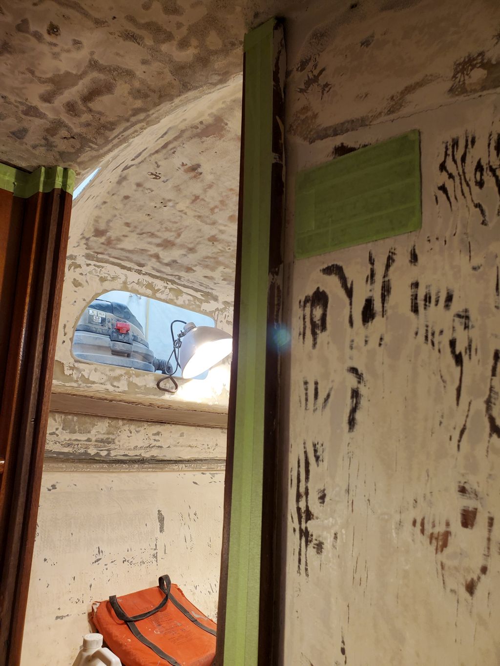
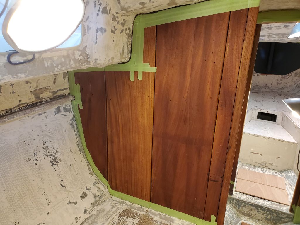
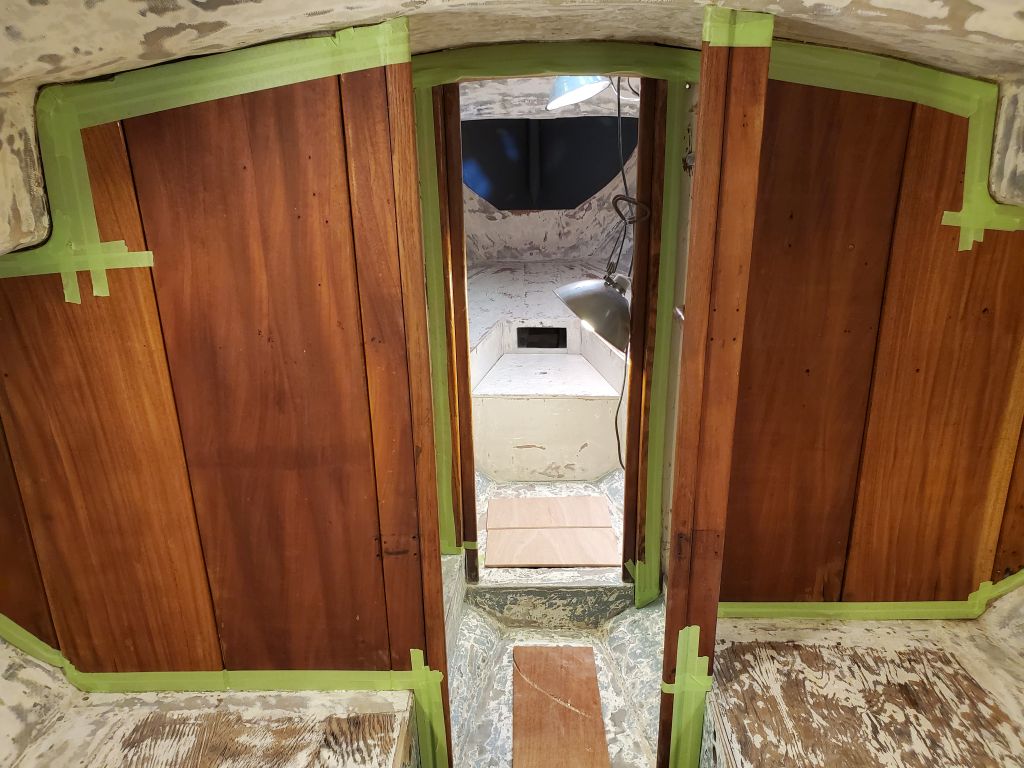
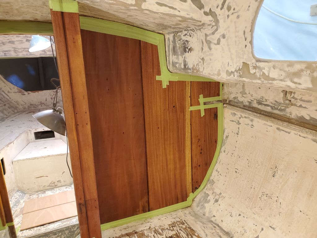
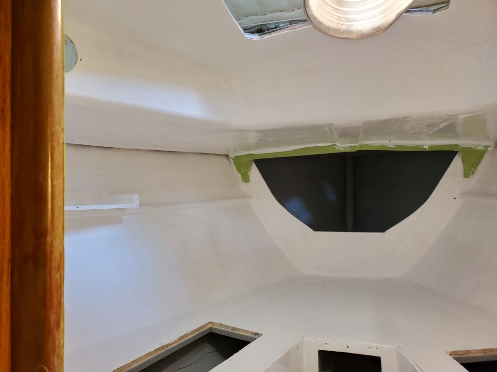
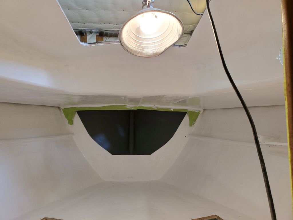
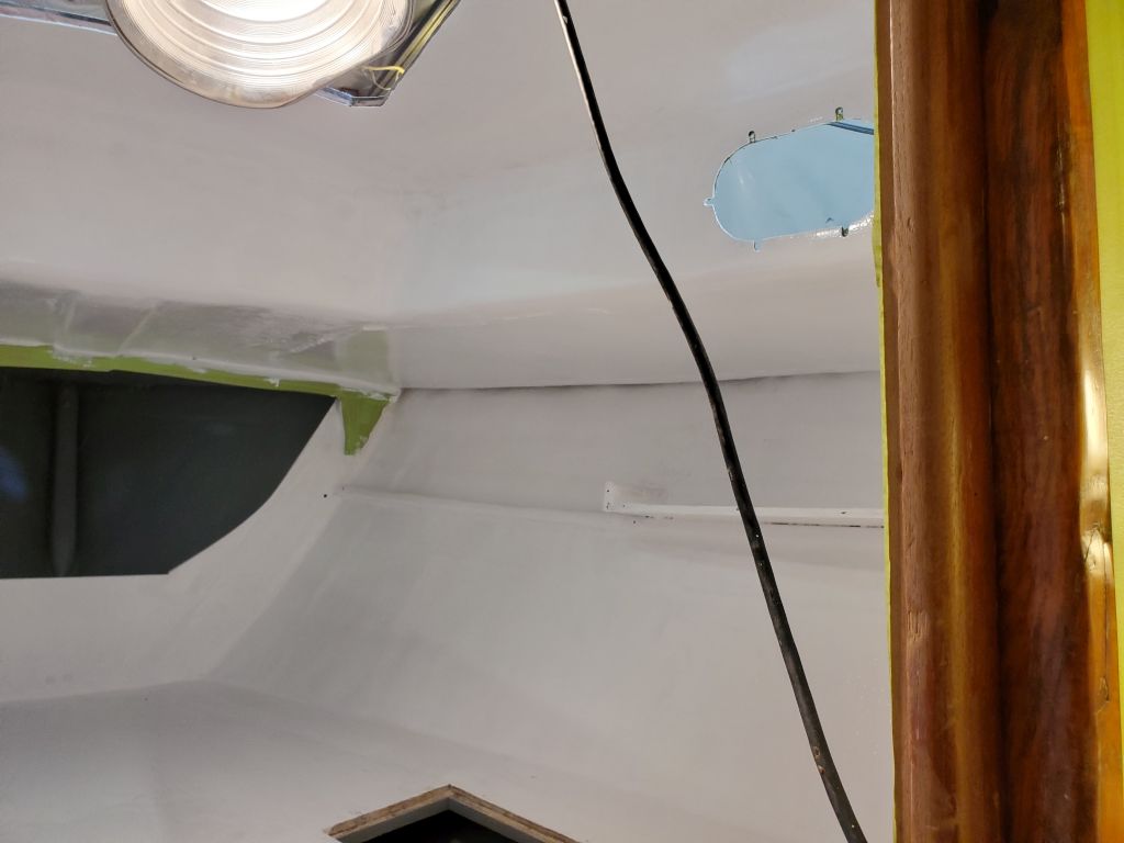
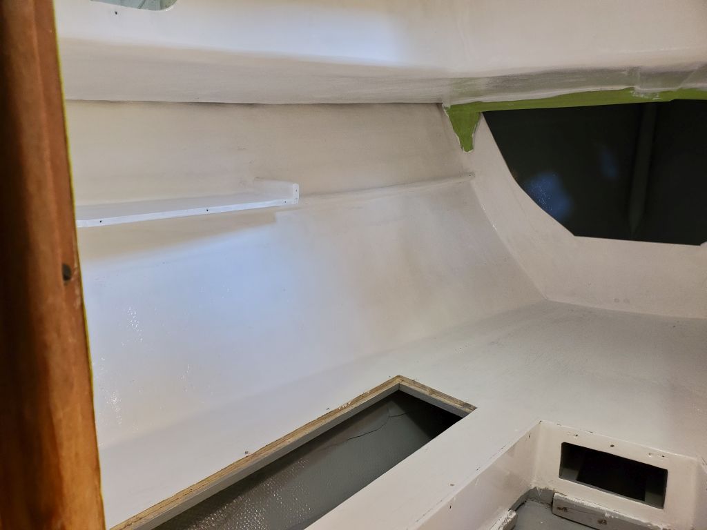
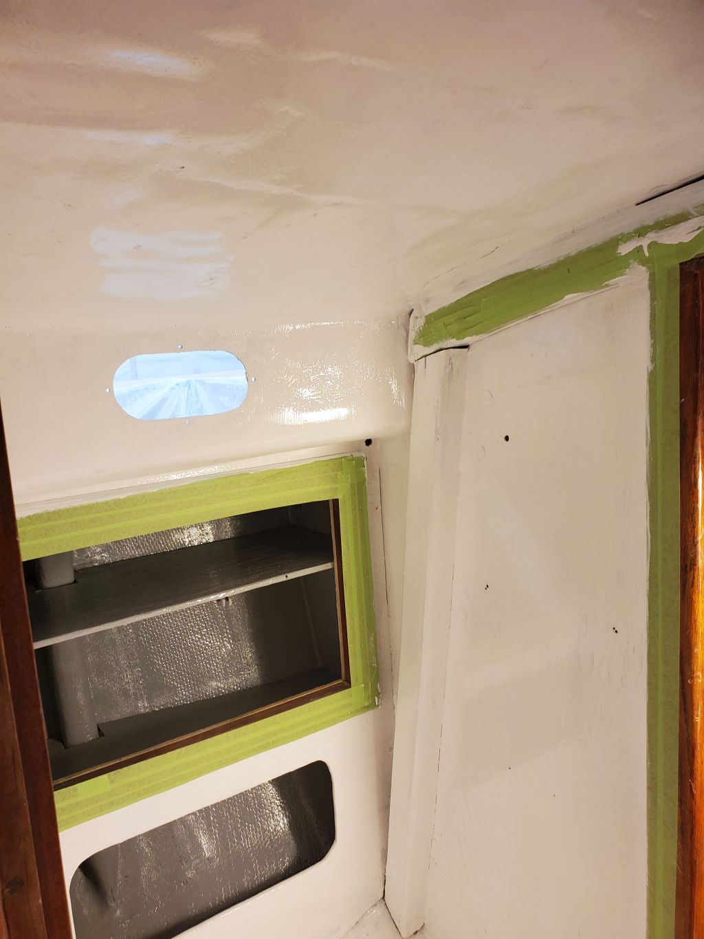
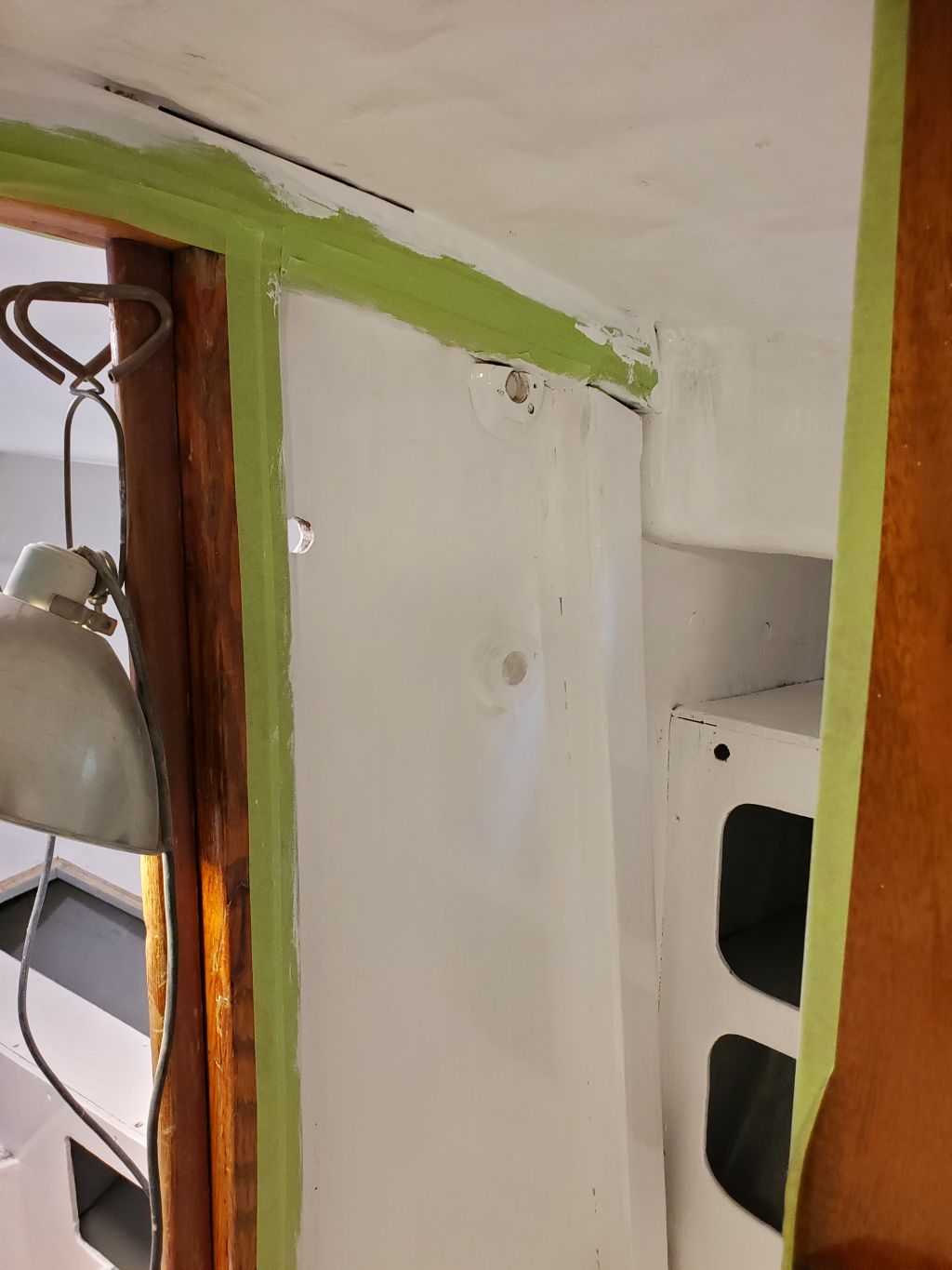
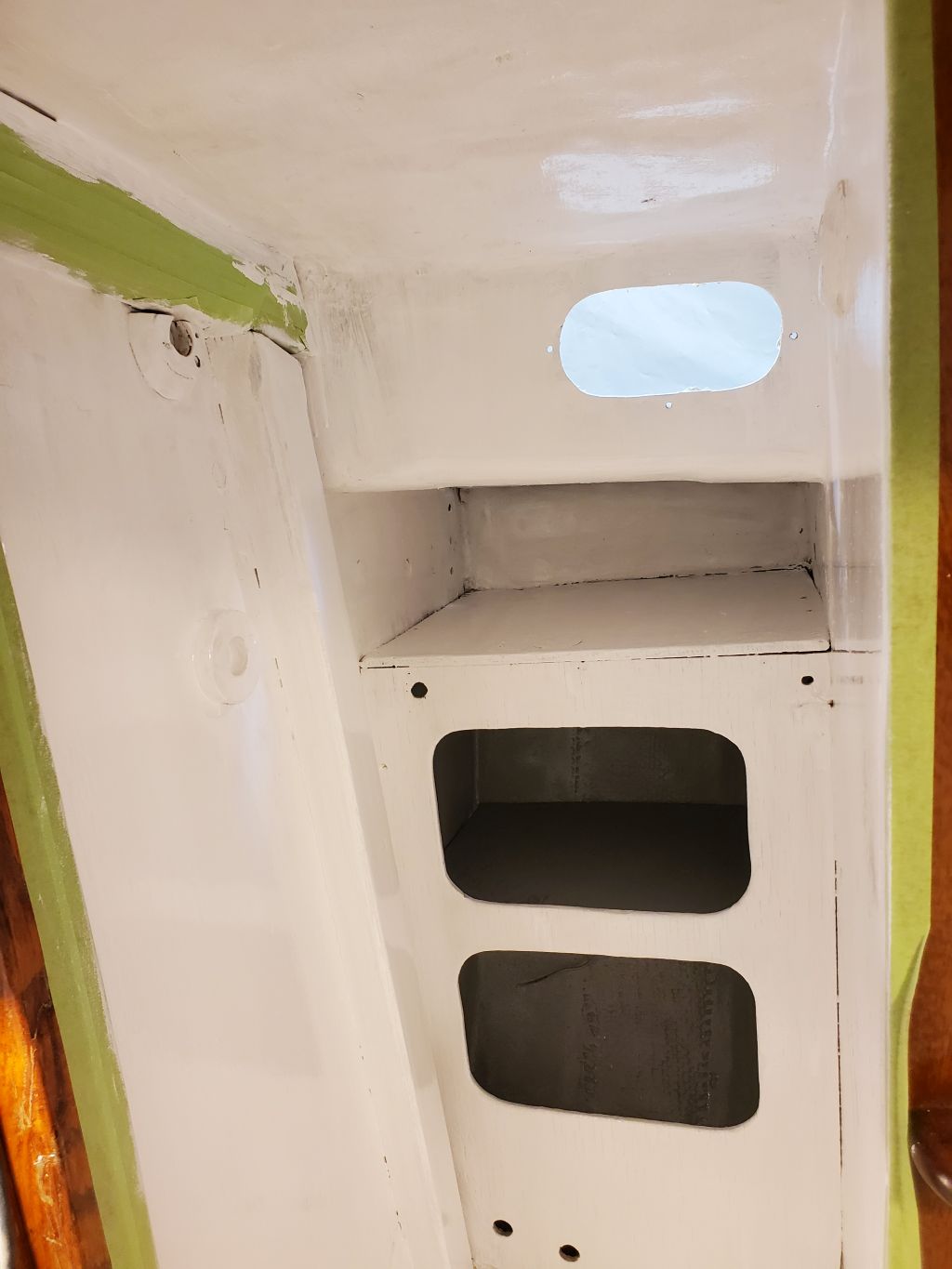
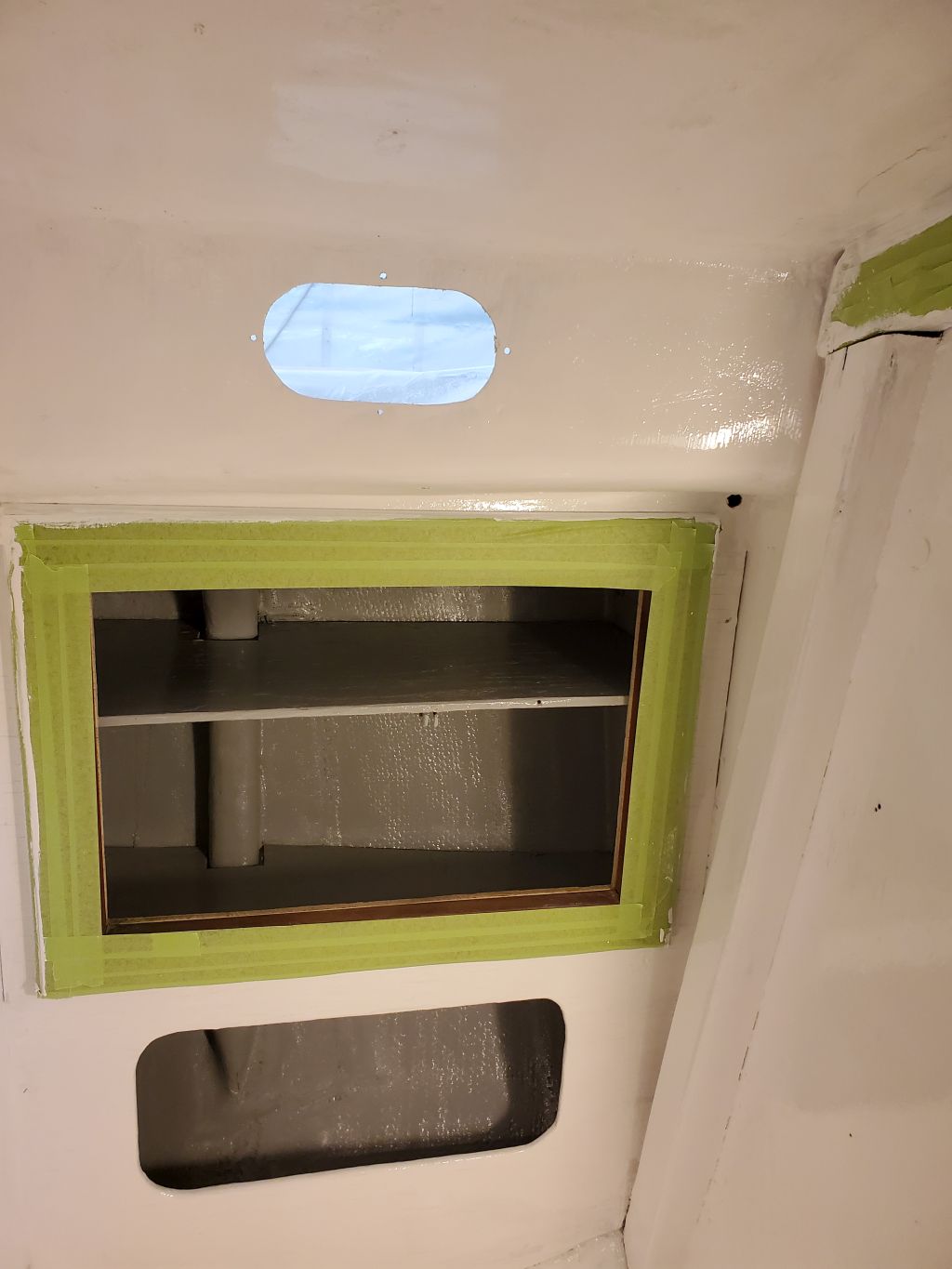
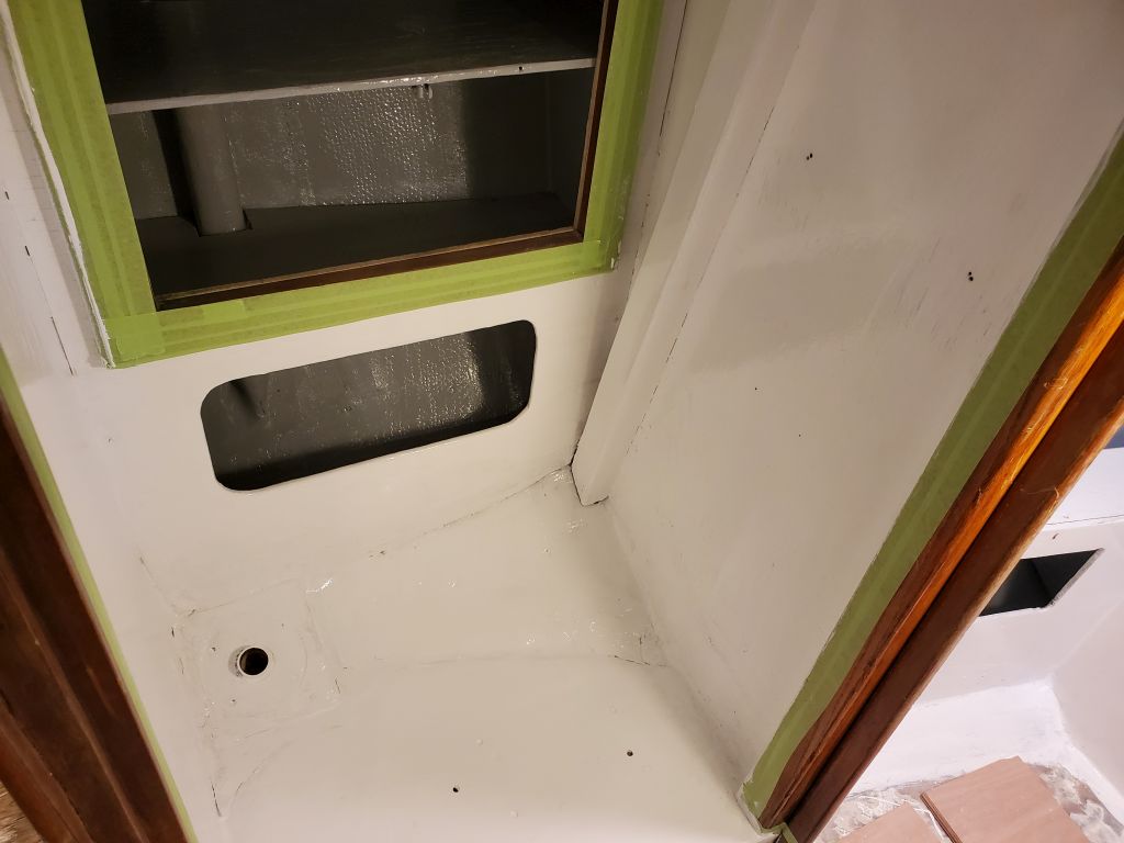
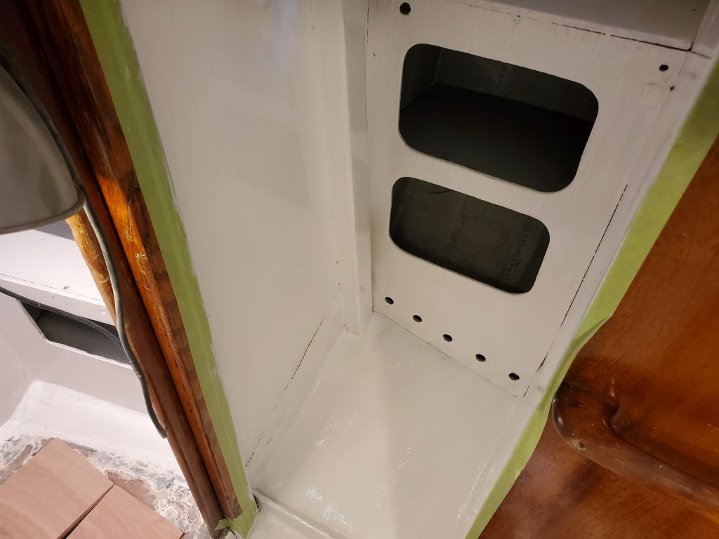
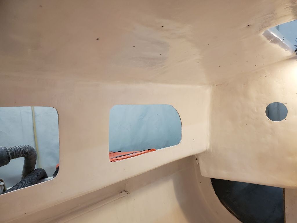
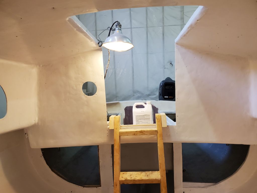
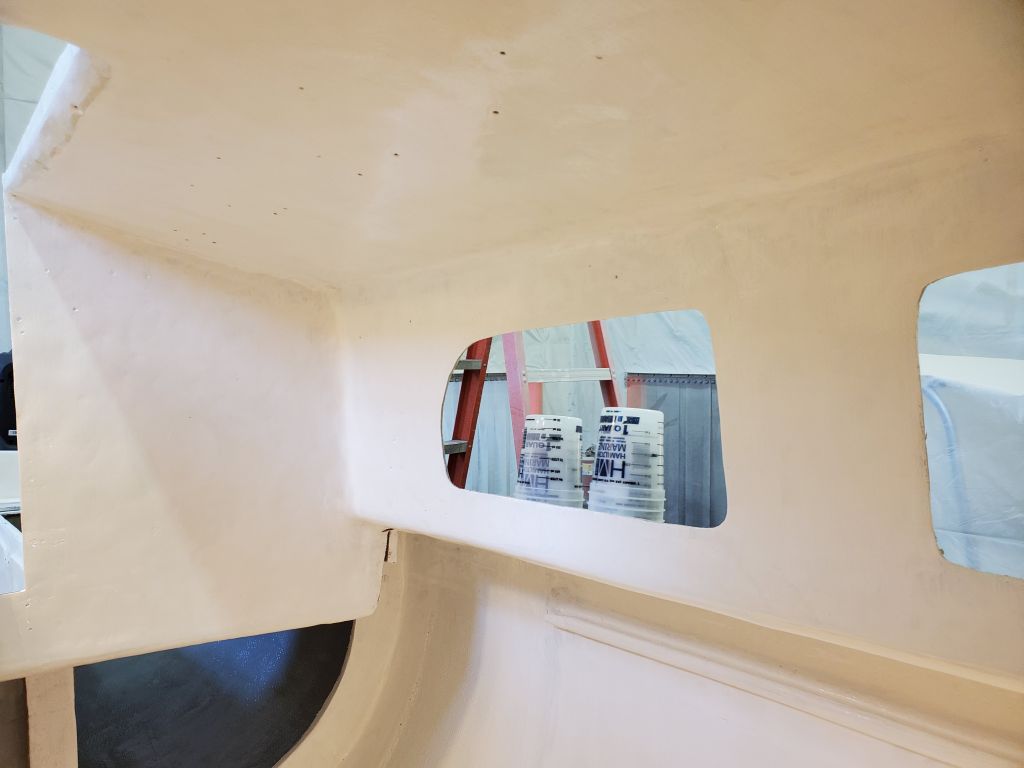
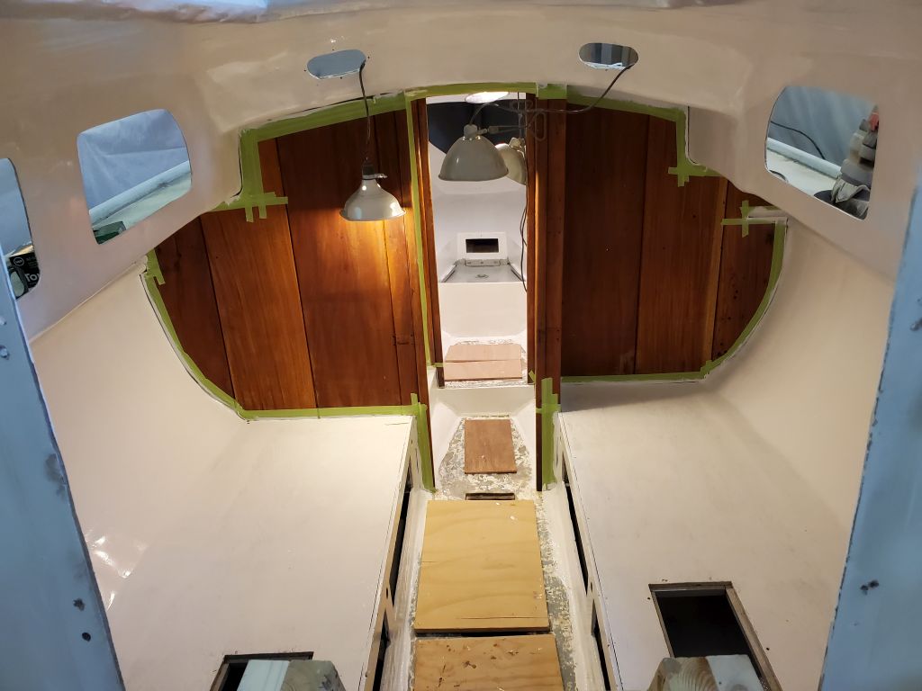
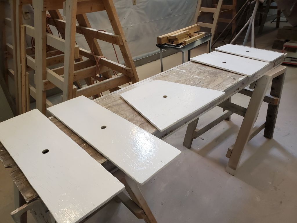
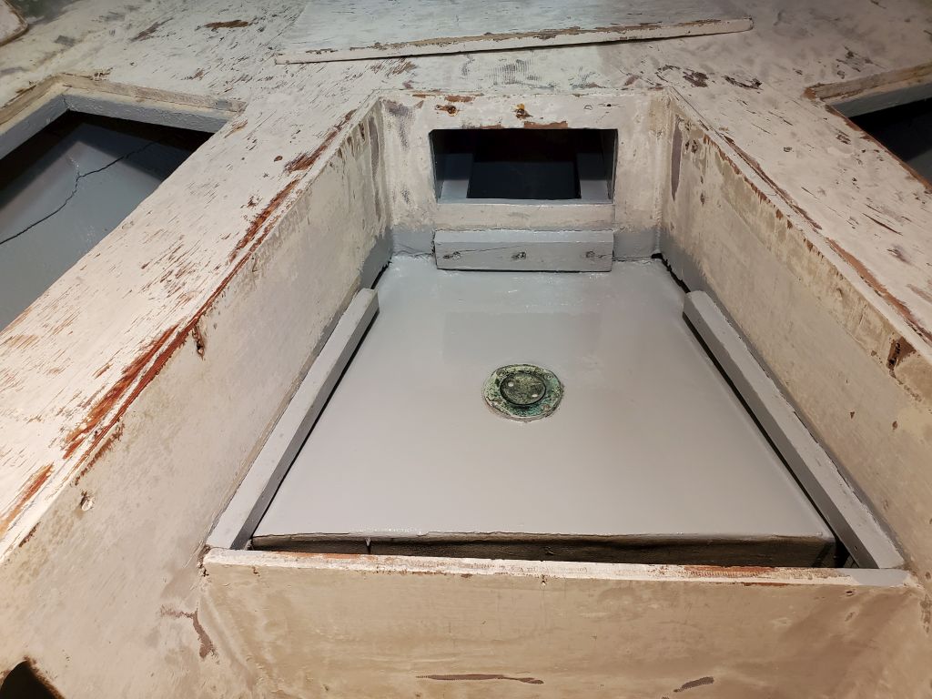
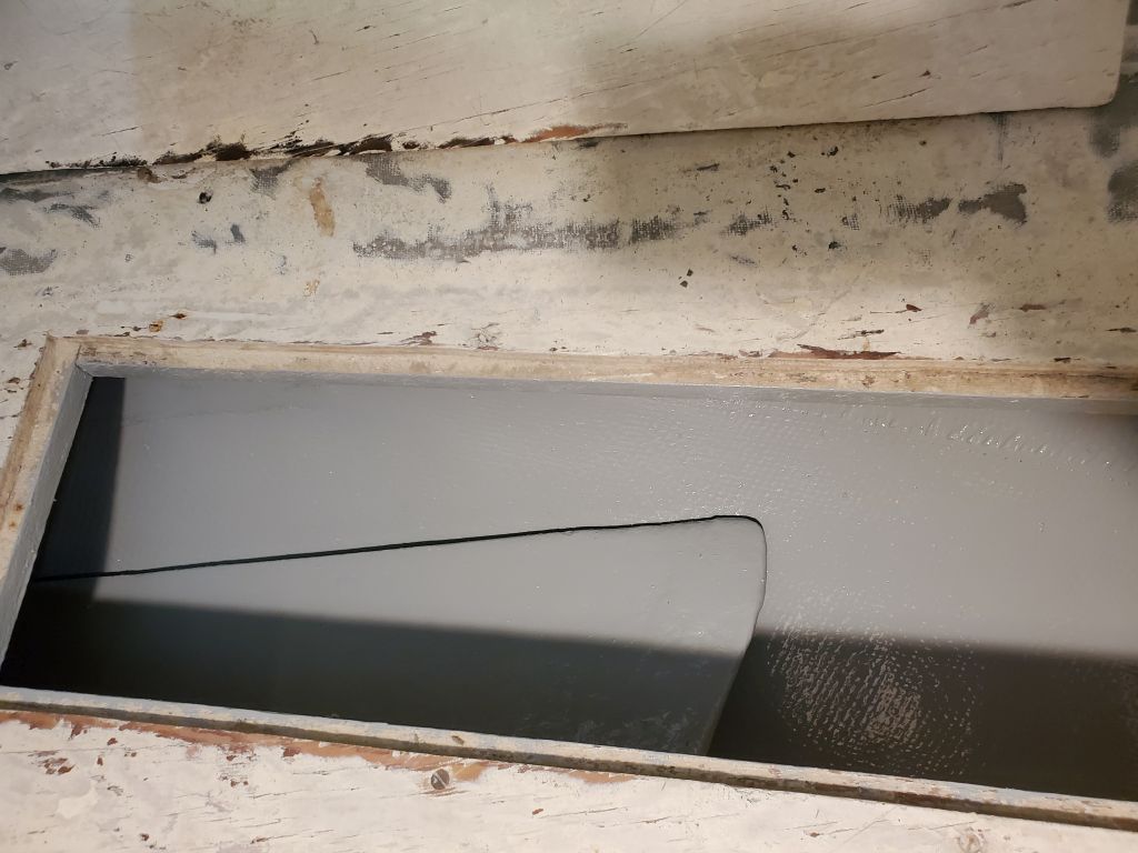
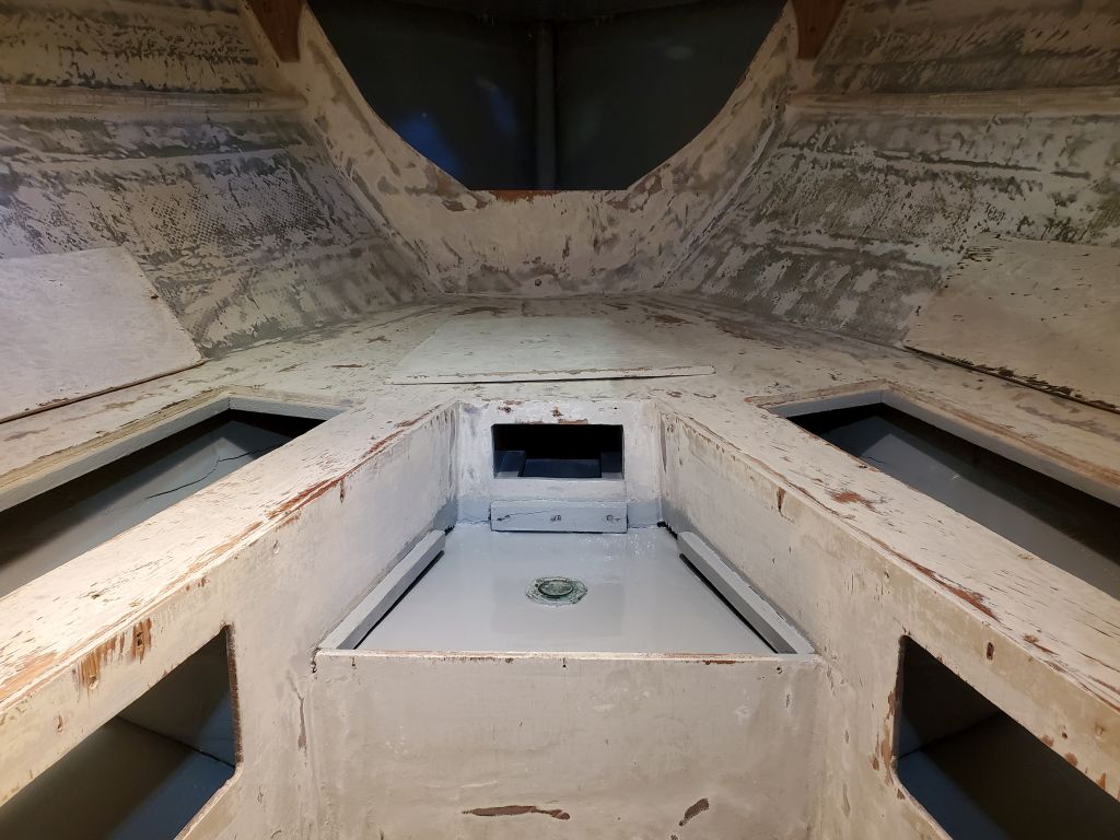
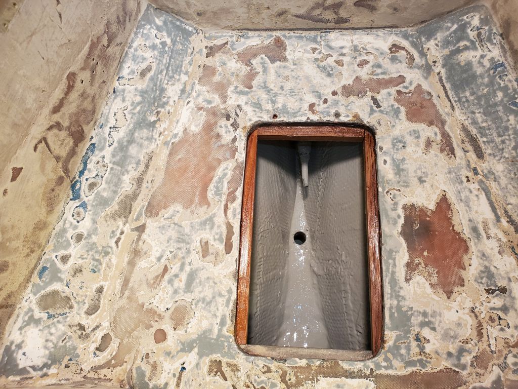
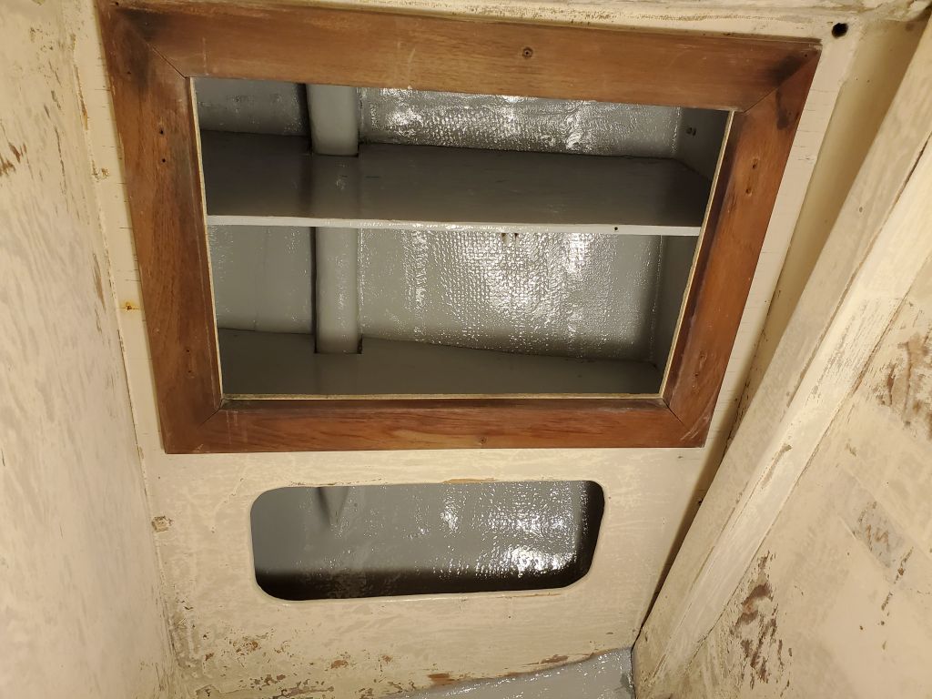
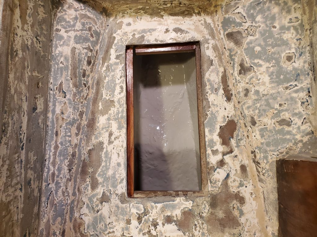
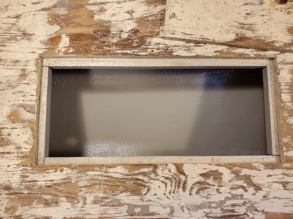
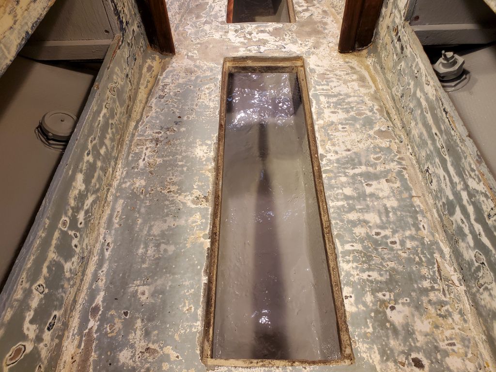
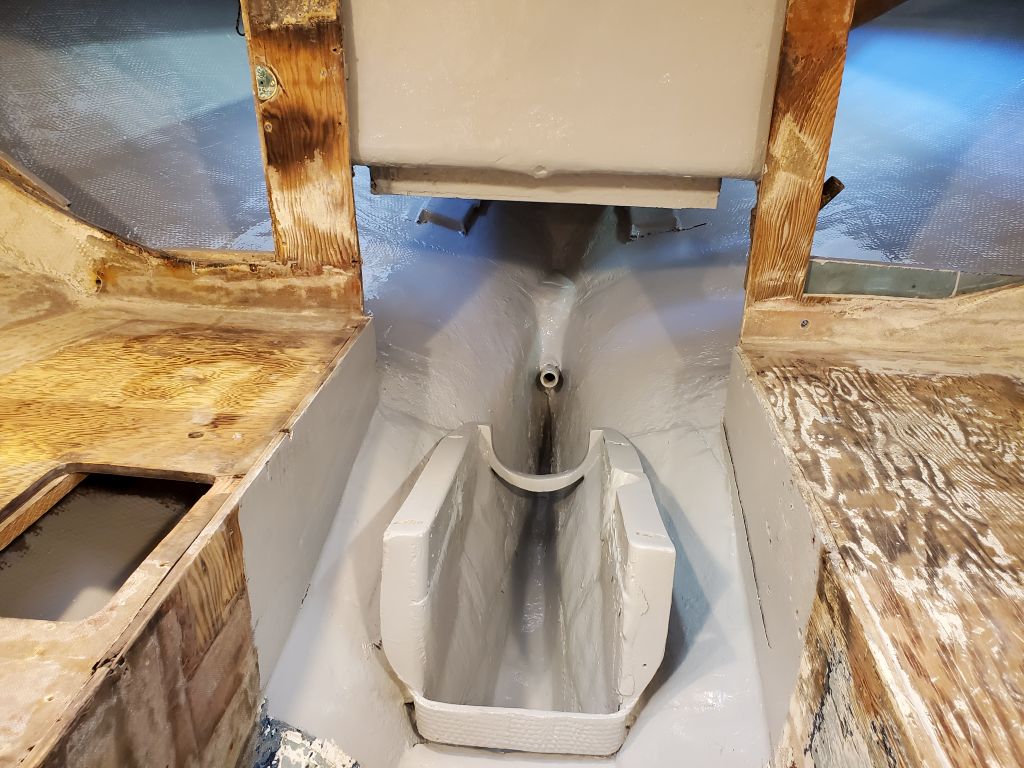
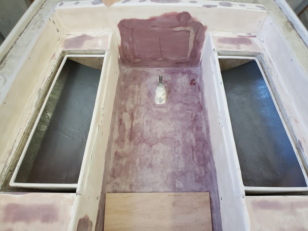
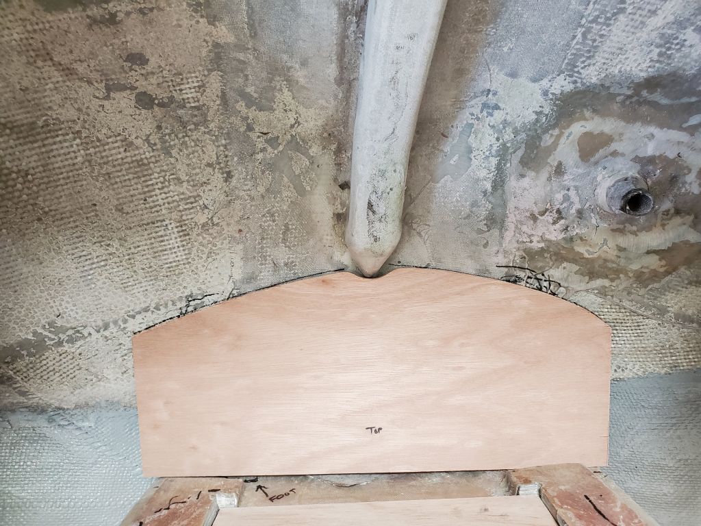
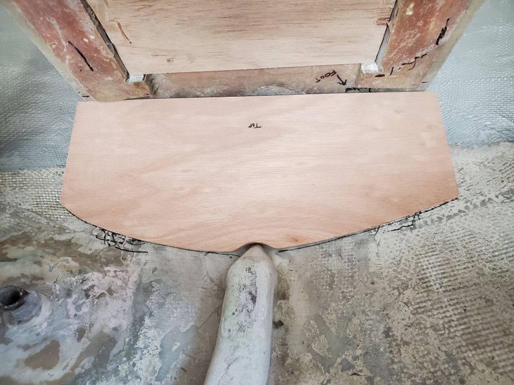
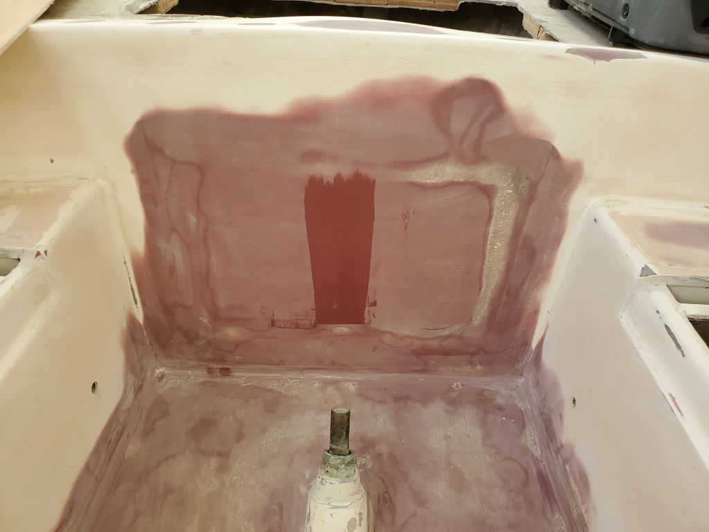
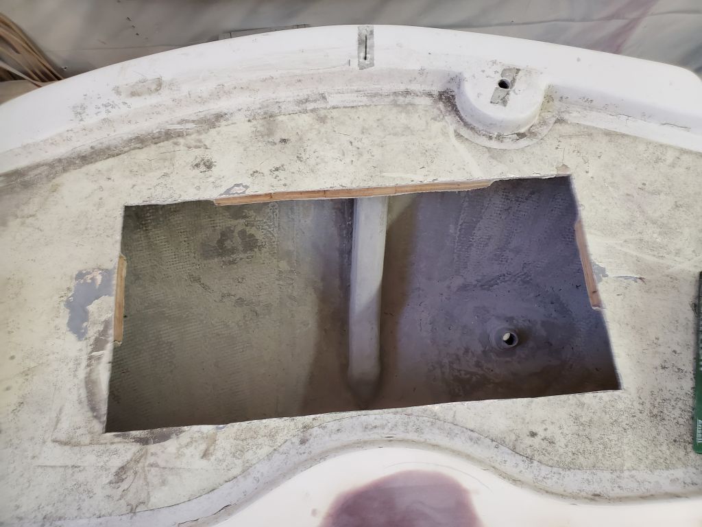
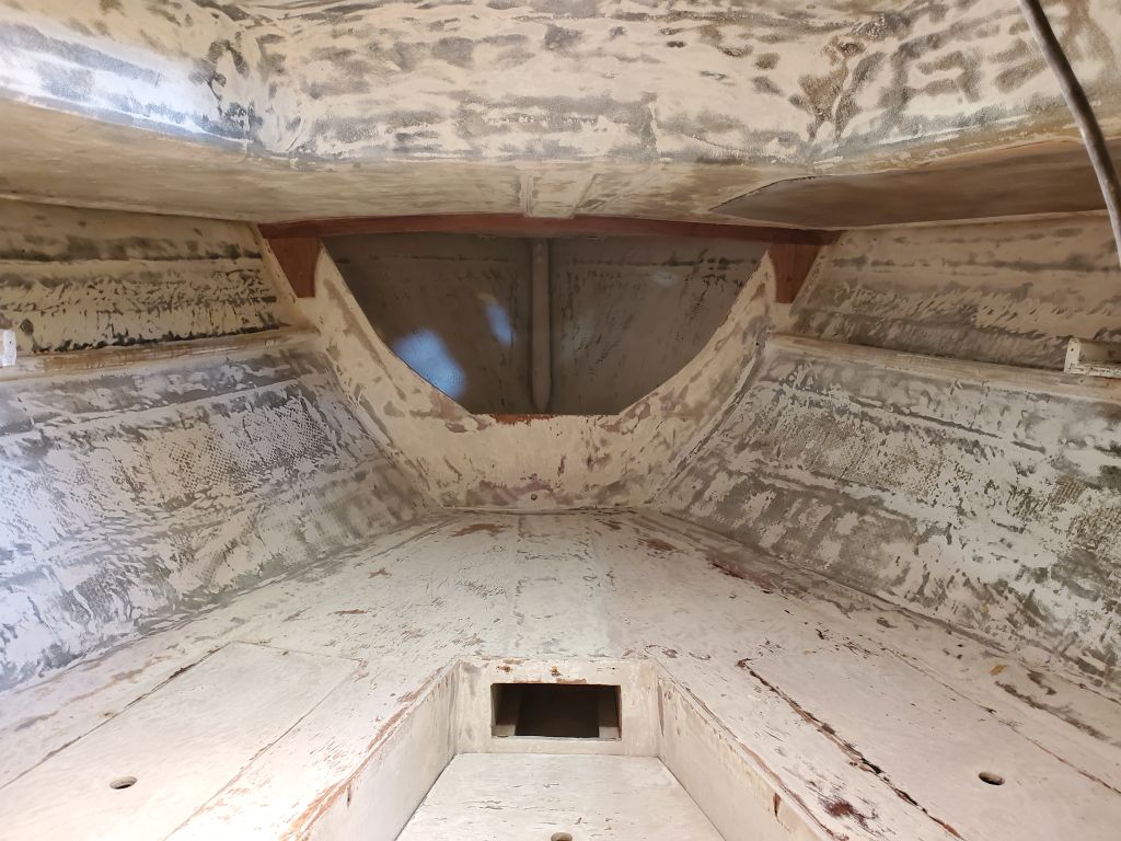
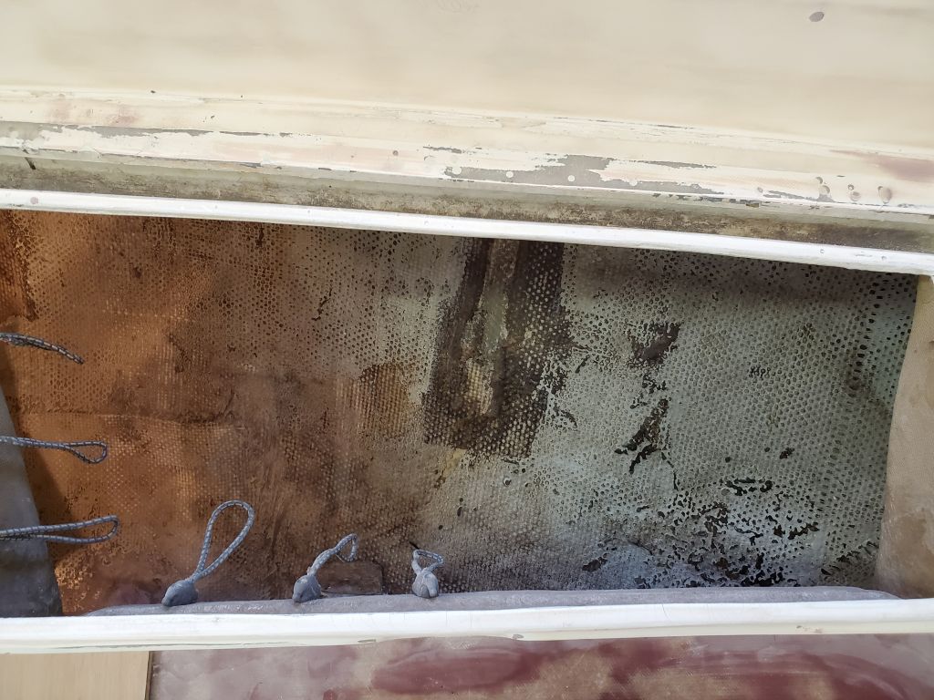
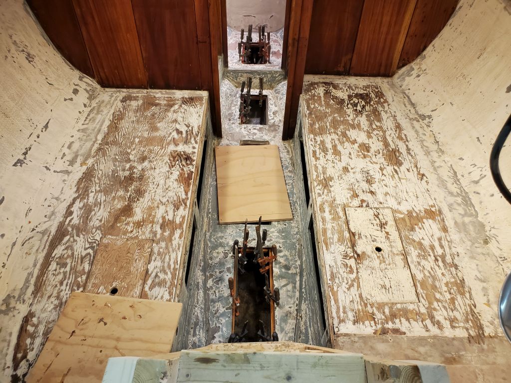
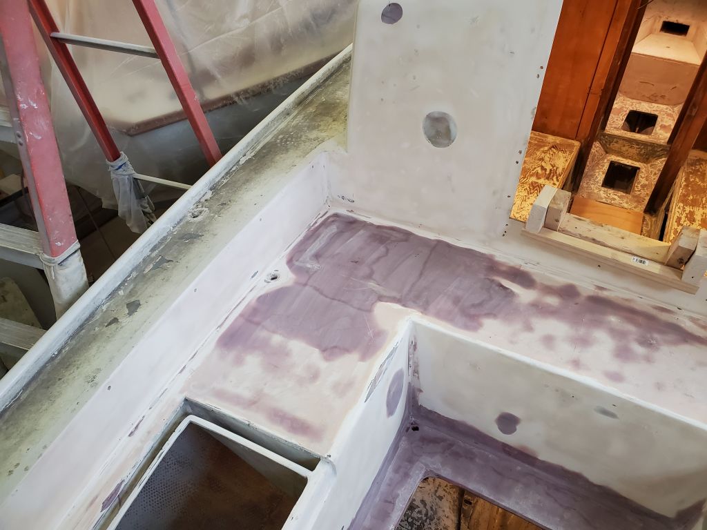
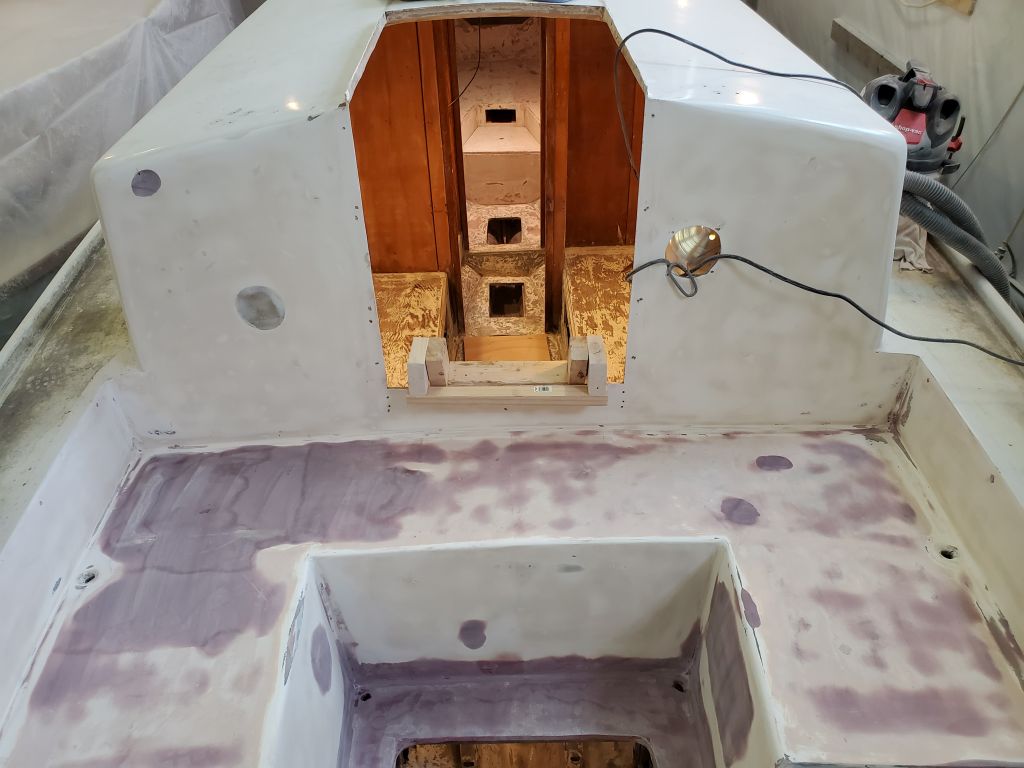
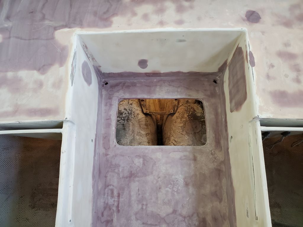
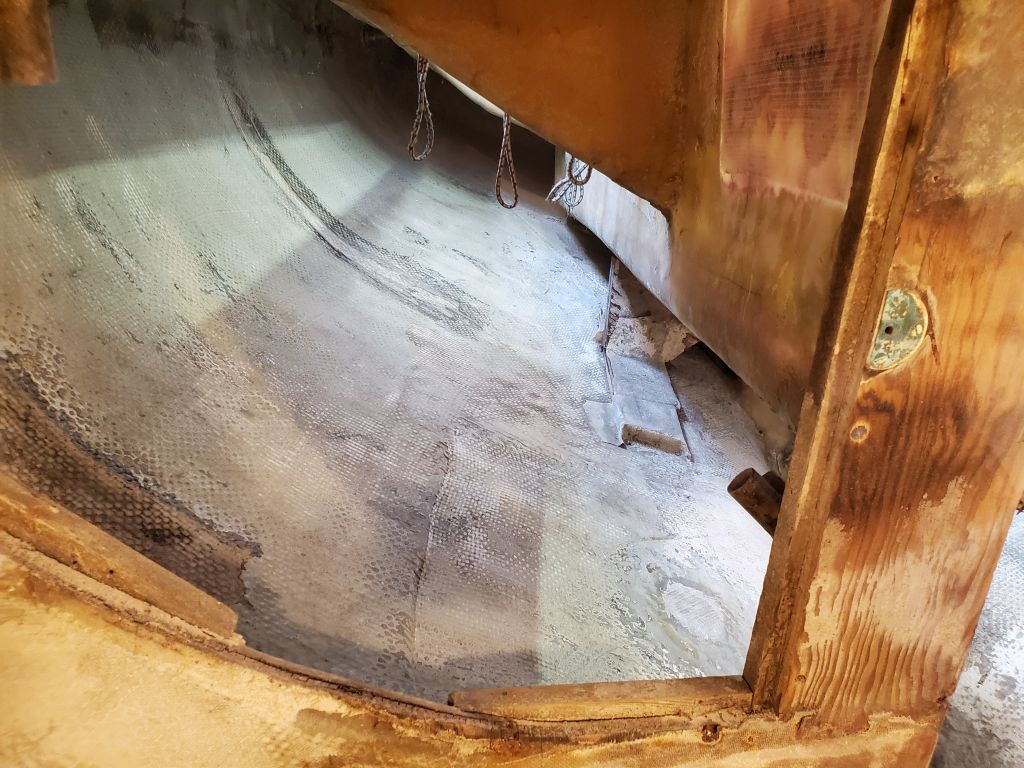
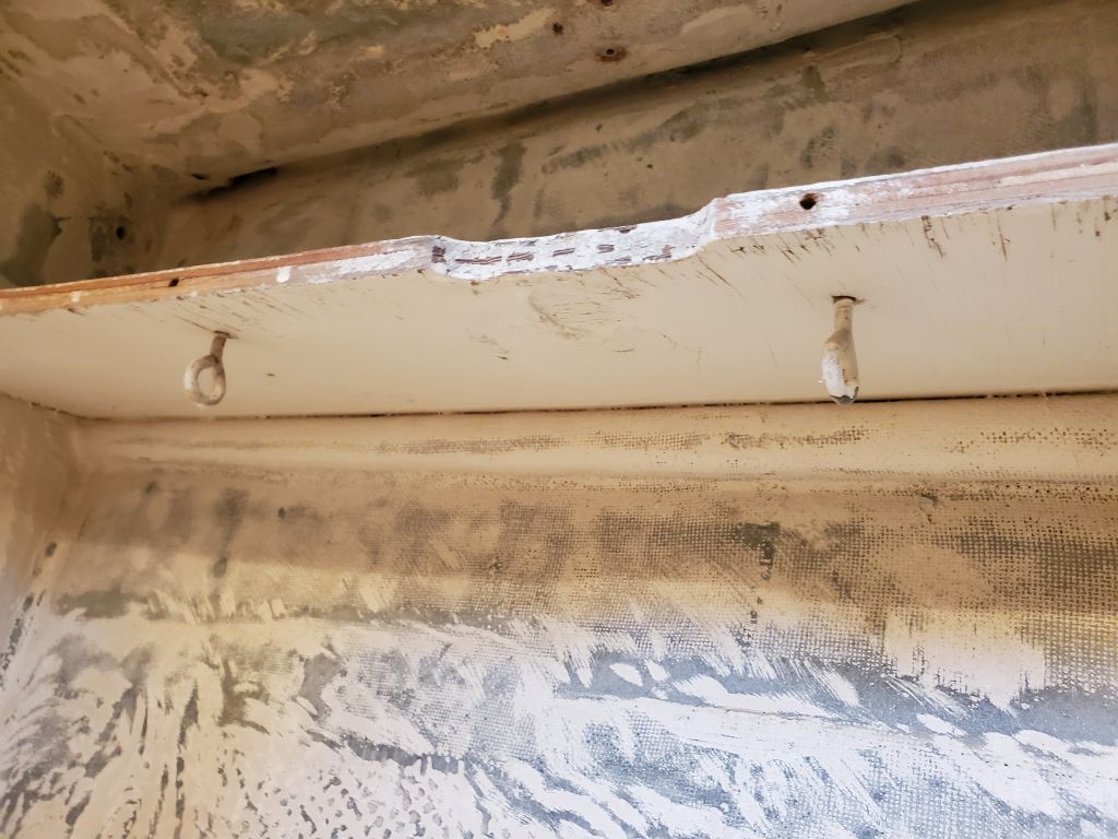
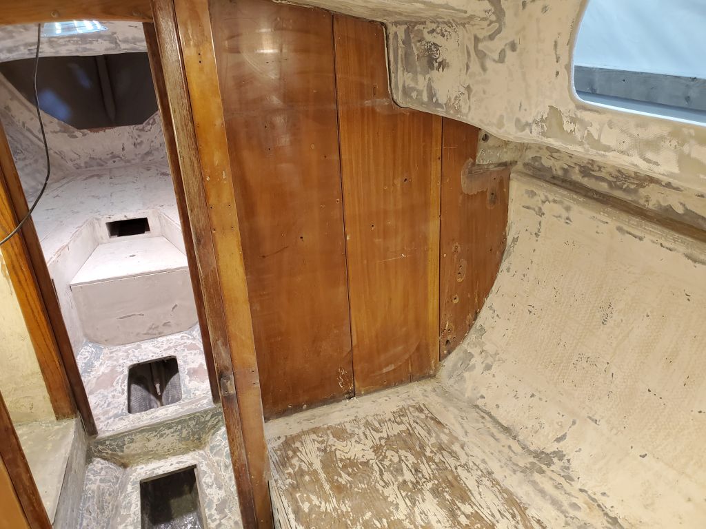
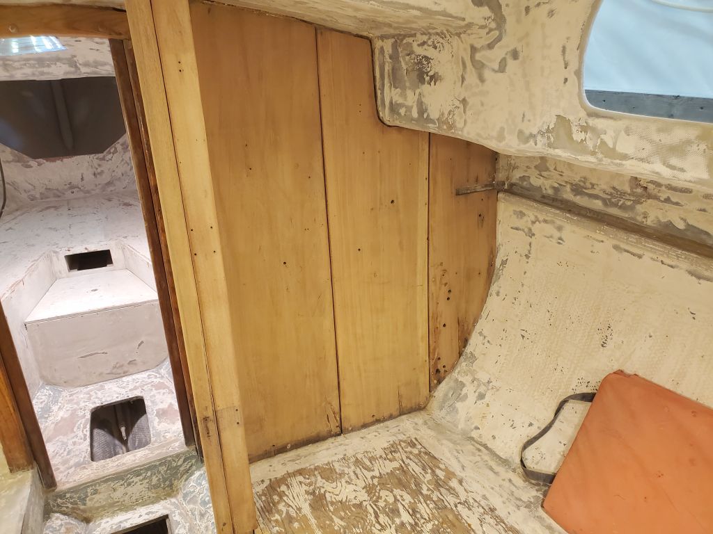
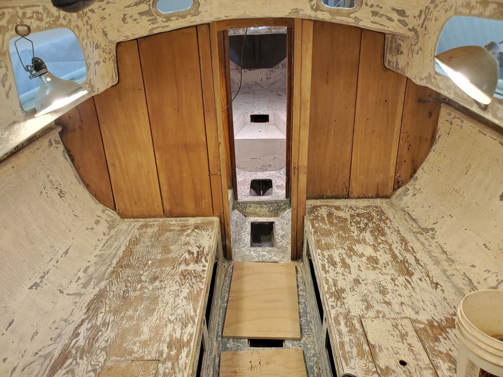
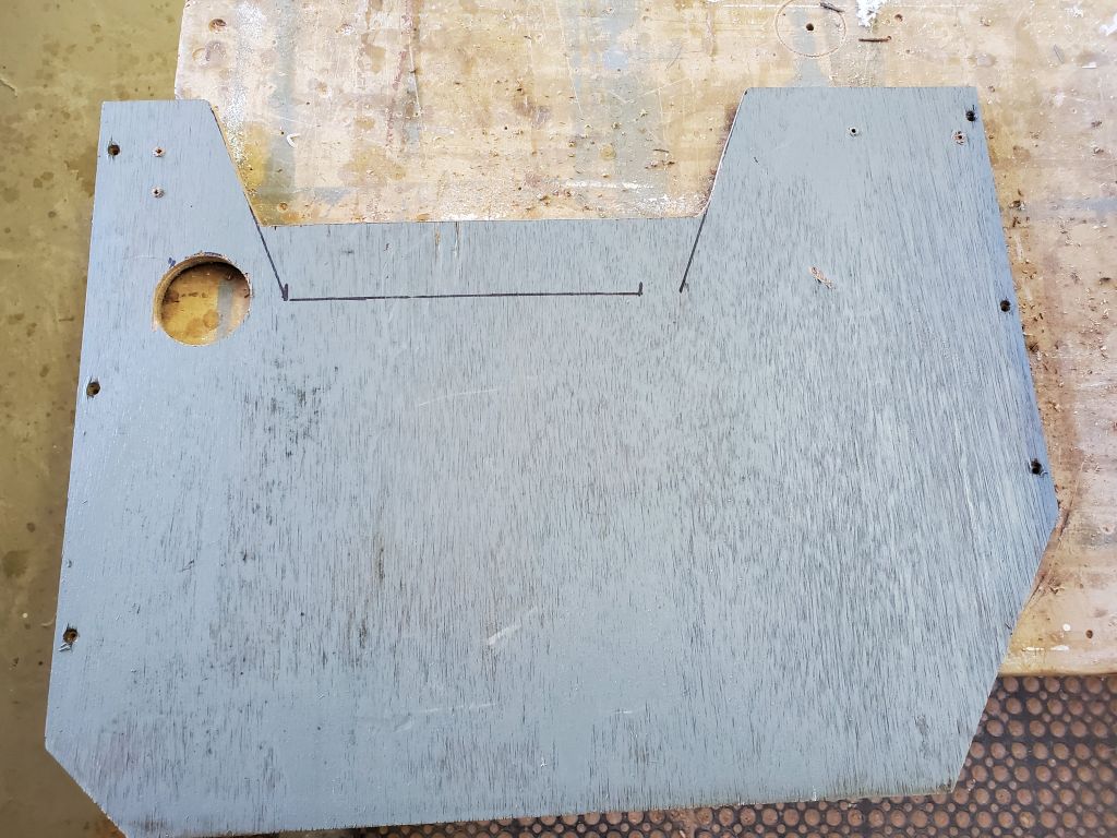
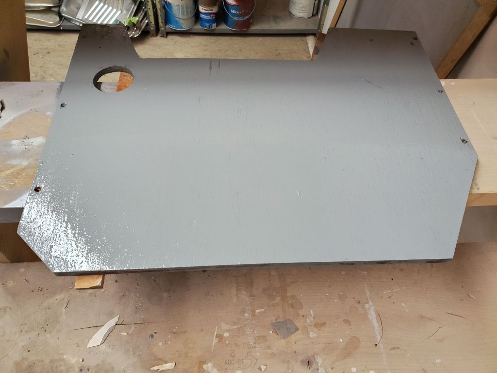
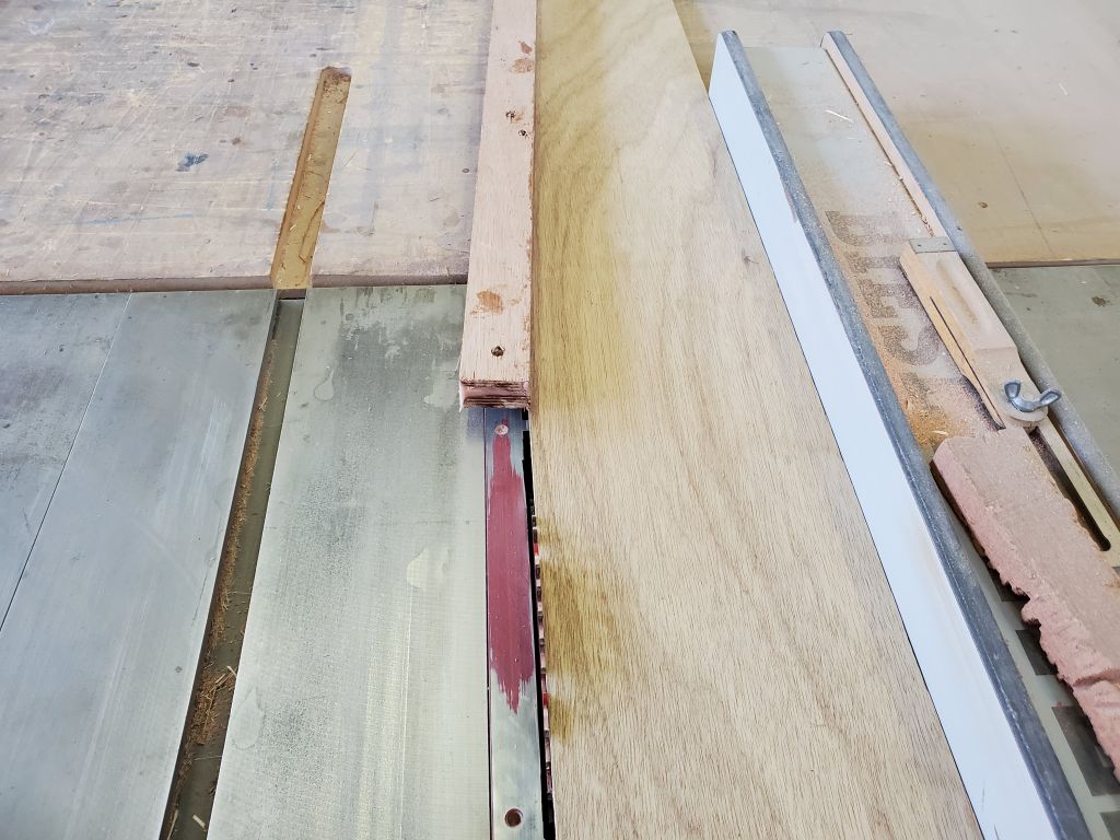
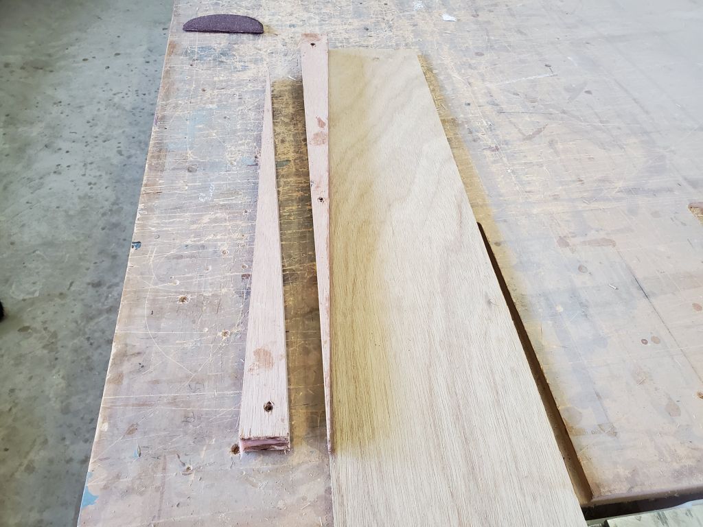
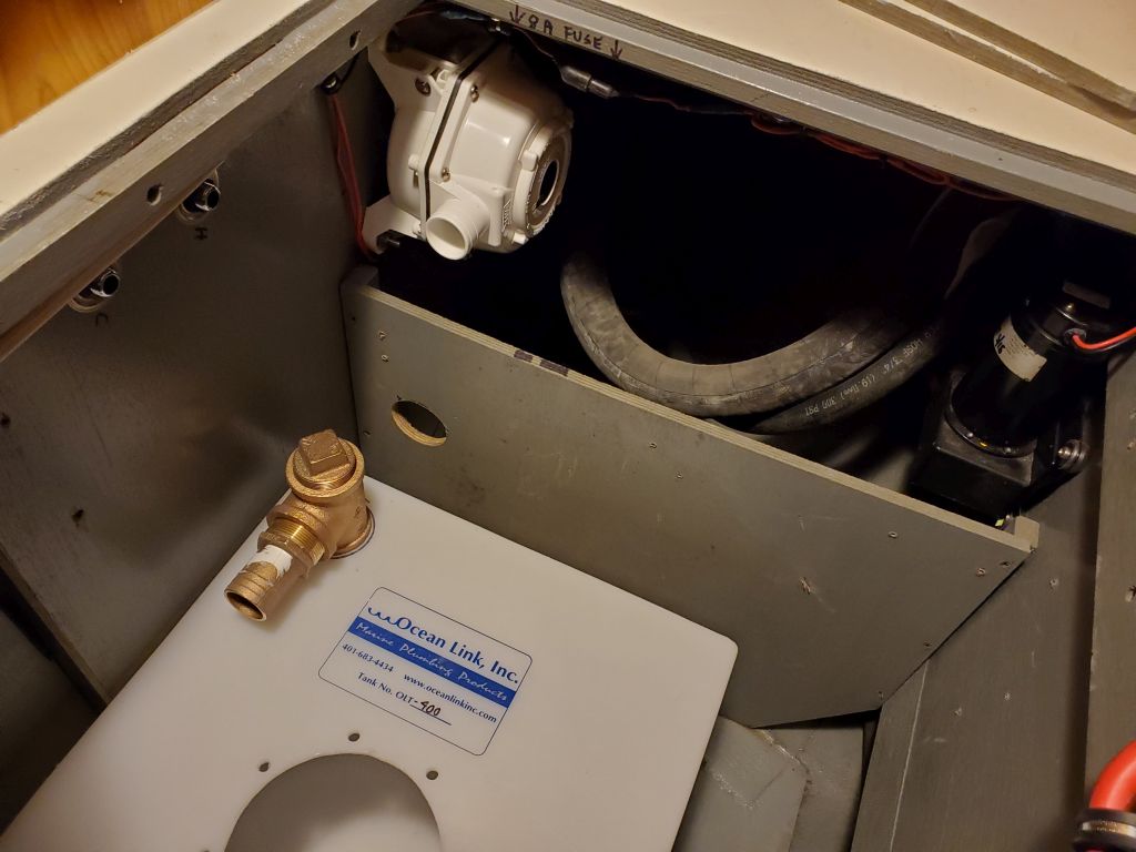
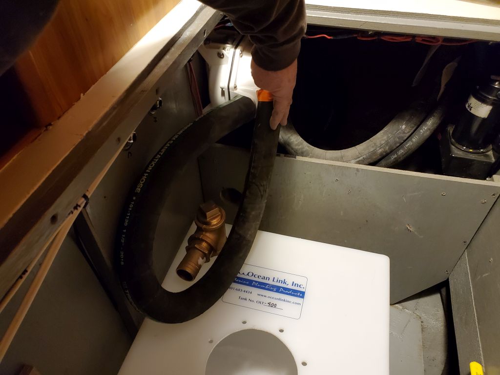
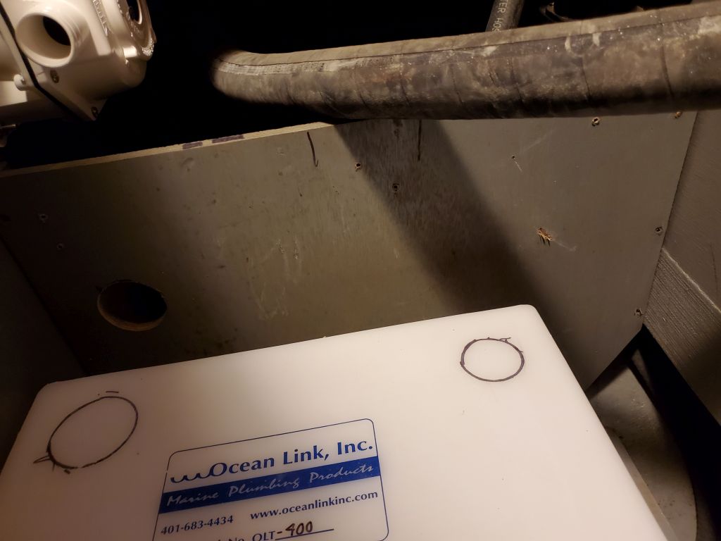
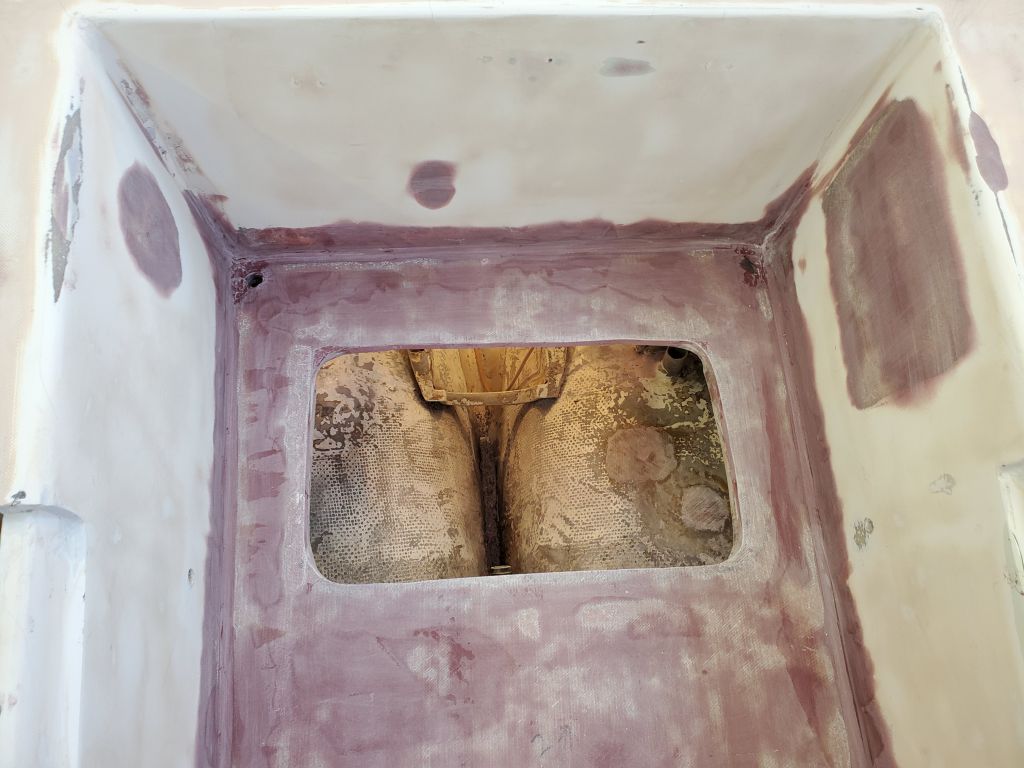
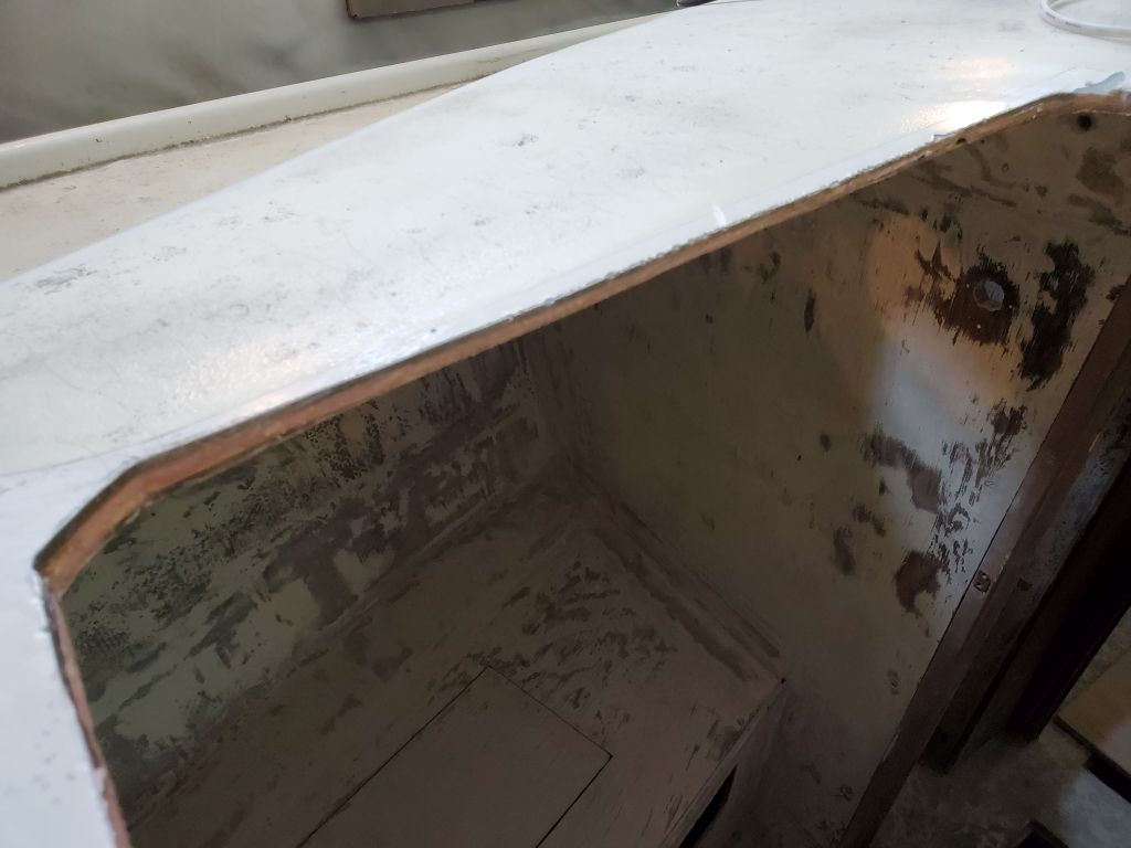
Using some guide marks I’d made up in the boat during a tank test-fit earlier, I made a relief cut in the portside divider from the holding tank compartment, which would allow clear passage of the inlet and vent hoses to the tank. I made the opening larger than it had to be because there was no reason not to, but left the bottom edge higher than the top of the tank so it could possibly receive a cleat to help secure the tank, or to support a shelf above. Afterwards, I painted both sides of the divider to prepare it for reinstallation soon.
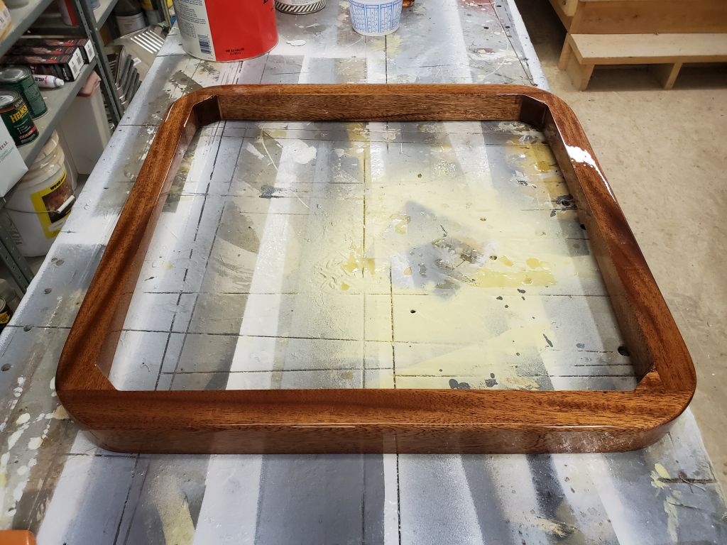
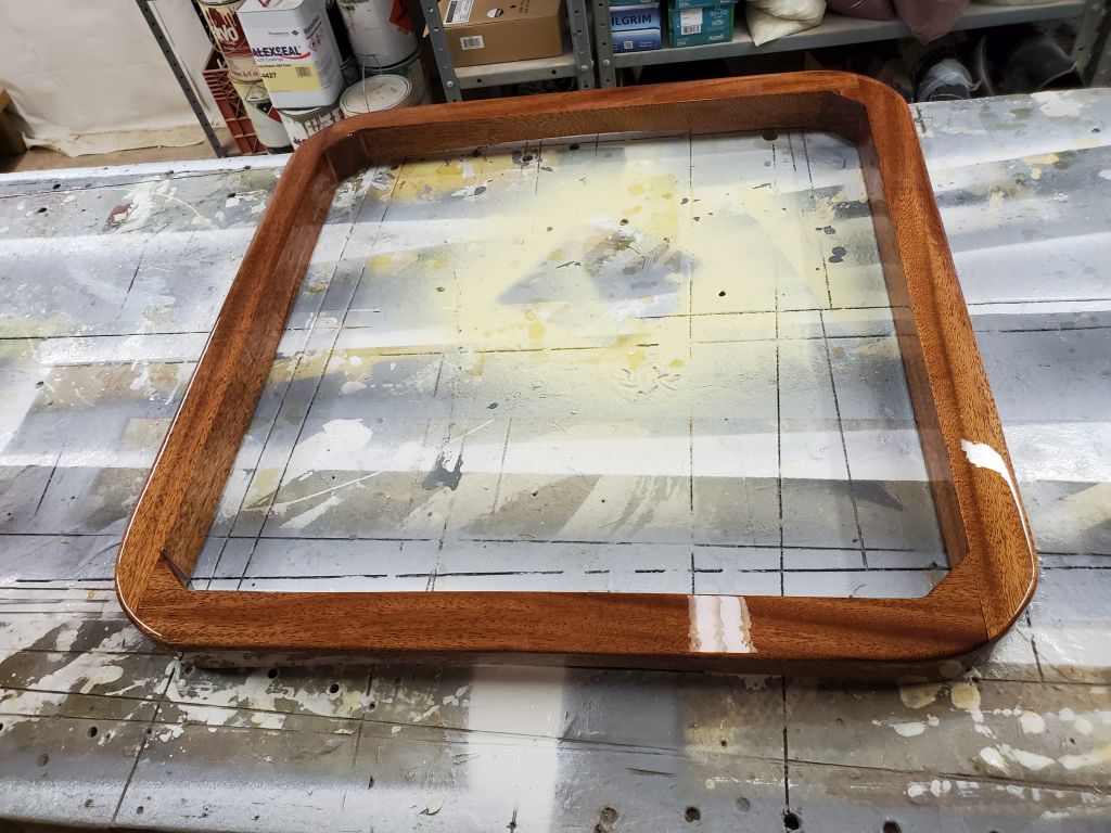
In addition to the large deck box underway for the coachroof, the owner had also requested one in the cockpit, at the aft end, to hold the spare propane tank and whatever else might fit. I was building these one at a time at the moment because I was juggling two projects at the same time, and now was a good opportunity to begin the next box. (There’d be two additional, smaller boxes for the coachroof to come as well.)
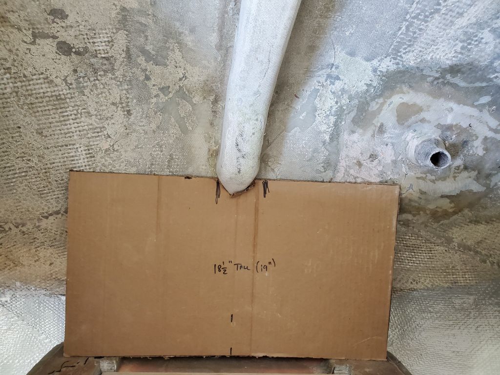
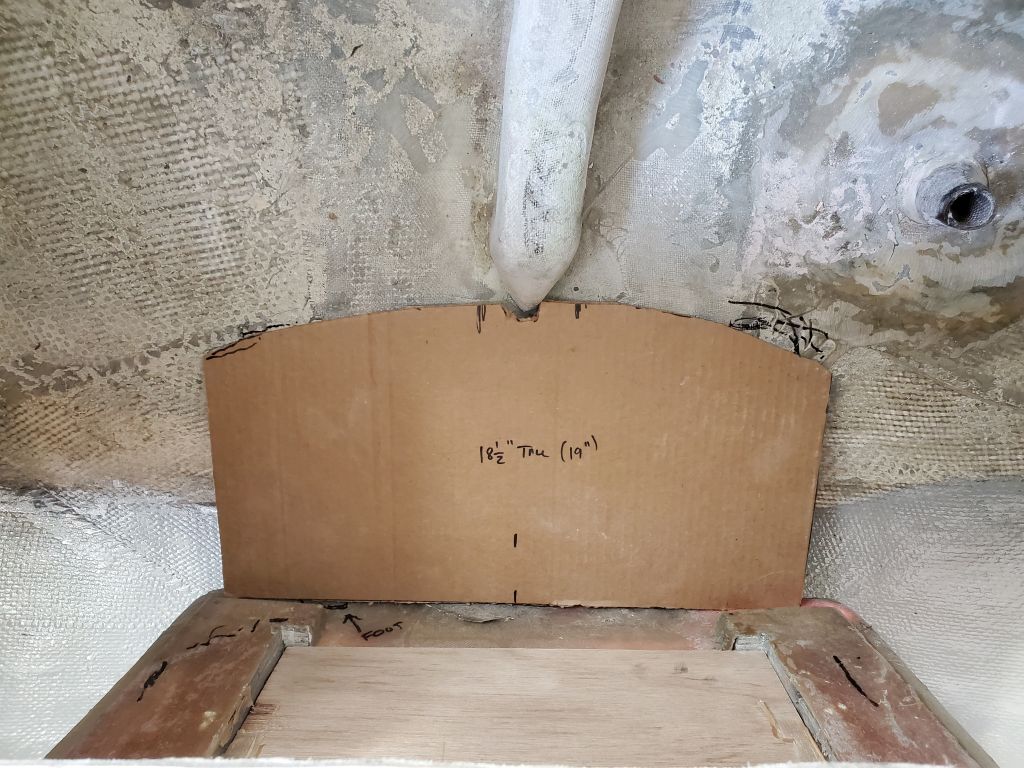
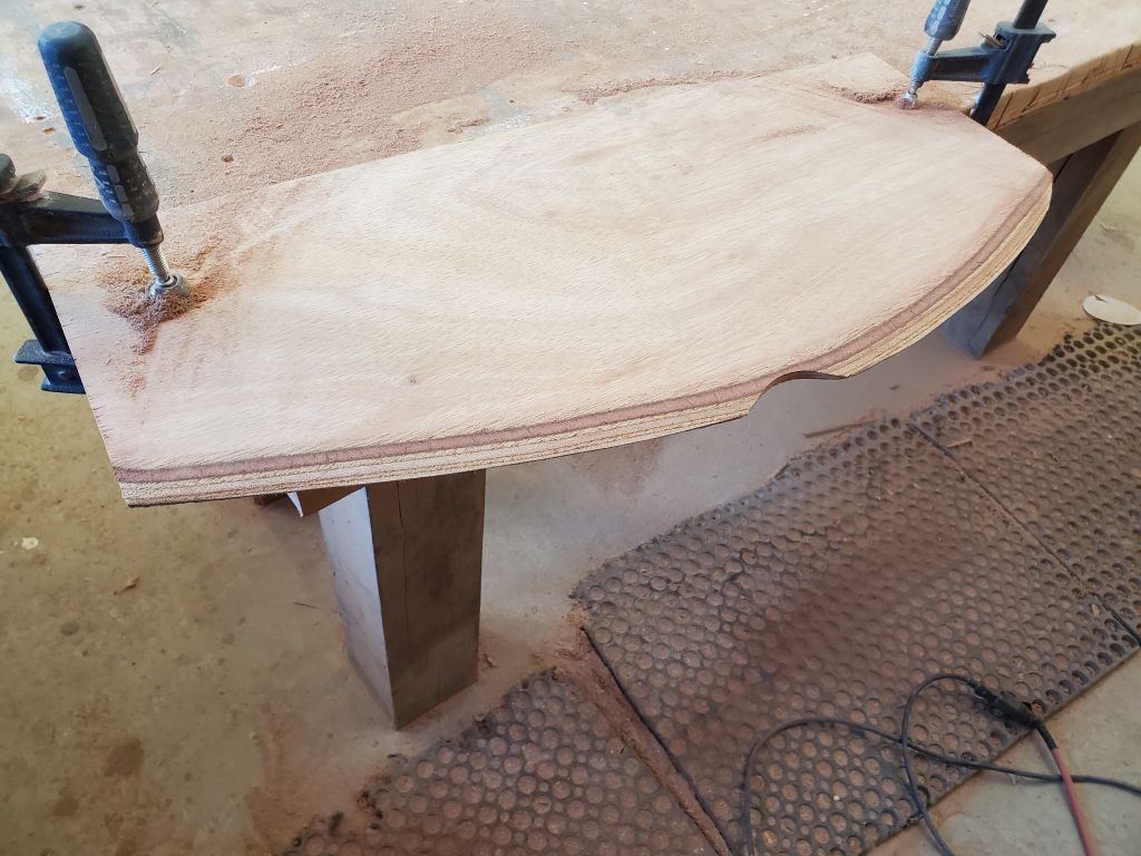
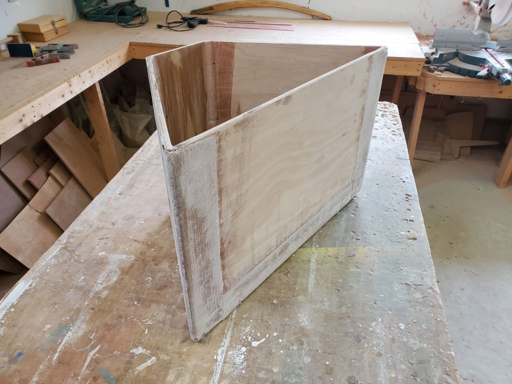
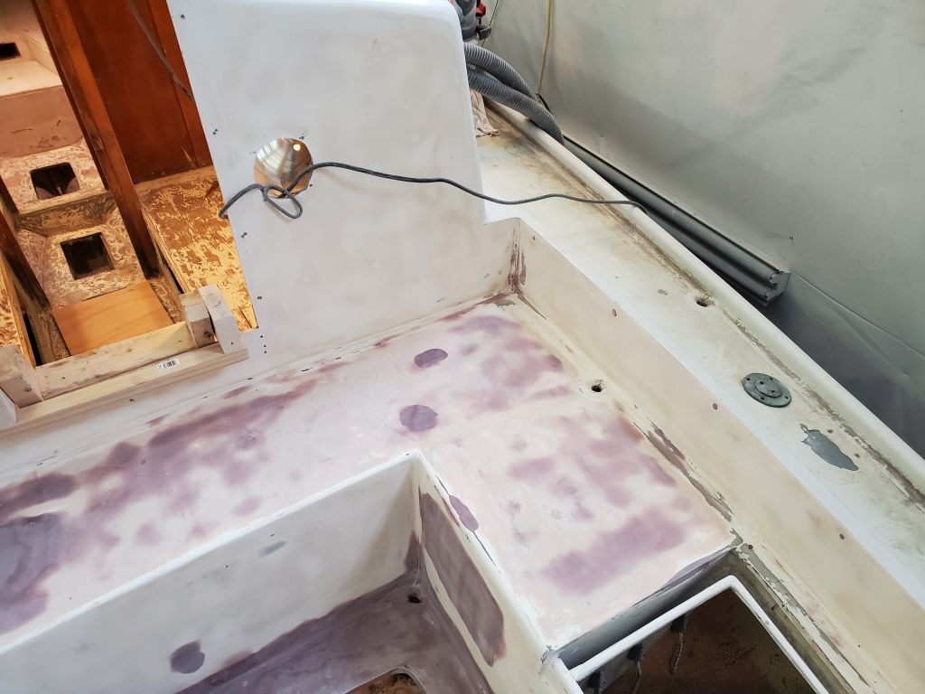
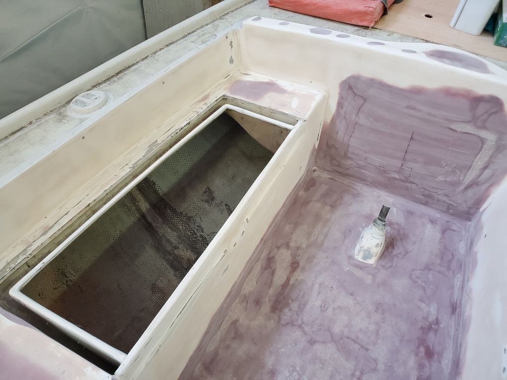
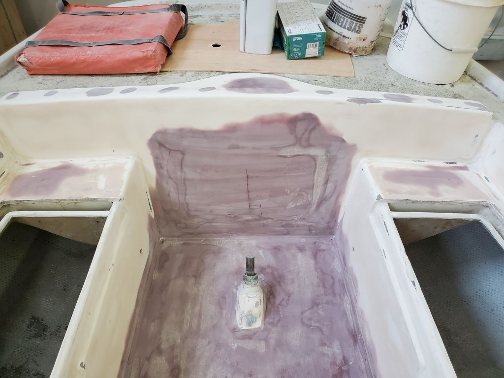
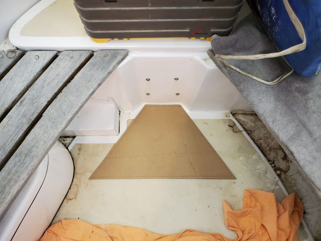
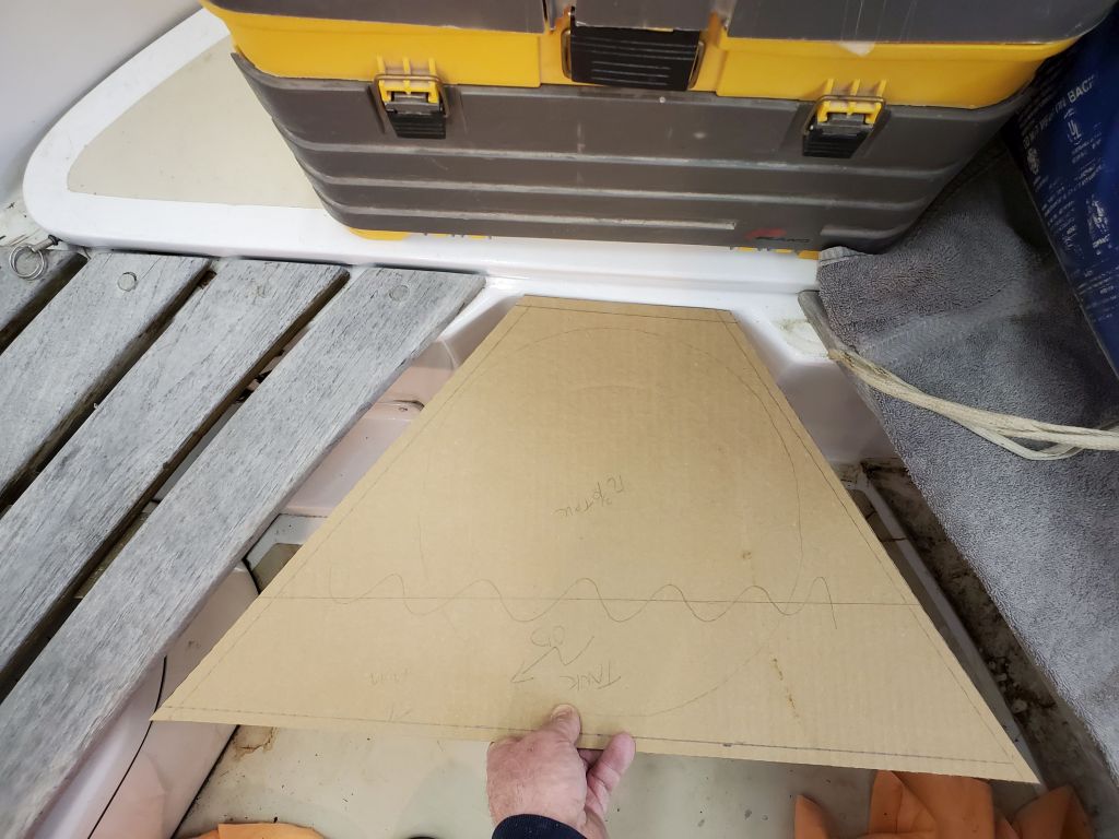
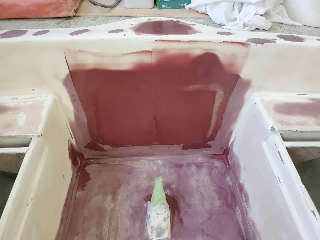
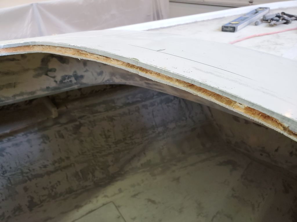
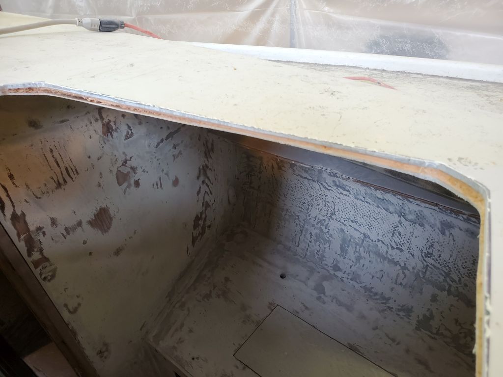
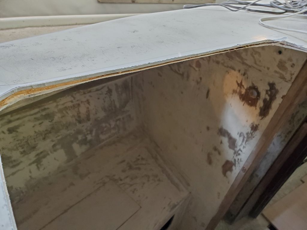
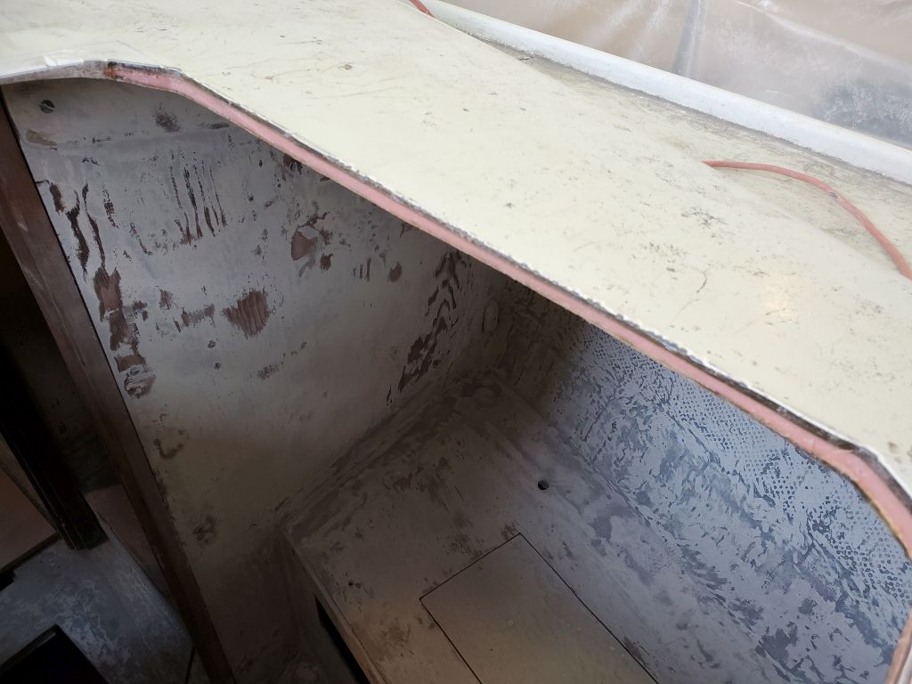
The cockpit in this boat was already small, and with virtually no good storage spaces. The space in which the new box was to fit was at the aft end of the cockpit, which was angled steeply because of the shape of the boat herself. To maximize useful space and make the box fit as well as possible in the cockpit, I planned for it to be angled to fill the available space, and after some measurements started with a cardboard template of the bottom. The new box would be roughly as high as, but not higher than, the adjacent seats on three sides, and the aft end of the box could tuck into the molded recess at the aft end of the cockpit. The small propane tank would fit nicely in the angle at the aft end of the box, and while it would take up the bulk of the room in the box, there’d be space for other small items, and possibly a removable shelf above the tank for additional storage.
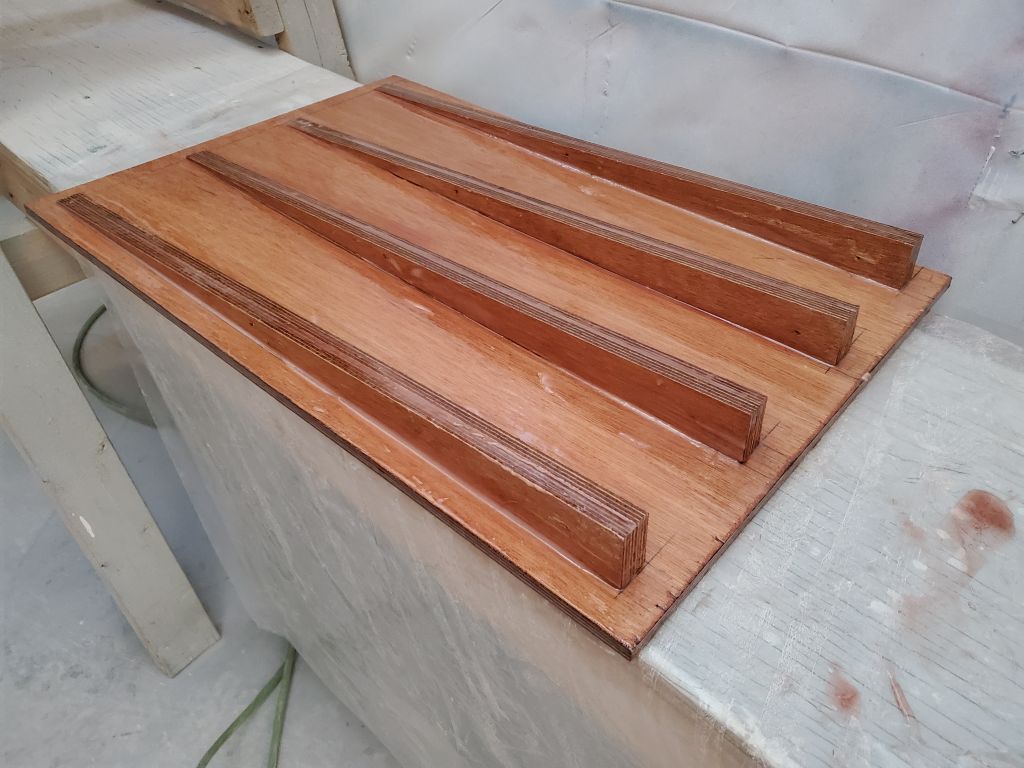
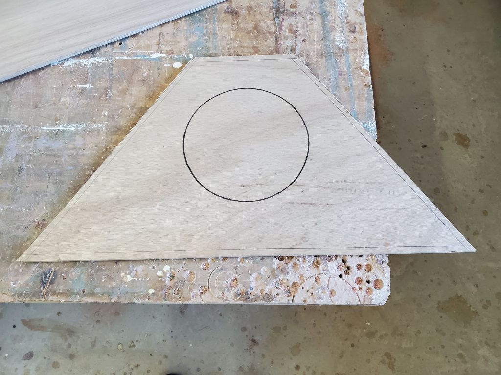
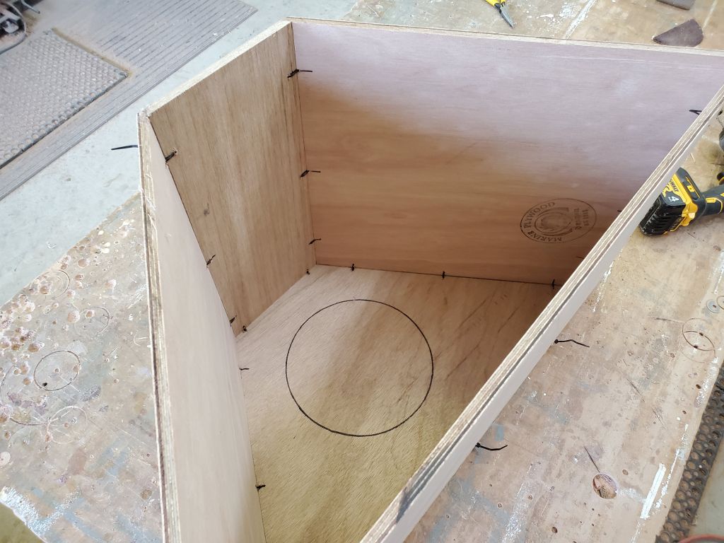
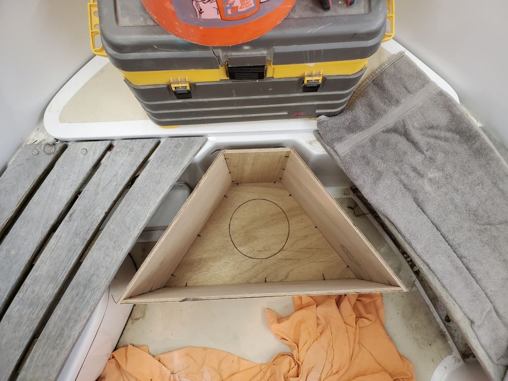
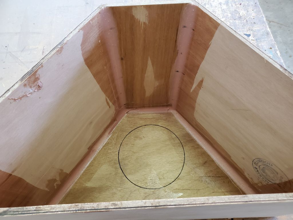
Satisfied with the template, I transferred it to some 9mm plywood and cut out the base, along with a slightly larger version that would eventually form the lid for the box (I set that aside for now). Using some plywood as temporary stand-ins for the sides and back, I located the propane tank on the base and marked the circle at the bottom of the tank on the plywood, for later use in attaching some cleats that would help secure the tank within. That was for later.
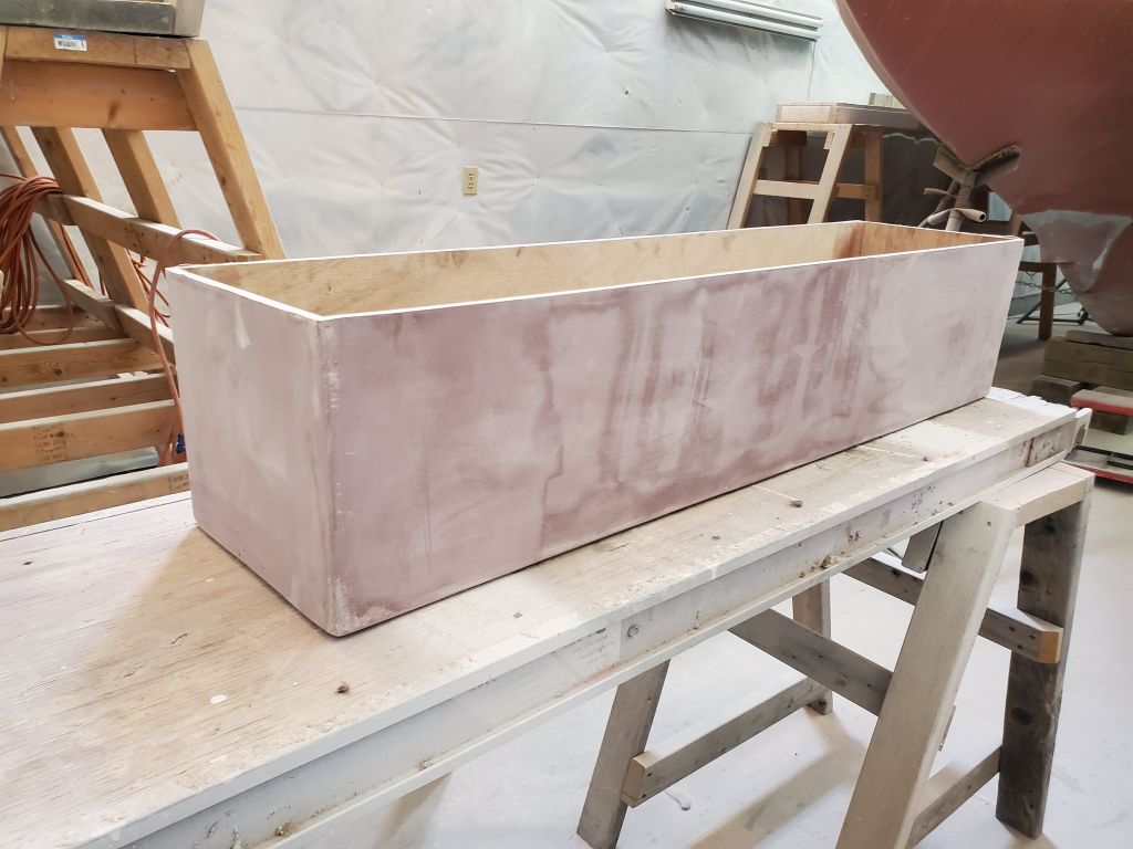
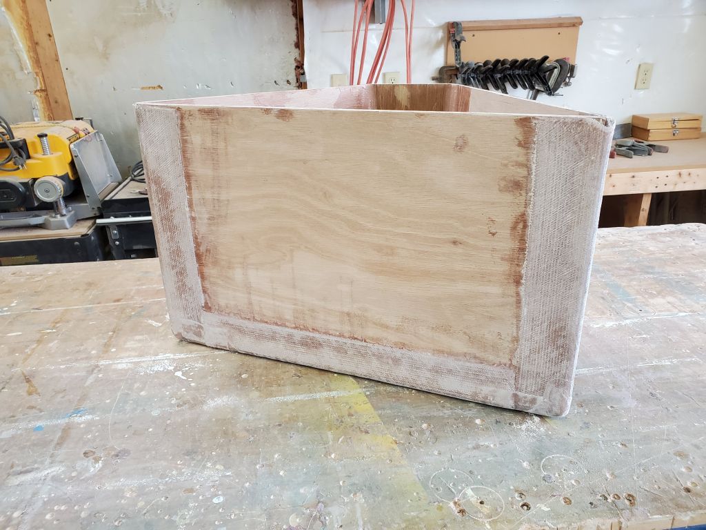
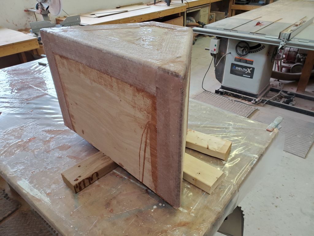
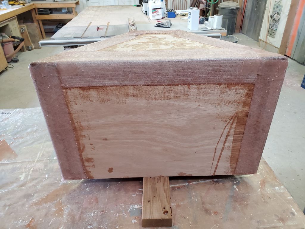
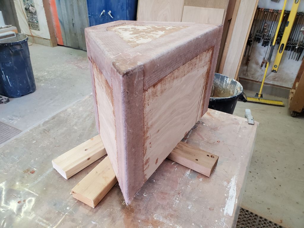
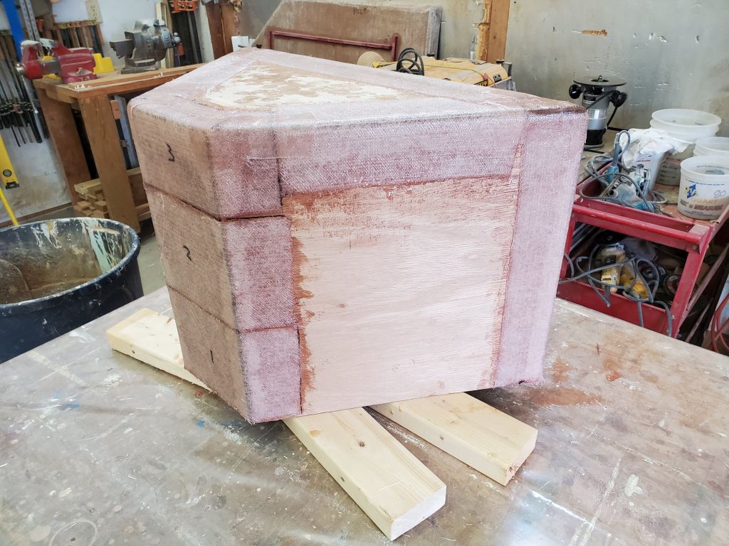
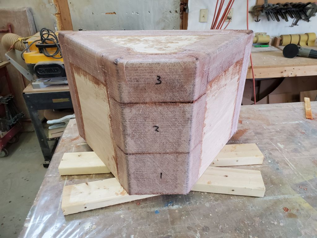
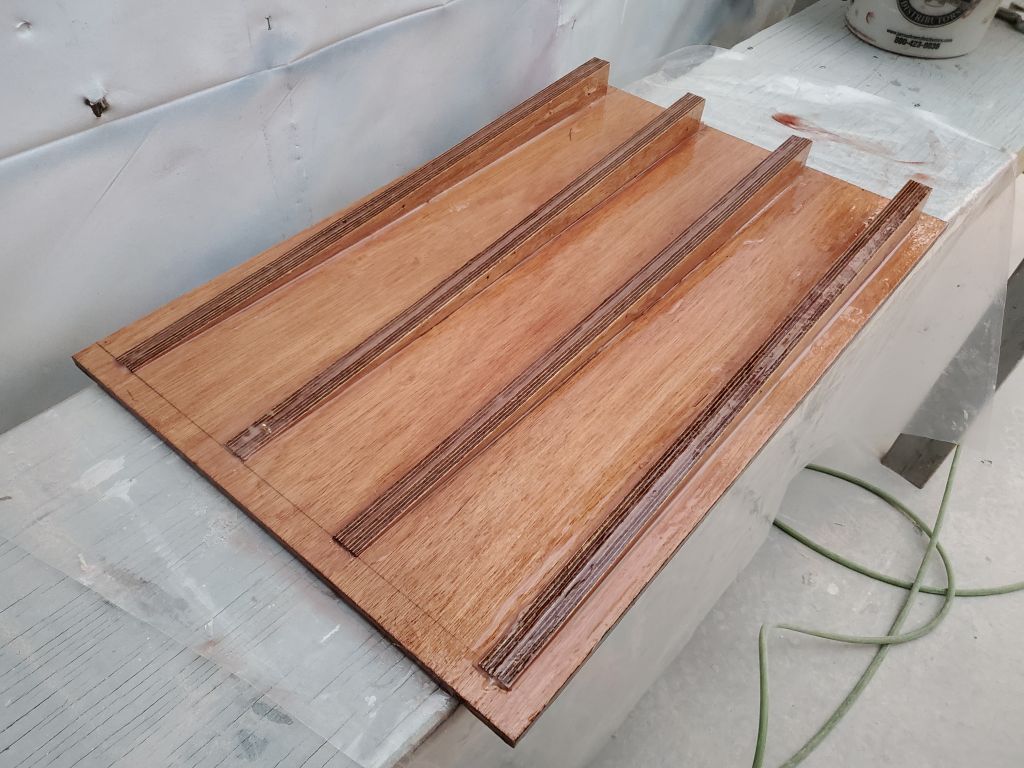
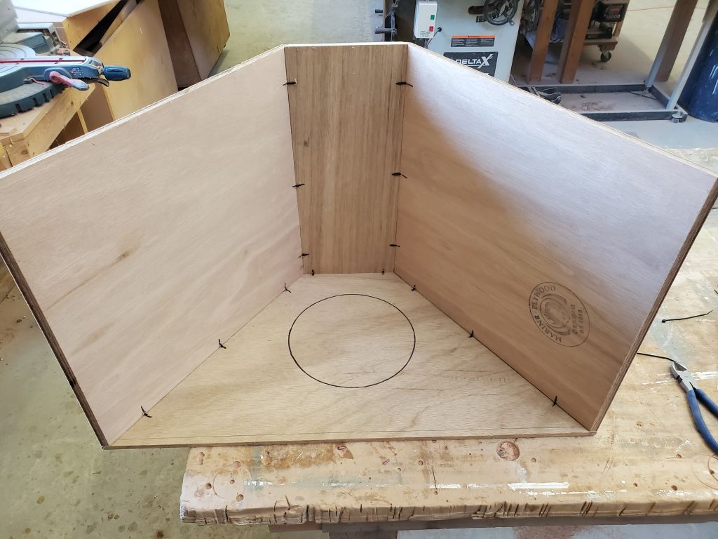
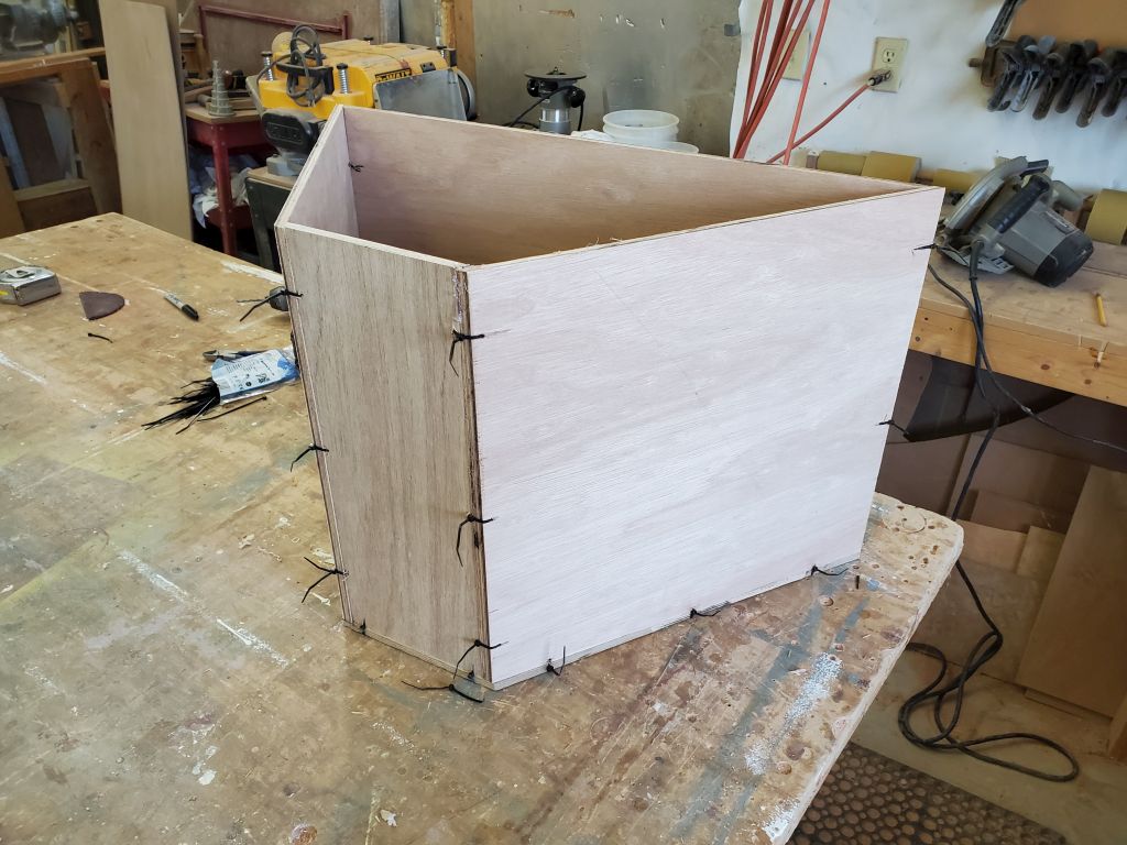
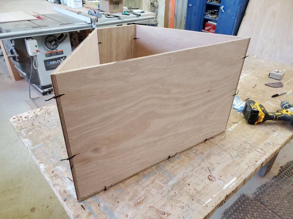
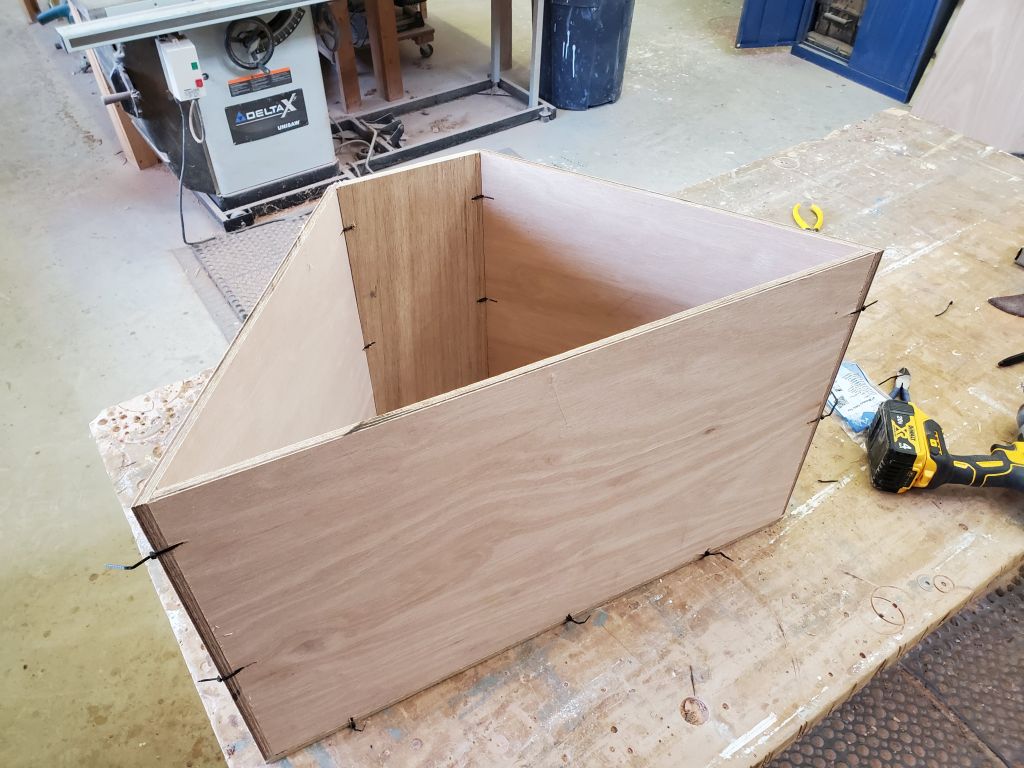
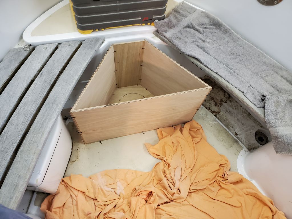
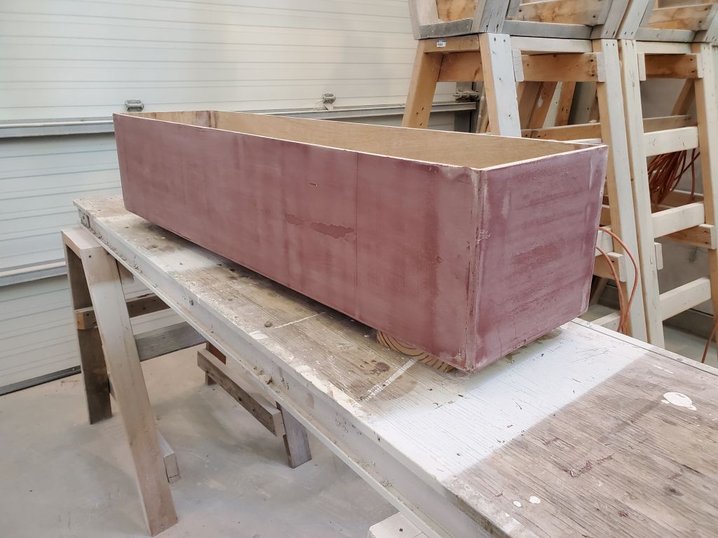
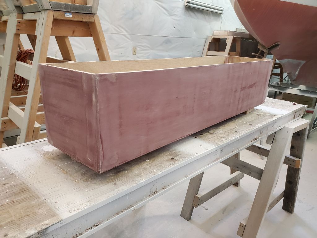
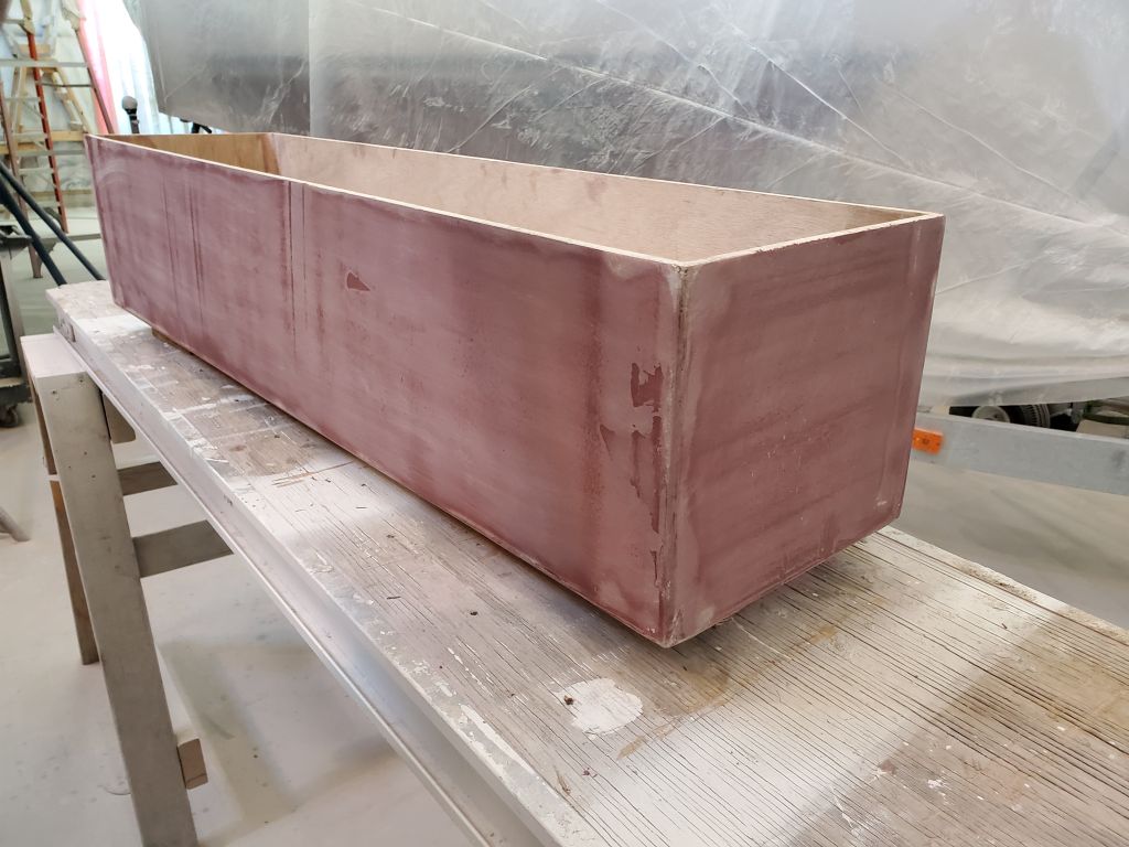
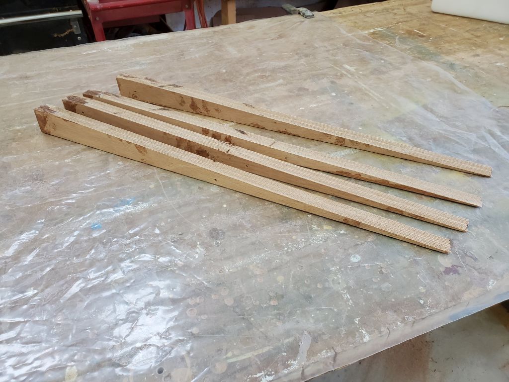
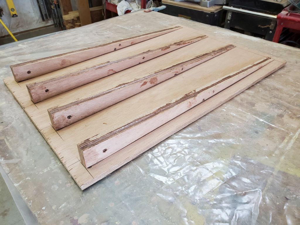
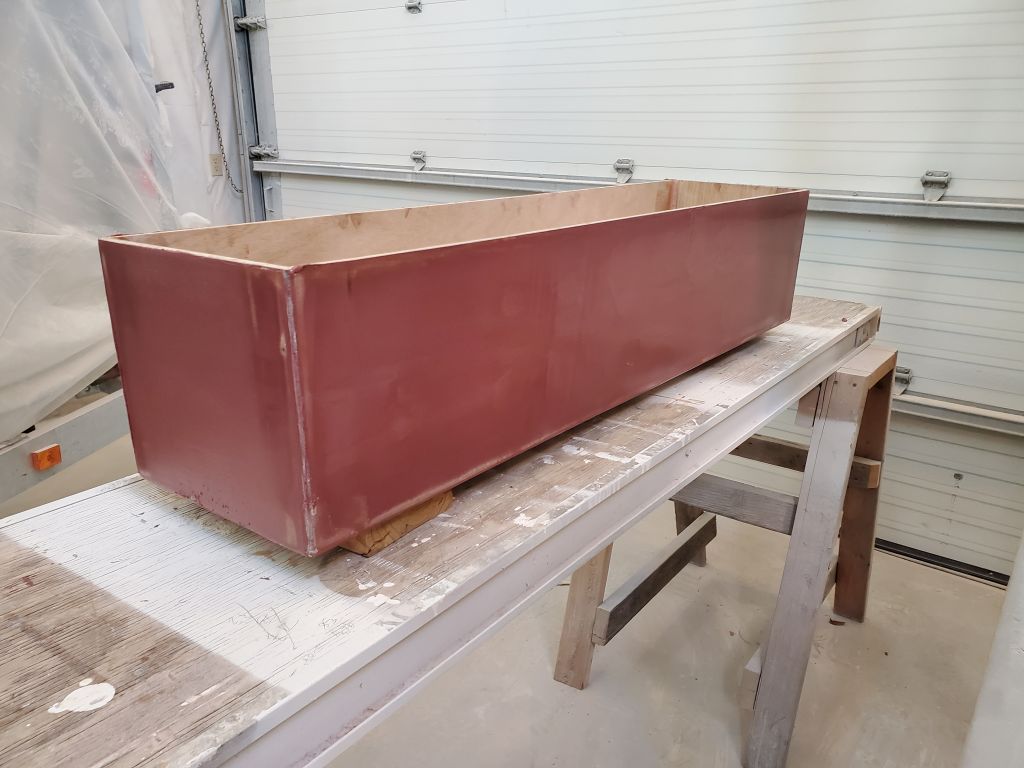
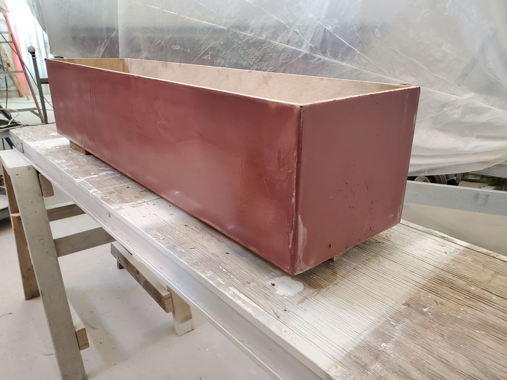
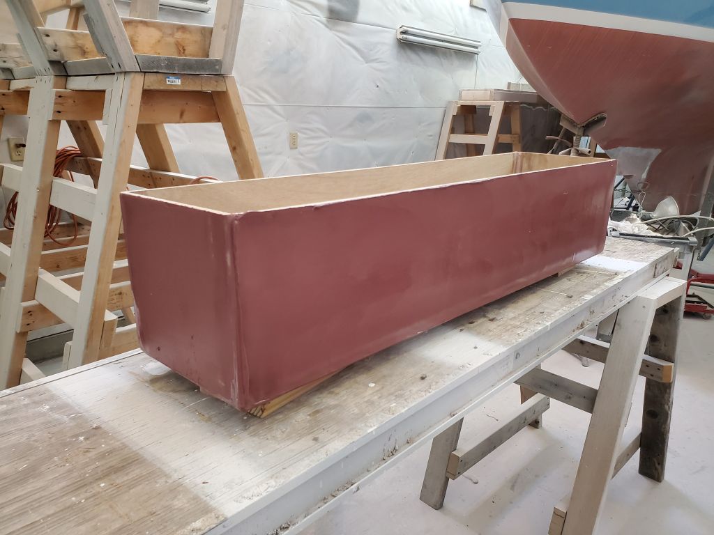
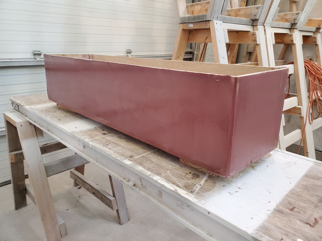
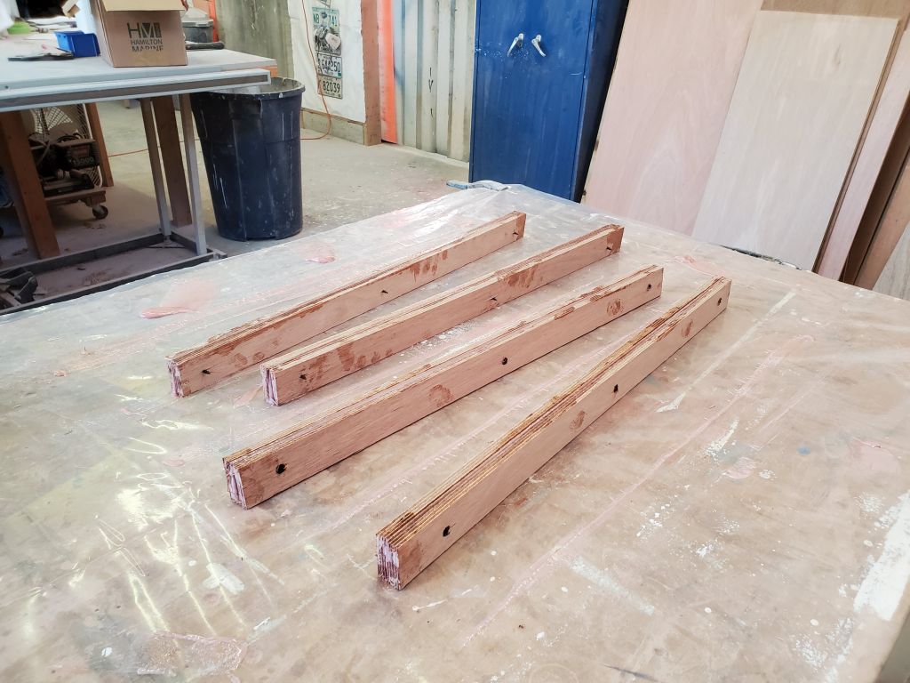
Then, I made up the four sides of the box. Allowing for 3/8″ high “feet” beneath the box (to keep it clear of the deck), and the 3/8″ (9mm) top of the box, and erring on the short side, the side pieces ended up 15-3/4″ tall, all of which would ultimately fit within the 17″ high maximum space (the height of the nearby seats). I secured the pieces of the box together as I went with small holes through which I tightened zip ties.
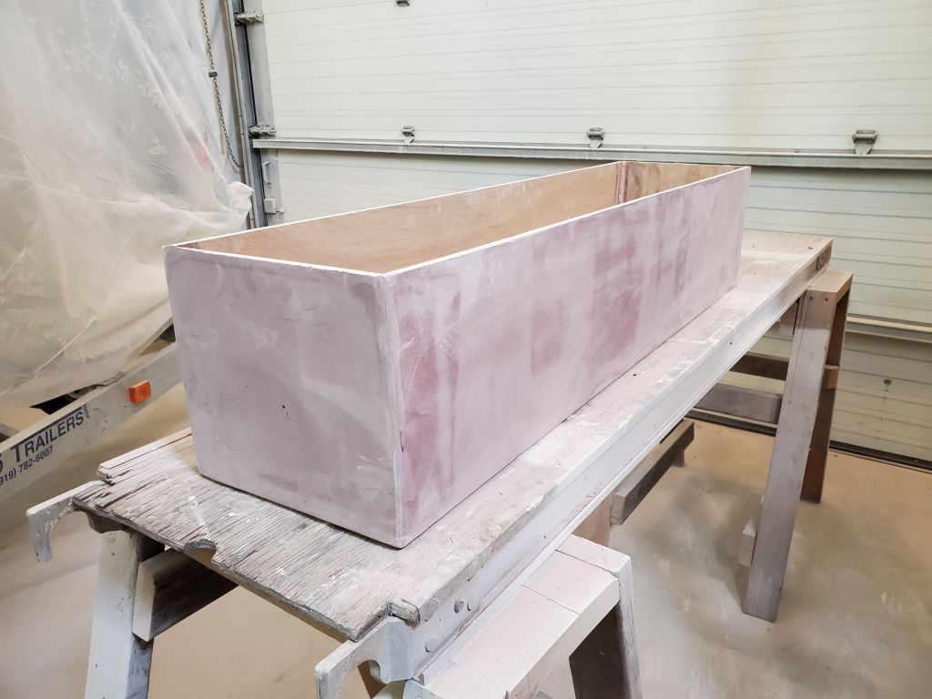
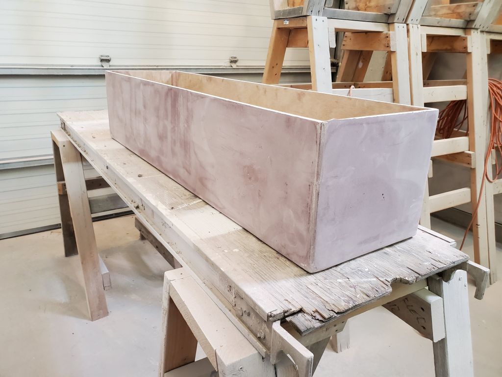
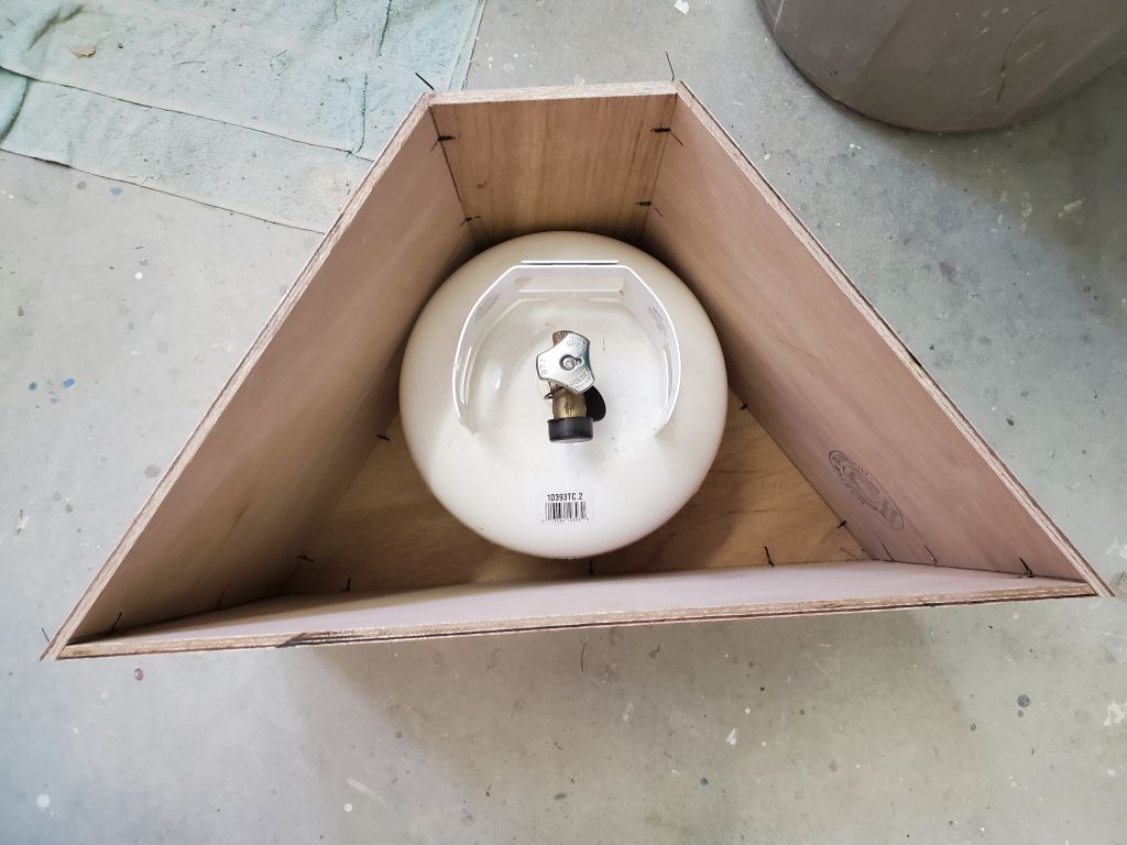
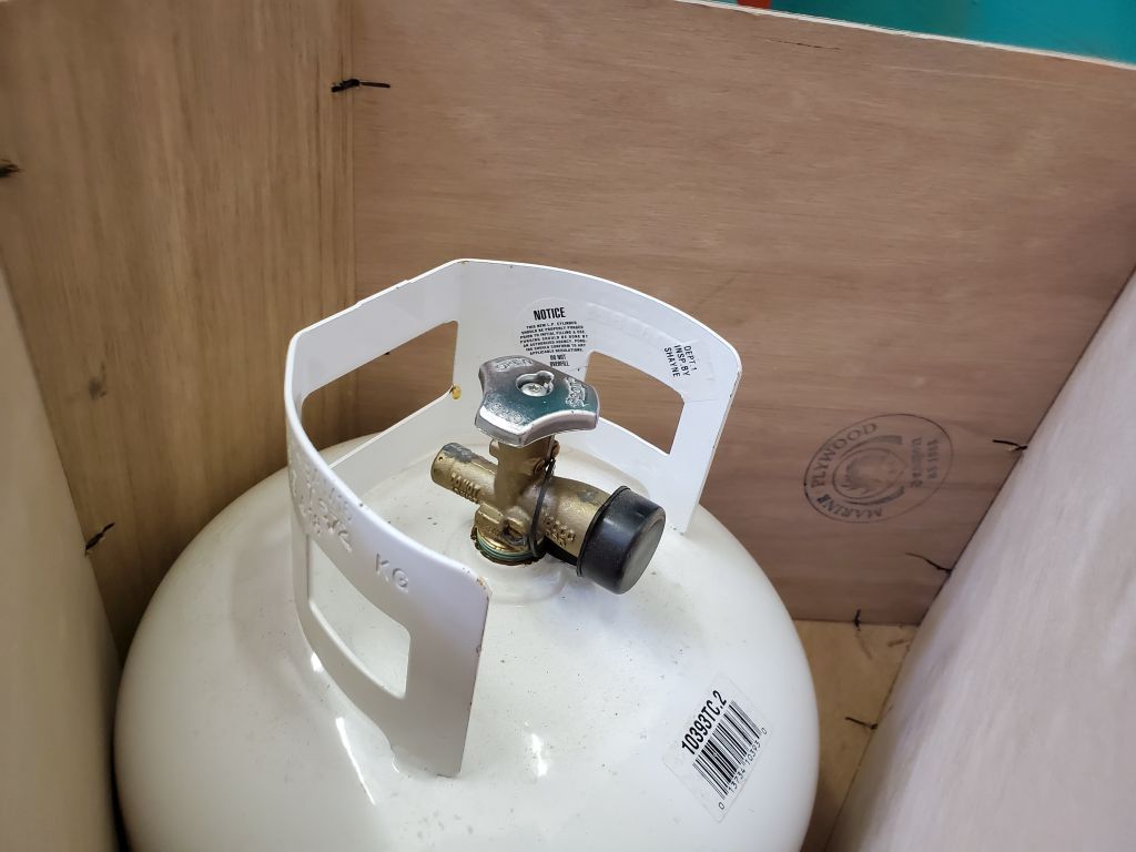
Now I test-fit the tank in the box, showing a roughly 4-5″ space above the top of the tank for an additional shelf. Then I checked the fit of the box in the cockpit. The floor space the box used up was not particularly valuable, and in any event the owner had kept the spare tank there in past years, covered with an overturned bucket, so this was only making better and cleaner use of the already spoken-for space.
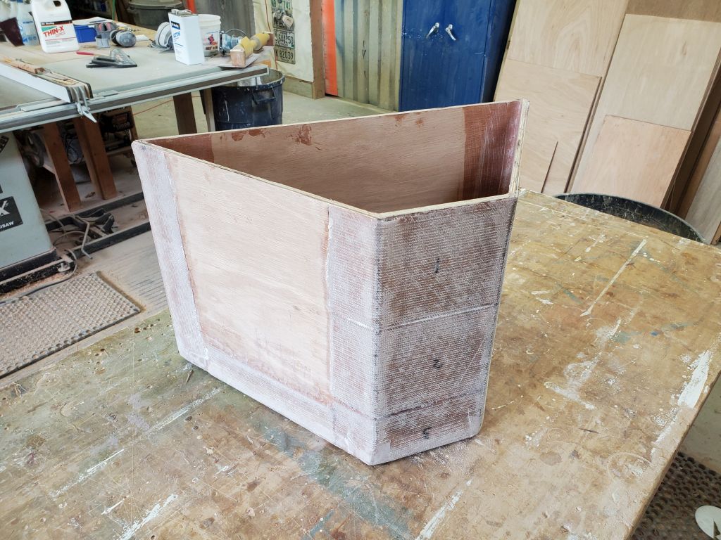
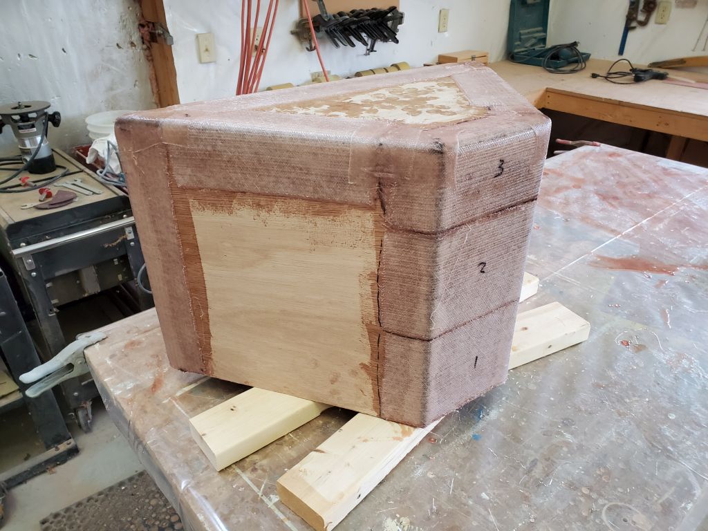
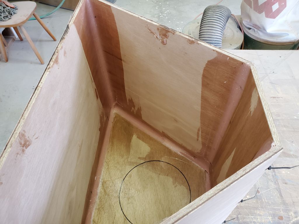
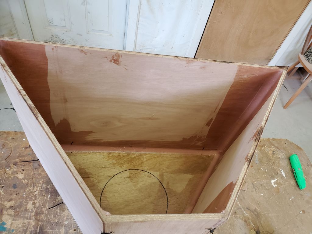
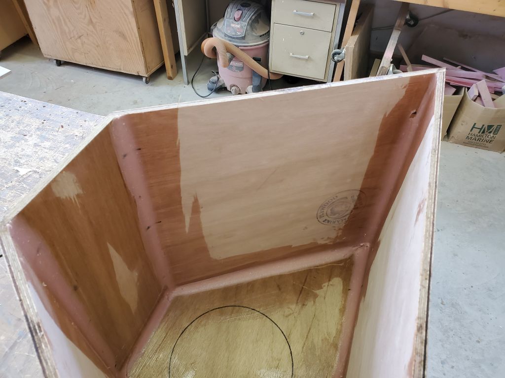
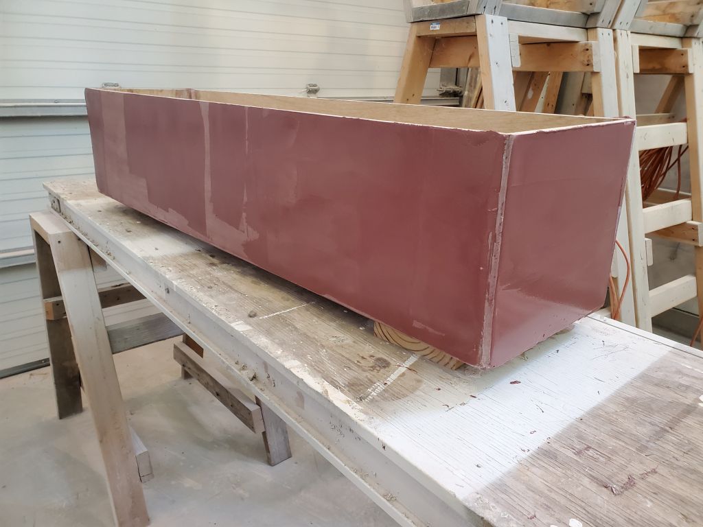
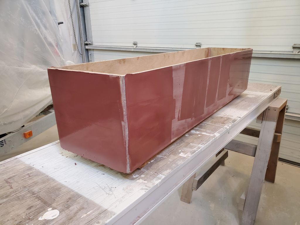
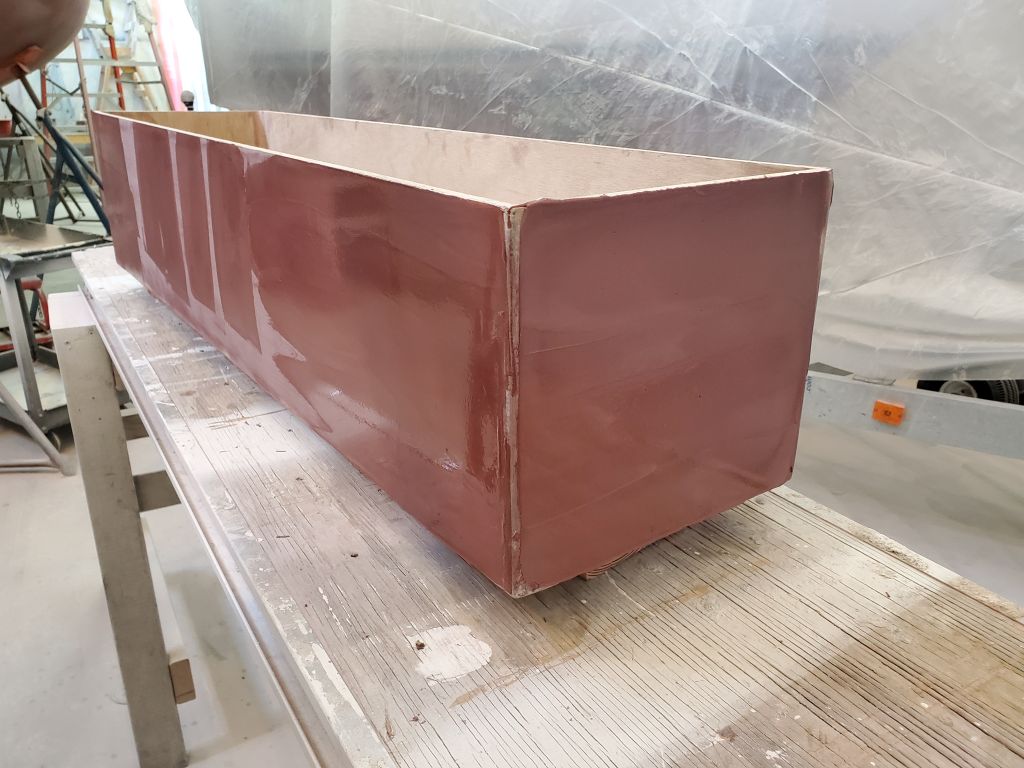
With the box dry-assembled, I installed epoxy fillets on the insides of the box over all the seams. These would hold the box together and reinforce the joints along with the fiberglass tabbing I’d later install on the outside.
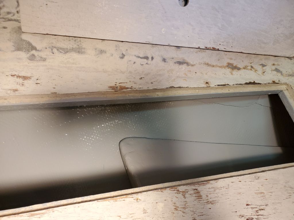
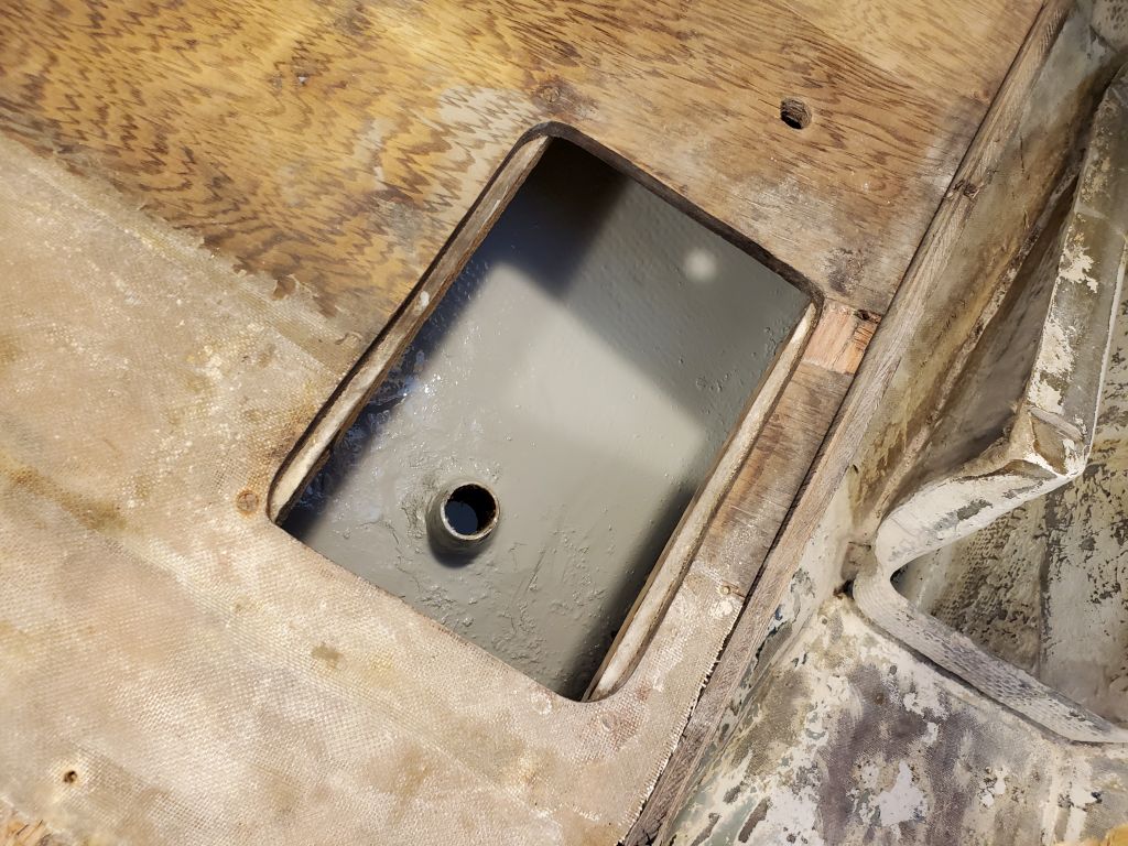
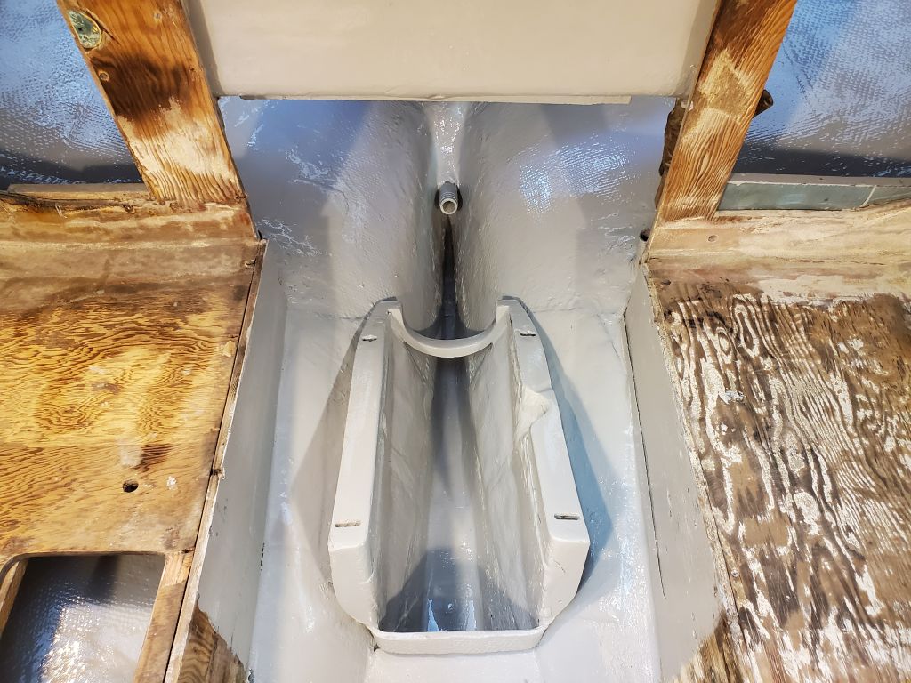
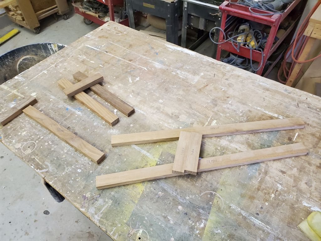
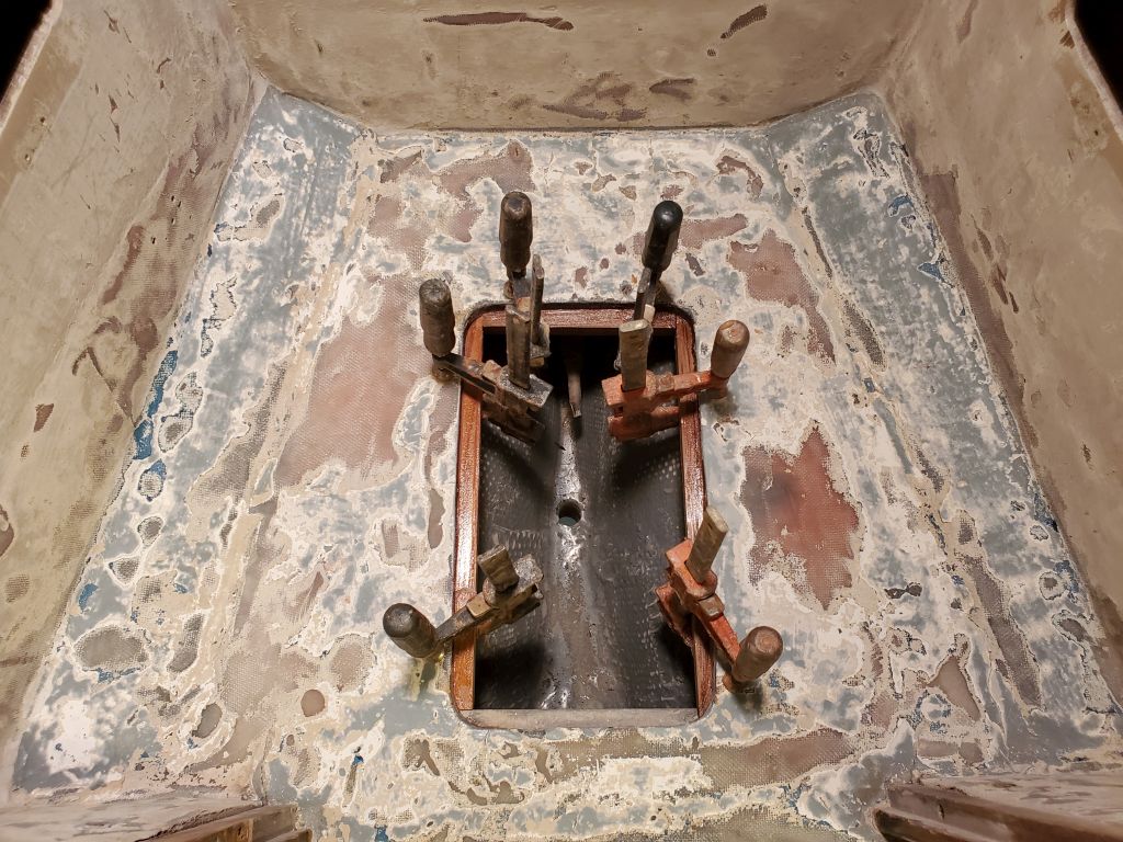
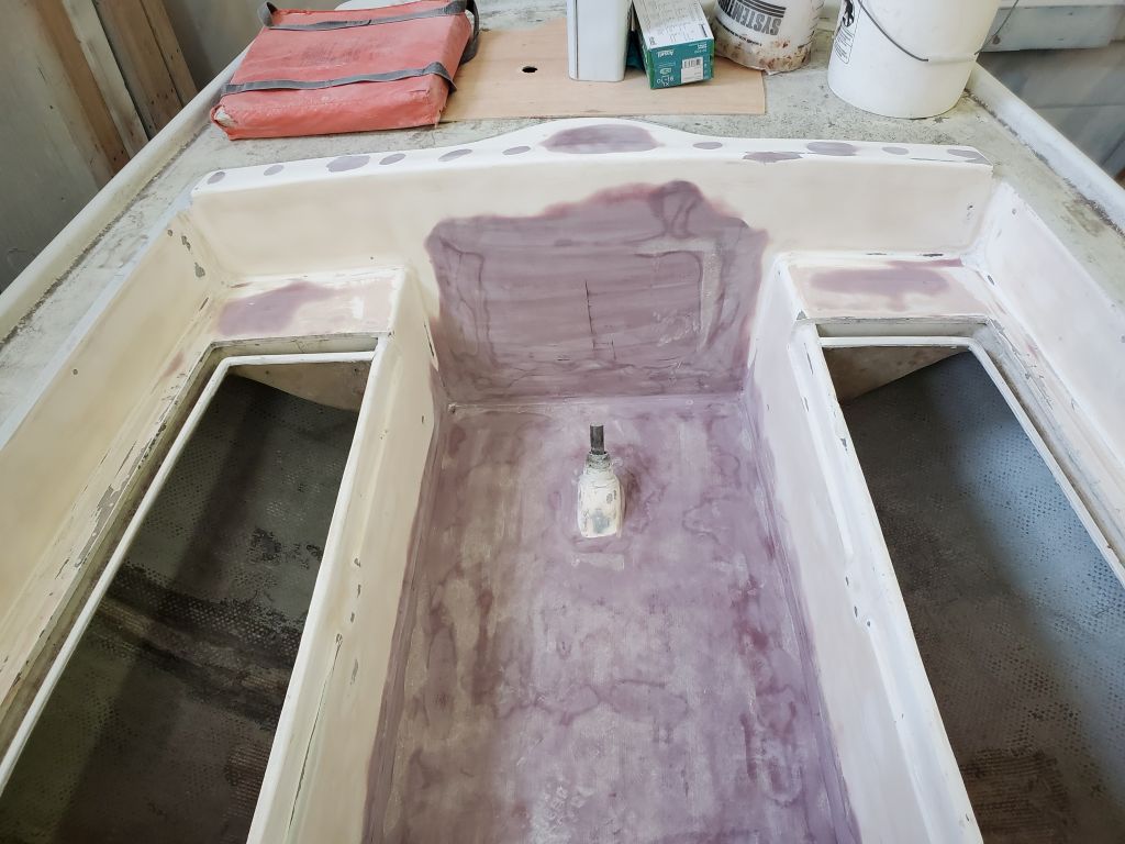
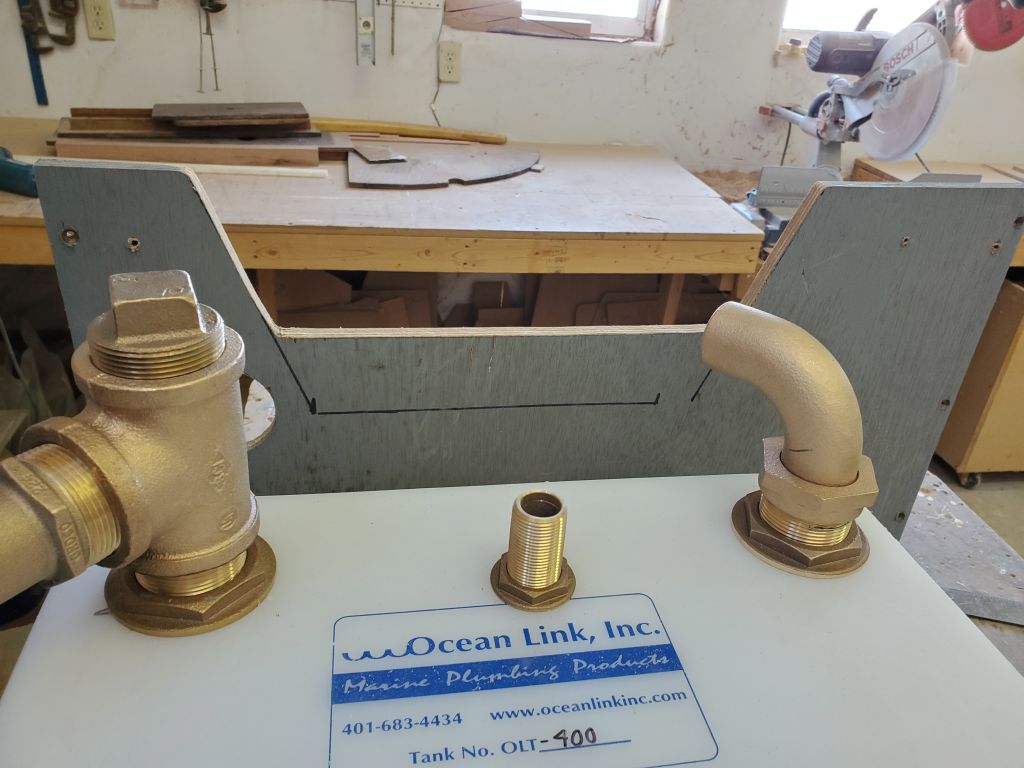
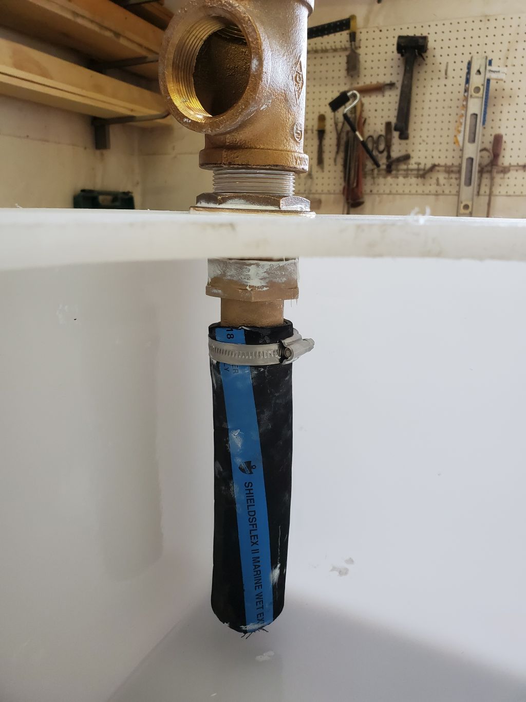
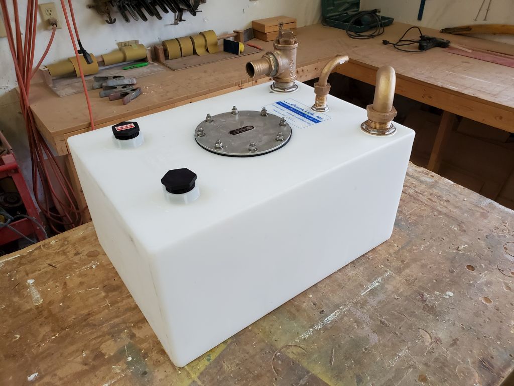
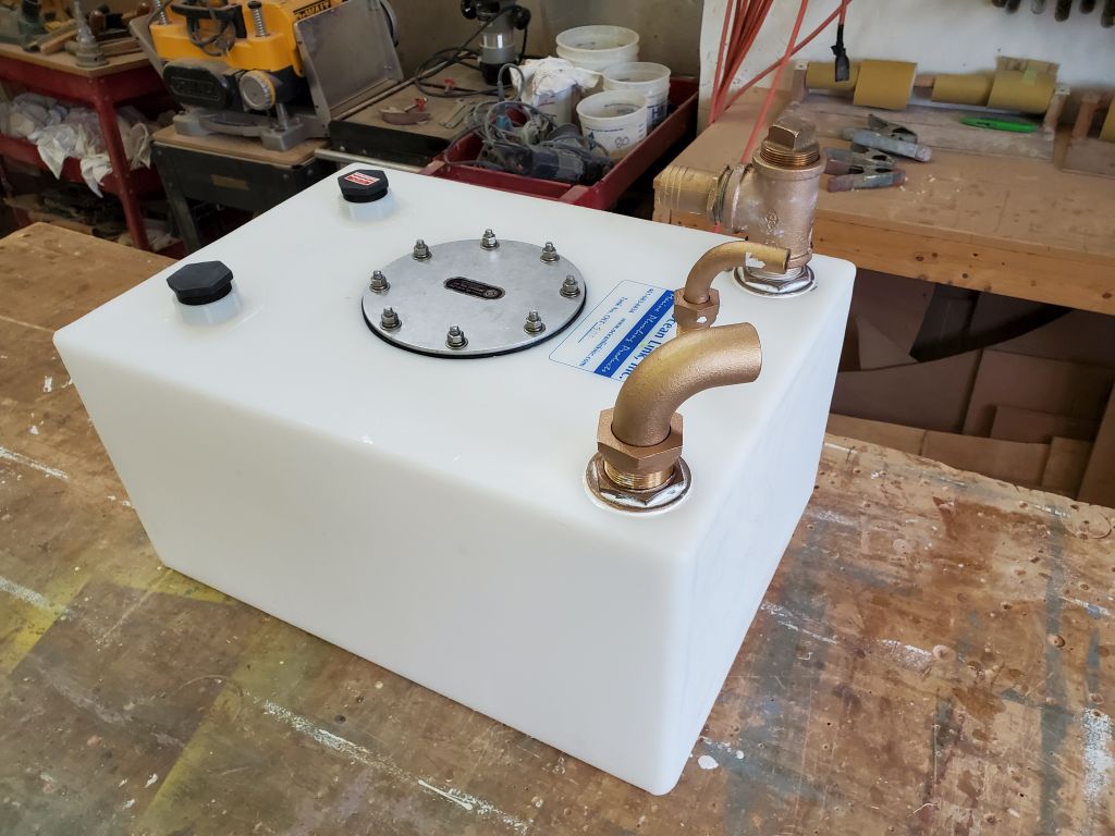
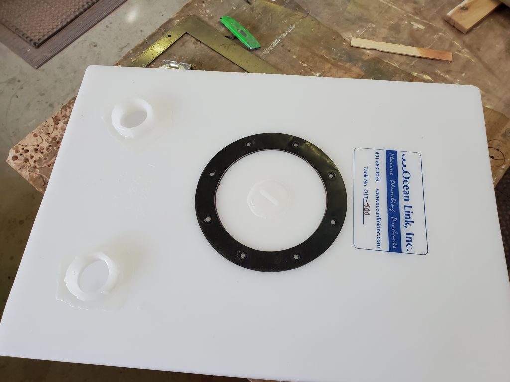
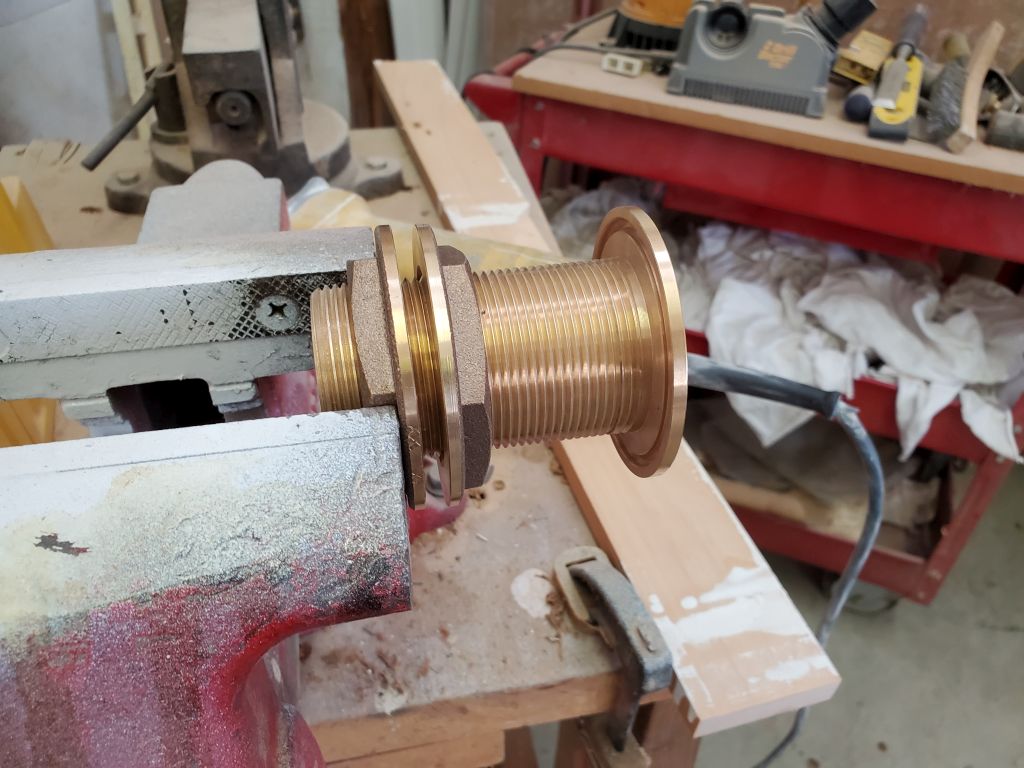
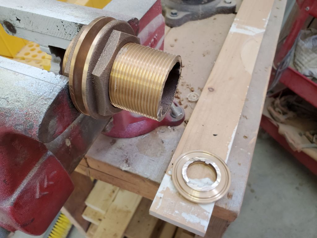
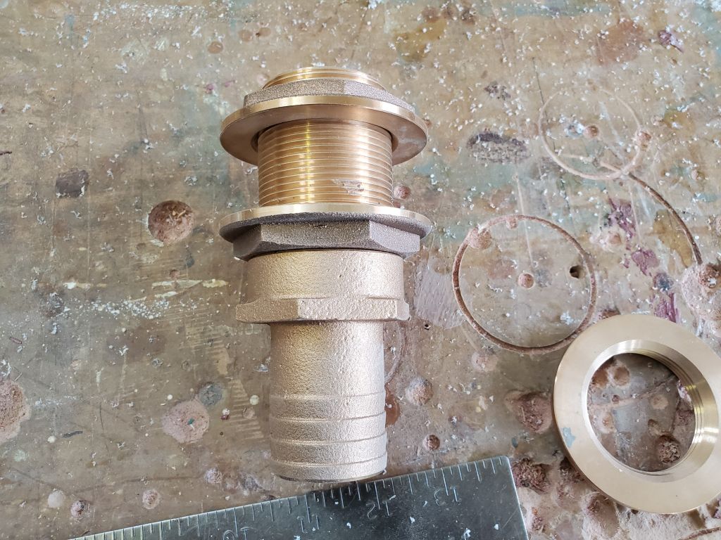
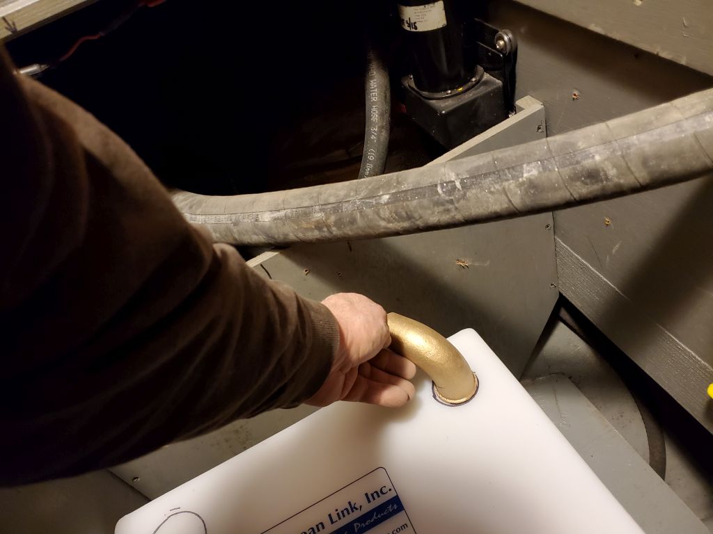
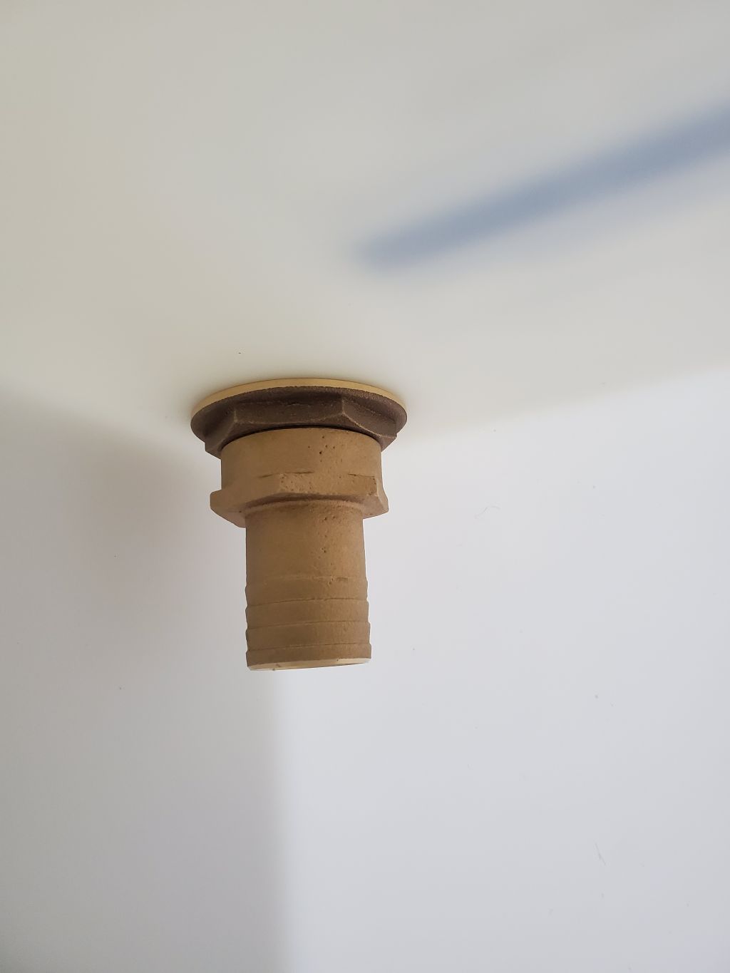
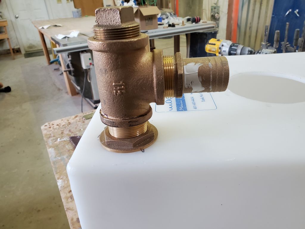
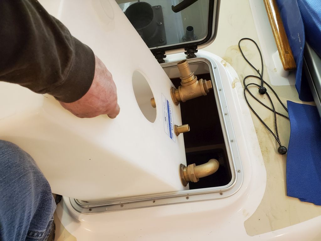
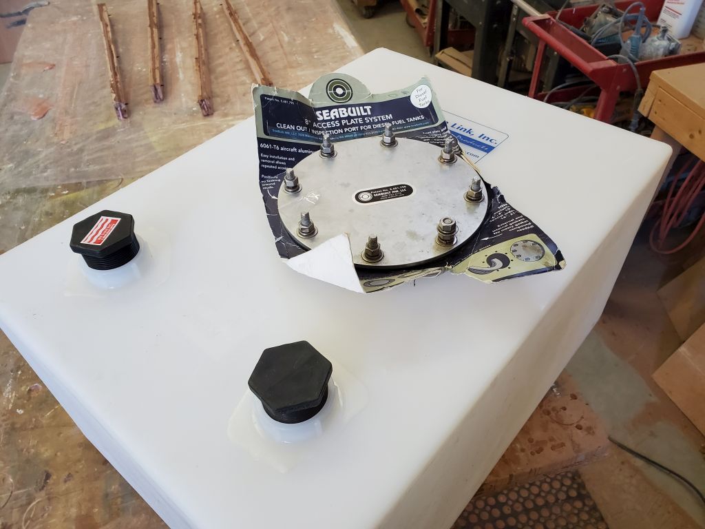
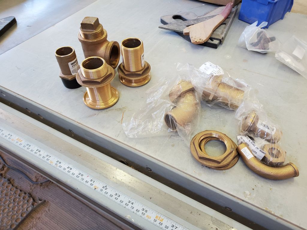
I thought I’d finish up work for the day by permanently installing the fittings in the new holding tank. Of course this ended up being a tougher job than I’d expected, and harder than it had been doing various dry-fits, but I got it done and was happy to have it so. I started by making up the diptube for the discharge, using trial and error to eventually get a length of hose (with bottom cut at an angle) to just about reach the bottom of the tank.
I thought I’d be able to put this hose on the internal hose barb once the main fittings were in place, so I applied 4200 sealant to the bronze discharge fittings and installed them through the tank, only to find that getting the hose on after the fact was impossible thanks to the right fit over the barb and the more-limited-than-you’d-think-it-would-be arm and hand access/dexterity through the inspection port and to the corner of the tank, so I had to remove the threaded barb fitting and put the hose on outside the tank. Then, I couldn’t get the threads started again–once more, a simple task when dry-fitting, but somehow impossible once the sticky stuff was in play and suddenly the whole thing mattered.
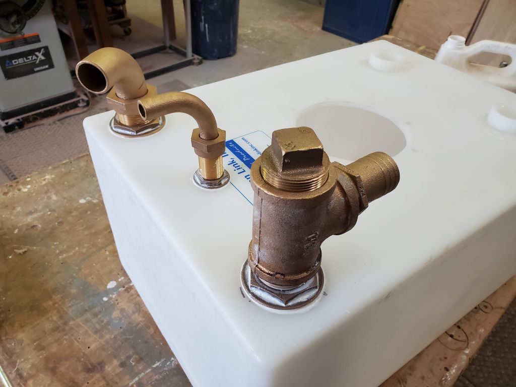
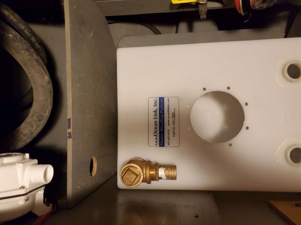
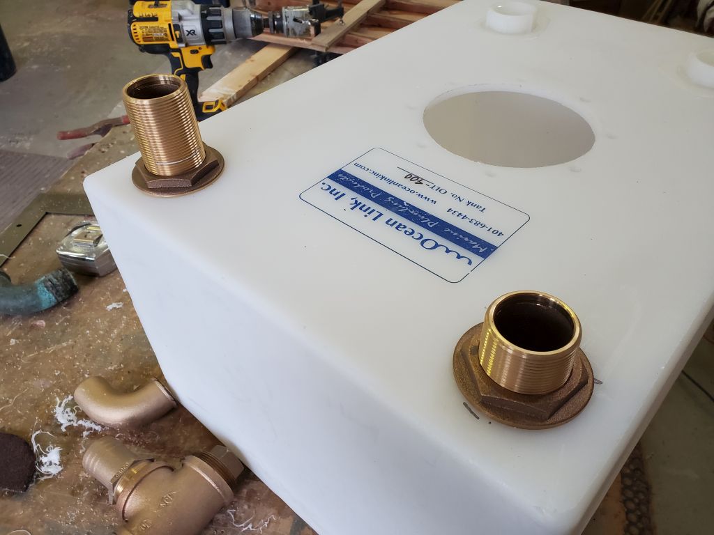
So with some mutterings of displeasure, I removed the top fixing nut (covered in goop), then the entire assembly so I could thread on the base fitting with the hose, and install that whole piece (hose, hose barb, and threaded neck) back into the tank. This worked, but it was all messier and more time-consuming than it had to be. I threaded on the bronze tee and tightened it before finalizing the installation so I could ensure it ended up facing the right direction.
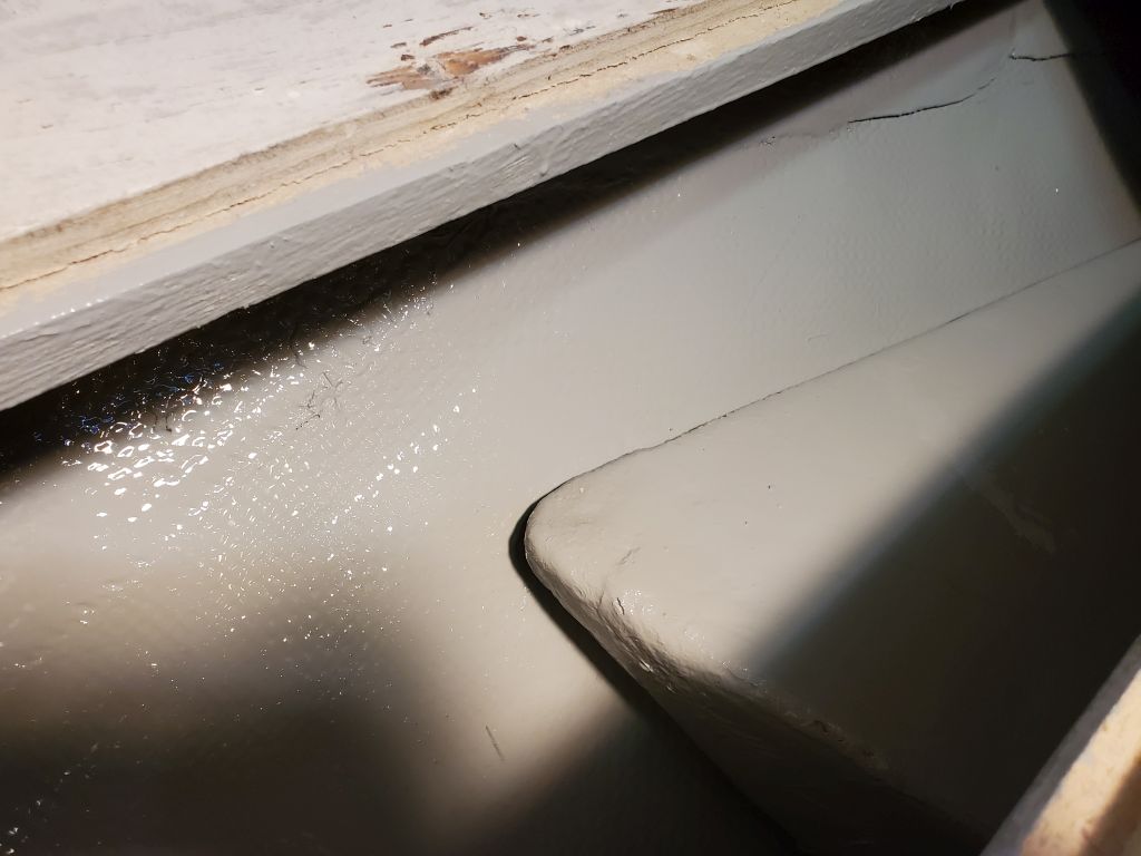
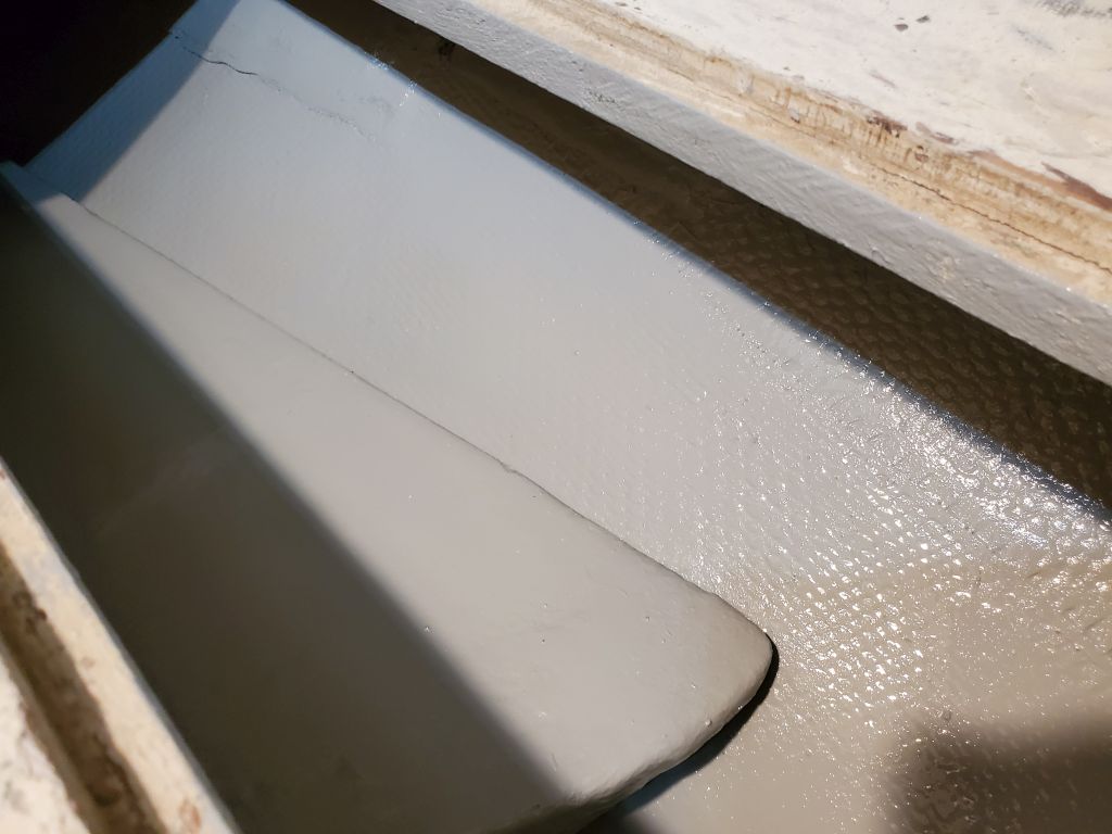
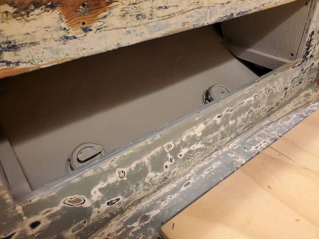
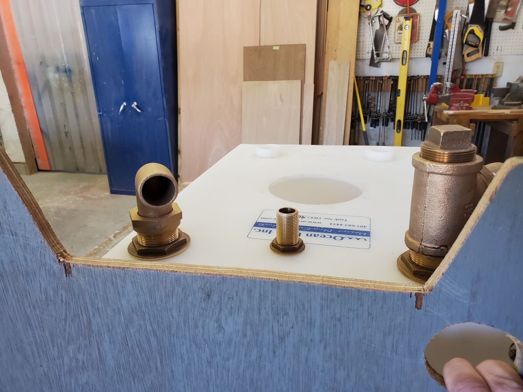
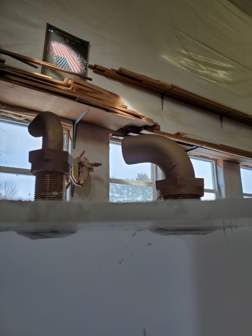
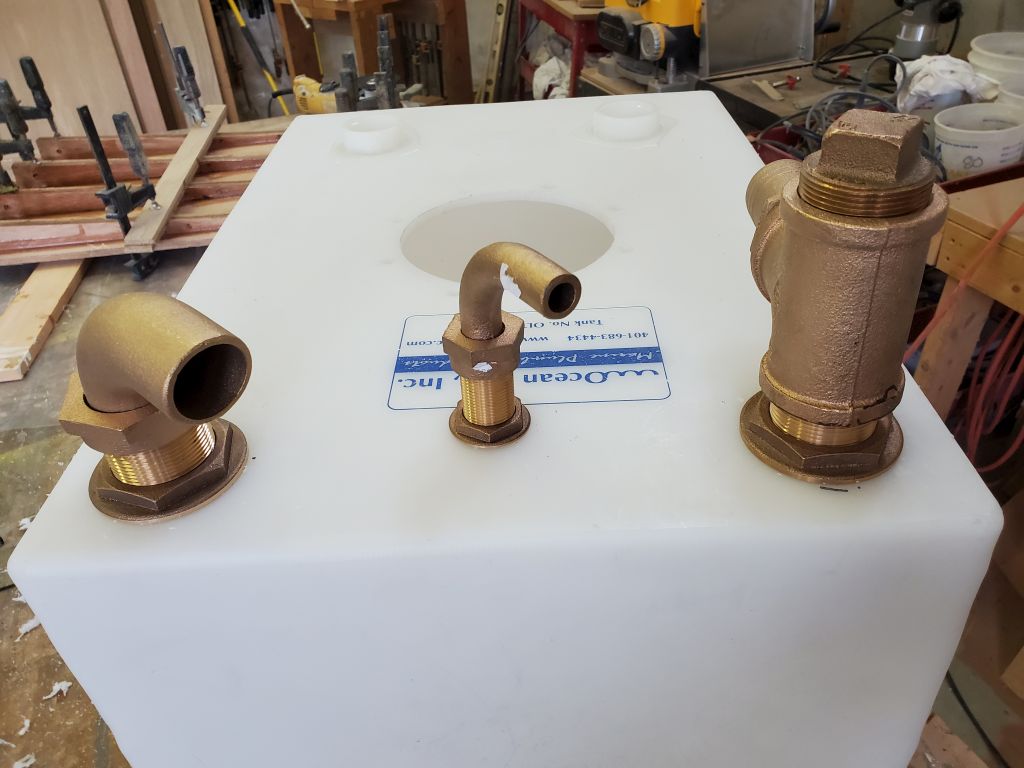
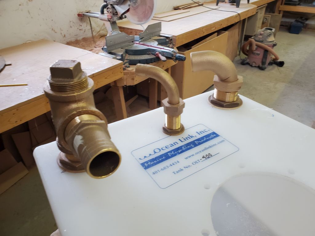
With the hard installation out of the way, the remaining two fixtures were much easier to install, also well-bedded in 4200.
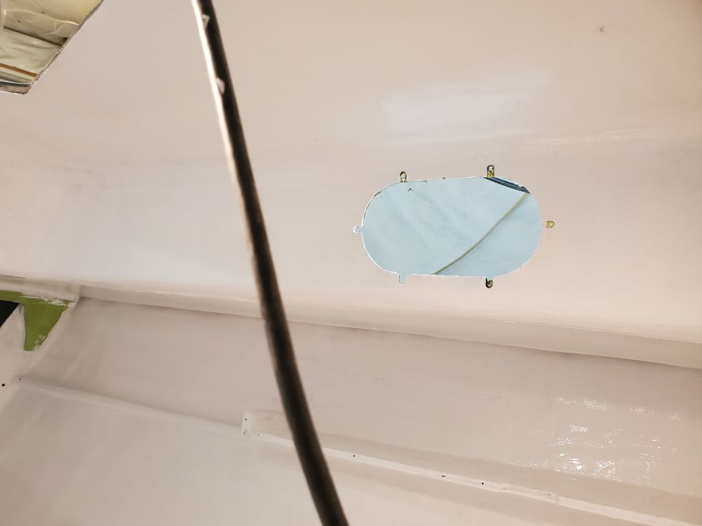
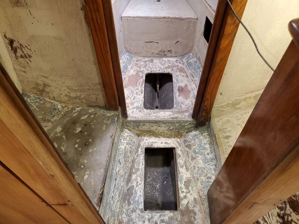
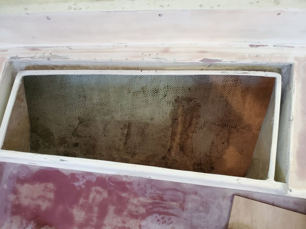
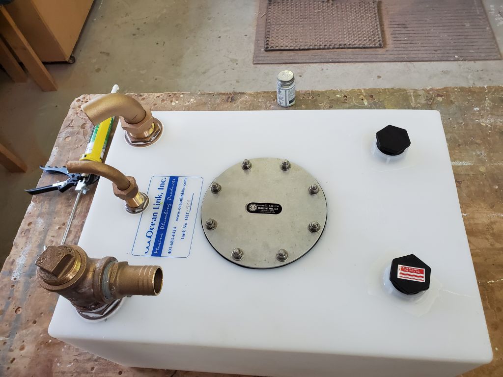
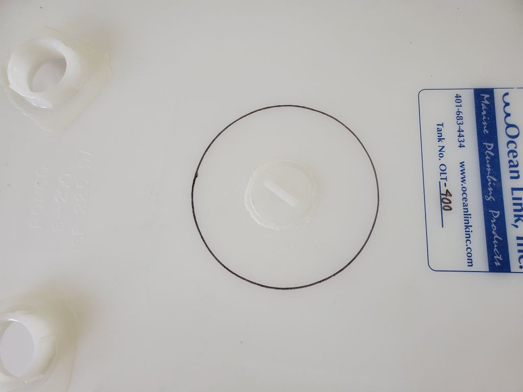
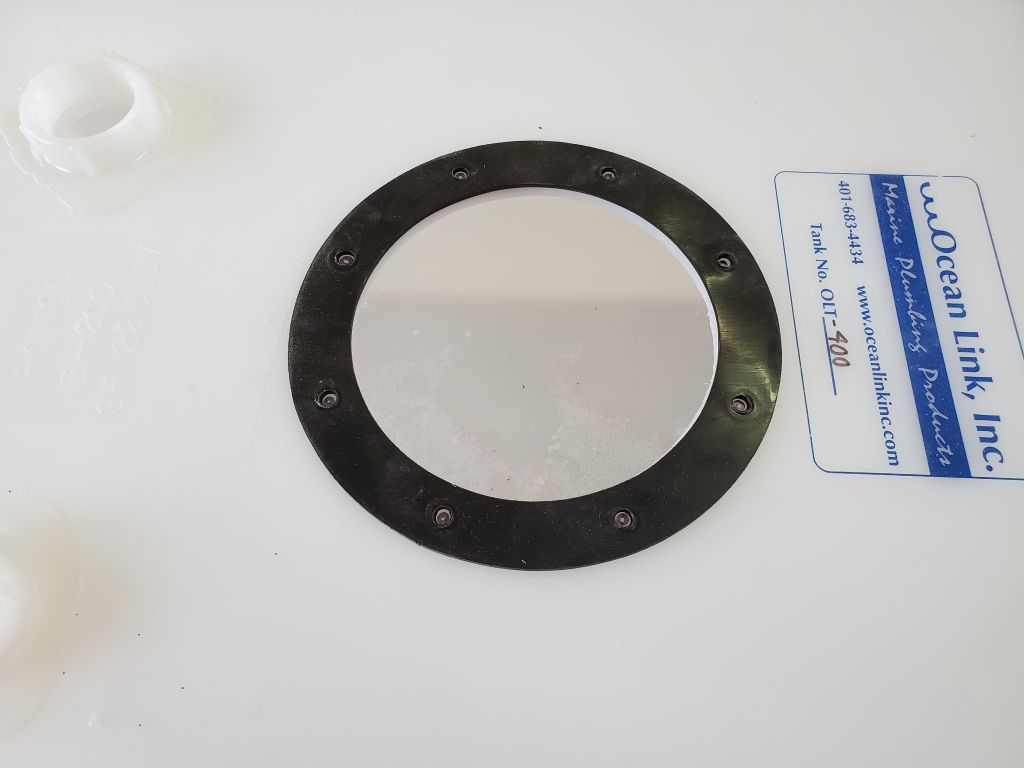
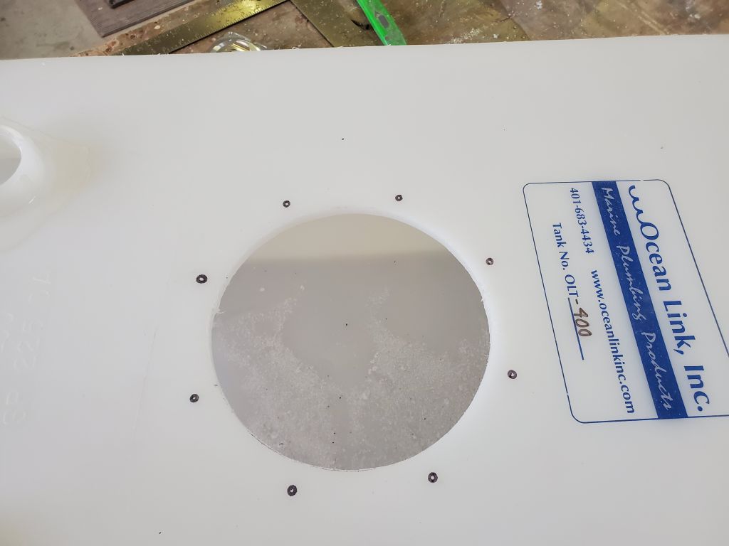
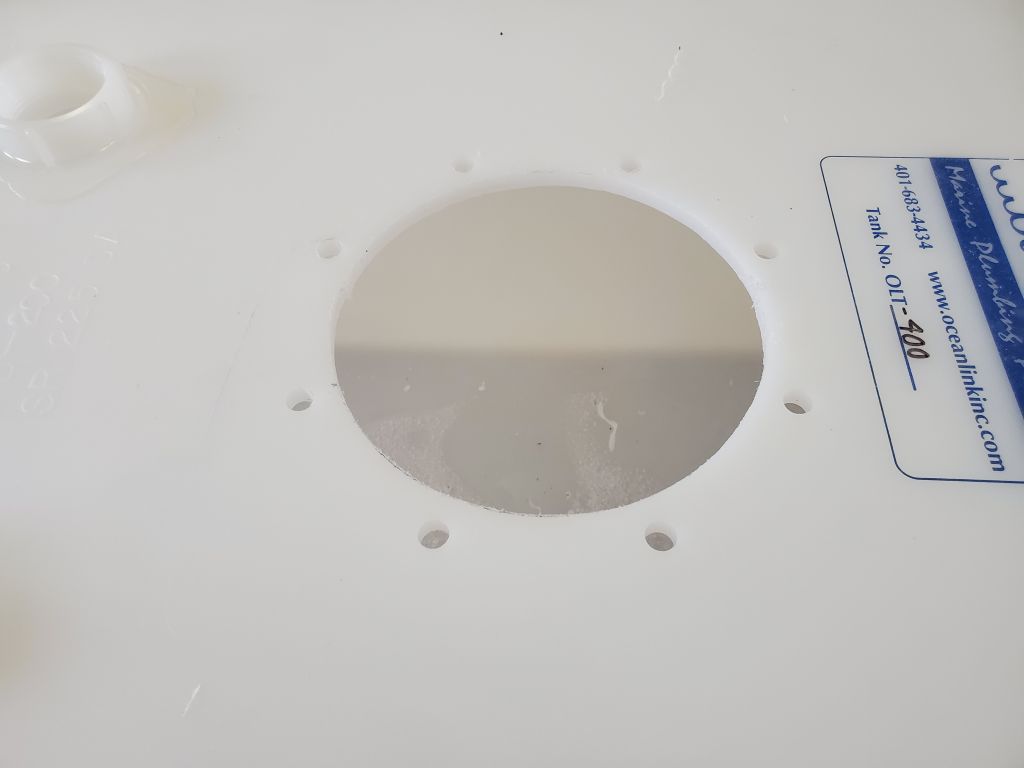
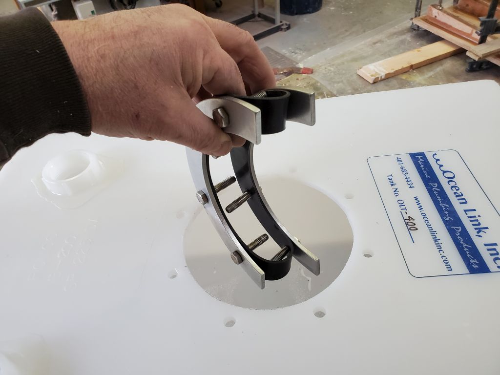
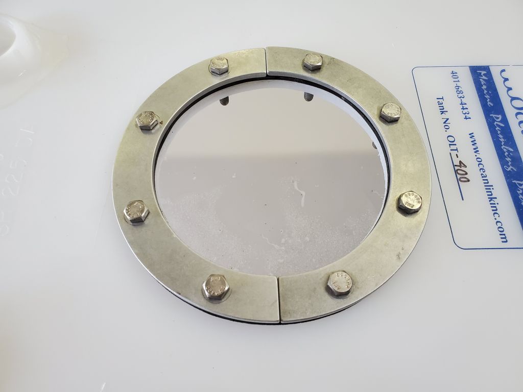
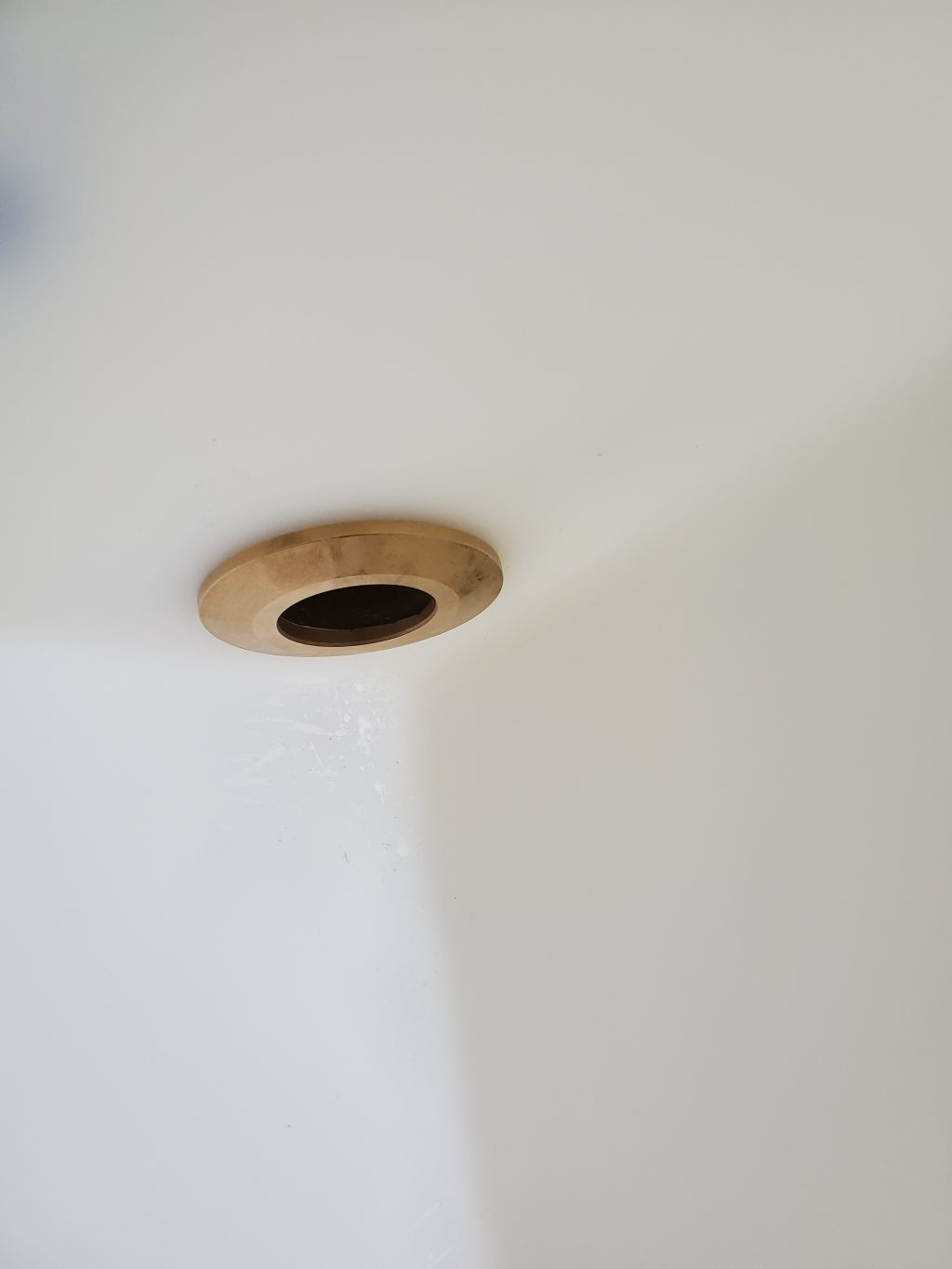
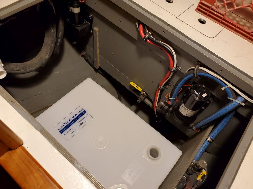
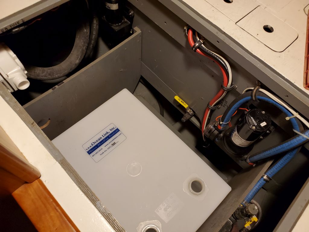
After cleaning out the inside of the tank, I saw no reason not to install the inspection port and remaining fittings. Once work on the new platform was complete, I could install the tank and finish up the work on the head system.
Total time billed on this job today: 4.5 hours
0600 Weather Observation: 2°, mainly clear. Forecast for the day: Mostly sunny, 23°.