(page 64 of 166)

Lyra 29

Tuesday

To begin the morning, I applied a second coat of paint to the two plywood bulkhead fillers.

In the engine room, I’d left the engine in the state pictured below.  Starting from this point, I eyeballed how I wanted to reconfigure the mounting flanges to get the shaft at the correct height and give room for adjustment in the mounting feet.

Removing the assembly once more to the nearby settee, I unbolted the flanges and, using the original spacers once more, reinstalled them with the vertical leg facing up, and at a slightly different height that would better suit the shaft position in the boat.

Replacing the engine on the foundations once more, I adjusted the mounts as needed to bring the two couplings into more or less perfect alignment.

Outside, I found that during the process the shaft had slipped aft by 3/8″ or so, which was a bit further than I wanted as it didn’t leave enough room to fit the propeller between the shaft and rudder, so after pulling things forward accordingly, I added a block of wood between the shaft and rudder to prevent it from moving again, and realigned the engine and coupling, clamping the forward mounts to prevent the assembly from slipping down the inclined foundations.  Once I was finally satisfied with the position of everything, I made some marks outlining the position of each mounting foot on the beds, and labeled each foot for its position.

Now I could remove the electric motor, shaft, and stuffing box for final assembly.  Down on the bench, I added 1/4″ graphite packing to the stuffing box (3 rings for now), and replaced the stock hose clamps with improved solid-band clamps.  I permanently installed the shaft coupling with its key and setscrews, since I could slip this through the stern tube from inside the boat at this point, which I did next after installing the stuffing box.

I wrapped tape around the lower adjusting nuts on each mounting foot, ostensibly to hold them in their proper adjustment when I removed them from the engine (this works better than not, but is not infallible), then, with each in place with its reference marks on the foundations, drilled the mounting holes and bolted the feet to the foundation.

Now I installed the motor a final time, placing it over the mounting studs and, at more length than I expected, realigning it to the shaft coupling.  I found that the tops of the foundations had a slight downward angle towards the outside, which, when the feet were bolted in place, caused some changes in the stud position and overall alignment.  Fortunately, adjustments were relatively straightforward, since the motor was light enough to easily move, raise, or lower as needed, and eventually the couplings mated properly and, after securing the engine’s mounting nuts, I could finalize the shaft connection with the supplied bolts.

Finally, I reinstalled the L-shaped brackets I’d removed from the front of the housing earlier when I’d tried the previous mounting flange position.  These little flanges would ultimately provide the basis for the front motor cover.

With the installation basics wrapped up within, I saw no reason not to install the propeller now.

The next item on the agenda, which I’d start forthwith, was the four large batteries required for the system.  Using the boxes in which the batteries came–which served as decent analogs for the batteries themselves as they were a close fit in size–I mocked up the proposed battery positions as the owner and I had discussed:  Two in front of the engine, where the box would also serve as a step for the companionway; and one each on either side of the engine, mounted either transversely or longitudinally (I thought transverse–long way across the boat as in the third photo–was more space-efficient).  This project would continue next time.

Total time billed on this job today:  7 hours

0600 Weather Observation:  4°, high clouds and windy.  Forecast for the day:   Mostly sunny and windy, 16°

Lyra 28

Monday

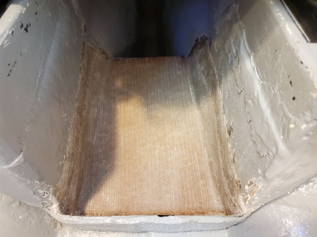
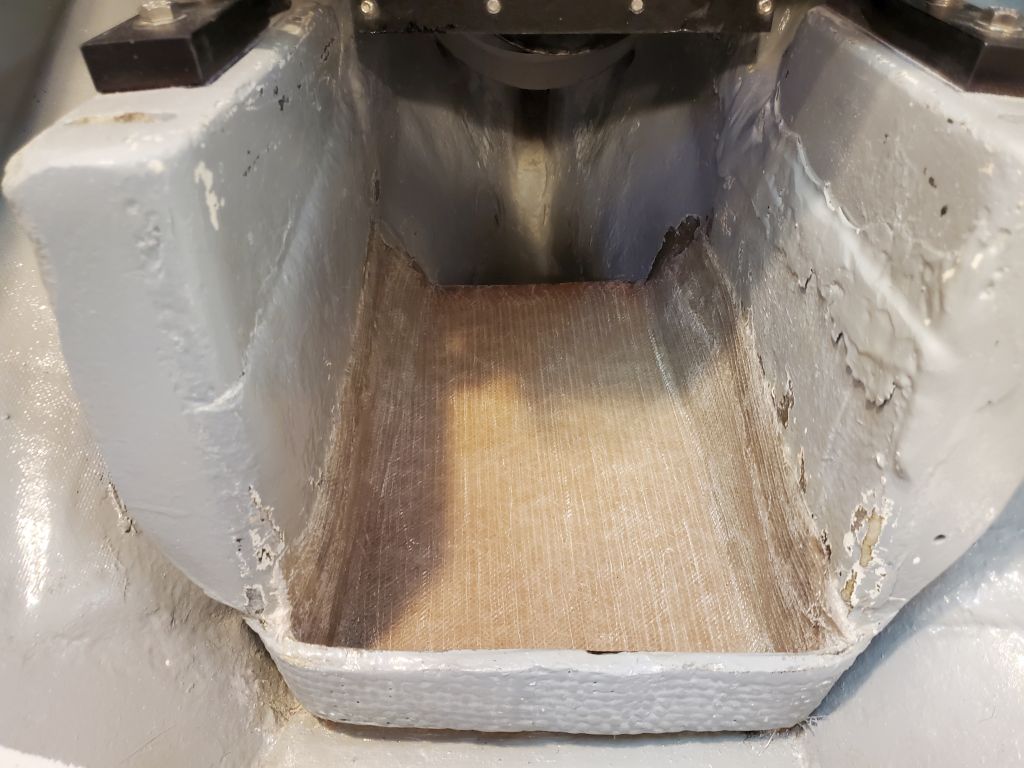
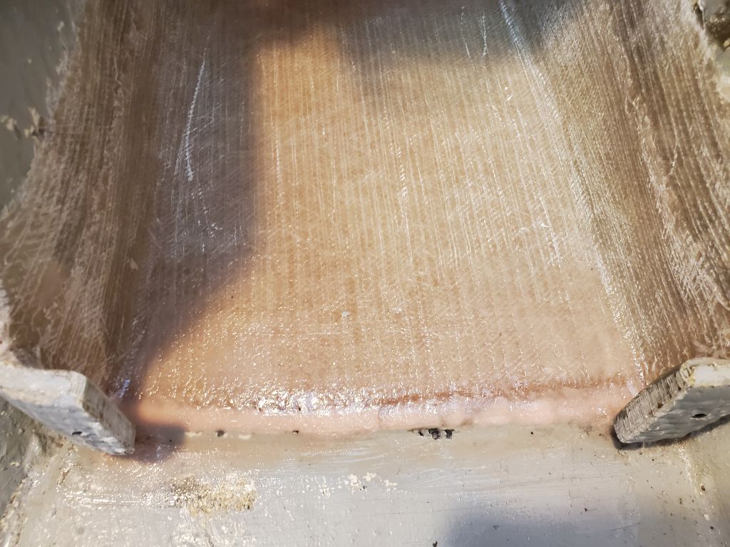
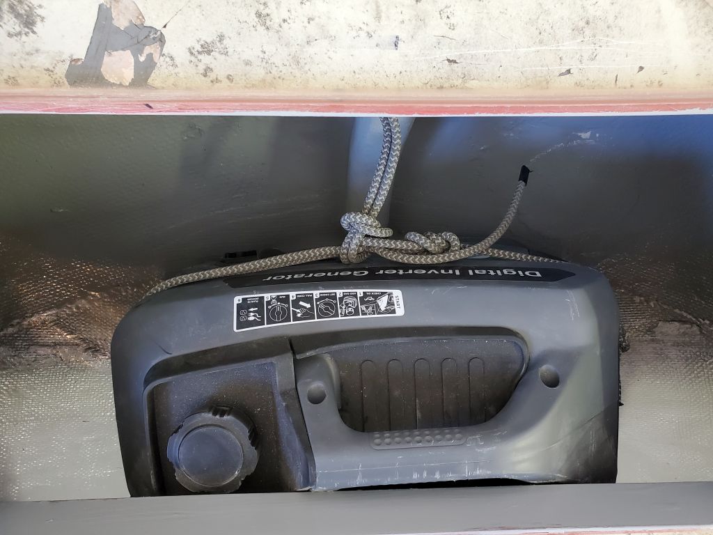
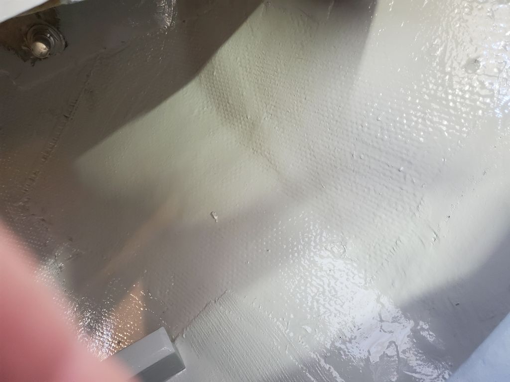
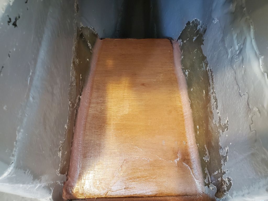
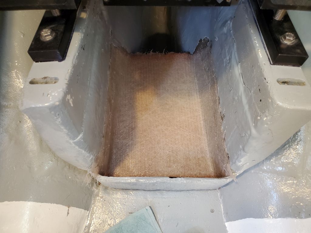
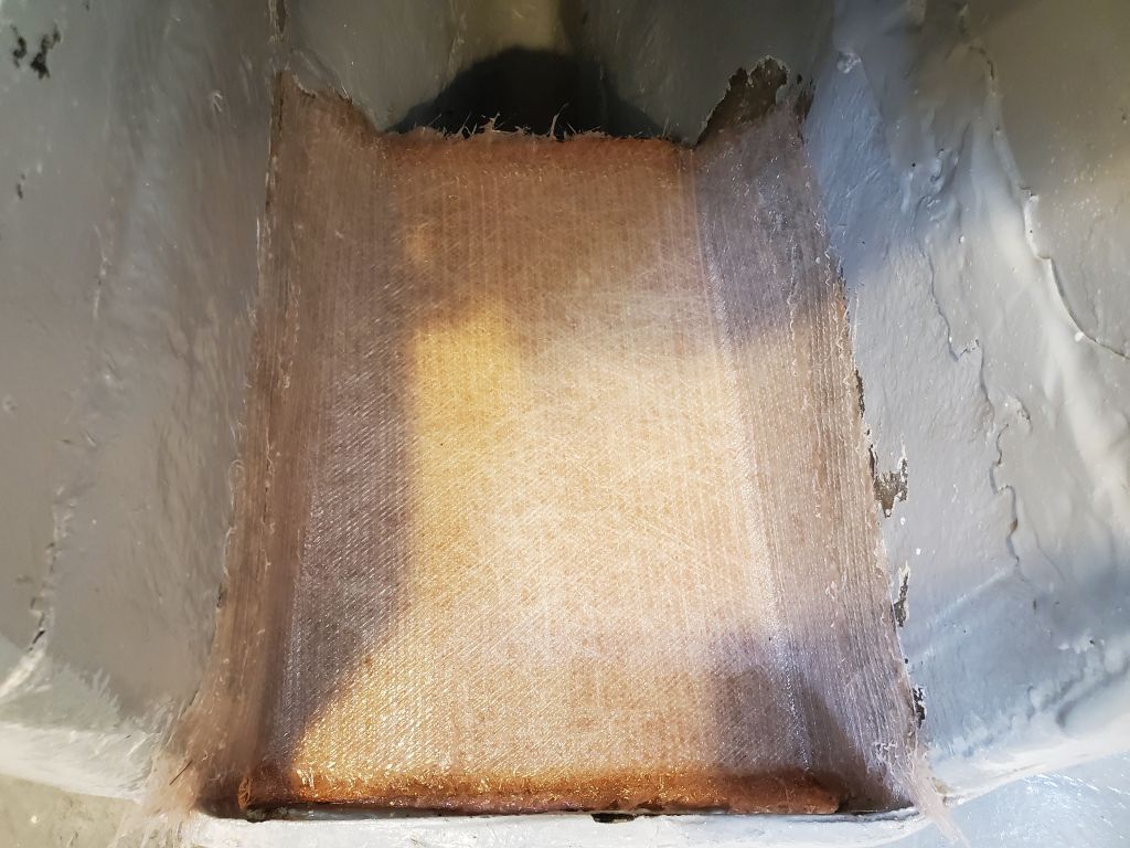
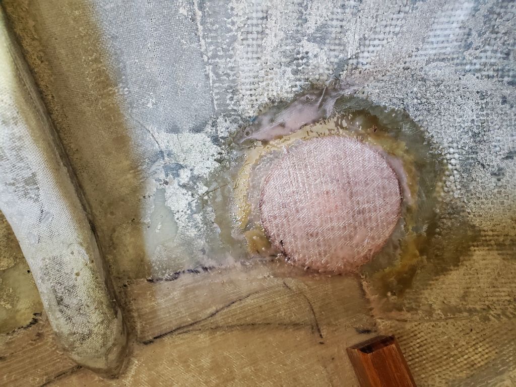
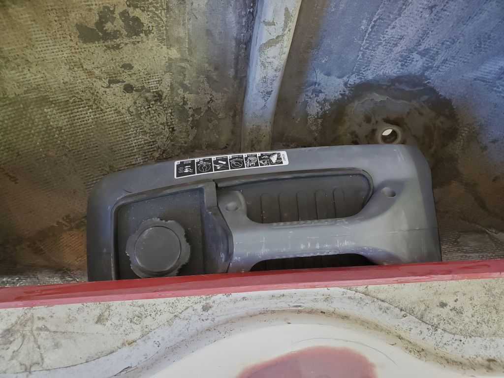
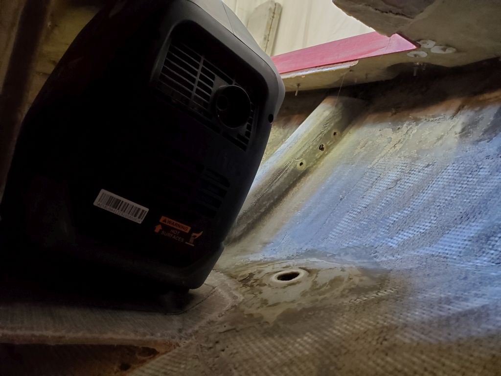
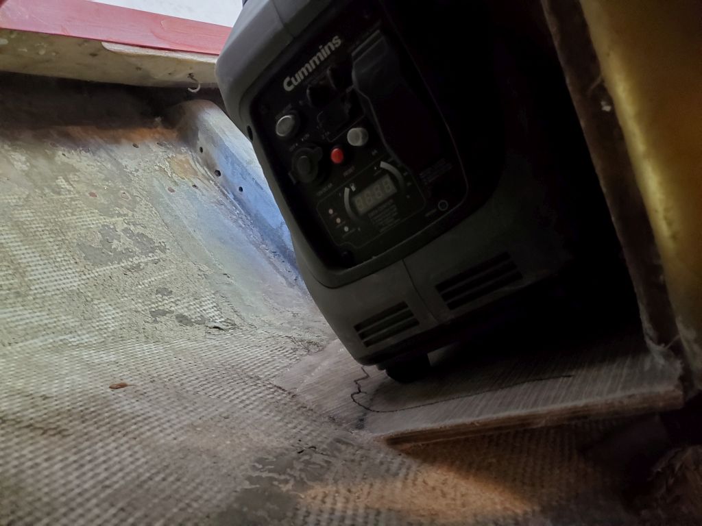
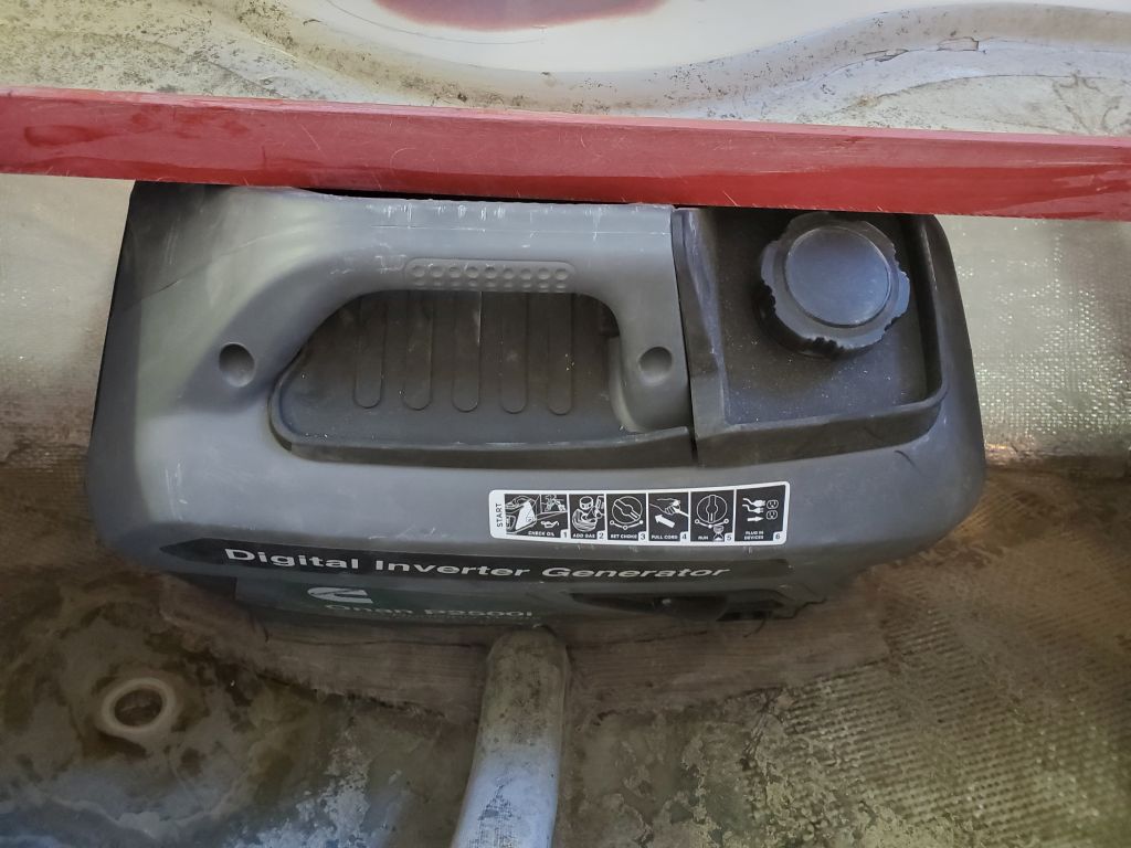
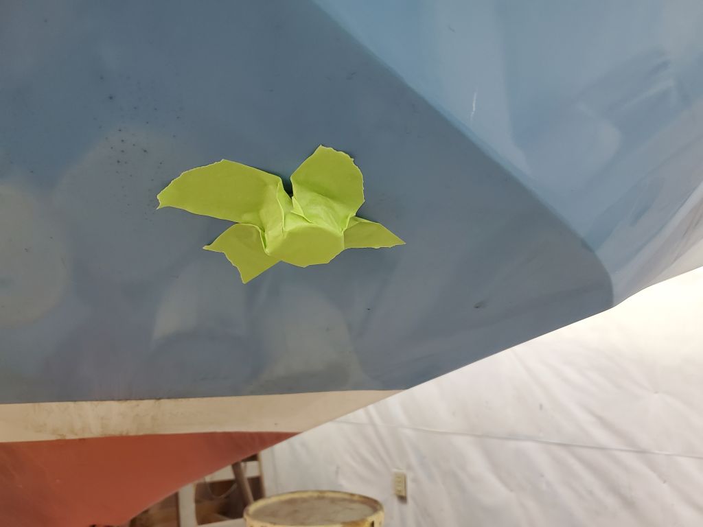
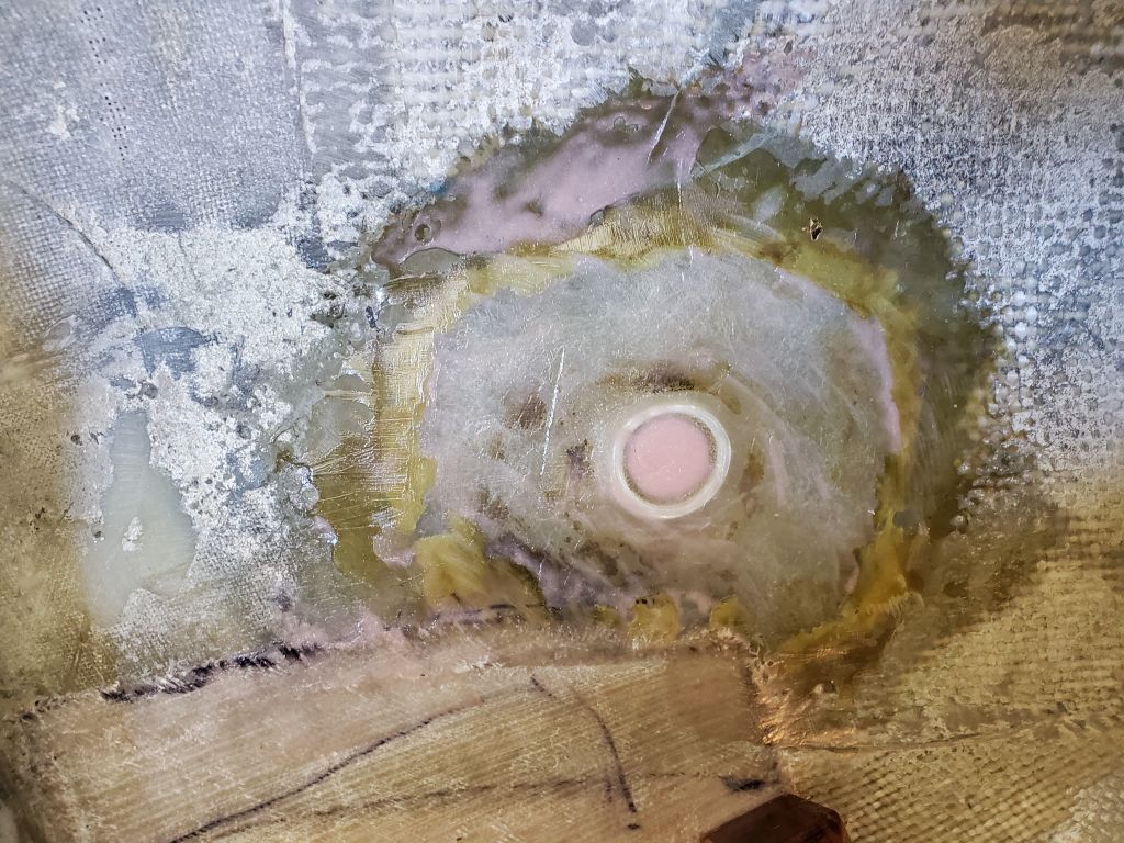
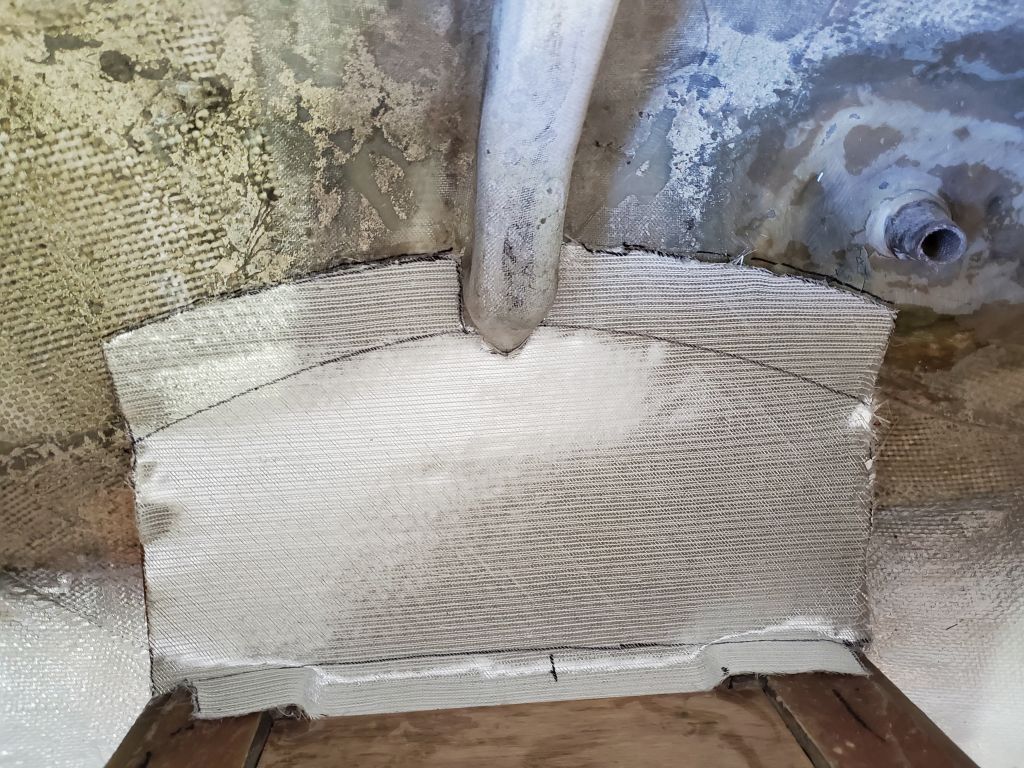
In the lazarette, I gave the newest work a light sanding as needed (the chocks for the generator and the new engine exhaust fill), then installed a fiberglass patch over the inside of the engine exhaust to complete the work there.

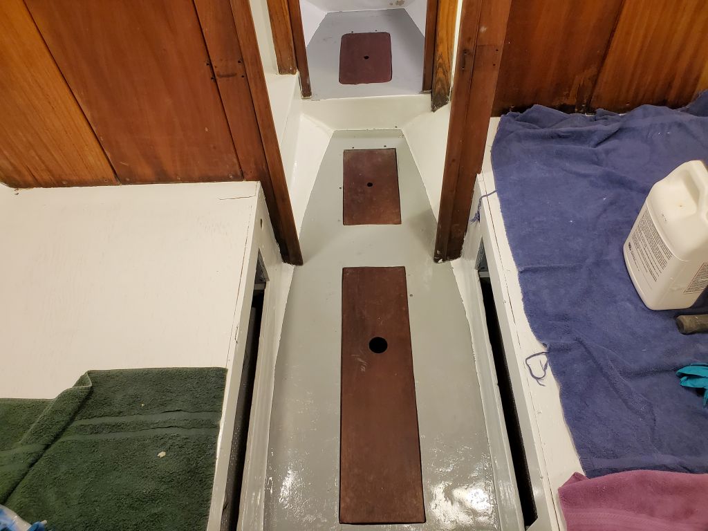
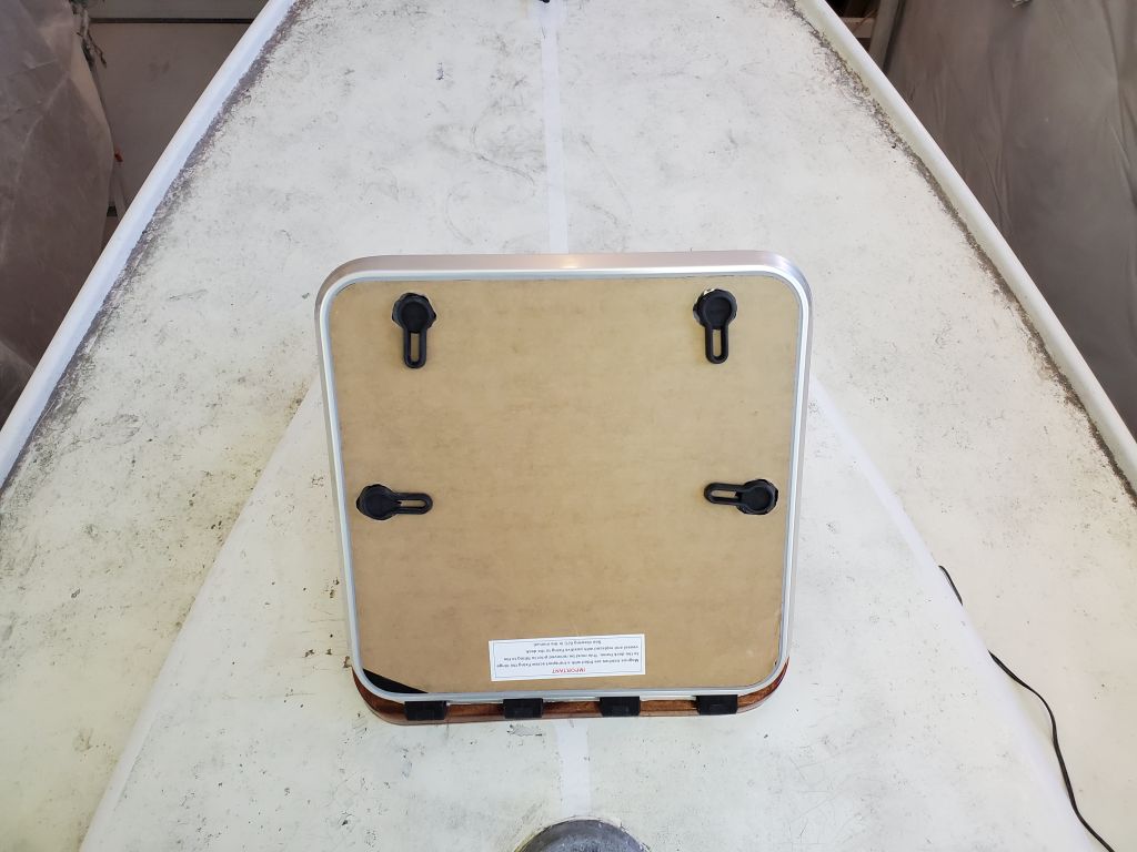
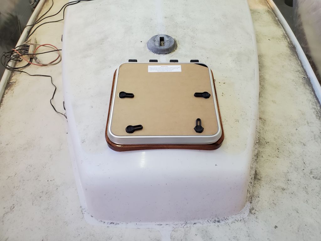
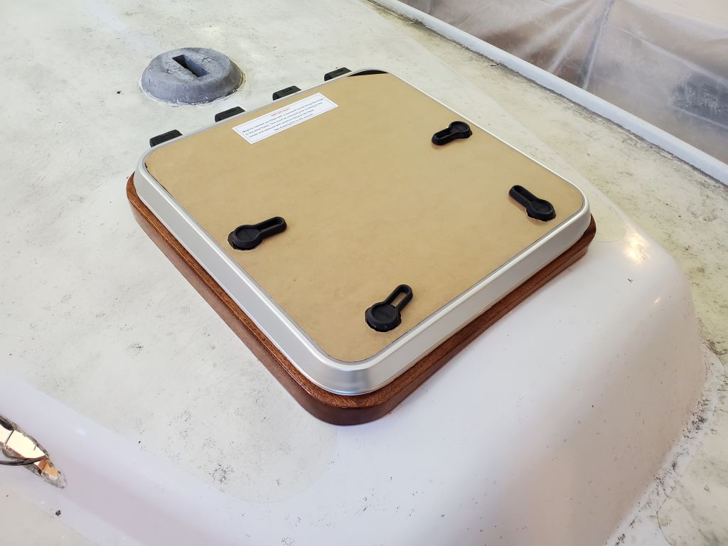
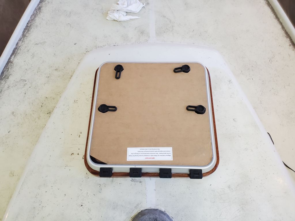
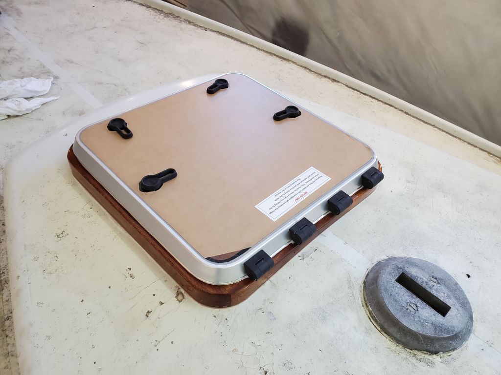
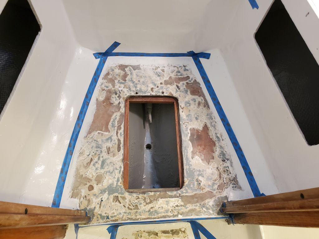
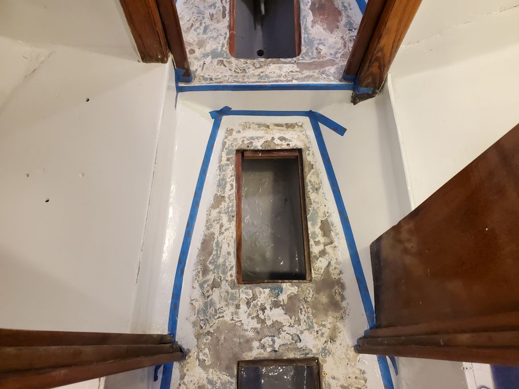
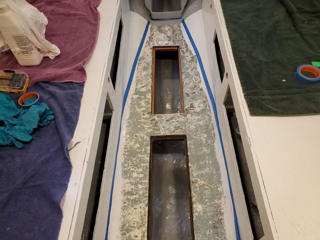
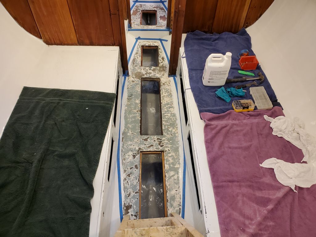
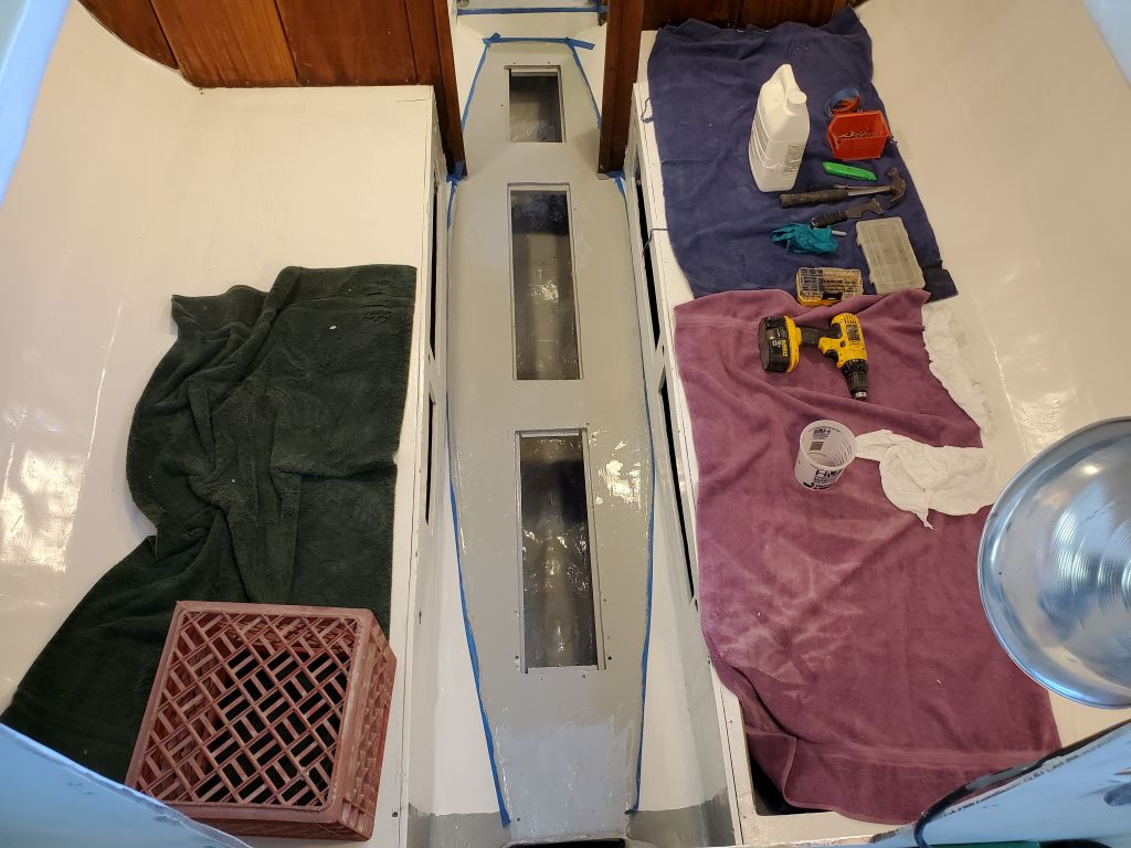
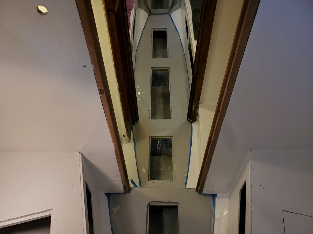
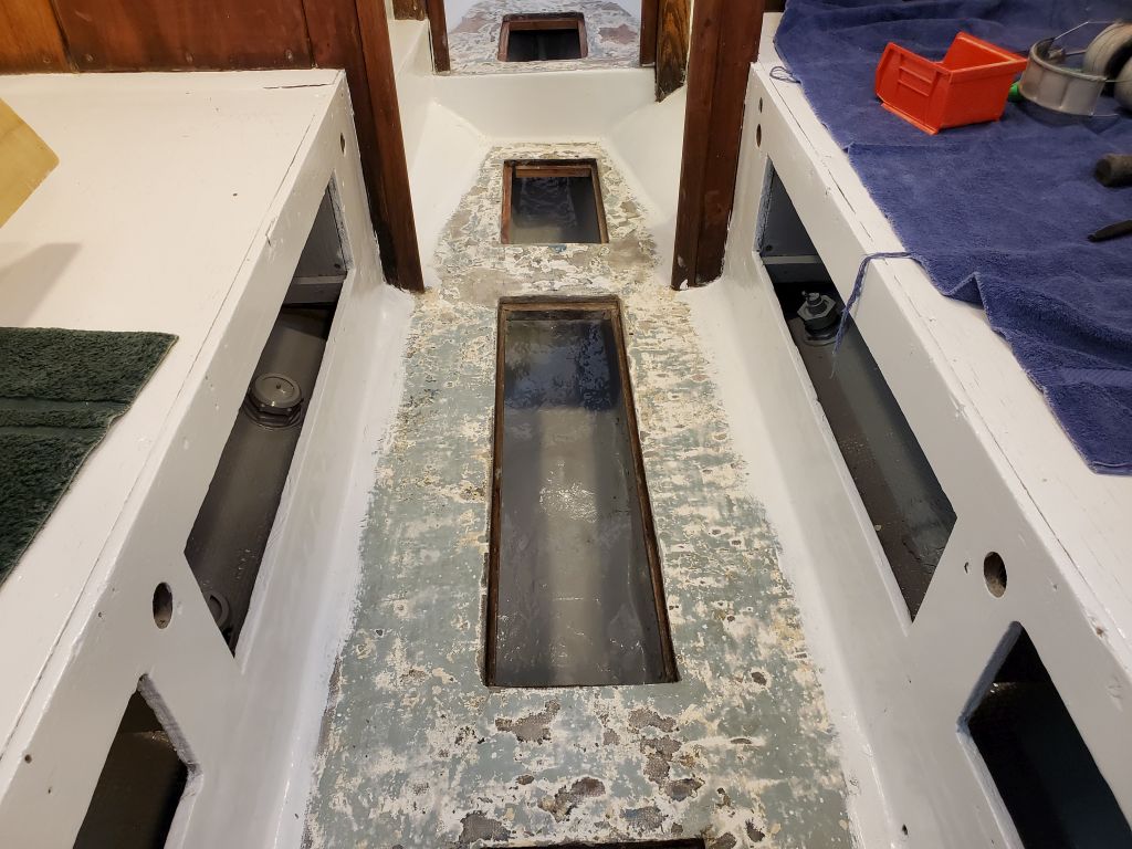
Some of the low-tack masking tape lining the cabin sole had lived up to its name and come partially unstuck and, in some cases, completely loose after the painting, and this left a less-crisp line of demarcation than I’d hoped for, but the new sole still looked OK.  I’d probably do another coat later in the project, but for now I could install the bilge hatches and cover the sole with some cloths for protection while I turned to other pursuits.

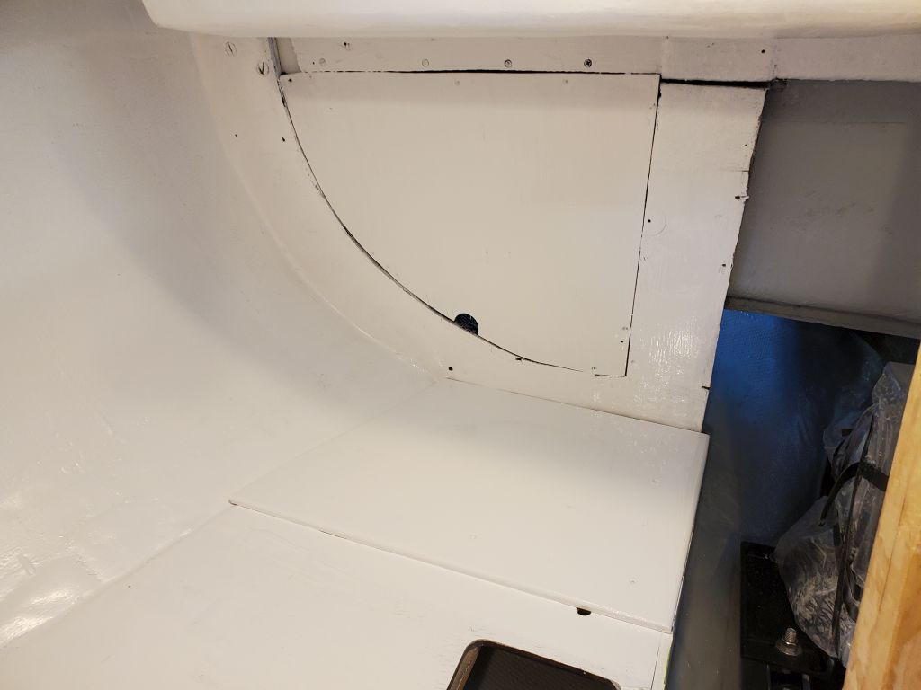
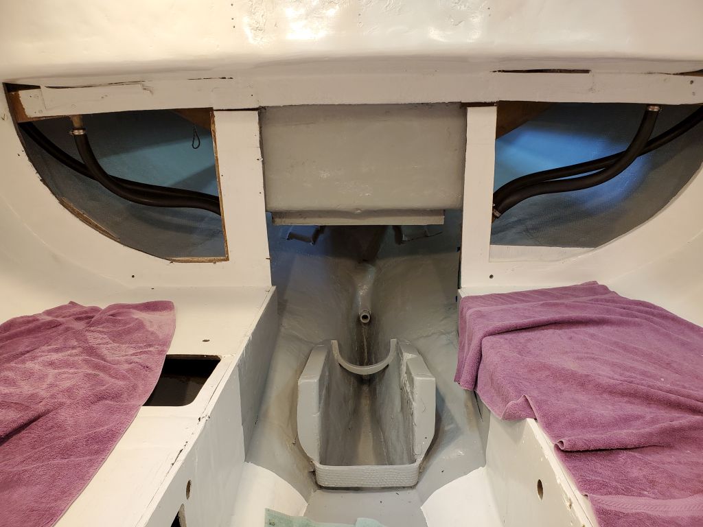
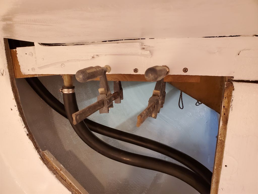
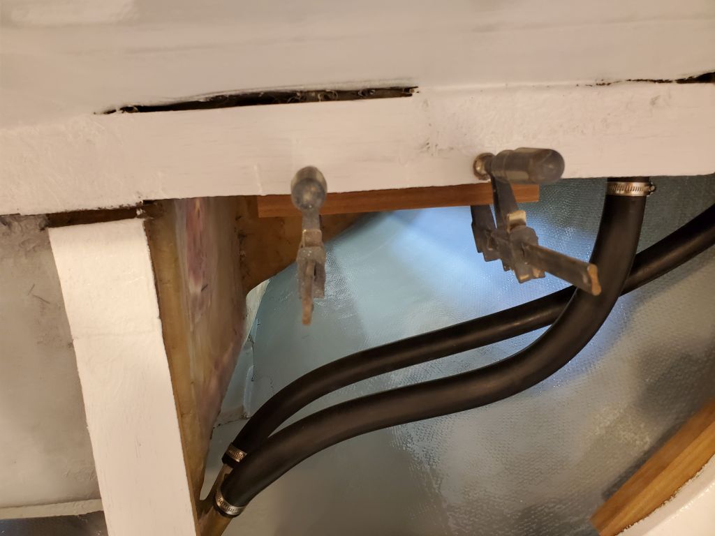
The first order of reassembly business now that the cabin painting was essentially done (pending touch-ups and new work to come) was the cockpit scuppers, including the seat and sidedeck drains.  These areas would soon be inaccessible or, at best, challenging to access, so now was the time to install new hoses and clamps all around.

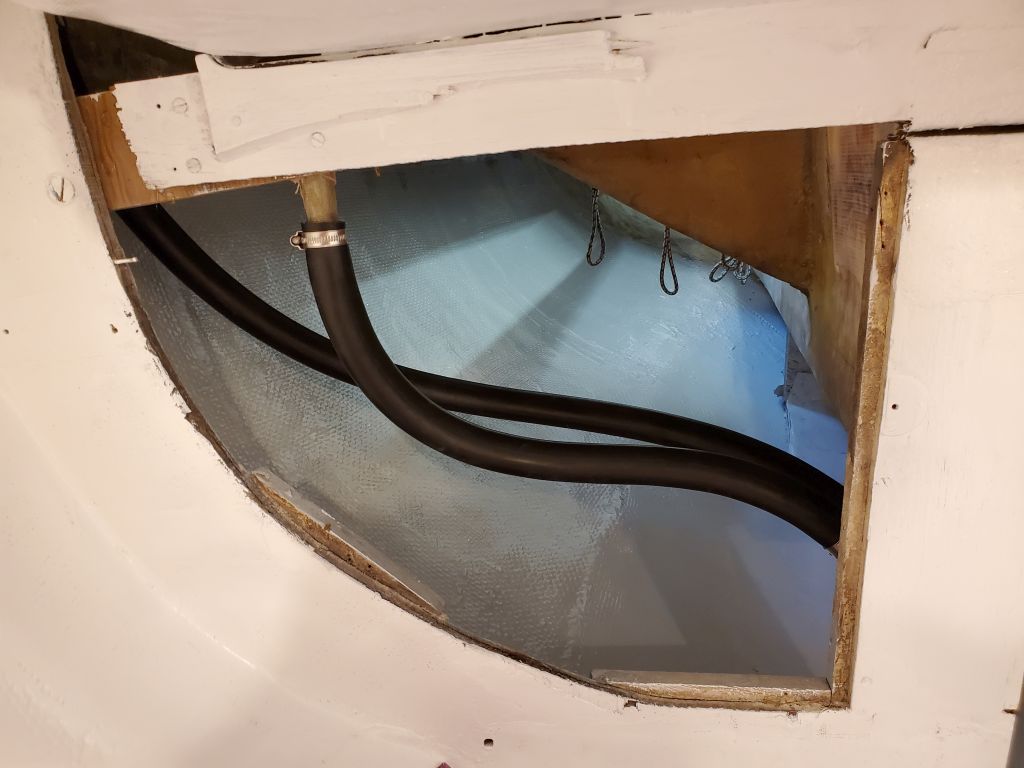
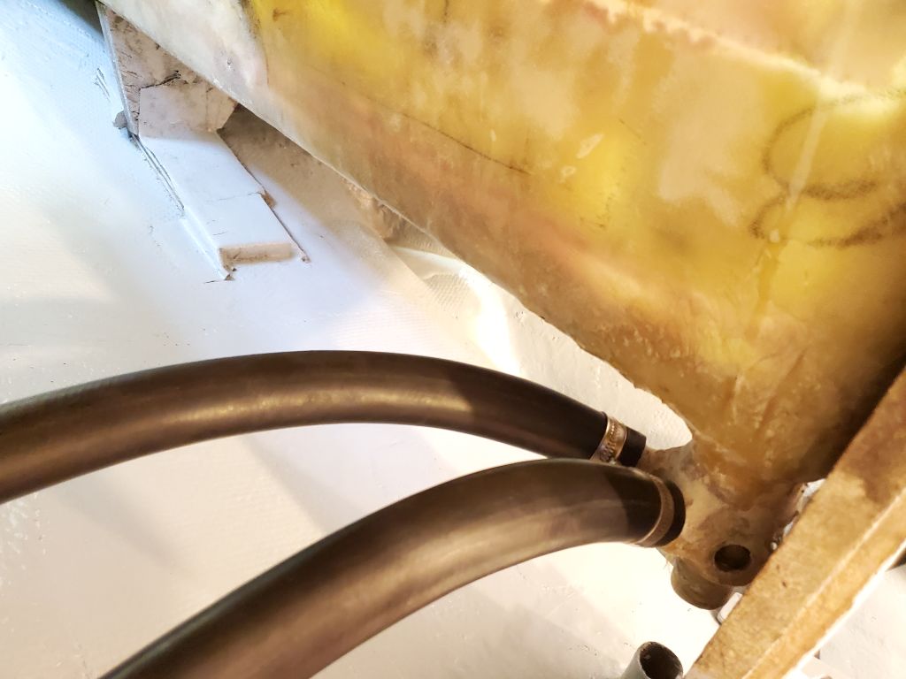
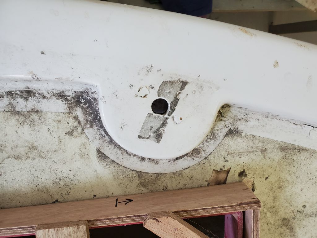
The sidedeck and cockpit seat drains led from their openings to a sort of Christmas tree arrangement of fiberglass tube barbs glassed to the main cockpit scuppers.  I’d measured these at 1″ diameter, and bought hose accordingly.  So I was rather surprised when on the very first hose, I had great difficulty getting the hose to fit over the fiberglass tube beneath the cockpit.  I fought with it for a while but couldn’t stretch the hose over the tube and get it down far enough, so I ended up sanding the exterior of the tube a bit, after which I could finally get the hose on and clamped successfully.  Fortunately, this particular tube seemed to be an anomaly, as the other end of this hose–and in fact all the remaining hoses–slid on their respective tubes without any undue issues.

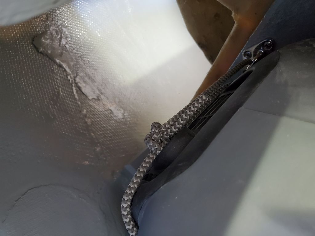
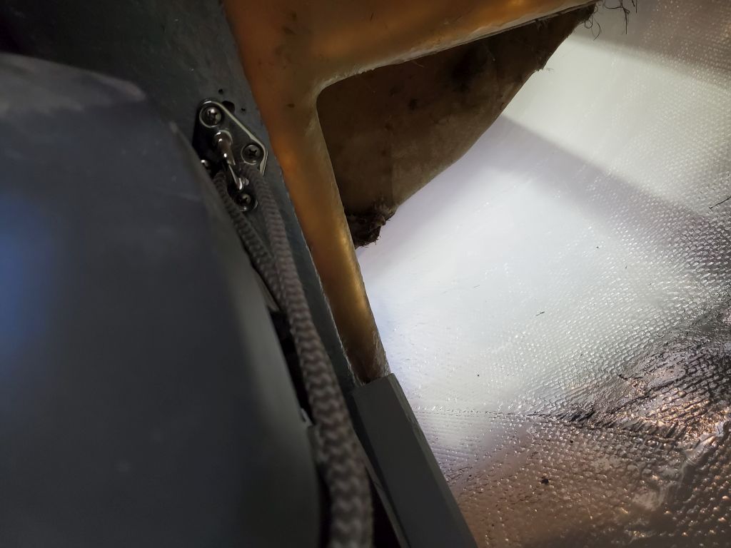
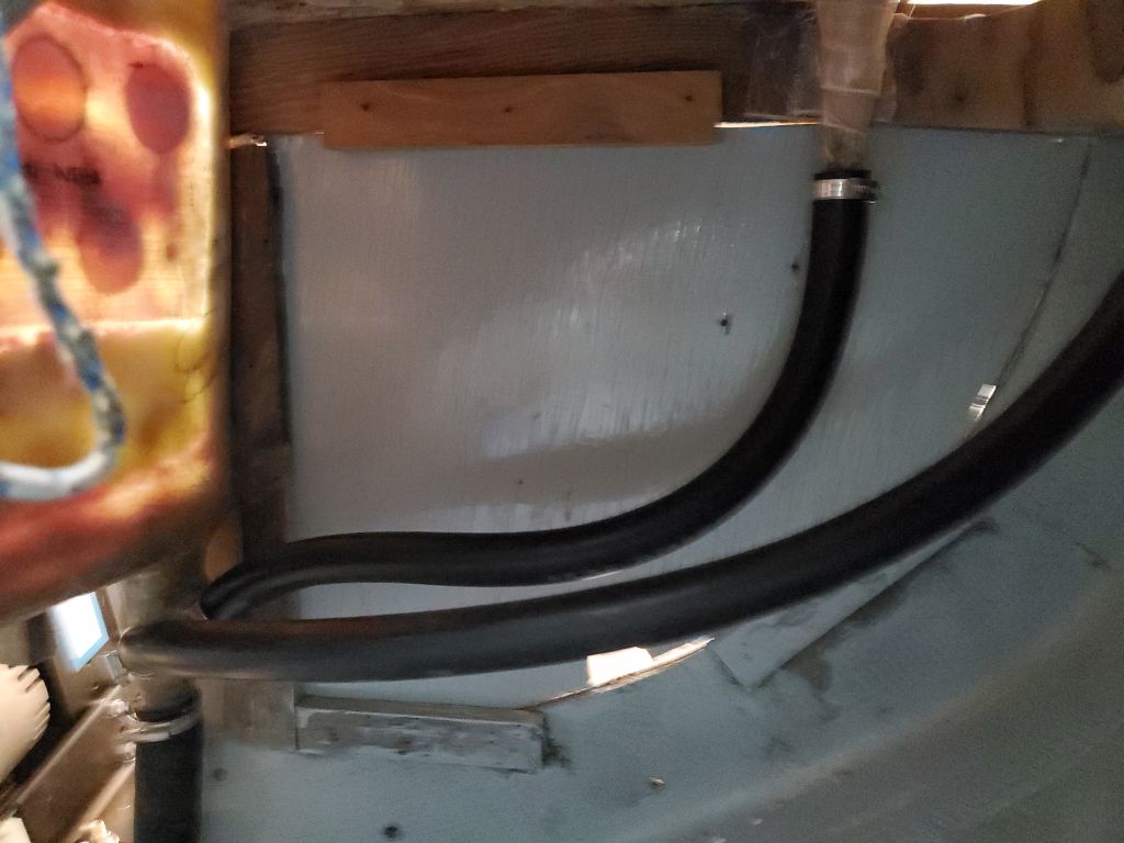
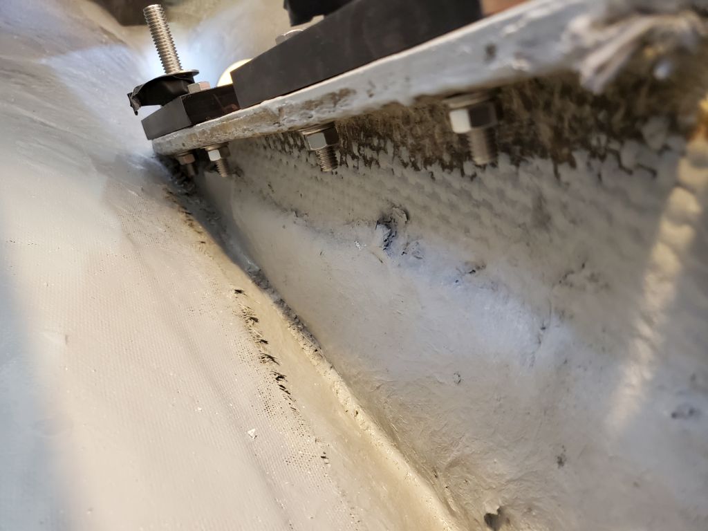
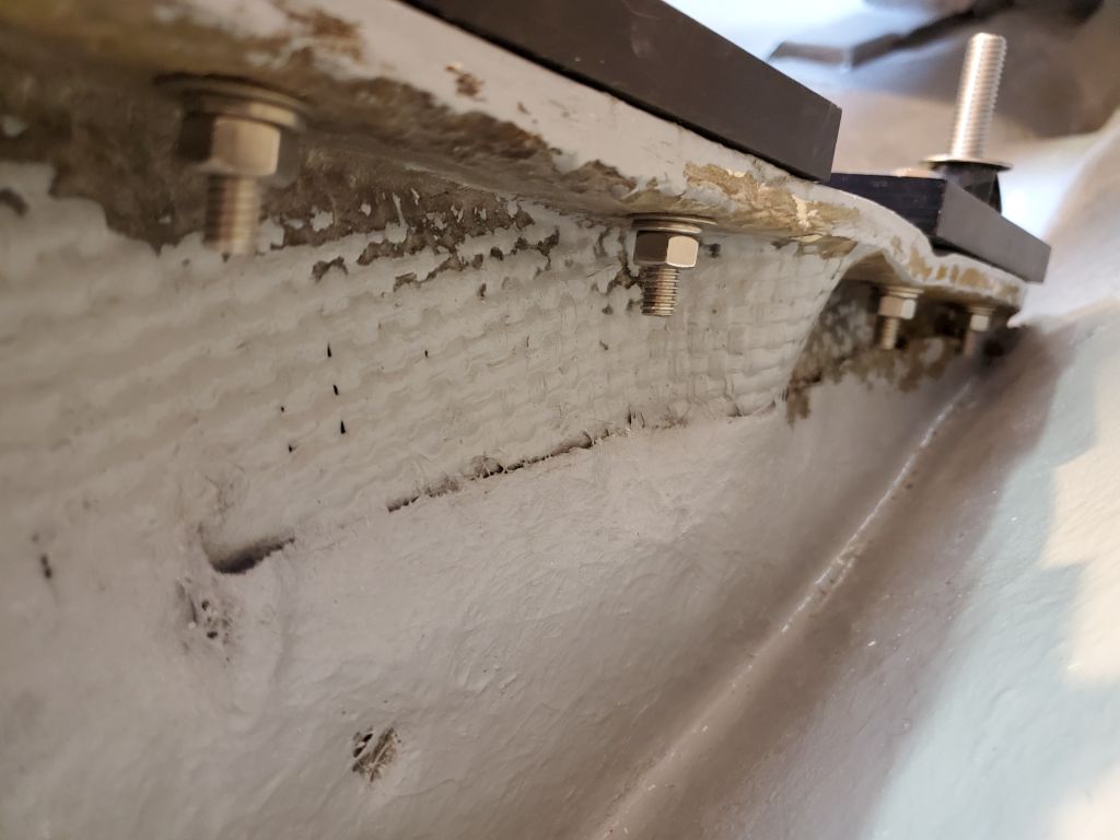
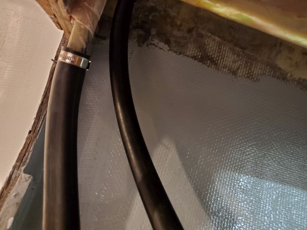
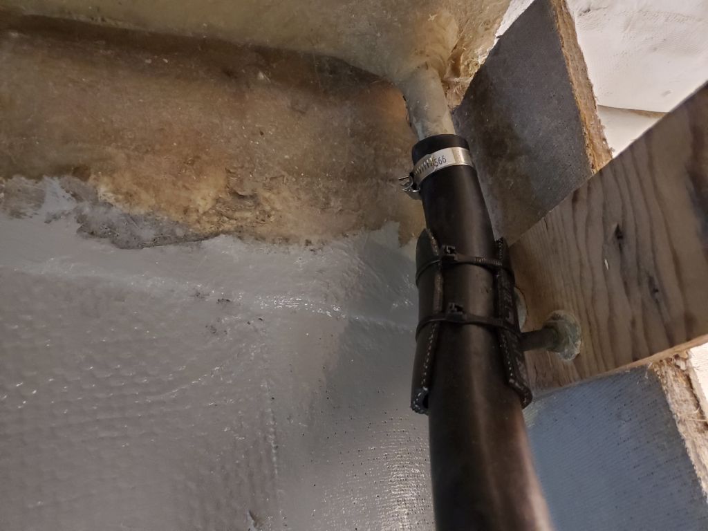
On the port sidedeck drain hose, I added some chafe gear where the hose led close by some bolts sticking out the back of the nearby bulkhead.

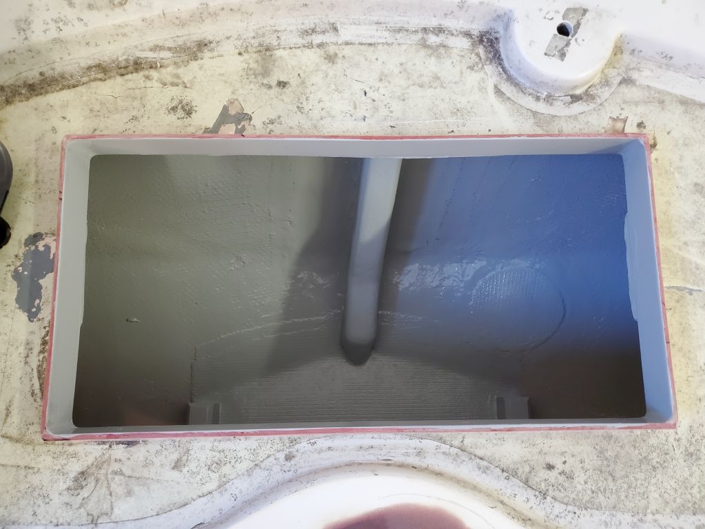
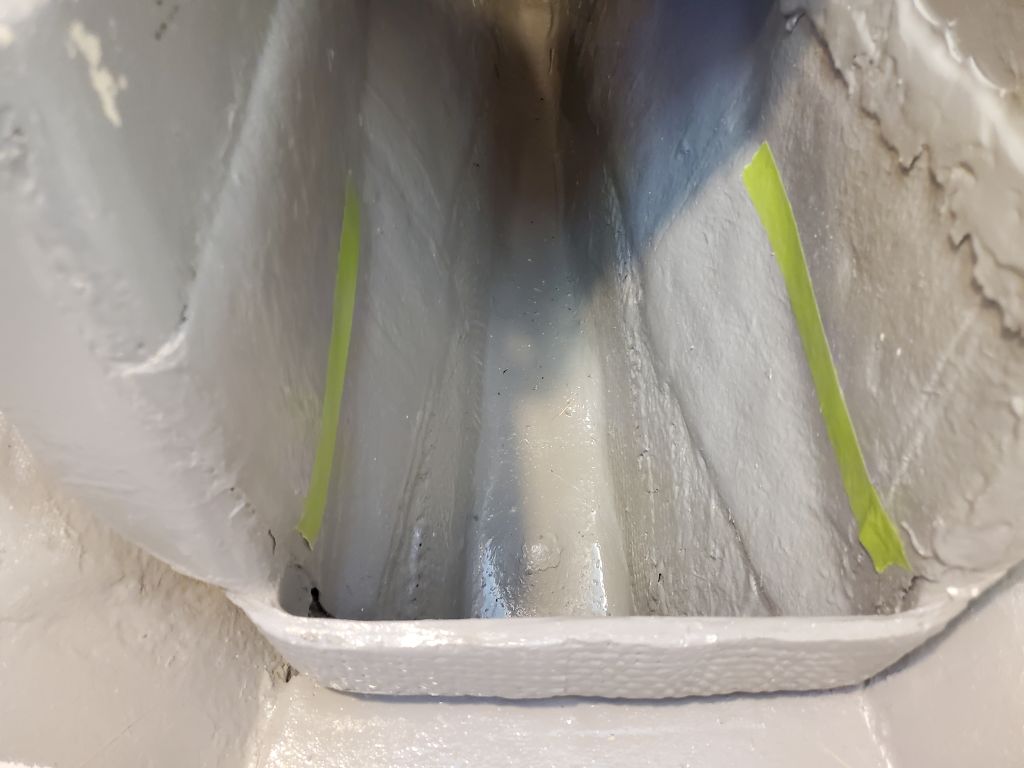
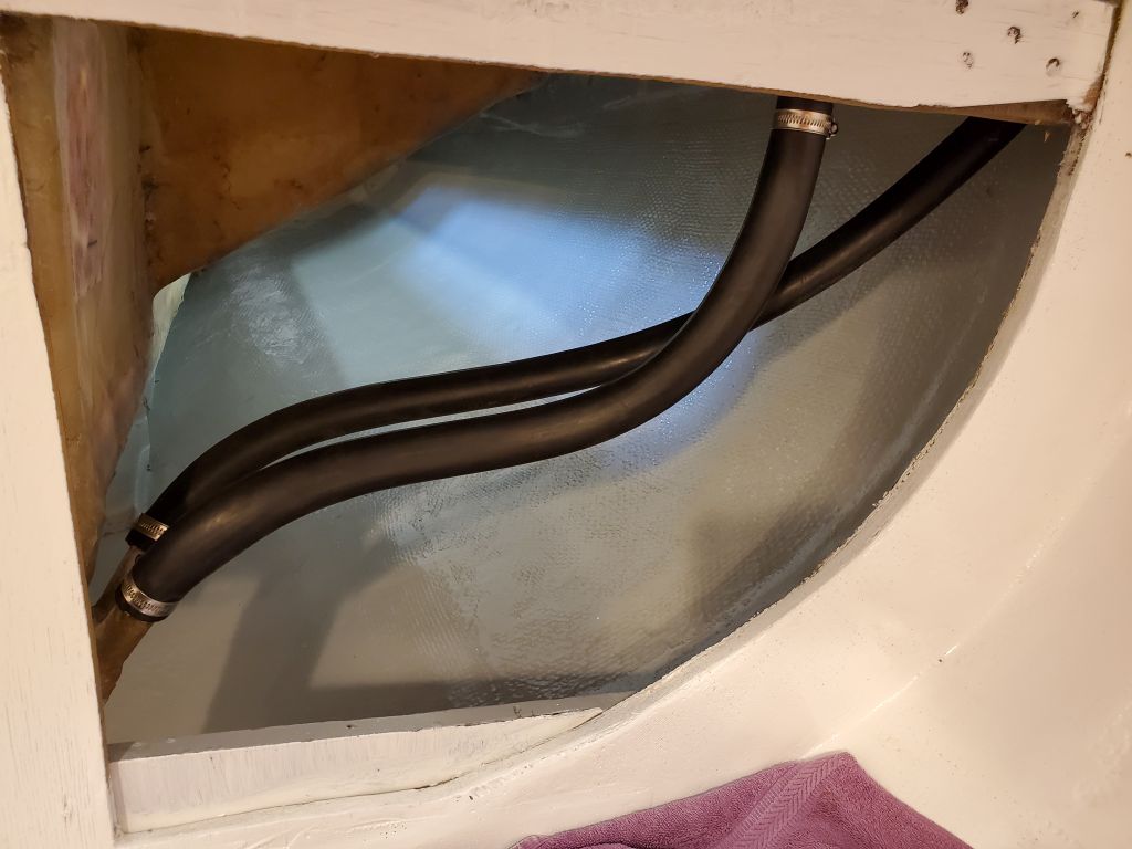
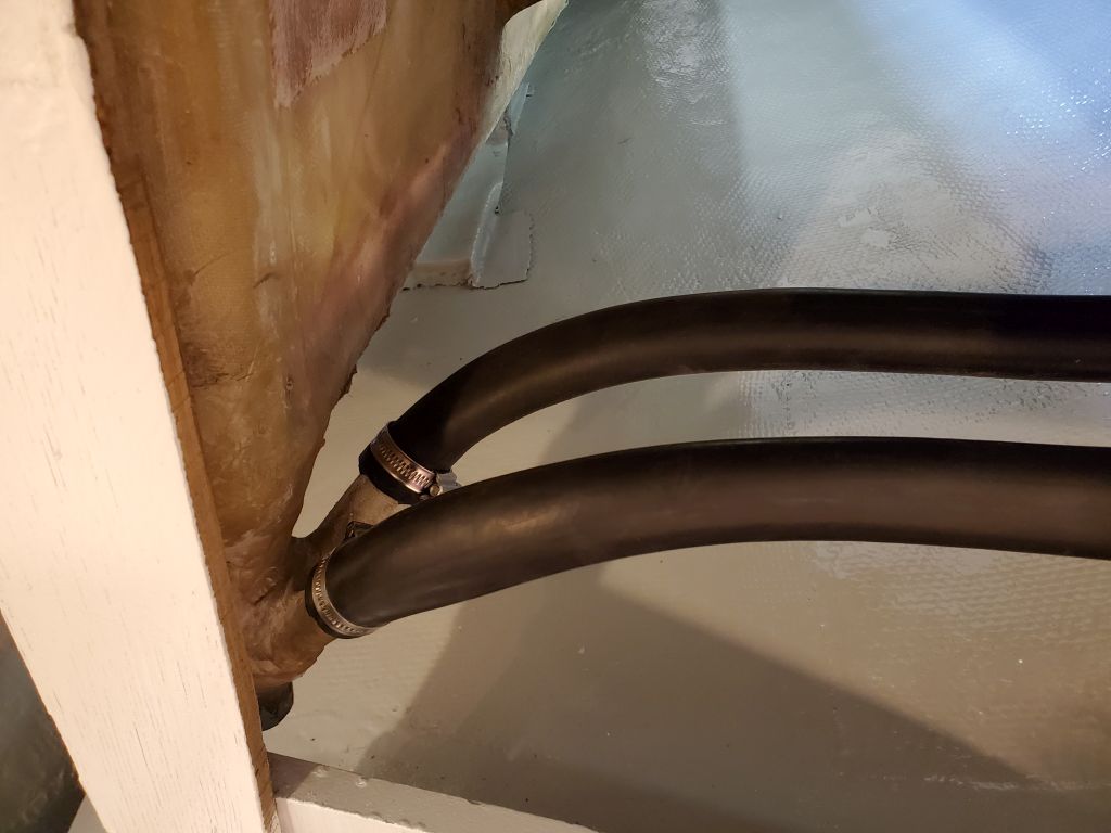
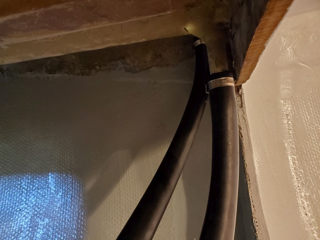
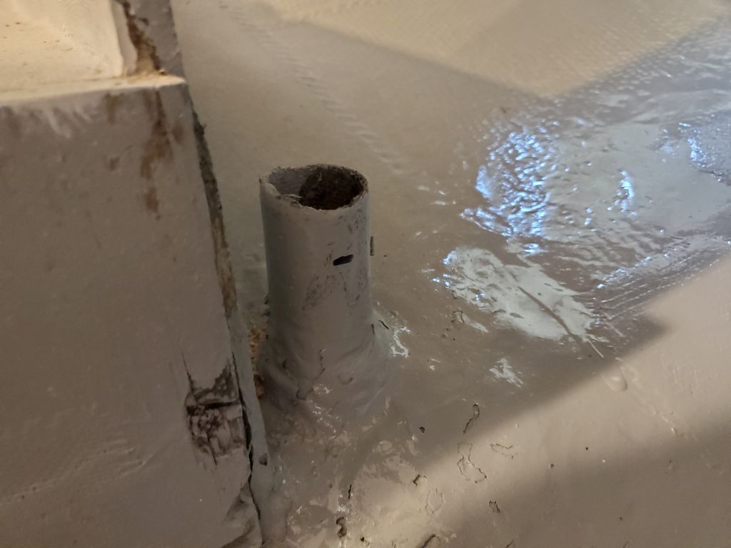
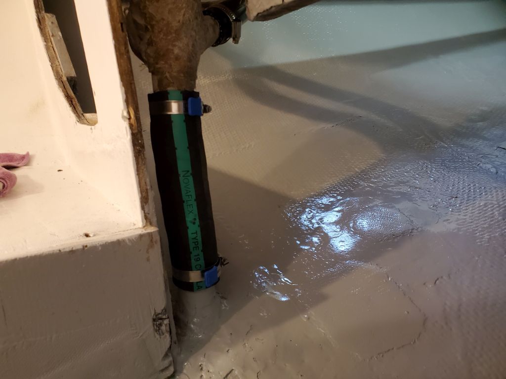
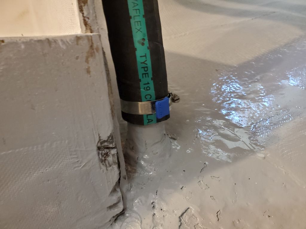
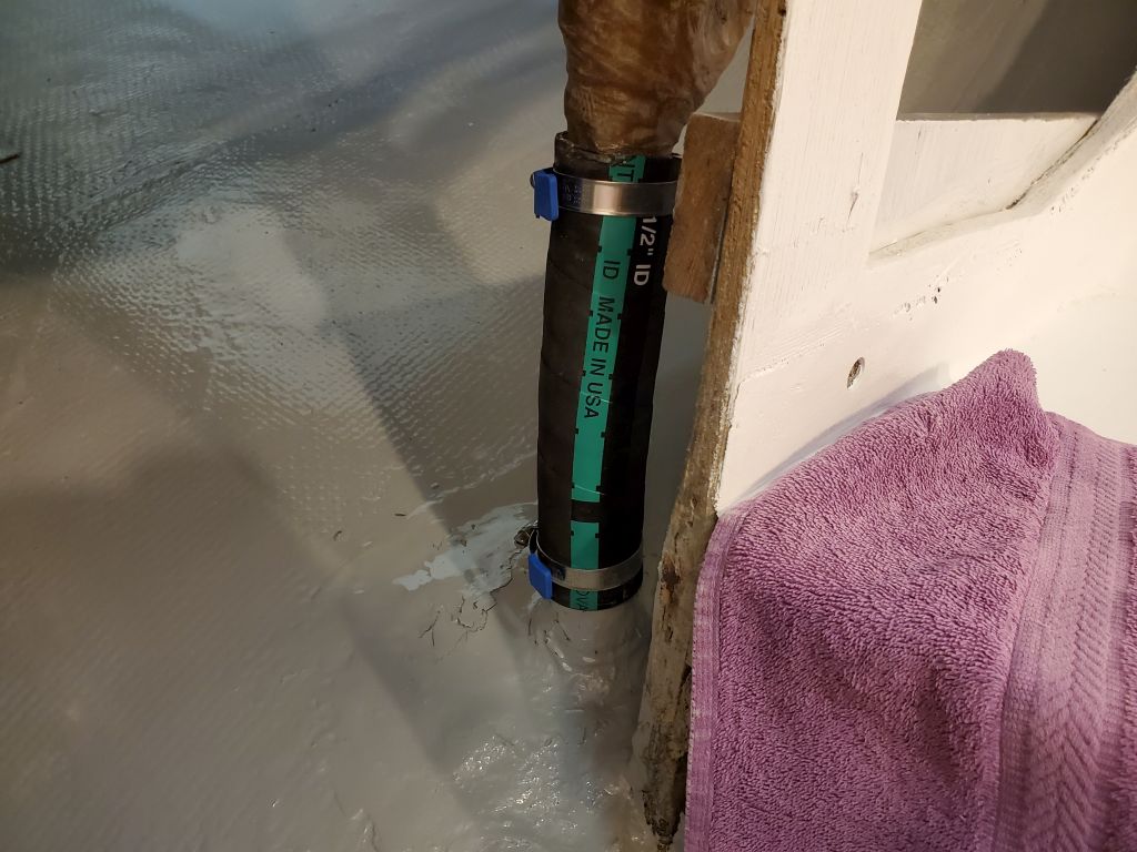
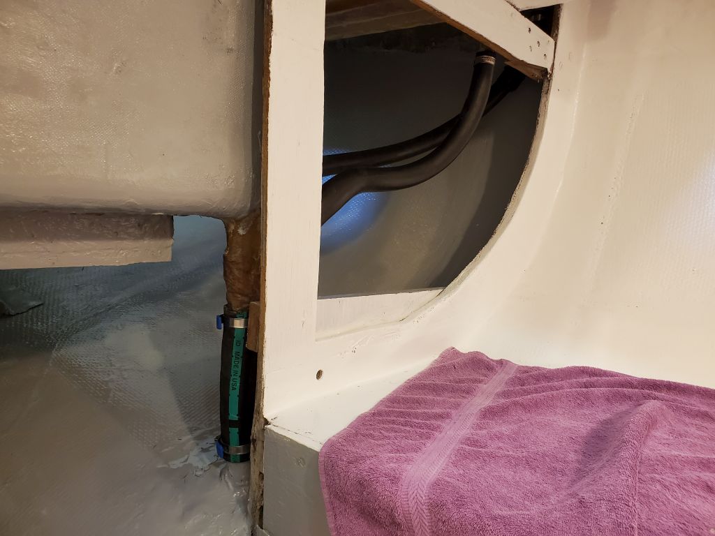
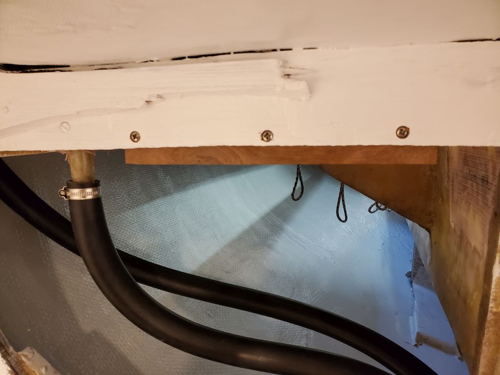
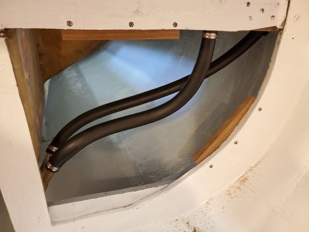
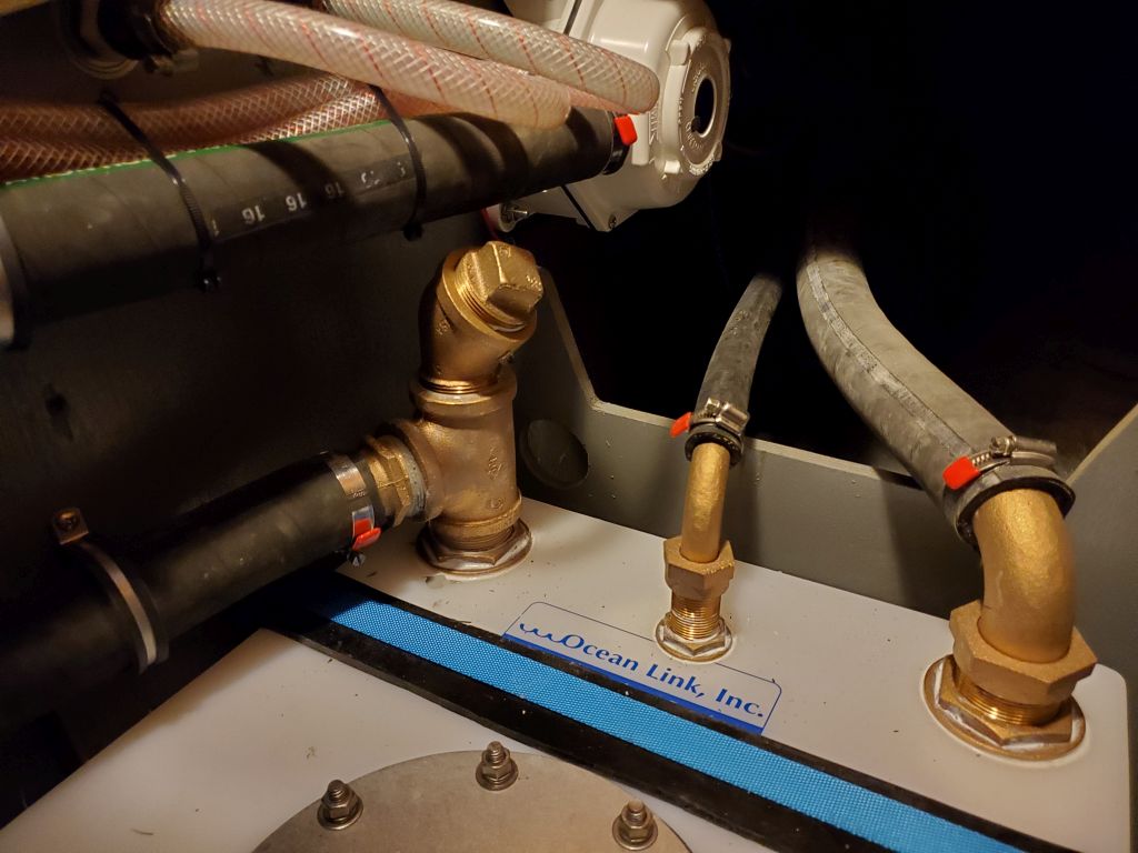
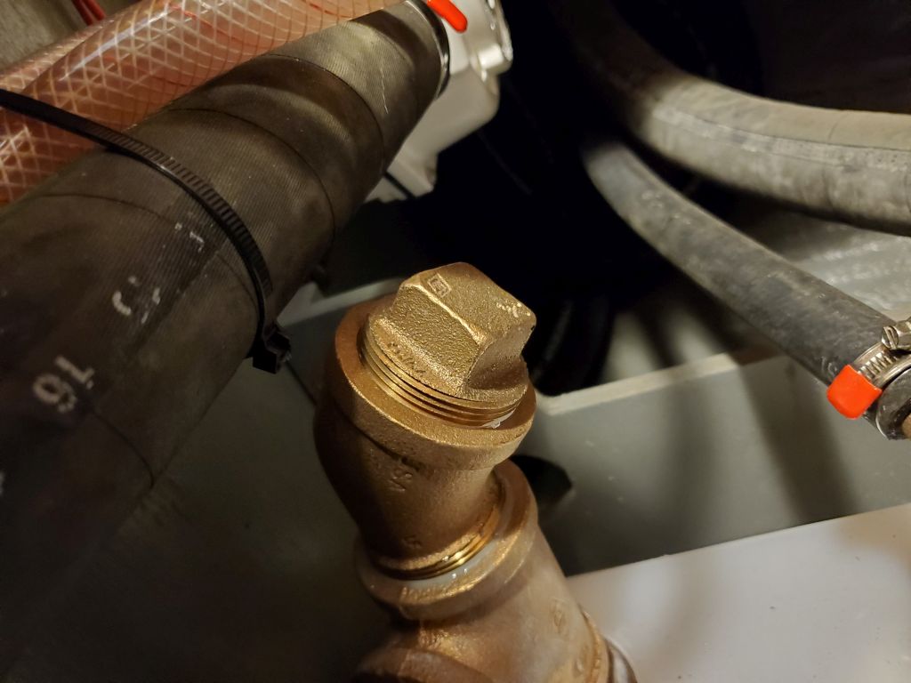
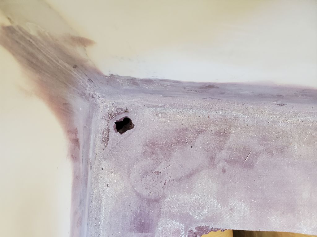
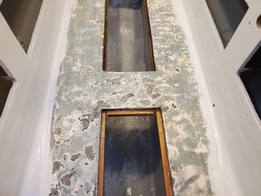
Next, I turned to the 1-1/2″ hoses for the main cockpit scuppers.  These short hoses led directly from the fiberglassed scupper tubes to similar tubes glassed into the hull nearly directly beneath, leaving little room for hose manipulation.  Knowing this issue in advance, I’d purchased hose specifically for the task that was a bit more flexible than the typical hardwall, wire-reinforced hose I might have otherwise used, hoping it would fit better in the tight space.  The fabric-reinforced coolant hose would be plenty strong, but much more supple for installation.

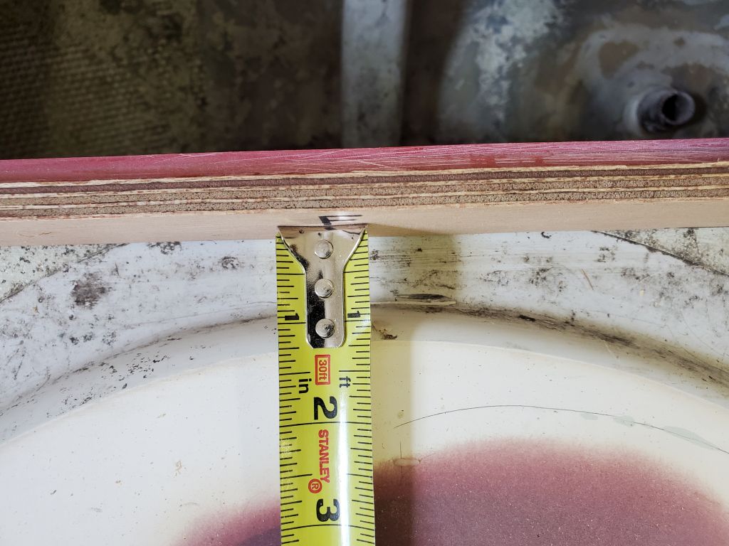
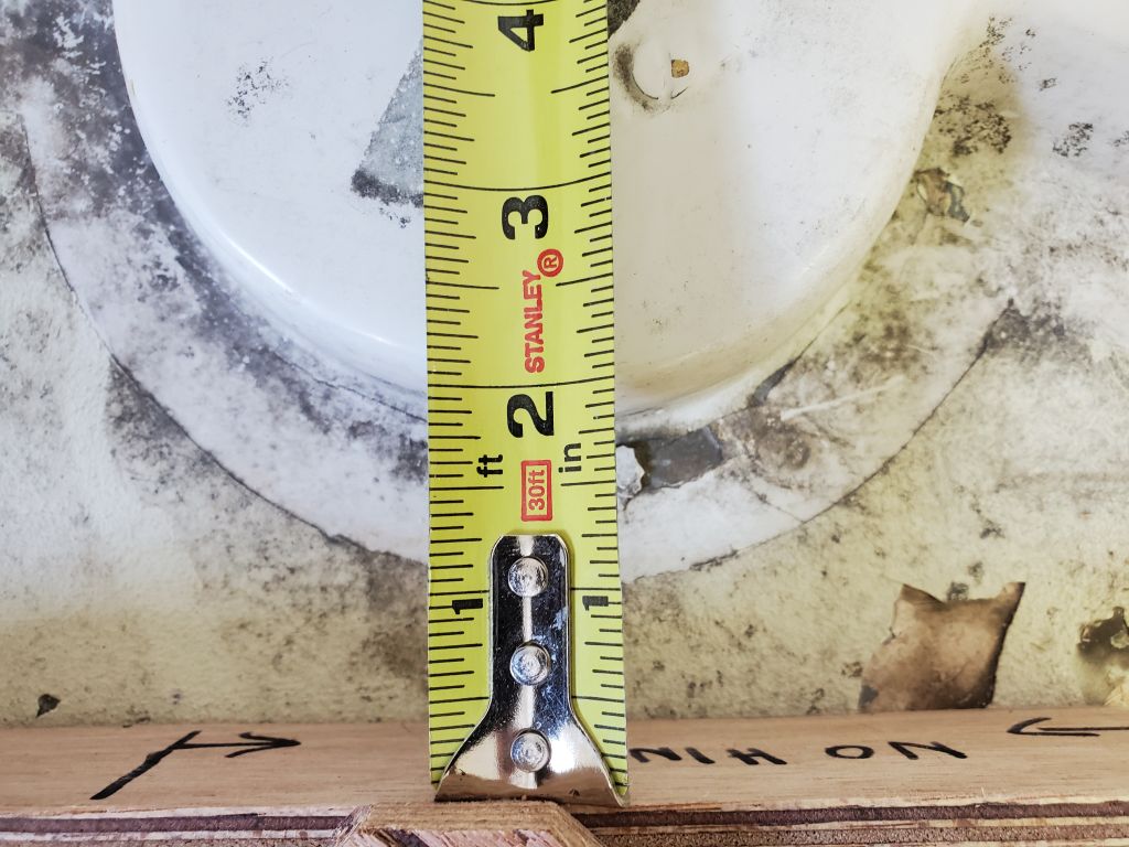
Before beginning, I made a mark on the hull tube end to give me a reference for how far onto those tubes, at a minimum, the hose needed to extend for good clamping.  If I couldn’t see the mark when all was said and done, I’d know all was well.  As it happened, the hose worked well for the application, as hoped, and I had little trouble installing it by forcing it down onto the hull barb as far as possible, then bending and manipulating the top end onto the tube beneath the cockpit, after which I could pull the hose back up while still leaving plenty of hose on the lower barb for clamping.

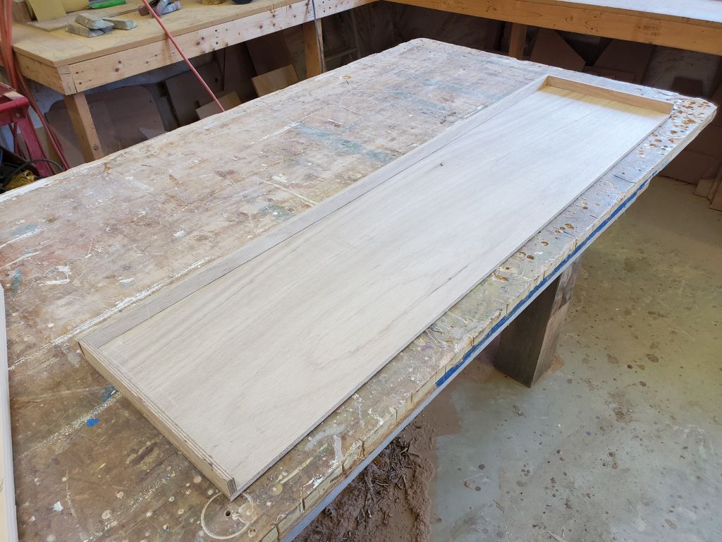
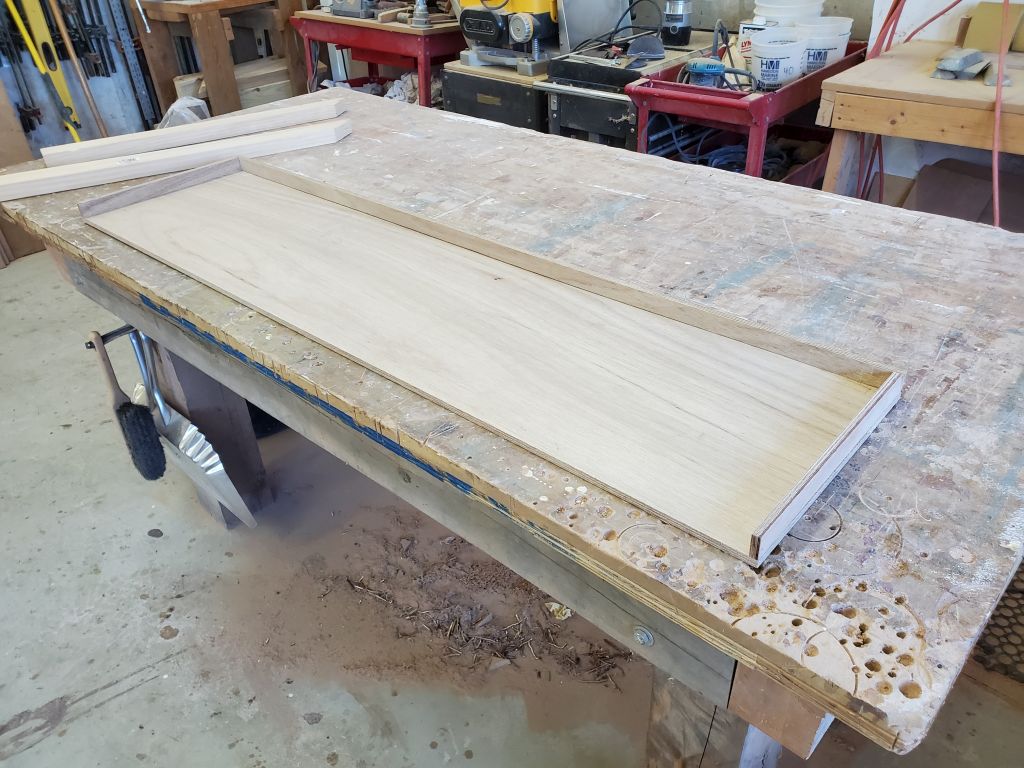
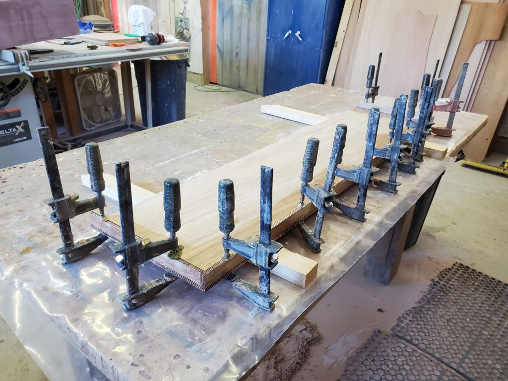
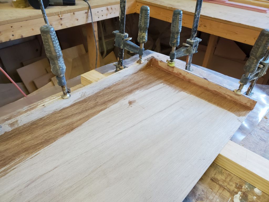
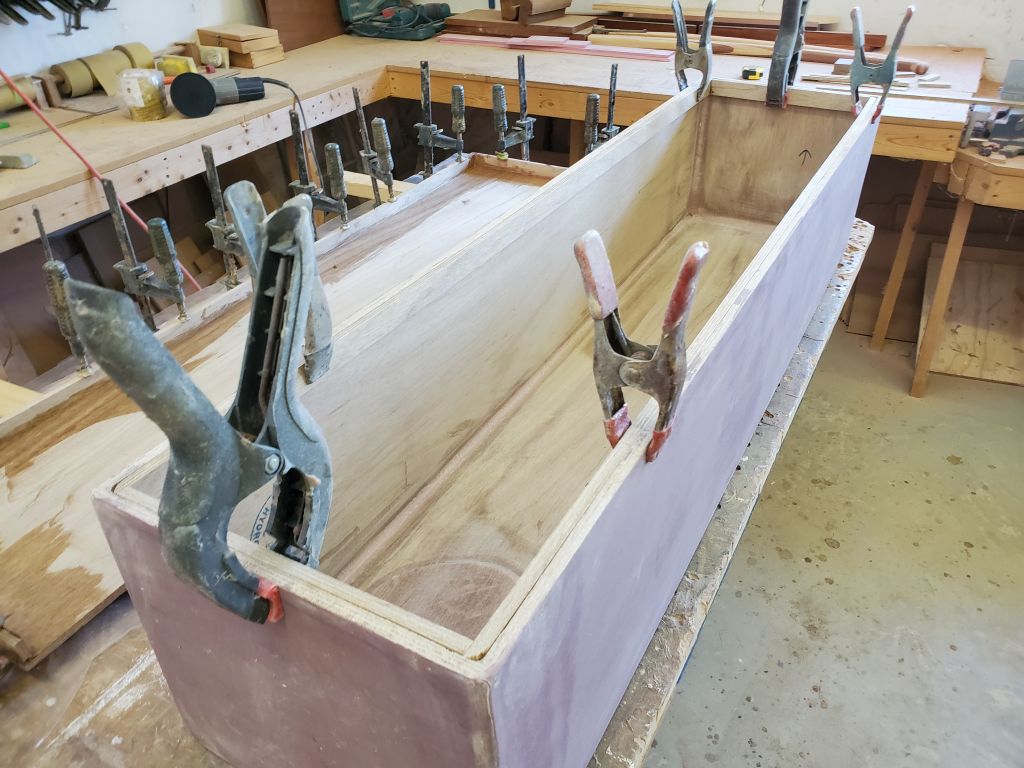
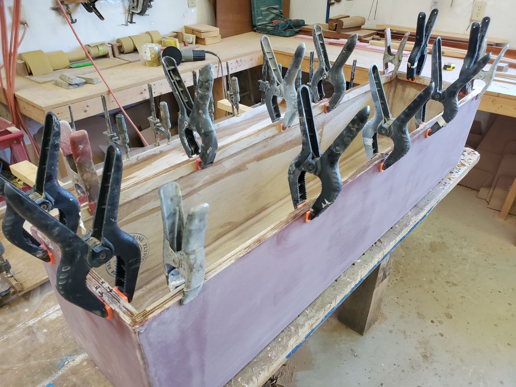
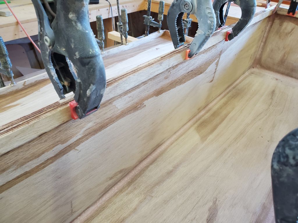
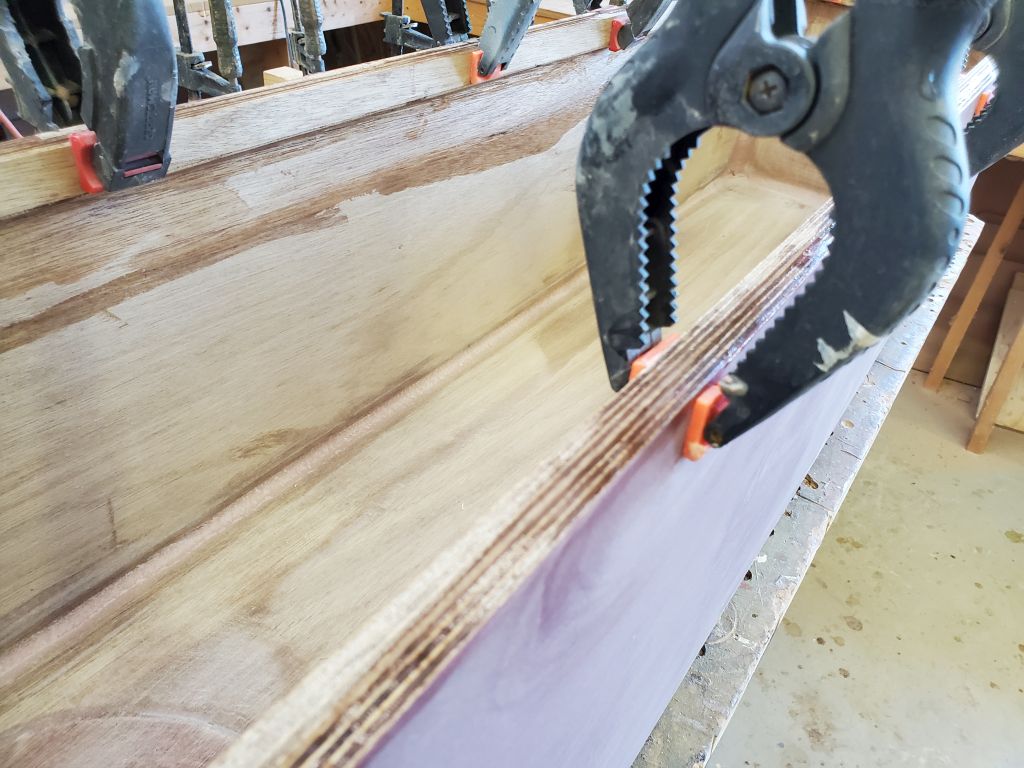
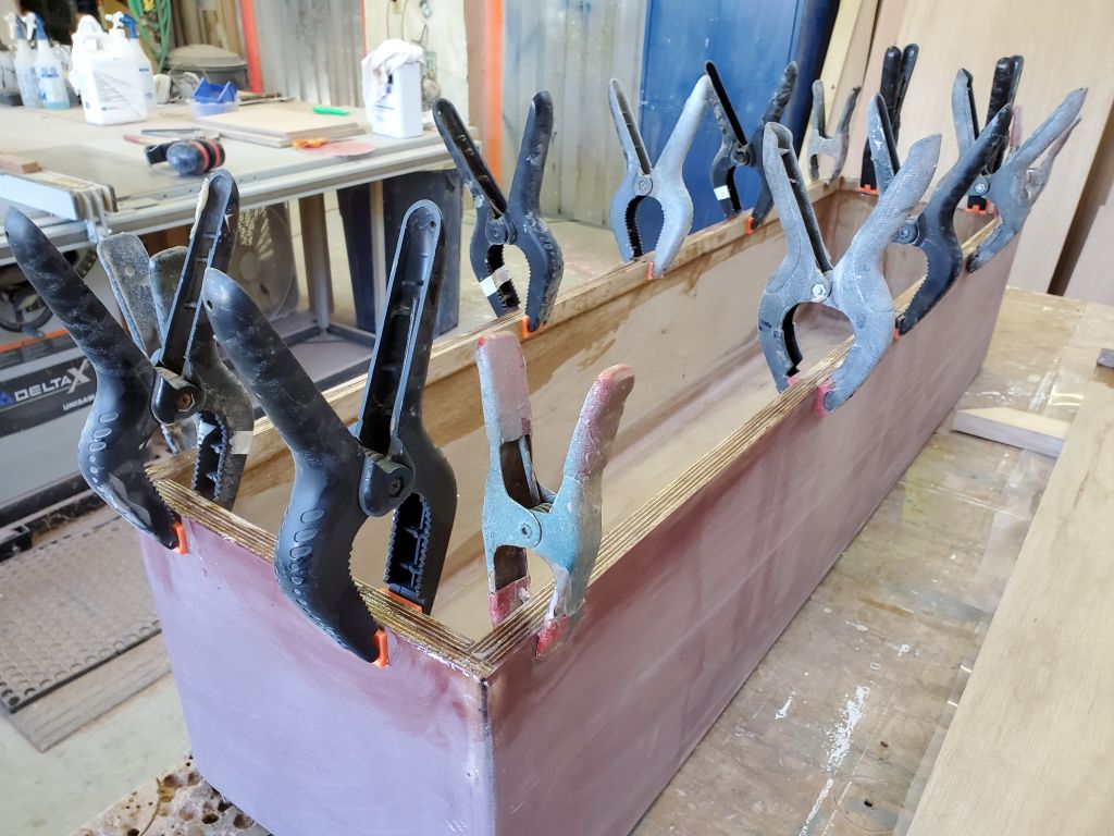
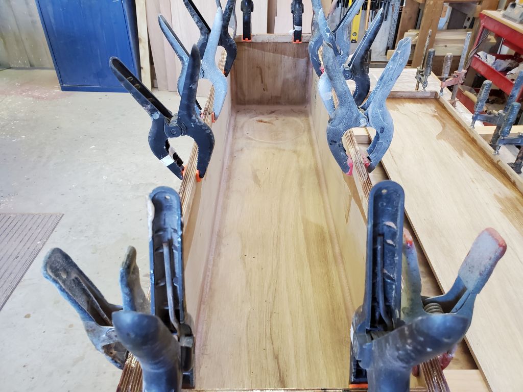
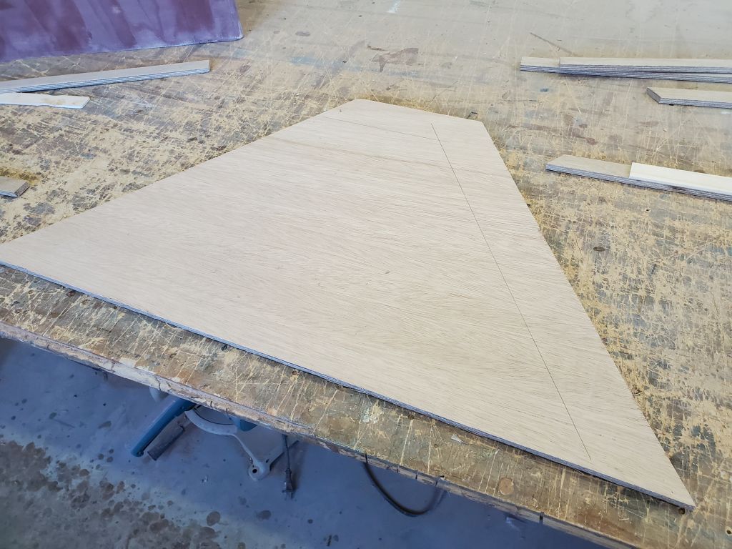
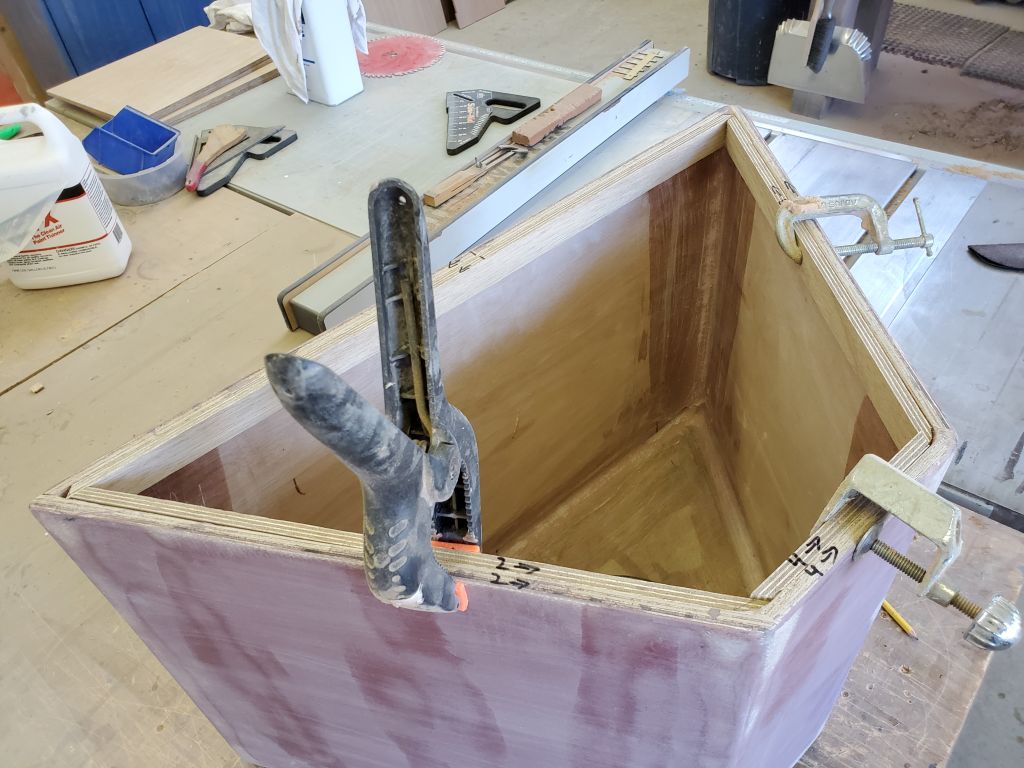
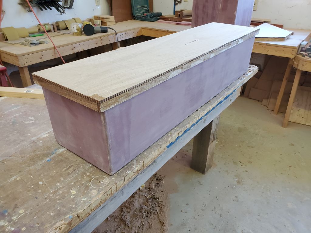
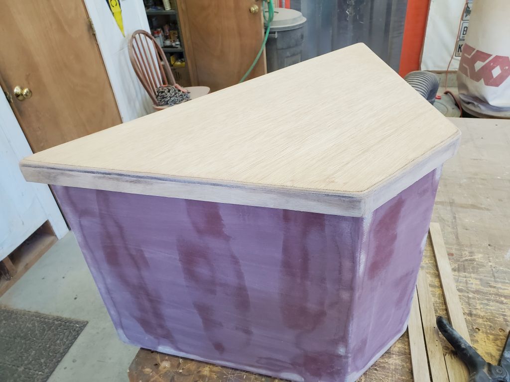
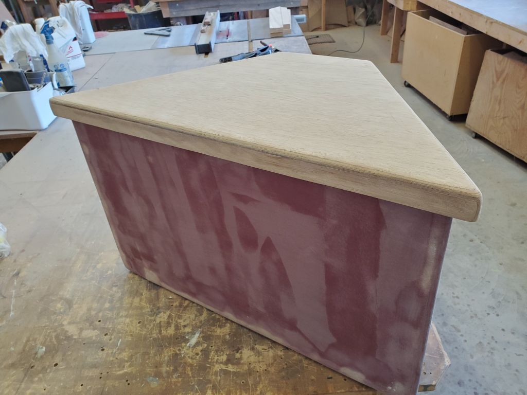
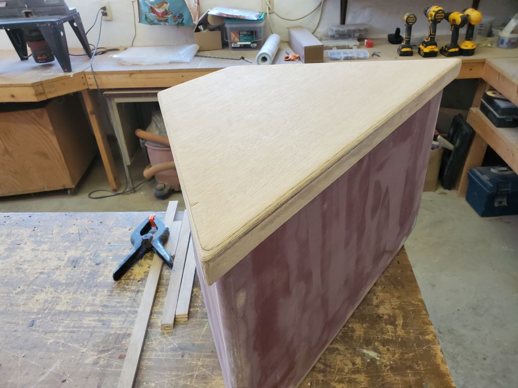
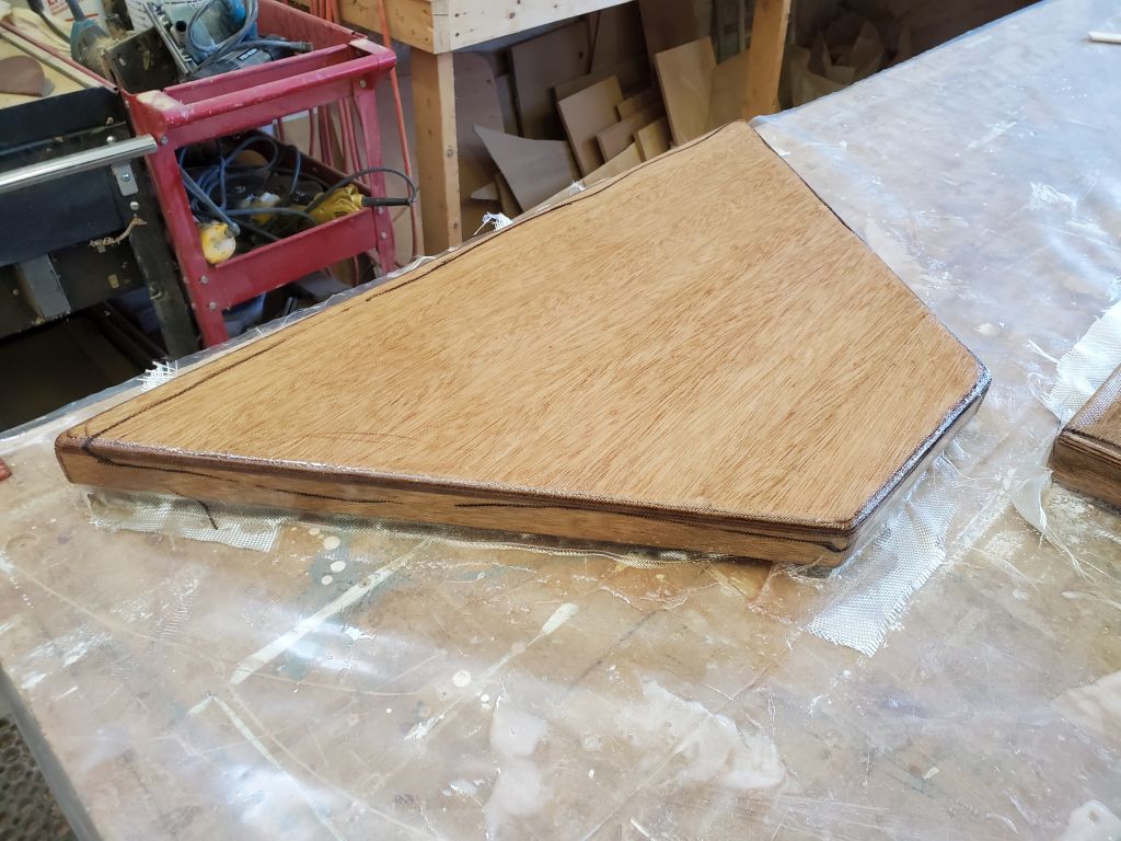
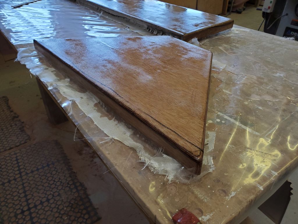
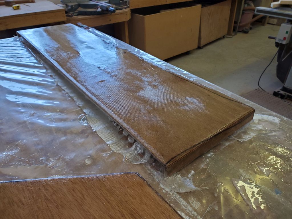
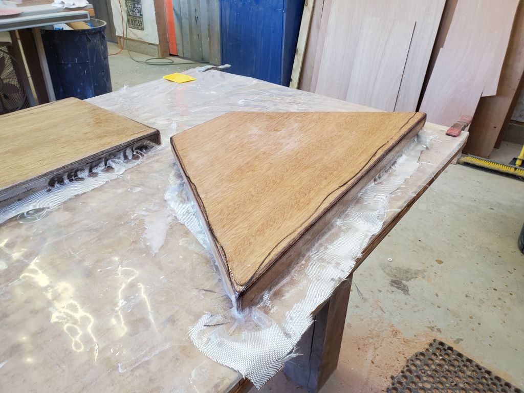
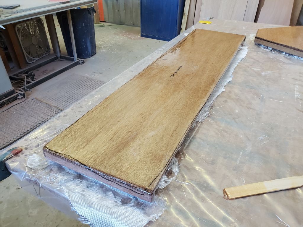
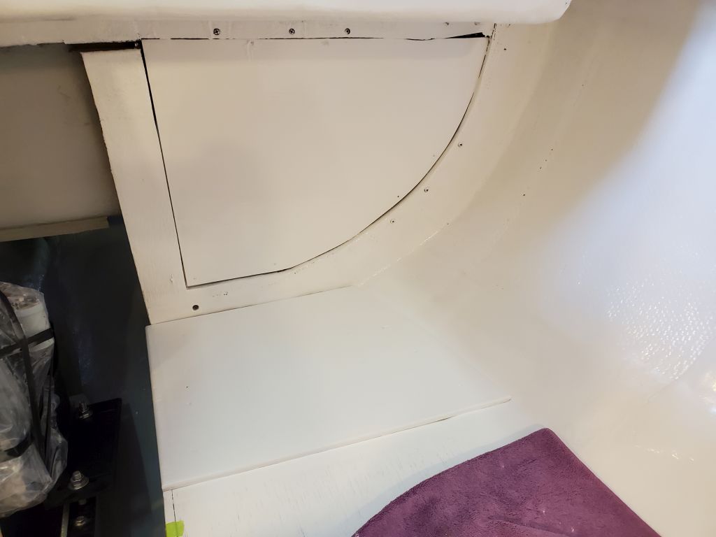
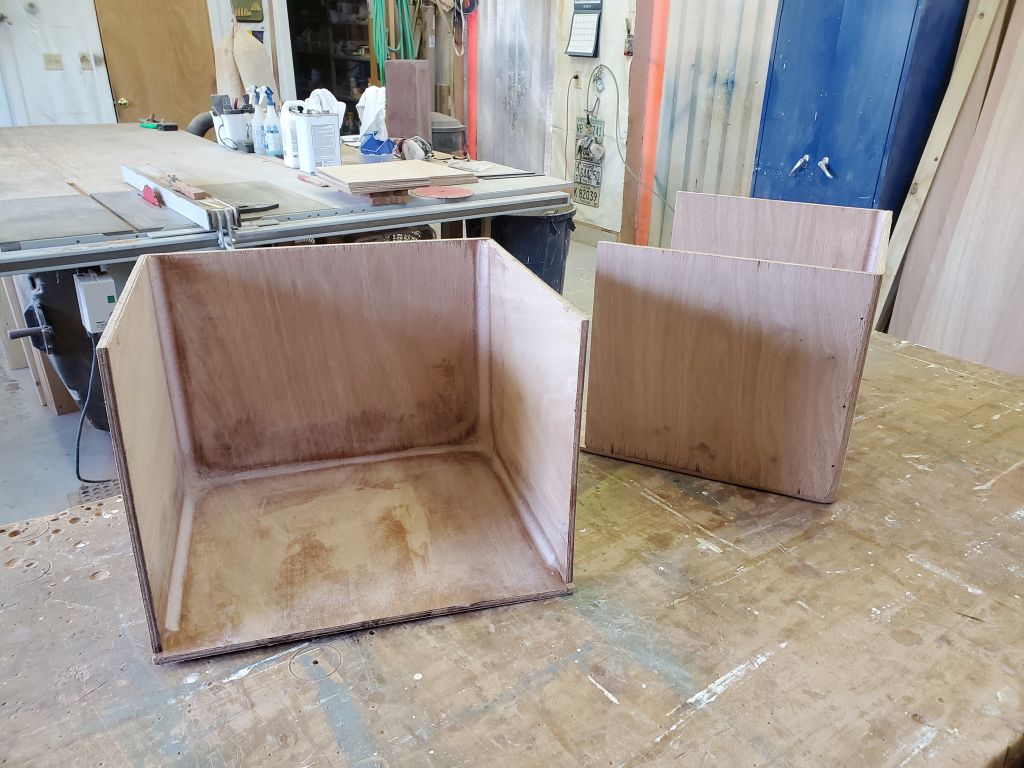
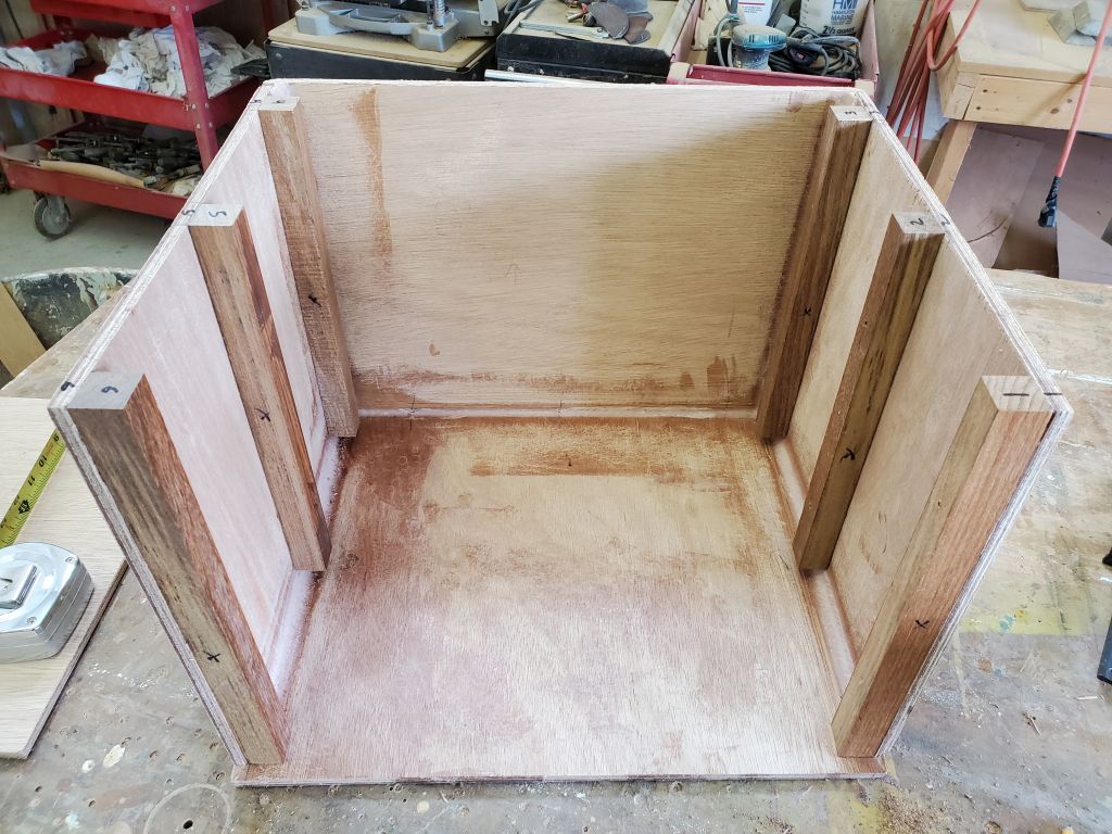
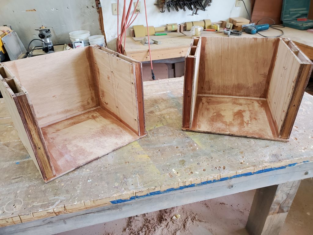
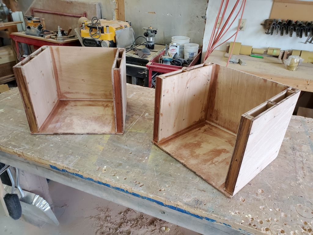
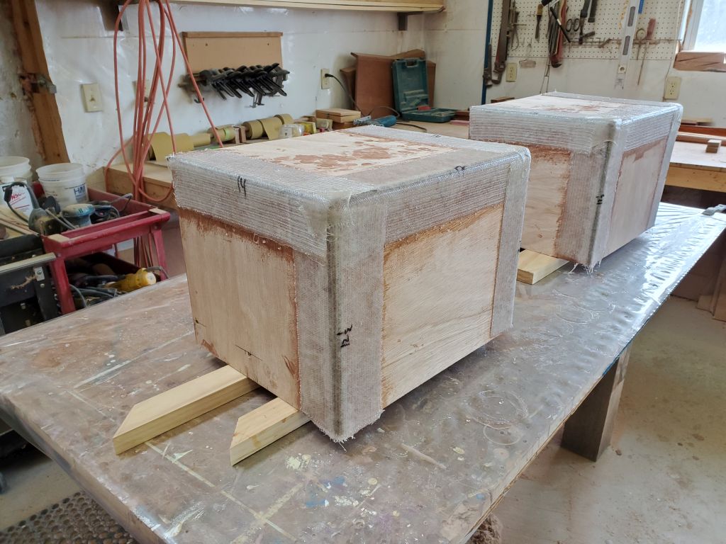
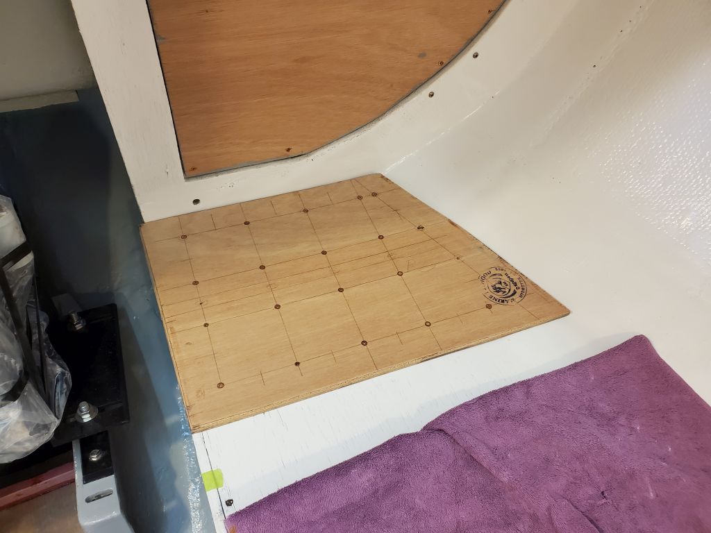
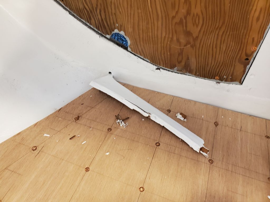
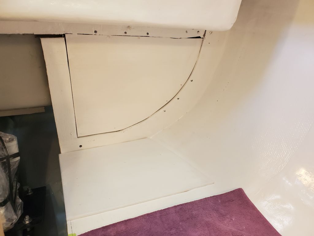
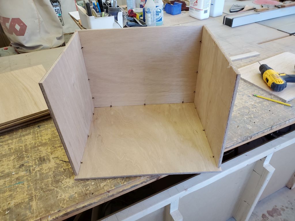
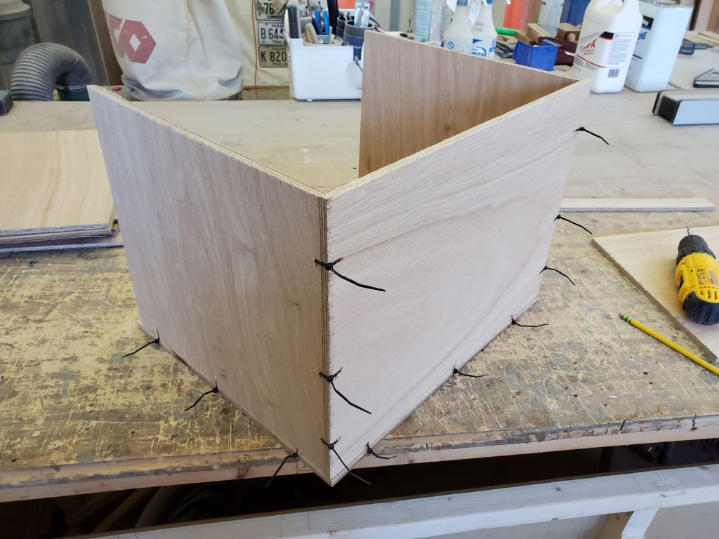
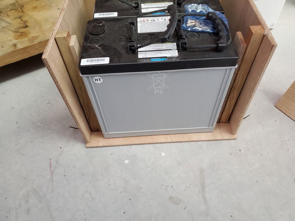
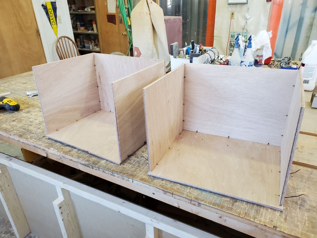
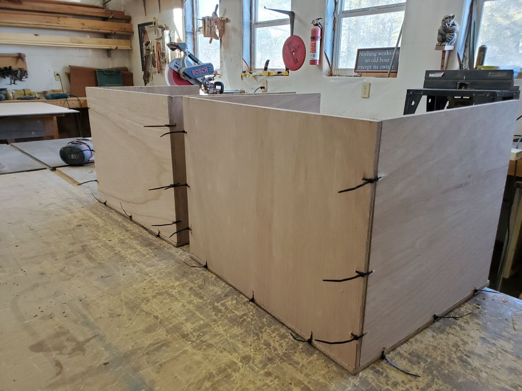
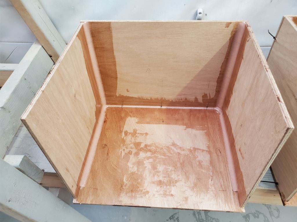
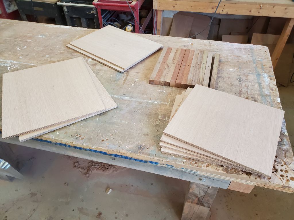
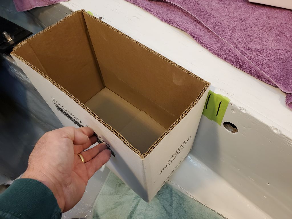
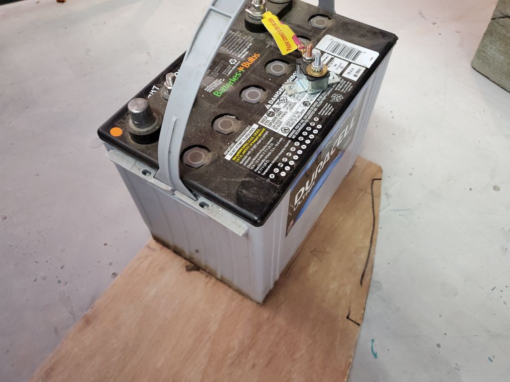
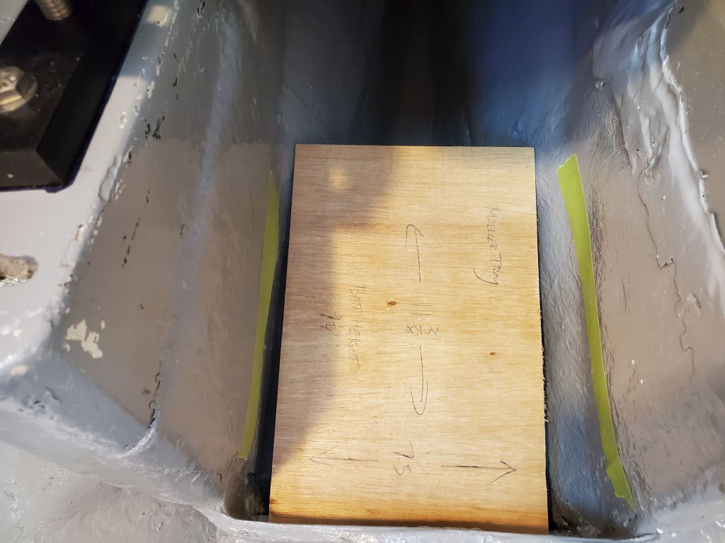
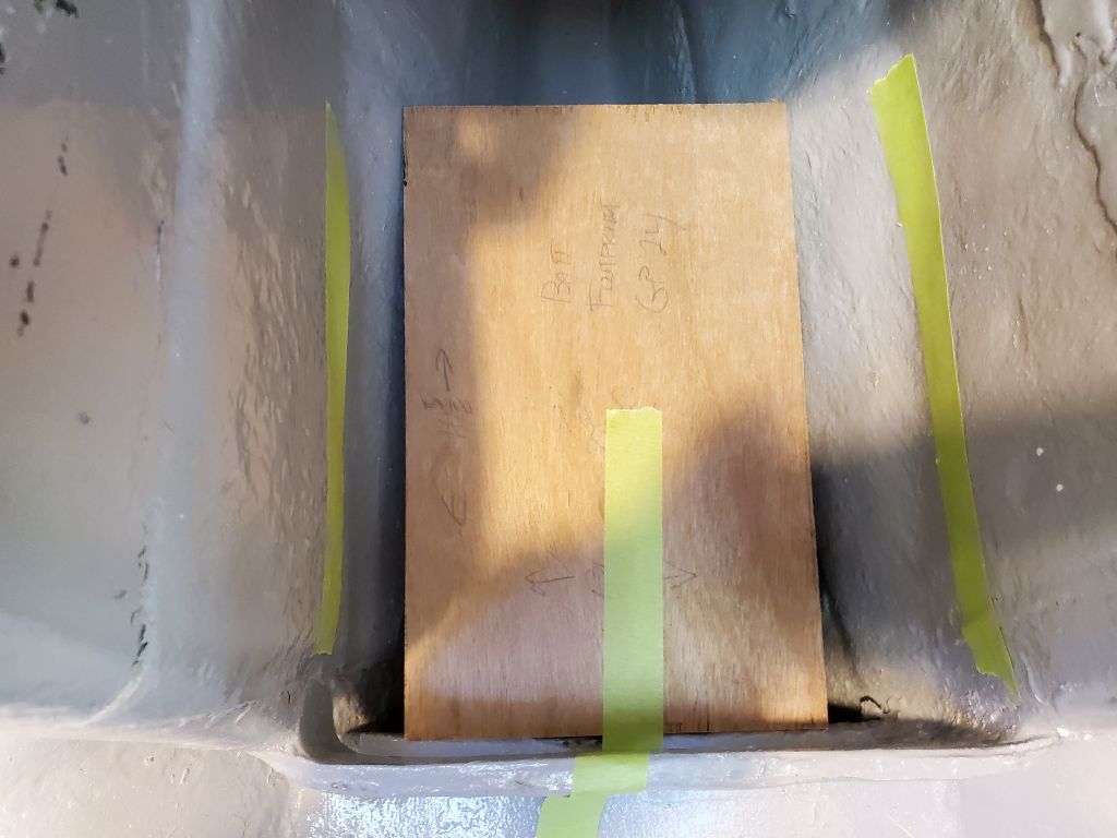
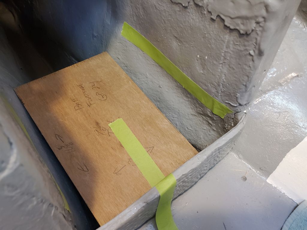
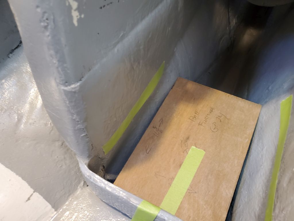
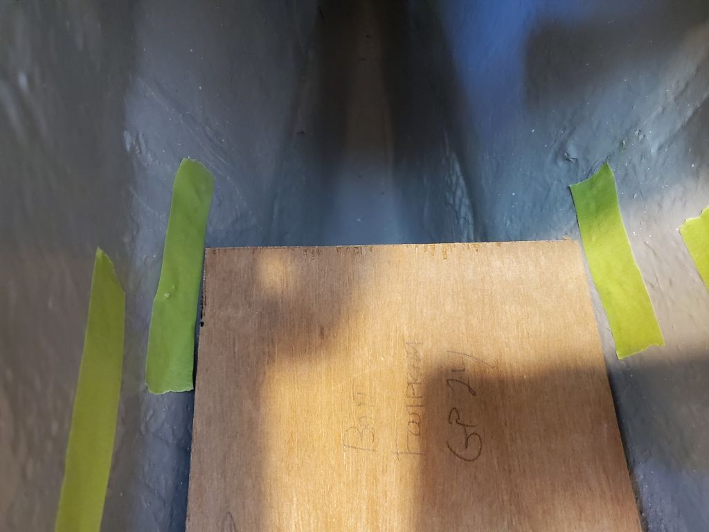
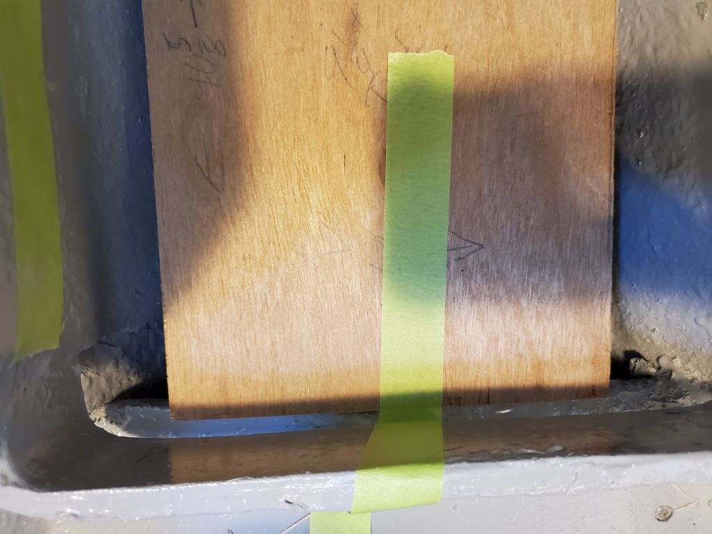
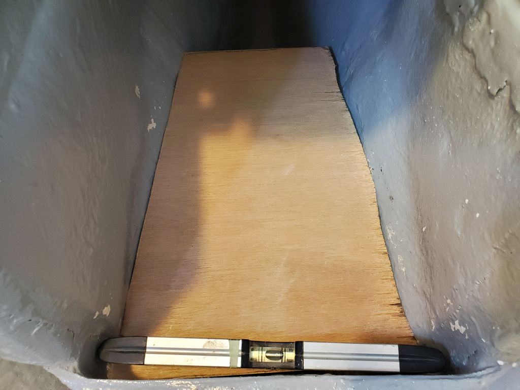
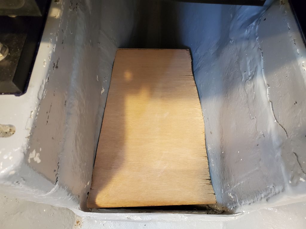
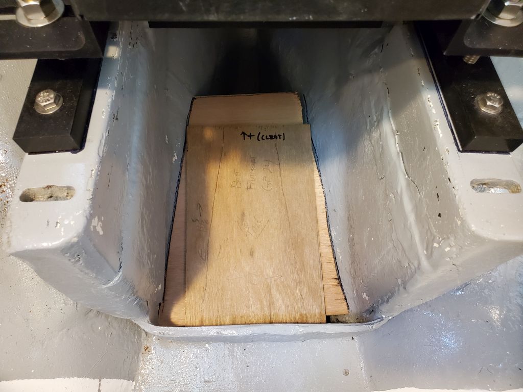
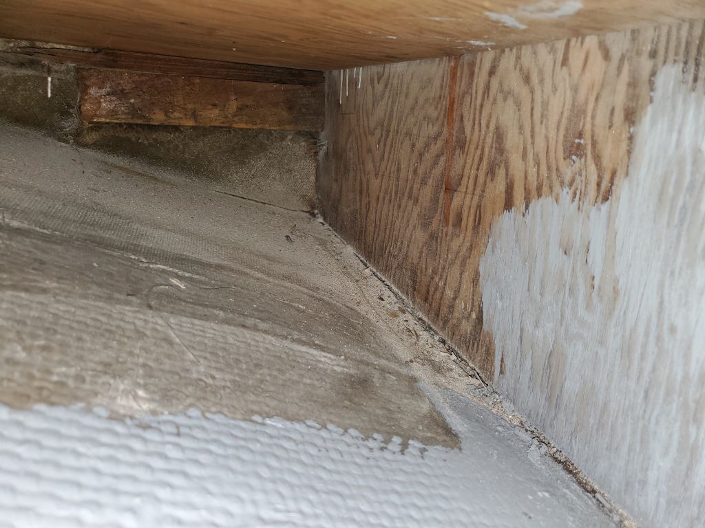
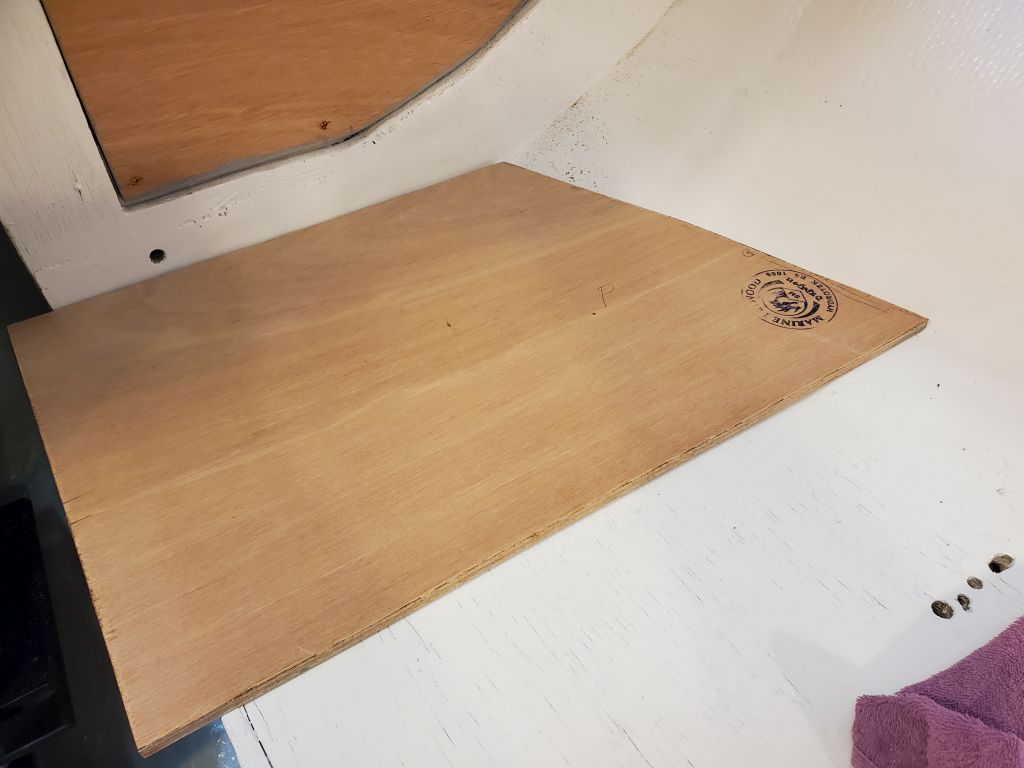
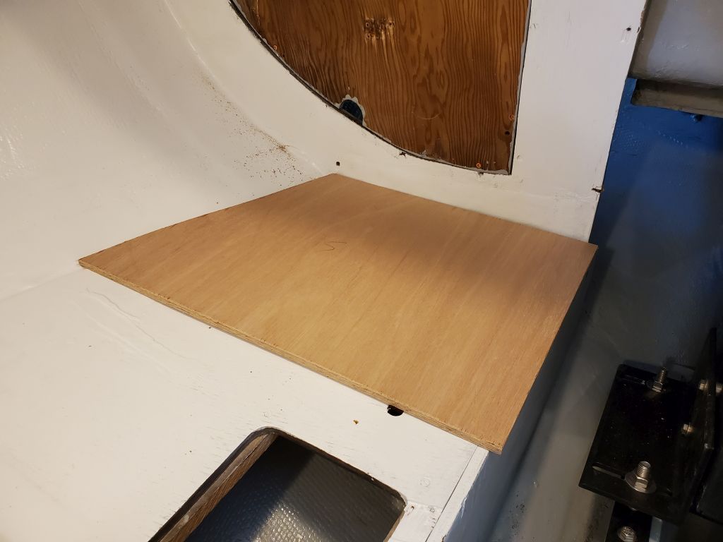
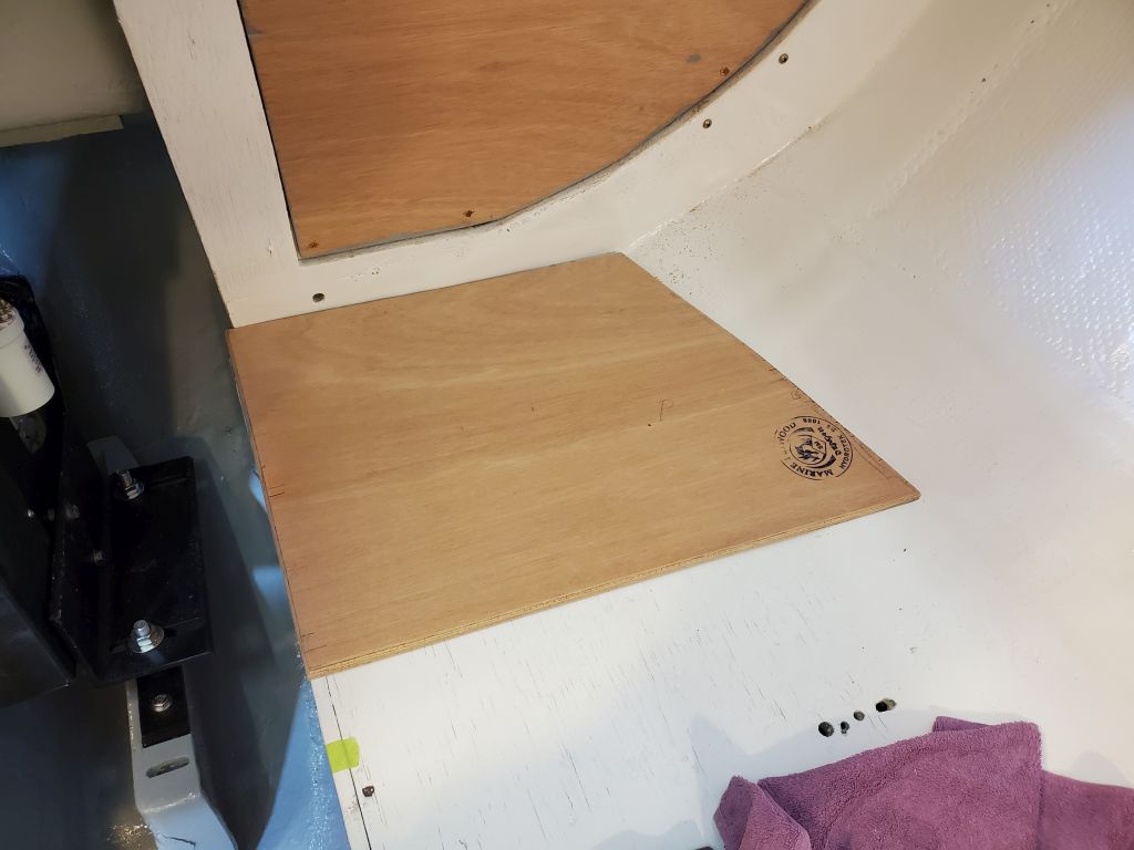
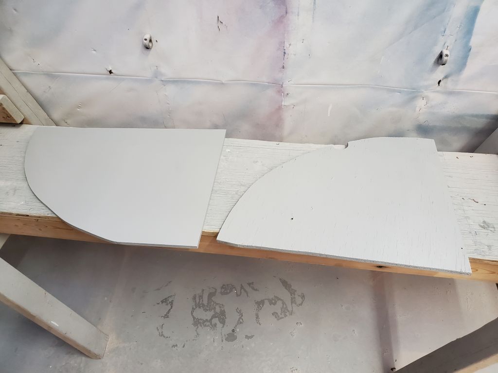
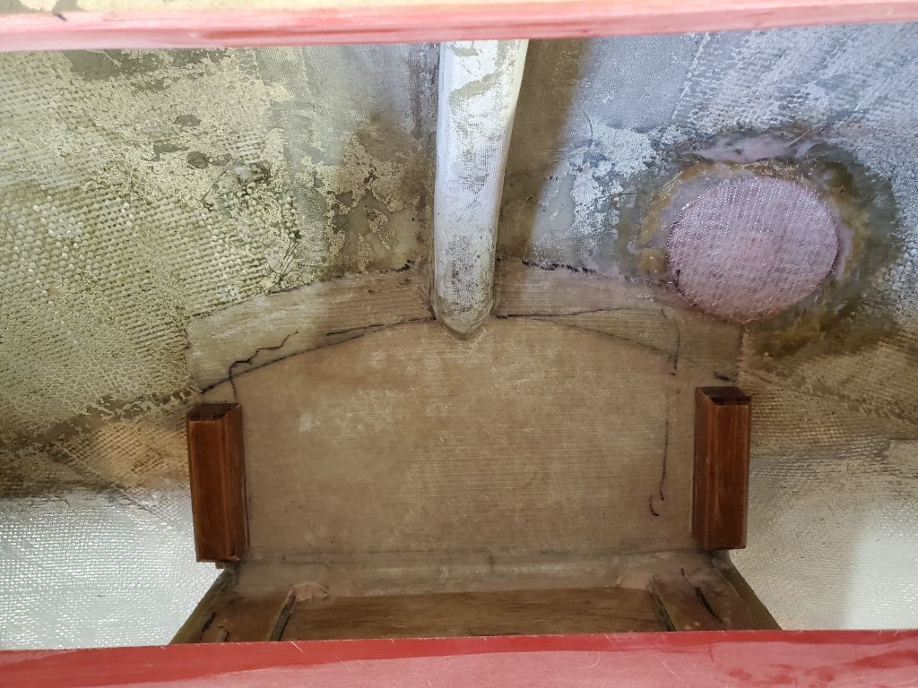
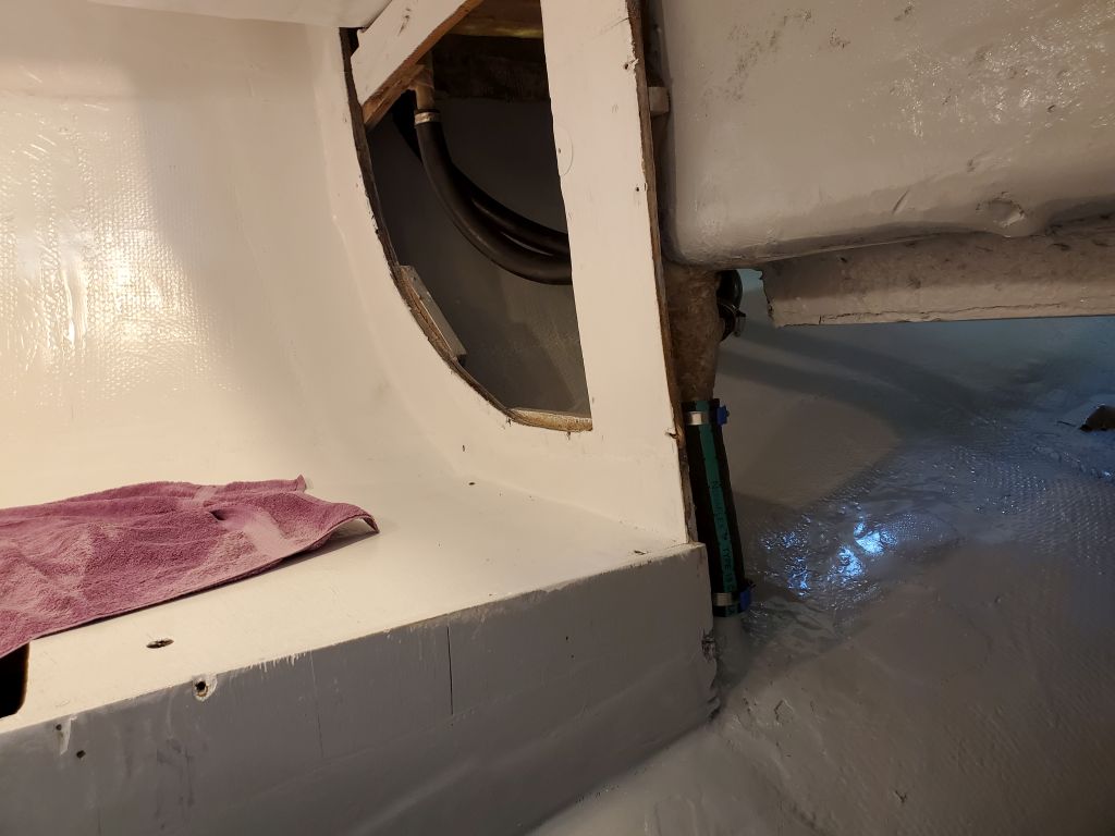
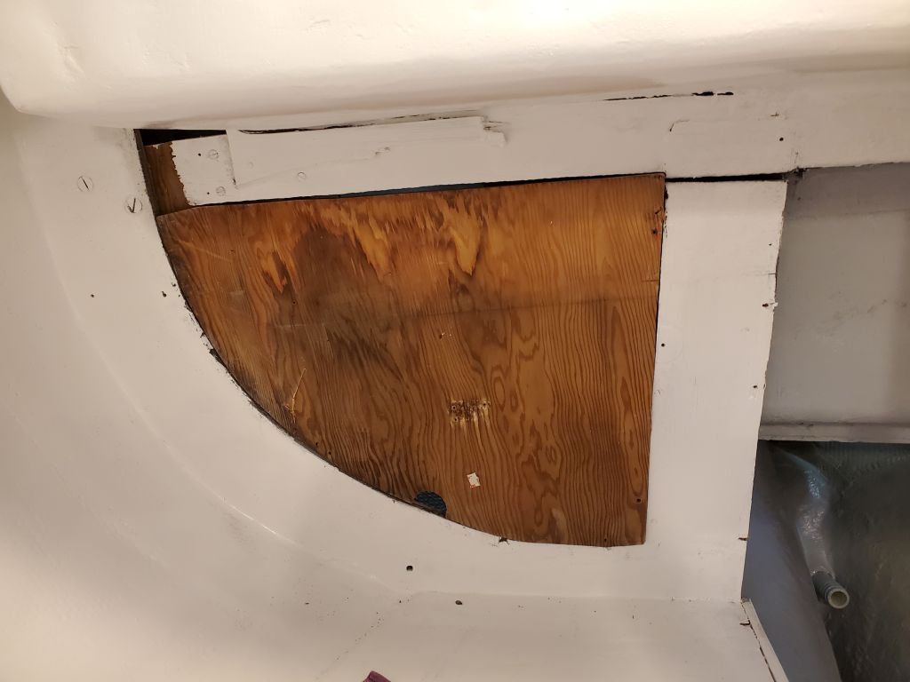
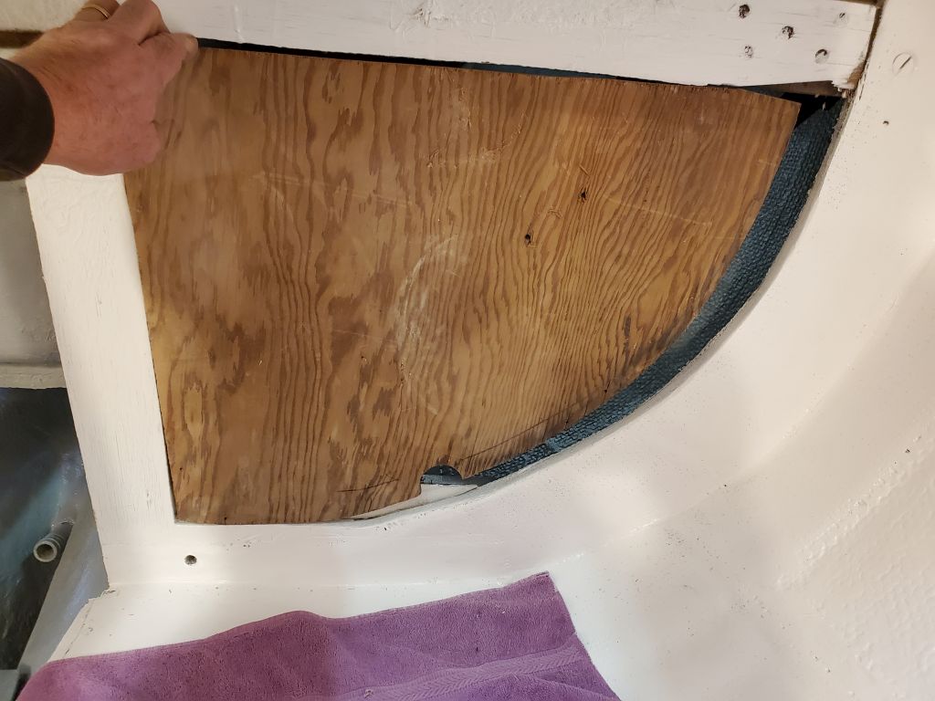
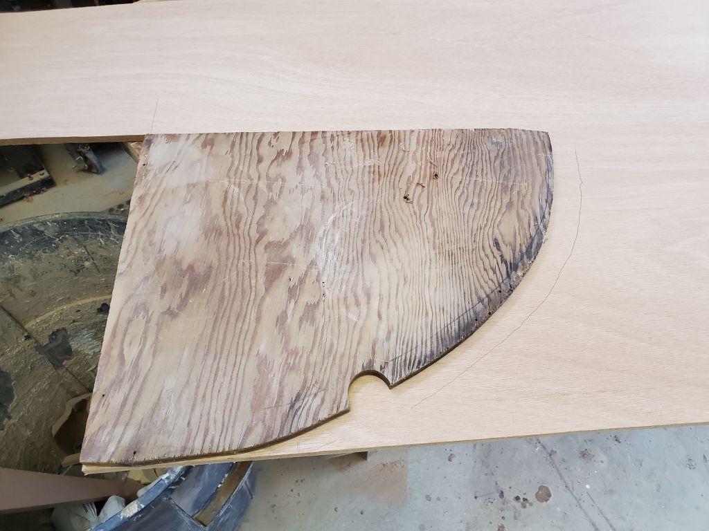
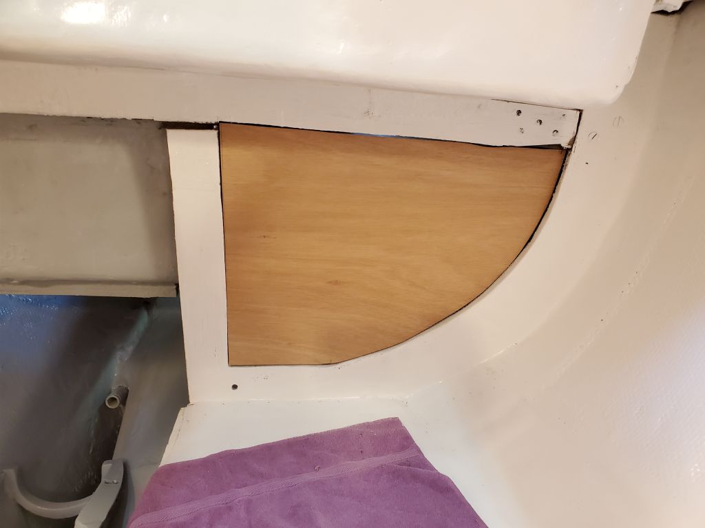
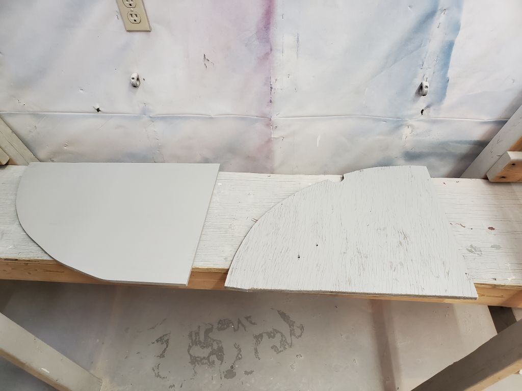
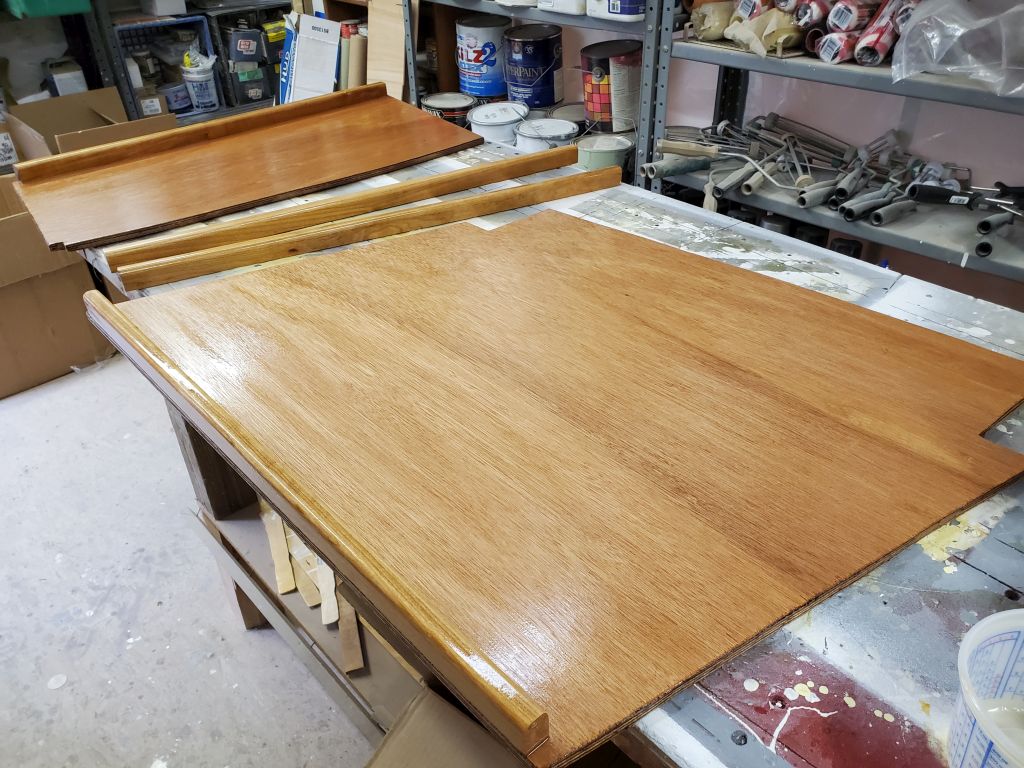
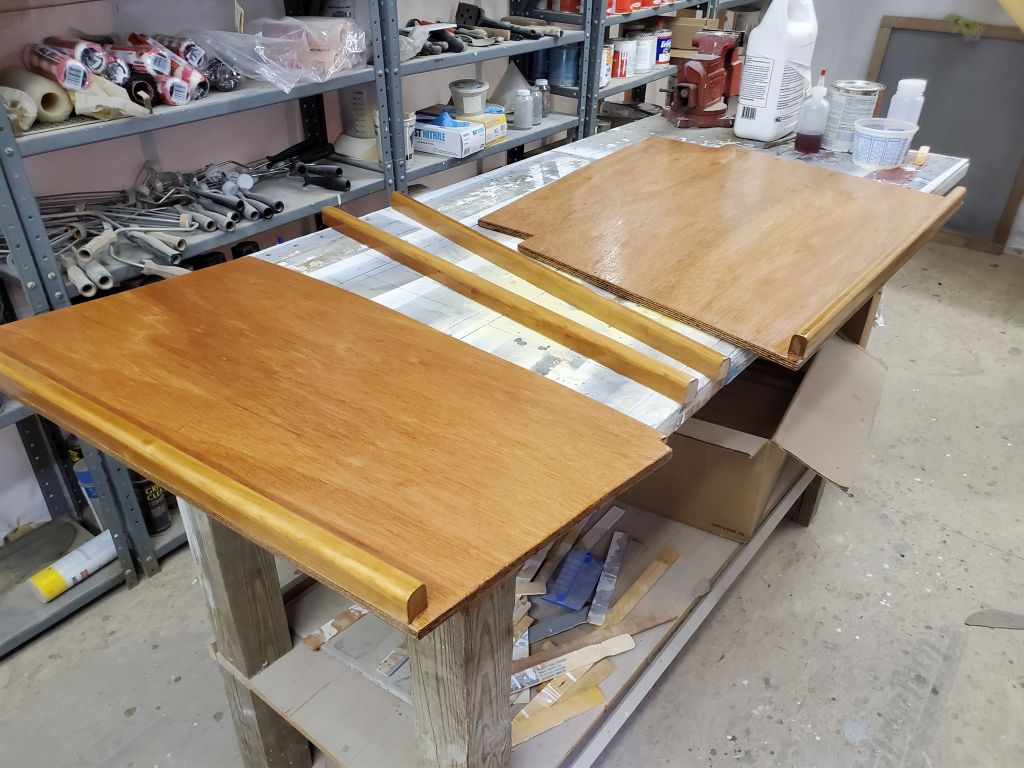
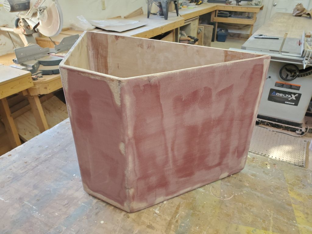
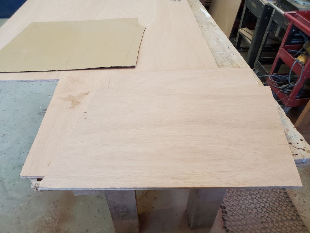
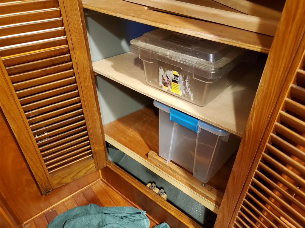
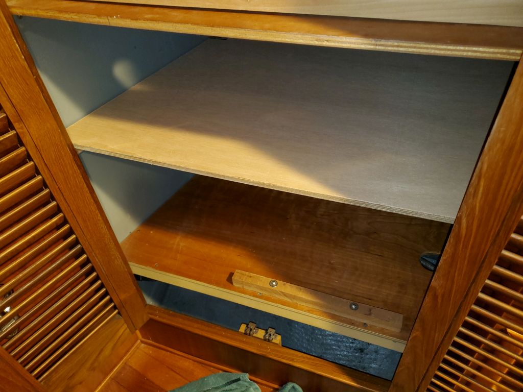
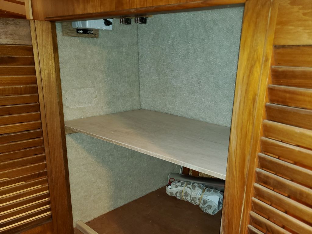
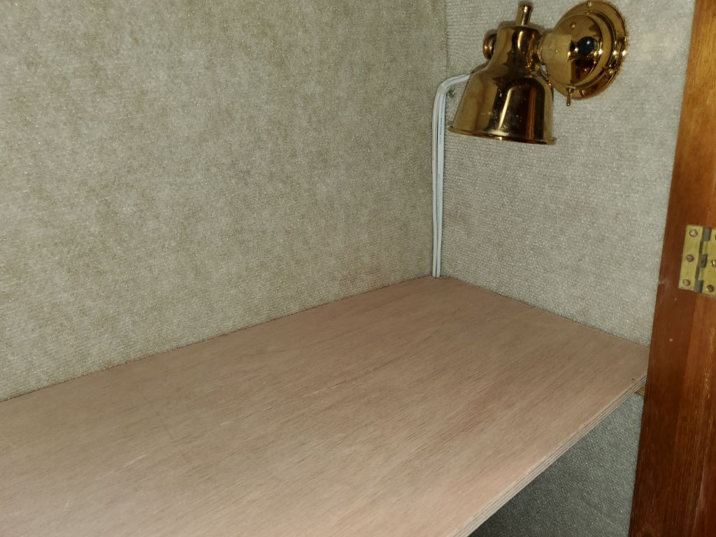
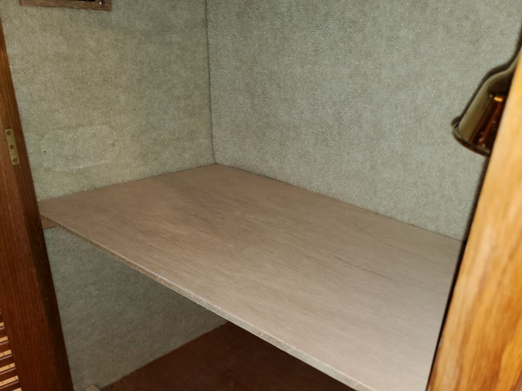
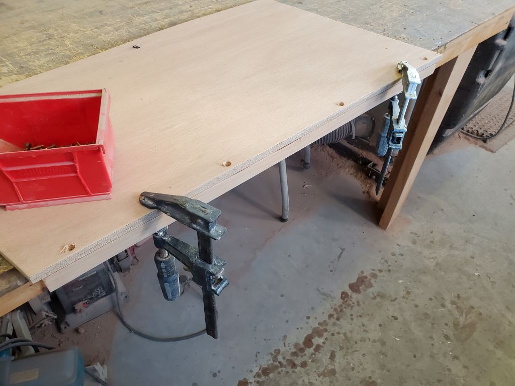
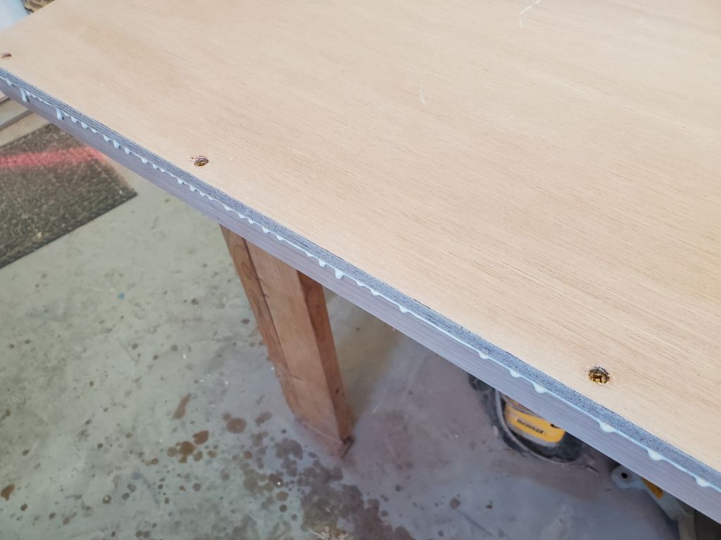
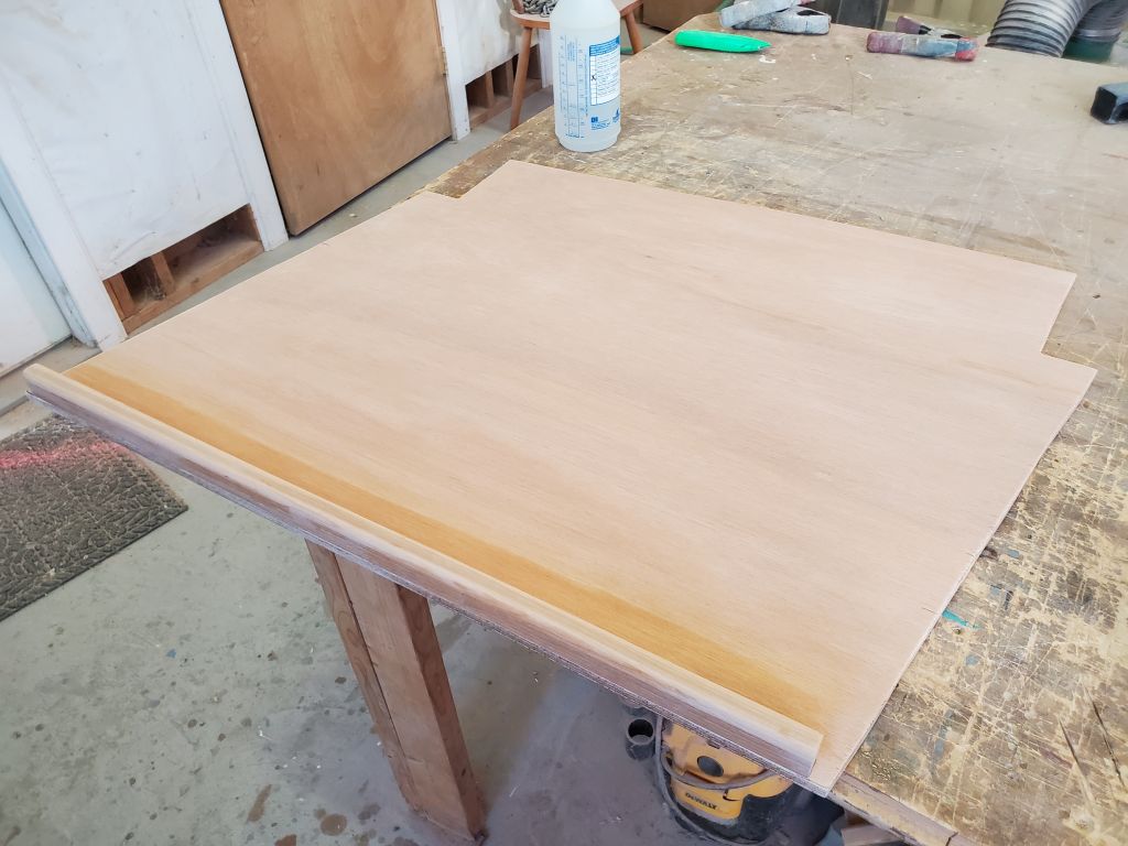
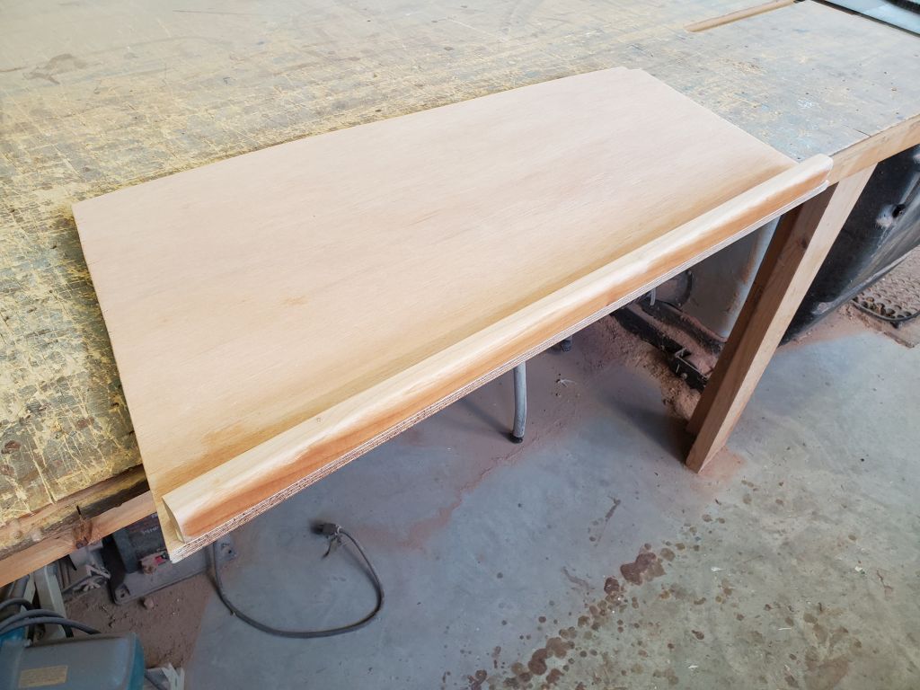
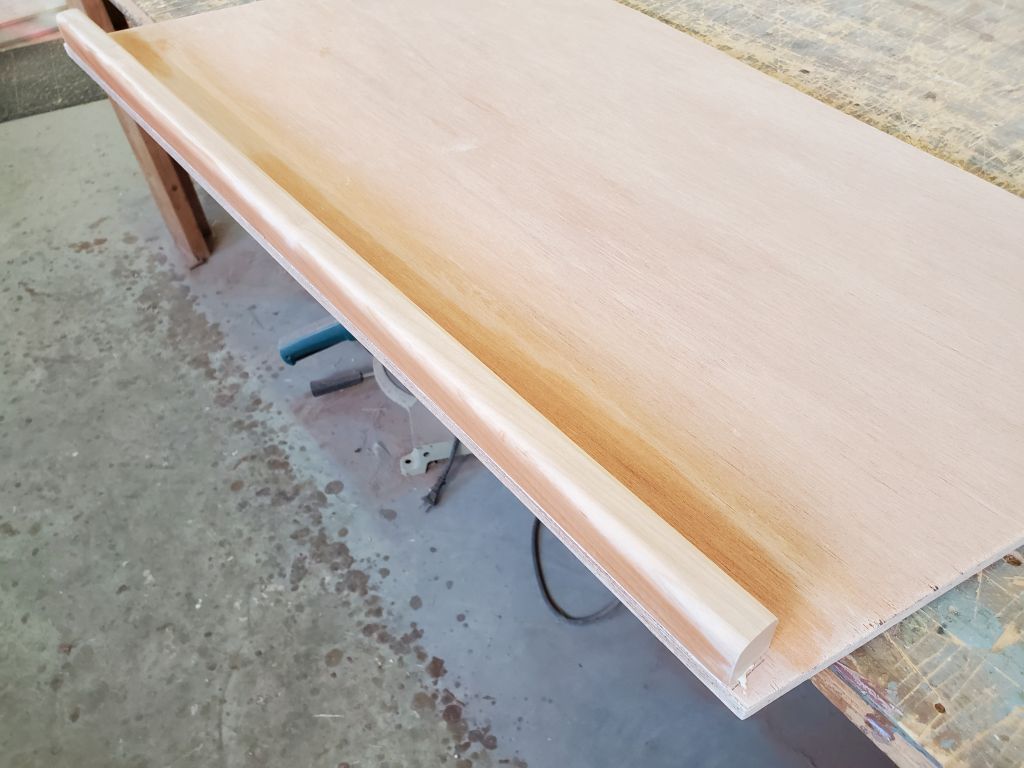
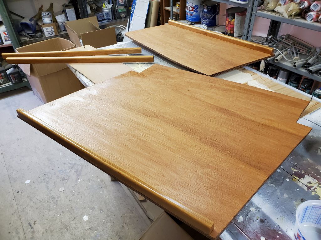
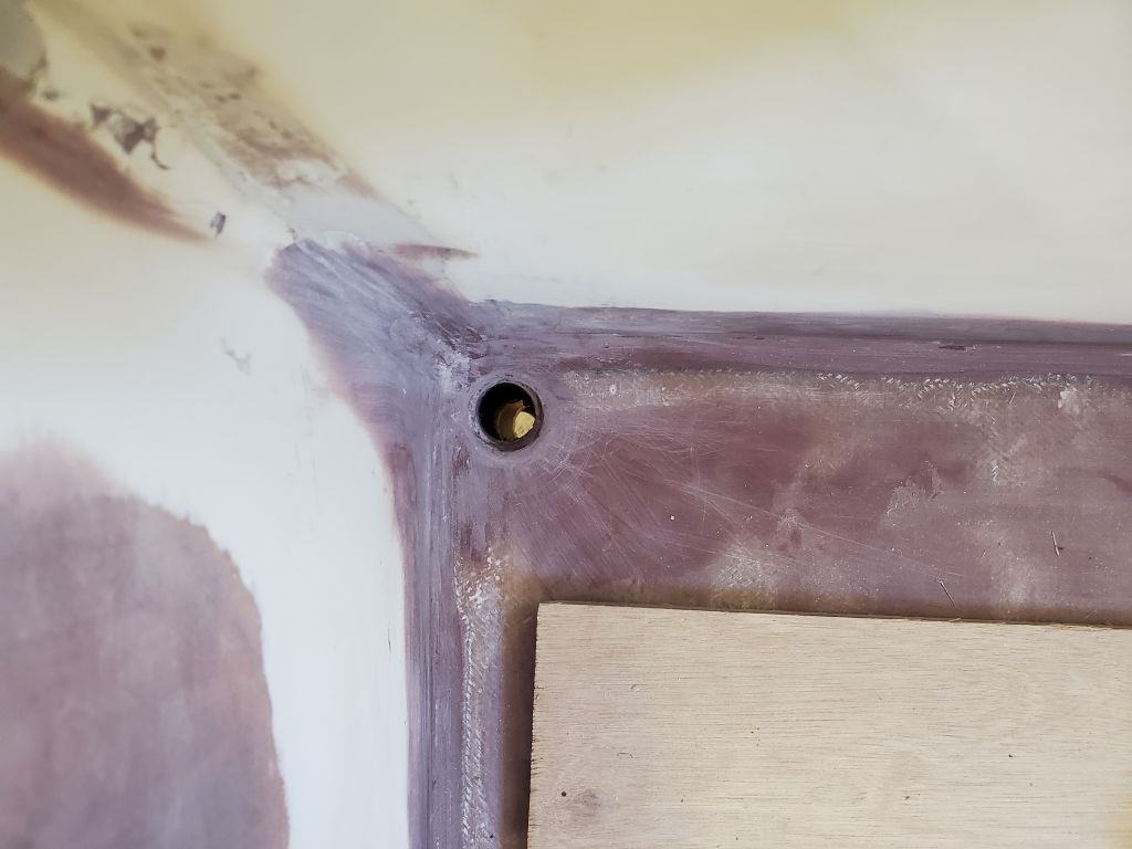
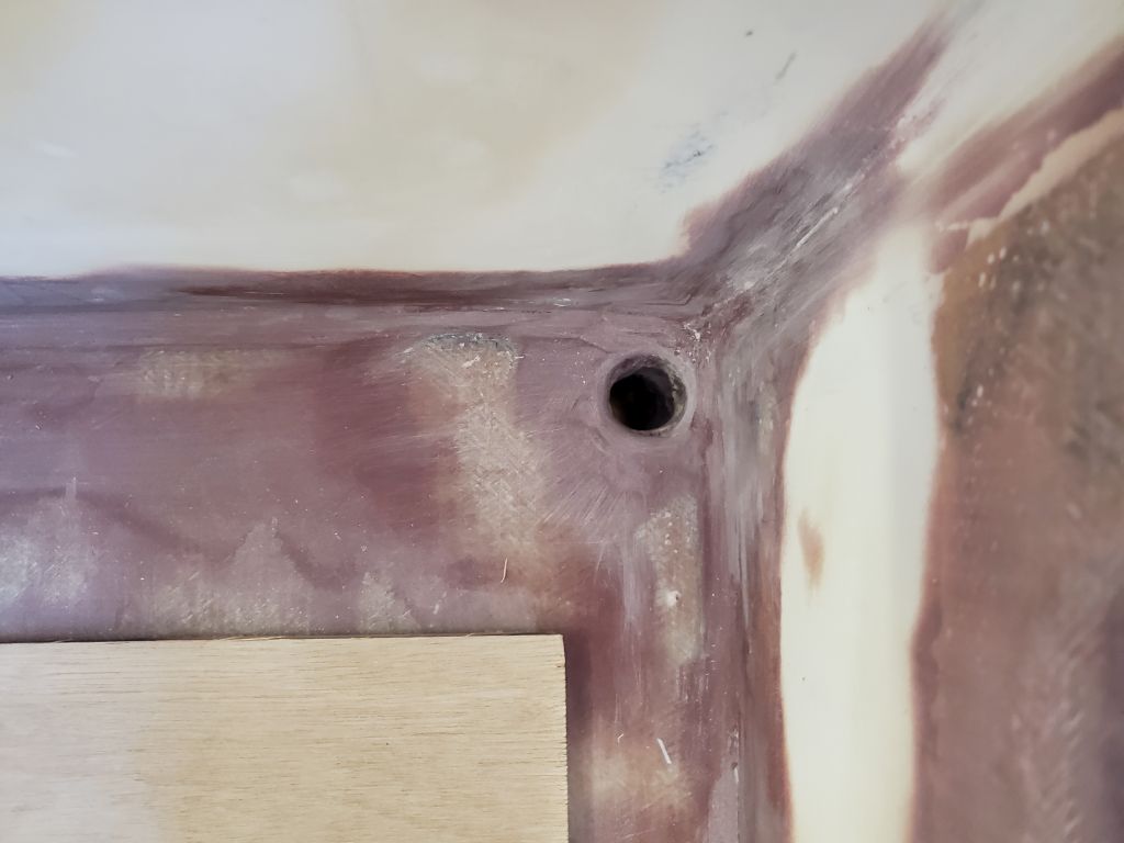
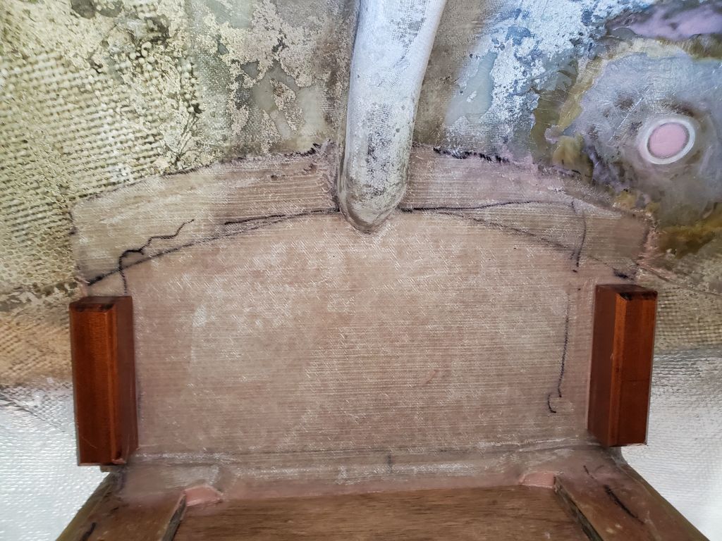
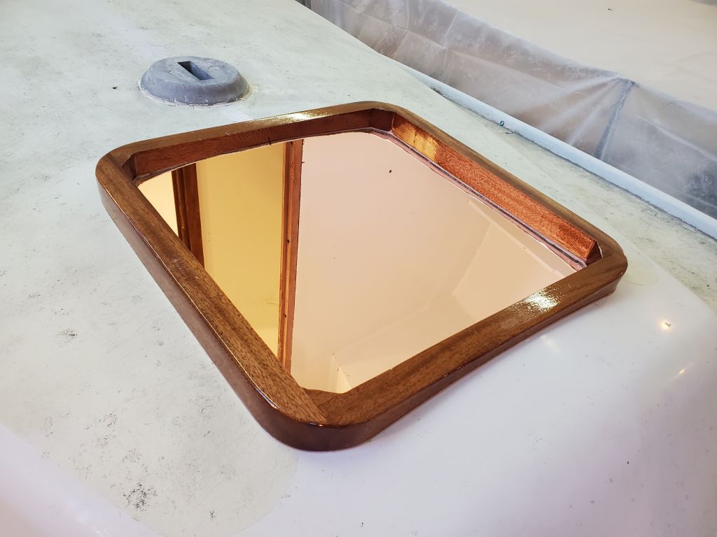
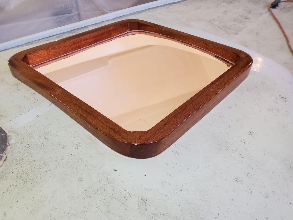
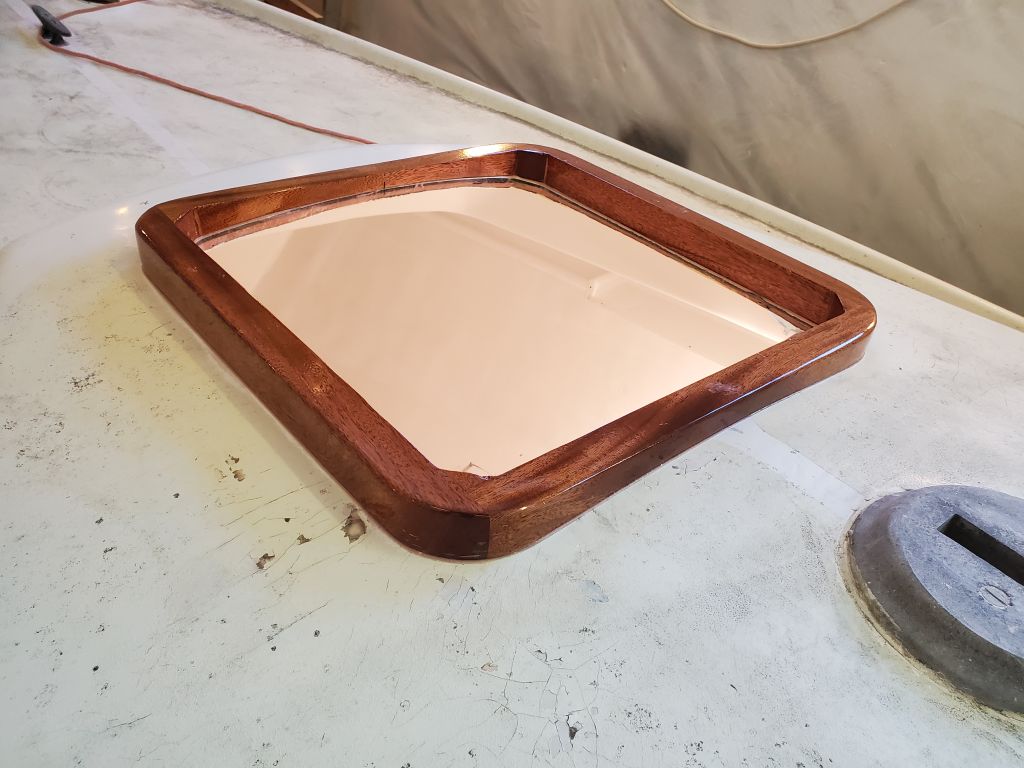
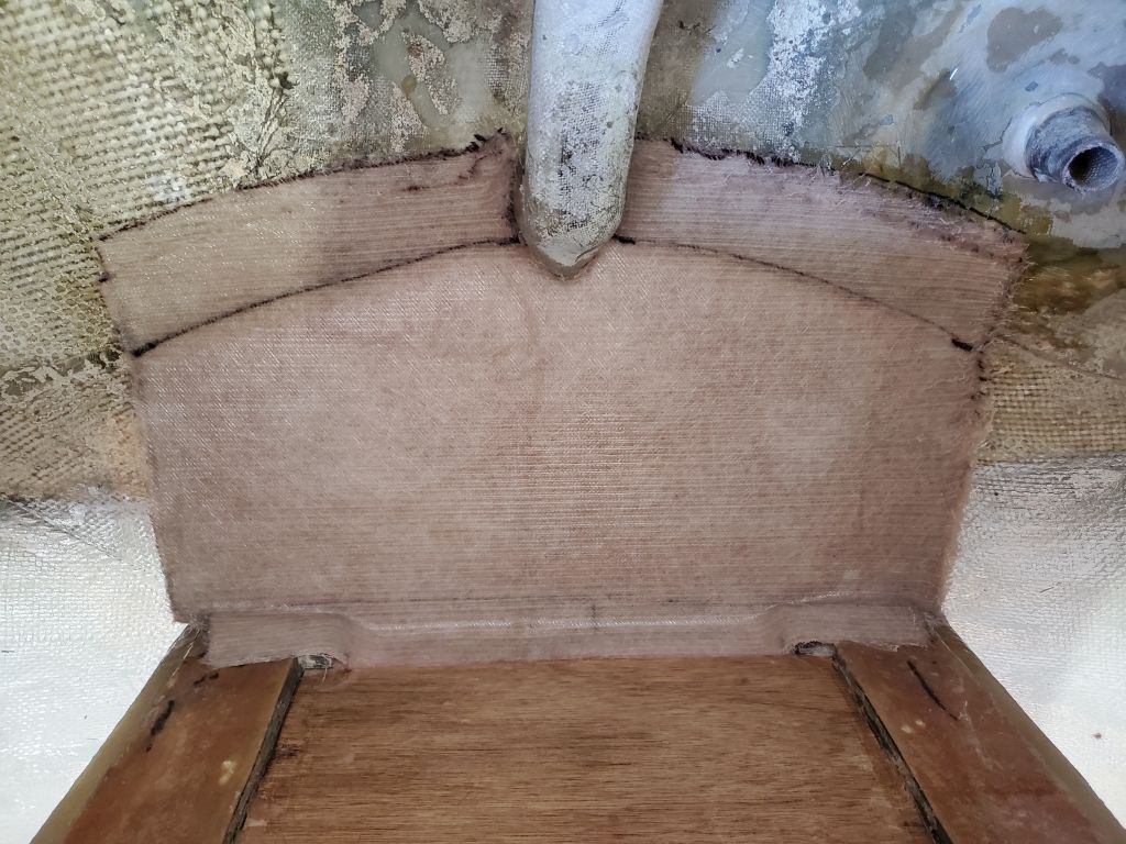
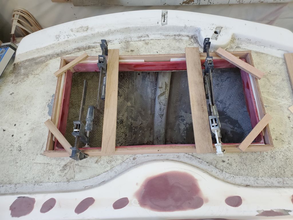
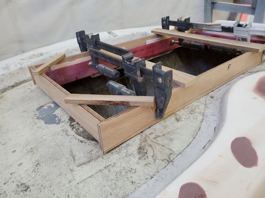
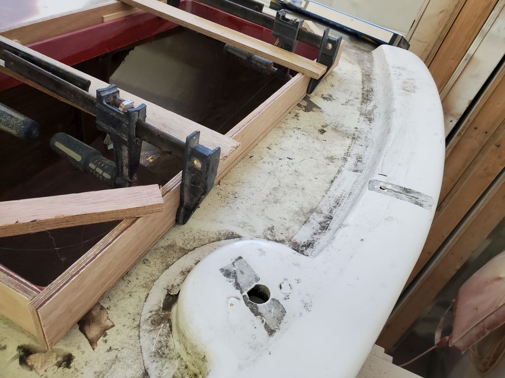
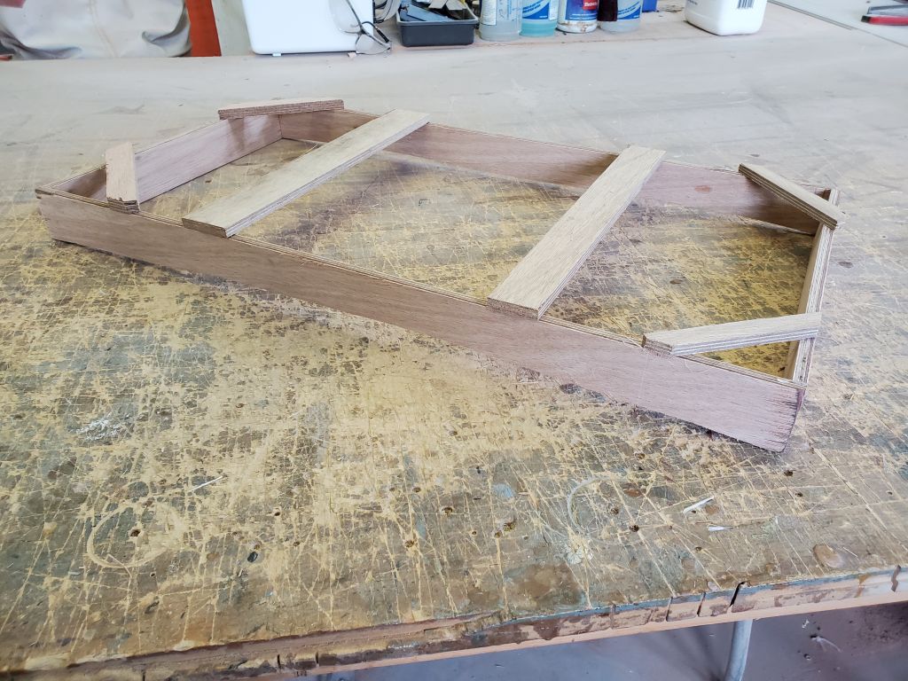
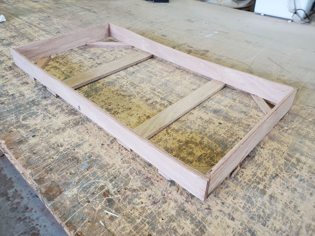
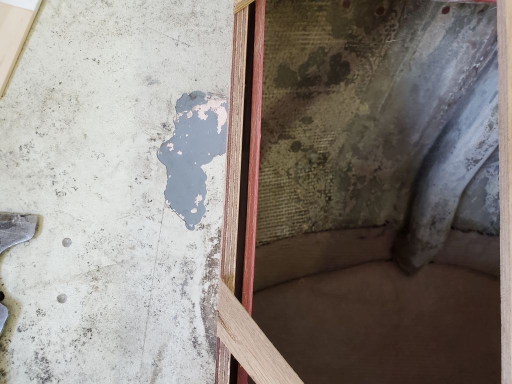
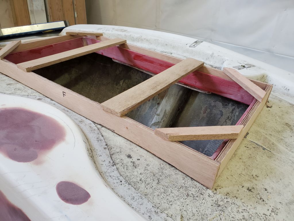
The starboard aft bulkhead originally (and still) had a little plywood insert to fill in the space, but because the port side had been behind the old icebox, there was no such piece there.  Now, to fill in that side, I used the starboard piece as a rough template to mark and cut out an insert from 12mm plywood to fit the port side.  These inserts would never be seen once the interior was finished, but would close off the lockers from the cabinets and interior spaces, and vise-versa.  They’d remain theoretically removable should it be necessary sometime far down the road.

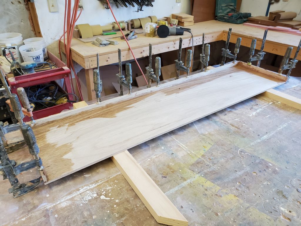
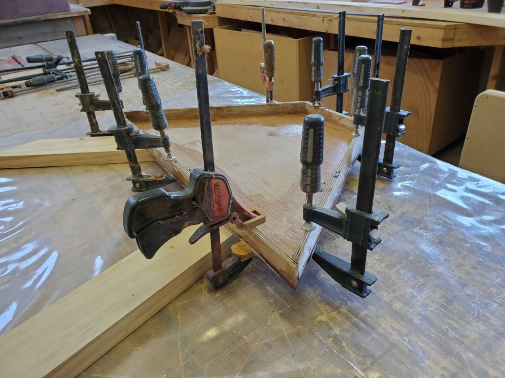
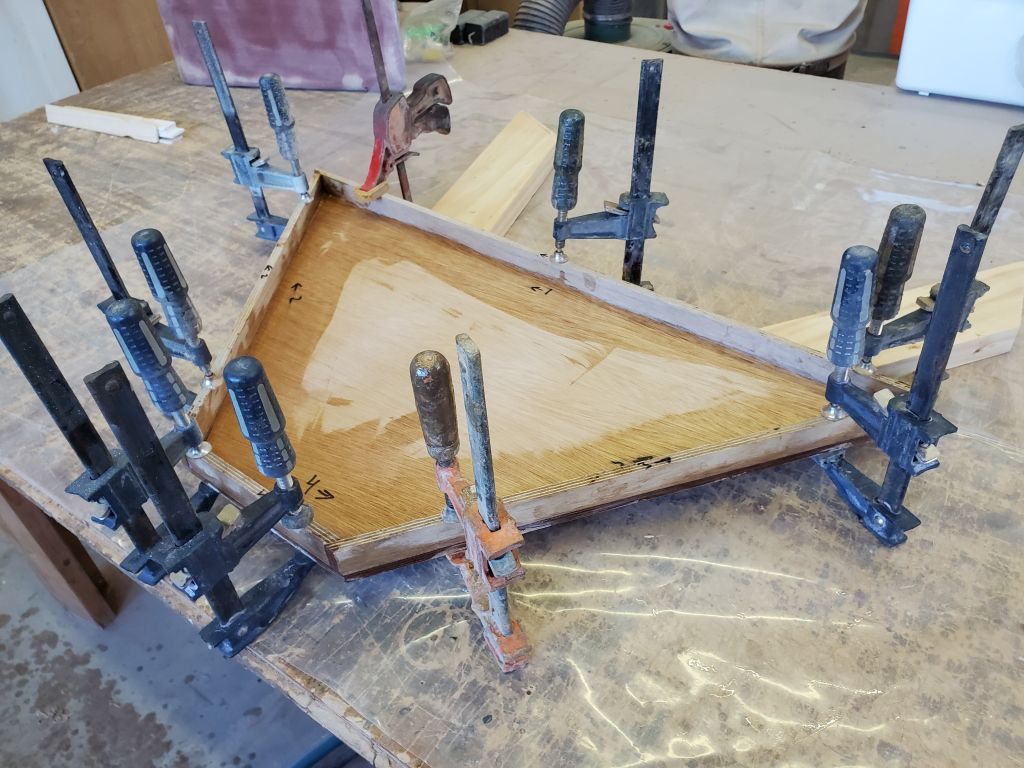
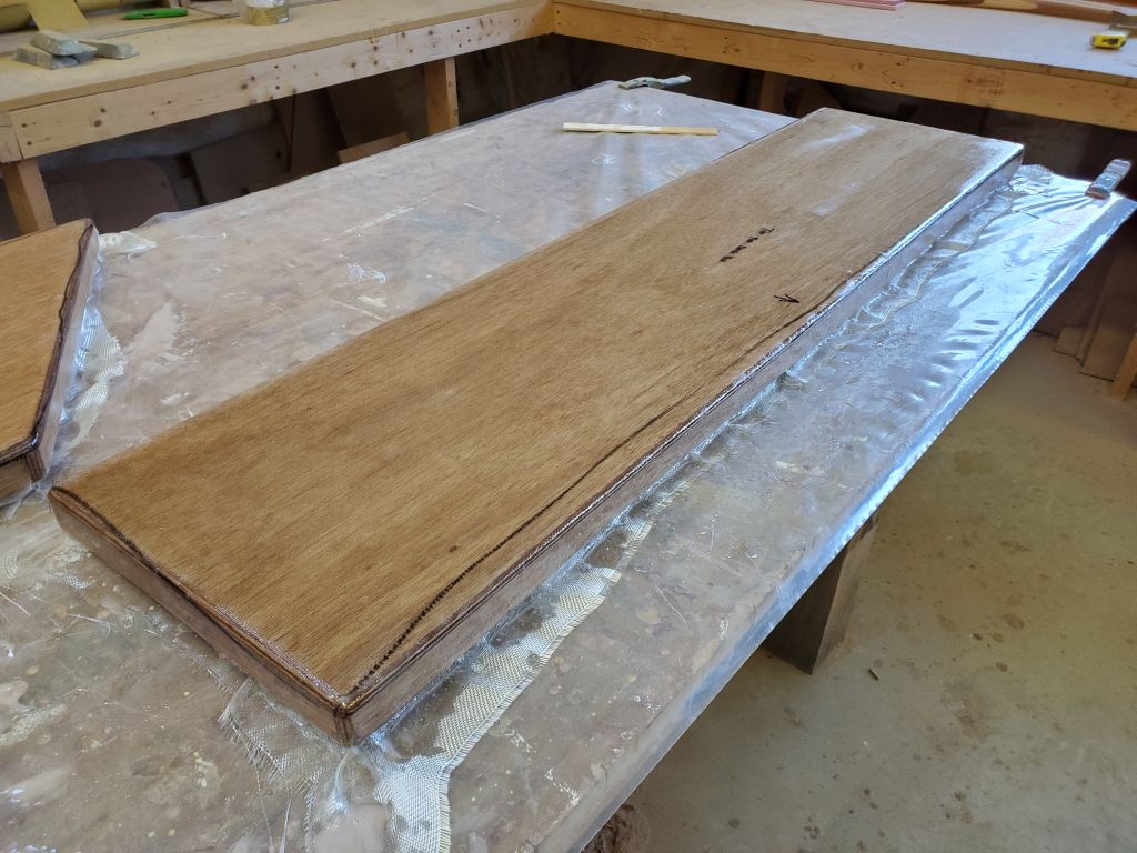
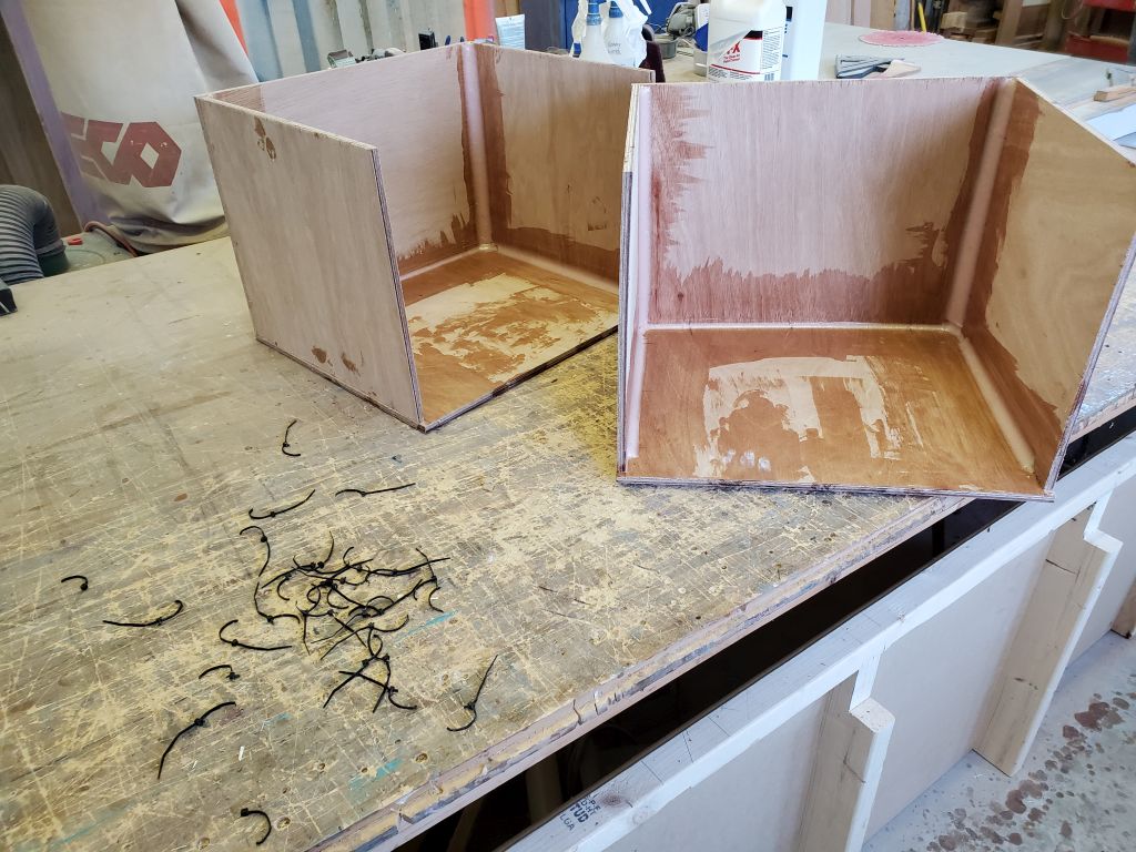
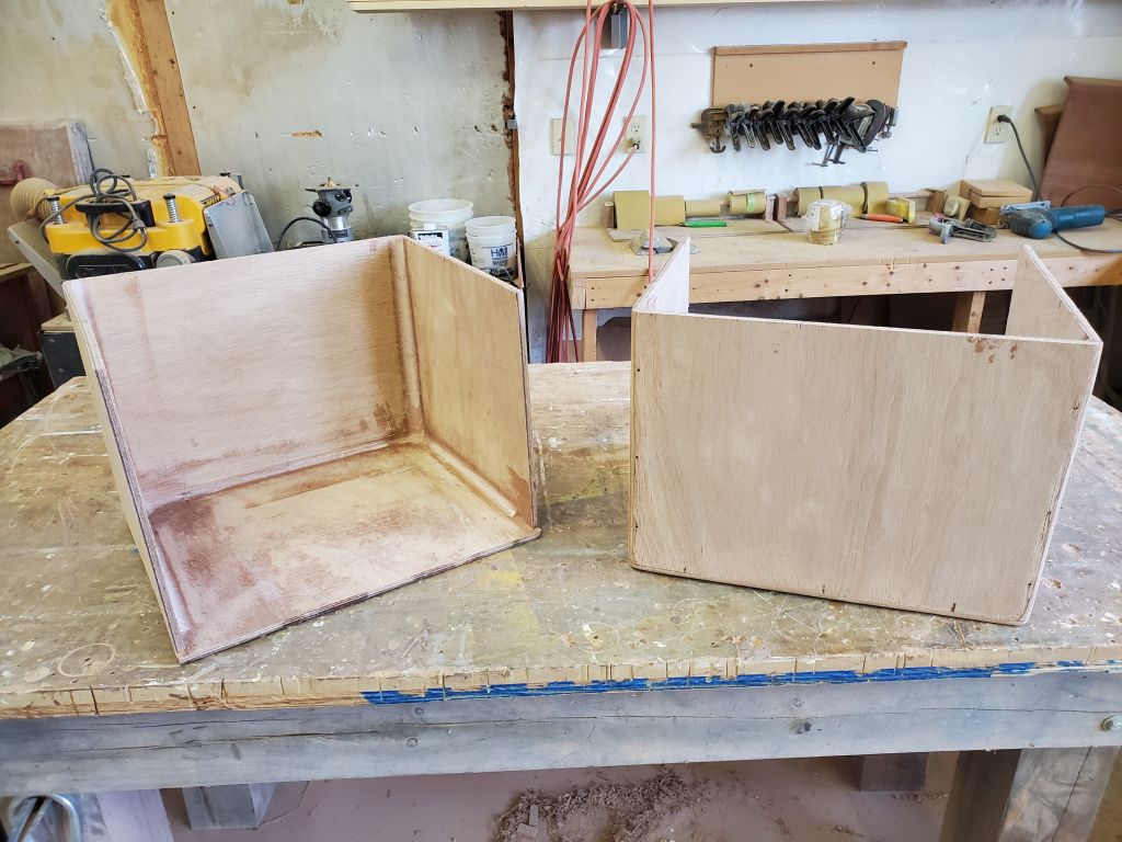
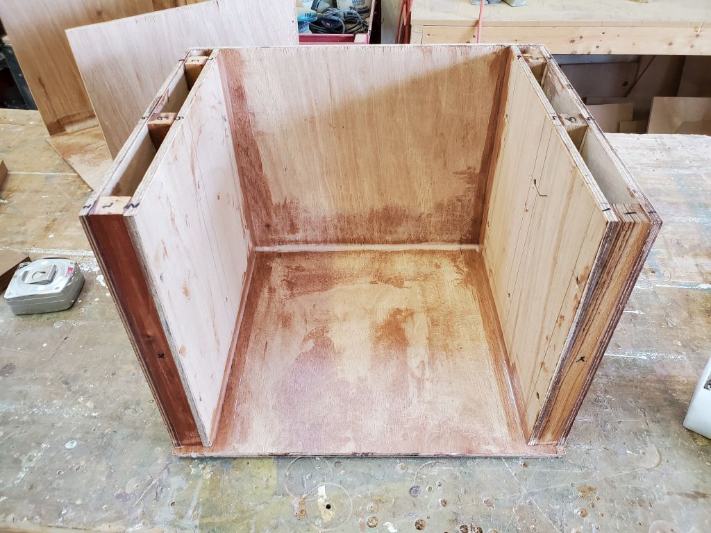
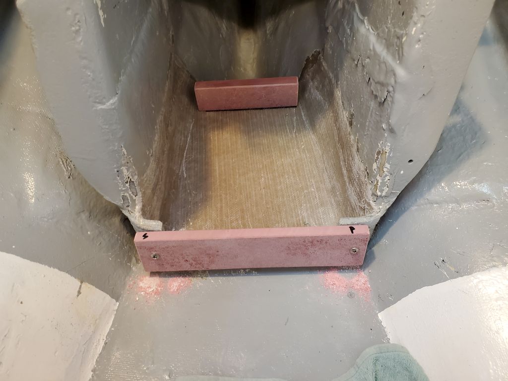
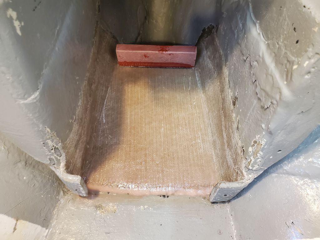
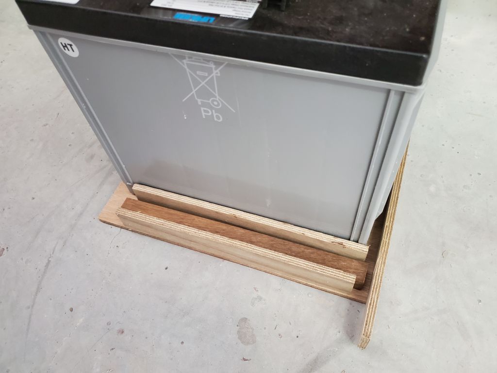
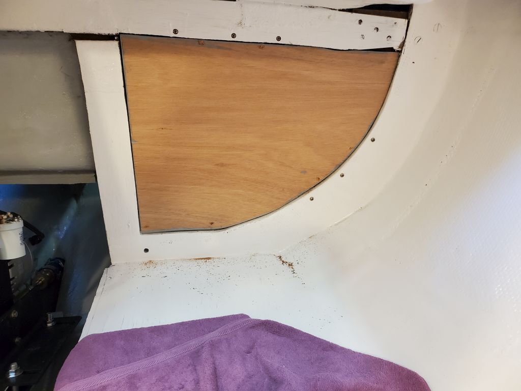
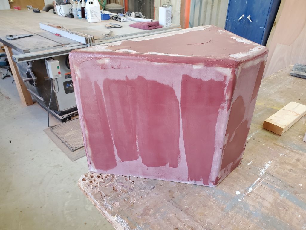
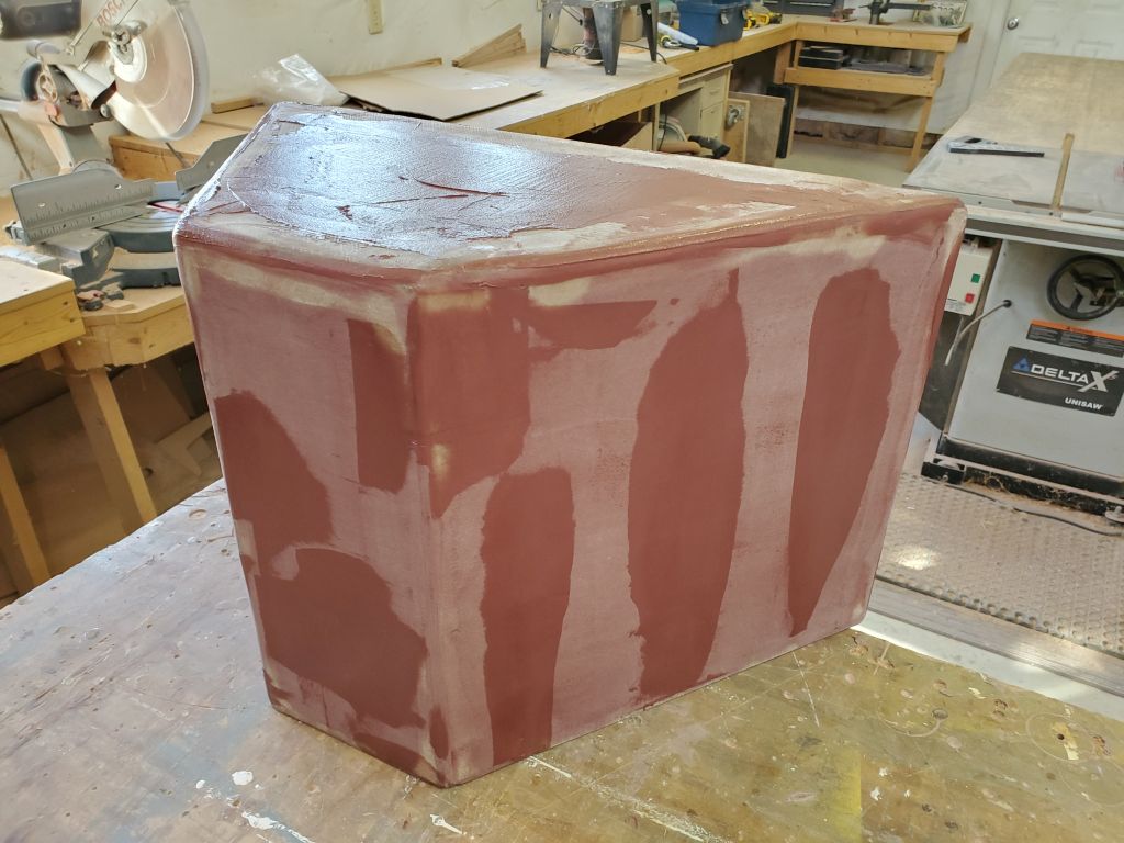
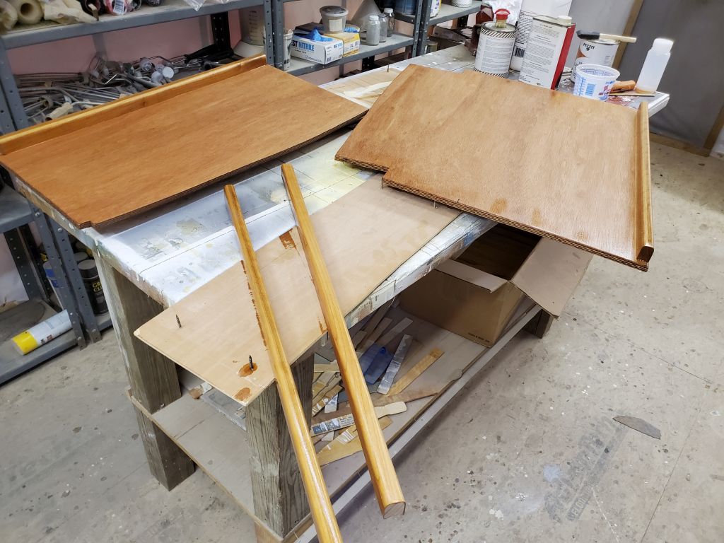
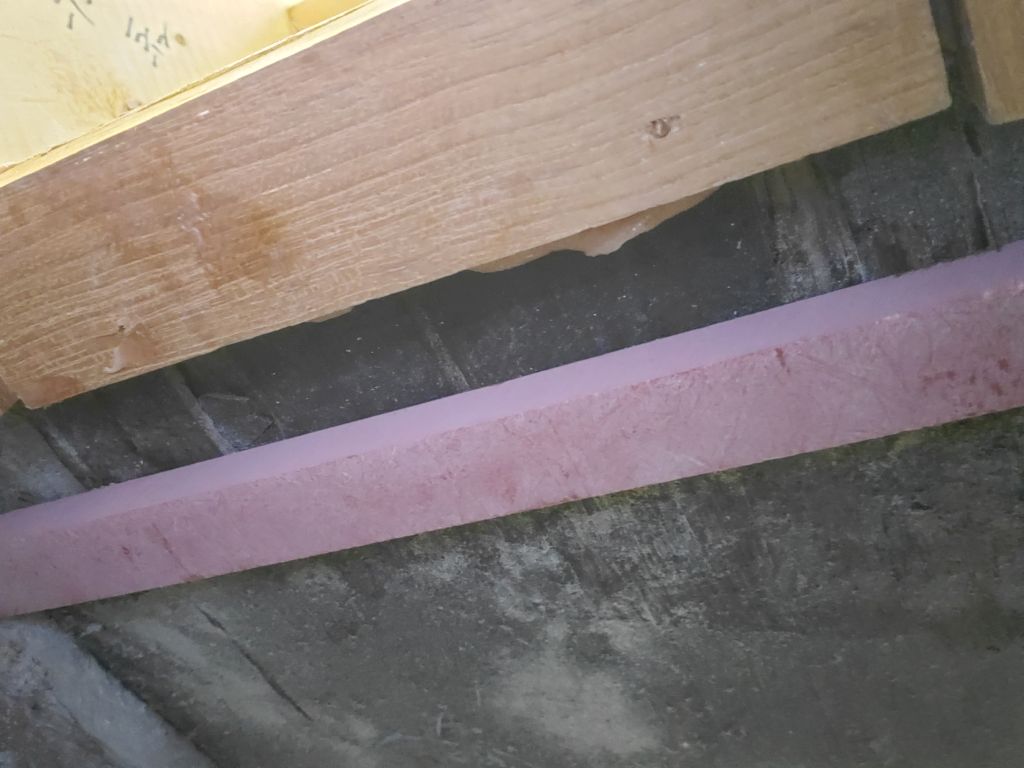
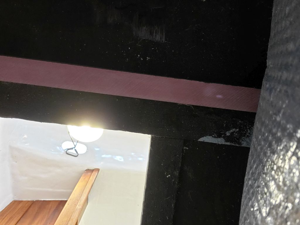
To prepare for installation, I painted the back (locker) sides of the two sections with the gray bilge paint.  The old piece (on the right in the photo) soaked in all the paint in short order, leaving an almost bare-looking surface, and I’d meant to recoat them at the end of the day, but forgot, so I’d do that next time.

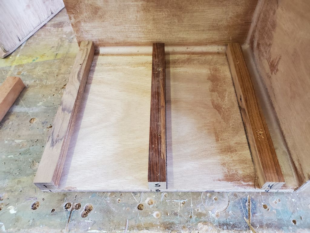
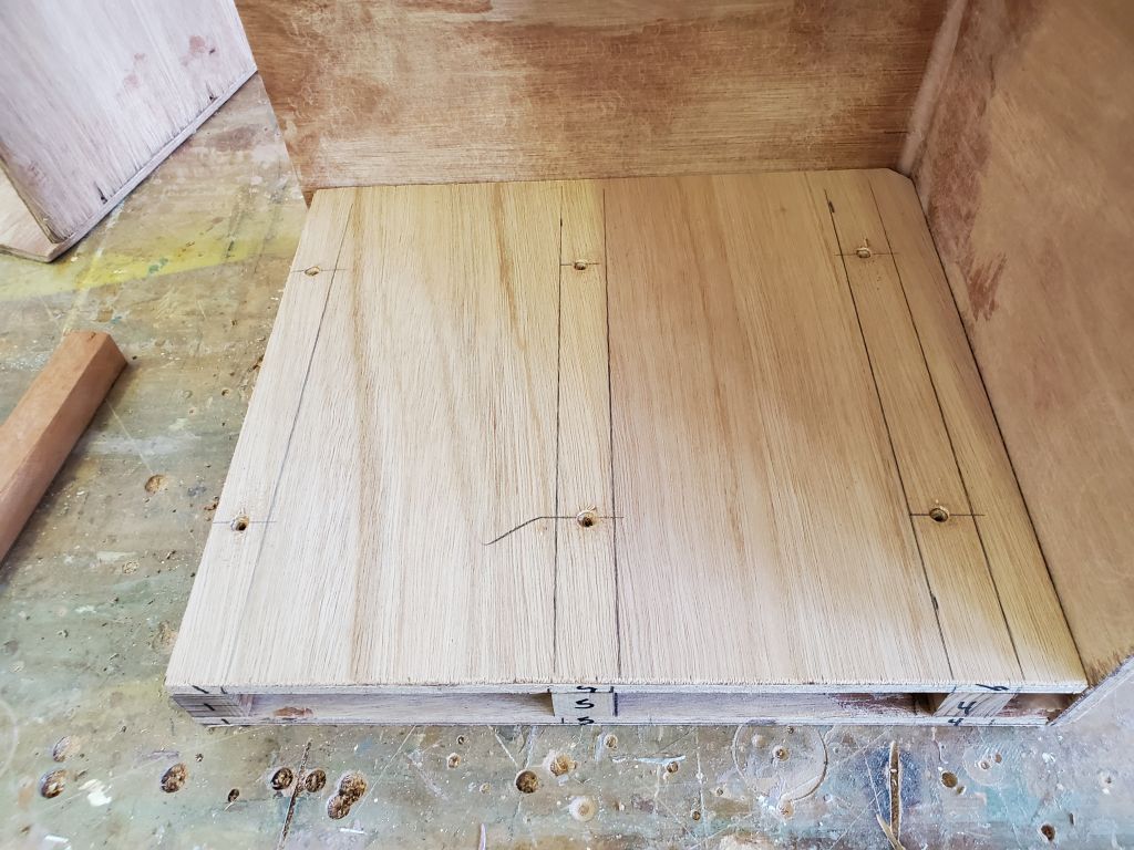
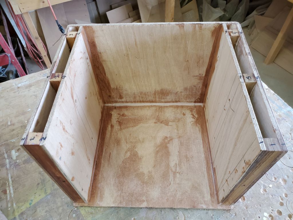
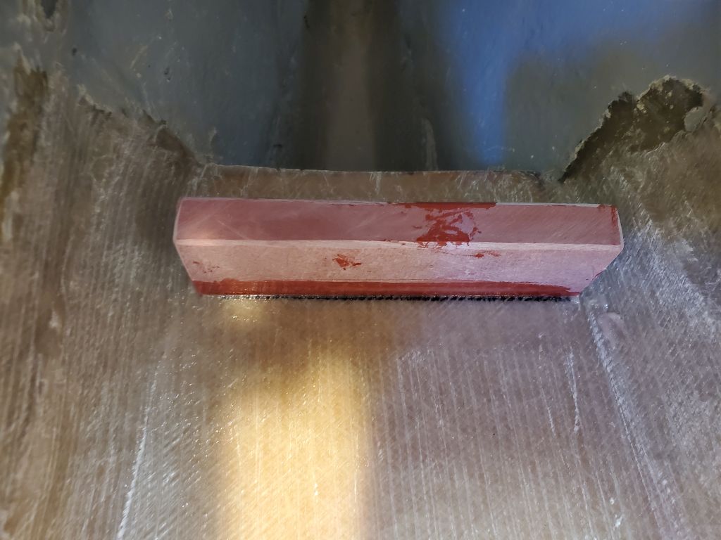
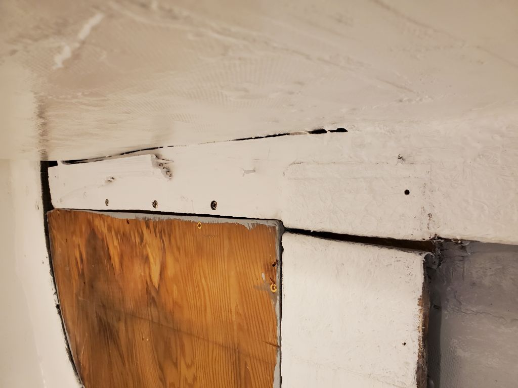
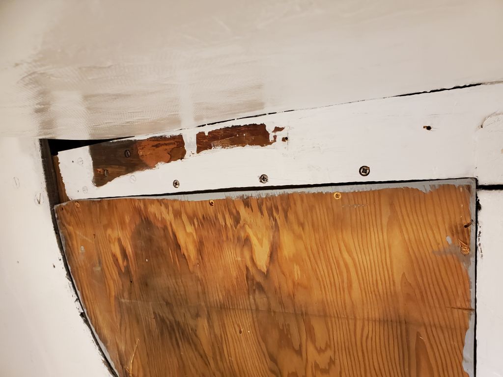
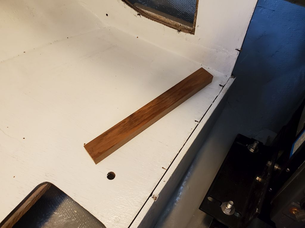
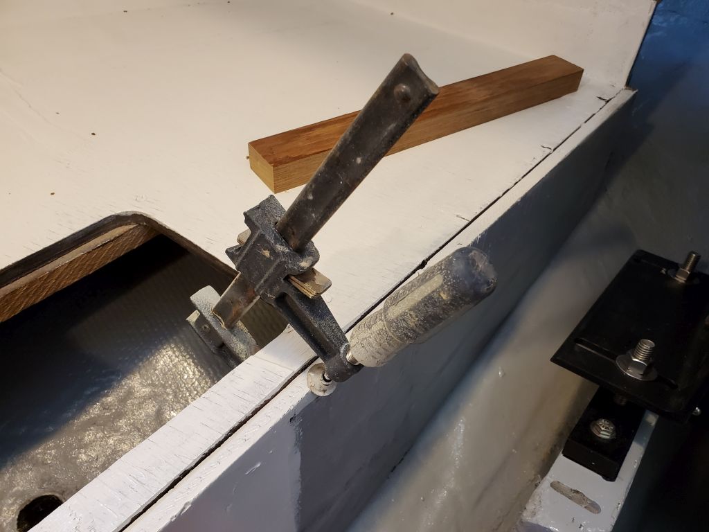
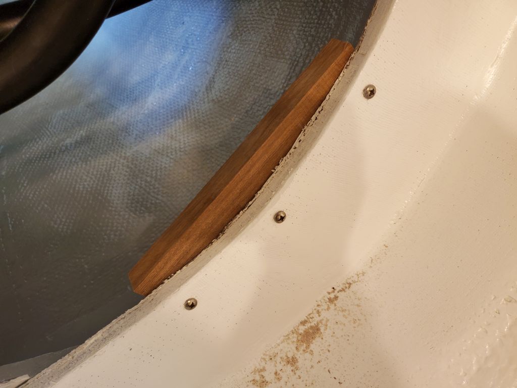
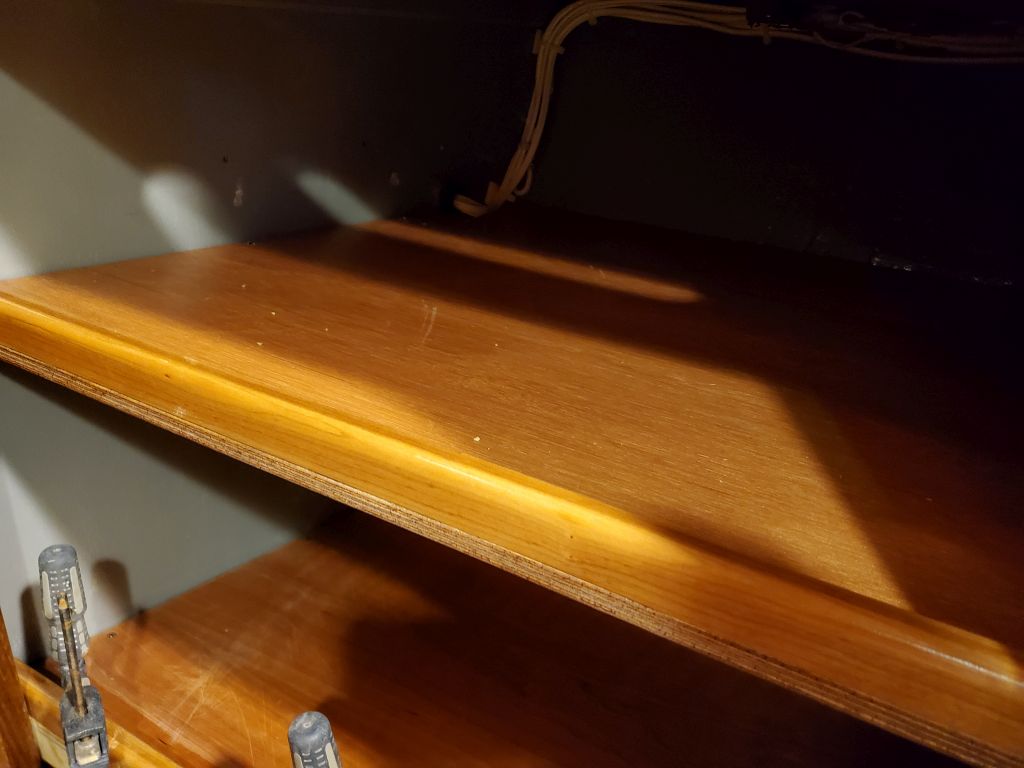
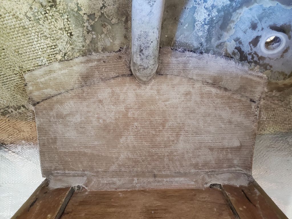
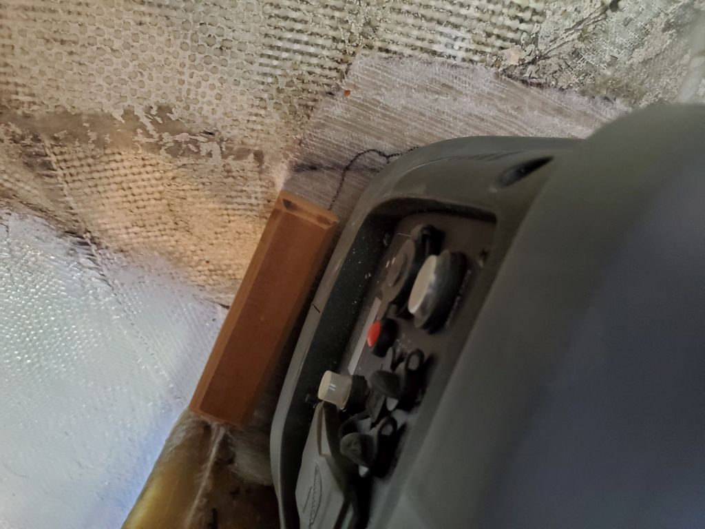
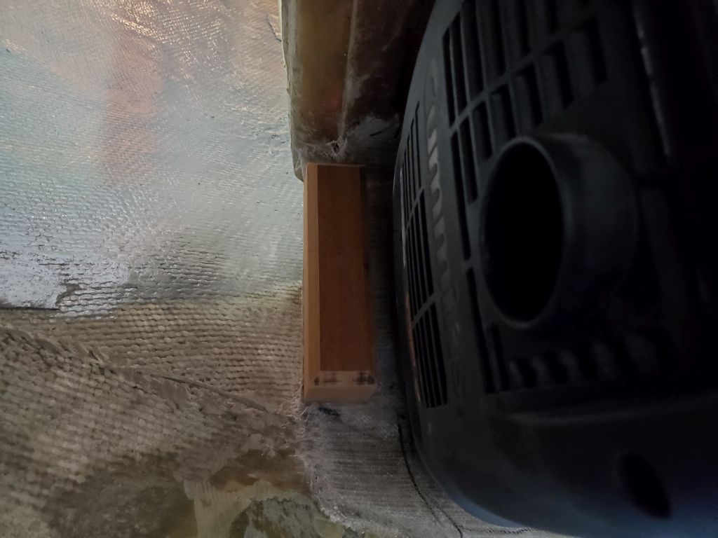
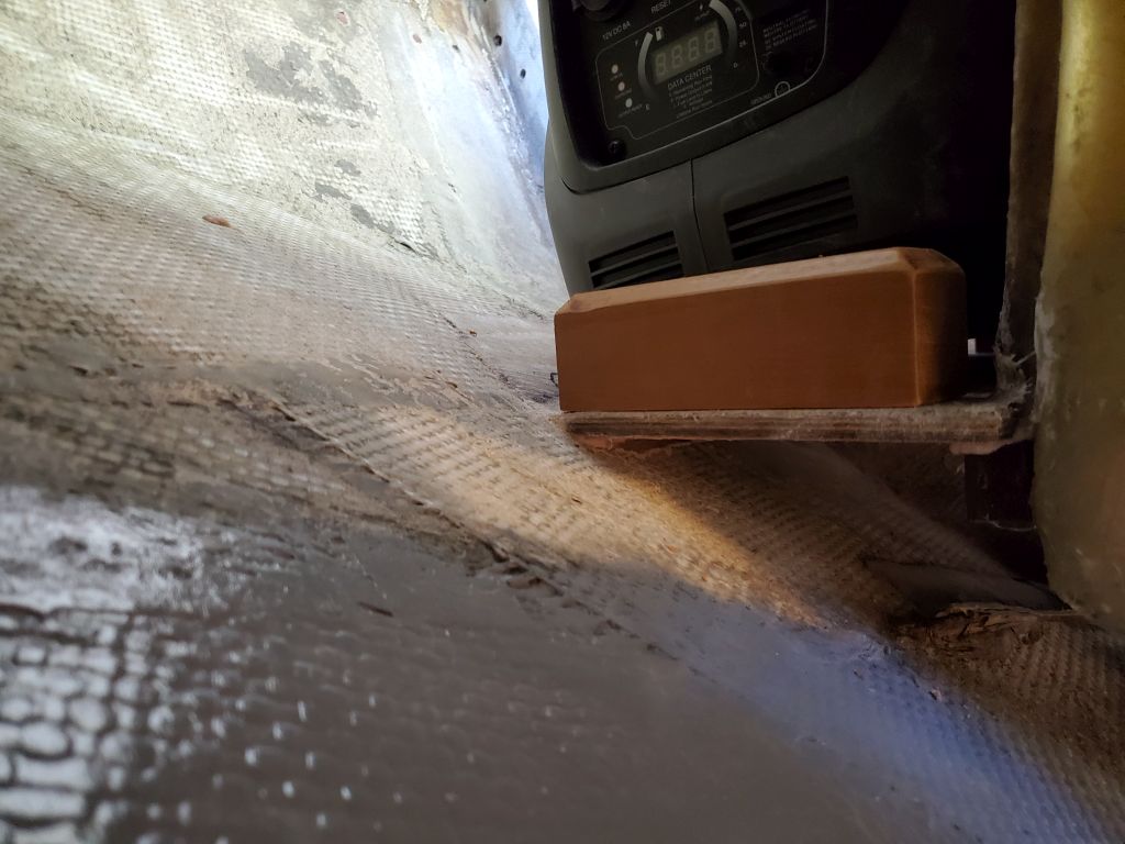
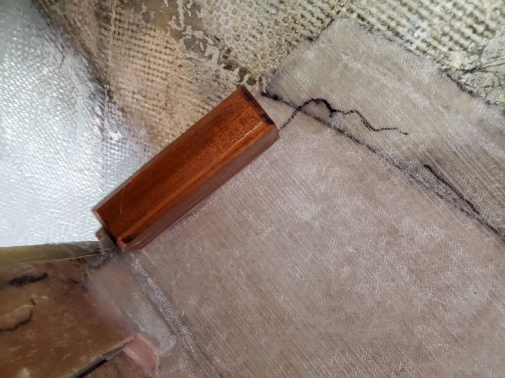
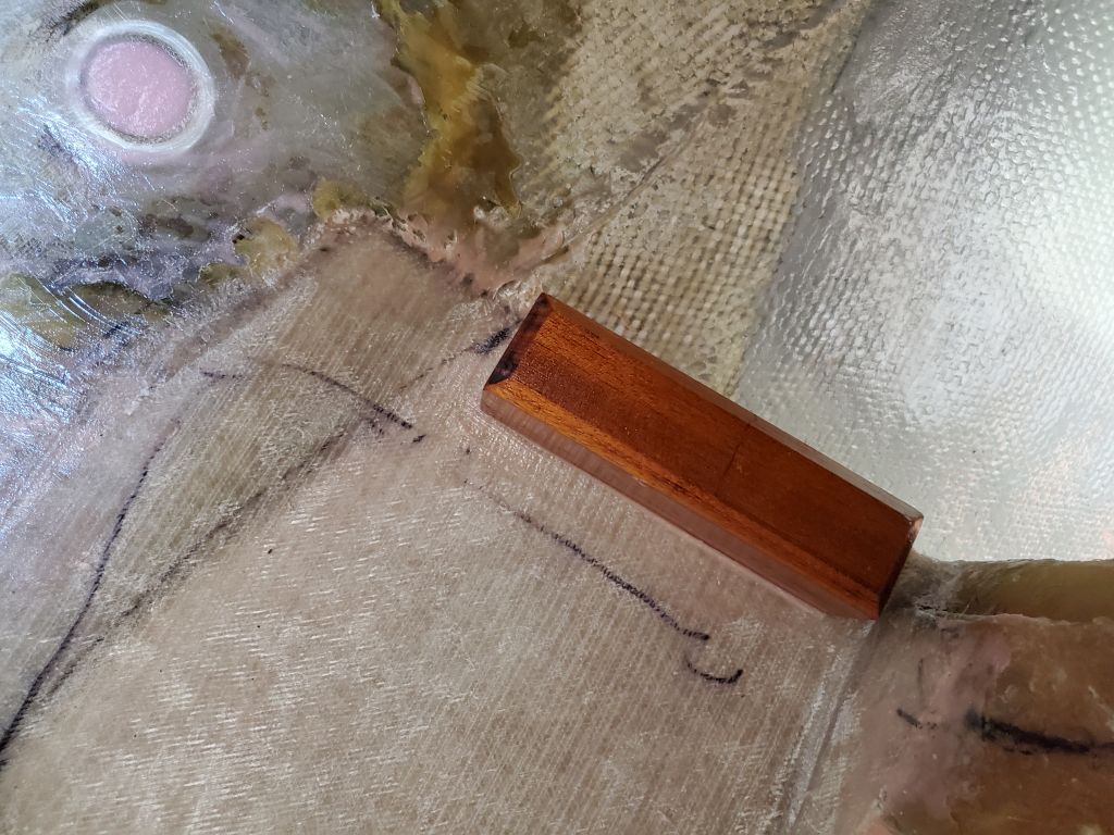
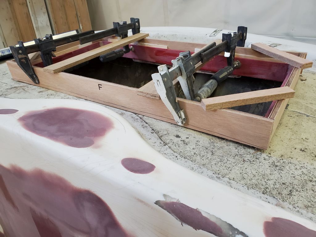
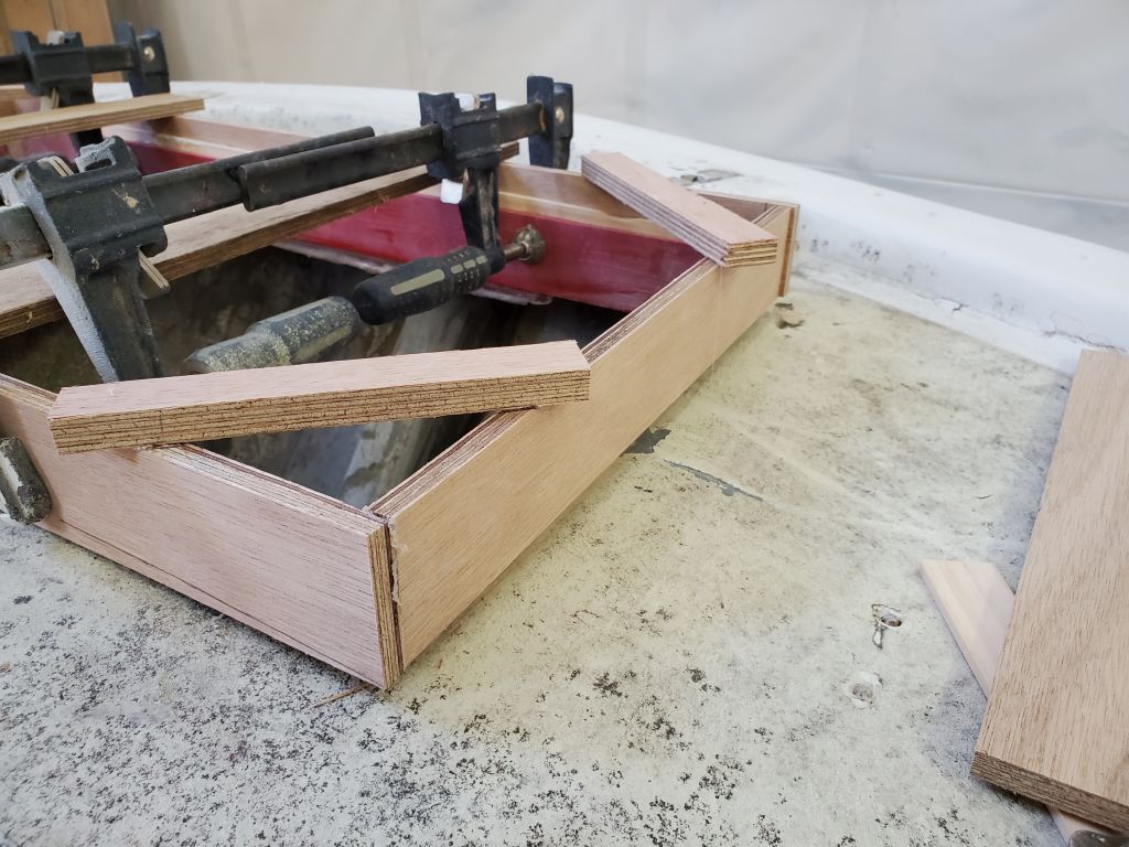
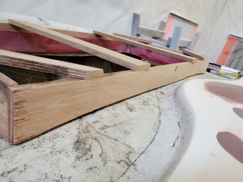
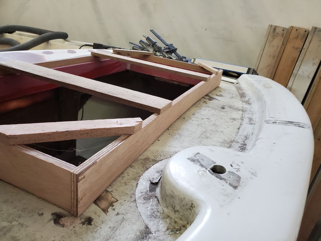
There were a couple wooden cleats behind the bulkhead web that would help support the inserts, and give places to install fasteners, but the port side needed a couple more, and I thought another one at the top of the starboard side would be helpful, so from leftover teak cutoffs I made up a few new cleats and secured them with screws, ready to accept the plywood soon.

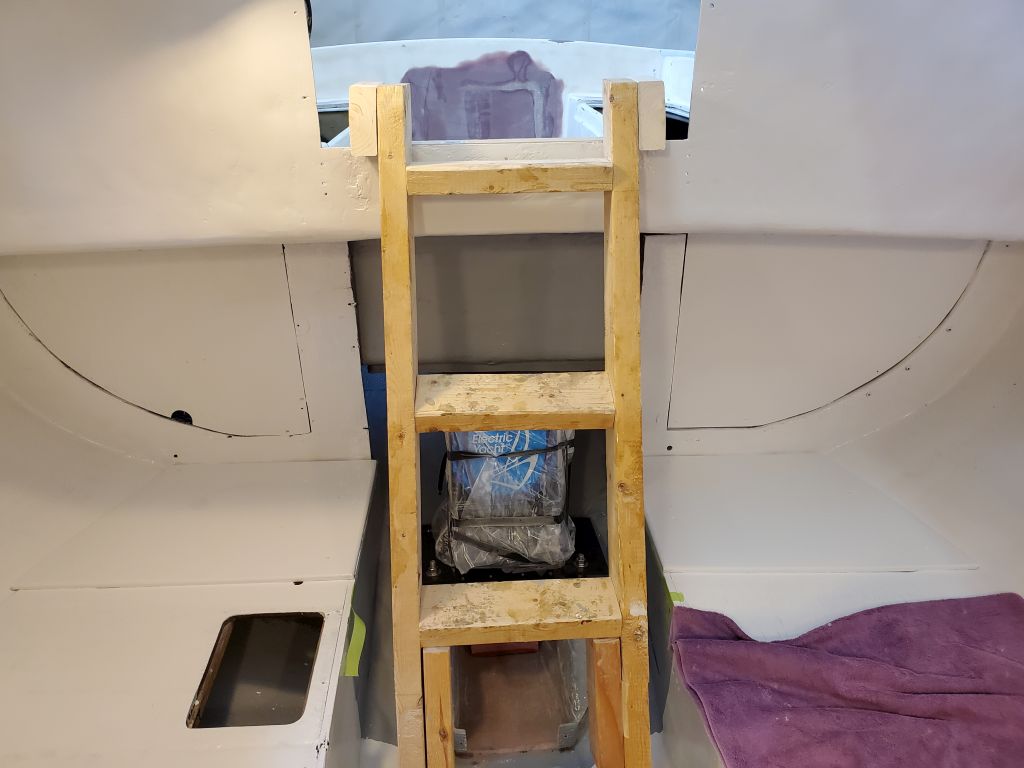
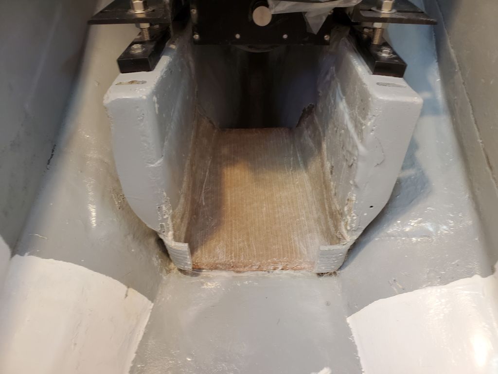
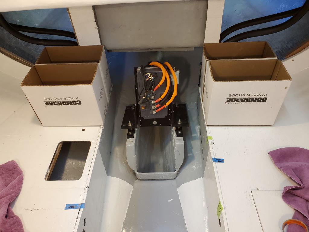
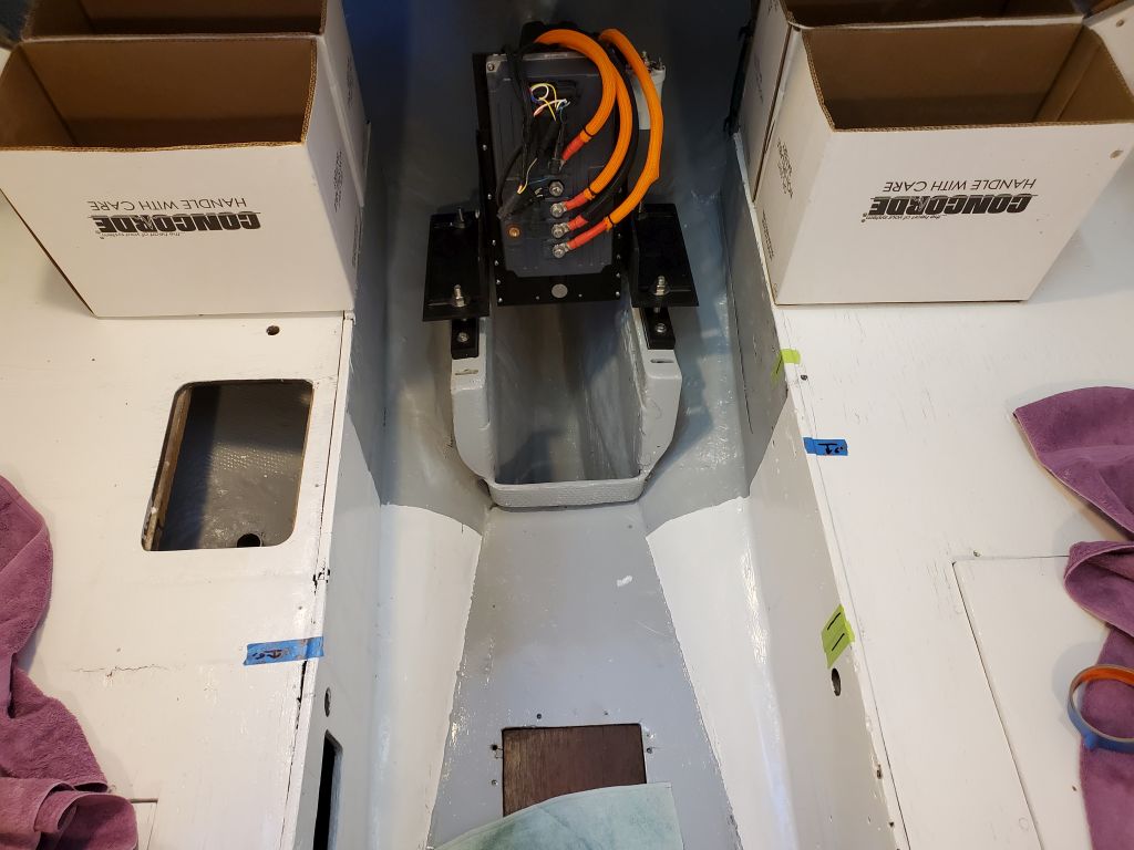
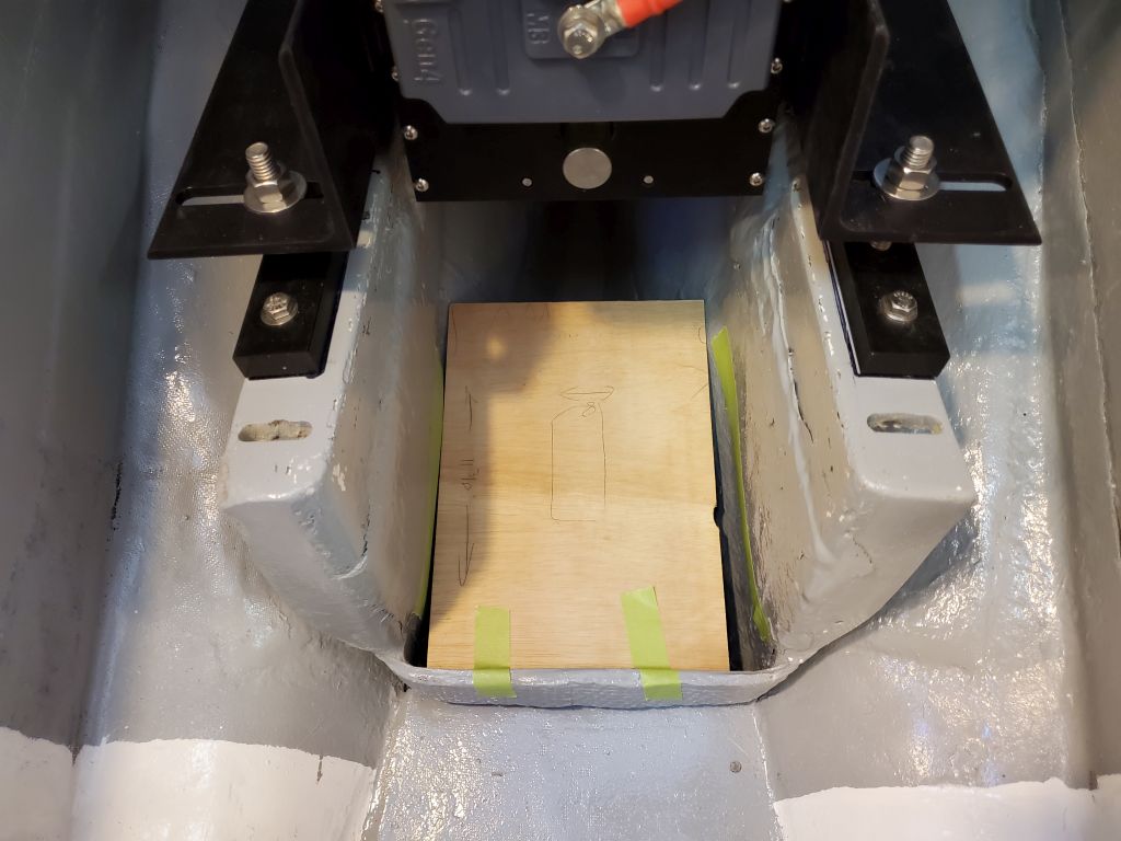
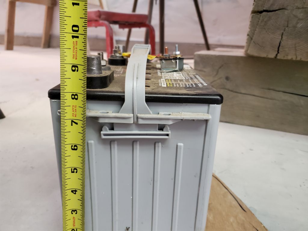
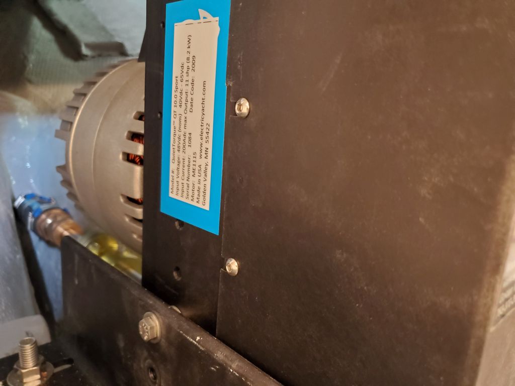
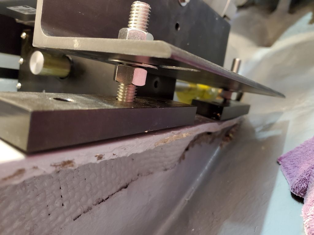
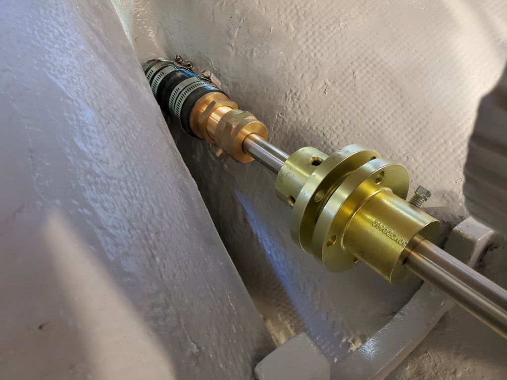
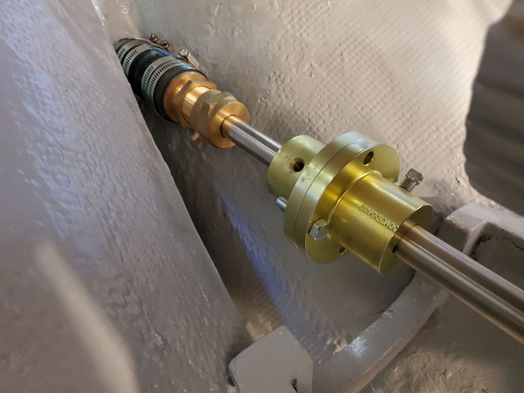
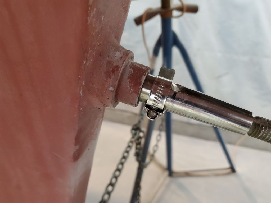
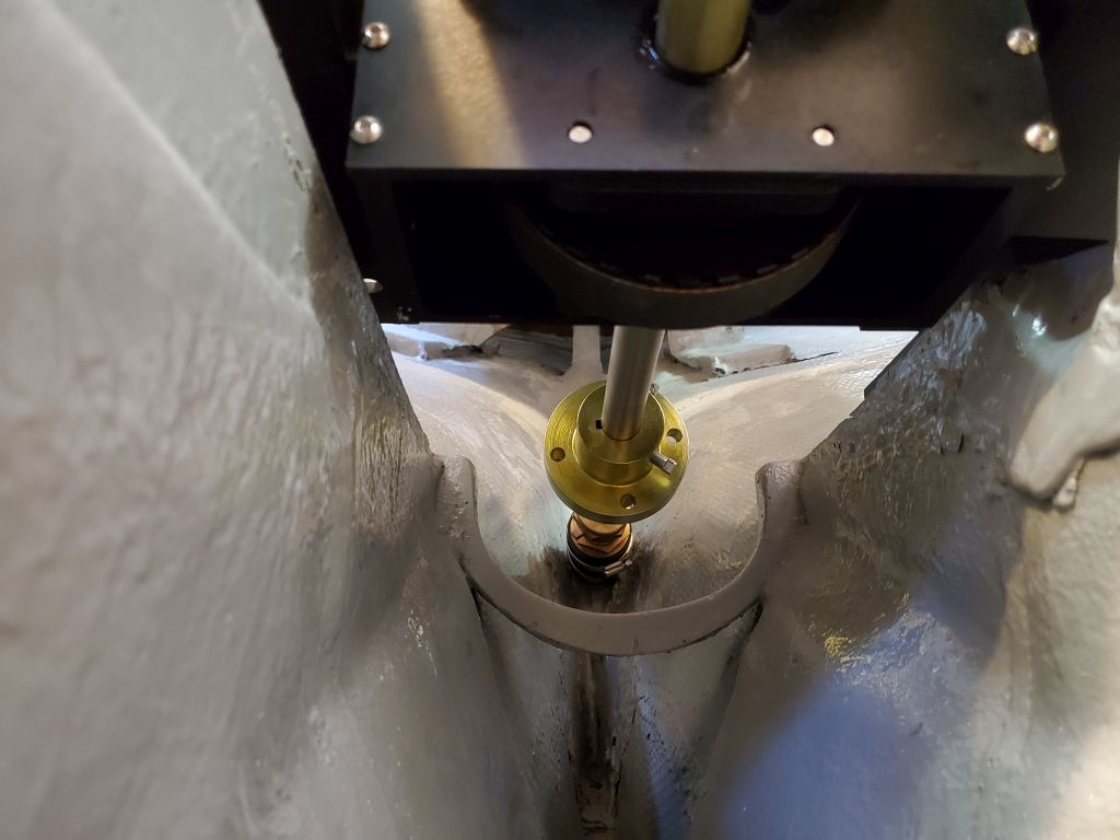
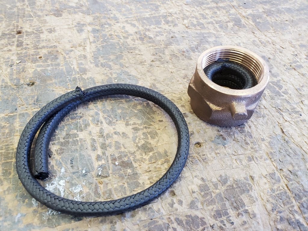
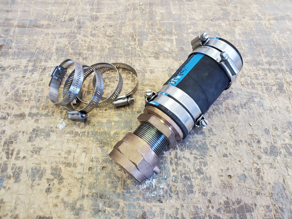
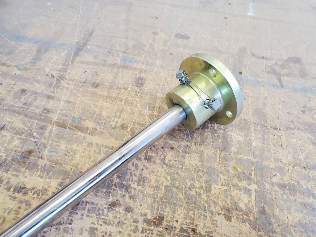
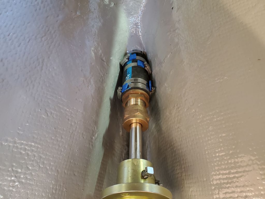
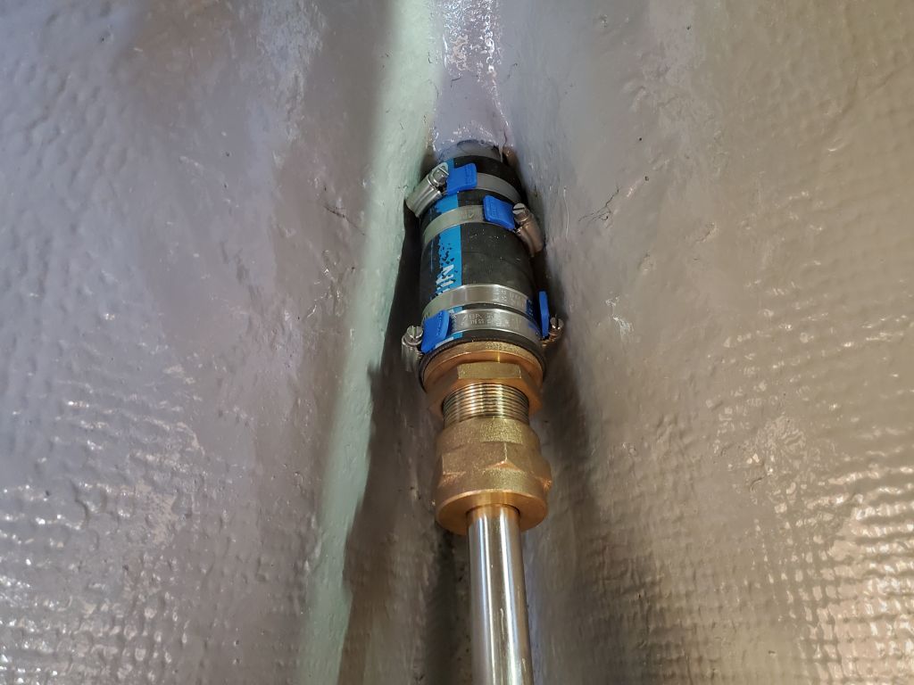
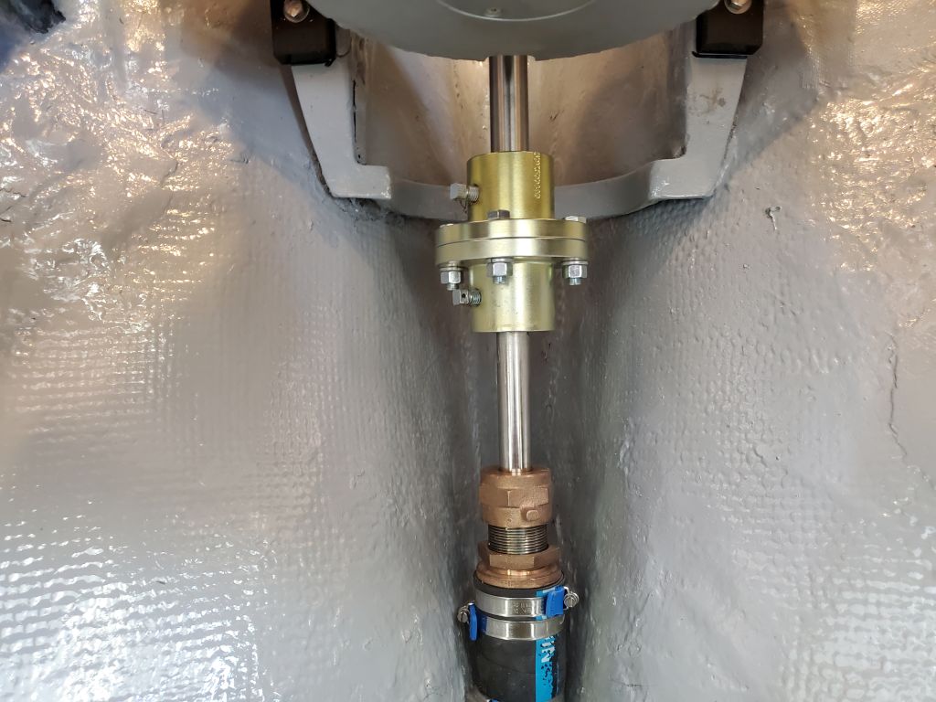
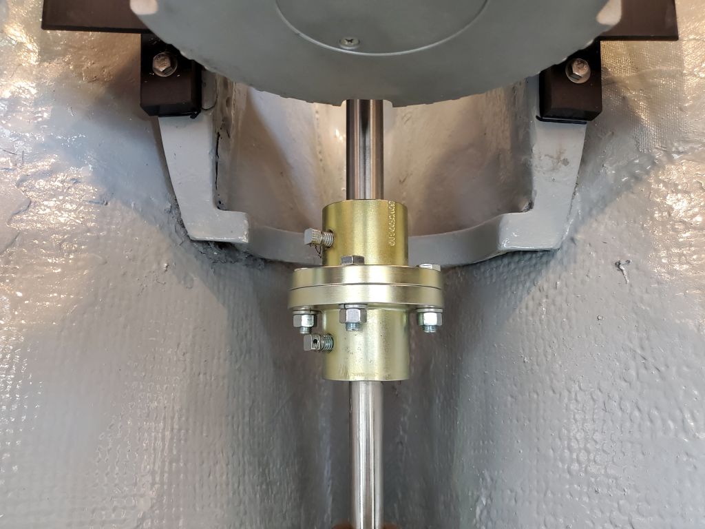
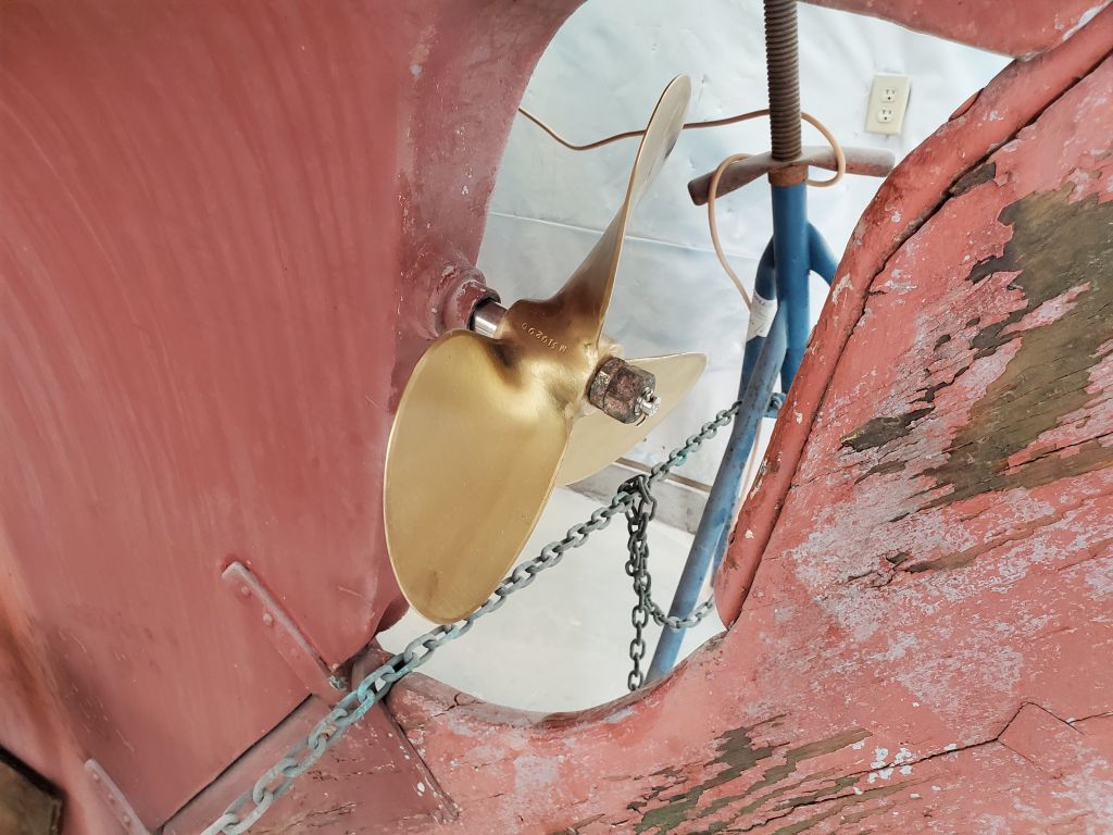
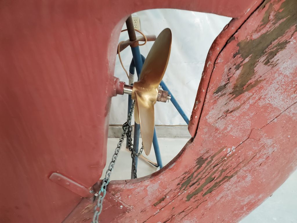
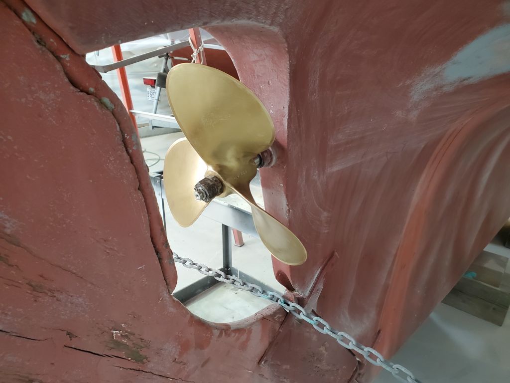
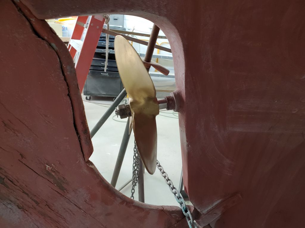
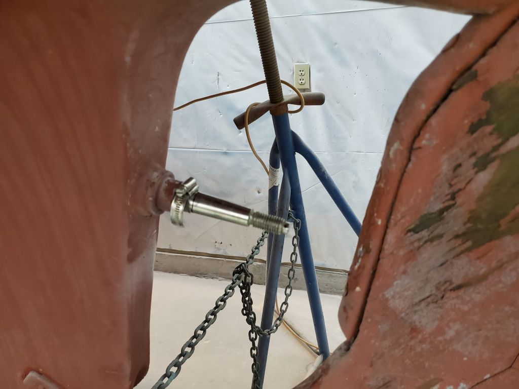
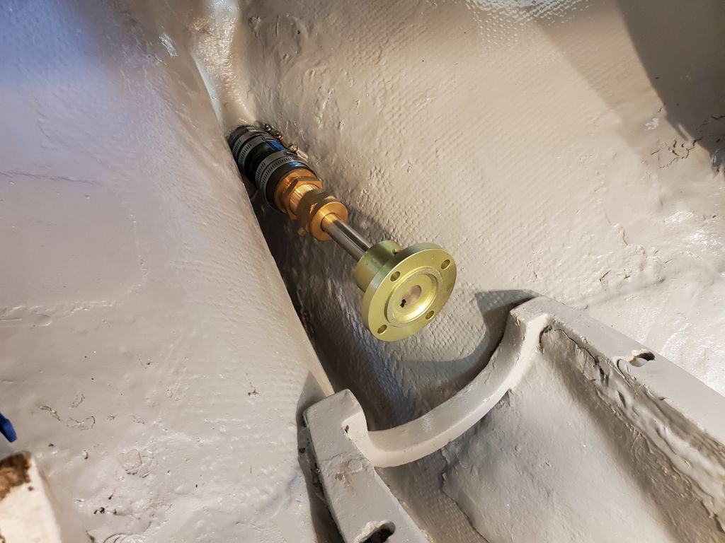
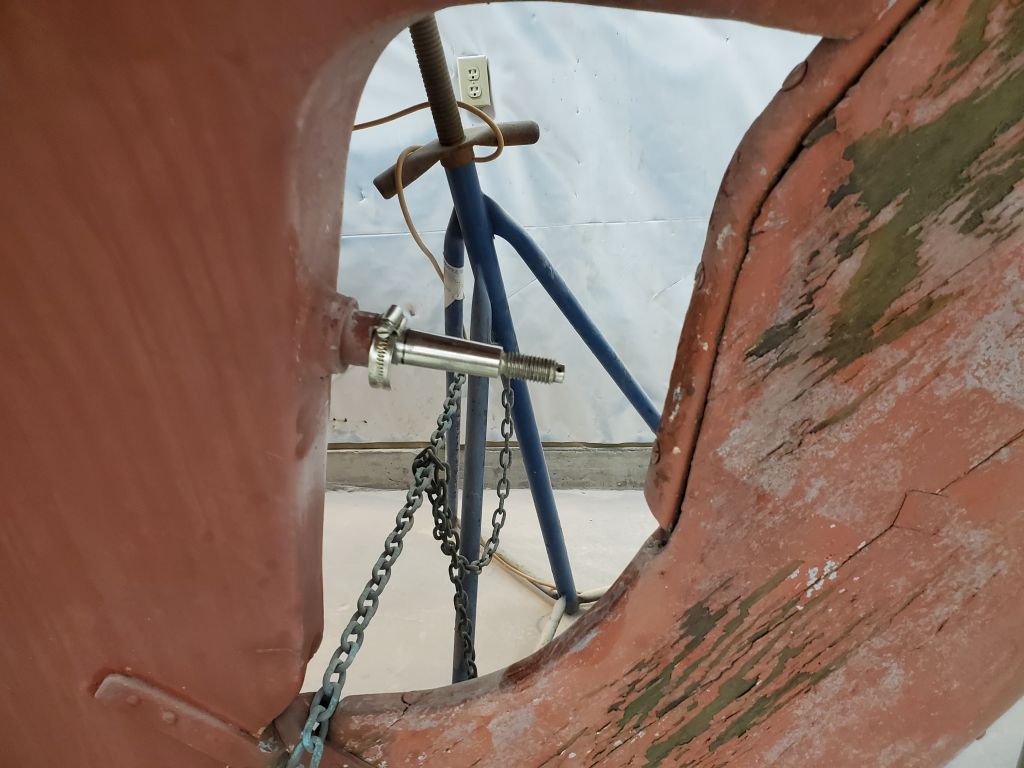
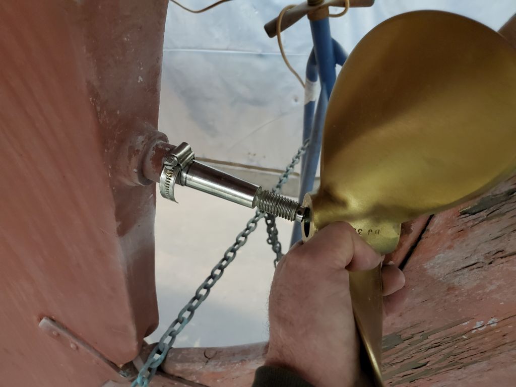
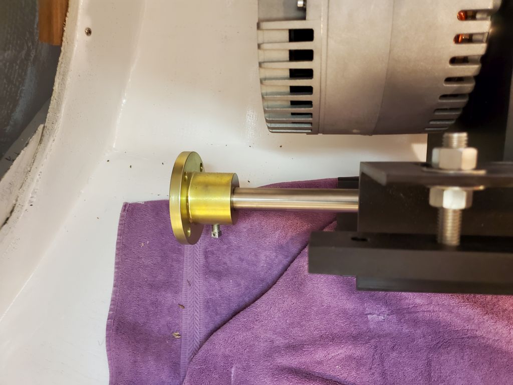
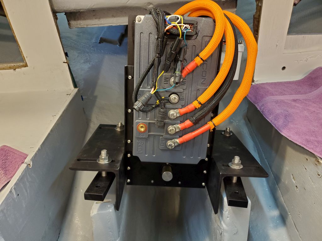
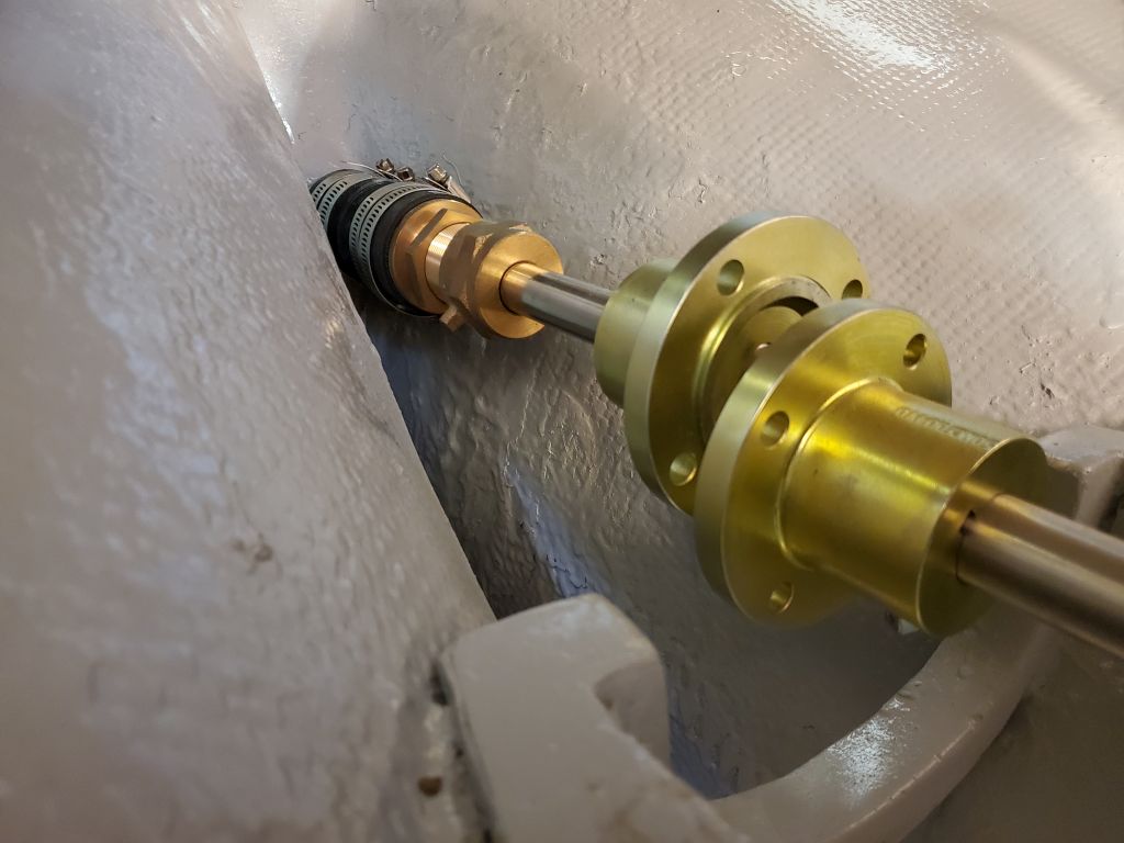
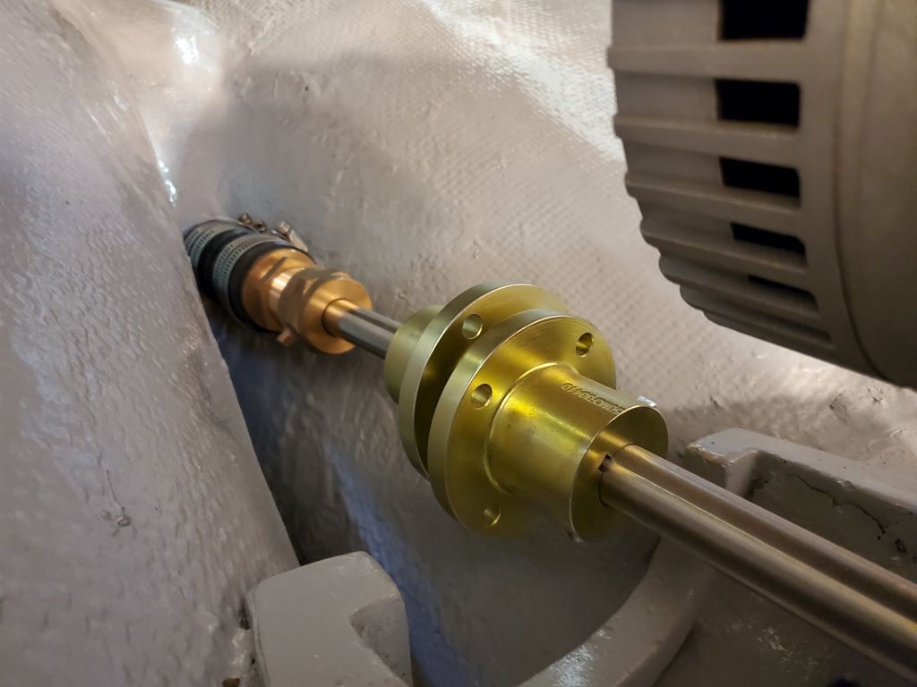
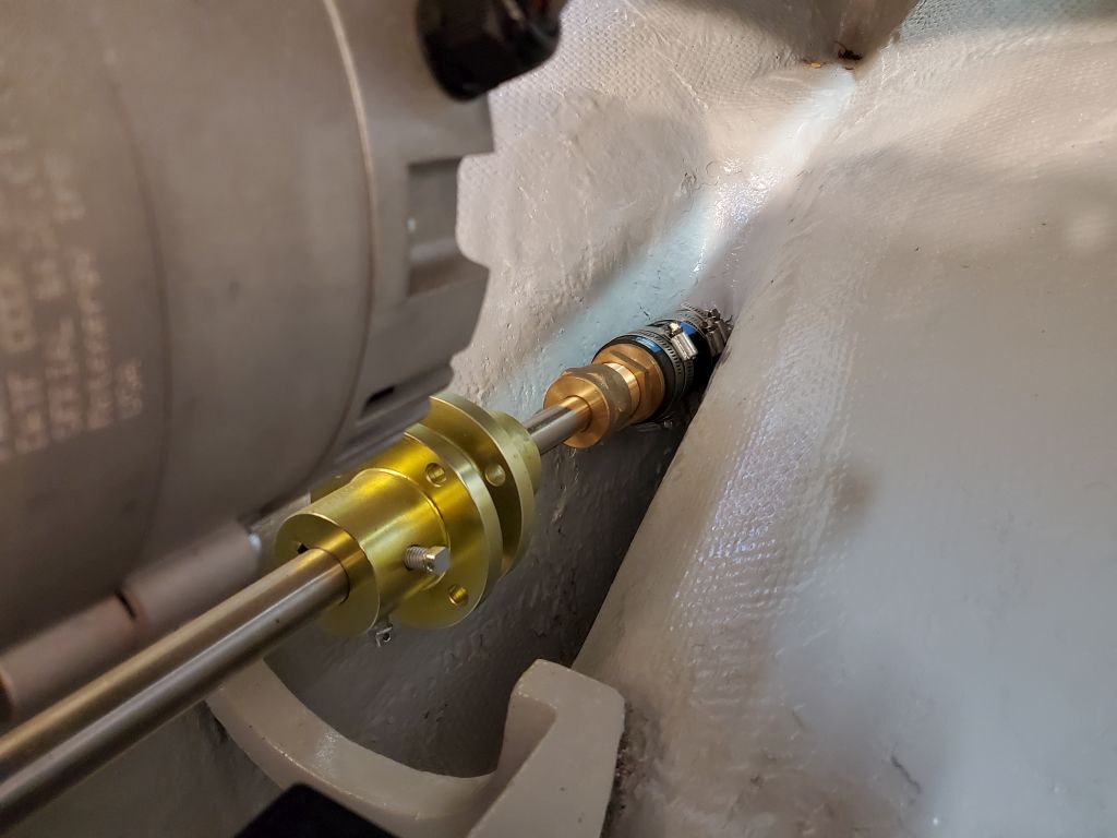
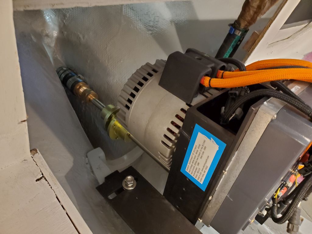
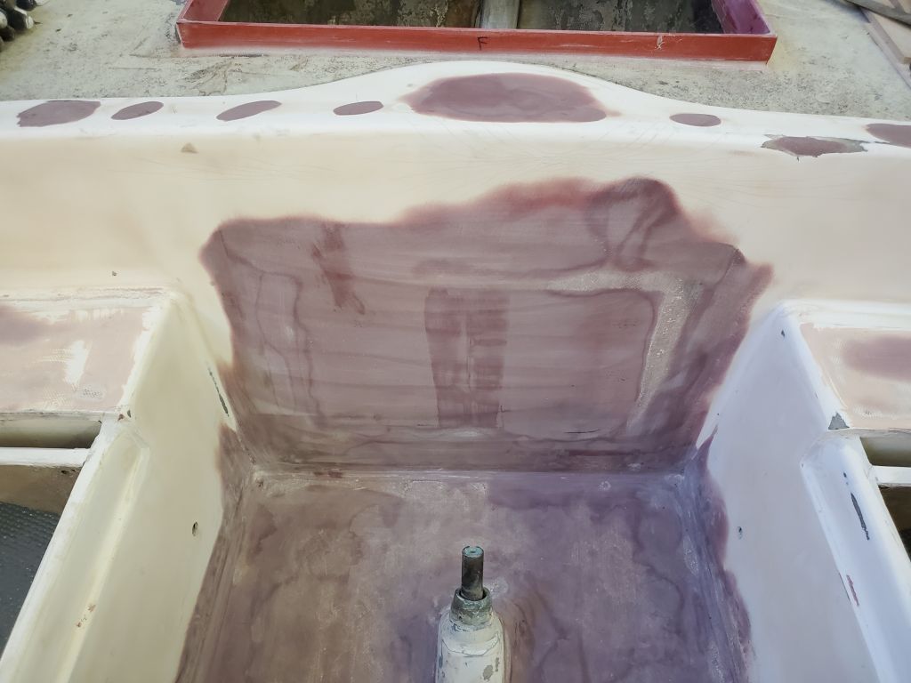
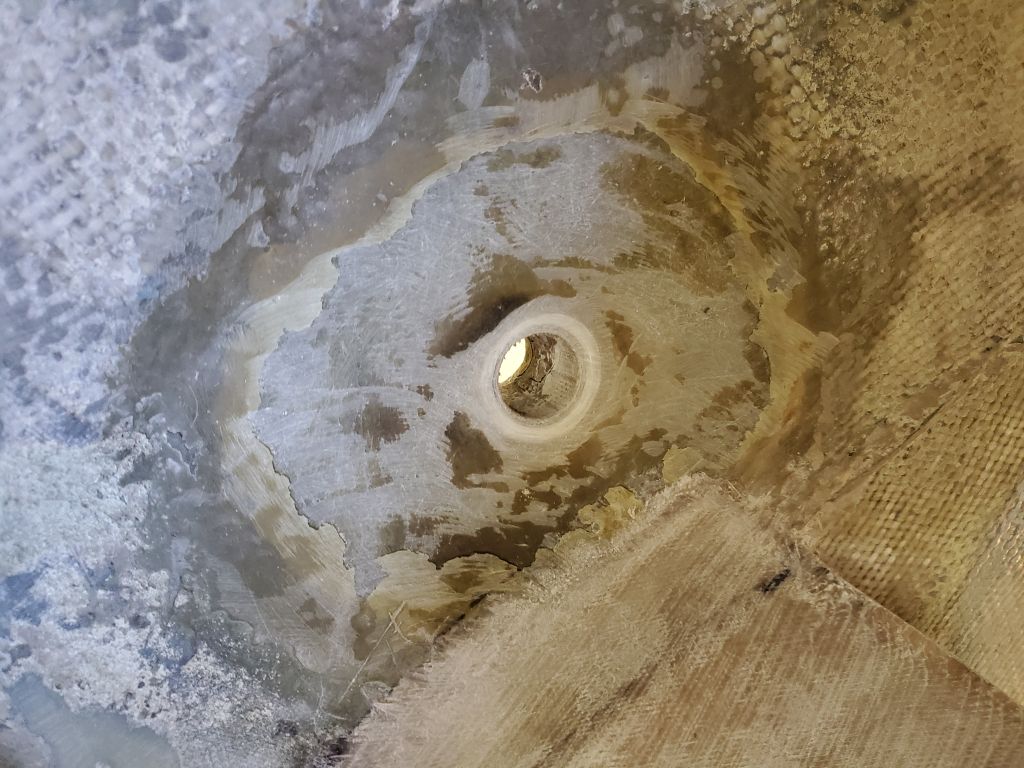
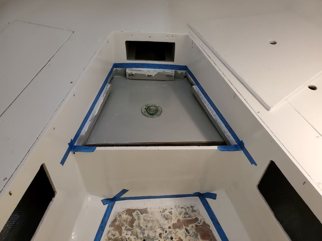
Now I was ready to start the basics of the electric motor installation.  To begin, I temporarily installed the shaft coupling on the prop shaft (leftover shaft–but much newer than original and in excellent condition–from the Atomic 4 installation), and temporarily installed the stuffing box (no packing yet installed) on the stern tube so I could install the shaft and position it where it needed to go.  Beforehand, I’d made a mark on the shaft to show roughly where the prop hub ended up, which showed a sort of minimum amount of shaft that had to extend aft of the Cutless bearing, and with the shaft in place I moved it around as needed to ensure that the propeller could be installed in the space between the shaft and rudder, which pretty much finalized the shaft position.  I secured a hose clamp around the shaft so I wouldn’t be able to pull it in further than this.

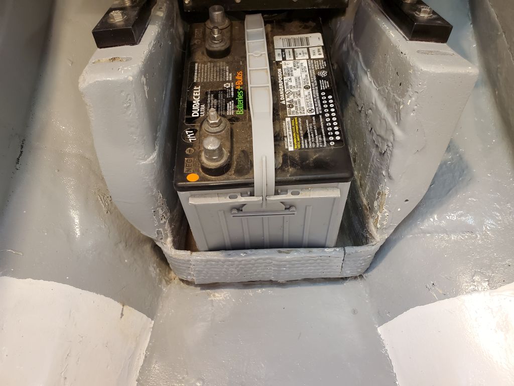
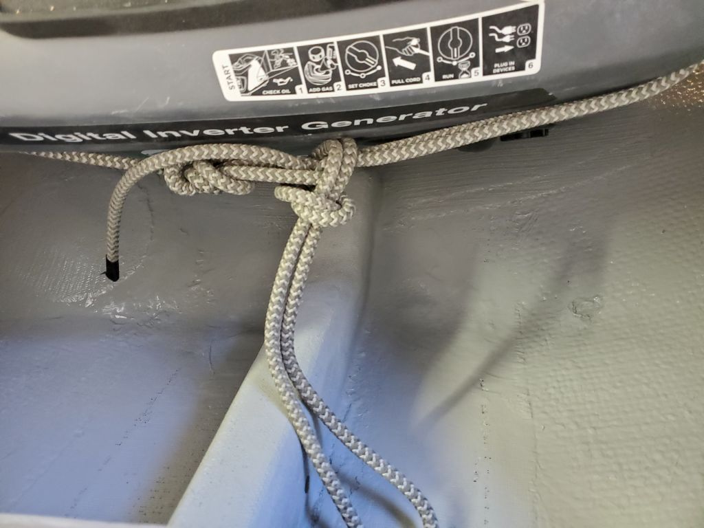
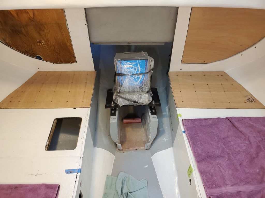
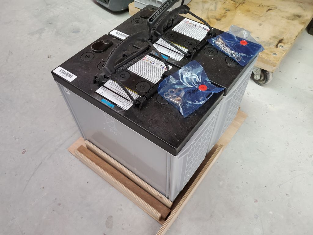
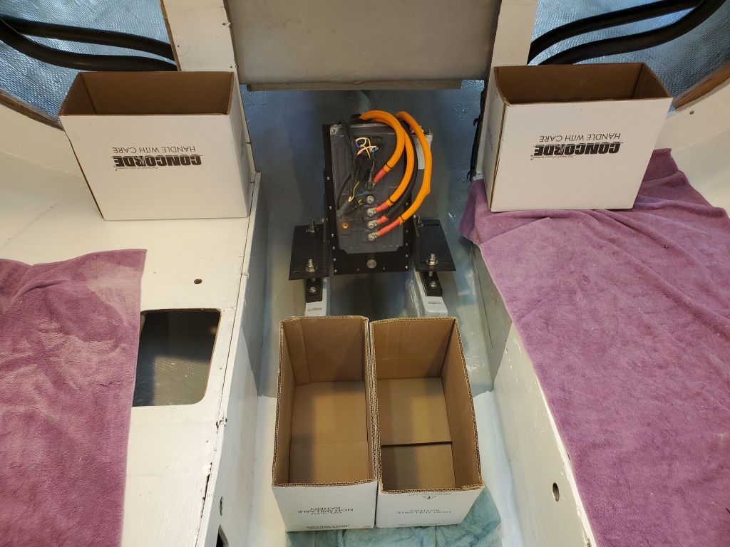
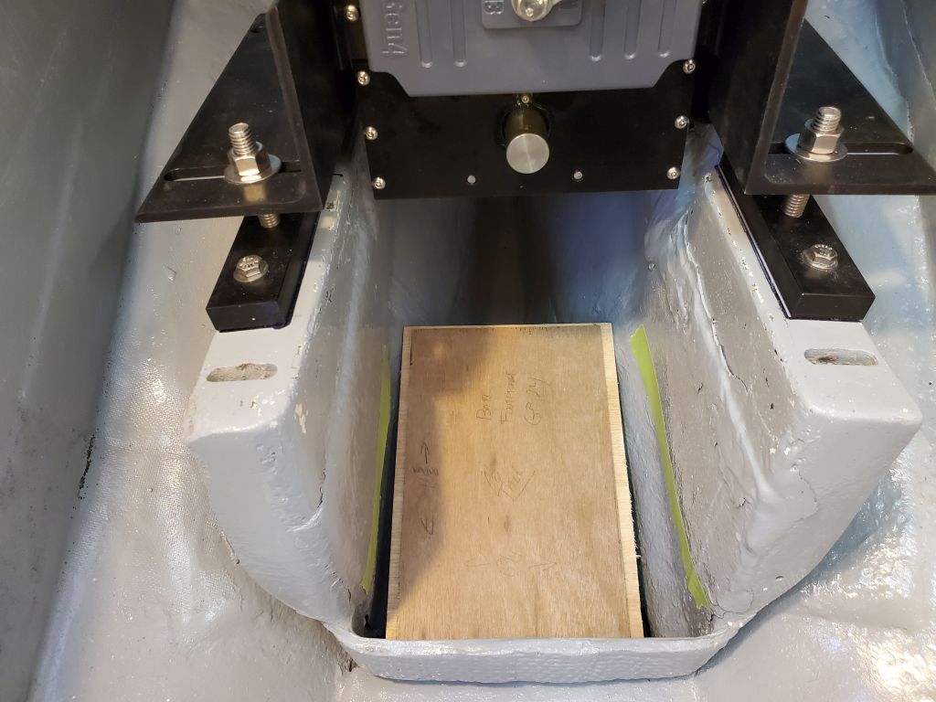
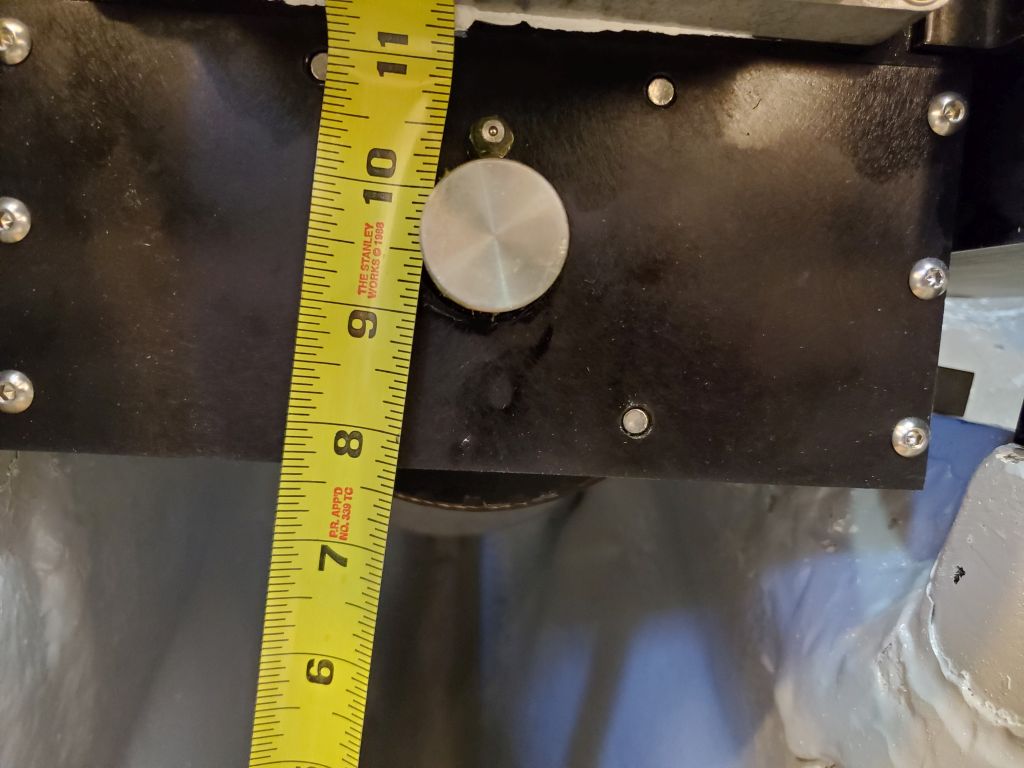
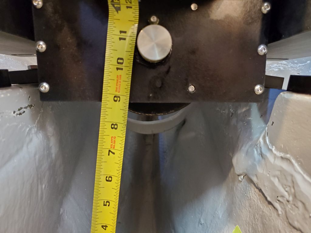
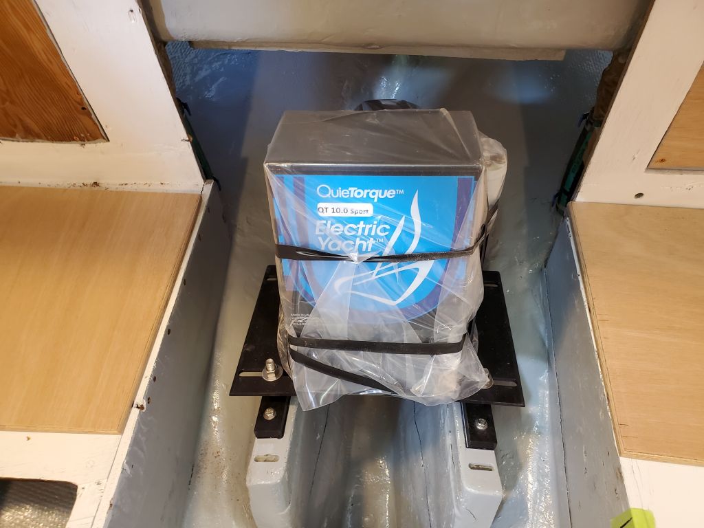
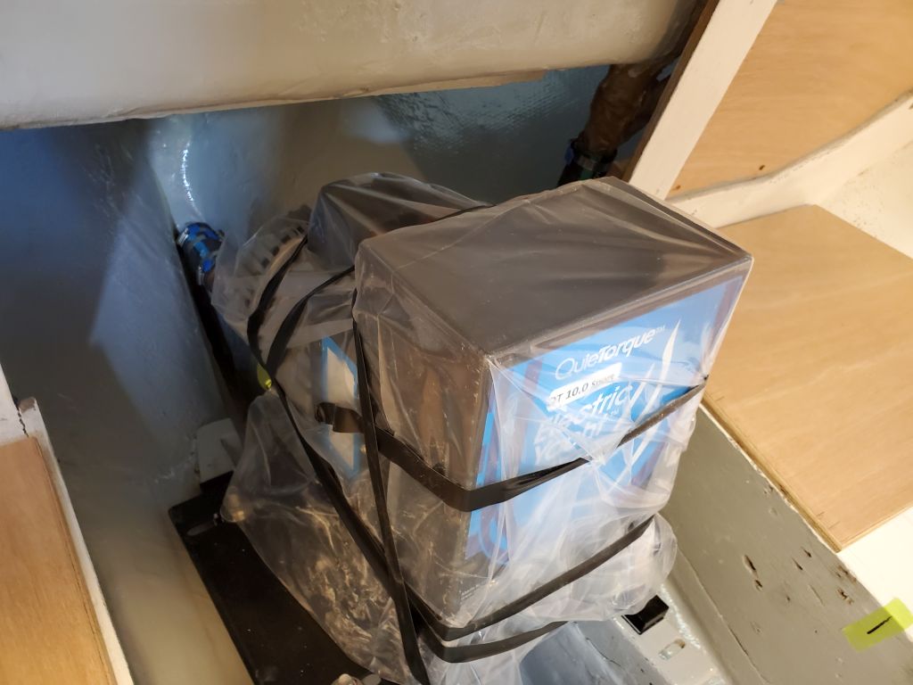
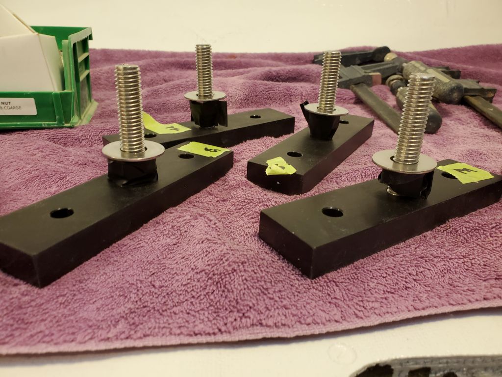
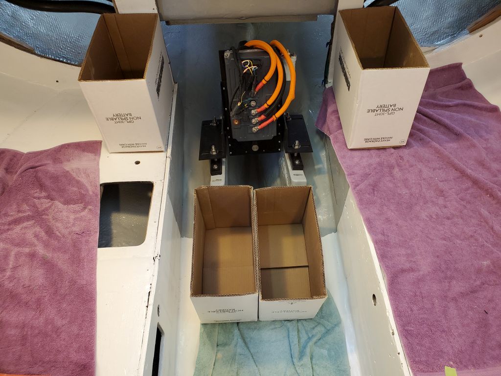
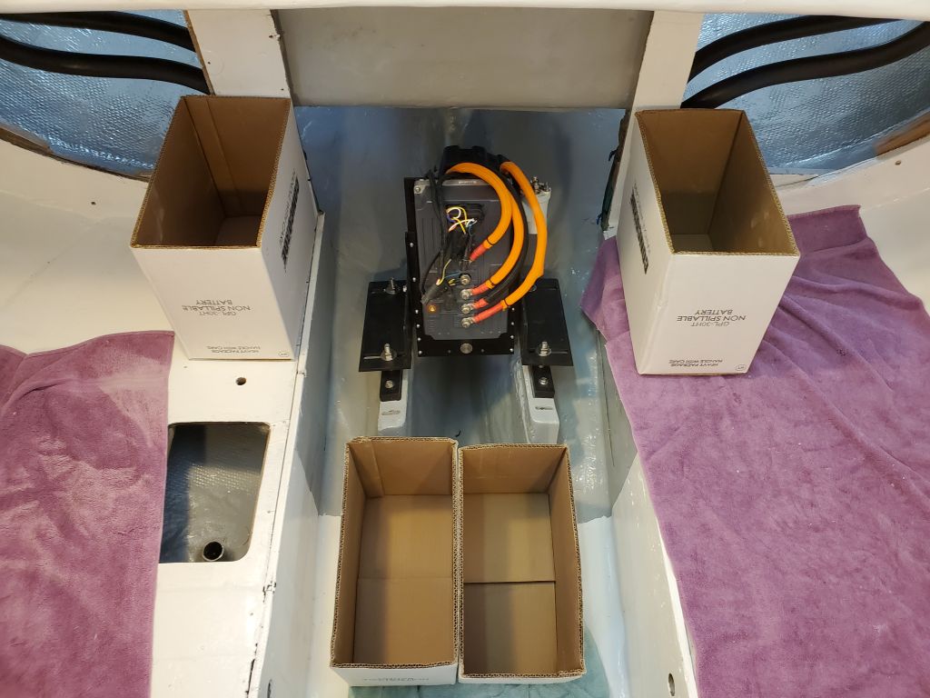
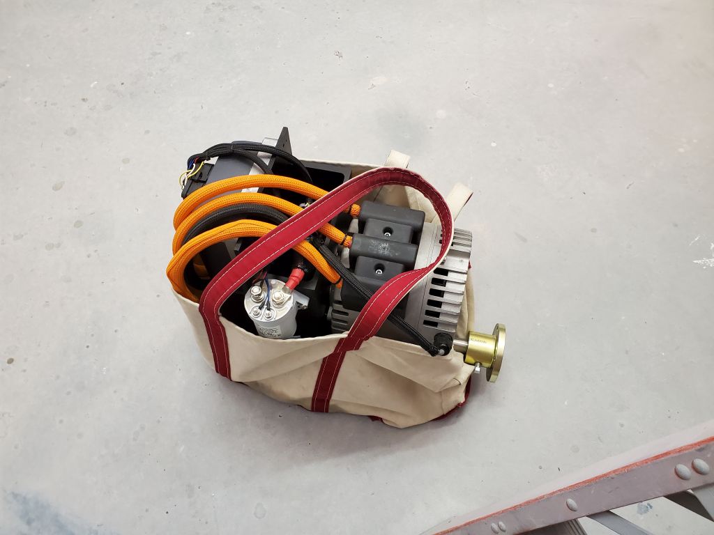
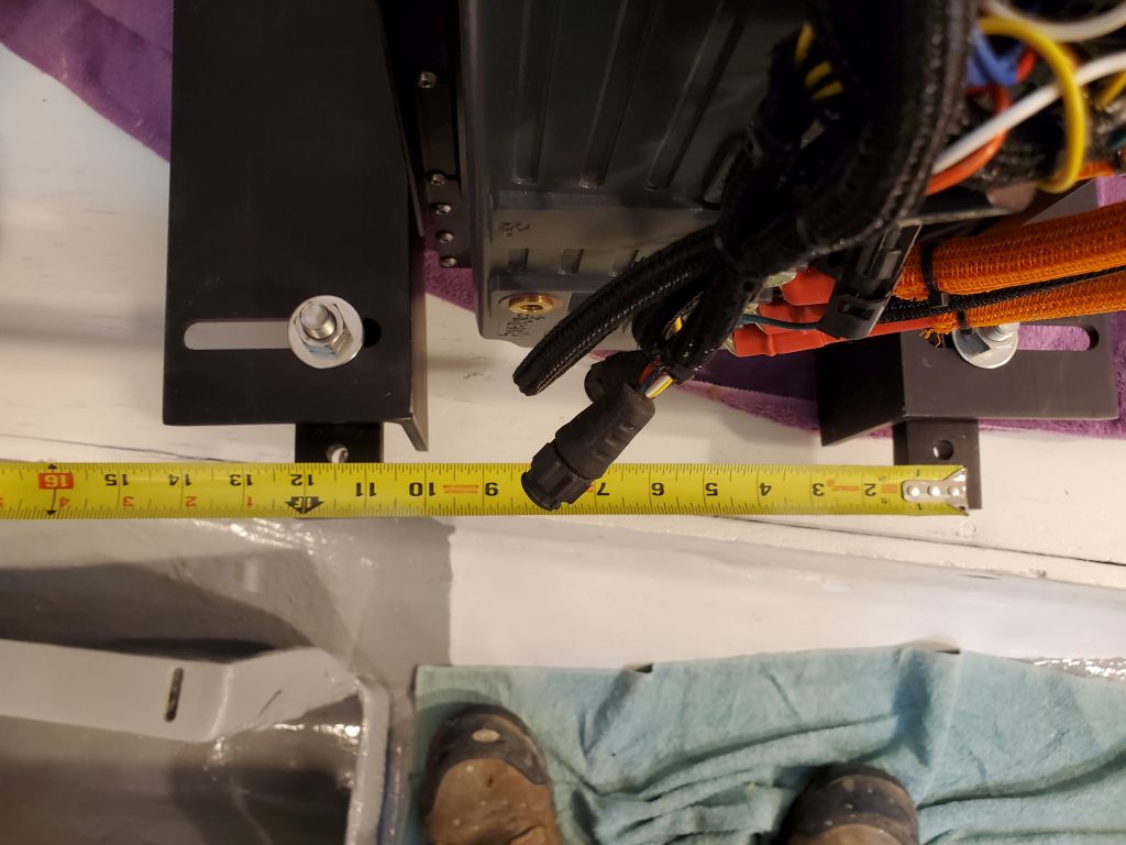
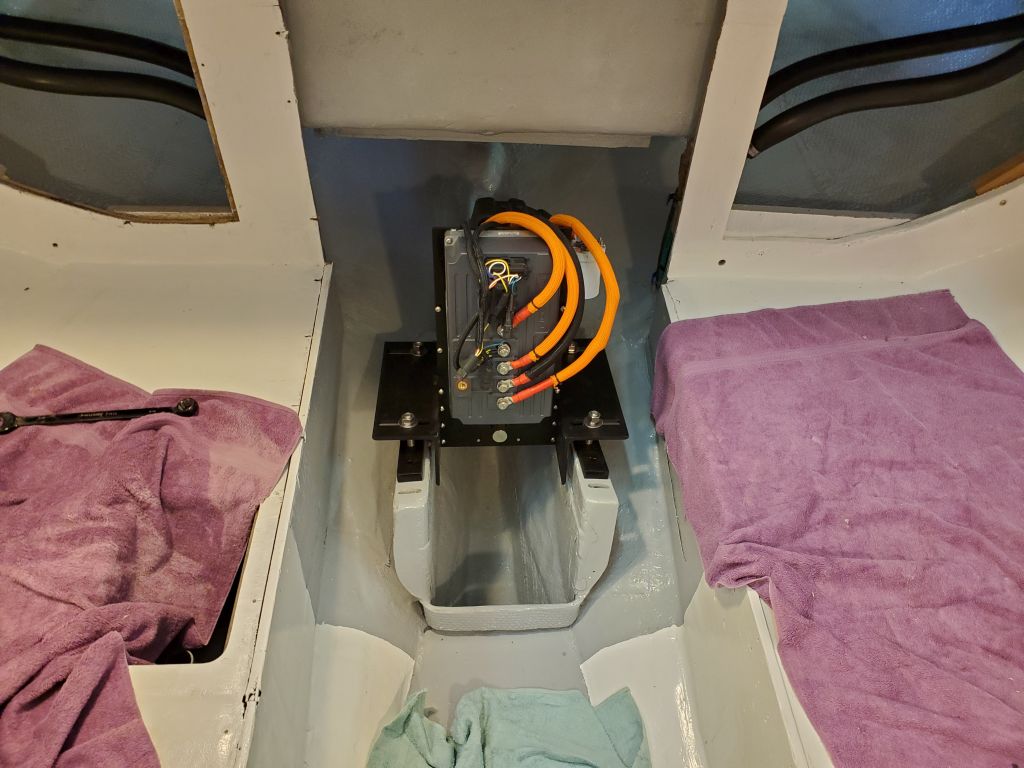
To bring the electric motor assembly into the boat, I found it handy to put it in a large tote bag, which made carting the weight up the ladder less awkward.  Once in the boat, and after familiarizing myself with the basics of installation per the instructions, the first thing I needed to do was reorient the mounting flanges, which could be positioned in various ways and at various heights to accommodate many different installation scenarios.  For this boat, I needed to turn the mounting slots outward (to accommodate the 11-1/2″ mounting centers of the existing foundation), and, based on a rough measurement of the shaft height, I thought I needed to turn the flanges over so the actual mounts would hang beneath, giving the motor something approximating its correct height vis-a-vis the prop shaft.  These changes were straightforward and served as a starting point, though I knew various adjustments would be needed.

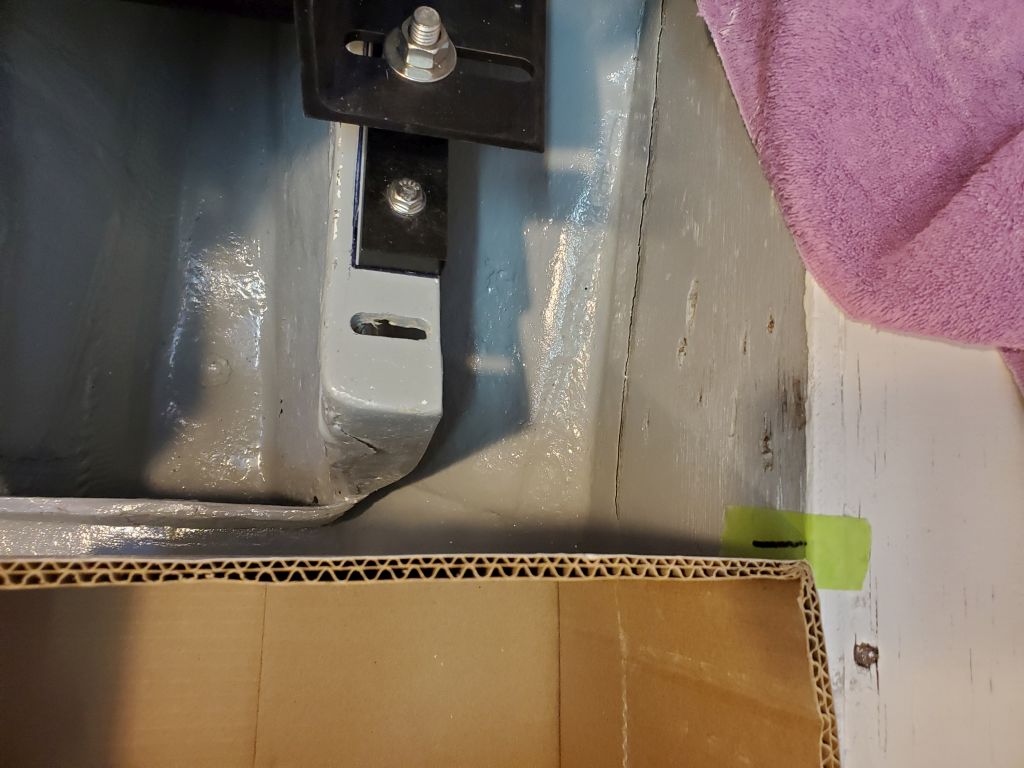
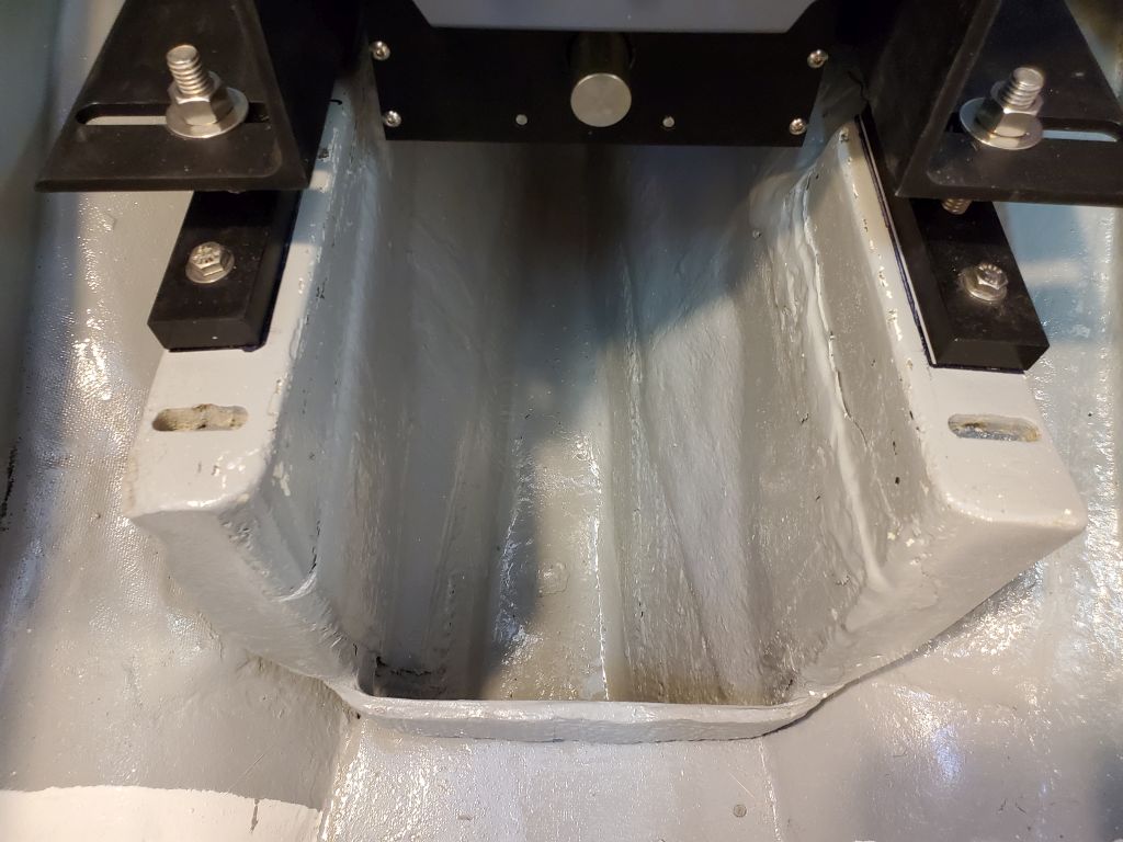
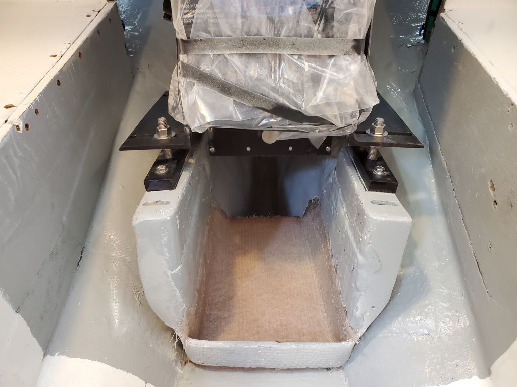
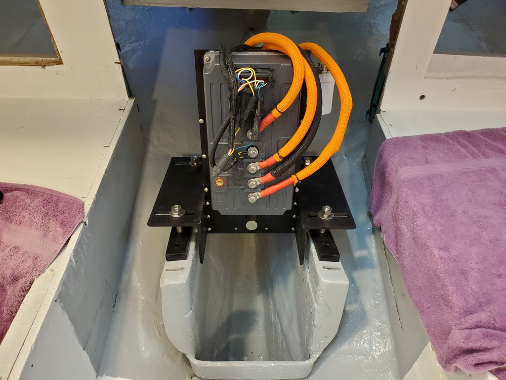
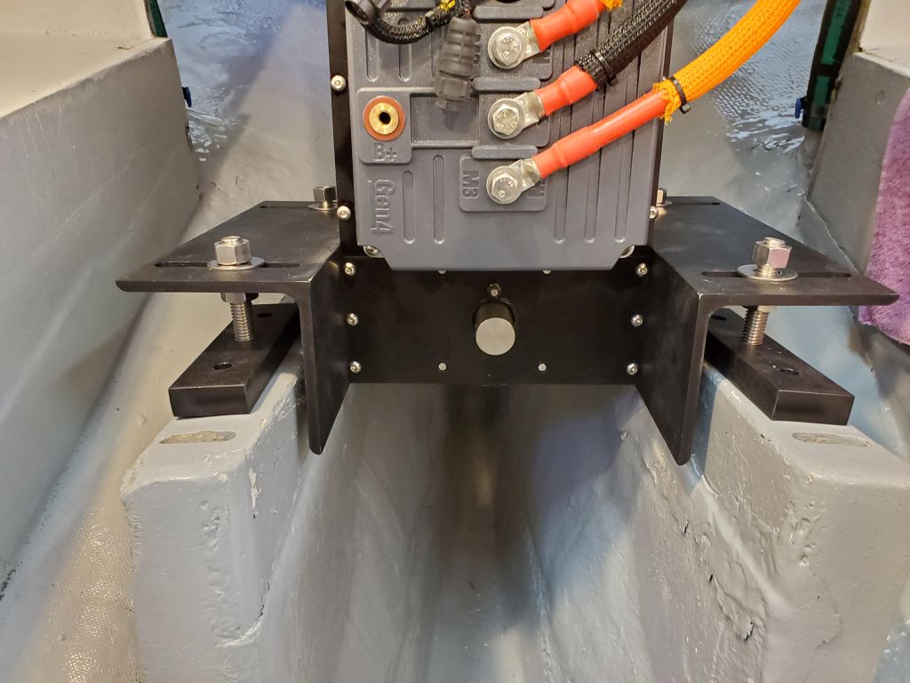
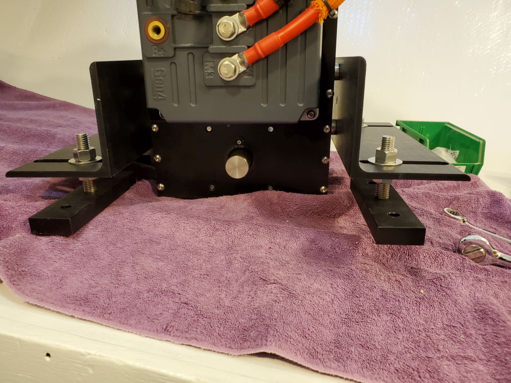
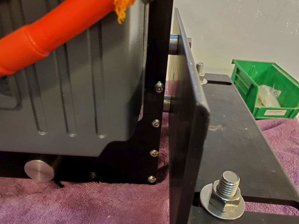
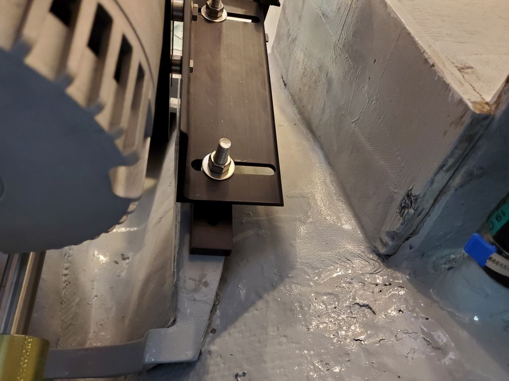
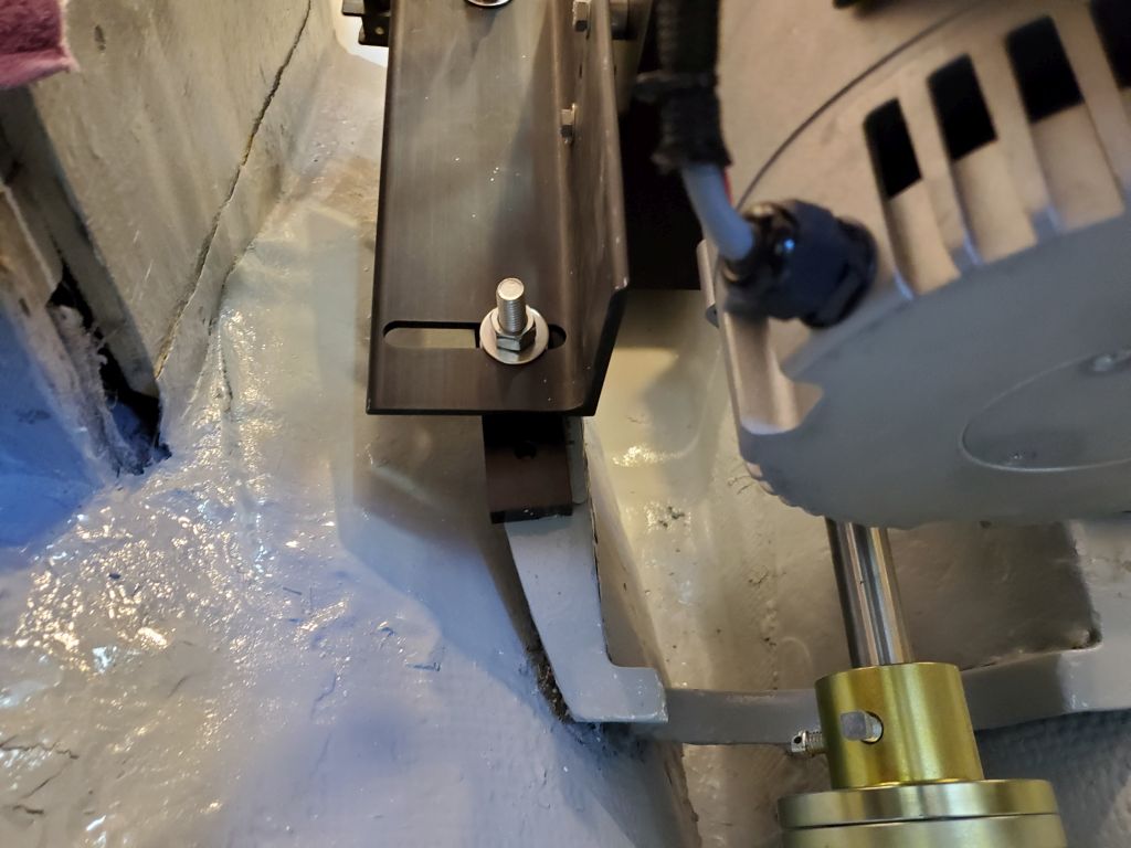
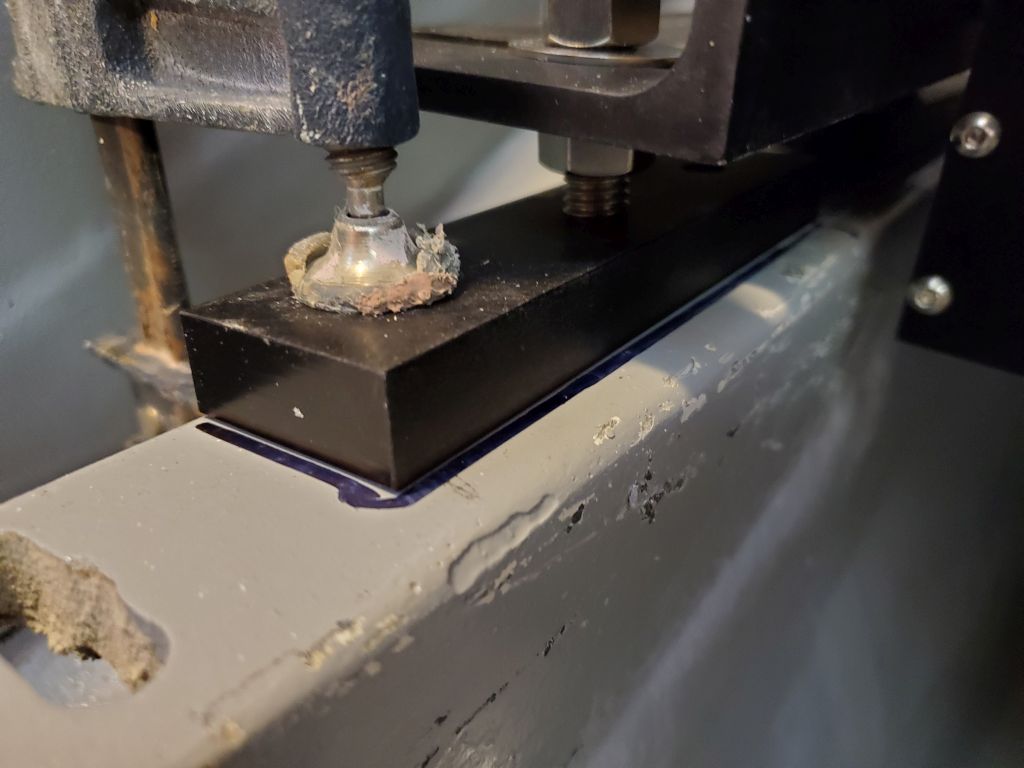
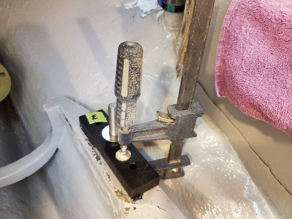
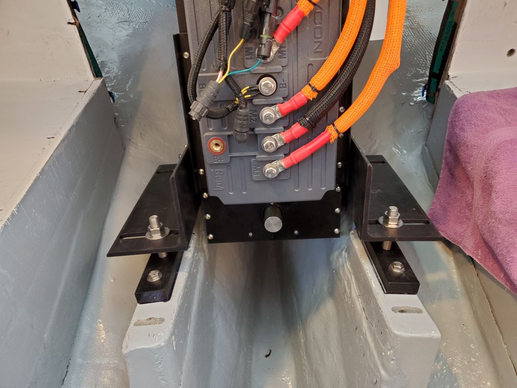
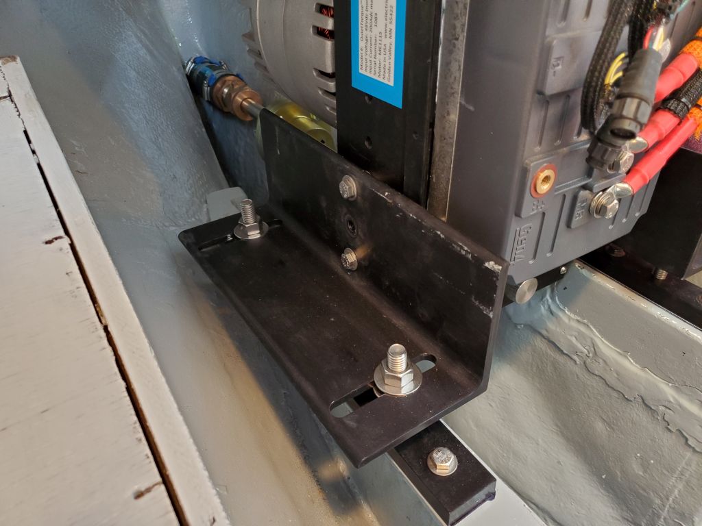
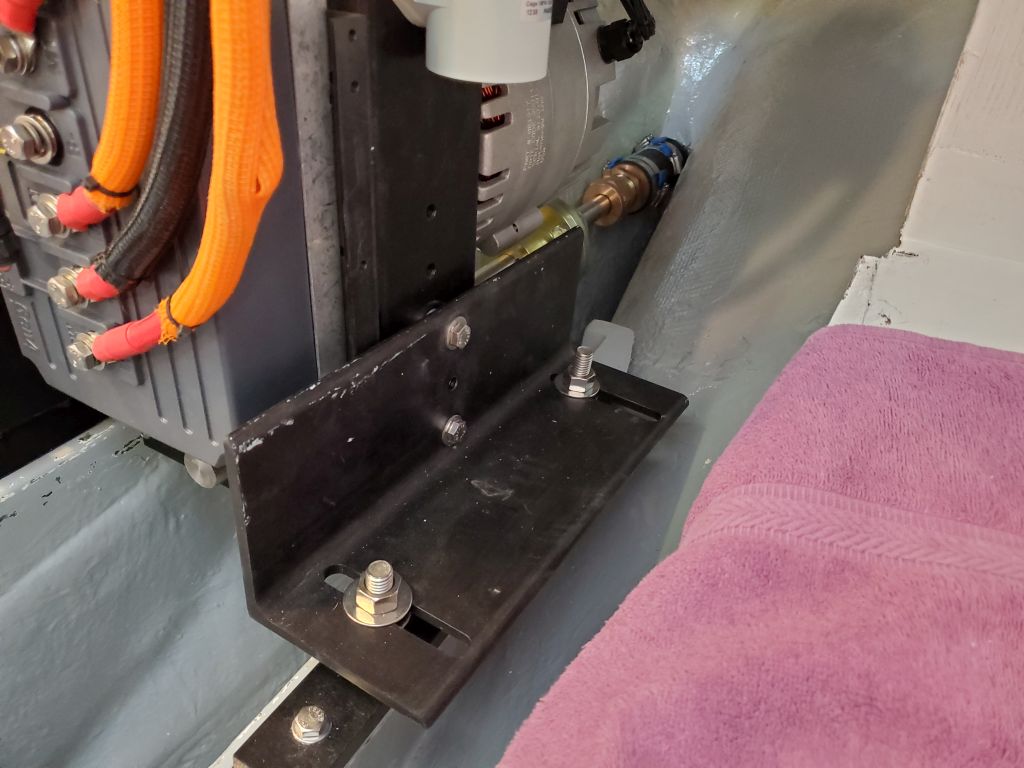
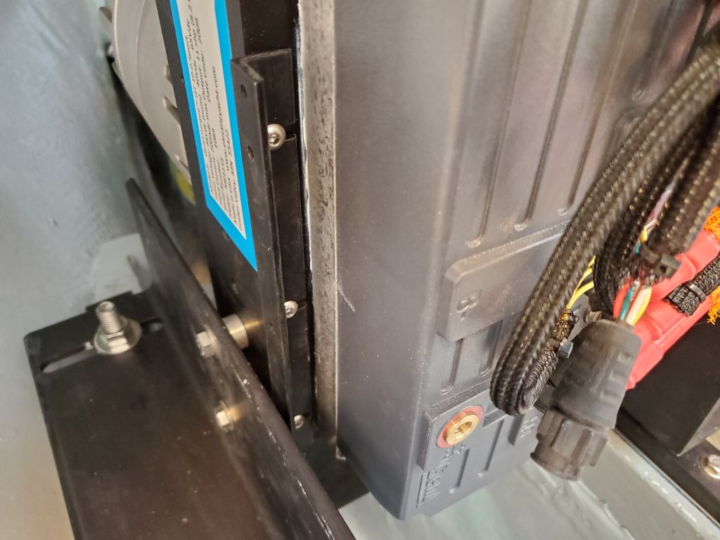
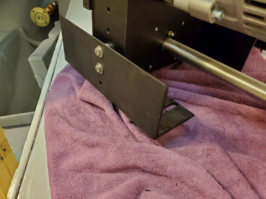
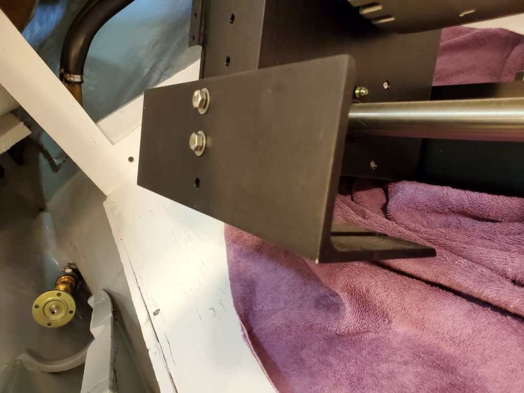
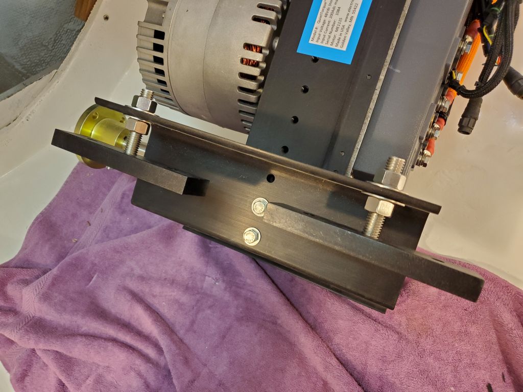
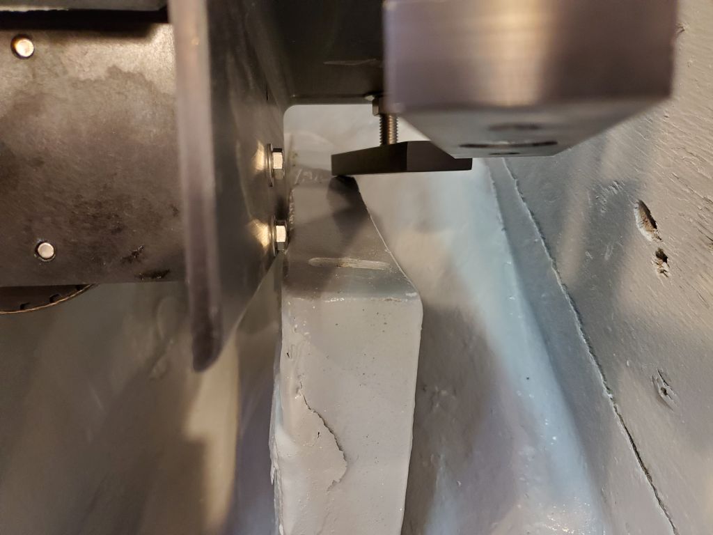
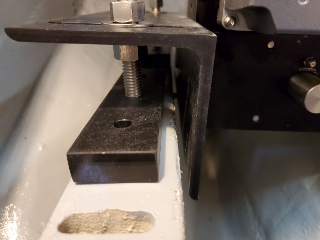
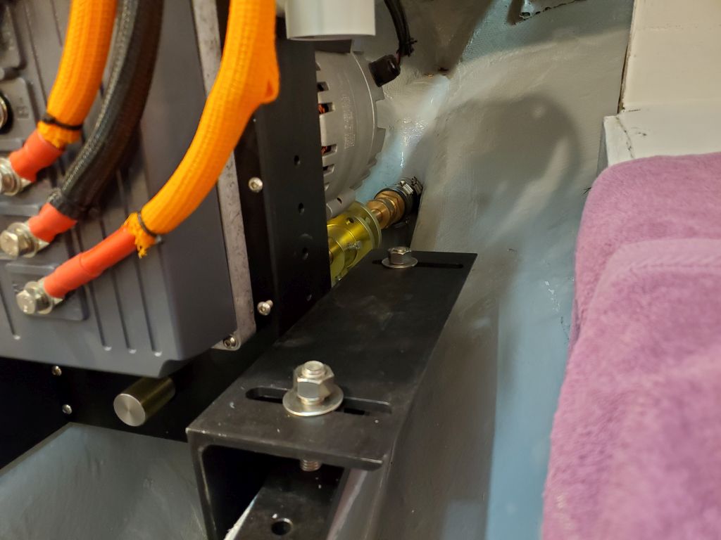
With the flanges realigned and the mounting feet loosely secured where my eyeball roughly thought, I tried the fit on the foundations, but immediately had a problem:  The L-shaped mounting brackets, secured to the engine unit with bolts and spacers, were a bit wider than the inside of the foundation, and the engine had to sit down within the space a bit because of the position of the shaft.

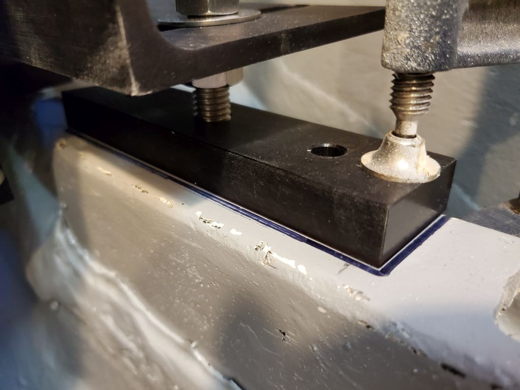
The first fix seemed just to be to reduce the width of the spacers (the purpose of the spacers is indefinable, but I wanted to try and keep them). On hand I had some extra-thick 5/16″ washers, two of which were about half the thickness of the original spacers, so I installed them and tried again.  However, this was still too wide to fit as is.

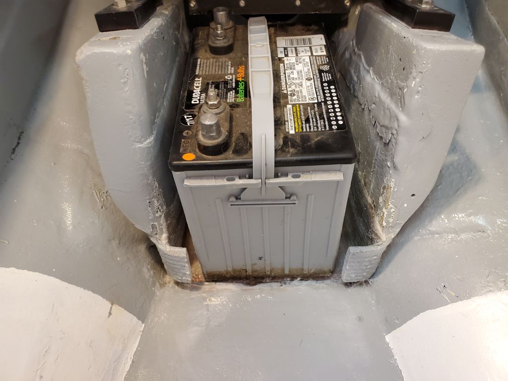
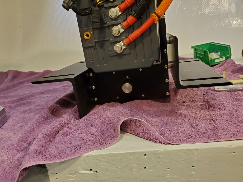
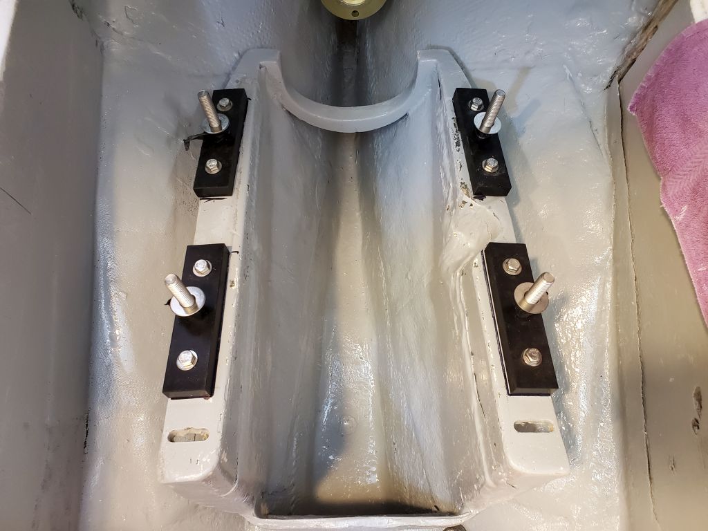
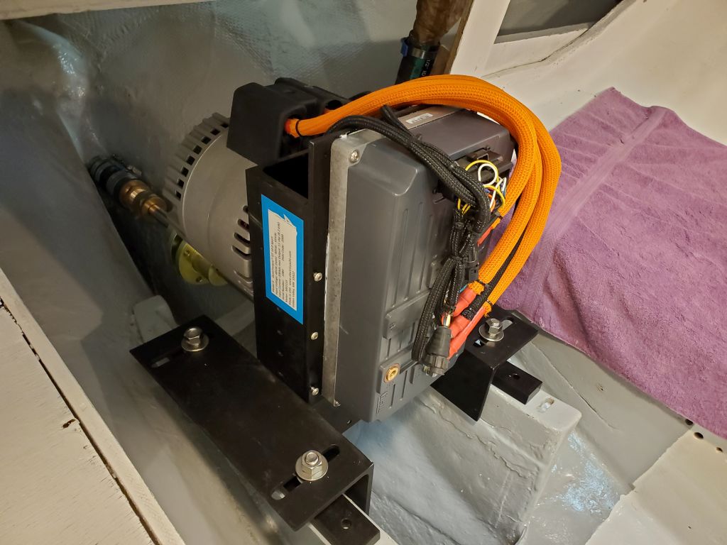
Now I thought I’d try the flanges without any spacers at all, which led to a related minor issue with the motor:  The little L-shaped brackets on the front of the unit, which accepted the front cover (not in place here) and screws, extended down just below the mounting flanges, which would prevent them from being secured tightly to the motor housing if I removed the spacers (this may be the only point of the spacers, come to that).  That would be an easy fix if needed, so for now I simply removed these two brackets, then attached the L-shaped flanges directly to the motor housing.

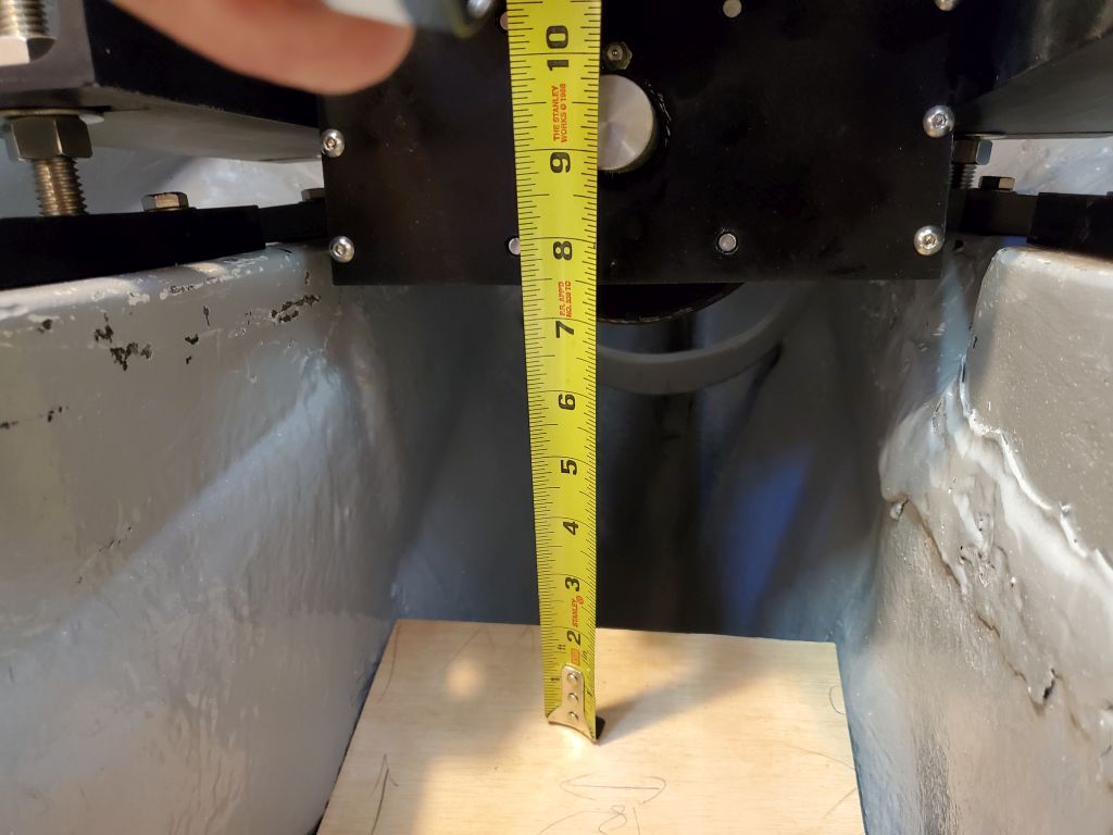
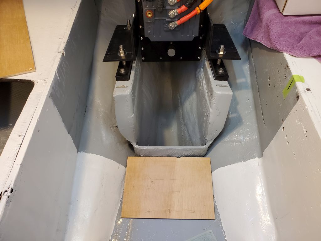
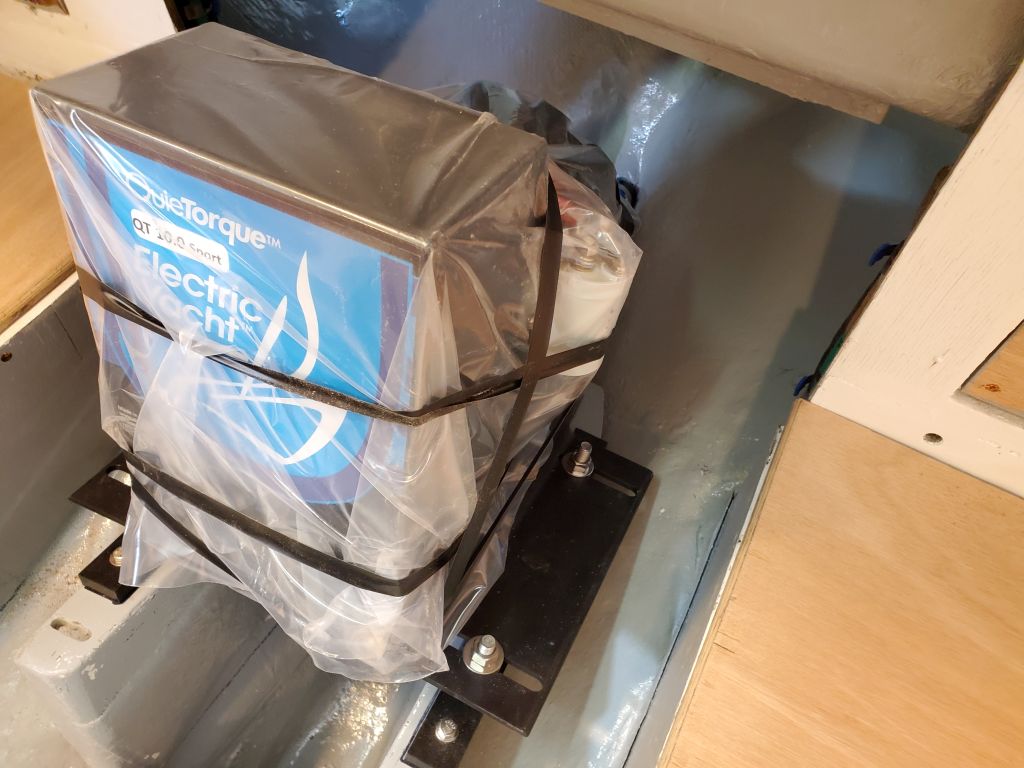
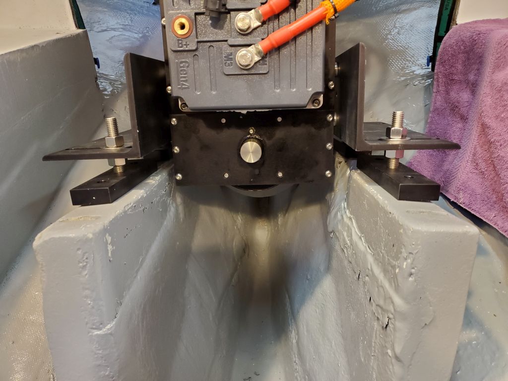
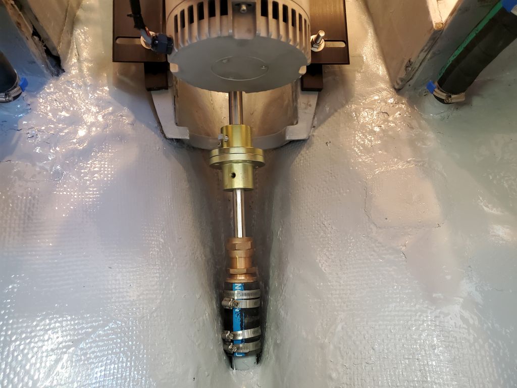
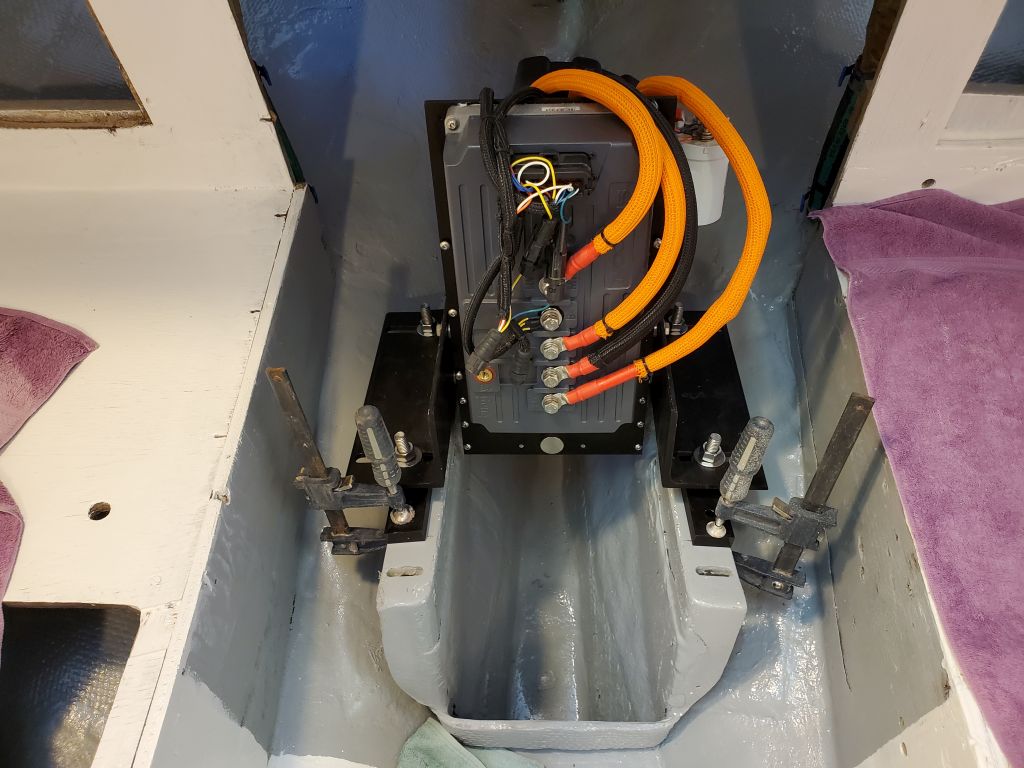
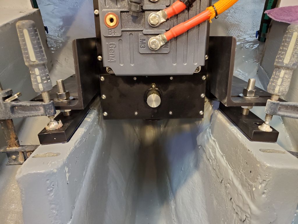
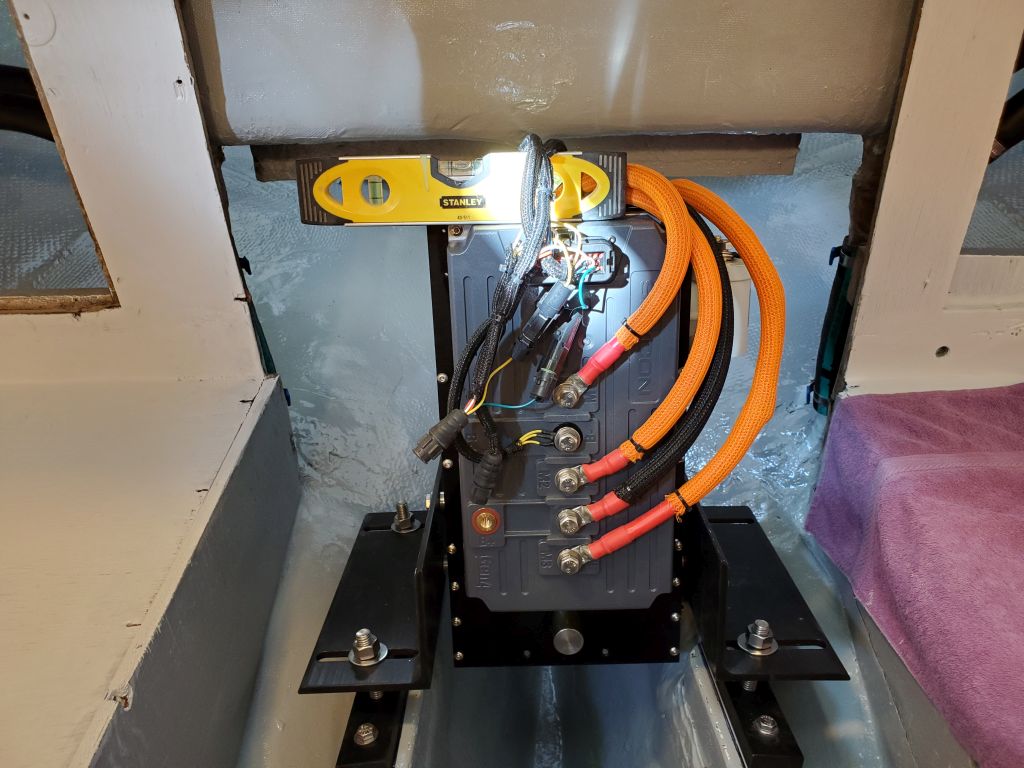
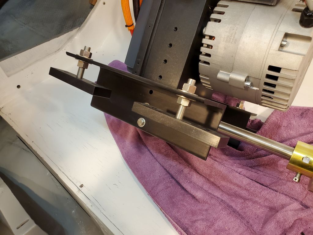
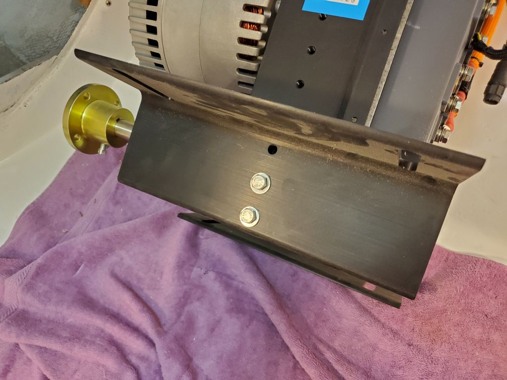
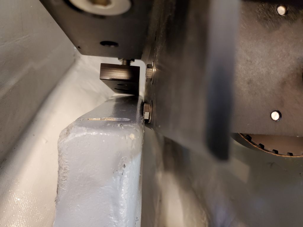
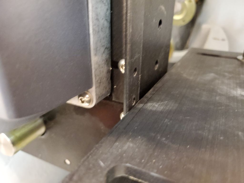
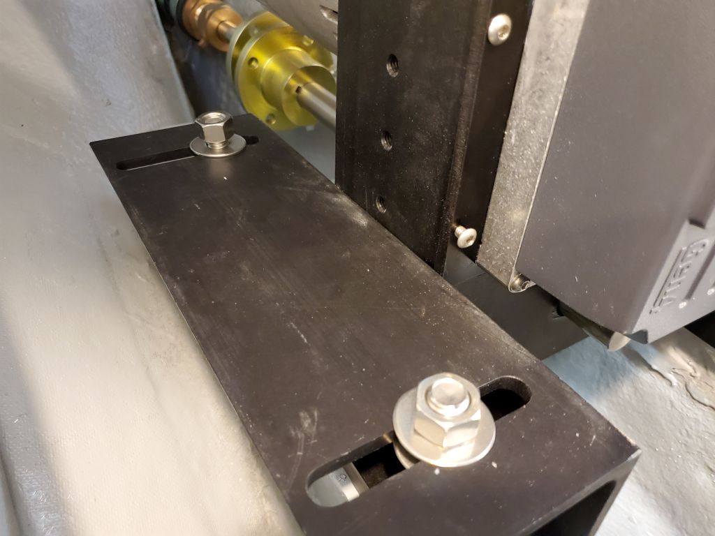
Now everything fit between the foundations, but the whole engine was a bit low, as evidenced by the way the two shaft couplings were misaligned.  That was to be expected and represented minor adjustments.  Now, the electric motor assembly is a lot lighter than a diesel or gas engine would be, and isn’t too bad to move around, but still, one hopes not to move it on and off the engine beds too many times in the course of an afternoon.  This had already been quite a bit of moving around so far.

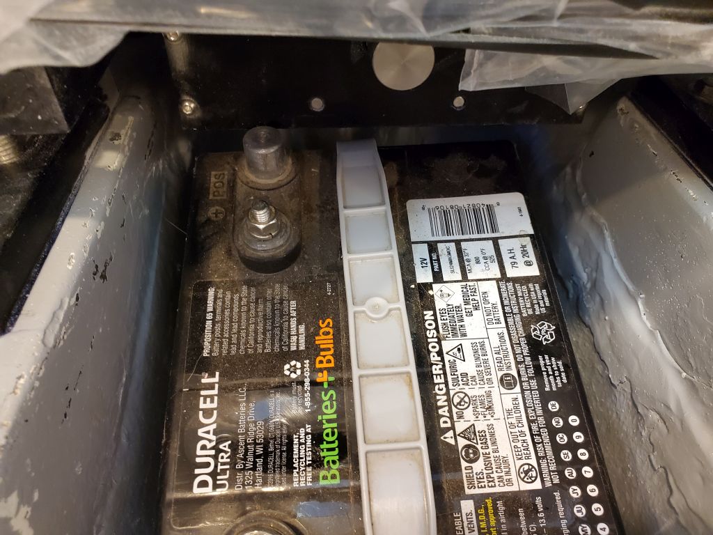
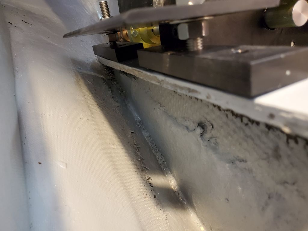
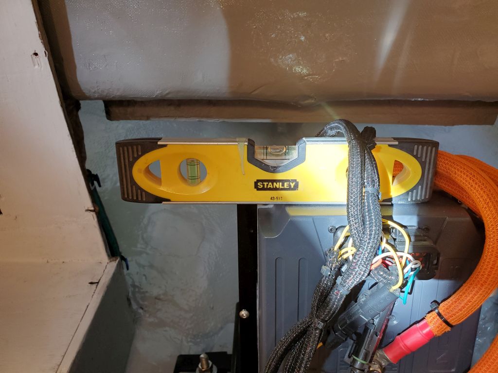
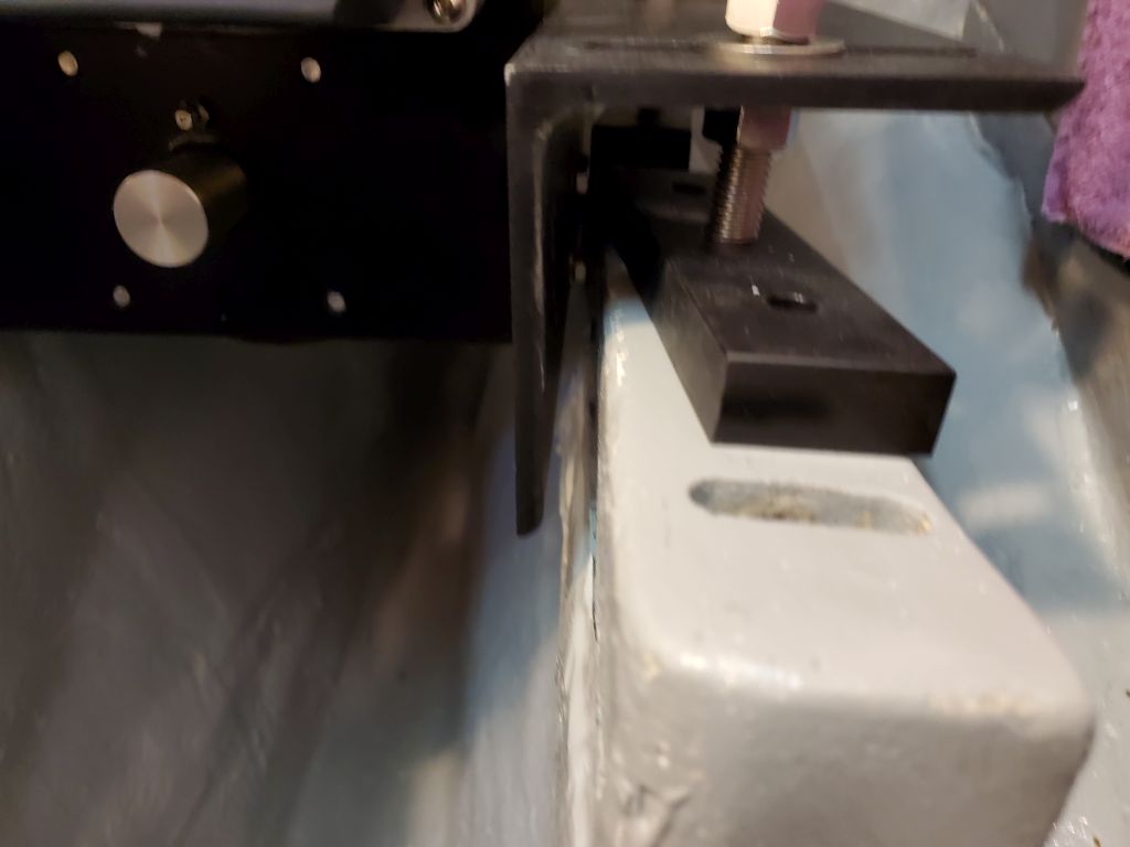
It was late in the day and I’d been determined to have the engine sitting on the foundations by the end of the day, but as I made some height adjustments to bring the couplings into alignment I realized that I’d have to realign the L-brackets differently, as the engine was ending up too high on the mounting studs, right at the top so far and the engine wasn’t yet adjusted correctly.

This was no particular problem, but by now it was too late to consider removing the engine and starting over, so I left that task for next time, when I’d determine how best to position the L-brackets and then get the engine properly set up and at the right height.

Total time billed on this job today:  7.5 hours

0600 Weather Observation:  36°, light rain.  Forecast for the day:   Showers and rain, 45°, becoming sharply colder overnight

Lively Heels Phase 3-27

Monday

After a few coats of varnish, the new shelves were ready for final installation.  With the support cleats already in place, installation was relatively straightforward, with a few screws on each side of both shelves to secure them to the cleats.

Next, I installed matching cherry fiddles on the two original shelves, using glue and screws on the main shelf midway up the compartment, and, because there was no access beneath for screws, glue only on the lowest shelf fiddle, which I held in place with clamps while the glue cured.  These fiddles were designed to help hold in the storage bins the owner planned to use, but with minimal height clearance on some of the shelves the fiddles couldn’t be too high lest they prevent the bins from being removed or installed.

Later, once the glue had enough time to cure, I removed the clamps from the lower fiddle and test-fit the three bins the owner had left, which completed this small project.

Total time billed on this job today :  1.5 hours (including varnishing time)

0600 Weather Observation:  36°, light rain.  Forecast for the day:   Showers and rain, 45°, becoming sharply colder overnight

Lively Heels Phase 3-26

Friday

During the week, as time allowed, I continued work on the cockpit storage box fairing, starting with the newly-sanded first coat that I’d left from the weekend.

Second round of fairing:

Another round of light sanding, then a third, minor, coat of fairing:

One more round of finish sanding brought the cockpit box to ready-for-primer state.

At the holding tank, I installed a 45° elbow at the top of the pumpout tee to provide better access:  The original setup  had been somewhat impeded by the hose directly above, an oversight that could easily have been (but wasn’t) avoided with a slightly different location for the fitting in the tank.  Fortunately, the elbow made for a quick and successful fix.

Continuing the closet shelving project, I transferred the marks from my cardboard patterns to a sheet of 12mm marine plywood and cut out the new shelves, which fit well on the first try other than needing to cut out a little corner of the top shelf to allow for some wiring to pass.

For all the shelves, to help hold the proposed storage bins in place while still allowing the bins to be removed (more of a concern with the lower shelves where clearances were tighter), I milled 1″ tall fiddles from cherry and cut them to length to span the widths of each shelves, including the two original shelves still in place.  These fiddles would also add strength and stiffness to the relatively wide shelves.  With the two new shelves available on the bench, I chose to install these fiddles now, using glue and screws.  I’d install the remaining fiddles on the other shelves in place a little later.

In keeping with the existing shelves, I chose to finish the new shelves with varnish, which looked pretty good even on the meranti plywood but more importantly would provide protection going forward.  I applied a thinned sealer coat of varnish to both sides of the new shelves, supporting them on some simple spikey things I use from time to time, and also finished the two new fiddles for the existing shelves.

Total time billed on this job today (and preceding days):  3.25 hours

0600 Weather Observation:  15°, clear.  Forecast for the day:   Sunny, 30°.

Lyra 27

Friday

I began the day with some light and quick sanding chores in the cockpit and generator locker, cleaning up the scupper openings, a small patch on the vertical repair to the lazarette opening, and lightly scuffing the new fiberglass on the generator platform.  I also cut off flush the old engine exhaust in the lazarette to prepare it for patching.

With the generator in place in the locker, I measured for some chocks that would help hold it securely for storage.  With a chock at each side of the new platform, plus the backstay chainplate (which held the generator securely at the aft end), and a simple lashing to secure the unit to the back side of the cockpit (where I planned to add some fittings to secure a lashing or strap), the generator wouldn’t move when not in use, yet would be easy to access and remove when needed.  I prepared two chocks from some scrap hardwood to fit the ends of the platform.

After final preparations, I epoxied the new wooden chocks in place, coating all surfaces of the wood with epoxy as well.

Meanwhile, I masked over the exterior of the old engine exhaust and filled it from within with an epoxy mixture.  Later I planned to cut off the exterior end flush.

Moving on, I turned to the forward hatch final installation.  After marking and predrilling all the fastener locations, I secured the hatch permanently with plenty of sealant and 20 screws, cleaning up the excess sealant squeezeout afterwards.  I’d leave the protective paper on the hatch for the duration of the project.

Inside the opening, I planned later to clean up and paint the exposed inner deck edge to finish it off.

In the cabin, I prepared the cabin sole and masked along the edges to protect the white paint.  I used a delicate-surface tape to be sure not to damage the fresh paint.  Afterwards, I applied a coat of the same light gray paint I used in the lockers and bilges.  This would give the new paint plenty of cure time over the weekend before any potential traffic.

Total time billed on this job today:  3.75 hours

0600 Weather Observation:  15°, clear.  Forecast for the day:   Sunny, 30°.

Lyra 26

Thursday

Having cured overnight, the forward hatch frame was ready for unclamping.  I’d soon install the new hatch to complete this task.

Following some light prep work in the generator compartment, I cut two layers of heavy fiberglass to sheathe and tab in the shelf, then installed them in epoxy resin.  The new fiberglass  overlapped the hull at the aft end by several inches, and wrapped up the back side of the cockpit well by a few inches as well.

The owner wanted to build the hatch for the new generator compartment, so I made up a simple plywood template I could give him that accurately portrayed the size of the coaming, and the shape of the surrounding deck.  Using roughly 1/8″ thick stir sticks as spacers between the coaming and the inside of the template (representing the minimum inside dimensions of the hatch), I built the raw template in place from 2″ wide strips of 9mm (3/8″) plywood and hot glue, adding stiffeners as needed.  Then, I scribed the shape of the deck on  all sides.

Down on the bench, I cut the template to my scribe lines as needed, and trimmed the overhanging braces and ends of the box.  I fine-tuned the shaping with a couple test-fits on deck to improve the fit after my initial cuts and shaping.  I made some additional reference marks and measurements to highlight various clearances to nearby obstructions, such as the curvy part of the traveler area, and the stern light molding behind, which might affect portions of the build.  Then, I marked the actual inside height of the coaming on the template as a final reference.

Looking to wrap up a few loose ends before I turned my full attention in the coming week to the cabin and the beginnings of systems installations–including scupper drain hoses, which, because of access issues, needed to be installed before the rest of the interior could be completed–I worked on the cockpit scuppers, which were still in rough form following the bulk cockpit work earlier.  Now, I reopened the holes in the cockpit corners with a hole saw and beveled them with a countersink before adding a bit more epoxy fairing compound in the corners and around and inside the drain openings to fine-tune the appearance and function.

In the cabin, I added some screws through the cabin sole and into the new cleats in various places to strengthen the joints and, as needed, cleaned up some epoxy squeezeout here and there and otherwise prepared the sole and cleats for painting in the immediate future.  The cabin sole itself, built from plywood with a fiberglass overlay, was in rather sketchy condition, the original plywood having lost much of its structural integrity over the years, and since it was generally just sound enough despite that (if far from good), and wholesale replacement wasn’t feasible at this time given the other more pressing needs of the project scope, I added some cross stiffeners below the sole in key points to help prevent flexing:  Just some scrap pieces of prefab fiberglass that happened to fit beneath the sole and could be tightly wedged into position.  With no real access beneath, these stopgaps would hopefully extend usefully the life of the existing sole for some modicum of time.

Total time billed on this job today:  5 hours

0600 Weather Observation:  40°, mostly clear.  Forecast for the day:   Sunny and windy, temperature dropping.

Skeedeen Phase 6-39

Wednesday

To replace the broken and cheesy plastic engine room vents that I’d removed early in the project, the owner had had some new bronze vents made, and now that the boat was temporarily indoors at another shop where the engine was being installed, it was a good time to go install the new vents.

The new vents were different than the old, but had used the originals as a guide for the bolting pattern and to fit properly over the openings in the hull.   Installation was a relatively straightforward process since I’d prepared the openings and hole locations with solid epoxy during the hull project earlier.  For each of the two vents, I followed this process:  Lay out the plate on the hull; drill and tap eight screw holes for 5/16″ machine screws (larger than needed but that’s how the fabricator made the vents); mill small countersinks at the top of each hole in the hull; install sealant; install vent with eight screws and clean up.

When I finished installing the vents, I realized that I’d installed the backwards, so I had to remove both, flip then so the slots faced aft, and reinstall.  The correct orientation is shown in the final two photos of this series.

Total time billed on this job today:  2 hours

0600 Weather Observation:  32°, mostly clear.  Forecast for the day:   Increasing clouds, 46°

Back to Skeedeen

Lyra 25

Wednesday

After being away from the shop all morning to finish up a small job offsite, I got back to work in the afternoon on the forward hatch, ready now for the final installation after some final masking to the hatch frame itself.

I installed the hatch frame in a bed of thickened epoxy adhesive, securing the frame with clamps as needed to press it into the epoxy and to keep it level from side to side.  I cleaned up the excess epoxy and shaped it as needed inside and out, then removed all the masking tape leaving clean lines everywhere.  I left the frames in the clamps to cure overnight.

Next, I prepared and installed the plywood platform in the generator compartment, now that the support cleat at the forward end was in place.  After surface preparations, I epoxied the bottom (hidden) side of the platform, then installed it in a bed of thickened epoxy adhesive at both sides, forming fillets as needed to smooth the transition to the hull and at the cockpit end.  I used a couple small lead weights to hold the platform securely against the hull, as it tended to rock slightly.

Afterwards, having already masked off around the hatch coaming again, I cleaned up the original fillets with some more epoxy, just to improve appearance and make the fillets consistent all around.  I removed the tape afterwards to leave a clean line.

Total time billed on this job today:  2.5 hours

0600 Weather Observation:  32°, mostly clear.  Forecast for the day:   Increasing clouds, 46°

Lyra 24

Tuesday

I’d planned to spend the day on the second coat of interior paint, but after careful inspection of all areas, and as critically as possible, I couldn’t find any reason why it would be necessary or even beneficial:  The finish on the first coat was so good as to obviate it, and I couldn’t find a notable fault.  Happy, if a bit surprised, to save the effort, I removed the masking tape and left the paint alone to continue curing before getting into any more interior work.  I planned to paint the cabin sole late in the week, which would give it the weekend to cure.

After some unrelated nits and nats during the morning, I got back to work on the generator storage area.  To test-fit the bottom platform in its final position, I used hot glue to mount a pair of temporary support blocks on the aft side of the cockpit well inside the locker, on which I could rest the plywood platform to check its angle properly against the “natural” angle of the generator in repose.  I ended up using a couple extra scraps of wood to raise the platform just a bit further, which worked pretty well and appeared to support the generator when installed.

After removing the temporary blocks and cleaning the bonding area, I installed with epoxy adhesive a 24″ hardwood cleat at the proper location; this would eventually support the inner edge of the new shelf.

For protection, I masked off the deck around the hatch opening, then installed the fiberglass hatch coaming permanently with thickened epoxy, forming a fillet around the outer edge and removing the tape when complete.  During an earlier work session, I’d already sanded away the paint from this narrow border to give the epoxy something real to bond to.

In a similar vein, I made final preparations towards the forward hatch installation.  Using the now-varnished hatch frame as a guide, I masked along its perimeter on the deck.  This gave me a line inside of which I needed to sand away the various paints to expose gelcoat for bonding.  With a sander, I could brush up against and slightly over the tape without causing damage to the adjacent areas, and remove the coatings within.  Inside the cabin, I used delicate surface tape and plastic to cover the opening and prevent sanding dust from going inside on the new paint.

Now I temporarily reinstalled the frame once more, and masked around it again, this time as protection against the epoxy I’d use to secure the frame to the deck in the near future.

Total time billed on this job today:  4 hours

0600 Weather Observation:  30°, partly clear, a crusty inch or two of snow from overnight.  Forecast for the day:   Partly sunny, 41°

Lively Heels Phase 3-25

Monday

After some shipping delays, the straps I’d ordered for the holding tank arrived, and with an afternoon available I looked forward to finishing the installation.

I began by reinstalling the modified port divider in the holding tank compartment.

After determining how to position the new angled base platform to allow room for the stainless eye straps that would hold the ratchet straps to secure the tank, I installed the platform with eight screws, four to a side, through predrilled holes in the platform, and with slight recesses to accept the screw head and a washer.  I secured the eye straps to the sole substrate with screws and pre-attached both ends of the ratchet straps, which featured stainless steel buckles and carabiners at the ends.

Now I could put the tank in place.  The tank fit easily through the overhead hatch, as planned, and soon it was in position.  However, I immediately ran into a problem.  Because of the various tank fittings, the hold-down straps only worked in two obvious areas where the way was clear–no problem there.  I’d used these positions to locate the eye straps and ratchet straps in the compartment.  What I’d not foreseen was a twofold problem:  First the starboard strap and ratchet buckle ended up interfering with the saltwater washdown pump and its filter housing, which were located on the bulkhead just ahead.  This meant there wasn’t clearance to operate the ratchet, and it also posed an ongoing clearance issue for the filter assembly.

In addition, the two ratchet buckles ended up closer to the top corner of the tank than I’d wanted, by virtue of the 12″ dead end measurement of these (and most similar) straps.  The starboard buckle, notwithstanding the filter issue, was more or less OK because the tank was higher on this side because of the angled platform.  But the port buckle (not shown here) ended up awkwardly and unacceptably at and just above the corner of the tank, and tensioning it in that position would likely tend to put undue pressure on the tank itself.

In a vacuum, as it happened, I could have made the starboard problem work, since the filter assembly and hose from the pump were actually easy to remove at a whim thanks to the design of the pump housing (a little plastic clip holds things in place).  So by removing the filter and hose assembly, I had enough room to operate the ratchet, and then reinstall the filter.  But this still wasn’t ideal, and in the end the fix for the port side worked a treat for the starboard as well.

The fix was to take the carabiners on the buckle side of the ratchet out of the picture.  Fortunately, I could remove easily enough the eye straps and slip the sewn loop of the ratchet strap over the eye, then re-secure the eyes.  Because the carabiners were permanantly attached, with the webbing sewn though a closed eye in the hooks, I couldn’t remove them, so I taped them above the webbing loop and out of the way to keep them from flopping around loosely.

This had the net effect of lowering the buckles by close to three inches at each location, which solved both issues nicely:  On the starboard side, the buckle was now below and clear of the pump housing (check); and on the port side, the buckle was now nicely below the tank corner where it could be safely tensioned (check).  This was a relief.  Now I could strap down the tank properly and finally, using some strips of 1/4″ thick rubber (left over from the first attempt at the new anchor pad on the stem) as chafe gear beneath the straps.

Continuing, I moved on to the hose connections, which were straightforward and didn’t take long, and went according to plan.  I secured the loop from the tank discharge to the nearby  pump with a pair of clamps to hold it securely and avoid any undue tension on the fittings at either end.  Afterwards, I reinstalled the water lines to the head shower setup, which I’d removed for access early in the project, cut off the excess strap length from the tank hold-downs, and wrapped up other details in the space to call this installation complete.

Total time billed on this job today:  3 hours

0600 Weather Observation:  12°, partly clear.  Forecast for the day:   Mostly cloudy, snow and rain in the afternoon and evening, 35 °

Older posts Newer posts