Monday
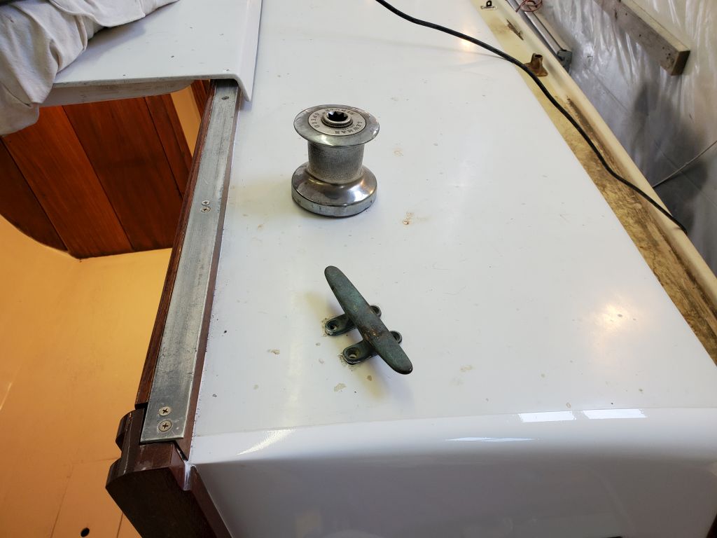
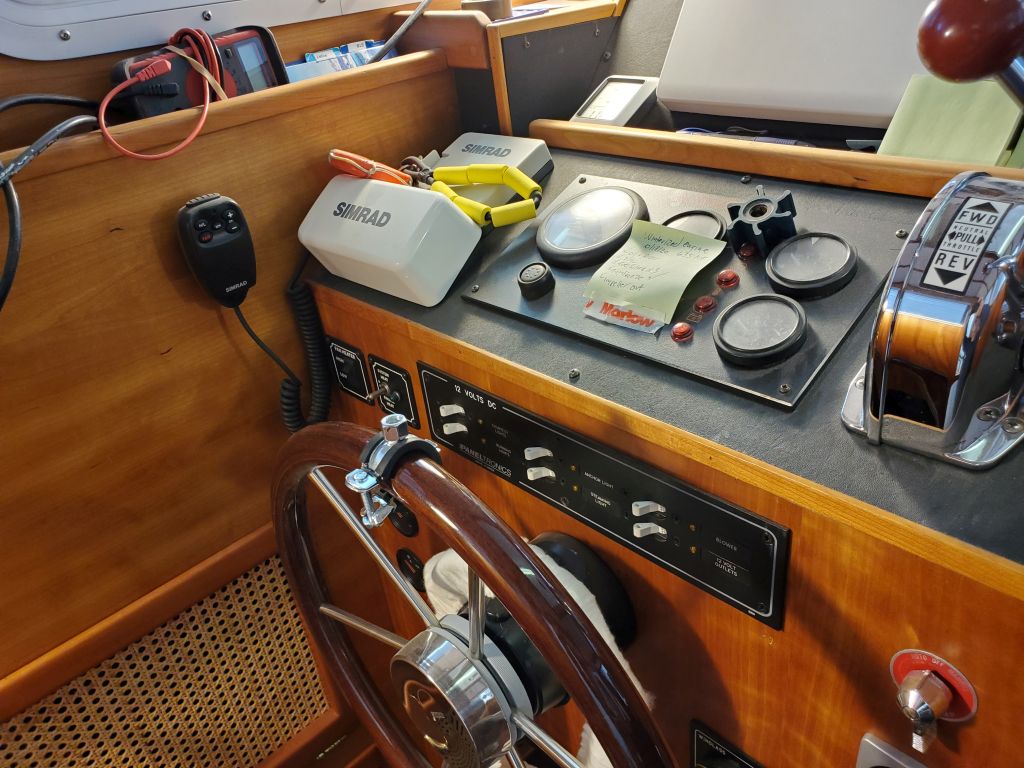
With my part of the project wrapping up and the boat scheduled to be moved soon, I turned my focus back to the interior and the galley countertop. The new laminate the owner ordered had arrived, and now I could finish up the countertops and their final installation.
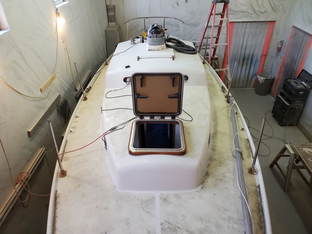
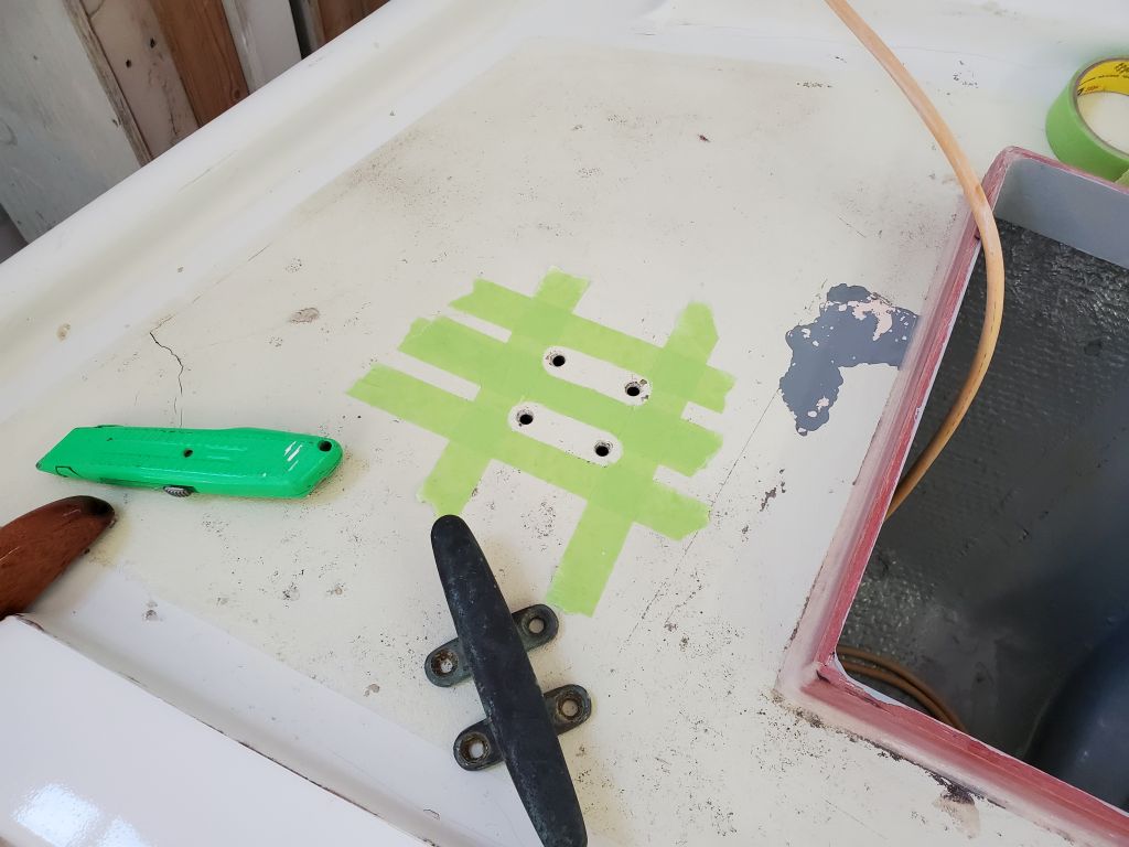
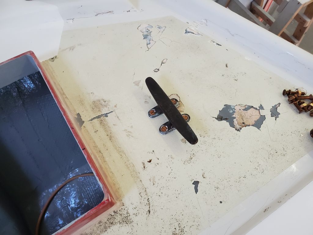
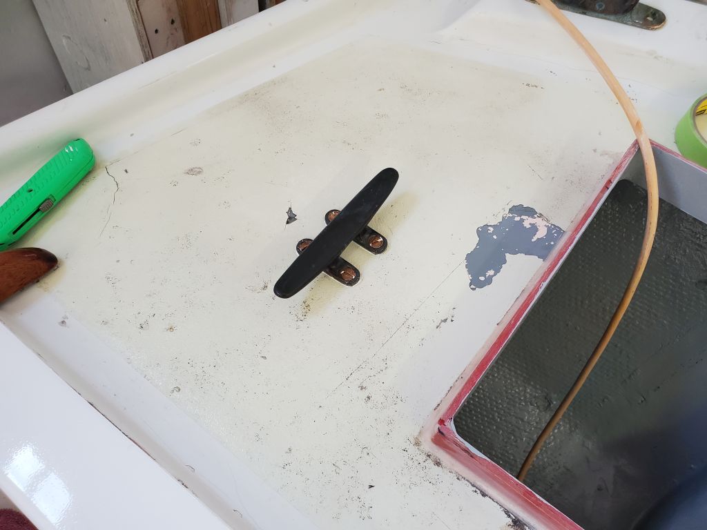
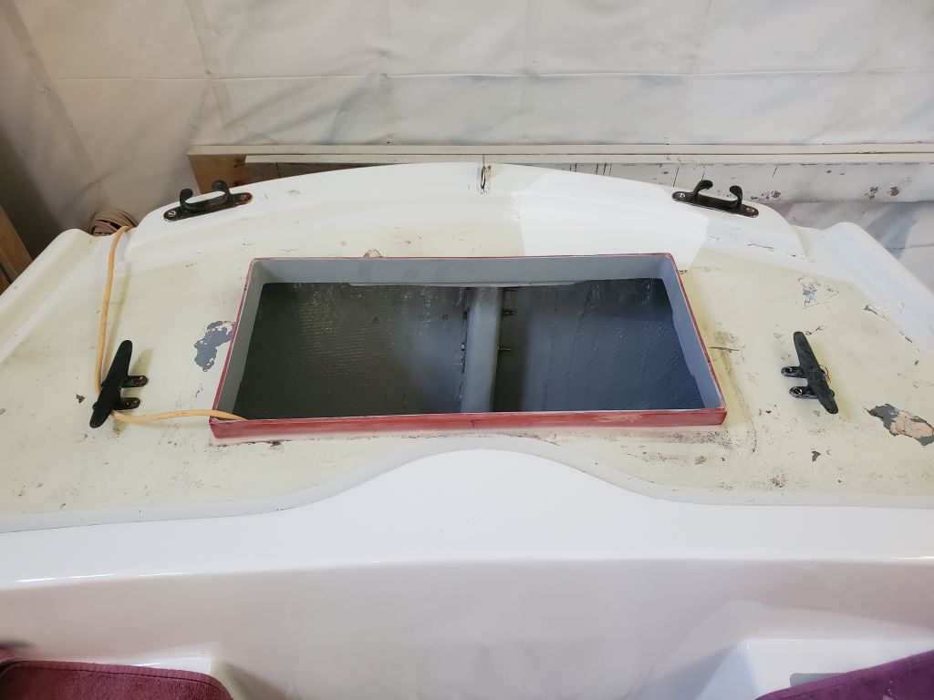
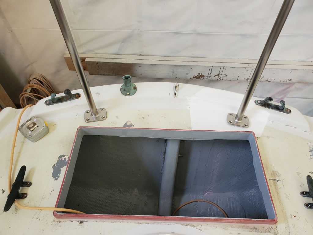
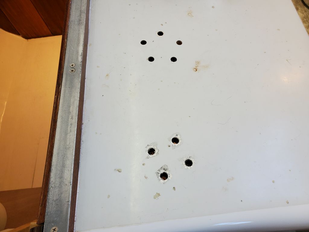
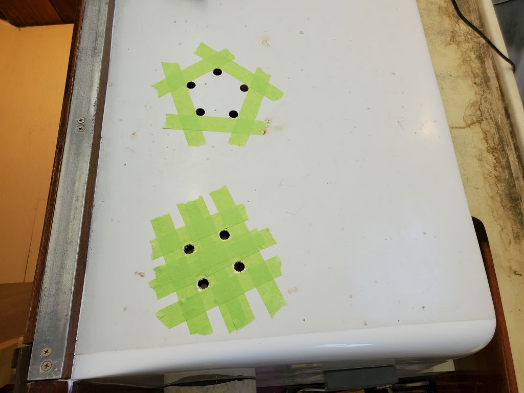
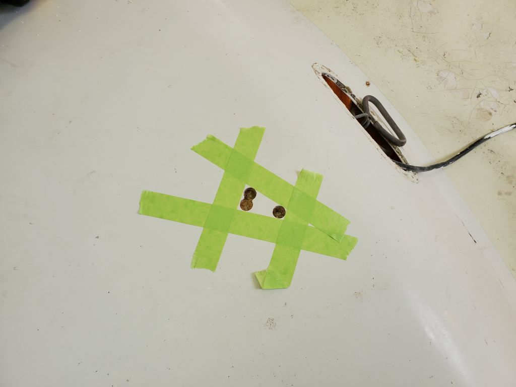
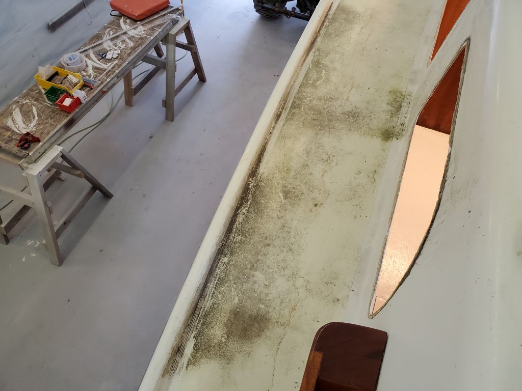
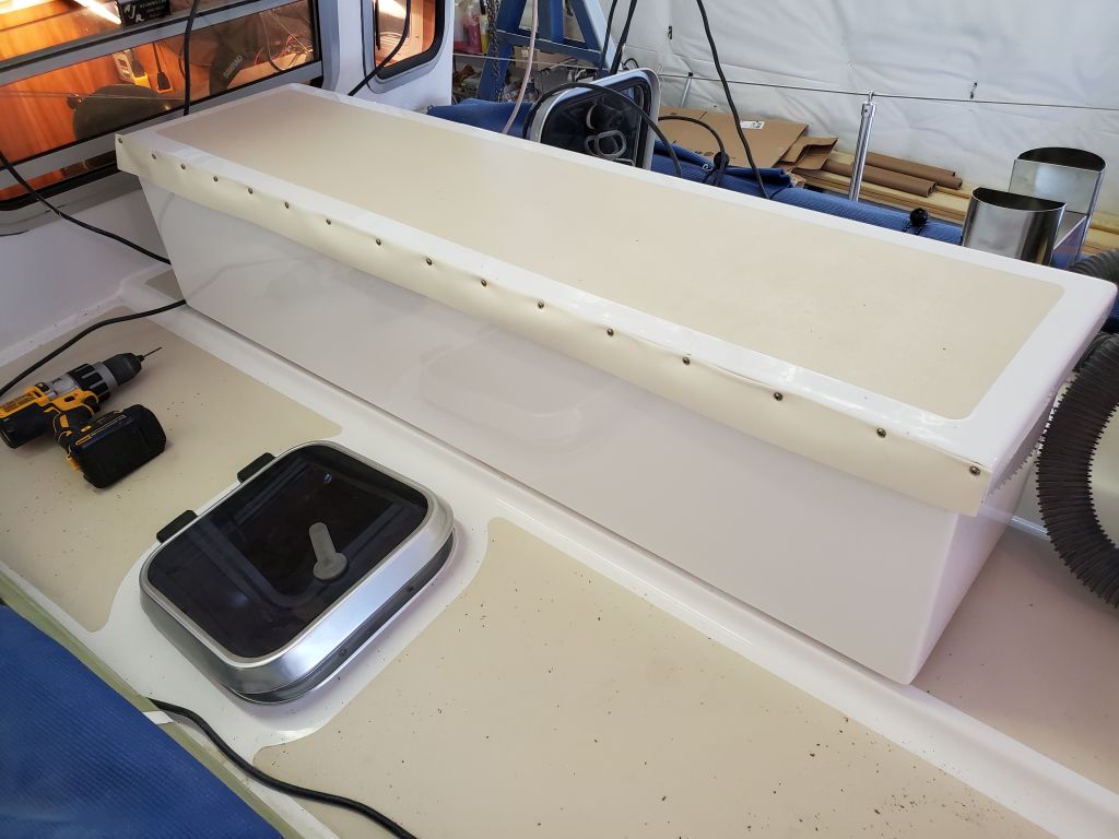
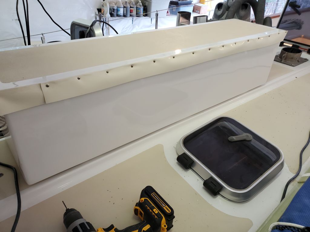
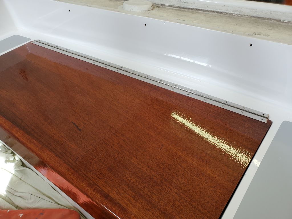
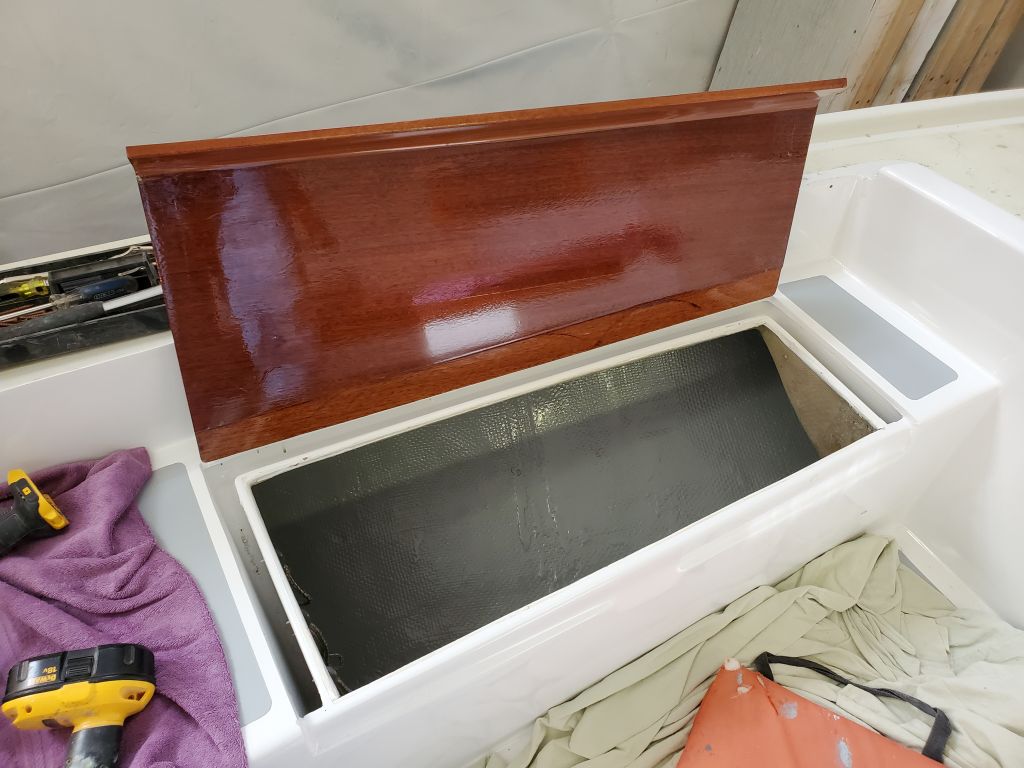
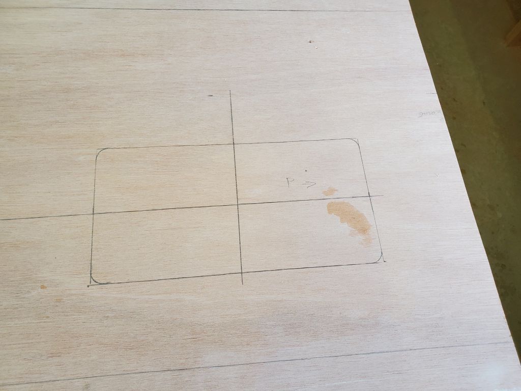
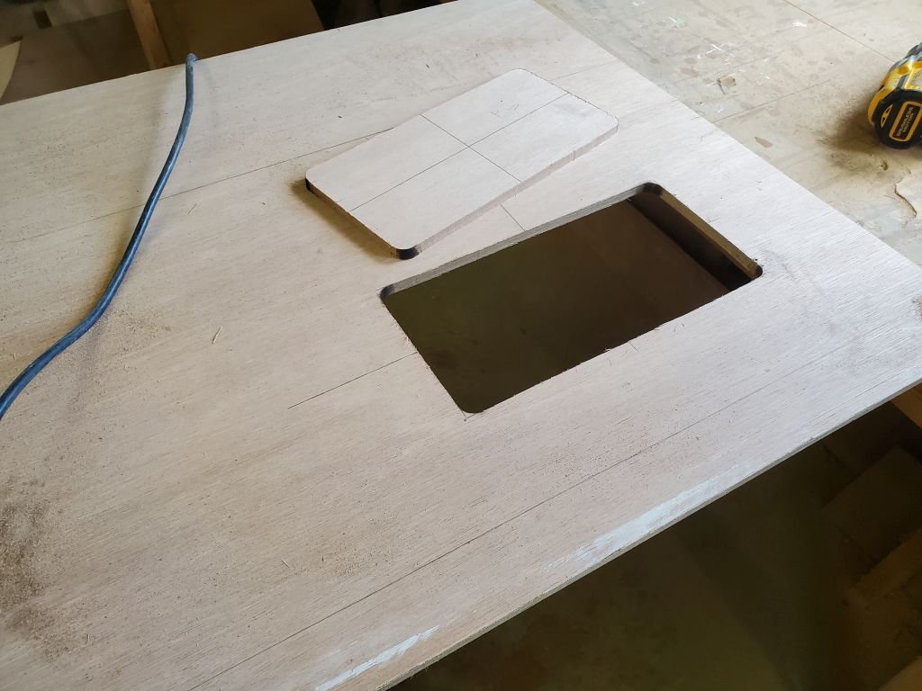
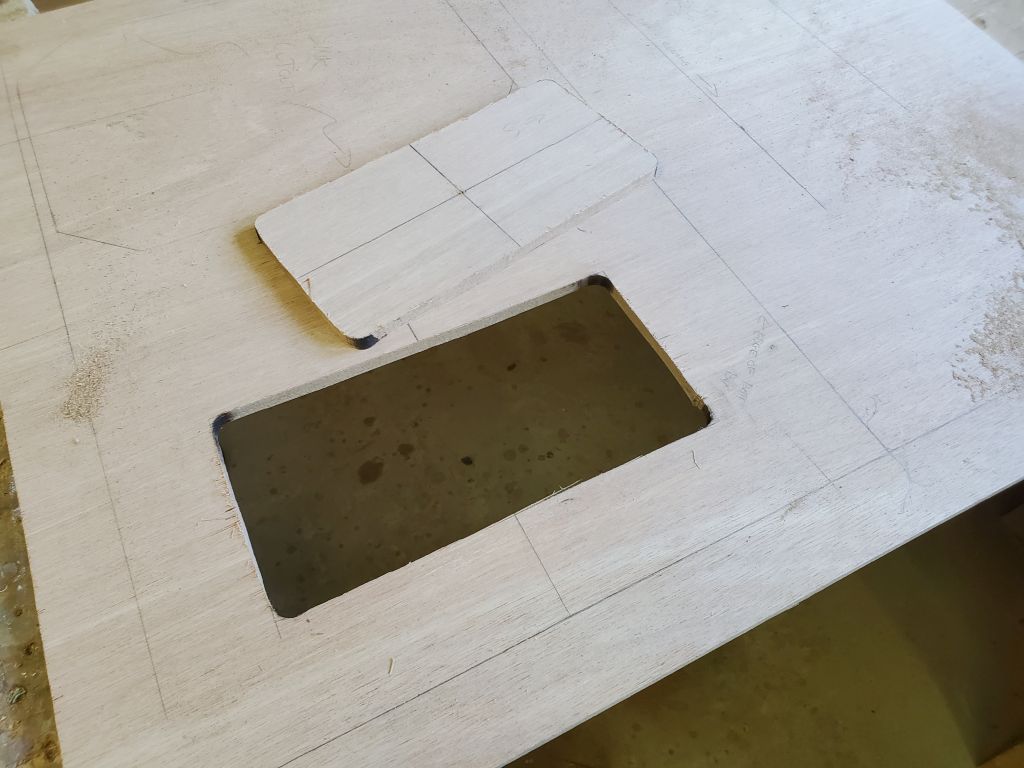
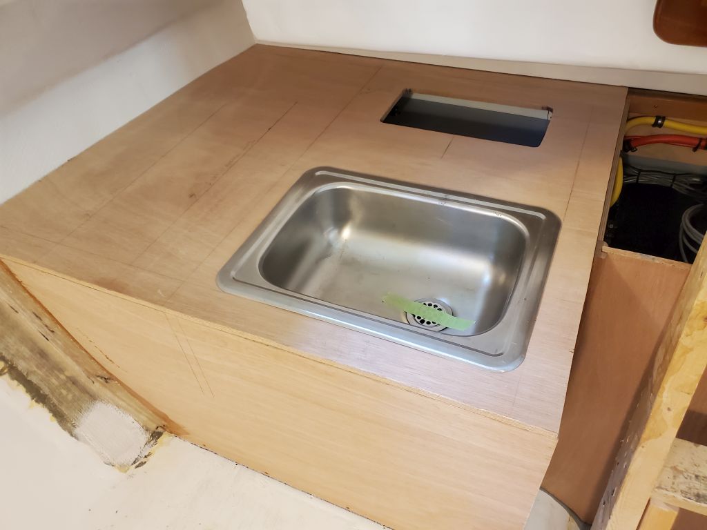
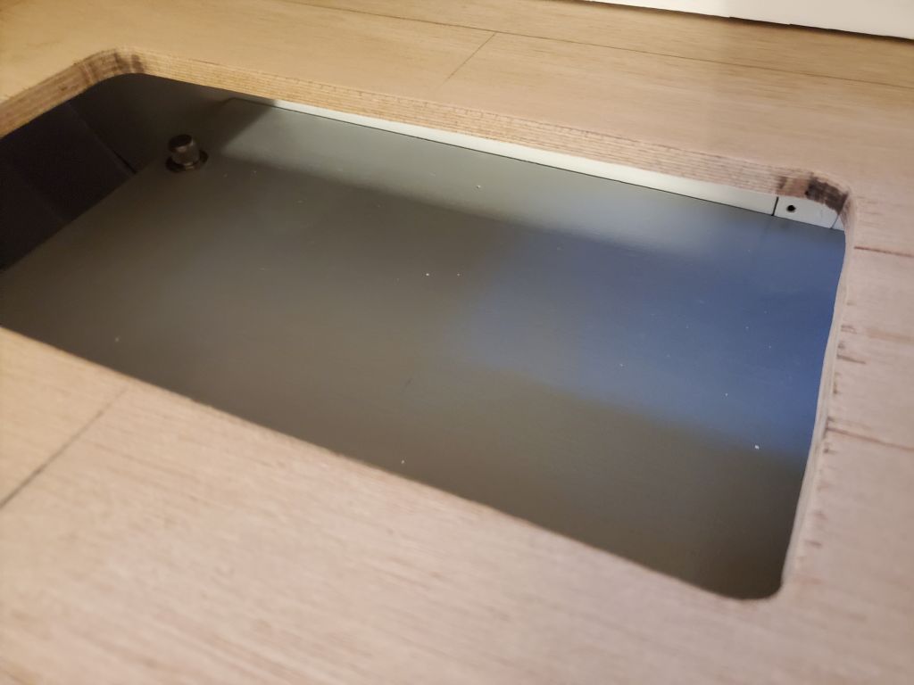
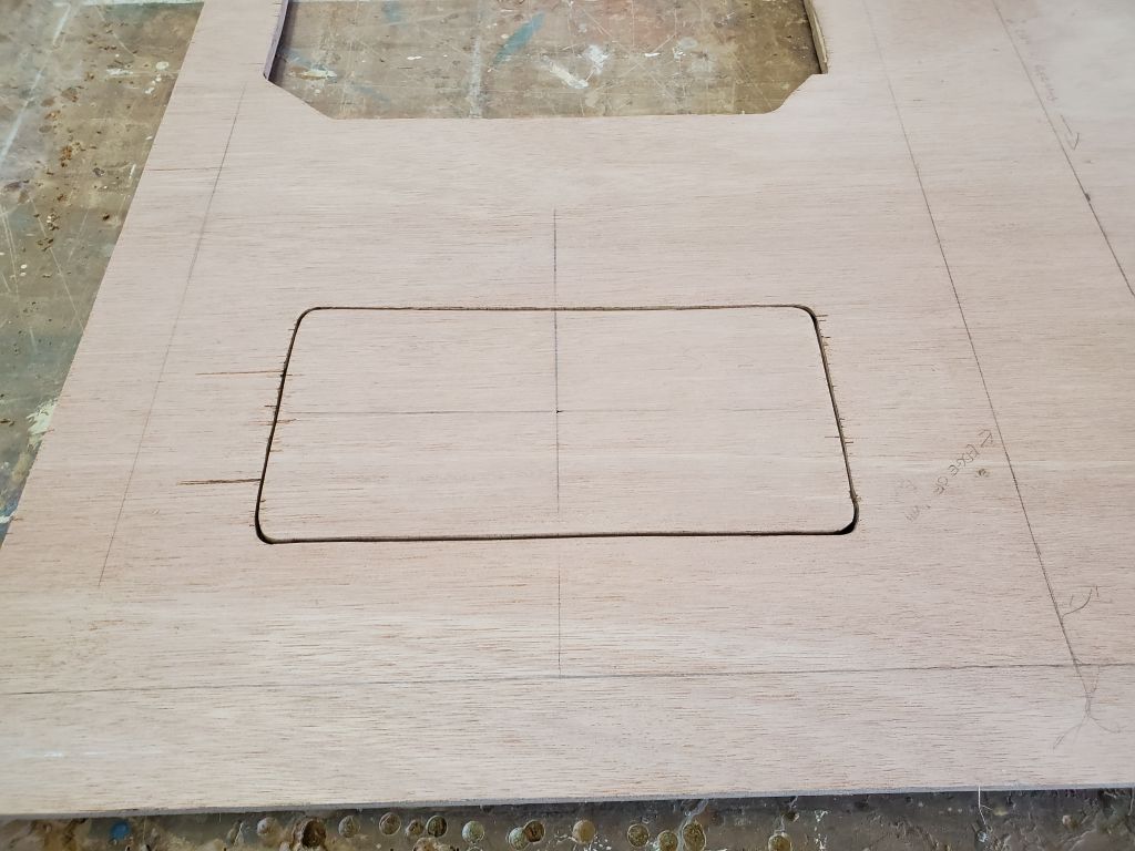
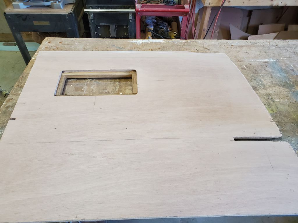
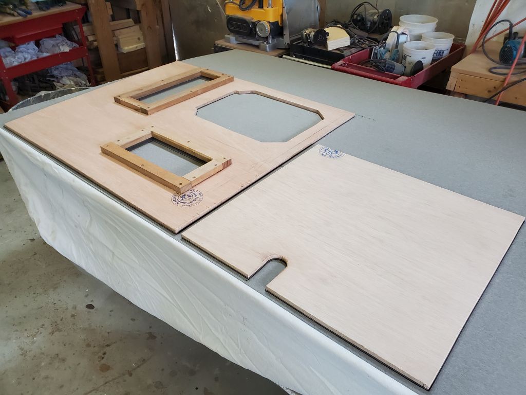
First, though, I needed to cut some access hatches. Several weeks previously, I’d made some reference marks to show the centers of the battery boxes, for eventual top-access hatches required to remove the battery box lids and, if necessary, service the wiring connections or detach things should the batteries need to be removed. Now, I laid out what seemed to be a reasonable hatch size, 12″ x 6″–large enough for access, but no larger than necessary either. I cut out the hatch openings with a jigsaw.

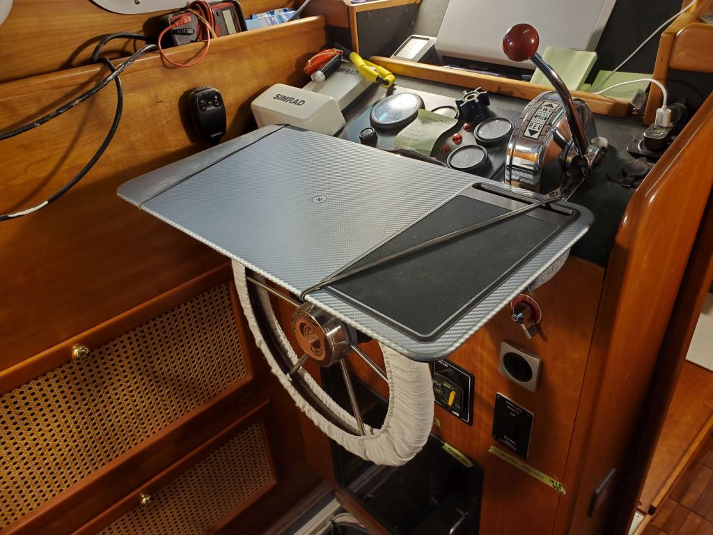
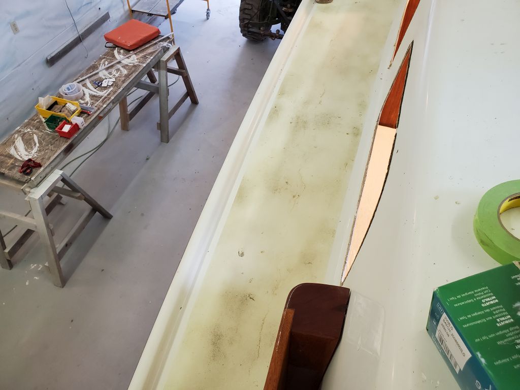
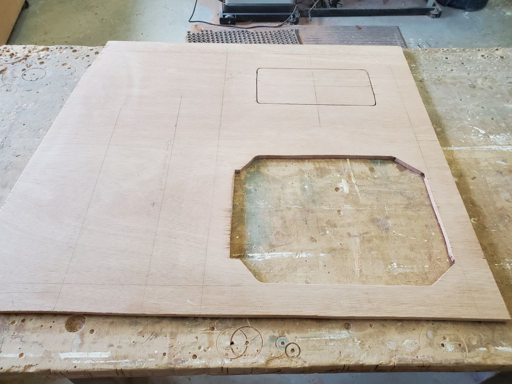
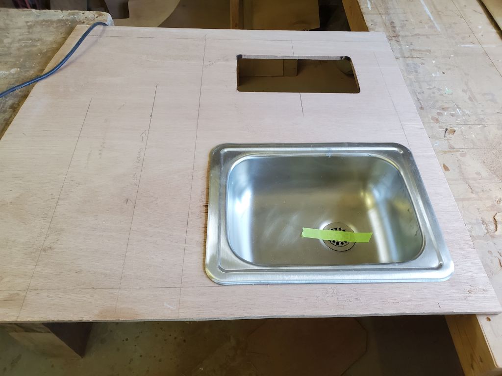
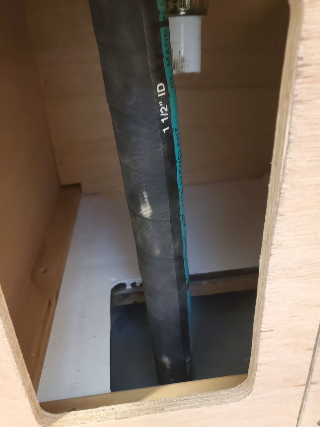
I’d laid out the galley sink cutout earlier as well, and now I made the cut. Then, I test-fit the starboard countertop in the boat to check the sink location, measure for the drain hose, and confirm that the battery access hatches performed as and provided the access needed.
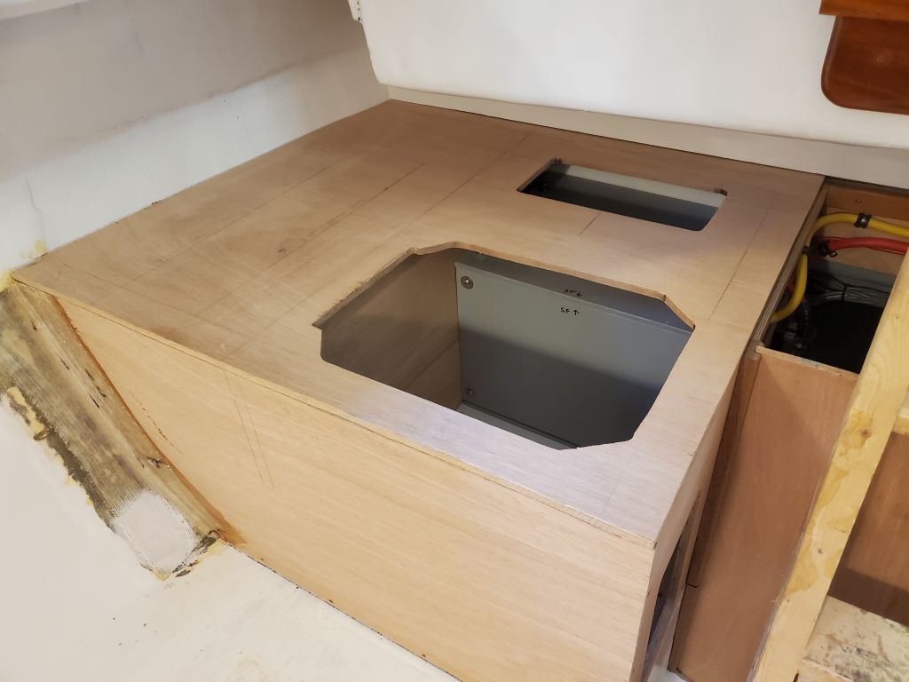

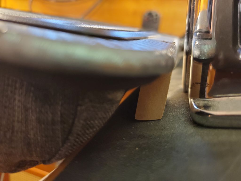
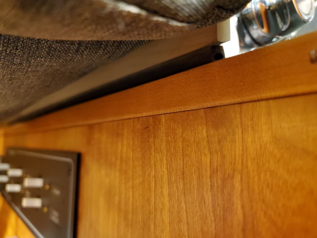
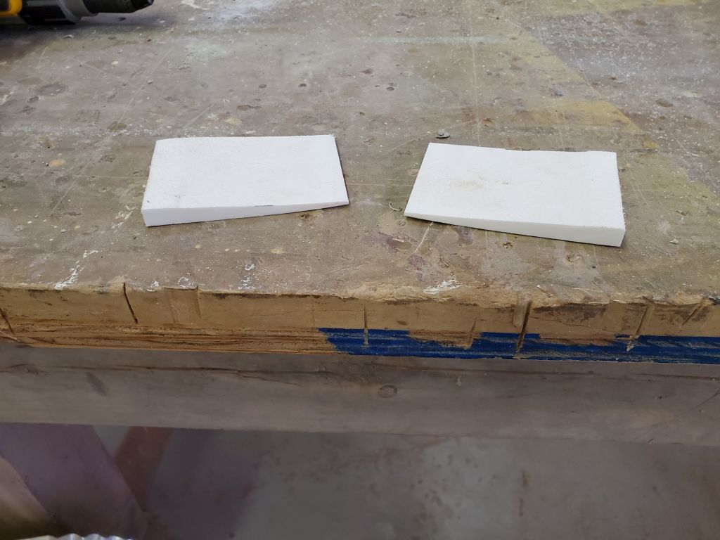
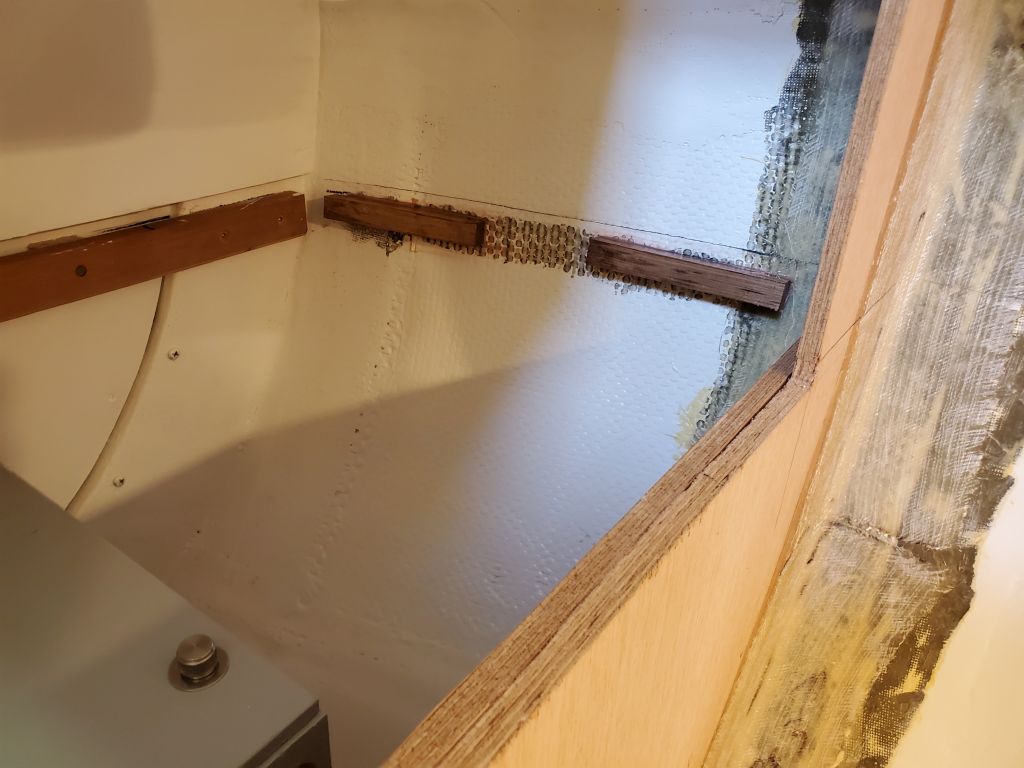
Satisfied with the fit, I prepared some hardwood blocks to support the countertops where they met the hull on both sides. I’d previously marked the correct height and prepared the hull by removing the paint in the general area, and now I glued the blocks in place with epoxy and a dab of hot glue to help hold them while the epoxy cured. There was no need for full-length cleats here, and installing those would have been substantially more effort for no gain.

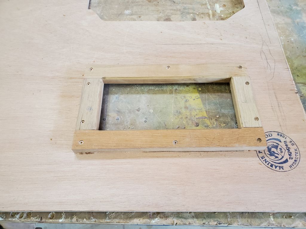
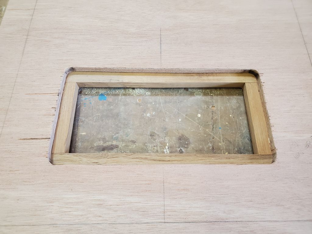
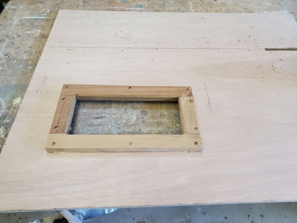
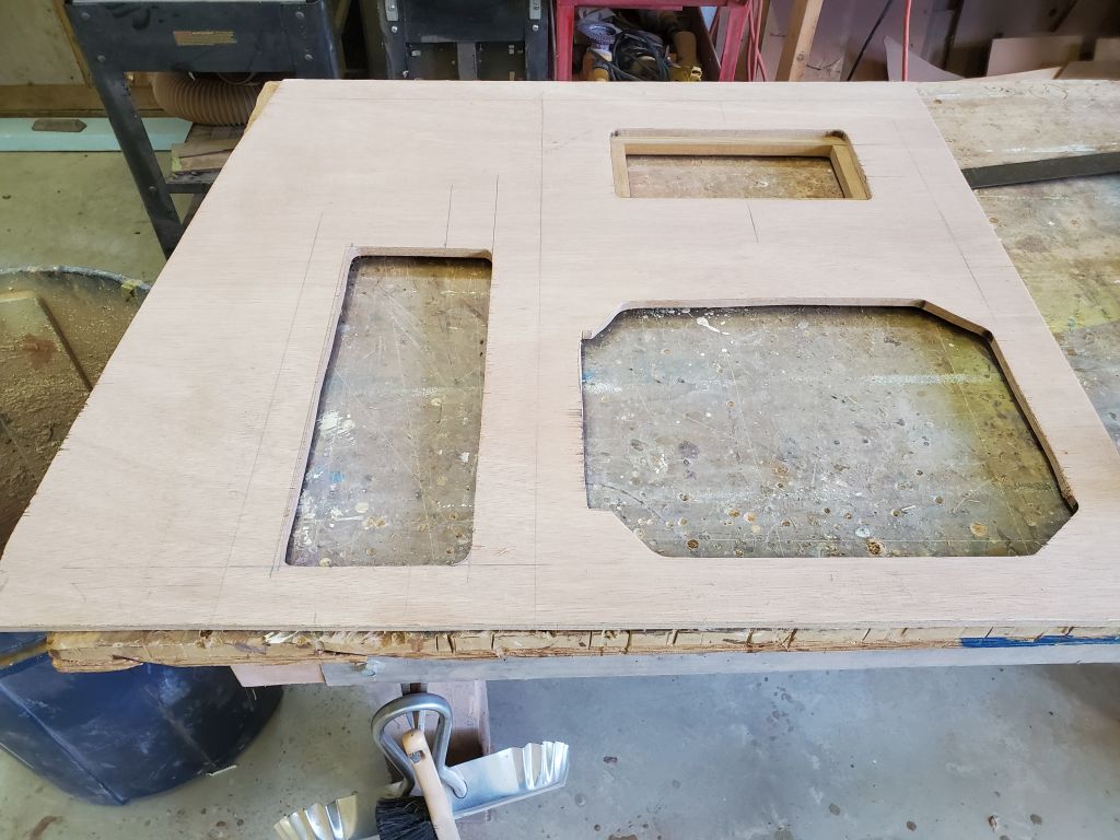
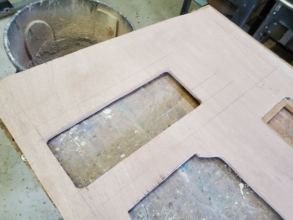
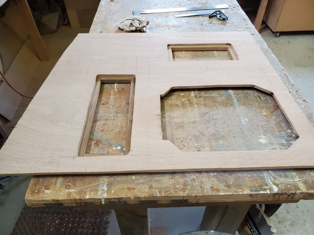
To finish off the new hatch openings, I milled, cut, and installed with glue and screws hardwood cleats around each opening from the bottom. The owner and I collaborated on a final hatch in the starboard countertop to afford access to the large storage area outboard of the sink and battery storage areas, which I eventually laid out outboard of the sink, leaving room for a future upper cabinet against the hull.


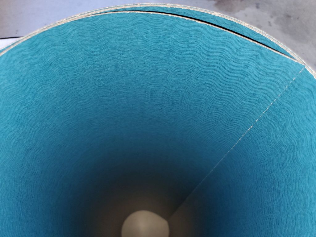
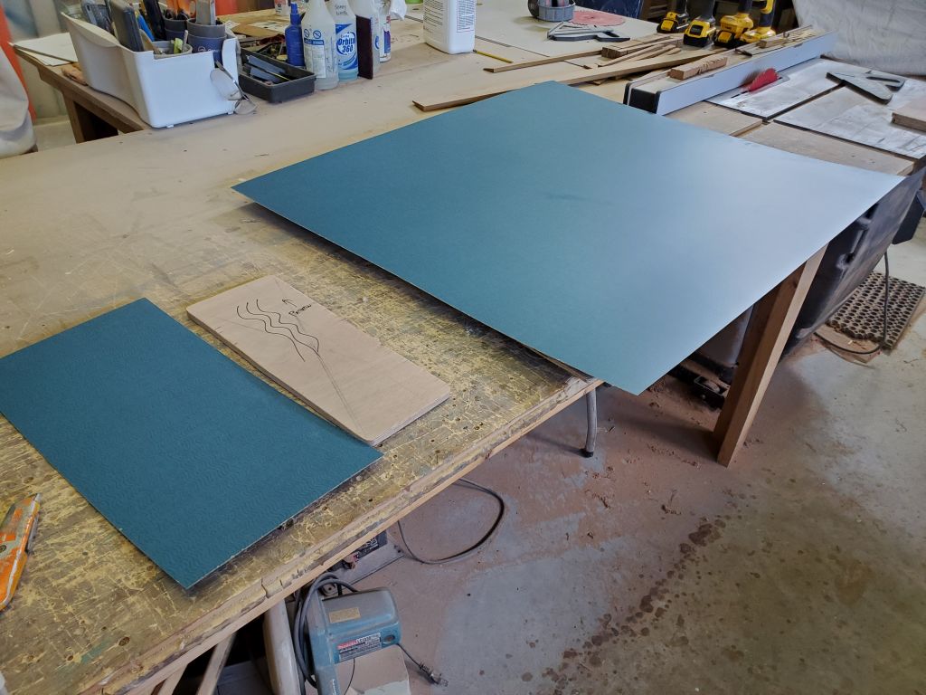
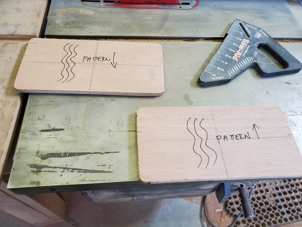
With the countertops and hatches prepared, next I laid out the laminate for the countertop. The chosen material had a wavy pattern of faint, but discernable, lines running through, and this pattern meant that I had fewer options in laying out the pieces than I would with a solid color, as the waves had to be consistent from section to section.

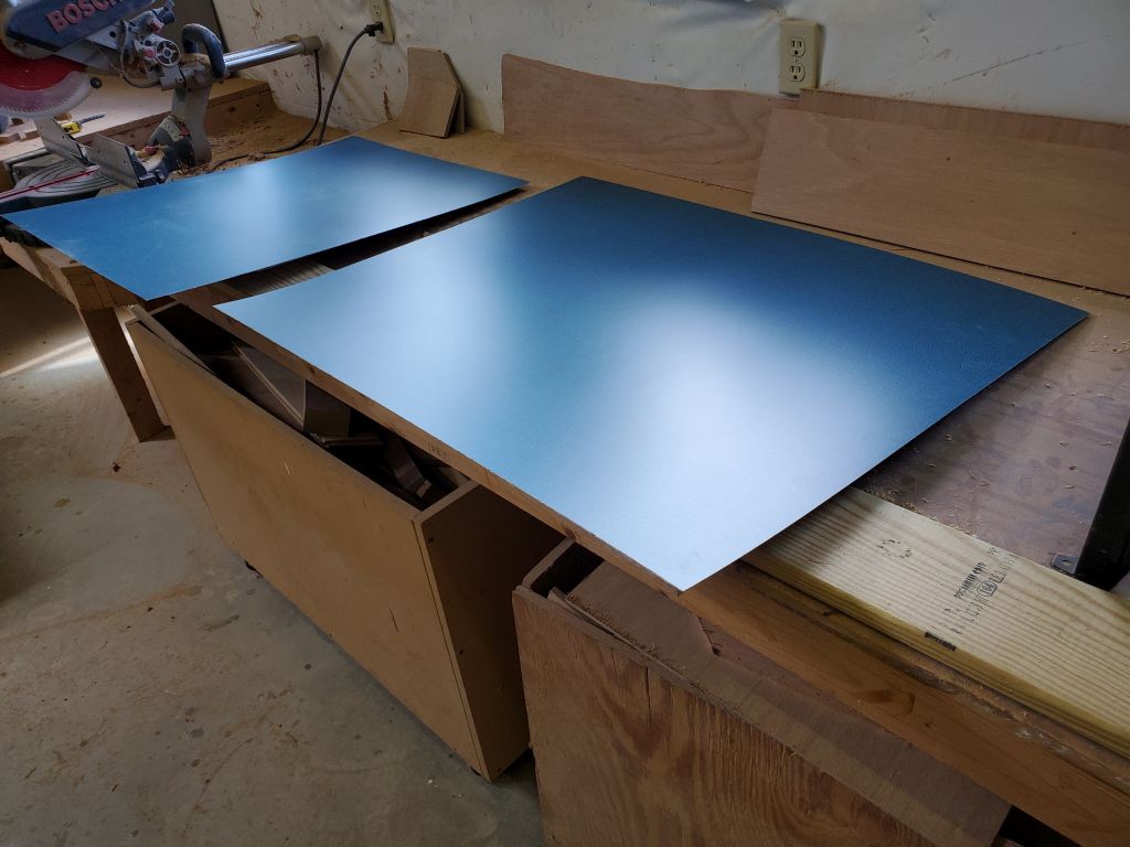
There wasn’t enough length to the piece of laminate to allow me to lay out the three sections of countertop (port and starboard, plus the engine room cover) with the pattern running athwartships, which was probably just as well since keeping the pattern aligned between sections would have been tough. So this meant that the pattern needed to run fore and aft, which have me more options in terms of laying out the countertop sections to maximize use of the available material. With laminate shears, I cut sections of laminate slightly oversized for each section of countertop, and ensured that I had adequate offcuts/scrap with which to make the three small hatches. The pattern direction was crucial on the hatches, so I drew on the plywood accordingly. I expected it would prove to be a challenge to align, at least remotely well, the wavy pattern on the hatches with that of the parent countertop, but that was a problem for a little later. This all left ample material leftover for a future countertop in the space opposite the head.
At this point I was ready to permanently install the laminate. Alas, my plans were stymied when I found that both cans of contact cement I had on hand were hardened and dried out. Rather than waste what was left of the afternoon getting the replacement cement right away–there’d not be time to do the gluing once I returned–I made plans to go after work and instead turned to the final hardware installations I needed to do.
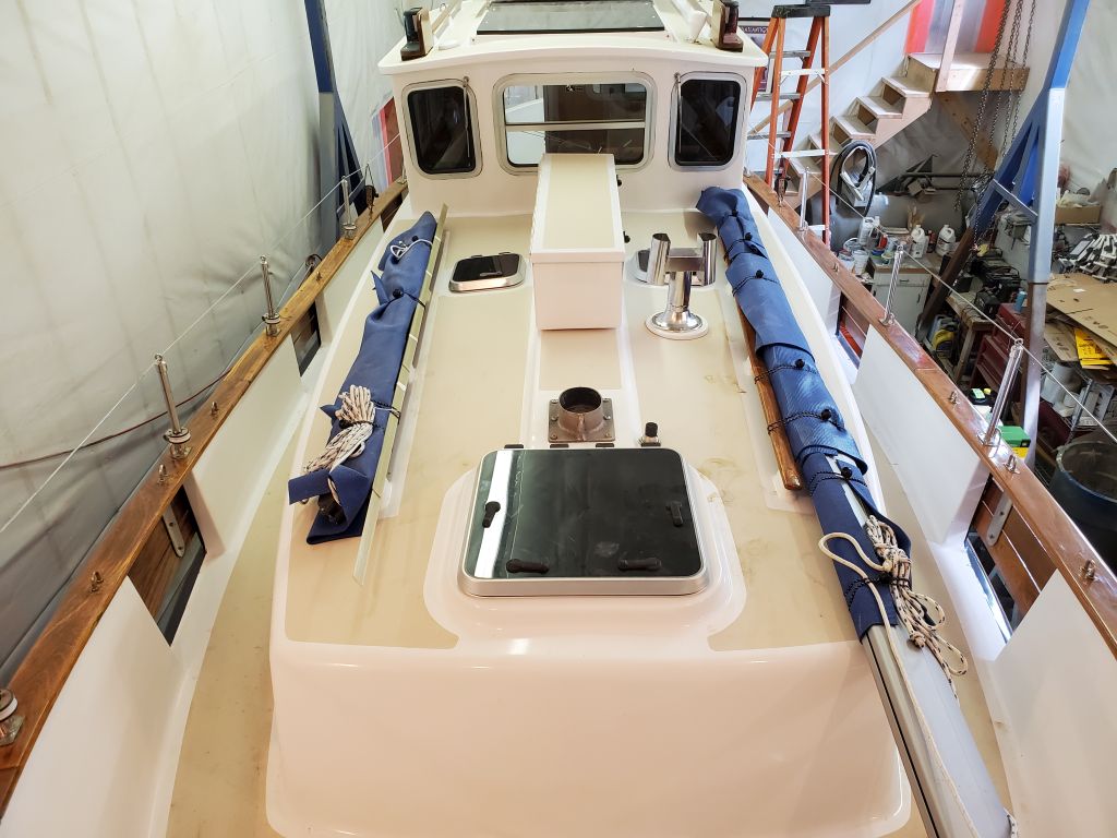
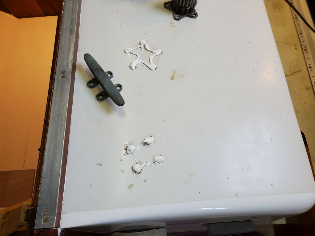
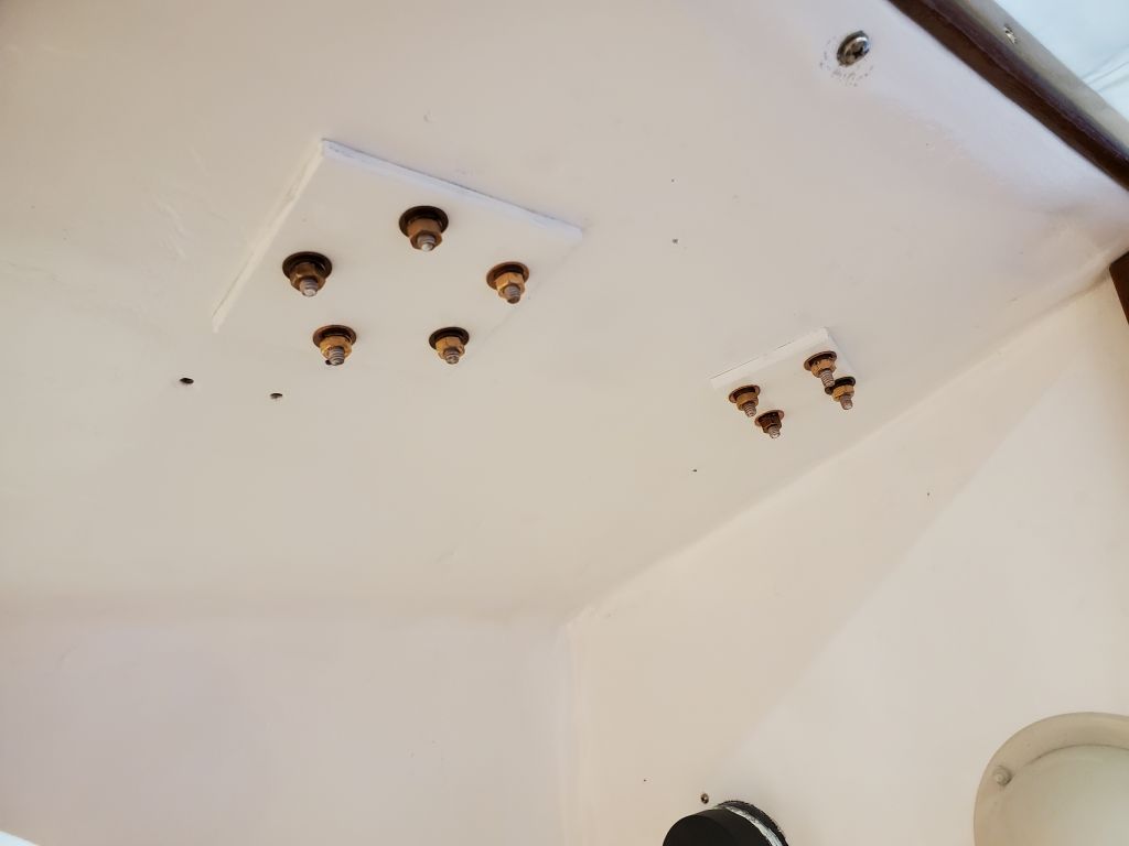
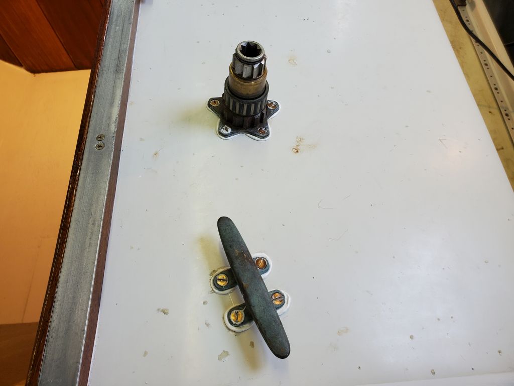
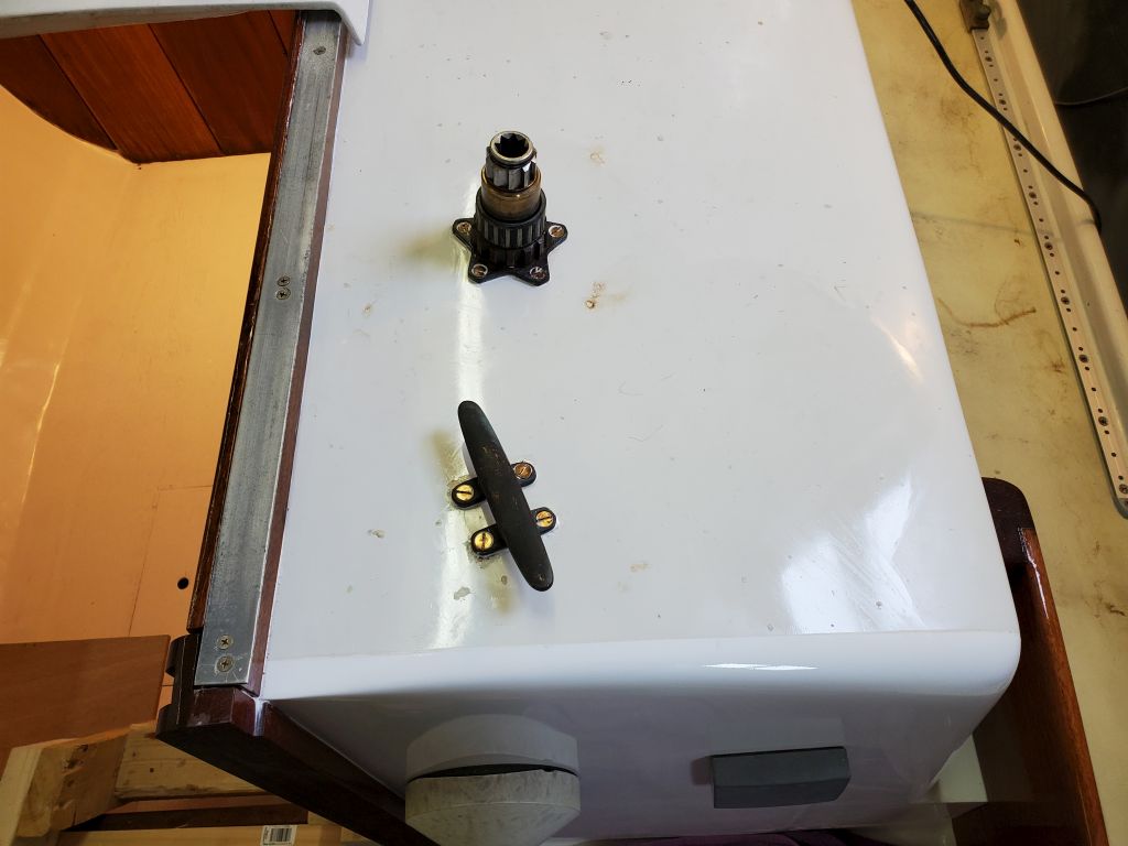
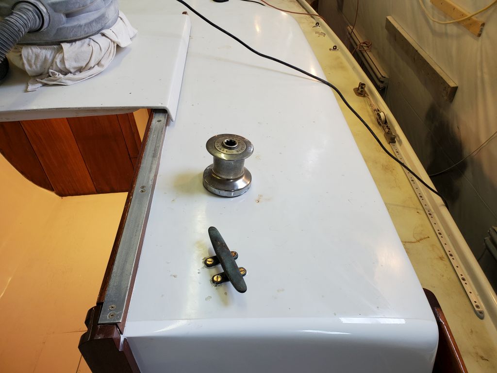
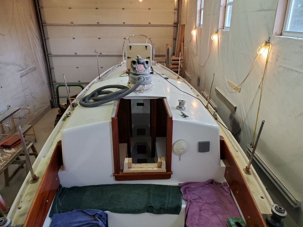
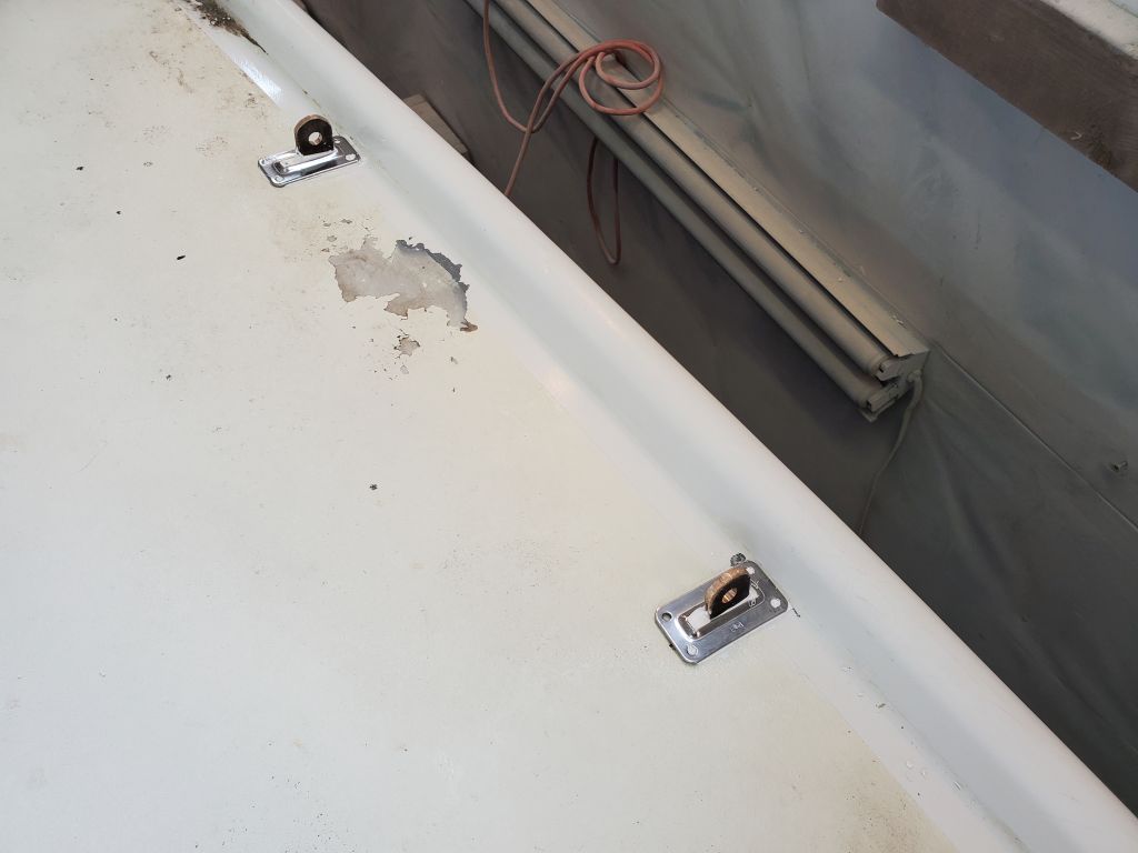
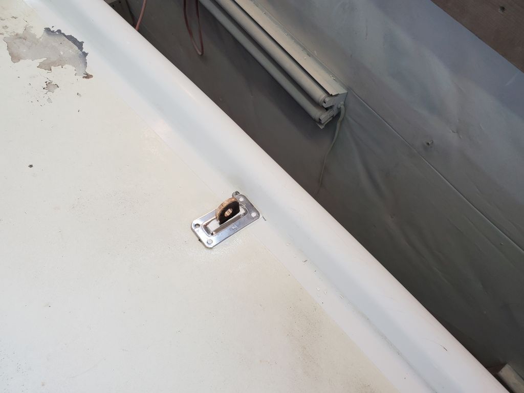
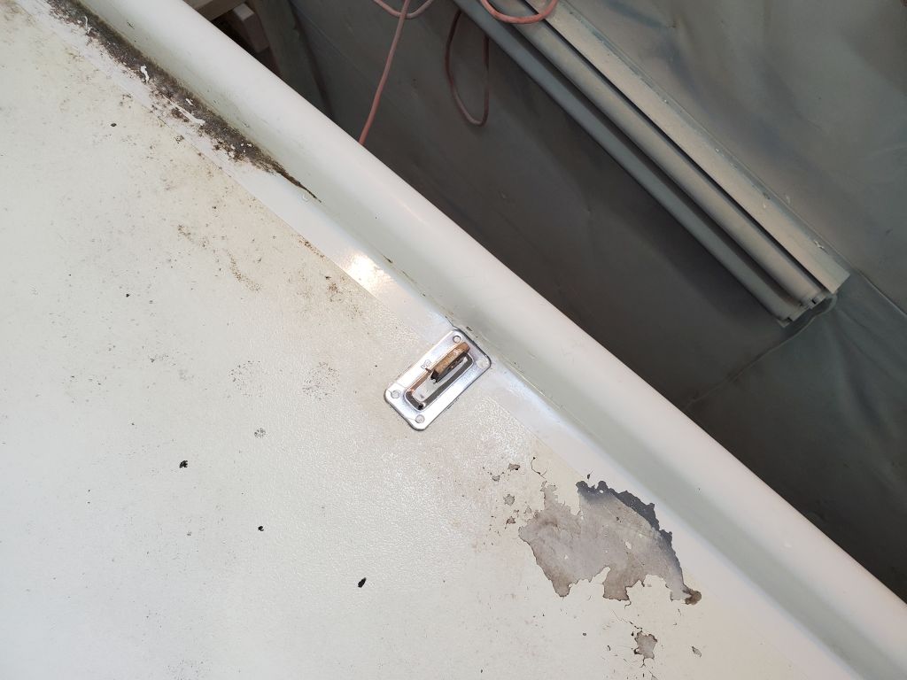
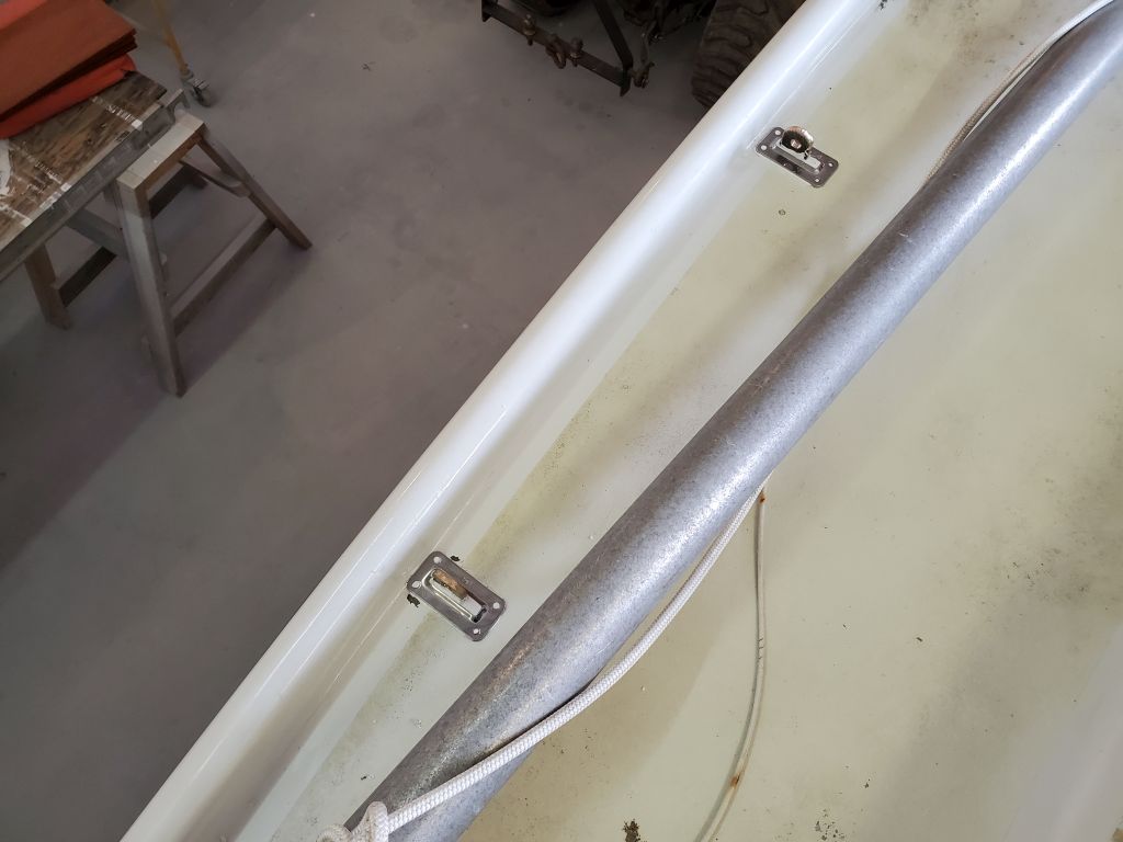
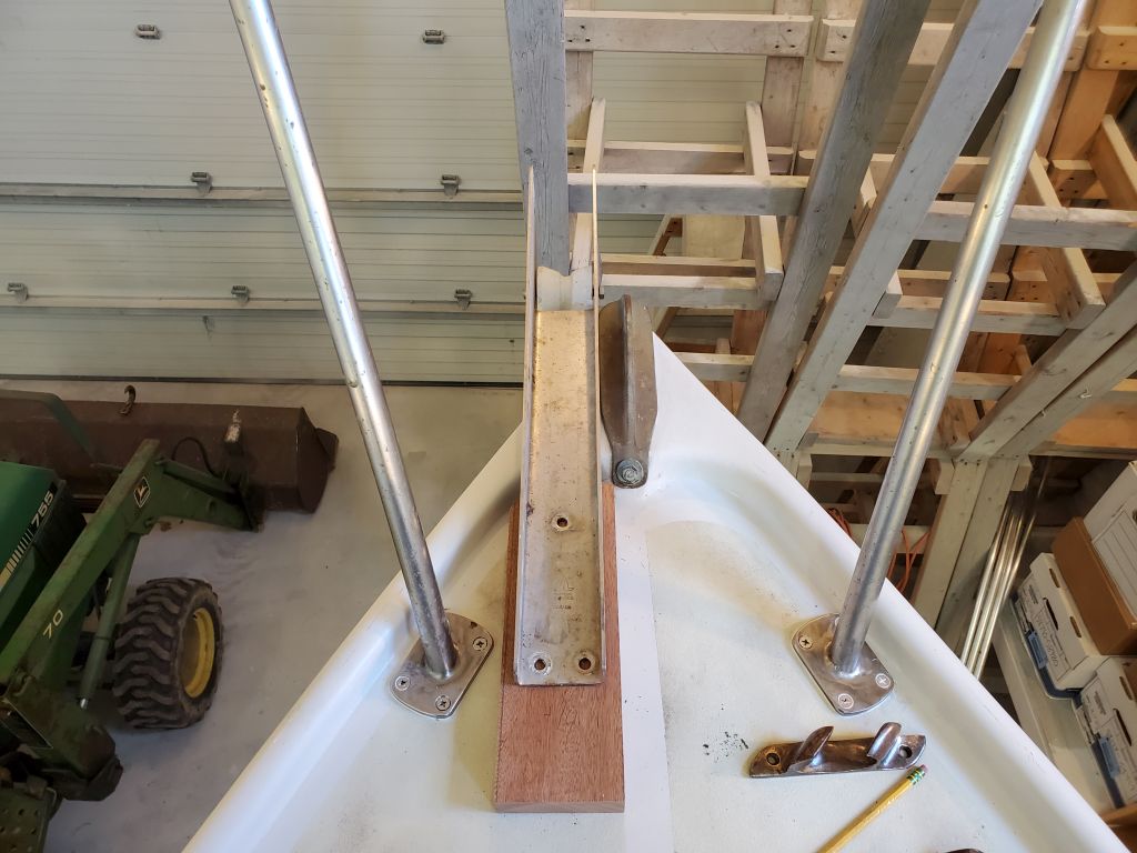
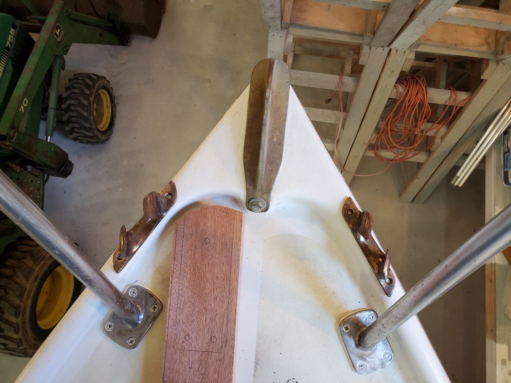
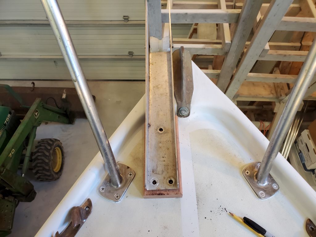
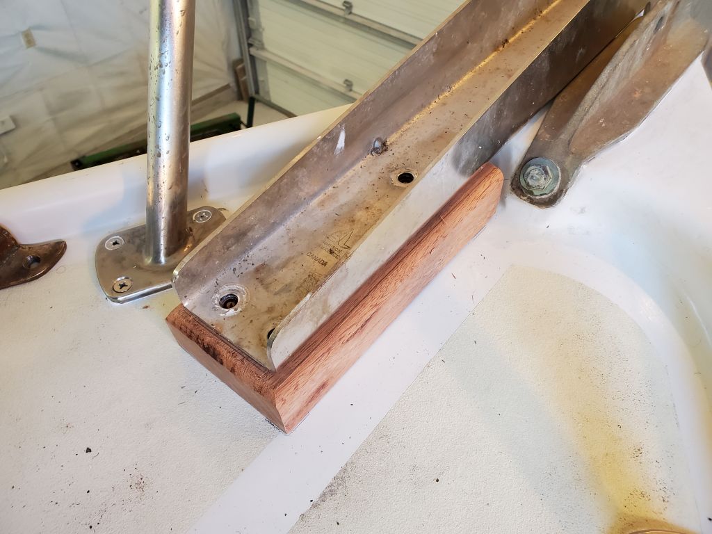
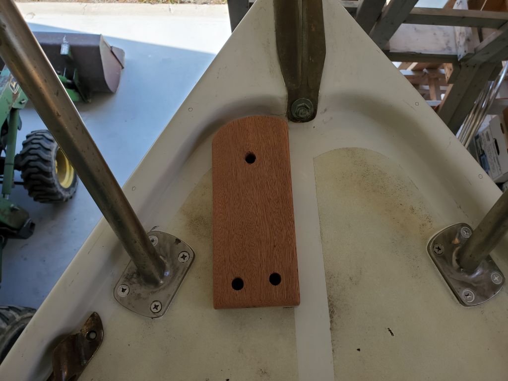
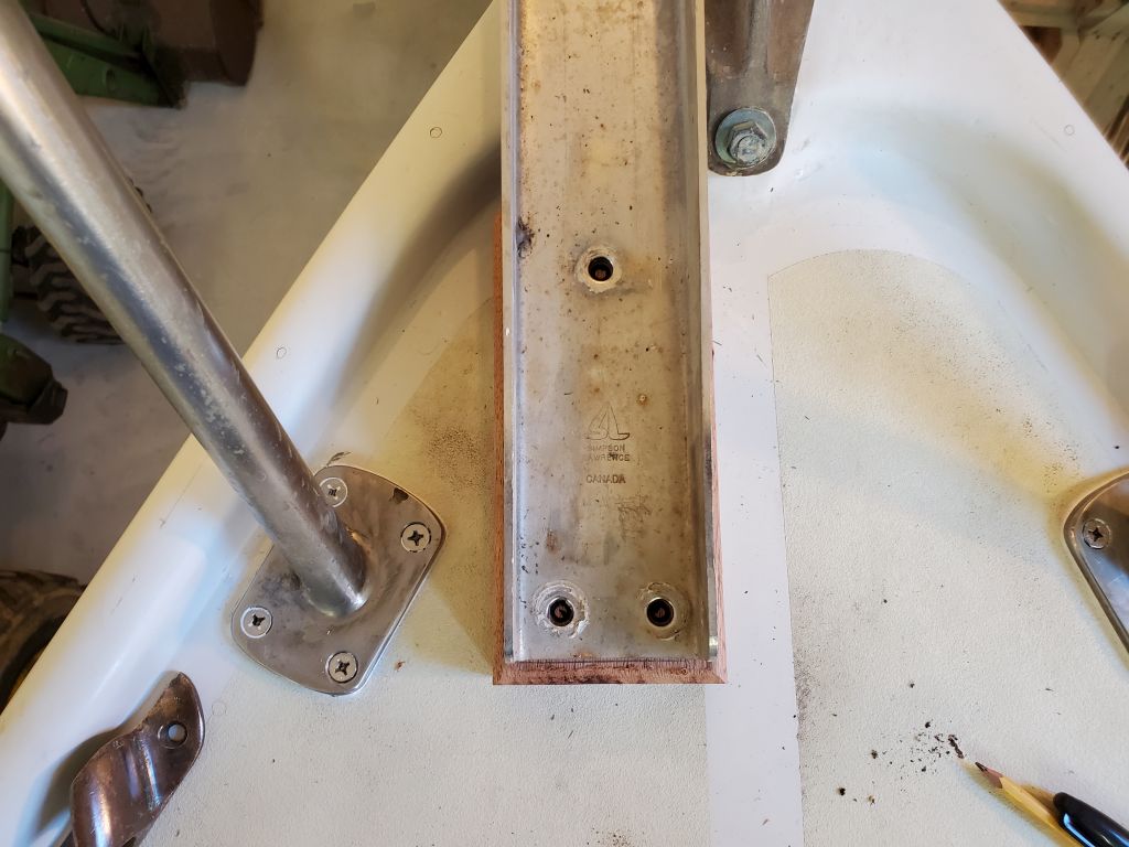
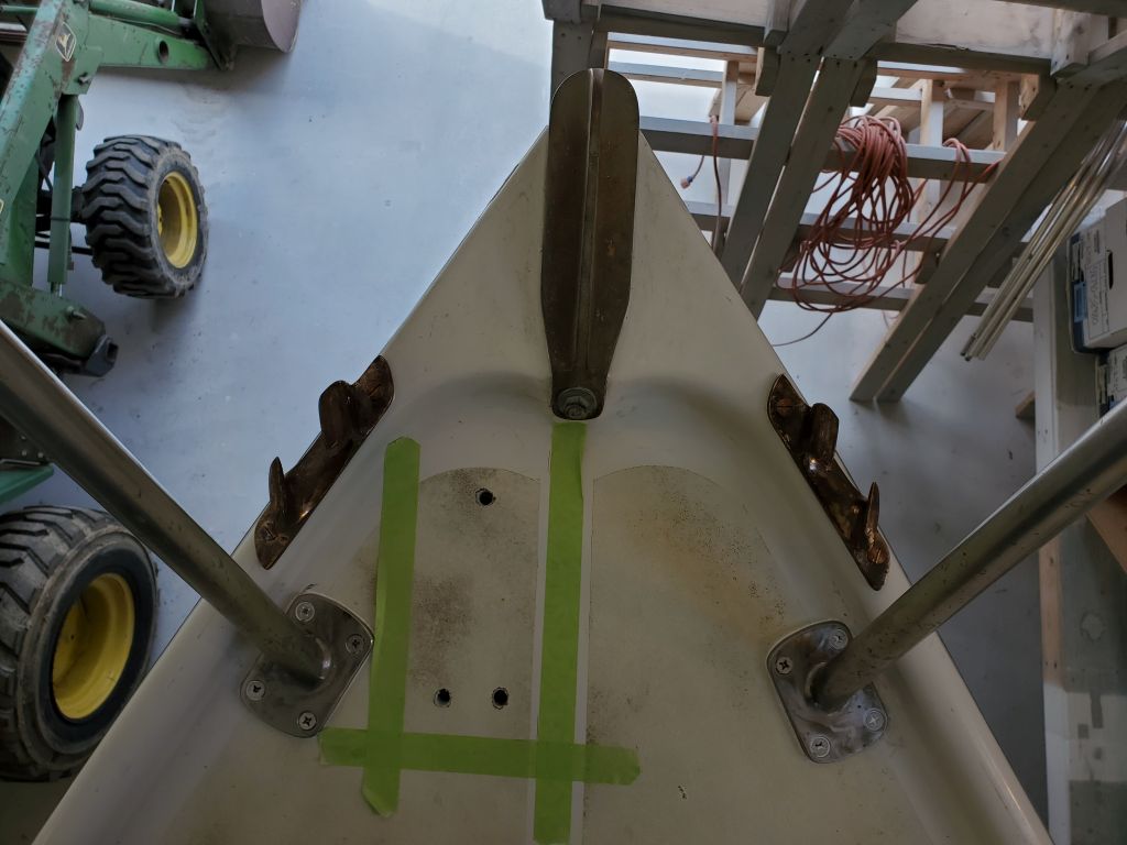
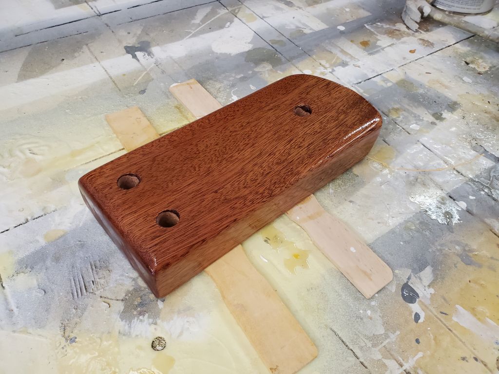
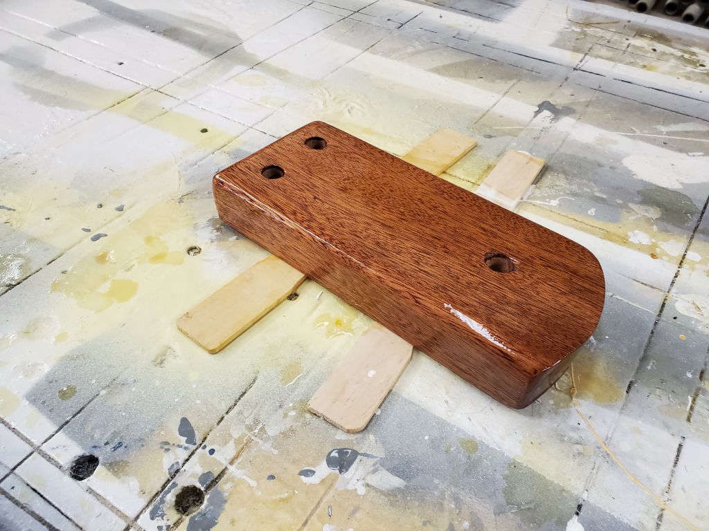
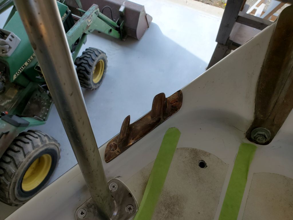
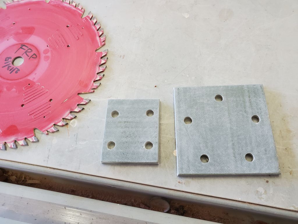
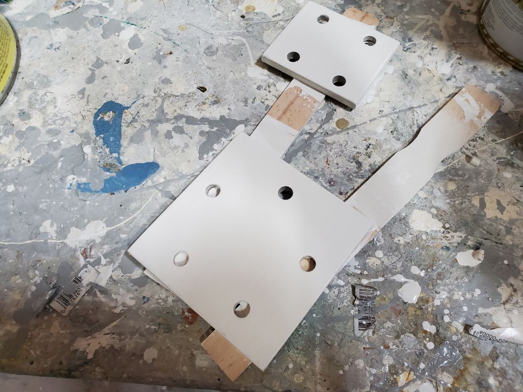
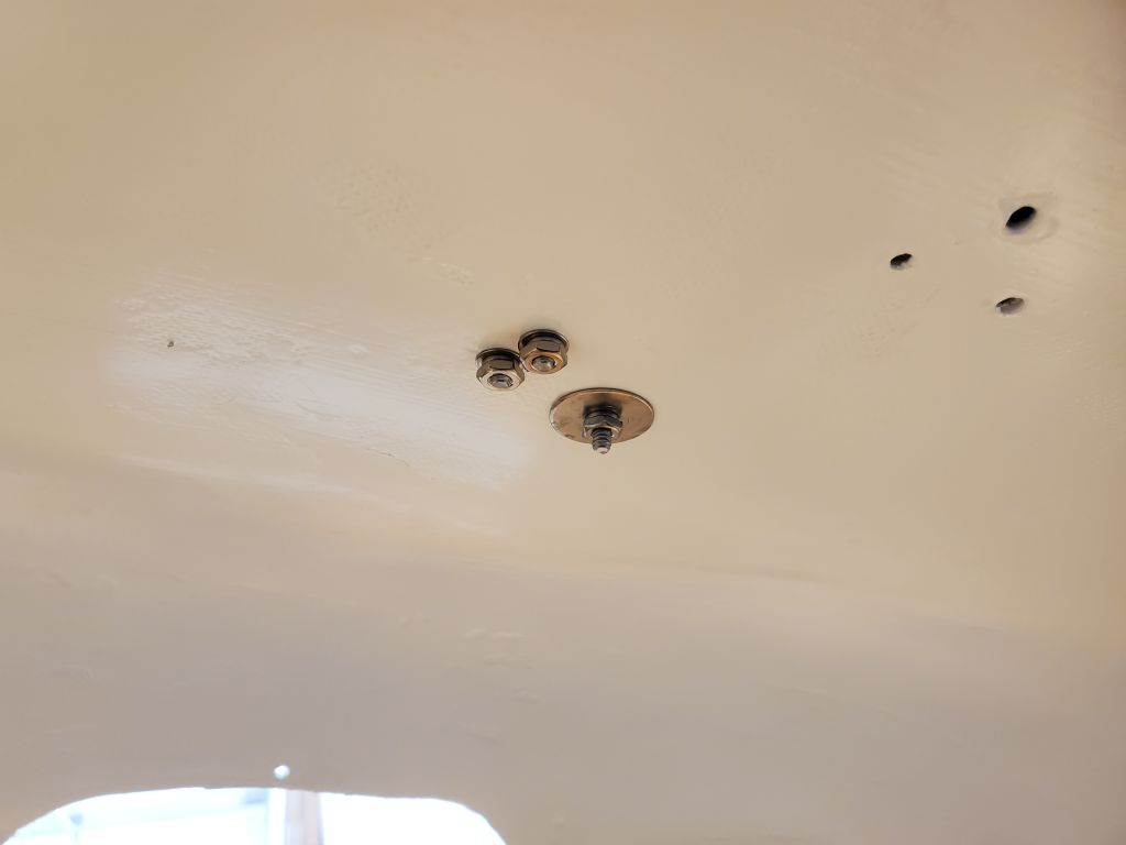
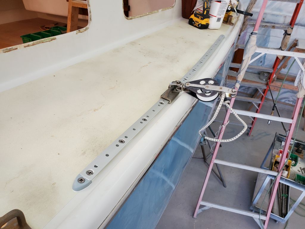
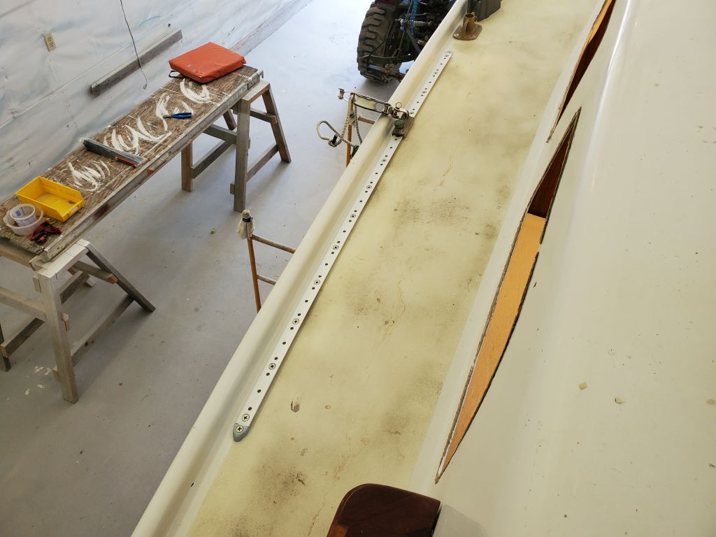
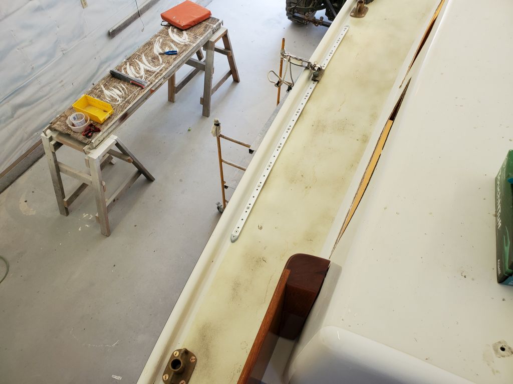
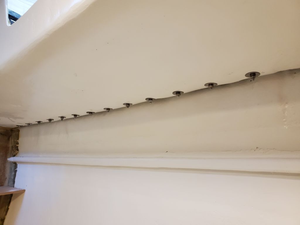
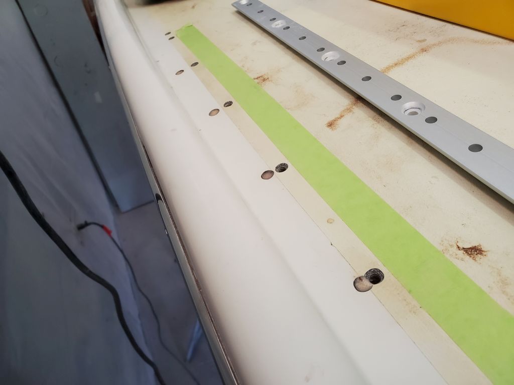
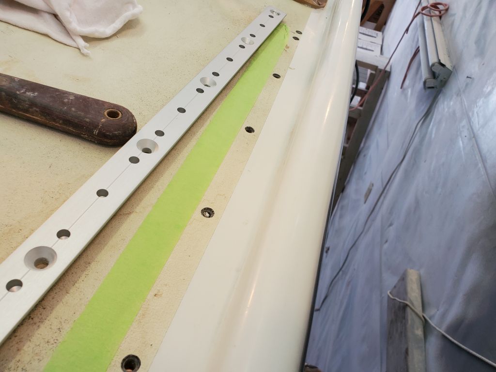
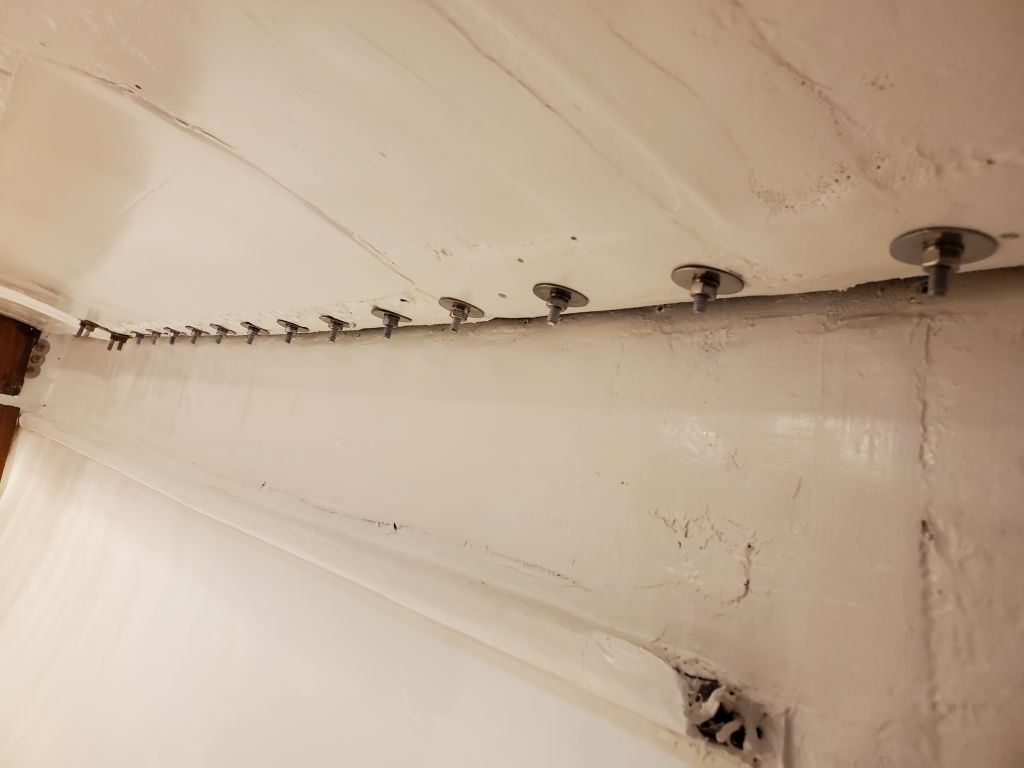
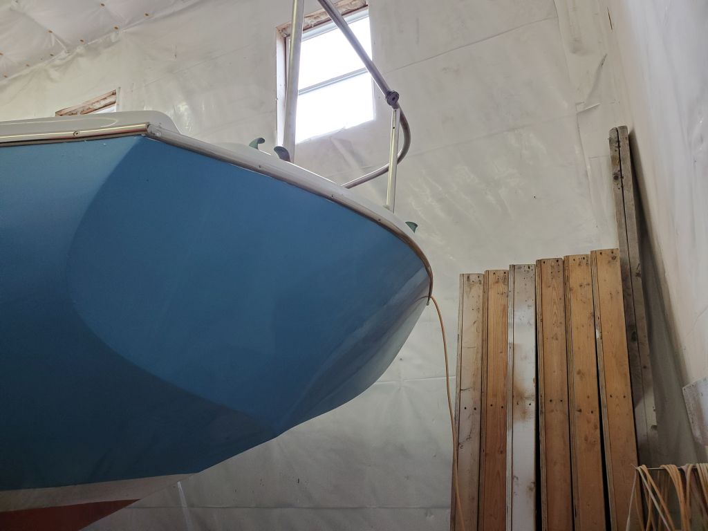
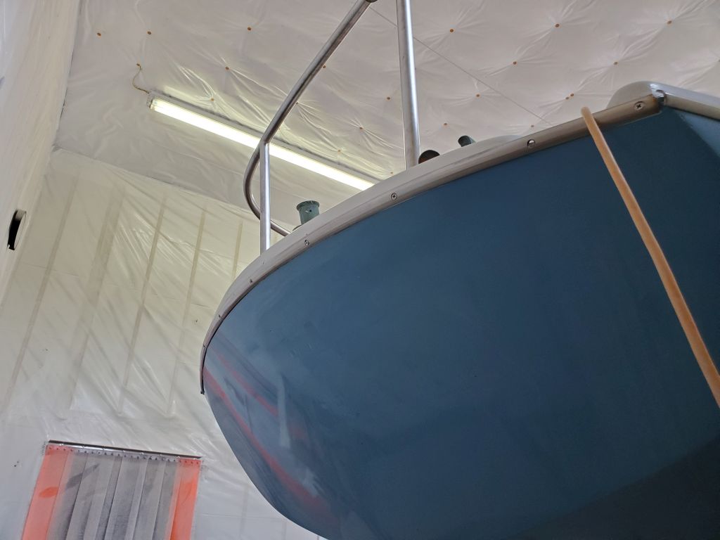
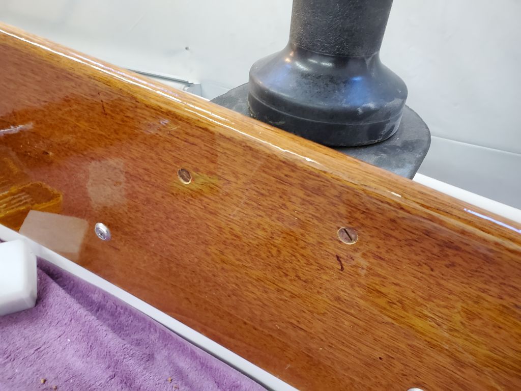
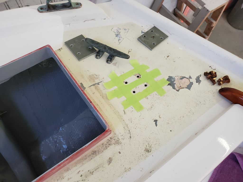
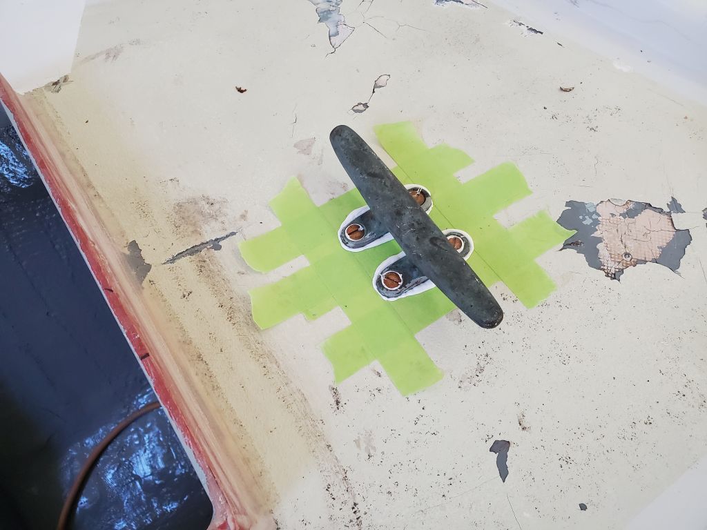
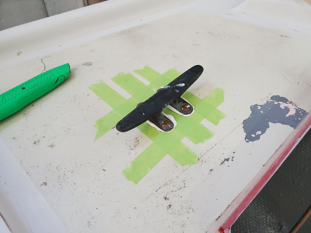
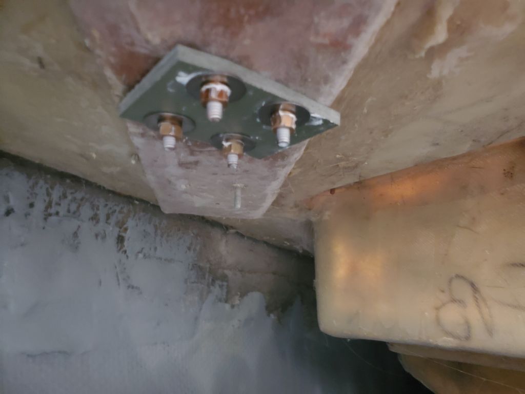
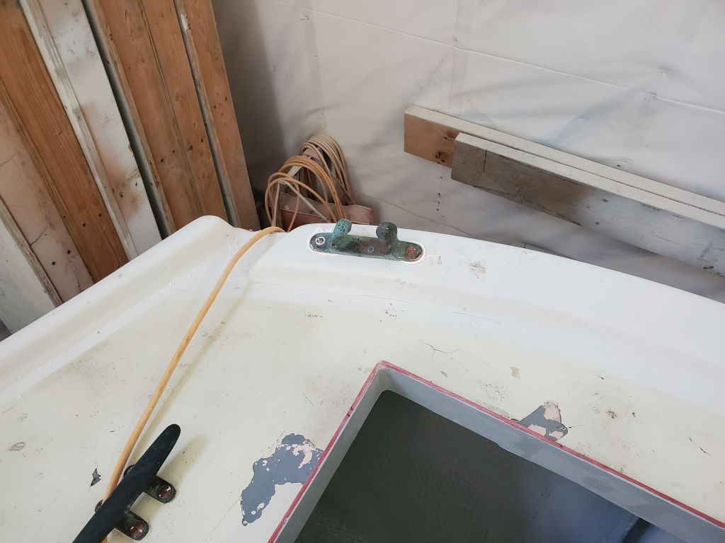
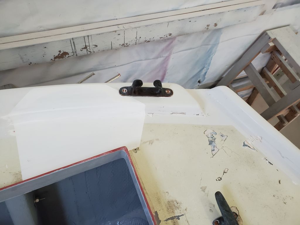
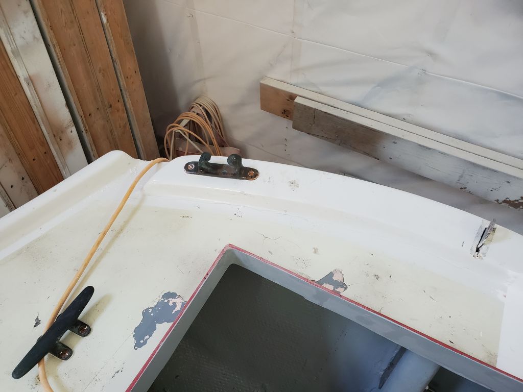
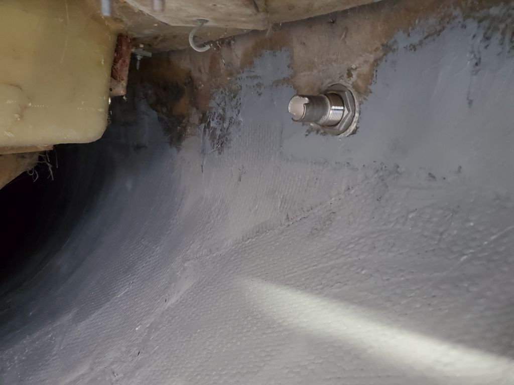
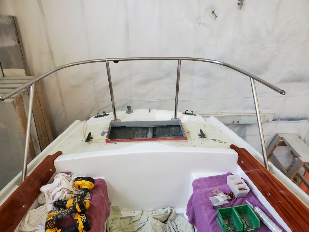
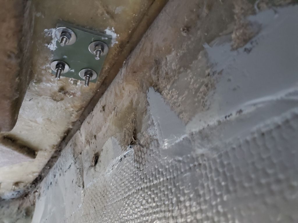
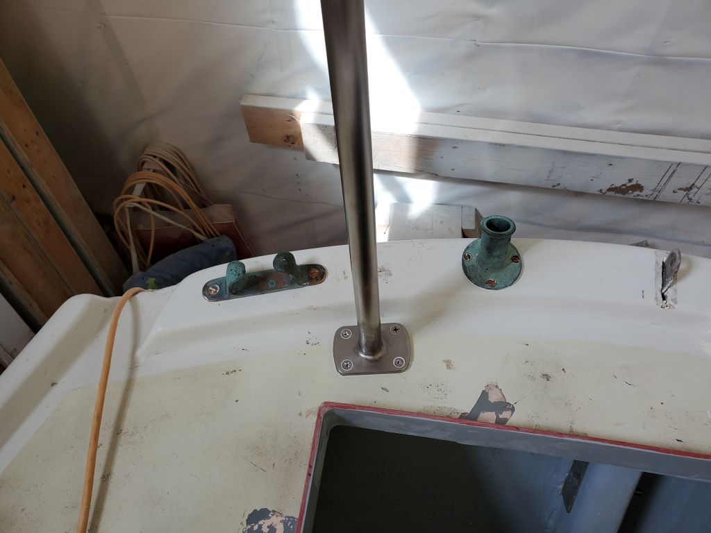
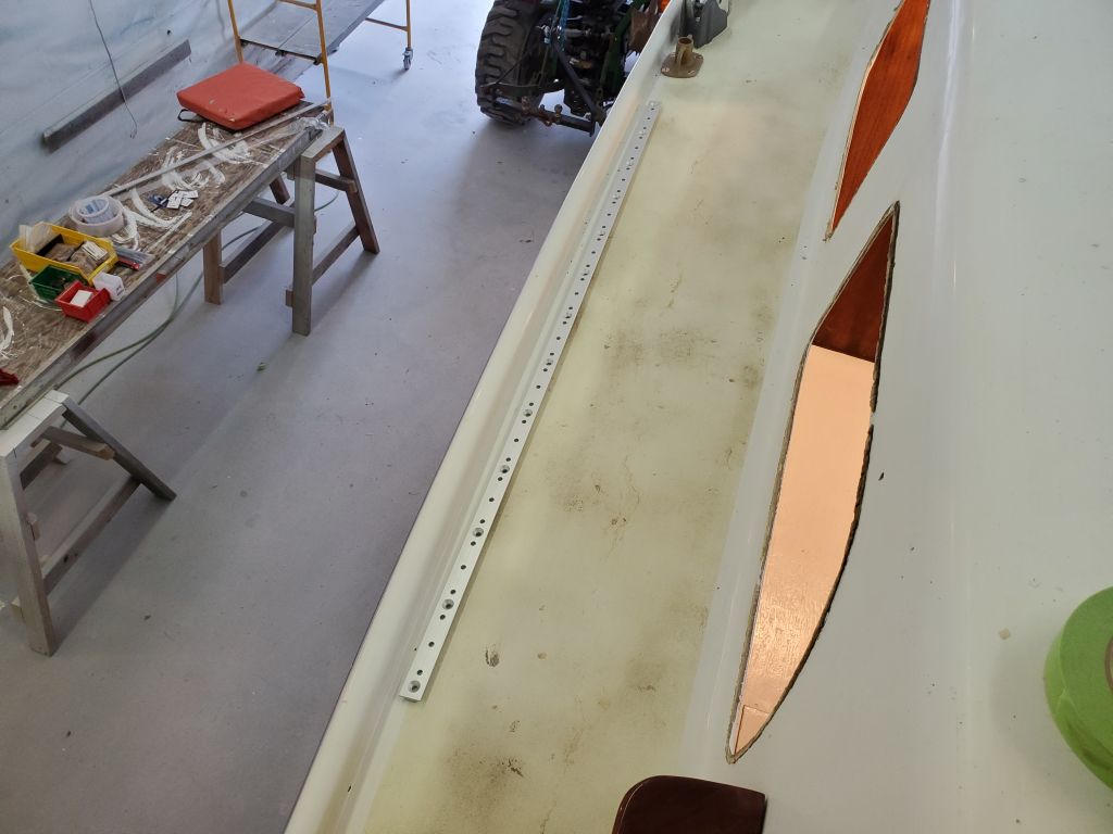
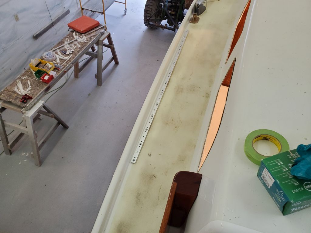
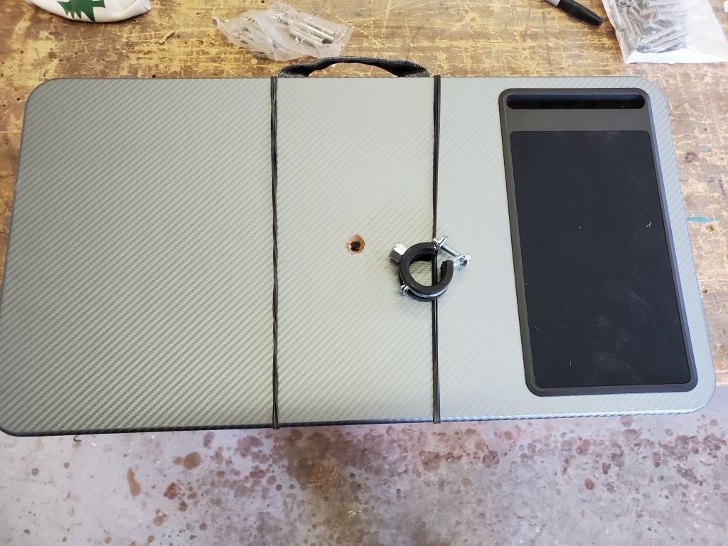
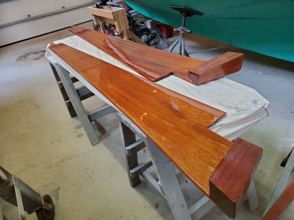
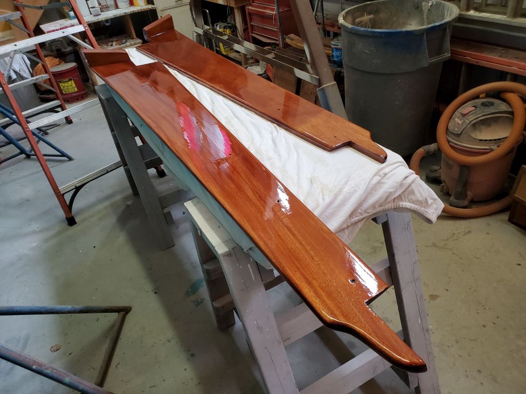
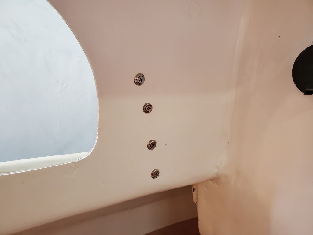
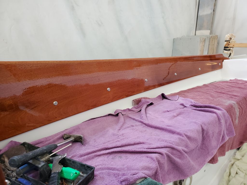
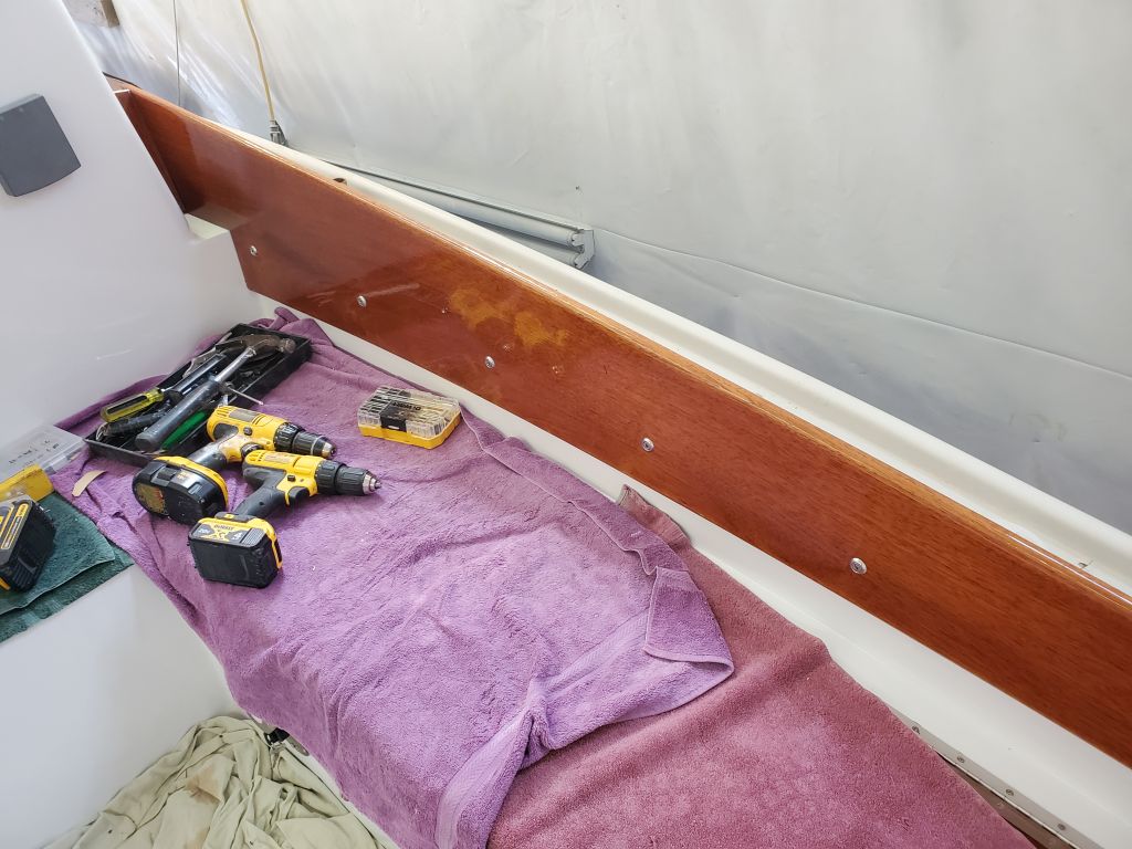
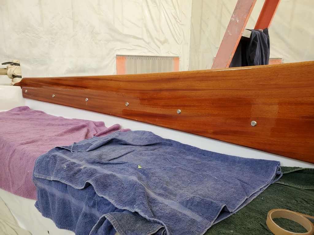
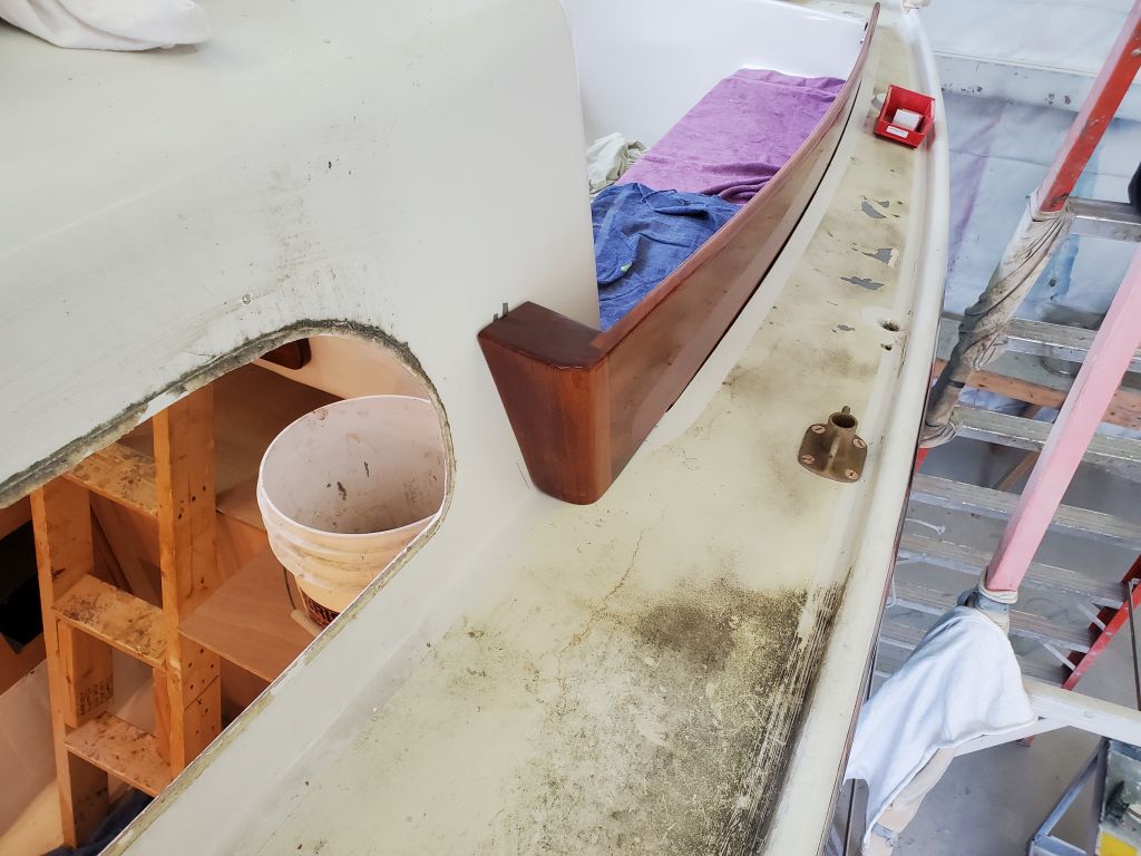
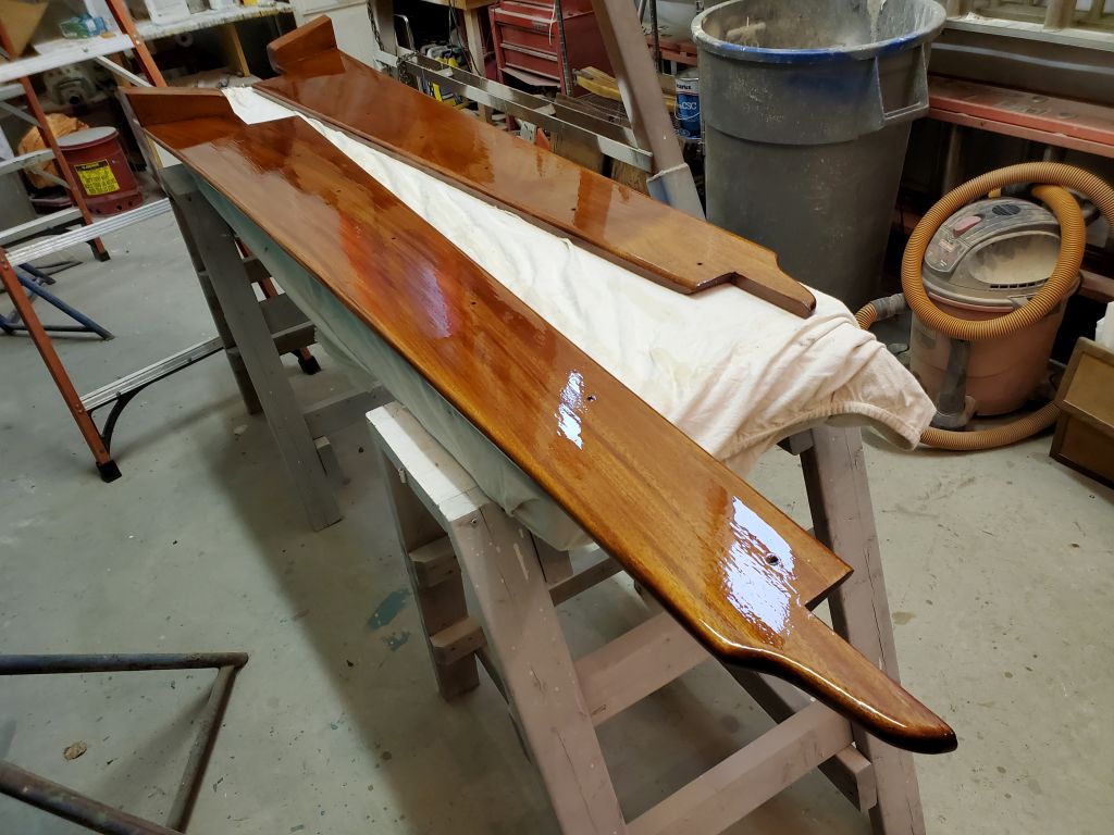
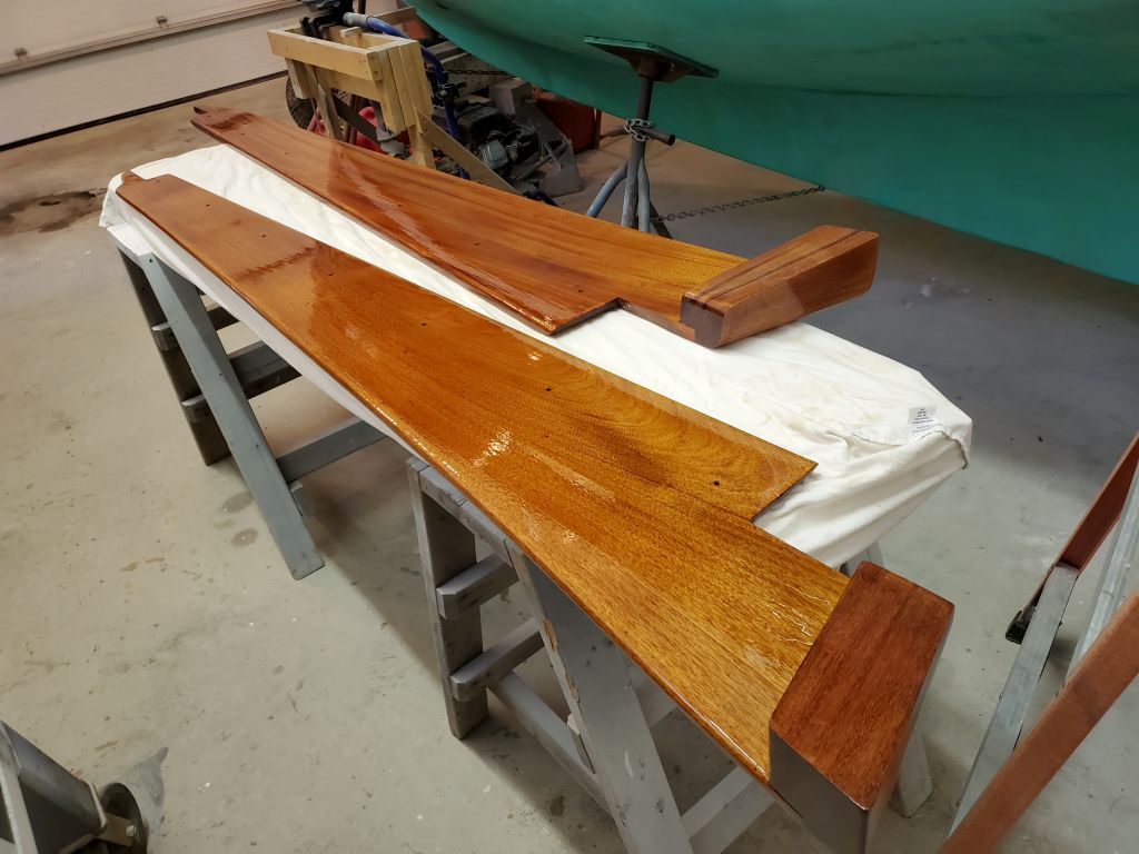
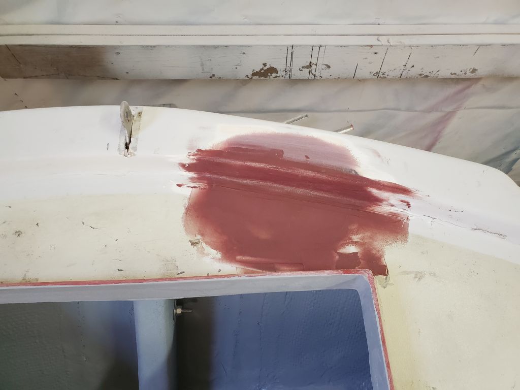
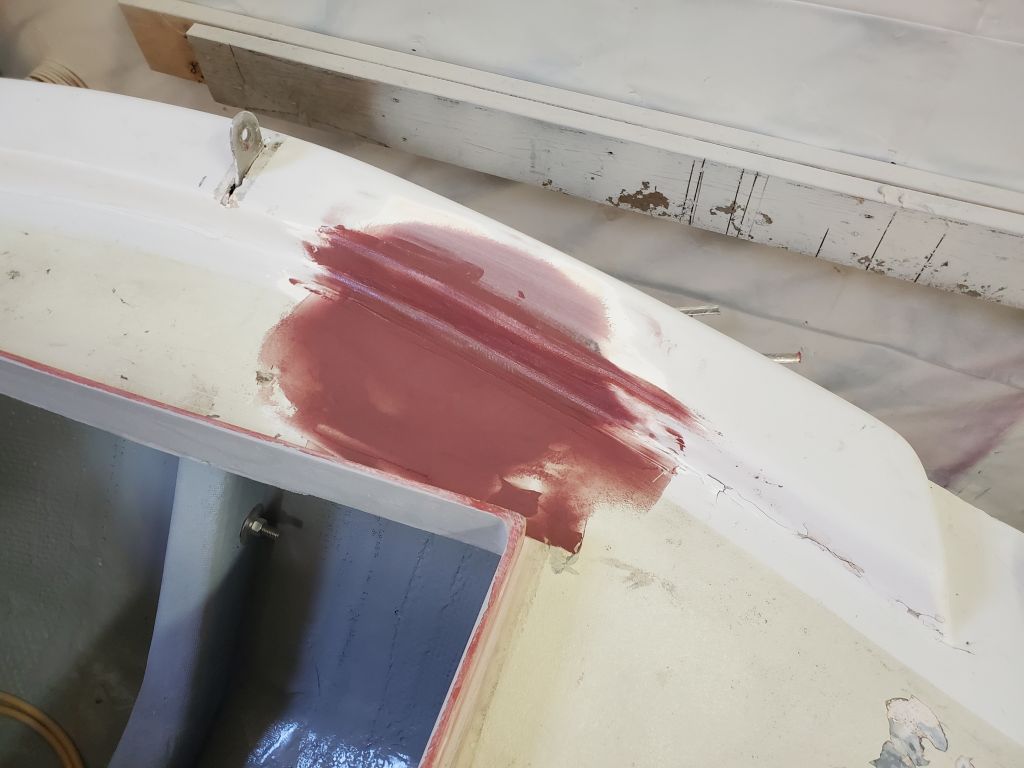
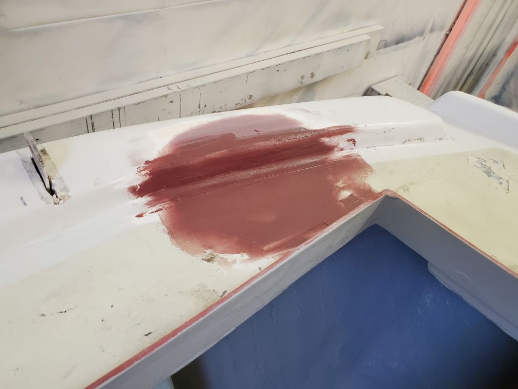
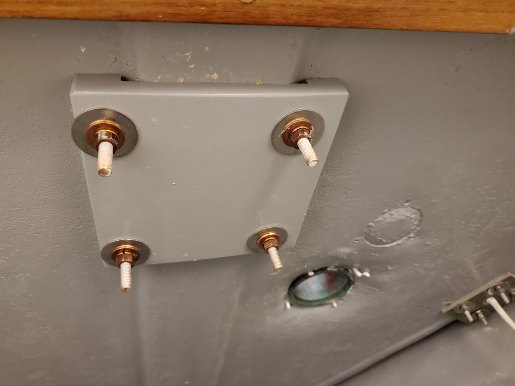
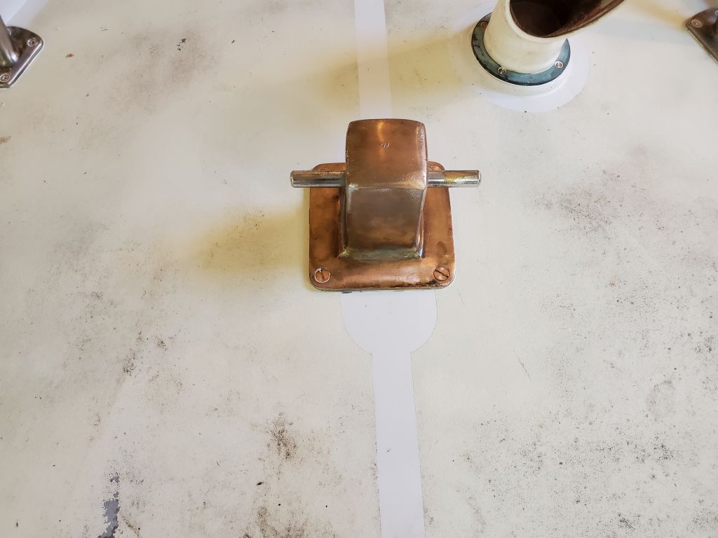
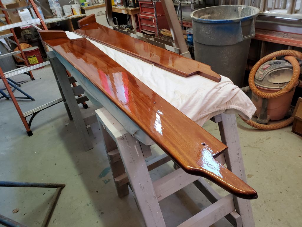
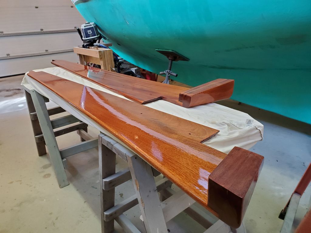
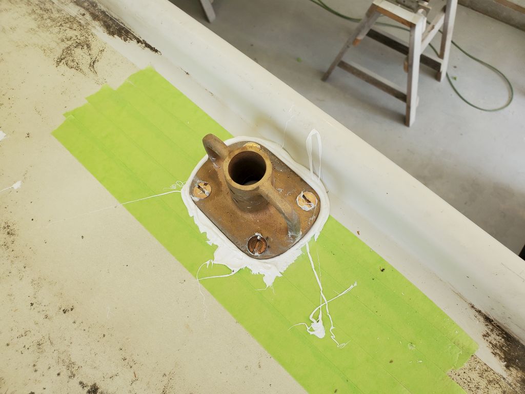
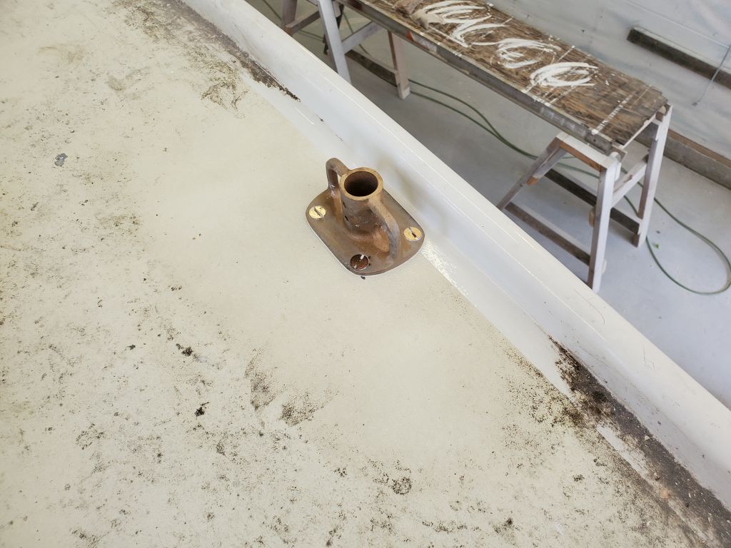
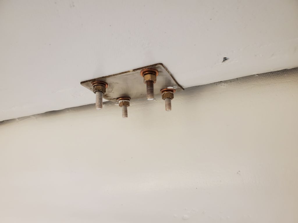
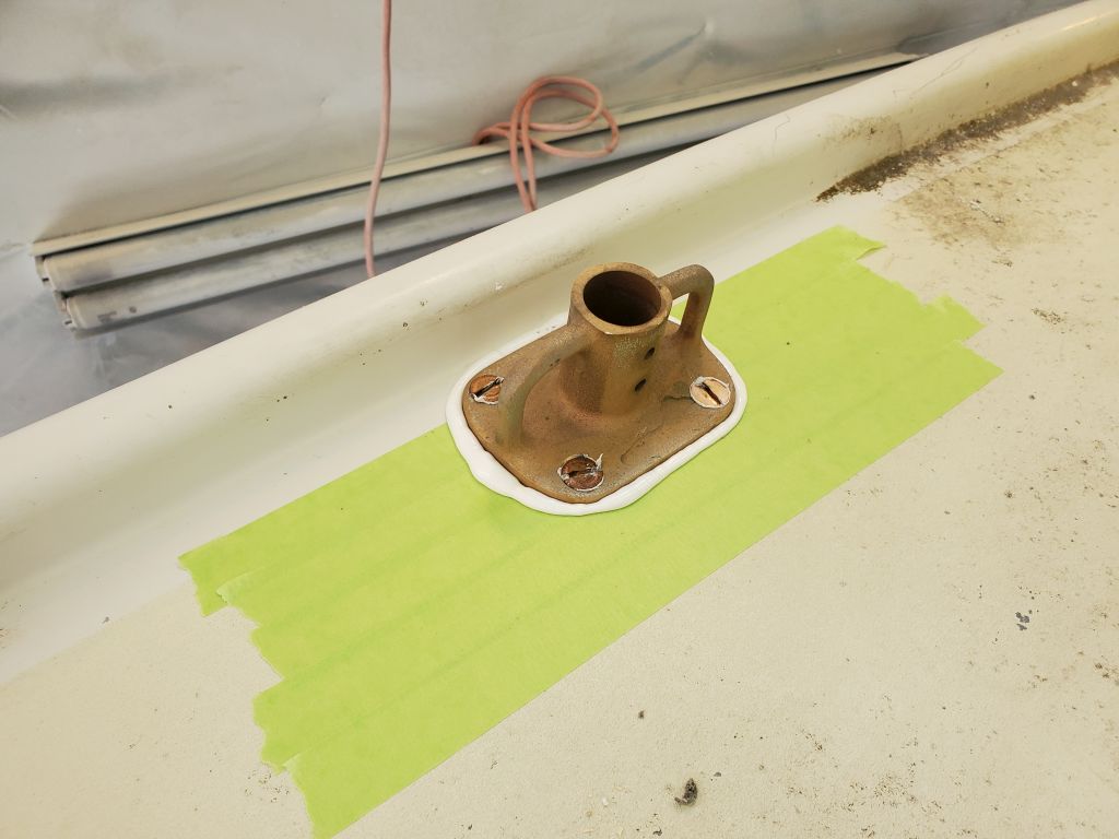
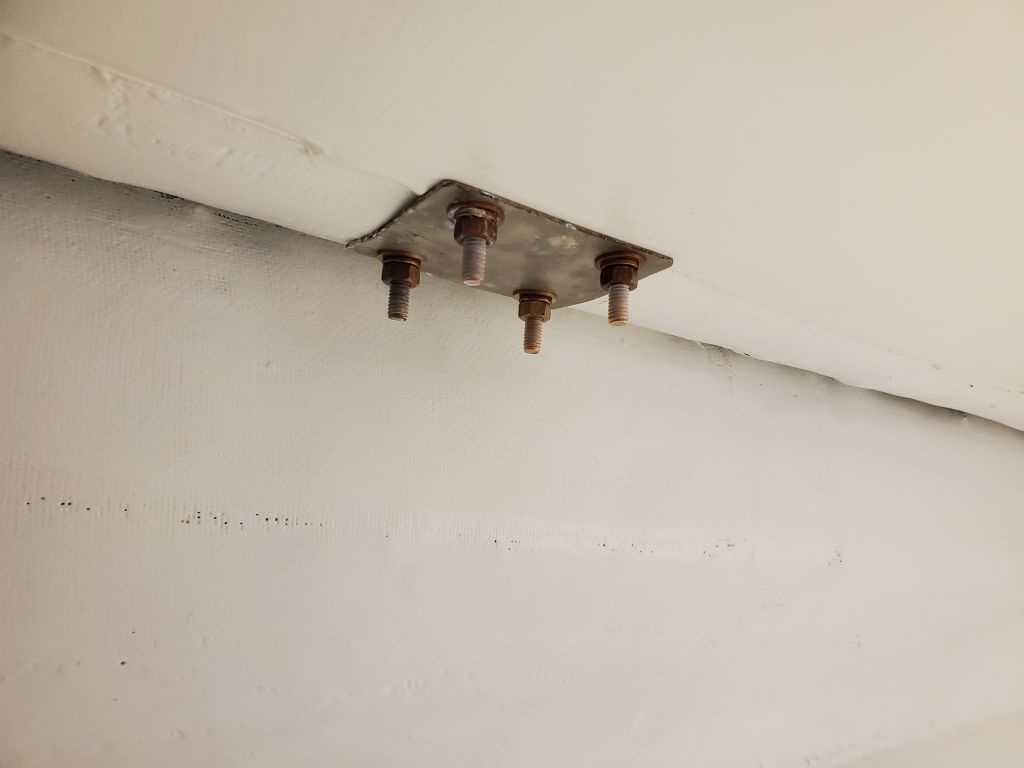
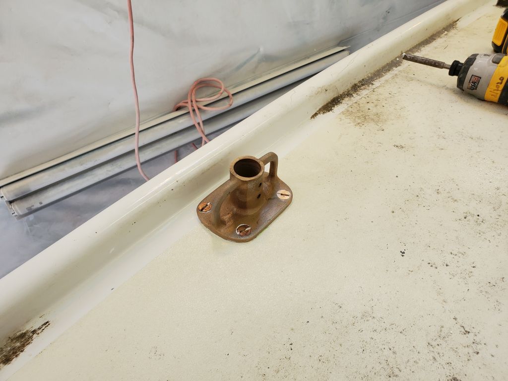
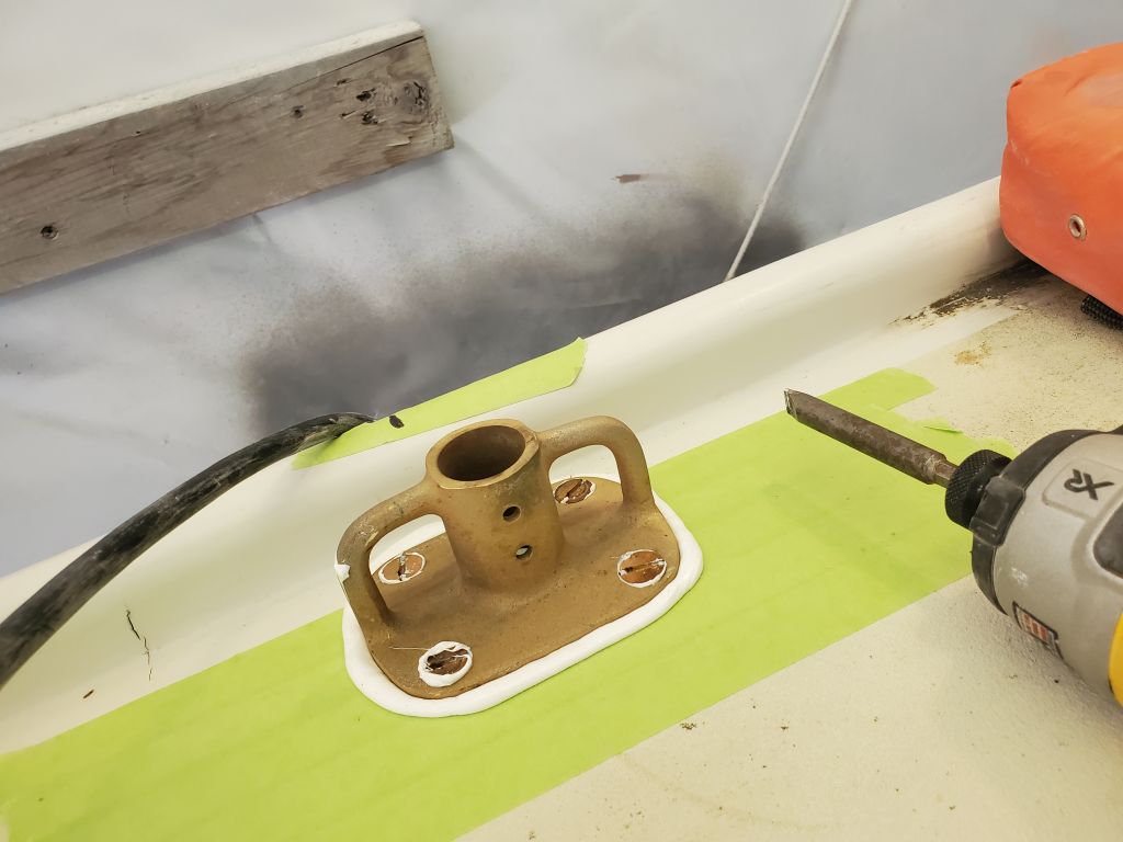
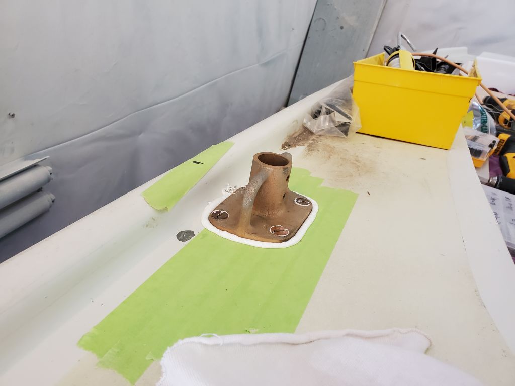
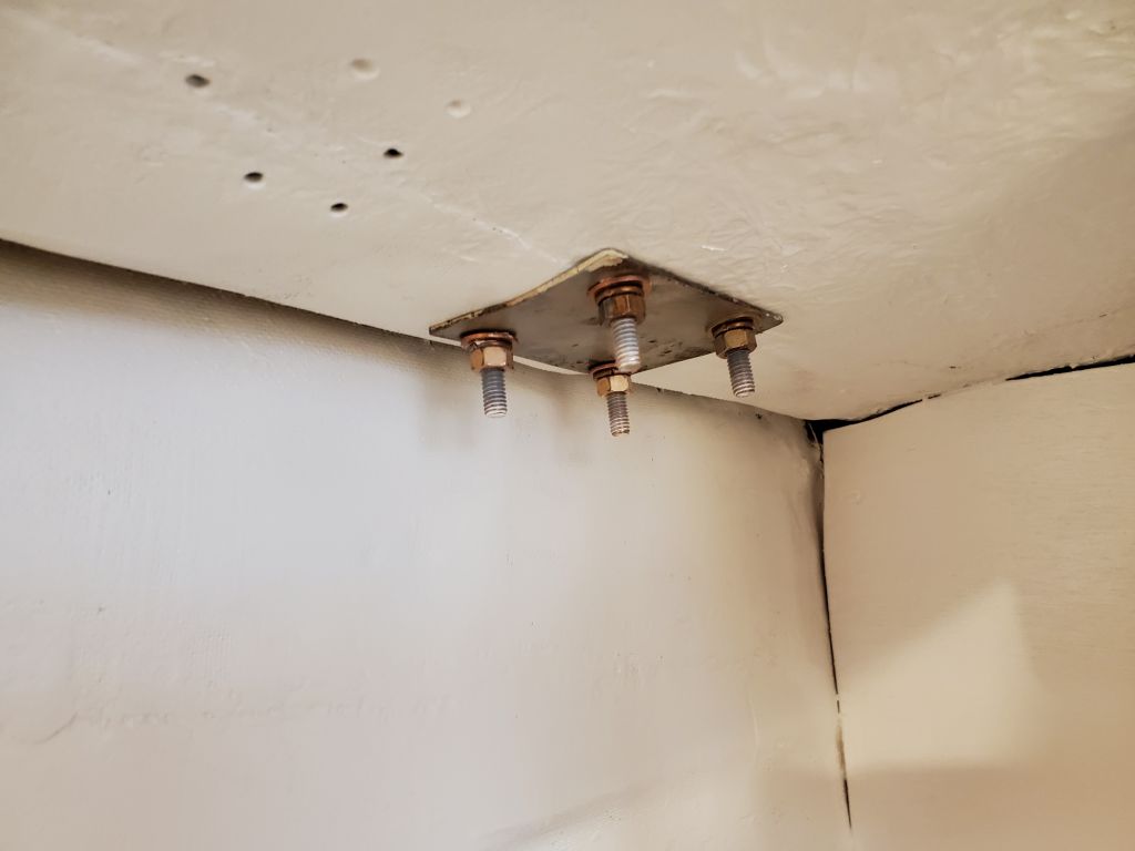
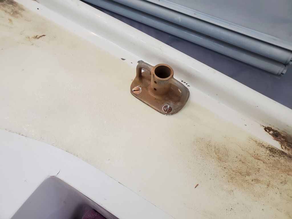
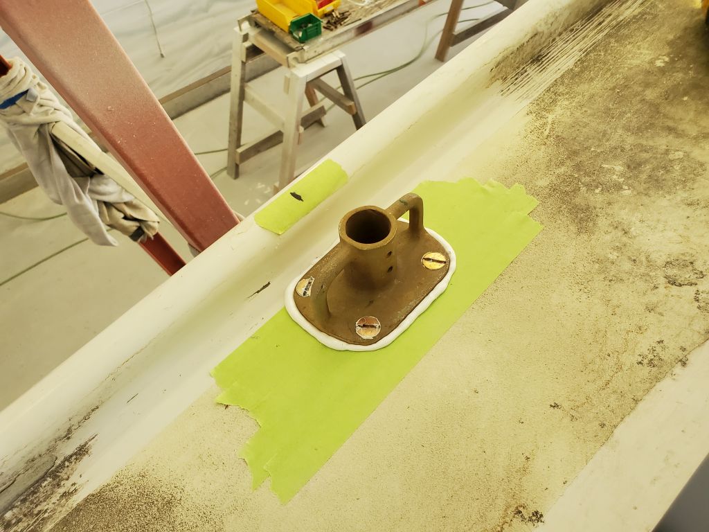
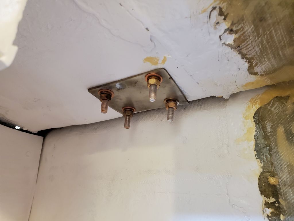
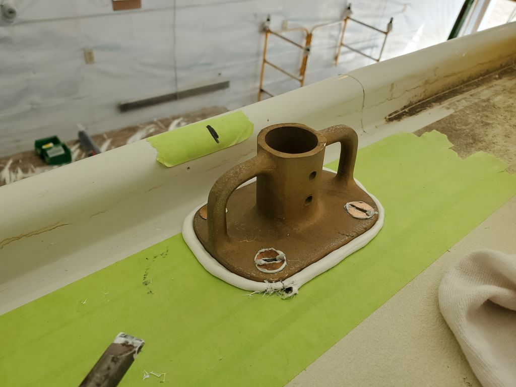
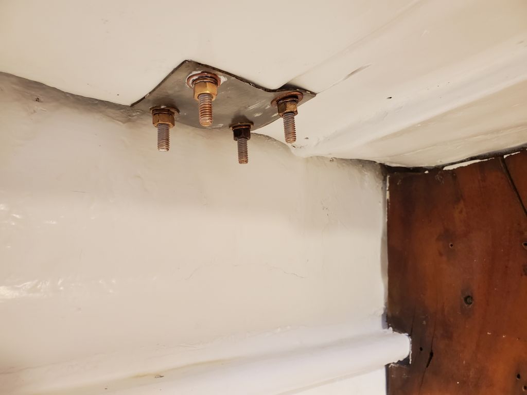
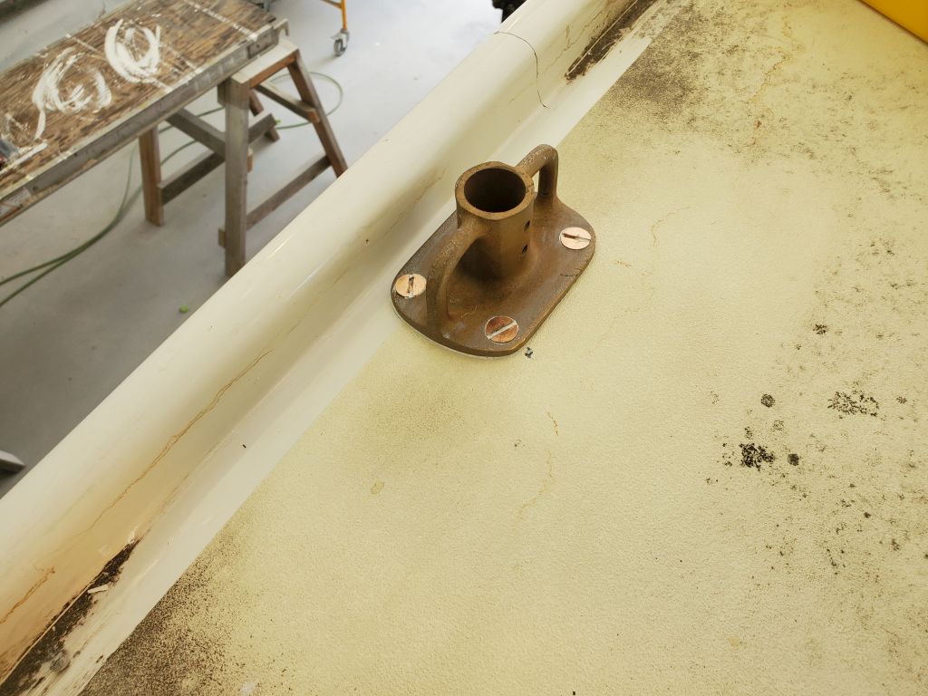
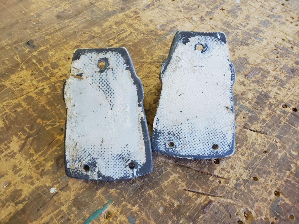
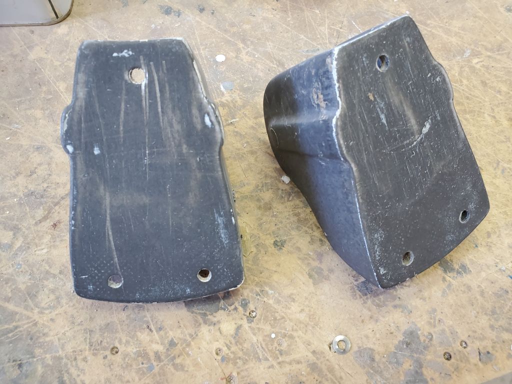
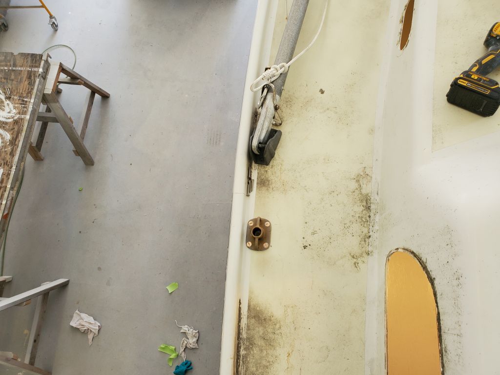
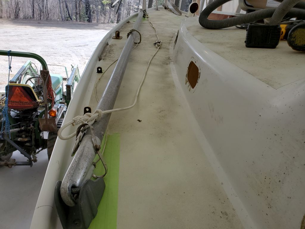
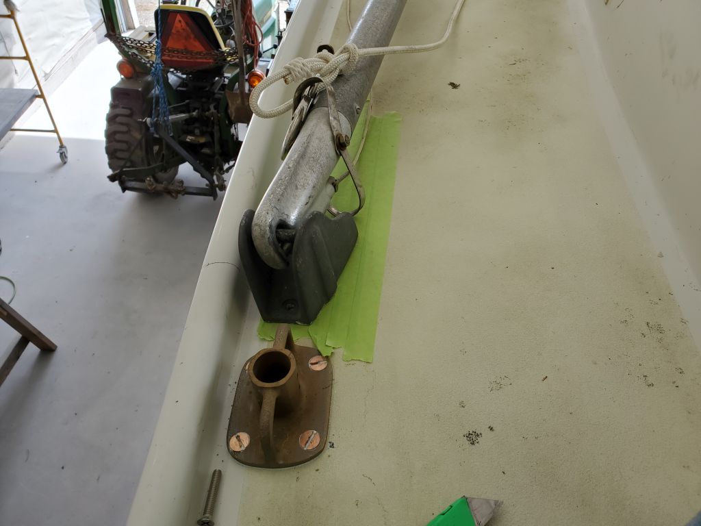
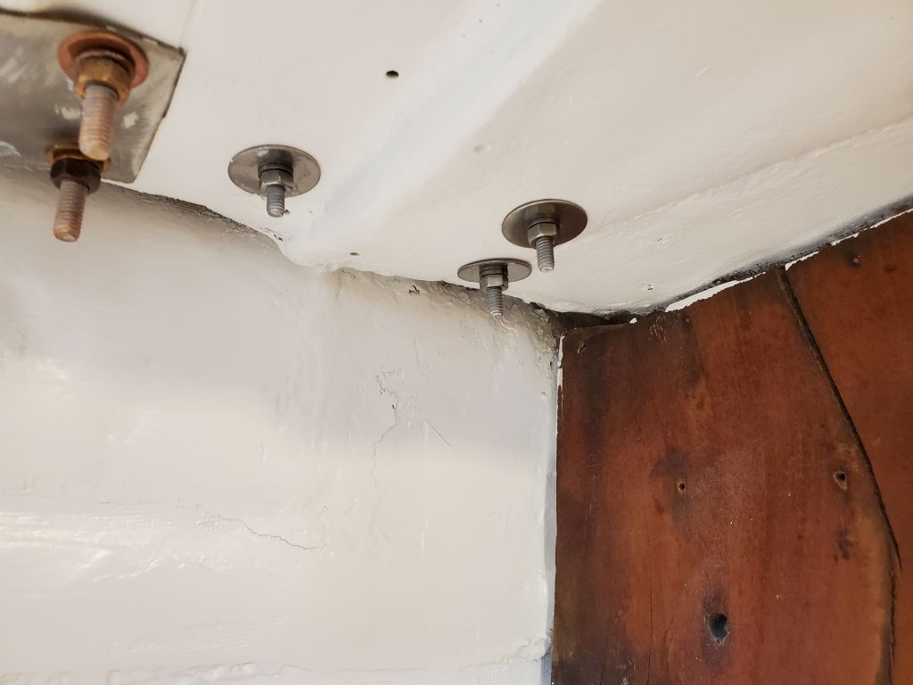
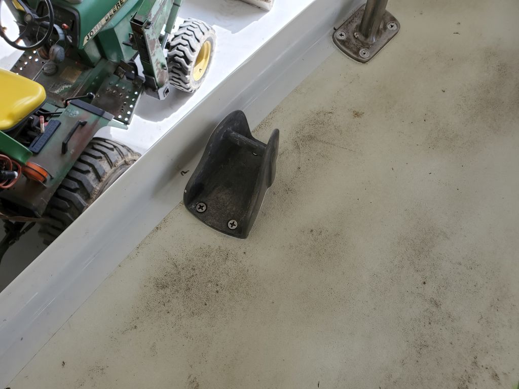
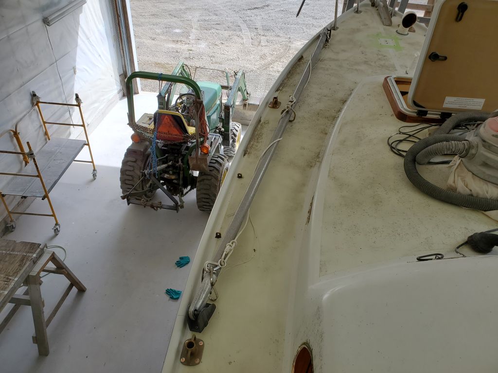
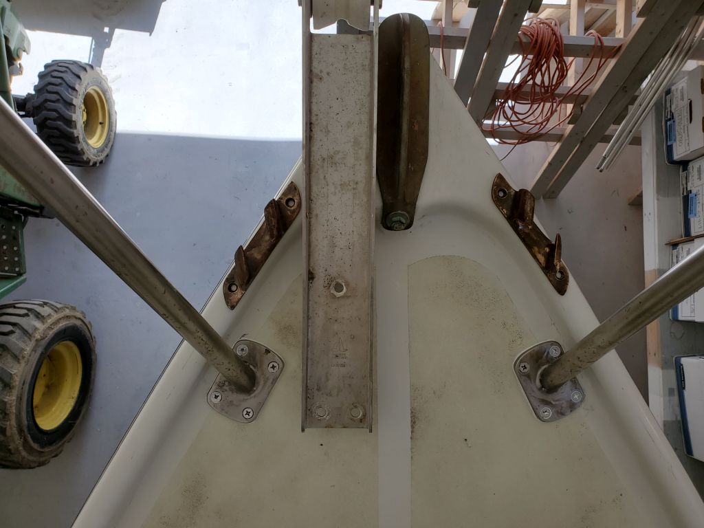
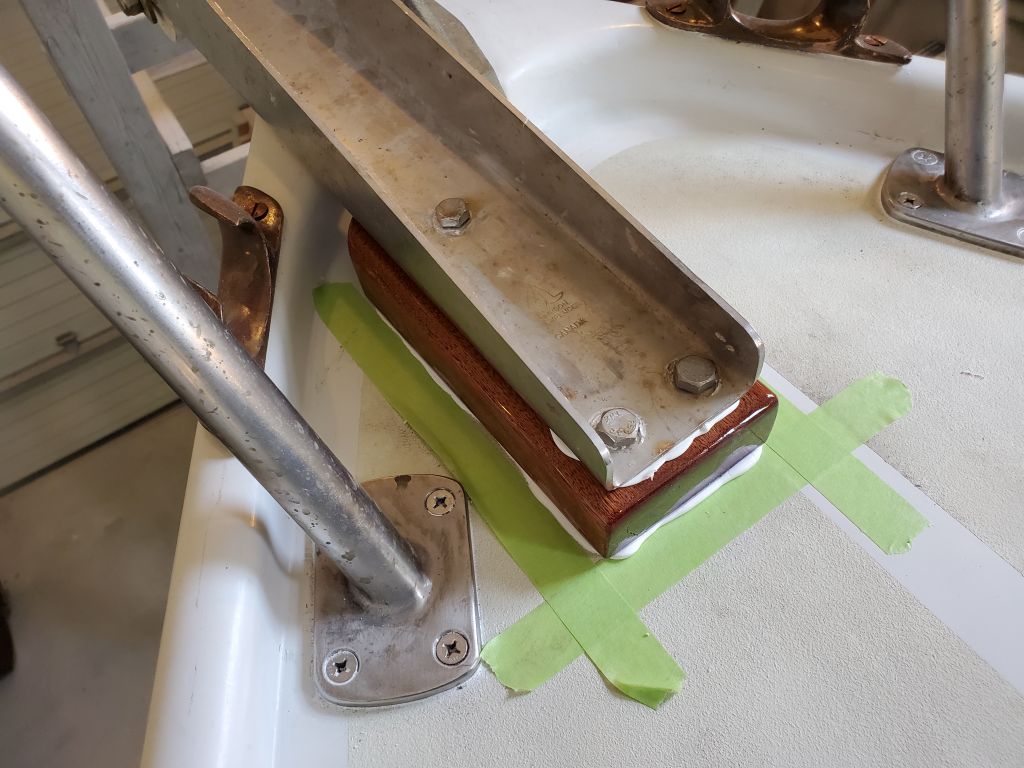
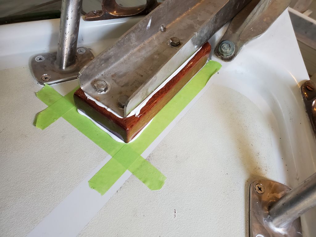
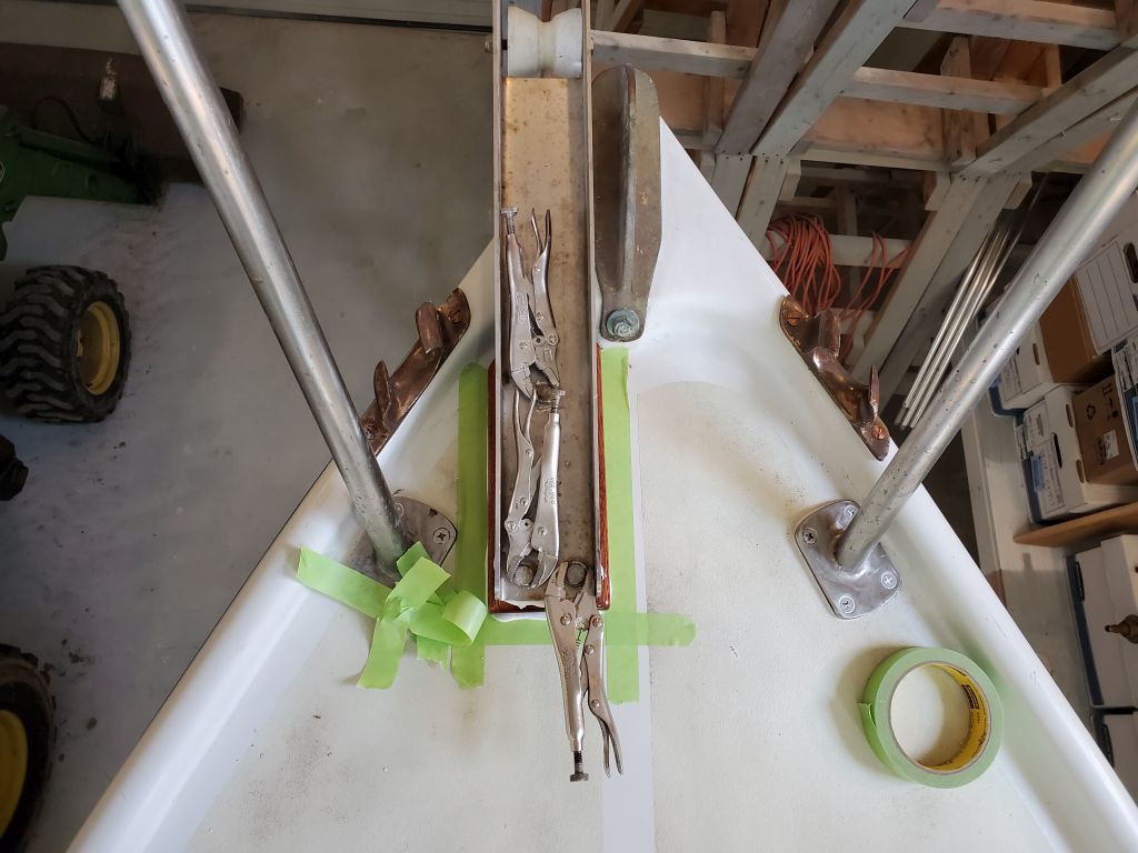
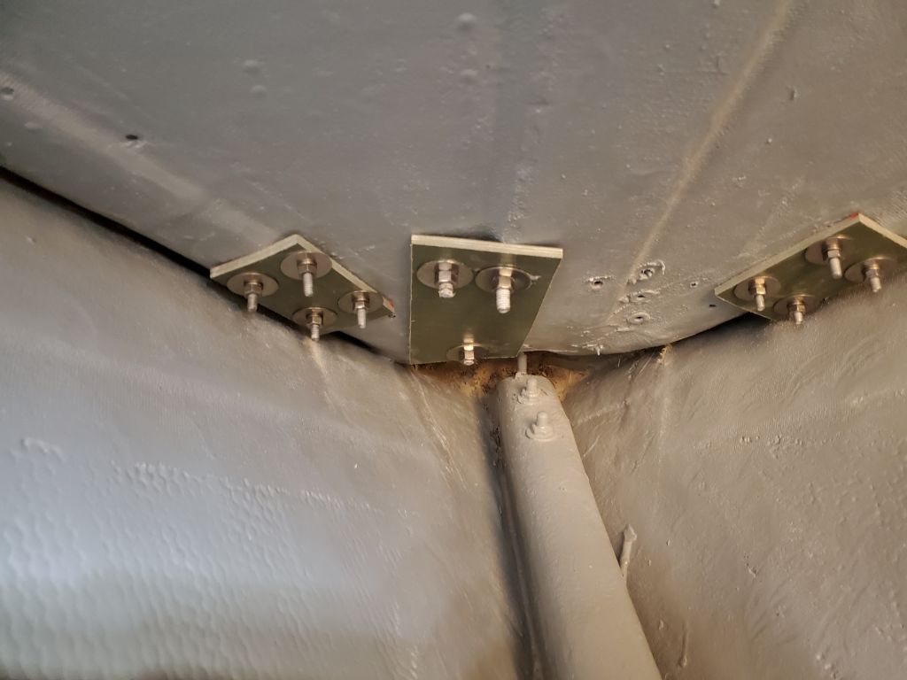
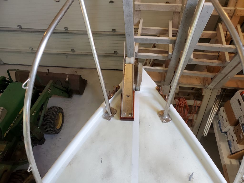
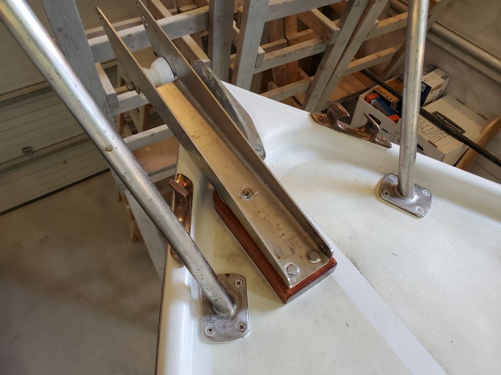
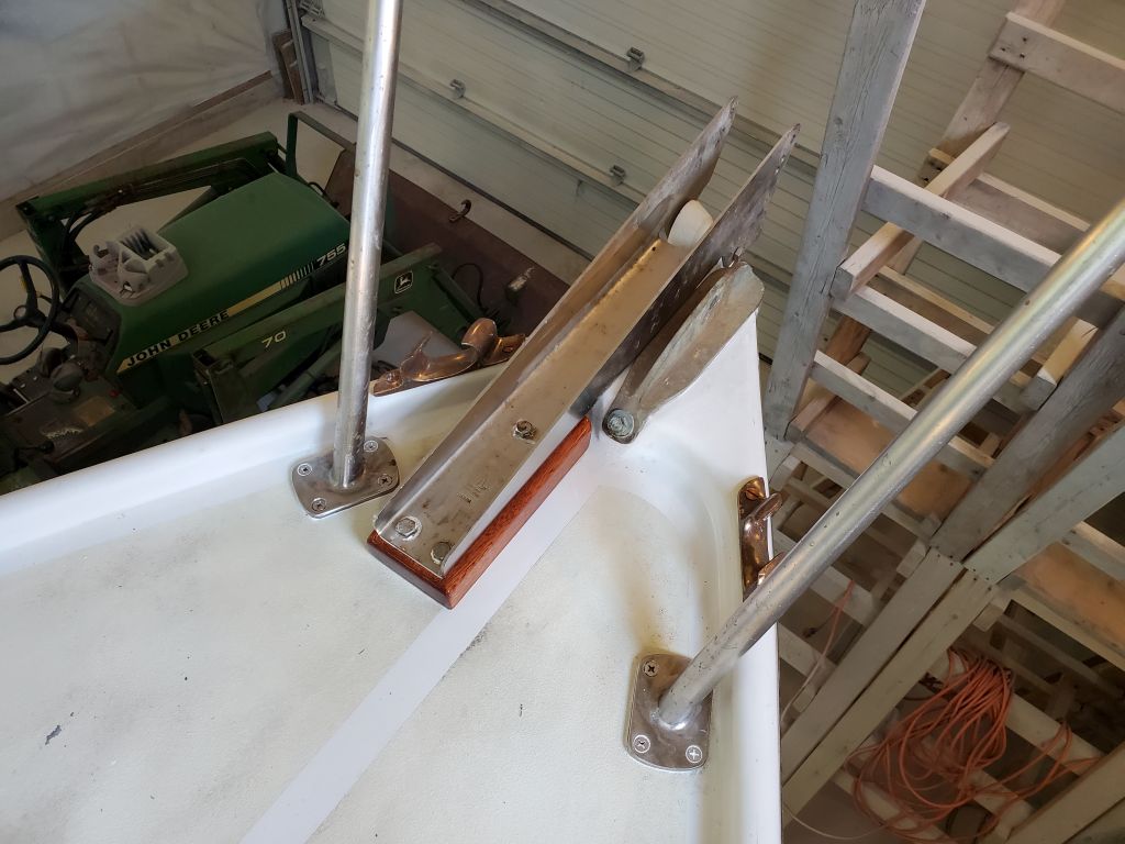
Over the past few days, I’d finished up the varnish on the anchor roller support block (six in all), and now I could finish up the installation. I prepared a backing place from fiberglass laminate, then installed the roller with sealant and 3/8″ bolts, nuts, and washers.

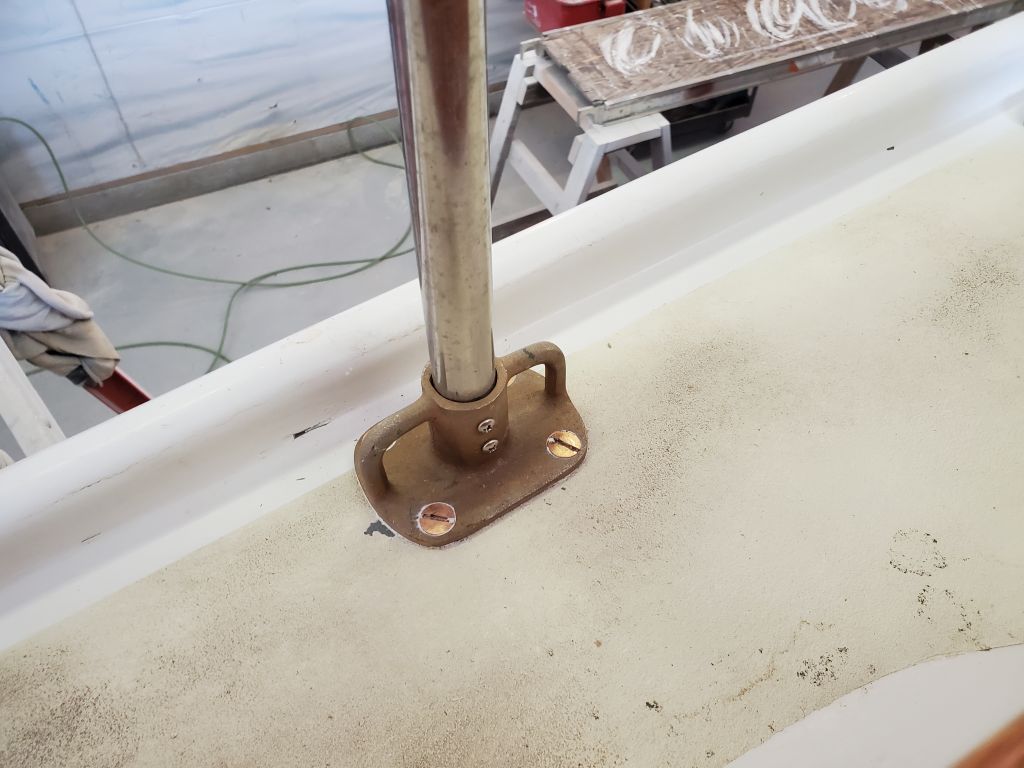
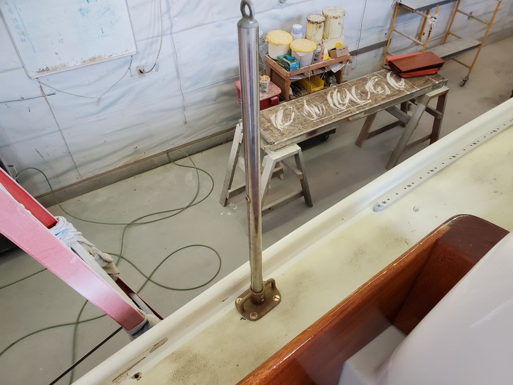
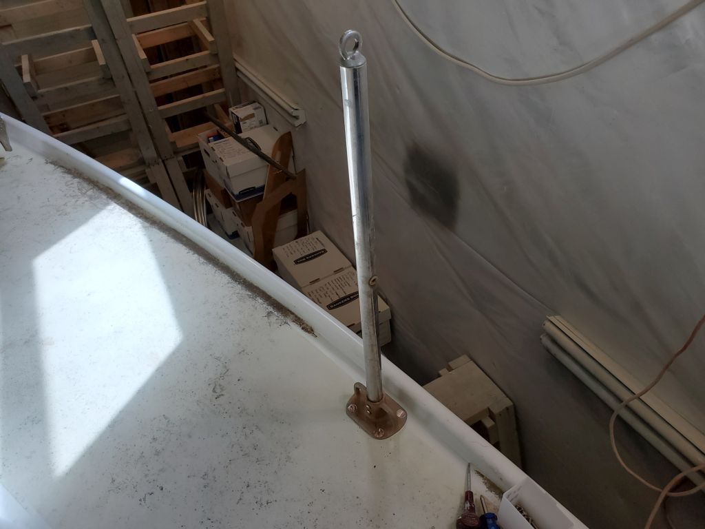
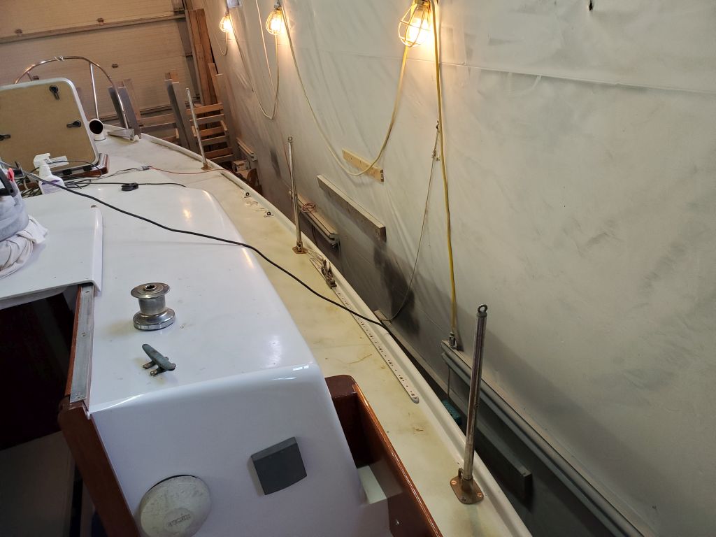
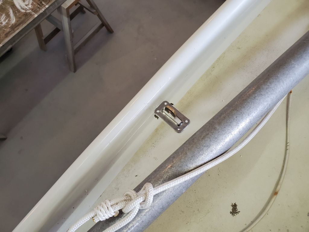
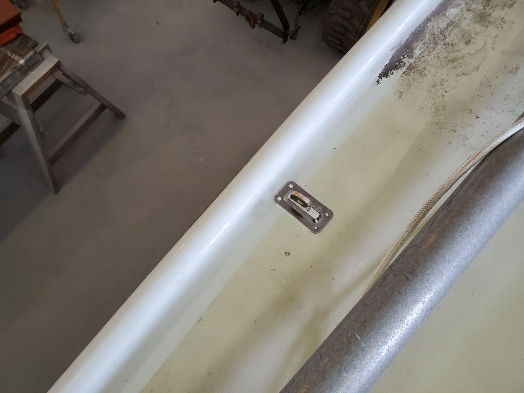
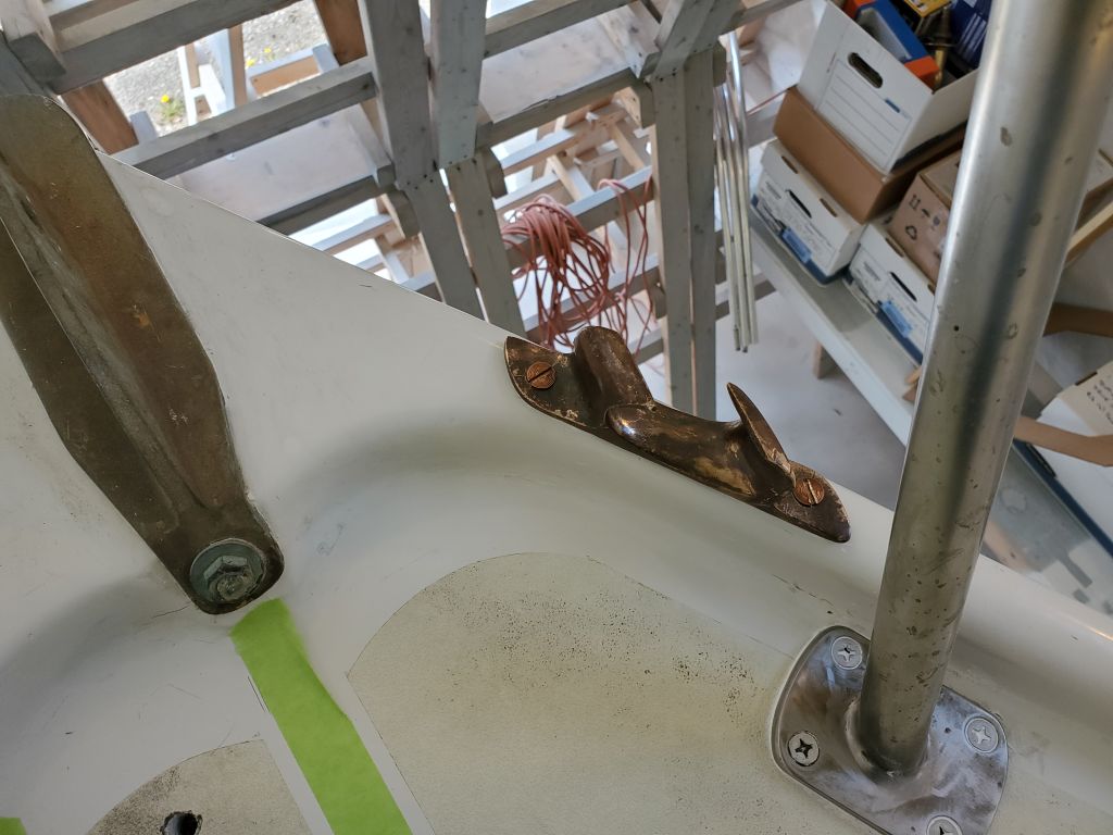
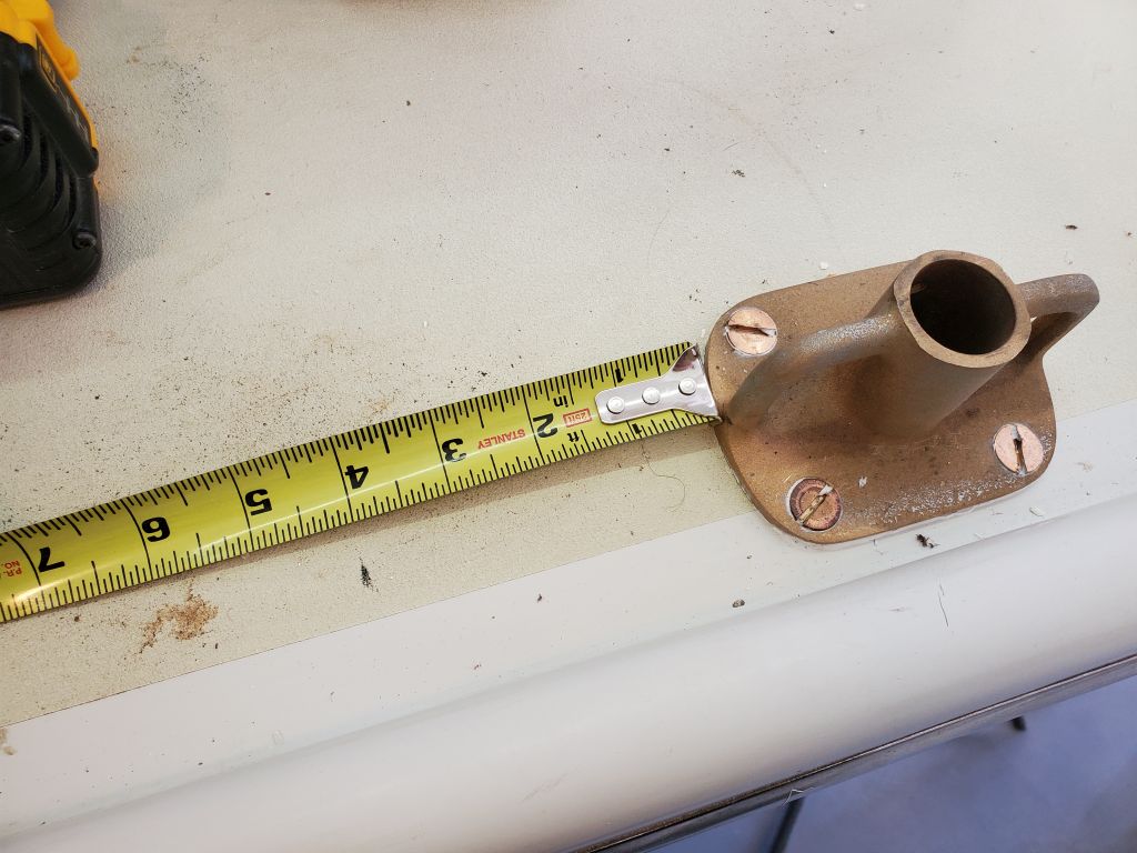
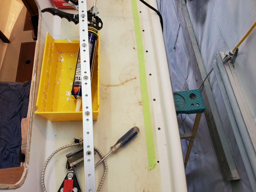
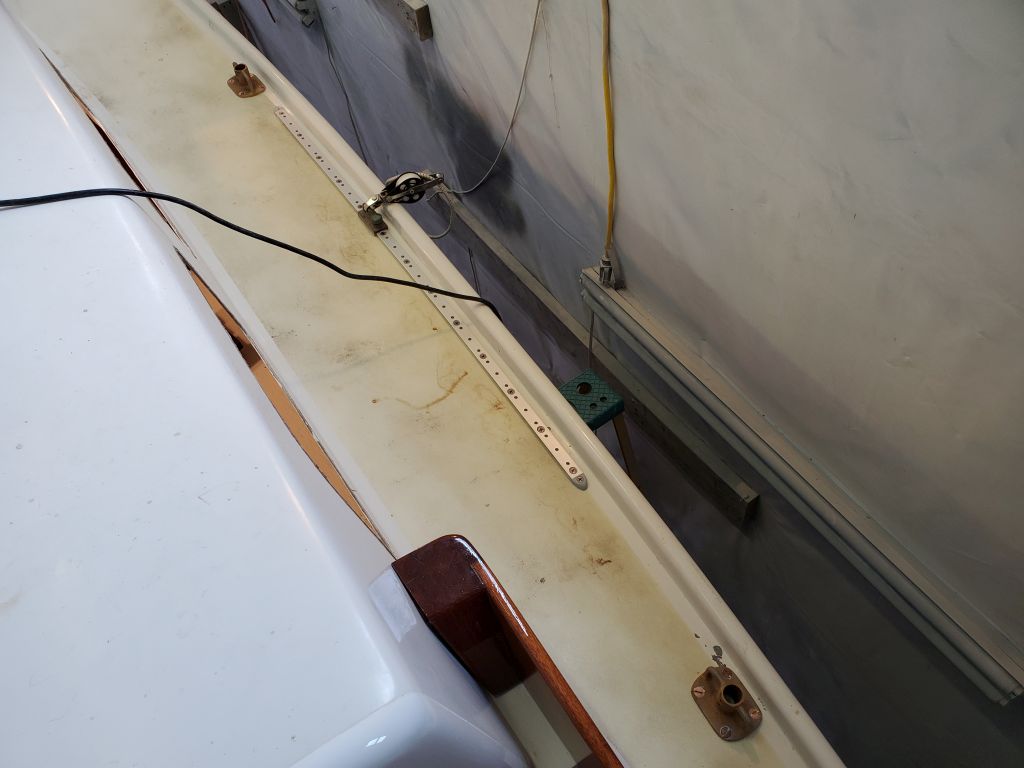
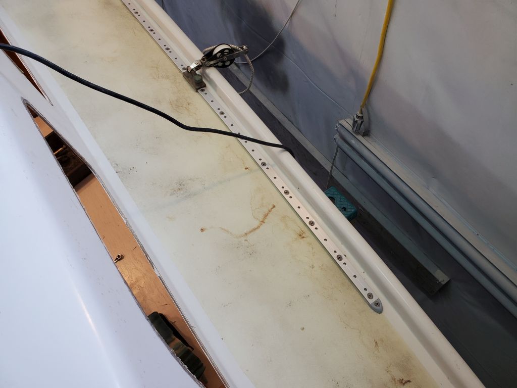
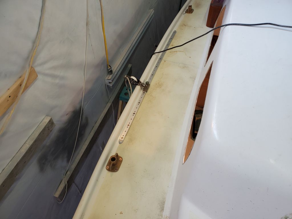
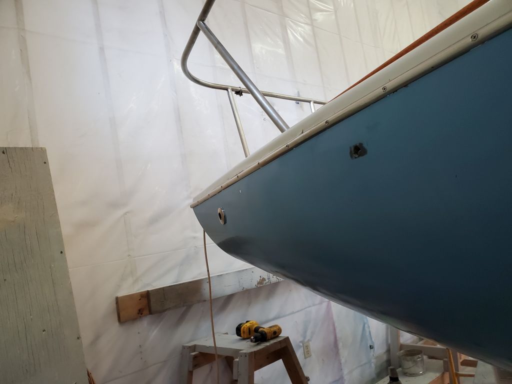
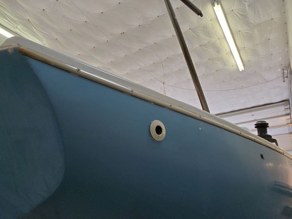
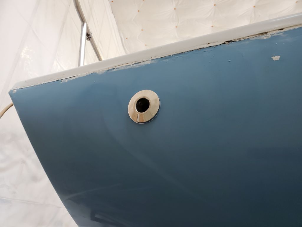
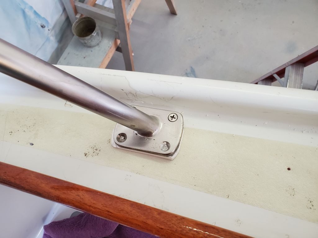
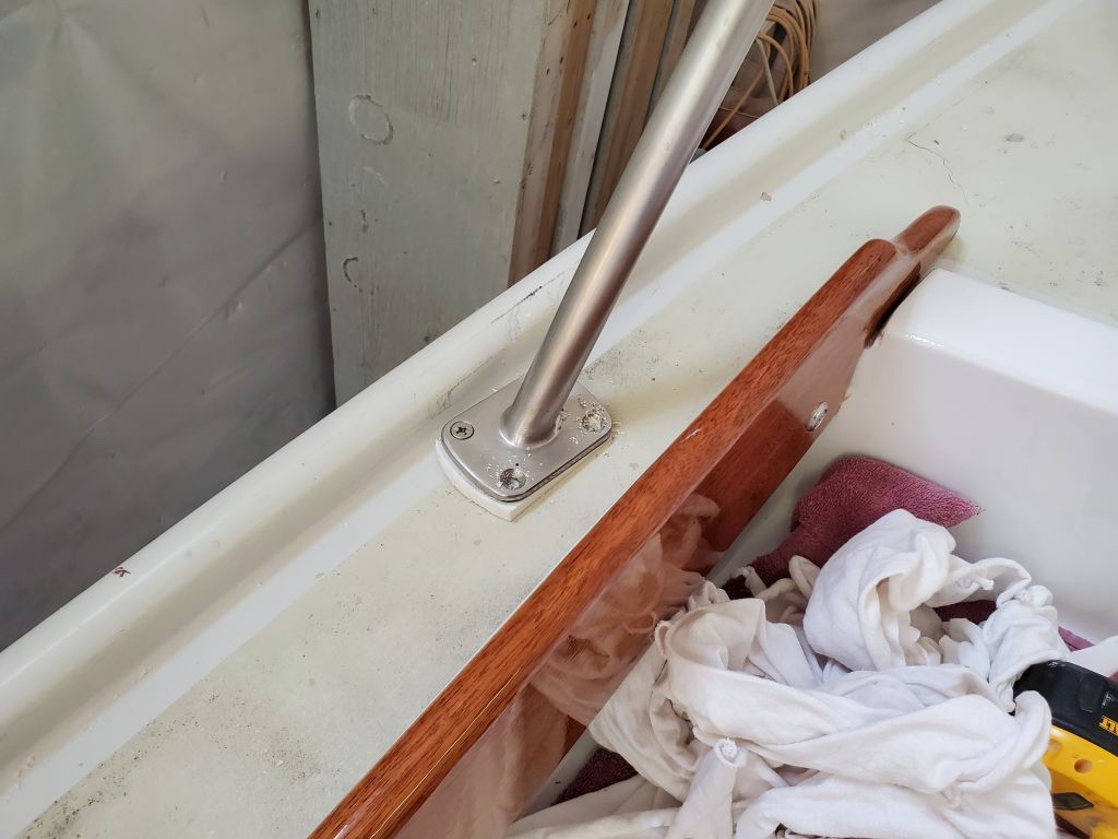
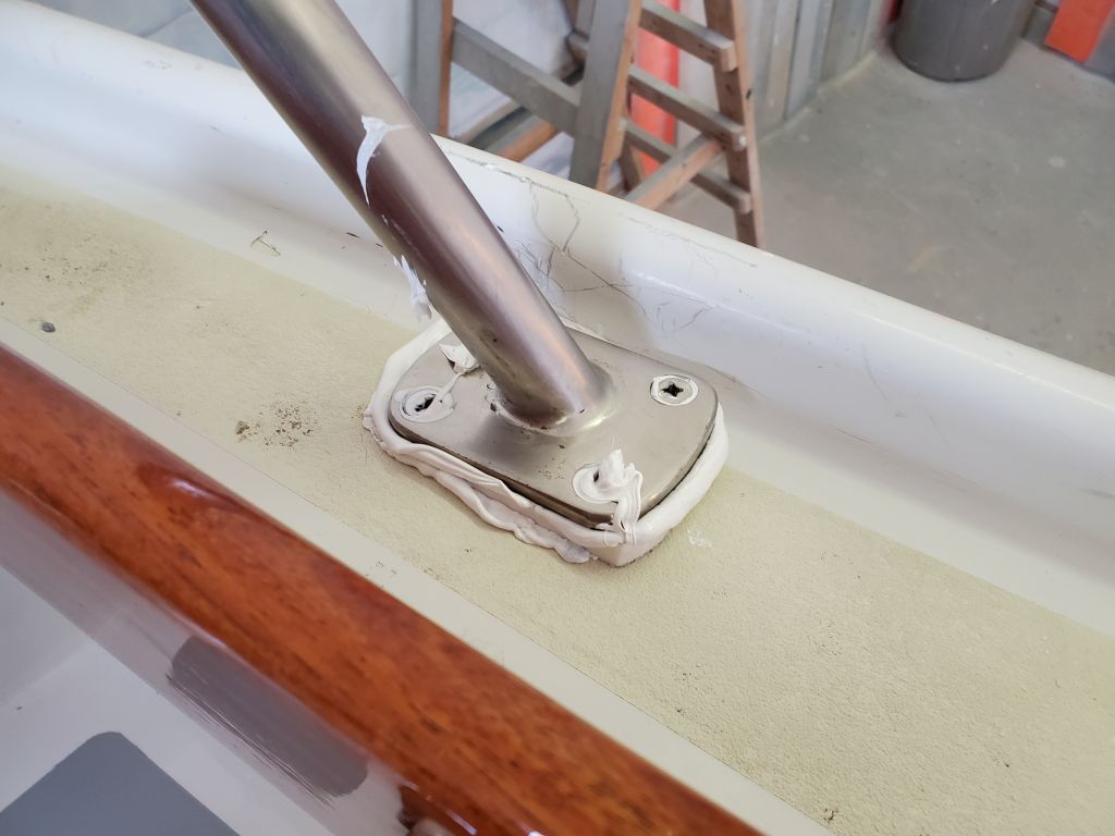
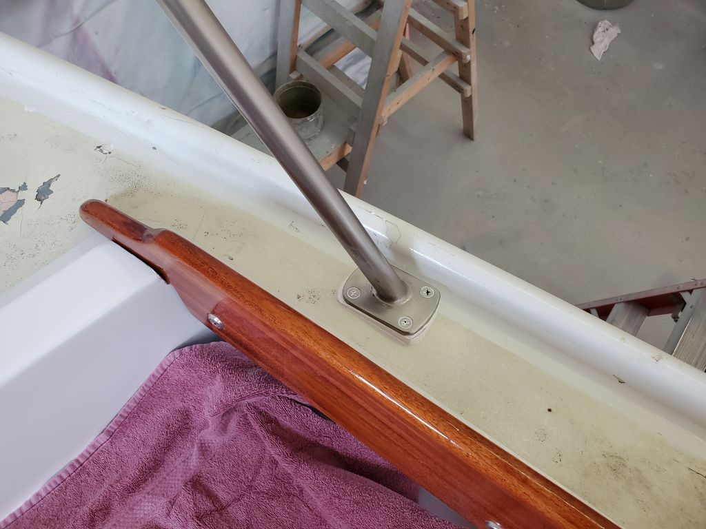
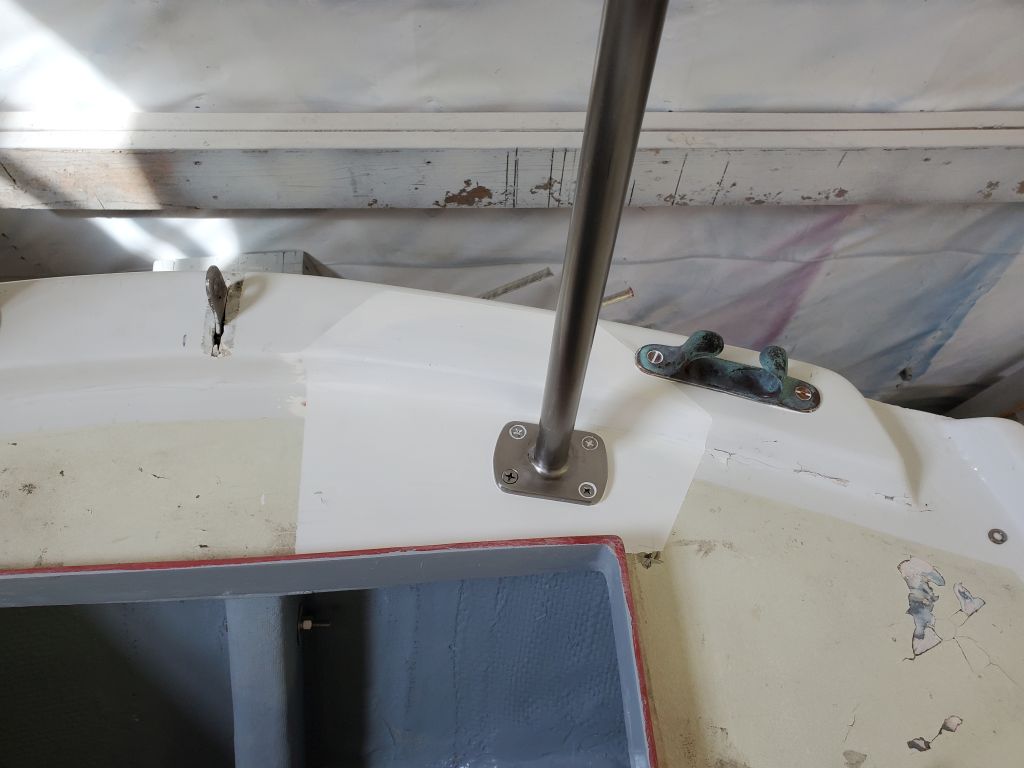
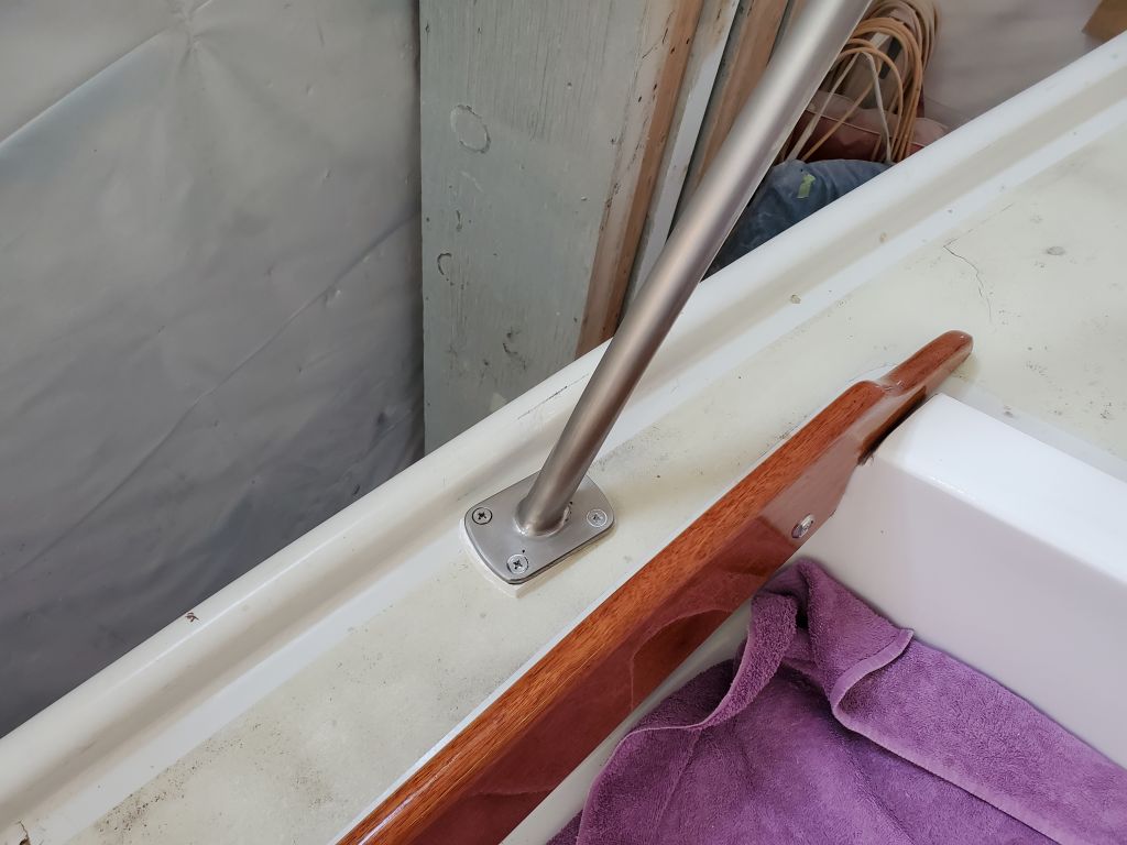
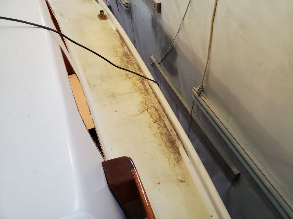
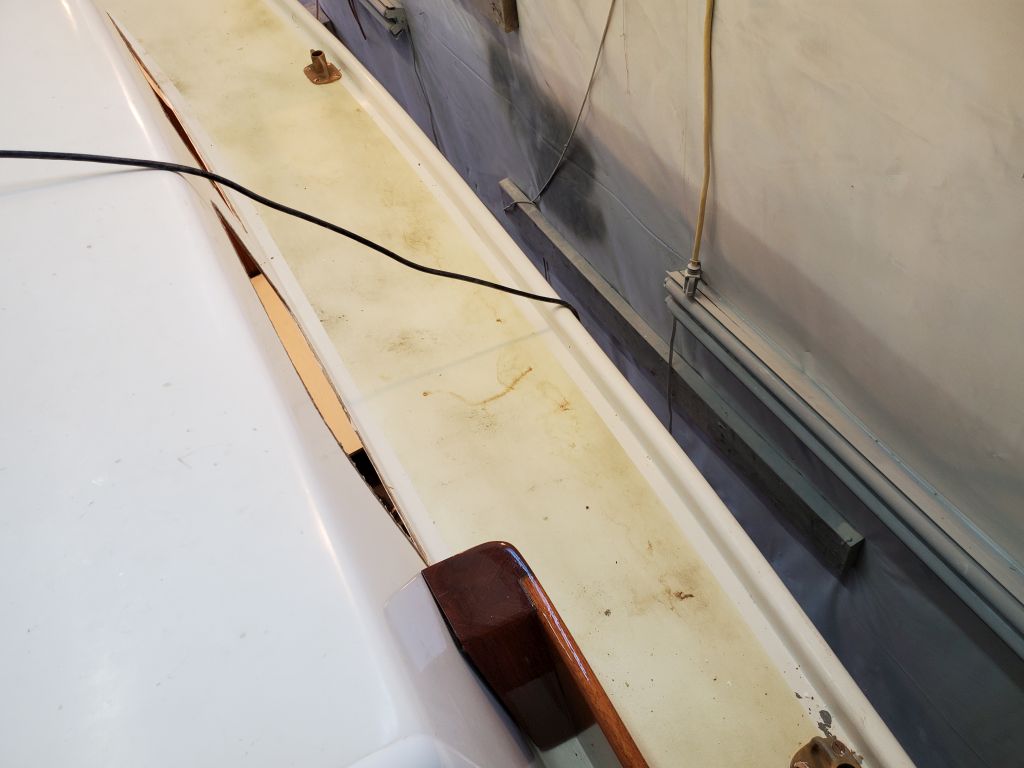
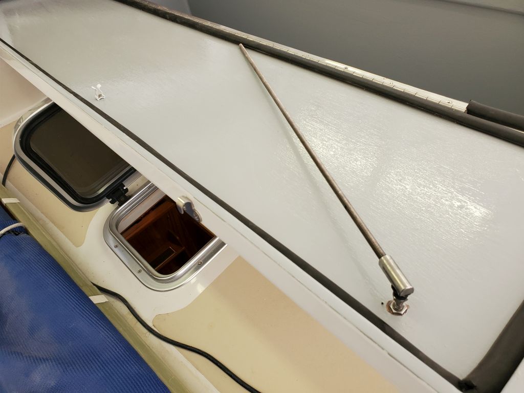
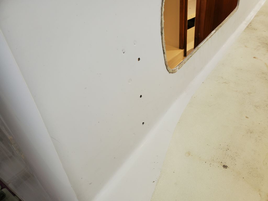
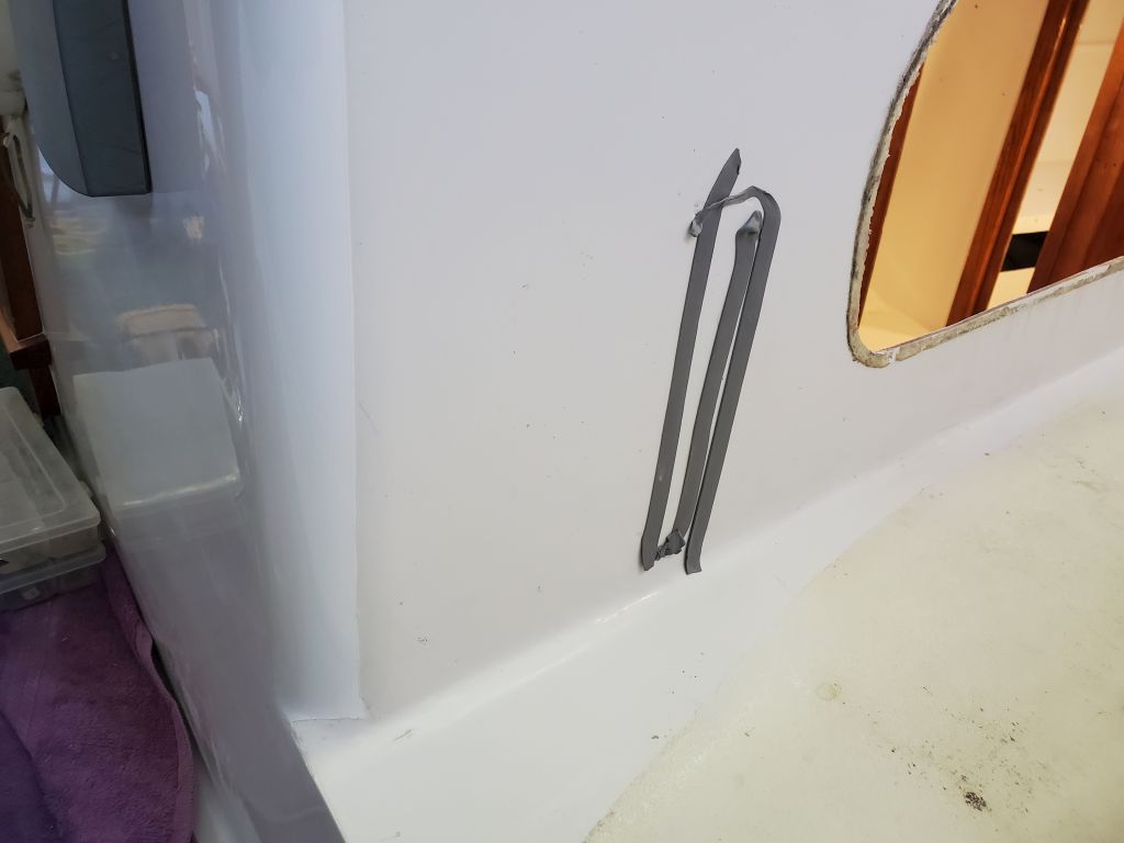
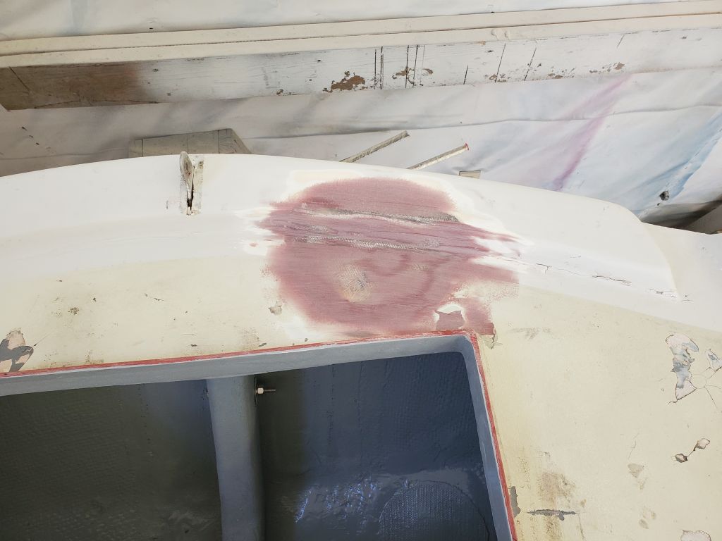
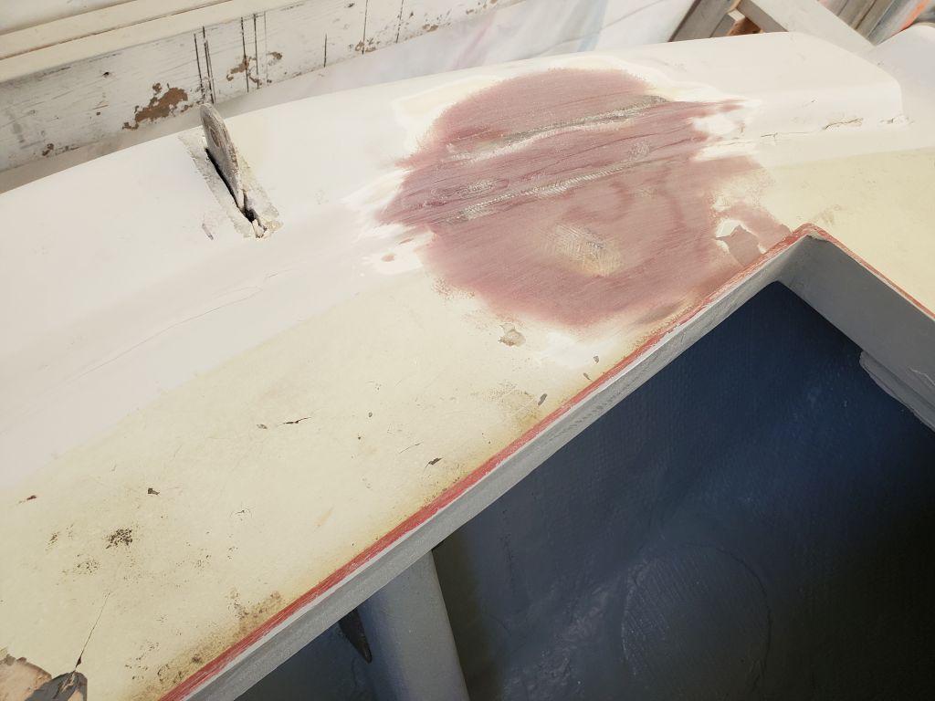
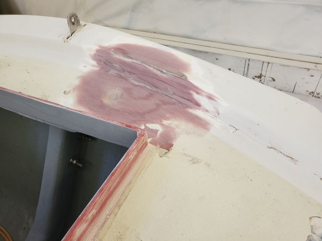
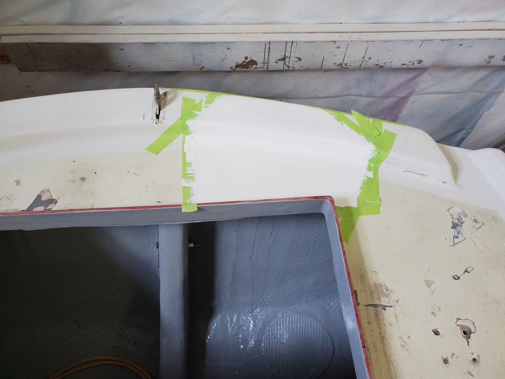
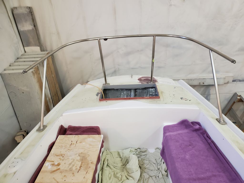
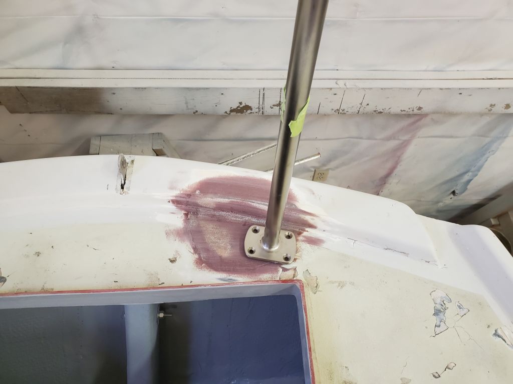
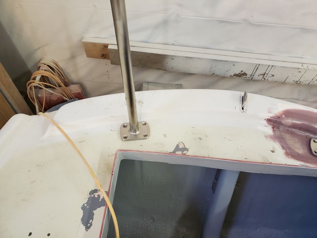
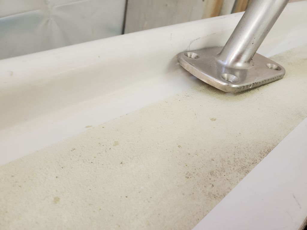
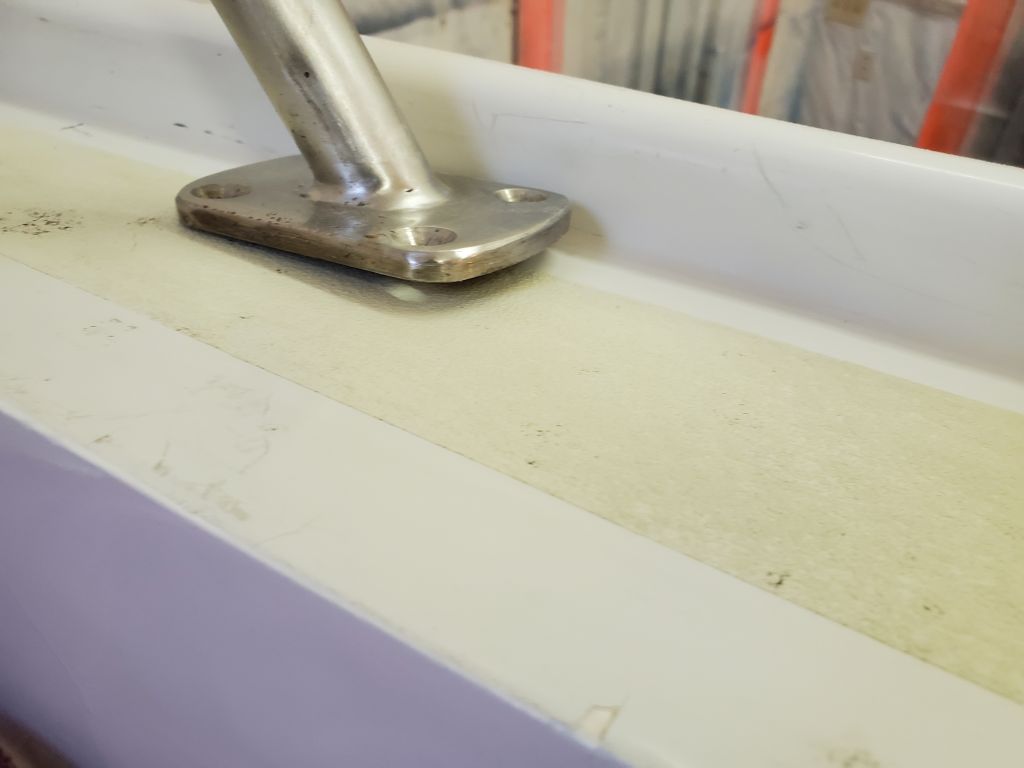
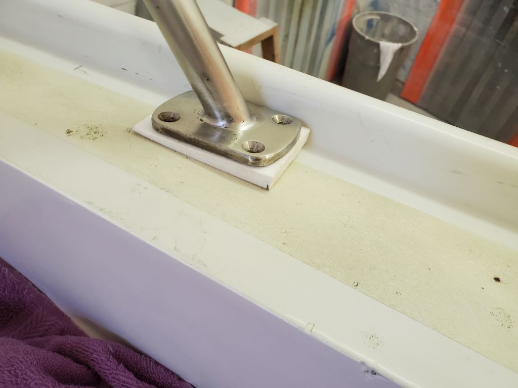
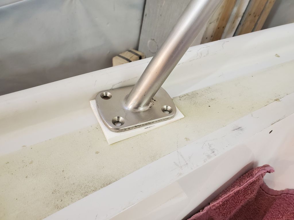
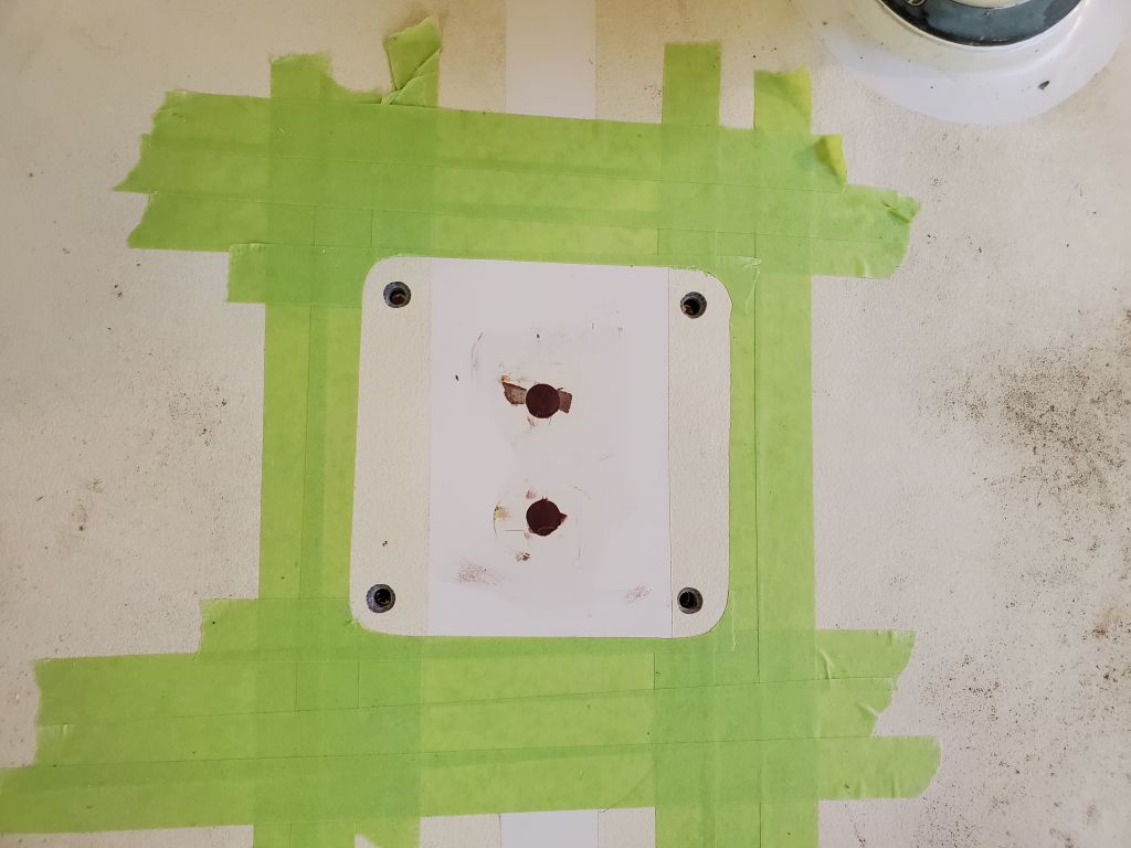
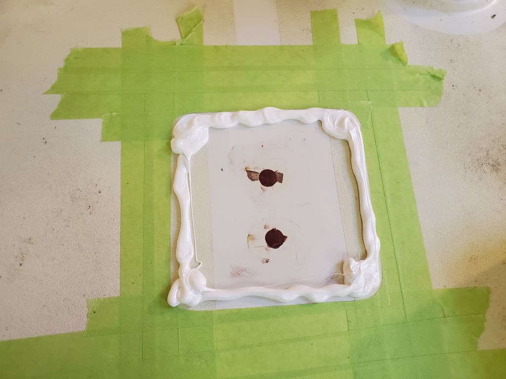
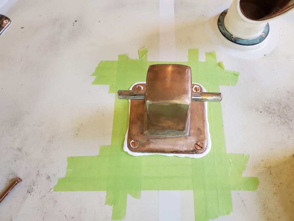
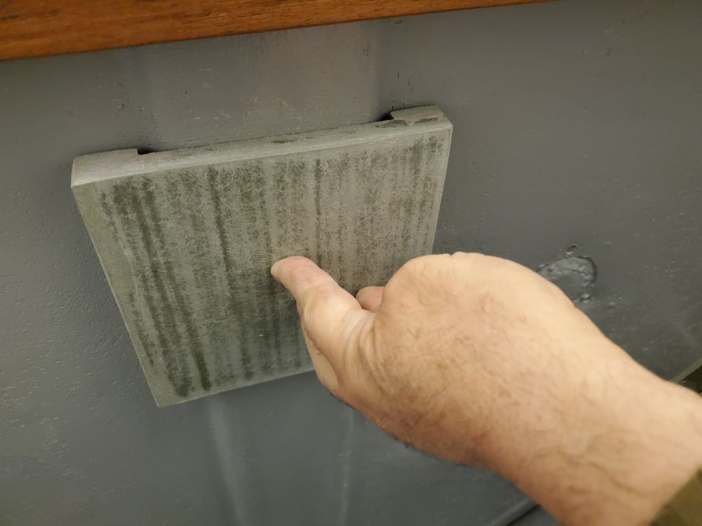
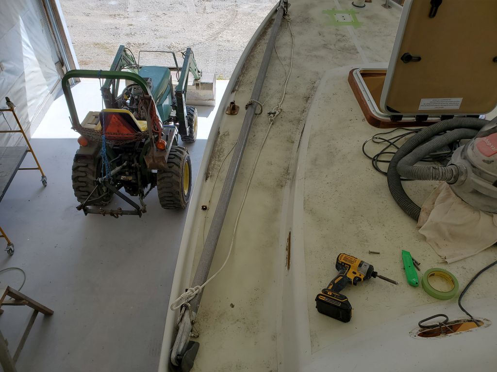
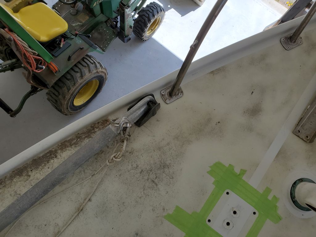
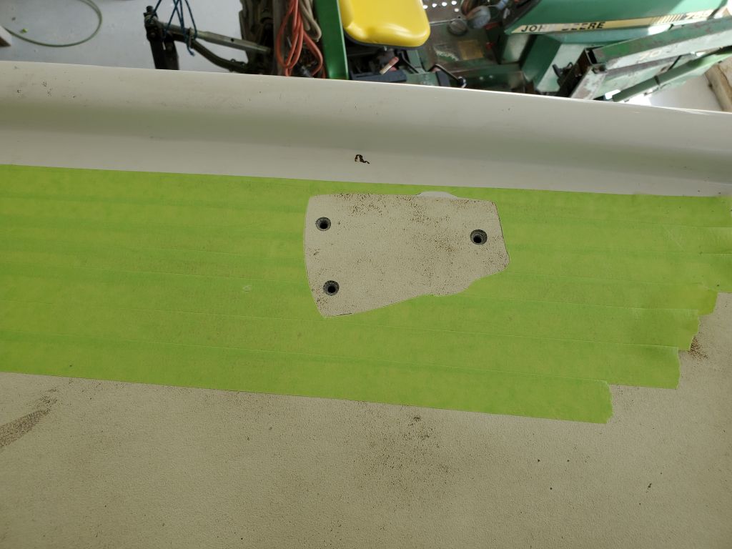
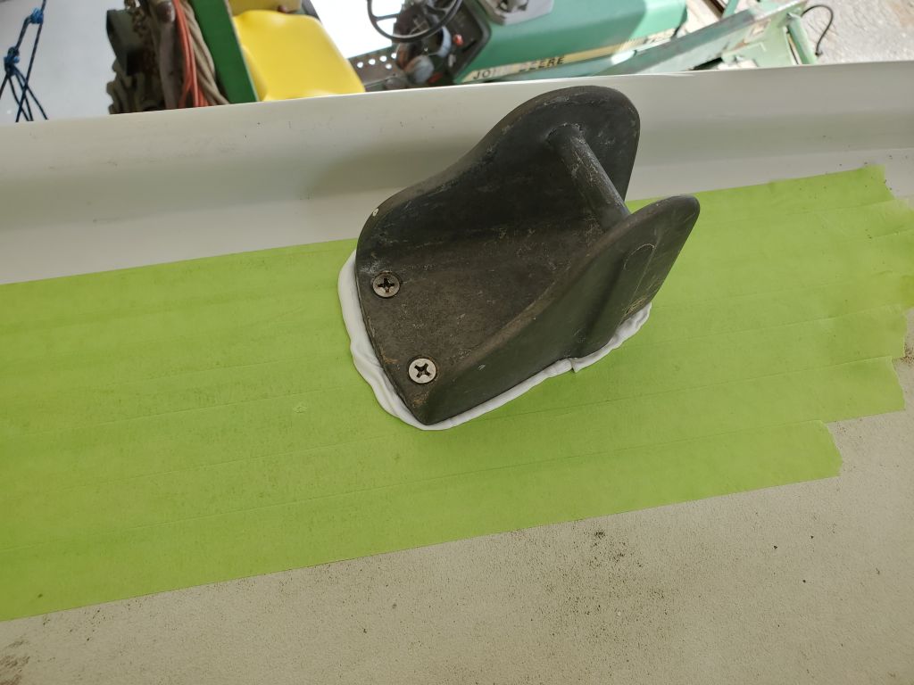
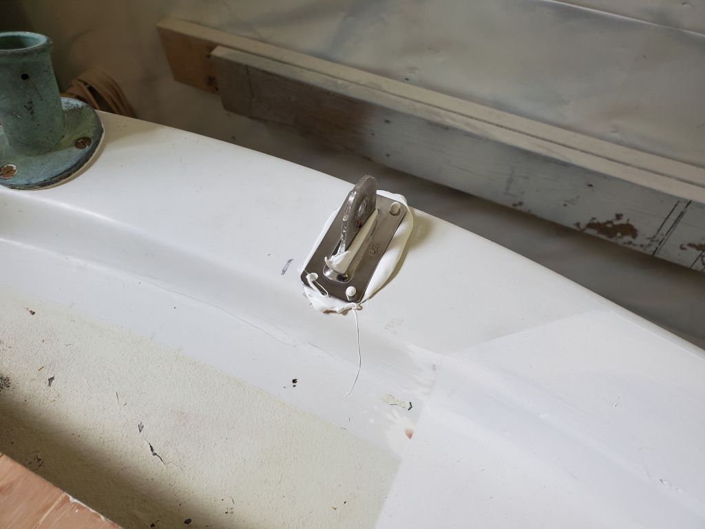
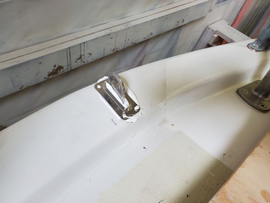
Finally, I installed the long-awaited chainplate cover for the backstay, applying ample sealant around the opening and pressing the cover in to place. I’d trim the excess later, once it cured.
Total time billed on this job today: 7 hours
0600 Weather Observation: 35°, partly cloudy. Forecast for the day: Mostly sunny and windy, 50°