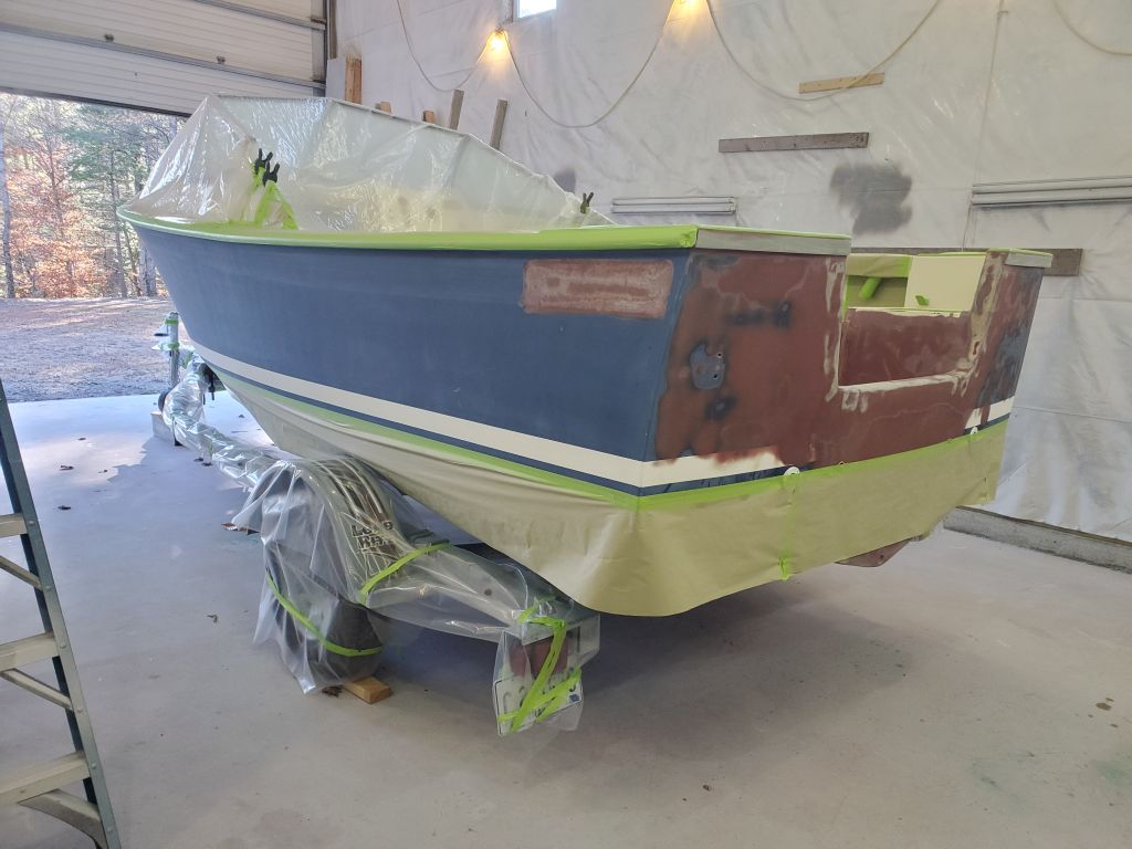
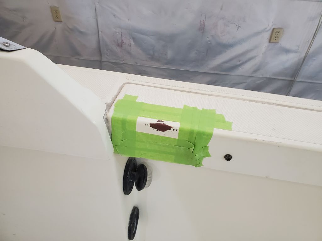
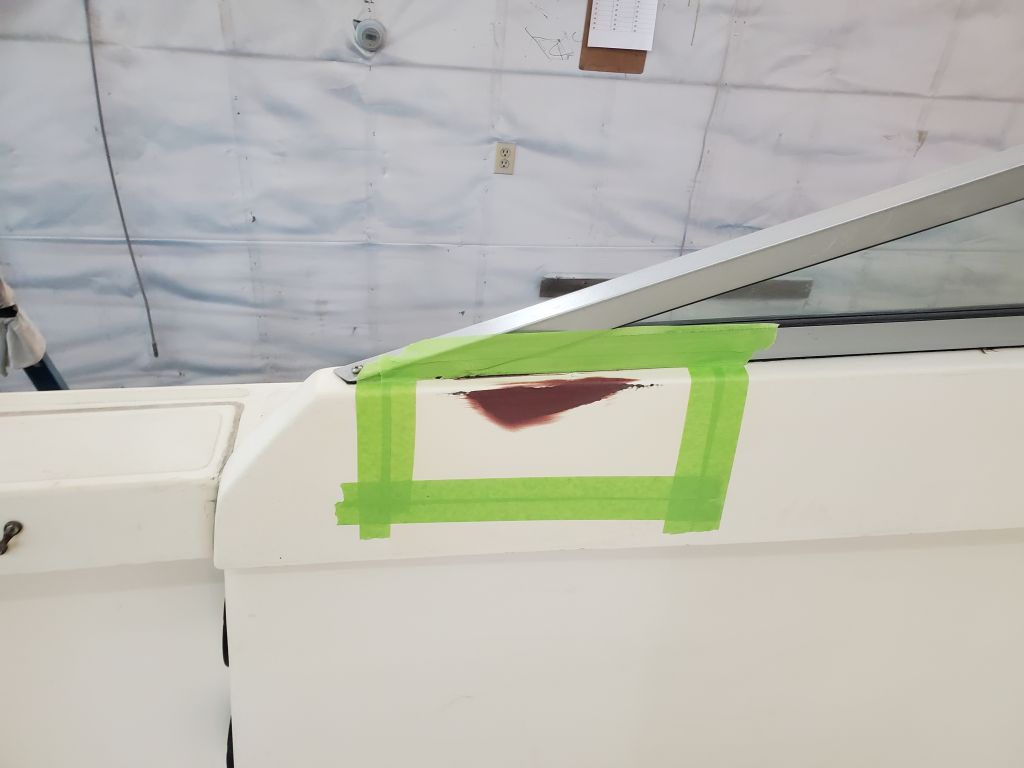
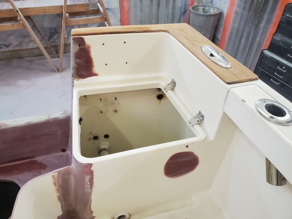
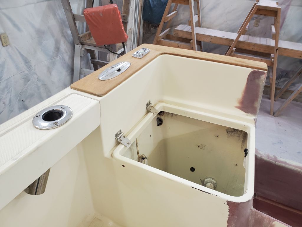
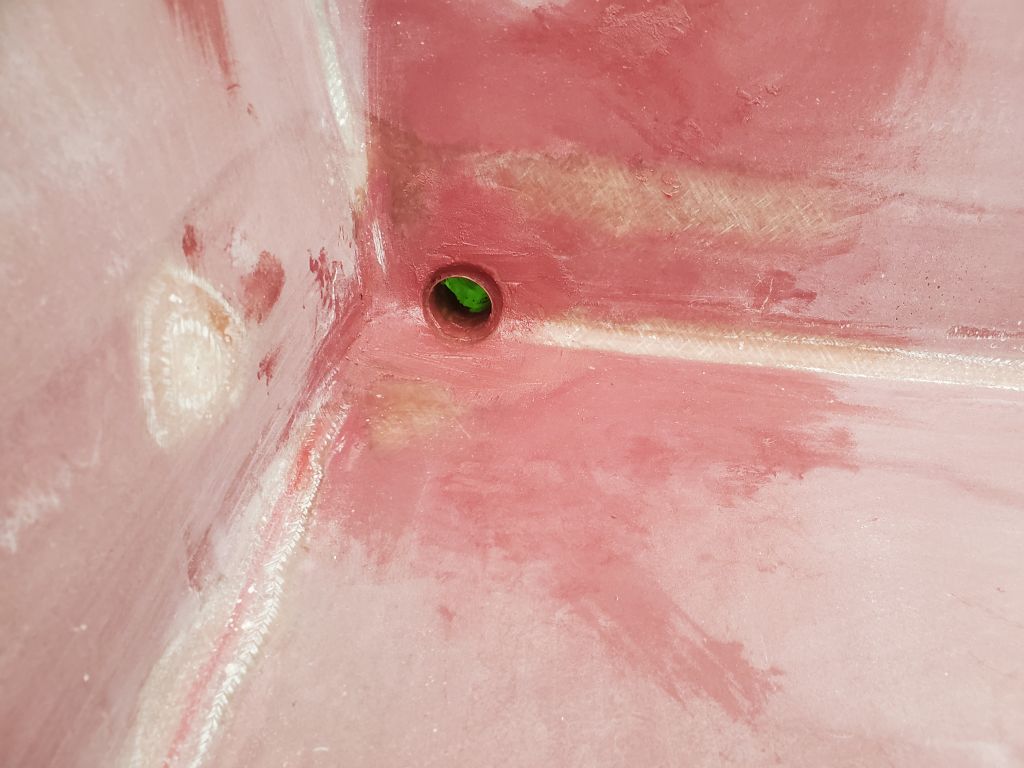
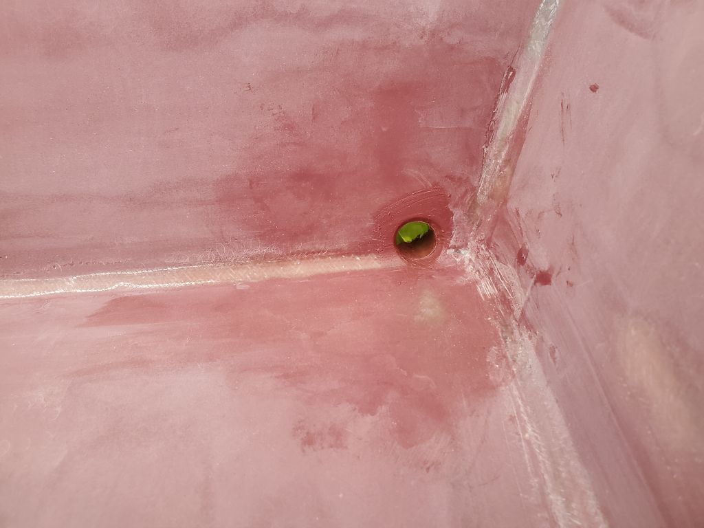
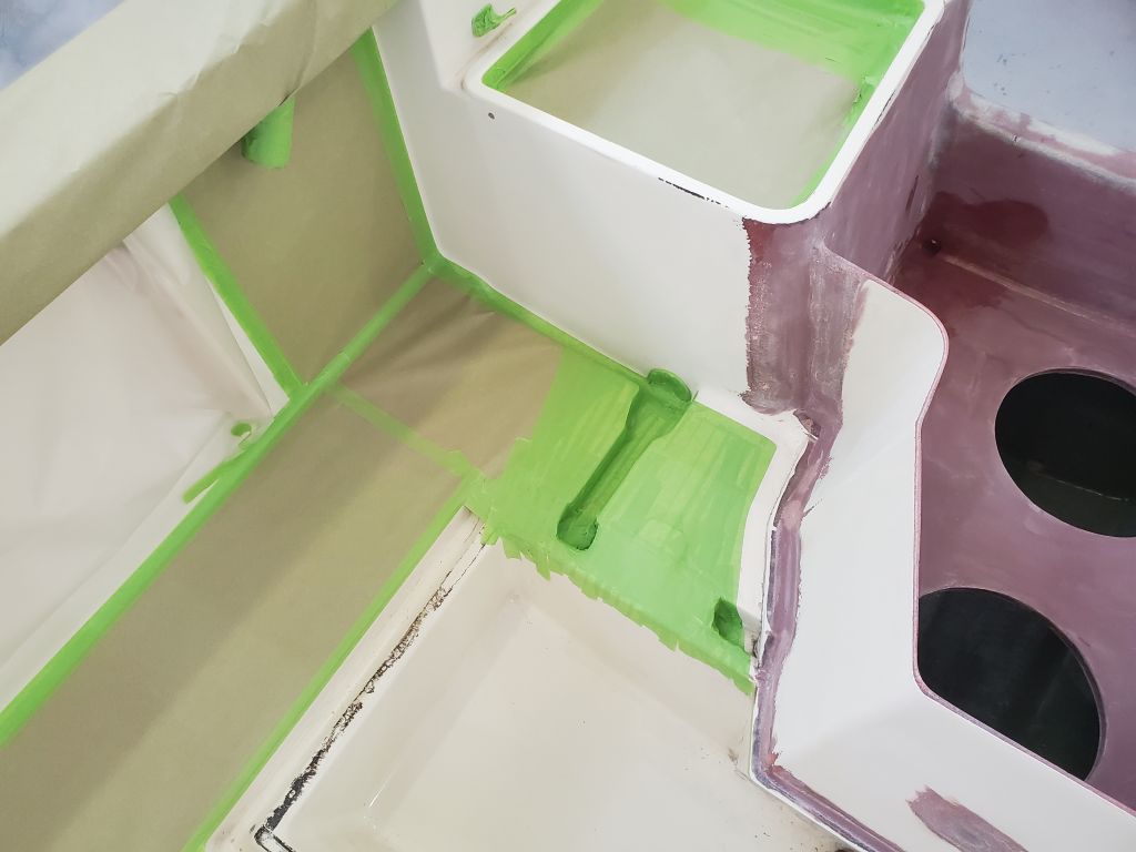
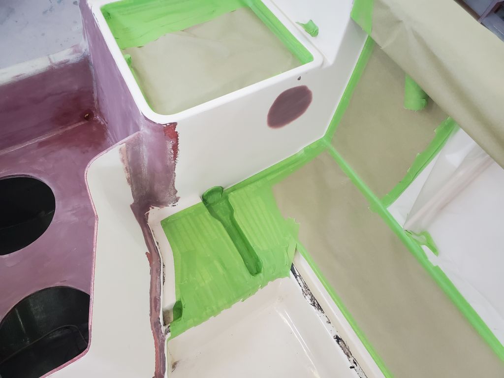
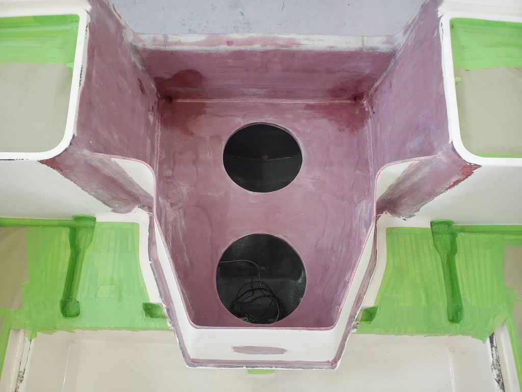
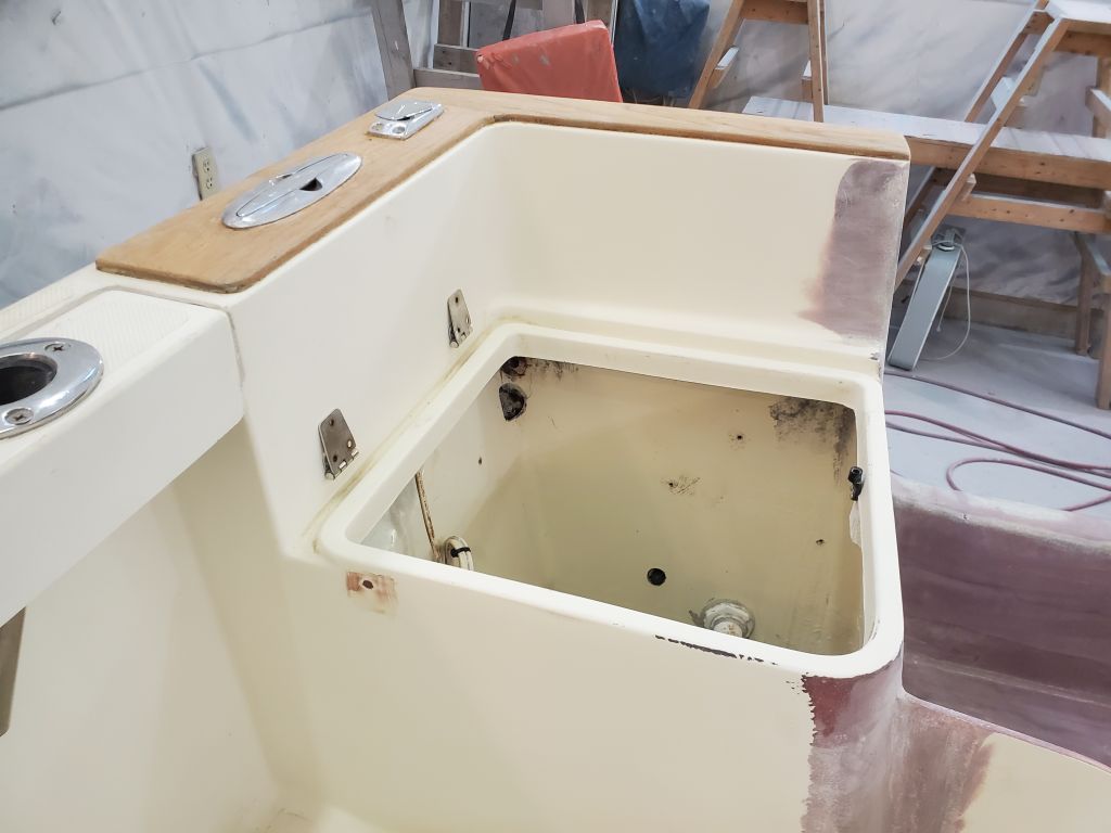
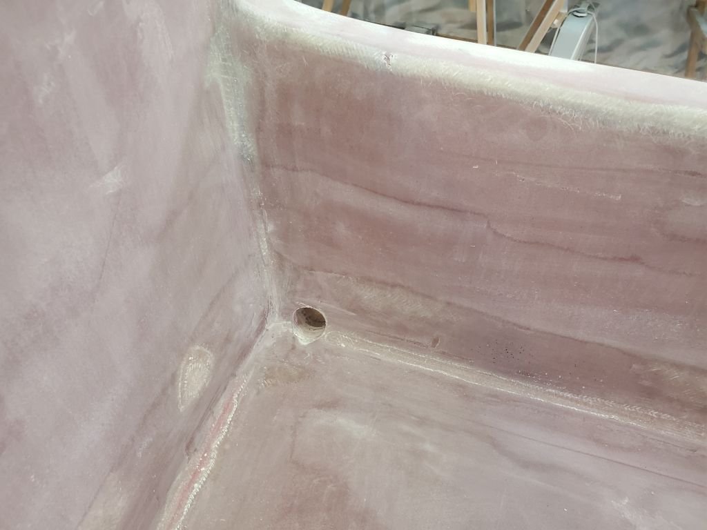
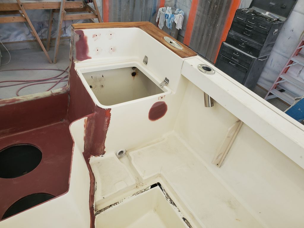
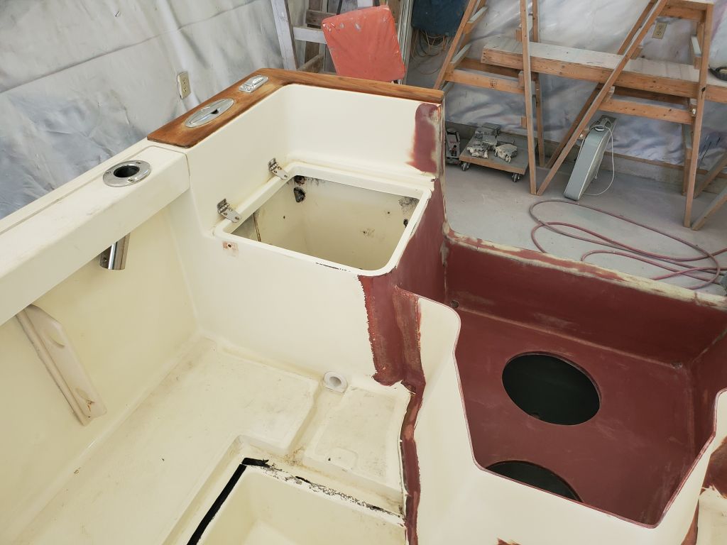
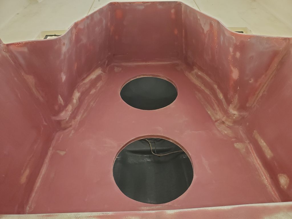
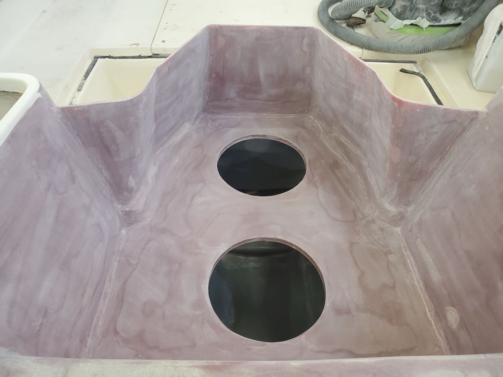
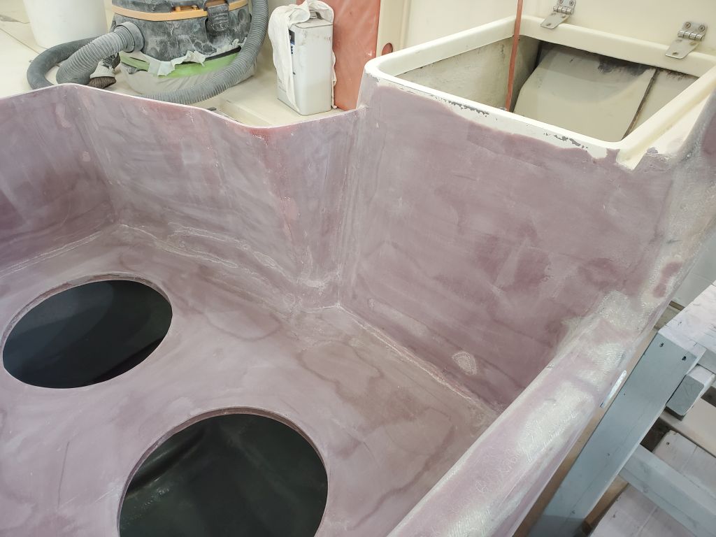
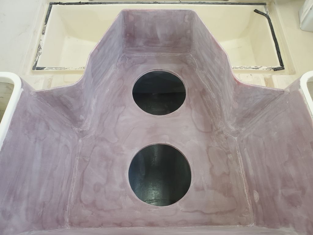
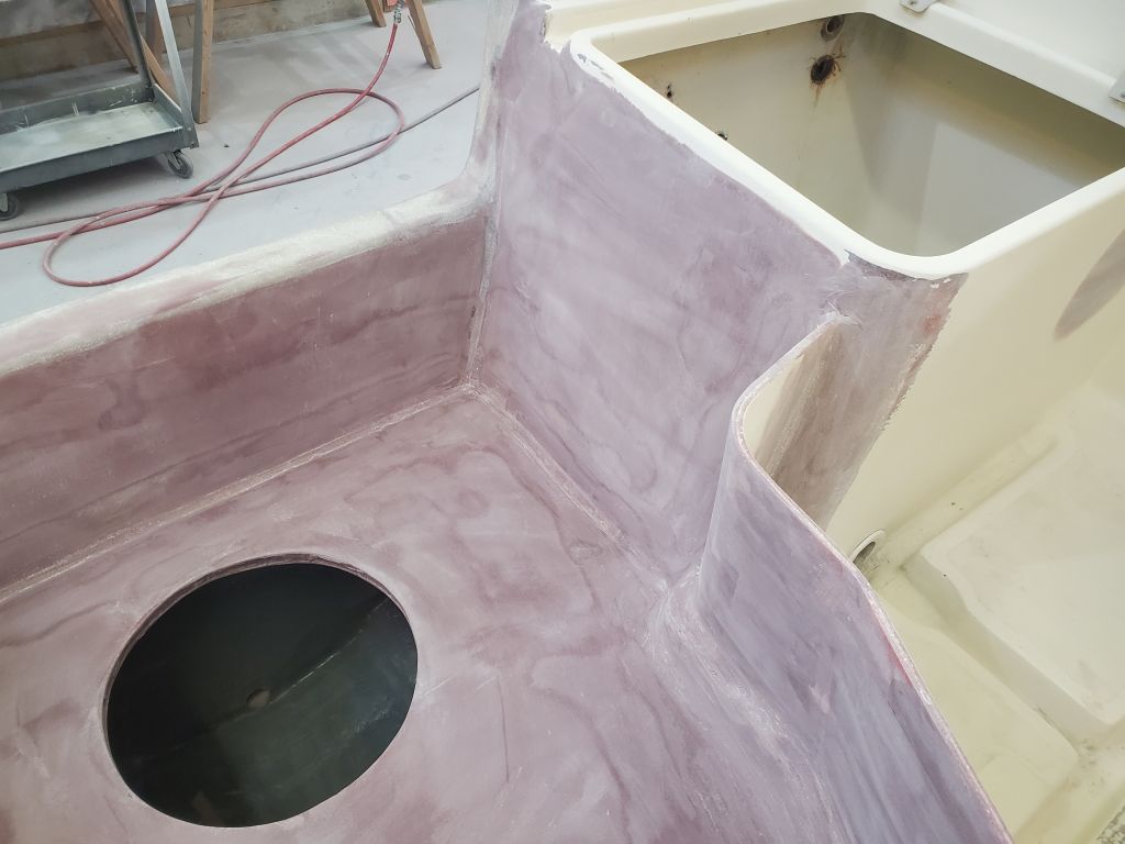
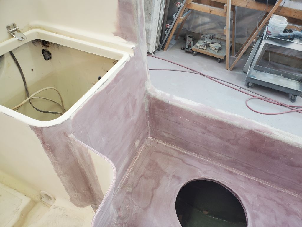
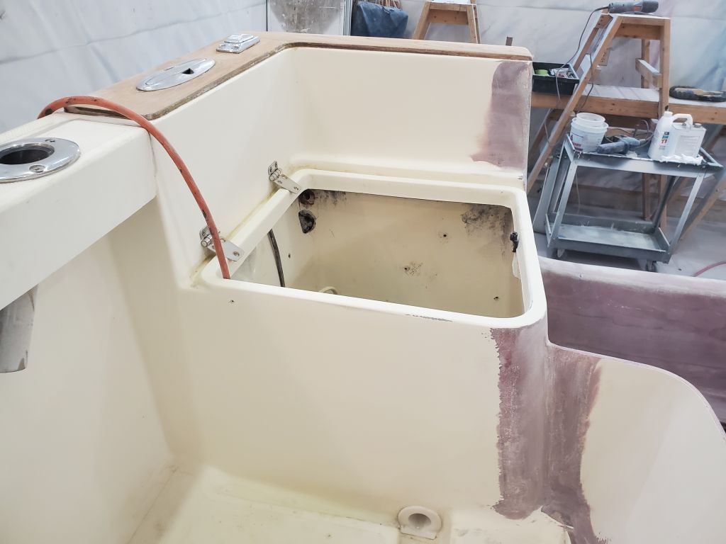
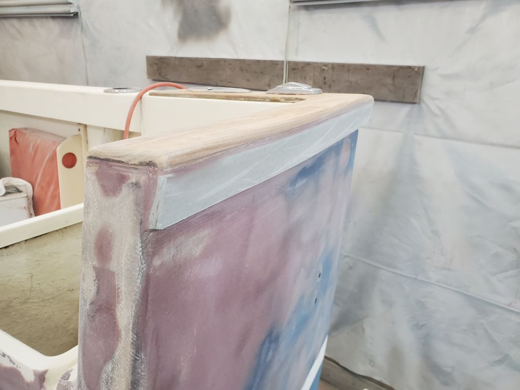
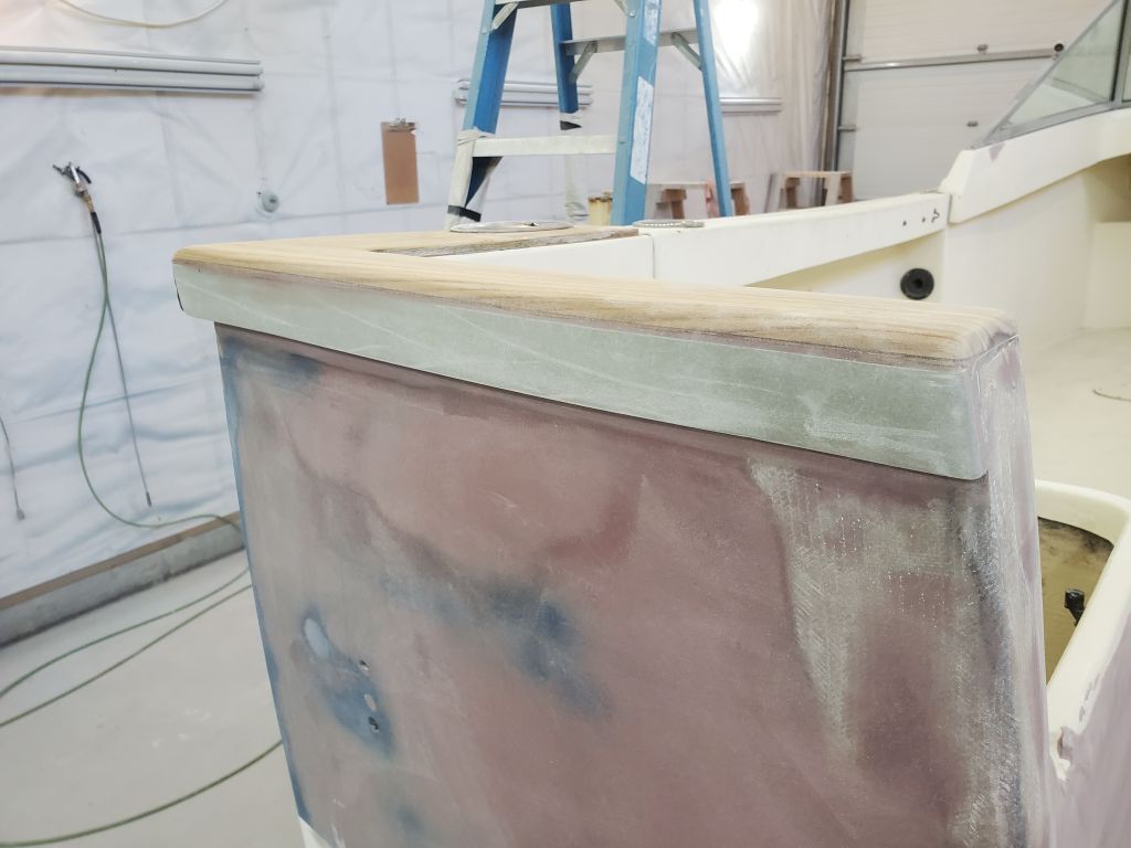
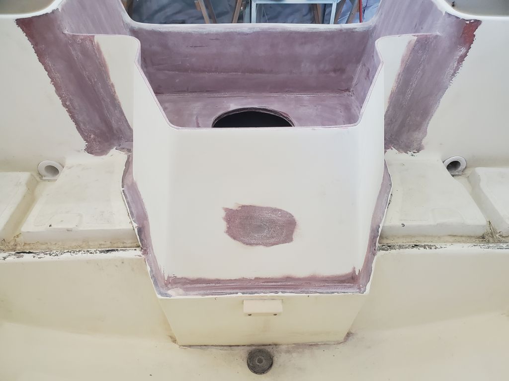
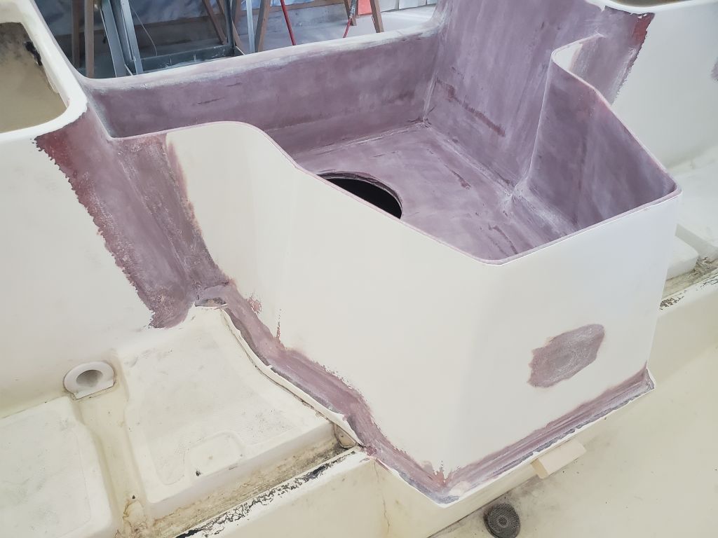
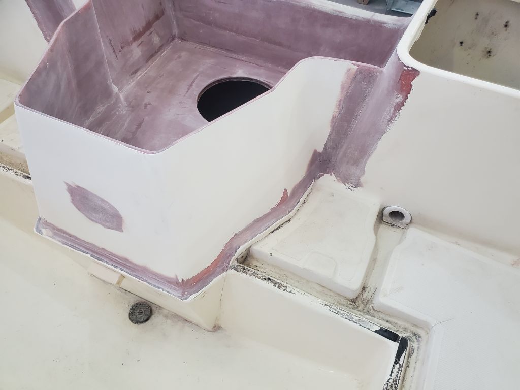
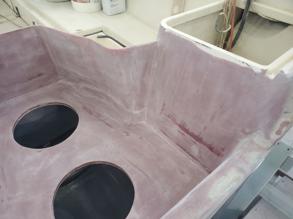
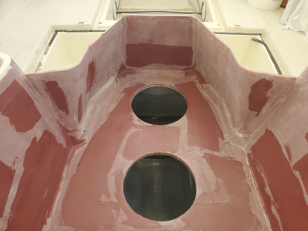
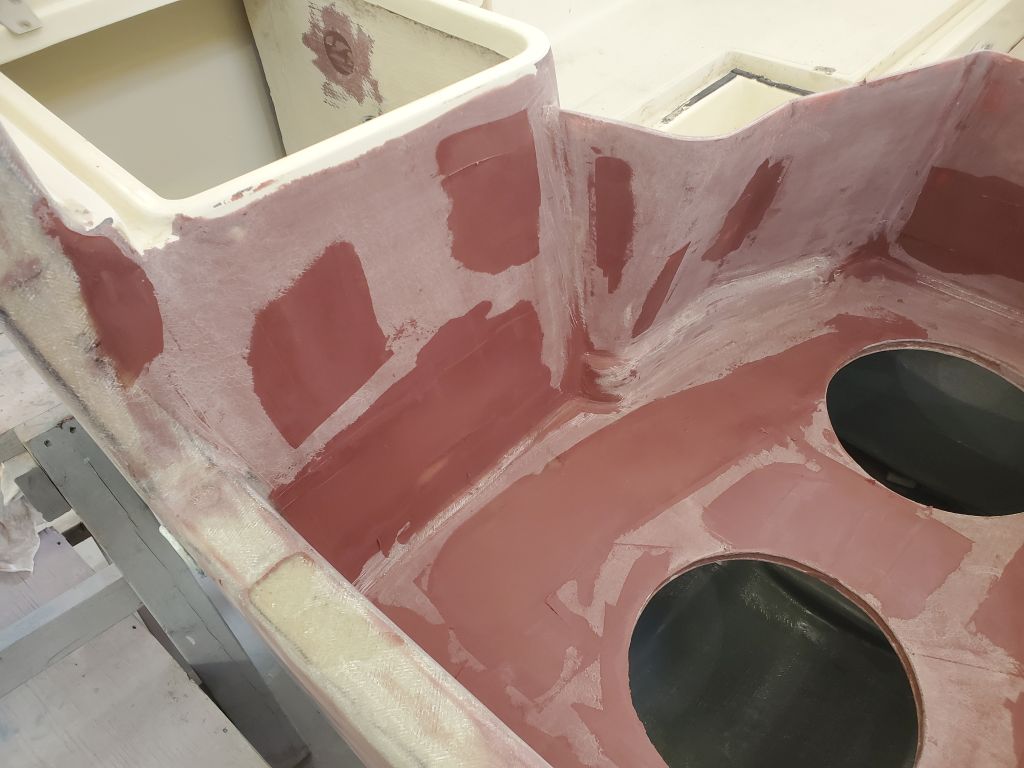
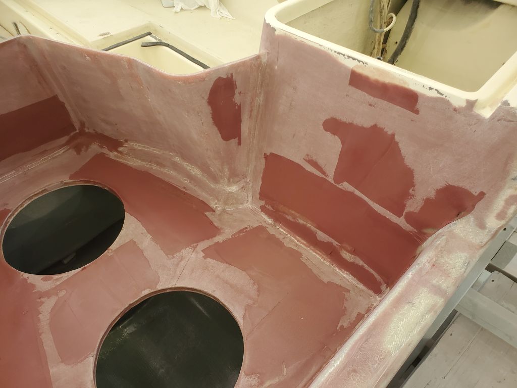
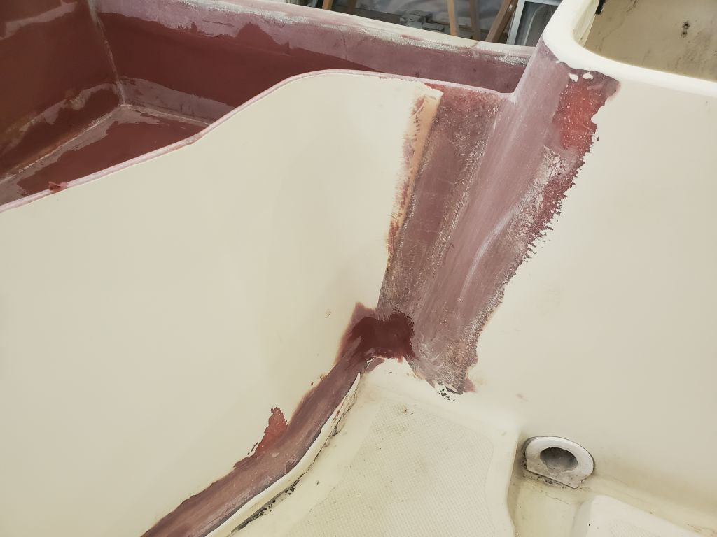
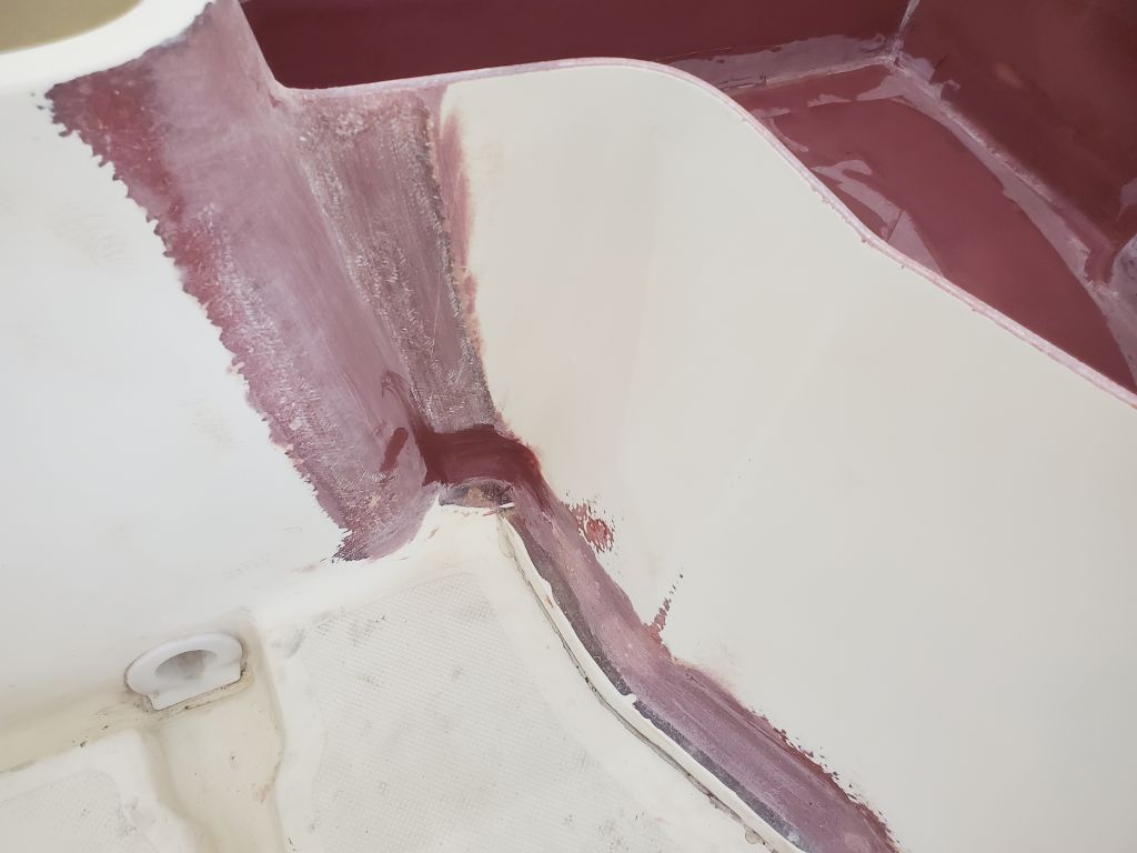
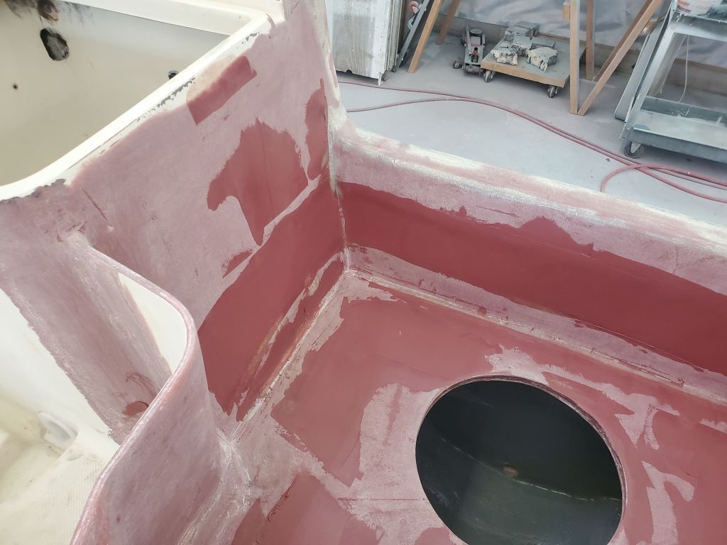
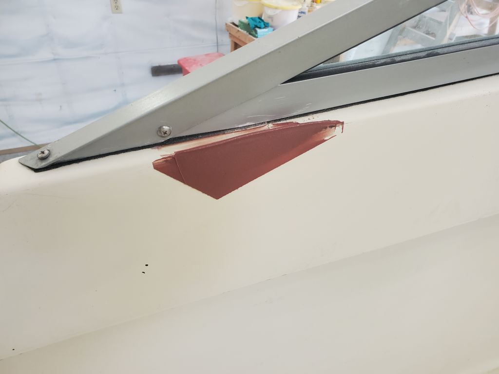
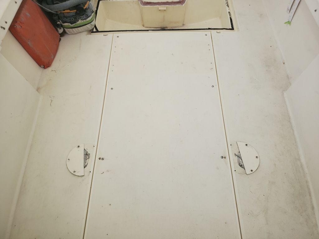
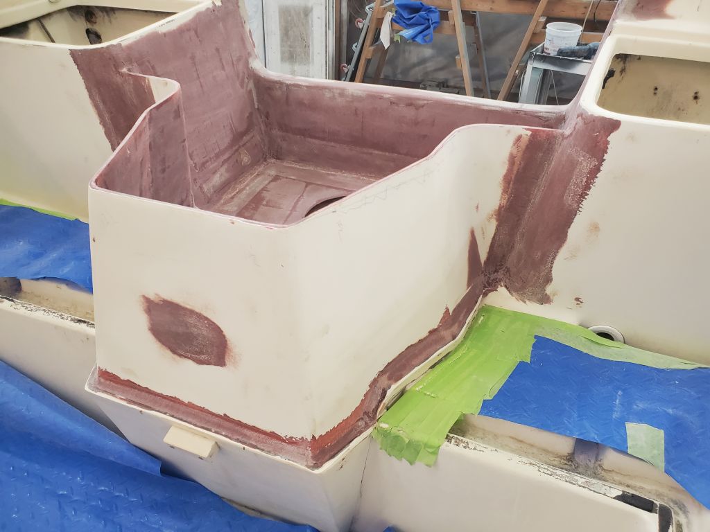
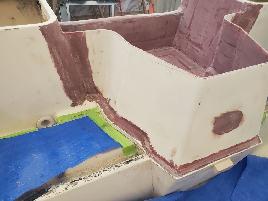
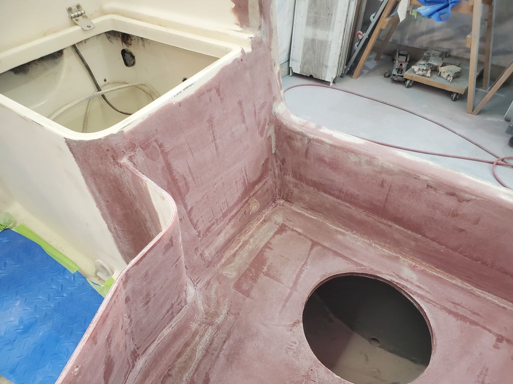
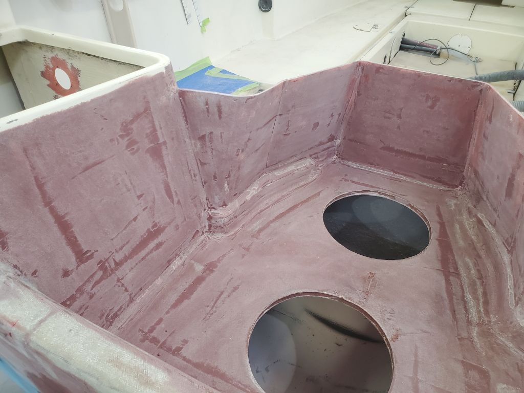
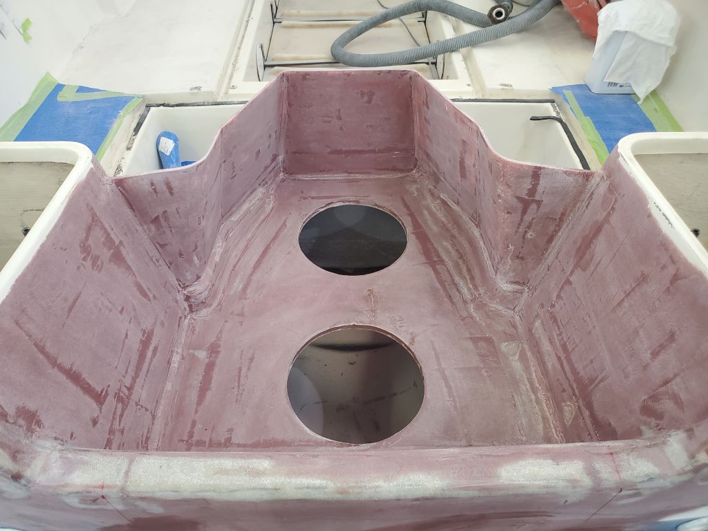
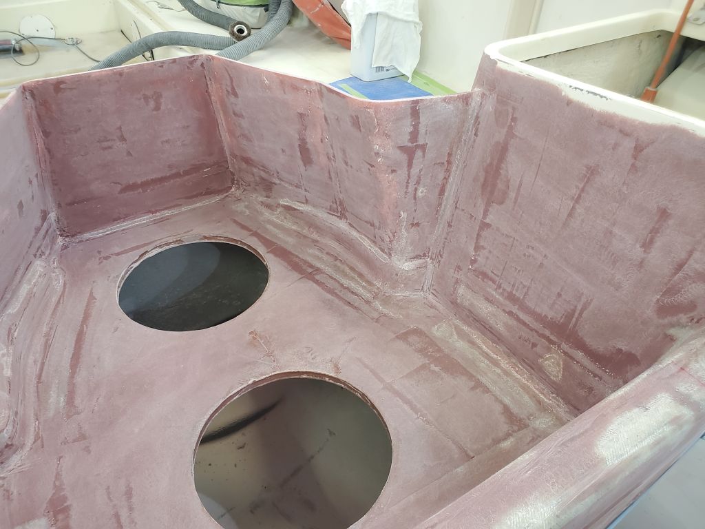
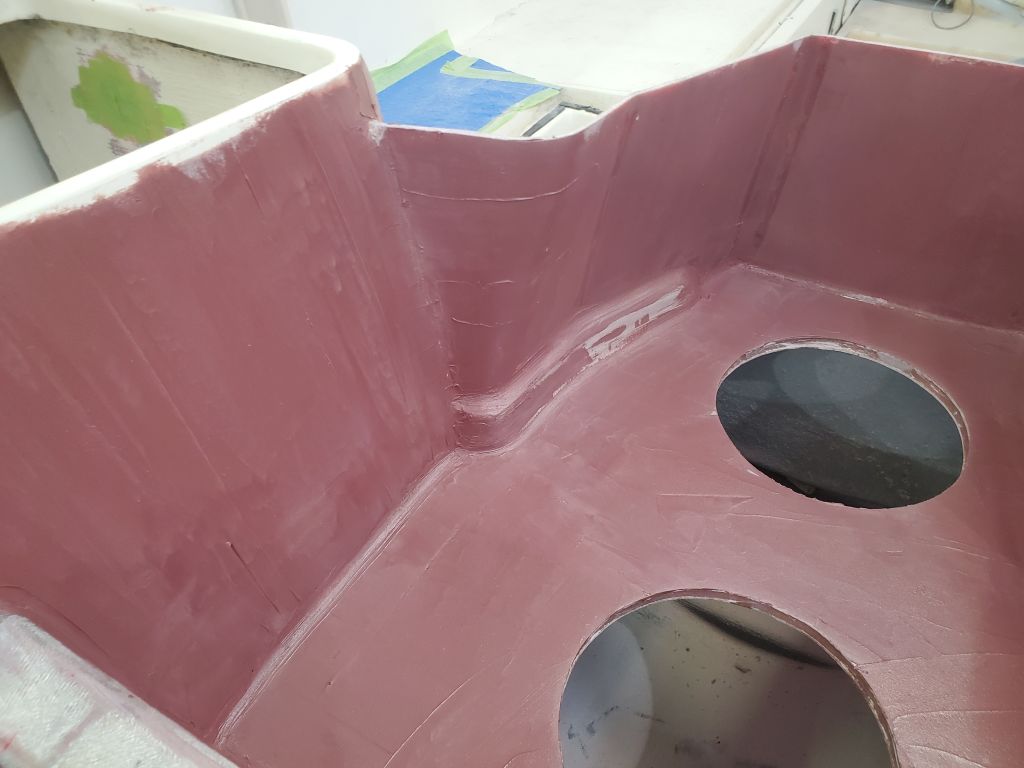
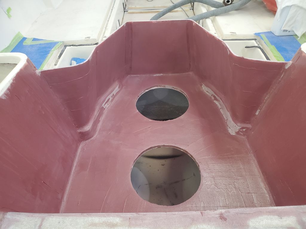
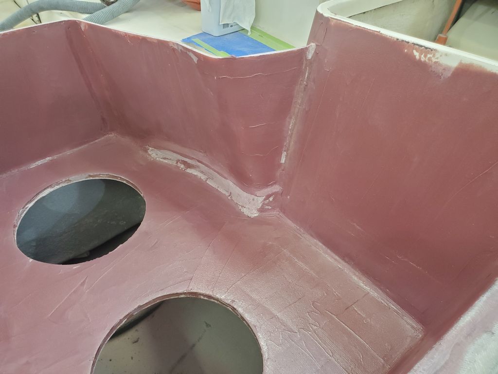
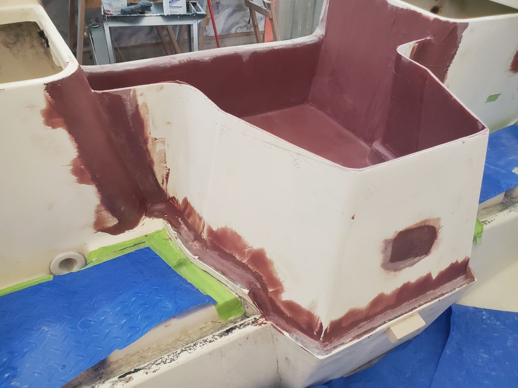
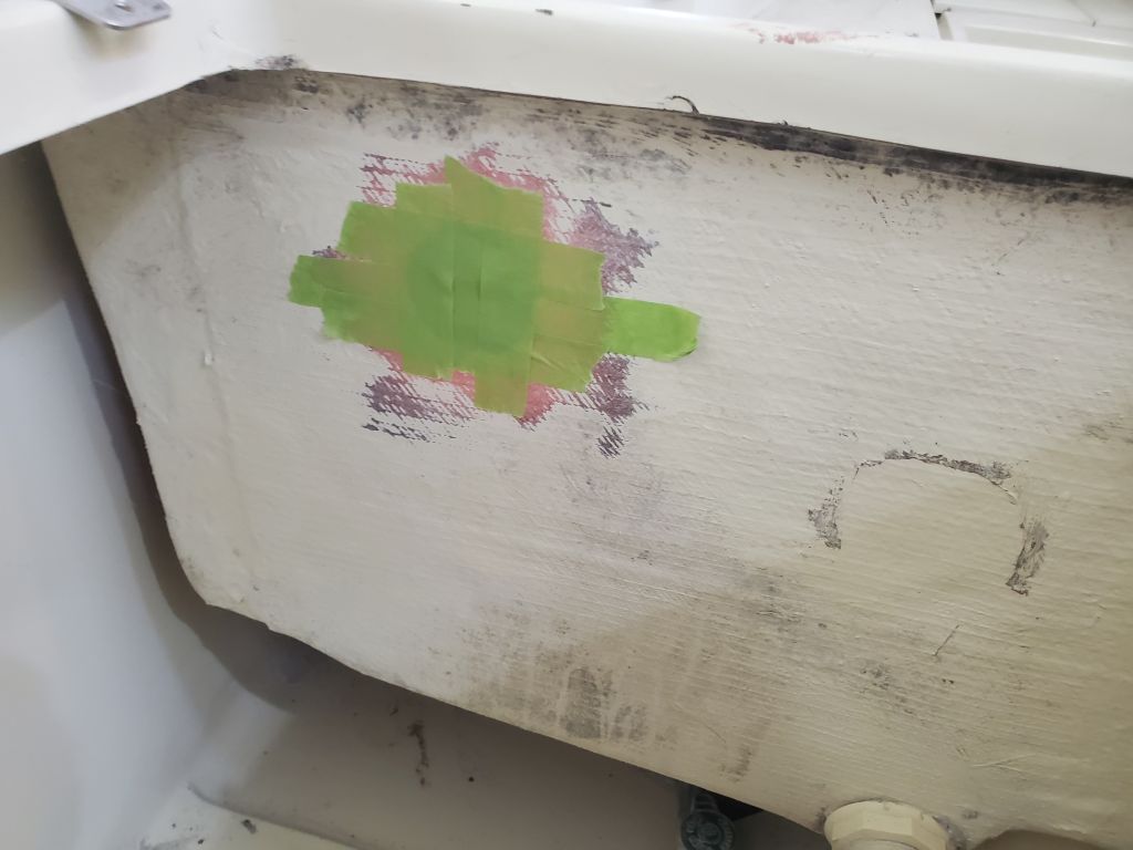
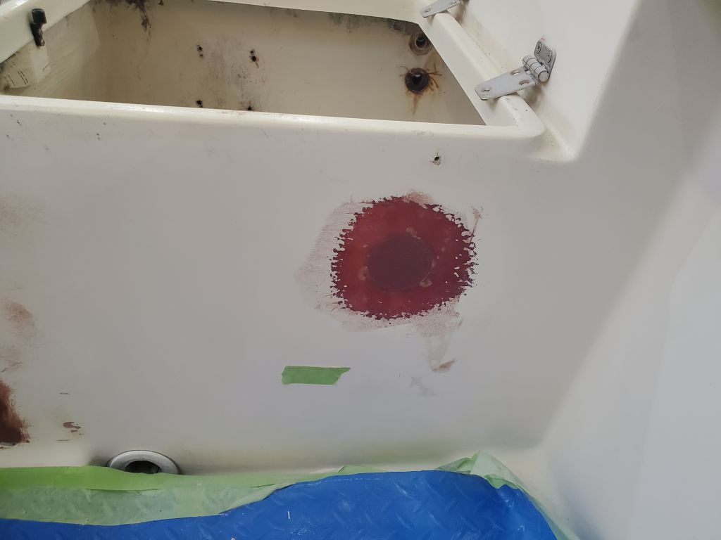
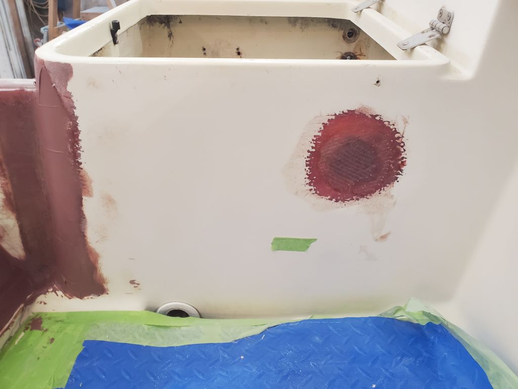
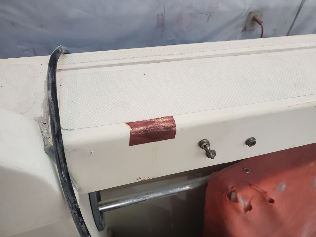
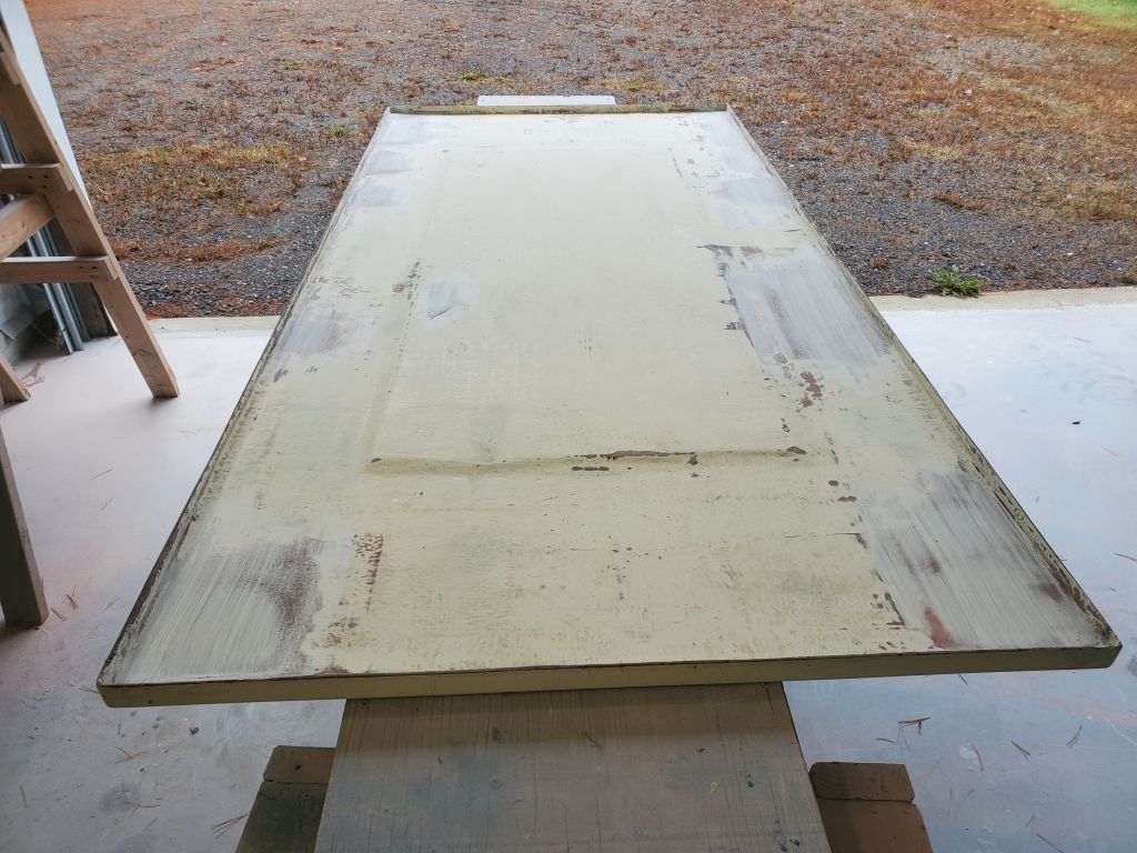
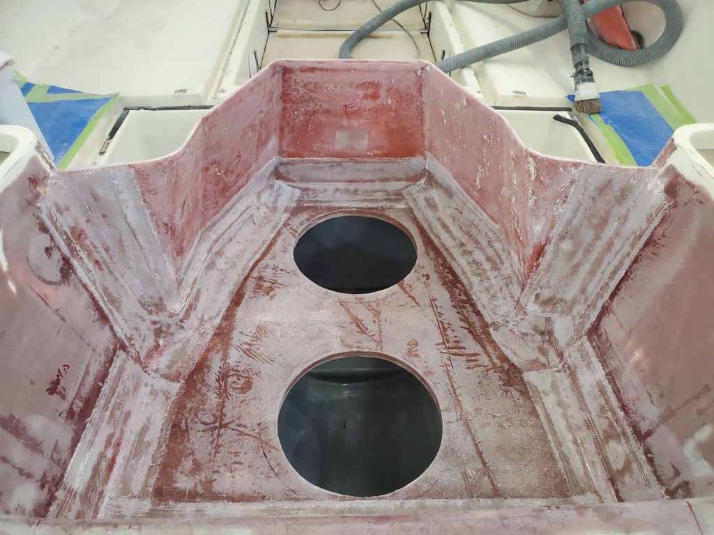
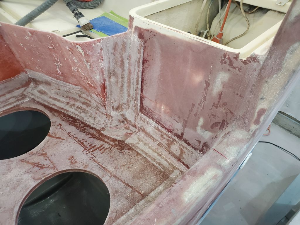
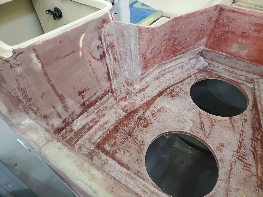
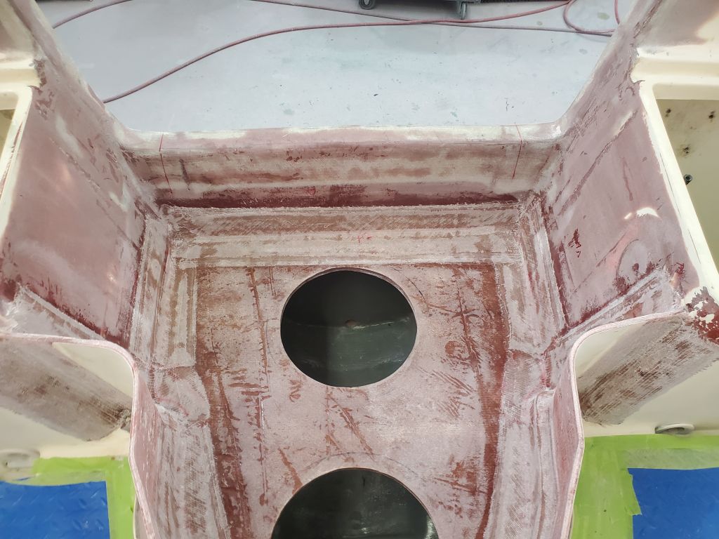
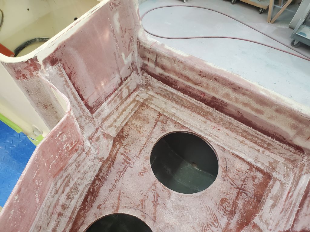
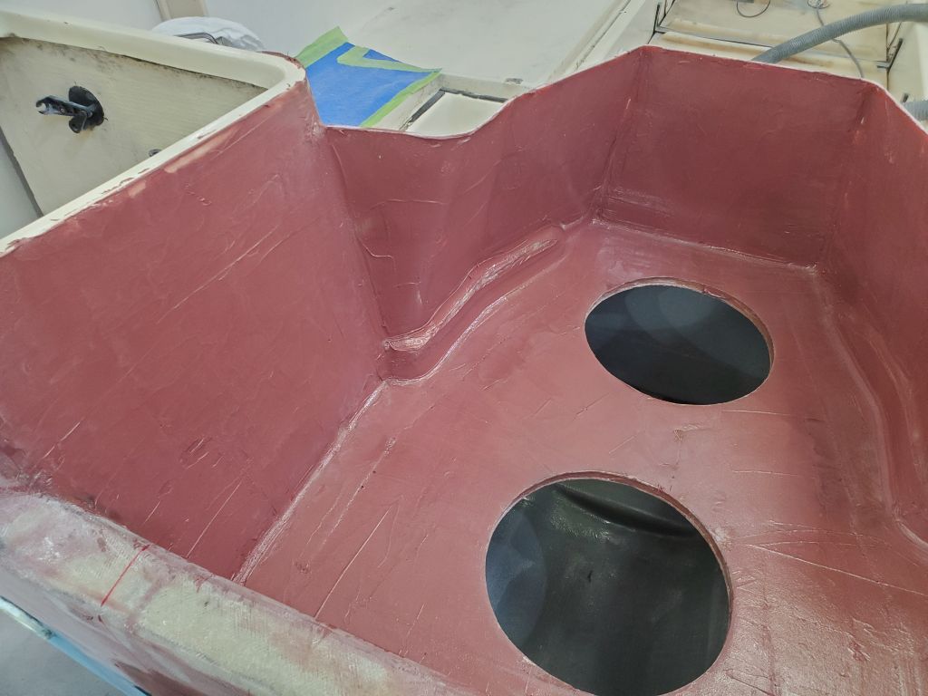
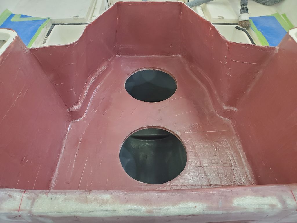
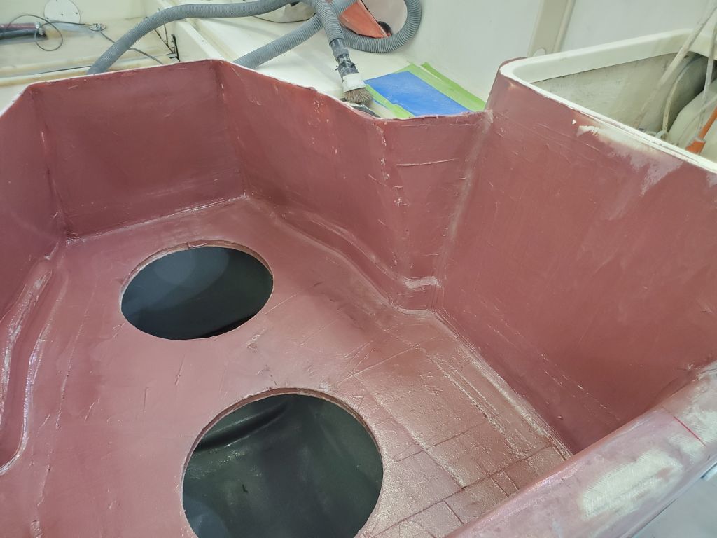
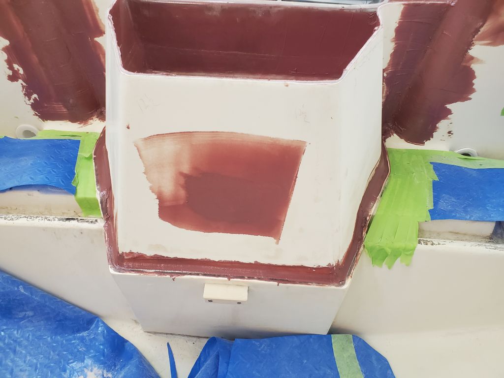
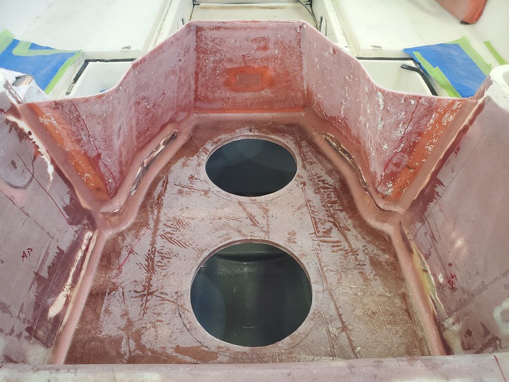
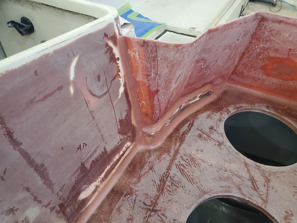
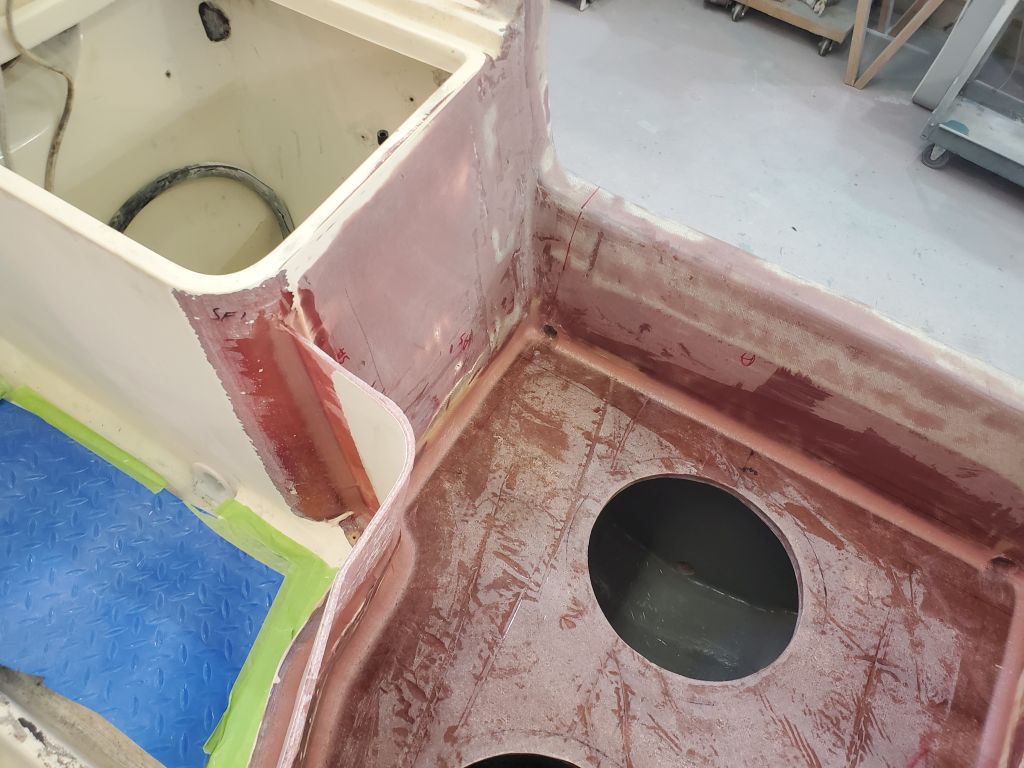
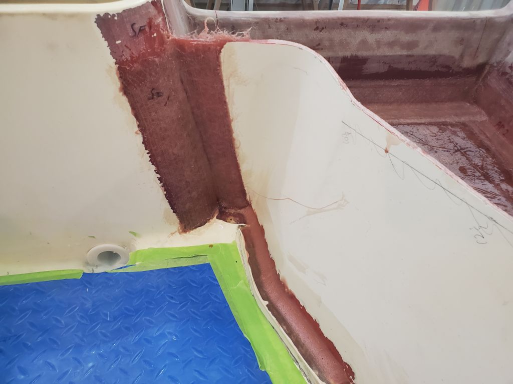
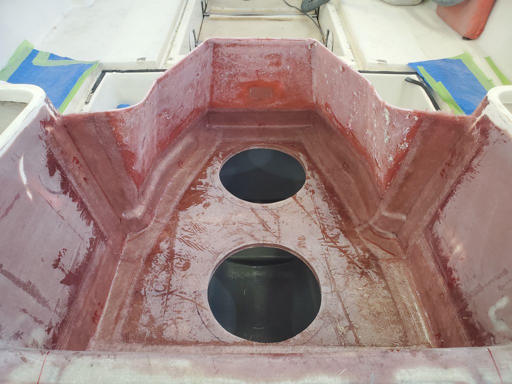
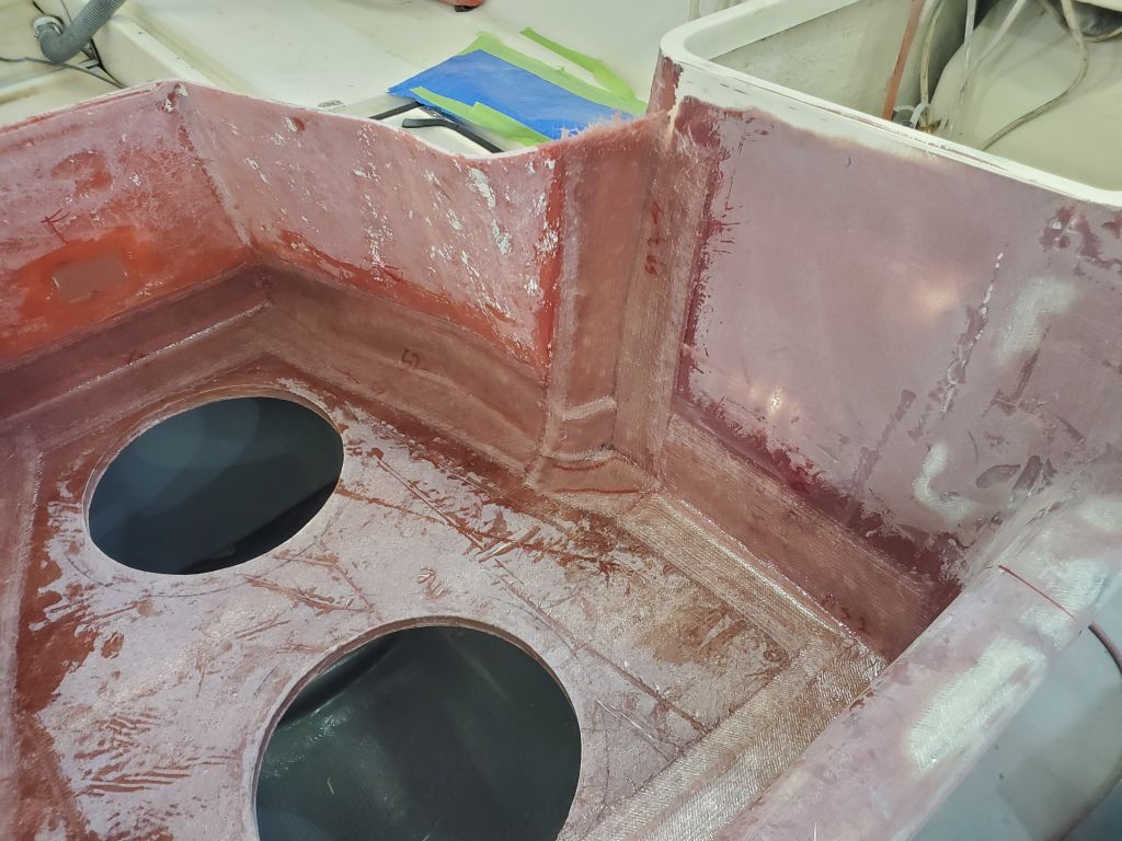
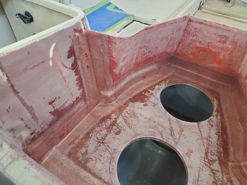
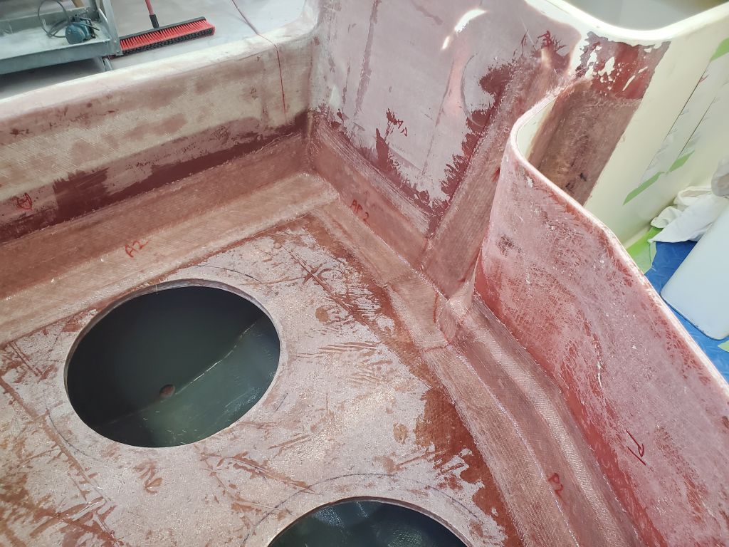
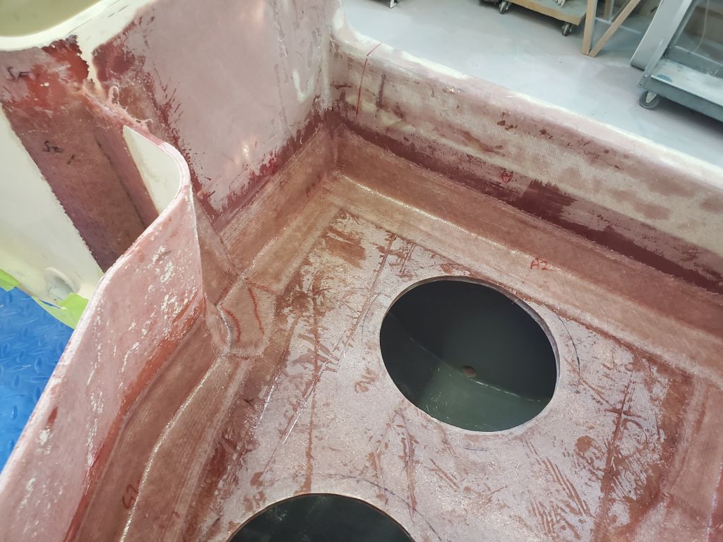
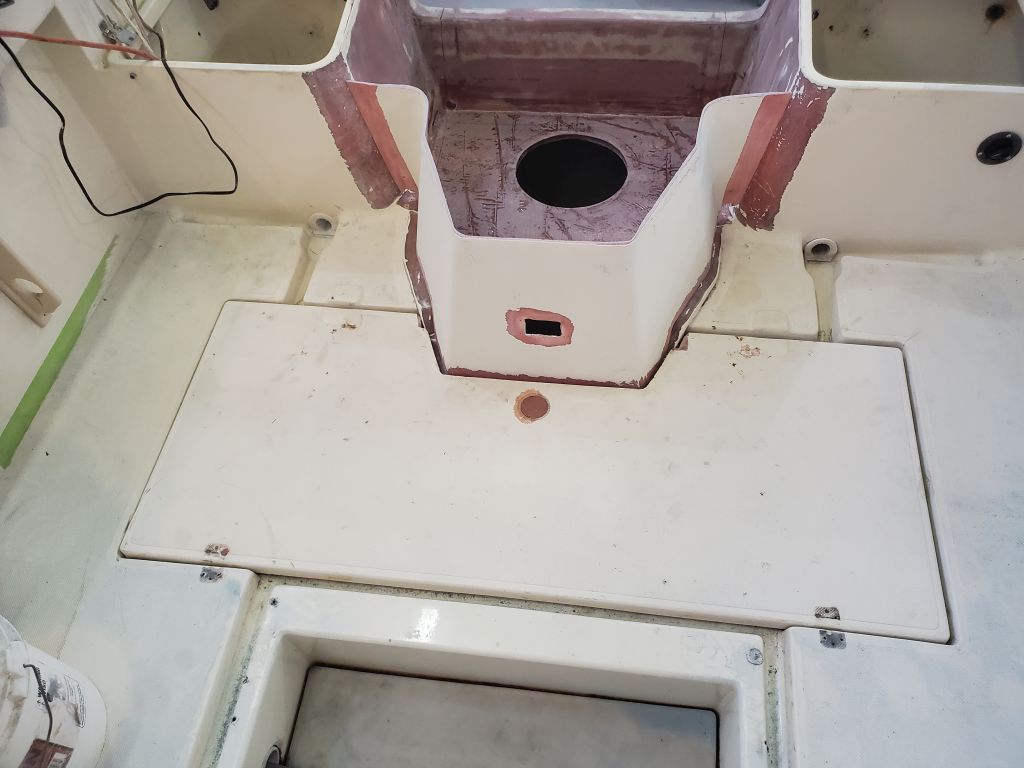
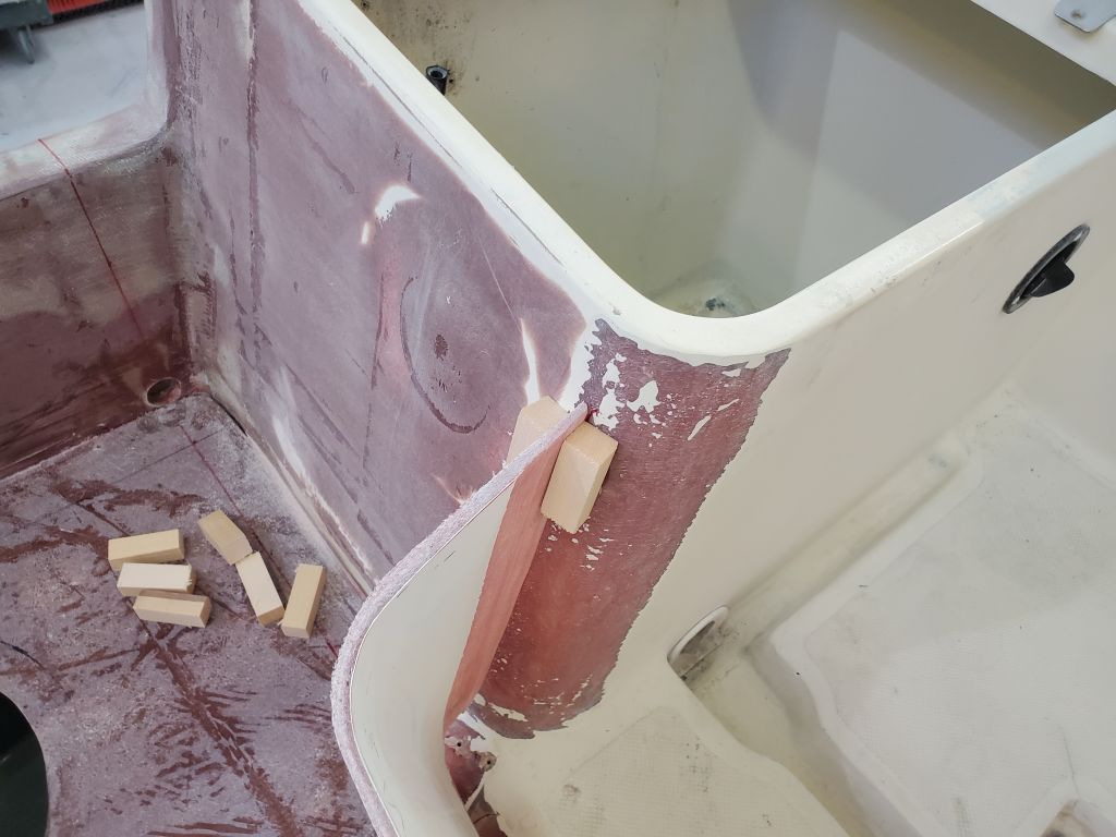
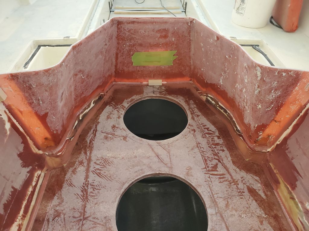
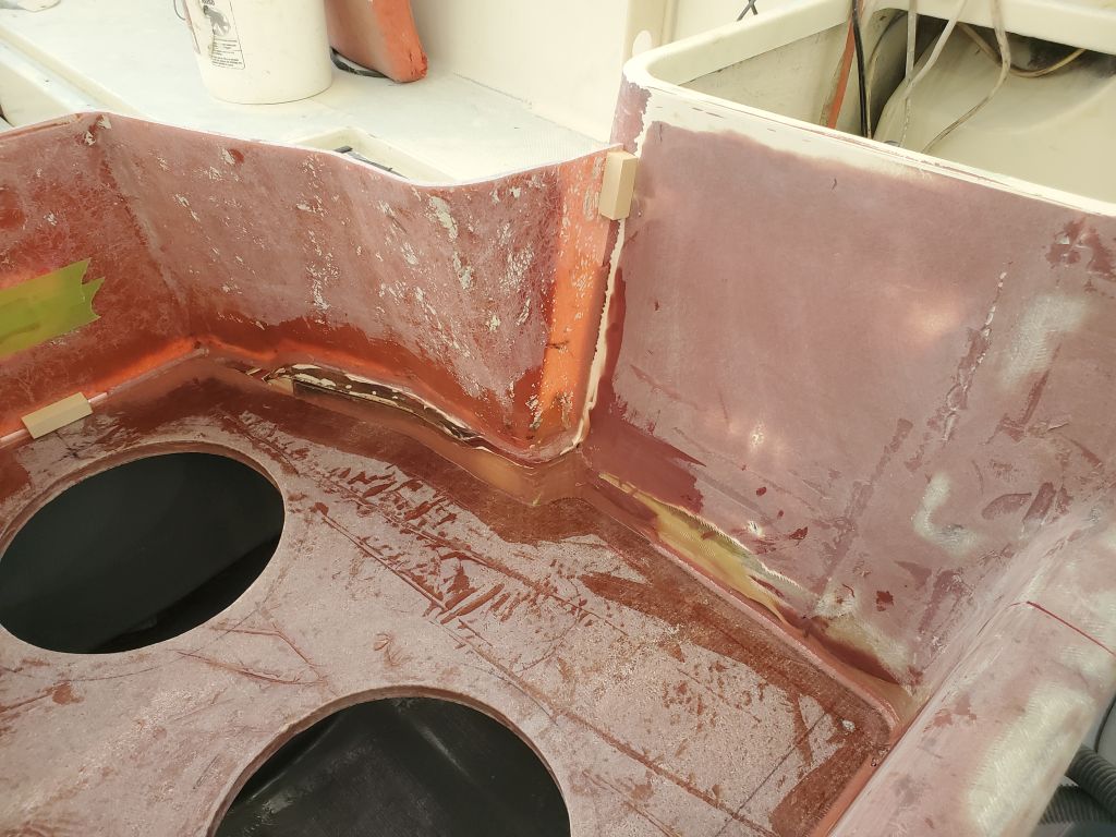
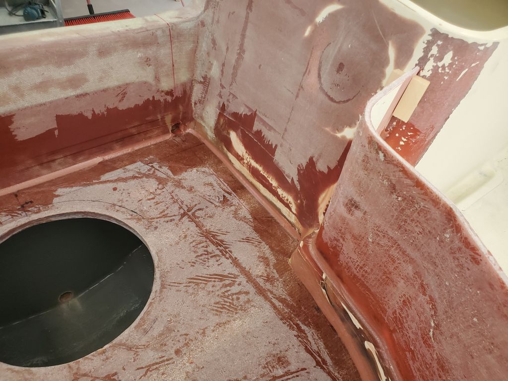
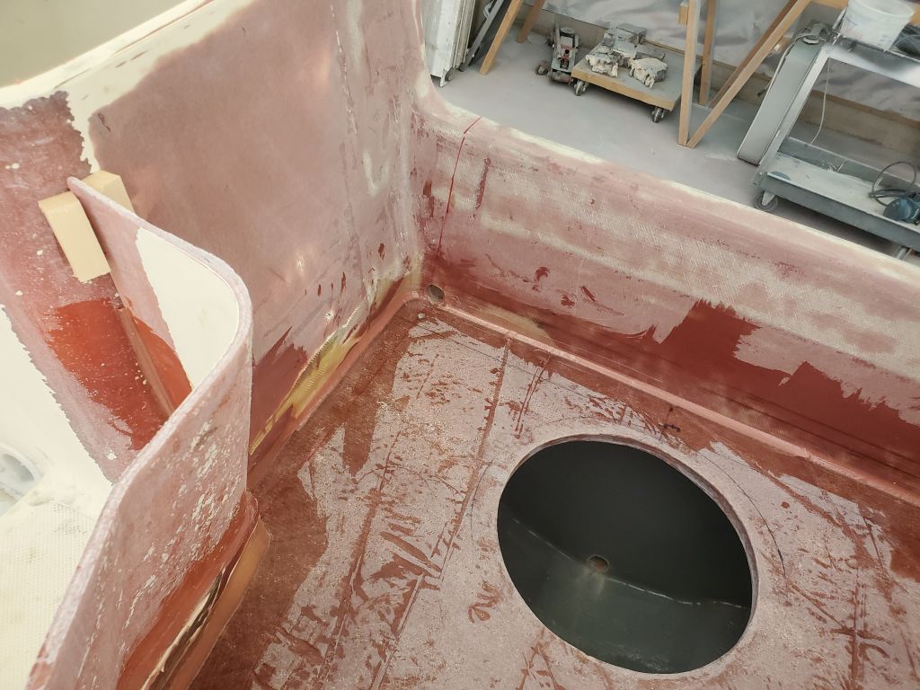
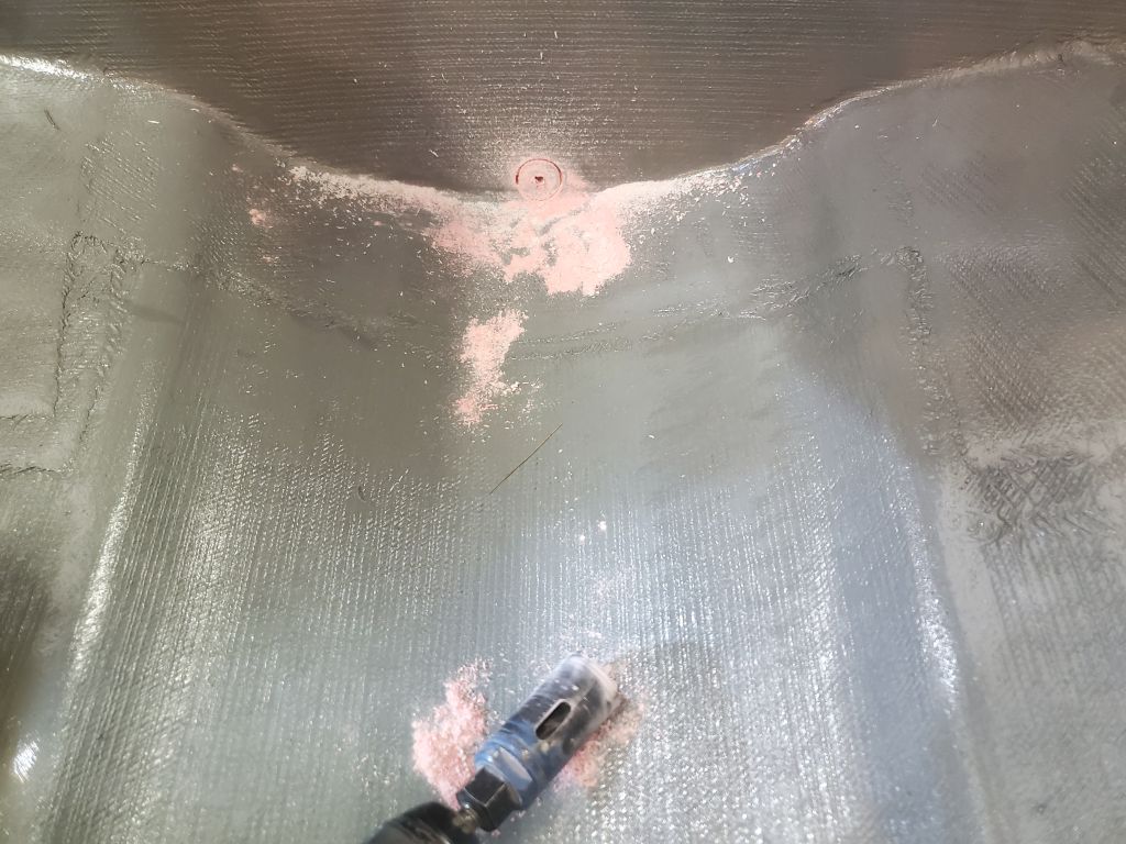
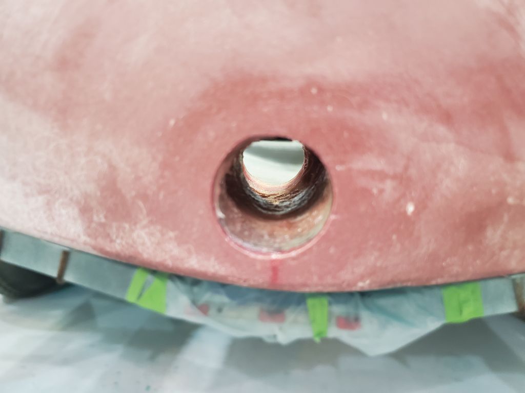
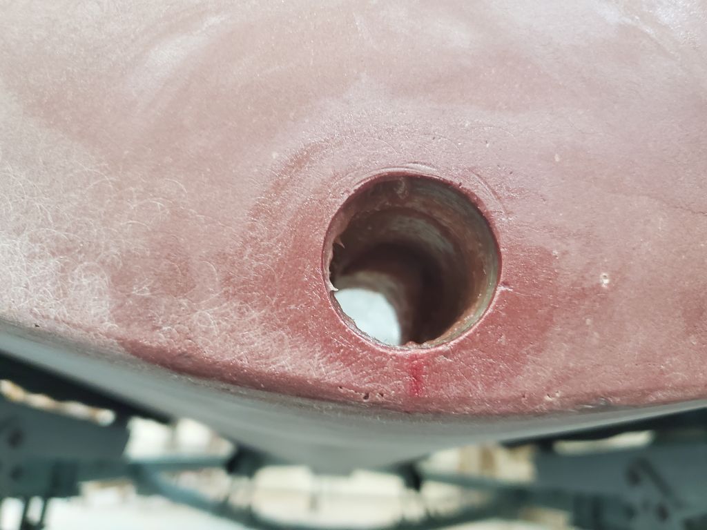
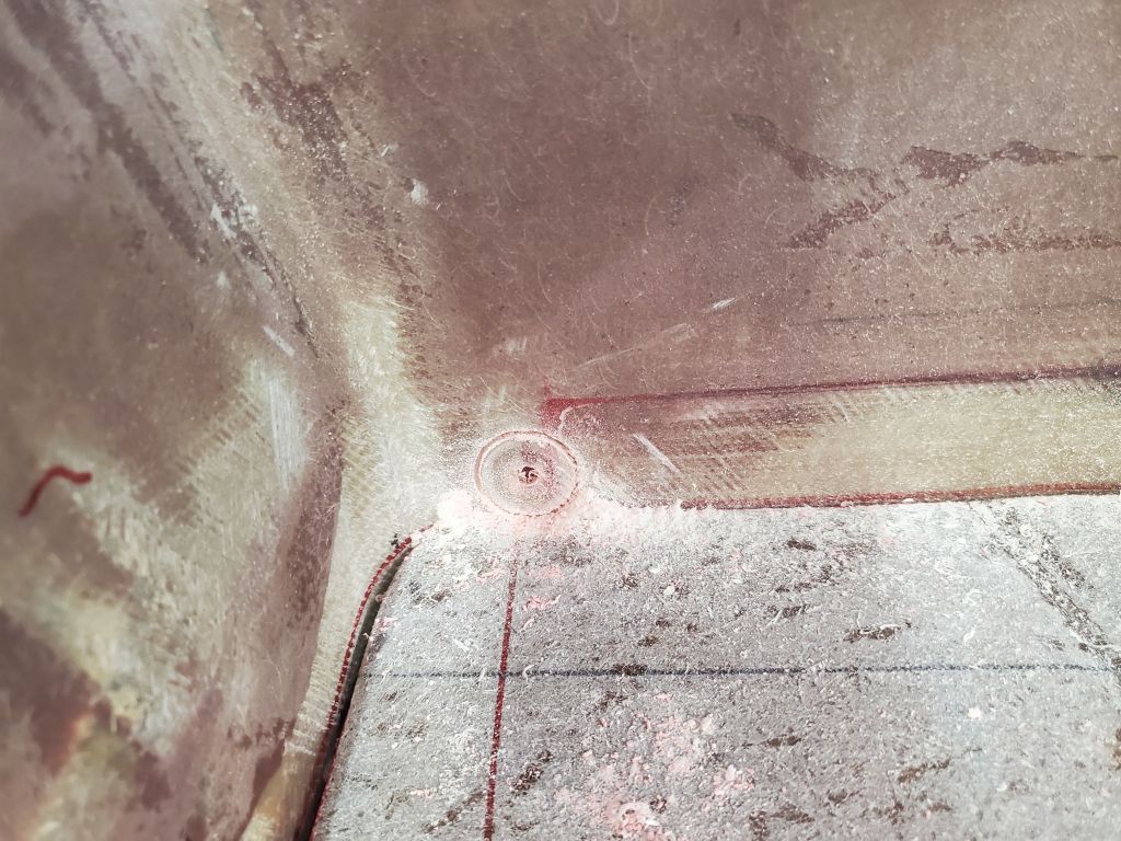
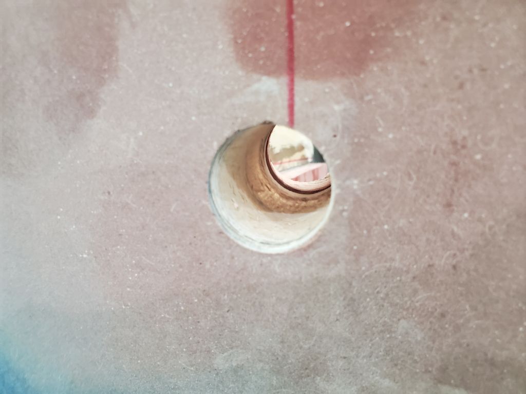
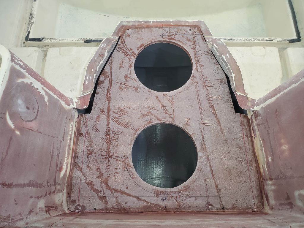
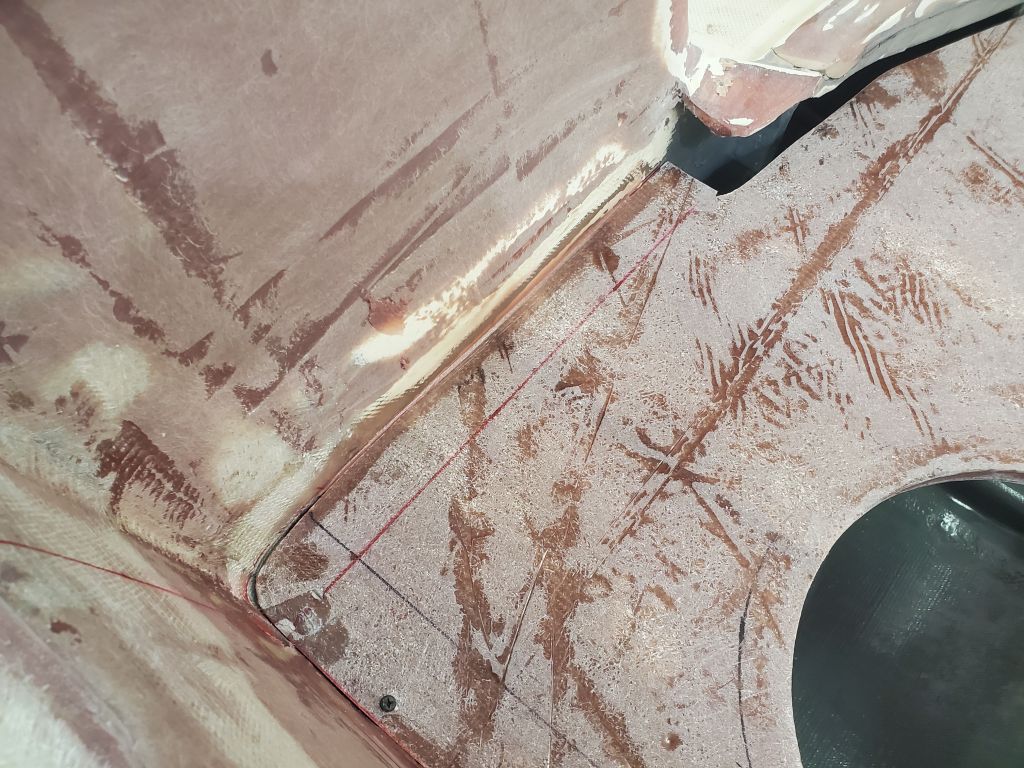
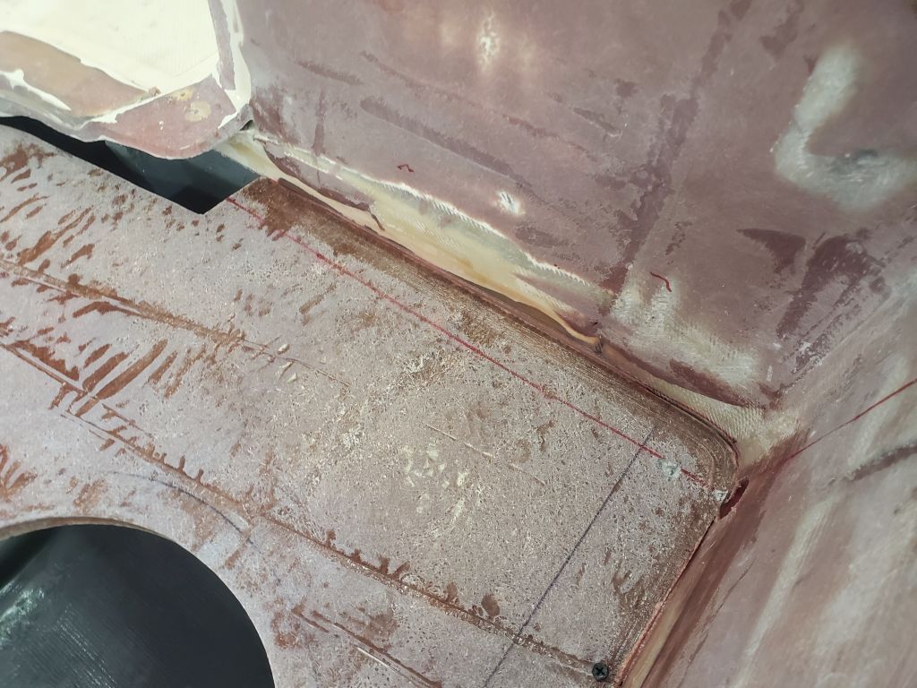
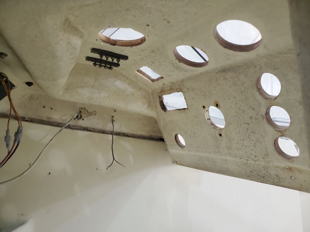
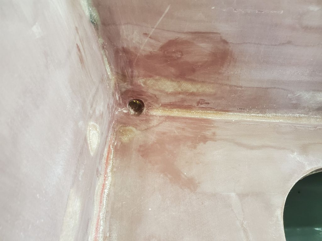
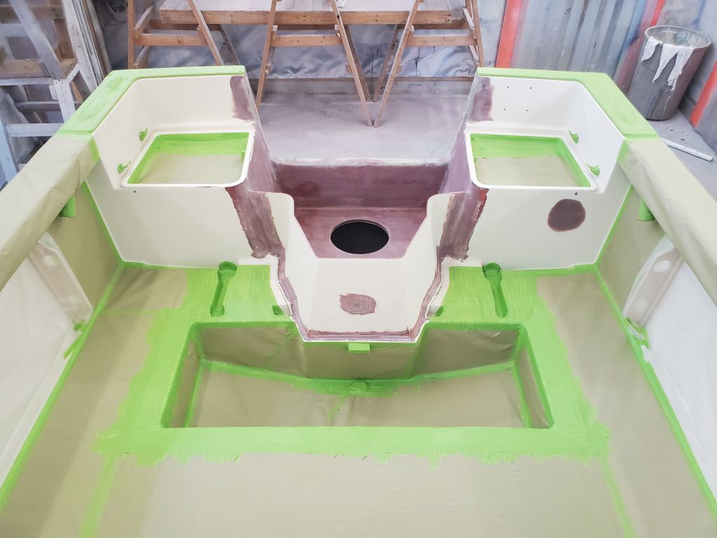
Continuing in the cockpit, first I sanded as needed the scupper openings in the outboard well, smoothing yesterday’s epoxy work. I’d touch these up later, after high-build, along with various anticipated other areas around the boat.
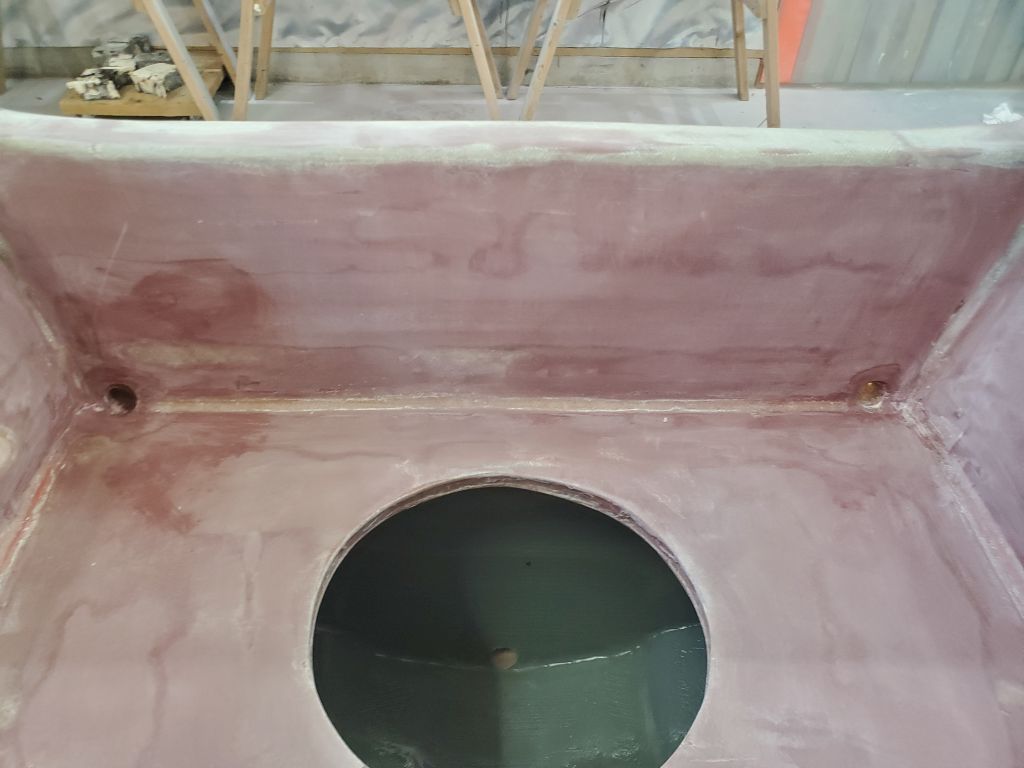
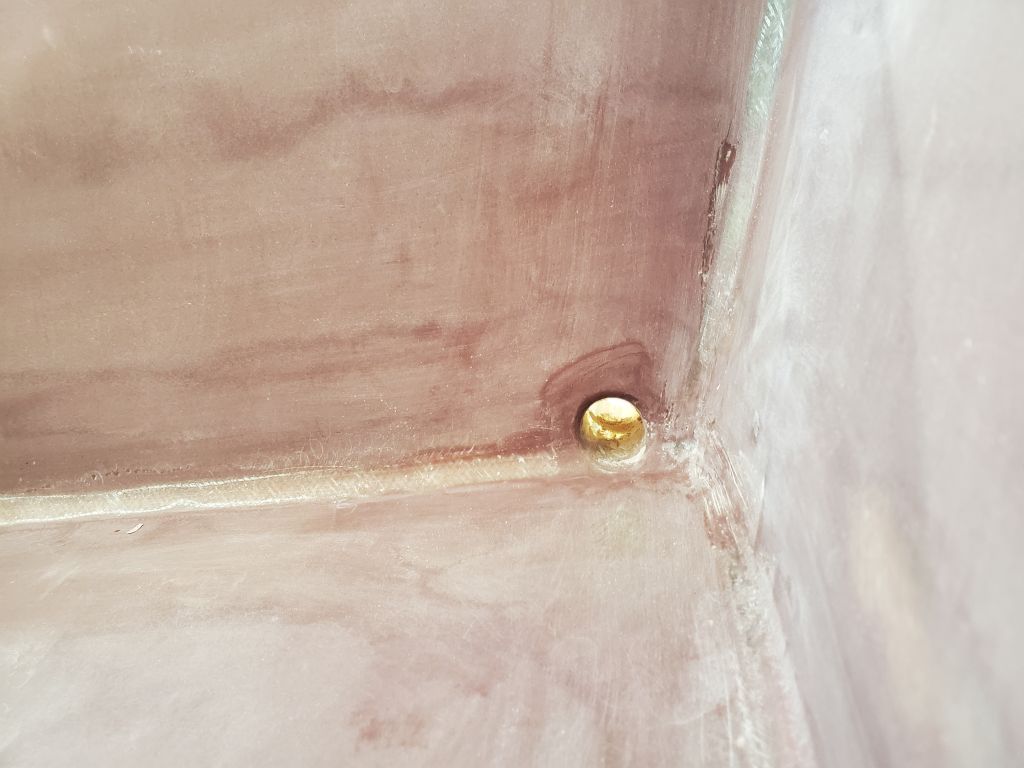
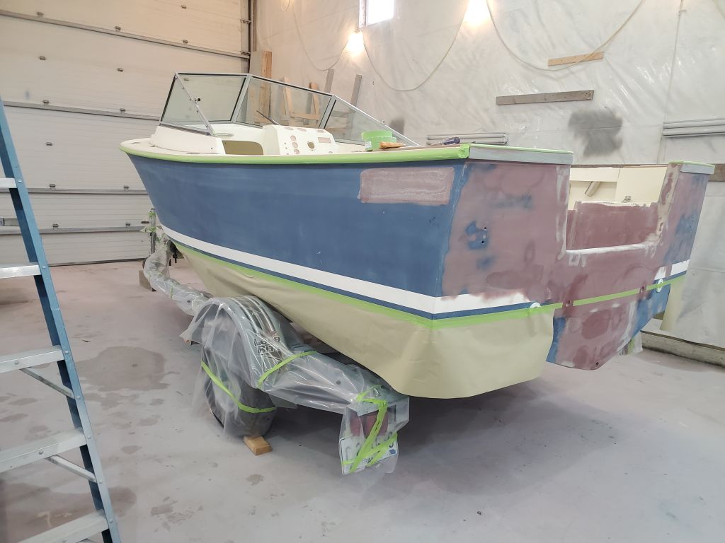
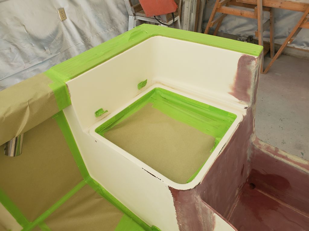
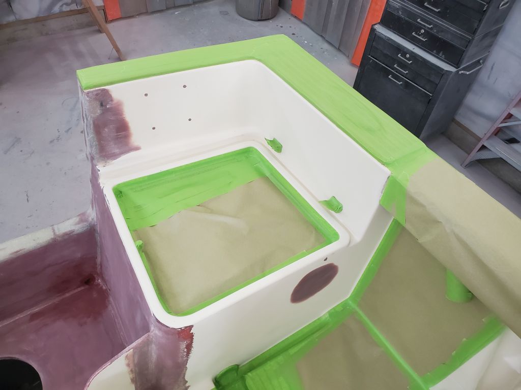
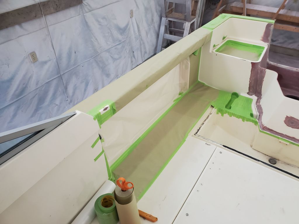
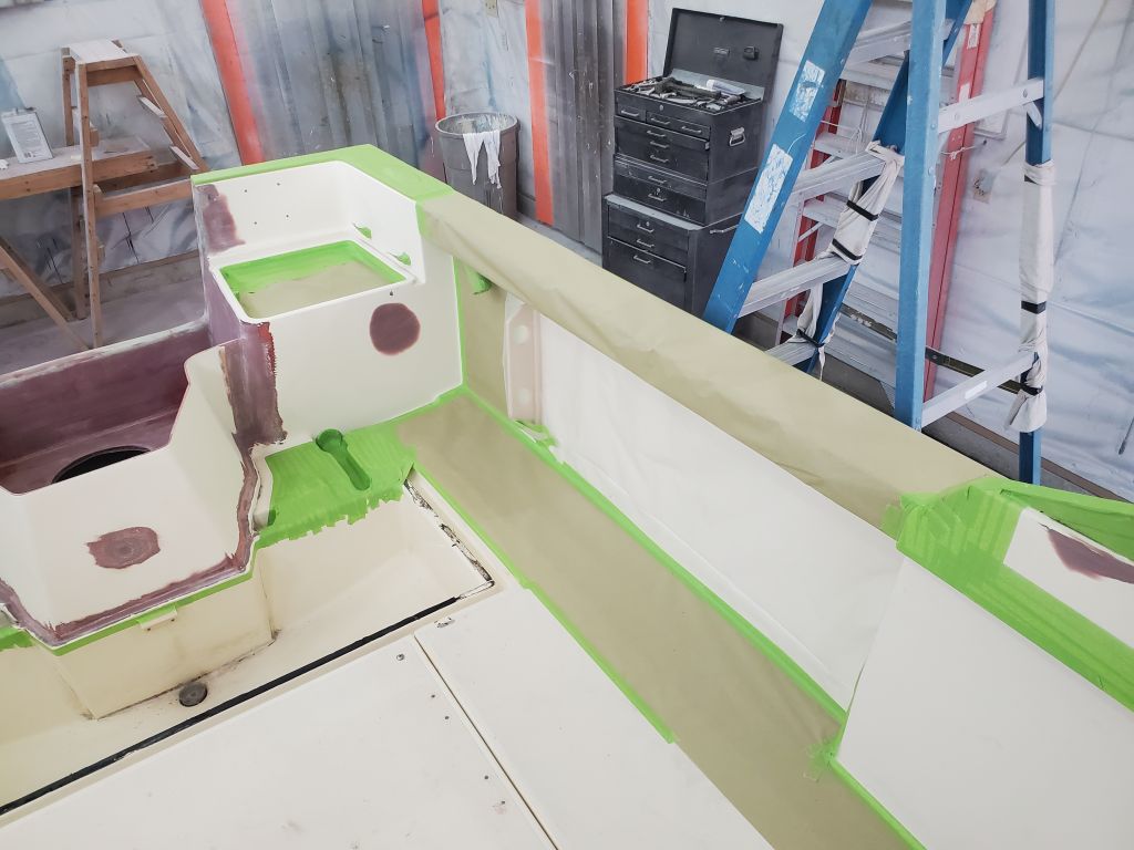
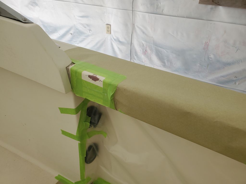
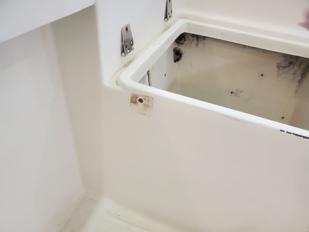
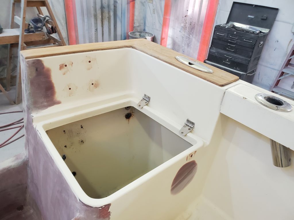
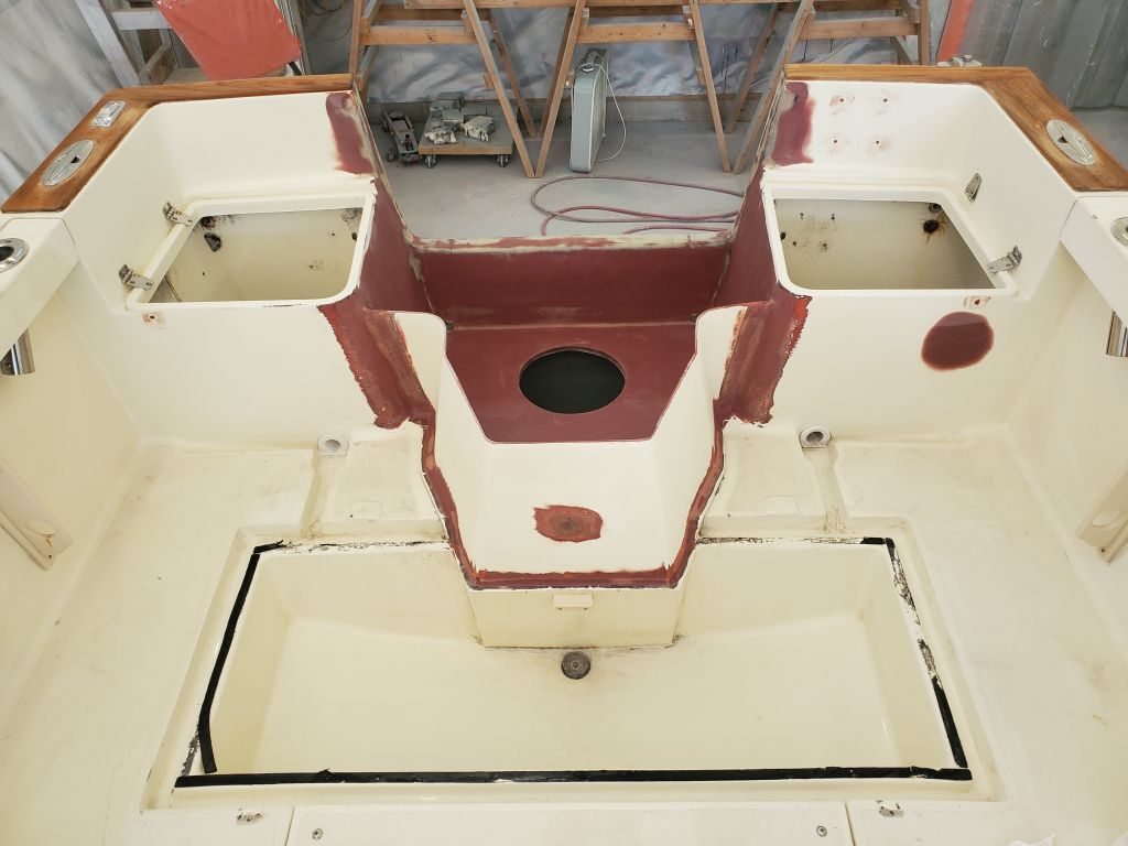
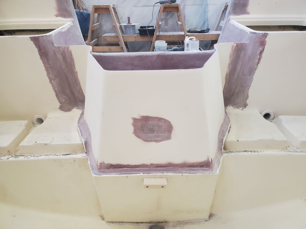
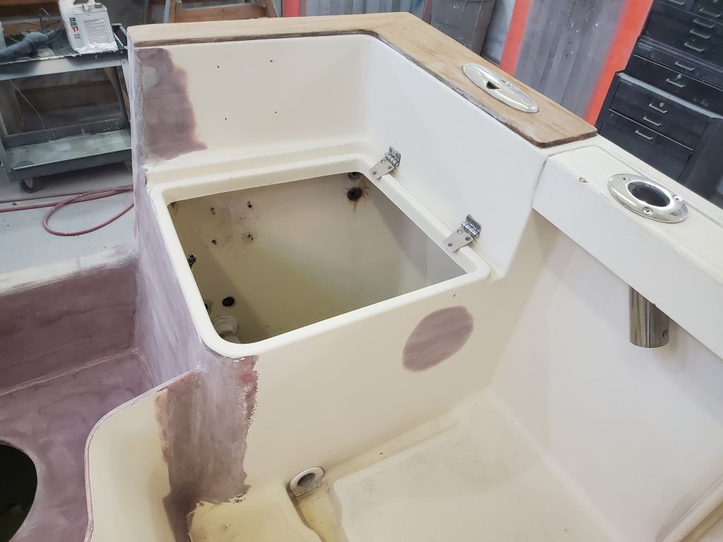
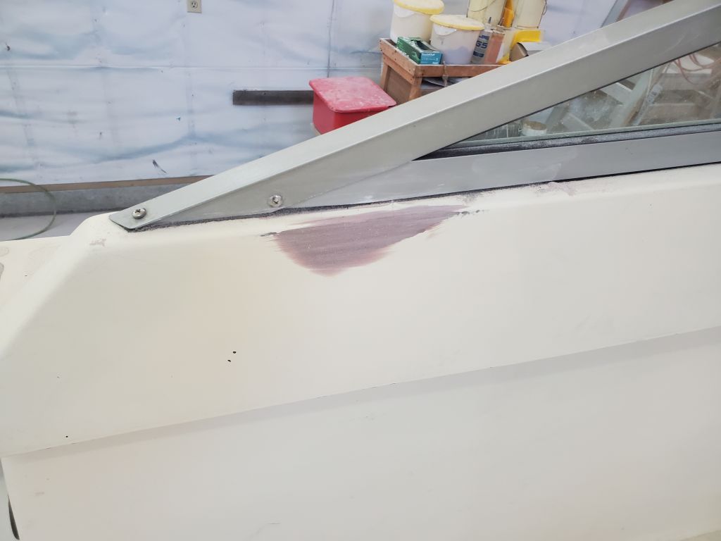
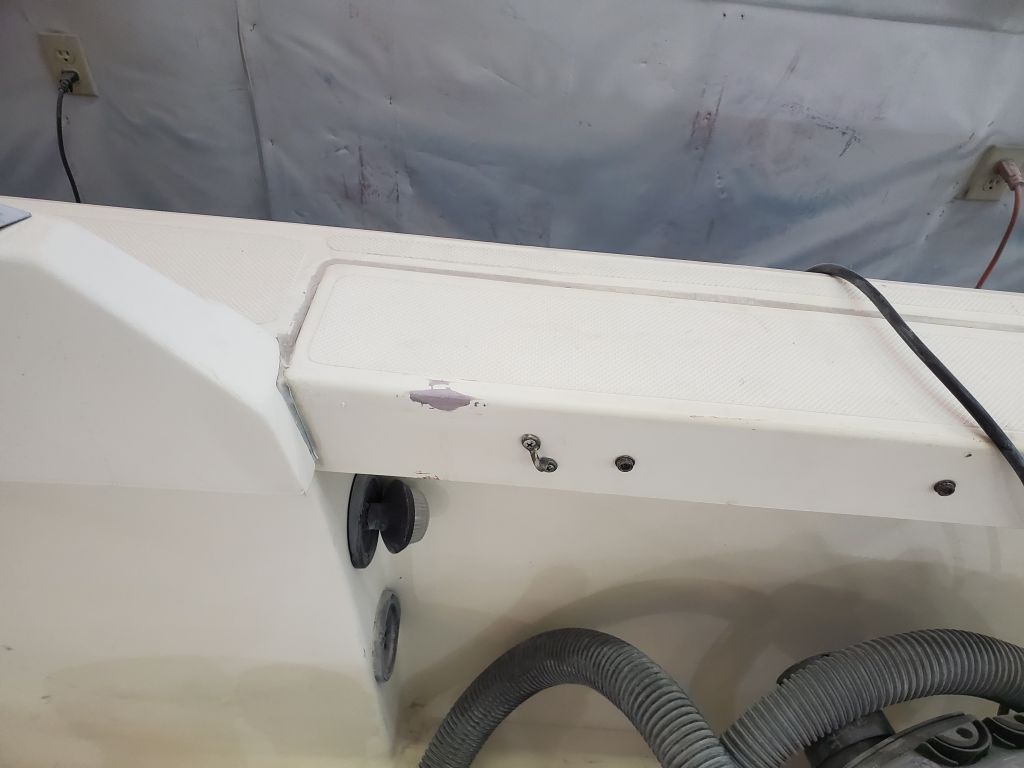
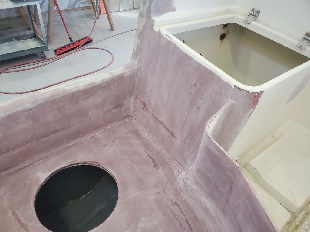
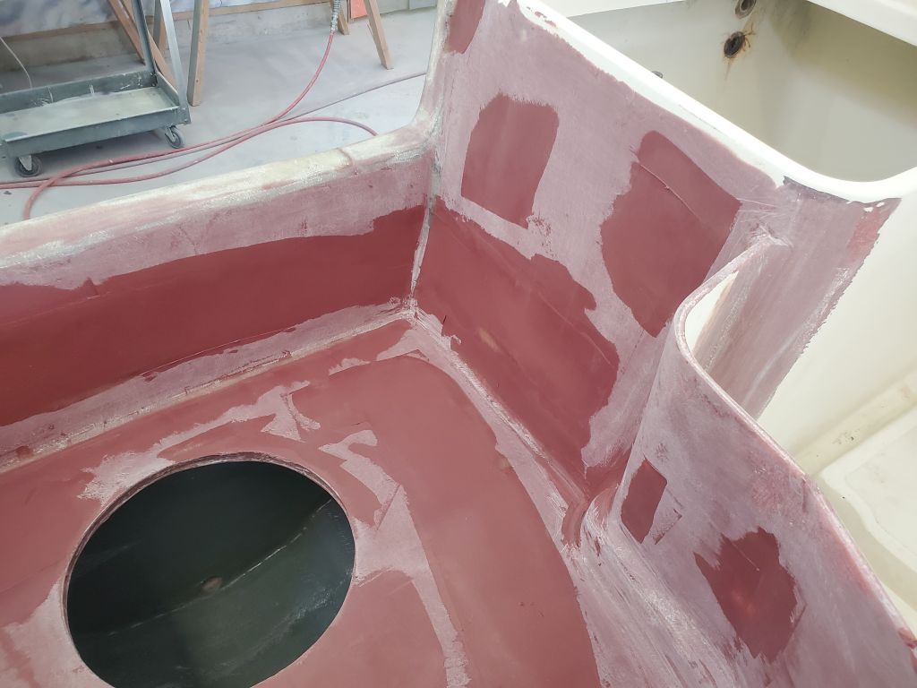
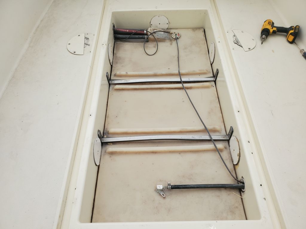
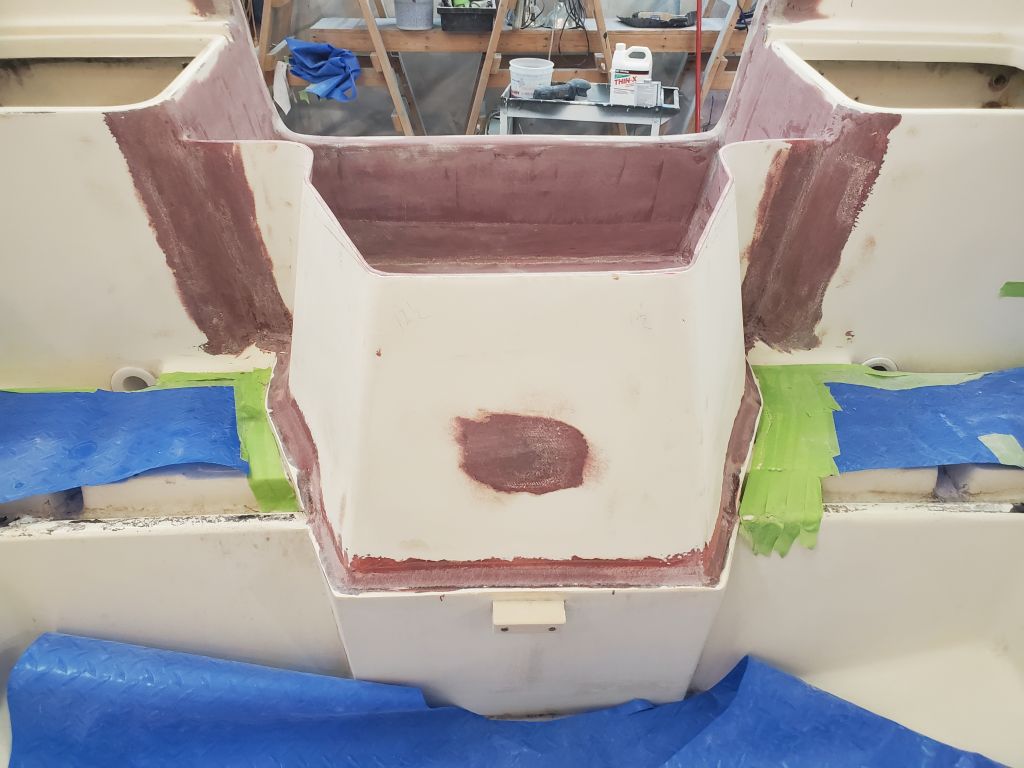
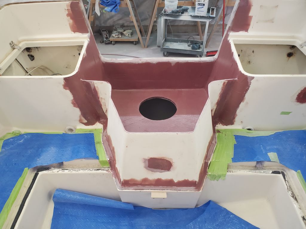
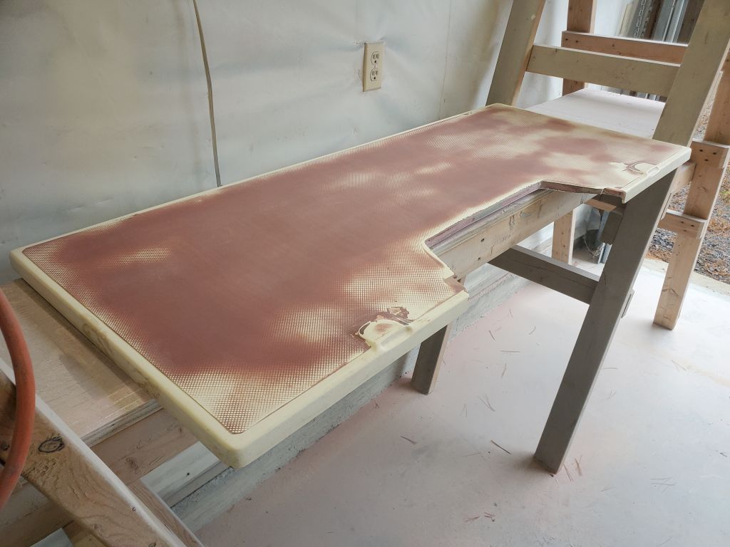
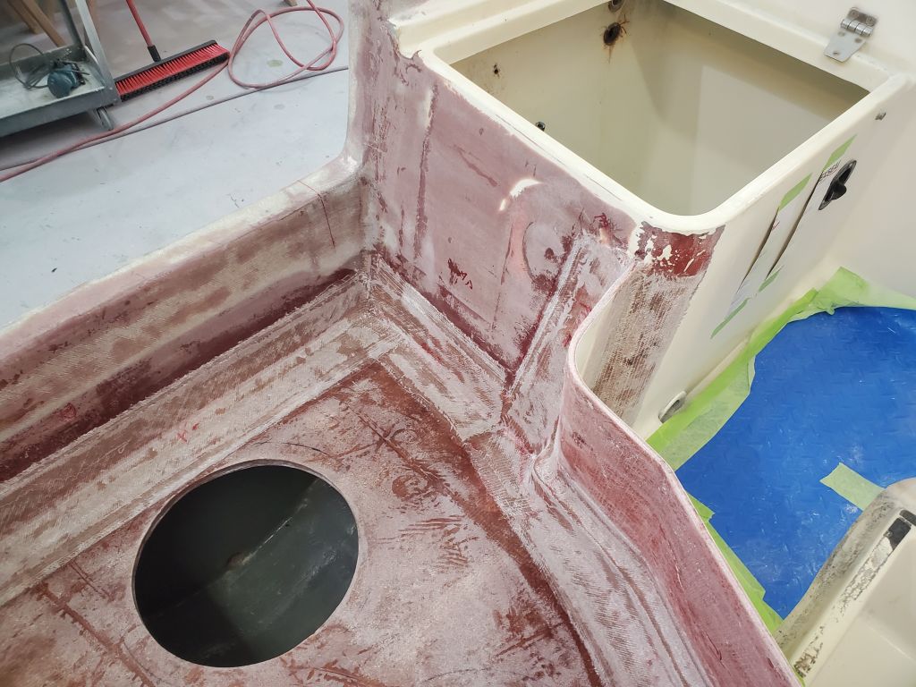
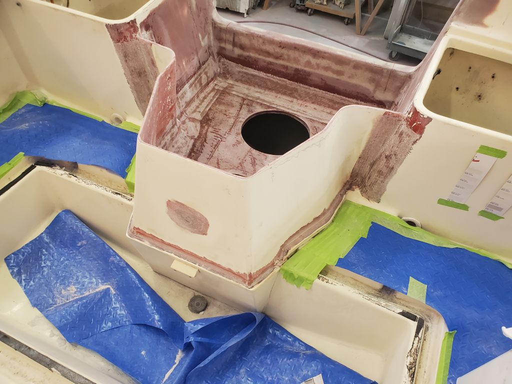
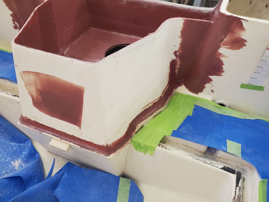
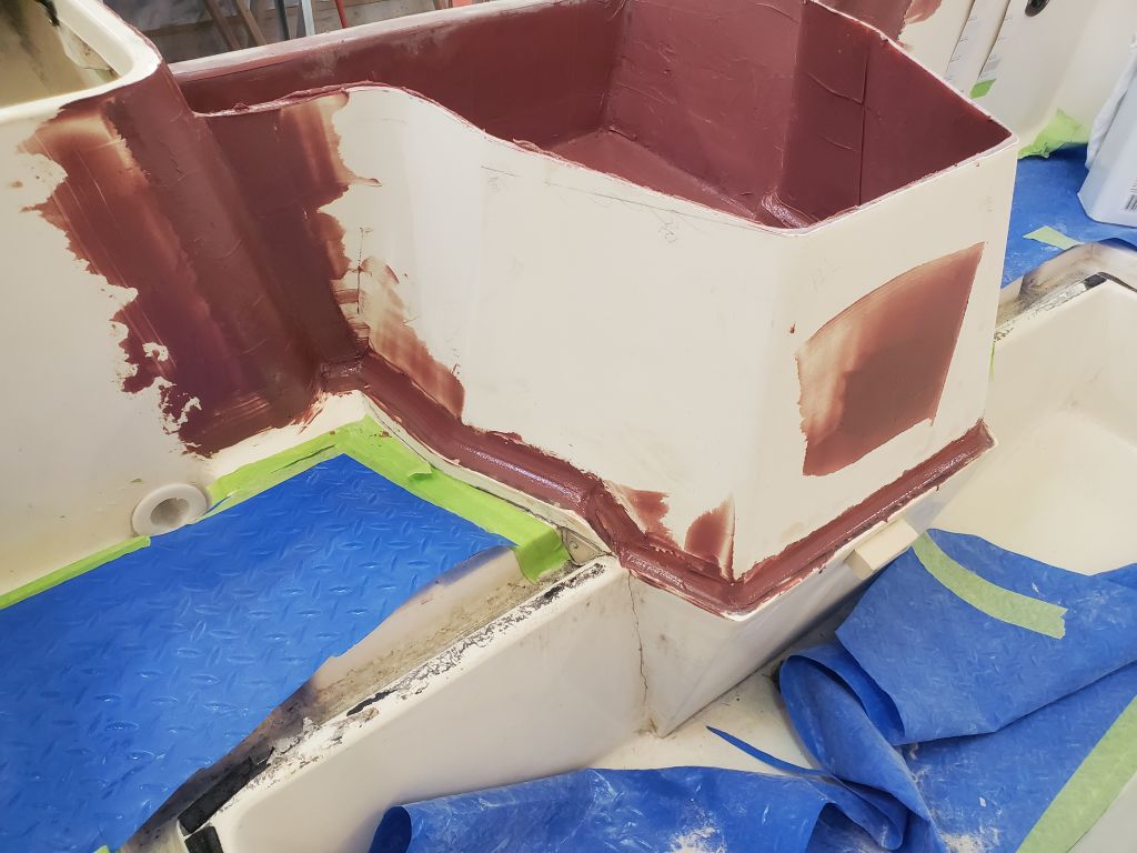
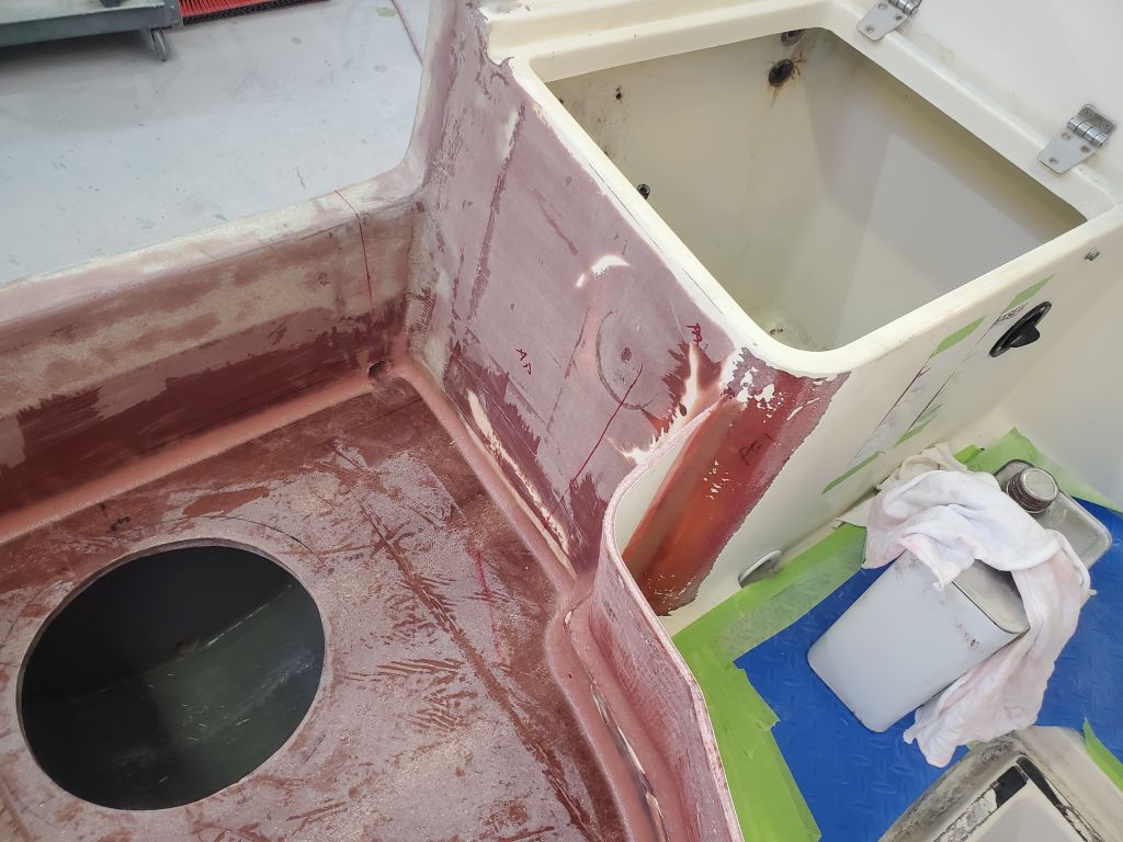
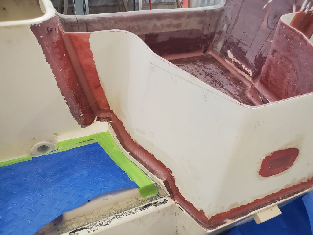
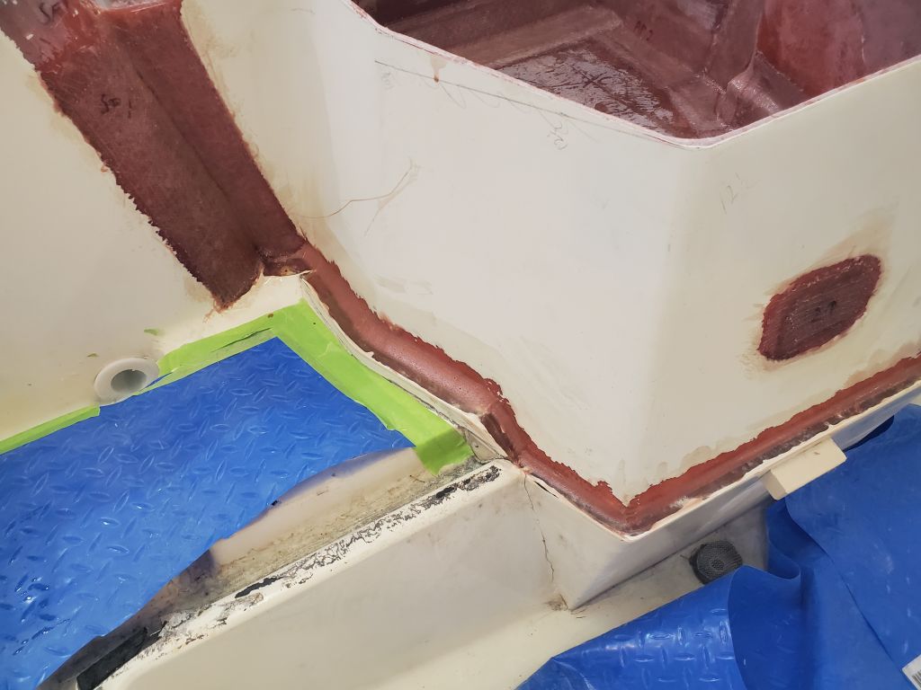
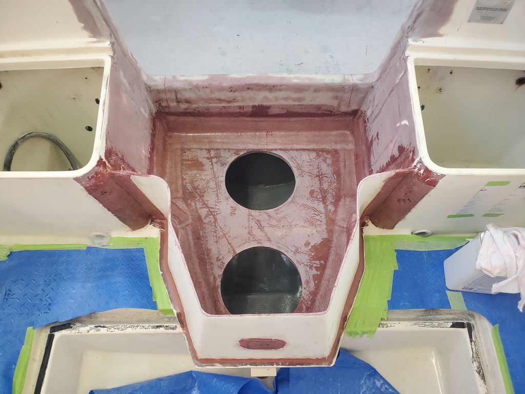
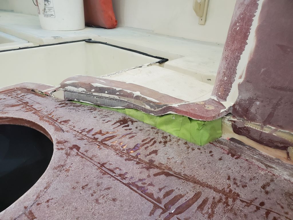
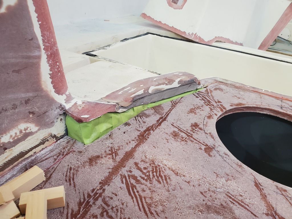
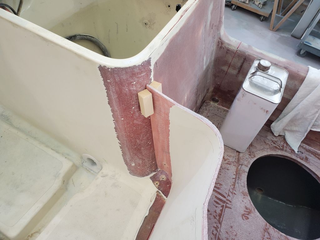
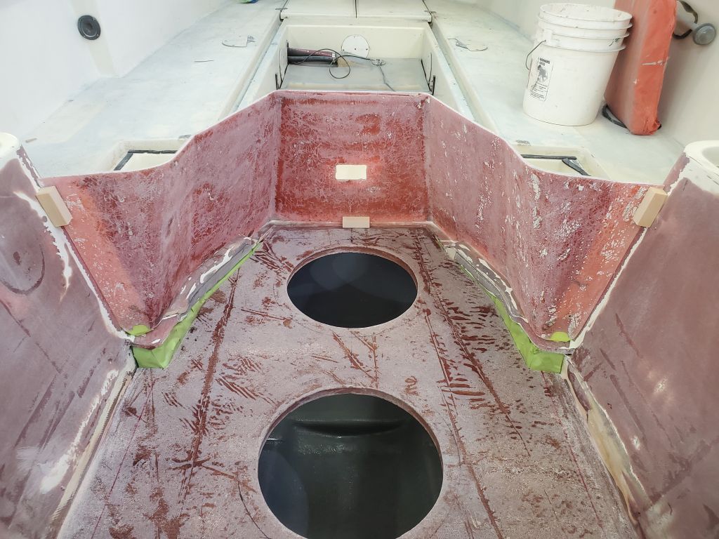
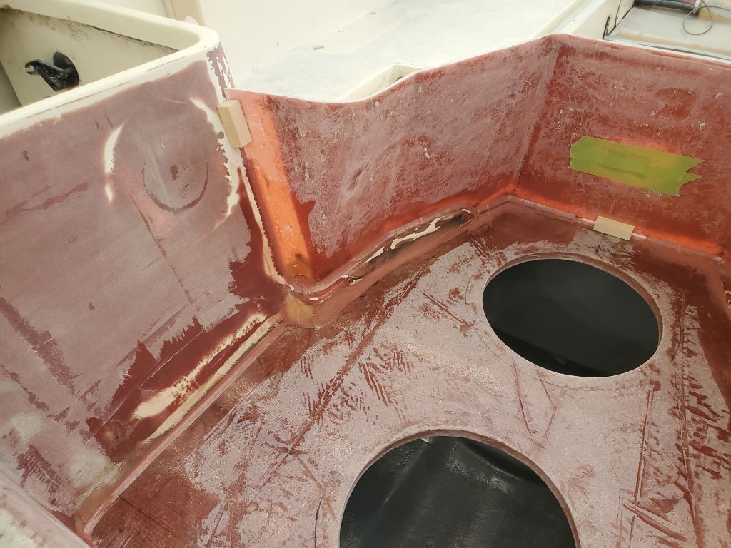
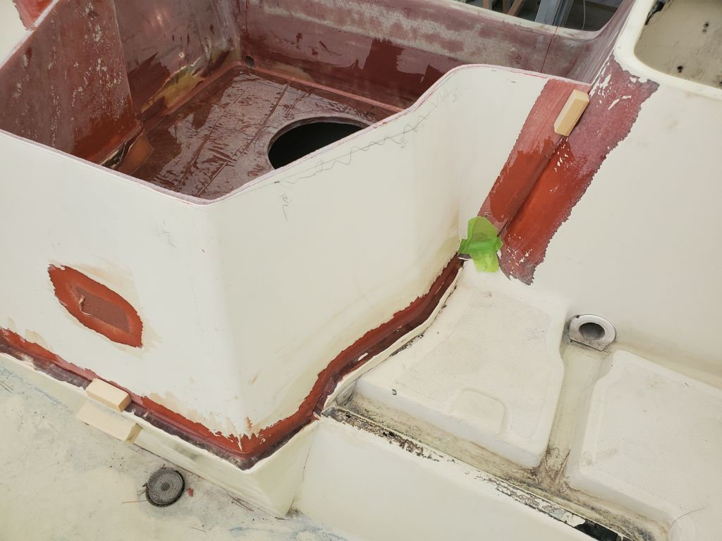
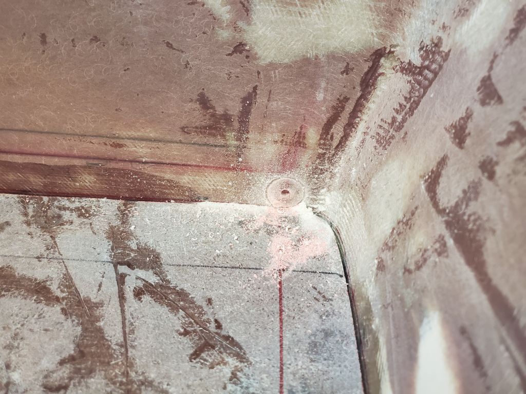
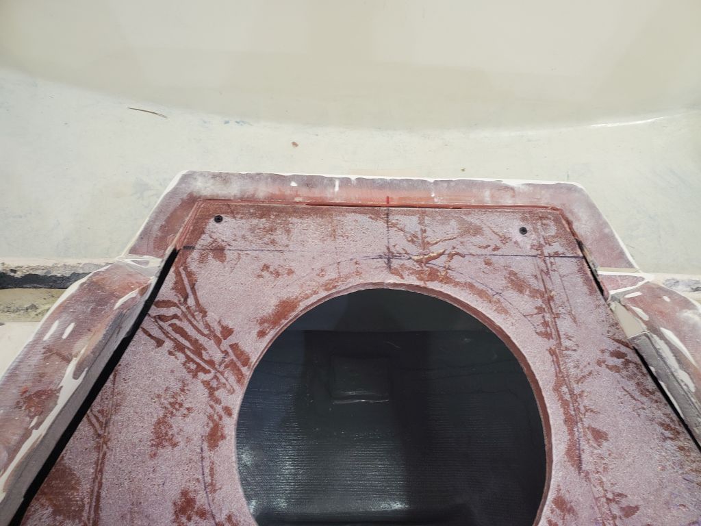
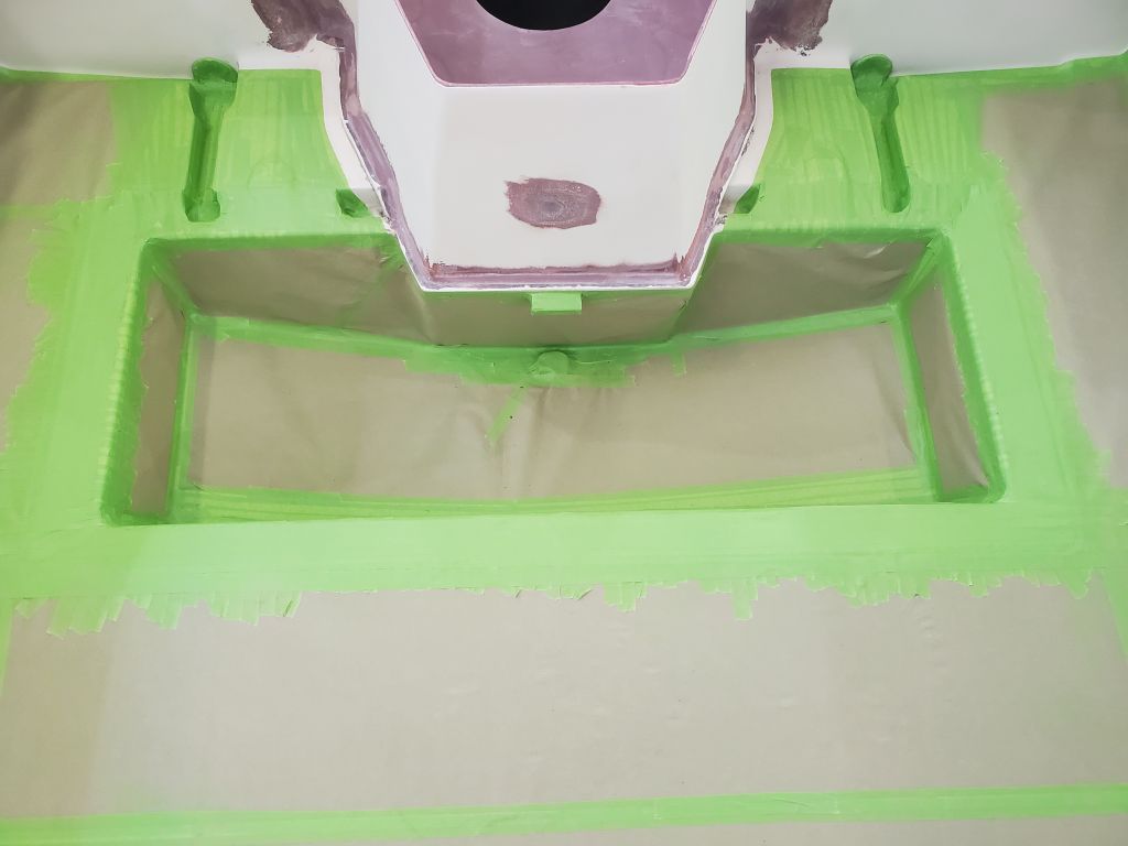
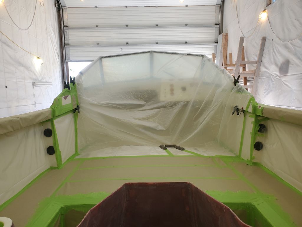
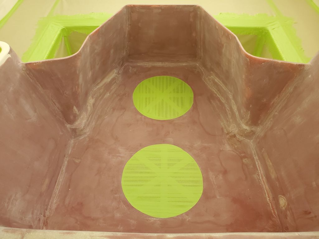
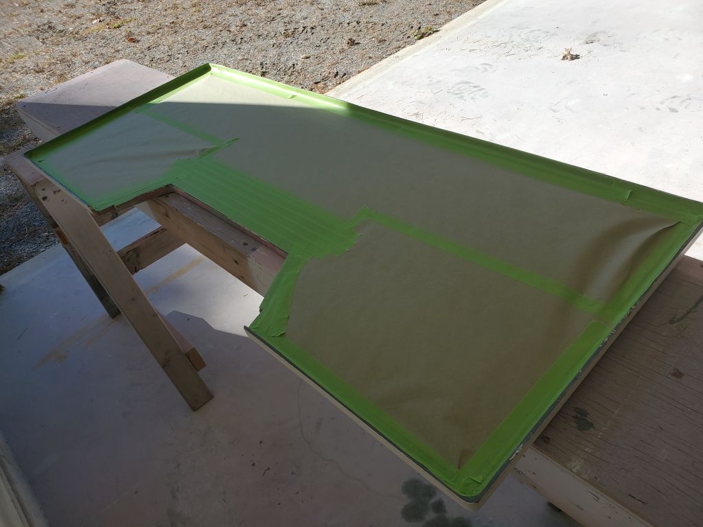
finished up the masking work near the new outboard well, mainly masking off the inside of the livewell for protection and so I could stand there while spraying. I also masked with paper several feet of the cockpit leading forward, before transitioning to plastic at the vertical edges and forward part of the cockpit. I keep the plastic away from being directly adjacent to areas being sprayed, since the overspray on the plastic tends to flake off later and can contaminate the paint.
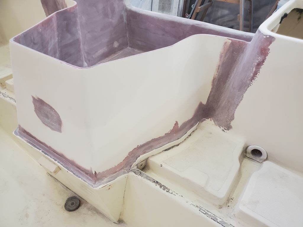
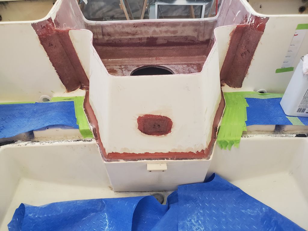
I ordered wider masking tape when preparing for the paint work, but it was backordered and hadn’t arrived, so I used the 1″ tape, of which I had sufficient supply, for all masking chores; this got a little silly taping over the livewell gutters, but there you are.

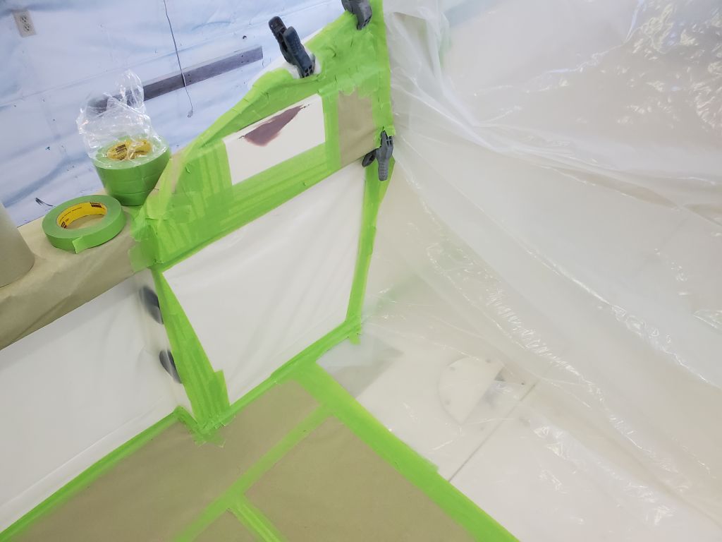
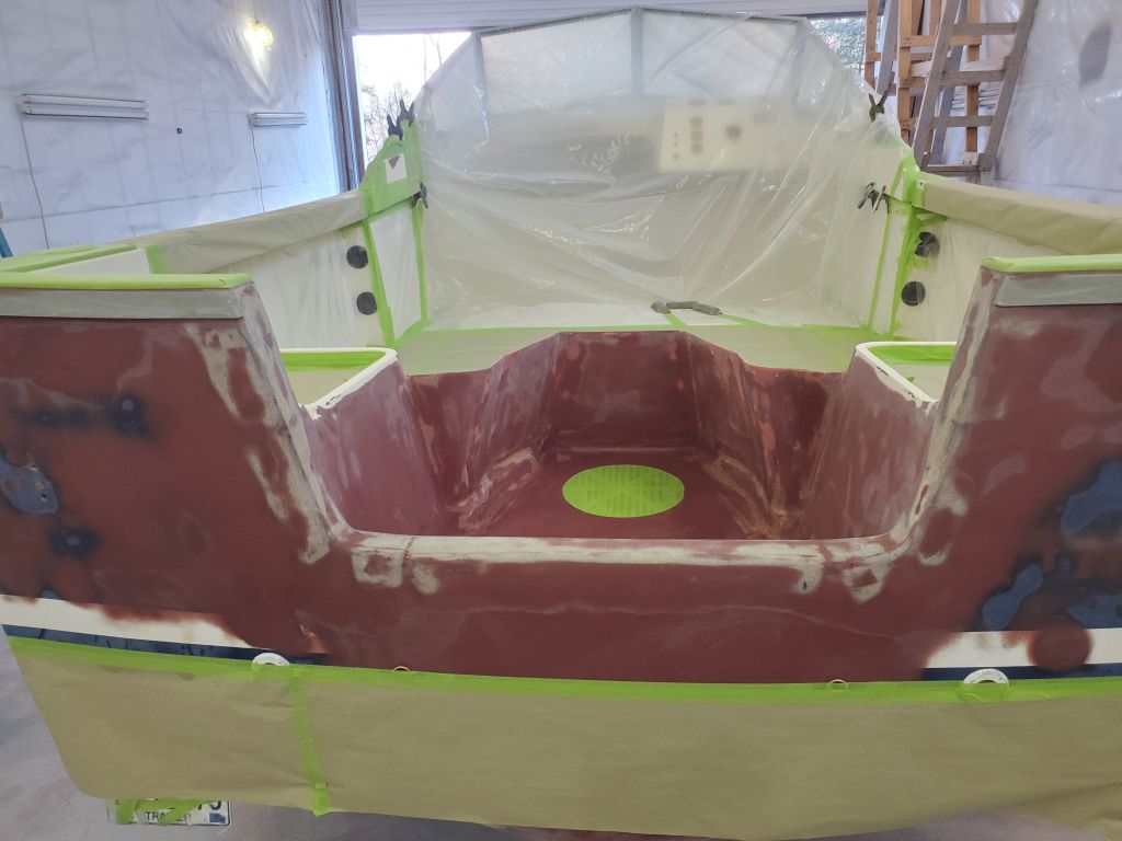
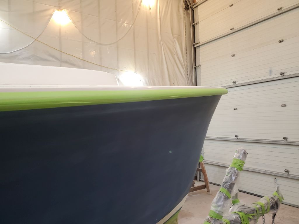
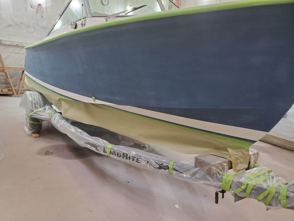
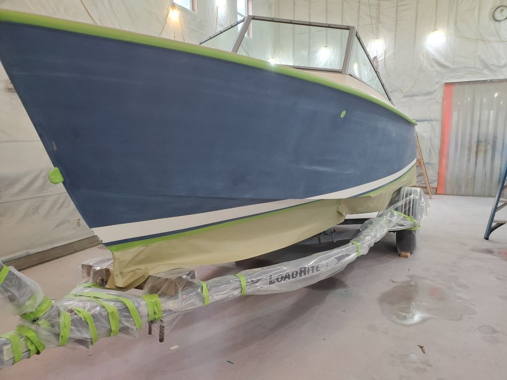
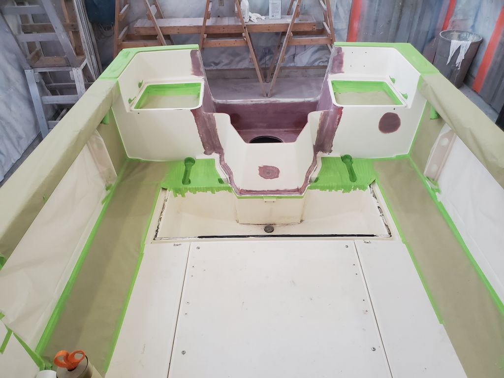
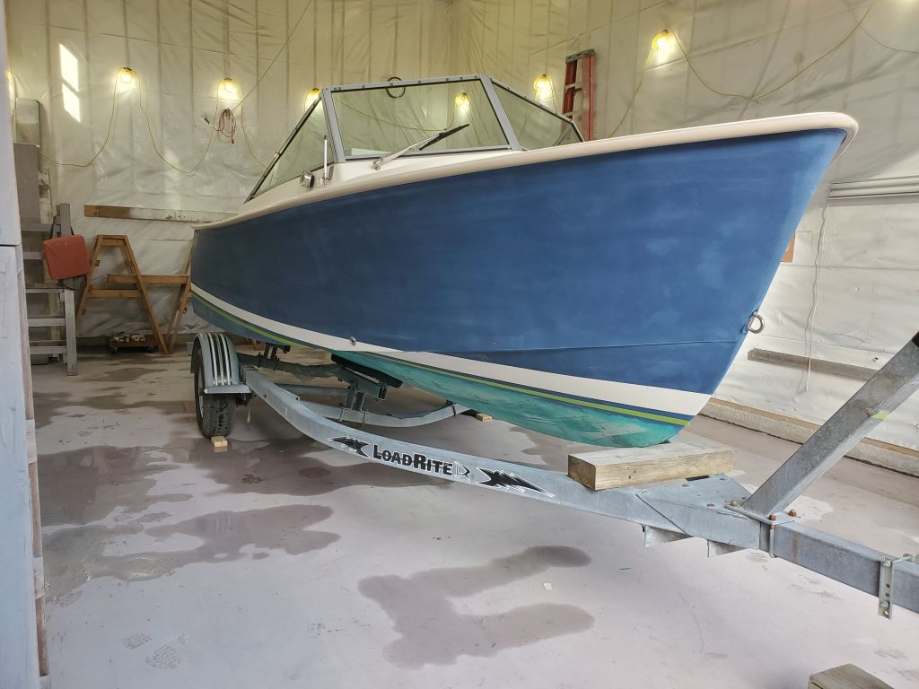
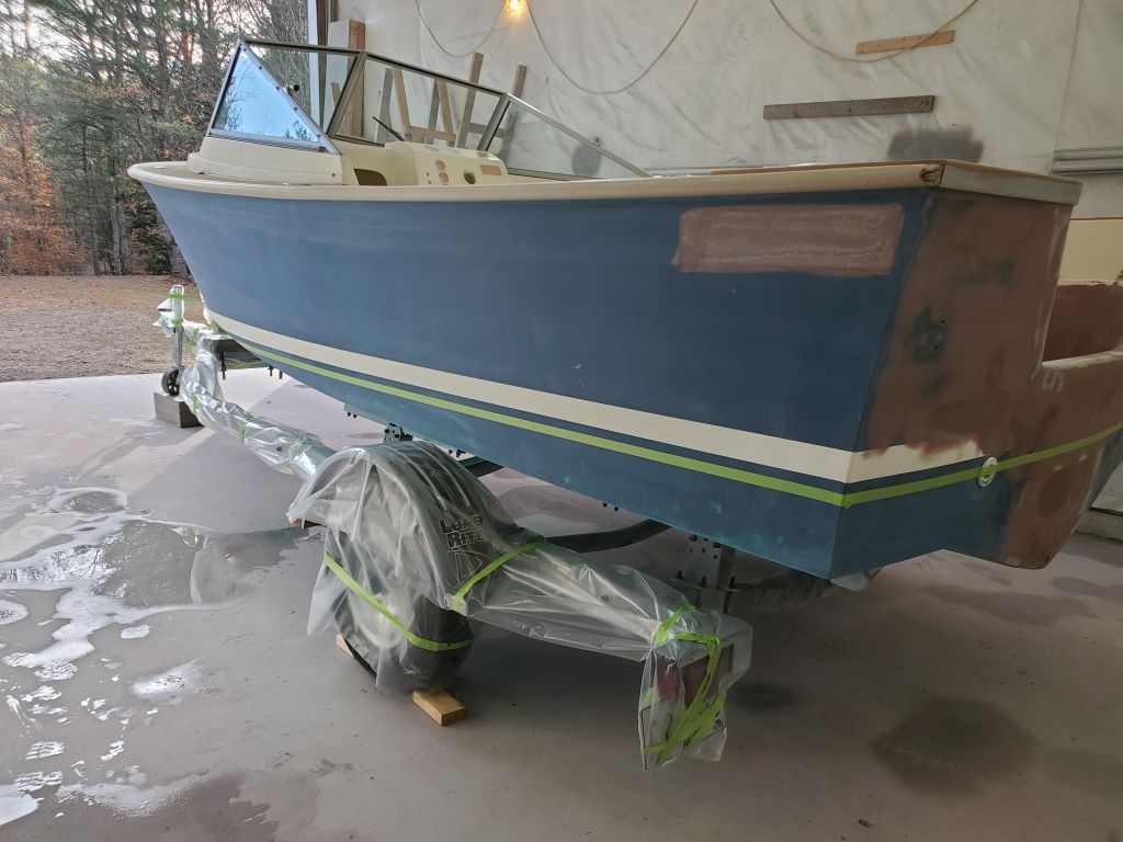
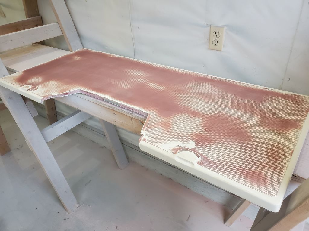
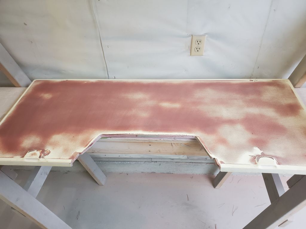
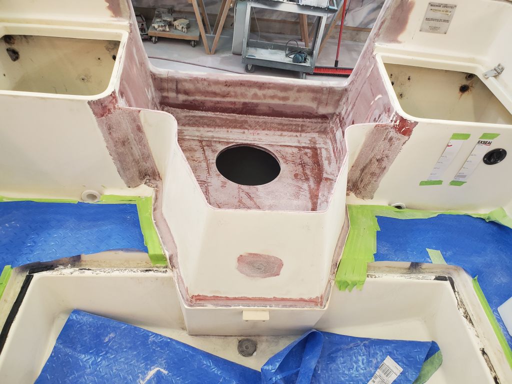
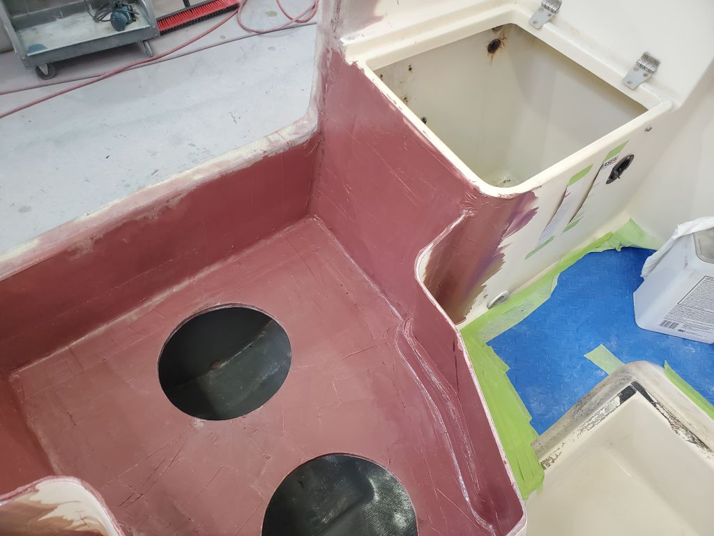
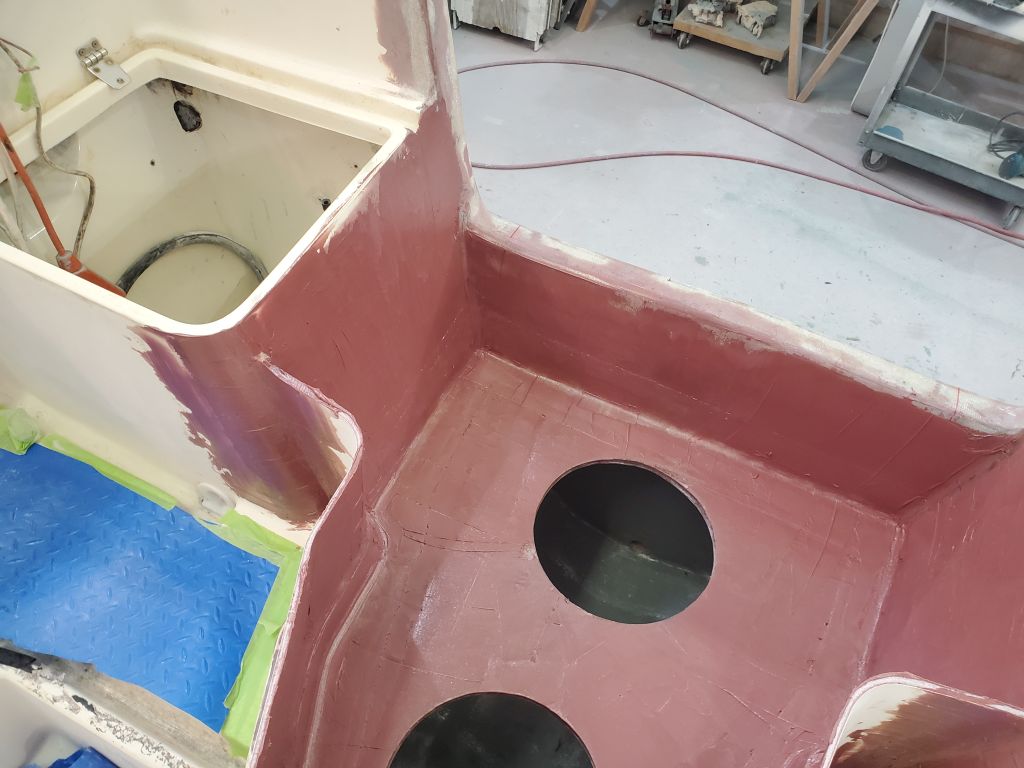
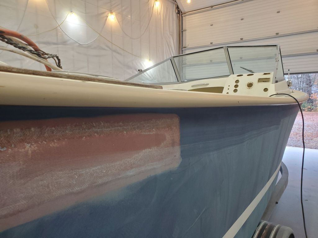
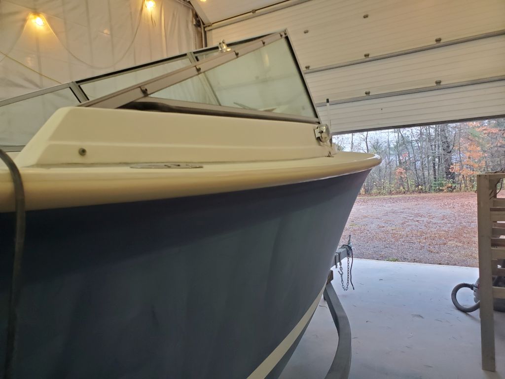
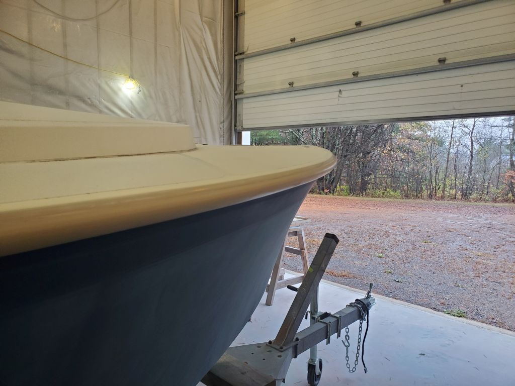
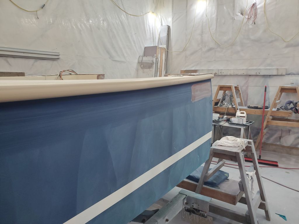
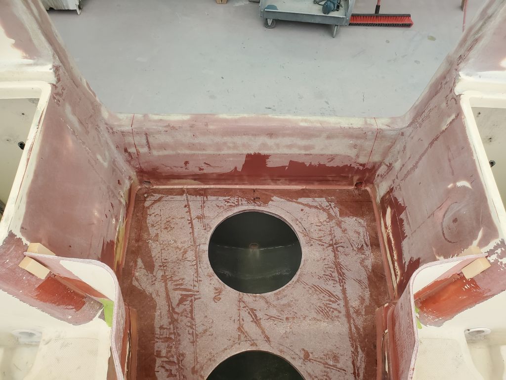
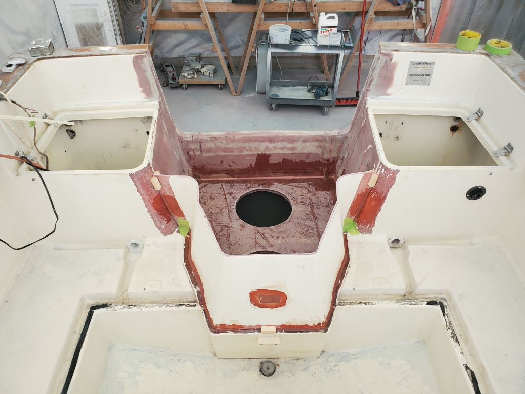
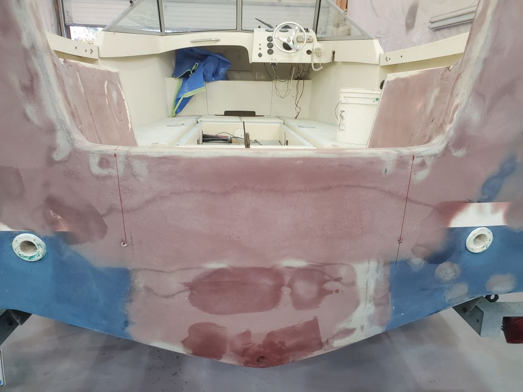
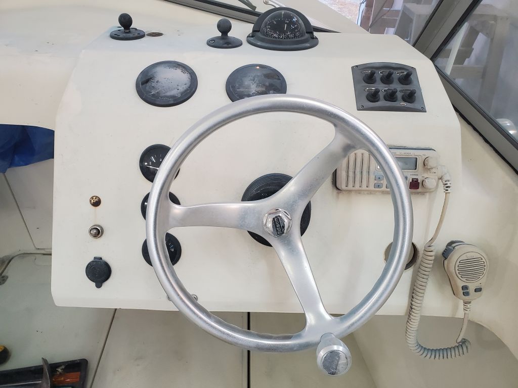
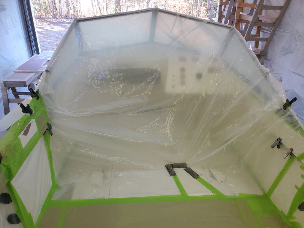
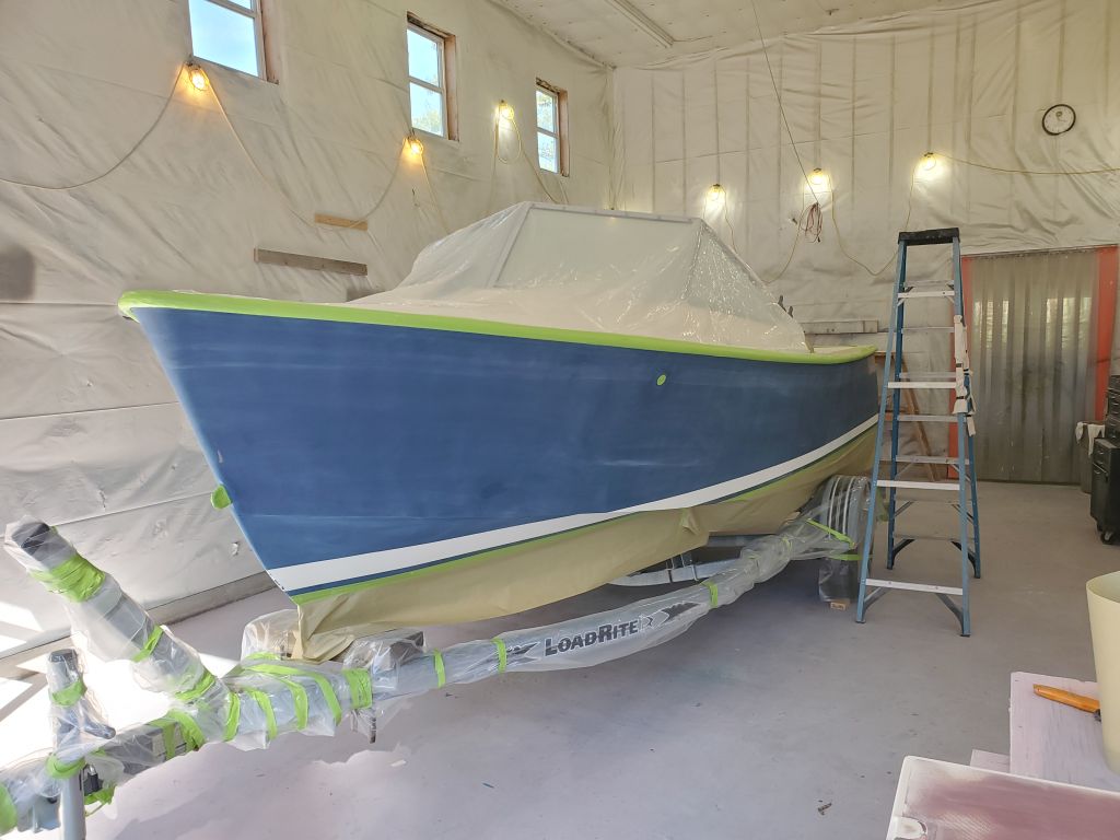
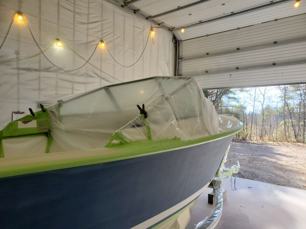
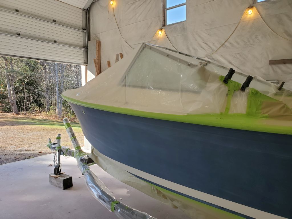
Next, I draped the bow and forward area of the the cockpit with plastic sheeting to protect these areas during the painting process.

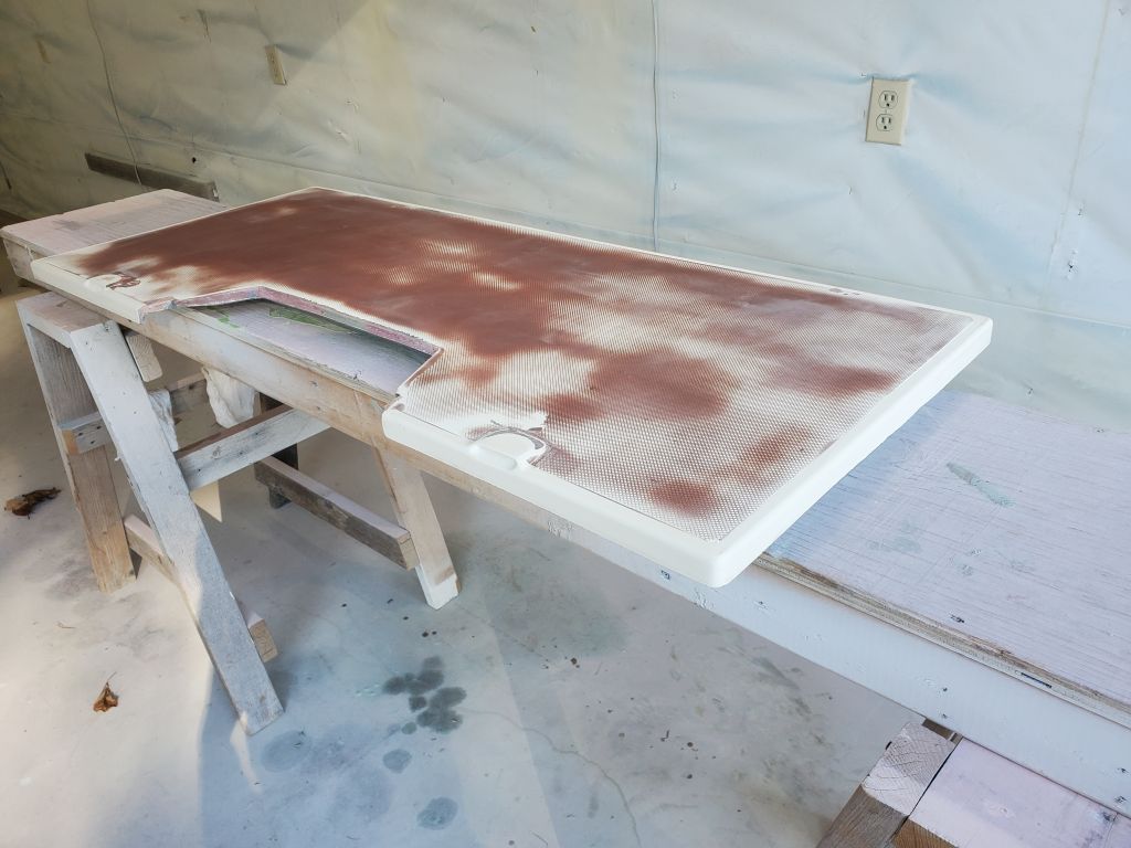
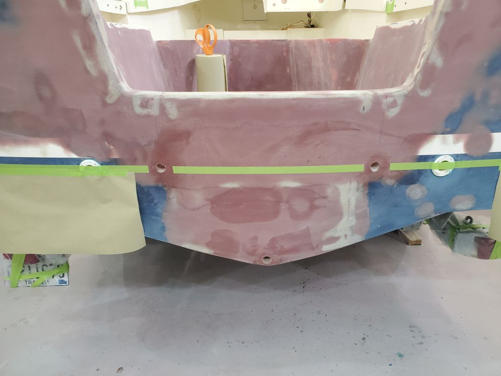
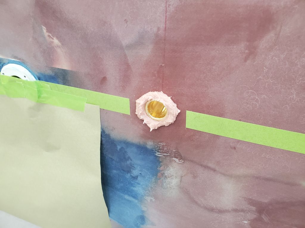
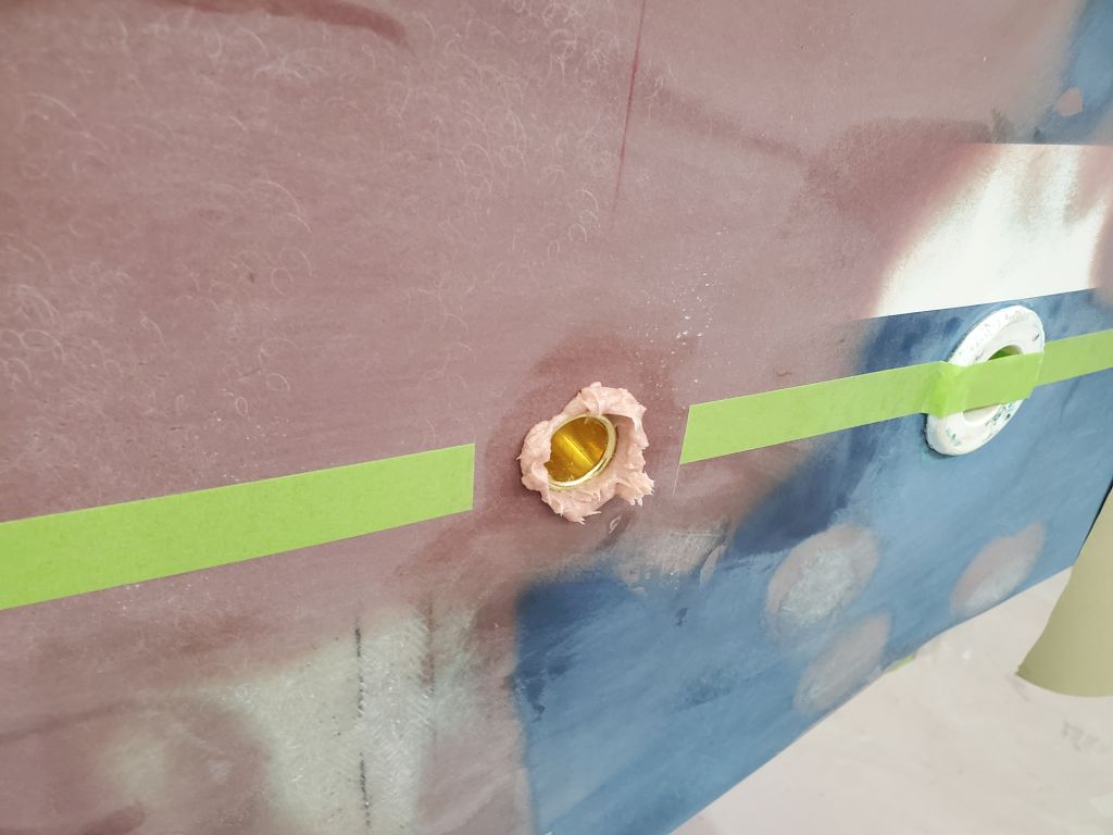
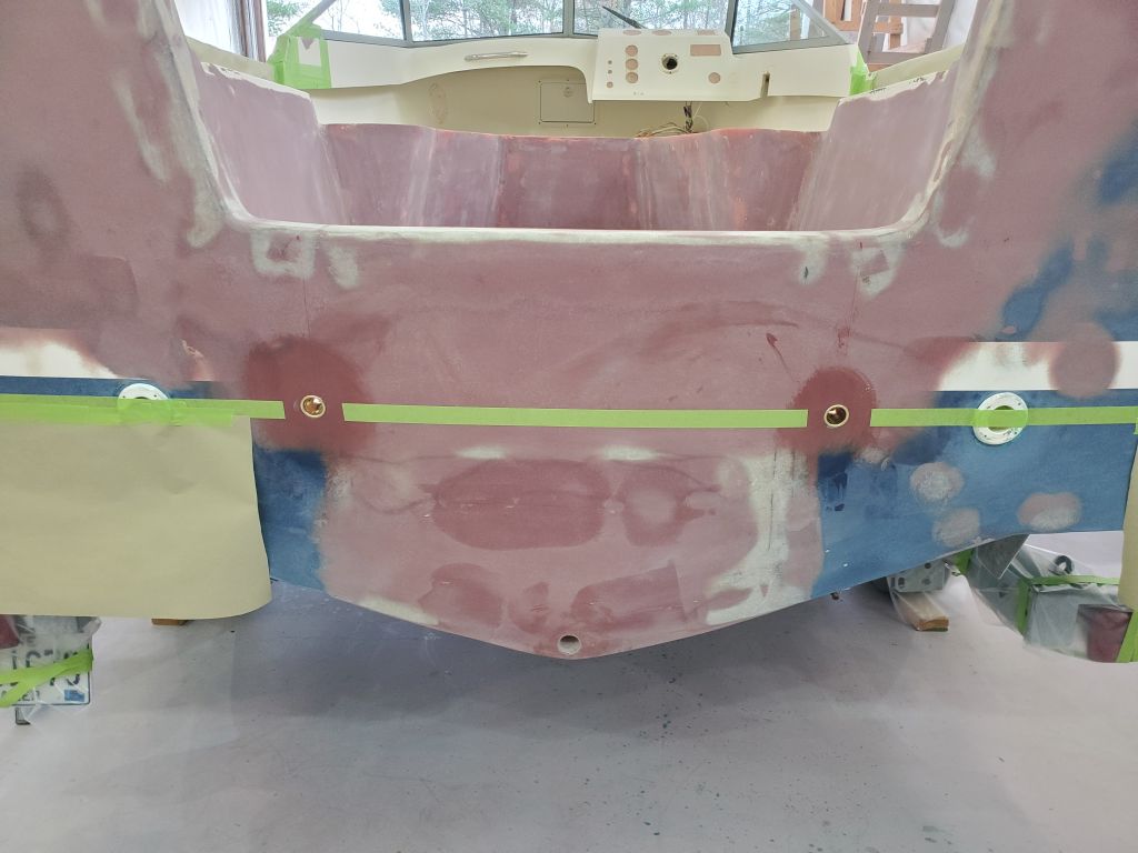
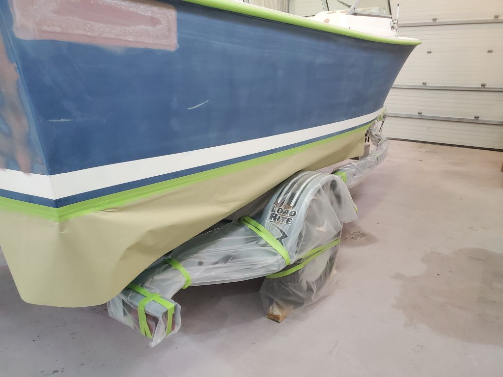
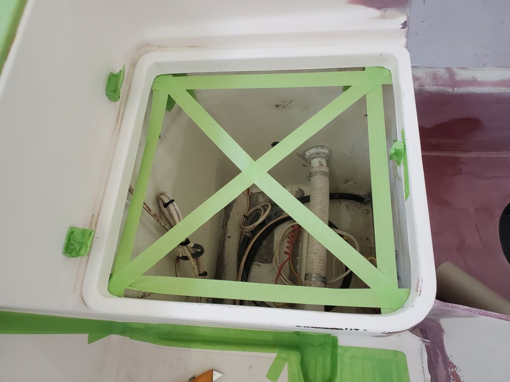
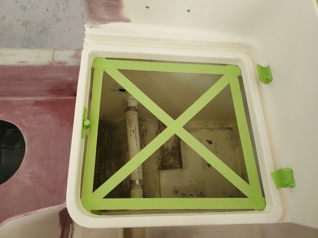
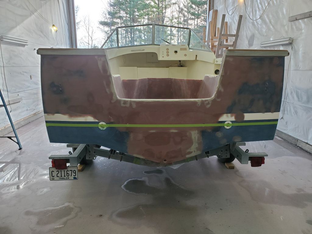
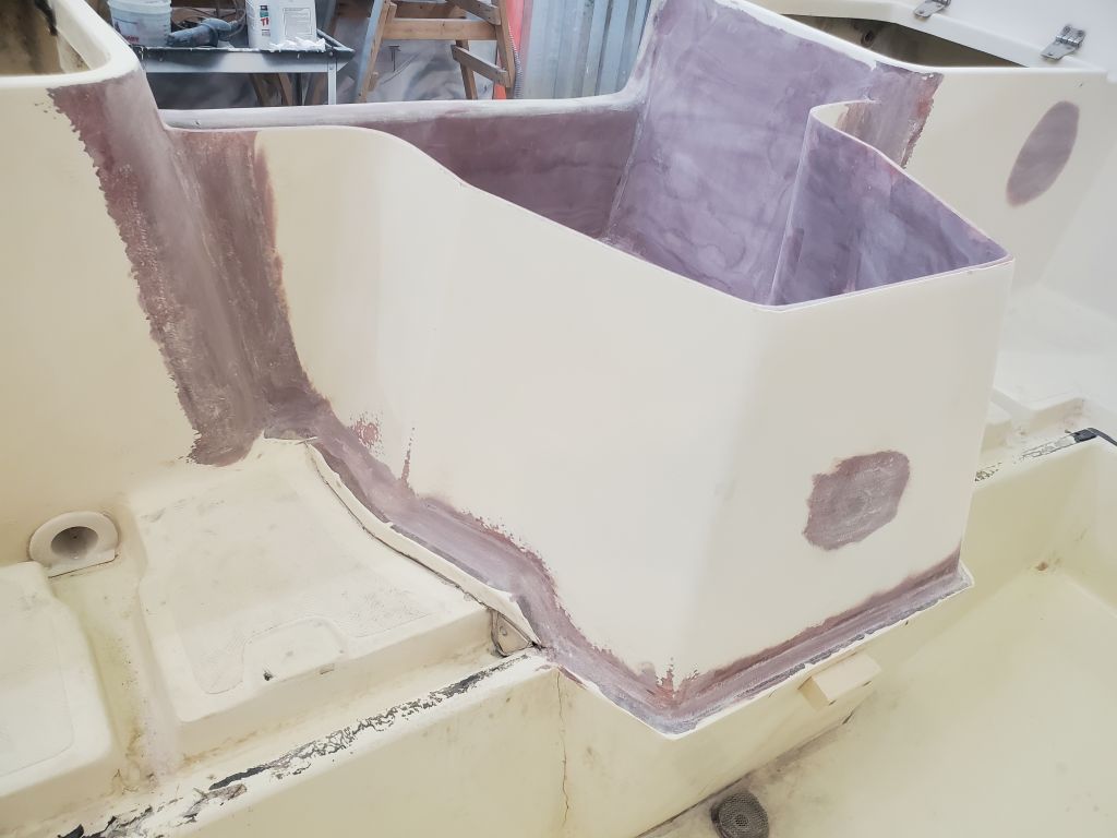
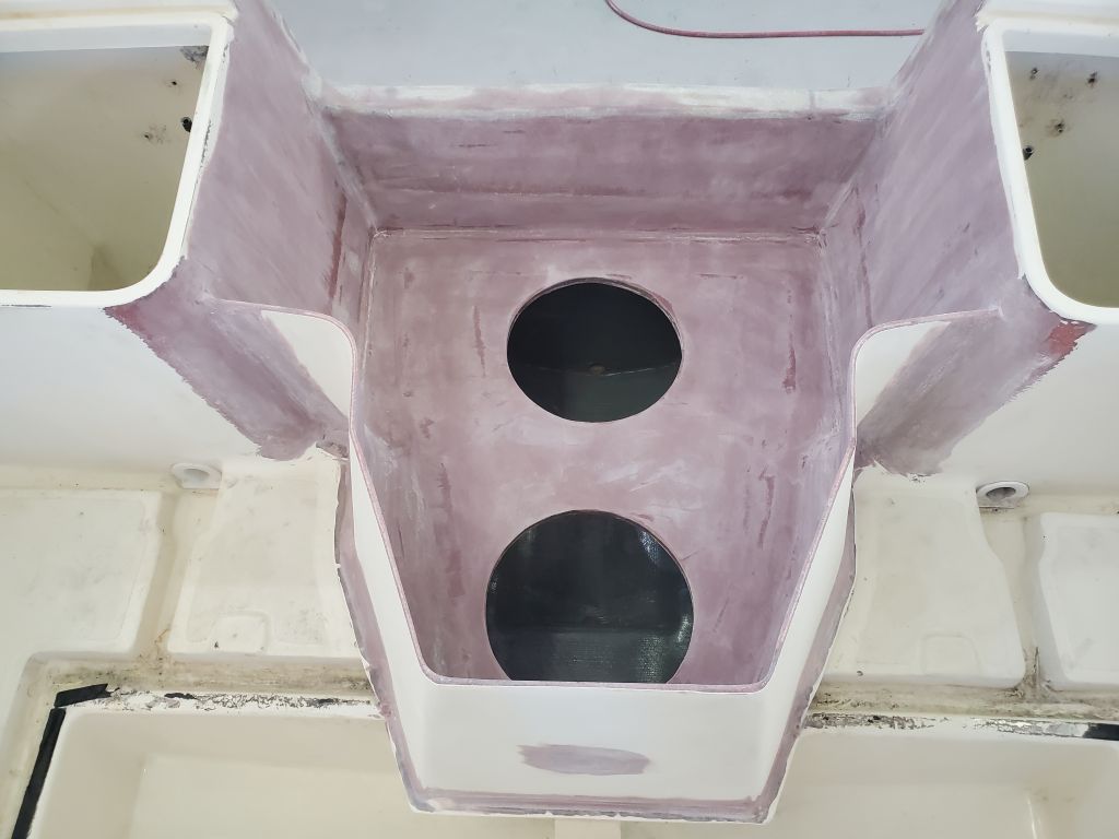
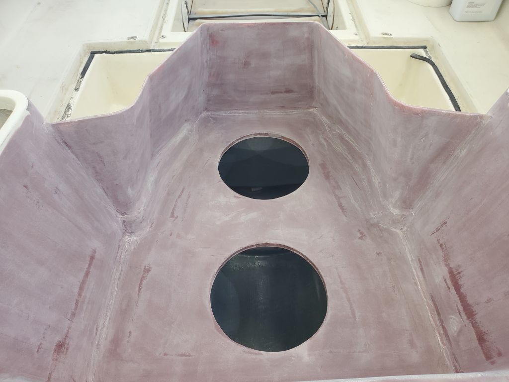
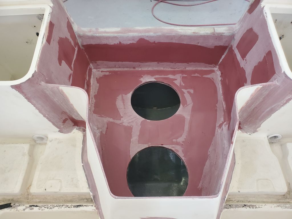
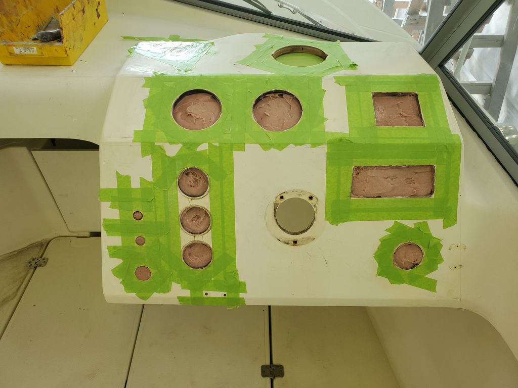
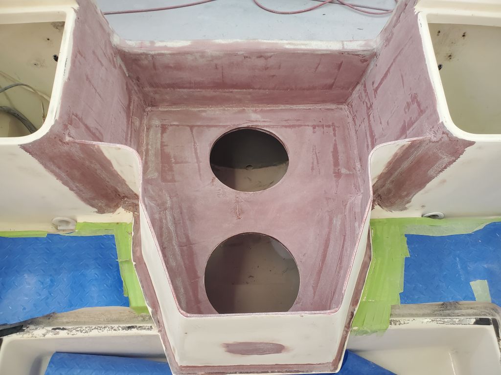
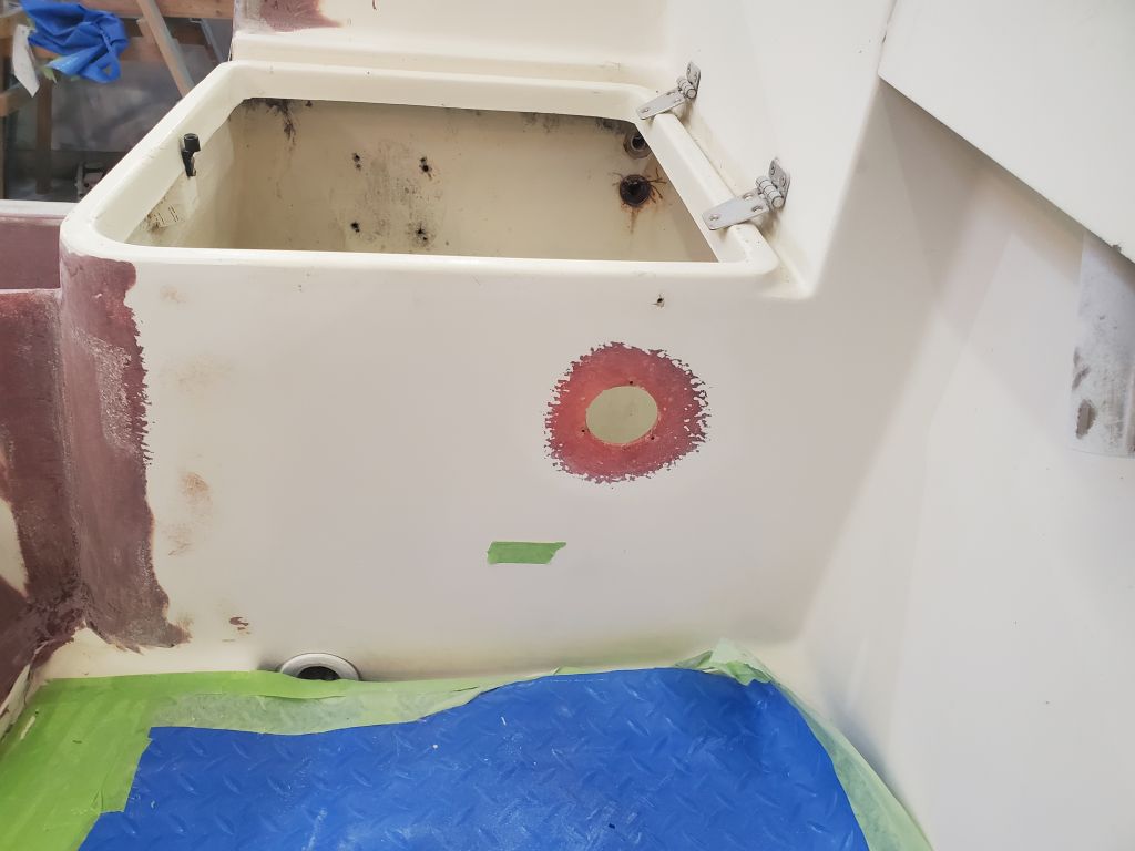
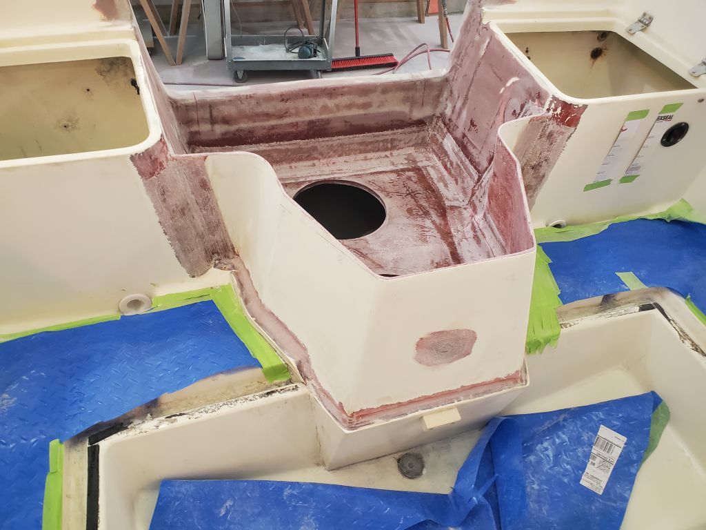
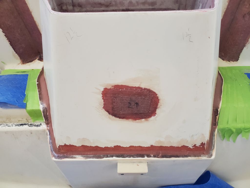
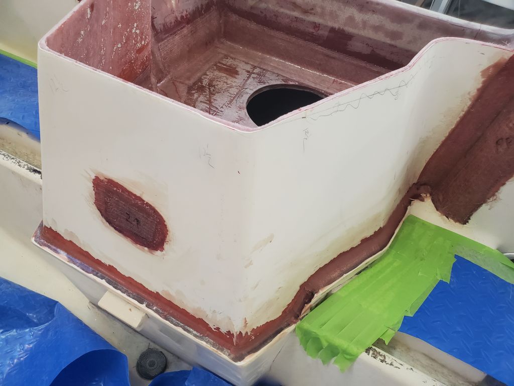
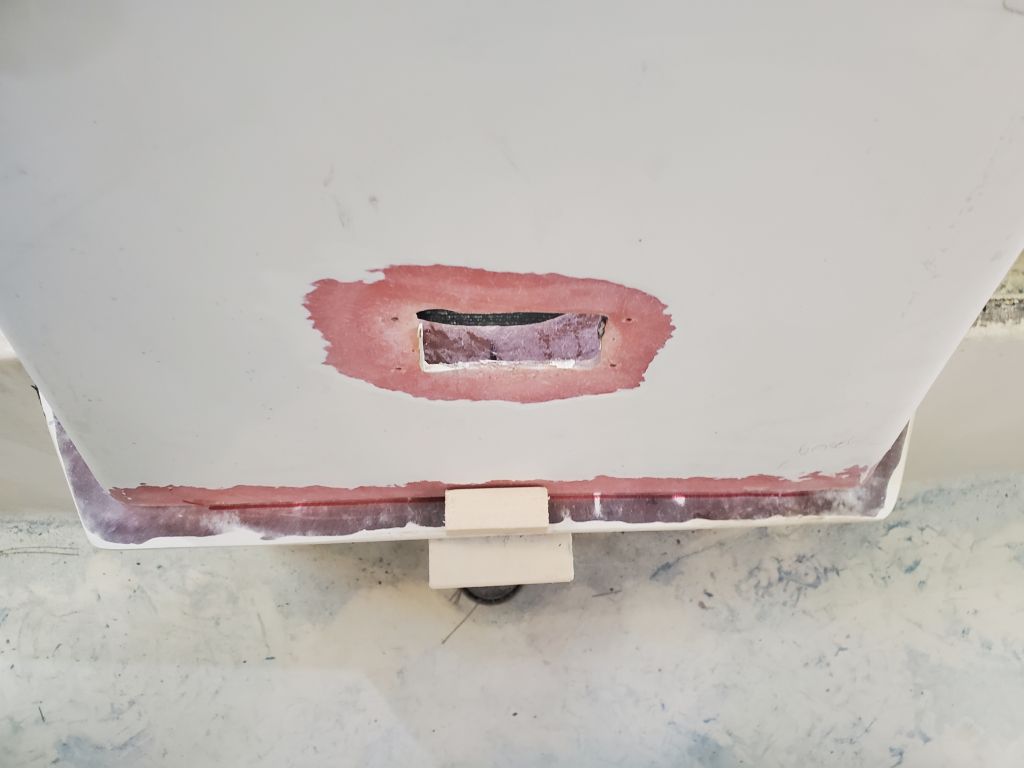
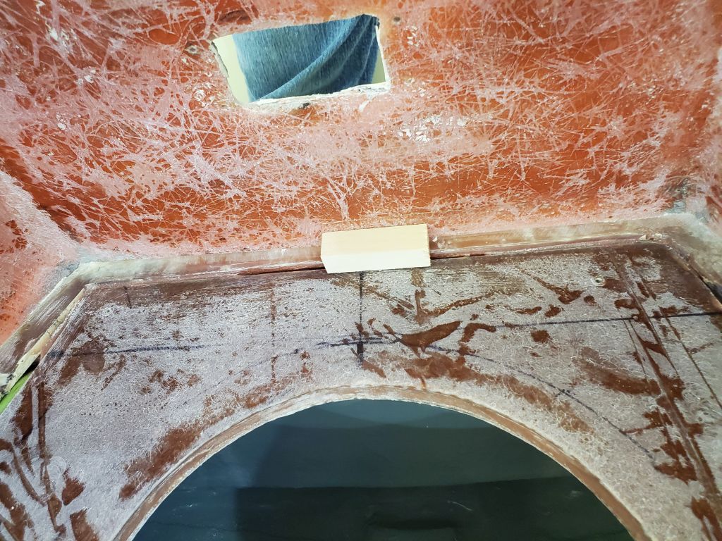
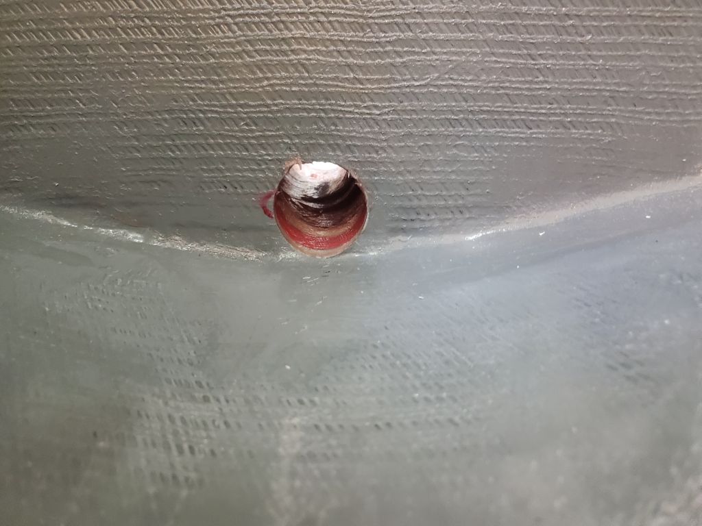
Afterwards, I finished up the masking with the two hatch openings in the outboard well, and the underside of the livewell hatch, which I’d already painted. I also remasked the remainder of the transom beneath the new scuppers.


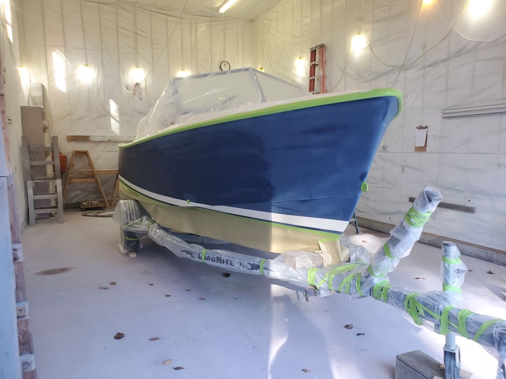
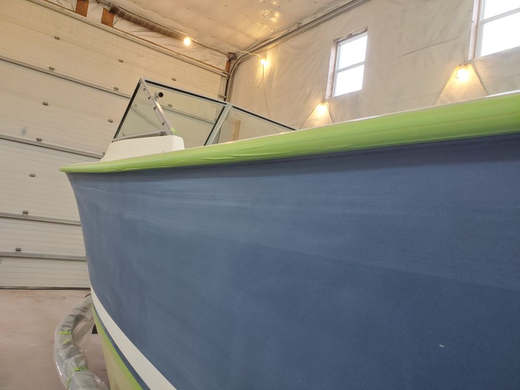
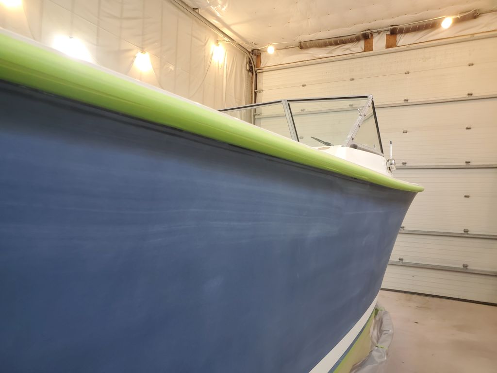
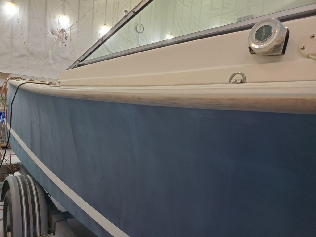
During the remains of the day, I prepared spray and paint equipment as needed, otherwise prepared the shop, and finished up with a final solvent wash of the hull and applicable deck areas using the proprietary solvent designed for this paint system.