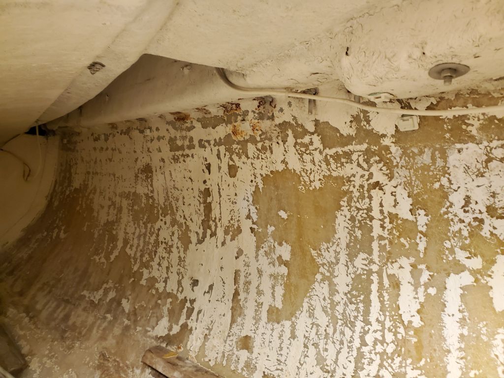
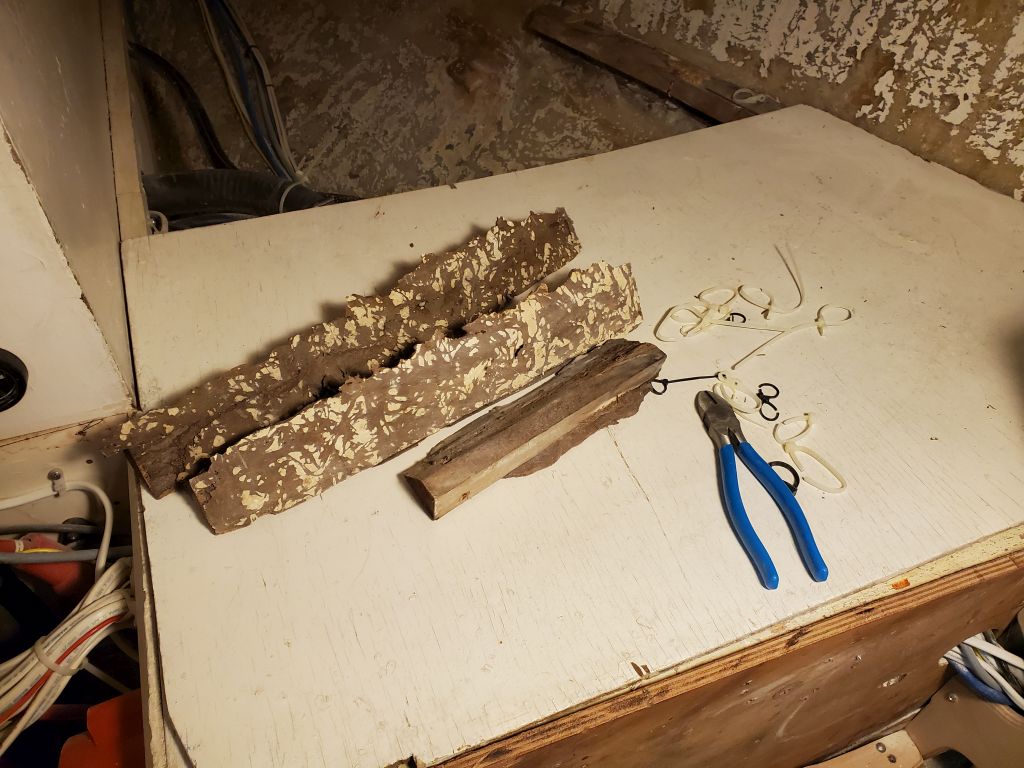
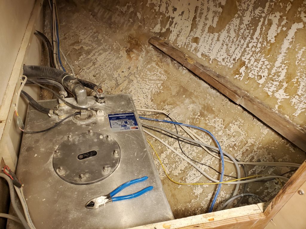
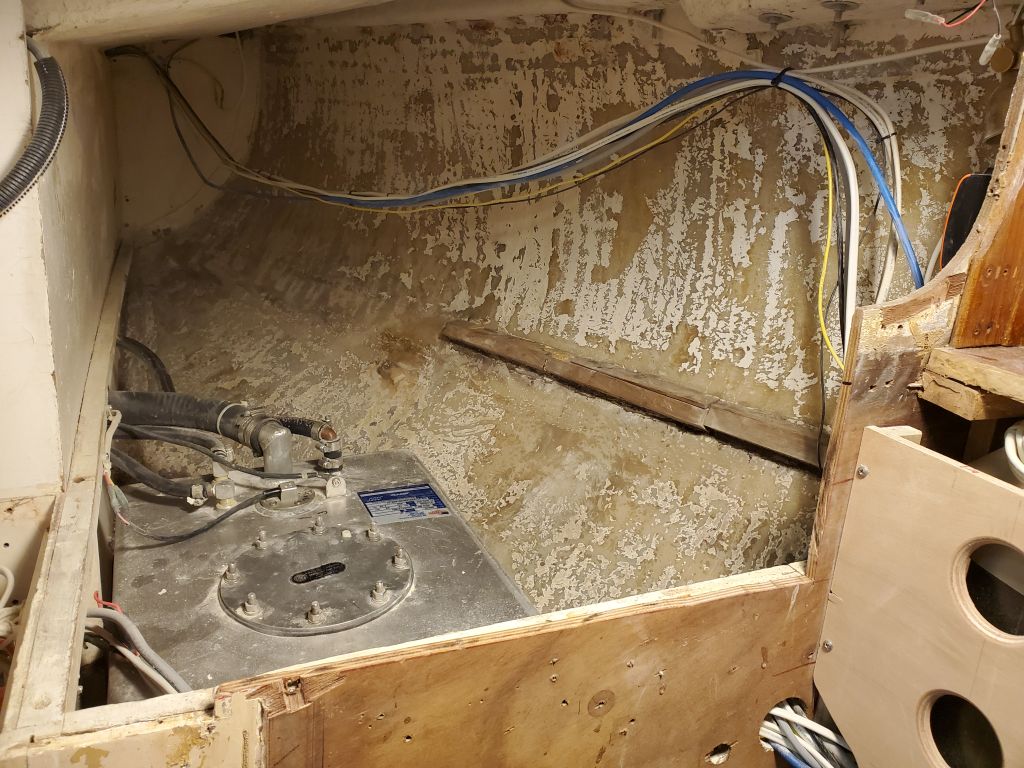
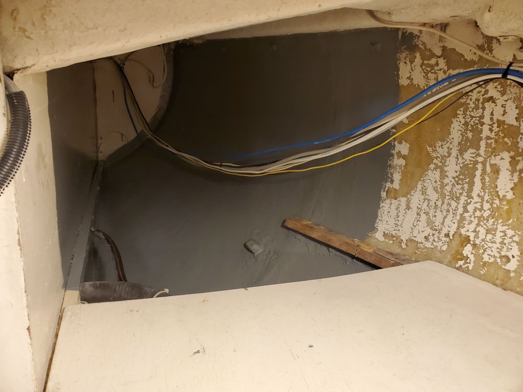
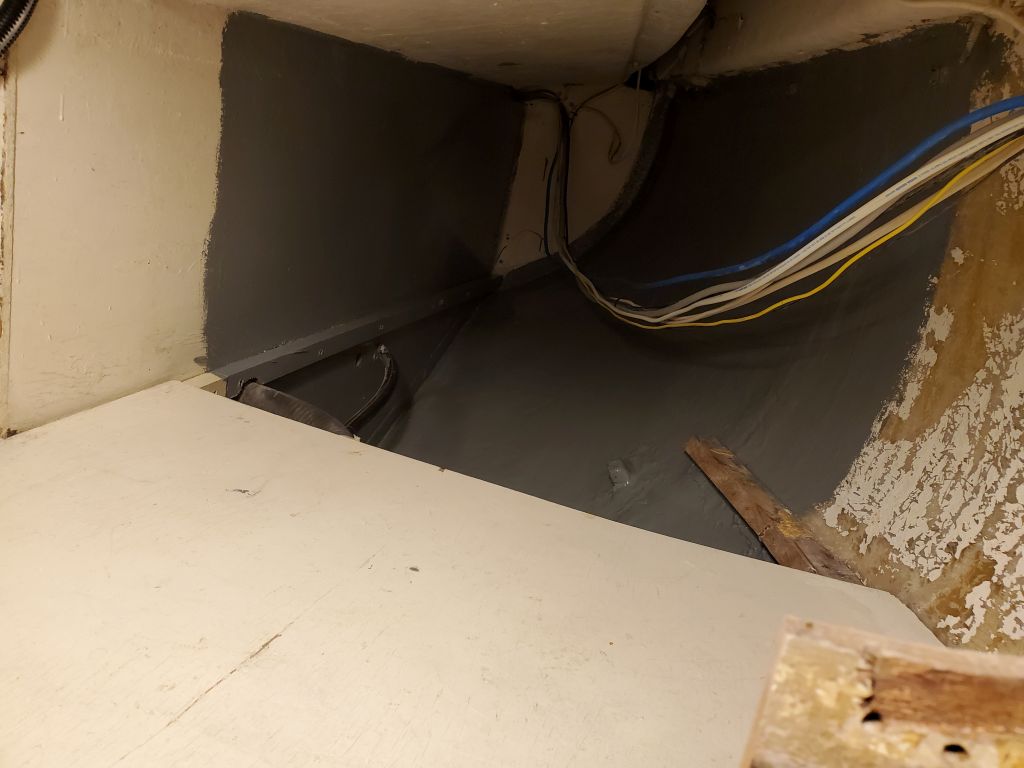
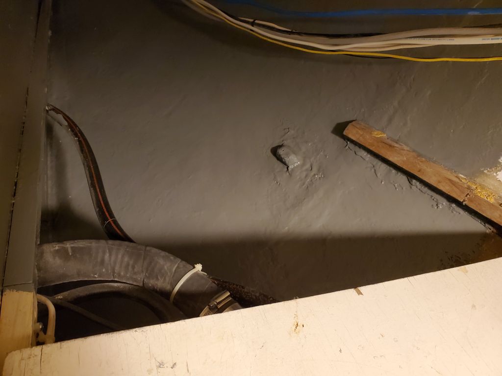
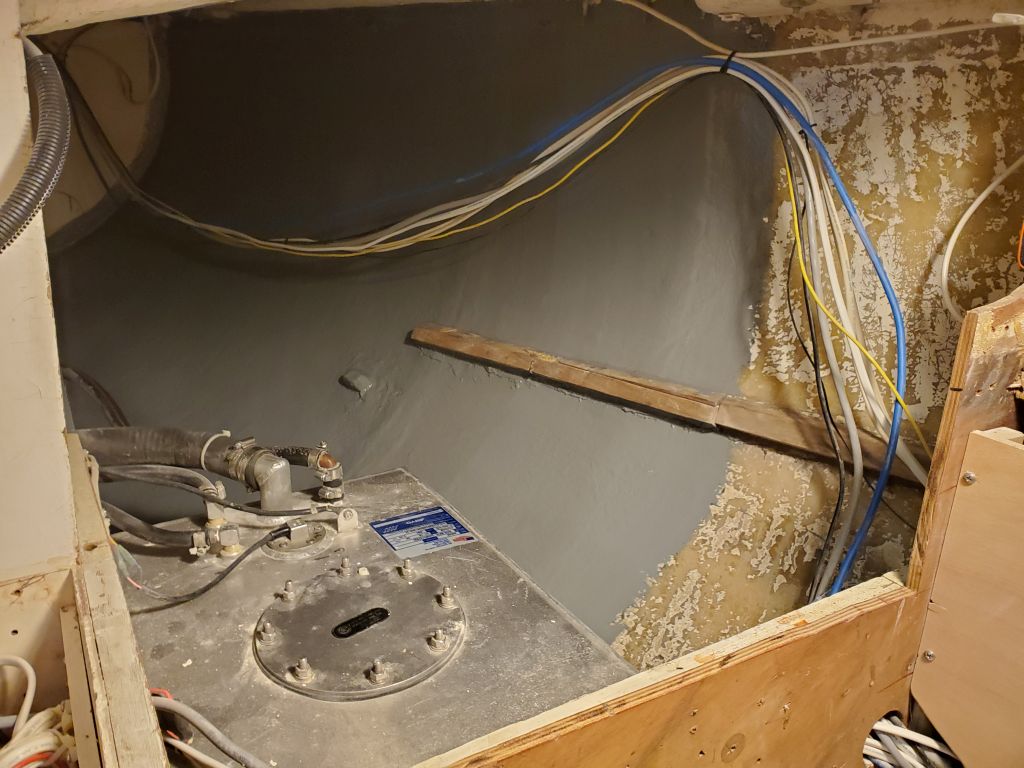
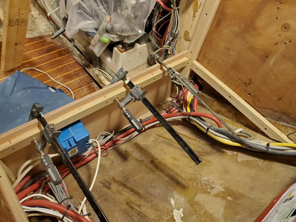
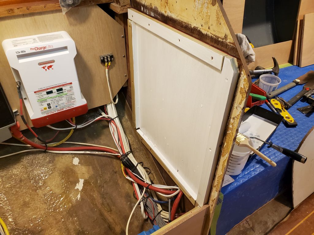
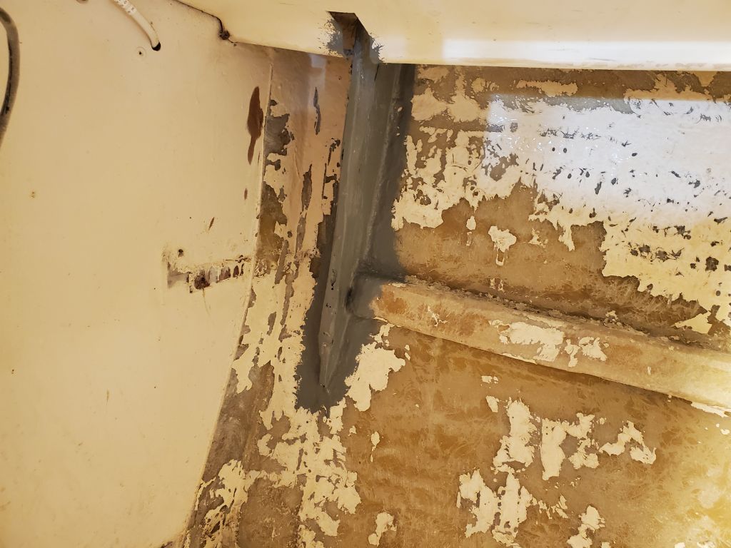
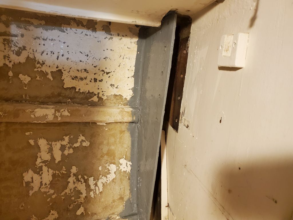
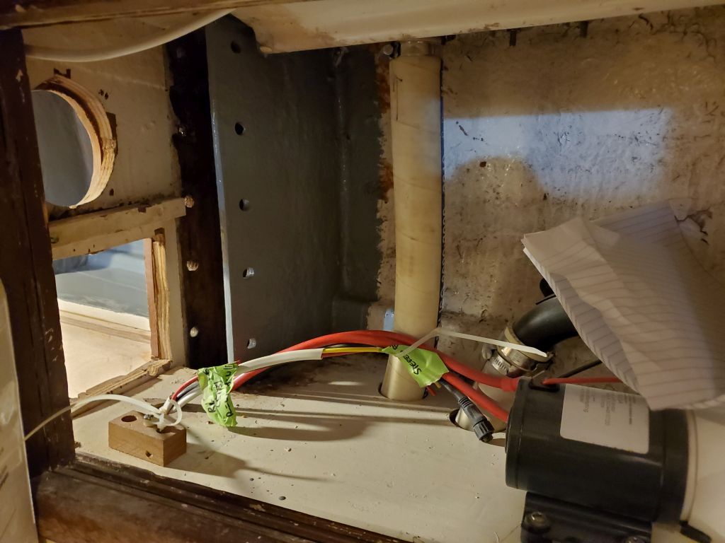
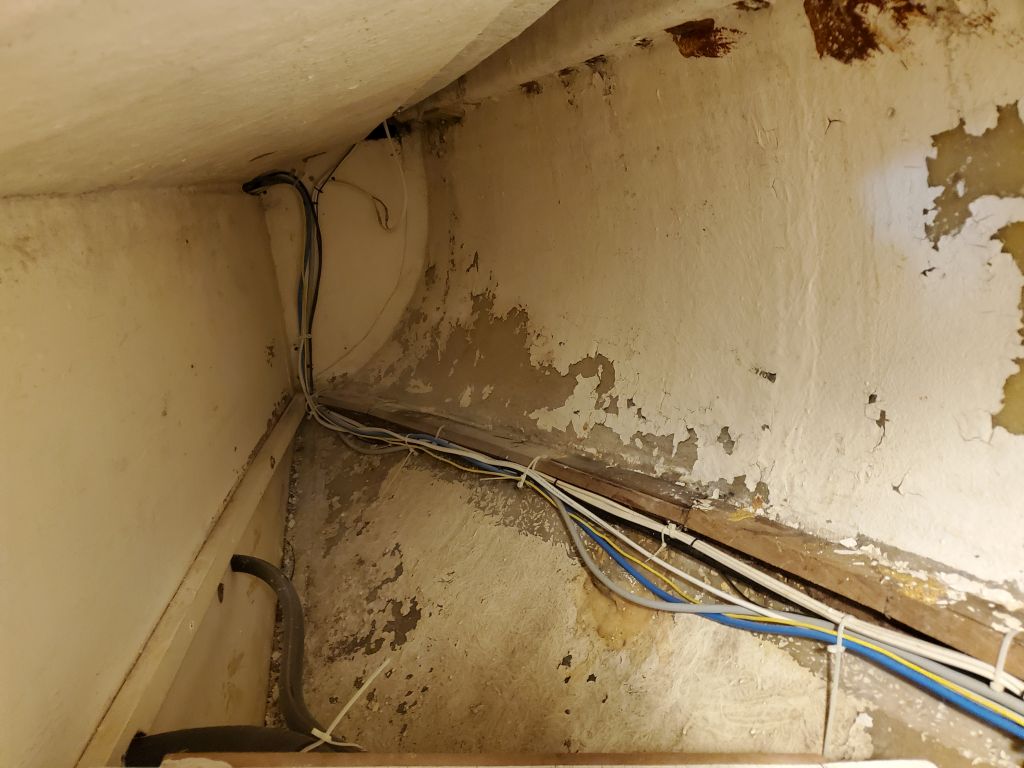
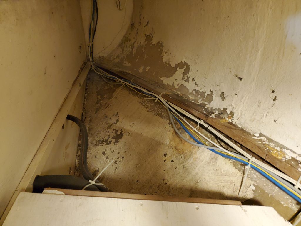
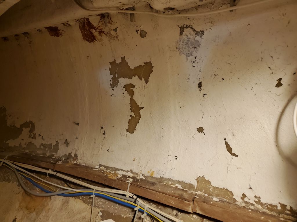
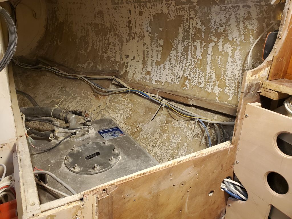
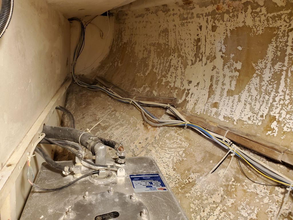
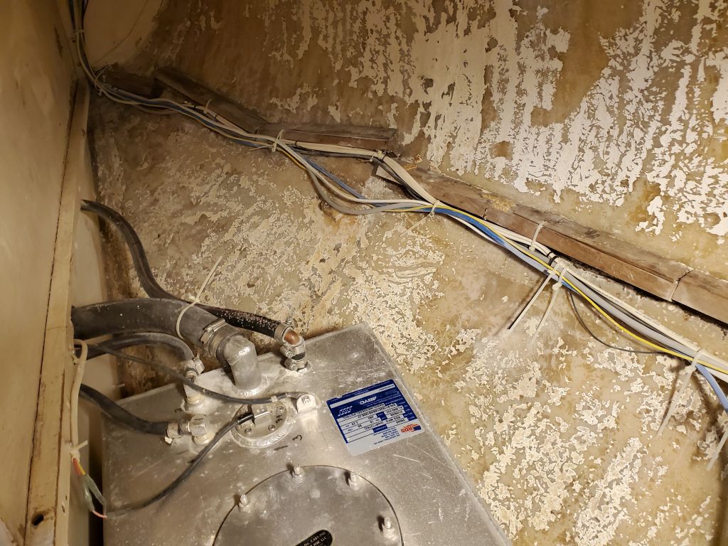
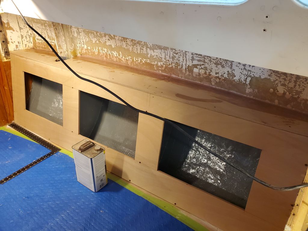
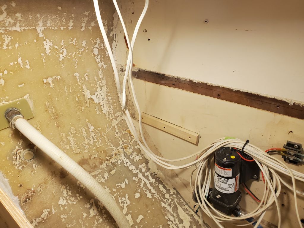
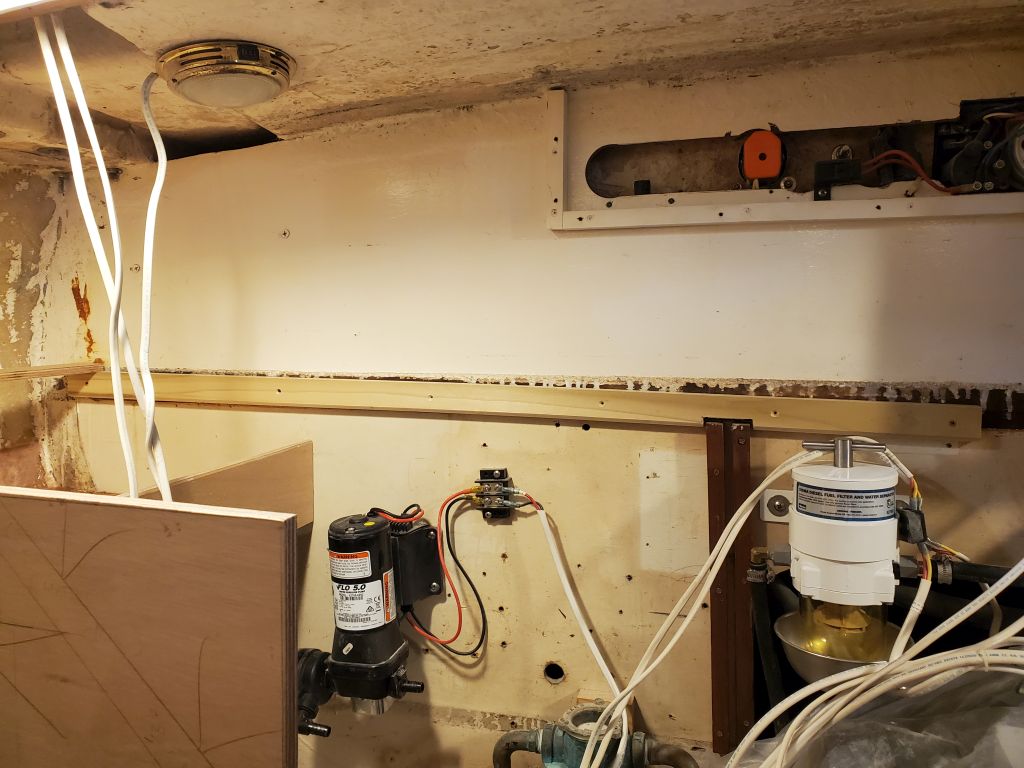
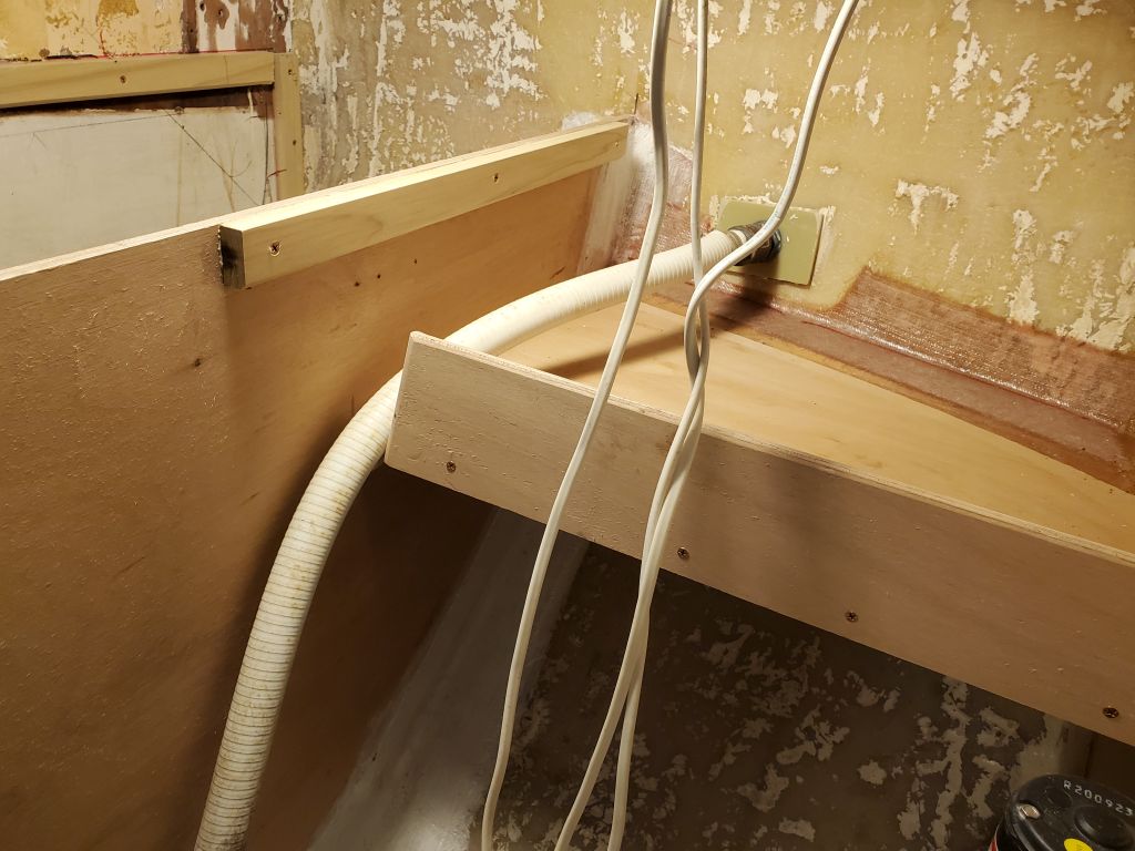
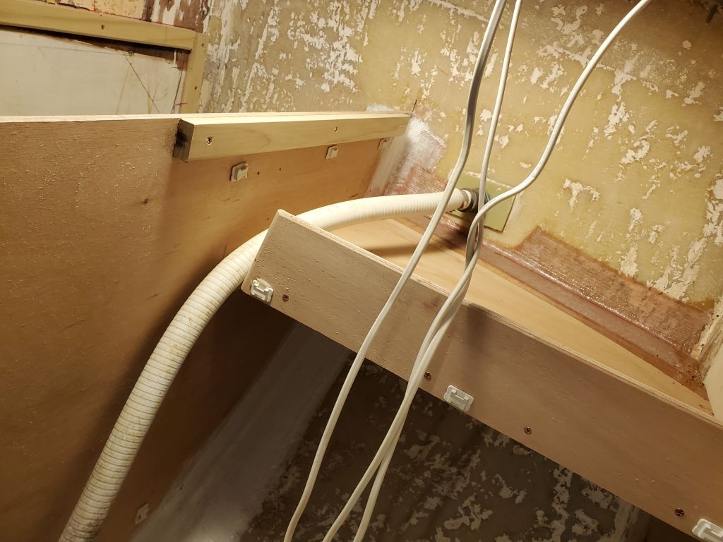
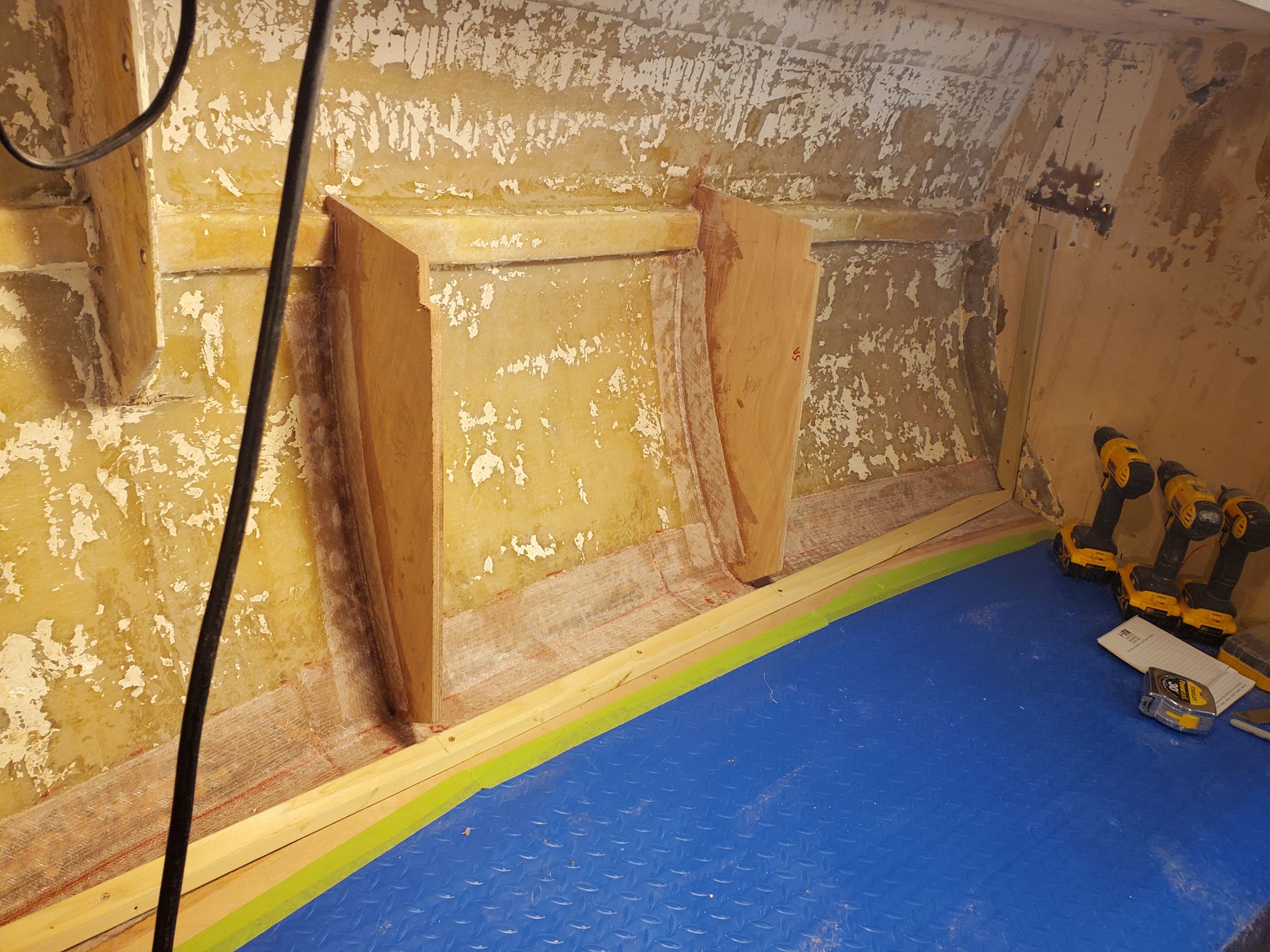
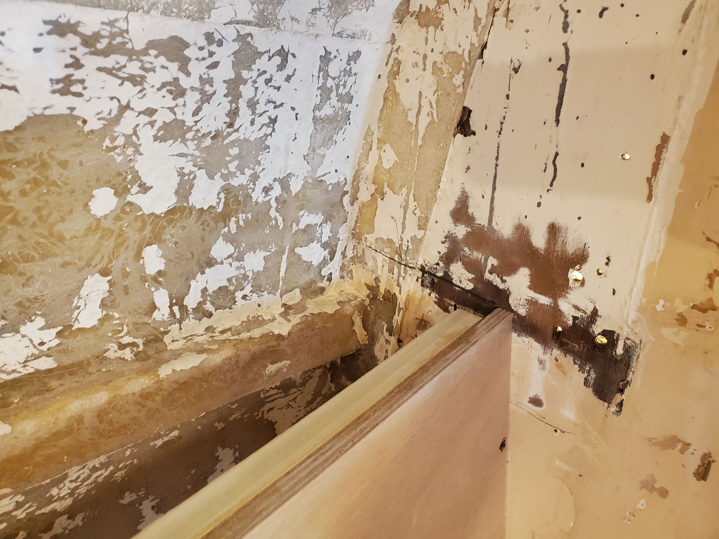
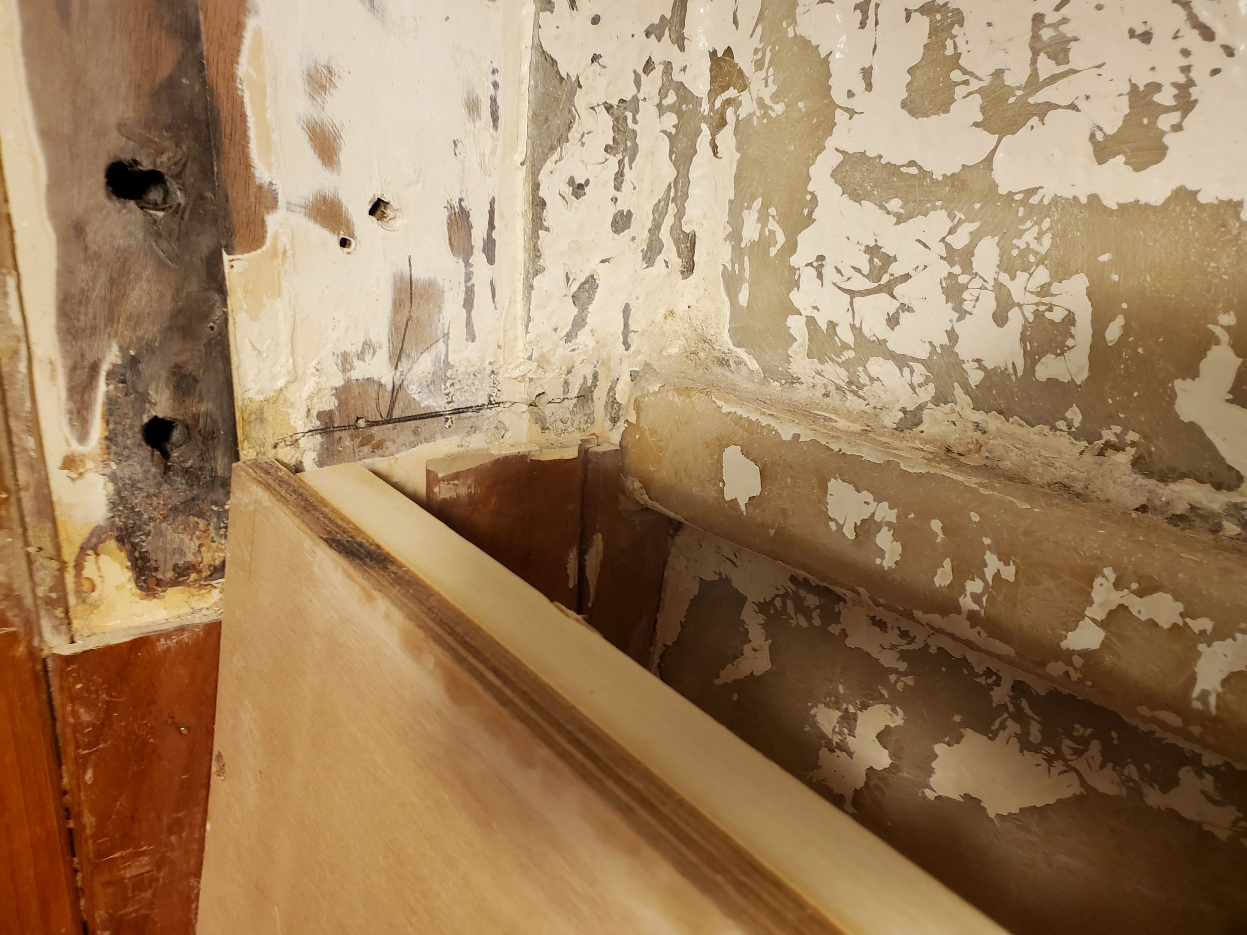
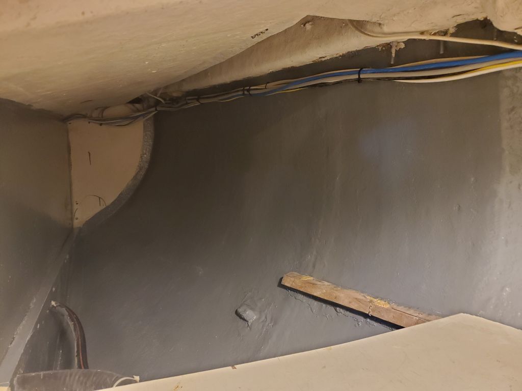
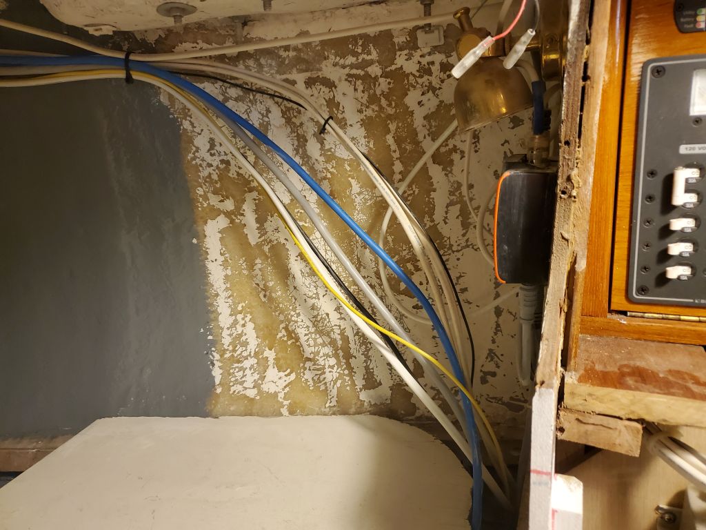
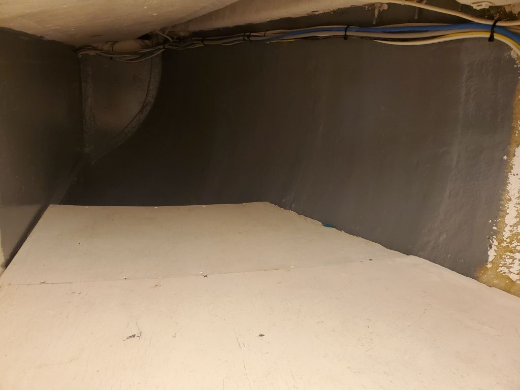
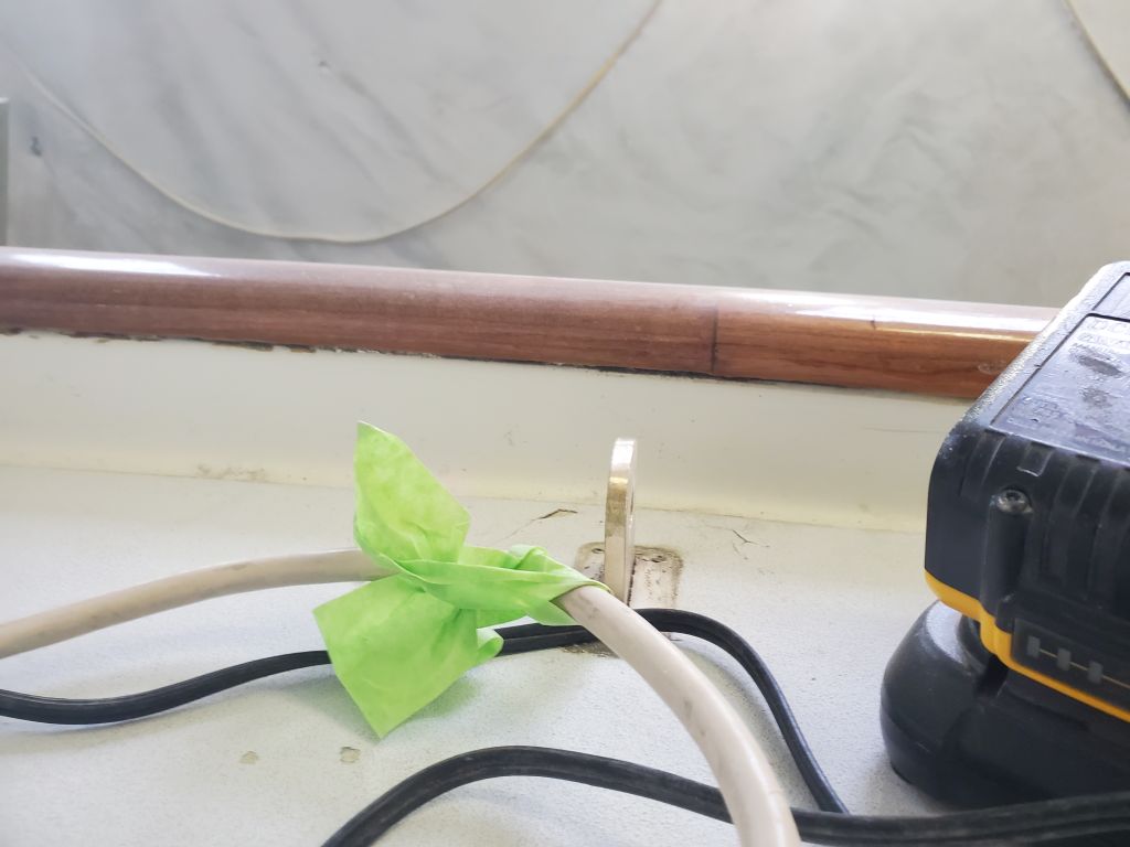
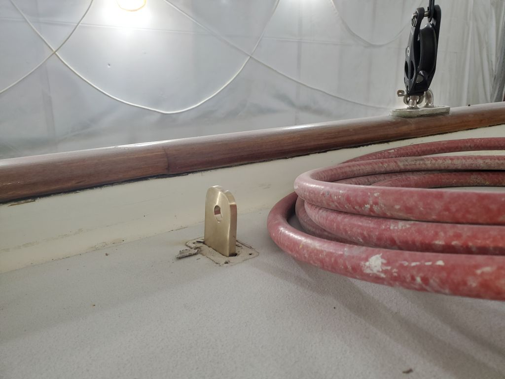
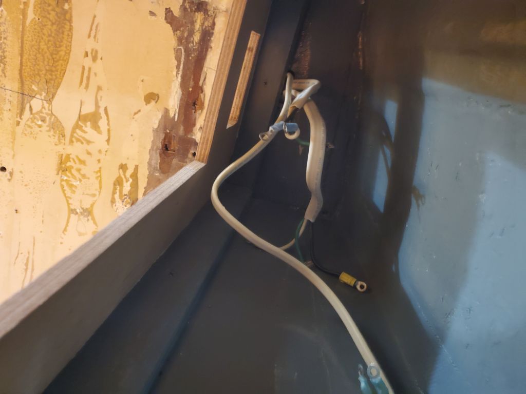
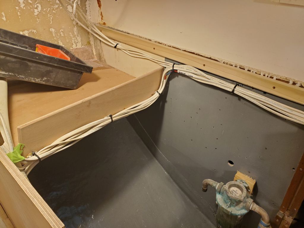
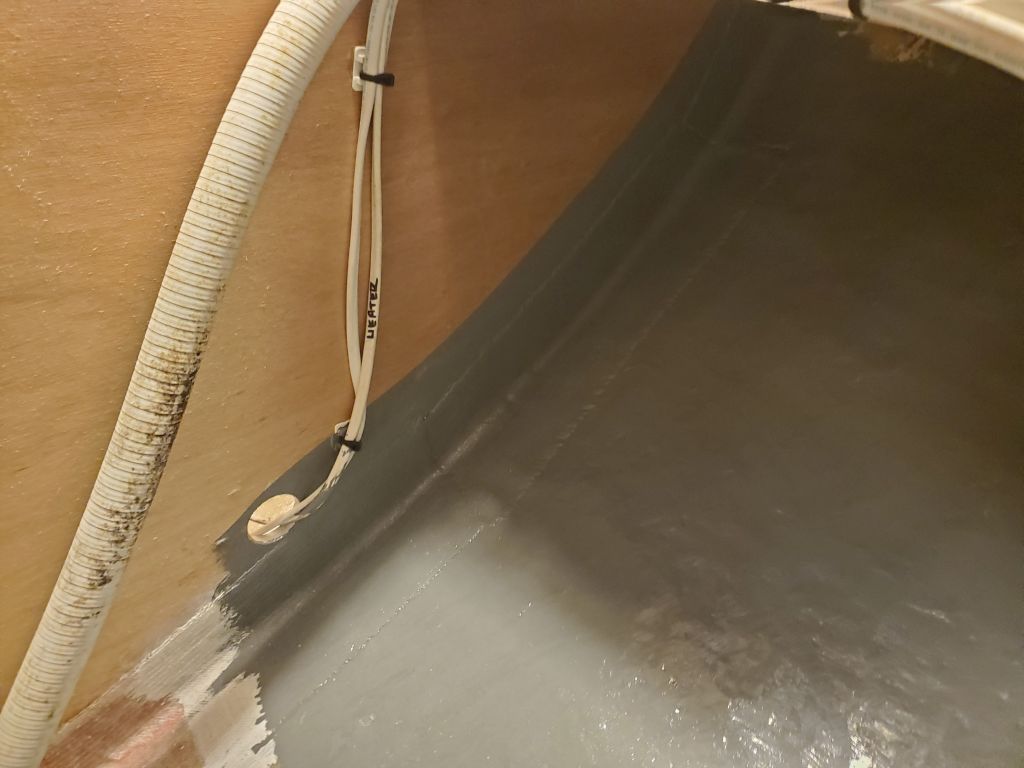
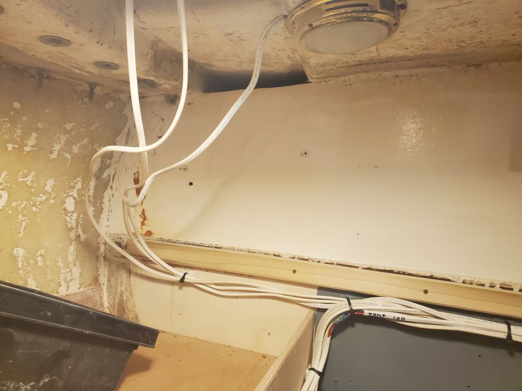
My first task was the contorting one of getting the wire bundle in the quarterberth secured to the new wire mounts beneath the gunwale, now that the paint was finished. I also painted the small bulkhead at the aft end of the space, which had been tough to get to with the wires in the way before. At the forward end, I still had to see where the wires would end up leading themselves and how the galley work would tie in, so I left that part of the bundle unsecured for now.
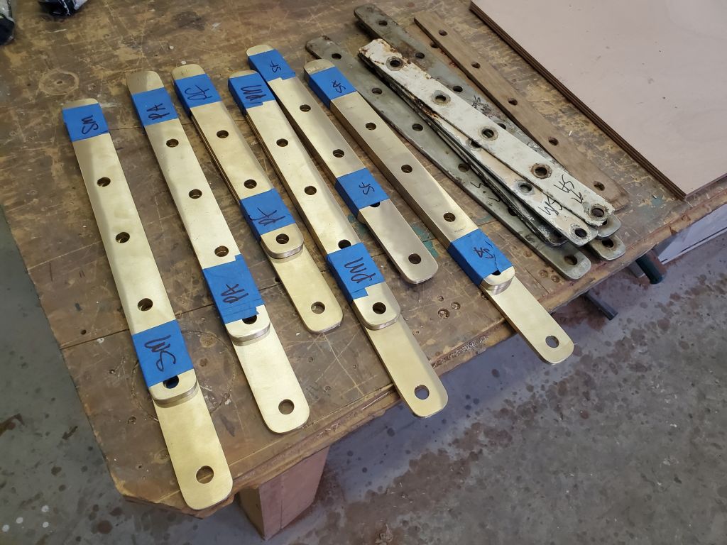
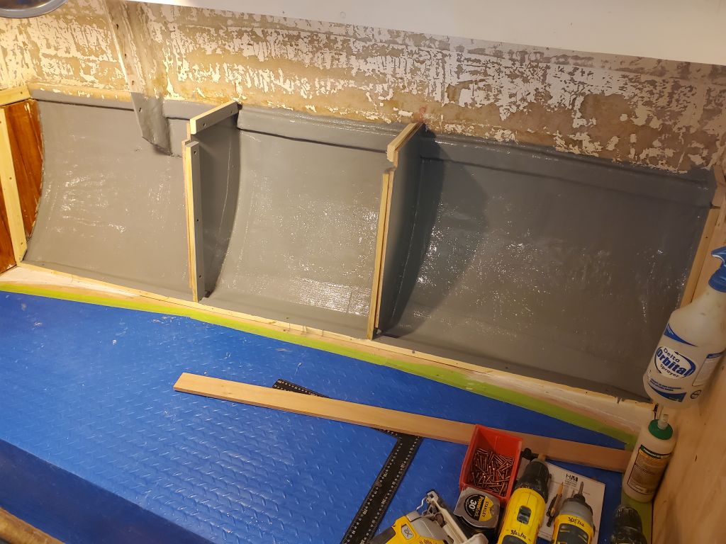
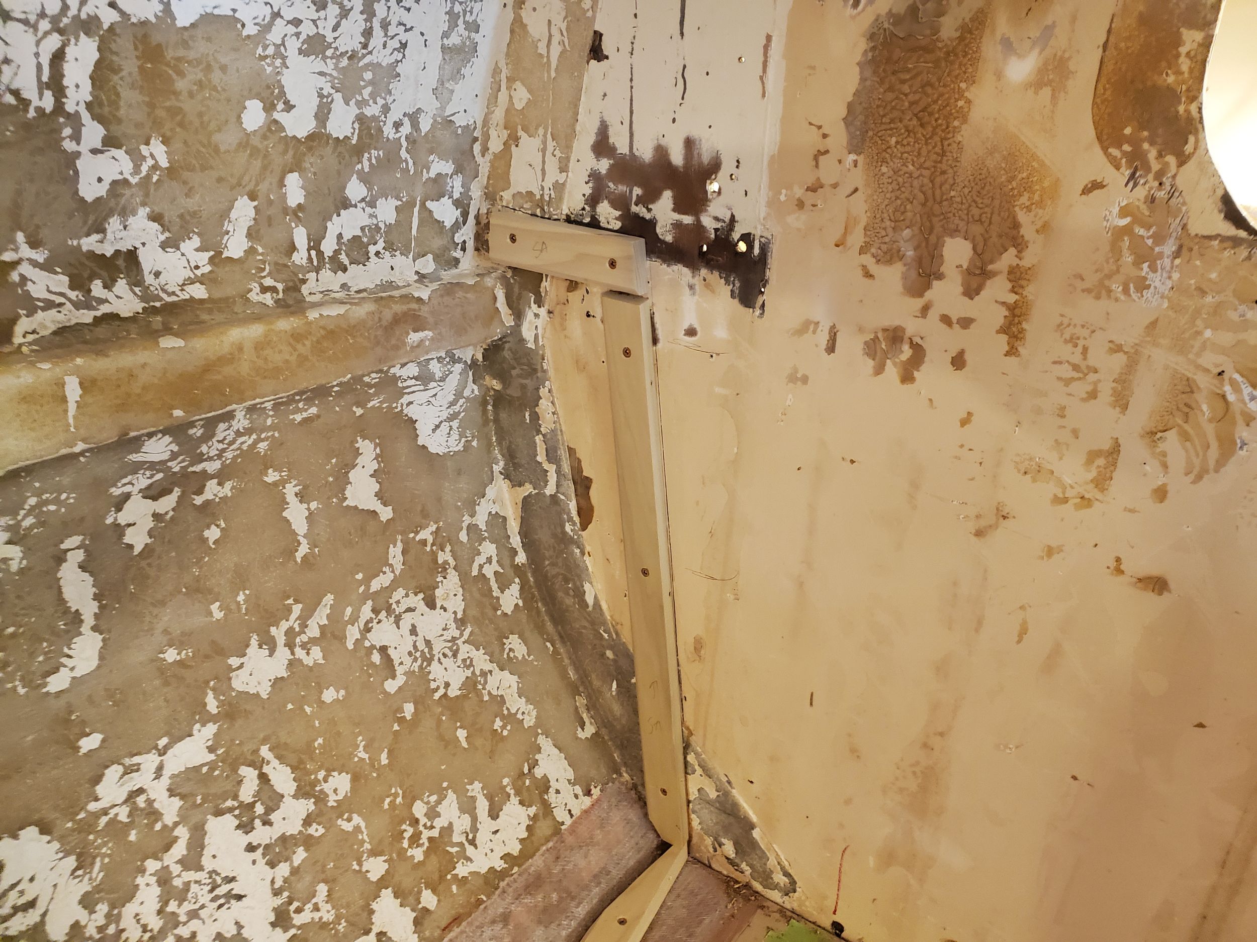
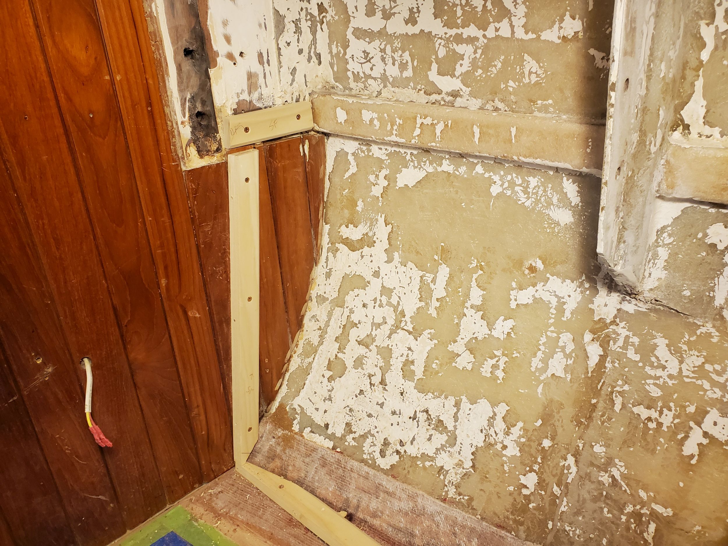
With most of my new bronze hardware on hand for the chainplates, I decided to install the after four, leaving the two new forward lowers for another time (none had ever been installed before and I’d need to cut slots through the deck). Installing the two aft lowers wasn’t too bad, though on the port side, where the alignment of things was a bit different, it turned out to be awkward getting the lowest bolt in, as it was more or less aligned with the settee shelf, so I had to open up a new slot in the shelf on the fly. I’d come back some later time to install the deck plates and bedding.
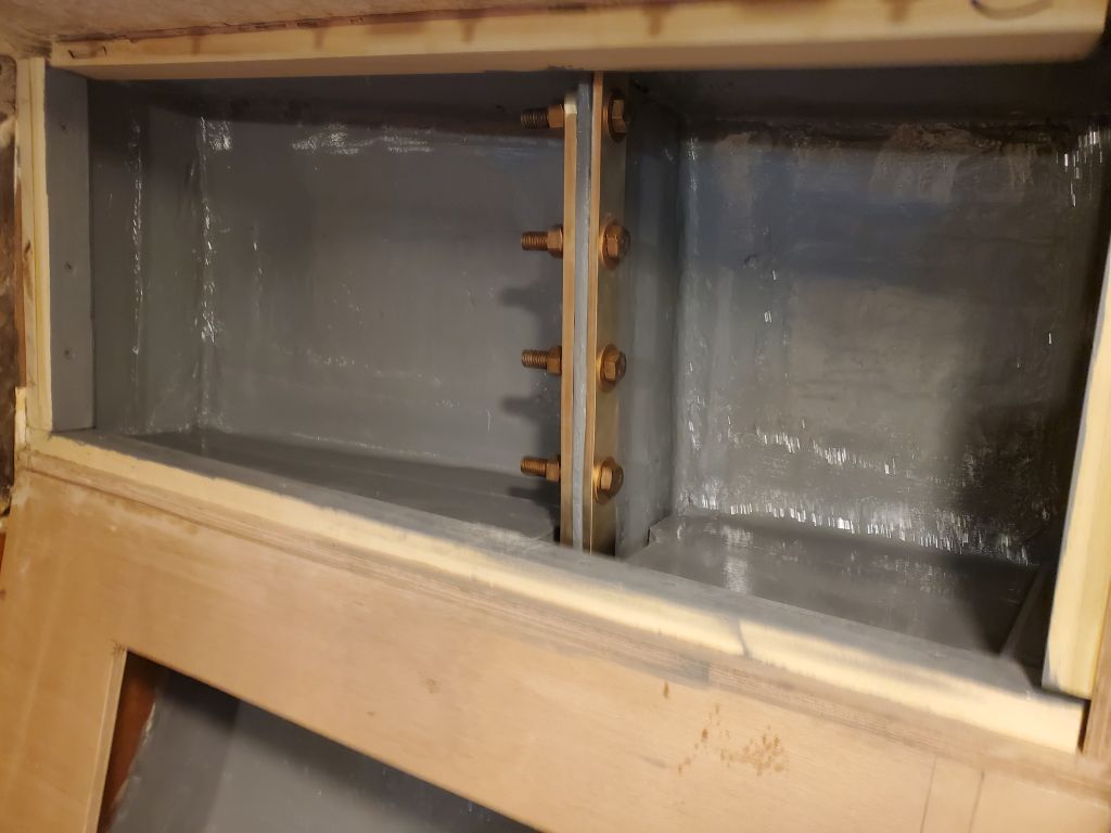
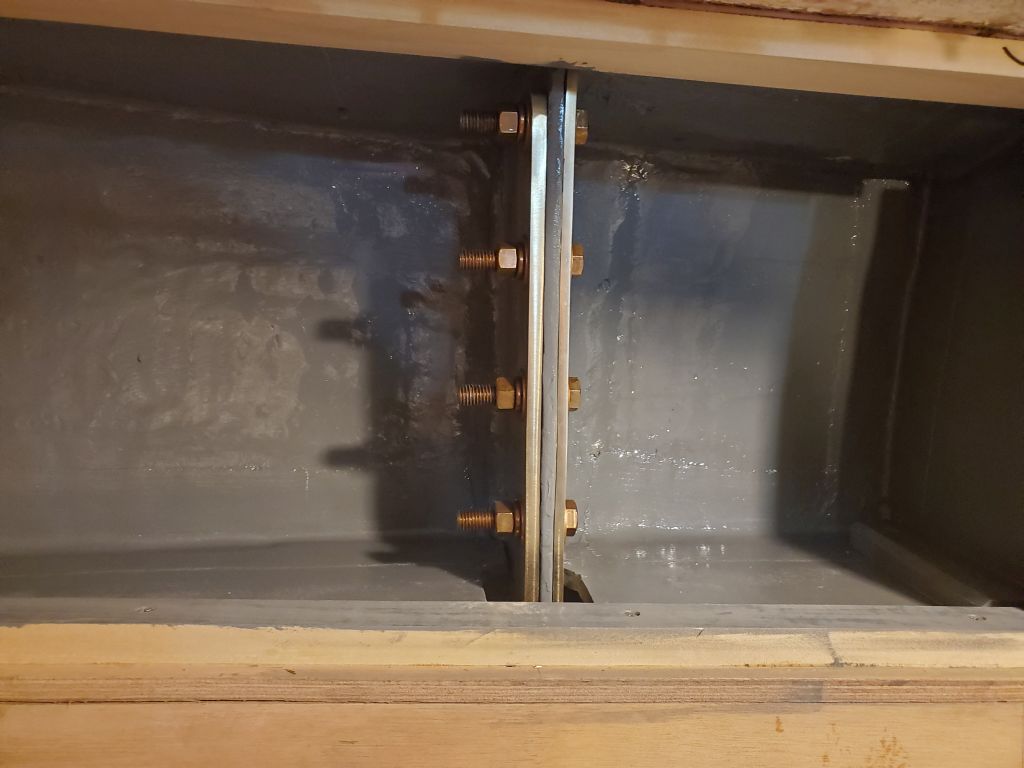
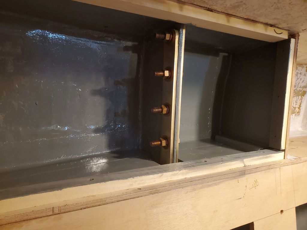
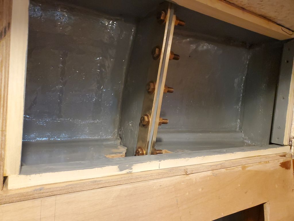
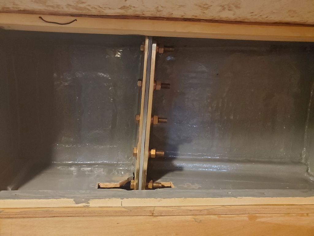
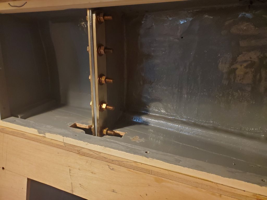
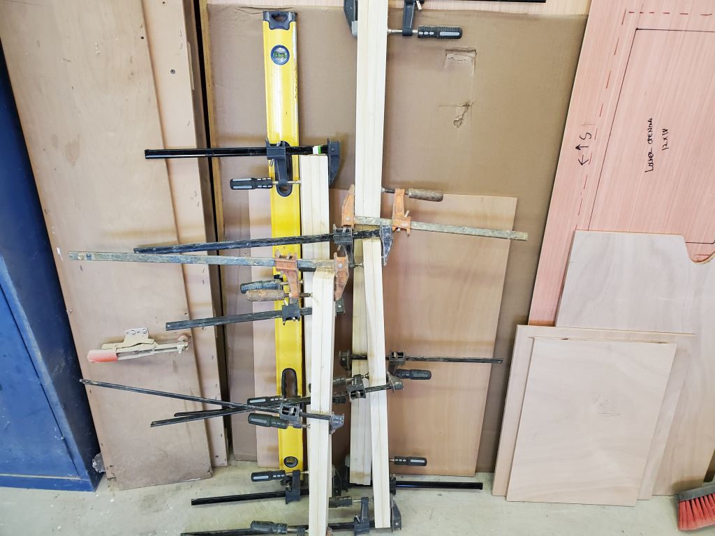
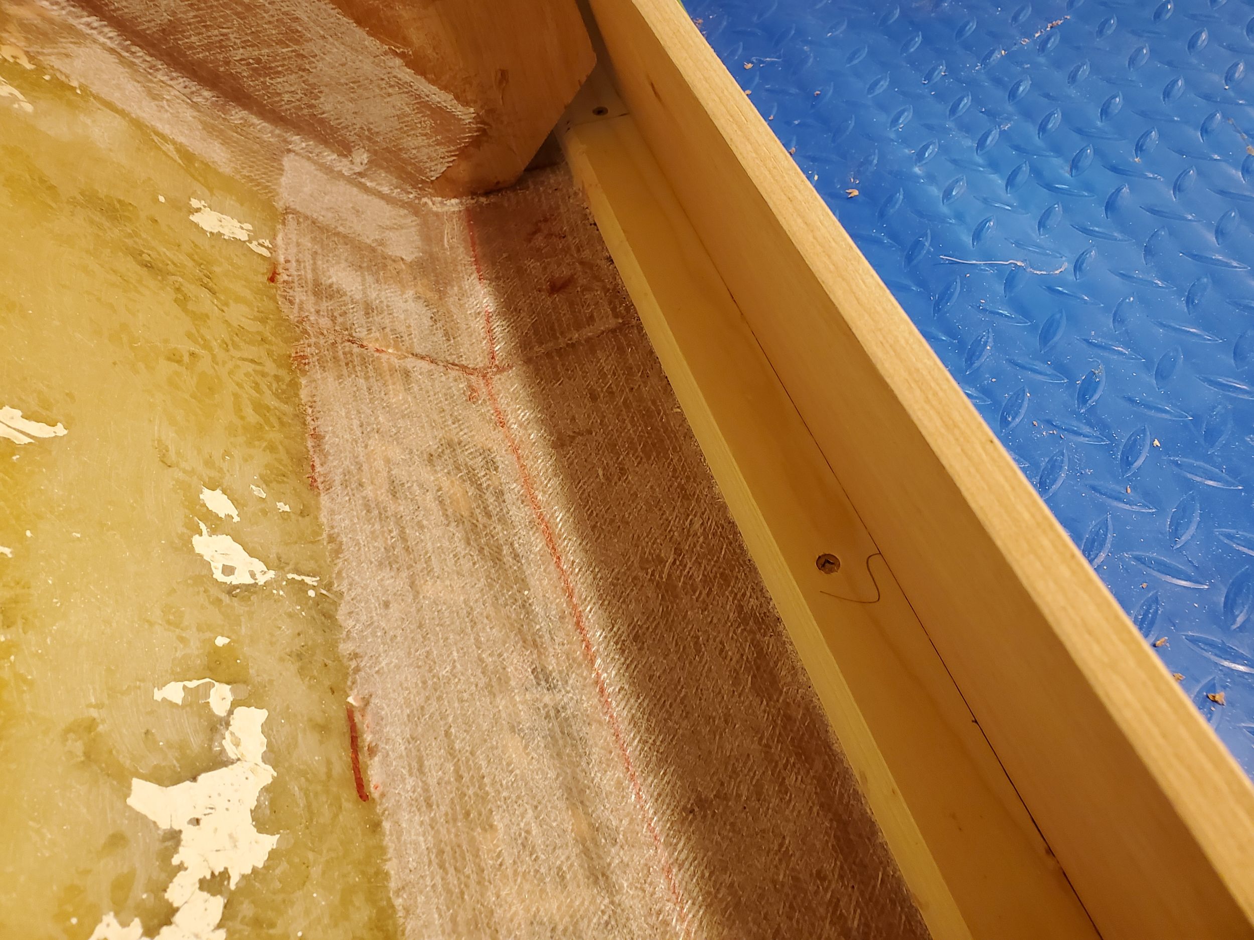
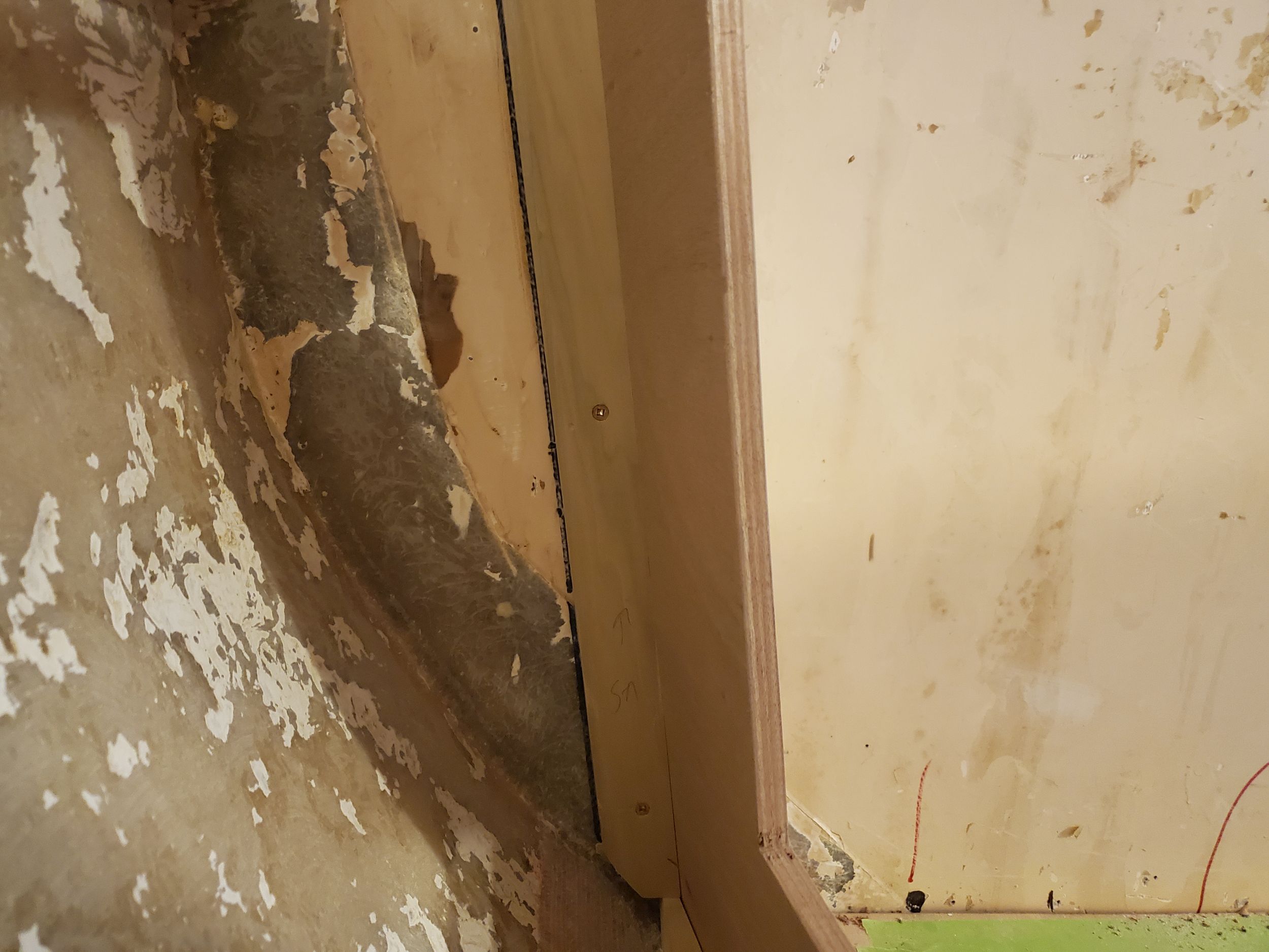
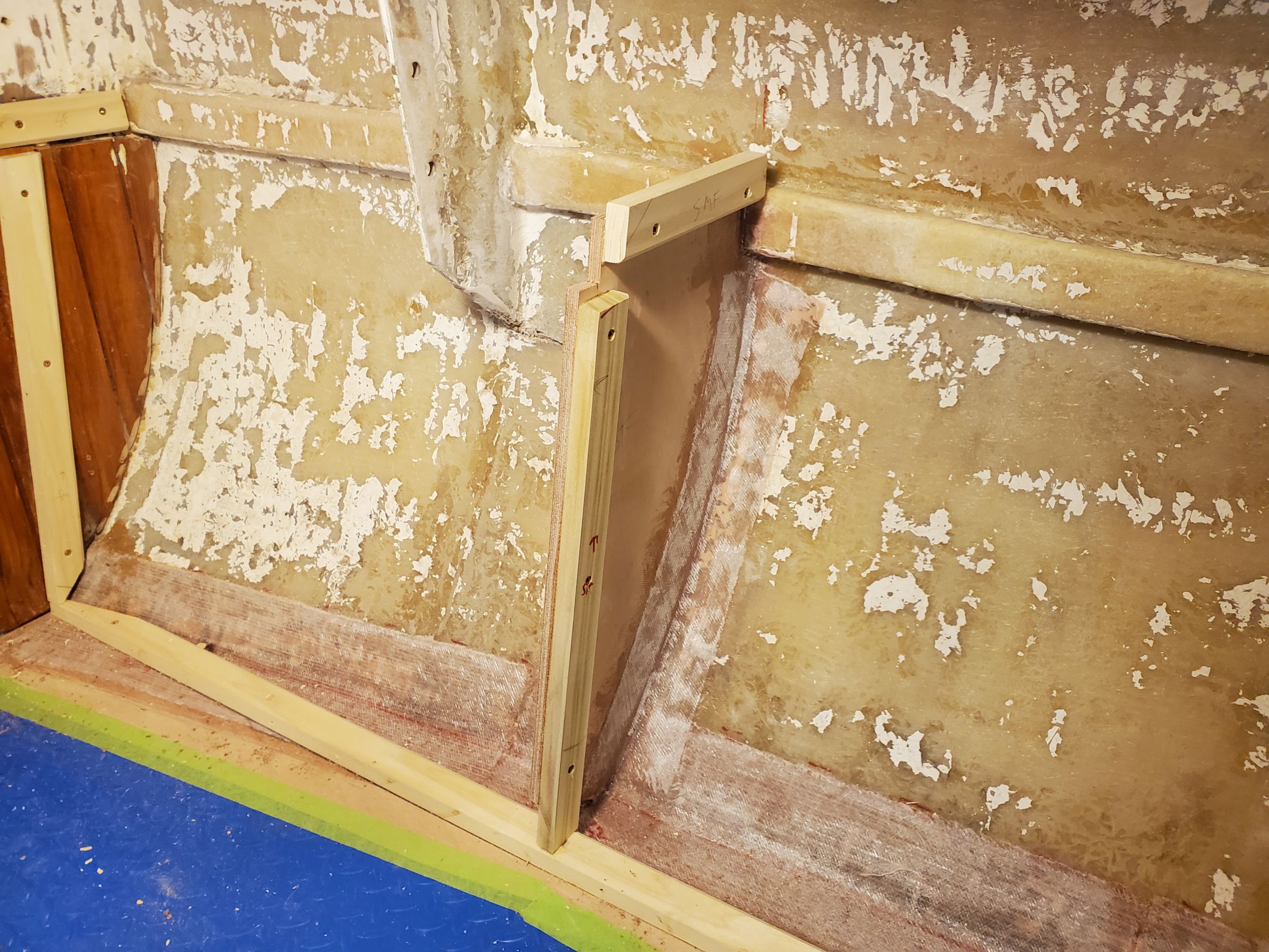
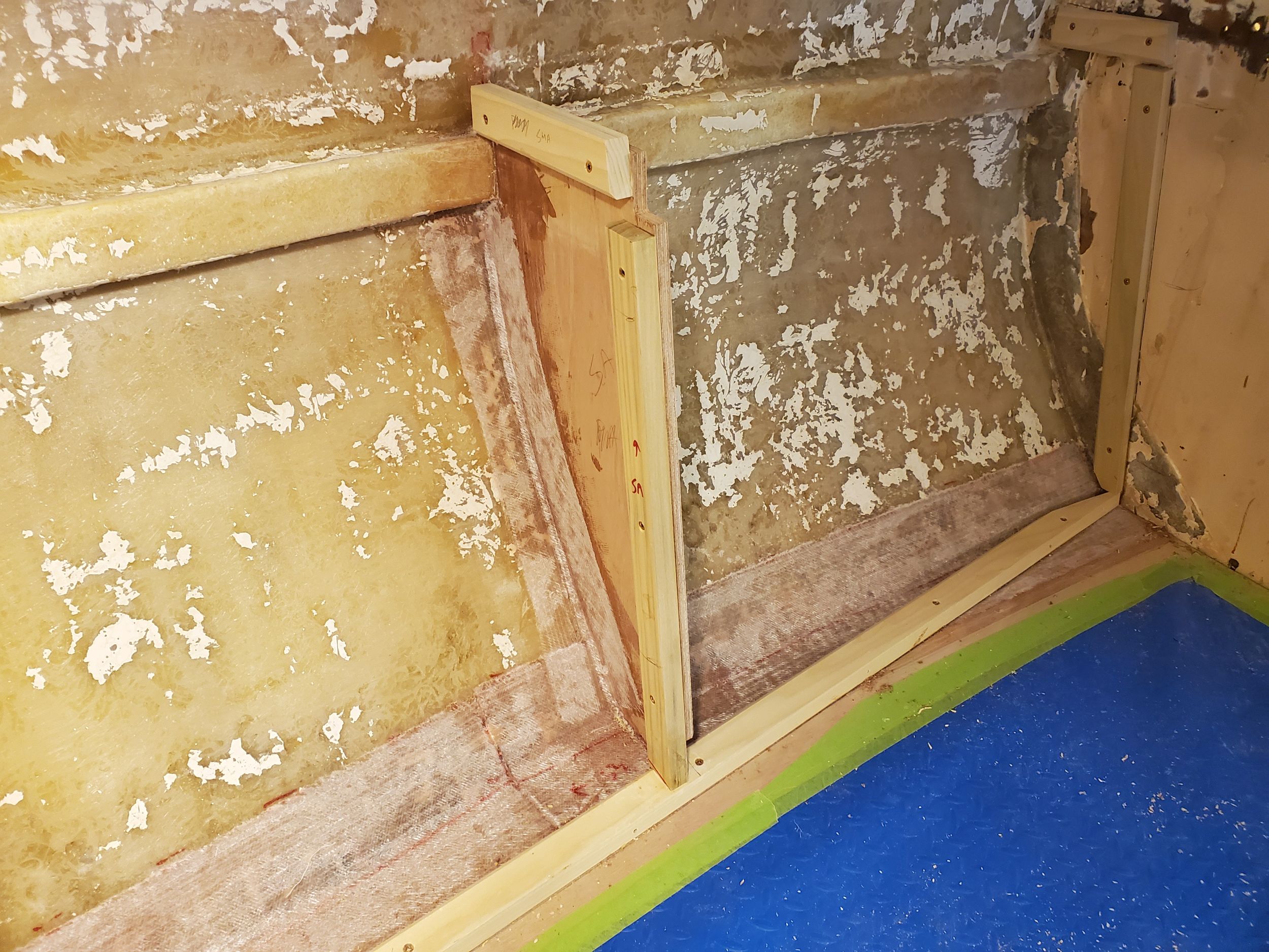
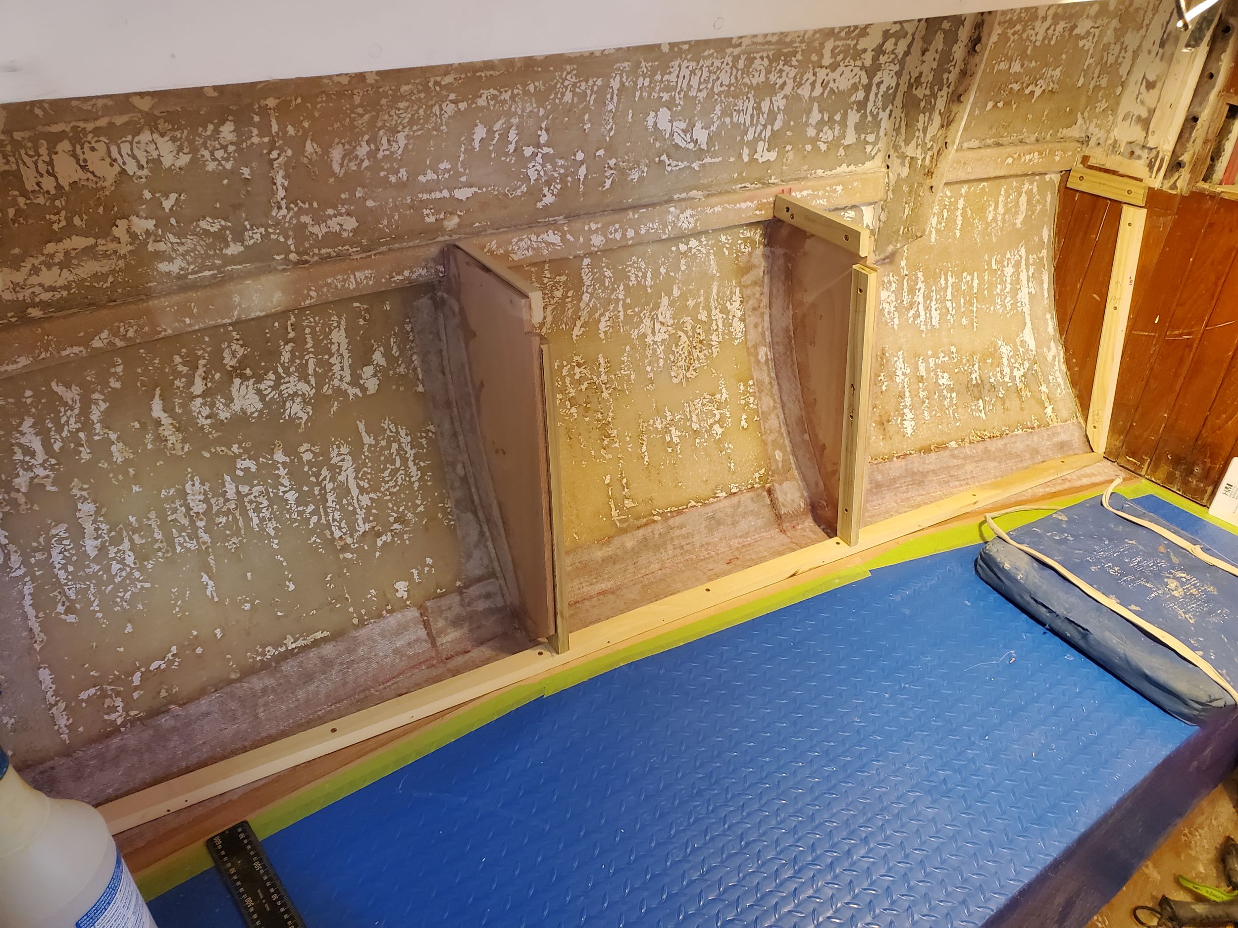
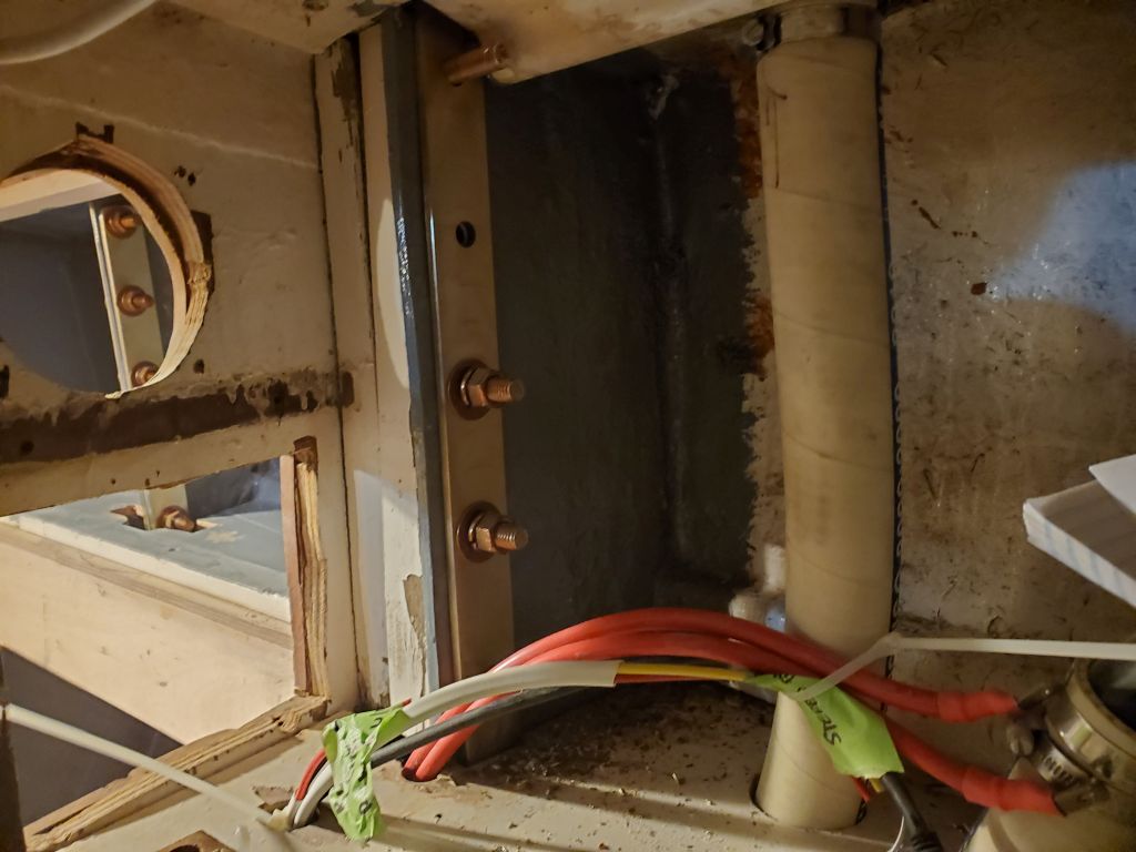
The main chainplates, or uppers, were a bit more difficult to install. Though there was a substantial set of fiberglass knees for the chainplate forward of the main bulkhead, the original installation had bolted the chainplates through both, with wooden spacers to fill the 2-1/2″ gap between the bulkhead and knees. I had no desire to change the original, so I installed the replacements the same way. This ended up taking some time because the tiniest misalignment on one end, with spacers, backing plates, and five, 5″ bolts, turned into something more difficult at the other end, and it simply took much longer to get the bolts in place (particularly on the starboard side, which was the first one I tried) than one would think. Otherwise, the process went smoothly enough, though I did end up ruining the threads on the end of one of the bolts, so I had to order a replacement since I’d ordered only enough for the job, as these bolts were expensive and otherwise unneeded stock around the shop.
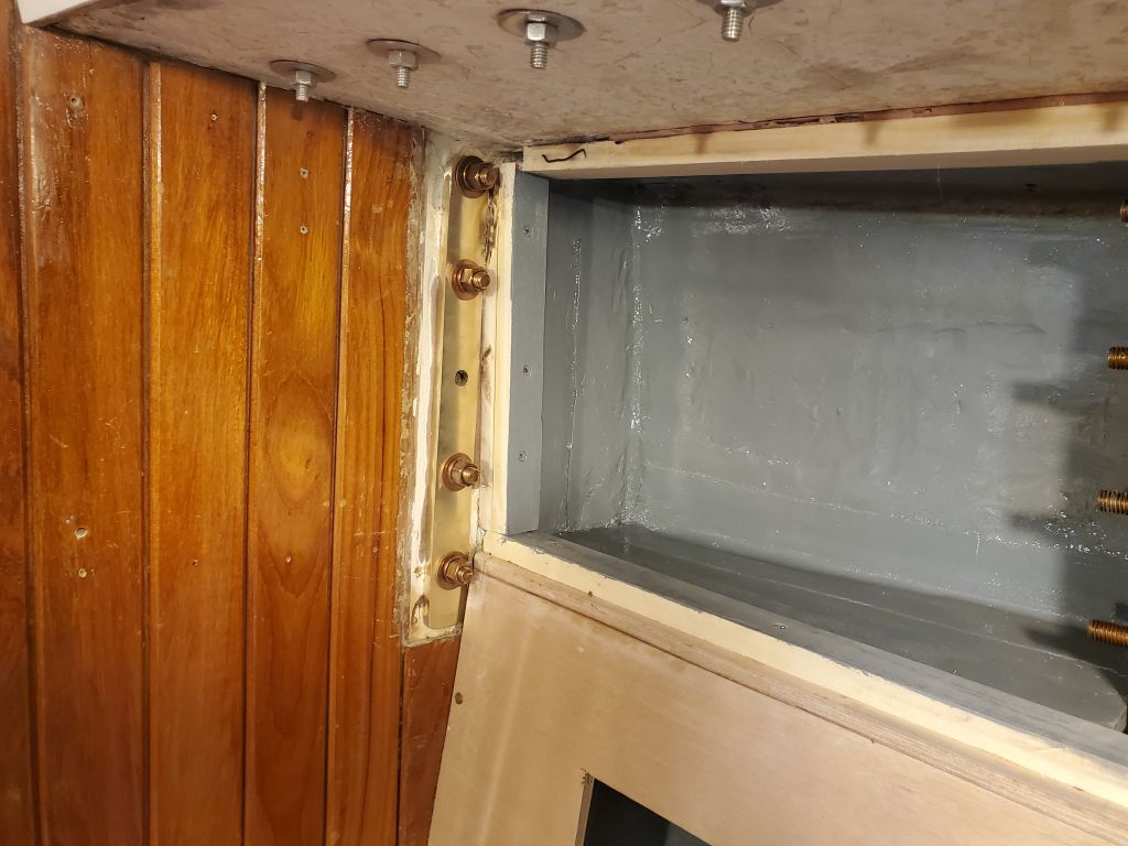
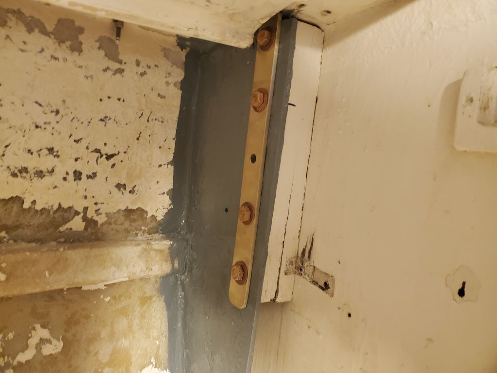
I had to order 6″ bolts for the port side because of latent differences between the two sides, and these came from a different supplier, but later in the day they arrived and I had better (and faster) luck with this side–though I’d miscalculated the number of washers needed, perhaps because I didn’t account for using flat washers on both sides of each bolt, so I couldn’t finish the installation with what I had on hand. But all the holes were aligned, and I hoped to be able to finish the installation quickly with additional washers.
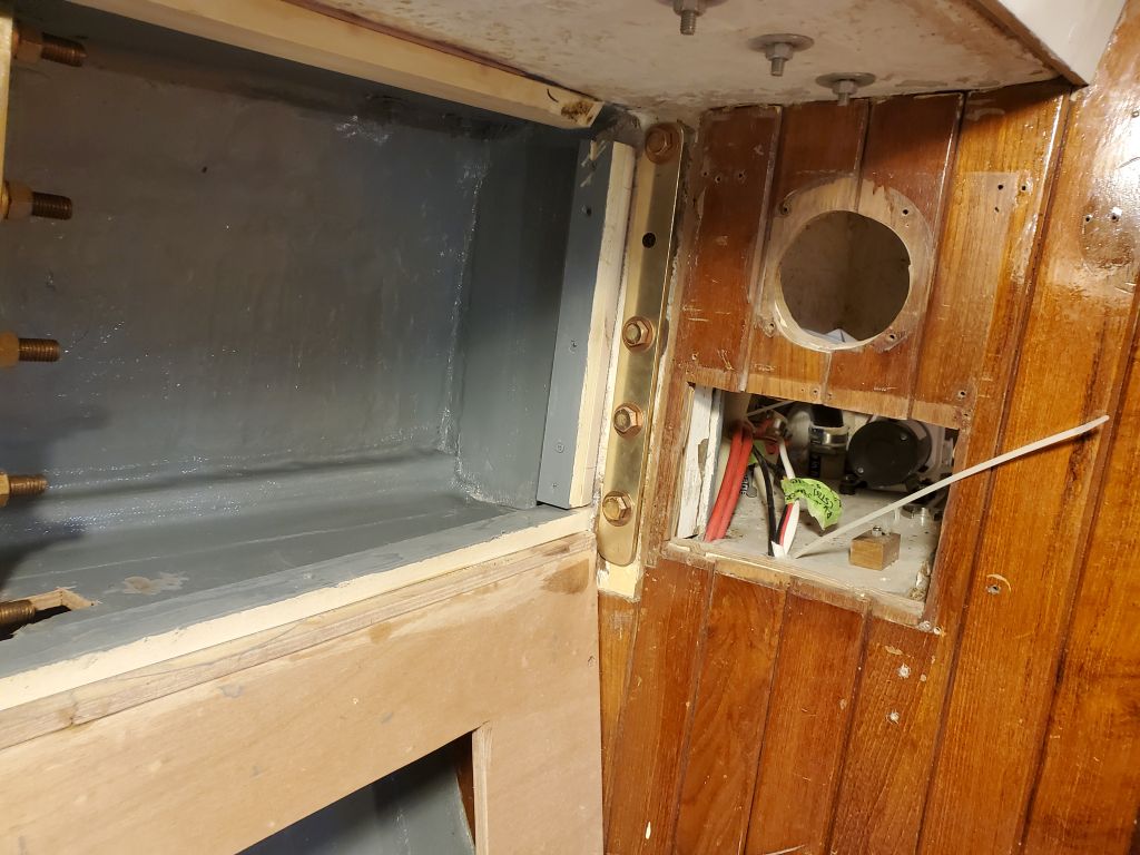
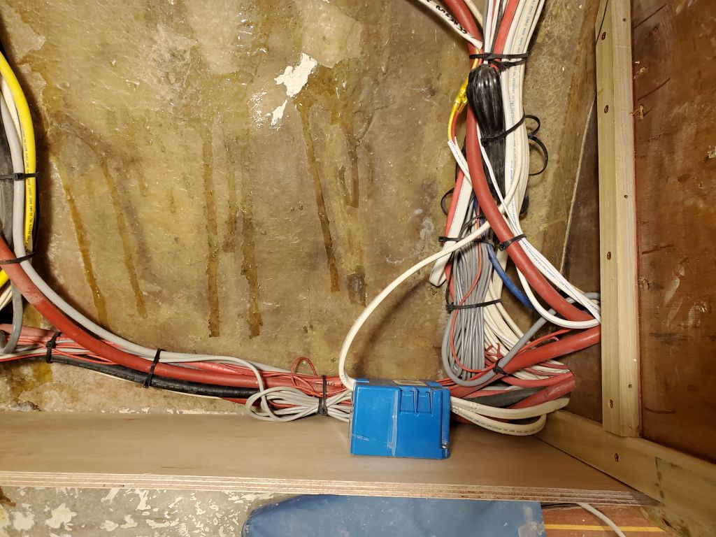
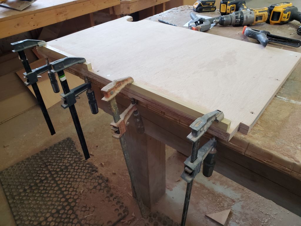
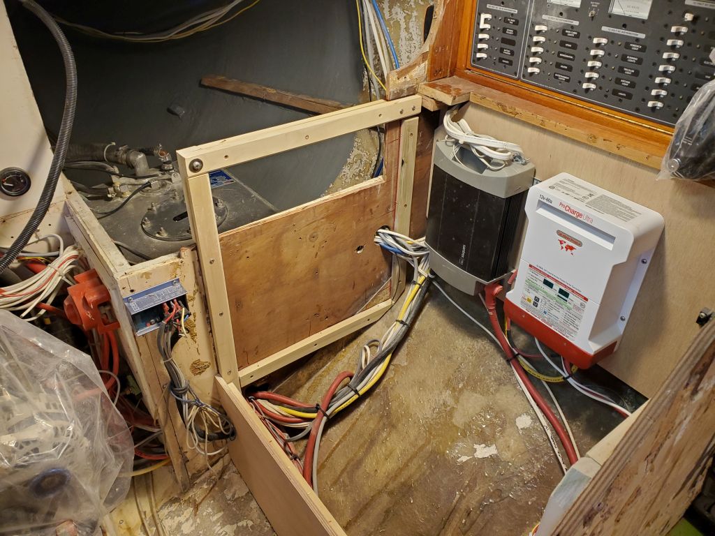
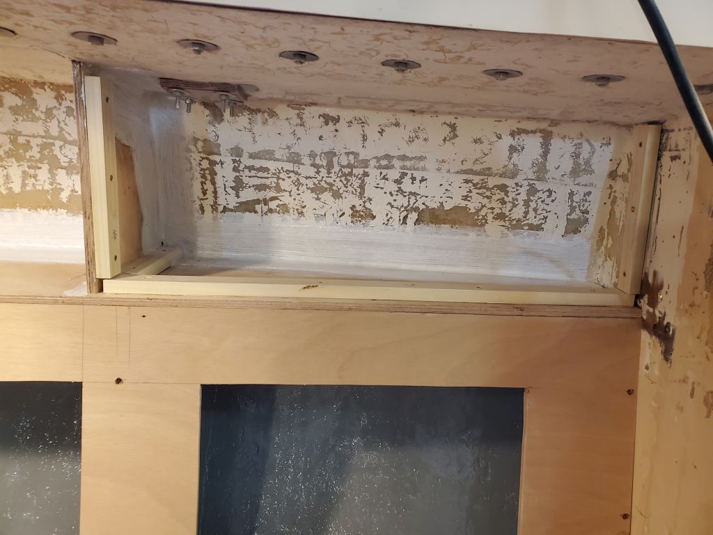
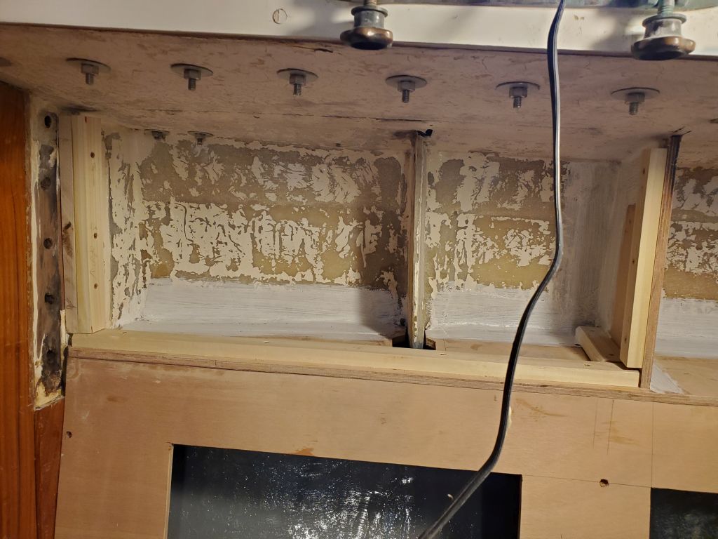
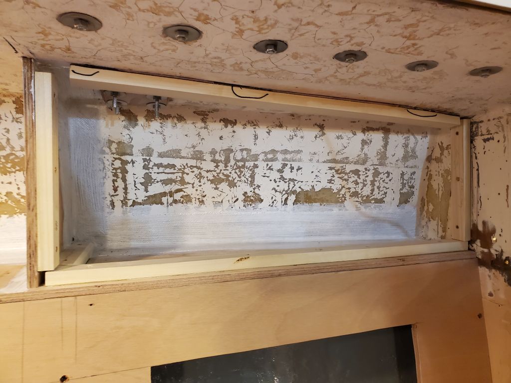
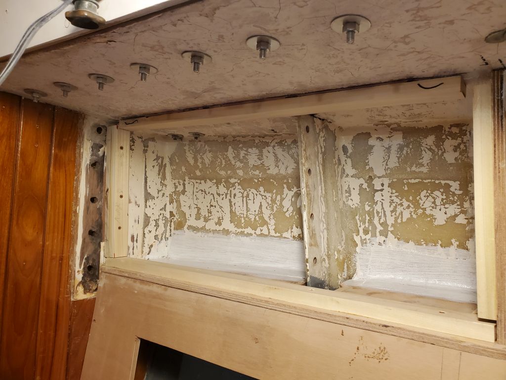
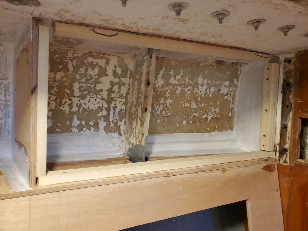
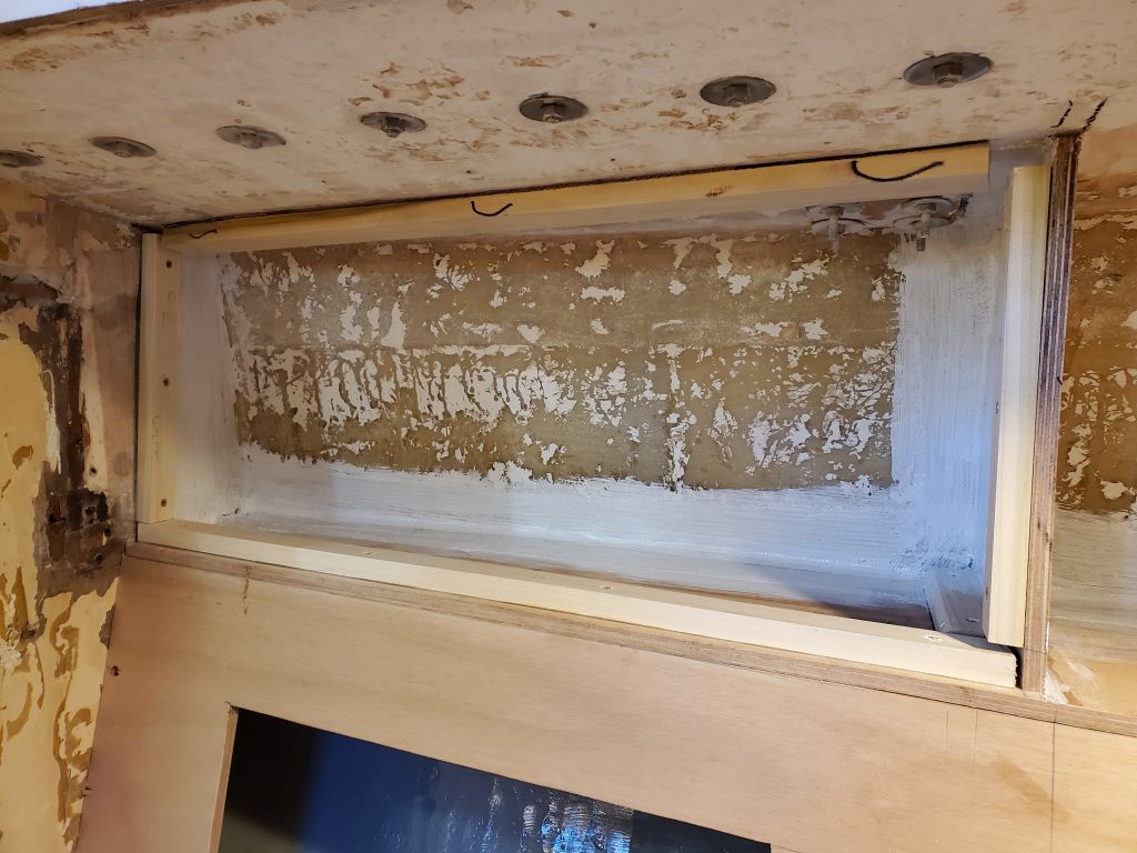
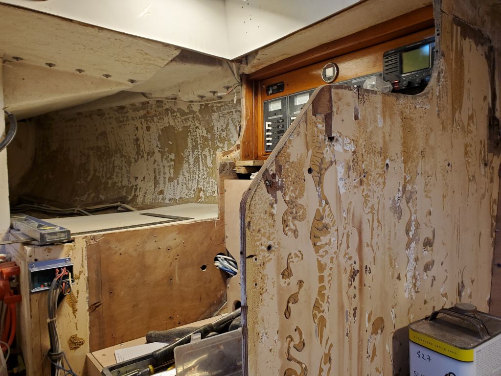
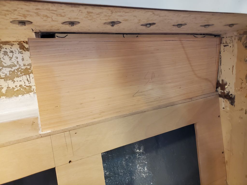
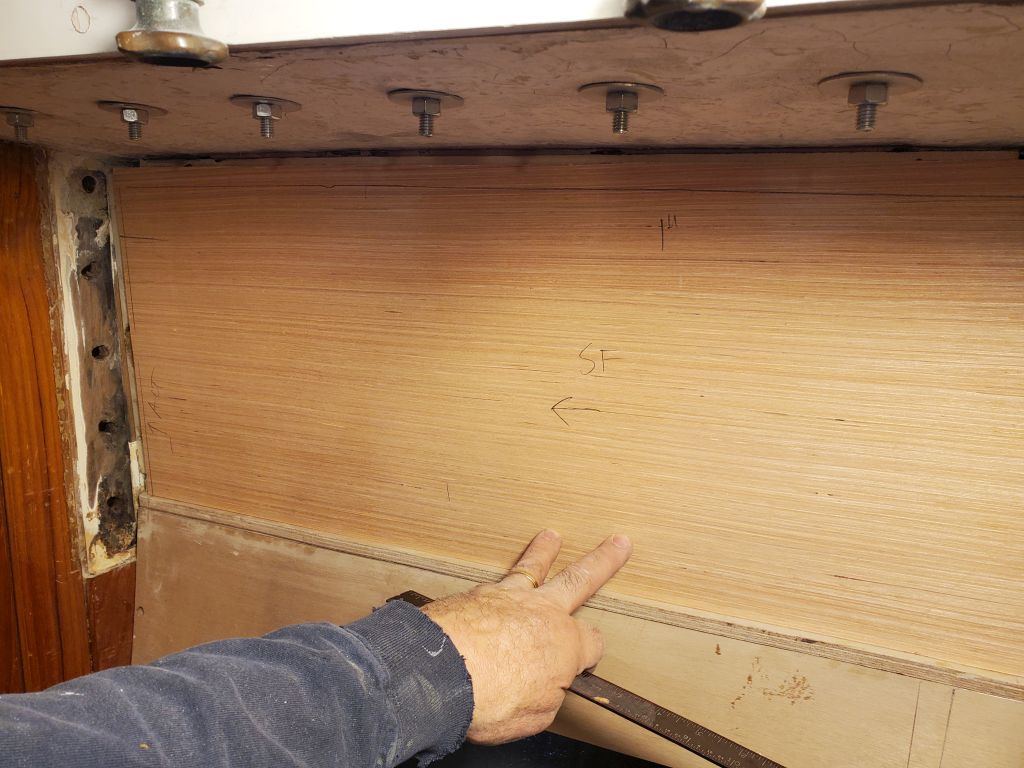
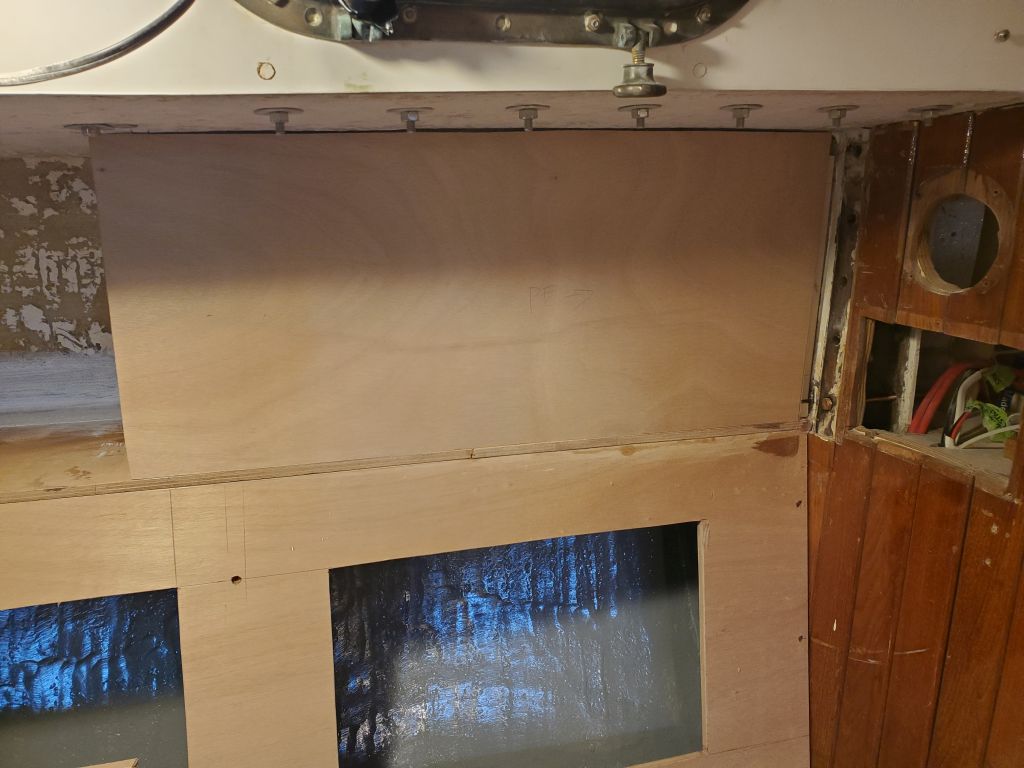
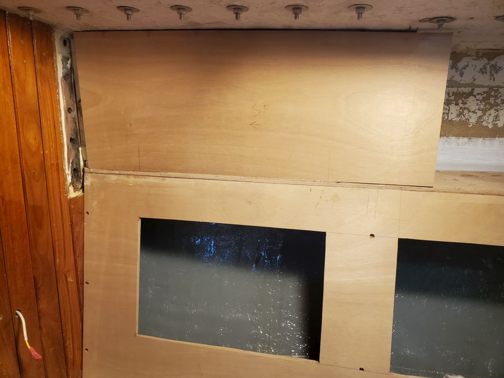
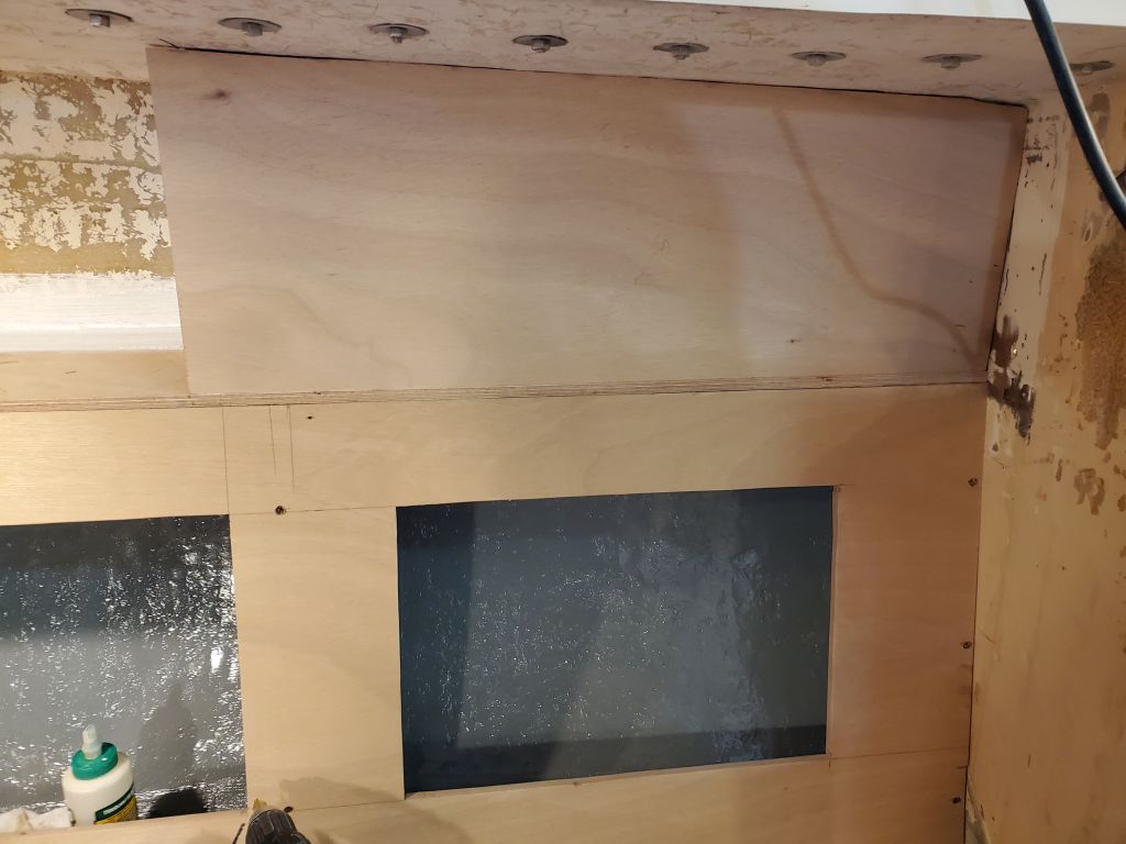
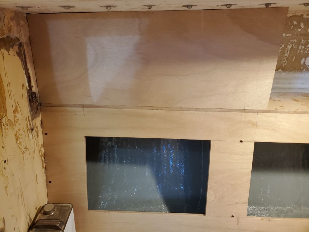
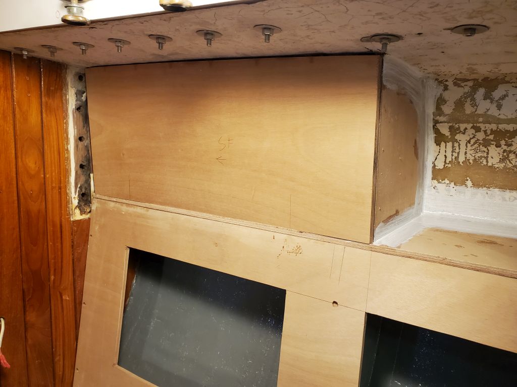
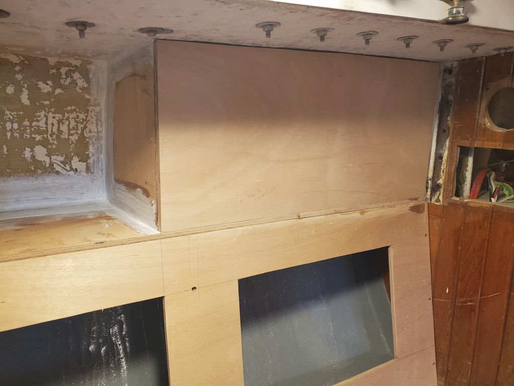
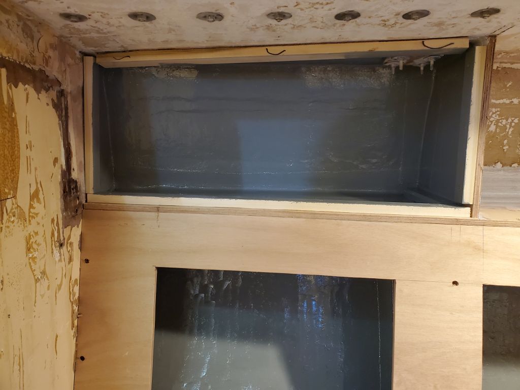
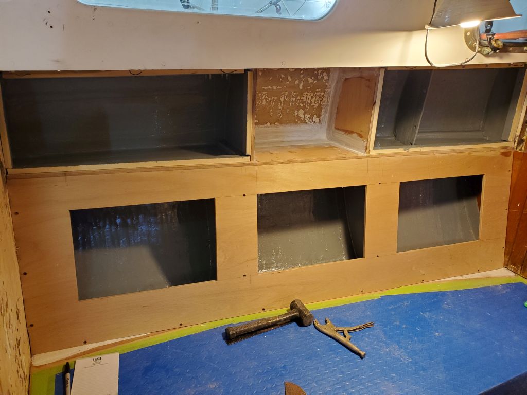
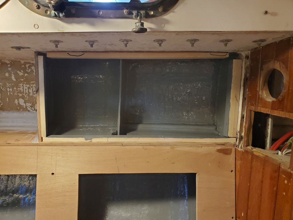
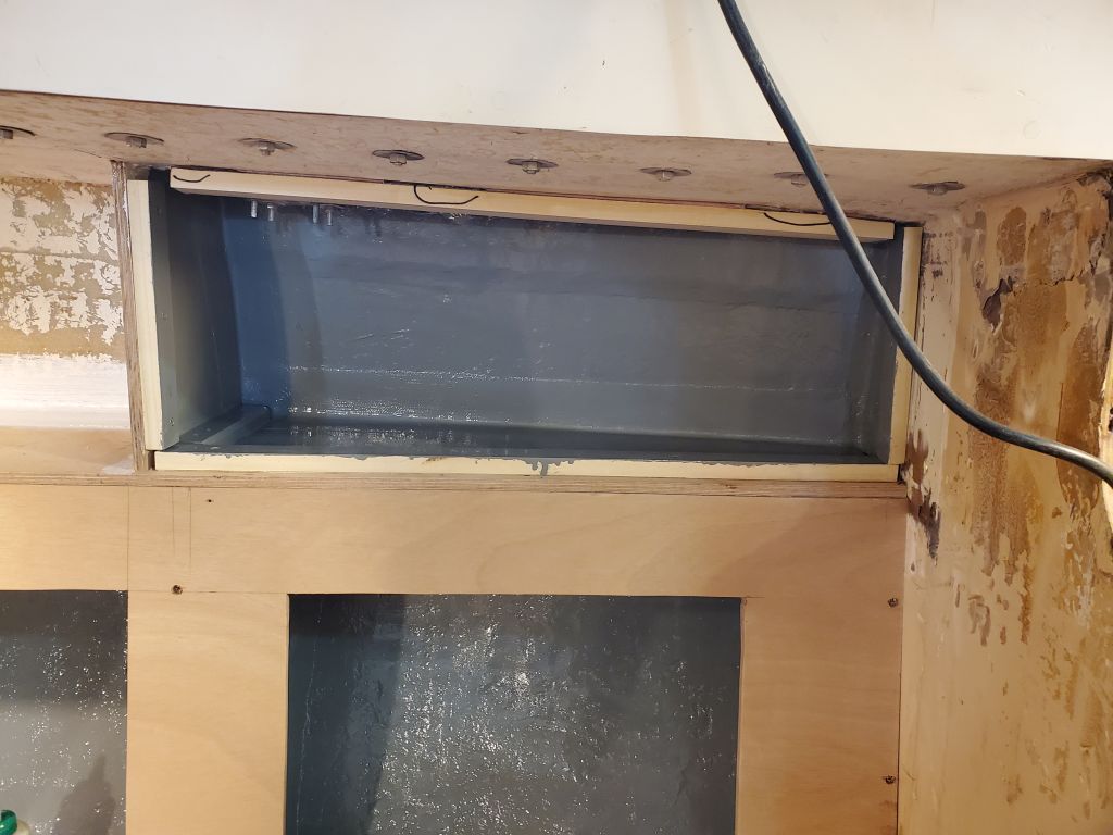
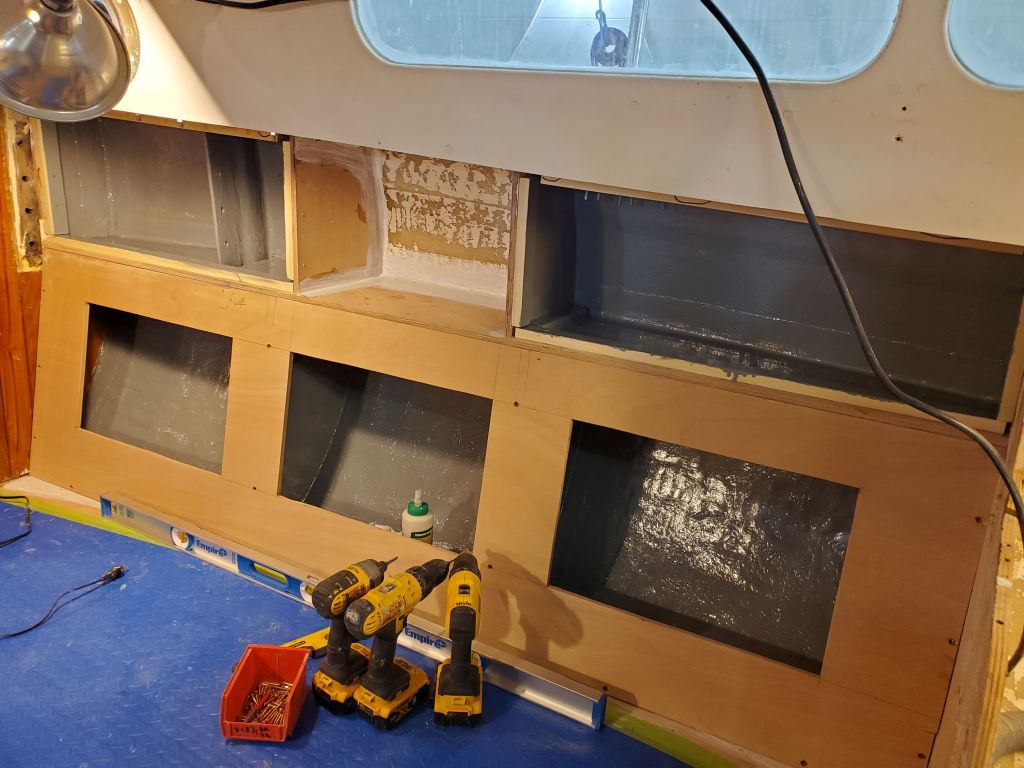
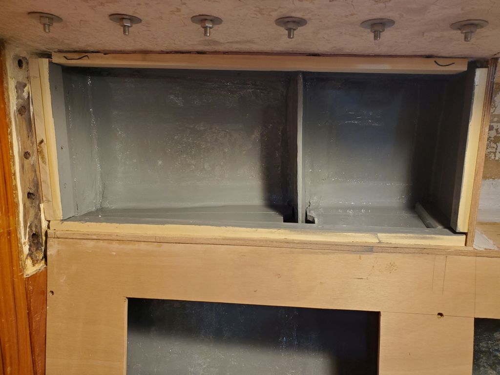
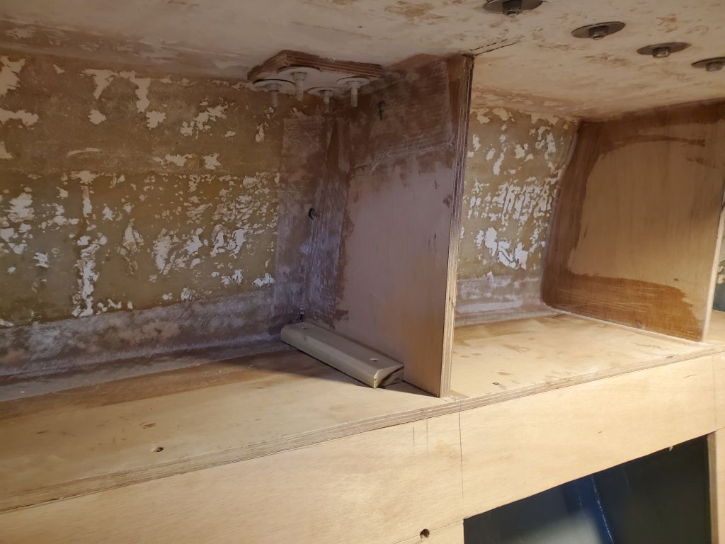
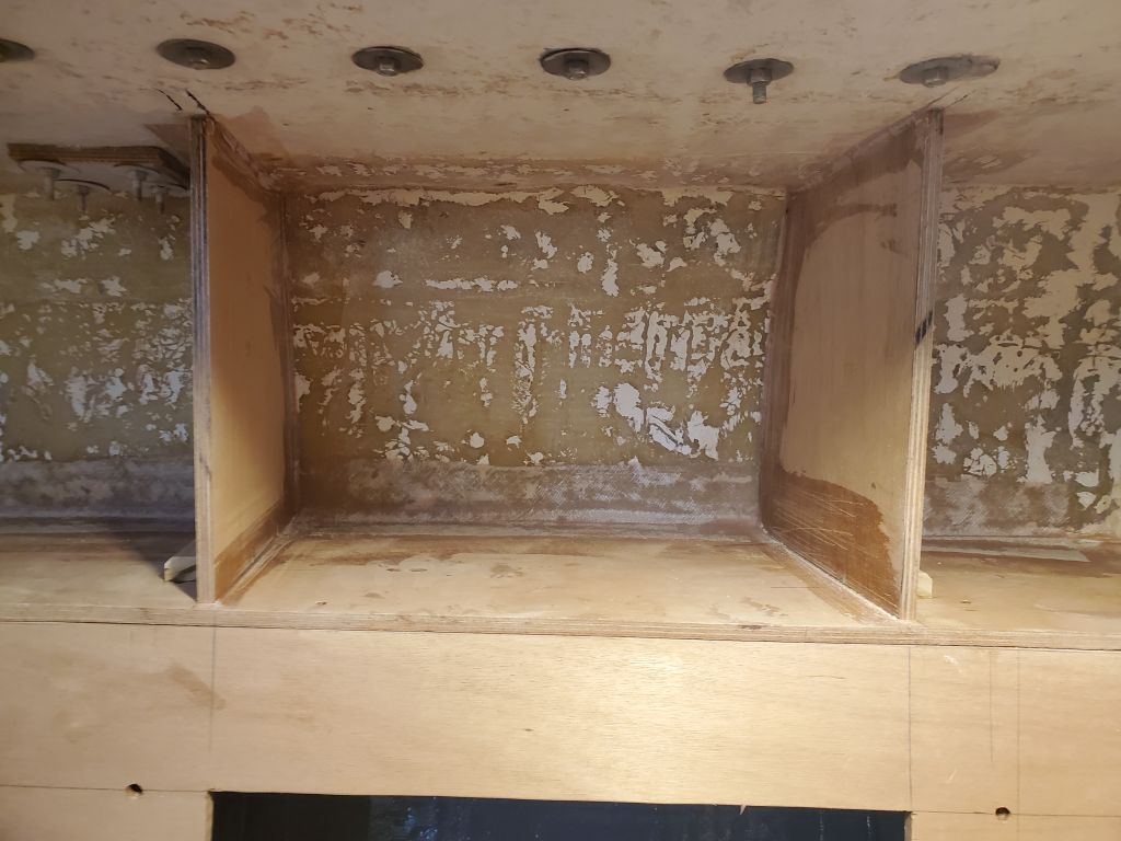
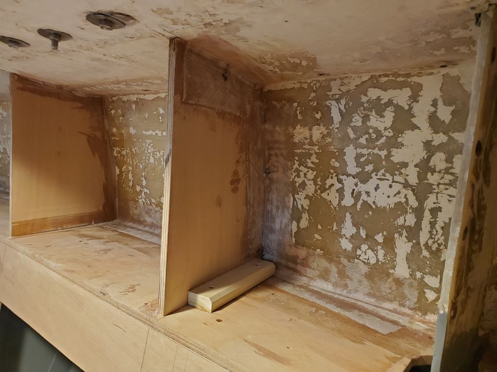
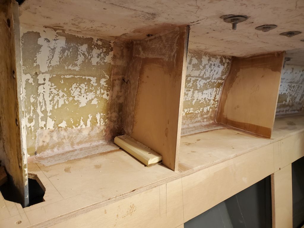
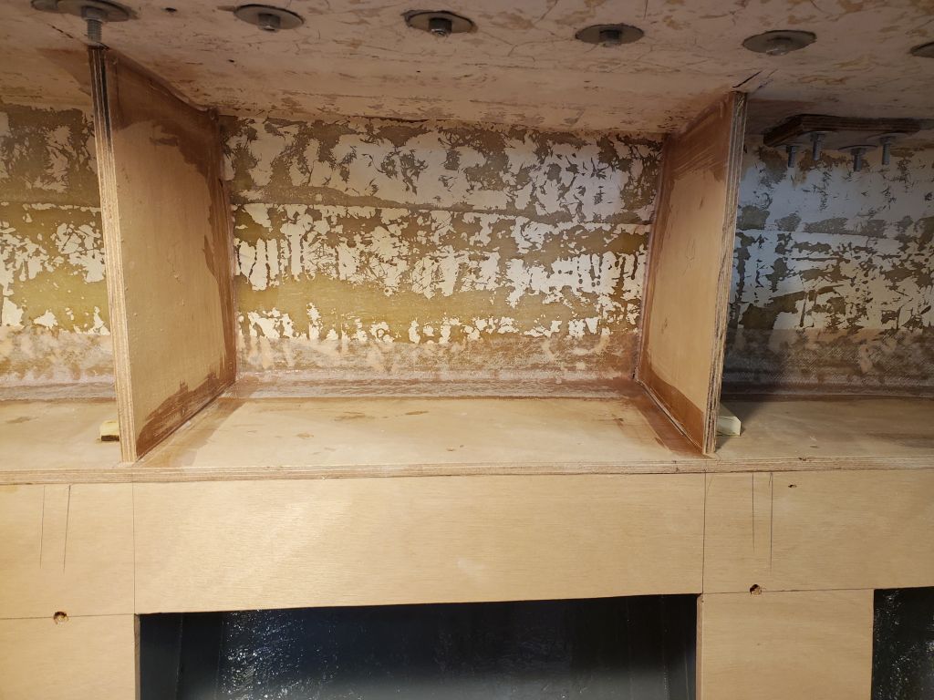
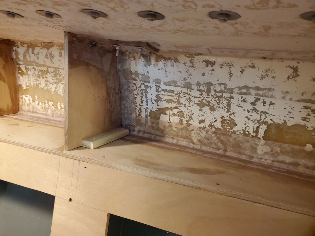
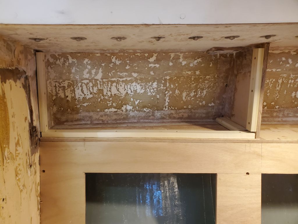
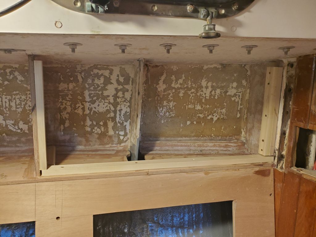
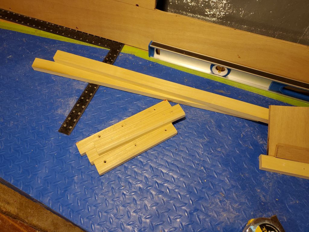
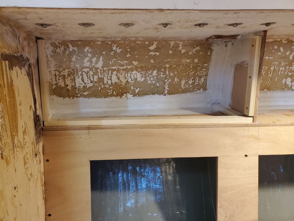
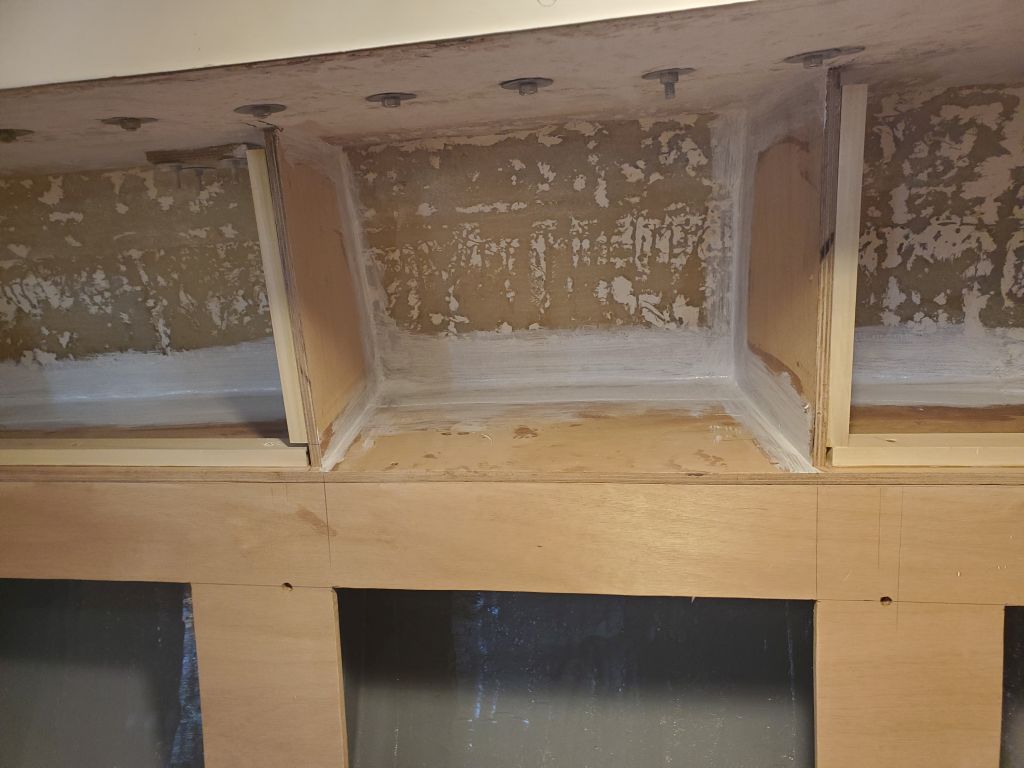
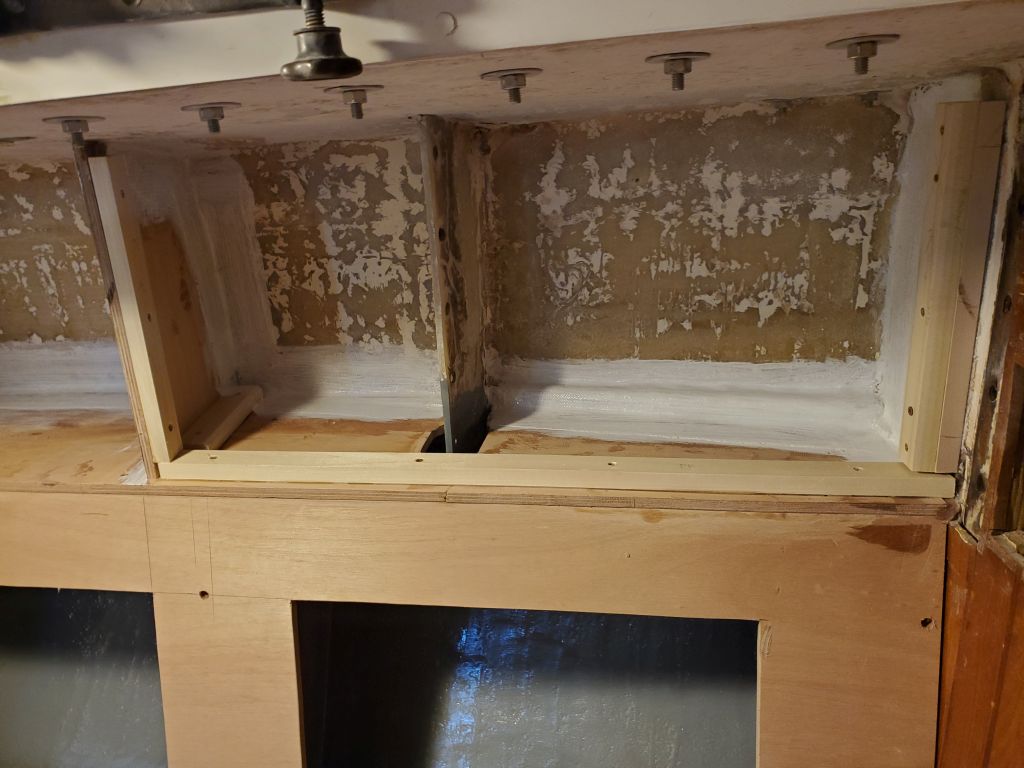
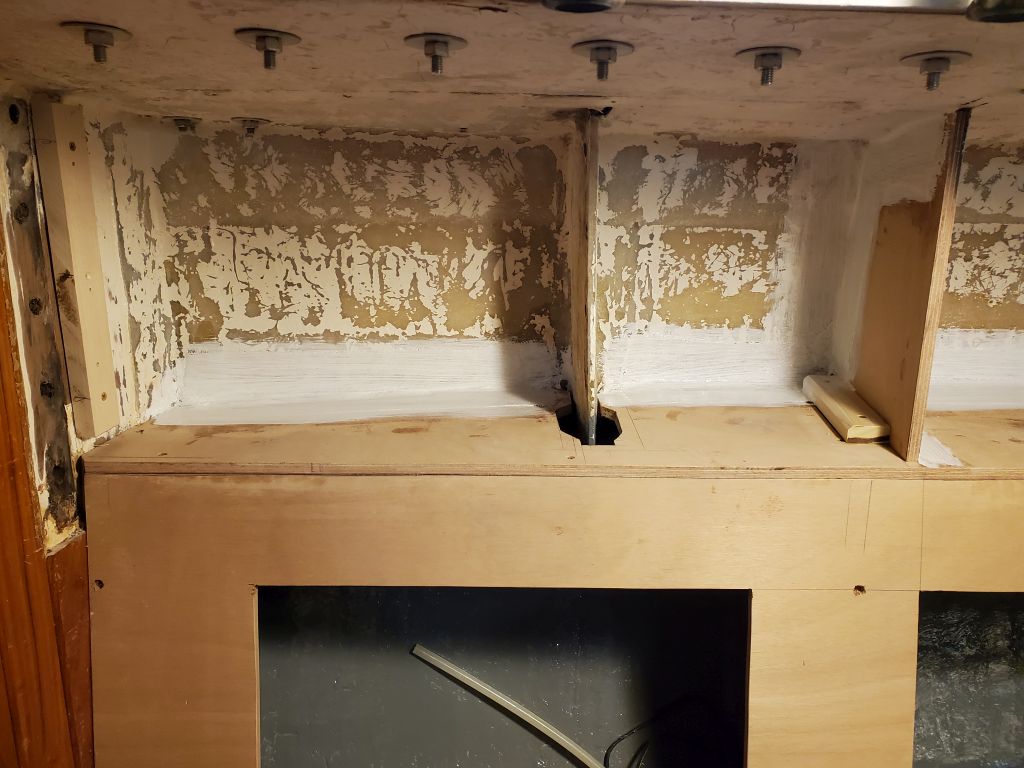
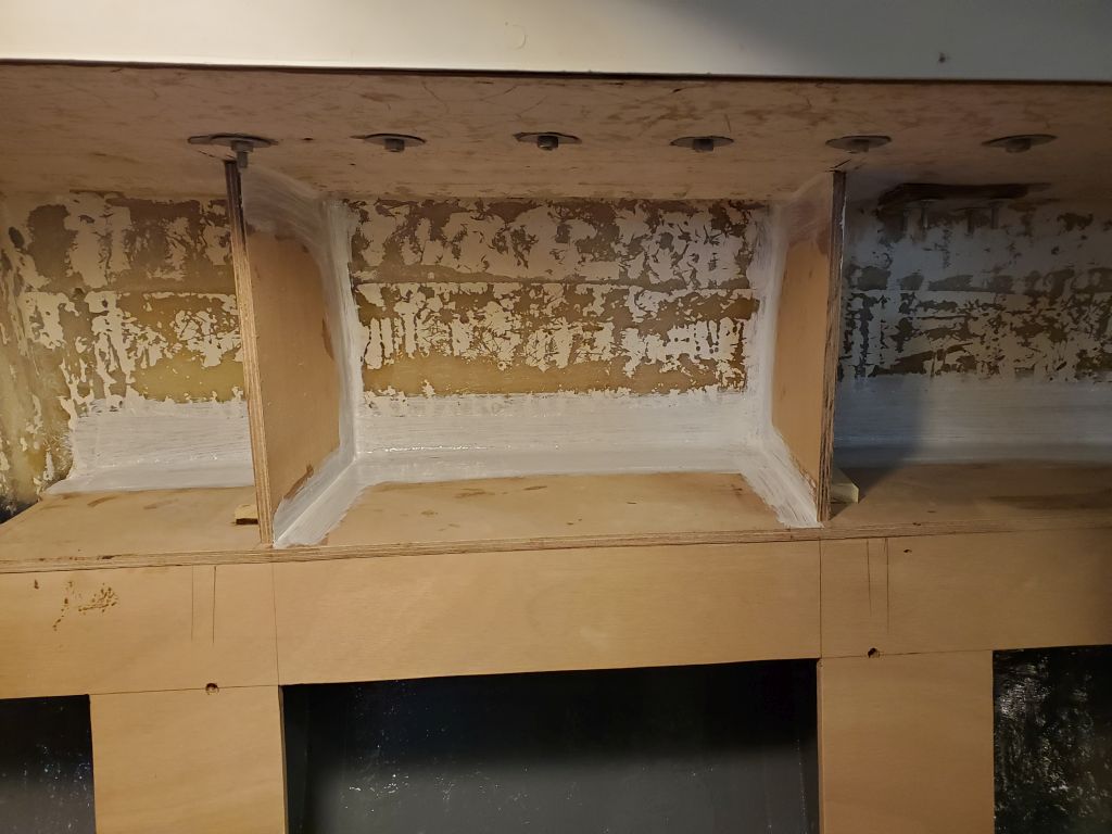
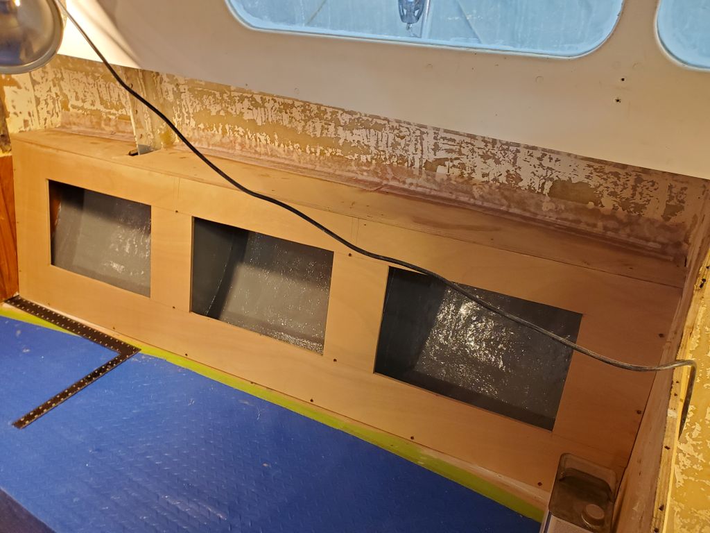
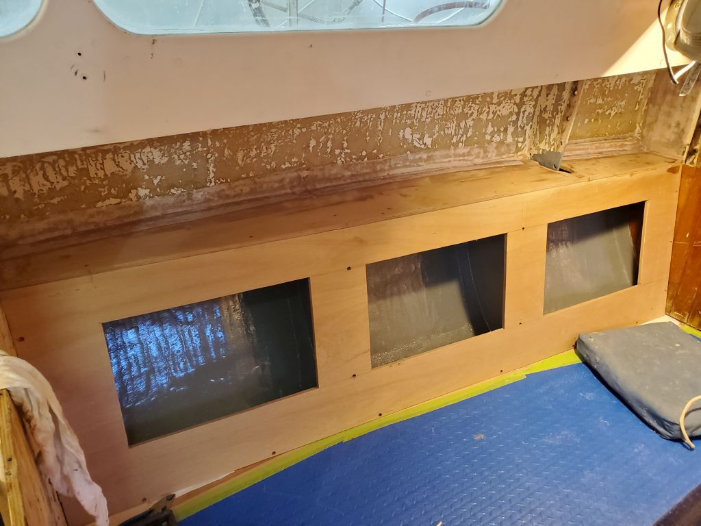
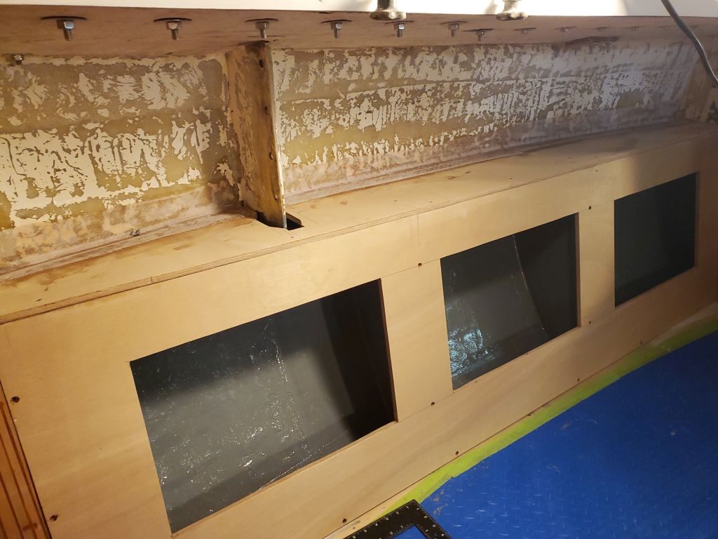
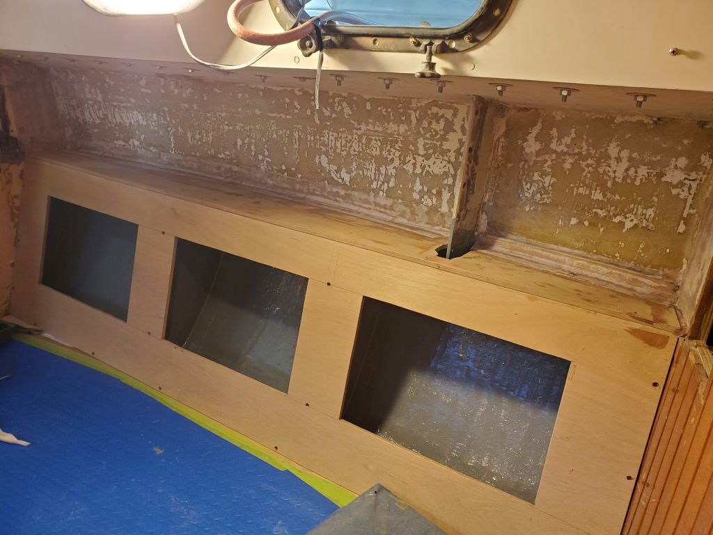
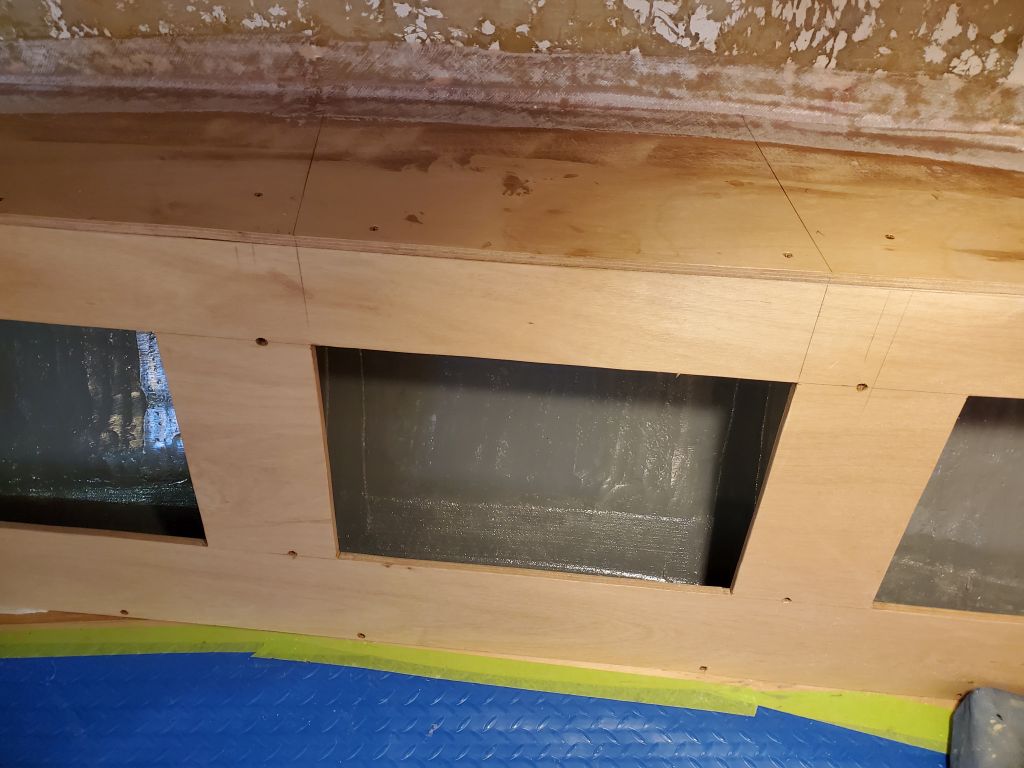
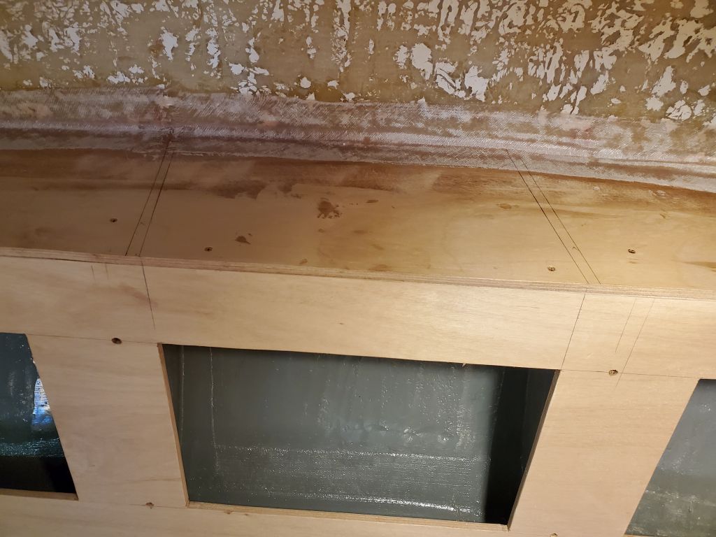
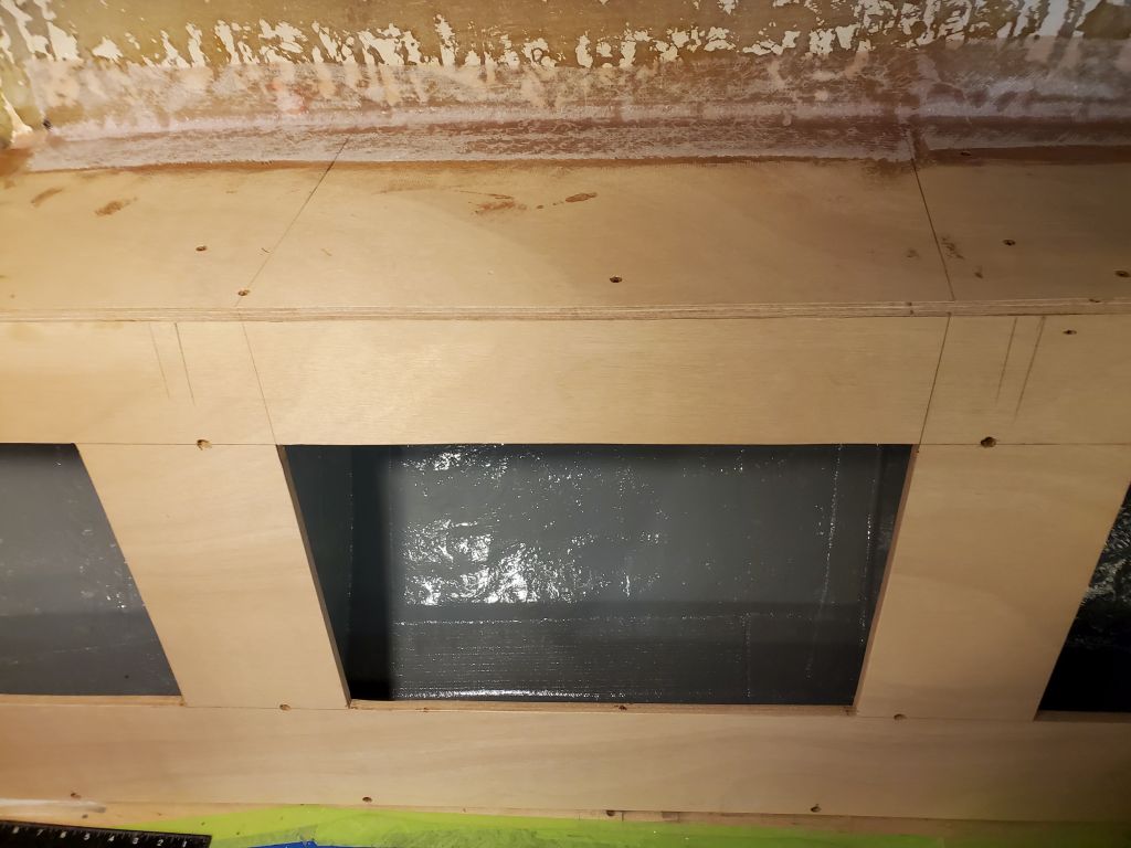
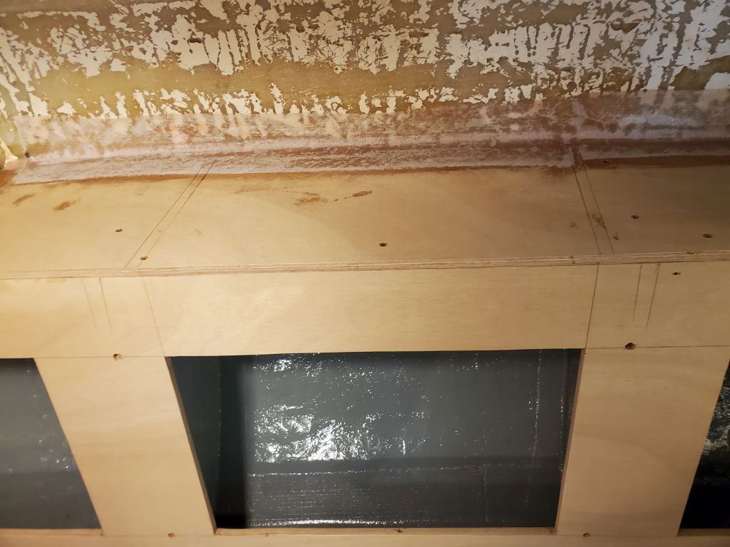
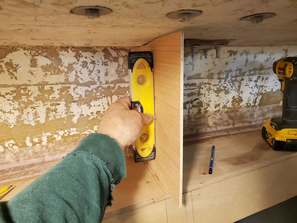
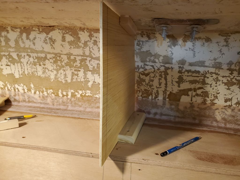
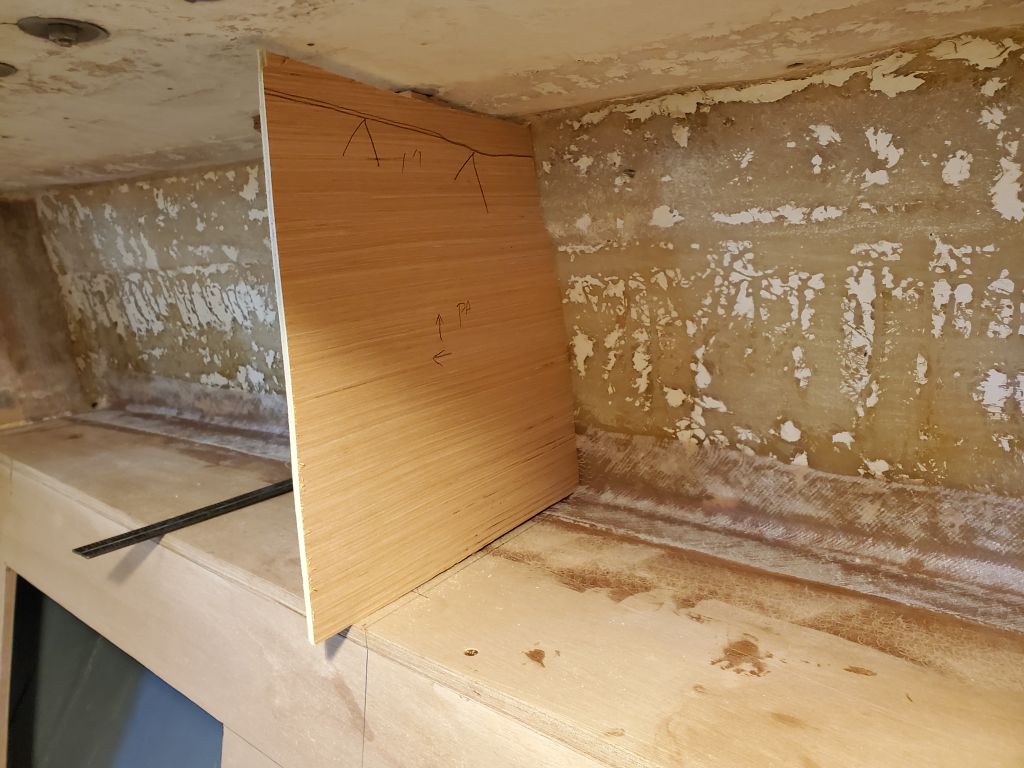
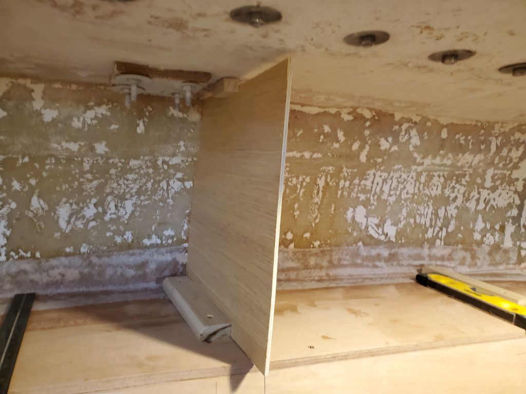
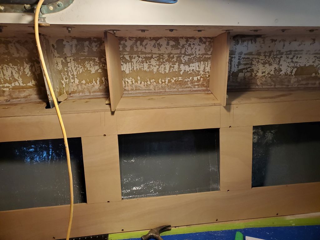
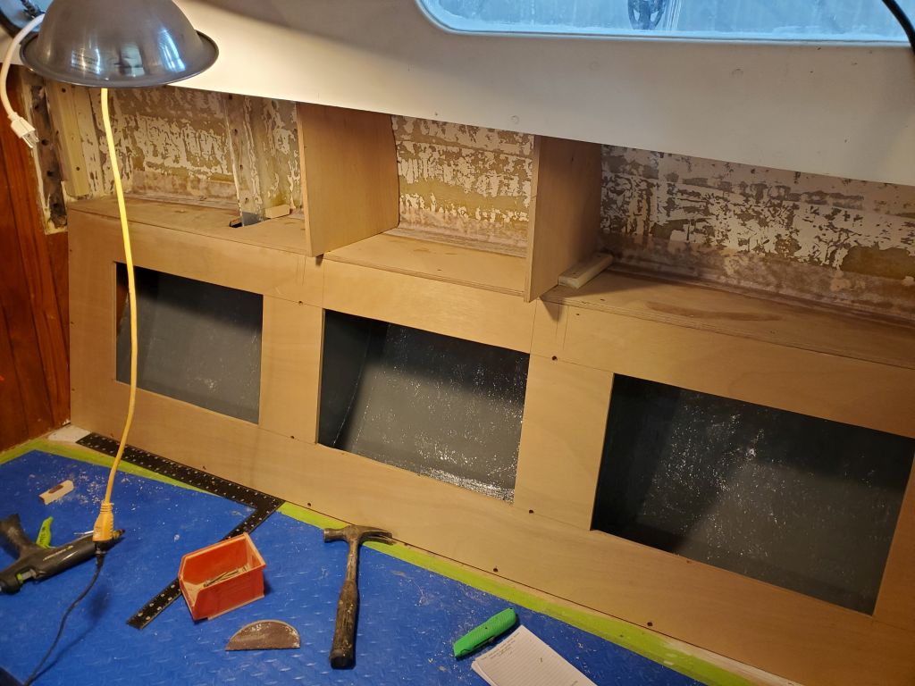
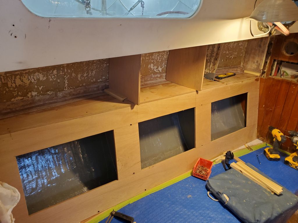
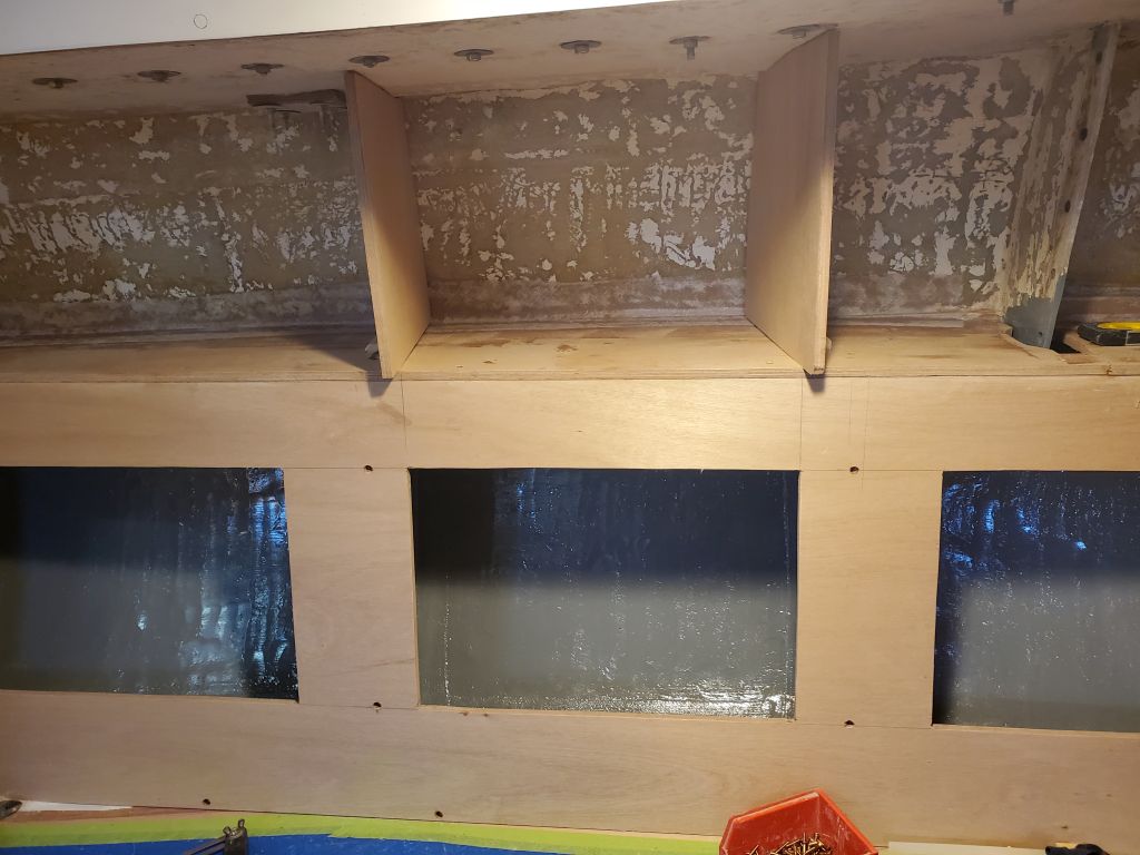
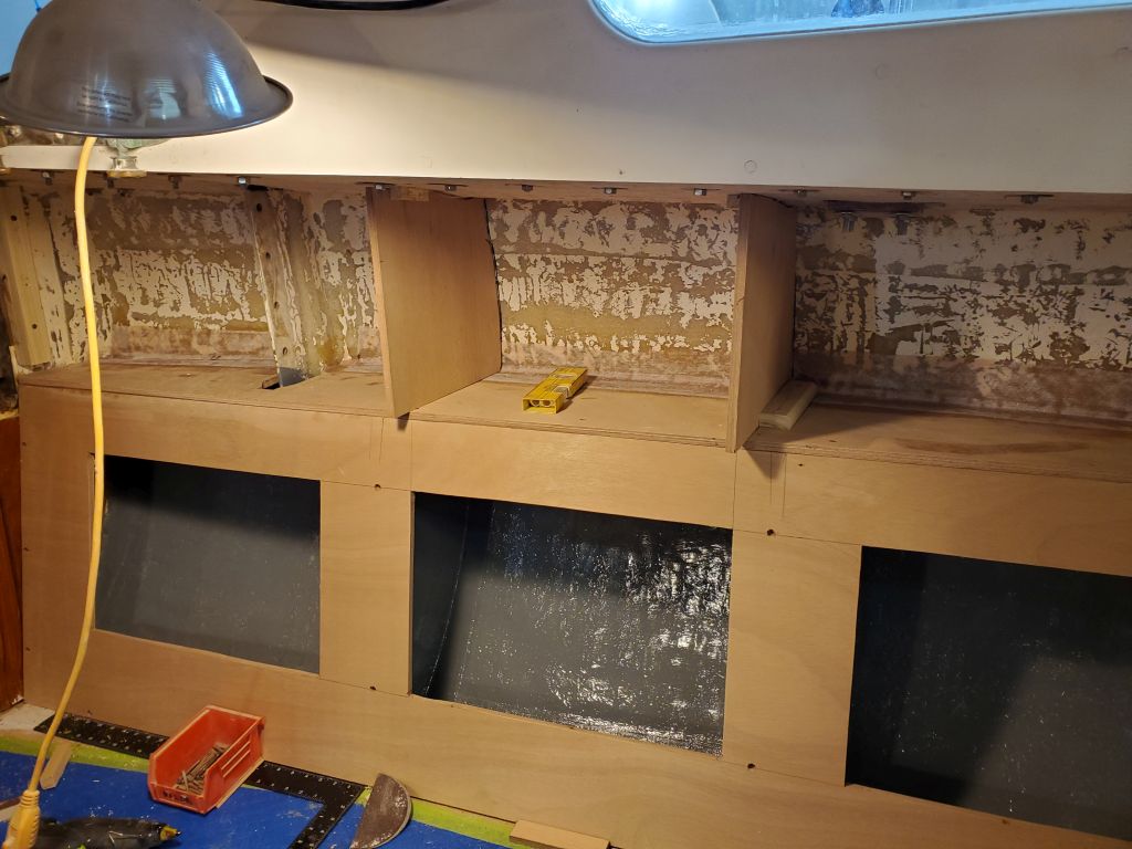
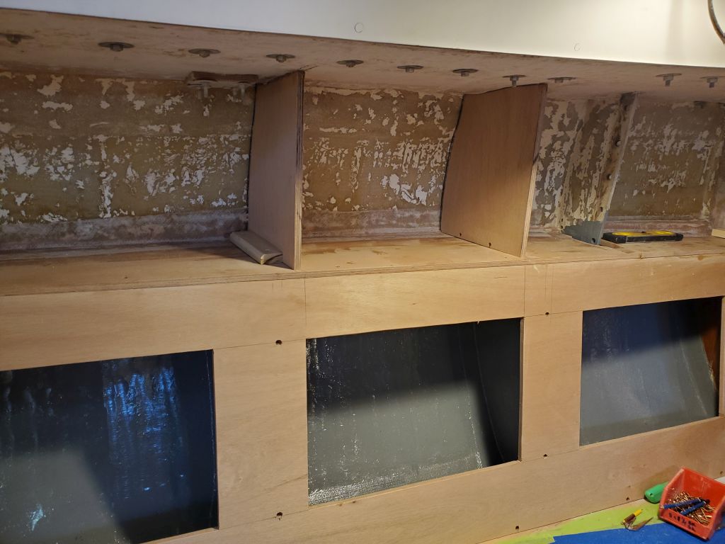
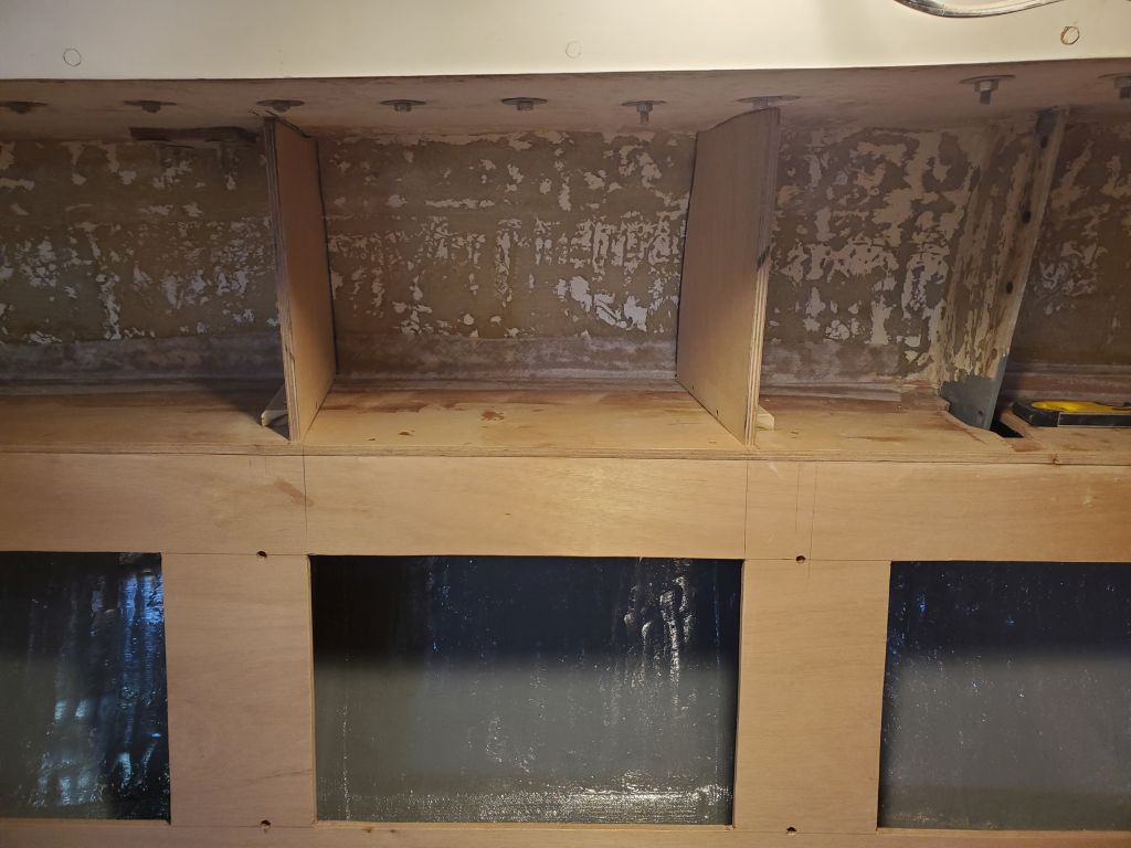
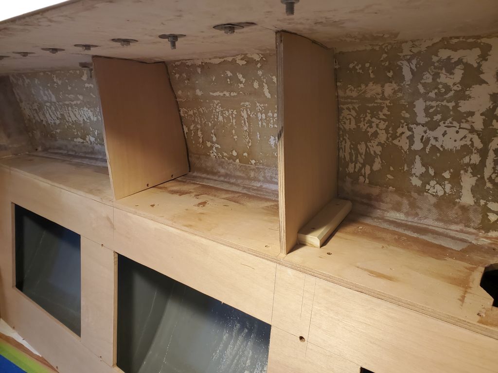
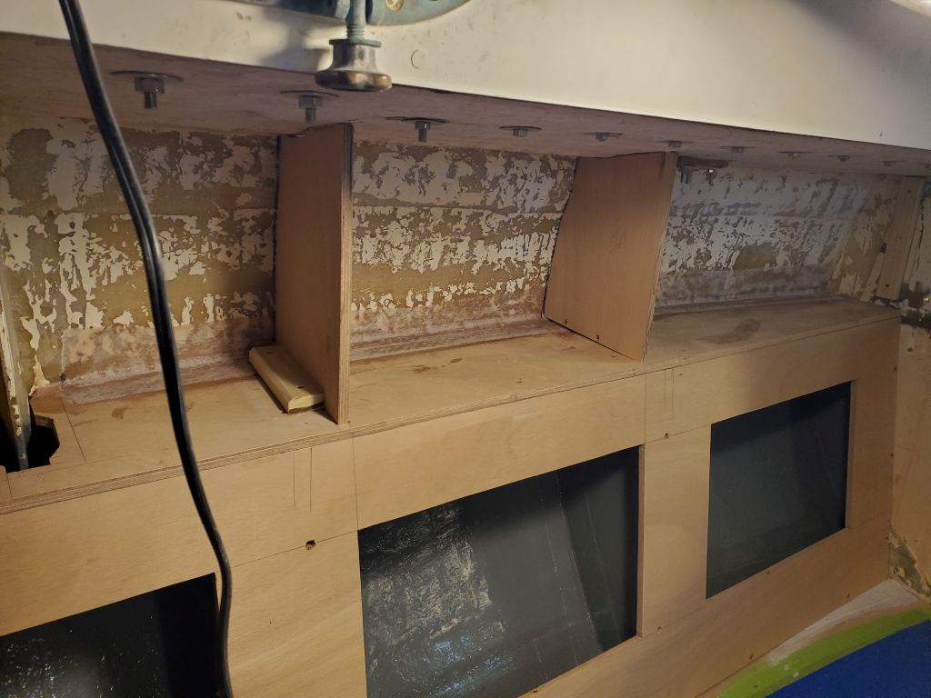
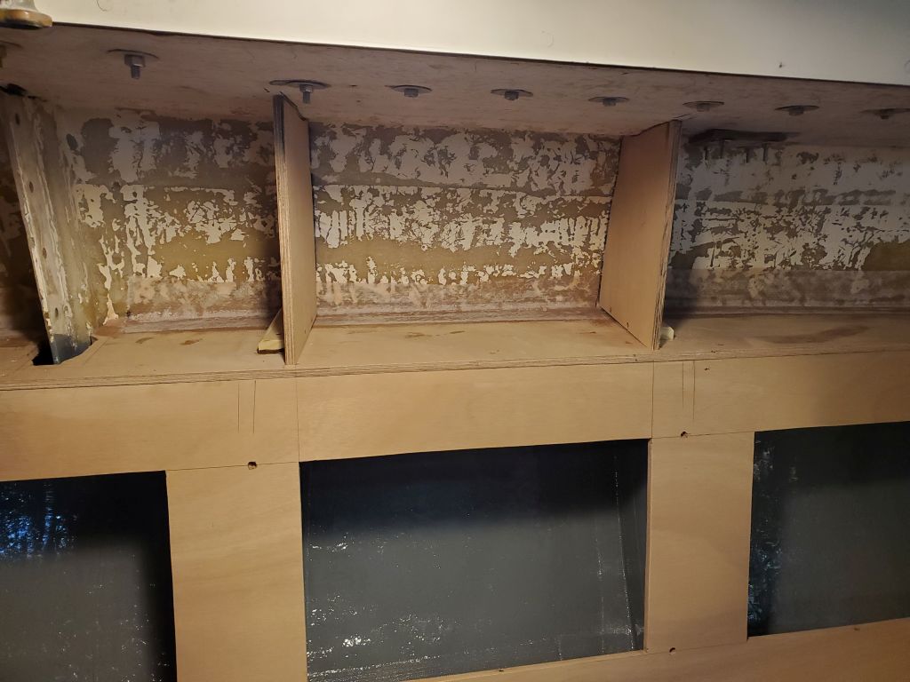
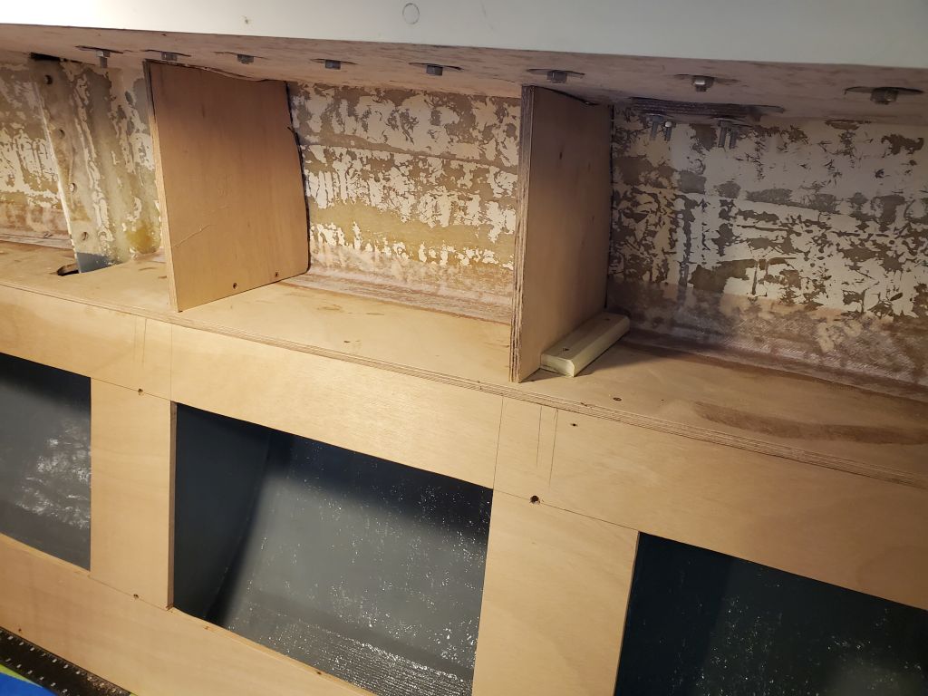
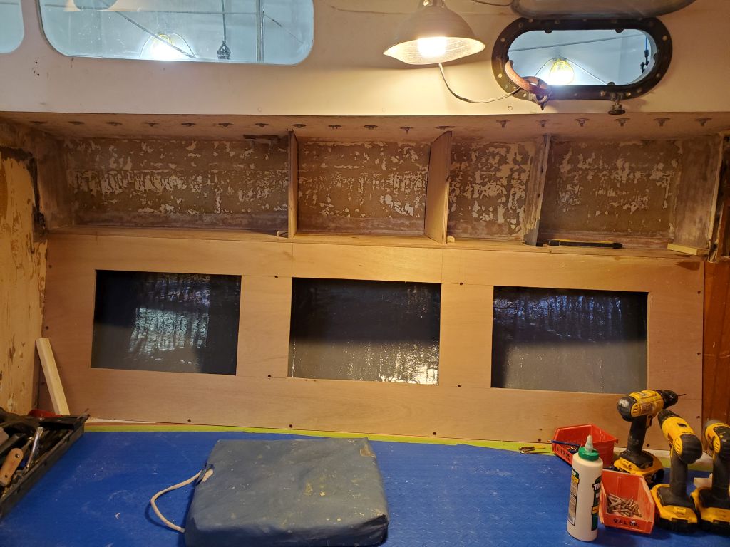
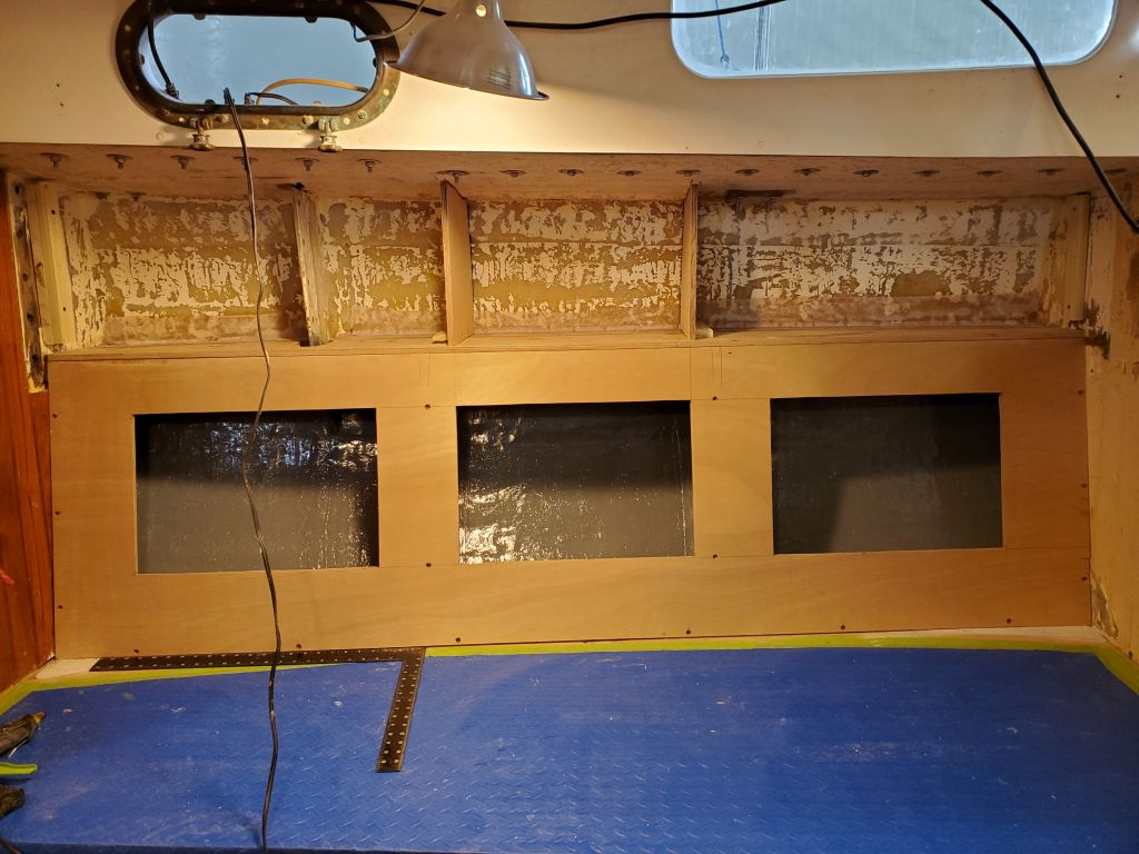
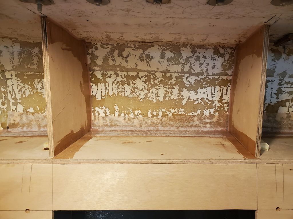
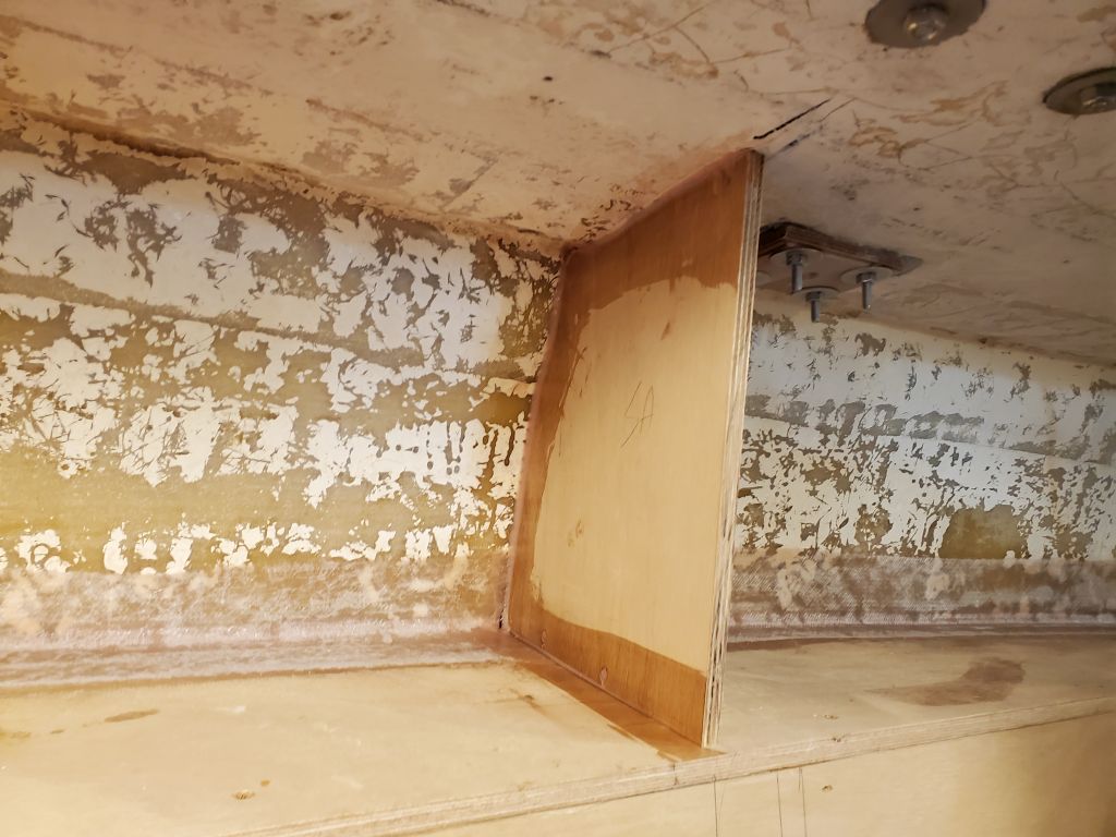
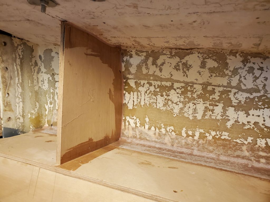
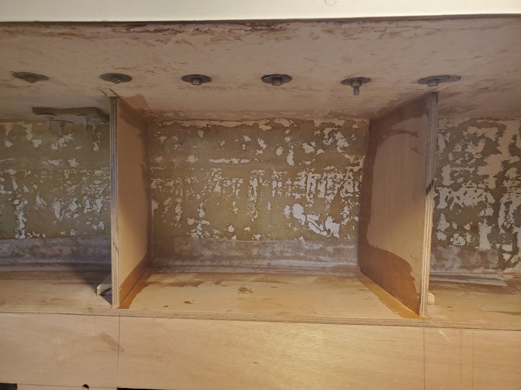
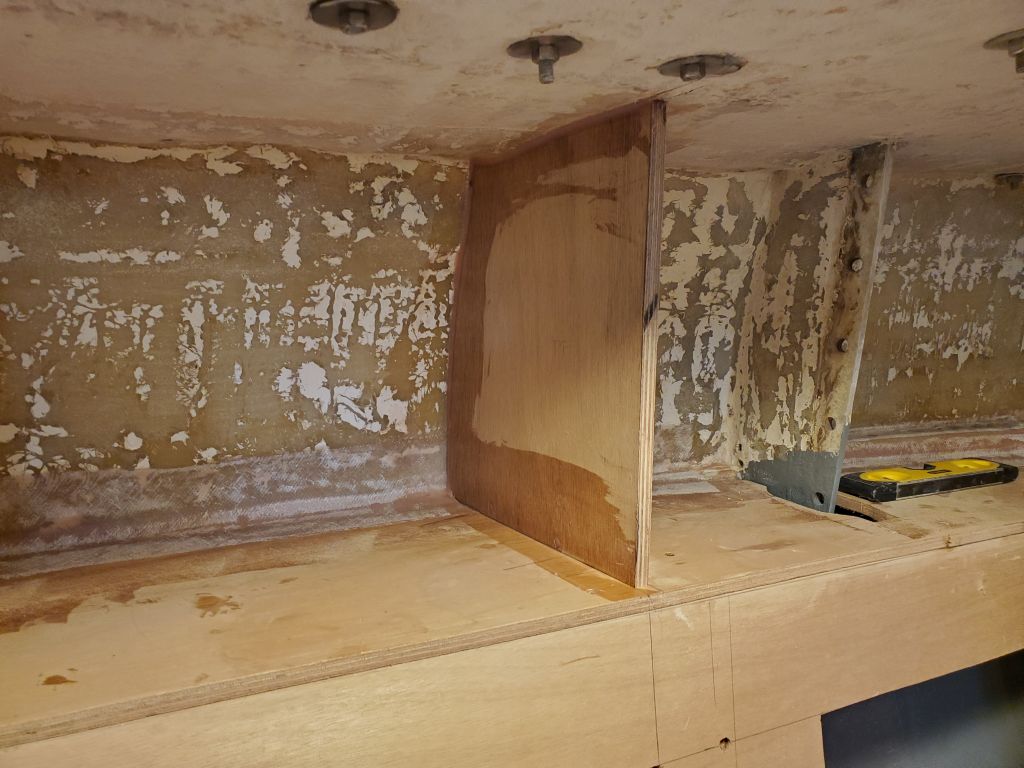
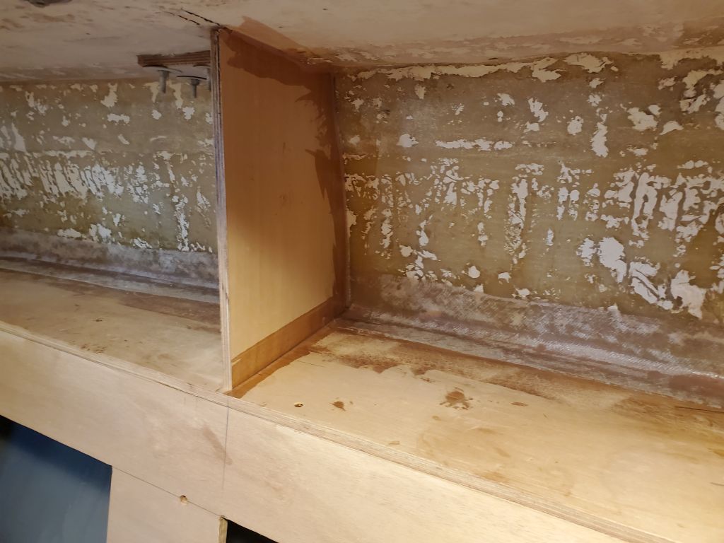
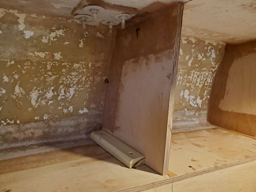
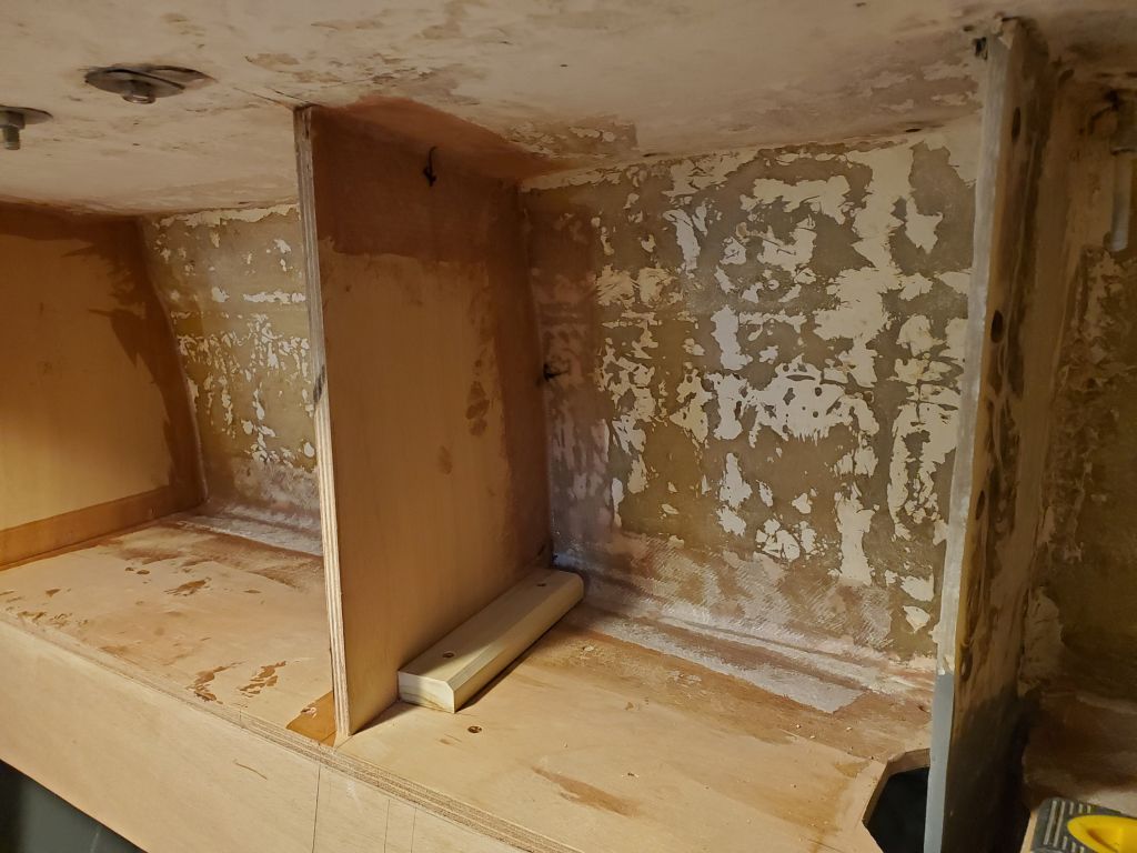
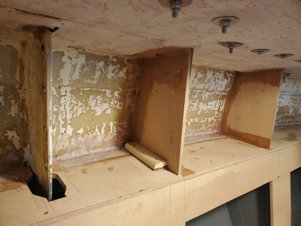
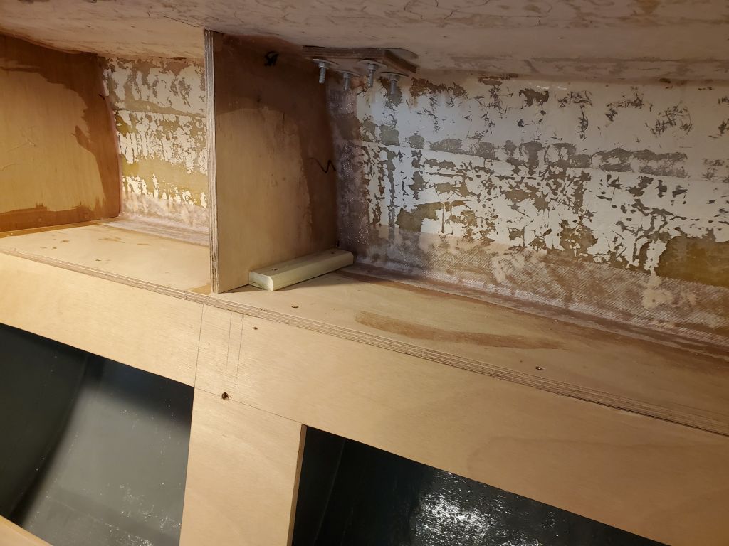
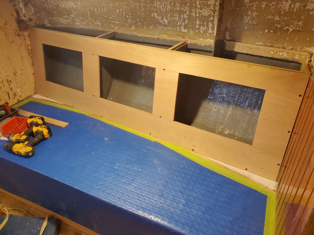
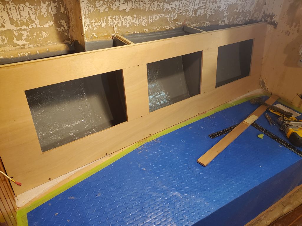
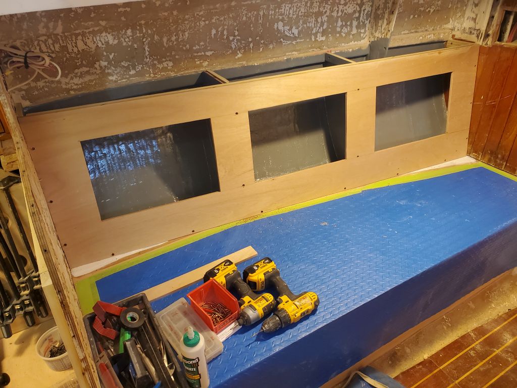
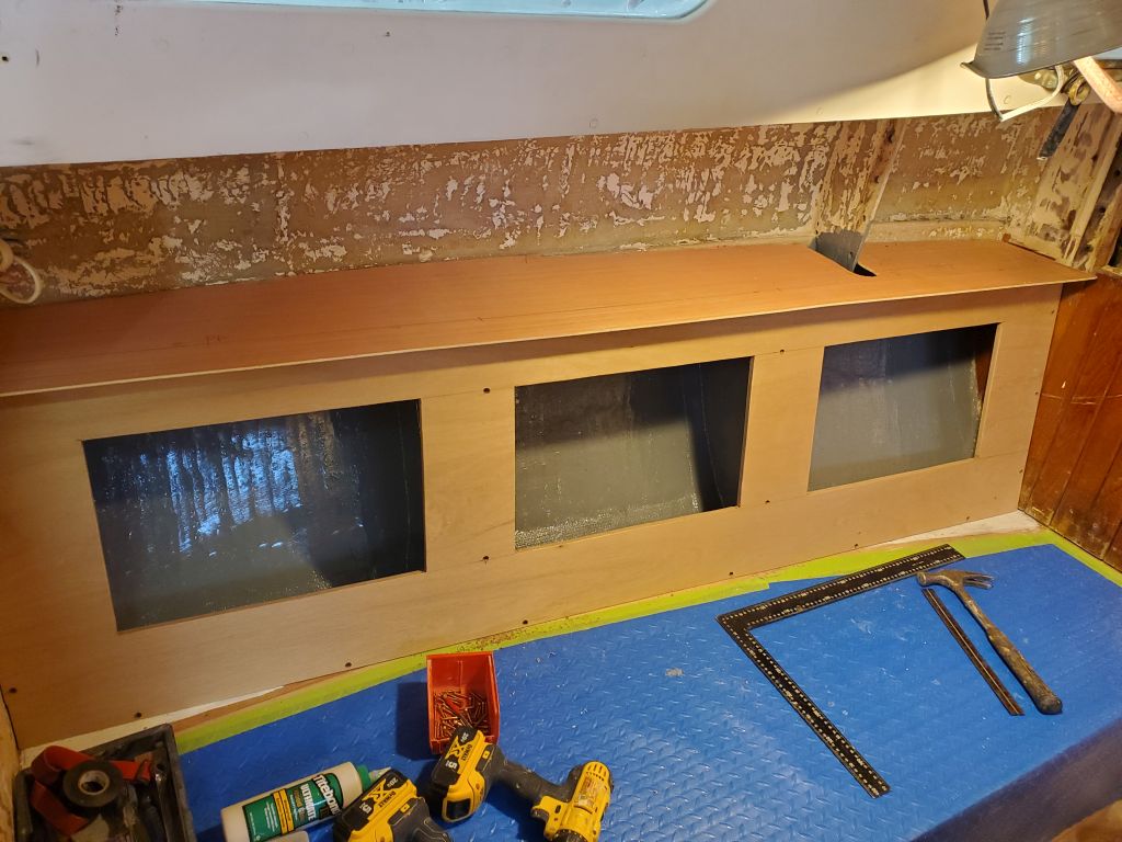
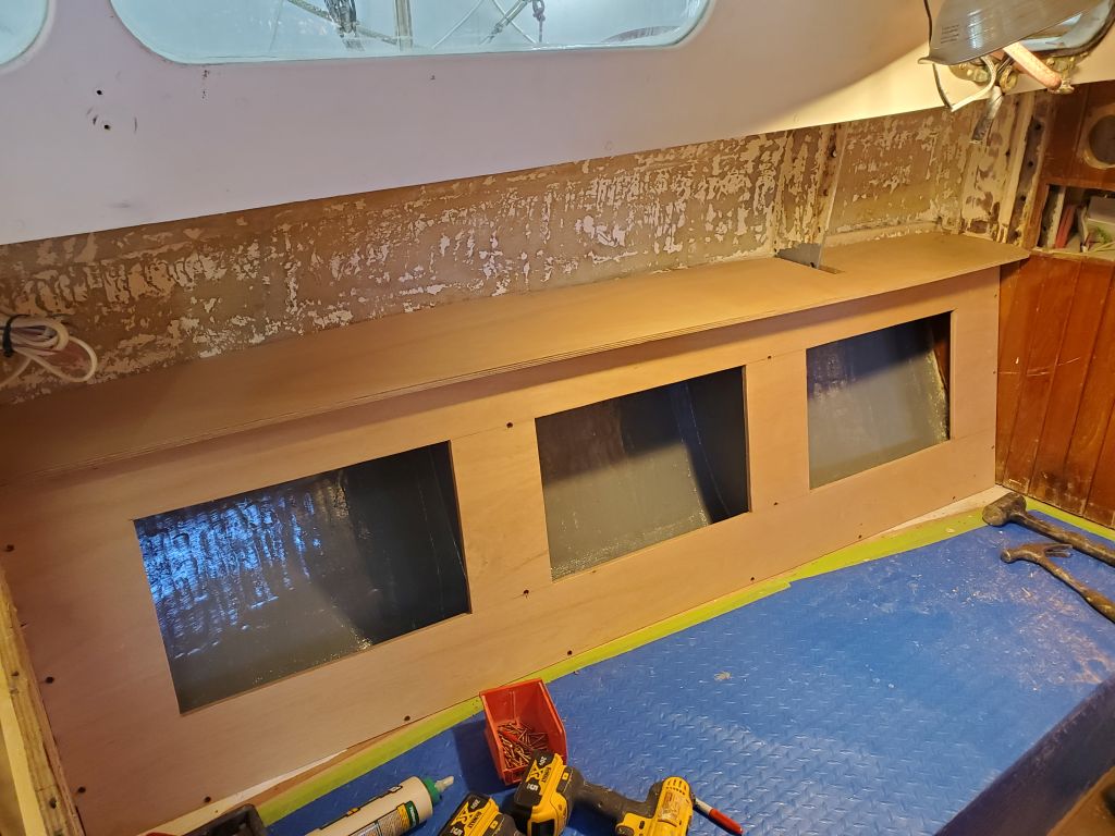
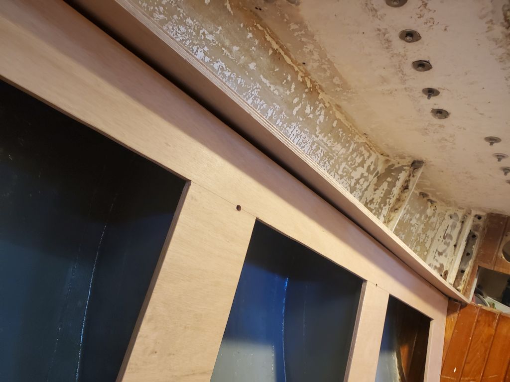
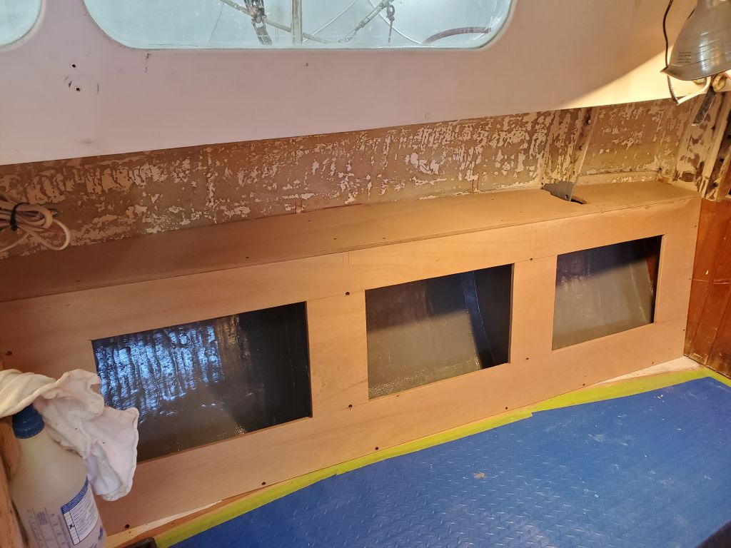
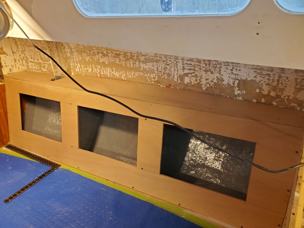
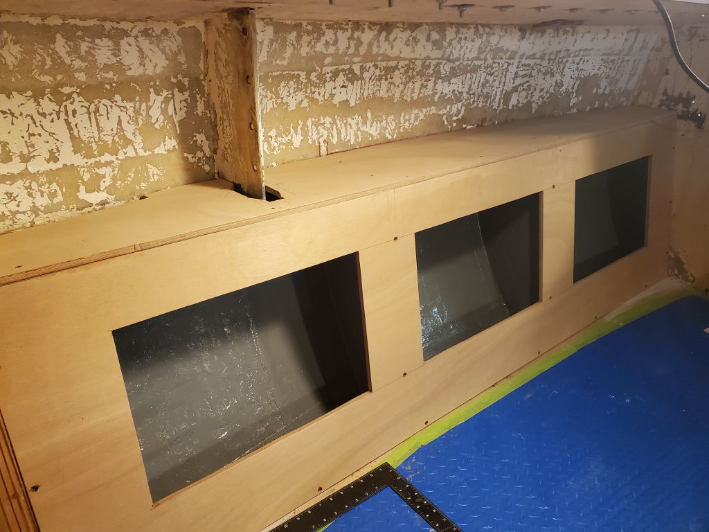
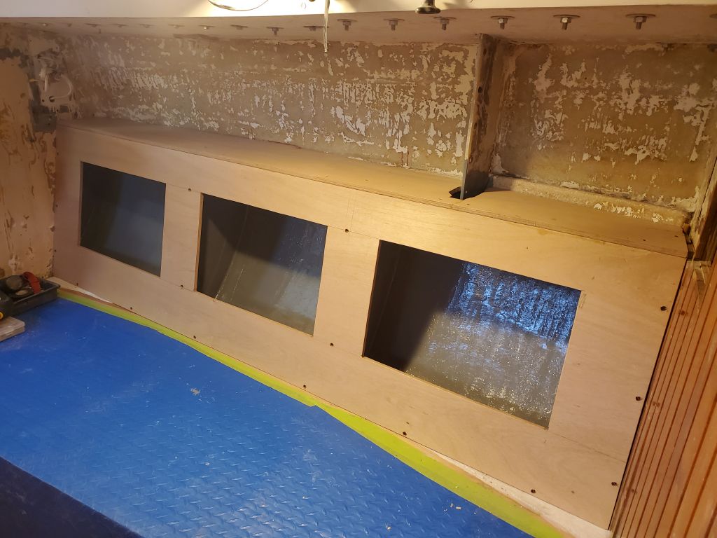
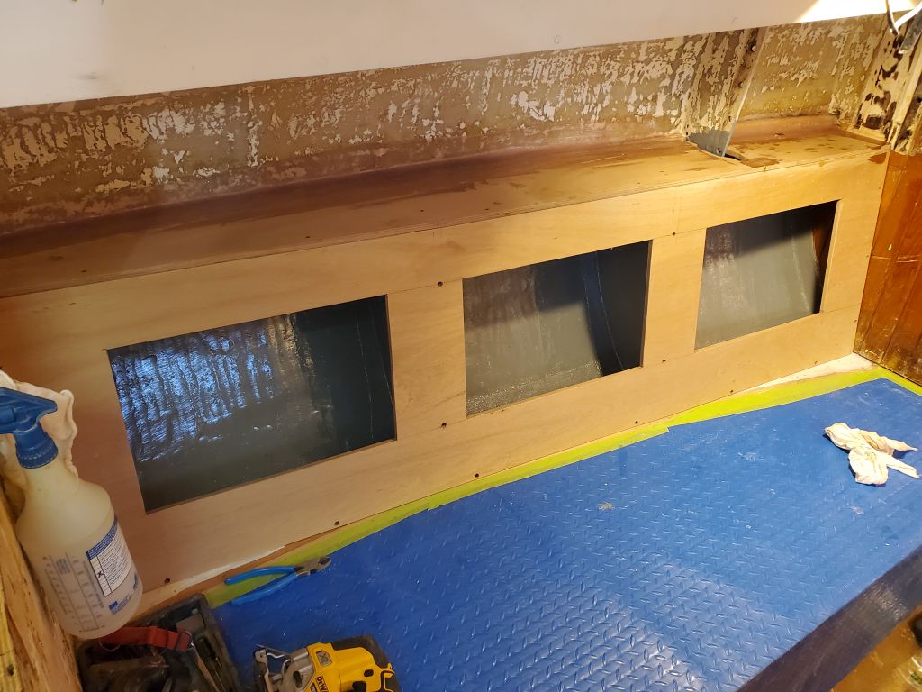
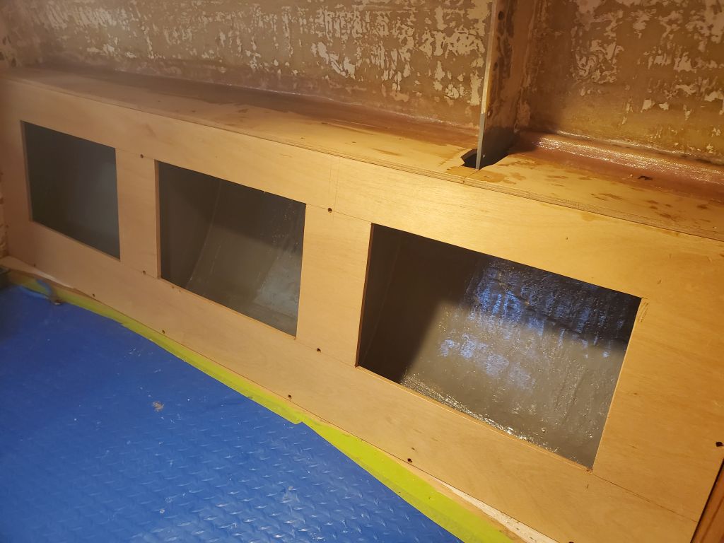
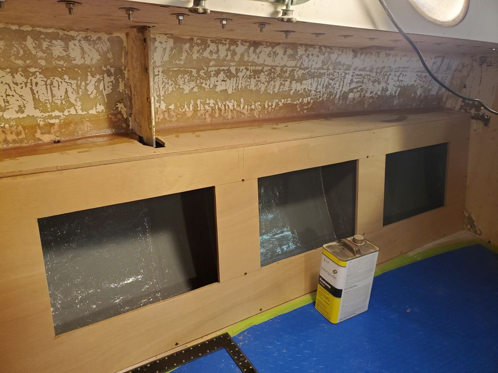
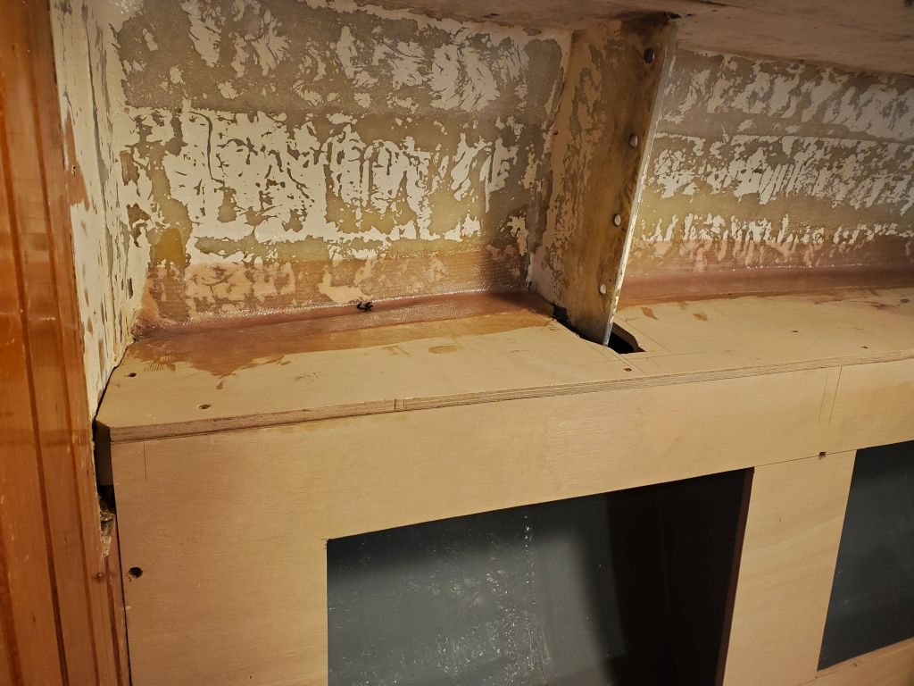
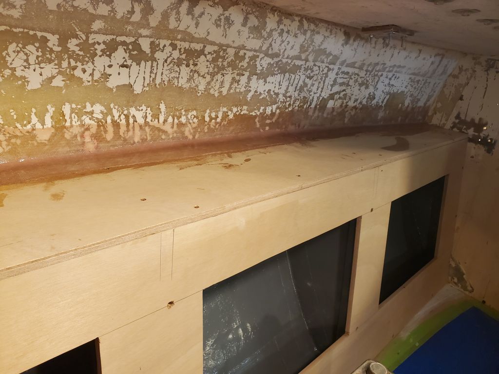
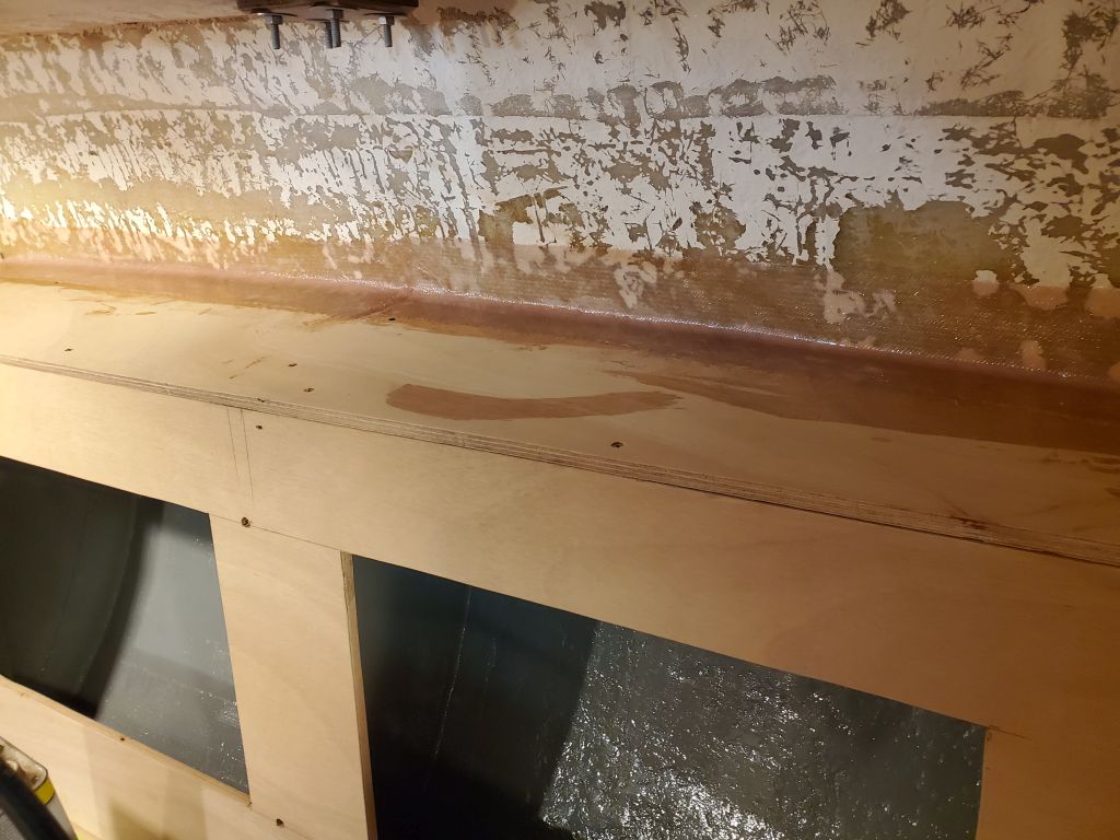
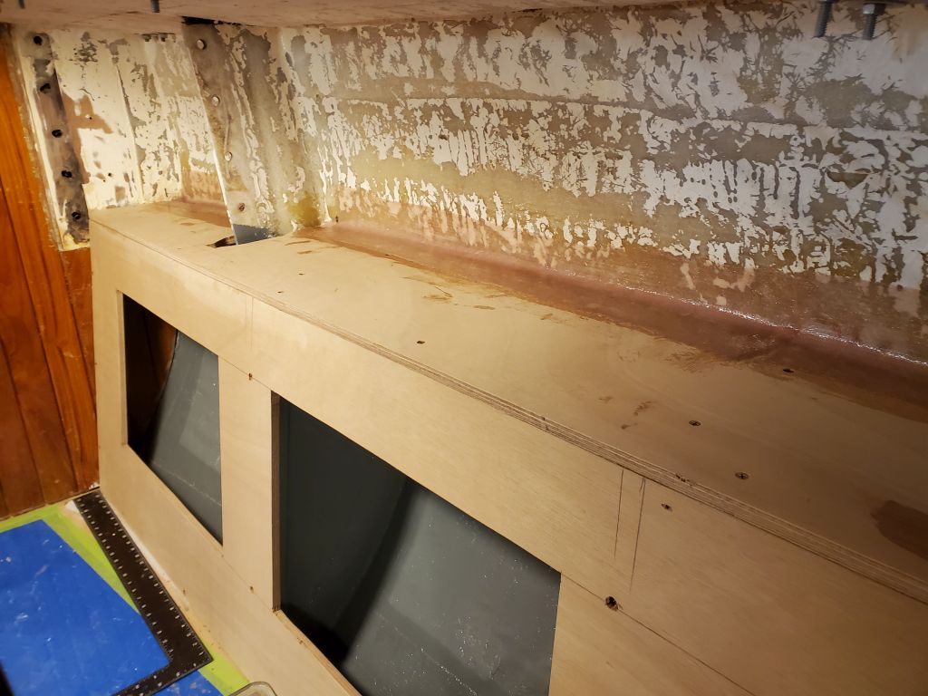
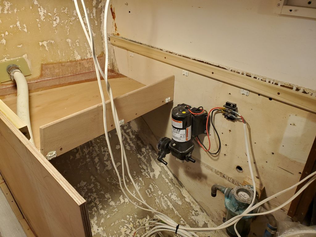
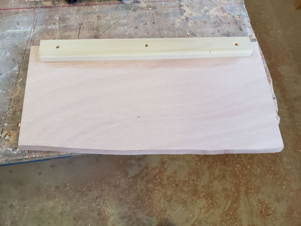
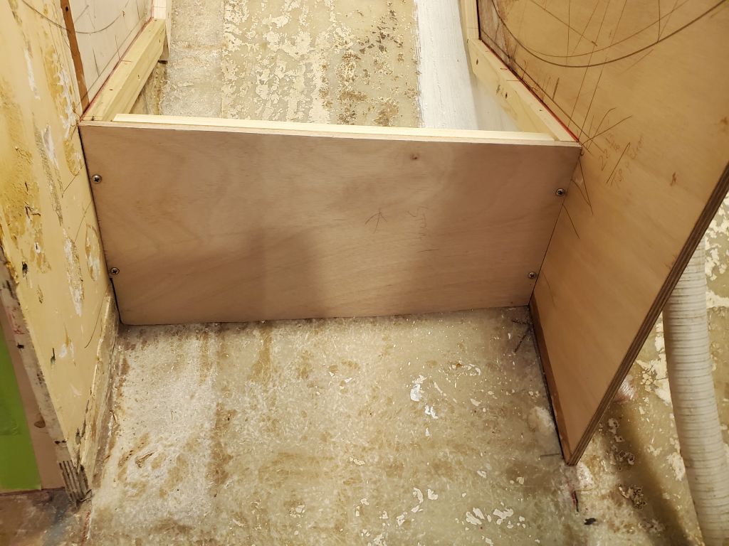
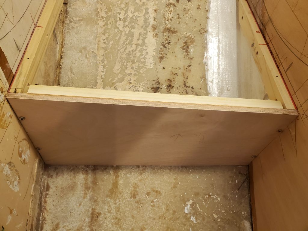
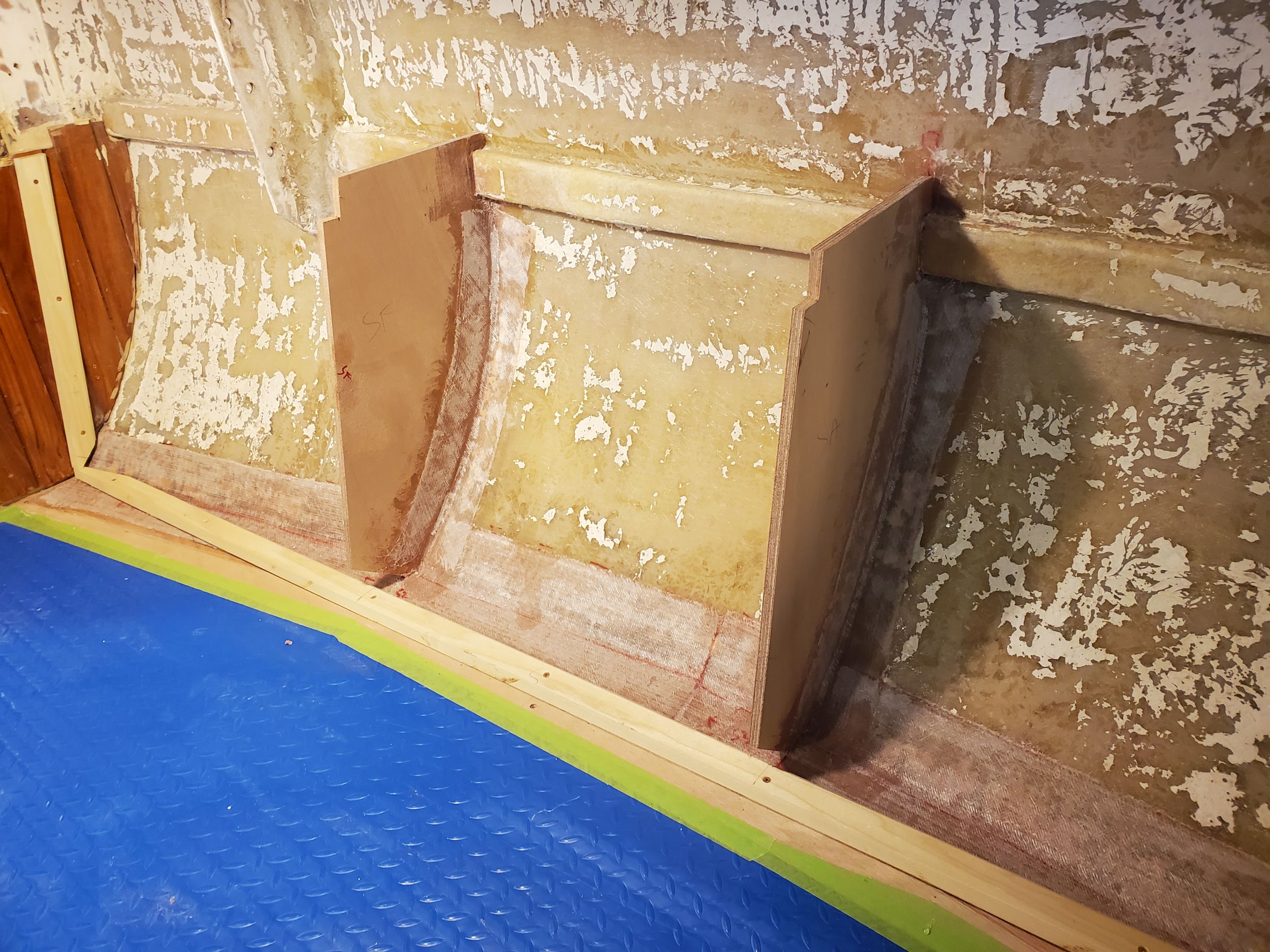
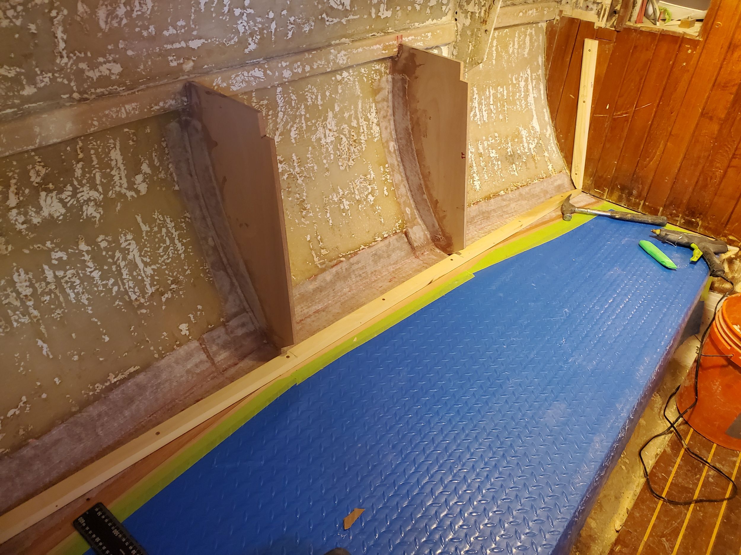
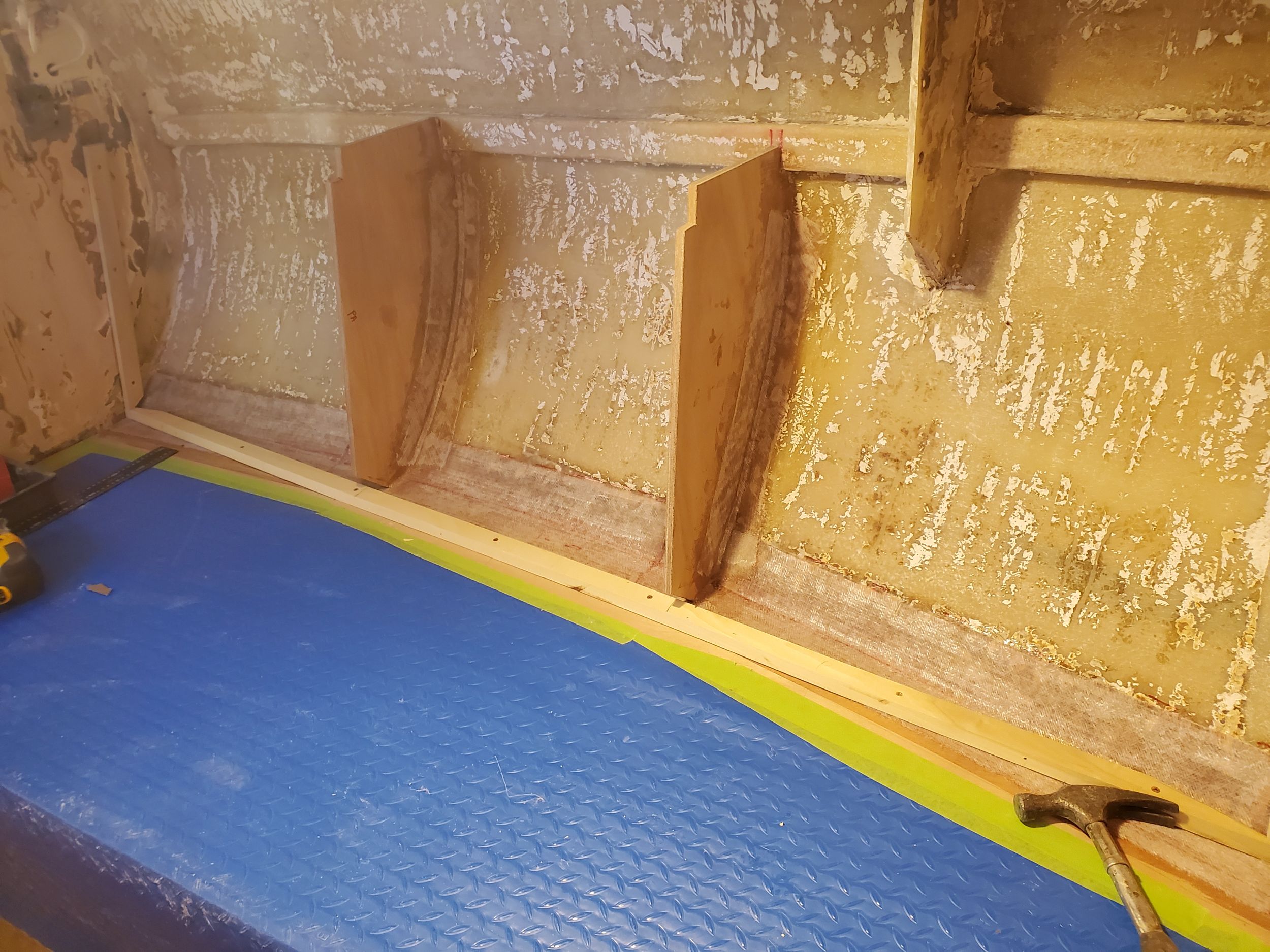
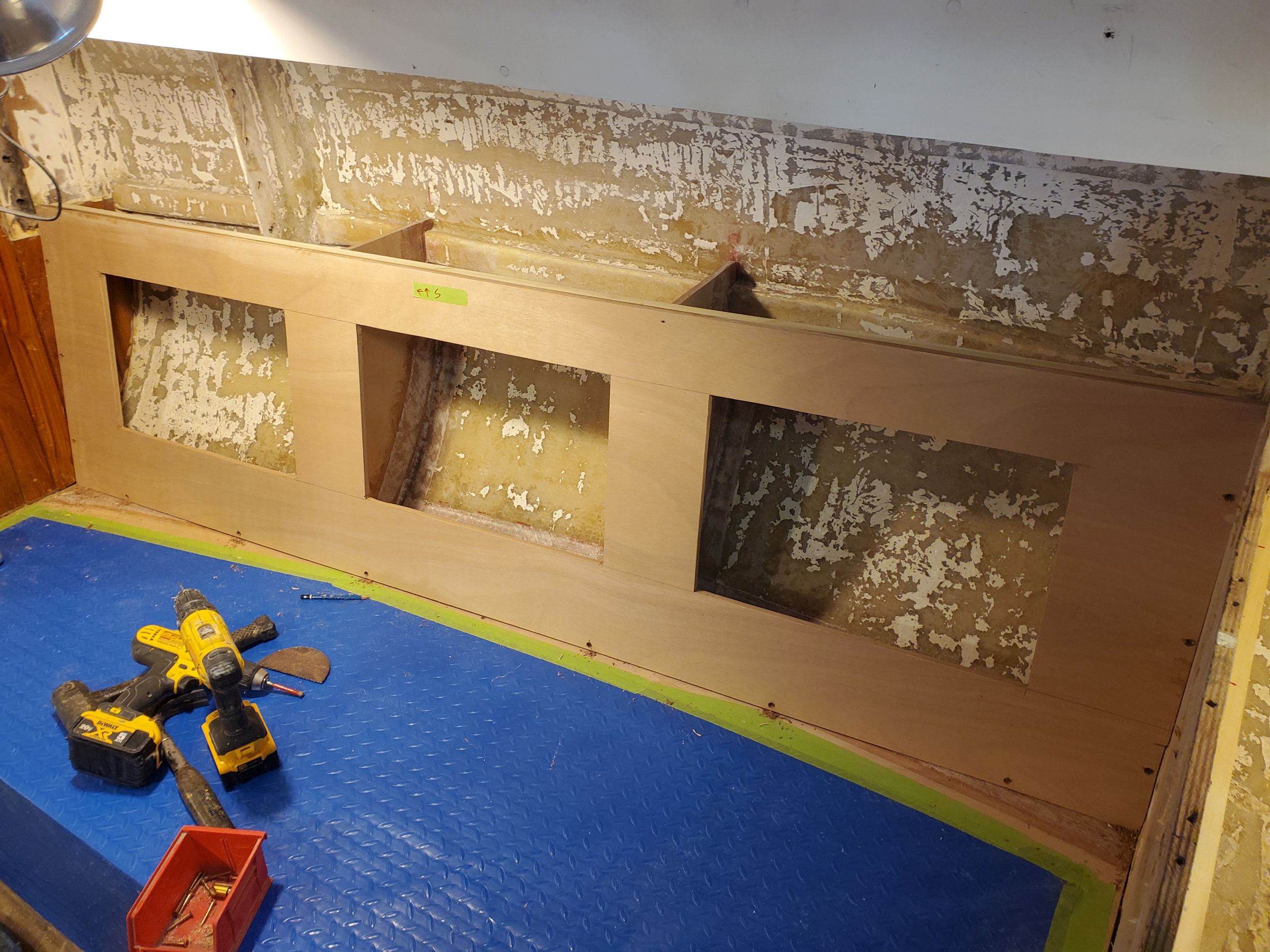
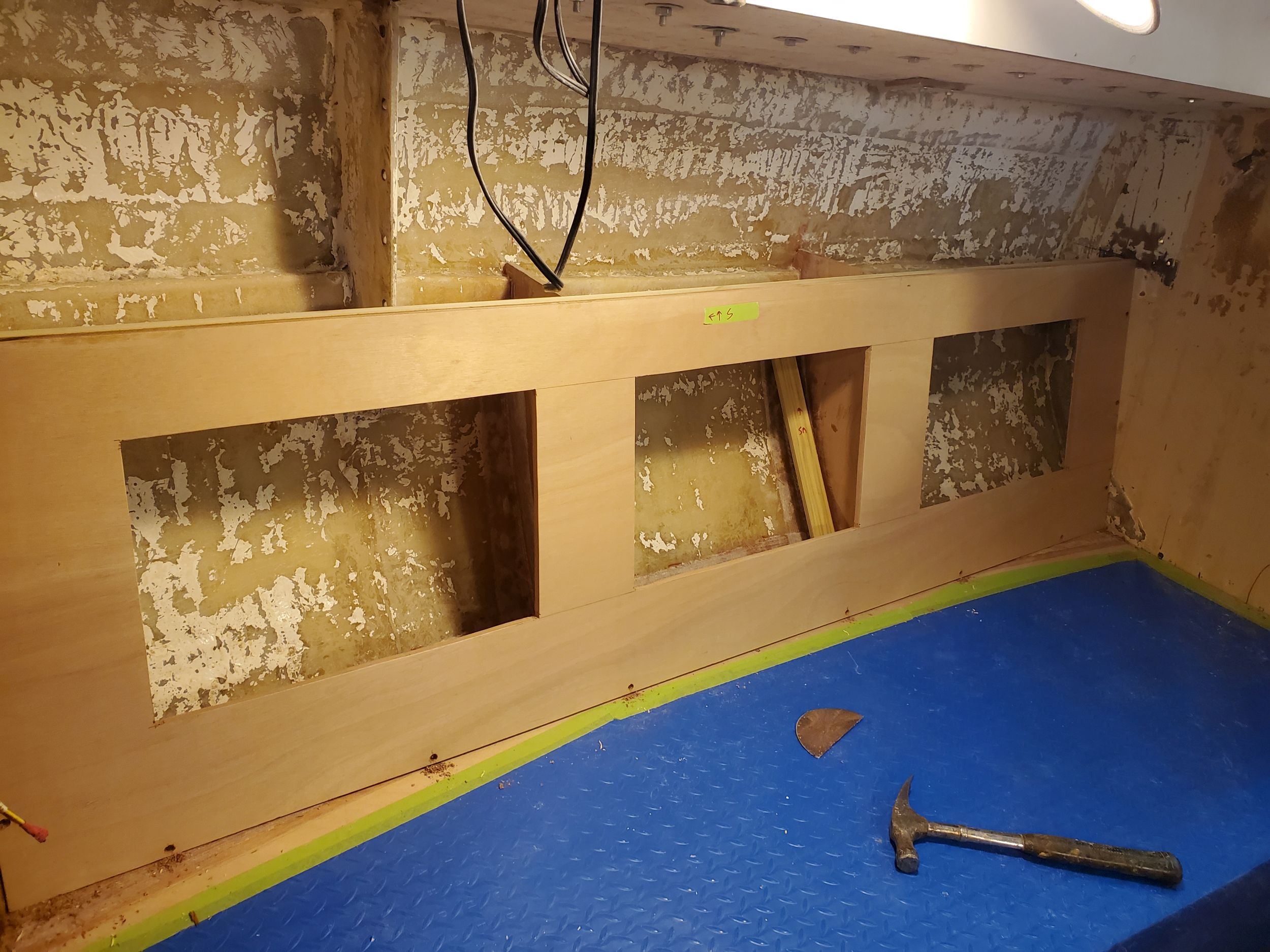
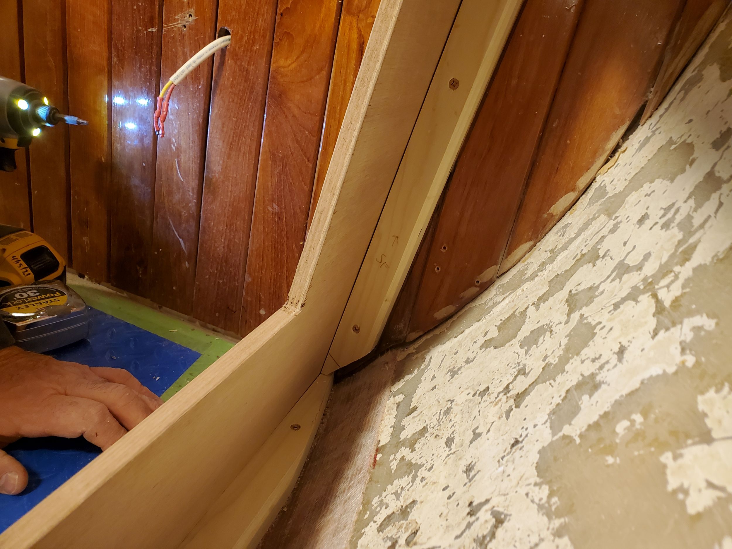
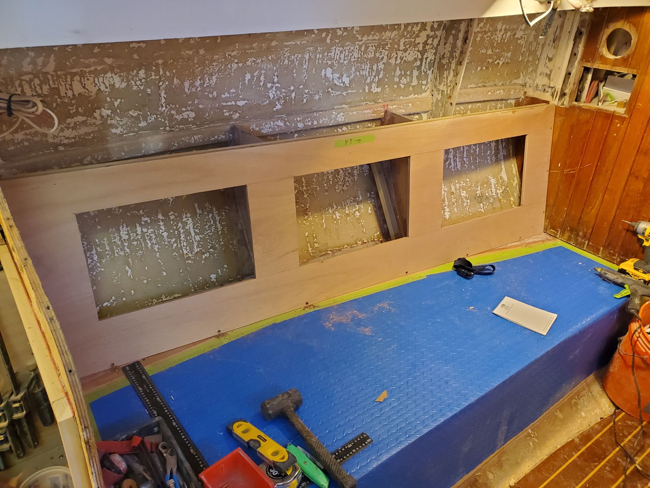
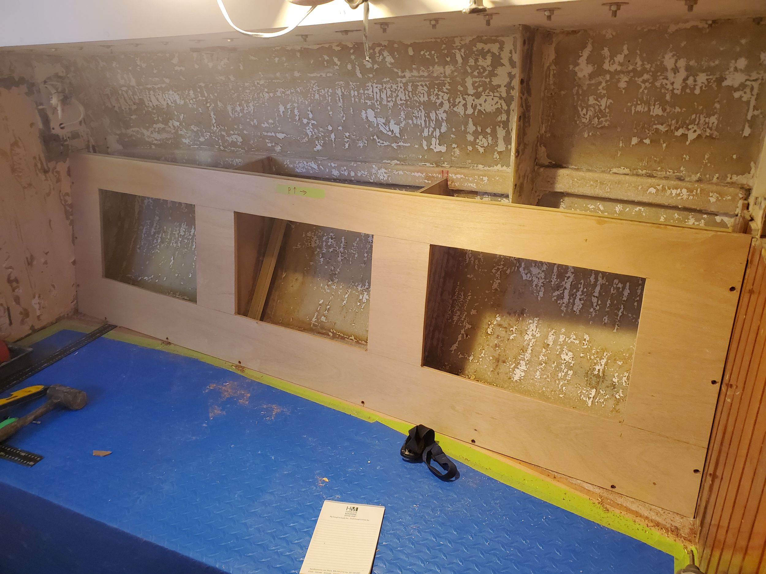
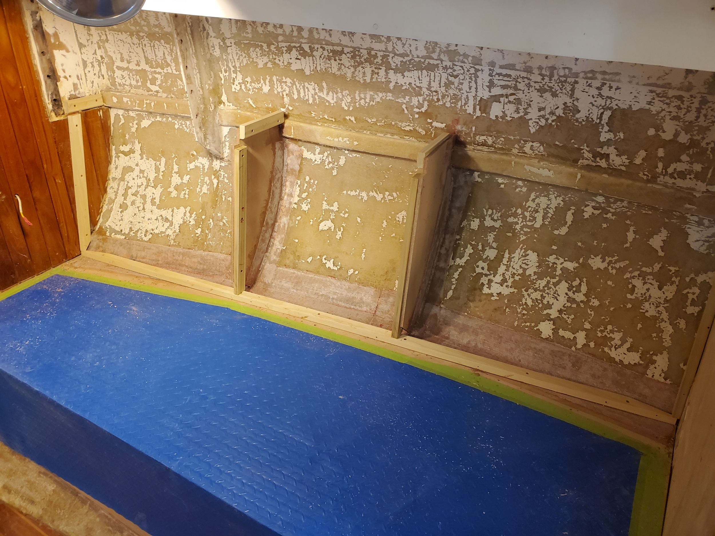
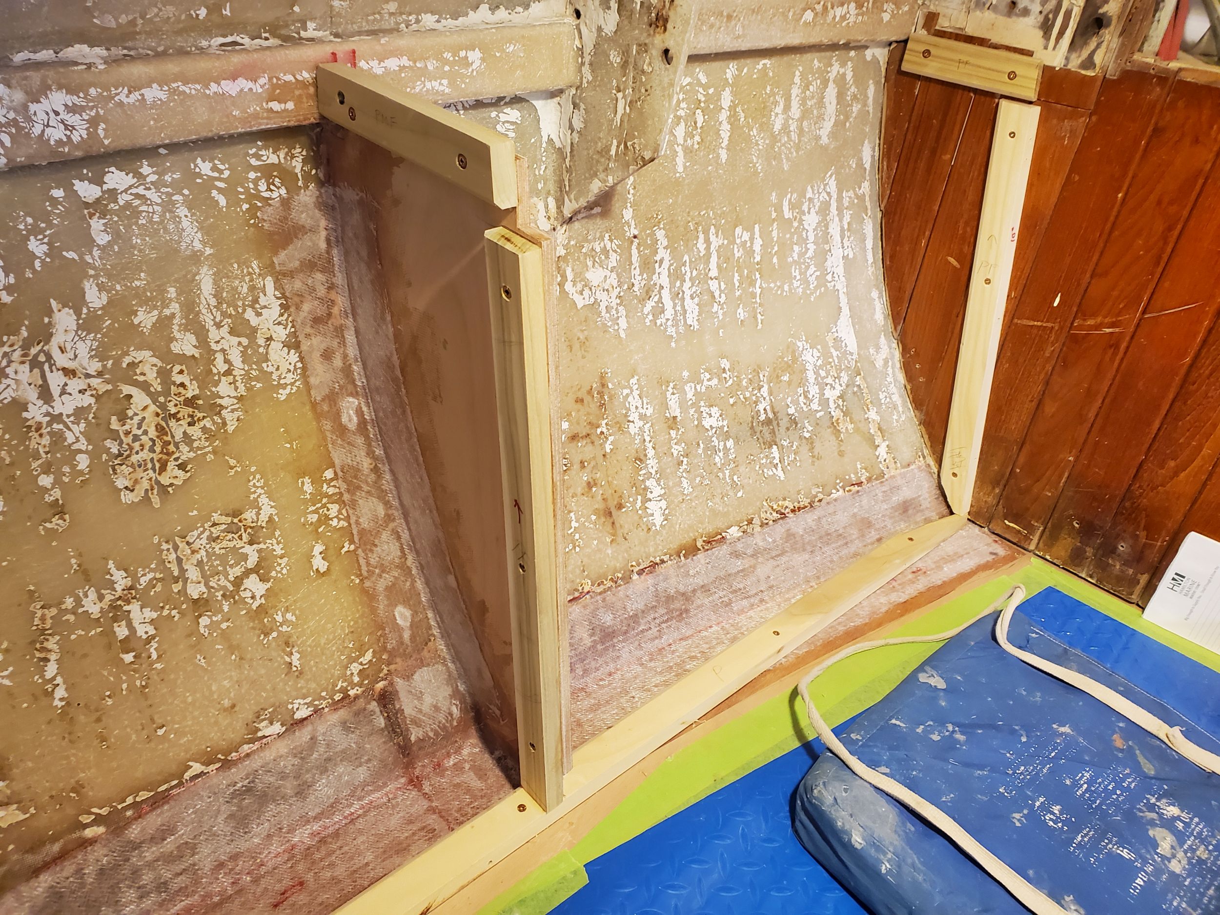
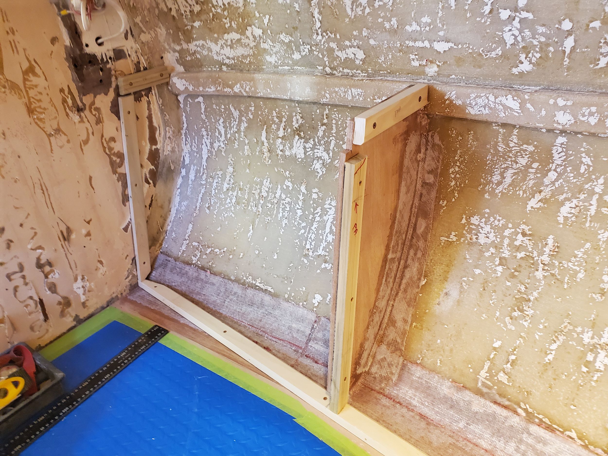
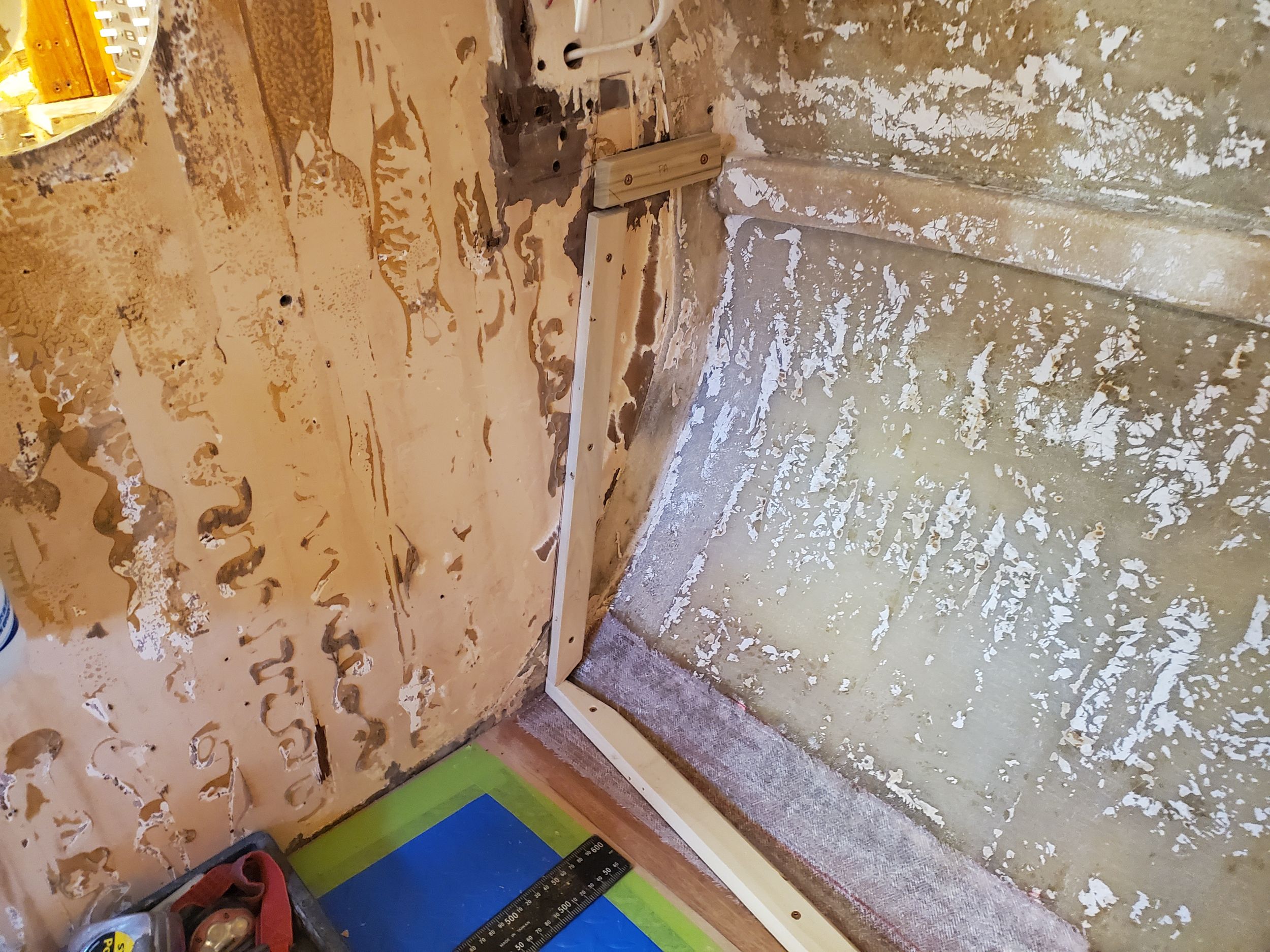
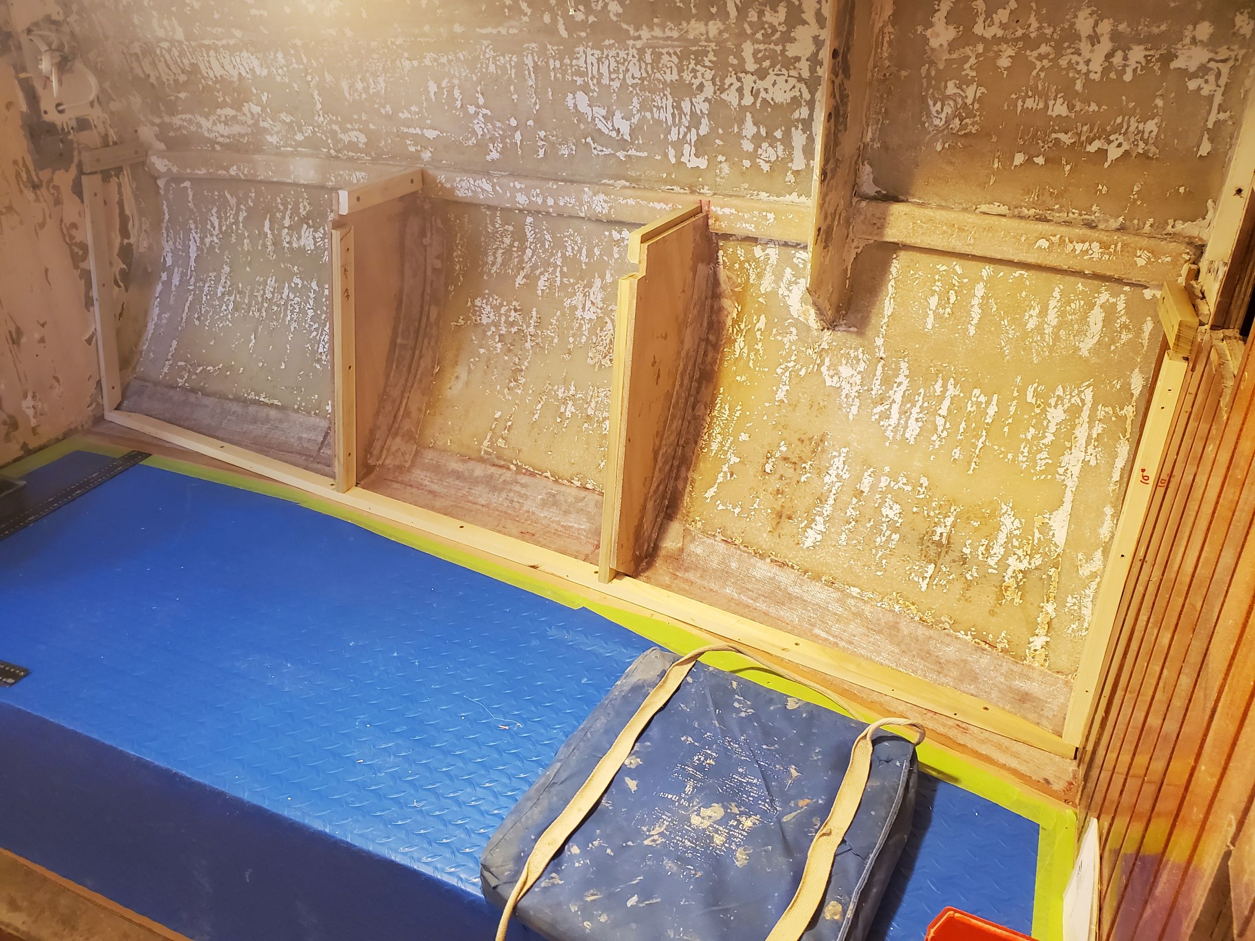
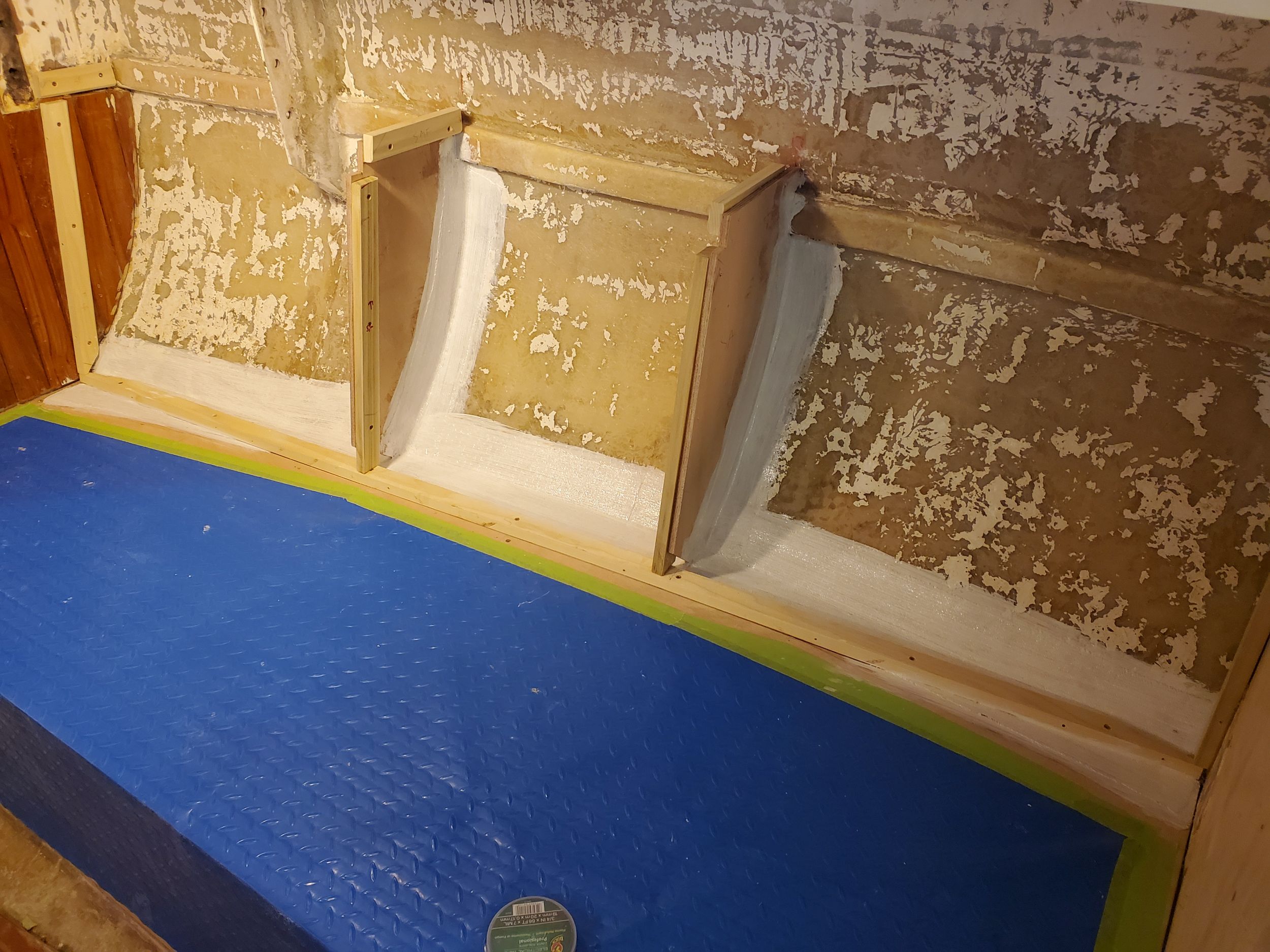
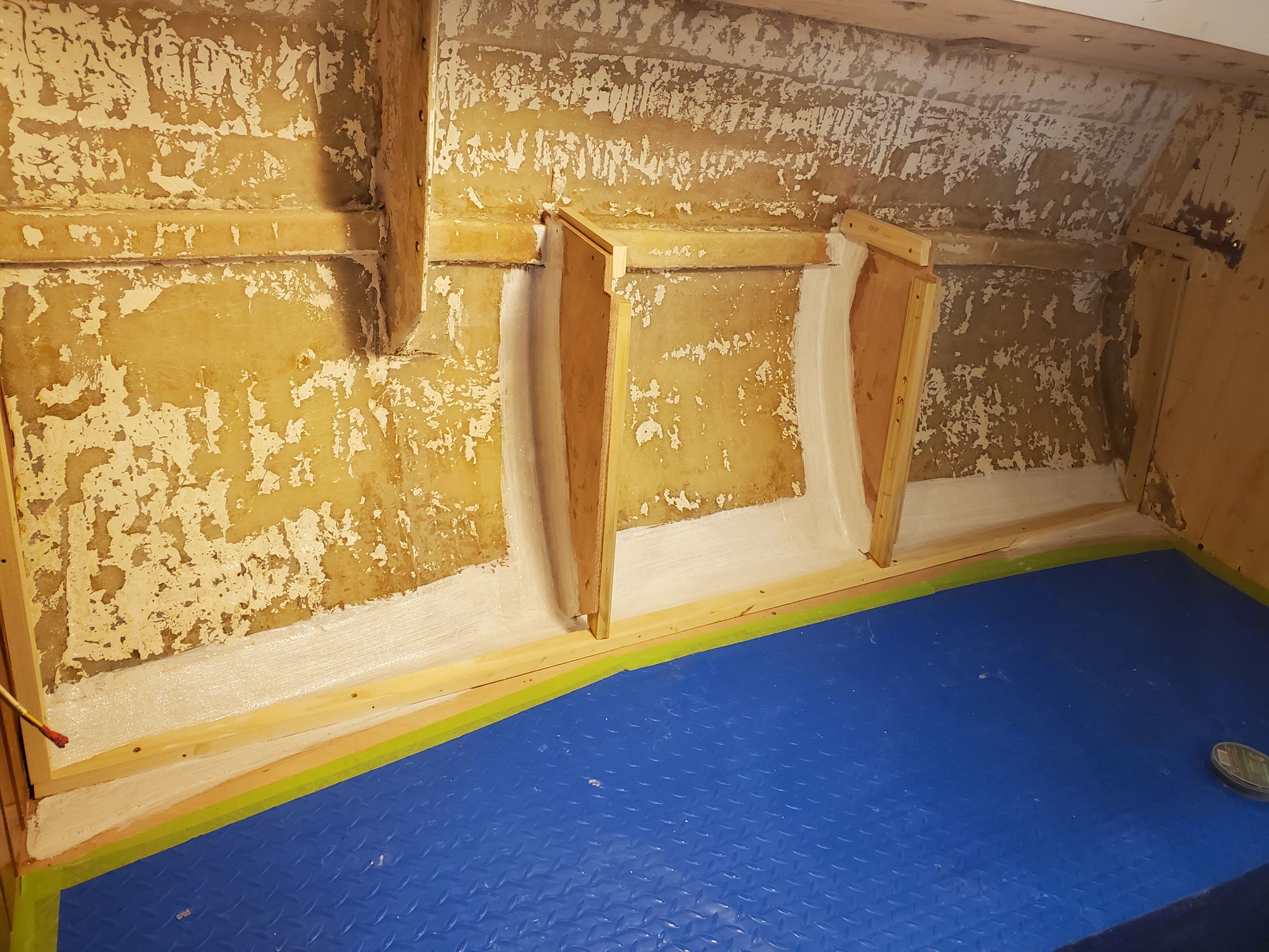
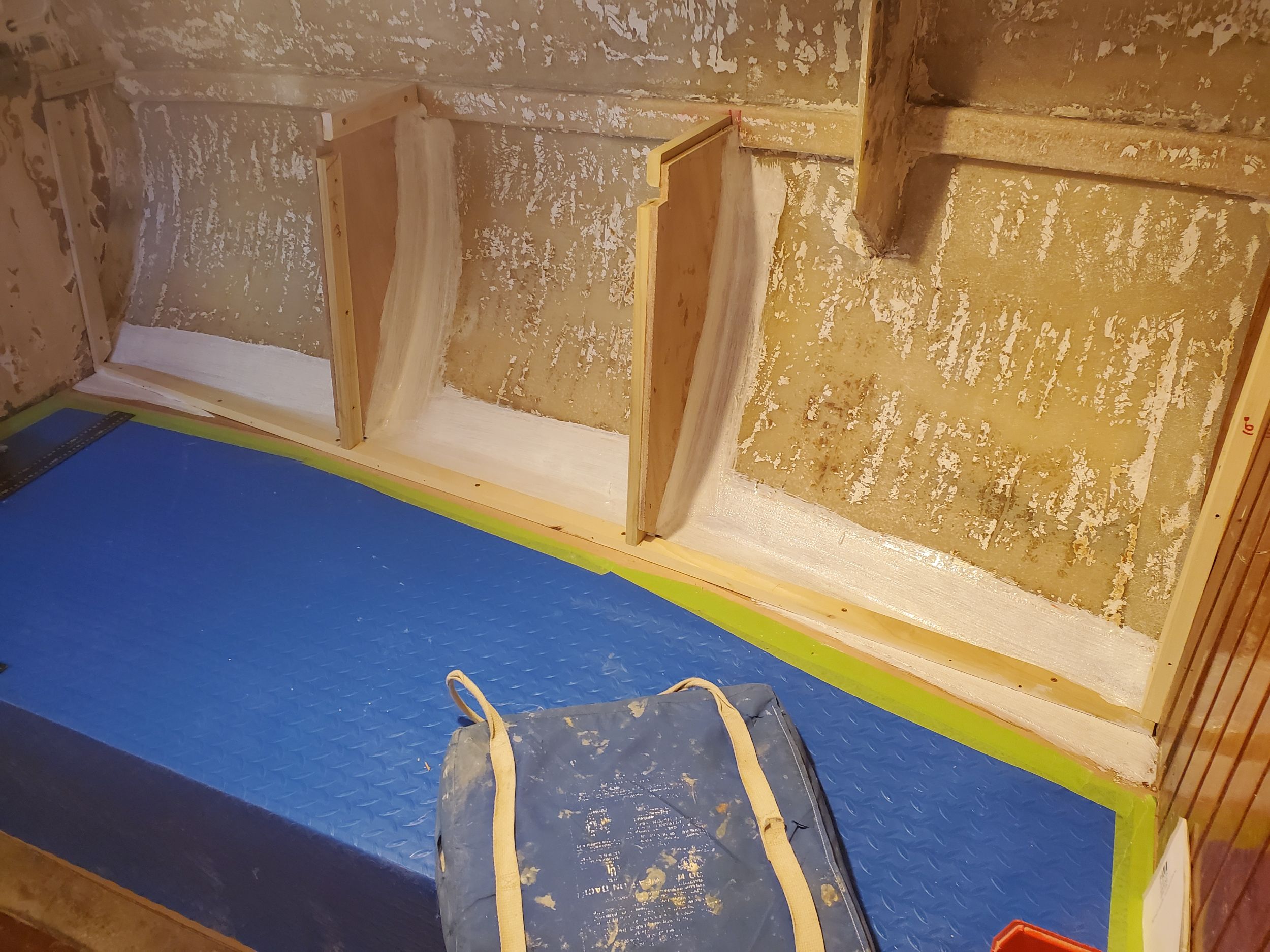
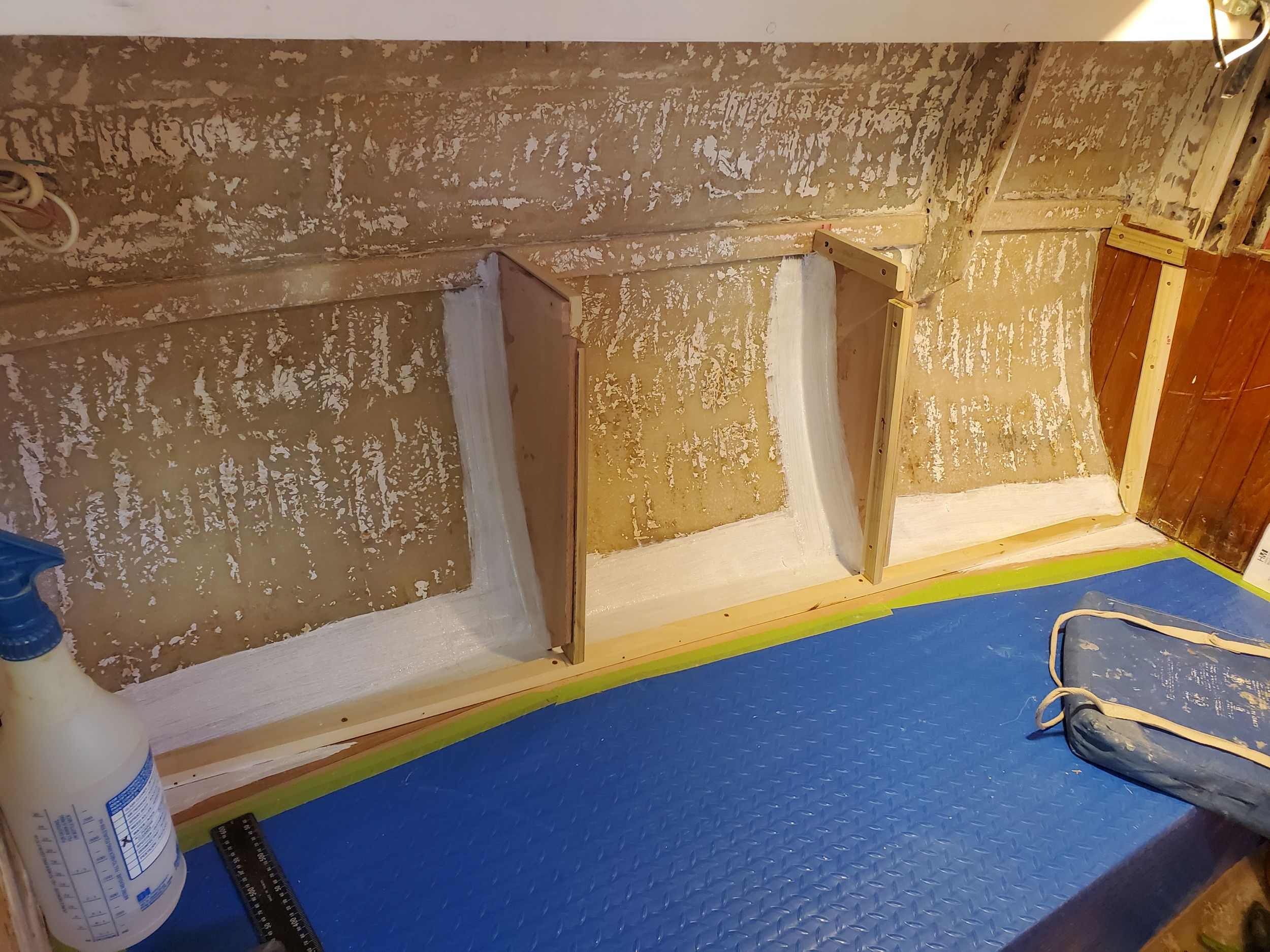
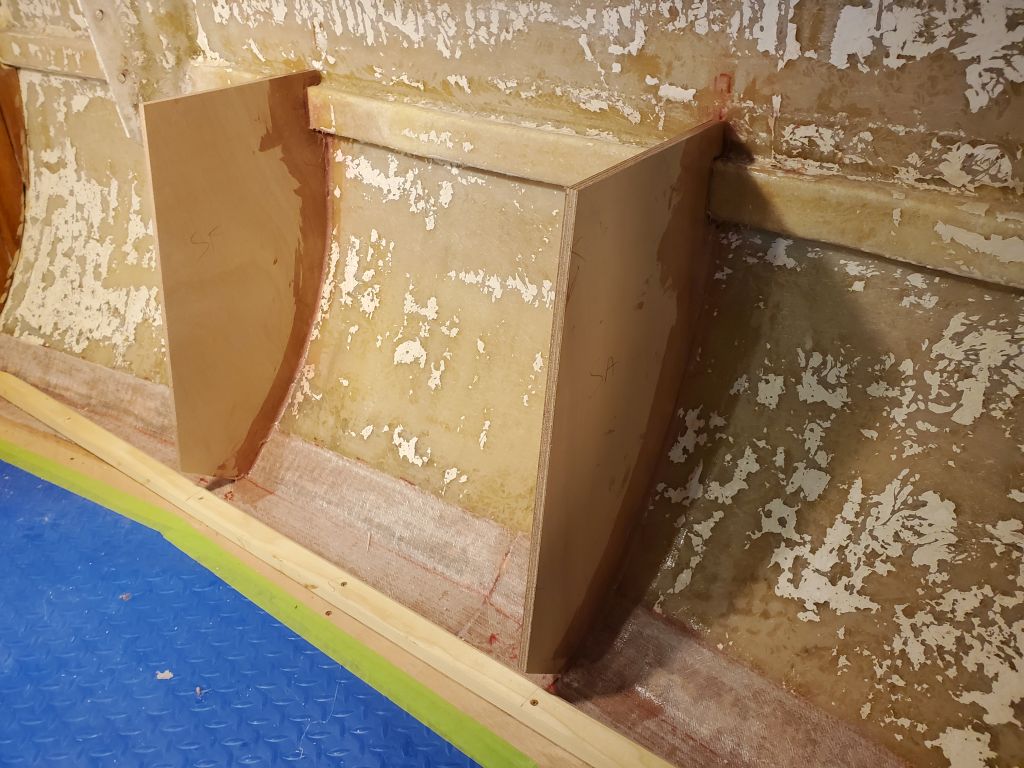
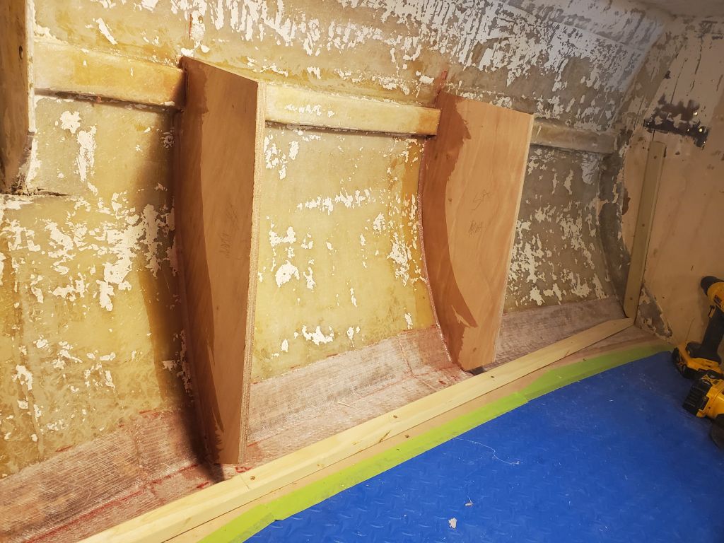
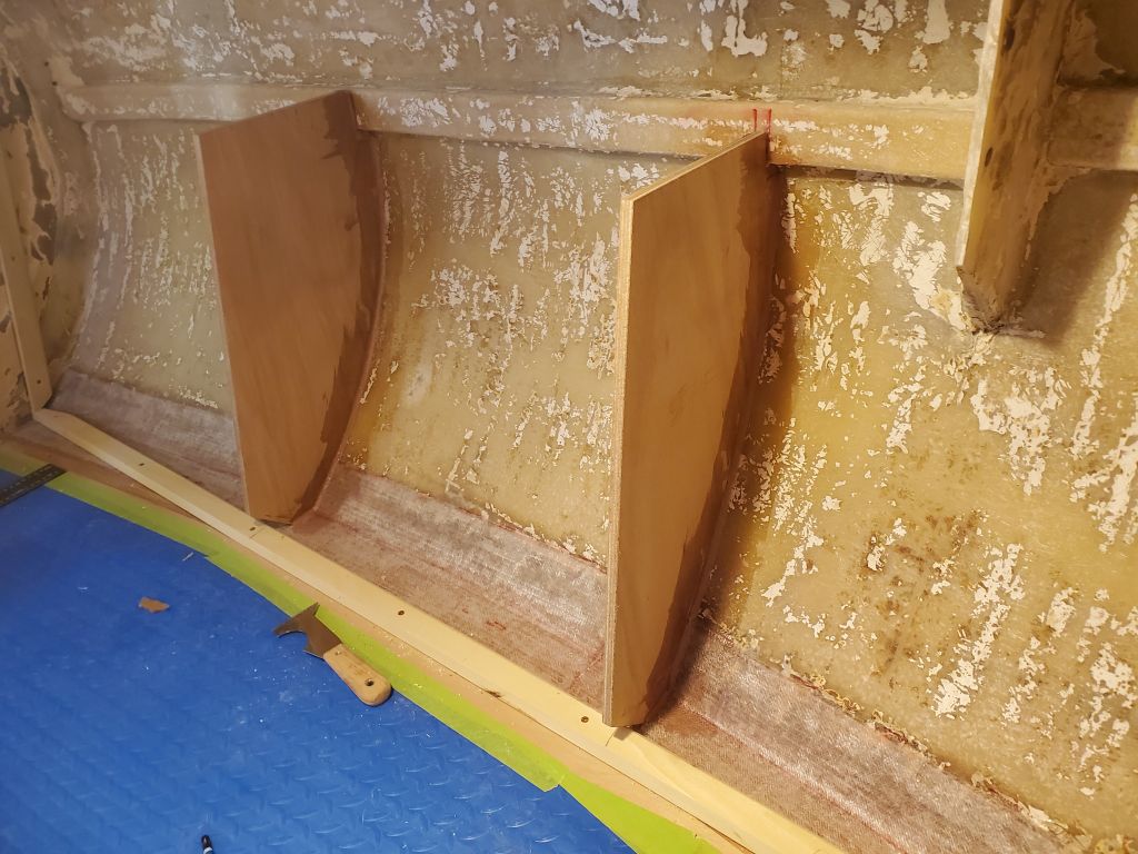
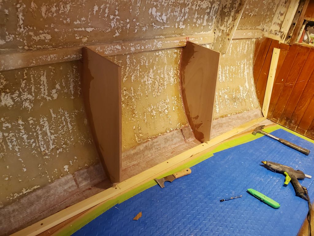
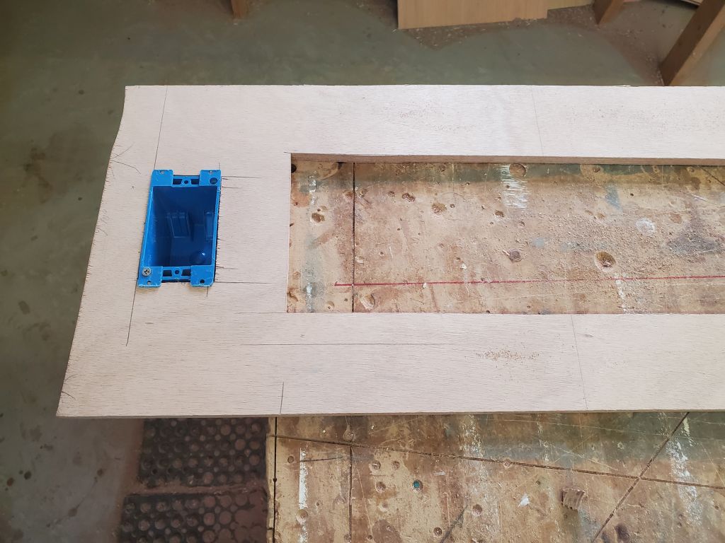
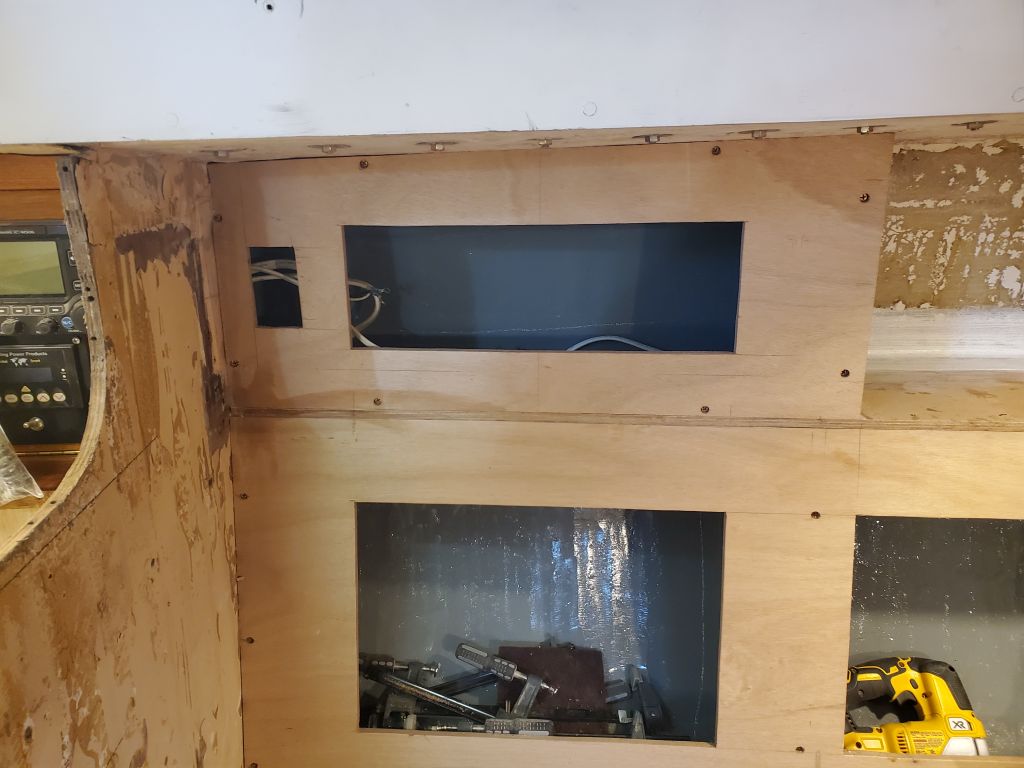
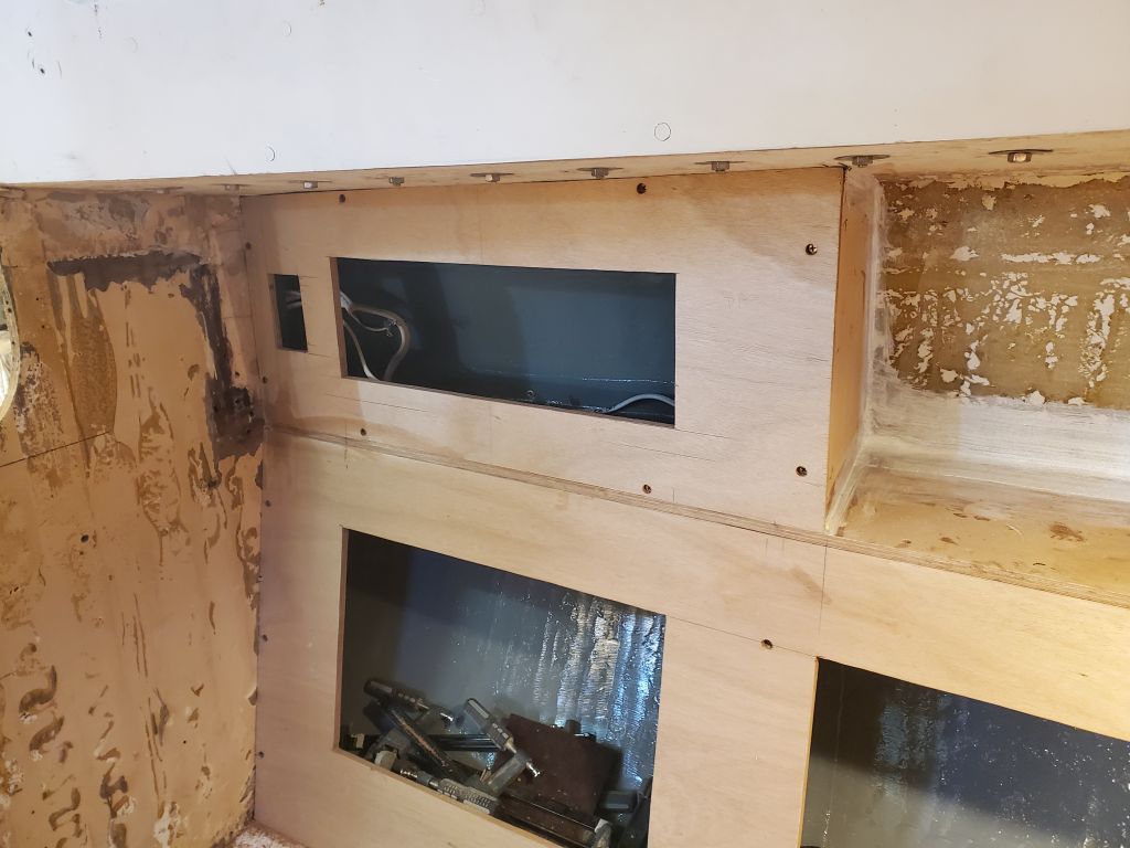
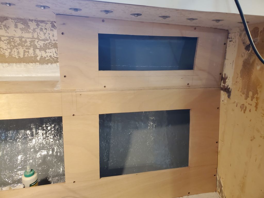
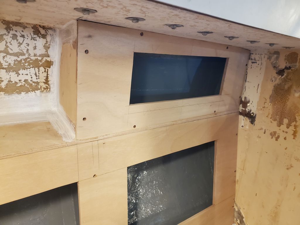
I’d hold off installing the forward set of upper cabinets till the chainplates were done, but now I could install the after set, after first taking a moment to cut an opening for an outlet box on the port side, to replicate what was in the original interior. I also re-led the wiring for this box through a new hole into the electrical locker, as the originals were outside of the new locker.
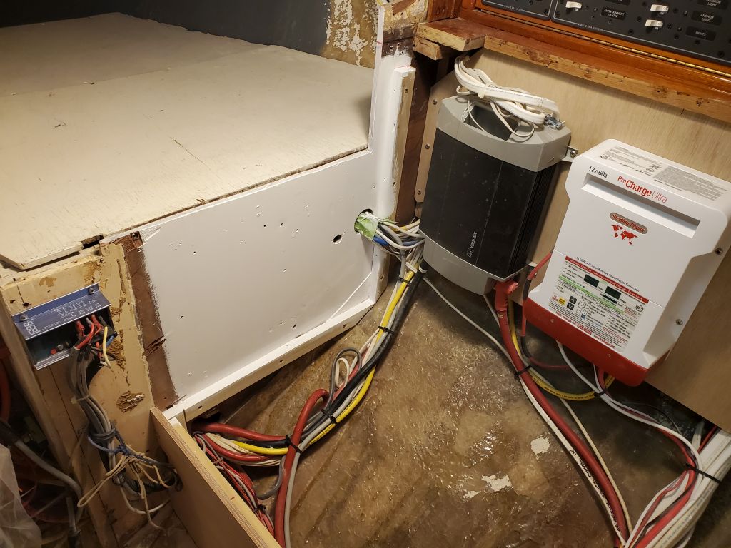
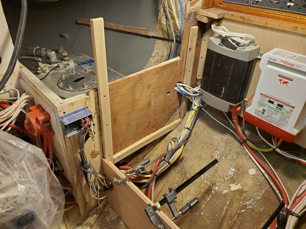
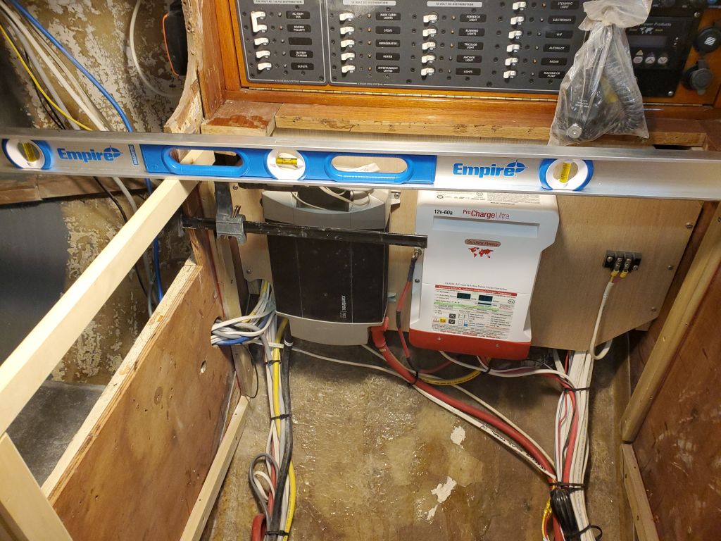
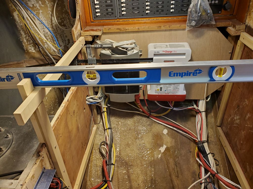
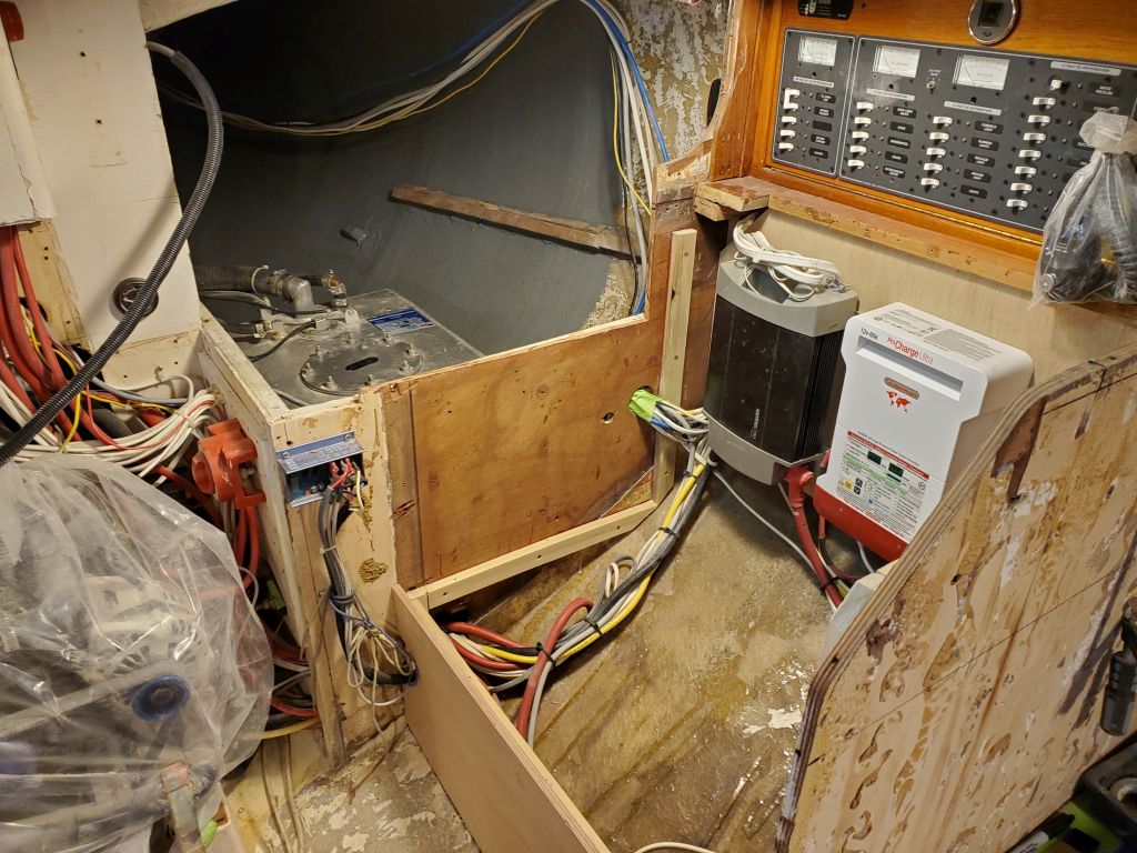
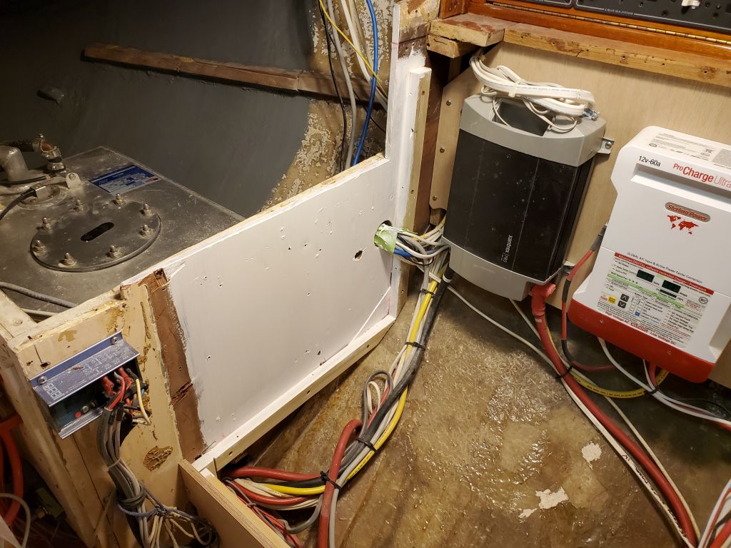
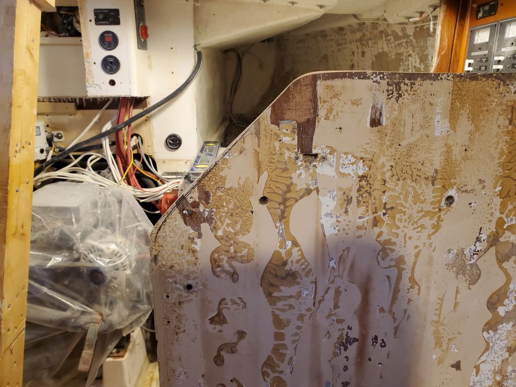
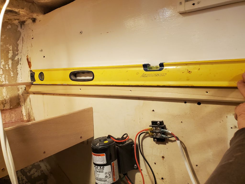
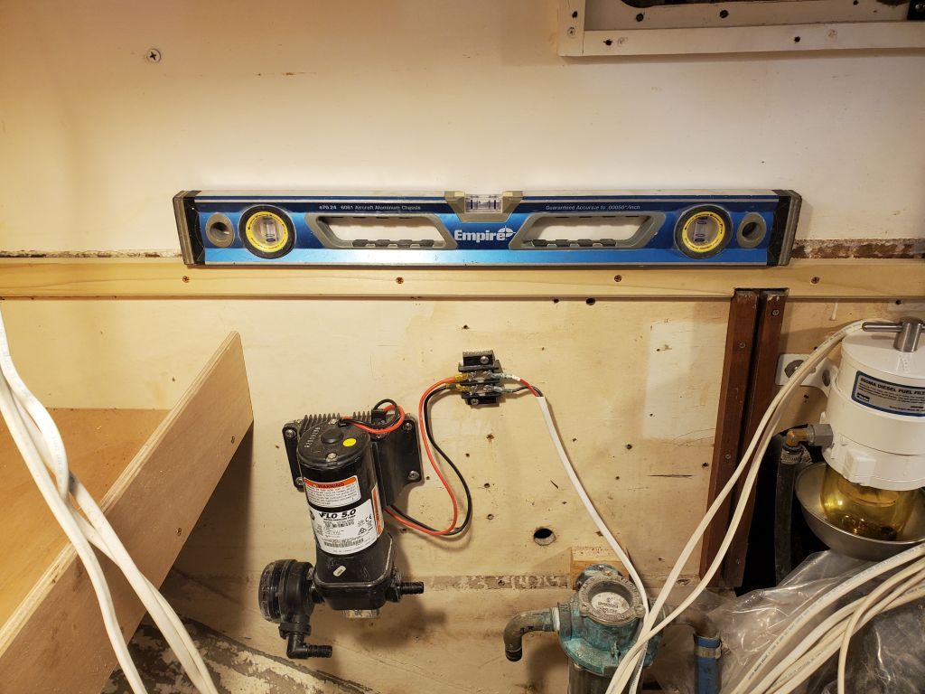
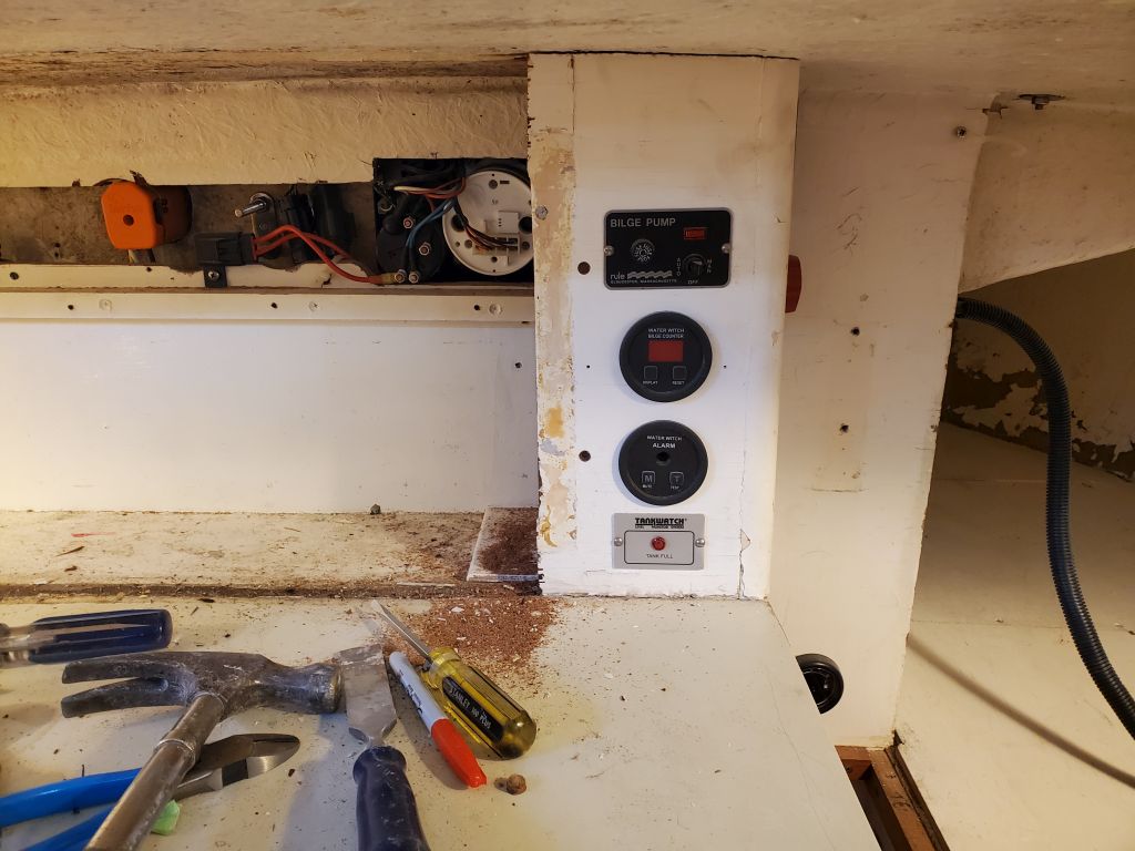
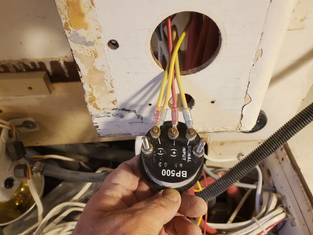
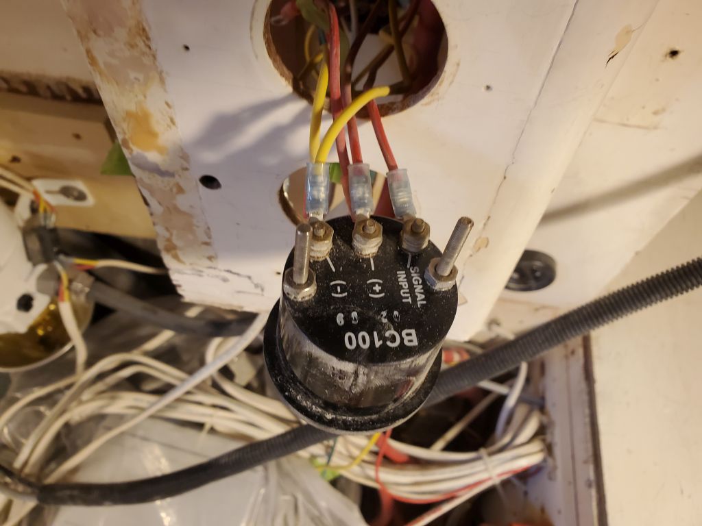
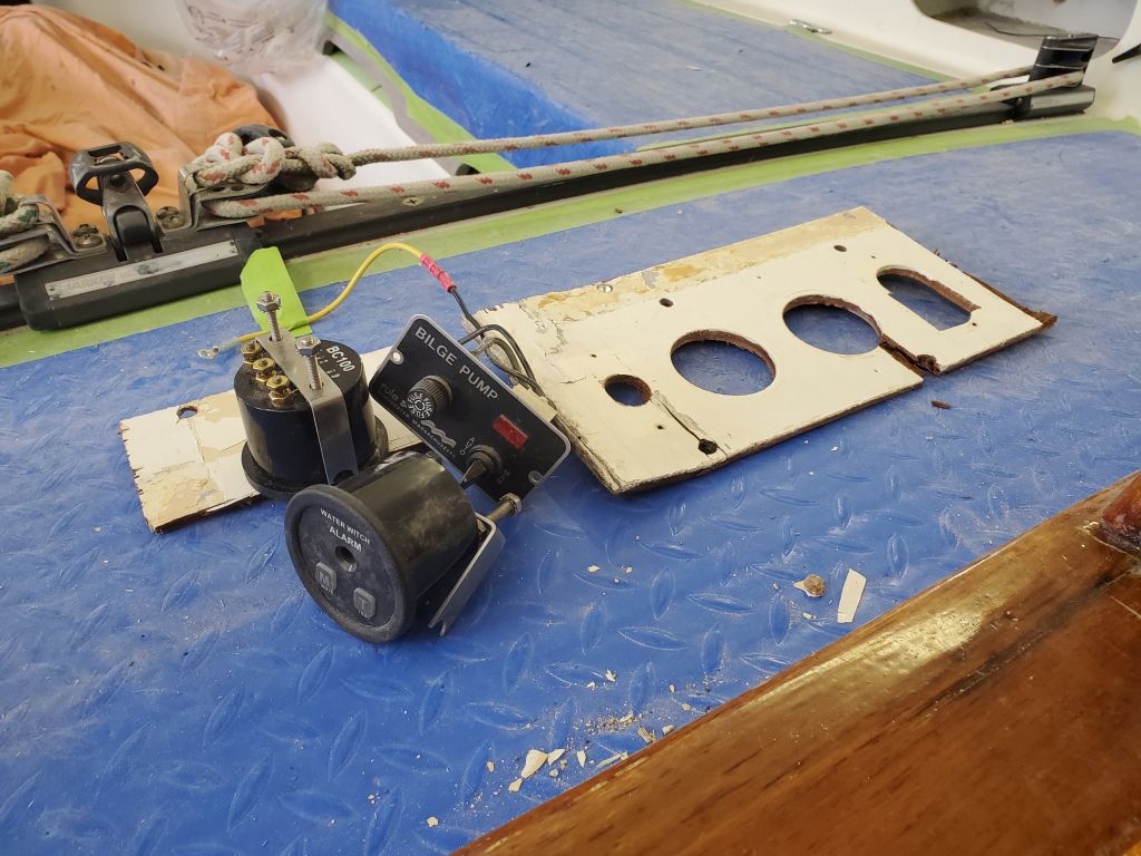
In the galley, I decided to temporarily remove the bilge pump switch and two related gauges below from a small, original panel so that I could eventually reinstall these in the new galley cabinet. I removed the wiring from each, labeling as needed, and removed these installations so I could remove the face panel as well; I planned to leave the adjacent battery switch panel in place, where it could be easily accessed through the new lockers once built, and since relocating it at all would involve more re-wiring work than it was worth.
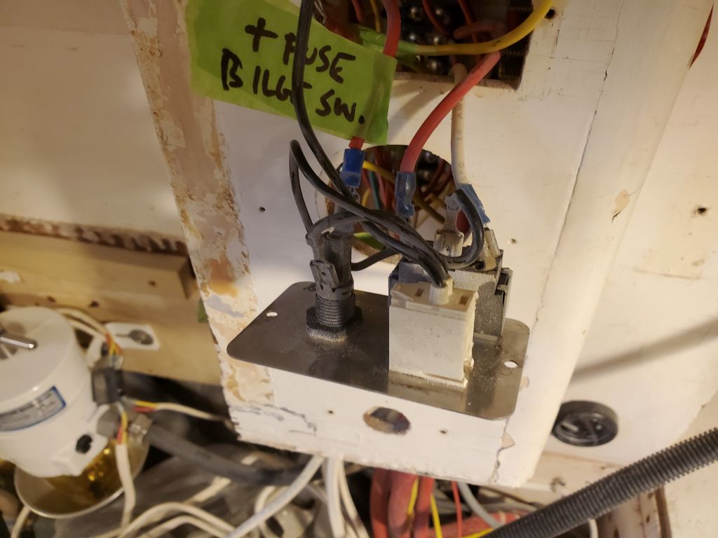
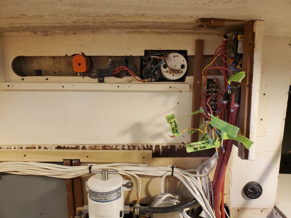
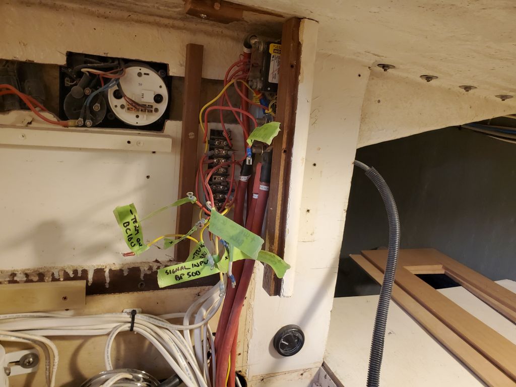
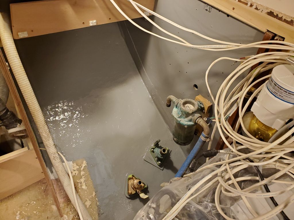
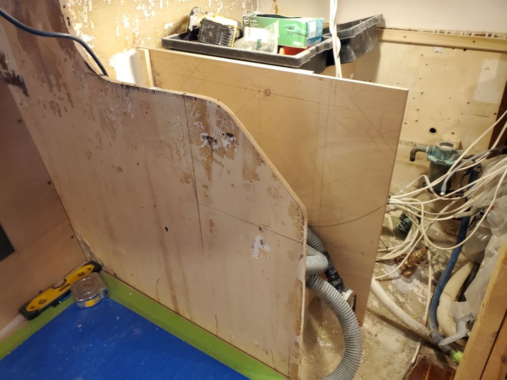
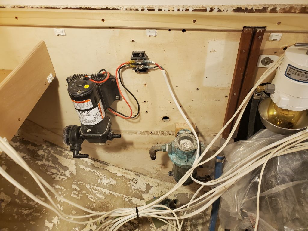
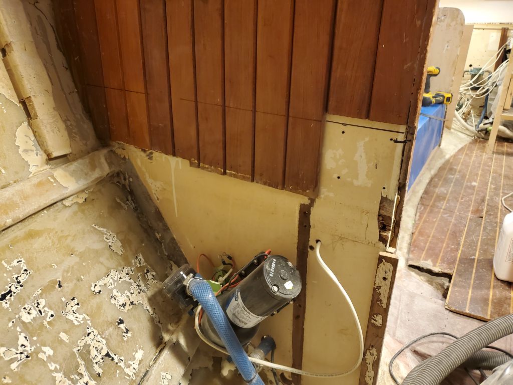
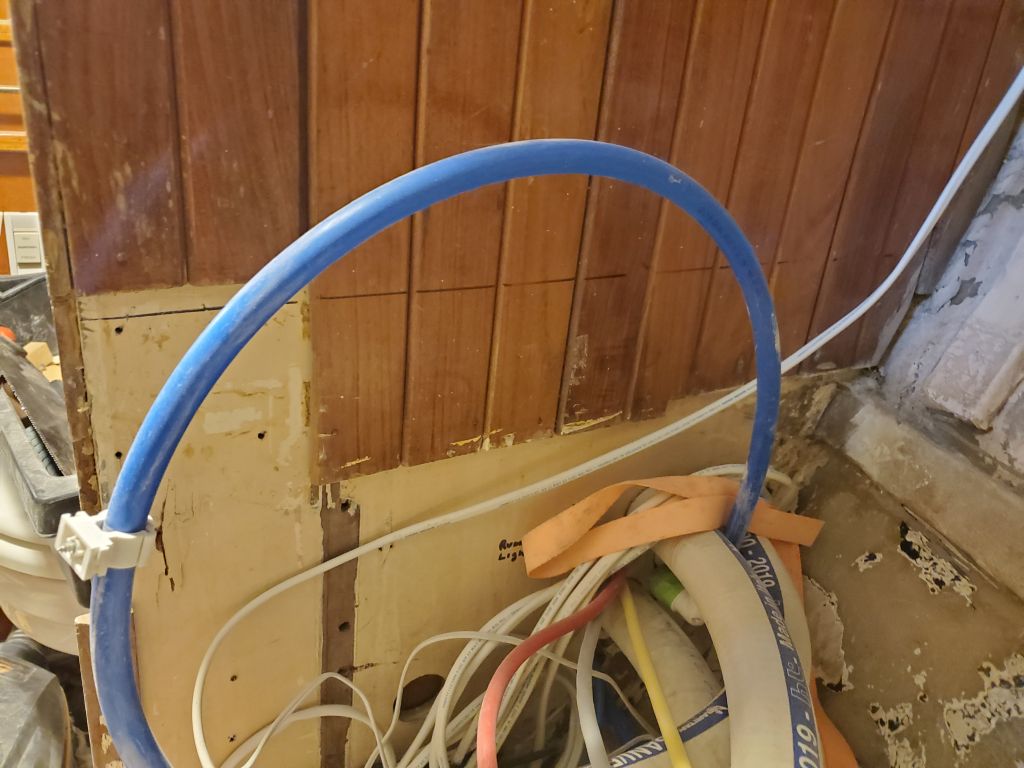
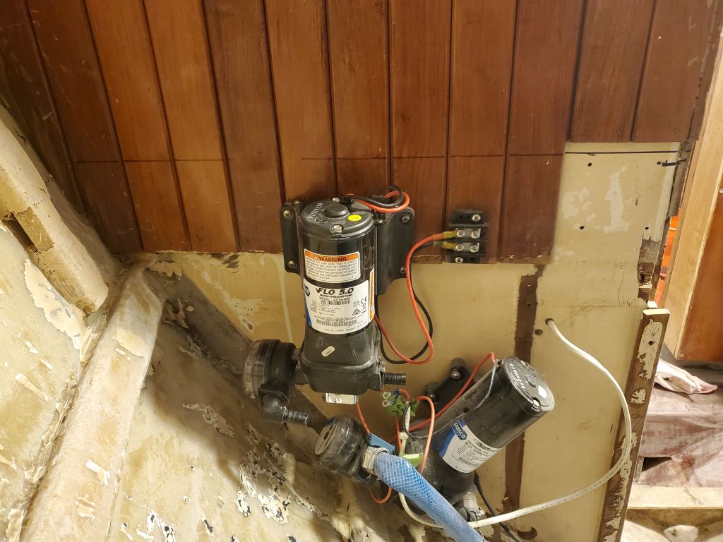
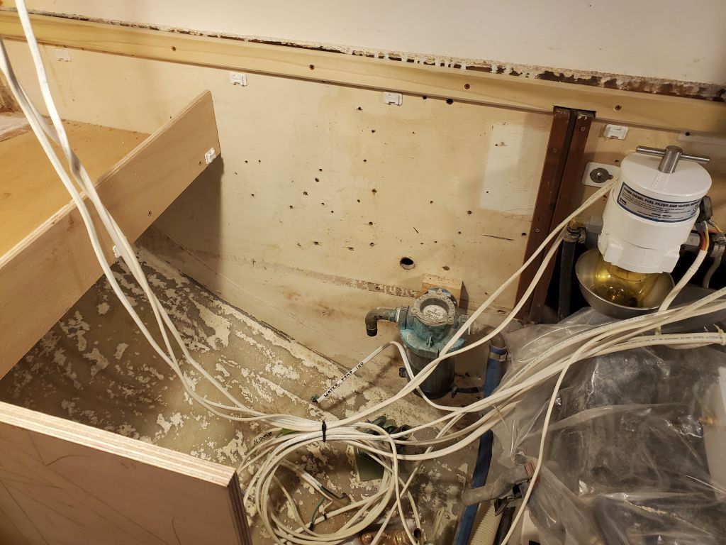
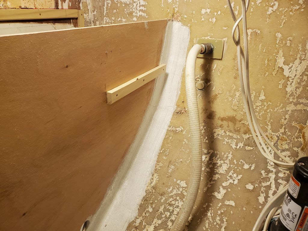
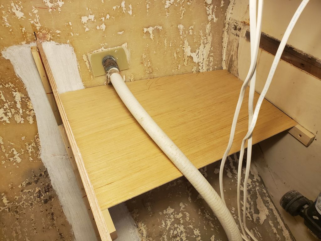
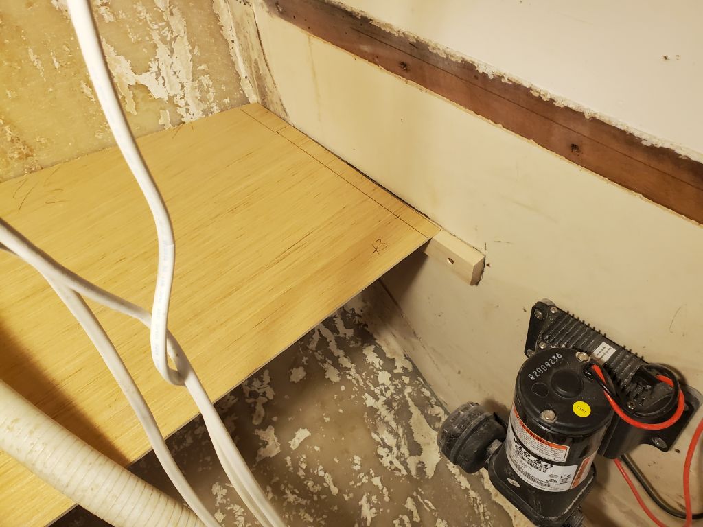
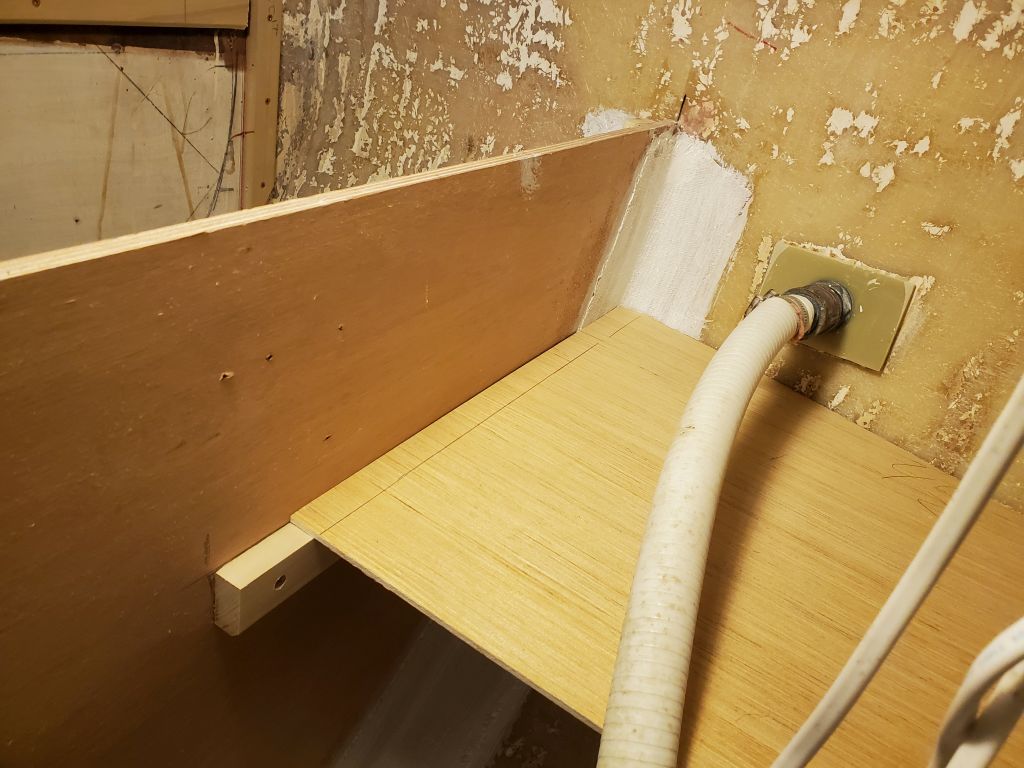
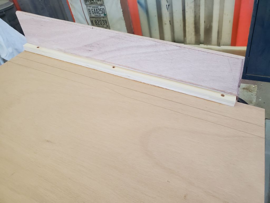
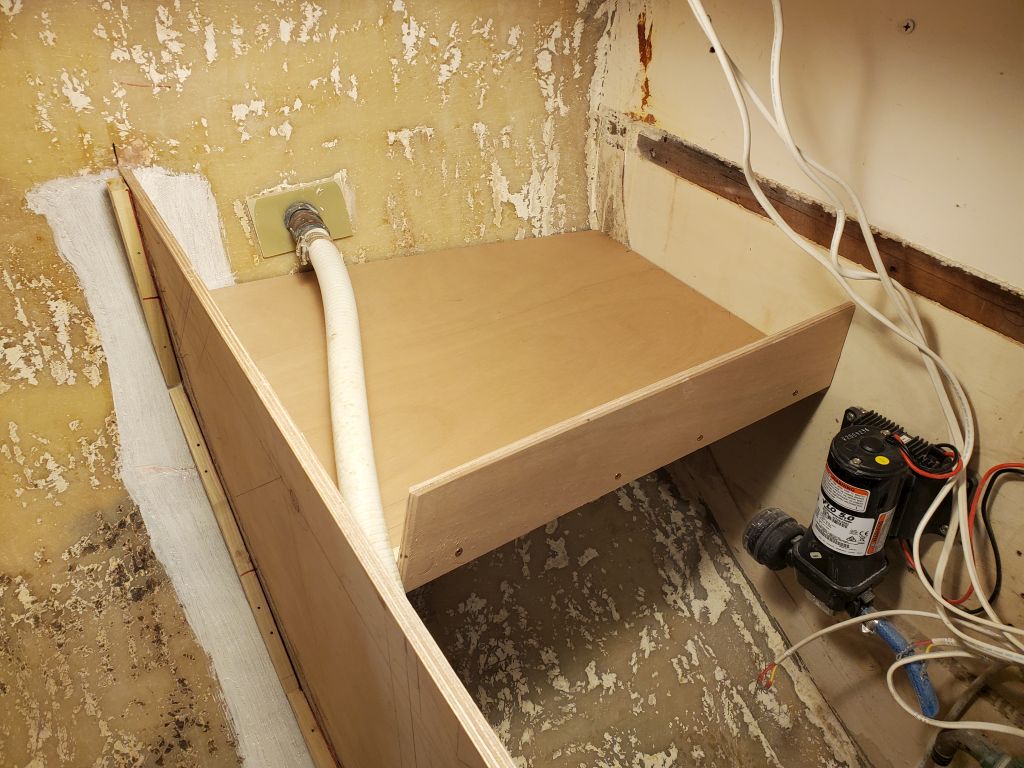
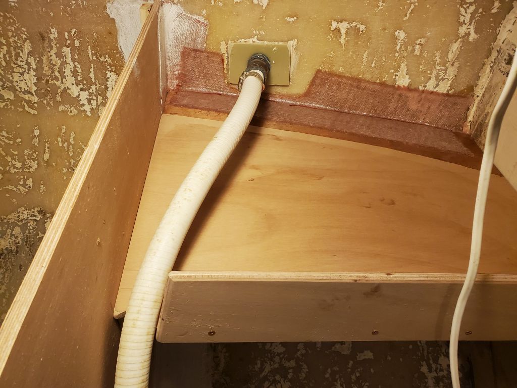
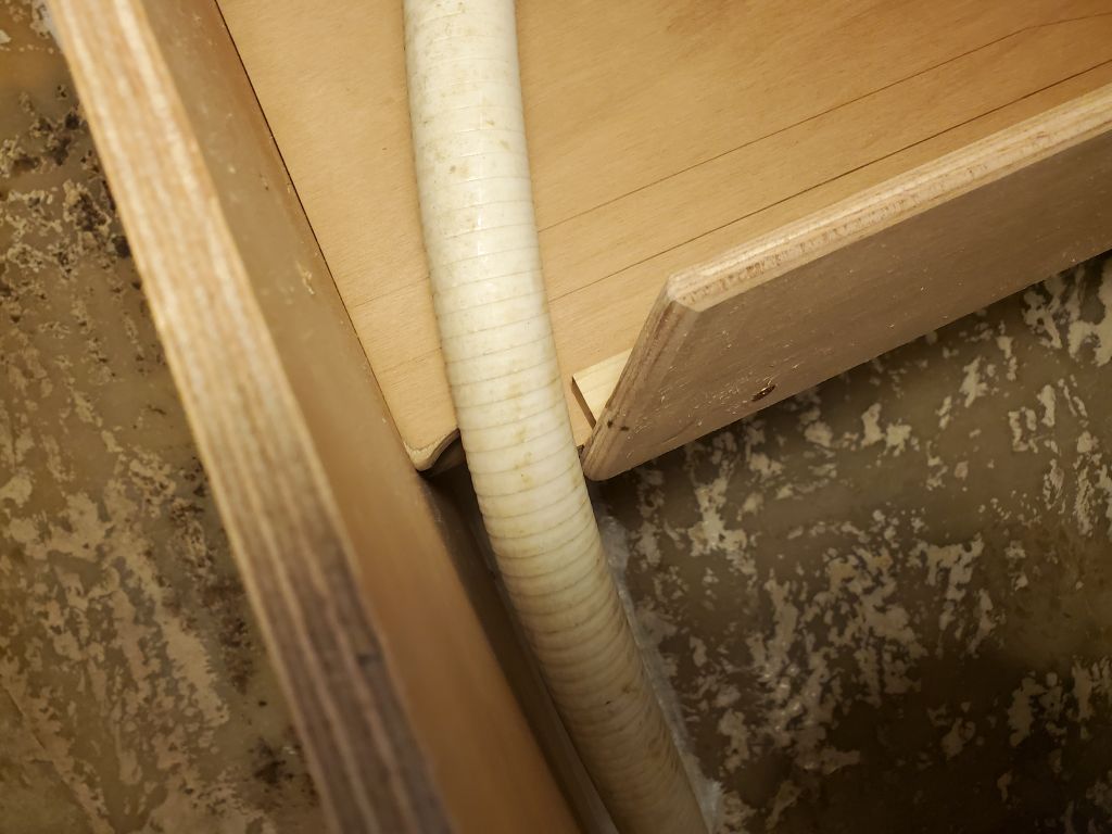
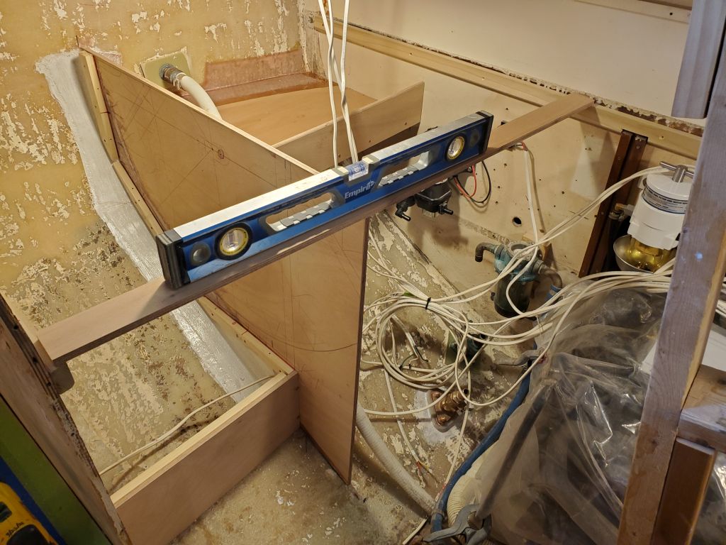
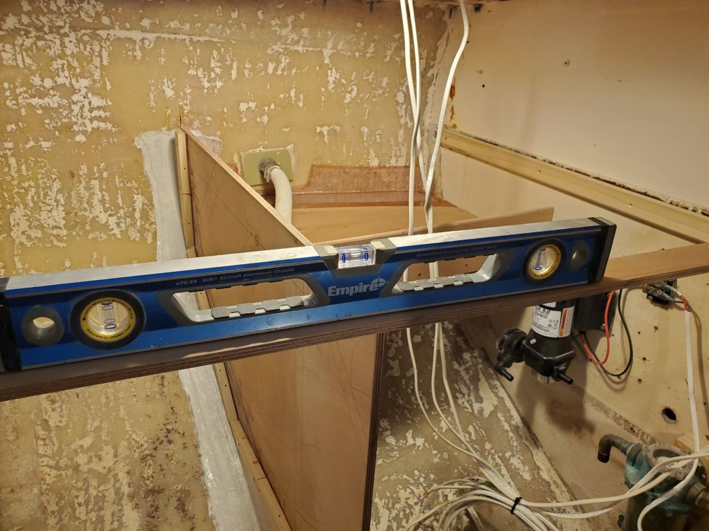
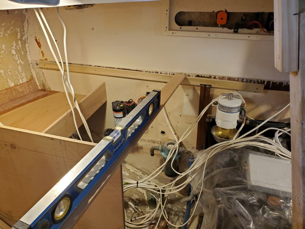
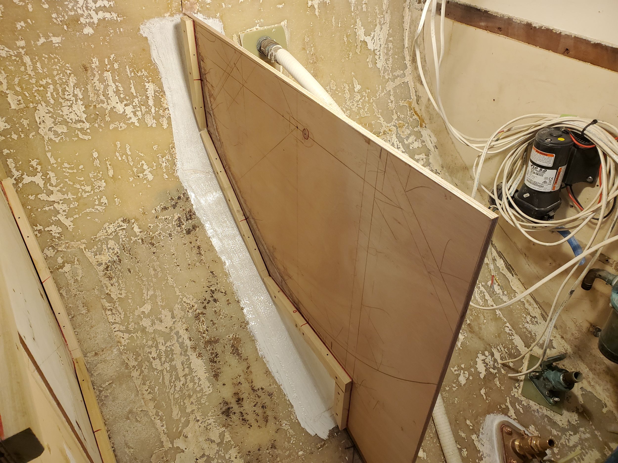
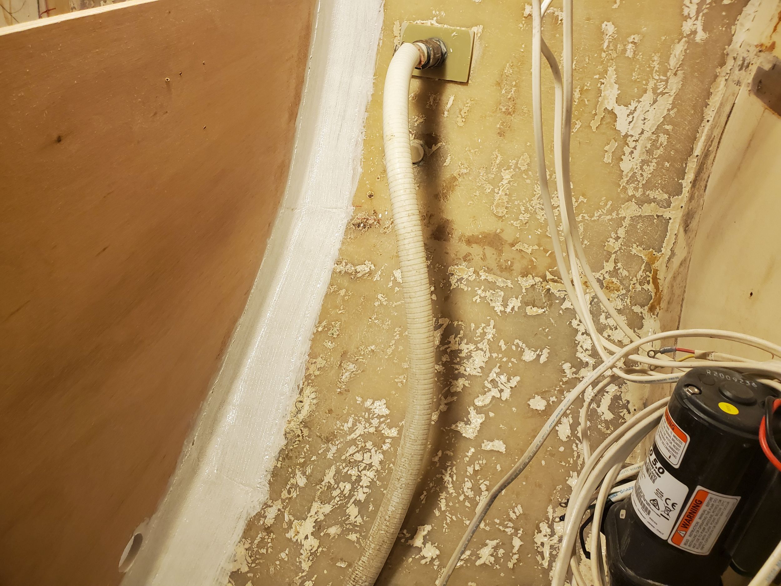
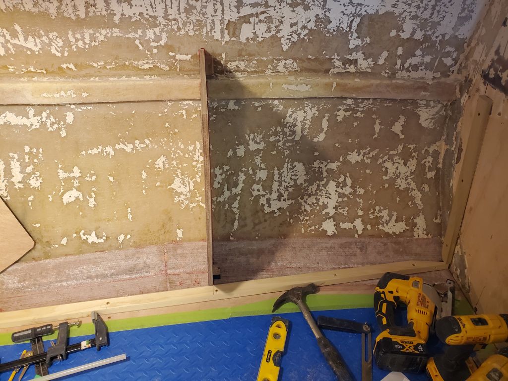
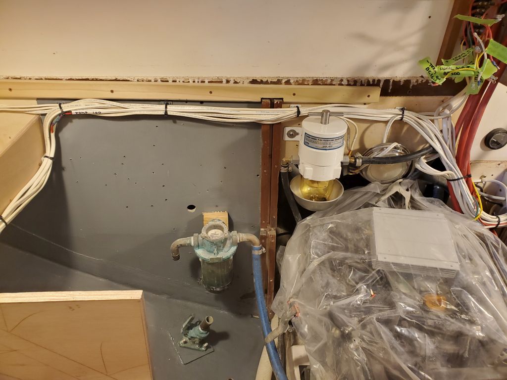
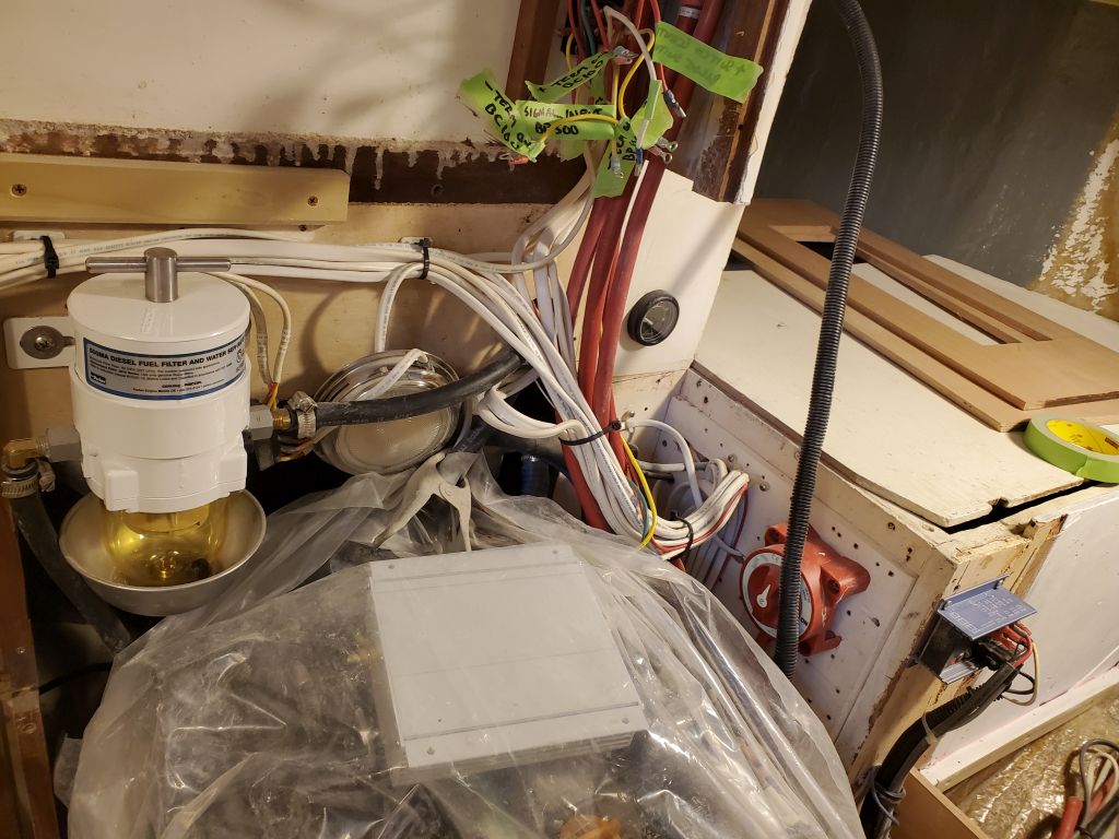
Meanwhile, I started to clean up and secure some of the wiring run through the galley, which wiring had originally been secured beneath the old countertop. Now, I resecured it to the new wire mounts along the aft bulkhead and elsewhere to direct various portions where they needed to go. I spliced a new length of wire to the original fresh water pump wiring so I could extend it forward to the new location. All this work was leading up to the continuation of the galley construction presently. Additional work remained as the process progressed.
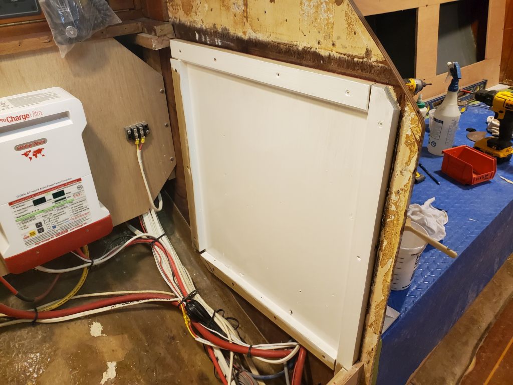
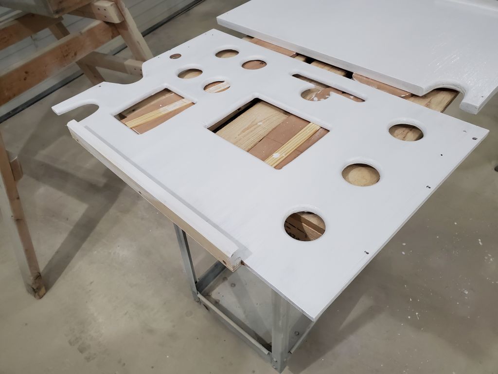
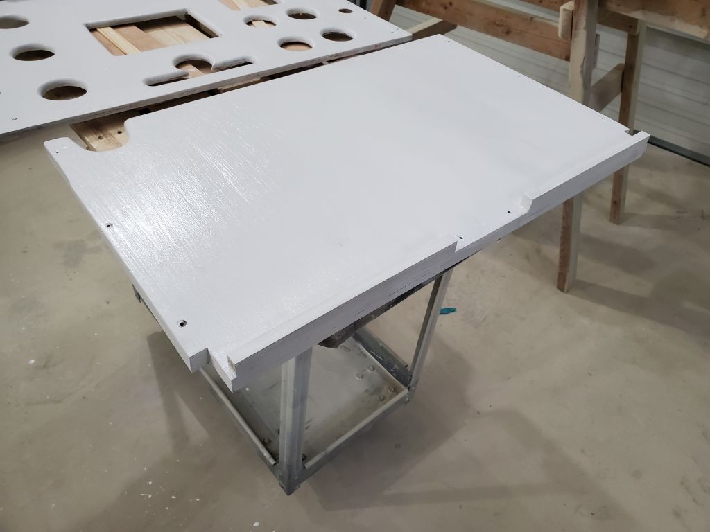
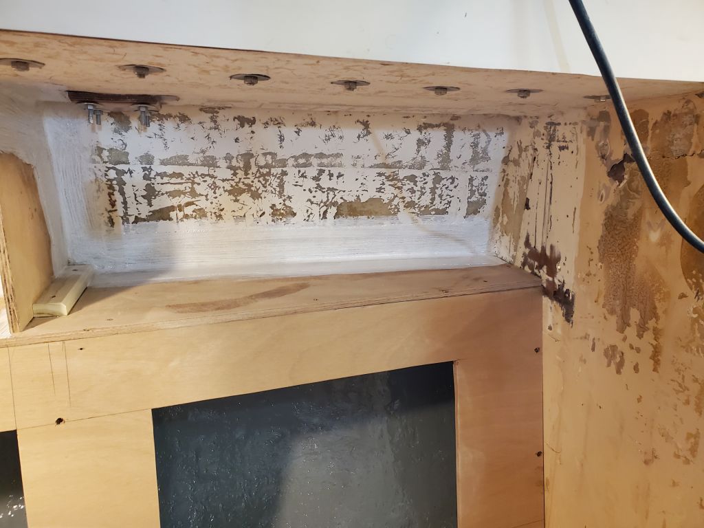
To wrap up the day, I prepped and painted, this time with white semi-gloss finish paint, the bulkheads and panels from the refrigerator locker.